Section 03 ENGINE Subsection 01 (TABLE OF CONTENTS) VMR2001_031_03_01TOC.FM 03-01-1 TABLE OF CONTENTS 0 REMOVAL AND INSTALLATION .......................................................................................... 03-02-1 1, ENGINE .......................................................................................................................... 03-02-2 2, ENGINE PINION............................................................................................................. 03-02-4 EXHAUST SYSTEM .......................................................................................................... 03-02-4 6, OIL TANK ....................................................................................................................... 03-02-5 COOLING SYSTEM ............................................................................................................... 03-03-1 RADIATOR ......................................................................................................................... 03-03-1 WATER PUMP.................................................................................................................... 03-03-2 COOLING SYSTEM LEAK TEST ....................................................................................... 03-03-3 INSPECTION ...................................................................................................................... 03-03-3 DRAINING THE SYSTEM .................................................................................................. 03-03-3 COOLING SYSTEM REFILLING ........................................................................................ 03-03-3 1, PRESSURE CAP ............................................................................................................. 03-03-3 WATER PUMP.................................................................................................................... 03-03-3 2, RADIATOR ..................................................................................................................... 03-03-4 3, RADIATOR PROTECTOR ............................................................................................... 03-03-4 4, THERMOSTAT ............................................................................................................... 03-03-4 5, COOLANT TANK ........................................................................................................... 03-03-5 6,7, FAN AND HEAT SHIELD ............................................................................................ 03-03-5 8, TEMPERATURE SENDER.............................................................................................. 03-03-6 9, TEMPERATURE SENSOR ............................................................................................. 03-03-6 MAGNETO SYSTEM ............................................................................................................. 03-04-1 1, MAGNETO ..................................................................................................................... 03-04-2 2, ROTOR ........................................................................................................................... 03-04-2 3, SPARG CLUTCH ............................................................................................................ 03-04-3 4, TRIGGER COIL ............................................................................................................... 03-04-3 CYLINDER AND HEAD .......................................................................................................... 03-05-1 CYLINDER AND HEAD ...................................................................................................... 03-05-1 VALVE ................................................................................................................................ 03-05-2 1,2, CAMSHAFT ................................................................................................................. 03-05-3 3, CENTRIFUGAL DECOMPRESSOR............................................................................................. 03-05-4 4, CYLINDER HEAD ........................................................................................................... 03-05-5 5, VALVE SPRING .............................................................................................................. 03-05-5 6, VALVE ............................................................................................................................ 03-05-5 7, VALVE STEM SEAL ....................................................................................................... 03-05-6 8, CYLINDER ...................................................................................................................... 03-05-6

Welcome message from author
This document is posted to help you gain knowledge. Please leave a comment to let me know what you think about it! Share it to your friends and learn new things together.
Transcript
Section 03 ENGINESubsection 01 (TABLE OF CONTENTS)
VMR2001_031_03_01TOC.FM 03-01-1
TABLE OF CONTENTS 0REMOVAL AND INSTALLATION .......................................................................................... 03-02-1
1, ENGINE .......................................................................................................................... 03-02-22, ENGINE PINION............................................................................................................. 03-02-4EXHAUST SYSTEM .......................................................................................................... 03-02-46, OIL TANK ....................................................................................................................... 03-02-5
COOLING SYSTEM ............................................................................................................... 03-03-1
RADIATOR ......................................................................................................................... 03-03-1
WATER PUMP.................................................................................................................... 03-03-2
COOLING SYSTEM LEAK TEST ....................................................................................... 03-03-3INSPECTION ...................................................................................................................... 03-03-3DRAINING THE SYSTEM .................................................................................................. 03-03-3COOLING SYSTEM REFILLING ........................................................................................ 03-03-31, PRESSURE CAP............................................................................................................. 03-03-3WATER PUMP.................................................................................................................... 03-03-32, RADIATOR ..................................................................................................................... 03-03-43, RADIATOR PROTECTOR............................................................................................... 03-03-44, THERMOSTAT ............................................................................................................... 03-03-45, COOLANT TANK ........................................................................................................... 03-03-56,7, FAN AND HEAT SHIELD ............................................................................................ 03-03-58, TEMPERATURE SENDER.............................................................................................. 03-03-69, TEMPERATURE SENSOR ............................................................................................. 03-03-6
MAGNETO SYSTEM ............................................................................................................. 03-04-1
1, MAGNETO ..................................................................................................................... 03-04-22, ROTOR ........................................................................................................................... 03-04-23, SPARG CLUTCH ............................................................................................................ 03-04-34, TRIGGER COIL ............................................................................................................... 03-04-3
CYLINDER AND HEAD .......................................................................................................... 03-05-1
CYLINDER AND HEAD ...................................................................................................... 03-05-1
VALVE ................................................................................................................................ 03-05-2
1,2, CAMSHAFT................................................................................................................. 03-05-33, CENTRIFUGAL DECOMPRESSOR............................................................................................. 03-05-44, CYLINDER HEAD ........................................................................................................... 03-05-55, VALVE SPRING.............................................................................................................. 03-05-56, VALVE ............................................................................................................................ 03-05-57, VALVE STEM SEAL ....................................................................................................... 03-05-68, CYLINDER ...................................................................................................................... 03-05-6
Section 03 ENGINESubsection 01 (TABLE OF CONTENTS)
03-01-2 VMR2001_031_03_01TOC.FM
CRANKSHAFT/BALANCER SHAFT ....................................................................................... 03-06-1
1, PISTON PIN .................................................................................................................... 03-06-22, PISTON ........................................................................................................................... 03-06-23, PISTON RINGS............................................................................................................... 03-06-34, BALANCER SHAFT......................................................................................................... 03-06-45, BALANCER GEAR .......................................................................................................... 03-06-56, CRANKSHAFT ................................................................................................................ 03-06-57, COUNTER GEAR ............................................................................................................ 03-06-6CRANKSHAFT BUSHING................................................................................................... 03-06-6BALL BEARINGS IN HOUSING ......................................................................................... 03-06-7RECENTRE CRANKSHAFT................................................................................................. 03-06-7RECENTRE BALANCER SHAFT......................................................................................... 03-06-7
LUBRICATION SYSTEM......................................................................................................... 03-07-1
TROUBLESHOOTING......................................................................................................... 03-07-2ENGINE PRESSURE TEST................................................................................................. 03-07-2OIL CHANGE AND OIL FILTER REPLACEMENT .............................................................. 03-07-21, OIL TANK STRAINER..................................................................................................... 03-07-32, ENGINE OIL PRESSURE REGULATOR......................................................................... 03-07-43, RETURN OIL PUMP........................................................................................................ 03-07-44, PRESSURE OIL PUMP ................................................................................................... 03-07-55, ENGINE OIL STRAINER ................................................................................................. 03-07-5
CLUTCH .................................................................................................................................. 03-08-1
CLUTCH ADJUSTMENT .................................................................................................... 03-08-21, PRESSURE PLATE.......................................................................................................... 03-08-22, PRESSURE PLATE BEARING ........................................................................................ 03-08-23,4,5, FRICTION DRIVE PLATE, STEEL DRIVEN PLATE AND CLUTCH BASKET ........... 03-08-26, CLUTCH RELEASE SHAFT............................................................................................. 03-08-4
TRANSMISSION .................................................................................................................... 03-09-1
SHIFTING MECHANISM .................................................................................................... 03-09-2TRANSMISSION................................................................................................................. 03-09-3TRANSMISSION SHAFT BEARINGS ................................................................................ 03-09-4
Section 03 ENGINESubsection 02 (REMOVAL AND INSTALLATION)
VMR2001_006_03_02.FM 03-02-1
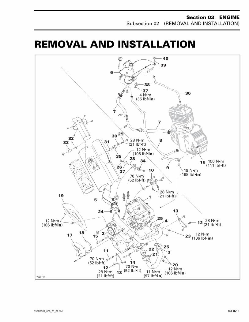
REMOVAL AND INSTALLATION 0
Section 03 ENGINESubsection 02 (REMOVAL AND INSTALLATION)
03-02-2 VMR2001_006_03_02.FM
1, ENGINE
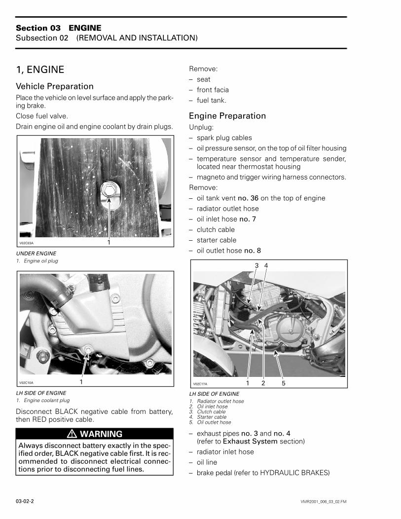
Vehicle PreparationPlace the vehicle on level surface and apply the park-ing brake.Close fuel valve.Drain engine oil and engine coolant by drain plugs.
UNDER ENGINE1. Engine oil plug
LH SIDE OF ENGINE1. Engine coolant plug
Disconnect BLACK negative cable from battery,then RED positive cable.
Remove:– seat– front facia– fuel tank.
Engine PreparationUnplug:– spark plug cables– oil pressure sensor, on the top of oil filter housing– temperature sensor and temperature sender,
located near thermostat housing– magneto and trigger wiring harness connectors.Remove:– oil tank vent no. 36 on the top of engine– radiator outlet hose– oil inlet hose no. 7– clutch cable– starter cable– oil outlet hose no. 8
LH SIDE OF ENGINE1. Radiator outlet hose2. Oil inlet hose3. Clutch cable4. Starter cable5. Oil outlet hose
– exhaust pipes no. 3 and no. 4(refer to Exhaust System section)
– radiator inlet hose– oil line– brake pedal (refer to HYDRAULIC BRAKES)
WARNING
Always disconnect battery exactly in the spec-ified order, BLACK negative cable first. It is rec-ommended to disconnect electrical connec-tions prior to disconnecting fuel lines.

Section 03 ENGINESubsection 02 (REMOVAL AND INSTALLATION)
VMR2001_006_03_02.FM 03-02-3
– RH footrest (refer to BODY)– engine pinion no. 2
(refer to Engine Pinion section)
RH SIDE OF ENGINE1. Exhaust pipes2. Radiator inlet hose3. Oil line4. Brake pedal5. Footrest
– carburetor and carburetor adaptor (refer to CAR-BURETOR AND AIR INTAKE SILENCER)
– gearshift pedal no. 9.Unscrew neutral switch connector.
RemovalRemove the upper support bracket no. 10 com-pletely.
Install engine lifting tool (P/N 529 035 610) then,install a hoist.Remove:– upper engine support bolt no. 11– lower bolts no. 12 retaining the engine support
no. 13 on either side, then, remove supports– front lower mounting bolt no. 14– rear lower mounting bolt no. 15– rear upper mounting bolt no. 16.Remove engine from vehicle.
InstallationFor installation, reverse the removal procedure,paying attention to the following details.Reattach cables, hoses, wiring harness, etc.Adjust clutch cable.Bleed rear brake.Before to start the engine, remove oil filter.Unfasten pressure bleeding screw.
BEHIND OIL FILTER1. Bleeding screw
Unscrew and remove one spark plug.Turn engine using starter until oil emerges in filterchamber.Tighten pressure bleeding screw. Torque to 25 N•m(18 lbf•ft).Install oil filter.This operation activated the oil pump. Check if ve-hicle runs correctly.

Section 03 ENGINESubsection 02 (REMOVAL AND INSTALLATION)
03-02-4 VMR2001_006_03_02.FM
2, ENGINE PINION
RemovalSlack drive chain.Remove pinion cover no. 17 and metallic chain guardno. 18.Set the first gear.Unlock retaining ring then, unscrew the retainingnut.NOTE: Discard the retaining ring.Remove engine pinion and drive chain together.
InspectionCheck pinion for wear or other damage. Replace ifnecessary.
InstallationCAUTION: Replace chain, sprocket and piniontogether to prevent rapid chain and sprocketwear. Install a new retaining ring each time thepinion is removed.For the installation, reverse the removal procedure.Paying attention to the following details.Install pinion with lips on the engine side.
Install retaining ring then retaining nut.Torque retaining nut to 140 N•m (103 lbf•ft), thenlock retaining ring.Adjust drive chain. Refer to MAINTENANCE.
EXHAUST SYSTEM
Exhaust Pipe Removal3, RH Exhaust PipeRemove heat shield no. 19.Remove exhaust pipe nuts no. 20.Unscrew exhaust clamp no. 21.Pull exhaust pipe forward.Remove pipe gasket no. 22.
4, LH Exhaust PipeRemove RH exhaust pipe.Remove exhaust pipe nuts no. 23.Remove springs no. 24 retaining exhaust pipe andmuffler. Use exhaust spring installer/remover (P/N529 035 400).Pull exhaust pipe forward.Remove pipe gasket no. 25.
Exhaust Pipe InstallationRH Exhaust PipeFor installation, reverse the removal procedure,paying attention to the following details.Use a new exhaust pipe gasket and make surethat it is properly installed.Tighten flange nuts, making sure RH exhaust pipeis properly aligned inside LH exhaust pipe.
LH Exhaust PipeFor installation, reverse the removal procedure,paying attention to the following details.Use a new exhaust pipe gasket and make surethat it is properly installed.Install flange nuts, making sure exhaust pipe isproperly aligned inside muffler ball socket then in-stall retaining springs after pushing muffler for-ward in exhaust pipe. Do not torque yet.Install RH exhaust pipe.Torque all flange nuts.
WARNING
Never touch exhaust system components im-mediately after the engine has been run be-cause these components are very hot.
Section 03 ENGINESubsection 02 (REMOVAL AND INSTALLATION)
VMR2001_006_03_02.FM 03-02-5
5, Muffler RemovalRemove exhaust pipes.Remove screw no. 26, washer no. 27 and spacerno. 28.Under rear fender, remove screw no. 29, washerno. 30, bushing no. 31, another washer no. 32and spacer no. 33.Remove muffler.
Muffler InstallationFor installation, reverse the removal procedure.NOTE: Check rubber bushings nos. 34 and 35 forcracks or other damages, change if necessary.
6, OIL TANK
RemovalRemove front facia. Refer to BODY.Remove head light. Refer to ACCESSORIES.Drain engine oil.Remove:– oil inlet hose no. 7– oil outlet hose no. 8– oil tank vent no. 36.Unscrew bolts retaining oil tank and fuel tank cov-er to the frame.Unscrew bolt no. 37 under oil tank.Pull oil tank.
InstallationFor installation, reverse the removal procedure.Paying attention to the following details.Install rubber washer no. 38 between oil tank andframe.Do not forget spacers no. 39 in the grommetsno. 40.Bleed engine if necessary. Refer to MAINTENANCE.
Section 03 ENGINESubsection 03 (COOLING SYSTEM)
VMR2001_007_03_03A.FM 03-03-1
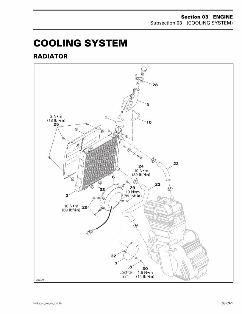
COOLING SYSTEM 0RADIATOR
!"#

Section 03 ENGINESubsection 03 (COOLING SYSTEM)
03-03-2 VMR2001_007_03_03A.FM
WATER PUMP
$%&#
Section 03 ENGINESubsection 03 (COOLING SYSTEM)
VMR2001_007_03_03A.FM 03-03-3
COOLING SYSTEM LEAK TESTInstall special plug (radiator cap) (P/N 529 021 400)and hose pincher (P/N 529 009 900) on overflowhose no. 10. Pressurize all system through cool-ant reservoir to 103 kPa (15 PSI).Check all hoses, radiator and cylinder/base for cool-ant leaks. Spray a soap/water solution and look forair bubbles.
INSPECTIONCheck general condition of hoses and clamp tight-ness.
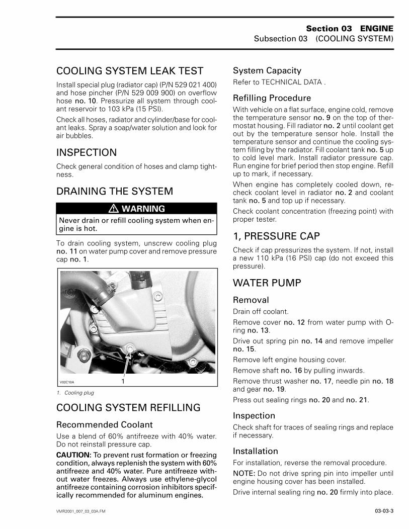
DRAINING THE SYSTEM
To drain cooling system, unscrew cooling plugno. 11 on water pump cover and remove pressurecap no. 1.
1. Cooling plug
COOLING SYSTEM REFILLING
Recommended CoolantUse a blend of 60% antifreeze with 40% water.Do not reinstall pressure cap.CAUTION: To prevent rust formation or freezingcondition, always replenish the system with 60%antifreeze and 40% water. Pure antifreeze with-out water freezes. Always use ethylene-glycolantifreeze containing corrosion inhibitors specif-ically recommended for aluminum engines.
System CapacityRefer to TECHNICAL DATA .
Refilling ProcedureWith vehicle on a flat surface, engine cold, removethe temperature sensor no. 9 on the top of ther-mostat housing. Fill radiator no. 2 until coolant getout by the temperature sensor hole. Install thetemperature sensor and continue the cooling sys-tem filling by the radiator. Fill coolant tank no. 5 upto cold level mark. Install radiator pressure cap.Run engine for brief period then stop engine. Refillup to mark, if necessary.When engine has completely cooled down, re-check coolant level in radiator no. 2 and coolanttank no. 5 and top up if necessary.Check coolant concentration (freezing point) withproper tester.
1, PRESSURE CAPCheck if cap pressurizes the system. If not, installa new 110 kPa (16 PSI) cap (do not exceed thispressure).
WATER PUMP
RemovalDrain off coolant.Remove cover no. 12 from water pump with O-ring no. 13.Drive out spring pin no. 14 and remove impellerno. 15.Remove left engine housing cover.Remove shaft no. 16 by pulling inwards.Remove thrust washer no. 17, needle pin no. 18and gear no. 19.Press out sealing rings no. 20 and no. 21.
InspectionCheck shaft for traces of sealing rings and replaceif necessary.
InstallationFor installation, reverse the removal procedure.NOTE: Do not drive spring pin into impeller untilengine housing cover has been installed.Drive internal sealing ring no. 20 firmly into place.
WARNING
Never drain or refill cooling system when en-gine is hot.

Section 03 ENGINESubsection 03 (COOLING SYSTEM)
03-03-4 VMR2001_007_03_03A.FM
Fill cavity between sealing rings with Molykote 111paste.Drive external sealing ring no. 21 into place withthe relevant adapter until flush with the race.
2, RADIATOR
RemovalDrain cooling system.Remove:– front facia (refer to BODY)– inlet no. 22 and outlet no. 23 hoses
1. Radiator inlet hose2. Radiator outlet hose
– overflow hose no. 10– headlight– ignition coils– radiator protector– mounting bolts no. 24 on the top.Pull radiator out of frame by the RH side.
InspectionCheck radiator air passage for clogging or damage.Remove insects, mud or other obstructions withcompressed air or low pressure water.Check for any coolant leakage from radiator andhoses.
InstallationFor installation, reverse the removal procedure.Refill radiator.NOTE: Do not forget rubber bushings no. 33 un-der radiator.
3, RADIATOR PROTECTOR
RemovalRemove screws no. 25 retaining protector on ra-diator.
InspectionCheck protector air passage for damage.Remove insects, mud or other obstructions withcompressed air or low pressure water.
InstallationFor installation, reverse the removal procedure.
4, THERMOSTATThe thermostat is a single action type.
RemovalThe thermostat is located on the RH side of engine.Unfasten cover no. 26 from thermostat housing.
RH SIDE OF ENGINE1. Remove screws
Pull out thermostat.Remove O-ring no. 27. Check O-ring for damageand change if necessary.

Section 03 ENGINESubsection 03 (COOLING SYSTEM)
VMR2001_007_03_03A.FM 03-03-5
TestTo check thermostat, put in water and heat water.Thermostat should open when water temperaturereaches 75°C (167°F).
InstallationFor installation, reverse the removal procedure.
5, COOLANT TANK
Overflow Coolant TankThe coolant expands as the temperature (up to100 - 110°C (212 - 230°F)) and pressure rise in thesystem. If the limiting system working pressurecap is reached 110 kPa (16 PSI), the pressure reliefvalve in the pressure cap is lifted from its seat andallows coolant to flow through the overflow hoseinto the overflow coolant tank.
RemovalRemove overflow hose no. 10.Unfasten the hose anchor no. 28 retaining coolanttank.Empty coolant tank.
InstallationThe installation is the reverse of the removal pro-cedure.
6,7, FAN AND HEAT SHIELD
TestRefer to ACCESSORIES.
Fan RemovalUnscrew nuts no. 29, and pull fan in exhaust di-rection.
1. Remove bolts (two bolts on each side)
Unplug fan connector.
Fan InstallationFor the installation, reverse the removal proce-dure.
Heat Shield RemovalRemove fan.Remove bolts no. 30 and spacers no. 32.
Heat Shield InstallationThe installation is the reverse of the removal pro-cedure.NOTE: Apply Loctite 271 on threads.
Section 03 ENGINESubsection 03 (COOLING SYSTEM)
03-03-6 VMR2001_007_03_03A.FM
8, TEMPERATURE SENDER
RemovalUnplug temperature sender connectors.Unscrew temperature sender.
TestUsing a multimeter, measure the resistance be-tween both temperature sender connectors.The multimeter should indicate an infinite resis-tance (O.L.), if not change the temperature sender.If the resistance is infinite (O.L.), heat the temper-ature sender, above 95°C (203°F). The resistanceshould be 0.1 Ω. If not, change the temperaturesender.
InstallationThe installation is the reverse of the removal pro-cedure, paying attention to the following detail.Check gasket no. 31 and change if necessary.CAUTION: Don’t apply any product on thethreads or on the gasket.
9, TEMPERATURE SENSOR
RemovalUnplug temperature sensor connector.Unscrew temperature sensor.
TestUsing a multimeter, measure the resistance be-tween connector on the top of temperature sen-sor and threads.The multimeter should indicate an infinite resis-tance (O.L.), if not change the temperature sensor.If the resistance is infinite (O.L.), heat the temper-ature sensor, above 115°C (239°F). The resistanceshould be 0.1 Ω. If not, change the temperaturesensor.
InstallationThe installation is the reverse of the removal pro-cedure.CAUTION: Don’t apply any product on thethreads.
Section 03 ENGINESubsection 04 (MAGNETO SYSTEM)
VMR2001_008_03-04A.FM 03-04-1
MAGNETO SYSTEM 0
$'
!"#
()*")#"
!"#
()*")#"
!"#
!"#
'#")*+),-.#"),
'#")*+),-.#"),

Section 03 ENGINESubsection 04 (MAGNETO SYSTEM)
03-04-2 VMR2001_008_03-04A.FM
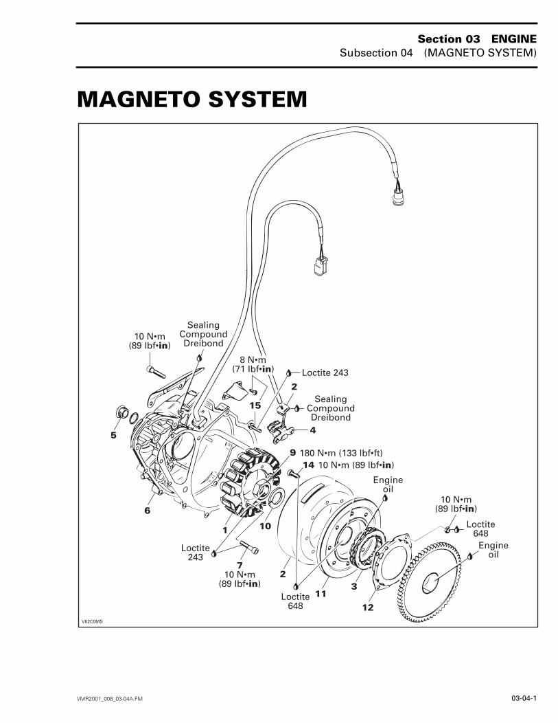
1, MAGNETO
RemovalUnfasten socket screws on right engine housingcover.Unfasten central screw plug no. 5, screw in han-dle (P/N 529 035 622) and remove ignition coverno. 6.
RH SIDE
Remove gasket.NOTE: Clean all metal component in a non-ferrousmetal cleaner. Use Bombardier gasket remover(P/N 413 708 500) or suitable equivalent.Remove all socket screws no. 7 retaining magne-to to ignition cover then pull magneto.
InstallationFor installation, reverse the removal procedure.Paying attention to the following details.Seal rubber grommet no. 8 on electrical line withsealing compound Dreibond (P/N 420 297 906).Screw handle in center bore.Fit magneto housing and screw down.Unfasten handle and install screw plug in cover.NOTE: Install a new gasket on ignition cover.
2, ROTOR
RemovalLock crankshaft with locking bolt (P/N 529 035617). Refer to CRANKSHAFT/BALANCER SHAFT.Remove ignition cover no. 6.Unscrew nut no. 9 retaining rotor.Remove lock washer no. 10.Install magneto puller (P/N 420 976 235) andcrankshaft protector (P/N 420 876 557) then re-move rotor.
InstallationFor installation, reverse the removal procedure.Paying attention to the following details.Apply light coat of Loctite 648 to taper on rotor hubno. 11.Oil sparg clutch no. 3 in sparg clutch housingno. 12.Slide rotor onto crankshaft, woodruff key andgroove must be aligned in one line.Rotate starter double gear counterclockwise toenable the sparg clutch to slide on the collar ofsparg clutch gear no. 13.CAUTION: Taper on crankshaft and rotor mustbe free of grease.Install lock washer and nut on crankshaft end. Ap-ply Loctite 243 on threads. Torque to 180 N•m(133 lbf•ft).
WARNING
Never disconnect harness on ignition systemwhile engine is running.
/
Section 03 ENGINESubsection 04 (MAGNETO SYSTEM)
VMR2001_008_03-04A.FM 03-04-3
3, SPARG CLUTCH
RemovalRemove rotor no. 2.Unscrew all socket screws no. 14 retaining rotorand sparg clutch housing no. 12.Remove sparg clutch from sparg clutch housing.
InstallationFor installation, reverse the removal procedure.NOTE: Apply engine oil on sparg clutch.Install sparg clutch with the arrow on the top.
4, TRIGGER COIL
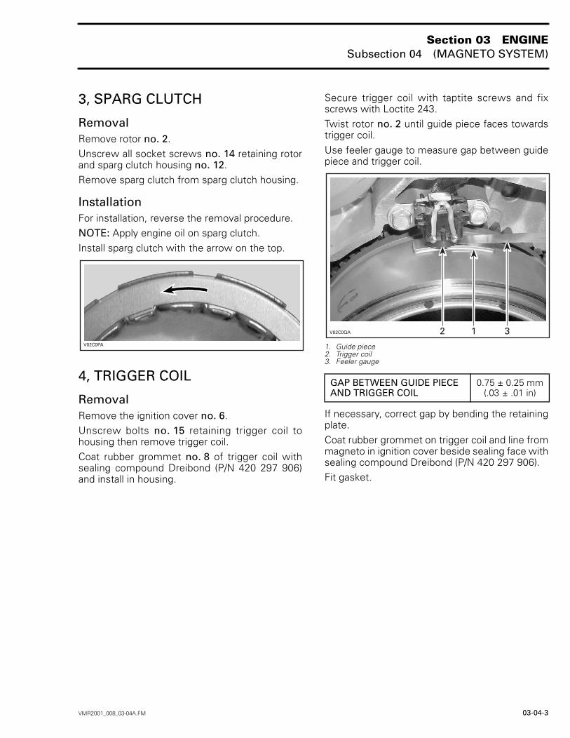
RemovalRemove the ignition cover no. 6.Unscrew bolts no. 15 retaining trigger coil tohousing then remove trigger coil.Coat rubber grommet no. 8 of trigger coil withsealing compound Dreibond (P/N 420 297 906)and install in housing.
Secure trigger coil with taptite screws and fixscrews with Loctite 243.Twist rotor no. 2 until guide piece faces towardstrigger coil.Use feeler gauge to measure gap between guidepiece and trigger coil.
1. Guide piece2. Trigger coil3. Feeler gauge
If necessary, correct gap by bending the retainingplate.Coat rubber grommet on trigger coil and line frommagneto in ignition cover beside sealing face withsealing compound Dreibond (P/N 420 297 906).Fit gasket.
0
GAP BETWEEN GUIDE PIECE AND TRIGGER COIL
0.75 ± 0.25 mm(.03 ± .01 in)
1
Section 03 ENGINESubsection 05 (CYLINDER AND HEAD)
VMR2001_009_03-05A.FM 03-05-1
CYLINDER AND HEAD 0CYLINDER AND HEAD
('
!"#
()*")#"
Section 03 ENGINESubsection 05 (CYLINDER AND HEAD)
03-05-2 VMR2001_009_03-05A.FM
VALVE
23
()*")#"
()*")#"
()*")#"
!"#
!"#
'+#. #*.#4#
Section 03 ENGINESubsection 05 (CYLINDER AND HEAD)
VMR2001_009_03-05A.FM 03-05-3
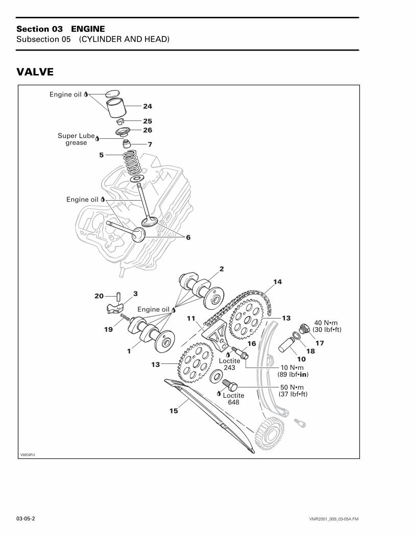
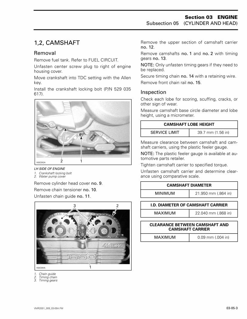
1,2, CAMSHAFT
RemovalRemove fuel tank. Refer to FUEL CIRCUIT.Unfasten center screw plug to right of enginehousing cover.Move crankshaft into TDC setting with the Allenkey.Install the crankshaft locking bolt (P/N 529 035617).
LH SIDE OF ENGINE1. Crankshaft locking bolt2. Water pump cover
Remove cylinder head cover no. 9.Remove chain tensioner no. 10.Unfasten chain guide no. 11.
1. Chain guide2. Timing chain3. Timing gears
Remove the upper section of camshaft carrierno. 12.Remove camshafts no. 1 and no. 2 with timinggears no. 13.NOTE: Only unfasten timing gears if they need tobe replaced.Secure timing chain no. 14 with a retaining wire.Remove front chain rail no. 15.
InspectionCheck each lobe for scoring, scuffing, cracks, orother sign of wear.Measure camshaft base circle diameter and lobeheight, using a micrometer.
Measure clearance between camshaft and cam-shaft carriers, using the plastic feeler gauge.NOTE: The plastic feeler gauge is available at au-tomotive parts retailer.Tighten camshaft carrier to specified torque.Unfasten camshaft carrier and determine clear-ance using comparative scale.
5
6
CAMSHAFT LOBE HEIGHT
SERVICE LIMIT 39.7 mm (1.56 in)
CAMSHAFT DIAMETER
MINIMUM 21.950 mm (.864 in)
I.D. DIAMETER OF CAMSHAFT CARRIER
MAXIMUM 22.040 mm (.868 in)
CLEARANCE BETWEEN CAMSHAFT AND CAMSHAFT CARRIER
MAXIMUM 0.09 mm (.004 in)
Section 03 ENGINESubsection 05 (CYLINDER AND HEAD)
03-05-4 VMR2001_009_03-05A.FM
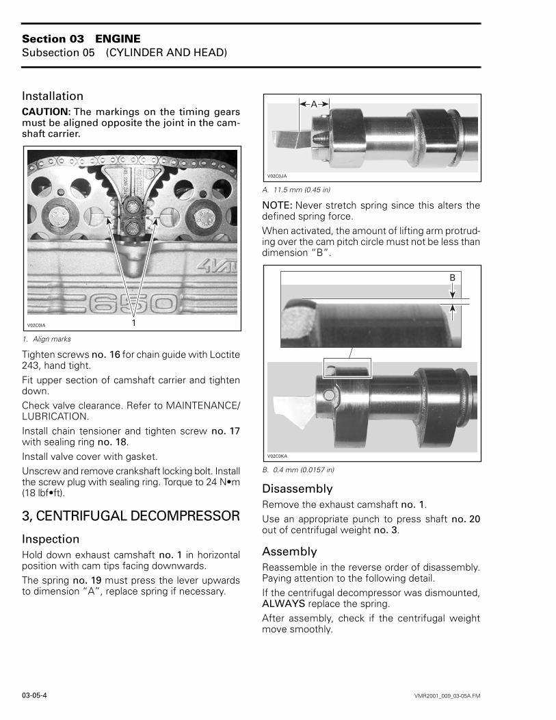
InstallationCAUTION: The markings on the timing gearsmust be aligned opposite the joint in the cam-shaft carrier.
1. Align marks
Tighten screws no. 16 for chain guide with Loctite243, hand tight.Fit upper section of camshaft carrier and tightendown.Check valve clearance. Refer to MAINTENANCE/LUBRICATION.Install chain tensioner and tighten screw no. 17with sealing ring no. 18.Install valve cover with gasket.Unscrew and remove crankshaft locking bolt. Installthe screw plug with sealing ring. Torque to 24 N•m(18 lbf•ft).
3, CENTRIFUGAL DECOMPRESSOR
InspectionHold down exhaust camshaft no. 1 in horizontalposition with cam tips facing downwards.The spring no. 19 must press the lever upwardsto dimension “A”, replace spring if necessary.
A. 11.5 mm (0.45 in)
NOTE: Never stretch spring since this alters thedefined spring force.When activated, the amount of lifting arm protrud-ing over the cam pitch circle must not be less thandimension “B”.
B. 0.4 mm (0.0157 in)
DisassemblyRemove the exhaust camshaft no. 1.Use an appropriate punch to press shaft no. 20out of centrifugal weight no. 3.
AssemblyReassemble in the reverse order of disassembly.Paying attention to the following detail.If the centrifugal decompressor was dismounted,ALWAYS replace the spring.After assembly, check if the centrifugal weightmove smoothly.
7
8
9
Section 03 ENGINESubsection 05 (CYLINDER AND HEAD)
VMR2001_009_03-05A.FM 03-05-5
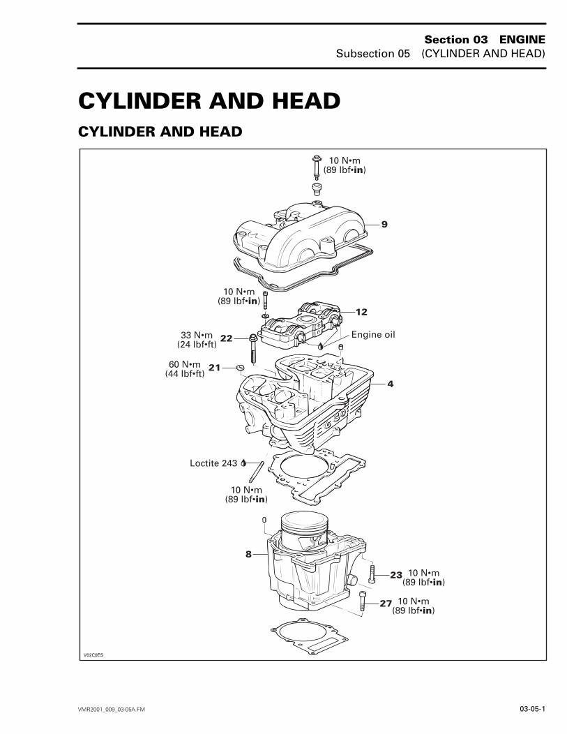
4, CYLINDER HEAD
RemovalRemove engine from vehicle. Refer to INSTALLA-TION AND REMOVAL.Remove starter. Refer to STARTING SYSTEM.Remove camshafts.Withdraw the front chain rail no. 11.Unfasten nuts no. 21 on stud bolts and collar screwsno. 22.Unfasten socket screws no. 23 linking cylinderhead to cylinder.Remove cylinder head.
InspectionCheck for crack between valve seats or other dam-age, if so, replace cylinder head.
InstallationFor installation, reverse the removal procedure.Paying attention to the following details.Fitting cylinder head gasket.Slide timing chain through chain duct.Tighten cylinder head and cylinder hand tight withcollar screws.Screw collar nuts onto stud bolts and tighten cross-wise.Tighten collar screws crosswise.Tighten socket screws on cylinder base.Install camshafts.
5, VALVE SPRING
RemovalRemove:– cylinder head no. 4– valve tappet no. 24.Compress valve spring, use a spring compressor.Remove valve cotters no. 25.Remove spring compressor, valve spring retainerno. 26 and valve spring.
InspectionCheck valve spring for rust or corrosion and freelength.
InstallationFor installation, reverse the removal procedure.
6, VALVE
RemovalRemove valve spring no. 5.Push the valve stem then pull valve out of valveguide.
InspectionValve ClearanceRefer to MAINTENANCE/LUBRICATION.
ValveInspect valve surface, check for abnormal stemwear and bending. If so, replace by a new one.
Valve Stem and Valve Guide Check valve stem and valve guide for wear or fric-tion surfaces, if so, replace parts.Measure valve stem and valve guide in three plac-es, using a micrometer and a small hole gauge.NOTE: Clean valve guide to remove carbon de-posits before measuring.
VALVE SPRING FREE LENGTH
SERVICE LIMIT 44.5 mm (1-3/4 in)
VALVE STEM DIAMETER mm (in)
SERVICE LIMIT
Exhaust 5.935 mm (.233 in)
Intake 5.95 mm (.234 in)
I.D. VALVE GUIDE mm (in)
SERVICE LIMIT
Exhaust6.080 mm (.239 in)
Intake
Section 03 ENGINESubsection 05 (CYLINDER AND HEAD)
03-05-6 VMR2001_009_03-05A.FM
Change valve if valve stem is out of specification.Change cylinder head if valve guides are out ofspecification.
Valve Face and SeatCheck valve face and seat for burning, pitting andother signs of damage.Apply some lapping compound to valve face andwork valve on its seat with a lapping tool.Measure valve face contact width. NOTE: The location of contact area should be incenter of valve face.Measure valve seat width, using a caliper.
If valve seat contact width is too wide, too narrowor has spots, the seat must be ground or cylinderhead replaced.
InstallationInstall valve.NOTE: Remove assembly sleeve once again.Install valve spring and valve plate spring.NOTE: Install valve tappets with a small amountof grease to facilitate assembly.
7, VALVE STEM SEAL
RemovalRemove valve.Remove valve stem seal with a special pliers.
InspectionInspection of valve stem seals is not needed asnew seals should always be installed whenever acylinder head is diassembled.
InstallationFor installation, reverse the removal procedure.
8, CYLINDER
RemovalRemove:– cylinder head no. 4, if necessaryNOTE: If the cylinder head does not have to bedisassembled, do not separate cylinder head fromcylinder.– water cooling hose from cylinder– socket screws no. 27 retaining cylinder to the
crankcase housing.Pull cylinder.
InspectionCylinderCheck cylinder for cracks, scoring, rust and wearridges on the top and bottom of the cylinder.
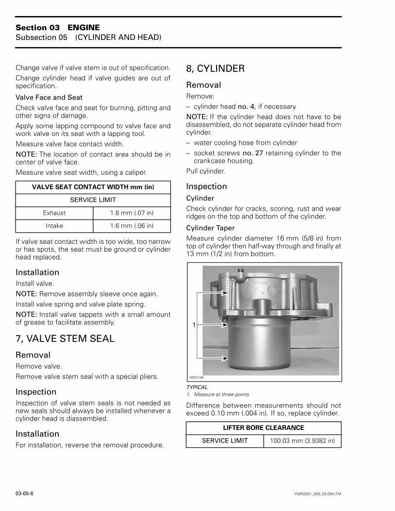
Cylinder TaperMeasure cylinder diameter 16 mm (5/8 in) fromtop of cylinder then half-way through and finally at13 mm (1/2 in) from bottom.
TYPICAL1. Measure at three points
Difference between measurements should notexceed 0.10 mm (.004 in). If so, replace cylinder.
VALVE SEAT CONTACT WIDTH mm (in)
SERVICE LIMIT
Exhaust 1.8 mm (.07 in)
Intake 1.6 mm (.06 in)
LIFTER BORE CLEARANCE
SERVICE LIMIT 100.03 mm (3.9382 in)
8
Section 03 ENGINESubsection 05 (CYLINDER AND HEAD)
VMR2001_009_03-05A.FM 03-05-7
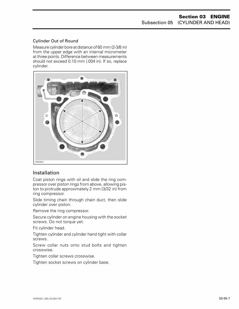
Cylinder Out of RoundMeasure cylinder bore at distance of 60 mm (2-3/8 in)from the upper edge with an internal micrometerat three points. Difference between measurementsshould not exceed 0.10 mm (.004 in). If so, replacecylinder.
InstallationCoat piston rings with oil and slide the ring com-pressor over piston rings from above, allowing pis-ton to protrude approximately 2 mm (3/32 in) fromring compressor.Slide timing chain through chain duct, then slidecylinder over piston.Remove the ring compressor. Secure cylinder on engine housing with the socketscrews. Do not torque yet.Fit cylinder head.Tighten cylinder and cylinder hand tight with collarscrews.Screw collar nuts onto stud bolts and tightencrosswise.Tighten collar screws crosswise.Tighten socket screws on cylinder base.
Section 03 ENGINESubsection 06 (CRANKSHAFT/BALANCER SHAFT)
VMR2001_010_03-06A.FM 03-06-1
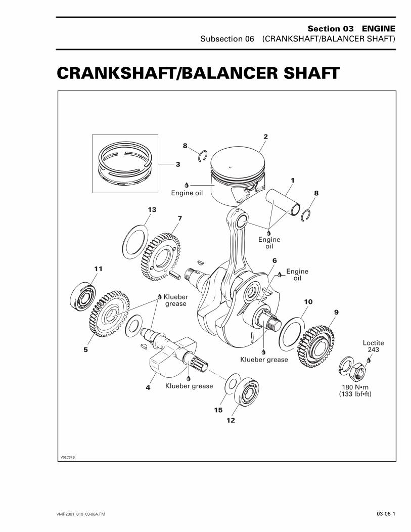
CRANKSHAFT/BALANCER SHAFT 0
()*")#"
()*")#"
##.*.#4#
()*")#"
##.*.#4#
!"#
##.*.#4#
2'
Section 03 ENGINESubsection 06 (CRANKSHAFT/BALANCER SHAFT)
03-06-2 VMR2001_010_03-06A.FM
1, PISTON PIN
RemovalRemove engine. Refer to REMOVAL AND IN-STALLATION.Remove cylinder. Refer to CYLINDER AND HEAD.Remove both piston pin circlips no. 8 then pressout piston pin.
InspectionCheck piston pin for crack or other damage.Measure both ends of piston pin with a micrometer.
InstallationFor installation, reverse the removal procedure.Paying attention to the following details.Apply engine oil on the piston pin.Insert piston pin into piston and connecting rod. Secure piston pin with both piston pin circlips.NOTE: Do not align the end gap of the piston pincirclips with the cutout in the piston bore.
2, PISTON
RemovalRemove piston pin no. 1.Detach piston from connecting rod.NOTE: Mark base of piston on exhaust end.Remove cylinder.Remove both piston pin circlips no. 8 then pushpiston pin no. 1 out of piston.Detach piston from connecting rod.NOTE: Mark base of piston on exhaust end.
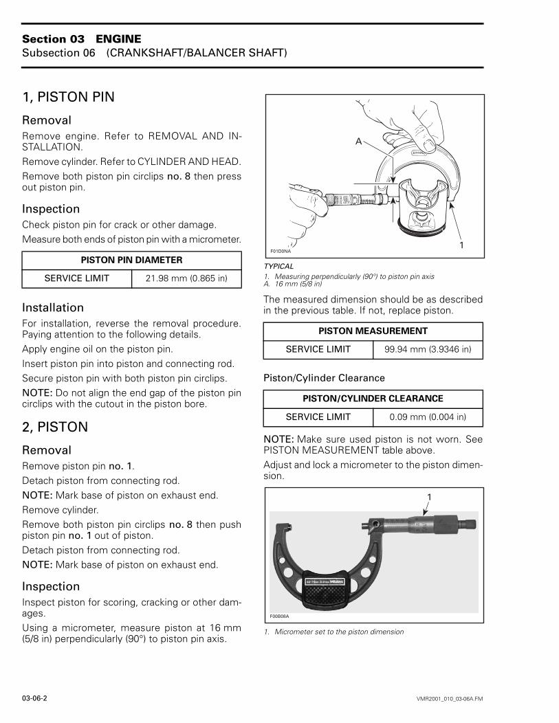
InspectionInspect piston for scoring, cracking or other dam-ages.Using a micrometer, measure piston at 16 mm(5/8 in) perpendicularly (90°) to piston pin axis.
TYPICAL1. Measuring perpendicularly (90°) to piston pin axisA. 16 mm (5/8 in)
The measured dimension should be as describedin the previous table. If not, replace piston.
Piston/Cylinder Clearance
NOTE: Make sure used piston is not worn. SeePISTON MEASUREMENT table above.Adjust and lock a micrometer to the piston dimen-sion.
1. Micrometer set to the piston dimension
PISTON PIN DIAMETER
SERVICE LIMIT 21.98 mm (0.865 in)
PISTON MEASUREMENT
SERVICE LIMIT 99.94 mm (3.9346 in)
PISTON/CYLINDER CLEARANCE
SERVICE LIMIT 0.09 mm (0.004 in)
F01D0NA1
A
29
Section 03 ENGINESubsection 06 (CRANKSHAFT/BALANCER SHAFT)
VMR2001_010_03-06A.FM 03-06-3
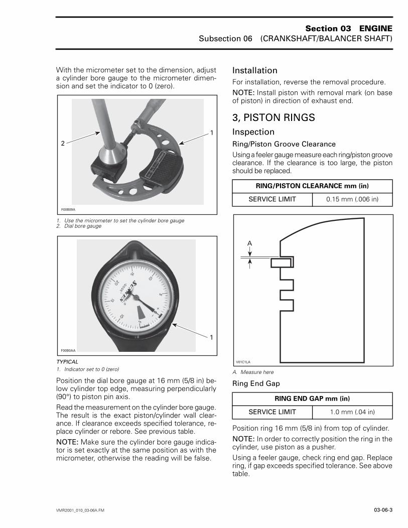
With the micrometer set to the dimension, adjusta cylinder bore gauge to the micrometer dimen-sion and set the indicator to 0 (zero).
1. Use the micrometer to set the cylinder bore gauge2. Dial bore gauge
TYPICAL1. Indicator set to 0 (zero)
Position the dial bore gauge at 16 mm (5/8 in) be-low cylinder top edge, measuring perpendicularly(90°) to piston pin axis.Read the measurement on the cylinder bore gauge.The result is the exact piston/cylinder wall clear-ance. If clearance exceeds specified tolerance, re-place cylinder or rebore. See previous table.NOTE: Make sure the cylinder bore gauge indica-tor is set exactly at the same position as with themicrometer, otherwise the reading will be false.
InstallationFor installation, reverse the removal procedure.NOTE: Install piston with removal mark (on baseof piston) in direction of exhaust end.
3, PISTON RINGSInspectionRing/Piston Groove ClearanceUsing a feeler gauge measure each ring/piston grooveclearance. If the clearance is too large, the pistonshould be replaced.
A. Measure here
Ring End Gap
Position ring 16 mm (5/8 in) from top of cylinder.NOTE: In order to correctly position the ring in thecylinder, use piston as a pusher.Using a feeler gauge, check ring end gap. Replacering, if gap exceeds specified tolerance. See abovetable.
F00B09A
1
2
F00B0AA
1
RING/PISTON CLEARANCE mm (in)
SERVICE LIMIT 0.15 mm (.006 in)
RING END GAP mm (in)
SERVICE LIMIT 1.0 mm (.04 in)
Section 03 ENGINESubsection 06 (CRANKSHAFT/BALANCER SHAFT)
03-06-4 VMR2001_010_03-06A.FM
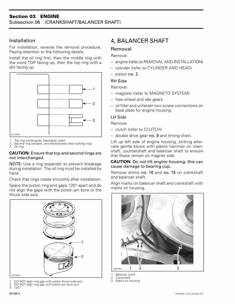
InstallationFor installation, reverse the removal procedure.Paying attention to the following details.Install the oil ring first, then the middle ring withthe word TOP facing up, then the top ring with adot facing up.
1. Top ring (rectangular, black/gray color)2. Second ring (scraper, chrome/stainless steel looking ring)3. Oil ring
CAUTION: Ensure that top and second rings arenot interchanged.NOTE: Use a ring expander to prevent breakageduring installation. The oil ring must be installed byhand.Check that rings rotate smoothly after installation.Space the piston ring end gaps 120° apart and donot align the gaps with the piston pin bore or thethrust side axis.
1. DO NOT align ring gap with piston thrust side axis2. DO NOT align ring gap with piston pin bore axisA. 120°
4, BALANCER SHAFTRemovalRemove:– engine (refer to REMOVAL AND INSTALLATION)– cylinder (refer to CYLINDER AND HEAD)– piston no. 2.
RH SideRemove:– magneto (refer to MAGNETO SYSTEM)– free wheel and idle gears– oil filter and unfasten two screw connections on
base plate for engine housing.
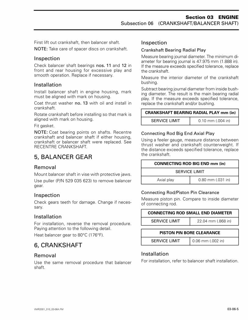
LH SideRemove:– clutch (refer to CLUTCH)– double drive gear no. 9 and timing chain.Lift up left side of engine housing, striking alter-nate gentle blows with plastic hammer on main-shaft, countershaft and balancer shaft to ensurethat these remain on magnet side.CAUTION: Do not tilt engine housing; this cancause damage to bearing cup.Remove shims no. 10 and no. 15 on crankshaftand balancer shaft.Align marks on balancer shaft and crankshaft withmarks on housing.
1. Balancer shaft2. Crankshaft3. Marks on housing
A31C2OA
1
2
A A
A
'
Section 03 ENGINESubsection 06 (CRANKSHAFT/BALANCER SHAFT)
VMR2001_010_03-06A.FM 03-06-5
First lift out crankshaft, then balancer shaft.NOTE: Take care of spacer discs on crankshaft.
InspectionCheck balancer shaft bearings nos. 11 and 12 infront and rear housing for excessive play andsmooth operation. Replace if necessary.
InstallationInstall balancer shaft in engine housing, markmust be aligned with mark on housing.Coat thrust washer no. 13 with oil and install incrankshaft.Rotate crankshaft before installing so that mark isaligned with mark on housing.Fit gasket.NOTE: Coat bearing points on shafts. Recentrecrankshaft and balancer shaft if either housing,crankshaft or balancer shaft were replaced. SeeRECENTRE CRANKSHAFT.
5, BALANCER GEAR
RemovalMount balancer shaft in vise with protective jaws.Use puller (P/N 529 035 623) to remove balancergear.
InspectionCheck gears teeth for damage. Change if neces-sary.
InstallationFor installation, reverse the removal procedure.Paying attention to the following detail.Heat balancer gear to 80°C (176°F).
6, CRANKSHAFT
RemovalUse the same removal procedure that balancershaft.
InspectionCrankshaft Bearing Radial PlayMeasure bearing journal diameter. The minimum di-ameter for bearing journal is 47.975 mm (1.888 in).If the measure exceeds specified tolerance, replacethe crankshaft.Measure the interior diameter of the crankshaftbushing. Subtract bearing journal diameter from inside bush-ing diameter. The result is the main bearing radialplay. If the measure exceeds specified tolerance,replace the crankshaft and/or bushing.
Connecting Rod Big End Axial PlayUsing a feeler gauge, measure distance betweenthrust washer and crankshaft counterweight. Ifthe distance exceeds specified tolerance, replacethe crankshaft.
Connecting Rod/Piston Pin ClearanceMeasure piston pin. Compare to inside diameterof connecting rod.
InstallationFor installation, refer to balancer shaft installation.
CRANKSHAFT BEARING RADIAL PLAY mm (in)
SERVICE LIMIT 0.10 mm (.004 in)
CONNECTING ROD BIG END mm (in)
SERVICE LIMIT
Axial play 0.80 mm (.031 in)
CONNECTING ROD SMALL END DIAMETER
SERVICE LIMIT 22.04 mm (.868 in)
PISTON PIN BORE CLEARANCE
SERVICE LIMIT 0.06 mm (.002 in)
Section 03 ENGINESubsection 06 (CRANKSHAFT/BALANCER SHAFT)
03-06-6 VMR2001_010_03-06A.FM
7, COUNTER GEAR
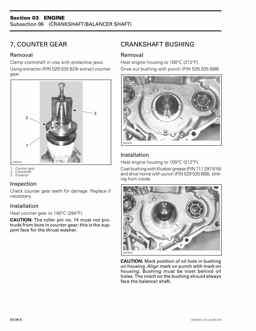
RemovalClamp crankshaft in vise with protective jaws.Using extractor (P/N 529 035 624) extract countergear.
1. Counter gear2. Crankshaft3. Extractor
InspectionCheck counter gear teeth for damage. Replace ifnecessary.
InstallationHeat counter gear to 140°C (284°F).CAUTION: The roller pin no. 14 must not pro-trude from bore in counter gear; this is the sup-port face for the thrust washer.
CRANKSHAFT BUSHING
RemovalHeat engine housing to 100°C (212°F).Drive out bushing with punch (P/N 529 035 688).
InstallationHeat engine housing to 100°C (212°F).Coat bushing with Klueber grease (P/N 711 297 616)and drive home with punch (P/N 529 035 689), strik-ing from inside.
CAUTION: Mark position of oil hole in bushingon housing. Align mark on punch with mark onhousing. Bushing must be inset behind oilholes. The notch on the bushing should alwaysface the balancer shaft.
3
:
Section 03 ENGINESubsection 06 (CRANKSHAFT/BALANCER SHAFT)
VMR2001_010_03-06A.FM 03-06-7
BALL BEARINGS IN HOUSING
RemovalHeat output shaft in the housing to 80°C (176°F).Using a suitable slide hammer, extract ball bearing.
InstallationPlace the housing in oven to 100°C (212°F).NOTE: The sealed ends of the cage must pointoutwards.
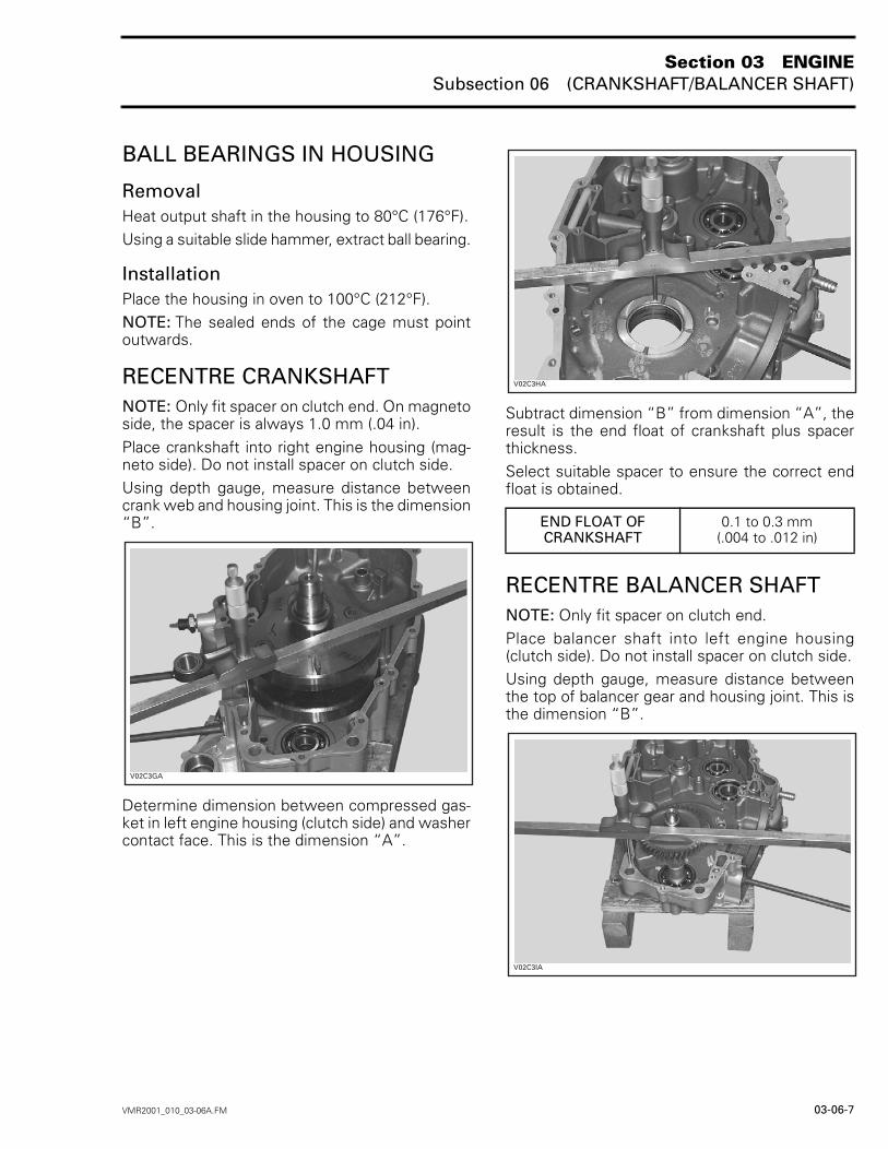
RECENTRE CRANKSHAFTNOTE: Only fit spacer on clutch end. On magnetoside, the spacer is always 1.0 mm (.04 in).Place crankshaft into right engine housing (mag-neto side). Do not install spacer on clutch side.Using depth gauge, measure distance betweencrank web and housing joint. This is the dimension“B”.
Determine dimension between compressed gas-ket in left engine housing (clutch side) and washercontact face. This is the dimension “A”.
Subtract dimension “B” from dimension “A”, theresult is the end float of crankshaft plus spacerthickness.Select suitable spacer to ensure the correct endfloat is obtained.
RECENTRE BALANCER SHAFTNOTE: Only fit spacer on clutch end.Place balancer shaft into left engine housing(clutch side). Do not install spacer on clutch side.Using depth gauge, measure distance betweenthe top of balancer gear and housing joint. This isthe dimension “B”.
5
END FLOAT OF CRANKSHAFT
0.1 to 0.3 mm (.004 to .012 in)
6
7
Section 03 ENGINESubsection 06 (CRANKSHAFT/BALANCER SHAFT)
03-06-8 VMR2001_010_03-06A.FM
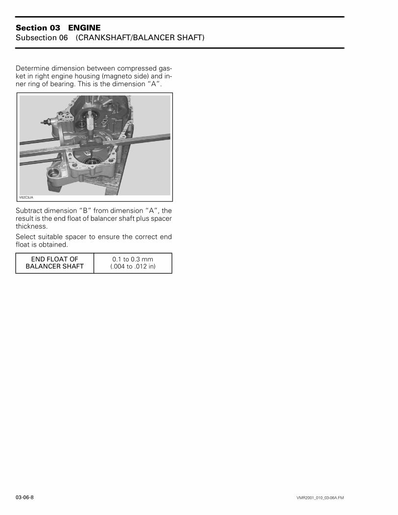
Determine dimension between compressed gas-ket in right engine housing (magneto side) and in-ner ring of bearing. This is the dimension “A”.
Subtract dimension “B” from dimension “A”, theresult is the end float of balancer shaft plus spacerthickness.Select suitable spacer to ensure the correct endfloat is obtained.
END FLOAT OF BALANCER SHAFT
0.1 to 0.3 mm (.004 to .012 in)
8
Section 03 ENGINESubsection 07 (LUBRICATION SYSTEM)
VMR2001_011_03-07A.FM 03-07-1
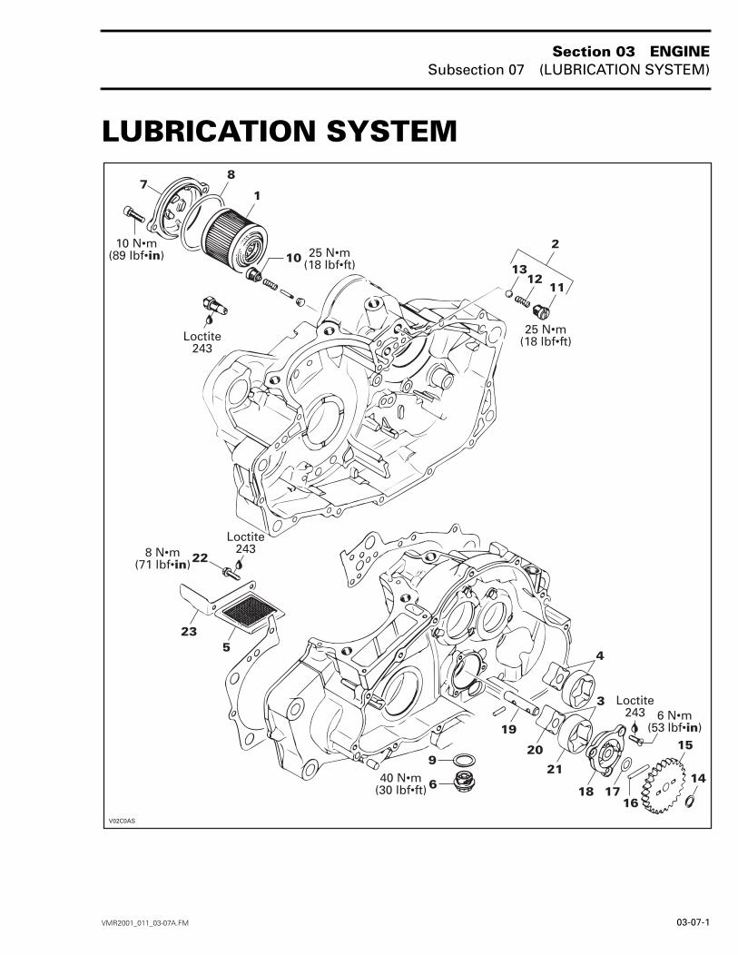
LUBRICATION SYSTEM 0
'
!"#
!"#
!"#

Section 03 ENGINESubsection 07 (LUBRICATION SYSTEM)
03-07-2 VMR2001_011_03-07A.FM
TROUBLESHOOTING
Oil Level Low– external oil leak– worn or incorrect piston rings installation– worn valve seal– defective oil pump
Low or No Oil Pressure– clogged oil orifice(s)– incorrect oil being used– leaking oil seal– oil strainer– oil pump worn or damaged– defective oil pressure regulator
Oil Contamination (white appearance)– coolant mixing with oil– faulty water pump seal– faulty head gasket– water leak in crankcase– air trapped at pump inlet
ENGINE PRESSURE TESTNOTE: The engine pressure test should be donewith a warm engine and the recommended oil.Remove the oil pressure switch above oil filter andinstall an oil pressure gauge (P/N 529 035 652).
1. Oil pressure gauge
The engine pressure should be 50 kPa (7 PSI) min-imum at idle and 300 kPa (44 PSI) at 6000 RPM.NOTE: The maximum oil pressure is 600 kPa(87 PSI).If the engine pressure is out of specifications,check the points described in Low or No Oil Pres-sure section above.
OIL CHANGE AND OIL FILTER REPLACEMENTOil and filter are to be replaced at the same time.Oil change should be done with a warm engine.
Ensure vehicle is on a level surface.Remove dipstick.Clean the reservoir drain plug area.Drain all oil from oil tank by removing drain plug.Wipe out any oil spillage.Place a drain pan under the engine drain plug area.Unscrew drain plug no. 6.
UNDER VEHICLE1. Oil drain plug
Wait a while to allow oil to flow out of oil filter.Unscrew oil filter cover no. 7.Remove oil filter and replace by a new.NOTE: Check and change O-ring no. 8, if neces-sary.
9
WARNING
The engine oil can be very hot. Wait until en-gine oil is warm.
Section 03 ENGINESubsection 07 (LUBRICATION SYSTEM)
VMR2001_011_03-07A.FM 03-07-3
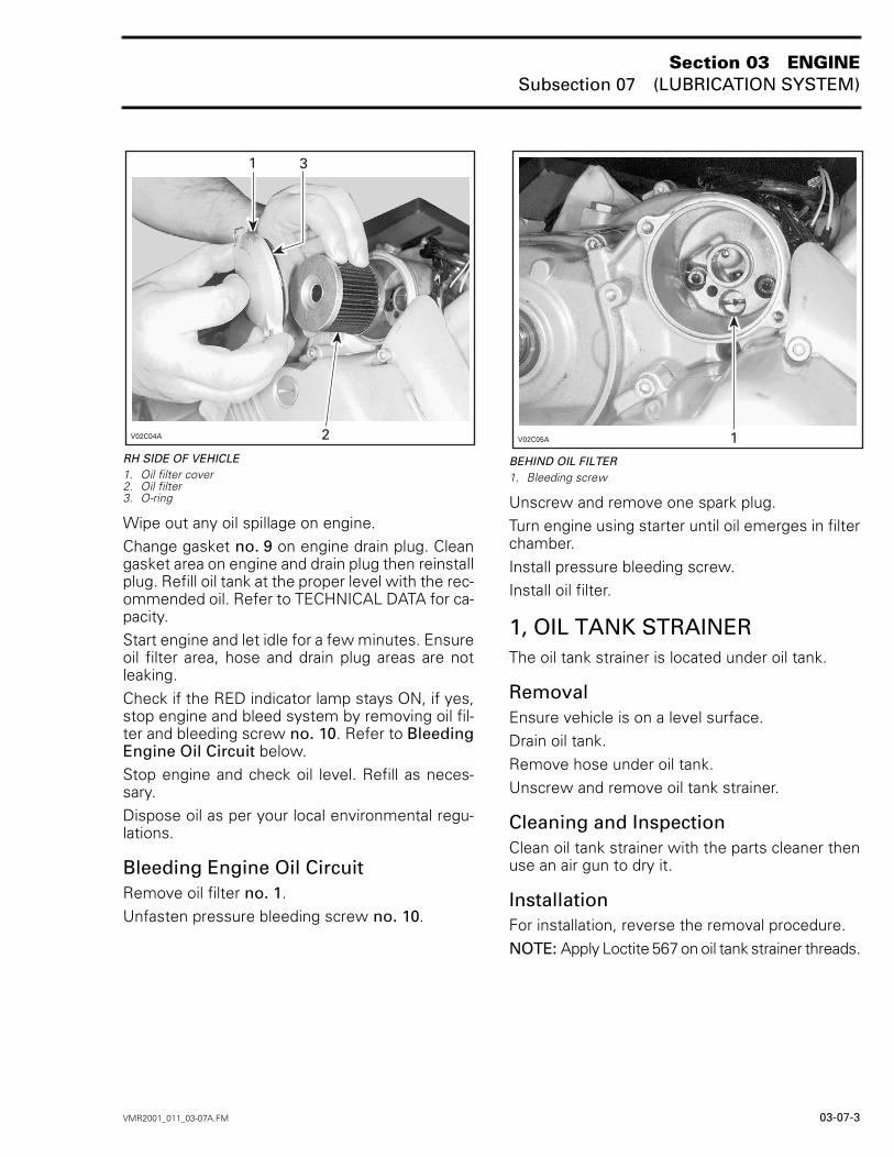
RH SIDE OF VEHICLE1. Oil filter cover2. Oil filter3. O-ring
Wipe out any oil spillage on engine.Change gasket no. 9 on engine drain plug. Cleangasket area on engine and drain plug then reinstallplug. Refill oil tank at the proper level with the rec-ommended oil. Refer to TECHNICAL DATA for ca-pacity.Start engine and let idle for a few minutes. Ensureoil filter area, hose and drain plug areas are notleaking.Check if the RED indicator lamp stays ON, if yes,stop engine and bleed system by removing oil fil-ter and bleeding screw no. 10. Refer to BleedingEngine Oil Circuit below.Stop engine and check oil level. Refill as neces-sary.Dispose oil as per your local environmental regu-lations.
Bleeding Engine Oil CircuitRemove oil filter no. 1.Unfasten pressure bleeding screw no. 10.
BEHIND OIL FILTER1. Bleeding screw
Unscrew and remove one spark plug.Turn engine using starter until oil emerges in filterchamber.Install pressure bleeding screw.Install oil filter.
1, OIL TANK STRAINERThe oil tank strainer is located under oil tank.
RemovalEnsure vehicle is on a level surface.Drain oil tank.Remove hose under oil tank.Unscrew and remove oil tank strainer.
Cleaning and InspectionClean oil tank strainer with the parts cleaner thenuse an air gun to dry it.
InstallationFor installation, reverse the removal procedure.NOTE: Apply Loctite 567 on oil tank strainer threads.
Section 03 ENGINESubsection 07 (LUBRICATION SYSTEM)
03-07-4 VMR2001_011_03-07A.FM
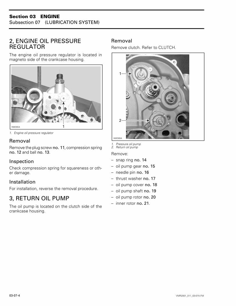
2, ENGINE OIL PRESSURE REGULATORThe engine oil pressure regulator is located inmagneto side of the crankcase housing.
1. Engine oil pressure regulator
RemovalRemove the plug screw no. 11, compression springno. 12 and ball no. 13.
InspectionCheck compression spring for squareness or oth-er damage.
InstallationFor installation, reverse the removal procedure.
3, RETURN OIL PUMPThe oil pump is located on the clutch side of thecrankcase housing.
RemovalRemove clutch. Refer to CLUTCH.
1. Pressure oil pump2. Return oil pump
Remove:– snap ring no. 14– oil pump gear no. 15– needle pin no. 16– thrust washer no. 17– oil pump cover no. 18– oil pump shaft no. 19– oil pump rotor no. 20– inner rotor no. 21.
-
Section 03 ENGINESubsection 07 (LUBRICATION SYSTEM)
VMR2001_011_03-07A.FM 03-07-5
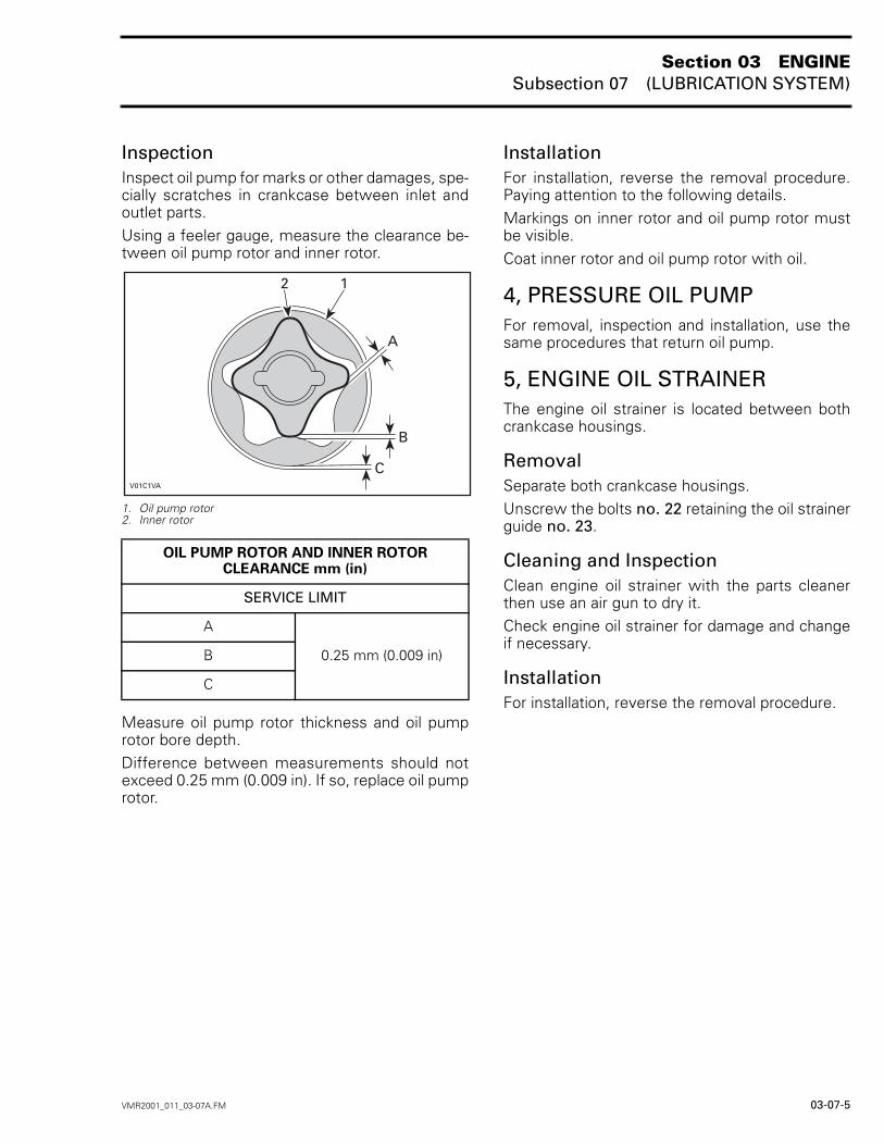
InspectionInspect oil pump for marks or other damages, spe-cially scratches in crankcase between inlet andoutlet parts.Using a feeler gauge, measure the clearance be-tween oil pump rotor and inner rotor.
1. Oil pump rotor2. Inner rotor
Measure oil pump rotor thickness and oil pumprotor bore depth. Difference between measurements should notexceed 0.25 mm (0.009 in). If so, replace oil pumprotor.
InstallationFor installation, reverse the removal procedure.Paying attention to the following details.Markings on inner rotor and oil pump rotor mustbe visible.Coat inner rotor and oil pump rotor with oil.
4, PRESSURE OIL PUMPFor removal, inspection and installation, use thesame procedures that return oil pump.
5, ENGINE OIL STRAINERThe engine oil strainer is located between bothcrankcase housings.
RemovalSeparate both crankcase housings.Unscrew the bolts no. 22 retaining the oil strainerguide no. 23.
Cleaning and InspectionClean engine oil strainer with the parts cleanerthen use an air gun to dry it.Check engine oil strainer for damage and changeif necessary.
InstallationFor installation, reverse the removal procedure.
OIL PUMP ROTOR AND INNER ROTORCLEARANCE mm (in)
SERVICE LIMIT
A
0.25 mm (0.009 in)B
C
9

Section 03 ENGINESubsection 08 (CLUTCH)
VMR2001_012_03-08A.FM 03-08-1
CLUTCH 0
-
!"#
()*")#"
'+#. #*.#4#
'+#. #*.#4#
'+#. #*.#4#
'+#. #*.#4#

Section 03 ENGINESubsection 08 (CLUTCH)
03-08-2 VMR2001_012_03-08A.FM
CLUTCH ADJUSTMENTThe clutch adjustment is necessary after any worksin the clutch system. Refer to MAINTENANCE forprocedure.
1, PRESSURE PLATENOTE: It’s not necessary to remove engine fromvehicle to disassemble the clutch.
RemovalDrain engine oil and coolant.Detach clutch cable.Remove:– starter– water pump cover no. 7– LH engine housing cover no. 8.Unfasten screws no. 9, retaining clutch springno. 10 and pressure plate, crosswise.
Lift off pressure plate completely.
InspectionCheck pressure plate for crack or other damage.Change if necessary.
InstallationFor installation, reverse the removal procedure.CAUTION: Never pull clutch release lever back-wards when the engine is hot. The pressureplate bearing may come out of pressure plate.
2, PRESSURE PLATE BEARING
InspectionPressure plate bearing must have full freedom ofmovement. If not, change the bearing.Check spline on clutch actuator rack no. 11.Change if necessary.
DisassemblyRemove the retaining ring no. 12 with retainingring pliers.Heat pressure plate to 80°C (176°F) then removepressure plate bearing.
AssemblyFor assembly, reverse the disassembly order.CAUTION: Never pull clutch release lever back-wards when the engine is hot. The pressureplate bearing may come out of pressure plate.
3,4,5, FRICTION DRIVE PLATE, STEEL DRIVEN PLATE AND CLUTCH BASKET
DisassemblyRemove the pressure plate no. 1.Remove friction plates no. 3 and steel drivenplates no. 4 from clutch basket no. 5.Unlock the tab washer no. 13 then install spannertool for clutch basket (P/N 529 035 618).
-
-
Section 03 ENGINESubsection 08 (CLUTCH)
VMR2001_012_03-08A.FM 03-08-3
Unscrew the clutch lock nut no. 14 then removetab washer.Remove clutch hub no. 15, clutch basket includingthrust washer no. 16 and needle bearings no. 17and no. 18.
InspectionFriction Drive PlateMeasure the package of friction drive plate thick-ness.Friction drive plates must be replaced when thick-ness is 27.5 mm (1.827 in) thick or less for the wholepackage.
The friction drive plate maximum warpage shouldfall through a slot of 3.75 mm (.148 in).
Steel Driven PlateThe steel driven maximum warpage should fallthrough a slot of 1.63 mm (.064 in).The wear limit of the whole package is 11.5 mm(.453 in).
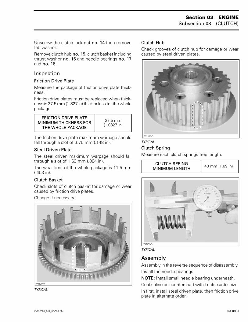
Clutch BasketCheck slots of clutch basket for damage or wearcaused by friction drive plates.Change if necessary.
TYPICAL
Clutch HubCheck grooves of clutch hub for damage or wearcaused by steel driven plates.
TYPICAL
Clutch SpringMeasure each clutch springs free length.
TYPICAL
AssemblyAssembly in the reverse sequence of disassembly.Install the needle bearings.NOTE: Install small needle bearing underneath.Coat spline on countershaft with Loctite anti-seize.In first, install steel driven plate, then friction driveplate in alternate order.
FRICTION DRIVE PLATEMINIMUM THICKNESS FOR
THE WHOLE PACKAGE
27.5 mm(1.0827 in)
-
CLUTCH SPRINGMINIMUM LENGTH
43 mm (1.69 in)
-
-
Section 03 ENGINESubsection 08 (CLUTCH)
03-08-4 VMR2001_012_03-08A.FM
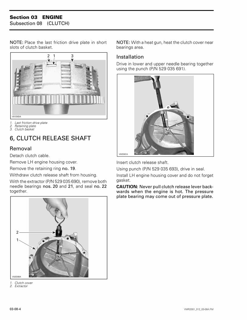
NOTE: Place the last friction drive plate in shortslots of clutch basket.
1. Last friction drive plate2. Retaining plate3. Clutch basket
6, CLUTCH RELEASE SHAFT
RemovalDetach clutch cable.Remove LH engine housing cover.Remove the retaining ring no. 19.Withdraw clutch release shaft from housing.With the extractor (P/N 529 035 690), remove bothneedle bearings nos. 20 and 21, and seal no. 22together.
1. Clutch cover2. Extractor
NOTE: With a heat gun, heat the clutch cover nearbearings area.
InstallationDrive in lower and upper needle bearing togetherusing the punch (P/N 529 035 691).
Insert clutch release shaft.Using punch (P/N 529 035 693), drive in seal.Install LH engine housing cover and do not forgetgasket.CAUTION: Never pull clutch release lever back-wards when the engine is hot. The pressureplate bearing may come out of pressure plate.
--
-9
-

Section 03 ENGINESubsection 09 (TRANSMISSION)
VMR2001_013_03-09A.FM 03-09-1
TRANSMISSION 0
(
##.*.#4#
##.*.#4#
()*")#"'+#. #
*.#4#
()*")#"
()*")#"
()*")#"
Section 03 ENGINESubsection 09 (TRANSMISSION)
03-09-2 VMR2001_013_03-09A.FM
SHIFTING MECHANISM
RemovalRemove engine from vehicle. Refer to REMOVALAND INSTALLATION.Separate both crankcase housings. Refer toCRANKSHAFT/BALANCER SHAFT.Press shift pawl slightly outwards and withdrawshift shaft no. 1 with shift pawl.Remove index lever no. 2 and index spring no. 3.Remove shift fork shafts nos. 4 and 5 from shiftforks nos. 6, 7 and 8.Swivel shift forks outwards and remove.Withdraw shift drum no. 9.
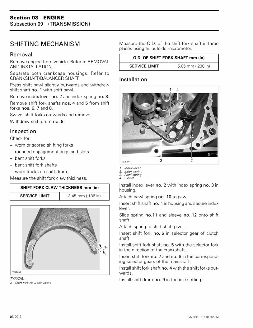
InspectionCheck for:– worn or scored shifting forks– rounded engagement dogs and slots– bent shift forks– bent shift fork shafts– worn tracks on shift drum.Measure the shift fork claw thickness.
TYPICALA. Shift fork claw thickness
Measure the O.D. of the shift fork shaft in threeplaces using an outside micrometer.
Installation
1. Index lever2. Index spring3. Pawl spring4. Sleeve
Install index lever no. 2 with index spring no. 3 inhousing.Attach pawl spring no. 10 to pawl.Insert shift shaft no. 1 in housing and secure indexlever.Slide spring no.11 and sleeve no. 12 onto shiftshaft.Attach spring to shift shaft pivot.Insert shift fork no. 6 in selector gear of clutchshaft.Install shift fork shaft no. 5 with the selector forkin the direction of the crankshaft.Insert shift fork no. 7 and no. 8 in the correspond-ing selector gears of the mainshaft.Install shift fork shaft no. 4 with the shift forks out-wards.Install shift drum no. 9 in the idle setting.
SHIFT FORK CLAW THICKNESS mm (in)
SERVICE LIMIT 3.45 mm (.136 in)
(
O.D. OF SHIFT FORK SHAFT mm (in)
SERVICE LIMIT 5.85 mm (.230 in)
(
Section 03 ENGINESubsection 09 (TRANSMISSION)
VMR2001_013_03-09A.FM 03-09-3
Press back index lever and shift pawl and installthe shift drum.Move index lever and shift pawl into mesh.Check transmission function: shift up and downthrough all gears, checking that the detent in allgears disengages smoothly from the shift pawl.Assemble engine.Once again, shift up and down through all gears,slowly allowing selector lever to return to its orig-inal position. The clicking noise of the engagingshift pawl must be clearly audible.Install engine.
TRANSMISSION
RemovalRemove the shifting mechanism. Refer to theabove section.Remove shift fork shafts nos. 4 and 5.Swivel shift forks nos. 6, 7 and 8 outwards andremove.Withdraw shift drum no. 9.Using a plastic mallet, tap mainshaft no. 13 to as-sist withdrawing mainshaft together with clutchshaft no. 14.NOTE: Before removal withdraw the separategears nos. 15 and 16 from mainshaft.
DisassemblyMainshaftUsing special pliers slide circlip no. 17 slightlybackwards to remove circlip no. 18 which is se-cured by the angled ring no. 19. Remove gears.Remove circlip no. 20 and withdraw gear.CAUTION: Retaining ring must not be over-stretched.
Clutch ShaftRemove gear nos. 21, 22 and 23.Remove circlip no. 24 with special pliers.Remove gear.
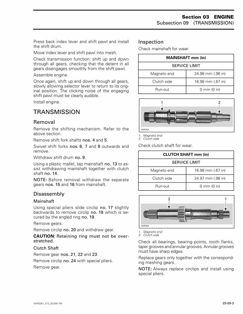
InspectionCheck mainshaft for wear.
1. Magneto end2. Clutch side
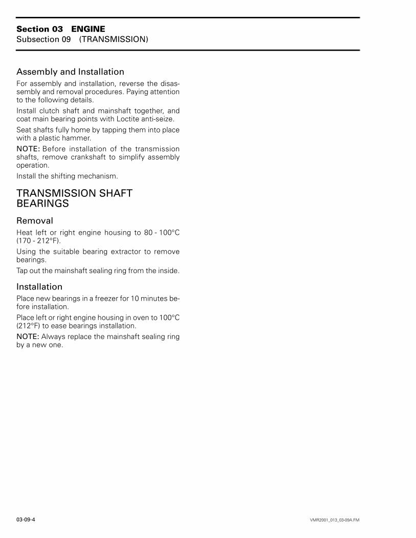
Check clutch shaft for wear.
1. Magneto end2. Clutch side
Check all bearings, bearing points, tooth flanks,taper grooves and annular grooves. Annular groovesmust have sharp edges.Replace gears only together with the correspond-ing meshing gears.NOTE: Always replace circlips and install usingspecial pliers.
MAINSHAFT mm (in)
SERVICE LIMIT
Magneto end 24.98 mm (.98 in)
Clutch side 16.98 mm (.67 in)
Run-out 0 mm (0 in)
CLUTCH SHAFT mm (in)
SERVICE LIMIT
Magneto end 16.98 mm (.67 in)
Clutch side 24.97 mm (.98 in)
Run-out 0 mm (0 in)
(
(
Section 03 ENGINESubsection 09 (TRANSMISSION)
03-09-4 VMR2001_013_03-09A.FM
Assembly and InstallationFor assembly and installation, reverse the disas-sembly and removal procedures. Paying attentionto the following details.Install clutch shaft and mainshaft together, andcoat main bearing points with Loctite anti-seize.Seat shafts fully home by tapping them into placewith a plastic hammer.NOTE: Before installation of the transmissionshafts, remove crankshaft to simplify assemblyoperation.Install the shifting mechanism.
TRANSMISSION SHAFT BEARINGS
RemovalHeat left or right engine housing to 80 - 100°C(170 - 212°F).Using the suitable bearing extractor to removebearings.Tap out the mainshaft sealing ring from the inside.
InstallationPlace new bearings in a freezer for 10 minutes be-fore installation.Place left or right engine housing in oven to 100°C(212°F) to ease bearings installation.NOTE: Always replace the mainshaft sealing ringby a new one.
Related Documents