Volume 7—Motor Controls, Logic and Connectivity CA08100008E—April 2011 www.eaton.com V7-T44-1 44 44 44 44 44 44 44 44 44 44 44 44 44 44 44 44 44 44 44 44 44 44 44 44 44 44 44 44 44 44 Industrial Control Transformers Types MTE and MTK CE Marked Type AP 44.1 Transformers Standards and Certifications . . . . . . . . . . . . . . . . . . . . . . . . . . . . . . . . . V7-T44-2 Catalog Number Selection . . . . . . . . . . . . . . . . . . . . . . . . . . . . . . . . . . V7-T44-3 Type MTE . . . . . . . . . . . . . . . . . . . . . . . . . . . . . . . . . . . . . . . . . . . . . . . V7-T44-4 Type MTK . . . . . . . . . . . . . . . . . . . . . . . . . . . . . . . . . . . . . . . . . . . . . . . V7-T44-13 CE Marked . . . . . . . . . . . . . . . . . . . . . . . . . . . . . . . . . . . . . . . . . . . . . . V7-T44-18 Type AP . . . . . . . . . . . . . . . . . . . . . . . . . . . . . . . . . . . . . . . . . . . . . . . . V7-T44-25 Learn Online

Welcome message from author
This document is posted to help you gain knowledge. Please leave a comment to let me know what you think about it! Share it to your friends and learn new things together.
Transcript

Volume 7—Motor Controls, Logic and Connectivity
CA08100008E—April 2011 www.eaton.com
V7-T44-1
444444444444444444444444444444444444444444444444444444444444
Industrial Control Transformers
Types MTE and MTK
CE Marked
Type AP
44.1 Transformers
Standards and Certifications. . . . . . . . . . . . . . . . . . . . . . . . . . . . . . . . .
V7-T44-2
Catalog Number Selection . . . . . . . . . . . . . . . . . . . . . . . . . . . . . . . . . .
V7-T44-3
Type MTE . . . . . . . . . . . . . . . . . . . . . . . . . . . . . . . . . . . . . . . . . . . . . . .
V7-T44-4
Type MTK . . . . . . . . . . . . . . . . . . . . . . . . . . . . . . . . . . . . . . . . . . . . . . .
V7-T44-13
CE Marked . . . . . . . . . . . . . . . . . . . . . . . . . . . . . . . . . . . . . . . . . . . . . .
V7-T44-18
Type AP . . . . . . . . . . . . . . . . . . . . . . . . . . . . . . . . . . . . . . . . . . . . . . . .
V7-T44-25
LearnOnline
Tab44.book Page 1 Thursday, April 7, 2011 7:35 AM

V7-T44-2 Volume 7—Motor Controls, Logic and Connectivity
CA08100008E—April 2011 www.eaton.com
444444444444444444444444444444444444444444444444444444444444
44.1
Industrial Control Transformers
Transformers
Industrial Control Transformers
Contents
Description Page
TransformersType MTE . . . . . . . . . . . . . . . . . . . . . . . . . . . . .
V7-T44-4
Type MTK . . . . . . . . . . . . . . . . . . . . . . . . . . . . .
V7-T44-13
CE Marked . . . . . . . . . . . . . . . . . . . . . . . . . . . .
V7-T44-18
Type AP . . . . . . . . . . . . . . . . . . . . . . . . . . . . . . .
V7-T44-25
Standards and Certifications
Eaton dry-type distribution transformers are approved, listed, recognized or may comply with the following standards.
Engineering Standards
Notes
�
UL 5085 replaces UL 506.
�
Applies to 25–50 kVA.
�
Applies to 25 kVA.
�
Applies to 15–25 kVA.
�
Applies to 37.5 kVA.
�
Applies to 3 kVA.
�
Applies to 5–9 kVA.
Applies to 30–75 kVA.
Applies to 30 kVA.
In addition to the above standards, Eaton dry-type distribution transformers are also manufactured in compliance with the applicable standards listed below.Not all of the following standards apply to every transformer.
NEC:
National Electrical Code
®.
NEMA ST-1:
Specialty Transformers (C89.1) (control transformers).
NEMA ST-20:
General-Purpose Transformers.
NEMA TP-1:
Guide for Determining Energy Efficiency for Distribution Transformers.
NEMA 250:
Enclosures for Electrical Equipment (1000 volts maximum).
IEEE C57.12.01:
General Requirements for Dry-Type Distribution and Power Transformers (including those with solid-cast and/or resin-encapsulated windings).
ANSI C57.12.70:
Terminal Markings and Connections for Distribution and Power Transformers.
ANSI C57.12.91:
Standard Test Code for Dry-Type Distribution and Power Transformers.
CSA C22 No. 47-M90:
Air-Cooled Transformers (Dry-Type).
CSA C9-M1981:
Dry-Type Transformers.
CSA C22.2 No. 66:
Specialty Transformers.
CSA 802-94:
Maximum Losses for Distribution, Power and Dry-Type Transformers.
NEMA TP-2:
Standard Test Method for Measuring the Energy Consumption of Distribution Transformers.
NEMA TP-3
Catalog ProductName
ULStandard
�
UL/cULFileNumber
UL ListedControlNumber
cUL EnergyEfficiencyFile Number
CSAFileNumber
InsulationSystemTemp/ºC
kVASingle-Phase
kVAThree-Phase
ApplicableIECStandard
Industrial Control Transformer
MTE 5085 E46323 702X — LR27533 105 0.025–1.5 N/A 61558
MTK 5085 E46323 702X — LR27533 180 0.05–5 N/A 61558
Encapsulated Transformer
AP 5085 E10156 591H — — 180 3–10 N/A 61558
AP 1561 E78389 591H — — 180 15 N/A 61558
EP 5085 E10156 591H — LR60545 180 0.05–10 N/A 61558
EP 1561 E78389 591H EV157
�
LR60545
�
180 15–50 N/A 61558
�
/ 726
�
EPT 5085 E10156 591H — LR60545 180 N/A 3–9 61558
�
/ 726
�
EPT 1561 E78389 591H EV157
LR60545
180 N/A 15–75 726
MPC 1062 E53449 591H — LR60546 180 3–25 15–30 —
Ventilated Transformer
DS-3 1561 E78389 591H — — 220 15–167 N/A 60726
DT-3 1561 E78389 591H — — 220 N/A 15–750 60726
KT 1561 E78389 591H — — 220 N/A 9–500 N/A
Tab44.book Page 2 Thursday, April 7, 2011 11:27 AM

Volume 7—Motor Controls, Logic and Connectivity
CA08100008E—April 2011 www.eaton.com
V7-T44-3
444444444444444444444444444444444444444444444444444444444444
44.1
Industrial Control Transformers
Transformers
Catalog Number Selection
Industrial Control Transformers, CE Marked Control Transformers—Example: CE0250E2FCE
�
Notes
�
For Eaton’s dry-type transformers catalog number selection, see Volume 2,
CA08100003E
.
Contact your local Eaton sales office for voltage combinations not shown. Use table for catalog number breakdown only. Do not use to create catalog numbers because all combinations may not be valid.
ModificationsType MTE/MTKCE = CE Marked control transformerFB = Factory-mounted two-pole primary
fuse block for rejection type fusesFBN= Factory-mounted two-pole primary
fuse block for non-rejection–type fuses
Q = Secondary fuse clips for 1/4 x 1-1/4 inch fuses
XX = No secondary fuse clipsRT = Ring type terminals for
connection to fuse blockES = Electrostatic shieldFS = Factory-mounted finger-safe
terminal shields
Type APB = Bottom mountedS = Side/wall mountedES = Electrostatic shieldCU = Copper windings
Type MTA/MTCFB = Factory-mounted three-pole fuse
block (two-pole primary rejection type with single-pole secondary non-rejection type)
ES = Electrostatic shieldL = Lead terminations
CE 0250 E 2F CE
TypeC = Industrial control transformerCE = CE Marked control transformer
VA Rating
0025 = 250050 = 500075 = 750100 = 1000150 = 1500200 = 2000250 = 2500300 = 300
0350 = 3500500 = 5000750 = 7501000 = 10001500 = 15002000 = 20003000 = 30005000 = 5000
Type AP Only:0003 = 30000005 = 50000007 = 75000010 = 100000015 = 15000
Transformer DesignA = MTAC = MTCE = MTEK = MTKP = AP
VoltagePrimary Secondary
ACAG1B2A
2B2C2F2G2U
2V2W3A3B3C3D4B4C4D4E4H4W5E
6U
7G (TypeAP only)
====
=====
=============
=
=
380 x 415208/240/277/380/480120 x 240240 x 480,
230 x 460,220 x 440
240 x 480240 x 480230/460230/460220/380/440/550,
230/400/460/575,240/416/480/600
208/230/400/460/575208/230/400/460/575208/277115230/460/575208/380/416208/230/460/575550/575/600380/400/415208/230/460/575380/400/415550/575/600200/220/440,
208/230/460, 240/480
240/416/480/600,230/400/460/575,220/380/440/550,208/500
240 x 480
242424120/115/110
24120 x 240115115/23023/110, 24/115,
25/120
24/115/230115/23012024115/95115/9524110/115/120110 x 22011522/23/2422/23/2423/110, 24/115,
25/120
99/120/130, 95/115/125, 91/110/120, 85/100/110120/240
Tab44.book Page 3 Thursday, April 7, 2011 11:27 AM
V7-T44-4 Volume 7—Motor Controls, Logic and Connectivity
CA08100008E—April 2011 www.eaton.com
444444444444444444444444444444444444444444444444444444444444
44.1
Industrial Control Transformers
Transformers
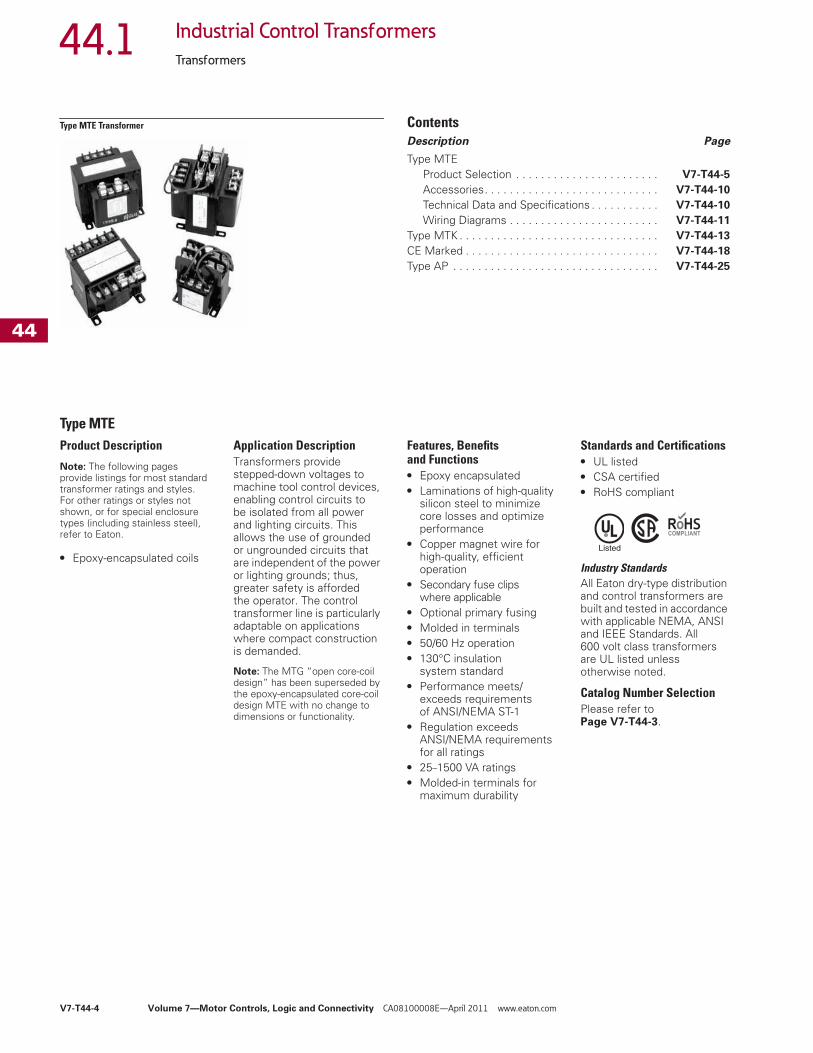
Type MTE Transformer
Contents
Description Page
Type MTEProduct Selection . . . . . . . . . . . . . . . . . . . . . . .
V7-T44-5
Accessories. . . . . . . . . . . . . . . . . . . . . . . . . . . .
V7-T44-10
Technical Data and Specifications . . . . . . . . . . .
V7-T44-10
Wiring Diagrams . . . . . . . . . . . . . . . . . . . . . . . .
V7-T44-11
Type MTK . . . . . . . . . . . . . . . . . . . . . . . . . . . . . . . .
V7-T44-13
CE Marked . . . . . . . . . . . . . . . . . . . . . . . . . . . . . . .
V7-T44-18
Type AP . . . . . . . . . . . . . . . . . . . . . . . . . . . . . . . . .
V7-T44-25
Type MTE
Product Description
Note:
The following pages provide listings for most standard transformer ratings and styles. For other ratings or styles not shown, or for special enclosure types (including stainless steel), refer to Eaton.
●
Epoxy-encapsulated coils
Application Description
Transformers provide stepped-down voltages to machine tool control devices, enabling control circuits to be isolated from all power and lighting circuits. This allows the use of grounded or ungrounded circuits that are independent of the power or lighting grounds; thus, greater safety is afforded the operator. The control transformer line is particularly adaptable on applications where compact construction is demanded.
Note:
The MTG “open core-coil design” has been superseded by the epoxy-encapsulated core-coil design MTE with no change to dimensions or functionality.
Features, Benefits and Functions
●
Epoxy encapsulated
●
Laminations of high-quality silicon steel to minimize core losses and optimize performance
●
Copper magnet wire for high-quality, efficient operation
●
Secondary fuse clips where applicable
●
Optional primary fusing
●
Molded in terminals
●
50/60 Hz operation
●
130°C insulation system standard
●
Performance meets/exceeds requirements of ANSI/NEMA ST-1
●
Regulation exceeds ANSI/NEMA requirements for all ratings
●
25
–
1500 VA ratings
●
Molded-in terminals for maximum durability
Standards and Certifications
●
UL listed
●
CSA certified
●
RoHS compliant
Industry Standards
All Eaton dry-type distribution and control transformers are built and tested in accordance with applicable NEMA, ANSI and IEEE Standards. All 600 volt class transformers are UL listed unless otherwise noted.
Catalog Number Selection
Please refer to
Page V7-T44-3
.
Tab44.book Page 4 Thursday, April 7, 2011 11:27 AM

Volume 7—Motor Controls, Logic and Connectivity
CA08100008E—April 2011 www.eaton.com
V7-T44-5
444444444444444444444444444444444444444444444444444444444444
44.1
Industrial Control Transformers
Transformers
Product Selection
Additional Product Selection information is available in Volume 2,
CA08100003E
.
Type MTE
Primary: 240 x 480, 230 x 460, 220 x 440 with JumpersSecondary: 120/115/110 with Fuse Clips for 13/32 x 1-1/2 Fuses
Primary: 240 x 480 with JumpersSecondary: 24 with Fuse Clips for 13/32 x 1-1/2 Fuses (through 500 VA)
Primary: 120 X 240 with JumpersSecondary: 24 with Fuse Clips for 13/32 x 1-1/2 Fuses
Primary: 208/277Secondary: 120 with Fuse Clips for 13/32 x 1-1/2 Fuses
Notes
�
See
Page V7-T44-11
for wiring diagrams.
�
105°C insulation system.
VAWiringDiagram
�
WeightLbs (kg)
StyleNumber
25 1 1.7 (0.8)
C0025E2A
�
50 1 2.6 (1.2)
C0050E2A
�
75 1 3.5 (1.6)
C0075E2A
�
100 1 4.2 (1.9)
C0100E2A
�
150 1 6.7 (3.0)
C0150E2A
200 1 8.5 (3.9)
C0200E2A
250 1 10.0 (4.5)
C0250E2A
300 1 11.3 (5.1)
C0300E2A
350 1 13.6 (6.2)
C0350E2A
500 1 19.2 (8.7)
C0500E2A
750 1 28.1 (12.8)
C0750E2A
1000 1 29.5 (13.4)
C1000E2A
1500 1 40.0 (18.1)
C1500E2A
VAWiringDiagram
�
WeightLbs (kg)
StyleNumber
50 2 2.7 (1.2)
C0050E2B
�
75 2 3.5 (1.6)
C0075E2B
�
100 2 4.2 (1.9)
C0100E2B
�
150 2 6.7 (3.0)
C0150E2B
200 2 8.5 (3.9)
C0200E2B
250 2 10.1 (4.6) C0250E2B
300 2 11.4 (5.2) C0300E2B
350 2 13.4 (6.1) C0350E2B
500 2 17.5 (7.9) C0500E2B
750 2 28.1 (12.8) C0750E2B
VAWiringDiagram �
WeightLbs (kg)
StyleNumber
50 3 2.6 (1.2) C0050E1B �
75 3 3.6 (1.6) C0075E1B �
100 3 4.4 (2.0) C0100E1B �
150 3 6.7 (3.0) C0150E1B
200 3 8.3 (3.8) C0200E1B
250 3 10.1 (4.6) C0250E1B
300 3 11.2 (5.1) C0300E1B
350 3 13.2 (6.0) C0350E1B
500 3 17.5 (7.9) C0500E1B
VAWiringDiagram �
WeightLbs (kg)
StyleNumber
50 4 2.9 (1.3) C0050E3A �
75 4 3.8 (1.7) C0075E3A �
100 4 4.5 (2.0) C0100E3A �
150 4 6.9 (3.1) C0150E3A
200 4 8.7 (3.9) C0200E3A
250 4 10.2 (4.6) C0250E3A
300 4 11.4 (5.2) C0300E3A
350 4 13.7 (6.2) C0350E3A
500 4 17.2 (7.8) C0500E3A
750 4 25.7 (11.7) C0750E3A
Tab44.book Page 5 Thursday, April 7, 2011 11:27 AM

V7-T44-6 Volume 7—Motor Controls, Logic and Connectivity CA08100008E—April 2011 www.eaton.com
444444444444444444444444444444444444444444444444444444444444
44.1 Industrial Control Transformers
Transformers
Primary: 240 x 480 with JumpersSecondary: 120 x 240 with Jumpers, Secondary Fuse Clips Not Applicable
Primary: 550/575/600Secondary: 110/115/120 with for 13/32 x 1-1/2 Fuses
Primary: 380/400/415Secondary: 22/23/24 with Fuse Clips for 13/32 x 1-1/2 Fuses
Primary: 550/575/600Secondary: 22/23/24 with Fuse Clips for 13/32 x 1-1/2 Fuses
Primary: 230/460/575Secondary: 115/95 with Fuse Clips for 13/32 x 1-1/2 Fuses
Primary: 380/400/415Secondary: 110 x 220 with Jumpers; Fuse Clips Not Applicable
Notes� See Page V7-T44-11 for wiring diagrams.� 105°C insulation system.� Secondary fuse clips are not available on this catalog number.
VAWiringDiagram �
WeightLbs (kg)
StyleNumber
50 11 2.6 (1.2) C0050E2CXX �
75 11 3.5 (1.6) C0075E2CXX �
100 11 4.2 (1.9) C0100E2CXX �
150 11 6.7 (3.1) C0150E2CXX
200 11 8.5 (3.9) C0200E2CXX
250 11 10.0 (4.6) C0250E2CXX
300 11 11.8 (5.4) C0300E2CXX
350 11 13.6 (6.2) C0350E2CXX
500 11 17.5 (8.0) C0500E2CXX
750 11 26.4 (12.0) C0750E2CXX
VAWiringDiagram �
WeightLbs (kg)
StyleNumber
50 10 2.7 (1.2) C0050E4C �
75 10 3.6 (1.6) C0075E4C �
100 10 4.2 (1.9) C0100E4C �
150 10 6.8 (3.1) C0150E4C
200 10 8.4 (3.8) C0200E4C
250 10 10.0 (4.6) C0250E4C
300 10 11.3 (5.1) C0300E4C
350 10 13.6 (6.2) C0350E4C
500 10 16.8 (7.6) C0500E4C
750 10 25.7 (11.7) C0750E4C
VAWiringDiagram �
WeightLbs (kg)
StyleNumber
50 13 2.5 (1.1) C0050E4H �
75 13 3.5 (1.6) C0075E4H �
100 13 4.0 (1.8) C0100E4H �
150 13 6.5 (3.0) C0150E4H
200 13 8.2 (3.7) C0200E4H
250 13 10.0 (4.5) C0250E4H
300 13 11.0 (5.0) C0300E4H
350 13 13.6 (6.2) C0350E4H
500 13 17.7 (8.0) C0500E4H
VAWiringDiagram �
WeightLbs (kg)
StyleNumber
50 12 2.5 (1.1) C0050E4W �
75 12 3.5 (1.6) C0075E4W �
100 12 4.0 (1.8) C0100E4W �
150 12 6.5 (3.0) C0150E4W
200 12 8.2 (3.7) C0200E4W
250 12 10.0 (4.5) C0250E4W
300 12 11.0 (5.0) C0300E4W
350 12 13.6 (6.2) C0350E4W
500 12 17.7 (8.0) C0500E4W
750 12 28.0 (12.7) C0750E4WXX �
VAWiringDiagram �
WeightLbs (kg)
StyleNumber
50 5 3.5 (1.6) C0050E3C �
75 5 4.5 (2.0) C0075E3C �
100 5 6.0 (2.7) C0100E3C �
150 5 7.7 (3.5) C0150E3C
200 5 9.0 (4.1) C0200E3C
250 5 9.7 (4.4) C0250E3C
300 5 11.7 (5.3) C0300E3C
350 5 16.5 (7.5) C0350E3C
500 5 21.5 (9.8) C0500E3C
750 5 28.0 (12.7) C0750E3C
VAWiringDiagram �
WeightLbs (kg)
StyleNumber
50 6 3.0 (1.4) C0050E4D �
75 6 4.0 (1.8) C0075E4D �
100 6 5.2 (2.4) C0100E4D �
150 6 7.0 (3.2) C0150E4D
200 6 8.7 (3.9) C0200E4D
250 6 10.2 (4.6) C0250E4D
300 6 11.0 (5.0) C0300E4D
350 6 13.0 (5.9) C0350E4D
500 6 20.0 (9.1) C0500E4D
750 6 28.0 (12.7) C0750E4D
Tab44.book Page 6 Thursday, April 7, 2011 11:27 AM

Volume 7—Motor Controls, Logic and Connectivity CA08100008E—April 2011 www.eaton.com V7-T44-7
444444444444444444444444444444444444444444444444444444444444
44.1Industrial Control Transformers
Transformers
Primary: 200/220/440, 208/230/460, 240/480Secondary: 23/110, 24/115, 25/120 with Fuse Clips for 13/32 x 1-1/2 Fuses
Universal Design (MTE Epoxy Encapsulated)Primary: 240/416/480/600, 230/400460/575, 220/380/440/550, 208/500Secondary: 99/120/130, 95/115/125, 91/110/120, 85/100/110 with Fuse Clips for 13/32 x 1-1/2 Fuses
Transformers with Primary Fuse Blocks
Primary: 240 x 480, 230 x 460, 220 x 440 with Jumpers and Two-Pole Primary Fuse Block for Rejection-Type FusesSecondary: 120/115/110 with Fuse Clips for 13/32 x 1-1/2 Fuses
Primary: 240 x 480 with Jumpers and Two-Pole Primary Fuse Block for Rejection-Type FusesSecondary: 24 with Fuse Clips for 13/32 x 1-1/2 Fuses
Notes� See Page V7-T44-11 for wiring diagrams.� 105°C insulation system.� Type MTG open core-coil universal design has been superseded by Type MTE epoxy
encapsulated universal design with no changes to form, fit or function.� Type MTE epoxy encapsulated universal design.
VAWiringDiagram �
WeightLbs (kg)
StyleNumber
50 7 3.4 (1.5) C0050E5E �
75 7 4.8 (2.2) C0075E5E �
100 7 5.9 (2.7) C0100E5E �
150 7 7.9 (3.6) C0150E5E
200 7 10.6 (4.8) C0200E5E
250 7 13.9 (6.3) C0250E5E
300 7 15.5 (7.0) C0300E5E
350 7 16.8 (7.6) C0350E5E
500 7 23.4 (10.6) C0500E5E
VAWiringDiagram �
WeightLbs (kg)
StyleNumber
50 8 4.0 (1.8) C0050E6U ��
100 8 6.6 (3.0) C0100E6U ��
150 8 8.8 (4.0) C0150E6U ��
250 8 14.7 (6.7) C0250E6U ��
350 8 18.6 (8.4) C0350E6U ��
500 8 25.6 (11.6) C0500E6U ��
750 8 30.5 (13.8) C0750E6U ��
VAWiringDiagram �
WeightLbs (kg)
StyleNumber
50 1 2.8 (1.3) C0050E2AFB �
75 1 3.7 (1.7) C0075E2AFB �
100 1 4.4 (2.0) C0100E2AFB �
150 1 6.9 (3.1) C0150E2AFB
200 1 8.7 (3.9) C0200E2AFB
250 1 10.2 (4.6) C0250E2AFB
300 1 11.5 (5.2) C0300E2AFB
350 1 13.8 (6.3) C0350E2AFB
500 1 19.4 (8.8) C0500E2AFB
750 1 28.3 (12.8) C0750E2AFB
1000 1 29.7 (13.4) C1000E2AFB
1500 1 40.2 (18.1) C1500E2AFB
VAWiringDiagram �
WeightLbs (kg)
StyleNumber
50 2 2.8 (1.3) C0050E2BFB �
75 2 3.8 (1.7) C0075E2BFB �
100 2 4.4 (2.1) C0100E2BFB �
150 2 6.9 (3.1) C0150E2BFB
200 2 8.7 (3.9) C0200E2BFB
250 2 10.3 (4.7) C0250E2BFB
300 2 11.6 (5.3) C0300E2BFB
350 2 13.6 (6.2) C0350E2BFB
500 2 17.7 (8.0) C0500E2BFB
Tab44.book Page 7 Thursday, April 7, 2011 11:27 AM

V7-T44-8 Volume 7—Motor Controls, Logic and Connectivity CA08100008E—April 2011 www.eaton.com
444444444444444444444444444444444444444444444444444444444444
44.1 Industrial Control Transformers
Transformers
Primary: 120 x 240 with Jumpers and Two-Pole Primary Fuse Block for Rejection-Type FusesSecondary: 24 with Fuse Clips for 13/32 x 1-1/2 Fuses
Primary: 208/277 with Two-Pole Primary Fuse Block for Rejection-Type FusesSecondary: 120 with Fuse Clips for 13/32 x 1-1/2 Fuses
Primary: 550/575/600 with Two-Pole Primary Fuse Block for Rejection-Type FusesSecondary: 110/115/120 with Fuse Clips for 13/32 x 1-1/2 Fuses
Primary: 380/400/415 with Two-Pole Primary Fuse Block for Rejection-Type FusesSecondary: 22/23/24 with Fuse Clips for 13/32 x 1-1/2 Fuses
Primary: 550/575/600 with Two-Pole Primary Fuse Block for Rejection-Type FusesSecondary: 22/23/24 with Fuse Clips for 13/32 x 11/2 Fuses
Primary: 230/460/575 with Two-Pole Primary Fuse Block for Rejection-Type FusesSecondary: 115/95 with Fuse Clips for 13/32 x 1-1/2 Fuses
Notes� See Page V7-T44-11 for wiring diagrams.� 105°C insulation system.
VAWiringDiagram �
WeightLbs (kg)
StyleNumber
50 3 2.8 (1.3) C0050E1BFB �
75 3 3.8 (1.7) C0075E1BFB �
100 3 4.6 (2.1) C0100E1BFB �
150 3 6.9 (3.1) C0150E1BFB
200 3 8.5 (3.9) C0200E1BFB
250 3 10.3 (4.7) C0250E1BFB
300 3 11.4 (5.2) C0300E1BFB
350 3 13.4 (6.1) C0350E1BFB
500 3 17.7 (8.0) C0500E1BFB
VAWiringDiagram �
WeightLbs (kg)
StyleNumber
50 4 3.1 (1.4) C0050E3AFB �
75 4 4.0 (1.8) C0075E3AFB �
100 4 4.7 (2.1) C0100E3AFB �
150 4 7.1 (3.2) C0150E3AFB
200 4 8.9 (4.0) C0200E3AFB
250 4 10.4 (4.7) C0250E3AFB
300 4 11.6 (5.3) C0300E3AFB
350 4 13.9 (6.3) C0350E3AFB
500 4 17.4 (7.9) C0500E3AFB
VAWiringDiagram �
WeightLbs (kg)
StyleNumber
50 10 2.9 (1.3) C0050E4CFB �
75 10 3.8 (1.7) C0075E4CFB �
100 10 4.4 (2.0) C0100E4CFB �
150 10 7.0 (3.2) C0150E4CFB
200 10 8.6 (3.9) C0200E4CFB
250 10 10.2 (4.6) C0250E4CFB
300 10 11.5 (5.2) C0300E4CFB
350 10 13.8 (6.3) C0350E4CFB
500 10 17.0 (7.7) C0500E4CFB
750 10 25.9 (11.8) C0750E4CFB
VAWiringDiagram �
WeightLbs (kg)
StyleNumber
50 13 2.6 (1.2) C0050E4HFB �
75 13 3.7 (1.7) C0075E4HFB �
100 13 4.2 (1.9) C0100E4HFB �
150 13 6.7 (3.0) C0150E4HFB
200 13 8.4 (3.8) C0200E4HFB
250 13 10.2 (4.6) C0250E4HFB
VAWiringDiagram �
WeightLbs (kg)
StyleNumber
50 12 2.7 (1.2) C0050E4WFB �
75 12 3.7 (1.7) C0075E4WFB �
100 12 4.2 (1.9) C0100E4WFB �
150 12 6.7 (3.0) C0150E4WFB
200 12 8.4 (3.8) C0200E4WFB
250 12 10.2 (4.6) C0250E4WFB
VAWiringDiagram �
WeightLbs (kg)
StyleNumber
50 5 3.7 (1.7) C0050E3CFB �
75 5 4.7 (2.1) C0075E3CFB �
100 5 6.2 (2.8) C0100E3CFB �
150 5 7.9 (3.6) C0150E3CFB
200 5 9.2 (4.2) C0200E3CFB
250 5 9.9 (4.5) C0250E3CFB
300 5 11.9 (5.4) C0300E3CFB
350 5 16.7 (7.6) C0350E3CFB
500 5 21.7 (9.9) C0500E3CFB
Tab44.book Page 8 Thursday, April 7, 2011 11:27 AM

Volume 7—Motor Controls, Logic and Connectivity CA08100008E—April 2011 www.eaton.com V7-T44-9
444444444444444444444444444444444444444444444444444444444444
44.1Industrial Control Transformers
Transformers
Primary: 380/400/415 with Two-Pole Primary Fuse Block for Rejection-Type FusesSecondary: 110 x 220 with Jumpers; Fuse Clips Not Available
Primary: 200/220/440, 208/230/460, 240/480 with Two-Pole Primary Fuse Block for Rejection-Type FusesSecondary: 23/110, 24/115, 25/120 with Fuse Clips for 13/32 x 1-1/2 Fuses
Universal Design (MTE Epoxy Encapsulated)Primary: 240/416/480/600, 230/400/460/575, 220/380/440/550, 208/500 with Two-Pole Primary Fuse Block for Rejection-Type FusesSecondary: 99/120/130, 95/115/125, 91/110/120, 85/100/110 with Fuse Clips for 13/32 x 1-1/2 Fuses
Notes� See Page V7-T44-11 for wiring diagrams.� 105°C insulation system.� Type MTG open core-coil universal design has been superseded by Type MTE epoxy
encapsulated universal design with no changes to form, fit or function.� Type MTE epoxy encapsulated universal design.
VAWiringDiagram �
WeightLbs (kg)
StyleNumber
50 6 3.2 (1.5) C0050E4DFB �
75 6 4.2 (1.9) C0075E4DFB �
100 6 5.4 (2.5) C0100E4DFB �
150 6 7.2 (3.3) C0150E4DFB
200 6 8.9 (4.0) C0200E4DFB
250 6 10.4 (4.7) C0250E4DFB
300 6 11.2 (5.1) C0300E4DFB
350 6 13.2 (6.0) C0350E4DFB
500 6 20.2 (9.2) C0500E4DFB
VAWiringDiagram �
WeightLbs (kg)
StyleNumber
50 7 3.6 (1.6) C0050E5EFB �
75 7 5.0 (2.3) C0075E5EFB �
100 7 6.1 (2.8) C0100E5EFB �
150 7 8.1 (3.7) C0150E5EFB
200 7 10.8 (4.9) C0200E5EFB
250 7 14.1 (6.4) C0250E5EFB
300 7 15.7 (7.1) C0300E5EFB
350 7 17.0 (7.7) C0350E5EFB
500 7 23.6 (10.7) C0500E5EFB
VAWiringDiagram �
WeightLbs (kg)
StyleNumber
50 8 4.2 (1.9) C0050E6UFB ��
100 8 6.8 (3.1) C0100E6UFB ��
150 8 9.0 (4.1) C0150E6UFB ��
250 8 14.9 (6.8) C0250E6UFB ��
350 8 18.8 (8.5) C0350E6UFB ��
500 8 25.8 (11.7) C0500E6UFB ��
Tab44.book Page 9 Thursday, April 7, 2011 11:27 AM

V7-T44-10 Volume 7—Motor Controls, Logic and Connectivity CA08100008E—April 2011 www.eaton.com
444444444444444444444444444444444444444444444444444444444444
44.1 Industrial Control Transformers
Transformers
Accessories
Primary Fuse KitThe primary fuse kit includes a two-pole class CC fuse block, instructions, and all associated mounting and wiring hardware. Fuses are not included. When installed, the primary fuse kit will add a maximum of 11/16 inch to the transformer depth and 1-15/16 inches to the transformer height.
Primary Fuse Kit
Finger-Safe Terminal Covers (Optional)● Fits CE Marked designs 50–750 VA● Fits MTE designs 0.25–750 VA
Finger-Safe Terminal Covers
Finger-Safe Primary Fuse Block Covers● Fits two-pole primary fuse blocks on MTE designs
Finger-Safe Primary Fuse Block Covers
Secondary Fuse Clip Cover
Secondary Fuse Clip Cover
Technical Data and Specifications
Insulation System and Temperature RiseIndustry standards classify insulation systems and rise as shown below:
Insulation System Classification
The design life of transformers having different insulation systems is the same—the lower-temperature systems are designed for the same life as the higher-temperature systems.
Series-Multiple WindingsSeries-multiple windings consist of two similar coils in each winding that can be connected in series or parallel (multiple). Transformers with series-multiple windings are designated with an “x” or “/” between the voltage ratings, such as voltages of “120/240” or “240 x 480.” If the series-multiple winding is designated by an “x,” the winding can be connected only for a series or parallel. With the “/” designation, a mid-point also becomes available in addition to the series or parallel connection. As an example, a 120 x 240 winding can be connected for either 120 (parallel) or 240 (series), but a 120/240 winding can be connected for 120 (parallel), 240 (series) or 240 with a 120 mid-point.
For additional information, please refer to Volume 2, CA08100003E.
Description Catalog Number
Primary fuse kit PFK1
Description Catalog Number
Four terminal transformers FSK4
Four terminal Series 2 transformers only FSK4S2
Six terminal transformers FSK6
Description Catalog Number
Primary fuse block covers FSKFB
Description Catalog Number
Fits 500 VA and smaller models SFCS
Fits models greater than 500 VA SFCL
FSK4
FSK6
FSKFB
Ambient + Winding Rise + Hot Spot = Temp. Class
40°C 55°C 10°C 105°C
40°C 80°C 30°C 150°C
25°C 135°C 20°C 180°C
40°C 115°C 30°C 185°C
40°C 150°C 30°C 220°C
Tab44.book Page 10 Thursday, April 7, 2011 11:27 AM

Volume 7—Motor Controls, Logic and Connectivity CA08100008E—April 2011 www.eaton.com V7-T44-11
444444444444444444444444444444444444444444444444444444444444
44.1Industrial Control Transformers
Transformers
Wiring Diagrams
Diagram 1
Diagram 2
Diagram 3
Diagram 4
Diagram 5
Diagram 6
Diagram 7
Diagram 8
Tab44.book Page 11 Thursday, April 7, 2011 11:27 AM

V7-T44-12 Volume 7—Motor Controls, Logic and Connectivity CA08100008E—April 2011 www.eaton.com
444444444444444444444444444444444444444444444444444444444444
44.1 Industrial Control Transformers
Transformers
Diagram 9
Diagram 10
Diagram 11
Diagram 12
Diagram 13
Diagram 14
Diagram 15
Diagram 16
H1 H3 H2 H4 H1 H3 H2 H4
H1 H3 H2 H4
X4 X2 X3 X1
X4 X2 X3 X1 X4 X2 X3 X1
240 V 480 V
240 V120 V
H1 H2
X2 X1
600 V575 V550 V
24 V23 V22 V
H1 H2
X2 X1
420 V400 V380 V
24 V23 V22 V
H1 H2 H3 H4 H5
X3 X2 X1
550,
575,
600
V
440,
460,
480
V
380,
400,
416
V
220,
230,
240
V
23/2
4/25
110,
115,
120
V
0 V
0 V
X4 X3 X2 X1
H1 H2 H3 H4 H5 H6
575
V
460
V
400
V
230
V
208
V
0 V
0 V
24V
115
V
230
V
X4 X3 X2 X1
H1 H2 H3 H4 H5 H6
575
V
460
V
400
V
230
V
208
V
0 V
0 V
0 V
115
V
115
V
Tab44.book Page 12 Thursday, April 7, 2011 11:27 AM

Volume 7—Motor Controls, Logic and Connectivity CA08100008E—April 2011 www.eaton.com V7-T44-13
444444444444444444444444444444444444444444444444444444444444
44.1Industrial Control Transformers
Transformers
Type MTK Transformer ContentsDescription Page
Type MTE . . . . . . . . . . . . . . . . . . . . . . . . . . . . . . . . V7-T44-4
Type MTKProduct Selection . . . . . . . . . . . . . . . . . . . . . . . V7-T44-14
Technical Data and Specifications . . . . . . . . . . . V7-T44-15
Wiring Diagrams . . . . . . . . . . . . . . . . . . . . . . . . V7-T44-15
CE Marked . . . . . . . . . . . . . . . . . . . . . . . . . . . . . . . V7-T44-18
Type AP . . . . . . . . . . . . . . . . . . . . . . . . . . . . . . . . . V7-T44-25
Type MTKProduct Description
Note: The following pages provide listings for most standard transformer ratings and styles. For other ratings or styles not shown, or for special enclosure types (including stainless steel), refer to Eaton.
● Epoxy resin-impregnated coil
● Economical solution for high inrush applications
Application DescriptionTransformers provide stepped-down voltages to machine tool control devices, enabling control circuits to be isolated from all power and lighting circuits. This allows the use of grounded or ungrounded circuits that are independent of the power or lighting grounds; thus, greater safety is afforded the operator. The control transformer line is particularly adaptable on applications where compact construction is demanded.
Features, Benefits and Functions● Epoxy resin impregnated
coil design● Copper magnet wire for
high-quality, efficient operation
● 50/60 Hz operation● 180ºC insulation system● Performance meets/
exceeds requirements of ANSI/NEMA ST-1
● Regulation exceeds ANSI/NEMA requirements for all ratings
● 500–5000 VA ratings
Standards and Certifications● UL listed● CSA certified● RoHS compliant
Industry StandardsAll Eaton dry-type distribution and control transformers by Eaton Corporation are built and tested in accordance with applicable NEMA, ANSI and IEEE Standards. All 600 volt class transformers are UL listed unless otherwise noted.
Catalog Number SelectionPlease refer to Page V7-T44-3.
Tab44.book Page 13 Thursday, April 7, 2011 11:27 AM

V7-T44-14 Volume 7—Motor Controls, Logic and Connectivity CA08100008E—April 2011 www.eaton.com
444444444444444444444444444444444444444444444444444444444444
44.1 Industrial Control Transformers
Transformers
Product SelectionAdditional Product Selection information is available in Volume 2, CA08100003E.
Type MTK
Primary: 240 x 480, 230 x 460, 220 x 440Secondary: 120/115/110
Primary: 208/277 Secondary: 120
Primary: 230/460/575 Secondary: 115/95
Primary: 208/380/416 Secondary: 115/95
Primary: 550/575/600 Secondary: 110/115/120
Primary: 380/400/415 Secondary: 110 x 220
Primary: 240 x 480 with JumpersSecondary: 120 x 240 with Jumpers, Secondary Fuse Clips Not Applicable
Primary: 120 x 240 with Jumpers Secondary: 24
Primary: 240/416/480/600, 230/400/460/575, 220/380/440/550, 208/500Secondary: 99/120/130, 95/115/125, 91/110/120, 85/100/110
Note� See Page V7-T44-15 for wiring diagrams.
VAWiringDiagram �
WeightLbs (kg)
StyleNumber
500 1 13.0 (5.9) C0500K2A
750 1 19.5 (8.9) C0750K2A
1000 1 29.8 (13.6) C1000K2A
1500 1 30.0 (13.6) C1500K2A
2000 1 38.0 (17.3) C2000K2A
3000 1 53.0 (24.1) C3000K2A
5000 1 89.0 (40.5) C5000K2A
VAWiringDiagram �
WeightLbs (kg)
StyleNumber
1000 4 29.0 (13.1) C1000K3A
1500 4 33.0 (15.0) C1500K3A
2000 4 43.0 (19.5) C2000K3A
3000 4 64.0 (29.0) C3000K3A
5000 4 102.0 (46.3) C5000K3A
VAWiringDiagram �
WeightLbs (kg)
StyleNumber
1000 5 29.2 (13.3) C1000K3C
1500 5 33.5 (15.2) C1500K3C
2000 5 42.5 (19.3) C2000K3C
3000 5 63.7 (29.0) C3000K3C
5000 5 102.0 (46.4) C5000K3C
VAWiringDiagram �
WeightLbs (kg)
StyleNumber
1000 9 29.0 (13.1) C1000K3D
1500 9 43.0 (19.5) C1500K3D
2000 9 55.0 (25.0) C2000K3D
3000 9 74.0 (33.5) C3000K3D
5000 9 108.0 (49.0) C5000K3D
VAWiringDiagram �
WeightLbs (kg)
StyleNumber
1000 10 29.0 (13.1) C1000K4C
1500 10 33.0 (15.0) C1500K4C
2000 10 43.0 (19.5) C2000K4C
3000 10 64.0 (29.0) C3000K4C
5000 10 102.0 (46.3) C5000K4C
VAWiringDiagram �
WeightLbs (kg)
StyleNumber
1000 6 28.0 (12.7) C1000K4D
1500 6 33.0 (15.0) C1500K4D
2000 6 43.0 (19.5) C2000K4D
3000 6 64.0 (29.0) C3000K4D
5000 6 102.0 (46.3) C5000K4D
VAWiringDiagram �
WeightLbs (kg)
StyleNumber
1000 11 26.4 (12.0) C1000K2CXX
1500 11 31.0 (14.1) C1500K2CXX
2000 11 40.0 (18.2) C2000K2CXX
3000 11 56.0 (25.5) C3000K2CXX
5000 11 85.5 (28.9) C5000K2CXX
VAWiringDiagram �
WeightLbs (kg)
StyleNumber
750 3 19.0 (8.6) C0750K1B
1000 3 26.4 (12.0) C1000K1B
VAWiringDiagram �
WeightLbs (kg)
StyleNumber
1000 8 26.5 (12.0) C1000K6U
1500 8 38.5 (17.5) C1500K6U
2000 8 52.0 (23.6) C2000K6U
3000 8 68.0 (30.9) C3000K6U
5000 8 105.0 (47.7) C5000K6U
Tab44.book Page 14 Thursday, April 7, 2011 11:27 AM

Volume 7—Motor Controls, Logic and Connectivity CA08100008E—April 2011 www.eaton.com V7-T44-15
444444444444444444444444444444444444444444444444444444444444
44.1Industrial Control Transformers
Transformers
Technical Data and Specifications
Insulation System and Temperature RiseIndustry standards classify insulation systems and rise as shown below:
Insulation System Classification
The design life of transformers having different insulation systems is the same—the lower-temperature systems are designed for the same life as the higher-temperature systems.
Series-Multiple WindingsSeries-multiple windings consist of two similar coils in each winding that can be connected in series or parallel (multiple). Transformers with series-multiple windings are designated with an “x” or “/” between the voltage ratings, such as voltages of “120/240” or “240 x 480.”If the series-multiple winding is designated by an “x,” the winding can be connected only for a series or parallel. With the “/” designation, a mid-point also becomes available in addition to the series or parallel connection. As an example, a 120 x 240 winding can be connected for either 120 (parallel) or 240 (series), but a 120/240 winding can be connected for 120 (parallel), 240 (series) or 240 with a 120 mid-point.
For additional information, please refer to Volume 2, CA08100003E.
Ambient
+ Winding Rise
+ Hot Spot
= Temp. Class
40°C 55°C 10°C 105°C
40°C 80°C 30°C 150°C
25°C 135°C 20°C 180°C
40°C 115°C 30°C 185°C
40°C 150°C 30°C 220°C
Wiring Diagrams
Diagram 1
Diagram 2
Diagram 3
Diagram 4
Tab44.book Page 15 Thursday, April 7, 2011 11:27 AM

V7-T44-16 Volume 7—Motor Controls, Logic and Connectivity CA08100008E—April 2011 www.eaton.com
444444444444444444444444444444444444444444444444444444444444
44.1 Industrial Control Transformers
Transformers
Diagram 5
Diagram 6
Diagram 7
Diagram 8
Diagram 9
Diagram 10
Diagram 11
Diagram 12
H1 H3 H2 H4 H1 H3 H2 H4
H1 H3 H2 H4
X4 X2 X3 X1
X4 X2 X3 X1 X4 X2 X3 X1
240 V 480 V
240 V120 V
H1 H2
X2 X1
600 V575 V550 V
24 V23 V22 V
Tab44.book Page 16 Thursday, April 7, 2011 11:27 AM

Volume 7—Motor Controls, Logic and Connectivity CA08100008E—April 2011 www.eaton.com V7-T44-17
444444444444444444444444444444444444444444444444444444444444
44.1Industrial Control Transformers
Transformers
Diagram 13
Diagram 14
Diagram 15
Diagram 16
H1 H2
X2 X1
420 V400 V380 V
24 V23 V22 V
H1 H2 H3 H4 H5
X3 X2 X1
550,
575,
600
V
440,
460,
480
V
380 ,
400,
416
V
220,
230,
240
V
23/2
4/25
110,
115,
120
V
0 V
0 V
X4 X3 X2 X1
H1 H2 H3 H4 H5 H6
575
V
460
V
400
V
230
V
208
V
0 V
0 V
24V
115
V
230
V
X4 X3 X2 X1
H1 H2 H3 H4 H5 H6
575
V
460
V
400
V
230
V
208
V
0 V
0 V
0 V
115
V
115
V
Tab44.book Page 17 Thursday, April 7, 2011 11:27 AM

V7-T44-18 Volume 7—Motor Controls, Logic and Connectivity CA08100008E—April 2011 www.eaton.com
444444444444444444444444444444444444444444444444444444444444
44.1 Industrial Control Transformers
Transformers
Type MTE CE-Marked CPT ContentsDescription Page
Type MTE . . . . . . . . . . . . . . . . . . . . . . . . . . . . . . . . V7-T44-4
Type MTK . . . . . . . . . . . . . . . . . . . . . . . . . . . . . . . . V7-T44-13
CE MarkedProduct Selection . . . . . . . . . . . . . . . . . . . . . . . V7-T44-19
Accessories. . . . . . . . . . . . . . . . . . . . . . . . . . . . V7-T44-21
Technical Data and Specifications . . . . . . . . . . . V7-T44-21
Wiring Diagrams . . . . . . . . . . . . . . . . . . . . . . . . V7-T44-22
Type AP . . . . . . . . . . . . . . . . . . . . . . . . . . . . . . . . . V7-T44-25
CE MarkedProduct Description
Note: The following pages provide listings for most standard transformer ratings and styles. For other ratings or styles not shown, or for special enclosure types (including stainless steel), refer to Eaton.
Application DescriptionTransformers provide stepped-down voltages to machine tool control devices, enabling control circuits to be isolated from all power and lighting circuits. This allows the use of grounded or ungrounded circuits that are independent of the power or lighting grounds; thus, greater safety is afforded the operator. The control transformer line is particularly adaptable on applications where compact construction is demanded.
Features, Benefits and Functions
Type MTE● Epoxy encapsulated
coil design● Copper magnet wire for
high-quality, efficient operation
● Laminations of high-quality silicon steel to minimize core losses and optimize performance
● Molded-in terminals● 50/60 Hz operation● 130°C insulation
system standard● Performance meets/
exceeds requirements of ANSI/NEMA ST-1
● Regulation exceeds ANSI/NEMA requirements for all ratings
● Non-short circuit-proof transformer, isolation type
Type MTK● Epoxy resin-impregnated
coil design● Copper magnet wire for
high-quality, efficient operation
● 50/60 Hz operation● 180°C insulation system● Performance meets/
exceeds requirements of ANSI/NEMA ST-1
● Regulation exceeds ANSI/NEMA requirements for all ratings
● 500–5000 VA ratings
Standards and Certifications● UL listed● CSA certified● CE Marked units comply
with IEC EN-61558-2● RoHS compliant
Industry StandardsAll Eaton dry-type distribution and control transformers are built and tested in accordance with applicable NEMA, ANSI and IEEE Standards. All 600 volt class transformers are UL listed unless otherwise noted.
Catalog Number SelectionPlease refer to Page V7-T44-3.
Tab44.book Page 18 Thursday, April 7, 2011 11:27 AM

Volume 7—Motor Controls, Logic and Connectivity CA08100008E—April 2011 www.eaton.com V7-T44-19
444444444444444444444444444444444444444444444444444444444444
44.1Industrial Control Transformers
Transformers
Product SelectionAdditional Product Selection information is available in Volume 2, CA08100003E.
Type MTE CE Marked IP00
Primary: 240 x 480, 230 x 460, 220 x 440 with JumpersSecondary: 120/115/110
Primary: 240 x 480 with JumpersSecondary: 24
Primary: 120 x 240 with JumpersSecondary: 24
Primary: 550/575/600Secondary: 110/115/1204
Primary: 380/400/415Secondary: 110 x 220 with Jumpers
Primary: 200/220/440, 208/230/460, 240/480Secondary: 23/110, 24/115, 25/120
Notes� See Page V7-T44-22 for wiring diagrams.� 105°C insulation system.
Transformers are designed to operate in a maximum ambient of 40°C. Contact your local Eaton sales office for availability on additional CE Marked control transformers. For other ratings or styles not shown, refer to Eaton.
VAWiringDiagram �
WeightLbs (kg)
StyleNumber
50 1 3.5 (1.6) CE0050E2ACE �
75 1 4.8 (2.2) CE0075E2ACE �
100 1 5.9 (2.7) CE0100E2ACE �
150 1 8.5 (3.9) CE0150E2ACE
200 1 10.6 (4.8) CE0200E2ACE
250 1 11.3 (5.1) CE0250E2ACE
300 1 13.2 (6.0) CE0300E2ACE
350 1 14.9 (6.8) CE0350E2ACE
500 1 21.0 (9.5) CE0500E2ACE
750 1 29.8 (13.5) CE0750E2ACE
VAWiringDiagram �
WeightLbs (kg)
StyleNumber
50 2 3.4 (1.5) CE0050E2BCE �
75 2 4.2 (1.9) CE0075E2BCE �
100 2 5.9 (2.7) CE0100E2BCE �
150 2 8.5 (3.9) CE0150E2BCE
200 2 10.6 (4.5) CE0200E2BCE
250 2 11.3 (5.1) CE0250E2BCE
300 2 13.2 (6.0) CE0300E2BCE
350 2 14.9 (6.8) CE0350E2BCE
500 2 19.2 (8.7) CE0500E2BCE
750 2 28.1 (12.8) CE0750E2BCE
VAWiringDiagram �
WeightLbs (kg)
StyleNumber
50 3 3.4 (1.5) CE0050E1BCE �
75 3 4.2 (1.9) CE0075E1BCE �
100 3 5.9 (2.7) CE0100E1BCE �
150 3 8.5 (3.9) CE0150E1BCE
200 3 10.6 (4.5) CE0200E1BCE
250 3 11.3 (5.1) CE0250E1BCE
300 3 13.2 (6.0) CE0300E1BCE
350 3 14.9 (6.8) CE0350E1BCE
500 3 19.2 (8.7) CE0500E1BCE
750 3 29.8 (13.5) CE0750E1BCE
VAWiringDiagram �
WeightLbs (kg)
StyleNumber
50 10 3.5 (1.6) CE0050E4CCE �
75 10 4.8 (2.2) CE0075E4CCE �
100 10 5.9 (2.7) CE0100E4CCE �
150 10 8.5 (3.9) CE0150E4CCE
200 10 10.6 (4.8) CE0200E4CCE
250 10 11.3 (5.1) CE0250E4CCE
300 10 13.2 (6.0) CE0300E4CCE
350 10 14.9 (6.8) CE0350E4CCE
500 10 21.0 (9.5) CE0500E4CCE
750 10 29.8 (13.5) CE0750E4CCE
VAWiringDiagram �
WeightLbs (kg)
StyleNumber
50 6 3.5 (1.6) CE0050E4DCE �
75 6 4.8 (2.2) CE0075E4DCE �
100 6 5.9 (2.7) CE0100E4DCE �
150 6 8.5 (3.9) CE0150E4DCE
200 6 10.6 (4.8) CE0200E4DCE
250 6 11.3 (5.1) CE0250E4DCE
300 6 13.2 (6.0) CE0300E4DCE
350 6 15.2 (6.9) CE0350E4DCE
500 6 21.0 (9.5) CE0500E4DCE
750 6 29.8 (13.5) CE0750E4DCE
VAWiringDiagram �
WeightLbs (kg)
StyleNumber
50 7 4.2 (1.9) CE0050E5ECE �
75 7 5.9 (2.7) CE0075E5ECE �
100 7 7.9 (3.6) CE0100E5ECE �
150 7 10.0 (4.5) CE0150E5ECE
200 7 12.8 (5.8) CE0200E5ECE
250 7 15.2 (6.9) CE0250E5ECE
300 7 16.8 (7.6) CE0300E5ECE
350 7 19.2 (8.7) CE0350E5ECE
500 7 27.0 (12.3) CE0500E5ECE
Tab44.book Page 19 Thursday, April 7, 2011 11:27 AM

V7-T44-20 Volume 7—Motor Controls, Logic and Connectivity CA08100008E—April 2011 www.eaton.com
444444444444444444444444444444444444444444444444444444444444
44.1 Industrial Control Transformers
Transformers
Type MTK CE Marked with Factory Mounted Finger-Safe Terminal Covers IP20
Primary: 240 x 480, 230 x 460, 220 x 440 with JumpersSecondary: 120/115/110
Primary: 240 x 480 with JumpersSecondary: 24
Primary: 120 x 240 with JumpersSecondary: 24
Primary: 200/220/440, 208/230/460, 240/480Secondary: 23/110, 24/115, 25/120
Primary: 220/380/440/550, 230/400/460/575, 240/416/480/600Secondary: 23/110, 24/115, 25/120
Primary: 208/230/400/460/575Secondary: 24 �/115/230
Primary: 240/416/480/600, 230/400/460/575, 220/380/440/550, 208/500Secondary: 99/120/130, 95/115/125, 91/110/120, 85/100/110
Notes� See Page V7-T44-22 for wiring diagrams.� 24 volt secondary only available through 1000 VA.
VATerminalType
WiringDiagram �
WeightLbs (kg)
StyleNumber
250 A 1 8.8 (4.0) CE0250K2ACEFS
300 A 1 11.0 (5.0) CE0300K2ACEFS
350 A 1 11.2 (5.1) CE0350K2ACEFS
500 A 1 14.8 (6.7) CE0500K2ACEFS
750 A 1 18.0 (8.2) CE0750K2ACEFS
1000 A 1 26.3 (11.9) CE1000K2ACEFS
1500 C 1 40.0 (18.1) CE1500K2ACEFS
2000 C 1 45.1 (20.5) CE2000K2ACEFS
3000 C 1 65.2 (29.6) CE3000K2ACEFS
5000 C 1 104.8 (47.5) CE5000K2ACEFS
VATerminalType
WiringDiagram �
WeightLbs (kg)
StyleNumber
250 C 2 8.2 (3.7) CE0250K2BCEFS
300 C 2 9.5 (4.3) CE0300K2BCEFS
350 C 2 12.2 (5.5) CE0350K2BCEFS
500 C 2 14.4 (6.5) CE0500K2BCEFS
750 C 2 19.5 (8.9) CE0750K2BCEFS
1000 C 2 26.2 (11.9) CE1000K2BCEFS
VATerminalType
WiringDiagram �
WeightLbs (kg)
StyleNumber
250 C 3 8.3 (3.8) CE0250K1BCEFS
300 C 3 9.3 (4.2) CE0300K1BCEFS
350 C 3 12.0 (5.4) CE0350K1BCEFS
500 C 3 14.4 (6.5) CE0500K1BCEFS
750 C 3 19.5 (8.9) CE0750K1BCEFS
1000 C 3 25.2 (11.4) CE1000K1BCEFS
VATerminalType
WiringDiagram �
WeightLbs (kg)
StyleNumber
250 B 7 12.5 (5.7) CE0250K5ECEFS
300 B 7 14.0 (6.3) CE0300K5ECEFS
350 B 7 15.3 (6.9) CE0350K5ECEFS
500 B 7 20.8 (9.4) CE0500K5ECEFS
750 C 7 29.8 (13.5) CE0750K5ECEFS
1000 C 7 30.2 (13.7) CE1000K5ECEFS
VATerminalType
WiringDiagram �
WeightLbs (kg)
StyleNumber
250 B 14 14.3 (6.5) CE0250K2UCEFS
300 B 14 15.8 (7.2) CE0300K2UCEFS
350 B 14 16.5 (7.5) CE0350K2UCEFS
500 B 14 20.5 (9.3) CE0500K2UCEFS
750 C 14 28.8 (13.1) CE0750K2UCEFS
1000 C 14 39.4 (17.9) CE1000K2UCEFS
VATerminalType
WiringDiagram �
WeightLbs (kg)
StyleNumber
250 B 15 14.9 (6.8) CE0250K2VCEFS
300 B 15 17.4 (7.9) CE0300K2VCEF
350 B 15 17.8 (8.1) CE0350K2VCEFS
500 B 15 26.6 (12.1) CE0500K2VCEFS
750 B 15 32.5 (14.7) CE0750K2VCEFS
1000 C 15 44.0 (20.0) CE1000K2VCEFS
1500 C 15 45.4 (20.6) CE1500K2WCEFS
2000 C 16 58.6 (26.6) CE2000K2WCEFS
3000 C 16 92.9 (42.1) CE3000K2WCEFS
5000 C 16 127.4 (57.8) CE5000K2WCEFS
VATerminalType
WiringDiagram �
WeightLbs (kg)
StyleNumber
250 A 8 11.4 (5.2) CE0250K6UCEFS
300 A 8 13.6 (6.2) CE0300K6UCEFS
350 A 8 14.2 (6.4) CE0350K6UCEFS
500 A 8 17.4 (7.9) CE0500K6UCEFS
750 A 8 27.5 (12.5) CE0750K6UCEFS
1000 A 8 27.9 (12.6) CE1000K6UCEFS
1500 A 8 43.1 (19.5) CE1500K6UCEFS
2000 B 8 56.0 (25.4) CE2000K6UCEFS
3000 B 8 76.2 (34.6) CE3000K6UCEFS
Tab44.book Page 20 Thursday, April 7, 2011 11:27 AM

Volume 7—Motor Controls, Logic and Connectivity CA08100008E—April 2011 www.eaton.com V7-T44-21
444444444444444444444444444444444444444444444444444444444444
44.1Industrial Control Transformers
Transformers
Accessories
Protection Index IP00When terminal covers are installed on primary and secondary, and fuse block covers are used, the protection index is IP20.
Finger-Safe Terminal Covers (Optional)● Fits CE Marked designs 50–750 VA● Fits MTE designs 0.25–750 VA
Finger-Safe Terminal Covers
Finger-Safe Primary Fuse Block Covers● Fits two-pole primary fuse blocks on MTE designs
Finger-Safe Primary Fuse Block Covers
Secondary Fuse Clip Cover
Secondary Fuse Clip Cover
Technical Data and Specifications
Overload CapabilityShort-term overload is designed into transformers as required by ANSI. Basically, dry-type distribution transformers will deliver 200% nameplate load for one-half hour, 150% load for one hour and 125% load for four hours without being damaged, provided that a constant 50% load precedes and follows the overload. See ANSI C57.96-01.250 for additional limitations.
Continuous overload capacity is not deliberately designed into a transformer because the design objective is to be within the allowed winding temperature rise with nameplate loading.
Insulation System and Temperature RiseIndustry standards classify insulation systems and rise as shown below:
Insulation System Classification
The design life of transformers having different insulation systems is the same—the lower-temperature systems are designed for the same life as the higher-temperature systems.
Series-Multiple WindingsSeries-multiple windings consist of two similar coils in each winding that can be connected in series or parallel (multiple). Transformers with series-multiple windings are designated with an “x” or “/” between the voltage ratings, such as voltages of “120/240” or “240 x 480.” If the series-multiple winding is designated by an “x,” the winding can be connected only for a series or parallel. With the “/” designation, a mid-point also becomes available in addition to the series or parallel connection. As an example, a 120 x 240 winding can be connected for either 120 (parallel) or 240 (series), but a 120/240 winding can be connected for 120 (parallel), 240 (series) or 240 with a 120 mid-point.
For additional information, please refer to Volume 2, CA08100003E.
Description Catalog Number
Four terminal transformers FSK4
Four terminal Series 2 transformers only FSK4S2
Six terminal transformers FSK6
Description Catalog Number
Primary fuse block covers FSKFB
Description Catalog Number
Fits 500 VA and smaller models SFCS
Fits models greater than 500 VA SFCL
FSK4
FSK6
FSKFB
Ambient + Winding Rise + Hot Spot = Temp. Class
40°C 55°C 10°C 105°C
40°C 80°C 30°C 150°C
25°C 135°C 20°C 180°C
40°C 115°C 30°C 185°C
40°C 150°C 30°C 220°C
Tab44.book Page 21 Thursday, April 7, 2011 11:27 AM
V7-T44-22 Volume 7—Motor Controls, Logic and Connectivity CA08100008E—April 2011 www.eaton.com
444444444444444444444444444444444444444444444444444444444444
44.1 Industrial Control Transformers
Transformers
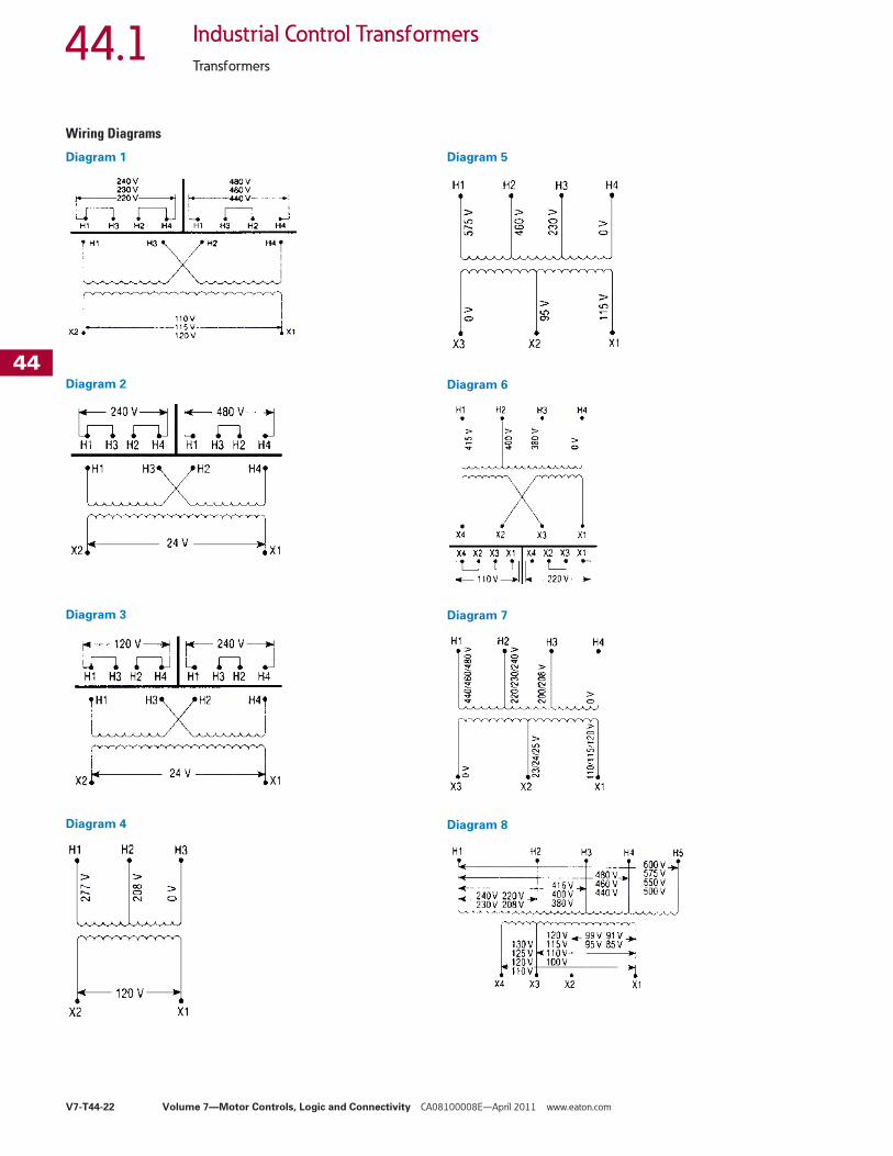
Wiring Diagrams
Diagram 1
Diagram 2
Diagram 3
Diagram 4
Diagram 5
Diagram 6
Diagram 7
Diagram 8
Tab44.book Page 22 Thursday, April 7, 2011 11:27 AM

Volume 7—Motor Controls, Logic and Connectivity CA08100008E—April 2011 www.eaton.com V7-T44-23
444444444444444444444444444444444444444444444444444444444444
44.1Industrial Control Transformers
Transformers
Diagram 9
Diagram 10
Diagram 11
Diagram 12
Diagram 13
Diagram 14
Diagram 15
Diagram 16
H1 H3 H2 H4 H1 H3 H2 H4
H1 H3 H2 H4
X4 X2 X3 X1
X4 X2 X3 X1 X4 X2 X3 X1
240 V 480 V
240 V120 V
H1 H2
X2 X1
600 V575 V550 V
24 V23 V22 V
H1 H2
X2 X1
420 V400 V380 V
24 V23 V22 V
H1 H2 H3 H4 H5
X3 X2 X1
550,
575,
600
V
440,
460,
480
V
380,
400,
416
V
220,
230,
240
V
23/2
4/25
110,
115,
120
V
0 V
0 V
X4 X3 X2 X1
H1 H2 H3 H4 H5 H6
575
V
460
V
400
V
230
V
208
V
0 V
0 V
24V
115
V
230
V
X4 X3 X2 X1
H1 H2 H3 H4 H5 H6
575
V
460
V
400
V
230
V
208
V
0 V
0 V
0 V
115
V
115
V
Tab44.book Page 23 Thursday, April 7, 2011 11:27 AM

V7-T44-24 Volume 7—Motor Controls, Logic and Connectivity CA08100008E—April 2011 www.eaton.com
444444444444444444444444444444444444444444444444444444444444
44.1 Industrial Control Transformers
Transformers
Acceptable Rating of Primary Overcurrent Protection for CE Marked Control Transformers �
Acceptable Maximum Rating of Secondary Overcurrent Protection �
Regulation Data Chart
Notes� For values over 6.3A, use 10 x 38 mm timelag (IEC - 269-3-1). Ta = 40°C control type.� For units with Class 105°C insulation system.� For units with Class 130°C insulation system.� For units with Class 180°C insulation system.
To comply with NEMA standards that require all magnetic devices to operate successfully at 85% of rated voltage, the 90% secondary column is most often used in selecting a transformer. No comparable requirement is available for IEC.
Fuses 13/32 x 1-1/2 Inches (10 x 38 mm) Timelag (IEC 269)Sec. Voltage 50 75 100 150 200 250 300 350 500 750
115 2.0 2.0 4.0 4.0 6.0 6.0 8.0 10.0 12.0 20.0
120 2.0 2.0 4.0 4.0 6.0 6.0 8.0 10.0 12.0 20.0
200 1.0 2.0 2.0 4.0 4.0 4.0 4.0 6.0 8.0 12.0
208 1.0 2.0 2.0 4.0 4.0 4.0 4.0 6.0 8.0 12.0
220 1.0 1.0 2.0 4.0 4.0 4.0 4.0 6.0 6.0 10.0
230 1.0 1.0 2.0 4.0 4.0 4.0 4.0 6.0 6.0 10.0
240 1.0 1.0 2.0 4.0 4.0 4.0 4.0 4.0 6.0 10.0
277 0.5 1.0 1.0 2.0 4.0 4.0 4.0 4.0 6.0 8.0
380 0.5 1.0 1.0 2.0 2.0 4.0 4.0 4.0 6.0 6.0
400 0.5 0.5 1.0 2.0 2.0 4.0 4.0 4.0 4.0 6.0
415 0.5 0.5 1.0 1.0 2.0 4.0 4.0 4.0 4.0 6.0
440 0.5 0.5 1.0 1.0 2.0 2.0 4.0 4.0 4.0 6.0
460 0.5 0.5 1.0 1.0 2.0 2.0 4.0 4.0 4.0 6.0
480 0.5 0.5 0.5 1.0 2.0 2.0 4.0 4.0 4.0 6.0
550 0.5 0.5 0.5 1.0 1.0 2.0 2.0 4.0 4.0 4.0
575 0.5 0.5 0.5 1.0 1.0 2.0 2.0 4.0 4.0 4.0
600 0.5 0.5 0.5 1.0 2.0 2.0 2.0 4.0 4.0 4.0
Miniature Fuses 5 x 20 mm Timelag (IEC 127-2/III)Sec. Voltage 50 75 100 150 200 250 300 350 500 750
23 2.50 4.00 5.00 8.00 10.0 12.00 16.00 16.00 25.00 —
24 2.50 4.00 5.00 8.00 10.0 12.00 16.00 16.00 25.00 32.00
25 2.50 4.00 5.00 8.00 10.0 12.00 16.00 16.00 25.00 32.00
90 0.63 1.00 1.25 2.00 2.50 3.15 4.00 4.00 6.30 10.00
95 0.63 0.80 1.25 1.60 2.50 3.15 4.00 4.00 6.30 8.00
100 0.50 0.80 1.00 1.60 2.00 2.50 3.15 4.00 5.00 8.00
110 0.50 0.80 1.00 1.60 2.00 2.50 3.15 4.00 5.00 8.00
115 0.50 0.80 1.00 1.60 2.00 2.50 3.15 3.15 5.00 8.00
120 0.50 0.63 1.00 1.25 2.00 2.50 2.50 3.15 5.00 6.30
220 0.25 0.40 0.50 0.80 1.00 1.25 1.60 1.60 2.50 4.00
230 0.25 0.40 0.50 0.80 1.00 1.25 1.60 1.60 2.50 4.00
240 0.25 0.32 0.50 0.63 1.00 1.25 1.25 1.60 2.50 3.15
Transformer VA Rating
Inrush VA at 20% Power FactorNEMA/IEC95% Sec. Voltage
NEMA/IEC90% Sec. Voltage
NEMA/IEC85% Sec. Voltage
25 � 100/— 130/— 150/—
50 � 170/190 200/220 240/270
75 � 310/350 410/460 450/600
100 � 370/410 540/600 730/810
150 � 780/850 930/1030 1150/1270
200 � 810/900 1150/1270 1450/1600
250 � 1400/1540 1900/2090 2300/2530
300 � 1900/2090 2700/2970 3850/4240
350 � 3100/3410 3650/4020 4800/5280
500 � 4000/4400 5300/5830 7000/7700
750 � 8300/9130 11,000/12,100 14,000/15,400
1000 � 15,000/16,500 21,000/23,000 27,000/29,500
1000 � 9000/9900 13,000/14,300 18,500/20,300
1500 � 10,500/11,500 15,000/16,500 20,500/22,500
2000 � 17,000/18,900 25,500/27,300 34,000/36,400
3000 � 24,000/25,700 36,000/38,500 47,500/50,200
5000 � 55,000/58,800 92,500/98,900 115,000/122,000
Tab44.book Page 24 Thursday, April 7, 2011 11:27 AM

Volume 7—Motor Controls, Logic and Connectivity CA08100008E—April 2011 www.eaton.com V7-T44-25
444444444444444444444444444444444444444444444444444444444444
44.1Industrial Control Transformers
Transformers
Type AP Transformer ContentsDescription Page
Type MTE . . . . . . . . . . . . . . . . . . . . . . . . . . . . . . . . V7-T44-4
Type MTK . . . . . . . . . . . . . . . . . . . . . . . . . . . . . . . . V7-T44-13
CE Marked . . . . . . . . . . . . . . . . . . . . . . . . . . . . . . . V7-T44-18
Type APCatalog Number Selection. . . . . . . . . . . . . . . . . V7-T44-26
Product Selection . . . . . . . . . . . . . . . . . . . . . . . V7-T44-26
Technical Data and Specifications . . . . . . . . . . . V7-T44-26
Type APProduct Description● Encapsulated designs
Application DescriptionTransformers provide stepped-down voltages to machine tool control devices, enabling control circuits to be isolated from all power and lighting circuits. This allows the use of grounded or ungrounded circuits that are independent of the power or lighting grounds; thus, greater safety is afforded the operator. The control transformer line is particularly adaptable on applications where compact construction is demanded.
Features, Benefits and Functions● Resin encapsulated● 60 Hz operation● 180°C insulation system● 115°C rise standard;
80°C rise optional● Convenient screw-type
terminal board● Bottom or side/wall-
mounting designs● Performance meets/
exceeds requirements of ANSI/NEMA ST-1
● Regulation exceeds ANSI/NEMA requirements for all ratings
Standards and Certifications● UL recognized
Industry StandardsAll Eaton dry-type distribution and control transformers are built and tested in accordance with applicable NEMA, ANSI and IEEE Standards.
Tab44.book Page 25 Thursday, April 7, 2011 11:27 AM

V7-T44-26 Volume 7—Motor Controls, Logic and Connectivity CA08100008E—April 2011 www.eaton.com
444444444444444444444444444444444444444444444444444444444444
44.1 Industrial Control Transformers
Transformers
Catalog Number SelectionPlease refer to Page V7-T44-3.
Product SelectionAdditional Product Selection information is available in Volume 2, CA08100003E.
240/480 Volts to 120/240 Volts, 60 Hz
Technical Data and Specifications
Overload CapabilityShort-term overload is designed into transformers as required by ANSI. Dry-type distribution transformers will deliver 200% nameplate load for one-half hour, 150% load for one hour and 125% load for four hours without being damaged, provided that a constant 50% load precedes and follows the overload. See ANSI C57.96-01.250 for additional limitations.
Continuous overload capacity is not deliberately designed into a transformer because the design objective is to be within the allowed winding temperature rise with nameplate loading.
Insulation System and Temperature RiseIndustry standards classify insulation systems and rise as shown below:
Insulation System Classification
The design life of transformers having different insulation systems is the same—the lower-temperature systems are designed for the same life as the higher-temperature systems.
Sound LevelsAll Eaton 600 volt class general-purpose dry-type distribution transformers are designed to meet NEMA ST-20 levels.
Winding TerminationsEaton recommends external cables be rated 90ºC (sized at 75°C ampacity) for encapsulated designs.
Series-Multiple WindingsSeries-multiple windings consist of two similar coils in each winding that can be connected in series or parallel (multiple). Transformers with series-multiple windings are designated with an “x” or “/” between the voltage ratings, such as voltages of “120/240” or “240 x 480.” If the series-multiple winding is designated by an “x,” the winding can be connected only for a series or parallel.
With the “/” designation, a mid-point also becomes available in addition to the series or parallel connection. As an example, a 120 x 240 winding can be connected for either 120 (parallel) or 240 (series), but a 120/240 winding can be connected for 120 (parallel), 240 (series) or 240 with a 120 mid-point.
For additional information, please refer to Volume 2, CA08100003E.
Note: For additional information, refer to Eaton’s Industrial Control Transformer Binder B1228A. For other ratings or styles not shown, or for special enclosure types (including stainless steel), refer to Eaton.
Note� See Page V7-T44-22 for wiring diagrams.
kVA Mounting FrameWiringDiagram �
WeightLbs (kg)
StyleNumber
3 Bottom FR133 5 65 (29.5) C0003P7GB
5 Bottom FR99 5 104 (47.2) C0005P7GB
7.5 Bottom FR100 5 129 (58.6) C0007P7GB
10 Bottom FR101 5 148 (67.2) C0010P7GB
15 Bottom FR134 5 197 (89.4) C0015P7GB
3 Side/Wall FR292 5 65 (29.5) C0003P7GS
5 Side/Wall FR256 5 104 (47.2) C0005P7GS
7.5 Side/Wall FR257 5 129 (58.6) C0007P7GS
10 Side/Wall FR258 5 148 (67.2) C0010P7GS
15 Side/Wall FR259 5 197 (89.4) C0015P7GS
Ambient
+ Winding Rise
+ Hot Spot
= Temp. Class
40°C 55°C 10°C 105°C
40°C 80°C 30°C 150°C
25°C 135°C 20°C 180°C
40°C 115°C 30°C 185°C
40°C 150°C 30°C 220°C
Tab44.book Page 26 Thursday, April 7, 2011 11:27 AM
Related Documents