TG701 Field Instruments Overhaul TA - 2015 Field Maintenance Team: Usama Tariq Khan/Haris Muhammad/Muhammad Asad Ullah Prepared by: Muhammad Asad Ullah Reviewed by: Raja Naveed Lehrasab

Welcome message from author
This document is posted to help you gain knowledge. Please leave a comment to let me know what you think about it! Share it to your friends and learn new things together.
Transcript
TG701 Field Instruments Overhaul
TA - 2015
Field Maintenance Team: Usama Tariq Khan/Haris Muhammad/Muhammad Asad Ullah
Prepared by: Muhammad Asad Ullah
Reviewed by: Raja Naveed Lehrasab
TG701 Field Instruments Overhaul
Page 1
Introduction
Gas turbine overhaul is always a complex and exciting task. Plant start-up after TA is always linked to the
availability of gas turbine after its overhaul, which makes the job critical and challenging.
The job in TA-2015 was special as a number of critical jobs were being carried out in parallel. The control
system was being replaced with Mark-VIe, turbine rotor was being replaced and the generator rotor had
to be removed for inspection. These activities necessitated better planning, improved coordination with
other teams and perfect execution of the job.
An elaborate plan was prepared before TA in view of the importance of field devices’ proper
overhauling/calibration to ensure that all the above mentioned modifications/replacements achieve
desired results in terms of machine performance and avoid unnecessary delays.
Planning
A thorough planning process was executed to create a detailed job plan. Various discussion sessions for
information and experience sharing were held with engineers and staff. Field visits were also carried out.
Following major activities were concluded:
Creation of work procedures for overhauling of each category of instruments
Creation of checklists to record all the parameters of removal, calibration and re-installation.
Fabrication of new thermowells for proper calibration of Temperature switches.
Arrangement of special tools for working on gas turbine.
Management of TG inventory to ensure the availability of critical spares
Arrangement of consumable spares.
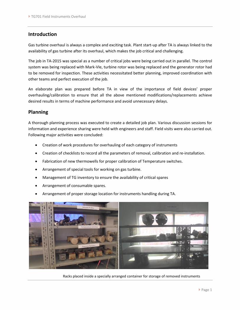
Arrangement of proper storage location for instruments handling during TA.
Racks placed inside a specially arranged container for storage of removed instruments

TG701 Field Instruments Overhaul
Page 2
TA Activities
During the Turnaround, the sequence of working was such that initially the instruments were removed
according to the machine dismantling process and placed in workshop where they were checked and
calibrated. Later, they were re-installed along with turbine reassembly. Some of the instruments were
checked on-site.
A total of 171 instruments were checked amongst which some were removed for the first time. A summary
of the instruments is given below.
Sr. No. Instrument Type Checked / Calibrated
1 Pressure Switch 16
2 Temperature Switch 16
3 Level Switch 02
4 Limit Switch 15
5 Transmitters 05
5 SOV 19
7 Thermocouples 42
8 Analog IO/Misc. 06
9 Seismic probes & vibration switches 07
10 Bentley Nevada Probes 08
11 Magnetic Pickups 03
12 Control Valves 07
13 Gauges 25
Besides the normal jobs, there were some activities which required special preparation. A brief summary
of these activities is give below.
1) Modification at Bearing No. 1
The radial and thrust vibration measurement of turbine rotor is done by 2 VTs and 1 XT installed at the
bearing No. 1. Replacement of turbine rotor was planned in this Turnaround. However, the new rotor
design had a keyphasor notch at the position where the VTs were installed originally. Due to this reason,
GE changed the location and type of VTs and shifted the XT to the active side of the thrust bearing. The
installation mechanism for all three was changed as well.
This arrangement required special VTs which were not available with us. To cope with this situation,
arrangements were made with the help of Machinery department to ensure correct installation, probe
safety and oil sealing.

TG701 Field Instruments Overhaul
Page 3
After dismantling, the bearing cover was brought to the machine shop and a mandrel was placed inside it
to simulate the turbine rotor. The new probes’ adapter assembly was installed according to this
arrangement.
In the field, new JBs were installed and the extension cables were routed through tubing up to the main
JB.
Probe Adjustment Job in Workshop
2) New Transmitters Installation
With the up-grade of control system from Mark-II to Mark-VIe, the existing 4-wire transmitters were
replaced by 2-wire transmitters. Three new transmitters were added to the system as well.
- 20CD: Compressor Discharge pressure transmitter (Replaced)
- 20FG: Gas Fuel Pressure Transmitter (Replaced)
- 96HFD-1: Hydraulic Oil Filter DP transmitter (New Transmitter)
- 96HQ: Hydraulic Supply Pressure (New Transmitter)
- 96QA: Lube Oil header pressure transmitter (New Transmitter)
3) 20CB installation:
There are two anti-surge valves installed on the gas turbine which bleed compressor air up to 95% speed
of the turbine. 20CB is the SOV which supplies air to these valves.
The SOV’s ports are located in the turbine compartment while its solenoid assembly is installed through a
metal plate in the wall adjoining accessory compartment. The SOV is installed in one corner under the
turbine and its access is blocked by 20AA, 20PL, VA-17 and some other piping and instrument power
connections tubing.
TG701 Field Instruments Overhaul
Page 4
The SOV’s working was tested automatically during TG shutdown, when it opened the bleed valves below
95% speed. During the Turnaround, the coil health of the SOV and other field checks were performed and
were found ok. During the test startup checking, however, the SOV developed fault and started passing
which would result in bleed valves closure before the desired speed.
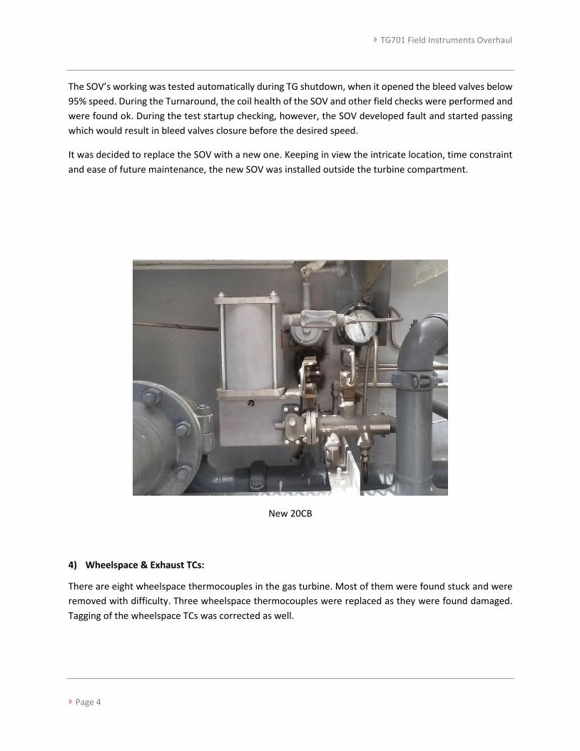
It was decided to replace the SOV with a new one. Keeping in view the intricate location, time constraint
and ease of future maintenance, the new SOV was installed outside the turbine compartment.
New 20CB
4) Wheelspace & Exhaust TCs:
There are eight wheelspace thermocouples in the gas turbine. Most of them were found stuck and were
removed with difficulty. Three wheelspace thermocouples were replaced as they were found damaged.
Tagging of the wheelspace TCs was corrected as well.
TG701 Field Instruments Overhaul
Page 5
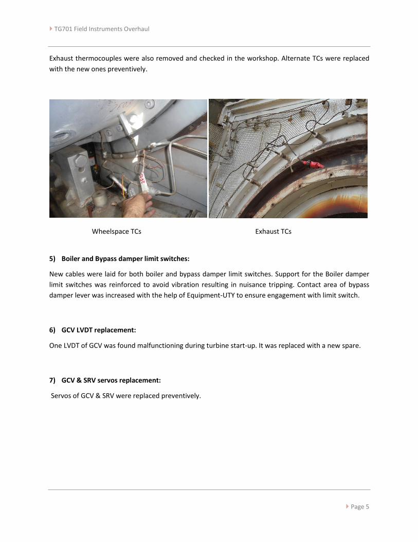
Exhaust thermocouples were also removed and checked in the workshop. Alternate TCs were replaced
with the new ones preventively.
Wheelspace TCs Exhaust TCs
5) Boiler and Bypass damper limit switches:
New cables were laid for both boiler and bypass damper limit switches. Support for the Boiler damper
limit switches was reinforced to avoid vibration resulting in nuisance tripping. Contact area of bypass
damper lever was increased with the help of Equipment-UTY to ensure engagement with limit switch.
6) GCV LVDT replacement:
One LVDT of GCV was found malfunctioning during turbine start-up. It was replaced with a new spare.
7) GCV & SRV servos replacement:
Servos of GCV & SRV were replaced preventively.

TG701 Field Instruments Overhaul
Page 6
8) 06-LLS-102 level switch replacement:
06-LLS-102 is a side mounted float type level switch at steam drum of B-601. The switch was found in rusty
condition, so it was replaced with a new one.
06-LLS-102
Future Actions:
In light of our experience in this Turnaround, following are the recommended actions for improvement.
1) Spares present in the warehouse since commissioning should be checked for physical health.
2) Test setups should be developed for checking SOVs in field and/or workshop.
3) Externally adjustable GE vibration probes (identical to the ones installed in FFBL) should be procured
for installation at bearing # 1, as per original GE design for the new rotor.
Related Documents