FANs 216, 1628.3 Product/Technical Bulletin T500 Issue Date 0899 © 1999 Johnson Controls, Inc. 1 Part No. 24-8347-35, Rev. E www.johnsoncontrols.com Code No. LIT-216173 T500 Series Thermostats provide an economical control solution for single-stage, multi-stage, or heat pump systems. Up to four event setpoints can be selected, as well as heat, cool, automatic changeover, and off modes. Thermostats are available in the following types: T500HCP-1 (1 heat/1 cool), T500HPP-1 (heat pump, 3 heat/2 cool), T500HPP-2 (heat pump, 1 heat/1 cool), T500MSP-1 (2 heat/2 cool). Each thermostat is packaged with the necessary mounting hardware, and installation is simple and fast for reduced cost. Figure 1: T500 Series Programmable Thermostats Features and Benefits ! Low-Profile Design Complements any decor ! No Batteries Required Retains scheduled events and temperatures upon loss of power ! Lockable Access Cover and Keypad Lockout Prevents unauthorized changes ! Full Function Liquid Crystal Display (LCD) Makes controls easy to read, easy to use ! Remote Sensor Terminals Allows the T500 thermostat to be mounted up to 300 m (1,000 ft) away from the controlled space using a SEN-500-1 (sold separately) ! Auxiliary Output Energizes for auxiliary equipment operation ! Fuzzy Logic Control Optimizes control performance ! Smart Fan Option Provides continous fan operation in the occupied mode and intermittent operation at night T500 Series Programmable Thermostats

Welcome message from author
This document is posted to help you gain knowledge. Please leave a comment to let me know what you think about it! Share it to your friends and learn new things together.
Transcript
FANs 216, 1628.3Product/Technical Bulletin T500
Issue Date 0899
© 1999 Johnson Controls, Inc. 1Part No. 24-8347-35, Rev. E www.johnsoncontrols.comCode No. LIT-216173
T500 Series Thermostats provide an economicalcontrol solution for single-stage, multi-stage, or heatpump systems. Up to four event setpoints can beselected, as well as heat, cool, automatic changeover,and off modes.
Thermostats are available in the following types:T500HCP-1 (1 heat/1 cool), T500HPP-1 (heat pump,3 heat/2 cool), T500HPP-2 (heat pump, 1 heat/1 cool),T500MSP-1 (2 heat/2 cool). Each thermostat ispackaged with the necessary mounting hardware, andinstallation is simple and fast for reduced cost.
Figure 1: T500 Series Programmable Thermostats
Features and Benefits
!!!! Low-Profile Design Complements any decor
!!!! No Batteries Required Retains scheduled events and temperaturesupon loss of power
!!!! Lockable Access Cover andKeypad Lockout
Prevents unauthorized changes
!!!! Full Function Liquid CrystalDisplay (LCD)
Makes controls easy to read, easy to use
!!!! Remote Sensor Terminals Allows the T500 thermostat to be mounted upto 300 m (1,000 ft) away from the controlledspace using a SEN-500-1 (sold separately)
!!!! Auxiliary Output Energizes for auxiliary equipment operation
!!!! Fuzzy Logic Control Optimizes control performance
!!!! Smart Fan Option Provides continous fan operation in theoccupied mode and intermittent operation atnight
T500 Series Programmable Thermostats

2 T500 Series Programmable Thermostats Product/Technical Bulletin
Introduction
The T500 thermostats use an adaptive control routine,based on fuzzy logic, to determine the heating orcooling load of the controlled space. The routinecalculates load by evaluating recent room conditionsand room reactions to heating and cooling. This load isused to determine the cycle rate of the equipment,giving optimal control of the space.
Supplies Needed
• drill
• 4.7 mm (3/16 in.) drill bit
• 3 mm (1/8 in.) flat-blade screwdriver
• hammer
• marking pencil
• wire stripper
T500MSP-1T500HPP-1
T500HCP-1T500HPP-2
Dimn
114.3(4-1/2)
127 (5)
101.6 (4)
22.2(7/8)
Figure 2: T500 Dimensions, mm (in.)
Location Considerations
Locate T500 thermostat as follows:
• on a partitioning interior wall, and approximately1.5 m (5 ft) above the floor in a location of averagetemperature
• away from direct sunlight or radiant heat, outsidewalls or behind doors, air discharge grills,stairwells, or outside doors
• away from steam or water pipes, warm air stacks,unheated/uncooled areas, or sources of electricalinterference
!CAUTION: Shock Hazard.
Disconnect power supply beforewiring connections are made toprevent electrical shock orpossible damage to theequipment.
Installation and Wiring
Note: When replacing an existing thermostat,remove and use wire tags to identify terminaldesignations.
To install and wire the thermostat:
1. Lift the thermostat cover and insert a small coininto the slot located in the bottom center of thethermostat case and twist 1/4 turn. (See Figure 3.)Grasp the base from the bottom two corners andseparate from the thermostat.
2. Swing the thermostat out from the bottom, and liftup and out of the base. Place the rectangularopening in the base over the equipment controlwires protruding from the wall and, using the baseas a template, mark the location of the twomounting holes. No leveling is required.
3. Use the supplied anchors and screws for mountingon drywall or plaster. Drill two 4.7 mm (3/16 in.)holes at the marked locations, tap nylon anchorsflush to wall surface, and fasten. (See Figure 4.)
4. Connect the wires from the existing system to thethermostat terminals according to wiringdesignations in Table 2, Table 3, Table 4, orTable 5. Push extra wire back into the wall. Wiresmust be flush to the plastic base. Plug hole with afireproof material to prevent drafts from affectingambient temperature readings.

T500 Series Programmable Thermostats Product/Technical Bulletin 3
!CAUTION: Equipment Damage Hazard.
Before applying power, make allwiring connections and checkthe connections. Short-circuitedor improperly connected wiresmay result in permanentdamage to the unit.
Figure 3: Separating the T500 from the Base
Figure 4: Mounting the Base

4 T500 Series Programmable Thermostats Product/Technical Bulletin
Installing the Thermostat Cover Lock
If desired, insert the plastic lock piece into the bottomof the mounted base. The ends of the lock pieceshould fit snugly under the lock pins extending from thebottom of the mounted base. The tab in the middle ofthe lock piece should extend downward from themounted base. (See Figure 5.)
To release the locking mechanism, press the lockpiece up and into the base while gently prying open thethermostat at the same time. Use caution to avoidcracking the thermostat base or cover.
Thermostat Base
Plastic Lock Pin
Snap plastic lock into place.
Figure 5: Installing the Thermostat Lock
Reattaching the Thermostat and Coverto the Installed Base
1. Position the thermostat inside the cover, andattach on the hinged tabs located at the top of thebase.
2. Swing the thermostat and cover down, and presson the bottom center edge until they snap in place.(See Figure 6.)
HingedTabs
Figure 6: Installing the T500 Thermostat

T500 Series Programmable Thermostats Product/Technical Bulletin 5
DIP Switch Selections
!CAUTION: Equipment Damage Hazard.
Before selecting a minimumon/off time, ensure theequipment can tolerate thefollowing maximum hourlycycle rates: 7.5 cycles per hourwhen using 4-minute on/off, or15 cycles per hour when using2-minute on/off.
Table 1: DIP Switch SelectionsDIP Switch Switch
SelectionDescription
1 On Allows 2-event (day, night) programming.
Off Allows 4-event (morning, day, evening, night) programming.
2(Smart Fan)
On During the morning, day, and evening events, the fan automatically cycles with theequipment or runs continuously if the Fan button is pressed. To run continuously, theFan button need only be pressed once during the morning, day, or evening eventafter programming the thermostat. Smart Fan remembers that the fan should runcontinuously during these events after that.
During the night event, the fan automatically cycles with the equipment by default.Pressing the Fan button during the night event overrides and causes the fan to runcontinuously for that night only.
At the end of the night event, Smart Fan remembers the fan selection (automaticcycling or continuous fan) for the morning, day, and evening events and reverts back.
Off Allows the fan to cycle with equipment or run continuously if the Fan button ispressed, regardless of the event. Changing between events does not affect the fan.
3 On Allows 2-minute minimum on/off time for heating and cooling equipment.
Off Allows 4-minute minimum on/off time for heating and cooling equipment.
4 On Locks the keyboard, disabling buttons to prevent tampering. (Only the Outdoor and∨∨∨∨ and ∧∧∧∧ buttons will function. See Programming the Thermostat, MakingProgramming Changes While the Keyboard is Locked, and Temporary [1 Hour][Keyboard Locked] in this bulletin.)
Off Unlocks the keyboard.
5 On T500HCP-1, T500HPP-2, T500MSP-1 only: Allows the fan to delay with the plenumswitch.
T500HPP-1 only: Compressor/Auxiliary Interlocked: Turns off the compressor whenthe auxiliary heat is on. The compressor will remain off for 2 minutes after theauxiliary heat is turned off to ensure that the heat pump coil has cooled.
Off T500HCP-1, T500HPP-2, T500MSP-1 only: Allows fan to operate immediately with acall for heat.
T500HPP-1 only: Compressor/Auxiliary Normal: Allows the compressor and auxiliaryheat to be on simultaneously.
Continued on next page . . .

6 T500 Series Programmable Thermostats Product/Technical Bulletin
DIP Switch(Cont.)
SwitchSelection
Description
6 On T500HPP-1, T500MSP-1 only: Allows multi-stage heating or cooling.
Off T500HPP-1, T500MSP-1 only: Allows single-stage heating or cooling.
7 LED 1 iconoff/on(See Table 5.)
T500HPP-1, T500MSP-1 only: Optional selection: LCD icon comes on with LED 1.
8 LED 2 iconoff/on(See Table 5.)
T500HPP-1, T500MSP-1 only: Optional selection: LCD icon comes on with LED 2.
4 Events Per Day
Smart Fan Disabled
Heat/Cool: 4 Minute (Minimum On)
Keyboard Unlocked
ON1
32
45
2 Events Per Day
Smart Fan Enabled
Heat/Cool: 2 Minute (Minimum On)
Keyboard Locked
Fan Immediatewith Heat Call
Fan On withPlenum Switch
Figure 7: T500HCP-1 Factory-Set DIP SwitchSettings (All Off)
RS2
RS1
W1
Y1G
R
24V
24V(c)
Heating
CoolingFan
Common
Hcp-1wire
RS+V
Figure 8: T500HCP-1 Wiring Terminals
Table 2: T500HCP-1 Output TerminalDesignations
Terminal Function
W1 Energizes on call for heating
Y1 Energizes on call for cooling
G Energizes fan on call for heating orcooling or by pressing Fan button
R Independent switching voltage
24V 24 VAC from equipment transformer
24V(c) 24 VAC (common) from equipmenttransformer
RS2
RS1
RS+V
Connections for outdoor airtemperature or indoor remotesensors; refer to instructions includedwith sensors.

T500 Series Programmable Thermostats Product/Technical Bulletin 7
Compressor/AuxiliaryNormal
Single Stage
LED 1 Icon Off
LED 2 Icon Off
4 Events Per Day
Smart Fan Disabled
Heat/Cool: 4 Minute(Minimum On)
Keyboard Unlocked
ON1
32
45
6
2 Events Per Day
Smart Fan Enabled
Heat/Cool: 2 Minute(Minimum On)
Keyboard Locked
78
LED 1 Icon (Filter) LED 2 Icon (Wrench/Fault)
Compressor/AuxiliaryInterlocked
Multi-stage
Figure 9: T500HPP-1 DIP Factory-SetDIP Switch Settings
W2
1st Stage Compressor
24VAC
Figure 10: T500HPP-1 Wiring Terminals
Table 3: T500HPP-1 Output TerminalDesignations
Terminal Function
W2 Energizes auxiliary heat assecond-stage heating in emergencyheat mode
Y2 Energizes compressor No. 2 on callfor second-stage heating or cooling
W1 Energizes auxiliary heat aslast-stage heating or first-stage inemergency heat
Y1 Energizes compressor No. 1 on callfor heating or cooling
G Energizes fan on call for heating orcooling or by pressing Fan button
R Independent switching voltage
24V 24 VAC from equipment transformer
24V(c) 24 VAC (common) from equipmenttransformer
O Energizes reversing valve in thecooling mode
B Energizes reversing valve in theheating mode
LED 1
LED 2
Input connection that energizesLED 1 or LED 2 from remote statusdevice (See Figure 9 and Table 6.)
RS2
RS1
RS+V
Connections for outdoor airtemperature or indoor remotesensors; refer to instructionsincluded with sensors.
NO
COM
NC
The relay coil is de-energized in thenight event. In all other events, therelay coil is energized. (SeeFigure 16.)
8 T500 Series Programmable Thermostats Product/Technical Bulletin
ON1
32
45
4 Events Per Day 2 Events Per Day
Smart Fan Disabled Smart Fan Enabled
Heat/Cool: 4 Minute(Minimum On)
Heat/Cool: 2 Minute(Minimum On)
Keyboard Unlocked Keyboard Locked
Fan Immediatewith Heat Call
Fan On withPlenum Switch
Figure 11: T500HPP-2 Factory-Set DIP SwitchSettings (All Off)
RS2RS1RS+V
W1
B
Hpp-2wire
Compressor
Fan
Common24VAC
Figure 12: T500HPP-2 Wiring Terminals
Table 4: T500HPP-2 Output TerminalDesignations
Terminal Function
Single-StageHeat PumpThermostat
ConventionalSingle-StageHeat/CoolThermostat
W1* Jumpered to Y1(See Note.)
Energizes on callfor heating(See Note.)
Y1 Energizescompressorcontactor(See Note.)
Energizes on callfor cooling(See Note.)
G Energizes fan on call for heating orcooling or by pressing Fan button
R Independent switching voltage(See Note.)
24V 24 VAC from equipment transformer
24V(c) 24 VAC (common) from equipmenttransformer
RS2RS1
RS+V
Connections for outdoor air temperatureor indoor remote sensors; refer toinstructions included with sensors
O Energizesreversing valve inthe cooling mode
Not used
B Energizesreversing valve inthe heating mode
Not used
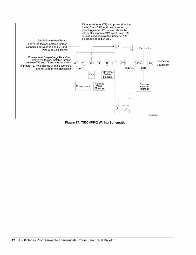
Note: Single-Stage Heat Pump:Leave the factory-installed jumper connectedbetween W1 and Y1 and wire O or B as shown inFigure 12.
Conventional Single-Stage Heat/Cool:Remove the factory-installed jumper between W1and Y1 and wire as shown in Figure 12. Note thatthe O and B terminals are not used in thisapplication.

T500 Series Programmable Thermostats Product/Technical Bulletin 9
Single Stage
LED 1 Icon Off
LED 2 Icon Off
4 Events Per Day
Smart Fan Disabled
Heat/Cool: 4 Minute(Minimum On)
Keyboard Unlocked
ON1
32
45
6
2 Events Per Day
Smart Fan Enabled
Heat/Cool: 2 Minute(Minimum On)
Keyboard Locked
78
LED 1 Icon (Filter) LED 2 Icon (Wrench/Fault)
Multi-stage
Fan Immediatewith Heat Call
Fan On with Plenum Switch
Figure 13: T500MSP-1 Factory SetDIP Switch Settings
W2
R
NO
COM
NC
2nd Stage Heating2nd Stage Cooling1st Stage Heating1st Stage Cooling
Fan
24VACCommon
Figure 14: T500MSP-1 Wiring Terminals
Table 5: T500MSP-1 Output TerminalDesignations
Terminal Function
W2 Energizes on a call forsecond-stage heat
Y2 Energizes on a call forsecond-stage cooling
W1 Energizes on a call for first-stageheat
Y1 Energizes on a call for first stagecooling
G Energizes fan on call for heating orcooling or by pressing the Fanbutton
R Independent switching voltage
24V 24 VAC from equipmenttransformer
24V(c) 24 VAC (common) from equipmenttransformer
O Energizes in the cooling mode
B Energizes in the heating mode
LED 1
LED 2
Input connection that energizesLED 1 or LED 2 from remote statusdevice (See Figure 13 andTable 6.)
RS2
RS1
RS+V
Connections for outdoor airtemperature or indoor remotesensors; refer to instructionsincluded with sensors
NO
COM
NC
The relay coil is de-energized in thenight event. In all other events, therelay coil is energized. (SeeFigure 18.)

10 T500 Series Programmable Thermostats Product/Technical Bulletin
Wiring Diagrams
1st StageCompressor
1st StageHeat Fan
W1 Y1 G 24V(c)R 24V
T1 T2
RS+V RS1 RS2
RemoteSensor
(if used)
Thermostat
Equipment
Electronics
If the transformer (T2) is to power all of the loads,R and 24 must be connected by inserting jumper J 1located above the relays. If a separate 24V transformer (T1) is to be used, remove J 1 todisconnect R and 24V(c).
P
P
Hcp-1diag
J 1P
Optional
Figure 15: T500HCP-1 Wiring Schematic

T500 Series Programmable Thermostats Product/Technical Bulletin 11
1st StageCompressor
ReverseValve
Heating
2nd StageHeat
1st StageHeat
Fan
ReverseValve
Cooling
W1 Y1 Y2W2 G O B 24V(c) RS+V RS1 RS2
Remotesensor
(if used)
R 24V LED1LED2
T1 T2Field contact switches
2nd StageCompressor
Electronics
COM
OCC(all other events)
NO NC
COM
UNOCC(night event
if thermostat
loses power)
NO NC
Thermostat
Equipment
Hpp-1diag
If the transformer (T2) is to power all of the loads R and 24V must be connected by inserting jumper
1, located above the relays. If a separate 24Vtransformer (T1) is to be used, remove the jumper
to disconnect R and 24V.
JP
JP1JP1
Optional
Figure 16: T500HPP-1 Wiring Schematic
12 T500 Series Programmable Thermostats Product/Technical Bulletin
Compressor
Fan
W1 Y1 G
24V(c)
R 24V
T1 T2
RS+V
RS1
RS2
Remotesensor(if used)
Electronics
O B
ReverseValve
Cooling
ReverseValve
Heating
Thermostat
Equipment
Single-Stage Heat Pump:Leave the factory-installed jumper
connected between W1 and Y1 and wire O or B as shown.
Conventional Single-Stage Heat/Cool:
between W1 and Y1 and wire as shown in Figure 12. Note that the O and B terminals
are not used in this application.
If the transformer (T2) is to power all of the loads, R and 24V must be connected by inserting jumper JP1, located above therelays. If a separate 24V transformer (T1)is to be used, remove the jumper JP1 to disconnect R and 24V(c).
JP1
Hpp2-diag
Remove the factory-installed jumper
Figure 17: T500HPP-2 Wiring Schematic

T500 Series Programmable Thermostats Product/Technical Bulletin 13
1st StageCool
2nd StageHeatHeat
Fan
Cooling
W1 Y1 Y2 G O B 24V(c) RS1
RS2
RemoteSensor(if used)
R 24V LED1
LED2
T1 T2
2nd Stage
Electronics
COM
OCC
events)
NO NC
COM
UNOCC(night event
or if thermostat
NO NC
Thermostat
Equipment
Reverse Valve
If the transformer (T2) is to power all of the loads,R and 24V must be connected by inserting jumperJ 1 located above the relays. If a separate 24Vtransformer (T1) is to be used, remove the jumper
1 to disconnect R and 24V(c).
P
JP
JP1
optional
ReverseValveHeating
RS+V
Figure 18: T500MSP-1 Wiring Schematic
14 T500 Series Programmable Thermostats Product/Technical Bulletin
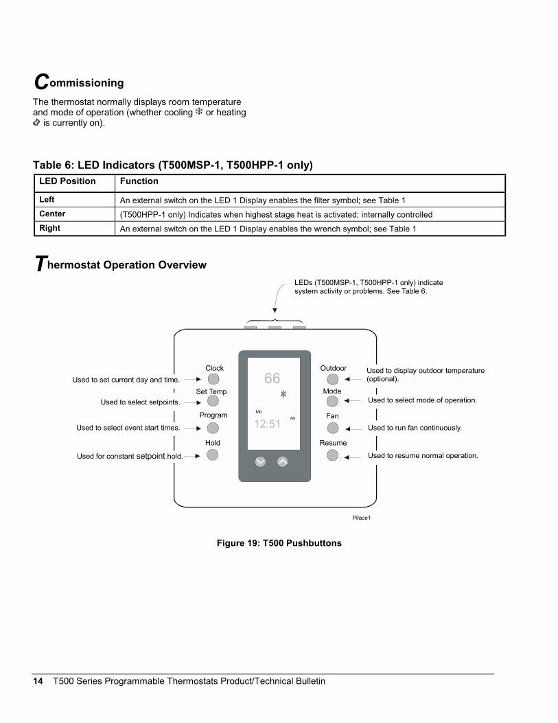
Commissioning
The thermostat normally displays room temperatureand mode of operation (whether cooling or heating
is currently on).
Table 6: LED Indicators (T500MSP-1, T500HPP-1 only)
LED Position Function
Left An external switch on the LED 1 Display enables the filter symbol; see Table 1
Center (T500HPP-1 only) Indicates when highest stage heat is activated; internally controlled
Right An external switch on the LED 1 Display enables the wrench symbol; see Table 1
Thermostat Operation Overview
Mode
Clock
Set Temp
Outdoor
FanProgram
ResumeHold
66
12:51Mo
AM
Used to display outdoor temperature(optional).
Used to select mode of operation.
Used to run fan continuously.
Used to resume normal operation.
Used to select setpoints.
Used to select event start times.
Used for constant hold.setpoint
LEDs (T500MSP-1, T500HPP-1 only) indicatesystem activity or problems. See Table 6.
Used to set current day and time.
Piface1
Figure 19: T500 Pushbuttons
T500 Series Programmable Thermostats Product/Technical Bulletin 15
Mode
Repeated pressing of the Mode button allowsselection from four modes of operation (five for theT500HPP-1/Heat Pump model):
• When the Snowflake and the word COOL aredisplayed, the thermostat is in the cooling mode.When the thermostat is calling for cooling, thesnowflake will flash.
• When the Flame and the word HEAT aredisplayed, the thermostat is in the heating mode.When the thermostat is calling for heating, theflame will flash.
• When the Flame and E Ht (emergency heat)are displayed, the thermostat will control using theemergency heat with the compressor locked out.(T500HPP-1/Heat Pump only.)
• When the Snowflake and the Flame symbolsand word AUTO are displayed, the thermostat willautomatically change over between heating andcooling.
Note: The thermostat never allows less than a 1°C(2°F) difference between the heating andcooling setpoints.
• When OFF is displayed, the equipment will notoperate.
Note: Use caution when using the OFF mode inextremely cold weather.
Celsius/Fahrenheit
Press the ∨∨∨∨ and ∧∧∧∧ buttons simultaneously to alternatebetween Celsius and Fahrenheit display.
Fuzzy Logic Control
Over time, the T500 learns how long it takes thesystem to meet the load. If the system can change theroom temperature quickly, the T500 allows thethermostat to drift further from setpoint before startingthe equipment. If the system takes a longer period oftime to change the room temperature, it will not allowthe temperature to drift as far from setpoint. The T500also takes into account the minimum On/Off times.The 2-minute On/Off time allows the equipment tocycle more frequently at smaller differentials than the4-minute On/Off time. For multi-stage applications, the
T500 does not bring on the next stage of cooling orheating if it knows that the system can change thetemperature by 6 degrees in 1 hour, or 1 degree in10 minutes. To verify thermostat operation, force thenext stage on by changing the setpoint more than2 degrees.
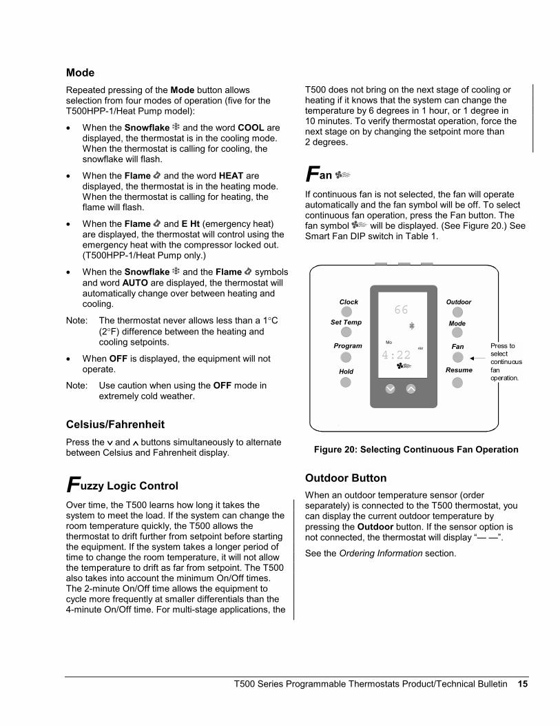
Fan
If continuous fan is not selected, the fan will operateautomatically and the fan symbol will be off. To selectcontinuous fan operation, press the Fan button. Thefan symbol will be displayed. (See Figure 20.) SeeSmart Fan DIP switch in Table 1.
Mode
Clock
Set Temp
Outdoor
FanProgram
ResumeHold
66
4:22Mo
AM Press toselect continuousfan operation.
Figure 20: Selecting Continuous Fan Operation
Outdoor Button
When an outdoor temperature sensor (orderseparately) is connected to the T500 thermostat, youcan display the current outdoor temperature bypressing the Outdoor button. If the sensor option isnot connected, the thermostat will display “— —”.
See the Ordering Information section.

16 T500 Series Programmable Thermostats Product/Technical Bulletin
Programming Overview
Thermostat programming is a 3-part process: settingcurrent time, choosing event setpoints, and settingevent times. Throughout the programming procedure,the following terms will be used:
Event = morning, day, evening, night
Event time = the time the event starts
Event setpoint = the temperature setpoint of theevent; each event can have only one setpoint forheating or cooling.
Program flexibility is achieved by varying the programstart times. When consecutive events are programmedwith the same event time, the thermostat will controlthe temperature according to the setpoint of the latestevent.
Table 7 is an example of event times and setpoints fora given week using a 4-event program. See theowner’s manual for a blank table.
Note: A 2-event program will only include dayand night events.
Table 7: Sample 4-Event Program Settings
Event Morning Day Evening Night
EventSetpoint
Heat68°F
Cool80°F
Heat72°F
Cool76°F
Heat66°F
Cool78°F
Heat60°F
Cool85°F
(Time) (Time) (Time) (Time)
Monday 6 a.m. 8 a.m. 5 p.m. 11 p.m.
Tuesday 6 a.m. 8 a.m. 5 p.m. 11 p.m.
Wednesday 6 a.m. 8 a.m. 5 p.m. 11 p.m.
Thursday 6 a.m. 8 a.m. 5 p.m. 11 p.m.
Friday 6 a.m. 8 a.m. 5 p.m. 11 p.m.
Saturday 6 a.m.* 6 a.m. 12 p.m. 12 p.m.
Sunday 12 p.m. 12 p.m. 12 p.m. 12 p.m.**
* Thermostat controls to the day setpoint until noon.
** Thermostat controls to the night setpoint until 6 a.m. Monday morning.

T500 Series Programmable Thermostats Product/Technical Bulletin 17
Programming the Thermostat
Setting the Current Day and Time
To set the current day and time:
1. Press and release the Clock button.The display will flash a day of the week.
2. Press the ∨∨∨∨ or ∧∧∧∧ buttons until the current dayshows.
3. Press Clock again. The display will flash the hour.
4. Press the ∨∨∨∨ or ∧∧∧∧ buttons until the current hourshows. Be sure AM or PM corresponds to theproper time.
5. Press Clock again. The display will flash minutes(:00). (See Figure 21.)
6. Press the ∨∨∨∨ or ∧∧∧∧ buttons until the current minutesshow.
7. Press Clock to complete the procedure or wait15 seconds to return to normal display.
Setting the Event Setpoints
Setpoints are programmed for both heating andcooling modes, and either two (day and night) orfour (morning, day, evening, and night) events per day.(See Table 1.) To program a setpoint:
1. Press the Mode button until heat is displayed.
2. Press the Set Temp button. The mode (heat orcool ), event (morning, day, evening, or night)symbols, and the present setpoint will bedisplayed.
3. Press the ∨∨∨∨ or ∧∧∧∧ buttons to adjust setpoints for thedisplayed event and mode.
4. Press Set Temp to move to the next event. Pressthe ∨∨∨∨ or ∧∧∧∧ buttons to adjust the setpoint. Repeatthis step until all event setpoints are programmed.
5. Press Mode until cooling is displayed, andrepeat Steps 2 through 4.
6. Select the desired mode of operation: heat, cool,auto.
7. When programming is complete, press theResume button to return to the normal display.
!CAUTION: Equipment Damage Hazard.
Operating a cooling systemwithout proper limit controls invery low outdoor airtemperatures can permanentlydamage the cooling equipment.
Mode
Clock
Set Temp
Outdoor
FanProgram
ResumeHold
66
:0 0Mo
AM
Press to set days, hours, and minutes.
Figure 21: Setting the Current Day and Time
Push Button Auto Repeat
Holding the Program button down will advance youthrough the programming menu in sequence to thedesired option.

18 T500 Series Programmable Thermostats Product/Technical Bulletin
Setting the Event Times
To program event times:
1. Press and release the Program button. Themorning event symbol and the current dayappear.
2. Press the ∨∨∨∨ or ∧∧∧∧ buttons to select the first singleday or the first day of a block of days to beprogrammed.
3. Press and release Program. Press the ∨∨∨∨ or ∧∧∧∧buttons to set the start time hour for the first event.
4. Press and release Program. Press the ∨∨∨∨ or ∧∧∧∧buttons to set the minutes in 10-minute intervals(i.e., 8:10, 8:20, etc.).
5. Press Program to advance to the next event.
6. Repeat Steps 3 through 5 for all remaining events.After programming the last event, press Program.Copy will be displayed.
7. If you do not want to copy the program, pressProgram and proceed to Step 9. To copy theprogram, press the ∨∨∨∨ or ∧∧∧∧ buttons to selectindividual days to copy the program to. The Copyfunction will only allow program times to be copiedto sequential days (i.e., Tuesday, Wednesday,Thursday).
8. Press Program to copy program settings to theselected days of the week.
9. Repeat the procedures for Setting the Event Timesfor any remaining unprogrammed days of theweek.
10. When finished, verify that all events areprogrammed correctly by repeatedly pressing theProgram button. When Copy appears, pressProgram to skip to the next day.
11. When programming is complete, press Resume toreturn to normal display.
Note: See Table 7 for an example of programmingfor a given week.
Mode
Clock
Set Temp
Outdoor
FanProgram
ResumeHold
66
5:00Mo
AM
Press to set hours,minutes, and events.
Figure 22: Setting the Event Times
Scheduling 1-, 2-, 3- and 4-Event Days inthe Same Week
If the DIP switch is set for 4-event days, a 2-event daycan be programmed by setting the same event time forconsecutive events. See the example shown inTable 7.
Making Programming Changes While theKeyboard is Locked
To make programming changes while the DIP switch isset to lock the keyboard:
1. Open the thermostat and switch the DIP switch tounlock the keyboard. (See Table 1: DIP SwitchSelections.) Close the thermostat.
2. Make necessary program changes.
3. Open the thermostat and switch the DIP switch tolock the keyboard again. Close the thermostat.

T500 Series Programmable Thermostats Product/Technical Bulletin 19
Override
Constant Hold
To maintain a constant temperature setting:
1. Press the Mode button until the desired mode isdisplayed (heating, cooling, auto).
2. Press the ∨∨∨∨ or ∧∧∧∧ buttons to set the desiredsetpoint(s).
Note: If the Auto mode is used, press Mode twice,and press the ∨∨∨∨ or ∧∧∧∧ buttons to select acooling setpoint. Press Mode again, and the∨∨∨∨ or ∧∧∧∧ buttons to select a heating setpoint.Press Mode again to set the mode back toAuto.
3. Press the Hold button. Setpoint(s) will bemaintained continuously.
4. Pressing and releasing the Resume button willcancel the Hold and return to programmedsetpoints.
Mode
Clock
Set Temp
Outdoor
FanProgram
ResumeHold
66
HOLDMo
AM
Press for constant hold.
Figure 23: Constant Override (Hold)
Progressive Recovery
During the night mode the thermostat is designed toanticipate a programmed setpoint change. WithProgressive Recovery, the desired temperature will beattained at the programmed time instead of beginningthe temperature cycle change. Recovery option isselected by pressing the Program and Fan buttonssimultaneously.
Temporary (3 Hour) (KeyboardUnlocked)
To implement a temporary change from the currentevent setpoint for a 3-hour period:
1. Press the ∨∨∨∨ or ∧∧∧∧ buttons to change the scheduledsetpoint ± 3°C or ± 6°F. The current mode ofoperation will appear on the display and anhourglass symbol will appear. The temporarysetpoint will be maintained for 3 hours.
Note: If the Auto mode is used, press Mode, andpress the ∨∨∨∨ or ∧∧∧∧ buttons to select a heatingsetpoint. Press Mode again, and the ∨∨∨∨ or ∧∧∧∧buttons to select a cooling setpoint.
2. Pressing and releasing the Resume button willcancel the override and return to the programmedsetpoint at any time during the 3 hours.
Note: If the setpoint is altered while in the nightmode, the thermostat will change to the daymode setting.
Temporary (1 Hour) (Keyboard Locked)
To implement a temporary change from the currentevent setpoint for a 1-hour period:
1. Press the ∨∨∨∨ or ∧∧∧∧ buttons to change the scheduledsetpoint. The current mode of operation will appearon the display and an hourglass symbol willappear. The temporary setpoint will be maintainedfor 1 hour.
Note: If the Auto mode is used, press Mode, andpress the ∨∨∨∨ or ∧∧∧∧ buttons to select a heatingsetpoint. Press Mode again, and the ∨∨∨∨ or ∧∧∧∧buttons to select a cooling setpoint.
2. Pressing and releasing the Resume button willcancel the override and return to the programmedsetpoint at any time during the 1 hour.

20 T500 Series Programmable Thermostats Product/Technical Bulletin
Setting Electronic Outdoor High andLow Temperature Balance Points(T500HPP-1 only)
The optional outdoor temperature sensor (orderseparately) can be installed to allow the selection ofoutdoor balance points that will lock out auxiliary heator cooling, depending on the outdoor temperature.The factory-set HibP (auxiliary heat) and LobP(compressors) setpoints are 48°C (118.4°F), and-48°C (-54.4°F) respectively. The HibP and/or LobP willbe shown on lower LCD.
The HibP is the temperature above which the auxiliaryheat is locked out. The LobP is the temperature belowwhich the compressors are locked out.
To set the balance points:
1. Press and hold the Outdoor button while pressingthe Mode button. HibP will appear on the display.
2. Raise or lower the HibP (high balance point) bypressing the ∨∨∨∨ or ∧∧∧∧ buttons.
3. Set the LobP (low balance point) by pressing andholding the Outdoor button. LobP will appear onthe display.
4. Raise or lower the LobP by pressing the ∨∨∨∨ or ∧∧∧∧buttons to set the auxiliary heat setpoint.
5. Press Resume to return to the normal display.
Options
Remote Sensor
The indoor remote sensor allows the T500 to bemounted away from the controlled space, and allowsuse of multiple sensors for temperature averaging.Order separately. See Table 10: Optional Accessories.
Outdoor Sensor
Order separately. See Table 10: Optional Accessories.
Power Failures
If power fails, AC will be displayed for 2 hours. After2 hours, the display will go blank.
If power is restored in the first 2 hours, the internalclock will be current and the thermostat will resumenormal operation. If power is restored after 2 hours,
12:00 AM will flash and the thermostat will control tothe night event setpoint until the clock is reset.
Note: If the power fails when the thermostat is in thecontinuous HOLD mode, the thermostat willcontinue controlling to the HOLD temperaturewhen power is restored. When the userpresses the Resume button, the clock willflash 12:00 AM and will remain in the nightevent setpoint until the clock is reset.
Verification
To verify proper functioning of the thermostat:
1. Press the Mode button to select the heat or coolmode. (See Figure 24.)
2. Press the ∨∨∨∨ or ∧∧∧∧ buttons to raise the setpointabove or below the current ambient temperature.The thermostat should call for either heating orcooling.
If the equipment does not come on, proceed to theTroubleshooting section.
Mode
Clock
Set Temp
Outdoor
FanProgram
ResumeHold
66
5:00Mo
AM
Press to select mode (heat or cool).
Figure 24: Verifying Proper Operation
Sensor Calibration (Fan/10 Seconds)
The internal and remote sensors can be calibrated toeliminate wire resistance errors or to match anotherreference.
1. Press and hold the Fan button for 10 seconds.
2. Adjust the temperature with the ∨∨∨∨ or ∧∧∧∧ buttons.The temperature is shown on the lower display tothe hundredths place. For example, 72°F on thelarge display is shown as 72 13.

T500 Series Programmable Thermostats Product/Technical Bulletin 21
Troubleshooting
Table 8: Troubleshooting
Symptom Possible Cause Corrective Action
No display/faint display ... Supply voltage incorrect Use a voltmeter to check the voltage between the 24V and24V(c) terminals. Voltage should be between 20-30 VAC.If voltage is less than 20 VAC, disconnect the thermostatand check the voltage between 24V and the other systemwires; see possible causes below. If voltage is greater than30 VAC, troubleshoot the power source and replace thethermostat.
System transformer weak oroverloaded
Check and/or replace with a suitable 24V transformer.
Thermostat damagedbecause system voltagewas greater than 30 VAC
Replace with new thermostat and ensure new thermostat isisolated from the system using suitable relays and atransformer of the proper rating.
Keyboard inoperative ... Keyboard locked Switch the keyboard DIP switch to the unlocked position.
Thermostat will not call forheat ...
Compressor delay still inprogress
Wait - equipment short cycle protection in progress.
Thermostat setpoint issatisfied
Raise the heating setpoint using the ∧∧∧∧ button.
Thermostat will not call forcooling ...
Compressor delay still inprogress
Wait - equipment short cycle protection in progress.
Thermostat setpoint issatisfied
Lower the cooling setpoint using the ∨∨∨∨ button.
Fan does not turn on ... Fan failure Place a jumper between terminals R and G. Fan shouldcome on. If it does not, troubleshoot the fan system. If fandoes come on, replace the thermostat.
AC appears on the LCD ... 20-30 VAC is absent from24V and 24V(c)
Using a voltmeter, measure voltage between the 24V and24V(c) terminals. If the reading is less than 20 VAC, checksystem transformer. If the voltage is between 20-30 VAC,replace the thermostat.
LCD shows missing orextra segments ...
LCD failure Replace the unit.

22 T500 Series Programmable Thermostats Product/Technical Bulletin
Ordering information
Table 9: Ordering Information
Item Product Code Number
Programmable Thermostat, Single-stage, 1 Heat, 1 Cool T500HCP-1
Programmable Thermostat, Multi-stage, 2 Heat, 2 Cool T500MSP-1
Programmable Thermostat, Heat Pump, 3 Heat, 2 Cool T500HPP-1
Programmable Thermostat, Heat Pump, 1 Heat, 1 Cool T500HPP-2
Accessories
Table 10: Optional Accessories (includes mounting hardware)
Item Product Code Number
Remote Indoor Temperature Sensor SEN-500-1
Outdoor Air Temperature Communication Module with Outdoor Air Sensor SEN-500-2
Outdoor Air Temperature Communication Module with Duct Mount Sensor SEN-500-3
Conversion Module ACC-500-1
Thermostat Wall Plate ACC-500-2
Replacement and Repair Parts
The SEN-500 series of products allows for easyreplacement of the sensor. For a replacement sensor,contact the nearest Johnson Controls branch office or
wholesale distributor and order using the informationfrom Table 10: Optional Accessories, Table 11:Replacement Parts, and Table 12: Repair Parts.
Table 11: Replacement Parts
Item Product Code Number
Replacement Outdoor Air Temperature Communication Module SEN-500-603
Replacement Outdoor Air Temperature Sensor (including mounting hardware) SEN-500-604
Replacement Duct Mount Temperature Sensor (including mounting hardware) SEN-500-605
Table 12: Repair Parts
Item Product Code Number
3 in. Sensor Probe (use with outdoor air sensor) SEN-500-601
8 in. Sensor Probe (use with duct mount sensor) SEN-500-602

T500 Series Programmable Thermostats Product/Technical Bulletin 23
Specifications
Product T500HCP-1, T500MSP-1, T500HPP-1, T500HPP-2
Power Requirements 20-30 VAC, 50/60 Hz, 24 VAC nominal
Relay Contact Rating Maximum Inductive: 1 ampere with surges to 3 amperes, 24 VAC Class 2Maximum Resistive: 1 ampere, 24 VDC (2000 VA Maximum for all outputs)Minimum: 10 uA for 24 VAC circuit; 10 mA for 24 VDC circuit
Recommended Wire Size 18 gauge
Occupied/UnoccupiedRelay Contacts
(T500HPP-1 andT500MSP-1 only)
Single-Pole/Double-Throw; The normally open contact is closed in the night event or if thethermostat loses power. The normally closed contact is closed in all other events.
Thermostat MeasurementRange
0 to 48°C (28 to 124°F)
Outdoor Air TemperatureIndication Range
-48 to 48°C (-50 to 124°F)
Control Range Heating: 5 to 30°C in 1° steps; 38 to 88°F in 1° stepsCooling: 16 to 40°C in 1° steps; 60 to 108°F in 1° steps
Display Resolution 1C or 1F
Minimum Deadband (Between heating and cooling) 1°C or 2°F
°°°°C/°°°°F Conversion 20°C = 68°F, each Celsius degree above or below 20°C = 2°F
Ambient OperatingConditions
0 to 55°C (32 to 131°F); 5 to 90% RH non-condensing
Continued on next page . . .

24 T500 Series Programmable Thermostats Product/Technical Bulletin
Specifications (Cont.)
Ambient StorageTemperatures
-34 to 55°C (-30 to 131°F)
Dimensions (H x W x D) 114.3 x 101.6 x 22.2 mm (4 1/2 x 4 x 7/8 in.) (T500HCP-1, T500HPP-2)114.3 x 127 x 22.2 mm (4 1/2 x 5 x 7/8 in.) (T500HPP-1, T500MSP-1)
Shipping Weight 0.171 kg (0.37 lb) (T500HCP-1, T500HPP-2)0.204 kg (0.45 lb) (T500HPP-1, T500MSP-1)
FCC Compliance This equipment has been tested and found to comply with the limits for a Class A digitaldevice and verified to Class B pursuant to Part 15 of FCC Rules. These limits are designedto provide reasonable protection against harmful interference when this equipment isoperated in a commercial environment. This equipment generates, uses, and can radiateradio frequency energy and, if not installed and used in accordance with the instructionmanual, may cause harmful interference to radio communications. Operation of thisequipment in a residential area is likely to cause harmful interference in which case theuser will be required to correct the interference at his/her own expense.
The performance specifications are nominal and conform to acceptable industry standards. For application at conditions beyond thesespecifications, consult the local Johnson Controls office. Johnson Controls, Inc. shall not be liable for damages resulting from misapplicationor misuse of its products.
This device complies with Class A Part 15 of the FCC rules. It was also verified to Class B. Operation is subject to the following twoconditions:(1) This device may not cause harmful interference.(2) This device must accept any interference received, including interference that may cause undesired operation.This Class A digital apparatus meets all of the requirements of the Canadian Interference-Causing Equipment Regulations. Cet appareilnumerique de la Classe A respecte toutes les exigences du Reglement sur le materiel brouilleur du Canada.
Controls Group507 E. Michigan StreetP.O. Box 423 Printed in U.S.A.Milwaukee, WI 53201 www.johnsoncontrols.com
Related Documents