SOURCE OF QUALITY January 13, 2011 Mr. Pierre Saverot NMSS, SFST- Licensing Branch Mail Stop EBB-3D-02M U.S. Nuclear Regulatory Commission Washington, DC 20555-0001 Document Control Desk Director, Spent Fuel Project Office Office of Nuclear Material Safety and Safeguards U.S. Nuclear Regulatory Commission Washington, DC 20555-0001 Subject: NRC RAI dated March 10, 2010, Certificate of Compliance No. 9263 Dear Sirs, Attached please find Source Production and Equipment Co., Inc.'s (SPECs) response to NRC's requests for additional information (RAIs) regarding SPEC's application for revision of Certificate of Compliance No. 9263. The attachment includes specific replies to each RAI, revised drawings, revised pages for the Safety Analysis Report (SAR), and appendices. I have also enclosed two electronic copies of this document for Mr. Saverot. Should you or any staff or reviewer have any questions regarding our application or the attached report please do not hesitate to contact me. We are in urgent need of the new certificate and would like to work with NRC to reduce the review time and cost of the review where possible. Sincerely, Kelley Richardt 504-464-9471 [email protected] WAREGLATORY\APPLICATRM, 2009, 150 300\150, RAiexplanationr7.wpd Page I of 29 t4 tA S a)2- +LF he' £ Source Production & Equipment Co., Inc. 113 Teal Street St. Rose, LA 70087-9691 Phone 504/464-9471 FAX 504/467-7685 Website: www.specl50.com

Welcome message from author
This document is posted to help you gain knowledge. Please leave a comment to let me know what you think about it! Share it to your friends and learn new things together.
Transcript

SOURCE OF QUALITY
January 13, 2011
Mr. Pierre SaverotNMSS, SFST- Licensing BranchMail Stop EBB-3D-02MU.S. Nuclear Regulatory CommissionWashington, DC 20555-0001
Document Control DeskDirector, Spent Fuel Project OfficeOffice of Nuclear Material Safety andSafeguardsU.S. Nuclear Regulatory CommissionWashington, DC 20555-0001
Subject: NRC RAI dated March 10, 2010, Certificate of Compliance No. 9263
Dear Sirs,
Attached please find Source Production and Equipment Co., Inc.'s (SPECs) response to NRC'srequests for additional information (RAIs) regarding SPEC's application for revision ofCertificate of Compliance No. 9263. The attachment includes specific replies to each RAI,revised drawings, revised pages for the Safety Analysis Report (SAR), and appendices. I havealso enclosed two electronic copies of this document for Mr. Saverot.
Should you or any staff or reviewer have any questions regarding our application or the attachedreport please do not hesitate to contact me. We are in urgent need of the new certificate andwould like to work with NRC to reduce the review time and cost of the review where possible.
Sincerely,
Kelley [email protected]
WAREGLATORY\APPLICATRM, 2009, 150 300\150, RAiexplanationr7.wpd
Page I of 29t4 tA S a)2- +LF
he'£ Source Production & Equipment Co., Inc.
113 Teal Street St. Rose, LA 70087-9691 Phone 504/464-9471 FAX 504/467-7685 Website: www.specl50.com

ADDITIONAL INFORMATION PER NRC REQUEST FOR SPEC- 150, CERTIFICATE 9263
RAI SPEC's Position / Response
1 Specify whichjoins are structural and which are non- Drawing 15B000 contained notes describing the welding andstructural on the licensing drawings. The licensing inspection for "structural joints". These notes were removeddrawings should unambiguously describe the welds from 155B000, and added to drawing 15B002A which depictson the package. both Important to Safety (ITS) and non-ITS welds. The welding
and inspection specifications for each weld are described on thedrawing with arrows pointing to each weld. See Appendix A forrevised drawings.
2 Clarify why internal structural joins do not undergo The internal welds are not ITS welds. The internal welds are notdye-penetrant testing. 360 degree welds, they don't attach the bulkheads to the housing
all the way around, the outer bulkhead welds do. They functionas a construction aid by holding the internal components inposition for the external 360 degree welds. Therefore, theprimary reason to perform a visual weld inspection of theinternal welds is to detect warpage, misalignments, adverseaffects on the base weld material, improper fit up, and otherunacceptable weld attributes.The outer 360 degree welds that attach the bulkheads to thehousing are dye penetrant tested.
3 Citing a standard industrial code, specify that all Drawing 15B002A was revised to point to each specific weldthermal metal joins will be examined. State the and specify the corresponding inspection method depending onexamination methodologies and the acceptance whether the weld is important to safety. Drawing notes werecriteria used in the weld fabrication by citing a added as follows:standard industrial code. - This important to safety (ITS) weld is fabricated and liquid
penetrant inspected in accordance with ASME Section VIII,Division I, or, fabricated and inspected in accordance with AWSD1.9.- This weld is not ITS, and is fabricated and visually inspectedin accordance with ASME Section VIII, Division I, or, fabricatedand visually inspected in accordance with AWS D 1.9.See Appendix A for revised drawings.
3 Ensure that Section 8.1.2 of the application is Section 8.1.2 was revised to be consistent with the above RAIconsistent with the licensing drawings. response. See Appendix C: Revised page 73.
4 Specify ASME code of construction (e.g., Section Welds are performed in accordance with the applicableVIII, Division I) which is used as the basis for requirements ofASME Section VIII, Division I using procedureswelding for thermal metal joins on the package. and welders qualified in accordance with ASME Section IX.
We plan to transition both fabrication and welding to the AWScode later. See Appendix A for revised drawings.
Page 2 of 29

ADDITIONAL INFORMATION PER NRC REQUEST FOR SPEC-150, CERTIFICATE 9263
RAI SPEC's Position / Response
5 Clarify why the ASTM E- 165 is used as the basis for The statement on drawing 15BO02A has been revised to statethe examination procedures ofthermal metaljoins on that dye penetrant weld examinations are performed inthe package, and not Section V of the ASME code. accordance with ASME Section VIII, Division I. ASME Section
V, Article 24 covers Liquid Penetrant Standards, and includesSE-165 (which states that it is identical to ASTM E 165).
6 Specify a standard industrial code, e.g., ASTM or The drawings were revised by adding a note stating "See SARASME, which mandates the minimum mechanical for Material Specification". We have included an Appendix toproperties and level of fabrication quality for all Section 5.0 of the SAR listing the material specifications formaterials used to construct components that are materials related to package safety, with the exception ofsafety-related, with the exception of zirconium and zirconium and depleted uranium alloys. The depleted uraniumdepleted uranium alloys. shields are surveyed to ensure that they shield properly. They
are described in the drawings as being at least 99% pure, with aminimum density of 18.3 glcc, and weight of 35 to 37 1/4pounds. See Appendix A for revised drawings and Appendix Dfor material specifications.
7 Provide the safety classification of the polymer foam SPEC will withdraw our request to remove the QAused in the package. Section 5.4.1 of NUREG/CR- Classification from the shield drawing. All drawing notes and6407 lists impact limiters as Category A items. the description of the s-tube have been removed from the
drawing as they are not similarly classified. The polymer foamin the SPEC-150 does not function as an impact limiter. See_ Appendix A for revised drawings.
8 Provide dimensional information of the join near Withdrawn, see Conversation Record (ML 103210646).component 3 on licensing drawing 15B002A (this ison the previous, not current revision) labeled TMJ.Clarify if this join is welded or brazed.
9 State in Section 7.1.1. that visual inspection of SPEC will revise Section 7.1.1 to. require that the. exposedexposed fasteners and welds will occur during fasteners and welds be checked prior to loading. See Appendixpreparation for loading. C, revised page 39.
10 Specify a minimum weight and density for the Drawing 15B008 has been revised to add a minimum density ofdepleted uranium shield on sheet 1 of drawing 18.3g/cc and a minimum weight of 34 pounds. As theseB150008. Needed to determine compliance with 10 requirements are new, they are not applicable to SPEC-150CFR 71.31 (a)(5)(iii) ("internal and external shields manufactured prior to the issue date of USA/9263/B(U)-structures supporting or protecting receptacles"). 96, revision 8. Shields manufactured prior to that date must
continue to meet the conditions of revision 7 and prior packageapprovals, and are inspected and surveyed to verify acceptability.See Appendices A and D.
Page 3 of 29

ADDITIONAL INFORMATION PER NRC REQUEST FOR SPEC-150, CERTIFICATE 9263
RAI SPEC's Position / Response
11 Provide the citation for the source from which the SPEC calculated the attenuated exposure rate and a report withgamma ray constants were taken. the technical basis is submitted with our application. See
Appendix E.
12 Reword the discussion in the second paragraph of See Appendix B for additional information demonstrating theSection 5.2 (shielding before/after normal conditions ability of the SPEC-150 to meet external radiation standards intests) in the SAR (page 34) and the similar normal and accident conditions. This report is intended to be andiscussion on page 36, Section 5.3 (after hypothetical Appendix to section 5.0 of our application. Appendix Caccident conditions) dealing with thej ustification for contains the revised SAR pages.not performing measurements at one meter.
10 CFR 71.43(f) (no loss in normal conditions), This information is presented in Table 3 of Appendix B.
10 CFR 71.47 (external radiation standards) when This information is presented in Tables I and 2 of Appendix B.normally prepared for transit of less than 200mrem/hr at the surface
and the transport index not exceeding 10, This information is presented in Tables 1 and 2 of Appendix B
10 CFR 71.51(a)(1) (no loss in normal conditions) This information is presented in Table 3 of Appendix B.and
(a)(2)(<lrem at 1 meter in hypothetical accident This information is presented in Tables 1 and 5 of Appendix B.conditions).
13 Justify the use of an 8-curie or 4-curie source for the See Appendix B for information demonstrating the ability of thenormal conditions of transport and hypothetical SPEC-150 to meet external radiation standards in normal andaccident conditions tests. The standard cited in the accident conditions. This report is intended to be an AppendixSAR (ANSI N432-1980 for measuring shielding to section 5.0 of our application.efficiency) specifies activity of the source used in thetest should be within a factor of 10 of the limitingcontent.
14 Explain / justify the difference between the See Appendix B for information demonstrating the ability of the"Maximum" column in the first table in Section 5.1 SPEC-150 to meet external radiation standards in normal and(package shielding) and the "Maximum Before" accident conditions. This report is intended to be an Appendixcolumn in the table in Section 5.2 (pre normal to section 5.0 of our application.conditions testing). I
Page 4 of 29

Appendix A: Revised drawings.
Drawing Rev Description of Changes from Current Certificate
15B000 8 Removed fabrication and inspection notes, they are now described on155B002A. Added supplemental shielding note from 155B008 rev 5, addedmaximum weight and materials from 15B002A rev 6. Added note to seeSAR for material specifications.
15B002A 7 Added fabrication and inspection notes for ITS and non-ITS welds, addedmaterial specifications for safety related components.
155B008 6 Removed notes that did not specifically describe the depleted uraniumshield. Added minimum weight and density.
199B005 1 Added material specifications for safety related components, the sourceassembly lock, device lock, lock module housing and lock modulefaceplate.
199B006 1 Added material specifications for safety related components, the sourceassembly lock and device lock.
(190909) (0) (No changes needed, original drawing was not replaced and is notappended.)

.I ftlnkITDnI I rn re'tDv rftl I ~~I ltL~ , J,
SrATEMEITS OF FABRICANION:
1. SUPPLEMENTAL SHIELDING. IF NEEDED TO MEET NORMAL CONDIlION DOSERATE LIMITS, IS ATTACHED TO THE SHIELD OR OTHER PACKAGE COMPONENTSUSING ALUMINUM EPO POTTnNG COMPOUND. THE SUPPLEME•TAL SHIELDINGCONSISTS OF ONE POUND OR LESS OF DEPLETED URANIUM. TUNGSTEN OR LEAD.
2. MAIMUM WEIGHT: 53.5 LBS;
3. SEE SAR FOR MATERIM. SPECIFICATIONSHOUSING CER I 3/M2"THICOUTLET END SUPPORT CUP & BULKHEAD ARE I/- THICKXINNER SUPPORT CUP IS 2s NOMINAL.SCHEDULE 10 PIPEBOTTOM PLATE (RASE) IS 3/1,- THICK
REVISIONS' ___
I DPTWE GIT APP-(I) SM CA ME FMM 15M 'jj lub
(2) SU GA PUE FMDs 158 I BYRD
(3) SEE CIA PUE FDMISMO100 4-14-0 5. OW04-14-GB i(C4-14-U5 RO
(4) SEE GA PUE PUW 100.l 9-21-06 S. 9100
-5) po 1U~ m061007-f. 10-15-a6 &.W
(8) mHmwEI -v gom606-0 5-8-0a & ffmD5-0-rn 9m
.7 mwmT6 GD 008105. 3-10-0 E3-1 1-m K
ALL OIAKM ARE NCI MCI MCI-
UPPER MOUNTING HOLES (OPTIONAL)
-SAFETY PLUG
IX LOWER MOUNTING HOLES
mmull IS FROOCM & EWWIIFE CO0. IXC113TM f. r RMLA M707
U - - W 1.0-11 E-150 TYPE B(U) PAO(AGEN - - MO N ~ ~ISOMEIPE VIEW
"cý 5!BOSQQO CLIMB %m41 l1 .
I' T

NOTES:1. REMOVED.
A SEESAR FOR MATERIAL SPECIFICATIONS.
A IMPORTANT TO SA, FEoY wTL]. ARE FABRICA1TED AD UQUID PENETRANT INSPECTED IN ACCORDANCEWITH THE" APPLICABLE REQUIREMENTS OF ASME SECTION III, DIMSION Ik OR, FABRCATED AND INSPECTEDIN ACCORDANCE WITH AWS D1.9.
THIS WELD iS NOT. TE. AND. IS FABRICATED AND VISUALLY INSPECTED IN ACORDANCE• WIH ASBESECTION Vil, DIVISION . OR. FABRICATED AND VISUALLY INSPECTED IN ACCORDANCE WITH AWS 01.9.
ATITANIUMSUPPORT
CUP -"
PLUGA

I CONTROLLED COPY NO I
3-1-0 RMCO Of CA ME UFW tU.M 4-13-U & it.
4.-0t Ice4-13-U mo
93 u Uam, BW7-Ct 10-7-48 a. ff=4/"g
ML a=,=UWm. I UtI
NOTES:
1. MMHIP 34 TO 37-1/4ý LBS&
2. MMIUIAS OF OOHSYXIMJ~lNOUEMLI URAHI~i. IIN3UM WX9 PURE, D~aW WW LI~IM 3 q/cc.
A, n(E TCLEWME I TO MAUM FORi VARWIO IN THE NOT 7WP.
SDR iPVRUIO &,EIAWENT M. XNCMA 1 I .I T AJ
I T'

I I CONTROLLED COPY NO I
NOTE:A SEE SAR FOR MATERIAL SPECIFICATIONS.
ASTAINLESS STEELSOURCE ASSEMBLY LOCK
RE
REVISIONSV DESCRIPTION DATE APPROVED
ALL CHANGES ARE IN MQ1. MQ1 MQ1
TITANIUM ATLOCK MODULE HOUSING
SOURCE ASSEMBLY
Li\STAINLESS STEELSOURCE LOCK SHAFT
(ENGAGES OPERATING LEVER)
A STAINLESS STEELDEVICE LOCK SHAFT
(ENGAGES DEVICE KEY)
TITANIUM ALOCK MODULE FACEPLATE
UNLESS OTNMSE SPEOVNDMMONGS ARE I HESa
IF1RffiGES AMmR~nGd DECIMLS
N/ADO NfT SCALE DRWWO1
NONE
NONE
APPROVALS I ATlE
D1KP I-10-11
CHECKD Mml I m <= 11
SOURCE PRODUCTION & EQUIPMENT CO, INC113 TEAL ST, ST ROSE, LA 70087
LOCK MODULE-MODEL LM-200,SPEC
APPROVED~ ~l
QaAS N
SU 8 I 00N 5 IRlSCALE: NTS I 00106001 SHEET 1 OF 1
.1. .1 L
'P

CONTROLLED COPY NO
FaI Rm-IIONS I
NOTES:,
I. ARROWS INDICATE DIRECTION OF ROTATION TO UNLOCK.
S• SAR FOR ,MATERIAL SPEOFC'I1ONS.
-STARNLES STuSOLRCE LOCK
SOURCE ASSEDBLYCONNECTOR
SOURCE LOCK ANDDEVICE LOCK ENGAGED
-LOCKING BALL
j
V FROM LOCK DO SIDE IEW
! wa SOUR PROIJON & EQUUPMNT 00., INC
198006- SEA 615 00100101 ISlEE I OFI
I T

Appendix B:2011 Clarification of External Radiation Levels,
to be appended to section 5.0 of the SPEC-150 SARin response to NRC RAI's 12, 13, 14

Source Production and Equipment Co., Inc. (SPEC)2011 Clarification of External Radiation LevelsReport on background for answers to RAI's 12, 13, 14SPEC-150 Package, CoC No. 9263Prepared by K.Richardt, 11/29/10
In RAI' s 12, 13 and 14, NRC requested additional information in order to verify SPEC's compliancewith 10 CFR 71.43(f), 10 CFR 71.47 and 10 CFR 71.51(a)(1) and (a)(2). Several portions of theSAR will need to be revised to clarify our compliance with these requirements. Specific revisionsrequired are listed at the end of this report. This report is intended to provide a full analysis ofSPEC's compliance with the required dose rates for the SPEC-150.
The following table from NUREG- 1886 Joint Canada - United States Guide for Approval of TypeB(U) and Fissile Material Transportation Packages is presented as a summary of the shieldingevaluations that demonstrate that the SPEC-150 meets dose rate requirements when loaded tocapacity with Ir192. See analysis for the calculated dose rates for Se-75 and Yb-169.
Table 1
Summary Table of Maximum Package Surface 1 Meter from Package SurfaceRadiation Levels mSv/h (mrem/h) mSv/h (mremih)
Top Side Bottom Top Side Bottom
Normal Conditions of Transport
Gamma 1.1 (110) 1.4(144) 1.1 (110) 0.011 (1.1) 0.016(1.6) 0.011 (1.1)
Neutron NA NA NA NA NA NA
Total 1.1 (110) 1.4(144) 1.1 (110) 0.011 (1.1) 0.016(1.6) 0.011 (1.1)
10 CFR 71.47 (a) or Paragraphs 2(200) 2(200) 2(200) 0.1 (10)* 0.1 (10)* 0.1 (10)*530 and 531 of TS-R-1 Limit
Hypothetical Accident Conditions
Gamma 0.06 (6) 0.06 (6) 0.05 (5)
Neutron NA NA NA
Total 0.06 (6) 0.06 (6) 0.05 (5)
10 CFR 71.51(a)(2) or 656(b)(ii)(i) of TS-R-1 Limit 10 (1000) 10 (1000) 10 (1000)
10 CFR 71.4710 CFR 71.47, External radiation standards for all packages, states that each package of radioactivematerials offered for transportation must be designed and prepared for shipment so that underconditions normally incident to transportation the radiation level does not exceed 200 mrem/hr atany point on the external surface of the package, and the transport index does not exceed 10.
Source Production and Equipment C., Inc.St. Rose, Louisiana USA
Appendix to Section 5.0 Appended inJanuary 2011

SPEC performed a detailed survey covering 425 points on the SPEC-150 as prepared for transportwith a 137 curie Ir- 192 source. The readings were extrapolated to 150 curies, and the readings at thesurface were also corrected to allow for the distance from the radiation detector probe to the surfaceof the package. The survey results demonstrate that the SPEC-150 meets 10 CFR 71.47 and are asfollows (these values were also included in Table 1). They are included in the current SAR inSection 5.1, package shielding, pages 33 and 34.
1 Table 2: Radiation Levels as Prepared for TransportSummary Table of Maximum Package Surface 1 Meter from Package Surface
Radiation Levels mSv/h (mrem/h) mSv/h (mrem/h)
Top Side Bottom Top Side Bottom
Normal Conditions of Transport
Gamma 1.1 (110) 1.4(144) 1.1 (116) 0.011 (1.1) 0.016(1.6) 0.011(1.1)
Neutron NA NA NA NA NA NA
Total 1.1 (110) 1.4(144) 1.1 (116) 0.011 (1.1) 0.016(1.6) 0.011(1.1)
10 CFR 71.47 (a) or Paragraphs 2(200) 2(200) 2(200) 0.1 (10) 0.1 (10) 0.1 (10)530 and 531 of TS-R-1 Limit
In addition, through testing, SPEC demonstrated that radiation levels would increase by less than20% by testing prototypes in normal conditions. If the radiation levels measured in the detailedsurvey above were increased by 20%, the external radiation levels would still meet the requirementsof 10 CFR 71.47.
10 CFR 71.43(f) and 10 CFR 71.51(a)Normal conditions testing was performed with an 8 curie source to demonstrate that the SPEC-150meets 10 CFR 71.43(f) and 10 CFR 71.51 (a). These regulations require that a package be designed,constructed and prepared for shipment so that under the normal conditions tests specified in 10 CFR71.71 there would be no loss or dispersal of radioactive contents, no significant increase in externalsurface radiation levels, and no substantial reduction in the effectiveness of the package.
The SPEC-150 was tested in accordance with 10 CFR 71.71. The radiation levels were measuredbefore and after the tests. There was no loss or dispersal of contents, the increase of 14% is belowIATA's 20% definition of "significant increase", and there was no substantial reduction in theeffectiveness of the package. Actual surface readings are provided in the current SAR in Appendix9.5, Survey Data, files SRP1294A and SRP1294B, (all dose rates are expressed in mrem/h) and inTable 3.
Table 3: Radiation Levels Before and After Normal Conditions Testing
Surface Pre-Drop Post-Drop Change % of Change
Top 6.4 6.4 0.0 0.00%
Right 6.8 7.0 +0.2 2.94%
Source Production and Equipment C., Inc. Appendix to Section 5.0 Appended inSt. Rose, Louisiana USA January 2011

Table 3: Radiation Levels Before and After Normal Conditions Testing
Surface Pre-Drop Post-Drop Change % of Change
Lock 4.4 5.0 +0.6 13.64%
Outlet 3.2 3.2 0.0 0.00%
Bottom 4.8 5.4 +0.6 12.50%
Left 5.6 5.8 +0.2 3.57%
10 CFR 71.51(a)(2)10 CFR 71.51 (a)(2) requires that a Type B package be designed, constructed, and prepared forshipment so that in hypothetical accident conditions there would be no escape of radioactive materialexceeding a A2 in one week, and no external radiation dose rate exceeding 10 mSv/h (1 rem/h) at 1m (40 in) from the external surface of the package.
For the initial testing, SPEC-150 prototype 4 was loaded with 22 curies of Ir-192 and two 9 meterdrop tests and 1 puncture test were performed. There was no escape of any radioactive material. Theradiation levels were measured on the surface after testing and extrapolated to 150 curies anddistance corrected. These extrapolated and corrected surface radiation levels meet the requirementsin 10 CFR 71.51 (a)(2) for radiation levels at one meter. Therefore, the dose rate at one meter wouldbe a fraction of the 10 mSv/h (1 rem/h) limit and were not measured after the test. Actual surfacereadings may be found in the current SAR in Appendix 9.5, Survey Data, file SRP894B (with doserates expressed in mrem/h).
Table 4: Radiation Levels After Initial Hypothetical Accident Conditions Testing
Surface: Actual Readings: mSv/h (mrem/h) Extrapolated and Corrected: mSv/h (mrem/h)
Top 0.20 (20) 1.64 (164)
Right 0.28 (28) 2.29 (229)
Lock 0.26 (26) 2.13(213)
Outlet 0.14(14) 1.15 (115)
Bottom 0.18 (18) 1.47 (147)
Left 0.20 (20) 1.64 (164)
Additional 9 meter drop tests and puncture tests were performed in 1997 (see Appendix9.6). Thetests were performed using SPEC-150 serial number 500 with a 26 curie source. Radiation readingswere taken at the surface and one meter from the surface. The extrapolated and corrected surfacereadings meet the dose rate requirement at one meter. The external radiation levels are presentedin Table 5. These Values were used for the hypothetical accident conditions section of Table 1.
Source Production and Equipment C., Inc.St. Rose, Louisiana USA
Appendix to Section 5.0 Appended inJanuary 2011

Table 5: Radiation Levels After Additional Hypothetical Accident Conditions Testing
Actual Readings: mSv/h (mrem/h) Extrapolated and Corrected: mSv/h (mremlh)Surface:
Surface Im Surface Im
Top 0.14 (14) 0.01 (1.0) 0.82 (82) 0.06(6)
Right 0.14 (1.4) 0.09 (0.9) 0.82 (82) 0.05 (5)
Lock 0.11 (11) 0.01 (1.0) 0.64 (64) 0.06(6)
Outlet 0.10 (10) 0.09 (0.9) 0.58 (58) 0.05(5)
Bottom 0.11(11) 0.09 (0.9) 0.64 (64) 0.05(5)
Left 0.20 (20) 0.01 (1.0) 1.16(116) 0.06(6)
SAR Revisions:1. Section 5, pages 31 and 32: Revise the first sentence to read "A shielding evaluation of the
model SPEC-150 was performed to demonstrate compliance with NRC and IAEArequirements". Eliminate the remainder of the paragraph as it contains details of testingrequirements for industrial radiography equipment. Combine paragraphs one and two.(RAI- 13)
2. Section 5.2, page 34: Eliminate the last sentence in the last paragraph, one meter readingsare not needed to measure any increase in radiation levels as a result of normal conditionstesting. Surface radiation levels were used to make that determination. (RAI-12)
3. Section 5.3, page 36 (A&B). Add Table below with actual surface radiation levels fromAppendix 9.5, survey data, file SRP295B with dose rates expressed in mrem/h. Change lastsentence from "Readings at one meter were not made because the surface readings aloneverify that the package meets the radiation level requirements at one meter and because thereadings at one meter would be too low to be statistically relevant." to "The radiation levelsat the surface meet the requirements in 10 CFR 71.51 (a)(2) for radiation levels at one meter.Therefore, the dose rate at one meter would be a fraction of the 10 mSv/h (1 rem/h) limit andactual one meter readings were not taken." (RAI- 12)
Actual, Extrapolated and Corrected Surface Dose Rate, Hypothetical Accident Conditions Testing
Surface: Actual Readings: mSv/h (mrem/h) Extrapolated and Corrected: mSv/h (mrem/h)
Top 0.042 (4.2) 1.89 (189)
Right 0.038 (3.8) 1.71 (171)
Lock 0.034 (3.4) 1.53 (153)
Outlet 0.022 (2.2) 0.99 (99)
Bottom 0.038 (3.8) 1.71 (171)
Left 0.036 (3.6) 1.62 (162)

Appendix C: Revised SAR Pages
Pages Section Description of Change
31 5.0 Revised the first sentence to read "A shielding evaluation of the modeland SPEC-150 was performed to demonstrate compliance with NRC and IAEA32 requirements". Eliminated the remainder of the paragraph as it contains
details of testing requirements for industrial radiography equipment.Combined paragraphs one and two. (RAI-13)
34 5.2 Eliminated the last sentence in the last paragraph, one meter readings arenot needed to measure any increase in radiation levels as a result of normalconditions testing. Surface radiation levels were used to make thatdetermination. (RAI- 12)
36A 5.3 Added Table actual surface radiation levels from Appendix 9.5, survey data,and file SRP295B with dose rates expressed in mrem/h. Change last sentence36B from "Readings at one meter were not made because the surface readings
alone verify that the package meets the radiation level requirements at onemeter and because the readings at one meter would be too low to bestatistically relevant." to "The radiation levels at the surface meet therequirements in 10 CFR 71.51 (a)(2) for radiation levels at one meter.Therefore, the dose rate at one meter would be a fraction of the 10 mSv/h (1rem/h) limit and actual one meter readings were not taken." (RAI-12)
39 7.1.1 Added requirement to visually check the exposed fasteners and welds.
73 8.1.2 Revised acceptance testing section to conform to revised drawingrequirements for welds that are Important to Safety (ITS) and non-ITS.

4.2 Requirements for Normal Conditions of Transport
4.2.1 Release of Radioactive Material
Based on the results of the evaluations for normal conditions of transport performed inSection 2.8 above, there was no release of radioactive material from the primary containmentvessel.
4.2.2 Pressurization of Containment Vessel
The is negligible gas contained within the minute void of the sealed source capsule, thereforeany pressurization due to temperature or reduced pressure at flight altitudes would not effectthe integrity of the sealed source capsule.
4.2.3 Coolant Contamination
No coolants are used in the package.
4.2.4 Coolant Loss
No coolants are used in the package.
4.3 Containment Requirement for the Hypothetical Accident Conditions
4.3.1 Fission Gas Products
No fissionable radioactive material is used in the model SPEC- 150 package.
4.3.2 Releases of Contents
Based on the results of the Type B performance tests described in Section 2.9 the specialform, sealed source capsule was not affected in any manner. Therefore, there can be norelease of radioactive material from the primary containment vessel due to the conditionsspecified in the hypothetical accident conditions.
5. SHIELDING EVALUATION
A shielding evaluation of the model SPEC-150 was performed to demonstrate compliance with NRC andIAEA requirements. Adequate shielding design for the model SPEC-150 is established by actualmeasurements of radiation profiles from randomly selected prototypes, and by actual measurements ofresulting radiation levels after the numerous tests performed for normal conditions of transport andhypothetical accident conditions on two test packages. Theoretical calculations have not been used.
For surface radiation levels a correction factor was applied to adjust for the distance from the Center of the
Source Production and Equipment C., Inc. Revised inSt. Rose, Louisiana USA Page 31 January 2011v

detector to the surface of the package. The correction factor was based on NRC Draft Regulatory Guide andValue/Impact Statement, dated December 1979, titled "Measurements of Radiation Levels on Surfaces ofPackages of Radioactive Materials." Table 1 of Appendix A was used to calculate the correction factor. Thiswas used instead of the significantly lower correction factor that would be calculated by the use of Table2. The assumption in Table 2 that the inverse linear expression should be used instead of the inverse squarelaw is not accurate for the package and detector size used. The correction factor was calculated based onthe smallest linear dimension of the package and was applied to the radiation readings taken at all surfacelocations, including both ends of the package. Lower correction factors were not calculated as the lineardimension of the package (distance to source) increased. Therefore, the corrected surface readings presentedin this application are based on the highest correction factor and represent the most conservativeinterpretation of the regulatory guide.
The shortest linear dimension is of the SPEC- 150 is 5-3/8 inches and the longest linear dimension is 14-1/2inches. The GM tube detector is an LND model 714 which has an effective diameter of 0.190 inch and anactual exterior diameter of 0.250 inch. The GM tube detector is installed in a probe that positions the surfaceof the package 5/16 inch from the surface of the detector. A margin of safety was added to the calculatedcorrection factor to adjust for inherent instrument inaccuracies. A final correction factor of 1.2 was adoptedand was applied to surface radiation readings measured during the shielding evaluation tests. The
unadjusted surface radiation readings and their locations are presented on sketches in Appendix 9.
5.1 Package Shielding
A depleted uranium casting weighing approximately thirty-seven pounds is used for the principalshielding material. A titanium or zircalloy S-Tube permits the source assembly to pass through thedepleted uranium shield for use as an industrial radiography exposure device. When the modelSPEC-150 is used as a transport package, the sealed source capsule is positioned in the centerof thedepleted uranium shield primarily by the lock mechanism which positions the source assembly inthe device. The source assembly lock must be locked in order to prepare the package for shipment.The lock cannot be locked unless the source assembly is positioned such
Source Production and Equipment C., Inc. Revised inSt. Rose, Louisiana USA Page 32 January 2011

One Meter from Surface 150 Ci Iridium-192
Package MaximumSurface mrern/hr
Top 1.1Bottom 1.1Left Side 0.9Right Side 1.1Lock End 1.6Outlet End 0.9Combined 1.6
5.2 Normal Conditions of Transport
Radiation surveys were performed after each of the normal conditions of transport tests which wereperformed; free drop, penetration and compression. Radiation levels were measured at a sufficientnumber of locations to determine if there were any significant changes compared to the radiationlevels prior to the tests. No changes in radiation levels were measured after each of the penetrationand compression tests. The five 4 foot free drop tests were performed on Prototype No. 4 after thecombined hypothetical accident condition tests. The maximum surface radiation levels on each ofthe six surfaces were measured after each drop. The results were extrapolated to 150 Ci Iridium aretabulated below:
Surface Maximum mrem/hr 150 Ci Iridium-192Before 1 st 2nd 3rd 4th 5th
Top 144 135 144 131 140 126Bottom 108 113 108 117 117 122Right Side 153 149 158 153 153 117Left Side 126 131 122 122 113 131Outlet End 72 72 63 63 72 68Lock End 99 95 108 104 104 113
The maximum change in surface radiation levels above was 14% which is less than the 20% increasein surface radiation criteria specified in JAEA Safety Series No. 6 Regulations for the Safe Transportof Radioactive Material 1985 Edition (As Amended 1990). The highest unadjusted andunextrapolated surface radiation readings and their locations are shown on the radiation profilesketch of the survey dated 12/17/94. See Appendix 9. The activity of the Ir-192 source was eightcuries. The highest radiation level was located at the right side of the package and measured 7.0mR/hr at the surface.
Source Production and Equipment C., Inc. Revised inSt. Rose, Louisiana USA Page 34 January 2011

The highest unadjusted and unextrapolated surface radiation readings and their locations onPrototype No. 4 are shown on the radiation profile sketch of the survey dated 8/30/94. See Appendix9. The activity of the Ir- 192 source was 22 curies. The highest radiation level was located at theright side of the package and measured 28 mR/hr at the surface. Adjusted and extrapolated to 150curies the reading is 229 mR/hr which is far below the allowable limit of 1,000 mR/hr at one meter.
Prototype No. 4 was subjected to five four-foot drop tests December 17, 1994. A survey was madeafter all five tests. The highest unadjusted and unextrapolated surface radiation readings and theirlocations are shown on the radiation profile sketch of the survey dated 12/17/94. See Appendix 9.The activity of the Ir- 192 source was eight curies. The highest radiation level was located at the rightside of the package and measured 7 mR/hr at the surface. Adjusted and extrapolated to 150 curiesthe reading is 158 mR/hr which is far below the allowable limit of 1,000 mR/hr at one meter. Thereadings are assumed to be less accurate than the previous readings made on August 30, 1994because the activity of the Ir-192 source is only eight curies.
Prototype No. 4 was subjected to a third 30-foot drop test, followed by a one meter puncture test,and a fourth 30 foot drop test on February 25, 1995. The highest unadjusted and unextrapolatedsurface radiation readings and their locations on Prototype No. 4 are shown on the radiation profilesketch of the survey dated 2/25/95. A survey was made after all three tests. See Appendix 9. Theactivity of the Ir- 192 source was four curies. The highest radiation level was located at the top ofthe package and measured 4.2 mR/hr at the surface. Adjusted and extrapolated to 150 curies thereading is 171 mR/hr which is far below the allowable limit of 1,000 mR/hr at one meter. Thereadings are assumed to be less accurate than the previous readings made on August 30, 1994 andDecember 17, 1994 because the activity of the Ir- 192 source is only four curies. The radiation levelsat the surface meet the requirements in 10 CFR 71.51(a)(2) for radiation levels at one meter.Therefore, the dose rate at one meter would be a fraction of the 10 mSv/h (1 rem/h) limit and actualreadings were not taken.
[Actual, Extrapolated and Corrected Surface Dose Rate, Hypothetical Accident Conditions Testing
Surface: Actual Readings: mSv/h (mrem/h) Extrapolated and Corrected: mSv/h (mrem/h)
Top 0.042 (4.2) 1.89 (189)
Right 0.038 (3.8) 1.71 (171)
Lock 0.034 (3.4) 1.53 (153)
Outlet 0.022 (2.2) 0.99 (99)
Bottom 0.038 (3.8) 1.71 (171)
Left 0.036 (3.6) 1.62 (162)
5.4 Source Specification
Source Production and Equipment C., Inc. Revised inSt. Rose, Louisiana USA Page 36A January 2011

The source assembly used in the normal condition of transport and hypothetical accident conditionsradiation level measurements was a model SPEC G-60 with an original activity of 137 Ci. Thesource was corrected for decay to each day that the tests were performed and the presented resultsextrapolated to an activity of 150 Ci.
5.5 Model Specification
Physical radiation measurements were performed on prototype packages and radiation surveys wereperformed on the prototype test packages after the tests for normal conditions of transport andhypothetical accident conditions. Theoretical calculations or scale models were not used.
Source Production and Equipment C., Inc.St. Rose, Louisiana USA
Revised inJanuary 2011Page 36B
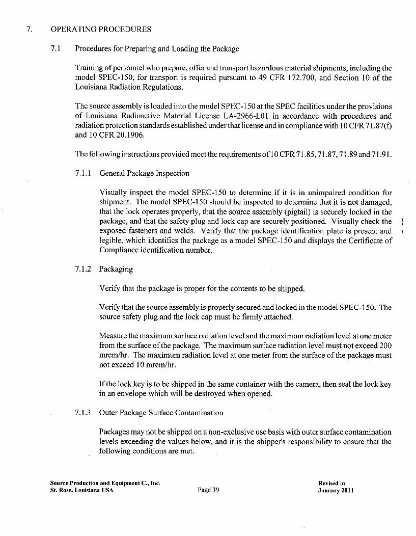
7. OPERATING PROCEDURES
7.1 Procedures for Preparing and Loading the Package
Training of personnel who prepare, offer and transport hazardous material shipments, including themodel SPEC-150, for transport is required pursuant to 49 CFR 172.700, and Section 10 of theLouisiana Radiation Regulations.
The source assembly is loaded into the model SPEC-i150 at the SPEC facilities under the provisionsof Louisiana Radioactive Material License LA-2966-LO1 in accordance with procedures andradiation protection standards established under that license and in compliance with 10 CFR 71.87(f)and 10 CFR 20.1906.
The following instructions provided meet the requirements of 10 CFR 71.85, 71.87, 71.89 and 71.91.
7.1.1 General Package Inspection
Visually inspect the model SPEC-150 to determine if it is in unimpaired condition forshipment. The model SPEC-150 should be inspected to determine that it is not damaged,that the lock operates properly, that the source assembly (pigtail) is securely locked in thepackage, and that the safety plug and lock cap are securely positioned. Visually check theexposed fasteners and welds. Verify that the package identification plate is present andlegible, which identifies the package as a model SPEC- 150 and displays the Certificate ofCompliance identification number.
7.1.2 Packaging
Verify that the package is proper for the contents to be shipped.
Verify that the source assembly is properly secured and locked in the model SPEC-i150. Thesource safety plug and the lock cap must be firmly attached.
Measure the maximum surface radiation level and the maximum radiation level at one meterfrom the surface of the package. The maximum surface radiation level must not exceed 200mrem/hr. The maximum radiation level at one meter from the surface of the package mustnot exceed 10 mrem/hr.
If the lock key is to be shipped in the same container with the camera, then seal the lock keyin an envelope which will be destroyed when opened.
7.1.3 Outer Package Surface Contamination
Packages may not be shipped on a non-exclusive use basis with outer surface contaminationlevels exceeding the values below, and it is the shipper's responsibility to ensure that thefollowing conditions are met.
Source Production and Equipment C., Inc. Revised inSt. Rose, Louisiana USA Page 39 January 2011

package construction inspection tests pursuant to the quality assurance program under NRCCertificate of Compliance No. 0102 and inspection prior to shipment to a customer. In mostinstances when the package is shipped to a customer it contains a radioactive source assembly.
8.1.1 Visual Inspection
Each packaging is visually inspected as part of the quality assurance final package inspection afterconstruction, which includes quality of workmanship, adherence to production specifications anddrawings, presence of attached identification plates and warnings, and presence of components, suchas source safety plug and lock cap. The final inspection must ensure that the package conforms tothe drawings specified in the Certificate of Compliance.
Each source assembly is visually inspected after fabrication.
Prior to shipment the package is again visually inspected to assure that the source assembly isproperly contained in the packaging, and the shipment is properly marked and labeled for shipment.
8.1.2 Structural and Pressure Tests
Although structural acceptance tests on the model SPEC- 150 are not indicated because of the ruggeddesign and durable materials of construction any structural failure would be apparent, a liquidpenetrant test is performed during fabrication on important to safety weld joints. See drawing15B002A which depicts specific inspection method used for specific SPEC-150 welds. Visualinspection is performed on the welded joints that connect the inner bulkhead plate to the bottomplate, the inner bulkhead support cup to the inner bulkhead, and the outlet end plate support cup tothe outlet end plate and bottom plate. Both visual and liquid penetrant inspection is performed onthejoints that comprise the basic structure of the package which consists of the housing cover (shell),bottom plate and both end plates.
Visual and Liquid Penetrant inspections are performed in accordance with the ASME Code forBoilers and Pressure Vessels, Section VIII, Division 1.
Pressure tests are not indicated because there is no possibility of a pressure build up which wouldaffect the structure of the containment or the integrity of
Source Production and Equipment C., Inc. Page 73 Revised inSt. Rose, Louisiana USA January 2011

Appendix D: Materials of Construction

Grade 2 Titanium Components Standards
ASME ASTM
SB-265 B 265
SB-337 B 337
SB-338 B 338
SB-348 B 348
SB-381 B 381
SB-861 B 861
SB-862 B 862
Tungsten Components Standard:
ASTM B 777
Safety Plug
Cable: Manufactured to RR-W-410
Tip: Stainless steel per 300 seriesstandards listed in right columns
300 Series Stainless Steel Standards
ASME ASTM
SA213 A213
SA 240 A 240
SA 249 A 249
SA 269 A 269
SA 270 A 270
SA 271 A 271
SA 276 A 276
SA 312 A 312
SA 336 A 336
SA 358 A 358
SA 376 A 376
SA 409 A 409
SA 473 A 473
SA 479 A 479
SA 480 A 480
SA 484 A 484
SA 554 A 554
SA 581 A 581
SA 582 A 582
SA 666 A 666
SA 688 A 688
Quick Disconnect Coupling Specifications (component of safety plug)
Snap - Tite brand stainless steel quick disconnect, catalog number SPHC6-6F
Hofmann brand stainless steel quick disconnect, catalog number HHS3-S6
Dixon or Perfecting brand stainless steel quick disconnect, catalog number 3VF3-SS-E
Hydrason brand stainless steel quick disconnect, catalog number 0026012120
SPEC manufactured stainless steel quick disconnect

Appendix E:John Munro Report
Shielding of the SPEC-150 with 75Selenium and '69Ytterbium

Report
By: John J. Munro III
Date: 31 December 2010
Subject Shielding of the SPEC-150 with 75Selenium and '69Ytterbium
We present the following report to demonstrate the shielding efficiency of the SPEC-1 50 RadiographicExposure Device/Type B(U) Container, when containing up to 150 Ci of either 75Selenium or '69Ytterbium,satisfies the regulatory requirements.
The SPEC-150 locates the sources approximately 68 mm (2.68 inches) from the surface of the container.The uranium thickness in the least-shielded direction is 48 mm (1.91 in).
The radiation exposure rate on the surface of the container is calculated from:
The exposure rate at a point in space is expressed as:
FAS= [1]
where: F: Specific Exposure Rate ConstantA: Activity of the Source (150 Ci)r: Distance from the source to the point of interest:
(i.e. Surface of the Container: 0.068 m;One meter from the Surface: 1.068 m)
The Broad Beam transmission of photons through a material can be expressed as:
= - = B(E,-x(e [2]
I0
where: j Transmission FactorI: Exposure Rate in the presence of shielding1o: Exposure Rate in the absence of shieldingB(E): Exposure Build-Up Factor/lp(E). Mass Absorption CoefficientP. Density of the shielding materialx: Thickness of the shielding material along the beam pathE: Energy of the photon
The values of B(E) and ulp(E) are photon energy-dependent. The resultant transmission for all of the
photons emitted by the radionuclide, r, is therefore calculated from the relationship:
r (JB(E, x)i e[3]
where: f(E)%: Fraction of exposure rate due to photons of energy Ei: Represents the i th photon
113 Teal Street, St. Rose, LA 70087-9591Tel: 978.340.0156; Fax: 978.687.1971; e-mail: [email protected]

75Selenium
We applied this method to the transmission of 7 5Selenium photons through uranium.
The 75Selenium exposure rate constant was taken as 200 mR m2 h-1 Ci1 , as presented in the 1970Radiological Health Handbook, presented by Weeks et al.', and referenced in USNRC-issued Certificatesof Compliance for Radioactive Material Packages USA/9296/B(U)-96 and USN9269/B(U)-96.
The 75Selenium spectrum consists of 20 photons with energies above 15 keV.' The mass attenuationcoefficient for uranium for each of these photon energies was interpolated from the values presented byNIST."' Exposure Buildup values were interpolated from data for Uranium presented in ANS/ANSI-6.4.3-1991.iv
The resultant calculated transmission for photons of 75Selenium through 48 mm of uranium is.
Using Eq. 1 and the minimum shielding of the SPEC-150, (i.e. 48 mm):
At Surface At 1 meterI from Surface
Calculated (48 mm Uranium) 0.012 mR/hr 4.8 x 10-•I { mR/hr
This result is less than 0.006% of the regulatory limit for the surface of the container and less than0.0005% of the regulatory limit at one meter from the surface.
We also repeated this calculation using extreme assumptions:
" the mass attenuation coefficients 20% less than the values used above" the exposure buildup factors were 2X the values used above* the Specific Gamma Ray Exposure Constant (1) was 5X the value used above
Under these extreme assumptions, the resultant exposure rates would be:
Under Extreme Assumptions I At Surface At 1 meterfrom Surface
Calculated (48 mm Uranium) 1.2 mR/hr 0.005 mR/hr
This result is less than 0.6% of the regulatory limit for the surface of the container and less than 0.05% ofthe regulatory limit at one meter from the surface.
Clearly, the SPEC-150 shielding is capable of containing 150 Ci of 75Selenium and maintaining theradiation levels surrounding the package within the regulatory limits.
169Ytterbium
We applied this same method to the transmission of '69Ytterbium photons through uranium.
The 169Ytterbium exposure rate constant was taken as 180 mR m2 h-1 CF', as presented by Mason et al.v
The 169Ytterbium spectrum consists of 78 photons with energies above 15 keV.2 The mass attenuationcoefficients for uranium for each photon energy were interpolated from the values presented by NIST.3Exposure Buildup values were interpolated from data for Uranium presented in ANS/ANSI-6.4.3-1 991.4
The resultant calculated transmission for photons of 75Selenium through 48 mm of uranium is.
2

Using Eq. 1 and the minimum shielding of the SPEC-150, (i.e. 48 mm):
At Surface At 1 meter1 from Surface
Calculated (48 mm Uranium) 1 0.012 mR/hr 5.0 x 10VI mR/hr
This result is less than 0.006% of the regulatory limit for the surface of the container and less than0.0005% of the regulatory limit at one meter from the surface.
We also repeated this calculation using extreme assumptions:
* the mass attenuation coefficients 20% less than the values used above* the exposure buildup factors were 2X the values used above* the Specific Gamma Ray Exposure Constant (I) was 5X the value used above
Under these extreme assumptions, the resultant exposure rates would be:
Under Extreme Assumptions ( At Surface At 1 meterfrom Surface
Calculated (48 mm Uranium) 1.1 mR/hr 0.004 mR/hr
This result is 0.53% of the regulatory limit for the surface of the container and 0.04% of the regulatory limitat one meter from the surface.
Clearly, the SPEC-150 shielding is capable of containing 150 Ci of 16Ytterbium and maintaining theradiation levels surrounding the package within the regulatory limits.
Conclusion
The shielding afforded by the SPEC-1 50 is sufficient to contain up to 150 Ci of either 75Selenium or16Ytterbium. The SPEC 150 adequately provides sufficient shielding to meet the regulatoryrequirements. Even under the extreme assumptions that
, the mass attenuation coefficients are 20% less than the values used in our original calculation* the exposure buildup factors were 2X the values used in our original calculation* the Specific Gamma Ray Exposure Constant (1) was 5X the value used in our original calculation
the resultant exposure rates would be well less than 1% of the regulatory limit.
Weeks KJ, Schulz RJ, Selenium-75: a potential source for use in high-activity brachytherapy irradiators, Med
Phys. 1986 Sep-Oct;13(5):728-31.
htto:I/Alww.nndc.bnl.qov/lnudat2/indx dec.isp
Hubbell JH and Seltzer SM, Tables of X-Ray Mass Attenuation Coefficients and Mass Energy-AbsorptionCoefficients from 1 keV to 20 MeV for Elements Z = 1 to 92 and 48 Additional Substances of Dosimetric Interest,http:/lwww.phvsics.nist.oov/PhvsRefData/XrayMassCoef/cover.html
iv Trubey DK et al., Gamma-Ray Attenuation Coefficients and Buildup Factors for Engineering Materials,ANSI/ANS-6.4.3-1991
V Mason DL, Battista JJ, Barnett RB, Porter AT, Ytterbium-1 69: calculated physical properties of a new radiationsource for brachytherapy, Med Phys. 1992 May-Jun;1 9(3):695-703.
3
Related Documents