T30A / T60A Tape Library LL030F/LL060F User ’ s Guide Rev.7 <T30A> <T60A> -This User's Guide provides information to use the unit safely and correctly and to avoid a personal injury and/or a damage to the customer's properties. Thoroughly read this manual to fully understand handling of the unit. -Keep this User's Guide with the unit to see whenever it is necessary. -Make sure to provide this User's Guide along with the unit to a third party. 856-129409-160-A

Welcome message from author
This document is posted to help you gain knowledge. Please leave a comment to let me know what you think about it! Share it to your friends and learn new things together.
Transcript

T30A / T60A Tape Library
LL030F/LL060F
User’s Guide
Rev.7
<T30A> <T60A>
-This User's Guide provides information to use the unit safely and correctly and to avoid a
personal injury and/or a damage to the customer's properties. Thoroughly read this manual to
fully understand handling of the unit.
-Keep this User's Guide with the unit to see whenever it is necessary.
-Make sure to provide this User's Guide along with the unit to a third party.
856-129409-160-A

-i-
Handling of laser product When the Fibre Chanel drive is installed, class 1 laser product is used in this product.
1 Klassenlaserprodukt wird zu der Zeit des Einsatzes von einem Fibre Chanel-Antrieb mit diesem Produkt
benutzt.
Japanese acceptance statement
Chinese acceptance statement
Taiwan acceptance statement
WEEE Disposing of your used NEC product
In the European Union
EU-wide legislation as implemented in each Member State requires that used
electrical and electronic products carrying the mark (left) must be disposed of
separately from normal household waste. This includes tape library or electrical
components, such as tape drive, AC power supply.
When you dispose of such products, please follow the guidance of your local
authority or ask the shop where you purchased the product, or if applicable,
follow applicable legislation or agreement you may have.The mark on electrical
and electronic products may only apply to the current Europian Union Menber
States.
Outside the European Union
If you wish to dispose of used electrical and electronic products outside the
European Union, please contact your local authority and ask for the correct
method of disposal.
-ii-
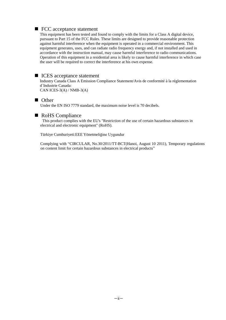
FCC acceptance statement This equipment has been tested and found to comply with the limits for a Class A digital device,
pursuant to Part 15 of the FCC Rules. These limits are designed to provide reasonable protection
against harmful interference when the equipment is operated in a commercial environment. This
equipment generates, uses, and can radiate radio frequency energy and, if not installed and used in
accordance with the instruction manual, may cause harmful interference to radio communications.
Operation of this equipment in a residential area is likely to cause harmful interference in which case
the user will be required to correct the interference at his own expense.
ICES acceptance statement Industry Canada Class A Emission Compliance Statement/Avis de conformité à la réglementation
d`Industrie Canada:
CAN ICES-3(A) / NMB-3(A)
Other Under the EN ISO 7779 standard, the maximum noise level is 70 decibels.
RoHS Compliance This product complies with the EU's "Restriction of the use of certain hazardous substances in
electrical and electronic equipment" (RoHS).
Türkiye Cumhuriyeti:EEE Yönetmeliğine Uygundur
Complying with “CIRCULAR, No.30/2011/TT-BCT(Hanoi, August 10 2011), Temporary regulations
on content limit for certain hazardous substances in electrical products”

-iii-
Safety Precautions
Before use, In order to use the product safely and correctly, be sure to read over this book, please handle it
properly.
This product has been designed with sufficient safety. In case of improper use of this product, the operator
may be injured and damage to property may result. After reading this manual, store it for future reference if
necessary.
Follow the instructions in this Guide for your safety to use the product.
The product contains components with possible danger, hazards that may cause by ignoring warnings, and
preventive actions against such hazards.
This product contains components with potential hazards, which are marked with a warning label placed on
or arount those components
In this Guide or warning labels, "WARNING" or "CAUTION" is used to indicate a degree of danger. These
terms are defined as follows:
Indicates the presence of a hazard that may result in death or serious
personal injury if the instruction is ignored.
Indicates the presence of a hazard that may cause minor personal injury,
including burns, or property damage if the instruction is ignored.
Precautions and notices against hazards are presented with one of the following three symbols. The
individual symbols are defined as follows:
SYMBOL MEAN
This symbol indicates the presence of a hazard if the instruction is ignored. An image in
the symbol illustrates the hazard type. (Attention)
This symbol indicates prohibited actions. An image in the symbol illustrates a particular
prohibited action. (Prohibited Action)
This symbol indicates mandatory actions. An image in the symbol illustrates a mandatory
action to avoid a particular hazard. (Mandatory Action)

-iv-
(Example)
Disconnect the power cord(s) before installing or removing the product. Make sure to power off the product and disconnect the power cord(s) from a power outlet
before installing/removing the server. All voltage is removed only when the power cords
are unplugged.
Attentions
Indicates that improper use may
cause an electric shock.
Indicates that improper use may
cause fingers to be caught.
Indicates that improper use may
cause personal injury.
Indicates that improper use may
cause personal injury.
Indicates that improper use may
cause explosion or burst.
Indicates that improper use may
cause fingers or hands to be
caught.
Indicates that improper use may
cause fumes or fire.
Indicates that improper use may
cause eye damage.
Prohibited Actions
Do not disassemble, repair, or
modify the server. Otherwise, an
electric shock or a fire may be
caused.
Do not touch the server
components with wet hand.
Otherwise, an electric shock may
be caused.
Do not touch any other component
than specified. Otherwise, an
electric shock or burn may be
caused.
Keep water or liquid away from
the server. Otherwise, an electric
shock or a fire may be caused.
Do not place the server near a fire.
Otherwise, a fire may be caused.
Indicates a general prohibited
action that cannot be specifically
identified.
Mandatory Action
Unplug the power cord of the
server. Otherwise, an electric shock
or a fire may be caused.
Indicates a mandatory action that
cannot be specifically identified.
Make sure to follow the
instruction.
Be sure to provide earthing.
Otherwise, an electric shock or a
fire may be caused.
Symbol indicating a prohibited action (may not always be
indicated)
Description of a danger
Symbol to draw attention Term indicating a degree of danger
-v-
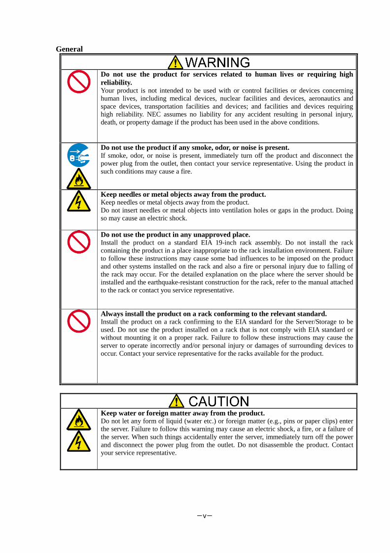
General
Do not use the product for services related to human lives or requiring high
reliability. Your product is not intended to be used with or control facilities or devices concerning
human lives, including medical devices, nuclear facilities and devices, aeronautics and
space devices, transportation facilities and devices; and facilities and devices requiring
high reliability. NEC assumes no liability for any accident resulting in personal injury,
death, or property damage if the product has been used in the above conditions.
Do not use the product if any smoke, odor, or noise is present. If smoke, odor, or noise is present, immediately turn off the product and disconnect the
power plug from the outlet, then contact your service representative. Using the product in
such conditions may cause a fire.
Keep needles or metal objects away from the product. Keep needles or metal objects away from the product.
Do not insert needles or metal objects into ventilation holes or gaps in the product. Doing
so may cause an electric shock.
Do not use the product in any unapproved place. Install the product on a standard EIA 19-inch rack assembly. Do not install the rack
containing the product in a place inappropriate to the rack installation environment. Failure
to follow these instructions may cause some bad influences to be imposed on the product
and other systems installed on the rack and also a fire or personal injury due to falling of
the rack may occur. For the detailed explanation on the place where the server should be
installed and the earthquake-resistant construction for the rack, refer to the manual attached
to the rack or contact you service representative.
Always install the product on a rack conforming to the relevant standard. Install the product on a rack confirming to the EIA standard for the Server/Storage to be
used. Do not use the product installed on a rack that is not comply with EIA standard or
without mounting it on a proper rack. Failure to follow these instructions may cause the
server to operate incorrectly and/or personal injury or damages of surrounding devices to
occur. Contact your service representative for the racks available for the product.
Keep water or foreign matter away from the product. Do not let any form of liquid (water etc.) or foreign matter (e.g., pins or paper clips) enter
the server. Failure to follow this warning may cause an electric shock, a fire, or a failure of
the server. When such things accidentally enter the server, immediately turn off the power
and disconnect the power plug from the outlet. Do not disassemble the product. Contact
your service representative.

-vi-
Rack
Do not overload the supply circuit by connecting this equipment with other
equipment so that the total exceeds the outlet rating. To prevent fires, wiring and device damage, the total power drawn by the equipment in
the rack shall not exceed the rating of the branch circuit. Contact your electric constructor
or the local power company for the requirements on the wiring and installation of electric
facilities.
Do not carry or install the product only by a single person. More than one person is required to carry or install the rack. Failure to follow this
instruction may cause the rack to fall to result in personal injury and/or breakages of
surrounding devices. In particular, a high rack (such as 44U rack) is unstable if it is not
fixed by stabilizers. More than one person is required to hold the rack to carry and install
the product.
Do not install the product so that the load may be concentrated on a specific
point. Install stabilizers on the rack or connect more than one rack with each other to distribute
the load to avoid the weight is concentrated on one spot. Failure to follow this instruction
may cause the rack to fall to result in personal injury.
Do not install components on the product only by a single person. More than one person is required to install parts including the doors and trays for the rack.
Failure to follow this instruction may cause some parts to fall to be broken and/or to result
in personal injury.
Anchor the equipment rack. The equipment rack must be anchored (putting stabilizers or providing seismic protection)
to an unmovable support to prevent it from falling over when the product is removed from
the rack. The anchors must be able to withstand a force of up to 113kg (250lbs.) You must
also consider the weight of any other device installed in the rack.
Do not pull more than one device out of the rack at the same time. Pulling out more than one device from the rack may cause the rack to be fallen. Only pull
out a single device from the rack at a time.
-vii-
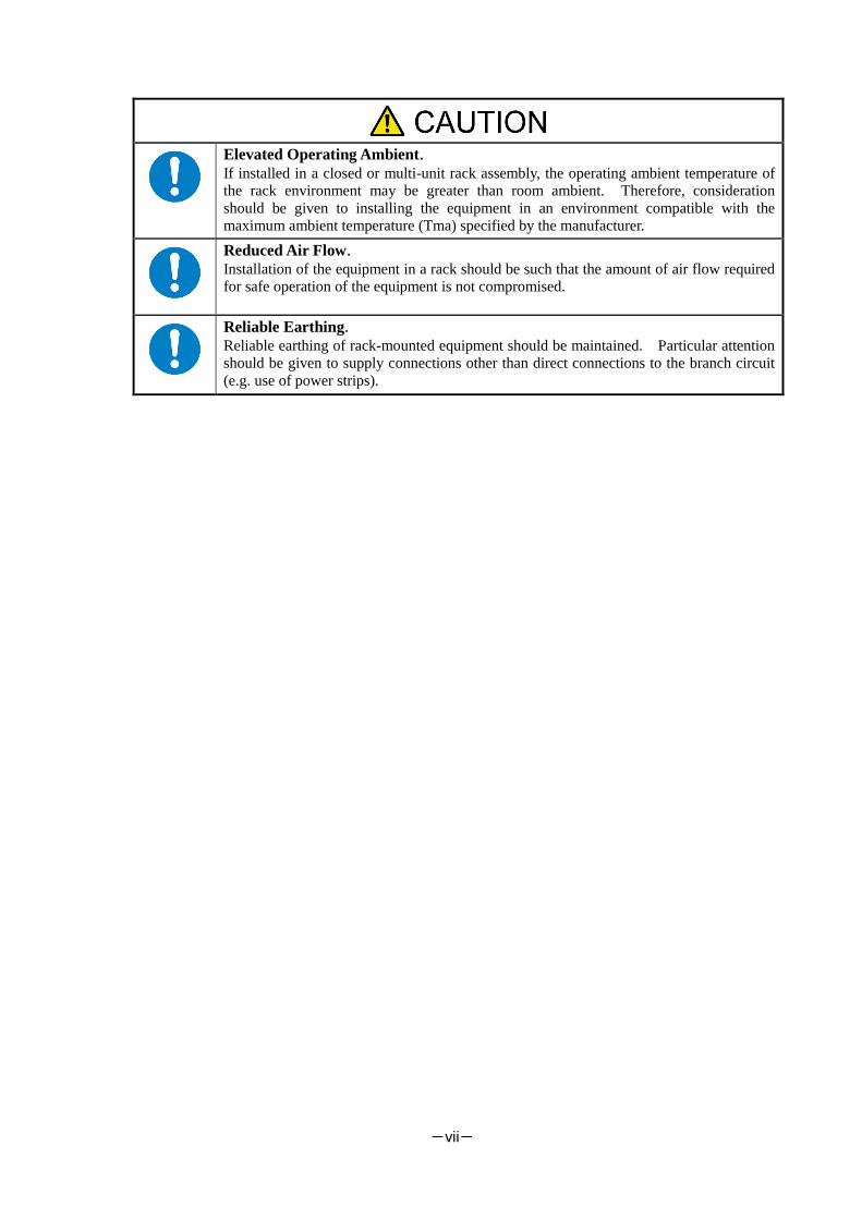
Elevated Operating Ambient.
If installed in a closed or multi-unit rack assembly, the operating ambient temperature of
the rack environment may be greater than room ambient. Therefore, consideration
should be given to installing the equipment in an environment compatible with the
maximum ambient temperature (Tma) specified by the manufacturer.
Reduced Air Flow.
Installation of the equipment in a rack should be such that the amount of air flow required
for safe operation of the equipment is not compromised.
Reliable Earthing.
Reliable earthing of rack-mounted equipment should be maintained. Particular attention
should be given to supply connections other than direct connections to the branch circuit
(e.g. use of power strips).

-viii-
Power Supply and Power Cord Use
Do not hold the power plug with a wet hand. Do not disconnect/connect the plug while your hands are wet. Failure to follow this
warning may cause an electric shock.
Do not connect the ground wire to a gas pipe. Never connect the ground wire to a gas pipe. Failure to follow this warning may cause a
gas explosion.
If you disconnect the power, disconnect the two power lines. The product might be powered from 2 AC power lines. If you disconnect the power from
the device, both 2 power sources must be disconnected. It may cause an electric shock if
the power is not disconnected properly.
Plug in to a proper power source. Use a proper wall outlet. Use of an improper power source may cause a fire or a power
leak. Do not install the product where you need an extension cord. Use of a cord that does
not meet the power specifications of the product may heat up the cord and cause a fire.
Do not connect the power cord to an outlet that has an illegal number of
connections. The electric current exceeding the rated flow overheats the outlet, which may cause a fire.
Insert the power plug into the outlet as far as it goes. Heat generation resulting from a halfway inserted power plug (imperfect contact) may
cause a fire. Heat will also be generated if condensation is formed on dusty blades of the
halfway inserted plug, increasing the possibility of fire.
Do not use the attached power cord for any other devices or usage. The power cord that comes with your product is designed aiming to connect with this
product and to use with the product, and its safety has been tested. Do not use the attached
power cord for any other purpose. Doing so may cause a fire or an electric shock.

-ix-
Use the authorized power cord only. Use only the power cord that comes with your product. Use of an unauthorized power
cord may cause a fire when the electric current exceeds the rated flow. Also, observe the
following to prevent an electric shock or a fire caused by a damaged cord.
・Do not stretch the cord harness.
・Do not pinch the power cord.
・Do not bend the power cord.
・Keep chemicals away from the power cord.
・Do not twist the power cord.
・Do not place any object on the power cord.
・Do not step on the power cord.
・Do not alter, modify, or repair the power cord.
・Do not bundle the power cords.
・Do not secure the power cord with staples or equivalents.
・Do not use any damaged power cord.
(Replace a damaged power cord with a new one of the same specifications. Ask your
service representative for replacement.)

-x-
Installation, Relocation, Storage, and Connection
Do not use or store this product in corrosive environment. Avoid the usage or storage of this product in an environment which may be exposed to
corrosive gases, such as those including but not limited to: sulfur dioxide, hydrogen
sulfide, nitrogen dioxide, chlorine, ammonia and/or ozone. Avoid installing this product
in a dusty environment or one that may be exposed to corrosive materials such as sodium
chloride and/or sulfur. Avoid installing this product in an environment which may have
excessive metal flakes or conductive particles in the air. Such environments may cause
corrosion or short circuits within this product, resulting in not only damage to this
product, but may even lead to be a fire hazard. If there are any concerns regarding the
environment at the planned site of installation or storage, please contact your sales agent.
Do not install the product in any place other than specified. Do not install the product in the following places or any place other than specified in this
Guide. Failure to follow this instruction may cause a fire.
・a dusty place
・a humid place such as near a boiler
・a place exposed to direct sunlight
・an unstable place
Do not install the parts other than specified. Do not install third-party products or options on the device. Operation is no longer
successful, and may cause fire or malfunction.
Do not block the intake and exhaust holes. Do not block air intake holes at the front or back of the product. Internal temperature rises
may cause malfunction and doing so may cause a fire.
Do not use any unauthorized interface cable. Use only interface cables provided by NEC and locate a proper device and connector
before connecting a cable. Using an unauthorized cable or connecting the product to an
improper destination may result in a fire by short circuit. Also, observe the following
notes on using and connecting an interface cable.
・Do not step on the cable.
・Do not place any object on the cable.
・Do not use the device with loose cable connections.
・Do not use any damaged cable connector.
・Lock the cable certainly by the attachments such as screws.
Treat SAS cables with care and respect. Rough treatment of SAS cables could cause deterioration of characteristics or mechanical
damage (line disconnection).
・Ensure a minimum bending radius of 150mm.
・Make sufficient allowance for the cable forming.
・Do not forcibly stretch a cable or otherwise stress it.

-xi-
Treat optical fiber cables with care and respect. Rough treatment of optical fiber cables could cause deterioration of characteristics or
mechanical damage (line disconnection).
・Ensure a minimum bending radius of 38mm.
・Do not drop a cable on the floor or otherwise shock it.
・If not connecting a cable, place caps on it. When connecting a cable, do not discard the
caps but save them (as well as those for connectors on the unit).
As the optical power is attenuated by dust or dirt and it may cause data error, be sure to
clean the optical connector using the following procedure when optical fibre cable is
inserted to the product:
1. Spray air or another parts cleaning gas on the optical connector for several seconds.
2. Wipe the optical connector lightly several times with a non-fibrous cloth wetted with
isopropyl alcohol.
3. Spray parts cleaning gas on the optical connector for several seconds again.
Be careful when handling the laser products. The product contains class-1 laser products based on JIS C6802, EN60825-1 (+A-11), and
21 CFR 1040.10 and 1040.11 issued by the U.S. Food and Drug Association (FDA).
Do not look straight at the optical fiber cable, optical fiber connector, or laser transceiver
module because there is a risk of eye damage, depending on the laser power level.
Note that JIS C6802, EN60825, and IEC60825 defines class-1 laser as the level of laser
which causes no injury if human is exposed to it.
Prevent damage from electrostatic discharge. Components in the device is sensitive to static electricity. Even a slight discharge, could
damage the electrical components in the device. Even if a component receives damage, an
error may not occur immediately, but the state is aggravated and is causing a
"intermittent" problem gradually.
Before touching the product, touch an unpainted metal surface. It is effective to use
commercially available anti-static wrist strap with a clip terminal.
・If the frame of the device is metal, touch the frame.
・Otherwise, touch the wall part of the product or a screw of the door frame.
・Stay as still as possible when touching the components inside the product to avoid
produce static electricity.
Do not pinch your finger with rails or other components. Be careful sufficiently not to pinch or cut your fingers with the rails etc. when you
mount/unmount the product on the rack.
Do not apply any load on the device pulled out from the rack. Do not apply any load on the device pulled out from the rack. Doing so bends the frame of
the device. Consequently, the device cannot be pushed back into the rack. Placing an
object on the device may also cause personal injury if the device drops.
Relocation of the product. Consult with your service representative for relocation of the product.
Disposal of the product. The product contains liquid crystal display (LCD). Consult with your service
representative before disposing of the product. Dispose of the unit according to the
ordinance of the local government.

-xii-
Cleaning and Working with Internal Devices
Do not disassemble, repair, or alter the product. Never attempt to disassemble, repair, or alter the product on any occasion. Failure to
follow this instruction may cause an electric shock or fire as well as malfunctions of the
server.
Disconnect the power plug before cleaning the product. Make sure to power off and disconnect the power plug from a power outlet before
cleaning product. Touching any internal components of the product with its power cord
connected to a power source may cause electric shock even if the product’s power is
offline. Disconnect the power plug from the outlet occasionally and clean the plug with a
dry cloth. Heat will be generated if condensation is formed on a dusty plug, which may
cause a fire.
Avoid installation in extreme temperature conditions. Immediately after the device is powered off, its internal components are very hot. Please
work after confirming the product was cooled enough.
Make sure to complete installation. Install power cords and interface cables surely.
Improper installation of the cords and cables may cause a contact failure, resulting in
smoking or fire.
Handling of damaged LCD (liquid crystal display) The product uses the liquid crystal display that contains harmful liquid to the human body.
If you need to touch the damaged LCD, take extreme care not to touch the liquid inside
the display. If the liquid enters your mouth, immediately gargle and consult with your
doctor. If the liquid adheres your skin or eyes, rinse it for at least 15 minutes, and then
consult with your doctor.
Ask your service representative for repair of the LCD.

-xiii-
During Operation
Do not use the product if any smoke, odor, or noise is present. If smoke, odor, or noise is present, immediately turn off the product and disconnect the
power plug from the outlet, then contact your service representative. Using the product in
such conditions may cause a fire.
Do not put hand inside the device. Do not put your hand inside the device. There is a possibility of injury by pinching your
hands with the internal components..
Stay away from the fan. Keep your hand or hair away from the cooling fan on the rear of the product. Failure to
follow this warning may get your hand or hair caught in the fan, resulting in injury.
Avoid contact with the product during thunderstorms. If it starts thundering before you disconnect the power plug, do not touch any part of the
product including the cables. Failure to follow this warning may cause an electric shock
by the thunderbolt.
Do not peep into device when magazine operations. The part of the magazine has a mechanism to automatically open.
If you are peeping into the device during magazine operations, it may be injured part of
the magazine hit the face.
Do not put the finger in the opening of the magazine while operating the I/O
station. The I/O station dashes out to a device front side after pressing the enter button. Please
there must not be danger from which the hand is placed between the moving part, and do
not affix the hand to the magazine, and do not put the finger in the opening of the
magazine until the I/O station dashes out. Please push the magazine a little when the
finger is placed in the opening of the magazine by any chance and pull out the finger
while returning it.
Keep any animal (Pet) away from the product. Keep any animal (Pet) away from the product. Pet’s discharges or fur may enter the
device and cause a fire or electric shock.
To avoid incommoding reflections at visual display workplaces this device must
not be placed in the direct field of view. This device is not intended for use in the direct field of view at visual display workplaces.
To avoid incommoding reflections at visual display workplaces this device must not be
placed in the direct field of view.

-xiv-
Warning Labels The following warning labels have been attached to this unit. Customers and maintenance service personnel
are urged to keep these warnings in the forefront of their minds when operating this unit. (Do not remove or
soil these labels.)
If any of these labels are missing, removed, soiled, or otherwise unreadable, contact your local maintenance
service company.
Warning Label Meaning / Location
T30A
T60A
[Do not disassemble]
Only the maintenance
Personnelcan disassemble
the unit.
[Heavy load]
To avoid personal injury, at
least three persons must
carry the unit.
[Do not put the thing on]
Do not put the thing on the
device.
[Do not put on length.]
Do not put the device on
length.
Location: Top plate of the
unit
T60A
[Redundant power supply
use]
Location: back of device
T30A/T60A
[Attention that rolls hand and
finger]
Location:Drive

-xv-
The mark of this manual
The following signs are used in this manual.
Kind of display
Kind Content
It explains the content for which attention is especially necessary in
operating.
It explains information on the limitations in the operation.
It explains amplification of the text.

-xvi-
Contents
Handling of laser product .................................................................................................... i Japanese acceptance statement ............................................................................................. i Chinese acceptance statement .............................................................................................. i Taiwan acceptance statement ............................................................................................... i WEEE ................................................................................................................................ i FCC acceptance statement .................................................................................................. ii ICES acceptance statement ................................................................................................. ii Other ................................................................................................................................ ii RoHS Compliance ............................................................................................................. ii Warning Labels ............................................................................................................... xiv The mark of this manual ................................................................................................... xv
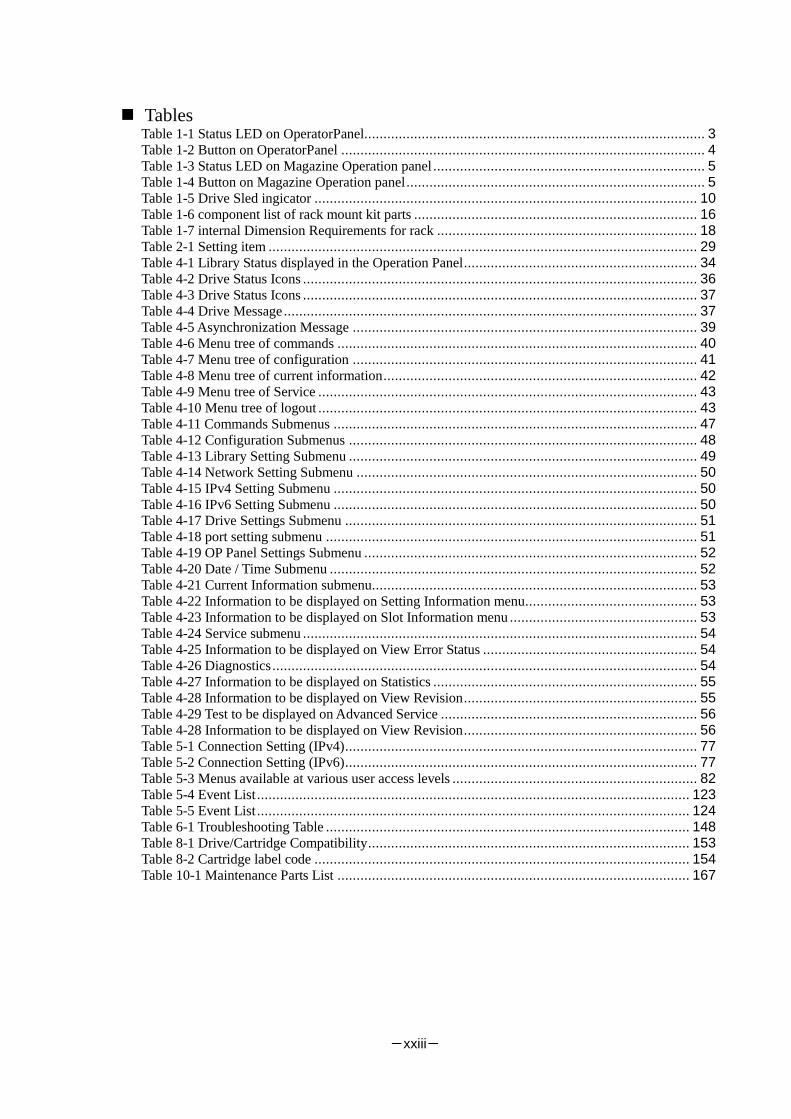
Contents ....................................................................................................................................... xvi Figures ........................................................................................................................... xxi Tables .......................................................................................................................... xxiii
Preface ....................................................................................................................................... xxiv Remarks ....................................................................................................................... xxiv Exemptions ................................................................................................................... xxv Use Limitation ............................................................................................................... xxv
Chapter1 General Description ...................................................................................................... 1 1.1 Handling Precautions ................................................................................................................. 1
1.1.1 Notes on Use ....................................................................................................................... 1 1.2 Transfer of Library ..................................................................................................................... 1 1.3 Names and Features of Components ............................................................................................ 2
1.3.1 Front View .......................................................................................................................... 2 1.3.2 Operator panel ..................................................................................................................... 3
1.3.2.1 Status LED .................................................................................................................... 3 1.3.2.2 LCD .............................................................................................................................. 4 1.3.2.3 Button ........................................................................................................................... 4
1.3.3 Magazine operation panel ..................................................................................................... 5 1.3.3.1 Magazine Status LED ..................................................................................................... 5 1.3.3.2 Button ........................................................................................................................... 5 1.3.3.3 Ethernet connector for maintenance ................................................................................. 6
1.3.4 Magazine ............................................................................................................................ 7 1.3.4.1 Slot number ................................................................................................................... 7 1.3.4.2 Active Slot ..................................................................................................................... 8 1.3.4.3 I/O station ...................................................................................................................... 8 1.3.4.4 Escape slot ..................................................................................................................... 8 1.3.4.5 Cleaning Slot ................................................................................................................. 8 1.3.4.6 Inactive slot ................................................................................................................... 8
1.3.5 Rear View ........................................................................................................................... 9 1.3.6 Drive Sled Ingicator ........................................................................................................... 10 1.3.7 Power Module LED ............................................................................................................ 11
1.4 Encryption ............................................................................................................................... 12 1.5 Disposal of the Product and Comsumables ................................................................................. 13 1.6 Unpacking ............................................................................................................................... 14
1.6.1 Unpacking ........................................................................................................................ 14 1.7 Installing the Rack Mounting Kit .............................................................................................. 16
1.7.1 Components ...................................................................................................................... 16 1.7.2 Caution points for rack mounting ........................................................................................ 17 1.7.3 Rack mount rail attachment position ................................................................................... 19 1.7.4 Attachment of Rack mount rail L/R..................................................................................... 20 1.7.5 Attachment of Rack mount bracket L/R ............................................................................... 21 1.7.6 Installation of library ......................................................................................................... 22 1.7.7 Attachment of Rack ear ...................................................................................................... 24

-xvii-
1.7.8 Attachment of label plate.................................................................................................... 25 1.8 Removal of shipment Stabilizer ................................................................................................. 26
Chapter2 Setup ......................................................................................................................... 27 2.1 Connection of a Interface Cable ................................................................................................ 27
2.1.1 Connection of SAS Cable ................................................................................................... 27 2.1.2 Connection of FC Cable ..................................................................................................... 28
2.2 Connection of AC Power Cable ................................................................................................ 29 2.3 Power-On and self test.............................................................................................................. 29 2.4 Setting Drive configuration ....................................................................................................... 29 2.5 Setting Library and Drive configuration ..................................................................................... 29 2.6 Diagnostic Test ........................................................................................................................ 30 2.7 Operation Checks after Installation ............................................................................................ 30
Chapter3 Power-On and Power-Off ............................................................................................ 31 3.1 Power-On and Power-On Sequence ........................................................................................... 31 3.2 Starting the System .................................................................................................................. 31 3.3 Shutting Down the System ........................................................................................................ 31 3.4 Power-Off and Power-Off Sequence .......................................................................................... 31
Chapter4 Operator Panel ........................................................................................................... 32 4.1 Panel Indications ...................................................................................................................... 32
4.1.1 Menu Screen ..................................................................................................................... 32 4.1.2 Status Display screen ......................................................................................................... 33
4.1.2.1 Library State ................................................................................................................ 33 4.1.2.2 Drive State ................................................................................................................... 37
4.1.3 Asynchronization message screen ....................................................................................... 39 4.2 Menu Tree ............................................................................................................................... 40 4.3 Login ...................................................................................................................................... 44
4.3.1 Service Login .................................................................................................................... 45 4.4 Top Menu ................................................................................................................................ 46
4.4.1 Commands ........................................................................................................................ 47 4.4.2 Configuration .................................................................................................................... 48
4.4.2.1 Library Settings ............................................................................................................ 49 4.4.2.2 Network Settings .......................................................................................................... 50 4.4.2.3 Drive Settings .............................................................................................................. 51 4.4.2.4 OP Panel Settings ......................................................................................................... 52 4.4.2.5 Date / Time .................................................................................................................. 52 4.4.2.6 Set Default ................................................................................................................... 52
4.4.3 Current Information ........................................................................................................... 53 4.4.3.1 Setting Information ....................................................................................................... 53 4.4.3.2 Slot Information ........................................................................................................... 53
4.4.4 Service .............................................................................................................................. 54 4.4.4.1 View Error Status ......................................................................................................... 54 4.4.4.2 Diagnostics .................................................................................................................. 54 4.4.4.3 Statistics ...................................................................................................................... 55 4.4.4.4 Telnet Service Port ....................................................................................................... 55 4.4.4.5 View Revision ............................................................................................................. 55 4.4.4.6 Drive Replacement ....................................................................................................... 55 4.4.4.7 Advanced Service ......................................................................................................... 56 4.4.4.8 Library Log ................................................................................................................. 56
4.4.5 Logout .............................................................................................................................. 56 4.5 Configuring the Library ............................................................................................................ 57
4.5.1 Viewing Configuration data of the library ............................................................................ 57 4.5.2 Change password ............................................................................................................... 57 4.5.3 Setting of Drive ................................................................................................................. 59
4.5.3.1 Setting of Serial Attached SCSI ..................................................................................... 59 4.5.3.2 Setting of Fibre Channel ............................................................................................... 60 4.5.3.3 Setting robot control path .............................................................................................. 61 4.5.3.4 Power Save Mode ........................................................................................................ 62
4.5.4 Switching between ONLINE and OFFLINE ........................................................................ 62 4.5.5 Setting of I/O Station ......................................................................................................... 63

-xviii-
4.5.6 Setting of Active Slot ......................................................................................................... 63 4.6 Insertion and Removing Cartridge by Operator Panel ................................................................. 64
4.6.1 Magazine Operations ......................................................................................................... 64 4.6.1.1 Removing Magazine ..................................................................................................... 64 4.6.1.2 Insertion of cartridges into magazine .............................................................................. 66 4.6.1.3 Removal of cartridges from magazine ............................................................................ 66 4.6.1.4 Emergency removal of magazine ................................................................................... 67
4.6.2 I/O Station Operations ....................................................................................................... 68 4.7 Using the operation panel to move cartridges ............................................................................. 69
4.7.1 Load cartridge into drive .................................................................................................... 69 4.7.2 Removing from the drive.................................................................................................... 71
4.8 Cleaning .................................................................................................................................. 73 4.8.1 Cleaning by Operation panel .............................................................................................. 73 4.8.2 Auto Cleaning ................................................................................................................... 73
4.9 Rebooting the Library .............................................................................................................. 74 4.10 Rebooting Drive ..................................................................................................................... 75
Chapter5 Remote Manager Interface .......................................................................................... 76 5.1 Connection Configuration ......................................................................................................... 76 5.2 Connection Settings ................................................................................................................. 77 5.3 Startup of Remote Manager Interface ........................................................................................ 78
5.3.1 Connection of https ............................................................................................................ 79 5.4 Login Formats ......................................................................................................................... 80 5.5 Web Page Configuration ........................................................................................................... 81 5.6 Web Page Detail ...................................................................................................................... 82
5.6.1 Menu windows .................................................................................................................. 82 5.6.2 Login ................................................................................................................................ 83 5.6.3 Library information viewing menu(Monitor Sytem) ............................................................. 84
5.6.3.1 Library Basic Information(System Summary) ................................................................. 84 5.6.3.2 Library Detailed Information Window (Library Map) ..................................................... 86
5.6.4 Library management menu (Manage Library) ...................................................................... 93 5.6.4.1 Move Cartridge window (Move Cartridge) ..................................................................... 93 5.6.4.2 Unload Drive window (Unload Drive) ........................................................................... 95 5.6.4.3 Clean Drive window (Clean Drive) ................................................................................ 96 5.6.4.4 Library State (OFFLINE/ONLINE)switching window(Library State) ............................... 97
5.6.5 Library setting (Configure Library) ..................................................................................... 98 5.6.5.1 Account setting (User Access) ....................................................................................... 98 5.6.5.2 Physical View (Physical) ............................................................................................ 101 5.6.5.3 Library setup window (Logical)................................................................................... 102 5.6.5.4 Network setup window (Network) ............................................................................... 105 5.6.5.5 Date and Time setup window (Date and Time) ............................................................. 107 5.6.5.6 Event Notification setup window(SMTP) ..................................................................... 108 5.6.5.7 Event Notifications setup window (SNMP) .................................................................. 109 5.6.5.8 Encryption Basis ......................................................................................................... 112 5.6.5.9 Encryption Detail ........................................................................................................ 113 5.6.5.10 Licenses Registration ................................................................................................. 114 5.6.5.11 Saving the File Setting / Restore Screen (Save and Restore) .......................................... 115
5.6.6 Library maintenance (Service Library) ............................................................................... 117 5.6.6.1 View Library Logs ...................................................................................................... 117 5.6.6.2 Download Library /Drive logs (Download Logs) ........................................................... 118 5.6.6.3 Reset (Reset Library / Drive) ........................................................................................ 119 5.6.6.4 Firmware Refresh Screen (Firmware Update) ............................................................... 120 5.6.6.5 Statistical Information (Usage Statistics) ...................................................................... 121 5.6.6.6 Web Shell (web shell) ................................................................................................. 122
5.7 Event list ............................................................................................................................... 123 Chapter6 Encryption Key Management Function ...................................................................... 125
6.1 General Information ............................................................................................................... 125 6.1.1 Features of Encryption Key Management Option ............................................................... 125 6.1.2 Encryption Mechanism .................................................................................................... 125 6.1.3 Types of Keys ................................................................................................................. 125

-xix-
6.1.3.1 Master Key ................................................................................................................ 126 6.1.3.2 Encryption Key .......................................................................................................... 127 6.1.3.3 Backup of encryption key ........................................................................................... 127
6.2 Basic Operation of encryption key management function .......................................................... 128 6.2.1 Setup .............................................................................................................................. 128
6.2.1.1 Registering the activation key ...................................................................................... 129 6.2.1.2 Checking the license key registration status .................................................................. 129 6.2.1.3 Enabling the encryption key management function ....................................................... 130 6.2.1.4 Registering (importing) the master key......................................................................... 131 6.2.1.5 Exporting (backing up) the master key ......................................................................... 133
6.2.2 Operation ........................................................................................................................ 134 6.2.2.1 To Create encrypted medium ....................................................................................... 134
6.2.3 Checking tape media Information ..................................................................................... 135 6.2.3.1 Sharing tape medium among multiple libraries ............................................................. 135
6.2.4 Maintenance .................................................................................................................... 135 6.2.4.1 Backup of Encryption Key (Basic Operation) ............................................................... 135 6.2.4.2 Executing Set Default ................................................................................................. 136 6.2.4.3 Checking the encryption log ........................................................................................ 136
6.3 Advance Operation of encryption key management function ..................................................... 137 6.3.1 Using LTO2 / LTO3 Tape Medium ................................................................................... 138 6.3.2 Enabling or Disableing Enctyption for Each tape medium................................................... 138
6.3.2.1 Setting tape medium encryption................................................................................... 139 6.3.2.2 Sharing tape medium among multiple libraries (advanced) ............................................ 140
6.3.3 Importing and Exporting the Encryption Key(For Each Tape Medium) ................................ 140 6.3.3.1 When to import the encryption key .............................................................................. 141 6.3.3.2 To import the encryption key ...................................................................................... 141 6.3.3.3 To export an encryption key ........................................................................................ 143
6.3.4 Disabling the Encryption Management Function for the Library .......................................... 144 6.3.5 Changing the Master Key ................................................................................................. 145 6.3.6 Backing Up and Restoring the KEY Database .................................................................... 145
6.3.6.1 Backing up the KEY database ..................................................................................... 146 6.3.6.2 Restoring the KEY database ........................................................................................ 146
6.3.7 Clearing encryption information ....................................................................................... 147 6.3.7.1 To clear encryption information................................................................................... 147
6.4 Points to Check When a Failure or Abnormality Occurs ............................................................ 148 6.5 FAQ about Encryption Key Management function ................................................................... 149 6.6 List of Encryption Event Log Messages ................................................................................... 150
Chapter7 Installation of Option ................................................................................................ 151 7.1 Install of drive ....................................................................................................................... 151 7.2 Install of power module .......................................................................................................... 151 7.3 Install of activation key .......................................................................................................... 152
Chapter8 Cartridges ................................................................................................................ 152 8.1.1 Data Cartridge ................................................................................................................. 153 8.1.2 WORM cartridge ............................................................................................................. 153 8.1.3 Cleaning cartridge ........................................................................................................... 153 8.1.4 Diagnosis cartridge .......................................................................................................... 153
8.2 Cartridge Label ...................................................................................................................... 154 8.2.1 Attaching a cartridge label ................................................................................................ 155
8.3 Write Protection ..................................................................................................................... 156 8.4 Notes on Handling ................................................................................................................. 157
8.4.1 Notes on Use ................................................................................................................... 157 8.4.2 General ........................................................................................................................... 157 8.4.3 Use protection standard .................................................................................................... 157 8.4.4 Service Life ..................................................................................................................... 158 8.4.5 Cartridge storage ............................................................................................................. 158
Chapter9 Maintenance............................................................................................................. 159 9.1 Drive Cleaning ...................................................................................................................... 159
9.1.1 Auto Cleaning ................................................................................................................. 159 9.2 Diagnosis test ........................................................................................................................ 160

-xx-
9.3 Cleaning of device ................................................................................................................. 160 9.4 Cleaning of Magazine Filter .................................................................................................... 161 9.5 Cleaning of cartridge .............................................................................................................. 161 9.6 Updating the Firmware ........................................................................................................... 162
9.6.1 Confirming the Firmware Version ..................................................................................... 162 9.6.2 Updating the Library Firmware ......................................................................................... 163 9.6.3 Updating the Drive Firmware ........................................................................................... 164
9.7 Troubleshooting Procedures .................................................................................................... 165 9.8 Moving the Library ................................................................................................................ 166
Chapter10 Replacing Maintenance Parts ................................................................................... 167 10.1 Saving and Restoring Maintenance Information ...................................................................... 168
10.1.1 Saving Maintenance Information .................................................................................... 168 10.1.2 Restoring Maintenance Information ................................................................................ 169
10.2 Replacing the Device ............................................................................................................ 170 10.3 Replacing the Maintenance Chassis ....................................................................................... 170 10.4 Replacing the Contoller Board .............................................................................................. 171 10.5 Replacing the Drive Module ................................................................................................. 173 10.6 Replacing the Power Supply Module ..................................................................................... 174 10.7 Replacing the Operator Panel PKG ........................................................................................ 175 10.8 Replacing the Escape Slot ..................................................................................................... 177 10.9 Replacing the Front Magazine and Rear Magazine ................................................................. 177 10.10 Replacing the Air Filter ...................................................................................................... 178 10.11 Replacing the Drive fan ...................................................................................................... 181 10.12 Replacing the Internal FC cable ........................................................................................... 184 10.13 Replacing the Front bezel L................................................................................................. 185 10.14 Replacing the Front bezel R ................................................................................................ 186
Chapter11 Self-Diagnosis Function .......................................................................................... 187 11.1 Mechanism Test ................................................................................................................... 187
11.1.1 Demo (Slot-Drv-Slot) ..................................................................................................... 187 11.1.2 Demo (Slot-Slot) ........................................................................................................... 187 11.1.3 MSBF Test .................................................................................................................... 187 11.1.4 X-Move Test ................................................................................................................. 187 11.1.5 Y-Move Test ................................................................................................................. 187 11.1.6 Pick/Put Test ................................................................................................................. 187 11.1.7 Pick/Put/Move Test ........................................................................................................ 187 11.1.8 Vibration Test ............................................................................................................... 187
11.2 LCD/LED Test .................................................................................................................... 187 11.3 Phy Test .............................................................................................................................. 187
Chapter12 Action in breakdown and abnormal circumstances .................................................... 188 12.1 Trouble Shooting ................................................................................................................. 189 12.2 When you request maintenance ............................................................................................. 190

-xxi-
Figures Figure 1-1 Front of the Library (Above: T30A/Below: T60A) ......................................................... 2 Figure 1-2 Operator panel ............................................................................................................. 3 Figure 1-3 Magazine operation panel(left:T30A,right:T60A) .......................................................... 5 Figure 1-4 Slot Number of Magazine(Above:T30A,Below:T60A) ................................................... 7 Figure 1-5 Components on the Rear of the Library(T30A) .............................................................. 9 Figure 1-6 Components on the Rear of the Library(T60A) .............................................................. 9 Figure 1-7 Components of Rack mount kit parts ........................................................................... 16 Figure 1-8 Illustration of Rack Bars ............................................................................................ 17 Figure 1-9 Rack Dimensions ....................................................................................................... 18 Figure 1-10 Rack mount rail attachment position.......................................................................... 19 Figure 1-11 attachment of rack mount rails .................................................................................. 20 Figure 1-12 attachment of rack mount bracket R(left:T30A , right :T60A) ...................................... 21 Figure 1-13 attachment of rack mount bracket L(left:T30A , right :T60A) ...................................... 21 Figure 1-14 Mounting of library onto rack ................................................................................... 22 Figure 1-15 attachment of rack ears ............................................................................................. 23 Figure 1-16 Fastening of Library’s front side ............................................................................... 24 Figure 1-17 attachment of label plate ........................................................................................... 25 Figure 4-1 Menu Screen ............................................................................................................. 32 Figure 4-2 Component of Operator Panel ..................................................................................... 33 Figure 4-3 Accessor Icon ............................................................................................................ 34 Figure 4-4 Magazine Icon ........................................................................................................... 35 Figure 4-5 Magazine Icon(Magazine is Opened) .......................................................................... 35 Figure 4-6 Magazine Icon(I/O Station is set) ................................................................................ 35 Figure 4-7 Magazine Icon (I/O Station is opened) ........................................................................ 36 Figure 4-8 Magazine Icon(Slot Image) ........................................................................................ 36 Figure 4-9 Root screen of Top Menu ........................................................................................... 46 Figure 4-10 Move Cartidge ......................................................................................................... 69 Figure 4-11 Select source Screen................................................................................................. 69 Figure 4-12 Select Destination Screen ......................................................................................... 70 Figure 4-13 Select Execute ......................................................................................................... 70 Figure 4-14 Move Cartridge ....................................................................................................... 71 Figure 4-15 Select source screen ................................................................................................. 71 Figure 4-16 Select Destination screen .......................................................................................... 72 Figure 4-17 Select Execute ......................................................................................................... 72 Figure 4-18 Reboot Library ........................................................................................................ 74 Figure 5-1 Input URL................................................................................................................. 78 Figure 5-2 Login page(before entry) ............................................................................................ 83 Figure 5-3 Login page(after entry) .............................................................................................. 83 Figure 5-4 Library Basic Information Window ............................................................................. 84 Figure 5-5 Library map .............................................................................................................. 86 Figure 5-6 Detail(Magazine) ....................................................................................................... 87 Figure 5-7 Accessor Information ................................................................................................. 88 Figure 5-8 Library information ................................................................................................... 89 Figure 5-9 Network information.................................................................................................. 90 Figure 5-10 Notification information ........................................................................................... 91 Figure 5-11 Drive information .................................................................................................... 92 Figure 5-12 Move Cartridge ....................................................................................................... 93 Figure 5-13 Unload Drive ........................................................................................................... 95 Figure 5-14 Clean Drive ............................................................................................................. 96 Figure 5-15 Library state ............................................................................................................ 97 Figure 5-16 confirmation screen.................................................................................................. 97 Figure 5-17 UserAccess ............................................................................................................. 98 Figure 5-18 Add a User .............................................................................................................. 99 Figure 5-19 Remove a User confirmation screen ........................................................................ 100 Figure 5-20 Physical ................................................................................................................ 101 Figure 5-21 Logcal .................................................................................................................. 102 Figure 5-22 Network setup ....................................................................................................... 105

-xxii-
Figure 5-23 Date and Time setup .............................................................................................. 107 Figure 5-24 SMTP setup ........................................................................................................... 108 Figure 5-25 SNMP setup .......................................................................................................... 109 Figure 5-26 SNMPv3 setup ....................................................................................................... 110 Figure 5-27 Trap list.................................................................................................................. 111 Figure 5-28 Encryption Basis setup ............................................................................................ 112 Figure 5-29 Encryption Detail setup ........................................................................................... 113 Figure 5-30 Licenses Registration .............................................................................................. 114 Figure 5-31 Save/Restore .......................................................................................................... 115 Figure 5-32 View Library logs ................................................................................................... 117 Figure 5-33 Download Logs ...................................................................................................... 118 Figure 5-34 Reset Library / Drive............................................................................................... 119 Figure 5-35 Firmware Update ................................................................................................... 120 Figure 5-36 Usage Statistics ..................................................................................................... 121 Figure 5-37 Web Shell .............................................................................................................. 122 Figure 6-1 activation key is not registered .................................................................................. 129 Figure 6-2 activation key is registered ....................................................................................... 129 Figure 6-3 Encryption Enable ................................................................................................... 130 Figure 6-4 Master key is registered ........................................................................................... 130 Figure 6-5 Manual Input of Master key...................................................................................... 131 Figure 6-6 File Input of Master key ........................................................................................... 132 Figure 6-7 Export of Master key ............................................................................................... 133 Figure 6-8 Encryption Detail .................................................................................................... 134 Figure 6-9 Encryption Detail .................................................................................................... 138 Figure 6-10 Encryption Setting ................................................................................................. 139 Figure 6-11 manual inputting of the encryption key .................................................................... 141 Figure 6-12 file inputting of the encryption key .......................................................................... 142 Figure 6-13 Export of the encryption key ................................................................................... 143 Figure 6-14 Disabling the Encryption Management Function ...................................................... 144 Figure 6-15 Changing Master Key ............................................................................................ 145 Figure 6-16 Backup or Restore of KEY Database ....................................................................... 145 Figure 6-17 Backup of KEY Database ....................................................................................... 146 Figure 6-18 Clear of Encryption information ............................................................................. 147 Figure 8-1 Names of Cartridge Parts ......................................................................................... 152 Figure 8-2 Data Cartridge Label ................................................................................................ 154 Figure 8-3 Attaching a cartridge label ........................................................................................ 155 Figure 8-4 Write Protection of cartridge ..................................................................................... 156 Figure 9-1 Confirming the Firmware Version ............................................................................. 162 Figure 9-2 Firmware Update Window (Library Firmware Update) ............................................... 163 Figure 9-3 Firmware Update Window (Drive Firmware Update) ................................................. 164 Figure 10-1 Save/Restore Window ............................................................................................ 168 Figure 10-2 Save/Restore Window ............................................................................................ 169
-xxiii-
Tables Table 1-1 Status LED on OperatorPanel......................................................................................... 3 Table 1-2 Button on OperatorPanel ............................................................................................... 4 Table 1-3 Status LED on Magazine Operation panel ....................................................................... 5 Table 1-4 Button on Magazine Operation panel .............................................................................. 5 Table 1-5 Drive Sled ingicator .................................................................................................... 10 Table 1-6 component list of rack mount kit parts .......................................................................... 16 Table 1-7 internal Dimension Requirements for rack .................................................................... 18 Table 2-1 Setting item ................................................................................................................ 29 Table 4-1 Library Status displayed in the Operation Panel ............................................................. 34 Table 4-2 Drive Status Icons ....................................................................................................... 36 Table 4-3 Drive Status Icons ....................................................................................................... 37 Table 4-4 Drive Message ............................................................................................................ 37 Table 4-5 Asynchronization Message .......................................................................................... 39 Table 4-6 Menu tree of commands .............................................................................................. 40 Table 4-7 Menu tree of configuration .......................................................................................... 41 Table 4-8 Menu tree of current information .................................................................................. 42 Table 4-9 Menu tree of Service ................................................................................................... 43 Table 4-10 Menu tree of logout ................................................................................................... 43 Table 4-11 Commands Submenus ............................................................................................... 47 Table 4-12 Configuration Submenus ........................................................................................... 48 Table 4-13 Library Setting Submenu ........................................................................................... 49 Table 4-14 Network Setting Submenu ......................................................................................... 50 Table 4-15 IPv4 Setting Submenu ............................................................................................... 50 Table 4-16 IPv6 Setting Submenu ............................................................................................... 50 Table 4-17 Drive Settings Submenu ............................................................................................ 51 Table 4-18 port setting submenu ................................................................................................. 51 Table 4-19 OP Panel Settings Submenu ....................................................................................... 52 Table 4-20 Date / Time Submenu ................................................................................................ 52 Table 4-21 Current Information submenu..................................................................................... 53 Table 4-22 Information to be displayed on Setting Information menu............................................. 53 Table 4-23 Information to be displayed on Slot Information menu ................................................. 53 Table 4-24 Service submenu ....................................................................................................... 54 Table 4-25 Information to be displayed on View Error Status ........................................................ 54 Table 4-26 Diagnostics ............................................................................................................... 54 Table 4-27 Information to be displayed on Statistics ..................................................................... 55 Table 4-28 Information to be displayed on View Revision ............................................................. 55 Table 4-29 Test to be displayed on Advanced Service ................................................................... 56 Table 4-28 Information to be displayed on View Revision ............................................................. 56 Table 5-1 Connection Setting (IPv4) ............................................................................................ 77 Table 5-2 Connection Setting (IPv6) ............................................................................................ 77 Table 5-3 Menus available at various user access levels ................................................................ 82 Table 5-4 Event List ................................................................................................................. 123 Table 5-5 Event List ................................................................................................................. 124 Table 6-1 Troubleshooting Table ............................................................................................... 148 Table 8-1 Drive/Cartridge Compatibility .................................................................................... 153 Table 8-2 Cartridge label code .................................................................................................. 154 Table 10-1 Maintenance Parts List ............................................................................................ 167

-xxiv-
Preface This User's Guide describes the operation (mainly for the hardware) of the T30A and T60A Tape
Library (hereinafter called "T30A Library" or "T60ALibrary" or ”Library”).
Refer to the manual of the backup software for commands and console messages of backup software.
This manual is intended for the operator of the library, however, it provides useful information
for system programmer and system administrator of the computer.
7th edition,September 2016
Remarks
(1) Trademarks
- Linear Tape-Open, LTO, Ultrium are trademarks of Hewlett-Packard Company, International
Business Machines Corporation, and Quantum of the U.S.A.
- IBM is a registered trademark of International Business Machines Corporation of the U.S.A.
- HP is registered trademarks of Hewlett-Packard Company of the U.S.A. in the United States.
- Windows is registered trademarks of Microsoft Corporation in the United States and other
countries.
- Java and other Java-based names and logos are trademarks or registered trademarks of Oracle
Corporation, Inc. in the United States and other countries.
This manual describes neither nor clearly.
(2) No part of this manual may be reproduced in any form without the prior written permissi
on of NEC Corporation.
(3) The contents of this manual may be revised without prior notice.
(4) The contents of this manual shall not be copied or altered without the prior written permi
ssion of NEC Corporation.
(5) All efforts have been made to ensure the accuracy of all information in this manual. If y
ou notice any part unclear, incorrect, or omitted in this manual, contact the service represe
ntative where you purchased this product.

-xxv-
Exemptions (1) NEC assumes no liability arising from the use of this product, nor any liability for incidental or
consequential damages arising from the use of this manual regardless of Item (5) on the previous
page.
(2) NEC assumes no liability for the data stored in memory (data cartridge) regardless of existence of
an error or a failure.
(3) NEC assumes no liability for the damages caused by an earthquake, fires beyond our
responsibility, action by the third party, other accidents, customers' intended or unintended faults,
incorrect operation, and other uses under abnormal conditions.
(4) NEC assumes no liability for the accompanying damages (e.g., profit loss or business
interruption) arising from the use or unserviceable state.
(5) NEC assumes no liability for the damages caused by ignoring the description in this manual.
(6) NEC assumes no liability for the damages arising from the malfunction of the unit caused by the
use of an unauthorized devices and/or software.
Use Limitation (1) This product is not intended to be used for the system which includes the devices which may
directly affect human lives. Do not use the product for such a purpose.
(2) Special consideration for the operation, maintenance, and management of the system are required
when this product is used for the system including the devices which may affect human safety
and public facility. Contact your service representative for such a case.

-xxvi-
This page is intentionally blank.

-1-
Chapter1 General Description
This chapter describes the major hardware components of the library system and the system
specifications.
The T30A tape library is an automated tape management system that contains one or two LTO
Ultrium drives. This library can house up to 30 cartridges.
The T60A tape library is an automated tape management system that contains one to four LTO
Ultrium drives. This library can house up to 60 cartridges.
1.1 Handling Precautions
Follow the instructions below to ensure that the product operates normally.
1.1.1 Notes on Use
The product has a cooling fan on the back. Do not obstruct the air vent or use the product in a
badly ventilated place. Do not store or use the product in an extremely hot place or a place
subject to sudden changes in temperature.
The product is made up of precision electronic components. Avoid applying shock to the
product, and do not store or use the product in a place subject to vibration.
Do not store or use the product in a place where it might come into contact with chemical
substances or vaporized chemicals.
Do not move or transport the product with its power on.
Do not store or use the product with heavy objects placed on it.
Do not turn off the power to the product while it is operating.
Do not insert cartridges in the magazine that do not comply with the product specifications.
1.2 Transfer of Library When transferring (or selling) the product or any of its accessories to a third party, follow the
instructions below.
Main unit When transferring (or selling) the product to a third party, be sure to also provide this guide.
Accessories
Since all accessories are required for setup and other procedures, they should be provided as well.

-2-
1.3 Names and Features of Components This section shows the location of each component of the library and outlines its operation.
For information about how to mount the library in the rack, see "1.7Installing the Rack Mounting
Kit.")
1.3.1 Front View
Figure 1-1 Front of the Library (Above: T30A/Below: T60A)
(1).Magazine operation panel
(When the front panel is removed, the Ethernet connector for maintenance is found inside.)
(2).Magazine
(T30A has one magazine, and T60A has two magazines (upper and lower).)
(3).Operator panel
(1) (2) (3)
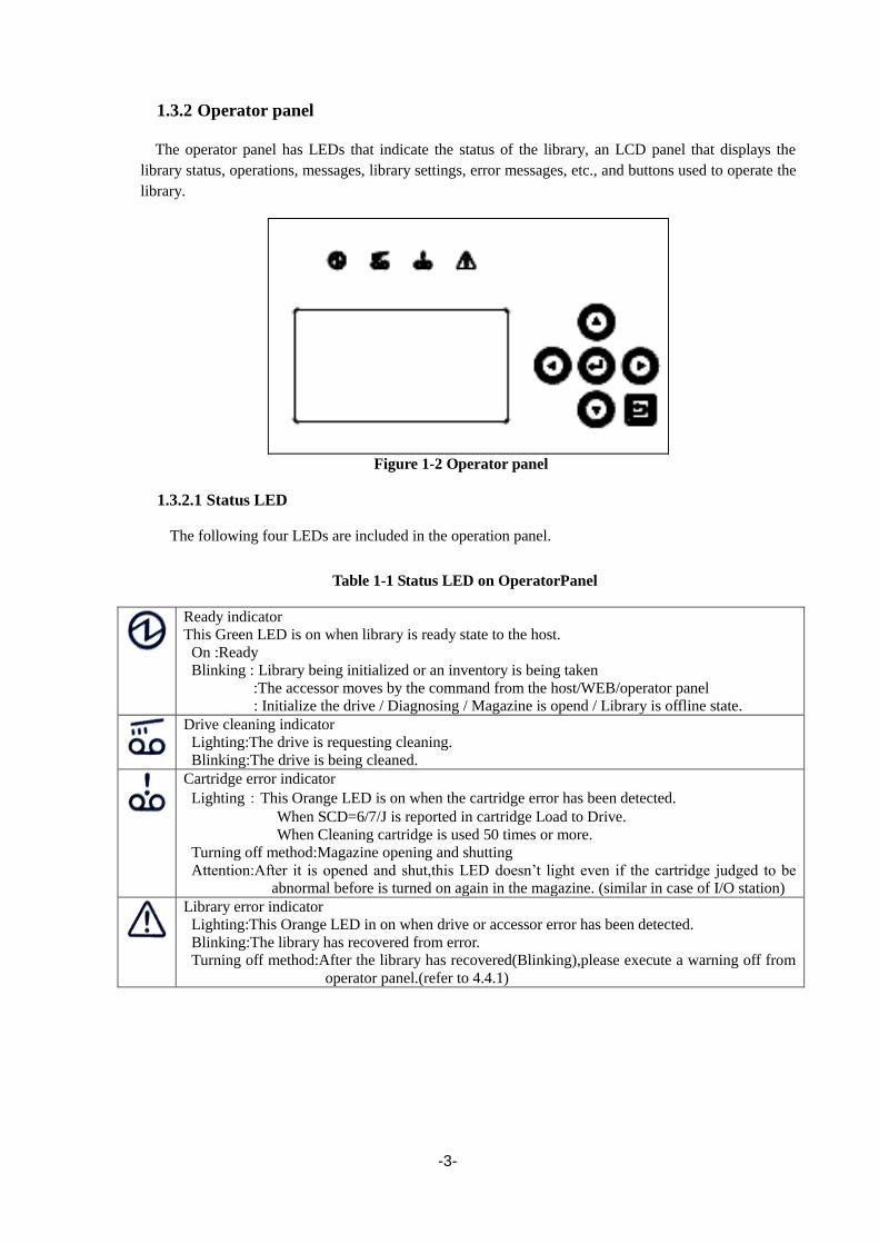
-3-
1.3.2 Operator panel
The operator panel has LEDs that indicate the status of the library, an LCD panel that displays the
library status, operations, messages, library settings, error messages, etc., and buttons used to operate the
library.
Figure 1-2 Operator panel
1.3.2.1 Status LED
The following four LEDs are included in the operation panel.
Table 1-1 Status LED on OperatorPanel
Ready indicator
This Green LED is on when library is ready state to the host.
On :Ready
Blinking : Library being initialized or an inventory is being taken
:The accessor moves by the command from the host/WEB/operator panel
: Initialize the drive / Diagnosing / Magazine is opend / Library is offline state.
Drive cleaning indicator
Lighting:The drive is requesting cleaning.
Blinking:The drive is being cleaned.
Cartridge error indicator
Lighting:This Orange LED is on when the cartridge error has been detected.
When SCD=6/7/J is reported in cartridge Load to Drive.
When Cleaning cartridge is used 50 times or more.
Turning off method:Magazine opening and shutting
Attention:After it is opened and shut,this LED doesn’t light even if the cartridge judged to be
abnormal before is turned on again in the magazine. (similar in case of I/O station)
Library error indicator
Lighting:This Orange LED in on when drive or accessor error has been detected.
Blinking:The library has recovered from error.
Turning off method:After the library has recovered(Blinking),please execute a warning off from
operator panel.(refer to 4.4.1)

-4-
1.3.2.2 LCD
The LCD panel displays the library state, operations, messages, library settings, error messages, etc.
The LCD panel has a built-in backlight LED and is backlit when the operator panel is used.
If you disable the Auto Backlight OFF function on the OP Panel Settings menu, the backlight is
automatically turned off if the specified time elapses without any operation being performed.
1.3.2.3 Button
Table 1-2 Button on OperatorPanel
Direction button
It is used for the selection of the operation menu and the cursor position movement.
Enter button
Use this button to select the item currently indicated by the cursor. Also use this button to
determine the selected menu or value.
Cancel button
Use this button to cancel the selected menu or value or to return to the previous (upper
level) menu.

-5-
1.3.3 Magazine operation panel
Figure 1-3 Magazine operation panel(left:T30A,right:T60A)
1.3.3.1 Magazine Status LED
Table 1-3 Status LED on Magazine Operation panel
This LED indicates the internal status of the I/O station.
When the I/O station is closed:
On: The I/O station contains one or more cartridges.
Off: The I/O station contains no cartridge.
When the I/O station is open, the LED is off. The color of the LED is green.
1.3.3.2 Button
Table 1-4 Button on Magazine Operation panel
Magazine unlock button / indicator
Magazine unlock request button.
This Green LED is on when the button is enabled.
I/O Station unlock button / indicator
I/O station unlock request button.
This Green LED is on when the button is enabled. After the unlock button is pressed, the I/O station is unlocked by the enter button
pressing.
LED of the unlock button blinks until the decision button is pressed.
Power button / indicator
Button to power on / off.
This LED is orange when power is being supplied, or the LED is green lighting when
power is on.

-6-
1.3.3.3 Ethernet connector for maintenance
When the front bezel of the magazine operation panel is removed, the Ethernet connector for
maintenance is found inside.
The Ethernet connector for maintenance is used for logging in to the remote management interface
as a user with maintenance personnel authority. (The IP address of the maintenance port is
192.0.2.1.)
In the Ethernet connector for maintenance, a remote administration interface can be used like the
Ethernet connector on the back of equipment.
For information about how to remove the front bezel of the magazine operation panel, see
"10.13Replacing the Front bezel L."

-7-
1.3.4 Magazine
There are two types of magazines: one can hold 18 cartridges, and the other can hold 12 cartridges.
The library houses the 18-cartridge-type magazine in the front and the 12-cartridge-type magazine in
the back.
The 18-cartridge-type magazine has nine columns, and the 12-cartridge-type magazine has six
columns. Each column can hold two tape cartridges inserted end to end.
When two or more drives are mounted, the drive slot is used as the escape slot. When only one
drive is mounted, an escape slot module is provided for temporarily storing tape cartridges.
1.3.4.1 Slot number
The slot numbers range from 1 to 30 for T30A and from 1 to 60 for T60A. In each column, the
slot in the back has the smaller slot number.
When a column contains one tape cartridge, that tape cartridge is housed in the front slot and an odd
number is assigned to this slot. When another tape cartridge is inserted into the same column, the
previously inserted tape cartridge is moved to the back slot and the slot number of this back slot
changes to an odd number. An even number is assigned to the front slot that now contains the newly
inserted tape cartridge.
Figure 1-4 Slot Number of Magazine(Above:T30A,Below:T60A)

-8-
1.3.4.2 Active Slot This slot is used to store a data cartridge.
There are as many active slots as the value of Active Slots specified from the operator panel. For
details, see "4.4.2.1 Library Settings”
By default, the Active Slots value is set to "18" for T30A and "48" for T60A.
1.3.4.3 I/O station This slot is used to insert tape cartridges into the library as well as to eject tape cartridges.
You can set whether to enable or disable the I/O station from the operator panel. For details, see
“4.4.2.1Library Settings”
If you enable the I/O station, the magazine slot numbers shown below are assigned to the I/O station
slots.
Slot numbers: 29/30 for T30A; 59/60 for T60A.
By default, the I/O station function is disabled.
1.3.4.4 Escape slot This slot is used to temporarily store tape cartridges when moving tape cartridges inside this product.
When only one drive is mounted, an escape slot module is provided at the location where an additional
drive is usually mounted and this module is used as the escape slot.
When two or more drives are mounted, the drive slot is used as the escape slot.
1.3.4.5 Cleaning Slot This slot contains a cleaning cartridge for auto cleaning. Since auto cleaning is not available, this
slot is normally not used.
If you enable auto cleaning from the operator panel or remote management interface, the inactive
slot containing a cleaning cartridge is automatically assigned as the cleaning slot. (A barcode label is
used to judge whether a cartridge is a cleaning cartridge. A cleaning cartridge without a barcode
label is not recognized as such.)
1.3.4.6 Inactive slot This slot is one that fits none of the above descriptions.
When auto cleaning is enabled, an inactive slot is used as the cleaning slot.
For information about the auto cleaning function, see "4.8.2Auto Cleaning”
By default, the number of inactive slots is "0".

-9-
1.3.5 Rear View
Figure 1-5 Components on the Rear of the Library(T30A)
Figure 1-6 Components on the Rear of the Library(T60A)
(1)Power supply (In case of T60A,the redundant power supply might be installed)
(2).AC power connector
(3).Drive
(4).Drive Sled indicator (refer to 1.3.6)
(5).SAS access port or FC access port
SAS Drive: Two connectors are mounted on the device back and forth.
(front :port A, back:port B(not use))
FC Drive: Two connectors are mounted on the vertical direction of the device.
(upper : port A, lower:port B(not use))
(6).Ethernet access port
(7).Fastening screw for transportation
(8).Interface cable fastener (to be used for fastening the interface cable as necessary)
(1) (2) (3) (4) (5) (6) (7)
(8)
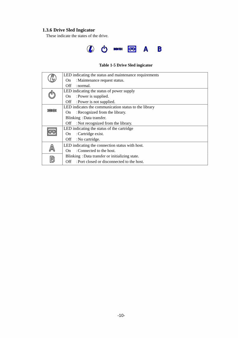
-10-
1.3.6 Drive Sled Ingicator
These indicate the states of the drive.
Table 1-5 Drive Sled ingicator
LED indicating the status and maintenance requirements
On :Maintenance request status.
Off :normal.
LED indicating the status of power supply
On :Power is supplied.
Off :Power is not supplied.
LED indicates the communication status to the library
On :Recognized from the library.
Blinking :Data transfer.
Off :Not recognized from the library.
LED indicating the status of the cartridge
On :Cartridge exist.
Off :No cartridge.
LED indicating the connection status with host.
On :Connected to the host.
Blinking :Data transfer or initializing state.
Off :Port closed or disconnected to the host.

-11-
1.3.7 Power Module LED
Three LED that shows the following is mounted on the back side of the power source module.
・AC:When the AC voltage is supplied, it lights.
・DC:When the DC voltage is supplied, it lights.
・Alarm:When abnormality occurs by the power source module, it lights.

-12-
1.4 Encryption This function allows you to encrypt cartridges by setting either an encryption key automatically
generated from the master key or a separately specified encryption key to the drive.
The library stores encryption keys and manages them individually on a cartridge-by-cartridge basis
using barcode labels.
This function is disabled by default. It is enabled when a license key is input from the remote
management interface.
When enabled, the encryption function behaves as follows:
Setting the encryption function requires administrator authority.
The library has a database that can hold encryption keys for 2000 cartridges.
If an attempt is made to store encryption keys for more than 2000 cartridges in the database, the
stored data is deleted starting with the oldest encryption key.
The encryption key database can be saved and restored by using the remote management interface.

-13-
1.5 Disposal of the Product and Comsumables Observe all relevant local government regulations when disposing of this product, its packaging
material, or cartridges. Note that the power cable accompanying the product should be disposed of
together with the product so as to prevent it from being used improperly for another device. For details,
contact the relevant local authority.
Data stored in a tape cartridge:
It is your responsibility to properly erase the data stored in a used tape cartridge so that
confidential data (e.g., business information or accounting data) is not leaked to a third
party.
To avoid data leakage, it is strongly recommended to erase the data completely using
your backup software. For information about how to erase data, see the manual of
the backup software.
NEC is not liable for any leakage of data resulting from improper data erasure.
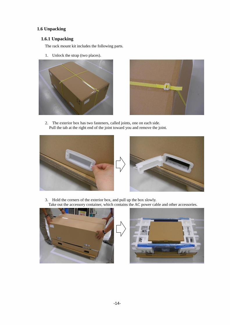
-14-
1.6 Unpacking
1.6.1 Unpacking
The rack mount kit includes the following parts.
1. Unlock the strap (two places).
2. The exterior box has two fasteners, called joints, one on each side.
Pull the tab at the right end of the joint toward you and remove the joint.
3. Hold the corners of the exterior box, and pull up the box slowly.
Take out the accessory container, which contains the AC power cable and other accessories.
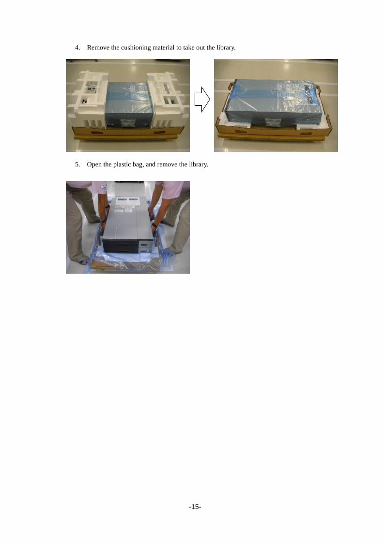
-15-
4. Remove the cushioning material to take out the library.
5. Open the plastic bag, and remove the library.

-16-
1.7 Installing the Rack Mounting Kit
1.7.1 Components
The rack mounting kit consists of the components shown below.
Figure 1-7 Components of Rack mount kit parts
Table 1-6 component list of rack mount kit parts
Item
No
Name Qty
<1> Rack mount rail L 1
<2> Rack mount rail R 1
<3> Rack mount bracket L 1
<4> Rack mount bracket R 1
<5> Rack earL 1
<6> Rack earR 1
<7> Screws(M3) 8
<8> Screws(M5) 2
<9> Flat head screws(M6) 8
③
②
④
⑤(T30A)
⑦
① ⑧
⑨
⑥(T30A)
⑤(T60A) ⑥(T60A)
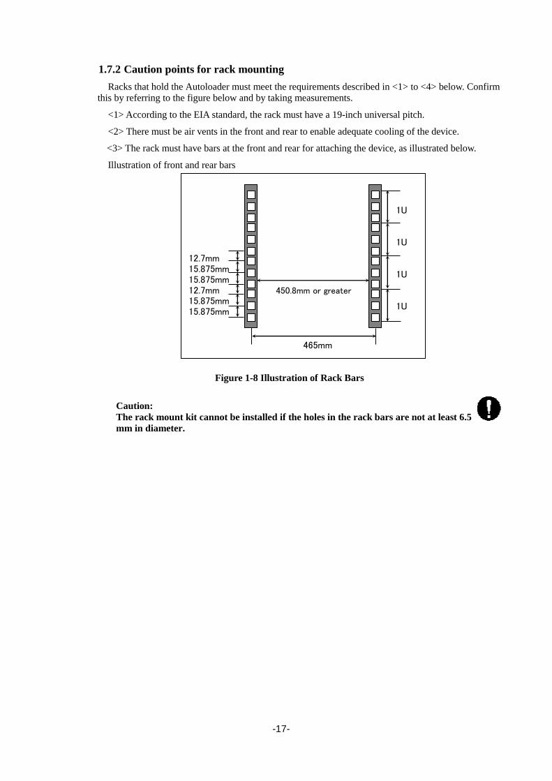
-17-
1.7.2 Caution points for rack mounting
Racks that hold the Autoloader must meet the requirements described in <1> to <4> below. Confirm
this by referring to the figure below and by taking measurements.
<1> According to the EIA standard, the rack must have a 19-inch universal pitch.
<2> There must be air vents in the front and rear to enable adequate cooling of the device.
<3> The rack must have bars at the front and rear for attaching the device, as illustrated below.
Illustration of front and rear bars
Figure 1-8 Illustration of Rack Bars
Caution:
The rack mount kit cannot be installed if the holes in the rack bars are not at least 6.5
mm in diameter.
12.7mm 15.875mm 15.875mm 12.7mm 15.875mm 15.875mm
1U 1U 1U 1U
450.8mm or greater
465mm

-18-
<4> The rack's internal dimensions must meet the dimension requirements shown in Figures A to C
below.
[unit: mm]
Figure 1-9 Rack Dimensions
Table 1-7 internal Dimension Requirements for rack
Site Description Requirement
A Distance from front device mounting bracket to inner
side of front door
25mm or above
B Gap between front and rear device mounting brackets 680 to 1050mm
C Distance from rear of device to inner side of rear door 30mm or above
Rear door
Mounting brackets
Front door
Enlarged view of X area
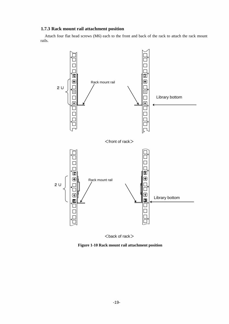
-19-
1.7.3 Rack mount rail attachment position
Attach four flat head screws (M6) each to the front and back of the rack to attach the rack mount
rails.
Figure 1-10 Rack mount rail attachment position
Library bottom
<front of rack>
2U
Library bottom
Rack mount rail
<back of rack>
Rack mount rail
2U

-20-
1.7.4 Attachment of Rack mount rail L/R
Perform the following steps to attach the left and right rack mount rails.
<1> Use four flat head screws (M6) to attach the rack mount rail L to the front and rear of the rack.
<2> Use four flat head screws (M6) to attach the rack mount rail R to the front and rear of the rack.
Figure 1-11 attachment of rack mount rails
Rack mount rail L
Rack mount rail R
<front of rack> Flat head screws
Flat head screws

-21-
1.7.5 Attachment of Rack mount bracket L/R
Perform the following steps to attach the left and right rack mount brackets.
<1> Use four screws (M3) to attach the rack mount bracket R to the right of the library.
<2> Use four screws (M3) to attach the rack mount bracket L to the left of the library.
Figure 1-12 attachment of rack mount bracket R(left:T30A , right :T60A)
Figure 1-13 attachment of rack mount bracket L(left:T30A , right :T60A)
Rack mount bracket R screws(M3)
screws(M3)
screws(M3) screws(M3)
Rack mount bracket L

-22-
1.7.6 Installation of library
Set the Library onto the rack mount rail at the front of the rack, and then slowly slide it toward the
rear.
Transport and install of the rack by two people or more. The rack falls and it causes the
injury and the damage of surroundings. Especially, the rack (44U etc.) with height is
not fixed to the delicate state by the stabilizer etc.Transport and set it up while
supporting the rack by two people or more.
Figure 1-14 Mounting of library onto rack
T30A
T60A
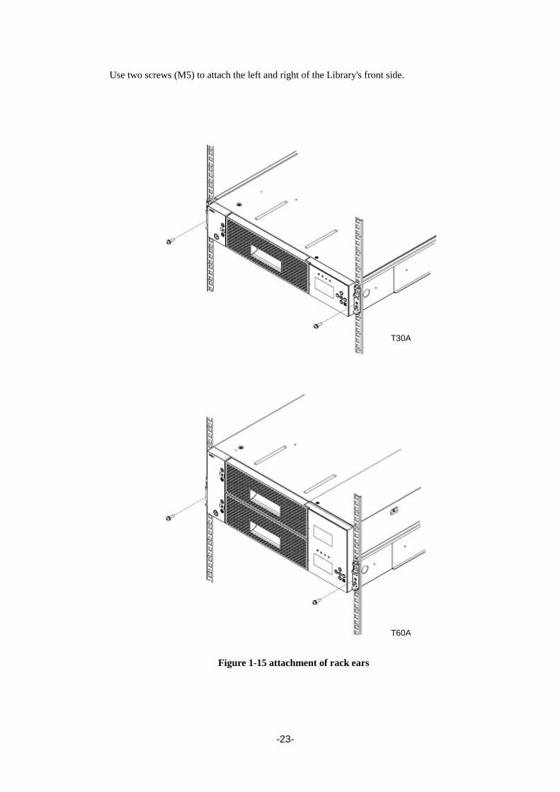
-23-
Use two screws (M5) to attach the left and right of the Library's front side.
Figure 1-15 attachment of rack ears
T30A
T60A

-24-
1.7.7 Attachment of Rack ear
Attach the left and right rack ears to the left and right of the Library's front side.
Figure 1-16 Fastening of Library’s front side
T30A
T60A

-25-
1.7.8 Attachment of label plate
Attach the label plate with repetition belt to the left of library ‘s back side.
Figure 1-17 attachment of label plate

-26-
1.8 Removal of shipment Stabilizer
The Library has a screw that is fastened to its rear side to stabilize the internal Accessor during
shipment.
Before using the Library, be sure to unfasten this screw.
Make sure that the shipment stabilizer screw has been unfastened.
If the power is turned on while the screw is still fastened, operation faults may
occur
If the error message "***CHK*** CODE:[0009]" is displayed, turn off the power and
unfasten
this shipment stabilizer screw before turning the power back on.

-27-
Chapter2 Setup
This chapter describes the cable connections, diagnostic test, and operation checks, which are all needed to
set up the library.
* If setup is not necessary, go to "Chapter4Operator Panel" or "Chapter5Remote Manager Interface Remote
Management Interface."
2.1 Connection of a Interface Cable This section describes how to connect the product to a server or switch by using an interface cable.
The T60A library can house up to four drives, and the T30A library can house up to two drives.
2.1.1 Connection of SAS Cable
Connect each SAS drive of the library to a server by using an SAS cable. The product has an SAS
connector on the back.Be sure to connect the SAS cable to Port A of each drive.
Make sure that the cable is plugged all the way in.
(* The product will not work if the cable is connected to Port B.)
After connecting the cable, make sure it is connected securely.
The SAS cable's connector includes a locking mechanism.
Make sure it is set to the locked position.
Please connect it from the connector of a lower number sequentially when you connect
divergence SAS cable.

-28-
2.1.2 Connection of FC Cable
Connect the FC drive of the product to a server or switch by using an FC cable. The product has
an FC connector on the back. Be sure to connect the FC cable to Port A. Before connecting the
cable, remove the white protection caps.
(* The product will not work if the cable is connected to Port B.)
(Connector on the upper side of the drive; shown on the right is the connector with the caps
removed.)
For information about how to connect a server or switch, see the manual accompanying the server
or switch.
After connecting the cable, make sure it is connected securely.
The FC cable's connector includes a locking mechanism.
Make sure it is set to the locked position.

-29-
2.2 Connection of AC Power Cable After connecting the signal cable, insert the AC power cable's plug into the Library's AC power
connector. Make sure that the plug is fully inserted.
When the redundant power supply is installed in the library, insert the AC power cable’s plug into
each Library’s AC connector.
2.3 Power-On and self test Turning on the power of the unit starts power-on sequence automatically.
For description of power-on, see “3.1Power-On and Power-On Sequence”.
2.4 Setting Drive configuration Set the interface configuration in the drive module referring the panel operation in
4.4.2Configuration.
[SAS interface]
・Drive Path The setting of drive path
・Media Changer Path The setting of the media changer path of the robot
・Link Speed 3Gbps、6Gbps
・Power Save Mode The setting of drive power save mode
[FC interface]
・Control Path The setting of drive path
・Media Changer Path The setting of the media changer path of the robot
・Topology Point to Point / loop
・Loop ID 0 to 125
・Link Speed Auto、1Gbps、2Gbps、4Gbps、8Gbps
・Power Save Mode The setting of drive power save mode
When a wrong topology, Loop ID, and Link Speed are set, the entire system might be
negatively affected.
・Please set it to the loop when connecting directly with HBA.
・Please set it to Point to Point when you pass the FC switch.
2.5 Setting Library and Drive configuration After the library starts normally, the composition of the library and the drive can be set.
Table 2-1 Setting item
Setting item procedure
1.Setting of library and drive
(1) Setting of Fibre Channel or SAS
(2) Setting of drive port / media changer path
(3) Setting of I/O Station
(4) Setting of slots
4.5.3.1 or 4.5.3.2
4.5.3.3
4.5.5
4.5.6
2.Setting of Network
(1) Setting of IP address
(2) Setting of subnetmask
(3) Setting of gateway
(4) Setting of DHCP
5.2
5.2
5.2
5.2
3.Setting of Time 4.4.2.5 or 5.6.5.5
Since time information is reset (2000/1/1/00:00:00) when the state of the equipment power supply
OFF continues, please carry out a time setup again after the power supply ON.

-30-
2.6 Diagnostic Test Load the diagnostic cartridge in the library, and execute the diagnostic test. For information about
how to perform this test, see "9.2Diagnosis test."
2.7 Operation Checks after Installation After installing and setting up the library, connecting the cables, executing the diagnostic test, and
loading the cartridges, check the following:
1. Check that all the cables are connected properly to the connectors.
2. Check that there are no unnecessary items, such as components, connectors, or tools, left in the
library.
3. Check that the magazines are mounted.
4. It is confirmed whether the time displayed in the library is correct. (If time shifts, a set change is
done. Please refer to 4.4.2.5 or 5.6.5.5 )
After checking the library, perform a connection check from the server.
If you can recognize the library from the server, perform an online check using backup software. If
the library is offline, change the relevant setting to make it online or check the setting of the server.
For information about how to perform a check by using the backup software, refer to the manual of the
backup software.
-31-
Chapter3 Power-On and Power-Off
3.1 Power-On and Power-On Sequence
Turning on the power of the product initiates a self test. The self test takes several minutes, but no
other operation can be performed during the test.
Before turning on the power, check that the fastening screw for transportation has been
removed (see "1.8Removal of shipment Stabilizer").
3.2 Starting the System When starting the system, first start the LIbrary (and any peripheral devices connected to the server or
workstation), then turn the server or workstation's power on to start the system.
1) Push the power switch button located on the front of the unit to turn on the power.
2) When the power is supplied, [Power LED] goes on green and the system starts power-on test.
3) When the power-on test successfully completed, a [Ready] appears on the operator panel.
If a cartridge is loaded into the drive before the system is started, errors may occur
when reading or writing data stored in the cartridge.
3.3 Shutting Down the System When shutting down the system, first turn off the power to the server or workstation, then the power to
the Library (and any peripheral devices connected to the server or workstation) to shut down the system.
When shutting down the system, use your backup application or check for messages on
the LCD to make sure that no cartridges have been loaded into the cartridge drive. If
the system is shut down while a cartridge is loaded in the cartridge drive, the next time
the system is started errors may occur when reading or writing data stored in the
cartridge, which can lead to malfunctions in the cartridge or the Library.
Do not shut down and restart the system while the Library is operating. Make sure that
the LIbrary has stopped before shutting down the system or restarting it.
3.4 Power-Off and Power-Off Sequence 1) Push the power switch button (for about 1sec) located on the front of the unit to turn off the power.
2) The shutdown processing is begun, and the power supply is turned off automatically.
When the data cartridge is stored in the drive, power supply OFF is not carried out automatically.
After choosing [NO],take out a data cartridge from a drive and carry out power supply OFF again, or
choose [Yes], and turn off a power supply as it is.
However, if power supply OFF is carried out where a data cartridge is stored in a drive, it will become
a cause of failure of a data cartridge and this equipment.
In moving of Library, turn off the power supply of library(see “9.8Moving the Library”)

-32-
Chapter4 Operator Panel
This chapter describes how to use the operation panel and how to enter settings for the Library and the
cartridge drive.
Settings can be entered for the Accessor and the drive only after the Library has been reset.
4.1 Panel Indications The library unit has three screens. The [Menu screen] is used for operation and setting of library unit.
The [Status Display screen] is for real-time display of the internal state of library unit. The
[Asynchronization message screen] display the message to draw attention to the operator. Described
below is detailed explanation of [Menu screen], [Status Display screen] and [Asynchronization message
screen].
4.1.1 Menu Screen [Menu screen] appears when a user attempts to operate the library unit or configure it. The following
items are displayed.
Figure 4-1 Menu Screen
1.Menu title
Indicates the menu title currently displayed.
2.Menu item
Indicates the menu item. See "4.2Menu Tree" for details.
1.Menu title
2.Menu item

-33-
4.1.2 Status Display screen [Status Display screen] changes its display when no button operation is performed within certain
period of time on [Menu screen], or when Cancel button is pressed on [TopMenu] menu.
Shown below is the [Status Display screen]. The [Status Display screen] has the [Library State] that
displays a status of library and [Drive State] that displays a status of drive.
Each screen can be switched by pressing buttons other than Enter.
4.1.2.1 Library State
In this example, library state that installed four half-Height drives is displayed.
Figure 4-2 Component of Operator Panel
Library State is composed of the following.
1.Library status display
The following terms are used to indicate the status of the library.
(1)
(2)
(4)
(5)
(6) (8)
(7) (3)
(9)

-34-
Table 4-1 Library Status displayed in the Operation Panel
Message Description
PLEASE INSERT MAGAZINE Magazine insertion is requested.
MAGAZINE UNLOCKED Magazine is not locked.
PLEASE CLOSE I/O STATION I/O Station CLOSE is requested.
INITIALIZING・・・ Initialization is in progress.
INVENTORY・・・ Inventory is in progress.
SETTING・・・ Setting in progress
** CHK **
[XXXX]
Library error status (xxxx is the CHK code)
RECOVERING・・・ PLEASE WAIT
Library firmware is in recovery.
LIBRARY FIRMWARE
UPDATING!
Library firmware update is in progress.
DRIVEn FIRMWARE
UPDATING!
Drive firmware update is in progress.
DRIVE DUMP DATA
UPLOADING!
Dump data is being uploaded from drive.
EXCHANGE SLOTFULL A cartridge is stored in the exchange slot.
CARTRIDGE WRONG
INSERTION
A cartridge has been incorrectly inserted in the drive.
ENDURANCE
COUNT OVER
The number of Accessor mechanism operations has reached
the expected life (endurance) value
OFFLINE Library Offline(Not Ready)
CLEANING... During drive cleaning
(This status message is displayed in doing “Clean Drive”)
REPLACE CLEANING MEDIA Replacement of cleaning cartridge
CLEAN DRIVEn Drive n cleaning is requested
PSU n FAULT Power module error
PSU n FAN ERROR Power module fan error
REDUNDANT PSU ERROR Redundant power module error
Drive n FAN ERROR Drive FAN error
READY Ready(Idle)
2. Accessor status display section
Indicates whether a cartridge tape exists in the picker section of the accessor.
Figure 4-3 Accessor Icon
(With no cartridge tape)
(with cartridge tape)

-35-
3.Magazine status display section
Indicates the status of magazines on the library unit.
Figure 4-4 Magazine Icon
When the magazine is Opened, the display changes as shown below.
(In this example,Lower Magazine is Opened.)
Figure 4-5 Magazine Icon(Magazine is Opened)
When I/O Station is set, it is displayed as follows.
Figure 4-6 Magazine Icon(I/O Station is set) When the I/O Station is Opened, the display changes as shown below. ([!] mark is displayed)
Cartridge existence information other than I/O Station are maintained.
I/O Station Disable I/O Station Enable
Upper Magazine
Lower Magazine
rear
front
18slot Magazine 12slot Magazine
Upper
Center
Lower
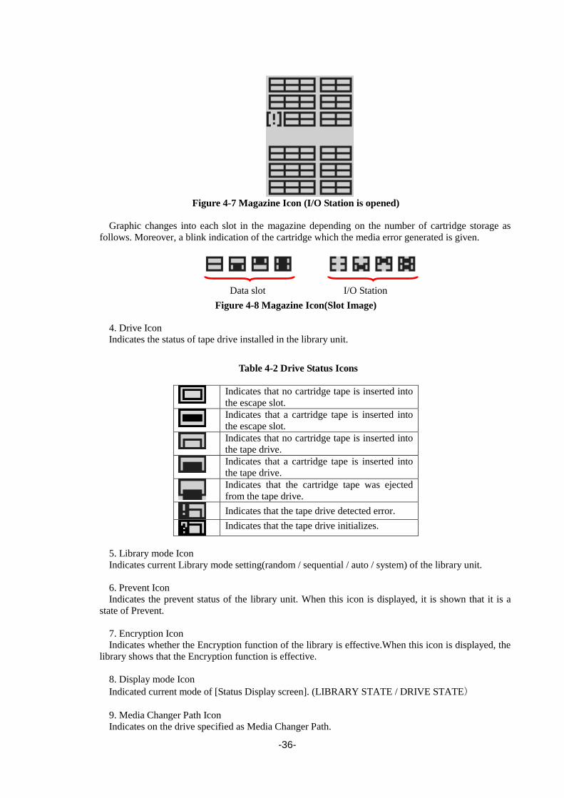
-36-
Figure 4-7 Magazine Icon (I/O Station is opened)
Graphic changes into each slot in the magazine depending on the number of cartridge storage as
follows. Moreover, a blink indication of the cartridge which the media error generated is given.
Figure 4-8 Magazine Icon(Slot Image)
4. Drive Icon
Indicates the status of tape drive installed in the library unit.
Table 4-2 Drive Status Icons
Indicates that no cartridge tape is inserted into
the escape slot.
Indicates that a cartridge tape is inserted into
the escape slot.
Indicates that no cartridge tape is inserted into
the tape drive.
Indicates that a cartridge tape is inserted into
the tape drive.
Indicates that the cartridge tape was ejected
from the tape drive.
Indicates that the tape drive detected error.
Indicates that the tape drive initializes.
5. Library mode Icon
Indicates current Library mode setting(random / sequential / auto / system) of the library unit.
6. Prevent Icon
Indicates the prevent status of the library unit. When this icon is displayed, it is shown that it is a
state of Prevent.
7. Encryption Icon
Indicates whether the Encryption function of the library is effective.When this icon is displayed, the
library shows that the Encryption function is effective.
8. Display mode Icon
Indicated current mode of [Status Display screen]. (LIBRARY STATE / DRIVE STATE)
9. Media Changer Path Icon
Indicates on the drive specified as Media Changer Path.
Data slot I/O Station

-37-
4.1.2.2 Drive State
In this example, library state that installed four half-Height drives is displayed.
Drive State is composed of the following.
1. Drive Icon
Indicates the status of tape drive installed in the library unit.
Indicates whether a cartridge tape exists in the drive.
Table 4-3 Drive Status Icons
Indicates that no cartridge tape is inserted into the tape drive.
Indicates that a cartridge tape is inserted into the tape drive.
Indicates that the cartridge tape was ejected from the tape drive.
2. Drive message
Indicates the status of tape drive installed in the library unit.
The following terms are used to indicate the status of the drive.
Table 4-4 Drive Message
Message Description
Ready Indicates that a cartridge tape is inserted into the tape drive.
Not Ready Indicates that the tape drive is initialing.
Empty Indicates that no cartridge tape is inserted into the tape drive.
Ejected Indicates that the cartridge tape was ejected from the tape drive.
Loading Indicates that the tape drive is loading a cartridge tape.
Unloading Indicates that the cartridge tape is unloading from the tape drive.
Rewinding Indicates that the tape drive is rewinding a cartridge tape.
Cleaning Indicates that the cleaning cartridge is cleaning the tape drive.
Reading Indicates that the tape drive is reading data out from the cartridge tape.
Writing Indicates that the tape drive is writing data into the cartridge tape.
Locating Indicates that the tape drive is locating a cartridge tape.
Erasing Indicates that the tape drive is erasing data into the cartridge tape.
Formatting Indicates that the tape drive is formatting a cartridge tape.
Calibrating Indicates that the tape drive is calibrating.
Offline Indicates that the tape drive is offline.
Other Other
(1)
(2)
(3)
(4)
(8)
(5)
(6)
(7)
-38-
3. Display mode Icon
Indicates the current mode of [Status Display screen]. (LIBRARY STATE / DRIVE STATE)
4. Prevent Icon
Indicates the prevent status of the drive. When this icon is displayed, it is shown that it is a state of
Prevent.
5. Fan Error Icon
Indicates the fan error status of drive.
6. Encryption mode Icon
Indicates whether an encryption setup of a drive is effective.
7. Compressed mode Icon
Indicates whether the data compression setup of a drive is effective
8. Drive Error Icon
Indicates the error code when drive error occurs.(See “B-3”)

-39-
4.1.3 Asynchronization message screen [Asynchronization message screen] is indicated from [Menu screen] and [Status Display screen] by
priority.
There are two kinds (the message to disappear automatically when time passes to some degree and
the message to disappear when the operator intervenes it) in this message.
Table 4-5 Asynchronization Message
Asynchoronization
Message Description
I/O Station is
being opened
Unlocking of I/O Station
Indication: Demanded the I/O Station lock release from the main management task
Message off:End of lock release
I/O Station is
opened
Unlocked of I/O Station
Indication: End of lock release
Message off:In five seconds or pressing some key
I/O Station open
failed
Unlocking of I/O Station failed CHK status
Indication: Abnormal termination of lock release of I/O station
Message off:Pressing some key
Magazine is being
unlocked(T30A)
Unlocking of Magazine
Indication: Demanded the Magazine lock release from the main management task
Message off: End of lock release
Upper Magazine
is being
unlocked(T60A)
Unlocking of Upper Magazine
Indication: Demanded the Magazine lock release from the main management task
Message off: End of lock release
Lower Magazine
is being
unlocked (T60A)
Unlocking of Lower Magazine
Indication: Demanding the Magazine lock release from the main management task
Message off: End of lock release
Magazine
is unlocked(T30A)
Unlocked of Magazine
Indication: End of lock release
Message off:Opening the Magazine or in 60 seconds without opening the magazine
Upper Magazine
is unlocked(T60A)
Unlocked of Upper Magazine
Indication: End of lock release
Message off:Opening the Magazine or in 60 seconds without opening the magazine
Lower Magazine
is unlocked(T60A)
Unlocked of Lower Magazine
Indication: End of lock release
Message off:Opening the Magazine or in 60 seconds without opening the magazine
Magazine unlock
failed
Unlocking of Magazine failed CHK status
Indication: Abnormal termination of lock release of Magazine
Message off:Pressing some key
Library Firmware
update in progress
Updating Library Firmware
Indication:Demanded display from each task
Message off: Demanded message-off from each task
Drive Microcode
update in progress
Updating Drive Firmware
Indication:Demanded display from each task
Message off: Demanded message-off from each task
Library Dump
upload in progress
Uploading Library Dump
Indication:Demanded display from each task
Message off: Demanded message-off from each task
Drive Dump upload
in progress
Updating Drive Dump
Indication:Demanded display from each task
Message off: Demanded message-off from each task
Other Depending on the task of demanding.
Indication:Demanded display from each task
Message off: Demanded message-off from each task

-40-
4.2 Menu Tree
Table 4-6 Menu tree of commands
Top Menu Submenu
Commands
Move Cartridge
Unload
Clean Drive
Shipping Move
Reboot Drive
Reboot Library
Library State Online / Offline
Drive State
Selecting of drive
Online / Offline
Warning Clear

-41-
Table 4-7 Menu tree of configuration
Top Menu Submenu
Configuration
Library Settings I/O station Enable / Disable
Active Slots
Auto Cleaning Mode Enable / Disable
Library Mode Random Mode
Sequential Mode Loop Mode Enable / Disable Autoload Mode Enable / Disable
Cleaning Notice Near Expired Enable / Disable
Every Cleaning Enable / Disable
Apply
Network Settings Link Speed Auto Negotiation / 10Base-T Full / 10Base-T Half / 100Base-TX Full / 100Base-TX Half / 1000Base-T Full / 1000Base-T Half
Protocol Stack IPv4 / IPv6
IPv4 Settings DHCP IPv4 Enable / Disable
IP Address
Subnet Mask
Gateway
Apply
IPv6 Settings Stateless DHCP Enable / Disable
DHCP IPv6 Enable / Disable
IP Address
Prefix Length
Gateway
Apply
Apply
Drive Settings Selection of drive
Port A Drive Path Enable / Disable
Link Speed (SAS)
3Gbps / 6Gbps
Topology Loop / Point to Point
Set Loop ID
Link Speed (FC)
Auto Negotiation / 8Gbps / 4Gbps / 2Gbps / 1Gbps
Port B Port A
Media Changer Path Enable / Disable
Power Save Mode Enable / Disable
Apply
OP Panel Settings Auto Backlight OFF Enable / Disable
Login Mode Enable / Disable
Auto Logout Mode Enable / Disable
Change Password
Date / Time Set Date
Set Time
Time Zone
Set Default
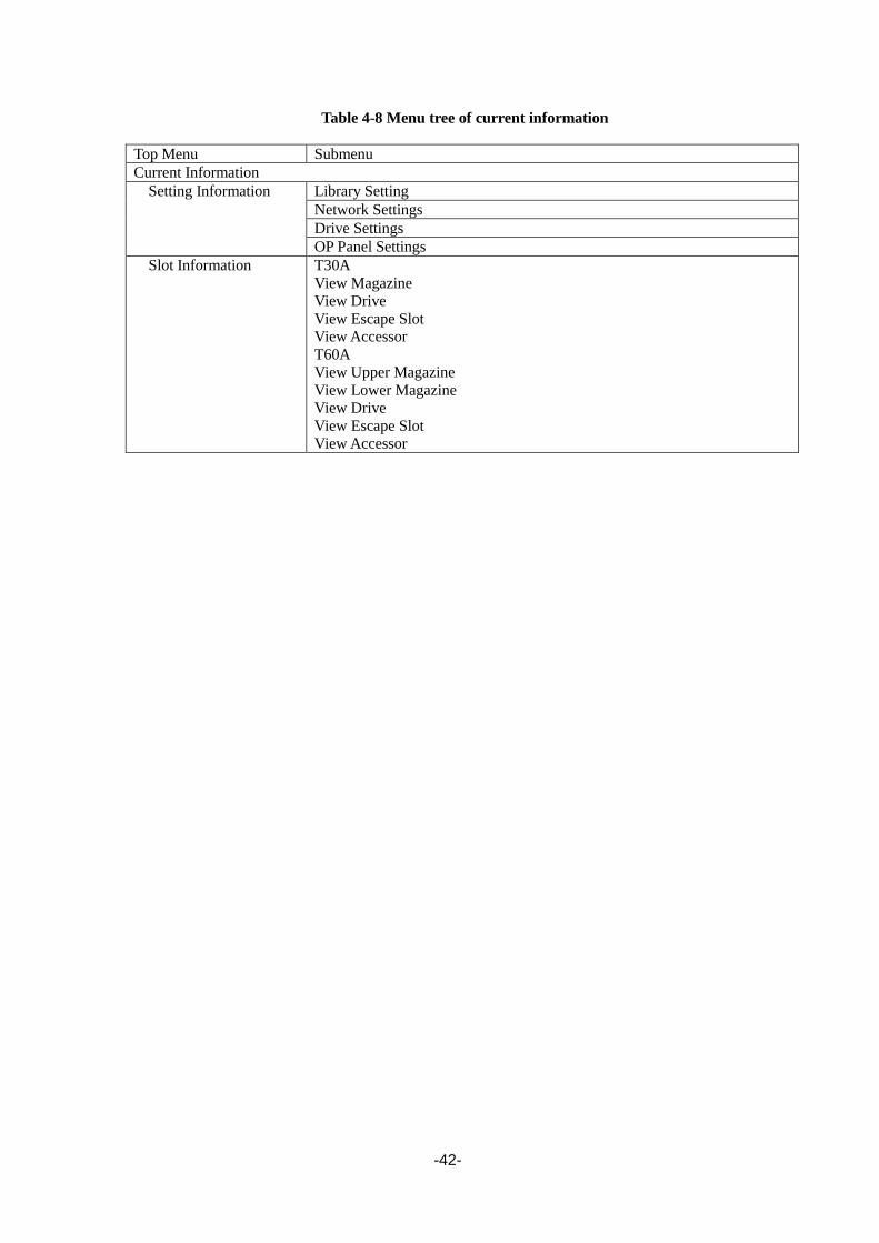
-42-
Table 4-8 Menu tree of current information
Top Menu Submenu
Current Information
Setting Information Library Setting
Network Settings
Drive Settings
OP Panel Settings
Slot Information T30A
View Magazine
View Drive
View Escape Slot
View Accessor
T60A
View Upper Magazine
View Lower Magazine
View Drive
View Escape Slot
View Accessor

-43-
Table 4-9 Menu tree of Service
Top Menu Submenu
Service
View Error Status View Library Error
View Drive Error
Diagnostics Library Verify
Drive Diagnostics Perform R/W Test
Media Test
Head Test
Statistics View Accessor Data
View Retry Data
View Error Data
Clear Accessor Data
Clear Retry Data
Clear Error Data
Telnet Service Port
(only service login)
Enable / Disable
View Revision
Drive Replacement
(only service login)
Advanced Services
(only service login)
Mechanism Test Demo(Slot-Drv-Slot)
Demo(Slot-Slot)
MSBF Test
X-Move Test
Y-Move Test
Pick/Put Test
Pick/Put/Move Test
Vibration Test
MAG Endurance Test
I/O Endurance Test
LCD/LED Test
Phy Test Normal Operation
Test Mode 1
Test Mode 2
Test Mode 3
Test Mode 4
Library Log
Advanced Settings
Table 4-10 Menu tree of logout
Top Menu Submenu
Logout
When the Login Mode setting is invalid, the item of Logout is not displayed.

-44-
4.3 Login Login is required before removing the Library's magazine, entering settings, or using the operation
panel's functions.
1) After the library unit is powered on and diagnosis of accessor starts.
2) Diagnosis of accessor is completed, the menu screen as shown below appears.
3) Enter the password on this menu screen.
Enter the user password consisting of four-digit number (from 0 to 9).
The factory-set user password is set as "0000".
4) If the password entered does not match the one stored in the library unit, the following message
is displayed. If this message is displayed, repeat steps from 3). Retry for password entry is not
limited.
5) When the correct password is entered, the [TopMenu] is displayed, and the library unit becomes
ready to operate. For menu screen, see ” 4.1.1Menu Screen”.
When the Auto Login setting is effective, this screen changes to "Top Menu" at once without
being displayed. When Login has succeeded, the Login screen is not displayed as long as it
doesn't Logout or automatic operation Logout do.
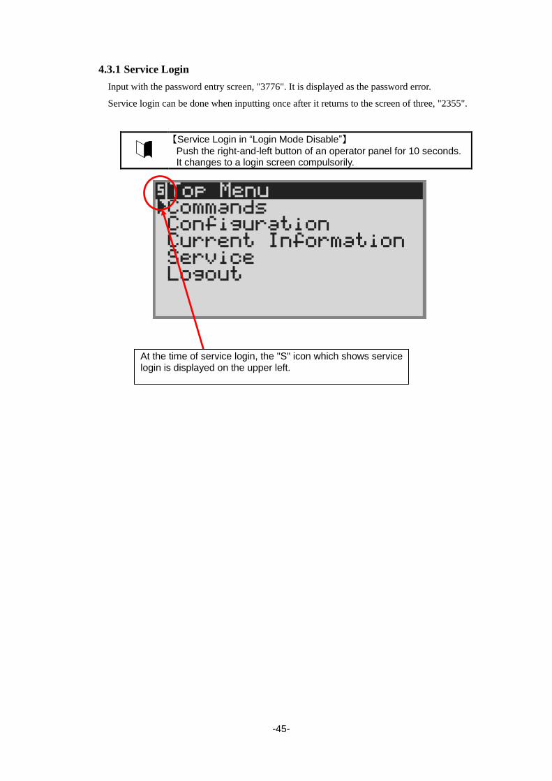
-45-
4.3.1 Service Login
Input with the password entry screen, "3776". It is displayed as the password error.
Service login can be done when inputting once after it returns to the screen of three, "2355".
【Service Login in “Login Mode Disable”】
Push the right-and-left button of an operator panel for 10 seconds. It changes to a login screen compulsorily.
At the time of service login, the "S" icon which shows service login is displayed on the upper left.

-46-
4.4 Top Menu
After Log in, the following screen is displayed.
Figure 4-9 Root screen of Top Menu

-47-
4.4.1 Commands
Use the COMMANDS menu when moving the cartridge in the library or cleaning the drive through
operator panel.
Table 4-11 Commands Submenus
Submenu item Default Description
Move Cartridge - Use this menu to move a cartridge in a slot to another slot of
the library.
Specify the slot type and slot numbers of source and
destination slots.
Unload - Use this menu to unload the cartridge from the drive.
In addition, it is necessary to execute Move Cartridge to return
it to the slot.
Clean Drive - Use this menu to provide cleaning on the drive.
Cleaning cartridge must be loaded beforehand.
See Section 4.8.1 for details.
Shipping Move - To carry the library, moves the robot to the carriage position.
Note: Take all the cartridges out from the magazine before
running this command. Before carrying the library, always run
this command.
After executing this command, be sure to fasten the Accessor
using the stabilizer screw.
Reboot Drive - This reboots the drive.
See Section4.10 for details.
Reboot Library - This reboots the Library.
Library State
■Online
□Offline
Online This submenu can be used to switch the Library state between
online and offline.
See Section 4.5.4 for details.
Drive State Online This submenu can be used to switch the Drive state between
online and offline.
Warning Clear - When turning it off when the lighting Alarm indicator is
recovered from the error situation, it selects it.
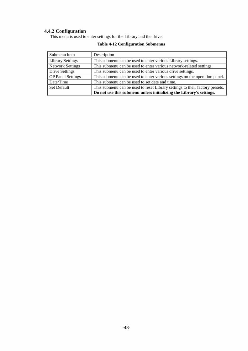
-48-
4.4.2 Configuration This menu is used to enter settings for the Library and the drive.
Table 4-12 Configuration Submenus
Submenu item Description
Library Settings This submenu can be used to enter various Library settings.
Network Settings This submenu can be used to enter various network-related settings.
Drive Settings This submenu can be used to enter various drive settings.
OP Panel Settings This submenu can be used to enter various settings on the operation panel.
Date/Time This submenu can be used to set date and time.
Set Default This submenu can be used to reset Library settings to their factory presets.
Do not use this submenu unless initializing the Library's settings.

-49-
4.4.2.1 Library Settings
Table 4-13 Library Setting Submenu
Submenu item Default Description
I/O Station Disable Enable or disable the I/O station.
Active Slots T30A:18
T60A:48
Sets the number of data slots and the active/inactive setting.
Each logical library can be set.
Auto Cleaning Mode Disable Enable or disable auto cleaning.
Each logical library can be set.
For auto cleaning to be executed, an Inactive slot must be set
in advance.
Library Mode Random Mode This submenu can be used to switch between random and
sequential mode.
Sequential mode should be set when used in environments in
which the Accessor cannot be controlled.
・Random Mode
Random mode should be set when using backup software.
Sequential Mode
-Loop Mode
Operation does not stop after the cartridge has been unloaded
by the host from the last slot. Instead, the first slot's cartridge
is loaded, and then operation continues.
-Auto Load Mode
When the magazine is set to the Library, the cartridge is
automatically mounted in the drive.
Cleaning Notice - This submenu can be used to setup the SNMP about
Cleaning.
・Nearly Expired
Nearly Expired trap is reported from setup value to 1.
Setup value:1-49
・Every Cleaning
Set up whether it remains for every cleaning execution
and report the number of times trap.
Apply - The above-mentioned setting is applied.
Auto Cleaning Mode:
When you use the library with backup software, please set up an Auto Cleaning
Mode Disable.
If the backup software supports the AUTO CLEANING Mode, use the auto
cleaning function of backup software.

-50-
4.4.2.2 Network Settings
Table 4-14 Network Setting Submenu
Submenu item Default Description
Link Speed Auto Negotiation This sets the network's communications mode.
To use the auto setting, select "AUTO".
Protocol Stack IPv4 Only Setting of Protocol Stack
IPv4 Setting - Setting of IPv4 network
IPv6 Setting - Setting of IPv6 network
Table 4-15 IPv4 Setting Submenu
Submenu item Default Description
DHCP IPv4 Disable This submenu can be used to configure the DHCP
server.
IP Address 192.168.1.1 This sets the IP address for access via a network.
Subnet Mask 255.255.255.0 This enables the Autoloader to be accessed from a
subnet.
Gateway 192.168.1.254 This indicates a gateway connection between subnets.
Apply - The above-mentioned setting is applied.
Table 4-16 IPv6 Setting Submenu
Submenu item Default Description
Stateless DHCP Disable This submenu can be used to configure the stateless
DHCP.
DHCP IPv6 Disable This submenu can be used to configure the DHCP
server.
IP Address 0::0 This sets the IP address for access via a network.
Plefix length 64 This sets plefix length.
Gateway 0::0 This indicates a gateway connection between subnets.
Apply - The above-mentioned setting is applied.

-51-
4.4.2.3 Drive Settings
Table 4-17 Drive Settings Submenu
Submenu item Default Description
Port-A - Setting of Port A of the selected drive.
Port-B - Setting of Port B of the selected drive.
A set content is the same as PortA. The license is
necessary for the setting.
Media changer path Drive #1
Enable
Drive #2-#4
Disable
Set the drive that controls the library.
Apply - The above-mentioned setting is applied.
Table 4-18 port setting submenu
Submenu item Default Description
Drive path Port –A:Enbale Setting of port-A(Enable / Disable)
Link Speed
(SAS model.)
3Gbps Link Speed:
Specify the drive max Link Speed,
”3Gbps”, “6Gbps” are selectable.
Topology
(It is non-display in
the SAS model.)
Point to point Specify the topology type
Set Loop ID
(It is non-display in
the SAS model.)
000 Specify the three-digit number Loop ID.
Valid number range is 000-125.
Link Speed
(FC model.)
8Gbps Link Speed: Specify the drive Link Speed, ”Auto”,
“1Gbps”, “2Gbps”, “4Gbps” or “8Gbps” are
selectable.

-52-
4.4.2.4 OP Panel Settings
Table 4-19 OP Panel Settings Submenu
Submenu item Default Description
Auto Backlight OFF Disable This sets the panel's contrast.
・Enable
This sets the time until the LCD back light is
automatically shut off.
・Disable
This disables the LCD back light auto off
function.
Login mode Enable This submenu can be used to set login mode.
Auto Logout Enable This submenu can be used to set auto-logout.
・Enable
Sets Auto-Logout time.
Change Password 0000 This submenu can be used to change the login
password.
4.4.2.5 Date / Time
Table 4-20 Date / Time Submenu
Submenu item Default Description
Set Date 2000/00/00 This submenu can be used to set the date.
Set Time 00:00:00 This submenu can be used to set the time.
Time Zone +0:00 This submenu can be used to set the time zone.
4.4.2.6 Set Default
This menu can be used to reset the Autoloader's settings to its factory presets.

-53-
4.4.3 Current Information Current information about library, network, drives, cartridges in the library are displayed.
Table 4-21 Current Information submenu
Submenu item Description
Setting Information Use this menu to view the configuration of the library.
Slot Information Use this menu to view the information of the cartridge stored in the
library.
4.4.3.1 Setting Information
This menu can be used to view the configuration of the library.
Table 4-22 Information to be displayed on Setting Information menu
Submenu item Description
Library Settings Partition / I/O station / Active Slots / Auto Cleaning / Library Mode /
Cleaning notice
Network Settings link status / wwide node name / protocol stack / DHCP IPv4 / IP
Address IPv4 / subnet mask IPv4 / gateway IPv4 / stateless DHCP /
DHCP IPv6 / IP address IPv6 / Prifix Length / Gateway IPv6
Drive Settings Port-A / Port-B / Media Changer / Power Save Mode
OP Panel Settings Auto Backlight / Login Mode / Auto Logout
Date/Time Settings Date/time/UTC
4.4.3.2 Slot Information
This menu can be used this menu to view the information of the cartridge stored in the library.
Table 4-23 Information to be displayed on Slot Information menu
Submenu item Description
View Upper Magazine Displays the information of the cartridge stored in upper magazine.
View Lower Magazine Displays the information of the cartridge stored in Lower magazine.
View Drive Displays the information of the cartridge loaded in the drive.
View Accessor Displays the information of the tape retained by the accessor.
View Escape Slot Displays the information of the cartridge loaded in the escape slot.

-54-
4.4.4 Service This menu is used to check or test errors in the Library or drive.
Table 4-24 Service submenu
Submenu item Description
View Error Status This checks the errors in Library or the drive.
Diagnostics This diagnoses Library.
At least one data cartridge is needed to diagnose Library.
Statistics This checks the statistics information in Library.
Telnet Service Port This enables and disables the TELNET port.
View Revision This checks the firmware revision information.
Drive Replacement This menu is used in exchanging the drive.
Advanced services This menu can be used to test of library.(only service login)
Library Log This checks the library log.
4.4.4.1 View Error Status
Table 4-25 Information to be displayed on View Error Status
Submenu item Description
View Library Error This checks the errors in Library.
View Drive Error This checks the errors in the drive.
4.4.4.2 Diagnostics
Table 4-26 Diagnostics
Submenu item Description
Library Verify This diagnoses Library.
Drive Diagnostics This diagnoses the drive in Library.
・Perform R/W Test
・Media Test
・Head Test
At least one data cartridge is needed to diagnose.
The I/O station is unlocked when the diagnosis begins, and turn on the diagnosis
cartridge.
The I/O station is unlocked when the diagnosis ends, and exhaust the diagnosis cartridge.
When detecting it abnormally, an error code is shown to an operator panel, so please push
Enter button to advance check movement first after confirmation.
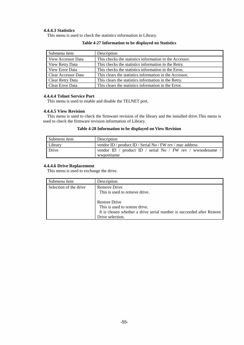
-55-
4.4.4.3 Statistics This menu is used to check the statistics information in Library.
Table 4-27 Information to be displayed on Statistics
Submenu item Description
View Accessor Data This checks the statistics information in the Accessor.
View Retry Data This checks the statistics information in the Retry.
View Error Data This checks the statistics information in the Error.
Clear Accessor Data This clears the statistics information in the Accessor.
Clear Retry Data This clears the statistics information in the Retry.
Clear Error Data This clears the statistics information in the Error.
4.4.4.4 Telnet Service Port This menu is used to enable and disable the TELNET port.
4.4.4.5 View Revision This menu is used to check the firmware revision of the library and the installed drive.This menu is
used to check the firmware revision information of Library.
Table 4-28 Information to be displayed on View Revision
Submenu item Description
Library vendor ID / product ID / Serial No / FW rev / mac address
Drive vendor ID / product ID / serial No / FW rev / wwnodename /
wwportname
4.4.4.6 Drive Replacement This menu is used to exchange the drive.
Submenu item Description
Selection of the drive Remove Drive
This is used to remove drive.
Restore Drive
This is used to restore drive.
It is chosen whether a drive serial number is succeeded after Restore
Drive selection.

-56-
4.4.4.7 Advanced Service This menu is used to test of Library. (Do not use it usually. )
Table 4-29 Test to be displayed on Advanced Service
Submenu item Description
Mechanism test The following mechanism test can be executed. (Do not use it usually. )
・Demo (Slot-Drv-Slot)
・Demo (Slot-Slot)
・MSBF Test
・X-Move Test
・Y-Move Test
・Pick/Put Test
・Pick/Put/Move Test
・Vibration Test
LCD / LED test LCD / LED test can be executed. (Do not use it usually. )
Phy test Ethernet phy test can be executed. (Do not use it usually. )
4.4.4.8 Library Log
This menu is used to check the Library Log.
Table 4-30 Information to be displayed on View Revision
Submenu item Description
Library Log Error Log / Cleaning Log / Media Error Log
4.4.5 Logout This returns to the Login menu.

-57-
4.5 Configuring the Library This section describes Library configuration,setting of the drive, changing of the password , and
setting for I/O station.
4.5.1 Viewing Configuration data of the library Take the following steps to view the configuration data of the library.
1) [Login]. See Section 4.3Login for detail.
2) Select [Current Information].
3) Select [Setting Information] from [Current Information].
The configuration information of the library is displayed.
To view the firmware version of the library, select [View Revision] from [service] of [Top menu].
4.5.2 Change password The following describes how to change the password used during login.
1) [Login]. See Section 4.3Login for detail.
2) Select [Configuration].
3) Select [OP Panel Settings] from [Configuration].
4) Select [Change Password] from [Configuration].
5) The following password input menu will appear.
Enter a new four-digit password.
6) Next, retype the password that you entered at step 5).
7) If the password entered in step 5) and 6) match, the following message will appear.

-58-
Once the above message is displayed, the new password is valid.
If the entered passwords do not match, the following message will appear.
If the above message is displayed, start again from step 4).
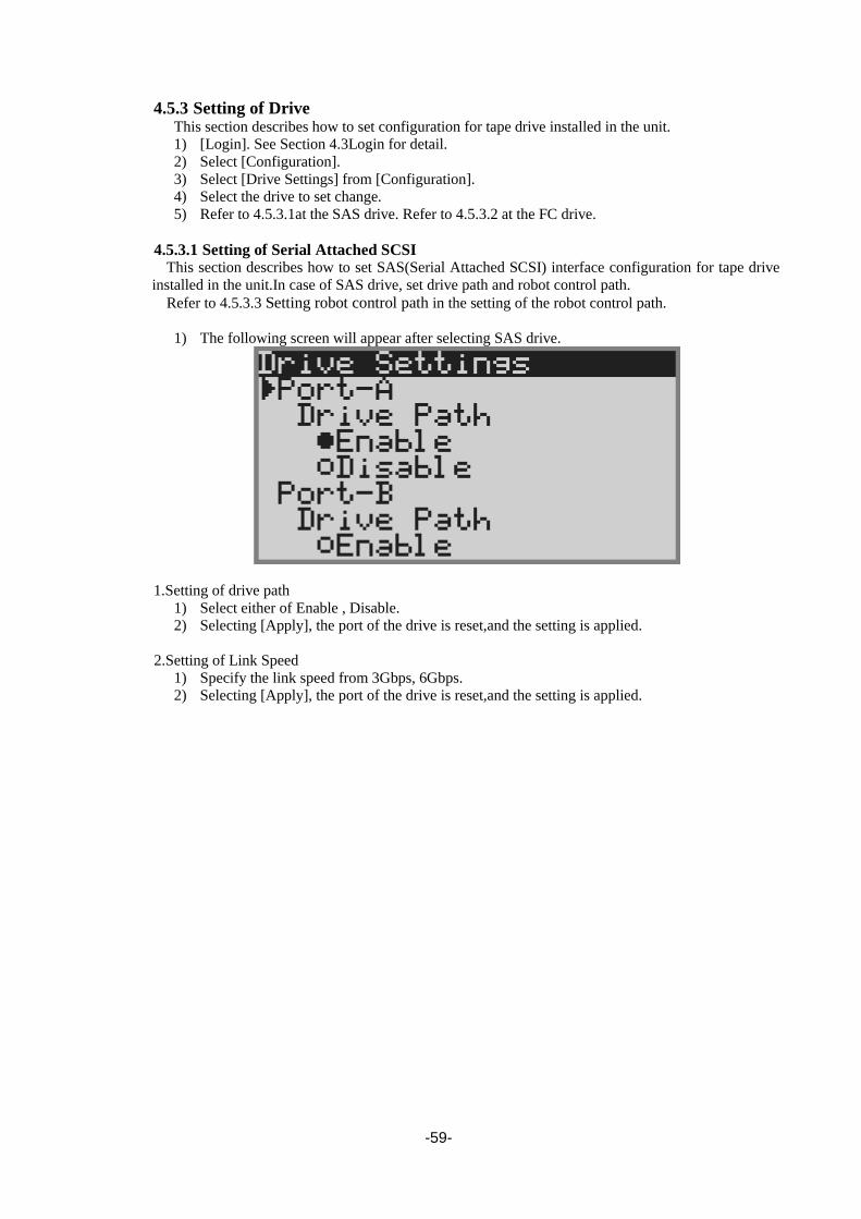
-59-
4.5.3 Setting of Drive This section describes how to set configuration for tape drive installed in the unit.
1) [Login]. See Section 4.3Login for detail.
2) Select [Configuration].
3) Select [Drive Settings] from [Configuration].
4) Select the drive to set change.
5) Refer to 4.5.3.1at the SAS drive. Refer to 4.5.3.2 at the FC drive.
4.5.3.1 Setting of Serial Attached SCSI This section describes how to set SAS(Serial Attached SCSI) interface configuration for tape drive
installed in the unit.In case of SAS drive, set drive path and robot control path.
Refer to 4.5.3.3 Setting robot control path in the setting of the robot control path.
1) The following screen will appear after selecting SAS drive.
1.Setting of drive path
1) Select either of Enable , Disable.
2) Selecting [Apply], the port of the drive is reset,and the setting is applied.
2.Setting of Link Speed
1) Specify the link speed from 3Gbps, 6Gbps.
2) Selecting [Apply], the port of the drive is reset,and the setting is applied.

-60-
4.5.3.2 Setting of Fibre Channel This section describes how to set Fibre channel interface configuration for tape drive installed in the
unit. In case of FC drive, set drive path , topology , loop ID , Link Speed and robot control path.
1) The following screen will appear after selecting SAS drive.
1.Setting of drive path
1) Select either of Enable , Disable.
2) Selecting [Apply], the port of the drive is reset,and the setting is applied.
2.Setting of Topology
1) Select either of Loop , Point to Point.
2) Selecting [Apply], the port of the drive is reset,and the setting is applied.
3.Setting of Loop ID
1) Select [Set Loop ID].
2) Input three-digit number for Loop ID.
3) Selecting [Apply], the port of the drive is reset,and the setting is applied.
The valid value for Loop ID is in the range between 000 and 125.
4.Setting of Link Speed
3) Specify the link speed from Auto Negotiation, 8Gbps, 4Gbps, 2Gbps, or 1Gbps.
4) Selecting [Apply], the port of the drive is reset,and the setting is applied.
Setting of Fibre Channel:
Selecting [Apply], the port of the drive is reset,and the setting is applied.
If [Apply] is selected after all of 1(Topology), 2(Loop ID) and 3(Link Speed) are set,
setting can be set by port reset only once.

-61-
4.5.3.3 Setting robot control path
This section describes how to set robot control path.
1) [Login]. See Section 4.3Login for detail.
2) Select [Configuration].
3) Select [Drive Settings] from [Configuration].
4) Select the drive that sets the robot control passing.
5) Select Enable under Media Changer Path.
6) Selecting [Apply], the port of the drive is reset,and the setting is applied.
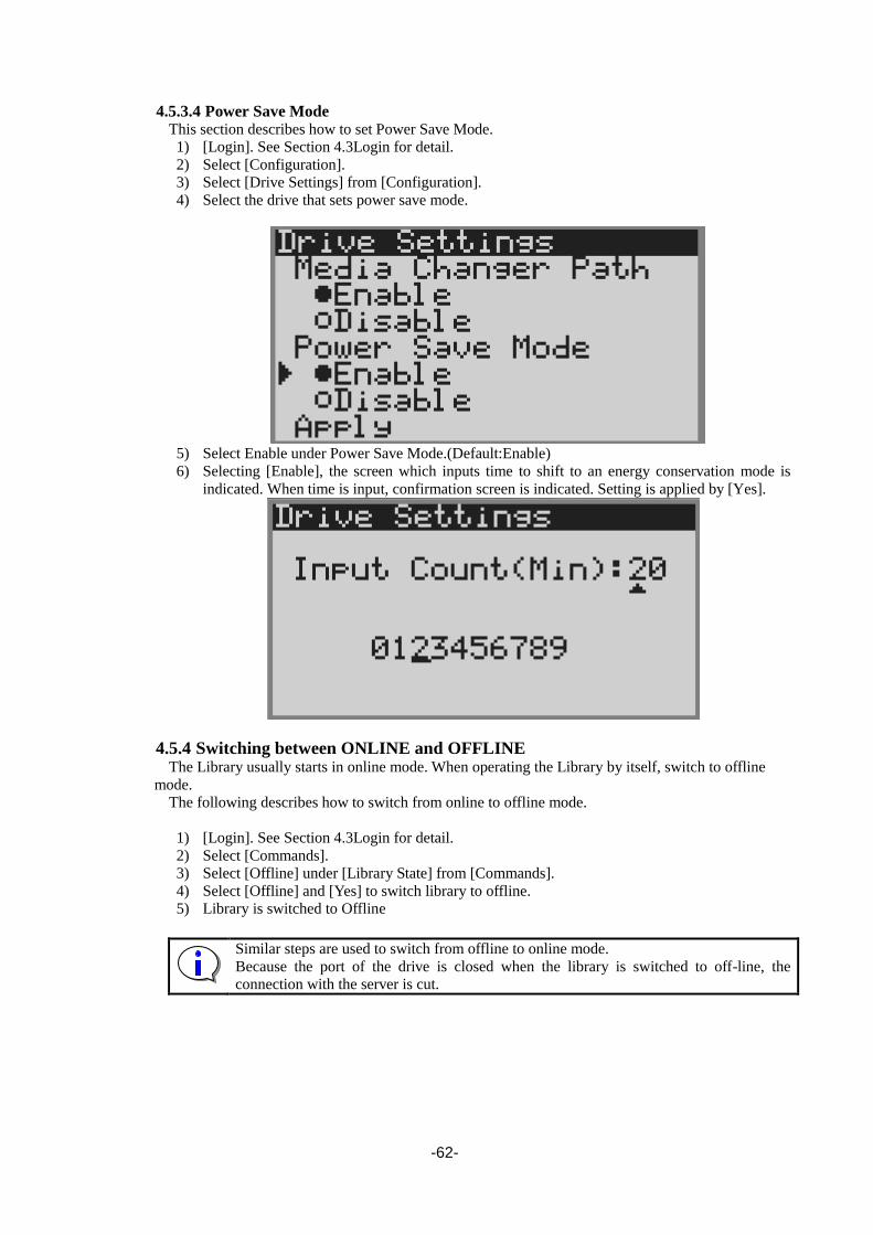
-62-
4.5.3.4 Power Save Mode
This section describes how to set Power Save Mode.
1) [Login]. See Section 4.3Login for detail.
2) Select [Configuration].
3) Select [Drive Settings] from [Configuration].
4) Select the drive that sets power save mode.
5) Select Enable under Power Save Mode.(Default:Enable)
6) Selecting [Enable], the screen which inputs time to shift to an energy conservation mode is
indicated. When time is input, confirmation screen is indicated. Setting is applied by [Yes].
4.5.4 Switching between ONLINE and OFFLINE The Library usually starts in online mode. When operating the Library by itself, switch to offline
mode.
The following describes how to switch from online to offline mode.
1) [Login]. See Section 4.3Login for detail.
2) Select [Commands].
3) Select [Offline] under [Library State] from [Commands].
4) Select [Offline] and [Yes] to switch library to offline.
5) Library is switched to Offline
Similar steps are used to switch from offline to online mode.
Because the port of the drive is closed when the library is switched to off-line, the
connection with the server is cut.

-63-
4.5.5 Setting of I/O Station You can configure the library unit to use a part of the front magazine as I/O station. Described
below is the setting procedure.
1) [Login]. See Section 4.3Login for detail.
2) Select [Configuration]
3) Select [Library Settings] from [Configuration].
4) Select [Enable] of [I/O station] from [Library Settings].
5) Selecting [Apply], the port of the drive is reset,and the setting is applied.
4.5.6 Setting of Active Slot You can change the number of slots logically in the library unit. Described below is setting
procedure.
1) [Login]. See Section 4.3Login for detail.
2) Select [Configuration].
3) Select [Library Setting] from [Configuration].
4) Select [Active Slots] from [Library Settings].
5) The following screen will appear.
6) Input number of Active slots.Select [Yes] to set change number of Active slots.
7) Selecting [Apply], the port of the drive is reset,and the setting is applied.
If I/O Station is enabled:
If the I/O station is enabled, two decreases of the number of slots that can be set.
The number that can be set as Active Slots is only the even numbers.

-64-
4.6 Insertion and Removing Cartridge by Operator Panel This section describes how to insert and remove the cartridge from the library by the operation of
the operator panel using the magazine and I/O station.
4.6.1 Magazine Operations 4.6.1.1 Removing Magazine
Magazine parts are composed of front magazine and rear magazine.
Described below is the procedure to remove front magazine.
1) [Login]. See Section 4.3Login for detail.
2) Put Magazine Unlock button.(refer to 1.3.3.2Button)
3) The message of [Magazine is unlocked] is displayed in Library state on LCD screen, and
magazine is unlocked. Next,draw out the magazine.
4) Draw out the magazine slowly until there is a locked feeling. Please do not draw out the
magazine strongly.
5) Draw out the magazine with pressing the lever under the left of the magazine.( Release lever of
fall prevention lock).
(Draw out the magazine by both hands.)
The front magazine can be removed above.
Release lever of fall prevention lock Draw out the magazine by both hands.

-65-
Described below is the procedure to remove rear magazine.
The rear magazine is drawn out to the position of the following picture with drawing out the front
magazine.
6) A rear magazine is drawn out according to the procedure3),4) similar to the procedure for
drawing out the front magazine.(Refer to follwing picture about the location of release lever of
fall prevention lock)
Please do not draw out the magazine strongly.
release lever of fall prevention lock

-66-
4.6.1.2 Insertion of cartridges into magazine
When inserting cartridges into the slots of the magazine, note the direction of each cartridge. If a
cartridge is inserted in the wrong direction, malfunctions may occur. Refer to the photo below before
inserting.
For description of magazine slot numbers, see” 1.3.4.1Slot number”
Insert the cartridges correctly. If a cartridge is inserted in the wrong direction or
it is not fully inserted into the slot, the Library may not start, an error message
may be displayed, and the Accessor or cartridge may be damaged.
4.6.1.3 Removal of cartridges from magazine
To remove a cartridge, slide the locking mechanism to the left located next to the slot's opening.

-67-
4.6.1.4 Emergency removal of magazine
This removal method should be used only during an emergency.
When the magazine is taken out in case of things except the necessity by the following operations,
neither the library device operation, the drive device nor the tape cartridge can be guaranteed.
Moreover, please note that it causes the breakdown of the transportation device ([accessor]) and the
magazine when the tape cartridge is taken out while operating.
The steps for removing the magazine from the Library are described below.
1) Insert a pointed object (such as a small Philips screwdriver) into the round hole shown below.
2) Keep the object inserted while pulling out the magazine.
The point to remove upper magazine in the emergency
The point to remove lower magazine in the emergency

-68-
4.6.2 I/O Station Operations
The I/O station dashes out to a device front side after pressing the enter button. Please
there must not be danger from which the hand is placed between the moving part, and
do not affix the hand to the magazine, and do not put the finger in the opening of the
magazine until the I/O station dashes out. Please push the magazine a little when the
finger is placed in the opening of the magazine by any chance and pull out the finger
while returning it.
1) [Login]. See Section 4.3Login for detail.
2) Push Magazine I/O station Unlock button.(refer to 1.3.3.2Button)
3) The message of [Push Enter Key] is displayed in Library state on LCD screen
4) Push Enter button , and I/O station is opened.
5) Refer to the photo below before inserting.
6) Close I/O station.
7) Inventory automatically starts.
The I/O Station lock release is not done when set from the host to the state of Media Removal
Prevented.
Insert the cartridges correctly. If a cartridge is inserted in the wrong direction or
it is not fully inserted into the slot, the Library may not start, an error message
may be displayed, and the Accessor or cartridge may be damaged.
Don’t lift the cover of the I/O station.

-69-
4.7 Using the operation panel to move cartridges
4.7.1 Load cartridge into drive The following describes how to use the operation panel to move a cartridge from a specified
magazine slot into the drive.
In this example, the cartridge in slot 1 will be loaded into the drive #1.
1) [Login]. See Section 4.3Login for detail.
2) Select [Commands].
3) Select [Move Cartridge] from [Commands].
4) The screen to specify the Source and Destination is displayed.
Figure 4-10 Move Cartidge
5) Select [slotxx] under [Source], and the slot where the cartridge is stored is displayed.
In this example, select slot01.
Figure 4-11 Select source Screen

-70-
6) Select [slotxx] under [Destination], and the slot where the no cartridge is stored is displayed.
In this example, slect Drive1.
Figure 4-12 Select Destination Screen
7) Select [Execute], the cartridge is moved and inserted into the drive.
Figure 4-13 Select Execute

-71-
4.7.2 Removing from the drive
This operation should be performed only during emergencies, such as when the
operation cannot be controlled from a host device.
The following describes the steps for moving a cartridge from the drive.
In this example, the cartridge in drive 1 will be removed into the slot1.
1) [Login]. See Section 4.3Login for detail.
2) If the library is in online state, set it to offline. See Section 4.5.4Switching between ONLINE and OFFLINE for details.
Select [Unload] from [Commands] to eject a cartridge from the drive.
If you select [Unload], you are prompted to select the drive to unload. Specify the relevant
drive and execute the command. When [Unload] is executed, the cartridge moves to the drive
bay.
3) Select [Move Cartridge] from [Commands].
4) The screen to specify the Source and Destination is displayed.
Figure 4-14 Move Cartridge
5) Select [slotxx] under [Source], and the slot where the cartridge is stored is displayed.
In this example, select Drive1.
Figure 4-15 Select source screen

-72-
6) Select [slotxx] under [Destination], and the slot where the no cartridge is stored is displayed.
In this example, slect Slot01.
Figure 4-16 Select Destination screen
7) Select [Execute], the cartridge is ejected from the drive and moved to the slot.
Figure 4-17 Select Execute

-73-
4.8 Cleaning
4.8.1 Cleaning by Operation panel
Before using the operation panel to set cleaning, make sure that the backup software will not be
executing any jobs during the cleaning process. (If necessary, take measures such as turning off the
backup software service.)
・Use a special cleaning cartridge with a bar code label that supports the drive to be
cleaned.
・Clean the drive once a month or a backup of 100 hours when cleaning is necessary
in operation.(When there is a cleaning request from the drive, clean the drive.)
・Each cleaning cartridge can be used up to 50 times.
Record the number of use, and when 50 times is reached, replace the cleaning
cartridge.
The drive will not be cleaned even if the cleaning cartridge being used has
exceeded its service life. When it's detected that a cleaning cartridge reached its
service life, it's shown to an operator panel with "REPLACE CLEANING
MEDIA".
・[Clean Drive] doesn't operate when the bar code for the cleaning cartridge is not
stuck on the cleaning cartridge. In that case, please use and clean [Move
Cartridge].
・[Clean drive] should be performed only when there are no backup software jobs
being executed.
1) Check that the cleaning cartridge is appropriate to the target drive and its use count limitation
has not been reached.
2) [Login]. See Section 4.3Login for detail.
3) Remove the magazine, and set the cleaning cartridge into the slot.
4) Select [Clean Drive] from [Commands].
5) Select the target drive to be cleaned.
6) The drive automatically performs cleaning. When the cleaning is complete, the cleaning
cartridge is returned to the slot as before.
7) Remove the magazine, and then remove the cleaning cartridge.
4.8.2 Auto Cleaning
When you use the library with backup software, please set up an Auto Cleaning
Mode Disable.
If the backup software supports the AUTO CLEANING function, use the auto
cleaning function of backup software.
The auto cleaning function enables the Library to automatically clean drives that require cleaning.
Be sure to insert the cleaning cartridge into an Inactive slot.
When the auto cleaning function is on and the drive requests cleaning, the Accessor removes the
cleaning cartridge from the unused slot and loads it into the drive. When cleaning is finished, it returns
the cartridge to the same Inactive slot.

-74-
4.9 Rebooting the Library
If a reset is executed without first executing the following steps, the device and/or
cartridge may be damaged, and data may be lost.
A reboot (initialization) is required in the following cases.
・When a system administrator or maintenance engineer has ordered a reboot of the Library.
・When errors have occurred in the Accessor and/or drive.
The following describes the steps for rebooting the library.
1) [Login]. See Section 4.3Login for detail.
2) Make sure that all jobs have been completed. If the library is in online state, set it to offline.
See Section 4.5.4Switching between ONLINE and OFFLINE for details.
3) Select [Reboot Library] from [Commands].
4) The confirming message will appear.Setting is applied by selecting [Yes].
5) The library reboots.
Figure 4-18 Reboot Library

-75-
4.10 Rebooting Drive
If a reset is executed without first executing the following steps, the device and/or
cartridge may be damaged, and data may be lost.
A reboot (initialization) is required in the following cases.
・When a system administrator or maintenance engineer has ordered a reboot of the Library.
・When errors have occurred in the Accessor and/or drive.
The following describes the steps for rebooting the library.
1) [Login]. See Section 4.3Login for detail.
2) Make sure that all jobs have been completed. If the library is in online state, set it to offline.
See Section 4.5.4Switching between ONLINE and OFFLINE for details.
3) Select [Reboot Drive] from [Commands].
4) The confirming message will appear.Setting is applied by selecting [Yes].
5) The drive reboots.

-76-
Chapter5 Remote Manager Interface
This chapter describes how to use the Library's Ethernet functions ((Remote Manager interface),
SNMP Agent, and email notification).
5.1 Connection Configuration
The following configuration is required when using Ethernet functions.
(1)General
・10BASE-T/100BASE-TX/1000BASE-T LAN(full duplex or half duplex is OK, Gateway is
accessible)
(2)Remote Manager Interface
Web browser : Operation is confirmed with Internet Explorer 7 / Internet Explorer 8 /
Internet Explorer 9 / Internet Explorer 10 / Internet Explorer 11 / Firefox3.6.
(3)SNMP function
SNMP Manager: Trap reception and MIB extraction by an MIB browser are enabled. Various
settings are required to enable monitoring. (See the relevant software
manual for description of these settings.)
※SNMP : Simple Network Management Protocol
(4)email notification
Mail server does not require SMTP authentication (mail servers that do require SMTP
authentication are not supported)
※SMTP : Simple Mail Transfer Protocol
SNMP Manager E-mail
通知先
E-mail 通知先
SNMP
Manager email 通知先
notification list
Web ブラウザ
Web ブラウザ
Web
browser
LAN
(10BASE-T/100BASE-TX/1000BASE-T)
server
Library

-77-
5.2 Connection Settings When using the Library's Ethernet function, the following items must be set appropriately. These
items can be set and checked via the operation panel. For description of how to change these settings,
see “4.4.2Configuration”.
Consult with a network manager concerning the settings for these items.
Table 5-1 Connection Setting (IPv4)
Item Default value Description of setting
DHCP Disable This sets whether or not DHCP will be used to dynamically
assign IP addresses, etc. Set this to ON to have DHCP
dynamically assign IP addresses, etc. Set it to off when a
fixed IP address is used. The IP addresses that are assigned
by DHCP, can be checked by selecting [Setting
Information] from [Current Information] on the operation
panel.
IP Address 192.168.1.1
Library device's IP address
When using an Ethernet function, the appropriate IP
address must be set. This can also be set automatically by
DHCP.
Subnet Mask 255.255.255.0 Network's subnet mask
When using an Ethernet function, the appropriate subnet
mask must be set. This can also be set automatically by
DHCP.
Gateway 192.168.1.254 The gateway is specified for access from a different subnet
mask. This setting is not necessary when access is always
within the same network. This can also be set automatically
by DHCP.
Table 5-2 Connection Setting (IPv6)
Item Default value Description of setting
Stateless DHCP Disable Information is retrieved from a router advertisement, and
the IPv6 address, prefix length, and gateway are set
automatically.
DHCP IPv6 Disable This sets whether or not DHCP will be used to dynamically
assign IP addresses, etc. Set this to ON to have DHCP
dynamically assign IP addresses, etc. Set it to off when a
fixed IP address is used. The IP addresses that are assigned
by DHCP, can be checked by selecting [Setting
Information] from [Current Information] on the operation
panel.
IP Address 0::0 Library device's IP address
When using an Ethernet function, the appropriate IP
address must be set. This can also be set automatically by
DHCP.
Prefix Length 64 This sets Prefix length.
Gateway 0::0 The gateway is specified for access from a different subnet
mask. This setting is not necessary when access is always
within the same network. This can also be set automatically
by DHCP.

-78-
5.3 Startup of Remote Manager Interface
Open a Web browser from any network-connected terminal, and enter the IP address that was set for
the Library as the URL.
Figure 5-1 Input URL
If this product and the terminal are normally connected with the network respectively, the log in
screen is displayed as the first stage screen.
Please end a browser from the task manager when a browser doesn't react. Afterwards,
please reactivate a browser again.

-79-
5.3.1 Connection of https The connection method to the remote manager interface in https is as follows.
(1) Https://(IP address set to the tape device) is input.
(2) When connecting it with the Web service not registered on the attestation site like the remote
manager interface, warning is displayed as shown. "Continue to this website (Not
recommended)" is clicked.

-80-
5.4 Login Formats
(1)Registered users
Up to six users can be freely set.
The administrator / service is already registered as the reserved user, so the total number of
users, including the reserved user and the freely selectable users, is 15.
(Reserved user)
User type Username Password (default value)
Administrator admin secure
Maintenance service ser001
No. of characters Up to 8 Up to 16
* Both the username and password are case sensitive.
Login after connecting the maintenance member with the Ethernet connector for maintenance
referring to "Ethernet connector for 1.3.3.3.
Refer to 5.6.5.1 for user's setting method.
(2) Simultaneous login
It is usually recommended to use it by one user because there is a possibility of worsening of
the response though can logged in at the same time by two or more users, the occurrence, and
doing the time-out by the communication fault.
(3) Access privileges
Web administrators have the following three levels of access privileges.
・ Administrator (user)
・ Super user
・ General(user)
The access level is distinguished by the user name used when the Web administrator logs in.
A password is required during login to prevent unauthorized access.
Below, users that can access the current page are indicated along the side of each page's
description.
Higher-level access privilege

-81-
5.5 Web Page Configuration
The page configuration shown by the browser can be divided into a banner section and a section of
specific information for each page.
Although the web page can be viewed on an 800 × 600-dot monitor, at least 1280 × 1024 dots is
recommended. The basic menu varies according to the access level of the logged in user.
Banner section
Menu
Page-Specific
information section

-82-
5.6 Web Page Detail All windows (except for the login window) display the following menus. Therefore, the user can easily
jump to any of these menus from any window.
5.6.1 Menu windows The following are the menus displayed in each window after login. When any of these menus is
selected, it changes to a color different from the color of the other menus.
Menus that are not available for the current user access level are not displayed.
See the following table for details.
Table 5-3 Menus available at various user access levels
Menu Meaning User Super
user
Admini
strator
Monitor System Menu used to check the Library's status ○ ○ ○
Manage Library Menu used to manage the Library × ○ ○
Configure Library Menu used to enter Library settings × × ○
Service Library Menu used to download log information ○ ○ ○
Help Help information can be accessed for each menu. ○ ○ ○
Logoff Closes the Remote Manager Interface, and goes to
the login window. ○ ○ ○
Menus(User) Menus(Super user) Menus(Administrator) Menus(service)

-83-
5.6.2 Login
[Function]
Login to the Web Manager.
Authentication is performed by username and password. The three access authority level
(administrator, super user and general user) is set according to the username entered. Then, go to the
Home page.
[Display contets]
1.Account
Enter username to login. (The account can be created in User Access)
2.Password
Enter the password for username. (The entered characters are indicated by asterisks (●).)
3.Login button
When Login button is clicked, the system checks if the entered username has been registered and
the password entered is for that username. (username and password are case-sensitive.) If the
username and password match, the screen goes to the Home page corresponding to the username.
If they are unmatched, login fails.
Figure 5-2 Login page(before entry)
Figure 5-3 Login page(after entry)

-84-
5.6.3 Library information viewing menu(Monitor Sytem) 5.6.3.1 Library Basic Information(System Summary)
[Monitor System]-[System Summary] All users
[Function]
This menu shows the image and basic information of the Library
Figure 5-4 Library Basic Information Window
(1)
(2)
(3)
(4)
(5)

-85-
[Information]
1. Device image
A photo of the device is shown.
2. Status
Library name: Library name
Library : Library status
(Ready,Not Ready / Dergraded / Failed / PSU n Fault / PSU n FAN Error)
・Failed : The library error was detected.
・Degraded : The mechanism has reached its durability.
Drive : Drive status
(Ready / Degraded / Failed / Drive FAN Error / Media Error / Cleaning Request)
・Failed : The drive error is detected.
・Degraded : The drive error is detected.
Magazine : Magazine’s status (Opened, Closed,etc)
3. Front Panel Indicators
These indicate the status of the LEDs on the front of the Library.
For further description of front panel indicators, see”1.3.2.1Status LED”
4. Configuration and Cartridge Counts
These indicate the slot settings and the number of cartridges.
(1)Drive
When the "Cartridge" value is "0", it means there are no cartridges in the drive. When it is "1",
it means a cartridge is in the drive. The Slots displays "N/A".
(2)Storage
This indicates the number of storage slot cartridges and the number of slot-loaded cartridges.
(3)Cleaning / Inactive
This indicates the number of cartridges in cleaning slots or inactive slots.
(4)I/O Station
This indicates the number of cartridges in the I/O Station and the number of loaded cartridges.
(5)Total
This indicates the total number of cartridges loaded in the Library and the total number of
slot-stored cartridges.
5. Version
(1)Library firmware version
This indicates the Library's firmware version.
(2)Library serial number
This indicates the Library's serial number.
(3)Drive n
This indicates the drive's firmware version.

-86-
5.6.3.2 Library Detailed Information Window (Library Map)
[Monitor System] - [Library Map] All users
[Function]
This menu describes the cartridges loaded in various slots and the Library's various parts.
[Information]
This window includes detailed information along the right side, which varies according to the
selected Accessor, drive, etc.
Figure 5-5 Library map
(1) (4)
(2)
(2)
(3)

-87-
1. Library Map
This shows the physical positions of cartridges stored in the Library, as well as images of the
Library's various components such as the Accessor and drive.
2. Details (Magazine)
(1)Slot Information
This section shows detailed information about the selected slot.
Slot type : Indicates the type of slot.
(Storage / I/O Station / Cleaning / Inactive)
Element address : Indicates the slot's address for reporting to the host.
(2)Cartridge Information
Detailed information on the cartridge is displayed when a slot with a cartridge is selected.
Cartridge label : Shows the cartridge's bar code label.
"Unknown" is displayed when there is no barcode label.
Remain : Indicates the number of cleaning cartridges remaining.
This is shown only when the cartridge type is "cleaning cartridge".
Media Status : Indicates the cartridge's status. (OK, Expired, Bad Media, etc.)
Encryptions : Indicates the encryption status.(Encrypted,Not encrypted,unknown)
Total Capacity :Indicates the total capacity of tape cartridge.
Used Capacity :Indicates the used capacity of tape cartridge.
Remaining Capacity :Indicates the remaining capacity of tape cartridge.
The correct remaining number cannot be shown unless a cleaning cartridge has
been loaded to the drive. Note that cartridge cleaning starts automatically when a
cleaning cartridge is loaded. Users are expected to monitor the number of times such
cleaning has been used.
Figure 5-6 Detail(Magazine)

-88-
3. Details (Others)
(1)Accessor
[Accessor information]
This section shows detailed information about the Accessor.
Status : Indicates the Accessor's status.
(Ready, Degraded, Failed, Not Ready, etc)
Error information : Displays the event information including an error that occurred in the
accessor and an event of articles of consumption exchange notification.
(It is not displayed when there is no event.)
Cartridge label : Shows the cartridge's bar code label.
"Unknown" is displayed when there is no barcode label.
Media Status : Indicates the cartridge's status. (OK, Expired, Bad Media, etc.)
Figure 5-7 Accessor Information

-89-
(2)Library
[Library information]
This section shows detailed information about the library.
Accessor Status : Indicates the Accessor's status.
(Ready,Degraded,Failed,Not Ready,etc)
Drive n status : Indicates the drive's status.
(Ready / Degraded / Failed / Drive FAN Error / Media Error / Cleaning Request)
Magazine n status : Indicates the magazine's status.
PSU n status :Indicates the PSU’s status.
Library mode : Indicates the Library's operation mode. (Random,etc)
I/O Station : Indicates the I/O Station's setup status. (Disable, Enable)
Auto cleaning : Indicates the auto cleaning settings. (Disable, Enable)
Bar code label length: Indicates settings of the bar code label lenghth.
Notice nearly expired : Indicates the setup of the Nearly Expired trap of a cleaning cartridge.
In Disable, a Nearly Expired trap is not notified.
In Enable, indicates the setup value.
Notice every cleaning: Indicates a setup of whether for it to remain for every cleaning
execution and to notify the trap of the number of times.
Drive power save mode: Indicates time for a drive to shift to energy-saving mode.
If there are no time and servo operation of a drive which are displayed,
it will shift to energy-saving mode.
Figure 5-8 Library information
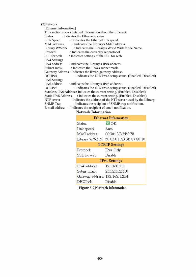
-90-
(3)Network
[Ethernet information]
This section shows detailed information about the Ethernet.
Status : Indicates the Ethernet's status.
Link Speed : Indicates the Ethernet link speed.
MAC address : Indicates the Library's MAC address.
Library WWNN : Indicates the Library's World Wide Node Name.
Protocol : Indicates the currently set protocol.
SSL for web : Indicates settings of the SSL for web.
IPv4 Settings
IPv4 address : Indicates the Library's IPv4 address.
Subnet mask : Indicates the IPv4's subnet mask.
Gateway Address : Indicates the IPv4's gateway address.
DCHPv4 : Indicates the DHCPv4's setup status. (Enabled, Disabled)
IPv6 Settings
IPv6 address : Indicates the Library's IPv6 address.
DHCPv6 : Indicates the DHCPv6's setup status. (Enabled, Disabled)
Stateless IPv6 Address: Indicates the current setting. (Enabled, Disabled)
Static IPv6 Address : Indicates the current setting. (Enabled, Disabled)
NTP server : Indicates the address of the NTP server used by the Library.
SNMP Trap : Indicates the recipient of SNMP trap notification.
E-mail address : Indicates the recipient of email notification.
Figure 5-9 Network information

-91-
(4)Notification
This section shows detailed information about the SMTP / SNMP.
SMTP Setting
SMTP server : Indicates the IP address of mail server.
Sender address : Indicates the e-mail address of library.
Subject : Indicates the subject of e-mail the library sends.
MailRecipients : Indicates the mail address.
SNMP Settings
Community : Indicates Community name of SNMP.
SNMP v3 Engine ID : Indicates Engine ID of SNMPv3 Agent.
Trap Recipients : Indicates the address of trap.
Figure 5-10 Notification information

-92-
4. Details (Drive)
(1)Drive n information
This section shows drive information.
Status : Indicates the drive's status.
(Ready / Degraded / Failed / Drive FAN Error / Media Error / Cleaning Request)
Element Status:Indicates the drive’s element status.
Vendor ID : Indicates the LTO drive manufacturer
Product ID : Indicates the drive's product name.
Serial number: Indicates the drive's serial number.
F/W version : Indicates the drive's firmware version.
Host I/F :Indicates the I/F of the drive.(SAS / FC)
Media Changer path : Indicates the setting of media changer path.
World Wide ID: Indicates the drive's WWN.
(2)Cartridge Information
When there is a cartridge in the drive, the cartridge's detailed information is shown.
Cartridge label : Indicates the cartridge's bar code label.
If there is no bar code label, "unknown" is displayed.
Write Protect : Indicates the cartridge's write protection status.
Media Status : Indicates the cartridge's status. (OK, Expired, Bad Media, etc.)
Encryption : Indicates encryption setting.(Enable,Disable)
Total Capacity :Indicates the total capacity of tape cartridge.
Used Capacity :Indicates the used capacity of tape cartridge.
Remaining Capacity :Indicates the remaining capacity of tape cartridge.
Figure 5-11 Drive information

-93-
5.6.4 Library management menu (Manage Library) 5.6.4.1 Move Cartridge window (Move Cartridge)
[Manage Library]-[Move Cartridge] Service/Administrator/Super user
[Function]
This window's functions are similar to those of the operation panel's [Move Cartridge] menu, which
moves the cartridges by specifying the source and destination of each cartridge to be moved.
[Use method]
Specifying the source element address and the destination element address to move cartridge.
[Information]
Figure 5-12 Move Cartridge
(1)
(2)
(3)
(4)

-94-
1. Specify source slot
Sepecify the source element address to transfer the cartridge.The slot where the cartridge is stored
is displayed.
Element Address can be narrowed with Row and Slot.
2. Specify destination slot
Sepecify the destination element address to transfer the cartridge.The slot where no cartridge is
stored is displayed.
Element Address can be narrowed with Row and Slot.
3. Slot map
Slot information is displayed in similar Library Map. The source slot and the target slot can be
selected from this map.
It specifies as a source slot when the slot where the cartridge is stored is selected and it is
specified as a target slot when the slot where no cartridge is stored is selected.
4. Move button
After specifying the source slot and the destination slot, move cartridge starts by clicking the
move button.

-95-
5.6.4.2 Unload Drive window (Unload Drive)
[Manage Library]-[Unload Drive] Service/Administrator/Super user
[Function]
This window's functions are similar to those of the operation panel's [Unload] menu, which enables
a cartridge that has been inserted in the drive to be unloaded, and displays an unload completion dialog
box when this operation is completed.
The "Unload Drive" function cannot be executed unless there is a cartridge in the drive.
[Use method]
1.Specify the drive to unload the cartridge.
2. Click the Unload button to start Unloading.
[Information]
Figure 5-13 Unload Drive
1.Specify the drive
Taget drive: Select the drive to unload the cartridge from the list.
2.Unload button
Click the Unload button, and Unloading starts.
(1)
(2)

-96-
5.6.4.3 Clean Drive window (Clean Drive)
[Manage Library]-[Clean Drive] Service/Administrator/Super user
[Function]
This window's functions are similar to those of the operation panel's [Clean Drive] menu, which
inserts a cleaning cartridge into the drive specified by the selected slot, and then cleans the drive.
When drive cleaning is finished, the cleaning cartridge is returned to the original slot, and the cleaning
complete dialog box is displayed.
The "Clean Drive" function cannot be executed unless there is a cleaning cartridge in the library.
・Use a special cleaning cartridge with a bar code label that supports the drive to be
cleaned.
・Clean the drive once a month or a backup of 100 hours when cleaning is necessary
in operation.(When there is a cleaning request from the drive, clean the drive.)
・Each cleaning cartridge can be used up to 50 times.
Record the number of use, and when 50 times is reached, replace the cleaning
cartridge.
The drive will not be cleaned even if the cleaning cartridge being used has
exceeded its service life.
・[Clean Drive] doesn't operate when the bar code for the cleaning cartridge is not
stuck on the cleaning cartridge. In that case, please use and clean [Move
Cartridge].
・[Clean drive] should be performed only when there are no backup software jobs
being executed.
[Use method]
1.Slect the drive to clean at target drive.
2. Select the cleaning cartridge to be used at “Use cartridge”
3. Click the Clean button to start Cleaning
[Information]
Figure 5-14 Clean Drive
1.Specify the drive
Taget drive: Select the drive to clean from the list.
2.Specify the cleaning cartridge
Use Cartridge: Select the cleaning cartridge to be used
3.Clean button
Click the Clean button, and Cleaning starts.
(1)
(2) (3)

-97-
5.6.4.4 Library State (OFFLINE/ONLINE)switching window(Library State)
[Manage Library] - [Library State] Service/Administrator/Super user
[Function]
This function is similar to the operation panel's [Library State] menu's function that switches the
Library's setting for the Accessor between online and offline.
[Use method]
1. Click the “Bring Offline”(Bring Online) button to view the confirmation screen.
2. Select "Yes" to execute switching.
[Information]
Figure 5-15 Library state
Figure 5-16 confirmation screen
1. Current state
Indicate the Library's online/offline status. (Online/Offline)
2. Bring Online / Offline button
Click this button to switch the Accessor's status between online and offline.
When the Library is online, the [Bring Offline] button is displayed.
When the Library is offline, the [Bring Online] button is displayed.
(1)
(2)

-98-
5.6.5 Library setting (Configure Library) 5.6.5.1 Account setting (User Access)
[Configure Library] - [User Access] Service/Administrator
[Function]
This window is used to add, modify, or remove users with login access.
To add a user, use the Select Action scroll box to select "Add User", and to remove a user, first
select the current user to be removed, then use the Select Action scroll box to select "Remove Users".
[Information]
Figure 5-17 UserAccess
1. Add User button
When "Add User" button is clicked, users can be newly registered.
2. Current Users
This lists the currently registered users.
3. Remove User button
When "Remove User" button is clicked, users can be removed.
(1)
(2) (3)
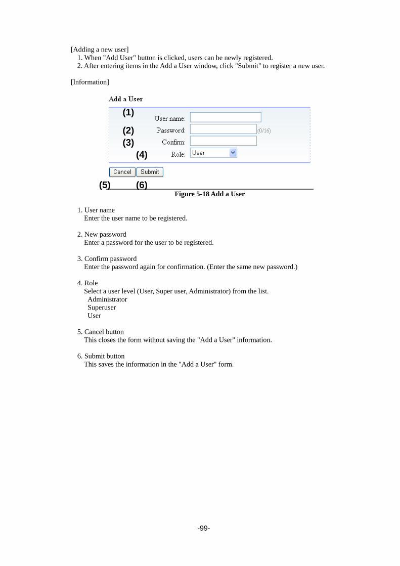
-99-
[Adding a new user]
1. When "Add User" button is clicked, users can be newly registered.
2. After entering items in the Add a User window, click "Submit" to register a new user.
[Information]
Figure 5-18 Add a User
1. User name
Enter the user name to be registered.
2. New password
Enter a password for the user to be registered.
3. Confirm password
Enter the password again for confirmation. (Enter the same new password.)
4. Role
Select a user level (User, Super user, Administrator) from the list.
Administrator
Superuser
User
5. Cancel button
This closes the form without saving the "Add a User" information.
6. Submit button
This saves the information in the "Add a User" form.
(1)
(2)
(3)
(4)
(5) (6)

-100-
【Removing a current user】
1. Select the user to remove from Current Users list.
2. When "Remove" is selected, the following dialog box is displayed.
3. Select "Yes" to remove the user.
Figure 5-19 Remove a User confirmation screen
The user himself cannot be deleted.
Service cannot be displayed the user of the Admin authority, be changed, and be
encrypting set deleted effectively.

-101-
5.6.5.2 Physical View (Physical)
[Configure Library] - [Physical] Service/Administrator
[Function]
This window is used to set the Library name.
[Information]
Figure 5-20 Physical
1. Library name
The Library's name can be registered.
2. Power Save mode
Configure the power save mode of a drive.
Enable: Power-save mode validity
Disable: Power-save mode invalidity
Time to shift to power-save mode further is set up at the time of Enable.
(Default value: 20 minutes)
3. Submit button
Click this button to confirm the settings. When complete, a Normal End message will appear.
(1)
(2)
(3)

-102-
5.6.5.3 Library setup window (Logical)
[Configure Library] - [Logical] Service/Administrator
[Function]
This window is used to set the Library's operation mode, I/O slot, and number of active slots.
[Information]
Figure 5-21 Logcal
(1)
(2) (3)
(4) (5) (6)
(8)
(10)
(7)
(9)
(11)

-103-
1. Library mode
For the Library mode setting, select "Random" or "Sequential".
Loop:
This setting is enabled when in "Sequential" mode. When the last cartridges is used while in
"Sequential" mode, this sets "Automatic looping" mode so that the first cartridge will be used
next.
Auto load:
This setting is enabled when in "Sequential" mode. When the magazine is locked, the
cartridge in the lowest-numbered slot is automatically loaded to the drive.
2. I/O station
This can be used to set the library's I/O station.
Use:valid
Specify whether to use the slots #59 and #60 as I/O station.(T60A)
Specify whether to use the slots #29 and #30 as I/O station.(T30A)
3. Number of active slots
This can be used to set the Library's active slots.
Number of active slots can specify only the even number.
The slot not set to Active slots is set to the cleaning / Inactive slot.
4. Auto cleaning
Sets auto cleaning.
When you use the library with backup software, please set up an Auto Cleaning
Mode Disable.
If the backup software supports the AUTO CLEANING function, use the auto
cleaning function of backup software.
5. Barcode label length
Selects the bar code label length to be reported to the host.(Default calue is 8)
6. Notice nearly expired
Sets the nearly expired trap of a cleaning cartridge.
In Disable, a Nearly Expired trap is not notified.
In Enable, the preset value of the number of times of the remainder of the timing which
notificates a trap is set up.
7. Notice every cleaning
Sets whether it remains for every cleaning execution and notifies the trap of the number of times.
8.Escape Mode
Sets a response mode of a drive during tape cartridge escape.
Simple: medium nothingness and reply.
Advance: off-line reply (Recommendation at the time of ARCserve use.)
9. Media Changer path
Sets media changer path.

-104-
10. Drive n ports
Sets drive n ports.
In case of SAS drive, sets Drive Path,Link speed.
In case of FC drive, sets Drive Path, topology , Loop ID, and Link speed.
11. Submit button
Click this button to confirm the settings. When complete, a Normal End message will appear.

-105-
5.6.5.4 Network setup window (Network)
[Configure Library] - [Network] Service/Administrator
[Function]
This window is used to set up network connections.
[Information]
Figure 5-22 Network setup
1. Ethernet setting
Link Speed: The network's link speed can be set as “Auto”, ”10Base-T Full”, “10Base-T Half”,
“100Base-TX Full”, “100Base-TX Half”, “1000Base-T Full”,or “1000Base-T
Half”.
2. Security setting
When "Enable SSL for Web" is checked, SSL is used between the Library and the Applet to set
encrypted communications.
3. IPv4 Settings
When "Use IPv4" is checked, the IPv4 protocol is used for communications.
Obtain an IP address automatically(DHCP):
The IPv4 address, subnet mask, and gateway are retrieved from the DHCP server and set
automatically.
Use static IP address
The IPv4 address, subnet mask, and gateway are set manually.
(1)
(2)
(3)
(4)
(5)
(6)

-106-
4. IPv6 Settings
When "Use IPv6" is checked, the IPv6 protocol is used for communications.
Obtain an IP address automatically(Stateless Auto Config):
Information is retrieved from a router advertisement, and the IPv6 address, prefix length, and
gateway are set automatically.
Obtain an IP address automatically(DHCP):
Information is retrieved by DHCP, and the IPv6 address, prefix length, and gateway are set
automatically.
Use static IP address
The IPv6 address, prefix length, and gateway are set manually.
5. DNS Settings
"Use DNS" is checked when using DNS settings.
6. Submit button
This button is used to confirm settings. When the settings are completed, a normal end message
will appear.

-107-
5.6.5.5 Date and Time setup window (Date and Time)
[Configure Library] - [Date and Time] Service/Administrator
[Function]
This window is used to set the Library's calendar/clock function.
[Information]
Figure 5-23 Date and Time setup
1. NTP server
This sets time updating from the Time Server (NTP server) as enabled or disabled.
Enable: Time information is retrieved from the NTP server.
Disable: Time information is not retrieved from the NTP server.
2. NTP server address
Specify the NTP server's address here.
3. Time Zone(GMT)
Select the local time zone from the drop-down list. (GMT -12:00 to GMT +13:00)
For example, Japan time is +09:00
4. Date(MM/DD/YYYY)
This sets the current date in MM/DD/YYYY format.
5. Time(HH:MM:SS)
This sets the current time in HH:MM:SS (24-hour display) format.
6. Load PC date time button
The time set to PC is loaded.
7. Submit button
This button is used to confirm settings.
(1)
(2)
(3)
(4)
(5) (6)
(7)

-108-
5.6.5.6 Event Notification setup window(SMTP)
[Configure Library]-[SMTP] Service/Administrator
[Function]
This window is used to set the destination to notify the Library information via email.
[Information]
Figure 5-24 SMTP setup
1. Send Setting
SMTP server address: Specify the mail server's IP address or domain name.
Sender address:Specify this Library's email address.
Subject: Specify the subject of email sent from the Library.
2. Mail To
Specify the destination email addresses for Library information.
3. Notice Level
Select one type of event for email notification.
(Emergency Only / Over Error / Over Warning / Over Information / Disable)
If Emergency Only is chosen, only the event of Emergency is notified.If Over Error is chosen, the
event of Emergency /Error is notified. If Over Warning is chosen, the event of Emergency
/Error/Warning is notified. If Over Information is chosen, all the events are notified.
4. Submit button
This button is used to confirm each setting.
5. Test button
Click this button to send test email to a registered "Mail to:" address to confirm email notification.
(1)
(2)
(3)
(4)
(5)

-109-
5.6.5.7 Event Notifications setup window (SNMP)
[Configure Library] - [SNMP] Service/Administrator
[Function]
This window is used to set the destination to notify the Library information via SNMP.
[Information]
Figure 5-25 SNMP setup
1. SNMP Enabled
The SNMP function is made effective.
Trap is not transmitted in the state where SNMP Enabled is not checked.
Since a setup of Community of Agent Setting is indispensable, an SNMP function does not
become effective unless Community is set up.
2. Agent Setting
These are general settings for SNMP.
Community:
Set the SNMP's community name.
Name:
Set the device name.
(1)
(2)
(3)
(4)
(5)
(6)

-110-
Location:
Set the device's physical location.
Contact:
Set contact information.
SNMPv3 engine ID:
The SNMPv3 Agent's Engine ID may have to be set for the manager.
3. Submit button
This button is used to confirm settings. When the Submit button is clicked, the entered values are
checked and are set when normal.
4. SNMPv3 User List
Enter the user information that is required to monitor the MIB data on devices accessed by the
Manager using the SNMPv3 protocol. The user names registered here are used to enable
execution of snmpget and snmpwalk commands from the SNMPv3 Manager.
When clicking modify button, following screen is displayed.
After setting “User name”, “Authentication” and “Privacy”, click “Submit" to register a new user.
In setting Authentication or Privacy, a password is needed.
Set Validity to Enable to make the user who registered effective.
Figure 5-26 SNMPv3 setup

-111-
5. Trap List
Enter the addresses to be notified via SNMP trap when the specified event occurs in the Library.
When clicking address part, following screen is displayed.
After setting “Address”, “User name”, “Authentication” and “Privacy”, click “Submit" to register
a trap list. In setting Authentication or Privacy, a password is needed.
Set Notice level at the levels other than Disable to enable to make the trap list who registered
effective.
Moreover, Version of SNMP can be set.
It corresponds in Version:V2/V3 and it is possible to correspond to inform by checking the check
box on the side of the item of Version at the setting.
Figure 5-27 Trap list
6. Test button
Click this button to send a test trap for confirmation of SNMP notification, to the addresses
registered under "Trap List".

-112-
5.6.5.8 Encryption Basis
[Configure Library] - [Encryption Basis] Administrator
[Function]
This window is used to set the encryption basis setting.
Please refer to section Chapter6 for details.
[Information]
Figure 5-28 Encryption Basis setup
1. Library Managed Encryption
This sets library managed encryption setting as enabled or disabled.
2. Master Key Import
This sets master key.
・Master Key was registered.:It is shown that the master key is registered.
・Overwrite master key: Check in overwriting the master key.
3. Submit button
This button is used to confirm each setting.
4. Master Key Export
This is used to export master key.
(1)
(2)
(3)
(4)

-113-
5.6.5.9 Encryption Detail
[Configure Library] - [Encryption Detail] Administrator
[Function]
This window is used to set the encryption basis setting.
Please refer to section Chapter6 for details.
Figure 5-29 Encryption Detail setup

-114-
5.6.5.10 Licenses Registration
[Configure Library] - [Licenses Registration] Service/Administrator
[Function]
This window is used to input the activation key to make the function of the option effective.
Figure 5-30 Licenses Registration

-115-
5.6.5.11 Saving the File Setting / Restore Screen (Save and Restore)
[Configure Library] - [Save and Restore] Service/Administrator
[Function]
This window is used to save a present setting calue and restore the saved set value.
The setting of the device can be succeeded by restoring the data saved when the maintenance chassis
are exchanged to a new maintenance chassis.
[Information]
Figure 5-31 Save/Restore
1. Download button
Save a present set value of the library.
2. Restore target
Select the restore target.
3. Refer button
Select the setting file.
4. Restore button
Restore the selected file.
(1)
(2)
(3)
(4)
(5)
-116-
5. Drive Replacement
It is used at the time of the maintenance work of a drive.
1) Check Remove of the drive to exchange and click Execute.
2) Remove a drive.
3) Attach the drive of service parts.
When you take over to the drive after exchanging the drive serial number before exchange, a
case checks.
4-1)Restore, and put a check into Succeed Serial Number, and click Execute.
When you do not take over to the drive after exchanging the drive serial number before
exchange, check
4-2)Restore, and click Execute.
[Case where are before and after exchange and a drive serial number is
not changed]
The work of a drive new recognition, by backup software becomes
unnecessary.
However, since the serial number indicated to the drive itself differs from
the drive serial number which can be checked with an operator panel or a
remote administration interface, cautions, such as the time of
maintenance, are needed.
[Case where are before and after exchange and a drive serial number is
changed]
The work of a drive new recognition, by backup software is needed.
[Being related with the save of a configuration file].
Please prepare for emergency and usually save a configuration file
periodically from the time of use.
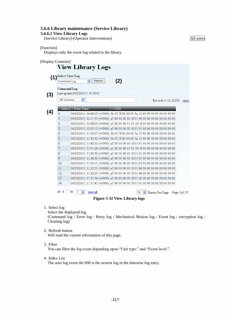
-117-
5.6.6 Library maintenance (Service Library) 5.6.6.1 View Library Logs
[Service Library]-[Operator Interventions] All users
[Function]
Displays only the event log related to the library.
[Display Contents]
Figure 5-32 View Library logs
1. Select log
Select the displayed log.
(Command log / Error log / Retry log / Mechanical Motion log / Event log / encryption log /
Cleaning log)
2. Refresh button
Will read the current information of this page.
3. Filter
You can filter the log event depending upon “Unit type:” and “Event level:”.
4. Index List
The auto log event the 000 is the newest log in the datewise log entry.
(1) (2)
(3)
(4)
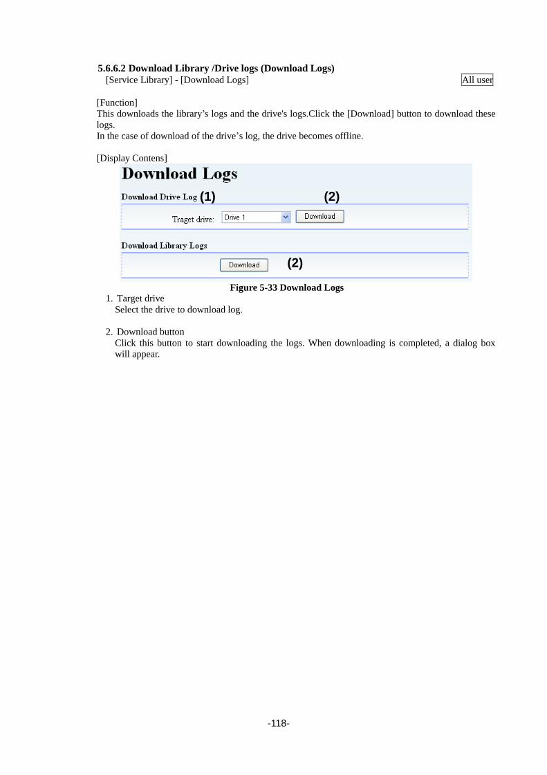
-118-
5.6.6.2 Download Library /Drive logs (Download Logs)
[Service Library] - [Download Logs] All user
[Function]
This downloads the library’s logs and the drive's logs.Click the [Download] button to download these
logs.
In the case of download of the drive’s log, the drive becomes offline.
[Display Contens]
Figure 5-33 Download Logs
1. Target drive
Select the drive to download log.
2. Download button
Click this button to start downloading the logs. When downloading is completed, a dialog box
will appear.
(1) (2)
(2)

-119-
5.6.6.3 Reset (Reset Library / Drive)
[Service Library]-[Reset Library and Drives] Service/Administrator
[Function]
Reset the library or drive.
[Display contents]
Figure 5-34 Reset Library / Drive
1. Target device
Select "Loader" or "Drive".
2. Reset button
After selecting the "Target device", clicking this button will reset the device.
Complete dialogue is displayed after the completion of reset command.
(2)
(1)

-120-
5.6.6.4 Firmware Refresh Screen (Firmware Update)
[Service Library] - [Firmware Update] Service/Administrator
[Function]
The firmware update of library or drive is done.
[Display contents]
Figure 5-35 Firmware Update
1. Library Firmware Update
Select "library firmware file".
The file designation is only possible by clicking the "Browse" Button.
2. Update button
Clicking "Update" Button will start the firmware update process.
3. Drive Firmware Update
Select the drive to update firmware.
Select "Drive firmware file".
The file designation is only possible by clicking the "Browse" Button.
4. Update button
Clicking "Update" Button will start the firmware update process.
(1)
(2)
(3)
(4)
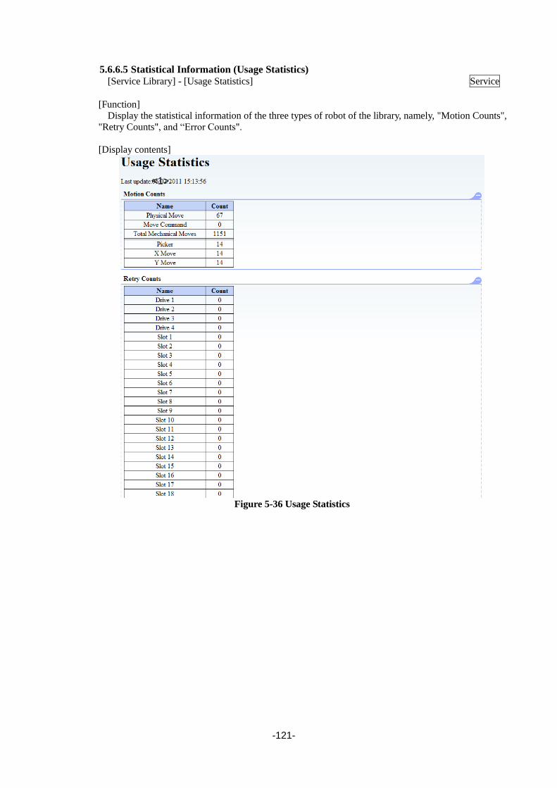
-121-
5.6.6.5 Statistical Information (Usage Statistics)
[Service Library] - [Usage Statistics] Service
[Function]
Display the statistical information of the three types of robot of the library, namely, "Motion Counts",
"Retry Counts", and “Error Counts".
[Display contents]
Figure 5-36 Usage Statistics
<1>

-122-
5.6.6.6 Web Shell (web shell)
[Service Library] - [Web Shell] Service
[Function]
The command prompt can be used.
[Display contents]
Figure 5-37 Web Shell

-123-
5.7 Event list
A list of events reported by SNMP and email is provided for reference.
The text strings displayed may vary slightly according to the Firmware Revision.
Table 5-4 Event List
Event Trap Event level Description of message
Drive error 1 emergency,2 DRIVE0x Broken. CHK=xxxx *1
Accessor error 2 emergency,2 ACCESSOR Broken. CHK=xxxx *2
Power module FAN error 11 emergency,2 POWER SUPPLY FAN failed.
CHK=xxxx *2
Power module error 12 emergency,2 POWER SUPPLY UNIT failed.
CHK=xxxx *2
FLASH memory error 13 emergency,2 FLASH MEMORY failed. CHK=xxxx
*2
ADI I/F error 14 emergency,2 DRIVE0x ADI I/F error. CHK=xxxx *1
Unlock magazine fails 16 emergency,2 MAGAZINE unlock failed. CHK=00D6
Unlock I/O Station fails 17 emergency,2 I/O SLOT unlock failed. CHK=00D7
Drive error 21 error,3 DRIVE0x Error. CHK=xxxx *1
Accessor error 22 error,3 ACCESSOR Error. CHK=xxxx *2
Drive FAN error 31 error,3 DRIVE0x Cooling error. CHK=xxxx *1
Drive power error 32 error,3 DRIVE0x Power error. CHK=xxxx *1
Drive or Medium error 33 error,3 DRIVE0x or MEDIA error. CHK=xxxx
*1
Drive I/F error 34 error,3 DRIVE0x I/F error. CHK=xxxx *1
Drive doesn’t presented 36 error,3 DRIVE does not exist. CHK=0008
Drive is prevented 37 error,3 DRIVE0x is prevented state.
CHK=xxxx *1
Power module FAN error 41 error,3 POWER SUPPLY FAN degraded.
CHK=xxxx *2
Power module error 42 error,3 POWER SUPPLY UNIT degraded.
CHK=xxxx *2
Bar code reader error 43 error,3 BARCODE READER error.
CHK=xxxx *2
I2C error 44 error,3 I2C error. CHK=xxxx *2
EEPROM error 45 error,3 EEPROM error. CHK=xxxx *2
Magazine doesn’t presented 46 error,3 MAGAZINE is not presented.
CHK=xxxx *2

-124-
Table 5-5 Event List
Event Trap Event level Description of message
Drive WARNING 51 warning,4 DRIVE0x Warning. CHK=xxxx *1
Accessor WARNING 52 warning,4 ACCESSOR Warning. CHK=xxxx
*2
Drive Cleaning request 53 warning,4 DRIVE0x Cleaning Request. *1
Request for replacement of Cleaning
Cartridge 54 warning,4 Clean Media Expired.
Cleaning Cartridge nearly expired 55 warning,4 Cleaning Media nearly expired
Remain cleaning number 56 warning,4
The number of cleaning uses
remaining=xx.Media=YYYYYY.
*3
Drive Hardware problem 57 warning,4
DRIVE01 Warning. CHK=024A
DRIVE02 Warning. CHK=034A
DRIVE03 Warning. CHK=044A
DRIVE04 Warning. CHK=054A
Medium error 71 warning,4 MEDIA error. CHK=xxxx *1
The drive enters online state. 101 info,5 DRIVE0x Online
The drive enters Not Ready state. 101 info,5 DRIVE0x Not Ready
The library enters online state. 102 info,5 LIBRARY Online
The library enters Not Ready state. 102 info,5 LIBRARY Not Ready
The library enters offline state. 102 info,5 LIBRARY Offline
Change of library operation mode 151 info,5
Library Mode Change to RANDOM
in logical library 1
Library Mode Change to
SEQUENTIAL in logical library 1
Start of inventory 153 info,5 LIBRARY Inventory
Start of medium transfer 155 info,5 ACCESSOR Move Start XXXX to
YYYY *4
Completion of medium transfer 155 info,5 ACCESSOR Move Complete
XXXX to YYYY *4
Start of auto cleaning 157 info,5 Auto cleaning start.
Completion of auto cleaning 157 info,5 Auto cleaning complete.
Unlock magazine 160 info,5 MAGAZINE unlock.
Unlock I/O station 161 info,5 I/O SLOT unlock.
SNMP Trap test 200 info,5 LIBRARY SNMP test trap
NOTE:
*1 XXXX:Drive Error code
*2 XXXX::Library Error code
*3 XX:The number of times of the cleaning cartridge remaining use, YY:Barcode label
*4 XXXX: Source element,YYYY:Destination element

-125-
Chapter6 Encryption Key Management Function
6.1 General Information This chapter introduces the main features of the encryption key management function.
6.1.1 Features of Encryption Key Management Option ・Enables you to easily build a secure backup system without relying on OS or backup software.
・The device administrator can ensure security by himself/herself without going through the backup
operator because each encryption key is set to a tape device from the Web browser terminal.
・Each encryption key supports both automatic device generation using the master key and
individual settings for each tape media.
・The encryption key import/export function enables you to take data out by using USB memory or
by sending email. The export key supports password protection and encryption of the encryption
key itself.
6.1.2 Encryption Mechanism
When you input the encryption license tape library, the encryption key management function of the
Library is enabled and you can record encrypted data to tape media.
An LTO4, LTO5, LTO6 and LTO7 drive incorporates hardware for encrypting data using the AES
(256 bits). With this hardware, you can record encrypted data to the tape media within the LTO4,
LTO5, LTO6 and LTO7 drive by setting the encryption key.
The Library can record encrypted data without making the backup software aware of it by
generating and managing the encryption key the LTO4, LTO5, LTO6 and LTO7 drive uses for each
tape medium stored in the Library and setting the corresponding encryption key to the LTO4, LTO5,
LTO6 and LTO7 drive when loading the tape media onto the LTO4, LTO5, LTO6 and LTO7 drive.
The encryption function does not work if an LTO2 / LTO3 tape media is
used.When encrypting data, be sure to use an LTO4, LTO5, LTO6 or LTO7 drive
and LTO4, LTO5, LTO6 or LTO7 tape media.
6.1.3 Types of Keys There are two types of keys used to encrypt data: a master key and an encryption key, which differs
for each tape medium. You must set one master key for each Library, and encryption keys can be set
for each tape medium as necessary.

-126-
6.1.3.1 Master Key
You must always set the master key when using this encryption management function.
The master key has the following two roles:
(1) Used when multiple Libraries share tape medium.
(2) Used to automatically generate encryption keys for each tape media.
1. Sharing tape media using the master key
If you set the same master key to multiple Libraries, these devices can share tape medium
without regard to the encryption key.
If encryption keys are individually set to each tape medium, tape medium cannot
be shared even if the same master key is set. When using such encryption keys,
import the corresponding encryption key into the Library every time you import
tape media into the Library.
2. Automatic generation of encryption key
This Library automatically generates different encryption keys for each tape medium from the
master key and the serial number recorded in the tape medium. If different Libraries have the same
master key and tape media serial number, the same encryption key is generated.
Management console (WEB)
Master key distribution
Cartridge sharing

-127-
6.1.3.2 Encryption Key
Encryption keys can be set on each tape medium. Set these keys only to necessary tape medium.
If you use the master key to share tape medium, it is not possible to share only some tape medium
because all the tape medium automatically generated using the master key are shared.
However, you can share tape medium without using the master key by individually setting an
encryption key to the tape media containing the tape medium you want to share.
6.1.3.3 Backup of encryption key
If an encryption key is lost due to a device failure or other cause, the encrypted data in the tape
medium cannot be decrypted. Therefore, always back up an encryption keys when registering the
master key or setting the encryption keys to a Library.
For backup procedures, see sections 6.2.1.5Exporting (backing up) the master key /
6.3.6.1Backing up the KEY database.

-128-
6.2 Basic Operation of encryption key management function This chapter describes the most basic operations under the conditions below. If you want to perform
operations under other conditions, make sure that you fully understand the description in this chapter,
and then go to “Advanced Operations” .
[Conditions]
Item Condition
Tape media in the Library All are LTO4 / LTO5 / LTO6 / LTO7 medium.
Key to be used Master key only (Encryption keys are not used.)
Sharing tape medium among multiple libraries Enabled by setting the same master key.
6.2.1 Setup To set up the encryption key management function, perform the following procedure:
To set up the function
Registering the activation key (See 6.2.1.1)
Enabling the encryption key management function
(See 6.2.1.3)
Registering (importing) the master key
(See 6.2.1.4)
Done
Exporting (backing up) the master key
(See 6.2.1.5)
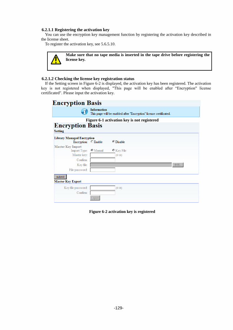
-129-
6.2.1.1 Registering the activation key
You can use the encryption key management function by registering the activation key described in
the license sheet.
To register the activation key, see 5.6.5.10.
Make sure that no tape media is inserted in the tape drive before registering the
license key.
6.2.1.2 Checking the license key registration status
If the Setting screen in Figure 6-2 is displayed, the activation key has been registered. The activation
key is not registered when displayed, "This page will be enabled after “Encryption" license
certificated". Please input the activation key.
Figure 6-1 activation key is not registered
Figure 6-2 activation key is registered

-130-
6.2.1.3 Enabling the encryption key management function
You must enable the encryption key management function to use it.
After enabling encryption, register the master key if it is not yet registered. (See 6.2.1.4Registering
(importing) the master key.) If the master key is already registered, click “Submit”.
Figure 6-3 Encryption Enable
Figure 6-4 Master key is registered

-131-
6.2.1.4 Registering (importing) the master key
Once you enable the encryption key management function, you can enter the master key.
The master key can be entered manually or by using a file.
・The master key is the most important information for this encryption key
management function. It is recommended to set a master key long enough (up to
16 characters) that third parties cannot easily guess it.
・Once you set the master key, change it as little as possible.
If you change the master key, the encrypted data previously created in the tape
media can no longer be read.
・If the master key is lost, you can no longer restore the encrypted data. Always
back up the master key at registration.
1. Manually entering the master key
Select [Master Key Import] of [Encryption Basis], and then select “Manual” for Import Type.
Next, enter values for Master Key and Confirm Key (the same character string), and then click
“Submit”.
Figure 6-5 Manual Input of Master key
When you click “Submit”, the message below should appear. Click “Yes”.
After rebooting the device automatically, the master key becomes effective.

-132-
2. Entering the master key file
Select [Master Key Import] of [Encryption Basis], and then select “Key File” for Import Type.
Next, enter the master key file and password, and then click “Submit”.
Use the password you entered when exporting the master key.
Be careful because the master key cannot be imported if you forget that
password.
Figure 6-6 File Input of Master key
When you click “Submit”, the message below should appear. Click “Yes”.
After rebooting the device automatically, the master key becomes effective.
3. Checking master key registration
After rebooting the Library, you can make sure that the master key is registered by selecting
[Master Key Import] of [Encryption Basis], and then making sure that Master Key Import shows
“Master Key was registered”.

-133-
6.2.1.5 Exporting (backing up) the master key
It is recommended to export and save (back up) the master key in a file after setting it so that you
can use it in the case of a device failure or other problem.
Note that it might become impossible to decrypt encrypted data if the master key
is lost.
You can share tape medium by importing the exported master key to other Libraries. For details
about how to share medium using the master key, see section 6.2.3.1.
When you click “Export”, the dialog box below appears. Specify the file to which you want to
export the master key, enter the password for the master key, and then click “Export”.
Figure 6-7 Export of Master key

-134-
6.2.2 Operation
6.2.2.1 To Create encrypted medium
You can create and read encrypted tape medium without considering higher applications such as
backup software by using the tape medium for which “Encryption” is specified in [Encryption Detail].
Use the initial settings, in which “Encryption” is specified for all tape media.
(The cleaning cartridge becomes disable automatically.)
(Remark)
You can see the encryption setting status of each slot from the Encryption Detail Setting screen.
In the figure below, purple indicates that the tape medium in the slot is setting “auto” for Key
Type.Green indicates that the tape medium in the slot is setting “import” for Key Type.
Figure 6-8 Encryption Detail

-135-
6.2.3 Checking tape media Information You can display information about the encryption of a specified slot by displaying Slot Information
from [Library Map].See section 5.6.3.2.
6.2.3.1 Sharing tape medium among multiple libraries
If you set the same master key to different Libraries, they can share tape medium.
Using one master key, you can share tape medium for which encryption keys were
automatically generated from the master key. Note that tape medium using
encryption keys generated by using different master keys or other methods
cannot be shared.
For details about how to share tape medium using these encryption keys, see
“6.3Advance Operation of encryption key management function”.
1. To register the same master key with multiple libraries
When setting the same master key to multiple Libraries, you can easily register the master key
by exporting the master key registered with the first Library and importing it to the second and
subsequent Libraries.
(Remark)
To import the master key: See “6.2.1.4Registering (importing) the master key”.
To export the master key: See “6.2.1.5Exporting (backing up) the master key”.
6.2.4 Maintenance
6.2.4.1 Backup of Encryption Key (Basic Operation)
It is necessary to back up encryption information in advance so that you can use it even if the
encryption information within the Library is corrupted due to a device failure or other cause.
Operation Method and Backup of Encryption Information
Backup target Backup time
Basic operation Master key When registering the master key
Advanced operation Master key
KEY database When registering the master key
Every time you import the encryption key
You can save the master key into a file by using the master key export function.
For details about how to export the master key, see “6.2.1.5Exporting (backing up) the master
key”
Because it is not necessary to change the registered master key you set, one
backup should be enough.
However, note that you should back up the master key again after changing it.
For details about how to change the master key and notes for when changing it,
see “6.3.5Changing the Master Key”.

-136-
6.2.4.2 Executing Set Default
When you execute “Set Default” from the Library’s operation panel, the settings for the Library and
all registered encryption information (such as the master key) are cleared.
When you execute “Set Default”, encryption information is cleared. If you do not
back up encryption information before executing “Set Default” and then restore
encryption information after the execution, the encryption function cannot be
used.
6.2.4.3 Checking the encryption log
You can check the encryption key log information in [Encryption Log] of [View Library Logs]).
You can examine the appropriately 2,000 latest events in this log.
The encryption information log items are overwritten and cleared starting with
the oldest one. If you keep log records in the past, Please save them periodically.
Encryption Log is included in Library Log, and Save Library Log of Download
Logs when you preserve it. See “5.6.6.2Download Library /Drive logs (Download
Logs)
List of Encryption Log Events
Event details
Manually setting a master key
Exporting a master key
Importing a master key
Automatically generating an encryption key
Manually setting an encryption key
Exporting an encryption key
Importing an encryption key
Backing up an encryption key
Restoring an encryption key
Backing up the memory encryption information
Restoring the memory encryption information
Erasing the memory encryption information
Disabling device encryption
Enabling device encryption
Inventorying
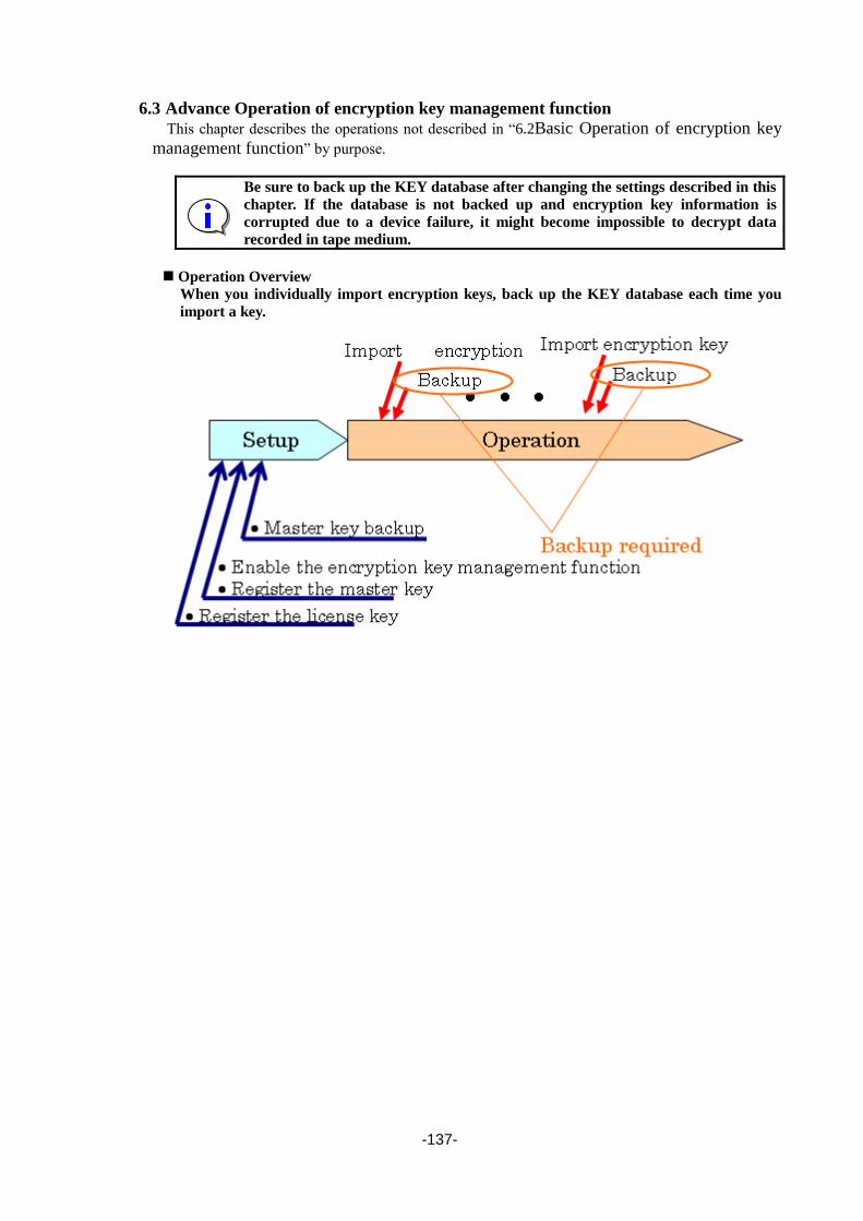
-137-
6.3 Advance Operation of encryption key management function
This chapter describes the operations not described in “6.2Basic Operation of encryption key
management function” by purpose.
Be sure to back up the KEY database after changing the settings described in this
chapter. If the database is not backed up and encryption key information is
corrupted due to a device failure, it might become impossible to decrypt data
recorded in tape medium.
Operation Overview
When you individually import encryption keys, back up the KEY database each time you
import a key.

-138-
6.3.1 Using LTO2 / LTO3 Tape Medium The tape cartridge that can be encrypted becomes the tape medium since LTO4. Therefore, when
the tape cartridge of LTO2 / LTO3 is used, it automatically becomes set to which the encryption is
invalid. Even if it is a tape cartridge of LTO2 / LTO3, for the tape cartridge on which the bar code
label is not stuck, it doesn't automatically become set to which the encryption is invalid.
6.3.2 Enabling or Disableing Enctyption for Each tape medium You can enable or disable encryption for each tape media. (All slots are encrypted by default.)
You can check the setting for each tape media in [Encryption Detail].
The tape medium stored in a purple slot in the figure below is Enable Encryption, and a tape
medium to which Key Type is set with Auto.
The tape medium stored in a green slot in the figure below is Enable Encryption, and a tape
medium to which Key Type is set with Import.
The tape medium stored in a white slot in the figure below is Disable Encryption.
Figure 6-9 Encryption Detail
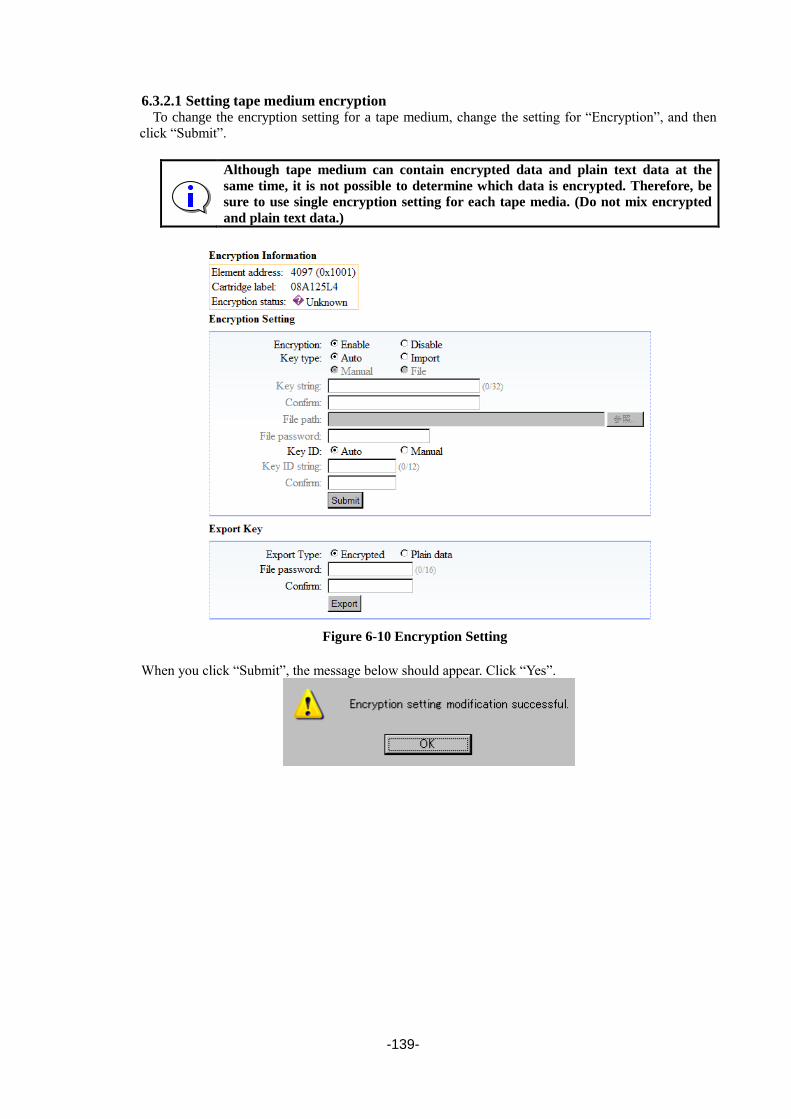
-139-
6.3.2.1 Setting tape medium encryption
To change the encryption setting for a tape medium, change the setting for “Encryption”, and then
click “Submit”.
Although tape medium can contain encrypted data and plain text data at the
same time, it is not possible to determine which data is encrypted. Therefore, be
sure to use single encryption setting for each tape media. (Do not mix encrypted
and plain text data.)
Figure 6-10 Encryption Setting
When you click “Submit”, the message below should appear. Click “Yes”.

-140-
6.3.2.2 Sharing tape medium among multiple libraries (advanced) Multiple Libraries can share tape medium by using either of the following two methods:
1. Sharing on a library basis (Register the same master key.)
2. Sharing on a tape basis (Register an encryption key for each tape medium.)
This chapter describes how to register an encryption key for each tape medium.
To register an encryption key for each tape medium, select “Import” for “Key Type” in [Encryption
Detail]. You can input the encryption key manually or by using a file. For details about how to
register the encryption key, see Section 6.3.3.2.
Be sure to back up the KEY database after registering the encryption key for each
tape. If the database is not backed up and encryption key information is
corrupted due to a device failure, it might become impossible to decrypt data
recorded in tape medium.
6.3.3 Importing and Exporting the Encryption Key(For Each Tape Medium) You can set an encryption key to each tape medium. When you set an individual encryption key to
each tape medium, the set encryption keys are saved in the KEY database in the Library, so you can
use them without setting them again after turning the Library on and off.
Be sure to back up the KEY database after importing an encryption key. If the
KEY database is not backed up and is then corrupted due to a device failure, it
might become impossible to decrypt the encrypted media.
This encryption key management function can manage one encryption key for
each tape media.
Be sure to set the same encryption key when setting the encryption key to tape
media for which an encryption key is already set. Note that tape media in which
data has been recorded using multiple encryption keys cannot be used for this
encryption key management function.

-141-
6.3.3.1 When to import the encryption key
Import the encryption keys when the encryption setting is newly set to "Import" for the cartridge.
The Library does not keep on store the encryption key for the tape media without
bar code label after exporting the key, even if the Library used the same tape
media in the past.
Therefore, you also need to import the encryption keys every time you import
tape medium without bar code label.
When turning it on to the device again, the key is automatically read for the tape
medium with bar code label because it memorizes it in the library.
However, you do not need to import an encryption key automatically generated
from the master key.
6.3.3.2 To import the encryption key
You can import an encryption key by selecting the import destination tape medium in [Encryption
Detail] and then specifying “Import” for “Key Type” for that slot. You can import the encryption key
manually or by using a file.
1. Manually inputting the encryption key
Select “Import” and “Manual” for “Key Type”, input an encryption key (max using 32
characters) for “Key String”, and then click “Submit”.
Figure 6-11 manual inputting of the encryption key
When you click “Submit”, the message below should appear. Click “Yes”.
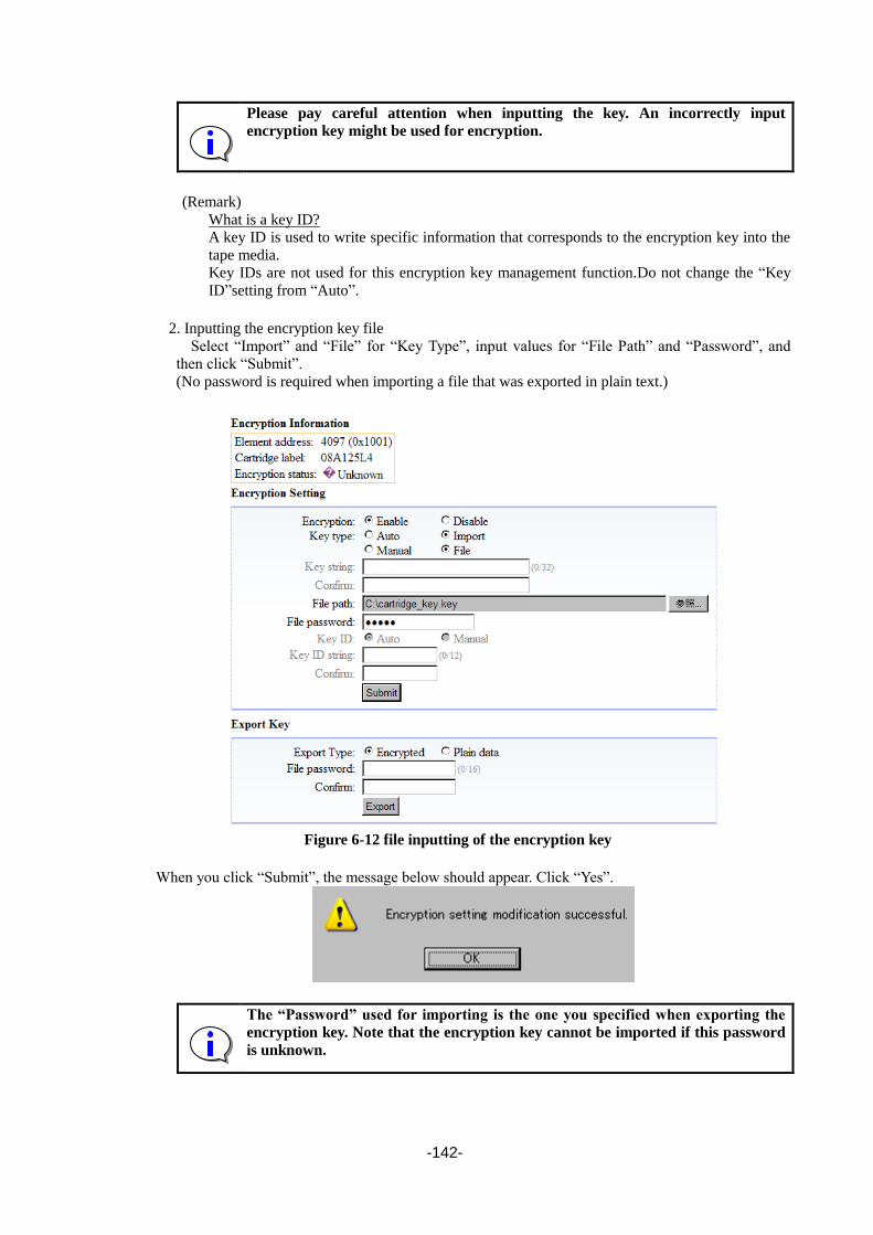
-142-
Please pay careful attention when inputting the key. An incorrectly input
encryption key might be used for encryption.
(Remark)
What is a key ID?
A key ID is used to write specific information that corresponds to the encryption key into the
tape media.
Key IDs are not used for this encryption key management function.Do not change the “Key
ID”setting from “Auto”.
2. Inputting the encryption key file
Select “Import” and “File” for “Key Type”, input values for “File Path” and “Password”, and
then click “Submit”.
(No password is required when importing a file that was exported in plain text.)
Figure 6-12 file inputting of the encryption key
When you click “Submit”, the message below should appear. Click “Yes”.
The “Password” used for importing is the one you specified when exporting the
encryption key. Note that the encryption key cannot be imported if this password
is unknown.

-143-
6.3.3.3 To export an encryption key
After selecting the exporting cartridge from Encryption Detail, the encryption key selects Export
Type.
When Encrypted is selected, it is possible to export by inputting the password and Confirm, and
pressing Export. (Export is pressed as it is for Plain data. )The password set at this time is needed at
import.
Figure 6-13 Export of the encryption key
An automatically generated encryption key is not generated until the tape media
is loaded into the drive. If you try to export the encryption key before it is
generated, an error occurs.
If you select “Plain Data” to export a file, the encryption key is displayed in text
format when the exported file is opened with a text editor. Therefore, take extra
care when outputting a file with “Plain Data” selected.
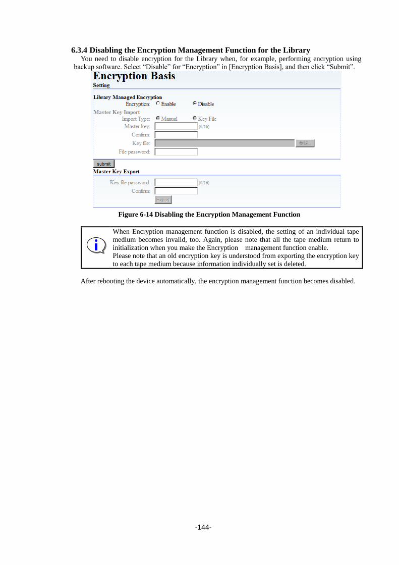
-144-
6.3.4 Disabling the Encryption Management Function for the Library You need to disable encryption for the Library when, for example, performing encryption using
backup software. Select “Disable” for “Encryption” in [Encryption Basis], and then click “Submit”.
Figure 6-14 Disabling the Encryption Management Function
When Encryption management function is disabled, the setting of an individual tape
medium becomes invalid, too. Again, please note that all the tape medium return to
initialization when you make the Encryption management function enable.
Please note that an old encryption key is understood from exporting the encryption key
to each tape medium because information individually set is deleted.
After rebooting the device automatically, the encryption management function becomes disabled.

-145-
6.3.5 Changing the Master Key You can overwrite the master key by selecting the “Overwrite Master Key” checkbox in
[Encryption Basis] (under [Setting]).
The setting procedure after selecting the checkbox is the same as when you set the master key for
the first time. For details, see “6.2.1.4Registering (importing) the master key”.
When you change the master key, all automatically generated encryption keys are
changed and the previously created tape medium become unreadable. Therefore,
before changing the master key, please pay careful attention do not to lose old
encryption keys by, for example, exporting the encryption keys for each tape
medium.
Figure 6-15 Changing Master Key
6.3.6 Backing Up and Restoring the KEY Database You can back up and restore the KEY database from [Encryption Detail].
Figure 6-16 Backup or Restore of KEY Database

-146-
6.3.6.1 Backing up the KEY database
When the password and Confirm (the same content as the password) are input to Backup Key
Database of Maintenance of Encryption Detail and "Backup" is pressed, the save screen is displayed.
The file preservation place is specified, and it saves a file.
Figure 6-17 Backup of KEY Database
6.3.6.2 Restoring the KEY database
The password of the backup of Key File and Key Database with Restore Key Database of
Maintenance of Encryption Detail is input, and "Restore" is pressed.
The following dialog is displayed, and the Key data base is restored.
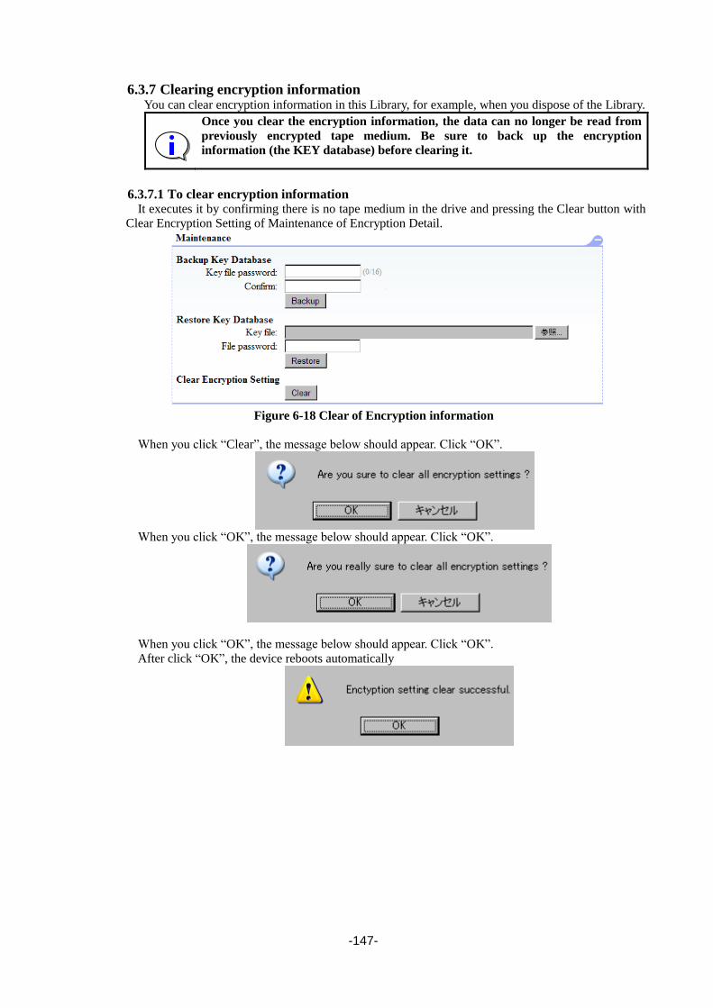
-147-
6.3.7 Clearing encryption information You can clear encryption information in this Library, for example, when you dispose of the Library.
Once you clear the encryption information, the data can no longer be read from
previously encrypted tape medium. Be sure to back up the encryption
information (the KEY database) before clearing it.
6.3.7.1 To clear encryption information
It executes it by confirming there is no tape medium in the drive and pressing the Clear button with
Clear Encryption Setting of Maintenance of Encryption Detail.
Figure 6-18 Clear of Encryption information
When you click “Clear”, the message below should appear. Click “OK”.
When you click “OK”, the message below should appear. Click “OK”.
When you click “OK”, the message below should appear. Click “OK”.
After click “OK”, the device reboots automatically

-148-
6.4 Points to Check When a Failure or Abnormality Occurs This section provides simple troubleshooting tips. Make sure that you use the Library correctly.
Table 6-1 Troubleshooting Table
Problem Countermeasure
Data cannot be encrypted. 1. Make sure that an LTO4 / LTO5 / LTO6 / LTO7 drive is used
for recording data.
2. Make sure that the tape media is not LTO1, LTO2, or LTO3
medium.
3. Make sure that encryption is enabled (for the Library and tape
medium).
Data cannot be decrypted. 1. Make sure that the correct encryption key is set.
The Remote Manager displays
“Normal” as the “Data Type” in
“Information” even if you
specify an encrypted tape.
1. Because “Data Type” is refreshed after you load tape media
into the drive, load the tape into the drive before checking the
value in the Remote Manager.
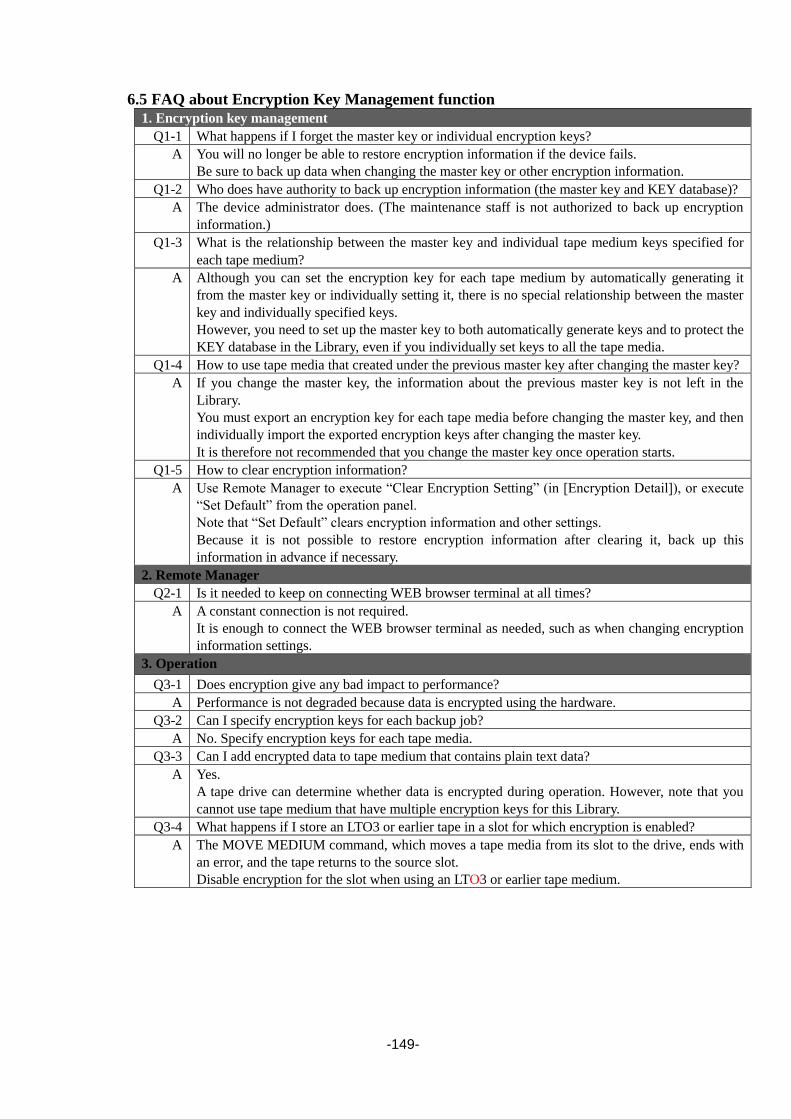
-149-
6.5 FAQ about Encryption Key Management function
1. Encryption key management
Q1-1 What happens if I forget the master key or individual encryption keys?
A You will no longer be able to restore encryption information if the device fails.
Be sure to back up data when changing the master key or other encryption information.
Q1-2 Who does have authority to back up encryption information (the master key and KEY database)?
A The device administrator does. (The maintenance staff is not authorized to back up encryption
information.)
Q1-3 What is the relationship between the master key and individual tape medium keys specified for
each tape medium?
A Although you can set the encryption key for each tape medium by automatically generating it
from the master key or individually setting it, there is no special relationship between the master
key and individually specified keys.
However, you need to set up the master key to both automatically generate keys and to protect the
KEY database in the Library, even if you individually set keys to all the tape media.
Q1-4 How to use tape media that created under the previous master key after changing the master key?
A If you change the master key, the information about the previous master key is not left in the
Library.
You must export an encryption key for each tape media before changing the master key, and then
individually import the exported encryption keys after changing the master key.
It is therefore not recommended that you change the master key once operation starts.
Q1-5 How to clear encryption information?
A Use Remote Manager to execute “Clear Encryption Setting” (in [Encryption Detail]), or execute
“Set Default” from the operation panel.
Note that “Set Default” clears encryption information and other settings.
Because it is not possible to restore encryption information after clearing it, back up this
information in advance if necessary.
2. Remote Manager
Q2-1 Is it needed to keep on connecting WEB browser terminal at all times?
A A constant connection is not required.
It is enough to connect the WEB browser terminal as needed, such as when changing encryption
information settings.
3. Operation
Q3-1 Does encryption give any bad impact to performance?
A Performance is not degraded because data is encrypted using the hardware.
Q3-2 Can I specify encryption keys for each backup job?
A No. Specify encryption keys for each tape media.
Q3-3 Can I add encrypted data to tape medium that contains plain text data?
A Yes.
A tape drive can determine whether data is encrypted during operation. However, note that you
cannot use tape medium that have multiple encryption keys for this Library.
Q3-4 What happens if I store an LTO3 or earlier tape in a slot for which encryption is enabled?
A The MOVE MEDIUM command, which moves a tape media from its slot to the drive, ends with
an error, and the tape returns to the source slot.
Disable encryption for the slot when using an LTO3 or earlier tape medium.

-150-
6.6 List of Encryption Event Log Messages This section provides the list of events registered as encryption setting log messages.
Message Meaning
Master Key was manually. Succeeded in registering the master key(manual).
Master Key was exported. Succeeded in exporting the master key.
Master Key was Imported. Succeeded in importing the master key.
Encryption Key was generated automatically. Succeeded in generating the encryption key
automatically.
Encryption Key was set manually. Succeeded in manually inputting encryption key.
Encryption Key was exported. Succeeded in exporting the encryption key.
Encryption Key was imported. Succeeded in restoring the encryption key.
Encryption keys were backed up. Succeeded in backing up the KEY database.
Encryption keys were restored. Succeeded in restoring the KEY database.
Encryption information was backed up. Succeeded in backing up the encryption information.
Encryption information was restored. Succeeded in restoring the encryption information. Encryption information was cleared. Succeeded in clearing the encryption information.
Encryption setting was changed disable. Succeeded in disabling the encryption management
function.
Encryption setting was changed enable. Succeeded in enabling the encryption management
function.
Tape cartridge inventory was executed. Succeeded in inventorying the tape media.

-151-
Chapter7 Installation of Option
Install the option after stopping JOB of the server when the option is increased, and
cutting the power supply in the library.
Reboot the server after completing an optional install. If the server is not rebooted, the
library cannot be normally recognized from the server.
When the power source module is increased in case of the case of T60A, it is not
necessary to stop the server JOB, and to cut the power supply in the library.
7.1 Install of drive This section provides the procedure of installation drive.
1) Stop any jobs running on the server.
2) If there is a cartridge in the drive, move it to the magazine slot by using the backup software or
by using the operating panel.
3) Turn off the power to the library.
4) The drive module is installed, and the drive module is fixed with two screws.
When drive # 2 is increased, the escape slot is mounted. Please detach the escape slot referring
to "Exchange of 10.10 save in the clause slots", and install the drive module.
In the case of T60A, please install the drive module detaching the screw two places where the
drive cover is fixed when increasing it in drive # 3/#4.
Please abandon detached escape slot and drive cover.
5) Stick the name of product label attached to a drive in the label plate installed in the rack mount
kit back side.
6) Turn on the power to the library.
7) Perform drive diagnostics, referring to 9.2.
8) Connect the interface cable.In the case of FC drive,set topology / Loop ID / Link Speed /
Media Changer path.In case of SAS drive,set media changer path.
9) Confirm operation check after installation.Refer to 2.7.
7.2 Install of power module This section provides the procedure of installation power module.
1) The cover of the power supply blank mounted on the position of a red square frame of the
figure below is detached. Detaching the blank cover draws out the power supply while pulling
the lock of a blue projection part forward.
2) The power source module is installed.
3) Insert the AC power cable in the connector of the AC power supply increased.
Please confirm the plug has been completely inserted.
4) Stick the name of product label attached to a power module in the label plate installed in the
rack mount kit back side.

-152-
7.3 Install of activation key This section provides the procedure of installation activation key.
1) Register activation key.(Refer to 5.6.5.10)
2) The power source module is installed.
3) Stick the name of product label attached to a license option in the label plate installed in the
rack mount kit back side.
Chapter8 Cartridges
This chapter describes handling of the cartridges used by the Library, and how they are used.
The various parts of the data cartridge are outlined below.
Figure 8-1 Names of Cartridge Parts
Leader pin
Write protection switch
Label attachment area
Insertion guide Insertion direction mark
Cartridge door
(shown here as open)

-153-
8.1.1 Data Cartridge
For the LTO Ultrium4 drive, Ultrium 2, 3, or 4 cartridges with uncompressed capacities of 200,
400, and 800 GB can be used respectively.
For the LTO Ultrium5 drive, Ultrium 3, 4, or 5 cartridges with uncompressed capacities of 400,
800, and 1500 GB can be used respectively.
For the LTO Ultrium6 drive, Ultrium 4, 5, or 6 cartridges with uncompressed capacities of 800,
1500, and 2500 GB can be used respectively.
For the LTO Ultrium7 drive, Ultrium 5, 6, or 7 cartridges with uncompressed capacities of 1500,
2500, and 6000 GB can be used respectively.
The data cartridge is a crucial product data is recorded and preserved. Please use
the one that the quality is guaranteed.
Note that the cartridges that can be used with the LTO drives vary according to the
product generation. See the table below for details.
Table 8-1 Drive/Cartridge Compatibility
Cartridge Drive LTO
Ultrium1
LTO
Ultrium2
LTO
Ultrium3
LTO
Ultrium4
LTO
Ultrium5
LTO
Ultrium6
LTO
Ultrium7
LTO
Ultrium4 *
LTO
Ultrium5 *
LTO
Ultrium6 *
LTO
Ultrium7 *
: Can be used *: Not writeable (read only) : Cannot be used
The cartridge door helps keep the cartridge clean when it is removed from the drive.
The write protection switch prevents data from being written onto a data cartridge.
The label attachment area is where the labels are attached. Attach the label within the recessed
attachment area. If the label protrudes beyond this area, problems may occur when loading the
cartridge into the internal drive.
8.1.2 WORM cartridge WORM (Write Once Read Many) type data cartridges are recordable but non-rewritable. As
opposed to ordinary data cartridges that can be written to and read from multiple times, it is not
possible to overwrite or erase data that has been recorded onto a WORM cartridge.
8.1.3 Cleaning cartridge These are cartridges that are used to clean within a drive.
Cleaning cartridges can be used up to 50 times.
Keep track of how many times the cleaning cartridge is used, and replace it after 50 times.
For description of cleaning methods, see “4.8Cleaning or 5.6.4.3Clean Drive window (Clean
Drive)”
8.1.4 Diagnosis cartridge The diagnosis cartridge is a cartridge only for the maintenance used only when the diagnosis test in
the library is done by the one that the label of special VOLSER (DG is included) was stuck on a usual
data cartridge. Please do not use it as a data cartridge.

-154-
8.2 Cartridge Label
The cartridge label displays the medium name and the usage of the cartridge by the character and
the bar code. The medium name is shown in the alphanumeric character of six digits that is called
VOLSER, and the usage is shown in the alphanumeric character of two digits that is called Media ID.
The table below shows the label code of the Ultrium cartridge used in this library.
Both characters of the code can be used for the label though are the vertically-written one and the
horizontally-written one. The example of labeling the data cartridge is shown below.
Figure 8-2 Data Cartridge Label
Table 8-2 Cartridge label code
Ultrium Cartridge Label code
Remarks VOLSER Media ID
Ultrium3 Data Cartridge □□□□□□ L3 400 G byte(non-compression)
Ultrium3 WORM Cartridge □□□□□□ LT 400 G byte(non-compression)
Ultrium4 Data Cartridge □□□□□□ L4 800 G byte(non-compression)
Ultrium4 WORM Cartridge □□□□□□ LU 800 G byte(non-compression)
Ultrium5 Data Cartridge □□□□□□ L5 1500 G byte(non-compression)
Ultrium5 WORM Cartridge □□□□□□ LV 1500 G byte(non-compression)
Ultrium6 Data Cartridge □□□□□□ L6 2500 G byte(non-compression)
Ultrium6 WORM Cartridge □□□□□□ LW 2500 G byte(non-compression)
Ultrium7 Data Cartridge □□□□□□ L7 6000 G byte(non-compression)
Ultrium7 WORM Cartridge □□□□□□ LX 6000 G byte(non-compression)
Universal Cleaning Cartridge CLNU◇◇ CU
Diagnosis Cartridge DG△◇◇◇ L4 Diagnosis(For LTO4 / LTO5 Drive)
Diagnosis Cartridge DG△◇◇◇ L5 Diagnosis(For LTO5 / LTO6 Drive)
Diagnosis Cartridge DG△◇◇◇ L6 Diagnosis(For LTO6 / LTO7 Drive)
NOTE:□ :A~Z、0~9
◇ :0~9
△ :space
CU shows the universal cleaning cartridge that can be used by the all makers' LTO
Ultrium drives.
L5
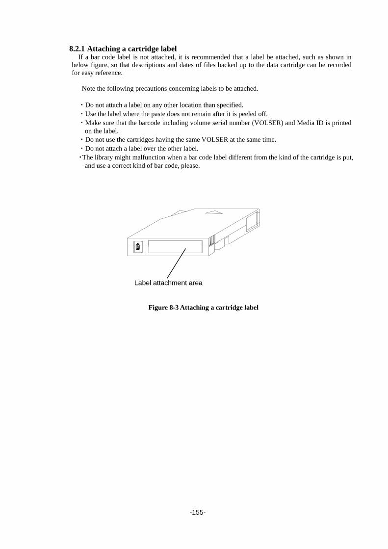
-155-
8.2.1 Attaching a cartridge label If a bar code label is not attached, it is recommended that a label be attached, such as shown in
below figure, so that descriptions and dates of files backed up to the data cartridge can be recorded
for easy reference.
Note the following precautions concerning labels to be attached.
・Do not attach a label on any other location than specified.
・Use the label where the paste does not remain after it is peeled off.
・Make sure that the barcode including volume serial number (VOLSER) and Media ID is printed
on the label.
・Do not use the cartridges having the same VOLSER at the same time.
・Do not attach a label over the other label.
・The library might malfunction when a bar code label different from the kind of the cartridge is put,
and use a correct kind of bar code, please.
Figure 8-3 Attaching a cartridge label
Label attachment area
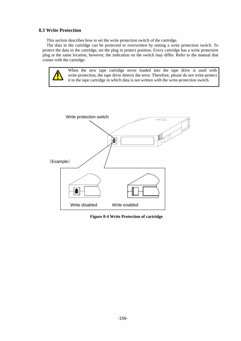
-156-
8.3 Write Protection
This section describes how to set the write protection switch of the cartridge.
The data in the cartridge can be protected or overwritten by setting a write protection switch. To
protect the data in the cartridge, set the plug in protect position. Every cartridge has a write protection
plug at the same location, however, the indication on the switch may differ. Refer to the manual that
comes with the cartridge.
When the new tape cartridge never loaded into the tape drive is used with
write-protection, the tape drive detects the error. Therefore, please do not write-protect
it to the tape cartridge in which data is not written with the write-protection switch.
Figure 8-4 Write Protection of cartridge
Write protection switch
(Example)
Write disabled Write enabled
-157-
8.4 Notes on Handling
This section describes precautions needed for handling the data cartridge.
8.4.1 Notes on Use □ Before Use
・Do not use the data cartridge if it is damaged, deformed, or bent.
・If the data cartridge is exposed to an environment other than the operating or storage
environment, expose it to the operating environment for a longer time than the period when
it is exposed to other environment (for 24 hours at maximum) before use. If temperature is
greatly different between the storage site and the operating site, do not rush the cartridge
into the operating environment. Leave the data cartridge in temperature of the operating site
with temperature gradient set to 10ºC/hour.
□ When Loading into Magazine or Slot:
Insert the data cartridge securely. Close the empty protective case firmly and store it in a place
free of dust and dirt.
□ After Use
Be sure to put the data cartridge that you used in the protective case and store it in a place free
of dust and dirt. You can place it horizontally or vertically.
□ Disposal
For the disposal of the cartridge, observe the waste disposal rules of your local government.
8.4.2 General □ Do not touch a tape (magnetic side) by hands
□ Do not bring a substance which generate magnetic close to the cartridge.
□ Do not place the cartridge in a place subject to direct sunlight or a place near a heater.
□ Do not apply strong shock.
□ Avoid handling the cartridge while eating or drinking. Take due consideration not to adhere
thinner or alcohol to the cartridge.
□ Be sure to put the data cartridge that you used in the protective case.
□ Insert the cartridge to the magazine gently and carefully.
□ Be sure to put the data cartridge that you used in the protective case and store it in a place free
of dust and dirt. You can place it horizontally or vertically.
8.4.3 Use protection standard It is necessary to prohibit the prolonged use for the cartridge, and to change it for a new data
cartridge when corresponding to either of the following item.
□ When a strong impact such as drop it is given, and the data cartridge receives damage
□ When the record side is dirty with the liquids such as the soft drink, coffee, and tea, solvents,
the metal powders, and the tobacco dust, etc.
When the data cartridge shown in the above-mentioned is used, the head and the
device are damaged, it will make dirty, and it causes the equipment breakdown.
Moreover, when a new as it is data cartridge is used noticing neither dirt nor the
damage of the head, damage might be expanded by making a new data cartridge
dirty, and damaging it.
-158-
8.4.4 Service Life The service life of the data cartridge varies greatly depending on operating/storage environment. The
estimated life may be shortened by operating environment conditions (temperature, humidity, dust,
etc.)
□ Create the data cartridge management book. Record the date when each data cartridge is used
and estimate how many years and how often each cartridge is used.
□ Examine the data cartridge management book and index label regularly. Discard the cartridges
having low reliability, for example, those which generate write/read errors.
□ Periodically check the data cartridge records and the cartridge labels, and if they indicate that
the data cartridge at hand has been used for so long that write or read errors may occur due to
degraded reliability, dispose of the data cartridge.
8.4.5 Cartridge storage □ Maintain the proper storage conditions, and keep the storage area clean.
□ Write protection should be set for cartridges put into storage.
□ If a cartridge is being stored for a long time, the cartridge should be read periodically to
confirm that the backup data remains recoverable.
□ To help ensure safe storage, store cartridges in a location that is far removed from the system in
which the cartridges are used.

-159-
Chapter9 Maintenance This chapter explains how to maintain the library so that it can always be used to the best advantage.
In the unlikely event that smoke, strange odors or strange sounds are emitted
from this device, turn its power switch off immediately, then pull the power plug
from the socket. Continued use under such conditions may cause fire. If this
device breaks down or becomes damaged, use the power switch to turn off the
Library, then pull the power plug from the socket.
9.1 Drive Cleaning Cleaning should be performed about once a month.
However, for Autoloaders that are used frequently, cleaning should be performed about once every
100 hours of backup time.
See "4.8.1Cleaning by Operation panel" or "5.6.4.3Clean Drive window (Clean Drive)" for the
operation of the cleaning.
Before using the operation panel to set cleaning, make sure that the backup software will not be
executing any jobs during the cleaning process. (If necessary, take measures such as turning off the
backup software service.)
・Use a special cleaning cartridge with a bar code label that supports the drive to be
cleaned.
・Clean the drive once a month or a backup of 100 hours when cleaning is necessary
in operation.(When there is a cleaning request from the drive, clean the drive.)
・Each cleaning cartridge can be used up to 50 times.
Record the number of use, and when 50 times is reached, replace the cleaning
cartridge.
The drive will not be cleaned even if the cleaning cartridge being used has
exceeded its service life. When it's detected that a cleaning cartridge reached its
service life, it's shown to an operator panel with "REPLACE CLEANING
MEDIA".
・[Clean Drive] doesn't operate when the bar code for the cleaning cartridge is not
stuck on the cleaning cartridge. In that case, please use and clean [Move
Cartridge].
・[Clean drive] should be performed only when there are no backup software jobs
being executed.
9.1.1 Auto Cleaning
When you use the library with backup software, please set up an Auto Cleaning
Mode Disable.
If the backup software supports the AUTO CLEANING function, use the auto
cleaning function of backup software.

-160-
9.2 Diagnosis test The operation of the library unit and of individual drive units can be tested by using the library’s
Diagnostics menu.
For details about diagnostic testing, see “4.4.4.2Diagnostics”.
1) [Login]. See Section 4.3Login for detail.
2) Select [Commands].
3) Select [Diagnostics] from [Commands].
4) The library device can be diagnosed by [Library Verify]. The drive unit can be diagnosed by
[Drive Diagnostics].
5) When selecting [Drive Diagnostics], select the detailed test.
6) If error indicator is lighted in the diagnosis, then contact your service representative.
When detecting it abnormally, an error code is shown to an operator panel,
so please push Enter button to advance check movement first after confirmation.
A special diagnostic medium is needed for the diagnostic test.
Do not use the user medium for the diagnostic test.
9.3 Cleaning of device Please contain water or the detergent in a soft cloth and wipe the dirt of externals lightly.
Before cleaning the library, be sure to turn the power off and unplug the power cable
from the outlet. If you clean the interior of the library with the power turned on, your
fingers may become caught or stuck in moving parts, resulting in injury.
If you wipe the library with volatile chemicals such as benzine or paint thinner, the
library exterior might be damaged or become discolored. This also applies if the
library is sprayed with insecticide.

-161-
9.4 Cleaning of Magazine Filter The magazine of the library contains a filter to prevent dirt and dust entering the library. Clean the
filter about once a year so that it does not become plugged up.
To clean the magazine filter, suction out dirt and dust from the magazine bezel part by using a
vacuum cleaner or similar device.
Lightly place the cleaner nozzle on magazine bezel holes in the rectangular areas in the figure below
and suction out the dirt and dust.
9.5 Cleaning of cartridge Using a commercial dry cotton swab, wipe off dust adhering to the surface of the removed cartridge.
Be careful not to open the shutter of the tape cartridge during cleaning, as this may
cause dust to enter the tape cartridge.
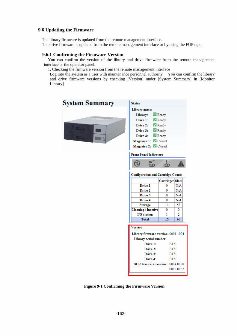
-162-
9.6 Updating the Firmware
The library firmware is updated from the remote management interface.
The drive firmware is updated from the remote management interface or by using the FUP tape.
9.6.1 Confirming the Firmware Version You can confirm the version of the library and drive firmware from the remote management
interface or the operator panel.
1. Checking the firmware version from the remote management interface
Log into the system as a user with maintenance personnel authority. You can confirm the library
and drive firmware versions by checking [Version] under [System Summary] in [Monitor
Library].
Figure 9-1 Confirming the Firmware Version

-163-
2. Confirming the firmware version from the operator panel
Log into the system as a user with maintenance personnel authority. You can confirm the library
and drive firmware versions by checking [View Revision] under [Service].
For details about how to log in as a user with maintenance personnel authority, see 4.3.1.
9.6.2 Updating the Library Firmware
Update the library firmware from the remote management interface.
1) Start the remote management interface and log in as a user with service authority.
Use the following account and password for login:
Account: service
Password: ser001
2) Select "Firmware Update" from [Service Library].
Figure 9-2 Firmware Update Window (Library Firmware Update)
3) Specify the name and path of the file containing the firmware data in the [Send file] text box at
the bottom of the Library Firmware Update window.
4) Clicking the [Browse] button displays a file selection dialog box. Select the firmware data
file.
5) Clicking the [Update] button starts updating the firmware.
6) After updating, restart the backup server.

-164-
9.6.3 Updating the Drive Firmware
Update the drive firmware from the remote management interface.
1) Start the remote management interface and log in as a user with service authority.
Use the following account and password for login:
Account: service
Password: ser001
2) Select [Firmware Update] from [Service Library].
Figure 9-3 Firmware Update Window (Drive Firmware Update)
3) Select the drive whose firmware is to be updated from [Target Drive] at the bottom of the
Drive Firmware Update window.
4) Specify the name and path of the file containing the firmware data in the [Send file] text box at
the bottom of the Drive Firmware Update window.
5) Clicking the [Browse] button displays a file selection dialog box. Select the firmware data
file.
6) Clicking the [Update] button starts updating the firmware.
7) After updating, restart the backup server.
-165-
9.7 Troubleshooting Procedures
The following describes the troubleshooting procedures carried out when an error occurs in the
library.
1. If a library error occurs, collect the backup software error log and library logs.
Collect the following logs from the library:
Use the remote management interface for log collection.
For details about operating the remote management interface, see Chapter5.
(1) Log in as a user with maintenance personnale authority.
(2) Select [Download Logs] from [Service Library] and download the following logs:
・Drive Normal logs (only for the drive where the error occurred)
・Drive Force logs (only for the drive where the error occurred)
・Library logs
2. From the error log detail status in the backup software and library logs, locate the part that
possibly caused the error.
3. Confirm the possibly faulty part from the library error code/drive error code. If necessary,
replace the possibly faulty part.

-166-
9.8 Moving the Library Please follow the following procedure when moving or transporting this machine.
When shutting down the system, refer to “3.2Starting the System”
1) [Login]. See Section 4.3Login for detail.
2) If there is a cartridge in the drive, first unload it (eject), and then move it to the magazine slot.
Either consult the back up software manual or use the front panel keys.(See “4.7.2Removing
from the drive”
3) Remove the cartridge from magazine.(See “4.6.1Magazine Operations”)
4) Execute [Shipping move] of [Commands] from operator panel.
5) Confirm the display of [Tighten the shipping Screw and Turn the Power] and tighten the screw
for transportation on the back of machine.
※ Do the following work even when you cannot tighten the screw.
6) Turn OFF the power switch of the machine.
7) Remove the AC Power Cable, Interface Cable.
Do not turn off the power switch of the machine if the interface is in inactive
state. If you turn off the power switch of the device while the bus is in active State,
there is a risk of data loss or unstable bus state. If the system needs to be switched
off and is still connected to the LAN, then contact the administrator before
switching off.
When you are transporting this machine, please re-pack it in the packaging material
and in the same way it was packed at the time of purchase. If you do not have the
packaging. material, then transport the machine in soft cushioning material in order
to protect from shocks.

-167-
Chapter10 Replacing Maintenance Parts This chapter describes the procedure for replacing the field replacement units of the library.
Table 10-1 Maintenance Parts List
Maintenance part Target Part No. Work procedure
reference
Maintenance chassis T30A 243-539019-201- A 10.3
Maintenance chassis T60A 243-539019-202- A 10.3
Controller board T30A/T60A 243-539019-205- A 10.4
LTO4 SAS drive module T30A/T60A 243-539019-214- A 10.5
LTO5 SAS drive module T30A/T60A 243-539019-215- A 10.5
LTO6 SAS drive module T30A/T60A 243-539019-216- A 10.5
LTO7 SAS drive module T30A/T60A 243-539019-217- A 10.5
LTO4 FC drive module T30A/T60A 243-539019-224- A 10.5
LTO5 FC drive module T30A/T60A 243-539019-225- A 10.5
LTO6 FC drive module T30A/T60A 243-539019-226- A 10.5
LTO7 FC drive module T30A/T60A 243-539019-227- A 10.5
Power supply module T30A/T60A 243-539019-271- A 10.6
Operator panel PKG T30A/T60A 243-539019-272- A 10.7
Escape slot T30A/T60A 243-539019-273- A 10.8
Front magazine T30A/T60A 243-539019-274- A 10.9
Rear magazine T30A/T60A 243-539019-275- A 10.9
Air filter T30A/T60A 243-539019-276- A 10.10
Drive fan T30A/T60A 243-539019-277- A 10.11
Internal FC cable T30A/T60A 243-539019-279- A 10.12
Front bezel L T30A 243-539019-285- A 10.13
Front bezel L T60A 243-539019-286- A 10.13
Front bezel R T30A 243-539019-287- A 10.14
Front bezel R T60A 243-539019-288- A 10.14

-168-
10.1 Saving and Restoring Maintenance Information Some maintenance part replacement procedures may require maintenance information to be saved and
restored. These procedures are described below.
10.1.1 Saving Maintenance Information
1. Log into the remote management interface as a user with service authority.
(Account name: service, password: ser001)
2. Click the [Save/Restore] menu and click the Download button.
Figure 10-1 Save/Restore Window
3. Specify the name of the folder and file for saving maintenance information.
4. Exit the browser.
This completes saving the library device maintenance information in the folder specified in step 3.
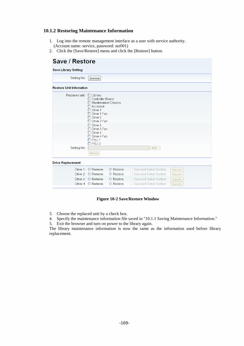
-169-
10.1.2 Restoring Maintenance Information
1. Log into the remote management interface as a user with service authority.
(Account name: service, password: ser001)
2. Click the [Save/Restore] menu and click the [Restore] button.
Figure 10-2 Save/Restore Window
3. Choose the replaced unit by a check box.
4. Specify the maintenance information file saved in "10.1.1 Saving Maintenance Information."
5. Exit the browser and turn on power to the library again.
The library maintenance information is now the same as the information used before library
replacement.

-170-
10.2 Replacing the Device
1. The supervisory service of all the services of backup software, a tape, and a changer driver is
suspended.The Windows version Networker stops a server.
2. If there is a cartridge in the drive, move it to the magazine slot by using the backup software or by
using the operating panel.
3. Save the maintenance information, referring to "10.1.1 Saving Maintenance Information".
4. Remove the magazine and eject the cartridge from it. In this case, record which cell includes which
medium.
5. Turn off the power to the library, referring to “9.8".
6. Replace the library.
When replacing the library, two or more people are required if using T30A, and three
or more people are required if using T60A.
7. Connect the interface cable and AC cable and turn on the power to the library.
8. Restore the maintenance information, referring to "10.1.2 Restoring Maintenance Information".
9. Perform library diagnostics, referring to "9.2".
10. Based on the information recorded in step 4, store the cartridge that was in the library to be
replaced in the same place in the magazine.
10.3 Replacing the Maintenance Chassis
1. The supervisory service of all the services of backup software, a tape, and a changer driver is
suspended.The Windows version Networker stops a server.
2. If there is a cartridge in the drive, move it to the magazine slot by using the backup software or by
using the operating panel.
3. Save the maintenance information, referring to "10.1.1 Saving Maintenance Information".
4. Turn off the power to the library, referring to “9.8"
Perform this step in service login mode.
5. Remove all magazines, referring to "4.6.1.4".
6. Remove the drive. Record where it was mounted.
7. Remove the controller board.
8. Remove the power supply module.
9. Replace the maintenance chassis.
When replacing the library, two or more people are required if using T30A, and three
or more people are required if using T60A.
10. Remount the removed magazines, drive, power supply, and controller board.
For the magazines and drive, mount them in the same places they were before replacement.
11. Connect the interface cable and AC cable and turn on the power to the library.
Connect the interface cable to the same place as before replacement.
12. Fault LED lights up after turn on the power to the library, and it is displayed on an operator panel
as "UNMATCHED MAINT DATA ERROR."
13. Restore the maintenance information, referring to "10.1.2 Restoring Maintenance Information".
14. Since it is displayed as Unit information was restored successful, turn off and turn on the power
supply of a library.
15. Perform library diagnostics, referring to "9.2".
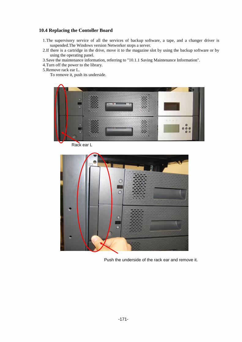
-171-
10.4 Replacing the Contoller Board
1. The supervisory service of all the services of backup software, a tape, and a changer driver is
suspended.The Windows version Networker stops a server.
2. If there is a cartridge in the drive, move it to the magazine slot by using the backup software or by
using the operating panel.
3. Save the maintenance information, referring to "10.1.1 Saving Maintenance Information".
4. Turn off the power to the library.
5. Remove rack ear L.
To remove it, push its underside.
Rack ear L
Push the underside of the rack ear and remove it.

-172-
6. Remove the front bezel of the magazine operating panel.
Remove it by pushing the left lock.
7. Unfasten the controller board screw and pull the controller board towards you.
8. Replace the controller board with a new one, fasten the screw, and then mount the front bezel and
rack ear L using the opposite procedure to the procedure used to demount them.
9. Turn on the power to the library.
10. Fault LED lights up after turn on the power to the library, and it is displayed on an operator panel
as "UNMATCHED MAINT DATA ERROR."
11. Restore the maintenance information, referring to "10.1.2 Restoring Maintenance Information".
12. Since it is displayed as Unit information was restored successful, turn off and turn on the power
supply of a library.
13. Perform library diagnostics, referring to "9.2Diagnosis test".
Screw

-173-
10.5 Replacing the Drive Module The drive module replacement procedure is the same for all drive types.
1. The supervisory service of all the services of backup software, a tape, and a changer driver is
suspended.The Windows version Networker stops a server.
2. If there is a cartridge in the drive, move it to the magazine slot by using the backup software or by
using the operating panel.
3. Remove the interface cable connected to the drive to be replaced.
4. [Service Login] in Operator panel. See Section 4.3.1Service Login for detail.
5. Select [Drive Replacement] from [Service].
6. Select the drive to exchange and select Remove Drive.
7. Unfasten the two screws shown below and extract the drive to be replaced.
8. Mount the new drive and anchor it with two screws shown above.
9. Select [Drive Replacement] from [Service].
10. Select the drive exchanged and select Restore Drive.
11. It is checked whether a serial number is succeeded before and after drive exchange.
[Yes] is chosen when succeeding a serial number before and after drive exchange.
[No] is chosen when not succeeding a serial number before and after drive exchange.
12. Restore the maintenance information, referring to "10.1.2 Restoring Maintenance Information".
13. From the operator panel, confirm that the drive has been recognized.
14. Connect the interface cable to the new drive.
15. Perform drive diagnostics, referring to "9.2Diagnosis test".
Screws
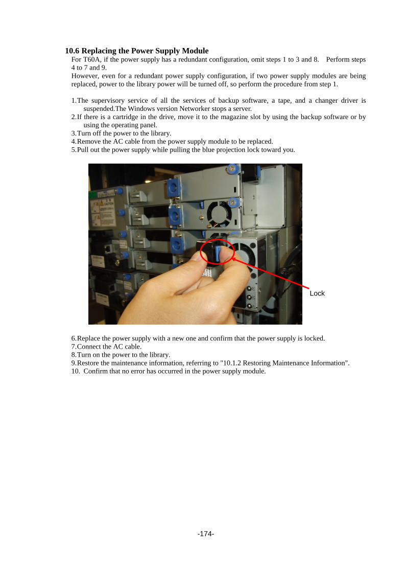
-174-
10.6 Replacing the Power Supply Module For T60A, if the power supply has a redundant configuration, omit steps 1 to 3 and 8. Perform steps
4 to 7 and 9.
However, even for a redundant power supply configuration, if two power supply modules are being
replaced, power to the library power will be turned off, so perform the procedure from step 1.
1. The supervisory service of all the services of backup software, a tape, and a changer driver is
suspended.The Windows version Networker stops a server.
2. If there is a cartridge in the drive, move it to the magazine slot by using the backup software or by
using the operating panel.
3. Turn off the power to the library.
4. Remove the AC cable from the power supply module to be replaced.
5. Pull out the power supply while pulling the blue projection lock toward you.
6. Replace the power supply with a new one and confirm that the power supply is locked.
7. Connect the AC cable.
8. Turn on the power to the library.
9. Restore the maintenance information, referring to "10.1.2 Restoring Maintenance Information".
10. Confirm that no error has occurred in the power supply module.
Lock

-175-
10.7 Replacing the Operator Panel PKG
1. Remove bezel R, referring to "10.14Replacing the Front bezel R".
2. Remove the cables from the operator panel PKG connectors.
The figure below shows T60A. For T30A, remove only the left cable.
No cable is connected to the right connector.
Remove the two screws shown below and demount the LCD cover frame.
3. Remove the screw shown below and demount the operator panel PKG.
Connectors
Screw
LCD cover frame
Screw
Operator panel PKG

-176-
4. Remove the FFC cable from the two operator panel PKG connectors shown below, and demount the
operator panel PKG.
5. Mount the operator panel PKG using the opposite procedure to the procedure used to demount it.
Confirm that the FFC cable is latched and mount the operator panel PKG.
6. Mount front bezel R and the front magazine. This completes replacement.
7. Turn on the power to the library.
8. Confirm that the operator panel displays properly and that pressing buttons is recognized normally.
FFC cable connectors

-177-
10.8 Replacing the Escape Slot
1. The supervisory service of all the services of backup software, a tape, and a changer driver is
suspended.The Windows version Networker stops a server.
2. Turn off the power to the library.
3. Remove the two screws anchoring the save slot and extract the save slot.
If the extracted save slot contains a cartridge, pull it out.
4. Replace the save slot.
5. Turn on the power to the library.
6. If a cartridge was removed in step 3, return it to the library.
10.9 Replacing the Front Magazine and Rear Magazine
1. Remove the magazine to be replaced from the library. (See "4.6.1.1Removing Magazine.")
2. Eject the cartridge from the magazine and record which cell includes which tape.
3. Based on the information recorded in step 2, store the cartridge that was in the magazine to be
replaced in the same place in the new magazine.
4. Insert the magazine into the library.
Screws

-178-
10.10 Replacing the Air Filter
1. Remove the front magazine whose air filter is to be replaced from the library. (See
"4.6.1.1Removing Magazine.")
2. Place the front magazine on a stable place such as a desk. Make sure that the bezel section is
positioned over the edge of the desk so that it does not touch the surface of the desk, as shown in
the figure below.
3. Push the I/O station unlock lever at the back of the front magazine in the direction of the arrow.
I/O station unlock lever

-179-
4. Remove the four screws anchoring the bezel and demount it.
Screws

-180-
5. Pull the air filter forward while pinching and releasing the right and left claws anchoring the air
filter.
6. Mount the new air filter. When mounting the new filter, be careful about its orientation. When
inserting it, push the sections circled in red below on the other sides of the claws with your finger
to confirm that the claws have completely latched onto the sheet metal hole edges.
7. Insert the removed bezel and temporarily fasten the four screws removed in step 4.
8. Tighten the upper-right screw while strongly pushing the bezel against the sheet metal. Then,
tighten the remaining screws in the order of upper-left, lower-left, and lower-right.
9. Push the I/O station until it is locked.
10. Insert the front magazine into the library. This completes replacement.

-181-
10.11 Replacing the Drive fan
1. Remove the drive module whose drive fan is to be replaced, referring to "10.5Replacing the Drive
Module".
2. Remove the screw anchoring the drive cover and demount the drive cover.
When removing the cover, it is necessary to open the left latch (shown below) a little in the
direction of the arrow to release the latch.
3. Loosen the two screws shown below, hold them, and pull the drive slowly toward you.
Draw out the drive until you feel resistance. Do not force it.
Screw
Screws

-182-
4. Remove the two drive connectors shown below. The figure below shows an example of the FC
drive.
Remove the cables from the cord keeper.
5. Pull out the drive further. When pulling it out, be careful not to bend the internal cables, causing
the wires to break.
6. Remove the three fan bracket screws shown below and demount the fan.
7. Remove the fan connector. Use tweezers to do this.
Drive connectors
Cord keeper
Screws

-183-
8. Mount the fan using the opposite procedure to the procedure used to demount it.
Wire the fan cable as shown below.
Take care not to get the cables caught when pushing in the drive.
Take care not to get the cables caught when mounting the drive cover.
To mount the drive cover, insert its two projections.
Drive cover projections

-184-
10.12 Replacing the Internal FC cable
1. Pull out the drive and remove the two connectors connected to the drive, referring to
"10.5Replacing the Drive Module".
2. Remove the cable from the cord keeper.
3. Remove the chassis-side connector of the internal FC cable.
The connector cannot be removed by using your fingers the space is too narrow, so remove it by
picking it up with tweezers from above.
4. Pull out the drive from the chassis and remove the drive-side connector of the internal FC cable.
5. Mount the internal FC cable using the opposite procedure to the procedure used to demount it.
6. When inserting the drive and mounting the drive cover, take care not to get the cables caught.
Internal FC cable, chassis-side connector
Internal FC cable, drive-side connector

-185-
10.13 Replacing the Front bezel L
1. Remove rack ear L.
To remove it, push its underside.
2. Remove front bezel L of the magazine operating panel.
Remove it while pushing the left lock.
3. Mount front bezel L and rack ear L using the opposite procedure to the procedure used to demount
them.
Push the underside of the rack ear and remove it.
Rack ear L

-186-
10.14 Replacing the Front bezel R
1. The supervisory service of all the services of backup software, a tape, and a changer driver is
suspended.The Windows version Networker stops a server.
2. Turn off the power to the library.
3. Remove the library from the rack and remove the upper and lower front magazines.
4. Remove the four right screws from the front of the library and remove rack bracket front R.
5. Remove the three left screws of bezel R and remove bezel R.
The figure below shows T60A. For T30A, remove two screws.
6. Mount bezel R using the opposite procedure to the procedure used to demount it.
7. Insert the front magazine and turn on the power to the library.
Rack bracket R
Screws

-187-
Chapter11 Self-Diagnosis Function
11.1 Mechanism Test Tests the library mechanism.
11.1.1 Demo (Slot-Drv-Slot) Repeats only the movement between slots.
11.1.2 Demo (Slot-Slot) Repeats only the movement between a slot and a drive.
11.1.3 MSBF Test Repeats only the SWAP operation.
11.1.4 X-Move Test Repeats only the X-movement operation.
11.1.5 Y-Move Test Repeats only the Y-movement operation.
11.1.6 Pick/Put Test Repeats only the Pick/Put operation of the media.
11.1.7 Pick/Put/Move Test Repeats only tape transfers between specific cells.
11.1.8 Vibration Test Repeats the movement between a slot and a fixed slot and between a slot and a drive.
11.2 LCD/LED Test Through manual operation, turns on and off all LEDs and renders/clears all the dots of the LCD.
11.3 Phy Test Used to test the Ethernet Phy. (Generally not used.)

-188-
Chapter12 Action in breakdown and abnormal circumstances Check each component of the library according to troubleshooting briefly described
Please refer to the manual of the application software for the associated problem in the main the
application software.
In the unlikely event that smoke, strange odors or strange sounds are emitted
from this device, turn its power switch off immediately, then pull the power plug
from the socket. Continued use under such conditions may cause fire. If this
device breaks down or becomes damaged, use the power switch to turn off the
Library, then pull the power plug from the socket.
Note that turning off the Library's power while it is operating may result in loss
of data.

-189-
12.1 Trouble Shooting
Symptom Action
Power
The library does not turn on.
Nothing is displayed on
operator panel.
・Make sure that all the AC cords are correctly connected.
・Check if an electricity is supplied to the outlet.
・Exchange the alternating-current power cable
・Confirm the wind has risen from the exhaust hole in back of the library
The library failed in the
following self test of device
power supply switch ON.
The error message is
displayed in the LCD of a
front panel.
・Confirm whether the complete insertion of all cartridges in the magazine
and the magazine are correctly obtained.
・Confirm whether the fastened screw is removed.
Connection
The host doesn't detect this
product.
・Confirm whether the cable is correctly installed in this product.
・Confirm whether this product is recognized by the operating system.
Performance
It is inefficient of the backup
of data in the library.
・Confirm whether lack of a resource, a fragmentation of a file and a file
with small size on the backup server side don't exist in quantities.
・Confirm whether coding software of HDD isn't working on the backup
server.
・Confirm whether reading doesn't become slow by access's concentrating
on one disk.
・Contact the shop or the maintenance service company that bought it.
Operation
It is not possible to write it in
the tape cartridge.
・Check the access authority of the host device to the filesystem.
・Confirm whether the tape type used is correct.
・Check a write protection switch of the tape cartridge, and confirm be
recordable.
・Change it for a new tape cartridge.

-190-
Symptom Action
Cleaning
Request for cleaning the
drive is repeatedly displayed.
・Replace the cleaning cartridge with new one and perform cleaning.
(Reference)
when using a laundry tape until use frequency restriction,
it'll be the following indication.
(Example)
・When the message to request for cleaning by a liquid crystal display is
also indicated after cleaning of a drive, a cleaning tape is exchanged.
(Reference)
when requesting for cleaning from a drive, it'll be the following indication.
(The example when requesting for cleaning from drive #1,)
Other
The cartridge remains in the
drive.
・Confirm the setting of the backup application
(Change to specification that does Eject after the backup ends)
・Execute [Unload Drive] from [Commands].
ERROR indicator is lit. 1. Check which error code is shown on the operation panel.
2. Check the status of cartridge, accessor, and/or drive through the internal
check window.
a) All the cartridges are completely inserted and secured in correct
direction.
b) No foreign object exists at the bottom of the library.
c) Check the drive status.
3. Power off the library.
4. Check if the drive pack is completely secured.
5. Power on the library.
12.2 When you request maintenance When you request maintenance to repair or replace one or more devices, write down the lamp
indication and the message on the LCD display. The information is valid for maintenance.
Lighting
Lighting

-191-
AppendixA Specifications
A-1Library T30A(LL030F) T60A(LL060F)
Maximum data storage capacity LTO Ultrium5
1500GB×30 (3000GB*1×30)
LTO Ultrium6
2500GB×30 (6250GB*1×30)
LTO Ultrium7
6000GB×30 (15000GB*1×30)
LTO Ultrium5
1500GB×60 (3000GB*1×60)
LTO Ultrium6
2500GB×60 (6250GB*1×60)
LTO Ultrium7
6000GB×60 (15000GB*1×60)
Number of drives 1 or 2 1-4
Number of cartridge tapes 30(max) 60(max)
Interface 6Gbps SAS,8Gbps Fibre Channel
Dimensions 446mm(W)x869mm(D)x88mm(H) (T30A)
446mm(W)x869mm(D)x177mm(H) (T60A)
Rack spave 2U 4U
Weight*2 26.1kg(Full Componet) 45.4kg(Full Componet)
Data transfer rate LTO Ultrium5
140MB/s (in the non-compression mode),
240MB/s (in the compression mode)
LTO Ultrium6
160MB/s (in the non-compression mode),
400MB/s (in the compression mode)
LTO Ultrium7
300MB/s (in the non-compression mode),
600MB/s (in the compression mode)(SAS)
750MB/s (in the compression mode)(FC)
Inquiry LL-2B01
Power voltage AC100 – 240V
Frequency 50/60Hz
Input current 1.7-0.8A 2.8-1.3A
Power consumption (maximum) 132W 230W(using redundant power module)
[During
operation]
Ambient
temperature 10℃~40℃
Relative
humidity 20%~80%RH
Highest dry bulb
temperature 26℃
[During
non-operation
*2]
Ambient
temperature –30℃~60℃
Relative
humidity 10%~90%RH
Highest dry bulb
temperature 26℃
[During
transportation
*3]
Ambient
temperature –23℃~49℃
Relative
humidity 20%~80%RH
Highest dry bulb
temperature 26℃
*1:When the compression efficiency is X2 (x2.5 only LTO6)
*2:Does not include a cartridge.
*3:Include a cartridge.

-192-
A-2Data cartridge Maximum data storage capacity 800 GB (1600 GB in the compression mode) LTO4
1500 GB (3000 GB in the compression mode) LTO5
2500 GB (6250 GB in the compression mode) LTO6
6000 GB (15000 GB in the compression mode) LTO7
Environmental requirement
[During operation] Ambient temperature 10℃~45℃
Relative humidity 20%~80%RH
Highest dry bulb temperature 26℃
[During storage] Ambient temperature 16℃~32℃
Relative humidity 20%~80%RH
Highest dry bulb temperature 26℃
State of keeping Be sure to put the data cartridge in the protective case and store
it in a place free of dust and dirt. You can place it horizontally or
vertically.
[During transportation] Ambient temperature –23℃~49℃
Relative humidity 20%~80%RH
Highest dry bulb temperature 26℃
[State of trancportation] Be sure to put the data cartridge in the protective case and store
it in a place free of dust and dirt. In addition, please put in the
cardboard box and wrap it so that power should not join the data
cartridge.
A-3Cleaning cartridge
Cleaning cartridges can be used up to 50 times.
Keep track of how many times each cleaning cartridge is used, and replace it after 50 times.
Environmental conditions
Same as data cartridge.

-193-
AppendixB Drive
B-1 front
Figure shows the external view of the front face and the names of sections.
1.Status LED
2.Unload button
3.Single character display(SCD)
B-2 Status LED The status LED indicates the status of the tape drive. Depending on the status, the LED lights or
blinks green or yellow. Table list below is the status of the status LED and its description.
Color and
status of
status lamp
Description
OFF Tape drive power-off state
Green/ON Tape drive power-on state or request of cleaning (if C appears on the single
character display)
Green/blink The tape drive provides tape read/write, rewind, locate, or load/unload operation.
Yellow/ON The tape drive is being started or in the maintenance mode.
Yellow/blin
k
Any of the following states:
- If the lamp blinks once per second, an error occurs and the intervention of a
maintenance engineer is required. If so, the error code is that displayed on the
single character display.
- If the lamp blinks twice per second, the tape drive updates firmware using the
FMR tape, SCSI bus, fiber channel, or RS-422.
- If the lamp blinks four times per second, the tape drive detects an error and runs
the firmware recovery (the reset operation is done automatically).
<2> <1>
<3>

-194-
B-3 SCD
If a fault occurs in the drive, the relevant error code appears on the single character display. Table B-2
lists the error codes possibly appearing on the single character display.
Code Description
0 No errors
This code is displayed in the following cases.
When cartridge drive's power supply status goes from off to on
When diagnostics ends normally
Caution: The single character blinks when the cartridge drive is operating normally.
1 Cooling problem
The cartridge drive has been detected as exceeding the recommended temperature range.
2 Power supply problem
External power supply has been detected as either approaching the recommended voltage
limit (while drive is operating) or exceeding the recommended voltage limit (while drive is
not operating).
3 Firmware problem
Check whether the cartridge drive has detected a firmware error.
4 Firmware or cartridge drive problem
Check whether the cartridge drive has detected a firmware or cartridge drive hardware fault
5 Cartridge drive hardware problem
Check whether the cartridge drive has detected a cartridge drive hardware error, cartridge
pass error, or read/write error.
To protect the drive and/or cartridge from damage, once the cartridge is ejected, do not
insert a new cartridge.
6 Cartridge drive/media error
It has been confirmed that the drive has detected an error, but it is impossible to tell
whether the cause is in the hardware or the cartridge.
7 Media error (occurs often)
Check whether the cartridge drive has detected an error caused by a cartridge defect.
8 Cartridge drive /SCSI bus error
Check whether the cartridge drive has detected an error in the cartridge drive hardware or
the SCSI bus.
9 Cartridge drive/RS-422 error
Check whether the cartridge drive has detected an error in the cartridge drive hardware or
the RS-422 connection.
A Cartridge drive hardware problem
It has been confirmed that the cartridge drive's operation has been degraded, but the drive
can be continuously used.
C Cleaning required
E Information message
The cartridge drive's SAS port is offline.
F Drive of Fiber Channel Error – NO LIGHT
J Media that the drive cannot execute commands on has been loaded
P Write operation to a write protected cartridge has been attempted
e The drive detected a configuration or set-up error prior to an encryption operation. A
problem may exist with the key manager communication path.
If this error appears immediately after power-on, there is a hardware failure or the
necessary cryptographic certificate is missing or corrupted – drive replacement is required
for this case only.
u The drive is in the process of uploading and flashing new Firmware
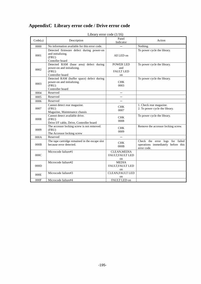
-195-
AppendixC Library error code / Drive error code
Library error code (1/16)
Code(H) Description Panel
Indicator Action
0000 No information available for this error code. - Nothing.
0001
Detected firmware defect during power-on
and initializing.
(FRU)
Contoller board
All LED on
To power cycle the library.
0002
Detected RAM (base area) defect during
power-on and initializing.
(FRU)
Controller board
POWER LED
and
FAULT LED
on
To power cycle the library.
0003
Detected RAM (buffer space) defect during
power-on and initializing.
(FRU)
Controller board
CHK
0003
To power cycle the library.
0004 Reserved -
0005 Reserved -
0006 Reserved -
0007
Cannot detect rear magazine.
(FRU)
Magazine, Maintenance chassis
CHK
0007
1. Check rear magazine.
2. To power cycle the library.
0008
Cannot detect available drive.
(FRU)
Drive I/F cable, Drive, Controller board
CHK
0008
To power cycle the library.
0009
The accessor locking screw is not removed.
(FRU)
The Accessor locking screw
CHK
0009
Remove the accessor locking screw.
000A Reserved -
000B
The tape cartridge remained in the escape slot
because error detected. CHK
000B
Check the error logs for failed
operations immediately before this
error code.
000C
Microcode failure#1 CLEAN,MEDIA
FAULT,FAULT LED
on
000D
Microcode failure#2
MEDIA
FAULT,FAULT LED
on
000E Microcode failure#3 CLEAN,FAULT LED
on
000F Microcode failure#4 FAULT LED on

-196-
Library error code (2/16)
Code(H) Description Panel
Indicator Action
0010
Failed in data acquisition from DHCP server.
(FRU)
DHCP Server, LAN cable, Controller board -
1. Check server.
2. Check DHCP configuration.
3. Check LAN cable connection.
4. To power cycle the library.
0011
Failed in time data acquisition from time
server.
(FRU)
Time Server, LAN cable, Controller board
-
1. Check server.
2. Check NTP configuration.
3. Check LAN cable connection.
4. To power cycle the library.
0012 Reserved -
0013 Reserved -
0014 The abnormalities of the destination of a
microcode download file were detected. -
0015 Reserved -
0016 Reserved -
0017 Reserved -
0018
The reading of the target mark is abnormal.
(FRU)
Drive, Maintenance chassis
CHK
0018
1. To power cycle the library.
0019 Reserved -
001A Reserved -
001B Reserved -
001C Reserved -
001D Reserved -
001E Reserved -
001F Reserved -

-197-
Library error code (3/16)
Code(H) Description Panel
Indicator Action
0020 Reserved
0021 Reserved
0022 Reserved
0023 Reserved
0024 Reserved -
0025 Reserved -
0026 Reserved -
0027 Reserved -
0028 Reserved -
0029 Reserved -
002A Reserved -
002B Reserved -
002C Reserved -
002D Reserved -
002E Reserved -
002F Reserved -

-198-
Library error code (4/16)
Code(H) Description Panel
Indicator Action
0030 Reserved
0031 Reserved
0032 Reserved
0033 Reserved
0034 Reserved -
0035 Reserved -
0036 Reserved -
0037 Reserved -
0038 Reserved -
0039 Reserved -
003A Reserved -
003B Reserved -
003C Reserved -
003D Reserved -
003E Reserved -
003F Reserved -

-199-
Library error code (5/16)
Code(H) Description Panel
Indicator Action
0040 Reserved -
0041 Reserved -
0042 Reserved -
0043 Reserved -
0044 Reserved -
0045 Reserved -
0046 Reserved -
0047 Reserved -
0048 Reserved -
0049 Reserved -
004A Reserved -
004B Reserved -
004C Reserved -
004D Reserved -
004E Reserved -
004F Reserved -

-200-
Library error code (6/16)
Code(H) Description Panel
Indicator Action
0050 Reserved -
0051 Reserved -
0052 Reserved -
0053
Defect in response information from barcode
reader.
(FRU)
Maintenance chassis,
CONTROLLER BOARD
CHK
0053
0054 Reserved -
0055 Reserved -
0056
Check sum defect in received data from
barcode reader.
(FRU)
Maintenance chassis,
CONTROLLER BOARD
CHK
0056
0057
Defect in barcode reader.
(FRU)
Maintenance chassis,
CONTROLLER BOARD
CHK
0057
0058
Defect in data reading of barcode reader.
(FRU)
Maintenance chassis,
CONTROLLER BOARD
CHK
0058
0059
Defect in FLASH control of barcode reader.
(FRU)
Maintenance chassis,
CONTROLLER BOARD
CHK
0059
005A
Defect in barcode reader verify.
(FRU)
Maintenance chassis,
CONTROLLER BOARD
CHK
005A
005B
Cannot detect I2C command interrupt
acknowledge from barcode reader in 60
seconds.
(FRU)
Maintenance chassis,
CONTROLLER BOARD
CHK
005B
005C
Cannot complete I2C send/receive operation
in 10 seconds.
(FRU)
Maintenance chassis,
CONTROLLER BOARD
CHK
005C
005D
Defect in I2C interface (NAK).
(FRU)
Maintenance chassis,
CONTROLLER BOARD
CHK
005D
005E
Defect in arbitration lost.
I2C arbitration lost failure.
(FRU)
Maintenance chassis,
CONTROLLER BOARD
CHK
005E
005F
Not becoming I2C ready.
(FRU)
Maintenance chassis,
CONTROLLER BOARD
CHK
005F
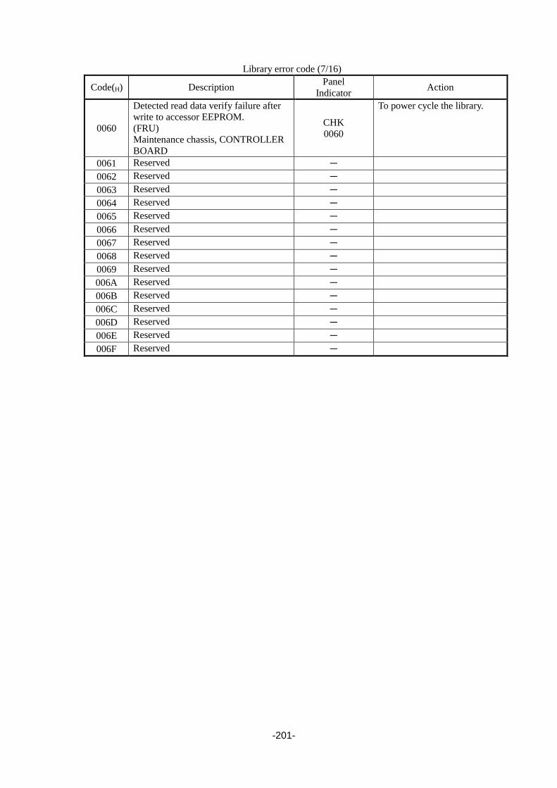
-201-
Library error code (7/16)
Code(H) Description Panel
Indicator Action
0060
Detected read data verify failure after
write to accessor EEPROM.
(FRU)
Maintenance chassis, CONTROLLER
BOARD
CHK
0060
To power cycle the library.
0061 Reserved -
0062 Reserved -
0063 Reserved -
0064 Reserved -
0065 Reserved -
0066 Reserved -
0067 Reserved -
0068 Reserved -
0069 Reserved -
006A Reserved -
006B Reserved -
006C Reserved -
006D Reserved -
006E Reserved -
006F Reserved -

-202-
Library error code (8/16)
Code(H) Description Panel
Indicator Action
0070
Cannot execute calibration because picker has a
medium.
(FRU)
Maintenance chassis, CONTROLLER BOARD
CHK
0070
1. To power cycle the library.
2. Unless calibration operated, this error
does not occur.
0071
Cannot execute calibration because magazine is
not inserted.
(FRU)
Maintenance chassis, CONTROLLER BOARD
CHK
0071
1. To power cycle the library.
2. Unless calibration operated, this error
does not occur.
0072
Defect in calibration data.
(FRU)
Maintenance chassis, CONTROLLER BOARD
CHK
0072
1. To power cycle the library.
2. Unless calibration operated, this error
does not occur.
0073
Cannot detect I/O slot sensor open state in I/O
slot sense operation during calibration.
(FRU)
I/O Slot Sensor, CONTROLLER BOARD
CHK
0073
To power cycle the library.
0074
Cannot get/check medium and read barcode
because picker has a medium.
(FRU)
Maintenance chassis, CONTROLLER BOARD
CHK
0074
1. Check picker if it has a medium.
2. To power cycle the library.
0075
Cannot put medium because picker does not
have a medium.
(FRU)
Maintenance chassis, CONTROLLER BOARD
CHK
0075
1. Check picker if it has a medium.
2. To power cycle the library.
0076 Reserved -
0077 Reserved -
0078 Reserved -
0079 Reserved -
007A Reserved -
007B Reserved -
007C
Cannot eject medium because drive does not
become condition of EJECT after 200 seconds
in getting medium from drive.
(FRU)
Drive, CONTROLLER BOARD
CHK
007C
1. To power cycle the library.
2. Move the medium manually via Web
or Operator Panel.
3. Check the medium.
007D
Drive does not become condition of MOUNT
after 200 seconds in putting medium to drive.
(FRU)
Drive, Maintenance chassis, CONTROLLER
BOARD
CHK
007D
1. To power cycle the library.
2. Check the medium and exchange
medium.
007E
Drive does not become condition of SET after 3
seconds in putting medium to drive.
(FRU)
Drive, Maintenance chassis, CONTROLLER
BOARD
CHK
007E
1. To power cycle the library.
2. Check the medium and exchange
medium.
007F
In medium picking or putting, drive interface
error detected or drive is not connected.
(FRU)
Drive, Maintenance chassis, CONTROLLER
BOARD
CHK
007F
To power cycle the library.

-203-
Library error code (9/16)
Code(H) Description Panel
Indicator Action
0080
X motion error #1 (In X motion, defect in data of
origin sensor when picker moves to target
position.)
(FRU)
Maintenance chassis, CONTROLLER BOARD
CHK
0080
To power cycle the library.
0081
X motion error #2 (Detected motor step-out in X
motion.)
(FRU)
Maintenance chassis, CONTROLLER BOARD
CHK
0081
To power cycle the library.
0082
X motion error #3 (Detected motor step-out in
initializing.)
(FRU)
Maintenance chassis, CONTROLLER BOARD
CHK
0082
To power cycle the library.
0083
X motion error #4 (After X motion, detected
discrepancy of encoder count.)
(FRU)
Maintenance chassis, CONTROLLER BOARD
CHK
0083
To power cycle the library.
0084
Cannot detect X origin position during
initializing.
(FRU)
Maintenance chassis, CONTROLLER BOARD
CHK
0084
To power cycle the library.
0085 Reserved -
0086 Reserved -
0087
When the encoder count coefficient calculation
pulse/operated, the coefficient was not able to be
calculated.
(FRU)
Maintenance chassis, CONTROLLER BOARD
CHK
0087
To power cycle the library.
0088
When the calibration operated, the lock position
was not able to be detected.
(FRU)
Maintenance chassis, CONTROLLER BOARD
CHK
0088
To power cycle the library.
0089 Reserved
008A Reserved -
008B Reserved -
008C Reserved -
008D Reserved -
008E Reserved -
008F
Magazine was removed during X motion.
(FRU)
Maintenance chassis, CONTROLLER BOARD
CHK
008F
1. Check magazine.
2. To power cycle the library.
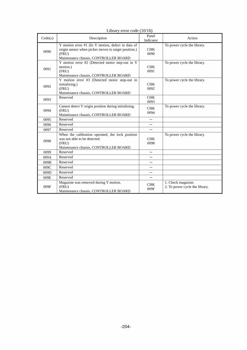
-204-
Library error code (10/16)
Code(H) Description Panel
Indicator Action
0090
Y motion error #1 (In Y motion, defect in data of
origin sensor when picker moves to target position.)
(FRU)
Maintenance chassis, CONTROLLER BOARD
CHK
0090
To power cycle the library.
0091
Y motion error #2 (Detected motor step-out in Y
motion.)
(FRU)
Maintenance chassis, CONTROLLER BOARD
CHK
0091
To power cycle the library.
0092
Y motion error #3 (Detected motor step-out in
initializing.)
(FRU)
Maintenance chassis, CONTROLLER BOARD
CHK
0092
To power cycle the library.
0093 Reserved CHK
0093
0094
Cannot detect Y origin position during initializing.
(FRU)
Maintenance chassis, CONTROLLER BOARD
CHK
0094
To power cycle the library.
0095 Reserved -
0096 Reserved -
0097 Reserved -
0098
When the calibration operated, the lock position
was not able to be detected.
(FRU)
Maintenance chassis, CONTROLLER BOARD
CHK
0098
To power cycle the library.
0099 Reserved -
009A Reserved -
009B Reserved -
009C Reserved -
009D Reserved -
009E Reserved -
009F
Magazine was removed during Y motion.
(FRU)
Maintenance chassis, CONTROLLER BOARD
CHK
009F
1. Check magazine.
2. To power cycle the library.

-205-
Library error code (11/16)
Code(H) Description Panel
Indicator Action
00A0 Reserved -
00A1 Reserved -
00A2 Reserved -
00A3 Reserved -
00A4 Reserved -
00A5 Reserved -
00A6 Reserved -
00A7 Reserved -
00A8 Reserved -
00A9 Reserved -
00AA Reserved -
00AB Reserved -
00AC Reserved -
00AD Reserved -
00AE Reserved -
00AF Reserved -
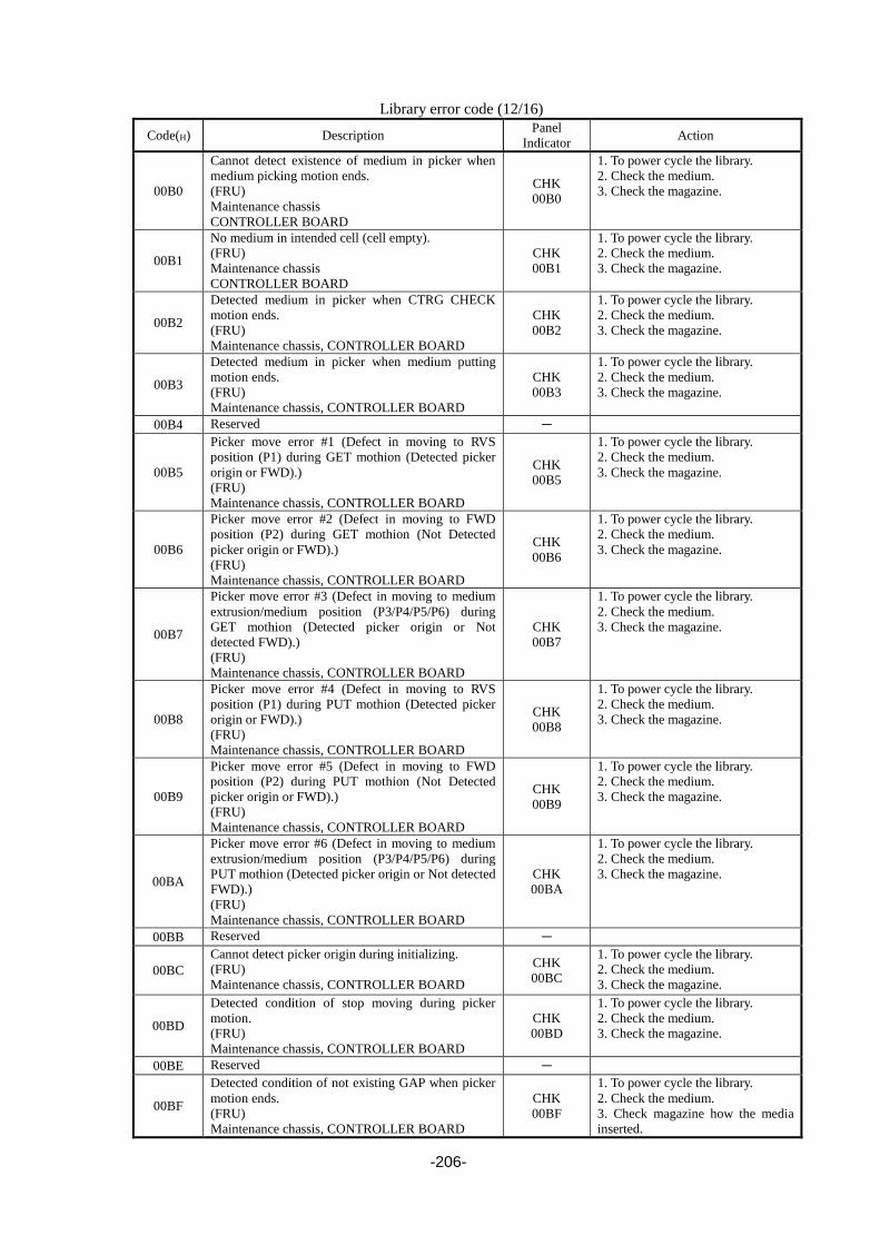
-206-
Library error code (12/16)
Code(H) Description Panel
Indicator Action
00B0
Cannot detect existence of medium in picker when
medium picking motion ends.
(FRU)
Maintenance chassis
CONTROLLER BOARD
CHK
00B0
1. To power cycle the library.
2. Check the medium.
3. Check the magazine.
00B1
No medium in intended cell (cell empty).
(FRU)
Maintenance chassis
CONTROLLER BOARD
CHK
00B1
1. To power cycle the library.
2. Check the medium.
3. Check the magazine.
00B2
Detected medium in picker when CTRG CHECK
motion ends.
(FRU)
Maintenance chassis, CONTROLLER BOARD
CHK
00B2
1. To power cycle the library.
2. Check the medium.
3. Check the magazine.
00B3
Detected medium in picker when medium putting
motion ends.
(FRU)
Maintenance chassis, CONTROLLER BOARD
CHK
00B3
1. To power cycle the library.
2. Check the medium.
3. Check the magazine.
00B4 Reserved -
00B5
Picker move error #1 (Defect in moving to RVS
position (P1) during GET mothion (Detected picker
origin or FWD).)
(FRU)
Maintenance chassis, CONTROLLER BOARD
CHK
00B5
1. To power cycle the library.
2. Check the medium.
3. Check the magazine.
00B6
Picker move error #2 (Defect in moving to FWD
position (P2) during GET mothion (Not Detected
picker origin or FWD).)
(FRU)
Maintenance chassis, CONTROLLER BOARD
CHK
00B6
1. To power cycle the library.
2. Check the medium.
3. Check the magazine.
00B7
Picker move error #3 (Defect in moving to medium
extrusion/medium position (P3/P4/P5/P6) during
GET mothion (Detected picker origin or Not
detected FWD).)
(FRU)
Maintenance chassis, CONTROLLER BOARD
CHK
00B7
1. To power cycle the library.
2. Check the medium.
3. Check the magazine.
00B8
Picker move error #4 (Defect in moving to RVS
position (P1) during PUT mothion (Detected picker
origin or FWD).)
(FRU)
Maintenance chassis, CONTROLLER BOARD
CHK
00B8
1. To power cycle the library.
2. Check the medium.
3. Check the magazine.
00B9
Picker move error #5 (Defect in moving to FWD
position (P2) during PUT mothion (Not Detected
picker origin or FWD).)
(FRU)
Maintenance chassis, CONTROLLER BOARD
CHK
00B9
1. To power cycle the library.
2. Check the medium.
3. Check the magazine.
00BA
Picker move error #6 (Defect in moving to medium
extrusion/medium position (P3/P4/P5/P6) during
PUT mothion (Detected picker origin or Not detected
FWD).)
(FRU)
Maintenance chassis, CONTROLLER BOARD
CHK
00BA
1. To power cycle the library.
2. Check the medium.
3. Check the magazine.
00BB Reserved -
00BC
Cannot detect picker origin during initializing.
(FRU)
Maintenance chassis, CONTROLLER BOARD
CHK
00BC
1. To power cycle the library.
2. Check the medium.
3. Check the magazine.
00BD
Detected condition of stop moving during picker
motion.
(FRU)
Maintenance chassis, CONTROLLER BOARD
CHK
00BD
1. To power cycle the library.
2. Check the medium.
3. Check the magazine.
00BE Reserved -
00BF
Detected condition of not existing GAP when picker
motion ends.
(FRU)
Maintenance chassis, CONTROLLER BOARD
CHK
00BF
1. To power cycle the library.
2. Check the medium.
3. Check magazine how the media
inserted.

-207-
Library error code (13/16)
Code(H) Description Panel
Indicator Action
00C0
Picker cannot move because magazine was
removed.
(FRU)
Maintenance chassis
CHK
00C0
1. To power cycle the library.
2. Check the medium.
3. Check the magazine.
00C1
When I/O lock release (IOULK) operates, I/O
lock sensor OFF cannot be detected.
(FRU)
Maintenance chassis,
CONTROLLER BOARD
CHK
00C1
1. To power cycle the library.
2. Check the magazine.
00C2 Reserved -
00C3 Reserved -
00C4 Reserved -
00C5
Picker move error #7(Defect in moving to
RVS position(P1) during the motion other
than GET/PUT(Detected picker origin or
FWD).)
(FRU)
Maintenance chassis,
CONTROLLER BOARD
CHK
00C5
1. To power cycle the library.
2. Check the medium.
3. Check the magazine.
00C6
Picker move error #8(Defect in moving to
FWD position (P2) during the motion other
than GET/PUT(Not Detected picker origin
or FWD).)
(FRU)
Maintenance chassis,
CONTROLLER BOARD
CHK
00C6
1. To power cycle the library.
2. Check the medium.
3. Check the magazine.
00C7
Picker move error #9(Defect in moving to
medium extrusion/medium position
(P3/P4/P5/P6) during the motion other than
GET/PUT(Not Detected picker origin or
FWD).)
(FRU)
Maintenance chassis,
CONTROLLER BOARD
CHK
00C7
1. To power cycle the library.
2. Check the medium.
3. Check the magazine.
00C8 Reserved -
00C9
Picker calibration error #1 (Cannot detect
CTRG sensor ON during picker calibration.)
(FRU)
Maintenance chassis,
CONTROLLER BOARD
CHK
00C9
Unless calibration operated, this
error does not occur.
00CA
Picker calibration error #2
(The encoder count became more than the P6
value during picker calibration.)
(FRU)
Maintenance chassis,
CONTROLLER BOARD
CHK
00CA
1. To power cycle the library.
2. Check the medium.
3. Check the magazine.
00CB
Picker calibration error #3
(The lock position was not able to be detected
during picker calibration.)
(FRU)
Maintenance chassis,
CONTROLLER BOARD
CHK
00CB
1. To power cycle the library.
2. Check the medium.
3. Check the magazine.
00CC
GET motion error during Picker calibration
(Not detected CTRG sensor ON in GET
motion during Picker calibration.)
(FRU)
Maintenance chassis,
CONTROLLER BOARD
CHK
00CC
1. To power cycle the library.
2. Check the medium.
3. Check the magazine.
00CD Reserved -
00CE
Not detected lock position during LIMIT
CHECK motion
(FRU)
Maintenance chassis,
CHK
00CE
1. To power cycle the library.
2. Check the medium.
3. Check the magazine.

-208-
CONTROLLER BOARD
00CF Reserved -

-209-
Library error code (14/16)
Code(H) Description Panel
Indicator Action
00D0
Detected check sum error during firmware
update.
(FRU)
F/W
CHK
00D0
To power cycle the library.
00D1
Detected firmware ID error during firmware
update.
(FRU)
F/W
CHK
00D1
To power cycle the library.
00D2
Detected boot information error during
firmware update.
(FRU)
F/W
CHK
00D2
To power cycle the library.
00D3
Stopped processing because BCR does not
become Maintenance mode when BCR
firmware updating.
(FRU)
Maintenance chassis,
CONTROLLER BOARD
CHK
00D3
To power cycle the library.
00D4
Detected error during BCR F/Wchecking
(FRU)
Maintenance chassis, F/W
CHK
00D4
To power cycle the library.
00D5 Reserved -
00D6
The lock could not be released at the time of
magazine ejection.
(FRU)
Maintenance chassis,
CONTROLLER BOARD
CHK
00D6
To power cycle the library.
00D7
The lock could not be released at the time of
I/O station opening.
(FRU)
Maintenance chassis,
CONTROLLER BOARD
CHK
00D7
To power cycle the library.
00D8
Power supply #1 FAN error was detected
(FRU)
Power supply #1
CHK
00D8
00D9
Power supply #2 FAN error was detected
(FRU)
Power supply #2
CHK
00D9
00DA Reserved -
00DB Reserved -
00DC
Power supply #1 error was detected
(FRU)
Power supply #1
CHK
00DC
00DD
Power supply #2 error was detected
(FRU)
Power supply #2
CHK
00DD
00DE Reserved -
00DF Reserved -

-210-
Library error code (15/16)
Code(H) Description Panel
Indicator Action
00E0
When writing into flash memory, the writing was not finished within 1 ms. (FRU)
CONTROLLER BOARD
CHK
00E0
To power cycle the library.
00E1
When clearing the sector in flash memory, the
clearing was not finished within 10 seconds.
(FRU)
CONTROLLER BOARD
CHK
00E1
To power cycle the library.
00E2
An error was detected in unit configuration
data area stored in flash memory.
(FRU)
CONTROLLER BOARD
CHK
00E2
To power cycle the library.
00E3
A checksum error was detected in the data
stored in flash memory.
(FRU)
CONTROLLER BOARD
CHK
00E3
To power cycle the library.
00E4 Reserved -
00E5 Reserved -
00E6 Reserved -
00E7 Reserved -
00E8 Reserved -
00E9 Reserved -
00EA Reserved -
00EB Reserved -
00EC Reserved -
00ED Reserved -
00EE Reserved -
00EF Reserved -

-211-
Library error code (16/16)
Code(H) Description Panel
Indicator Action
00F0
Sensor Abnomaly #1
(At blink check, magazine sensor 1 abnomaly
detected.)
(FRU)
Maintenance chassis
CHK
00F0
00F1
Sensor Abnomaly #2
(At blink check, magazine sensor 2 abnomaly
detected.)
(FRU)
Maintenance chassis
CHK
00F1
00F2
Sensor Abnomaly #3
(At blink check, magazine sensor 3 abnomaly
detected.)
(FRU)
Maintenance chassis
CHK
00F2
00F3
Sensor Abnomaly #4
(At blink check, magazine sensor 4 abnomaly
detected.)
(FRU)
Maintenance chassis
CHK
00F3
00F4
Sensor Abnomaly #5
(At blink check, I/O station sensor 1
abnomaly detected.)
(FRU)
Maintenance chassis
CHK
00F4
00F5
Sensor Abnomaly #6
(At blink check, I/O station sensor 2
abnomaly detected.)
(FRU)
Maintenance chassis
CHK
00F5
00F6
Sensor Abnomaly #7
(At blink check, I/O station sensor 3
abnomaly detected.)
(FRU)
Maintenance chassis
CHK
00F6
00F7
Sensor Abnomaly #8
(At blink check, I/O station sensor 4
abnomaly detected.)
(FRU)
Maintenance chassis
CHK
00F7
00F8
Sensor Abnomaly #9
(At blink check, X origin point sensor
abnomaly detected.)
(FRU)
Maintenance chassis
CHK
00F8
00F9
Sensor Abnomaly #10
(At blink check, cartridge sensor abnomaly
detected.)
(FRU)
Maintenance chassis
CHK
00F9
00FA
Sensor Abnomaly #11
(At blink check, picker forward sensor
abnomaly detected.)
(FRU)
Maintenance chassis
CHK
00FA
00FB
Sensor Abnomaly #12
(At blink check, picker origin point sensor
abnomaly detected.)
(FRU)
Maintenance chassis
CHK
00FB
00FC
Sensor Abnomaly #14
(At blink check, Y origin point sensor
abnomaly detected.)
(FRU)
CHK
00FC

-212-
Maintenance chassis
00FD Reserved
00FE Reserved
00FF Reserved -
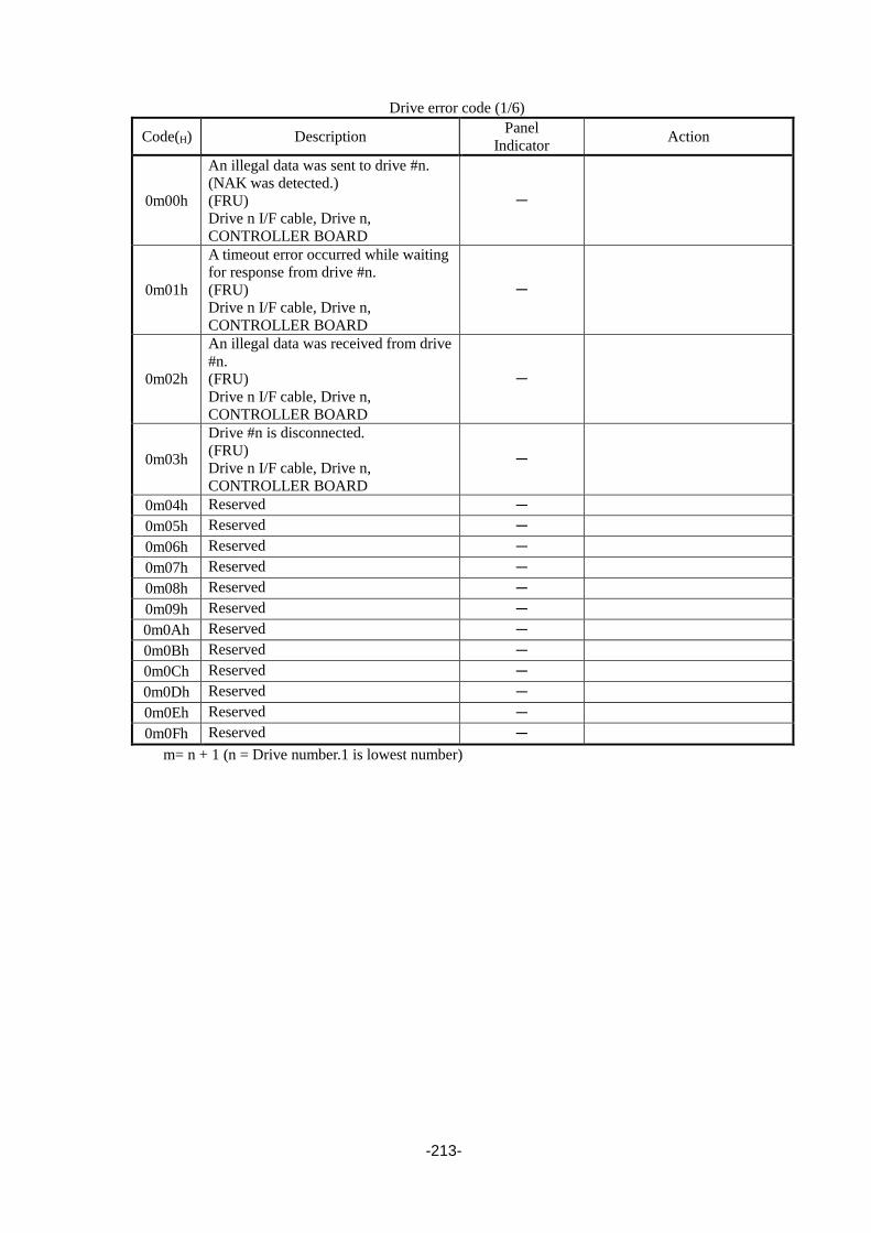
-213-
Drive error code (1/6)
Code(H) Description Panel
Indicator Action
0m00h
An illegal data was sent to drive #n.
(NAK was detected.)
(FRU)
Drive n I/F cable, Drive n,
CONTROLLER BOARD
-
0m01h
A timeout error occurred while waiting
for response from drive #n.
(FRU)
Drive n I/F cable, Drive n,
CONTROLLER BOARD
-
0m02h
An illegal data was received from drive
#n.
(FRU)
Drive n I/F cable, Drive n,
CONTROLLER BOARD
-
0m03h
Drive #n is disconnected.
(FRU)
Drive n I/F cable, Drive n,
CONTROLLER BOARD
-
0m04h Reserved -
0m05h Reserved -
0m06h Reserved -
0m07h Reserved -
0m08h Reserved -
0m09h Reserved -
0m0Ah Reserved -
0m0Bh Reserved -
0m0Ch Reserved -
0m0Dh Reserved -
0m0Eh Reserved -
0m0Fh Reserved -
m= n + 1 (n = Drive number.1 is lowest number)
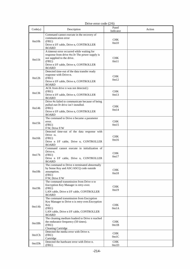
-214-
Drive error code (2/6)
Code(H) Description Panel
Indicator Action
0m10h
Command cannot execute in the recovery of
communication error
(FRU)
Drive n I/F cable, Drive n, CONTROLLER
BOARD
CHK
0m10
0m11h
A timeout error occurred while waiting for
response from drive #n.Or The power supply is
not supplied to the drive.
(FRU)
Drive n I/F cable, Drive n, CONTROLLER
BOARD
CHK
0m11
0m12h
Detected time-out of the data transfer ready
reaponse with Drive-n.
(FRU)
Drive n I/F cable, Drive n, CONTROLLER
BOARD
CHK
0m12
0m13h
ACK from drive n was not detected.)
(FRU)
Drive n I/F cable, Drive n, CONTROLLER
BOARD
CHK
0m13
0m14h
Drive #n failed to communicate because of being
pulled out.Or drive isn’t installed.
(FRU)
Drive n I/F cable, Drive n, CONTROLLER
BOARD
CHK
0m14
0m15h
The command to Drive n became a parameter
error.
(FRU)
F/W, Drive F/W
CHK
0m15
0m16h
Detected time-out of the data response with
Drive –n.
(FRU)
Drive n I/F cable, Drive n, CONTROLLER
BOARD
CHK
0m16
0m17h
Command cannot execute in initialization of
Drive-n.
(FRU)
Drive n I/F cable, Drive n, CONTROLLER
BOARD
CHK
0m17
0m18h
The command to Drive n terminated abnormally
by Sense Key and ASC/ASCQ code outside
assumption.
(FRU)
F/W, Drive F/W
CHK
0m18
0m19h
The command transmission from Drive n to
Encryption Key Manager is retry-over.
(FRU)
LAN cable, Drive n I/F cable, CONTROLLER
BOARD
CHK
0m19
0m1Ah
The command transmission from Encryption
Key Manager to Drive n is retry-over.Encryption
Key
(FRU)
LAN cable, Drive n I/F cable, CONTROLLER
BOARD
CHK
0m1A
0m1Bh
The cleaning medium loaderd to Drive n reached
the endurance frequency (50 times).
(FRU)
Cleaning Cartridge
CHK
0m1B
0m1Ch
Detected the media error with Drive n.
(FRU)
Cartridge
CHK
0m1C
0m1Dh Detected the hardware error with Drive n.
(FRU)
CHK
0m1D

-215-
Cartridge, Drive n
0m1Eh
Command cannot execute for disconnection of
Drive-n.
(FRU)
Drive n I/F cable, Drive n, CONTROLLER
BOARD
CHK
01mE
0m1Fh
Detected the initialization time-out with Drive n.
(FRU)
Drive n I/F cable, Drive n, CONTROLLER
BOARD
CHK
0m1F
m= n + 1 (n = Drive number.1 is lowest number)

-216-
Drive error code (3/6)
Code(H) Description Panel
Indicator Action
0m20h
Detected Medium error with Drive-n.
(FRU)
Cartridge
CHK
0m20
0m21h
Abort Task from Drive n or Logical
Unit Reset was received, and the
command was interrupted.
(FRU)
Cartridge,Drive
CHK
0m21
0m22h Reserved -
0m23h Reserved -
0m24h Reserved -
0m25h Reserved -
0m26h Reserved -
0m27h Reserved -
0m28h Reserved -
0m29h Reserved -
0m2Ah Reserved -
0m2Bh Reserved -
0m2Ch Reserved -
0m2Dh Reserved -
0m2Eh Reserved -
0m2Fh Reserved -
m= n + 1 (n = Drive number.1 is lowest number)

-217-
Drive error code (4/6)
Code(H) Description Panel
Indicator Action
0m30h
After Unload, the medium was not exhausted
though passed six minutes.
(FRU)
Drive n I/F cable, Drive n, CONTROLLER
BOARD
CHK
0m30
0m31h
Cannot eject medium because drive is in state
of Prevent Medium Removal.
(FRU)
Drive n I/F cable, Drive n, CONTROLLER
BOARD
CHK
0m31
0m32h
Detected the FAN error with Drive n.
(FRU)
Drive n FAN
CHK
0m32
0m33h Reserved -
0m34h Reserved -
0m35h Reserved -
0m36h Reserved -
0m37h Reserved -
0m38h Reserved -
0m39h Reserved -
0m3Ah Reserved -
0m3Bh Reserved -
0m3Ch Reserved -
0m3Dh Reserved -
0m3Eh Reserved -
0m3Fh Reserved -
m= n + 1 (n = Drive number.1 is lowest number)

-218-
Drive error code (5/6)
Code(H) Description Panel
Indicator Action
0m40h Reserved -
0m41h
Detected Drive error “1” with Drive
n.(Cooling Problem)
(FRU)
Drive n FAN, Drive n
CHK
0m41
0m42h
Detected Drive error “2” with Drive n.
(Power Problem)
(FRU)
Drive n
CHK
0m42
0m43h
Detected Drive error “3” with Drive n.
(Microcode Problem)
(FRU)
Drive n
CHK
0m43
0m44h
Detected Drive error “4” with Drive n.
(Microcode or Drive Problem)
(FRU)
Drive n
CHK
0m44
0m45h
Detected Drive error “5” with Drive n. (Drive
Error)
(FRU)
Drive n
CHK
0m45
0m46h
Detected Drive error “6” with Drive n. (Drive
or Meida Error)
(FRU)
Drive n, cartridge
CHK
0m46
0m47h
Detected Drive error “7” with Drive n.
(Media Error)
(FRU)
cartridge
CHK
0m47
0m48h
Detected Drive error “8” with Drive n. (SCSI
Bus Interface or Fibre Channel Error)
(FRU)
SAS/FC cable,Drive n
CHK
0m48
0m49h
Detected Drive error “9” with Drive n.
(RS-422 Error)
(FRU)
Drive n I/F cable
CHK
0m49
0m4Ah
Detected Drive error “A” with Drive n.(Drive
Error)
(FRU)
Drive n
CHK
0m4A
0m4Bh Reserved -
0m4Ch Reserved -
0m4Dh Reserved -
0m4Eh Reserved -
0m4Fh
Detected Drive error “F” with Drive n.(Drive
of Fibre Channel Error-NO LIGHT)
(FRU)
SAS/FC cable, Drive n
CHK
0m4F
m= n + 1 (n = Drive number.1 is lowest number)

-219-
Drive error code (6/6)
Code(H) Description Panel
Indicator Action
0m50h
Detected Drive error “J” with Drive n.
(Incompatible Medium Installed)
(FRU)
Cartridge
CHK
0m50
0m51h
Detected Drive error “P” with Drive n. (Write
operation to a write protected cartridge has
been attempted)
(FRU)
Cartridge, Drive n
CHK
0m51
0m52h Reserved -
0m53h
Detected Drive error “d” with Drive n.
(2 drives on fiber loop have the same
APL_PA)
(FRU)
Drive n setting
CHK
0m53
0m54h
Detected Drive error “e” with Drive n.
(The drive detected a configuration or set-up
error prior to an encryption operation)
(FRU)
Drive n I/F cable, Drive n
CHK
0m54
0m55h Reserved -
0m56h Reserved -
0m57h
Detected Drive error “u” with Drive n.
(The drive is in the process of uploading and
flashing new Firmware)
CHK
0m57
0m58h Reserved -
0m59h Reserved -
0m5Ah Reserved -
0m5Bh Reserved -
0m5Ch Reserved -
0m5Dh Reserved -
0m5Eh Reserved -
0m5Fh Reserved -
m= n + 1 (n = Drive number.1 is lowest number)

-220-
AppendixD Tape Alert D-1 Library Tape Alert
Code Flag Contents - Action
1 Library Hardware A Changer mechanism is having trouble communicating with the internal drive
・Turn the power off and on again.
4 Library Hardware D The changer mechanism has a hardware fault that is not mechanically related or requires a power cycle to recover
・Turn the power off and on again.
8 Library Maintenance Library preventative maintenance required
・If it is detected the cleaning request, clean the drive.
12 Library Stray Tape Stray cartridge left in library after previous error recovery
・Please remove the tape cartridge from the drive.
Please refer to Section 4.7.2 if you take out in the operation of the library apparatus.
・Turn the power off and on again.
13 Library Pick Retry Operation to pick a cartridge from a slot had to perform an excessive number of retries before succeeding
・If events occur continues, call the maintenance staff.
14 Library Place Retry Operation to place a cartridge in a slot had to perform an excessive number of retries before succeeding
・If events occur continues, call the maintenance staff.
16 Library Door Changer door open prevents library functioning
・After storing the magazine, re-run the operation.
17 Library Mailslot Mechanical problem with import/export mailslot
・Call to maintenance staff.
18 Library Magazine Library magazine not present.
・After storing the magazine, re-run the operation.
23 Library Scan Retry Operation to scan the bar code on a cartridge had to perform an excessive number of retries before succeeding
・Exchanger the barcode label.
・If events occur continues, call the maintenance staff.
27 Cooling Fan Failure One or more fans inside the library have failed. Internal flag state only cleared when all fans are working again
・Call to maintenance staff.
28 Power Supply Redundant power supply failure inside the library subsystem
・Call to maintenance staff.
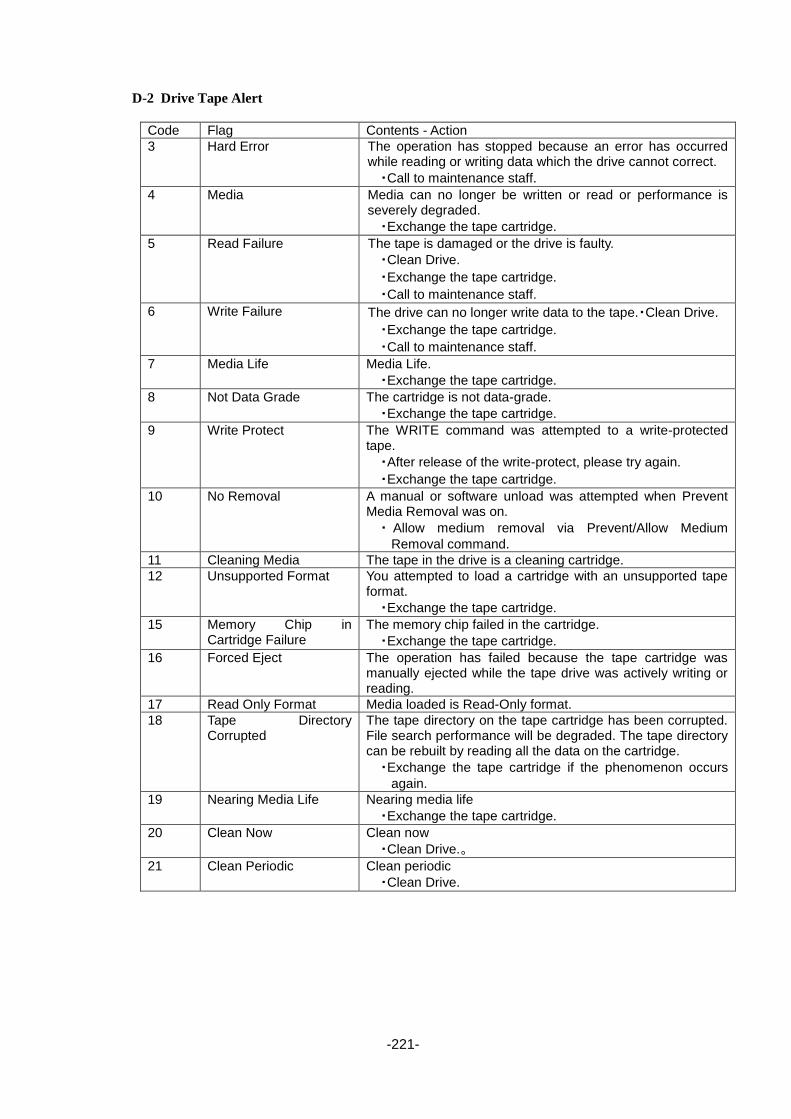
-221-
D-2 Drive Tape Alert
Code Flag Contents - Action
3 Hard Error The operation has stopped because an error has occurred while reading or writing data which the drive cannot correct.
・Call to maintenance staff.
4 Media Media can no longer be written or read or performance is severely degraded.
・Exchange the tape cartridge.
5 Read Failure The tape is damaged or the drive is faulty.
・Clean Drive.
・Exchange the tape cartridge.
・Call to maintenance staff.
6 Write Failure The drive can no longer write data to the tape.・Clean Drive.
・Exchange the tape cartridge.
・Call to maintenance staff.
7 Media Life Media Life.
・Exchange the tape cartridge.
8 Not Data Grade The cartridge is not data-grade.
・Exchange the tape cartridge.
9 Write Protect The WRITE command was attempted to a write-protected tape.
・After release of the write-protect, please try again.
・Exchange the tape cartridge.
10 No Removal A manual or software unload was attempted when Prevent Media Removal was on.
・ Allow medium removal via Prevent/Allow Medium
Removal command.
11 Cleaning Media The tape in the drive is a cleaning cartridge.
12 Unsupported Format You attempted to load a cartridge with an unsupported tape format.
・Exchange the tape cartridge.
15 Memory Chip in Cartridge Failure
The memory chip failed in the cartridge.
・Exchange the tape cartridge.
16 Forced Eject The operation has failed because the tape cartridge was manually ejected while the tape drive was actively writing or reading.
17 Read Only Format Media loaded is Read-Only format.
18 Tape Directory Corrupted
The tape directory on the tape cartridge has been corrupted. File search performance will be degraded. The tape directory can be rebuilt by reading all the data on the cartridge.
・Exchange the tape cartridge if the phenomenon occurs
again.
19 Nearing Media Life Nearing media life
・Exchange the tape cartridge.
20 Clean Now Clean now
・Clean Drive.。
21 Clean Periodic Clean periodic
・Clean Drive.

-222-
Code Flag Contents - Action
22 Expired Cleaning Media Expired cleaning media
・Exchange the cleaning cartridge.
23 Invalid cleaning tape Invalid cleaning tape
・Exchange the cleaning cartridge.
30 Hardware A The drive has a hardware fault that requires a reset to recover.
・Turn the power off and on again.
・Call to maintenance staff.
31 Hardware B The drive has a hardware fault that is not related to the read/write operation or the drive requires a power cycle to recover.
・Call to maintenance staff.
32 Interface The drive has identified an interface fault.
・Check host interface connection.
33 Eject Media Eject media
・Eject the tape cartridge.
・Exchange the tape cartridge.
34 Download Fault Firmware download failed
・Confirm the firmware file.
・Try firmware download again.
36 Drive Temperture The drive’s temperature limits are exceeded.
・Please check the installation environment of the library.
37 Drive Voltage The drive’s voltage limits are exceeded.
・Call to maintenance staff.
38 Predictive Failure Predictive failure of drive hardware
・Execute the corresponding error if other as has occurred.
39 Diagnostics Required Diagnostics required
・Call to maintenance staff.
51 Tape Directory Invalid at Unload
Tape directory invalid at unload
・Exchange the tape cartridge if the phenomenon occurs
again.
52 Tape System Area Write Failure
Tape system area write failure
・Exchange the tape cartridge if the phenomenon occurs
again.
53 Tape System Area Read Failure
Tape system area read failure
・Exchange the tape cartridge if the phenomenon occurs
again.
55 Loading Failure Loading failure
・Exchange the tape cartridge.
・Call to maintenance staff.
56 Unrecoverable Unload Failure
Unrecoverable unload failure
・Please remove the tape cartridge from the drive.
Please refer to Section 4.7.2 if you take out in the operation of the library apparatus.
・Call to maintenance staff.
59 WORM Medium – Integrity Check Faied
(WORM Medium - integrity check failed) set when the drive determines that the data on tape is suspect from a WORM point of view.
・Exchange the tape cartridge.
60 WORM Medium – Over Write Attempted
(WORM Medium - Overwrite Attempted) set when the drive rejects a Write operation because the rules for allowing WORM writes have not been met.
・Exchange the tape cartridge.

-223-
[factory]
AppendixE Library assembly procedure
T30A library assembly procedure
Item list
1.T30A
:LL030F-D1AL0
2.Drive module(LTO4-LTO7 SAS / LTO4-LTO7 FC)
: LL060A-D1H04AS / LL060A-D1H05AS / LL060A-D1H06AS / LL060A-D1H07AS
: LL060A-D1H04AF / LL060A-D1H05AF / LL060A-D1H06AF / LL060A-D1H07AF
3.Escape Slot
: LL060A-D1ES1
Procedure 1
・Insert item 2 in the lower side of item 1, and tighten two screws by 150 ±10%(cN・m)
・Insert item 2 or item 3 in the upper side of item 1 , and tighten two screws by 150 ±10&(cN・m)
(Insert item3 at one drive composition. Insert item2 at two drives composition.)

-224-
T60A library assembly procedure
Item list
1.T60A
:LL060F-D1AL0
2.Drive module(LTO4-LTO7 SAS / LTO4-LTO7 FC)
: LL060A-D1H04AS / LL060A-D1H05AS / LL060A-D1H06AS / LL060A-D1H07AS
: LL060A-D1H04AF / LL060A-D1H05AF / LL060A-D1H06AF / LL060A-D1H07AF
3.Escape Slot
: LL060A-D1ES1
6 Power supply
: LL060A-D1PW1
7 PS Blank panel
Procedure 1
・Insert item 2 in the lower side of item 1, and tighten two screws by 150 ±10%(cN・m)
・Insert item 2 or item 3 in the second step from the bottom of item 1 , and tighten two screws by 150
±10&(cN・m)
(Insert item3 in the second step from the bottom of item 1 at one drive composition. Insert item2 at two
drives composition.)
(Detach the drive cover mounted on the positions of drive #3, and insert item2 at 3 drives composition.)
(Detach the drive cover mounted on the positions of drive #3 and #4, and insert item2 at 4 drives
composition.)
Procedure 2
・Insert item 6 detaching item 7 mounted on the power supply insertion part in the upper part of the device
at two in power supply composition.

-225-
AppendixF OpenSSL License
/* Copyright (C) 1995-1998 Eric Young ([email protected])
* All rights reserved.
*
* This package is an SSL implementation written
* by Eric Young ([email protected]).
* The implementation was written so as to conform with Netscapes SSL.
*
* This library is free for commercial and non-commercial use as long as
* the following conditions are aheared to. The following conditions
* apply to all code found in this distribution, be it the RC4, RSA,
* lhash, DES, etc., code; not just the SSL code. The SSL documentation
* included with this distribution is covered by the same copyright terms
* except that the holder is Tim Hudson ([email protected]).
*
* Copyright remains Eric Young's, and as such any Copyright notices in
* the code are not to be removed.
* If this package is used in a product, Eric Young should be given attribution
* as the author of the parts of the library used.
* This can be in the form of a textual message at program startup or
* in documentation (online or textual) provided with the package.
*
* Redistribution and use in source and binary forms, with or without
* modification, are permitted provided that the following conditions
* are met:
* 1. Redistributions of source code must retain the copyright
* notice, this list of conditions and the following disclaimer.
* 2. Redistributions in binary form must reproduce the above copyright
* notice, this list of conditions and the following disclaimer in the
* documentation and/or other materials provided with the distribution.
* 3. All advertising materials mentioning features or use of this software
* must display the following acknowledgement:
* "This product includes cryptographic software written by
* Eric Young ([email protected])"
* The word 'cryptographic' can be left out if the rouines from the library
* being used are not cryptographic related :-).
* 4. If you include any Windows specific code (or a derivative thereof) from
* the apps directory (application code) you must include an acknowledgement:
* "This product includes software written by Tim Hudson ([email protected])"
*
* THIS SOFTWARE IS PROVIDED BY ERIC YOUNG ``AS IS'' AND
* ANY EXPRESS OR IMPLIED WARRANTIES, INCLUDING, BUT NOT LIMITED TO, THE
* IMPLIED WARRANTIES OF MERCHANTABILITY AND FITNESS FOR A PARTICULAR
PURPOSE
* ARE DISCLAIMED. IN NO EVENT SHALL THE AUTHOR OR CONTRIBUTORS BE LIABLE
* FOR ANY DIRECT, INDIRECT, INCIDENTAL, SPECIAL, EXEMPLARY, OR CONSEQUENTIAL
* DAMAGES (INCLUDING, BUT NOT LIMITED TO, PROCUREMENT OF SUBSTITUTE GOODS
* OR SERVICES; LOSS OF USE, DATA, OR PROFITS; OR BUSINESS INTERRUPTION)
* HOWEVER CAUSED AND ON ANY THEORY OF LIABILITY, WHETHER IN CONTRACT,
STRICT
* LIABILITY, OR TORT (INCLUDING NEGLIGENCE OR OTHERWISE) ARISING IN ANY WAY
* OUT OF THE USE OF THIS SOFTWARE, EVEN IF ADVISED OF THE POSSIBILITY OF
* SUCH DAMAGE. *
* The licence and distribution terms for any publically available version or
* derivative of this code cannot be changed. i.e. this code cannot simply be

-226-
* copied and put under another distribution licence
* [including the GNU Public Licence.]
*/
/* ====================================================================
* Copyright (c) 1998-2001 The OpenSSL Project. All rights reserved.
*
* Redistribution and use in source and binary forms, with or without
* modification, are permitted provided that the following conditions
* are met:
*
* 1. Redistributions of source code must retain the above copyright
* notice, this list of conditions and the following disclaimer.
*
* 2. Redistributions in binary form must reproduce the above copyright
* notice, this list of conditions and the following disclaimer in
* the documentation and/or other materials provided with the
* distribution.
*
* 3. All advertising materials mentioning features or use of this
* software must display the following acknowledgment:
* "This product includes software developed by the OpenSSL Project
* for use in the OpenSSL Toolkit. (http://www.openssl.org/)"
*
* 4. The names "OpenSSL Toolkit" and "OpenSSL Project" must not be used to
* endorse or promote products derived from this software without
* prior written permission. For written permission, please contact
*
* 5. Products derived from this software may not be called "OpenSSL"
* nor may "OpenSSL" appear in their names without prior written
* permission of the OpenSSL Project.
*
* 6. Redistributions of any form whatsoever must retain the following
* acknowledgment:
* "This product includes software developed by the OpenSSL Project
* for use in the OpenSSL Toolkit (http://www.openssl.org/)"
*
* THIS SOFTWARE IS PROVIDED BY THE OpenSSL PROJECT ``AS IS'' AND ANY
* EXPRESSED OR IMPLIED WARRANTIES, INCLUDING, BUT NOT LIMITED TO, THE
* IMPLIED WARRANTIES OF MERCHANTABILITY AND FITNESS FOR A PARTICULAR
* PURPOSE ARE DISCLAIMED. IN NO EVENT SHALL THE OpenSSL PROJECT OR
* ITS CONTRIBUTORS BE LIABLE FOR ANY DIRECT, INDIRECT, INCIDENTAL,
* SPECIAL, EXEMPLARY, OR CONSEQUENTIAL DAMAGES (INCLUDING, BUT
* NOT LIMITED TO, PROCUREMENT OF SUBSTITUTE GOODS OR SERVICES;
* LOSS OF USE, DATA, OR PROFITS; OR BUSINESS INTERRUPTION)
* HOWEVER CAUSED AND ON ANY THEORY OF LIABILITY, WHETHER IN CONTRACT,
* STRICT LIABILITY, OR TORT (INCLUDING NEGLIGENCE OR OTHERWISE)
* ARISING IN ANY WAY OUT OF THE USE OF THIS SOFTWARE, EVEN IF ADVISED
* OF THE POSSIBILITY OF SUCH DAMAGE.
* ====================================================================
*
* This product includes cryptographic software written by Eric Young
* ([email protected]). This product includes software written by Tim
* Hudson ([email protected]).
*
*/

T30A/T60A Tape Library
Users Guide Revision 7(September, 2016)
NEC Corporation 5-7-1, SHIBA, MINATOKU
TOKYO, JAPAN
TEL +81 33 454 1111 (Reception)
NEC Corporation 2011-2016 A part or all of this document cannot be reproduced or modified without prior permission of NEC.
Information in this document may be subject to change without notice.
856-129409-160-A
Related Documents