T Se Sup (SAL KLODI Rr. Barrik Kati III – Tirane – S Tel: 06940 Email: klo Email: klo UN TECH ecurity u pply Cen LW) and IODAsh.p kadave P.118 Zyra Nr.2 Shqiperi 0 43470 odioda@yaho odioda@gmai ITED NAT HNIC upgrade ntre “Mu d ammu P p.k oo.com il.com TIONS DEV AL CAL S e of Mini ullet”- - unition s PROJEC MAR VELOPMEN LBANIA SPEC istry of -Small A storage l CT DESI RS 2020 NT PROGR IFICA Interior Arms Li location IGN RAMME ATIO r (Mol) ght Wea n, Second ON Main aYesns d Phase e

Welcome message from author
This document is posted to help you gain knowledge. Please leave a comment to let me know what you think about it! Share it to your friends and learn new things together.
Transcript

T
SeSup
(SAL
KLODIRr. BarrikKati III – Tirane – STel: 06940Email: kloEmail: klo
UN
TECH
ecurity upply CenLW) and
IODAsh.pkadave P.118 Zyra Nr.2
Shqiperi 0 43470 odioda@yahoodioda@gmai
ITED NAT
HNIC
upgradentre “Mud ammu
P
p.k
oo.com il.com
TIONS DEV
AL
CAL S
e of Miniullet”- -
unition s
PROJEC
MAR
VELOPMEN
LBANIA
SPEC
istry of -Small Astorage l
CT DESI
RS 2020
NT PROGR
IFICA
InteriorArms Lilocation
IGN
RAMME
ATIO
r (Mol) ght Wea
n, Second
ON
Main aYesns d Phase
e
SECTION 1
GENERAL SPECIFICATION
1.1. General Specifications
1.1.1 Unit of measurements
1.1.2 Time duration graphic
1.1.3 Mischievous works
1.1.4 Information tables
1.2. Deliveries of Supervisor
1.2.1 Written authorization
1.2.2 Submissions to supervisor
1.1 General Specifications
1.1.1 Unit of measurements
In general the measurements units, when signing a Contract are metric units as: mm, cm, m, m², m³, Km, N (Njuton), Mg (1000 kg) and grad celcius. Decimal points are written as “. “.
1.1.2 Time duration graphic
The contractor shall give the supervisor a detailed program showing the order, procedure and method according to which he proposes on the building method up to the conclusion of works.
The Information kept by the supervisor should include: general arrangement drawings that show the arrangement of the building and any building or other temporary structure, which he proposes to use; constructional deployment details and temporary jobs; Other plans it proposes to adopt for the construction and completion of all works, as well as the following, details of skilled labor and not qualified and supervision of works.
The method and order proposed to execute these permanent works is subject to regulation and approved by the supervisor, and the price of the contract must be such as to include any necessary adjustments, as required by the supervisor during the implementation of works.
1.1.3 Mischievous works
Any work that is not in accordance with these specifications must be rejected and the contractor shall repair any defects at its own expense, according to the project.
1.1.4 Information tables, etc.
No information tables shall be placed with the exception:
The contractor will build two tables, containing information provided by the supervisor and placed on sites designated by it. The words should be written in such a way as to be legible from a distance of 50 m. Language must be written in English and Albanian.
1.2 Deliveries of Supervisor
1.2.1 Written authorization
“Written regulations” will refer to any documents and signed letter by the Supervisor sent to the contractor that includes instruction, guiding or orientation for the contractor on how to carry out the execution of this contract.
The approved, directed, authorized, required, permitted, ordered, instructed, named, considered necessary, orders or not (including names, verbs, adjectives, and adverbs) of an importance, will be understood as written approvals, directions, authorizations, orders, permits, rules, instructions, appointments, Supervisor orders will be used to release a next work plan.
1.2.2 Submissions to supervisor
The contractor must deliver to the Supervisor for each additional work, a detailed drawing and work shall commence only after the approval of the supervisor
Contractor must sign proposals, details, sketches, calculations, information, materials, test certificate, whenever requested by the supervisor. Supervisor will accept every submission and if appropriate will respond to the contractor in accordance with all the relevant clause of the contract. Any acceptance should be made in agreement with the Supervisor date and reference of the approved program and the time needed by Supervisor to make these admissions.
Samples
The Contractor shall provide samples, labeled by all adjustments, accessories and other topics that may be required right from supervisor for inspection.
The samples must be delivered to the Supervisor office.
The as-built drawings and measurements booklet.
The contractor must prepare and submit to the Supervisor three groups of documentations according to the project. This material shall include a complete set of design project drawings as-built, additional drawings made during the execution of works approved by the Supervisor and the measurement booklet for each work volume.

SECTION 2
SITE CLEARANCE AND DEMOLITION
2.1.1 Clearance of the Site
2.1.2 Removal of structures, fences, etc
2.1.3 Protection of fences, trees & hedges, etc
2.1.4 Protection of cleared ground
2.1.5 Measurement and payment for Site clearance
2.1.5.1 Clearance
2.1.5.2 Removal of trees and stumps
2.1.5.3 Removal of topsoil
2.1.5.4 Removal of Buildings, Fences and Structures
2.1.6 Demolition and Removal of Concrete Structures
2.1.6.1 General
2.1.6.2 Materials.
2.1.6.3 Scaffolding
2.1.6.4 Supervision
2.1.6.5 Sequence of Demolition Operations
2.1.6.6 Safety
2.1.6.7 Method of Demolition
2.1.7 Measurement and payment for Demolition of Structures

2.1.1 Clearance of the Site
At the commencement of the Contract, unless otherwise specified or directed, the Contractor shall take down all hedges and trees, remove all vegetation and all objectionable organic material from the area of the road reserve, road junctions, material sites, lines of ditches or drains and such areas as the Engineer may direct, and burn or dispose of all such debris in tips to be provided by the Contractor.
The areas between the side drains under the actual site of the road, or toes of embankments, or tops of cuttings, and lines of ditches and channels outside the area of the road, shall be cleared completely of all grass and vegetation irrespective of depth. Where organic topsoil occurs this shall be removed and stockpiled separately for re-use or spoiled, as directed by the Engineer.
The holes left by the removal of roots shall be back-filled and compacted to 93% BS(or equivalent) Compaction (heavy) with approved material up to the existing ground level or up to the top of subgrade level if the area is to be excavated, whichever is the lesser.
Clearing shall further include the removal of loose stones and boulders which are exposed or laying on the surface.
2.1.2 Removal of structures, fences, etc.
The Contractor shall carefully take down and clear only such buildings, fences or other structures directed by the Engineer. The components shall be dismantled, cleaned and stacked in separate heaps. Materials which, in the opinion of the Engineer, are not fit for re-use shall be removed from the Site to a tip provided by the Contractor. Materials which are re-usable shall remain the property of the Employer and shall be preserved and protected by the Contractor until removed by the Employer or until the expiration of the Contract.
The Contractor shall, at his own expense, make good any damage done to other property during the removal of these buildings fences and other structures and shall, if necessary, pay compensation.
2.1.3 Protection of fences, trees & hedges, etc.
All existing paths, fences, walls, hedges, trees, shrubs, lawns and other features which the Engineer instructs shall not be removed or otherwise dealt with, shall be protected from damage and upon completion of the Works shall be a handed over in a proper state to the satisfaction of the Engineer.
Where fences, walls and other structures are damaged by the Contractor they shall be made good at the Contractor's expense to the satisfaction of the Engineer.
2.1.4 Protection of cleared ground
It is the Contractor's responsibility to programe his work in such a way that the cleared ground is not unduly exposed to inclement weather before commencing earth-works. Any deterioration due to exposure, after clearing for any reason whatsoever, notwithstanding prior approval, shall be remedied at the Contractor's expense before commencing earthwork operations.
2.1.5Measurement and payment for site clearance
2.1.5.1Clearance
Site Clearance shall be measured by the Hectare. Payments will be made under the items and at the rates inserted in the Bill of Quantities, which shall include for the clearance of all objectionable materials, rubbish, existing structures, fences, and growth of any kind including bushes, trees and stumps up to 1.5m girth (measured at 30 cm above ground level), grubbing up roots, backfilling holes and the disposing of debris by burning or carting to tip to be proved by the Contractor.
2.1.5.2 Removal of Trees and stumps
Trees or stumps of girth greater than 1.5m (measured at 30 cm above ground level) shall be measured by number and paid for at the rate in the Bill of Quantities. The Engineer may direct that the timber from trees shall be saved. In such cases, the Contractor shall cut the trunk and branches of the tree into convenient lengths and remove and stack these neatly off the line of the road of I work. The remainder of the tree shall be disposed of and the hole filled in as I previously specified. All such work shall be included for in the rate.
2.1.5.3 Removal of topsoil
The removal of topsoil where directed, shall be at an average depth of 150 mm I over the area and shall be deposited and spread neatly and smoothly in thin layers within the road reserve clear of the Works, or stockpiling for re-use. The unit of measurement shall be square metres and payment shall be made at the rate inserted in the Bill of Quantities.
2.1.5.4 Removal of Buildings, Fences and Structures.
Payment for this work will be included in the item rate for Site clearance. Buildings defined in this paragraph are structures constructed from permanent materials but not in concrete or reinforced concrete.
2.1.6Demolition and Removal of Concrete Structures
The Contractor will be required to demolish, breakout and/or remove existing structures which are to widened or lengthened or which become redundant. Structures include concrete and reinforced concrete buildings, culverts, bridge components, ditches, walls, military structures and other types, as may be directed by the Engineer.

2.1.6.1 General
Before any demolition works are started a detailed survey and examination of the structure shall be made and recorded by the Contractor and kept available for inspection.
The relationship and condition of any properties or structures that may be affected by the demolition shall be considered. The overall stability and possible occurrence of unbalanced thrusts shall be checked by the Contractor. All bracing members shall be identified and protected to ensure that demolition is carried out in a sequence that maintains the safety and stability of the structure. At all times the methods, materials and equipment used shall accord with the need to safeguard life and property.
2.1.6.2 Materials
Any materials required for the demolition works shall be in accordance with the Specification or the appropriate standards.
Materials arising from the works shall be removed as they accrue and not stored, disposed of or used again on the Site except with the approval of the Engineer. Where necessary, the Contractor shall take precautions to prevent the spreading of mud and debris on the highway by vehicles. It is the Contractor's responsibility to provide a tip for disposal of all materials, unless directed otherwise by the Engineer. No refuse waste or debris shall be allowed to enter the public sewers and watercourses.
2.1.6.3 Scaffolding
Any scaffolding required shall be designed and erected in accordance with the relevant standards. Erection of scaffolding shall be carried out by an experienced and competent scaffolder and it shall be of an independent tied type. The Contractor shall ensure that all necessary adjustments are required to the scaffolding to ensure that its stability is maintained as the work proceeds. Care shall be taken that the load of any debris collecting on a scaffold does not exceed the loading for the design. All measures necessary shall be taken to prevent debris from being accidentally dislodged from the platform. Scaffolds shall at all times during use be suitable for the purpose for which they are intended and shall comply with any local Authority requirements.
2.1.6.4 Supervision
The Contractor shall appoint a competent and experienced person trained in the type of operation being used for demolition to supervise and control the work on Site.
I 2.1.6.5 Sequence of Demolition Operations
Before the commencement of any demolition work a programme shall be drawn up and submitted to the Engineer for his approval. The programme shall state the Contractor's proposed sequence of work, his method of operation and the plant and equipment he proposes to use for such work, and the time for each operation shall be clearly indicated.
The Contractor shall take into account the possibility of sudden and severe climatic changes that might affect the work. Approval of the Contractor's programme by the Engineer shall not relieve the Contractor of any of his i responsibilities or duties under the Contract.
2.1.6.6 Safety
The Contractor shall ensure that the plant and equipment is:
o Of an appropriate type and standard having regard to the location and type of work involved
o In the charge of a competent and experienced operator,
o Maintained in good working condition at all times.
During demolition work all operators shall wear adequate protective clothing or protective equipment such as safety helmets, goggles, ear defenders and respirators.
Over-loading of any part of the structure by debris and materials shall be avoided. When materials or debris are lowered, care shall be taken to prevent the material swinging, falling or being projected in such a manner that it creates a danger to the safety of personnel, the surrounding structure or public property of any kind.
Suitable nets, protective hoardings and barriers shall be erected by the Contractor to prevent accidental harm to persons or damage to property by falling or flying materials and debris.
When mechanical plant, such as cranes, hydraulic excavators and rock breakers, are used for demolition, care shall be taken to ensure that no part of such machines can come into contact with, or in close proximity to, overhead or underground electricity or telephone wires or cables. The Contractor shall in sufficient time prior to the commencement of the Works, inform the relevant, Authority so that the Authority may take necessary steps for protecting or rerouting the cables.
2.1.6.7 Method of Demolition
The Contractor's proposed method of demolition will be such that where part of the structure is to remain; the method adopted for removal must ensure that no damage or weakening of the remaining structure occurs. The Contractor shall take adequate precautions to ensure the stability of that part which remains. The method employed shall be subject to the Engineer's approval.
Where demolition work cannot be carried out safely from a part of the structure, a suitable working platform must be used. The structure shall generally be demolished in reverse order to that of construction. Steel and reinforced concrete structural members shall be lowered to the ground or be cut into lengths appropriate to the weight and size of member before being allowed to fall. Debris shall be allowed to fall freely only where there is no danger of damage occurring to the retained structures.
Suitable equipment shall be employed to support beams, columns and slabs, whilst they are cut and lowered to the ground.
In solid single span slabs, the slab shall be cut into strips parallel to the main reinforcement and demolished strip by strip.
Generally, demolition work shall commence by removing as much dead load as possible without interfering with the main structural members. Temporary works shall be designed to carry the required loads under the most severe conditions. Sections to be demolished shall be supported by suitable lifting equipment then cut and lowered to the ground under control.
The use of explosives must, as far as possible, be avoided but if it becomes necessary in special circumstances it shall be carried out in accordance with KTZ.
2.1.7 Measurement and Payment for Demolition of Structures
Demolition shall be measured by the cubic metre, based on the net volume of the member demolished or removed from the structure in the process of demolition, and shall be paid for at the rate inserted in the Bill of Quantities. The unit rate for demolition will be deemed to

include for the work of all measures to be taken by the Contractor to comply with the requirements of this section.
SECTION 3
GROUND WORKS, EXCAVATIONS AND FOUNDATIONS
3.1- Ground works
3.1.1-Preparation of formations
3.1.2- Treatment of slopes
3.1.3- Protection of earthworks
3.2 -Excavations for bases and foundations
3.2.1-Excavations
3.2.2- Fillings
3.2.3- Backfilling
3.2.4- Filling around the structures
3.1 Ground works
3.1.1 Preparation of formations
Preparation of formations includes the following tasks:
Recognition and accuracy of network installations as: underground pipes water supply, exhaust pipes, electrical and telephone cables etc.
Measurement of terrain and soil taking of evidence Deforestation and removal of roots of terrain Remove the soil with humus and its transportation or reuse Opening the holes to a required depth for foundations
3.1.2 Treatment of slopes
In the case of sloping terrain, treatment is done according to the following three:
Leveling the slope under the lowest point of the terrain Filling the site with extra material, up to the highest point of the terrain
Excavation and filling according to point average
Each of these cases will be used depending on the type of soil, the holding capacity of the soil and the loads of the building to be constructed on that plot of land.
3.1.3 Protection of earthworks
During earthworks must be protected on one hand the people who are involved in the construction project, on the other hand need to be protect people involved in the project. It should also protect the open pit for the foundation.
Protection of non-aligned people must be made by fencing (fence, mesh gabion etc.) This does not put them (especially children) in any risk. Also, put warning signs that prohibits the passage of siege by persons working on the project.
Pits and the people who are working must be protected against collapse. Rampart rate of each hole should be depending on the quality of soil with min. 45 degrees to the max. 60degrees.
If the soil contains minerals, which in contact with water lose stability, the earth and especially rampart should be preserved from the rain by reinforced reinforcement as specified in KTZ.
3.2 Excavations for bases and foundations
3.2.1 Excavations
Soil excavation works for foundations or underground works, up to depths of 1.5 m from the ground plane, soil of any nature and consistency, dry or wet (even if it is compact clay, sand, gravel, stones, etc.) by including cutting and removal of roots, trunks, stones, and parts volume up to 0.30 m3, meeting the obligations regarding the construction of underground as foundation canals, pipelines in general, etc.
3.2.2 Fillings
Layer stone and brick pieces selected in tight layers good, cleaned of dust, plaster and organic materials resulting from the demolition of the above described items. All materials resulting from demolition will be checked first by the supervisor and reuse shall be authorized by him.
3.2.3 Backfilling
Suitable material and replenishing material from temporary work will be used for replenishment. Any excess material will be available for shortages of materials required.
3.2.4 Filling around the structures
Material should be placed simultaneously on both sides of the wall or pole bracket. Subsequent fillings extracted from a material approved by the supervisor, throwing the layer thickness 150 mm with compression.

SECTION 4
CONCRETE, FORMWORK AND REINFORCEMENT
4.1 In-situ Concrete 4.1.1 General requirements for concrete 4.1.1.1. Records 4.1.1.2. Materials 4.1.1.3. Storage of materials 4.1.1.4 Classification of Concrete Mixes 4.1.2 Provision of Concrete 4.1.2.1. Batching & Mixing 4.1.2.2. Control of Water Content 4.1.2.3. Adjustment to Mix Proportions 4.1.2.4. Measurement & Payment for Provision of Concrete 4.1.3 Placing of Concrete 4.1.3.1. Transportation & Placing 4.1.3.2. Construction Joints 4.1.3.3. Curing & Protection 4.1.3.4. Adverse Weather Conditions 4.1.3.5. Pipes & Conduits 4.1.3.6. Measurement & Payment for Placing of Concrete 4.1.4 Testing of Concrete 4.1.4.1. General 4.1.4.2. Procedure in the Event of Failure 4.1.4.3. Measurement & Payment for Testing 4.1.5 Formwork and Concrete Finish 4.1.5.1. Definition 4.1.5.2. Design & Construction 4.1.5.3. Preparation of Formwork 4.1.5.4. Removal of Formwork 4.1.5.5. Formed Surfaces: Classes of Finish & Remedial Work 4.1.5.6 Measurement &Payment for Formwork 4.1.6 Reinforcement 4.6.1 Materials 4.6.2 Storage 4.6.3 Bending of reinforcement 4.6.4 Placing & Fixing 4.6.5 Cover 4.6.6 Splicing 4.6.7 Surface Condition
4.0: Concrete, Formwork and Reinforcement
4.1 In-situ Concrete
4.1.1 General requirements for concrete
This Section covers the general requirements applicable to all work in in-situ concrete.
4.1.1.1 Records:
The Contractor shall maintain written records that provide the following information: o Date on which each section was concreted, grade of concrete, time taken to place, the position
of the section in the works and the number of pockets or total weight of cement used in the section.
o Daily maximum and minimum temperatures. o Nature of samples and dates on which they were taken, including identifying marks. o Results of tests on samples taken.
4.1.1.2 Materials
Aggregates shall not contain deleterious amounts of organic materials such as grass, timber or similar materials. Aggregates that may be potentially alkali reactive shall be assessed and if there is a potential danger to alkali aggregate reaction the Engineer's decision as to the suitability of the aggregate shall be final and binding. Admixtures shall not be used in the concrete without the approval of the Engineer who may require tests to be made before their use. Admixtures, if allowed, shall comply with the requirements of norms. 4.1.1.3 Storage of materials
4.1.1.3.1 Cement
Cement which is stored on Site shall be kept under cover that provides adequate protection against moisture and other factors which may promote deterioration.
When cement is supplied in 50 kg pockets, they shall be closely and neatly stacked to a height not exceeding 12 pockets and arranged so that they are used in the order in which they were delivered to the Site.
Storage of cement in bulk in silos or similar containers shall be permitted provided that the cement drawn for use is measured by mass and not by volume.
Cement shall not be used when it has been kept in storage for longer than 6 weeks.
4.1.1.3.2 Aggregates
Aggregates of different nominal sizes shall be stored separately and in such a way that intermixing of different materials or contamination by foreign matter is avoided.
The storage areas shall be provided with a concrete base and with a restraint to prevent aggregates spilling off the base. The area shall be well drained to prevent contaminated surface run-off flowing into, or over, the area.

4.1.1.3.3 Storage Capacity
The storage capacity provided and the amount of material stored (whether cement, aggregates or water) shall be sufficient to ensure that no interruptions to the progress of the contract are occasioned by the lack of material.
4.1.1.4 Classification of Concrete Mixes
The following terms will be used to describe the grade of concrete required:
4.1.1.4.1 Concrete for Ancillary Purposes:
o Blinding/mass concrete shall be composed of ordinary Portland cement and nominal 40 mm graded aggregates.
o The ratio of the combined or all-in aggregate to the cement shall not be more than 8: 1 by volume or 10 : 1 by mass. No account need be taken of bulking.
o The concrete shall be mixed by machine or by hand to a uniform color and consistency before placing. The quantity of water used shall not exceed that required to produce a concrete with sufficient workability to be placed and compacted in the required location.
o The concrete shall be compacted by hand or by mechanical vibration.
4.1.1.4.2 Ordinary structural concrete
When a designed mix for ordinary structural concrete is specified the Contractor or manufacturer will be responsible for selecting the mix proportions to achieve the required strength and workability, but the Engineer will be responsible for specifying the minimum cement content and any other properties required to ensure durability.
The grade of concrete required shall be described as the characteristic strength in N/mm2 with the maximum size of aggregate in mm shown as a suffix to the grade, i.e. grade 25/20 is concrete with a characteristic strength of 25 N/mm2 using 20 mm maximum size aggregate that is equivalent with 250 kg/cm2 used in the design.
The Contractor's attention is drawn to the necessity of starting the concrete design studies for all concrete of quality C 25/20 or higher as soon as possible.
The concrete design studies could be made according to BS specifications, or to AASHTO .
Minimum Cement Content
For given aggregates the cement content should be sufficient to provide adequate workability with a low water/cement ratio so that the concrete can be completely compacted with the means available.
Table 4.1.1gives the minimum cement content required when using a particular size of aggregate in a Portland cement concrete, to provide acceptable durability under the appropriate conditions of exposure. The reduced minimum cement contents given in Table 4.1.1should only be used when trial mixes have verified that a concrete with a maximum free water/cement ratio is not greater than that given for the particular condition, can be consistently produced and that it is suitable for the conditions of placing and compaction.
The exposure conditions to be satisfied shall be moderate unless otherwise stated.
Design Strength
The concrete mix shall be designed to have at least the required minimum cement content and to have mean design strength greater than the required characteristic as shown in Table 4.1.0.
Evidence of Suitability of Proposed Mix Proportions
Evidence should be submitted to the Engineer for each grade of concrete showing that at the intended workability, the proposed mix proportions and manufacturing method will produce concrete of the required quality.
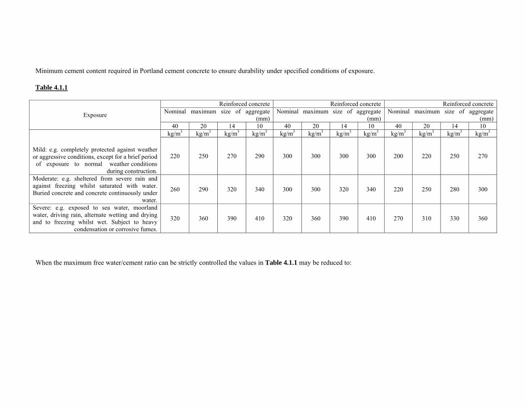
Minimum cement content required in Portland cement concrete to ensure durability under specified conditions of exposure.
Table 4.1.1
Exposure
Reinforced concrete Reinforced concrete Reinforced concrete Nominal maximum size of aggregate
(mm) Nominal maximum size of aggregate
(mm) Nominal maximum size of aggregate
(mm) 40 20 14 10 40 20 14 10 40 20 14 10
Mild: e.g. completely protected against weather or aggressive conditions, except for a brief period of exposure to normal weather conditions
during construction.
kg/m3 kg/m3 kg/m3 kg/m3 kg/m3 kg/m3 kg/m3 kg/m3 kg/m3 kg/m3 kg/m3 kg/m3
220 250 270 290 300 300 300 300 200 220 250 270
Moderate: e.g. sheltered from severe rain and against freezing whilst saturated with water. Buried concrete and concrete continuously under
water.
260 290 320 340 300 300 320 340 220 250 280 300
Severe: e.g. exposed to sea water, moorland water, driving rain, alternate wetting and drying and to freezing whilst wet. Subject to heavy
condensation or corrosive fumes.
320 360 390 410 320 360 390 410 270 310 330 360
When the maximum free water/cement ratio can be strictly controlled the values in Table 4.1.1 may be reduced to:
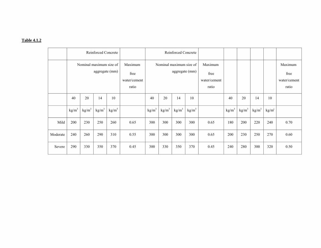
Table 4.1.2
Reinforced Concrete Reinforced Concrete
Nominal maximum size of
aggregate (mm)
Maximum
free
water/cement
ratio
Nominal maximum size of
aggregate (mm)
Maximum
free
water/cement
ratio
Maximum
free
water/cement
ratio
40 20 14 10 40 20 14 10 40 20 14 10
kg/m3 kg/m3 kg/m3 kg/m5 kg/m3 kg/m3 kg/m3 kg/m3 kg/m3 kg/m3 kg/m3 kg/mj
Mild 200 230 250 260 0.65 300 300 300 300 0.65 180 200 220 240 0.70
Moderate 240 260 290 310 0.55 300 300 300 300 0.65 200 230 250 270 0.60
Severe 290 330 350 370 0.45 300 330 350 370 0.45 240 280 300 320 0.50
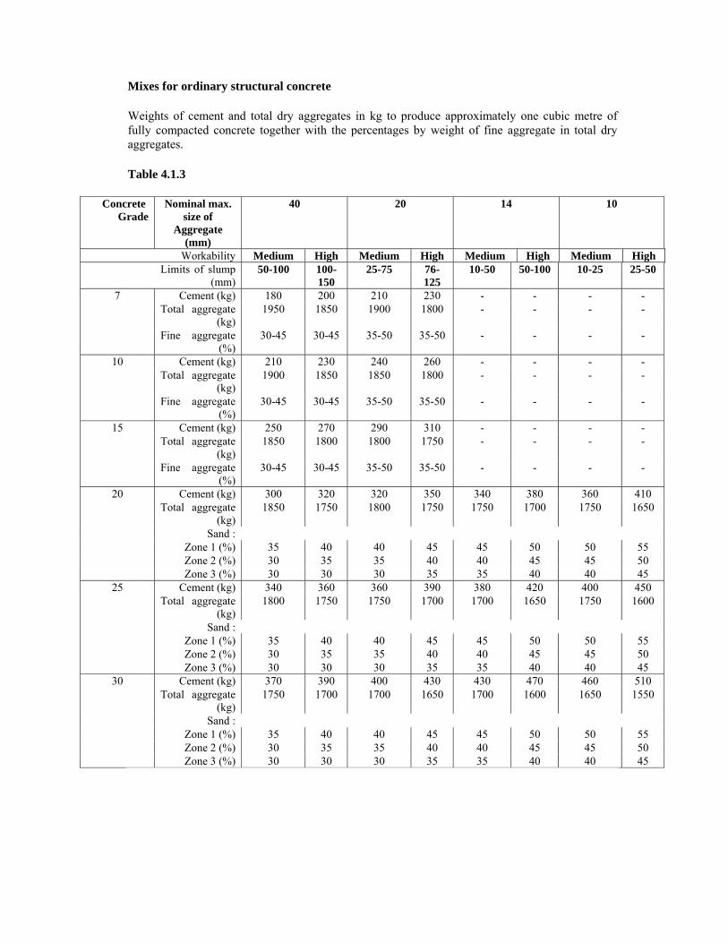
Mixes for ordinary structural concrete
Weights of cement and total dry aggregates in kg to produce approximately one cubic metre of fully compacted concrete together with the percentages by weight of fine aggregate in total dry aggregates.
Table 4.1.3
Concrete Grade
Nominal max. size of
Aggregate (mm)
40
20 14 10
Workability Medium High Medium High Medium High Medium High Limits of slump
(mm) 50-100 100-
150 25-75 76-
125 10-50 50-100 10-25 25-50
7 Cement (kg) 180 200 210 230 - - - -Total aggregate
(kg) 1950 1850 1900 1800 - - - -
Fine aggregate (%)
30-45 30-45 35-50 35-50 - - - -
10 Cement (kg) 210 230 240 260 - - - - Total aggregate
(kg) 1900 1850 1850 1800 - - - -
Fine aggregate (%)
30-45 30-45 35-50 35-50 - - - -
15 Cement (kg) 250 270 290 310 - - - - Total aggregate
(kg) 1850 1800 1800 1750 - - - -
Fine aggregate (%)
30-45 30-45 35-50 35-50 - - - -
20 Cement (kg) 300 320 320 350 340 380 360 410 Total aggregate
(kg) 1850 1750 1800 1750 1750 1700 1750 1650
Sand : Zone 1 (%) 35 40 40 45 45 50 50 55 Zone 2 (%) 30 35 35 40 40 45 45 50 Zone 3 (%) 30 30 30 35 35 40 40 45
25 Cement (kg) 340 360 360 390 380 420 400 450 Total aggregate
(kg) 1800 1750 1750 1700 1700 1650 1750 1600
Sand : Zone 1 (%) 35 40 40 45 45 50 50 55 Zone 2 (%) 30 35 35 40 40 45 45 50 Zone 3 (%) 30 30 30 35 35 40 40 45
30 Cement (kg) 370 390 400 430 430 470 460 510 Total aggregate
(kg) 1750 1700 1700 1650 1700 1600 1650 1550
Sand : Zone 1 (%) 35 40 40 45 45 50 50 55 Zone 2 (%) 30 35 35 40 40 45 45 50 Zone 3 (%) 30 30 30 35 35 40 40 45
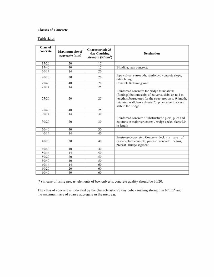
Classes of Concrete
Table 4.1.4
Class of concrete
Maximum size of aggregate (mm)
Characteristic 28-day Crushing
strength (N/mm2) Destination
15/20 20 15 15/40 40 15 Blinding, lean concrete, 20/14 14 20
20/20 20 20 Pipe culvert surrounds, reinforced concrete slope, ditch lining.
20/40 40 20 Concrete Retaining wall 25/14 14 25
25/20 20 25
Reinforced concrete: for bridge foundations (footings) bottom slabs of culverts, slabs up to 4 m length, substructures for the structures up to 9 length, retaining wall, box culverts(*), pipe culvert, access slab to the bridge
25/40 40 25 30/14 14 30
30/20 20 30 Reinforced concrete : Substructure : piers, piles and columns in major structures , bridge decks, slabs 9.0 m length
30/40 40 30 40/14 14 40
40/20 20 40 Prestressedconcrete : Concrete deck (in case of cast-in-place concrete) precast concrete beams, precast bridge segment.
40/40 40 40 50/14 14 50 50/20 20 50 50/40 40 50 60/14 14 60 60/20 20 60 60/40 40 60
(*) in case of using precast elements of box culverts, concrete quality should be 30/20.
The class of concrete is indicated by the characteristic 28 day cube crushing strength in N/mm2 and the maximum size of coarse aggregate in the mix; e.g.

Class 30/40 concrete means concrete with a characteristic cube crushing strength of 30N/mm2 at 28 days and a maximum size of coarse aggregate of 40 mm.
Strength concrete used under this contract, will be one or more of the classes given in Table 4.1.4. The cement content for any class of concrete shall not exceed 410 kg/m3 of concrete.
Where post-tensioning is used, the stressing operation cannot be proceeded with until the concrete has a minimum resistance of 30 N/mm2.
The slump of the concrete shall be within the range as specified in Table 4.1.5
Except where otherwise directed by the Engineer the water/cement ratio of the mix for any class of strength concrete shall not be more than 0.526, even if the strength requirements can be met by a mix with a higher water/cement ratio. Concrete with no restriction on the maximum water/cement ratio shall be designated by a prefix W, e.g. Class W30/40 concrete means concrete for which the water/cement ratio of the mix shall not be more than 0.526.
Slump values
Table 4.1.5
Type of construction Slump (mm)*
Max. Min
Paving concrete nosings and precast units 75 50
Prestressed concrete 75 25
Reinforced foundation walls, footings and cast in situ piles (excepting dry cast piles) 125 50
Slabs, beams, columns and reinforced walls 125 50
Concrete bases, caissons and substructure walls 100 25
Where high frequency vibrators are used, the values above shall be reduced by one third.
The concrete shall be of suitable workability without the excessive use of water so that it can be readily compacted into the corners of the formwork and around reinforcement, tendons and ducts without segregation of the material.
4.1.1.4.4 Nature and Source of each Material
Before the start of any concrete work on Site, the Contractor shall supply to the Engineer, for his approval, samples of the constituent materials of the concrete and a statement of the mix proportions which he proposes to use for each class of concrete.
The samples shall be accompanied by evidence that they comply with the requirements for the various materials specified. The statement of mix proportions shall be accompanied by evidence establishing that concrete made with the materials in the proportions proposed will have the properties specified.
Either:
Appropriate existing data as evidence of satisfactory previous performance for target mean strength and current margin and if required workability and w/c ratio, or:
Full details of tests or trial mixes, or:
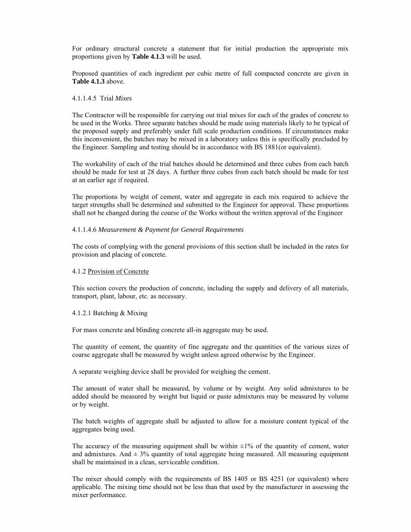
For ordinary structural concrete a statement that for initial production the appropriate mix proportions given by Table 4.1.3 will be used.
Proposed quantities of each ingredient per cubic metre of full compacted concrete are given in Table 4.1.3 above.
4.1.1.4.5 Trial Mixes
The Contractor will be responsible for carrying out trial mixes for each of the grades of concrete to be used in the Works. Three separate batches should be made using materials likely to be typical of the proposed supply and preferably under full scale production conditions. If circumstances make this inconvenient, the batches may be mixed in a laboratory unless this is specifically precluded by the Engineer. Sampling and testing should be in accordance with BS 1881(or equivalent).
The workability of each of the trial batches should be determined and three cubes from each batch should be made for test at 28 days. A further three cubes from each batch should be made for test at an earlier age if required.
The proportions by weight of cement, water and aggregate in each mix required to achieve the target strengths shall be determined and submitted to the Engineer for approval. These proportions shall not be changed during the course of the Works without the written approval of the Engineer
4.1.1.4.6 Measurement & Payment for General Requirements
The costs of complying with the general provisions of this section shall be included in the rates for provision and placing of concrete.
4.1.2 Provision of Concrete
This section covers the production of concrete, including the supply and delivery of all materials, transport, plant, labour, etc. as necessary.
4.1.2.1 Batching & Mixing
For mass concrete and blinding concrete all-in aggregate may be used.
The quantity of cement, the quantity of fine aggregate and the quantities of the various sizes of coarse aggregate shall be measured by weight unless agreed otherwise by the Engineer.
A separate weighing device shall be provided for weighing the cement.
The amount of water shall be measured, by volume or by weight. Any solid admixtures to be added should be measured by weight but liquid or paste admixtures may be measured by volume or by weight.
The batch weights of aggregate shall be adjusted to allow for a moisture content typical of the aggregates being used.
The accuracy of the measuring equipment shall be within ±1% of the quantity of cement, water and admixtures. And ± 3% quantity of total aggregate being measured. All measuring equipment shall be maintained in a clean, serviceable condition.
The mixer should comply with the requirements of BS 1405 or BS 4251 (or equivalent) where applicable. The mixing time should not be less than that used by the manufacturer in assessing the mixer performance.

In the case of mixes of low workability or high cement content this may not ensure maximum strength, and it may be advisable to determine a satisfactory mixing time by comparing the strength of samples mixed for different times.
4.1.2.2 Control of Water Content
The water content of each batch of concrete shall be adjusted so as to produce a concrete of the workability required by the trial mixes as appropriate.
4.1.2.3 Adjustment to Mix Proportions
During production adjustments of mix proportions may be made with the approval of the Engineer in order to minimise the variability of strength and to approach more closely the target mean strength. Such adjustments are regarded as part of the proper control of production but the specified limits of minimum cement content and maximum water/cement ratio shall be maintained. Changes in cement content shall be declared. Such adjustments to mix proportions shall not be taken to imply any change to the current margin.
opinion of the Engineer, not feasible to dewater before placing. No concrete shall be placed in flowing water.
4.1.2.4 Measurement & Payment for Provision of Concrete
The unit of measurement shall be the cubic metre measured as the volume when finally in place. Quantities shall be calculated from the net dimensions shown on the Drawings, or otherwise indicated by the Engineer. Payment for the placing of concrete will be according to paragraph 4.1.3.6.
4.1.3 Placing of Concrete
This section covers the transporting and placing of concrete after mixing.
4.1.3.1 Transportation & Placing
4.1.3.1.1 Transporting
Mixed concrete shall be discharged from the mixer and transported to its final position in such a manner that segregation or loss of ingredients are prevented and that the mix is of the required workability at the point and time of placing.
4.1.3.1.2 Placing
The Contractor shall give the Engineer at least 24 hours notice of his intention to place concrete to enable him to inspect the formwork and the steel reinforcement. No concrete shall be placed until the Engineer has given his approval to do so. The concrete shall be placed within one hour from the time of discharge from the mixer and retempering by the addition of water or other material shall not be allowed.
Wherever possible the concrete shall be deposited vertically into its final position (so as to avoid segregation or displacement of embedded items).
The working of deposited concrete (whether by means of vibrators or otherwise) to cause it to flow laterally shall be prohibited. The concrete shall be brought up in horizontal layers of compacted thickness not exceeding 0.5 metres and heaping shall be avoided.
Where chutes are used to convey the concrete, their slopes shall be such as not to cause segregation and suitable spouts of baffles shall be provided for the discharge of the concrete.
Concrete shall not be allowed to fall freely through a height of more than 1.5 metres.
Concrete shall not be placed during the hours of darkness unless proper lighting arrangements have been made and lights are in working order by midday. Furthermore, workmen shall not be allowed to work double shifts and the Contractor shall provide a new and rested shift for night work.
Concrete shall not be placed if the ambient temperature falls below 7°C. Concrete shall normally be placed only in the dry. Placing of concrete under water shall be allowed only under exceptional circumstances where it is, in the
Transporting and placing the mixed concrete is covered by this section and concrete ancillaries, including formwork and reinforcement, by subsequent sections.
4.1.3.1.3 Pumping
Pumping of concrete shall be allowed only after approval of the Engineer of the methods proposed by the Contractor. Samples of pumped concrete for testing shall be taken at the discharge end of the pipe.
4.1.3.1.4 Compaction
The concrete shall be fully compacted by approved means during and immediately after placing. It shall be thoroughly worked against the formwork and around embedded fittings without displacing them.
The concrete shall be free from honeycombing and planes of weakness. Successive layers of the same lift shall be thoroughly worked together.
Depositing concrete at any point and working it laterally into position, whether by spading, vibrating, or brother means shall be prohibited.
Unless otherwise agreed by the Engineer, concrete shall be compacted by the assistance of vibrators. Sufficient vibrators in serviceable condition shall be on site so thaLspare equipment is always available in the event of breakdowns.
Over-vibration resulting in segregation, surface laitance, leakage (or any combination of these) must be avoided.
Where immersion vibrators are used, contact with the formwork, and all inserts shall be avoided as far as practicable.
4.1.3.2 Construction Joints
4.1.3.2.1 General
Concreting shall be carried out continuously to the construction joints shown on the Working Drawings or as approved, except that if, because of an emergency (such as breakdown of the mixing plant or the occurrence of unsuitable weather) concreting has to be interrupted, a construction joint shall be formed at the place of stoppage in a manner which will least impair the durability, appearance and proper functioning of the concrete.
Unless otherwise shown on the Drawings the exact position of horizontal construction joints shall be marked on the formwork by means of gauge strips in order to obtain truly horizontal joints.
4.1.3.2.2 Preparation of Joint Surface
When the concrete has set and whilst it is still green, the surface film and all loose material shall be removed, without disturbing the aggregate, by means of a water jet assisted by light brushing to expose the aggregate and leave a sound, irregular surface. Where this is no possible, the surface film shall be removed after the concrete has hardened, by mechanical means appropriate to the degree of hardness of the concrete so as to expose the aggregate and leave a sound, irregular surface. The roughened surface shall be washed with clean water.
4.1.3.2.3 Placing Fresh Concrete at Construction Joints
When fresh concrete is placed the same day, it shall be placed directly against the older concrete surface, prepared as in 4.1.3.2.2 above.
When the fresh concrete is placed more than one day after the older concrete, a layer of approximately 15 mm thickness, consisting of cement, sand and water mixed in the same proportions as used in the concrete, shall be applied to the wetted surface of the older concrete immediately before the fresh concrete is placed.
The concrete placed immediately above a horizontal construction joint shall only contain two-thirds the normal quantity of coarse aggregate and shall not be the first batch through the mixer.
Where the older concrete is more than 3 days old, it shall be kept continuously wet for 24 hours before the mortar and fresh concrete in placed.
In the case of vertical surfaces, a 1:1 cement-sand slurry shall, wherever possible, be well worked into the prepared surfaces immediately before the fresh concrete is placed.
Epoxy type resins may be used for bonding at construction joints provided that full details thereof are submitted to the Engineer and that he approves their use. The surface of the older concrete shall be clean and dry and protected in accordance with the manufacturer's instructions and the fresh concrete placed within the period recommended by the manufacturer.
4.1.3.3 Curing & Protection
All concrete shall be cured by approved mean for a minimum of 7 days. This condition may be satisfied by leaving the forms in place.
4.1.3.4 Adverse Weather Conditions
4.1.3.4.1 Cold Weather
Concrete shall not be placed during falling temperature when the atmospheric temperature fall below 7°C. Concrete which has been damaged by frost or other causes shall be removed before fresh concrete is placed.
4.1.3.4.2 Hot Weather
When the surrounding atmospheric temperature is over 32 °C, the temperature of the concrete when deposited shall not be allowed to exceed 32°C. Stockpiles of aggregate and all metal contact surfaces shall be shielded from the direct rays of the sun or cooled by spraying with water.
4.1.3.5 Pipes & Conduits
No pipes or conduits other than those shown on the Working Drawings shall be embedded in the concrete without approval. The amount of cover over pipes and fittings shall be at least 25 mm.
4.1.3.6 Measurement &Payment for Placing of Concrete
No separate measurement will be made for placing concrete. Full compensation for the requirements for placing concrete shall be included in the rates for concrete inserted in the Bill of Quantities which shall include provision of concrete.
4.1.4 Testing of Concrete
This section covers the test plan for designed or prescribed concrete mixes and the procedures in the event of failures.
4.1.4.1 General
Testing shall be carried out in accordance with Clause 6.2.9, and all the provision therein shall apply.
4.1.4.2 Procedure in the Event of Failure
If the concrete is considered by the Engineer to have failed to comply with the Specifications, the Engineer shall have the right to require that any or all of the following measures shall be taken by and at the cost of the Contractor:
The materials or proportions of the mixture shall be changed to obtain a higher strength.
The curing shall be resumed until such time as cores, drilled from the portions of the structure containing the concrete which failed, show that the strength of the concrete has satisfied the strength requirements. The total period allowed shall not exceed 2 months after placing of the concrete.
If the results of the tests on cores indicate that, despite the additional period of time allowed, the concrete does not satisfy the specified requirements, full-scale load test shall be carried out.
If core tests, or load test, are, in the opinion of the Engineer impracticable, or if a tested portion of the structure fail to pass the tests, the Contractor shall, on the instructions of the Engineer, replace each portion that failed or that contains concrete that failed, as relevant, at his own expense.
4.1.4.3 Measurement & Payment for Testing
The cost of all testing in accordance with this section including the provision of concrete cubes, shall be borne by the Contractor, and the Contractor shall allow in his rates for any disturbance or delays that may occur.
No claim will be entertained for any delays, or change of programme, caused by the failure of concrete and the check testing described hereinabove, whether the check tests prove the concrete to be acceptable or not.
4.1.5 Formwork and Concrete Finish
4.1.5.1 Definition
Formwork shall include all temporary or permanent forms required for forming the concrete, together with all temporary construction required for their support.
4.1.5.2 Design &Construction
Formwork shall be so designed and constructed that the concrete can be properly placed and compacted, without loss or leakage of material from the concrete. After hardening the concrete shall be in the positions and of the required shapes, levels and dimensions shown on the Drawings.
The formwork and joints shall be capable of resisting the dead load, pressure of the wet concrete, wind forces and all other superimposed loads and forces. The Contractor will be solely responsible for the strength and stability of the formwork.
The Contractor shall prepare drawings and calculations for system of formwork to be used and shall submit these to the Engineer for approval prior to commencing construction.
Wire ties shall not be permitted and tie-rods shall be used. Tie-rods or their removal parts shall be extracted without damage and the remaining holes filled with mortar. No permanently embedded metal parts of tie-rods shall have less than 40 mm cover to the finished concrete surface.
Unless otherwise shown on the drawings, fillet strips shall be built into corners of the formwork in order that 25 mm x 25 mm chamfers may be obtained on all exposed corners of the concrete, whether such chamfers are shown on the Drawings or not.
Where necessary for the proper placing of concrete, temporary openings for cleaning or placing purposes shall be provided.
4.1.5.3 Preparation of Formwork
Surfaces of formwork that are to be in contact with fresh (wet) concrete shall be so treated as to ensure easy release and non-adhesion of concrete to formwork during stripping. Coating with release agents shall be done strictly in accordance with the manufacturer's instructions.
Timber forms shall be lightly wetted just prior to placing concrete.
Before reuse, all formwork shall be reconditioned and all form surfaces that are to be in contact with the concrete shall be thoroughly cleaned without causing damage to the surface of the formwork.
4.1.5.4 Removal of Formwork
Formwork shall not be removed before the concrete has attained sufficient strength to support its own mass and any loads that may be imposed on it.
This condition shall be assumed to require formwork to remain in place, after placing of the concrete, for the appropriate minimum period of time given in Table 4.1.3 unless the Contractor can prove to the satisfaction of the Engineer that shorter periods are sufficient to fulfill this condition.
Minimum period before striking formwork using ordinary Portland Cement.

Table 4.1.7
Minimum period before striking Type of formwork Surface temperature of concrete
Vertical formwork to columns 16 °C 7 °C Walls and large beams 2 days 3 days
Soffit formwork to slabs 4 days 7 days Props to slabs 11 days 14 days
Soffit formwork to beams 8 days 14 days Props to beams 1 5 days 21 days
Note: A shorter period may be allowed by the Engineer when using Rapid Hardening Cement.
For cold weather periods should be increased by Vi day for each day the temperature falls between 7°C and 2°C, and one day for each day on which the temperature drops below 2°C.
Formwork shall be removed carefully so that shock and damage to the concrete are avoided.
4.1.5.5 Formed Surfaces: Classes of Finish & Remedial Work
Class A Surface Finish
To be used on not exposed concrete surfaces.
The irregularities in the finish shall be no greater than those obtained from the use of wrought thickened square edge timber boards arranged in a regular pattern. The finish is intended to be left as struck but imperfections such as small fins and slight surface discoloration shall be made good by methods approved by the Engineer.
Class C Surface Finish
To be used on exposed concrete surfaces.
For this finish the formwork shall be constructed of materials which will provide a smooth finish of uniform texture and appearance. The formwork shall be so jointed and fixed that it imparts no blemishes. No stains shall be left on the concrete by the formwork. The Contractor shall make good any imperfections in the resulting finish as required by the Engineer. Joint marks shall follow a regular pattern approved by the Engineer to fit in with the appearance of the structure.
The Contractor shall ensure that permanently exposed concrete surfaces to Class A and C finish are protected from rust marks, spillage and stains of all kinds, except from causes beyond the control of the Contractor.
Any remedial treatment to surfaces shall be agreed with the Engineer following inspection immediately after the removal of formwork and shall be carried out without delay. No surface may be treated before inspection by the Engineer.
Small areas of honeycombing or other imperfections, as well as isolated surface, air and water bubbles, shall be filled in with a mortar consisting of the cement and sand portion of the concrete mix used.
For the repair of large or deep areas of honeycombing, special methods and techniques, such as pneumatically applied mortar, pressure grouting, epoxy bonding agents, etc., may be used as agreed by the Engineer. All patches and repairs shall be kept continuously wet for at least 5 days.
If the finish of exposed surfaces does not comply with the requirements for uniformity of texture and appearance, the Contractor shall, when instructed to do so by the Engineer, rub down the exposed surfaces of the structure or any part thereof as specified below. Before rubbing all repairs must be completed.
The surface shall be saturated with water for at least one hour, initial rubbing shall be carried out with a medium coarse carborundum stone, using a small amount of mortar on the face. Rubbing shall be continued until all form marks, projections and irregularities are removed and a uniform surface is obtained. The paste produced by the rubbing shall be kept in place. The final rubbing shall be carried out with a fine carborundum stone and water. This rubbing shall continue until the entire surface is of a smooth, even texture and uniform in colour. Thereafter the surface shall be washed with a brush to remove surplus paste and powder.
4.1.5.6 Measurement & Payment for Formwork
There will be no separate measurement of formwork except for:
The rates inserted against items for the provision and placing of concrete shall include full compensation for providing formwork of either Class A or Class C as specified in the billed item, in accordance with these Specifications.
The tendered price shall include for the supply of all materials as required, erection of formwork, staging, and supports; for construction of forms,ecc and for the stripping and removal of the formwork after completion of the work.
Unformed finishes will not be paid for and shall be included in the rates.
4.1.6 Reinforcement
4.1.6.1 Materials: Reinforcement Steel shall be in accordance with the design requests: B450, S-500, Feb44k,
Steel fabric reinforcement shall comply with the requirements of BS 4483 and shall be delivered to the Site in flat mats.
o Hot rolled mild steel bars and hot rolled high yield bars shall comply with the requirements of BS 4449 (or equivalent).
o Steel reinforcement shall be grade 400 MPa o Cold worked steel bars shall comply with the requirements of BS 4461 (or equivalent). o Hard drawn mild steel wire shall comply with the requirements of BS 4482 (or
equivalent). o The bond strength of deformed bars, as defined in BS 4449 and BS 4461 (or equivalent),
shall not exceed that of a plain round bar by 40% or more when tested in accordance with British Standard Code of Practice CP 114: Part 2 Clause 603.
o In the case of bars complying with the requirements of BS 4449 and BS 4461 (or equivalent) the Contractor shall provide a certificate confirming that samples, taken from the bars delivered to the Works, pass the rebend test. The frequency of sampling and the method of quality control shall be in accordance with Table 4 and Clause 20 respectively of these British Standards. 4.1.6.2 Storage:
Steel reinforcement shall be stacked off the ground and, in aggressive environments, protection shall be provided in the form of sheds or tarpaulins.
4.1.6.3 Bending of reinforcement:
o Reinforcement shall be bent to the dimensions shown on- the bending schedules and in accordance with BS 4466 (or equivalent).
o Except as allowed for below, all bars shall be bent cold and bending shall be done slowly, a steady, even pressure being used. Hot bending is not allowed.
o No flame-cutting of high tensile bars shall be permitted except with the approval of the Engineer. Bars already bent may not be straightened and reused.
4.1.6.4 Placing & Fixing:
Reinforcement shall be positioned as shown on the Drawings and maintained in these positions throughout concreting operations. It shall be secured by tying at intersections with 1.25 mm or greater diameter annealed wire or by the use of suitable clips, where permitted by the Engineer, by welding. It shall be supported in its correct position by hangers or saddles, and aligned by chairs and spacers of approved design and material.
NOTE: Notwithstanding the tolerances given, the amount of cover on reinforcing bars as shown on the Drawings shall be maintained.
4.1.6.5 Cover:
The term cover in this context shall mean the minimum clear thickness of concrete between the surface of the reinforcement and face of the concrete.
The minimum cover shall be as directed by the Engineer.
The cover shall be increased by the expected depth of any surface treatment, e.g. when concrete is bush hammered or when rebates are provided.
Cover blocks or spacers required for ensuring that the specified cover is obtained shall be of a material, shape and design acceptable to the Engineer.
Concrete spacer blocks shall be made with 5 mm maximum size aggregate and shall be of the same strength and material source as the surrounding concrete. The blocks shall be formed in specially manufactured modules and the concrete compacted on a table vibrator all to the approval of the Engineer.
4.1.6.6 Splicing:
Splicing or joining of reinforcing bars shall be made only as and where shown on the Drawings or as otherwise approved.
The length of the overlap in a splice shall be not less than that shown on the working Drawings.
4.1.6.7 Surface Condition:
Immediately before the concrete is placed around the reinforcement, the reinforcement shall be clean, free from mud, oil, grease, paint, loose rust, loose mill scale or any other substance that can have an adverse chemical effect on the steel or concrete, or reduce the bond.
4.1.6.9 Measurement & Payment for Reinforcement
The unit of measurement for steel bars shall be the tonne of reinforcement in place in accordance with the Drawings and bending schedules, or as directed or authorised by the Engineer.
The tendered price shall include for the supply, delivery, cutting, bending, waste, placing and fixing of steel, including all tying wire, spacers, stools and supports, clips ties and separators.

SECTION 5
OUTER FENCING WORKS
5.1- General description works
5.2- Unit of measurements
5.3- Foundation Materials
5.3.1 – Concrete material
5.3.2 – Concrete mixed with stonematerial
5.4- Gabion wire meshes
5.5- Steel elements
5.1 Ge
eneral descri
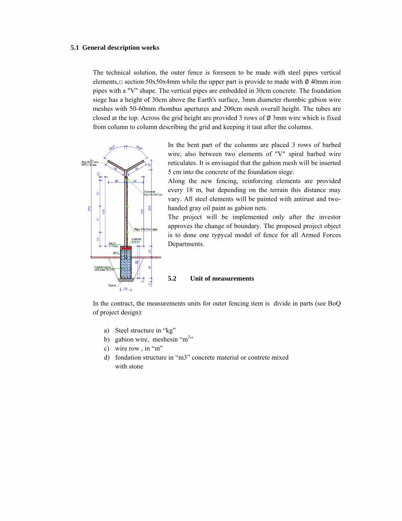
The technicelements,□ pipes with asiege has a meshes witclosed at thfrom colum
In the controf project d
a) Steb) gabc) wird) fon
wit
iption works
cal solution, section 50x5
a "V" shape. height of 30
th 50-60mm rhe top. Acrossmn to column
ract, the measdesign):
eel structure inbion wire, mere row , in “mndation structuth stone
s
the outer fen50x4mm whilThe vertical pcm above therhombus apers the grid heigdescribing th
In the benwire, alsoreticulates5 cm into Along thevery 18 vary. All handed grThe projapproves is to doneDepartme
5.2 U
surements un
n “kg” eshesin “m2”
m” ure in “m3” c
nce is foresee the upper ppipes are embe Earth's surfartures and 20ght are providhe grid and ke
nt part of theo between tws. It is envisagthe concrete
he new fencim, but depesteel element
ray oil paint aect will be the change oe one typyca
ents.
Unit of measu
nits for outer f
concrete mate
en to be madart is provide
bedded in 30cface, 3mm dia00cm mesh ovded 3 rows ofeeping it taut a
e columns arwo elements ged that the gof the founda
ing, reinforciending on thets will be pai
as gabion netsimplemente
of boundary. Tal model of f
urements
fencing item
erial or contre
de with steele to made withcm concrete. Tameter rhombverall height.
f ∅ 3mm wireafter the colum
re placed 3 rof "V" spira
gabion mesh wation siege. ing elementse terrain thisinted with ans. d only afterThe proposedfence for all
is divide in p
te mixed
l pipes vertich ∅ 40mm iroThe foundatiobic gabion wi. The tubes a
e which is fixemns.
rows of barbeal barbed wiwill be inserte
s are provides distance matirust and two
r the investod project objeArmed Force
parts (see Bo
cal on on re re ed
ed re ed
ed ay o-
or ect es
oQ
5.3 Foundation Materials
Foundation structure for the outer fence acording diferent area zone, will be realized in part with concrete material and in part with contrete mixed with stone.
5.3.1 Concrete material
The specifications of the concrete material for the realization of the foundations shall be taken according to the descriptions given in Chapter 4
5.3.2 Concrete mixed with stone material
Concrete mixed with stone material for foundation fence will be realized as a mixture of carbonic limestone with concrete. The proportion between the component parts of the mixture will be 75-80% concrete and 20-25% stone. The stones to be used for mixing will be of carbon origin. The maximum dimensions of these stones will be max 150-200mm. They should be free from dust and other dirt. Stones with chemical content wich have activity with cement portland should not be used. The specifications of the concrete material shall be taken according to the descriptions given in Chapter 4.
5.4 Gabion wire meshes
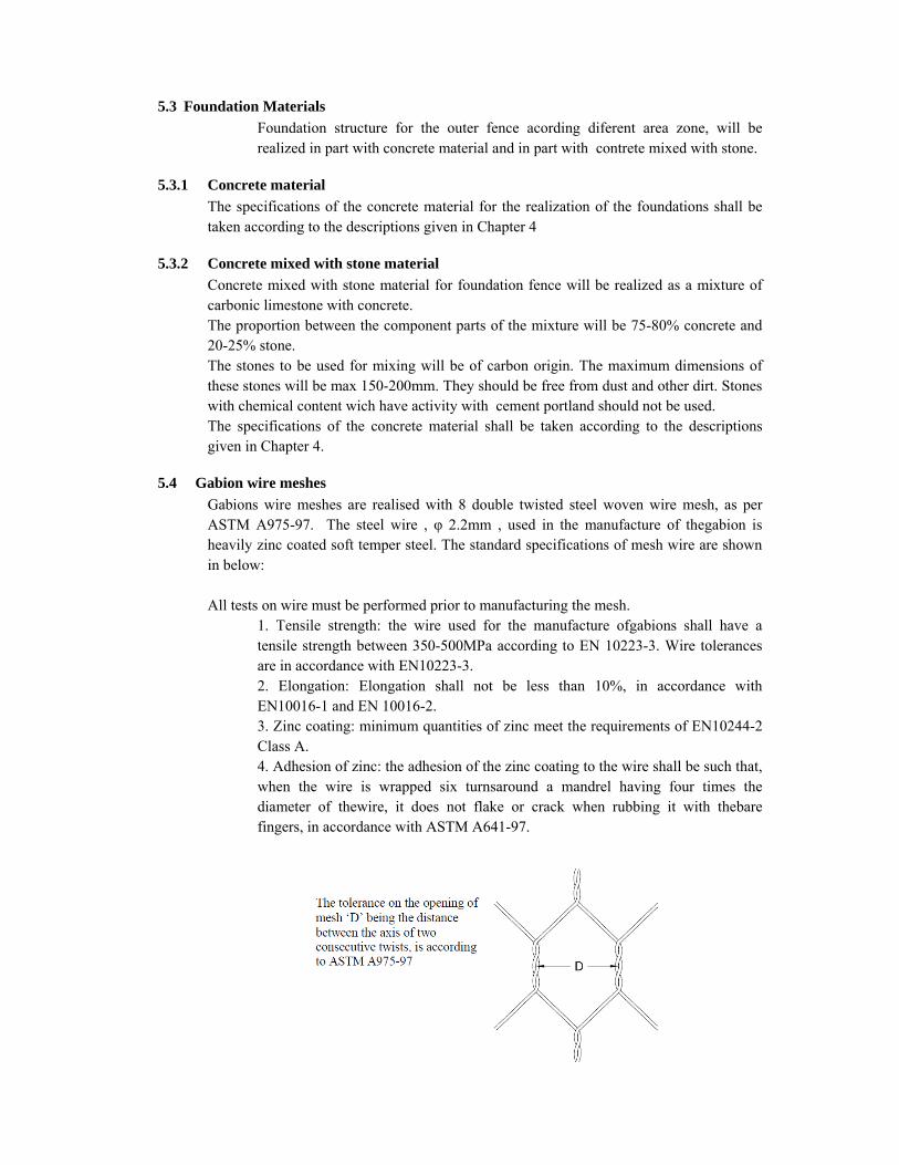
Gabions wire meshes are realised with 8 double twisted steel woven wire mesh, as per ASTM A975-97. The steel wire , φ 2.2mm , used in the manufacture of thegabion is heavily zinc coated soft temper steel. The standard specifications of mesh wire are shown in below: All tests on wire must be performed prior to manufacturing the mesh.
1. Tensile strength: the wire used for the manufacture ofgabions shall have a tensile strength between 350-500MPa according to EN 10223-3. Wire tolerances are in accordance with EN10223-3. 2. Elongation: Elongation shall not be less than 10%, in accordance with EN10016-1 and EN 10016-2. 3. Zinc coating: minimum quantities of zinc meet the requirements of EN10244-2 Class A. 4. Adhesion of zinc: the adhesion of the zinc coating to the wire shall be such that, when the wire is wrapped six turnsaround a mandrel having four times the diameter of thewire, it does not flake or crack when rubbing it with thebare fingers, in accordance with ASTM A641-97.
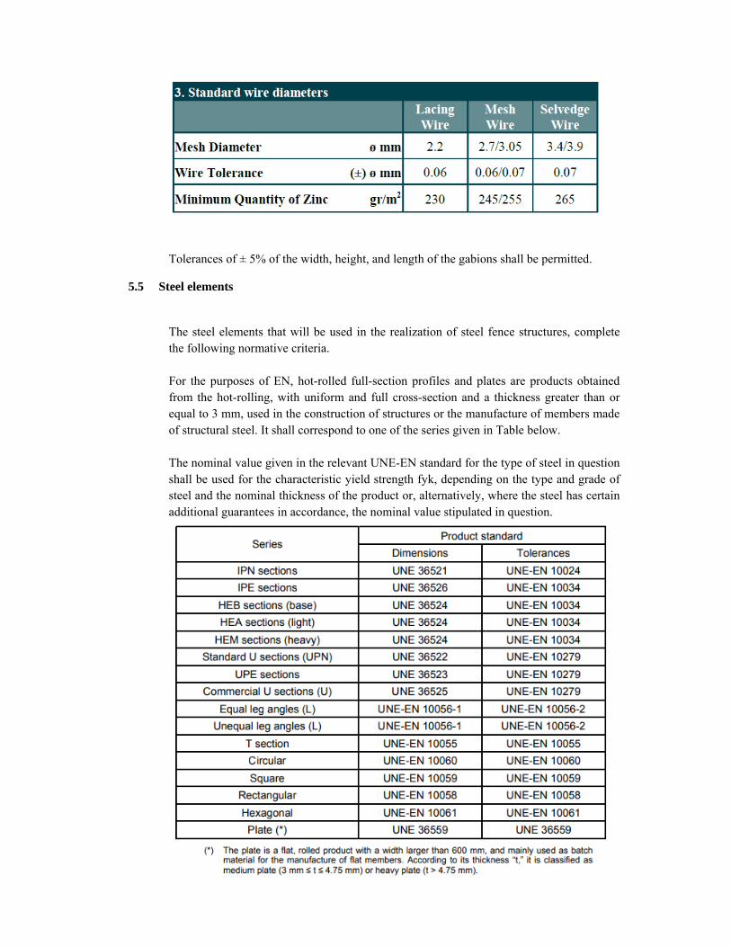
Tolerances of ± 5% of the width, height, and length of the gabions shall be permitted.
5.5 Steel elements
The steel elements that will be used in the realization of steel fence structures, complete the following normative criteria. For the purposes of EN, hot-rolled full-section profiles and plates are products obtained from the hot-rolling, with uniform and full cross-section and a thickness greater than or equal to 3 mm, used in the construction of structures or the manufacture of members made of structural steel. It shall correspond to one of the series given in Table below. The nominal value given in the relevant UNE-EN standard for the type of steel in question shall be used for the characteristic yield strength fyk, depending on the type and grade of steel and the nominal thickness of the product or, alternatively, where the steel has certain additional guarantees in accordance, the nominal value stipulated in question.

The connection of the elements to the foundation structure will be realized according to the details of the project. The joint between the steel elements will be welded. The entire structure will be coated with two hands antiruxhio paint.
SECTION 6
LIGHTING NETWORK WORKS
6.1- General description
6.2- Cables
6.3- Command Panels
6.4- Electric Manholes
6.5- Plastic Pipes
6.6- Light-equipment
6.7- Lighting Pillars
6.1 General description
Throughout the surrounding area of the object, it is required to create a lighted space of not less than 4 m in width inside of fencing. Is proposed the technical solution which one consist with placing lights on the pillars about 8 m high, every 25m length distance.
Turning these lights on and off will become automatically in function of natural lighting, i.e. the moment the twilight starts, the electricity grid will become on and at the dawn of the day the electricity grid will become off. Is also provided a manual control of thelighting network in case of need. Supply cables are calculated so that the line voltage loss does not exceed 3.3% of the nominal supply voltage of this network. This guarantees us that the intensity of the light produced by the luminaries is in almost equal parameters. The command frame of these lamps is intended to be in the low voltage panel environment of the electrical cab located within the territory of the facility. The lights are placed in pillars that are 8 m height and with 4-5 m distance from the outer fencing. The distance between the light pillars is variable from 20m to 25 m, this as a function of the fence line and the relief. The illuminator used in this case is 100W LED, which produce a light intensity of 14500 Lm. The lamp have 100 000 hours/work.In this case illumination isd very good about100 Lux /m2, in function of the environment
6.2 Cables
Cables must meet these general technical characteristics: 1. Power transmission cable, insulated with high quality G7 ethylpropylene rubber and PVC insulation layer, which does not allow ignition and reduction of emission of gaseous gases. 2. Be multipolar cables with flexible conductors 3. Conductor be baker, flexible, dressed
4. The insulation shall be ethylpropylene rubber compound at high temperature 90ºC of high quality G7. 5. The filling material shall be non-humid, preventing the ignition of the spark and reducing the emission of corroded gases. 6.The outer layer of insulation shall be Rz thermoplastic blend of Rz quality, which does not allow spark ignition and reducing emission of corrosive gases. 7. Technical Characteristics: -Nominal voltage 0.6 / 1KV - Working temperature 90 ºC - Short circuit 250º C -Temperature storage max 40 ºC - Maximum strengths per 1mm2 section 50N / mm2 -Minimum cable bending radius 4 times the outer diameter 8. Field of Use: Power transmission cable, for indoor outdoor installation, for wall mounting and metal structures as well as for underground paving 9. Be branded with IMQ or CE or G7 quality brands. 10. Be accompanied by catalogs of the respective manufacturing plant, and possibly also by specimens.
6.3 Command Panels
• Metal cassettes should be airtight, sealed with a key • 4 polar 60A slot machines should have these features Magnetothermal type Reference norm CEI EN 60898 4P version Magnetothermal Characteristics C Nominal currents at 30 ° C 100A Rated voltage 400V 440V maximum working voltage 500V insulation voltage Nominal frequency 50-60 Hz Short circuit rated power 10kA Operating temperature -25-60 ° C The maximum number of electric maneuvers is 10,000 cycles Maximum number of mechanical maneuvers 20,000 cycles IP20 / IP40 protection grade
6.4 Electric Manholes
The manholes will be plastic, submerged in concrete, with dimensions according to verification. The plastic manhole covers must meet the following conditions: • Plastic material • Size 300x300x20mm • Rectangular forms • Complete with all relevant framework
6.5 Plastic Pipes
• Flexible pipe D = 75/90mm must meet the following requirements:

- Sigla FU 15 - CEI standard EN 50086-1 - IMQ quality mark in every 3 ml - Material: polyethylene. 2-layer tubes of different densities. - Usage: for underground power plants of telecommunication networks. - Settlement: underground.
6.6 Light-equipment
• Lamp power: (according to project drawings). Lamp Type: LED • Insulation rate: - for IP 66 optical band - for IP 43 accessories • Constructive features: - polypropylene upper cover reinforced RAL gray - aluminum illuminated body painted with polyester 7035 gray RAL 7035 paint - 99.85% pure aluminum reflector embedded in a piece, oxidized and lucidated. - Installation in armrests with max 60mm diameter - Guarantee made of silicon material - Filter against humidity - Porcelain lamps with focus adjustment device - Tempered flat glass or transparent UV-stabilized polycarbonate - Opening and closing of the optical group is made with two inox screws, while for the accessory group with the two bottom tips - Shades of dark gray polyamide glass. - All electrical components used shall be of IMQ mark for 230 V- 50Hz power supply. - Lighting fittings shall be in accordance with EN 60598/1 and EN 60598-2-3 - Anti corrosion treatment, with chromatization ALODIN 1200 - Lighting fittings shall be in accordance with EN 60598/1 - Ecological material guarantee
6.7 Lighting Pillars
• The columns are metallic, conical, zinc-coated, PAINTED, with yellow paint, with a total height as in drawing project. • Metal poles should be complete with lids. • Wind exposed area = 0.2m² • 46x186mm clamping window dimensions • Material - steel with UTS> 410N / mm² (Fe 430-UNI EN 10025) • Surface coating - hot rusting • Pillar spacer 3.5m and 4.5m = 3mm while 5.5m and >7.8m = 4mm • The diameter of the pole at the upper extreme is 60mm.

SECTION 7
SURVEILLANCE SYSTEM AND EQUIPMENT
7.1- General description works
7.2- Unit of measurements
7.3- Equipment technical specification
7.1 General description works
For the realization of the camera control system, of the entire boundary of the object, it was considered that the whole territory should be under control at any moment. For this reason the cameras are selected;
o Overview 100m (150m) o Rotation Option 0 ° - 360 ° (Pan), 20 ° to 90 ° (Tilt), 180 ° (Autoflip) o With the option of viewing at night (0.002 Lux (color), 0.0002 Lux (B/W) o With the possibility of detecting movements o With the possibility of defining the area needed for control o To withstand mechanical shocks
The transmit network of cameras is based on fiber optic cable. Insertion of fiber optic cable is done according to the ring system.Also the equipment of this network is such as to serve this cable system.F.O.This ring system means that each node receives and responds to the packets that you address for that node.
Since the ring has no end and the data stops in the node, the RING networks no needs for limits. Each node serves as a repeater for transmission.
But as we can see from the scheme we have combined two networks, that ring and with star form.
Are provide two types of cameras
o Camera Bullet (fixed ) o Camera PTZ
Bullet cameras, as seen in the scheme, are placed to view certain spaces, while PTZ cameras that are positioned in pillars above 6 m and serve to control a 100 m wide area.
All the information of camerasis registrated in NVR. All camera information is recorded in the NVR which has a capacity of up to 48TB which is sufficient and if there is a need to add additional cameras. This also comes from the capability of the equipment ,compressionVideo: H.265, H.264, MJPEG. The system also provides Joystik equipment that will be operated manually by the PTZ camera operator. Also PTZ cameras can be set to automatically control certain areas of the space they cover.
It foreseen to have one monitor 42” which relates with NVR, which connect through cable HDMI.
When programming the camera signal, it must be borne in mind that at all times the surrounding area of the object is to be viewed by the camera.
7.2 Unit of measurements
The measurements units of payments for surveillance system, is divide in diferent items, see BoQ of project design.
7.3 Equipment technical specification
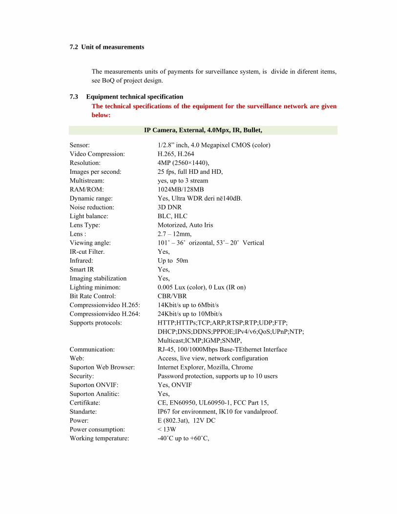
The technical specifications of the equipment for the surveillance network are given below:
IP Camera, External, 4.0Mpx, IR, Bullet,
Sensor: 1/2.8” inch, 4.0 Megapixel CMOS (color) Video Compression: H.265, H.264 Resolution: 4MP (2560×1440), Images per second: 25 fps, full HD and HD, Multistream: yes, up to 3 stream RAM/ROM: 1024MB/128MB Dynamic range: Yes, Ultra WDR deri në140dB. Noise reduction: 3D DNR Light balance: BLC, HLC Lens Type: Motorized, Auto Iris Lens : 2.7 – 12mm, Viewing angle: 101˚ – 36˚ orizontal, 53˚– 20˚ Vertical IR-cut Filter. Yes, Infrared: Up to 50m Smart IR Yes, Imaging stabilization Yes, Lighting minimon: 0.005 Lux (color), 0 Lux (IR on) Bit Rate Control: CBR/VBR Compressionvideo H.265: 14Kbit/s up to 6Mbit/s Compressionvideo H.264: 24Kbit/s up to 10Mbit/s Supports protocols: HTTP;HTTPs;TCP;ARP;RTSP;RTP;UDP;FTP;
DHCP;DNS;DDNS;PPPOE;IPv4/v6;QoS;UPnP;NTP; Multicast;ICMP;IGMP;SNMP,
Communication: RJ-45, 100/1000Mbps Base-TEthernet Interface Web: Access, live view, network configuration Suporton Web Browser: Internet Explorer, Mozilla, Chrome Security: Password protection, supports up to 10 users Suporton ONVIF: Yes, ONVIF Suporton Analitic: Yes, Certifikate: CE, EN60950, UL60950-1, FCC Part 15, Standarte: IP67 for environment, IK10 for vandalproof. Power: E (802.3at), 12V DC Power consumption: < 13W Working temperature: -40˚C up to +60˚C,
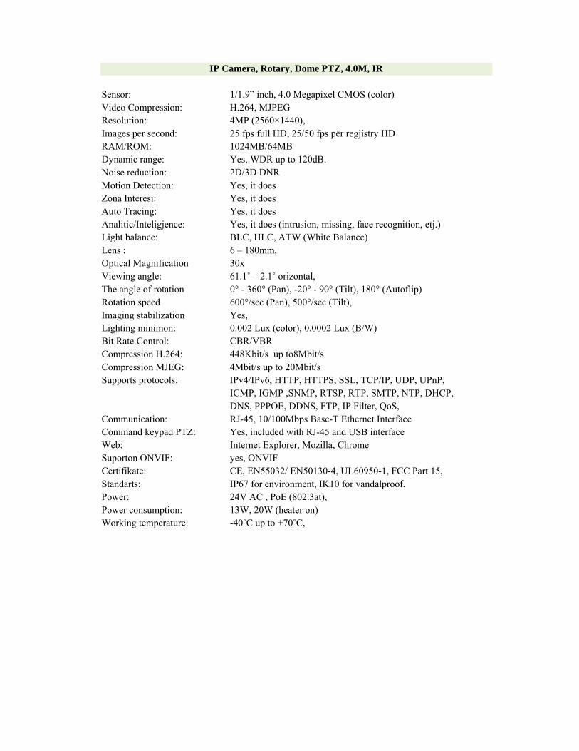
IP Camera, Rotary, Dome PTZ, 4.0M, IR Sensor: 1/1.9” inch, 4.0 Megapixel CMOS (color) Video Compression: H.264, MJPEG Resolution: 4MP (2560×1440), Images per second: 25 fps full HD, 25/50 fps për regjistry HD RAM/ROM: 1024MB/64MB Dynamic range: Yes, WDR up to 120dB. Noise reduction: 2D/3D DNR Motion Detection: Yes, it does Zona Interesi: Yes, it does Auto Tracing: Yes, it does Analitic/Inteligjence: Yes, it does (intrusion, missing, face recognition, etj.) Light balance: BLC, HLC, ATW (White Balance) Lens : 6 – 180mm, Optical Magnification 30x Viewing angle: 61.1˚ – 2.1˚ orizontal, The angle of rotation 0° - 360° (Pan), -20° - 90° (Tilt), 180° (Autoflip) Rotation speed 600°/sec (Pan), 500°/sec (Tilt), Imaging stabilization Yes, Lighting minimon: 0.002 Lux (color), 0.0002 Lux (B/W) Bit Rate Control: CBR/VBR Compression H.264: 448Kbit/s up to8Mbit/s Compression MJEG: 4Mbit/s up to 20Mbit/s Supports protocols: IPv4/IPv6, HTTP, HTTPS, SSL, TCP/IP, UDP, UPnP,
ICMP, IGMP ,SNMP, RTSP, RTP, SMTP, NTP, DHCP, DNS, PPPOE, DDNS, FTP, IP Filter, QoS,
Communication: RJ-45, 10/100Mbps Base-T Ethernet Interface Command keypad PTZ: Yes, included with RJ-45 and USB interface Web: Internet Explorer, Mozilla, Chrome Suporton ONVIF: yes, ONVIF Certifikate: CE, EN55032/ EN50130-4, UL60950-1, FCC Part 15, Standarts: IP67 for environment, IK10 for vandalproof. Power: 24V AC , PoE (802.3at), Power consumption: 13W, 20W (heater on) Working temperature: -40˚C up to +70˚C,

NVR Network Video Recorder, 32 channels, H.265 / H.264, Ultra 4K Video inputs: 32 Canals, Camera Type: IP cameras, of all kinds and brands, MegaPixel Software: With central management and camera control program Analtike: Yes, intelligent video system (intrusion, missing, face recognition,
etc.) CompressionVideo: H.265, H.264, MJPEG Resolution Video: 3840 × 2160, 1920 × 1080, 1280 × 1024, 1280 × 720, 1024 × 768,
1024 × 768, (HD, Full HD, 4K) Output Video: 1xVGA, 2 x HDMI , Full HD, HD (1920×1080, 1280×1024, 1280
× 720 , 1024 × 768), up to 4K Frame for sec: 25fps for each camera, in resolution HD and HD Recording Rate: 384Mbps Bit Rate: 16Kbit/s deri ne 20Mbit/s, për çdo kanal Register mode: Manual, Alarm, Motion Detection, Schedule Function: Playback/Regjistry/Live/Back-up/network Saving registration: HDD, USB, eSATA, network Network: 2 xRJ45 10/100/1000M ethernet interface, Supports protocols: HTTP, HTTPs, TCP/IP, IPv4/IPv6, UPnP, RTSP, UDP,
SMTP, NTP, DHCP, DNS, IP Filter, PPPoE,DDNS, FTP, Alarm Server, IP Search etj.
RS interface: 1x RS232, 1x RS485 Audio interface: 1Ch input, 1Ch output USB Interface: 2xUSB2.0, 2xUSB 3.0 E-sata interface Yes, it does 1 x eSata Port HDD: 8sataIII port (hdd 4TB up to 6TB); Storage: 12TB, Enterprice level HDD Raid: Yes, it does RAID 0/1/5/6/10 Procesori: Intel Dual Core Processor Rack mount Yes, 2U, cabinet mountable, Suporton ONVIF: Yes, ONVIF 2.4 Certifikate: CE, EN55022, EN55024, EN50130-4, EN60950-1 FCC Part 15, Power: 100V - 240V, 50Hz - 60Hz Operating Conditions: -10 ° C to + 55 ° C, operating temperature Storage conditions: -20 ° C to + 70 ° C, from 0 - 90% relative humidity

Industrial Switch, manageable, 8 ports RJ-45, PoE, 2 SPF Gibabit
Technology: Industrial Switch, Manageable, 8xRJ45, PoE, 2xSFP Gibabit Usage: Indoors, high and low temperatures, for use with IP, PoE cameras, for
network connection cameras in RING topology, certified for industrial use Gigabit Link: 2xSFP with fiber optic, uplink up to 50km Industrial PoE; 8 PoE ports and PoE + IEE 802.af/at Mounting: In DIN Rail, in closed cabinets as well as in IT cabinets Management: Web GUI Interface, Diagnosis and Analysis through Simple Network
Management Protocol (SNMP), Spanning-tree protocol (STP), Link Layer Discovery Protocol (LLDP), Discovery Protocol
Integration: IP Discovery, DHCP Dynamic Host Configuration Protocol Security: Secure access; port-security Data Load: VLAN aware, Internet Group Management Protocol (IGMP) and DHCP
snooping to filter unwanted data Hardware: DRAM 128MB DDR2, Flash Memory 160MB Software: LLDP, CDP aware, MSTP, STP Portfast, ICMP Vlans, static IP, Trust
Ingress DSCP, COS, Priority Port, port-security, IGMP querier, DHCP server SNMP v2 / v3, SNMP trap, syslog, IGMP snooping, DHCP snooping, BPDU guard, Radius client, Etherchannel, Alarms, PoE capability.
Output Power: 130-200W including PoE Power Supply: AC input 100-240V, 50-60HZ, 48V DC output, 3.15A, supports up to 8
PoE ports or 5 PoE + ports indoors, din rail mountable to outdoor and indoor cabinets.
Temperature: Works in temperatures from -40˚C to + 70˚C in open / hole cabinets, from -40˚C to + 60˚C in hermetically insulated cabinets, from -40˚C to + 75˚ C in the cabinet where there is ventilation, from -40˚C to + 85˚C storage temperature.
Safety Certificate: CE, EN 60950-1 UL / CSA / IEC / EN 61010-2-201, UL / CSA 60950-1 Environmental Certificate: ANSI / ISA 12.12.01 (Class1, Div2 A-D), EN 60079-0, IEC 60079-0,
UL 60079-0, 15, CAN / CSA C22.2 No. 60079-0, -15, EMC Certificate: FCC 47 CFR Part 15 Class A, EN 55022 / CISPR 22 Class A, EN 55016, RoHS compliance, CE Marking, IEC / EN 61000 Standard IEEE: IEEE 802.1D, IEEE 802.1p, IEEE 802.1q VLAN, IEEE 802.1s
Multiple SpanningTrees, IEEE 802.1w Rapid SpanningTree, IEEE 802.3ad LACP IEEE 802.3af, IEEE 802.3at RFC adaptation Supports RFC 768 UDP, RFC 791, RFC 793 TCP, RFC 791 ICMP, RFC 854 Telnet, RFC 2068 HTTP, RFC 2131, 2132 DHCP
SFP: Supports various SFP types, GLC-FE-100FX / LX / BX / DXGLC-LH-SM, 550m / MMF 10km / SMF, GLC-LX-SM-RGD,

SWITCH 24 Portable, PoE, Manageable
Technical specifications
Type of Device Switch - 24 ports - Managed
Type Rack-mountable
Ports 24 x 10/100/1000 + 2 x 1 Gigabit SFP+
Power Over Ethernet (PoE)
370W
Performance Switching capacity : 176 Gbps Forwarding performance (64-byte packet size) : 65.5 Mpps
MAC Address Tabela
8K
Distance Management Protocols
SNMP 1, SNMP 2, RMON 1, RMON 2, RMON 3, RMON 9, Telnet, SNMP 3, SNMP 2c, HTTP, HTTPS, TFTP, SSH
Encryption Algorithm
SSL
Authentication Secure Shell (SSH), RADIUS, TACACS+
Characteristics
Layer 2 switching, auto-sensing per device, dynamic IP address assignment , power over Ethernet (PoE), auto-negotiation, BOOTP support, ARP support, load balancing, VLAN support, auto-uplink (auto MDI/MDI-X), IGMP snooping, Syslog support, DiffServ support, Broadcast Storm Control, IPv6 support, Multicast Storm Control, Unicast Storm Control, Rapid Spanning Tree Protocol (RSTP) support, Multiple Spanning Tree Protocol (MSTP) support, DHCP snooping, Dynamic Trunking Protocol (DTP) support, Port Aggregation Protocol (PAgP) support, Access Control List (ACL) support, Quality of Service (QoS), PoE+, Link Aggregation Control Protocol (LACP), Port Security, MAC Address Notification, Remote Switch Port Analyzer (RSPAN)
Standarte
IEEE 802.3, IEEE 802.3u, IEEE 802.3z, IEEE 802.1D, IEEE 802.1Q, IEEE 802.3ab, IEEE 802.1p, IEEE 802.3af, IEEE 802.3x, IEEE 802.3ad (LACP), IEEE 802.1w, IEEE 802.1x, IEEE 802.1s, IEEE 802.3ah, IEEE 802.1ab (LLDP), IEEE 802.3at
RAM 128 MB
Flash memory 64 MB Flash
Status Indicators Port status, link activity, port transmission speed, port duplex mode, power, system
Expansion / Connection
Interfaces
24 x 10Base-T/100Base-TX/1000Base-T - RJ-45 - PoE USB : 1 x 4 PIN USB Type A 1 x console - mini-USB Type B - management 1 x console - RJ-45 - management 1 x 10Base-T/100Base-TX - RJ-45 - management 2 x SFP+
Extra Slots (Expansion)
1 (total) / 1 (free) x Stacking Module

Computer Workstation For software, management and monitoring of the camera system and IT
Type: Computer workstation (brand, original brand) Purpose: For the use and monitoring of high quality HD cameras Monitor: 2xLED 24 ”, Full HD, 1920x1080, HDMI cables: Included four pieces, for connecting monitors and TVs, Processor: Intel Xeon Quad Hand Processor, 2.93GHZ Memory: 8GB HDD: 500GB 7200rmp sata III HDD Graphics: 2xPCI Express, 2GB dedicated memory, 2xHDMI output each Optical: DVD +/- RW Network: 10/100 / 1000Mbps Çerfifikatë: CE
42 ”Monitor / TV For computer connection and camera monitoring
Display: LED Dimensions 42 ”inch Resolution: Full HD, 1920x1020p Frequency: 100Hz, Contrast: High, mega TV Receiver Yes, DVB-T / C Interfaces: 2xHDMI, 1xVGA, USB interface Yes, 2xUSB 2.0audio 2x10W
Energy
Power Device Power supply - internal
Energy (Volt) AC 120/230 V ( 50/60 Hz )
Different
Standarts TUV GS, CISPR 22 Class A, GOST, BSMI CNS 13438 Class A, CISPR 24, NOM, VCCI Class A ITE, EN55024, CB, EMC, MIC, IEC 60950-1, EN 60950-1, UL 60950-1 Second Edition, RoHS, CSA C22.2 No. 60950-1, FCC Part 15 B Class A
System Application / Requirements
Software LAN Base
Service & Support Limited lifetime warranty
Service & Support (Details)
Limited warranty - replacement - lifetime - response time: next business day Limited warranty - power supply and fans New releases update
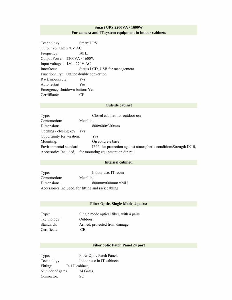
Smart UPS 2200VA / 1600W For camera and IT system equipment in indoor cabinets
Technology: Smart UPS Output voltage: 230V AC Frequency: 50Hz Output Power: 2200VA / 1600W Input voltage: 180 - 270V AC Interfaces: Status LCD, USB for management Functionality: Online double convertion Rack mountable: Yes, Auto restart: Yes Emergency shutdown button: Yes Çerfifikatë: CE
Outside cabinet
Type: Closed cabinet, for outdoor use Construction: Metallic Dimensions: 800x600x300mm Opening / closing key Yes Opportunity for aeration: Yes Mounting: On concrete base Environmental standard IP66, for protection against atmospheric conditionsStrength IK10, Accessories Included, for mounting equipment on din rail
Internal cabinet:
Type: Indoor use, IT room Construction: Metallic, Dimensions: 800mmx600mm x24U Accessories Included, for fitting and rack cabling
Fiber Optic, Single Mode, 4 pairs:
Type: Single mode optical fiber, with 4 pairs Technology: Outdoor Standards: Armed, protected from damage Certificate: CE
Fiber optic Patch Panel 24 port
Type: Fiber Optic Patch Panel, Technology: Indoor use in IT cabinets Fitting: In 1U cabinet, Number of gates 24 Gates, Connector: SC

Patch Panel Fiber Optic 8 Port,
Type: Fiber Optic Patch Panel, Technology: Use in outdoor cabinets Fitting: Din Rail Number of gates 8 Gates, Connector: SC / LC
SFP
Type: SFP Gibabit, for switches and non-fiber optical transmission / reception,
Usage: For network connection of core switches and camera switches
Technology: Single Mode, Long Range,
Capacity: 1Gbps, high transmission and reception capacity
Distance: Up to 20km
Default: IEEE 802.3, Digital Diagnostics Monitoring (DDM),
Wavelength 1310nm
Connectors: SC / LC (by fiber technology and patch panel)
KLODIODA L.t.d ADMINISTRATOR
____________________________ YLLI KARAPICI
Related Documents