DIRECT VENT INSERT WARNING: This product must be installed by a licensed plumber or gas fitter when installed in the Commonwealth of Massachusetts. IMPORTANT: Installation of a CO detector is required in the fireplace room when installed in the Commonwealth of Massachusetts. ◙ Do not store or use gasoline or other flammable vapors and liquids in the vicinity of this or any other appliance. IF YOU SMELL GAS: ◙ Do not light any appliance. ◙ Do not touch any electrical switch: do not use any phone in your building. ◙ Immediately call gas supplier from a neighbors phone. Follow the gas supplier instructions. ◙ If you cannot reach your gas supplier, call the fire department. ◙ Installation and service must be performed by a qualified installer, service agency or the gas supplier. WARNING: If the information in these instructions are not followed exactly, a fire or explosion may result, causing property damage, personal injury or loss of life. This appliance is only for use with the type (s) of gas indicated on the rating plate. A conversion kit is supplied with the appliance. www.kozyheat.com Quality Fireplaces for Life DO NOT DISCARD INSTALLER: LEAVE THIS MANUAL WITH THE APPLIANCE. CONSUMER: RETAIN THIS MANUAL FOR FUTURE REFERENCE. October 2009 911XXL-R06 This appliance may be installed in an aftermarket permanently located, manufactured (mobile) home, where not prohibited by local codes. A manufactured home (USA only) or mobile home OEM installation must conform with the Manufac- tured Home Construction and Safety Standard, Title 24 CFR, Part 3280, or when such a standard is not applicable, the Standard for Manufactured Home Installations, ANSI/NCSBCS A225.1, or Stan- dard for Gas Equipped Recreational Vehicles and Mobile Housing, CSA Z240.4 INSTALLATION AND OPERATION MANUAL

Welcome message from author
This document is posted to help you gain knowledge. Please leave a comment to let me know what you think about it! Share it to your friends and learn new things together.
Transcript
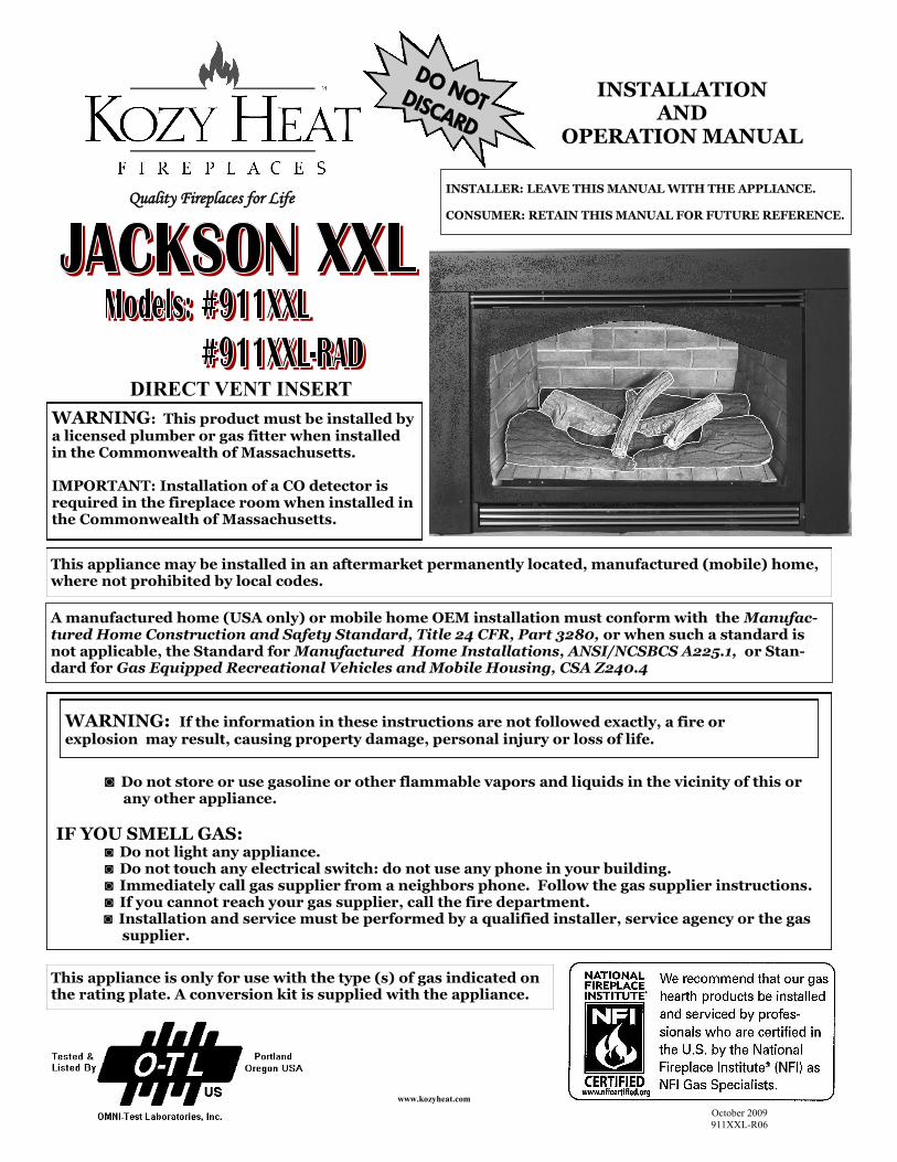
DIRECT VENT INSERT
WARNING: This product must be installed by a licensed plumber or gas fitter when installed in the Commonwealth of Massachusetts. IMPORTANT: Installation of a CO detector is required in the fireplace room when installed in the Commonwealth of Massachusetts.
◙ Do not store or use gasoline or other flammable vapors and liquids in the vicinity of this or any other appliance.
IF YOU SMELL GAS: ◙ Do not light any appliance. ◙ Do not touch any electrical switch: do not use any phone in your building. ◙ Immediately call gas supplier from a neighbors phone. Follow the gas supplier instructions. ◙ If you cannot reach your gas supplier, call the fire department. ◙ Installation and service must be performed by a qualified installer, service agency or the gas supplier.
WARNING: If the information in these instructions are not followed exactly, a fire or explosion may result, causing property damage, personal injury or loss of life.
This appliance is only for use with the type (s) of gas indicated on the rating plate. A conversion kit is supplied with the appliance.
www.kozyheat.com
Quality Fireplaces for Life
DO NOT DISCARD
INSTALLER: LEAVE THIS MANUAL WITH THE APPLIANCE. CONSUMER: RETAIN THIS MANUAL FOR FUTURE REFERENCE.
October 2009
911XXL-R06
This appliance may be installed in an aftermarket permanently located, manufactured (mobile) home, where not prohibited by local codes.
A manufactured home (USA only) or mobile home OEM installation must conform with the Manufac-tured Home Construction and Safety Standard, Title 24 CFR, Part 3280, or when such a standard is not applicable, the Standard for Manufactured Home Installations, ANSI/NCSBCS A225.1, or Stan-dard for Gas Equipped Recreational Vehicles and Mobile Housing, CSA Z240.4
INSTALLATION AND
OPERATION MANUAL

CONGRATULATIONS! We welcome you as a new owner of a Kozy Heat gas fireplace. Kozy Heat products are designed with superior components and materials and assembled by trained craftsmen who take pride in their work. The burner and valve assembly are 100% test-fired and the complete fireplace is thoroughly inspected before packaging to ensure that you receive a quality product. Our commitment to quality and customer satisfaction have remained the same for over 30 years. We offer a complete line of gas and wood fireplaces, unique cabinets and stylish accessories to compliment any décor. Adding a fireplace is one of the best ways to increase the value of your home and we are proud to offer a network of dealers throughout the country to help make your experience everything you imagine. We pride ourselves in being dedicated to not only function and reliability, but customer safety as well. We offer our continual support and guidance to help you achieve the maximum benefit and enjoyment from your Kozy Heat gas fireplace.
Jim Hussong Dudley Hussong President Board Chairman
INTRODUCTION
Read this manual before installing or operating this appliance. Please retain this owner’s manual for future reference.
Homeowner Reference Information We recommend that you record the following information about your fireplace.
Model Name:______________________________ Date purchased/installed:____________ Serial Number:____________________________ Location on fireplace:_______________ Dealership purchased from:__________________ Dealer Phone:_____________________ Notes:_____________________________________________________________________ __________________________________________________________________________ __________________________________________________________________________
PAGE 1


TABLE OF CONTENTS
PAGE 2
TABLE OF CONTENTS
MILLIVOLT BOARD
Millivolt Board Installation 19
Millivolt Board Removal 20
ZC SHROUD ASSEMBLY AND INSTALLATION
ZC Shroud Assembly and Installation 21
MASONRY SHROUD ASSEMBLY AND INSTALLATION
Masonry Shroud Assembly and Installation 22-23
LOG SET INSTALLATION
Log Set Installation 24
LIGHTING AND SHUTDOWN
Lighting and Shutdown 25-28
PRESSURE TESTING
Pressure Testing 29
FINALIZING THE INSTALLATION
Flame Appearance 30
Venturi Adjustment 30
Restrictor Usage / Troubleshooting / Installation / Modification 31
Seasonal Heat Dump 32
MAINTENANCE
Maintenance 33
TROUBLESHOOTING
Troubleshooting 34-36
REPLACEMENT PARTS LIST
Replacement Parts List 37
WARRANTY
Warranty 38-39
INTRODUCTION
Introduction and Homeowner Reference Information 1
TABLE OF CONTENTS
Table of Contents 2
SAFETY INFORMATION
Safety Information 3
FEATURES
Features 4
COMMONWEALTH OF MASSACHUSETTS INFORMATION
Commonwealth of Massachusetts Information 5
SPECIFICATIONS
Fireplace Insert Dimensions 6
Clearances 6
Components List 7
Additional Components Required 7
Placement Clearance Requirements 7
EXISTING FIREPLACE SPECIFICATIONS
Existing Fireplace Requirements 8
Existing Fireplace Minimum Opening Requirements 8
PREPARE EXISTING FIREPLACE
Prepare Existing Fireplace 9
GLASS FRAME ASSEMBLY
Remove Glass Frame Assembly 9
Install Glass Frame Assembly 9
FAN DIRECT WIRE INSTALLATION
Fan Direct Wire Installation 10
THERMOSTAT / WALL SWITCH / REMOTE
Thermostat / Wall Switch / Remote 11
GAS LINE CONNECTION
Gas Line Connection 12
INSTALLATION
Approved Venting 13
Air Duct Removal 13
Millivolt Board Removal 13
Restrictor 14
VENTING INSTALLATION
Kozy Heat #815-CL Co-Linear Vent System 15
Run Vent System Through Existing Chimney 16
Position Fireplace Insert 17
Attach Air Duct To Insert 17
COMPLETE FAN WIRING INSTALLATION
Complete Fan Wiring Installation 18


Installation and repair should be done only by a qualified service person. The appliance should be
inspected by a qualified service person before use. Annual inspection by a qualified service person is
required to maintain warranty. More frequent cleaning may be required due to excessive lint from
carpeting, bedding materials, etc. It is imperative that control compartments, burners and
circulation air passageways of the appliance be kept clean.
This fireplace insert is to be installed into a solid fuel masonry or factory built non-combustible fire-
place that has been installed in accordance with the National, Provincial, State and local building
codes.
Children and adults should be alerted to the hazards of high surface temperatures and should stay
away to avoid burns or clothing ignition.
Young children should be carefully supervised when they are in the same room as the appliance.
Clothing or other flammable material should not be place on or near the appliance.
Adequate accessibility clearances for servicing and proper operation must be maintained.
This appliance must not share or be connected to a chimney flue serving any other appliance.
Keep area around the appliance clear of combustible materials, gasoline and other flammable vapor
and liquids.
The flow of combustion and ventilation air must not be obstructed.
Due to high temperatures the appliance should be located out of traffic and away from furniture and
draperies.
The glass front or any part removed for servicing the appliance must be replaced prior to operating
the appliance. Work should be done by a qualified service technician.
Clean glass only when cool and only with non-abrasive cleansers.
Do not operate this appliance with the glass/frame assembly removed, cracked or broken. The glass
assembly, Part #700-01T, shall only be replaced as a complete unit, as supplied by Hussong Mfg. Co.,
Inc. Replacement of the glass assembly must only be performed by a licensed or qualified service per-
son. DO NOT SUBSTITUTE MATERIALS.
Do not strike or slam glass assembly.
Any safety screen or guard removed for servicing the appliance must be replaced prior to operating
the appliance.
Under no circumstances should any solid fuel (wood, coal, paper or cardboard etc.) be used in this
appliance.
Keep burner and control compartment clean.
Do not use this fireplace if any part has been under water. Immediately call a qualified service
technician to inspect this appliance and to replace any part of the control system and any gas control
which has been under water.
This fireplace has been tested to and complies with ANSI Z21.88a-2007·CSA 2.33a-2007·M02 “VENTED GAS FIREPLACE
HEATERS” by OMNI-Test Laboratories, Portland, OR. Installation must conform with local building codes or in the absence of local
building codes, with the National Fuel Gas Code, ANSIZ223.1/NFPA 54 - Current Edition, or the Natural or Propane Installation Code,
CSAB149.1
SAFETY INFORMATION
PAGE 3

High efficiency
High quality lifetime glass
21” x 35”” (533 mm x 889 mm)
Quick latch glass frame assembly
Co-linear vent system - (manifold)
Seasonal heat dump baffle
Patented burner system and log design
High - Low regulator
*Automatic fan kit (2) - 75 CFM
Refractory brick lining
Minnesota Energy Code compliant to 50 pascals
* Model 911XXL only
Grills (required) – several styles/finishes
Arched valance brass or chrome trim
Rectangular valance (replaces arched valance)
Valance Screen
On-off remote control or thermostatic remote control
Wall mount thermostat / wireless wall mount thermostat
Decorative screen doors in various styles and finishes
Decorative full door shrouds in various styles and finishes
3 pc. or 4 pc. shrouds (Masonry or ZC style)
Shroud trim in various finishes
Custom shrouds (Masonry or ZC style)
Automatic fan kit (2) - 75 CFM (#911XXL-RAD Models)
Each unit factory tested!
Tested by OMNI - Test Laboratories
Sealed combustion chamber with standing pilot ignition
Removable millivolt board with 30-second delay pilot
Automatic pressure relief glass system
Requires no electricity to operate (excluding fan)
Bedroom and mobile home approved
Fireplace Weight (as packaged for shipment)
167 lbs. (75.75 kg)
FEATURES
STANDARD FEATURES
OPTIONAL FEATURES
WEIGHT
SAFETY FEATURES
PAGE 4

COMMONWEALTH OF MASSACHUSETTS REQUIREMENTS
NOTE: The following requirements reference
various Massachusetts and national codes not
contained in this manual.
For all sidewall horizontally vented gas fueled equipment installed in every dwelling, building or structure used in whole or in part for residential purposes, including those owned or operated by the Commonwealth and where the side wall exhaust vent termination is less than (7) feet above finished grade in the
area of the venting, including but not limited to decks and porches, the following requirements shall be satisfied:
INSTALLATION OF CARBON MONOXIDE DETECTORS
At the time of installation of the side wall horizontally vented gas fueled equipment, the installing plumber or gas-fitter shall observe that a hard wired carbon monoxide detector with an alarm and battery back-up is installed on the floor level where the gas equipment is to be installed. In addition, the in-
stalling plumber or gas-fitter shall observe that a battery operated or hard wired carbon monoxide detector is installed on each additional level of the dwell-
ing, building or structure served by the side wall horizontal vented gas fueled equipment. It shall be the responsibility of the property owner to secure the services of qualified licensed professionals for the installation of hard wired carbon monoxide detectors.
In the event that the side wall horizontally vented gas fueled equipment is installed in a crawl space or attic, the hard wired carbon monoxide detector with alarm and battery back-up may be installed on the next adjacent floor level.
In the event that the requirements of this subdivision can not be met at the time of completion of installation, the owner shall have a period of thirty (30) days to comply with the above requirements; provided, however, that during said thirty (30) day period, a battery operated carbon monoxide detector with
an alarm shall be installed.
APPROVED CARBON MONOXIDE DETECTORS
Each carbon monoxide detector as required in accordance with the above provisions shall comply with NFPA 720 and be ANSI/UL 2034 listed and IAS certified.
SIGNAGE
A metal or plastic identification plate shall be permanently mounted to the exterior of the building at a minimum of eight (8) feet above grade directly in line with the exhaust vent terminal for the horizontally vented gas fueled heating appliance or equipment. The sign shall read, in print no less the one-half
inch (1/2”) in size, “GAS VENT DIRECTLY BELOW. KEEP CLEAR OF ALL OBSTRUCTIONS”.
INSPECTION
The state or local gas inspector of the side wall horizontally vented gas fueled equipment shall not approve the installation unless, upon inspection, the inspector observes carbon monoxide detectors and signage installed in accordance with the provisions of 248 CMR 5.08 (2) (a) 1 through 4.
EXEMPTIONS
The following equipment is exempt from 248 CMR 5.08 (2) (a) 1 through 4:The equipment listed in Chapter 10 entitled “Equipment Not Required To Be Vented” in the most current edition of NFPA 54 as adopted by the Board; and Product Approved side wall horizontally vented gas fueled equipment in-
stalled in a room or structure separate from the dwelling, building or structure used in whole or in part for residential purposes.
MANUFACTURER REQUIREMENTS - GAS EQUIPMENT VENTING SYSTEM PROVIDED
When the manufacturer of Product Approved side wall horizontally vented gas equipment provides a venting system design or venting system compo-nents with the equipment, the instructions provided by the manufacturer for installation of the equipment and the venting system shall include:
Detailed instructions for the installation of the venting system design or the venting system components; and
A complete parts list for the venting system design or venting system.
MANUFACTURER REQUIREMENTS - GAS EQUIPMENT VENTING SYSTEM NOT PROVIDED
When the manufacturer of Product Approved side wall horizontally vented gas equipment does not provide the parts for venting the flue gases, but identi-fies “special venting systems”, the following requirements shall be satisfied by the manufacturer:
The referenced “special venting systems” instructions shall be included with the appliance or equipment installation instructions and;
The “special venting systems” shall be Product Approved by the Board, and the instructions for that system shall include a parts list and
detailed installation instructions.
A copy of all installation instructions for all Product Approved side wall horizontally vented gas fueled equipment, all venting instructions, all parts lists
for venting instructions, and/or all venting design instructions shall remain with the appliance or equipment at the completion of the installation.
PAGE 5
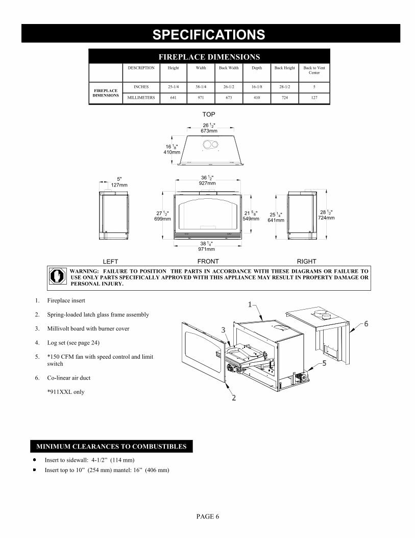
TOP
FRONT RIGHTLEFT
38 14"971mm
27 12"699mm
25 14"641mm
28 12"724mm
5"
127mm
36 12"927mm
21 5 8"549mm
26 12"673mm
16 18"410mm
FIREPLACE DIMENSIONS
DESCRIPTION Height Width Back Width Depth Back Height Back to Vent
Center
FIREPLACE
DIMENSIONS
INCHES 25-1/4 38-1/4 26-1/2 16-1/8 28-1/2 5
MILLIMETERS 641 971 673 410 724 127
SPECIFICATIONS
MINIMUM CLEARANCES TO COMBUSTIBLES
Insert to sidewall: 4-1/2” (114 mm)
Insert top to 10” (254 mm) mantel: 16” (406 mm)
PAGE 6
WARNING: FAILURE TO POSITION THE PARTS IN ACCORDANCE WITH THESE DIAGRAMS OR FAILURE TO
USE ONLY PARTS SPECIFICALLY APPROVED WITH THIS APPLIANCE MAY RESULT IN PROPERTY DAMAGE OR
PERSONAL INJURY.
1. Fireplace insert
2. Spring-loaded latch glass frame assembly
3. Millivolt board with burner cover
4. Log set (see page 24)
5. *150 CFM fan with speed control and limit
switch
6. Co-linear air duct
*911XXL only

PLACEMENT CLEARANCE REQUIREMENTS
This fireplace must be installed on a level surface capable of supporting the fireplace and venting.
This fireplace insert is to be installed into a solid fuel masonry or factory built non-combustible fireplace that has been installed in
accordance with the National, Provincial, State and local building codes.
Due to high surface temperatures, fireplace should be located out of traffic and away from furniture and draperies.
This fireplace may be installed in a bedroom.
Please be aware of the large amount of heat this fireplace will produce when determining a location.
SPECIFICATIONS
PAGE 7
MODEL #911XXL COMPONENTS LIST
(#XXL-770) - Millivolt Board Assembly with 18” Flexible
Gas Line attached
(#700-203) - Manual Gas Shut-off Valve
(#XXL-135) - Burner Assembly
(#XXL-G900) - Refractory Set
(#XXL-500) - Log Package
(#700-01T) - Glass with Gasket
(#XXL-005) - Glass Valance
(#OCK-S47A) - LP Conversion Kit
(#815-CL3) - Co-Linear Air Chute
(#XXL-028) - Fan Kit (2)-75 CFM
(#900-085) - 4” Restrictor Plate
ADDITIONAL COMPONENTS REQUIRED
Vent System; Part #815-CL: For use with minimum 6” x 8” I.D. masonry or 8” I.D. Class A metal chimneys - Includes 12 ft. (3.66 m)
compressed, expandable to 25 ft (7.62 m) co-linear 3” x 4” flexible chimney, and termination cap.
Part #510: Used in conjunction with #815-CL to extend termination up to a maximum of 40 ft. (12.19 m).
Other approved venting: Selkirk
Shrouds - 3 pc & 4 pc.: Standard shrouds are available for this insert and will fit most applications. Custom shrouds may be ordered on a
non-returnable basis. When ordering a custom shroud, please specify the existing fireplace front opening height
and width. Grill set (required) in various finishes purchased separately.
or
Blank Shrouds - 3 & 4 pc.: Blank shrouds are available for on-site custom fit applications and are sized to the opening after the insert has
been installed. The interior perimeter is properly sized to fit onto the insert. The outer perimeter must be cut,
formed and finished (painted). Grill set (required) in various finishes purchased separately.
or
Full Door Shrouds: Full door decorative shrouds are available for this insert and are used in place of a standard or blank shroud.
(#XXL-770) - Millivolt Board Assembly with 18” Flexible
Gas Line attached
(#700-203) - Manual Gas Shut-off Valve
(#XXL-135) - Burner Assembly
(#XXL-G900) - Refractory Set
(#XXL-500) - Log Package
(#700-01T) - Glass with Gasket
(#XXL-005) - Glass Valance
(#OCK-S47A) - LP Conversion Kit
(#815-CL3) - Co-Linear Air Chute
(#900-085) - 4” Restrictor Plate
MODEL #911XXL-RAD COMPONENTS LIST

26 3 4"679mm
38 12"978mm
16 12"419mm
28"
711mm
THIS INSERT IS APPROVED FOR INSTALLATION IN MASONRY AND FACTORY-BUILT SOLID FUEL BURNING FIREPLACES.
EXISTING FIREPLACE REQUIREMENTS
The existing fireplace & chimney must be clean and in good working order and constructed of non-combustible materials.
A gas line must be able to be installed to the insert.
Provisions made to provide electrical power to operate the insert fan and thermostatic control (if used).
Any chimney clean-outs must fit properly.
Existing Chimney must be comprised of one of the following: Class „A‟ metal chimney: 8” minimum inside diameter.
Masonry Chimney: 6" x 8" minimum inside diameter.
Existing Chimney Height: Minimum: 11 ft. (3.35 m)
Maximum: 40 ft. (12.19 m)
Determine length of your existing chimney:
1. Remove and discard existing chimney cap.
2. Measure from fireplace base to the top of chimney.
Subtract 24” (610 mm).
This is the total length of co-linear flexible aluminum you will require.
MEASUREMENT FROM FIREPLACE BASE TO TOP OF CHIMNEY:____________
LESS 24”" (610 mm) : -24" (610 mm)
TOTAL CHIMNEY LENGTH REQUIRED: ____________
NOTE: It is helpful to have two people complete the
next step in determining chimney height.
EXISTING FIREPLACE SPECIFICATIONS
CAUTION: THIS APPLIANCE MUST NOT BE CONNECTED
TO A CHIMNEY FLUE SERVING A SEPARATE SOLID-
FUEL BURNING APPLIANCE.
EXISTING FIREPLACE MINIMUM OPENING REQUIREMENTS
Height: 28" (711 mm)
Front Width : 38-1/2" (978 mm)
Depth: 16-1/2" (419 mm)
Back Width : 26-3/4" (679 mm)
All dimensions are minimum requirements
PAGE 8

PAGE 9
PREPARE THE EXISTING FIREPLACE
1. The refractory, glass doors, screen rails, screen mesh and log grates may be removed from existing fireplace before installing this gas
fireplace insert.
2. Any smoke shelves, shields and baffles may be removed if attached by mechanical fasteners.
3. If necessary, remove firebrick on sides and back of the existing fireplace to obtain at least the minimum opening requirements listed on
page 8.
4. The fireplace flue damper can be fully blocked open or removed for installation of this gas fireplace insert.
5. Remove existing chimney cap.
6. Clean chimney and inside of fireplace to prevent creosote smell from entering the home.
7. Place „THIS UNIT HAS BEEN MODIFIED‟ label in the bottom of existing firebox so it will be visible if this gas fireplace insert is re-
moved.
8. Run electrical wiring if hard wiring to the pre-installed electrical box in the insert if desired.
See „FAN DIRECT WIRE INSTALLATION‟ instructions on page 10.
9. Run any electrical wiring needed if insert is to be run by a thermostat.
10. Run gas line to existing fireplace.
WARNING: CUTTING ANY SHEET-METAL PARTS OF THE FIREPLACE, IN WHICH THE GAS FIREPLACE IS TO BE
INSTALLED, IS PROHIBITED.
PREPARE THE EXISTING FIREPLACE
REMOVE GLASS FRAME ASSEMBLY
A. Locate the spring-loaded handles securing glass frame assembly at the bottom of firebox.
B. Pull bottom handles out and „down‟ to release glass frame assembly bottom.
C. Pull bottom of glass frame assembly out and lift up off tabs at top of firebox.
INSTALL GLASS FRAME ASSEMBLY
A. Place glass frame assembly top over tabs at top of firebox.
B. Pull bottom handles out and „up‟ to secure glass frame assembly bottom.
WARNING: DO NOT OPERATE THIS FIRE-
PLACE WITH THE GLASS REMOVED,
CRACKED OR BROKEN. REPLACEMENT
OF GLASS ASSEMBLY, #700-01T SHOULD
BE DONE BY A LICENSED OR QUALIFIED
SERVICE PERSON.
WARNING: DO NOT REMOVE GLASS ASSEMBLY
WHEN HOT!
GLASS FRAME ASSEMBLY
Inco
min
g w
iring
11
0V-1
20V
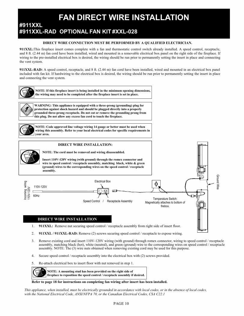
911XXL:This fireplace insert comes complete with a fan and thermostatic control switch already installed. A speed control, receptacle,
and 8 ft. (2.44 m) fan cord have been installed, wired and mounted in a removable electrical box panel on the right side of the fireplace. If
wiring to the pre-installed electrical box is desired, the wiring should be run prior to permanently setting the insert in place and connecting
the vent system.
NOTE: If this fireplace insert is being installed in the minimum opening dimensions,
the wiring may need to be completed after the fireplace insert is set in place.
WARNING: This appliance is equipped with a three-prong (grounding) plug for
protection against shock hazard and should be plugged directly into a properly
grounded three-prong receptacle. Do not cut or remove the grounding prong from
this plug. Do not allow any excess fan cord to touch the fireplace.
NOTE: Code approved line voltage wiring 14 gauge or better must be used when
wiring this assembly. Refer to your local electrical codes for specific requirements in
your area.
Speed Control / Receptacle Assembly Temperature Switch:
Magnetically attaches to bottom of firebox.
Electrical Box
60Hz
110V-120V
Ground W
ire
DIRECT WIRE INSTALLATION:
NOTE: The cord must be removed and wiring disassembled.
Insert 110V-120V wiring (with ground) through the romex connector and
wire to speed control / receptacle assembly, matching black, white & green
(ground) wires to the corresponding wires on the speed control / receptacle
assembly.
DIRECT WIRE INSTALLATION
1. 911XXL: Remove nut securing speed control / receptacle assembly from right side of insert floor.
2. 911XXL / 911XXL-RAD: Remove (2) screws securing speed control / receptacle to expose wiring.
3. Remove existing cord and insert 110V-120V wiring (with ground) through romex connector, wiring to speed control / receptacle assembly, matching black (hot), white (neutral), and green (ground) wire to the corresponding wires on speed control / receptacle assembly. NOTE: The (3) wire nuts obtained when removing existing cord may be used for this purpose.
4. Secure speed control / receptacle assembly into the electrical box with (2) screws provided.
5. Re-attach electrical box to insert floor with nut removed in step 1.
Refer to page 18 for instructions on completing fan wiring after insert has been installed.
This appliance, when installed, must be electrically grounded in accordance with local codes, or in the absence of local codes,
with the National Electrical Code, ANSI/NFPA 70, or the Canadian Electrical Codes, CSA C22.1
DIRECT WIRE CONNECTION MUST BE PERFORMED BY A QUALIFIED ELECTRICIAN.
PAGE 10
NOTE: A mounting stud has been provided on the right side of
fireplace to reposition the speed control / receptacle assembly if desired.
FAN DIRECT WIRE INSTALLATION #911XXL #911XXL-RAD OPTIONAL FAN KIT #XXL-028
911XXL-RAD: A speed control, receptacle, and 8 ft. (2.44 m) fan cord have been installed, wired and mounted in an electrical box panel
included with fan kit. If hardwiring to the electrical box is desired, the wiring should be run prior to permanently setting the insert in place
and connecting the vent system.

THERMOSTAT / WALL SWITCH / REMOTE
CAUTION: DO NOT CONNECT HIGH
VOLTAGE (115V) WIRE TO THE GAS
VALVE!
If desired, a thermostat (wireless style also available), wall switch,
or remote control assembly may be used to turn the fireplace „OFF‟
and „ON‟. Only ONE of these may be installed. Follow instructions
included with each assembly.
WALL SWITCH / THERMOSTAT:
Run low-voltage (thermostat) wires from terminals on the gas valve to
the desired location of wall switch or thermostat.
Attach the appropriate connectors to wall switch / thermostat wires
and connect to the top and bottom terminals marked TH / TPTH on
the gas valve.
REMOTE CONTROL:
Follow instructions included with the remote control.
IMPORTANT: The insulated cover included with the remote
control must be placed over the remote receiver to prevent over-
heating.
IMPORTANT: If ON/OFF rocker switch wires are
not disconnected, the ON/OFF rocker switch on the
millivolt board must be in the „OFF‟ position for
proper operation of any of these components.
If rocker switch is „ON‟, the fireplace burner will operate until it is
turned „OFF‟ by the rocker switch. A wall switch, thermostat, or
remote control will not turn the fireplace „OFF‟ when it has been
turned „ON‟ by the rocker switch.
NOTE: The fireplace must be turned „ON‟ and
„OFF‟ by the same method. For example: If fire-
place is turned „ON‟ by the remote control, it must
be turned „OFF‟ by the remote control.
Remote Control Wiring Diagram
NOTE: INSTALLATION OF THERMOSTAT OR WALL
SWITCH SHOULD ONLY BE DONE BY A QUALIFIED
INSTALLER.
Thermostat Wiring Diagram
OPTIONAL:
Disconnect ON/OFF rocker
switch wires from the back
of gas valve.
PAGE 11

GAS LINE CONNECTION
IMPORTANT:
DO NOT RUN GAS LINE IN A MANNER THAT WOULD OBSTRUCT FAN OPERATION OR OPERATION OF FAN COMPONENTS.
Run gas line into existing fireplace, preferably through the left or right side, 2” (51 mm) from the bottom as shown in illustration below.
NOTE: If installing this insert into minimum opening dimensions, the gas line may need to be run after the insert is in place due to space
limitations.
NOTE: If installing this gas fireplace insert into a factory-built fireplace and the factory-built fireplace has no access hole provided, an access
hole of 1 ½"(38 mm) or less may be drilled through the lower sides or bottom of the firebox in a proper workmanship like manner. This ac-
cess hole must be plugged with non-combustible insulation after the gas supply line has been installed.
2” (51 mm) from bottom to gas line WARNING LABEL
911XXL / 911XXL-RAD
NATURAL GAS LP GAS
MINIMUM INLET GAS PRESSURE 5.0 inches W.C. (7.0 W.C. recommended) 11.0 inches W.C. (recommended)
MAXIMUM INLET GAS PRESSURE 10.5 inches W.C. 13.0 inches W.C.
MANIFOLD PRESSURE (HI) 3.5 inches W.C 10.0 inches W.C.
MANIFOLD PRESSURE (LO) 1.7 inches W.C. 6.5 inches W.C
ORIFICE SIZE #30 #47
INPUT BTU/hr. 42,000 42,000
MINIMUM INPUT BTU/hr. 29,500 30,000
EFFICIENCY 70% 76%
AFUE 69% 75%
PAGE 12
IMPORTANT: For high altitude installations, consult the local gas distributor or the authority having jurisdiction for proper rating methods.
INSTALLATION
IMPORTANT: ALL STEPS AS OUTLINED IN „PREPARE THE EXISTING FIREPLACE‟ MUST BE COMPLETED BEFORE
CONTINUING WITH THIS INSTALLATION.
Kozy Heat #815-CL Co-Linear Vent System. Follow instructions on following pages.
Selkirk
Follow instructions included from vent pipe manufacturer as well as the venting requirements as outlined in this installation manual.
APPROVED VENTING
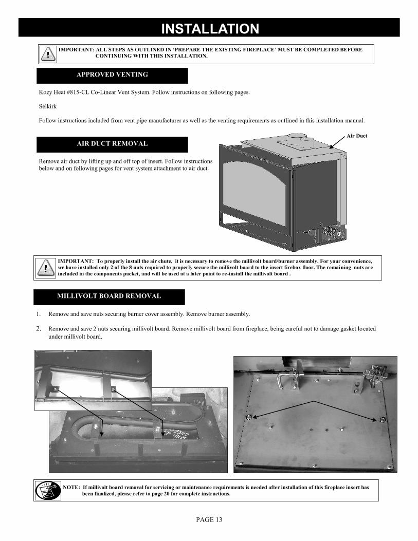
AIR DUCT REMOVAL
Remove air duct by lifting up and off top of insert. Follow instructions
below and on following pages for vent system attachment to air duct.
MILLIVOLT BOARD REMOVAL
1. Remove and save nuts securing burner cover assembly. Remove burner assembly.
2. Remove and save 2 nuts securing millivolt board. Remove millivolt board from fireplace, being careful not to damage gasket located
under millivolt board.
IMPORTANT: To properly install the air chute, it is necessary to remove the millivolt board/burner assembly. For your convenience,
we have installed only 2 of the 8 nuts required to properly secure the millivolt board to the insert firebox floor. The remaining nuts are
included in the components packet, and will be used at a later point to re-install the millivolt board .
NOTE: If millivolt board removal for servicing or maintenance requirements is needed after installation of this fireplace insert has
been finalized, please refer to page 20 for complete instructions.
PAGE 13
Air Duct

Large Restrictor Bend tabs to approx. 80 degree
angles to create tension to hold
itself in place when installed.
Remove tab (s) to create
small restrictor
Slide restrictor into exhaust pipe with tabs
pointing toward you.
RESTRICTOR INSTALLATION
Each installation is unique and affected by various factors including venting configuration, altitude and climate. Therefore, after fireplace insert
installation is complete, a restrictor may be required or may need to be removed or modified.
Page 31 has information on restrictor recommendations depending on burner flame appearance and instructions on installation after venting is
completed.
RESTRICTOR
INSTALLATION
IMPORTANT: DO NOT INSTALL IF THE VENTING CONFIGURATION
IS AT THE MINIMUM REQUIREMENTS!
PAGE 14

A. Carefully extend the 3” combustion intake and 4” exhaust pipes (and extension kit if used) to equal the total chimney length required.
B. If using „Full Connection‟ method:
1. Slide 3" intake pipe (end without collar) over collar on termination cap. Secure with 3 self-tapping screws (provided).
2. Place a bead of sealant around inner edge of 4" exhaust pipe (end without collar) and slide onto corresponding collar on termination
cap. Secure with 3 self-tapping screws (provided). Apply additional sealant around joint to ensure a seal.
C. If an extension kit is being used, it must be connected as follows:
Exhaust extension: Apply a liberal bead of sealant around exhaust adaptor (male) extension pipe and slide into female connector on end of
4” exhaust pipe already attached to the chimney termination plates. Secure with 3 self-tapping screws, (provided). To
ensure an air-tight seal, additional sealant should be applied at the point of connection.
Combustion intake extension: Apply a liberal bead of sealant (provided) around male end of extension kit and slide into female end of 3”
combustion intake pipe attached to the chimney termination plates. Secure with 3 self-tapping screws
(provided). To ensure an air-tight seal, additional sealant should be applied at the point of connection.
VENTING INSTALLATION
NOTE: The co-linear pipe included with this vent system is designed to extend up to 25 ft. (7.62 m).
If additional length is required, Part #510 is available to extend the venting to a maximum of 40 ft (12.19 m).
NOTE: If using „stub‟ method for the combustion air pipe, extending it is not necessary. Determine length
needed from the air duct on insert (4 ft. (1.22 m) minimum) to above the damper opening in the exist-
ing chimney. Remove excess combustion air pipe from end without a collar. Continue with Step B. #2
below.
PAGE 15
KOZY HEAT #815-CL CO-LINEAR VENT SYSTEM

We strongly suggest wrapping the first 3 ft.(914 mm) of vent system below the termina-
tion cap with non-faced fiberglass insulation (secure with wire) before running it through
the existing chimney. This will prevent cold air from coming down the existing chimney.
NOTE: If offsets are present in existing chimney, it may be easier to place a
weighted rope around the end of each pipe to guide them through it.
DO NOT ATTEMPT TO TIE ONE ROPE AROUND BOTH PIPES.
VENTING INSTALLATION
1. Guide rope, if used, and flexible pipe(s) down existing chimney. See illustration at lower left.
2. To secure chimney termination cap to the existing chimney, apply a liberal bead of sealant (provided) around the top of existing chim-
ney. Set termination cap into position as instructed in installation manual included with chosen vent system .
3. From inside existing fireplace opening, CAREFULLY pull ropes down until 4" exhaust pipe and 3” combustion air intake (if using „full
connection method‟), are into existing fireplace.
STUB VENTING: From inside existing fireplace, insert a minimum 4ft. (1.22m) section of combustion air pipe (end without collar) past the
damper opening and into existing fireplace. See illustration at lower right.
4. We strongly suggested placing non-faced fiberglass insulation between vent pipes and existing chimney to prevent heat loss up the
chimney, being careful not to block end pipe if using stub method.
Minimum 4 ft. (1.22m) section
of 3" combustion air flex pipe
DO NOT block pipe
end with insulation or
any other sealing
materials
4" exhaust flex pipe
must be connected
to collar on
fireplace insert and
termination cap
Seal area around
vent pipes with
non-faced fiberglass
insulation
PAGE 16
RUN VENTING THROUGH EXISTING CHIMNEY

CONNECT VENT SYSTEM TO AIR DUCT
1. Place air duct (previously removed from insert top, page 13) into the ex-
isting fireplace opening.
2. Place a bead of sealant (provided) around 4” exhaust pipe. Slide exhaust
pipe inside 4" collar air duct. Secure with (3) ½" self-tapping screws,
provided. Apply additional sealant around the joint to ensure an air-tight
seal.
3. Apply a liberal bead of sealant (provided) around 3” collar on the air duct.
Slide 3” combustion intake pipe over the collar. Secure with (3) ½" self-
tapping screws, provided. To ensure an air-tight seal, apply additional
sealant around the joint.
1. Slide insert into fireplace opening.
2. If necessary, level insert by threading leveling bolts (included in components
packet) into nuts mounted inside lower air passage.
3. Attach air duct to insert by aligning the two holes in insert top to studs on
each side of the 4" exhaust duct, and the four holes at back of insert to
mounting studs at lower end of air duct.
4. Locate baffle with seasonal heat dump inside the firebox, noting the (2)
access holes (A) on each side of the heat dump. Secure air duct to insert
through the access holes with (2) 1/4" nuts.
5. Secure lower end of air duct to insert firebox with (4) 1/4" nuts.
Leveling legs (2 per side)
POSITION FIREPLACE INSERT
ATTACH AIR DUCT TO INSERT
IMPORTANT: Before completing steps 4 & 5, ensure that air duct gasket is
properly seated.
PAGE 17
NOTE: To prevent rattling noises that may occur during fan operation,
position air duct back and side flanges on the „OUTSIDE” of insert bottom
flanges.
Position air duct back and sides
outside insert

COMPLETE FAN WIRING INSTALLATION
1. Place thermostatic control switch on bottom of insert firebox.
2. Plug power cord into electrical box receptacle.
3. Turn speed control counter-clockwise until it „clicks‟. This is the „OFF‟ position.
4. Turn speed control „ON‟ by turning the knob clockwise past the „click‟ - this is the highest setting.
Before adjusting the temperature control switch, unplug the 3-prong
plug on the fan cord from the receptacle. Adjust position of the
temperature control switch to a warmer location under the firebox to
turn fan „ON‟ sooner or move it to a cooler location under firebox
to turn the fan „ON‟ later. The fan will turn on when the sensor in
the temperature control switch reaches 110° F and will turn „OFF‟
when the sensor reaches 90° F. After adjustment, plug the 3-prong
plug on fan cord into the receptacle.
NOTE: This appliance must be electrically grounded and connected in accordance with local codes, or in the absence of local codes, with
the National Electrical Code, ANSI/NFPA 70 Current Edition, or the Canadian Electrical Code CSA C22.1.
NOTE: This fan will not operate unless the speed control has been turned „ON‟ and sufficient heat has been applied to the temperature
control switch. The fan will turn „ON‟ and „OFF‟ automatically as the fireplace heats and cools. Adjust fan to desired speed while it is
running.
TEMPERATURE CONTROL SWITCH POSITION
Temperature Control Switch (looking through lower grill opening).
ELECTRICAL WARNING: DO NOT ALLOW MILLIVOLT BOARD COMPONENTS (WIRES, FLEXLINES, ETC.) TO COME IN CON-
TACT WITH FAN ASSEMBLY COMPONENTS.
PAGE 18
#911XXL
#911XXL-RAD OPTIONAL FAN KIT #XXL-028
#911XXL & #911XXL-RAD
#911XXL-RAD with optional fan kit #XXL-028
1. If not previously done, turn gas valve and manual shut off valve to „OFF‟. Disconnect gas line from manual shut off valve.
2. Remove lower grill if previously installed.
3. Slide left, then right fan through the lower grill opening (right side of gas valve), positioning onto their corresponding mounting studs on
the floor of fireplace. Secure each fan with (2) nuts included.
4. Connect left fan extension wires to terminals on right fan.
5. Install electrical box with speed control assembly onto either right or left mounting studs located toward front of fireplace.
6. Connect the flexible gas line to the manual shut off valve. Turn the manual shut off valve to „ON‟.
7. Re-install lower grill.
CAUTION: CHECK CONNECTION FOR LEAKS.
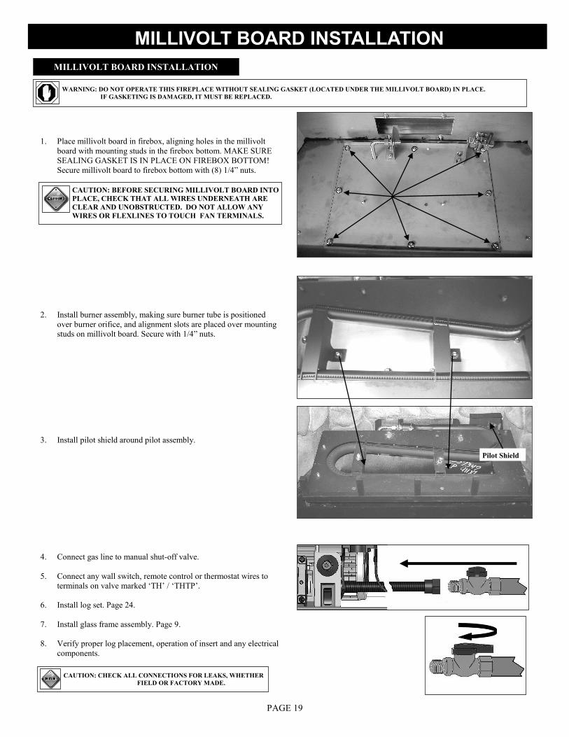
1. Place millivolt board in firebox, aligning holes in the millivolt
board with mounting studs in the firebox bottom. MAKE SURE
SEALING GASKET IS IN PLACE ON FIREBOX BOTTOM!
Secure millivolt board to firebox bottom with (8) 1/4” nuts.
2. Install burner assembly, making sure burner tube is positioned
over burner orifice, and alignment slots are placed over mounting
studs on millivolt board. Secure with 1/4” nuts.
3. Install pilot shield around pilot assembly.
Pilot Shield
MILLIVOLT BOARD INSTALLATION
MILLIVOLT BOARD INSTALLATION
WARNING: DO NOT OPERATE THIS FIREPLACE WITHOUT SEALING GASKET (LOCATED UNDER THE MILLIVOLT BOARD) IN PLACE.
IF GASKETING IS DAMAGED, IT MUST BE REPLACED.
CAUTION: BEFORE SECURING MILLIVOLT BOARD INTO
PLACE, CHECK THAT ALL WIRES UNDERNEATH ARE
CLEAR AND UNOBSTRUCTED. DO NOT ALLOW ANY
WIRES OR FLEXLINES TO TOUCH FAN TERMINALS.
4. Connect gas line to manual shut-off valve.
5. Connect any wall switch, remote control or thermostat wires to
terminals on valve marked „TH‟ / „THTP‟.
6. Install log set. Page 24.
7. Install glass frame assembly. Page 9.
8. Verify proper log placement, operation of insert and any electrical
components.
CAUTION: CHECK ALL CONNECTIONS FOR LEAKS, WHETHER
FIELD OR FACTORY MADE.
PAGE 19

MILLIVOLT BOARD REMOVAL (after installation)
1. Turn gas control knob to the „OFF‟ position.
2. Shut off gas supply at the manual shut-off valve.
3. Disconnect gas line flex tube from the manual shut-off valve.
4. Disconnect any wall switch, remote control, or thermostat wires
from „TH‟ / „THTP‟ terminals on the gas valve.
5. Remove glass assembly. Page 9.
6. Remove logs.
7. Remove nuts securing burner assembly. Remove burner assem-
bly from firebox.
8. Remove pilot shield.
9. Remove (8) nuts securing millivolt board. Lift board up and out
of firebox.
CAUTION: If the burner and/or pilot have been burning, use the appropriate protection to avoid burns or damage to personal property before
removing any components.
NOTE: It is not necessary to remove the shroud or full
door shroud to remove millivolt board.
Pilot Shield
PAGE 20

Shroud assembly includes: (1) Shroud top (8) Phillips head screws
(1) Shroud left side (2) Shroud extensions
(1) Shroud right side with on/off rocker switch mounting hole
1. Remove nuts from upper grill. Place grill rods through holes in shroud top section. Secure with nuts. If necessary, recess upper
grill by re-positioning in one of three mounting holes.
2. Secure right and left shroud sections to top section by aligning (2) holes in side sections to holes in top section. Secure with phillips
head screws (2 ea. side).
3. Snap rocker switch into place on shroud.
4. Slide one connector on each rocker switch wire to the rocker switch.
5. Attach shroud to insert by placing tabs on left and right shroud pieces into slots in insert. The shroud will set into place.
6. Slide remaining connectors on rocker switch wires to terminals on gas valve marked „TH‟ and „THTP‟.
ZC SHROUD ASSEMBLY AND INSTALLATION
IMPORTANT: You will need the following items from the insert components packet: Rocker switch wires On/Off Rocker switch
You will also need the grill set (sold separately) .
OPTIONAL: Attach shroud extensions by aligning slots in shroud with desired
hole in shroud extension. Secure with phillips head screws.
IMPORTANT: CHECK ALL CONNECTIONS WHETHER FIELD OR FACTORY
MADE, FOR LEAKS.
7. Remove nuts from lower grill, insert grill bolts through lower hinges on insert. Attach and tighten nuts.
PAGE 21

1. Remove nuts from upper grill. Place grill rods through holes in shroud top section. Secure with nuts.
2. Secure right and left shroud sections to top section by aligning holes in side sections to holes in top section. Secure from bot-
tom with screws provided (2 ea. side).
3. Snap rocker switch into place on shroud. Slide one connector on each rocker switch wire to the rocker switch.
ATTACH THE SHROUD
OUTSIDE FIT APPLICATIONS:
1. Attach shroud to insert by inserting tabs (A) on left and right shroud sections to holes (B) in insert face. The shroud will set down
into place.
2. Slide remaining connectors on rocker switch wires to top and bottom terminals marked „TH‟ and „THTP‟ on the gas valve.
3. Remove nuts from lower grill, insert grill bolts through lower hinges on insert. Attach and tighten nuts.
Snap On/Off rocker switch into mounting hole as shown.
1. Remove glass frame assembly. Refer to page 9 if necessary.
2. Referring to illustration at right, use a tin snips to remove lower
end of (4) mounting tabs on shroud side sections.
Remove lower end of each tab (4)
MASONRY SHROUD ASSEMBLY AND INSTALLATION Shroud assembly includes: (1) Shroud top (8) Phillips head screws
(1) Shroud left side (1) Set „inside fit‟ brackets
(1) Shroud right side with on/off rocker switch mounting hole
IMPORTANT: You will need the following items from the insert components packet: Rocker switch wires On/Off Rocker switch
You will also need the upper grill from the grill set (sold separately) .
Screws are secured from the bottom.
INSIDE FIT APPLICATIONS: ( You will require the „inside fit‟ brackets included with shroud assembly).
PAGE 22

1. Align holes in mounting brackets to the corresponding holes in insert face, making
sure brackets are positioned as shown in Figure 1. Secure with screws provided
(Figure 2).
2. Position tabs (lower end previously removed) on shroud into slots in the insert face,
aligning oblong holes on inside flange of shroud side sections to holes in mounting
brackets. Secure with (4) screws (C), 2 each side. Figure 3.
3. Slide remaining connectors on rocker switch wires to terminals on gas valve marked
„TH‟ / THTP‟.
4. Remove nuts from lower grill, insert grill bolts through lower hinges on insert.
Attach and tighten nuts. Figure 4.
IMPORTANT- MOUNTING BRACKET ORIENTATION
The right mounting bracket is notched out at the bottom. Figure 1.
Flanges on both mounting brackets face the inside of insert. Figure 1.
OPTIONAL MASONRY PANEL INSTALLATIONS:
1. Remove screws (A) (2 ea. side) securing the masonry panels. Figure 2.
2. Align holes in mounting brackets to the corresponding holes in insert face & ma-
sonry panels, making sure brackets are positioned as shown in Figure 2. Secure
with screws removed in step1and included in shroud components packet.
3. Position tabs (lower end previously removed) on shroud into slots in the insert
face, aligning oblong holes on inside flange of shroud side sections to holes in
mounting brackets. Secure with (4) screws (C), 2 each side. Figure 3.
4. Slide remaining connectors on rocker switch wires to terminals on gas valve
marked „TH‟ / „THTP‟.
5. Remove nuts from lower grill, insert grill bolts through lower hinges on insert.
Attach and tighten nuts. Figure 4. Secure brackets at top & bottom holes with screws provided.
Figure 2
Secure shroud to brackets at inside flange
Figure 3
A
C
B
Note flange orientation
Figure 1
MASONRY SHROUD ASSEMBLY AND INSTALLATION
Figure 4
IMPORTANT: CHECK ALL CONNECTIONS WHETHER FIELD
OR FACTORY MADE, FOR LEAKS.
PAGE 23
Left panel Right panel
BC
BB
S424 S423
S421
AP1
X5
BL
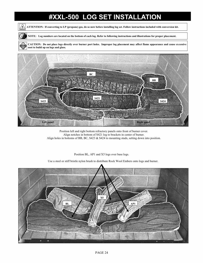
#XXL-500 LOG SET INSTALLATION
ATTENTION: If converting to LP (propane) gas, do so now before installing log set. Follow instructions included with conversion kit.
NOTE: Log numbers are located on the bottom of each log. Refer to following instructions and illustrations for proper placement.
CAUTION: Do not place logs directly over burner port holes. Improper log placement may affect flame appearance and cause excessive
soot to build up on logs and glass.
Position left and right bottom refractory panels onto front of burner cover.
Align notches in bottom of S421 log to brackets in center of burner.
Align holes in bottoms of BB, BC, S423 & S424 to mounting studs, setting down into position.
Position BL, AP1 and X5 logs over base logs.
Use a steel or stiff bristle nylon brush to distribute Rock Wool Embers onto logs and burner.
PAGE 24
FOR YOUR SAFETY - READ BEFORE LIGHTING
WARNING: IF YOU DO NOT FOLLOW THESE INSTRUCTIONS EXACTLY, A FIRE OR EXPLOSION MAY RESULT, CAUSING
PROPERTY DAMAGE, PERSONAL INJURY OR LOSS OF LIFE.
1. This appliance has a pilot which must be lighted by hand. When lighting
the pilot, follow these instructions exactly.
2. BEFORE LIGHTING, smell all around the appliance for gas. Be sure to
smell next to the floor because some gas is heavier than air and will
settle on the floor.
3. Use only your hand to push in or turn the gas control knob. Never use
tools. If the knob will not push in, or turn by hand, do not try to repair it,
call a qualified service technician. Forced or attempted repair may result
in a fire or explosion, and loss of warranty.
4. Do not use this appliance if any part has been under water.
Immediately call a qualified service technician to inspect the
appliance and to replace any part of the control system which has been
under water.
DO NOT STORE OR USE GASOLINE OR OTHER
FLAMMABLE VAPORS AND LIQUIDS IN THE
VICINITY OF THIS OR ANY OTHER APPLIANCE.
DUE TO HIGH SURFACE TEMPERATURES, KEEP CHILDREN, CLOTHING AND FURNITURE AWAY.
This appliance needs fresh air for safe operation and must be installed so there are provisions for adequate combustion and ventilation air.
WHAT TO DO IF YOU SMELL GAS:
Do not touch any electrical switches
Do not try to light any appliance
Do not use the phone in your building
Immediately call your gas supplier from a neighbor‟s
phone
Follow the gas supplier‟s instructions
If you cannot reach your gas supplier, call the fire de-
partment
LIGHTING AND SHUTDOWN
WARNING: CHILDREN AND ADULTS SHOULD BE ALERTED TO THE HAZARDS OF HIGH SURFACE TEMPERATURES
AND SHOULD STAY AWAY TO AVOID BURNS OR CLOTHING IGNITION. YOUNG CHILDREN SHOULD BE CAREFULLY
SUPERVISED WHEN THEY ARE IN THE SAME ROOM AS THE APPLIANCE. CLOTHING OR OTHER FLAMMABLE MATE-
RIAL MUST NOT BE PLACED ON OR NEAR THE APPLIANCE.
NOTE: A PAINT SMELL WILL OCCUR DURING THE FIRST FEW HOURS OF BURNING. IT IS RECOMMENDED TO
LEAVE THE FAN OFF DURING THIS PERIOD TO HELP SPEED THE PAINT CURING PROCESS.
NOTE: THIS FIREPLACE MAY PRODUCE NOISES OF VARYING DEGREE AS IT HEATS AND COOLS DUE TO METAL
EXPANSION AND CONTRACTION. THIS IS NORMAL AND DOES NOT AFFECT THE PERFORMANCE OR LONGEVITY
OF THE FIREPLACE.
PAGE 25
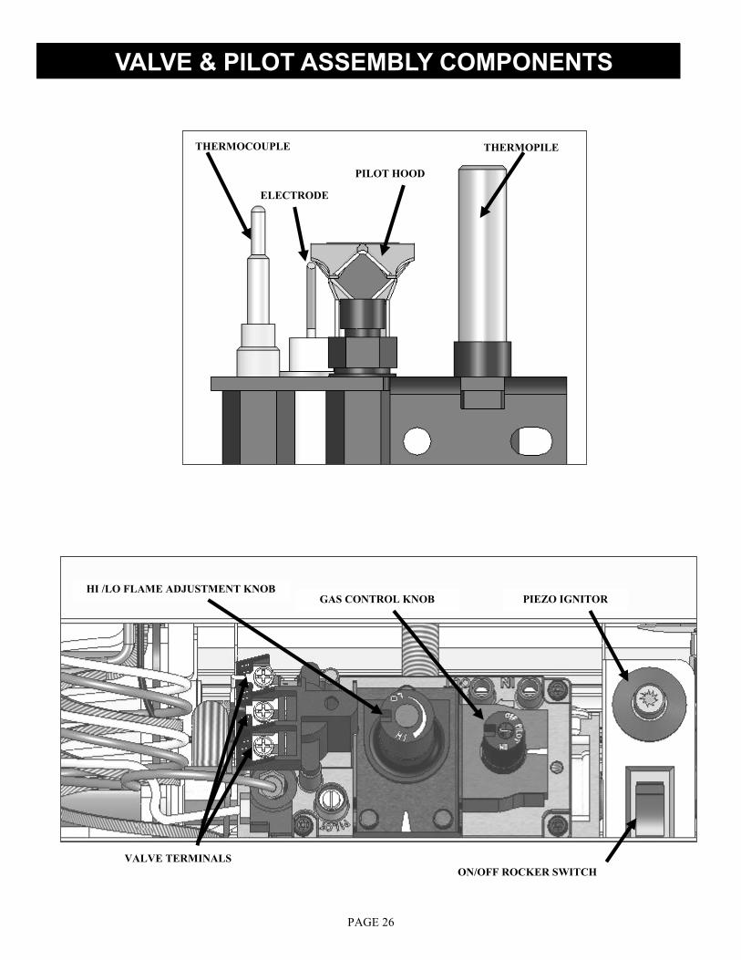
VALVE & PILOT ASSEMBLY COMPONENTS
VALVE TERMINALS
GAS CONTROL KNOB PIEZO IGNITOR HI /LO FLAME ADJUSTMENT KNOB
ON/OFF ROCKER SWITCH
ELECTRODE
PILOT HOOD
THERMOPILE THERMOCOUPLE
PAGE 26

1. Set thermostat to the lowest setting, if installed.
2. Turn off all electrical power to the appliance. (Fan).
3. Open lower grill to access the gas valve & controls.
E. Push gas control knob in slightly and turn
counterclockwise to „ON‟. The burner can now be
turned „ON‟ by depressing the ON/OFF rocker
switch located beside the valve, or wall switch, OR
by setting the thermostat or remote control to the
desired setting.
F. Turn on all electric power to the appliance (if appli-
cable).
NOTE: When the fireplace is initially lit, condensation
will appear on the glass; this is normal in all gas
fireplaces and will disappear after several minutes.
LIGHTING AND SHUTDOWN (cont.)
A. Push gas control knob in slightly and turn
clockwise to “OFF”. Wait five (5) minutes to allow any gas
that may have accumulated inside the firebox to escape. If
you then smell gas, STOP! Follow the safety information
on the front cover and on the previous page of this installa-
tion manual. If you don‟t smell gas, go to the next step.
B. Locate pilot - follow metal tube from gas
control. The pilot is located inside the
combustion chamber.
C. Push gas control knob on the gas valve in slightly and
turn counterclockwise to „PILOT‟. Push valve knob in
and hold while repeatedly pressing the piezo igniter
button until the pilot is lit while continuing to hold in
the gas control knob.
D. Hold gas control knob in for one (1) minute
after pilot is lit. Release the gas control knob. If the
pilot goes out, repeat steps C-D. When the pilot is lit,
proceed to step E.
NOTE: Gas control knob cannot be turned from “PILOT” to
“OFF” unless knob is pushed in slightly. Do not force.
PILOT TUBE
PILOT B
C
D 1 MINUTE
E
LIGHTING
5 MINUTES
A
CAUTION: If knob does not pop up when released, stop and
immediately call your service technician or the gas supplier.
If the pilot will not stay lit after several tries, turn the gas
control knob to OFF and call your service technician or the
gas supplier.
PAGE 27

NOTE: This control valve has an interlock device. If pilot
has been turned off, it cannot be relit until the thermocou-
ple has cooled, (approximately 60 seconds).
LIGHTING AND SHUTDOWN (cont.)
G. To turn the burner „OFF‟, depress the ON/OFF rocker switch to „OFF‟,
flip „off‟ wall switch or adjust setting on the thermostat or remote
control.
NOTE: The pilot will stay lit.
H. Turn the pilot off by pushing in and turning the gas control knob to the
„OFF‟ position. DO NOT FORCE.
The gas control valve has a HI /LO flame adjustment knob designed to allow
you to tailor the look and heat output of your fireplace. Adjust by turning the
middle knob on the gas control valve.
ADJUSTING FLAME HEIGHT
TURN BURNER OFF
TURN PILOT OFF
G
H
PAGE 28

NOTE: The appliance and its individual shutoff valve must be disconnected from the gas supply piping system during any pressure
testing of that system at pressures in excess of ½ psi.
NOTE: The appliance must be isolated from the gas supply piping system by closing its individual manual shut-off valve during any
pressure testing of the gas line at test pressures equal to or less than ½ psi (3.5 kPa).
IMPORTANT NOTICE: Pressure check taps for the manifold (outgoing) and inlet (incoming) pressure have been incorporated into the
valve. The pressure tap marked „OUT‟ measures outgoing pressure and the pressure tap marked „IN‟ measures incoming pressure. Follow
instructions below for proper testing procedures.
MANIFOLD PRESSURE TEST:
1. Light pilot.
2. Loosen manifold („OUT‟) pressure tap screw (counter-clockwise).
3. Attach manometer to pressure tap using a 5/16” I.D. hose.
4. Turn gas control knob to „ON‟.
5. Press rocker switch to „ON‟ and note manometer reading.
6. Press rocker switch to „OFF‟.
7. Disconnect manometer hose and tighten screw (clockwise). Screw should be snug, do not over tighten.
8. Attach manometer to manifold pressure tap to verify that it is completely sealed. Manometer should read no pressure when the
rocker switch is pressed to „ON‟.
INLET PRESSURE TEST:
1. Loosen inlet („IN‟) pressure tap screw (counter-clockwise).
2. Attach manometer using a 5/16” I.D. hose.
3. Light pilot.
4. Turn gas control knob to „ON‟ (burner should not light). Note manometer reading.
5. Press rocker switch to „ON‟. Check pressure to ensure that it stays near the maximum inlet pressure.
6. Press rocker switch to „OFF‟.
7. Turn gas control knob to „OFF‟.
8. Disconnect hose and tighten screw (clockwise). Screw should be snug, do not over tighten.
9. Relight pilot and turn gas control knob to „ON‟. Reattach manometer to inlet pressure tap to verify that it is
completely sealed. Manometer should read no pressure.
CAUTION: A LOW PRESSURE READING CAN
CAUSE DELAYED IGNITION
MANIFOLD INLET
PRESSURE TESTING
NOTE: If inlet pressure reading is too high or too low, contact the gas company. Only a qualified gas service technician should adjust the
incoming gas pressure.
PAGE 29

1. Remove glass frame assembly. Refer to page 9.
2. Remove log set.
3. Remove burner assembly. Refer to page 20.
4. Loosen screw on burner venturi and adjust as necessary.
Tighten screw.
5. Reinstall all components previously removed.
6. Light fireplace and wait 15 minutes before determining if
any further adjustments are needed.
FINALIZING THE INSTALLATION
FLAME APPEARANCE:
Flame appearance is affected by several factors including altitude, venting configuration and fuel quality. Although the venturi setting has
been factory set, adjustments may be necessary for optimal performance and visual aesthetics.
When fireplace is first lit, the flames will be blue. The flames will gradually turn yellowish-orange during the first 15 minutes of opera-
tion. If the flames remain blue or the flames become dark orange with evidence of sooting (black tips), the burner tube venturi may need
to be adjusted.
WARNING: BURNER TUBE ADJUSTABLE VENTURI POSITIONING SHOULD ONLY BE PERFORMED BY A
QUALIFIED PROFESSIONAL SERVICE TECHNICIAN.
WARNING: TO AVOID PROPERTY DAMAGE OR PERSONAL INJURY, ALLOW FIREPLACE AMPLE TIME TO
COOL BEFORE MAKING ANY ADJUSTMENTS.
FACTORY SET BURNER TUBE VENTURI SETTINGS
(ADJUST AS NECESSARY FOR YOUR INSTALLATION)
NATURAL GAS LP (PROPANE) GAS
3/16” (5 mm) OPEN 1/2” (13 mm) OPEN
BURNER TUBE VENTURI ADJUSTMENT GUIDELINES
VENTURI POSITION FLAME COLOR VENTURI ADJUSTMENT
Closed too far Dark orange flame with black tips Open venturi setting slightly
Open too far Blue flames Close venturi setting slightly
NOTE: IF SOOT IS PRESENT, CHECK LOG POSITIONING BEFORE ADJUSTING BURNER VENTURI. LOGS
MUST NOT BLOCK BURNER PORTS.
IMPORTANT: SLIGHT ADJUSTMENTS TO THE BURNER VENTURI OPENING CREATE DRAMATIC RESULTS.
ADJUST AT SLIGHT INCREMENTS UNTIL DESIRED LOOK IS ACHIEVED. ALWAYS BURN FIREPLACE FOR
AT LEAST 15 MINUTES AND ALLOW TIME TO COOL BEFORE MAKING ANY FURTHER ADJUSTMENTS.
TO ADJUST VENTURI:
BURNER VENTURI
PAGE 30
FINALIZING THE INSTALLATION
PAGE 31
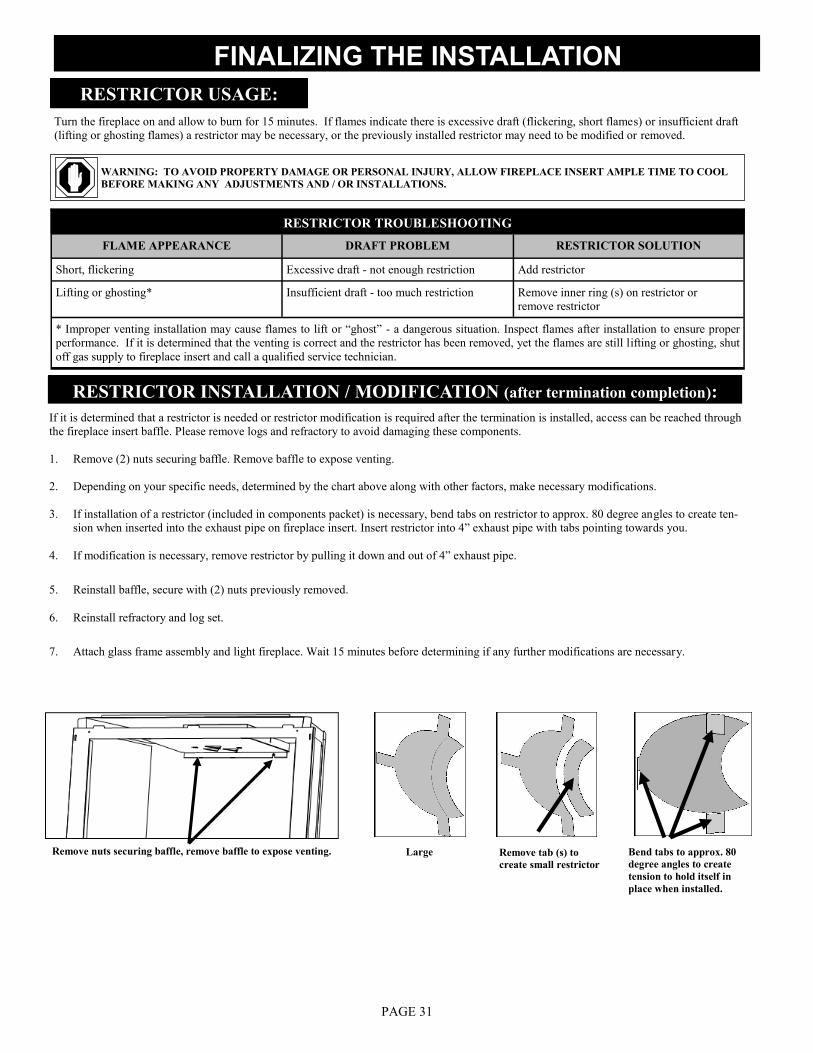
RESTRICTOR USAGE:
Turn the fireplace on and allow to burn for 15 minutes. If flames indicate there is excessive draft (flickering, short flames) or insufficient draft
(lifting or ghosting flames) a restrictor may be necessary, or the previously installed restrictor may need to be modified or removed.
WARNING: TO AVOID PROPERTY DAMAGE OR PERSONAL INJURY, ALLOW FIREPLACE INSERT AMPLE TIME TO COOL
BEFORE MAKING ANY ADJUSTMENTS AND / OR INSTALLATIONS.
If it is determined that a restrictor is needed or restrictor modification is required after the termination is installed, access can be reached through
the fireplace insert baffle. Please remove logs and refractory to avoid damaging these components.
1. Remove (2) nuts securing baffle. Remove baffle to expose venting.
2. Depending on your specific needs, determined by the chart above along with other factors, make necessary modifications.
3. If installation of a restrictor (included in components packet) is necessary, bend tabs on restrictor to approx. 80 degree angles to create ten-
sion when inserted into the exhaust pipe on fireplace insert. Insert restrictor into 4” exhaust pipe with tabs pointing towards you.
4. If modification is necessary, remove restrictor by pulling it down and out of 4” exhaust pipe.
5. Reinstall baffle, secure with (2) nuts previously removed.
6. Reinstall refractory and log set.
7. Attach glass frame assembly and light fireplace. Wait 15 minutes before determining if any further modifications are necessary.
RESTRICTOR INSTALLATION / MODIFICATION (after termination completion):
RESTRICTOR TROUBLESHOOTING
FLAME APPEARANCE DRAFT PROBLEM RESTRICTOR SOLUTION
Short, flickering Excessive draft - not enough restriction Add restrictor
Lifting or ghosting* Insufficient draft - too much restriction Remove inner ring (s) on restrictor or
remove restrictor
* Improper venting installation may cause flames to lift or “ghost” - a dangerous situation. Inspect flames after installation to ensure proper
performance. If it is determined that the venting is correct and the restrictor has been removed, yet the flames are still lifting or ghosting, shut
off gas supply to fireplace insert and call a qualified service technician.
Large Remove tab (s) to
create small restrictor
Bend tabs to approx. 80
degree angles to create
tension to hold itself in
place when installed.
Remove nuts securing baffle, remove baffle to expose venting.

SEASONAL HEAT DUMP
This fireplace insert has been manufactured with a heat dump damper located at the inside top of firebox. This allows infinite
control over the amount of heat emitted into the living area without affecting flame height.
INSTALLER: Please install this fireplace insert with the heat dump in the closed position.
HOMEOWNER: This fireplace insert has been installed with the heat dump in the closed position and will operate at its peak efficiency
at this setting. The heat dump may be opened as much as necessary to maintain desired heat level.
Remove glass frame assembly. Open or close heat dump as desired. Re-install glass frame assembly.
CAUTION: DO NOT ATTEMPT TO ADJUST THE HEAT DUMP OPENING IF THE FIREPLACE HAS BEEN IN OPERATION.
ALLOW AMPLE TIME TO COOL OR USE THE APPROPRIATE PROTECTION TO AVOID SERIOUS BURNS AND / OR PROP-
ERTY DAMAGE.
FINALIZING THE INSTALLATION
Shown in closed position Shown in partial open position
PAGE 32

Annual cleaning of the burner system is required.
The burner assembly may be removed for easier
access. Refer to pages 19-20 in this installation
manual for complete instruction on removing &
reinstalling the burner assembly.
Visually check for blocked port holes, especially
near the pilot. Blocked port holes may cause de-
layed ignition.
Reinstall the burner assembly following instruc-
tions on page 20 of this installation manual.
Visually check pilot light and burner when in
operation. The flames should be steady, not lifting
or floating.
Annual examination of the venting system by a qualified agency is required.
IF THE VENT-AIR INTAKE SYSTEM IS DISASSEMBLED FOR ANY
REASON, RE-INSTALL PER THE INSTRUCTIONS PROVIDED WITH
THE INITIAL INSTALLATION.
The flow of combustion and ventilation air must not be obstructed.
The appliance is required to be inspected at least once a year by a
professional service person.
The compartment below the firebox (behind the lower grill) must be cleaned
at least once a year, more frequent cleaning may be required due to excessive
lint from carpeting, bedding materials, or other fibrous materials. It is im-
perative that the burner be cleaned once a year.
VENT SYSTEM
FAN
NOTE: INSTALLATION AND REPAIR SHOULD BE DONE ONLY BY A
QUALIFIED SERVICE PERSON. THE APPLIANCE SHOULD BE INSPECTED
BEFORE USE AND ANNUALLY BY A QUALIFIED SERVICE PERSON. MORE
FREQUENT CLEANING MAY BE REQUIRED DUE TO EXCESSIVE LINT
FROM CARPETING, BEDDING MATERIALS, ETC. IT IS IMPERATIVE THAT
CONTROL COMPARTMENTS, BURNERS AND CIRCULATION AIR
PASSAGEWAYS OF THE APPLIANCE BE KEPT CLEAN.
IMPORTANT: ANY SAFETY SCREEN OR GUARD REMOVED FOR SERVICING
MUST BE REPLACED PRIOR TO OPERATING THE APPLIANCE.
Burner Orifice
Clean glass only when cool and only with non-
abrasive cleansers.
Do not operate this fireplace with the glass/frame
assembly removed, cracked or broken.
The glass assembly, part #700-01T, shall only be
replaced as a complete unit, as supplied by Hus-
song Mfg. Co., Inc.
Replacement of the glass & frame assembly,
part #700-01T, must only be performed by a li-
censed or qualified service person.
DO NOT SUBSTITUTE MATERIALS.
Do not strike or slam glass door assembly.
CAUTION: LABEL ALL WIRES PRIOR TO DISCONNECTION WHEN SERVICING
CONTROLS. WIRING ERRORS CAN CAUSE IMPROPER AND DANGEROUS
OPERATION. VERIFY PROPER OPERATION AFTER SERVICING.
MAINTENANCE
CAUTION: KEEP THE APPLIANCE AREA CLEAR OF COMBUSTIBLE MATERI-
ALS, SUCH AS GASOLINE AND OTHER FLAMMABLE VAPORS AND LIQUIDS.
GLASS CLEANING & REPLACEMENT
MILLIVOLT BOARD SYSTEM
The fan should be disconnected from electrical current, and cleaned
(vacuumed) every six months. The bearings are sealed and require no oiling.
Pilot
Burner Ports
PAGE 33
TROUBLESHOOTING
NO SPARK FROM ELECTRODE TO PILOT WHEN PIEZO BUTTON IS TRIGGERED.
A. Check wiring at back of piezo for proper connection.
B. Check wiring at electrode for proper connection.
C. Check position of electrode (1/8” (3 mm) between electrode and pilot). Readjust if necessary.
D. Look for arc below electrode and along electrode wire. Direct metal contact may cause an arc below electrode.
SPARK IGNITOR WILL NOT LIGHT AFTER REPEATED TRIGGERING OF PIEZO BUTTON.
A. No gas or low gas pressure.
♦ Check remote shut off valves from fireplace. Usually there is a valve near the main. There may be more than (1) valve between
the fireplace and the main.
♦ Low gas pressure can be caused by several situations such as a bent line, too narrow diameter pipe, or low line pressure. Consult
with plumber or gas supplier.
B. No LP in tank.
♦ Check LP (propane) tank. Refill if necessary.
PILOT WILL NOT STAY LIT AFTER CAREFULLY FOLLOWING LIGHTING INSTRUCTIONS.
A. Check that pilot flame impinges on thermocouple. Clean and / or adjust pilot for maximum flame impingement.
B. Ensure the thermocouple connection at gas valve is fully inserted and tight (hand tight plus 1/4 turn).
C. Thermocouple reading below 15 millivolts.
♦ Disconnect thermocouple from valve, place one millivolt meter lead wire on the end of the thermocouple and the other millivolt
meter lead wire on the thermocouple‟s copper wire. Start pilot while holding valve knob in. If the millivolt reading is less than 15
millivolts, replace the thermocouple.
.
D. Thermopile not generating sufficient millivolts.
♦ Pilot flame must be enveloping thermopile. Adjust pilot flame if necessary.
♦ Check thermopile wire connections at valve. Tighten if necessary.
♦ Check thermopile with millivolt meter. Turn remote / thermostat / wall switch or ON/OFF switch to OFF. Turn valve knob to
PILOT position (pilot should remain lit). Take reading at THTP & TP terminals on gas valve. Reading should be 350 millivolts
minimum. Replace thermopile if reading falls below specified minimum.
CAUTION: THE FOLLOWING MUST BE PERFORMED BY A QUALIFIED TECHNICIAN.
PAGE 34

A. Gas control knob not turned to „ON‟.
B. „ON‟/„OFF‟ switch not turned on.
C. Remote, wall switch or thermostat not turned „ON‟.
D. Plugged main burner orifice.
E. Remote, wall switch ,thermostat or „ON/ OFF‟ switch wires defective.
♦ Check wires for proper connections. Place jumper wires across terminal at switch. If burner lights, replace defective switch.
♦ If switch checks ok, place jumper wires across switch wires on gas valve. If burner lights, wires are faulty or connections are bad.
TROUBLESHOOTING
BURNER WILL NOT LIGHT
FREQUENT PILOT OUTAGES
A. Pilot shield not installed.
B. Pilot flame too high or too low, causing pilot safety to drop out.
♦ Clean and adjust flame for maximum flame impingement on thermopile.
BURNER WON‟T STAY LIT
A. Thermopile wires loose at valve terminals.
♦ Tighten if necessary.
B. Thermopile wires ground out due to pinched wires.
♦ Free pinched wires if necessary.
C Refractory panel placement.
♦ Refractory panels must be tight against firebox walls. It may be necessary to secure panels with high-temp sealant, especially
around the intake duct.
PAGE 35
MORE TROUBLESHOOTING ON FOLLOWING PAGE

A. No LP (propane) in tank.
♦ Check tank and refill if necessary.
B. Glass frame assembly not installed correctly.
♦ Refer to page 9 in this manual for proper glass frame assembly installment instructions.
C. Defective thermopile or thermocouple.
♦ Check thermopile and thermocouple for proper millivolts.
A. Improper Venturi setting.
♦ Venturi may need to be closed slightly.
B. Improper vent cap installation.
♦ Check for proper vent cap installation.
C. Blockage or vent system leaks.
TROUBLESHOOTING
PILOT AND BURNER EXTINGUISH WHILE IN OPERATION
D. Improper pitch on horizontal vent.
♦ 1/4” (6 mm) rise per foot is required on horizontal venting.
E. Inner vent pipe leaking exhaust gases back into firebox.
♦ Check for leaks. Repair if necessary.
F. Improper vent cap installation.
♦ Check for proper vent cap installation. Maximum downward slope of horizontal vent cap is 1/4” (6 mm). Adjust if necessary.
♦ Check vent cap for blockage. Remove debris if necessary.
G. Excessive draft.
GLASS SOOTING
A. Improper log placement.
♦ Refer to log placement instructions on page 24 of this installation manual.
B. Improper venturi setting.
♦ Venturi may need to be opened slightly to allow more air into the gas mix.
C. Improper pitch on horizontal venting.
♦ 1/4” (6 mm) rise per foot is required on horizontal venting.
FLAME BURNS BLUE AND LIFTS OFF BURNER
PAGE 36

Replacement parts are available through your local dealer. Contact them for availability and pricing.
911XXL MILLIVOLT BOARD AND PARTS
9XL-770 911XXL Millivolt Board - Nat Gas 700-092 Millivolt Generator
9XL-771 911XXL Millivolt Board - LP Gas 700-059 Thermocouple
700-023 On/Off Rocker Switch 700-203 Manual Shut-off Valve
700-086N S.I.T. Valve - Natural Gas 700-213-B 18” Flexible Gas Line-Black
700-087 S.I.T. Valve - LP Gas 700-225-F Flexible Gas Line-Valve to Burner Connection
700-064 Pilot Assembly - Nat Gas 700-230 Natural Gas Orifice #30
700-064-1 Pilot Assembly - LP Gas 700-247 LP Gas Orifice #47
700-090 Piezo Igniter w/ Nut (no wire) OCK-S30A Natural Gas Conversion Kit
700-060 Flexible Pilot Tubing (Valve to Pilot) OCK-S47A LP Gas Conversion Kit
9XL-035 Burner Tube & Cover
*Consult your dealer for information on optional accessories available for this fireplace. This appliance tested & certified by: OMNI - Test Laboratories, Inc. 13327 NE Airport Way Portland, Oregon 97230 Model #911XXL Model #911XXL-RAD October 2009-REV-06
Manufactured by: Hussong Mfg. Co., Inc. 204 Industrial Park Drive Lakefield, Minnesota 56150 507-662-6641 www.kozyheat.com
REPLACEMENT PARTS LIST
REFRACTORY PANELS (Sandstone)
XXL-G900 Back / Sides Refractory Panels - 3pc.
XXL-G901 Bottom Refractory Panels
XXL-G990B Back Refractory Panel (only)
XXL-G900S Side Refractory Panel (1side only)
FAN ASSEMBLIES
XXL-028 Fan Kit
LOG SET XXL-500 8 pc. Log Set
S421 S421 Log
BC BC Log
BB BB Log
S423 S423 Log
S424 S424 Log
BL BL Log
X5 X5 Log
AP1 AP1 Log
900-REMB Rock Wool Embers
GLASS & GLASS GASKET
XXL-005 Replacement Valance - only
900-006 1-1/8” Glass Gasket w/ Adhesive
700-01T 35” x 21” Glass with Gasket
PAGE 37

PAGE 38

PAGE 39
Related Documents