Thesis Final Report Faculty Advisor: Dr. Thomas E. Boothby April 3, 2013 Office Building Sayre, PA Structural Seth M. Moyer

Welcome message from author
This document is posted to help you gain knowledge. Please leave a comment to let me know what you think about it! Share it to your friends and learn new things together.
Transcript
Thesis Final Report
Faculty Advisor: Dr. Thomas E. Boothby April 3, 2013
Office Building
Sayre, PA
Structural Seth M. Moyer
Thesis Final Report Seth M. Moyer | Structural
April 3, 2013 Office Building | Sayre, PA 2
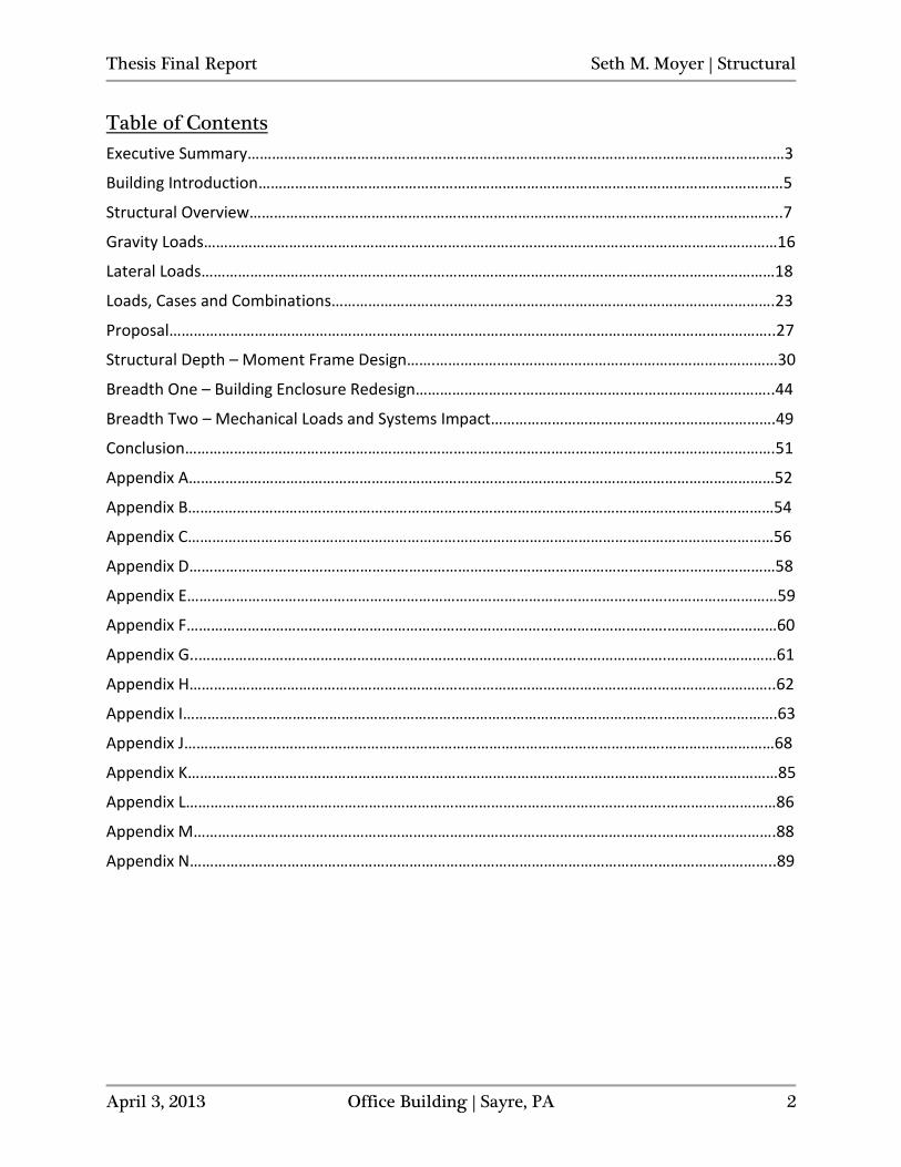
Table of Contents
Executive Summary……………………………………………………………………………………………………………………3
Building Introduction…………………………………………………………………………………………………………………5
Structural Overview…………………………………………………………………………………………………………………..7
Gravity Loads……………………………………………………………………………………………………………………………16
Lateral Loads……………………………………………………………………………………………………………………………18
Loads, Cases and Combinations……………………………………………………………………………………………….23
Proposal…………………………………………………………………………………………………………………………………..27
Structural Depth – Moment Frame Design…….…………………………………………………………………………30
Breadth One – Building Enclosure Redesign……………………..……………………………………………………..44
Breadth Two – Mechanical Loads and Systems Impact…………………………………………………………….49
Conclusion……………………………………………………………………………………………………………………………….51
Appendix A………………………………………………………………………………………………………………………………52
Appendix B………………………………………………………………………………………………………………………………54
Appendix C………………………………………………………………………………………………………………………………56
Appendix D………………………………………………………………………………………………………………………………58
Appendix E……………………………………………………………………………………………………….………………………59
Appendix F……………………………………………………………………………………………………….………………………60
Appendix G..…………………………………………………………………………………………………….………………………61
Appendix H…………………………………………………………………………………………………….………………………..62
Appendix I……………………………………………………………………………………………………….……………………….63
Appendix J……………………………………………………………………………………………………….………………………68
Appendix K……………………………………………………………………………………………………….………………………85
Appendix L……………………………………………………………………………………………………….………………………86
Appendix M…………………………………………………………………………………………………….……………………….88
Appendix N…………………………………………………………………………………………………….………………………..89
Thesis Final Report Seth M. Moyer | Structural
April 3, 2013 Office Building | Sayre, PA 3
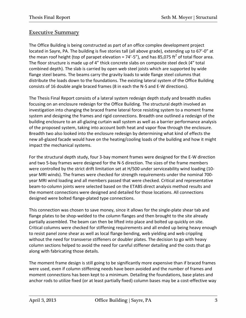
Executive Summary
The Office Building is being constructed as part of an office complex development project located in Sayre, PA. The building is five stories tall (all above grade), extending up to 67’-0” at the mean roof height (top of parapet elevation = 74’-5”), and has 85,075 ft2 of total floor area. The floor structure is made up of 4” thick concrete slabs on composite steel deck (4” total combined depth). The slab is carried by open web steel joists which are supported by wide flange steel beams. The beams carry the gravity loads to wide flange steel columns that distribute the loads down to the foundations. The existing lateral system of the Office Building consists of 16 double angle braced frames (8 in each the N-S and E-W directions). The Thesis Final Report consists of a lateral system redesign depth study and breadth studies focusing on an enclosure redesign for the Office Building. The structural depth involved an investigation into changing the braced frame lateral force resisting system to a moment frame system and designing the frames and rigid connections. Breadth one outlined a redesign of the building enclosure to an all-glazing curtain wall system as well as a barrier performance analysis of the proposed system, taking into account both heat and vapor flow through the enclosure. Breadth two also looked into the enclosure redesign by determining what kind of effects the new all-glazed facade would have on the heating/cooling loads of the building and how it might impact the mechanical systems. For the structural depth study, four 3-bay moment frames were designed for the E-W direction and two 5-bay frames were designed for the N-S direction. The sizes of the frame members were controlled by the strict drift limitation set at H/500 under serviceability wind loading (10-year MRI winds). The frames were checked for strength requirements under the nominal 700-year MRI wind loading and all members passed that were checked. Critical and representative beam-to-column joints were selected based on the ETABS direct analysis method results and the moment connections were designed and detailed for those locations. All connections designed were bolted flange-plated type connections. This connection was chosen to save money, since it allows for the single-plate shear tab and flange plates to be shop-welded to the column flanges and then brought to the site already partially assembled. The beam can then be lifted into place and bolted up quickly on site. Critical columns were checked for stiffening requirements and all ended up being heavy enough to resist panel zone shear as well as local flange bending, web yielding and web crippling without the need for transverse stiffeners or doubler plates. The decision to go with heavy column sections helped to avoid the need for careful stiffener detailing and the costs that go along with fabricating those details. The moment frame design is still going to be significantly more expensive than if braced frames were used, even if column stiffening needs have been avoided and the number of frames and moment connections has been kept to a minimum. Detailing the foundations, base plates and anchor rods to utilize fixed (or at least partially fixed) column bases may be a cost-effective way
Thesis Final Report Seth M. Moyer | Structural
April 3, 2013 Office Building | Sayre, PA 4
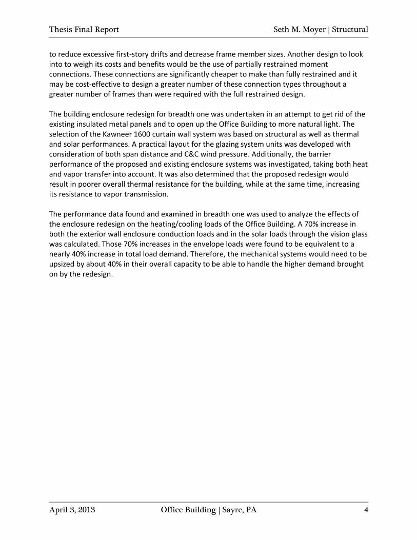
to reduce excessive first-story drifts and decrease frame member sizes. Another design to look into to weigh its costs and benefits would be the use of partially restrained moment connections. These connections are significantly cheaper to make than fully restrained and it may be cost-effective to design a greater number of these connection types throughout a greater number of frames than were required with the full restrained design. The building enclosure redesign for breadth one was undertaken in an attempt to get rid of the existing insulated metal panels and to open up the Office Building to more natural light. The selection of the Kawneer 1600 curtain wall system was based on structural as well as thermal and solar performances. A practical layout for the glazing system units was developed with consideration of both span distance and C&C wind pressure. Additionally, the barrier performance of the proposed and existing enclosure systems was investigated, taking both heat and vapor transfer into account. It was also determined that the proposed redesign would result in poorer overall thermal resistance for the building, while at the same time, increasing its resistance to vapor transmission. The performance data found and examined in breadth one was used to analyze the effects of the enclosure redesign on the heating/cooling loads of the Office Building. A 70% increase in both the exterior wall enclosure conduction loads and in the solar loads through the vision glass was calculated. Those 70% increases in the envelope loads were found to be equivalent to a nearly 40% increase in total load demand. Therefore, the mechanical systems would need to be upsized by about 40% in their overall capacity to be able to handle the higher demand brought on by the redesign.
Thesis Final Report Seth M. Moyer | Structural
April 3, 2013 Office Building | Sayre, PA 5
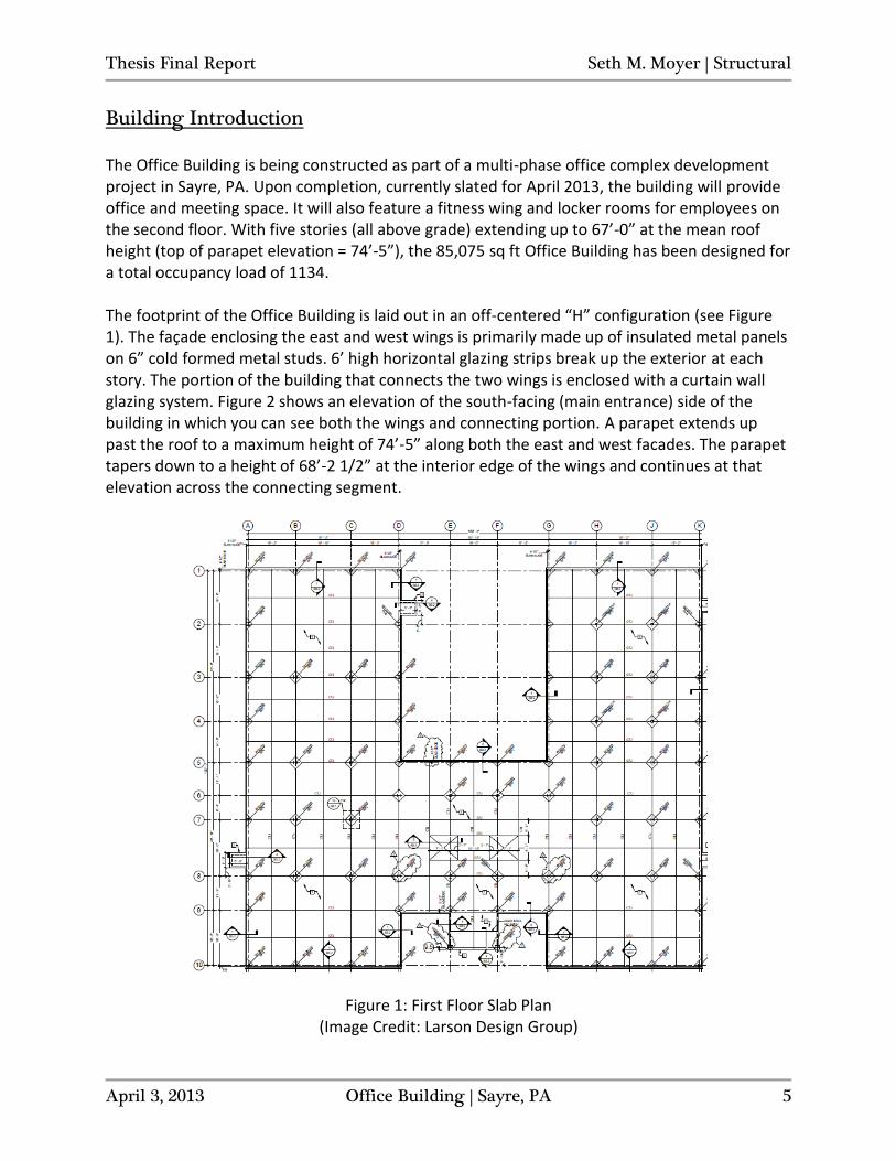
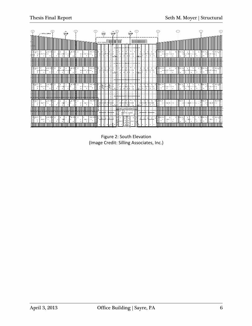
Building Introduction The Office Building is being constructed as part of a multi-phase office complex development project in Sayre, PA. Upon completion, currently slated for April 2013, the building will provide office and meeting space. It will also feature a fitness wing and locker rooms for employees on the second floor. With five stories (all above grade) extending up to 67’-0” at the mean roof height (top of parapet elevation = 74’-5”), the 85,075 sq ft Office Building has been designed for a total occupancy load of 1134. The footprint of the Office Building is laid out in an off-centered “H” configuration (see Figure 1). The façade enclosing the east and west wings is primarily made up of insulated metal panels on 6” cold formed metal studs. 6’ high horizontal glazing strips break up the exterior at each story. The portion of the building that connects the two wings is enclosed with a curtain wall glazing system. Figure 2 shows an elevation of the south-facing (main entrance) side of the building in which you can see both the wings and connecting portion. A parapet extends up past the roof to a maximum height of 74’-5” along both the east and west facades. The parapet tapers down to a height of 68’-2 1/2” at the interior edge of the wings and continues at that elevation across the connecting segment.
Figure 1: First Floor Slab Plan (Image Credit: Larson Design Group)
Thesis Final Report Seth M. Moyer | Structural
April 3, 2013 Office Building | Sayre, PA 6
Figure 2: South Elevation (Image Credit: Silling Associates, Inc.)
Thesis Final Report Seth M. Moyer | Structural
April 3, 2013 Office Building | Sayre, PA 7
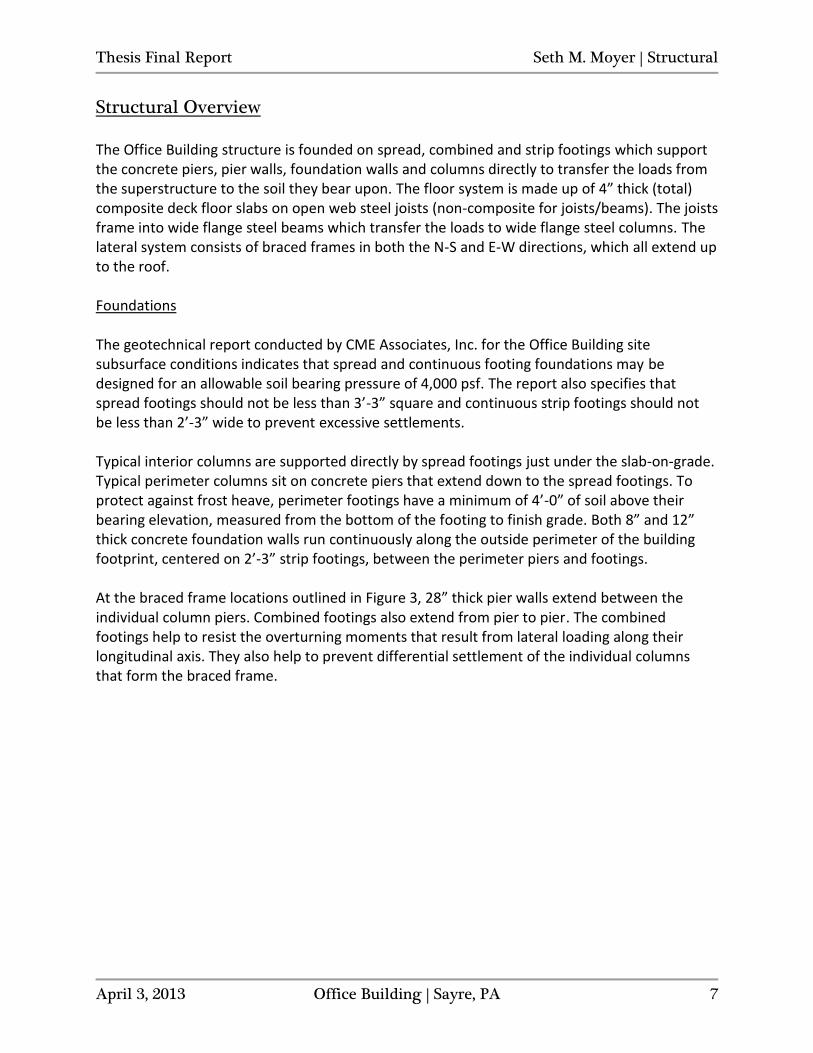
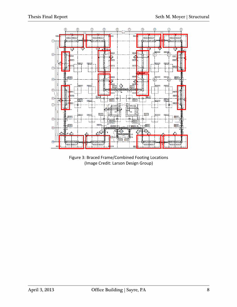
Structural Overview The Office Building structure is founded on spread, combined and strip footings which support the concrete piers, pier walls, foundation walls and columns directly to transfer the loads from the superstructure to the soil they bear upon. The floor system is made up of 4” thick (total) composite deck floor slabs on open web steel joists (non-composite for joists/beams). The joists frame into wide flange steel beams which transfer the loads to wide flange steel columns. The lateral system consists of braced frames in both the N-S and E-W directions, which all extend up to the roof. Foundations The geotechnical report conducted by CME Associates, Inc. for the Office Building site subsurface conditions indicates that spread and continuous footing foundations may be designed for an allowable soil bearing pressure of 4,000 psf. The report also specifies that spread footings should not be less than 3’-3” square and continuous strip footings should not be less than 2’-3” wide to prevent excessive settlements. Typical interior columns are supported directly by spread footings just under the slab-on-grade. Typical perimeter columns sit on concrete piers that extend down to the spread footings. To protect against frost heave, perimeter footings have a minimum of 4’-0” of soil above their bearing elevation, measured from the bottom of the footing to finish grade. Both 8” and 12” thick concrete foundation walls run continuously along the outside perimeter of the building footprint, centered on 2’-3” strip footings, between the perimeter piers and footings. At the braced frame locations outlined in Figure 3, 28” thick pier walls extend between the individual column piers. Combined footings also extend from pier to pier. The combined footings help to resist the overturning moments that result from lateral loading along their longitudinal axis. They also help to prevent differential settlement of the individual columns that form the braced frame.
Thesis Final Report Seth M. Moyer | Structural
April 3, 2013 Office Building | Sayre, PA 8
Figure 3: Braced Frame/Combined Footing Locations (Image Credit: Larson Design Group)
Thesis Final Report Seth M. Moyer | Structural
April 3, 2013 Office Building | Sayre, PA 9
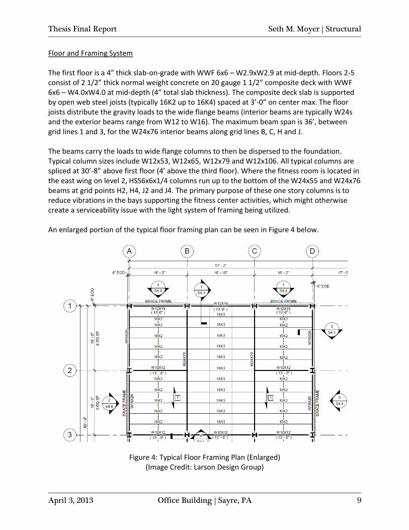
Floor and Framing System The first floor is a 4” thick slab-on-grade with WWF 6x6 – W2.9xW2.9 at mid-depth. Floors 2-5 consist of 2 1/2” thick normal weight concrete on 20 gauge 1 1/2” composite deck with WWF 6x6 – W4.0xW4.0 at mid-depth (4” total slab thickness). The composite deck slab is supported by open web steel joists (typically 16K2 up to 16K4) spaced at 3’-0” on center max. The floor joists distribute the gravity loads to the wide flange beams (interior beams are typically W24s and the exterior beams range from W12 to W16). The maximum beam span is 36’, between grid lines 1 and 3, for the W24x76 interior beams along grid lines B, C, H and J. The beams carry the loads to wide flange columns to then be dispersed to the foundation. Typical column sizes include W12x53, W12x65, W12x79 and W12x106. All typical columns are spliced at 30’-8” above first floor (4’ above the third floor). Where the fitness room is located in the east wing on level 2, HSS6x6x1/4 columns run up to the bottom of the W24x55 and W24x76 beams at grid points H2, H4, J2 and J4. The primary purpose of these one story columns is to reduce vibrations in the bays supporting the fitness center activities, which might otherwise create a serviceability issue with the light system of framing being utilized. An enlarged portion of the typical floor framing plan can be seen in Figure 4 below.
Figure 4: Typical Floor Framing Plan (Enlarged) (Image Credit: Larson Design Group)
Thesis Final Report Seth M. Moyer | Structural
April 3, 2013 Office Building | Sayre, PA 10
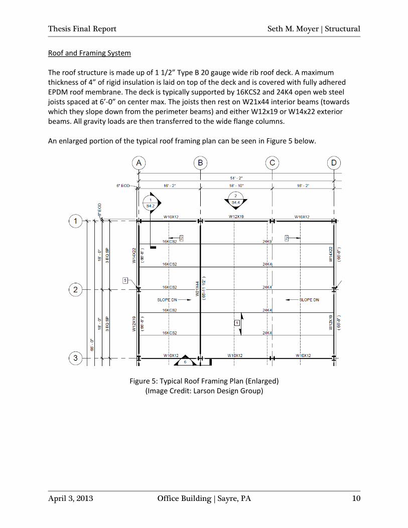
Roof and Framing System The roof structure is made up of 1 1/2” Type B 20 gauge wide rib roof deck. A maximum thickness of 4” of rigid insulation is laid on top of the deck and is covered with fully adhered EPDM roof membrane. The deck is typically supported by 16KCS2 and 24K4 open web steel joists spaced at 6’-0” on center max. The joists then rest on W21x44 interior beams (towards which they slope down from the perimeter beams) and either W12x19 or W14x22 exterior beams. All gravity loads are then transferred to the wide flange columns. An enlarged portion of the typical roof framing plan can be seen in Figure 5 below.
Figure 5: Typical Roof Framing Plan (Enlarged) (Image Credit: Larson Design Group)
Thesis Final Report Seth M. Moyer | Structural
April 3, 2013 Office Building | Sayre, PA 11
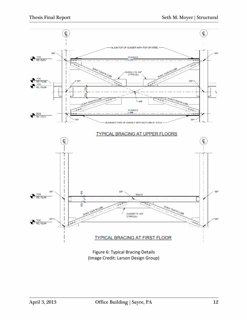
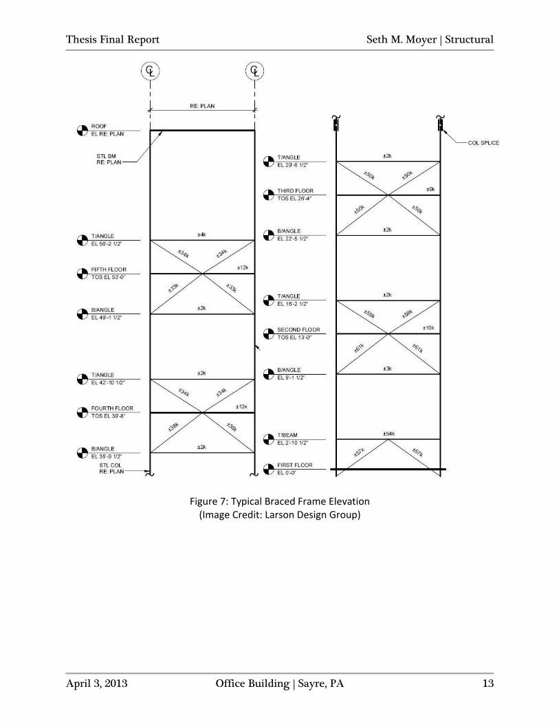
Lateral System The lateral force resisting system of the Office Building is made up of 16 “K” braced frames (8 in each the N-S and E-W directions) (see Figure 3 for plan locations). The double angles brace the center work point of the perimeter beam at each floor down to the horizontal double angle-to-column intersection points above the windows of the floor below and up to the horizontal double angle-to-column intersection points below the windows of the floor above (double angles brace the base of the columns to the center work point of the horizontal wide flange beam below the windows at level 1). See Figures 6 and 7 for bracing and frame details. Wind pressures on the exterior of the building are collected by the façade and the resultant forces are transferred into the floor/roof diaphragms. The diaphragms at each story act rigidly and transfer the story shear forces to the braced frames that run parallel to the direction of the loading (the roof diaphragm has been treated as rigid for simplification of modeling and analysis, although it will likely behave as flexible since it is constructed of untopped steel decking). The braced frames resist the lateral loads based on the proportion of their relative stiffness. These story forces accumulate at each floor, moving down through the building until the total base shear is transferred into the ground via the foundation. Similarly, for seismic loads induced by the building’s response to ground motion/acceleration, the total base shear is distributed to the diaphragms at each story as a function of the respective heights and weights attributed to each level. Once distributed, the seismic forces are transmitted through the diaphragms and into the braced frames based on relative stiffness. Similarly, the story forces accumulate and are eventually transferred down to the bearing soils through the foundation.
Thesis Final Report Seth M. Moyer | Structural
April 3, 2013 Office Building | Sayre, PA 12
Figure 6: Typical Bracing Details (Image Credit: Larson Design Group)
Thesis Final Report Seth M. Moyer | Structural
April 3, 2013 Office Building | Sayre, PA 13
Figure 7: Typical Braced Frame Elevation (Image Credit: Larson Design Group)
~ ~
~ ~
Thesis Final Report Seth M. Moyer | Structural
April 3, 2013 Office Building | Sayre, PA 14
Design Codes The major model and design codes and standards used in the design of the Office Building:
- Pennsylvania Uniform Construction Code (PAUCC) - International Building Code 2009 (IBC 2009) (as adopted and modified by the PAUCC) - Minimum Design Loads for Buildings and Other Structures (ASCE 7-05) - Specification for Structural Concrete (ACI 301-05) - Building Code Requirements for Structural Concrete (ACI 318-08) - Specification for Structural Steel Buildings (AISC 360-05) - Standard Specifications for Open Web Steel Joists, K-Series (SJI-K-1.1 05) - Design Manual for Composite Decks, Form Decks, Roof Decks and Cellular Metal Floor
Deck with Electrical Distribution, SDI Pub. No. 29 The same codes and standards are being referenced for use in this technical report with the following exceptions:
- ASCE 7-10 - AISC Steel Construction Manual, 14th Edition, LRFD - Specification for Structural Steel Buildings (AISC 360-10) - Building Code Requirements for Structural Concrete (ACI 318-11)
Thesis Final Report Seth M. Moyer | Structural
April 3, 2013 Office Building | Sayre, PA 15
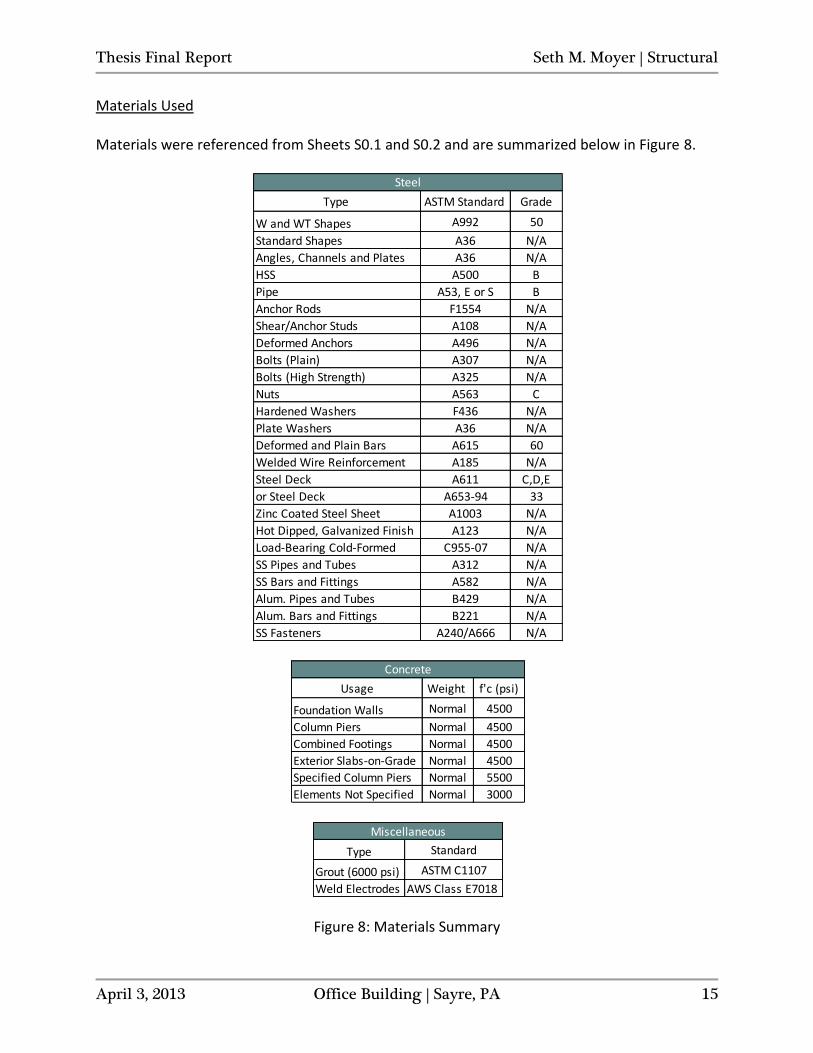
Materials Used Materials were referenced from Sheets S0.1 and S0.2 and are summarized below in Figure 8.
Figure 8: Materials Summary
Type ASTM Standard Grade
W and WT Shapes A992 50
Standard Shapes A36 N/A
Angles, Channels and Plates A36 N/A
HSS A500 B
Pipe A53, E or S B
Anchor Rods F1554 N/A
Shear/Anchor Studs A108 N/A
Deformed Anchors A496 N/A
Bolts (Plain) A307 N/A
Bolts (High Strength) A325 N/A
Nuts A563 C
Hardened Washers F436 N/A
Plate Washers A36 N/A
Deformed and Plain Bars A615 60
Welded Wire Reinforcement A185 N/A
Steel Deck A611 C,D,E
or Steel Deck A653-94 33
Zinc Coated Steel Sheet A1003 N/A
Hot Dipped, Galvanized Finish A123 N/A
Load-Bearing Cold-Formed C955-07 N/A
SS Pipes and Tubes A312 N/A
SS Bars and Fittings A582 N/A
Alum. Pipes and Tubes B429 N/A
Alum. Bars and Fittings B221 N/A
SS Fasteners A240/A666 N/A
Steel
Usage Weight f'c (psi)
Foundation Walls Normal 4500
Column Piers Normal 4500
Combined Footings Normal 4500
Exterior Slabs-on-Grade Normal 4500
Specified Column Piers Normal 5500
Elements Not Specified Normal 3000
Concrete
Type Standard
Grout (6000 psi) ASTM C1107
Weld Electrodes AWS Class E7018
Miscellaneous
Thesis Final Report Seth M. Moyer | Structural
April 3, 2013 Office Building | Sayre, PA 16
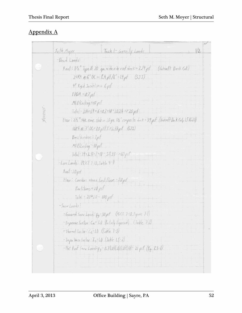
Gravity Loads Dead, live and snow loads will be calculated and compared to the design loads used by the structural engineer. Spot checks of various typical framing members will then be made using the loads that were calculated. Dead and Live Loads
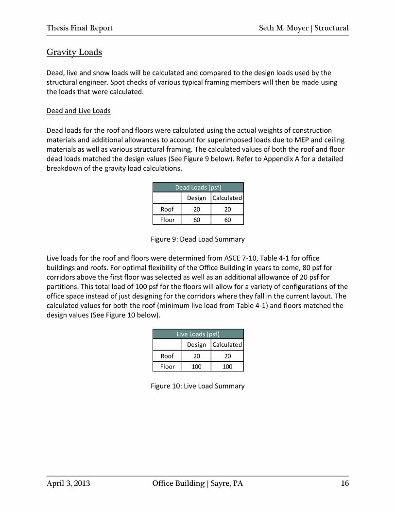
Dead loads for the roof and floors were calculated using the actual weights of construction materials and additional allowances to account for superimposed loads due to MEP and ceiling materials as well as various structural framing. The calculated values of both the roof and floor dead loads matched the design values (See Figure 9 below). Refer to Appendix A for a detailed breakdown of the gravity load calculations.
Figure 9: Dead Load Summary
Live loads for the roof and floors were determined from ASCE 7-10, Table 4-1 for office buildings and roofs. For optimal flexibility of the Office Building in years to come, 80 psf for corridors above the first floor was selected as well as an additional allowance of 20 psf for partitions. This total load of 100 psf for the floors will allow for a variety of configurations of the office space instead of just designing for the corridors where they fall in the current layout. The calculated values for both the roof (minimum live load from Table 4-1) and floors matched the design values (See Figure 10 below).
Figure 10: Live Load Summary
Design Calculated
Roof 20 20
Floor 60 60
Dead Loads (psf)
Design Calculated
Roof 20 20
Floor 100 100
Live Loads (psf)
Thesis Final Report Seth M. Moyer | Structural
April 3, 2013 Office Building | Sayre, PA 17
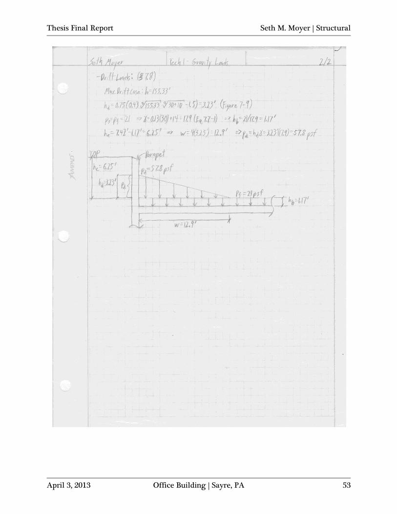
Snow and Drift Loads The flat roof snow load was determined to be 21 psf from a ground snow load value of 30 psf (Refer to Appendix A for flat roof snow load calculation details). 21 psf is less than the design snow load of 24 psf. This is due to the fact that the design value was calculated using a thermal factor of 1.1 as opposed to the 1.0 used for the calculation in this report. It was assumed that the roof could be considered warm, since the structure is heated and the roof is not openly ventilated, and therefore Ct=1.0. However, using the thermal factor of 1.1 is conservative. The maximum value of the snow drift load was calculated for the longest stretch of roof (lu=155.33’) upwind of the full-height parapet. In this case, the drift snow load was found to be a maximum of 57.8 psf directly against the parapet at the east or west exterior walls. This value is superimposed onto the flat roof snow load and results in a maximum snow load value of 78.8 psf at the inside face of the parapet. Refer to Appendix A for the hand calculations of the drift load as well as a loading diagram at the parapet.
Thesis Final Report Seth M. Moyer | Structural
April 3, 2013 Office Building | Sayre, PA 18
Lateral Loads
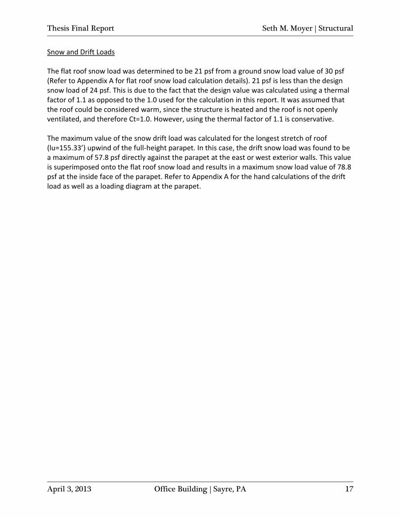
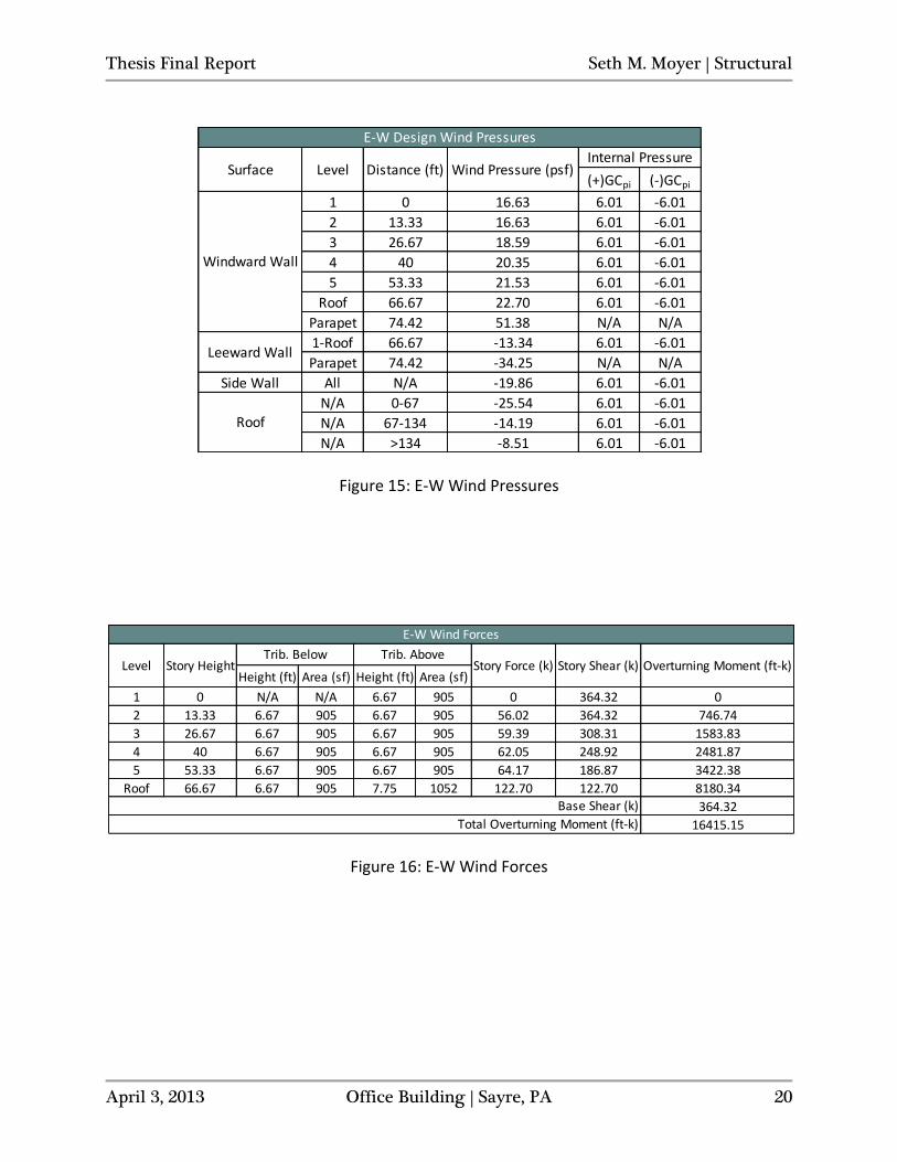
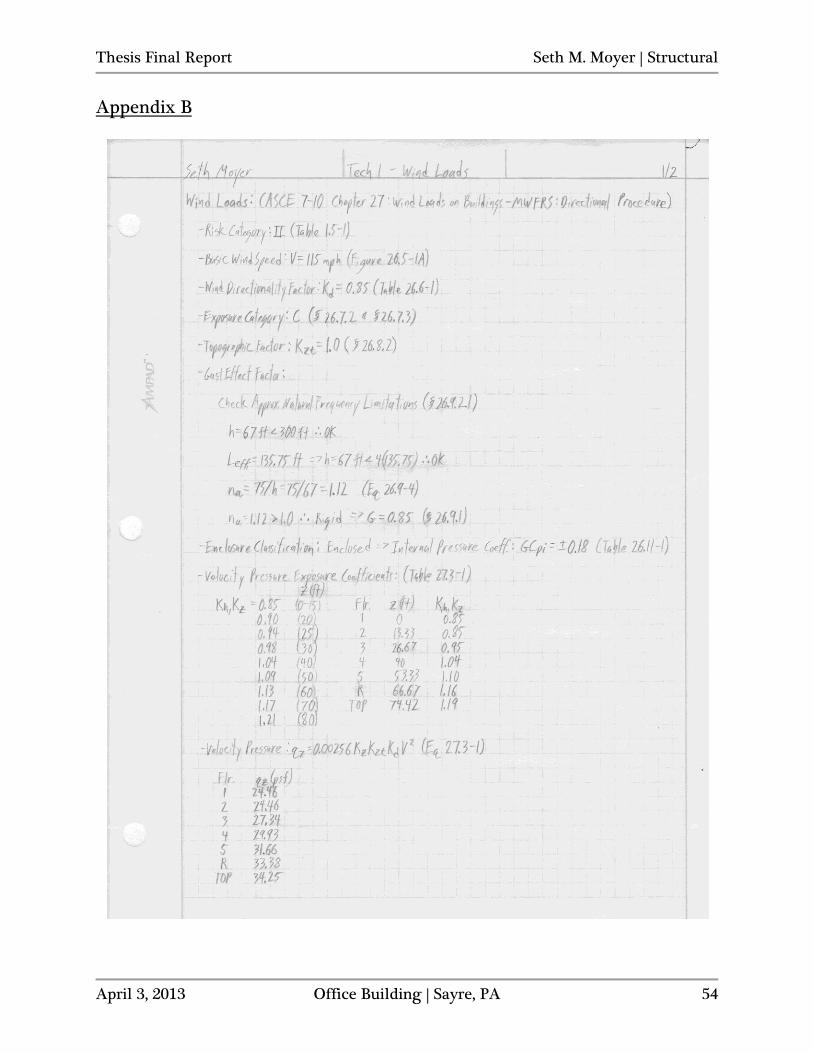
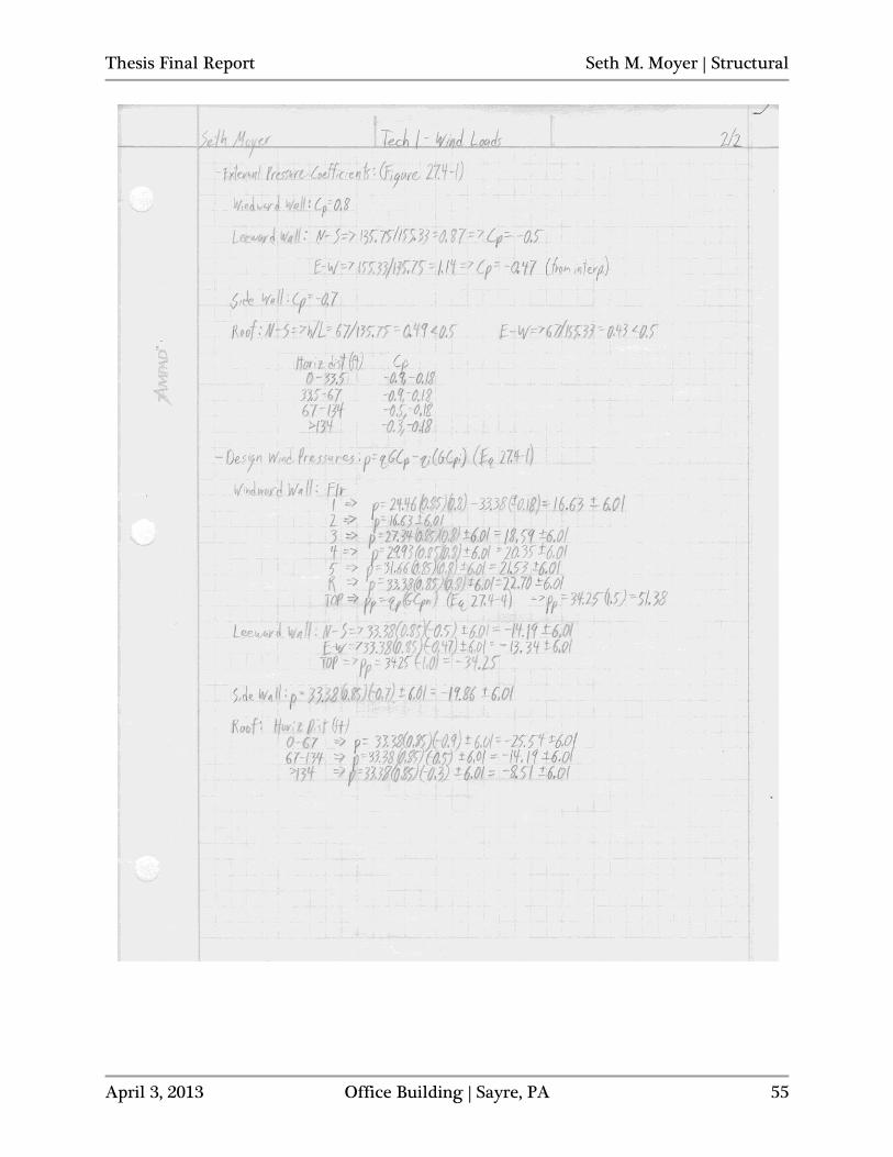
Wind Loads Design wind pressures and loads were calculated for both N-S and E-W directions in accordance with ASCE 7-10, Chapter 27 (MWFRS – Directional Procedure). Design pressures were calculated by hand and were resolved into story forces using Excel. Refer to Figures 11-18 and Appendix B for wind loading summary and calculations.
Figure 11: N-S Wind Pressures
Figure 12: N-S Wind Forces
(+)GCpi (-)GCpi
1 0 16.63 6.01 -6.01
2 13.33 16.63 6.01 -6.01
3 26.67 18.59 6.01 -6.01
4 40 20.35 6.01 -6.01
5 53.33 21.53 6.01 -6.01
Roof 66.67 22.70 6.01 -6.01
Parapet 74.42 51.38 N/A N/A
1-Roof 66.67 -14.19 6.01 -6.01
Parapet 74.42 -34.25 N/A N/A
Side Wall All N/A -19.86 6.01 -6.01
N/A 0-67 -25.54 6.01 -6.01
N/A 67-134 -14.19 6.01 -6.01
N/A >134 -8.51 6.01 -6.01
Windward Wall
Leeward Wall
Roof
N-S Design Wind Pressures
Surface Level Distance (ft) Wind Pressure (psf)Internal Pressure
Height (ft) Area (sf) Height (ft) Area (sf)
1 0 N/A N/A 6.67 1035 0 370.36 0
2 13.33 6.67 1035 6.67 1035 65.83 370.36 877.46
3 26.67 6.67 1035 6.67 1035 69.68 304.54 1858.26
4 40 6.67 1035 6.67 1035 72.72 234.86 2908.76
5 53.33 6.67 1035 6.67 1035 75.15 162.14 4007.82
Roof 66.67 6.67 1035 Varies 570 86.99 86.99 5799.64
370.36
15451.95
Trib. Below Trib. AboveLevel Story Height
Total Overturning Moment (ft-k)
Story Force (k) Story Shear (k) Overturning Moment (ft-k)
N-S Wind Forces
Base Shear (k)
Thesis Final Report Seth M. Moyer | Structural
April 3, 2013 Office Building | Sayre, PA 19
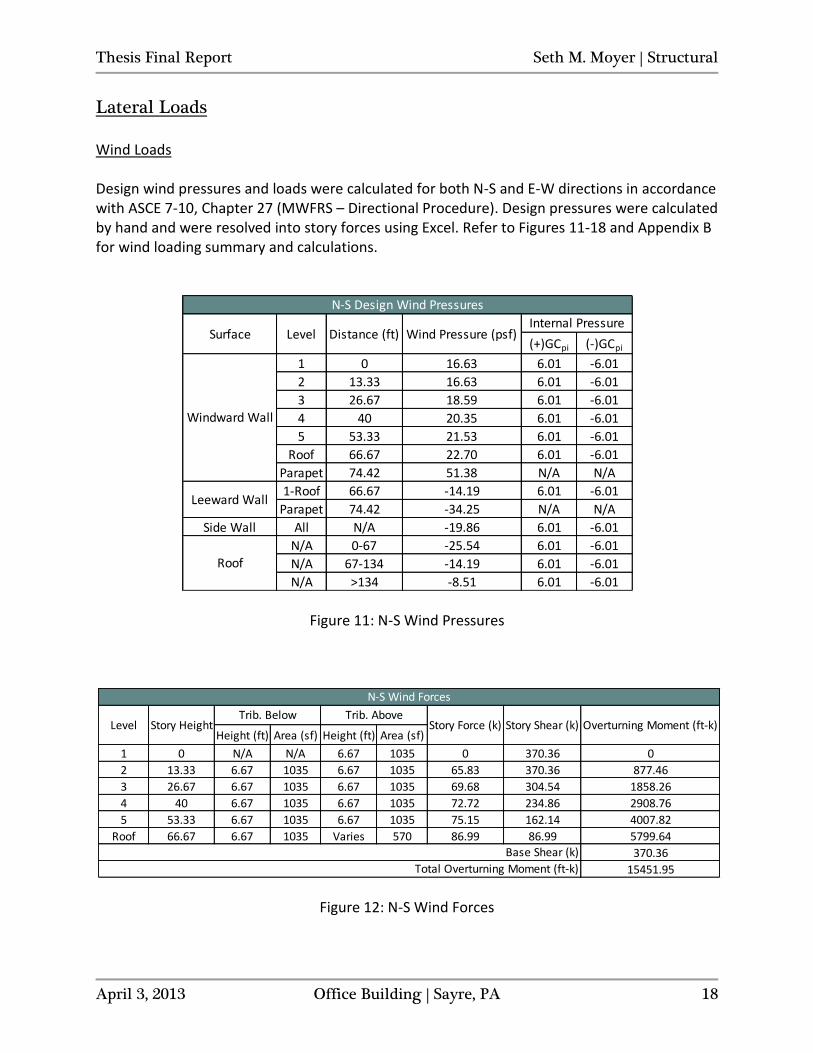
Figure 13: N-S Wind Pressure Diagram
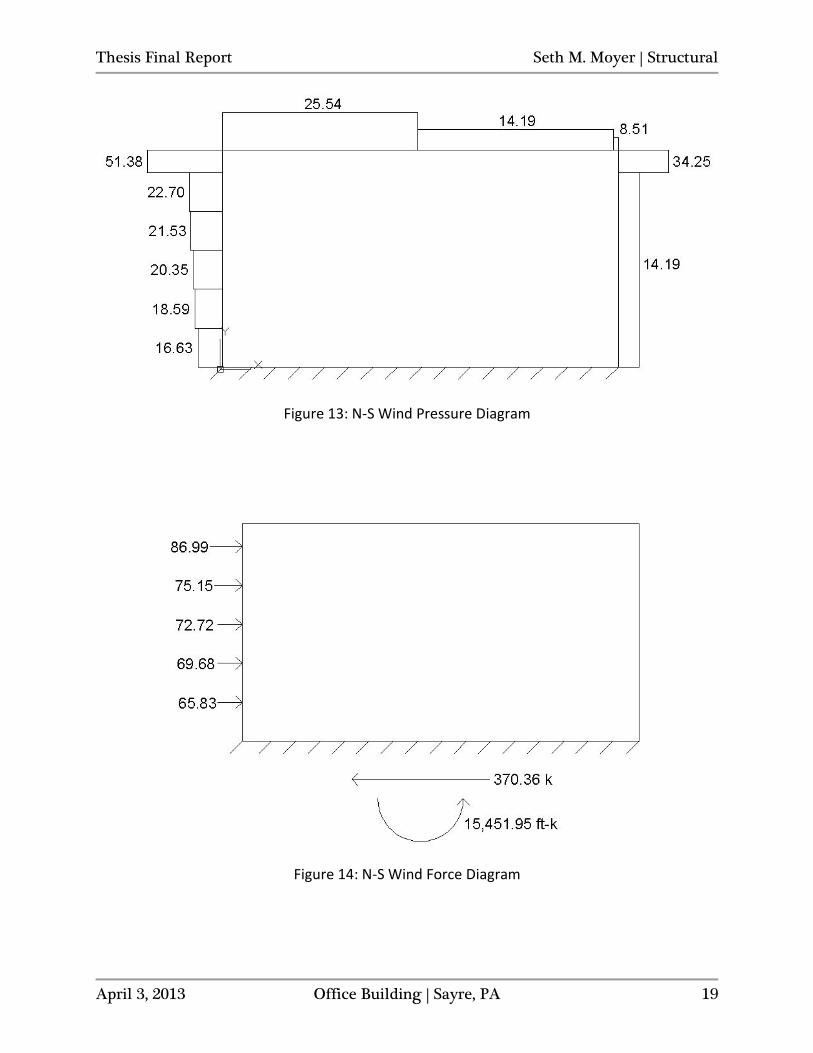
Figure 14: N-S Wind Force Diagram
Thesis Final Report Seth M. Moyer | Structural
April 3, 2013 Office Building | Sayre, PA 20
Figure 15: E-W Wind Pressures
Figure 16: E-W Wind Forces
(+)GCpi (-)GCpi
1 0 16.63 6.01 -6.01
2 13.33 16.63 6.01 -6.01
3 26.67 18.59 6.01 -6.01
4 40 20.35 6.01 -6.01
5 53.33 21.53 6.01 -6.01
Roof 66.67 22.70 6.01 -6.01
Parapet 74.42 51.38 N/A N/A
1-Roof 66.67 -13.34 6.01 -6.01
Parapet 74.42 -34.25 N/A N/A
Side Wall All N/A -19.86 6.01 -6.01
N/A 0-67 -25.54 6.01 -6.01
N/A 67-134 -14.19 6.01 -6.01
N/A >134 -8.51 6.01 -6.01
Surface Level Distance (ft) Wind Pressure (psf)Internal Pressure
Windward Wall
Leeward Wall
Roof
E-W Design Wind Pressures
Height (ft) Area (sf) Height (ft) Area (sf)
1 0 N/A N/A 6.67 905 0 364.32 0
2 13.33 6.67 905 6.67 905 56.02 364.32 746.74
3 26.67 6.67 905 6.67 905 59.39 308.31 1583.83
4 40 6.67 905 6.67 905 62.05 248.92 2481.87
5 53.33 6.67 905 6.67 905 64.17 186.87 3422.38
Roof 66.67 6.67 905 7.75 1052 122.70 122.70 8180.34
364.32
16415.15
E-W Wind Forces
Level Story HeightTrib. Below Trib. Above
Story Force (k) Story Shear (k) Overturning Moment (ft-k)
Base Shear (k)
Total Overturning Moment (ft-k)
Thesis Final Report Seth M. Moyer | Structural
April 3, 2013 Office Building | Sayre, PA 21
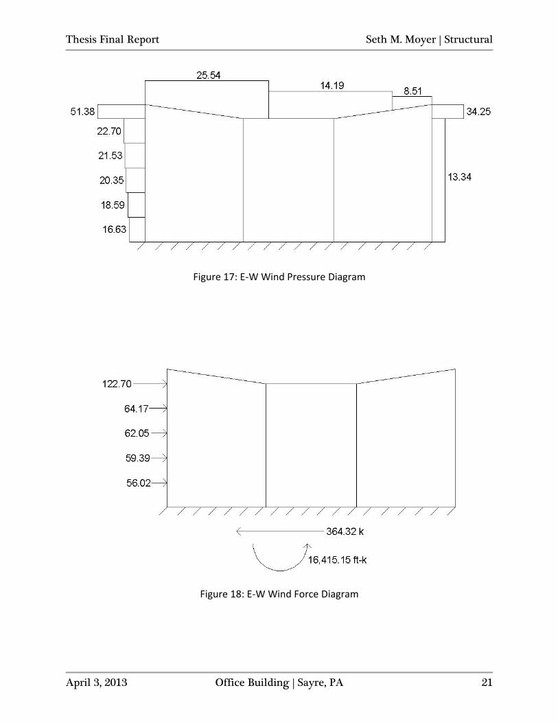
Figure 17: E-W Wind Pressure Diagram
Figure 18: E-W Wind Force Diagram
Thesis Final Report Seth M. Moyer | Structural
April 3, 2013 Office Building | Sayre, PA 22
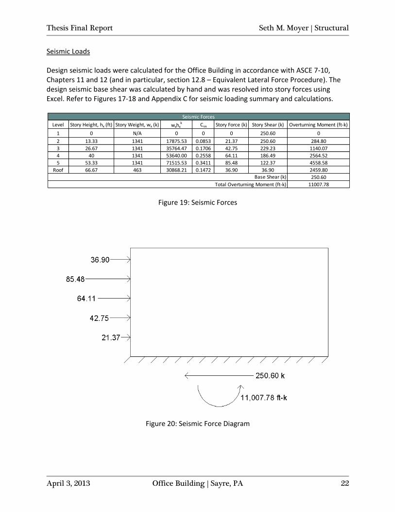
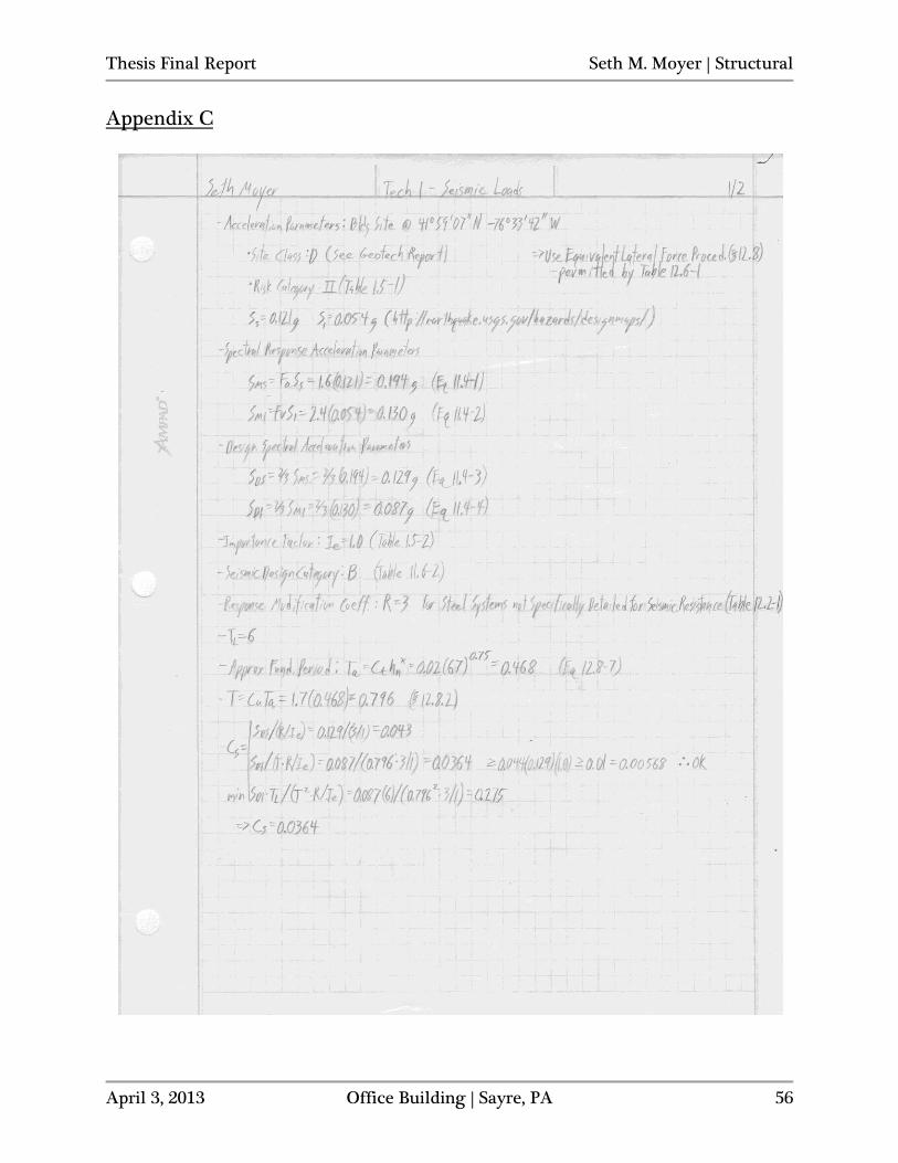
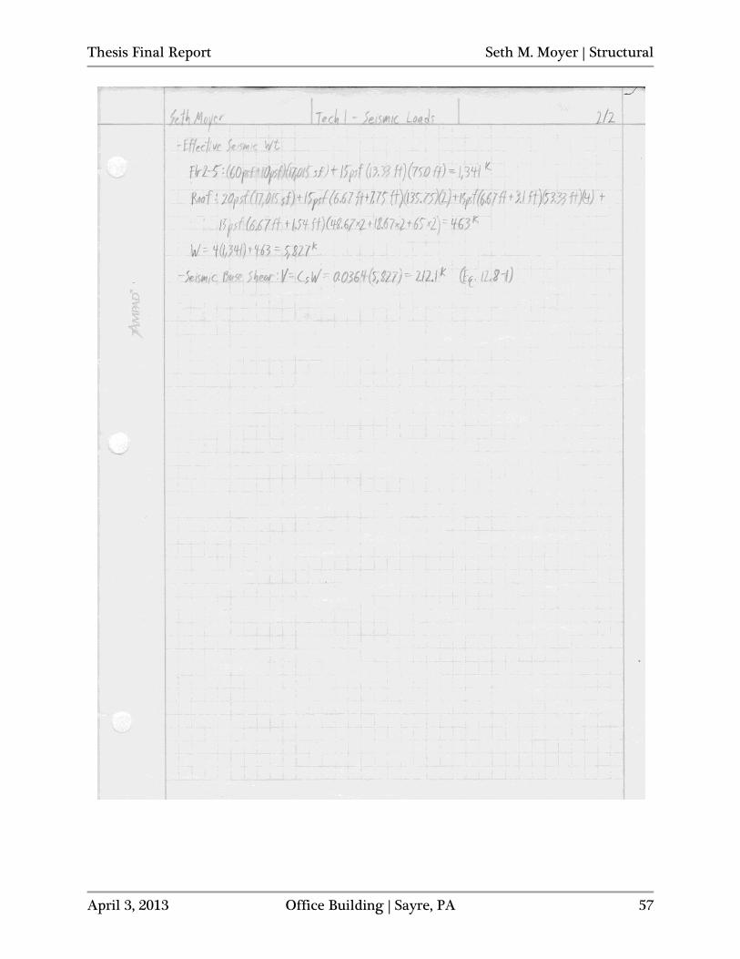
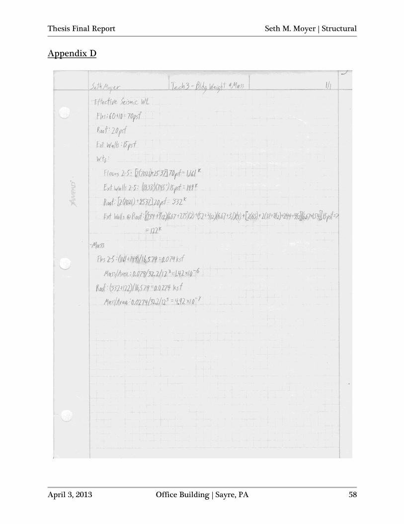
Seismic Loads Design seismic loads were calculated for the Office Building in accordance with ASCE 7-10, Chapters 11 and 12 (and in particular, section 12.8 – Equivalent Lateral Force Procedure). The design seismic base shear was calculated by hand and was resolved into story forces using Excel. Refer to Figures 17-18 and Appendix C for seismic loading summary and calculations.
Figure 19: Seismic Forces
Figure 20: Seismic Force Diagram
Level Story Height, hx (ft) Story Weight, wx (k) wxhxk Cvx Story Force (k) Story Shear (k) Overturning Moment (ft-k)
1 0 N/A 0 0 0 250.60 0
2 13.33 1341 17875.53 0.0853 21.37 250.60 284.80
3 26.67 1341 35764.47 0.1706 42.75 229.23 1140.07
4 40 1341 53640.00 0.2558 64.11 186.49 2564.52
5 53.33 1341 71515.53 0.3411 85.48 122.37 4558.58
Roof 66.67 463 30868.21 0.1472 36.90 36.90 2459.80
250.60
11007.78
Base Shear (k)
Seismic Forces
Total Overturning Moment (ft-k)
Thesis Final Report Seth M. Moyer | Structural
April 3, 2013 Office Building | Sayre, PA 23
Loads, Cases and Combinations
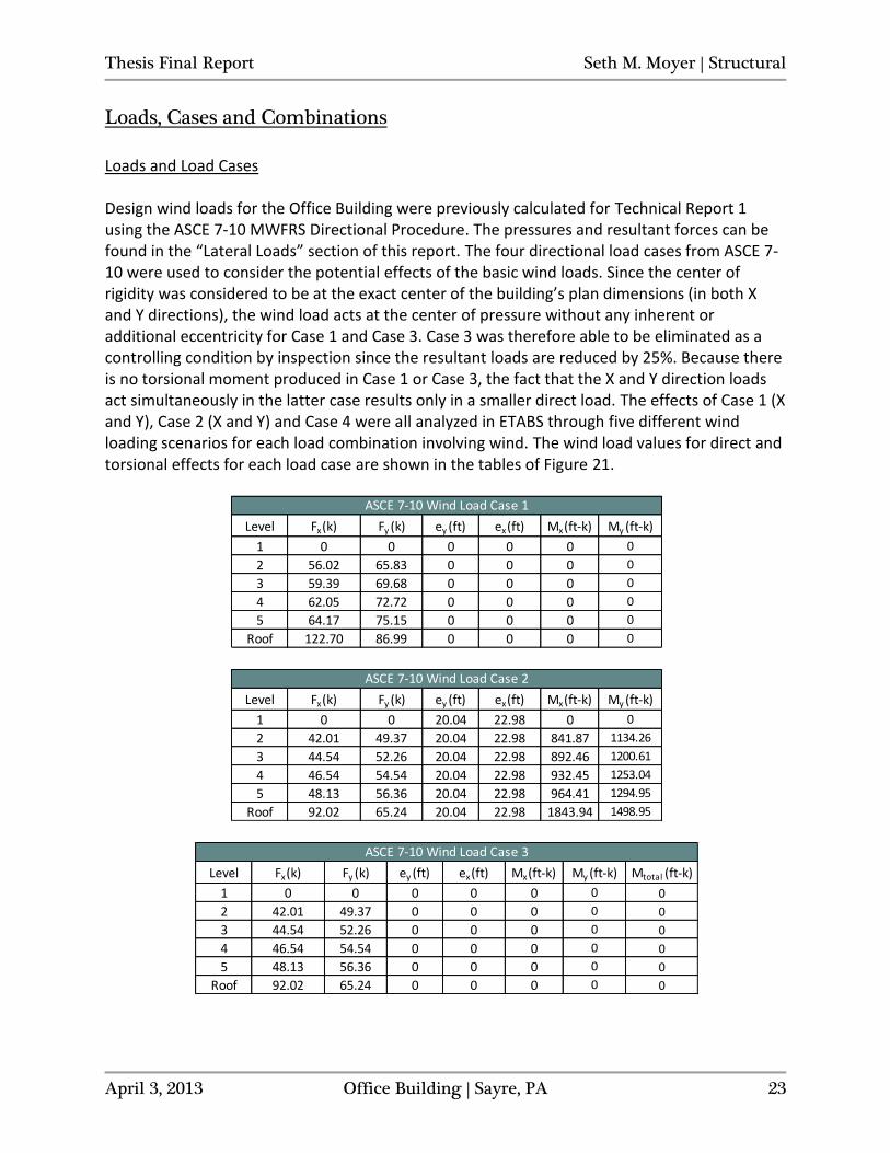
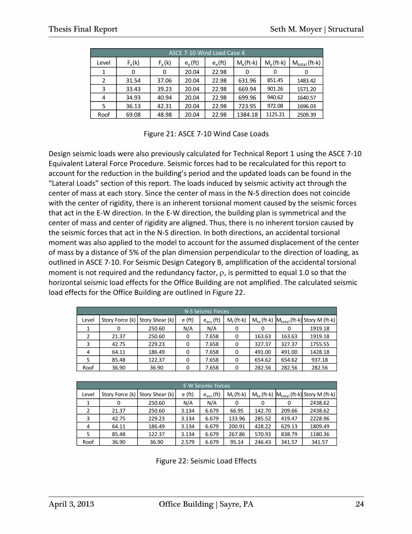
Loads and Load Cases Design wind loads for the Office Building were previously calculated for Technical Report 1 using the ASCE 7-10 MWFRS Directional Procedure. The pressures and resultant forces can be found in the “Lateral Loads” section of this report. The four directional load cases from ASCE 7-10 were used to consider the potential effects of the basic wind loads. Since the center of rigidity was considered to be at the exact center of the building’s plan dimensions (in both X and Y directions), the wind load acts at the center of pressure without any inherent or additional eccentricity for Case 1 and Case 3. Case 3 was therefore able to be eliminated as a controlling condition by inspection since the resultant loads are reduced by 25%. Because there is no torsional moment produced in Case 1 or Case 3, the fact that the X and Y direction loads act simultaneously in the latter case results only in a smaller direct load. The effects of Case 1 (X and Y), Case 2 (X and Y) and Case 4 were all analyzed in ETABS through five different wind loading scenarios for each load combination involving wind. The wind load values for direct and torsional effects for each load case are shown in the tables of Figure 21.
Level Fx (k) Fy (k) ey (ft) ex (ft) Mx (ft-k) My (ft-k)
1 0 0 0 0 0 0
2 56.02 65.83 0 0 0 0
3 59.39 69.68 0 0 0 0
4 62.05 72.72 0 0 0 0
5 64.17 75.15 0 0 0 0
Roof 122.70 86.99 0 0 0 0
ASCE 7-10 Wind Load Case 1
Level Fx (k) Fy (k) ey (ft) ex (ft) Mx (ft-k) My (ft-k)
1 0 0 20.04 22.98 0 0
2 42.01 49.37 20.04 22.98 841.87 1134.26
3 44.54 52.26 20.04 22.98 892.46 1200.61
4 46.54 54.54 20.04 22.98 932.45 1253.04
5 48.13 56.36 20.04 22.98 964.41 1294.95
Roof 92.02 65.24 20.04 22.98 1843.94 1498.95
ASCE 7-10 Wind Load Case 2
Level Fx (k) Fy (k) ey (ft) ex (ft) Mx (ft-k) My (ft-k) Mtotal (ft-k)
1 0 0 0 0 0 0 0
2 42.01 49.37 0 0 0 0 0
3 44.54 52.26 0 0 0 0 0
4 46.54 54.54 0 0 0 0 0
5 48.13 56.36 0 0 0 0 0
Roof 92.02 65.24 0 0 0 0 0
ASCE 7-10 Wind Load Case 3
Thesis Final Report Seth M. Moyer | Structural
April 3, 2013 Office Building | Sayre, PA 24
Figure 21: ASCE 7-10 Wind Case Loads
Design seismic loads were also previously calculated for Technical Report 1 using the ASCE 7-10 Equivalent Lateral Force Procedure. Seismic forces had to be recalculated for this report to account for the reduction in the building’s period and the updated loads can be found in the “Lateral Loads” section of this report. The loads induced by seismic activity act through the center of mass at each story. Since the center of mass in the N-S direction does not coincide with the center of rigidity, there is an inherent torsional moment caused by the seismic forces that act in the E-W direction. In the E-W direction, the building plan is symmetrical and the center of mass and center of rigidity are aligned. Thus, there is no inherent torsion caused by the seismic forces that act in the N-S direction. In both directions, an accidental torsional moment was also applied to the model to account for the assumed displacement of the center of mass by a distance of 5% of the plan dimension perpendicular to the direction of loading, as outlined in ASCE 7-10. For Seismic Design Category B, amplification of the accidental torsional
moment is not required and the redundancy factor, , is permitted to equal 1.0 so that the horizontal seismic load effects for the Office Building are not amplified. The calculated seismic load effects for the Office Building are outlined in Figure 22.
Figure 22: Seismic Load Effects
Level Fx (k) Fy (k) ey (ft) ex (ft) Mx (ft-k) My (ft-k) Mtotal (ft-k)
1 0 0 20.04 22.98 0 0 0
2 31.54 37.06 20.04 22.98 631.96 851.45 1483.42
3 33.43 39.23 20.04 22.98 669.94 901.26 1571.20
4 34.93 40.94 20.04 22.98 699.96 940.62 1640.57
5 36.13 42.31 20.04 22.98 723.95 972.08 1696.03
Roof 69.08 48.98 20.04 22.98 1384.18 1125.21 2509.39
ASCE 7-10 Wind Load Case 4
Level Story Force (k) Story Shear (k) e (ft) eacc (ft) Mt (ft-k) Mta (ft-k) Mtotal (ft-k) Story M (ft-k)
1 0 250.60 N/A N/A 0 0 0 1919.18
2 21.37 250.60 0 7.658 0 163.63 163.63 1919.18
3 42.75 229.23 0 7.658 0 327.37 327.37 1755.55
4 64.11 186.49 0 7.658 0 491.00 491.00 1428.18
5 85.48 122.37 0 7.658 0 654.62 654.62 937.18
Roof 36.90 36.90 0 7.658 0 282.56 282.56 282.56
N-S Seismic Forces
Level Story Force (k) Story Shear (k) e (ft) eacc (ft) Mt (ft-k) Mta (ft-k) Mtotal (ft-k) Story M (ft-k)
1 0 250.60 N/A N/A 0 0 0 2438.62
2 21.37 250.60 3.134 6.679 66.95 142.70 209.66 2438.62
3 42.75 229.23 3.134 6.679 133.96 285.52 419.47 2228.96
4 64.11 186.49 3.134 6.679 200.91 428.22 629.13 1809.49
5 85.48 122.37 3.134 6.679 267.86 570.93 838.79 1180.36
Roof 36.90 36.90 2.579 6.679 95.14 246.43 341.57 341.57
E-W Seismic Forces

Thesis Final Report Seth M. Moyer | Structural
April 3, 2013 Office Building | Sayre, PA 25
The torsional effects from the seismic previously outlined were not entered into ETABS directly, as they were for the wind loading. Instead, only the story forces were entered and were applied at the center of mass for each story. The effects of the inherent eccentricity to the center of rigidity as well as the accidental torsional moments were taken into account within the ETABS model.
Thesis Final Report Seth M. Moyer | Structural
April 3, 2013 Office Building | Sayre, PA 26
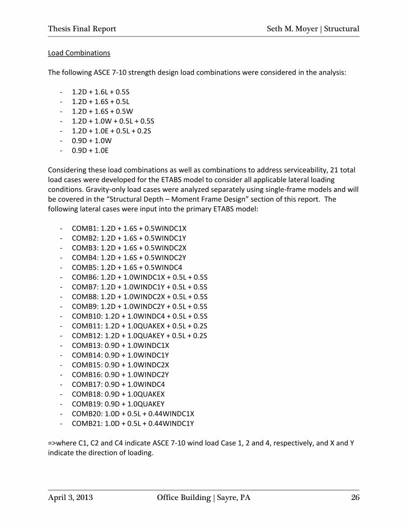
Load Combinations The following ASCE 7-10 strength design load combinations were considered in the analysis:
- 1.2D + 1.6L + 0.5S - 1.2D + 1.6S + 0.5L - 1.2D + 1.6S + 0.5W - 1.2D + 1.0W + 0.5L + 0.5S - 1.2D + 1.0E + 0.5L + 0.2S - 0.9D + 1.0W - 0.9D + 1.0E
Considering these load combinations as well as combinations to address serviceability, 21 total load cases were developed for the ETABS model to consider all applicable lateral loading conditions. Gravity-only load cases were analyzed separately using single-frame models and will be covered in the “Structural Depth – Moment Frame Design” section of this report. The following lateral cases were input into the primary ETABS model:
- COMB1: 1.2D + 1.6S + 0.5WINDC1X - COMB2: 1.2D + 1.6S + 0.5WINDC1Y - COMB3: 1.2D + 1.6S + 0.5WINDC2X - COMB4: 1.2D + 1.6S + 0.5WINDC2Y - COMB5: 1.2D + 1.6S + 0.5WINDC4 - COMB6: 1.2D + 1.0WINDC1X + 0.5L + 0.5S - COMB7: 1.2D + 1.0WINDC1Y + 0.5L + 0.5S - COMB8: 1.2D + 1.0WINDC2X + 0.5L + 0.5S - COMB9: 1.2D + 1.0WINDC2Y + 0.5L + 0.5S - COMB10: 1.2D + 1.0WINDC4 + 0.5L + 0.5S - COMB11: 1.2D + 1.0QUAKEX + 0.5L + 0.2S - COMB12: 1.2D + 1.0QUAKEY + 0.5L + 0.2S - COMB13: 0.9D + 1.0WINDC1X - COMB14: 0.9D + 1.0WINDC1Y - COMB15: 0.9D + 1.0WINDC2X - COMB16: 0.9D + 1.0WINDC2Y - COMB17: 0.9D + 1.0WINDC4 - COMB18: 0.9D + 1.0QUAKEX - COMB19: 0.9D + 1.0QUAKEY - COMB20: 1.0D + 0.5L + 0.44WINDC1X - COMB21: 1.0D + 0.5L + 0.44WINDC1Y
=>where C1, C2 and C4 indicate ASCE 7-10 wind load Case 1, 2 and 4, respectively, and X and Y indicate the direction of loading.
Thesis Final Report Seth M. Moyer | Structural
April 3, 2013 Office Building | Sayre, PA 27
Proposal
Structural Depth Through the analyses performed for previous technical reports, the existing structural system of the Office Building was determined to be sufficient for both strength and serviceability requirements. The only exceptions were several story drifts, found in Technical Report 3, which exceeded allowable drift limitations under wind loading. Of the alternate floor systems considered in Technical Report 2, only composite steel was considered to be a viable option, and it was found to have similar properties and performance to the original floor. The composite design was found to weigh about 12 psf less, and cost around 6% less ($/sf) than the existing floor design. However, the major advantage offered by composite steel is improved vibration control, and the existing floor system of composite deck slabs on open web steel joists was specifically designed to limit vibrations in accordance with AISC Design Guide 11. For these reasons, the focus of the structural depth was placed on a redesign of the lateral system. Although the existing lateral force resisting system is made up of double angle braced frames, it acts, effectively, much as a moment frame system. The bracing configuration in place below and above the windows at each story (bracing is only below, not above, the windows at level 5) has the double angle braces extending up/down to connection points at the top and bottom corners of the windows at each level. Therefore, the bracing connections to the columns, via gusset plates, are occurring at effectively unbraced locations along the height of the columns (at points several feet above and below the perimeter beam and floor diaphragm elevations, at which the columns are fully braced). Because of the brace termination points, bending moments are introduced into the columns. This configuration necessitates the columns to resist interactive axial and flexural forces, creating a significantly less efficient bracing arrangement than fully triangulated braces would offer. Therefore, the braced frames in place are not fully taking advantage of the benefits that a braced frame system is capable of achieving in terms of efficiency. Moment frames will be investigated and used to replace the existing braced frames as the lateral force resisting system for the Office Building. Fully restrained moment connections will be used for the rigid frames in which the lateral support, through resistance of sway in the frames, will be provided by maintaining the right angles between connected members (beam-to-column connections) through sufficient connection rigidity/stiffness. The connections will be designed to provide a full transfer of moment with negligible relative rotation between the members making up each joint, in accordance with the controlling wind loading case and applicable load combinations of ASCE 7-10 as determined in Technical Report 3. In order to optimize the redesign of the lateral system, the moment frames will, ideally, be located at or near the perimeter of the Office Building, as the existing braced frames are currently. Columns that are part of moment connections will be assessed for strength and, where required, member sizes will either be changed or stiffening elements and/or doubler
Thesis Final Report Seth M. Moyer | Structural
April 3, 2013 Office Building | Sayre, PA 28
plates will be provided. Existing beams in the moment frames will also be checked for strength and sizes will be changed where necessary. Breadth One The existing bracing configuration was designed for the locations above and below the windows so that the horizontal glazing strips could continue around the perimeter of the building, uninterrupted by the structure. This then allowed the lateral resistance to be placed primarily around the building’s perimeter where it would be most effective and efficient while preserving the strong horizontal features that define the architecture of the building. Insulated metal panels spanning above and below the glazing effectively hide the double angle braces. With the proposed structural redesign of the Office Building’s lateral system, the bracing members will be replaced by moment frames, primarily along the exterior grid lines. As a result, the enclosure of the east and west wings will be redesigned with a glazing system to replace the current insulated metal panels. The glazing will be similar to the system used to enclose the central portion of the building, between the east and west wings, where no braced frames are located in the original design layout. The new enclosure will provide more natural light to the interior office and meeting spaces throughout the building, similar to that already provided for the circulation core of the building. The proposed new glazing system will be researched and carefully assessed with respect to its performance as the building’s primary enclosure. The performance will be investigated by looking into the behavior of the barrier and how it affects the movement of heat and moisture through the building enclosure. The proposed layout and placement of the glazing system units will consider both span distances and wind loading conditions. Breadth Two With the enclosure redesign proposed for Breadth One, a high percentage of the building’s exterior envelope will be changed from insulated metal panels to a glazing system. Such a major change could potentially have a significant impact on the conditions and environment inside the Office Building. After researching and analyzing a new enclosure as a part of Breadth One, its overall hygrothermal performance will be assessed and compared to that of the insulated metal panels. Differences in performance will be used to assess the effects of this redesign on the heating and cooling loads of the building and the potential impact on its mechanical systems. MAE Requirements Means and methods from graduate level coursework will be used throughout the investigation, analysis and design of the depth and breadth work proposed for the senior thesis project in spring 2013. AE 530 - Computer Modeling of Building Structures has provided the base
Thesis Final Report Seth M. Moyer | Structural
April 3, 2013 Office Building | Sayre, PA 29
knowledge to effectively model and analyze the Office Building’s structural system using ETABS analysis software. The depth study will rely heavily on the coursework from AE 534 – Analysis and Design of Steel Connections for the design and specification of the fully restrained moment connections forming the rigid moment frames. The breadth studies will both draw on the material covered in AE 542 – Building Enclosure Science and Design for the analysis, assessment and design of the proposed enclosure.
Thesis Final Report Seth M. Moyer | Structural
April 3, 2013 Office Building | Sayre, PA 30
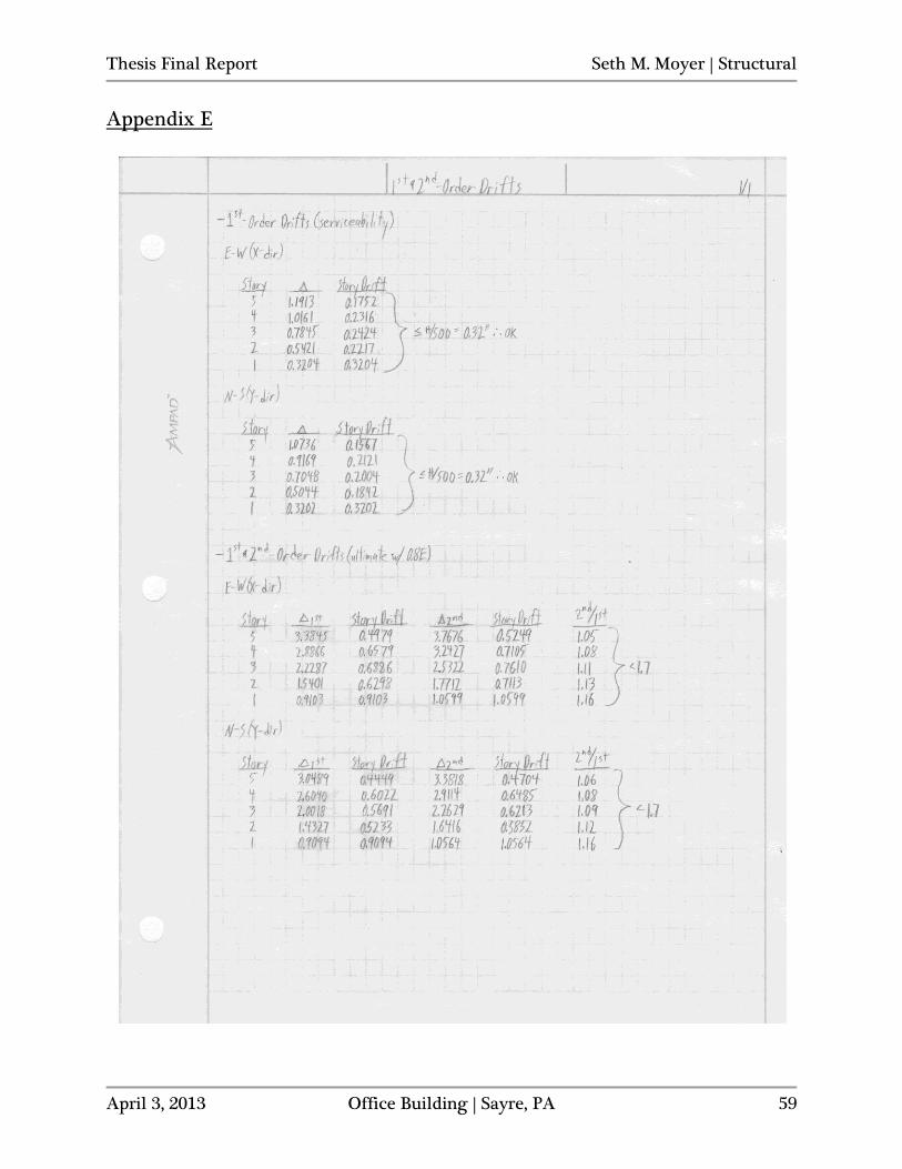
Structural Depth - Moment Frame Design For the reasons outlined previously in the “Proposal” section of this report, the depth study will focus on a redesign of the Office Building’s lateral force resisting system, which is currently made up of double angle braced frames, to moment frames. Moment frames provide significantly less efficient stiffness with respect to member proportions than braced frames offer, relying on flexural rather than axial stiffness to resist lateral displacements of the structure. With this principle in mind, the preliminary design of the moment frames was based on meeting the serviceability deflection requirements that were assumed to control over the strength requirements of the rigid frames members. Preliminary Drift Considerations The support conditions at the bases of the moment frame columns have a major impact on the overall stiffness of the structure as well as the design moments on individual frame members. In order to consider the bases fixed, the rotational stiffness of the shallow foundations would need to be assessed and the base plates, anchor rods and piers would need to be specifically detailed to transfer moments from the columns into the foundations and finally to the soil. Even with proper design and detailing, the actual rotational stiffness of the footings and surrounding soils will lead to a condition somewhere between truly fixed and truly pinned. Without looking any further into the foundation details for the purposes of this study, the bases will be considered as pin supports. This assumption will lead to larger structural drifts, especially at story one, and will therefore require larger rigid frame members to limit those deflections. It may be desirable and potentially advantageous to consider and compare the costs associated with the (partially) fixed condition, requiring further foundation detailing and smaller frame members, and the pinned condition, with larger frame members and smaller foundations with less detailing. Based on observations of common industry practices, it is reasonable to consider the design of moment frames utilizing pinned bases where member sizes do not become grossly excessive. In setting the drift limit for lateral wind loading, which was found to be the controlling source of lateral forces in Technical Report 3, the proposed enclosure redesign breadth study was taken into consideration. With the intention that the entire façade was going to be changed to a curtain wall glazing system, the drift limit was chosen as H/500 (0.32” per story) to account for the greater potential sensitivity of a primarily glass enclosure to lateral displacements. This limit is 20% more restrictive than the industry standard of H/400 that is typically used and will allow for greater flexibility in the selection and layout of the glazing units. Serviceability Wind Loading The Appendix C Commentary on Serviceability Considerations in ASCE 7-10 states that the wind loading due to nominal 700-year mean recurrence interval (MRI) wind speeds is “excessively conservative” for checking building serviceability requirements and that the load combination
Thesis Final Report Seth M. Moyer | Structural
April 3, 2013 Office Building | Sayre, PA 31
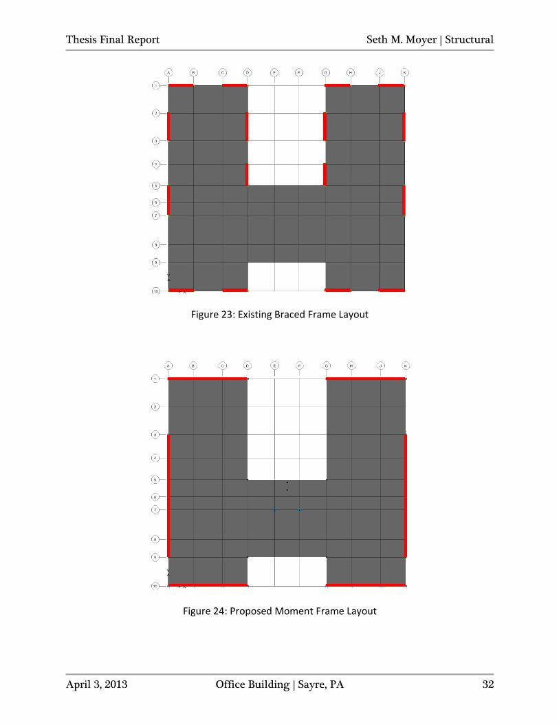
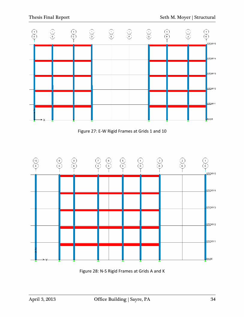
of D + 0.5L + Wa may be used instead. The 10-year serviceability wind speed for the Office Building is mapped at 76 mph (ASCE 7-10, Figure CC-1) and the wind case, including the force multiplier, represented by Wa can be found from provided wind velocities. Taking the ratio of the 10-year MRI wind speed to the 700-year MRI wind speed and squaring it gives the force multiplier/load factor for use in considering serviceability loads of 0.44 (76mph/115mph=0.66, 0.66^2=0.44). This can be verified by taking the ratio of the serviceability to strength load factors in ASCE 7-05, which also yields 0.7/1.6=0.44. The factor of 0.44 was used in ETABS with the load combination D + 0.5L + 0.44W and allowed for serviceability checks of the model without having to recalculate and input any new loads on an individual basis. The load combination used in the design of the E-W (X-direction) frames was COMB20: 1.0D + 0.5L + 0.44WINDC1X, and the combination used in the design of the N-S (Y-direction) frames was COMB21: 1.0D + 0.5L + 0.44WINDC1Y. Moment Frame Layout Due to the inherent lesser efficiency in using moment versus braced frames with respect to frame member size/weight, rigid frames are generally the more expensive option. The heavier sections that may be required can lead to higher overall material costs with increased steel tonnage and could also take longer and/or cost more to physically construct. Additionally, the need for column stiffening and its detailing can carry steep costs. Based on the preferences of various industry professionals, going with larger cross sections appears to be preferred to heavily detailed and stiffened members at moment connections where feasible, and when the members are not already exceedingly heavy. Fabrication time for attaching stiffening elements to columns is regarded as the primary source of expense for those stiffened members, as opposed to the cost of the stiffening material itself. Where there is no significant amount of savings in utilizing heavier columns over smaller, stiffened sections, it is often just simply easier to bump up the column size, if the section is not already excessively large/heavy. The plan locations chosen for the moment frames are along the perimeter of the Office Building, similar to the locations of a majority of the braced frames in the existing structure (see Figure 23), where they will be most effective at resisting torsional effects induced by wind and seismic lateral loads. There are two three-bay frames along both grids 1 and 10, acting in the east-west (E-W) or X-direction and a 5-bay frame along both grids A and K, acting in the north-south (N-S) or Y-direction. See Figure 24 for proposed moment frame locations, marked by red lines. The lateral design moved forward having only two lines of rigid frames acting in each direction with the intention of using larger beams and columns, but a lesser overall number of frames. This decision was made to reduce the labor costs and time involved in requiring a much greater number of moment connections in additional frames. All six of the individual frames extend the entire height of the building. See Figures 27 and 28 for frame elevations.
Thesis Final Report Seth M. Moyer | Structural
April 3, 2013 Office Building | Sayre, PA 32
Figure 23: Existing Braced Frame Layout
Figure 24: Proposed Moment Frame Layout
Thesis Final Report Seth M. Moyer | Structural
April 3, 2013 Office Building | Sayre, PA 33
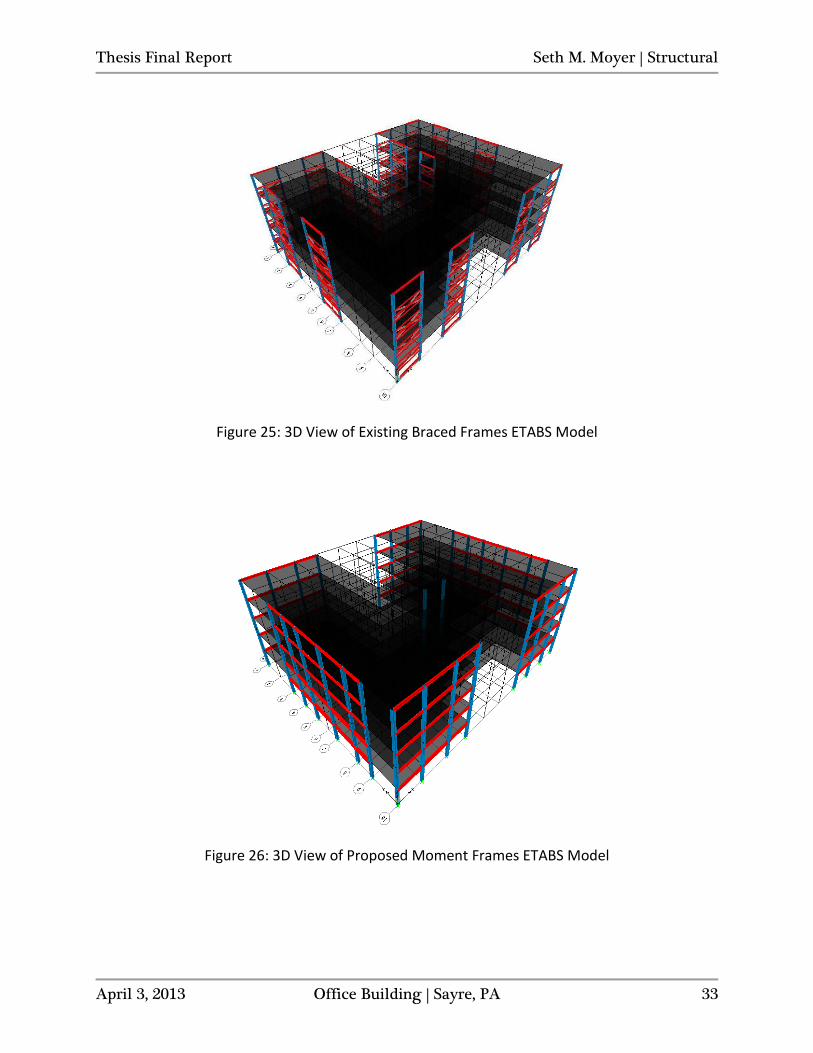
Figure 25: 3D View of Existing Braced Frames ETABS Model
Figure 26: 3D View of Proposed Moment Frames ETABS Model
Thesis Final Report Seth M. Moyer | Structural
April 3, 2013 Office Building | Sayre, PA 34
Figure 27: E-W Rigid Frames at Grids 1 and 10
Figure 28: N-S Rigid Frames at Grids A and K
Thesis Final Report Seth M. Moyer | Structural
April 3, 2013 Office Building | Sayre, PA 35
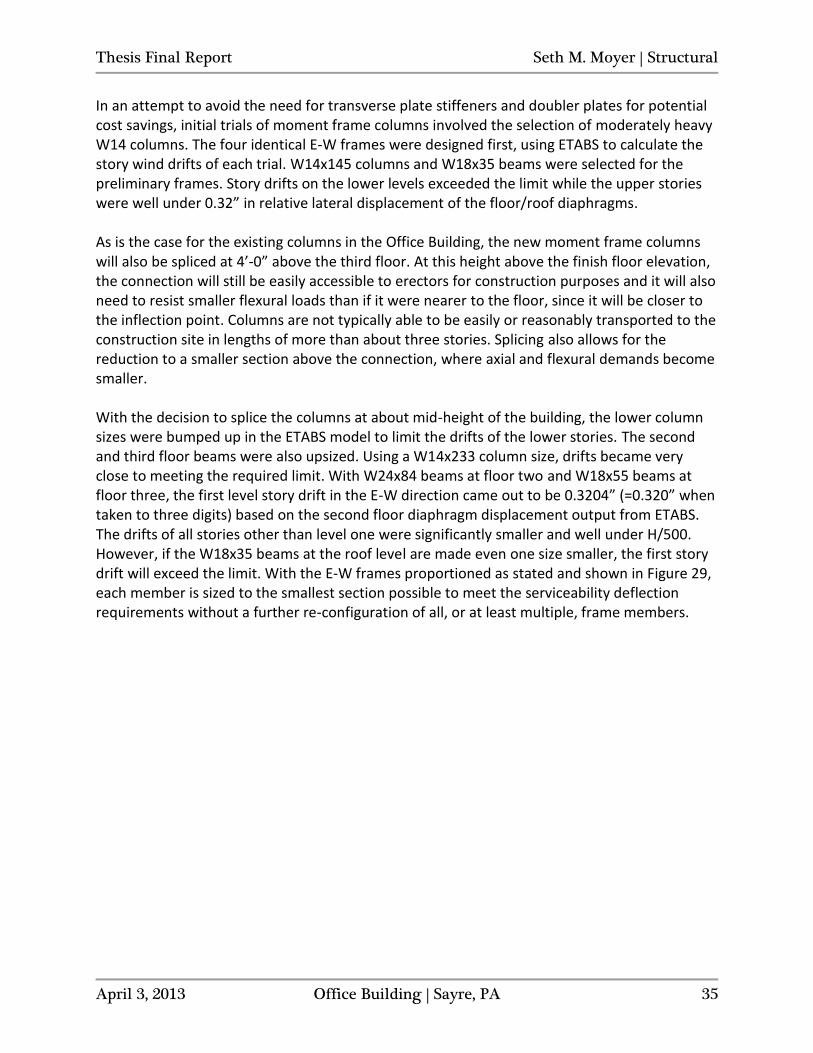
In an attempt to avoid the need for transverse plate stiffeners and doubler plates for potential cost savings, initial trials of moment frame columns involved the selection of moderately heavy W14 columns. The four identical E-W frames were designed first, using ETABS to calculate the story wind drifts of each trial. W14x145 columns and W18x35 beams were selected for the preliminary frames. Story drifts on the lower levels exceeded the limit while the upper stories were well under 0.32” in relative lateral displacement of the floor/roof diaphragms. As is the case for the existing columns in the Office Building, the new moment frame columns will also be spliced at 4’-0” above the third floor. At this height above the finish floor elevation, the connection will still be easily accessible to erectors for construction purposes and it will also need to resist smaller flexural loads than if it were nearer to the floor, since it will be closer to the inflection point. Columns are not typically able to be easily or reasonably transported to the construction site in lengths of more than about three stories. Splicing also allows for the reduction to a smaller section above the connection, where axial and flexural demands become smaller. With the decision to splice the columns at about mid-height of the building, the lower column sizes were bumped up in the ETABS model to limit the drifts of the lower stories. The second and third floor beams were also upsized. Using a W14x233 column size, drifts became very close to meeting the required limit. With W24x84 beams at floor two and W18x55 beams at floor three, the first level story drift in the E-W direction came out to be 0.3204” (=0.320” when taken to three digits) based on the second floor diaphragm displacement output from ETABS. The drifts of all stories other than level one were significantly smaller and well under H/500. However, if the W18x35 beams at the roof level are made even one size smaller, the first story drift will exceed the limit. With the E-W frames proportioned as stated and shown in Figure 29, each member is sized to the smallest section possible to meet the serviceability deflection requirements without a further re-configuration of all, or at least multiple, frame members.
Thesis Final Report Seth M. Moyer | Structural
April 3, 2013 Office Building | Sayre, PA 36
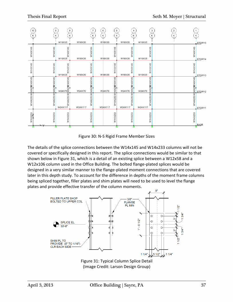
Figure 29: E-W Rigid Frame Member Sizes After sizing the members of the four E-W direction frames, the two N-S (Y-direction) frames were modeled in ETABS with the same column sections and beam sizes at each floor as those acting in the X-direction. With the first story drift slightly exceeding 0.32”, the beams at the second and third floors were adjusted. The beams were bumped up to W24x117 at floor two and W24x76 at floor three. Keeping all other members the same as the X-direction frames, the first level story drift in the N-S direction came out to be 0.3202” (=0.320” when taken to three digits). See Figure 30 for a frame elevation showing member sizes. See Appendix E for story drifts.
Thesis Final Report Seth M. Moyer | Structural
April 3, 2013 Office Building | Sayre, PA 37
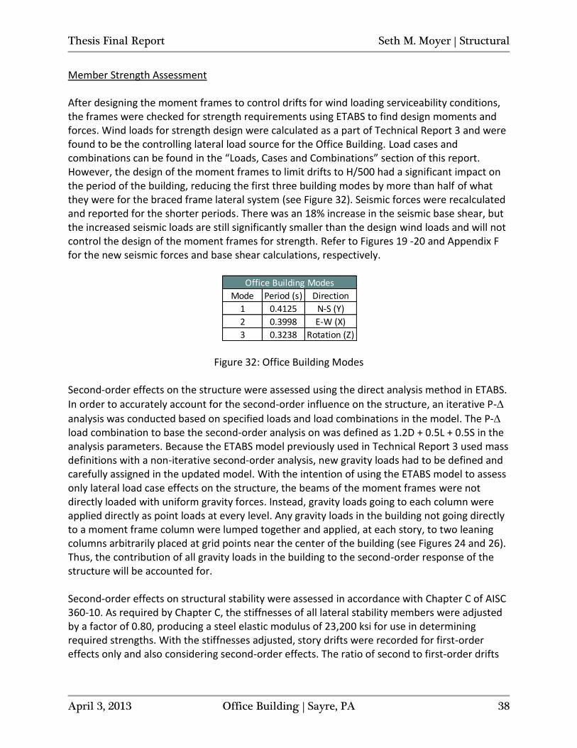
Figure 30: N-S Rigid Frame Member Sizes The details of the splice connections between the W14x145 and W14x233 columns will not be covered or specifically designed in this report. The splice connections would be similar to that shown below in Figure 31, which is a detail of an existing splice between a W12x58 and a W12x106 column used in the Office Building. The bolted flange-plated splices would be designed in a very similar manner to the flange-plated moment connections that are covered later in this depth study. To account for the difference in depths of the moment frame columns being spliced together, filler plates and shim plates will need to be used to level the flange plates and provide effective transfer of the column moments.
Figure 31: Typical Column Splice Detail
(Image Credit: Larson Design Group)
Thesis Final Report Seth M. Moyer | Structural
April 3, 2013 Office Building | Sayre, PA 38
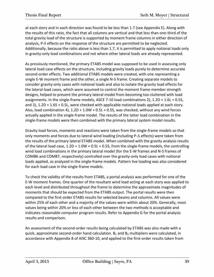
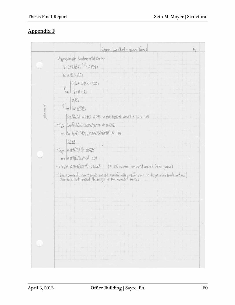
Member Strength Assessment After designing the moment frames to control drifts for wind loading serviceability conditions, the frames were checked for strength requirements using ETABS to find design moments and forces. Wind loads for strength design were calculated as a part of Technical Report 3 and were found to be the controlling lateral load source for the Office Building. Load cases and combinations can be found in the “Loads, Cases and Combinations” section of this report. However, the design of the moment frames to limit drifts to H/500 had a significant impact on the period of the building, reducing the first three building modes by more than half of what they were for the braced frame lateral system (see Figure 32). Seismic forces were recalculated and reported for the shorter periods. There was an 18% increase in the seismic base shear, but the increased seismic loads are still significantly smaller than the design wind loads and will not control the design of the moment frames for strength. Refer to Figures 19 -20 and Appendix F for the new seismic forces and base shear calculations, respectively.
Figure 32: Office Building Modes Second-order effects on the structure were assessed using the direct analysis method in ETABS.
In order to accurately account for the second-order influence on the structure, an iterative P-
analysis was conducted based on specified loads and load combinations in the model. The P- load combination to base the second-order analysis on was defined as 1.2D + 0.5L + 0.5S in the analysis parameters. Because the ETABS model previously used in Technical Report 3 used mass definitions with a non-iterative second-order analysis, new gravity loads had to be defined and carefully assigned in the updated model. With the intention of using the ETABS model to assess only lateral load case effects on the structure, the beams of the moment frames were not directly loaded with uniform gravity forces. Instead, gravity loads going to each column were applied directly as point loads at every level. Any gravity loads in the building not going directly to a moment frame column were lumped together and applied, at each story, to two leaning columns arbitrarily placed at grid points near the center of the building (see Figures 24 and 26). Thus, the contribution of all gravity loads in the building to the second-order response of the structure will be accounted for. Second-order effects on structural stability were assessed in accordance with Chapter C of AISC 360-10. As required by Chapter C, the stiffnesses of all lateral stability members were adjusted by a factor of 0.80, producing a steel elastic modulus of 23,200 ksi for use in determining required strengths. With the stiffnesses adjusted, story drifts were recorded for first-order effects only and also considering second-order effects. The ratio of second to first-order drifts
Mode Period (s) Direction
1 0.4125 N-S (Y)
2 0.3998 E-W (X)
3 0.3238 Rotation (Z)
Office Building Modes
Thesis Final Report Seth M. Moyer | Structural
April 3, 2013 Office Building | Sayre, PA 39
at each story and in each direction was found to be less than 1.7 (see Appendix E). Along with the results of this ratio, the fact that all columns are vertical and that less than one-third of the total gravity load of the structure is supported by moment frame columns in either direction of
analysis, P- effects on the response of the structure are permitted to be neglected. Additionally, because the ratio above is less than 1.7, it is permitted to apply notional loads only in gravity-only load combinations and not where other lateral loads are already represented. As previously mentioned, the primary ETABS model was supposed to be used in assessing only lateral load case effects on the structure, including gravity loads purely to determine accurate second-order effects. Two additional ETABS models were created, with one representing a single E-W moment frame and the other, a single N-S frame. Creating separate models to consider gravity-only cases with notional loads and also to isolate the gravity load effects for the lateral load cases, which were assumed to control the moment frame member strength designs, helped to prevent the primary lateral model from becoming too cluttered with load assignments. In the single-frame models, ASCE 7-10 load combinations 2), 1.2D + 1.6L + 0.5S, and 3), 1.2D + 1.6S + 0.5L, were checked with applicable notional loads applied at each story. Also, load combination 4), 1.2D + 1.0W + 0.5L + 0.5S, was checked, without any wind forces actually applied in the single-frame model. The results of the latter load combination in the single-frame models were then combined with the primary lateral system model results. Gravity load forces, moments and reactions were taken from the single-frame models so that
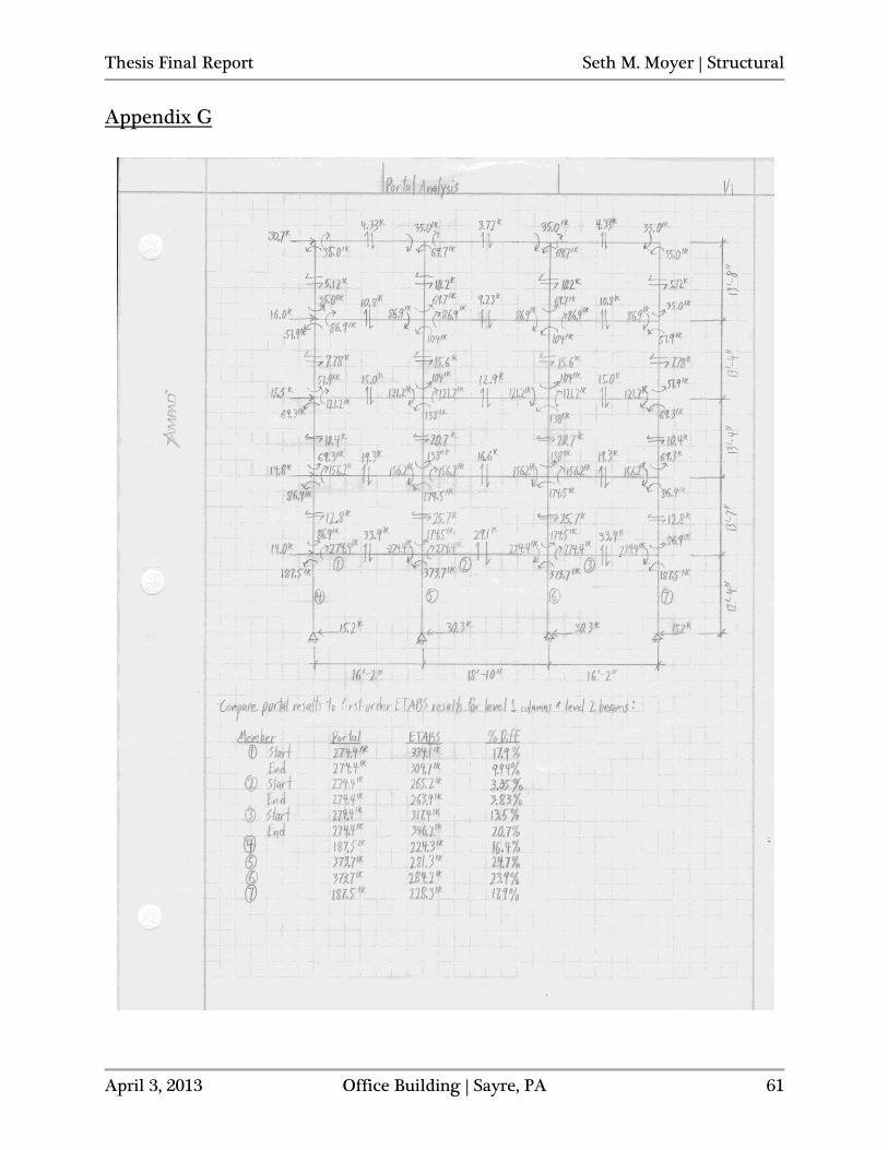
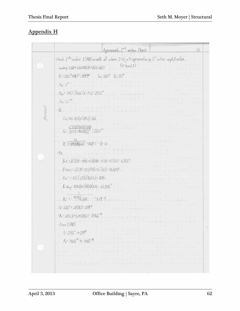
only moments and forces due to lateral wind loading (including P- effects) were taken from the results of the primary lateral ETABS model. When combined with the gravity analysis results of the lateral load case, 1.2D + 1.0W + 0.5L + 0.5S, from the single-frame models, the controlling wind load combinations in the primary lateral model (for the E-W frames and N-S frames of COMB6 and COMB7, respectively) controlled over the gravity-only load cases with notional loads applied, as analyzed in the single-frame models. Pattern live loading was also considered for each load case in the single-frame models. To check the validity of the results from ETABS, a portal analysis was performed for one of the E-W moment frames. One quarter of the resultant wind load acting at each story was applied to each level and distributed throughout the frame to determine the approximate magnitudes of moments that should be expected from the ETABS output. The portal results were then compared to the first-order ETABS results for selected beams and columns. All values were within 25% of each other and a majority of the values were within about 20%. Generally, most values being within 20% or less of each other between the two methods is acceptable and indicates reasonable computer program results. Refer to Appendix G for the portal analysis results and comparison. An assessment of the second-order results being calculated by ETABS was also made with a quick, approximate second-order hand calculation. B1 and B2 multipliers were calculated, in accordance with Appendix 8 of AISC 360-10, and applied to the first-order results taken from
Thesis Final Report Seth M. Moyer | Structural
April 3, 2013 Office Building | Sayre, PA 40
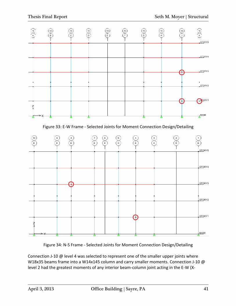
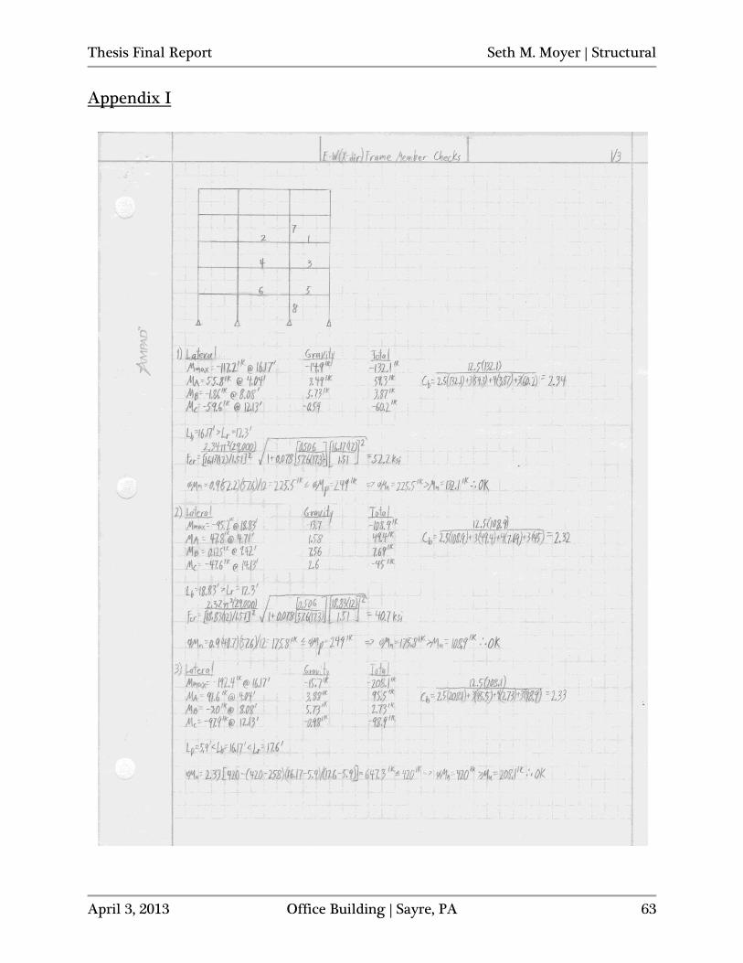
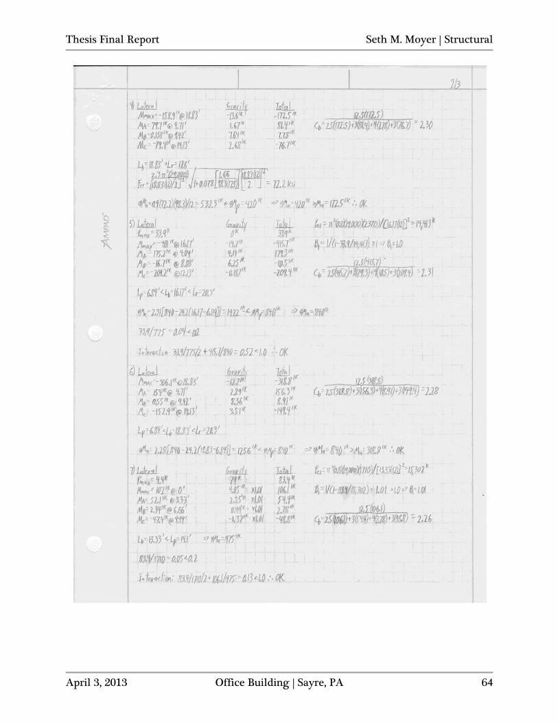
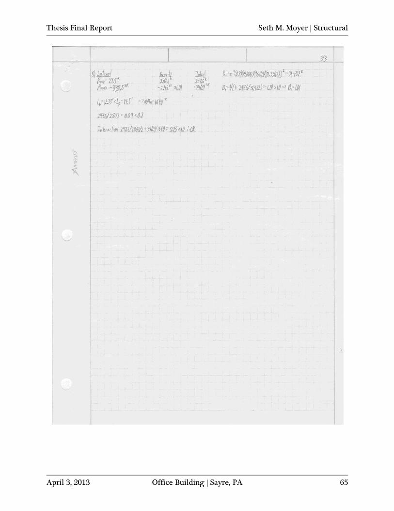
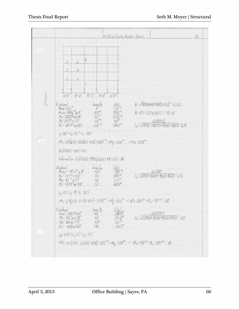
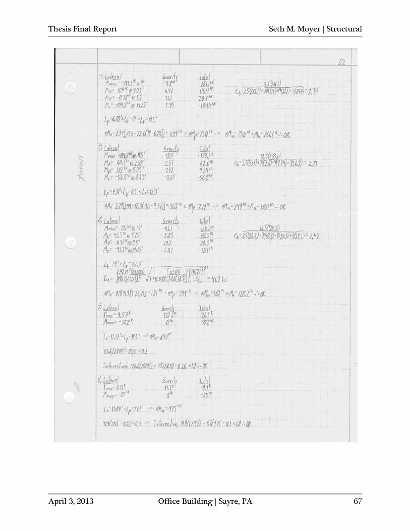
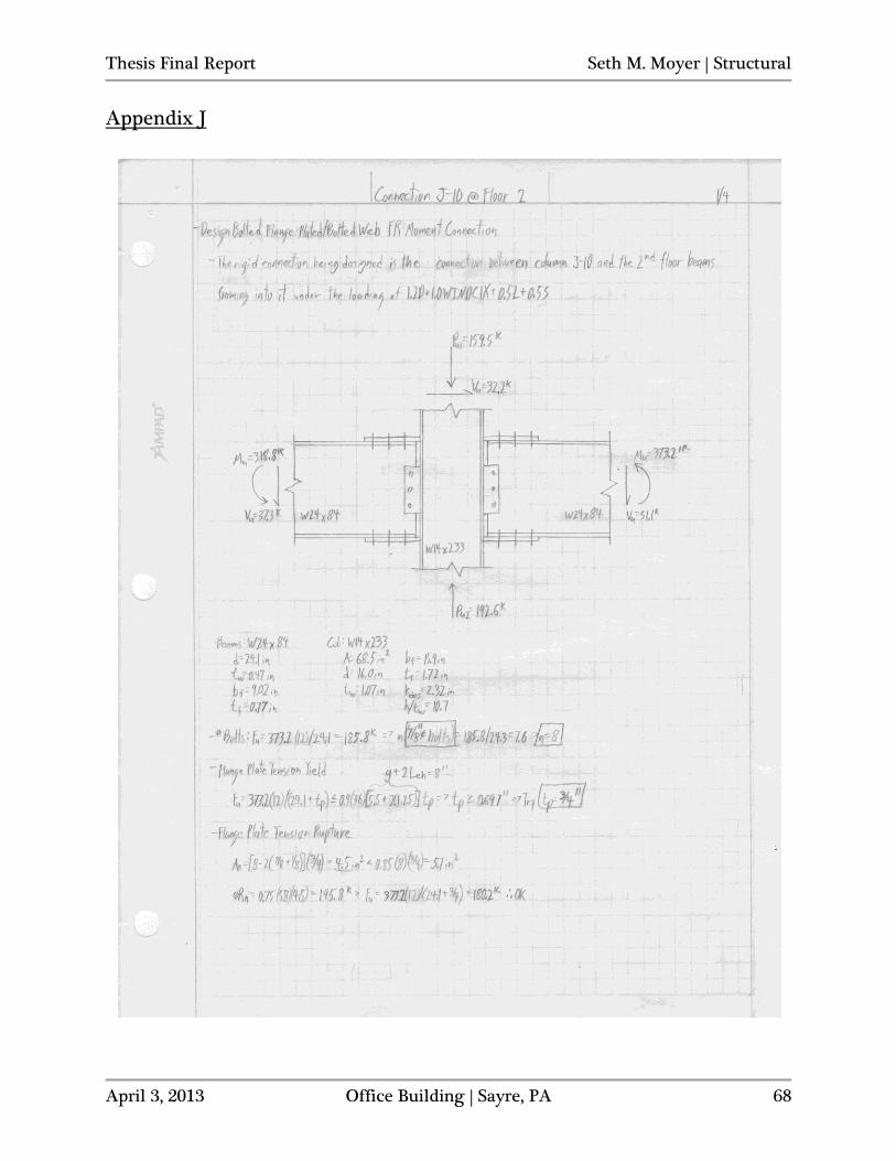
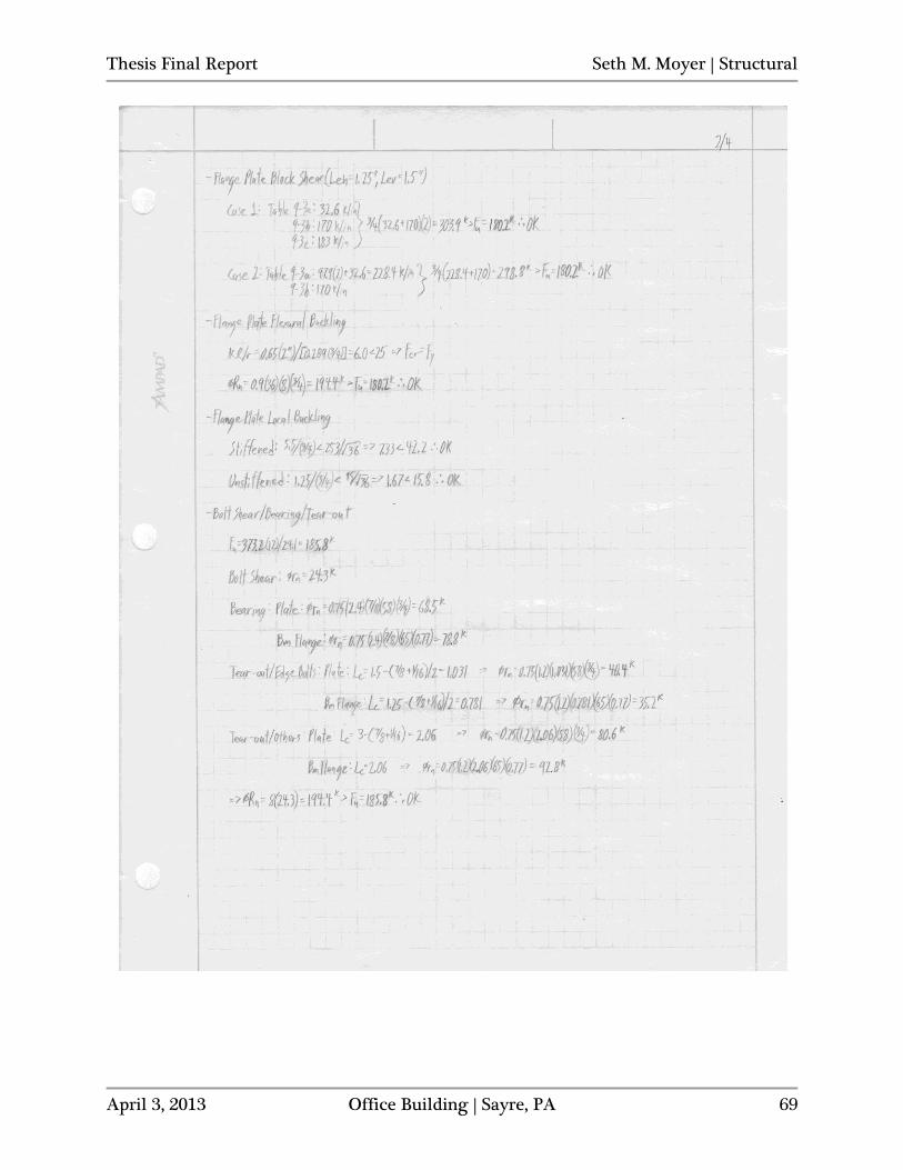
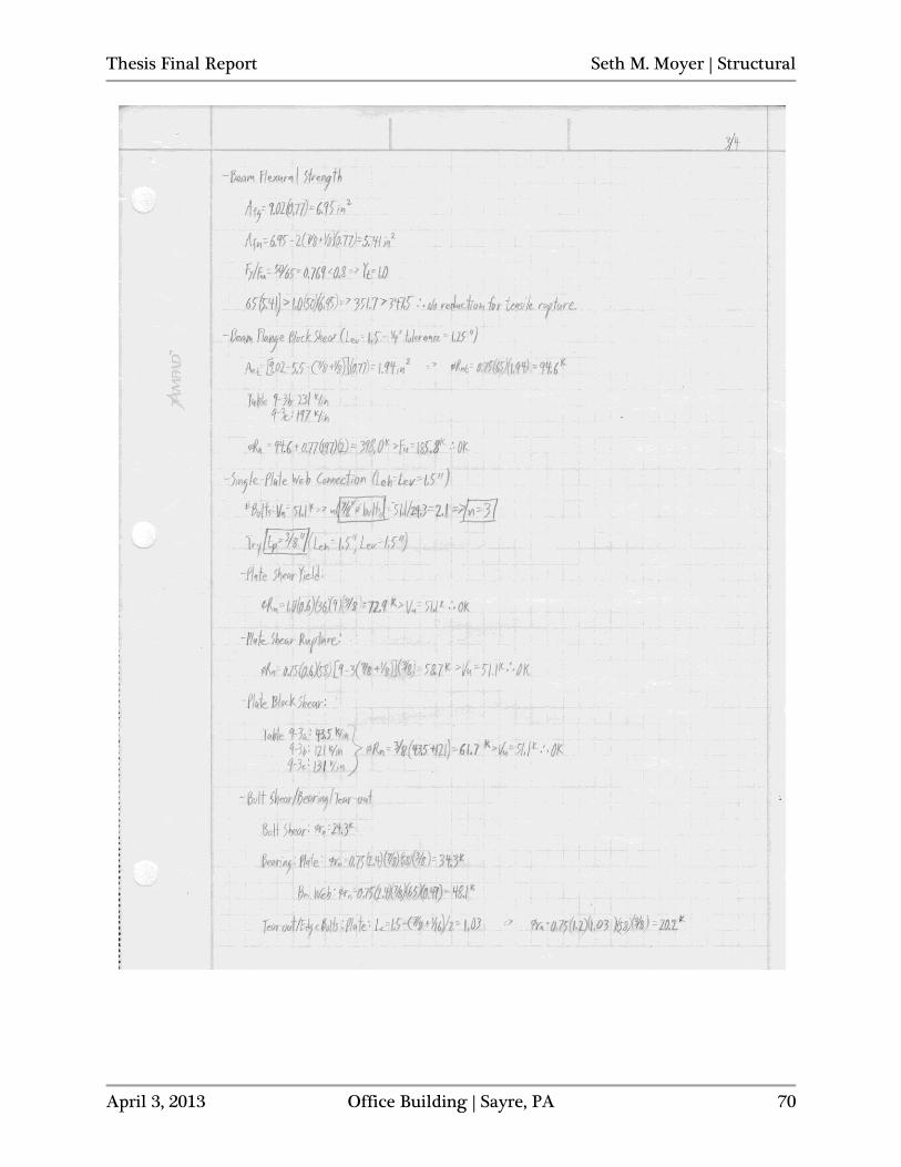
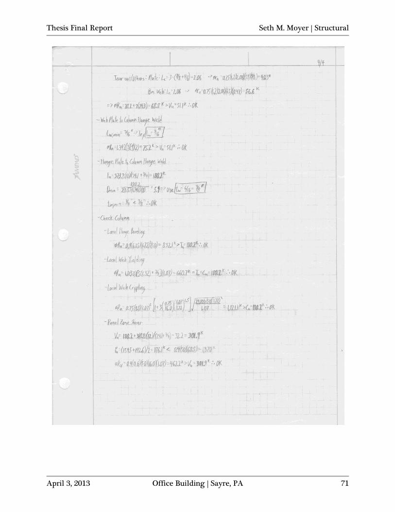
ETABS. The results from the hand calculated approximation and the actual second-order ETABS output were nearly identical (see Appendix H). After validating the results obtained from ETABS by hand, the rigid frame members were checked to see if they would meet the strength requirements determined from the direct analysis method. Representative and critical members of the frames acting in each direction were checked by hand for purely flexural and combined axial and flexural conditions. The nominal strengths of all members that were checked exceeded their respective required design strengths. See Appendix I for details of the member check calculations. Moment Connection Design With the frame member sections finalized, the moment connections can be designed and detailed. Since bolted connections are quicker to erect and less costly than field-welded connections and bolting is typically preferred to welding on site when possible, bolted flange-plated connections will be used for the fully restrained moment connection type in this design. Shear capacity in the connections will be provided by single-plate shear tabs. The flange plates and shear tabs can be shop-welded to the column flanges and then transported to the site already partially assembled. The beams can then be lifted into place and bolted to the single and flange plates on site to save money and time on assembly. Several critical and representative rigid frame joints were selected to design and detail the fully restrained moment connections for. Connections were specifically designed for the following joint locations: J-10 @ level 4, J-10 @ level 2, K-10 @ level 2, K-4 @ level 2 (see Figures 33 and 34 for joint locations). Additionally, in lieu of detailing the moment connection at joint K-8 @ level 4, a quick check was performed for panel zone shear to see if there were any column stiffening requirements at that location, where the greatest sum of moments going into the upper W14x145 column via the beams on either side occurred. The need for any column stiffening was effectively avoided in all moment frames due to the adequate column web shear areas provided by the heavy columns.
Thesis Final Report Seth M. Moyer | Structural
April 3, 2013 Office Building | Sayre, PA 41
Figure 33: E-W Frame - Selected Joints for Moment Connection Design/Detailing
Figure 34: N-S Frame - Selected Joints for Moment Connection Design/Detailing Connection J-10 @ level 4 was selected to represent one of the smaller upper joints where W18x35 beams frame into a W14x145 column and carry smaller moments. Connection J-10 @ level 2 had the greatest moments of any interior beam-column joint acting in the E-W (X-
Thesis Final Report Seth M. Moyer | Structural
April 3, 2013 Office Building | Sayre, PA 42
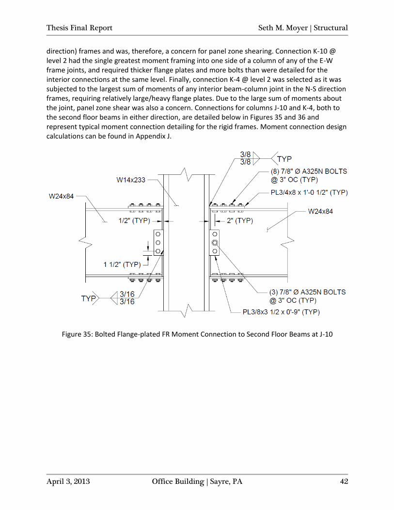
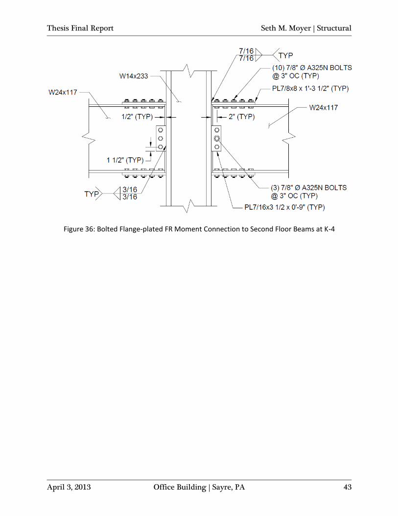
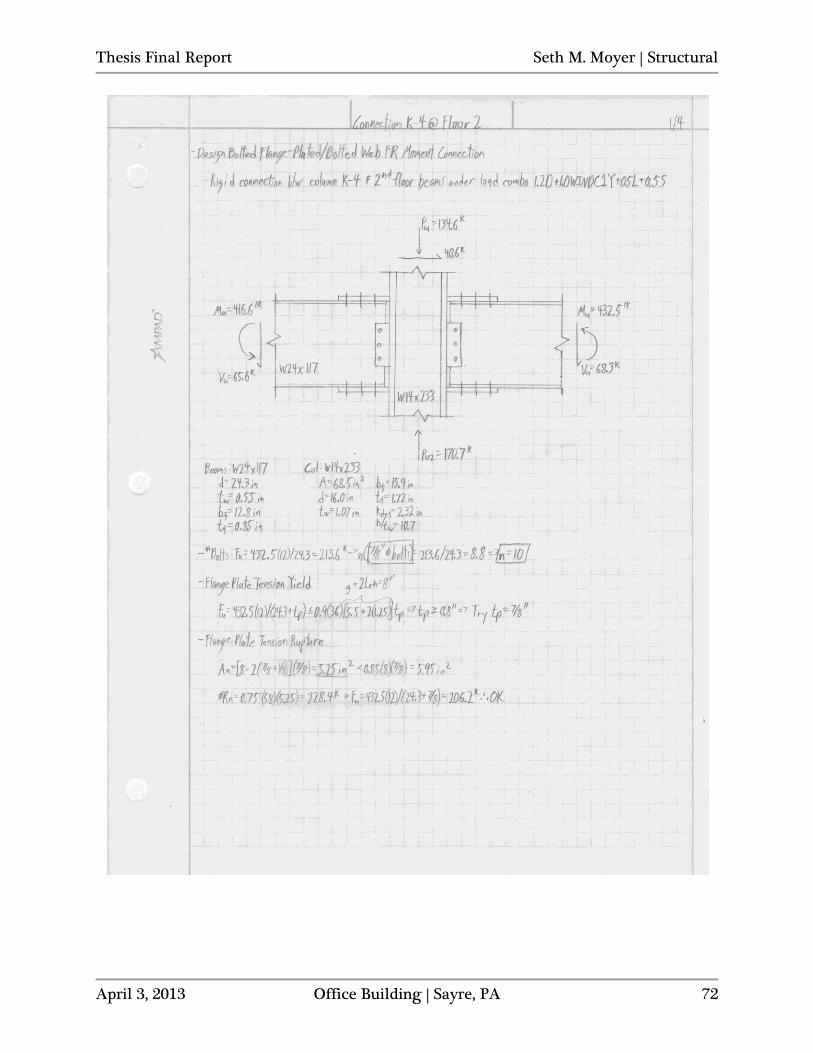
direction) frames and was, therefore, a concern for panel zone shearing. Connection K-10 @ level 2 had the single greatest moment framing into one side of a column of any of the E-W frame joints, and required thicker flange plates and more bolts than were detailed for the interior connections at the same level. Finally, connection K-4 @ level 2 was selected as it was subjected to the largest sum of moments of any interior beam-column joint in the N-S direction frames, requiring relatively large/heavy flange plates. Due to the large sum of moments about the joint, panel zone shear was also a concern. Connections for columns J-10 and K-4, both to the second floor beams in either direction, are detailed below in Figures 35 and 36 and represent typical moment connection detailing for the rigid frames. Moment connection design calculations can be found in Appendix J.
Figure 35: Bolted Flange-plated FR Moment Connection to Second Floor Beams at J-10
Thesis Final Report Seth M. Moyer | Structural
April 3, 2013 Office Building | Sayre, PA 43
Figure 36: Bolted Flange-plated FR Moment Connection to Second Floor Beams at K-4
Thesis Final Report Seth M. Moyer | Structural
April 3, 2013 Office Building | Sayre, PA 44
Breadth One – Building Enclosure Redesign
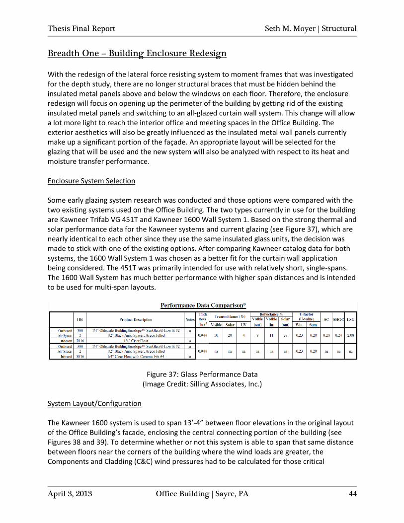
With the redesign of the lateral force resisting system to moment frames that was investigated for the depth study, there are no longer structural braces that must be hidden behind the insulated metal panels above and below the windows on each floor. Therefore, the enclosure redesign will focus on opening up the perimeter of the building by getting rid of the existing insulated metal panels and switching to an all-glazed curtain wall system. This change will allow a lot more light to reach the interior office and meeting spaces in the Office Building. The exterior aesthetics will also be greatly influenced as the insulated metal wall panels currently make up a significant portion of the façade. An appropriate layout will be selected for the glazing that will be used and the new system will also be analyzed with respect to its heat and moisture transfer performance. Enclosure System Selection Some early glazing system research was conducted and those options were compared with the two existing systems used on the Office Building. The two types currently in use for the building are Kawneer Trifab VG 451T and Kawneer 1600 Wall System 1. Based on the strong thermal and solar performance data for the Kawneer systems and current glazing (see Figure 37), which are nearly identical to each other since they use the same insulated glass units, the decision was made to stick with one of the existing options. After comparing Kawneer catalog data for both systems, the 1600 Wall System 1 was chosen as a better fit for the curtain wall application being considered. The 451T was primarily intended for use with relatively short, single-spans. The 1600 Wall System has much better performance with higher span distances and is intended to be used for multi-span layouts.
Figure 37: Glass Performance Data (Image Credit: Silling Associates, Inc.)
System Layout/Configuration The Kawneer 1600 system is used to span 13’-4” between floor elevations in the original layout of the Office Building’s facade, enclosing the central connecting portion of the building (see Figures 38 and 39). To determine whether or not this system is able to span that same distance between floors near the corners of the building where the wind loads are greater, the Components and Cladding (C&C) wind pressures had to be calculated for those critical
Thesis Final Report Seth M. Moyer | Structural
April 3, 2013 Office Building | Sayre, PA 45
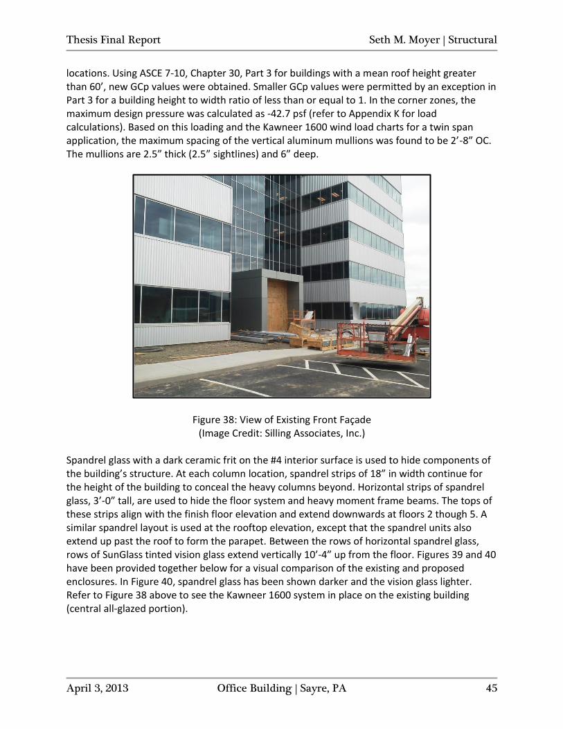
locations. Using ASCE 7-10, Chapter 30, Part 3 for buildings with a mean roof height greater than 60’, new GCp values were obtained. Smaller GCp values were permitted by an exception in Part 3 for a building height to width ratio of less than or equal to 1. In the corner zones, the maximum design pressure was calculated as -42.7 psf (refer to Appendix K for load calculations). Based on this loading and the Kawneer 1600 wind load charts for a twin span application, the maximum spacing of the vertical aluminum mullions was found to be 2’-8” OC. The mullions are 2.5” thick (2.5” sightlines) and 6” deep.
Figure 38: View of Existing Front Façade (Image Credit: Silling Associates, Inc.)
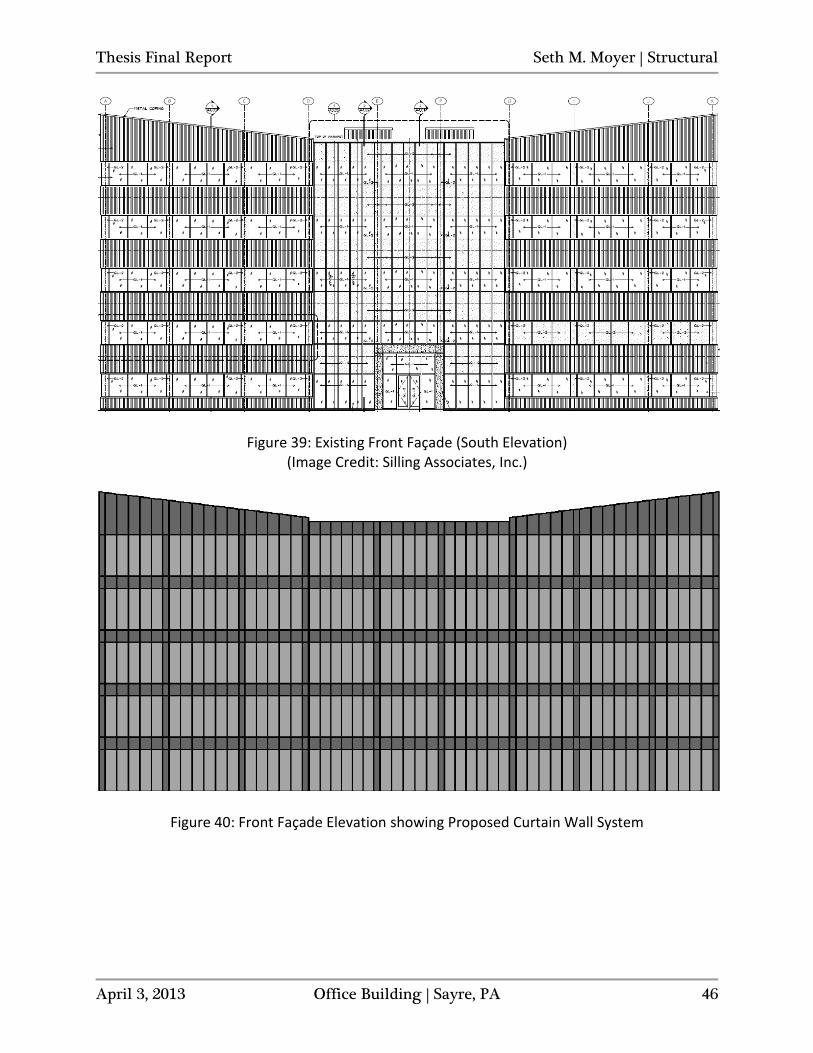
Spandrel glass with a dark ceramic frit on the #4 interior surface is used to hide components of the building’s structure. At each column location, spandrel strips of 18” in width continue for the height of the building to conceal the heavy columns beyond. Horizontal strips of spandrel glass, 3’-0” tall, are used to hide the floor system and heavy moment frame beams. The tops of these strips align with the finish floor elevation and extend downwards at floors 2 though 5. A similar spandrel layout is used at the rooftop elevation, except that the spandrel units also extend up past the roof to form the parapet. Between the rows of horizontal spandrel glass, rows of SunGlass tinted vision glass extend vertically 10’-4” up from the floor. Figures 39 and 40 have been provided together below for a visual comparison of the existing and proposed enclosures. In Figure 40, spandrel glass has been shown darker and the vision glass lighter. Refer to Figure 38 above to see the Kawneer 1600 system in place on the existing building (central all-glazed portion).
Thesis Final Report Seth M. Moyer | Structural
April 3, 2013 Office Building | Sayre, PA 46
Figure 39: Existing Front Façade (South Elevation) (Image Credit: Silling Associates, Inc.)
Figure 40: Front Façade Elevation showing Proposed Curtain Wall System

Thesis Final Report Seth M. Moyer | Structural
April 3, 2013 Office Building | Sayre, PA 47
Barrier Performance Analysis The performance of the enclosure as the building’s primary barrier to the outside environment was assessed by looking into its resistance to heat and vapor flow. Thermal resistance (RT) values and vapor resistance totals for four different exterior wall compositions were calculated to assess and compare the new proposed enclosure with the existing layout. The RT-values and vapor resistances (RV) found for each of the four cases are as follows:
- Kingspan 400 V-Wave Insulated Metal Panels (IMPs) Wall Section - RT: 26.3 hr-ft2-°F/Btu - RV: 6.70 hr-ft2-inHg/gr
- Kawneer 1600 Wall System 1 – Spandrel Glass Wall Section
- RT: 17.9 hr-ft2-°F/Btu - RV: 4.48 hr-ft2-inHg/gr *(value only applies to silicone sealants at window joints)
- Kawneer 1600 Wall System 1 – Vision Glass Wall Section
- RT: 3.35 hr-ft2-°F/Btu - RV: 4.35 hr-ft2-inHg/gr *(value only applies to silicone sealants at window joints)
- Kawneer 451T - Vision Glass Wall Section
- RT: 3.85 hr-ft2-°F/Btu - RV: 4.35 hr-ft2-inHg/gr *(value only applies to silicone sealants at window joints)
RT-values for the Kingspan 400 IMPs and Kawneer 1600 – Spandrel Glass wall sections, which both have a series of wall system components backing them up, were calculated using the isothermal planes method to account for varying wall compositions along the length of each particular wall (such as studs occupying the batt insulated cavity space at 24” OC). The planes method produces an average resistance value for components that overlap so that they can be accounted for accurately in a single analysis. The method was chosen as it is most accurate when dealing with envelopes containing highly conductive materials (like metal studs) that penetrate insulation. For the two cases of vision glass units and the spandrel glass layer of the Kawneer 1600 system, the center-of-glass (COG) U-value provided by the manufacturer was adjusted to get a more accurate U-value for the system as a whole using the appropriate Kawneer thermal charts. By first finding the proportion of vision area to total area, the corresponding system value can then be located on the chart. For all cases, the ratio of vision to total area was about 0.9. There was some difficulty in determining permeance properties for the wall sections containing glass. Without finding a perm rating for the insulated glass units or for glass at all, the water vapor transmission was assumed to be negligible. Instead, the vapor resistance was found for the silicone window sealant, which acts as the weakest link for vapor penetration through any
Thesis Final Report Seth M. Moyer | Structural
April 3, 2013 Office Building | Sayre, PA 48
portion of the glazing system. Because this small strip area is only located around the perimeter of the windows, it should not be directly compared to the higher reported vapor resistance of the IMP wall section and made to look inferior. In reality, the curtain wall system has a greater overall resistance to water vapor transmission due to the properties of the glass and aluminum mullions that should be considered along with the weak link properties of the silicone. Details of the wall systems and their make-up can be seen broken down for each wall section in Appendix L along with the detailed calculations of thermal and vapor resistances reported above. From the results of the barrier analysis, it is apparent that the enclosure redesign will cause the overall thermal resistance of the building to go down, as the IMPs with the greatest thermal resistance values will be replaced by Kawneer 1600 Spandrel and Vision wall sections which both have lower RT-values. However, the overall vapor resistance of the building will increase as the glazing is made to enclose the entire building perimeter.
Thesis Final Report Seth M. Moyer | Structural
April 3, 2013 Office Building | Sayre, PA 49
Breadth Two – Mechanical Loads and Systems Impact
The hygrothermal properties investigated for the barrier performance analysis in the first breadth study will now be used to determine what effects the building enclosure redesign will have on the heating/cooling loads of the building. The potential impact on the mechanical systems will also be assessed. Heating/Cooling Load Effects To see how big of an impact would be made on the mechanical loads of the building with the proposed enclosure redesign, the relative areas of the different enclosure types were first found for both the existing and proposed facade layouts. The areas are as follows:
- Existing Enclosure Areas: - IMPs: 23,649 sf - 451T: 19,175 sf - 1600 Spandrel: 3,457 sf - 1600 Vision: 3,355 sf
- Proposed Enclosure Areas:
- 1600 Vision: 38,276 sf - 1600 Spandrel: 11,359 sf
The conductive heating/cooling loads for both designs were found by dividing the areas by their respective RT-values. The proportion of proposed to existing conductive loads came out to be 1.70. This means that there would be a 70% increase in the conductive enclosure loads with the new proposed design. The solar load incurred by the vision glass is directly proportional to the vision glass area. Therefore, the amount that the load will increase is proportional to the increase in total vision glass area. Since the amount of vision glass increases by 70%, so too does the solar load in the Office Building. Mechanical Systems Impact To determine the impact of the redesign on the building’s mechanical systems, the portion of the total load that the enclosure accounts for in the existing design needs to be found. The ten 20-ton Mitsubishi condensing units that serve the Office Building have a total cooling capacity of 200 tons. It is also assumed that the equipment was oversized by about 15%. In that case, the total demand serviced by the condensing units is around 174 tons. The existing conductive cooling load and solar load need to be found in tons of cooling. Applying a CLTD value taken from ASHRAE, the conductive load comes out to be 29.5 tons.
Thesis Final Report Seth M. Moyer | Structural
April 3, 2013 Office Building | Sayre, PA 50
Applying a SC and SCL value, also taken from ASHRAE, the solar load is found to be 65.7 tons. Combining the loads and dividing by the demand of 174 tons, the enclosure driven portion of the total load is close to 55%. It can now be determined that a 70% increase in the external/façade enclosure loads is equal to about a 40% increase in total demand. With that amount of additional load, an equivalent system would have a required mechanical equipment capacity of 280 tons. Assuming a basic mechanical system costs roughly $3,000/ton of cooling installed, the minimum additional mechanical equipment costs would be about $240,000, which is nearly 2% of the total project construction cost of $11,000,000. Refer to Appendices L and N for further details and calculations completed for the second breadth study.
Thesis Final Report Seth M. Moyer | Structural
April 3, 2013 Office Building | Sayre, PA 51
Conclusion
The Thesis Final Report consists of a lateral system redesign depth study and breadth studies centered on a redesign of the building enclosure of the Office Building. The structural depth was an investigation into changing the braced frame lateral force resisting system to a moment frame system and designing the frames and rigid connections. Breadth one outlined a redesign of the building enclosure to an all-glazing curtain wall system. It also involved an analysis of the barrier performance of the proposed system, considering heat and vapor flow through the enclosure. Breadth two took a further look into the enclosure redesign by determining what sort of effects the change would have on the heating/cooling loads of the building and how it might impact the mechanical systems. For the structural depth, four 3-bay moment frames were designed for the E-W direction and two 5-bay frames were designed for the N-S direction. The sizes of the frame members were controlled by the drift limitation set as H/500 under serviceability wind loading (10-year MRI winds). The frames were checked for strength requirements and all members passed that were checked. Critical and representative beam-to-column joints were selected and the moment connections were designed and detailed for those locations. All connections designed were bolted flange-plated type connections. The shear tab and flange plates in this sort of connection can be shop-welded to the column flanges and then the beam can be erected and bolted up on site. Critical columns were checked for stiffening requirements, but all ended up being heavy enough without the need for transverse stiffeners or doubler plates. The building enclosure redesign for breadth one was undertaken to get rid of the existing insulated metal panels and to open up the Office Building to more light. The selection of the Kawneer 1600 curtain wall system was based on structural as well as thermal and solar performances. A practical layout for the glazing system units was developed. Furthermore, the barrier performance of the proposed and existing enclosure systems was investigated, taking both heat and vapor transfer into account. It was determined that the proposed redesign would result in poorer overall thermal resistance for the building, while also increasing its resistance to vapor transmission. The performance data found and examined in breadth one was used to analyze the effects of the enclosure redesign on the heating/cooling loads of the Office Building. A 70% increase in the exterior wall enclosure conduction loads and in the solar loads through the vision glass was calculated. Those 70% increases in the envelope loads were found to be equivalent to a nearly 40% increase in total load demand. The mechanical systems would need to be upsized by about 40% in their overall capacity to be able to handle the higher demand.
Thesis Final Report Seth M. Moyer | Structural
April 3, 2013 Office Building | Sayre, PA 52
Appendix A
Thesis Final Report Seth M. Moyer | Structural
April 3, 2013 Office Building | Sayre, PA 53
Thesis Final Report Seth M. Moyer | Structural
April 3, 2013 Office Building | Sayre, PA 54
Appendix B
Thesis Final Report Seth M. Moyer | Structural
April 3, 2013 Office Building | Sayre, PA 55
Thesis Final Report Seth M. Moyer | Structural
April 3, 2013 Office Building | Sayre, PA 56
Appendix C
Thesis Final Report Seth M. Moyer | Structural
April 3, 2013 Office Building | Sayre, PA 57
Thesis Final Report Seth M. Moyer | Structural
April 3, 2013 Office Building | Sayre, PA 58
Appendix D
Thesis Final Report Seth M. Moyer | Structural
April 3, 2013 Office Building | Sayre, PA 59
Appendix E
Thesis Final Report Seth M. Moyer | Structural
April 3, 2013 Office Building | Sayre, PA 60
Appendix F
Thesis Final Report Seth M. Moyer | Structural
April 3, 2013 Office Building | Sayre, PA 61
Appendix G
Thesis Final Report Seth M. Moyer | Structural
April 3, 2013 Office Building | Sayre, PA 62
Appendix H
Thesis Final Report Seth M. Moyer | Structural
April 3, 2013 Office Building | Sayre, PA 63
Appendix I
Thesis Final Report Seth M. Moyer | Structural
April 3, 2013 Office Building | Sayre, PA 64
Thesis Final Report Seth M. Moyer | Structural
April 3, 2013 Office Building | Sayre, PA 65
Thesis Final Report Seth M. Moyer | Structural
April 3, 2013 Office Building | Sayre, PA 66
Thesis Final Report Seth M. Moyer | Structural
April 3, 2013 Office Building | Sayre, PA 67
Thesis Final Report Seth M. Moyer | Structural
April 3, 2013 Office Building | Sayre, PA 68
Appendix J
Thesis Final Report Seth M. Moyer | Structural
April 3, 2013 Office Building | Sayre, PA 69
Thesis Final Report Seth M. Moyer | Structural
April 3, 2013 Office Building | Sayre, PA 70
Thesis Final Report Seth M. Moyer | Structural
April 3, 2013 Office Building | Sayre, PA 71
Thesis Final Report Seth M. Moyer | Structural
April 3, 2013 Office Building | Sayre, PA 72
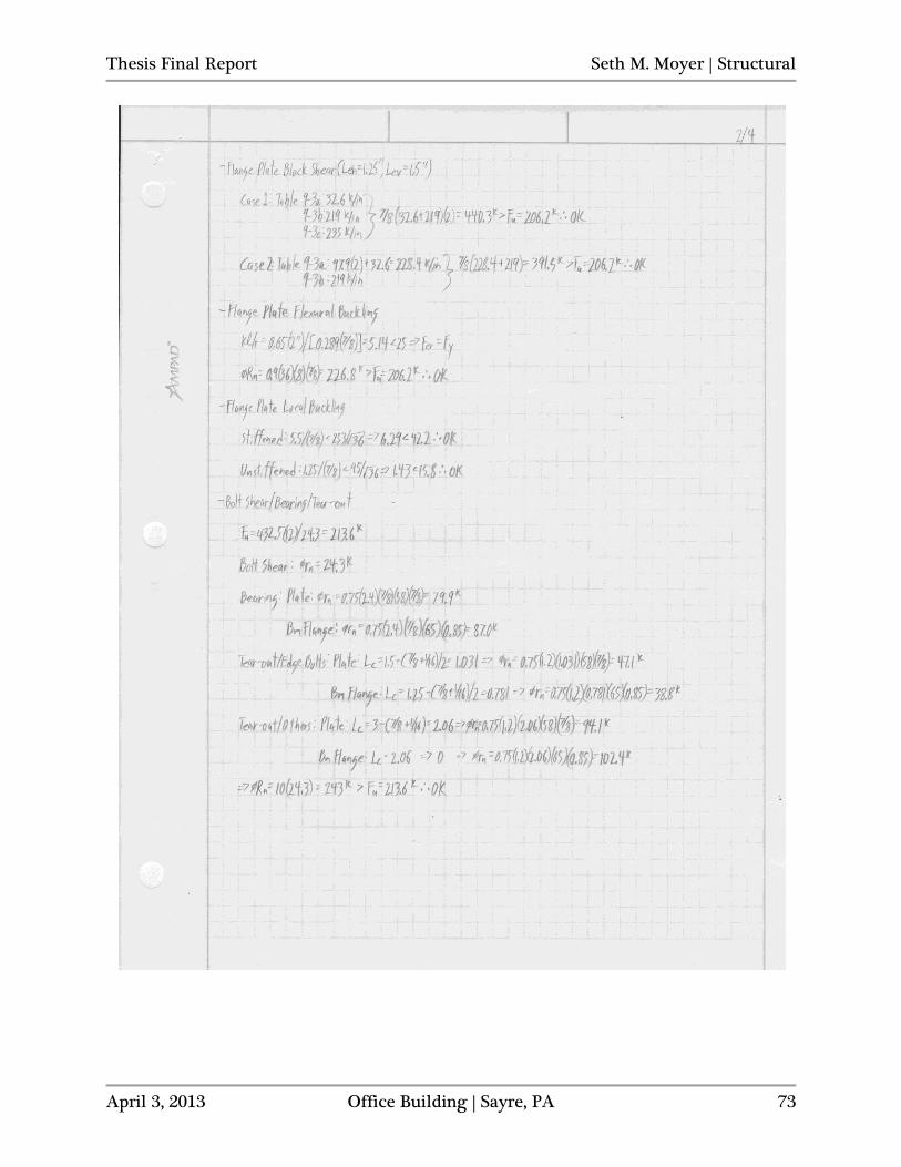
Thesis Final Report Seth M. Moyer | Structural
April 3, 2013 Office Building | Sayre, PA 73
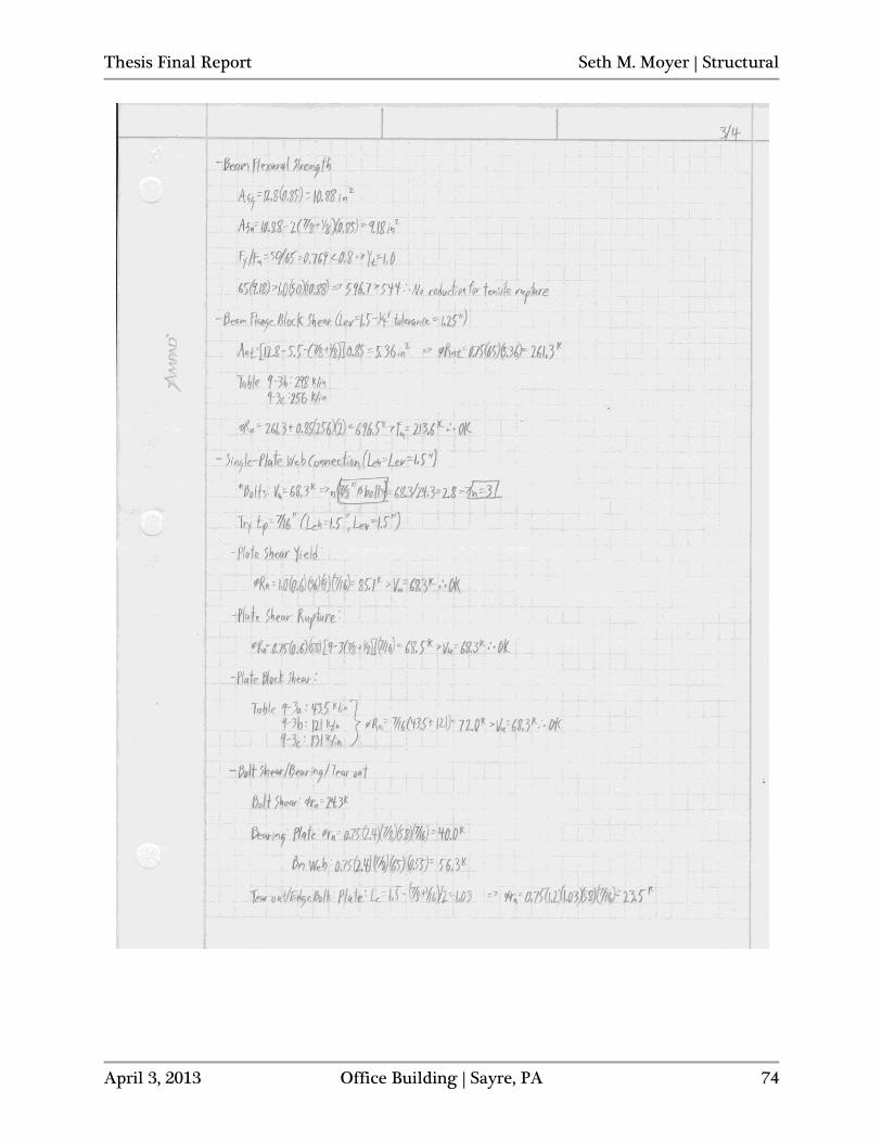
Thesis Final Report Seth M. Moyer | Structural
April 3, 2013 Office Building | Sayre, PA 74
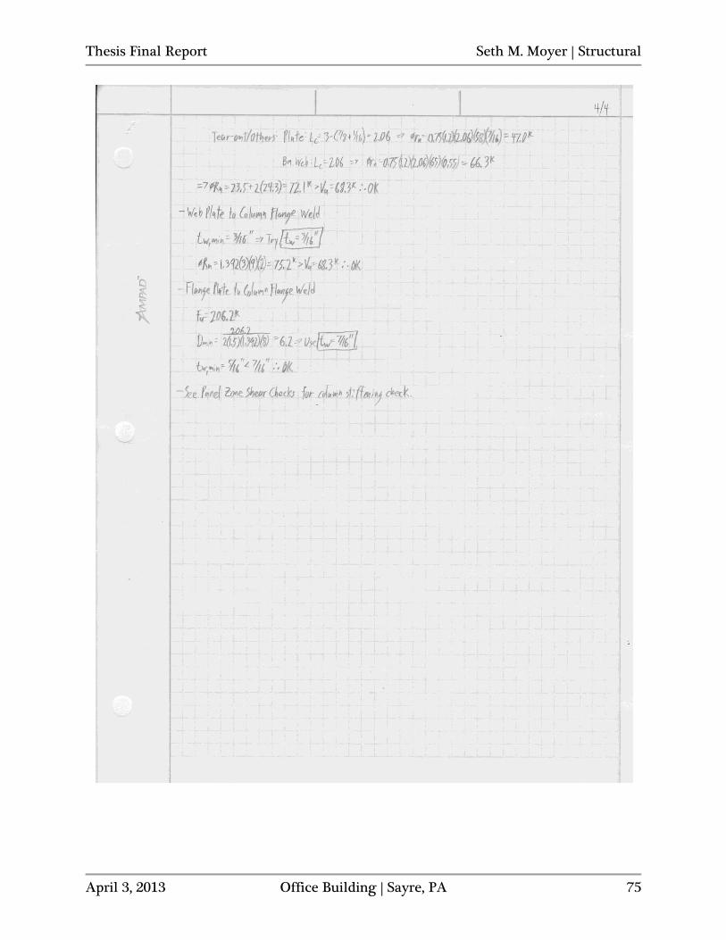
Thesis Final Report Seth M. Moyer | Structural
April 3, 2013 Office Building | Sayre, PA 75
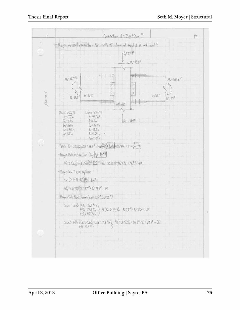
Thesis Final Report Seth M. Moyer | Structural
April 3, 2013 Office Building | Sayre, PA 76
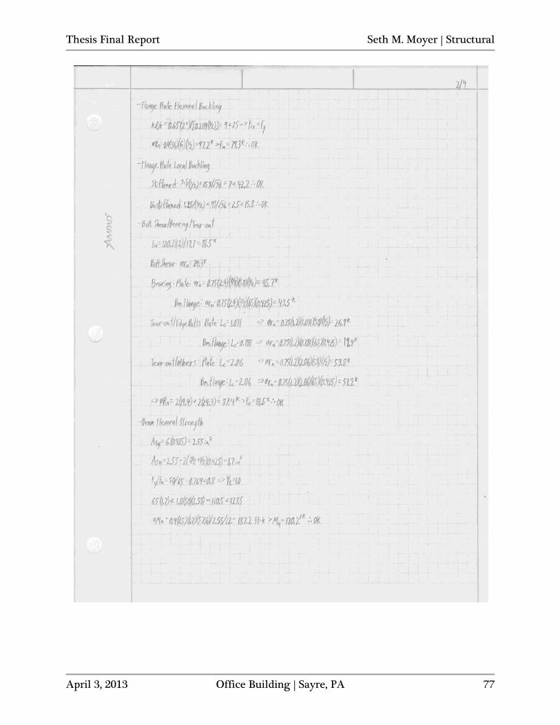
Thesis Final Report Seth M. Moyer | Structural
April 3, 2013 Office Building | Sayre, PA 77
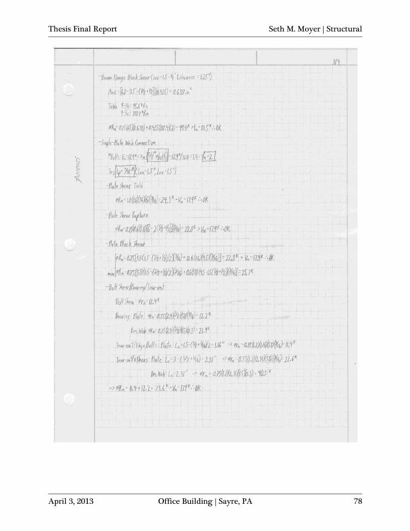
Thesis Final Report Seth M. Moyer | Structural
April 3, 2013 Office Building | Sayre, PA 78
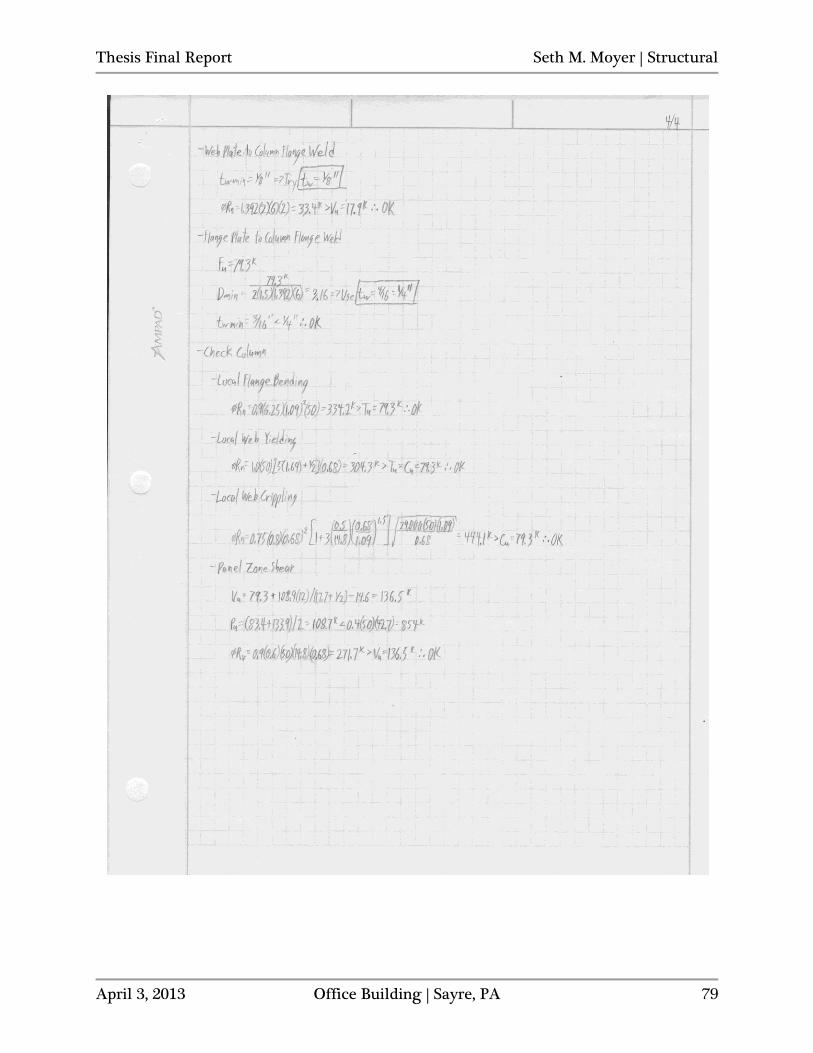
Thesis Final Report Seth M. Moyer | Structural
April 3, 2013 Office Building | Sayre, PA 79
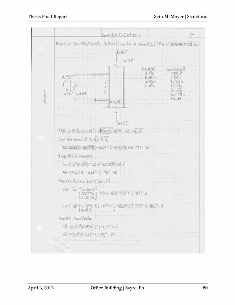
Thesis Final Report Seth M. Moyer | Structural
April 3, 2013 Office Building | Sayre, PA 80
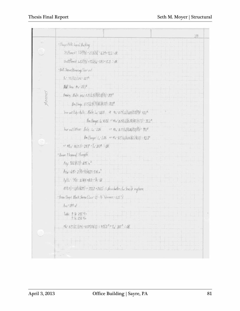
Thesis Final Report Seth M. Moyer | Structural
April 3, 2013 Office Building | Sayre, PA 81
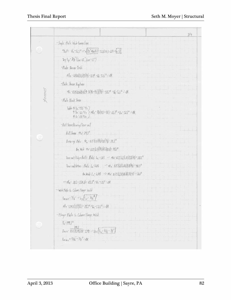
Thesis Final Report Seth M. Moyer | Structural
April 3, 2013 Office Building | Sayre, PA 82
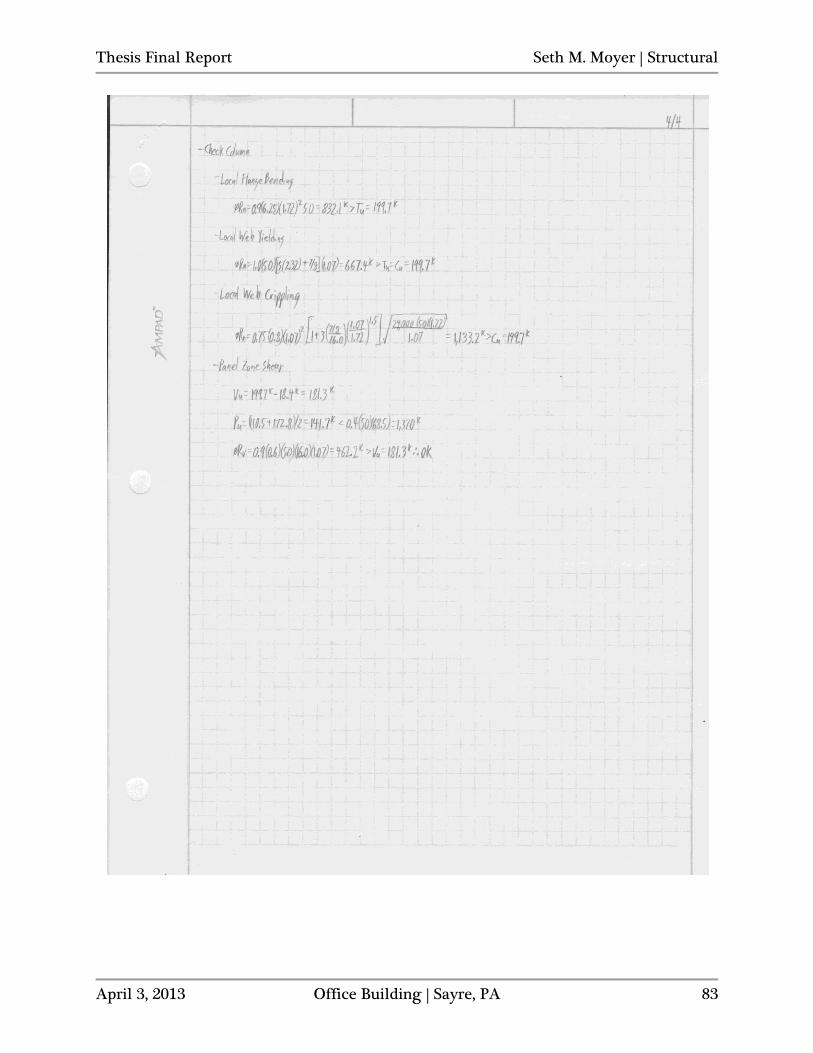
Thesis Final Report Seth M. Moyer | Structural
April 3, 2013 Office Building | Sayre, PA 83
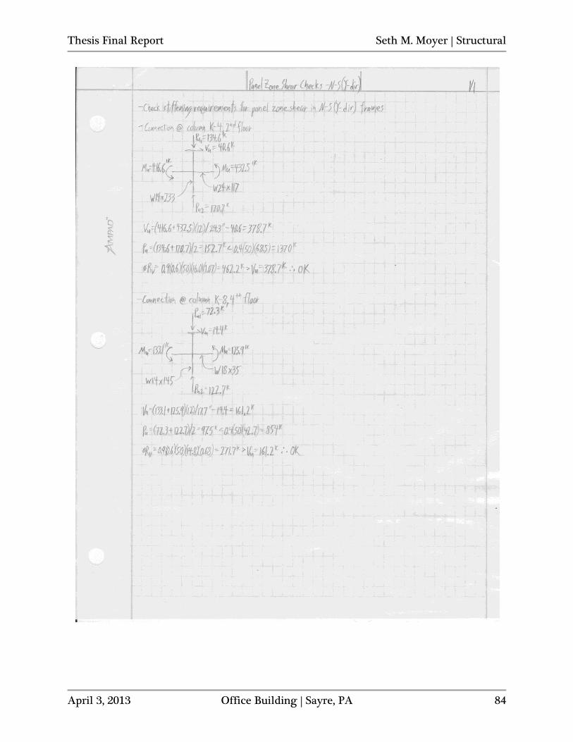
Thesis Final Report Seth M. Moyer | Structural
April 3, 2013 Office Building | Sayre, PA 84
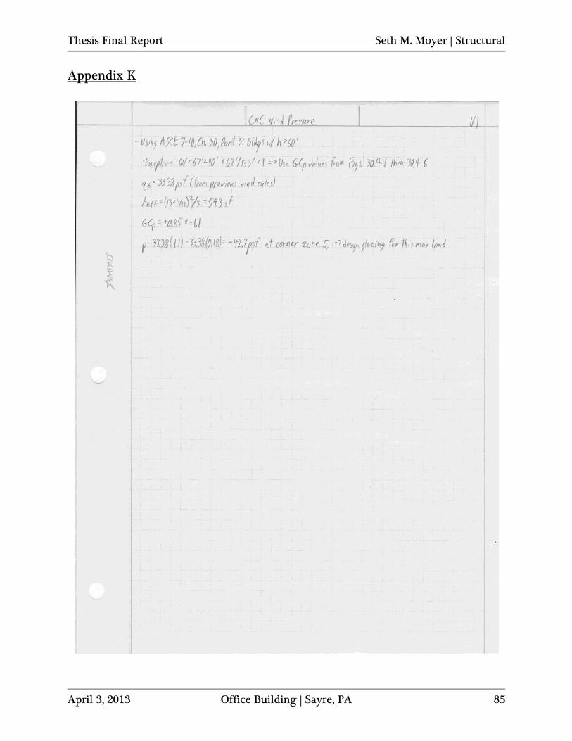
Thesis Final Report Seth M. Moyer | Structural
April 3, 2013 Office Building | Sayre, PA 85
Appendix K
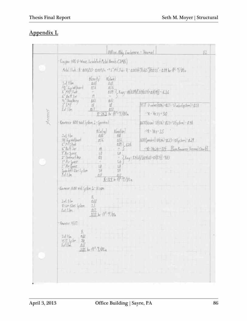
Thesis Final Report Seth M. Moyer | Structural
April 3, 2013 Office Building | Sayre, PA 86
Appendix L
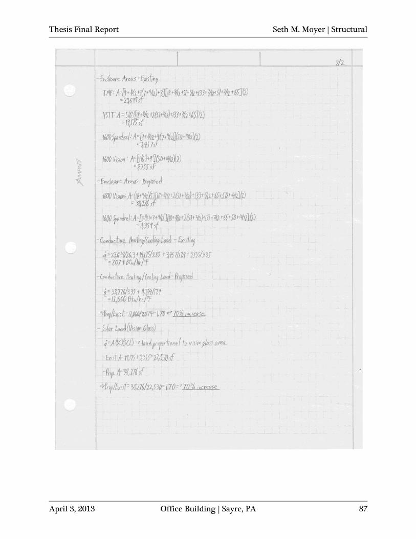
Thesis Final Report Seth M. Moyer | Structural
April 3, 2013 Office Building | Sayre, PA 87
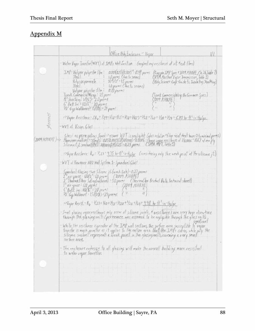
Thesis Final Report Seth M. Moyer | Structural
April 3, 2013 Office Building | Sayre, PA 88
Appendix M
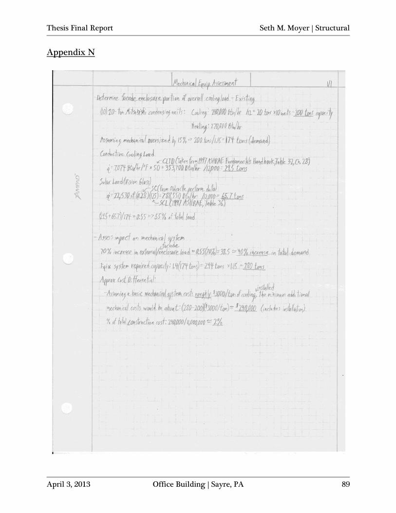
Thesis Final Report Seth M. Moyer | Structural
April 3, 2013 Office Building | Sayre, PA 89
Appendix N
Related Documents