T H E U N I V E R S I T Y O F B R I T I S H C O L U M B I 1 Modeling software behavior UML Acknowledgement: some slides from Philippe Kruchten, Steve Easterbrook

T H E U N I V E R S I T Y O F B R I T I S H C O L U M B I A 1 Modeling software behavior UML Acknowledgement: some slides from Philippe Kruchten, Steve.
Dec 26, 2015
Welcome message from author
This document is posted to help you gain knowledge. Please leave a comment to let me know what you think about it! Share it to your friends and learn new things together.
Transcript
T H E U N I V E R S I T Y O F B R I T I S H C O L U M B I A
1
Modeling software behaviorUML
Acknowledgement: some slides from Philippe Kruchten, Steve Easterbrook
2
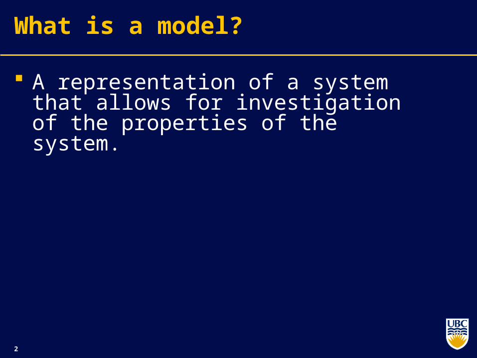
What is a model?
A representation of a system that allows for investigation of the properties of the system.
3
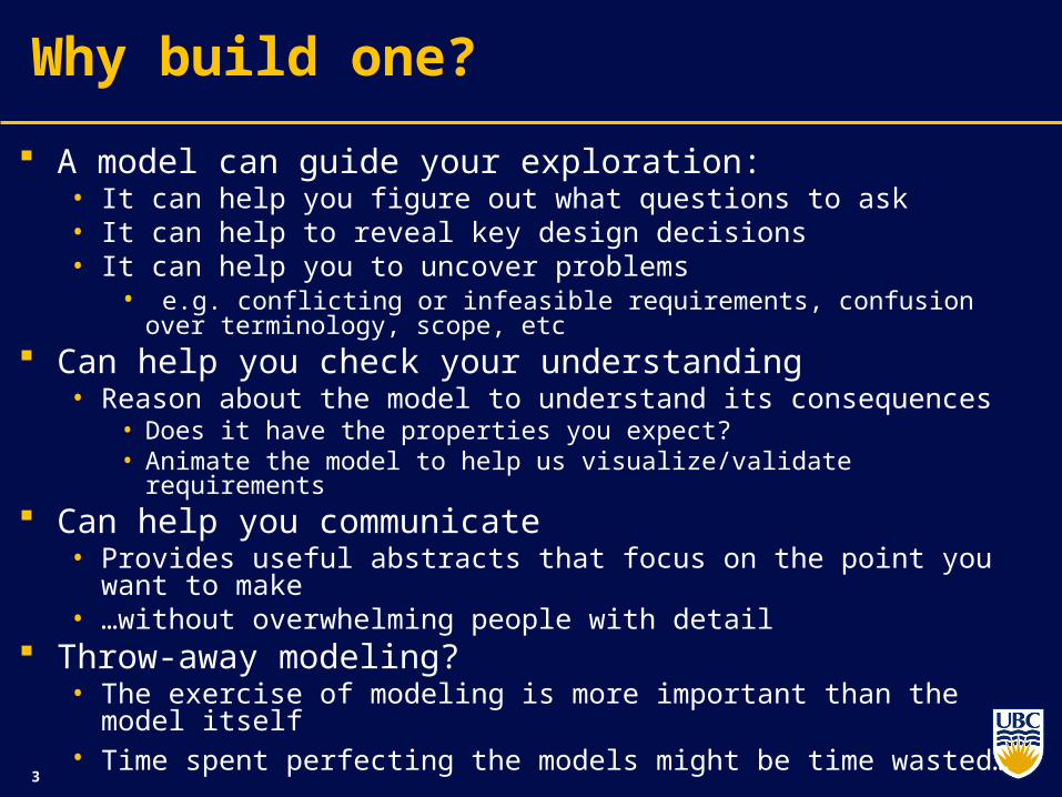
Why build one?
A model can guide your exploration:• It can help you figure out what questions to ask• It can help to reveal key design decisions• It can help you to uncover problems
• e.g. conflicting or infeasible requirements, confusion over terminology, scope, etc
Can help you check your understanding• Reason about the model to understand its consequences
• Does it have the properties you expect?• Animate the model to help us visualize/validate requirements
Can help you communicate• Provides useful abstracts that focus on the point you want to make• …without overwhelming people with detail
Throw-away modeling?• The exercise of modeling is more important than the model itself• Time spent perfecting the models might be time wasted…
4
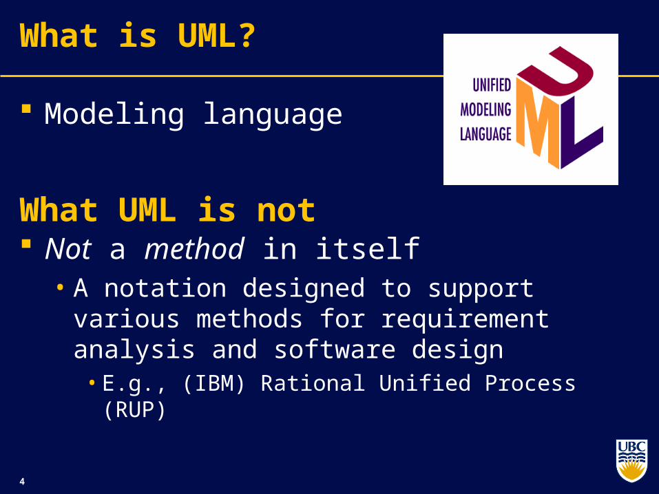
What is UML?
Modeling language
What UML is not Not a method in itself
• A notation designed to support various methods for requirement analysis and software design
• E.g., (IBM) Rational Unified Process (RUP)

5
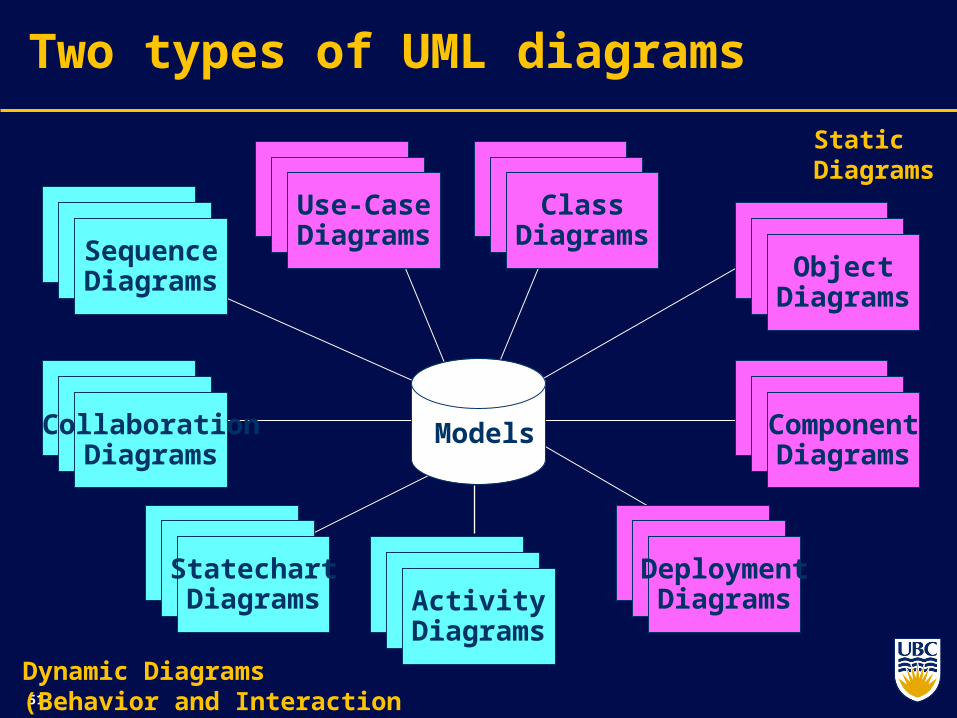
Two types of UML diagrams
ActivityDiagrams
Models
Dynamic Diagrams (Behavior and Interaction
StatechartDiagrams
CollaborationDiagrams
SequenceDiagrams
Use-CaseDiagrams
ClassDiagrams
ObjectDiagrams
ComponentDiagrams
DeploymentDiagrams
Static Diagrams
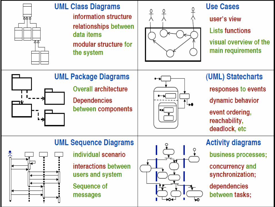
6
Visual modeling of a software system
Actor A
Use Case 1
Use Case 2
Actor B
user : Clerk
mainWnd : MainWnd
fileMgr : FileMgr
repository : Repositorydocument : Document
gFile : GrpFile
9: sortByName ( )
L1: Doc view request ( )
2: fetchDoc( )
5: readDoc ( )
7: readFile ( )
3: create ( )
6: fillDocument ( )
4: create ( )
8: fillFile ( )
Window95
¹®¼ °ü¸®
Ŭ¶óÀ̾ðÆ®.EXE
Windows
NT
¹®¼ °ü¸® ¿£Áø.EXE
WindowsNT
Windows95
Solaris
ÀÀ¿ë¼ ¹ö.EXE
AlphaUNIX
IBM
Mainframe
µ¥ÀÌŸº£À̽º¼ ¹ö
Windows95
¹®¼ °ü¸® ¾ÖÇø´Document
FileManager
GraphicFile
File
Repository DocumentList
FileList
user
mainWnd fileMgr : FileMgr
repositorydocument : Document
gFile
1: Doc view request ( )
2: fetchDoc( )
3: create ( )
4: create ( )
5: readDoc ( )
6: fillDocument ( )
7: readFile ( )
8: fillFile ( )
9: sortByName ( )
ƯÁ¤¹®¼ ¿¡ ́ ëÇÑ º¸±â¸¦ »ç¿ëÀÚ°¡ ¿äûÇÑ´Ù.
È ÀÏ°ü̧ ®ÀÚ´Â Àоî¿Â ¹®¼ ÀÇ Á¤º¸¸¦ ÇØ´ç ¹®¼
°´Ã¼¿¡ ¼³Á¤À» ¿äûÇÑ´Ù.
È ̧é °´Ã¼´Â ÀоîµéÀÎ °´Ã¼µé¿¡ ´ëÇØ ÀÌ̧ §º°·Î
Á¤·ÄÀ» ½ÃÄÑ È ̧é¿¡ º¸¿©ÁØ´Ù.
Forward and Reverse Engineering
Openning
Writing
ReadingClosing
add file [ numberOffile==MAX ] / flag OFF
add file
close file
close fileUse Case 3
Use-CaseDiagram Class Diagram
Collaboration Diagram
Sequence Diagram
Component Diagram
StateDiagram
GrpFile
read( )open( )create( )fillFile( )
rep
Repository
name : char * = 0
readDoc( )readFile( )
(from Persistence)
FileMgr
fetchDoc( )sortByName( )
DocumentList
add( )delete( )
Document
name : intdocid : intnumField : int
get( )open( )close( )read( )sortFileList( )create( )fillDocument( )
fList
1
FileList
add( )delete( )
1
File
read( )
read() fill the code..
Deployment Diagram
7
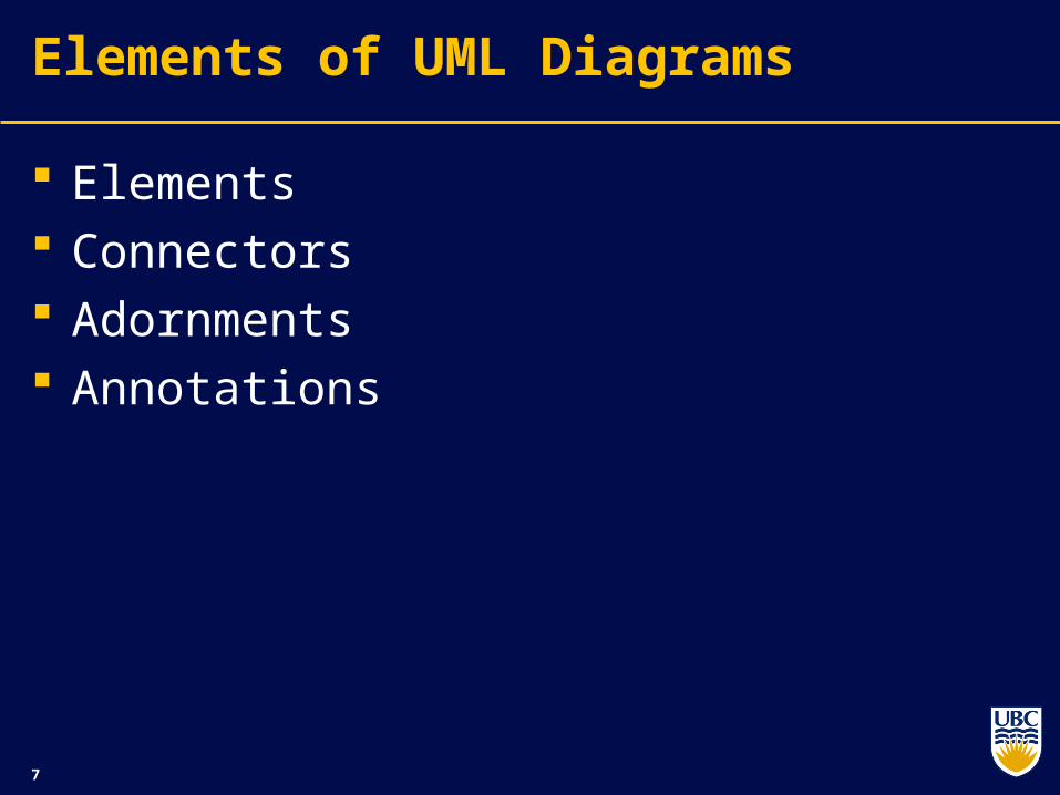
Elements of UML Diagrams
Elements Connectors Adornments Annotations

8
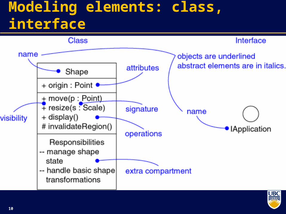
Reminder: Class
A description of a set of objects that share the same attributes, operations, methods, relationships, and semantics.
A class may use a set of interfaces to specify collections of operations it provides to its environment
9
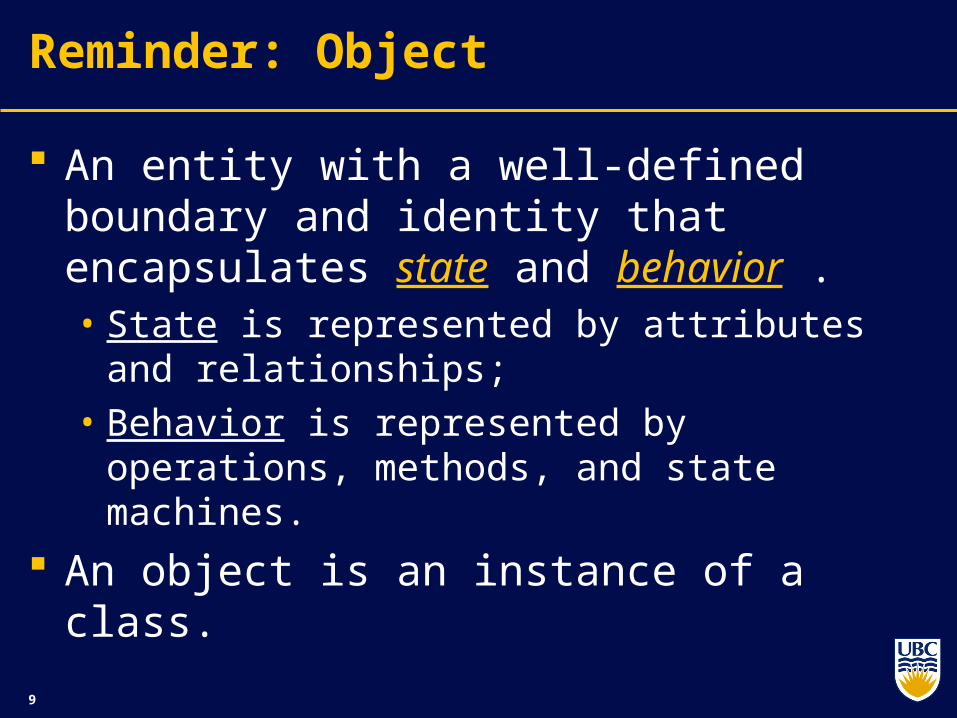
Reminder: Object
An entity with a well-defined boundary and identity that encapsulates state and behavior . • State is represented by attributes and
relationships; • Behavior is represented by operations, methods,
and state machines.
An object is an instance of a class.
10
Modeling elements: class, interface
11
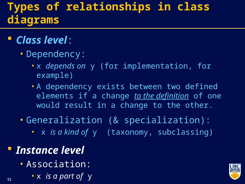
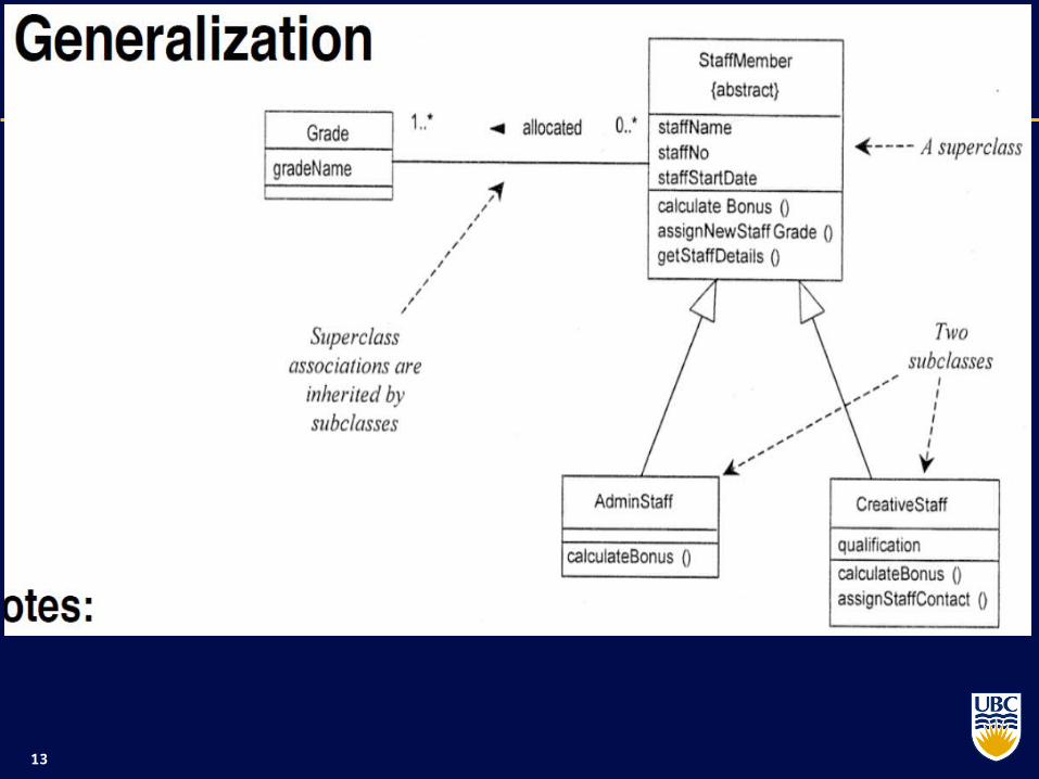
Types of relationships in class diagrams
Class level:• Dependency:
• x depends on y (for implementation, for example)• A dependency exists between two defined elements if
a change to the definition of one would result in a change to the other.
• Generalization (& specialization):• x is a kind of y (taxonomy, subclassing)
Instance level• Association:
• x is a part of y
12
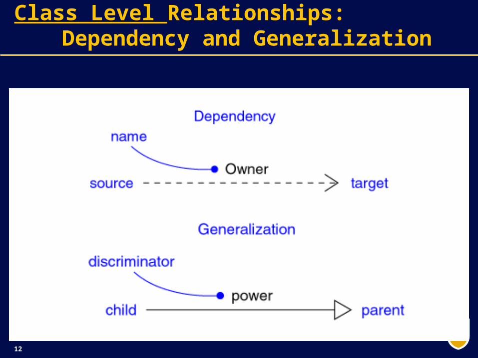
Class Level Relationships: Dependency and Generalization
13

14
Types of relationships in class diagrams
Class level:• Dependency:
• x depends on y (for implementation, for example)• A dependency exists between two defined elements if
a change to the definition of one would result in a change to the other.
• Generalization (& specialization):• x is a kind of y (taxonomy, subclassing)
Instance level• Association:
• x is a part of y

15
Instance-Level Relationships: Association
A relationship that models a bi (or multi)-directional semantic connection among instances.
An association
represents a
family of links
16
One more association example
Role
Activity0..*
1
0..*
1
Performs
Artifact0..*1 0..*1 IsResponsibleFor
0..*
0..*
0..*
input0..*
Consumes
0..*
0..*
0..*
0..*
Produces
17
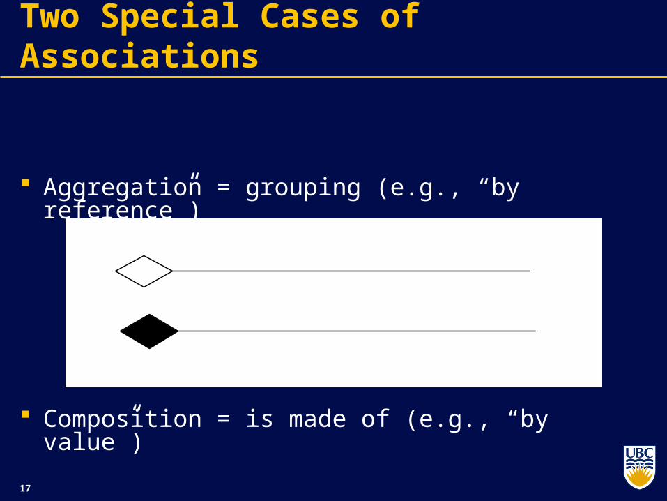
Aggregation = grouping (e.g., “by reference”)
Composition = is made of (e.g., “by value”)
Two Special Cases of Associations
18
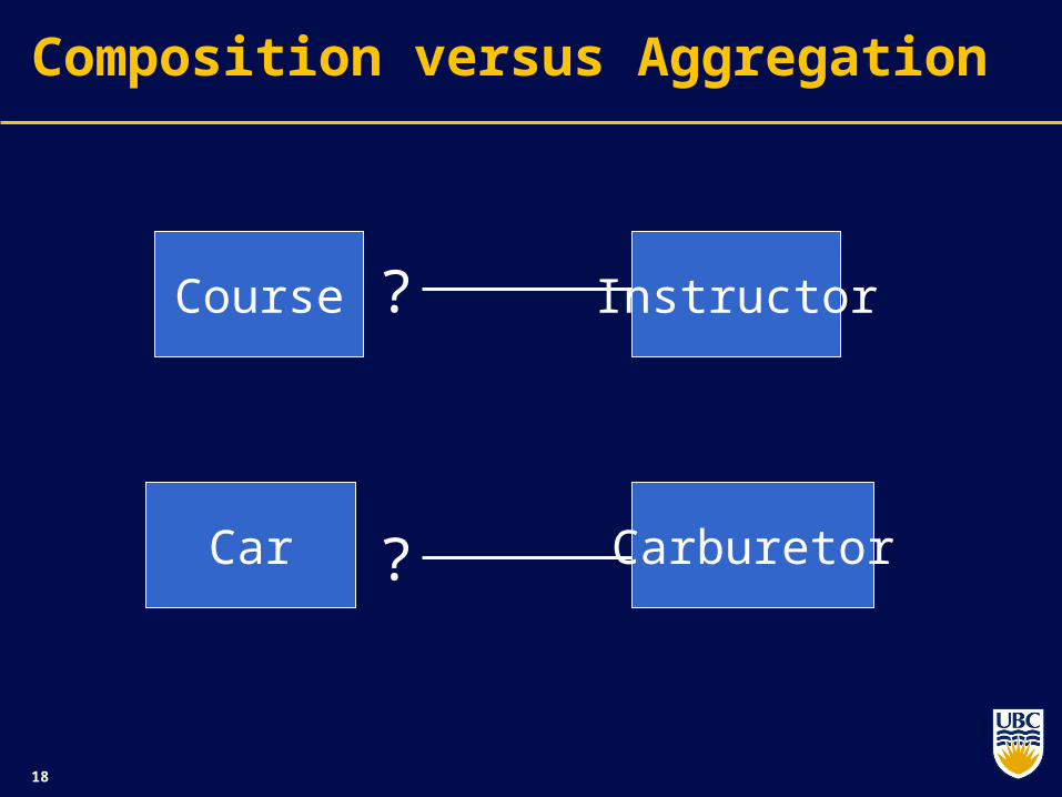
Composition versus Aggregation
Course Instructor
Car Carburetor
?
?

19
Composition versus Aggregation
Course Instructor
Car CarburetorComposition
Aggregation
20
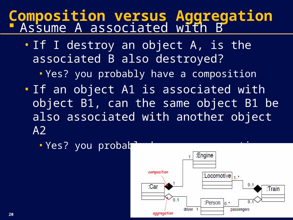
Composition versus Aggregation Assume A associated with B
• If I destroy an object A, is the associated B also destroyed?
• Yes? you probably have a composition
• If an object A1 is associated with object B1, can the same object B1 be also associated with another object A2
• Yes? you probably have an aggregation
21
Composition vs. Aggregation
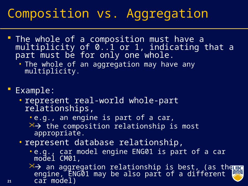
The whole of a composition must have a multiplicity of 0..1 or 1, indicating that a part must be for only one whole. • The whole of an aggregation may have any multiplicity.
Example: • represent real-world whole-part relationships,
• e.g., an engine is part of a car, the composition relationship is most appropriate.
• represent database relationship, • e.g., car model engine ENG01 is part of a car model
CM01, an aggregation relationship is best, (as the engine,
ENG01 may be also part of a different car model)

22
Class Diagram (2)
WorkItem(from Basic Elements)
Step ActivityKind1
1..*
1
1..*
WorkDefinitionName(from Names)
ArtifactName(from Names)
RoleKind(f rom Basic Elements)
0..10..* performer0..10..*
0..* 0..*0..* assistant 0..*
WorkDefinition
0..*
1
0..*
1
1
0..*
1
0..*
ArtifactKind
+ isDeliverable : Boolean
(from Basic Elements)
1
0..*
1
0..*
1
0..*
1
0..*
0..*
0..1
0..*
0..1
IsResponsibleFor
ArtifactUsageName
+ isInput : Boolean+ isOutput : Boolean+ hasWorkPerArtifact : Boolean
(from Names)
1
0..*
1
0..*
1
0..*
1
0..*IsOfKind
23
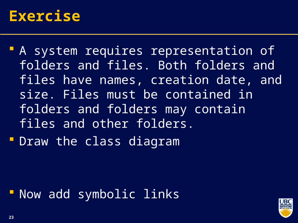
Exercise
A system requires representation of folders and files. Both folders and files have names, creation date, and size. Files must be contained in folders and folders may contain files and other folders.
Draw the class diagram
Now add symbolic links
24
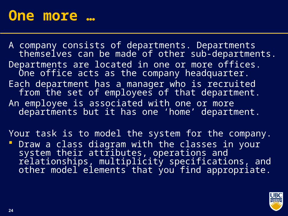
One more …
A company consists of departments. Departments themselves can be made of other sub-departments.
Departments are located in one or more offices. One office acts as the company headquarter.
Each department has a manager who is recruited from the set of employees of that department.
An employee is associated with one or more departments but it has one ‘home’ department.
Your task is to model the system for the company. Draw a class diagram with the classes in your system their
attributes, operations and relationships, multiplicity specifications, and other model elements that you find appropriate.
25
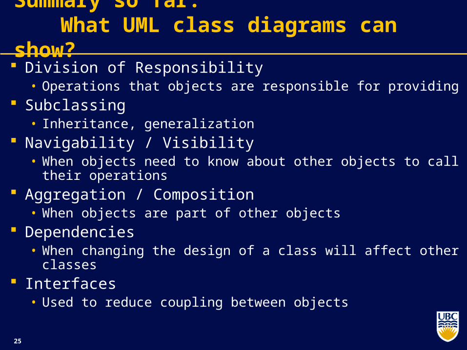
Summary so far: What UML class diagrams can show?
Division of Responsibility• Operations that objects are responsible for providing
Subclassing• Inheritance, generalization
Navigability / Visibility• When objects need to know about other objects to call their
operations Aggregation / Composition
• When objects are part of other objects Dependencies
• When changing the design of a class will affect other classes Interfaces
• Used to reduce coupling between objects
26
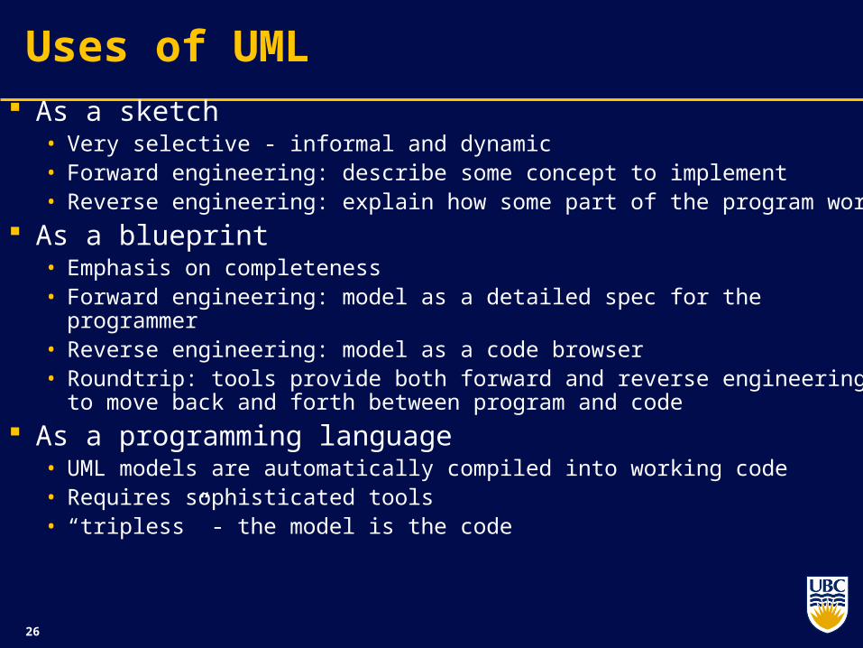
Uses of UML As a sketch
• Very selective - informal and dynamic• Forward engineering: describe some concept to implement• Reverse engineering: explain how some part of the program works
As a blueprint• Emphasis on completeness• Forward engineering: model as a detailed spec for the programmer• Reverse engineering: model as a code browser• Roundtrip: tools provide both forward and reverse engineering to move
back and forth between program and code
As a programming language• UML models are automatically compiled into working code• Requires sophisticated tools• “tripless” - the model is the code
27
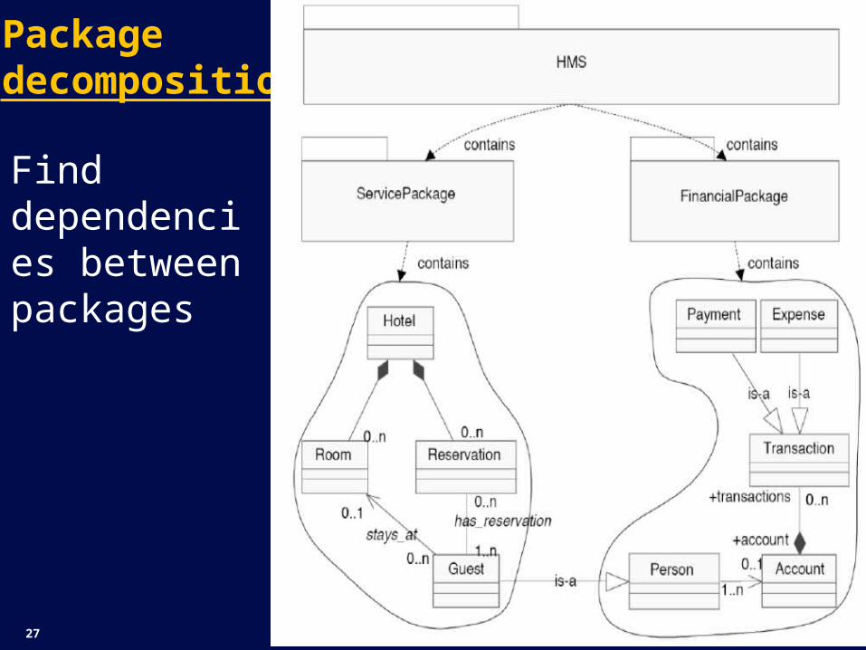
Package decomposition
Find dependencies between packages
28
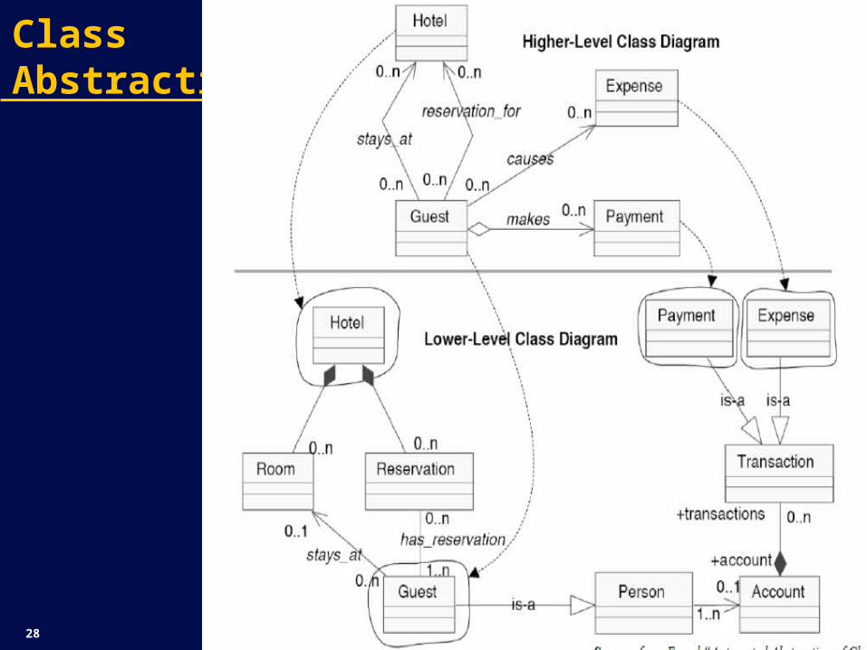
Class Abstraction
29
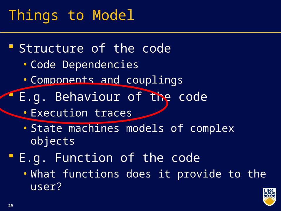
Things to Model
Structure of the code• Code Dependencies• Components and couplings
E.g. Behaviour of the code• Execution traces• State machines models of complex objects
E.g. Function of the code• What functions does it provide to the user?
30
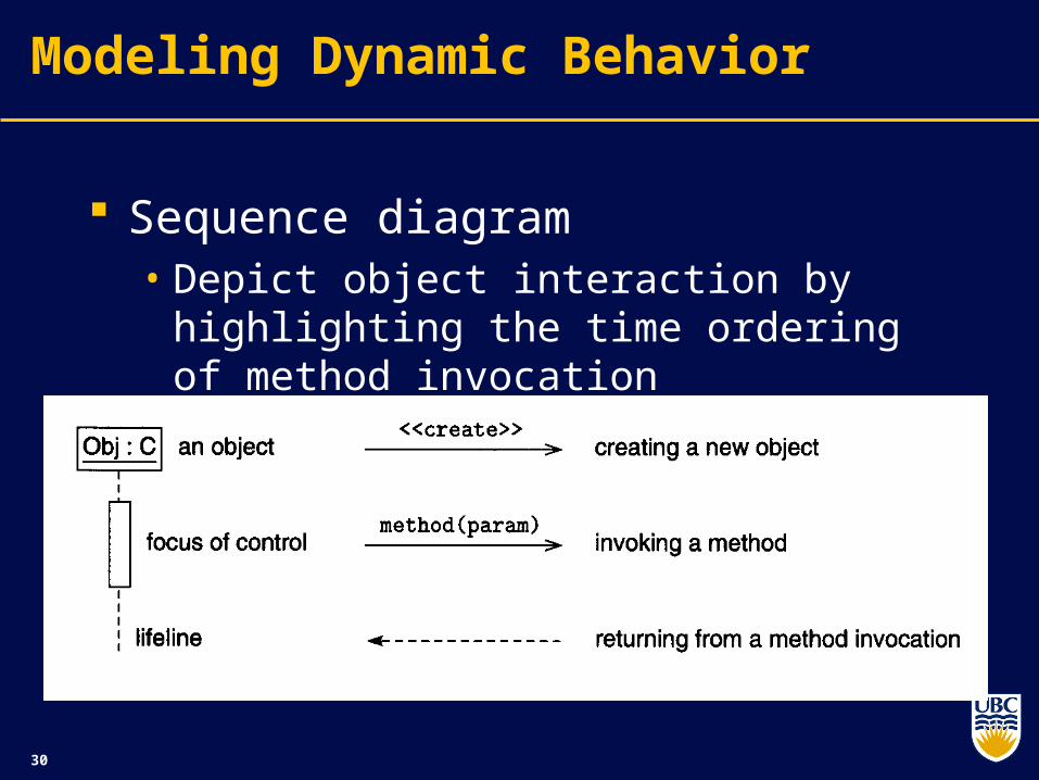
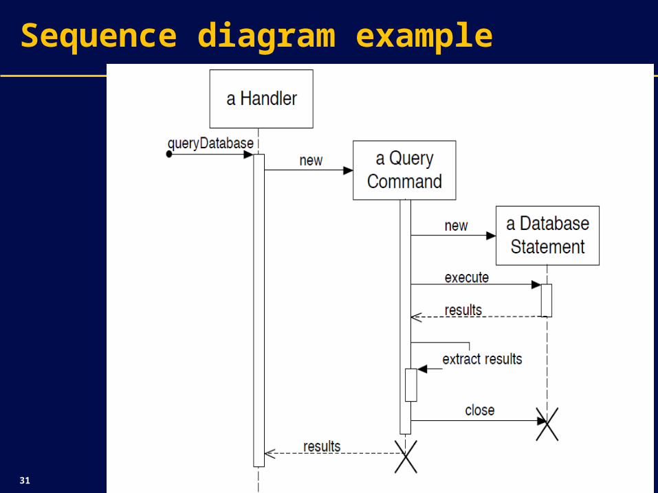
Modeling Dynamic Behavior
Sequence diagram• Depict object interaction by highlighting the
time ordering of method invocation
31
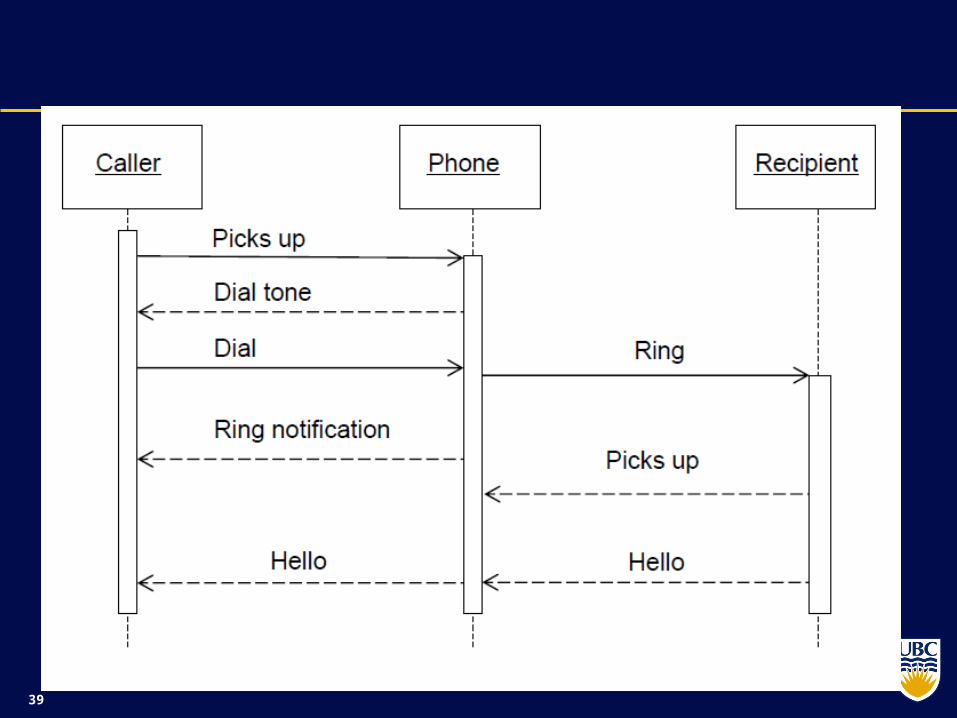
Sequence diagram example

32
Sequence diagram
33
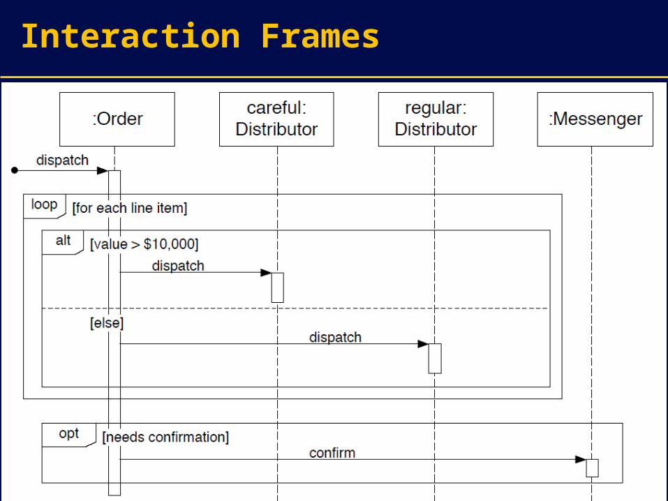
Interaction Frames

34
Interaction Frame Operators
Operator Meaning
alt Alternative; only the frame whose guard is true will execute
opt Optional; only executes if the guard is true
par Parallel; frames execute in parallel
loop Frame executes multiple times, guard indicates how many
region Critical region; only one thread can execute this frame at a time
neg Negative; frame shows an neg invalid interaction
ref Reference; refers to a sequence shown on another
Diagram
sd Sequence Diagram; used to surround the whole
diagram (optional)
35
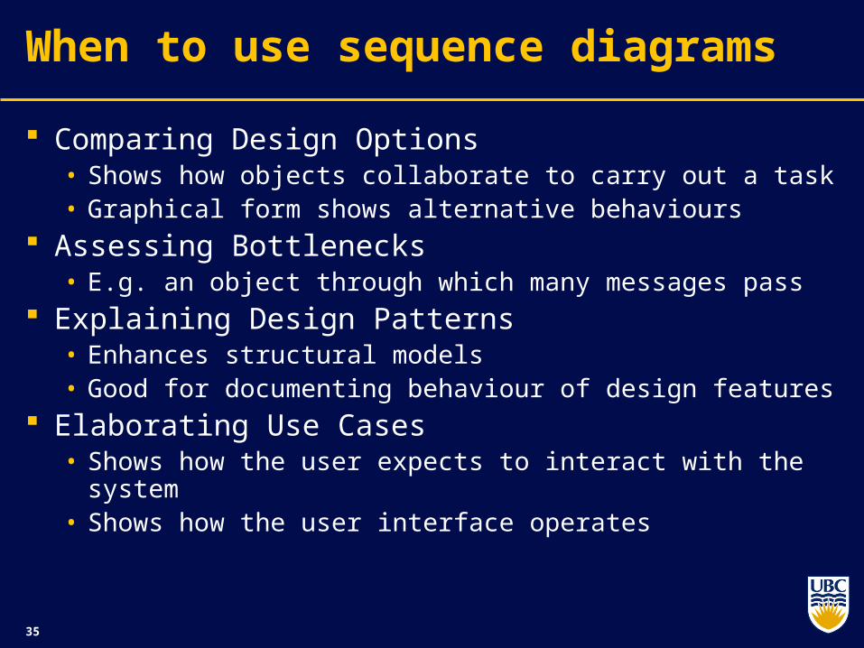
When to use sequence diagrams
Comparing Design Options• Shows how objects collaborate to carry out a task• Graphical form shows alternative behaviours
Assessing Bottlenecks• E.g. an object through which many messages pass
Explaining Design Patterns• Enhances structural models• Good for documenting behaviour of design features
Elaborating Use Cases• Shows how the user expects to interact with the system• Shows how the user interface operates
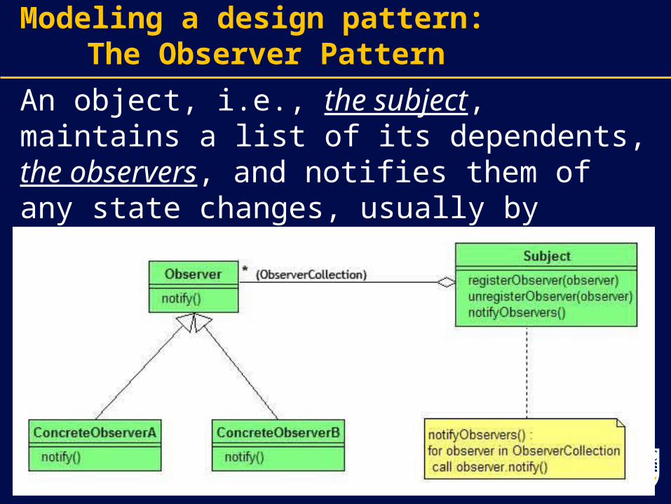
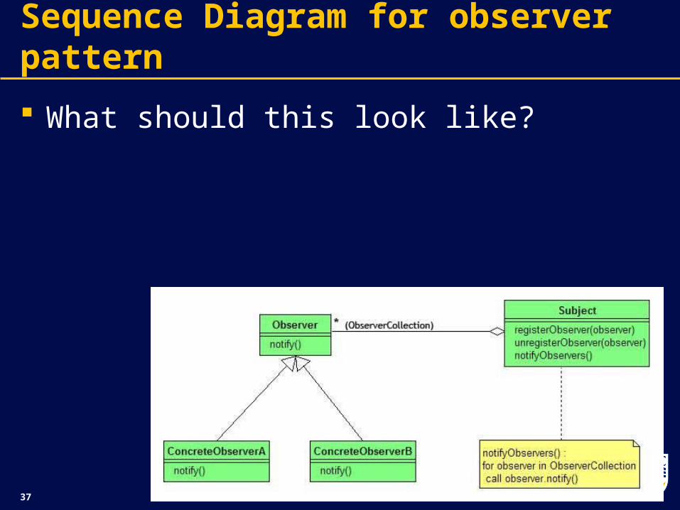
Modeling a design pattern: The Observer Pattern
An object, i.e., the subject, maintains a list of its dependents, the observers, and notifies them of any state changes, usually by calling one of their methods.
37
Sequence Diagram for observer pattern
What should this look like?
39
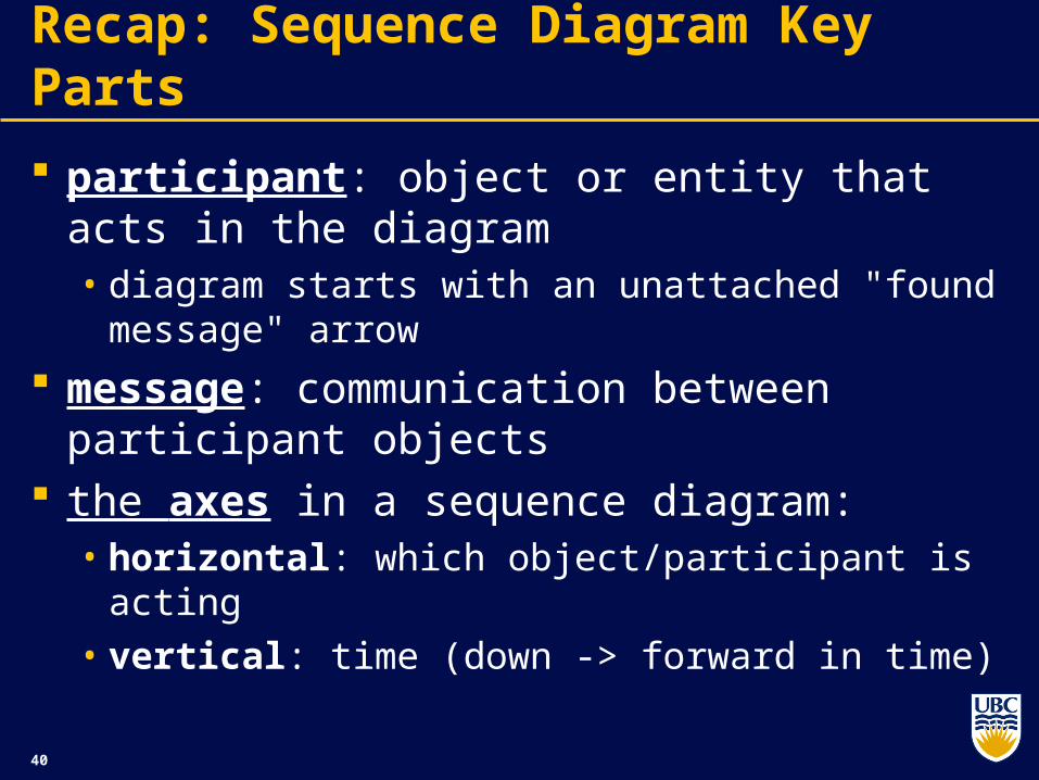
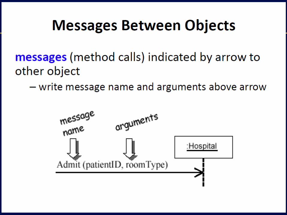
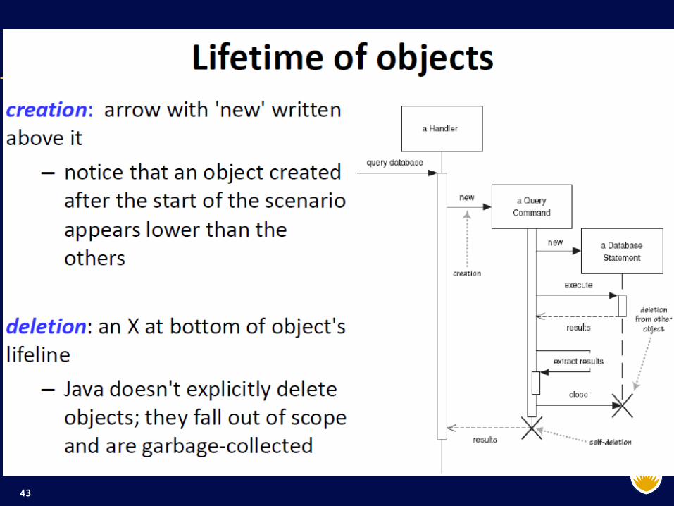
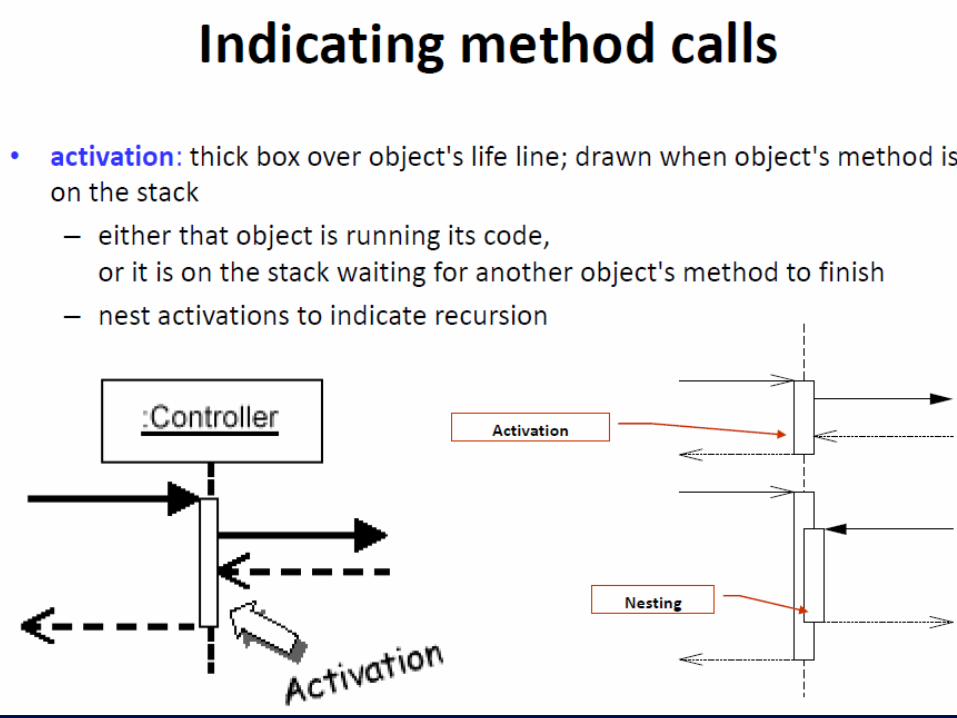
Recap: Sequence Diagram Key Parts
participant: object or entity that acts in the diagram • diagram starts with an unattached "found
message" arrow
message: communication between participant objects
the axes in a sequence diagram: • horizontal: which object/participant is acting • vertical: time (down -> forward in time)
40
41
42
43
44
45
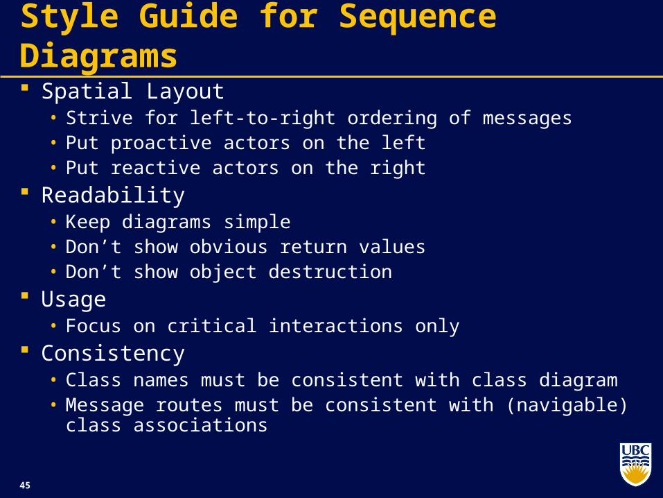
Style Guide for Sequence Diagrams
Spatial Layout• Strive for left-to-right ordering of messages• Put proactive actors on the left• Put reactive actors on the right
Readability• Keep diagrams simple• Don’t show obvious return values• Don’t show object destruction
Usage• Focus on critical interactions only
Consistency• Class names must be consistent with class diagram• Message routes must be consistent with (navigable) class
associations
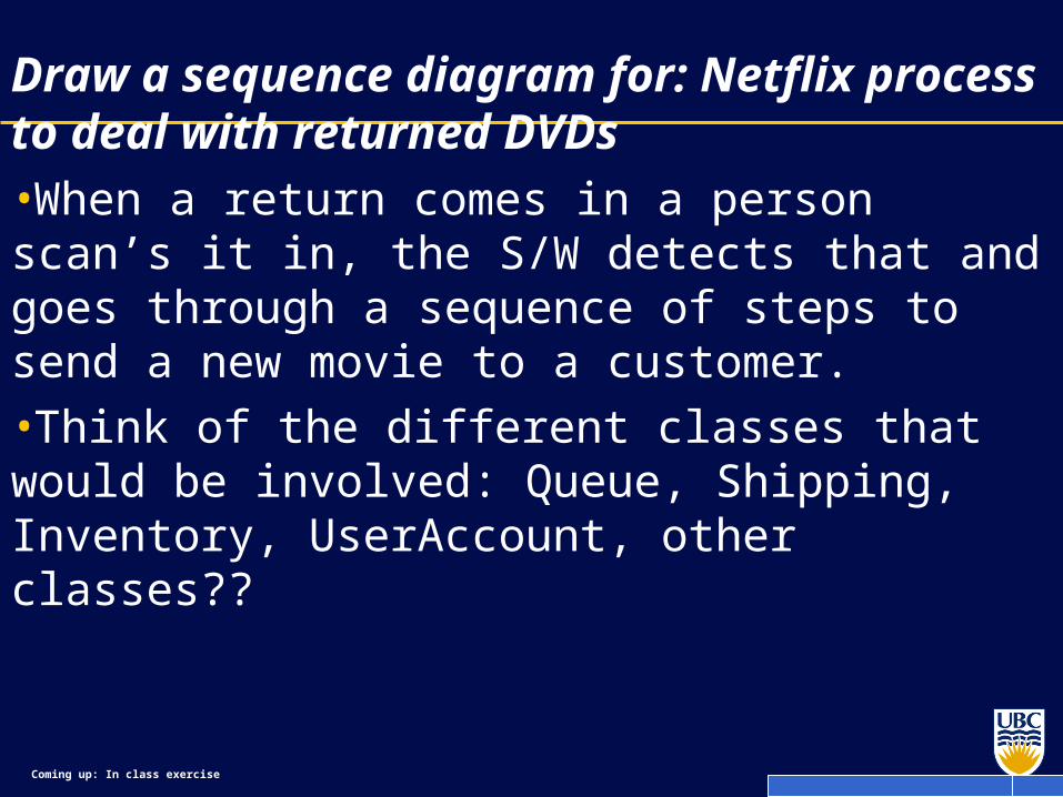
Coming up: In class exercise
Draw a sequence diagram for: Netflix process to deal with returned DVDs•When a return comes in a person scan’s it in, the S/W detects that and goes through a sequence of steps to send a new movie to a customer.
•Think of the different classes that would be involved: Queue, Shipping, Inventory, UserAccount, other classes??
47
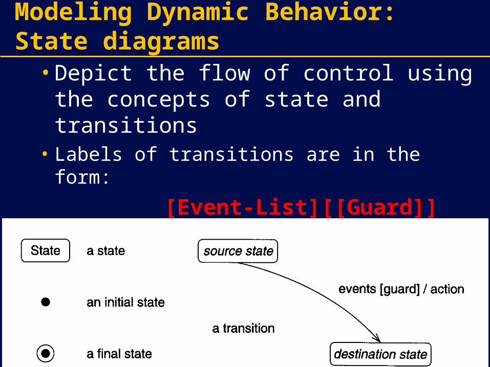
Modeling Dynamic Behavior: State diagrams
• Depict the flow of control using the concepts of state and transitions
• Labels of transitions are in the form:
[Event-List][[Guard]][/Action]- Entry action and exit action
entry/Action1 or exit/Action2
48
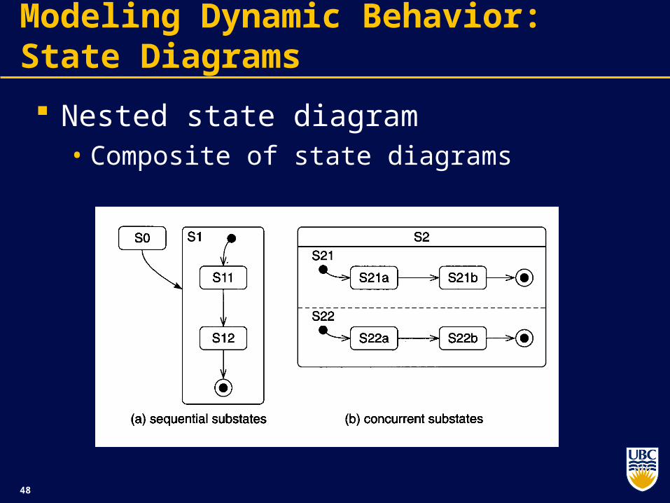
Modeling Dynamic Behavior: State Diagrams
Nested state diagram• Composite of state diagrams
49
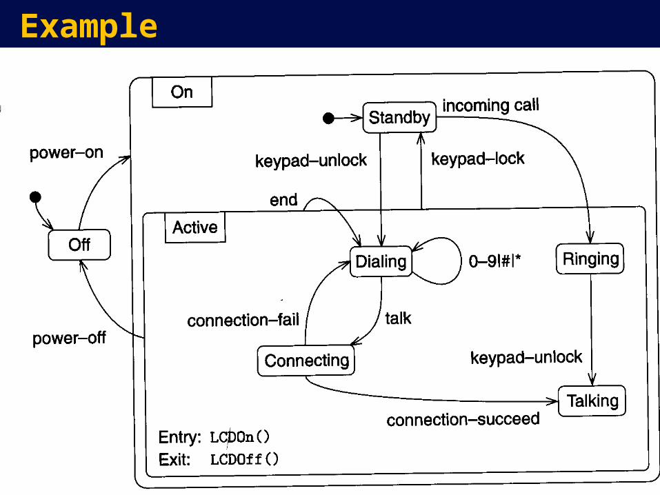
Example
50
Exercise
Reservations are made for repairs of vehicles (if space is available, otherwise they are added to a waiting list). The vehicle is delivered and waits in the dock until repair can commence. Repair can commence at any time. During repair new parts may be needed and the vehicle may have to wait for the parts to arrive. When repairs are completed a test drive is organized. Following the test, more repairs may be needed, or the vehicle will become ready to be picked up. Eventually the vehicle is picked up by its owner.
51
Two types of UML diagrams
ActivityDiagrams
Models
Dynamic Diagrams (Behavior and Interaction
StatechartDiagrams
CollaborationDiagrams
SequenceDiagrams
Use-CaseDiagrams
ClassDiagrams
ObjectDiagrams
ComponentDiagrams
DeploymentDiagrams
Static Diagrams
52
Design Patterns
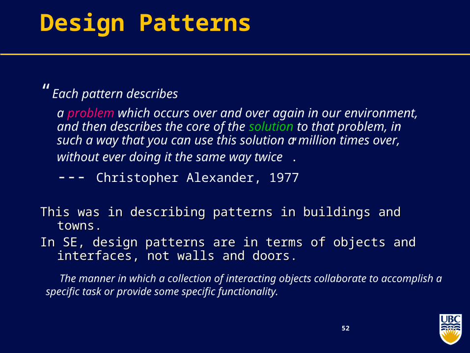
“Each pattern describes
a problem which occurs over and over again in our environment, and then describes the core of the solution to that problem, in such a way that you can use this solution a million times over, without ever doing it the same way twice”.
--- Christopher Alexander, 1977
This was in describing patterns in buildings and towns.This was in describing patterns in buildings and towns.In SE, design patterns are in terms of objects and interfaces, not In SE, design patterns are in terms of objects and interfaces, not
walls and doors.walls and doors.
The manner in which a collection of interacting objects collaborate to accomplish a specific task or provide some specific functionality.

53
Architecture vs. Design Patterns
Key decisions ….
Architecture
Design Patterns Lower level than architectures (Sometimes, called micro-architecture) Reusable collaborations that solve subproblems within an application
how can I decouple subsystem X from subsystem Y?
Design patterns support object-oriented reuse at a high level of abstraction Design patterns provide a “framework” that guides and constrains object-oriented implementation
Why Design Patterns?
What is a Design Pattern?
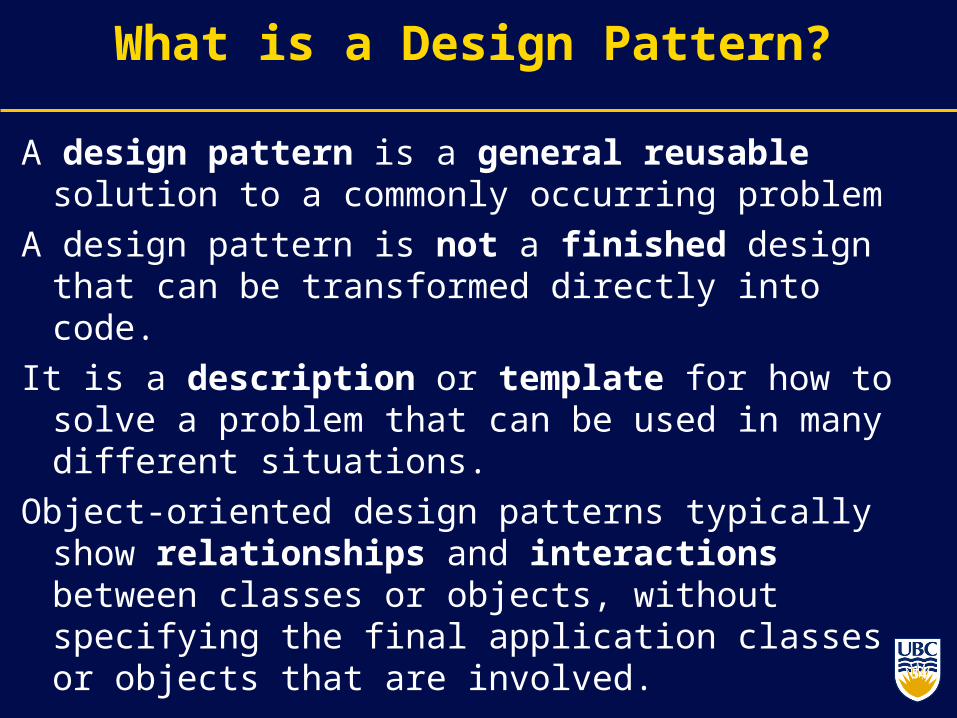
A design pattern is a general reusable solution to a commonly occurring problem
A design pattern is not a finished design that can be transformed directly into code.
It is a description or template for how to solve a problem that can be used in many different situations.
Object-oriented design patterns typically show relationships and interactions between classes or objects, without specifying the final application classes or objects that are involved. 54

55
55
FactoryBuilderPrototypeSingleton
AdapterBridgeCompositeDecoratorFaçadeFlyweightProxy
InterpreterTemplateChain of ResponsibilityCommandIteratorMediatorMementoObserverStateStrategyVisitor
Creational Structural Behavioral
Design Patterns : Elements of Reusable Object-Oriented Software (1995) , Gamma, Helm, Johnson , Vlissides
56
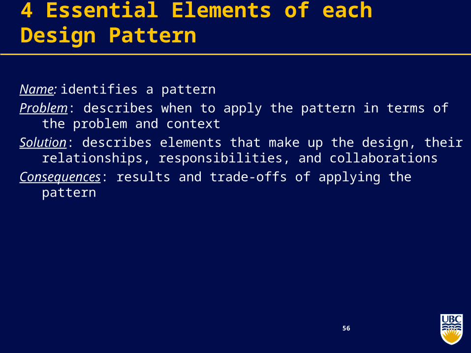
4 Essential Elements of each Design Pattern
Name: identifies a pattern
Problem: describes when to apply the pattern in terms of the problem and context
Solution: describes elements that make up the design, their relationships, responsibilities, and collaborations
Consequences: results and trade-offs of applying the pattern

More patterns: Singleton
Ensure a class has only one instance, and provide a global point of access to it.
public class Singleton { private Singleton() {} private static _instance = null; public static S getInstance () { if (_instance == null) _instance = new Singleton(); return _instance; } ...}
Lazy instantiationTactic of delaying the creation of an object, the calculation of a value, or some other expensive process until the first time it is needed.
57
return _instance;return _instance;
58
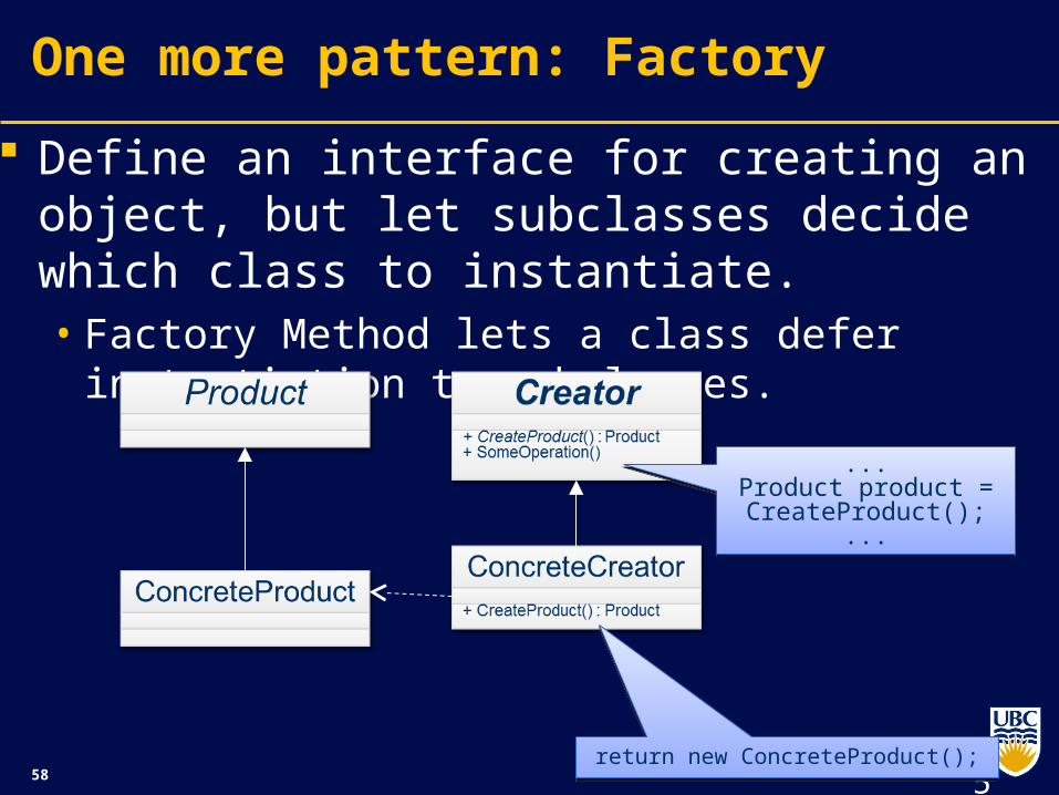
One more pattern: Factory
Define an interface for creating an object, but let subclasses decide which class to instantiate. • Factory Method lets a class defer instantiation to
subclasses.
58
return new ConcreteProduct();return new ConcreteProduct();
...Product product = CreateProduct();
...
...Product product = CreateProduct();
...

59
Related Documents