T-6B Electrical System Created: 24 Aug 2015 Updated: 30 Aug 2015 T6BDriver.com

Welcome message from author
This document is posted to help you gain knowledge. Please leave a comment to let me know what you think about it! Share it to your friends and learn new things together.
Transcript

T-6B Electrical System
Created: 24 Aug 2015Updated: 30 Aug 2015
T6BDriver.com

Objectives
• Identify power sources of electrical system
• Understand electrical distribution within system
• Identify location and understand operation of circuit breaker panels
(Utilize electrical system schematic while reviewing this slideshow)

References
• T-6B NATOPS Manual• Section 1
• Electrical Power Supply System
• Starter/Generator
• Battery
• Auxiliary Battery
• External Power
• Bus Tie Switch
• Section 5• Figure 5-1 Instrument Markings
• Battery/Starter Limitations
• Generator Limitations
• Section 8, Chapter 4• Visual Communications
• System mainly a DC system
• System power supplied by Starter/Generator
• Battery allows for stored power and engine starts
• Auxiliary Battery utilized as emergency source of power
• Electric power distributed by numerous electrical bus & avionics bus (separated by battery or generator side)
• Ability to isolate generator side from battery side through use of Bus Tie
Electrical System Overview
Battery(24v/42a hr)
Ext Pwr
HotBatBus
Clock ELTChip Detect Emer FlapsOBOGS Ram Air ValveFDR MxBatt Switch
Bat Switch
Gen SwitchBus TieSwitch
BUS TIE
FwdBatBus
AftBatBus
Fwd AviBat Bus
Aft AviBat Bus
AftGenBus
FwdGenBus
Fwd AviGen Bus
Aft AviGen Bus
Avionics MasterSwitch
Aux Battery(24v/5a hr)
AuxBatBus
GEN BUS
Aux BatSwitch
IAC #1 Ldg Gr ContUFCP Flap ContRH MFD Prop SysPMU Ail/El/Rud TrimEDMStarterBoost PumpIgnition
Air CondTADSpd BrkNWSEDMFuel BalFire Det #2AOA/Pitot/TAT HT
BFICOM 2Fire Det #1
BAT BUS
UFCPRH MFD
LH MFDCTR MFD
CTR MFD
IAC #2 TCASLH MFD RAD ALTADC DMEIRS XPDRCOM 1
22v 29.5v 32.2v
EICAS Volts
NormalCaution ExceedanceCaution
ON
OFF
OPEN
NORM
BAT
GEN
ON
OFF
Charge
Charge
Starter/Generator(28v/300a hr)Starter
Relay
Inflight: +50 to -2 ampsGround/Inflight: 28.0 to 28.5 volts
Min 22v Ext PwrMin 23.5v Batt Start
EICAS
Gen SwitchBus TieSwitch
OPEN
NORM
GEN
Charge
Starter/Generator(28v/300a hr)Starter
Relay
Inflight: +50 to -2 ampsGround/Inflight: 28.0 to 28.5 volts
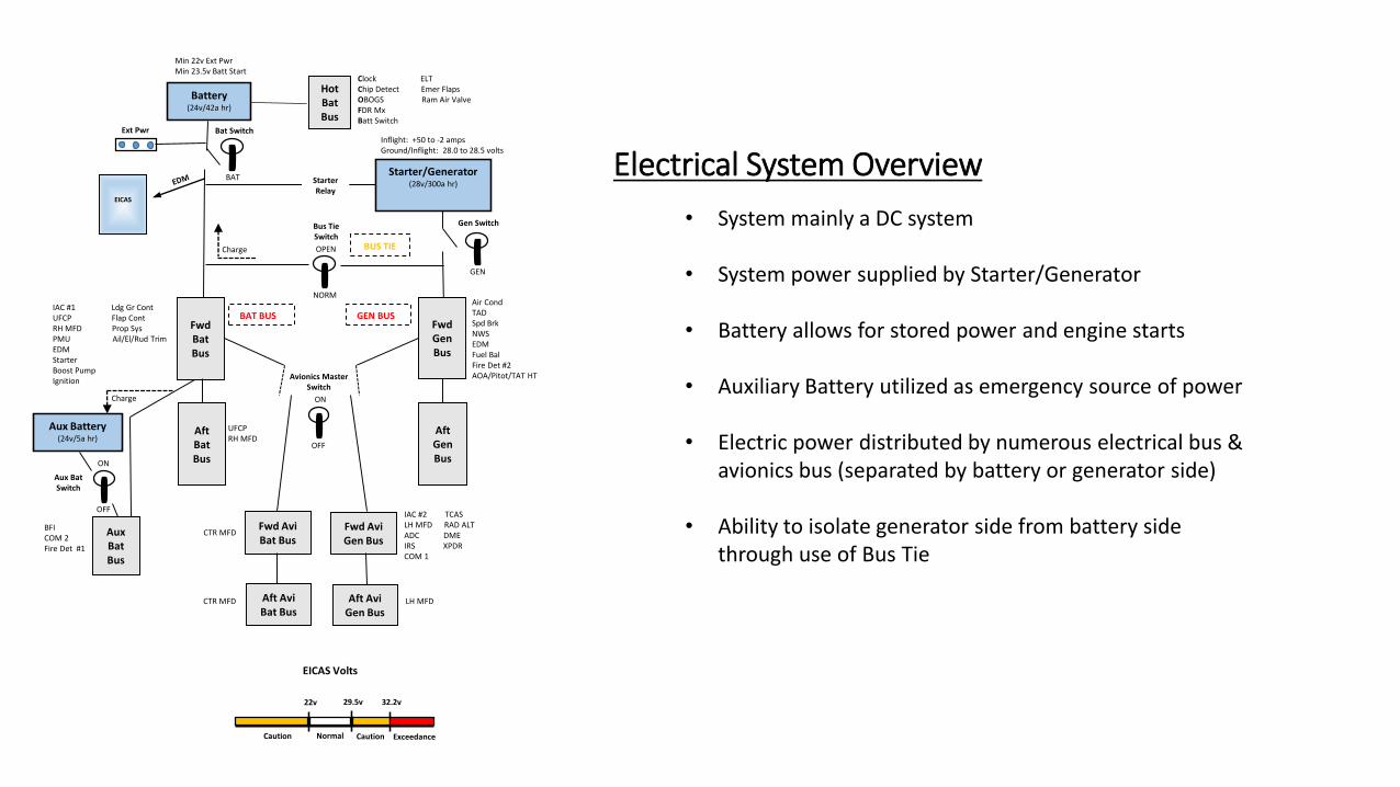
Starter/Generator
• Dual use system as starter or generator
• 28V/300amp
• Location• Left side of engine accessory compartment• Cooled by air intake duct routed from left side of engine cowl
• Primary aircraft power
• Generator Control Unit (GCU)• Located in rear cockpit, under panel immediately aft of OBOGS regulator• Keeps generator output within system limits
Power Sources(Starter/Generator)
ToGen Bus
ToBat
Charge
ToBat Bus
ToAux Bat
Starter/Generator Air Intake Duct
Gen SwitchBus TieSwitch
OPEN
NORM
GEN
Charge
Starter/Generator(28v/300a hr)Starter
Relay
Inflight: +50 to -2 ampsGround/Inflight: 28.0 to 28.5 volts
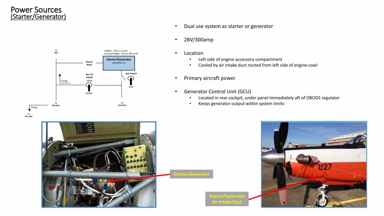
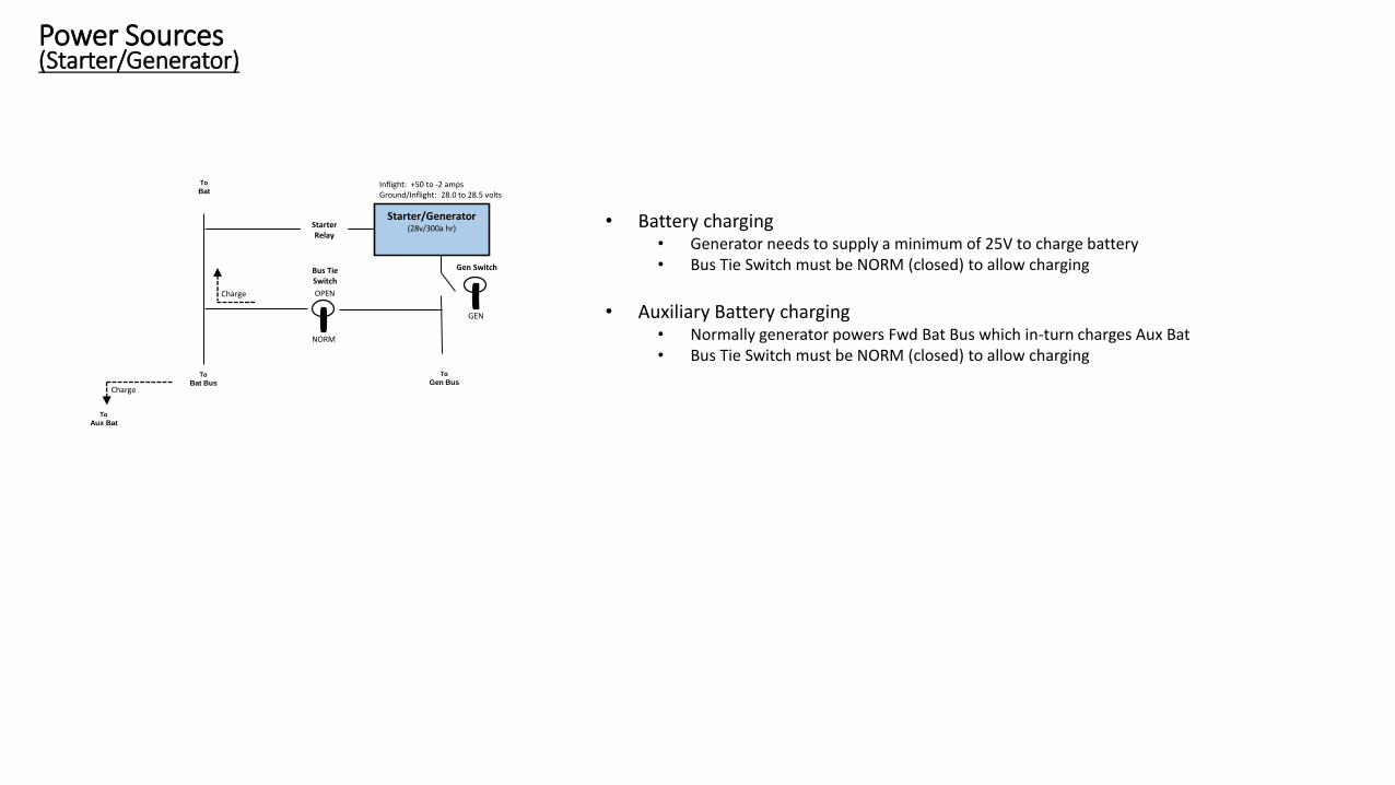
• Battery charging• Generator needs to supply a minimum of 25V to charge battery• Bus Tie Switch must be NORM (closed) to allow charging
• Auxiliary Battery charging• Normally generator powers Fwd Bat Bus which in-turn charges Aux Bat• Bus Tie Switch must be NORM (closed) to allow charging
Power Sources(Starter/Generator)
ToGen Bus
ToBat
Charge
ToBat Bus
ToAux Bat
Gen SwitchBus TieSwitch
22v 29.5v 32.2v
EICAS Volts
NormalCaution ExceedanceCaution
OPEN
NORM
GEN
Charge
Starter/Generator(28v/300a hr)Starter
Relay
Inflight: +50 to -2 ampsGround/Inflight: 28.0 to 28.5 volts
Generator Switch
Power Sources(Starter/Generator)
ToGen Bus
ToBat
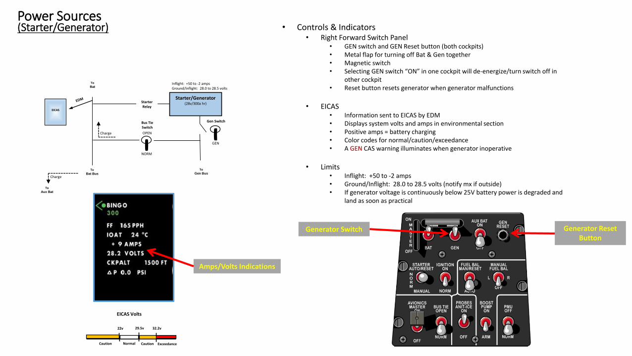
• Controls & Indicators• Right Forward Switch Panel
• GEN switch and GEN Reset button (both cockpits)• Metal flap for turning off Bat & Gen together• Magnetic switch• Selecting GEN switch “ON” in one cockpit will de-energize/turn switch off in
other cockpit • Reset button resets generator when generator malfunctions
• EICAS• Information sent to EICAS by EDM• Displays system volts and amps in environmental section• Positive amps = battery charging• Color codes for normal/caution/exceedance• A GEN CAS warning illuminates when generator inoperative
• Limits• Inflight: +50 to -2 amps• Ground/Inflight: 28.0 to 28.5 volts (notify mx if outside)• If generator voltage is continuously below 25V battery power is degraded and
land as soon as practical
Generator Reset Button
Amps/Volts Indications
Charge
ToBat Bus
ToAux Bat
EICAS
Battery
Power Sources(Battery)
Battery(24v/42a hr)
Bat Switch
Gen SwitchBus TieSwitch
22v 29.5v 32.2v
EICAS Volts
NormalCaution ExceedanceCaution
OPEN
NORM
BAT
GEN
Charge
Charge
Starter/Generator(28v/300a hr)Starter
Relay
Inflight: +50 to -2 ampsGround/Inflight: 28.0 to 28.5 volts
ToGen Bus
ToBat Bus
ToHot Bat Bus
ToAux Bat
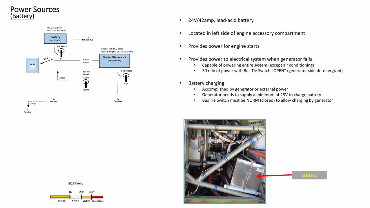
• 24V/42amp, lead-acid battery
• Located in left side of engine accessory compartment
• Provides power for engine starts
• Provides power to electrical system when generator fails• Capable of powering entire system (except air conditioning)• 30 min of power with Bus Tie Switch “OPEN” (generator side de-energized)
• Battery charging• Accomplished by generator or external power• Generator needs to supply a minimum of 25V to charge battery• Bus Tie Switch must be NORM (closed) to allow charging by generator
Min 22v Ext PwrMin 23.5v Batt Start
EICAS

Battery Switch
Power Sources(Battery)
Battery(24v/42a hr)
Bat Switch
Gen SwitchBus TieSwitch
22v 29.5v 32.2v
EICAS Volts
NormalCaution ExceedanceCaution
OPEN
NORM
BAT
GEN
Charge
Charge
Starter/Generator(28v/300a hr)Starter
Relay
Inflight: +50 to -2 ampsGround/Inflight: 28.0 to 28.5 volts
ToGen Bus
ToBat Bus
ToHot Bat Bus
ToAux Bat
• Controls & Indicators• Right Forward Switch Panel
• BAT switch for power application (both cockpits)• Metal flap for turning off Bat & Gen together• Magnetic switch• Selecting BAT switch “ON” in one cockpit will de-energize/turn switch off in
other cockpit
• EICAS• Displays system volts and amps in environmental section• Positive amps = battery charging• Color codes for normal/caution/exceedance
• Limits• Do not connect external power below 22.0V• 23.5V minimum for engine start using battery start
Amps/Volts Indications
Min 22v Ext PwrMin 23.5v Batt Start
EICAS

Aux Battery
Power Sources(Auxiliary Battery)
Battery(24v/42a hr)
Bat Switch
Gen SwitchBus TieSwitch
Aux Battery(24v/5a hr)
Aux BatSwitch
22v 29.5v 32.2v
EICAS Volts
NormalCaution ExceedanceCaution
OPEN
NORM
BAT
GEN
ON
OFF
Charge
Charge
Starter/Generator(28v/300a hr)Starter
Relay
Inflight: +50 to -2 ampsGround/Inflight: 28.0 to 28.5 volts
ToGen Bus
ToBat Bus
ToHot Bat Bus
• 24V/5amp
• Located in left avionic compartment (left E-bay)
• CB on Battery CB Panel (front cockpit left side)• Aux Bat will not charge if CB popped
• When generator & battery fail, provides power to:• Backup Flight Instruments (BFI)• Com 2 (standby VHF)• Fire detection loop #1
• Provides 30 minutes of power
• Auxiliary Battery charging• Normally generator powers Bat Bus which in-turn charges Aux Bat• Bus Tie Switch must be NORM (closed) to allow charging
Min 22v Ext PwrMin 23.5v Batt Start
ToAux Bat Bus
EICAS
Aux Bat CB
Bat CB Panel

Power Sources(Auxiliary Battery)
Battery(24v/42a hr)
Bat Switch
Gen SwitchBus TieSwitch
Aux Battery(24v/5a hr)
Aux BatSwitch
22v 29.5v 32.2v
EICAS Volts
NormalCaution ExceedanceCaution
OPEN
NORM
BAT
GEN
ON
OFF
Charge
Charge
Starter/Generator(28v/300a hr)Starter
Relay
Inflight: +50 to -2 ampsGround/Inflight: 28.0 to 28.5 volts
ToGen Bus
ToBat Bus
ToHot Bat Bus
• Controls & Indicators• Right Forward Switch Panel
• AUX BAT switch for power application• Front cockpit only
• System Test Panel• Front cockpit only• Tests aux battery power level• Hold switch for a minimum of 5 seconds ensuring light remains illuminated
Min 22v Ext PwrMin 23.5v Batt Start
Aux Battery Switch
Aux Battery Test Switch
Aux Battery Test Light
ToAux Bat Bus
EICAS
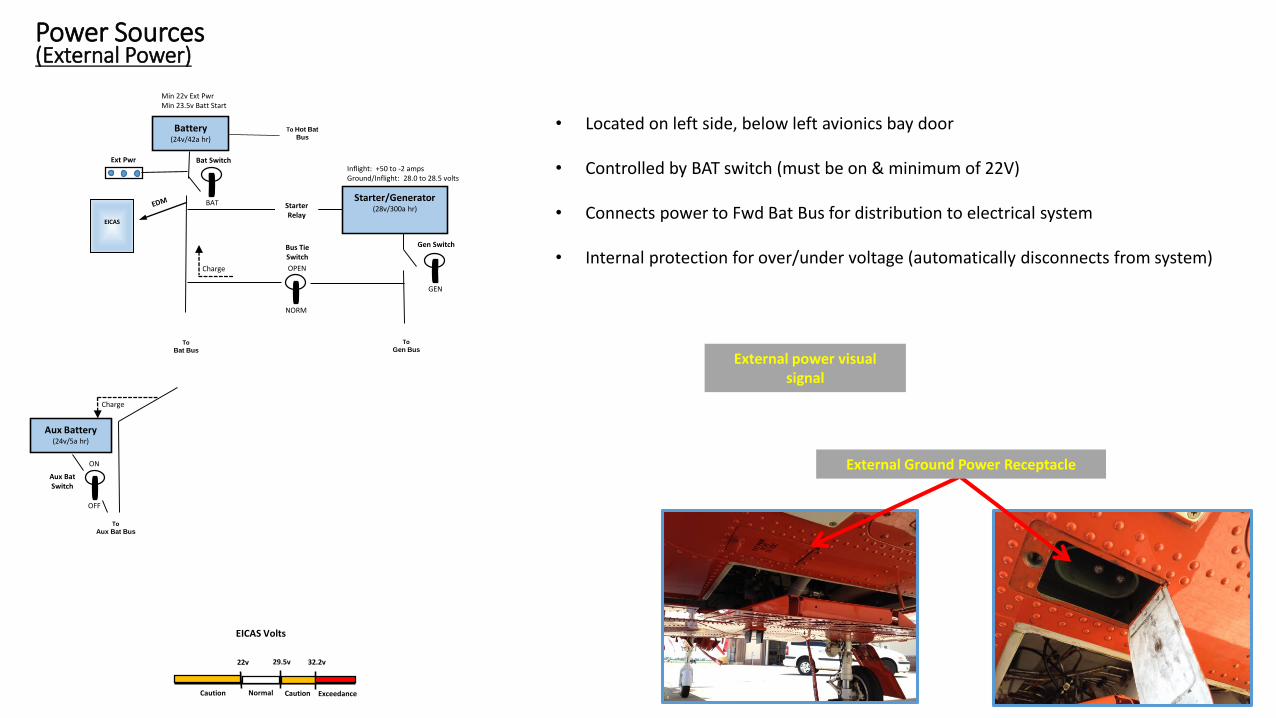
• Located on left side, below left avionics bay door
• Controlled by BAT switch (must be on & minimum of 22V)
• Connects power to Fwd Bat Bus for distribution to electrical system
• Internal protection for over/under voltage (automatically disconnects from system)
External Ground Power Receptacle
Power Sources(External Power)
Battery(24v/42a hr)
Ext Pwr Bat Switch
Gen SwitchBus TieSwitch
Aux Battery(24v/5a hr)
Aux BatSwitch
22v 29.5v 32.2v
EICAS Volts
NormalCaution ExceedanceCaution
OPEN
NORM
BAT
GEN
ON
OFF
Charge
Charge
Starter/Generator(28v/300a hr)Starter
Relay
Inflight: +50 to -2 ampsGround/Inflight: 28.0 to 28.5 volts
ToGen Bus
ToBat Bus
To Hot Bat
Bus
Min 22v Ext PwrMin 23.5v Batt Start
ToAux Bat Bus
External power visual signal
EICAS

• Electrical Bus Bar• Main way to mass distribute electricity in a system• Physically a “bus” is a metal bar• Place various systems on one or numerous electrical bus for ease of isolation or electrical
loading
• Circuit Breaker (CB)• Placed between electrical bus and equipment wired to bus• Prevents to much current (amps) from damaging equipment• Number on CB indicates max amperage at which CB will “pop”
Power Distribution(Basic Theory)
Battery(24v/42a hr)
Ext Pwr Bat Switch
Gen SwitchBus TieSwitch
Aux Battery(24v/5a hr)
Aux BatSwitch
22v 29.5v 32.2v
EICAS Volts
NormalCaution ExceedanceCaution
OPEN
NORM
BAT
GEN
ON
OFF
Charge
Charge
Starter/Generator(28v/300a hr)Starter
Relay
Inflight: +50 to -2 ampsGround/Inflight: 28.0 to 28.5 volts
ToGen Bus
ToBat Bus
Min 22v Ext PwrMin 23.5v Batt Start
ToAux Bat Bus
Electrical Bus Bar
CB “popped” CB not “popped”
EICAS
To Hot Bat
Bus
Power Distribution(Circuit Breaker Panels)
Battery(24v/42a hr)
Ext Pwr Bat Switch
Gen SwitchBus TieSwitch
Aux Battery(24v/5a hr)
Aux BatSwitch
22v 29.5v 32.2v
EICAS Volts
NormalCaution ExceedanceCaution
OPEN
NORM
BAT
GEN
ON
OFF
Charge
Charge
Starter/Generator(28v/300a hr)Starter
Relay
Inflight: +50 to -2 ampsGround/Inflight: 28.0 to 28.5 volts
ToGen Bus
ToBat Bus
Min 22v Ext PwrMin 23.5v Batt Start
ToAux Bat Bus
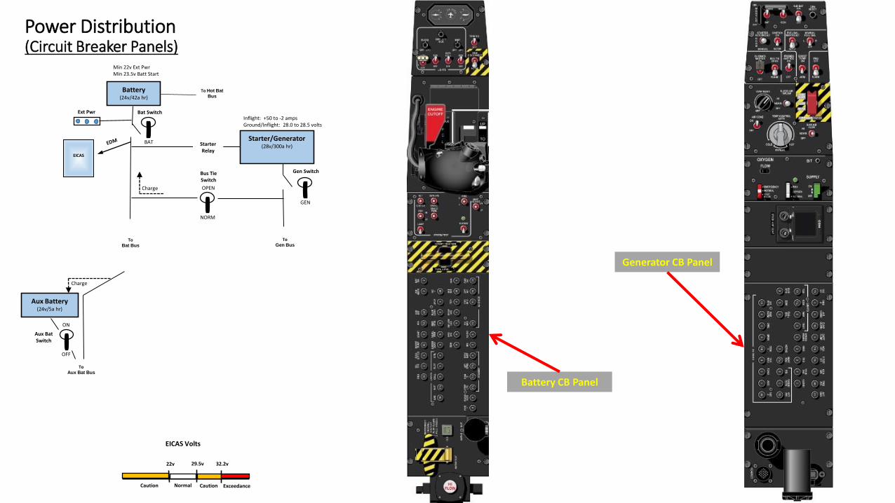
Battery CB Panel
Generator CB Panel
EICAS
To Hot Bat
Bus
Power Distribution(Hot Battery Bus)
Battery(24v/42a hr)
Ext Pwr Bat Switch
Gen SwitchBus TieSwitch
Aux Battery(24v/5a hr)
Aux BatSwitch
22v 29.5v 32.2v
EICAS Volts
NormalCaution ExceedanceCaution
OPEN
NORM
BAT
GEN
ON
OFF
Charge
Charge
Starter/Generator(28v/300a hr)Starter
Relay
Inflight: +50 to -2 ampsGround/Inflight: 28.0 to 28.5 volts
ToGen Bus
ToBat Bus
Min 22v Ext PwrMin 23.5v Batt Start
ToAux Bat Bus
EICAS
HotBatBus
Clock ELTChip Detect Emer FlapsOBOGS Ram Air ValveFDR MxBatt Switch
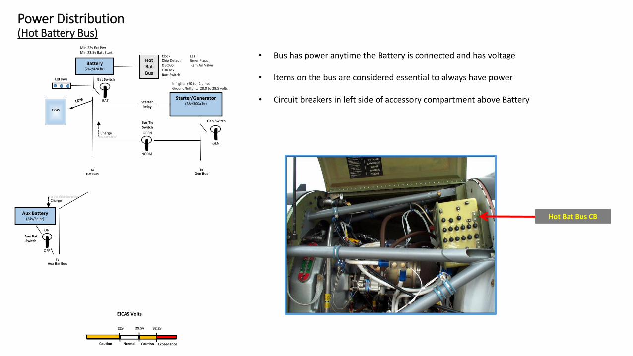
• Bus has power anytime the Battery is connected and has voltage
• Items on the bus are considered essential to always have power
• Circuit breakers in left side of accessory compartment above Battery
Hot Bat Bus CB
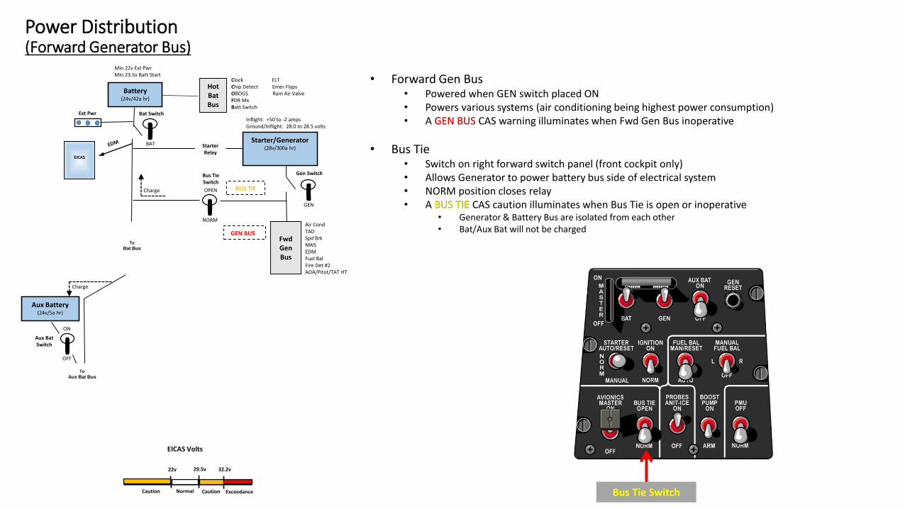
• Forward Gen Bus• Powered when GEN switch placed ON• Powers various systems (air conditioning being highest power consumption)• A GEN BUS CAS warning illuminates when Fwd Gen Bus inoperative
• Bus Tie• Switch on right forward switch panel (front cockpit only)• Allows Generator to power battery bus side of electrical system• NORM position closes relay• A BUS TIE CAS caution illuminates when Bus Tie is open or inoperative
• Generator & Battery Bus are isolated from each other• Bat/Aux Bat will not be charged
Power Distribution(Forward Generator Bus)
Battery(24v/42a hr)
Ext Pwr Bat Switch
Gen SwitchBus TieSwitch
Aux Battery(24v/5a hr)
Aux BatSwitch
22v 29.5v 32.2v
EICAS Volts
NormalCaution ExceedanceCaution
OPEN
NORM
BAT
GEN
ON
OFF
Charge
Charge
Starter/Generator(28v/300a hr)Starter
Relay
Inflight: +50 to -2 ampsGround/Inflight: 28.0 to 28.5 volts
Min 22v Ext PwrMin 23.5v Batt Start
ToAux Bat Bus
BUS TIE
FwdGenBus
GEN BUS
Air CondTADSpd BrkNWSEDMFuel BalFire Det #2AOA/Pitot/TAT HT
ToBat Bus
Bus Tie Switch
EICAS
HotBatBus
Clock ELTChip Detect Emer FlapsOBOGS Ram Air ValveFDR MxBatt Switch
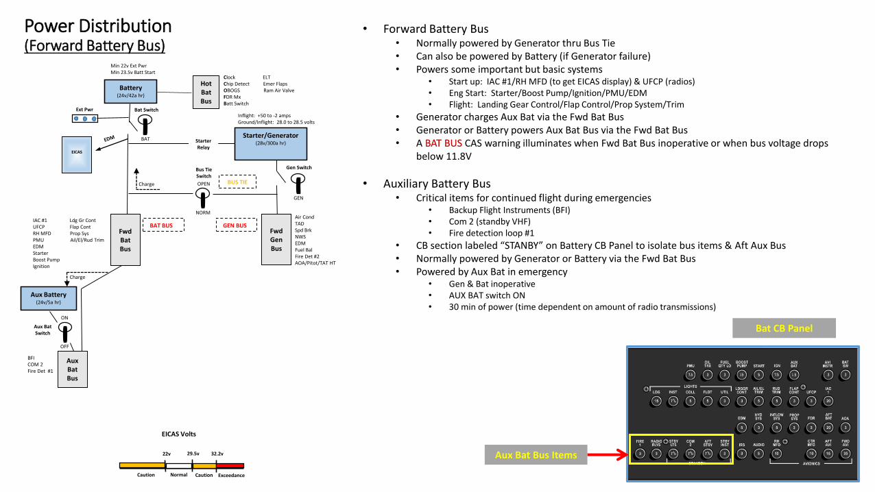
• Forward Battery Bus• Normally powered by Generator thru Bus Tie• Can also be powered by Battery (if Generator failure)• Powers some important but basic systems
• Start up: IAC #1/RH MFD (to get EICAS display) & UFCP (radios)• Eng Start: Starter/Boost Pump/Ignition/PMU/EDM• Flight: Landing Gear Control/Flap Control/Prop System/Trim
• Generator charges Aux Bat via the Fwd Bat Bus• Generator or Battery powers Aux Bat Bus via the Fwd Bat Bus• A BAT BUS CAS warning illuminates when Fwd Bat Bus inoperative or when bus voltage drops
below 11.8V
• Auxiliary Battery Bus• Critical items for continued flight during emergencies
• Backup Flight Instruments (BFI)• Com 2 (standby VHF)• Fire detection loop #1
• CB section labeled “STANBY” on Battery CB Panel to isolate bus items & Aft Aux Bus• Normally powered by Generator or Battery via the Fwd Bat Bus• Powered by Aux Bat in emergency
• Gen & Bat inoperative• AUX BAT switch ON• 30 min of power (time dependent on amount of radio transmissions)
Power Distribution(Forward Battery Bus)
Battery(24v/42a hr)
Ext Pwr Bat Switch
Gen SwitchBus TieSwitch
Aux Battery(24v/5a hr)
Aux BatSwitch
22v 29.5v 32.2v
EICAS Volts
NormalCaution ExceedanceCaution
OPEN
NORM
BAT
GEN
ON
OFF
Charge
Charge
Starter/Generator(28v/300a hr)Starter
Relay
Inflight: +50 to -2 ampsGround/Inflight: 28.0 to 28.5 volts
Min 22v Ext PwrMin 23.5v Batt Start
BAT BUSIAC #1 Ldg Gr ContUFCP Flap ContRH MFD Prop SysPMU Ail/El/Rud TrimEDMStarterBoost PumpIgnition
FwdBatBus
BUS TIE
FwdGenBus
GEN BUS
Air CondTADSpd BrkNWSEDMFuel BalFire Det #2AOA/Pitot/TAT HT
AuxBatBus
BFICOM 2Fire Det #1
EICAS
Aux Bat Bus Items
Bat CB Panel
HotBatBus
Clock ELTChip Detect Emer FlapsOBOGS Ram Air ValveFDR MxBatt Switch

• Aft Generator Bus• Powered by Fwd Gen Bus• CB on Gen CB Panel• Can isolate aft bus from front cockpit if single-pilot
Power Distribution(Aft Generator & Battery Bus)
Battery(24v/42a hr)
Ext Pwr Bat Switch
Gen SwitchBus TieSwitch
Aux Battery(24v/5a hr)
Aux BatSwitch
22v 29.5v 32.2v
EICAS Volts
NormalCaution ExceedanceCaution
OPEN
NORM
BAT
GEN
ON
OFF
Charge
Charge
Starter/Generator(28v/300a hr)Starter
Relay
Inflight: +50 to -2 ampsGround/Inflight: 28.0 to 28.5 volts
Min 22v Ext PwrMin 23.5v Batt Start
BAT BUSIAC #1 Ldg Gr ContUFCP Flap ContRH MFD Prop SysPMU Ail/El/Rud TrimEDMStarterBoost PumpIgnition
FwdBatBus
BUS TIE
FwdGenBus
GEN BUS
Air CondTADSpd BrkNWSEDMFuel BalFire Det #2AOA/Pitot/TAT HT
AuxBatBus
BFICOM 2Fire Det #1
EICAS
AftBatBus
AftGenBus
UFCPRH MFD
Aft Bat Bus CB
Bat CB Panel
Gen CB Panel
Aft Gen Bus CB
• Aft Battery Bus• Powered by Fwd Bat Bus• CB on Bat CB Panel• Powers RH MFD & UFCP for rear cockpit• Can isolate aft bus from front cockpit if single-pilot
HotBatBus
Clock ELTChip Detect Emer FlapsOBOGS Ram Air ValveFDR MxBatt Switch
Battery(24v/42a hr)
Ext Pwr
HotBatBus
Clock ELTChip Detect Emer FlapsOBOGS Ram Air ValveFDR MxBatt Switch
Bat Switch
Gen SwitchBus TieSwitch
BUS TIE
FwdBatBus
AftBatBus
AftGenBus
FwdGenBus
Avionics MasterSwitch
Aux Battery(24v/5a hr)
AuxBatBus
GEN BUS
Aux BatSwitch
IAC #1 Ldg Gr ContUFCP Flap ContRH MFD Prop SysPMU Ail/El/Rud TrimEDMStarterBoost PumpIgnition
Air CondTADSpd BrkNWSEDMFuel BalFire Det #2AOA/Pitot/TAT HT
BFICOM 2Fire Det #1
BAT BUS
UFCPRH MFD
22v 29.5v 32.2v
EICAS Volts
NormalCaution ExceedanceCaution
ON
OFF
OPEN
NORM
BAT
GEN
ON
OFF
Charge
Charge
Starter/Generator(28v/300a hr)Starter
Relay
Inflight: +50 to -2 ampsGround/Inflight: 28.0 to 28.5 volts
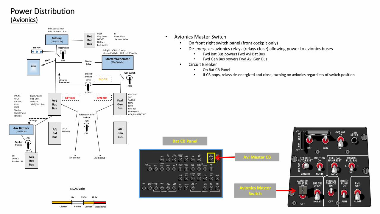
• Avionics Master Switch• On front right switch panel (front cockpit only)• De-energizes avionics relays (relays close) allowing power to avionics buses
• Fwd Bat Bus powers Fwd Avi Bat Bus• Fwd Gen Bus powers Fwd Avi Gen Bus
• Circuit Breaker• On Bat CB Panel• If CB pops, relays de-energized and close, turning on avionics regardless of switch position
Min 22v Ext PwrMin 23.5v Batt Start
EICAS
Power Distribution(Avionics)
ToAvi Bat Bus
ToAvi Gn Bus
Avionics Master Switch
Avi Master CB
Bat CB Panel

Battery(24v/42a hr)
Ext Pwr
HotBatBus
Clock ELTChip Detect Emer FlapsOBOGS Ram Air ValveFDR MxBatt Switch
Bat Switch
Gen SwitchBus TieSwitch
BUS TIE
FwdBatBus
AftBatBus
AftGenBus
FwdGenBus
Fwd AviGen Bus
Avionics MasterSwitch
Aux Battery(24v/5a hr)
AuxBatBus
GEN BUS
Aux BatSwitch
IAC #1 Ldg Gr ContUFCP Flap ContRH MFD Prop SysPMU Ail/El/Rud TrimEDMStarterBoost PumpIgnition
Air CondTADSpd BrkNWSEDMFuel BalFire Det #2AOA/Pitot/TAT HT
BFICOM 2Fire Det #1
BAT BUS
UFCPRH MFD
IAC #2 TCASLH MFD RAD ALTADC DMEIRS XPDRCOM 1
22v 29.5v 32.2v
EICAS Volts
NormalCaution ExceedanceCaution
ON
OFF
OPEN
NORM
BAT
GEN
ON
OFF
Charge
Charge
Starter/Generator(28v/300a hr)Starter
Relay
Inflight: +50 to -2 ampsGround/Inflight: 28.0 to 28.5 volts
Min 22v Ext PwrMin 23.5v Batt Start
EICAS
Power Distribution(Forward Avi Generator Bus)
• Powered by Fwd Gen Bus
• Powers important avionics items critical for instrument flight
• Circuit Breakers• CBs on Gen CB Panel• Individual CBs for items• One CB for entire bus isolation
Gen CB Panel
Fwd Avi Gen Bus CB
Fwd Avi Gen Bus(individual items)
Battery(24v/42a hr)
Ext Pwr
HotBatBus
Clock ELTChip Detect Emer FlapsOBOGS Ram Air ValveFDR MxBatt Switch
Bat Switch
Gen SwitchBus TieSwitch
BUS TIE
FwdBatBus
AftBatBus
AftGenBus
FwdGenBus
Fwd AviGen Bus
Avionics MasterSwitch
Aux Battery(24v/5a hr)
AuxBatBus
GEN BUS
Aux BatSwitch
IAC #1 Ldg Gr ContUFCP Flap ContRH MFD Prop SysPMU Ail/El/Rud TrimEDMStarterBoost PumpIgnition
Air CondTADSpd BrkNWSEDMFuel BalFire Det #2AOA/Pitot/TAT HT
BFICOM 2Fire Det #1
BAT BUS
UFCPRH MFD
IAC #2 TCASLH MFD RAD ALTADC DMEIRS XPDRCOM 1
22v 29.5v 32.2v
EICAS Volts
NormalCaution ExceedanceCaution
ON
OFF
OPEN
NORM
BAT
GEN
ON
OFF
Charge
Charge
Starter/Generator(28v/300a hr)Starter
Relay
Inflight: +50 to -2 ampsGround/Inflight: 28.0 to 28.5 volts
Min 22v Ext PwrMin 23.5v Batt Start
EICAS
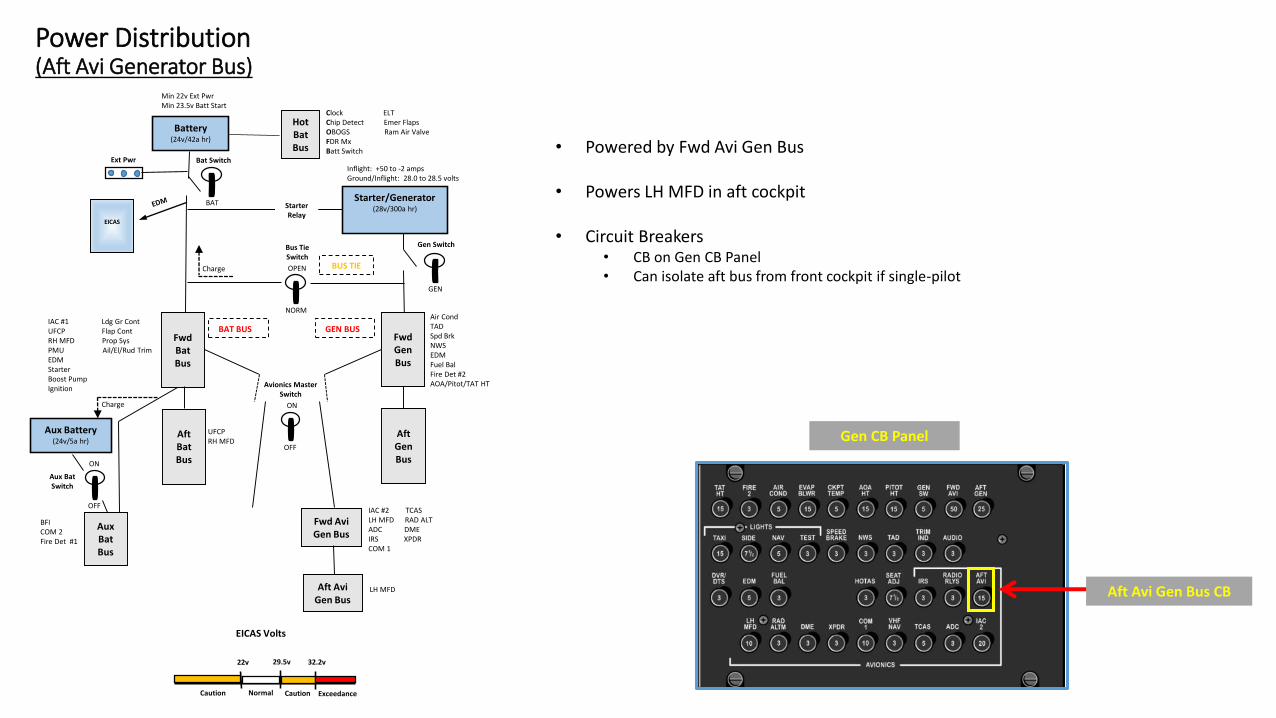
Power Distribution(Aft Avi Generator Bus)
• Powered by Fwd Avi Gen Bus
• Powers LH MFD in aft cockpit
• Circuit Breakers• CB on Gen CB Panel• Can isolate aft bus from front cockpit if single-pilot
Aft AviGen Bus
LH MFD
Gen CB Panel
Aft Avi Gen Bus CB
Battery(24v/42a hr)
Ext Pwr
HotBatBus
Clock ELTChip Detect Emer FlapsOBOGS Ram Air ValveFDR MxBatt Switch
Bat Switch
Gen SwitchBus TieSwitch
BUS TIE
FwdBatBus
AftBatBus
Fwd AviBat Bus
AftGenBus
FwdGenBus
Fwd AviGen Bus
Avionics MasterSwitch
Aux Battery(24v/5a hr)
AuxBatBus
GEN BUS
Aux BatSwitch
IAC #1 Ldg Gr ContUFCP Flap ContRH MFD Prop SysPMU Ail/El/Rud TrimEDMStarterBoost PumpIgnition
Air CondTADSpd BrkNWSEDMFuel BalFire Det #2AOA/Pitot/TAT HT
BFICOM 2Fire Det #1
BAT BUS
UFCPRH MFD
CTR MFD
IAC #2 TCASLH MFD RAD ALTADC DMEIRS XPDRCOM 1
22v 29.5v 32.2v
EICAS Volts
NormalCaution ExceedanceCaution
ON
OFF
OPEN
NORM
BAT
GEN
ON
OFF
Charge
Charge
Starter/Generator(28v/300a hr)Starter
Relay
Inflight: +50 to -2 ampsGround/Inflight: 28.0 to 28.5 volts
Min 22v Ext PwrMin 23.5v Batt Start
EICAS
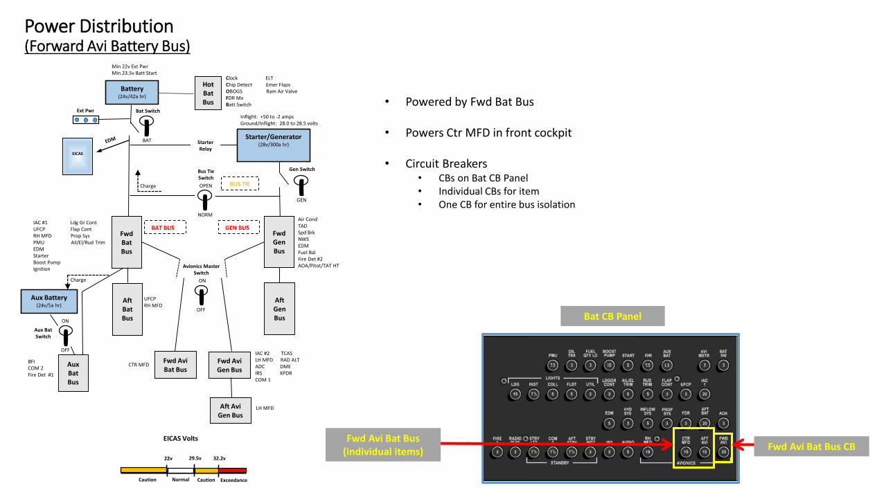
Power Distribution(Forward Avi Battery Bus)
Aft AviGen Bus
LH MFD
• Powered by Fwd Bat Bus
• Powers Ctr MFD in front cockpit
• Circuit Breakers• CBs on Bat CB Panel• Individual CBs for item• One CB for entire bus isolation
Bat CB Panel
Fwd Avi Bat Bus(individual items) Fwd Avi Bat Bus CB
Battery(24v/42a hr)
Ext Pwr
HotBatBus
Clock ELTChip Detect Emer FlapsOBOGS Ram Air ValveFDR MxBatt Switch
Bat Switch
Gen SwitchBus TieSwitch
BUS TIE
FwdBatBus
AftBatBus
Fwd AviBat Bus
Aft AviBat Bus
AftGenBus
FwdGenBus
Fwd AviGen Bus
Aft AviGen Bus
Avionics MasterSwitch
Aux Battery(24v/5a hr)
AuxBatBus
GEN BUS
Aux BatSwitch
IAC #1 Ldg Gr ContUFCP Flap ContRH MFD Prop SysPMU Ail/El/Rud TrimEDMStarterBoost PumpIgnition
Air CondTADSpd BrkNWSEDMFuel BalFire Det #2AOA/Pitot/TAT HT
BFICOM 2Fire Det #1
BAT BUS
UFCPRH MFD
LH MFDCTR MFD
CTR MFD
IAC #2 TCASLH MFD RAD ALTADC DMEIRS XPDRCOM 1
22v 29.5v 32.2v
EICAS Volts
NormalCaution ExceedanceCaution
ON
OFF
OPEN
NORM
BAT
GEN
ON
OFF
Charge
Charge
Starter/Generator(28v/300a hr)Starter
Relay
Inflight: +50 to -2 ampsGround/Inflight: 28.0 to 28.5 volts
Min 22v Ext PwrMin 23.5v Batt Start
EICAS
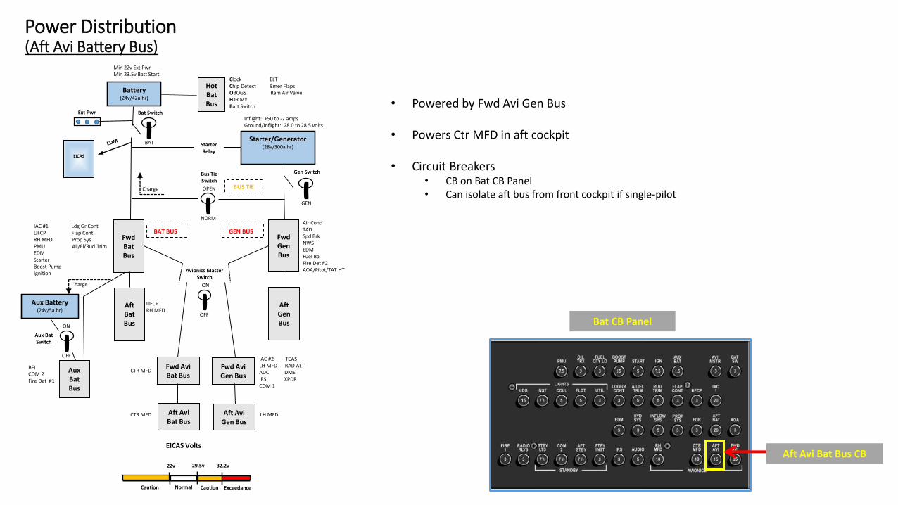
Power Distribution(Aft Avi Battery Bus)
• Powered by Fwd Avi Gen Bus
• Powers Ctr MFD in aft cockpit
• Circuit Breakers• CB on Bat CB Panel• Can isolate aft bus from front cockpit if single-pilot
Bat CB Panel
Aft Avi Bat Bus CB

Battery(24v/42a hr)
Ext Pwr
HotBatBus
Clock ELTChip Detect Emer FlapsOBOGS Ram Air ValveFDR MxBatt Switch
Bat Switch
Gen SwitchBus TieSwitch
BUS TIE
FwdBatBus
AftBatBus
Fwd AviBat Bus
Aft AviBat Bus
AftGenBus
FwdGenBus
Fwd AviGen Bus
Aft AviGen Bus
Avionics MasterSwitch
Aux Battery(24v/5a hr)
AuxBatBus
GEN BUS
Aux BatSwitch
IAC #1 Ldg Gr ContUFCP Flap ContRH MFD Prop SysPMU Ail/El/Rud TrimEDMStarterBoost PumpIgnition
Air CondTADSpd BrkNWSEDMFuel BalFire Det #2AOA/Pitot/TAT HT
BFICOM 2Fire Det #1
BAT BUS
UFCPRH MFD
LH MFDCTR MFD
CTR MFD
IAC #2 TCASLH MFD RAD ALTADC DMEIRS XPDRCOM 1
22v 29.5v 32.2v
EICAS Volts
NormalCaution ExceedanceCaution
ON
OFF
OPEN
NORM
BAT
GEN
ON
OFF
Charge
Charge
Starter/Generator(28v/300a hr)Starter
Relay
Inflight: +50 to -2 ampsGround/Inflight: 28.0 to 28.5 volts
• Aircraft made to fly single pilot from front cockpit so need the ability to isolate various equipment and buses from front cockpit
• Battery CB Panel has:• Fwd Bat Bus (individual item CBs)• Aft Bat Bus (Bus CB)• Aux Bat Bus (individual item CBs)• Aft Aux Bat Bus (Bus CB)• Fwd Avi Bat Bus (Bus CB & individual item CBs)• Aft Avi Bat Bus (Bus CB)
Min 22v Ext PwrMin 23.5v Batt Start
EICAS
Power Distribution(Circuit Breaker Review)
Bat CB Panel
Gen CB Panel
• Generator CB Panel has:• Fwd Gen Bus (individual item CBs)• Aft Gen Bus (Bus CB)• Fwd Avi Gen Bus (Bus CB & individual item CBs)• Aft Avi Gen Bus (Bus CB)
Battery(24v/42a hr)
Ext Pwr
HotBatBus
Clock ELTChip Detect Emer FlapsOBOGS Ram Air ValveFDR MxBatt Switch
Bat Switch
Gen SwitchBus TieSwitch
BUS TIE
FwdBatBus
AftBatBus
Fwd AviBat Bus
Aft AviBat Bus
AftGenBus
FwdGenBus
Fwd AviGen Bus
Aft AviGen Bus
Avionics MasterSwitch
Aux Battery(24v/5a hr)
AuxBatBus
GEN BUS
Aux BatSwitch
IAC #1 Ldg Gr ContUFCP Flap ContRH MFD Prop SysPMU Ail/El/Rud TrimEDMStarterBoost PumpIgnition
Air CondTADSpd BrkNWSEDMFuel BalFire Det #2AOA/Pitot/TAT HT
BFICOM 2Fire Det #1
BAT BUS
UFCPRH MFD
LH MFDCTR MFD
CTR MFD
IAC #2 TCASLH MFD RAD ALTADC DMEIRS XPDRCOM 1
22v 29.5v 32.2v
EICAS Volts
NormalCaution ExceedanceCaution
ON
OFF
OPEN
NORM
BAT
GEN
ON
OFF
Charge
Charge
Starter/Generator(28v/300a hr)Starter
Relay
Inflight: +50 to -2 ampsGround/Inflight: 28.0 to 28.5 volts
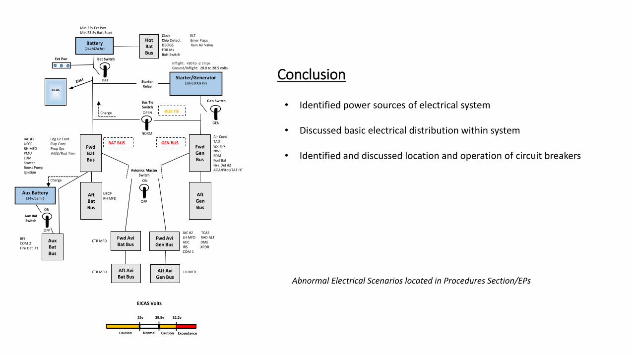
Conclusion
• Identified power sources of electrical system
• Discussed basic electrical distribution within system
• Identified and discussed location and operation of circuit breakers
Abnormal Electrical Scenarios located in Procedures Section/EPs
Min 22v Ext PwrMin 23.5v Batt Start
EICAS
Related Documents