ENGINE CONTENTS page page 2.0L SOHC ENGINE ...................... 1 2.5L VM DIESEL ....................... 40 2.0L SOHC ENGINE INDEX page page DESCRIPTION AND OPERATION ENGINE COMPONENTS .................. 3 ENGINE IDENTIFICATION ................. 1 ENGINE LUBRICATION SYSTEM ............ 2 GENERAL SPECIFICATION ................ 2 DIAGNOSIS AND TESTING CHECKING ENGINE OIL PRESSURE ........ 3 SERVICE PROCEDURES CRANKSHAFT END PLAY ................. 6 CYLINDER BORE AND PISTON SIZING ....... 4 FITTING CONNECTING RODS .............. 5 FITTING CRANKSHAFT BEARINGS .......... 6 FITTING PISTON RINGS .................. 4 REMOVAL AND INSTALLATION CAMSHAFT OIL SEAL ................... 12 CAMSHAFT ............................ 7 CRANKSHAFT OIL SEAL—REAR ........... 20 CRANKSHAFT ......................... 21 CYLINDER HEAD COVER ................. 6 CYLINDER HEAD ....................... 10 FRONT CRANKSHAFT OIL SEAL ........... 18 OIL FILTER ........................... 24 OIL FILTER ADAPTER ................... 24 OIL PAN .............................. 17 OIL PUMP ............................ 25 PISTON AND CONNECTING ROD .......... 25 ROCKER ARM/HYDRAULIC LASH ADJUSTER . . 8 SPARK PLUG TUBE ...................... 7 TIMING BELT COVER ................... 11 TIMING BELT SYSTEM .................. 13 VALVE SEALS AND SPRINGS IN VEHICLE ... 10 VIBRATION DAMPER .................... 28 DISASSEMBLY AND ASSEMBLY OIL PUMP ............................ 29 VALVE SERVICE WITH THE CYLINDER HEAD REMOVED .......................... 29 CLEANING AND INSPECTION CYLINDER BLOCK AND BORE ............ 34 CYLINDER HEAD AND CAMSHAFT JOURNALS .......................... 32 OIL PUMP ............................ 32 SPECIFICATIONS ENGINE 2.0L SOHC ..................... 34 TORQUE CHART 2.0L SOHC .............. 36 SPECIAL TOOLS ENGINE 2.0L SOHC ..................... 36 DESCRIPTION AND OPERATION ENGINE IDENTIFICATION The engine identification number is located on the left rear of the cylinder block behind starter (Fig. 1). Fig. 1 Engine Identification SOHC NS/GS ENGINE 9-1

Welcome message from author
This document is posted to help you gain knowledge. Please leave a comment to let me know what you think about it! Share it to your friends and learn new things together.
Transcript

NS/GS ENGINE 9 - 1
ENGINE
CONTENTS
page
2.0L SOHC ENGINE . . . . . . . . . . . . . . . . . . . . . . 1
page
2.5L VM DIESEL . . . . . . . . . . . . . . . . . . . . . . . 40
2.0L SOHC ENGINE
INDEX
page
DESCRIPTION AND OPERATIONENGINE COMPONENTS . . . . . . . . . . . . . . . . . . 3ENGINE IDENTIFICATION . . . . . . . . . . . . . . . . . 1ENGINE LUBRICATION SYSTEM . . . . . . . . . . . . 2GENERAL SPECIFICATION . . . . . . . . . . . . . . . . 2
DIAGNOSIS AND TESTINGCHECKING ENGINE OIL PRESSURE . . . . . . . . 3
SERVICE PROCEDURESCRANKSHAFT END PLAY . . . . . . . . . . . . . . . . . 6CYLINDER BORE AND PISTON SIZING . . . . . . . 4FITTING CONNECTING RODS . . . . . . . . . . . . . . 5FITTING CRANKSHAFT BEARINGS . . . . . . . . . . 6FITTING PISTON RINGS . . . . . . . . . . . . . . . . . . 4
REMOVAL AND INSTALLATIONCAMSHAFT OIL SEAL . . . . . . . . . . . . . . . . . . . 12CAMSHAFT . . . . . . . . . . . . . . . . . . . . . . . . . . . . 7CRANKSHAFT OIL SEAL—REAR . . . . . . . . . . . 20CRANKSHAFT . . . . . . . . . . . . . . . . . . . . . . . . . 21CYLINDER HEAD COVER . . . . . . . . . . . . . . . . . 6CYLINDER HEAD . . . . . . . . . . . . . . . . . . . . . . . 10FRONT CRANKSHAFT OIL SEAL . . . . . . . . . . . 18OIL FILTER . . . . . . . . . . . . . . . . . . . . . . . . . . . 24OIL FILTER ADAPTER . . . . . . . . . . . . . . . . . . . 24
page
OIL PAN . . . . . . . . . . . . . . . . . . . . . . . . . . . . . . 17OIL PUMP . . . . . . . . . . . . . . . . . . . . . . . . . . . . 25PISTON AND CONNECTING ROD . . . . . . . . . . 25ROCKER ARM/HYDRAULIC LASH ADJUSTER . . 8SPARK PLUG TUBE . . . . . . . . . . . . . . . . . . . . . . 7TIMING BELT COVER . . . . . . . . . . . . . . . . . . . 11TIMING BELT SYSTEM . . . . . . . . . . . . . . . . . . 13VALVE SEALS AND SPRINGS IN VEHICLE . . . 10VIBRATION DAMPER . . . . . . . . . . . . . . . . . . . . 28
DISASSEMBLY AND ASSEMBLYOIL PUMP . . . . . . . . . . . . . . . . . . . . . . . . . . . . 29VALVE SERVICE WITH THE CYLINDER HEAD
REMOVED . . . . . . . . . . . . . . . . . . . . . . . . . . 29CLEANING AND INSPECTION
CYLINDER BLOCK AND BORE . . . . . . . . . . . . 34CYLINDER HEAD AND CAMSHAFT
JOURNALS . . . . . . . . . . . . . . . . . . . . . . . . . . 32OIL PUMP . . . . . . . . . . . . . . . . . . . . . . . . . . . . 32
SPECIFICATIONSENGINE 2.0L SOHC . . . . . . . . . . . . . . . . . . . . . 34TORQUE CHART 2.0L SOHC . . . . . . . . . . . . . . 36
SPECIAL TOOLSENGINE 2.0L SOHC . . . . . . . . . . . . . . . . . . . . . 36
DESCRIPTION AND OPERATION
ENGINE IDENTIFICATIONThe engine identification number is located on the
left rear of the cylinder block behind starter (Fig. 1).
Fig. 1 Engine Identification SOHC

9 - 2 ENGINE NS/GS
DESCRIPTION AND OPERATION (Continued)
Engine Lubrication Components
GENERAL SPECIFICATION
Type . . . . . . . . . . . . . In-Line OHV, DOHC & SOHCBore . . . . . . . . . . . . . . . . . . . . . 87.5mm (3.445 Inch)Stroke . . . . . . . . . . . . . . . . . . . 83.0mm (3.268 inch)Compression Ratio . . . . DOHC - 9.6:1 SOHC - 9.8:1Displacement . . . . . . . . . 2.0 Liters (122 Cubic Inch)Firing Order . . . . . . . . . . . . . . . . . . . . . . . . 1, 3, 4, 2Compression Pressure . . . . . . . . . . . 1172 - 1551 kPa
(170 - 225 psi)Maximum Variation Between Cylinders . . . . . . 25%Lubrication . . . Pressure Feed - Full Flow Filtration
(Crankshaft Driven Pump)Engine Oil Capacity . . Refer to Group 0, Lubrication
and Maintenance
ENGINE LUBRICATION SYSTEM
ENGINE LUBRICATIONRefer to Group 0, Lubrication and Maintenance for
recommended oil to be used in various engine appli-cation. System is full flow filtration, pressure feedtype. The oil pump is mounted in the front enginecover and driven by the crankshaft. Pressurized oil isthen routed through the main oil gallery, running thelength of the cylinder block, supplying main and rod
bearings with further routing. Rod bearing oil throw-off lubricates the pistons from directed slots on theside of the connecting rod assemblies. Camshaft andvalve mechanisms are lubricated from a full-lengthcylinder head oil gallery supplied from the crankcasemain oil gallery.
PRESSURE LUBRICATIONOil drawn up through the pickup tube is pressur-
ized by the pump and routed through the full flow fil-ter to the main oil gallery running the length of thecylinder block. A cylinder head restrictor, located inthe block, provides increased oil flow to the main oilgallery (Fig. 2).
MAIN/ROD BEARINGSA diagonal hole in each bulkhead feeds oil to each
main bearing. Drilled passages within the crankshaftroute oil from main bearing journals to connectingrod journals.
CAMSHAFT/HYDRAULIC LASH ADJUSTERSA vertical hole at the number five bulkhead routes
pressurized oil through a restrictor up into the cylin-der head. The rocker shafts route oil to the rockerarms/hydraulic lash adjuster assemblies.

NS/GS ENGINE 9 - 3
DESCRIPTION AND OPERATION (Continued)
SPLASH LUBRICATIONOil returning to the pan from pressurized compo-
nents supplies lubrication to the valve stems. Cylin-der bores and wrist pins are splash lubricated fromdirected slots on the connecting rod thrust collars.
ENGINE COMPONENTSCYLINDER BLOCK AND BEDPLATE ASSEM-
BLY: A partial open deck is used for cooling andweight reduction with water pump molded into theblock. Nominal wall thickness is 4 mm. The bedplateincorporates main bearing caps. Rear seal retainer isintegral with the block.
CRANKSHAFT: A nodular cast iron crankshaft isused. The engine has 5 main bearings, with number3 flanged to control thrust. The 52 mm diametermain and 48 mm diameter crank pin journals (all)have undercut fillet radiuses that are deep rolled foradded strength. To optimize bearing loading 8 coun-terweights are used. Hydrodynamic seals provide endsealing, where the crankshaft exits the block.Anaerobic gasket material is used for parting linesealing. A sintered iron timing belt sprocket ismounted on the crankshaft nose. This sprocket trans-mits crankshaft movement, via timing belt to thecamshaft sprocket providing timed valve actuation.
PISTONS: The SOHC Engine DOES NOT haveprovision for a free wheeling valve train. Non freewheeling valve train means, in the event of a brokentiming belt Pistons will contact the Valves. Allengines use pressed-in piston pins to attach forgedpowdered metal connecting rods. The connecting rodsare a cracked cap design and are not repairable. Hex
Fig. 2 Engine Lubrication System— SOHC
head cap screw are used to provide alignment anddurability in the assembly. Pistons And Connectingrods are serviced as an assembly.
PISTON RINGS: The piston rings include amolybdenum faced top ring for reliable compressionsealing and a taper faced intermediate ring for addi-tional cylinder pressure control. Oil Control RingPackage consist of 2 steel rails and a expanderspacer.
CYLINDER HEAD—SOHC: It features a SingleOver Head Camshaft, four-valves per cylinder crossflow design. The valves are arranged in two inlinebanks, with the two intake per cylinder facingtoward the radiator. The exhaust valves facingtoward the dash panel. Rocker arm shafts mountdirectly to the cylinder head. It incorporates powdermetal valve guides and seats. The hollow rocker armshafts supplies oil to the hydraulic lash adjusters,camshaft and valve mechanisms.
CAMSHAFT—SOHC: The nodular iron camshafthas five bearing journals and 3 cam lobes per cylin-der. Provision for cam position sensor on the cam atthe rear of cylinder head which also acts as thrustplate. A hydrodynamic oil seal is used for oil controlat the front of the camshaft.
VALVES—SOHC: Four valves per cylinder areactuated by roller rocker arms/hydraulic lash adjust-ers assemblies which pivot on rocker arm shafts. Allvalves have 6 mm diameter chrome plated valvestems. The valve train has 33 mm (1.299 inch) diam-eter intake valves and 28 mm (1.10 inch) diameterexhaust valves. Viton rubber valve stem seals areintegral with spring seats. Valve springs, springretainers, and locks are conventional design.
INTAKE MANIFOLD: The intake manifold is amolded plastic composition, attached to the cylinderhead with ten fasteners. This long branch designenhances low and mid-range torque.
EXHAUST MANIFOLD: The exhaust manifold ismade of nodular cast iron for strength and high tem-peratures. Exhaust gasses exit through a machined,articulated joint connection to the exhaust pipe.
DIAGNOSIS AND TESTING
CHECKING ENGINE OIL PRESSURE(1) Remove oil pressure switch and install gauge
assembly C-3292 with adaptor.(2) Run engine until thermostat opens.
CAUTION: If oil pressure is 0 at idle, Do Not per-form the 3000 RPM test in the next step.
(3) Oil Pressure: Curb Idle 25 kPa (4 psi) mini-mum 3000 RPM 170-550 kPa (25-80 psi).

9 - 4 ENGINE NS/GS
DIAGNOSIS AND TESTING (Continued)
(4) If oil pressure is 0 at idle. Shut off engine,check for pressure relief valve stuck open, a cloggedoil pick-up screen or a damaged oil pick-up tubeO-ring.
SERVICE PROCEDURES
CYLINDER BORE AND PISTON SIZINGThe cylinder walls should be checked for out-of-
round and taper with Tool C-119 (Fig. 3). The cylin-der bore out-of-round is 0.050 mm (.002 inch)maximum and cylinder bore taper is 0.051 mm (0.002inch) maximum. If the cylinder walls are badlyscuffed or scored, the cylinder block should berebored and honed, and new pistons and rings fitted.Whatever type of boring equipment is used, boringand honing operation should be closely coordinatedwith the fitting of pistons and rings in order thatspecified clearances may be maintained. Refer toHoning Cylinder Bores outlined in the Stan-dard Service Procedures for specification andprocedures.
Measure the cylinder bore at three levels in direc-tions A and B (Fig. 3). Top measurement should be10 mm (3/8 inch) down and bottom measurementshould be 10 mm (3/8 inch.) up from bottom of bore.Refer to Cylinder Bore and Piston SpecificationsChart.
SIZING PISTONSPiston and cylinder wall must be clean and dry.
Piston diameter should be measured 90 degrees topiston pin about 17.5 mm (11/16 inch) from the bot-
Fig. 3 Checking Cylinder Bore Size
tom of the skirt as shown in (Fig. 4). Cylinder boresshould be measured halfway down the cylinder boreand transverse to the engine crankshaft center lineshown in (Fig. 3). Refer to Cylinder Bore and Speci-fications Table. Correct piston to bore clearance mustbe established in order to assure quiet and economi-cal operation.
Chrysler engines use pistons designed specificallyfor each engine model. Clearance and sizing locationsvary with respect to engine model.
NOTE: Pistons and cylinder bores should be mea-sured at normal room temperature, 21°C (70°F).
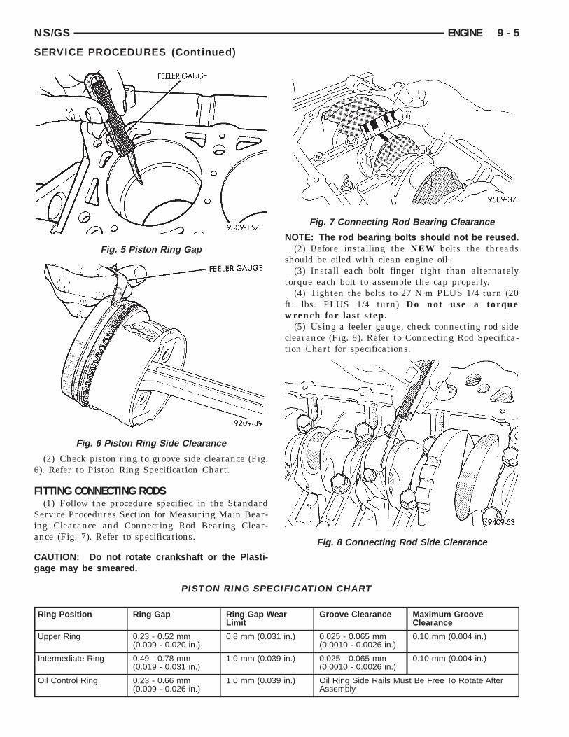
FITTING PISTON RINGS(1) Wipe cylinder bore clean. Insert ring and push
down with piston to ensure it is square in bore. Thering gap measurement must be made with the ringpositioning at least 12 mm (0.50 inch) from bottom ofcylinder bore. Check gap with feeler gauge (Fig. 5).Refer to Piston Ring Specification Chart.
CYLINDER BORE AND PISTONSPECIFICATION CHART
Standard Bore MaximumOut-of-Round
MaximumTaper
87.5 mm(3.445 in.)
0.051 mm(0.002 in.)
0.051 mm(0.002 in.)
Standard Piston SizeFederal
Emission:87.463 - 87.481 mm(3.4434 - 3.4441 in.)
Low EmissionVehicle (LEV):
87.456 - 87.474 mm(3.4432 - 3.4439 in.)
Piston to Bore ClearanceFederal
Emission:0.012 - 0.044 mm
(0.0004 - 0.0017 in.)Low EmissionVehicle (LEV):
0.18 - 0.050 mm(0.0008 - 0.0020 in.)
Measurements Taken at Piston Size Location
Fig. 4 Piston Measurements
NS/GS ENGINE 9 - 5
SERVICE PROCEDURES (Continued)
(2) Check piston ring to groove side clearance (Fig.6). Refer to Piston Ring Specification Chart.
FITTING CONNECTING RODS(1) Follow the procedure specified in the Standard
Service Procedures Section for Measuring Main Bear-ing Clearance and Connecting Rod Bearing Clear-ance (Fig. 7). Refer to specifications.
CAUTION: Do not rotate crankshaft or the Plasti-gage may be smeared.
Fig. 5 Piston Ring Gap
Fig. 6 Piston Ring Side Clearance
NOTE: The rod bearing bolts should not be reused.(2) Before installing the NEW bolts the threads
should be oiled with clean engine oil.(3) Install each bolt finger tight than alternately
torque each bolt to assemble the cap properly.(4) Tighten the bolts to 27 N·m PLUS 1/4 turn (20
ft. lbs. PLUS 1/4 turn) Do not use a torquewrench for last step.
(5) Using a feeler gauge, check connecting rod sideclearance (Fig. 8). Refer to Connecting Rod Specifica-tion Chart for specifications.
Fig. 7 Connecting Rod Bearing Clearance
Fig. 8 Connecting Rod Side Clearance
PISTON RING SPECIFICATION CHART
Ring Position Ring Gap Ring Gap WearLimit
Groove Clearance Maximum GrooveClearance
Upper Ring 0.23 - 0.52 mm(0.009 - 0.020 in.)
0.8 mm (0.031 in.) 0.025 - 0.065 mm(0.0010 - 0.0026 in.)
0.10 mm (0.004 in.)
Intermediate Ring 0.49 - 0.78 mm(0.019 - 0.031 in.)
1.0 mm (0.039 in.) 0.025 - 0.065 mm(0.0010 - 0.0026 in.)
0.10 mm (0.004 in.)
Oil Control Ring 0.23 - 0.66 mm(0.009 - 0.026 in.)
1.0 mm (0.039 in.) Oil Ring Side Rails Must Be Free To Rotate AfterAssembly

9 - 6 ENGINE NS/GS
SERVICE PROCEDURES (Continued)
FITTING CRANKSHAFT BEARINGSRefer to Measuring Main Bearing Clearance in
Standard Service Procedures. Refer to CrankshaftSpecification Chart for specifications.
CRANKSHAFT END PLAY
DIAL INDICATOR METHOD(1) Mount a dial indicator to front of engine, locat-
ing probe on nose of crankshaft (Fig. 9).
(2) Move crankshaft all the way to the rear of itstravel.
CONNECTING ROD SPECIFICATION CHART
Connecting Rod Bearing Oil ClearanceNew Part: 0.026 - 0.059 mm (0.001 - 0.0023 in.)Wear Limit: 0.075 mm (0.003 in.)
Connecting Rod Side ClearanceNew Part: 0.13 - 0.38 mm (0.005 - 0.015 in.)Wear Limit: 0.40 mm (0.016 in.)
Fig. 9 Checking Crankshaft End Play— DialIndicator
(3) Zero the dial indicator.(4) Move crankshaft all the way to the front and
read the dial indicator. Refer to Crankshaft Specifi-cation Chart for specifications.
FEELER GAGE METHOD(1) Move crankshaft all the way to the rear of its
travel using a lever inserted between a main bearingcap and a crankshaft cheek, using care not to dam-age any bearing surface. Do not loosen main bearingcap.
(2) Use a feeler gauge between number threethrust bearing and machined crankshaft surface todetermine end play.
REMOVAL AND INSTALLATION
CYLINDER HEAD COVER
REMOVAL(1) Remove ignition coil pack (Fig. 10).(2) Remove the cylinder head cover bolts.(3) Remove cylinder head cover from cylinder
head.
INSTALLATIONBefore installation, clean cylinder head and cover
mating surfaces. Make certain the cylinder headcover mating surface is flat.
(1) Install new valve cover gasket.
CAUTION: Do not allow oil or solvents to contactthe timing belt as they can deteriorate the rubberand cause tooth skipping.
(2) Install cover assembly to head and tighten fas-teners to 12 N·m (105 in. lbs.).
(3) Install ignition coil pack. Tighten fasteners to23 N·m (200 in. lbs.).
CRANKSHAFT SPECIFICATION CHART
Crankshaft End-Play New Part: 0.09 - 0.24 mm (0.0035 - 0.0094 in.)Wear Limit: 0.37 mm (0.015 in.)
Main Bearing Clearance New Part: 0.022 - 0.062 mm (0.0008 - 0.0024 in.)
Connecting Rod Bearing Clearance New Part: 0.026 - 0.059 mm (0.001 - 0.0023 in.)Wear Limit: 0.075 mm (0.003 in.)
Main Bearing Journal Diameter Standard: 52.000 6 0.008 mm (2.0472 6 0.0003 in.)1st Undersize: 51.983 6 0.008 mm
(2.0466 6 0.0003 in.)Connecting Rod Journal Diameter Standard: 48.000 6 0.008 mm (1.8897 6 0.0003 in.)1st Undersize: 47.983 6 0.008 mm
(1.8891 6 0.0003 in.)

NS/GS ENGINE 9 - 7
REMOVAL AND INSTALLATION (Continued)
SPARK PLUG TUBE(1) Remove valve cover. Refer to procedure out-
lined in this section.(2) Using locking pliers remove the tube from the
cylinder head (Fig. 11). Discard old tube.
(3) Clean area around spark plug with Mopartparts cleaner or equivalent.
(4) Apply Mopart Stud and Bearing Mount orequivalent to a new tube approximately 1 mm fromthe end in a 3 mm wide area.
(5) Install sealer end of tube into the cylinderhead. Then carefully install the tube using a hard-wood block and mallet until the tube is seated intothe bottom of the bore.
(6) Install valve cover. Refer to procedure outlinedin this section.
SPARK PLUG TUBE SEALSThe spark plug tube seals are located in the cylin-
der head cover (Fig. 12). These seals are pressed intothe cylinder head cover to seal the outside perimeter
Fig. 10 Ingition Coil Pack
Fig. 11 Servicing Spark Plug Tubes
of the spark plug tubes. If these seals show signs ofhardness and/or cracking they should be replaced.
CAMSHAFT
NOTE: TO REMOVE CAMSHAFT THE CYLINDERHEAD MUST BE REMOVED.
REMOVAL(1) Perform fuel system pressure release procedure
before attempting any repairs. Refer to Group 14,Fuel System
(2) Remove the cylinder head cover. Refer to proce-dure outlined in this section.
(3) Mark rocker arm shaft assemblies so that theyare installed in their original positions.
(4) Remove rocker arm shaft bolts. Refer to proce-dure outlined in this section.
(5) Remove timing belt, timing belt tensioner, andcamshaft sprocket. Refer to timing belt service out-lined in this section.
(6) Remove inner timing belt cover.(7) Remove cylinder head. Refer to procedure out-
lined in this section.(8) Remove camshaft sensor and camshaft target
magnet.(9) Remove camshaft from the rear of cylinder
head.
INSPECT CYLINDER HEAD FOR THE FOLLOWING:
NOTE:• Check oil feed holes for blockage.• Inspect cylinder head camshaft bearings for
wear, Refer to Cylinder Head, Inspection and Clean-ing.
• Check camshaft bearing journals for scratchesand worn areas. If light scratches are present, theymay be removed with 400 grit sand paper. If deep
Fig. 12 Spark Plug Tube Seals
9 - 8 ENGINE NS/GS
REMOVAL AND INSTALLATION (Continued)
scratches are present, replace the camshaft andcheck the cylinder head for damage. Replace thecylinder head if worn or damaged. Check the lobesfor pitting and wear. If the lobes show signs ofwear, check the corresponding rocker arm roller forwear or damage. Replace rocker arm/hydraulic lashadjuster if worn or damaged. If lobes show signs ofpitting on the nose, flank or base circle; replace thecamshaft.
INSTALLATION(1) Lubricate the camshaft journals with oil and
install camshaft without rocker arm assembliesinstalled.
(2) Install camshaft target magnet into the end ofthe camshaft. Tighten mounting screw to 3.4 N·m (30in. lbs.).
(3) Install camshaft position sensor and tightenmounting screws to 9 N·m (80 in. lbs.).
(4) Measure camshaft end play using the followingprocedure:
• Mount dial indicator C-3339 or equivalent, to astationary point on cylinder head (Fig. 13).
• Using a suitable tool, move camshaft to rear-ward limits of travel.
• Zero the dial indicator.• Move camshaft forward to limits of travel and
read dial indicator.• End play travel: 0.13 - 0.33 mm (0.005 - 0.013
in.).
(5) Install front camshaft seal. Camshaft must beinstalled before the camshaft seal is installed. Referto procedure outlined in this section.
(6) Install cylinder head. Refer to procedure out-lined in this section.
(7) Install camshaft sprocket and tighten to 115N·m (85 ft. lbs.).
(8) Install inner timing belt cover.
Fig. 13 Camshaft End Play
(9) Install timing belt tensioner and timing belt.Refer to procedures outlined in this section.
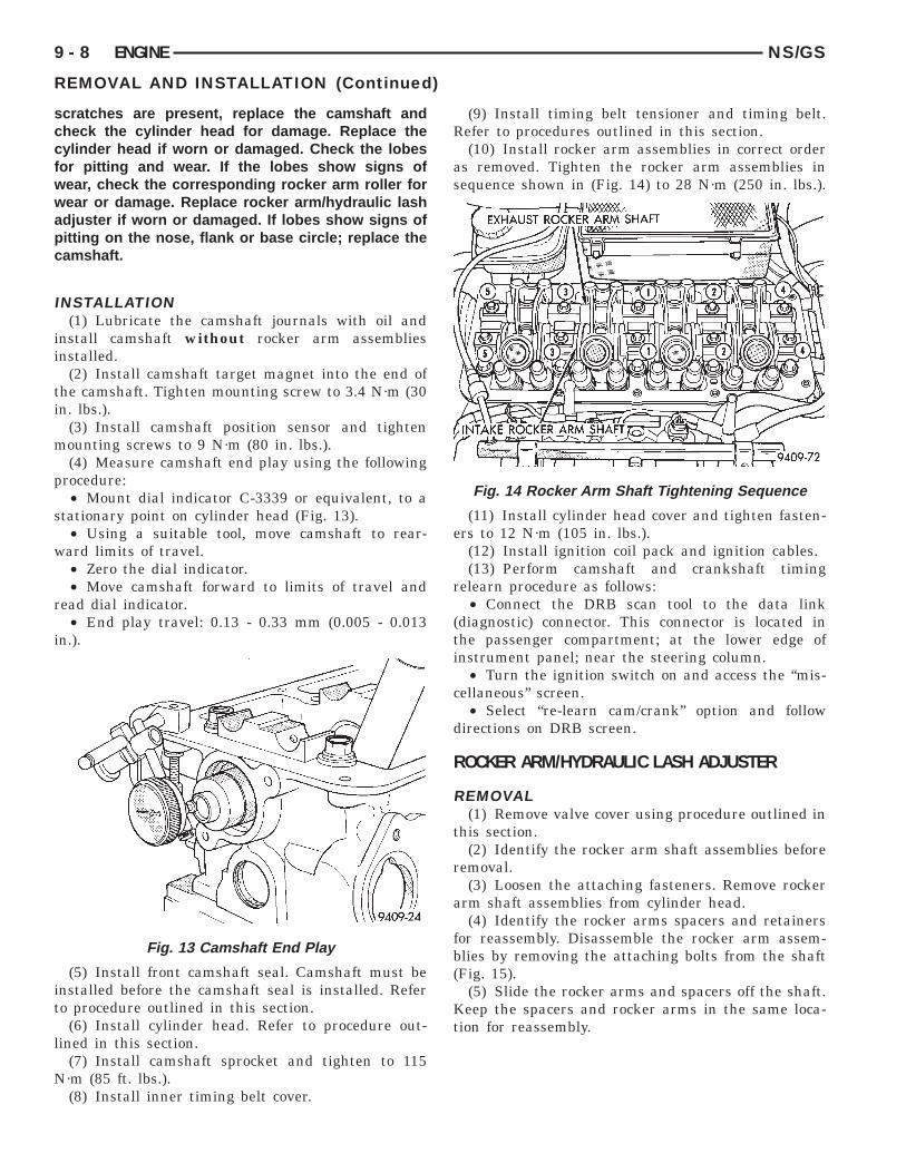
(10) Install rocker arm assemblies in correct orderas removed. Tighten the rocker arm assemblies insequence shown in (Fig. 14) to 28 N·m (250 in. lbs.).
(11) Install cylinder head cover and tighten fasten-ers to 12 N·m (105 in. lbs.).
(12) Install ignition coil pack and ignition cables.(13) Perform camshaft and crankshaft timing
relearn procedure as follows:• Connect the DRB scan tool to the data link
(diagnostic) connector. This connector is located inthe passenger compartment; at the lower edge ofinstrument panel; near the steering column.
• Turn the ignition switch on and access the “mis-cellaneous” screen.
• Select “re-learn cam/crank” option and followdirections on DRB screen.
ROCKER ARM/HYDRAULIC LASH ADJUSTER
REMOVAL(1) Remove valve cover using procedure outlined in
this section.(2) Identify the rocker arm shaft assemblies before
removal.(3) Loosen the attaching fasteners. Remove rocker
arm shaft assemblies from cylinder head.(4) Identify the rocker arms spacers and retainers
for reassembly. Disassemble the rocker arm assem-blies by removing the attaching bolts from the shaft(Fig. 15).
(5) Slide the rocker arms and spacers off the shaft.Keep the spacers and rocker arms in the same loca-tion for reassembly.
Fig. 14 Rocker Arm Shaft Tightening Sequence

NS/GS ENGINE 9 - 9
REMOVAL AND INSTALLATION (Continued)
NOTE: Inspect the rocker arm for scoring, wear onthe roller or damage to the rocker arm (Fig. 16)Replace if necessary. Check the location where therocker arms mount to the shafts for wear or dam-age. Replace if damaged or worn. The rocker armshaft is hollow and is used as a lubrication oil duct.Check oil holes for clogging with small wire, cleanas required. Lubricate the rocker arms and spacers.Install onto shafts in their original position (Fig. 15).
INSTALLATION
CAUTION: Set crankshaft to 3 notches before TDCbefore installing rocker arm shafts. Refer to TimingBelt System and Camshaft Seal Service of this sec-tion for procedure.
(1) Install rocker arm/hydraulic lash adjusterassembly making sure that adjusters are at least
Fig. 15 Rocker Arm Shaft Assemblies
Fig. 16 Rocker Arm Assemblies
partially full of oil. This is indicated by little or noplunger travel when the lash adjuster is depressed. Ifthere is excessive plunger travel. Place the rockerarm assembly into clean engine oil and pump theplunger until the lash adjuster travel is taken up. Iftravel is not reduced, replace the assembly. Hydrauliclash adjuster and rocker arm are serviced as anassembly.
(2) Install rocker arm and shaft assemblies withNOTCH in the rocker arm shafts pointing up andtoward the timing belt side of the engine (Fig. 17).Install the retainers in their original positions on theexhaust and intake shafts (Fig. 15).
CAUTION: When installing the intake rocker armshaft assembly be sure that the plastic spacers donot interfere with the spark plug tubes. If the spac-ers do interfere rotate until they are at the properangle. To avoid damaging the spark plug tubes, donot attempt rotating the spacers by forcing downthe shaft assembly.
(3) Tighten bolts to 28 N·m (250 in. lbs.) insequence shown in (Fig. 18).
Fig. 17 Rocker Arm Shaft Notches
Fig. 18 Rocker Arm Shaft Tightening Sequence

9 - 10 ENGINE NS/GS
REMOVAL AND INSTALLATION (Continued)
HYDRAULIC LASH ADJUSTER NOISEA tappet-like noise may be produced from several
items. Refer to Lash Adjuster Noise - Diagnosis inStandard Service Procedures, outlined in this Group.Lash adjusters are replaced with the rockerarm as an assembly.
VALVE SEALS AND SPRINGS IN VEHICLE
REMOVAL(1) Remove rocker arm shafts assemblies as previ-
ously outlined in this section.(2) Rotate crankshaft until piston is at TDC on
compression.(3) With air hose attached to adapter tool installed
in spark plug hole, apply 90-120 psi air pressure.(4) Using Special Tool MD-998772A with adapter
6779 (Fig. 19) compress valve springs and removevalve locks.
(5) Remove valve spring.(6) Remove valve stem seal by using a valve stem
seal tool (Fig. 20).
Fig. 19 Removing and Installing Valve Spring
Fig. 20 Valve Stem Oil Seal Tool
INSTALLATION(1) Install valve seal/valve spring seat assembly
as outlined in the Valve Installation procedure in thissection.
(2) Using Special Tool MD-998772A compress valvesprings only enough to install locks. Correct align-ment of tool is necessary to avoid nicking valve stems(air pressure required), piston at TDC.
(3) Install rocker arm shaft assemblies as previ-ously outlined in this section.
(4) Install valve cover as previously outlined inthis section.
CYLINDER HEAD
REMOVAL(1) Perform fuel system pressure release procedure
before attempting any repairs. Refer to Group 14,Fuel System
(2) Disconnect negative battery cable. Drain cool-ing system. Refer to Group 7, Cooling System.
(3) Disconnect all vacuum lines, electrical wiringand fuel lines from throttle body.
(4) Remove throttle linkage.(5) Remove accessory drive belts. Refer to Group 7,
Cooling System for procedure.(6) Remove power brake vacuum hose from intake
manifold.(7) Raise vehicle and remove exhaust pipe from
manifold.(8) Remove power steering pump assembly and set
aside.(9) Disconnect coil pack wiring connector and
remove coil pack and bracket from engine.(10) Remove cylinder head cover.(11) Remove cam sensor and fuel injectors wiring
connectors.(12) Remove intake manifold. Removal procedure
outline in Group 11.
Fig. 21 Valve Spring Assembly
NS/GS ENGINE 9 - 11
REMOVAL AND INSTALLATION (Continued)
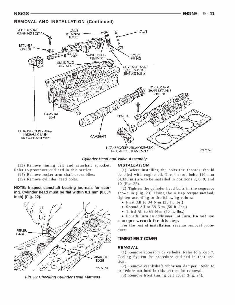
Cylinder Head and Valve Assembly
(13) Remove timing belt and camshaft sprocket.Refer to procedure outlined in this section.
(14) Remove rocker arm shaft assemblies.(15) Remove cylinder head bolts.
NOTE: Inspect camshaft bearing journals for scor-ing. Cylinder head must be flat within 0.1 mm (0.004inch) (Fig. 22).
Fig. 22 Checking Cylinder Head Flatness
INSTALLATION(1) Before installing the bolts the threads should
be oiled with engine oil. The 4 short bolts 110 mm(4.330 in.) are to be installed in positions 7, 8, 9, and10 (Fig. 23).
(2) Tighten the cylinder head bolts in the sequenceshown in (Fig. 23). Using the 4 step torque method,tighten according to the following values:
• First All to 34 N·m (25 ft. lbs.)• Second All to 68 N·m (50 ft. lbs.)• Third All to 68 N·m (50 ft. lbs.)• Fourth Turn an additional 1/4 Turn, Do not use
a torque wrench for this step.For the rest of installation, reverse removal proce-
dure.
TIMING BELT COVER
REMOVAL(1) Remove accessory drive belts. Refer to Group 7,
Cooling System for procedure outlined in that sec-tion.
(2) Remove crankshaft vibration damper. Refer toprocedure outlined in this section for removal.
(3) Remove front timing belt cover (Fig. 24).

9 - 12 ENGINE NS/GS
REMOVAL AND INSTALLATION (Continued)
INSTALLATION(1) Install front timing cover.(2) Install crankshaft vibration damper Refer to
procedure outlined in this section for installation.(3) Install accessory drive belts. Refer to Group 7,
Cooling System Accessory Drive section for proce-dure.
CAMSHAFT OIL SEAL
REMOVAL
CAUTION: Do Not Rotate the camshaft or crank-shaft when timing belt is removed damage to theengine may occur.
Fig. 23 Cylinder Head Tightening Sequence
Fig. 24 Timing Belt Cover
(1) Remove timing belt cover and belt. Removalprocedure is outlined in this section. Remove cam-shaft sprocket bolt, with the Modified Special ToolC-4687-1 as shown in (Fig. 25).
(2) Hold camshaft sprocket with modified toolwhile removing bolt. Remove sprocket from camshaft.
(3) Remove camshaft seal using Special ToolC-4679–A (Fig. 26).
CAUTION: Do not nick shaft seal surface or sealbore.
(4) Shaft seal lip surface must be free of varnish,dirt or nicks. Polish with 400 grit paper if necessary.
Fig. 25 Modification to Special Tool
Fig. 26 Removing Camshaft Oil Seal

NS/GS ENGINE 9 - 13
REMOVAL AND INSTALLATION (Continued)
INSTALLATION(1) Install camshaft seal flush with cylinder head
using Special Tool MD 998306 (Fig. 27).
(2) Install camshaft sprocket retaining bolt. Holdcamshaft sprocket with Special Tool C-4687-1 (Fig.25) and tighten bolt to 115 N·m (85 ft. lbs.).
TIMING BELT SYSTEM
CHECKING BELT TIMING—COVER INSTALLED• Remove number one spark plug.• Using a dial indicator, set number one cylinder
to TDC on the compression stroke.
Fig. 27 Installing Camshaft Seal
• Remove the access plug from the outer timingbelt cover (Fig. 28).
• Check the timing mark on the camshaftsprocket, it should align with the arrow on the rearbelt cover (Fig. 29).
REMOVAL—TIMING BELT(1) Remove accessory drive belts. Refer to Group 7,
Cooling System for procedure outlined in that sec-tion.
(2) Remove crankshaft damper bolt. Removedamper using the large side of Special Tool 1026 andinsert 6827-A (Fig. 30).
Fig. 29 Camshaft Timing Marks
Fig. 28 Timing Belt System

9 - 14 ENGINE NS/GS
(3) Remove front timing belt cover (Fig. 31).
CAUTION: Align camshaft and crankshaft timingmarks before removing the timing belt.
(4) Loosen timing belt tensioner fasteners (Fig. 33)and remove timing belt and tensioner.
CAUTION: Do not loosen, tighten, or remove thetensioner pivot bolt (Fig. 32).
CAMSHAFT AND CRANKSHAFT TIMINGPROCEDURE AND BELT INSTALLATION—SOHC ENGINE
(1) When tensioner is removed from the engine itis necessary to compress the plunger into the ten-sioner body.
Fig. 30 Crankshaft Damper—Removal
Fig. 31 Timing Belt Cover
REMOVAL AND INSTALLATION (Continued)
(2) Place the tensioner into a vise equipped withsoft jaws and slowly compress the plunger (Fig. 34).
CAUTION: Index the tensioner in the vise the sameway it is installed on the engine. This is to ensureproper pin orientation when tensioner is installedon the engine.
(3) When plunger is compressed into the tensionerbody install a 1.9 mm (5/64) allen wrench or pinthrough the body and plunger to retain plunger inplace until tensioner is installed.
(4) Set crankshaft sprocket to TDC by aligning thesprocket with the arrow on the oil pump housing,then back off to 3 notches before TDC (Fig. 35).
Fig. 32 Tensioner Pulley Assembly
Fig. 33 Remove Timing Belt

NS/GS ENGINE 9 - 15
REMOVAL AND INSTALLATION (Continued)
(5) Set camshaft to TDC by aligning mark onsprocket with the arrow on the rear of timing beltcover (Fig. 36).
(6) Move crankshaft to 1/2 mark before TDC (Fig.37) for belt installation.
(7) Install timing belt. Starting at the crankshaft,go around the water pump sprocket and then aroundthe camshaft sprocket.
Fig. 34 Compressing Timing Belt Tensioner
Fig. 35 Crankshaft Sprocket Timing
Fig. 36 Camshaft Timing Mark
(8) Move crankshaft sprocket to TDC to take upbelt slack. Install tensioner to block but do nottighten fasteners.
(9) Using a torque wrench on the tensioner pulleyapply 28 N·m (250 in. lbs.) of torque (Fig. 38).
(10) With torque being applied to the tensionerpulley move the tensioner up against the tensionerpulley bracket and tighten fasteners to 31 N·m (275in. lbs.) (Fig. 38).
(11) Pull tensioner plunger pin. Pretension is cor-rect when pin can be removed and installed.
(12) Rotate crankshaft 2 revolutions and check thealignment of the timing marks (Fig. 38).
(13) Install front half of timing cover.
Fig. 37 Adjusting Crankshaft Sprocket for TimingBelt Installation
Fig. 38 Adjusting Timing Belt Tension

9 - 16 ENGINE NS/GS
REMOVAL AND INSTALLATION (Continued)
(14) Install crankshaft damper using M12-1.75 x150 mm bolt, washer, thrust bearing and nut fromSpecial Tool 6792. Install crankshaft damper bolt andtighten to 142 N·m (105 ft. lbs.) (Fig. 39).
(15) Install accessory drive belts. Refer to Group 7,Cooling System Accessory Drive section for proce-dure.
(16) Perform camshaft and crankshaft timingrelearn. Refer to Group 25, Emission Control Sys-tems for procedure.
TIMING BELT—w/AUTO TENSIONER—IFEQUIPPED
CHECKING BELT TIMING—COVER INSTALLED• Remove number one spark plug.• Using a dial indicator, set number one cylinder
to TDC on the compression stroke.• Remove the access plug from the outer timing
belt cover (Fig. 28).• Check the timing mark on the camshaft
sprocket, it should align with the arrow on the rearbelt cover (Fig. 29).
REMOVAL—TIMING BELT(1) Remove accessory drive belts. Refer to Group 7,
Cooling System for procedure outlined in that sec-tion.
(2) Raise vehicle on a hoist and remove right innersplash shield (Fig. 42).
(3) Remove crankshaft damper bolt. Removedamper using the large side of Special Tool 1026 andinsert 6827-A (Fig. 30).
(4) Lower vehicle and place a jack under engine.(5) Remove right engine mount. Refer to procedure
outlined in this section.(6) Remove right engine mount bracket (Fig. 44).(7) Remove front timing belt cover (Fig. 31).
Fig. 39 Crankshaft Damper—Installation
CAUTION: Align camshaft and crankshaft timingmarks before removing the timing belt by rotatingthe engine with the crankshaft.
(8) Insert a 8 mm Allen wrench into the belt ten-sioner. Before rotating the tensioner insert the longend of a 1/8” or 3 mm Allen wrench into the pin holeon the front of the tensioner (Fig. 33). Rotate the ten-sioner counterclockwise with the Allen wrench, whilepushing in lightly on the 1/8 in. or 3 mm Allenwrench, until it slides into the locking hole.
(9) Remove timing belt.
CAUTION: Do not rotate the camshafts once thetiming belt has been removed or damage to valvecomponents may occur.
CAMSHAFT AND CRANKSHAFT TIMING PROCEDURE ANDBELT INSTALLATION —SOHC ENGINE
(1) Set crankshaft sprocket to TDC by aligning thesprocket with the arrow on the oil pump housing,then back off to 3 notches before TDC (Fig. 35).
(2) Set camshaft to TDC by aligning mark onsprocket with the arrow on the rear of timing beltcover (Fig. 36).
(3) Move crankshaft to 1/2 mark before TDC (Fig.37) for belt installation.
(4) Install timing belt. Starting at the crankshaft,go around the water pump sprocket and then aroundthe camshaft sprocket.
(5) Move crankshaft sprocket to TDC to take upbelt slack.
(6) Remove the pin or 1/8” or 3 mm Allen wrenchfrom belt tensioner.
(7) Rotate crankshaft 2 revolutions and check thealignment of the timing marks (Fig. 50).
(8) Install front half of timing cover.(9) Install engine mount bracket.(10) Install Right engine mount. Refer to proce-
dure outlined in this section.(11) Remove jack from under engine.(12) Install crankshaft damper using M12-1.75 x
150 mm bolt, washer, thrust bearing and nut fromSpecial Tool 6792. Install crankshaft damper bolt andtighten to 142 N·m (105 ft. lbs.) (Fig. 39).
(13) Install accessory drive belts. Refer to Group 7,Cooling System Accessory Drive section for proce-dure.
(14) Raise vehicle on hoist and install right innersplash shield.
(15) Perform camshaft and crankshaft timingrelearn procedure as follows:
• Connect the DRB scan tool to the data link(diagnostic) connector. This connector is located inthe passenger compartment; at the lower edge ofinstrument panel; near the steering column.

NS/GS ENGINE 9 - 17
REMOVAL AND INSTALLATION (Continued)
Fig. 40 Timing Belt System
• Turn the ignition switch on and access the “mis-cellaneous” screen.
• Select “re-learn cam/crank” option and followdirections on DRB screen.
OIL PAN
REMOVAL(1) Drain engine oil.(2) Remove transmission inspection cover.(3) If equipped with air conditioning remove oil fil-
ter and adaptor. Refer to Oil Filter Adapter Removaland Installation in this section.
(4) Remove oil pan.
Fig. 41 Camshaft Timing Marks
(5) Clean oil pan and all gasket surfaces.
Fig. 42 Right Inner Splash Shield

9 - 18 ENGINE NS/GS
REMOVAL AND INSTALLATION (Continued)
INSTALLATION(1) Apply Mopar Silicone Rubber Adhesive Sealant
or equivalent at the oil pump to engine block partingline (Fig. 52).
(2) Install a new oil pan gasket to pan.(3) Install pan and tighten screws to 12 N·m (105
in. lbs.).(4) Install oil filter and adaptor.(5) Install proper amount of oil. With oil filter 4.25
Liters (4.5 Qts.). Without oil filter 3.8 Liters (4.0Qts.)
FRONT CRANKSHAFT OIL SEAL
REMOVAL(1) Using Special Tool 1026 and Insert 6827–A,
remove crankshaft damper (Fig. 53).(2) Remove outer timing belt cover and timing
belt. Refer to Timing Belt System outlined in thissection.
Fig. 43 Crankshaft Damper—Removal
Fig. 44 Right Engine Mount Bracket
(3) Remove crankshaft sprocket using Special Tool6793 and insert C-4685-C2 (Fig. 54).
CAUTION: Do not nick shaft seal surface or sealbore.
Fig. 45 Timing Belt Cover
Fig. 46 Timing Belt Removal

NS/GS ENGINE 9 - 19
REMOVAL AND INSTALLATION (Continued)
(4) Using Tool 6771 to remove front crankshaft oilseal (Fig. 55). Do not damage the seal contact areaon the crankshaft.
INSTALLATION(1) Install new seal by using Tool 6780–1 (Fig. 56).
Fig. 47 Crankshaft Sprocket Timing
Fig. 48 Camshaft Timing Mark
Fig. 49 Adjusting Crankshaft Sprocket for TimingBelt Installation
(2) Place seal into opening with seal springtowards the inside of engine. Install seal until flushwith cover.
(3) Install crankshaft sprocket (Fig. 57). UsingSpecial Tool 6792.
NOTE: Make sure the word “front” on the sprocketis facing you.
(4) Install timing belt and covers. Refer to TimingBelt System in this section for installation.
(5) Install crankshaft damper (Fig. 58). Use thrustbearing/washer and 12M-1.75 x 150 mm bolt from
Fig. 50 Crankshaft and Camshaft Timing
Fig. 51 Crankshaft Damper—Installation

9 - 20 ENGINE NS/GS
Special Tool 6792. Install crankshaft damper bolt andtighten to 142 N·m (105 ft. lbs.)
CRANKSHAFT OIL SEAL—REAR
REMOVAL(1) Insert a 3/16 flat bladed screwdriver between
the dust lip and the metal case of the crankshaft
Fig. 52 Oil Pan Sealing
Fig. 53 Crankshaft Damper—Removal
Fig. 54 Crankshaft Sprocket—Removal
REMOVAL AND INSTALLATION (Continued)
seal. Angle the screwdriver (Fig. 59) through the dustlip against metal case of the seal. Pry out seal.
CAUTION: Do not permit the screwdriver blade tocontact crankshaft seal surface. Contact of thescrewdriver blade against crankshaft edge (cham-fer) is permitted.
INSTALLATION
CAUTION: If burr or scratch is present on thecrankshaft edge (chamfer), cleanup with 400 gritsand paper to prevent seal damage during installa-tion of new seal.
Fig. 55 Front Crankshaft Oil Seal—Removal
Fig. 56 Front Crankshaft Oil Seal—Installation

NS/GS ENGINE 9 - 21
REMOVAL AND INSTALLATION (Continued)
NOTE: When installing seal, no lube on seal isneeded.
(1) Place Special Tool 6926-1 on crankshaft. This isa pilot tool with a magnetic base (Fig. 60).
(2) Position seal over pilot tool. Make sure you canread the words THIS SIDE OUT on seal (Fig. 60).Pilot tool should remain on crankshaft during instal-lation of seal. Ensure that the lip of the seal is facingtowards the crankcase during installation.
CAUTION: If the seal is driven into the block pastflush, this may cause an oil leak.
(3) Drive the seal into the block using Special Tool6926-2 and handle C-4171 (Fig. 61) until the tool bot-toms out against the block (Fig. 62).
CRANKSHAFT
REMOVAL(1) Remove oil filter and adapter from bedplate.
Fig. 57 Crankshaft Sprocket—Installation
Fig. 58 Crankshaft Damper—Installation
(2) Remove collar from oil pan to transmissionhousing.
(3) Remove oil pan.(4) Remove crankshaft sprocket and oil pump both
procedures outlined in this section.(5) Remove all main bearing cap and bedplate
bolts from the engine block (Fig. 63).(6) Using a mallet tap the bedplate loose from the
engine block dowel pins.
Fig. 59 Rear Crankshaft Oil Seal—Removal
Fig. 60 Rear Crankshaft Seal and Special Tool6926-1

9 - 22 ENGINE NS/GS
CAUTION: Do not pry up on one side of the bed-plate. Damage may occur to cylinder block and bed-plate alignment.
Fig. 61 Crankshaft Seal Special Tool 6926-2
Fig. 62 Rear Crankshaft Seal—Installation
REMOVAL AND INSTALLATION (Continued)
(7) Bedplate should be removed evenly from thecylinder block dowel pins.
(8) Lift out crankshaft from cylinder block. Be surenot to damage the main bearings or journals whenremoving the crankshaft.
CRANKSHAFT MAIN BEARINGS LOCATIONThe crankshaft is supported in five main bearings.
All upper bearing shells in the crankcase have oilgrooves. All lower bearing shells installed in the (bed-plate) main bearing cap are plain. Crankshaft endplay is controlled by a flanged bearing on the numberthree main bearing journal (Fig. 64).
NOTE: The upper and lower main Bearing shellsare Not interchangeable. The lower shells have arevised tab to prevent improper installation.
CRANKSHAFT MAIN JOURNALS INSPECTIONThe crankshaft journals should be checked for
excessive wear, taper and scoring. Limits of taper orout-of-round on any crankshaft journals should beheld to .025 mm (.001 inch). Journal grinding shouldnot exceed .305 mm (.012 inch) under the standardjournal diameter. DO NOT grind thrust faces ofNumber 3 main bearing. DO NOT nick crank pin orbearing fillets. After grinding, remove rough edgesfrom crankshaft oil holes and clean out all passages.
CAUTION: With the nodular cast iron crankshaftsused it is important that the final paper or cloth pol-ish after any journal regrind be in the same direc-tion as normal rotation in the engine.
Upper and lower Number 3 bearing halves areflanged to carry the crankshaft thrust loads and areNOT interchangeable with any other bearing halvesin the engine (Fig. 64). All bearing cap bolts removedduring service procedures are to be cleaned and oiledbefore installation. Bearing shells are available instandard and the following undersized: 0.016 mm(.0006 inch), .032 mm (.0012 inch), .250 mm (.010inch). Never install an undersize bearing that willreduce clearance below specifications.
INSTALLATION(1) Install the main bearing shells with the lubri-
cation groove in the cylinder block. Install O-ringinto recess in the block (Fig. 65).
(2) Make certain oil holes in block line up with oilhole in bearings and bearing tabs seat in the blocktab slots.
CAUTION: Do Not get oil on the bedplate matingsurface. It will affect the sealer ability to seal thebedplate to cylinder block.

NS/GS ENGINE 9 - 23
REMOVAL AND INSTALLATION (Continued)
(3) Oil the bearings and journals and installcrankshaft and O-ring in cylinder block.
CAUTION: Use only the specified anaerobic sealeron the bedplate or damage may occur to theengine.
(4) Apply 1.5 to 2.0 mm (0.059 to 0.078 in.) bead ofMopar Torque Cure Gasket Maker to cylinder blockas shown in (Fig. 66).
(5) Install lower main bearings into main bearingcap/bedplate. Make certain the bearing tabs are
Fig. 63 Bedplate Bolts
seated into the bedplate slots. Install the main bear-ing/bedplate into engine block.
(6) Before installing the bolts oil threads withclean engine oil, wipe off any excess oil.
(7) Install main bearing bedplate to engine blockbolts 11, 17 and 20 finger tight. Tighten this boltsdown together until the bedplate contacts the cylin-der block. Torque bolts to 30 N·m (22 ft. lbs.) (Fig.67).
Fig. 64 Main Bearing Identification

9 - 24 ENGINE NS/GS
REMOVAL AND INSTALLATION (Continued)
(8) Install main bearing bedplate to engine blockbolts (1 thru 10) and torque each bolt to 81 N·m (60ft. lbs.) in sequence shown in (Fig. 67).
Fig. 65 Installing Main Bearing Upper Shell
Fig. 66 Main Bearing Caps/Bedplate Sealing
Fig. 67 Main Bearing Caps/Bedplate TorqueSequence
(9) Install main bearing bedplate to engine blockbolts (11 thru 20), with baffle studs in positions 12,13 and 16 and torque each bolt to 30 N·m (22 ft. lbs.)in sequence shown in (Fig. 67).
(10) After the main bearing bedplate is installed,check the crankshaft turning torque. The turningtorque should not exceed 5.6 N·m (50 in. lbs.).
(11) Install oil pump. If crankshaft end play is tobe checked refer to service procedures in this section.
(12) Install crankshaft sprocket.(13) Install oil filter adapter and filter.(14) Install oil pan and collar. Refer to procedures
outlined in the section.(15) Perform camshaft and crankshaft timing
relearn procedure as follows:• Connect the DRB scan tool to the data link
(diagnostic) connector. This connector is located inthe passenger compartment; at the lower edge ofinstrument panel; near the steering column.
• Turn the ignition switch on and access the “mis-cellaneous” screen.
• Select “re-learn cam/crank” option and followdirections on DRB screen.
OIL FILTER ADAPTER
REMOVE AND INSTALLEnsure O-ring is in the groove on adapter. Align
roll pin into engine block and tighten assembly to 80N·m (60 ft. lbs.) (Fig. 68).
OIL FILTER
REMOVE AND INSTALL
CAUTION: When servicing the oil filter (Fig. 69)avoid deforming the filter, install tool band strapagainst the seam at the base of the filter. The seam,joining the can to the base is reinforced by thebase plate.
(1) Turn counterclockwise to remove.(2) To install, lubricate new filter gasket. Check
filter mounting surface. The surface must be smooth,flat and free of debris or old pieces of rubber. Screw
Fig. 68 Engine Oil Filter Adapter to Engine Block

NS/GS ENGINE 9 - 25
REMOVAL AND INSTALLATION (Continued)
filter on until gasket contacts base. Tighten to 21N·m (15 ft. lbs.).
OIL PUMP
REMOVAL(1) Disconnect negative cable from battery.(2) Remove Timing Belt. Refer to Timing Belt Sys-
tem, in this section.(3) Remove Oil Pan. Refer to Oil Pan Removal in
this section.(4) Remove Crankshaft Sprocket using Special Tool
6793 and insert C-4685-C2 (Fig. 70).
(5) Remove oil pick-up tube.(6) Remove oil pump (Fig. 71) and front crankshaft
seal.
INSTALLATION(1) Make sure all surfaces are clean and free of oil
and dirt.
Fig. 69 Engine Oil Filter
Fig. 70 Crankshaft Sprocket—Removal
(2) Apply Mopart Gasket Maker to oil pump asshown in (Fig. 72). Install o–ring into oil pump bodydischarge passage.
(3) Prime oil pump before installation.(4) Align oil pump rotor flats with flats on crank-
shaft as you install the oil pump to the block.
NOTE: Front crankshaft seal MUST be out of pumpto align, or damage may result.
(5) Torque all oil pump attaching bolts to 28 N·m(250 in. lbs.)
(6) Install new front crankshaft seal using SpecialTool 6780 (Fig. 73).
(7) Install crankshaft sprocket, using Special Tool6792 (Fig. 74).
(8) Install oil pump pick-up tube and oil pan.(9) Install Timing Belt. Refer to procedure outlined
in this section.(10) Connect negative cable to battery.
PISTON AND CONNECTING ROD
REMOVAL(1) Remove top ridge of cylinder bores with a reli-
able ridge reamer before removing pistons from cyl-inder block. Be sure to keep tops of pistonscovered during this operation. Mark piston withmatching cylinder number (Fig. 75).
(2) Remove oil pan. Scribe the cylinder number onthe side of the rod and cap (Fig. 76) for identification.
(3) Pistons will have a stamping in the approxi-mate location shown in (Fig. 75). These stamps willbe either a directional arrow or a weight identifica-tion for the assembly. L is for light and H is forheavy. These assemblies should all be the sameweight class. Service piston assemblies are markedwith a S and can be used with either L or H produc-tion assemblies. The weight designation stampsshould face toward the timing belt side of the engine.
(4) Pistons and connecting rods must be removedfrom top of cylinder block. Rotate crankshaft so thateach connecting rod is centered in cylinder bore.
(5) Remove connecting rod cap bolts Do not useold bolts if reinstalling connecting rod. Pusheach piston and rod assembly out of cylinder bore.
NOTE: Be careful not to nick crankshaft journals.
(6) After removal, install bearing cap on the mat-ing rod.
(7) Piston and Rods are serviced as an assembly.
PISTON RING—REMOVAL(1) ID mark on face of upper and intermediate pis-
ton rings must point toward piston crown.

9 - 26 ENGINE NS/GS
REMOVAL AND INSTALLATION (Continued)
Fig. 71 Oil Pump and Tube
(2) Using a suitable ring expander, remove upperand intermediate piston rings (Fig. 77).
(3) Remove the upper oil ring side rail, lower oilring side rail and then oil ring expander from piston.
(4) Clean ring grooves of any carbon deposits.
PISTON RINGS—INSTALLATION(1) Install rings with manufacturers I.D. mark fac-
ing up, to the top of the piston (Fig. 78).
CAUTION: Install piston rings in the followingorder:
a. Oil ring expander.
Fig. 72 Oil Pump Sealing
b. Upper oil ring side rail.c. Lower oil ring side rail.d. No. 2 Intermediate piston ring.
Fig. 73 Front Crankshaft Seal—Installation

NS/GS ENGINE 9 - 27
REMOVAL AND INSTALLATION (Continued)
e. No. 1 Upper piston ring.f. Install the side rail by placing one end between
the piston ring groove and the expander. Hold endfirmly and press down the portion to be installeduntil side rail is in position. Do not use a pistonring expander (Fig. 79).
(2) Install upper side rail first and then the lowerside rail.
(3) Install No. 2 piston ring and then No. 1 pistonring (Fig. 78).
Fig. 74 Crankshaft Sprocket—Installation
Fig. 75 Piston Markings
Fig. 76 Identify Connecting Rod to Cylinder
(4) Position piston ring end gaps as shown in (Fig.80).
(5) Position oil ring expander gap at least 45° fromthe side rail gaps but not on the piston pin center or
Fig. 77 Piston Rings—Removing and Installing
Fig. 78 Piston Ring Installation
Fig. 79 Installing Side Rail
9 - 28 ENGINE NS/GS
REMOVAL AND INSTALLATION (Continued)
on the thrust direction. Staggering ring gap is impor-tant for oil control.
PISTON AND ROD —INSTALLATION(1) Before installing pistons and connecting rod
assemblies into the bore, be sure that compressionring gaps are staggered so that neither is in line withoil ring rail gap.
(2) Before installing the ring compressor, makesure the oil ring expander ends are butted and therail gaps located as shown in (Fig. 80).
(3) Immerse the piston head and rings in cleanengine oil, slide the ring compressor, over the piston(Fig. 81). Be sure position of rings does notchange during this operation.
(4) The weight stamp designation L or H will be inthe front half of the piston should face toward thefront of the engine for SOHC engine. The arrowshould face toward the front of the engine for DOHCengine (Fig. 75).
(5) Rotate crankshaft so that the connecting rodjournal is on the center of the cylinder bore. Insert
Fig. 80 Piston Ring End Gap Position
Fig. 81 Installing Piston
rod and piston assembly into cylinder bore and guiderod over the crankshaft journal.
(6) Tap the piston down in cylinder bore, using ahammer handle. At the same time, guide connectingrod into position on connecting rod journal.
(7) Install rod caps. Install New bolts and tightento 27 N·m (20 ft.lb.) Plus 1/4 turn.
VIBRATION DAMPER
NOTE: If a gap is found in the crankshaft damper,in the area where the Poly-V Generator belt ridesthis is normal and is acceptable (Fig. 82).
REMOVAL(1) Remove accessory drive belts. Refer to Group 7,
Cooling System for procedure outlined in that sec-tion.
(2) Remove crankshaft damper bolt. Removedamper using the large side of Special Tool 1026 andinsert 6827–A (Fig. 83).
Fig. 82 Weld Gap
Fig. 83 Crankshaft Damper—Removal

NS/GS ENGINE 9 - 29
REMOVAL AND INSTALLATION (Continued)
INSTALLATION(1) Install crankshaft damper using M12-1.75 x
150 mm bolt, washer, thrust bearing and nut fromSpecial Tool 6792. Install crankshaft damper bolt andtighten to 142 N·m (105 ft. lbs.) (Fig. 84).
(2) Install accessory drive belts. Refer to Group 7,Cooling System Accessory Drive section for proce-dure.
DISASSEMBLY AND ASSEMBLY
OIL PUMP(1) To remove the relief valve, proceed as follows:(2) Remove the threaded plug and gasket from the
oil pump (Fig. 85).
CAUTION: Oil pump pressure relief valve must beinstalled as shown in (Fig. 85) or serious damagemay occur.
(3) Remove spring and relief valve (Fig. 85).
Fig. 84 Crankshaft Damper—Installation
Fig. 85 Oil Pressure Relief Valve
(4) Remove oil pump cover screws, and lift offcover.
(5) Remove pump rotors.(6) Wash all parts in a suitable solvent and inspect
carefully for damage or wear (Fig. 86).
VALVE SERVICE WITH THE CYLINDER HEADREMOVED
REMOVAL(1) With cylinder head removed, compress valve
springs using Special Tool C-3422-B or equivalent.(2) Remove valve retaining locks, valve spring
retainers, valve stem seals and valve springs.(3) Before removing valves, remove any burrs
from valve stem lock grooves to prevent dam-age to the valve guides. Identify valves to insureinstallation in original location.
VALVE INSPECTION(1) Clean valves thoroughly and discard burned,
warped and cracked valves.(2) Measure valve stems for wear. Measure stem
about 60 mm beneath the valve lock grooves.(3) If valve stems are worn more than 0.05 mm
(.002 in.), replace valve.
VALVE GUIDES(1) Remove carbon and varnish deposits from
inside of valve guides with a reliable guide cleaner.(2) Using a small hole gauge and a micrometer,
measure valve guides in 3 places top, middle and bot-tom (Fig. 87). Refer to Valve Guide SpecificationChart for specifications. Replace guides if they arenot within specification.
(3) Check valve guide height (Fig. 88).
TESTING VALVE SPRINGS(1) Whenever valves have been removed for inspec-
tion, reconditioning or replacement, valve springs
Fig. 86 Oil Pump

9 - 30 ENGINE NS/GS
DISASSEMBLY AND ASSEMBLY (Continued)
should be tested Special Tool C-647. As an example,the compression length of the spring to be tested is33.34 mm (1-5/16 inches). Turn tool table until sur-face is in line with the 33.34 mm (1-5/16 inch) markon the threaded stud and the zero mark on the front.Place spring over stud on the table and lift compress-ing lever to set tone device (Fig. 89). Pull on torquewrench until ping is heard. Take reading on torquewrench at this instant. Multiply this reading by two.This will give the spring load at test length. Frac-tional measurements are indicated on the table forfiner adjustments. Discard the springs that do notmeet specifications. The Following specificationsapply to both intake and exhaust valve springs.
Fig. 87 Checking Wear on Valve Guide—Typical
VALVE GUIDE SPECIFICATION CHART
Valve GuideDiameter
Intake Valve Exhaust Valve
5.975 - 6.000 mm(0.2352 - 0.2362
in.)
5.975 - 6.000 mm(0.2352 - 0.2362 in.)
Valve Guide ClearanceIntake Valve Exhaust Valve
New: 0.023 - 0.066 mm(0.001 - 0.0025 in.)
0.051 - 0.094 mm(0.002 - 0.0037 in.)
Service Limit: 0.25 mm (0.010 in.)
Fig. 88 Valve Guide Height
• Valve Closed Nominal Force— 67 lbs. @ 39.8 mm(1.57 in.)
• Valve Open Nominal Force— 160 lbs. @ 32.6 mm(1.28 in.)
(2) Verify springs are not distorted with a steelsquare and surface plate, check springs from bothends. If the spring is more than 1.5 mm (1/16 inch)out of square, install a new spring.
REFACING VALVES AND VALVE SEATS(1) The intake and exhaust valve seats and valve
face have a 45 degree angle.(2) Inspect the remaining margin after the valves
are refaced (Fig. 90). Intake valves with less than0.95 mm (1/32 inch.) margin and Exhaust valveswith less than 1.05 mm (3/64 inch) margin should bediscarded.
(3) When refacing valve seats, it is important thatthe correct size valve guide pilot be used for reseat-ing stones. A true and complete surface must beobtained. For valve specifications see Valve Specifica-tion Chart.
(4) Measure the concentricity of valve seat andvalve guide using a valve seat runout dial indicator.
Fig. 89 Valve Spring Testing
Fig. 90 Intake and Exhaust Valve Refacing

NS/GS ENGINE 9 - 31
DISASSEMBLY AND ASSEMBLY (Continued)
Total runout should not exceed. 0.051 mm (0.002inch.) (total indicator reading).
(5) Inspect the valve seat with Prussian blue todetermine where the valve contacts the seat. To dothis, coat valve seat LIGHTLY with Prussian bluethen set valve in place. Rotate the valve with lightpressure. If the blue is transferred to the center ofvalve face, contact is satisfactory. If the blue is trans-ferred to top edge of the valve face, lower valve seatwith a 15 degrees stone. If the blue is transferred tothe bottom edge of valve face raise valve seat with a65 degrees stone.
• Intake valve seat diameter is 33 mm (1.299 in.)• Exhaust valve seat diameter is 28 mm (1.102
in.)(6) Valve seats which are worn or burned can be
reworked, provided that correct angle and seat widthare maintained. The intake valve seat must be ser-viced when the valve seat width is 2.0 mm (0.079 in.)or greater. The exhaust valve seat must be servicedwhen the valve seat width is 2.5 mm (0.098 in.) orgreater. Otherwise the cylinder head must bereplaced.
(7) When seat is properly positioned the width ofintake and exhaust seats should be 0.75 to 1.25 mm(0.030 to 0.049 in.) (Fig. 91).
(8) Check valve tip to spring seat dimensions Aafter grinding the valve seats or faces. Grind valvetip to 43.51 - 44.57 mm (1.71 - 1.75 in.) for exhaustvalve and 45.01 - 46.07 mm (1.77 - 1.81 in.) forintake valve over spring seat when installed in thehead (Fig. 92). The valve tip chamfer may need to bereground to prevent seal damage when the valve isinstalled.
VALVE SPECIFICATION CHART
Face AngleIntake andExhaust:
45 - 45 1/2°
Head DiameterIntake: 33.12 - 33.37 mm (1.303 - 1.313 in.)Exhaust: 28.57 - 28.83 mm (1.124 - 1.135 in.)
Length (Overall)Intake: 114.69 - 115.19 mm (4.515 - 4.535 in.)Exhaust: 116.94 - 117.44 mm (4.603 - 4.623 in.)
Stem DiameterIntake: 5.934 - 5.952 mm (0.2337 - 0.2344 in.)Exhaust: 5.906 - 5.924 mm (0.2326 - 0.2333 in.)
Valve MarginIntake: 1.15 - 1.48 mm (0.0452 - 0.0582 in.)Exhaust: 1.475 - 1.805 mm (0.0580 - 0.0710 in.)
CLEANINGClean all valve guides, valves and valve spring
assemblies thoroughly with suitable cleaning solutionbefore reassembling.
VALVE INSTALLATION(1) Coat valve stems with clean engine oil and
insert in cylinder head.(2) Install new valve stem seals on all valves using
a valve stem seal tool (Fig. 93). The valve stem sealsshould be pushed firmly and squarely over valveguide.
CAUTION: If oversize valves are used, there is onlyone oversize valve available. The same stem seal isused on both the standard and oversize valve.
(3) Install valve springs and retainers. Compressvalve springs only enough to install locks, takingcare not to misalign the direction of compression.Nicked valve stems may result from misalignment ofthe valve spring compressor.
Fig. 91 Valve Seat Refacing
Fig. 92 Spring Installed Height and Valve Tip toSpring Seat Dimensions

9 - 32 ENGINE NS/GS
DISASSEMBLY AND ASSEMBLY (Continued)
CAUTION: When depressing the valve springretainers with valve spring compressor the lockscan become dislocated. Check to make sure bothlocks are in their correct location after removingtool.
(4) Check the valve spring installed height B afterrefacing the valve and seat (Fig. 92). Make sure mea-surements are taken from top of spring seat to thebottom surface of spring retainer. If height is greaterthan 40.18 mm (1.58 in.), install a 0.762 mm (0.030in.) spacer under the valve spring seat to bringspring height back within specification.
(5) Install rocker arm shafts as previouslydescribed in this section.
(6) Checking dry lash. Dry lash is the amount ofclearance that exists between the base circle of aninstalled cam and the rocker arm roller when theadjuster is drained of oil and completely collapsed.Specified dry lash is 1.17 mm (0.046 in.) for intakeand 1.28 mm (0.050 in.) for exhaust. After performingdry lash check, refill adjuster with oil and allow 10minutes for adjuster/s to bleed down before rotatingcam.
CLEANING AND INSPECTION
CYLINDER HEAD AND CAMSHAFT JOURNALS
INSPECTING CYLINDER HEADCylinder head must be flat within 0.1 mm (0.004
inch) (Fig. 94).Inspect cylinder head camshaft bearings for wear.Check camshaft journals for scratches and worn
areas. If light scratches are present, they may beremoved with 400 grit sand paper. If deep scratchesare present, replace the camshaft and check the cyl-inder head for damage. Replace the cylinder head ifworn or damaged. Check the lobes for pitting andwear. If the lobes show signs of wear, check the cor-responding rocker arm roller for wear or damage.
Fig. 93 Valve Stem Oil Seal Tool
Replace rocker arm/hydraulic lash adjuster if worn ordamaged. If lobes show signs of pitting on the nose,flank or base circle; replace the camshaft.
CLEANINGRemove all gasket material from cylinder head and
block. Be careful not to gouge or scratch the alumi-num head sealing surface.
OIL PUMP(1) Clean all parts thoroughly. Mating surface of
the oil pump should be smooth. Replace pump coverif scratched or grooved.
(2) Lay a straightedge across the pump cover sur-face (Fig. 95). If a 0.076 mm (0.003 inch.) feelergauge can be inserted between cover and straightedge, cover should be replaced.
(3) Measure thickness and diameter of outer rotor.If outer rotor thickness measures 7.64 mm (0.301inch.) or less (Fig. 96), or if the diameter is 79.95 mm(3.148 inches) or less, replace outer rotor.
Fig. 94 Checking Cylinder Head Flatness
Fig. 95 Checking Oil Pump Cover Flatness

NS/GS ENGINE 9 - 33
CLEANING AND INSPECTION (Continued)
(4) If inner rotor measures 7.64 mm (.301 inch) orless replace inner rotor (Fig. 97).
(5) Slide outer rotor into pump housing, press toone side with fingers and measure clearance betweenrotor and housing (Fig. 98). If measurement is 0.39mm (0.015 inch.) or more, replace housing only ifouter rotor is in specification.
(6) Install inner rotor into pump housing. If clear-ance between inner and outer rotors (Fig. 99) is .203mm (.008 inch) or more, replace both rotors.
(7) Place a straightedge across the face of thepump housing, between bolt holes. If a feeler gaugeof .102 mm (.004 inch) or more can be insertedbetween rotors and the straightedge, replace pumpassembly (Fig. 100). ONLY if rotors are in specs.
(8) Inspect oil pressure relief valve plunger forscoring and free operation in its bore. Small marksmay be removed with 400-grit wet or dry sandpaper.
(9) The relief valve spring has a free length ofapproximately 60.7 mm (2.39 inches) it should testbetween 18 and 19 pounds when compressed to 40.5mm (1.60 inches). Replace spring that fails to meetspecifications.
Fig. 96 Measuring Outer Rotor Thickness
Fig. 97 Measuring Inner Rotor Thickness
(10) If oil pressure is low and pump is within spec-ifications, inspect for worn engine bearings, damagedor missing oil pick-up tube o-ring, clogged oil pick-uptube screen, clogged oil filter and stuck open pres-sure relief valve or other reasons for oil pressureloss.
Fig. 98 Measuring Outer Rotor Clearance inHousing
Fig. 99 Measuring Clearance Between Rotors
Fig. 100 Measuring Clearance Over Rotors

9 - 34 ENGINE NS/GS
CLEANING AND INSPECTION (Continued)
CYLINDER BLOCK AND BORE(1) Clean cylinder block thoroughly and check all
core hole plugs for evidence of leaking.(2) If new core plugs are installed, Refer to Engine
Core Plugs outlined in this section.(3) Examine block and cylinder bores for cracks or
fractures.
CYLINDER BORE INSPECTIONThe cylinder walls should be checked for out-of-
round and taper with Tool C-119 (Fig. 101). The cyl-inder bore out-of-round is 0.050 mm (.002 inch)maximum and cylinder bore taper is 0.051 mm (0.002inch) maximum. If the cylinder walls are badlyscuffed or scored, the cylinder block should berebored and honed, and new pistons and rings fitted.Whatever type of boring equipment is used, boringand honing operation should be closely coordinatedwith the fitting of pistons and rings in order thatspecified clearances may be maintained. Refer toHoning Cylinder Bores outlined in the Stan-dard Service Procedures for specification andprocedures.
Measure the cylinder bore at three levels in direc-tions A and B (Fig. 101). Top measurement should be10 mm (3/8 inch) down and bottom measurementshould be 10 mm (3/8 inch.) up from bottom of bore.Refer to Cylinder Bore and Piston SpecificationChart for specifications.
Fig. 101 Checking Cylinder Bore Size
SPECIFICATIONS
ENGINE 2.0L SOHC
Cylinder BlockCylinder Bore Diameter . . . 87.4924 - 87.5076 mm(3.4446 - 3.4452.in.)Out-of-Round (Max.) . . . . . . . 0.051 mm (0.002 in.)Taper (Max.) . . . . . . . . . . . . . 0.051 mm (0.002 in.)
Pistons (Federal Emission)Clearance 17.5 mm (11/16 in.) from bottom ofskirt . . . . . 0.012 - 0.044 mm (0.0004 - 0.0017 in.)Weight . . . . . . . 325 - 335 grams (11.47 - 11.82 oz.)Land Clearance (Diametrical) . . 0.734 - 0.797 mm
(0.029 - 0.031 in.)Piston Length . . . . . . . . . . . . . . 64 mm (2.520 in.)Piston Ring Groove DepthNo. 1 . . . . . . . 3.989 - 4.188 mm (0.157 - 0.165 in.)Piston Ring Groove DepthNo. 2 . . . . . . . 4.462 - 4.661 mm (0.176 - 0.184 in.)Piston Ring Groove DepthNo. 3 . . . . . . . 3.847 - 4.131 mm (0.151 - 0.163 in.)
Pistons (Low Emission Vehicle—LEV)Clearance 10.42 mm (0.42 in.) from bottom ofskirt . . . . . 0.018 – 0.50 mm (0.0008 – 0.0020 in.)Weight . . . . . . 320 – 329 grams (11.29 – 11.60 oz.)Land Clearance (Diametrical) . . 0.758 – 0.790 mm
(0.0299 – 0.0312 in.)Piston Length . . . . . . . . . . . . . 55.8 mm (2.197 in.)Piston Ring Groove DepthNo. 1 . . . . . . . 3.989 - 4.188 mm (0.157 - 0.165 in.)Piston Ring Groove DepthNo. 2 . . . . . . . 4.462 - 4.661 mm (0.176 - 0.184 in.)Piston Ring Groove DepthNo. 3 . . . . . . . 3.847 - 4.131 mm (0.151 - 0.163 in.)
Piston PinsClearance in Piston . . . . . . . . . . 0.008 - 0.020 mm
(0.0003 - 0.0008 in.)In Rod (Interference) . . . . . . . . . 0.018 - 0.043 mm
(0.0007 - 0.0017 in.)
CYLINDER BORE AND PISTONSPECIFICATION CHART
Standard Bore Max. Out-of-Round
Max. Taper
87.5 mm(3.445 in.)
0.051 mm(0.002 in.)
0.051 mm(0.002 in.)
Standard Piston Size87.463 - 87.481 mm (3.4434 - 3.4441 in.)
Piston to Bore Clearance0.012 - 0.044 mm (0.0005 - 0.0017 in.)
Measurements taken at Piston Size Location.

NS/GS ENGINE 9 - 35
SPECIFICATIONS (Continued)
Cylinder BlockDiameter . . . . . . . . . . . . . . . . 20.998 - 21.003 mm
(0.8267 - 0.8269 in.)End Play . . . . . . . . . . . . . . . . . . . . . . . . . . . . NoneLength . . . . . 74.75 - 75.25 mm (2.943 - 2.963 in.)
Piston RingsRing Gap Top Compression Ring . . 0.23 - 0.52 mm
(0.009 - 0.020 in.)Ring Gap 2nd Compression Ring . . 0.49 - 0.78 mm
(0.019 - 0.031 in.)Ring Gap Oil Control(Steel Rails) . . . 0.23 - 0.66 mm (0.009 - 0.026 in.)Ring Side Clearance Both CompressionRings . . . . 0.025 - 0.065 mm (0.0010 - 0.0026 in.)Oil Ring (Pack) . . . . . . . . . . . . . 0.004 - 0.178 mm
(0.0002 - 0.0070 in.)Ring Width Compression Rings . . . 1.17 - 1.19 mm
(0.046 - 0.047 in.)Oil Ring (Pack) . . . . . . . . . . . . . 2.854 - 3.008 mm
(0.1124 - 0.1184 in.)Connecting Rod
Bearing Clearance . . . . . . . . . . . 0.026 - 0.059 mm(0.001 - 0.0023 in.)
Piston Pin Bore Diameter . . . . . 20.96 - 20.98 mm(0.8252 - 0.8260 in.)
Large End Bore Diameter . . . 50.991 - 51.005 mm(2.0075 - 2.0081 in.)
Side Clearance . 0.13 - 0.38 mm (0.005 - 0.015 in.)Total Weight (Less Bearing) . 543 grams (1.20 lbs.)
CrankshaftConnecting Rod JournalDiameter . . 47.9924 - 48.0076 mm (1.8894 - 1.8900 in.)Out-of-Round (Max.) . . . . . 0.0035 mm (0.0001 in.)Taper (Max.) . . . . . . . . . . . 0.0038 mm (0.0001 in.)Main Bearing Diametrical ClearanceNo. 1 - 5 . . 0.022 - 0.062 mm (0.0008 - 0.0024 in.)End Play . . . . 0.09 - 0.24 mm (0.0035 - 0.0094 in.)
Main Bearing JournalsDiameter . . . . . . . . . . . . . . 51.9924 - 52.0076 mm
(2.0469 - 2.0475 in.)Out-of-Round (Max.) . . . . . 0.0035 mm (0.0001 in.)Taper (Max.) . . . . . . . . . . . 0.0038 mm (0.0001 in.)
ENGINE 2.0L SOHCRocker Arm Shaft
Rocker Arm Shaft Diameter . . 19.996 – 19.984mm(0.786 – 0.7867 in.)
Rocker Arm Shaft Retainers (Width)Intake (All) . . . . . . . . . . . . . . . 28.46 mm (1.12 in.)Exhaust . . . . . . . . . . . . . 1 & 5 29.20 mm (1.14in.)
2, 3, and 4 - 40.45 mm (1.59 in.)Rocker Arm/Hydraulic Lash Adjuster *
Rocker Arm Inside Diameter . . 20.00 – 20.02 mm(0.787 – 0.788 in.)
Rocker Arm Shaft Clearance . . . 0.016 – 0.054 mm(0.0006 – 0.0021 in.)
Body Diameter . . . . . . . . . . . 22.949 – 22.962 mm(0.9035 – 0.9040 in.)
Plunger Travel Minimum (Dry) . . . . . . . . . 2.2 mm(0.087 in.)
Rocker Arm Ratio . . . . . . . . . . . . . . . . . . . 1.4 to 1Cylinder Head Camshaft Bearing Diameter
No. 1 . . . . 41.20 – 41.221 mm (1.622 – 1.6228 in.)No. 2 . . . . . . 41.6 – 41.621 mm (1.637 – 1.638 in.)No. 3 . . . . . . 42.0 – 42.021 mm (1.653 – 1.654 in.)No. 4 . . . . . . 42.4 – 42.421 mm (1.669 – 1.670 in.)No. 5 . . . . . 42.8 – 42.821 mm (1.685 – 1.6858 in.)
Camshaft Journal DiameterNo. 1 . . . 41.128 – 41.147 mm (1.619 – 1.6199 in.)No. 2 . . . . 41.528 – 41.547 mm (1.634 – 1.635 in.)No. 3 . . . . 41.928 – 41.947 mm (1.650 – 1.651 in.)No. 4 . . . . 42.328 – 42.374 mm (1.666 – 1.668 in.)No. 5 . . . 42.728 – 42.747 mm (1.682 – 1.6829 in.)Diametrical Bearing Clearance . 0.053 – 0.093 mm
(0.0027 – 0.003 in.)Max. Allowable . . . . . . . . . . . 0.12 mm (0.0047 in.)End Play . . . . . . . . . . 0.05 – 0.39 mm (0.0059 in.)
Lift (Zero Lash )Intake . . . . . . . . . . . . . . . . . . . 7.2 mm (0.283 in.)Exhaust . . . . . . . . . . . . . . . . . 7.03 mm (0.277 in.)
Valve Timing Exhaust Valve**Closes (ATDC) . . . . . . . . . . . . . . . . . . . . . . . . 5.4°Opens (BBDC) . . . . . . . . . . . . . . . . . . . . . . . 43.7°Duration . . . . . . . . . . . . . . . . . . . . . . . . . . . 229.1°
Valve Timing Intake Valve **Closes (ABDC) . . . . . . . . . . . . . . . . . . . . . . . 41.1°Opens (ATDC) . . . . . . . . . . . . . . . . . . . . . . . . 13.9°Duration . . . . . . . . . . . . . . . . . . . . . . . . . . . 207.2°Valve Overlap . . . . . . . . . . . . . . . . . . . . . . . . . . 0°
Cylinder HeadMaterial . . . . . . . . . . . . . . . . . . . . Cast AluminumGasket Thickness (Compressed) . . . . . . . 1.15 mm
(0.045 in.)Valve Seat
Angle . . . . . . . . . . . . . . . . . . . . . . . . . . . . . . . . 45°Runout (Max.) . . . . . . . . . . . . . . 0.050 mm (0.002)Width (Finish) Intake andExhaust . . . . . 0.75 – 1.25 mm (0.030 – 0.049 in.)
Valve Guide FinishedDiameter I.D. . 5.975 – 6.000 mm (.235 – .236 in.)Guide Bore Diameter (Std.) . . . . . 11.0 – 11.02 mm
(0.4330 – 0.4338 in.)Valves
Face Angle Intake and Exhaust . . . . . 45 – 45-1/2°Head Diameter Intake . . . . . . . 32.12 – 33.37 mm
(1.303 – 1.313 in.)Head Diameter Exhaust . . . . . . 28.57 – 28.83 mm
(1.124 – 1.135 in.)
9 - 36 ENGINE NS/GS
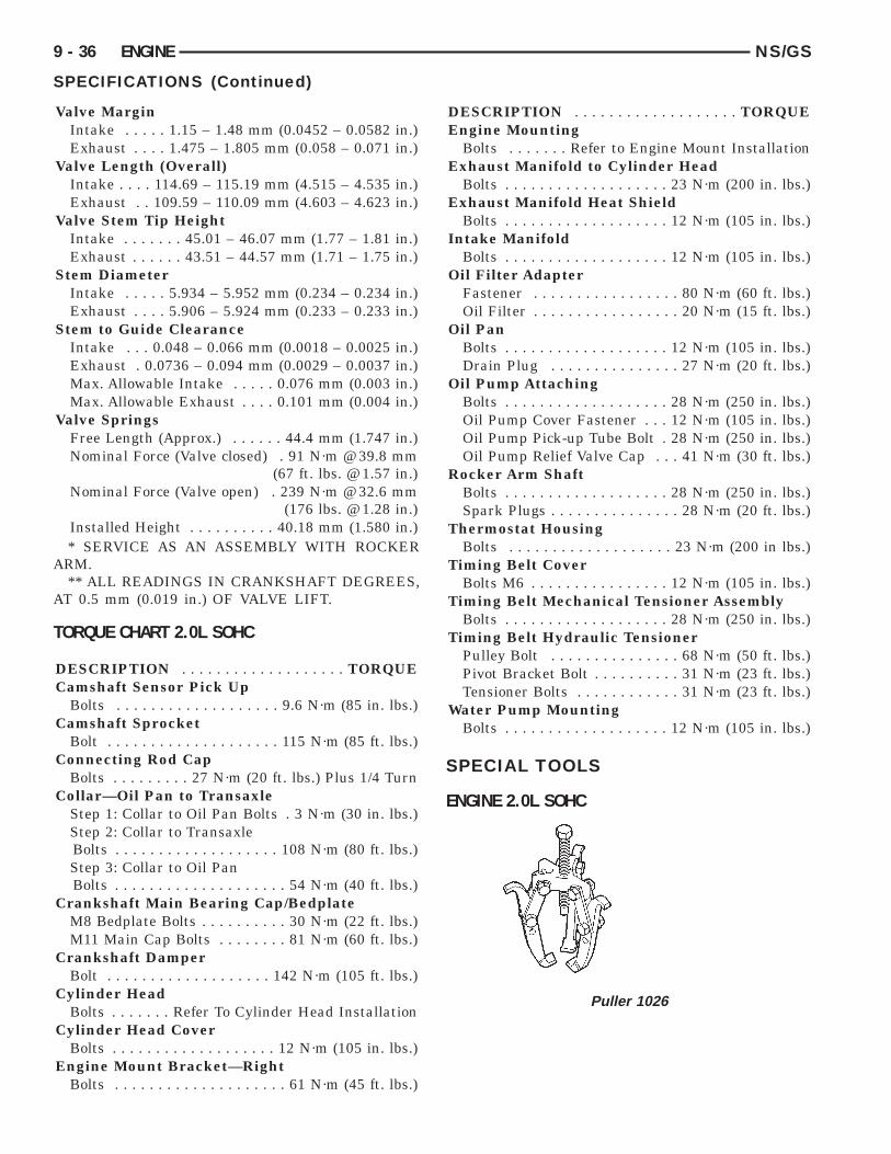
SPECIFICATIONS (Continued)
Valve MarginIntake . . . . . 1.15 – 1.48 mm (0.0452 – 0.0582 in.)Exhaust . . . . 1.475 – 1.805 mm (0.058 – 0.071 in.)
Valve Length (Overall)Intake . . . . 114.69 – 115.19 mm (4.515 – 4.535 in.)Exhaust . . 109.59 – 110.09 mm (4.603 – 4.623 in.)
Valve Stem Tip HeightIntake . . . . . . . 45.01 – 46.07 mm (1.77 – 1.81 in.)Exhaust . . . . . . 43.51 – 44.57 mm (1.71 – 1.75 in.)
Stem DiameterIntake . . . . . 5.934 – 5.952 mm (0.234 – 0.234 in.)Exhaust . . . . 5.906 – 5.924 mm (0.233 – 0.233 in.)
Stem to Guide ClearanceIntake . . . 0.048 – 0.066 mm (0.0018 – 0.0025 in.)Exhaust . 0.0736 – 0.094 mm (0.0029 – 0.0037 in.)Max. Allowable Intake . . . . . 0.076 mm (0.003 in.)Max. Allowable Exhaust . . . . 0.101 mm (0.004 in.)
Valve SpringsFree Length (Approx.) . . . . . . 44.4 mm (1.747 in.)Nominal Force (Valve closed) . 91 N·m @ 39.8 mm
(67 ft. lbs. @ 1.57 in.)Nominal Force (Valve open) . 239 N·m @ 32.6 mm
(176 lbs. @ 1.28 in.)Installed Height . . . . . . . . . . 40.18 mm (1.580 in.)* SERVICE AS AN ASSEMBLY WITH ROCKER
ARM.** ALL READINGS IN CRANKSHAFT DEGREES,
AT 0.5 mm (0.019 in.) OF VALVE LIFT.
TORQUE CHART 2.0L SOHC
DESCRIPTION . . . . . . . . . . . . . . . . . . . TORQUECamshaft Sensor Pick Up
Bolts . . . . . . . . . . . . . . . . . . . 9.6 N·m (85 in. lbs.)Camshaft Sprocket
Bolt . . . . . . . . . . . . . . . . . . . . 115 N·m (85 ft. lbs.)Connecting Rod Cap
Bolts . . . . . . . . . 27 N·m (20 ft. lbs.) Plus 1/4 TurnCollar—Oil Pan to Transaxle
Step 1: Collar to Oil Pan Bolts . 3 N·m (30 in. lbs.)Step 2: Collar to TransaxleBolts . . . . . . . . . . . . . . . . . . . 108 N·m (80 ft. lbs.)Step 3: Collar to Oil PanBolts . . . . . . . . . . . . . . . . . . . . 54 N·m (40 ft. lbs.)
Crankshaft Main Bearing Cap/BedplateM8 Bedplate Bolts . . . . . . . . . . 30 N·m (22 ft. lbs.)M11 Main Cap Bolts . . . . . . . . 81 N·m (60 ft. lbs.)
Crankshaft DamperBolt . . . . . . . . . . . . . . . . . . . 142 N·m (105 ft. lbs.)
Cylinder HeadBolts . . . . . . . Refer To Cylinder Head Installation
Cylinder Head CoverBolts . . . . . . . . . . . . . . . . . . . 12 N·m (105 in. lbs.)
Engine Mount Bracket—RightBolts . . . . . . . . . . . . . . . . . . . . 61 N·m (45 ft. lbs.)
DESCRIPTION . . . . . . . . . . . . . . . . . . . TORQUEEngine Mounting
Bolts . . . . . . . Refer to Engine Mount InstallationExhaust Manifold to Cylinder Head
Bolts . . . . . . . . . . . . . . . . . . . 23 N·m (200 in. lbs.)Exhaust Manifold Heat Shield
Bolts . . . . . . . . . . . . . . . . . . . 12 N·m (105 in. lbs.)Intake Manifold
Bolts . . . . . . . . . . . . . . . . . . . 12 N·m (105 in. lbs.)Oil Filter Adapter
Fastener . . . . . . . . . . . . . . . . . 80 N·m (60 ft. lbs.)Oil Filter . . . . . . . . . . . . . . . . . 20 N·m (15 ft. lbs.)
Oil PanBolts . . . . . . . . . . . . . . . . . . . 12 N·m (105 in. lbs.)Drain Plug . . . . . . . . . . . . . . . 27 N·m (20 ft. lbs.)
Oil Pump AttachingBolts . . . . . . . . . . . . . . . . . . . 28 N·m (250 in. lbs.)Oil Pump Cover Fastener . . . 12 N·m (105 in. lbs.)Oil Pump Pick-up Tube Bolt . 28 N·m (250 in. lbs.)Oil Pump Relief Valve Cap . . . 41 N·m (30 ft. lbs.)
Rocker Arm ShaftBolts . . . . . . . . . . . . . . . . . . . 28 N·m (250 in. lbs.)Spark Plugs . . . . . . . . . . . . . . . 28 N·m (20 ft. lbs.)
Thermostat HousingBolts . . . . . . . . . . . . . . . . . . . 23 N·m (200 in lbs.)
Timing Belt CoverBolts M6 . . . . . . . . . . . . . . . . 12 N·m (105 in. lbs.)
Timing Belt Mechanical Tensioner AssemblyBolts . . . . . . . . . . . . . . . . . . . 28 N·m (250 in. lbs.)
Timing Belt Hydraulic TensionerPulley Bolt . . . . . . . . . . . . . . . 68 N·m (50 ft. lbs.)Pivot Bracket Bolt . . . . . . . . . . 31 N·m (23 ft. lbs.)Tensioner Bolts . . . . . . . . . . . . 31 N·m (23 ft. lbs.)
Water Pump MountingBolts . . . . . . . . . . . . . . . . . . . 12 N·m (105 in. lbs.)
SPECIAL TOOLS
ENGINE 2.0L SOHC
Puller 1026

NS/GS ENGINE 9 - 37
SPECIAL TOOLS (Continued)
Crankshaft Damper Removal Insert 6827-A
Camshaft Sprocket Remover/Installer C-4687
Camshaft Sprocket Remover/Installer AdapterC-4687-1
Camshaft Seal Remover C-4679-A
Camshaft Seal Installer MD-998306
Crankshaft Damper Installer 6792
Valve Spring Compressor MD-998772-A
Spring Compressor Adapter 6779
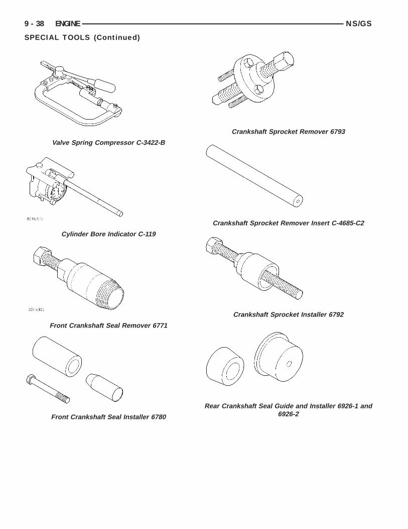
9 - 38 ENGINE NS/GS
SPECIAL TOOLS (Continued)
Valve Spring Compressor C-3422-B
Cylinder Bore Indicator C-119
Front Crankshaft Seal Remover 6771
Front Crankshaft Seal Installer 6780
Crankshaft Sprocket Remover 6793
Crankshaft Sprocket Remover Insert C-4685-C2
Crankshaft Sprocket Installer 6792
Rear Crankshaft Seal Guide and Installer 6926-1 and6926-2

NS/GS ENGINE 9 - 39
SPECIAL TOOLS (Continued)
Pressure Gage C-3292
Dial Indicator C-3339
Indicator Bore Size C-119
Valve Spring Tester C-647

9 - 40 ENGINE NS/GS
2.5L VM DIESEL
INDEX
page
GENERAL INFORMATIONENGINE IDENTIFICATION . . . . . . . . . . . . . . . . 41GENERAL SPECIFICATION . . . . . . . . . . . . . . . 40
DESCRIPTION AND OPERATIONLUBRICATION SYSTEM . . . . . . . . . . . . . . . . . . 41
DIAGNOSIS AND TESTINGENGINE DIAGNOSIS—MECHANICAL . . . . . . . 44ENGINE DIAGNOSIS—PERFORMANCE . . . . . 43HYDRAULIC TAPPETS . . . . . . . . . . . . . . . . . . . 47
SERVICE PROCEDURESCHANGING ENGINE OIL AND FILTER . . . . . . . 47CHECKING OIL LEVEL . . . . . . . . . . . . . . . . . . . 47CRANKSHAFT END PLAY . . . . . . . . . . . . . . . . 50FITTING PISTON RING . . . . . . . . . . . . . . . . . . 50TIMING PROCEDURE . . . . . . . . . . . . . . . . . . . 49VALVE AND SEAT REFACING . . . . . . . . . . . . . 49
REMOVAL AND INSTALLATIONCAMSHAFT . . . . . . . . . . . . . . . . . . . . . . . . . . . 62CAMSHAFT BEARINGS . . . . . . . . . . . . . . . . . . 63CRANKSHAFT MAIN BEARINGS . . . . . . . . . . . 63CRANKSHAFT—REMOVAL . . . . . . . . . . . . . . . 72CYLINDER HEAD . . . . . . . . . . . . . . . . . . . . . . . 55CYLINDER HEAD COVER . . . . . . . . . . . . . . . . 54CYLINDER LINER . . . . . . . . . . . . . . . . . . . . . . 72ENGINE ASSEMBLY . . . . . . . . . . . . . . . . . . . . . 53ENGINE MOUNT—FRONT . . . . . . . . . . . . . . . . 51ENGINE MOUNT—REAR . . . . . . . . . . . . . . . . . 52ENGINE MOUNT—RIGHT . . . . . . . . . . . . . . . . 51HYDRAULIC TAPPETS . . . . . . . . . . . . . . . . . . . 60INJECTION PUMP . . . . . . . . . . . . . . . . . . . . . . 61MOUNT—LEFT SIDE . . . . . . . . . . . . . . . . . . . . 51OIL FILTER ADAPTER AND OIL COOLER . . . . 68OIL PAN . . . . . . . . . . . . . . . . . . . . . . . . . . . . . . 66
page
OIL PUMP . . . . . . . . . . . . . . . . . . . . . . . . . . . . 67OIL PUMP PRESSURE RELIEF VALVE . . . . . . 67PISTONS AND CONNECTING ROD . . . . . . . . . 68REAR CRANKSHAFT OIL SEAL . . . . . . . . . . . . 72ROCKER ARMS AND PUSH RODS . . . . . . . . . 54TIMING GEAR COVER . . . . . . . . . . . . . . . . . . . 61TIMING GEAR COVER OIL SEAL . . . . . . . . . . . 61VACUUM PUMP . . . . . . . . . . . . . . . . . . . . . . . . 68VALVE SPRINGS—CYLINDER HEAD NOT
REMOVED . . . . . . . . . . . . . . . . . . . . . . . . . . 55VALVES AND VALVE SPRINGS—HEAD OFF . . 60VIBRATION DAMPER . . . . . . . . . . . . . . . . . . . . 61
DISASSEMBLY AND ASSEMBLYHYDRAULIC TAPPETS . . . . . . . . . . . . . . . . . . . 73
CLEANING AND INSPECTIONCRANKSHAFT . . . . . . . . . . . . . . . . . . . . . . . . . 77CRANKSHAFT MAIN BEARING . . . . . . . . . . . . 77CYLINDER HEAD . . . . . . . . . . . . . . . . . . . . . . . 75CYLINDER HEAD COVERS . . . . . . . . . . . . . . . 74CYLINDER LINER . . . . . . . . . . . . . . . . . . . . . . 78HYDRAULIC TAPPETS . . . . . . . . . . . . . . . . . . . 76OIL PAN . . . . . . . . . . . . . . . . . . . . . . . . . . . . . . 78OIL PUMP . . . . . . . . . . . . . . . . . . . . . . . . . . . . 76PISTON AND CONNECTING ROD . . . . . . . . . . 76ROCKER ARMS AND PUSH RODS . . . . . . . . . 74TIMING GEAR COVER . . . . . . . . . . . . . . . . . . . 75VALVES AND VALVE SPRINGS . . . . . . . . . . . . 76
SPECIFICATIONS2.5L VM DIESEL . . . . . . . . . . . . . . . . . . . . . . . . 78TORQUE . . . . . . . . . . . . . . . . . . . . . . . . . . . . . 80
SPECIAL TOOLS2.5L VM DIESEL . . . . . . . . . . . . . . . . . . . . . . . . 81
GENERAL INFORMATION
GENERAL SPECIFICATION
Type . . . . . . . . . . . . . . . . . . . . . . . . 425CLIEE (36B)Displacement . . . . . . . . . . . . . . . . . . . 2.5L (2499 cc)Bore . . . . . . . . . . . . . . . . . . . . . . . . . . . . . 92.00 mmStroke . . . . . . . . . . . . . . . . . . . . . . . . . . . . 94.00 mmCompression Ratio . . . . . . . . . . . . . . . . . . . . 20.95:1Vacuum at Idle . . . . . . . . . . 600 mm/Hg (23.6 In/Hg)Thermostat Opening . . . . . . . . . . . . . . . . 80°C62°CGenerator Rating . . . . . . . . . . . . Bosch 50/120 AmpCooling System Capacity . . . . . . . . . . . . . . 9.5 LiterPower Steering Capacity . . . . . . . . . . . . . 0.75 Liter
Type . . . . . . . . . . . . . . . . . . . . . . . . 425CLIEE (36B)Engine Oil Capacity . . . . . 6.5 Liters With Oil Filter
ChangeTiming System . Pushrod Operated Overhead valves,
With Gear-Driven Camshaft.Air Intake . . . . . . . . . . . . . . . . . . . . . . . . Dry FilterFuel Feed . . . . . . . . . . . Vacuum Pump Incorporated
in Injection Pump.Fuel System . . . . . . . . . . . . . Indirect Fuel Injection
(Precombustion Chamber)Combustion Cycle . . . . . . . . . . . . . . . . . . . . 4 StrokeCooling System . . . . . . . . . . . . . . . . . . Water CooledInjection Pump . . . . . . . Rotary Pump Electronically
Controlled.

NS/GS ENGINE 9 - 41
GENERAL INFORMATION (Continued)
Type . . . . . . . . . . . . . . . . . . . . . . . . 425CLIEE (36B)Lubrication . Pressure Lubrication by Rotary Pump,
Full-Flow FiltrationEngine Rotation . . . . Clockwise Viewed From Front
Cover
ENGINE IDENTIFICATIONThe engine model code (3-digit number/letter code)
and serial number are stamped on the forward facingside of the engine block (Fig. 1).
DESCRIPTION AND OPERATION
LUBRICATION SYSTEMThe pressurized system (Fig. 2) uses a rotary pump
(3) located in the front of the engine block, driven bya gear which meshes directly with the crankshaftgear. All the oil sent to every lubricated part is fil-tered. The pump sends the oil through a pressurerelief valve (2) to the filter (7) and through galleriesin the crankcase to the crankshaft bearings (8), cam-shaft bearings (11) and turbocharger (10). The pistonpins, connecting rod small ends and insides of thepistons are lubricated and cooled by oil sprayed outfrom jets (9) in the crankshaft mounting blocks. Thelubricating oil is sent to the rockers (12) through an
external pipe (Fig. 3). A valve in the filter cartridgeenables the oil to be circulated even when the car-tridge is clogged.
Sump inlet (1). Pressure relief valve (2). Oil pump(3). Oil cooler (6). Filter cartridge (7). Crankshaftbearings (8). Jet valve (9). Turbocharger bearings(10). Camshaft bearings (11). Rockers (12).
Fig. 1 Engine Code Location
Fig. 2 Lubrication System

9 - 42 ENGINE NS/GS
DESCRIPTION AND OPERATION (Continued)
Fig. 3 Lubrication Lines

NS/GS ENGINE 9 - 43
DIAGNOSIS AND TESTING
ENGINE DIAGNOSIS—PERFORMANCE
CONDITION POSSIBLE CAUSES CORRECTION
ENGINE WILL NOTCRANK OR CRANKSSLOWLY
1. Starting motor operating, but not cranking theengine.
1. Remove the starter motor. Check for brokenflywheel teeth or a broken starter motor spring.
2. Crankshaft rotation restricted. 2. Rotate the engine to check for rotationalresistance.
3. Starting circuit connections loose or corroded. 3. Clean and tighten connections.4. Neutral safety or starter relay inoperative. 4. Check starter relay supply voltage and proper
operation of neutral safety switch (if equipped).Replace defective parts.
5. Battery charge low. 5. Check Battery voltage. Replace battery if acharge cannot be held.
6. No voltage to starter solenoid. 6. Check voltage to solenoid. If necessary, replacethe solenoid.
7. Solenoid or starter motor inoperative. 7. Replace starter motor.
ENGINE CRANKS, BUTWILL NOT START, NOSMOKE
1. No fuel in supply tank. 1. Fill fuel supply.
2. Electrical fuel shutdown solenoid not operating. 2. Check for loose wires and verify that the fuelshutdown solenoid is functioning. Check for faultcodes in the ECU.
3. Fuel injection system defective: Cranking speedsensor. Loose connection between ECU andharness. No power supply to the ECU. Looseconnection between injection pump and harness.
3. Check for fault codes at ECU. Refer to Group 14,Fuel System for repairs procedures.
4. Air intake or exhaust plugged. 4. Remove the obstruction.5. Fuel filter plugged. 5. Drain fuel/water separator and replace fuel filter.6. Excessive fuel inlet restriction. 6. Check for restriction. Correct cause.7. Injection pump not getting fuel or fuel is aerated. 7. Check fuel flow/bleed fuel system.8. One or more injectors worn or not operatingproperly.
8. Check/replace bad or improperly operatinginjectors.
9. Camshaft out of time. 9. Check/correct timing chain sprocket alignment.
ENGINE HARD TOSTART, OR WILL NOTSTART, SMOKE FROMEXHAUST
1. Incorrect starting procedure. 1. The fuel shutoff solenoid control must be in therun position. Ensure the proper procedure is beingused.
2. Cranking speed to slow. 2. Check the battery, starter motor and look forloose or corroded wiring connections.
3. Cylinder head heater plugs defective. 3. Verify system is working. Verify connectionbetween heater plug relay and ECU. Repair/replaceinoperative parts.
4. Insufficient intake air 4. Inspect or replace air filter and check forobstruction in air supply.
5. Air in fuel system or the fuel supply isinadequate.
5. Check the fuel flow through the filter and bleedsystem. Locate and eliminate the air source.
6. Contaminated fuel. 6. Verify by operating the engine with clean fuelfrom a temporary tank. Check for the presence ofgasoline. Drain and flush fuel supply tank. Replacefuel/water separator filter.
7. Fuel screen plugged. 7. Check fuel screen.8. One or more injectors worn or not operatingproperly.
8. Check/replace improperly operating injectors.
9. Injector pump out of time. 9. Check pump timing. Refer to Group 14, FuelSystem for procedure.
10. Engine compression low. 10. Check compression to identify the problem.11. Fuel injection system defective. 11. Vacuum modulator defective causing EGR to
open in cold condition. Check for fault codes in theECU.

9 - 44 ENGINE NS/GS
DIAGNOSIS AND TESTING (Continued)
ENGINE DIAGNOSIS—MECHANICAL
CONDITION POSSIBLE CAUSES CORRECTION
LUBRICATING OIL PRESSURELOW
1. Low oil level. 1a. Check and fill with clean engineoil.
1b. Check for severe external oilleaks that could reduce thepressure.
2. Oil viscosity thin, diluted, orwrong specification.
2. Verify the correct oil is beingused. Check for oil dilution.
3. Improperly operating pressureswitch/gauge
3. Verify the pressure switch isfunctioning correctly. If not, replaceswitch/gauge.
4. Relief valve stuck open. 4. Check/replace valve.5. Plugged oil filter. 5. Change oil filter. Oil filter change
interval may need to be revised.6. Oil cooler was replaced, shippingplugs left in cooler.
6. Check/removed shipping plugs.
7. Worn oil pump. 7. Check/replace oil pump.8. Suction tube loose or sealleaking.
8. Check and replace seal.
9. Worn bearing or wrong bearinginstalled.
9. Inspect and replace connectingrod or main bearings. check andreplace piston cooling oil jet.
10. Oil jets under piston loose orbad fit.
10. Check oil jets position.
LUBRICATING OIL LOSS 1. External oil leaks. 1. Visually inspect for oil leaks.Repair as required.
2. Crankcase being overfilled. 2. Verify that the correct dipstick isbeing used.
3. Incorrect oil specification orviscosity.
3a. Make sure the correct oil isbeing used.3b. Look for reduced viscosity fromdilution with fuel.3c. Review/reduce the oil changeintervals.
4. Oil cooler leak. 4. Check and replace the oil cooler.5. High blow-by forcing oil out thebreather.
5. Check the breather tube area forsigns of oil loss.

NS/GS ENGINE 9 - 45
DIAGNOSIS AND TESTING (Continued)
ENGINE DIAGNOSIS—MECHANICAL CONT.
CONDITION POSSIBLE CAUSES CORRECTION
LUBRICATING OIL LOSS(CONT.)
6. Turbocharger leaking oil into theair intake.
6. Inspect air duct for evidence of oiltransfer.
7. Piston rings not sealing (oil beingconsumed by the engine).
7. Perform blow-by check. Repair asrequired.
COMPRESSION KNOCKS 1. Air in fuel system. 1. Bleed the fuel system (refer toGroup 14, Fuel System).
2. Poor quality fuel or water/gasolinecontaminated fuel.
2. Verify by operating from atemporary tank with good fuel. Cleanand flush the fuel supply tank.Replace fuel/water separator.
3. Engine Overloaded. 3. Verify the engine load rating is notbeing exceeded.
4. Improperly operating injectors. 4. Check and replace injectors.5. Fuel injection system defective. 5a. Instrumented injection. 5b. Timing
solenoid of the fuel pump. 5c. Preand post heat time of the glow plugs.Check the fault codes in the ECU.
EXCESSIVE ENGINE NOISES 1. Drive belt squeal, insufficienttension or abnormally high loading.
1. Inspect the drive belts. Make surewater pump pulley, generator andpower steering all turn freely.
2. Intake air and exhaust leak. 2. Refer to excessive exhaust smoke.(Engine Diagnosis and Testing)
3. Excessive valve lash. 3. Make sure the rocker arms are notbent. Defective hydraulic lashadjuster.
4. Turbocharger noise. 4. Check turbocharger impeller andturbine wheel for housing contact.
5. Power function knock. 5. Check and replace rod and mainbearings.
6. Fuel injection system defective. 6a. Instrumented injection. 6b. Timingsolenoid of the fuel pump. 6c. Preand post heat time of the glow plugs.Check the fault codes in the ECU.

9 - 46 ENGINE NS/GS
DIAGNOSIS AND TESTING (Continued)
ENGINE DIAGNOSIS—MECHANICAL CONT.

NS/GS ENGINE 9 - 47
DIAGNOSIS AND TESTING (Continued)
HYDRAULIC TAPPETSBefore disassembling any part of the engine to cor-
rect tappet noise, check the oil pressure. If vehiclehas no oil pressure gauge, install a reliable gauge atthe pressure sending unit. The pressure should bebetween 3.5 bars to 5.0 bars at 4000 RPM.
Check the oil level after the engine reaches normaloperating temperature. Allow 5 minutes to stabilizeoil level, check dipstick. The oil level in the panshould never be above the FULL mark or below theADD OIL mark on dipstick. Either of these 2 condi-tions could be responsible for noisy tappets.
OIL LEVEL HIGHIf oil level is above the FULL mark, it is possible
for the connecting rods to dip into the oil. With theengine running, this condition could create foam inthe oil pan. Foam in oil pan would be fed to thehydraulic tappets by the oil pump causing them tolose length and allow valves to seat noisily.
OIL LEVEL LOWLow oil level may allow oil pump to take in air.
When air is fed to the tappets, they lose length whichallows valves to seat noisily. Any leaks on intake sideof oil pump through which air can be drawn will cre-ate the same tappet action. Check the lubricationsystem from the intake strainer to the pump cover,including the relief valve retainer cap. When tappetnoise is due to aeration, it may be intermittent orconstant, and usually more than 1 tappet will benoisy. When oil level and leaks have been corrected,operate the engine at fast idle. Run engine for a suf-ficient time to allow all of the air inside the tappetsto be bled out.
TAPPET NOISE DIAGNOSIS(1) To determine source of tappet noise, operate
engine at idle with cylinder head covers removed.(2) Feel each valve spring or rocker arm to detect
noisy tappet. The noisy tappet will cause the affectedspring and/or rocker arm to vibrate or feel rough inoperation.
NOTE: Worn valve guides or cocked springs aresometimes mistaken for noisy tappets. If such isthe case, noise may be dampened by applying sidethrust on the valve spring. If noise is not apprecia-bly reduced, it can be assumed the noise is in thetappet. Inspect the rocker arm push rod socketsand push rod ends for wear.
(3) Valve tappet noise ranges from light noise to aheavy click. A light noise is usually caused by exces-sive leak down around the unit plunger or by theplunger partially sticking in the tappet body cylinder.The tappet should be replaced. A heavy click is
caused by a tappet check valve not seating or by for-eign particles becoming wedged between the plungerand the tappet body. This will cause the plunger tostick in the down position. This heavy click will beaccompanied by excessive clearance between thevalve stem and rocker arm as valve closes. In eithercase, tappet assembly should be removed for inspec-tion and cleaning.
(4) The valve train generates a noise very muchlike a light tappet noise during normal operation.Care must be taken to ensure that tappets are mak-ing the noise. In general, if more than one tappetseems to be noisy, its probably not the tappets.
SERVICE PROCEDURES
CHECKING OIL LEVELTo assure proper engine lubrication, the engine oil
must be maintained at the correct level. Check theoil level at regular intervals, such as every fuel stop.
The best time to check the oil level is about 5 min-utes after a fully warmed-up engine is shut off, orbefore starting the vehicle after it has sat overnight.
Checking the oil while the vehicle is on levelground, will improve the accuracy of the oil levelreadings (Fig. 4).
CHANGING ENGINE OIL AND FILTERChange engine oil and filter at mileage and time
intervals described in the Maintenance Schedule.
Fig. 4 Checking Engine Oil

9 - 48 ENGINE NS/GS
SERVICE PROCEDURES (Continued)
ENGINE OIL CHANGE
WARNING: NEW OR USED ENGINE OIL CAN BEIRRITATING TO THE SKIN. AVOID PROLONGED ORREPEATED SKIN CONTACT WITH ENGINE OIL.CONTAMINANTS IN USED ENGINE OIL, CAUSED BYINTERNAL COMBUSTION, CAN BE HAZARDOUS TOYOUR HEALTH. THOROUGHLY WASH EXPOSEDSKIN WITH SOAP AND WATER. DO NOT WASHSKIN WITH GASOLINE, DIESEL FUEL, THINNER, ORSOLVENTS, HEALTH PROBLEMS CAN RESULT. DONOT POLLUTE, DISPOSE OF USED ENGINE OILPROPERLY. CONTACT YOUR DEALER OR GOVERN-MENT AGENCY FOR LOCATION OF COLLECTIONCENTER IN YOUR AREA.
Run engine until achieving normal operating tem-perature.
(1) Position the vehicle on a level surface and turnengine off.
(2) Remove oil fill cap.(3) Hoist vehicle. Refer to Hoisting and Jacking
Recommendations.(4) Place a suitable drain pan under crankcase
drain.(5) Remove drain plug from crankcase and allow
oil to drain into pan (Fig. 5). Inspect drain plugthreads for stretching or other damage. Replacedrain plug if damaged.
(6) Install drain plug in crankcase.(7) Lower vehicle and fill crankcase with specified
type and amount of engine oil.(8) Install oil fill cap.(9) Start engine and inspect for leaks.(10) Stop engine and inspect oil level.
Fig. 5 Oil Drain Plug
ENGINE OIL
ENGINE OIL QUALITYUse only oils conforming to API (American Petro-
leum Institute) quality SG/CD, or CCMC G4. Useonly Diesel engine oil meeting standard MIL-2104Cor API service classification SG/CD or CCMM PD1 .
OIL VISCOSITYGrade 15W-40 is recommended for temperatures
between +35°C to –10°C (95°F to 14°F). Low viscosityoils must have the proper API quality or the CCMCG5 designation. Low viscosity oils are preferred whenminimum temperatures consistently fall below –12°C(10°F).
ENGINE OIL FILTER CHANGE(1) Position a drain pan under the oil filter.(2) Using a suitable oil filter wrench loosen filter.(3) Rotate the oil filter counterclockwise to remove
it from the oil filter base (Fig. 6).
(4) When filter separates from base, tip gasket endupward to minimize oil spill. Remove filter from vehi-cle.
(5) With a cloth, wipe clean the gasket sealing sur-face of oil and grime.
OIL FILTER INSTALLATION(1) Lightly lubricate oil filter gasket with engine
oil.(2) Thread filter onto the base. When gasket
makes contact with sealing surface, hand tighten fil-ter one full turn, do not over tighten.
Fig. 6 Oil Filter

NS/GS ENGINE 9 - 49
SERVICE PROCEDURES (Continued)
(3) Add oil, verify crankcase oil level and startengine. Inspect filter area for oil leaks.
TIMING PROCEDURE
CAUTION: If a timing gear is removed you mustloosen the rocker arm supports before rotating thecrankshaft or camshaft. This will prevent the valveshitting the pistons.
For the engine components to be in proper timingorder, the timing gear marks (dots) must be alignedas shown in (Fig. 7). To facilitate reassembly, alignthe timing marks as shown in (Fig. 7), or mark thetiming gear positions before removal of any markedgears or gear driven component(s).
VALVE AND SEAT REFACING
VALVE REFACING(1) Use a valve refacing machine to reface the
intake and exhaust valves to the specified angle.(2) After refacing, a margin of at least 4.52-4.49
mm (.178-.177 inch) must remain (Fig. 8). If the mar-gin is less than 4.49 mm (.177 inch), the valve mustbe replaced.
VALVE SEAT REFACING(1) Install a pilot of the correct size in the valve
guide bore. Reface the valve seat to the specifiedangle with a good dressing stone. Remove onlyenough metal to provide a smooth finish.
(2) Use tapered stones to obtain the specified seatwidth when required.
Fig. 7 Aligning Timing Marks
Fig. 8 Valve Specification

9 - 50 ENGINE NS/GS
SERVICE PROCEDURES (Continued)
VALVE STAND DOWNValve stand down is to maintain the adequate com-
pression ratio.(1) Invert cylinder head.(2) Fit each valve to its respective valve guide.(3) Using a straight edge and feeler gauge (Fig. 9),
check valve head stand down: Inlet valve head standdown .80 to 1.2 mm (.031 to .047 in.) and exhaustvalve stand down .79 to 1.19 mm (.031 to .047 in).
(4) If valve head stand down is not in accordancewith above, discard original valves, check stand downwith new valves and recut valve seat inserts toobtain correct stand down.
VALVE GUIDE HEIGHT(1) Valve Guides height requirement.(2) Measurement A (Fig. 10): 13.50 - 14.00 mm.
VALVE STEM-TO-GUIDE CLEARANCEMEASUREMENT
(1) Measure and record internal diameter of valveguides. Valve guide internal diameter is 8.0 to 8.015mm (.3149 to .3155 in.).
(2) Measure valve stems and record diameters.Intake valve stem diameter 7.94 to 7.96 mm (.3125 to.3133 in). Exhaust valve stem diameter 7.92 to 7.94mm (.3118 to .31215 in).
Fig. 9 Checking Valve Stand Down
Fig. 10 Valve Guide Height
(3) Subtract diameter of valve stem from internaldiameter of its respective valve guide to obtain valvestem clearance in valve guide. Clearance of inletvalve stem in valve guide is .040 to .075 mm (.0015to .0029 in). Clearance of exhaust valve stem in valveguide is .060 to .095 mm (.0023 to .0037 in).
(4) If valve stem clearance in valve guide exceedstolerances, new valve guides must be installed.
FITTING PISTON RING(1) Wipe cylinder bore clean. Insert ring and push
down with piston to ensure it is square in bore. Thering gap measurement must be made with the ringpositioning at least 12 mm (0.50 in.) from bottom ofcylinder bore (Fig. 11). Check gap with feeler gauge.Top compression ring gap .25 to .50mm (.0098 to.0196 in.). Second compression ring gap .25 to .35mm(.0098 to .0137 in.). Oil control ring gap .25 to .58mm(.0098 to .0228 in.).
(2) If ring gaps exceed dimension given, new ringsor cylinder liners must be fitted. Keep piston rings inpiston sets.
(3) Check piston ring to groove clearance (Fig. 12).Top compression ring gap .08 to .130mm (.0031 to.0051 in.). Second compression ring gap .070 to.102mm (.0027 to .0040 in.). Oil control ring gap .040to .072mm (.0015 to .0028 in.).
CRANKSHAFT END PLAY(1) Attach dial indicator to engine block (Fig. 13).(2) Move crankshaft toward front of engine and
zero indicator.(3) Move crankshaft toward the rear of engine and
record measurement.(4) Subtract specified crankshaft end float from
figure obtained. Crankshaft end float 0.08 to0.21mm.
(5) Select thrust washer which will give correctend float.
Fig. 11 Ring Gap Measurement

NS/GS ENGINE 9 - 51
SERVICE PROCEDURES (Continued)
(6) Refer to crankshaft main bearing Installation ifnot in specification.
NOTE: If engine is disassembled refer to Crank-shaft Main Bearing Removal and Installation for thisprocedure.
REMOVAL AND INSTALLATION
ENGINE MOUNT—FRONT(1) Disconnect battery.(2) Remove lower air dam at front fascia.(3) Remove the bolts holding tow bracket and front
mount to the lower crossmember.
Fig. 12 Piston Ring Side Clearance
Fig. 13 Measuring Crankshaft End Play
(4) Remove thru bolt in engine mount (Fig. 14).Remove mount.
(5) Reverse removal procedure for installation.(6) Torque engine mount thru bolt to 65 N·m (48
ft. lbs.)(7) Torque crossmember bolts for tow bracket and
engine mount to 54 N·m (40 ft. lbs.)
ENGINE MOUNT—RIGHT(1) Remove the right engine mount top support
bracket bolt (Fig. 15).(2) Remove the load on the engine motor mounts
by carefully supporting the engine and transmissionassembly with a floor jack.
(3) Remove the engine mount to frame bolts.(4) Remove the thru bolt from the mount assembly.
Remove insulator(5) If replaceing or removing right engine mount
bracket the torque on the mounting bolts is 40 N·m(30 ft. lbs.)
(6) Reverse removal procedure for installation.(7) Torque engine mount top bolt (Vertical) to 101
N·m (75 ft. lbs.)(8) Torque engine mount thru bolt (Horizontal) to
145 N·m (107 ft. lbs.)(9) Torque engine mount to frame bolts to 68 N·m
(50 ft. lbs.)
MOUNT—LEFT SIDE(1) Raise vehicle on hoist and remove left front
wheel.(2) Remove inner splash shield.(3) Support the transmission with a transmission
jack.(4) Remove the insulator thru bolt from the mount
(Fig. 16).(5) Remove the transmission mount bolts and
remove mount. It may be necessary to lower trans-mission slightly to remove mount.
(6) Reverse removal procedure for installation.(7) Install mount. Torque transmission mount bolts
to 54 N·m (40 ft. lbs.).(8) Align mount into frame bracket with transmis-
sion jack, install thru bolt. Torque thru bolt to 71N·m (53 ft. lbs.).
Fig. 14 Front Engine Mount and Tow Bracket
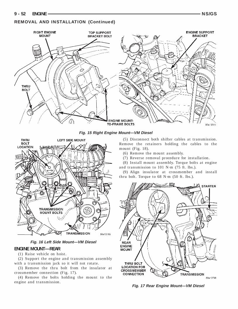
9 - 52 ENGINE NS/GS
REMOVAL AND INSTALLATION (Continued)
Fig. 15 Right Engine Mount—VM Diesel
ENGINE MOUNT—REAR(1) Raise vehicle on hoist.(2) Support the engine and transmission assembly
with a transmission jack so it will not rotate.(3) Remove the thru bolt from the insulator at
crossmember connection (Fig. 17).(4) Remove the bolts holding the mount to the
engine and transmission.
Fig. 16 Left Side Mount—VM Diesel
(5) Disconnect both shifter cables at transmission.Remove the retainers holding the cables to themount (Fig. 18).
(6) Remove the mount assembly.(7) Reverse removal procedure for installation.(8) Install mount assembly. Torque bolts at engine
and transmission to 101 N·m (75 ft. lbs.).(9) Align insulator at crossmember and install
thru bolt. Torque to 68 N·m (50 ft. lbs.).
Fig. 17 Rear Engine Mount—VM Diesel

NS/GS ENGINE 9 - 53
REMOVAL AND INSTALLATION (Continued)
ENGINE ASSEMBLY
REMOVAL(1) Disconnect the battery.(2) Remove the air cleaner assembly and inlet
hose.(3) Remove both hoses at intercooler and engine.(4) Disconnect EGR vacuum hose.(5) Disconnect brake booster vacuum hose.(6) Disconnect oil pressure switch connector (Fig.
19).(7) Disconnect Wiring harness bracket at transaxle
shift tower.(8) Disconnect transaxle wiring at speed sensor,
crank sensor, and backup light switch.(9) Remove both transmission shift cables at trans-
mission.(10) Remove negative battery cable at cylinder
block (Fig. 19).(11) Remove oil separator.(12) Remove connectors at coolant temperature
sensor and A/C compressor.(13) Disconnect fuel injection pump wiring connec-
tors (Fig. 19).(14) Disconnect glow plug connectors.(15) Disconnect electrical connector at number 1
fuel injector.(16) Raise vehicle on hoist.(17) Remove right side splash shield (Fig. 20).
WARNING: THE COOLANT IN A RECENTLY OPER-ATED ENGINE IS HOT AND PRESSURIZED. USECARE TO PREVENT SCALDING BY HOT COOLANT.
Fig. 18 Shift Cables at Rear Mount
CAREFULLY RELEASE THE PRESSURE BEFOREREMOVING THE RADIATOR DRAIN COCK AND CAP.
(18) Drain the cooling system (refer to Group 7,Cooling).
(19) Lower vehicle.(20) Remove Coolant pressure bottle and discon-
nect low coolant level sensor.(21) Disconnect both heater hoses.(22) Remove the lower radiator hose.(23) Remove the upper radiator hose.(24) Remove fuel line at injector pump and cap.(25) Remove power steering reservoir and reposi-
tion.(26) Remove upper radiator crossmember.(27) Disconnect cooling fan module connector.
Fig. 19 Component Locations
Fig. 20 Right Side Splash Shield

,
9 - 54 ENGINE NS/GS
)
(28) Remove radiator support bolts. It is neces-sary to loosen the receiver/dryer to gain accessto the radiator bolts.
(29) Remove radiator and fans as an assembly.(30) Remove accessory drive belt generator/power
steering. Refer to Group 7, for procedure.(31) Remove both power steering lines at pump
and cap both lines.
NOTE: It is not necessary to discharge A/C systemfor engine removal.
(32) Remove A/C compressor. Secure compressoraway from engine for clearance during engineremoval.
(33) Remove Generator and adjusting bracket.
NOTE: Do not remove the mounting base from thegenerator. It is aligned at the factory and cannot berealigned in the field.
(34) Hoist vehicle.(35) Remove exhaust pipe at turbo outlet.(36) Remove connections at starter.(37) Remove power steering high pressure line
bracket at rear of oil pan.(38) Remove both driveshafts from transaxle. Refer
to Group 2, Suspension and Driveshafts.(39) Disconnect clutch cable at transaxle.(40) Remove reinforcement plate on lower cross-
member.(41) Remove front and rear engine mounts. Refer
to procedure outlined in this section.(42) Drain engine oil and remove oil filter if neces-
sary.(43) Mount both special tool, engine support brack-
ets VM-1026 to cylinder block (Fig. 21).(44) Using engine dolly and cradle assembly with
4 adjustable posts align posts with holes in theengine support brackets.
(45) Lower vehicle so weight of only the engineand transmission is on the dolly and cradle assem-bly.
(46) Remove left side splash shield to gain accessto thru bolt for left side mount.
(47) Remove right engine mount and left sidemount. Refer to procedure outlined in this section.
(48) Raise vehicle slowly. It may be necessary tomove the engine/transmission assembly on the dollyto allow for removal around body.
(49) Reverse removal procedure for installation.
CYLINDER HEAD COVER
REMOVAL(1) Disconnect the battery cables.(2) Remove generator bracket.
REMOVAL AND INSTALLATION (Continued
(3) Remove breather hose.(4) Remove coolant pressure tank.(5) Remove cylinder head cover.
INSTALLATION(1) Install cylinder head cover, torque nuts to 23.5
N·m (208 in. lbs.).(2) Install coolant pressure tank.(3) Install breather hose.(4) Install generator bracket, tighten bolts to 7
N·m (4 ft. lbs.).(5) Connect battery cable.
ROCKER ARMS AND PUSH RODS
REMOVAL(1) Disconnect the battery cables.(2) Remove generator bracket.(3) Remove breather hose.(4) Remove coolant pressure tank.(5) Remove cylinder head cover.(6) Remove rocker retaining nuts (Fig. 22).(7) Remove rocker assembly. Place them on a
bench in the same order as removed.(8) Remove the push rods and place them on a
bench in the same order as removed.
INSTALLATION(1) Install the push rods in the same order as
removed.(2) Install rocker arm assemblies in the same
order as removed. Tighten the rocker arm nuts to29.4 N·m (264 in. lbs.) torque.
Fig. 21 Engine Removal

NS/GS ENGINE 9 - 55
REMOVAL AND INSTALLATION (Continued)
(3) Install cylinder head cover, torque nuts to 14.7N·m (132 in. lbs.).
(4) Install coolant pressure tank.(5) Install breather hose.(6) Install generator bracket, tighten bolts to 7
N·m (4 ft. lbs.).(7) Connect the service valves to the A/C compres-
sor ports, if equipped with air conditioning.(8) Connect battery cable.
VALVE SPRINGS—CYLINDER HEAD NOTREMOVED
This procedure can be done with the engine cylin-der head installed on the block.
REMOVALEach valve spring is held in place by a retainer
and a set of conical valve locks. The locks can beremoved only by compressing the valve spring.
(1) Remove the engine cylinder head cover, refer tocylinder head cover removal in this section.
(2) Remove rocker arms assemblies for access toeach valve spring to be removed.
(3) Remove push rods. Retain the push rods, androcker arms assemblies in the same order and posi-tion as removed.
(4) Inspect the springs and retainer for cracks andpossible signs of weakening.
(5) Install an air hose adaptor in the fuel injectorhole.
(6) Connect an air hose to the adapter and applyair pressure slowly. Maintain at least 621 kPa (90
Fig. 22 Rocker Arm Retaining Nut
psi) of air pressure in the cylinder to hold the valvesagainst their seats.
(7) Tap the retainer or tip with a rawhide hammerto loosen the lock from the retainer. Use Valve SpringCompressor Tool to compress the spring and removethe locks.
(8) Remove valve spring and retainer.Inspect the valve stems, especially the grooves. An
Arkansas smooth stone should be used to removenicks and high spots.
INSTALLATION(1) Install valve spring and retainer.(2) Compress the valve spring with Valve Spring
Compressor Tool and insert the valve locks. Releasethe spring tension and remove the tool. Tap thespring from side-to-side to ensure that the spring isseated properly on the engine cylinder head.
(3) Disconnect the air hose. Remove the adaptorfrom the fuel injector hole and install the fuel injec-tor.
(4) Repeat the procedures for each remaining valvespring to be removed.
(5) Install the push rods. Ensure the bottom end ofeach rod is centered in the plunger cap seat of thehydraulic valve tappet.
(6) Install the rocker arm assemblies, at their orig-inal location.
(7) Tighten the rocker arm assembly nut to 106N·m (78 ft. lbs.) torque.
(8) Install the engine cylinder head cover, refer tocylinder head cover installation in this section.
CYLINDER HEAD
REMOVAL(1) Disconnect the battery cable.
WARNING: DO NOT REMOVE THE CYLINDERBLOCK DRAIN PLUGS OR LOOSEN THE RADIATORDRAIN COCK WITH THE SYSTEM HOT AND PRES-SURIZED BECAUSE SERIOUS BURNS FROM THECOOLANT CAN OCCUR.
(2) Drain the cooling system. Refer to Group 7,Cooling.
(3) Remove wiper module. Refer to Group 8K,Windshield Wiper Unit Removal for procedure.
(4) Remove coolant pressure bottle.(5) Remove intercooler hose at intake manifold
(Fig. 23).(6) Remove intercooler hose at turbocharger inter-
cooler tube.(7) Remove the upper radiator hose.(8) Remove water manifold.(9) Disconnect the heater hoses and coolant pres-
sure bottle hoses.

9 - 56 ENGINE NS/GS
REMOVAL AND INSTALLATION (Continued)
(10) Disconnect EGR tube from EGR valve (Fig.25).
(11) Remove exhaust pipe from turbocharger elbowand.
(12) Disconnect oil feed line from turbo (Fig. 24).(13) Disconnect oil drain line from turbo.(14) Remove Intake manifold. Refer to Group 11,
Exhaust System and Intake Manifold.(15) Remove lift eye and brake vacuum tube at
rear of exhaust manifold.
Fig. 23 Intercooler Assembly
Fig. 24 Turbocharger
(16) Remove the support strut from block to turbo-charger exhaust elbow.
(17) Remove Exhaust manifold. Refer to Group 11,Exhaust System and Intake Manifold.
(18) Remove oil line at pressure switch.(19) Remove oil feed line for rocker arm assemblies
(Fig. 26).
(20) Remove Crankcase breather hose from valvecover
(21) Remove the engine cylinder head cover.
Fig. 25 EGR Valve and Tube
Fig. 26 Rocker Arm Oil Feed Lines

NS/GS ENGINE 9 - 57
REMOVAL AND INSTALLATION (Continued)
(22) Remove the injector sensor wire at the con-nector, and glow plug Connectors.
NOTE: The attachment point for the injector sensorwire at the injector is not a connector. The connec-tor is located in the wire 4 to 6 inches away fromthe injector.
(23) Remove injector fuel lines from injectors topump.
(24) Remove fuel injectors with tool VM-1012A(Fig. 27) and (Fig. 28) Refer to Group 14, Fuel Sys-tem.
(25) Remove rocker retaining nuts (Fig. 29).(26) Remove rocker assemblies. Place them on a
bench in the same order as removed.
Fig. 27 Fuel Injector Tool VM-1012A
Fig. 28 Fuel Injector
(27) Remove the push rods and place them on abench in the same order as removed.
(28) Mark cylinder heads to ensure installation inthere original position.
(29) Remove the engine cylinder head bolts withspecial tool VM-1018 and VM-1019.
(30) Remove the engine cylinder heads and gasket.
NOTE: A single steel head gasket is used for 4 cyl-inder heads (Fig. 32).
(31) Stuff clean lint free shop towels into the cyl-inder bores.
CYLINDER HEAD GASKET
NOTE: If cylinder wall liners have not beenremoved; the same thickness head gasket removed,may be used.
CAUTION: Piston protrusion must be measured, todetermine cylinder head gasket thickness, if one ormore cylinder wall liners have been replaced.
Cylinder head gaskets are available in three thick-ness. The different thicknesses are marked withidentification holes (one, two or none) (Fig. 32). Thegasket is to be installed DRY. DO NOT use a gas-ket sealing compound on the gasket.
(1) Use special tool VM-1010 with dial indicatorspecial tool VM- 1013 (Fig. 30).
(2) Bring the piston of cylinder no. 1 exactly to topdead center.
Fig. 29 Rocker Arm Retaining Nut

9 - 58 ENGINE NS/GS
REMOVAL AND INSTALLATION (Continued)
(3) Zero the dial indicator on the cylinder blockmating surface.
(4) Setup the dial indicator on the piston crown(above the center of the piston pin) 5mm (1/8 in.)from the edge of the piston and note the measure-ment (Fig. 31).
(5) Repeat the procedure with the rest of the cyl-inders.
(6) Establish the thickness of the gasket for allfour cylinder heads on the basis of the greatest pis-ton protrusion (Fig. 32).
INSTALLATION CYLINDER HEAD(1) Remove the shop towels from the cylinder
bores. Coat the bores with clean engine oil.(2) Install cylinder head alignment studs
(VM-1009).(3) After determining the correct head gasket
thickness, clean the block and head mating surfaces,place the engine cylinder head gasket over the dow-els.
(4) Place the engine cylinder head over the dowels.
CAUTION: Engine cylinder head bolts can bereused up to three times.
Fig. 30 Measuring Piston Protrusion
Fig. 31 Piston Protrusion Chart
(5) Tighten the engine cylinder head bolts insequence according to the following procedure (Fig.33):
a. The threads and underside heads of the boltsshould be lubricated. Use the cylinder head align-ment studs tool number VM-1009. Position the headson the block and secure with the ten large centerbolts and spacers (clamps), finger tight only.
b. Ensure that the various clamps are installedcorrectly and the head gasket remain in their properposition, completely covered. Then, lubricate andinstall the eight small bolts, also finger tight.
(6) Loosen assembly oil feed line for rocker armassemblies
(7) Install the intake and exhaust manifolds withnew gaskets, partially tightening the nuts to a max-imum of 5 N·m (44 in. lbs.). This will align the heads(refer to Group 11, Exhaust System and Intake Man-ifold for the proper procedures). Install lift eye andbrake vacuum tube at this time.
(8) Then, tighten the 12mm bolts with special toolVM-1019 in the following manner:
(9) 1st Phase: Tightening Head Bolts (Fig. 33).Central bolts (A-L): Tighten all bolts, starting withbolt A then B-C-D-E-F-G-H-I-L, to 30 N·m. Repeatthe operation with the same torque. Following thesame sequence rotate each bolt through an angle of
Fig. 32 Head Gasket Identification

NS/GS ENGINE 9 - 59
REMOVAL AND INSTALLATION (Continued)
Fig. 33 Engine Cylinder Head Bolt Tightening Sequence
70° using angle torque tool. Then rotate the bolts anadditional 70° following tightening sequence.
(10) Then, tighten the 14mm bolts with specialtool VM-1018 in the following manner:
(11) Side bolts (M1-M2): Tighten M1 bolts to 30N·m, then rotate them 85° (65). Tighten M2 bolts to30 N·m, then rotate them 85° (65).
(12) 2nd Phase: After 20 minutes of engine oper-ation at operating temperature, allow engine to cooldown completely. Then retorque the head bolts as fol-lows:
(13) Central bolts A-L: Starting from bolt A,slacken and retorque it immediately to 30 N·m + 65°.Rotate the bolt an additional 65°. Then proceed inthe same way, bolt by bolt, following alphabeticalorder, as indicated.
(14) Side bolts M1-M2: Without slackening ,torque bolts M1 then bolts M2 to 90 N·m (66 ft. lbs.).
(15) Tighten intake nuts to 30 N·m (22 ft. lbs.) andexhaust manifolds nuts to 30 N·m (22 ft. lbs.) speci-fied torque after completing Phase 2.
(16) If the engine cylinder head is to be replacedand the original valves used, measure the valve stemdiameter. Only standard size valves can be used witha service replacement engine cylinder head unlessthe replacement head valve stem guide bores arereamed to accommodate oversize valve stems.Remove all carbon buildup and reface the valves.
(17) Tighten oil feed lines for rocker arm assem-blies and oil pressure switch to 13 N·m (112 in. lbs.).
(18) Install push rods and rocker arm assemblies,tighten nut to 29.4 N·m (264 in. lbs.).
(19) Install fuel injectors use tool VM-1012 (referto Group 14, Fuel System).
(20) Install valve cover, tighten nuts to 14.7 N·m(132 in. lbs.).
(21) Connect crankcase breather hose.(22) Connect the injector sensor wire connector,
and the glow plug connectors.(23) Install oil feed line, tighten banjo bolts to 12.7
N·m (108 in. lbs), and oil drain line to turbo.(24) Install water manifold tighten bolts to 12 N·m
(106 in. lbs.).(25) Install exhaust pipe to turbo elbow, tighten
bolts to 28 N·m (250 in. lbs.).(26) Install the support strut from block to turbo-
charger exhaust elbow.(27) Install EGR tube to EGR valve, tighten bolts
to 26 N·m (19 ft. lbs.).(28) Install intercooler hoses at intake manifold.(29) Install coolant pressure bottle and hoses.(30) Install wiper module. Refer to Group 8K,
Windshield Wiper Unit Installation for procedure.(31) Install intercooler hose at turbocharger tube.(32) Install fuel injector lines from the pump to
injectors, tighten nuts to 17.6 N·m (156. lbs.).(33) Connect the upper radiator hose.(34) Connect negative cable to battery.(35) Fill the cooling system. Check for leaks.
WARNING: USE EXTREME CAUTION WHEN THEENGINE IS OPERATING. DO NOT STAND IN DIRECTLINE WITH THE FAN. DO NOT PUT HANDS NEARTHE PULLEYS, BELTS OR FAN. DO NOT WEARLOOSE CLOTHING.

9 - 60 ENGINE NS/GS
REMOVAL AND INSTALLATION (Continued)
(36) Operate the engine with the radiator cap off.Inspect for leaks and continue operating the engineuntil the thermostat opens. Add coolant, if required.
VALVES AND VALVE SPRINGS—HEAD OFFThis procedure is done with the engine cylinder
head removed from the block.
REMOVAL(1) Remove the engine cylinder head from the cyl-
inder block. Refer to cylinder head removal in thissection.
(2) Use Valve Spring Compressor Tool and com-press each valve spring.
(3) Remove the valve locks, retainers, and springs.(4) Use an Arkansas smooth stone or a jewelers
file to remove any burrs on the top of the valve stem,especially around the groove for the locks.
(5) Remove the valves, and place them in a rack inthe same order as removed.
INSTALLATION(1) Fit each valve to its respective valve guide.
NOTE: If valves and valve seats have been refacedrefer to Service Procedures in this section. FollowThe Valve Stand Down procedure.
(2) Install lower, washer and spring.(3) Install upper spring collar, and compress valve
spring with spring compressor tool. Install split coneretainers.
HYDRAULIC TAPPETS
REMOVAL(1) Remove coolant pressure bottle.(2) Remove cylinder head cover. Refer to cylinder
head cover removal in this section.(3) Remove rocker assembly and push rods. Iden-
tify push rods to ensure installation in original loca-tion (Fig. 34).
(4) Remove cylinder head, intake manifold, andexhaust manifold. Refer to cylinder head removal inthis section.
(5) Remove yoke retainer and aligning yokes (Fig.35).
(6) Slide Hydraulic Tappet Remover/Installer Toolthrough opening in block and seat tool firmly in thehead of tappet.
(7) Pull tappet out of bore with a twisting motion.If all tappets are to be removed, identify tappets toensure installation in original location.
(8) If the tappet or bore in cylinder block is scored,scuffed, or shows signs of sticking, ream the bore tonext oversize. Replace with oversize tappet.
CAUTION: The plunger and tappet bodies are notinterchangeable. The plunger and valve mustalways be fitted to the original body. It is advisableto work on one tappet at a time to avoid mixing ofparts. Mixed parts are not compatible. DO NOT dis-assemble a tappet on a dirty work bench.
INSTALLATION(1) Lubricate tappets.(2) Install tappets and yoke retainers in their orig-
inal positions. Ensure that the oil feed hole in theside of the tappet body faces up (away from thecrankshaft).
Fig. 34 Tappet and Rocker Arm Assembly
Fig. 35 Tappet and Yoke

NS/GS ENGINE 9 - 61
REMOVAL AND INSTALLATION (Continued)
(3) Install cylinder head, intake manifold, andexhaust manifold. Refer to cylinder head installationin this section.
(4) Install push rods in original positions.(5) Install rocker arms in original positions.(6) Install cylinder head cover. Refer to cylinder
valve cover installation in this section.(7) Start and operate engine. Warm up to normal
operating temperature.
CAUTION: To prevent damage to valve mechanism,engine must not be run above fast idle until allhydraulic tappets have filled with oil and havebecome quiet.
VIBRATION DAMPER
REMOVAL(1) Disconnect the battery cable.(2) Raise vehicle on hoist.(3) Remove right side lower splash shield.(4) Remove generator, power steering belt. Refer to
Group 7, Cooling.(5) Remove water pump belt. Refer to Group 7,
Cooling.(6) Remove engine starter. Refer to Group, 8B for
procedure(7) Install flywheel locking tool VM.1014 to pre-
vent engine rotation.
NOTE: Crankshaft damper nut is left handedthread.
(8) Remove vibration damper nut.(9) Remove vibration damper. No special tool is
needed for removal.
CAUTION: If thread sealant is used it is importantto remove all the old thread sealant from thethreads on the crankshaft.
INSTALLATION
NOTE: Before installing damper be sure the O-ringinside the center of the damper is in its grove.
(1) Install vibration damper.
CAUTION: Correct torque on the vibration dampernut is important or engine damage can occur.
(2) Install vibration damper nut and tighten to 441N·m (325 ft. lbs.).
(3) Remove flywheel locking tool, and installengine starter.
(4) Install both accessary drive belts. Refer toGroup 7, Cooling.
(5) Install right splash shield.(6) Lower vehicle.(7) Connect the battery cable.
TIMING GEAR COVER OIL SEAL
REMOVAL(1) Disconnect the battery cable.(2) Remove vibration damper. Refer to vibration
damper removal in this section.(3) Pry out seal (Fig. 36).
INSTALLATIONRemove the oil seal ring. The seating diameter
must be 68.000 - 68.030 mm.(1) Install new seal using special tool VM-1015.(2) Install vibration damper. Refer to vibration
damper installation in this section.(3) Connect the battery cable.
INJECTION PUMPFor removal and installation of injection pump
refer to Group 14, Fuel.
TIMING GEAR COVER
REMOVAL(1) Disconnect the battery cable.(2) Raise vehicle on hoist.(3) Remove right splash shield.(4) Remove accessary drive belts. Refer to Group 7,
Cooling.(5) Remove vibration damper nut.
NOTE: Crankshaft damper nut is left handedthread.
(6) Remove vibration damper.
Fig. 36 Front Cover Seal

9 - 62 ENGINE NS/GS
REMOVAL AND INSTALLATION (Continued)
(7) Remove power steering/air conditioning pulleynut. Remove pulley.
CAUTION: Remove old loctite from threads onpump.
(8) Remove pump shaft support bracket assembly.(9) Disconnect the water drain pipe hose at the
timing cover.
CAUTION: When separating the timing geat coverfrom the block take care not to damage the matingsurface of the timing gear cover or block. Also takecare not to damage the timing gears or componentslocated inside the timing gear cover near the edge.
(10) Remove timing gear cover.
INSTALLATION(1) Apply a continuous 3 mm bead of Silicone
Sealer to timing cover, install within 10 minutes,tighten Torx bolts to 11 N·m (96 in. lbs) (Fig. 37).
(2) Install pump shaft support bracket assembly,tighten nuts to 24.5 N·m (216 in. lbs.).
(3) Install Power steering/air conditioning pulley,tighten to 170 N·m (125 ft. lbs.).
CAUTION: Correct torque on the power steering/airconditioning pulley nut is important or engine dam-age can occur.
(4) Connect water drain pipe hose at the timingcover.
Fig. 37 Front Cover Sealer Location
NOTE: Before installing damper be sure O-ring oninside center of damper is in place.
(5) Install vibration damper.
CAUTION: Correct torque on the vibration dampernut is important or engine damage can occur.
(6) Tighten vibration damper nut to 441 N·m (325ft. lbs.).
(7) Install accessary drive belts. Refer to Group 7,cooling for procedure.
(8) Install splash shield.(9) Lower vehicle.(10) Connect battery cable.
CAMSHAFT
REMOVAL(1) To service the camshaft (Fig. 38) the engine
must be removed from the vehicle.
(2) Remove valve cover. Refer to valve coverremoval in this section.
(3) Remove rocker arms and push rods. Identifypush rods to ensure installation in there originallocation.
(4) Remove cylinder head. Refer to cylinder headremoval in this section.
(5) Remove hydraulic tappets. Refer to tappetremoval in this section.
(6) Remove vibration damper. Refer to vibrationdamper removal in this section.
(7) Remove power steering pulley.(8) Remove pump shaft support bracket.(9) Remove timing gear cover. Refer to timing gear
cover removal in this section.(10) Remove camshaft.
Fig. 38 Camshaft Assembly

NS/GS ENGINE 9 - 63
REMOVAL AND INSTALLATION (Continued)
THRUST PLATE INSPECTIONCheck the thickness (Fig. 40) of the plate at points
a-b-c-d. If the measurement is not between 3.950 -4.050 it must be changed.
INSTALLATION(1) Coat the camshaft journals with clean engine
oil and carefully install the camshaft complete withthrust plate and gear. Tighten the retaining bolts to24 N·m. Be sure to align the timing marks as shown.
Fig. 39 Camshaft Removal
Fig. 40 Camshaft Thrust Plate
(2) Install hydraulic tappets and retaining yokes.(3) Install cylinder heads.(4) Push rods, and rocker arm assemblies. In there
original location.(5) Install valve cover.(6) Install Timing case cover.(7) Install Vibration damper.(8) Reinstall Engine.
CAMSHAFT BEARINGSThis procedure requires that the engine is removed
from the vehicle.
REMOVAL(1) With engine completely disassembled, drive out
rear cam bearing core hole plug.(2) Install proper size adapters and horseshoe
washers (part of Camshaft Bearing Remover/InstallerTool) at back of each bearing shell. Drive out bearingshells.
INSTALLATION(1) Install new camshaft bearings with Camshaft
Bearing Remover/Installer Tool by sliding the newcamshaft bearing shell over proper adapter.
(2) Position rear bearing in the tool. Install horse-shoe lock and by reversing removal procedure, care-fully drive bearing shell into place.
(3) Install remaining bearings in the same man-ner. Bearings must be carefully aligned to bring oilholes into full register with oil passages from themain bearing. If the camshaft bearing shell oil holesare not in exact alignment, remove and install themcorrectly. Install a new core hole plug at the rear ofcamshaft. Be sure this plug does not leak.
CRANKSHAFT MAIN BEARINGS
REMOVAL(1) Disconnect battery cable.(2) Remove engine from vehicle, refer to engine
removal in this section.(3) Install engine to engine stand.(4) Remove accessary drive system.(5) Remove cylinder head cover, refer to cylinder
head cover removal in this section.(6) Remove rocker arm and push rods, refer to
rocker arm and push rod section in this section.(7) Remove intake, exhaust manifold and turbo-
charger, refer to Group 11, Exhaust System andIntake Manifold.
(8) Remove water manifold.(9) Remove oil feed lines to rocker arms.(10) Remove cylinder heads.(11) Remove oil pan and oil pick-up.(12) Remove piston and connecting rods from
crankshaft journals.

9 - 64 ENGINE NS/GS
(13) Remove pistons and connecting rods fromblock.
(14) Remove vibration damper. Refer to procedurein this section.
(15) Remove front cover. Refer to procedure in thissection.
(16) Remove oil pump drive gear.(17) Install special tool VM-1004 onto crankshaft
over gear (Fig. 41).
(18) Remove main bearing oil feed and carrierlocators from block.
(19) Remove flywheel and adaptor plate fromengine block.
(20) Remove thrust bearings from rear main bear-ing carrier (Fig. 42).
(21) Slide crankshaft and bearing carriers rear-ward to rear of block. If you encounter difficulty inremoving the complete assembly as previouslydescribed, slide the assembly rearward sufficiently togain access to the main bearing carrier bolts. Markthe carriers for assembly and remove the bolts, twofor each carrier (Fig. 43).
(22) Separate the two halves of each carrier,remove from the crankshaft and temporarily re-as-semble the carriers (Fig. 44). Withdraw the crank-shaft through the rear of the crankcase.
INSTALLATION
NOTE: Assemble engine according to sequencedescribed, thus saving time and preventing dam-ages to engine components. Clean parts with a suit-able solvent and dry them with compressed air
Fig. 41 Crankshaft Special Tool VM.1004
REMOVAL AND INSTALLATION (Continued)
before assembly. Use new gaskets where applicableand torque wrenches for correct tightening of com-ponents.
(1) Thoroughly clean crankcase and oil passages,and blow dry with compressed air.
(2) Install new main bearing shells in each of thecarrier halves. Assemble the carriers to the crank-shaft journals, ensuring that the carriers areinstalled in their original locations. Secure each car-rier with the two bolts tightening evenly to 42 N·m(31 ft. lbs.) (Fig. 44).
(3) Slide special tool (VM-1002) over the crank-shaft gear and, insert the crankshaft and carrierassembly into the crankcase in the same mannerused for removal.
(4) Align the holes in the lower carriers, with thecenter of the crankcase webs (Fig. 45).
(5) Secure each carrier assembly to the crankcasewith the main bearing oil feed and carrier locatorsand tighten them to 54 N·m (40 ft. lbs).
(6) Install rear main bearing carrier onto crank-shaft ensuring arrow on bearing carrier aligns withvertical web in center of crankcase.
(7) Install rear oil seal.(8) Install new O-rings in adaptor plate.(9) Install adaptor plate and tighten bolts to 47
N·m (35 ft. lbs.).(10) Install bolts to main bearing carrier and
tighten to 26.5 N·m (20 ft. lbs.).(11) Position flywheel and O-ring on crankshaft
and align bolt holes.
NOTE: For purposes of checking crankshaft endplay used flywheel bolts may be used. Final assem-bly requires new flywheel bolts.
(12) Install 2 flywheel bolts, 180° apart, andtighten bolts to 20 N·m plus 60° (15 ft. lbs.) plus 60°.
(13) Attach dial indicator to engine block.(14) Move crankshaft toward front of engine and
zero indicator.(15) Move crankshaft toward the rear of engine
and record measurement.(16) Subtract specified crankshaft end play from
figure obtained. Crankshaft end play 0.08 to 0.21 mm(0.0032 to 0.0083 in.).
(17) Select thrust washers which will give correctend play.
(18) Remove tools and flywheel.(19) Lubricate thrust washer halves and fit them
into the rear main bearing carrier.(20) To verify correct end play, install 2 flywheel
bolts 180° apart, and tighten bolts to 20 N·m plus 60°(15 ft. lbs. plus 60°).
(21) Measure crankshaft end play with a dialgauge. Crankshaft end play should not exceed 0.08-

NS/GS ENGINE 9 - 65
REMOVAL AND INSTALLATION (Continued)
Fig. 42 Crankshaft and Bearings
0.21 mm (0.0032 to 0.0083 in.) (Fig. 46). If end clear-ance exceeds these values install oversize thrustwasher.
CAUTION: Use NEW flywheel bolt for the followingprocedure.
(22) Install new O-ring on flywheel. Install fly-wheel. The 6 flywheel bolts must be tightened as fol-lows:
a. Torque the 6 flywheel bolts to 60 N·m (44 ft.lbs.).
b. Loosen 2 of the 6 bolts, 180° apart. Torque the 2bolts to 20 N·m (180 in. lbs.). Then using a torqueangle gauge rotate the 2 bolts 65° additional.
c. Loosen the next 2 bolts, 180° apart and followthe same procedure.
Fig. 43 Carrier Bolts
d. Loosen the last 2 bolts, 180° apart and followthe same procedure.
(23) Install Transmission. Refer to procedure inGroup 21, Transmission.
(24) Install pistons and connecting rod assemblies,refer to piston and connecting rods in this section.
(25) Install oil pick up tube and tighten bolts to 25N·m (18 ft. lbs.).
(26) Install oil pan, refer to oil pan installation inthis section.
(27) Install vacuum pump. Tighten retainingscrews to 20 N·m (15 ft. lbs.).
Fig. 44 Crankshaft and Carrier Bearing Assembly

9 - 66 ENGINE NS/GS
REMOVAL AND INSTALLATION (Continued)
CAUTION: The vacuum pump must be centered inthe block and tighten with two bolts. Ensure thatthe pump spins freely. If vacuum pump drags or
Fig. 45 Main Bearing Carrier Alignment
Fig. 46 Measuring Crankshaft End Play
does not spin freely loosen bolts and perform pro-cedures again.
(28) Before installing oil pump check pump boredepth in block (A) and pump body height (B) (Fig.47). Difference between A and B should be0.020-0.082 mm (.0007 to 0032 in.).
(29) Install oil pump and tighten retaining screwsto 27 N·m (20 ft. lbs.). Check for normal backlashbetween pump and crankshaft gears.
(30) Install oil pump drive Gear.(31) Install front cover. Refer to procedure in this
section.(32) Install vibration damper. Refer to procedure
in this section.(33) Install cylinder heads. Refer to procedure in
this section.(34) Install rocker arms and push rods. Refer to
procedure in this section.(35) Install cylinder head cover. Refer to procedure
in this section.(36) Install accessary drive system.(37) Install engine in vehicle. Refer to procedure in
this section.(38) Fill engine with the correct amount of fluids
specified.(39) Connect battery cable.
OIL PAN
REMOVAL(1) Disconnect battery cable.(2) Raise vehicle on hoist.
Fig. 47 Oil Pump Bore Depth
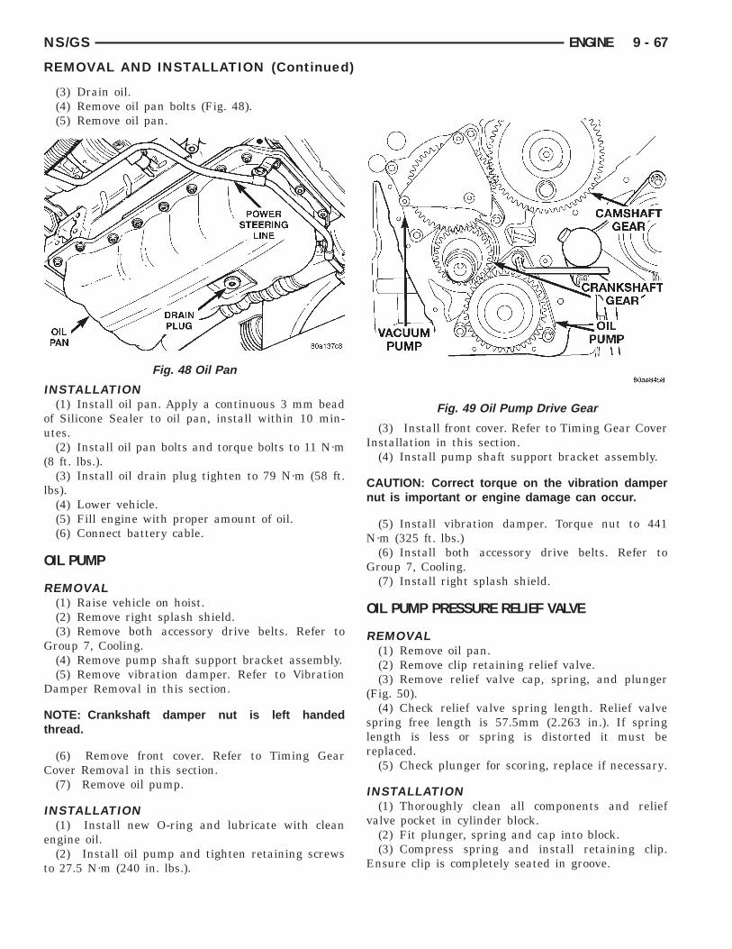
NS/GS ENGINE 9 - 67
REMOVAL AND INSTALLATION (Continued)
(3) Drain oil.(4) Remove oil pan bolts (Fig. 48).(5) Remove oil pan.
INSTALLATION(1) Install oil pan. Apply a continuous 3 mm bead
of Silicone Sealer to oil pan, install within 10 min-utes.
(2) Install oil pan bolts and torque bolts to 11 N·m(8 ft. lbs.).
(3) Install oil drain plug tighten to 79 N·m (58 ft.lbs).
(4) Lower vehicle.(5) Fill engine with proper amount of oil.(6) Connect battery cable.
OIL PUMP
REMOVAL(1) Raise vehicle on hoist.(2) Remove right splash shield.(3) Remove both accessory drive belts. Refer to
Group 7, Cooling.(4) Remove pump shaft support bracket assembly.(5) Remove vibration damper. Refer to Vibration
Damper Removal in this section.
NOTE: Crankshaft damper nut is left handedthread.
(6) Remove front cover. Refer to Timing GearCover Removal in this section.
(7) Remove oil pump.
INSTALLATION(1) Install new O-ring and lubricate with clean
engine oil.(2) Install oil pump and tighten retaining screws
to 27.5 N·m (240 in. lbs.).
Fig. 48 Oil Pan
(3) Install front cover. Refer to Timing Gear CoverInstallation in this section.
(4) Install pump shaft support bracket assembly.
CAUTION: Correct torque on the vibration dampernut is important or engine damage can occur.
(5) Install vibration damper. Torque nut to 441N·m (325 ft. lbs.)
(6) Install both accessory drive belts. Refer toGroup 7, Cooling.
(7) Install right splash shield.
OIL PUMP PRESSURE RELIEF VALVE
REMOVAL(1) Remove oil pan.(2) Remove clip retaining relief valve.(3) Remove relief valve cap, spring, and plunger
(Fig. 50).(4) Check relief valve spring length. Relief valve
spring free length is 57.5mm (2.263 in.). If springlength is less or spring is distorted it must bereplaced.
(5) Check plunger for scoring, replace if necessary.
INSTALLATION(1) Thoroughly clean all components and relief
valve pocket in cylinder block.(2) Fit plunger, spring and cap into block.(3) Compress spring and install retaining clip.
Ensure clip is completely seated in groove.
Fig. 49 Oil Pump Drive Gear

9 - 68 ENGINE NS/GS
REMOVAL AND INSTALLATION (Continued)
OIL FILTER ADAPTER AND OIL COOLER
REMOVAL(1) Remove oil filter.(2) Remove oil cooler adapter bolt.(3) Remove oil cooler (Fig. 51).
INSTALLATION(1) Install oil cooler with new gasket, tighten oil
cooler adapter bolt to 60 N·m (44 ft. lbs.).
Fig. 50 Oil Pressure Relief Valve
Fig. 51 Oil Cooler
(2) Install oil filter adapter to oil cooler andtighten to 49 N·m (36. lbs.).
(3) Install oil filter and tighten to 9.8 N·m (85 in.lbs.) and add oil.
VACUUM PUMP
REMOVAL(1) Remove the front cover refer to front cover
removal in this section.(2) Remove 4 bolts.
(3) Remove vacuum pump.
INSTALLATION(1) To install the vacuum pump, align the outer
part of the gear with the inner part using a screw-driver or similar tool, align with timing marks ongear set and install.
(2) Install bolts and tighten to 20 N·m (15 ft. lbs.).(3) Install front cover.
PISTONS AND CONNECTING ROD
REMOVAL(1) Disconnect the battery cable.(2) Remove cylinder heads, refer to cylinder head
removal in this section.(3) Raise vehicle on host.(4) Remove oil pan, refer to oil pan removal in this
section.(5) Remove top carbon ridge of cylinder bores with
a reliable ridge reamer before removing pistons fromcylinder block. Be sure to keep tops of pistons
Fig. 52 Vacuum Pump
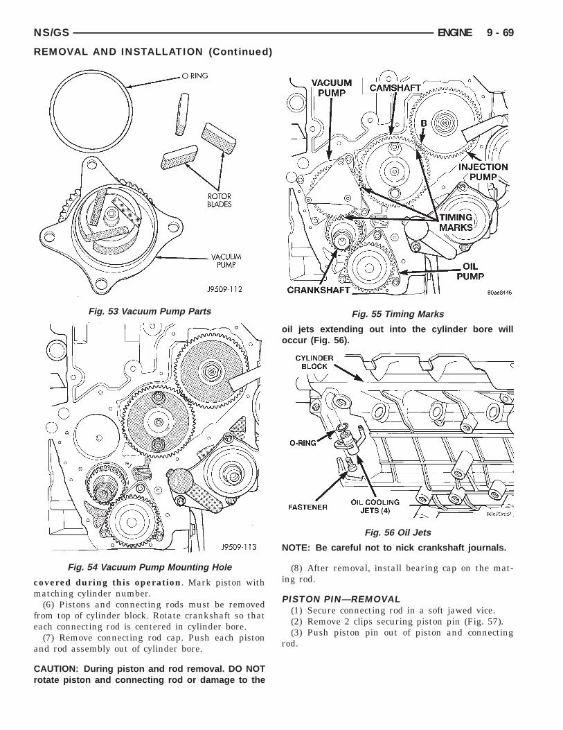
NS/GS ENGINE 9 - 69
REMOVAL AND INSTALLATION (Continued)
covered during this operation. Mark piston withmatching cylinder number.
(6) Pistons and connecting rods must be removedfrom top of cylinder block. Rotate crankshaft so thateach connecting rod is centered in cylinder bore.
(7) Remove connecting rod cap. Push each pistonand rod assembly out of cylinder bore.
CAUTION: During piston and rod removal. DO NOTrotate piston and connecting rod or damage to the
Fig. 53 Vacuum Pump Parts
Fig. 54 Vacuum Pump Mounting Hole
oil jets extending out into the cylinder bore willoccur (Fig. 56).
NOTE: Be careful not to nick crankshaft journals.
(8) After removal, install bearing cap on the mat-ing rod.
PISTON PIN—REMOVAL(1) Secure connecting rod in a soft jawed vice.(2) Remove 2 clips securing piston pin (Fig. 57).(3) Push piston pin out of piston and connecting
rod.
Fig. 55 Timing Marks
Fig. 56 Oil Jets

9 - 70 ENGINE NS/GS
REMOVAL AND INSTALLATION (Continued)
PISTON RING—REMOVAL(1) Identification (ID) mark on face of upper and
intermediate piston rings must point toward pistoncrown.
(2) Using a suitable ring expander, remove upperand intermediate piston rings (Fig. 58).
(3) Remove the upper oil ring side rail, lower oilring side rail and then oil ring expander from piston.
(4) Carefully clean carbon from piston crowns,skirts and ring grooves ensuring the 4 oil holes inthe oil control ring groove are clear.
FITTING PISTON RINGS(1) Wipe cylinder bore clean. Insert ring and push
down with piston to ensure it is square in bore. Thering gap measurement must be made with the ringpositioning at least 12 mm (0.50 in.) from bottom ofcylinder bore. Check gap with feeler gauge (Fig. 59).Top compression ring gap .25 to .50 mm (.0098 to.0196 in.). Second compression ring gap .25 to .35mm (.0098 to .0137 in.). Oil control ring gap .25 to.58 mm (.0098 to .0228 in.).
(2) If ring gaps exceed dimension given, new ringsor cylinder liners must be fitted. Keep piston rings inpiston sets.
(3) Check piston ring to groove clearance (Fig. 60).Top compression ring gap .08 to .130 mm (.0031 to
Fig. 57 Piston Assembly
.0051 in.). Second compression ring gap .070 to .102mm (.0027 to .0040 in.). Oil control ring gap .040 to.072 mm (.0015 to .0028 in.).
PISTON RINGS—INSTALLATION(1) Install rings on the pistons using a suitable
ring expander (Fig. 58).(2) Top compression ring is tapered and chromium
plated. The second ring is of the scraper type andmust be installed with scraping edge facing bottom ofthe piston. The third is an oil control ring (Fig. 61).Ring gaps must be positioned, before inserting pistoninto the liners, as follows (Fig. 62).
(3) Top ring gap must be positioned at 30 degreesto the right of the combustion chamber recess (look-ing at the piston crown from above).
(4) Second piston ring gap should be positioned onthe opposite side of the combustion chamber recess.
(5) Oil control ring gap to be located 30 degrees tothe left of combustion chamber recess.
(6) When assembling pistons check that compo-nents are installed in the same position as before dis-
Fig. 58 Piston Rings—Removing and Installing
Fig. 59 Ring Gap Measurement

NS/GS ENGINE 9 - 71
REMOVAL AND INSTALLATION (Continued)
assembly, determined by the numbers stamped onthe crown of individual pistons. Engine cylinders arenumbered starting from gear train end of the engine.Face chamber recess side of piston towardscamshaft. Therefore, the numbers stamped on conrod big end should also face in the same direction. Toinsert piston into cylinder, use a ring compressor asshown in (Fig. 63).
PISTON PIN—INSTALLATION(1) Secure connecting rod in soft jawed vice.(2) Lubricate piston pin and piston with clean oil.(3) Position piston on connecting rod.
Fig. 60 Piston Ring Side Clearance
Fig. 61 Piston Ring Identification
CAUTION: Ensure combustion recess in pistoncrown and the bearing cap numbers on the con-necting rod are on the same side.
(4) Install piston pin.(5) Install clips in piston to retain piston pin.(6) Remove connecting rod from vice.
PISTON—INSTALLATION(1) Before installing pistons, and connecting rod
assemblies into the bore, be sure that compressionring gaps are staggered so that neither is in line withoil ring rail gap (Fig. 62).
(2) Before installing the ring compressor, makesure the oil ring expander ends are butted and therail gaps located as shown in (Fig. 62).
(3) Immerse the piston head and rings in cleanengine oil, slide the ring compressor, over the pistonand tighten with the special wrench (Fig. 63).Ensure position of rings does not change dur-ing this operation.
Fig. 62 Piston Ring Gap Location
Fig. 63 Installing Piston

9 - 72 ENGINE NS/GS
REMOVAL AND INSTALLATION (Continued)
(4) Face chamber recess side of piston towardscamshaft.
(5) Install connecting rod bolt protectors on rodbolts.
(6) Rotate crankshaft so that the connecting rodjournal is on the center of the cylinder bore. Insertrod and piston into cylinder bore and guide rod overthe crankshaft journal.
CAUTION: During piston and rod installation. DONOT rotate piston and connecting rod or damage tothe oil jets extending out into the cylinder bore willoccur (Fig. 56).
(7) Tap the piston down in cylinder bore, using ahammer handle. At the same time, guide connectingrod into position on connecting rod journal.
(8) Install rod caps. Install nuts on cleaned andoiled rod bolts and tighten nuts to 29.5 N·m (22 ft.lb.) plus 60°.
CYLINDER LINER
REMOVAL(1) Remove cylinder heads (refer to cylinder head
removal in this section).(2) Remove Oil pan (refer to oil pan removal in
this section).(3) Remove pistons (refer to piston removal in this
section).(4) Use tool VM-1001 to remove liners (Fig. 64).(5) Remove shims from cylinder liner or cylinder
block recess. Keep shims with each cylinder liner.
INSTALLATION(1) Carefully clean residual sealer from liner and
crankcase, and degrease the crankcase where itcomes into contact with the liners. Referring to (Fig.65), install the liners in the crankcase as shown (A),rotating them back and forth by 45° in order to guar-antee correct positioning.
(2) Measure the liner recess relative to block deckwith a dial indicator mounted on a special toolVM-1010 A. All the measurements must be takenon camshaft side. Zero dial gauge on block deck.
(3) Move dial gauge to cylinder liner record read-ing on dial gauge.
(4) Remove liner and special tool.(5) Then select the correct shim thickness to give
proper protrusion (0.01 - 0.06 mm).(6) Fit the shim and the O-rings onto the liner.(7) Lubricate the lower liner location in the block.
Apply LOCTITE 275 to the corner of the liner seat.Apply LOCTITE 275 uniformly to the upper part ofthe liner at area.
(8) Fit the liners in the crankcase making surethat the shim is positioned correctly in the seat. Lock
the liners in position using special tool (VM-1016)and bolts (Fig. 66). Clean the residual LOCTITE onthe upper surface of the block deck.
(9) Recheck the liner protrusion. It should be 0.01- 0.06 mm.
NOTE: A period of six hours must elapse betweenthe liners being installed and engine start-up. Ifengine assembly is not continued after liner instal-lation, the liners need to be clamped for twelvehours minimum.
(10) Refer to Cylinder Head Removal and Installa-tion procedure in this section. To measure piston pro-trusion for installation of proper head gasketthickness.
CRANKSHAFT—REMOVALRefer to CRANKSHAFT MAIN BEARING
REMOVAL in this section.
REAR CRANKSHAFT OIL SEAL
REMOVAL(1) Remove transmission. Refer to Group 21,
Transmission for removal procedure.(2) Remove flywheel.
Fig. 64 Cylinder Liner—Removal
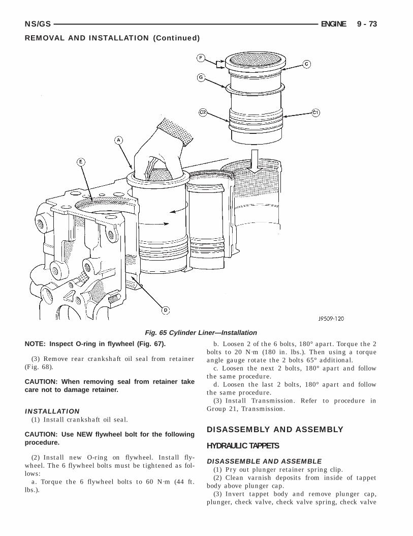
NS/GS ENGINE 9 - 73
REMOVAL AND INSTALLATION (Continued)
Fig. 65 Cylinder Liner—Installation
NOTE: Inspect O-ring in flywheel (Fig. 67).
(3) Remove rear crankshaft oil seal from retainer(Fig. 68).
CAUTION: When removing seal from retainer takecare not to damage retainer.
INSTALLATION(1) Install crankshaft oil seal.
CAUTION: Use NEW flywheel bolt for the followingprocedure.
(2) Install new O-ring on flywheel. Install fly-wheel. The 6 flywheel bolts must be tightened as fol-lows:
a. Torque the 6 flywheel bolts to 60 N·m (44 ft.lbs.).
b. Loosen 2 of the 6 bolts, 180° apart. Torque the 2bolts to 20 N·m (180 in. lbs.). Then using a torqueangle gauge rotate the 2 bolts 65° additional.
c. Loosen the next 2 bolts, 180° apart and followthe same procedure.
d. Loosen the last 2 bolts, 180° apart and followthe same procedure.
(3) Install Transmission. Refer to procedure inGroup 21, Transmission.
DISASSEMBLY AND ASSEMBLY
HYDRAULIC TAPPETS
DISASSEMBLE AND ASSEMBLE(1) Pry out plunger retainer spring clip.(2) Clean varnish deposits from inside of tappet
body above plunger cap.(3) Invert tappet body and remove plunger cap,
plunger, check valve, check valve spring, check valve

9 - 74 ENGINE NS/GS
DISASSEMBLY AND ASSEMBLY (Continued)
retainer and plunger spring. Check valve could beflat or ball.
Assemble tappets in reverse order.
Fig. 66 Liner Clamp Location
Fig. 67 Flywheel
CLEANING AND INSPECTION
CYLINDER HEAD COVERSRemove any original sealer from the cover sealing
surface of the engine cylinder head.Remove all residue from the sealing surface using
a clean, dry cloth.
ROCKER ARMS AND PUSH RODS
CLEANINGClean all the components (Fig. 69) with cleaning
solvent.Use compressed air to blow out the oil passages in
the rocker arms and push rods.
INSPECTIONInspect the pivot surface area of each rocker arm.
Replace any that are scuffed, pitted, cracked orexcessively worn.
Inspect the valve stem tip contact surface of eachrocker arm and replace any rocker arm that is deeplypitted.
Inspect each push rod end for excessive wear andreplace as required. If any push rod is excessivelyworn because of lack of oil, replace it and inspect thecorresponding hydraulic tappet for excessive wear.
Inspect the push rods for straightness by rollingthem on a flat surface or by shining a light betweenthe push rod and the flat surface.
A wear pattern along the length of the push rod isnot normal. Inspect the engine cylinder head forobstruction if this condition exists.
Fig. 68 Crankshaft Seal

NS/GS ENGINE 9 - 75
CLEANING AND INSPECTION (Continued)
CYLINDER HEAD
CLEANINGThoroughly clean the engine cylinder head and cyl-
inder block mating surfaces. Clean the intake andexhaust manifold and engine cylinder head matingsurfaces. Remove all gasket material and carbon.
Check to ensure that no coolant or foreign materialhas fallen into the tappet bore area.
Remove the carbon deposits from the combustionchambers and top of the pistons.
INSPECTIONUse a straightedge and feeler gauge to check the
flatness of the engine cylinder head and block matingsurfaces (Fig. 70).
Minimum cylinder head thickness 89.95mm (3.541in.)
CAUTION: If only one cylinder head is found to bedistorted and requires machining, it will also benecessary to machine the remaining cylindersheads and end plates by a corresponding amountto maintain correct cylinder alignment.
Fig. 69 Rocker Arm Components
VALVE GUIDE HEIGHT(1) Valve Guides height requirement.(2) Measurement A (Fig. 71): 13.50 - 14.00 mm.
VALVE STEM-TO-GUIDE CLEARANCEMEASUREMENT
(1) Measure and record internal diameter of valveguides. Valve guide internal diameter is 8.0 to 8.015mm (.3149 to .3155 in.).
(2) Measure valve stems and record diameters.Intake valve stem diameter 7.94 to 7.96 mm (.3125 to.3133 in). Exhaust valve stem diameter 7.92 to 7.94mm (.3118 to .31215 in).
(3) Subtract diameter of valve stem from internaldiameter of its respective valve guide to obtain valvestem clearance in valve guide. Clearance of inletvalve stem in valve guide is .040 to .075 mm (.0015to .0029 in). Clearance of exhaust valve stem in valveguide is .060 to .095 mm (.0023 to .0037 in).
(4) If valve stem clearance in valve guide exceedstolerances, new valve guides must be installed.
TIMING GEAR COVERBe sure mating surfaces of timing gear cover and
cylinder block are clean and free from burrs.
Fig. 70 Checking Cylinder Head Flatness
Fig. 71 Valve Guide Height

9 - 76 ENGINE NS/GS
CLEANING AND INSPECTION (Continued)
VALVES AND VALVE SPRINGS
VALVE CLEANINGClean all carbon deposits from the combustion
chambers, valve ports, valve stems, valve stemguides and heads.
Clean all grime and gasket material from theengine cylinder head machined gasket surfaces.
INSPECTIONInspect for cracks in the combustion chambers and
valve ports.Inspect for cracks on the exhaust seat.Inspect for cracks in the gasket surface at each
coolant passage.Inspect valves for burned, cracked or warped
heads.Inspect for scuffed or bent valve stems.Replace valves displaying any damage.Check valve spring height. (Fig. 72).
HYDRAULIC TAPPETS(1) Clean all tappet parts in a solvent that will
remove all varnish and carbon.(2) Replace tappets that are unfit for further ser-
vice with new assemblies.(3) If plunger shows signs of scoring or wear,
install a new tappet assembly. If valve is pitted, orvalve seat on end of plunger is prevented from seat-ing, install a new tappet assembly.
Fig. 72 Valve Spring Chart
OIL PUMP
CLEANINGWash all parts in a suitable solvent and inspect
carefully for damage or wear (Fig. 74).
INSPECTION(1) Before installing oil pump check pump bore
depth in block (A) and pump body height (B) (Fig.73). Difference between A and B should be0.020-0.082 mm.
(2) Check clearance between rotors (Fig. 75).
PISTON AND CONNECTING ROD
PISTONS(1) Piston Diameter: Size Group A: 91.93-91.94mm
(3.6191-3.6196 in.) Size Group B: 91.94-91.95mm
Fig. 73 Oil Pump Bore Depth
Fig. 74 Oil Pump Inner and Outer Rotors

NS/GS ENGINE 9 - 77
CLEANING AND INSPECTION (Continued)
(3.6196-3.6200 in.). Maximum wear limit .05mm(.0019 in.).
(2) Check piston pin bores in piston for roundness.Make 3 checks at 120° intervals. Maximum out ofroundness .05mm (.0019in.).
(3) The piston diameter should be measuredapproximately 15 mm (.590 in.) up from the base.
(4) Skirt wear should not exceed 0.1 mm (.00039in.).
(5) The clearance between the cylinder liner andpiston should not exceed 0.25 mm (.0009 in.).
(6) Make sure the weight of the pistons does notdiffer by more than 5 g.
CONNECTING ROD(1) Assemble bearing shells and bearing caps to
their respective connecting rods ensuring that theserrations on the cap and reference marks arealigned.
(2) Tighten bearing cap bolts to 29 N·m (21 ft. lbs.)plus 60°.
(3) Check and record internal diameter of crankend of connecting rod.
Note: When changing connecting rods, all fourmust have the same weight and be stamped with thesame number. Replacement connecting rods willonly be supplied in sets of four.
(4) Connecting rods are supplied in sets of foursince they all must be of the same weight category.Max allowable weight difference is 18 gr. NOTE: Onone side of the big end of the con-rod there is a two-digit number which refers to the weight category. Onthe other side of the big end there is a four digit
Fig. 75 Checking Rotor Clearance
number on both the rod and the cap. These numbersmust both face the camshaft as well as the recess onthe piston crown (Fig. 76). Lightly heat the piston inoven. Insert piston pin in position and secure it withprovided snap rings. The Four digit numbersmarked on con rod big end and rod cap mustbe on the same side as the camshaft (Fig. 76).After having coated threads with Molyguard, tightencon rod bolts to 29 N·m (21 ft. lbs.) plus 60°.
PISTON PIN(1) Measure the diameter of piston pin in the cen-
ter and both ends (Fig. 77).(2) Piston pin diameter is 29.990 to 29.996mm
(1.1807 to 1.1809 in.).
CRANKSHAFT
CRANKSHAFT JOURNALS(1) Using a micrometer, measure and record crank-
shaft connecting rod journals, take reading of eachjournal 120° apart. Crankshaft journal diameter is53.84 to 53.955mm (2.1196 to 2.1242 in.).
(2) Crankshaft journals worn beyond limits orshow signs of out of roundness must be reground orreplaced. Minimum reground diameter is 53.69mm(2.1137 in.).
BEARING-TO-JOURNAL CLEARANCECompare internal diameters of connecting rod with
crankshaft journal diameter. Maximum clearancebetween connecting rod and crankshaft journals .022to .076mm (.0008 to .0029 in.) (Fig. 78).
CRANKSHAFT MAIN BEARING
INSPECTION(1) Fit main bearing carriers together and torque
to 42 N·m (31 ft. lbs.)(2) Check internal diameter of bearings.
Fig. 76 Connecting Rod Identification

9 - 78 ENGINE NS/GS
CLEANING AND INSPECTION (Continued)
(3) If internal diameter of original bearing is beingchecked and figures are not within specifications,new bearings must be used.
(4) Check crankshaft main bearing journals tobearing clearances. Clearances of main bearings is.03 to .088mm (.0011 to .0035 in.).
OIL PANRemove all gasket material from cylinder block. Be
careful not gouge pan sealing surface.
Fig. 77 Piston, Connecting Rod and Pin
Fig. 78 Bearing Clearance
CYLINDER LINER
INSPECTIONThe cylinder walls should be checked for out-of-
round and taper with dail bore gauge. The cylinderbore out-of-round is 0.100 mm (.0039 inch) maximumand cylinder bore taper is 0.100 mm (0.0039 inch)maximum. If the cylinder walls are badly scuffed orscored, new liners should be installed and honed, andnew pistons and rings fitted.
Measure the cylinder bore at three levels in direc-tions A and B (Fig. 79). Top measurement should be10 mm (3/8 inch) down and bottom measurementshould be 10 mm ( 3/8 inch.) up from bottom of bore.
SPECIFICATIONS
2.5L VM DIESEL
DESCRIPTION . . . . . . . . . . . SPECIFICATIONSType . . . . . . . . . . . . . . . . . . . . . . 425CLIEE (36B)Number of Cylinder . . . . . . . . . . . . . . . . . . . . . . 4Bore . . . . . . . . . . . . . . . . . . . . . . . . . . . . . . 92 mmStroke . . . . . . . . . . . . . . . . . . . . . . . . . . . . 94 mmCapacity . . . . . . . . . . . . . . . . . . . . . . . 2499.5 cm3Injection Order . . . . . . . . . . . . . . . . . . . . . 1-3-4-2Compression Ratio . . . . . . . . . . . . . . . 21:1 (6 0.5)
CrankshaftFront Journal Diameter . . . . . . . . . . . . . . . . . . . .
Nominal . . . . . . . . . . . . . . . . . 62.985–63.000 mm–0.25 . . . . . . . . . . . . . . . . . . . . 62.735–62.750 mm–0.125 . . . . . . . . . . . . . . . . . . . 62.860–62.875 mm
Front Bearing Diameter . . . . . . . . . . . . . . . . . . . .Nominal . . . . . . . . . . . . . . . . . 63.043–63.088 mm–0.25 . . . . . . . . . . . . . . . . . . . . 62.793–62.838 mm–0.125 . . . . . . . . . . . . . . . . . . . 62.918–62.963 mmClearance Between Journal and Bearing:0.043–0.103 mm . . . . . . . . . . . . . . . . . . . . . . . . . .
Center Journal Diameter . . . . . . . . . . . . . . . . . . .
Fig. 79 Liner Inspection
NS/GS ENGINE 9 - 79
SPECIFICATIONS (Continued)
DESCRIPTION . . . . . . . . . . . SPECIFICATIONSNominal . . . . . . . . . . . . . . . . . 63.005–63.020 mm–0.25 . . . . . . . . . . . . . . . . . . . . 62.755–62.770 mm–0.125 . . . . . . . . . . . . . . . . . . . 62.880–62.895 mm
Center Bearing Diameter . . . . . . . . . . . . . . . . . . .Nominal . . . . . . . . . . . . . . . . . 63.050–63.093 mm–0.25 . . . . . . . . . . . . . . . . . . . . 62.800–62.843 mm–0.125 . . . . . . . . . . . . . . . . . . . 62.925–62.968 mmClearance Between Journal and Bearing:0.030–0.088 mm . . . . . . . . . . . . . . . . . . . . . . . . . .
Rear Journal Diameter . . . . . . . . . . . . . . . . . . . . .Nominal . . . . . . . . . . . . . . . . . 79.980–80.000 mm–0.25 . . . . . . . . . . . . . . . . . . . . 79.730–79.750 mm–0.125 . . . . . . . . . . . . . . . . . . . 79.855–79.875 mm
Rear Bearing Diameter . . . . . . . . . . . . . . . . . . . . .Nominal . . . . . . . . . . . . . . . . . 80.045–80.070 mm–0.25 . . . . . . . . . . . . . . . . . . . . 79.795–79.820 mm–0.125 . . . . . . . . . . . . . . . . . . . 79.920–79.945 mmClearance Between Journal and Bearing:0.045–0.090 mm (Wear Limit: 0.200 mm) . . . . . . .
Connecting Rod Journal . . . . . . . . . . . . . . . . . . . .Nominal . . . . . . . . . . . . . . . . . 53.940–53.955 mm–0.25 . . . . . . . . . . . . . . . . . . . . 53.690–53.705 mm–0.125 . . . . . . . . . . . . . . . . . . . 53.815–53.830 mm
Connecting Rod Bearing . . . . . . . . . . . . . . . . . . . .Nominal . . . . . . . . . . . . . . . . . 53.977–54.016 mm–0.25 . . . . . . . . . . . . . . . . . . . . 53.727–53.766 mm–0.125 . . . . . . . . . . . . . . . . . . . 53.852–53.891 mmClearance Between Journal and Bearing:0.022–0.076 mm (Wear Limit: 0.200 mm) . . . . . . .
Crankshaft End PlayEnd Play . . . . . . . . . . . . . . . . . . . . . 0.08–0.21 mmAdjustment . . . . . . . . . . . . . . . . . Thrust WashersThrust Washers Available . . . . . . . . 2.31–2.36 mmThrust Washers Available . . . . . . . . 2.41–2.46 mmThrust Washers Available . . . . . . . . 2.51–2.56 mm
Main Bearing CarriersFront . . . . . . . . . . . . . . . . . . . . 67.025–67.050 mmCenter . . . . . . . . . . . . . . . . . . . 66.670–66.690 mmRear . . . . . . . . . . . . . . . . . . . . 85.985–86.005 mm
LinersInternal Diameter . . . . . . . . . . 92.000–92.010 mmProtrusion . . . . . . . . . . . . . . . . . . . . 0.01–0.06 mmAdjustment . . . . . . . . . . . . . . . . . . . . . . . . . ShimsAvailable Shims: . . . . . . . . . . . . . . . . . . . 0.15 mmAvailable Shims: . . . . . . . . . . . . . . . . . . . 0.17 mmAvailable Shims: . . . . . . . . . . . . . . . . . . . 0.20 mmAvailable Shims: . . . . . . . . . . . . . . . . . . . 0.23 mmAvailable Shims: . . . . . . . . . . . . . . . . . . . 0.25 mm
Cylinder HeadMinimum Thickness . . . . . . . . . . 89.95–90.05 mmGasket . . . . . . . . . . . . . . . . . . . . . . . . . . . . . SteelGasket thickness: . . . . . . . 1.42 6 0.1 mm 0 HolesGasket thickness: . . . . . . . 1.62 6 0.1 mm 1 Holes
DESCRIPTION . . . . . . . . . . . SPECIFICATIONSGasket thickness: . . . . . . . 1.52 6 0.1 mm 2 Holes
End PlatesHeight . . . . . . . . . . . . . . . . . . . . . 89.02–90.00 mm
Connecting RodsWeight (Without the crankbearing) . . . . . . . . . . . . . . . . . . 1129–1195 gramsSmall End Bearing Internal DiameterMinimum . . . . . . . . . . . . . . . . . . . . . . . 30.035 mmMaximum . . . . . . . . . . . . . . . . . . . . . . 30.050 mmCrankshaft Bearings Standard InternalDiameter . . . . . . . . . . . . . . . . . 53.997–54.016 mm
PistonsSkirt Diameter . . . . . . . . . . . . 91.935–91.945 mm(Measured at approximately 15 mm above thebottom of the skirt)Piston Clearance . . . . . . . . . . . . . 0.055–0.075 mmTop of Piston to Cylinder Head . . . . 0.80–0.89 mmPiston Protrusion . . . . . 0.53–0.62 mm Fit Gasket
(1.42), 0 HolesPiston Protrusion . . . . . 0.73–0.82 mm Fit Gasket
(1.62), 1 HolePiston Protrusion . . . . . 0.63–0.72 mm Fit Gasket
(1.52), 2 HolesPiston Pins
Type . . . . . . . . . . . . . . . . . . . . . . . . . Full FloatingPin Diameter . . . . . . . . . . . . . . 29.990–29.996 mmClearance . . . . . . . . . . . . . . . . . . 0.004–0.014 mm
Piston Rings (Clearance in Groove)Top . . . . . . . . . . . . . . . . . . . . . . . 0.080–0.130 mmSecond . . . . . . . . . . . . . . . . . . . . . 0.070–0.102 mmOil Control . . . . . . . . . . . . . . . . . 0.040–0.072 mm
Piston Rings (Fitted Gap)Top . . . . . . . . . . . . . . . . . . . . . . . . . 0.25–0.50 mmSecond . . . . . . . . . . . . . . . . . . . . . . 0.20–0.35 mmOil Control . . . . . . . . . . . . . . . . . . . 0.25–0.58 mm
CamshaftJournal Diameter Front . . . . . 53.460–53.480 mmBearing Clearance . . . . . . . . . . . . . 0.06–0.13 mmJournal Diameter Center . . . . 53.460–53.480 mmBearing Clearance . . . . . . . . . . . . . 0.06–0.13 mmJournal Diameter Rear . . . . . . 53.460–53.480 mmBearing Clearance . . . . . . . . . . . . . 0.06–0.13 mm
TappetsOutside Diameter . . . . . . . . . . 22.195–22.212 mm
Rocker GearShaft Diameter . . . . . . . . . . . . . 21.979–22.00 mmBushing internal diameter . . . 22.020–22.041 mmAssembly Clearance . . . . . . . . . . 0.020–0.062 mm
Valves (Intake)Opens . . . . . . . . . . . . . . . . . . . . . . . . 26° B.T.D.C.Closes . . . . . . . . . . . . . . . . . . . . . . . . 58° A.B.D.C.
Valves (Exhaust)Opens . . . . . . . . . . . . . . . . . . . . . . . . 64° B.B.D.C.Closes . . . . . . . . . . . . . . . . . . . . . . . . 38° A.T.D.C.

9 - 80 ENGINE NS/GS
SPECIFICATIONS (Continued)
DESCRIPTION . . . . . . . . . . . SPECIFICATIONSValve Face Angle
Intake . . . . . . . . . . . . . . . . . . . . . . . 55°30’– 55°50’Exhaust . . . . . . . . . . . . . . . . . . . . . 45°25’– 45°35’
Valve Head DiameterIntake . . . . . . . . . . . . . . . . . . . . . 40.05–40.25 mmExhaust . . . . . . . . . . . . . . . . . . . . . 33.8–34.0 mm
Valve Head Stand DownIntake . . . . . . . . . . . . . . . . . . . . . . . 1.08–1.34 mmExhaust . . . . . . . . . . . . . . . . . . . . . 1.99–1.25 mm
Valve Stem DiameterIntake . . . . . . . . . . . . . . . . . . . . . 7.940–7.960 mmExhaust . . . . . . . . . . . . . . . . . . . . 7.922–7.940 mm
Valve Clearance in GuideIntake . . . . . . . . . . . . . . . . . . . . . 0.040–0.075 mmExhaust . . . . . . . . . . . . . . . . . . . . 0.060–0.093 mm
Valve GuideInside Diameter . . . . . . . . . . . . . . . 8.0–8.015 mmFitted Height . . . . . . . . . . . . . . . . . 13.5–14.0 mm
Valve SpringFree Length . . . . . . . . . . . . . . . . . . . . . 44.65 mmFitted Length . . . . . . . . . . . . . . . . . . . . . 38.6 mmLoad at Fitted Length . . . . . . . . . . . . 34 6 6% KgLoad at Top of Lift . . . . . . . . . . . . . 92.5 6 4% KgNumber of Coils . . . . . . . . . . . . 5.33 Valve Timing
Oil Pressureat 4000 rpm . . . . . 3.0 to 4.5 bar (Oil at 90–100°C)Pressure Relief Valve Opens . . . . . . . . . . 6.38 barPressure Relief Valve–Free Length . . . . . 57.5 mm
Oil PumpOuter Rotor End Float . . . . . . . . . . 0.03–0.09 mmInner Rotor End Float . . . . . . . . . . 0.03–0.09 mmOuter Rotor to Body DiameterClearance . . . . . . . . . . . . . . . . . . 0.130–0.230 mmRotor Body to Drive Gear Clearance (Pump NotFitted) . . . . . . . . . . . . . . . . . . . . . . 3.27–3.73 mm
TORQUE
DESCRIPTION . . . . . . . . . . . . . . . . . . . TORQUEGenerator Mounting Bracket
Bolts . . . . . . . . . . . . . . . . . . . . 47 N·m (35 ft. lbs.)Camshaft Thrust Plate Retaining Bolts
Bolt . . . . . . . . . . . . . . . . . . . . . 24 N·m (18 ft. lbs.)Cylinder Head
Bolts . . See Cylinder Head Installation ProcedureConnecting Rod
Bolts . . . . . . . . . . . 29.5 N·m +60° (22 ft. lbs. +60°)Crankshaft Bearing Carrier
Bolts . . . . . . . . . . . . . . . . . . . . 44 N·m (32 ft. lbs.)Crankshaft damper (Pulley)
Nut . . . . . . . . . . . . . . . . . . . 441 N·m (325 ft. lbs.)EGR Valve to Intake Manifold
Tube . . . . . . . . . . . . . . . . . . . . 26 N·m (19 ft. lbs.)
DESCRIPTION . . . . . . . . . . . . . . . . . . . TORQUEEGR Tube to EGR Valve
Bolts . . . . . . . . . . . . . . . . . . . . 26 N·m (19 ft. lbs.)Engine Mount—Front
Support Bracket Engine Bolts . 68 N·m (50 ft. lbs.)Support Bracket TransmissionBolts . . . . . . . . . . . . . . . . . . . 101 N·m (75 ft. lbs.)Support Cushion CrossmemberBolts . . . . . . . . . . . . . . . . . . . . 54 N·m (40 ft. lbs.)Support Cushion Thru Bolt . . . 65 N·m (48 ft. lbs.)
Engine Mount—RearSupport Bracket TransmissionBolts . . . . . . . . . . . . . . . . . . . 101 N·m (75 ft. lbs.)Support Bracket to EngineBracket . . . . . . . . . . . . . . . . . 101 N·m (75 ft. lbs.)Support Cushion Thru Bolt . . . 68 N·m (50 ft. lbs.)
Engine Mount—LeftTransmission Mounting Bolts . 54 N·m (40 ft. lbs.)Support Cushion Thru Bolt . . . 71 N·m (53 ft. lbs.)
Engine Mount—RightMount to Frame Rail Bolts . . . 68 N·m (50 ft. lbs.)Mount Bolt (Horizontal) . . . 145 N·m (107 ft. lbs.)Mount Bolt (Vertical) . . . . . . . 101 N·m (75 ft. lbs.)
Right Engine Mount BracketBolts . . . . . . . . . . . . . . . . . . . . 40 N·m (30 ft. lbs.)
Exhaust Pipe to TurbochargerBolts . . . . . . . . . . . . . . . . . . . 28 N·m (250 in. lbs.)
Exhaust Manifold Outlet to TurboNuts . . . . . . . . . . . . . . . . . . . . 32 N·m (24 ft. lbs.)
Exhaust Elbow to TurboBolts . . . . . . . . . . . . . . . . . . . . 30 N·m (22 ft. lbs.)
Exhaust Manifold MountingNuts . . . . . . . . . . . . . . . . . . . . 30 N·m (22 ft. lbs.)
FlywheelBolts . . . . . See Rear Crankshaft Seal InstallationProcedure
Engine Adaptor PlateBolts . . . . . . . . . . . . . . . . . . . . 47 N·m (35 ft. lbs.)
Front Timing Gear CoverBolts . . . . . . . . . . . . . . . . . . . . 11 N·m (96 in. lbs.)
Fuel FilterNuts . . . . . . . . . . . . . . . . . . . 28 N·m (250 in. lbs.)
Glow PlugsPlugs . . . . . . . . . . . . . . . . . . 14 N·m (120 in. lbs.)
Idler Pulley Pump Support BracketNuts . . . . . . . . . . . . . . . . . . . 26 N·m (228 in. lbs.)
Idler Pulleys (left handed threads)Bolts . . . . . . . . . . . . . . . . . . . . 47 N·m (35 ft. lbs.)
Injector Pump fuel linesNuts . . . . . . . . . . . . . . . . . . 17.6 N·m (156 in. lbs.)
Injector Pump GearLock Nut . . . . . . . . . . . . . . . . . . . . . . . . . . 86 N·m
Injector Pump MountingNuts . . . . . . . . . . . . . . . . . . 27.5 N·m (240 in. lbs.)

NS/GS ENGINE 9 - 81
SPECIFICATIONS (Continued)
DESCRIPTION . . . . . . . . . . . . . . . . . . . TORQUEInjector
Tighten to . . . . . . . . . . . . . . . . 65 N·m (48 ft. lbs.)Intake Manifold Mounting
Nuts . . . . . . . . . . . . . . . . . . . 30 N·m (264 in. lbs.)Main Bearing Oil Delivery Union
Bolts . . . . . . . . . . . . . . . . . . . . 54 N·m (40 ft. lbs.)Oil Feed Line To Rocker Arms
Bolts . . . . . . . . . . . . . . . . . 12.7 N·m (108 in. lbs.)Oil Feed Line to Block
Bolts . . . . . . . . . . . . . . . . . 12.7 N·m (108 in. lbs.)Oil Feel Line to Vacuum Pump
Bolts . . . . . . . . . . . . . . . . . 16.7 N·m (145 in. lbs.)Oil Filter
Tighten to . . . . . . . . . . . . . . . 9.8 N·m (85 in. lbs.)Oil Filter Adaptor
Fastener . . . . . . . . . . . . . . . . . 49 N·m (36 ft. lbs.)Oil Filter Base
Fastener . . . . . . . . . . . . . . . . . 49 N·m (36 ft. lbs.)Oil Pan Mounting
Bolts . . . . . . . . . . . . . . . . . . . 12 N·m (108 in. lbs.)Oil Pickup Tube
Bolts . . . . . . . . . . . . . . . . . . 11.3 N·m (100 in. lbs.)Oil Pump Mounting
Bolts . . . . . . . . . . . . . . . . . 27.5 N·m (240 in. lbs.)Oil Pan Drain
Plug . . . . . . . . . . . . . . . . . . . . . 54 N·m (40 ft. lbs.)Power Steering Pressure Hose
Fastener . . . . . . . . . . . . . . . . 28 N·m (240 in. lbs.)Power Steering Pulley
Nut . . . . . . . . . . . . . . . . . . . 170 N·m (125 ft. lbs.)Rear Crankshaft Bearing Carrier
Bolts . . . . . . . . . . . . . . . . . . 10.8 N·m (95 in. lbs.)Rocker Arm Cover
Bolts . . . . . . . . . . . . . . . . . 14.7 N·m (132 in. lbs.)Rocker Arm Mounting
Nuts . . . . . . . . . . . . . . . . . . 29.4 N·m (264 in. lbs.)Power Steering Pump Mounting
Nuts . . . . . . . . . . . . . . . . . . 24.5 N·m (216 in. lbs.)Turbocharger Mounting
Nuts . . . . . . . . . . . . . . . . . . . 32 N·m (288 in. lbs.)Turbocharger Oil Delivery
Bolt . . . . . . . . . . . . . . . . . . 27.5 N·m (240 in. lbs.)Turbocharger Oil Drain
Bolts . . . . . . . . . . . . . . . . . . 10.8 N·m (95 in. lbs.)Vacuum Pump Mounting
Bolts . . . . . . . . . . . . . . . . . . 10.8 N·m (95 in. lbs.)Water Manifold Mounting
Bolts . . . . . . . . . . . . . . . . . . 11.8 N·m (108 in. lbs.)Water Pump Pulley
Bolts . . . . . . . . . . . . . . . . . 27.5 N·m (240 in. lbs.)
SPECIAL TOOLS
2.5L VM DIESEL
Crankshaft Pulley and Gear Remover VM.1000A
Cylinder Liner Puller VM.1001
Crankshaft Bearing Remover/Installer VM.1002

9 - 82 ENGINE NS/GS
SPECIAL TOOLS (Continued)
Crankshaft Remover/Installer Sleeve VM.1004
Torque Angle Gauge VM.1005
Cylinder Head Bolt Wrench VM.1006A
Cylinder Head Guide Studs VM.1009
Cylinder Liner Protrusion Tool VM.1010
Injector Socket Remover/Installer VM.1012A

NS/GS ENGINE 9 - 83
SPECIAL TOOLS (Continued)
Dial Indicator Gauge VM.1013
Flywheel Locking Tool VM.1014
Timing Cover Oil Seal Installer VM.1015
Cylinder Retainers VM.1016
Cylinder Head Bolt Wrench M12 VM.1018

9 - 84 ENGINE NS/GS
SPECIAL TOOLS (Continued)
Adapter Cylinder Leakage Tester VM.1021
Cylinder Head Bolt Wrench M14 VM.1019
Support Brackets Engine Removal/InstallationVM.1026
Related Documents