Systems Optimization for Mobility Management Ashutosh Dutta Electrical Engineering Department Columbia University March xx, 2010

Systems Optimization for Mobility Management Ashutosh Dutta Electrical Engineering Department Columbia University March xx, 2010.
Dec 22, 2015
Welcome message from author
This document is posted to help you gain knowledge. Please leave a comment to let me know what you think about it! Share it to your friends and learn new things together.
Transcript

Systems Optimization for Mobility Management
Ashutosh DuttaElectrical Engineering Department
Columbia UniversityMarch xx, 2010

Outline• Motivation
• Vision
• Key Contributions
• Sample results
• Conclusions and Future work

Motivation• Cellular mobility typically involves handoff across
homogeneous access technology – Optimization techniques are carefully engineered to improve
the handoff performance• IP-based mobility involves movement across access
technologies, administrative domains, at multiple layers and involve interaction between multiple protocols– Mechanisms and design principles for optimized handover
are poorly understood– Currently there are ad hoc solutions for IP mobility
optimization, not engineering practice – No formal methodology to systematically discover or
evaluate mobility optimizations – No methodology for systematic evaluation or prediction of
"run-time" cost/benefit tradeoffs

Backbone
AdministrativeDomain B
L2 PoA
Corresponding Host
128.59.10.7
IPch
207.3.232.10
207.3.240.10
128.59.11.8
N2
N1N1
N2
N1- Network 1 (802.11)N2- Network 2 ( CDMA/GPRS)
ConfigurationAgent
L3 PoA 207.3.232.10
MobileHost
AuthenticationAgent
Authorization Agent
RegistrationAgent
RegistrationAgent
Administrative Domain A
ConfigurationAgent
Authorization Agent
SignalingProxy
AuthenticationAgent
SignalingProxy
L3 PoA
L2 PoA
L2 PoA
L2 PoA
L2 PoA
L2 PoA
L3 PoA
Mobility Illustration in IP-based 4G network
128.59.9.6900 ms media interruption
802.11 802.11
802.11802.11
4 Seconds media interruption
Handoff Delay~ 18 s
802.11 CDMA
18 Seconds media interruption
L3 PoA
A
B
CD

What is the vision?• IP-based mobility needs to provide handoff
performance comparable to cellular mobility• In order to transition ad hoc optimization
approaches to engineering best practice we need the following:– Framework or model that can analyze the mobility event
in a systematic way, can verify and predict the performance under systems resource constraints
– A set of fundamental design principles to optimize handoff components across layers
– A set of well defined methodologies to verify the optimization techniques for mobility in an IP-based network

My Key Contribution
1. Identification of the fundamental properties that are rebound during handover event and systematic analysis of the operations that are intrinsic to handover
2. Modeling of the handover process that allows performance predictions to be made for both an un-optimized handover and for specific optimization methodologies under systems resource constraints and data dependency
3. Development of series of optimization techniques based on fundamental rules of optimization that could be applied to link, network, and application layers and preserve the user experience by optimizing the handover related delay and packet loss
4. Proof-of-concept of these handoff optimization techniques by building experimental systems and comparing these results with model-based prediction

Systems analysis of handoff components

MobilityEvent
Network discovery &selection
Networkattachment
Configuration Securityassociation
Bindingupdate
Mediareroute
Channeldiscovery
L2 association
Routersolicitation
Domainadvertisement
Identifieracquisition
DuplicateAddressDetection
AddressResolution
Authentication
Keyderivation
Identifierupdate
Identifiermapping
Bindingcache
Tunneling
Buffering
Forwarding
Bi-casting/Multicasting
Serverdiscovery
IdentifierVerification
Subnetdiscovery
P1 P2 P3 P4 P5 P6
P11
P13
P12
P21
P22
P23
P31
P32
P33 P41
P42P51
P52
P53
P54
P61 P62
P63
P64
System decomposition of handover process

Handover: Distributed operation across multiple layers
Time
L2PoA
L3PoA
Discovery Attachment Configuration
SecurityAssociation
p11
p12
p21
p31
p32 p42
p41Server(Proxy,/HA)
p22
Binding Update
MediaRerouting
p51p31
p32
p41 p42
p42 p63
p62
p13p23
p31
p33
MN
p11 p12 p21 p22p31 p41
p61p32 p42
p13 p23p33 p51
p51
p52
p52
CN
p42 p52p61
p54
p53 p54
p61
p61p62
p64p51

Mobility/Function
AccessType
Network Discovery
Resource Discovery
TriggeringTechnique
DetectionTechnique
Configuration
Key exchange/Authentication
Encryption BindingUpdate
MediaRerouting
GSM TDMA BCCH FCCH ChannelStrength
SCH TMSI SRES/A3 DES MSCContld.
Anchor
WCDMA CDMA PILOT SYNCChannel
ChannelStrength
Frequency TMSI SRES/A3 AES Network
Control
Anchor
IS-95 CDMA PILOT SYNCchannel
ChannelStrength
RTC TMSI Diffie-HellmanAKA
Kasumi MSCContld.
AnchorMSC
CDMA1X-EVDO
EVDO PILOTChannel
SYNCChannel
Channel
Strength
RTC TMSI Diffie-Hellman/CAVE
AES MSC PDSN/MSC
802.11 CSMA/CA
Beacon11R
11R802.21
SNR atMobile
Scanning.ChannelNumber,SSID
SSID,Channel number
Layer 2 authenticate802.1XEAP
WEP/WPA802.11i
Associate IAPP
Cell IP Any Gatewaybeacon
Mobilemsmt.
AP
beacon
ID
GW Beacon MAC
Address
AP address
IPSec IPSec RouteUpdate
IntermediateyRouter
MIPv4 Any ICMPRouter adv.FA adv.
ICMP
Router
Adv.
FA adv.L2 triggering
FA adv FA-CoACo-CoA
IKE/PANAAAA
IPSec MIPRegistration
FARFAHA
MIPv6 Any StatelessProactive
CARD802.2111R
RouterAdv.
RouterPrefix
CoA IKE/PANAAAA
IPSEC MIP updateMIP RO
CHMAPHA
SIPM Any StatelessICMP Router
802.2111R
L3RouterAdv.
Router Prefix, ICMP
CoAAORRe-Register
INVITE exchange/AAA
IPSEC/SRTP/S/MIME
Re-INVITE
B2BUACHRTPtrans
Functional Matrix of Mobility Event

MN pAR nAR HA CN
L2 Handoff
BU
BAck
Router Advertisement (Rtr Adv)
Router Solicitation (Rtr Sol)
Neighbor Solicitation (NS)
Neighbor Advertisement (NA)
[MN-CoA:CN] [MN-HoA:CN] [Data Tunneling] [MN-HoA:CN] [Data]
HoTI HoTI
CoTI
HoT HoT
CoTBU
BAck
Data Traffic at nPoA
Addressuniqueness
Movement Detect
Bin
ding
Upd
ate
Ret
urn
Rou
tabi
lity
Rou
te O
ptim
izat
ion
nAP AAAProbe Request
Probe Response
Beacon
Open Authentication
EAP-OL EAP-TLS
EAP Success
L2 Association
Layer 3configuration
4-way handshake
Discovery
Authentication
L2SecurityAssociation
Data
L3 Handoff
Handoff Analysis of Mobile IPv6

Proposed optimization techniques for handoff components

Proposed optimization techniques for respective handoff components
Handoff
components
Fundamental
principles
My proposed
optimization
techniques
Key
advantages
My
publications
Related
work
Discovery - Proactive discovery - Caching neighboring
network elements
and parameters
Application layer proactive discovery of network and resources
- Access
independent
- Eliminates
layer 2 scanning
delay
1. ACM Mobiquitous 2005
2. IEEE Broadnets 2006
3. IEEE 802.21 (2005)
• Selective scanning for 802.11 (Shin et al.)• Periodic scanning
(Montavont et al.)• Search in parallel with data (Velayos et al.)
Detection of
network
attachment
- Cross layer event triggers
- Policy-based approach based on mobile’s movement and type of application
-Link layer event triggers to expedite network detection or loss of network
- Use of cross layer information and policy to limit the binding update
-Speed up the execution of upper layer operations- Avoids the un-necessary binding update overhead
- Policy-based approach
1. IEEE WTC 2006
2. Springer Journal 2007
3. IEEE 802.21 (2005)
4. IEEE Wireless Communication Magazine
5. IEEE MILCOM
Teraoka et al.
Politis et al.
Carli et al.
Lee et al.
Zeadaly et al.
Configuration -Network assisted duplicate address detection- Reduction of signaling between mobile and server
- Caching of network identifier address
- Router assisted Duplicate Address Detection
- Client does not perform DAD
1. IEEE Sarnoff 2005
2. 2007 Springer
Journal on Wireless Personal Communication
Optimistic DAD
Passive DAD
Rapid Commit RFC 4039
- Proactive IP address acquisition
- Network layer configuration delay is avoided

Proposed optimization techniques for respective handoff components (contd.)
Handoff
components
Fundamental
principles
My proposed
optimization
techniques
Key
advantages
My
publications
Related
work
Binding Update Limit the binding update traversal
distance
- Anchor assisted hierarchical binding update for network layer and application layer mobility protocol
- Reduction in global signaling overhead
1. IEEE PIMRC 2004
2. ACM MC2R
3. IEEE MILCOM 2005
4. IEEE Wireless
Communication
Magazine 2003
5. IEEE Wireless Magazine 2008
MIP-RR
RFC 4857
HMIPv6 RFC 4140
Infrastructure-based single host
mobility
- Proactive
binding update
- Eliminates the binding update delay completely
- Limit binding update delay based on cross layer triggers (e.g., layer 2 and application layer)
- Mobility optimization based on mobility pattern and application- Increases throughput by 50 %
Multi-layer
Mobility
- Policy-based
approach based on mobile’s movement and type of application
- Cross layer triggers
1. IEEE MILCOM
2002, 2003
2. IEEE Wireless
Communication
magazine
3. Wiley journal on
Computer
communication

Proposed optimization techniques for respective handoff components (contd.)
Handoff
components
Fundamental
principles
My proposed
optimization
techniques
Key
advantages
My
publications
Related
work
Layer 3 security
association
- Limit the signaling exchange between authenticator and mobile for key generation
- Network layer assisted pre-authentication
- Access independent
- Enables pre-authentication across administrative domains
1. ACM Mobiquitous
2005,
2. ACM Mobiquitous 2007
3. IRTF MOBOPTS 2005
4. IEEE WCM magazine
2008
5. HOKEY WG
6. ACM MC2R 2005
7. ACM WMASH 2004
802.11i
802.11r
Context transfer
(e.g., Bargh et al.)
Forte el al.
- Avoid re-keying process
- Maintain security association using an
Anchor agent
- Minimal
infrastructure
change
- Works with any mobility protocol
Miu et al.
Bahl et al.
Rodriguez et al.
(context transfer)
Binding update
(contd.)
- Retransmission of
binding update- Simultaneous binding update - Forwarding or caching of binding update
- Location Proxy- Binding update Proxy
Eliminates vulnerability interval
1.IEEE MILCOM
2. IEEE Wireless
Communication
Magazine
3. Wiley Journal on
Computer
Communication
Tilak and Ghazaleh
Dreibholz et al.
- Soft handoff approach- Timer-based retransmission
- Can be implemented easily
Simultaneous
mobility
- Simultaneous bindings- Receiver and sender assisted approaches
-No significant increase in handoff
latency

Proposed optimization techniques for respective handoff components
Media
re-routing - Position media redirection entity closer to the mobile
- Maintain direct path between communicating hosts for packet delivery
- Transient redirection of in-flight data from previous network
- Reduces the packet loss during handoff by 60%
1. IEEE Wireless
Communication Magazine 2003
2. IEEE PIMRC 2006
3. IEEE Wireless
Communication Magazine 2008
4. IEEE WCNC 2007
FMIPv6
Malki et al.
Moore et al.
Krishnamurty et al.
RFC 3775
Wu et al.
SIP
Unicast
- Small group multicasting - Works well for multiple number of neighboring networks
- Edge network buffering - Dynamic buffering adjusts the buffer size based on handoff delay and reduces packet loss to zero
-Packet interceptor to change the source and destination address of the end nodes
-40 % latency improvement for small packets -- Only application layer changes in the MN and CN
Multicast -Reduction in
“JOIN” latency-Reduction in “Leave” latency- Hierarchical multicast approach
- Proactive JOIN- Proxy assisted Leave- JOIN during registration
- No tunnel overhead-Application layer triggering
- Suitable for intra-domain mobility
1. NOSSDAV 99
2. ICC 2001
3.IEEE Communication
Magazine, 2004
Wu et al.
McAuley et al.
Lin et al.
Handoff
components
Fundamental
principles
My proposed
optimization
techniques
Key
advantages
My
publications
Related
work

Modeling Mobility

Why Mobility Model ?• Optimization techniques of a mobility event can be designed
based on precedence relations amongst events and concurrent, conflicts or resource sharing type operations
• Need a framework and model – to analyze and schedule handoff processes for systems optimization – to conduct trade-off analysis between systems resources and
performance metrics
• Specific expected results– Determine the maximum parallelism possible between handoff primitives – Determine handoff delays based on the execution of primitive operations
under constraints of limits on parallelism and constraints on the use of shared resources
– A methodology to verify the systems performance of a specific optimization technique
– A methodology that can help design the optimal path of sequence of execution of events

Specifics of IP-mobility model
• Mobility event exhibits concurrent, sequential, conflicts or resource sharing behavior similar to a Flexible Manufacturing Systems (FMS)
• Handoff-related processes can be modeled as Discrete Event Dynamic Systems (DEDS) that span across layers and include multiple protocols
• I use Deterministic Timed Transition Petri Net (DTTPN) to evaluate and predict the performance of the system that demonstrates parallelism, optimistic or speculative operations

Modeling Steps
• Determine data dependency of mobility events
• Analyze the resource consumption for handoff components
• DEDS Modeling of various handoff components
• Systems performance for handoff events
• Scheduling of handoff functions
• Verification of behavioral properties e.g., deadlock

Dependency analysis of mobility eventsHandoff Process Precedence
RelationshipData it depends on
P11 – Channel Discovery P00 Signal-to-Noise Ratio valueP12 – Subnet discovery P21,P22 Layer 2 beacon ID
L3 router advertisementP13 – Server discovery P12 Subnet address
Default router addressP21- Layer 2 association P11 Channel number
MAC address Authentication key
P22- Router solicitation P21, P12 Layer 2 bindingP23- Domain advertisement P13 Server configuration
Router advertisementP31 – Identifier acquisition P23,P12 Default gateway
Subnet address Server address
P32 – Duplicate addressDetection
P31 ARPRouter advertisement
P33 – Address resolution P32, P31 New identifierP41 – Authentication P13 Address of authenticatorP42 – Key Derivation P41 PMK (Pairwise Master Key) P51 – Identifier update P31,P52 L3 Address
Uniqueness of L3 addressP52 – Identifier verification P31 Completion of COTIP53 – Identifier mapping P51 Updated MN address
at CN and HAP54 – Binding cache P53 New Care-of-address mappingP61 – Tunneling P51 Tunnel end-point address
Identifier addressP62 – Forwarding P51, P53 New address of the mobileP63 – Buffering P62, P51 New identifier acquisition P64 – Multicasting/Bicasting P51 New identifier acquisition

Resource usage per mobility eventsSub transitions
Sub-operations Resource Consumption
Bytes exchanged CPU samples Power (nano joules)
t00 Layer 2 un-reachability test 43 5 51600t01 Layer 3 unreachability 86 3 103200t11 Discover layer 2 channel 109 3 130800t12 Discover layer 3 subnet 110 4 132000t13 Discover server 126 5 540000t21 Layer 2 association 99 2 118800t22 Router solicitation 70 4 84000t23 Domain advertisement 226 4 271200t31 Identifier acquisition 1426 5 1711200t32 Duplicate address detection 164 6 196800t33 Address resolution 60 3 72000t41 Layer 2 open authentication 94 3 112800t42 Layer 2 EAP 2842 6 3410400t43 Four-way handshake 504 4 604800t51 Master key derivation (PMK) 0 10 0
t52 Session key derivation (PTK) 0 6 0
t61 Identifier update 204 4 422400t62 Identifier verification 148 6 177600t63 Identifier mapping 0 8 0t64 Binding cache 0 3 0t71 Fast binding update 110 3 132000
t72 Local caching 0 6 0
t81 Tunneling 60 2 72000t82 Forwarding 100 2 120000t83 Buffering 120 3 144000t91 Local id mapping 40 4 48000
t92 Multicasting/bicasting 192 2 230400

0% 20% 40% 60% 80% 100%
Battery
Bandwidth
CPU
Type
s of
reso
urce
s
Percentage of resources usage
L2 beacon adv
L2 Active Scanning
L2 Association
Open Authentication
EAPOL
4-Way handshake
Router Solicitation
Router Advertisement
DHCP
DAD
Binding Update
COTI
L3 unreachability
Server Discovery
L2 unreachability

t1 t2b. Conflict
P1
p1
p2
p1
p2
p1
p2
t1
t2
t3
f. Confusion
P1 t1 t2 P3
a. Sequential
c. Concurrent
p1
p2
t1
t2
P3
e. Merging
p1
p2 p3
t1
t2
g. Mutual exclusiveh. Priority
t1
d. Data dependency
i. Cyclici. Cyclic
Sample Petri Net Primitives

Pa Pb
Pa Pb
Pa
Pb
Pa
Pb
tc
Pa
Pb
pb
pa
tc
tc
ta tc tb
ta tbta
tc tb
tc ta
tb
ta
tb
pa starts before pb
pa meets pb
pa overlaps pb
pa during pb
pa starts pb
pa finishes pb
pa starts with pbpa
pb
tc
tb
tc tata
tb
Capturing sequence of handoff operations in Timed Petri Nets

01/06/2009 HICSS-42 26
Petri Net Approach to Systems Modeling in IP-based Handoff
ConnectedP8
Disconnected
NetworkAttached
Mobile NodeAuthenticated
SecurityAssociationEstablished
Identifier Updated
P1 P2 P3
P4P5AP6
P0
t1
t2t3
t4
t5t6t8
P7
t7
t9
t0
PM
PP
PB2
P5B
NetworkDiscovered
Mobile NodeConfigured

01/06/2009 HICSS-42 27
Hierarchical Representation- Handoff Sub-processes
NetworkResourceDiscovery
ConfigurationProcess
NetworkAttached
MobileConfigured
NetworkDetectionProcess
P1 P2 P3P0t2
t3
p01
p02
p03
t01
t02 t03ChannelDiscovery
Subnet discovery
Serverdiscovery
P11 P12 P13
t11 t12 t13
NetworkDiscovered
p21
p22
p23
L2association
Routersolicitation
DomainAdvertisement
t22
t21
t23
t1
Identifieracquisition
DuplicateAddressDetection
Addressresolution

28
Places of Petri Net model for IP-based mobility
Places Description
P0 Mobile node is in disconnected state
P1 Network and resources discovered
P2 Target network selected
P3 Mobile node is configured and registered
P4 Mobile node is authenticated
P5A, P5B Security association is established
P6 Binding update is complete
P7 Intra-domain binding update is complete
P8 Mobile is connected state
PB Bandwidth resources
PM Memory resources
PP CPU resources

29
Transitions for Petri Net Model for IP-based mobility
Transition Description
t0 Mobile node gets disconnect trigger
t1 Mobile node discovers the network and resources at the new PoA
t2 Mobile node selects the network
t3 Mobile node goes through configuration and registration
t4 Mobile node goes through authentication process
t5 Mobile node goes through key derivation and security association process
t6 Mobile node goes through binding update process
t7 Mobile node goes through hierarchical binding update
t8 Data gets redirected to the mobile node
t9 Data gets redirected to the mobile node

Verification of handover systems performance using Petri net
1. Cycle time of Deterministic Timed Petri net– Minimum cycle time (C) is an indicator of maximum
performance– Determines which specific sequence of transition during a
handover provides minimum handover delay
2. Floyd algorithm– S matrix is formed out of token loading matrix, transition matrix
and distance matrix– Inspection of the diagonal elements of matrix “S” indicates
whether systems meets the required performance
3. Resource Time Product (RTP)4. Performance evaluation using MATLAB-based Petri net
Tools– Coverability Tree, Incidence matrix help determine system
behavior

Configuration Example (DHCP)
Mobile Server DHCP Discover
DHCP Offer
DHCP Request
Processing
Processing
ProcessingDHCP ACK
ARPING (anybody has this address)
Waits foran answerto check address
Assignsaddress
Updates ARP Cache
IdentifierAcquisition
Duplicate Address Detection
AddressResolution

Configuration Process
t1p1
p0 t2 p3 t3
(Resource BatteryPower)
p5
(Resource Bandwidth PB)
p4
(Resource CPU PP)
p6
3
IdentifierAcquisition
Duplicate Address Detection Address
Resolution
12
2
ConfiguredMobileAuthenticated
2
2
3

Sub-process - 1(Identifier Acquisition)
Client isin process of getting IP address
Initial Client SendsDiscoverMessage
ServerOffers Address
Client RequestsAddress
ServerAcknowledges
P1
P3
P4t1
t2 t3 t4
(Resource battery) (Resource Bandwidth)
(Resource Processing power)
p5p4 p6
P2
Client ischecking theaddress
Client Waits for theaddress

Sub-process - 2Duplicate Address Detection
Initial ClientSendsARP/NeighborDiscovery
Client confirmsthe address
P1P2 P3
t1t2 t3
Client Listen for ARP response
(Resource Battery Power)
(Resource PB) (Resource PP)
3 21
3 1
2

Sub-process 3- IP Address Resolution (IP Address-MAC mapping)
Idle SendARP Broadcast
P1t1
(Resource Battery) (Resource PB) (Resource PP)
3
32 2
MapsIP addressto MAC
P 2
Network Processing ARP
t2

Reachability Analysis(Configuration)
M0= [1003430]T
M1= [0102120]T
M2= [0010220]T
M3= [0003431]T
t1 fires
t2 fires
t3 fires

Incidence Matrix Analysis(Configuration)
Output matrix D+=
Input Matrix D- =
Incidence matrix D = D+ - D- =

Matrix equation-based approach(Configuration)
µ’ = µ+x.D
Given a sequence σ = t1t2t3 translates to a firing vector
f(σ) = (1,1,1), one can determine the marking µ’ as
µ’ = (1, 0,0,3,4,3,0) +(1,1,1).
µ’ = (1,0,0,3,4,3,0) + (-1,0,0,0,0,0,1)
µ’ = (0,0,0,3,4,31)
Thus, µ’ is reachable from the initial marking with a sequence of transition t1,t2,t3 that corresponds to (1,1,1)

t11
p1p0t2
p2
t13
DisconnectTrigger
ScanningL3 subnet discovery
Server discovery
(Resource PM) (Resource PB) (Resource PP)
2 1 2
32
Discovery Process
Resourcesdiscovered
p6
p3 p4 p5
Discovery Process

t1p1p0 t2 p2
t3
Layer 2association
Router Solicitation
Domainadvertisement
(Resource battery) (Resource PB) (Resource PP)
2
Network Attachment
Mobile connected
p6
p3 p4 p5
Channelavailable
Attachment Process

t1p1p0
t2
WEPKey
OpenAuth
EAP
p3p2
p4
2
2
Mobile Authenticated
p5
3
22
(Resource Battery PM)
(ResourceProcessing Power PP)
(Resource Bandwidth PB)
Authentication Process

Domaindiscovered
L3 subnet discovery
NetworkDiscovery
t1p0 t2 p4 t3
DisconnectTrigger
scanningServer discovery
NetworkAttachment
t5
t4p5
p7 t23
Probing
RouterSolicitation Domain
advertisement
t6p8 t7
Authentication
WEPKey Open
Auth
EAP
P2
P1
P3
p10
Channelavailable
IdentifierAcquisition
Duplicate Address Detection
AddressResolution
p12p11
t9p13
MobileConfigured
ServerDiscovered
Configuration
p6
p9
p14t8 t10
t11 p15
Discovery, Attachment, Authentication,Configuration,

L3 subnet discovery
NetworkDiscovery
t1p0 t2 p4 t3
DisconnectTrigger
scanningServer discovery
NetworkAttachment
t5
t4p5
p7 t23
Probing
RouterSolicitation Domain
advertisement
t6p8 t7
Authentication
WEPKey Open
Auth
EAP
P2
P1
P3
p10
Channelavailable
IdentifierAcquisition
Duplicate Address Detection
AddressResolution
p12p11
t9p13
MobileConfigured
ServerDiscovered
Domaindiscovered
Configuration
p6
p9
p14t8 t10
t11 p15

Layertransition
Location
Extraneous action
Layer 2
Layer 3
ApplicationLayer
Layer 2Event
Layer 3Event
Layer 4Event
Enter Mobility Event
Leave layer 2
Disconnected
Leave layer 3
Leave mobilityevent
Enter layer 3
Enter layer 2
Connected
SNR goes belowa threshold
State
Eventtransition
discovery
Scanning is performed
NetworkSelected
L2 authentication performed
Authenticated
L3 discovery
L3 addressacquisition
DAD
configuration
L3 authenticationperformed
authenticated
buffering
BU performed
Forwarding
Media redirection
Petri net model across layers (x)

System evaluation Experimental and model-based

Experimental systems based on optimization principles Proof-of-concept of Experimental Systems I have verified
Types
Of
scheduling
Relevant
Optimization
Principles
SIP-based
Fast handoff
Mobile
VPN
Media
Independent
Pre-authentication
Simultaneous
Mobility
Optimized handoff
In IMS
Muti-layer
Mobility
Fast
Handoff
For Multicast
Target
System
Sequential Maintain direct
path between CH and MH
xP
E
R
F
O
R
M
A
N
C
E
&
R
E
S
O
U
R
C
E
S
Limit binding update between CH and MH
x X
Maintain Security association
between end-points
X
Anchor-based
forwarding x X
Predictive Proactive network discovery XProactive authentication XProactive identifier configuration
X
Proactive
binding update x xDynamic Buffering xProactive Security association
(context transfer)
x
Parallel Simultaneous discovery of Layer 2 and
Layer 3 point of attachment
x

System Evaluation: Media Independent Pre-authentication – Architecture
AA CA
MN-CA keyAR
Network 3
AR
AA CA
MN-CA key
Network 2
INTERNETInformation
Server
Mobile
CurrentNetwork 1
AR
AP1 Coverage Area AP 2 & 3 Coverage Area
AR
Network 4
CN
AP3AP2AP1 CTNTN
CTN – Candidate Target NetworksTN – Target Network

Home Network HA
Media Independent Pre-authentication Mechanism
CN: Correspondent NodeMN: Mobile NodeAA: Authentication AgentCA: Configuration AgentAR: Access Router
AA CA
A(X)
2. DATA [CN<->A(Y)] over proactive handovertunnel [AR<->A(X)]
AR
L2 handoff procedure
Domain XDomain Y
CN
Data in new domain
1. DATA[CN<->A(X)]
MN-CA key
Preconfiguration
pre-authentication
MN-AR key3. DATA[CN<->A(Y)]
Data in old domain
MN
A(Y)
BU
Proactive handovertunneling end
procedure
Tunneled Data
MN
• Proactive discovery of networks and network elements• Proactive authentication• Pre-configuration by caching IP address• Proactive binding update• Buffering and copy-forwarding techniques
Key Optimization Techniques Applied:
InformationServer
Proactivediscovery
BufferModule

Experimental results Post-authentication vs. Pre-authenticationTypes
Of Authentication
Post-authentication
(Sequential)
Network Layer
Assisted layer 2
(Proactive discovery and Pre-authentication)
Handoff
Operation
Non
Roaming
Roaming Non
Roaming
Roaming
Tscan 460 ms 460 ms 0 0
Tauth 61 ms 599 ms 177 ms 831 ms
TConf
(2 AP)
0 0 16 ms 17 ms
Tassoc
+ 4 Way handshake
18 ms 17 ms 15 ms 17 ms
Total 539 ms 1076 ms 208 ms 865 ms
Time affecting handover
539 ms 1076 ms 15 ms 17 ms

Results (I) Proactive vs. non-optimized – Intra-technology
handoff802.11 802.11
• non-optimized– About 200 packets loss, ~ 4 s during
handover• Includes standard delay due to layer 2, IP
address acquisition, Re-Invite, Authentication/Authorization
• Media Independent Pre-auth – No packet loss during pre-authentication,
pre-configuration and pro-active handoff before L2 handoff
– Zero packet loss with buffering, 5 ms delay during handoff
• Includes delay due to layer 2, update to delete the tunnel on the router
• reduced the layer 2 delay in hostapDriver• L2 delay depends upon driver and chipset
Mobility Type MIPv6 SIP Mobility
Handoff
Parameters
Buffering Disabled
+ RO Disabled
Buffering
Enabled
+ RO
Disabled
Buffering Disabled
+ RO
Enabled
Buffering
Enabled
+ RO
Enabled
Buffering
Disabled
Buffering
Enabled
L2 handoff (ms)
4.00 4.0 4.00 4.00 4.00 4.00
L3 handoff
(ms)
1.00 1.00 1.00 1.00 1.00 1.00
Avg. packet loss
1.3 0 0.7 0 1.50 0
Avg. inter-packet interval (ms)
16.00 16.00 16.00 16.00 16.00 16.00
Avg. inter-packet arrival time during handover (ms)
21 45 21 67 21 29.00
Avg. packet jitter (ms)
n/a 29.00 n/a 51.00 n/a 13.00
Buffering period (ms)
n/a 50.00 n/a 50.00 n/a 20.00
Avg. Buffered Packets
n/a 2.00 n/a 3.00 n/a 3.00
Detailed Results: Proactive Handoff
802.11 802.114 s

MNMPA Client
MNMIHF
MPA Server
ParameterReport and Link Down
Subscription
Target Network: CDMA
13. Link Parameter Report Indication (Threshold 3)
4. Get Info Request
9. Get Info Confirm
1. Subscribe Request to event: Link Parameter Report
5. MIH Message: Get Info Request (SPRQL query) InformationService Query
Response
2. Configure Threshold Request: Wi-Fi Signal Levels: thr1, thr2, thr3
ISMIH User
MPA Proactive HO 12. MPA: Pre-authentication, Pre-configuration, Proactive HO Tunnel
ISMIHF
Mobile Node (MN)
Information Server
confirm
Link Going DownThreshold 1
Link Going DownThreshold 2
Link Going DownThreshold 2
11. Link Action Request: EV-DO, Link Power Up
confirm
14. MPA: Layer 2 HO
confirm
3. Link Parameter Report Indication (Threshold 1)
10. Link Parameter Report Indication (Threshold 2)
8. MIH Message: Get Info Response (RDF query response)
6. Get Info Request
7. Get Info Response
ThresholdConfiguration
MPA HO Complete
EV-DO Link Up
Legend
MIH Commands
MIH Link Events
MPA Signaling
Message Types
EV-DO interface
VoIP Through
Wi-Fi interface
15. Link Action Request: Wi-Fi, Link Power DownWi-Fi Link Down
confirm
Mobile Initiated Handoff – Heterogeneous handover

Wi-Fi Link Down
MNMPA Client
MNMIHF
Serving PoS: WiFi
11. Link Action Request: Wi-Fi, Link Power Down
4. Get Info Request (SPRQL query) Info Service
Query/Response
2. Configure Threshold Request: Wi-Fi Signal Levels: thr1
MPA Proactive HO 9. MPA: Pre-authentication, Pre-configuration, Proactive HO Tunnel
Mobile Node (MN)Information
Server
confirm
Link Going Down
6. Link Action Request: EV-DO, Link Power Up
Response
10. MPA: actual HO
3. Link Parameter Report Indication
5. Net HO Candidate Request
Get Info Response (RDF query response)
Link Parameter Rep Subscription &
ThresholdConfiguration
MPA HOComplete
EV-DO Link Up
MPA Server
Target PoS:CDMA
1. Subscribe Req.:Link Parameter Rep
Response
7.Response
Net HO CandidateIndication
Response
Response
8. N2N HO Query Resources Request
N2N HO Query Resources
Net HO Candidate Request
confirm
Net HO Candidate Response
Network Initiated Handoff – Heterogeneous handover

A. Comparison of optimized and non-optimized homogeneous handoff
Handoff Delay~ 18 s
802.11 CDMA
Handoff Delay16 s
802.11 CDMA
a. MIP-based Non-optimized handoff
b. SIP-based Non-optimized handoff
c. MPA and 802.21 assisted optimizedhandoff
802.11 CDMA
B. Comparison of optimized and non-optimized heterogeneous handoff
b. MPA assisted optimized handoff
a. Non-optimized handoff
Media interruption 4 s
802.11 802.11
MPA Server10.10.40.52/24
Sample Application: skype
Wifi AP MN
Pre-Auth
CN
Sample Application: skype
X.X.X.X/Y(Global IP)
Local IP0: 10.10.40.21
Internet
EV-DO Network
MN Traffic= IP-IP: X.X.X.X/10.10.40.21
TunnelBuffer
Provide handover services to MN via tunneled traffic
10.10.30.52/24
IS
802.21 capable device.
802.21 Info Server can be used in EV-DO
to WiFi Handover
MIH Query for WiFi access availability
MN Traffic= IP-IP: X.X.X.X/ Verizon PPP
Local IP1: Verizon PPP (via EV-DO)
AAA
nARL3 PoA
MN
AP1L2 PoA
AP0(L2 PoA)
Pre-authentication
Network ANetwork B
Pre-configuration
pARL3 PoA
CoreNetwork DHCP
server PANA server
Buffering module
Tunnelingmodule
MN
HA (MIP)Home Network
Proactive Handover Tunnel
CN
Network C Network D
802.11 – 802.11 802.11 – CDMA

Petri net model forSample Optimization Techniques

Results from Petri net modeling• Using MATLAB analyze Timed Petri net-based mobility
models and verify optimization techniques– Optimized security association– Hierarchical binding update– Redirection of in-flight data– Optimized configuration– Multi-interface mobility– Simultaneous mobility– Multicast mobility
• Prediction of handover performance under different handoff schedules– Sequential, parallel, proactive
• Verification of system behavior– Deadlocks in the system
• Concurrent system• Simultaneous mobility

VPN mobility (without HA) MNCN i-HA VPN-GW
data
Handoff
Tunnel1 Tunnel2
IKE Key exchange
Context establishment
Double tunneled data
New VPN tunnel creation
New data New data on double tunnel
Tunnel/Detunnel

VPN mobility with home agent (x-HA)
CN i-HA x-HAVPN-GW MN
HandoffX-MIP Reg
X-MIP reply
Tunnel1 Tunnel2 Tunnel3
Triple tunneled data
New MIPTunnel creation
Triple tunneled dataTunnel/de-tunnel

Mobile VPN resource analysisTasks Resources Needed
Battery
Power
Bandwidth Processing Power
VPN
Mobility
without
x-HA
IKE 2 3 1
Security context 1 1 2
New VPN Tunnel creation
1 1 2
Tunnel/de-tunnel ops 1 2 2
VPN mobility
with HA
External MIP update 1 1 1
New MIP Tunnel creation
1 1 1
Tunnel/de-tunnel ops 1 3 3

MobileGets data
Security Contextestablished
t1p1p0
t2
MobileRe-configured
IKEExchange
p4p3p5
2
p2
3
3
(Battery Power)(ResourceProcessing Power PP)
(Resource Bandwidth PB)
Tunnelcreation
Tunnel/De-tunneloperation
2
2
p6
VPN mobility (without HA)

New Tunnelcreation
t1p1p0
t2
Mobilere-configured
IdentifierUpdate
p4p3
p5
p5
(Battery Power) (ResourceProcessing Power PP)
(Resource Bandwidth PB)
MobileGets data
Tunnel/de-tunneloperations
p2
2
3
p6
VPN mobility (with xHA)

MH CHVisited SIP
RegistrarForwarding Agent
IP2(New Address)
Re-INVITE
Forward traffic
(IP1:p1 ---> IP2:p1)
New traffic from CH
SIP-CGI (3)
Media before handoff
(Binding Update)
Register (Fast Binding Update)
Tunneled in-flight data
ACK
OK
Handoff
Hierarchical binding update

Mobileconfigured
GlobalBindingUpdate
Identifier Verification
IdentifierMapping
FastBindingUpdate
Mobile getsTransient data
LocalTunnel setup
LocalForwarding
GlobalDataforwarding
Packet reordering
t1 t2 t3 t4
t5t6
t7
t8
p12p11
p13PBPM
3
PP
Petri net model: Hierarchical binding update

MN CNSA1 SA3MA1 HA
SA2 Adv
LCoA and RCoAConfiguration
Local Binding Update (LBU)
Local Binding Acknowledgement (LBacK)
Global BU
MN-MA Tunnel
SA3 Adv
Local Binding Update
LBacK
MN- MA Tunnel (New)l
Data
DataTunneled Data
Global ACK
MA2SA2
Inter-domainhandoff
Intra-domainhnadoffLCoA Configuration LBU
Data
Tunnel
Data
Hierarchical binding update

Localconfiguration
Globalconfiguration
MN-MATunnel creationLocal
Binding Update
GlobalBinding Update
MA-HATunnelcreation
HA-MA Tunneling
De-capsulation/Encapsulationat MA
MA-MN Tunneling
Mobileauthenticated
De-capsulation/Encapsulationat MA
Localconfiguration
MN-MATunnel creation
LocalBinding Update
MA Tunneling
De-capsulation/at the mobile
Mobileauthenticated
MobileReceives Data
a. Inter-domain handoff
b. Intra-domain handoff
Pteri net model: Hierarchical binding update

RA RouterDHCPServerMobile
NodeDHCP Discover
DHCP Offer
DHCP Request
DHCP ACK
Update ARPcacheMulticast announcement
Multicast announcement
MobileAssigns address
(a)
Duplicate Address Detection Optimization

DAD Optimization
MobileAuthenticated
Identifier Acquisition
P4 P5 P6
Addressresolution
Mobileconfigured
DuplicateAddressDetection
P0
P1
P2
P3Battery power
Bandwidth ProcessingPower

Multi-interface mobility
• Key Points to elaborate– Precedence relationship and resource constraints
affect the way handoff takes place between the access networks
– As an example, each access network has different characteristics and resource constraints
• CDMA network has bandwidth resource constraints• 802.11 network maybe limited to CPU power constraints• Authentication procedures is different in two different
networks– The model has the ability to predict the handoff
performance when the mobile hands off between two different access networks with certain resource constraints

Resource usage and timing operation (CDMA vs. 802.11)
Operations Resources in 802.11 Operations in CDMA Timing
Battery
Power
(nJ)
Bytes
transferred
CPU
(cycles)
Battery
Power
(nJ)
Bytes
transferred
CPU
Processing
(tokens)
802.11 CDMA
Discovery 414000 345 12 196800 328 9 745 422
Layer 2
Authentication
4126800 3439 29 1392000 232 14 106 200
Configuration 2257200 1881 22 5454000 909 12 510 850
Security
Association
940800 784 10 4752000 792 10 640 4500
Binding
Update
422400 352 18 2160000 360 18 168 599

Bandwidth Resource is different in 802.11 and CDMA(Mobile is connected when both are connected)

802.11 and CDMA interfaces come up in parallel(mobile is in connected state only when both the interfaces are
active)

802.11 and CDMA – parallel (If any one interface is active then the mobile is in connected state

802.11-CDMA – make-before-break


802.11 – CDMA Break-before-make

Coverability Tree

t1p1p0
t2 p2 t3
DisconnectTrigger
ScanningL3 subnet discovery Server
discovery
2 1 2
32
Resourcesdiscovered
p6
p3 p4 p5
(Resource: Battery power) (Resource: CPU cycles )(Resource: Bandwidth)

t1p1p0 t2 p2
t3
Layer 2association
Router Solicitation Domain
advertisement
2
Mobile connected
p6
p3 p4 p5
Channelavailable
(Resource: Battery Power) (Resource: CPU Cycles)(Resource: Bandwidth)

t1p1p0
t2
WEPKey
OpenAuth
EAP
p3p2
p4
2
2
Mobile Authenticated
p5
3
22
(Resource: Battery power) (Resource: CPU cycles)(Resource: Bandwidth)

t1p1
p0 t2 p2 t3
p4p3 p5
3
1
IdentifierAcquisition
Duplicate Address Detection
AddressResolution
12
2
MobileConfigured
MobileAuthenticated
(Resource: Battery Power) (Resource: CPU cycles)(Resource: Bandwidth)
p6

Scheduling(Sequential/Parallel/Proactive)

Power Resources
scanning Authentication 4-way Handshake
t2 t3 t4 t5P2 P3 P4
Association
Connected
MobileDisconnected
BandwidthResources
CPUresources
P1
PB
PM
PP
P0
t1Disconnection
NetworkDiscovered
Mobileauthenticated
1 token
Sequential Operations (Discovery and Authentication

MATLAB model for sequential operations

PA
CPU
MemoryPB
4-way handshakecompletet2
t3 t4
P2
P3
t1
Scanning
Authentication
NetworkDiscovered
4-wayHandshakeOperation
P1
ResourcesNetwork b/w
MobileAuthenticated
ConnectedAssociation
P0
P01
P02
2
2
ConcurrentOperations (Discovery and Authentication)

MATLAB modeling for concurrent operations

Verification from Petri Net modeling using Cycle Time-based approach
Optimization
Schedule
Relevant
loop in Petri Net
Di N
i
Max Di/Ni
Minimum
Cycle Time
Sequential p0t1p1t2p2t3p3t4p4t5p0
470 1 470
Concurrent p0t1p01t2p1t3p3t4p0
420 1 420
Proactive P1t1P2t4P3t5P1 17 1 17
Transition Operation Time
t1 Disconnection
Trigger
5 ms
t2 Scanning 400 ms
t3 Authentication 50 ms
t4 4-way handshake 10 ms
t5 Association 5 ms

Association
Networkdiscovery
P11
t11
PA2
4-way Handshake(SA)
t1
t4 t5
P2 P3
Connected
Disconnected
Pre-authentication
Current Network Target Network
PA1
PC
PB1
PD
t12
t13
APKey installation
P12
P1
Network discovery and authentication Process – Proactive Scheduling

Token loading matrixTransition Time matrix
Distance matrix S Matrix
Sequential operation (Flyod Algorithm)

Token loading matrix Transition Time matrix
Distance matrix S matrix
Proactive operation (Floyd algorithm)
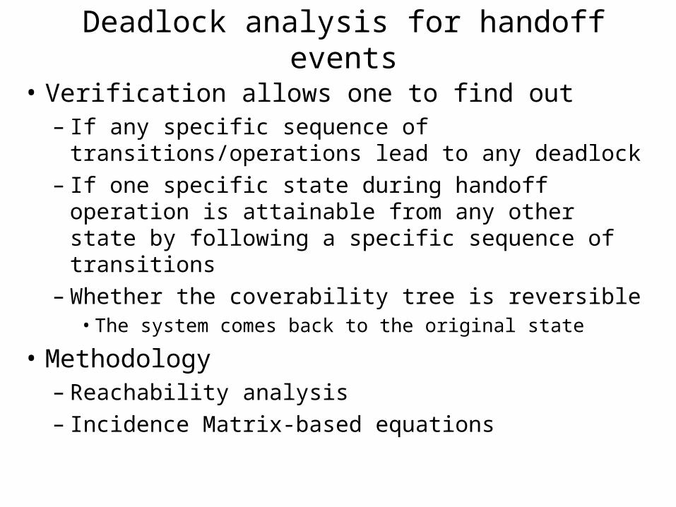
Deadlock analysis for handoff events
• Verification allows one to find out – If any specific sequence of
transitions/operations lead to any deadlock– If one specific state during handoff operation is
attainable from any other state by following a specific sequence of transitions
– Whether the coverability tree is reversible• The system comes back to the original state
• Methodology– Reachability analysis– Incidence Matrix-based equations

Untimed Concurrent (Resource deadlock) – (MATLAB)

Deadlock avoidance for concurrent operations(by adding resources)

Simultaneous Mobility (No deadlock)

Simultaneous Mobility (Deadlock due to incomplete binding update)

Simultaneous Mobility (Deadlock avoidance)
(By use of retransmission techniques)
Conclusions• This thesis contributes to the general theory of optimized
handover – It addresses the need for a formal systems model that can
characterize a mobility event, associated optimization methodologies and can provide handoff performance predictions
• Developed Petri net models for handoff that can – analyze the behavioral properties (e.g., deadlock)– validate systems performance of any type of handoff optimization – define handoff schedule to obtain a specific systems performance
• Developed optimization techniques across several layers and verified these techniques by applying these to several experimental case studies
• Based on the results derived a set of fundamental principles of systems optimization for handoff that include protocol design methodologies and guidelines that will enable deployment of right set of mobility protocols and optimization techniques

Future Work• Current Petri net model can be enhanced to study
mobility in ad hoc networks• Enhancement to generate automatic schedule of
handoff operations given a set of resource constraints, performance objectives and dependence graph
• Ability to design a customized mobility protocol that will define its own set of elementary operations for each of the desired handoff functions
• Future models should consider resource utilization among the network components (e.g., Access point, router, server) in a distributed fashion
• I envision specification of the functional components of mobility protocols and tools that search for context specific optimizations, such as caching, proactive feature and cross layer techniques

Backup slides(detailed results, mechanisms etc.)

Handoff Statistics• Handoff rate depends upon the following parameters
– Average cell size– Mobile’s speed (e.g., vehicular, pedestrian)– Average call duration– Cell capacity
• Example
Micro-cellular campus environment: A user is subjected to 8 to 10 handoffs per day
Macro-cellular environment: A regular commuter in USA is subjected to an average of 2 to 6 handoffs per day
• Average one-way commute is 16 miles• Cell site coverage varies from 5 miles to 15 miles• In a heavily dense area cell sizes are small to accommodate capacity
• Percentage of Handoff related signaling– Handoff related signaling amounts to about 2% of the total data traffic that a user is subjected to– Average user spends 700 minutes/month for voice = 23 minutes/day = 13*60*23 kbits/day = 2 Mbytes/day– Data usage - 90 Mbytes/month = 3 Mbytes/day– Thus, total data and voice should be about 5 Mbytes– Handoff related signaling messages – 70 kbytes/per day (MIPv6) , 100 Kbytes/day SIP– Handoff related signaling amounts to about 2% of the total traffic

Timing sequence for MPA (proactive handoff)
R2MNCNDHCP
RTP
PANA DHCP
PANA (ACK)
SIP Re_INVITE (IP1)56.359
56.478
56.582
RTP (39835)
OK
ACK
56.722
12.498
12.504
12.509
HandoffDecision
PANA Trigger to delete tunnel
RTP (42568)
RTP (42569)12.51312.52912.593
RTP (42573)
IWCONFIG (IOCTL)
RTP (42574)
12.585
(12.600)JOIN
(19.610)JOIN (ACK)(Auth/Assoc, ifconfig, route,)
L2 handoff+ local L3Configuration
PANA Response
RTP (42577)
BU
12.674
MNNetwork 1
Network 2 Network 3
First packet in new network (non-tunneled)
12.613Lost packet (in the tunnel)
DHCP(IP1)
RTP
RTP
Tunnel Deletedin PAA
RTP
X
First Tunneled Data
NoPackets lostDuring BU
Tunnel Setup
Signal
RTP Data
Lost RTP Data
Tunneled packet
RTP (42570)
OK (tunneled)
RTP packetsSpaced ~16-20 ms
IP0
IP1
RTP (42575)X
X
Lost packet (in the tunnel)
Lost packet (in the tunnel) RTP (42576)12.633
12.653

Review of Research ProgressTime
Line
Work Progress
at the proposal
Status
at the defense
Identification of handoff components Completed Completed
Design and proof of concept mobility optimization for handoff components
Completed Completed
Systems prototype verification of optimization methodologies
Completed Completed
Initial IP-mobility systems modeling Completed Completed
July
2008
Complete the validation of up to 4 optimization techniques using Petri net models
Working Completed
September
2008
Develop methodology for minimizing handoff using Petri net
Working Completed
November
2008
Tradeoff design of proactive handoff scheme
Working Completed
December
2008
Thesis writing Completed
March 2009 Thesis defense Present

Mobility systems modeling using Timed Petri netProblem• Mechanisms and design principles for
optimized handover are poorly understood• No formal methodology to systematically
discover or evaluate mobility optimizationsApproach• Identification of the fundamental properties
that are rebound during handover event• Systematic analysis of the primitive
handover operations• Modeling of the handover process that
allows performance predictions to be made for both an un-optimized handover and for specific optimization techniques under systems resource constraints
Results• Timed Petri net-based mobility models for
handoff processes using MATLAB and Time Net Tools
• Verification of optimization techniques• Prediction of handover performance under
some resource constraints (e.g., battery, CPU and network bandwidth)
NetworkResourceDiscovery
ConfigurationProcess
NetworkAttached
MobileConfigured
NetworkDetectionProcess
P1 P2 P3P0t2
t3
p01
p02
p03
t01
t02 t03ChannelDiscovery
Subnet discovery
Serverdiscovery
P11 P12 P13
t11 t12 t13
NetworkDiscovered
p21
p22
p23
L2association
Routersolicitation
DomainAdvertisement
t22
t21
t23
t1
Identifieracquisition
DuplicateAddressDetection
Addressresolution
PA
CPU
MemoryPB
4-way handshakecompletet2
t3 t4
P2
P3
t1
Scanning
Authentication
NetworkDiscovered
4-wayHandshakeOperation
P1
ResourcesNetwork b/w
MobileAuthenticated
ConnectedAssociation
P0
P01
P02
2
2
Figure 2: Concurrent handoff operations
Figure 1: Timed Petri net modeling for handoff

Resource Usage –Configuration
Functions Tasks Resources Needed (Equivalent Tokens)
Battery
Power
Bandwidth CPU
cycles
Configuration Identifier Acquisition 1 1 1
Duplicate Address
Detection
3 3 1
Address resolution 3 2 1

Relevant Petri net representation to capture handoff primitives
t1 t2b. Conflict
P1
p1
p2
p1
p2
p1
p2
t1
t2
t3
f. Confusion
P1 t1 t2 P3
a. Sequential
c. Concurrent
p1
p2
t1
t2
P3
e. Merging
p1
p2 p3
t1
t2
g. Mutual exclusiveh. Priority
Techniques appliedfor mobility modeling
t1
d. Data dependency

ConnectedP8
Disconnected
NetworkDiscovered
NetworkAttached
MobileConfigured
AuthenticatedSecurityAssociationEstablished
Updated
NetworkResourceDiscovery Network
SelectionDetectionProcess Configuration
Process
AuthenticationProcess
Binding Update
MediaForwarding
P1 P2 P3
P4P5P6
P0
t1
t2t3
t4
t5t6t7
P7
Intra-domainBinding update
t8t9BufferingRedirection
t0
p01
p02
p03
t01
t02t03
t013
t04
Security AssociationProcess
Modeling IP Mobility in Petri Net
Resource 1
Resource 2
Resource 3
Scanning
Subnet discovery
2

Data dependency analysis of handoff components Handoff Process Depends on data
from Set of Data it depends on
(Not a complete list)
P11 - Channel discovery P00 Channel broadcast
P12 – Subnet discovery P21,P22 L2 beacon ID, L 3 Router advertisement
P13 – Server discovery P12 Subnet address, Default router address
P21 – L2 association P11 Channel number, MAC address, Auth Key
P22 – Router Solicitation P21, P12 Layer 2 binding
P23 – Domain Advertisement P13 Server configuration, Router advertisement
P31 – Identifier Acquisition P23, P12 Default gateway, Subnet address, server address
P32 – Duplicate Address Detection P31 ARP, Layer 3 connectivity
P33 – Address Resolution P32, P31 New Identifier
P41 - Authentication P13, P22 Discovery of auth server
P42 – Key derivation P41 Availability of PMK, Layer 2 and Layer 3 association
P51 – Identifier update P31, P52 Layer 3 address, Verification of L3 address
P52 – Identifier verification -
P53 – Identifier mapping P51 HA, CN gets the new address (Identifier)
P54 – Binding Cache - Completion of identifier update
P61 – Tunneling P51 End-point addresses (router), identifier address
P62 - Forwarding P51, P53 New address of the mobile
P63 - Buffering P62, P51 New Identifier acquisition
P64 – Multicasting/bicasting P51 New identifier acquisition

Hierarchical Petri Net modeling using Timenet (Mobile IPv6) Discovery
AuthenticationSecurity Association
BindingUpdate
Configuration
MediaRe-routing

Why Petri net
• Petri nets can exactly model non-product form features such as priorities, synchronization, forking, blocking
• Can be used as both logical and quantitative models
• Forms the foundation for formal analysis models
• Strong analysis methods

Formal approach to mobility systems modeling
Problem:• Mechanisms and design
principles for optimized handover
are poorly understood• No formal methodology to
systematically discover or evaluate
mobility optimizations
Approach:• Framework or model that can
analyze the mobility event in a
systematic way, can verify and
predict the performance under
systems resource constraints

Formal approach to mobility systems modeling Problem• Mechanisms and design principles for
optimized handover are poorly understood• No formal methodology to systematically
discover or evaluate mobility optimizationsApproach• Identification of the fundamental properties
that are rebound during handover event• Systematic analysis of the primitive
handover operations• Modeling of the handover process that
allows performance predictions to be made for both an un-optimized handover and for specific optimization techniques under systems resource constraints
Results• Timed Petri net-based mobility models for
handoff processes using MATLAB and Time Net tools to
• Verification of these models • Prediction of handover performance under
specific resource constraints (e.g., battery, CPU and network bandwidth)
NetworkResourceDiscovery
ConfigurationProcess
NetworkAttached
MobileConfigured
NetworkDetectionProcess
P1 P2 P3P0t2
t3
p01
p02
p03
t01
t02 t03ChannelDiscovery
Subnet discovery
Serverdiscovery
P11 P12 P13
t11 t12 t13
NetworkDiscovered
p21
p22
p23
L2association
Routersolicitation
DomainAdvertisement
t22
t21
t23
t1
Identifieracquisition
DuplicateAddressDetection
Addressresolution
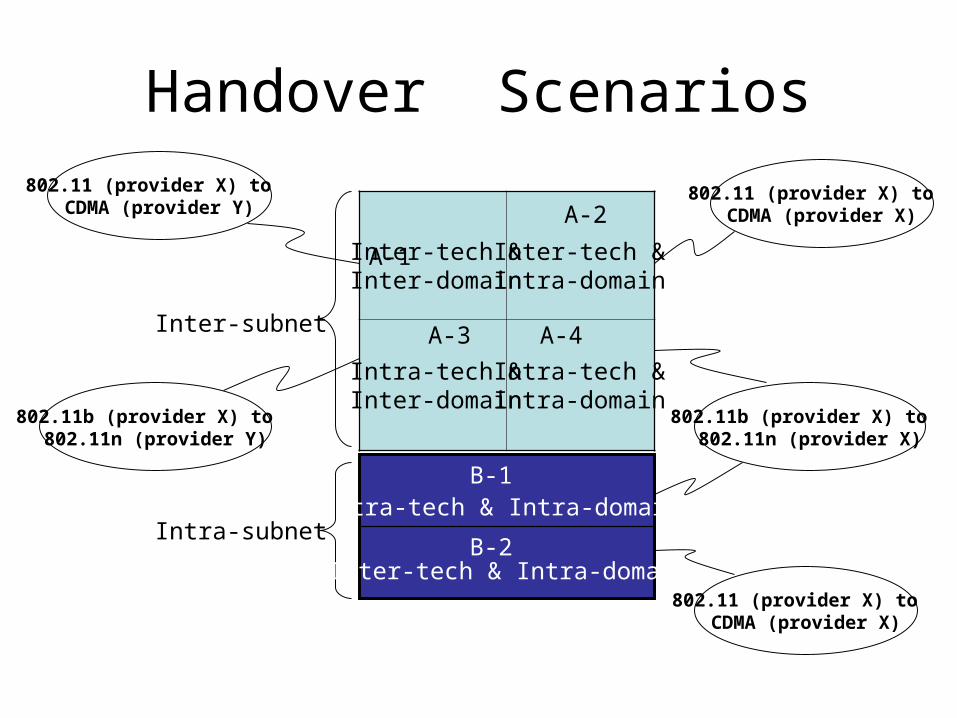
Handover Scenarios
A-1 A-2
Inter-subnet
Intra-subnet
Intra-tech &Inter-domain
Intra-tech & Intra-domain
Inter-tech &Inter-domain
Inter-tech &Intra-domain
Intra-tech &Intra-domain
802.11 (provider X) to CDMA (provider X)
802.11 (provider X) to CDMA (provider Y)
802.11b (provider X) to 802.11n (provider X)
802.11b (provider X) to 802.11n (provider Y)
Inter-tech & Intra-domain802.11 (provider X) to
CDMA (provider X)
A-3 A-4
B-1
B-2

Mobility/Function
AccessType
Network Discovery
Resource Discovery
TriggeringTechnique
DetectionTechnique
Configuration
Key exchange/Authentication
Encryption BindingUpdate
MediaRerouting
CDMA1X-EVDO
EVDO PILOTChannel
SYNCChannel
Channel
Strength
RTC TMSI Diffie-Hellman/CAVE
AES MSC PDSN/MSC
802.11 CSMA/CA
Beacon11R
11R802.21
SNR atMobile
Scanning.ChannelNumber,SSID
SSID,Channel number
Layer 2 authenticate802.1XEAP
WEP/WPA802.11i
Associate IAPP
Functional characteristics between CDMA and 802.11 networks

How to make the model useful for a realistic deployment
• How do the resource constraints and access characteristics affect the handover behavior during handover between heterogeneous access networks
• Single interface case– Between 802.11 networks
• Break-before-make case• Using virtual interface
• Multiple interface case– Between 802.11 and CDMA network
• Two cases– Make-before-break– Break-before-make

MIH Users
MIH Function
Lower Layers
MIH Users
MIH Function
Lower Layers
Local Entity Remote Entity
Remote Command
MIH
Eve
ntLi
nk E
vent
Remote Event
Link
Com
man
d
Rem
ote
Link
Co
mm
and
Remote IS Query/Response
Rem
ote
IS
Que
ry/R
espo
nse
IS
Que
ry/R
espo
nse
Rem
ote
MIH
Eve
nt
MIH
Indi
catio
n
MIH
Com
man
d
Related Documents