Dedicated to my kind and devoted parents Summer 2016 – London --------------------------------------------

Welcome message from author
This document is posted to help you gain knowledge. Please leave a comment to let me know what you think about it! Share it to your friends and learn new things together.
Transcript

Dedicated to my kind and devoted parents
Summer 2016 – London
--------------------------------------------

1
DISCIPLINE BREAKDOWN STRUCTURE
BRIDGING PROJECT MANAGEMENT AND SYSTEMS ENGINEERING TO FORM AN
INTEGRATED MANAGEMENT SYSTEM IN MULTIDISCIPLINARY RAIL PROJECTS
Hadi Sanei
A PhD thesis submitted in fulfilment
of the requirements for the degree of
Doctor of Philosophy
UCL Centre for Systems Engineering
University College London
2016
Under supervision of
Professor Alan Smith

2
Declaration
I, Hadi Sanei, confirm that the work presented in this thesis is my own. Where
information has been derived from other sources, I confirm that this has been indicated
in the thesis.
Signature:
Location: LONDON, UK
Date: 23 July 2016
© HADI SANEI
UCL CENTRE FOR SYSTEMS ENGINEERING
UNIVERSITY COLLEGE LONDON
LONDON, UNITED KINGDOM
JULY 2016
The copyright of this thesis remains with the author. No quotation or information
derived from this document may be published without the prior written consent of the
author.

3
Abstract…….
The complexity of multidisciplinary projects requires that many specialities and
disciplines work together. In rail infrastructure projects, the term ‘systems engineering
(SE)’ is being widely used, yet it is still loosely defined. This PhD thesis proposes the
use of a Disciplinary Breakdown Structure (DBS), an approach that better integrates SE
as it is currently understood with traditional project management (PM) to make PM
more efficient.
A review of PM, SE and their relationship, particularly in the rail sector, identified gaps
in performance, the most significant of which is a lack of integration between the SE
and PM activities. Case study material was examined and a survey was conducted. The
results highlighted the lack of consensus and consistency of the definition of SE and its
application by project practitioners at various levels. Interface management (IM) was
identified as a key factor contributing in project failure or success. IM was reviewed in
the context of SE and PM, and existing methods and solutions were examined.
The DBS as a new solution, was developed and introduced to improve the IM life cycle
from definition to closure. This solution is based on industry discipline sectors (in this case,
the rail sector) and therefore it is independent from project specific requirement. Exploring
more detail of the DBS revealed its capability in integrating SE and PM more generally.
The DBS is a modular solution (with a potential to become an industry standard) that
provides a basis for the rapid development of project-bespoke management systems,
improving PM efficiency by saving time and resources.
The approach has been tested in two major rail project case studies in the UK and one in
Canada and the results, benefits, constraints and the areas of improvements are
discussed in more detail.

4
Table of Contents
DECLARATION ............................................................................................................. 2
ABSTRACT……. ............................................................................................................ 3
TABLE OF CONTENTS ................................................................................................ 4
LIST OF FIGURES ...................................................................................................... 12
LIST OF TABLES ........................................................................................................ 16
ACKNOWLEDGEMENTS .......................................................................................... 18
ABBREVIATIONS ....................................................................................................... 19
FOREWORD……. ........................................................................................................ 21
CHAPTER 1 INTRODUCTION ........................................................................... 23
1.1. Research Background ................................................................................................................ 24
1.1.1. Systems Engineering in Construction (Rail) Projects ............................................................. 24
1.1.2. Systems Engineering and Project Management Integration .................................................. 25
1.1.3. Project Management Efficiency ................................................................................................ 26
1.1.4. Interface Management ............................................................................................................... 26
1.2. Research Problem Definition .................................................................................................... 28
1.3. Solution Development ................................................................................................................ 30
1.3.1. Solution Requirements Definition ............................................................................................ 31
1.3.2. Solution Requirements Analysis ............................................................................................... 32
1.4. Research Question Analysis ...................................................................................................... 33
1.5. Literature Review Structure ..................................................................................................... 34
1.6. Research Summary .................................................................................................................... 35
1.6.1. Research Scope ........................................................................................................................... 35
1.6.2. Work Packages ........................................................................................................................... 36
1.7. PhD Thesis Structure ................................................................................................................. 38

5
CHAPTER 2 RESEARCH APPROACH AND METHODOLOGY ................. 40
2.1. Introduction ................................................................................................................................ 41
2.2. Research Philosophy .................................................................................................................. 41
2.2.1. Ontology ...................................................................................................................................... 41
2.2.2. Epistemology .............................................................................................................................. 42
2.2.3. Paradigm .................................................................................................................................... 43
2.2.4. Objective ..................................................................................................................................... 43
2.2.5. Research Type ............................................................................................................................ 44
2.2.6. Mode of Enquiry ........................................................................................................................ 44
2.2.7. Research Methods ...................................................................................................................... 46
2.2.7.1. Case Study .................................................................................................................................. 46
2.2.7.2. Grounded Theory ...................................................................................................................... 46
2.2.7.3. Mixed-method ............................................................................................................................ 47
2.2.8. Data Collection Methods ........................................................................................................... 47
2.2.8.1. Survey/Questionnaire ................................................................................................................ 47
2.2.8.2. Interviews ................................................................................................................................... 48
2.2.8.3. Observation ................................................................................................................................ 49
2.2.8.4. Workshops .................................................................................................................................. 49
2.2.8.5. Data Triangulation .................................................................................................................... 50
2.3. Adopted Methodology ............................................................................................................... 50
2.3.1. Literature Review ...................................................................................................................... 52
2.3.2. Data Acquisition and Analysis .................................................................................................. 52
2.3.2.1. Survey ......................................................................................................................................... 52
2.3.2.2. Project Case Study ..................................................................................................................... 53
2.3.3. Solution Development ................................................................................................................ 54
2.3.4. Solution Verification and Validation ........................................................................................ 54
2.4. Ethical Considerations............................................................................................................... 55
2.5. Conclusion of the Chapter ......................................................................................................... 55
CHAPTER 3 PROJECTS, PROJECT MANAGEMENT AND SYSTEMS
ENGINEERING .............................................................................. 57
3.1. Introduction ................................................................................................................................ 58

6
3.2. Project and Project Management ............................................................................................. 59
3.2.1. Project ......................................................................................................................................... 59
3.2.2. Project Types .............................................................................................................................. 60
3.2.2.1. Type 1: Construction Projects .................................................................................................. 60
3.2.2.2. Type 2: Manufacturing Projects ............................................................................................... 60
3.2.2.3. Type 3: Management Projects .................................................................................................. 61
3.2.2.4. Type 4: Scientific Research Projects ........................................................................................ 62
3.2.3. Project Management .................................................................................................................. 62
3.2.4. Project Life Cycle ....................................................................................................................... 64
3.2.5. Project Success/Failure .............................................................................................................. 70
3.2.5.1. Successful Project Management for a Failed Project Scenario .............................................. 71
3.2.5.2. Failed Project Management for a Successful Project Scenario .............................................. 73
3.2.6. Key Factors Impacting Project Success ................................................................................... 74
3.3. Project Procurement Strategies in the Rail Sector ................................................................. 76
3.3.1. Rail Project Procurements Background .................................................................................. 77
3.3.2. Traditional Design, Build and Construct ................................................................................. 78
3.3.3. Design and Build or Engineering, Procurement and Construction ....................................... 79
3.3.4. Public Private Partnerships ...................................................................................................... 80
3.4. Project Management View of Interface Management ............................................................ 81
3.5. Systems Engineering .................................................................................................................. 85
3.5.1. Systems Engineering Background ............................................................................................ 86
3.5.2. Systems Engineering Definition ................................................................................................ 86
3.5.3. Systems Engineering Essential Procedures and Tools ............................................................ 88
3.5.4. Systems Engineering Life Cycle ................................................................................................ 89
3.6. Systems Engineering View of Interface Management ............................................................ 90
3.6.1. System (Project) Interfaces ....................................................................................................... 90
3.6.2. Systems Interface Management ................................................................................................ 91
3.7. Project Management and Systems Engineering Activities ..................................................... 94
3.7.1. Requirements Management ...................................................................................................... 94
3.7.1.1. Project Management View of Requirements Management .................................................... 97
3.7.1.2. Systems Engineering View of Requirements Management .................................................... 97

7
3.7.1.3. Requirements Allocation ........................................................................................................... 98
3.7.2. Scope Management .................................................................................................................... 98
3.7.3. Assumption Management .......................................................................................................... 99
3.7.4. Quality Management ............................................................................................................... 100
3.7.5. Resource Management ............................................................................................................ 101
3.7.6. Commercial Management – Budget and Cost ....................................................................... 101
3.7.7. Risk Management .................................................................................................................... 102
3.7.8. Issue Management ................................................................................................................... 102
3.7.9. Project Environment and Stakeholder Management ........................................................... 103
3.8. Integrated Management Tool ................................................................................................. 103
3.9. Conclusion of the Chapter ....................................................................................................... 104
CHAPTER 4 WORK BREAKDOWN STRUCTURES .................................... 106
4.1. Introduction .............................................................................................................................. 107
4.2. Work Breakdown Structure ................................................................................................... 108
4.2.1. Origins of the WBS .................................................................................................................. 108
4.2.2. WBS Definition in Literature.................................................................................................. 113
4.2.3. WBS Types ............................................................................................................................... 116
4.2.3.1. Product-based WBS ................................................................................................................. 117
4.2.3.2. Work-based WBS .................................................................................................................... 117
4.2.3.3. Organisation-based WBS ........................................................................................................ 117
4.2.4. Suitable WBS Type .................................................................................................................. 118
4.2.5. WBS Development ................................................................................................................... 119
4.2.6. WBS Dictionary ....................................................................................................................... 120
4.2.7. WBS Role .................................................................................................................................. 121
4.3. WBS and Interface Management ........................................................................................... 122
4.3.1. WBS Matrix.............................................................................................................................. 124
4.3.2. Design Structure Matrix .......................................................................................................... 125
4.4. Other Breakdown Structures .................................................................................................. 127
4.5. WBS Limitations ...................................................................................................................... 128
4.6. Systems Thinking in WBS Development ................................................................................ 128
4.7. Conclusion of the Chapter ....................................................................................................... 132

8
CHAPTER 5 SURVEY OF PRACTITIONERS ............................................... 134
5.1. Introduction .............................................................................................................................. 135
5.2. Survey Methodology ................................................................................................................ 135
5.3. Nature of Sample ..................................................................................................................... 138
5.3.1. Overall Sample – the ‘All’ ....................................................................................................... 139
5.3.2. Rail Targeted Sample – the ‘Rail’ .......................................................................................... 141
5.4. Decision Weight Factor ........................................................................................................... 142
5.5. Survey Results and Discussion ................................................................................................ 144
5.5.1. Opinion Ratio ........................................................................................................................... 145
5.5.2. Interface Management and Requirements Management Execution Quality ..................... 151
5.5.3. Work Breakdown Structure ................................................................................................... 155
5.5.3.1. WBS Development ................................................................................................................... 155
5.5.3.2. WBS Applications .................................................................................................................... 157
5.5.3.3. WBS Types ............................................................................................................................... 159
5.5.3.4. WBS and Systems Engineering ............................................................................................... 160
5.6. Conclusion of the Chapter ....................................................................................................... 162
CHAPTER 6 KEY FAILURE FACTORS IN A RAILWAY PROJECT CASE
STUDY ........................................................................................... 165
6.1. Introduction .............................................................................................................................. 166
6.2. Case Study Project Description .............................................................................................. 166
6.2.1. Programme Scope .................................................................................................................... 167
6.2.2. Case Study Project Scope ........................................................................................................ 168
6.2.3. Project Governance, Tools and Procedures ........................................................................... 170
6.3. Nature of Sample ..................................................................................................................... 172
6.3.1. Documents/Logbook Format .................................................................................................. 172
6.3.2. Data Set ..................................................................................................................................... 173
6.4. Study Methodology .................................................................................................................. 175
6.4.1. Data Selection ........................................................................................................................... 176
6.4.2. Data Analysis ............................................................................................................................ 179
6.5. Results and Discussion ............................................................................................................. 181
6.6. Conclusion of the Chapter ....................................................................................................... 184

9
CHAPTER 7 PROPOSED DISCIPLINE BREAKDOWN STRUCTURE
CONCEPT ..................................................................................... 186
7.1. Introduction .............................................................................................................................. 187
7.2. Discipline Breakdown Structure ............................................................................................. 187
7.2.1. DBS Concept ............................................................................................................................ 187
7.2.2. DBS Relation with WBS, PBS and OBS ................................................................................ 189
7.2.3. DBS Development .................................................................................................................... 190
7.2.4. DBS Format .............................................................................................................................. 191
7.2.5. Other Benefits of DBS ............................................................................................................. 192
7.3. Integration of the Management System ................................................................................. 193
7.3.1. DBS and Project Interfaces ..................................................................................................... 195
7.3.2. DBS and Project Scope/Requirements ................................................................................... 196
7.3.3. DBS and Project Deliverables ................................................................................................. 197
7.3.4. Management Activities Integration ........................................................................................ 197
7.4. DBS Project-specific Customisation ....................................................................................... 198
7.5. Project Information System .................................................................................................... 200
7.6. Conclusion of the Chapter ....................................................................................................... 200
CHAPTER 8 THE DBS APPLICATION IN RAIL STATION PROJECTS –
CASE STUDIES ............................................................................ 202
8.1. Introduction .............................................................................................................................. 203
8.2. CS1 – A Rail Station Upgrade Project in the UK, 2009 ........................................................ 203
8.2.1. CS1 Introduction ...................................................................................................................... 203
8.2.2. CS1 Systems Engineering Approach ...................................................................................... 205
8.2.3. Existing Project Systems Engineering and Project Management Activities, Tools and
Documents ................................................................................................................................ 206
8.2.4. Proposed Interface Management System Based on the DBS ............................................... 208
8.2.5. CS1 DBS Development ............................................................................................................ 208
8.2.6. CS1 Interface Management System Development ................................................................ 210
8.2.7. Management System Integration Based on the Proposed DBS............................................ 213
8.2.7.1. Requirements Management System ....................................................................................... 213
8.2.7.2. Design Deliverable List ............................................................................................................ 214
8.2.7.3. Compliance Process ................................................................................................................. 214

10
8.2.8. CS1 Proposed Verification and Validation System Tool ...................................................... 215
8.3. CS2 – A Rail Station Upgrade Project in the UK, 2011 ........................................................ 221
8.3.1. CS2 Introduction ...................................................................................................................... 221
8.3.2. CS2 Systems Engineering Approach ...................................................................................... 222
8.3.3. CS2 DBS Development ............................................................................................................ 222
8.3.4. CS2 DBS Adoption ................................................................................................................... 223
8.4. CS3 – A New Rail Station Design in Canada, 2012 ............................................................... 223
8.4.1. CS3 Introduction ...................................................................................................................... 223
8.4.2. CS3 Systems Engineering Approach ...................................................................................... 224
8.4.3. CS3 DBS Development ............................................................................................................ 224
8.4.4. CS3 DBS Adoption ................................................................................................................... 225
8.5. DBS Added Value .................................................................................................................... 225
8.5.1. CS1 Feedback and Testimonial .............................................................................................. 225
8.5.2. CS3 Feedback and Testimonial .............................................................................................. 227
8.6. DBS Template .......................................................................................................................... 229
8.6.1. DBS Comparison ...................................................................................................................... 229
8.6.2. DBS Adaptation Tool ............................................................................................................... 230
8.7. Conclusion of the Chapter ....................................................................................................... 230
CHAPTER 9 CONCLUSION AND FUTURE WORK .................................... 232
9.1. Introduction .............................................................................................................................. 233
9.2. Main Research Scope Recap ................................................................................................... 233
9.3. Research Need Justification .................................................................................................... 234
9.4. Solution Development .............................................................................................................. 236
9.5. Research Key Conclusion Messages ....................................................................................... 237
9.5.1. Project Management and Systems Engineering .................................................................... 237
9.5.2. Interface Management and Requirements Management ..................................................... 238
9.5.3. WBS and Its Relationship to Project Management and Systems Engineering ................... 239
9.5.4. Discipline Breakdown Structure ............................................................................................. 240
9.5.5. DBS Testing – Case Study ....................................................................................................... 241
9.6. Future Work ............................................................................................................................. 242
9.6.1. DBS – an Industry Standard/Database .................................................................................. 242

11
9.6.2. Integrated Management System Application (Database) ..................................................... 242
9.6.3. Project Definition and Initiation ............................................................................................. 243
9.7. Dissemination ........................................................................................................................... 243
9.8. Conclusion of the Chapter ....................................................................................................... 244
REFERENCES…… .................................................................................................... 246
APPENDICES…… ..................................................................................................... 270
Appendix 1 Questionnaire/Survey ......................................................................................... 271
Appendix 2 Survey Cover Letters ......................................................................................... 283
Appendix 3 Survey Report Generated by Opinio ................................................................ 292
Appendix 4 Data Analysis Register ....................................................................................... 338
Appendix 5 Systems Engineering Architecture Based on the DBS..................................... 345
Appendix 6 CS1 – Discipline Breakdown Structure ............................................................ 347
Appendix 7 CS1 – Interface Control Matrix ........................................................................ 353
Appendix 8 CS1 – Interface Status ........................................................................................ 355
Appendix 9 CS1 – Interface Management System User Guide ........................................... 358
Appendix 10 CS1 – Validation and Verification System User Guide ................................... 371
Appendix 11 CS1 – Requirements Management System User Guide .................................. 384
Appendix 12 Visual Basic Codes for the Integrated Management System Developed Based
on the Proposed DBS ............................................................................................................... 397

12
List of Figures
Figure 1: Research Thoughts Structure .................................................................................................... 30
Figure 2: Solution Development – V Life Cycle.................................................................................... 31
Figure 3: Literature Review Structure ...................................................................................................... 35
Figure 4: An Integrated Management System ........................................................................................ 36
Figure 5: The Iron Triangle ......................................................................................................................... 64
Figure 6: Mapping the Different Project Life Cycle Phases ................................................................ 66
Figure 7: Alignment of Existing Plans of Work (Churcher and Richards, 2015) ........................... 68
Figure 8: Integrated Project Life Cycle .................................................................................................... 69
Figure 9: Project Management Success versus Failure Using the Iron Triangle ............................ 70
Figure 10: Project Management Success versus Failure ...................................................................... 72
Figure 11: New Procurement Strategies and Risk Allocation ............................................................. 81
Figure 12: System Development Waterfall Life Cycle (Stevens et al., 1998) ................................. 89
Figure 13: System Development V-Model Life Cycle (Stevens et al., 1998) ................................. 90
Figure 14: Project Decomposition ............................................................................................................. 92
Figure 15: Interface Identification – Interface Matrix........................................................................... 93
Figure 16: Interface Allocation to the Sub-system Suppliers .............................................................. 93
Figure 17: Interface Closeout – Evidence and Certificate.................................................................... 94
Figure 18: Reduction of Cost and Duration during Design Development ........................................ 96
Figure 19: Project Management Breakdown Structures ....................................................................... 99
Figure 20: Work Breakdown Structure – 1961 (Haugan, 2002) ....................................................... 109
Figure 21: Surface Vehicle Systems Work Breakdown Structure and Definitions (US
Department of Defense, 2011).................................................................................................................. 112

13
Figure 22: Five Functional Aspects for Interface Management (Chua and Godinot, 2006) ...... 123
Figure 23: Part of a WBS Matrix Developed for the Case Study of a Transportation Project
(Chua and Godinot, 2006) ......................................................................................................................... 125
Figure 24: Example of an N2 Diagram for Typical WBS (PBS Level) around PBS with No
Systems Thinking ........................................................................................................................................ 129
Figure 25: Systems Thinking Alignment with WBS Development Process .................................. 130
Figure 26: Example of an N2 Diagram – WBS (PBS Level) with System Design Level and
Relation to the Sub-systems ...................................................................................................................... 131
Figure 27: Survey Participant Demographical View for the ‘All’ Sample .................................... 140
Figure 28: Survey Participant Demographical View for the ‘Rail’ Sample ................................... 142
Figure 29: Decision Weight Factors’ Relations to Decisions Made in Major Rail Projects ...... 144
Figure 30: Opinion Ratio for IM and RM Responsibility for the ‘All’ Sample ............................ 148
Figure 31: Opinion Ratio for IM and RM Responsibility for the ‘Rail’ Sample .......................... 150
Figure 32: Q17, 18, 24, 34 and 35 Results Proportions ...................................................................... 153
Figure 33: WBS Development Paths ...................................................................................................... 157
Figure 34: Number of WBS Forms Used in the Same Project .......................................................... 157
Figure 35: WBS Incorporated in Project Tools and Applications .................................................... 158
Figure 36: Single Form WBS Incorporation into the Project Tools and Applications ................ 159
Figure 37: WBS Structure ......................................................................................................................... 160
Figure 38: SE Application and Relationship with WBS ..................................................................... 161
Figure 39: Case Study Project within the Programme ........................................................................ 167
Figure 40: ECF Project Team Structure ................................................................................................. 170
Figure 41: Comment Logbook Template ............................................................................................... 173
Figure 42: Sample Period for the Purpose of This Research ............................................................. 177
Figure 43: Snapshot of the Combined Results Register of 2,179 Reviewed and Analysed
Comments ..................................................................................................................................................... 180

14
Figure 44: Discipline Leads’ Number of Comments ........................................................................... 181
Figure 45: Comments Distribution Based on the Main Reasons/Activities ................................... 182
Figure 46: Data Breakdown Based on Sensitivity Factor................................................................... 183
Figure 47: Comments Sensitivity in Relation to IM, RM and V&V ............................................... 184
Figure 48: DBS Model Example for a Component in a Rail Project ............................................... 188
Figure 49: DBS Relation with WBS, PBS and OBS ........................................................................... 190
Figure 50: Life Cycle of the DBS Development and DBS Use Proposed in This Study ............ 191
Figure 51: DBS Tree Model and Levels Proposed in This Study .................................................... 192
Figure 52: PM and SE Activities and Relationship through Breakdown Structures .................... 194
Figure 53: DBS Concept to Form an Integrated Management System ........................................... 195
Figure 54: Interface Management System Adopting DBS on a DSM Structure ........................... 196
Figure 55: Requirements Management System Codification Concept Based on the DBS ......... 196
Figure 56: Project Deliverable List Codification Concept Based on the DBS .............................. 197
Figure 57: Integrated Approach for the Systems Engineering and Project Management Activities
......................................................................................................................................................................... 198
Figure 58: Customising the DBS Based on the Project-specific Requirements ............................ 199
Figure 59: Project Information System Based on the DBS ................................................................ 200
Figure 60: SE-related Documents Issued by Hadi Sanei .................................................................... 205
Figure 61: DBS Development for CS1 ................................................................................................... 209
Figure 62: Interface Management System Process Flow ................................................................... 210
Figure 63: Interface Management System Process Including Location Information ................... 213
Figure 64: ICM Developed Based on the Proposed DBS for CS1 ................................................... 216
Figure 65: Interface Control Document developed for CS1 .............................................................. 217
Figure 66: LBS Cross-check against ICM developed for CS1.......................................................... 218
Figure 67: Codification of the Project RMS Based on the DBS developed for CS1 ................... 219

15
Figure 68: Snapshot of the DDL Codified by the DBS developed for CS1 ................................... 220
Figure 69: Integrated Management System Architecture Developed for CS1 .............................. 221
Figure 70: Developing the DBS for CS2 Based on the DBS Template Developed for CS1 ...... 222
Figure 71: DBS Template Development Comparison ........................................................................ 229

16
List of Tables
Table 1: Solution Requirements Analysis and Work Required in This Research .......................... 32
Table 2: Research Structure and Deliverables ........................................................................................ 37
Table 3: The Differences between Quantitative and Qualitative Research (Kumar, 2005) ......... 45
Table 4: Overview of Research Objectives, Methods and Outcomes ............................................... 51
Table 5: The Five-dimensional Success Model (Shenhar and Dvir, 2007) ...................................... 74
Table 6: Famous Project Failures (Bahill and Henderson, 2004, BBC, 2014b) .............................. 75
Table 7: Key Dates in the Origins of Systems Engineering as a Discipline (INCOSE, 2006) .... 86
Table 8: Reasons for Project Failure (Alexander and Stevens, 2002) ............................................... 96
Table 9: Development Key Stages of the WBS Concept over Time from 1957 to 2011 ............ 113
Table 10: WBS Definition – Changes by Version (Norman et al., 2008) ...................................... 116
Table 11: Typical Selection of the Type of WBS Development Based on Different Types of
Projects........................................................................................................................................................... 119
Table 12: WBS Levelling Comparison with Two Alternate Approaches That Include Systems
Thinking ........................................................................................................................................................ 131
Table 13: Survey Distribution .................................................................................................................. 136
Table 14: Survey Participant Demographical Distribution for the ‘All’ Sample .......................... 139
Table 15: Survey Participant Demographical Distribution for the ‘Rail’ Sample ........................ 141
Table 16: Survey Numerical Results for RM and IM Responsibility – Opinion Ratio ............... 147
Table 17: Survey Numerical Results for IM and RM Execution Quality ....................................... 152
Table 18: Q17, 18, 24, 34 and 35 Results Scoring ............................................................................... 154
Table 19: Q17, 18, 24, 34 and 35 Mean Score Calculations ............................................................. 155
Table 20: Survey Q19 Structure ............................................................................................................... 156
Table 21: Survey Question 19 – Detailed Results................................................................................ 156

17
Table 22: Survey Numerical Results for WBS – SE Relationship ................................................... 161
Table 23: Q23 Results Scoring ................................................................................................................. 162
Table 24: Q23 Mean Score Calculations ................................................................................................ 162
Table 25: Full Data Set............................................................................................................................... 174
Table 26: Categorising the Full Data Set into a Short List of Data to be analysed in This
Research ........................................................................................................................................................ 178
Table 27: Main Reasons and Activities for Data Analysis ................................................................ 179
Table 28: Breakdown of the Comments Based on the Nature of Issue ........................................... 182

18
Acknowledgements
Firstly, I would like to express my sincere gratitude to my supervisor, Professor Alan
Smith, for his continuous support, patience, motivation and immense knowledge. His
guidance helped me throughout the research and writing of this thesis.
Besides my advisor, I would like to thank the rest of my thesis committee, Professor
Graziella Branduardi Raymont, Dr Michael Emes, Mr Matt Whyndham and Dr Rahul
Rahul Phadke, for their insightful support, comments and encouragement, but also for
the hard questions which inspired me to widen my research to include various
perspectives.
My sincere thanks goes to the current and former CH2M (formerly Halcrow) senior
management team, Professor Tim Broyd, Mr James Rowntree, Mr Sam El-Jouzi, Mr
Rob Kaul, Mr Mike Birch, Mr Ian Scrowston and Mr Steve West, who provided me
with opportunity, facility and funding to make this part-time study possible.
I would like to thank my colleagues in various firms, Mr Ken Foster, Dr Vasileios
Vernikos, Mr Martyn Noak, Mr Reece Baily, Mr Alex Siljanovski, Mr Eddie Walters,
Mr John Parsons, Mr David Ellis and Ms Virginia Borkoski, for their support, feedback
and help in the project case studies and data gathering.
I would like to thank my two greatest professional mentors, Mr Ken Foster and Mr
Javid Shahriari. I would not have achieved what I have now in my professional life
without their constant support and encouragement.
I would like to thank my dear brother, Dr Hamed Sanei, for his encouragement and
personal support. He has been a source of inspiration in all aspects of my personal life.
Many other colleagues, friends and family members supported me through this long
journey. I would like to thank all of them for their great support and encouragement.
Finally, my last word is for the love of my life, my wife, Neda. Your love, patience,
support and encouragement made this journey possible. This would not have
happened without you. I love you and thank you for all you have done!

19
Abbreviations
APM Association for Project Management
APM BoK APM Body of Knowledge
BM Business Manager
CBS Cost Breakdown Structure
CM Change Management
CMS Cable Management System
CoM Configuration Management
CS Case Study
D&B Design and Build
DBS Discipline Breakdown Structure
DoD Department of Defense
DSM Design Structure Matrix
DWF Decision Weight Factor
ECF Engineering Consulting Firm
ECI Early Contractor Involvement
EPC Engineering, Procurement and Construction
ICD Interface Control Document
ICM Interface Control Matrix
IEC International Electrotechnical Commission
IEEE Institute of Electrical and Electronics Engineers
IM Interface Management
IMS Interface Management System
INCOSE International Council on Systems Engineering
IOS International Organization for Standardization
JV Joint Venture
LBS Location Breakdown Structure
LRT Light Rail Transit
MEP Mechanical, Electrical and Plant
MIT Massachusetts Institute of Technology
MOE Margin Of Error
MR Main Reason
MRQ Main Research Question
MRS Main Research Scope
NASA National Aeronautics and Space Administration
NEC New Engineering Contract
OBS Organisation Breakdown Structure
OR Opinion Ratio
PBS Product Breakdown Structure
PC Project Control (support) professional
PDL Project Deliverable List
PERT Program Evaluation and Review Technique
PFI Private Finance Initiative
PLC Project Life Cycle
PM Project Management
PMBOK Project Management Book Of Knowledge
PMI Project Management Institute

20
PPP Public Private Partnership
QM Quality Management
RACI Responsible, Accountable, Consulted, Informed
RIBA Royal Institute of British Architects
RM Requirements Management
RMS Requirements Management System
SAGE Semi-Automatic Ground Environment
SE Systems Engineering
SEMP Systems Engineering Management Plan
ST Systems Thinking
TQ Technical Query
TS Technical Solution
UCL University College London
V&V Verification and Validation
VB Visual Basic
WBS Work Breakdown Structure
WI Work Information
WP Work Package

21
Foreword…….
I started this research in 2009, the second year of my career as a junior systems engineer
in the UK Rail sector of Halcrow Group Ltd. Prior to this, I spent nearly 10 years
working as project manager and business manager in the information technology sector,
holding an engineering degree in computer hardware. In 2004, I moved to the UK and
completed a master degree in computer networks in 2006. In my master programme, I
worked on a research programme in the modelling of queuing systems with Markov
processes to evaluate systems performance for which I developed a mathematical
solution, to model multi-processor systems with breakdown and repair, overcoming the
‘state space explosion’ problem. The result of this research was documented in my MSc
thesis, ‘Approximate solution for 2-dimensional Markov processes modelling multi-
server systems prone to breakdowns’ (Sanei, 2006) for which I received a Master with
Distinction degree. I also worked as a co-author with my supervisors, Dr Orhan
Gemikonakli and Dr Enver Ever and presented my research papers in international
conferences in this field (Sanei, 2006, Gemikonakli et al., 2007, Ever et al., 2008).
In 2009, when this research programme started, systems engineering (SE) was relatively
new in the rail industry and many people had no or very limited understanding of its
role, scope and benefit to projects. Although many of the key clients in the rail sector,
including Transport for London and Network Rail, were beginning to mandate the
discipline for their projects, there was still not enough understanding across the
business. On the project sites, some were mistaking the systems engineers with rail
systems engineers and so were engaging them in very technical railway system
discussions, while others were seeing them as experts in information system and
technology.
The SE identity crisis in industry became even more interesting for me after reading
‘Confronting an identity crisis—how to “brand” systems engineering’ (Emes et al.,
2005). I therefore tasked myself to increase awareness within the rail sector, starting
from the Halcrow office.
To begin, I gathered various quotes about systems engineering definition from people in
industry into a short document entitled ‘What is systems engineering?’ While I was

22
educating myself, I was also trying to collect and share information with others in
different forms. Later, I published an internal company paper on systems engineering
entitled ‘Requirements management’, in which I outlined a practical definition for SE
and, more specifically, requirements management (RM). In this document, I also
demonstrated the benefits of adopting SE and RM to save time and resources in project
delivery (Sanei, 2007).
But the lessons learnt from these activities showed that while more effort is necessary to
more define SE as a key role in PM, more constructive work was required to develop
more a systematic approach for managing the interfaces in such multidisciplinary
projects. For this reason in 2009, I started this research in the form of a part-time PhD
programme at UCL while I was working for Halcrow as an interface manager for the
railway system design of the AMG line project in Kuala Lumpur, Malaysia – a major
national light rail train system with 19 km of elevated route and 12 new stations.
During this journey, I worked on various other large national and international
infrastructure rail projects in the UK, Malaysia, Indonesia, India, Qatar, Brazil and
Canada. I held many different roles and responsibilities, including systems engineer,
requirements manager, interface manager, project manager, systems integration
specialist, quality assurance manager and risk manager. Such a diverse work experience
gave me a chance to gain practical experience and unique perspective of the systematic
thinking in managing projects of this kind. The observations and the data gathered over
the past 7 years have been crucial to support this research.
Hadi Sanei – Summer 2016

23
Chapter 1 INTRODUCTION
RESEARCH BACKGROUND 24
RESEARCH PROBLEM DEFINITION 28
SOLUTION DEVELOPMENT 30
RESEARCH QUESTION ANALYSIS 33
LITERATURE REVIEW STRUCTURE 34
RESEARCH SUMMARY 35
PHD THESIS STRUCTURE 38

Chapter 1 Introduction ----------------------------------------------------------------------------------------------------------------------------------------
24
1.1. Research Background
1.1.1. Systems Engineering in Construction (Rail) Projects
Construction projects are becoming larger and more complex (Shokri et al., 2012,
Shokri et al., 2015), involving multiple suppliers and sub-suppliers from project design
to implementation, testing and completion. These suppliers and sub-suppliers have
different responsibilities in a given project to deliver different parts; they also have
different work cultures, backgrounds and, in many cases, work locations.
In recent railway projects, multinational contractors often work together to deliver a
piece of a design package. Difficulties with integration among these suppliers is
becoming a major risk to the project, and project managers require integrated
approaches to overcome this risk. The systems engineering (SE) approach has been
introduced to support project management (PM) to overcome part of these difficulties
(Locatelli et al., 2014, Emes et al., 2012, Sharon et al., 2011, Calvano and John, 2004,
INCOSE, 2004, Elliott, 2014, Elliott et al., 2011).
In the UK Rail sector, the requirement to adopt an SE approach and to provide evidence
of compliance in the delivery of design and build projects began to appear in the
literature in the late 1990s and early 2000s. The first general SE standard – IOS/IEC
15288, which covers processes and life cycle stages – was first shaped in 1994 and was
formally issued in 2002 (IEEE, 2002). Also among the first systems engineering
standards in the rail sector was the London Underground Ltd LUL-1-209 standard,
which was issued in 2007 and revised in 2009. This standard was issued to mandate the
use of the SE in the UK railway projects (London Underground Ltd., 2009).
When the author started working in the rail sector as a systems engineer in 2007, the
role was mainly limited to develop Systems Engineering Management Plans (SEMPs)
which detailed processes, procedures and data/information flow. Only some technical
parts of such plans were put into practice. The SEMP in a given project, depending on
its size and complexity, covered various sections that sometimes overlapped with the
Project Management Plan. The SEMP produced for the detailed design phase of a major
station upgrade project in London, for example, covers the life cycle model;
requirements management (RM); interface management (IM); project information
model; project change control; human factor; issue/risk and assumption management;

Chapter 1 Introduction ----------------------------------------------------------------------------------------------------------------------------------------
25
electromagnetic compatibility/electromagnetic interference; reliability, availability and
maintainability; operability and maintenance assurance; and verification & validation
(V&V) (Parsons and Wareham, 2010). In the SEMP developed for a Canadian
Crosstown Light Rail Transit Station Design project in Toronto, however, only life
cycle model, RM, IM, project information model and V&V were planned due to
different project characteristic and scopes (Sanei, 2011). Review of various other
SEMPs in different projects of different types indicates that the following three SE
activities are the mostly common topics in the SEMP documents:
1. Interface and Integration Management Plan
2. RM Plan
3. V&V Plan
1.1.2. Systems Engineering and Project Management Integration
It was observed by the author when this research started that in many of the major
projects, there was no practical connection between procedures developed in a SEMP
and the functions of project management; ‘systems engineering in silo’ was a common
theme in rail sector projects. As an example, in two major capital projects, it was
observed that the design supplier issued the SEMP when the design was almost
completed merely to demonstrate compliances with the project deliverables. This
demonstrates a bigger issue, as not only was the supplier not practicing the SEMP, but
the client never asked for it in progress audits.
It also was observed by the author that on rail infrastructure projects, senior managers
with many years of experience tend to manage the projects on their own classic way. In
some cases they completely dismiss SE because they see no value other than a complete
duplication of overhead and effort to their PM role. Recently, however, the good work
of many researchers and practitioners, as well as events organised mainly by the
International Council on Systems Engineering (INCOSE), have resulted in better
understanding among project managers, many of whom show a greater interest in
understanding and applying an SE approach on their PM functions. This also could be
driven by the shift in clients’ attitudes toward the use of SE in the project delivery as
they begin to understand its benefits to their projects – not only in relation to time and
budget, but also in additional confidence in the quality of deliverables. Some

Chapter 1 Introduction ----------------------------------------------------------------------------------------------------------------------------------------
26
researchers even focus on adopting an SE approach in the middle of the process to
further support these benefits.
1.1.3. Project Management Efficiency
Cost, time and quality known as the famous Iron Triangle are the main three project
constraints that should be satisfied by any project (Atkinson, 1999, Elliott, 2014).
In this research, therefore, making the project more efficient means improving the
project management to save time and cost where and how it is possible, while
complying with high quality standards.
1.1.4. Interface Management
The initial thoughts for this research emerged when the author worked as a systems
engineer to develop and adopt a systematic IM process for the design life cycle of a
major rail station modernisation and expansion project in central London. In this
project, IM was the area of interest for both PM and SE and, therefore, some believed
that IM was an SE function, while others were convinced that IM was a natural PM
activity. In the design phase of this station modernisation project, the core responsibility
of the interface manager was identified as:
1) Capture and manage the design interfaces
2) Provide ownership for the interfaces to collect compliance evidence
3) Provide a tool to facilitate the IM processes
4) Provide a systematic approach to collect the evidence, saving time and resources
As the work continued, and the procedures developed, the work also covered:
5) Capturing the project requirements from various documents into an RM
repository
6) Categorising and assigning the requirements to the relevant parties/owners
7) Providing verification evidences against the requirements by linking the design
deliverables to the requirements
The intention was to develop a procedure viable for all parties using the existing
information, including:

Chapter 1 Introduction ----------------------------------------------------------------------------------------------------------------------------------------
27
Various documents (Project Scope Document, Requirements Specification,
Conceptual Design Statements, etc.), from which the requirements repository
could be developed
A Work Breakdown Structure (WBS) and organisational chart in the form of
Organisation Breakdown Structure, from which the interfaces between various
parties and teams could be captured
A list of deliverables registered in the document control management system
generated and delivered by various contractors at the completion of their works
An approved SEMP developed by the team at the early stage of the project
commission
The main challenges that needed to be addressed in order to develop the required
interface management procedure were identified as follows:
1. Identifying the interface points and relating them to the existing documents as
compliance/closeout evidence:
It was observed that the project team was identifying the interfaces and presenting
and discussing them in long, repetitive meetings and workshops. This was time
consuming and inefficient and carried a high level of risk for both the project and
the project team. The work was around different levels of information, and the
parties required access to different parts of the project/system in order to coordinate
the interfaces among parts of the system.
Therefore, the Interface Management Systems (IMSs) need to be based on an
information breakdown concept, as this is the only way that the parts involved in the
project could be identified and their interactions and interfaces points could be
captured, monitored and managed.
2. Creating ownership for the interfaces across the project:
It was observed that through various workshops, the project manager and project
engineering team agreed on the interfaces as they identified them and recorded the
interfaces in action registers. This could be more efficient if the interface points
were identified in advanced and could be communicated before the design took
place.

Chapter 1 Introduction ----------------------------------------------------------------------------------------------------------------------------------------
28
3. Creating a programme-wide V&V solution to verify and validate the compliance of
the project interfaces by relating the evidence/deliverables to the project interfaces
captured from various project documents or to the requirements identified within
data repository systems:
Engineering design projects have several types of deliverables in the form of
drawings, reports and other type of documents. These deliverables should provide
assurance on the compliance of the project interfaces and requirements. In this
station modernisation project, all the documents and deliverables were stored in a
document repository database. Therefore, a system was required to develop links
between the related deliverables and the project interfaces and requirements with
minimal input from suppliers. Thousands of interfaces and hundreds of requirements
were to be managed in this project. It was realised that the existing solutions in PM
were struggling to manage this volume with a low margin of error. It is important to
note that linking the deliverables to the interfaces is not the main issue; the
complexity is in forming a solution that can establish a basis to identify the
interfaces and expected evidences in advance of the design work.
4. Integrating an SE approach with PM:
Managing the requirements, managing the interfaces and providing assurance
through linking evidence to the requirements and interfaces are the common
functions between PM and SE. Therefore, integrating the SE approach with PM
through linking their tools and procedures is critical (Emes et al., 2012).
5. Facilitating reusability of the procedure in similar projects:
In developing any form of a procedure or system, it is critical to think about the
reusability of the procedure for similar projects in future. Therefore, the intention
was to develop a modular system based on series of templates so that it can be
customised and reused in similar projects.
1.2. Research Problem Definition
The main goal of this study is to make PM more efficient by formulating a solution to:

Chapter 1 Introduction ----------------------------------------------------------------------------------------------------------------------------------------
29
Improve IM as one of the key PM activities in multidisciplinary projects
Integrate SE and PM activities in managing projects
Considering the research background explained above, and the author’s observation and
experience in addressing the issue explained in a major project, the main research
question (MRQ) is summarised as follows:
How can SE and PM activities be better integrated to support project managers to
manage their multidisciplinary (rail) projects more efficiently?
(MRQ)
The work explained in the research background directed the attention of this research to
focus mainly toward managing the IM among various engineering disciplines. There are
many examples proving that projects of different scales fail due to the lack of proper
and systematic IM (see Chapter 3, Chapter 5, and Chapter 6). Therefore, PM could be
more efficient if an improved IMS can avoid reworks, thereby saving time and
resources by reducing unnecessary works/changes (Staats, 2014).
Figure 1 summarises the thought structure initiating this research to further divide the
MRQ to more verifiable sub-questions as follows:
Work to be performed:
1. Propose a solution based on a breakdown structure concept as it needs to
communicate with different layers/levels of project information
2. Apply the proposed solution to improve IM and developing an IMS
3. Apply the proposed solution to bridge the SE and PM activities to develop an
Integrated Management System
Results that will be achieved:
4. Improving IM and developing an IMS improves PM
5. Improving PM makes the project and its PM more efficient

Chapter 1 Introduction ----------------------------------------------------------------------------------------------------------------------------------------
30
Interface Management System Project & Project
Management (PM)
2. Improving IM
MRQ
How can SE and PM’s activities be better integrated to support project managers to
manage their multidisciplinary (rail) projects more efficiently?
Integrated Management System
Solution
1. Propose a solution based Breakdown Structure
Cost, Time, Quality (Performance)
3. Bridging SE and PM
5. Improving Project and PM efficiency
4. Improving PM Work need to be performed
Results that will be achieved
Figure 1: Research Thoughts Structure
The UK rail sector has been constantly working to adopt an SE approach to its projects.
As a result, almost any project within the UK rail sector requires the involvement of
some level of SE in the project. Therefore, more research is required to find more
solutions that support systems thinking (ST) and SE capabilities in various branches of
the rail sector, whether in management or in engineering. This will not only be a great
contribution to the SE world, but will also provide more scientific evidence as
justification for rail sector projects to invest in adopting systems thinking and SE.
The result of this research aims to contribute to the world of SE by providing some level
of efficiency to PM.
1.3. Solution Development
Figure 2 presents a simple V-model used for the life cycle of the solution development
in this research project.

Chapter 1 Introduction ----------------------------------------------------------------------------------------------------------------------------------------
31
Scope Definition
Req. Definition
Req. Verification
Scope Validation
Implementation (i.e. works to be performed)
Figure 2: Solution Development – V Life Cycle
1.3.1. Solution Requirements Definition
As the first step, the requirements specification for the solution should be explored
based on the MRQ. Considering the ‘work to be performed’ identified in the MRQ (see
Figure 1), the following scope analysis is conducted to develop more specific
requirements for the solution.
Propose a solution based on a breakdown structure concept as it needs to
communicate with different layers/levels of project information
Requirement 1. The solution must be based on the breakdown structure concept,
a ‘divide and conquer’ approach.
Requirement 2. The solution must be useful for both SE and PM to form an
integrated management system – ‘bridging PM and SE activities including
functions, tools and procedures’.
Managing interfaces in a multidisciplinary rail project is essential. As noted,
such projects involve interfaces between many different groups and suppliers. As
presented in Figure 1, the focus is working to improve IM as one of the factors
contributing in improvement of the project efficiency.
Requirement 3. The solution must provide a systematic way to identify and
visualise the interface points and locations.
Requirement 4. The solution must provide a systematic way to allocate and
assign the interfaces to the relevant parties/owners.

Chapter 1 Introduction ----------------------------------------------------------------------------------------------------------------------------------------
32
Requirement 5. The solution must be usable in creating a systematic data
repository to link the project deliverables (as evidence) to the interfaces to
demonstrate that the project has addressed the interface issues.
Further requirements must also be met in the solution:
Requirement 6. The solution must be usable to create a structure to develop
tractability among all other PM documents.
Requirement 7. The solution must be modular and reusable for the projects of the
same kind in a bespoke form.
Requirement 8. The solution must provide time and resource savings.
1.3.2. Solution Requirements Analysis
The scope of the research as well as the requirements for the solution are analysed in
Table 1 to develop the work packages (WPs) necessary for this research life cycle.
Table 1: Solution Requirements Analysis and Work Required in This Research
Req. Work Required
Req. 1
The WBS is a common tool based on the ‘breakdown structure’ concept used in
PM in recent decades. Therefore, a review of literature is required to understand
its origin, definition and existing use in IM and PM. Also, any other breakdown
structure based concepts need to be reviewed. Further research and data are also
required in projects where WBS is used to further justify the usability of the
concept to achieve the objective of this research.
Req. 2
The Project and PM need to be reviewed and understood in order to design a
solution that will benefit the efficiency of projects. Also, case study projects
should be reviewed and analysed to assess project efficiency and explore the key
failure factors.
The SE concept needs to be reviewed because the goal is to develop a solution to
integrated SE and PM activities.

Chapter 1 Introduction ----------------------------------------------------------------------------------------------------------------------------------------
33
Req. Work Required
Req. 3,
4 and 5
The main focus of this research is to develop a solution that will improve IM.
Therefore, research in the area of IM is required. It is important to understand why
IM is necessary and how it impacts projects (with examples).
It is also necessary to analyse projects to understand how IM is practiced and how
IM impacts project efficiency.
It is also required to conduct research on other similar existing work in this area,
for example, the Design Structure Matrix (DSM) concept and WBS Matrix.
Req. 6,
7 and 8
These are the requirements needing to be met in the solution, including a tool that
is modular, reusable and can be used across the project.
1.4. Research Question Analysis
From the research background, problem and thoughts structure, along with the
requirements developed for the solution, the MRQ is analysed further to develop sub-
questions this research needs to answer. The MRQ and the sub questions are as follows:
How can SE and PM activities be better integrated to support project managers to
manage their multidisciplinary (rail) projects more efficiently?
MRQ
SQ1. What is the definition of SE and how does this relate to PM?
Literature review in project, PM and SE – Chapter 3
Research and data collection on SE’s impact on projects and the quality of its
adoption in different sectors to justify the importance of an SE approach in
project and PM – Chapter 5
SQ 2. Why is IM important in multidisciplinary construction projects? How can this
improve PM efficiency?
Literature review in IM definition and impact on projects – Chapter 3
Literature review on new procurement strategies to explore further the
importance of IM – Chapter 3

Chapter 1 Introduction ----------------------------------------------------------------------------------------------------------------------------------------
34
Research and data collection on the application of IM on different projects,
including the quality and the scope – Chapter 5
Research and data collection on the impact of IM on the efficiency of projects in
rail sector using real project case study – Chapter 6
SQ 3. How is IM proposed in the PM and SE literature?
Literature review on IM definition from both PM and SE points of view – Chapter 3
Research and data collection on IM in both PM and SE contexts – Chapter 5
SQ 4. What is the WBS, including its definition and origin? How is WBS used in the
context of PM and SE?
Literature review on WBS origin, definition and applications – Chapter 4
Research and data collection on WBS application in current projects as well as
the quality of WBS in different sectors – Chapter 5
SQ 5. What will the proposed solution for IM look like and how will it work?
Introducing the new solution and the concept with detail and case study
examples – Chapter 7 and Chapter 8
SQ 6. How will this solution support developing an integrated management system?
Introducing the hypothesis on how the solution can support developing an
integrated management system through integrating an SE and PM activities,
with case study – Chapter 7 and Chapter 8
1.5. Literature Review Structure
Based on the scope of the research as well as the requirements analysis conducted and
the questions developed above, the structure of the literature review in this research is
outlined below:
Project and PM Foundation – The main object this research aims to enhance.
This is to understand the foundation of project and PM as well as the PM’s
activities including tools and procedures.

Chapter 1 Introduction ----------------------------------------------------------------------------------------------------------------------------------------
35
IM Function – An area within PM that needs improvement. This is to understand
the PM and SE views of IM in projects, including tools and procedures as well as
existing methods and solutions including DSM or WBS Matrix.
ST and SE – The main engine to provide a solution for the research. This is to
understand the foundation of SE in complex projects, specifically the tools and
procedures of IM.
WBS – An existing breakdown structure based solution within PM that needs to
be understood to support forming a solution for this research question. This is to
understand the foundation of WBS and its relation to PM, IM, ST and SE.
Figure 3 is a schematic view of the literature review as conducted in this research and
summarised in the following chapters.
Project and Project Management
System Thinking and Systems Engineering
WBS
Solution
Interface Management
DSM WBS Matrix
Figure 3: Literature Review Structure
1.6. Research Summary
1.6.1. Research Scope
Considering the requirements identified for the solution, the main research scope (MRS)
is summarised and re-established in a research question as follows:
The research scope of this study is to formulate a fully integrated approach to develop
a modular and reusable solution that creates a traceable relationship between a
systems engineering approach and project management, including project delivery
tools and documents, in which all changes can be managed better, resulting in more
efficient project management.
(MRS)

Chapter 1 Introduction ----------------------------------------------------------------------------------------------------------------------------------------
36
Therefore, this thesis outlines the solution proposed to manage the interfaces within a
complex design package of work. It further demonstrates how the solution, which is a
breakdown structure concept, can be structured so as to bridge PM and SE in a form
linking their respective activities, applications, tools and documents (see Figure 4). This
research aims to develop a solution in a modular form that can be considered as a
standard and can be reused in other rail projects in a bespoke form.
Breakdown Structure
Solution
Integrated Management System
Project Management
Systems Engineering
Figure 4: An Integrated Management System
1.6.2. Work Packages
Considering the MRS, MRQ and requirements captured for the solution, this research
programme will conduct the WPs listed in Table 2, which also maps the identified WPs
to the chapters of this thesis as the deliverables of this research programme.

Chapter 1 Introduction ----------------------------------------------------------------------------------------------------------------------------------------
37
Table 2: Research Structure and Deliverables
Scope Work Packages Deliverables
“The research scope of
this study is to formulate
a fully integrated
approach to develop a
modular and reusable
solution to create a
traceable relationship
between a systems
engineering approach and
project management,
including project delivery
tools and documents, in
which all changes can be
managed better, resulting
in more efficient project
management.”
(Main Research Scope)
WP 1) Developing background, logic and
rational for this research, as well as
presenting the research structure
Chapter 1,
Chapter 2,
Chapter 5,
Chapter 6
Appendix 1,
Appendix 2,
Appendix 3
WP 2) Developing a research methodology to
suit the project scope and objectives based on
the existing methods of research
Chapter 2
WP 3) Conducting literature review to
understand the foundation of the research
based on Figure 3
Chapter 3,
Chapter 4
WP 4) Gathering and analysing data to
justify the importance and impact of systems
engineering, interface management and the
breakdown structure concept on project and
project management
Chapter 5,
Chapter 6
Appendix 1,
Appendix 3,
Appendix 4
WP 5) Developing and proposing a solution
to address the main problem, demonstrate the
logic and develop the concept in relation to
interlinking of the project management and
systems engineering functions
Chapter 7
WP 6) Validating the solution by adopting
the solution in a rail project as a case study
and analysing the behaviour and results
Chapter 8
Appendix 5,
Appendix 6,
Appendix 7,
Appendix 8,
Appendix 9,
Appendix 10,
Appendix 11,
Appendix 12

Chapter 1 Introduction ----------------------------------------------------------------------------------------------------------------------------------------
38
1.7. PhD Thesis Structure
Chapter 1 provides a background to the research and an overview of the thoughts
structure behind this research, along with a more detailed structure on the problem that
this research aims to resolve. The questions and objectives are put into context of the
research, and the main problem of the project is broken down into smaller WPs. This
chapter also structures the literature review requirements.
Chapter 2 provides the result of a survey conducted in research methodologies and
methods in the scientific world. An investigation was carried out into many different
research projects and various literature to better understand research methods, which
further justify the method used in this research. The main purpose of the chapter
however is to provide detail on the methods and procedures followed in this research
project. The chapter presents a high-level description on the step-by-step activities
conducted in this research project.
Chapter 3 describes the detailed literature review conducted in the areas of project, PM
and PM efficiency parameters. It also describes the results of the literature review
regarding IM as a major function in project and PM. Further literature review is
conducted in the area of ST and SE. The concept of interfacing and IM from the SE
view is further explored, and the applicability of ST and SE in PM is studied.
Chapter 4 reviews the wide range of literature regarding the WBS. The history of the
WBS is studied along with the applications of WBS in projects of different types. The
aim of this study is to explore the applicability of WBS and the general breakdown
structure concept in managing interfaces in multidisciplinary projects.
Chapter 5 provides a report on the research survey conducted in this work. The survey
methodology and the nature of sample are further detailed, and the gathered data are
discussed in detail. This survey was conducted to test the hypothesis on the IM and RM
applications within projects of different types from both the SE and PM views, as well
as the WBS development concept and its relationship to an SE approach.
Chapter 6 provides a report on a central London rail project used as a case study to
review the data to explore the key failure parameters as well as the relation to IM. The

Chapter 1 Introduction ----------------------------------------------------------------------------------------------------------------------------------------
39
study methodology and the gathered data are explained and a detailed discussion and
conclusion on the data is provided.
Chapter 7 develops and introduces the new proposed solution that addresses the main
problem this research aims to resolve.
Chapter 8 provides a report on the case study projects in which the proposed solution
adopted in three different projects (two in the UK and one in Canada). The case studies
presented in this chapter provide validation for the proposed solution.
Chapter 9 provides a detailed conclusion of this study in general and recommends
future work based on this study.

40
Chapter 2 RESEARCH APPROACH AND
METHODOLOGY
INTRODUCTION 41
RESEARCH PHILOSOPHY 41
ADOPTED METHODOLOGY 50
ETHICAL CONSIDERATIONS 55
CONCLUSION OF THE CHAPTER 55

Chapter 2 Research Approach and Methodology
----------------------------------------------------------------------------------------------------------
41
2.1. Introduction
A detailed survey of the existing research methods and perspectives was carried out for
this thesis. This chapter presents a summary of the existing research methodologies and
approaches in order to provide rationale for the specific methods and procedures
adopted in this research project. The main purpose of this chapter is to explain the step-
by-step works carried out in this research project. This chapter also outlines the
procedure and methods adopted for data acquisition, data analysis and discussions,
solution development, and solution validation and verification.
2.2. Research Philosophy
Research is a careful enquiry and thorough search for new information on different
topics (Kothari, 2006). Research also is defined as a systematic and organised effort to
find a solution for a specific question or problem (Gray, 2014). Research is summarised
as a continuing process of systematic investigation in an area of knowledge using the
best applicable and appropriate scientific methods to collect and gather factual materials
to solve identified real problems (Naoum 2006).
Similar to executing any other piece of work, to conduct research and produce results, a
method of execution including the paths to follow and the tools to be used has to be
developed (Project Execution Plan in the case of project and research methodology in the
case of research project). Therefore, different procedures and processes that are applicable
to the research are defined by the research methodology (Clarke, 2000). The methodology
should be identified based on the measurable and known research methodologies and
must be structured in a workable, reliable, unbiased and objective way. It is important to
highlight that the methodology will be governed by a series of assumptions and the
interpretation of its outcomes (Crotty, 1998, Easterby-Smith et al., 2002).
2.2.1. Ontology
Ontology is about the nature of reality and the environment in which the problem is
identified (Easterby-Smith et al., 2002). This is a view on the nature of reality that can
be measured from either ‘realist’, ‘critical realist’, or ‘relativist’ views (Coghlan and
Brannick, 2014). The realist view sees the reality as something out there that needs to be
found. It is based on the fact that the phenomenon is tangible, fixed and external and

Chapter 2 Research Approach and Methodology
----------------------------------------------------------------------------------------------------------
42
occurs independently (Coghlan and Brannick, 2014). The critical realist believes that
there is a reality which exists independently of our experience, but acknowledges that
reality is shaped by actions and dialogue (Coghlan and Brannick, 2014, Easterby-Smith
et al., 2002). Relativist view, on the other side, is based on the fact that a plethora of
realities may exist as subjective constructions of the mind (Easterby-Smith et al., 2002).
The ontology in this research is based on the critical realism view, as this approach
believes that the reality exists but is influenced by the presence of the research itself.
2.2.2. Epistemology
Epistemology (theory of knowledge) is the relationship with the knowledge and
justified belief (Steup and Matthias, 2014) that questions what constitutes valid
knowledge and how it can be obtained (Easterby-Smith et al., 2002). The researcher’s
view will frame the interaction which is being researched depending on the ontological
view. For example, the researcher’s approach will be objective if knowledge is
governed by the laws of nature or subjective if it is interpreted by individuals. Four
different epistemologies are introduced as follows (Creswell, 2014):
Positivism: Including determination, reductionism, empirical observation and
measurement and theory verification
Constructivism and Interpretivism: Including understanding, multiple participant
meanings, social and historical construction and theory generation
Advocacy/Participatory: Including political, empowerment issue-oriented,
collaborative and change-oriented
Pragmatism: Including consequences of actions, problem-centred, pluralistic and
real-word practice oriented
The epistemology of this research is based on a positivist approach. The research
predicts an issue and tests it by empirical observations and data gathering and analysis
through project case studies. Then the research develops and introduces a
solution/hypothesis to address the issue. More case studies and empirical data based on
real world practices are used in this research to test the hypothesis and justify the
solution. As the predicted issue in this research as well as the solution and the case
studies deal directly with people (multiple participant), the constructivism and

Chapter 2 Research Approach and Methodology
----------------------------------------------------------------------------------------------------------
43
interpretivism approach also is adopted in this research project. Also adopted in this
research is the pragmatism approach – a real-world practice-oriented approach that does
not perceive the phenomenon as an absolute unity and looks into many approaches to
gather and review data (Creswell, 2014). In this research, thoughts are used and
considered as tools for prediction of problems and finding solutions and actions.
2.2.3. Paradigm
The research paradigm is a theoretical framework which describes the way that
individuals view and approach problems within a research project (Fellows and Liu,
2008). The paradigm in research can take positivist, anti-positivist or interpretivist
perspectives. Positivism (experimental testing) is based on the fact that there are certain
laws of causation and therefore only clearly observable phenomena are considered for
choosing research methods and analysing the data in hand (Woods and Trexler, 2001).
According to the philosophical ideas of the French philosopher August Comte, true
knowledge is based on experience and can only be obtained by experiment and
observation. “Positivistic thinkers adopt his scientific method as a means of knowledge
generation” (Dash, 2005). Anti-positivism also expresses that the individuals according
to their own ideological positions see and understand the social reality and, therefore,
base their knowledge on what they have experienced rather than what is acquired from
or imposed from outside (Dash, 2005). Anti-positivism emphasises that reality is multi-
layered and complex (Cohen et al., 2000). Interpretivism acknowledges that reality is
context-dependant and thus it is expected that the data collected and analysed will be
influenced by that fact (Fellows and Liu, 2008, Kumar, 2005).
The paradigm in this research, therefore, takes a positivist perspective because the
researcher uses knowledge based on experimental work and real-world case studies to
identify the problem and develop solution.
2.2.4. Objective
Every research project objective will either be exploratory, correlational, descriptive or
explanatory (Kumar, 2005). The exploratory research is described as a type of research in
which the researcher has an idea or has observed something and seeks to understand more
about it. In most cases an exploratory research project lays the initial groundwork for future

Chapter 2 Research Approach and Methodology
----------------------------------------------------------------------------------------------------------
44
research. The explanatory is described as the attempt to connect ideas to understand cause and
effect in which the researcher looks at how things come together and interact (Kumar, 2005).
The research objective type adopted by this research project is a combination of
exploratory, descriptive and explanatory. This research investigates a specific problem
as a phenomenon and the roots and foundation of this phenomenon. While the author
has an idea to address this problem that needs to be described and investigated, the
results and observations lead to exploration of more benefits of the proposed solution.
This also will set a path for future research to be undertaken in this context.
2.2.5. Research Type
Research is either an applied research or a pure (basic) research, depending on its
application (Kumar, 2005). Applied research is practical and directly relates to a
pragmatic problem. It is a type of research in which the researcher(s) have a practical
focus aiming to achieve a particular solution that addresses a specific problem and is
suitable for a particular society or organisation. This means the outcomes of applied
research could potentially be used in real-world applications to solve real problems.
On the other hand, pure (basic) research is abstract and involves the development,
analysis and validation of hypotheses that may not be applicable to a practical situation.
This type of research is normally based on overall academic knowledge and interest in
expanding knowledge in a specific area. The results could eventually be applied in a
real-world application, but this is not the main objective of such research.
The research undertaken for this thesis is an applied research type as the author has a
specific attention to a pragmatic problem in real industrial projects. The outcome of this
research is in a form of a practical solution/product to address the problem. Case studies
on the real projects were conducted to validate and verify the solution.
2.2.6. Mode of Enquiry
Qualitative research and quantitative research are the two main governing modes of
enquiry (Naoum 2006, Creswell, 2014). The quantitative research approach focuses
mainly on factual information that can be quantified and validated through testing and
measuring. Information such as numerical data is collected through various methods
that can be analysed (Blaxter et al., 2003). This method is generally used to quantify

Chapter 2 Research Approach and Methodology
----------------------------------------------------------------------------------------------------------
45
data and to develop a general result from the sample for the population of interest. It is
also used to measure the incidence of different perspectives and opinions among the
sample sources. The quantitative data enquiry is sometimes followed by qualitative
research which is used to further explore some findings. The qualitative approach is a
way to analyse and understand the world of human experience (Creswell, 2014). In
qualitative research, data is collected in a natural setting and analysed in order to
identify patterns or themes. This approach best suits a topic where the research
problems need to be explored, where it is complex, and where a detailed understanding
is required (Creswell, 2014). A more detailed presentation of the two approaches is
shown in Table 3 (Kumar, 2005).
Table 3: The Differences between Quantitative and Qualitative Research (Kumar, 2005)
Difference with respect to Quantitative Research Qualitative Research
Underpinning philosophy Rationalist Empiricist
Approach to enquiry Structures/predetermined
methodology
Unstructured/semi-
structures in a phenomenon
of situation
Main purpose of
investigation
Quantifies the extent of variation
in a phenomenon or situation
Describes variations in a
phenomenon or situation
Measurement of variables
Emphasis on some form of either
measurement or classification of
variables
Emphasis on description of
variables
Sample size Emphasis on greater sample size Fewer cases
Focus of enquiry
Narrows focus in terms of
extent of enquiry, but assembles
required information from a
greater number of respondents
Covers multiple issues but
assembles required
information from fewer
respondents
Dominant research value Reliability and objectivity Authenticity but does not
claim to be value-free
Dominant research topic
Explains prevalence, incidence,
extent; discovers regularities and
formulates theories
Explores experiences,
meanings and perceptions
Analysis of data
Subjects variables to frequency
distributions, cross tabulations or
other statistical procedures
Subjects responses or
observation data to
identification of themes
and describes these
Communication of findings
Organisation more analytical in
nature, drawing inferences and
conclusions and testing
magnitude and strength of a
relationship
Organisation more
narrative in nature
In this research various data are collected through both quantitative and qualitative
modes in a combined form.

Chapter 2 Research Approach and Methodology
----------------------------------------------------------------------------------------------------------
46
2.2.7. Research Methods
The same research approach in the scientific world is transferable and, therefore, can be
used across different philosophical perspectives (Fellows and Liu, 2008). For this
reason, choosing a right research approach must be based on the type of data available
in the research. Although most researchers attempt to identify and separate the
approaches and present their research based on a specific research method, the reality is
more complicated (Lewis, 1994). For the primary research, the decision on the approach
to be taken for a research project should be based on the disciplinary expectations or the
research question (Stern, 1994, Annells, 1996) as well as the research “appeal, goal,
cost, rigor, interpretation and usefulness” (Glaser and Strauss, 1998). In addition, it is
also argued that the choice of research approach should focus not only on the research
but also on the people conducting the research and their style of work (Goulding et al.,
2015). Secondary research focuses on studies that other researchers have conducted
leading to books, articles, papers or even debates and discussions. In general, the
doctorate literature review is an ongoing process throughout the duration of the project.
The sections below outline some of the key research methods also adopted in this
research project.
2.2.7.1. Case Study
This research is a practical research with a strong attachment to the real world and real
projects. For this reason, a great deal of data for analysing the problem and identifying the
research gap, as well as validation and verification of the solution, are collected through
analysing and understanding of projects in which the author has been involved. Case
studies have the advantage of focusing and exploring specific details of research that other
methods often overlook (Denscombe, 2007). When a researcher is attempting to draw
generalised conclusions, however, one has to state the assumptions considered in order to
allow the case study conclusions to be transferable (Blaxter et al., 2003, Yin, 2009). These
projects were assessed as case studies and the data recorded and analysed accordingly.
2.2.7.2. Grounded Theory
The creation of new knowledge involves a research approach that allows the researcher
to assess the topic and collect and analysis any available data (Glaser and Holton,
2007), thus enabling the appearance of underlying patterns (Glaser and Strauss, 1998).

Chapter 2 Research Approach and Methodology
----------------------------------------------------------------------------------------------------------
47
According to Glaser and Strauss, classic grounded theory offers a holistic approach for
conceptualising such underlying patterns (Glaser and Strauss, 1967).
In this research a form of a grounded theory approach was used in unfolding the
research problem and justifying the need for the solution to be developed. Review of
literature as well as the project case study revealed a pattern on the same issue occurring
in different situations, leading to appreciation of the need to address the issue.
2.2.7.3. Mixed-method
Due to the nature of research in recent years, works need to be conducted in a mixed-
method approach as it offers different types of data for the same research problem, thus
improving the quality of findings (Bryman, 2012). Through the mixed-method
approach, limitations of some methods are mitigated by others. Each set of data being
collected for a specific purpose and analysed accordingly provides the researcher with a
data diversity that allows for a better perspective on the research problem (Bouma,
1996). A mixed-method approach is most suitable for applied research such as this one,
as it is expected to produce tangible findings.
2.2.8. Data Collection Methods
The data collection method is very much related to the type of the data that is required
in order to continue with the research. Generally, data can be categorised in two main
types depending on their source. Primary data (or ‘raw data’) are the first-hand
information gathered by the researcher directly through various methods such as
interviews, observation, questionnaires, action research and workshops. Secondary
data, on the other hand, are the information that have been analysed or collected by
others, for example, the data gathered from previous research publications, official
statistics and online information. Both primary and secondary data can be employed
within a well-structured and rigorous research methodology. The data collection
methods described below are the methods used in this research to collect the required data.
2.2.8.1. Survey/Questionnaire
A questionnaire is a structured series of questions with a pre-defined objective designed
to capture data on a specific area of research. Depending on the type, size and the data

Chapter 2 Research Approach and Methodology
----------------------------------------------------------------------------------------------------------
48
in the questionnaire, as well as the targeted recipients, it can be developed and delivered
using a variety of potential methods. As the questionnaires are completed in the absence
of the researcher, they should be carefully designed and structured to avoid any possible
ambiguity (Thomas, 1996). The delivery method of the questionnaire could be via face
to face meeting, telephone, mail or email. There are also a number of online survey
creators that not only help create the questionnaire based on the desired requirements,
but also facilitate the distribution as well as follow up in great detail. In comparison to
the data collection methods mentioned earlier, a questionnaire is less expensive and can
also provide anonymity.
For this research, a survey questionnaire was developed which considered all the
parameters explained above to cover the main blocks of knowledge for this research.
The questionnaire was created in an online survey creator (Opinio) and was distributed
to a large sample of recipients, as discussed in detail in Chapter 5 of this thesis.
2.2.8.2. Interviews
Various types of interviews – in structured, semi-structured or unstructured forms – can
be conducted in a research programme (Kumar, 2005, Naoum 2006). Each interview
method has its own merits and drawbacks. Structured interviews follow the same
pattern. An identical set of questions is posed to all participants in the same way, with
the same limitations of the participants’ time and scope. In such interviews, researchers
try to find a pattern in the answers to explore the targeted finding. Semi-structured
interviews, on the other hand, include open-ended questions. The nature of the questions
define the topic under investigation without limiting the interviewee. If the interviewee
has issues with the questions, or finds them difficult to answer for any reason, the
questions can always be rephrased. In an unstructured interview, the researcher is
investigating a specific topic but has no specific questions for the interviewee (Hancock
et al., 2009). This could be in a form of feedback on a specific trial or a general opinion
about subject matter. Interviews can be conducted face-to-face, via the telephone or, in
some cases, by email communication. Each method has its advantages and
disadvantages. The face-to-face interview gives the researcher a possibility to observe
reactions and to probe and clarify answers that may not be clear. However, this method
may be more costly and time consuming and may contain interviewer bias and/or
influence. The telephone interview is much faster and more cost effective and also

Chapter 2 Research Approach and Methodology
----------------------------------------------------------------------------------------------------------
49
allows for a greater geographic reach. The disadvantage is that the length is usually
more limited and there may be a difficulty in discussing specific topics (Dawson, 2009).
Written interview (like email) is the most cost-effective way. Another benefit of this
type of interview is the time interviewees have to think about the questions before they
answer; they also have a chance to read their own answers and rephrase or change if
they feel it is required. This reduces to almost zero errors in capturing the answers, as
the transcript of the responses is documented in writing.
In this study, different categories of people in the project case studied were face to face
interviewed in the semi-structured or unstructured formats, to collect the required data.
A number of email communications in the form of interview questions were also
exchanged to capture feedback on the proposed solution and system in the case studies
used in solution validation.
2.2.8.3. Observation
Direct observation research is a technique that has several applications, one of which is
when data collected is of limited value or difficult to evaluate (Hancock et al., 2009).
The principle of observation research (action research) is the direct involvement of the
researcher in the process under investigation aiming to identify, collect, develop and
evaluate data to assist him/her in answering the research question (Bryman, 2012).
Observation provided a transparent environment to collect data and information in cases
where the author was actively involved in projects or tasks related to the company that
sponsored this research.
2.2.8.4. Workshops
Forming focus groups or running workshops are the best techniques when the research
requires brainstorming discussions about specific topics among a specific group of
people (Bouma and Ling, 2004). Workshops could potentially be complex activities;
therefore, proper workshop preparations are required for the facilitators so they can
make the best use of such sessions. The conceptual framework of a workshop includes
the group cohesion, the discussion process, group composition, research setting, the
moderator and the group process factors (Fern, 2001). Ensuring the correct balance of
all workshop variables minimises the potential bias of the data captured. The group

Chapter 2 Research Approach and Methodology
----------------------------------------------------------------------------------------------------------
50
cohesion refers to the sense of closeness and common purpose. The discussion process
ensures that the group collaborates and that members contribute to the discussion
uniformly without participants antagonising each other. The correct group composition
is similar to the sampling method used in questionnaire research. It is critical that the
focus group includes members that as a group can deliver a balanced option to the
research topic raised (Fern, 2001). The research setting is also important, as the
workshop should be conducted in an environment appropriate for the research topic
with material and equipment suitable for the purpose of the workshop. One of the key
sections of the workshop process is the discussion.
In this study, a number of workshops were conducted with different skilled groups in
order to collect the required data for the newly developed solution. The workshops were
finalised by a number of follow-up communications in various forms including email,
meeting and teleconferences.
2.2.8.5. Data Triangulation
Triangulation can be used with both qualitative and quantitative data, irrespective of the
way they were collected and analysed (Fellows and Liu, 2008). Triangulation is
employed to add rigour to the research method employed by verifying the findings of
the research. In addition, triangulation strengthens the research findings as is minimises
deficiencies that other methods may have. This method allows any bias or weaknesses
from the data collection or analysis to be identified and be included in the research
conclusions (Silverman, 2004).
2.3. Adopted Methodology
This research project is based on a mixed-method approach. Regarding primary data
collection methods, the data collected in this research were qualitative and quantitative
data. Throughout this research a number of smaller research projects (work packages
[WPs]) were identified and conducted. The research methods or tools used for each
research block (chapter) are summarised in Table 4. Each chapter adopted a specific
data collection method according to the requirements of the objective that was being
addressed. This research comprised six WPs which have been mapped against methods
and outputs in Table 4.

Chapter 2 Research Approach and Methodology
----------------------------------------------------------------------------------------------------------
51
Table 4: Overview of Research Objectives, Methods and Outcomes
Scope Work Packages
Research and
Data Collection
Methods
Deliverables
“The research scope
of this study is to
formulate a fully
integrated approach to
develop a modular and
reusable solution to
create a traceable
relationship between a
systems engineering
approach and project
management,
including project
delivery tools and
documents, in which
all changes can be
managed better,
resulting in more
efficient project
management.”
(Main Research
Scope)
WP 1) Developing
background and a logic and
rational for this research, as
well as presenting the
research structure
- Mixed-method
(grounded theory
and case study)
- Questionnaire/
survey
- Interview
Chapter 1,
Chapter 2,
Chapter 5,
Chapter 6
Appendix 12,
Appendix 2,
Appendix 3
WP 2) Developing a research
methodology to suit the
project scope and objectives
based on the existing
methods of research
- Literature review
- Secondary data
collection
Chapter 2
WP 3) Conducting literature
review to understand the
foundation of the research
based on Figure 3
- Literature review
- Secondary data
collection
Chapter 3,
Chapter 4
WP 4) Gathering and
analysing data to justify the
importance and impact of
systems engineering,
interface management and
the breakdown structure
concept on project and
project management
- Case study
- Questionnaire/
Survey
- Interview
Chapter 5,
Chapter 6
Appendix 3,
Appendix 2,
Appendix 3
WP 5) Developing and
proposing a solution to
address the main problem,
demonstrate the logic and
develop the concept in
relation to interlinking of the
project management and
systems engineering
functions
- Observation
- Exploratory
- Descriptive
Chapter 7
WP 6) Validating the
solution by adopting the
solution in a real rail project
as a case study and analysing
the behaviour and results
- Case study
- Observation
- Interview
- Workshop
Chapter 8
Appendix 5,
Appendix 6,
Appendix 7,
Appendix 8,
Appendix 9,
Appendix 10,
Appendix 11,
Appendix 12

Chapter 2 Research Approach and Methodology
----------------------------------------------------------------------------------------------------------
52
2.3.1. Literature Review
This research is built on main blocks of knowledge of project management (PM),
systems engineering (SE), Work Breakdown Structure (WBS) and interface
management (IM). Literature review carried out in this research provided a better
understanding of the knowledge required for this research and helped clarify the
research problem. The literature review also provided more justification on the need for
a solution to address the research problem, as well as similar works conducted to
address the problem in the academic and industrial worlds.
2.3.2. Data Acquisition and Analysis
The main data for various parts of this thesis (mainly Chapter 5, Chapter 6 and Chapter
8) were gathered using survey and case study methods followed by number of interviews.
2.3.2.1. Survey
A survey of practitioners was carried out using an online questionnaire creator
application, ‘Opinio’, licenced and provided by UCL. The questionnaire was designed
in the form of 37 questions (including generic optional questions to collect demographic
information on the participants) (see Appendix 12). The survey was targeted to reach
the practitioners registered as members with the International Council on Systems
Engineering (INCOSE) and/or the Association for Project Management (APM) as well
as professionals working in industries. INCOSE and APM were approached and they
facilitated the distribution of the survey to their members. The survey was also
distributed among many other firms, including CH2M (formerly Halcrow), to those
classified as project managers in different grades. Finally, members of groups related to
PM and SE on professional social network LinkedIn were also invited to participate in
this survey. A copy of the cover letters used to communicate with parties mentioned are
enclosed in Appendix 2. More detail on the breakdown of the numbers is provided in
Chapter 5. Based on the assessments provided, it is estimated that the survey reached
nearly 100,000 inboxes.
In a period of 4 weeks, over 500 responses were received. Of these, 259 were identified
and labelled as reliable and relevant, from which 57 responses were related to the rail
sector. The rest related to other sectors including highway, bridges and tunnels,

Chapter 2 Research Approach and Methodology
----------------------------------------------------------------------------------------------------------
53
maritime, aerospace, automation, finance, healthcare, academic research and
development, energy, oil and gas, nuclear, environmental, water, defence and
information and communication. The participants mainly have related positions
including business managers, project managers, engineers/consultants, project control
professionals and systems engineers, with experience in working on projects of different
scales (please refer to Chapter 5 for more detail on the survey participants). In the data
analysis for the two main categories of the data of this survey – 259 ‘All’ entries and 57
entries in the ‘Rail’ subset – a 99 per cent confidence level is considered in all results
calculations and discussions.
2.3.2.2. Project Case Study
A major railway-related project in central London was studied to identify the key failure
parameters and test the hypothesis in regards to the role of IM in project success/failure.
The data for this study were provided by a major engineering consulting firm (ECF)
commissioned as the lead designer for the main design and build contracting joint
venture, with the main responsibility of producing the premises design to a ‘design
intent’ level. Premises is essentially architecture, but the architectural discipline as
particularly applied to the rail industry. The ‘design intent’ provides an architectural
concept and aesthetic feel for a design and outlines details such as fixings. More detail
on the ECF’s main responsibility and the programme scope is provided in Chapter 6.
The ECF’s project manager granted access to the data requested. He also participated in
a number of follow-up interviews in order to clarify the scope of work and the data that
his team provided for the purpose of this study.
The data provided are a series of comments in different comment logs by the
engineering team on the client side. These comments present issues on the drawings
produced by the ECF as part of the overall design build contract. Each comment needs
work and resources to be addressed and therefore it potentially impacts the project
performance in terms of time and budget. In this case study, the aim is to identify the
main reason (MR) of the creation of these comments to identify management activities
that could potentially prevent the comment, hence eliminating the resource waste.
The data sample provided includes 49 folders, each of which contains a logbook. Each
logbook contains information including the related packages of work, the drawings and

Chapter 2 Research Approach and Methodology
----------------------------------------------------------------------------------------------------------
54
report reviewed, revision numbers, communication parties and dates of discussions. In
total, there are 7,536 comment lines in all the logs within the 49 folders. The data within
the logbooks are generated within the period between 30 April 2012 and 17 November
2015. A full detail of the log format and the information within the comment logs is
provided in Chapter 6.
Analysing the 7,536 comments within the 49 folders revealed the number of
duplications in comments due to communication of the comments between client and
suppliers. Therefore, further assessment on the data was carried out and the data was
filtered down to remove duplications while maintaining the MR. As a result, a smaller
sample of 2,179 comment lines were analysed.
In order to conduct a consistent data analysis, the 2,179 comments were combined into
a single register to be analysed under the same terms. Every single comment within the
combined register was reviewed in detail and categorised based on the MR the comment
was generated. Chapter 6 further analyses the results and discusses the conclusion in
detail.
2.3.3. Solution Development
Chapter 7 is a detailed description of the proposed solution to address the research main
problem based on the new proposed hypothetical idea. The fundamentals of the
proposed idea, its development life cycle and its applicability are discussed in detail in
Chapter 7, along with the additional benefits and added values of the proposed solution
in managing projects.
2.3.4. Solution Verification and Validation
The new solution should be validated and verified against the research main scope and
questions. Case study, workshop and interview are the main methods used in this part of
the research in order to adopt the proposed solution; develop a system based on the
proposed solution and in accordance to the concept described in Chapter 7; and assess
the solution’s applicability and added values to the projects.
Case studies provided facility and real project environments in which the idea could be
implemented and tested. Workshops were to gather information on specific disciplines

Chapter 2 Research Approach and Methodology
----------------------------------------------------------------------------------------------------------
55
from the technical experts. Various interviews were carried out to collect feedback from
the project people on the solution applicability, suitability and value added.
The first case study (CS1) is a design phase for a complex metro station upgrade project
in central London, contracted to a major ECF, with an appointed SE team to adopt
applications of the SE in the design delivery in accordance with the client’s
requirements. The proposed solution was developed for the first time for this project. In
order to develop the solution, a number of workshops with the lead engineering teams
for different disciplines were conducted to capture information, as detailed in Chapter 8.
The proposed solution led to the design and development of an application system (see
Chapter 8 for the detail of the application and Appendix 12 for the codes developed) to
be used based on the proposed solution.
The second case study (CS2) is also a design phase for a similarly complex project for a
major upgrade of a rail station in London. CS2 was used as a trial to adopt the solution
that was developed in CS1 and to assess the applicability and reusability of the
proposed solution and the system, as well as the value added to the project.
The third case study (CS3) is also a complex design project for a new railway station in
the city of Toronto, Canada, contracted to a major ECF. CS3 was, therefore, used as
another trial to adopt the solution developed in CS1 and refined in CS2 as a template.
As CS3 is designing a new station, the scope for CS3 is wider than CS1 and CS2 and,
therefore, additional systems and sub-systems will be designed in this project.
2.4. Ethical Considerations
Ensuring research is conducted in an ethical manner is vital (Ritchie et al., 2013). In all
interactions with interviewees or during questionnaires, everyone was informed of the
purpose of the research and were all given a brief description of the research project.
They were informed that they would remain anonymous and that the findings of this
research may be published or presented in an academic context.
2.5. Conclusion of the Chapter
The governing ontology in this research is critical realism, and the epistemological
assumption was positivism and pragmatism. A variety of data collection and analysis

Chapter 2 Research Approach and Methodology
----------------------------------------------------------------------------------------------------------
56
research methods were adopted, involving a collaborative approach towards a process of
problem solving, in order to identify the need for change that would improve the
practice in organisations and contribute to scientific knowledge within the PM science.
The following chapters further discuss the detail of the methods, procedures and tools
used in each WP of this research project in order to gather data, analyse data, develop
results and discussions, develop a solution based on the proposed idea and validate the
developed solution in various project case studies.

57
Chapter 3 PROJECTS, PROJECT MANAGEMENT
AND SYSTEMS ENGINEERING
INTRODUCTION 58
PROJECT AND PROJECT MANAGEMENT 59
PROJECT PROCUREMENT STRATEGIES IN THE RAIL SECTOR 76
PROJECT MANAGEMENT VIEW OF INTERFACE MANAGEMENT 81
SYSTEMS ENGINEERING 85
SYSTEMS ENGINEERING VIEW OF INTERFACE MANAGEMENT 90
PROJECT MANAGEMENT AND SYSTEMS ENGINEERING ACTIVITIES 94
INTEGRATED MANAGEMENT TOOL 103
CONCLUSION OF THE CHAPTER 104

Chapter 3 Projects, Project Management and Systems Engineering ----------------------------------------------------------------------------------------------------------------------------------------
58
3.1. Introduction
This chapter summarises the literature review conducted in the following areas:
Fundamentals of project and project management (PM) exploring the definitions,
applications, success, failures and key tools and procedures.
Fundamentals of interface management (IM) exploring the definitions, impact on
project execution and efficiency and key tools and procedures.
Fundamentals of systems thinking (ST) and systems engineering (SE) approach
and management exploring the definitions, activities, applications and
applicability.
First the definitions of project and PM are explored in literature to establish the
differences between the project and PM concepts and understand how some research
draws a line to separate them while some sees them as one entity. This part also looks
into the project and PM success criteria and examines various factors that play role in
this area.
This chapter also presents a detailed study on IM in the context of project and PM. The
impact of the poor IM in the project is further investigated, and the need to improve IM
is further justified. Also the new procurement strategies for the construction projects in
the rail sector are further explored to justify the importance of IM in the delivery of such
projects.
The discussion is continued further by looking into the SE definition in today’s projects.
The history of SE is explored, and the overlap of the SE and PM is presented. The main
reason for this study is to find where, how and in what capacity SE can support PM to
make it more efficient.
This chapter later explores how a form of a breakdown structure document, primarily
the Work Breakdown Structure (WBS), could potentially be used as a tool to develop an
integrated management system.

Chapter 3 Projects, Project Management and Systems Engineering ----------------------------------------------------------------------------------------------------------------------------------------
59
3.2. Project and Project Management
The word ‘project’ means “a piece of planned work or an activity that is finished over a
period of time and intended to achieve a particular aim” (Cambridge Dictionaries
Online, 2015). In order to understand the definition of ‘project management’, it is
essential to review the definition of project in the literature.
3.2.1. Project
A project is described as a temporary organisation with assigned resources (such as
human, material or financial) to perform activities to manage changes and uncertainties
(Turner, 2006, Turner and Müller, 2003). A project is also explained as the achievement
of a specific objective which requires a group of resource-using activities that have to be
completed in a certain period of time and that has a specific start and end time (Munns
and Bjeirmi, 1996). There is, therefore, a common understanding of the definition of
‘project’ based on the different literature in different areas. The key common phrases in
the project definition are the combination of actions, achievement of an objective,
and satisfaction of a need.
There is a fundamental difference between project and operation. Operation is a
repetitive set of tasks that will be done over and over until it is set to be finished.
Projects, however, are unique with their own unique characteristics: “A project is a
unique, transient endeavour undertaken to achieve a desired outcome” (Association for
Project Management 2006). Operations could be defined in a binary format and could
be programmed to be done by machine, while projects are linear and involve different
levels and hierarchies of people.
Every project has its own characteristics and requires its own planning and
management. It is almost impossible to have two identical projects, even if they have
the same goals. Even repeating a project is different from the original project in one or
more aspects (such as commercial or administrative) (Lock, 2007). For this reason,
management approaches are naturally different, depending on many factors, including
the project nature, complexity, scale, environment and stakeholders. For this reason
there can be no guarantee that prescribing a specific management method will deliver a
successful project outcome. The success of each project and PM can only be measured

Chapter 3 Projects, Project Management and Systems Engineering ----------------------------------------------------------------------------------------------------------------------------------------
60
after the completion based on various factors. For the same reason, it is almost
impossible to define a fixed framework for PM that can be applied on all sorts of
projects. For the purpose of this research a following definition is assumed for ‘project’:
A project is a unique piece of planned work or activity that is finished over a period of
time and is intended to achieve a particular aim to satisfy a form of a need.
3.2.2. Project Types
Project is all about changes, uncertainties and risk; according to Dennis Lock, “The
principle identifying characteristic of a project is its novelty” (Lock, 2007). He also
continues in his book with a complete section in defining different project types.
Although this is arguably not a full list, it is sufficient to categorise four major types of
projects so the focus of this research can be further refined.
3.2.2.1. Type 1: Construction Projects
These are typically large-scale projects that should be implemented and developed in
the actual site where the end result will be used. The size and complexity of these
projects require a well-planned management process. Health and safety is a critical
matter and needs to be managed before anything else. The cost of this type of project is
normally set to be very high and, due to the complexity and involvement of multiple
disciplines, various contractors will be involved. Therefore IM and addressing
integration issues are critical in this type of project. Major construction projects in
different sectors – rail, tunnelling, mining, oil and transportation development – are
typical examples of this type of project (Lock, 2007).
This research project focuses on this type of project. Project delivery and PM rely
heavily on human input, so human behavioural impacts play a key role. As people are
very different from machines, there is more constraint in developing systematic
solutions that work perfectly in such an environment.
3.2.2.2. Type 2: Manufacturing Projects
The end delivery of this type of project is manufacturing a piece of electronic or
mechanical kit or a major item (system) such as a ship, train or aircraft. These projects

Chapter 3 Projects, Project Management and Systems Engineering ----------------------------------------------------------------------------------------------------------------------------------------
61
normally are developed in a laboratory, factory or workshop while the end product is
used in the field. Often the project will create a product which becomes ‘first of class’
or a prototype for wider production and commercial (or other) distribution. Such
projects can be very complicated (Lock, 2007).
The ‘kit of parts’ for an aircraft, for example, is very large and will involve the
coordination of numerous parties and contractors. Such integration and coordination is
essential and brings a high level of risk to the project which needs to be defined and
mitigated. Lock (2007) includes projects such as, new product research and
development, equipment manufacture, shipbuilding, automotive, aircraft and aerospace,
heavy engineering, food and drink and pharmaceuticals projects, in this type of projects
(Lock, 2007).
What should be noted here is that delivering such products relies more on machine and
automation after the design is completed by humans. Therefore, developing systematic
methods and solutions works better in the production line once it is set up for the first
time, and the production line can turn to an operation afterward.
3.2.2.3. Type 3: Management Projects
This is a common type of projects which address the internal management or
infrastructure of the organisation. Sometimes, this can be called internal
project/development for the benefit of the company itself. Relocating an office,
preparing for launch of a new product or introducing a new IT system are good
examples of this type of project (Lock, 2007).
These projects usually are not expected to make profit for the company, although they
will eventually bring benefit and profit to the organisation as a whole. For example,
implementing a new IT system will eventually bring some of the overhead costs down
or escalate the capability and therefore bring more projects to the organisation (Lock,
2007). The performance and success of this type of project is very important, so the
management process of this type of project is also essential. This is particularly true in a
rapidly changing world where a company must adapt to an evolving competitive
landscape.

Chapter 3 Projects, Project Management and Systems Engineering ----------------------------------------------------------------------------------------------------------------------------------------
62
3.2.2.4. Type 4: Scientific Research Projects
This project type is different from the others in that the final objectives of such projects
can be hard to define, making it difficult to determine cost and duration. A research
project could achieve a significant finding in a very short time and therefore return huge
profit in industry. Or it might observe a significant amount of cost over a long period of
time and never achieve a considerable outcome. Therefore, the risk associated with this
type of projects is different and could potentially be very high. Research projects need a
dynamic PM process, and the life cycle should be flexible to cope with change and
unexpected outcomes and events (Lock, 2007).
3.2.3. Project Management
There are different understandings and views on the definition and outlook of
management. Early civilisations proved that they had sophisticated organisation for
their own time, as well as the ability to organise themselves into massive groups of
people, tools, planning and tasks to perform large-scale activities. The building of
Egypt’s pyramids or China’s Great Wall are good examples of such performances
(Easterby-Smith et al., 2002). Formal records of historical management techniques can
be traced back to Chinese philosopher Mencius, who dealt with models and systems
(Easterby-Smith et al., 2002). Indeed, managing a project is one of the most respected
achievements of mankind (Morris, 1994).
Project management which has been called “an efficient tool to handle novel or
complex activities” (Munns and Bjeirmi, 1996), is a collection of techniques, skills,
processes and procedures used to plan, coordinate and manage a group of activities with
a common goal of achieving the identified objectives – within the allocated time and
budget – and the specified quality that satisfies the need specified by the project.
Project management is a planning oriented technique (Söderlund, 2004) which is further
defined as “the process of controlling the achievement of the project objectives”
(Munns and Bjeirmi, 1996).
A project is described as a temporary organisation to assign resources to manage a
change; the role of a project manager is explained as a chief executive for that

Chapter 3 Projects, Project Management and Systems Engineering ----------------------------------------------------------------------------------------------------------------------------------------
63
organisation with roles of planning and executing work while keeping the team
motivated (Turner and Müller, 2003).
The British Standard for PM, BS6079, describes PM as the planning, monitoring and
controlling of all of the project’s aspects, as well as developing motivation for all the
project parties to complete the project and achieve the objectives of the project –
including the quality and performance – using the project allocated resources (that is,
time and cost) (British Standards Institute, 1996).
The UK Association of Project Management (APM) Body of Knowledge (BoK) has a
similar definition to the BS6079, but also refers to the project manager as the single
point of responsibility for achieving the project objectives (Association for Project
Management 2006).
Reiss (1995) describes the project as a human activity that over a defined time scale will
achieve an objective and so describes PM as a combination of management, planning
and the management of change (Reiss, 1995).
Lock (2007) describes PM as an evolved management skill to plan, control and
coordinate the activities that need to be conducted in a complex and diverse form to
manage modern industrial and commercial projects (Lock, 2007).
Project management also is considered by Burke as a set of skilled management
techniques to plan and control projects under a strong single point of responsibility (that
is, project manager) (Burke, 1993).
Based on any definition of PM, the key terms of managing change; planning;
monitoring; managing a set of activities; achieving agreed objectives; within time and
budget; compliance with specified quality and performance; team motivation; single
point of responsibility; and people management are the common terms defining PM of
any kind. For the purpose of this research, the following definition is assumed for PM:
Project management is establishing a set of objectives and targets and managing
activities that need to be conducted, performed and completed in a planned sequence to
achieve the project goals to an agreed time, budget and quality.

Chapter 3 Projects, Project Management and Systems Engineering ----------------------------------------------------------------------------------------------------------------------------------------
64
For decades, researchers worked on finding solutions to better manage different types of
projects. Regardless of the definition of PM and the method adopted, the project
manager should satisfy the main three project constraints as explained in the famous
‘Iron Triangle’ shown in Figure 5 (Atkinson, 1999). Martin Barnes used this concept
over 40 years ago with cost, time and quality at its corners (Elliott, 2014).
Quality / Safe ty
Cost Time
Scope
Cost Time
Quality
Figure 5: The Iron Triangle
In other literature, the quality corner has been changed to performance or scope, and
quality and safety are included in the middle (Elliott, 2014, Baccarini, 2011, Emes et al.,
2012).
3.2.4. Project Life Cycle
Projects have a phased life that much of the literature calls the project life cycle (PLC).
This is a phased procedures to achieve the objective of a project from beginning to
completion (Ismail et al., 2013). Some researchers suggest that there is a difference
between the PLC and the PM life cycle. This has been further discussed in various
literature where authors draw a line between project and PM success and failures.
Munns and Bjeirmi (1996) express that the success of a project should be distinguished
from the success of project management (Munns and Bjeirmi, 1996). The difference is
further investigated by looking into the definition of PLC in different literature.
Novick (1990) lists the PLC phases as capital programming; concept study/alternatives
analysis; design and contract document preparation; construction (including
management and inception); operations, inspection, and maintenance; repair and
rehabilitation; and reconstruction and replacement (or disinvestment) (Novick, 1990).

Chapter 3 Projects, Project Management and Systems Engineering ----------------------------------------------------------------------------------------------------------------------------------------
65
Kartam (1996) describes these phases as conceptual planning and feasibility studies;
design and engineering; construction; and operation and maintenance (Kartam, 1996).
In a similar way, the PLC stages are elsewhere explained as the feasibility phase; design
phase; construction phase; exploitation phase and dismantling phase (Alshubbak et al.,
2009).
Saad (2011) also lists the PLC phases as the conceptual planning and economics
(feasibility study) phase; engineering and functional design phase (including three sub-
phases of preparing drawings and specifications, tender and award and procurement);
construction and completion of the project (implementation) phase; and operation and
utilisation phase (Saad, 2011).
Munns and Bjeirmi (1996); in a similar but a simple and generic form describe the
phases of a PLC as the conception phase; planning phase; production phase; handover
phase; utilisation; and closedown (Munns and Bjeirmi, 1996).
Although different forms of PLCs are introduced by different researchers, in principle
they all follow the same concept. As shown in Figure 6, some consider the closedown of
the project as part of a project cycle and others do not, but in reality this depends on the
type of project. For the purpose of this research, which focuses on rail infrastructure
projects, the closedown of a railway system or station will eventually be part of the
system and will happen when the system is either obsolete or planned to be changed.
The main role of PLC, therefore, is to provide a ‘birth to death’ image of a project to
provide a basis to develop and plan activities required for achieving the project
objective(s) (Project Management Institute (PMI), 2006), including identifying a project
management method. The key phases illustrated in a PLC are explained as follows:
Phase 1: Project Definition/Concept – In this phase the project question or need will
be identified to form the project scope. The initiation of a project happens in this
phase. Most of the time, projects in construction environment begin with a
recognition of a need for a facility (Saad, 2011). The public will be aware of the need
for this important project (Novick, 1990). Knowledge of the scope and scale is
limited or not available, and the estimated cost and time are very high level and
based on many assumptions (Novick, 1990).

Chapter 3 Projects, Project Management and Systems Engineering ----------------------------------------------------------------------------------------------------------------------------------------
66
Figure 6: Mapping the Different Project Life Cycle Phases
Phase 2: Planning Phase – Once the project and the scope are identified, project
objectives will be derived and detailed. The outcome of this phase will shape the
project structure, including the project requirements; project WBSs; project
governance and organisational breakdown structure; plans on schedule and budget;
procurement method; and PM and delivery team selection and appointment. Concept
study and feasibility valuation also will be conducted, along with the planning for the
next phase of the implementations (Novick, 1990, Kartam, 1996, Saad, 2011).
Phase 3: Development Phase – This phase includes design (which could be done in
different phases on its own) and implementation of the design to develop the
products/services required. In this phase, the project delivery team is on board and is
taking over the execution of the project. Designs and the architecture of the project

Chapter 3 Projects, Project Management and Systems Engineering ----------------------------------------------------------------------------------------------------------------------------------------
67
deliverables are implemented, products are developed/manufactured and integration
is performed and completed (Munns and Bjeirmi, 1996). In a classic rail
infrastructure project, this phase is delivered within sub-phases which include design
stages and then construction stages. Different clients do have different paths such as
Royal Institute of British Architects (RIBA) or Network Rail Guide to Rail
Investment Process (GRIP) 1 to 8 stages. Further detail can be found in Figure 7. In
this phase of the project identification and managing the interfaces is essential.
Phase 4: Commission and Handover – In this phase, the project execution team has
completed its work. The final product is tested and the performance is checked and
accepted by the client/users. Handover is completed and the product is ready to be
commissioned (Munns and Bjeirmi, 1996). Some believe that the PLC will end when
this phase does (Novick, 1990, Saad, 2011), while others consider the project
finished when the post-project impacts are analysed and the product is disassembled
or disposed of when the life of the product is over (Alshubbak et al., 2009, Ismail et
al., 2013). Depending on the type of contract, the end of this phase in construction
projects is more likely to be the end of the project delivery team commissions.
Phase 5: Operation – The end for delivery of a project which could be a product,
service, etc., is when the final product is accepted by the sponsor and is in its
operational environment. In rail projects, this is when the railway system is in
operation and the project delivery team might still be in charge as part of the project
for which they were commissioned.
Phase 6: Closedown – The life of the project is completed and the product is to be
disassembled, and disposed of or removed (if required). As discussed, in the railway
sector, this is the time the system is either obsoleted or is due to be modernised.
Churcher and Richards (2015) provide Figure 7, which is a comprehensive alignment of
different PLCs based on a detailed examination of the different plans of work within
various organisations (Churcher and Richards, 2015).

Chapter 3 Projects, Project Management and Systems Engineering ----------------------------------------------------------------------------------------------------------------------------------------
68
Figure 7: Alignment of Existing Plans of Work (Churcher and Richards, 2015)
Figure 8 is an integrated view which presents both the PLC and the product delivery
PLC stages. The figure presents the following:
The proportion of the time period for each stages of the PLC
The possible parties involved in each phase of the project and the product
delivery
That the product delivery as a project has its own stages which typically align
with project PLC phases 2 to 4 (Munns and Bjeirmi, 1996)
That tasks such as planning, scheduling, controlling and monitoring to achieve
the project requirements, objectives and eventually the scope PLC are iterative and
recursive

Chapter 3 Projects, Project Management and Systems Engineering ----------------------------------------------------------------------------------------------------------------------------------------
69
That in some cases, PLC could be extended, depending on the procurement
strategy in which the product delivery team is also responsible to operate the system
after completion
The great amount of time (and resources) for the planning and scheduling at the
beginning of a PLC that will be reduced when the project progresses
Phase 1: Project Definition / Concept
Phase2: Planning
Phase 3: Development
Phase 4: Commission and Handover
Phase 5: Operation
Phase 6: Closedown
SP, CL, EU, 3rdP
SP, CL, EU, 3rdP + PDT
SP, CL, EU, 3rdP + PDT
SP, CL, EU, 3rdP + PDT
SP, CL, EU, 3rdP + PDT (if applicable)
SP, CL, 3rdP + PDT (if applicable)
Project Life Cycle Phases Parties
Phase 1
Phase 2
Phase 3
Phase 4
Phase 5
Phase 6
Period
Product Delivery PLC
Project Scope Definition
Design / Architecture
Implementation / Production / Integration
Test & Commission / Handover
Operation and maintenance
Extend
ed P
LC
Removal and disposal
Planning / Scheduling / Deliverying
Extended PLC period if it is applicable
SP = Sponsor
CL = Client
EU = End User
3rdP = 3rd Parties
PDT = Product Delivery Team
Figure 8: Integrated Project Life Cycle
Most of the time project requirements in construction projects are either not well
defined or will be subject to change due to many different factors. As the result, the

Chapter 3 Projects, Project Management and Systems Engineering ----------------------------------------------------------------------------------------------------------------------------------------
70
project cycle will continue to spin (that is, consume resources) until the result of the
commissioning confirms that the project meets its requirements.
3.2.5. Project Success/Failure
Over the past 70 years, cost, time and quality (that is, the Iron Triangle) have been the
main way to measure the success of project (Figure 9 illustrates PM success v. failure
using the Iron Triangle approach). For this reason, in the past 20 years researchers
published papers and documents to develop new frameworks for measuring the project
management, using factors beyond the Iron Triangle. Atkinson (1999) suggests that the
Iron Triangle criteria are no more than two best guesses (that is, time and cost) and a
phenomenon (that is, quality) and not sufficient for this measurement. He then
introduces the Square Route as an improvement upon the Iron Triangle (Atkinson,
1999).
Quality
TimeCost
Target
Successful Project Management
Quality
TimeCost
Target
Failed Project Management
Figure 9: Project Management Success versus Failure Using the Iron Triangle
In parallel, some researchers suggest a clear difference between project and PM
definition, scope and schedule (Munns and Bjeirmi, 1996). They mainly suggest that
PM has objectives to deliver while a project has a long-term aim and benefit to realise,
and therefore the success criteria of the two are different. This could be right if the
project is only looked from the start to end from the project sponsor’s view. In principle,
it should be noted that the PM or ‘product delivery phase’ of a project for the project
owner is potentially a complete project for the party commissioned to deliver the
product. Therefore, a project is actually a combination of smaller projects with the same

Chapter 3 Projects, Project Management and Systems Engineering ----------------------------------------------------------------------------------------------------------------------------------------
71
life cycle. For example, in a rail station design and build project within a central capital,
from the sponsor’s point of view the project continues from the feasibility study through
the disposal. But the same project for a contractor commissioned for conducting a
feasibility study, the project ends at the end of the feasibility study. It is understandable,
then, that parties involved in a project debate over the realistic end line of the project so
that they can measure their success on completion of their commission. Serrador and
Turner (2014) on this topic state that:
“This focus on the end date of the project is understandable from a project and
project manager’s standpoint. The definitions of a project imply an end date; at that
time the project manager is likely to be released or move on to another project.”
(Serrador and Turner, 2014)
Reward schemes in many organisations also drive the project team and the manager to
finish the project on cost and time and nothing else (Turner, 2009). Cooke-Davies
(2002) highlights the difference between the critical factors for project and PM success
by splitting the questions into “what factors lead to project management success?”,
“what factors lead to a successful project?”, and “what factors lead to consistently
successful projects?” (Cooke-Davies, 2002)
In the following sections two scenarios are explained to further clarify the difference
between the project and PM success and failures.
3.2.5.1. Successful Project Management for a Failed Project Scenario
A project might be characterised as successful upon the completion of the product
delivery cycle, if it is completed on time and budget and to the quality (that is, delivered
in the shaded area as shown in Figure 10). However, if a deliverable in its intended
operation environment shows a failure, the project has failed regardless of the
successful management function. Many factors such as ‘return of investment’,
‘profitability’, ‘competition’ and ‘marketability’ are considered as important parameters
within a project’s goals in order to assess the project success (Munns and Bjeirmi,
1996). There are various examples when the project team successfully delivered the
project to the time, cost and quality but the project failed for number of reasons.

Chapter 3 Projects, Project Management and Systems Engineering ----------------------------------------------------------------------------------------------------------------------------------------
72
Qu
alit
y
On Time
On Budget Standard Quality
Low Quality
Co
st
Time
High Quality
Early Finish Delayed
Over Budget
Under Budget
Figure 10: Project Management Success versus Failure
The Tacoma Narrows Bridge, for example, collapsed because of instability in
crosswinds in the area. After the designers reviewed the requirements, they realised that
though the bridge was built in accordance to the standards and quality, it was the wrong
bridge for the environment (Bahill and Henderson, 2004).
The Edsel was a fancy car manufactured by Ford. A successful PM function delivered a
car in full compliance with the requirements. The car, however, didn’t sell because Ford
did not conduct solid market research and instead of making something people wanted,
they built a product that management wanted more (Bahill and Henderson, 2004).
The multibillion-dollar Iridium project of Motorola delivered on time and budget and
was credited as a successful delivery, but failed massively commercially because it did
not adjust to the changing in the business environment (Collyer and Warren, 2009,
Highsmith, 2004) .
It can be concluded that many of these projects were delivered successfully and we can
presume that the successes of the project delivery were celebrated and acknowledged
upon completion of the project. But the massive failures in the post delivery and in their
intended operation period and environment prove that a successful project delivery is
not a sufficient criterion to judge the success of a project. Many of these projects were
delivered in time and budget, however, so from the delivery teams’ points of view, the
very same projects were successful. The other key conclusion is in reference to IM.

Chapter 3 Projects, Project Management and Systems Engineering ----------------------------------------------------------------------------------------------------------------------------------------
73
Even is a poor IM is not impacting the PM success, it could potentially be a factor in
project failure when it is delivered and is in its intended operational environment.
3.2.5.2. Failed Project Management for a Successful Project Scenario
In another scenario, a project might be seen as failed when it fails to meet the Iron
Triangle criteria in the delivery stage. But if the same project proves to be a great
success in its operation phase, with a satisfied end user, the management failure of the
project (including project overspend or delay in delivery) will soon become irrelevant.
Shenhar, Levy and Dvir (1997) note that:
“As time goes by, it matters less whether the project has met its resource constraints;
in most cases, after about one year it is completely irrelevant. In contrast, after
project completion the second dimension, impact on the customer and customer
satisfaction, becomes more relevant.” (Shenhar et al., 1997)
In this context, Munnes and Bjeirmi (1996) similarly stress that when the PM is
completed, the short-term objectives of the management function could have failed. But
if the project’s long-term and larger objectives are satisfied, the outcome of the PM is a
success (Munns and Bjeirmi, 1996).
The film Titanic, for example, was produced extensively over budget and over time, but
it was the first film in history to generate over US$1 billion revenue (Collyer and
Warren, 2009). Similarly the Thames Barrier, the Fulmar North Sea oil project,
Concorde, Channel Tunnel, Great Belt Link, Oresund Access Links and Oresund Coast-
to-Coast Link are excellent examples of projects that failed in terms of the delivery but
had relatively successful outcomes over time (Munns and Bjeirmi, 1996, Flyvbjerg et
al., 2003).
As detailed in Table 5, a five-dimensional success model based on measuring on a
timely manner is another attempt to measure project efficiency (Shenhar and Dvir,
2007). Shenhar and Dvir (2007) express that they adopted the term ‘project efficiency’
instead of PM success which means meeting cost, time and scope goals, and use
‘project success’ to mean meeting wider business and enterprise goals (Shenhar et al.,
1997, Shenhar and Dvir, 2007).
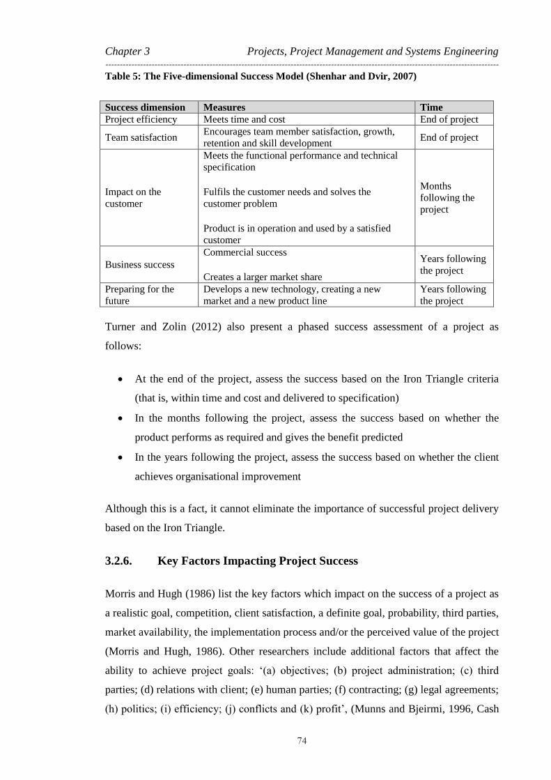
Chapter 3 Projects, Project Management and Systems Engineering ----------------------------------------------------------------------------------------------------------------------------------------
74
Table 5: The Five-dimensional Success Model (Shenhar and Dvir, 2007)
Success dimension Measures Time
Project efficiency Meets time and cost End of project
Team satisfaction Encourages team member satisfaction, growth,
retention and skill development End of project
Impact on the
customer
Meets the functional performance and technical
specification
Fulfils the customer needs and solves the
customer problem
Product is in operation and used by a satisfied
customer
Months
following the
project
Business success
Commercial success
Creates a larger market share
Years following
the project
Preparing for the
future
Develops a new technology, creating a new
market and a new product line
Years following
the project
Turner and Zolin (2012) also present a phased success assessment of a project as
follows:
At the end of the project, assess the success based on the Iron Triangle criteria
(that is, within time and cost and delivered to specification)
In the months following the project, assess the success based on whether the
product performs as required and gives the benefit predicted
In the years following the project, assess the success based on whether the client
achieves organisational improvement
Although this is a fact, it cannot eliminate the importance of successful project delivery
based on the Iron Triangle.
3.2.6. Key Factors Impacting Project Success
Morris and Hugh (1986) list the key factors which impact on the success of a project as
a realistic goal, competition, client satisfaction, a definite goal, probability, third parties,
market availability, the implementation process and/or the perceived value of the project
(Morris and Hugh, 1986). Other researchers include additional factors that affect the
ability to achieve project goals: ‘(a) objectives; (b) project administration; (c) third
parties; (d) relations with client; (e) human parties; (f) contracting; (g) legal agreements;
(h) politics; (i) efficiency; (j) conflicts and (k) profit’, (Munns and Bjeirmi, 1996, Cash

Chapter 3 Projects, Project Management and Systems Engineering ----------------------------------------------------------------------------------------------------------------------------------------
75
and Fox, 1992, Baker et al., 1974a, Baker et al., 1974b, Kerzner, 2009, Kumar, 1989, de
Wit, 1988).
Some of the famous failed projects with the main failure cause are gathered in Table 6
(Bahill and Henderson, 2004, BBC, 2014b).
Table 6: Famous Project Failures (Bahill and Henderson, 2004, BBC, 2014b)
Project Name Year Cause of failure Failure
Phase
Possible Failure
Factor
Tacoma Narrows
Bridge 1940 Scaling up an old design Delivery Poor Design
Edsel Automobile 1958 Failure to discover customer
needs Project
Poor Requirements
Definition
Vasa Warship 1961 Workmen were using different
systems of measurement Delivery Poor IM
Concorde SST 1976–
2003
It was not profitable
(1976–2003) Project
Poor Market
Analysis
IBM PCjr 1983 Failure to discover customer
needs Project
Poor Requirements
Definition
The Gimli Glider 1983 Using different units Delivery Poor IM
Chernobyl
Nuclear
Power Plant
1986 Bad design, bad risk
management Delivery
Poor PM,
including IM
New Coke 1988 Arrogance Project Poor Management
Lewis Spacecraft 1997 Design mistakes Delivery Poor PM,
including IM
Motorola Iridium
System 1999 Misjudged competition, mis-
predicted technology Project
Poor Market
Analysis
Mars Climate
Orbiter 1999 Use of different units Delivery Poor IM
Millennium
Bridge 2000
The up-and-down
synchronised footfall was
considered but not the side-to-
side effect
Delivery Poor Design
Sep 11 Attack on
World Trade
Center
2001 Failure to anticipate terrorist
threat
Delivery,
Project
Poor Requirements
Definition
Northeast power
outage 2003 Lack of tree trimming
Delivery,
Project Poor Requirements
Definition
Laufenburg
Bridge 2003
Missed integration between
two contractors Delivery Poor IM
French Railway 2015 Miscalculation of the size of
the train and the platforms Delivery Poor IM
Total number projects sampled 16 Projects
Failed in project delivery 11 of 16 Projects
Delivery failed because of IM 7 of 11 Projects

Chapter 3 Projects, Project Management and Systems Engineering ----------------------------------------------------------------------------------------------------------------------------------------
76
The information in the table shows that in this small sample, 11 out of 16 projects
(around 68 per cent) are failed in the delivery phase of the project. The other projects,
however, are delivered as planned but are classified as failed projects because of various
issues with the projects themselves, such as missed prediction for the profit. The data
here also show that in 7 out of the 11 projects which failed in the delivery phase,
interfacing and/or IM within the design and development stages play key roles in
project failure. While the key role of a poor IM in project failures can be seen in many
examples, there is not enough scientific research in this topic specifically with proposed
solutions.
In addition to this, the new construction procurements strategies – specifically in the rail
sector – have created more reason to justify the importance of interfacing and IM. The
new project procurement strategies in rail infrastructure projects is explained in the next
section to provide a full picture of the need for IM.
3.3. Project Procurement Strategies in the Rail Sector
Infrastructure projects and rail infrastructure projects in particular are becoming more
complex (Shokri et al., 2012, Shokri et al., 2015) with managerial, technical and
logistical problems with multiple activities from many parties delivering works with
numerous strata of interfaces of hardware and software. The execution lives of rail
projects are no longer limited to discrete and sequential phases like feasibility study,
design and construction with project organisations of only client, designer and
contractors (Staats, 2014, Anumba et al., 2007) and the full responsibility and
accountability of the project sponsor.
Another issue that plays a part in this consideration is the notion of the level of risk
transfer from public to private sector (Edkins and Smyth, 2006, Quiggin, 2005). In
traditional rail projects, the real risk was arguably for the project sponsor. No matter
what contract structure was in place, if a project failed completely, experienced massive
delay, had major incidents, or the contractor went bankrupt, the risk was still with the
promoter, owner and government – politically, financially and ultimately physically
(Bing et al., 2005). It is therefore a shift in contract strategies with an aim to shift the
risk more toward the private sector (contractors).
Chapter 3 Projects, Project Management and Systems Engineering ----------------------------------------------------------------------------------------------------------------------------------------
77
3.3.1. Rail Project Procurements Background
Initially, railway projects were funded by the private sector, by individual entrepreneurs
who would raise their own funding (Gourvish, 1986). They would commission the
design having conceived the project in the first place. They would then commission and
contract their supply chain, procure the land (or not – which is why there are some
interesting diversions to many of the early lines), build and operate. Many of these
companies failed and were taken over by other organisations with the onset of war and
the realisation of the importance of these critical pieces of logistical infrastructure, plus
the effects of the deterioration of the networks as revenue constrained investment in
maintenance. Thus most railways passed into public hands and became subject to
government procurement structures (Gourvish, 1986), and the industry was completely
nationalised by 1948 (Pollitt and Smith, 2002).
Innovation in the method of procurement did not advance greatly in most of the world
until the 1960s when a wave of market recessions, the emergence from two world wars
in 25 years and the public’s more vocal and politically active requirement for value for
money caused promoters to re-examine how this sort of infrastructure was procured.
“Pressure to change the standard model of public procurement arose initially from
concerns about the level of public debt, which grew rapidly during the
macroeconomic dislocation of the 1970s and 1980s.” (Quiggin, 2005)
This led to the emergence of a trend away from the traditional design, procure and
construct approach and towards more market-based approaches with greater emphasis
on output parameters and a move to a mix of finance sources that culminated in the rise
of Public Private Partnership (PPP) structures which developed the Engineering,
Procurement and Construction (EPC); Design and Build (D&B); Early Contractor
Involvement (ECI); Design, Build, Operate and Maintain; and Design, Build, Finance,
Operate and Maintain approaches. ECI, for example, requires that contractors get
involved in the project during the design phase. Walker (2012), for example, states:
“It is widely accepted that contractors have much potential valuable advice to offer
at the front-end of project development. This concept is sometimes called early
contractor involvement (ECI) and encompasses various relationship-based project
procurement (RBP) forms.” (Walker and Lloyd-Walker, 2012)

Chapter 3 Projects, Project Management and Systems Engineering ----------------------------------------------------------------------------------------------------------------------------------------
78
Reviewing literature in construction and engineering management provides detail on
how the new procurement strategies are moving to the approaches that requires a much
greater level of collaboration and cooperation between the project sponsor (client), the
project design team and the contractor delivering the project (Walker and Lloyd-
Walker, 2012, Mosey, 2009, Masterman, 2002, Walker and Rowlinson, 2008, Edkins
and Smyth, 2006).
Although this new shift in procurement provides benefits to the project in many aspects,
the more parties (participants) involved and the complexity of the relationship –
specifically in the design phase – introduce new challenges in managing the interfaces
(Edkins and Smyth, 2006, Smyth and Edkins, 2007).
“Co-operation, however, implies an increase in the number of participants. Also, in
partnerships, the actors are usually dependent upon each other.” (Klijn and
Teisman, 2003)
Rail projects are even more complex due to the fact that they involve large pieces of
civil infrastructure – even in its most extreme, hardly cutting edge engineering
development – which can be constructed in various pieces of individual work with
complex interfaces. This has lent itself to ever more complex contractual structures
which have in some places caused major challenges to cost, programme and
functionality.
3.3.2. Traditional Design, Build and Construct
The traditional rail infrastructure projects follow the straightforward and simple stages
of public procurement including design, build and construct. In this approach, the
sponsor, usually government at some level, will do all front-end work from scheme
Feasibility and Preliminary Operating Plan through to definition and detailed design,
cost, programme, business case, procurement and delivery strategy. At this point, the
sponsor will then go out to the market to find a contractor that can procure the delivery
of their design. The procurement at this stage could be done in different forms, such as:
Procuring packages of the civil works and the various component equipment for
the systems from individual manufacturers while the sponsor project manages
and integrates the systems and manages the interfaces

Chapter 3 Projects, Project Management and Systems Engineering ----------------------------------------------------------------------------------------------------------------------------------------
79
Contracting a master contractor who manages the supply chain and delivery,
including interface and integration, for the systems alone, with the civil
infrastructure delivered as above
Contracting a single contractor to deliver systems and infrastructure and manage
the interfaces and integration
This was the norm for most projects up until at least the 1980s, when the public sector
also retained the ownership of the assets and responsibility of the operation of the core
service (Quiggin, 2005). This was also a standard model in the rail sector and is how,
until relatively recently, many of the better known promoters like Hong Kong Mass
Transit Railway (MTR), British Railway (BR), London Underground Ltd (LUL) and
most of the major United States properties have managed the provision of this sort of
project.
This method requires a great deal of management and only really works if the client is
relatively well informed and either has a sufficiently large technical capability or buys
in the technical and PM skills from the consulting industry, in addition to the project
legal, financial, environmental services which may or may not be transferred as tasks to
the contractor(s).
3.3.3. Design and Build or Engineering, Procurement and Construction
Once again, the sponsor will, up to a point, do the front-end work of scheme definition,
feasibility project cost and business case. They will usually do prototypical designs and
give the operating requirements and performance requirements. This will be further
supported by systems specifications and these days by some basic interface and
integration structures. This is often described as developed to ‘60 per cent or basic
design’, a description that is popular with promoters such as the international financial
institutions like the Asian Development Bank, European Bank for Reconstruction and
Development and the Japanese International Cooperation Agency.
The contractor will then take this over as a design and progress to complete and manage
the procurement of the materials and workforce through compliance and construction to
testing, commissioning and handover.

Chapter 3 Projects, Project Management and Systems Engineering ----------------------------------------------------------------------------------------------------------------------------------------
80
This can be done as a total project or as a combination of Design, Procure, and
Construct for the civil infrastructure and the systems procured as D&B or EPC.
Furthermore, the client may decide on larger projects to package the civil work and let
these as D&B packages with a system-wide contract for rail systems.
The client will still need to employ or provide from its own resources the PM,
supervision and other specialist expertise and will require a level of competence of the
client organisation to ensure a successful project is delivered.
It is from these devolved finance and design models that the more recent approaches
developed in the 1980s, 1990s and early 21st century.
3.3.4. Public Private Partnerships
Public private partnerships (PPPs) have been defined as “any alliance between public
bodies, local authorities or central government and private companies” (Roe and Craig,
2004). This wide generic term covers all kinds of deal structures involving the public
and private sectors. A private finance initiative (PFI) is defined as:
“a more formal [version] of PPP….generally [providing] the capital asset and
services relating to that asset. The public sector specifies the level of service in
return for a unitary charge.” (Roe and Craig, 2004)
“…a form of public private partnership (PPP) that marries a public procurement
programme, where the public sector purchases capital items from the private sector,
to an extension of contracting-out, where public services are contracted from the
private sector.” (Allen, 2001)
Essentially, the PFI involves sub-contracting the design, building and operations of
public services (particularly capital assets and related services) to private sector
companies in a way that transfers construction and/or operational risk from the public
sector to the private sector (Edkins and Smyth, 2006, Quiggin, 2005). PFI was
introduced as a policy in the UK in 1992 as a means to increase investment, and in 1997
it became PPPs (Smyth and Edkins, 2007). Since then, it has been further developed
through project experience.

Chapter 3 Projects, Project Management and Systems Engineering ----------------------------------------------------------------------------------------------------------------------------------------
81
Figure 11 shows the shift in the risk transfer by moving to the new procurements
strategies as an example.
Deg
ree
of P
riva
te S
ecto
r In
volv
emen
t
Deg
ree
of P
riva
te S
ecto
r Ri
sk
PPPs
Degree of Public Sector Risk
Privatisation
DBFOM - Design / Build / Finance / Operate / Maintenance
DBFM - Design / Build / Finance / Maintenance
DBF - Design / Build / Finance
Alternate Service Delivery
Contracting Out
D&B - Design / Build
Public Owned / Operated
Figure 11: New Procurement Strategies and Risk Allocation
As shown, the more that private sector and contractors get involved, the more the risk is
transferred to them. This means the projects will be done much more efficiently and the
ultimate client (that is, tax payers in the case of rail projects) carry an overall lower
level of risk. The projects should be more efficient because efficiency is a critical factor
for the private sector. Therefore, any work leading to improved project efficiency by
avoiding resources waste, reworks, delay, etc., is considered to be significant for private
sector. This includes improving IM in procurement of multidisciplinary projects with
complex technical, managerial, contractual and political interfaces.
3.4. Project Management View of Interface Management
Construction projects, particularly rail, are becoming more complex due to new
advances in technology (Shokri et al., 2012) and greater depths of expertise and
knowledge, as well as the new procurement strategies discussed above. Therefore, the
projects are broken down into many more packages of works/projects, to be executed by
many more numbers of parties/contractors. Interface exists when one party needs
information from another party to complete a task of the project. It is described as a

Chapter 3 Projects, Project Management and Systems Engineering ----------------------------------------------------------------------------------------------------------------------------------------
82
point of contact between independent organisations (for example, groups, parties,
teams) that are interacting to achieve a larger system (Wren, 1967). Interfaces arise
during the decomposition of a project into smaller packages of works and contracts and
further down to the sub-systems and components (Staats, 2014). Equally the
management of interfaces across the whole project is becoming important for each of
those contractors. They are under pressure as they need to deliver to time, budget and
quality, which could be impacted in the absence of a robust IMS (Tomiyama and
Meijer, 2005).
“In building construction, interface issues exist between project or building
components not only during the design, manufacturing, and construction stages, but
also during the operation and maintenance phases of a building and its systems. Due
to the lack of IM (interface management), a wide variety of inferior interfaces have
repeatedly contributed to design errors, construction conflicts, and inter-party
coordination problem on the jobsite. While the awareness of interface issues and IM
increases, there is a lack of development of IM strategies and applicable tools, which
is considered increasingly more important.” (Chen et al., 2006)
Interface management is also described as:
“an effective tool in proactive avoidance or mitigation of any project issues,
including design conflicts, installation clashes, new technology application,
regulatory challenges, and contract claims, and would enhance the successful
delivery of megaprojects.” (Nooteboom, 2004)
Shokri et al. (2012) list the following as some examples of IM applications in
construction (Shokri et al., 2012):
Developing an effective and timely communication between a Main Automation
Contractor and a Main Electrical Contractor (Calgar and Connolly, 2007).
Project safety improvement and reducing the effect of hazardous processes (Kelly
and Berger, 2006).
Defining the human dynamics and communication strategies in agile PM (Chen et
al., 2007)

Chapter 3 Projects, Project Management and Systems Engineering ----------------------------------------------------------------------------------------------------------------------------------------
83
Interfaces are either internal (within a single team and single scope) or external
(between teams with a single scope) (Chen et al., 2007, Lin, 2009). And they are either
functional (derived from functional requirements) or physical (objects are physical
related) (Staats, 2014).
Some researchers believe that the early identification of the interfaces and plan to
closing them down, in the design stage of a project, reduces the risk of reworks,
resulting in preventing the project running over time, cost and budget (Chen et al., 2007,
Calgar and Connolly, 2007, Nooteboom, 2004). It is therefore key for a project manager
to identify early the area of interfaces and the parties involved, in order to facilitate
interactions, information exchanges and early agreements among them. The actions
taken for this purpose, and documents registered as the result, are invaluable for the
quality and assurance purpose. Interface management should be an ongoing and
iterative process throughout the life of a project with the ultimate goal of managing the
balance between scope, time, cost, quality and resources, because as a project
progresses, the interfaces change along with new relationships that should be managed
continuously (Crumrine et al., 2005, Wren, 1967).
In almost all of the projects in which the author has been involved in the past 10 years,
the project team has tried to develop an IM Plan at the early stage of the project to
formulate some sort of an IMS that can address the issue. In a generic format, an IMS
should cover the interface identification, interface assignment (ownership), interface
communication, interface management (control and monitor), and interface close out as
the key tasks (Lin, 2009, Calgar and Connolly, 2007, Pavitt and Gibb, 2003). Still, in
any new rail infrastructure project, IM is a challenge and a risk to the project delivery.
In reviewing various PM textbooks, it is difficult to find a specific topic on IM. In the
APM Body of Knowledge, for example, there is no heading on IM and only a few
references to managing the interfaces under sections like stakeholder management,
change control or conflict management (Association for Project Management 2006).
Similarly, the Handbook of Project Management Procedures has no section for IM and
only some references under the communication management plan, change report and
change order sections (Hamilton, 2004).

Chapter 3 Projects, Project Management and Systems Engineering ----------------------------------------------------------------------------------------------------------------------------------------
84
Unfortunately, in construction projects (including rail sector), IM is mostly seen as a
natural, even hidden aspect, of PM and the impact of it on project delivery is
underestimated (Nooteboom, 2004).
“Currently, it is not widely known what IM means in construction and what scope is
covered by IM.” (Staats, 2014)
Interface management is important because it will help prevent the project from
unnecessary reworks, therefore ensuring that the project will be delivered earlier, safer
and to the performance specified by the client. This means that better IM results in more
efficient PM. As a result of recent changes to the construction projects, researchers in
the PM field are focusing on IM in construction projects, establishing different
definitions (Chen et al., 2007).
Many of projects have been delivered late and over budget because of unnecessary
extensions due to integration issues. In many such ‘failed projects’, the most expensive
mistakes and delays are traced back to integration issues between the different design
teams (Staats, 2014).
Many publications describe inefficiency in managing the communications over the
interfaces (that is, IM) as a major cause for project cost and schedule overruns in mega-
projects (Nikander and Eloranta, 2001, Nitithamyong and Skibniewski, 2004, Han et al.,
2007, Jergeas and Ruwanpura, 2010, Wong and Zhang, 2013, Shokri et al., 2015).
Regarding London’s Thameslink project, the National Audit Office (2014) reports that:
“Despite the programme’s size and complexity, the Department did not devote
enough attention to managing interdependencies between the infrastructure, train
and franchise early on. The 3-year delay in procuring trains has made delivering
other parts of the programme more complex. When we reported in 2013, the
Department was expanding the programme management role of the Thameslink
systems integration team, and establishing an ‘interface steering group’ to address
interfaces between the infrastructure and other department-led programmes.”
(National Audit Office, 2014)

Chapter 3 Projects, Project Management and Systems Engineering ----------------------------------------------------------------------------------------------------------------------------------------
85
In the same report, they show the shift in the management approach to focusing more on
the interfacing and integration by reporting on the ongoing Crossrail project as follows:
“In contrast, Crossrail Limited’s plans for integrating the programme were well
advanced relative to other rail projects we reviewed. A director of operations
reporting to the chief executive was in place from 2006 to 2008 during the
development of Crossrail plans. In addition, operations staff have been in place
throughout the programme. Crossrail Limited recruited the current operations
director in early 2013, in advance of the appointment of the operator. The Joint
Sponsor Team also worked closely with the Department’s Crossrail and franchising
teams to align Crossrail with other rail services.” (National Audit Office, 2014)
‘French red faces over trains that are “too wide”’ was the BBC’s headline regarding a
massive debacle which dominated global headlines. SNCF, the French train operator,
realised that the 2,000 brand new trains it had ordered at the cost of €15 billion were too
wide for many of France’s station platforms (BBC, 2014b, BBC, 2014a). Although more
detailed investigation is taking place, the nature of an error is rooted in a lack of proper IM.
3.5. Systems Engineering
Systems engineering in complex projects is the emerging solution to transfer the project
governance from ‘project base’ to ‘system base’ to increase the chance of success that
can be applied at different levels and different stages of a project (Locatelli et al., 2014,
INCOSE, 2006, Calvano and John, 2004, Smartt and Ferreira, 2011b, Bahill and Clark,
2001). Applying SE in today’s rail sector projects is also getting more attention (Elliott
et al., 2011). Systems engineering is a collection of tools, techniques and methods, and
cradle-to-grave technical points of contact for the project, that are bound together by
some shared ideas (Elliott, 2014, Smartt and Ferreira, 2011a, Chen and Clothier, 2003).
Ideas and objectives to make PM more efficient by providing a systematic approach and
interdisciplinary supervision of the design help ensure that the project will successfully
deliver the main objective and so the user ‘need’ (Loureiro et al., 2004). As a systems
engineer working in the rail sector and facing complexities in PM, the author is trying to
use any opportunity to adopt the SE approach to the benefit of PM.
As explained in Chapter 1, although the SE adoption on PM is not the main focus of this
research, to achieve the objective of this study, it is important to understand ST and SE

Chapter 3 Projects, Project Management and Systems Engineering ----------------------------------------------------------------------------------------------------------------------------------------
86
fundamentals. For this reason, the following part of this chapter gives a very detailed
review on ST and SE, including their origin, definition, applications in construction
projects and relationship to PM activities.
3.5.1. Systems Engineering Background
Using the term ‘systems engineering’ as a technical discipline is traced back to the
1930s where Bell Communication Co., used this approach in its Telephone
Laboratories. A table in the International Council on Systems Engineering (INCOSE)
handbook (see Table 7) shows a summary of the development of SE as a discipline over
last 200 years (INCOSE, 2006).
Table 7: Key Dates in the Origins of Systems Engineering as a Discipline (INCOSE, 2006)
Date Event
1829 Rocket locomotive: progenitor of main-line railway motive power
1937 British multidisciplinary team to analyse the air defence system
1939–1945 Bell Labs supported NIKE development
1951–1980 SAGE Air Defence System defined and managed by MIT
1956 Invention of systems analysis by RAND Corporation
1962 Publication of A Methodology for Systems Engineering
1969 Jay Forrester (Modelling Urban Systems at MIT)
1994 Perry Memorandum urges military contractors to adopt commercial
practices such as IEEE P1220
2002 Release of ISO/IEC 15288
In 1992, the National Aeronautics and Space Administration (NASA) issued SE
handbook as a formal document for the first time. The initial work to develop this
document, however, was started in 1989 (NASA, 1995). Since then, various documents
in the form of handbooks, user manuals, tool manuals, reports and standards have been
developed and issued by various organisations and companies to explain SE and SE
management in different domains.
3.5.2. Systems Engineering Definition
Systems engineering is described in different books, publications, handbooks and
reports in different forms and characters. However, they all share the same concept of

Chapter 3 Projects, Project Management and Systems Engineering ----------------------------------------------------------------------------------------------------------------------------------------
87
engineering of a system based on ST (Davidz and Nightingale, 2008). In fact, in many
of the publications the term ‘systems engineering’ comes together with ‘strategy’
(Smartt and Ferreira, 2011b) which is based on ST.
The goal of ST is to understand how different components of a complex system work
and interact (Twisk et al., 2015, Leveson, 2002, Skyttner, 2005). This means realisation
of a system as a whole and understanding how the small parts work together to form the
project/system as a whole. This is how the impact of the parts in the whole system can
be realised and problems can be resolved before they become issues (Leveson, 2002).
“Complex systems cannot be understood by studying parts in isolation. The very
essence of the system lies in the interaction between parts and the overall behaviour
that emerges from the interaction. The system must be analysed as a whole.” (Ottino,
2003)
Systems engineering in management of an engineering design is a systematic approach
and inter-disciplinary supervision of the design to ensure that the project need and
objective are well understood and realised and that the project requirements are well
captured and modelled. It is also a solution to ensure that the project design and
implementation’s different elements and sub-systems mesh coherently to provide a
system which works together correctly as a whole.
The NASA SE handbook defines SE as a “methodical, disciplined approach for the
design, realization, technical management, operations, and retirement of a system.”
(NASA, 2007)
The INCOSE engineering handbook uses three representative definitions to illustrate SE
as a discipline, a process and a perspective (INCOSE, 2006):
”Systems engineering is a discipline that concentrates on the design and
application of the whole (system) as distinct from the parts. It involves looking
at a problem in its entirety, taking into account all the facets and all the
variables and relating the social to the technical aspect” (Ramo, 2002).
“Systems engineering is an iterative process of top-down synthesis,
development, and operation of a real-world system that satisfies, in a near

Chapter 3 Projects, Project Management and Systems Engineering ----------------------------------------------------------------------------------------------------------------------------------------
88
optimal manner, the full range of requirements for the system” (INCOSE, 2004,
INCOSE, 2006).
“Systems engineering is an interdisciplinary approach and means to enable the
realization of successful systems” (INCOSE, 2004, INCOSE, 2006).
Systems engineering introduces a systematic approach to the PM of complex
multidisciplinary projects in project realisation, requirements capturing, project scoping,
planning, scheduling and managing. In such projects, the complexity of the project and
number of parts that should be designed and implemented individually and assembled
as a whole can be very challenging for the project managers. Each of these parts could
potentially be a big project on their own in a large scale and size and therefore should be
well managed individually.
“With increasingly complex systems, relying on systems engineering as an
interdisciplinary method to manage engineering processes is essential for
companies.” (XUE et al., 2014)
Systems engineering and PM are described as the two essential aspects in success or
failure of a project (Boarder, 1995) and, therefore, the two should work together in an
integrated management system (Emes et al., 2012).
3.5.3. Systems Engineering Essential Procedures and Tools
The author has been involved in rail infrastructure projects in the past 10 years. Based
on his experience, the core responsibility of SE is the realisation of the project as a
system and modelling the project requirements, as well as understanding and managing
the interfaces between various small parts of the system. In theory, managing the scope
and requirements, as well as managing the interfaces and integration within PM, are the
main functions improved by an SE approach. In contrast to the lack of discussion on IM
in PM literature, as described earlier, SE has more references to IM but still not in a
great detail. Therefore IM in SE literature is also scarce (Staats, 2014). The INCOSE
Systems Engineering Handbook does contain a section on systems integration and some
materials related to IM (INCOSE, 2006).
In recent rail infrastructure projects, different processes, procedures, tools and
documents are developed to adopt SE in the life cycle of a project. These vary

Chapter 3 Projects, Project Management and Systems Engineering ----------------------------------------------------------------------------------------------------------------------------------------
89
depending on the nature and complexity of the project. The following section provides a
brief description of the SE life cycle and the key processes and tools used in
construction projects.
3.5.4. Systems Engineering Life Cycle
The SE life cycle is an iterative work cycle adopted to manage a project on a ‘cradle to
grave’ basis. The focus is based on ST to see the project as a system and to break it
down into smaller parts/sub-systems.
By adopting a SE approach to the PLC, periodic and iterative verification stages will be
established in which the progress of the project and compliance with project actual
requirements will be verified. The system life cycle is a process which defines the order
that information should be developed and produced. The system development can
follow a sequential linear process called waterfall or a V-Model with verification and
validation stages.
In the waterfall system life cycle, users, developers and designers have responsibility for
separate parts of the information individually (Stevens et al., 1998). In this life cycle,
each step of the life cycle acts as a milestone in which the progress of the project can be
monitored. The feedback and the consequent changes at each stage will be taken into
account before moving to the next stage. Figure 12 presents a simple view of such a life
cycle (Stevens et al., 1998).
User Requirements
System Requirements
Architectural Design
Integration & Verification
Installation & Validation
Operational Capability
Change & Feedback
Change & Feedback
Change & Feedback
Change & Feedback
Change & Feedback
Change & Feedback
Review
Review
Review
Component Delivery
Systems test
Acceptance testComponent Development
Figure 12: System Development Waterfall Life Cycle (Stevens et al., 1998)
The V-Model, however, is a system development life cycle in which the verification
happens across the horizontal links as well as between the definition phases (Stevens et
al., 1998). As Figure 13 shows, the project first goes through realisation. This means, as

Chapter 3 Projects, Project Management and Systems Engineering ----------------------------------------------------------------------------------------------------------------------------------------
90
per the left side of the V model, ‘what should be built’ by the project should be
identified and verified through ST by breaking down the system into smaller parts (sub-
systems) and defining the system architecture. Once the system is defined, components
will be implemented and developed.
Components will be tested and procured as per the right side of the V-model, and the
integration and system test will be verified. The process continues all the way to the
system operation where the developed system can be validated against the user
requirement (user satisfaction).
User Requirements
System Requirements
Architectural Design
Component Tests
Integration Tests
System Test
Acceptance Tests
Component Development
Verification
Verification
Verification
Validation
Verificaiton
Verificaiton
Figure 13: System Development V-Model Life Cycle (Stevens et al., 1998)
3.6. Systems Engineering View of Interface Management
3.6.1. System (Project) Interfaces
A ST view suggests that a system is completed (that is, the project has achieved its
objectives) only when all the smaller parts of the system (sub-systems) are assembled
and integrated and they can work together well with minimum error. Depending on how
the project works are broken down, sub-systems potentially are either work packages
(WPs), discipline tasks and responsibilities, teams and organisations or another form of
work breakdown.
In manufacturing a complex product, sub-parts are designed and developed based on a
separate, concurrent engineering approach. In train car manufacturing projects for
example, the parts of the train are designed and manufactured separately and sometimes

Chapter 3 Projects, Project Management and Systems Engineering ----------------------------------------------------------------------------------------------------------------------------------------
91
in different countries. Therefore, design and implementation of most of the modules of
the product are highly dependent on information from other modules and parts.
Projects in the rail infrastructure sector are complex, and many disciplines and
specialities are involved to deliver the project. Often, the scope of a small WP (sub-
system) of a project is a complex project itself in which the level of integration is much
greater. Therefore, it is necessary to have all sub-systems work and objectives well-
coordinated. It is also important to understand how sub-systems are created. The design
engineering of a typical new railway project needs many different engineering
disciplines to work together and design different systems and sub-systems.
In a simple world, a project interface exists where there is either a physical link between
two components of a project or where information from one component is required in
order to complete the design and implementation of the other component, as described
above.
“Interface is defined as the contact point between relatively autonomous
organizations which are interdependent and interacting as they seek to cooperate to
achieve some larger system objective.” (Wren, 1967)
Systems interfaces also are either hard or soft and either internal or external. The
interface is internal when the work should be performed and coordinated in a single
organisation (or discipline), and the interface is external when the work should be
performed in more than one organisation (or discipline) (Healy, 1997).
3.6.2. Systems Interface Management
The flow of design parameters, work instructions, space scheduling information and
resource use, must be coordinated across the abstract boundaries between all the project
sub-systems (Chua and Godinot, 2006). Where the attributes and the information of one
sub-system cause any constraint for the other subsystems, inadequate control of this
constraint could potentially lead to work disruptions and reworks due to interfacial
mismatch (Chua and Godinot, 2006). Interface management has been defined in various
other literature in different contexts. Wren’s paper (Wren, 1967) contains an excellent
list of references in which various definitions and applications on IM in different
environments are discussed.

Chapter 3 Projects, Project Management and Systems Engineering ----------------------------------------------------------------------------------------------------------------------------------------
92
As discussed earlier, systematic IM normally covers the following items (Lin, 2009,
Calgar and Connolly, 2007, Pavitt and Gibb, 2003):
Interface identification – requires a system decomposition and interaction
analysis
Interface ownership – requires assignment the interfaces to the owners
Interface communication – facilitates the communication between parties over
the interfaces captures and identified
Interface control and monitoring – manages and monitors the close out of the
interfaces
Interface closing out – documents the close out and assuring the compliances
For the purpose of this research, the definition below is assumed for IM from the SE
point of view:
The SE definition of IM is understanding of the parts of a system, realisation of the
relationships between these parts and facilitating inter-links in order to complete a fully
integrated system made of all the sub-systems.
Over the past 10 years, the author has developed IM procedures and tools for many
international rail projects, documented in different reports and plans (Sanei, 2011). In all
of these projects, the author tried to cover the steps required in systematic IM. The author
introduced the framework below on many of the rail projects as a backbone for the IMS:
1. Project/System Decomposition: Break down the project/system into small
parts/sub-systems (as presented in Figure 14) in order to access to the lower level of
the system and to understand and manage the system as a whole.
A
B
C
DE
F
G
H
I
J
A
D
C
B
E
F
G
H
I
JJ
Project / System
Project Parts /
Sub-Systems
Figure 14: Project Decomposition

Chapter 3 Projects, Project Management and Systems Engineering ----------------------------------------------------------------------------------------------------------------------------------------
93
2. Interface Identification: Understand the inter-relationship between small parts of
the project/system and identify the areas of interfaces by developing a N2 interface
matrix, as shown in Figure 15.
A
B
C
D
A B C D E F G H I
Figure 15: Interface Identification – Interface Matrix
Matrix to visualise the areas of interfaces between parts of a project
3. Interface Allocation: Assign interface responsibility to various parties and
suppliers of the sub-systems to provide interface resolution. Each of the parties in the
interface points have owners that should take the responsibility of the interfaces, as
shown in Figure 16.
A
B
C
D
A B C D E F G H I
G
H
ID
B
A
Supplier of these sub-systems
Figure 16: Interface Allocation to the Sub-system Suppliers
Allocating the responsibility of the interfaces to the relevant parties / suppliers involved
4. Coordination and Communication: Develop communication and coordination
paths to facilitate the management of the interfaces between assignees.
5. Interface Resolution: Assign works to assignees to develop interface resolution.

Chapter 3 Projects, Project Management and Systems Engineering ----------------------------------------------------------------------------------------------------------------------------------------
94
6. Interface Closeout and Verification: Provide assurance evidence to verify the
interface close out by developing identified interfaces to the project deliverables
which can certify the resolution of the interface (see Figure 17).
A
B
C
D
A B C D E F G H I
Deliverables
Figure 17: Interface Closeout – Evidence and Certificate
Interface management plays a key role in SE in complex multidisciplinary rail projects.
Various methods and applications are developed and customised to adopt a systematic
interface and integration management.
3.7. Project Management and Systems Engineering Activities
3.7.1. Requirements Management
The project requirement is the statement of what the customer needs (Macaulay, 1996).
The project requirement states what a specific product should do or what a particular
service should be. Systems engineering suggests that the requirements of a project
should be captured and analysed in a structured format. They must be registered in a
form of a document which clarifies the necessary attribute, capability, characteristic or
quality of the system. Requirements engineering is the engineering process of
developing and populating the requirement document (Macaulay, 1996).
In a multidisciplinary rail PLC, there are many types of requirements that need to be
managed from design to completion. The formal requirement phase in a project includes
the process of requirements elicitation, analysis, definition and specification. In a
process of project development, requirements can be categorised as five major groups as
follows:

Chapter 3 Projects, Project Management and Systems Engineering ----------------------------------------------------------------------------------------------------------------------------------------
95
1. User requirements: What the end user needs from the product or service. User
requirements are either an affordance or a constraint imposed by a user (Alexander
and Stevens, 2002, Henderson and Venkatraman, 1993, Kaplan and Norton, 2004).
2. Business requirements: Business requirements drive the goals of the business to
increase profit, decrease costs, improve data management, increase knowledge
transfer and improve efficiency. Business requirements are about defining goals
pertaining to the external business market that are defined and elaborated by the
organisation’s top management (Babar and Wong, 2012).
“A business strategy is about defining a precise and meaningful set of financial
and differentiating customer value targets agreed upon by all the top
management. This indicates that the top management is involved in defining the
strategy”(Babar and Wong, 2012).
3. Technical requirements: The project should be designed, planned, developed
and delivered to the technical specifications and standards specified as technical
requirements for the system. The final delivery of a project should fulfil the technical
requirements.
4. Functional/Non-functional requirements: Functional requirements are the
behaviour of the system which may be expressed as services, tasks or functions that
the system is required to perform (Malan and Bredemeyer, 2007). Non-functional
requirements, however, include answers to the question of how well the system must
perform the functional requirements (how fast, how accurate, how reliable, how user-
friendly, how precise, etc.).
5. Process requirements: Procedural requirements include processes, limitations,
methods, techniques that are required to be used in project development processes.
Studies show that in more than 60 per cent of failed software projects in the United
States, ‘poor requirements’ is one of the top five reasons (Visitacion, 2002). Based on
analysts’ reports, 71 per cent of software projects globally fail because of poor
requirements management (RM) (Lindquist, 2005). Lindquist (2005) further states that
poor RM is the single biggest reason for project failure, even bigger than bad
technology, missed deadlines or change management fiascos. Other studies also show a
high percentage of project schedules overruns, with 80 per cent due to creeping
requirements (Jones, 1994). As shown in Table 8, five of the eight major reasons for

Chapter 3 Projects, Project Management and Systems Engineering ----------------------------------------------------------------------------------------------------------------------------------------
96
software project failures are requirements based (Alexander and Stevens, 2002). The
table also suggests that the other three reasons relate to management while,
interestingly, none are technical related (Alexander and Stevens, 2002).
Table 8: Reasons for Project Failure (Alexander and Stevens, 2002)
Reasons for project failure %
Incomplete requirements 13.1
Didn’t involve users 12.4
Insufficient resources/schedule 10.6
Unrealistic expectations 9.9
Lack of managerial support 9.3
Changing requirements 8.7
Poor planning 8.1
Didn’t need it any longer 7.4
Figure 18 projects the expected cost and duration reduction of an application
development project when the RM is applied on a project.
User
Supplier
User
Supplier
Project progress – Iterations between user and supplier
(Number of submissions from drafts to the final)
User Approval
Over spend
and over run
With RM
Without RM
Time
Cu
mu
lati
ve
Res
ou
rce
Co
st
Left Shift
Figure 18: Reduction of Cost and Duration during Design Development

Chapter 3 Projects, Project Management and Systems Engineering ----------------------------------------------------------------------------------------------------------------------------------------
97
As the figure shows, in a project without RM, more iterations (that is, submissions of
draft works) between project supplier and user will happen when compared to a project
with RM. Therefore, more project resources will be spent over a longer time to achieve
the user approval of the final submission (that is, project completion).This figure also
presents the benefit of RM on project management performance. Where RM is not
adopted, a project goes to execution straight away. Fewer resources are required at the
beginning of the project, but more will be used over a longer time to achieve the user
approval. However, in a project with RM, more resources are required at the beginning
of the project to capture and manage the project requirements. Therefore, where a clear
set of requirements is available, an efficient number of resources are used over a shorter
time to achieve the project completion and user approval. This represents the left
shifting concept presented in literature (Emes et al., 2012, Emes et al., 2007):
“The idea of left shifting to invest effort in the early stages of projects will seem like
common sense to most systems engineers.” (Emes et al., 2012)
3.7.1.1. Project Management View of Requirements Management
For PM, it is important to capture the requirements and establish a common
understanding among all project parties and stakeholders at the beginning of the project.
Different stakeholders have different understandings of the project requirements from
their own point of view (Maylor, 2003, Alexander and Stevens, 2002). These
understandings need to be managed, and agreement should be achieved in order to have
a same expectation from the project objective and to protect the project from going to
the wrong direction.
In classic PM, project requirements often are defined when the project objective is
identified from the scope of the work (Association for Project Management 2006). For
this reason, PM literature describes scope management and managing the requirements
as hand-to-hand processes (Association for Project Management 2006, INCOSE, 2006).
3.7.1.2. Systems Engineering View of Requirements Management
As discussed, SE introduced in recent construction projects mainly focuses on IM and
RM. Management of the requirements in a multidisciplinary project is essential to
successful delivery of the end results. Systems engineering introduces an RM system

Chapter 3 Projects, Project Management and Systems Engineering ----------------------------------------------------------------------------------------------------------------------------------------
98
that can enable the project team to track and demonstrate the close out of the entire
project requirements (INCOSE, 2006). RM is a dynamic process with systematic
activities throughout the PLC to provide assurance that the project’s requirements are
identified and understood at the early stage of the project. In short, RM is the science
and art of gathering and managing requirements in a project. But what is important in
the RM from the SE point of view is the fact that in SE, the project is broken down into
the systems and sub-systems, and the requirements should be managed within different
levels of the system (INCOSE, 2006).
The key to successful requirements management is a harmony and balance. Therefore, it
is essential to develop a communications path among members of the development
team. It should identify who owns each of the requirements and who will be responsible
to deliver which requirement.
3.7.1.3. Requirements Allocation
When project requirements are captured, they need to be assigned and allocated to the
right supplier to be delivered (Parsons and Wareham, 2010). In traditional PM, a WBS
is the best mechanism to categorise, level and assign the requirements to each WP and
therefore to the relevant supplier/discipline.
This study intends to explore the constraints and issues with this technique and propose
a new solution to overcome the problem.
3.7.2. Scope Management
Scope management is described in in the APM BoK as:
“the process by which the deliverables and work to produce them are identified and
defined.” (Association for Project Management 2006)
To define and manage the scope of the projects, various documents – typically a WBS,
Product Breakdown Structure (PBS), Cost Breakdown Structure (CBS) and
Organisation Breakdown Structure (OBS) – need to be generated.

Chapter 3 Projects, Project Management and Systems Engineering ----------------------------------------------------------------------------------------------------------------------------------------
99
Where the end result of the project is a physical product, a WBS will typically be
developed from the project PBS. The PBS is a tree model of the project end products
which should be delivered by the project.
In traditional PM, WBS and PBS drive the development of the project OBS which sets
the project organisation and resources required in order to execute the project (see Figure
19).
Allocating duration, start and end time and priority to each WP in WBS is project
scheduling. Project scheduling leads resource and cost planning and presents the
performance of the project. This is the phase in which documents such as the CBS will
be created. Project scheduling also sets the milestones which will be used to measure
the progress and the success rate of the project. When the scope of the work is clear, the
requirements can be developed.
Make part A
Product
Person who makes Part A
WBS
PBS
OBS
Note 1: OBS is to be developed from a combination of PBS and WBS. There is no specific solution to develop a right selection of a team (OBS)
Cost to Make the part A
Time cost
Material Cost
CBS
Figure 19: Project Management Breakdown Structures
3.7.3. Assumption Management
Assumptions need to be made in order to continue with the part of the work when there
is uncertainty. The work continues based on the assumptions, but changes to the
assumption status can impact the overall project, posing a risk to the completion of the
project.

Chapter 3 Projects, Project Management and Systems Engineering ----------------------------------------------------------------------------------------------------------------------------------------
100
Managing the assumption in PM goes hand-in-hand with managing the requirements. In
most cases an assumption will become a requirement or will change other requirements.
For this reason, the PM view is to manage assumptions by registering them along with
the requirements and link them to the requirements with dependencies so the impact of
the changes to the status can be captured and managed. Relevant parties should be
aware of these assumptions and should act once there is change in any of these
assumptions.
Similar to the requirements, the project team will use various solutions and
documents to link the assumptions to the parties involved and often a breakdown
structure is required to enable the PM team to assign this assumptions to the right
owners.
3.7.4. Quality Management
As discussed, the project scope, requirements and interfaces are captured and managed
through project execution in different ways. There is, however, a need for a high-level
of quality control ensuring that the end result of the project will satisfy. In fact, a
process is required to provide assurance that the various systems and sub-systems
operate correctly in the first place so that the overall project fit for the purpose.
“Quality management is the discipline that is applied to ensure that both the outputs
of the project and the processes by which the outputs are delivered met the required
needs of stakeholders. Quality is broadly defined as fitness for purpose or more
narrowly as the degree of conformance of the outputs and process.” (Association for
Project Management 2006)
In order to deploy a quality management (QM) process, the PM team should develop
a QM Plan that addresses quality planning, quality assurance, quality control and
continuous improvement (Association for Project Management 2006). The process
should be deployed from the lowest level of the components and sub-systems to
provide assurance that every element is designed correctly and will work as
specified.

Chapter 3 Projects, Project Management and Systems Engineering ----------------------------------------------------------------------------------------------------------------------------------------
101
In order to access the various layers of the project activities and responsible parties,
there is also a need in this process for a form of breakdown structure that enables the
quality team to discover the project in different layers.
3.7.5. Resource Management
Execution of a project requires various types of resources, including people, materials,
knowledge and funding. Resource management is the identification and assignment of
the appropriate level of resources to different tasks within a project. Resource
management ensures that appropriate resources are made available at the right time and
location to be used with a project in a certain period of time. Various techniques such as
resource allocation, smoothing, levelling and scheduling are used in PM to manage the
resources (Project Management Institute (PMI), 2006).
As a basic document, an OBS may be developed at the early stage of the project, based
on the knowledge and professions required in order to achieve the objective of a project.
OBS is a tree model structure, which can be used to model the level of resources needed
for the project and when. As presented in Figure 19, the PBS and WBS are major
drivers in traditional PM to develop the OBS.
3.7.6. Commercial Management – Budget and Cost
Project budget and cost management is defining the project budget based on the project
cost estimate and managing the project actual cost against the budget while taking into
account the project progress and delivery (Healy, 1997, Lichtenberg, 1983).
The project cost estimate will normally be developed in the project definition phase.
The approved estimated budget will become the project budget. Cost is a main factor to
measure the level of project success, and this is essential to achieve the project objective
within the project budget and timeline (Project Management Institute (PMI), 2006). In
order to establish effective cost management, a solution is required to monitor the actual
cost against the project budget in lower level of the project tasks. Therefore, a model is
required to have a direct link between the project costs to the project budget for the WPs
within the project. Without cost management, it will be very easy to overrun the cost
before achieving the project objectives. The CBS is a tree model breakdown structure of
the project budget which presents the project overall financial status in total.

Chapter 3 Projects, Project Management and Systems Engineering ----------------------------------------------------------------------------------------------------------------------------------------
102
In traditional PM, a CBS is developed against the WPs within the WBS or against the
time and cost required by the project resources (the OBS) (Association for Project
Management 2006). In more complex projects, a combination of both may be used.
3.7.7. Risk Management
Risk management is a systematic process to identify the project risks and plan to
mitigate them to maximise project success. In order to perform a risk management
process, there is a need to develop a Risk Plan and Risk Register at the early stage of the
project (Aleshin, 2001). Once they are established, project risks should be registered in
a central project risk management tool along with mitigation plan, impact factor and any
other items related to the individual identified risk.
Risks should also be allocated to the relevant owners who are responsible to mitigate
the risk. Therefore, a kind of a breakdown structure should be used by the project risk
process to facilitate assigning the risk to the relevant owner(s) (Holzmann and Spiegler,
2011, Iranmanesh et al., 2007, Hillson, 2003).
3.7.8. Issue Management
Various events may happen during the life cycle of a project which will threaten the
achievement of the project objective. Resolving the ‘project issue’ is often beyond the
capability of the project manager. An issue may be identified at an early stage of a
project as a risk which then becomes an ‘issue’ when they actually happen. A project
issue, however, should not be confused with a project risk. Risk is uncertain and it
might not happen, while an issue is certain and has already happened. A project issue is
also different from a ‘problem’. Problems happen in a project and they can be resolved
by the project manager, while project issue is a problem which cannot be handled by the
project manager and is normally outside of the project manager control (Project
Management Institute (PMI), 2006). For a complex project it is very important to
develop a logbook to keep all the project issues.
Similar to project risks, issues need to be registered and linked back to the parties who
will be impacted and to those who are responsible. The Issue Register is another
document which needs to be developed in the PM process and assigned to various

Chapter 3 Projects, Project Management and Systems Engineering ----------------------------------------------------------------------------------------------------------------------------------------
103
project suppliers. Therefore, a form of a breakdown structure of the project is deemed to
be necessary for this assignment and management.
3.7.9. Project Environment and Stakeholder Management
When the project is defined, the project environment should be well understood.
Different parties who have an interest or role in a project or who will be impacted by the
project are the project stakeholders (Project Management Institute (PMI), 2006). Project
stakeholders should be well identified in advance and their role, influence and level of
impact should be defined and registered. Stakeholders do have a key role in defining the
level of success in a project (Project Management Institute (PMI), 2006), and it is
essential to have a plan to establish and manage the communication and integration
routes with them. Requirements and interests of each of the stakeholders also should be
understood and captured in various registers, such as a project stakeholder requirements
register. It is important that a stakeholder management system be implemented in a
complex project; this is essential to design and develop various tools and documents to
enhance the management process of the stakeholders and their requirements, interest,
impacts and interfaces.
Developing linkage between such registers to other PM documents and procedures is an
important challenge for the PM of any type.
3.8. Integrated Management Tool
Many other tools and documents may be developed in a management of a project
depending on the project size and complexity. These include a change register, technical
query register, action register and communication register.
The challenge to the management of the major multidisciplinary complex projects is
how all these tools and documents can be interlinked – how they can talk in the same
language and how best to capture, assess and manage their impact on each other to
mitigate the project risk and, therefore, assure the project success. In traditional PM, this
is quite a challenging topic and there is no specific formulation to find a solution to link
all the project documents and tools. As discussed, project managers use different
documents, tools and procedures in different environments, making it very difficult to

Chapter 3 Projects, Project Management and Systems Engineering ----------------------------------------------------------------------------------------------------------------------------------------
104
track changes to any item, causing heavy reliance on human intellectual activities and
increasing the risk of human errors.
What is common from the discussions and brief descriptions of the PM processes above
is the fact that one form of a breakdown structure of the project is always developed and
used for all the PM and SE processes. Some are developed around the WBS, some PBS
or OBS and some based on other different parameters.
An integrated management system, therefore, will be the solution to make PM much
more efficient (Loureiro et al., 2004). In fact, the SE and PM activities, tools and
documents need to be interlinked in an integrated management process (Emes et al.,
2012).
3.9. Conclusion of the Chapter
This chapter explained PM and its essential tools and processes in the context of
multidisciplinary construction projects with a brief reference to the rail sector.
It also explored the need for a better IM system in rail infrastructure projects by looking
at the new procurement strategies as well as the complexity of the projects. It then
detailed the importance of an IM system in PM efficiency, supported by many examples
of projects that failed due to the lack of a proper IM system.
The SE approach as a discipline was described in more detail, and its relationship to PM
in different sectors over the history was further investigated. The SE life cycle,
activities, tools and procedures were briefly analysed, and the relation to today’s
projects was discussed. A literature review explored and detailed the role of SE in the
execution of infrastructure projects.
In exploring the PM processes and tools, this chapter explained that the PM procedures
and tools all require a form of a breakdown structure to be able to function correctly and
communicate more efficiently. All parties should be informed periodically of changes to
the status of this information to enable the PM and project team to perform impact
assessments as required. For this reason, it was discussed that in traditional PM, a WBS
is the core that links the various aspects of project planning and project design.

Chapter 3 Projects, Project Management and Systems Engineering ----------------------------------------------------------------------------------------------------------------------------------------
105
It was further concluded that there is a need for an integrated management system to
make PM more efficient. Although no specific solution could be found in the literature
and real projects to suggest that a WBS can interlink all the tools and procedures within
SE and PM functions and activities, it was discovered that the project managers and
systems engineers tend to use WBS as a form of a breakdown structure to categorise the
project into smaller parts and manage the processes. For this reason, Chapter 4 presents
detailed research on the definition, origin and applications of a WBS.
This chapter made two important points that need to be further explored to lead the
research to achieve the objectives:
1. Interface Management is very important in multidisciplinary infrastructure
projects. The focus of this research is to improve the IMS by developing a new
solution and framework. For this reason, Chapter 4 presents more detailed research
on existing IMSs.
2. An integrated management system is required to link the SE and PM activities,
processes and tools. The solution must be a breakdown structure format in order to
access to the different layers of a project/system information and components. WBS
is identified as one of the most used documents by the project managers in industry.

106
Chapter 4 WORK BREAKDOWN STRUCTURES
INTRODUCTION 107
WORK BREAKDOWN STRUCTURE 108
WBS AND INTERFACE MANAGEMENT 122
OTHER BREAKDOWN STRUCTURES 127
WBS LIMITATIONS 128
SYSTEMS THINKING IN WBS DEVELOPMENT 128
CONCLUSION OF THE CHAPTER 132

Chapter 4 Work Breakdown Structures
----------------------------------------------------------------------------------------------------------
107
4.1. Introduction
Chapter 3 concluded that project managers tend to use a Work Breakdown Structure
(WBS) to categorise their projects into smaller parts and manage the project
management (PM) processes around WBS elements. It also expressed the need for a
novel structure which can be used as a core to develop an integrated management
system by linking systems engineering (SE) and PM activities and tools (Emes et al.,
2012). It was further expressed that this structure must be based on a breakdown
structure (Chua and Godinot, 2006) in order to access the different layers of a project
information. Chapter 3 therefore concluded that a modified version of the WBS or a
new breakdown structure could potentially be the solution that is required to link PM
and SE functions and activities to form an integrated management system.
The WBS is an approach for project planning which breaks down the project tasks in a
hierarchical format into measurable and manageable packages. In addition to the key
role of the WBS in project planning, the WBS is a vital part of management that could
potentially be able to link all PM processes, including cost management and scheduling,
risk and issue management, configuration management and their associated tools and
documents, including various project schedules and registers (for example, requirements
schedule, interface schedule, assumption register, issue register and action register).
Project management tends to use different forms of information breakdown structure
(like WBS) to categorise and manage the other part of the management processes;
however, there is no well-defined rule or technique to formulate the use of a WBS for
these tasks. The main reason for this is the WBS’s constraints, limitations and
development processes as well as differing views of the WBS.
This chapter revisits the WBS concept, as well as the concept of breakdown structure,
along with its origins, varieties and relationship with organisational structure. The
applications of the WBS will be further explored within various literature. The
relationship between the WBS, interface management (IM) and systems engineering
within multidisciplinary complex projects and PM will be further explored. A modified
version of the WBS that adopts a systems thinking (ST) and SE approach to the WBS
concept will be introduced, and its limitations and constraints will be further discussed.

Chapter 4 Work Breakdown Structures
----------------------------------------------------------------------------------------------------------
108
4.2. Work Breakdown Structure
The WBS is a hierarchical division of work elements, the totality of which forms the
scope of a project. It is fundamental to the planning process and is the natural
manifestation of a ‘divide and conquer’ approach. The WBS has become a main tool to
drive project planning, monitoring and hence efficient managing by slicing the works
into small packages based on, for example, the project subsystems, phases, stages,
location, organisation or a combination thereof. The WBS has been used in different
types of projects in different domains for over half a century.
While there are various definitions for WBS, they all define the concept in a same way.
To some, the WBS is a vehicle for allocating WPs to subcontractors. To others, it is a
detailed itinerary of all that needs to be done (and specified) to achieve the project
goals. For many, the value of the WBS is realised throughout the project. For others, its
main benefit is to ensure that through its creation, the scope of the project is fully
explored. In one guise or another, a WBS is present in the large majority of projects.
The nature of the WBS will depend upon the nature and the PM approach of the
organisation that is to undertake the project, as well as any applicable regulations or
obligations. Supply chain organisations for example, are structured around discrete
identifiable elements of the project deliverables, while other organisations like,
engineering consultancies are partitioned around specific knowledge and capabilities
that are integrated within the project as a whole.
The format of a WBS, therefore, is not likely to be unique, and many forms which
describe the same scope can exist. Choosing (or finding) the right format is key to the
creation of an effective WBS and, while central to PM, there are few specific rules or
techniques for their formulation which take into consideration both the differing uses
and the differing nature of organisations.
4.2.1. Origins of the WBS
The WBS concept was born in the US Department of Defense (DoD) within its Program
Evaluation and Review Technique (PERT). PERT itself, developed by Bill Pocock of
Booz Allen Hamilton and Gordon Perhson, was introduced in 1958 by the Department
of the Navy as a tool for scheduling the development of a complete weapons system

Chapter 4 Work Breakdown Structures
----------------------------------------------------------------------------------------------------------
109
(Fleming and Koppelman, 1998, Malcolm et al., 1959, Cottrell, 1999). PERT was
developed to support planning and scheduling by considering a project as an acyclic
network of sequential events and activities with their own expected durations for task
completion (Cottrell, 1999). PERT is able to incorporate uncertainty by making it
possible to schedule a project while not knowing precisely the details and durations of
all the activities. PERT is an event-oriented technique rather than start/finish-oriented
one and is used more in projects where time, rather than cost, is the major
driver/constraint. PERT is typically applied to very large-scale, one-time, complex, non-
routine infrastructure and research and development projects (Malcolm et al., 1959).
PERT and WBS concepts rapidly formed between 1958 and 1965. By 1961, the term
‘Work Breakdown Structure’ was well established (Haugan, 2002). The chart presented
in Figure 20 shows part of the WBS for the Fleet Ballistic Missile Maintenance
Training Facility, as published in an article within the General Electronic Corporation
(Haugan, 2002, Munson, 1961).
FBM Maintenance Training Facility
Management Government
Furnished Equipment Equipment
Modification Documentation
Installation Trainers Simulators
Dynamic Guidance
System S-1 System S-2
Figure 20: Work Breakdown Structure – 1961 (Haugan, 2002)
For the first time, the concept of a WBS was used in June 1962 by the DoD and the
National Aeronautics and Space Administration (NASA) in collaborative research work
for the purpose of controlling and planning large acquisition projects in order to develop
and deliver weapons or a space system (Norman et al., 2008, Cleland, 1964). As part of
this work, an extensive description of WBS in the form we know today was set in a

Chapter 4 Work Breakdown Structures
----------------------------------------------------------------------------------------------------------
110
document that was issued as a general guide for development of a uniform PERT/COST
system (US Department of Defense, 1962).
In October 1962, NASA expanded its discussion of the WBS in the NASA PERT and
Companion Cost System Handbook (NASA, 1962) in which a top-down development
of the WBS was proposed with lower level tasks contributing directly to the final
objectives of the project to ensure that the project is fully planned. It also noted that in
any project in which cost and time are integrated, it is essential that both cost and time
are derived and controlled from a common model (Haugan, 2002, US Department of
Defense, 1962).
The USAF PERT Implementation Manual, published in August 1964 by the US Air
Force to be used by the government agencies and private and public institutions,
contains a section which emphasises the WBS’s value as a basis for effective planning
and scheduling (US Air Force, 1964).
In 1968, the Department of Defense issued MIL-STD-881, Work Breakdown Structures
for Defense Materiel Items (US Department of Defense, 1968). This standard and the
WBS requirements were made mandatory for application to all US defence projects
developing or modifying the defence materiel items, which was being established as an
integral programme element of the 5-year defence programme; or a research,
development, test and engineering programme which was being established within an
aggregated programme element where the project funds was estimated to exceed US$10
million (Haugan, 2002). This standard established uniform top-level templates (upper
three levels) for common defence materiel items along with associated descriptions
(WBS Dictionary) for their elements. The upper three levels of a summary WBS in this
standard are organised and presented within the major defence materiel items including,
aircraft systems, electronics systems, missile systems, ordnance systems, ship systems,
space systems and surface vehicle systems. The primary objective of this handbook was
to achieve a consistent application of the WBS. This could be considered as the first
attempt to develop a predefined WBS that could be used as a template for different
projects within the same industry.
This document was further revised and reissued as MIL-STD-881A in 1975 and was
later updated to become MIL-STD-881B in 1993 (Defense, 1993, US Department of

Chapter 4 Work Breakdown Structures
----------------------------------------------------------------------------------------------------------
111
Defense, 1975). The application of this later standard was made mandatory for most
large US defence projects. In 1998, the MIL-STD-881B was formally cancelled and
superseded by MIL-HDBK-881 (US Department of Defense, 1998) in a form of a
handbook that was based on the existing MIL-STD-881B with no substantive changes
in the WBS definition. However, because of a change in DoD philosophy, this
handbook was issued as a guidance-only document. MIL-HDBK-881 also contains
guidelines for preparing, understanding and presenting a WBS and provides instructions
on how to develop a programme WBS. Also in this handbook, the role of the WBS in
contract negotiation and award and in post-contract performance was examined and the
definitions of WBSs for specific applications were stated. MIL-HDBK-881 remains
targeted at defence materiel items. The WBS templates which were developed for the
same seven DoD systems as in the original standard are still included in the handbook.
Figure 21 shows the WBS presented in MIL-HDBK-881 for surface vehicles along with
definition and more detail of the components; this has remained the same in all
revisions of this document since 1975 (US Department of Defense, 1975, Defense,
1993, US Department of Defense, 1998, US Department of Defense, 2005, US
Department of Defense, 2011).
In 2005 the document was again reissued and renamed to MIL-HDBK-881A (US
Department of Defense, 2005). The changes addressed advances in technology,
modification of the acquisition process and incorporation of new developmental
concepts and approaches. In January 2011, MIL-STD-881C was issued as a standard
which superseded the previous handbook. This standard reflects new technologies and
procedures (US Department of Defense, 2011).

Chapter 4 Work Breakdown Structures
----------------------------------------------------------------------------------------------------------
112
Figure 21: Surface Vehicle Systems Work Breakdown Structure and Definitions (US
Department of Defense, 2011)
Meanwhile, in 1987, the Project Management Institute (PMI) documented the
development of scope management techniques within a white paper entitled ‘A Guide to
the Project Management Body of Knowledge (PMBOK Guide)’. This white paper was
issued as part of work conducted to develop standards for general PM information and

Chapter 4 Work Breakdown Structures
----------------------------------------------------------------------------------------------------------
113
practices and covers a wide range of PM areas (Project Management Institute (PMI),
2000). Whereas an overview of the WBS concept is provided in the first formal issued
edition of the similarly entitled document in 1996 (Project Management Institute (PMI),
1996), the ‘Practice Standard for Work Breakdown Structures’ is comparable to the
DoD handbook, although intended for more general applications. Table 9 summarises
the key development of the WBS over a period of time from 1957 to 2011.
Table 9: Development Key Stages of the WBS Concept over Time from 1957 to 2011
Date WBS Development Key Events Reference
1957
PERT developed by Bill Pocock of Booz Allen
Hamilton and Gordon Perhson and introduced
by the US Navy
(Fleming and Koppelman,
1998)
1959 Technical paper on PERT with a graph
presenting WBS for the first time (Malcolm et al., 1959)
June 1962 DoD and NASA describe the WBS concept (US Department of Defense,
1962)
October1962 NASA publishes a document in which a top-
down level approach for WBS implemented (NASA, 1962)
1964 PERT implementation manual issues by the
US Air Force (US Air Force, 1964)
1968 DoD issues a WBS for defence material items
– STANDARD
(US Department of Defense,
1968)
1987 PMI documents the expansion of WBS
techniques across non-defence organisations
PMI (Project Management
Institute (PMI), 1996)
1998 DoD major revision on the WBS for defence
material items – HANDBOOK
(US Department of Defense,
1998)
2011 DoD major revision on the WBS for defence
material items – STANDARD again
(US Department of Defense,
2011)
4.2.2. WBS Definition in Literature
Presently, Googling ‘Work Breakdown Structure’ will provide more than 6 million
relevant websites. The WBS has been extensively discussed and recognised as a concept
to organise and structure the project work hierarchically into smaller units for better
performance control (Chua and Godinot, 2006, Globerson, 1994, Ayas, 1997, Tiner,
1985).
In some of the literature, the WBS is explained as a tool to define the project scope of
the work by breaking down the project from its objectives into small parts (work
packages [WPs]) (Bachy and Hameri, 1997). This definition tends to move WBS
development toward project requirements capture and mapping into project resources to
deliver the end objective of the project through delivering the small parts. In another

Chapter 4 Work Breakdown Structures
----------------------------------------------------------------------------------------------------------
114
view, however, the WBS is defined as the backbone of project planning and PM where
the project scope is well defined beforehand. In this case, the WBS serves as a way of
organising the work thematically, by discipline or any other criteria. In the following
sections some of the key definitions in literature are provided and discussed.
Youker (1991) describes WBS as a breakdown structure which is an artistic blend of the
sub-systems, life cycle phases and resources units (Youker, 1991, Globerson, 1994).
This description highlights the role of the WBS as a planning and scheduling tool.
On the US Department of Energy website (science.energy.gov) in Project Management
Tools and Resources, there is a module on Earned Value Management System by Booz
Allen Hamilton. In the tutorial module 2 (Booz Allen Hamilton, 2012), WBS is
explained as a project definition tool that groups the discrete work elements in a way
that helps organise and define the total scope of the work. The WBS elements are
defined as either product, data, service or any combination thereof. The module report
characterises the WBS as a tool to provide a necessary framework for detailed cost
estimation and cost control along with providing guidance for schedule development
and schedule control. It is considered to be a dynamic tool that can be revised and
updated as needed by the project manager. This definition, therefore, expresses both
aspects of the WBS as a tool for planning as well as a document for defining the scope
of the work.
In NASA Procedural Requirement 9501.2D, issued in 2001, the WBS is explained as a
family tree subdivision of the effort required to achieve the objectives of the project that
can be hardware, product, service or process oriented (NASA, 2001). In this document,
WBS is explained as a tool which will provide a common framework for the natural
development of the overall planning and control of a contract which also is a basis for
dividing work into definable increments from which the statement of work can be
developed and technical, schedule, cost and labour hour reporting can be established.
The NASA ‘Systems Engineering Handbook’ also defines WBS as a hierarchical
breakdown of the work necessary to complete a project (NASA, 2007) .
The Association for Project Management Body of Knowledge (APM BoK) describes
the WBS as the backbone of the Project Management Plan which details the works to be
done to deliver a project. This defines the WBS as a tool to specify the project scope of

Chapter 4 Work Breakdown Structures
----------------------------------------------------------------------------------------------------------
115
the work and which acts as a checklist to provide assurance that all areas of the project
are covered in the project plan. The APM BoK also sees WBS as a way to identify
responsibilities and resources required for the project and hence a basis for project
budget and time estimation (Association for Project Management 2006). Similarly, the
third edition of the PMBOK Guide describes the WBS as “a deliverable-oriented
hierarchical decomposition of the work to be executed by the project team to
accomplish the project objectives and create the required deliverables” (Project
Management Institute (PMI), 2004). This document also defines WBS as a tool to
organise and define the total scope of the project in which each descending level
represents an increasingly detailed definition of the project work. The WBS
development in the PMBOK is also explained as the decomposition of the project into
WPs.
Work packages are lower-level groupings of work elements that comprise a relatively
self-contained contribution to the project and so lend themselves to sub-contracting,
outsourcing or delegation en masse. Individual WPs may form the basis of a
subproject’s WBS. Work packages are then used as input to elaborate activities,
resources and milestones that can be costed, monitored and controlled (Brotherton et al.,
2008).
The deliverable orientation aspect of the WBS definition further evolved as the
definition of the WBS further improved. Table 10 shows the changes to the definition of
WBS through versions of the PMBOK Guide, as captured by Norman et al. (2008).
In summary, there are various definitions for WBS but they all share the same concept
of hierarchical partitioning of the work necessary to meet the project objectives. The
WBS is a bottom-up view of the project in which project tasks are broken down into a
level which is manageable and measurable. Later sections will further discuss the role of
the WBS and the development process.

Chapter 4 Work Breakdown Structures
----------------------------------------------------------------------------------------------------------
116
Table 10: WBS Definition – Changes by Version (Norman et al., 2008)1
The Project
Management Body
of Knowledge
(PMBPK) (1987)
A Guide to the
Project
Management Body
of Knowledge
(PMBOK Guide)
(1996)
A Guide to the
Project
Management Body
of Knowledge
(PMBOK Guide -
Second Edition)
(2000)
A Guide to the
Project
Management Body
of Knowledge
(PMBOK Guide -
Third Edition)
(2004)
A task-oriented
‘family tree’ of
activities
A deliverable-
oriented grouping of
project elements
which organises and
defines the total
scope of the project.
Each descending
level represents an
increasingly detailed
definition of a
project component.
Project components
may be products or
services.
A deliverable-
oriented grouping of
project elements
which organises and
defines the total
scope of the project.
Each descending
level represents an
increasingly detailed
definition of a
project component.
Project components
may be products or
services.
A deliverable-
oriented hierarchical
decomposition of the
work to be executed
by the project team
to accomplish the
project objectives
and create the
required deliverables.
It organises and
defines the total
scope of the project.
Each descending
level represents an
increasingly detailed
definition of the
project work. The
WBS is decomposed
into WPs. The
deliverable
orientation of the
hierarchy includes
both internal and
external deliverables.
4.2.3. WBS Types
A WBS can be configured in a number of different ways depending on various factors
such as project nature, deliverables and project tasks. This breakdown could be based on
activities, products or organisations, as well as many combinations thereof (Chua and
Godinot, 2006, Colenso, 2000, Christensen and Thayer, 2001, De Heredia and Santana,
1991, Lanford and McCann, 1983, Matthews, 1986, Reilly, 1993, Tiner, 1985, Smith
and Mills, 1983, Saynisch, 1983, Ruskin and Estes, 1995, Warner, 1997, Albert, 1995).
The APM describes three types of WBS as, product-based WBS, work-based WBS and
organisation-based WBS (Association for Project Management 2006). But no clear
prescription on how a WBS is to be developed for a project is provided. Other forms of
1 Sources: Project Management Institute, A guide to the project management body of knowledge (PMBOK guide), PMI, USA, 1996, 2000, and 2004.

Chapter 4 Work Breakdown Structures
----------------------------------------------------------------------------------------------------------
117
WBS – like a time-phased WBS which is organised around the project life cycle phases
or a resource-based WBS that is organised around the project resources – are also
described in various literature in different domains (Haugan, 2002, Norman et al.,
2008). Regardless of the type of the WBS, it is commonplace to see different types
appearing at different levels within a particular WBS.
4.2.3.1. Product-based WBS
A product-based WBS uses the natural hierarchy within the deliverables as a basis for
its underlying structure (Norman et al., 2008). The WBS is developed around the
physical structure of the product to indicate works need to be done to deliver the
products of the project goal (Haugan, 2002). Typically this type of WBS is fairly close
to the Product Breakdown Structure (PBS). Often the elements in the PBS will be
rephrased to form the product-based WBS.
4.2.3.2. Work-based WBS
A work-based WBS reflects the generic nature of the activities, the type of works or the
services to be performed in the project (for example, engineering, management,
construction, testing) (Norman et al., 2008). The APM introduces some common ways
of breaking down the works within a project around discipline, project life cycle and
sub-projects as follows (UCL, 2009, Association for Project Management 2006):
Discipline: Project tasks categorised based on the disciplines involved in the project, for
example, civil engineering or electrical engineering in a construction project
Project Life Cycle Phases (Time-phased WBS): Project tasks categorised based on the
phases in the project life cycle such as feasibility, definition, design or build
Sub-Project: Project tasks categorised based on the sub-projects where the project has
various sub-projects at the lower level
4.2.3.3. Organisation-based WBS
Organisation-based WBS maps to the relationships within the project organisation, for
example, departments, companies or contractors. Such organisational structure may pre-

Chapter 4 Work Breakdown Structures
----------------------------------------------------------------------------------------------------------
118
exist the project based on the existing organisation available to the project or may be
created for a particular project depends on the project needs and requirements.
4.2.4. Suitable WBS Type
Where the project involves the development of a system, it is natural to use a product-
based WBS since the work involves the creation of the various system elements and
their integration into a more complex whole. This approach can also be applied to
situations where the solution is less tangible, such as the creation of a service or the
reconfiguration (or change) of an existing structure. In both cases it is usually possible
to create something resembling a PBS as a starting point for the WBS.
Where the emphasis is assigning work to sub-contractors in a mature domain, then an
organisation-based approach may be more appropriate. While an organisation-based
WBS lends itself to the creation of distinct WPs that can be assigned to sub-contractors
or other organisational elements, they will not necessarily form effective sub-projects.
The interaction between WPs may be highly complex if the organisation is not mapped
to the PBS. Where the PBS/Organisation Breakdown Structure (OBS) matrix is
diagonal, then the allocation of high level WPs is likely to be more successful. Where
the matrix is filled, then individual elements of the product are being developed through
collaborations within the project organisation as a whole which may lead to difficulty
and increased management effort. Organisational structures do evolve, however, and
may become more aligned to the natural PBS as they mature.
The most likely optimal solution will arise when the PBS/OBS matrix has minimal
complexity (assuming the capability exists for each part of the organisation to discharge
its responsibility). For this reason, organisations often align around the typical PBS of
their products, for example, in a supply chain. The OBS is likely to be more flexible
than the PBS. Where there is mandated policy on the allocation of the workshare,
additional complexity, ineffectiveness and increased risk are more likely. However, in
the case that there is little PBS/OBS alignment, for example, in the civil engineering
sector where contractors provide broad services rather than distinct product elements
(for example, electrical installation), a demanding approach is required. Collaboration
between WPs becomes essential and the PM approach must take this additional

Chapter 4 Work Breakdown Structures
----------------------------------------------------------------------------------------------------------
119
complexity into consideration. Table 11 suggests a typical characterisation for some
common project domains.
Table 11: Typical Selection of the Type of WBS Development Based on Different Types of
Projects
Project Domain WBS Type
Large civil engineering projects Work-based
Defence equipment, space infrastructure and aerospace Product-based
Rail transport systems with staged service introduction Time-based
New consumer product development Product-based
Expeditions Time-based
Organisational change2 Product-based
Capability improvement within an organisation Organisation-based
4.2.5. WBS Development
A practical and effective way of developing a WBS could potentially be through the use
of pre-existing templates. Where there are no suitable templates, a number of suggested
approaches are available for the development of WBSs. For example, the PMI’s first
Practise Standard for Work Breakdown Structure suggests a staged process approach
for the development of a WBS (Project Management Institute (PMI), 2001). Factors
such as organisation culture, available resources, project time lines, locations and
project stage/phase revenues influence the configuration of a WBS. For instance, in a
railway line extension project, a WBS based on the project organisation and location
would be developed (organisation based), while the same project within the same
organisation and team would have a different WBS if the client asks for a staged service
provision for the system (time based) so that it would be aligned with a wider phased
project life cycle.
Haugan (2002) describes the development of a WBS in four phases (Haugan, 2002).
The first phase is capturing and specifying the project objective, focusing on the
products, services or results to be provided to the end user. This is where the
requirements management (RM) process impacts the development of the WBS. The
second phase focuses on the work necessary to create the deliverables of the project.
2 Here the product is the organisation and its functional elements

Chapter 4 Work Breakdown Structures
----------------------------------------------------------------------------------------------------------
120
The third phase identifies other enabling work elements necessary to assure the quality
of deliverables and the effective management of the project. The last phase is the
subdivision of each item in Phase 2 and Phase 3 to the level of components which can
be measured and costed (Haugan, 2002).
NASA Procedural Requirement 9501.2D states that the development of a WBS begins
with a consideration of the end objectives (NASA, 2001). These high-level objectives
are then subdivided into a complete set of manageable components in terms of size,
duration and responsibility (for example, systems, subsystems, components, tasks,
subtasks and WPs). The highest level of the WBS reflects the objectives of the project
and relates to the major deliverables (product based).
In the upper level of the WBS, major deliverables will be decomposed into logical
groups. The lower level of the WBS will provide sufficient detail to support PM
processes such as scheduling, cost estimation, resource allocation and risk assessment.
A group of the activities at the lowest-level of WBS form the project WPs, which are
measurable and manageable tasks that can be monitored and managed from the start to
the end of a project. These WPs can also be used as input to the scheduling process to
support the elaboration of tasks, activities, resources and milestones (Brotherton et al.,
2008). Work packages can be contracted out as stand-alone projects to various
contractors in some of the complex and large-scale projects/programmes.
Although there are many other ways suggested in different literature to develop WBS, it
is quite impossible to formulate the WBS development into a single format. As
discussed, development of a WBS very much depends on the project characteristics, and
therefore many different WBS patterns can be developed for the same project. However,
there has been very little work and discussion around developing standard-patterned
WBS to be used in different projects of the same nature.
4.2.6. WBS Dictionary
To successfully use the WBS in management, the elements of the WBS need to be
defined and clarified clearly at the earliest stage of the project. A WBS Dictionary is a
form of a document in which the various elements of the WBS in a project are defined
and clarified. A typical WBS Dictionary contains a high-level functional description
(the general nature of the business), a description of the ideal situation post-

Chapter 4 Work Breakdown Structures
----------------------------------------------------------------------------------------------------------
121
implementation, general requirements or tasks and relationships or dependencies with
other WBS elements from other streams (those not in a direct line) (Brotherton et al.,
2008).
4.2.7. WBS Role
The WBS represents the project charter. The project charter is a statement of the scope
and objectives of the project as well as the project participants. The high level of a WBS
should match the statement of the scope. At the beginning, the WBS is a main core to
manage the scope in PM because developing the WBS significantly aids capturing and
managing the scope of the work before the project starts. Through the process of WBS
development, the main scope of the work will be seen ahead of the project and grouped
in manageable categories (Norman et al., 2008, Taylor, 2009).
The WBS also plays a main role in developing the project network diagram in order to
develop and perform project scheduling. Work packages will be allocated in a block of
the project network to perform project time scheduling. Dependencies to the other tasks,
start and end time, duration, free float and total float in project planning can be achieved
easily by using a WBS (Lockyer and Gordon, 1991, Association for Project
Management 2006).
The WBS is also a main tool to perform project resource scheduling. Sufficient resource
will be allocated to each WP within a WBS (Globerson, 1994). Therefore, the overall
project resource schedule can be developed. Developing the resource schedule and time
schedule will then be used to perform resource smoothing or levelling. The WBS plays
a crucial role in the project Responsible, Accountable, Consulted, Informed (RACI)
Matrix. The RACI Matrix, a two-dimensional matrix between the WBS and OBS,
defines project tasks and allocates them to the relevant resources.
The WBS is also the main core to conduct an earned value management study on the
performance of the project against the project tasks against time and cost. The WPs
within the WBS will be used in this study (Brandon, 1998).
The WBS greatly assists the cost estimation, budget management and budget
monitoring processes. Estimating the overall cost of the project will be much easier and
more accurate by costing the WPs within WBS (Koonce et al., 2003).

Chapter 4 Work Breakdown Structures
----------------------------------------------------------------------------------------------------------
122
The DoD handbook defines the WBS as the basis for the negotiation of an approved
contract, contract budgeting and cost estimating (US Department of Defense, 2011).
The WBS should play a role in many other project and SE applications, tools and
processes such as project RM, IM, risk management, assurance management, human
factor management and procurement management. For the focus of this study, further
research in the role of WBS in IM within projects is conducted.
4.3. WBS and Interface Management
The International Council on Systems Engineering (INCOSE) and APM views of
interfacing and IM were reviewed in Chapter 3. As discussed, interfaces arise when
different people execute different tasks to form a single part of a work (Stuckenbruck,
1983, Chua and Godinot, 2006). Managing the complexity of interfaces in project
development is usually handled by mapping various kinds of project flowcharts and
diagrams, such as PERT or Gantt charts, that are made of the project WBS (Yassine et
al., 2001, Yassine, 2004). Poor IM hampers the collaboration of an interdisciplinary
team and negatively impacts the project management performance (Töpfer, 1995).
Therefore, managing the internal and external interfaces within a multidisciplinary
project is essential to deliver successful PM and requires specific knowledge and skills
(Healy, 1997, Stuckenbruck, 1983, Chua and Godinot, 2006). Managing time interfaces
to move a project smoothly from conception to delivery (Caron and Marchet, 1998,
Morris, 1988, Stuckenbruck, 1983), as well as technical interfaces to avoid reworks,
time wasting and financial losses are also equally essential for a successful project
delivery (Sundgren, 1999). Figure 22 presents five functional aspects proposed by Chua
and Godinot (2006) to develop an interface management system (Chua and Godinot,
2006).

Chapter 4 Work Breakdown Structures
----------------------------------------------------------------------------------------------------------
123
Figure 22: Five Functional Aspects for Interface Management (Chua and Godinot, 2006)
Interface definition, visibility, communication and control are the aspects in this model
that deal with interface problems/issues and advanced mitigation and prevention. The
response to interface issues, however, is the approach used to deal with the interface
issue when it occurs. The section in the middle presents the interface issues as a result
of deficiencies in the aspects in the section above, while the section at the bottom
suggests the corresponding remedial actions (Chua and Godinot, 2006).
It is essential to identify the interfaces in advance when a project starts and to
communicate and allocate responsibility to the interface owners (Stuckenbruck, 1983,
Healy, 1997, Chua and Godinot, 2006). The systematic management of the projects
considering interface and integration management requires tools and techniques for
decomposition and integration (Browning, 2001). As also discussed in Chapter 3,
visibility of the project requirements is essential and further supports the definition of
the responsibilities, therefore smoothing management of the interfaces across the team
(Morris, 1988).

Chapter 4 Work Breakdown Structures
----------------------------------------------------------------------------------------------------------
124
“Ultimately, interface management is essentially a communication task wherein
adequate communication flows and coordination among the diverse teams are
necessary for full technical integration of a system. Interfaces are generally
managed through meetings, which must gather technically knowledgeable,
committed, and empowered people for each interface. In this regard, the interface
management system must provide information and facilitate the process for
communicating, controlling interface issues, and resolving interface conflicts when
they arise.” (Chua and Godinot, 2006)
4.3.1. WBS Matrix
As mentioned earlier, traditional PM tends to use a WBS in managing various aspects of a
project including interfaces. However, there has been no specific framework or method to
formulate the use of a WBS in managing the interfaces (Chua and Godinot, 2006).
Often people look at the project from both product and activities (Albert, 1995). The
WBS matrix concept, therefore, is adopted to facilitate the relationship between project
activities (that is, Activity Breakdown Structure) and products (that is, PBS) within a
single matrix (Chua and Godinot, 2006). This concept was first introduced to combine
the main components and the functions of the system to define the WPs for the WBS
(Bachy and Hameri, 1997). The model further extended to incorporate all construction
project phases including design, procurement, construction and testing, as presented in
Figure 23 (Chua and Godinot, 2006). As the figure shows, the cross check between the
PBS and the Activity Breakdown Structure provides various WPs. The WPs identify
what should be done (from the Activity Breakdown Structure) in order to develop what
(from PBS) (Chua and Godinot, 2006).
The WBS matrix concept is a solution to develop the WP definition include the scope of
the work, the interface issues, the deliverables and the schedule and budget objectives
within different phases of the project (Chua and Godinot, 2006). While the concept
suggests a good approach to manage the interfaces within a multidisciplinary project, it
presents two major issues.
The first issue relates to the capability of identifying the interfaces among the
components of the project. For example, considering Figure 23, the WBS matrix
identifies the WP required to design the stray current and earthing cables under the

Chapter 4 Work Breakdown Structures
----------------------------------------------------------------------------------------------------------
125
direct current traction power supply system. The interface between this component and
other components that should be considered during the design stage, however, is not
visible and should only be captured in WP sheets as explained in Chau and Godinot
(2006). Therefore, this solution could be improved in such a way that the interfaces can
also be visualised in a matrix format.
Figure 23: Part of a WBS Matrix Developed for the Case Study of a Transportation
Project (Chua and Godinot, 2006)
The second issue relates to reusability of the approach for the projects of the same type.
The WBS matrix approach needs to be built from scratch for each project because the
matrix should reflect the project procurement and the organisation. These parameters
normally vary from project to project, even within the same domain.
4.3.2. Design Structure Matrix
A matrix is a powerful tool to present interactions between different elements in any
domain. A Design Structure Matrix (DSM), widely known as the methodology to

Chapter 4 Work Breakdown Structures
----------------------------------------------------------------------------------------------------------
126
handle dependencies and relationship between items (Danilovic and Browning, 2007,
Steward, 1981), is a single and manageable matrix format document with identical rows
and columns that models a system by representing the interactions between its elements,
including products, tasks and resources (Eppinger and Browning, 2012, Browning,
2001, Danilovic and Browning, 2007, Yassine et al., 2001). Despite the traditional PM
tools, the DSM methodology focuses on representation of the information flows rather
than a work flow that represents the project network (Yassine, 2004).
The DSM concept was originally formed in 1960s and further developed and published
in 1981 as a tool to identify the task dependencies in order to manage the design of
complex systems by sequencing the development process (Steward, 1981, Carrascosa et
al., 1998, Guenov and Barker, 2004). This concept was a natural successor to the N2
chart that was used for many years in SE (Becker et al., 2000, Guenov and Barker,
2004, Lano, 1977, Lano, 1979).
The use of the DSM concept increased in both academia and industry in the 1990s, and
since then it has been used extensively in various domains for different modelling tools
and techniques (Browning, 2001, Browning, 2002). The concept was used and adopted
to the fields of building constructions (Huovila et al., 1995, Koskela et al., 1997, Austin
et al., 1996, Austin et al., 1998) semiconductors (Eppinger, 2001, Osborne, 1993),
automotive (Sequeira, 1991, Malmstrdm et al., 1999, Rushton and Zakarian, 2000,
Smith and Eppinger, 1997a, Smith and Eppinger, 1997b), photographic (Ulrich and
Eppinger, 2000), aerospace (Ahmadi et al., 2001, Ahmadi and Wang, 1994, Clarkson
and Hamilton, 2000, Grose, 1994, Makins and Miller, 2000, Nour and Scanlan, 2000),
telecommunications (Pinkett, 1971), small-scale manufacturing (Lewis and Cangshan,
1997), factory equipment (Hameri, 1999) and electronic industries (Carrascosa et al.,
1998).
The DSM can be developed in different ways depending on the system being modelled.
For example, an interactions matrix among the components of a product will be used to
model the product architecture. The communication among resources can be modelled
using a DSM where the elements are the team members (Eppinger and Browning,
2012). Therefore, by adopting a DSM, a network of interfaces among activities within a
project can be developed. While DSM and WBS can develop the task interface diagram,
they cannot present the timing and the duration of the tasks.

Chapter 4 Work Breakdown Structures
----------------------------------------------------------------------------------------------------------
127
In summary, DSM is a method to engage different types of breakdown structure and
visualise and manage the interactions among their elements. Therefore, the scope of
DSM varies depending on the type of the breakdown structure that the DSM is
managing.
4.4. Other Breakdown Structures
Various breakdown structures are used to manage projects in different formats, so a
brief review of the various terms is useful for this study.
Activity Breakdown Structure: Activities required to be done during the life of the
project and in order to develop the project deliverables (Chua and Godinot, 2006,
Ahlemann and Backhaus, 2006)
Assembly Breakdown Structure: The sequences of the assembly of the final product in a
project (Bachy and Hameri, 1997, Hameri and Nitter, 2002, McClatchey et al., 1998,
Baker et al., 1998)
Functional Breakdown Structure: A form of a breakdown structure identifying the
functions that must be addressed to perform a generic mission in a modular format
(DeHoff et al., 2009)
Goal Breakdown Structure: A hierarchical structure of the project needs, goals and
objectives (Stanicek and Winkler, 2010). This is a structured descriptions of concrete
physical assets or core processes (Ulrik et al., 2009)
Organisation Breakdown Structure: A breakdown structure of the range of resources
and skills available to the project (Turner and Cochrane, 1993)
Product Breakdown Structure: A breakdown structure of the products (bill of materials
or part list) for the project (Bachy and Hameri, 1997, Turner and Cochrane, 1993)
Risk Breakdown Structure: A hierarchical structure of the project risks to assist in
understanding the distribution of risk on a project or across a business (Aleshin, 2001,
Hillson, 2003, Holzmann and Spiegler, 2011, Iranmanesh et al., 2007, Tah and Carr,
2000)

Chapter 4 Work Breakdown Structures
----------------------------------------------------------------------------------------------------------
128
Stage Breakdown Structure: A breakdown structure of the project key milestones,
information coordination and phases to correctly model the project execution and
relationship to the other parties involved (Vaculin et al., 2012, Conroy and Soltan,
1997)
System Breakdown Structure: A hierarchical structure of the systems within a system
(system and sub-systems) that as a whole describes the system and its behaviours
(Clark, 2009, Loureiro et al., 2004)
4.5. WBS Limitations
As discussed, a WBS cannot be a fixed document but should instead be developed in
various ways for the same project. Various factors such as project environment, project
nature, organisational culture and personal interest play key roles in WBS development,
and as a result WBSs vary in many aspects of their nature.
This is a not a major problem if a WBS were to be used only for a specific purpose such
as project scheduling and programming. Different project managers or project planners
can plan the project in different ways, but as long as the project can be monitored
against the plan there is no issue.
The main issue of the WBS becomes obvious when the WBS is intended to be used for
multiple purposes. For instance, a WBS which is developed for scheduling will not
necessarily be a good document for interface identification and IM. Or the same
document will not necessarily be useful for project requirements allocation and
management.
4.6. Systems Thinking in WBS Development
In a complex multidisciplinary project life cycle, information flow between various
WPs is an important part of PM. The level and complexity of interaction and
dependency between WPs should be minimised to reduce project risks and optimise the
overall PM efficiency. While communications within a project are useful and helpful, a
PBS that is not closely mapped to the system architecture will mean that system
elements will tend to be the result of collaborations between WPs with the
consequential risk of misunderstanding and conflicting priorities.

Chapter 4 Work Breakdown Structures
----------------------------------------------------------------------------------------------------------
129
For a product-based WBS, ST can be used to create a more coherent and simpler
structure. An N-squared (N2) diagram can be used to show the complexity of
information flow in a particular project.
Figure 24 presents an example of a top level WBS-N2 diagram where there is a
relatively poor alignment between PBS and the underlying system architecture. Most
WPs interact with most other WPs, increasing the project risk and slowing down the
project progress.
Figure 24: Example of an N2 Diagram for Typical WBS (PBS Level) around PBS with No
Systems Thinking
The PBS can be explicitly mapped against the systems architecture. While this adds an
additional element to the flow of activity, it ensures a simpler downstream project
organisation. The proposed project planning process would now look like:
Capture and validate requirements
Develop high level systems architecture
Define PBS
Define WBS and OBS
Define schedule, cost, etc.
This process has to be aligned with SE life cycle in accordance with Figure 25. Note the
systems engineering effort can be considered as an investment towards an effective
project implementation.

Chapter 4 Work Breakdown Structures
----------------------------------------------------------------------------------------------------------
130
Requirements PBS WBS ...APM View:
(No Systems Thinking)
Requirements Systems Architect
...INCOSE View:(Systems Thinking)
Figure 25: Systems Thinking Alignment with WBS Development Process
Of course the above is a simplification and does not include such important
considerations as risk management; the process is also likely to be iterative.
Nevertheless, an important consideration is added here, that is some serious
consideration to system architecture/systems design has to be done before the WBS
definition is in place. This means that SE cannot be left to the implementation phase, as
it provides an important input into project planning. Often at the onset of a project
planning phase, the high-level systems architecture is known, based on previous
systems developments within the domain, for example. In such cases the definition of
systems architecture may be largely one of fine tuning.
Explicitly including an SE WP can introduce a further simplification, which is
particularly useful where the architecture is not predefined. Through the SE WP,
coordination between the elements of a PBS-based WBS is assured. As shown in Figure
26, individual system elements also have their own associated, recursive lower level
WBSs.
Of course the introduction of an SE WP is commonplace in many sectors and has many
other advantages to support the development of a successful solution. We note here the
importance of this function in the management of the project and the need to minimise
communications complexity.

Chapter 4 Work Breakdown Structures
----------------------------------------------------------------------------------------------------------
131
Figure 26: Example of an N2 Diagram – WBS (PBS Level) with System Design Level and
Relation to the Sub-systems
Managing interfaces at sub-systems level makes the interfaces less complex in the
design system level
Where a system comprises largely independent, major sub-systems (sometimes referred
to as a system of systems) which may be brought into service at different times (Garrett
Jr. et al., 2010), it can be beneficial to introduce a level in the WBS that reflects this
high-level system architecture. Table 12 presents an example of this in a hypothetical
new rail network project.
Table 12: WBS Levelling Comparison with Two Alternate Approaches That Include
Systems Thinking
WBS Typical With ST
Level 1 Project Project
Level 2 PBS Systems Architecture
Level 3 Discipline PBS (Sub-systems)
Level 4 PBS within discipline Discipline or PBS within discipline
Level 5 PBS within discipline or discipline
The sub-systems combine in accordance with the system architecture to deliver the
required capability. Such sub-systems can be further broken down as necessary. The
addition of the system-aligned Level 2 ensures greater coherence at the highest level
with a minimum level of complexity between system-of-system sub-systems PM
communications.

Chapter 4 Work Breakdown Structures
----------------------------------------------------------------------------------------------------------
132
4.7. Conclusion of the Chapter
The WBS is an engine to drive the main works of PM activities. In traditional PM, the
WBS is developed in an early stage of the project. The WBS breaks the tasks involved
in a project into small categories as WPs in a measurable and manageable format.
Completing these WPs will lead to completing the project in total.
The WBS is the main backbone of the Project Management Plan and plays an essential
role in the following PM aspects:
Project resource scheduling by assigning WPs to the different resources in
multidisciplinary, team-based projects
Project time scheduling by allocating time and priorities to the WPs
Project cost estimation and budget management by associating cost and budget to
the WPs
Many other project activities, such as project risk management, RM and IM, by
studying the WPs
A project is a unique function with its own unique characteristics and, therefore, WBSs
tend to be developed in various ways depends on many different factors, including the
type of the project, type of industry, project manager work principle, company
regulation and legislation, project environment and parties involved. Therefore, it is not
possible to formulate the WBS development in a standard format. Some industries,
however, have developed generic WBS formats which still need to be customised and
tailored to suit the project.
Where the WBS is best structured around the PBS, it is proposed that efficiency will be
improved and risk reduced if the PBS is itself structured around the inherent system
architecture. Through the introduction of a system architecture (or, more generally, an
SE) WP, the complexity of interactions within the project can be reduced significantly.
However, this requires a close cooperation between the PM and SE functions at an early
and formative stage of the project and/or a phasing of the project such that a WBS can
be created for the later stages only after progress with the system definition.
Regardless of the type of the WBS, or development process, such breakdown structure
is a natural and imperative method to be used to manage interactions and interfaces

Chapter 4 Work Breakdown Structures
----------------------------------------------------------------------------------------------------------
133
among different element of a project or a system. Improving the quality of the
breakdown structure of a project or a system will improve the quality of IM, leading to
better, more efficient PM.

134
Chapter 5 SURVEY OF PRACTITIONERS
INTRODUCTION 135
SURVEY METHODOLOGY 135
NATURE OF SAMPLE 138
DECISION WEIGHT FACTOR 142
SURVEY RESULTS AND DISCUSSION 144
CONCLUSION OF THE CHAPTER 162

Chapter 5 Survey of Practitioners
----------------------------------------------------------------------------------------------------------
135
5.1. Introduction
In order to test the hypothesis discussed in this thesis, a survey was conducted. The
parts of the survey used for this chapter were designed and developed in order to:
Understand how individual professionals in different industries identify the scope
for systems engineering (SE) and project management (PM) in relation to
managing the interfaces and requirements in different projects.
Collect data in relation to the quality of the execution of interface and
requirements management (RM) activities in projects.
Collect data on different types and forms of Work Breakdown Structure (WBS)
and its development as well as the project tools and application incorporating
WBS
Understand the relationship between WBS and SE philosophies in PM
In this chapter, the methodology of the data gathering for the survey is explained,
followed by the nature of the sample. The data in relation to this chapter are filtered and
analysed in a phased approach and conclusions are given in detail. While this survey
collected information for the purpose of this thesis, it also collected additional valuable
data that could be used in future work beyond the scope of this research.
5.2. Survey Methodology
The main target sample pool for the survey were the professionals registered as
members with the International Council on Systems Engineering (INCOSE) UK Ltd
and the Association for Project Management (APM). Both INCOSE and APM were
approached through formal communication with their registries. INCOSE UK Ltd
placed the survey in its websites under the Academic Research section, and APM
communicated the survey through mass email to its members and associates. Cover
letters describing the purpose of the questionnaire were also attached to the survey and
distributed through these channels. The questionnaire was further distributed among
CH2M (formerly Halcrow) employees classified as project managers in different
grades, as well as major contacts including partners, competitors and clients of CH2M
through formal communication. Members of PM and SE groups on LinkedIn, the
professional social network, were also invited to participate in the survey. Table 13

Chapter 5 Survey of Practitioners
----------------------------------------------------------------------------------------------------------
136
summarises the survey distribution list. An image of the survey is attached in Appendix
12, and images of all cover letters and communications are attached in Appendix 2.
The survey created in the Opinio which is an online survey creator licensed by the UCL.
The Opinio also generated a machine report based on the results stored in its database
that is enclosed in the Appendix 3 as further information.
Table 13: Survey Distribution
Organisation/
Group
About No. of
Members
Distribution
method
Link to the
survey
INCOSE UK
Chapter
"INCOSE UK Limited is
registered in England
under no. 3641046
Registered address: 56
Adams Meadow,
Ilminster, Somerset, TA19
9DD
All material © INCOSE
UK Ltd 2009 - Present"
900 Website under
"Academic
Research"
http://www.incos
eonline.org.uk/N
ormal_Files/Res
earch/Academic
_Research.aspx?
CatID=Research
APM UK "Association for Project
Management is a
company limited by
guarantee. Registered in
England & No. 1218334.
Registered office as on
this page. Association for
Project Management is a
registered charity No.
290927. VAT number 285
1708 43."
21150 Mass email
communicatio
n through the
registry
N/A
CH2M PM
Team
CH2M is an engineering
company that provides
consulting, design,
construction and
operations services for
corporations and federal,
state and local
governments. The PM
team are the employees
graded as project
managers with a specific
grade in the organisation.
978 Mass email
communicatio
n
N/A
LinkedIn - The
APM (Official
group)
"The award-winning
Association for Project
Management is a
professional body which
exists to develop the art
and science of project
management. This group
helps all APM members
45656 LinkedIn
group
discussion
https://www.link
edin.com/groups/
30804/30804-
6004566619643
277315

Chapter 5 Survey of Practitioners
----------------------------------------------------------------------------------------------------------
137
Organisation/
Group
About No. of
Members
Distribution
method
Link to the
survey
and non-members to
network with each other
and share ideas."
LinkedIn –
Systems
Engineering
Group
"This group is open to all
engineers who feel
herself/himself as a part
of the complex whole and
made all the designs and
developments with a
harmony with this
complex whole."
8213 LinkedIn
group
discussion
https://www.link
edin.com/groups/
36892/36892-
6004566957830
004737
LinkedIn –
IBM Rational
DOORS (ex
Telelogic
DOORS) User
Group
"This IBM Rational
DOORS (ex Telelogic
DOORS) User Group
encourages discussions,
experience sharing, job
searches…between
professionals working
with (or simply interested
in) the tool 'IBM Rational
DOORS' (ex Telelogic
DOORS)."
3802 LinkedIn
group
discussion
https://www.link
edin.com/groups/
769057/769057-
6004566384586
088450
LinkedIn –
International
Systems
Engineering
Network
"This is an international
networking group for the
members of ALL
organizations that
promote and support
Systems Engineering and
for all professionals who
want to share their
knowledge and experience
related to Systems
Engineering."
15932 LinkedIn
group
discussion
https://www.link
edin.com/groups/
1218517/121851
7-
6004566957830
004738
LinkedIn –
INCOSE New
England
Chapter
"Welcome to the INCOSE
New England Chapter
group on LinkedIn."
54 LinkedIn
group
discussion
https://www.link
edin.com/groups/
904/904-
6004565758410
055681
Grand Total 96685
After a period of 4 weeks, the survey was frozen and the data of over 500 entries were
captured for further analysis. The data were filtered through review stages to a smaller
sample with completed and more reliable data.
The survey includes generic questions to collect demographic information on the
participants, including the type of the services and the size of the firms for which they
work, the scale of the projects in which they have experience, the industries in which
they have worked and some project experiences.

Chapter 5 Survey of Practitioners
----------------------------------------------------------------------------------------------------------
138
5.3. Nature of Sample
As shown in Table 13, it is estimated that the survey reached out to around 100,000
inboxes, within a reasonable margin of error. But as many of the people have
memberships in both APM and INCOSE, as well as other social web-based networks, it
is not possible to confirm the number of unique individuals who received and/or
reviewed the questionnaire.
At the first phase, over 500 responses received. The raw sample was reviewed and
analysed to remove duplications and incomplete data. After two rounds of detailed
reviews, 259 responses were identified as reliable and relevant, from which 57
responses were related to the rail sector. Demographically, participants were categorised
based on the following four main factors:
1) The type of industry sectors they have been involved, including rail, highway,
bridges and tunnels, maritime, aerospace, automation, finance, healthcare, academic
research and development, energy, oil and gas, nuclear, environmental, water,
defence and information and communication, as well as options to specify other
industry where applicable.
2) Their role in the business including:
a. Business Managers (BMs) – Directors in charge of approving project overall
schedule and budget
b. Project Managers – Project managers who manage the project operation and
cost/time/budget; also generally in charge of making decisions on team
appointment as well as tools and procedures selection and approval
c. Engineers/consultants (Eng.) – Engineers or consultants who build the product
d. Project control (support) professionals (PCs) – Project planners and any other
control function
e. Systems engineers – Systems engineers in charge of SE responsibilities as
defined in the project
3) The scale of the projects they have been involved in, including major
programmes (value more than US$100 million), major projects (value more than
US$20 million), medium-sized projects (value more than US$1 million) and small-
sized projects (value greater than US$10,000).

Chapter 5 Survey of Practitioners
----------------------------------------------------------------------------------------------------------
139
4) Whether they work on the client or supplier side (that is, contractors,
consultants, manufacturers)
Anywhere in this thesis that there is reference to this survey, the sample and the analysis
will be presented in two major forms:
i. The ‘All’, meaning all 259 entries
ii. The ‘Rail’, meaning the 57 entries with rail sector experience
5.3.1. Overall Sample – the ‘All’
Table 14 provides a numerical view of the participants and Figure 27 is a graphical
presentation of the participants’ demographic attributes (see Figure 28 for the ’Rail’
participants). As Figure 29 shows, the sample includes a mixture of people with
different level of roles in business and, therefore, different level of influences in
decision making (that is, the decision weight factor [DWF]). DWF is further described
in Section 5.4.
It is important to have results from people with different levels of influences or DWF
because the decision in the governance of the project could be different depending on
how people think and what level of influence they have to turn their opinions into
practice.
Table 14: Survey Participant Demographical Distribution for the ‘All’ Sample
Participants Project Scales Service Type
Role
Sample
Size
Major
Programme
>$100m
Major
Project
>$20m
Medium
Project
>$1m
Small
Project
>$10k Client Supplier
BMs 38 29 20 20 15 7 31
Systems
Engineers 59 45 38 40 20 7 52
Engineers 22 14 10 12 5 6 16
PCs 30 19 16 14 8 3 27
Project
Managers 107 51 49 53 33 20 87
TOTAL 256
The sample includes 42 per cent project managers, 81 per cent of whom work for major
supplier firms including consulting firms, contractors and builders and manufacturers,
and the rest for client organisations such as government agencies and ministries. Around

Chapter 5 Survey of Practitioners
----------------------------------------------------------------------------------------------------------
140
50 per cent of the project managers have experience of working in major projects and
programmes of over US$100 million.
Figure 27: Survey Participant Demographical View for the ‘All’ Sample
Fifteen per cent of the sample are business managers, including project directors,
practice leaders, sector directors and business development directors, 82 per cent of
whom work for major suppliers and 18 per cent of whom work for the clients. Around
80 per cent of the business managers who participated in the survey have experience of
working in major programmes of over US$100 million.
Twenty-three per cent of the overall sample are systems engineers, 88 per cent of whom
work on the supplier side and 12 per cent of whom work on the client side. Around 80
per cent of the systems engineers also have experience of working for major
programmes of over US$100 million.
The remaining 20 per cent of the sample are the other project team members, including
engineers, consultants and project support and control.
In summary, the sample includes relatively more project managers and a good balance
of systems engineers. The majority of the participants are from the supplier side, which
could potentially increase their attention to saving time and budget in project delivery.
On average, over 70 per cent of the sample do have experience of working in major

Chapter 5 Survey of Practitioners
----------------------------------------------------------------------------------------------------------
141
projects and programmes of over US$100 million. This sample provides a wide view of
the project professionals to further support the study.
5.3.2. Rail Targeted Sample – the ‘Rail’
In a similar table and graph to the previous section, Table 15 and Figure 28 provide
numerical results and graphical presentation of the participants, considering the
demographic attributes but only focusing on people from rails sector.
Table 15: Survey Participant Demographical Distribution for the ‘Rail’ Sample
Participants Project Scales Service Type
Role
Sample
Size
Major
Programme
>$100m
Major
Project
>$20m
Medium
Project
>$1m
Small
Project
>$10k Client Supplier
BMs 14 11 10 8 7 4 10
Systems
Engineers 19 17 12 11 4 2 17
Engineers 7 6 3 2 1 2 5
PCs 4 3 3 2 1 1 3
Project
Managers 13 10 6 4 2 2 11
TOTAL 57
The distribution of the rail-related results is also very similar to the overall results, only
with a smaller portion of project managers. But in principle the results for the rail sector
have a better balance between systems engineers and project managers with a smaller gap.
Forty-two percent of the participants with rail experience are project managers, 85 per
cent of whom come from supplier side and the other 15 per cent from client side. In a
very different figure from the ‘All’ sample, around 80 per cent of the rail project
managers worked in major programmes of over US$100 million.
In the ‘Rail’ sample, a slightly larger margin of 25 per cent are business managers, 70
per cent of whom come from the supplier side and 30 per cent from the client side.
Around 80 per cent of the business managers in the ‘Rail’ sample claim have experience
of working in major programmes of over US$100 million.
The ‘Rail’ sample includes more systems engineers, 33 per cent of the total participants.
Around 90 per cent of the systems engineers work for suppliers, and around 90 per cent
of them have experience of working in major programmes of over US$100 million.

Chapter 5 Survey of Practitioners
----------------------------------------------------------------------------------------------------------
142
The remaining 19 per cent of the ‘Rail’ sample were from project support team and
provided their view to give a different prospective to the results achieved.
Figure 28: Survey Participant Demographical View for the ‘Rail’ Sample
In summary, the ‘Rail’ sample has a better balance of project managers, systems
engineers and business managers, providing smoother and more balanced results.
Similarly in the ‘Rail’ sample also most are from the supplier side, and most have
experience of working in major multi-million dollar programmes.
5.4. Decision Weight Factor
In practice on any project or in any organisation, different roles have different level of
influence (the decision weight factor or DWF, as previously discussed) over different
types of decisions. Factors such as PM’s behaviour and emotions influencing the project
success, have been subject of much research. Müller and Turner (2007), along with
various other research, leadership programmes and schools, have presented how in the
general management context, the management and leadership style influences the
performance of the projects (Müller and Turner, 2007, Dulewicz and Higgs, 2004,
Goleman et al., 2002, Kets de Vries and Florent-Treacy, 2002, Whitmire and Nienstedt,
1991, Zaccaroa et al., 2001). However, Turner and Müller (2005) observe that the PM
literature almost ignored the impact and influence of the project manager’s competence
and style on the success of their project (Turner and Müller, 2005). In a research study

Chapter 5 Survey of Practitioners
----------------------------------------------------------------------------------------------------------
143
in 2007, Turner and Müller concluded that “1) the project manager’s leadership style
influences project success; and 2) different leadership styles are appropriate for
different types of project” (Müller and Turner, 2007).
The style of the project managers and other management teams, therefore, drive their
opinions, and has an important role in identifying the approaches to be adopted in
managing a project.
In more than 10 years of working in rail infrastructure projects, the author has observed
that in such projects, project managers normally have more influence over assembling
the project team and allocating the responsibility ownership and will, in fact, end up
choosing the approaches, tools and procedures for managing different parts of a project.
Top managers, including the business managers and project directors, have higher
responsibility in defining the project for the business, approving the project budget and
time, appointing the project management team, deciding partnering and competitions,
etc. Top managers are involved in defining and assessing business strategy (Babar and
Wong, 2012, Johnson and Lederer, 2010, Chan and Huff, 1992). Once the project is
approved and started in its execution life, business managers’ influence over the project-
level decisions such as assigning the project team and choosing the management
approach is limited to making recommendations to the project managers. Project
managers are responsible to deliver and, therefore, are the best suited to make the
ultimate decisions at the project level.
If systems engineers are appointed in a team by the project managers, they potentially
can have a great level of impact in pushing decisions toward structuring the team around
SE resources where applicable. The DWF of systems engineers to encourage the project
managers to use an SE approach and tools in the execution of the project is potentially
greater than business managers, as they have more capability to convince the project
managers to use an SE approach by justifying the benefits to the project.
The other project team members, including engineers, consultants, project control and
support, have minimum impact on structuring a team and using a specific approach for
management. Their opinions, therefore, could help with decision making but have a much
lower impact. The engineers and consultants or those who actually design and build the

Chapter 5 Survey of Practitioners
----------------------------------------------------------------------------------------------------------
144
product, however, have a much greater DWF over technical decisions such as engineering
calculations, choosing the suitable products and designing the systems and sub-systems.
While it is almost impossible to measure the DWF to an accurate number, it is reasonable to
make some level of comparison between the different groups. Figure 29 visualises the
relation of the project team’s DWFs to the type of the decisions made in a project over
different scenarios based on the author’s observation on major projects in the rail sector.
DWF
Decision
Types
Techn ica lManage r ia l
0%
100%
BMs
PCsEng.
Project Engineers / Consultants – Eng.
Systems Engineers
Project Managers
Business Managers - BMs
Project Control - PCs
Technical decisions such
as engineering
calculations, designs,
using technical tools, etc.
Project Execution Managerial
Decisions such as appointing
project team, and governances,
deciding on management
approaches, etc.
Very high level management
decision such as appointing
project managers, commercial
decisions, partnering, project
offices, etc.
Figure 29: Decision Weight Factors’ Relations to Decisions Made in Major Rail Projects
It is beyond the scope of this research, but if future research can measure DWF in a
numerical form, then it could potentially be used to normalise the Opinion Ratio (OR)
results from similar type of surveys to predict the likelihood of responsibility distribution
for various activities among a project’s different parties using the equation below:
Applied Ratio (AR) = 𝑂𝑅 × 𝐷𝑊F
5.5. Survey Results and Discussion
The questions within the survey were designed to discuss the interface management (IM),
requirements management (RM), Work Breakdown Structure (WBS) and systems
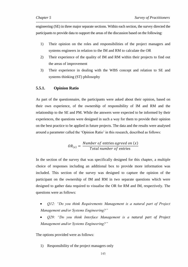
Chapter 5 Survey of Practitioners
----------------------------------------------------------------------------------------------------------
145
engineering (SE) in three major separate sections. Within each section, the survey directed the
participants to provide data to support the areas of the discussion based on the following:
1) Their opinion on the roles and responsibilities of the project managers and
systems engineers in relation to the IM and RM to calculate the OR
2) Their experience of the quality of IM and RM within their projects to find out
the areas of improvement
3) Their experience in dealing with the WBS concept and relation to SE and
systems thinking (ST) philosophy
5.5.1. Opinion Ratio
As part of the questionnaire, the participants were asked about their opinion, based on
their own experience, of the ownership of responsibility of IM and RM and the
relationship to the SE and PM. While the answers were expected to be informed by their
experiences, the questions were designed in such a way for them to provide their opinion
on the best practice to be applied in future projects. The data and the results were analysed
around a parameter called the ‘Opinion Ratio’ in this research, described as follows:
𝑂𝑅(𝑥) = 𝑁𝑢𝑚𝑏𝑒𝑟 𝑜𝑓 entries 𝑎𝑔𝑟𝑒𝑒𝑑 𝑜𝑛 (𝑥)
𝑇𝑜𝑡𝑎𝑙 𝑛𝑢𝑚𝑏𝑒𝑟 𝑜𝑓 entries
In the section of the survey that was specifically designed for this chapter, a multiple
choice of responses including an additional box to provide more information was
included. This section of the survey was designed to capture the opinion of the
participant on the ownership of IM and RM in two separate questions which were
designed to gather data required to visualise the OR for RM and IM, respectively. The
questions were as follows:
Q12: “Do you think Requirements Management is a natural part of Project
Management and/or Systems Engineering?”
Q29: “Do you think Interface Management is a natural part of Project
Management and/or Systems Engineering?”
The options provided were as follows:
1) Responsibility of the project managers only

Chapter 5 Survey of Practitioners
----------------------------------------------------------------------------------------------------------
146
2) Responsibility of the systems engineers only
3) Shared responsibility between project managers and systems engineers
4) Interface management is not the responsibility of the project managers or
systems engineers
5) No Response (or don’t know)
Table 16 summarises the gathered responses and presents the numerical results for
different scenarios and demonstrates the results for both the ‘All’ and the ‘Rail’ samples
in the scenarios which focus on IM and RM.
Figure 30 presents a graphical representation of the results of the OR from the table. The
graphs focus on the bigger sample and provide a like-to-like comparison presenting the
general OR of professionals in different industries over the responsibility of IM and RM.
In order to provide a more accurate view of the results with more focus on the responses
from the project managers and the systems engineers, a margin of error based on the
sample size is considered in the data analysis. For a simple sample, the maximum
margin of error (MOE) is a simple re-expression of the sample size n. The numerators
of these equations are rounded to two decimal places as 1.29/√n for MOE at 99 per
cent confidence, 0.98/√n for MOE at 95 per cent confidence, and 0.82/√n for MOE at
90 per cent confidence (Aufmann et al., 2008). For the purpose of this graph, a MOE
with a confidence level of 99 per cent is considered for the results given by the project
managers and the systems engineers. Therefore, the MOE is calculated as follows:
𝑀𝑂𝐸 𝑃𝑀𝑠 = 1.29
√𝑛𝑃𝑀𝑠
, 𝑤ℎ𝑒𝑟𝑒 𝑛 = 𝑠𝑎𝑚𝑝𝑙𝑒 𝑠𝑖𝑧𝑒
𝑛𝑃𝑀𝑠 = 107 » 𝑀𝑂𝐸 𝑃𝑀𝑠 = 1.29
√107= 9.67%
𝑀𝑂𝐸 𝑆𝐸𝑠 = 1.29
√𝑛𝑆𝐸𝑠
, 𝑤ℎ𝑒𝑟𝑒 𝑛 = 𝑠𝑎𝑚𝑝𝑙𝑒 𝑠𝑖𝑧𝑒
𝑛𝑆𝐸𝑠 = 59 » 𝑀𝑂𝐸 𝑃𝑀𝑠 = 1.29
√59= 13.73%

Chapter 5 Survey of Practitioners
----------------------------------------------------------------------------------------------------------
147
Table 16: Survey Numerical Results for RM and IM Responsibility – Opinion Ratio
Questions Sample Positions
BM
s
Sy
stems
En
gin
eers
En
g.
PC
s
Pro
ject
Ma
na
gers
SUM
Q12. “Do you
think
Requirements
Management is
a natural part of
Project
Management
and/or Systems
Engineering?”
All
Sample Size 38 59 22 30 107 256
PM 8 0 6 12 50 76
SE 5 27 1 1 3 37
PM+SE 12 22 5 2 9 50
Neither 1 0 2 0 2 5
No Response
(don’t know) 12 10 8 15 43 88
Rail
Sample Size 14 19 7 4 13 57
PM 4 0 2 3 9 18
SE 1 8 0 0 0 9
PM+SE 6 7 2 0 2 17
Neither 1 0 1 0 1 3
No Response (or
don’t know) 2 4 2 1 1 10
Q29. “Do you
think Interface
Management is
a natural part of
Project
Management
and/or Systems
Engineering?”
All
Sample Size 38 59 22 30 107 256
PM 7 6 5 8 35 61
SE 8 21 4 1 7 41
PM+SE 7 14 2 3 12 38
Neither 0 1 1 0 3 5
No Response (or
don’t know) 16 17 10 18 50 111
Rail
Sample Size 14 19 7 4 13 57
PM 5 1 1 3 6 16
SE 2 5 2 0 2 11
PM+SE 2 5 1 0 3 11
Neither 0 1 0 0 0 1
No Response (or
don’t know) 5 7 3 1 2 18

Chapter 5 Survey of Practitioners
----------------------------------------------------------------------------------------------------------
148
Figure 30: Opinion Ratio for IM and RM Responsibility for the ‘All’ Sample

Chapter 5 Survey of Practitioners
----------------------------------------------------------------------------------------------------------
149
The first interesting result is that for both functions, the graphs have very similar
behaviour. The most important conclusion from the graphs is an indication of different
views between the project managers and systems engineers. While the rest of the project
team almost have a flat opinion, the majority of the project managers believe that the
functions are best handled by PM while the systems engineers claim that both functions
are natural parts of SE.
The almost flat OR of the other project team members, including the business managers,
can further be considered as proof of the lack of consensus over the responsibility to
execute the IM and RM functions in a wider spectrum, which is a risk to the project of
any type. In addition, a high percentage of people skipped the question with no
response. If this is to be interpreted as ‘don’t know’, then this could also be seen as
further evidence of the lack of consensus described above.
The error bars in the graph show overlap in a scenario where PM is to handle the
interfaces as well as the scenario where a shared responsibility of PM and SE to manage
the requirements within a project is considered.
Figure 31 projects a similar analysis but in a smaller group of rail sector professionals,
the main focus of this study. The sample size of 57 for the rail sector is a relatively
small scale and therefore carries a higher MOE (MacCallum et al., 1999). Similar to the
previous case, the MOE at the 99 per cent confidence level for this sample is also
calculated as follows:
𝑀𝑂𝐸 𝑃𝑀𝑠 = 1.29
√𝑛𝑃𝑀𝑠
, 𝑤ℎ𝑒𝑟𝑒 𝑛 = 𝑠𝑎𝑚𝑝𝑙𝑒 𝑠𝑖𝑧𝑒
𝑛𝑃𝑀𝑠 = 13 » 𝑀𝑂𝐸 𝑃𝑀𝑠 = 1.29
√13= 27.74%
𝑀𝑂𝐸 𝑆𝐸𝑠 = 1.29
√𝑛𝑆𝐸𝑠
, 𝑤ℎ𝑒𝑟𝑒 𝑛 = 𝑠𝑎𝑚𝑝𝑙𝑒 𝑠𝑖𝑧𝑒
𝑛𝑆𝐸𝑠 = 19 » 𝑀𝑂𝐸 𝑃𝑀𝑠 = 1.29
√19= 22.94%

Chapter 5 Survey of Practitioners
----------------------------------------------------------------------------------------------------------
150
Figure 31: Opinion Ratio for IM and RM Responsibility for the ‘Rail’ Sample

Chapter 5 Survey of Practitioners
----------------------------------------------------------------------------------------------------------
151
In a very similar situation to the ‘All’ sample, rail project managers also claim that the
IM and RM are the natural parts of PM.
Another interesting conclusion from the graph is that the engineers mostly believe that
IM is an SE function while, similar to project managers, they still think that
requirements in a project should be handled and managed as part of PM.
The graph also shows a smaller number of people skipping the question without
response. Although this is a better news for the rail sector, the average rate of 20 per
cent of project managers and systems engineers skipping the question could potentially
indicate a high level of risk. This, therefore, further shows that the complexity of the
projects is required for the project team to be made more aware of systematic thinking
to make projects more efficient (Davidz and Nightingale, 2008).
The error bars are overlapped very closely and, therefore, the results can be considered
as the same under some circumstances. Still, even within such MOEs, the graph
presents the same lack of consensus described earlier among the systems engineers and
project managers over responsibility of RM in a project.
5.5.2. Interface Management and Requirements Management Execution
Quality
Question 24 is a standalone question designed to ask participants to grade the IM in
their existing projects. Questions 17 and 18 in the context of RM and questions 34 and
35 in the context of IM, however, are designed to collect data required to understand
how people observe, assess and rate the overall quality of IM and RM execution from
the other parties they are involved with, according to their project experiences. The
questions are as follows:
Q24: “How well are the interfaces managed in your projects?”
Q17: “How do you rate the quality of Requirements Management at your client
organisation?”
Q18: “How do you rate the quality of Requirements Management at your
supplier organisation?”
Q34: “How do you rate the quality of Interface Management at your client
organisation?”

Chapter 5 Survey of Practitioners
----------------------------------------------------------------------------------------------------------
152
Q35: “How do you rate the quality of Interface Management at your supplier
organisation?”
All five questions are Likert-type scale questions, which is an approach to
unidimensional scaling (Likert, 1932, Alphen et al., 1994, McIver and Carmines, 1981,
Allen and Seaman, 2007) with rating scales from poor to excellent and additional
options of ‘Not Applicable’, ‘Absent’ and ‘Don’t know’.
A wider range of scales is used in this question in accordance to the general rule Likert
and others recommend, because no matter how wide the range of data is, they can be
collapsed into condensed categories, if appropriate (Allen and Seaman, 2007, Likert,
1932).
Table 17 details the numerical results of responses to the above five questions. One-
hundred-seventy-one people answered questions 17 and 18 in relation to RM, 148
responded to question 24 and 147 responded to questions 34 and 35 in relation to IM.
Table 17: Survey Numerical Results for IM and RM Execution Quality
Questions
Excellen
t
Very
Good
Good
Averag
e
Poor
Very
Poor
Absen
t
Not
Applicab
le
Do N
ot
Know
Total
Q17. Quality of RM at
your client organisation? 7 13 38 54 26 7 2 8 16 171
Q18. Quality of RM at
your supplier
organisation?
4 7 33 51 19 9 2 24 22 171
Q24. Quality of IM in
your projects? 10 24 58 39 12 1 0 0 4 148
Q34. Quality of IM at
your client organisation? 7 10 41 48 16 6 2 1 16 147
Q35. Quality of IM at
your supplier
organisation?
2 7 33 50 16 4 0 13 22 147
Figure 32 also is a graphical presentation of the results that shows a very small bar for
the grades of Excellent and Very Good for all of the questions.

Chapter 5 Survey of Practitioners
----------------------------------------------------------------------------------------------------------
153
Figure 32: Q17, 18, 24, 34 and 35 Results Proportions
The data obtained from the Likert-type questionnaire can be assessed further to
calculate a mean score for each of the questions. Therefore, a model is required to take
into account the number of participants, as well as how they have graded the quality of
the functions within each these question, in order to calculate an overall score for each
question.
In order to calculate the mean score for each of the questions the following solution is
used:
1) Assumption made: 𝐆𝐢 = 𝐆𝐫𝐚𝐝𝐞, where, G1 = Excellent, G2 = Very Good, G3 =
Good, G4 = Average, G5 = Poor, G6 = Very Poor, G7 = Absent, G8 = Not
Applicable and G9 = Don’t know.
2) The Likert grades are scored as, and 𝐒𝐆𝐢 = 0 to 6, where 6 represents Excellent
and 0 represents Absent, Not Applicable and Don’t know, with 1 as the interval
(that is, SG1 = 6, SG2 = 5, SG3 = 4, SG4 = 3, SG5 = 2, SG6 = 1, SGi=7,8 and 9 = 0
3) 𝒏𝒊 is considered as the number of entries of each grade against each question
4) Score band (Sb) as a score for each grade against each question is calculated as
𝑺𝒃𝒊 = 𝒏𝒊 × 𝑮𝒊

Chapter 5 Survey of Practitioners
----------------------------------------------------------------------------------------------------------
154
5) The total number of entries per question is considered as ∝, which is calculated
as
∝ = ∑ 𝒏𝒊𝟗𝒊=𝟏 per each question
6) The sum of score bands per question is considered as β, which is calculated as
𝜷 = ∑ 𝑺𝒃𝒊𝟗𝒊=𝟏 per each question
7) Mean Score for each question is considered as 𝜇 which is calculated as 𝜇 = 𝛽/∝
Table 18 shows the number of entries for each question with a calculation for scoring
each grade against each question, and Table 19 presents the calculation for the mean
score for each question based on the equations above.
Table 18: Q17, 18, 24, 34 and 35 Results Scoring
Questions
Grade
Excellen
t
Very
Good
Good
Averag
e
Poor
Very
Poor
Absen
t
Not A
pplicab
le
Do N
ot K
now
𝐺𝑖 1 2 3 4 5 6 7 8 9
𝑆𝐺𝑖 6 5 4 3 2 1 0 0 0
Q17. RM / Client 𝑛𝑖 7 13 38 54 26 7 2 8 16
𝑆𝑏𝑖 42 65 152 162 52 7 0 0 0
Q18. RM / Supplier 𝑛𝑖 4 7 33 51 19 9 2 24 22
𝑆𝑏𝑖 24 35 132 153 38 9 0 0 0
Q34. IM / Client 𝑛𝑖 7 10 41 48 16 6 2 1 16
𝑆𝑏𝑖 42 50 164 144 32 6 0 0 0
Q35. IM / Supplier 𝑛𝑖 2 7 33 50 16 4 0 13 22
𝑆𝑏𝑖 12 35 132 150 32 4 0 0 0
Q24. IM / Existing Pro. 𝑛𝑖 10 24 58 39 12 1 0 0 4
𝑆𝑏𝑖 60 120 232 117 24 1 0 0 0
The results within Table 19 show that the mean score for all the questions are between
poor to average, with the exception of question 24 being between average to good. This
further presents the relatively poor to average quality of IM and RM in the industry and,
therefore, justifies the requirements to develop better solutions to improve these
activities and make the projects more efficient.

Chapter 5 Survey of Practitioners
----------------------------------------------------------------------------------------------------------
155
Table 19: Q17, 18, 24, 34 and 35 Mean Score Calculations
Questions Scoring Calculations 𝝁𝒒 = 𝜷𝒒
∝𝒒 SCALE
Q17. RM /
Client
∝17 = ∑ 𝑛𝑖
9
𝑖=1 =171
𝜇17 = 2.81 𝑝𝑜𝑜𝑟 < 𝜇17 < 𝑎𝑣𝑒𝑟𝑎𝑔𝑒
𝛽17 = ∑ 𝑆𝑏𝑖
9
𝑖=1 =480
Q18. RM /
Supplier
∝18 = ∑ 𝑛𝑖
9
𝑖=1 =171
𝜇18 = 2.29 𝑝𝑜𝑜𝑟 < 𝜇18 < 𝑎𝑣𝑒𝑟𝑎𝑔𝑒
𝛽18 = ∑ 𝑆𝑏𝑖
9
𝑖=1 =391
Q34. IM /
Client
∝34 = ∑ 𝑛𝑖
9
𝑖=1 =147
𝜇34 = 2.98 𝑝𝑜𝑜𝑟 < 𝜇34 < 𝑎𝑣𝑒𝑟𝑎𝑔𝑒
𝛽34 = ∑ 𝑆𝑏𝑖
9
𝑖=1 =438
Q35. IM /
Supplier
∝35 = ∑ 𝑛𝑖
9
𝑖=1 =147
𝜇35 = 2.48 𝑝𝑜𝑜𝑟 < 𝜇17 < 𝑎𝑣𝑒𝑟𝑎𝑔𝑒
𝛽35 = ∑ 𝑆𝑏𝑖
9
𝑖=1 =365
Q24. IM
∝24 = ∑ 𝑛𝑖
9
𝑖=1 =148
𝜇24 = 3.74 𝑎𝑣𝑒𝑟𝑎𝑔𝑒 < 𝜇17 < 𝑔𝑜𝑜𝑑
𝛽24 = ∑ 𝑆𝑏𝑖
9
𝑖=1 =554
5.5.3. Work Breakdown Structure
A section of the survey was designed to collect information on the WBS development
and applications on the real projects as well as the relationship to SE philosophy.
5.5.3.1. WBS Development
In Section 4.2.5, the different ways of WBS development were reviewed in different
literature. No data could be found in any literature suggesting a prescription to build
WBS in a single format that can be used in different kinds of environment. Also,
minimal work and discussion could be found regarding development of a standard
patterned WBS to be used in different projects of the same nature.
Question 19 of the survey asked attendees how they have developed a WBS in their
projects. The question and the choices are designed to categorise two fundamental ways
of WBS development: using a template or building from scratch for each project. Table
20 presents the structure of the question and the choices. There also are options for

Chapter 5 Survey of Practitioners
----------------------------------------------------------------------------------------------------------
156
those who never developed one or have different opinions that all are take into account
when the results are discussed.
Table 20: Survey Q19 Structure
Question Category Choices
Question 19:
How have you
developed
WBSs?
Template / Standard 1. Used template
2. Used previous similar projects
Develop from scratch
depending on different
project parameters
3. Structured around the project deliverables
4. Structured around the team or disciplines
5. Structured around the nature of the work
The same sample of the ‘All’ and the ‘Rail’ are used to see the overall results in
industry and compared to the rail sector. Table 21 presents the detailed numerical results
based on the absolute frequency as well as relative frequency by choices made by the
participants. The table also categorises the results into the main two scenarios
mentioned for the two data samples of the ‘All’ and the ‘Rail’.
Table 21: Survey Question 19 – Detailed Results
Choices
Absolute
frequency
Relative
frequency by
choice
Category
Absolute
frequency
Relative
frequency by
choice
‘All’ ‘Rail’ ‘All’ ‘All’ ‘All’ ‘Rail’ ‘All’ ‘Rail’
1. Used template 58 13 18% 14% Template /
Standard 109 27 33% 28% 2. Used previous
similar projects 51 14 15% 15%
3. Structured around
the project
deliverables
104 28 31% 29% Develop
from scratch
depending
on different
project
parameters
209 61 63% 64% 4. Structured around
the team or
disciplines
45 16 14% 17%
5. Structured around
the nature of the work 60 17 18% 18%
6. Never developed
one 13 7 4% 7% N/A 13 7 4% 7%
SUM 331 95 100% 100% 331 95 100% 100%
Results detailed in Table 21 and visualised in Figure 33 shows that in both overall
industry and the rail sector, over 60 per cent of those involved in developing a WBS in
projects have to do this from the scratch considering the different project-specific
characteristics such as project deliverables and works and tasks involved.

Chapter 5 Survey of Practitioners
----------------------------------------------------------------------------------------------------------
157
Figure 33: WBS Development Paths
Only 20 to 30 per cent either used a template WBS or used previous projects as
templates to build a new WBS for the new project. This result provides further evidence
that there is little work to develop a form of a standard breakdown structure that can be
used in managing projects.
5.5.3.2. WBS Applications
Many forms of breakdown structure are defined in the literature and many are used in
projects in different formats. Figure 34 presents the results from question 20 in the
survey, which show that over half of the projects only use one form of WBS in a project
while others use multiple types to serve different purposes within different project tools
and applications.
Figure 34: Number of WBS Forms Used in the Same Project

Chapter 5 Survey of Practitioners
----------------------------------------------------------------------------------------------------------
158
The purpose of question 21 in the survey is to identify the project functions and
application that use one or more form of a WBS in a project. The results presented in
Figure 35 show that, as expected, the primary use of WBS in projects is in project
planning and scheduling. Over 35 per cent in all industries as well as rail sector use
WBS in project planning tools. Results show that a relatively low percentage of
respondents use WBS in different formats and in various other PM tools and application
such as resource management tools or risk management tools.
Figure 35: WBS Incorporated in Project Tools and Applications
The interesting result, however, is that over 20 per cent of people in the rail sector use a
WBS approach in commercial management while a very low percentage, less than 5 per
cent across all businesses, use a WBS in commercial tools and applications.
Another conclusion from this result is a very weak link to SE tools and application to
any form of a WBS. If requirements and IM tools are to be considered as SE tools, the
graph shows that a very low percentage of the people link a WBS to these tools. This
further demonstrates that just around 0 to 10 per cent of the people use WBS or a form
of breakdown structure in IM.
It is also interesting to understand, where there is only one form of a WBS, what the
percentage of the people using the same WBS in different tools and application is. For
this reason, the same analysis as above was conducted for the scenario with only one
single form of WBS in the project.

Chapter 5 Survey of Practitioners
----------------------------------------------------------------------------------------------------------
159
Figure 36 presents the results from this study, which show that the single form WBS is
mainly used in project planning tools and applications. But around 10 to 15 per cent of
the people using a single form of WBS also use other PM tools such as resource and
risk planning tools. A very low portion of people use a single form WBS for IM and
RM.
Figure 36: Single Form WBS Incorporation into the Project Tools and Applications
A very interesting result is in regard to the use of WBS within the project commercial
tools. In this scenario, the result shows that a very low percentage, less than 5 per cent,
of both the ‘All’ sample and the ‘Rail’ sample use the same planning WBS within their
commercial tools to model the costs and expenses based on the resources and activities
in the WBS. Considering the high percentage of the people in rail sector using a form of
WBS for commercial use, this shows that the rail sector uses different types of
breakdown structures for managing the commercial tools, which is not necessarily
similar to the overall project WBS.
5.5.3.3. WBS Types
In Section 4.2.3, different types of WBSs were described and methods to choose the
most suitable WBS form to serve special purpose within specific work sectors was
reviewed within the literature. Within this survey, question 22 was designed to
understand how people tend to build a WBS within their projects. The choices given
included WBSs developed around product, service, resource and discipline. An ‘others’
option was also given for additional information for those who have other experiences.

Chapter 5 Survey of Practitioners
----------------------------------------------------------------------------------------------------------
160
The responses outside the choices were reviewed and consolidated into the responses.
As a result, the additional information, task and functional oriented WBSs are also
included in the results to be presented.
As shown in Figure 37, in general, a majority of the WBSs are developed around the
product and final deliverables of the project. Around 40 per cent of the WBSs within the
‘All’ sample are created around the project products. The result also show a high
percentage, around 30 per cent, of the WBSs within industry are developed around the
project disciplines, tasks and functions within the project.
Figure 37: WBS Structure
In the rail sector, however, there is a higher interest in developing WBS around the
project disciplines, tasks and functions. The same results were reviewed in Chapter 4,
where it was concluded that the major civil construction projects tend to use work-based
WBSs (see Figure 37, page 160).
5.5.3.4. WBS and Systems Engineering
Question 23 explored the link and relationship between the WBS concept and an SE
approach3 within the projects. The question is as follows:
3 The intention in this question is to understand, if a WBS is used in any of the SE tools and procedures.

Chapter 5 Survey of Practitioners
----------------------------------------------------------------------------------------------------------
161
Q23: “How well connected is the WBS to systems engineering management in
your opinion?”
Question 23 also is Likert-type scale question with rating scales from poor to excellent
with additional options of ‘Not Applicable’, ‘Not at all’ and ‘Don’t know’. Similar to
the other questions discussed in Section 5.5.2, this question collapses a wider range of
scales into a condensed category (Allen and Seaman, 2007, Likert, 1932).
Table 22 details the numerical results of the people who responded to the question
within the data sample of the ‘All’ and the ‘Rail’; 156 people answered the question, 42
of whom were from the rail sector.
Table 22: Survey Numerical Results for WBS – SE Relationship
Questions
Excellen
t
Very
Good
Good
Avera
ge
Poor
Very
Poor
Not a
t all
SUM
Q23 – the ‘All’ 9 26 36 43 17 1 1 156
Q23 – the ‘Rail’ 3 5 9 13 5 1 1 42
Figure 38 is a graphical presentation of the results that compare the rating from the ‘All’
sample with that from the ‘Rail’ sample. The same model used in Section 5.5.2 is used
to calculate a mean score for the two scenarios.
Figure 38: SE Application and Relationship with WBS

Chapter 5 Survey of Practitioners
----------------------------------------------------------------------------------------------------------
162
Table 23 shows the number of entries for the question per sample with a calculation for
scoring for each grade against each question. Table 24 presents the calculation for the
mean score for each scenario based on the model described in Section 5.5.2.
Table 23: Q23 Results Scoring
Questions
Grade
Ex
cellent
Very
Go
od
Go
od
Av
erage
Po
or
Very
Po
or
No
t at all
𝐺𝑖 1 2 3 4 5 6 7
𝑆𝐺𝑖 6 5 4 3 2 1 0
Q23 – the ‘All’ 𝑛𝑖 9 26 36 43 17 1 5
𝑆𝑏𝑖 54 130 144 129 34 1 0
Q23 – the ‘Rail’ 𝑛𝑖 3 5 9 13 5 1 1
𝑆𝑏𝑖 18 25 36 39 10 1 0
The results within Table 24 show that the mean scores for both samples are around
average. This, therefore, further presents the relatively poor link/relationship between
SE and the WBS concept.
Table 24: Q23 Mean Score Calculations
Questions Scoring Calculations 𝝁𝒒 = 𝜷𝒒
∝𝒒 SCALE
Q23 – the
‘All’
∝𝑎𝑙𝑙 = ∑ 𝑛𝑖
7
𝑖=1 =137
𝜇𝑎𝑙𝑙 = 3.59 𝑎𝑣𝑒𝑟𝑎𝑔𝑒 < 𝜇𝑎𝑙𝑙 < 𝑔𝑜𝑜𝑑
𝛽𝑎𝑙𝑙 = ∑ 𝑆𝑏𝑖
7
𝑖=1 =492
Q23 – the
‘Rail’
∝𝑟𝑎𝑖𝑙 = ∑ 𝑛𝑖
7
𝑖=1 =42
𝜇𝑟𝑎𝑖𝑙 = 3.07 𝑎𝑣𝑒𝑟𝑎𝑔𝑒 < 𝜇𝑟𝑎𝑖𝑙 < 𝑔𝑜𝑜𝑑
𝛽𝑟𝑎𝑖𝑙 = ∑ 𝑆𝑏𝑖
7
𝑖=1 =129
5.6. Conclusion of the Chapter
This chapter detailed a survey that was conducted to test the main parts of this research
hypothesis. The survey methodology, crowd targeting, engagement methodology, data
filtering and data analysis was explained. After a phased approach on the data review
and analysis, the results in this context were presented in various graphs and tables.
Chapter 5 Survey of Practitioners
----------------------------------------------------------------------------------------------------------
163
The data analysis within this chapter first indicates a lack of consensus among the
project players, including management and delivery teams, about the importance of
managing the interfaces and requirements within complex projects as standalone
functions. In addition, the survey clarifies that a PM view is to manage the interfaces
and requirements as natural part of managing a project, while an SE view is to have a
standalone and systematic approach, along with procedures and tools to conduct such
management functions.
The key conclusion from this data analysis is, therefore, a further clarification of the
identity crisis of SE in today’s projects and PM (Emes et al., 2005). The fact that there
is still such debate over the ownership of two such important management functions
justifies that more work is required to link the SE approach to PM in a more systematic
way so that the project can function more efficiently. This conclusion also further
explains why major projects of different types fail, simply due to very obvious interface
and quality issues, as discussed in Chapter 3.
The analysis also shows that because the interfaces and requirements are not being
managed well in industry, there is a major risk to the projects as they get larger and
more complex. This is a further justification to develop better solutions to enhance and
improve the IM and RM functions within managing the complex projects to make the
projects more efficient.
The survey also asked questions related to the WBS concept and its types, development
and applications, as well as its relationship with an SE approach. The key conclusion of
this section provided further evidence regarding the little work and research conducted
to create a standard breakdown structure concept that can be adopted in managing
projects of the same nature. This provides a justification on the requirements to conduct
such works and research.
It also concluded that the majority of the projects only use a single form WBS, and they
mainly tend to use this WBS in project planning and scheduling tools and documents.
The results clarified further the lack of projects using WBS or any other form of
breakdown structure to link different PM and SE tools and functions. This is more
significant, as it shows that the WBS concept has not been able to be used in IM within

Chapter 5 Survey of Practitioners
----------------------------------------------------------------------------------------------------------
164
multidisciplinary projects and, therefore, this reveals a need for further work in this
subject area.
The survey also presented a relatively poor connection between an SE approach and the
WBS concept that will provide more justification on requirements to adopt such
research work.

165
Chapter 6 KEY FAILURE FACTORS IN A RAILWAY
PROJECT CASE STUDY
INTRODUCTION 166
CASE STUDY PROJECT DESCRIPTION 166
NATURE OF SAMPLE 172
STUDY METHODOLOGY 175
RESULTS AND DISCUSSION 181
CONCLUSION OF THE CHAPTER 184

Chapter 6 Key Failure Factors in a Railway Project Case Study --------------------------------------------------------------------------------------------------------------------------------------
166
6.1. Introduction
In order to further explore key failure parameters in multidisciplinary rail projects, a
major railway related project in central London was chosen as a case study to be
examined.
The project team and the management of a major engineering consulting firm (ECF)
that have had major roles in this project were approached and granted access to some
data that will be explained in detail within this chapter. The project manager of the
current project was also interviewed in various sessions and through various email
communications, providing series of data and information.
In this chapter the project being studied is explained and its scale and timeline is
detailed to provide a context to the research. Also the project governance is presented
and the tools and procedures used in project management (PM) is explained.
Further detail on the data provided by the project is given and the methodology on the
data assessment is explained. Based on the methodology designed, the data is analysed
in detail and the results are presented and discussed. The results obtained are further
studied and the conclusion is provided.
As the project is an ongoing and high-profile national project, no permission was
granted to the author to use the actual name of the project and the name of the project
parties. However, full permission is given to use the data for academic research only.
6.2. Case Study Project Description
The project used in this research as the case study is a single project that is contracted
between a major design ECF and the main design and build contractor. Figure 39 is a
schematic view of the programme in whole and the case study project within the
programme.

Chapter 6 Key Failure Factors in a Railway Project Case Study --------------------------------------------------------------------------------------------------------------------------------------
167
Stage 1: Project Definition Phases
Stage 2: Design & Build – Main Contractor
20
07 –
De
c 20
09
20
10 - 2
016
Ph
ase 1
: 2
010
- 20
15P
hase
2:
20
15 - 2
016
RIBA D - Concept
RIBA G - Tender Design
Premises
M&E
Civil
ECF – Lead Designer
MEP Installation Design
Premises - Design Intent Civil Tunnel
23 Sub contractors – Final Design & Installation
1 2 3 4 5 6
7 8 9 10 11 12
13 14 15 16 17 18
19 20 21 22 23
Clinet
Coordination
Required
Figure 39: Case Study Project within the Programme
6.2.1. Programme Scope
The primary objectives of the programme are congestion relief and capacity
enhancement of a central London rail underground station, as well as improving public
access and interchange. Provision is to be made for passengers with reduced mobility
and for improved emergency escape. The upgrade will include enlarging the existing
ticket hall with new lifts, escalators, platform connections and step-free access from
street level. Station modernisation is also a major part of the scope of this programme,
from technology improvements to architectural modernisation. As the station is being
expanded and major alterations applied, fire safety improvement is also another key
major scope of this programme.
As Figure 39 shows, the programme consists of two major stages. Stage 1 was the
period from 2007 to December 2009 in which an existing concept design was developed
into a detailed tender design, Royal Institute of British Architects (RIBA) Stage G (refer
to Figure 7: Alignment of Existing Plans of Work (Churcher and Richards, 2015)).
Stage 2 is the construction period in which the designer provided design services to the
design and build contractor.

Chapter 6 Key Failure Factors in a Railway Project Case Study --------------------------------------------------------------------------------------------------------------------------------------
168
The construction is contracted out to a main design and build joint venture (JV)
contractor as a New Engineering Contract (NEC) Option C with the target cost of
approximately £300 million, with construction to be conducted in two phases of 2010–
2015 and 2015–2016, as shown in Figure 39. These two phases are only related to the
sections of the station to be commissioned in different phases.
NEC Option C is a contract with a target cost and the schedule of the activities in
which the outturn financial risks will be shared between the contractor and the client
in a proportion that is agreed in advanced (Broome and Hayes, 1997, NEC, 2013,
Institution of Civil Engineering (ICE), 2015). This is a type of contract that was
adopted in major UK contracts such as London 2012 Olympic and Paralympic Games
and Crossrail.
6.2.2. Case Study Project Scope
A JV of major international contractors formed and was awarded the construction
contract for a major station upgrade project in London in December 2009. The major
ECF in the UK that was approached and interviewed for the purpose of this study has
been involved as the lead designer on the project since 2007. Initially working for the
end user directly under a multidisciplinary design contract, it developed the design from
RIBA Stage D to RIBA Stage G and developed the tender documents. Disciplines
covered include civil/structural; tunnels; premises; mechanical, electrical, and plant
(MEP); communications; fire; human factors; and public health. The outcome of this
stage of the project was the set of project requirements specifications as well as work
information (WI4) that should be used as the main requirements to be designed and
delivered in Stage 2 (design and build) of the project.
Since 2010, the ECF, under a completely separate contract and separate project team,
has been commissioned to work as the lead designer for the main design and build
contracting JV, retaining responsibility for the civil/structural, tunnels and premises
design. The implementation design for the MEP, fire, public health and communications
disciplines however is now resides with an MEP contractor.
4 Work information (WI) is equivalent to the project requirements specification. This is a contractual document specifying the work required to be delivered by the supplier

Chapter 6 Key Failure Factors in a Railway Project Case Study --------------------------------------------------------------------------------------------------------------------------------------
169
The ECF has produced the premises design to a ‘design intent’ level. The design should
be in compliance with the project requirements specifications as well as the WI
developed in Stage 1 of the project. This work is then developed by the relevant
subcontractor for final installation design and physical installation.
The design intent provides an architectural concept and aesthetic feel for a design and
outlines details such as fixings. For example, for ceilings, the design intent drawings
provide sufficient information for the subcontractor designer to complete detailed
design of the fixings and connections, but the overall aesthetic of the completed
elements has already been set out in the design intent package.
Premises is essentially architecture, but is the architectural discipline as applied
particularly to the rail industry. This major client especially has its own idea about
what it wants to see. All products have to be on their approved register – a principle
established after the 1987 King’s Cross Station fire to ensure that all products were
not combustible. The ECF project manager who was interviewed for this study
stated:
“The role of the register has expanded now and it is as much a register of products
the client is comfortable can be maintained economically as it is a fire safety
initiative. It is very hard to get a product on the register as the client bureaucracy is
very slow (this stifles innovation but that’s the subject of another Ph.D.…).” (ECF
Project Manager, 2015)
The premises discipline has been selected for this exercise as it is the key
discipline with major coordination interfaces with all the other disciplines. As
discussed, the ECF as part of this contract has produced a design intent to then be
detailed up by the subcontractor designer/installers. There are 23 of these
subcontractors providing items from cladding to doors to tiling. Most but not all
have a design and drawing production responsibility for their area. Through the
Technical Design Review process, the ECF has responsibility to review and
comment on their drawings.
The contract between the main contractor JV and the ECF that interviewed for this
study is worth £10 million to the ECF and includes all contractor design alternatives and
the production of final Issued For Construction drawing packages.

Chapter 6 Key Failure Factors in a Railway Project Case Study --------------------------------------------------------------------------------------------------------------------------------------
170
6.2.3. Project Governance, Tools and Procedures
The ECF project manager was interviewed to understand the project governance and
team structure. The ECF overall project team and the interaction with the ECF client in
this specific contract that is the main design and build JV is summarised in the
organisation chart presented in Figure 40. The project team consists of a project
manager who reports to a project director. The project manager leads three main blocks:
quality management and assurance; project control, cost and legal; and the design team.
According to the project manager, a “systems engineering role was not required in the
contract with design and build [and] didn’t use any tools or procedures to manage the
requirements and interfaces” (ECF Project Manager, 2015). The coordination with
other contractors and clients managed through the assurance regime is detailed in a
Project Assurance Management Plan.
Design & Build – Main Contractor
ECF – Lead Designer
Project Director
Section QSQuality and
Assurance Manager
Engineering
Manager Design Manager
Project Director
Project Manager
Design Management, Primary
Design and Site Coordination
Quality Management, Safety
and Technical Assurance
Project Control, Change Control,
Document Control, Risk Management,
Cost, Contract and Legal
Design Team
Premises
Checkers
TunnelCivil /
Structural3D Modeller
Geotechnical Services
Figure 40: ECF Project Team Structure
The assurance regime makes the assumption that the lead designers understand the
requirements within project requirements specification and WI, and therefore it is only
concerned about the technically quality of the deliverables as well as overall
constructability. When the quality is controlled, deliverables are issued to the client for

Chapter 6 Key Failure Factors in a Railway Project Case Study --------------------------------------------------------------------------------------------------------------------------------------
171
acceptance or comment. The deliverables should be revisited based on the client and/or
other parties’ comments and request for changes. In this regime, no specific solution or
procedure is designed to control the deliverables in terms of compliance with detailed
project requirements specifications, WI and standards.
The project manager also stated that the architects changed the design completely from
what was done as part of Stage 1 without any clear instruction:
“They don’t appreciate the change they are making and the impact they have to the
project….They do what they do because they think this is what the client wants”
(ECF Project Manager, 2015).
They made the changes and they designed based on the new changes in the absence of
any sort of compliance review/audit with the project requirements specifications and
WI.
According to the project manager, there are also no systematic requirements or interface
management (IM) on the client side:
“To be honest the client keeps changing their mind.” “Some of the comments show
that we change the same thing three times because the client keeps changing their
mind….[The] client won’t tell you what they exactly want because it would be telling
us our job, but they just keep asking for changes to what we provide….We have to try
to interpret what the comment says and work based on that.” (ECF Project Manager,
2015)
Another key issue to generate changes to the work is the lack of managing the
innovation and technology that impacts the project requirements specifications and WI:
“Quite often when the comment says, ‘it is not in work information’, it is because of
the time from 2008 to now. [The] supplier changes the equipment and there is no
system to capture the changes systematically.” (ECF Project Manager, 2015)
Therefore, it can be concluded that the absence of a system to manage and track
requirements from customer to supplier has led to issues with requirement volatility and
solution traceability (that is, requirements validation).

Chapter 6 Key Failure Factors in a Railway Project Case Study --------------------------------------------------------------------------------------------------------------------------------------
172
6.3. Nature of Sample
The project manager of the ECF was approached by the author to discuss the possible
data that could be made available for the purpose of this research. As the project is an
ongoing project and multiple parties are involved, there is a high level of sensitivity
over the data sharing that limits the access to data. However, after various sessions with
the project manager, some data were made available related to the construction support
contract between the ECF and the main contractor JV who is responsible in building the
station.
The data are in a form of series of comment logs related to the client’s comments on the
packages produced since the contract between the ECF and the JV contractor began in
2010 and specifically the period March 2014 to November 2015. The data only relate to
the premises design package, which was the only remit in the contract between the ECF
and the main contractor JV. Civil and tunnel packages were all pretty much complete
before this specific period. The MEP comment logs were also produced, but they were
issued to the MEP and services installation designers. The comment logs have been
produced by the engineering team on the client side, presenting their issues and
comments on the drawings produced by the design consulting company as part of the
overall design build contract. According to the project manager, “The comments mainly
reflect what they see as inaccuracies, items not coordinated or items not in sufficient
detail (in their opinion)” (ECF Project Manager, 2015).
6.3.1. Documents/Logbook Format
Figure 41 is a snapshot of a typical logbook in which the comments and responses are
stored. Some of the logbooks have additional columns to accommodate more
discussions between the client and the supplier, but in principle the parameters required
for this study are shown in Figure 41.
The logbooks are populated based on these terms:
Discipline: In this column, the discipline lead who has generated the comment is
identified by his/her technical discipline (for example, electrical, mechanical,
premises or fire).

Chapter 6 Key Failure Factors in a Railway Project Case Study --------------------------------------------------------------------------------------------------------------------------------------
173
Section: In this column, the section of the project that the reviewed drawings
belong to is identified for the ease of reference for the suppliers.
Issue/Comment: In this column, the issue/comment is detailed.
Required action: In this column, the reviewers have described the actions
expected to be taken to address the issue/comment by the supplier.
Supplier Responses: In this column, the suppliers have responded to the
comments from the client after review and taking required action.
Further Client/Supplier Responses: In these columns, the dialogues between
suppliers and client is archived.
Client Status: In this column, the sensitivity of the comment is flagged by the
reviewer as Red (this action shall be completed before submission is accepted),
Yellow (accepted but comments must be addressed on next submission), Green
(accepted but issue to be noted/closed), and White (observation).
Figure 41: Comment Logbook Template
6.3.2. Data Set
The sample provided includes 49 folders, each of which contains a logbook in Excel
format. Each logbook contains information including the related packages of work, the
drawings and report reviewed, revision numbers, communication parties and dates of

Chapter 6 Key Failure Factors in a Railway Project Case Study --------------------------------------------------------------------------------------------------------------------------------------
174
discussions (see Figure 41). Each of the folders also provide some supporting drawings
with hand-sketched comments.
In total, there are 7,536 comments lines in all the logs within the 49 folders. Each entry
has various attributes including the nature of problem, the sensitivity of the comment,
the detail of the person who generated the comment (including the discipline name and
detail) and actions the client is expecting the supplier to take to address the
comment/issue. Table 25 presents a list of documents made available to the author. The
table presents the date shown on each document as well as the dates related to the first
and last revisions of the same document. It also shows the number of comments in each
log as well as the total number of revisions of the document to date.
Table 25: Full Data Set
Document
Review
Date On the Doc.
Reviewed 1st Rev. Date
Last Rev.
Date
Total
Revs.
No.
Comm.
Doc. 1 24/10/2014 10/09/2013 28/10/2014 5 35
Doc. 2 21/10/2014 21/06/2013 17/08/2015 35 222
Doc. 3 27/10/2014 21/04/2013 18/08/2015 23 126
Doc. 4 29/10/2014 06/03/2013 17/11/2015 35 155
Doc. 5 03/11/2014 14/10/2013 20/07/2015 22 182
Doc. 6 08/11/2013 08/11/2013 05/01/2015 4 15
Doc. 7 04/12/2014 06/03/2013 17/11/2015 35 175
Doc. 8 12/08/2014 04/04/2014 11/11/2014 4 75
Doc. 9 04/12/2014 21/06/2013 17/08/2015 35 213
Doc. 10 22/12/2014 14/11/2013 20/07/2015 22 194
Doc. 11 19/12/2014 06/03/2013 17/11/2015 35 181
Doc. 12 21/11/2014 08/11/2013 05/01/2015 4 15
Doc. 13 29/01/2015 21/06/2013 17/08/2015 35 229
Doc. 14 09/02/2015 14/08/2013 18/05/2015 12 46
Doc. 15 13/02/2015 03/06/2014 26/01/2015 5 24
Doc. 16 09/02/2015 14/08/2013 18/05/2015 12 45
Doc. 17 26/01/2015 03/06/2014 26/01/2015 5 23
Doc. 18 13/03/2015 14/11/2013 20/07/2015 22 223
Doc. 19 04/03/2015 04/07/2012 04/03/2015 88 596
Doc. 20 18/03/2015 11/08/2014 18/03/2015 3 5
Doc. 21 18/03/2015 18/03/2015 18/03/2015 1 22
Doc. 22 11/04/2015 02/08/2013 23/09/2015 49 382
Doc. 23 28/04/2015 06/03/2013 17/11/2015 35 180
Doc. 24 10/04/2015 12/04/2013 18/08/2015 23 126
Doc. 25 29/04/2015 21/06/2013 17/08/2015 35 213
Doc. 26 24/04/2015 19/12/2012 07/08/2015 13 23

Chapter 6 Key Failure Factors in a Railway Project Case Study --------------------------------------------------------------------------------------------------------------------------------------
175
Document
Review
Date On the Doc.
Reviewed 1st Rev. Date
Last Rev.
Date
Total
Revs.
No.
Comm.
Doc. 27 18/05/2015 20/08/2014 07/09/2015 7 42
Doc. 28 13/05/2015 06/03/2013 17/11/2015 35 180
Doc. 29 18/06/2015 07/11/2012 04/09/2015 21 60
Doc. 30 22/06/2015 14/08/2013 18/05/2015 12 49
Doc. 31 11/07/2015 02/08/2013 23/09/2015 49 380
Doc. 32 20/07/2015 06/03/2013 17/11/2015 35 180
Doc. 33 20/07/2015 01/06/2013 30/09/2015 23 95
Doc. 34 20/07/2015 14/11/2013 20/07/2015 22 223
Doc. 35 31/07/2015 21/06/2013 17/08/2015 35 213
Doc. 36 04/08/2015 06/03/2013 17/11/2015 35 180
Doc. 37 19/12/2014 07/11/2012 04/09/2015 21 95
Doc. 38 10/08/2015 21/06/2013 17/08/2015 35 215
Doc. 39 07/08/2015 19/12/2012 07/08/2015 13 21
Doc. 40 24/08/2015 02/08/2013 23/09/2015 49 380
Doc. 41 18/08/2015 12/04/2013 18/08/2015 23 126
Doc. 42 07/09/2015 20/08/2014 07/09/2015 7 43
Doc. 43 17/08/2015 21/06/2013 17/08/2015 35 213
Doc. 44 02/09/2015 06/03/2013 17/11/2015 35 180
Doc. 45 04/09/2015 07/11/2012 04/09/2015 21 137
Doc. 46 23/09/2015 02/08/2013 23/09/2015 49 380
Doc. 47 24/09/2015 06/03/2013 17/11/2015 35 180
Doc. 48 30/09/2015 01/06/2013 30/09/2015 23 58
Doc. 49 17/11/2015 06/03/2013 17/11/2015 35 180
Total number of comments: 7536
As the table presents, the data within the logbooks are generated within the period of 30
April 2012 (that is, the date of the first revision of the first comment log – Doc. 35) to
17 November 2015 (that is, the date of the last revision of the latest comment log – Doc.
21).
6.4. Study Methodology
These comments are the client’s issues regarding the design works produced by the
premises designer as part of the main contractor design and build contract that is issued
in during the period of the contract where the reviewers captured an issue in the design.
Each comment potentially impacts the project performance in terms of time and budget.
Comments have different impact weights to the project performance, but in principle if
any action could prevent any of the comments, then the action could potentially save
cost or time in the project and therefore make the project more efficient.

Chapter 6 Key Failure Factors in a Railway Project Case Study --------------------------------------------------------------------------------------------------------------------------------------
176
The aim of this study is to explore the main reason (MR) for creation of each of these
comments and to identify the activities that could potentially prevent the comment in
the first place. Therefore, the main interest of this study is the first revision of each
comment. Although the first response from the supplier could potentially be useful to
support a better understanding of the nature of issue, it is not necessary to have. The
further discussions do not need to be reviewed for the purpose of this research although
they carry valuable data for future research beyond the scope of this work.
The methodology design to conduct this study is based on the following steps:
Step 1: Data Selection: The data should be reviewed and combined into a single register
so they can all be studied under the same terms to achieve the results. In this practice,
the data are analysed and the duplications are removed to have a single set of data
suitable for a detailed study.
Step 2: Data Analysis: Once the single register is created, the comments should be
studied in detail. They will need to be categorised based on the MR that the comment is
generated and that the activity could prevent the generation of the data. For example, a
comment could be prevented if there were proper coordination and IM between two
disciplines in the design stage. But also a set of ‘reasons’ needs to be identified to have
a consistent review across the whole package of data.
Step 3: Result Analysis and Discussion: Once the results are completed, the discussion
will be conducted to provide the final conclusion.
6.4.1. Data Selection
After brief review of the comment, and sorting the data based on date, it appeared that
many of the documents are different revisions of the same document appearing in
different folders. This means many of the comment logbooks include duplicated
comments from other documents with only more discussions in the newer revisions.
Considering the scope of this research, the data were analysed and filtered down to
smaller set of data including every single comment in all the 49 documents with no
duplication. In order to filter the data two major rules applied:

Chapter 6 Key Failure Factors in a Railway Project Case Study --------------------------------------------------------------------------------------------------------------------------------------
177
Rule Number 1: As Table 25 shows, each document has different revisions. The earlier
revisions are developed as the result of discussion between client and supplier. These
revisions hold the most number of comments before they are addressed and closed, or
removed in some cases. Therefore, Rule Number 1 is to choose the earlier revisions
with the most number of comments.
Rule Number 2: The data gathered also show that as the documents are reviewed with
different discipline leads within the client side, new revisions are created each time new
comments are added. Therefore newer revisions have more comments. But also as the
project moves to the end, and as the comments are addressed, many of the comments
are removed and/or the sensitivity flag is changed. Therefore, Rule Number 2 is to pick
a time slot from the overall project timeline and only select logs with the date within
this period.
After a brief review of different revisions of the comments, and based on the suggestion
from the project manager, a 12-month time slot was selected as a base, as presented in
Figure 42. This figure also shows a schematic view of the increase and decrease of the
number of comments in the logbooks across the period of the time.
04/07/2012
17/11/2015
Comment log period
2010 2011 2012 2013 2014 2015
Sample Period
Aug 2014 July 2015
No. of Comments
Project Period
Figure 42: Sample Period for the Purpose of This Research
By sorting and grouping the data and applying the rules above as per Table 26, revisions
of the logbooks are selected in which the maximum number of comments are included
along with at least one line of response from the supplier to provide better
understanding of the root of the issue. Within this table, the documents selected for data
analysis are highlighted in bold.

Chapter 6 Key Failure Factors in a Railway Project Case Study --------------------------------------------------------------------------------------------------------------------------------------
178
Table 26: Categorising the Full Data Set into a Short List of Data to be analysed in This
Research
Doc. Review
LO
G
Date On the
Doc.
Reviewed
1st Rev.
Date
Last Rev.
Date
To
tal
Rev
s.
No
.
Co
mm
.
Rev. to be
Reviewed
Doc 19 A 04/03/2015 04/07/2012 04/03/2015 88 569 88 Yes
Doc 37
B
19/12/2014 07/11/2012 04/09/2015 21 95 21 Yes
Doc 29 18/06/2015 07/11/2012 04/09/2015 21 60 21 No
Doc 45 04/09/2015 07/11/2012 04/09/2015 21 137 21 No
Doc 26 C
24/04/2015 19/12/2012 07/08/2015 13 23 13 Yes
Doc 39 07/08/2015 19/12/2012 07/08/2015 13 21 13 No
Doc 4
D
29/10/2014 06/03/2013 17/11/2015 35 155 35 No
Doc 7 04/12/2014 06/03/2013 17/11/2015 35 175 35 No
Doc 11 19/12/2014 06/03/2013 17/11/2015 35 181 35 Yes
Doc 23 28/04/2015 06/03/2013 17/11/2015 35 155 35 No
Doc 28 13/05/2015 06/03/2013 17/11/2015 35 155 35 No
Doc 32 20/07/2015 06/03/2013 17/11/2015 35 155 35 No
Doc 36 04/08/2015 06/03/2013 17/11/2015 35 155 35 No
Doc 44 02/09/2015 06/03/2013 17/11/2015 35 180 35 No
Doc 47 24/09/2015 06/03/2013 17/11/2015 35 180 35 No
Doc 49 17/11/2015 06/03/2013 17/11/2015 35 180 35 No
Doc 24
E
10/04/2015 12/04/2013 18/08/2015 23 126 23 No
Doc 41 18/08/2015 12/04/2013 18/08/2015 23 126 23 No
Doc 3 27/10/2014 21/04/2013 18/08/2015 23 126 23 Yes
Doc 33 F
20/07/2015 01/06/2013 30/09/2015 23 95 23 Yes
Doc 48 30/09/2015 01/06/2013 30/09/2015 23 58 23 No
Doc 2
G
21/10/2014 21/06/2013 17/08/2015 35 222 35 Yes
Doc 9 04/12/2014 21/06/2013 17/08/2015 35 213 35 No
Doc 13 29/01/2015 21/06/2013 17/08/2015 35 213 35 No
Doc 25 29/04/2015 21/06/2013 17/08/2015 35 213 35 No
Doc 35 31/07/2015 21/06/2013 17/08/2015 35 213 35 No
Doc 38 10/08/2015 21/06/2013 17/08/2015 35 215 35 No
Doc 43 17/08/2015 21/06/2013 17/08/2015 35 213 35 No
Doc 22
H
11/04/2015 02/08/2013 23/09/2015 49 379 49 Yes
Doc 31 11/07/2015 02/08/2013 23/09/2015 49 379 49 No
Doc 40 24/08/2015 02/08/2013 23/09/2015 49 379 49 No
Doc 46 23/09/2015 02/08/2013 23/09/2015 49 379 49 No
Doc 14
I
09/02/2015 14/08/2013 18/05/2015 12 46 12 Yes
Doc 16 09/02/2015 14/08/2013 18/05/2015 12 45 12 No
Doc 30 22/06/2015 14/08/2013 18/05/2015 12 45 12 No
Doc 1 J 24/10/2014 10/09/2013 28/10/2014 5 35 5 Yes
Doc 6 K
08/11/2013 08/11/2013 05/01/2015 4 15 4 No
Doc 12 21/11/2014 08/11/2013 05/01/2015 4 15 4 Yes
Doc 5
L
03/11/2014 14/11/2013 20/07/2015 22 182 22 No
Doc 10 22/12/2014 14/11/2013 20/07/2015 22 194 22 Yes
Doc 18 13/03/2015 14/11/2013 20/07/2015 22 194 22 No
Doc 34 20/07/2015 14/11/2013 20/07/2015 22 194 22 No
Doc 17 M
26/01/2015 03/06/2014 26/01/2015 5 23 5 No
Doc 15 13/02/2015 03/06/2014 26/01/2015 5 24 5 Yes
Doc 20 N 18/03/2015 11/08/2014 18/03/2015 3 5 3 Yes
Doc 27 O 18/05/2015 20/08/2014 07/09/2015 7 42 7 Yes

Chapter 6 Key Failure Factors in a Railway Project Case Study --------------------------------------------------------------------------------------------------------------------------------------
179
Doc. Review
LO
G
Date On the
Doc.
Reviewed
1st Rev.
Date
Last Rev.
Date
To
tal
Rev
s.
No
.
Co
mm
.
Rev. to be
Reviewed
Doc 42 07/09/2015 20/08/2014 07/09/2015 7 43 7 No
Doc 21 P 18/03/2015 18/03/2015 18/03/2015 1 22 1 Yes
Doc 8 Q 12/08/2014 04/04/2014 11/11/2014 4 74 4 Yes
Total Number of comments to be analysed: 2179
In summary, 17 logbooks were picked and studied for the purpose of this chapter as
Table 26 shows including 2,179 line comments that need to be analysed for the purpose
of this research.
6.4.2. Data Analysis
The comments need to be grouped based on the MRs of their existence as well as the
activities that could prevent them. But also a set of ‘reasons’ should be identified to
have a consistent review across the whole package of data. In order to develop a set of
consistent reasons and activities, a small sample of the data was reviewed and the MRs
and activities were identified. The comments within the 49 identified documents were
grouped and categorised based on a consistent set of reasons and activities, as presented
in Table 27.
Table 27: Main Reasons and Activities for Data Analysis
Activity to prevent the issue Main Reason – MR
1. Interface Management (IM) Assumption – waiting for information from other
parties
1. Interface Management (IM) Missing interface requirements
1. Interface Management (IM) Non-compliance with interface
requirements/standard/specification
1. Interface Management (IM) Poor interface requirements definition from client
2. Requirements Management (RM) Missing requirement
2. Requirements Management (RM) Non-compliance with client
requirements/standard/specification
2. Requirements Management (RM) Poor requirements definition from client
3. Verification & Validation (V&V) Poor compliance evidence presentation
4. Change Management (CM) Late change information from client
4. Change Management (CM) Poor change management and communication
4. Change Management (CM) Poor communication for the changes with parties
4. Change Management (CM) Poor managing the changes through request for
information (RFI)
5. Configuration Management (CoM) Poor configuration management
5. Quality Management (QM) Poor quality check
6. Technical Solution (TS) Technical solution issue/recommendation
7. Technical Query (TQ) Technical query/clarification

Chapter 6 Key Failure Factors in a Railway Project Case Study --------------------------------------------------------------------------------------------------------------------------------------
180
Once this review was completed, and the comments were categorised based on ‘main
reasons’, ‘activities to prevent’ and ‘disciplines related’, the results were combined into
a single register in order to conduct detail analysis and discussions. A snapshot of this
single register is presented in Figure 43. Parts of the register are also presented in
Appendix 4 as a reference.
Figure 43: Snapshot of the Combined Results Register of 2,179 Reviewed and Analysed
Comments

Chapter 6 Key Failure Factors in a Railway Project Case Study --------------------------------------------------------------------------------------------------------------------------------------
181
6.5. Results and Discussion
The 2,179 comments raised on this design package of work are generated from the
discipline leads with the distribution shown in Figure 44.
Figure 44: Discipline Leads’ Number of Comments
In this grouping, the comments tagged as Civil and Architect are combined into the
Premises comments. The Electrical comments also include those tagged as Power. All
other generic comments or those related to disciplines such as Human Factor and
Electromagnetic Compatibility (EMC) are shown as part of General comments. The
results presented in Figure 44 provide a view of how comments are generated, but they
potentially could also be used for more detailed analysis for work beyond the scope of
this research.
The scope of this study is mainly concerned with the issues that led to the comments.
Table 28 shows the breakdown of the 2,179 comments based on the MR and the
activities to prevent the issue identified in Table 27.
A margin of error (MOE) based on the sample size of 2,179 is considered in the data
analysis. The maximum MOE is a simple re-expression of the sample size n, as
discussed previously. The numerators of these equations are rounded to two decimal
places as 1.29/√n for MOE at 99 per cent confidence that is applied for this sample
(Aufmann et al., 2008). Therefore, the MOE is calculated as follows:

Chapter 6 Key Failure Factors in a Railway Project Case Study --------------------------------------------------------------------------------------------------------------------------------------
182
𝑀𝑂𝐸 = 1.29
√𝑛, 𝑤ℎ𝑒𝑟𝑒 𝑛 = 𝑠𝑎𝑚𝑝𝑙𝑒 𝑠𝑖𝑧𝑒
𝑛 = 2179 » 𝑀𝑂𝐸 = 1.29
√2179= 3%
Table 28: Breakdown of the Comments Based on the Nature of Issue
Comments are related to: Number of comments
Interface Management (IM) 812
Requirements management (RM) 390
Technical Solution (TS) 234
Technical Query (TQ) 210
Qualify Check/Control (QM) 173
Verification & Validation (V&V) 112
General Notes/Comments (GN) 93
Change Management (CM) 85
Configuration Management (CoM) 70
Total 2179
The results, as shown in Figure 45, show that poor interface and requirements/scope
management are the two top reasons – together responsible for around 55 per cent – that
generate discussions and disagreement among the project parties, thus generating more
work, cost and time.
Figure 45: Comments Distribution Based on the Main Reasons/Activities
The data also provide the sensitivity and the importance of the comments based on how
the reviewers rated the comments using the colour code of Red, Yellow, Green and

Chapter 6 Key Failure Factors in a Railway Project Case Study --------------------------------------------------------------------------------------------------------------------------------------
183
White as described earlier. Figure 46 summarises the breakdown of the comments base
on their importance parameter.
Figure 46: Data Breakdown Based on Sensitivity Factor
Red and Yellow comments impact the project performance in a greater margin as they
potentially stop the acceptance and generate new additional work to resolve the issue
before the project can progress further.
As Figure 46 also shows under the Red and Yellow comments, poor IM as well as poor
requirements management (RM) are the two top reasons comments are generated. The
chart also shows that the poor IM is the single reason for most issues across all four
categories. Under Green comments as well as the White observation comments,
however, technical solutions and quality check are the two main reasons after poor IM.
Poor verification and validation (V&V) makes around 5 per cent of the comments,
which is relatively low in comparison to IM and RM. This, however, could be explained
based on the fact that the project is not completed yet. The results from the V&V
processes in a project life cycle are normally more visible when the project is in its final
stage and, therefore, this could be different if the comments are revisited when the
project is closed.

Chapter 6 Key Failure Factors in a Railway Project Case Study --------------------------------------------------------------------------------------------------------------------------------------
184
The results are narrowed down in the chart presented in Figure 47. As shown, 12.5 per
cent of the total 2,179 comments are Red flagged, with around 50 per cent Yellow and
24 per cent Green.
Figure 47: Comments Sensitivity in Relation to IM, RM and V&V
The results show that the poor IM, RM and V&V process together make up around 60
to 70 per cent of the comments under each of these categories.
In comparison to the Red and Yellow categories, Green-labelled comments result from
a relatively low percentage for RM issues. This shows that the majority of the
comments that are related to the poor requirements are the comments that stop project
progress and need more attention.
6.6. Conclusion of the Chapter
This chapter discussed the study that was conducted on the performance of project
management and delivery as part of an overall major programme of a railway station
modernisation project in central London. Access was permitted to a set of folders
including over 7,000 lines of comments communicated between the client and the
supplier over the acceptance of the design work of the premises performed by the ECF
that was interviewed for this study.
The results from the analysis of the data show that poor management of the interfaces
and coordination between different disciplines and parties, as well as poor

Chapter 6 Key Failure Factors in a Railway Project Case Study --------------------------------------------------------------------------------------------------------------------------------------
185
understanding and management of the project scope and requirements, are the top two
reasons to generate a considerable volume of discussions and disagreement among the
project parties, which results in generating more work, cost and time.
Poor IM and RM together with a poor V&V process make up around 60 to 70 per cent
of the comments, which shows how they can impact the project efficiency. This
therefore provides more justification on a need to work on this area.
As explained in Chapter 4, improving the quality of the breakdown structure within the
system or projects has a direct impact in the quality of interfacing and IM that further
justifies the solution required for a better breakdown structure.

186
Chapter 7 PROPOSED DISCIPLINE BREAKDOWN
STRUCTURE CONCEPT
INTRODUCTION 187
DISCIPLINE BREAKDOWN STRUCTURE 187
INTEGRATION OF THE MANAGEMENT SYSTEM 193
DBS PROJECT-SPECIFIC CUSTOMISATION 198
PROJECT INFORMATION SYSTEM 200
CONCLUSION OF THE CHAPTER 200

Chapter 7 Proposed Discipline Breakdown Structure Concept
----------------------------------------------------------------------------------------------------------
187
7.1. Introduction
Through the literature review and the research conducted, we can conclude that project
management (PM) and systems engineering (SE), as the two essential aspects in success
or failure of a project, should work together in an integrated management system
(Boarder, 1995, Loureiro et al., 2004, Emes et al., 2012). Previous chapters also
explained some of the PM and SE functions and activities. This chapter introduces and
explains the concept of forming an integrated management system with a focus on rail
sector projects.
Information is layered hierarchically in projects. Therefore, the integrating
structure must be similarly layered. The concept that is proposed in this chapter is
a breakdown, tree-form structure called the Discipline Breakdown Structure
(DBS), which is able to communicate with various levels of the information in a
project.
This chapter explains the proposed DBS concept and examines the applicability of the
DBS within projects, as well as the relation between the proposed DBS and other
existing breakdown structures.
7.2. Discipline Breakdown Structure
7.2.1. DBS Concept
Projects in rail sectors are typically multidisciplinary since various disciplines work
together to design and implement different parts of the required infrastructure. The rail
supply chain comprises organisations operating within relatively clearly defined
disciplines. These disciplines are therefore related to a project Organisation Breakdown
Structure (OBS) (which in part is a description of the supply chain), the Work
Breakdown Structure (WBS) (the work involved in the form of activities and work
packages naturally relates to disciplines, especially if the WBS is work-based) and the
Product Breakdown Structure (PBS) (since each element of the product is related to one
or more disciplines).
The DBS, therefore, is a hierarchical breakdown of disciplines that form the core
of a project organisation. Since disciplines are more fundamental than work,
products or organisations (for example, we have institutions and universities

Chapter 7 Proposed Discipline Breakdown Structure Concept
----------------------------------------------------------------------------------------------------------
188
shaped around disciplines like civil, mechanical and electrical engineering), it is
the application of a discipline that forms an activity, and products are the result of
the application of a discipline to a problem. Therefore, the DBS presents the
disciplines’ responsibilities in order to develop various parts of a project and to
deliver and integrate the project deliverables, along with defining the skills
required.
Figure 48 shows an example DBS model proposed for a rail station design project.
At the physical component level are the cameras that should be designed and
installed in the station for security purposes; these can be traced back to the
responsible discipline, which is the communication engineering discipline in this
project. In the case of the camera, the DBS shows the disciplines responsible for
determining the requirements, procuring and installing such a device within a rail
context. It is relatively generic and could be applied to many situations; the fine
detail would depend upon project-specific requirements, such as the specific
technology of the camera.
Rail Station Design
Power Engineering
Electrical Engineering
Communication Engineering
Rail systemsNetworks Security and Surveillance
CMSCCTV
Discipline Level 1 Breakdown (e.g. work category / systems)
Discipline Level 2 Breakdown (e.g. sub-systems)
SensorCameraDiscipline Level 3 Breakdown (e.g. physical components)
Figure 48: DBS Model Example for a Component in a Rail Project
Including a presentation of the DBS levelling.
The proposed DBS is based on the industry/domain in which the project is executed.
The project-specific scope will identify the relevant parts of the DBS for use in the
management system.

Chapter 7 Proposed Discipline Breakdown Structure Concept
----------------------------------------------------------------------------------------------------------
189
7.2.2. DBS Relation with WBS, PBS and OBS
The PBS is a breakdown of the products which should be assembled to form the
final delivery of the project. Therefore, in a typical rail project, the PBS represents
the products to be developed by the disciplines through the activities within the
WBS. The PBS is a project-specific document that is developed based on the
project-specific requirements and scope. In construction design projects, PBSs are
often defined as the series of the documents in the form of drawings, reports, tables,
schedules, etc.
The WBS is a hierarchical breakdown of a project into different packages of works. The
WBS is a project-specific document that is formed based on the project-specific scope
and the products to be developed by the project (that is, the PBS). The WBS can be
shaped around different factors such as tasks, phases/timing and resources. Within
different packages in WBS, several disciplines are involved. Chapter 5 concluded that
over 50 per cent of projects in the rail sector only have a single WBS and no other form
of breakdown structure. They mainly use the WBS for the purpose of the project
planning and scheduling.
The OBS is a breakdown of the resources holding various responsibilities within a
project structure. These people have different skills from different disciplines.
They will be conducting the activities of the WBS in order to develop the products
of the PBS. Therefore, the OBS in projects is also developed for the specific
project.
Figure 49 summarises the relation of the proposed DBS with WBS, PBS and OBS with
an example of a making a power control system as part of design and implementation of
a train station project. It shows that to supply a design for a power control system, the
DBS will help to understand what sort of technical skills are required, enabling the
allocation of suitable resources to this activity.

Chapter 7 Proposed Discipline Breakdown Structure Concept
----------------------------------------------------------------------------------------------------------
190
Project Scope
PBS WBS OBS
Industry Sector
Standard (e.g. Rail)
DBS
Project Scope
PBS WBS OBS
Power Control
Make a Power Control
Someone who makes the Power Control
Rail Industry Standards
Rail Training Modules
Rail Postgraduate Modules / Syllabus
etc.
Knowledge / Discipline required to make Power Control
WIT
HO
UT
DB
SW
ITH
DB
S
Power Control
Make a Power Control
Someone who makes the Power Control
Figure 49: DBS Relation with WBS, PBS and OBS
Example shown: making a power control. The upper part of the diagram shows the current
situation and the lower part shows the role of the proposed DBS.
7.2.3. DBS Development
The DBS development is based on the industry requirements. In practice, a template
DBS for an industry sector is best produced through the examination of several or even
many individual projects, together with a consideration of industry needs, supply chain
structure and norms. Considering the number of disciplines involved in typical project,
the projects and their existing WBS, PBS and OBS are valuable sources of information
to develop such a DBS
The development of the proposed DBS in this study is based on a project in a rail station
upgrade domain and its contractual requirements (that is, scope of the work). The latter
is supported by using previous experiences on working in similar projects in a similar
domain and with consultation with domain experts.

Chapter 7 Proposed Discipline Breakdown Structure Concept
----------------------------------------------------------------------------------------------------------
191
Once a DBS has been developed and tested for a particular project, then the DBS can
become a template for others in the future in the same domain, as presented in Figure
50.
Selective Project(s) in Rail Station Domain
PBS
WBS
OBS
Previous Experiences in Rail Station Domain
Consultations with Rail experts in different
disciplines
Future Projects in Rail Station
Domain
DBS
Various other Rail Standards, Best Practices,
etc.
Project Specific Scope
Customising the DBS template based on the
project specific Scope
Various Project Contractual Documents
Figure 50: Life Cycle of the DBS Development and DBS Use Proposed in This Study
7.2.4. DBS Format
Similar to the WBS structure, as presented in Figure 51, the proposed DBS is also
formatted in a tree model, as a logical breakdown of disciplines, skills and competences
they need to have in order to complete the project. The proposed DBS could be
presented in different levels depending on the nature of the disciplines involved. In this
study, three levels of elaboration below the discipline level are considered.

Chapter 7 Proposed Discipline Breakdown Structure Concept
----------------------------------------------------------------------------------------------------------
192
Sector
2 31
1.21.1 1.3
1.3.21.3.1 1.3.2
Discipline (e.g. disciplines in a work sector)
Discipline Level 1 Breakdown (e.g. work category / systems)
Discipline Level 2 Breakdown (e.g. sub-systems)
1.3.1.2 1.3.1.31.3.1.1Discipline Level 3 Breakdown (e.g. physical components)
Figure 51: DBS Tree Model and Levels Proposed in This Study
When the DBS is created for a specific work domain, it is proposed to be formatted in a
master modular database system. The database can be customised for specific projects
by selecting the modules related to the scope of a project. This means some of the
baseline documents, such as the interface matrix, or some of the key generic discipline-
related risks within the risk register should be predefined when the project is started.
The development of the database system in a form of an industrial application is beyond
the scope of this study. However, the DBS concept creates an opportunity for future
works to develop such industrial applications and software to enhance PM.
7.2.5. Other Benefits of DBS
When the proposed DBS within an industry sector is developed, it could also be used
for other purposes, including industry standards, industrial training modules,
educational courses or university degree syllabuses.
The proposed DBS also allows an assessment of the capability of the supply chain to
deliver a particular project and the identification of any weaknesses. Therefore, the DBS
acts as a measure of the supply chain’s capability and competency to deliver particular
skills and activities within a project.

Chapter 7 Proposed Discipline Breakdown Structure Concept
----------------------------------------------------------------------------------------------------------
193
7.3. Integration of the Management System
Figure 52 presents what this study assumes are the key activities of PM in a typical
project in rail sector. This presents a high-level view of the procedures and tools and the
relationship through the various breakdown structures. The assumptions are as follows:
Study Domain: Rail sector – Rail station upgrade domain
PM Activities: Scope Management, Planning/Scheduling, Activity Management
(for example, Design Management), Risk Management, Resource Management,
Commercial Management, Quality Management and Configuration Management
SE Activities: Requirements Management, Interface Management, Verification
& Validation and System Architecture
Breakdown Structure Documents: PBS, WBS, OBS and Cost Breakdown
Structure (CBS)
As Figure 52 shows, each of the activities require various tools and documents. To
manage the interfaces, for example, the SE uses various interface matrices and
interfaces data sheets. Various breakdown structures are also used in the management
system. The PBS is created in accordance to the scope of the project. The WBS is
developed based on the scope of the project as well the PBS. It then provides
information required to establish the OBS. All the breakdown structures contribute to
create the CBS that feeds information for the commercial team in order to model the
project finances.
These breakdown structures provide information for other activities. For example, the
WBS is the core for the project planning and scheduling and provides information for
activity management such as design management. Also, the WBS and the PBS together
contribute to project interface and requirements management. The OBS informs the
resource and communication management activities and their related tools and
documents. Therefore, all of the activities are related to the various breakdown
structures in different capacities. While the WBS, for instance, feeds information
directly to project planning, risk management as an activity uses the OBS information in
order to communicate the project risks to the responsible risk owners.

Chapter 7 Proposed Discipline Breakdown Structure Concept
----------------------------------------------------------------------------------------------------------
194
Figure 52: PM and SE Activities and Relationship through Breakdown Structures
Breakdown structures are the shared components of SE and PM.
Considering the given assumptions and the model, the DBS concept is proposed to be
used as a single core to create interlinks among all the PM and SE activities to form an
integrated management system, as presented in Figure 53. The proposed DBS,
therefore, should be able to communicate with the PM and SE activities, tools and
documents such as the WBS, Interface Management System (IMS), Requirements
Management System (RMS), Deliverable and Document Management System and
Validation and Verification.
In a traditional PM, as shown in Figure 52, many of the project documents and activities are
connected through the link they have to other breakdown structures such as the WBS, PBS,
and OBS. The WBS developed for project planning and scheduling in rail infrastructure
projects is normally a single breakdown structure tool that also has links to various project
documents. The proposed DBS is not introduced as a replacement for the WBS in this
study; rather, the DBS concept is introduced as a core that also links the WBS to the rest of
the PM and SE tools and documents in a more structured and fundamental way.

Chapter 7 Proposed Discipline Breakdown Structure Concept
----------------------------------------------------------------------------------------------------------
195
Project Management Systems Engineering
DBS
Commercial
Scope
Planning
Activity Risk
Resource
Stakeholders
Requirements
Interface
V&V
Communication
Issues
TQ / RFI
Shared Breakdown Structures
PBSWBS
OBSCBS
Deliverables / Documents
Any other PM/SE Activities
Note1: The DBS is related to all PM/SE Activities
Note2: Development of the Breakdown Structures is part of the PM
Figure 53: DBS Concept to Form an Integrated Management System
Breakdown structures are the shared components of SE and PM.
7.3.1. DBS and Project Interfaces
Chapter 4 reviewed in detail the Design Structure Matrix (DSM) method, a matrix-
based tool that can handle capturing and managing the interactions between different
elements of various breakdown structures in any domain. The DSM, as the
methodology that handles dependencies and relationships between items (Danilovic and
Browning, 2007, Steward, 1981), was described as a matrix-based document with
identical rows and columns to represent the interactions between its elements including
products, tasks and resources (Eppinger and Browning, 2012, Browning, 2001,
Danilovic and Browning, 2007, Yassine et al., 2001).
Therefore, the typical databases of the interfaces within different disciplines within an
industry sector can be captured and used as a pre-identified interface schedule by
adopting the DSM method using the proposed DBS. This method visualises and
manages the interactions among the elements of the DBS in the given industry
sector/domain (see Figure 54).

Chapter 7 Proposed Discipline Breakdown Structure Concept
----------------------------------------------------------------------------------------------------------
196
x
x
x
x
x
x
DBS
x
x
x x
DB
SAll levels of DBS
Dis. | Sys. | SubSys. | ComponentAll levels of DBS
Component |SubSys. | Sys. | Dis.Interface definition, requirements,
location, constraints, etc.
Interface Database
Discipline 1 Discipline 2 Interface Definition
Figure 54: Interface Management System Adopting DBS on a DSM Structure
7.3.2. DBS and Project Scope/Requirements
Based on its nature and level of detail, each requirement in a project should eventually
be delivered by one or more discipline(s) and, therefore, every requirement can be
related to the DBS items. Some of the requirements that are written as more high level
are related to the system or sub-systems levels of the DBS, and some that are more
detailed could be related to the DBS component level. Regardless of the PM methods,
in any project there will be some identification of the project requirements that need to
be fulfilled. A typical requirements schedule should be codified based on the proposed
DBS through the concept presented in Figure 55.
DBS
x
REF001
REF002
REF003
REF00n
Requirements Schedule
Req. ID Req. Definition Req. Status Req. Level
y
DBS
z
q
DBS
p
DBS DBS
Figure 55: Requirements Management System Codification Concept Based on the DBS
Each requirement within the project requirements schedule will be linked to relevant item(s)
from the DBS (based on the discipline and/or sub-disciplines involved in addressing the
requirement).

Chapter 7 Proposed Discipline Breakdown Structure Concept
----------------------------------------------------------------------------------------------------------
197
7.3.3. DBS and Project Deliverables
The final deliverables of the design stage of a construction project consist of a series of
deliverables in the form of reports, drawings, schedules, etc. The Project Deliverable
List (PDL) often is provided by the client at the beginning of the project. The PDL,
therefore, is a form of a PBS for a project of this type that identifies the design products
needed to be developed by suppliers.
The proposed approach is to codify the products within the PDL based on the proposed
DBS, similar to the approach that was taken for the requirements schedule. Each of the
deliverables should be generated by one or more discipline(s) and, therefore, depending
on the type of a product within the PDL, it can be related to one or more items in
different levels of the DBS. The concept is presented in Figure 56.
DBS
x
PDL001
PDL002
PDL003
PDL00n
Project Deliverable List - PDL
ID WBS Package Product Name Status
y
DBS
z
q
DBS
p
DBS DBS
Figure 56: Project Deliverable List Codification Concept Based on the DBS
Each deliverable within the project deliverable LIST (i.e. PBS) will be linked to relevant item(s)
from the DBS (based on the discipline and/or sub-disciplines involved in delivering the
deliverable).
7.3.4. Management Activities Integration
As the requirements schedule and the PDL are codified based on the proposed DBS, and
as the interface matrix is developed based on the proposed DBS, it can be concluded
that there is a relationship established among the project requirements, interfaces and
deliverables. Through this relationship, the relevant deliverables through the PDL can
be shortlisted against each requirement, with a relationship to the relevant interface(s).
Figure 57 shows the integrated approach concept that links these key project activities.

Chapter 7 Proposed Discipline Breakdown Structure Concept
----------------------------------------------------------------------------------------------------------
198
y
Dis
. 2
xz
REQ001
REQ002
REQ003
REQ00n
Req. Schdule
ID Req
x
Codes
y
Dis.1
Z x
1
1
1
1
1
1
x
x
Codes
PDL001
PDL002
PDL003
PDL00n
IDDeliverable
INT001
INT002
INT003
INT00n
ID Req
Interface Control Document
Project Deliverable List
Figure 57: Integrated Approach for the Systems Engineering and Project Management
Activities
As Figure 57 shows, the deliverables PDL002 and PDL003 are the potential evidence to
show the project compliance with the project requirement, REQ001. The interface
matrix shows that the item ‘x’ of Discipline 2 interfaces with item ‘z’ of Discipline 2.
The interface information and the requirements are detailed in the Interface Control
Document, item INT002. Therefore, the PDL002 and PDL003 are also potential
evidences to show that the project interface, INT002 is addressed and the project is in
compliance with the requirements set in the INT002. Therefore as an example, any
changes to the requirement REQ001 will impact the interface INT002 and its
requirements that means changes are required in deliverables PDL002 and PDL003.
The same concept is applicable across the other SE and PM activities explained earlier.
This means that if all other PM and SE registers and tools are codified based on the
proposed DBS, a relationship is developed among all these project tools and document.
7.4. DBS Project-specific Customisation
Even within the same industry sector, each project has its own unique scope and
requirements. However, similar disciplines are involved to perform similar types of
activities to achieve the projects’ objectives.

Chapter 7 Proposed Discipline Breakdown Structure Concept
----------------------------------------------------------------------------------------------------------
199
The proposed DBS is a modular database document that details all the possible
disciplines within a specific sector with the type of the work they conduct from high
level to the component level. One of the important aspects of the DBS concept is
reusability. The DBS shows its main benefit when it can be reused in different projects
of the same nature. Therefore, at the beginning of each project, the template DBS
should be customised based on the project scope and requirements review and analysis,
as shown in Figure 58. If this concept is well implemented, it means the baseline of the
project interfaces as well as many of the basic project registers already exist when the
project is implemented.
DBS – Discipline Breakdown Structure
DisciplineLevel 1
(system)Level 2
(subsystem)Level 3
(component)
Des. 1
Sys. 1.1
Sys. 1.2
Subsys. 1.1.1
Com. 1.1.1.1Com. 1.1.1.2Com. 1.1.1.3Com. 1.1.1.4Com. 1.1.2.1Com. 1.1.2.2Com. 1.2.1.1Com. 1.2.1.2Com. 1.2.2.1Com. 1.2.2.2
Subsys. 1.1.2
Subsys. 1.2.1
Subsys. 1.2.2
Des. 2Sys. 2.1
Sys. 2.2
Subsys. 2.1.1Com. 2.1.1.1Com. 2.1.1.2Com. 2.1.1.3Com. 2.1.2.1Com. 2.1.2.2Com. 2.1.2.3Com. 2.2.1.1Com. 2.2.1.2
Sub-sys. 2.1.2
Subsys. 2.2.1
Project Scope of the Work
Design Check List
Standards
Previous Experiences
Project Contractual Documents
etc., etc.
Schedule of the Project Requirements need to be
Satisfied by the Project
Modules selected based on the project specific scope
Customising the template DBS based on the scope and requirements of the project
Figure 58: Customising the DBS Based on the Project-specific Requirements
A modular database, therefore, should be developed in which items of the DBS template
can be chosen according to a combination of the project-specific contractual documents,
requirements specifications, scope documents and any other available information.
Developing such an application is beyond the scope of this work, but is work for the
future development, as such application can help systems engineers and project
managers to select the modules related to the project based on the scope of the work and
can generate many of the management schedules and reports instantly.

Chapter 7 Proposed Discipline Breakdown Structure Concept
----------------------------------------------------------------------------------------------------------
200
7.5. Project Information System
As part of this study, a project information system is designed, modelled and developed
in a form of an application in which the project requirements schedule, the project
interface database and the project deliverable register are linked through the proposed
DBS. The model provides an integrated navigation through the information that
facilitates monitoring, controlling and reporting the project progress against the
requirements and interfaces. The model also facilitates managing the impact of the
changes to one element of the project to the others. Figure 59 summarises the project
information model developed as part of this study. This application is developed with
Visual Basic on a Microsoft Excel platform as a basic tool that was utilised in the
project case studies described in Chapter 8.
Project Scope and Requirements Definition
Customising the DBS
Creating Interface Management System
Codification of the project Requirements
based on DBS
Codification of the project Deliverable list
based on DBS
Project Information System
Figure 59: Project Information System Based on the DBS
7.6. Conclusion of the Chapter
This chapter discussed a new concept to integrate the management systems of
multidisciplinary projects in the rail sector by interlinking various PM and SE activities,
tools and documents. This chapter identified the proposed DBS and further discussed
the development and applications within typical projects in the rail sector.

Chapter 7 Proposed Discipline Breakdown Structure Concept
----------------------------------------------------------------------------------------------------------
201
The key conclusions of this chapter are as follows:
1. The proposed DBS is a breakdown structure of various disciplines that are
involved in projects within a specific domain. This breakdown is based on the
skills and competencies required by disciplines within an industry sector.
2. The proposed DBS is aimed to become an industry standard DBS for a specific
sector/domain (for example, the rail sector or rail station upgrade domain),
depending on the level of information available.
3. The initial development of the DBS requires information collection in the
selected domain, such as industry standards and best practices, as well as
consultation with domain experts. Also practicing the solution in several projects
is required.
4. The proposed DBS is in the form of a modular database that needs to be
customised based on project-specific scope and requirements at the early stage
of the project definition.
5. The proposed DBS creates links between all project activities by communicating
with their tools and documents. For example, it provides a platform to develop
an interface management system when the project starts. All other project
documents can also be codified based on different levels of the DBS to create an
integrated information management system in order to bridge the activities of
the PM and the SE in rail sector projects.
6. The proposed DBS can improve the project efficiency through supporting the
project information architecture by providing access to various predefined
information when a project starts, such as possible risks, project requirements
and project cost elements related to the selected modules of the DBS.
7. The proposed DBS can eventually become a reference for projects in a specific
domain. This reference can drive the baseline of what is required for projects
supporting both the client and supply chain to identify the project requirements.
It can also become a reference for educational purposes in a specific domain.
In the next chapter, the proposed theory of DBS is applied in a rail station upgrade
project to test the hypothesis. The purpose of this case study is to further develop a
master DBS for the rail station project domain. Also, the case study tests the theory to
explore strengths and weaknesses in a real rail sector project.

202
Chapter 8 THE DBS APPLICATION IN RAIL
STATION PROJECTS – CASE STUDIES
INTRODUCTION 203
CS1 – A RAIL STATION UPGRADE PROJECT IN THE UK, 2009 203
CS2 – A RAIL STATION UPGRADE PROJECT IN THE UK, 2011 221
CS3 – A NEW RAIL STATION DESIGN IN CANADA, 2012 223
DBS ADDED VALUE 225
DBS TEMPLATE 229
CONCLUSION OF THE CHAPTER 230

Chapter 8 The DBS Application in Rail Station Projects – Case Studies
----------------------------------------------------------------------------------------------------------
203
8.1. Introduction
To provide context and to demonstrate the applicability of the Discipline Breakdown
Structure (DBS), this chapter develops examples of specific DBS applications and
presents case studies of different projects in the rail sector. The results of these studies
have helped refine the concept and provide insight into its application in the form of
processes, procedures, tools and document structure.
The chapter introduces three projects in which the DBS concept was deployed. The
three projects are identified and the process for the DBS development and adoption is
explained.
Case Study 1 (CS1) is a project in the UK in which the full DBS development process
and its application in project management (PM) activities are explained in detail. In
CS1, therefore, the proposed DBS is developed for the first time.
Case Study 2 (CS2) is also a project in the UK with a very similar scope to CS1. This
case study used the DBS developed in CS1 as a template, and its benefit to the project
process development and refinement is explored.
Case Study 3 (CS3) is a similar project in Canada with slightly different scope and
objectives. In CS3, the DBS that was developed in CS1 and refined in CS2, is used as a
base template in order to further refine the DBS and show the applicability of the same
DBS in similar projects of the same sector.
The three works together enabled the development of a possible DBS template for rail
station design projects as a specific domain.
8.2. CS1 – A Rail Station Upgrade Project in the UK, 2009
8.2.1. CS1 Introduction
CS1 is a design phase of a major and complex rail station upgrade project in central
London, contracted to a major engineering consulting firm (ECF). The ECF appointed a
systems engineering (SE) team to adopt applications of the SE in the delivery of the
design in accordance with the client’s requirements.
Chapter 8 The DBS Application in Rail Station Projects – Case Studies
----------------------------------------------------------------------------------------------------------
204
This project progress proved the importance of interface management (IM) in such
construction project. According to the design engineering manager of the project who
was interviewed for the purpose of this case study:
“On average, there was one major issue per day due to the lack of interface
management.” (CS1 Design Engineering Manaager, 2010)
When the project delivery and the design production was half way through, the author
joined the design team to develop a new systematic solution to manage the interfaces
among various design works to provide assurance that the design deliverables, including
drawings and reports, sufficiently addressed the interface requirements.
The proposed Interface Management System (IMS) was specified as a system to enable
identifying the areas of interfaces, assigning the interfaces to the relevant owners and
providing links to the relevant deliverables in order to provide evidences on the
interface compliance. As the design production was already started and many of the
deliverables were already delivered, the system was required to work with the existing
documents with minimum input and engagement from the contractors who completed
their tasks and left the project.
The proposed DBS concept was used to develop the IMS as it was specified. Also, the
outcome of the work was built into an integrated tool to create links between interfaces
and the relevant deliverables in the project master deliverables repository. As further
work, the proposed DBS was also used to link the project Requirements Management
System (RMS) to the IMS. The work conducted proved that the proposed DBS had
potential to provide what was necessary to create a project-wide verification and
validation (V&V) tool enabling the project team, including systems engineers and
project managers of both the client and supplier sides, to navigate through the system to
identify deliverables showing the compliance of the project interfaces and requirements.
The IMS and the V&V tool that was developed based the proposed DBS concept, was
presented in different formats such as posters, user manuals, reports, etc., and
distributed across the ECF offices globally to be developed and utilised in future
projects in different sectors. Figure 60 provides images of the key documents developed
based on the prosed DBS concept. Copies of the documents are also enclosed in
Appendix 5, Appendix 9, Appendix 10, and Appendix 11.

Chapter 8 The DBS Application in Rail Station Projects – Case Studies
----------------------------------------------------------------------------------------------------------
205
Figure 60: SE-related Documents Issued by Hadi Sanei5
Refer to Appendix 9, Appendix 10, and Appendix 11
The following parts present and explain a step-by-step detail on the development of the
IMS based on the proposed DBS. In addition to the DBS description, capabilities and
advantages, the constraints and limitations are also demonstrated.
8.2.2. CS1 Systems Engineering Approach
The project Systems Engineering Management Plan (SEMP) explained adopting the SE
approach for this project as capturing and developing the project requirements into a
fully integrated design submission. It also included a detailed review of the existing
information to ensure that the project captured all the requirements to deliver a
compliant design, taking into account any constraint arising from the technical
interfaces. Once the requirements were identified and agreed, they would need to be
allocated to the relevant owners in order for them to progress with the design
deliverables relevant to their respective technical areas. This allocation would provide
assurance that the designs were developed in accordance with the technical
requirements, standards and applicable legislation. This assurance evidence would be
collated at interdisciplinary checks at key points during the project and would support
the approvals by the client-appointed acceptance body.
The ECF, therefore, assembled an SE team at the beginning of the project to provide a
coordinated approach to the development of an integrated design. This team was also
supposed to undertake the necessary V&V activities to ensure the delivered design
would be robust and would fulfil the project requirements. The PM and SE teams also
5 Copies of these documents are included in Appendix 5, Appendix 9, Appendix 10, and Appendix 11.

Chapter 8 The DBS Application in Rail Station Projects – Case Studies
----------------------------------------------------------------------------------------------------------
206
maintained various registers and repositories separately and independently to manage
the interface requirements, design risks, technical assumptions and hazards data, etc.,
for demonstrating and managing.
8.2.3. Existing Project Systems Engineering and Project Management
Activities, Tools and Documents
As discussed, this project appointed a systems engineer in charge of overall SE
activities. Other PM activities including project commercial, scheduling and planning,
etc., were also in place in accordance with traditional PM standards and best practices.
The key activities and documents were as follows, without any physical link among the
information within these documents.
Work Breakdown Structure (WBS): The project planning team developed the
master WBS for the single purpose of project planning and scheduling. The WBS
was stored in a planning tool (P3) and was used for project scheduling as well as
cost monitoring for the work packages defined in the WBS. The WBS was used
as the main guide/structure to develop the proposed DBS.
RMS: The appointed SE team developed an RMS system in order to capture and
define the main objectives, scope and requirements of the project, as well as to
provide compliance check and audits necessary to provide design assurance. This
process was supported by the PM and SE teams at the early stages of the project
through the review of the project source documentation.
The requirements capture and definition was an iterative process during the life
cycle of the project, and they were stored in an Excel spreadsheet as a schedule
of requirements. The requirements were captured and generated through a series
of analyses on the project’s initial documents, including the results from a series
of requirements workshops, the client’s Request for Proposal or Invitation To
Tender, the Conceptual Design Statements for various parts of the project, the
project contractual agreement, the project scope documents and the Project
Requirements Specification document for applicable systems and sub-systems, as
well as the key standard documents.
Chapter 8 The DBS Application in Rail Station Projects – Case Studies
----------------------------------------------------------------------------------------------------------
207
Change Register: Change control management and requirements variation control
as part of the PM activities were also ongoing iterative processes during the
project that were embedded into the RMS. A separate register was maintained by
the PM team to keep the changes to the project scope and requirements. This
register was the main document for the change management and change control
in the design delivery phase of the project.
Assumption Register: Any project progresses based on assumptions. The PM
team developed an assumptions register as a standalone document in which any
assumption made with a discipline or team were registered. Assumptions would
have been challenged and changed to domain knowledge, redundant information
or a requirement as appropriate.
Design Deliverable List (DDL): A list of deliverables to be prepared and
delivered by the supplier (that is, the ECF).
Risk Register: The PM team developed a separate risk register to record the risk
introduced to the project by various team members. The risks were monitored in
the register until resolution was achieved. Any risk raised by any parties were to
be kept and updated in this register without any specific structure or any link to
any other project documents.
Technical Query (TQ) Register: The PM team developed a register in which they
logged the technical queries raised by the design team and responses received by
the relevant parties (mainly suppliers). Responses and all further actions as the
result of the responses were recorded and monitored in this register. Responses to
TQs could potentially be another source of new requirements or assumptions of
the project. The TQ Register was also a standalone register that was
independently monitored.
Issues Register: Another document developed by the PM team to store the project
issues identified and raised by the project team. It was important to take control
of the project issues as some could lead to major risk to the delivery of the
project. This register also was a standalone register with no link to any other
project document.

Chapter 8 The DBS Application in Rail Station Projects – Case Studies
----------------------------------------------------------------------------------------------------------
208
Design Action Register: The action register developed by the project delivery
manager is a form of a work/activity checklist for the project team. The design
needed to be performed as activities were identified from either the project
requirements schedule or the design reviews sessions with other parties. The
design action register was held in the project folder. This register stored the
actions related to the design activities, need to be conducted by the responsible
designer. This spreadsheet tool was used to drive the completion of the
outstanding design items on the project by the management team. This register
was version controlled and held on project drive. There was no physical link
between the items here and any other project documents.
The project assumption, risks, technical queries, issues, design actions and change items
impact each other and potentially will be the source for new requirements and interfaces
for the project. Also, any changes to the project requirements and interfaces has
potential impact on all other items named above. Therefore, a solution to interlink all
these document can provide a great deal of benefit to PM.
8.2.4. Proposed Interface Management System Based on the DBS
The proposed IMS was developed based on the approach explained in Figure 54 (see
Section 7.3.1). Therefore, the first step in developing the IMS is to create the proposed
DBS for the first time.
8.2.5. CS1 DBS Development
The proposed DBS for this project was developed based on the concept explained in
Section 7.2.3. Figure 61 is a modified illustration of Figure 50 that shows the DBS
development for the purpose of this work for CS1. As Figure 61 shows, the five main
sources used for developing the DBS in CS1 are as follows:
1. Selective project(s) in Rail Station Upgrade domain – CS1
o PBS – The DDL developed by the client
o WBS – Developed by the project planning team
o OBS – The proposed project organisation chart by the ECF

Chapter 8 The DBS Application in Rail Station Projects – Case Studies
----------------------------------------------------------------------------------------------------------
209
2. Various project contractual documents – Including the Invitation To Tender,
Letter of Commission, Contract, Scope documents, Conceptual Design
Statements, and Feasibility study report
3. Previous experiences in the rail station upgrade domain – Various references in
the company based on similar projects
4. Consultation with rail experts in different disciplines – Running workshops and
separate interview with discipline leads in the ECF to formalise the DBS
5. Various other rail standards, best practices, etc.
CS1 – Design of a major rail station upgrade in
London
DDL
WBS
Org. Chart
The ECF previous experiences in rail station
upgrade projects
Interview and workshop with the ECF engineering
team leaders
Future Projects in Rail Station
Domain
DBS
Other rail standards and best practices
Project Specific Scope
Customising the DBS template based on the
project specific Scope
ITT, CDS, Commission Letter, Feasibility Report,
Contract, Scope Doc.
Figure 61: DBS Development for CS1
One workshop per each discipline was followed by a number of consultations meetings
with the team leaders was carried out in order to develop the initial DBS for CS1, and
refining and finalising it. Many of the team leaders selected for this consultation process
were not part of the project team. They had no or very limited knowledge about the
project and its detail scope. This selection was an intentional decision, as the DBS
needed to be applicable to the industry at large, not only this single project. Therefore
the less knowledge about the specific project requirements was actually helpful to
capture more broad discipline information.

Chapter 8 The DBS Application in Rail Station Projects – Case Studies
----------------------------------------------------------------------------------------------------------
210
The DBS developed for CS1 was a three-level breakdown based on the format
described in Section 7.2.4., including systems, sub-systems and physical components
under each discipline defined in the engineering team of the ECF. In total, 116 items
were identified as physical components distributed among 8 disciplines under 11
systems and 28 sub-systems. A copy of the DBS is enclosed in Appendix 6.
The DBS was developed and stored in a database system developed for the purpose of
this work in Microsoft Excel. The DBS was codified based on the sample code structure
shown in Figure 51 (see Chapter 7, page 192).
8.2.6. CS1 Interface Management System Development
There was a large number of interfaces between different disciplines that required
satisfaction. Such a multidisciplinary project would struggle in design and execution if
good communication between different disciplines was not established. Duplication in
design, missing deadlines and noncompliance with the allocated budget were the key
issues raised as a result of a weak IM that could be addressed by developing an effective
IMS. The main scope of the IMS was therefore summarised as:
1. Identify the interface areas
2. Provide ownership for the interfaces – responsibility assignment
3. Verify interface compliance
Figure 62 shows the IMS process flow that was adopted in developing the IMS based on
the proposed DBS. Figure 63 shows the IMS process including location information, as
discussed below.
Discipline Breakdown Structure
Interface Control Matrix
Interface Control Document
Various Interface Schedule Reports
DBS ICM ICD Reports
Interface Status
Update
YES
NO
Figure 62: Interface Management System Process Flow

Chapter 8 The DBS Application in Rail Station Projects – Case Studies
----------------------------------------------------------------------------------------------------------
211
Interface Control Matrix (ICM): The ICM was the initial driver of the IMS process.
The Design Structure Matrix (DSM), as explained in Section 7.3.1, was used in order to
develop the ICM to establish the interfaces among the DBS components. Therefore, the
ICM was formed as a two-dimensional matrix, accommodating the DBS on each
dimension. This provided a visual way to define all possible interfaces among different
physical components of different disciplines.
In order to identify the interfaces, the expert opinion of the various discipline leaders
in the rail sector was required. Therefore, a series of independent workshops was
conducted with discipline experts to identify the interfaces of the chosen discipline
with the other disciplines. In this way, for each discipline, each area of interfaces was
discussed and agreed from both sides of the interface in at least two separate
workshops.
The result of this effort was summarised in the project ICM that is stored in Microsoft
Excel in a matrix format. The matrix was further codified and colour coded to be used
as project-wide interface presentation to the project team, as presented in Figure 64.
Interface Control Document (ICD): The ICM is a powerful tool to present the
interfaces between different disciplines. However, every interface should be defined in
more detail along with its other features and requirements. ICD is a form of an interface
database that holds information about the interfaces identified in the ICM (see Figure
54).
Therefore, a system was required to transfer each of the interface points into a database.
As the ICM was created in Microsoft Excel, for the purpose of this work, a Visual Basic
(VB) code6 was developed to build a separate datasheet in Microsoft Excel holding the
interfaces with their parents, sub-systems, systems and disciplines against each other.
The datasheet enabled entering new data in additional comments against each interface
to further explain the interfaces. This work provided additional space for comments
regarding ‘Component Definition’, ‘Interface Notes’ and ‘Interface Descriptions’. More
items could be added in separate columns. Once the ICD was populated by the VB
macro, all the data related to the interfaces were added into the ICD and sent to the lead
6 A copy of the Visual Basic code script written to develop the tool is enclosed in Appendix 12.

Chapter 8 The DBS Application in Rail Station Projects – Case Studies
----------------------------------------------------------------------------------------------------------
212
engineers for review and comment. Figure 65 shows a snapshot of the ICD created in
this work.
As the ICD was based on the DBS, it followed the same codification established for the
DBS. Each interface in the ICD had two related sets of codes, each representing a
member of the DBS. In CS1, a total number of 3,501 interfaces were captured as line
items in the ICD. The detailed number of the interfaces per disciplines is given in
Appendix 7.
Interface Location: The ICM and the ICD presented the interfaces between physical
components used in the station upgrade project. Many of these interfaces occurred a
number of times but in different locations. As the project progressed, further detail of
interfaces was required. Any single interface could potentially occur in different
locations; therefore, the location of each interface was defined and included in the
system.
For the purpose of the work in CS1, a new Location Breakdown Structure (LBS) was
created and included in the ICM, as shown in Figure 66. Although the LBS data cannot
be presented due to the confidential information on the physical locations, in principle,
the LBS was integrated in the ICM as a new dimension enabling cross-check between
locations within the LBS and the DBS components and their interfaces. These crosses
provided more information on the locations that the same interfaces applied within the
project area.
Adding a new dimension of the LBS into the ICM provided information on the number
of locations to which each individual interface applied. Therefore, the VB macro was
enhanced to rebuild the ICD per location in a new master ICD. As the result of this
practice the total number of line items (interfaces) within the newly refined ICD
increased from 3,051 interfaces to 36,842 interfaces, including all the locations. The
number of interfaces increased by this large margin because the same interfaces occur in
a number of different locations and they all are captured in the new ICD. The
breakdown of the interfaces based on location as well as the DBS is enclosed in
Appendix 7.
Therefore, the IMS process shown earlier was refined based on the LBS included in the
IMS, as presented in Figure 63.
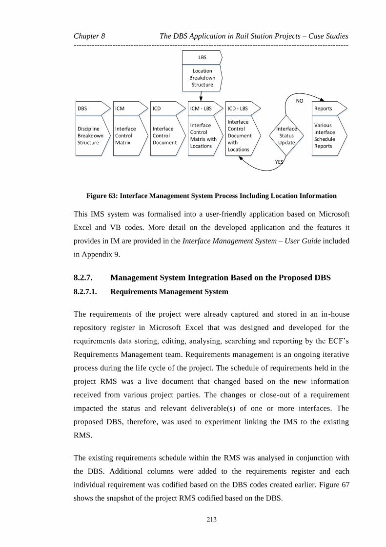
Chapter 8 The DBS Application in Rail Station Projects – Case Studies
----------------------------------------------------------------------------------------------------------
213
Discipline Breakdown Structure
Interface Control Matrix
Interface Control Document
Various Interface Schedule Reports
DBS ICM ICD Reports
Interface Status
Update
YES
NO
Location Breakdown Structure
LBS
Interface Control Matrix with Locations
ICM - LBS
Interface Control Document with Locations
ICD - LBS
Figure 63: Interface Management System Process Including Location Information
This IMS system was formalised into a user-friendly application based on Microsoft
Excel and VB codes. More detail on the developed application and the features it
provides in IM are provided in the Interface Management System – User Guide included
in Appendix 9.
8.2.7. Management System Integration Based on the Proposed DBS
8.2.7.1. Requirements Management System
The requirements of the project were already captured and stored in an in-house
repository register in Microsoft Excel that was designed and developed for the
requirements data storing, editing, analysing, searching and reporting by the ECF’s
Requirements Management team. Requirements management is an ongoing iterative
process during the life cycle of the project. The schedule of requirements held in the
project RMS was a live document that changed based on the new information
received from various project parties. The changes or close-out of a requirement
impacted the status and relevant deliverable(s) of one or more interfaces. The
proposed DBS, therefore, was used to experiment linking the IMS to the existing
RMS.
The existing requirements schedule within the RMS was analysed in conjunction with
the DBS. Additional columns were added to the requirements register and each
individual requirement was codified based on the DBS codes created earlier. Figure 67
shows the snapshot of the project RMS codified based on the DBS.

Chapter 8 The DBS Application in Rail Station Projects – Case Studies
----------------------------------------------------------------------------------------------------------
214
As requirements are related to the DBS and as the DBS items through the DSM concept
identify the areas of interfaces, the combination of these systems creates an integrated
system in which each requirement can be traced to the relevant interfaces. The impact
that any changes to any of the requirements have on the other parts of the system/project
can be traced and analysed through this integrated approach.
8.2.7.2. Design Deliverable List
The main delivery of a construction design project like CS1 is a series of documents in
the form of reports, drawings, schedules, etc. The deliverable list often is provided by
the client at the beginning of the project. The DDL is a form of a PBS for a project of
this type. In CS1, the DDL was provided by the client in a separate document. This was
a fixed list that was kept by the project document control team. Any changes to the
DDL were considered as changes to the project scope and were analysed through
change analysis.
In the proposed IMS, the products within the DDL were asked to be used as evidence to
show the project compliances with the requirements and interfaces. Therefore, a
relationship should be established between the project requirements and interfaces and
the DDL items.
In CS1, the same concept used in RMS was adopted by converting the DDL
document into a register in a form of a database in Microsoft Excel. Additional
columns were created to accommodate the DBS codes. The created matrix enabled a
codification process for the items in the DDL based on the DBS codes, as presented
in Figure 68.
8.2.7.3. Compliance Process
In CS1, a compliance process was identified to provide assurance that the deliverables
satisfied the project requirements. The generic term V&V is used to refer to all of the
activities that are aimed at making sure the final project will function as required. The
process is iterative, and encompasses a number of checks and reviews at key stages of
the project in the V life cycle of the project. In principle, as part of the SE activity in
CS1, the suppliers were required to provide a list of deliverables against each
requirement in which they can show and prove the compliances. The deliverables they

Chapter 8 The DBS Application in Rail Station Projects – Case Studies
----------------------------------------------------------------------------------------------------------
215
listed were part of the project main design deliverable list in most cases. There were
some exceptions in which the DDL was updated based on new deliverables identified
for the project.
8.2.8. CS1 Proposed Verification and Validation System Tool
In order to develop the concept and create the links and codifications as discussed, an
integrated information system in a form of an application was developed with VB on
the Microsoft Excel platform. The application held the ICD as well as the codified
requirements schedule and the DDL in a same workbook. The application was equipped
with a search engine in order to create a short list of deliverables from the DDL based
on a chosen requirement or interface. The engine searched through all the codes against
the DDL and filtered those matches with the codes related to the chosen interface or
requirement item. The architecture of this tool is based on the concept summarised in
Figure 57 (see Section 7.3.4).
The proposed DBS, therefore, was the core for this search engine. Once the final
versions of the ICD, Requirements Schedule and DDL were issued and codified based
on the proposed DBS, they were all imported into the V&V application. The
application was then made available for use in generating short lists of deliverables
based on any chosen interface from the ICD or any requirement from the
Requirements Schedule. More detail on the application features and the structure was
provided to the project team in the Verification and Validation Tool User Manual
included in Appendix 10.
The V&V application also linked to the main project cloud-based document control
system (ProjectWise7) to provide live access to the physical deliverables stored in the
document repository.
Figure 69 illustrates the overall system architecture used to develop the CS1 project
information system based on the proposed DBS and used to integrate the project RMS,
IMS and DDL in a V&V application tool.
7 ProjectWise is a cloud based application that provides project information and document management and collaboration services, developed by Bentley

Chapter 8 The DBS Application in Rail Station Projects – Case Studies
----------------------------------------------------------------------------------------------------------
216
Figure 64: ICM Developed Based on the Proposed DBS for CS18
8 A large printed copy of this ICM is located in Appendix 7.

Chapter 8 The DBS Application in Rail Station Projects – Case Studies
----------------------------------------------------------------------------------------------------------
217
Figure 65: Interface Control Document developed for CS1

Chapter 8 The DBS Application in Rail Station Projects – Case Studies
----------------------------------------------------------------------------------------------------------
218
Figure 66: LBS Cross-check against ICM developed for CS1

Chapter 8 The DBS Application in Rail Station Projects – Case Studies
----------------------------------------------------------------------------------------------------------
219
Figure 67: Codification of the Project RMS Based on the DBS developed for CS1

Chapter 8 The DBS Application in Rail Station Projects – Case Studies
----------------------------------------------------------------------------------------------------------
220
Figure 68: Snapshot of the DDL Codified by the DBS developed for CS1

Chapter 8 The DBS Application in Rail Station Projects – Case Studies
----------------------------------------------------------------------------------------------------------
221
Figure 69: Integrated Management System Architecture Developed for CS1
8.3. CS2 – A Rail Station Upgrade Project in the UK, 2011
8.3.1. CS2 Introduction
CS2 is another design phase for a complex rail station upgrade in central London,
contracted to the same major ECF. This project was used as a trial to adopt the DBS
concept developed in CS1. The scope of the project is very similar to CS1, and therefore
it is expected that the DBS developed for CS1 can be used with minimum alteration.
The DBS developed in CS1 was used as a template to develop an IMS similar to that in
CS1. This section discusses the DBS alteration and customisation for the purpose of

Chapter 8 The DBS Application in Rail Station Projects – Case Studies
----------------------------------------------------------------------------------------------------------
222
CS2 and describes its adaptation to the project. The purpose of this trial was to
understand the challenges in using the DBS as a template and developing a new IMS for
a new project based on the previous works.
8.3.2. CS2 Systems Engineering Approach
The scope of the SE approach for this project is very similar to CS1, including similar
types of tools and documents. Therefore, the ECF-appointed SE team developed various
SE activities, including a RMS.
8.3.3. CS2 DBS Development
The proposed DBS for this project was developed based on the concept discussed in
Section 7.2.3. Figure 70 is a modified illustration of Figure 50 that shows the DBS
development for the purpose of this work for CS2. As Figure 70 shows, the main
source to develop the DBS for CS2 was the DBS developed as a template for CS1.
Additional project information and documents were used as additional sources in order
to identify the gaps in the DBS.
Selective Project(s) in Rail Station Domain
PBS
WBS
OBS
Previous Experiences in Rail Station Domain
Consultations with Rail experts in different
disciplines
CS2 DBS
DBS
Various other Rail Standards, Best Practices,
etc.
CS2 Project Specific Scope and
Requirements
Customising the DBS template based on the
project specific Scope
Various Project Contractual Documents
Figure 70: Developing the DBS for CS2 Based on the DBS Template Developed for CS1

Chapter 8 The DBS Application in Rail Station Projects – Case Studies
----------------------------------------------------------------------------------------------------------
223
In total, 117 items were identified as physical components for the station design-related
works among 8 disciplines and under 11 systems and 29 sub-systems. Comparing the
DBS used in CS2 with the template DBS developed in CS1 shows that all 106
components of the CS1 DBS were used in the CS2 DBS. One additional sub-system
with a single component was added in accordance with the scope of the work for CS2.
8.3.4. CS2 DBS Adoption
Similar to CS1, the customised DBS was used in CS2 for the purpose of IM and RM, as
well as developing a project-wide V&V information control system. The main benefit
realised from this adoption was that over 99 per cent of the project interfaces pre-existed
through the established ICM transferred from CS1. This was a considerable time saver
for development of the project interface database and ICDs.
8.4. CS3 – A New Rail Station Design in Canada, 2012
8.4.1. CS3 Introduction
CS3 is the design phase of a major and complex new rail station in the city of Toronto,
Canada, contracted to a major ECF. This project was used as another trial to adopt the
DBS concept developed in CS1 and refined in CS2. As the project is designing a
completely new station, the scope of the work is wider than that of CS1 and CS2 and,
therefore, additional systems and sub-systems will be designed in this project.
When the project delivery and the design production started, the author joined the
design team to develop a systematic solution based on the proposed DBS to manage the
interfaces among various design works. This provides assurance that the design
deliverables, including drawings and reports, sufficiently address the interface
requirements.
The DBS developed in CS1 was used again as a template in order to develop an IMS
similar to that developed in CS1. The following section discusses the DBS alteration
and customisation for the purpose of CS3 and describes its adaptation to the project.
The purpose of this trial was also to understand the challenges in using the DBS as a
template and in developing a new IMS for a new project based on previous works.

Chapter 8 The DBS Application in Rail Station Projects – Case Studies
----------------------------------------------------------------------------------------------------------
224
8.4.2. CS3 Systems Engineering Approach
The scope of the SE approach for this project is limited to managing the interfaces with
other contractors designing other parts of the project and, mainly, the railway system
that goes through the new station. The project requirements are mainly managed by the
PM team through various scope and requirements schedules based on the project final
deliverable list supplied by the client.
The ECF, therefore, appointed a senior systems engineer at the beginning of the project
to provide a coordinated approach to the development of an IMS. The PM team also
maintains various registers and repositories separately and independently to manage the
interface requirements, design risks, technical assumptions, hazards data, etc.
8.4.3. CS3 DBS Development
Similar to CS2, the DBS for CB3 was also developed based on the concept presented in
Figure 70. As Figure 70 shows, the main source for developing the DBS for CS3 was
the DBS developed in CS1 and refined as a template in CS2. Other project-related
documents such as the Project Deliverable List, the PBS, the WBS and the project
contractual documents were used to customise the template DBS and select the modules
related to this project. They also drove additional items that needed to be included in the
DBS template.
As discussed in Chapter 7, several projects were required to be used as case studies in
order to build a master DBS that could be applied to other projects in the same sector.
Therefore, some alteration to the DBS template developed in CS1 and CS2 was
expected in order to make it suitable for CS3. As the scope of the CS3 project is wider
than that of CS1 and CS2, it was expected to have many missing items in the DBS
template that need to be added.
In total, there are 100 items identified as physical components for the station design-
related works among 7 disciplines, 14 systems and 26 sub-systems. Another 41 items
were identified under the railway system components that should be supplied by other
contractors; these are distributed among 6 disciplines, 18 systems and 23 sub-systems.

Chapter 8 The DBS Application in Rail Station Projects – Case Studies
----------------------------------------------------------------------------------------------------------
225
8.4.4. CS3 DBS Adoption
Similar to CS1 and CS2, the customised DBS was used in CS3 for the purpose of IM
and RM, as well as developing a project wide V&V information control system. The
main benefit realised from this adoption was that a large portion of the CS3 DBS was
based on the CS1 DBS template. This means that a majority of the project interfaces
pre-existed through the established ICM transferred from CS1. This is a massive time
saver for the development of the project interface database and ICDs.
8.5. DBS Added Value
8.5.1. CS1 Feedback and Testimonial
The project director for CS1 was interviewed to provide feedback on his observation of
the adoption of CS1 and the IMS developed based on the DBS concept. This senior
manager also encouraged using the DBS and IMS in many other projects globally in
different forms when he was in charge of the rail sector globally in the ECF. Below is a
full script of his opinion and feedback in this regard, as provided and confirmed by
email in a private communication:
“I am writing to offer my experience of the development and application of your
Discipline Breakdown Structure (DBS) approach to the management of complex
multi-discipline project management in the railway infrastructure project
environment.
We first used this approach in a major station upgrade project where I was the
project director, not just in a massive underground station redevelopment in a major
metro in a European capital city, but also as part of [redacted]’s migration towards
using the SEM approaches in rail while I was Chief Engineer. This project was not
just an exceptionally complex job, but was further compounded by the interface with
a major urban metro construction project underneath this critical work. A further
major challenge was to undertake this work while keeping this line open and
functioning while making huge changes to the structure of the original underground
station: a complex project with many interfaces. It was, as you will recall, very
effective and proved very attractive to the embedded client assurance team. We

Chapter 8 The DBS Application in Rail Station Projects – Case Studies
----------------------------------------------------------------------------------------------------------
226
developed as part of the interface management system approach an interface tool
which provided the following:
Interface control matrix
Integrated management system
V&V and compliance management system
We adopted the approaches above and I observed:
The DBS gave our team a detailed picture of the skills and activities the
project making input and resource planning easier and more efficient and
giving a predictable project cost build-up.
The interface matrix which was created and populated based on the DBS
could easily be transferred into the project and therefore it was a significant
time saving for the project not least because it provided a detailed interface
matrix once the project started – Giving a significant time and resource
saving. This is because previously we would have needed to spend a lot of
time and effort to capture identify and assign the project interfaces.
This integrated application created by Hadi Sanei, provided an easy system
for information navigation and V&V and compliance management for the
project requirements and interfaces base on the DBS concept.
Since this project commenced I have rolled out this process with the help of Hadi
Sanei I now as a matter of course use the DBS and the interface matrix associated in
other projects of the same type with considerable success in South America, S.E.
Asia and the Middle East as well as the UK and each time the DBS is applicable to a
project with a very small alteration as it is modular and you can pick items related to
the project and delete those that are not.
I personally think:
This concept can change project management significantly for the better
The DBS idea as a modular standard approach in management can save a
massive amount of time and resources in managing projects

Chapter 8 The DBS Application in Rail Station Projects – Case Studies
----------------------------------------------------------------------------------------------------------
227
I suggest that projects in our sector use and develop this approach further in
future projects” (Project Director for a UK Major Engineering Consulting
Firm, 2016)
8.5.2. CS3 Feedback and Testimonial
In developing the DBS concept for the design of this station project, the ECF interfaces
heavily with another major firm providing the design for the railway system. The
concept of using the DBS was found interesting by their senior management team. The
Senior Vice President of that firm, who was in charge of their project to supply design
for the railway system, asked his project team to adopt the same concept in their project.
He also used the DBS concept and the data developed in CS1 and CS2 for their future
projects. An interview was carried out and his testimonial about the DBS concept, as
provided to the author in a private communication, is as follows:
“Discipline Breakdown Structure – Developed by Hadi Sanei
As the Senior Vice President for one of Canada’s largest construction companies my
work includes leading the design effort for very large and complex new Light Rail
(LRT) systems. A major risk item for my company in the design of these large LRTs is
understanding the skills and activities needed to complete the design. The DBS model
developed by Hadi gave us an upfront understanding of what will be required and
reduced the uncertainty and risk to the project. We were able to customize the
modules to suit our projects with little effort and minimal cost, this provided us with
an understanding of requirements prior to the design effort commencing.
We further used the model to address the other major risk associated with LRT
Design, that of interface management. The pre-defined matrix that is part of the
model allowed as to have a firm understanding of the interfaces that needed to be
taken into account. Gave us the knowledge to make sure processes and procedures
included the interfaces from the very start of the project (something that would
normally have to be developed after the project commenced). This reduced the risk of
errors and omissions and in turn the risk of issues arising during construction. This
pre-determined knowledge saved my company a large amount of time and advanced
the schedule considerably allowing for cost savings in both time and operational
cost.

Chapter 8 The DBS Application in Rail Station Projects – Case Studies
----------------------------------------------------------------------------------------------------------
228
We first used this matrix as a test to determine the benefits it would bring to large
project, from this we have since used the same matrix (adapted to suit each project)
on two further projects, one of which is the largest LRT to be constructed in Canada
with CAPEX cost of over $4.5 billion. The results from the first use of the matrix
were so impressive we had no hesitation in using this on our signature project in
Canada. We find that one real advantage of the model as a whole is that it allows
our design director and his team to pick and choose modular components to suit the
project needs with little effort. This has proven to be a valuable advantage as we can
split it down in to segments and discipline areas to assist our design segment leads
on projects. This is no small feat as these LRT project are extremely complex and
have thousands of interfaces and disciplines.
I and my company would highly recommend this DBS system.” (Senior Vice
President for one of Canada’s largest Construction Companies, 2016)
The DBS concept and the IMS based on the DBS for this project were presented to the
client’s head of the transit rail programme (Ministry of Transportation for the municipal
government) in a private meeting with other senior management team members from
different stakeholders. The presentation was well received, and the following feedback
was provided to the author in a public communication shared with many other senior
management team in late 2012:
“I want to thank you for all of the work you put into today’s presentation of the
Systems Interface Plan for the project. The level of effort was evident, and your
understanding of the model and its use on [redacted] Station was appreciated by both
[redacted] and [redacted]. Some of [redacted]’s direct quotes: ‘I’m really pleased.’;
‘You’ve hit all of the hot buttons.’; ‘I’m very impressed.’; ‘I’m thrilled to have you
on this project.’ and most importantly; ‘You’ve given me more ammunition for
maintaining this project as DBB. [redacted] has used interface coordination as one of
the benefits of using DB procurement; I am now convinced otherwise.’
This opened up the opportunity for all of us to discuss how beneficial it is to keep us
on board for DBB, noting that with the specific station designer focusing on interface
coordination, having a sense of responsibility and independence from the systems
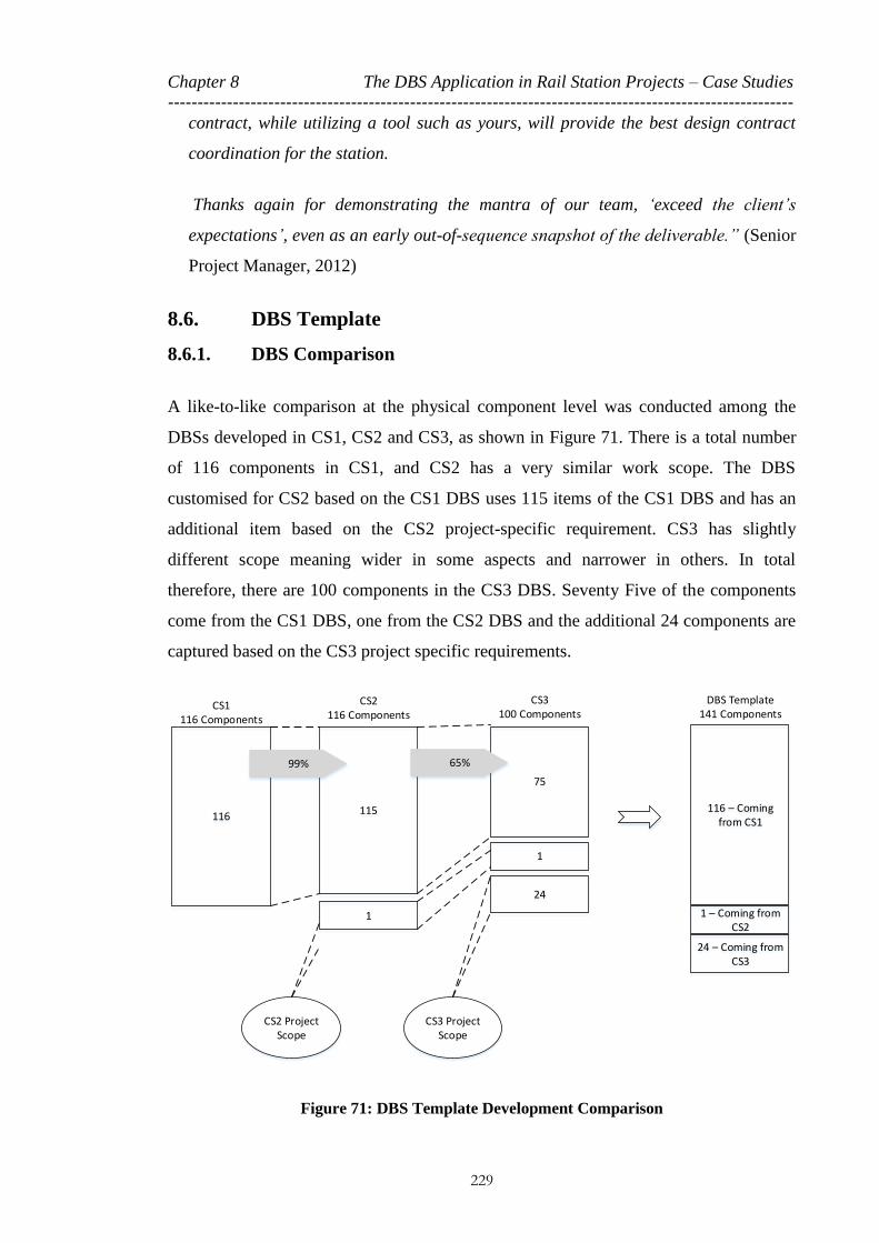
Chapter 8 The DBS Application in Rail Station Projects – Case Studies
----------------------------------------------------------------------------------------------------------
229
contract, while utilizing a tool such as yours, will provide the best design contract
coordination for the station.
Thanks again for demonstrating the mantra of our team, ‘exceed the client’s
expectations’, even as an early out-of-sequence snapshot of the deliverable.” (Senior
Project Manager, 2012)
8.6. DBS Template
8.6.1. DBS Comparison
A like-to-like comparison at the physical component level was conducted among the
DBSs developed in CS1, CS2 and CS3, as shown in Figure 71. There is a total number
of 116 components in CS1, and CS2 has a very similar work scope. The DBS
customised for CS2 based on the CS1 DBS uses 115 items of the CS1 DBS and has an
additional item based on the CS2 project-specific requirement. CS3 has slightly
different scope meaning wider in some aspects and narrower in others. In total
therefore, there are 100 components in the CS3 DBS. Seventy Five of the components
come from the CS1 DBS, one from the CS2 DBS and the additional 24 components are
captured based on the CS3 project specific requirements.
116 115
1
CS1116 Components
CS2116 Components
75
24
CS2 Project Scope
CS3 Project Scope
CS3100 Components
1
116 – Coming from CS1
1 – Coming from CS2
24 – Coming from CS3
DBS Template 141 Components
99% 65%
Figure 71: DBS Template Development Comparison

Chapter 8 The DBS Application in Rail Station Projects – Case Studies
----------------------------------------------------------------------------------------------------------
230
As Figure 71 shows, CS2 used over 99 per cent of the items in CS1, and CS3, with its
different work scope, uses over 65 per cent of the pre-existing DBS component. This
means that based on the DBS approach, more than two-thirds of the project interfaces,
as well as many other management documents, pre-exist. This is a great saving in the
time and effort that needs to be put in at the beginning of each project.
Figure 71 also shows that after working on three projects of the same nature, the master
DBS database totals 141 items.
8.6.2. DBS Adaptation Tool
As discussed in Section 7.4, the proposed DBS should be formed as a template that can
be reused in similar projects within the same domain. In order to put this concept into
practice, an application should be developed which works as a database with a user-
friendly front end, enabling the user to pick the right modules of a template DBS for the
specific project. Meanwhile, the database should hold an ICM for the master DBS items
as well as many of the project schedules and documents based on the master DBS.
Developing such an application is beyond the scope of this work. However, the SE team
in the ECF, with the help of the author, developed a sample application on the Microsoft
Access platform to implement the DBS concept. This application is used as a data store
to keep all data related to an IMS. The populated ICM was transferred into the database.
Interface search, edit, add and remove are the other facilities provided by this
application, as well as providing different reports on interfaces. This application has
limited capabilities and requires alterations each time it is used, so is not currently a
viable tool to be used in the industry. But it sets some of the key and basic functional
requirements required to develop such an application for future related works.
8.7. Conclusion of the Chapter
The proposed DBS concept was applied to three different projects to test and validate
the method based on the proposed solution. The projects used as case studies had
relatively similar scope but were in different locations and with different project teams
and supply chains.

Chapter 8 The DBS Application in Rail Station Projects – Case Studies
----------------------------------------------------------------------------------------------------------
231
The trial of the DBS concept activities summarised in this chapter demonstrated the
following key conclusions:
1. The DBS implementation in CS1 facilitated the identification and assignment of
the project interfaces in order to develop an IMS in a multidisciplinary project.
The further trials in CS2 and CS3 further demonstrated that regardless of the
project-specific team or work streams, the DBS is capable of identifying the
areas of interfaces that should be managed to a very detailed level. These case
studies also proved that the interface ownership and compliance verification will
be improved by using the DBS concept.
2. Application of the DBS in CS1, CS2 and CS3 demonstrated the capability of the
DBS to create links among the PM and SE activities in managing such projects.
These trials proved that using a DBS provides an integrated approach on
managing systems in which interfaces, requirements and deliverables are linked
and in which data can be traced and navigated from one to other.
3. The use of the DBS implemented in CS1, and later as a template in CS2 and
CS3, demonstrated the management efficiency that the DBS concept can
introduce to the projects by saving considerable time and resources as the result
of predefined interfaces. This shows that the DBS as a standard and a template
in specific domains can save a significant amount of time and resources by
generating predefined management baselines for various PM and SE key
activities such as project interfaces, risks, costs and activities.
4. The development of an integrated management tool based on the DBS concept
for CS1 and the customisation and reusability of that tool in CS2 and CS3
demonstrated the benefit of the DBS concept in implementation of a fully
integrated and traceable tool to navigate through the project information within
various tools, documents and registers. The tool not only provides various
reports and information on the compliances for requirements and interfaces, but
also provides a platform to manage the impacts that changes in some parts of the
project information have on the other parts.
232
Chapter 9 CONCLUSION AND FUTURE WORK
INTRODUCTION 233
MAIN RESEARCH SCOPE RECAP 233
RESEARCH NEED JUSTIFICATION 234
SOLUTION DEVELOPMENT 236
RESEARCH KEY CONCLUSION MESSAGES 237
FUTURE WORK 242
DISSEMINATION 243
CONCLUSION OF THE CHAPTER 244

Chapter 9 Conclusion and the Future Work
----------------------------------------------------------------------------------------------------------
233
9.1. Introduction
This chapter summarises the works conducted in this research and explains the
conclusions and outcomes achieved as the result of the research performed. Therefore,
the main research scope (MRS) identified in Chapter 1 is recapped and mapped against
the outcome of this research.
This chapter also provides an outlook on future work and projects that can be defined
based on the outcome of this research.
9.2. Main Research Scope Recap
The research scope of this study is to formulate a fully integrated approach to develop
a modular and reusable solution that creates a traceable relationship between a
systems engineering approach and project management, including project delivery
tools and documents, in which all changes can be managed better, resulting in more
efficient project management.
(MRS)
The ultimate goal of this research is to help project management (PM) to be more
efficient by using a systems engineering (SE) approach and activities within
multidisciplinary projects in rail sector.
The key assumptions made in this research project are as follows:
1. Improving ‘project efficiency’ refers to any effort that can result in saving
resources, including time and people.
2. In the type of projects that are the main interest of this research project, the key
SE activities are interface management (IM), requirements management (RM)
and verification and validation (V&V) (compliance management).
3. Interface management is a key activity of SE in such projects and is targeted to
be improved.
The key hypotheses in this research project that were tested through literature review
and case studies are as follows:

Chapter 9 Conclusion and the Future Work
----------------------------------------------------------------------------------------------------------
234
1. Poor IM and poor RM are key factors that can potentially cause project failure. If
they are not managed well, they contribute significantly to project reworks and
therefore inefficiency. Therefore, any attempt for improving these activities will
potentially improve the efficiency of the PM.
2. In such multidisciplinary projects, PM and SE introduce various activities along
with tools and documents. There is no reference in any literature or case studies
suggesting a systematic solution to link PM and SE in their physical activities
level and not just at the conceptual level. Therefore, a solution that can integrate
these activities can form an integrated management system that will make PM
more efficient.
3. The PM and SE documents and tools have different layers of information.
Therefore, they can be integrated through a solution that has access to different
layers of information of a project. Projects tend to use a Work Breakdown
Structure (WBS) as a single tree form structure to work with some of the PM and
SE activities, mainly commercial and planning/scheduling.
The key activities of this research and the expected outcome are as follows:
1. Studying PM and SE is fundamental to understanding the concept of project, PM
and SE, as well as to understanding the activities, tools and documents they
introduce in managing a typical construction project.
2. Understanding the importance of IM and RM in PM and their contribution
toward project failures.
3. Studying the fundamentals of the WBS and its relationship to the IM and SE
concepts and their activities.
4. Designing and developing a new solution to integrate PM and SE activities, tools
and documents to form an integrated management system.
5. Testing the new solution in real rail sector projects to realise its applicability,
strengths and constraints.
9.3. Research Need Justification
In order to justify the need for this study data was required to understand that:

Chapter 9 Conclusion and the Future Work
----------------------------------------------------------------------------------------------------------
235
1. The importance of the IM in such multidisciplinary projects and its impact in
project success / failure.
2. How people in industry think about PM, SE and more specifically the common
applications such as IM, RM and V&V.
Therefore different types of data gathered through reviewing literatures (mainly statistic
reports), conducting case study on a major rail station design project, as well as
conducting an industry survey.
Within the literature many examples were gathered to show that projects failed due to
poor management of interfaces and requirements. Reviewing the new project
procurements strategies in the rail domain revealed the shift toward transferring risk of
project delivery from sponsor to the contractors. Contractors are more concerned about
project efficiency as they need to manage their project delivery within agreed resources
including budget and time. Also as projects are contracted to multiple suppliers,
interfacing is becoming a serious issue and therefore improving the management of the
interfaces improves management efficiency.
A major railway station design project in central London was approached in order to
conduct a case study. Over 7500 line of communication between the project engineering
design supplier and the client engineering team gathered and analysed to understand the
main reason to generate such communications. The results showed that the poor IM and
RM contributed in generating over 50% of this comments, resulting in generating
unnecessary works, and therefore use of additional resources (i.e. time and cost).
An industrial survey was conducted in the form of an online questionnaire, targeting
mainly project managers and systems engineers with a focus on the main topics that
relate to this research including, IM, RM and WBS. The primary result of the survey
was the demonstration of a lack of consensus on IM and RM definition and
responsibilities among the project team at different levels. The results further showed
how poorly functioning IM and RM can impact projects. The survey also demonstrated
poor quality of IM and RM according to the industrial experiences. Since the WBS is a
structured and layered concept common in Project Management, the survey further
looked at the WBS and its possible application in IM. Less than 10% expressed having
any sort of experience of using the WBS for the purpose of IM.

Chapter 9 Conclusion and the Future Work
----------------------------------------------------------------------------------------------------------
236
The combination of the data gathered as explained above, provided the necessary
justification for a need to improve IM by integrating the SE approach and its application
into the PM solutions, to improve PM efficiency.
9.4. Solution Development
In this research a simple V life cycle model used for the solution development as
explained in earlier chapters. The main requirements for the solution identified are that
they must;
- be based on the breakdown structure (divide and conquer)
- integrate SE and PM tools and applications
- provide a systematic way to identify and visualise interfaces
- provide a systematic way to allocate and assign interfaces to relevant
parties/owners
- provide a systematic data repository to demonstrate that the project addresses the
interface issues and requirements
- create tractability among all other PM documents
- be modular and reusable
- provide time and resource savings
The DBS concept (that, similar to the WBS, PBS, OBS or many other breakdown
structure based concepts) is proposed and its use and application in managing projects is
explained. It was also further explained that how the proposed approach could not only
improve the IM, but also could bring SE and PM tools and functions together at a
working level and in an integrated format.
Disciplines can be viewed as more fundamental than work, product or organisations.
Disciplines are based on the extant configuration of an industrial capability and are less
related to the project unique specification and requirements.
When WBS templates exist, they must be tailored to a particular project and are so not
generally fixed. Various factors such as project environment, project nature,
organisational culture, personal preference, etc., play key roles in WBS development.
WBS is invented for the purpose of planning. Different PMs or project planners plan

Chapter 9 Conclusion and the Future Work
----------------------------------------------------------------------------------------------------------
237
projects in different ways. There is generally no uniquely ideal plan for project and it is
most important that a project has a plan so it can be monitored and measured against.
The Product Breakdown Structure (PBS) is a product oriented breakdown of a project’s
outcomes. In engineering projects, a PBS shows the deliverables to be developed by the
project. The WBS on the other hand structures the work of a project. In such
engineering projects, WBS shows the works to be done in the project to develop the
PBS products. The proposed DBS is a discipline / knowledge oriented breakdown of the
tasks under each disciplines involved in a project. These are the disciplines (typically
available with industry) that need to be involved to perform the works under WBS and
so to deliver products under PBS.
The proposed DBS can become the source to develop a logical breakdown of the
industry knowledge to be used in industry standards, university modules and syllabus,
training modules, etc. This could ultimately changes the way of thinking regarding the
management and delivery of projects across entire commercial domains.
9.5. Research Key Conclusion Messages
9.5.1. Project Management and Systems Engineering
The literature review of Chapter 3 provided an image of the fundamental definition of
project, PM and SE. The review looked into the PM and SE essential activities, tools
and processes with a focus on multidisciplinary construction projects with a brief
reference to the rail sector. The chapter also investigated and described the SE approach
as a discipline and its relationship to PM in different sectors over its history. The SE life
cycle, tools and procedures were briefly analysed, and the role of SE in the execution of
infrastructure projects was described. The key conclusions of Chapter 3 in the context of
PM and SE are as follows:
All of the activities introduced by SE and PM are defined around different layers
of project information in areas like commercial, planning, risk, scope and
requirements.
Integration of SE and PM activities can form an integrated management system,
improving PM efficiency.

Chapter 9 Conclusion and the Future Work
----------------------------------------------------------------------------------------------------------
238
Although no specific solution for integrating PM and SE activities in rail projects
could be found in the literature, it was explored that the project managers and
systems engineers tend to use a WBS as a form of a breakdown structure to
categorise the project into smaller parts and manage the processes.
The results of the survey conducted in Chapter 5 clarified further the identity crisis of
SE in today’s projects and PM. One of the key conclusion from this chapter on this
topic is as follows:
The lack of consensus among the project team people, including management
and delivery, on the need for systems thinking and an SE approach in such
projects.
9.5.2. Interface Management and Requirements Management
The literature review of Chapter 3 provided a definition of IM from both the PM
and SE perspectives. The importance of IM was further investigated by studying
new procurement strategies for rail projects that introduce more interfaces among
various suppliers. Chapter 3 also reviewed projects that failed as a result of poor
IM and RM. Therefore, the key conclusion of this chapter in this context is as
follows:
Interface management is a key function in PM because of the new procurement
strategies as well the historical record of project failures related to poor IM.
The survey in Chapter 5 collected data from practitioners on IM and its applications.
Key conclusion from the results of the Chapter 5 are as follows:
Lack of consensus among the project players, including management and
delivery teams, about the importance of managing the interfaces and
requirements as standalone functions.
Lack of consensus among project teams on the responsibility of IM (PM view is
to manage the interfaces and requirements as natural part of managing a project,
while an SE view is to have a standalone and systematic approach, along with its
procedures and tools).

Chapter 9 Conclusion and the Future Work
----------------------------------------------------------------------------------------------------------
239
The survey also concluded that because the interfaces and requirements are not
being managed well in industry, there is a major risk to the projects as they get
larger and more complex. This justifies developing better solutions to enhance
and improve IM and RM.
A project case study was studied in Chapter 6 to review the PM performance and the
key failure factors in a rail-related project as part of an overall major programme of a
railway station modernisation project in central London. The key conclusions from
Chapter 6 are as follows:
Poor management of the interfaces and coordination between different disciplines
and parties, as well as poor understanding and management of the project scope
and requirements, are the top two reasons that generate a considerable volume of
discussions and disagreement among the project parties, which results in
generating more work, cost and time.
This chapter concluded that poor IM and RM together with a poor V&V process
make up around 60 to 70 per cent of the additional arguments between a project
client and suppliers.
9.5.3. WBS and Its Relationship to Project Management and Systems
Engineering
The literature review in Chapter 4 fundamentally discussed the WBS’s definition, types,
development and applications. Chapter 4 also concluded that the WBS is the main
backbone of the PM, playing an essential role in the PM activities, including project
resource scheduling; project time scheduling; project cost estimation; budget
management; project risk management; and SE activities such as project IM, RM and
V&V. The key conclusion messages from Chapter 4 are as follows:
Work breakdown structures tend to be developed in various ways depending on
many different factors, including the type of the project, type of industry, project
manager work principle, company regulation and legislation, project environment
and parties involved.
It is not possible to formulate the WBS development in a standard format.

Chapter 9 Conclusion and the Future Work
----------------------------------------------------------------------------------------------------------
240
Improving the quality of the breakdown structure of a project or a system will
improve the quality of IM, leading to better, more efficient PM.
9.5.4. Discipline Breakdown Structure
Literature review, survey and project case study provided enough justification for a
need for a solution to address the following:
Improve IM in multidisciplinary projects
Bridge PM and SE activities to form an integrated management system
Chapter 7, therefore, introduced the proposed Discipline Breakdown Structure (DBS)
concept and its applicability. The key conclusions of the chapter are as follows:
The proposed DBS is a breakdown structure of the disciplines involved in
projects within a specific domain. The DBS presents the skills and competencies
required by disciplines within an industry sector.
The proposed DBS is a modular database. Every time it is used in a project, the
modules related to the project should be picked and customised based on the
project-specific scope and requirements at the early stage of the project
definition.
The proposed DBS improves the project efficiency by providing access to
various predefined information when a project starts, such as baselines for risks,
requirements and cost elements related to the selected modules of the DBS.
The proposed DBS creates links between all project activities including PM and
SE tools and documents. All other project documents can be related to the DBS
on different levels of information to create an integrated information
management system.
The proposed DBS is recommended to become an industry standard for a specific
domain.
The proposed DBS can eventually become a reference for projects in a specific
domain. This reference can drive the baseline of what is required for projects
supporting both the client and supply chain to identify the project requirements. It
can also become a reference for educational purposes in a specific domain.

Chapter 9 Conclusion and the Future Work
----------------------------------------------------------------------------------------------------------
241
The proposed DBS can also eventually become a standard benchmark to score
supply chain competency for various purposes including bid evaluation.
9.5.5. DBS Testing – Case Study
The proposed DBS concept was applied to three different projects with relatively
similar scope but in different locations and with different project teams and supply
chain. The key conclusion messages from these case studies are as follows:
The proposed DBS has played a key role in developing a structured and traceable
Interface Management System (IMS) for the project case studies. The IMS
developed in the projects used the DBS in identification of the areas of interfaces
in various layers of information from high level to the detailed component level.
The DBS also provided interface ownership as well as traceability for the
purpose of compliance verification within a V&V tool developed based on the
DBS.
The proposed DBS concept applied as a core to link the key project documents
including requirements schedule, interface matrix, interface database, design
deliverable register, and document control system as the key PM and SE
activities.
The proposed DBS developed for the first case study was reused as a template in
the second and third case studies. This presented the capability of the DBS
concept to be used as an industry standard. It also provided evidence on the time
and resources that can be saved by creating access to the predefined management
baseline information for various PM and SE key activities such as project
interfaces. This concept can be expanded to the other key project information
including risks, cost and activities.
Further application of the DBS would require the following to be addressed:
A much more comprehensive data gathering is required to ensure that a fully
comprehensive list of assets/skills within a branch of industry is captured before
the DBS could be considered as a standard.

Chapter 9 Conclusion and the Future Work
----------------------------------------------------------------------------------------------------------
242
Since technology advances at a fast pace, there is a danger that the data within a
developed DBS could become obsolete. Therefore, a timely review cycle needs
to be established.
Non-technical factors (including political and environmental) can impact the
project interfaces and architecture. These also need to be included since they are
not well captured in the DBS structure.
9.6. Future Work
This research discusses the idea of the DBS and its development. Although the main
focus of the author in developing this concept was to develop a systematic solution to
manage project interfaces, the results from the trial and the feedback received from
various project parties, including client and supply chain, unfolded the potential of the
DBS concept in changing the procurement of the multidisciplinary projects in different
aspects. Therefore, this is a new path that can generate new work streams and research
in developing new solutions, ideas and tools to improve management of the projects in
different sectors.
The following section summarises some of the key areas that can be further explored
based on the DBS concept.
9.6.1. DBS – an Industry Standard/Database
The DBS should be further developed in different sectors to the level that covers almost
all the possible scenarios in different sectors. The development of such a data repository
can become an industry standard in different sectors. Like any other standard, the DBS
should be updated as technology advances, though the concept remains the same. Such
a standard can be developed in a form of a database (data repository), and access can be
provided to the projects when it is required.
9.6.2. Integrated Management System Application (Database)
The DBS concept was explained as a core to link PM and SE activities and tools in
order to form an integrated management system. The trial of the concept and the project
case studies demonstrated the concept applicability in real projects.

Chapter 9 Conclusion and the Future Work
----------------------------------------------------------------------------------------------------------
243
Developing a comprehensive PM application database software based on the DBS
concept could potentially introduce a new era in management of such multidisciplinary
projects. The application should enable the project manager and the project team to
access the pre-stored DBS modules (based on the DBS standard developed for specific
sector) and select those related to the project and its main scopes. Once this is
completed, the software should generate various PM and SE tools and document these
with baseline information which is derived from the main data repository according to
the DBS modules selected for the project. This application should be a cloud-based
application with various access rights for different project team members. Traceability
of the information in different registers and tools through the DBS should be developed
and maintained in the application. The application could also be equipped with various
data analysis engines and reporting tools, helping the project team and other
stakeholders.
9.6.3. Project Definition and Initiation
The application of the DBS concept can potentially change the project definition,
initiations, costing and procuring. If the DBS becomes an industry standard, the
solutions should be developed to initiate the projects based around the DBS. This will
help the project sponsor to have a picture of what needs to be done before the project is
defined and started. Skills, complexity, cost, interfaces and parties that need to be
involved can be better predicted at the very early stages, even before a project is
formally initiated. This, however, needs more work and research to refine the DBS
concept and its development.
9.7. Dissemination
The concept of the DBS – along with the applications of IMS, Requirements
Management System (RMS) and V&V tools developed and used in the project case
studies presented in this thesis and many other projects globally – was presented in
different forms to various clients and parties. The concept has also been vital in securing
a number of major projects based on what was presented in the tender documentations.
Therefore, the concept has been presented in the following forms and formats:

Chapter 9 Conclusion and the Future Work
----------------------------------------------------------------------------------------------------------
244
In a form of a proposal as part of the bid documentation to secure major rail
projects globally
In the form of project reports to present the approach adopted in managing major
rail projects in the UK, Canada, Malaysia and Brazil
In the form of presentation in client workshop and conferences in Malaysia,
Brazil and Canada
In the form of a presentation poster for the purpose of business development and
marketing
9.8. Conclusion of the Chapter
This chapter is concluded by responding to the project main research question (MRQ)
identified and analysed in Chapter 1.
How can SE and PM activities be better integrated to support project managers to
manage their multidisciplinary (rail) projects more efficiently?
MRQ
This question has been the source of identification for the MRS, project work packages
and activities as well as the specifying the requirements for the solutions that need to be
developed in this study.
The SE and PM activities use different tools and documents which generate various
information related to the project in different layers. The documents need to inform each
other as in many occasions, the information and the changes in one document can
impact the other parts of a project. Therefore, these document and tools should be linked
and integrated. The best way to integrate a number of documents (mainly in the form of
registers) is to have them built around a same concept. The proposed DBS provides
what is necessary to form all PM and SE tools and documents around itself, and
therefore integrates them in practice.
Improving IM in a multidisciplinary project is vital. Many projects have failed
completely or partially due to poor IM. The proposed DBS facilitates the management
of interfaces on different levels of a project. Managing the interfaces eliminate project
risks.

Chapter 9 Conclusion and the Future Work
----------------------------------------------------------------------------------------------------------
245
The projects are managed more efficiently if they can save on resources, including time
and people. The proposed DBS saves both time and resources as follows:
The DBS improves project IM. Therefore it eliminate project rework and reduces
the risk of project failure, saving both time and resources.
The DBS creates access to the predefined information stored in the project
database. There will be considerable time and resource savings as a result of
having the main baseline of the information in various branches of the PM ready
when the project starts.
The DBS pictures a project in advanced and therefore highlights potential risks
and issue. This helps the PM to manage the issues and risks better, and therefore
saves project time and resources.
The DBS, along with the integrated management system application built based
on the DBS concept, provides a constructive tool for PM. Traceability of the
information through the DBS facilitates change management and impact analysis,
saving both time and resources.

246
REFERENCES……
AHLEMANN, F. & BACKHAUS, K. 2006. Project Management Software Systems
Requirements, Selection Process and Products. A Study by the Research Center
for Information Systems in Project and Innovation Networks. Germany.
AHMADI, R., ROEMER, T. A. & WANG, R. H. 2001. Structuring product
development processes. European Journal of Operational Research, 130, 539-
558.
AHMADI, R. & WANG, R. H. 1994. Rationalizing product design development
processes. UCLA Anderson Graduate School of Management.
ALBERT, N. 1995. Developing a useable work breakdown structure.
ALESHIN, A. 2001. Risk management of international projects in Russia. International
Journal of Project Management, 19, 207-222.
ALEXANDER, I. F. & STEVENS, R. 2002. Writting Better Requirements UK, Pearson
Education Limited.
ALLEN, G. 2001. The Private Finance Initiative (PFI). House of Commons Library:
Economic Policy and Statistics Section.
ALLEN, I. E. & SEAMAN, C. A. 2007. Likert Scales and Data Analyses. Quality
Progress.
ALPHEN, A. V., HALFENS, R., HASMAN, A. & IMBOS, T. 1994. Likert or Rasch?
Nothing is more applicable than good theory. Journal of Advanced Nursing, 20,
196-201.
ALSHUBBAK, A., PELLICER, E. & CATALÁ, J. 2009. A collaborative approach to
project life cycle definition based on the Spanish construction industry. 3rd
Conference on Engineering Work in Palestine
ANNELLS, M. 1996. Grounded Theory Method: Philosophical Perspectives, Paradigm
of Inquiry, and Postmodernism. Quality Health Research 6, 379-393.
247
ANUMBA, C. J., KAMARA, J. M. & CUTTING-DECELLE, A. F. 2007. Concurrent
Engineering in Construction, Abingdon, UK, Taylor & Francis.
ASSOCIATION FOR PROJECT MANAGEMENT 2006. APM Body of Knowledge,
Association for Project Management.
ATKINSON, R. 1999. Project management: cost, time and quality, two best guesses
and a phenomenon, its time to accept other success criteria. International
Journal of Project Management, 17.
AUFMANN, R. N., LOCKWOOD, J. S., NATION, R. D. & CLEGG, D. K. 2008.
Mathematical Thinking and Quantitative Reasoning New York, USA, Houghton
Mifflin Company.
AUSTIN, S., BALDWIN, A., LI, B. & WASKETT, P. 1998. Development of the
ADePT methodology: An interim report on the link IDAC 100 project
Loughborough University: Department of Civil and Building Engineering.
AUSTIN, S., BALDWIN, A. & NEWTON, A. 1996. A Data Flow Model to Plan and
Manage the Building Design Process. Journal of Engineering Design, 7, 3-25.
AYAS, K. 1997. Integrating corporate learning with project management. International
Journal of Production Economics, 51, 59-67.
BABAR, A. & WONG, B. Capturing Strategic Business Requirements: An Exploratory
Study. Software Engineering Conference (APSEC), 2012 19th Asia-Pacific, 4-7
Dec. 2012 2012. 446-451.
BACCARINI, D. 2011. Project objectives: A confused concept 36th Australasia
University Building Educators Association (AUBEA) Conferance.
BACHY, G. & HAMERI, A.-P. 1997. What to be implemented at the early stage of a
large-scale project. International Journal of Project Management, 15, 211-218.
BAHILL, A. T. & CLARK, B. 2001. The systems engineering started in the middle
process: A consensus of systems engineers and project managers. Systems
Engineering, 4, 16-167.
BAHILL, A. T. & HENDERSON, S. J. 2004. Requirements Development, Verification,
and Validation Exhibited in Famous Failures Systems Engineering, 8.

248
BAKER, B. N., FISHER, D. & MURPHY, D. C. 1974a. Factors affecting project
success National Technical Information Service
BAKER, B. N., FISHER, D. & MURPHY, D. C. 1974b. Project management in the
public sector: success and failure patterns compared to private sector projects
National Technical Information Service.
BAKER, N., BAZAN, A., CHEVENIER, G., ESTRELLA, F., KOVACS, Z., LE
FLOUR, T., LE GOFF, J. M., LIEANARD, S., MCCLATCHEY, R.,
MURRAY, S. & VIALLE, J. P. 1998. An object model for product and
workflow data management. Database and Expert Systems Applications, 731-
738.
BBC. 2014a. French red faces over trains that are 'too wide' [Online]. BBC. Available:
http://www.bbc.co.uk/news/world-europe-27497727 [Accessed Nov 2015
2015].
BBC. 2014b. Great miscalculations: The French railway error and 10 others [Online].
BBC. Available: http://www.bbc.co.uk/news/magazine-27509559 2014].
BECKER, O., BEN- ASHER, J. & ACKERMAN, I. 2000. A method for system
interface reduction using N2 charts. Systems Engineering, 3, 27-37.
BING, L., AKINTOYE, A., EDWARDS, P. J. & HARDCASTLE, C. 2005. The
allocation of risk in PPP/PFI construction projects in the UK. International
Journal of Project Management, 23, 25-35.
BLAXTER, L., HUGHES, C. & TIGHT, M. 2003. How to Research, Philadelphia,
USA, Open University Press.
BOARDER, J. C. 1995. The system engineering process Engineering Management
Conference. IEEE.
BOOZ ALLEN HAMILTON. 2012. Earned Value Management Tutorial Module 2:
Work Breakdown Structure [Online]. http://science.energy.gov/: US Department
of Energy. Available: http://science.energy.gov/opa/project-management/tools-
and-resources/.
BOUMA, G. D. 1996. The Research Process, Oxford, UK, Oxford University Press.

249
BOUMA, G. D. & LING, R. 2004. The Research Process, Oxford, UK, Oxford
University Press.
BRANDON, D. M. 1998. Implementing Earned Value Easily and Effectively. Project
Management Journal.
BRITISH STANDARDS INSTITUTE 1996. BS BS6079-Project Management.
BROOME, J. & HAYES, R. 1997. A comparison of the clarity of traditional
construction contracts and of the New Engineering Contract. International
Journal of Project Management, 15, 255-261.
BROTHERTON, S. A., FRIED, R. T. & NORMAN, E. S. Applying the Work
Breakdown Structure to the Project Management Lifecycle. PMI Global
Congress Proceedings, 2008 Denver, Colorado.
BROWNING, T. R. 2001. Applying the design structure matrix to system
decomposition and integration problems: a review and new directions IEEE
Transactions on Engineering Management, 48, 292-306.
BROWNING, T. R. 2002. Process integration using the design structure matrix.
Systems Engineering, 5, 180-193.
BRYMAN, A. 2012. Social Research Methods, Oxford, UK Oxford University Press.
BURKE, R. 1993. Project Management, Chichester, John Wiley and Sons.
CALGAR, J. & CONNOLLY, M. 2007. Interface management: effective information
exchange through improved communication. ABB Value Paper Series. Houston,
TX: ABB Inc.
CALVANO, C. N. & JOHN, P. 2004. Systems engineering in an age of complexity.
Systems Engineering, 7.
CAMBRIDGE DICTIONARIES ONLINE. 2015. Cambridge Dictionaries Online
[Online]. Cambridge University Cambridge University Press [Accessed 29 July
2015 2015].

250
CARON, F. & MARCHET, G. 1998. Project logistics: integrating the procurement and
construction processes. International Journal of Project Management, 16, 311-
319.
CARRASCOSA, M., EPPINGER, S. & WHITNEY, D. 1998. Using the design
structure matrix to estimate product development time. 1998 ASME Design
Engineering Technical Conferances Atlanta, Georgia, USA: ASME.
CASH, H. & FOX, R. 1992. Elements of successful project management. Systems
Management 10-12.
CHAN, Y. E. & HUFF, S. L. 1992. Strategy: an information systems research
perspective. The Journal of Strategic Information Systems, 1, 191-204.
CHEN, P. & CLOTHIER, J. 2003. Advancing systems engineering for systems-of-
systems challenges. Systems Engineering, 6, 170-183.
CHEN, Q., REICHARD, G. & BELIVEAU, Y. 2006. An interface object model for
interface management in building construction In: MARTINEZ, M. &
SCHERER, R. (eds.) eWork and eBusiness in Architecture, Engineering and
Construction ECPPM2006. Valencia, Spain.
CHEN, Q., REICHARD, G. & BELIVEAU, Y. 2007. Interface management-a
facilitator of lean construction and agile project management. Proceedings
IGLC-15.
CHRISTENSEN, M. & THAYER, R. 2001. The Work Breakdown Structure, Los
Alamitos, California, IEEE Computer Society.
CHUA, D. K. H. & GODINOT, M. 2006. Use of a WBS Matrix to Improve Interface
Management in Projects. Journal of Construction Engineering and
Management, 67-79.
CHURCHER, D. & RICHARDS, M. 2015. Cross-discipline design deliverables for
BIM Phase 1 report – Strategy Document
CLARK, J. O. 2009. System of Systems Engineering and Family of Systems
Engineering From a Standards, V-Model, and Dual-V Model Perspective.
Systems Conference, 2009 3rd Annual IEEE Vancouver, BC IEEE.
251
CLARKE, R. 2000. Appropriate Research Methods for Electronic Commerce
Available: http://www.rogerclarke.com/EC/ResMeth.html [Accessed 18 Oct
2015].
CLARKSON, P. J. & HAMILTON, J. R. 2000. ‘Signposting’, A Parameter-driven
Task-based Model of the Design Process Research in Engineering Design, 12,
18-38.
CLELAND, D. I. 1964. Project Management: An Innovation of Thought and Theory.
COGHLAN, D. & BRANNICK, R. 2014. Doing Action Research in Your Own
Organization London, SAGE Publications Ltd.
COHEN, L., LAWRENCE, M. & MORRISON, K. 2000. Research Methods in
Education London
COLENSO, K. 2000. Creating The Work Breakdown Structure. Artemis Management
Systems.
COLLYER, S. & WARREN, C. M. J. 2009. Project management approaches for
dynamic environments. International Journal of Project Management 27 355–
364.
CONROY, G. & SOLTAN, H. 1997. ConSERV, a methodology for managing multi-
disciplinary engineering design projects. International Journal of Project
Management, 15, 121-132.
COOKE-DAVIES, T. 2002. The “real” success factors on projects. International
Journal of Project Management, 20, 185-190.
COTTRELL, W. D. 1999. Simplified Program Evaluation and Review Technique
(PERT). Journal of Construction Engineering and Management, 125, 16-22.
CRESWELL, J. W. 2014. Research Design: Qualitative, Quantitative, and Mixed
Methods Approaches, London, UK, SAGE Publications Ltd. .
CROTTY, M. 1998. The Foundations of Social Research Australia, Allen & Unwin.
CRUMRINE, T., NELSON, R. C., C.LOUDERMILK, M. & MALBREL, C. A. 2005.
Interface management for subsea sand control completions. Offshore, 65, 88-92.

252
CS1 DESIGN ENGINEERING MANAAGER 2010. CS1 Design Engineering Manager
Interview Notes London, UK.
DANILOVIC, M. & BROWNING, T. R. 2007. Managing complex product
development projects with design structure matrices and domain mapping
matrices. International Journal of Project Management, 25, 300-314.
DASH, N. K. 2005. Selection of the Research Paradigm and Methodology [Online].
Manchester Metropolitan University Available:
http://www.celt.mmu.ac.uk/researchmethods/Modules/Selection_of_methodolog
y/ [Accessed 28 October 2015].
DAVIDZ , H. L. & NIGHTINGALE, D. J. 2008. Enabling systems thinking to
accelerate the development of senior systems engineers. Systems Engineering,
11, 1-14.
DAWSON, C. 2009. Introduction to Research Methods: A practical guide for anyone
undertaking a research project, Oxford, UK, How To Books Ltd. .
DE HEREDIA, S. & SANTANA, L. 1991. Project-breakdown structure: the tool for
representing the project system in project management. International Journal of
Project Management, 9, 157-161.
DE WIT, A. 1988. Measurement of project success. International Journal of Project
Management, 6, 164–170.
DEFENSE, U. D. O. 1993. MIL-STD-881B-Work Breakdown Structures for Defense
Materiel Items. Military Standard. Washington D.C., USA.
DEHOFF, B., LEVACK, D. & RHODES, R. 2009. The Functional Breakdown
Structure (FBS) and Its Relationship to Life Cycle Cost. 45th
AIAA/ASME/SAE/ASEE Joint Propulsion Conference & Exhibit. Denver,
Colorado, USA: American Institute of Aeronautics and Astronautic
DENSCOMBE, M. 2007. The Good Research Guide: For Small-Scale Social Research
Projects, McGraw Hill Open University Press.
DULEWICZ, S. V. & HIGGS, M. J. 2004. Design of a new instrument to assess
leadership dimensions and styles. Selection and Development Review, 20, 7-12.

253
EASTERBY-SMITH, M., THORPE, R. & JACKSON, P. 2002. Management Research,
London, SAGE Publications Ltd.
ECF PROJECT MANAGER 2015. ECF Project Manager Interview Note for Case
Study London, UK.
EDKINS, A. & SMYTH, H. 2006. Contractual Management in PPP Projects:
Evaluation of Legal versus Relational Contracting for Service Delivery. Journal
of Professional Issues in Engineering Education and Practice 132, 82-93.
ELLIOTT, B., O’NEIL, A., CLIVE, R., FELIX , S. & IAN, S. 2011. Overcoming
Barriers to Transferring Systems Engineering Practices into the Rail Sector.
Systems Engineering.
ELLIOTT, B. J. 2014. Benefits of Adopting Systems Engineering Approaches in Rail
Projects. PhD, University of Birmingham.
EMES, M., SMITH, A. & COWPER, D. 2005. Confronting an identity crisis—How to
“brand” systems engineering. Systems Engineering, 8, 164-186.
EMES, M., SMITH, A. & JAMES , A. M. Left-shift vs the time value of money:
unravelling the business case for systems engineering. INCOSE Spring
Conference, 2007 Swindon, UK. INCOSE.
EMES, M., SMITH, A., JAMES, A. M., WHYNDHAM, M. W., LEAL, R. &
JACKSON, S. C. 2012. Principles of Systems Engineering Management:
Reflections from 45 years of spacecraft technology research and development at
the Mullard Space Science Laboratory. INCOSE International Symposium.
Rome.
EPPINGER, S. 2001. Innovation at the speed of information. Harvard Business School
Publishing Corporation 79, 149 -158.
EPPINGER, S. D. & BROWNING, T. R. 2012. Design Structure Matrix Methods and
Applications USA, Massachusetts Institute of Technology
EVER, E., GEMIKONAKLI, O., SANEI, H. & KOCYIGIT, A. 2008. An analytical
approach for optimising the number of repairmen for large scale, homogeneous,
multi-server systems 20th European modeling and simulation symposium.
Briatico, Italy.

254
FELLOWS, R. & LIU, A. 2008. Research Methods for Construction, London, UK,
Wiley-Blackwell.
FERN, E. F. 2001. Advanced focus group research, London, UK, SAGE Publications
Ltd.
FLEMING, Q. W. & KOPPELMAN, J. M. 1998. Earned Value Project Management A
Powerful Tool for Software Projects. The Journal of Defense Software
Engineering, 19-23.
FLYVBJERG, B., BRUZELIUS, N. & ROTHENGATTER, W. 2003. Megaprojects
and Risk An Anatomy of Ambition United States of America, New York
Cambridge University Press (part of the University of Cambridge)
GARRETT JR., R. K., ANDERSON, S., BARON, N. T. & MORELAND JR., J. D.
2010. Managing the interstitials, a System of Systems framework suited for the
Ballistic Missile Defense System. Systems Engineering, 14, 87-109.
GEMIKONAKLI, O., SANEI, H. & EVER, E. 2007. Approximate solution for the
performability of Markovian queuing networks with a large number of servers. .
5th International Workshop on Signal Processing for Wireless Communication
(SPWC). London, UK.
GLASER, B. G. & HOLTON, J. 2007. Remodeling grounded theory. Historical Social
Research Supplement, 47-68.
GLASER, B. G. & STRAUSS, A. L. 1967. The Discovery of Grounded theory, United
States of America, AldineTransaction.
GLASER, B. G. & STRAUSS, A. L. 1998. Grounded Theory, Strategien Qualitativer
Forschung, Bern: Huber.
GLOBERSON, S. 1994. Impact of various work-breakdown structures on project
conceptualization. International Journal of Project Management, 12, 165-171.
GOLEMAN, D., BOYATZIO, R. & MCKEE, A. 2002. The New Leaders -
Transforming the art of leadership into the science of results. Cambridge
Massachusetts: Harvard Business School Press.

255
GOULDING, J. S., POUR RAHIMIAN, F., ARIF, M. & SHARP, M. D. 2015. New
offsite production and business models in construction: priorities for the future
research agenda. Architectural Engineering and Design Management, 11, 163-
184.
GOURVISH, T. R. 1986. British Railways 1948-73: A Business History USA,
Cambridge University Press.
GRAY, D. E. 2014. Doing Research in the Real World, London, SAGE Publications
Ltd.
GROSE, D. 1994. Reengineering the aircraft design process. 5th Symposium on
Multidisciplinary Analysis and Optimization, Multidisciplinary Analysis
Optimization Conferences.
GUENOV, M. D. & BARKER, S. G. 2004. Application of axiomatic design and design
structure matrix to the decomposition of engineering systems. Systems
Engineering, 8, 29-40.
HAMERI, A.-P. 1999. Document viewpoint on one-of-a-kind delivery process.
International Journal of Production Research 37, 1319-1336.
HAMERI, A.-P. & NITTER, P. 2002. Engineering data management through different
breakdown structures in a large-scale project. International Journal of Project
Management, 20, 375-384.
HAMILTON, A. 2004. Handbook of Project Management Procedures, London,
Thomas Telford Ltd.
HAN, S., KIM, D. & KIM, H. 2007. Predicting Profit Performance for Selecting
Candidate International Construction Projects. Journal of Construction
Engineering and Management 133, 425-436.
HANCOCK, B., OCKLEFORD, E. & WINDRIDGE, K. 2009. An Introduction to
Qualitative Research.
HAUGAN, G. T. 2002. Effective Work Breakdown Structures, Vienna, Management
Concepts Inc.

256
HEALY, P. L. 1997. Project Management: Getting the Job Done on Time and in
Budget, Port Melbourne, Vic. and Newton, USA, Butterworth-Heinemann.
HENDERSON, J. C. & VENKATRAMAN, N. 1993. Strategic Alignment: Leveraging
information technology for transforming organisations. IBM Sys Journal, 38,
472-484.
HIGHSMITH, J. 2004. Agile Project Management: Creating Innovative Products,
USA, Pearson Education, Inc. .
HILLSON, D. 2003. Using a Risk Breakdown Structure in project management.
Journal of Facilities Management, 2, 85-97.
HOLZMANN, V. & SPIEGLER, I. 2011. Developing risk breakdown structure for
information technology organizations. International Journal of Project
Management, 29, 537-546.
HUOVILA, P., KOSKELA, L., PIETILAINEN, K. & TANHUANPÄÄ, V. P. 1995.
Use of the design structure matrix in construction. 3rd International Workshop
on Lean Construction
IEEE 2002. Systems and software engineering — System life cycle processes. IEEE.
INCOSE 2004. INOCE Systems Engineering Handbook (Ver 2)- A Guide for System
Life Cycle Processes and Activities.
INCOSE 2006. INCOSE Systems Engineering Handbook (Ver3) - A Guide for System
Life Cycle Processes and Activities. In: HASKINS, C. (ed.) Ver 3 ed.: INCOSE
INSTITUTION OF CIVIL ENGINEERING (ICE). 2015. NEC Contracts [Online].
Scotland ICE. Available: https://www.ice.org.uk/disciplines-and-
resources/professional-practice/nec-contracts-and-ice-condititions-of-contract
[Accessed 30 Dec 2015 2015].
IRANMANESH, H., JALILI, M. & PIRMORADI, Z. 2007. Developing a new structure
for determining time risk priority using risk breakdown matrix in EPC projects
Industrial Engineering and Engineering Management, 2007 IEEE International
Conference. Singapore: IEEE.

257
ISMAIL, I., HAMEED MEMON, A. & ABDUL RAHMAN, I. 2013. Expert opinion on
risk level for factors affecting time and cost overrun along the project lifecycle
in Malaysian Construction Projects. International Journal of Construction
Technology and Management, 1.1, 10-15.
JERGEAS, G. & RUWANPURA, J. 2010. Why Cost and Schedule Overruns on Mega
Oil Sands Projects? Practice Periodical on Structural Design and Construction
15, 40-43.
JOHNSON, A. M. & LEDERER, A. L. 2010. CEO/CIO mutual understanding, strategic
alignment, and the contribution of IS to the organization. Information &
Management, 47, 138-149.
JONES, C. 1994. Assessment and Control of Software Risks, NJ, Yourdon Press Upper
Saddle River.
KAPLAN, R. S. & NORTON, D. P. 2004. Strategy Maps: Converting Intangible Assets
into Tangible Outcomes, Harvard Business School Publishing Corporation.
KARTAM, N. A. 1996. Making Effective Use of Construction Lessons Learned in
Project Life Cycle. Journal of Construction Engineering and Management 122,
14-21.
KELLY, B. & BERGER, S. 2006. Interface management: Effective communication to
improve process safety. Journal of Hazardous Materials, 130, 321-325.
KERZNER, H. 2009. Project Management: A Systems Approach to Planning,
Scheduling, and Controlling, John Wiley & Sons Inc.
KETS DE VRIES, M. F. R. & FLORENT-TREACY, E. 2002. Global Leadership from
A to Z: Creating High Commitment Organizations. Organizational Dynamics,
30, 295.
KLIJN, E.-H. & TEISMAN, G. R. 2003. Institutional and Strategic Barriers to Public—
Private Partnership: An Analysis of Dutch Cases. Public Money & Management
23, 137-146.
KOONCE, D., JUDD, R., SORMAZ, D. & MASEL, D. T. 2003. A hierarchical cost
estimation tool. Computers in Industry, 50, 293-302.

258
KOSKELA, L., BALLARD, G. & TANHUANPÄÄ, V. P. 1997. Toward lean design
management. 5th Annual Conference of the International Group for Lean
Construction (IGLC-5).
KOTHARI, C. R. 2006. Research Methodology, New Age International (P) Ltd.
KUMAR, D. 1989. Developing strategies and philosophies early for successful project
implementation. Project Management Journal, 7, 164-171.
KUMAR, R. 2005. Research Methodology, a step by step guide for beginners, London,
UK, SAGE Publications Ltd. .
LANFORD, H. W. & MCCANN, T. M. 1983. Effective planning and control of large
projects—Using work breakdown structure. Long Range Planning, 16, 38-50.
LANO, R. J. 1977. The N2 Chart. Informational Report. California.: TRW.
LANO, R. J. 1979. A technique for software and systems design. North-Holland,
Amsterdam.
LEVESON, N. G. 2002. System Safety Engineering: Back to the Future USA,
Massachusetts Institute of Technology.
LEWIS, J. R. 1994. Sample Sizes for Usability Studies: Additional Considerations.
Human Factors 36, 368-378.
LEWIS, W. P. & CANGSHAN, L. 1997. The Timely Allocation of Resources in the
Concurrent Design of New Products. Journal of Engineering Design 8, 3-17.
LICHTENBERG, S. Project objectives and budgets: how to link them. Proc. 8th Int.
Expert Seminar, 1983 Zurich. 63-68.
LIKERT, R. 1932. A technique for the measurement of attitudes. Archives of
Psychology, 22 140, 55.
LIN, Y.-C. Developing Construction Network-Based Interface Management System
Construction Research Congress 2009, 2009. 477-486.
LINDQUIST, C. 2005. Fixing the Software Requirements Mess. CIO Magazine.

259
LOCATELLI, G., MANCINI, M. & ROMANO, E. 2014. Systems Engineering to
improve the governance in complex project environments. International Journal
of Project Management, 32, 1395-1410.
LOCK, D. 2007. Project Management, England, Gower Publishing Limited.
LOCKYER, K. G. & GORDON, J. 1991. Critical Path Analysis and Other Project
Network Techniques, Pitman.
LONDON UNDERGROUND LTD. 2009. The System Engineering Process Applied to
Projects. UK: London Underground Library, .
LOUREIRO, G., LEANEY, P. G. & HODGSON, M. 2004. A systems engineering
framework for integrated automotive development. Systems Engineering, 7, 153-
166.
MACAULAY, L. A. 1996. Requirements Engineering, Manchester, Springers.
MACCALLUM, R. C., WIDAMAN, K. F., ZHANG, S. & HONG, S. 1999. Sample
size in factor analysis. Psychological Methods, 4, 84-99.
MAKINS, B. J. & MILLER, D. W. 2000. Web-based aerospace system evaluation
software: The development and assessment of conceptual space missions.
INCOSE International Symposium.
MALAN, R. & BREDEMEYER, D. 2007. Architecture Resources.
MALCOLM, D. G., ROSEBOOM, J. H. & CLARK, C. E. 1959. Application of a
Technique for Research and Development Program Evaluation. Operations
Research Journal, 7, 646-669.
MALMSTRDM, J., PIKOSZ, P. & MALMQVIST, J. 1999. Complementary Roles of
IDEFO and DSM for the Modeling of Information Management Processes.
Concurrent Engineering: Research and Applications, 7, 95-103.
MASTERMAN, J. W. E. 2002. An introduction to building procurement systems,
London, Spon Press.
MATTHEWS, M. D. 1986. Networking and information management: Its use by the
project planning function. Information & Management, 10, 1-9.

260
MAYLOR, H. 2003. Project Management, Pearson Education Limited.
MCCLATCHEY, R., KOVACS, Z., ESTRELLA, F., LE GOFF, J.-M., CHEVENIER,
G., BAKER, N., LIEUNARD, S., MURRAY, S., LE FLOUR, T. & BAZAN, A.
1998. The Integration of Product Data and Workflow Management Systems in a
Large Scale Engineering Database Application. Database Engineering and
Applications Symposium. Cardiff.
MCIVER, J. & CARMINES, E. 1981. Unidimensional Scaling, Sage.
MORRIS, P. 1988. Managing Project Interfaces - Key Points for Project Success.
Projecr Munagemenr Handbook.
MORRIS, P. W. G. 1994. The Management of Projects, London, Thomas Telford
Services Ltd,.
MORRIS, P. W. G. & HUGH, G. H. 1986. Preconditions of Success and Failure in
Major Projects. Technical paper No. 3.
MOSEY, D. 2009. Early Contractor Involvement in Building Procurement: Contracts,
Partnering and Project Management, Wiley-Blackwell.
MÜLLER, R. & TURNER, R. 2007. Matching the project manager’s leadership style to
project type. International Journal of Project Management, 25, 21-32.
MUNNS, A. & BJEIRMI, B. 1996. The role of projectmanagement in achieving project
success. International Journal of Project Management, 14, 81-87.
MUNSON, W. F. 1961. A Controlled Experiment in PERTing Costs. Polarise
Projection, GE Ordnance Department.
NAOUM , S. G. 2006. Dissertation research and writing for construction students,
Oxford, UK, Elsevier Butterworth Heinemann.
NASA 1962. NASA PERT and Companion Cost System Handbook. Washington, D.C.,
USA: National Aeronautics and Space Administration.
NASA 1995. Systems Engineering Handbook. Washington, D.C., USA: National
Aeronautics and Space Administration.

261
NASA 2001. NASA Procedures and Guidelines. Washington, D.C., USA: National
Aeronautics and Space Administration.
NASA 2007. NASA Systems Engineering Handbook. Washington D. C., USA:
National Aeronautics and Space Administration.
NATIONAL AUDIT OFFICE 2014. Lessons from major rail infrastructure
programmes. London: National Audit Office.
NEC 2013. NEC3 Engineering and Construction Contract Option C Target Contract
with Activity Schedule Thomas Telford Publishing.
NIKANDER, I. O. & ELORANTA, E. 2001. Project management by early warnings.
International Journal of Project Management, 19, 385-399.
NITITHAMYONG, P. & SKIBNIEWSKI, M. J. 2004. Web-based construction project
management systems: how to make them successful? Automation in
Construction, 13, 491-506.
NOOTEBOOM, U. 2004. Interface Management Improves On-Time, On-Budget
Delivery of Megaprojects Journal of Petroleum Technology, 56.
NORMAN, E. S., BROTHERTON, S. A. & FRIED, R. T. 2008. Work Breakdown
Structure: The Foundation for project Management Excellence USA, John
Wiley & Sons
NOUR, M. & SCANLAN, J. 2000. Modeling and simulating product development
process. 6th International Conference on Concurrent Enterprising
NOVICK, D. 1990. Life‐Cycle Considerations in Urban Infrastructure Engineering.
Journal of Management in Engineering, 6, 186-196.
OSBORNE, S. M. 1993. Product development cycle time characterization through
modeling of process iteration. M.S., Massachusetts Institute of Technology.
OTTINO, J. M. 2003. Complex Systems AIChE Journal, 49, 292-299.
PARSONS, J. & WAREHAM, B. 2010. Systems Engineering Management Plan In:
SANEI, H. (ed.). Londond

262
PAVITT, T. & GIBB, A. 2003. Interface Management within Construction: In
Particular, Building Facade. Journal of Construction Engineering and
Management 129, 8-15.
PINKETT, R. D. 1971. Product Development Process Modeling and Analysis of Digital
Wireless Telephones. M.B.A., Massachusetts Institute of Technology
POLLITT, M. G. & SMITH, A. S. J. 2002. The restructuring and privatisation of British
Rail: was it really that bad? Fiscal Studies, 23, 463-502.
PROJECT DIRECTOR FOR A UK MAJOR ENGINEERING CONSULTING FIRM.
2016. RE: Reference your work with me in the use of systems engineering
management approaches in rail projects and your development of the DBS
approach and process (Email sent to Hadi Sanei).
PROJECT MANAGEMENT INSTITUTE (PMI) 1996. A Guide to the Project
Management Body of Knowledge (PMBOK Guide), USA, Project Management
Institute.
PROJECT MANAGEMENT INSTITUTE (PMI) 2000. A Guide to the Project
Management Body of Knowledge (PMBOK Guide), USA, Project Management
Institute - PMI.
PROJECT MANAGEMENT INSTITUTE (PMI) 2001. Project Management Institute
Practice Standard for Work Breakdown Structures, USA, Project Management
Institute.
PROJECT MANAGEMENT INSTITUTE (PMI) 2004. A Guide to the Project
Management Body of Knowledge (PMBOK Guide). Third ed. USA: Project
Management Institute.
PROJECT MANAGEMENT INSTITUTE (PMI) 2006. Project Management Institute
Practice Standard for Work Breakdown Structures. USA: Project Management
Institute.
QUIGGIN, J. 2005. Public–Private Partnerships: Options for Improved Risk Allocation.
Australian Economic Review, 38, 445-450.
RAMO, S. 2002. Systems Engineering Manual, Federal Aviation Agency.

263
REILLY, N. B. 1993. The Work Breakdown Structure, New York, Van Nostrand
Reinhold.
REISS, G. 1995. Project Management Demystified: Today's Tools and Techniques,
Taylor & Francis e-Library E & FN Spon.
RITCHIE, J., LEWIS, J. & NICHOLLS, C. M. 2013. Qualitative Research Practice: A
Guide for Social Science Students and Researchers, London, SAGE Publications
Ltd. .
ROE, P. & CRAIG, A. 2004. Reforming the Private Finance Initiative. Tufton Street
London: Center for Policy Studies.
RUSHTON, G. J. & ZAKARIAN, A. 2000. Modular Vehicle Architectures: A Systems
Approach. 10th Annual International Symposium of INCOSE.
RUSKIN, A. M. & ESTES, W. E. 1995. Work Breakdown Structure Paradigms and
Processes, New York, M. Dekker.
SAAD, A. 2011. Factors Impacting the Project's Life Cycle Vietnam: E-Leader
Vietnam.
SANEI, H. 2006. Approximate Solution for 2-Dimensional Markov Processes
Modelling Multi-server Systems Prone to Breakdowns. MSc, Middlesex
University
SANEI, H. 2007. Requirements Management London: Halcrow Group
SANEI, H. 2011. Crosstown LRT Station Design - System Engineering Management
Plan. Toronto, Canada.
SAYNISCH, M. 1983. Project management system for a large international project.
International Journal of Project Management, 1, 115-121.
SENIOR PROJECT MANAGER. 2012. RE: Systems Interface Presentation w/Peter
and Amal (Email sent to Hadi Sanei and copied to all senior management team)
SENIOR VICE PRESIDENT FOR ONE OF CANADA’S LARGEST
CONSTRUCTION COMPANIES. 2016. RE: Discipline Breakdown Structure –
Developed by Hadi Sanei (Email sent to Hadi Sanei).

264
SEQUEIRA, M. W. 1991. Use of the design structure matrix in the improvement of an
automobile development process. M.S., Massachusetts Institute of Technology.
SERRADOR, P. & TURNER, J. R. 2014. The Relationship between Project Success
and Project Efficiency. Procedia - Social and Behavioral Sciences, 119, 75-84.
SHARON, A., DE WECK, O. L. & DORI, D. 2011. Project management vs. systems
engineering management: A practitioners' view on integrating the project and
product domains. Systems Engineering, 14, 427-440.
SHENHAR, A., LEVY, O. & DVIR, D. 1997. Mapping the dimensions of project
success. Project Management Journal, 28, 5-13.
SHENHAR, A. J. & DVIR, D. 2007. Reinventing Project Management : The Diamond
Approach to Successful Growth and Innovation Boston, Massachusetts, Harvard
Business School Press.
SHOKRI, S., AHN, S., LEE, S., HAAS, C. & HAAS, R. 2015. Current Status of
Interface Management in Construction: Drivers and Effects of Systematic
Interface Management. Journal of Construction Engineering and Management.
SHOKRI, S., SAFA, M., HAAS, C. T., HAAS, R. C. G., MALONEY, K. &
MACGILLIVRAY, S. 2012. Interface Management Model for Mega Capital
Projects. Construction Research Congress 447-456.
SILVERMAN, D. 2004. Qualitative Research: Theory, Method and Practice, London,
SAGE Publications Ltd.
SKYTTNER, L. 2005. General Systems Theory: Problems, Perspectives, Practice,
Singapore, World Scientific Publishing Co. Pls. Ltd. .
SMARTT, C. & FERREIRA, S. 2011a. Advancing Systems Engineering in Support of
the Bid and Proposal Process. Systems Engineering, 14, 255-266.
SMARTT, C. & FERREIRA, S. 2011b. Constructing a General Framework for Systems
Engineering Strategy. Systems Engineering.
SMITH, L. A. & MILLS, J. 1983. Reporting characteristics of automated project-
management systems. International Journal of Project Management, 1, 155-
159.

265
SMITH, R. P. & EPPINGER, S. 1997a. Identifying Controlling Features of Engineering
Design Iteration Management Science, 43, 276-293.
SMITH, R. P. & EPPINGER, S. 1997b. A Predictive Model of Sequential Iteration in
Engineering Design Management Science, 43, 1104-1120.
SMYTH, H. & EDKINS, A. 2007. Relationship management in the management of
PFI/PPP projects in the UK. International Journal of Project Management, 25,
232-240.
SÖDERLUND, J. 2004. Building theories of project management: past research,
questions for the future. International Journal of Project Management, 22, 183–
191.
STAATS, S. 2014. Interface Management in multidisciplinary infrastructure project
development - Diminishing integration issues across contractual boundaries in a
Systems Engineering environment. MSc, Delft University of Technology.
STANICEK, Z. & WINKLER, M. 2010. Service Systems Through the Prism of
Conceptual Modeling Institute for Operations Research and the Management
Sciences, 2, 112-125.
STERN, S. 1994. Two dynamic discrete choice estimation problems and simulation
method solutions. The Review of Economics and Statistics, 76, 695-702.
STEUP & MATTHIAS. 2014. Epistemology [Online]. Center for the Study of
Language and Information (CSLI), Stanford University. Available:
http://plato.stanford.edu/archives/spr2014/entries/epistemology/ [Accessed 28
October.
STEVENS, R., BROOK, P., JACKSON, K. & ARNOLD, S. 1998. Systems
Engineering Coping with Complexity, Kent, UK, Pearson Education.
STEWARD, D. V. 1981. The design structure system: A method for managing the
design of complex systems. IEEE Transactions on Engineering Management,
28, 71-74.
STUCKENBRUCK, L. C. 1983. Integration: The essential function of project
management. Project Management Handbook. New York: Van Nostrand
Reinhold.

266
SUNDGREN, N. 1999. Introducing Interface Management in New Product Family
Development. Journal of Production and Innovation Management, 16, 40-51.
TAH, J. H. M. & CARR, V. 2000. A proposal for construction project risk assessment
using fuzzy logic. Construction Management and Economics, 18, 491-500.
TAYLOR, M. D. 2009. How to Develop Work Breakdown Structures.
http://www.projectmgt.com/ [Online]. Available: http://www.projectmgt.com/.
THOMAS, R. 1996. Survey. In GREENFIELD T (ed.) Research methods: guidance for
post graduates. Arnold, London.
TINER, W. D. 1985. Subdivision of work on construction projects. International
Journal of Project Management, 3, 13-18.
TOMIYAMA, T. & MEIJER, B. R. 2005. Directions of next generation product
development. Springer Series in Advanced Manufacturing, 27-35.
TÖPFER, A. 1995. New products—Cutting the time to market. Long Range Planning,
28, 61-78.
TURNER, J. R. 2006. Towards a theory of project management: The nature of the
project. International Journal of Project Management, 24, 1-3.
TURNER, J. R. 2009. The Handbook of Project Based Management: Leading Strategic
Change in Organizations USA, McGraw Hill
TURNER, J. R. & COCHRANE, R. A. 1993. Goals-and-methods matrix: coping with
projects with ill defined goals and/or methods of achieving them. International
Journal of Project Management, 11, 93-102.
TURNER, J. R. & MÜLLER, R. 2003. On the nature of the project as a temporary
organization. International Journal of Project Management, 21, 1-8.
TURNER, J. R. & MÜLLER, R. 2005. The project manager's leadership style as a
success factor on projects: A literature review. Project Management Journal, 2,
49-61.
TWISK, D., COMMANDEUR, J. J. F., BOS, N., SHOPE, J. T. & KOK, G. 2015.
Quantifying the influence of safe road systems and legal licensing age on road

267
mortality among young adolescents: Steps towards system thinking. Accident
Analysis & Prevention, 74, 306-313.
UCL 2009. Section 10 - Scope Management APMP Examination - Overview of
Examination Structure and Guidance on Exam Technique. London: UCL.
ULRICH, K. T. & EPPINGER, S. 2000. Product Design and Development McGraw-
Hill.
ULRIK, F., WALDO, R. F. & PONTUS, J. 2009. Enterprise architecture dependency
analysis using fault trees and Bayesian networks. SpringSim '09 Proceedings of
the 2009 Spring Simulation Multiconference Stockholm, Sweden: Industrial
Information and Control Systems Royal Institute of Technology.
US AIR FORCE 1964. USAF PERT Implementation Manual. Washington D. C.:
Defense Technical Information Center.
US DEPARTMENT OF DEFENSE 1962. DOD and NASA Guide PERT/COST
Systems Design. Washington D.C, USA: Office of the Secretary of Defense.
US DEPARTMENT OF DEFENSE 1968. MIL-STD-881-Work Breakdown Structures
for Defense Materiel Items. Military Standard. Washington D.C., USA.
US DEPARTMENT OF DEFENSE 1975. MIL-STD-881A-Work Breakdown
Structures for Defense Materiel Items. Military Standard. Washington D.C.,
USA.
US DEPARTMENT OF DEFENSE 1998. MIL-HDBK-881-Work Breakdown
Structures for Defense Materiel Items. Military Standard. Washington D.C.,
USA.
US DEPARTMENT OF DEFENSE 2005. MIL-HDBK-881A-Work Breakdown
Structures for Defense Materiel Items. Military Standard. Washington D.C.,
USA.
US DEPARTMENT OF DEFENSE 2011. MIL-STD-881C-Work Breakdown
Structures for Defense Materiel Items. Military Standard. Washington D.C.,
USA.

268
VACULIN, R., YI-MIN, C., OPPENHEIM, D. V. & VARSHNEY, L. R. 2012. Work
as a Service Meta-model and Protocol for Adjustable Visibility, Coordination,
and Control. SRII Global Conference (SRII), 2012 Annual IEEE.
VISITACION, M. 2002. Do the Math: Strong Requirements Practices Save Spiraling
Project Costs. Giga Information Group, Inc.
WALKER, D. H. T. & LLOYD-WALKER, B. 2012. Understanding Early Contractor
Involvement (ECI) procurement forms In: SMITH, S. D. (ed.) 28th Annual
ARCOM Conference. Edinburgh, UK: Association of Researchers in
Construction Managemen.
WALKER, D. H. T. & ROWLINSON, S. 2008. Procurement Systems - A Cross
Industry Project Management Perspective, Abingdon, Oxon, Taylor & Francis.
WARNER, P. 1997. How to use a work breakdown structure, New York, Van Nostrand
Reinhold.
WHITMIRE, M. & NIENSTEDT, P. R. 1991. Leaders into the ’90s. Personnel Journal,
70, 80-86.
WONG, A. K. D. & ZHANG, R. 2013. Implementation of web‐based construction
project management system in China projects by Hong Kong developers.
Construction Innovation, 13, 26-49.
WOODS, M. & TREXLER, C. J. 2001. Linking interpretive theory to practice:
examining an underused research tool in agricultural education. Journal of
Agricultural Education, 42, 68-78.
WREN, D. A. 1967. Interface and Interorganizational Coordination. The Academy of
Management Journal, 10, 69-81.
XUE, R., BARON, C., ESTEBAN, P. & PRUN, D. 2014. Integrating Systems
Engineering with Project Management: a Current Challenge! INCOSE.
INCOSE.
YASSINE, A. A. 2004. An introduction to modeling and analyzing complex product
development processes using the design structure matrix (DSM) method.
Urbana, IL. 61801: Product Development Research Laboratory.

269
YASSINE, A. A., WHITNEY, D. E. & ZAMBITO, T. 2001. Assessment of Rework
Probabilities for Simulating Product Development Processes Using the Design
Structure Matrix (DSM). ASME 2001 International Design Engineering
Technical Conferences. Pittsburgh, Pennsylvania: ASME.
YIN, R. K. 2009. Case Study Research Design and Methods, California, USA, SAGE
Inc.
YOUKER, R. H. 1991. A new look at the WBS. PM Network, 5, 33-36.
ZACCAROA, S. J., RITTMANA, A. L. & MARKS, M. A. 2001. Team Leadership.
The Leadership Quality, 12, 451-483.

270
APPENDICES……
APPENDIX 1. QUESTIONNAIRE/SURVEY
APPENDIX 2. SURVEY COVER LETTERS
APPENDIX 3. SURVEY REPORT GENERATED BY OPINIO
APPENDIX 4. DATA ANALYSIS REGISTER
APPENDIX 5. CS1 – SYSTEMS ENGINEERING ARCHITECTURE BASED ON THE DBS
APPENDIX 6. CS1 – DISCIPLINE BREAKDOWN STRUCTURE
APPENDIX 7. CS1 – INTERFACE CONTROL MATRIX
APPENDIX 8. CS1 – INTERFACE STATUS
APPENDIX 9. CS1 – INTERFACE MANAGEMENT SYSTEM USER GUIDE
APPENDIX 10. CS1 – VALIDATION AND VERIFICATION SYSTEM USER GUIDE
APPENDIX 11. CS1 – REQUIREMENTS MANAGEMENT SYSTEM USER GUIDE
APPENDIX 12. VISUAL BASIC CODES FOR THE INTEGRATED MANAGEMENT SYSTEM
DEVELOPED BASED ON THE PROPOSED DBS

271
Appendix 1 Questionnaire/Survey
This appendix provides a full script of the questionnaire provided to conduct the survey
detailed in Chapter 5.

Appendix 1 Questionnaire/Survey
----------------------------------------------------------------------------------------------------------
272
Systems Engineering General
The Implementation of ‘Systems Engineering’ Practice would improve the
Effectives of the Project Management in Infrastructure Projects
As part of my PhD research at University College London, Centre for Systems
Engineering (UCLse) I have produced this survey which will be used for academic
purposes only. All responses will remain confidential and will only be used for data
analysis. Your effort is highly appreciated and will be regarded as a great support to my
research.
Author: Hadi Sanei
Supervisor: Professor Alan Smith
About you
1. Full Name (optional): -------------------
2. Company (Optional): -------------------
3. We would like to follow-up with some interviews. If you are happy to be contacted
please add your email here. No contact details will be passed to any third party or
outside the scope of this research.
Email: -------------------
4. Position in the company (please indicate the title that nearest describe to your role):
o Business Director
o Practice Leader
o Programme Manger
o Project Manager
o Systems Engineer
o Planner / Scheduler
o Engineer
o Others (please specify): -------------------

Appendix 1 Questionnaire/Survey
----------------------------------------------------------------------------------------------------------
273
5. Scale of Projects that you are or have been involved with (please indicate which
project scales you have been involved with, you may indicate more than one scale):
Major Programme >$100m
Major Project >$20m
Medium Project >$1m
Small Project>$10k
6. Type of Services
o Client (e.g. government procurement)
o Consultant
o Contractor
o Manufacturer
o Others (Please specify): -------------------
7. Sector (indicated one or more sectors):
Railway
Highway
Bridges and Tunnels
Aerospace
Finance
Healthcare
Academic Research
Energy Oil and Gas
Energy Nuclear
Water
Others (please specify): -------------------

Appendix 1 Questionnaire/Survey
----------------------------------------------------------------------------------------------------------
274
Part 1: Requirements Management
In this part we need to understand your experience in managing the Requirements in
your projects. We would like to explore the relationship between Requirements
Management and other project management’s activities, procedures and documents such
as “Scope Management”, “Project Objectives”, “Deliverables Management”, “Interface
Management”, etc.
8. What do you think is/are the main purpose(s) of Requirements Management? (You
may choose up to 4 items)
Understanding the scope/ objective of the work
Establish an agreed baseline
Facilitating Change Management/ Claim (meaning protecting both sides of the
contract)
Enable the verification of the deliverable`s compliance with the End User Need
Enable the verification of the deliverable`s compliance with the Client
Requirements
Traceability of different requirements coming from different sources in different
life cycle
Inform design and integration
Minimise reworks
Reducing Cost
Managing crossed requirements/interface requirements across the parties
involved
Others (Please specify): -------------------
9. Have you ever used commercial tool for Requirements Management/ Engineering?
o Yes
o No
10. If you used commercial tools, please name them? -------------------
11. How did you manage the requirements in the absence of a commercial tool? (Brief
description of tools developed/used) -------------------

Appendix 1 Questionnaire/Survey
----------------------------------------------------------------------------------------------------------
275
12. Do you think Requirements Management is a natural part of Project Managements
and / or Systems Engineering?
Project Management
System Engineering Management
Neither
13. Has there been a quantitative assessment of the value of Requirements Management
in your organisation?
o Yes
o No
o Don’t know
14. If your answer to previous Question is “Yes”, would you be able to share the
information? If yes, can you please enter your email here again to arrange a follow
up interview? -------------------
15. What type of requirements you mainly work with in your business?
Product Requirements
Process Requirements
Business Requirements
User Requirements
Functional Requirements
Non-Functional Requirements
Implementation Requirements
Contractual Requirements
Legal Requirements
Don’t Know
None
Others (Please specify): -------------------

Appendix 1 Questionnaire/Survey
----------------------------------------------------------------------------------------------------------
276
16. Who do you think would benefit the most from Requirements Management?
End User
Client
Contractor/Supplier
All Stakeholders
None
Don’t know
Others (Please specify): -------------------
17. How do you rate the quality of the Requirements Management at your Client
Organisation?
o Excellent
o Very Good
o Good
o Average
o Poor
o Very Poor
o Absent
o Not Applicable
o Don’t know
18. How do you rate the quality of the Requirements Management at your supplier
organisation?
o Excellent
o Very Good
o Good
o Average
o Poor
o Very Poor
o Absent
o Not Applicable
o Don’t know

Appendix 1 Questionnaire/Survey
----------------------------------------------------------------------------------------------------------
277
Part 2: WBS- Work Breakdown Structure
In this part of the questionnaire we like to understand your experience in relation to the
development of the WBS in your field. We also need to explore the WBS relationship
with other tools and documents in a project. The WBS and its application and
relationship to Systems Engineering Management is also covered in the section.
19. How have you developed WBSs?
Used Template
Used previous similar project
Structured around the project deliverables
Structured around the team or discipline
Structured around the nature of the work
Never developed one
Other (please Explain): -------------------
20. Typically how many concurrent versions of WBSs are used within a typical project
(differently in your project environment)?
o 1
o 2
o 3
o >3
21. Once developed which tools incorporated the WBSs?
Project Planning Tools
Commercial Tools
Interface Management Tools
Requirements Management Tool
Risk Management Tools
Resources Management Tools
Document Control Management Tools
None
Don’t know
Others (Please specify): -------------------

Appendix 1 Questionnaire/Survey
----------------------------------------------------------------------------------------------------------
278
22. How your WBS typically structured?
Product Oriented
Service Oriented
Resources Oriented
Discipline Oriented
Don’t know
None
Others (please specify): -------------------
23. How well connected is the WBS to systems engineering management in your
opinion?
o Excellent
o Very Good
o Good
o Average
o Poor
o Very Poor
o Not at all
o Don’t know

Appendix 1 Questionnaire/Survey
----------------------------------------------------------------------------------------------------------
279
Part 3: Systems Design/ Interface AND Systems Integration
In this section, we want to understand your experience on managing the interfaces
between different parties in a project in different phases of a project. We would like to
know if you have used or developed any tools or application for this purpose and see
how the results have helped your projects to be more efficient.
Interface Management and its relationship to the System Engineering Management in
also a topic that we would like to explore further.
24. How well are the interfaces managed in your projects? Opinion?
o Excellent
o Very Good
o Good
o Average
o Poor
o Very Poor
o Don’t know
25. What do you see as the major risks to the project as the results of a poor interface
management?
Rework
Project Schedule / Delay
Project cost Overrun
None
Don’t Know
Others (please specify): -------------------
26. Have you ever used a commercial tool for interface Management?
o Yes
o No
27. If you used commercial tool(s), please name them? -------------------

Appendix 1 Questionnaire/Survey
----------------------------------------------------------------------------------------------------------
280
28. How did you manage the interfaces in the absence of a commercial tool? (Brief
description of tools developed/ used)? -------------------
29. Do you think interface Management is a natural part of Project Management and/or
Systems Engineering?
Project Management
Systems Engineering Management
Neither
30. Has there been a quantitative assessment of the value of interface Management in
your organisation?
o Yes
o No
o Don’t know
31. If your answer to previous Question is “YES”, would you be able to share the
information? If yes, please enter your email again to arrange for the follow up
interview? -------------------
32. What type of interfaces do you mainly capture in your business?
Technical Interfaces
Stakeholders Interfaces
Contractual Interfaces
Human Machine Interfaces
None
Don’t know
Others (please specify): -------------------

Appendix 1 Questionnaire/Survey
----------------------------------------------------------------------------------------------------------
281
33. Who do you think would benefit the most from Interface Management?
End User
Client
Contractor / Supplier
None
Don’t Know
Others (Please specify)
34. How do you rate the quality of the Interface Management at your Client
organisation?
o Excellent
o Very Good
o Good
o Average
o Poor
o Very Poor
o Absent
o Not Applicable
o Don’t know
35. How do you rate the quality of the Interface Management at your Supplier
organisation?
o Excellent
o Very Good
o Good
o Average
o Poor
o Very Poor
o Absent
o Not Applicable
o Don’t know

Appendix 1 Questionnaire/Survey
----------------------------------------------------------------------------------------------------------
282
36. At what stage of the project is integration management important?
Feasibility Study
Outline Design
Detailed Design
Implementation
Hand over and Commissioning
None
Others (please specify)
Any other comment?
37. Is there any other comments you would like to share with us in this context?
Thanks you for taking our survey

283
Appendix 2 Survey Cover Letters
This appendix provides images of the cover letters sent to various parties to
communicate the questionnaire to conduct the survey detailed in Chapter 5.

Appendix 2 Survey Cover Letters
----------------------------------------------------------------------------------------------------------
284

Appendix 2 Survey Cover Letters
----------------------------------------------------------------------------------------------------------
285

Appendix 2 Survey Cover Letters
----------------------------------------------------------------------------------------------------------
286

Appendix 2 Survey Cover Letters
----------------------------------------------------------------------------------------------------------
287

Appendix 2 Survey Cover Letters
----------------------------------------------------------------------------------------------------------
288

Appendix 2 Survey Cover Letters
----------------------------------------------------------------------------------------------------------
289

Appendix 2 Survey Cover Letters
----------------------------------------------------------------------------------------------------------
290

Appendix 2 Survey Cover Letters
----------------------------------------------------------------------------------------------------------
291

292
Appendix 3 Survey Report Generated by Opinio
The survey detailed in Chapter 5 was created in Opinio, an online survey tool licensed
by UCL. This survey creator generates a full report based on the data stored. This
appendix provides as reference a full copy of the report generated by Opinio.

Appendix 3 Survey Report Generated by Opinio
----------------------------------------------------------------------------------------------------------
293

Appendix 3 Survey Report Generated by Opinio
----------------------------------------------------------------------------------------------------------
294

Appendix 3 Survey Report Generated by Opinio
----------------------------------------------------------------------------------------------------------
295

Appendix 3 Survey Report Generated by Opinio
----------------------------------------------------------------------------------------------------------
296

Appendix 3 Survey Report Generated by Opinio
----------------------------------------------------------------------------------------------------------
297

Appendix 3 Survey Report Generated by Opinio
----------------------------------------------------------------------------------------------------------
298

Appendix 3 Survey Report Generated by Opinio
----------------------------------------------------------------------------------------------------------
299

Appendix 3 Survey Report Generated by Opinio
----------------------------------------------------------------------------------------------------------
300

Appendix 3 Survey Report Generated by Opinio
----------------------------------------------------------------------------------------------------------
301

Appendix 3 Survey Report Generated by Opinio
----------------------------------------------------------------------------------------------------------
302

Appendix 3 Survey Report Generated by Opinio
----------------------------------------------------------------------------------------------------------
303

Appendix 3 Survey Report Generated by Opinio
----------------------------------------------------------------------------------------------------------
304

Appendix 3 Survey Report Generated by Opinio
----------------------------------------------------------------------------------------------------------
305

Appendix 3 Survey Report Generated by Opinio
----------------------------------------------------------------------------------------------------------
306

Appendix 3 Survey Report Generated by Opinio
----------------------------------------------------------------------------------------------------------
307

Appendix 3 Survey Report Generated by Opinio
----------------------------------------------------------------------------------------------------------
308

Appendix 3 Survey Report Generated by Opinio
----------------------------------------------------------------------------------------------------------
309

Appendix 3 Survey Report Generated by Opinio
----------------------------------------------------------------------------------------------------------
310

Appendix 3 Survey Report Generated by Opinio
----------------------------------------------------------------------------------------------------------
311

Appendix 3 Survey Report Generated by Opinio
----------------------------------------------------------------------------------------------------------
312

Appendix 3 Survey Report Generated by Opinio
----------------------------------------------------------------------------------------------------------
313
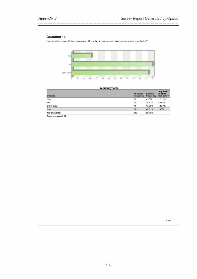
Appendix 3 Survey Report Generated by Opinio
----------------------------------------------------------------------------------------------------------
314

Appendix 3 Survey Report Generated by Opinio
----------------------------------------------------------------------------------------------------------
315

Appendix 3 Survey Report Generated by Opinio
----------------------------------------------------------------------------------------------------------
316
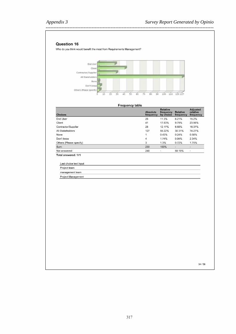
Appendix 3 Survey Report Generated by Opinio
----------------------------------------------------------------------------------------------------------
317

Appendix 3 Survey Report Generated by Opinio
----------------------------------------------------------------------------------------------------------
318

Appendix 3 Survey Report Generated by Opinio
----------------------------------------------------------------------------------------------------------
319

Appendix 3 Survey Report Generated by Opinio
----------------------------------------------------------------------------------------------------------
320

Appendix 3 Survey Report Generated by Opinio
----------------------------------------------------------------------------------------------------------
321

Appendix 3 Survey Report Generated by Opinio
----------------------------------------------------------------------------------------------------------
322

Appendix 3 Survey Report Generated by Opinio
----------------------------------------------------------------------------------------------------------
323

Appendix 3 Survey Report Generated by Opinio
----------------------------------------------------------------------------------------------------------
324

Appendix 3 Survey Report Generated by Opinio
----------------------------------------------------------------------------------------------------------
325

Appendix 3 Survey Report Generated by Opinio
----------------------------------------------------------------------------------------------------------
326

Appendix 3 Survey Report Generated by Opinio
----------------------------------------------------------------------------------------------------------
327

Appendix 3 Survey Report Generated by Opinio
----------------------------------------------------------------------------------------------------------
328

Appendix 3 Survey Report Generated by Opinio
----------------------------------------------------------------------------------------------------------
329

Appendix 3 Survey Report Generated by Opinio
----------------------------------------------------------------------------------------------------------
330

Appendix 3 Survey Report Generated by Opinio
----------------------------------------------------------------------------------------------------------
331

Appendix 3 Survey Report Generated by Opinio
----------------------------------------------------------------------------------------------------------
332
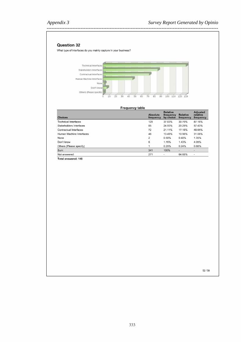
Appendix 3 Survey Report Generated by Opinio
----------------------------------------------------------------------------------------------------------
333

Appendix 3 Survey Report Generated by Opinio
----------------------------------------------------------------------------------------------------------
334

Appendix 3 Survey Report Generated by Opinio
----------------------------------------------------------------------------------------------------------
335

Appendix 3 Survey Report Generated by Opinio
----------------------------------------------------------------------------------------------------------
336

Appendix 3 Survey Report Generated by Opinio
----------------------------------------------------------------------------------------------------------
337
338
Appendix 4 Data Analysis Register
The results of the data analysis of the case study detailed in Chapter 6 were combined
into a single register in order to conduct detailed analysis and discussions. This
appendix provides a random selection of parts of the overall data analysis register to
demonstrate the method of the data gathering and analysis.

Appendix 4 Data Analysis Register
--------------------------------------------------------------------------------------------------------------------------------------------------------------------------------------
339
Data from log books Data Analysis
Doc
No Discipline Section Issue/Comment Required action
Fail
Factor Party1 Party2 Note Sens.
1 Premises – Name
[redacted] [redacted]
On drawing 08105, number 13 has now been assigned to
lift 3 street level. Please update CM Premises Premises
Late change information
from client 4. O
1 Premises - Name [redacted]
[redacted] On drawing 08100, number 14 has now been assigned to lift 1 street level.
Please update CM Premises Premises Late change information from client
4. O
1 Premises - Name
[redacted] [redacted]
Sign 326 has had to be split. It is not clear however the space now available for these two individual signs- no
being fixed on bulkhead. Please clarify the max. space available so signage can be adapted to suit.
Please clarify CM Premises Premises Late change information
from client 2. Y
2 M&E - Name
[redacted] [redacted]
No CSD's Provided in support of the co-ordination activities this area has been an area of weakness
historically. Co-ordination cannot be verified without
these deliverables WI chapter 1a section 7.8
Provide co-ordinated CDS's V&V Premises Mechanical Poor compliance
evidence presentation 1. R
2 M&E - Name
[redacted] [redacted]
Messroom / WC co-ordination has not been achieved and the end product is unsatisfactory End user liaison has also
not been carried out. WI chapter 1a section 7.4 and 7.8
Co-ordinate and provide an acceptable product IM Premises Mechanical None compliance with interface requirements /
standard / specification
1. R
2 M&E - Name
[redacted] [redacted]
Switchboards are still awaiting manufacturers details.
This means co-ordination is incomplete and the risk of rework increased WI chapter 1a section 7.8
Confirm and co-ordinate IM Premises Electrical
Assumption - awaiting
for information from other parties
1. R
2 M&E - Name
[redacted] [redacted]
Access to smoke detection. It is evident that access to
some detectors will be impossible and this demonstrates
that the level of co-ordination is not at a level to install
confidence WI chapter 1a section 7.8
Review detection access and co-ordinate
solution with Arch IM Premises Electrical
None compliance with interface requirements /
standard / specification
1. R
2 M&E - Name
[redacted] [redacted]
The fire drawings do not indicate where cabling is in
containment and when in conduit this could well mask an
extensive amount of containment that needs to be installed (and co-ordinated) that currently isn't shown and
also increases the risk of "make it up as you go along"
site works which increases programme risk. WI chapter 1a section 7.8
Detail where fire alarm cabling is routed in
trunking and when tubed. RM Premises Electrical Missing requirement 1. R
2 M&E - Name
[redacted] [redacted]
The fire suppression drawings for Esc are on hold
awaiting esc information this is clearly incomplete works.
Either complete the work or cloud the drawings
and resubmit the clouded sections at a later date. IM Premises Fire
None compliance with interface requirements /
standard / specification
1. R
2 Premises - Name
[redacted] [redacted]
It is to be noted that [redacted] was issued CLOSED, and
refers Prestige ticketing elements only. However, these drawings do raise other issues (some previously
discussed) hence, will have to be addressed prior to final
[redacted] acceptance of these areas.
Ticket hall package to be updated and issued for
acceptance. CoM Premises Premises
Poor configuration
management 2. Y
2 Fire - Name [redacted] On the right-side of the door there shows four Confirm the other services on the relevant QM Premises Electrical Poor Quality Check 4. O

Appendix 4 Data Analysis Register
--------------------------------------------------------------------------------------------------------------------------------------------------------------------------------------
340
Data from log books Data Analysis
Doc
No Discipline Section Issue/Comment Required action
Fail
Factor Party1 Party2 Note Sens.
[redacted] penetrations and the tray work is only identifiable on
drawing [redacted]
drawings.
2 M&E - Name
[redacted] [redacted]
When making reference to [redacted] the penetration for the service on grid ref [redacted] will clash with the
ceiling.
When including the floor finish to maintain the height to
the ceiling and the ceiling layer(s) there is a clash with
the service .
Review the coordination of this service such
there is no compromise of the premises standards.
IM Premises Electrical
None compliance with
interface requirements / standard / specification
2. Y
2 M&E - Name
[redacted] [redacted]
Sample review on drawings package has shown
inconsistencies.
Review the drawing set for coordination with
services, ceiling heights and fitting locations in
avoidance of install issues.
IM Premises Electrical
None compliance with
interface requirements /
standard / specification
2. Y
2 M&E - Name [redacted]
[redacted] Confirm that in other design packages that the maintenance of the [redacted] have been considered.
Confirm that the risk of maintenance has been
considered as required by CDM regulations, and
that the best overall solution is in place.
TQ Premises Mechanical Technical Query / Clarification
4. O
2 M&E - Name [redacted]
[redacted] Confirm the fans serving the [redacted] are rated no less than 300degC as stipulated in [redacted].
Please confirm. TQ Premises Mechanical Technical Query / Clarification
2. Y
2 Name [redacted] [redacted] Please indicate position of fire alarm interface box for completeness in the [redacted] room
Add this information on the next revision of this
drawing or explain which other drawing this
information is shown on.
IM Premises Fire Missing interface requirements
4. O
2 Name [redacted] [redacted]
[redacted] room should be a sloping floor or each
[redacted] should be mounted on a plinth. This is
probably shown on an architectural drawing.
Add this information on the next revision of this
drawing or explain which other drawing this
information is shown on.
IM Premises Electrical Missing interface
requirements 4. O
2 M&E - Name
[redacted] [redacted]
The drawings specifies a minimum length for the 25mm
flexible conduit as 500mm for the double and single socket outlets.
Designer to explain the rational behind using
500mm as the minimum length of the flexible conduit.
TQ Premises Electrical Technical Query /
Clarification 3. G
2 M&E - Name
[redacted] [redacted]
The detail does not specify the type of unistrut either
heavy or light gauge.
Provide type detail of the supports on the drawing or explain which other drawing this
information is shown on.
QM Premises Electrical Poor Quality Check 4. O
2 Communication -
Name [redacted] [redacted]
A number of the back of house rooms are shown with
only one speaker is this compliant to [redacted]?
Please confirm with only one speaker in the
back of house and plant rooms that the design / install is compliant to [redacted] standards
V&V Premises Communication Poor compliance
evidence presentation 2. Y
2 Communication - Name [redacted]
[redacted]
Please confirm where speakers are fitted in false ceilings
a secondary means of supporting the speakers has been
provided in order to comply with BS5839 Part 8.
please confirm V&V Premises Communication Poor compliance evidence presentation
2. Y
2 Communication -
Name [redacted] [redacted]
Should there be a speaker in the lobby for Lift 4 in order to comply with the minimum STI levels with standard
[redacted].
please confirm V&V Premises Communication Poor compliance
evidence presentation 4. O

Appendix 4 Data Analysis Register
--------------------------------------------------------------------------------------------------------------------------------------------------------------------------------------
341
Data from log books Data Analysis
Doc
No Discipline Section Issue/Comment Required action
Fail
Factor Party1 Party2 Note Sens.
2 Communication -
Name [redacted] [redacted] Should speakers be shown in toilet and shower areas?
Please confirm that the design / install is
compliant to [redacted] standards V&V Premises Communication
Poor compliance
evidence presentation 4. O
2 Fire - Name [redacted]
[redacted] Confirm that the lift 4 Lobby smoke curtain interface remains.
Clarify V&V Premises Fire Poor compliance evidence presentation
4. O
2 Premises - Name
[redacted] [redacted]
Bearing in mind the location and size of the existing escalator 3, 4 & 5 trays are being retained,the lengths as
shown appear to have been reduced. - See RFI 1358.
Confirm if the existing tray are to be changed and if this change has been coordinated with the
maintainer [redacted]. If there is no change, please indicate the correct
existing size and location, intrgrated and
designed into the proposed ticket hall. Update
drawing accordingly.
CM Premises Premises Poor change management and
communication
1. R
2 Premises - Name [redacted]
[redacted]
Previous comments raised on handrail size (see [redacted]) in this and a number of packages have not
been addressed. Please address and update [redacted], and
all other affected drawings showing the 40mm dia. Instead of the 50mm dia..
Please update CoM Premises Premises Poor configuration management
1. R
2 Premises - Name [redacted]
[redacted] The [redacted] has been changed to the "Ticket Clerk’s Office" and accepted.
Please amend room label as this would impact on the [redacted] labelling. Update drawing.
CM Premises Premises
Poor change
management and
communication
2. Y
2 Premises - Name [redacted]
[redacted] Please ensure all ceiling fixtures are coordinated with M & E.
V&V Premises Mechanical Poor compliance evidence presentation
2. Y
2 Premises - Name [redacted]
[redacted]
All exposed concrete surfaces in public areas up to 3m
high would require anti graffiti coating as per [redacted]
standards.
Please ensure this is addressed. V&V Premises Premises Poor compliance evidence presentation
2. Y
2 Premises - Name
[redacted] [redacted]
On det. 03 for the glass screen, it's not clear if its been designed to meet the relevant required standards in
relation to crowd loading and appropriate design loading
and impact performance.
Please clarify. V&V Premises Premises Poor compliance
evidence presentation 2. Y
2 Premises - Name
[redacted] [redacted] It’s not clear the threshold detail at all the lift interface.
Please clarify the threshold detail at all the lift
interface. V&V Premises Premises
Poor compliance
evidence presentation 2. Y
2 Premises - Name [redacted]
[redacted] Threshold detail at vitrine door doesn't appear to be covered.
Please clarify V&V Premises Premises Poor compliance evidence presentation
2. Y
2 Premises - Name [redacted]
[redacted]
It appears RFI 1465 had some loading requirements,
which had to be taken into consideration, when designing
elements incorporated into the escalator enclosure.
Please confirmed if the balustrade proposal has taken into consideration these requirements
CM Premises Premises Poor managing the changes through RFI
2. Y
2 Premises - Name
[redacted] [redacted]
Please confirm that requirements for replacement/removal of balustrade, gaps/joints in
balustrade, prevention of sharp corners/edges and
Please provide design in the detailed drawings. V&V Premises Premises Poor compliance
evidence presentation 2. Y

Appendix 4 Data Analysis Register
--------------------------------------------------------------------------------------------------------------------------------------------------------------------------------------
342
Data from log books Data Analysis
Doc
No Discipline Section Issue/Comment Required action
Fail
Factor Party1 Party2 Note Sens.
exposed glass edge, will be taken into consideration in the
detailed design.
3 M&E - Name
[redacted] [redacted]
Render to soffit is a poor solution and prone to fail in this situation, it is also problematic and messy on site.
Update (08/01/13): Issue closed on the understanding that the contractor has
attended to the comment made by [redacted].
review soffit treatment TS Premises Mechanical Technical Solution Issue
/ Recommendation 3. G
3 M&E - Name
[redacted] [redacted]
This location may change subject to architecture
comments made on [redacted]. Review decision on [redacted]. CM Premises Electrical
Late change information
from client 4. O
3 M&E - Name
[redacted] [redacted]
The angle bracket is shown to have 2 channels back-to-
back to make the necessary length for the hex bolts. It maybe easier if the bracket was placed further towards
the socket such a single channel can be used.
[redacted] No change.
Review fixing details to make the install easier. TS Premises Electrical Technical Solution Issue
/ Recommendation 4. O
3 M&E - Name
[redacted] [redacted]
You can reduce the accessory items if there is a bend in
the galvanised conduit such that the flexible conduit can
be fixed directly which can reduce the adaptor components.
Review fixing details to make the install easier. TS Premises Electrical
Technical Solution Issue
/ Recommendation 3. G
3 Premises - Name
[redacted] [redacted]
Speaker locations and accessibilty to cables may not be
suitable for delivery into service.
[redacted] to confim that [redacted] have
agreements with Maintainer. TS Premises Premises
Technical Solution Issue
/ Recommendation 2. Y
3 Premises - Name
[redacted] [redacted]
It is noted on drawing to cut glass panel around PHP.
Please clarify the need to cut the glass panel. Can PHP not be surface fixed as per Ticket Hall installation?
[redacted] to update as necessary TS Premises Premises Technical Solution Issue
/ Recommendation 2. Y
3 Premises - Name
[redacted] [redacted]
On the wall tiling/frieze interface detail shown on
[redacted], it appears the face of the tiles and frieze are in
alignment. It's noted on [redacted] that, the frieze are faceted in the
curved sections of the tunnel.
Please clarify if the wall tiles in the curved sections of the tunnel, would be installed on a
faceted wall srface, to pevent a discord between
the faceted frieze and the tilled wall.
TS Premises Premises Technical Solution Issue
/ Recommendation 2. Y
10 Civil Engineering [redacted]
Please advise whether it has been checked with OSD the
construction loads to be allowed for due to OSD
construction.
Advise on the approach used or the relevant assurance document to look at.
V&V Premises Premises Poor compliance evidence presentation
3. G
10 Section Manager
- Name [redacted] [redacted]
Drawing 02235 references drawing 02278, which has not been submitted for acceptance. It details the [redacted]
structure which is inside the [redacted] boundary
Submit drawing 02278 CoM Premises Premises Poor configuration
management 1. R
10 OSD Team [redacted] In our comments of September 2009, we asked if
insulation could be provided behind the glass panels to
[redacted] believe this may be a change. Please
discuss before implementing. CM Premises Premises
Poor communication for
the changes with parties 3. G

Appendix 4 Data Analysis Register
--------------------------------------------------------------------------------------------------------------------------------------------------------------------------------------
343
Data from log books Data Analysis
Doc
No Discipline Section Issue/Comment Required action
Fail
Factor Party1 Party2 Note Sens.
the walls and soffit, since this will be a party wall with
the OSD in the final condition, and the [redacted] entrance space will effectively be external. Can this be
provided?
10 M&E - Name
[redacted] [redacted]
It seems almost all of the comments made by [redacted]
previously on the construction issue has not been adressed.
[redacted] Provide evidence of the 'agreement'.
When will comments be
addressed/incorporated? CoM Premises Mechanical
Poor configuration
management 4. O
11 M&E - Name [redacted]
[redacted]
There are routes where only 5 No 150mm dia ducts are
being casted with only one spare duct. It is practicable to
cast another duct.
Provide spare ducts otherwise a concession will need to be placed against standard [redacted]
TS Premises Electrical Technical Solution Issue / Recommendation
1. R
11 M&E - Name
[redacted] [redacted]
There are routes where only 5 No 150mm dia ducts are
being casted with only one spare duct. It is practicable to cast another duct.
Provide spare ducts otherwise a concession will
need to be placed against standard [redacted] TS Premises Electrical
Technical Solution Issue
/ Recommendation 1. R
11 Premises - Name
[redacted] [redacted]
It is not clear how the frieze in the mosaic area meets the
WI requirements of the [redacted] signage scheme. The
WI signage scheme frieze, consist of the station name/way out signs and directional signs above
alternative way out sign.
It's also not clear how continuity of the signage
requirement of the frieze is achieved between the non-
mosaic and mosaic areas.
Please comply with WI design for the frieze
height/signage. V&V Premises Premises
Poor compliance
evidence presentation 1. R
19 M&E - Name
[redacted] [redacted]
The main earth bar is to be located in the [redacted]
transformer room. Most of the connections shown on the main earth bar would be connected to a [redacted] outside
the [redacted] transformer room due to the different
maintenance responsibilities.
Correct connections on main earth bar and SEB (subsidiary earth bar) in the Powerlink
transformer room area.
TS Premises Electrical Technical Solution Issue
/ Recommendation 1. R
19 Section Manager
- Name [redacted] [redacted]
The document is not signed as having been reviewed and accepted by [redacted] and therefore cannot be accepted
by [redacted]
[redacted] - sheet signed
In line with the contractual requirements for self assurance, review and accept internally before
submitting to the Project Manager for
acceptance
CoM Premises Premises Poor configuration
management 3. G
19 Section Manager
- Name [redacted] [redacted]
The revision history for earlier revisions has been omitted, please reinstate.
[redacted] - reinstated
Please re-instate CoM Premises Premises Poor configuration
management 3. G
19 Project Engineer -
Name [redacted] [redacted]
Will the IP Bosch camera be able to support an uprated
recording for events when integrated with verint
please confirm as this is a system requirement.
Testing confirmation required that the V&V Premises Communication
Poor compliance
evidence presentation 1. R

Appendix 4 Data Analysis Register
--------------------------------------------------------------------------------------------------------------------------------------------------------------------------------------
344
Data from log books Data Analysis
Doc
No Discipline Section Issue/Comment Required action
Fail
Factor Party1 Party2 Note Sens.
integration between Verint and Bosch has been
successful and the [redacted] statement is correct at 1080p resolution [redacted]
19 Project Engineer - Name [redacted]
[redacted] Compliant or non-compliant?
see comment outstanding [redacted]. Closed
[redacted] concession requirements to be
discussed
V&V Premises Communication Poor compliance evidence presentation
3. G
19 Project Engineer - Name [redacted]
[redacted] Cable labels confirmed at meeting with [redacted] on the [redacted], document requires update
see comment, Closed on reissue of drawings & schedules[redacted]. Closed[redacted]
CM Premises Communication Late change information from client
3. G
19 Name [redacted] [redacted] As discussed, asset labels, cable labelling should be as per previously accepted detail. Asset register data to be
agreed with the Maintainer ([redacted]).
see comment. Details agreed with[redacted] CM Premises Communication Late change information
from client 3. G
19 Project Engineer -
Name [redacted] [redacted] [redacted] comments on [redacted] are still open see comment CoM Premises Communication
Poor configuration
management 2. Y
22 Structures [redacted]
Comment from previous review on drawing [redacted] not captured or addressed.
Cat B comment - drawing missing from submission pack
CoM Premises Premises Poor configuration
management 1. R

345
Appendix 5 Systems Engineering Architecture Based on
the DBS
This appendix provides a copy of the poster created to demonstrate the proposed
Systems Engineering Architecture. This poster was used to present the concept to large
external audiences and for marketing to future clients.

Appendix 5 Systems Engineering Architecture Based on the DBS
----------------------------------------------------------------------------------------------------------
346
Redacted

347
Appendix 6 CS1 – Discipline Breakdown Structure
This appendix presents a copy of the codified DBS developed for CS1.

Appendix 6 CS1 – Discipline Breakdown Structure
--------------------------------------------------------------------------------------------------------------------------------------------------------------------------------------
348
1 Mechanical & Electrical 1.1 Power 1.1.1 HV Power 1.1.1.1 Switchgear
1 Mechanical & Electrical 1.1 Power 1.1.1 HV Power 1.1.1.2 Transformer
1 Mechanical & Electrical 1.2 Electrical 1.2.1 LV Power 1.2.1.1 Distribution Boards
1 Mechanical & Electrical 1.2 Electrical 1.2.1 LV Power 1.2.1.2 Switchboard
1 Mechanical & Electrical 1.2 Electrical 1.2.1 LV Power 1.2.1.3 Point of Use Equipment
1 Mechanical & Electrical 1.2 Electrical 1.2.1 LV Power 1.2.1.4 UPS
1 Mechanical & Electrical 1.2 Electrical 1.2.1 LV Power 1.2.1.5 Battery / Battery Chargers
1 Mechanical & Electrical 1.2 Electrical 1.2.1 LV Power 1.2.1.6 Maintenance Sockets
1 Mechanical & Electrical 1.2 Electrical 1.2.2 Lighting 1.2.2.1 Normal Light Fitting
1 Mechanical & Electrical 1.2 Electrical 1.2.2 Lighting 1.2.2.2 Emergency Fitting
1 Mechanical & Electrical 1.2 Electrical 1.2.2 Lighting 1.2.2.3 Intelligent Sensors
1 Mechanical & Electrical 1.3 Mechanical 1.3.1 Drainage / Public Health 1.3.1.1 Sump
1 Mechanical & Electrical 1.3 Mechanical 1.3.1 Drainage / Public Health 1.3.1.2 Pump
1 Mechanical & Electrical 1.3 Mechanical 1.3.1 Drainage / Public Health 1.3.1.3 Control Equipment
1 Mechanical & Electrical 1.3 Mechanical 1.3.1 Drainage / Public Health 1.3.1.4 Pipe / Valve
1 Mechanical & Electrical 1.3 Mechanical 1.3.2 Ventilation 1.3.2.1 Chillers
1 Mechanical & Electrical 1.3 Mechanical 1.3.2 Ventilation 1.3.2.2 Ventilation Fans
1 Mechanical & Electrical 1.3 Mechanical 1.3.2 Ventilation 1.3.2.3 Control Equipment
1 Mechanical & Electrical 1.3 Mechanical 1.3.2 Ventilation 1.3.2.4 Dampers
1 Mechanical & Electrical 1.3 Mechanical 1.3.2 Ventilation 1.3.2.5 Noise Mitigation Measures
1 Mechanical & Electrical 1.3 Mechanical 1.3.2 Ventilation 1.3.2.6 AHU (Air Handling Unit)
1 Mechanical & Electrical 1.3 Mechanical 1.3.2 Ventilation 1.3.2.7 Atmosphere Vents/Louvers
1 Mechanical & Electrical 1.4 ALL SYSTEMS 1.4.1 CMS (Cable Management System) 1.4.1.1 Cable
1 Mechanical & Electrical 1.4 ALL SYSTEMS 1.4.1 CMS (Cable Management System) 1.4.1.2 Containment
1 Mechanical & Electrical 1.4 ALL SYSTEMS 1.4.2 Control & Protection 1.4.2.1 Interlocking
1 Mechanical & Electrical 1.4 ALL SYSTEMS 1.4.2 Control & Protection 1.4.2.2 Earthing
Redacted

Appendix 6 CS1 – Discipline Breakdown Structure
--------------------------------------------------------------------------------------------------------------------------------------------------------------------------------------
349
1 Mechanical & Electrical 1.4 ALL SYSTEMS 1.4.2 Control & Protection 1.4.2.3 EMI/EMC
1 Mechanical & Electrical 1.4 ALL SYSTEMS 1.4.2 Control & Protection 1.4.2.4 SCADA
2 Communications 2.1 Communication 2.1.1 Comms Bearer Network (WAN Backbone) 2.1.1.1 Network Router (Hub/Switch)
2 Communications 2.1 Communication 2.1.2 Public Address 2.1.2.1 Speaker
2 Communications 2.1 Communication 2.1.2 Public Address 2.1.2.2 SOR Equipment
2 Communications 2.1 Communication 2.1.2 Public Address 2.1.2.3 Amplifier
2 Communications 2.1 Communication 2.1.2 Public Address 2.1.2.4 Router
2 Communications 2.1 Communication 2.1.2 Public Address 2.1.2.5 Platform Announcement Point
2 Communications 2.1 Communication 2.1.2 Public Address 2.1.2.6 Radio/Mic (Handset & Antenna))
2 Communications 2.1 Communication 2.1.2 Public Address 2.1.2.7 ANS (Ambient Noise Sensor)
2 Communications 2.1 Communication 2.1.3 Passenger Information 2.1.3.1 PID (Passenger Information Display)
2 Communications 2.1 Communication 2.1.3 Passenger Information 2.1.3.2 PHP (Passenger Help Point)
2 Communications 2.1 Communication 2.1.3 Passenger Information 2.1.3.3 Help Point System (Distribution System )
2 Communications 2.1 Communication 2.1.4 Station Monitoring 2.1.4.1 CCTV Cameras
2 Communications 2.1 Communication 2.1.4 Station Monitoring 2.1.4.2 CCTV Matrix
2 Communications 2.1 Communication 2.1.4 Station Monitoring 2.1.4.3 CCTV Recorders (DVR)
2 Communications 2.1 Communication 2.1.4 Station Monitoring 2.1.4.4 CCTV display equipment
2 Communications 2.1 Communication 2.1.4 Station Monitoring 2.1.4.5 SCADA system
2 Communications 2.1 Communication 2.1.5 Ticketing System 2.1.5.1 Ticket Office Machines (TOMS)
2 Communications 2.1 Communication 2.1.5 Ticketing System 2.1.5.2 Gate Line Equipment (UTS)
2 Communications 2.1 Communication 2.1.5 Ticketing System 2.1.5.3 Passenger Operated Machines (POMS)
2 Communications 2.1 Communication 2.1.6 Telephone System 2.1.6.1 Signal Post Telephones
2 Communications 2.1 Communication 2.1.6 Telephone System 2.1.6.2 PABX
2 Communications 2.1 Communication 2.1.6 Telephone System 2.1.6.3 MDF (Main Distribution Frame)
2 Communications 2.1 Communication 2.1.6 Telephone System 2.1.6.4 Public Payphones
2 Communications 2.1 Communication 2.1.6 Telephone System 2.1.6.5 Office Phones
Redacted

Appendix 6 CS1 – Discipline Breakdown Structure
--------------------------------------------------------------------------------------------------------------------------------------------------------------------------------------
350
2 Communications 2.1 Communication 2.1.7 Radio Network 2.1.7.1 Track to Train Leaky Feeder
2 Communications 2.1 Communication 2.1.7 Radio Network 2.1.7.2 Station Leaky Feeder
2 Communications 2.1 Communication 2.1.7 Radio Network 2.1.7.3 Antennae
2 Communications 2.1 Communication 2.1.8 CMS (Cabling Management System) 2.1.8.1 Cable
2 Communications 2.1 Communication 2.1.8 CMS (Cabling Management System) 2.1.8.2 Containment
3 Civil/Structural Engineering 3.1 Civil 3.1.1 Tunnels and Structures 3.1.1.1 Office Buildings (s)
3 Civil/Structural Engineering 3.1 Civil 3.1.1 Tunnels and Structures 3.1.1.2 Equipment Rooms
3 Civil/Structural Engineering 3.1 Civil 3.1.1 Tunnels and Structures 3.1.1.3 Station Operation Room (SOR)
3 Civil/Structural Engineering 3.1 Civil 3.1.1 Tunnels and Structures 3.1.1.4 Ticket Office
3 Civil/Structural Engineering 3.1 Civil 3.1.1 Tunnels and Structures 3.1.1.5 Station Accommodation
3 Civil/Structural Engineering 3.1 Civil 3.1.1 Tunnels and Structures 3.1.1.6 Amenities
3 Civil/Structural Engineering 3.1 Civil 3.1.1 Tunnels and Structures 3.1.1.7 Station Entrances
3 Civil/Structural Engineering 3.1 Civil 3.1.1 Tunnels and Structures 3.1.1.8 Shaft
3 Civil/Structural Engineering 3.1 Civil 3.1.1 Tunnels and Structures 3.1.1.9 Platform
3 Civil/Structural Engineering 3.1 Civil 3.1.1 Tunnels and Structures 3.1.1.10 Subway (Underbridge)
3 Civil/Structural Engineering 3.1 Civil 3.1.1 Tunnels and Structures 3.1.1.11 Platform Inverts
3 Civil/Structural Engineering 3.1 Civil 3.1.1 Tunnels and Structures 3.1.1.12 Overbridges
3 Civil/Structural Engineering 3.1 Civil 3.1.1 Tunnels and Structures 3.1.1.13 Cross Passage(s)
3 Civil/Structural Engineering 3.1 Civil 3.1.1 Tunnels and Structures 3.1.1.14 Concourse
3 Civil/Structural Engineering 3.1 Civil 3.1.1 Tunnels and Structures 3.1.1.15 Stairs
3 Civil/Structural Engineering 3.1 Civil 3.1.1 Tunnels and Structures 3.1.1.16 Roof / Ceiling (access design)
3 Civil/Structural Engineering 3.1 Civil 3.1.1 Tunnels and Structures 3.1.1.17 Escalator
3 Civil/Structural Engineering 3.1 Civil 3.1.1 Tunnels and Structures 3.1.1.18 Lift
3 Civil/Structural Engineering 3.1 Civil 3.1.1 Tunnels and Structures 3.1.1.19 Tunnels / Structures
4 Lift & Escalator 4.1 L&E 4.1.1 Passenger Movement Equipment 4.1.1.1 Lift
4 Lift & Escalator 4.1 L&E 4.1.1 Passenger Movement Equipment 4.1.1.2 Escalator
Redacted

Appendix 6 CS1 – Discipline Breakdown Structure
--------------------------------------------------------------------------------------------------------------------------------------------------------------------------------------
351
4 Lift & Escalator 4.1 L&E 4.1.2 Control/Operation System 4.1.2.1 Power Supply
4 Lift & Escalator 4.1 L&E 4.1.2 Control/Operation System 4.1.2.2 Propulsion systems
4 Lift & Escalator 4.1 L&E 4.1.2 Control/Operation System 4.1.2.3 Control Panel
4 Lift & Escalator 4.1 L&E 4.1.2 Control/Operation System 4.1.2.4 Alarm
4 Lift & Escalator 4.1 L&E 4.1.2 Control/Operation System 4.1.2.5 SCADA Interface card
4 Lift & Escalator 4.1 L&E 4.1.2 Control/Operation System 4.1.2.6 PA
4 Lift & Escalator 4.1 L&E 4.1.2 Control/Operation System 4.1.2.7 CCTV
4 Lift & Escalator 4.1 L&E 4.1.2 Control/Operation System 4.1.2.8 Battery Backup
4 Lift & Escalator 4.1 L&E 4.1.2 Control/Operation System 4.1.2.9 Ventilation Equipment
4 Lift & Escalator 4.1 L&E 4.1.2 Control/Operation System 4.1.2.10 Lighting
4 Lift & Escalator 4.1 L&E 4.1.3 Interconnection 4.1.3.1 Cable
4 Lift & Escalator 4.1 L&E 4.1.3 Interconnection 4.1.3.2 Containment
4 Lift & Escalator 4.1 L&E 4.1.3 Interconnection 4.1.3.3 Pipe works
5 Planning / Architecture 5.1 Premises 5.1.1 Aesthetics 5.1.1.1 Int. Finishes
5 Planning / Architecture 5.1 Premises 5.1.1 Aesthetics 5.1.1.2 Ext. Finishes
5 Planning / Architecture 5.1 Premises 5.1.1 Aesthetics 5.1.1.3 Ironmonger / Fixing + Fixtures
5 Planning / Architecture 5.1 Premises 5.1.2 Light 5.1.2.1 Natural
5 Planning / Architecture 5.1 Premises 5.1.2 Light 5.1.2.2 Artificial
5 Planning / Architecture 5.1 Premises 5.1.3 Way finding 5.1.3.1 Int. Signage
5 Planning / Architecture 5.1 Premises 5.1.3 Way finding 5.1.3.2 Ext. Signage
5 Planning / Architecture 5.1 Premises 5.1.4 Allocation/Constraint Spatial 5.1.4.1 Headroom
5 Planning / Architecture 5.1 Premises 5.1.4 Allocation/Constraint Spatial 5.1.4.2 Usable Width
5 Planning / Architecture 5.1 Premises 5.1.4 Allocation/Constraint Spatial 5.1.4.3 Run offs
5 Planning / Architecture 5.1 Premises 5.1.4 Allocation/Constraint Spatial 5.1.4.4 Maintenance access
5 Planning / Architecture 5.1 Premises 5.1.4 Allocation/Constraint Spatial 5.1.4.5 Platform Width
6 Fire Engineering 6.1 Fire Engineering 6.1.1 Fire Main 6.1.1.1 Fire Sprinklers
Redacted

Appendix 6 CS1 – Discipline Breakdown Structure
--------------------------------------------------------------------------------------------------------------------------------------------------------------------------------------
352
6 Fire Engineering 6.1 Fire Engineering 6.1.1 Fire Main 6.1.1.2 Fire Pipes (inc. Valves)
6 Fire Engineering 6.1 Fire Engineering 6.1.1 Fire Main 6.1.1.3 Fire Hydrants
6 Fire Engineering 6.1 Fire Engineering 6.1.1 Fire Main 6.1.1.4 Supply Point
6 Fire Engineering 6.1 Fire Engineering 6.1.2 Fire Detection 6.1.2.1 Fire Alarms
6 Fire Engineering 6.1 Fire Engineering 6.1.2 Fire Detection 6.1.2.2 Fire Sensors
6 Fire Engineering 6.1 Fire Engineering 6.1.2 Fire Detection 6.1.2.3 Fire Doors
6 Fire Engineering 6.1 Fire Engineering 6.1.2 Fire Detection 6.1.2.4 Fire Refugees
6 Fire Engineering 6.1 Fire Engineering 6.1.2 Fire Detection 6.1.2.5 Fire Lobbies
6 Fire Engineering 6.1 Fire Engineering 6.1.2 Fire Detection 6.1.2.6 Fire Compartmentation
6 Fire Engineering 6.1 Fire Engineering 6.1.3 Interconnection 6.1.3.1 Cable
6 Fire Engineering 6.1 Fire Engineering 6.1.3 Interconnection 6.1.3.2 Containment
7 Permanent Way (Track) 7.1 Pway 7.1.1 Alignment 7.1.1.1 Clearance Envelope (static & Dynamic)
7 Permanent Way (Track) 7.1 Pway 7.1.1 Alignment 7.1.1.2 PTI (Platform Train Interface)
8 Signalling 8.1 Train Control System 8.1.1 Track Based 8.1.1.1 Track Signalling system
8 Signalling 8.1 Train Control System 8.1.1 Track Based 8.1.1.2 ODO Equipment (vehicle)
8 Signalling 8.1 Train Control System 8.1.2 Station based 8.1.2.1 ODO Equipment (station)
8 Signalling 8.1 Train Control System 8.1.3 Wayside Equipment 8.1.3.1 Signal Heads
8 Signalling 8.1 Train Control System 8.1.3 Wayside Equipment 8.1.3.2 Emergency Plungers
8 Signalling 8.1 Train Control System 8.1.3 Wayside Equipment 8.1.3.3 Signalling Room
8 Signalling 8.1 Train Control System 8.1.3 Wayside Equipment 8.1.3.4 Main Cabling
8 Signalling 8.1 Train Control System 8.1.3 Wayside Equipment 8.1.3.5 Tail Cables
Redacted

353
Appendix 7 CS1 – Interface Control Matrix
This appendix presents a copy of a full Interface Control Matrix developed for CS1.

Appendix 7 CS1 – Interface Control Matrix
----------------------------------------------------------------------------------------------------------
354
Redacted

355
Appendix 8 CS1 – Interface Status
This appendix provides detail of the interface numbers based on location and discipline
for CS1.

Appendix 8 CS1 – Interface Status
----------------------------------------------------------------------------------------------------------
356
LBS (Location Breakdown Structure) for the CS1
Project Location
LU Lines
Line [redacted]
Platforms
Lower Concourse
Escalator
Over Bridges
Stairs
Lifts
Line [redacted]
Platforms
Interchange Passageway
Over Bridges
Stairs
Lifts
Operations Building & Shafts
Operations Building FCB Operations Building
Shaft FCB shaft
Tunnels into FCB
Ticket Hall & Enterances
Entrances
[redacted]
[redacted]
[redacted]
Ticket Hall
Public area
SOR (Station Operation
Room)
Secure suite area
Staff accommodation
Ticket Hall Basement
Staff accommodation areas
Plant / Equipment Rooms &
Machine Chamber
Number of Interfaces per Disciplines in the CS1
Number of Interfaces per Disciplines
Count of System
Discipline Total
Civil/Structural Engineering 767
Communications 635
Fire Engineering 301
L&E 371
M&E 951
Planning / Architecture 381
Pway 21
Signalling 74
Grand Total 3501
Redacted

Appendix 8 CS1 – Interface Status
----------------------------------------------------------------------------------------------------------
357
The CS1 General Report on Number of Interfaces per Disciplines for eac Location
Discipline
Location
Civil /
Structural
Eng.
Comm. Fire
Eng. L&E M&E
Planning /
Architecture Pway Signal.
Grand
Total
[redacted] 124 276 145 438 373 1356
Escalator 187 253 187 298 502 200 1627
[redacted] 267 354 285 299 851 350 2406
[redacted] 230 223 285 242 520 288 1788
Interchange
Passageway 137 256 205 438 293 1329
Lifts 341 482 310 598 1032 332 3095
Lower Concourse 214 256 205 113 438 293 1519
Over Bridges 140 448 350 766 586 2290
[redacted] Street 206 321 197 355 450 373 1902
Plant / Equipment
Rooms & Machine
Chamber
157 432 219 298 815 293 2214
Platforms 430 816 470 1208 630 42 148 3744
Plaza Entrances 206 276 169 355 438 373 1817
Public area 291 343 203 342 438 324 1941
Secure suite area 90 357 177 735 293 1652
SOR (Station
Operation Room) 163 406 177 578 293 1617
Staff
accommodation 70 172 219 578 293 1332
Staff
accommodation
areas
160 184 219 57 669 293 1582
Stairs 264 448 318 766 614 2410
Tunnels into FCB 78 235 205 410 293 1221
Grand Total 3755 6538 4545 2957 12070 6787 42 148 36842
Redacted

358
Appendix 9 CS1 – Interface Management System
User Guide
This appendix provides a copy of the Interface Management System User Manual that
was created for the end users of the system, developed for CS1 and used in CS2 and
CS3.

Appendix 9 CS1 – Interface Management System User Guide
----------------------------------------------------------------------------------------------------------
359
Redacted

Appendix 9 CS1 – Interface Management System User Guide
----------------------------------------------------------------------------------------------------------
360
Redacted

Appendix 9 CS1 – Interface Management System User Guide
----------------------------------------------------------------------------------------------------------
361
Redacted

Appendix 9 CS1 – Interface Management System User Guide
----------------------------------------------------------------------------------------------------------
362
Redacted

Appendix 9 CS1 – Interface Management System User Guide
----------------------------------------------------------------------------------------------------------
363
Redacted

Appendix 9 CS1 – Interface Management System User Guide
----------------------------------------------------------------------------------------------------------
364
Redacted

Appendix 9 CS1 – Interface Management System User Guide
----------------------------------------------------------------------------------------------------------
365
Redacted

Appendix 9 CS1 – Interface Management System User Guide
----------------------------------------------------------------------------------------------------------
366
Redacted

Appendix 9 CS1 – Interface Management System User Guide
----------------------------------------------------------------------------------------------------------
367
Redacted

Appendix 9 CS1 – Interface Management System User Guide
----------------------------------------------------------------------------------------------------------
368
Redacted

Appendix 9 CS1 – Interface Management System User Guide
----------------------------------------------------------------------------------------------------------
369
Redacted

Appendix 9 CS1 – Interface Management System User Guide
----------------------------------------------------------------------------------------------------------
370
Redacted

371
Appendix 10 CS1 – Validation and Verification System
User Guide
This appendix provides a copy of the Validation and Verification Management System
User Manual that was created for the end users of the system, developed for CS1 and
used in CS2 and CS3.

Appendix 10 CS1 – Validation and Verification System User Guide
----------------------------------------------------------------------------------------------------------
372
Redacted

Appendix 10 CS1 – Validation and Verification System User Guide
----------------------------------------------------------------------------------------------------------
373
Redacted

Appendix 10 CS1 – Validation and Verification System User Guide
----------------------------------------------------------------------------------------------------------
374
Redacted

Appendix 10 CS1 – Validation and Verification System User Guide
----------------------------------------------------------------------------------------------------------
375
Redacted

Appendix 10 CS1 – Validation and Verification System User Guide
----------------------------------------------------------------------------------------------------------
376
Redacted

Appendix 10 CS1 – Validation and Verification System User Guide
----------------------------------------------------------------------------------------------------------
377
Redacted

Appendix 10 CS1 – Validation and Verification System User Guide
----------------------------------------------------------------------------------------------------------
378
Redacted

Appendix 10 CS1 – Validation and Verification System User Guide
----------------------------------------------------------------------------------------------------------
379
Redacted

Appendix 10 CS1 – Validation and Verification System User Guide
----------------------------------------------------------------------------------------------------------
380
Redacted

Appendix 10 CS1 – Validation and Verification System User Guide
----------------------------------------------------------------------------------------------------------
381
Redacted

Appendix 10 CS1 – Validation and Verification System User Guide
----------------------------------------------------------------------------------------------------------
382
Redacted

Appendix 10 CS1 – Validation and Verification System User Guide
----------------------------------------------------------------------------------------------------------
383
Redacted

384
Appendix 11 CS1 – Requirements Management System
User Guide
This appendix provides a copy of the Requirements Management System User Manual
that was created for the end users of the system, developed for CS1 and used in CS2 and
CS3.

Appendix 11 CS1 – Requirements Management System User Guide
----------------------------------------------------------------------------------------------------------
385
Redacted

Appendix 11 CS1 – Requirements Management System User Guide
----------------------------------------------------------------------------------------------------------
386
Redacted

Appendix 11 CS1 – Requirements Management System User Guide
----------------------------------------------------------------------------------------------------------
387
Redacted

Appendix 11 CS1 – Requirements Management System User Guide
----------------------------------------------------------------------------------------------------------
388
Redacted

Appendix 11 CS1 – Requirements Management System User Guide
----------------------------------------------------------------------------------------------------------
389
Redacted

Appendix 11 CS1 – Requirements Management System User Guide
----------------------------------------------------------------------------------------------------------
390
Redacted

Appendix 11 CS1 – Requirements Management System User Guide
----------------------------------------------------------------------------------------------------------
391
Redacted

Appendix 11 CS1 – Requirements Management System User Guide
----------------------------------------------------------------------------------------------------------
392
Redacted

Appendix 11 CS1 – Requirements Management System User Guide
----------------------------------------------------------------------------------------------------------
393
Redacted

Appendix 11 CS1 – Requirements Management System User Guide
----------------------------------------------------------------------------------------------------------
394
Redacted

Appendix 11 CS1 – Requirements Management System User Guide
----------------------------------------------------------------------------------------------------------
395
Redacted

Appendix 11 CS1 – Requirements Management System User Guide
----------------------------------------------------------------------------------------------------------
396
Redacted

397
Appendix 12 Visual Basic Codes for the Integrated
Management System Developed Based on the
Proposed DBS
This appendix provides a full script of the Visual Basic code designed and developed
for the IMS based on the DBS concept. This tool was developed by the author for CS1
and was modified for further use in CS2 and CS3.

Appendix 12 Visual Basic Codes for the IMS Developed Based on the Proposed DBS
----------------------------------------------------------------------------------------------------------
398
' v&v tool applied on [redacted] systems engineering process
' Designed and developed by: Hadi Sanei
Public Declare Function FindWindow Lib "user32" Alias "FindWindowA" (ByVal
lpClassName As String, ByVal lpWindowName As String) As Long
Public Declare Function SetWindowLong Lib "user32" Alias "SetWindowLongA"
(ByVal hwnd As Long, ByVal nIndex As Long, ByVal dwNewLong As Long) As Long
Public Declare Function CallWindowProc Lib "user32" Alias "CallWindowProcA"
(ByVal lpPrevWndFunc As Long, ByVal hwnd As Long, ByVal Msg As Long, ByVal
wParam As Long, _
ByVal lParam As Long) As Long
Public uMsg As Long
Public Const WM_LBUTTONDOWN = 32
Public Const GWL_WNDPROC = -4
Public ghWnd As Long
Public lpPrevWndProc As Long
Public RC As Long
Public Function Hook(hnWnd As Long) As Long
ghWnd = hnWnd
lpPrevWndProc = SetWindowLong(ghWnd, GWL_WNDPROC, AddressOf
WindowProc)
Hook = 0
End Function
Public Function WindowProc(ByVal hw As Long, ByVal uMsg As Long, ByVal
wParam As Long, ByVal lParam As Long) As Long
If uMsg = WM_LBUTTONDOWN Then
Dim actcell As Integer
actcell = ActiveCell.Column
If actcell = 22 Then
interfacecode
'j = ActiveCell.Column
'i = ActiveCell.Row
'report1 = Sheet6.Cells(i, j - 4).Text
'report2 = Sheet6.Cells(i, j - 3).Text
'MsgBox report1
'MsgBox report2
'Testcode (report1), (report2)
Redacted

Appendix 12 Visual Basic Codes for the IMS Developed Based on the Proposed DBS
----------------------------------------------------------------------------------------------------------
399
ElseIf actcell = 5 Then
LBScode
Else
'reqcode
req2
'q = ActiveCell.Column
'p = ActiveCell.Row
'report3 = Sheet1.Cells(p, q + 121).Text
'report4 = Sheet1.Cells(p, q + 124).Text
'MsgBox report3
'MsgBox report4
'Testcode (report3), (report4)
End If
Else
WindowProc = CallWindowProc(lpPrevWndProc, hw, uMsg, wParam, lParam)
End If
unHook
End Function
Public Function unHook() As Long
RC = SetWindowLong(ghWnd, GWL_WNDPROC, lpPrevWndProc)
unHook = RC
End Function
-----------------------------------------------------------------------
' v&v tool applied on [redacted] systems engineering process
' Designed and developed by: Hadi Sanei
Sub Testcode(code1 As String, code2 As String)
' MsgBox (code)
' Dim Msg, Style, Title, Help, Ctxt, Response, MyString
' Msg = "Do you want to return to the ICD Sheet?" ' Define message.
' Style = vbYesNo + vbQuestion + vbDefaultButton1 ' Define buttons.
' Title = "Return" ' Define title.
Redacted

Appendix 12 Visual Basic Codes for the IMS Developed Based on the Proposed DBS
----------------------------------------------------------------------------------------------------------
400
' Help = "DEMO.HLP" ' Define Help file.
' Ctxt = 1000 ' Define topic
Sheet21.Select
Selection.AutoFilter Field:=21, Criteria1:=code1, Operator:=xlOr, _
Criteria2:=code2
' Columns("A:A").Select
' Selection.AutoFilter
' Selection.AutoFilter Field:=1, Criteria1:="=1", Operator:=xlOr, _
' Criteria2:="=2"
'Response = MsgBox(Msg, Style, Title, Help, Ctxt)
'If Response = vbYes Then ' User chose Yes.
' Sheet6.Select
'End If
Dim frm As New frmMsg
frm.Show
End Sub
-----------------------------------------------------------------------
' v&v tool applied on [redacted] systems engineering process
' Designed and developed by: Hadi Sanei
Sub req2()
Sheet22.Range("A3:Z60000").Delete
Sheet21.Range("A1:Z1").Copy Destination:=Sheet22.Range("A2:Z2")
i = ActiveCell.Row
j = ActiveCell.Column
h = 3
For t = 141 To 171 Step 3
If Not Sheet1.Cells(i, t) = "" Then
code1 = Sheet1.Cells(i, t)
For p = 2 To 2000
If Sheet21.Cells(p, 21) = code1 Then
For q = 1 To 24
Sheet21.Cells(p, q).Copy Destination:=Sheet22.Cells(h, q)
If q = 24 Then
If Sheet21.Cells(p, q) = "" Then
Sheet22.Cells(h, 24) = "No Link"
Redacted

Appendix 12 Visual Basic Codes for the IMS Developed Based on the Proposed DBS
----------------------------------------------------------------------------------------------------------
401
Sheet22.Cells(h, 24).Font.Underline = xlUnderlineStyleNone
Sheet22.Cells(h, 24).Font.Color = 1
Sheet22.Cells(h, 24).Font.Size = 8
End If
End If
Next
h = h + 1
End If
Next
End If
Next
Sheet22.Select
Sheet22.Cells(3, 1).Select
Dim frm As New frmMsg
frm.Show
End Sub
-----------------------------------------------------------------------
Sub reqcode()
Sheet22.Range("A2:Z60000").Delete
Sheet21.Range("A1:Z1").Copy Destination:=Sheet22.Range("A1:Z1")
i = ActiveCell.Row
j = ActiveCell.Column
code1 = Sheet1.Cells(i, 141)
code2 = Sheet1.Cells(i, 144)
code3 = Sheet1.Cells(i, 147)
code4 = Sheet1.Cells(i, 150)
code5 = Sheet1.Cells(i, 153)
code6 = Sheet1.Cells(i, 156)
code7 = Sheet1.Cells(i, 159)
code8 = Sheet1.Cells(i, 162)
code9 = Sheet1.Cells(i, 165)
code10 = Sheet1.Cells(i, 168)
code11 = Sheet1.Cells(i, 171)
'MsgBox code1
'MsgBox code2
'MsgBox code3
Redacted

Appendix 12 Visual Basic Codes for the IMS Developed Based on the Proposed DBS
----------------------------------------------------------------------------------------------------------
402
'MsgBox code4
'MsgBox code5
'MsgBox code6
'MsgBox code7
'MsgBox code8
'MsgBox code9
'MsgBox code10
'MsgBox code11
h = 2
For p = 2 To 2000
If Sheet21.Cells(p, 21) = code1 Then
For q = 1 To 21
Sheet21.Cells(p, q).Copy Destination:=Sheet22.Cells(h, q)
' Sheet22.Cells(h, q) = Sheet21.Cells(p, q)
Next
h = h + 1
End If
Next
For p = 2 To 2000
If Sheet21.Cells(p, 21) = code2 Then
For q = 1 To 21
Sheet21.Cells(p, q).Copy Destination:=Sheet22.Cells(h, q)
' Sheet22.Cells(h, q) = Sheet21.Cells(p, q)
Next
h = h + 1
End If
Next
For p = 2 To 2000
If Sheet21.Cells(p, 21) = code3 Then
For q = 1 To 21
Sheet21.Cells(p, q).Copy Destination:=Sheet22.Cells(h, q)
' Sheet22.Cells(h, q) = Sheet21.Cells(p, q)
Next
h = h + 1
End If
Next
For p = 2 To 2000
If Sheet21.Cells(p, 21) = code4 Then
For q = 1 To 21
Sheet21.Cells(p, q).Copy Destination:=Sheet22.Cells(h, q)
' Sheet22.Cells(h, q) = Sheet21.Cells(p, q)
Next
h = h + 1
Redacted

Appendix 12 Visual Basic Codes for the IMS Developed Based on the Proposed DBS
----------------------------------------------------------------------------------------------------------
403
End If
Next
For p = 2 To 2000
If Sheet21.Cells(p, 21) = code5 Then
For q = 1 To 21
Sheet21.Cells(p, q).Copy Destination:=Sheet22.Cells(h, q)
' Sheet22.Cells(h, q) = Sheet21.Cells(p, q)
Next
h = h + 1
End If
Next
For p = 2 To 2000
If Sheet21.Cells(p, 21) = code6 Then
For q = 1 To 21
Sheet21.Cells(p, q).Copy Destination:=Sheet22.Cells(h, q)
' Sheet22.Cells(h, q) = Sheet21.Cells(p, q)
Next
h = h + 1
End If
Next
For p = 2 To 2000
If Sheet21.Cells(p, 21) = code7 Then
For q = 1 To 21
Sheet21.Cells(p, q).Copy Destination:=Sheet22.Cells(h, q)
' Sheet22.Cells(h, q) = Sheet21.Cells(p, q)
Next
h = h + 1
End If
Next
For p = 2 To 2000
If Sheet21.Cells(p, 21) = code8 Then
For q = 1 To 21
Sheet21.Cells(p, q).Copy Destination:=Sheet22.Cells(h, q)
' Sheet22.Cells(h, q) = Sheet21.Cells(p, q)
Next
h = h + 1
End If
Next
For p = 2 To 2000
If Sheet21.Cells(p, 21) = code9 Then
For q = 1 To 21
Redacted

Appendix 12 Visual Basic Codes for the IMS Developed Based on the Proposed DBS
----------------------------------------------------------------------------------------------------------
404
Sheet21.Cells(p, q).Copy Destination:=Sheet22.Cells(h, q)
' Sheet22.Cells(h, q) = Sheet21.Cells(p, q)
Next
h = h + 1
End If
Next
For p = 2 To 2000
If Sheet21.Cells(p, 21) = code10 Then
For q = 1 To 21
Sheet21.Cells(p, q).Copy Destination:=Sheet22.Cells(h, q)
' Sheet22.Cells(h, q) = Sheet21.Cells(p, q)
Next
h = h + 1
End If
Next
For p = 2 To 2000
If Sheet21.Cells(p, 21) = code11 Then
For q = 1 To 21
Sheet21.Cells(p, q).Copy Destination:=Sheet22.Cells(h, q)
' Sheet22.Cells(h, q) = Sheet21.Cells(p, q)
Next
h = h + 1
End If
Next
Sheet22.Select
Sheet22.Cells(1, 1).Select
Dim frm As New frmMsg
frm.Show
End Sub
-----------------------------------------------------------------------
' v&v tool applied on [redacted] systems engineering process
' Designed and developed by: Hadi Sanei
Sub interfacecode()
Sheet22.Range("A3:Z60000").Delete
Sheet21.Range("A1:Z1").Copy Destination:=Sheet22.Range("A2:Z2")
i = ActiveCell.Row
j = ActiveCell.Column
Redacted

Appendix 12 Visual Basic Codes for the IMS Developed Based on the Proposed DBS
----------------------------------------------------------------------------------------------------------
405
code1 = Sheet6.Cells(i, j - 4).Text
code2 = Sheet6.Cells(i, j - 3).Text
'MsgBox code1
'MsgBox code2
h = 3
For p = 2 To 2000
If Sheet21.Cells(p, 21) = code1 Then
For q = 1 To 24
Sheet21.Cells(p, q).Copy Destination:=Sheet22.Cells(h, q)
' Sheet22.Cells(h, q) = Sheet21.Cells(p, q)
If q = 24 Then
If Sheet21.Cells(p, q) = "" Then
Sheet22.Cells(h, 24) = "No Link"
Sheet22.Cells(h, 24).Font.Underline = xlUnderlineStyleNone
Sheet22.Cells(h, 24).Font.Color = 1
Sheet22.Cells(h, 24).Font.Size = 8
End If
End If
Next
h = h + 1
End If
Next
For p = 2 To 2000
If Sheet21.Cells(p, 23) = code2 Then
For q = 1 To 24
Sheet21.Cells(p, q).Copy Destination:=Sheet22.Cells(h, q)
' Sheet22.Cells(h, q) = Sheet21.Cells(p, q)
If q = 24 Then
If Sheet21.Cells(p, q) = "" Then
Sheet22.Cells(h, 24) = "No Link"
Sheet22.Cells(h, 24).Font.Underline = xlUnderlineStyleNone
Sheet22.Cells(h, 24).Font.Color = 1
Sheet22.Cells(h, 24).Font.Size = 8
End If
End If
Next
h = h + 1
End If
Redacted

Appendix 12 Visual Basic Codes for the IMS Developed Based on the Proposed DBS
----------------------------------------------------------------------------------------------------------
406
Next
Sheet22.Select
Sheet22.Cells(3, 1).Select
Dim frm As New frmMsg
frm.Show
End Sub
-----------------------------------------------------------------------
' v&v tool applied on [redacted] systems engineering process
' Designed and developed by: Hadi Sanei
Sub LBScode()
Sheet22.Range("A3:Z60000").Delete
Sheet21.Range("A1:Z1").Copy Destination:=Sheet22.Range("A2:Z2")
i = ActiveCell.Row
j = ActiveCell.Column
Dim filter1 As String
Dim frm As New frmMsg
Dim Msg, Style, Title, Help, Ctxt, Response, MyString
Msg = "This action may take several minutes. Do you want to continue?" ' Define
message.
Style = vbOKCancel + vbExclamation + vbDefaultButton1 ' Define buttons.
Title = "Warning" ' Define title.
' Help = "DEMO.HLP" ' Define Help file.
Ctxt = 1000 ' Define topic
Response = MsgBox(Msg, Style, Title, Help, Ctxt)
If Response = vbOK Then ' User chose Yes.
filter1 = "nothing"
Location = Sheet3.Cells(i, j - 1)
h = 3
For y = 18 To 19
For t = 2 To 20445
If Sheet6.Cells(t, 3) = Location Then
code1 = Sheet6.Cells(t, y)
hadi = 0
For w = 2 To h
If Sheet22.Cells(w, 21) = code1 Then
hadi = 1
End If
Next
Redacted

Appendix 12 Visual Basic Codes for the IMS Developed Based on the Proposed DBS
----------------------------------------------------------------------------------------------------------
407
If Not hadi = 1 Then
If Not code1 = filter1 Then
For p = 2 To 2000
If Sheet21.Cells(p, 21) = code1 Then
For q = 1 To 24
Sheet21.Cells(p, q).Copy Destination:=Sheet22.Cells(h, q)
If q = 24 Then
If Sheet21.Cells(p, q) = "" Then
Sheet22.Cells(h, 24) = "No Link"
Sheet22.Cells(h, 24).Font.Underline =
xlUnderlineStyleNone
Sheet22.Cells(h, 24).Font.Color = 1
Sheet22.Cells(h, 24).Font.Size = 8
End If
End If
Next q
h = h + 1
End If
Next p
End If
End If
filter1 = code1
End If
Next
Next
Sheet22.Select
Sheet22.Cells(3, 1).Select
End If
' Dim frm As New frmMsg
frm.Show
End Sub
-----------------------------------------------------------------------
Sub DocRef()
Dim DocRefName As String
For i = 2 To 2000
DocRefName = Sheet21.Cells(i, 3).Text + "-" + Sheet21.Cells(i, 4).Text + "-" +
Sheet21.Cells(i, 5).Text + "-" + Sheet21.Cells(i, 6).Text + "-" + Sheet21.Cells(i, 7).Text
+ "-" + Sheet21.Cells(i, 8).Text
Sheet21.Cells(i, 23) = DocRefName
Next
Redacted

Appendix 12 Visual Basic Codes for the IMS Developed Based on the Proposed DBS
----------------------------------------------------------------------------------------------------------
408
End Sub
-----------------------------------------------------------------------
Sub LinkRef()
For i = 2 To 2000
For j = 2 To 5000
If Sheet21.Cells(i, 23) = Sheet4.Cells(j, 5) Then
If Not Sheet4.Cells(j, 31) = "" Then
Sheet21.Cells(i, 24).Select
Sheet21.Hyperlinks.Add anchor:=Selection, Address:=Sheet4.Cells(j,
31).Text, TextToDisplay:="Link"
' Sheet21.Cells(i, 24) = Sheet4.Cells(j, 31).Text
End If
End If
Next
Next
End Sub
-----------------------------------------------------------------------
Sub Macro1()
'
' Macro1 Macro
' Macro recorded 09/09/2008 by SaneiH
'
'
Range("Y11").Select
ActiveSheet.Hyperlinks.Add anchor:=Selection, Address:= _
"pwname:\\Tottenham%20Court%20Road\Documents\Deliverables\Architecture\Oxfor
d%20St%20Entrance\Drawings\PDFs%20(Drawing)\HAG-N105-8742-ARC-D-PLN-2-
01227-01" _
, TextToDisplay:= _
"pwname:\\Tottenham Court Road\Documents\Deliverables\Architecture\Oxford
St Entrance\Drawings\PDFs (Drawing)\HAG-N105-8742-ARC-D-PLN-2-01227-01"
End Sub
Public Function IntPerDisProc(keydis As String) As Long
ICDDisForm.Hide
Sheet21.Select
Sheet21.Cells(3, 4).Select
Sheet21.Range("A3:AY3000").Delete
Sheet21.Cells(1, 5) = keydis
Sheet21.Cells(1, 5).Font.ColorIndex = 3
Sheet21.Cells(1, 5).Font.Size = 16
Redacted

Appendix 12 Visual Basic Codes for the IMS Developed Based on the Proposed DBS
----------------------------------------------------------------------------------------------------------
409
Sheet21.Cells(1, 14) = 0
c = 0
For i = 3 To 2010
If Sheet5.Cells(i, 5) = keydis Or Sheet5.Cells(i, 16) = keydis And Not
Sheet5.Cells(i, 11) = "To be Deleted" Then
c = c + 1
End If
Next
Sheet21.Cells(10, 100) = c
Dim NoDisMe As String
NoDisMe = Sheet21.Cells(10, 100).Text + " Interfaces. Report creation may take
about " + Sheet21.Cells(10, 100).Text + " seconds! Would you like to continue?"
' warning message creation
Dim Msg, Style, Title, Help, Ctxt, Response, MyString
Msg = NoDisMe ' Define message.
Style = vbYesNo + vbQuestion + vbDefaultButton2 ' Define buttons.
Title = "Warning" ' Define title.
Help = "DEMO.HLP" ' Define Help file.
Ctxt = 1000 ' Define topic
' context.
' Display message.
Response = MsgBox(Msg, Style, Title, Help, Ctxt)
If Response = vbYes Then ' User chose Yes.
P = 3
For i = 3 To 2010
If Sheet5.Cells(i, 5) = keydis Or Sheet5.Cells(i, 16) = keydis And Not
Sheet5.Cells(i, 11) = "To be Deleted" Then
For j = 1 To 46
Sheet5.Cells(i, j).Copy Destination:=Sheet21.Cells(P, j)
Next
Sheet21.Cells(1, 14) = P - 2
P = P + 1
End If
Next
Sheet21.Select
Sheet21.Cells(3, 5).Select
Else ' User chose No.
MyString = "No" ' Perform some action.
End If
ViewForm.Show
Redacted

Appendix 12 Visual Basic Codes for the IMS Developed Based on the Proposed DBS
----------------------------------------------------------------------------------------------------------
410
End Function
-----------------------------------------------------------------------
Sub Cordination()
P = 2
For i = 5 To 136
For j = 5 To 136
If Cells(i, j) = 1 Then
Sheet17.Cells(P, 1) = i - 4
Sheet17.Cells(P, 2) = j - 4
P = P + 1
End If
Next
Next
End Sub
-----------------------------------------------------------------------
Sub CreatICD()
P = 2
For i = 5 To 136
For j = 5 To 136
If Cells(i, j) = 1 Then
Sheet17.Cells(P, 4) = Cells(i, 1)
Sheet17.Cells(P, 5) = Cells(i, 2)
Sheet17.Cells(P, 6) = Cells(i, 3)
Sheet17.Cells(P, 7) = Cells(i, 4)
Sheet17.Cells(P, 10) = Cells(4, j)
Sheet17.Cells(P, 11) = Cells(3, j)
Sheet17.Cells(P, 12) = Cells(2, j)
Sheet17.Cells(P, 13) = Cells(1, j)
Sheet17.Cells(P, 3) = P + 4000
P = P + 1
End If
Next
Next
End Sub
-----------------------------------------------------------------------
Sub CreatIcdLocation()
Redacted

Appendix 12 Visual Basic Codes for the IMS Developed Based on the Proposed DBS
----------------------------------------------------------------------------------------------------------
411
P = 2
q = 0
h = 0
For i = 2 To 2008
For j = 18 To 40
If Cells(i, j) = 0 Then
q = q + 1
Else
h = h + 1
Sheet6.Cells(P, 1) = Sheet5.Cells(i, 3) * 10 + h
Sheet6.Cells(P, 2) = Sheet5.Cells(i, 4)
Sheet6.Cells(P, 3) = Sheet5.Cells(i, j)
Sheet6.Cells(P, 4) = Sheet5.Cells(i, 5)
Sheet6.Cells(P, 5) = Sheet5.Cells(i, 6)
Sheet6.Cells(P, 6) = Sheet5.Cells(i, 7)
Sheet6.Cells(P, 7) = Sheet5.Cells(i, 8)
Sheet6.Cells(P, 8) = Sheet5.Cells(i, 9)
Sheet6.Cells(P, 9) = Sheet5.Cells(i, 10)
Sheet6.Cells(P, 10) = Sheet5.Cells(i, 11)
Sheet6.Cells(P, 11) = Sheet5.Cells(i, 12)
Sheet6.Cells(P, 12) = Sheet5.Cells(i, 13)
Sheet6.Cells(P, 13) = Sheet5.Cells(i, 14)
Sheet6.Cells(P, 14) = Sheet5.Cells(i, 15)
Sheet6.Cells(P, 15) = Sheet5.Cells(i, 16)
' Sheet11.Cells(p, 13) = p + 4000
P = P + 1
End If
Next
h = 0
Next
End Sub
-----------------------------------------------------------------------
Sub LocationAlocation()
P = 2
For i = 5 To 136
Redacted

Appendix 12 Visual Basic Codes for the IMS Developed Based on the Proposed DBS
----------------------------------------------------------------------------------------------------------
412
For j = 5 To 136
If Cells(i, j) = 1 Then
For k = 144 To 166
If Cells(i, k) = 1 Then
Sheet17.Cells(P, k - 129) = Cells(4, k)
Else
Sheet17.Cells(P, k - 129) = 0
End If
Next
P = P + 1
End If
Next
Next
End Sub
-----------------------------------------------------------------------
Sub CreatICDDic()
P = 2
For i = 5 To 136
For j = 5 To 136
If Cells(i, j) = 1 Then
Sheet17.Cells(P, 4) = Cells(i, 1)
Sheet17.Cells(P, 5) = Cells(i, 2)
Sheet17.Cells(P, 6) = Cells(i, 3)
Sheet17.Cells(P, 7) = Cells(i, 4)
Sheet17.Cells(P, 10) = Cells(4, j)
Sheet17.Cells(P, 11) = Cells(3, j)
Sheet17.Cells(P, 12) = Cells(2, j)
Sheet17.Cells(P, 13) = Cells(1, j)
Sheet17.Cells(P, 3) = P + 4000
P = P + 1
End If
Next
Next
End Sub
Sub CreatIcdLocationDic()
P = 2
q = 0
h = 0
For i = 2 To 3502
For j = 15 To 37
Redacted

Appendix 12 Visual Basic Codes for the IMS Developed Based on the Proposed DBS
----------------------------------------------------------------------------------------------------------
413
If Cells(i, j) = 0 Then
q = q + 1
Else
h = h + 1
Sheet18.Cells(P, 3) = Sheet17.Cells(i, 4)
Sheet18.Cells(P, 4) = Sheet17.Cells(i, 5)
Sheet18.Cells(P, 5) = Sheet17.Cells(i, 6)
Sheet18.Cells(P, 6) = Sheet17.Cells(i, 7)
Sheet18.Cells(P, 9) = Sheet17.Cells(i, 10)
Sheet18.Cells(P, 10) = Sheet17.Cells(i, 11)
Sheet18.Cells(P, 11) = Sheet17.Cells(i, 12)
Sheet18.Cells(P, 12) = Sheet17.Cells(i, 13)
Sheet18.Cells(P, 1) = Sheet17.Cells(i, 3) * 10 + h
Sheet18.Cells(P, 2) = Sheet17.Cells(i, j)
' Sheet11.Cells(p, 13) = p + 4000
P = P + 1
End If
Next
h = 0
Next
End Sub
-----------------------------------------------------------------------
Sub LocationAlocationDic()
P = 2
For i = 5 To 136
For j = 5 To 136
If Cells(i, j) = 1 Then
For k = 144 To 166
If Cells(i, k) = 1 Then
Sheet17.Cells(P, k - 129) = Cells(4, k)
Else
Sheet17.Cells(P, k - 129) = 0
End If
Next
P = P + 1
End If
Next
Next
Redacted

Appendix 12 Visual Basic Codes for the IMS Developed Based on the Proposed DBS
----------------------------------------------------------------------------------------------------------
414
End Sub
Sub InsertDeliverableCodeICDsheet()
' Discipline 1
For i = 2 To 2008
For P = 1 To 134
If Sheet20.Cells(P, 2) = Sheet5.Cells(i, 5) Then
Sheet5.Cells(i, 41) = Sheet20.Cells(P, 1)
P = 134
End If
Next
Next
' System 1
For i = 2 To 2008
For P = 1 To 134
If Sheet20.Cells(P, 4) = Sheet5.Cells(i, 6) Then
Sheet5.Cells(i, 42) = Sheet20.Cells(P, 3)
P = 134
End If
Next
Next
' Sub-system 1
For i = 2 To 2008
For P = 1 To 134
If Sheet20.Cells(P, 6) = Sheet5.Cells(i, 7) Then
Sheet5.Cells(i, 43) = Sheet20.Cells(P, 5)
P = 134
End If
Next
Next
' Discipline 2
For i = 2 To 2008
Redacted

Appendix 12 Visual Basic Codes for the IMS Developed Based on the Proposed DBS
----------------------------------------------------------------------------------------------------------
415
For P = 1 To 134
If Sheet20.Cells(P, 2) = Sheet5.Cells(i, 16) Then
Sheet5.Cells(i, 46) = Sheet20.Cells(P, 1)
P = 134
End If
Next
Next
' System 2
For i = 2 To 2008
For P = 1 To 134
If Sheet20.Cells(P, 4) = Sheet5.Cells(i, 15) Then
Sheet5.Cells(i, 45) = Sheet20.Cells(P, 3)
P = 134
End If
Next
Next
' Sub-system 2
For i = 2 To 2008
For P = 1 To 134
If Sheet20.Cells(P, 6) = Sheet5.Cells(i, 14) Then
Sheet5.Cells(i, 44) = Sheet20.Cells(P, 5)
P = 134
End If
Next
Next
End Sub
-----------------------------------------------------------------------
Sub InsertDeliverableCodeICDwithLocationSheet()
' Discipline 1
For i = 2 To 20441
For P = 1 To 134
If Sheet20.Cells(P, 2) = Sheet6.Cells(i, 4) Then
Redacted

Appendix 12 Visual Basic Codes for the IMS Developed Based on the Proposed DBS
----------------------------------------------------------------------------------------------------------
416
Sheet6.Cells(i, 16) = Sheet20.Cells(P, 1)
P = 134
End If
Next
Next
' System 1
For i = 2 To 20441
For P = 1 To 134
If Sheet20.Cells(P, 4) = Sheet6.Cells(i, 5) Then
Sheet6.Cells(i, 17) = Sheet20.Cells(P, 3)
P = 134
End If
Next
Next
' Sub-system 1
For i = 2 To 20441
For P = 1 To 134
If Sheet20.Cells(P, 6) = Sheet6.Cells(i, 6) Then
Sheet6.Cells(i, 18) = Sheet20.Cells(P, 5)
P = 134
End If
Next
Next
' Discipline 2
For i = 2 To 20441
For P = 1 To 134
If Sheet20.Cells(P, 2) = Sheet6.Cells(i, 15) Then
Sheet6.Cells(i, 21) = Sheet20.Cells(P, 1)
P = 134
End If
Next
Next
Redacted

Appendix 12 Visual Basic Codes for the IMS Developed Based on the Proposed DBS
----------------------------------------------------------------------------------------------------------
417
' System 2
For i = 2 To 20441
For P = 1 To 134
If Sheet20.Cells(P, 4) = Sheet6.Cells(i, 14) Then
Sheet6.Cells(i, 20) = Sheet20.Cells(P, 3)
P = 134
End If
Next
Next
' Sub-system 2
For i = 2 To 20441
For P = 1 To 134
If Sheet20.Cells(P, 6) = Sheet6.Cells(i, 13) Then
Sheet6.Cells(i, 19) = Sheet20.Cells(P, 5)
P = 134
End If
Next
Next
End Sub
-----------------------------------------------------------------------
Sub InsertDeliverableCodeICDallDisSheet()
' Discipline 1
For i = 3 To 2009
For P = 1 To 134
If Sheet20.Cells(P, 2) = Sheet2.Cells(i, 4) Then
Sheet2.Cells(i, 18) = Sheet20.Cells(P, 1)
P = 134
End If
Next
Next
' System 1
Redacted

Appendix 12 Visual Basic Codes for the IMS Developed Based on the Proposed DBS
----------------------------------------------------------------------------------------------------------
418
For i = 3 To 2009
For P = 1 To 134
If Sheet20.Cells(P, 4) = Sheet2.Cells(i, 5) Then
Sheet2.Cells(i, 19) = Sheet20.Cells(P, 3)
P = 134
End If
Next
Next
' Sub-system 1
For i = 3 To 2009
For P = 1 To 134
If Sheet20.Cells(P, 6) = Sheet2.Cells(i, 6) Then
Sheet2.Cells(i, 20) = Sheet20.Cells(P, 5)
P = 134
End If
Next
Next
' Discipline 2
For i = 3 To 2009
For P = 1 To 134
If Sheet20.Cells(P, 2) = Sheet2.Cells(i, 17) Then
Sheet2.Cells(i, 23) = Sheet20.Cells(P, 1)
P = 134
End If
Next
Next
' System 2
For i = 3 To 2009
For P = 1 To 134
If Sheet20.Cells(P, 4) = Sheet2.Cells(i, 16) Then
Sheet2.Cells(i, 22) = Sheet20.Cells(P, 3)
P = 134
End If
Redacted

Appendix 12 Visual Basic Codes for the IMS Developed Based on the Proposed DBS
----------------------------------------------------------------------------------------------------------
419
Next
Next
' Sub-system 2
For i = 3 To 2009
For P = 1 To 134
If Sheet20.Cells(P, 6) = Sheet2.Cells(i, 15) Then
Sheet2.Cells(i, 21) = Sheet20.Cells(P, 5)
P = 134
End If
Next
Next
End Sub
-----------------------------------------------------------------------
.Redacted

420
THE END
© HADI SANEI
UCL CENTRE FOR SYSTEMS ENGINEERING
UNIVERSITY COLLEGE LONDON
LONDON, UNITED KINGDOM
JULY 2016
The copyright of this thesis remains with the author. No quotation or information
derived from this document may be published without the prior written consent of the
author.
Related Documents