TR04013 MARCH 26, 2004 System-Wide Information Management (SWIM) Architecture and Requirements CNS-ATM TASK 17 Final Report PREPARED FOR: FEDERAL AVIATION ADMINISTRATION ATM SYSTEM ARCHITECTURE BRANCH AIR TRAFFIC OPERATION PLANNING 800 INDEPENDENCE AVENUE, S.W. WASHINGTON, DC 20591 PREPARED BY: ITT INDUSTRIES ADVANCED ENGINEERING AND SCIENCES DIVISION 1761 BUSINESS CENTER DRIVE RESTON, VIRGINIA 20190-5337 Advanced Engineering & Sciences, a division of ITT Industries (ITT-AES) 1761 Business Center Drive, Reston, Virginia 20190-533

Welcome message from author
This document is posted to help you gain knowledge. Please leave a comment to let me know what you think about it! Share it to your friends and learn new things together.
Transcript
TR04013 MARCH 26, 2004
System-Wide Information Management (SWIM) Architecture and Requirements
CNS-ATM TASK 17 Final Report
PREPARED FOR:
FEDERAL AVIATION ADMINISTRATION ATM SYSTEM ARCHITECTURE BRANCH
AIR TRAFFIC OPERATION PLANNING 800 INDEPENDENCE AVENUE, S.W.
WASHINGTON, DC 20591
PREPARED BY:
ITT INDUSTRIES ADVANCED ENGINEERING AND SCIENCES DIVISION
1761 BUSINESS CENTER DRIVE RESTON, VIRGINIA 20190-5337
Advanced Engineering & Sciences, a division of ITT Industries (ITT-AES) 1761 Business Center Drive, Reston, Virginia 20190-533

CNS-ATM Task 17
3/26/04

CNS-ATM Task 17
3/26/04 ES-1 TR04013
EXECUTIVE SUMMARY
CNS-ATM Task 17 has addressed the future vision of the National Airspace System (NAS) by developing a functional architecture, physical architecture and initial set of NAS-level requirements for the System Wide Information Management (SWIM) concept. These have been developed to provide a SWIM that supports effective collaboration among all participants, provides flexibility in assigning airspace and infrastructure resources, automates the establishment and teardown of communications connections between NAS systems to support NAS operations, and offers increased NAS information security. This task was performed by adopting the formalized System Engineering approach to architecture/requirements development presented in the NAS System Engineering Manual. Task 17 task activities included:
• Development of a SWIM functional architecture
• Identification of NAS-level requirements for SWIM (based on the functional architecture)
• Development of a SWIM physical architecture
• Identification of technologies that would be required to implement the SWIM functions (from the SWIM functional analysis)
• Identification of hardware/software, data, and people/facility components to accommodate SWIM functionality
• Investigation of design alternatives specific to the SWIM architecture
• Development of candidate physical architecture solutions
• Modeling and simulation of SWIM processes
• Investigation of SWIM transition issues
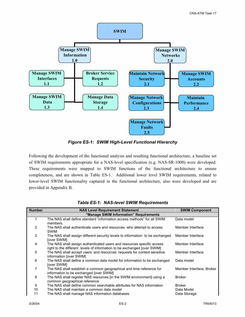
Component functions of SWIM were defined based on SWIM operating concepts captured in the NAS Concept of Operations, SWIM/NWIS Concept of Use, and the NAS Target System Description. These high level functions were organized and decomposed into lower level functions, leading to a hierarchical depiction of SWIM functionality. The first two levels of SWIM functions that comprise the functional architecture are shown in Figure ES-1.
CNS-ATM Task 17
3/26/04 ES-2 TR04013
SWIM
Manage SWIMInformation
1.0
Manage SWIMNetworks
2.0
Manage SWIMData1.3
Manage DataStorage
1.4
Manage SWIMInterfaces
1.1
Maintain NetworkSecurity
2.1
Manage NetworkConfigurations
2.3
Maintain Performance
2.4
Manage NetworkFaults
2.5
Manage SWIMAccounts
2.2
Broker ServiceRequests
1.2
Figure ES-1: SWIM High-Level Functional Hierarchy Following the development of the functional analysis and resulting functional architecture, a baseline set of SWIM requirements appropriate for a NAS-level specification (e.g. NAS-SR-1000) were developed. These requirements were mapped to SWIM functions of the functional architecture to ensure completeness, and are shown in Table ES-1. Additional lower level SWIM requirements, related to lower-level SWIM functionality captured in the functional architecture, also were developed and are provided in Appendix B.
Table ES-1: NAS-level SWIM Requirements Number NAS Level Requirement Statement SWIM Component
“Manage SWIM Information” Requirements 1 The NAS shall define standard “information access methods” for all SWIM
members. Data model
2 The NAS shall authenticate users and resources who attempt to access SWIM
Member Interface
3 The NAS shall assign different security levels to information to be exchanged [over SWIM]
Member Interface
4 The NAS shall assign authenticated users and resources specific access right to the different levels of information to be exchanged [over SWIM]
Member Interface
5 The NAS shall accept users’ and resources’ requests for context sensitive information [over SWIM]
Member Interface
6 The NAS shall define a common data model for information to be exchanged [over SWIM]
Data model
7 The NAS shall establish a common geographical and time reference for information to be exchanged [over SWIM]
Member Interface, Broker
8 The NAS shall register NAS resources [in the SWIM environment] using a common geographical reference
Broker
9 The NAS shall define common searchable attributes for NAS information Broker 10 The NAS shall maintain a common data model Data Model 11 The NAS shall manage NAS information databases Data Storage

CNS-ATM Task 17
3/26/04 ES-3 TR04013
Number NAS Level Requirement Statement SWIM Component “Manage SWIM Information” Requirements
12 The NAS shall provide means for authorized users and resources to access NAS information databases
Broker
13 The NAS shall control SWIM security control information Broker 14 The NAS shall process user and resource information requests Broker 15 Upon a standing request, the NAS shall automatically deliver updated context
sensitive information to authorized requesting users and resources Broker
16 Upon a standing request, the NAS shall automatically deliver real-time information on time [over SWIM] to authorized requesting users and resources
Broker
17 Upon a one-time request, the NAS shall deliver context sensitive information to authorized requesting users and resources
Broker
18 The NAS shall automatically establish source and user connections [over SWIM] for delivery of information
Network Manager
19 The NAS shall transport dynamically changing information Network Manager 20 The NAS shall transport static (non-changing) information Network Manager 21 The NAS shall transport scheduled information Network Manager 22 The NAS shall deliver NAS information to multiple users and resources [over
SWIM] Broker
23 The NAS shall use common geographic reference attributes for information transported [over SWIM]
Data Model
24 The NAS shall use common data attributes for information transported [over SWIM]
Data Model
25 Upon standing request, the NAS shall provide the capability to automatically collect information [through SWIM]
Broker
26 The NAS shall cache information exchanged [over SWIM] Data Storage 27 The NAS shall archive NAS information exchanged [over SWIM] when
requested Data Storage
“Manage SWIM Networks” Requirements 28 The NAS shall provide resource management [for SWIM]. Network Manager 29 The NAS shall make NAS resource information accessible [via SWIM] Network Manager 30 The NAS shall make NAS management information accessible [via SWIM] Network Manager 31 The NAS shall adapt to dynamic changes in NAS information providers and
users Network Manager
32 The NAS shall monitor end-to-end Quality of Service parameters [for SWIM] Network Manager 33 The NAS shall maintain end-to-end Quality of Service [of SWIM] Network Manager 34 The NAS shall provide account management [for SWIM] Network Manager 35 The NAS shall provide fault management [for SWIM] Network Manager 36 The NAS shall provide security functions [for SWIM] Network Manager
The SWIM functional architecture and SWIM NAS-level requirements were used as inputs to the SWIM physical architecture development effort. As a first step in the translation of the functional domain to the physical domain, the enabling technologies for SWIM were captured, including both information technologies and communication technologies. These technologies consisted of browsers, domain-specific middleware/applications, data presentation and format translation standards, distribution middleware, service middleware, object/schema definition languages, wrapper technologies, distributed database management/access, IP networking, SNMP/CORBA network management, authentication, and subject/content-based routing. Components (including hardware/software, data, and people/facilities) that accommodate these technologies and the identified functionality required for SWIM were then identified. Table ES-2 provides a listing of SWIM hardware and software components.

CNS-ATM Task 17
3/26/04 ES-4 TR04013
Table ES-2: SWIM HW/SW Component List
HW/SW Component Name H/W S/W Role
Dedicated and/or Shared Component of the
NAS Member Interface X X Supports domain/member-specific services
as well as distribution and general exchange services; the H/W supports implementation of the interface S/W on a gateway (as needed)
Dedicated
Browser X Supports standardized information access services
Shared
Web Server X X Supports standardized browser information access
Shared or Dedicated
Data Model Registry (Metadata Repository – MDR)
X X Registers and stores SWIM data model information
Dedicated
Information Object Repository (IOR)
X X Registers and stores SWIM information object schema information
Dedicated
Broker X X Processes members requests such as publish, subscribe and query by matching published information objects with members who have subscribed to or who query the data
Dedicated
Data Storage X X Stores information objects for fast retrieval and temporary storage of exchanged data. Data storage includes Data Marts, or optionally Data Warehouse
Dedicated
Network Manager Interface
X X Enable a network manager to monitor status, test parameter modifications, and implement network parameter changes
Dedicated or Shared
Network Manager X X Provides the means to control SWIM through fault management, configuration management, account management, performance management and security management
Dedicated or Shared
Local and Wide Area Network
X X Provides data transport capability Shared
Security X X Protects SWIM components and connections; detects and corrects security threats and breaches
Dedicated or Shared
A schematic connection diagram for these components is provided in Figure ES-2.

CNS-ATM Task 17
3/26/04 ES-5 TR04013
NAS Computing Services
SWIM Member InterfaceServices
Operating SystemNetwork Interface(TCP/IP port, etc)
Hardware(CPU, Memory, I/O, etc)
NAS System
SWIM MemberInterfaceServices
SWIM InterfaceHardware
(CPU, Memory, I/O, etc)
NAS User
Local and/or Wide Area Network
NAS Computing Services
Operating SystemNetwork Interface(TCP/IP port, etc)
Hardware(CPU, Memory, I/O, etc)
NAS System
NAS User
Browser Application
Operating SystemNetwork Interface(TCP/IP port, etc)
Hardware(CPU, Memory, I/O, etc)
Computing SystemWith Standard
Browser
NAS User
SWIM BrokerServices
SWIM BrokerHardware
(CPU, Memory, I/O, etc)
SWIM Data ModelRegistry Services
SWIM Data ModelRegistry Hardware
(CPU, Memory, I/O, etc)
IOR MDR
NetworkMngmt
Interface
NetworkMngmt
Interface
NetworkMngmt
Services
SWIM Network ManagerHardware
(CPU, Memory, I/O, etc)
Network ManagementInterface Services
SWIM NetworkManagement
Interface Services
Hardware(CPU, Memory, I/O, etc)
NAS NetworkManagement System
OR
AND/OR
AND/OR
SWIM NetworkManagement System
SWIM WebServer ServicesSWIM Web Server
Hardware(CPU, Memory, I/O, etc)
NetworkMngmt
Interface
MEMBERINTERFACE
BROWSER
WEB SERVER
MDRIOR
BROKER
NETWORK MANAGER INTERFACE
SECURITY
NAS Component
SWIM Component
Key
NAS Component
SWIM Component
Key
NAS Computing Services
SWIM Member InterfaceServices
Operating SystemNetwork Interface(TCP/IP port, etc)
Hardware(CPU, Memory, I/O, etc)
NAS System
SWIM MemberInterfaceServices
SWIM InterfaceHardware
(CPU, Memory, I/O, etc)
NAS User
Local and/or Wide Area Network
NAS Computing Services
Operating SystemNetwork Interface(TCP/IP port, etc)
Hardware(CPU, Memory, I/O, etc)
NAS System
NAS User
Browser Application
Operating SystemNetwork Interface(TCP/IP port, etc)
Hardware(CPU, Memory, I/O, etc)
Computing SystemWith Standard
Browser
NAS User
SWIM BrokerServices
SWIM BrokerHardware
(CPU, Memory, I/O, etc)
SWIM Data ModelRegistry Services
SWIM Data ModelRegistry Hardware
(CPU, Memory, I/O, etc)
IORIOR MDR
NetworkMngmt
Interface
NetworkMngmt
Interface
NetworkMngmt
Services
SWIM Network ManagerHardware
(CPU, Memory, I/O, etc)
Network ManagementInterface Services
SWIM NetworkManagement
Interface Services
Hardware(CPU, Memory, I/O, etc)
NAS NetworkManagement System
OR
AND/OR
AND/OR
SWIM NetworkManagement System
SWIM WebServer ServicesSWIM Web Server
Hardware(CPU, Memory, I/O, etc)
NetworkMngmt
Interface
MEMBERINTERFACE
BROWSER
WEB SERVER
MDRIOR
BROKER
NETWORK MANAGER INTERFACE
SECURITY
NAS Component
SWIM Component
Key
NAS Component
SWIM Component
Key
Figure ES-2: Overview of SWIM Hardware and Software Components In addition to the hardware and software components mentioned above, the SWIM data component (including the common data model and information object concepts) and the people/facility component were also defined. For each identified SWIM component, design decisions required for the development of the SWIM physical architecture were identified. These included:
• Data Representation Design and Data Granularity
• Required Broker Functionality and Distribution (Topology)
• Network Management Alternatives
• Data Storage Methods
• Member Interface Integration Options
• Communications Options
Of particular interest was the investigation of broker functionality and processing capability. Analysis and simulation were used to investigate three candidate alternatives. An overview of these alternatives is provided in Table ES-3. Details can be found in Appendix G.

CNS-ATM Task 17
3/26/04 ES-6 TR04013
Table ES-3: Comparison of Broker Concepts Broker Concept Description Advantages Disadvantages
Pub/Sub Broker A Pub/Sub Broker carries out a full set of functions so that the operations/interactions between publishers and subscribers are strict publish/subscribe system behavior (fully decoupled in all three aspects -- space, time, and synchronization).
Changes in publishers or subscribers completely transparent to each other; unified management of exchanged information
Possible extra latency in the process (since data flows through broker); ability to handle large stream data may be limited by load capability of the broker
Lightweight Broker A Lightweight Broker carries out a subset of full Pub/Sub Broker functions and leaves some of the functions to some traditional messaging mechanisms (e.g., Remote Procedure Call, Message Queue etc.). The operation/interactions between publishers and subscribers may not be fully decoupled in all three aspects (time, space and synchronization).
Supports implementation of several variants of Pub/Sub schemes
Publishers/subscribers are not fully decoupled; pre-defined data channels need to be established
VC Broker VC Broker functionality is extended to process stringent performance stream data differently in case a full Pub/Sub Broker can not process stream data efficiently. The extended functionality includes being able to set up a virtual connection (VC) for publishers and subscribers when dealing with stream data.
Broker approach is tailored to data type (i.e. stream or non-stream)
Extra complexity in information management functions such as data monitoring; publisher/subscriber are not fully decoupled (stream data)
Based on the investigation of the identified design decision topics, three candidate physical architectures for SWIM were identified. They included:
• Candidate A: an architecture where SWIM services include information processing using a Pub/Sub Broker; where brokers are distributed throughout the NAS at ARTCCs and large facilities, TRACONs/AFSSs and ATCTs; and where brokers are connected via a hybrid topology (i.e. hierarchical within ARTCC regions/peer-to-peer between ARTCC regions)
• Candidate B: an architecture where SWIM services include information exchange via a Lightweight Broker; where a moderately large number of brokers for service setup are located at NAS ARTCCs and large facilities (e.g. ATCSCC); and where brokers use peer-to-peer connections
• Candidate C: an architecture where SWIM services can include information processing via a broker or via a virtual circuit between an information publisher and information requester; where brokers are distributed in the NAS to ARTCCs and large facilities as well as to TRACONs/AFSSs; and where brokers are connected via a hierarchical topology
An illustration of the candidate architectures is provided in Figure ES-3.

CNS-ATM Task17
3/26/2004 ES-7 TR04013
Figure ES-3: Candidate Physical Architectures for SWIM
SWIM Process: Pub/Sub Broker
Data Mart
Distributed Computing
Network Management
SecurityPub/Sub Broker
Distributed communications and network infrastructure (in blue)
Member interface
Publ
ishe
rs
Subs
crib
ers
SWIM Process: Pub/Sub Broker
Data Mart
Distributed Computing
Network Management
SecurityPub/Sub Broker
Distributed communications and network infrastructure (in blue)
Member interfaceMember interface
Publ
ishe
rs
Subs
crib
ers
Distributed Computing
Network Management
Security
SWIM Process: Lightweight Broker
Data Channels Member interface
Distributed communications and network infrastructure (in blue)
Lightweight Broker
Data Mart
Publ
ishe
rs
Subs
crib
ers
Distributed Computing
Network Management
Security
SWIM Process: Lightweight Broker
Data ChannelsData Channels Member interfaceMember interface
Distributed communications and network infrastructure (in blue)
Lightweight Broker
Data Mart
Publ
ishe
rs
Subs
crib
ers
SWIM Process: VC Broker Case
DM
Distributed Computing
Network Management
SecurityVC Broker
Member interface
Distributed communications and network infrastructure (in blue)
Publ
ishe
rs
Subs
crib
ers
SWIM Process: VC Broker Case
DM
Distributed Computing
Network Management
SecurityVC Broker
Member interfaceMember interface
Distributed communications and network infrastructure (in blue)
Publ
ishe
rs
Subs
crib
ers

CNS-ATM Task 17
3/26/2004 ES-8 TR04013
The simulation effort conducted as part of this study found that the recommended SWIM architectures will meet the information management requirements for SWIM as well as FAA service communication requirements. However, the following items are recommended:
• Brokers should be located in “hub” facilities, where traffic patterns converge, to minimize additional network resource load and propagation latency. Additional brokers should be considered if multiple hubs can be identified.
• Variants of the publish application to support real-time dissemination of periodic information should be employed as needed to meet FAA communication requirements (e.g., for surveillance information); however, the standard publish application should be employed when it will meet requirements in order to maximize the benefits of the broker architecture and to avoid unnecessary burden at servers.
• Publish applications should be developed to re-use TCP connections for frequently published information (e.g., inter-publish times < 60 seconds) in order to reduce network overhead traffic.
• Subscribe, register and query processes should employ TCP as the underlying transport protocol; publish processes should employ the transport protocol recommended for the information to be published (e.g., UDP for surveillance information and TCP for weather, automation, and navigation & landing services).
• IP multicast should be used where applicable to reduce the network load of replicated packets.
• Minimum content granularity should allow subscriptions to specify information type (e.g., weather) and sub-type (e.g., Weather 11), with filters for source of information (e.g., facility name and location).
Additionally, new FAA policies that will be required to support SWIM operation were identified:
• Application layer acknowledgement policies, including retransmission and timeout policies.
• Information objects storage policies.
The processing of refining and comparing candidate physical architectures for SWIM as well as the initial work to specify requirements associated with design models of SWIM components necessitates continuation of the physical architecture development work effort. Specifically, required future task items include:
• Interaction with NAS IPTs to explore data model/representation requirements and constraints
• Investigation and definition of data models and query possibilities associated with specific SWIM services
• Further identification of SWIM performance requirements and constraints
• Evaluation and comparison of candidate physical architectures in terms of performance, cost, schedule, and ease of transition

CNS-ATM Task17
3/26/2004 ES-9 TR04013
• Development of initial security documentation associated with SWIM in support of SCAP development
• Development of Engineering Demonstration Models of one or more of the architecture candidates using COTS hardware and software.

CNS-ATM Task17
3/26/2004 ES-10 TR04013

CNS-ATM Task17
3/26/2004 i TR04013
ACKNOWLEDGMENTS
This task was conducted for the Federal Aviation Administration's ATM System Architecture Branch, Air Traffic Operation Planning (ATOP). The authors wish to acknowledge Mr. Joshua Hung and Mr. John Horrocks, who provided technical oversight and guidance throughout the course of the task, as well as Mr. Steve Bradford, who provided comments on the SWIM architecture concepts developed for this task.

CNS-ATM Task17
3/26/2004 ii TR04013

CNS-ATM Task17
3/26/2004 iii TR04013
TABLE OF CONTENTS
SECTION PAGE 1. Introduction.......................................................................................................1-1
1.1 Background.........................................................................................................1-1 1.1.1 Pre-SWIM Communications Architecture Activities .........................................1-2 1.1.2 SWIM Development Background.......................................................................1-2
1.2 Other SWIM Development Related Activities ...................................................1-3 1.3 Overview of Task 17...........................................................................................1-4 1.4 Task 17 Methodology .........................................................................................1-8 1.5 Document Organization......................................................................................1-9 1.6 Applicable Documents......................................................................................1-10
2. SWIM Functional Analysis ..............................................................................2-1 2.1 Introduction and Methodology ...........................................................................2-1 2.2 SWIM Operating Concept ..................................................................................2-1 2.3 SWIM Functional Architecture ..........................................................................2-5
2.3.1 SWIM Functional Analysis (First Iteration) .......................................................2-5 2.3.2 SWIM Functional Analysis (Second Iteration)...................................................2-6
3. SWIM Requirements........................................................................................3-1 3.1 Introduction and Methodology ...........................................................................3-1 3.2 SWIM Requirements ..........................................................................................3-2
4. SWIM Physical Architecture Components ....................................................4-1 4.1 Methodology and Inputs For Identification of Physical Architecture
Components ........................................................................................................4-1 4.1.1 Overview of Analysis Inputs ..............................................................................4-1 4.1.2 Defining the Design Solution Plan .....................................................................4-3
4.2 Identifying SWIM Physical Architecture Components ......................................4-4 4.2.1 SWIM Enabling Technologies............................................................................4-4 4.2.2 SWIM Physical Architecture Components.......................................................4-10 4.2.3 Functional Compliance Matrix .........................................................................4-15
5. SWIM Design Decision Analysis .....................................................................5-1 5.1 Identification of Design Tradeoffs......................................................................5-1 5.2 Data Representation Design................................................................................5-5
5.2.1 Defining the Common Data Model.....................................................................5-5 5.2.2 Information Objects for Real-time/Stream Data.................................................5-8 5.2.3 SWIM Data Discovery........................................................................................5-8
5.3 Required Broker Functionality and Broker Distribution ....................................5-8 5.3.1 Introduction.........................................................................................................5-8 5.3.2 SWIM Alternative Broker Concepts.................................................................5-10 5.3.3 Description of Broker Scenarios.......................................................................5-12 5.3.4 Comparison of Broker Scenarios ......................................................................5-20
5.4 SWIM Interface Integration Options ................................................................5-21 5.5 Required Communication Capability ...............................................................5-23
CNS-ATM Task17
3/26/2004 iv TR04013
5.6 Network Management Alternatives ..................................................................5-26 5.6.1 Simple Network Management Protocol (SNMP) Based Network Management5-26 5.6.2 Object Oriented Broker Based Network Management .....................................5-27
5.7 Data Storage Issues...........................................................................................5-28 6. SWIM Design Decision Analysis and Simulation ..........................................6-1
6.1 Introduction.........................................................................................................6-1 6.2 Simulation Overview ..........................................................................................6-1
6.2.1 Modeling and Simulation Process ......................................................................6-1 6.2.2 Development of Custom Application Layer Processes.......................................6-2 6.2.3 Integration into NAS Model ...............................................................................6-3 6.2.4 Broker Functionality/Distribution Analysis Results .........................................6-16
6.3 Required Communication Capability ...............................................................6-17 7. Physical Architecture Alternatives..................................................................7-1
7.1 Physical Architecture Solution Space.................................................................7-1 7.1.1 Candidate “A” Architecture Description ............................................................7-3 7.1.2 Candidate “B” Architecture Description ............................................................7-5 7.1.3 Candidate “C” Architecture Description ............................................................7-7
7.2 Physical Architecture Comparisons....................................................................7-9 8. Transition ..........................................................................................................8-1
8.1 Introduction.........................................................................................................8-1 8.2 Transition to SWIM – Development Considerations..........................................8-1
8.2.1 SWIM Development Process Approach .............................................................8-3 8.2.2 Activities Associated with SWIM Development ................................................8-5
8.3 Transition to SWIM – Migration Considerations and Evolution Alternatives .8-10 8.3.1 Related NAS Activities.....................................................................................8-10 8.3.2 SWIM Evolution Roadmaps.............................................................................8-11
8.4 Transition Issues ...............................................................................................8-29 9. Conclusions and Recommendations................................................................9-1

CNS-ATM Task17
3/26/2004 v TR04013
LIST OF FIGURES
FIGURES PAGE
Figure 1-1: ITT/ASD-100 Communications Architecture Development..............................................1-2 Figure 1-2: NAS System Engineering Process......................................................................................1-5 Figure 1-3: Requirements and Architecture Definition.........................................................................1-6 Figure 1-4: The Synthesis Process Activities........................................................................................1-7 Figure 1-5: Task 17 Work Flow Diagram .............................................................................................1-8 Figure 2-1: Mapping Functional Architectures .....................................................................................2-6 Figure 2-2: 1st and 2nd Level SWIM Functional Decomposition...........................................................2-7 Figure 3-1 Requirements Methodology ................................................................................................3-2 Figure 4-1: Overview of SWIM Hardware and Software Components ..............................................4-13 Figure 4-2: Function Allocation Process .............................................................................................4-16 Figure 5-1: SWIM Architecture Design Issues ......................................................................................5-2 Figure 5-2: SWIM Design Topic Dependence and Order of Resolution ..............................................5-3 Figure 5-3: Data Granularity Alternatives.............................................................................................5-7 Figure 5-4: Data Granularity Options ...................................................................................................5-7 Figure 5-5: Pub/Sub Broker Scenarios.................................................................................................5-13 Figure 5-6: Three General Levels of Broker Distribution for the NAS ...............................................5-14 Figure 5-7: Lightweight Broker Scenarios ...........................................................................................5-17 Figure 5-8: VC Broker Scenarios........................................................................................................5-19 Figure 5-9: SWIM Interface Integration Options.................................................................................5-22 Figure 5-10: SNMP-based Network Management ..............................................................................5-27 Figure 5-11: CORBA-based Network Management ...........................................................................5-28 Figure 6-1: Modeling and Simulation Process ......................................................................................6-2 Figure 6-2: Context Definition of SWIM Process Models....................................................................6-3 Figure 6-3: NAS Model - Cleveland ATS and TM Area of Control.....................................................6-4 Figure 6-4: Traffic Specification Example............................................................................................6-5 Figure 6-5: Broker Placement in the NAS Model - ZOB and DTW Facilities .....................................6-6 Figure 6-6: Surveillance Traffic Latencies............................................................................................6-7 Figure 6-7: Weather, Automation and Navigation Traffic Latencies....................................................6-7 Figure 6-8: Surveillance, Weather, Automation and Navigation Traffic Latency Distributions ..........6-8 Figure 6-9: Throughput at Campus Router Induced by Surveillance Broker........................................6-9 Figure 6-10: Throughput Induced at Campus Router by Weather Broker ............................................6-9 Figure 6-11: Throughput Induced at Campus Router by Automation Broker ....................................6-10 Figure 6-12: Throughput Induced at Navigation Router by Navigation & Landing Broker...............6-10 Figure 6-13: Reduction in Surveillance Publish Time Using Real-Time Publish Application...........6-11 Figure 6-14: Incorporation of External Broker in DTW .....................................................................6-12 Figure 6-15: Throughput Induced at Navigation Router by External Broker .....................................6-12 Figure 6-16: Throughput Reduction at Weather Broker .....................................................................6-13 Figure 6-17: Throughput Reduction at Automation Broker................................................................6-13 Figure 6-18: Reduction in TCP Delay due to External Broker ...........................................................6-14 Figure 6-19: Reduction in Throughput at Weather Broker due to Connection Reuse ........................6-15

CNS-ATM Task17
3/26/2004 vi TR04013
Figure 6-20: Reduction in Throughput at Automation Broker due to Connection Reuse...................6-15 Figure 6-21: Reduction in TCP Delay due to Connection Reuse........................................................6-16 Figure 6-22: Comparison of Traffic Latencies with and without IP Multicast ...................................6-17 Figure 6-23: Comparison of Throughput at Surveillance Broker........................................................6-18 Figure 6-24: Comparison of Throughput at Weather Broker ..............................................................6-18 Figure 6-25: Comparison of Throughput at Automation Broker ........................................................6-19 Figure 6-26: Surveillance, Weather and Automation Multicast Traffic...............................................6-19 Figure 7-1: Design Options That Affect Architecture Alternatives ......................................................7-1 Figure 7-2: Candidate “A” Broker Domain Block Diagram .................................................................7-4 Figure 7-3: Candidate “A” Broker Distribution ....................................................................................7-5 Figure 7-4: Candidate “B” Broker Domain Block Diagram .................................................................7-6 Figure 7-5: Candidate “B” Broker Distribution ....................................................................................7-7 Figure 7-6: Candidate “C” Broker Domain Block Diagram .................................................................7-8 Figure 7-7: Candidate “C” Broker Distribution ....................................................................................7-9 Figure 8-1: SWIM Hardware and Software Physical Architecture Components..................................8-2 Figure 8-2: Overview of SWIM Software Development Transition Activities ....................................8-6 Figure 8-3: Overview of SWIM Data Management Transition Activities ............................................8-8 Figure 8-4: Overview of the SWIM Member Interface Integration Transition Activities ....................8-9 Figure 8-5: SWIM Member Interface Options....................................................................................8-11 Figure 8-6: Current Surveillance Information Sharing in the NAS.....................................................8-16 Figure 8-7: Example Initial SWIM Surveillance Architecture............................................................8-17 Figure 8-8: Example Target SWIM Surveillance Architecture...........................................................8-18 Figure 8-9: Current Weather Information Sharing in the NAS...........................................................8-19 Figure 8-10: Example Initial SWIM Weather Architecture ................................................................8-20 Figure 8-11: Example Target SWIM Weather Architecture ...............................................................8-22 Figure 8-12: Overview of Current Flight Management Information Sharing in the NAS ..................8-23 Figure 8-13: Example Initial SWIM Flight Management Information Sharing Architecture.............8-24 Figure 8-14: Example Target SWIM Flight Data Processing/Management Architecture ..................8-25 Figure 8-15: Current Aeronautical Information Sharing in the NAS..................................................8-26 Figure 8-16: Example Initial SWIM Aeronautical Information Sharing Architecture........................8-27 Figure 8-17: Example Target SWIM Aeronautical Information Architecture ....................................8-28 Figure 9-1: SWIM Physical Architecture Hardware/Software ..............................................................9-1

CNS-ATM Task17
3/26/2004 vii TR04013
LIST OF TABLES
TABLES PAGE
Table 2-1: SWIM Concepts from the NAS CONOPS ..........................................................................2-2 Table 2-2: SWIM Concepts from NWIS CONUSE..............................................................................2-3 Table 3-1: NAS-level SWIM Requirements Compliance Matrix .........................................................3-3 Table 4-1: Needed Synthesis Data .......................................................................................................4-2 Table 4-2: Sample NAS-Level Performance Requirements Applicable to SWIM ...............................4-7 Table 4-3: Mapping Technology Categories to Applicable to SWIM Functions..................................4-8 Table 4-4: Identification of Enabling Technologies for SWIM ............................................................4-9 Table 4-5: Partial HW/SW Component List for SWIM......................................................................4-11 Table 4-6: SWIM HW/SW Component List .......................................................................................4-12 Table 4-7: SWIM Functionality Compliance Matrix ..........................................................................4-16 Table 5-1: Summary of Investigated Design Trade-offs for SWIM ......................................................5-1 Table 5-2: Publish/Subscribe Systems and Variant Implementations..................................................5-10 Table 5-3: Comparison of Broker Concepts.........................................................................................5-11 Table 5-4: Characterizing SWIM Data by Service Domain................................................................5-15 Table 5-5: Comparison of Broker Topology Designs ..........................................................................5-15 Table 5-6: Comparison of Broker Functionality ..................................................................................5-20 Table 5-7: Comparison of SWIM Interface Integration Options ........................................................5-22 Table 5-8: SWIM Member Interface Option Summary .......................................................................5-23 Table 5-9: Classification of Subscription Languages...........................................................................5-26 Table 5-10: Summary of Network Management Options ...................................................................5-28 Table 5-11: Data Storage Issues - Advantages/Disadvantages and Related Issues..............................5-29 Table 5-12: Summary of Data Storage Option Decisions for SWIM...................................................5-30 Table 6-1: SWIM Process Pattern Descriptions....................................................................................6-3 Table 7-1: Three Candidate Architecture Alternatives Derived from Key Design Tradeoffs ..............7-2 Table 8-1: Comparison of Software Development Methods.................................................................8-3 Table 8-2: Comparison of Development Process Approaches..............................................................8-4 Table 8-3: Relationship of NAS Activities to SWIM Development ...................................................8-10 Table 8-4: Comparison of SWIM Interface Opportunities by NAS System/Data Domain ................8-12 Table 8-5 Integrate SWIM Interface Application – Legacy NAS System Responsibility ...................8-13 Table 8-6 Integrate SWIM Interface Application – Member Interface Application Responsibility ....8-14 Table 8-7: SWIM Interface Options for NAS Surveillance Systems..................................................8-17 Table 8-8: Additional SWIM Interface Options for NAS Surveillance Systems................................8-19 Table 8-9: SWIM Interface Options for NAS Weather Systems ........................................................8-20 Table 8-10: Additional SWIM Interface Options for NAS Weather Systems ....................................8-22 Table 8-11: SWIM Interface Options for NAS Flight Data Processing/Management Systems..........8-24 Table 8-12: Additional SWIM Interface Options for NAS Flight Data Processing/Management Systems............................................................................................................................8-26 Table 8-13: SWIM Interface Options for NAS Aeronautical Information Systems ...........................8-27 Table 8-14: Additional SWIM Interface Options for NAS Aeronautical Information Systems .........8-29 Table 8-15: Overview of Transition Issues (with a Focus on Prototype Development) ......................8-29

CNS-ATM Task17
3/26/2004 viii TR04013
CNS-ATM Task17
3/26/2004 1-1 TR04013
1. INTRODUCTION
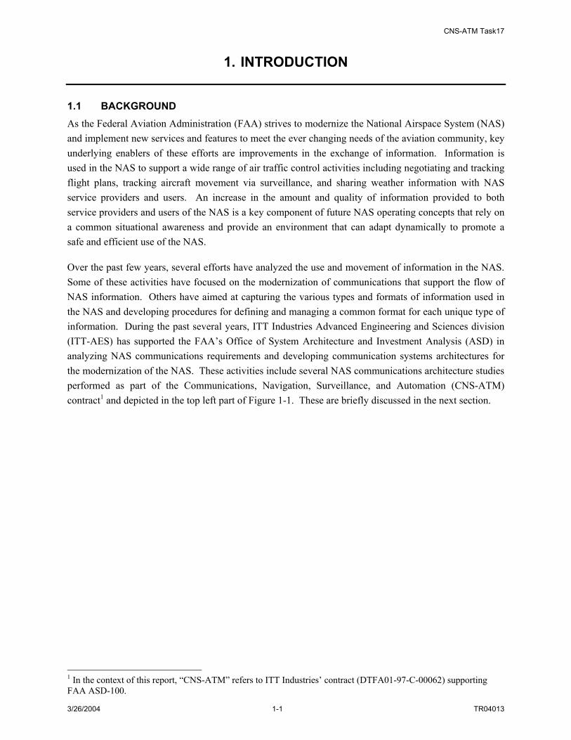
1.1 BACKGROUND As the Federal Aviation Administration (FAA) strives to modernize the National Airspace System (NAS) and implement new services and features to meet the ever changing needs of the aviation community, key underlying enablers of these efforts are improvements in the exchange of information. Information is used in the NAS to support a wide range of air traffic control activities including negotiating and tracking flight plans, tracking aircraft movement via surveillance, and sharing weather information with NAS service providers and users. An increase in the amount and quality of information provided to both service providers and users of the NAS is a key component of future NAS operating concepts that rely on a common situational awareness and provide an environment that can adapt dynamically to promote a safe and efficient use of the NAS. Over the past few years, several efforts have analyzed the use and movement of information in the NAS. Some of these activities have focused on the modernization of communications that support the flow of NAS information. Others have aimed at capturing the various types and formats of information used in the NAS and developing procedures for defining and managing a common format for each unique type of information. During the past several years, ITT Industries Advanced Engineering and Sciences division (ITT-AES) has supported the FAA’s Office of System Architecture and Investment Analysis (ASD) in analyzing NAS communications requirements and developing communication systems architectures for the modernization of the NAS. These activities include several NAS communications architecture studies performed as part of the Communications, Navigation, Surveillance, and Automation (CNS-ATM) contract1 and depicted in the top left part of Figure 1-1. These are briefly discussed in the next section.
1 In the context of this report, “CNS-ATM” refers to ITT Industries’ contract (DTFA01-97-C-00062) supporting FAA ASD-100.

CNS-ATM Task17
3/26/2004 1-2 TR04013
2001 200320022000 2004
NAS
Sys
tem
Eng
inee
ring
Proc
ess
NAS-Level RequirementsUnallocated Requirements
CNS-ATM Task 17
Functional ArchitectureFunctional Hierarchy N2 Data I/F Diagrams
CNS-ATM Task 17FFDs
SWIM Services & Operating Concepts
NWIS/SWIMCONUSE
NWIS/SWIMCONUSE
NWIS in NASArchitecture 4.0NWIS in NAS
Architecture 4.0
FTIFTINAS Communications
Architecture VisionCNS-ATM Task 10
NAS Communications Architecture VisionCNS-ATM Task 10
Future NAS Communications Architecture/Validation CNS-ATM Task 11/12
Future NAS Communications Architecture/Validation CNS-ATM Task 11/12
NWIS Architecture StudyCNS-ATM Task 15
NWIS Architecture StudyCNS-ATM Task 15
Physical ArchitectureNetwork Functionality Broker Arch. Implications Network Mngt.
CNS-ATM Task 17
1999
SWIM Services/NetworkSimulation
IS/SM
CNS-ATM Task 17Communication Architecture
RTCA NASCONOPs
RTCA NASCONOPs
ICAO ATMCPSWIM Paper
ICAO ATMCPSWIM Paper
Figure 1-1: ITT/ASD-100 Communications Architecture Development
1.1.1 Pre-SWIM Communications Architecture Activities Pre-SWIM communications architecture studies have analyzed NAS communications requirements and the applicability of current technologies and architecture concepts for meeting NAS communications needs. These CNS-ATM studies include CNS-ATM Tasks 4, 5, 10, 11, 12, and 14. Building on earlier communications tasks, CNS-ATM Task 11 developed a recommended communications architecture based on modern Internet Protocol (IP)-based telecommunications technologies in detail for a regional subset of the NAS and evaluated this architecture to demonstrate that the existing FAA requirements for operational voice and data, as well as administrative voice and data, could be served by these technologies. Task 12 analyzed existing NAS communications performance requirements and assessed the ability of these requirements to sufficiently specify the performance of new communications architectures; in particular the CNS-ATM Task 11 recommended architecture. Task 12 also verified through OPNET modeling and simulation that the technology recommended in Task 11 would meet or exceed NAS performance requirements. CNS-ATM Task 14 verified through OPNET simulation that the architecture would still meet these requirements even when modern security enhancing functionality was added to it. 1.1.2 SWIM Development Background While the above studies were in progress, the FAA; RTCA, Inc.; EuroControl; and other organizations were formulating new concepts for controlling air traffic more efficiently and safely. The increased availability of information to both service providers and users of the NAS is a key component of these future NAS operational concepts. They rely on a common understanding of current and expected NAS conditions to provide an environment that can adapt dynamically to promote a safer and more efficient NAS. NAS-Wide Information Services (NWIS) was the name the FAA used for the communications

CNS-ATM Task17
3/26/2004 1-3 TR04013
services that would enable these new information sharing concepts in the NAS; internationally these services were labeled System-Wide Information Management (SWIM). In 2003 the FAA adopted the SWIM designation. Key milestones in the development of SWIM concept include the following (see also Figure 1-1):
• Initial definitions of the NWIS concept by the NAS Information Architecture Team for its study of the NAS Information Architecture Evolution (1998)
• Definitions of high-level operating concepts for SWIM in the RTCA NAS Concept of Operations (CONOPS) (2000 and 2002)
• Development of the NWIS Concept of Use (CONUSE) document (2002)
• Development of the NWIS architecture concept in the CNS-ATM Task 15 study (February 2003)
The future vision of NAS operations supports effective collaboration among all participants, provides flexibility in assigning airspace and infrastructure resources, automates the establishment and teardown of communications connections between NAS systems to support NAS operations, and offers increased NAS information security. Extensive information sharing is required to support such a vision. SWIM will provide this information sharing functionality. High-level functionality for SWIM has been derived from the two NAS concept documents listed above: the NAS CONOPs and the NWIS CONUSE. The overriding principle of SWIM presented in these documents is delivery of the right information to the right place at the right time. CNS-ATM Task 15 started by analyzing the two SWIM concept documents. It then defined and described FAA information services for surveillance, weather, flight information, aeronautical information, and resource management and developed an Information Source/Sink Model for these services. Of particular relevance to this current task, Task 15 developed and recommended a high level functional architecture to support delivery of these information services, more specifically, an architectural concept that provides Publish/Subscribe information management with decentralized management and decentralized data exchange. The findings of CNS-ATM Task 152 directly support Task 17 activities and will be described in greater detail in this report. 1.2 OTHER SWIM DEVELOPMENT RELATED ACTIVITIES SWIM – Net Centric Meetings were initiated by FAA ASD-100 starting in 2003 because of increasing, parallel interest in the “SWIM” concept inside the FAA and similar “Net Centric” activities within other Government agencies such as NASA and the Department of Defense (DoD). These meetings feature participation by interested parties in both Government and Industry and seek to promote a common vision and implementation strategy for SWIM in the NAS, both in the near future and in the decades to come. It is anticipated that work performed as a follow-on to this CNS-ATM Task 17 will be conducted as part of
2 NAS-Wide Information Services (NWIS) Architecture Development -CNS-ATM Task 15, ITT AES, TR03010, February 22, 2003.

CNS-ATM Task17
3/26/2004 1-4 TR04013
a larger team effort encompassing FAA ASD-100, FAA AND-500, NASA, MITRE, MIT/LL, Boeing ATM, CSC, ITT/AES, and several other contracting organizations. 1.3 OVERVIEW OF TASK 17 The purpose of CNS-ATM Task 17 is to continue the development of the NWIS/SWIM architecture concepts presented in Task 15 by defining SWIM functional and physical architectures and developing NAS-level requirements required to provide SWIM functionality. While the goals of Tasks 15 and 17 were similar, Task 17 adopted a more formalized approach made possible by the release of the NAS System Engineering Manual (SEM)3. The SEM provides a structured System Engineering (SE) methodology based upon industry standard and FAA best practices (see Figure 1-2). This process is beneficial because4:
SE addresses translation of stakeholder needs into system requirements and facilitates the process by which the specification of systems and/or components satisfies those requirements. Although programs differ in underlying requirements, SE provides a logical sequence of steps toward deriving good requirements and transforming them into solutions regardless of the program’s size or complexity. These steps generate a series of work products that specify characteristics of systems (at any level), demonstrate and document the traceability to stakeholder needs (expressed or implied), and define how the requirements are validated and the systems (and associated components) are verified. To maximize effectiveness, SE commences before any significant product development activities and continues throughout the program’s lifecycle. When performed correctly, SE helps to ensure that program execution is right from the start. If problems are encountered, they are detected and resolved early. This process reduces program cost and risk.
3 National Airspace System - System Engineering Manual, Federal Aviation Administration, ASD-100 Architecture and System Engineering, Version 2.1, November 13, 2003. 4 Ibid. p. 1-1.

CNS-ATM Task17
3/26/2004 1-5 TR04013
Figure 1-2: NAS System Engineering Process5
An important concept presented in the SEM is the idea that system engineering is performed as an iterative process, with periodic feedback throughout the SE process as the system architecture evolves (see Figure 1-2). For example, requirements feedback is required when proposed architectures cannot meet all requirements, perhaps because of technology or cost constraints. Similarly, design feedback may be necessary because certain design issues discovered in the synthesis process can compel a re-examination of the functional analysis process.
5 Ibid., p. 4.1-1.
CNS-ATM Task17
3/26/2004 1-6 TR04013
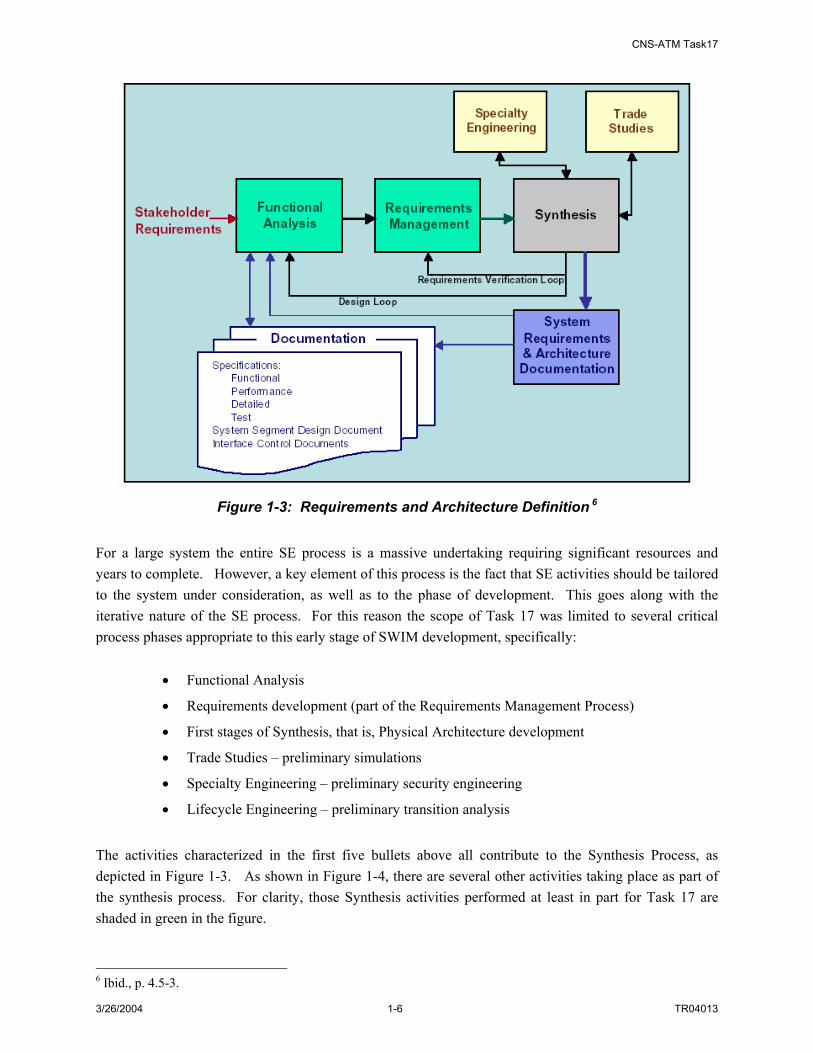
Figure 1-3: Requirements and Architecture Definition 6
For a large system the entire SE process is a massive undertaking requiring significant resources and years to complete. However, a key element of this process is the fact that SE activities should be tailored to the system under consideration, as well as to the phase of development. This goes along with the iterative nature of the SE process. For this reason the scope of Task 17 was limited to several critical process phases appropriate to this early stage of SWIM development, specifically:
• Functional Analysis
• Requirements development (part of the Requirements Management Process)
• First stages of Synthesis, that is, Physical Architecture development
• Trade Studies – preliminary simulations
• Specialty Engineering – preliminary security engineering
• Lifecycle Engineering – preliminary transition analysis
The activities characterized in the first five bullets above all contribute to the Synthesis Process, as depicted in Figure 1-3. As shown in Figure 1-4, there are several other activities taking place as part of the synthesis process. For clarity, those Synthesis activities performed at least in part for Task 17 are shaded in green in the figure.
6 Ibid., p. 4.5-3.

CNS-ATM Task17
3/26/2004 1-7 TR04013
FunctionalAnalysis
Requirements Management
Requirements Review and Objectives Definition
Allocate Requirements to System Elements
Define Design Solution Plan
Identify System Safety Engineering Attributes
Identify Technology Requirements
Identify Make or Buy Alternatives
Identify Off-the-Shelf Availability
Allocate Design Constraints to
System Elements
Define Design & Performance Characteristics
Assess Failure Modes, Effects, & Critically
Assess Testability Needs
Assess Standardization Opportunities
Assess Life Cycle Factors *
Define Physical Architecture
Analyze & Refine Design
Alternative
Preferred Design
Selection
Configuration Baseline and Architecture Documentation
AssessRequirementsCompliance
RequirementsFeedback
Loop
DesignFeedback
Loop
compliant
Non-compliant with baseline
SynthesisLoop
KeyTask 17 Key Activity
Other Task 17 Activity
* For Task 17: Transition Analysis
FunctionalAnalysis
Requirements Management
Requirements Review and Objectives Definition
Allocate Requirements to System Elements
Define Design Solution Plan
Identify System Safety Engineering Attributes
Identify Technology Requirements
Identify Make or Buy Alternatives
Identify Off-the-Shelf Availability
Allocate Design Constraints to
System Elements
Define Design & Performance Characteristics
Assess Failure Modes, Effects, & Critically
Assess Testability Needs
Assess Standardization Opportunities
Assess Life Cycle Factors *
Define Physical Architecture
Analyze & Refine Design
Alternative
Preferred Design
Selection
Configuration Baseline and Architecture Documentation
AssessRequirementsCompliance
RequirementsFeedback
Loop
DesignFeedback
Loop
compliant
Non-compliant with baseline
SynthesisLoop
KeyTask 17 Key Activity
Other Task 17 Activity
* For Task 17: Transition Analysis
Figure 1-4: The Synthesis Process Activities7
Task 17 SWIM system engineering work items were organized into specific task activities as identified below:
• Subtask A: Functional Architecture
• Subtask B: NAS-Level Requirements Development
• Subtask C: Physical Architecture Development
7 Ibid., p. 4.5-8.

CNS-ATM Task17
3/26/2004 1-8 TR04013
• Subtask D: SWIM Transition Alternatives and Recommendations
• Subtask E: SWIM Architecture Simulation/Validation
This document is a cumulative report capturing the analyses and results associated with each of the Task 17 subtasks. 1.4 TASK 17 METHODOLOGY The worked performed for the various Task 17 subtasks was generally performed in serial fashion, as earlier subtask activity became input for later subtask activities. An overview of the workflow for Task 17 is captured in Figure 1-5.
NWISConcept of Use
NAS ConceptOf Operations
CNS-ATMTask 15
Other NWIS/SWIM Documents
Subtask A: NWIS/SWIM
Functional Analysis& Functional ArchitectureDevelopment
Subtask A: NWIS/SWIM
Functional Analysis& Functional ArchitectureDevelopment
Subtask B:NAS-level
RequirementsDevelopment
for NWIS/SWIM
Subtask B:NAS-level
RequirementsDevelopment
for NWIS/SWIM
Subtask C:NWIS/SWIM
PhysicalArchitectureDevelopment
Subtask C:NWIS/SWIM
PhysicalArchitectureDevelopment
Subtask D:Transition Alternatives& Recommendation
Subtask D:Transition Alternatives& Recommendation
Subtask E:NWIS/SWIMArchitectureSimulation/Validation
Subtask E:NWIS/SWIMArchitectureSimulation/Validation
NAS-SR-1000
NAS-SR-1000Re-write Activities
Task 17Report
Figure 1-5: Task 17 Work Flow Diagram
For Subtask 17A, SWIM and NAS operating concept documents, the NAS Target System Description and both previous and on-going SWIM-related analysis activities were used to capture specific objectives and operating concepts for SWIM. With these ideas in mind and with consideration of previous SWIM functional analysis activity, general functional categories to define SWIM were derived. From this, specific high-level functions were identified, described and then decomposed into component functionality. Using the identified functionality for SWIM and with consideration of existing and proposed changes to NAS-SR-10008, NAS-level functional requirements for SWIM were developed in Subtask 17B. A
8 National Airspace System – System Requirements Specification, NAS-SR-1000 with Changes 1-16, US Department of Transportation, Federal Aviation Administration, March 21, 2002.
CNS-ATM Task17
3/26/2004 1-9 TR04013
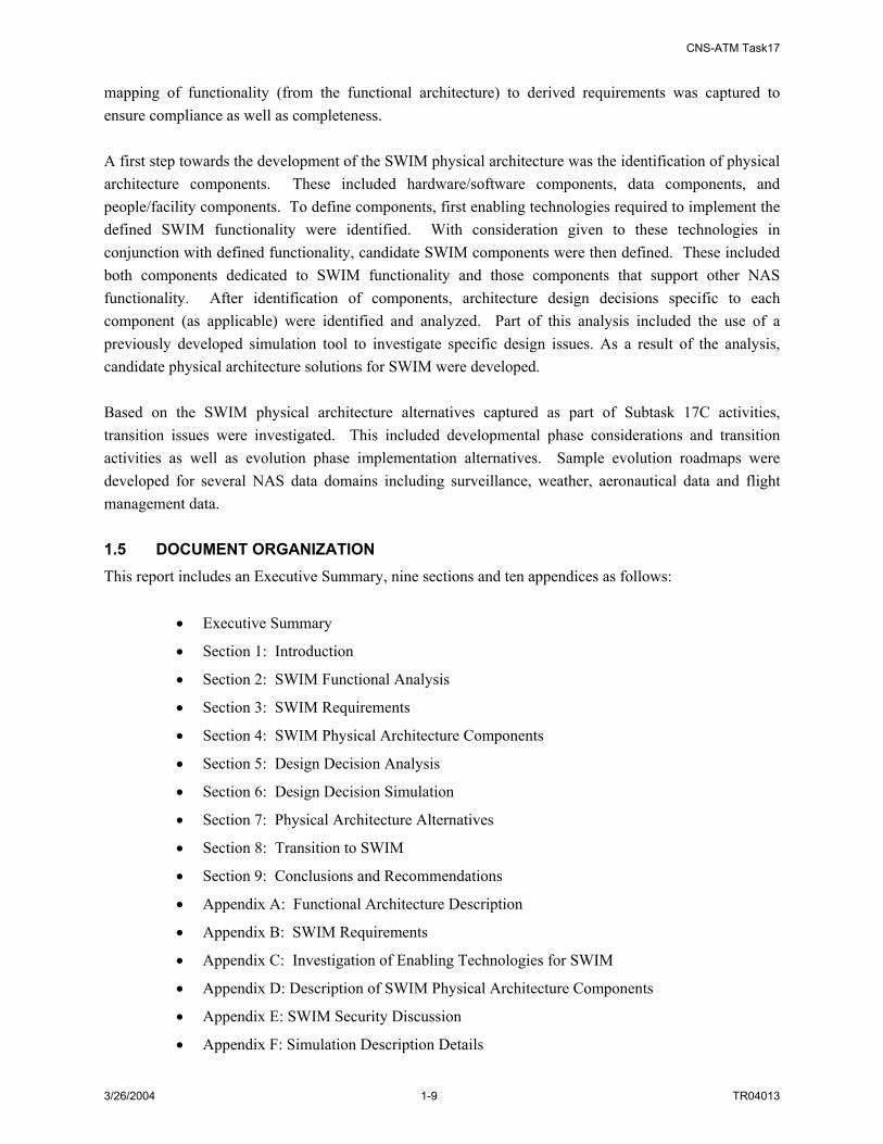
mapping of functionality (from the functional architecture) to derived requirements was captured to ensure compliance as well as completeness. A first step towards the development of the SWIM physical architecture was the identification of physical architecture components. These included hardware/software components, data components, and people/facility components. To define components, first enabling technologies required to implement the defined SWIM functionality were identified. With consideration given to these technologies in conjunction with defined functionality, candidate SWIM components were then defined. These included both components dedicated to SWIM functionality and those components that support other NAS functionality. After identification of components, architecture design decisions specific to each component (as applicable) were identified and analyzed. Part of this analysis included the use of a previously developed simulation tool to investigate specific design issues. As a result of the analysis, candidate physical architecture solutions for SWIM were developed. Based on the SWIM physical architecture alternatives captured as part of Subtask 17C activities, transition issues were investigated. This included developmental phase considerations and transition activities as well as evolution phase implementation alternatives. Sample evolution roadmaps were developed for several NAS data domains including surveillance, weather, aeronautical data and flight management data. 1.5 DOCUMENT ORGANIZATION This report includes an Executive Summary, nine sections and ten appendices as follows:
• Executive Summary
• Section 1: Introduction
• Section 2: SWIM Functional Analysis
• Section 3: SWIM Requirements
• Section 4: SWIM Physical Architecture Components
• Section 5: Design Decision Analysis
• Section 6: Design Decision Simulation
• Section 7: Physical Architecture Alternatives
• Section 8: Transition to SWIM
• Section 9: Conclusions and Recommendations
• Appendix A: Functional Architecture Description
• Appendix B: SWIM Requirements
• Appendix C: Investigation of Enabling Technologies for SWIM
• Appendix D: Description of SWIM Physical Architecture Components
• Appendix E: SWIM Security Discussion
• Appendix F: Simulation Description Details

CNS-ATM Task17
3/26/2004 1-10 TR04013
• Appendix G: Design Decision Analysis Details
• Appendix H: NAS Sensors and Systems
• Appendix I: Terms and Concepts Used in the Report
• Appendix J: List of Abbreviations and Acronyms
The Executive Summary following the title page gives a concise description of the contents of the report, with emphasis on its results and recommendations. Section 1 describes the scope and objectives of the CNS-ATM Task 17 study in the context of NAS modernization and FAA’s efforts to improve the exchange of information. It provides the workflow of Task 17, its overall methodology and the organization of the report. Section 2 documents three iterations of SWIM functional analysis and presents the revised SWIM functional architecture. Section 3 discusses the iterative development of NAS-level requirements for SWIM and top level SWIM requirements. Section 4 explains the synthesis process used to develop the SWIM physical architecture and identifies and describes its components. Section 5 analyzes design issues and documents the simulation activities employed to resolve them. Section 6 shows three physical architecture alternatives based on different design decision selections. Section 7 proposes some possible NAS architecture steps in the transition to SWIM capabilities in the areas of surveillance, weather and aeronautical and flight information. It discusses options and policy issues for the transition to SWIM. Section 8 summarizes Task 17 activities, conclusions and recommendations for future SWIM works. Appendices A through J list SWIM functions (A) and requirements (B), provide more detail on enabling technologies (C), SWIM components (D), security considerations (E), SWIM simulation activities (F), design decisions (G) and interfaces for NAS sensors and legacy systems (H), while the final two appendices provide reference material on terms and concepts (I) and acronyms (J). 1.6 APPLICABLE DOCUMENTS The following list identifies some of the more relevant FAA and other source documents used in the preparation of this report. Concept of Use for NAS-Wide Information Services (NWIS), Federal Aviation Administration, July 1, 2002. Future NAS Communications Architecture Validation, CNS-ATM Task 12 Report, Prepared for Federal Aviation Administration, ASD-120/140, by ITT Industries, Advanced Engineering and Sciences Division, TR01084, October 2001. NAS-Wide Information Services (NWIS) Architecture Development, CNS-ATM Task 15 Report, Prepared for Federal Aviation Administration, ASD-120, by ITT Industries, Advanced Engineering and Sciences Division, TR03010, February 22, 2003. NAS-Wide Information Services (NWIS)/System-Wide Information Management (SWIM) Architecture and Requirements, Functional Requirements, CNS-ATM Task 17A Report, Prepared for Federal Aviation Administration, ASD-120, by ITT Industries, Advanced Engineering and Sciences Division, TR03091, July 29, 2003. (SWIM) Architecture and Requirements, NAS-Level Requirements Development, CNS-ATM Task 17B Report, Prepared for Federal Aviation Administration, ASD-120, by ITT Industries, Advanced Engineering and Sciences Division, TR03091, September 8, 2003.

CNS-ATM Task17
3/26/2004 1-11 TR04013
System-Wide Information Management (SWIM) Architecture and Requirements, Physical Architecture Development, CNS-ATM TASK 17C Report, Prepared for Federal Aviation Administration, ASD-120, by ITT Industries, Advanced Engineering and Sciences Division, TR04008, February 9, 2004. National Airspace System Concept of Operations, RTCA Select Committee for Free Flight, Fall 2002. National Airspace System - System Engineering Manual, Federal Aviation Administration, ASD-100 Architecture and System Engineering, Version 2.1, November 13, 2003. National Airspace System – System Requirements Specification, NAS-SR-1000 with Changes 1-16, US Department of Transportation, Federal Aviation Administration, March 21, 2002. NAS Target System Description (TSD), Steve Bradford, FAA presentation, May 2003

CNS-ATM Task17
3/26/2004 1-12 TR04013
CNS-ATM Task17
3/26/2004 2-1 TR04013
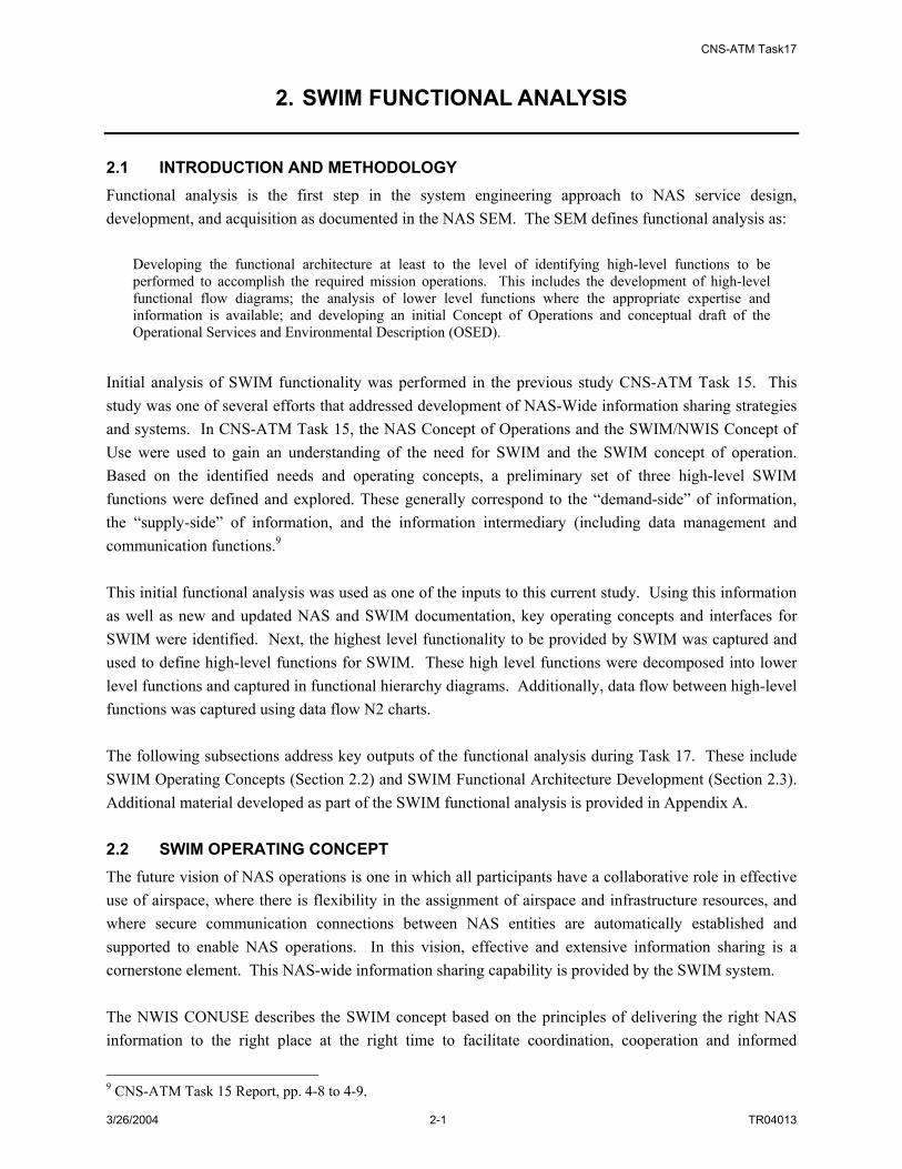
2. SWIM FUNCTIONAL ANALYSIS
2.1 INTRODUCTION AND METHODOLOGY Functional analysis is the first step in the system engineering approach to NAS service design, development, and acquisition as documented in the NAS SEM. The SEM defines functional analysis as:
Developing the functional architecture at least to the level of identifying high-level functions to be performed to accomplish the required mission operations. This includes the development of high-level functional flow diagrams; the analysis of lower level functions where the appropriate expertise and information is available; and developing an initial Concept of Operations and conceptual draft of the Operational Services and Environmental Description (OSED).
Initial analysis of SWIM functionality was performed in the previous study CNS-ATM Task 15. This study was one of several efforts that addressed development of NAS-Wide information sharing strategies and systems. In CNS-ATM Task 15, the NAS Concept of Operations and the SWIM/NWIS Concept of Use were used to gain an understanding of the need for SWIM and the SWIM concept of operation. Based on the identified needs and operating concepts, a preliminary set of three high-level SWIM functions were defined and explored. These generally correspond to the “demand-side” of information, the “supply-side” of information, and the information intermediary (including data management and communication functions.9 This initial functional analysis was used as one of the inputs to this current study. Using this information as well as new and updated NAS and SWIM documentation, key operating concepts and interfaces for SWIM were identified. Next, the highest level functionality to be provided by SWIM was captured and used to define high-level functions for SWIM. These high level functions were decomposed into lower level functions and captured in functional hierarchy diagrams. Additionally, data flow between high-level functions was captured using data flow N2 charts. The following subsections address key outputs of the functional analysis during Task 17. These include SWIM Operating Concepts (Section 2.2) and SWIM Functional Architecture Development (Section 2.3). Additional material developed as part of the SWIM functional analysis is provided in Appendix A. 2.2 SWIM OPERATING CONCEPT The future vision of NAS operations is one in which all participants have a collaborative role in effective use of airspace, where there is flexibility in the assignment of airspace and infrastructure resources, and where secure communication connections between NAS entities are automatically established and supported to enable NAS operations. In this vision, effective and extensive information sharing is a cornerstone element. This NAS-wide information sharing capability is provided by the SWIM system. The NWIS CONUSE describes the SWIM concept based on the principles of delivering the right NAS information to the right place at the right time to facilitate coordination, cooperation and informed
9 CNS-ATM Task 15 Report, pp. 4-8 to 4-9.
CNS-ATM Task17
3/26/2004 2-2 TR04013
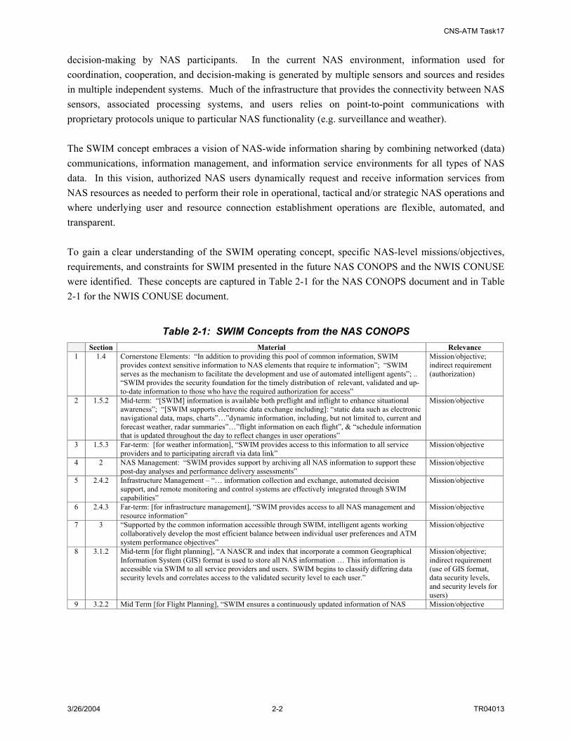
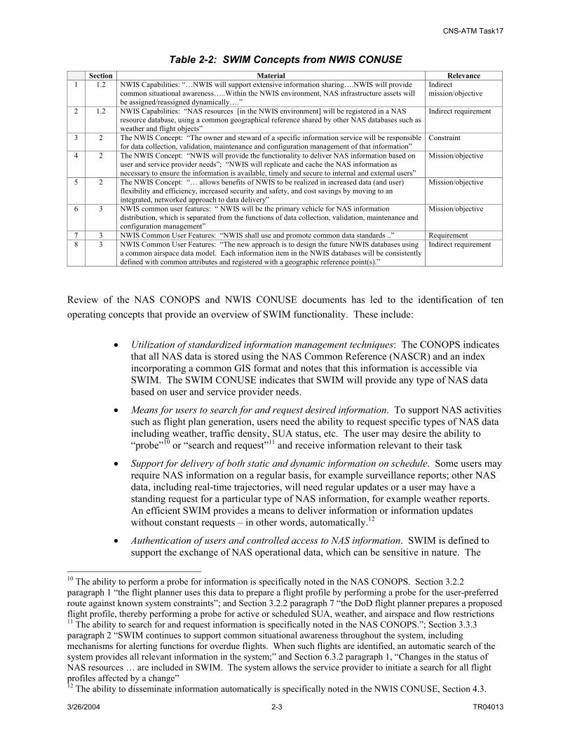
decision-making by NAS participants. In the current NAS environment, information used for coordination, cooperation, and decision-making is generated by multiple sensors and sources and resides in multiple independent systems. Much of the infrastructure that provides the connectivity between NAS sensors, associated processing systems, and users relies on point-to-point communications with proprietary protocols unique to particular NAS functionality (e.g. surveillance and weather). The SWIM concept embraces a vision of NAS-wide information sharing by combining networked (data) communications, information management, and information service environments for all types of NAS data. In this vision, authorized NAS users dynamically request and receive information services from NAS resources as needed to perform their role in operational, tactical and/or strategic NAS operations and where underlying user and resource connection establishment operations are flexible, automated, and transparent. To gain a clear understanding of the SWIM operating concept, specific NAS-level missions/objectives, requirements, and constraints for SWIM presented in the future NAS CONOPS and the NWIS CONUSE were identified. These concepts are captured in Table 2-1 for the NAS CONOPS document and in Table 2-1 for the NWIS CONUSE document.
Table 2-1: SWIM Concepts from the NAS CONOPS Section Material Relevance
1 1.4 Cornerstone Elements: “In addition to providing this pool of common information, SWIM provides context sensitive information to NAS elements that require te information”; “SWIM serves as the mechanism to facilitate the development and use of automated intelligent agents”; .. “SWIM provides the security foundation for the timely distribution of relevant, validated and up-to-date information to those who have the required authorization for access”
Mission/objective; indirect requirement (authorization)
2 1.5.2 Mid-term: “[SWIM] information is available both preflight and inflight to enhance situational awareness”; “[SWIM supports electronic data exchange including]: “static data such as electronic navigational data, maps, charts”…”dynamic information, including, but not limited to, current and forecast weather, radar summaries”…”flight information on each flight”, & “schedule information that is updated throughout the day to reflect changes in user operations”
Mission/objective
3 1.5.3 Far-term: [for weather information], “SWIM provides access to this information to all service providers and to participating aircraft via data link”
Mission/objective
4 2 NAS Management: “SWIM provides support by archiving all NAS information to support these post-day analyses and performance delivery assessments”
Mission/objective
5 2.4.2 Infrastructure Management – “… information collection and exchange, automated decision support, and remote monitoring and control systems are effectively integrated through SWIM capabilities”
Mission/objective
6 2.4.3 Far-term: [for infrastructure management], “SWIM provides access to all NAS management and resource information”
Mission/objective
7 3 “Supported by the common information accessible through SWIM, intelligent agents working collaboratively develop the most efficient balance between individual user preferences and ATM system performance objectives”
Mission/objective
8 3.1.2 Mid-term [for flight planning], “A NASCR and index that incorporate a common Geographical Information System (GIS) format is used to store all NAS information … This information is accessible via SWIM to all service providers and users. SWIM begins to classify differing data security levels and correlates access to the validated security level to each user.”
Mission/objective; indirect requirement (use of GIS format, data security levels, and security levels for users)
9 3.2.2 Mid Term [for Flight Planning], “SWIM ensures a continuously updated information of NAS Mission/objective
CNS-ATM Task17
3/26/2004 2-3 TR04013
Table 2-2: SWIM Concepts from NWIS CONUSE Section Material Relevance 1 1.2 NWIS Capabilities: “…NWIS will support extensive information sharing….NWIS will provide
common situational awareness…..Within the NWIS environment, NAS infrastructure assets will be assigned/reassigned dynamically….”
Indirect mission/objective
2 1.2 NWIS Capabilities: “NAS resources [in the NWIS environment] will be registered in a NAS resource database, using a common geographical reference shared by other NAS databases such as weather and flight objects”
Indirect requirement
3 2 The NWIS Concept: “The owner and steward of a specific information service will be responsible for data collection, validation, maintenance and configuration management of that information”
Constraint
4 2 The NWIS Concept: “NWIS will provide the functionality to deliver NAS information based on user and service provider needs”; “NWIS will replicate and cache the NAS information as necessary to ensure the information is available, timely and secure to internal and external users”
Mission/objective
5 2 The NWIS Concept: “… allows benefits of NWIS to be realized in increased data (and user) flexibility and efficiency, increased security and safety, and cost savings by moving to an integrated, networked approach to data delivery”
Mission/objective
6 3 NWIS common user features: “ NWIS will be the primary vehicle for NAS information distribution, which is separated from the functions of data collection, validation, maintenance and configuration management”
Mission/objective
7 3 NWIS Common User Features: “NWIS shall use and promote common data standards ..” Requirement 8 3 NWIS Common User Features: “The new approach is to design the future NWIS databases using
a common airspace data model. Each information item in the NWIS databases will be consistently defined with common attributes and registered with a geographic reference point(s).”
Indirect requirement
Review of the NAS CONOPS and NWIS CONUSE documents has led to the identification of ten operating concepts that provide an overview of SWIM functionality. These include:
• Utilization of standardized information management techniques: The CONOPS indicates that all NAS data is stored using the NAS Common Reference (NASCR) and an index incorporating a common GIS format and notes that this information is accessible via SWIM. The SWIM CONUSE indicates that SWIM will provide any type of NAS data based on user and service provider needs.
• Means for users to search for and request desired information. To support NAS activities such as flight plan generation, users need the ability to request specific types of NAS data including weather, traffic density, SUA status, etc. The user may desire the ability to “probe”10 or “search and request”11 and receive information relevant to their task
• Support for delivery of both static and dynamic information on schedule. Some users may require NAS information on a regular basis, for example surveillance reports; other NAS data, including real-time trajectories, will need regular updates or a user may have a standing request for a particular type of NAS information, for example weather reports. An efficient SWIM provides a means to deliver information or information updates without constant requests – in other words, automatically.12
• Authentication of users and controlled access to NAS information. SWIM is defined to support the exchange of NAS operational data, which can be sensitive in nature. The
10 The ability to perform a probe for information is specifically noted in the NAS CONOPS. Section 3.2.2 paragraph 1 “the flight planner uses this data to prepare a flight profile by performing a probe for the user-preferred route against known system constraints”; and Section 3.2.2 paragraph 7 “the DoD flight planner prepares a proposed flight profile, thereby performing a probe for active or scheduled SUA, weather, and airspace and flow restrictions 11 The ability to search for and request information is specifically noted in the NAS CONOPS.”; Section 3.3.3 paragraph 2 “SWIM continues to support common situational awareness throughout the system, including mechanisms for alerting functions for overdue flights. When such flights are identified, an automatic search of the system provides all relevant information in the system;” and Section 6.3.2 paragraph 1, “Changes in the status of NAS resources … are included in SWIM. The system allows the service provider to initiate a search for all flight profiles affected by a change” 12 The ability to disseminate information automatically is specifically noted in the NWIS CONUSE, Section 4.3.

CNS-ATM Task17
3/26/2004 2-4 TR04013
NWIS CONUSE includes such terms as “subscribing users”, “authorized external users”, and “secure information sharing”. The NAS CONOPS indicates that SWIM will “classify differing data security levels and correlates access to the validated security level to each user”. SWIM needs to provide the means to secure the access to the NAS information that it carries
• Support of both FAA and non-FAA ground and airborne users and data sources. NAS information is required by a large set of users, and provided by numerous resources.
• Automatic establishment of resource/user connections and automatic collection and delivery of information (adapting to changes in SWIM sources/users). To adapt to dynamic conditions of the NAS, including dynamic information requirements, SWIM supports an automated means of establishing information connections. This supports the System-to-System (SYSCO) concept introduced in the NAS CONOPS. For example, surveillance information from adjacent or auxiliary equipment may need to be redistributed when a partial degradation or loss of surveillance capability occurs; as aircraft move between defined airspace, they can automatically be provided with relevant weather alerts for the airspace; and assignment of resources to support dynamic reassignment of airspace between facilities may be established automatically. This capability also supports the use of intelligent agents (introduced in the CONOPS) to be used to perform information discovery, collection and exchange functionality on behalf of the service provider or NAS user.
• Accommodation of all NAS data (e.g. surveillance, weather, flight profiles). To support collaborative decision making among NAS service providers and users (including the flight deck and Flight Operations Center), a common understanding of the NAS is required. This common understanding requires the use of consistent data – and a wide range of NAS data. To achieve the efficiency of NAS operations identified in the CONOPS, SWIM must accommodate all types of NAS data.
• Support of a common geographical and time index/reference associated with NAS information. The NAS CONOPS identifies the use of a NASCR and an index that uses a common GIS as being used to store NAS data including terrain, obstacle, weather, navigation, surveillance, communication coverage, and other information. This use of a common reference is also reflected in the NWIS CONUSE, which indicates that information may be searched for based on a geographical reference. The CONUSE also indicates that a time reference will be provided with stored data.
• Support of legacy NAS systems with minimal changes. The future vision of the NAS includes integration of new technologies and systems (e.g. satellite derived positioning systems and new Decision Support Systems) in addition to existing systems (e.g. primary and secondary radars). For transition purposes and to enable efficient data exchange in the near term as well as the far term, SWIM accommodates legacy systems with minimal impact.
• Provision of a scalable and standards-based solution. The NWIS CONUSE describes the use of common data interfaces as well as common data standards. In order to address the wide range of NAS data types and users, to fully support situational awareness between service providers and users, and to support such functionality as SYSCO, the SWIM solution is one that is standards-based. For transition and evolution purposed, the SWIM solution must be scalable, implying that the solution can start small and expand to address increasing demand.

CNS-ATM Task17
3/26/2004 2-5 TR04013
2.3 SWIM FUNCTIONAL ARCHITECTURE Two iterations of functional analysis were performed during Task 17. The first iteration used as task inputs the updated NAS CONOPs, SWIM/NWIS CONUSE, NAS TSD and the findings of other SWIM-related activities as a basis for developing the primary functional components of SWIM. These functional components were organized into groups of common functionality, and the high-level functional architecture diagram was developed. A description of each top-level SWIM function was developed, and an N2 diagram capturing data flow between the functions was generated. Next, where applicable, the top-level functions were decomposed into component functions. This functional architecture was used as input to the physical architecture development effort. The work to develop a physical architecture for SWIM led to a revised consideration of the SWIM functionality. As a result, a second iteration of functional analysis was performed. The following sections address both the initial (Section 2.3.1) and revised (Section 2.3.2) functional analysis and resulting functional architecture for SWIM. 2.3.1 SWIM Functional Analysis (First Iteration) One of the initial steps of the Task 17 study included a functional analysis of the SWIM concept. Having revisited SWIM operating concepts addressed in the SWIM CONUSE and NAS CONOPs, the component functions of SWIM were defined. From the highest level perspective, this component addressed three categories of functionality, namely:
• Management of SWIM Service Interfaces - the management of user connectivity to SWIM including how to access SWIM via pre-defined access specifications that address access protocols and languages, information products or requirements, and other information used to support plug-and-play type connectivity, as well as registration/authentication of users. This function also addresses the transactions between a user and SWIM to search, request, accept and provide NAS information.
• Management of SWIM Operations - the association of information requests to available NAS/SWIM information and the directing of NAS/SWIM resources to support SWIM services. This function also addresses the security control, configuration management of SWIM resources, and the monitoring and control of SWIM/NAS resources. It also provides monitoring of service quality and adjustment of SWIM connectivity as necessary.
• Management of SWIM Data - the definition and management of common SWIM information formats and the association of defined NAS information objects with NAS/SWIM resources. This function also addresses the publishing and maintaining of an information directory for SWIM.
These categories were mapped into high level functions addressing three primary yet distinct areas of information sharing capability in which SWIM provides a role: 1) interfacing to NAS users and resources that supply or receive data; 2) providing all operations that relate to enabling information services (e.g. processing requests, dynamically establishing connections between data suppliers and data requesters, ensuring service quality and security, etc); and 3) supporting a means to use and index data in standardized formats to enable information exchange by all types of NAS users and resources.

CNS-ATM Task17
3/26/2004 2-6 TR04013
The Subtask 17A functional analysis also included the decomposition of these high-level functions to 2nd and 3rd level functions. The relationship between functions was captured in functional flow diagrams and N2 data flow diagrams. Subtask 17B activities included the generation of NAS level requirements for SWIM derived from the Subtask 17A functional analysis outputs. As part of the process of verifying a complete functional architecture, it was considered useful and informative to map the identified high-level functions for SWIM to a standard architecture reference model. In particular, the functions have been mapped to the ISO Reference Model of Open Distributed Processing (RM-ODP) [ISO/IEC 10746]. An overview of this reference model is provided in Appendix A. The mapping of the SWIM high-level functions (First Iteration) to the reference model is shown in Figure 2-1. Note in the figure that the RM-ODP model provides a straightforward way to reorganize functions into two major categories: Information Management and Network Management. This allocation of functionality has its merits in the development of a physical architecture, especially as it groups together all network management functionality, which can be decomposed in accordance with ISO Network Management standards, in particular ISO 7498-413.
Manage SWIMService Interface
Manage SWIMData
Manage SWIMOperations
Task 17A Functions
Human InteractionService
Model/InformationManagement Service
System ManagementServices
ISO RM-ODP Model
CommunicationServices
InformationManagement
NetworkManagement
Figure 2-1: Mapping Functional Architectures
2.3.2 SWIM Functional Analysis (Second Iteration) Two initial steps were taken to develop a physical architecture for SWIM. As a first step of moving from the logical to physical domain, enabling technologies for SWIM functions were identified. Then, consideration of SWIM functionality in conjunction with the enabling technologies led to the identification of candidate physical architecture components for SWIM. During this process, the merit of
13 ISO/IEC 7498-4:1989 - Information processing systems -- Open Systems Interconnection -- Basic Reference Model -- Part 4: Management framework - 1st edition
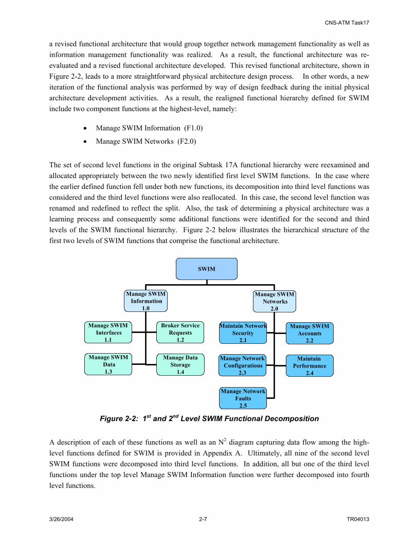
CNS-ATM Task17
3/26/2004 2-7 TR04013
a revised functional architecture that would group together network management functionality as well as information management functionality was realized. As a result, the functional architecture was re-evaluated and a revised functional architecture developed. This revised functional architecture, shown in Figure 2-2, leads to a more straightforward physical architecture design process. In other words, a new iteration of the functional analysis was performed by way of design feedback during the initial physical architecture development activities. As a result, the realigned functional hierarchy defined for SWIM include two component functions at the highest-level, namely:
• Manage SWIM Information (F1.0)
• Manage SWIM Networks (F2.0)
The set of second level functions in the original Subtask 17A functional hierarchy were reexamined and allocated appropriately between the two newly identified first level SWIM functions. In the case where the earlier defined function fell under both new functions, its decomposition into third level functions was considered and the third level functions were also reallocated. In this case, the second level function was renamed and redefined to reflect the split. Also, the task of determining a physical architecture was a learning process and consequently some additional functions were identified for the second and third levels of the SWIM functional hierarchy. Figure 2-2 below illustrates the hierarchical structure of the first two levels of SWIM functions that comprise the functional architecture.
SWIM
Manage SWIMInformation
1.0
Manage SWIMNetworks
2.0
Manage SWIMData1.3
Manage DataStorage
1.4
Manage SWIMInterfaces
1.1
Maintain NetworkSecurity
2.1
Manage NetworkConfigurations
2.3
Maintain Performance
2.4
Manage NetworkFaults
2.5
Manage SWIMAccounts
2.2
Broker ServiceRequests
1.2
Figure 2-2: 1st and 2nd Level SWIM Functional Decomposition
A description of each of these functions as well as an N2 diagram capturing data flow among the high-level functions defined for SWIM is provided in Appendix A. Ultimately, all nine of the second level SWIM functions were decomposed into third level functions. In addition, all but one of the third level functions under the top level Manage SWIM Information function were further decomposed into fourth level functions.

CNS-ATM Task17
3/26/2004 2-8 TR04013
The list below provides the names and numbers of the final set of SWIM functions according to their hierarchical relationships. Appendix A gives descriptions of all of these functions and includes the mapping between the original Subtask 17A defined SWIM functions and this final set:
• 1.0 Manage SWIM Information
• 1.1 Manage SWIM Interfaces
– 1.1.1 Supply Access Methods
ο 1.1.1.1 Define Access Methods
ο 1.1.1.2 Maintain Access Methods
– 1.1.2 Control SWIM Access
ο 1.1.2.1 Register Member
ο 1.1.2.2 Maintain Member List
ο 1.1.2.3 Identify and Authenticate Members
ο 1.1.2.4 Authorize SWIM Access (User Data Protection)
ο 1.1.2.5 Maintain SWIM Access Limitations
– 1.1.3 Conduct Interface Transactions
ο 1.1.3.1 Translate Data Format
ο 1.1.3.2 Convert Communications Protocol
ο 1.1.3.3 Process SWIM-to-Member Requests
ο 1.1.3.4 Process Member-to-SWIM Requests
ο 1.1.3.5 Exchange Status/Control Messages
• 1.2 Broker Service Requests
– 1.2.1 Maintain Registration
ο 1.2.1.1 Maintain Local SWIM Member Registration
ο 1.2.1.2 Maintain Remote Broker Registration Information
ο 1.2.1.3 Provide Broker Naming Service
– 1.2.2 Process Transactions
ο 1.2.2.1 Prioritize Requests
ο 1.2.2.2 Process Publish Requests
ο 1.2.2.3 Process Subscribe Requests
ο 1.2.2.4 Process Query Requests
ο 1.2.2.5 Perform Discovery Services
ο 1.2.2.6 Process Control/Status Messages
ο 1.2.2.7 Balance SWIM Load
– 1.2.3 Perform Data Services
ο 1.2.3.1 Validate Member Data
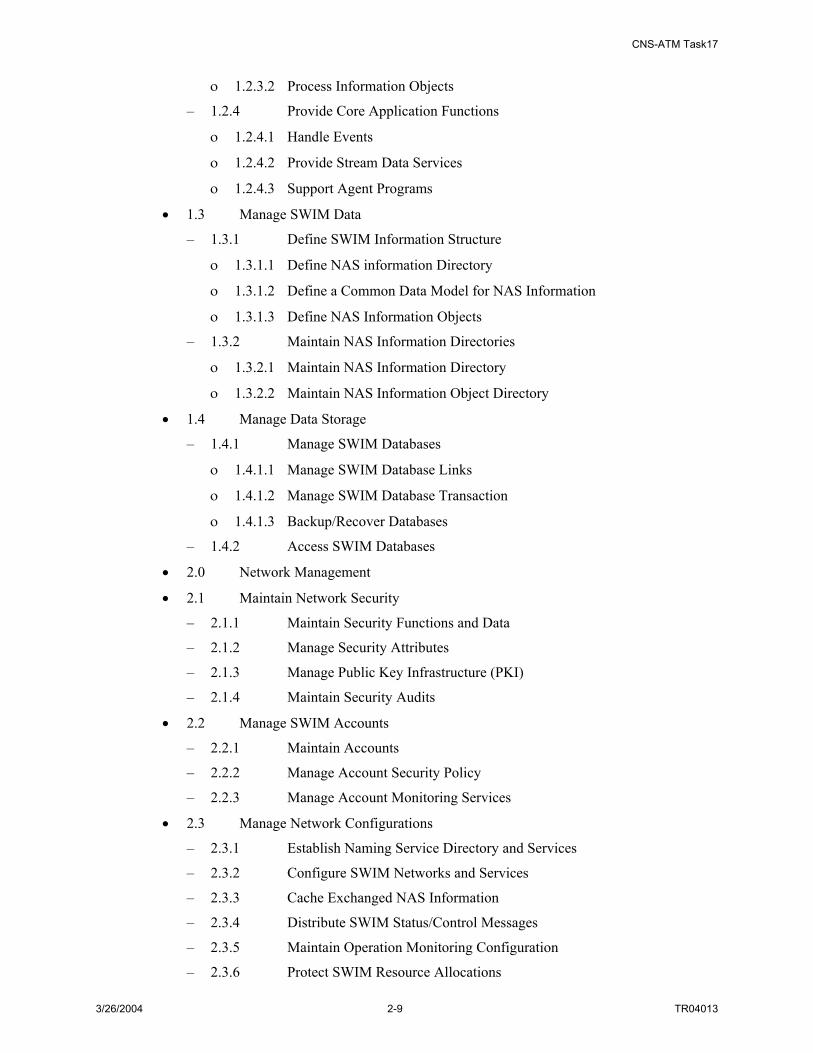
CNS-ATM Task17
3/26/2004 2-9 TR04013
ο 1.2.3.2 Process Information Objects
– 1.2.4 Provide Core Application Functions
ο 1.2.4.1 Handle Events
ο 1.2.4.2 Provide Stream Data Services
ο 1.2.4.3 Support Agent Programs
• 1.3 Manage SWIM Data
– 1.3.1 Define SWIM Information Structure
ο 1.3.1.1 Define NAS information Directory
ο 1.3.1.2 Define a Common Data Model for NAS Information
ο 1.3.1.3 Define NAS Information Objects
– 1.3.2 Maintain NAS Information Directories
ο 1.3.2.1 Maintain NAS Information Directory
ο 1.3.2.2 Maintain NAS Information Object Directory
• 1.4 Manage Data Storage
– 1.4.1 Manage SWIM Databases
ο 1.4.1.1 Manage SWIM Database Links
ο 1.4.1.2 Manage SWIM Database Transaction
ο 1.4.1.3 Backup/Recover Databases
– 1.4.2 Access SWIM Databases
• 2.0 Network Management
• 2.1 Maintain Network Security
– 2.1.1 Maintain Security Functions and Data
– 2.1.2 Manage Security Attributes
– 2.1.3 Manage Public Key Infrastructure (PKI)
– 2.1.4 Maintain Security Audits
• 2.2 Manage SWIM Accounts
– 2.2.1 Maintain Accounts
– 2.2.2 Manage Account Security Policy
– 2.2.3 Manage Account Monitoring Services
• 2.3 Manage Network Configurations
– 2.3.1 Establish Naming Service Directory and Services
– 2.3.2 Configure SWIM Networks and Services
– 2.3.3 Cache Exchanged NAS Information
– 2.3.4 Distribute SWIM Status/Control Messages
– 2.3.5 Maintain Operation Monitoring Configuration
– 2.3.6 Protect SWIM Resource Allocations

CNS-ATM Task17
3/26/2004 2-10 TR04013
– 2.3.7 Manage SWIM Security Functions Infrastructure
– 2.3.8 Maintain Secure Communications
• 2.4 Maintain Performance
– 2.4.1 Monitor SWIM Connectivity Status
– 2.4.2 Monitor SWIM Flow of Data Status
– 2.4.3 Monitor SWIM Traffic Performance Status
– 2.4.4 Collect SWIM Quality Control Data
– 2.4.5 Evaluate Service Quality
– 2.4.6 Adjust Communication Load
• 2.5 Manage Network Faults
– 2.5.1 Detect and Diagnose Faults
– 2.5.2 Remove Faults and Recover System

CNS-ATM Task17
3/26/2004 3-1 TR04013
3. SWIM REQUIREMENTS
3.1 INTRODUCTION AND METHODOLOGY SWIM requirements development can be viewed as an iterative process. The first iteration of SWIM requirements development work of Subtask 17B was built on the functional analysis and functional architecture development results of Subtask 17A, as well as the NAS CONOPS, the NWIS CONUSE, and previous CNS-ATM Task reports. In addition it references the baselined set of NAS level system requirements in NAS-SR-1000. ASD-120 has an ongoing parallel effort to revise and update the NAS-SR-1000 based on the principles and processes in the FAA’s SEM. Since the rewrite activity has not yet completed updating NAS-SR-1000, the existing requirements referenced in this document refer to the current baseline provided in the public version of Capability and Architecture Tool Suite - Internet (CATS-I) (as of early 2004). Proposed new NAS level requirements produced in Subtask 17B have been defined in compliance with the guidelines in the SEM and using guidance received from the requirements rewrite group. The outputs of the requirements analysis of Subtask 17B fed into the physical architecture development of Subtask 17C. Subtask 17C development resulted in some changes in the functional hierarchy and function refinements. These changes generated some new and revised requirements. This was the second iteration of SWIM requirements development. These requirements changes and refinement results are presented in Appendix B of this report. Based on the steps identified above, the work flow diagram that identifies the major activities performed for the two iterations of SWIM requirements analysis is described in the following section and is captured in Figure 3-1. The methodology of deriving NAS level SWIM requirements employed for this subtask is described as follows. First, the relationship between the NAS level SWIM requirements and NAS-SR-1000 was examined to determine applicability of existing NAS-SR-1000 requirements to SWIM and to determine where the NAS level SWIM requirements would fit in. Then, three sets of NAS-level SWIM requirements were derived as follows:
• Set 1 - From the sixteen high level functionalities abstracted in CNS-ATM Task 15 report.
• Set 2 - From the CONOPS and NWIS CONUSE documents.
• Set 3 - From the SWIM functions defined in Subtask 17A.
Finally, the three sets of requirements were consolidated to provide a single comprehensive non-overlapping set of NAS level requirements for SWIM. Just as with the NAS level requirements already specified in NAS-SR-1000, the resulting requirements for the most part are levied on the NAS, that is, they are not explicitly allocated to “SWIM”; however in many cases requirements are implicitly allocated to SWIM by inclusion of “SWIM” in the requirement statement.

CNS-ATM Task17
3/26/2004 3-2 TR04013
NWISConcept of Use
CNS-ATM Task 17AFunctional Analysis
Derive NAS Level Requirements for SWIM
Derive NAS Level Requirements for SWIM
Derive NAS Level Requirements for SWIM
Derive NAS Level Requirements for SWIM
Derive Functional Requirements for SWIM subsystem
Derive Functional Requirements for SWIM subsystem
Subtask 17B Report
Task 15 Report High-Level SWIM
Functionalities
Derive NAS Level Requirements for SWIM
Derive NAS Level Requirements for SWIM
NAS-Level SWIMRequirements
Set1
NAS-Level SWIMRequirements
Set2
NAS-Level SWIMRequirements
Set3
SWIM SubsystemFunctional
Requirements
NAS-Level SWIMRequirementsConsolidated
CNS-ATM Task 17CPhysical Architecture
Refine SWIMRequirementsRefine SWIMRequirements
Refine SWIMFunctions
Refine SWIMFunctions
NAS Concept of Operations
Refined SWIMRequirementsAppendix A
Refined SWIMRequirementsAppendix A
Subtask 17Final Report
Task 17A Activities
Refinement Activities
Figure 3-1 Requirements Methodology
3.2 SWIM REQUIREMENTS Two types of SWIM requirements have been developed. One is the specification of SWIM requirements at the NAS level (unallocated requirements). The other is the specification of SWIM functional requirements at the subsystem level (allocated requirements). NAS level SWIM requirements are presented in this section; while SWIM functional requirements and their corresponding functional compliance matrix (where each requirement is traced to a function) are presented in Appendix B of this report. The existing requirements in NAS-SR-1000 were examined to determine their applicability to SWIM and to find a place in the NAS-SR-1000 documentation structure for NAS level SWIM requirements. This step is important because it serves as a check and further guidance for the determination of the three sets of NAS level SWIM requirements. It should remembered that the three requirements sets are derived from future information sharing concepts and needs of the NAS; however it is necessary to ensure that derived NAS level requirements for SWIM are compatible with the existing NAS requirements that, in most cases, are not going away The Requirements Baseline used for the architecture development effort is a list of proposed NAS level requirements needed for the SWIM functional architecture developed as part of Subtask 17B. These requirements were derived directly from the high-level functions captured in the Subtask 17A SWIM functional analysis effort. To date, these requirements are still undergoing FAA review but are

CNS-ATM Task17
3/26/2004 3-3 TR04013
considered satisfactory input to this initial physical architecture development task. It is expected that NAS level requirements developed for SWIM will be issued later as a NAS Change Proposal (NCP) as part of the ASD-100 efforts to re-write NAS-SR-1000. Table 3-1 shows the allocation of NAS-level SWIM requirements (from Task 17B) to first level SWIM components (defined in Section 4). In some cases, requirements have been mapped to more than one SWIM component. For example, Requirement 7 “The NAS shall process user and resource information requests” is mapped to both the ‘member interface’ component and to the ‘broker’ component. This is necessary to accommodate both the processing of a user requests by member interfaces and the further processing of the request by the broker.
Table 3-1: NAS-level SWIM Requirements Compliance Matrix Num NAS Level Requirement Statement SWIM Component
(See Section 4) “Manage SWIM Information” Requirements 1 The NAS shall define standard “information access methods” for all SWIM
members. Data model
2 The NAS shall authenticate users and resources who attempt to access SWIM Member Interface 3 The NAS shall assign different security levels to information to be exchanged
[over SWIM] Member Interface
4 The NAS shall assign authenticated users and resources specific access right to the different levels of information to be exchanged [over SWIM]
Member Interface
5 The NAS shall accept users’ and resources’ requests for context sensitive information [over SWIM]
Member Interface
6 The NAS shall define a common data model for information to be exchanged [over SWIM]
Data model
7 The NAS shall establish a common geographical and time reference for information to be exchanged [over SWIM]
Member Interface, Broker
8 The NAS shall register NAS resources [in the SWIM environment] using a common geographical reference
Broker
9 The NAS shall define common searchable attributes for NAS information Broker 10 The NAS shall maintain a common data model Data Model 11 The NAS shall manage NAS information databases Data Storage 12 The NAS shall provide means for authorized users and resources to access
NAS information databases Broker
13 The NAS shall control SWIM security control information Broker 14 The NAS shall process user and resource information requests Broker 15 Upon a standing request, the NAS shall automatically deliver updated context
sensitive information to authorized requesting users and resources Broker
16 Upon a standing request, the NAS shall automatically deliver real-time information on time [over SWIM] to authorized requesting users and resources
Broker
17 Upon a one-time request, the NAS shall deliver context sensitive information to authorized requesting users and resources
Broker
18 The NAS shall automatically establish source and user connections [over SWIM] for delivery of information
Network Manager
19 The NAS shall transport dynamically changing information Network Manager 20 The NAS shall transport static (non-changing) information Network Manager 21 The NAS shall transport scheduled information Network Manager 22 The NAS shall deliver NAS information to multiple users and resources [over
SWIM] Broker
23 The NAS shall use common geographic reference attributes for information transported [over SWIM]
Data Model
24 The NAS shall use common data attributes for information transported [over SWIM]
Data Model
25 Upon standing request, the NAS shall provide the capability to automatically collect information [through SWIM]
Broker
26 The NAS shall cache information exchanged [over SWIM] Data Storage

CNS-ATM Task17
3/26/2004 3-4 TR04013
Num NAS Level Requirement Statement SWIM Component (See Section 4)
27 The NAS shall archive NAS information exchanged [over SWIM] when requested
Data Storage
“Manage SWIM Networks” Requirements 28 The NAS shall provide resource management [for SWIM]. Network Manager 29 The NAS shall make NAS resource information accessible [via SWIM] Network Manager 30 The NAS shall make NAS management information accessible [via SWIM] Network Manager 31 The NAS shall adapt to dynamic changes in NAS information providers and
users Network Manager
32 The NAS shall monitor end-to-end Quality of Service parameters [for SWIM] Network Manager 33 The NAS shall maintain end-to-end Quality of Service [of SWIM] Network Manager 34 The NAS shall provide account management [for SWIM] Network Manager 35 The NAS shall provide fault management [for SWIM] Network Manager 36 The NAS shall provide security functions [for SWIM] Network Manager

CNS-ATM Task17
3/26/2004 4-1 TR04013
4. SWIM PHYSICAL ARCHITECTURE COMPONENTS
The approach to the development of the physical architecture for SWIM uses the process outlined in the NAS SEM for Synthesis activities as a guide. As defined in the SEM, the purpose of Synthesis is “to define design solutions and identify systems that will satisfy the requirements baseline.”14 An output of the Synthesis process is the physical architecture. A key part of the physical architecture description is the identification and description of the building blocks or components of the physical architecture. These include hardware and software elements, data elements and people and facility elements. This section specifically addresses the identification of SWIM physical architecture components. 4.1 METHODOLOGY AND INPUTS FOR IDENTIFICATION OF PHYSICAL ARCHITECTURE COMPONENTS Three major steps were performed to identify SWIM components. First, enabling technologies required for SWIM were identified (Section 4.2.1). Next, components to implement the identified technologies as well as to accommodate SWIM functionality were then identified (Section 4.2.2). And finally, to verify identification of a complete set of components for SWIM, a functional compliance matrix (Section 4.2.3) was generated. The methodology or plan for identifying SWIM components (including inputs to the process) is described further in the following subsections. 4.1.1 Overview of Analysis Inputs As Synthesis activities encompass the system design process, there are several engineering inputs that are necessary. Initial inputs to the design process, as identified in the NAS SEM, are presented in Table 4-1.
14 NAS SEM, p. 4.5-1.

CNS-ATM Task17
3/26/2004 4-2 TR04013
Table 4-1: Needed Synthesis Data 15
The focus of the current effort is not the full range of system design and synthesis activities as described in the SEM. Rather, the focus is on identification of key design issues related to the development of the SWIM architecture and the development of initial physical architecture alternative concepts. As such, some of the initial inputs identified in Table 4-1, such as the Integrated Program Plan (IPP); Operational Services and Environment Description (OSED); and Work Breakdown Structure (WBS), that do not exist have not been considered at this time. This does not prevent the identification of key physical architecture design components and it should be noted that iteration of the design process can take place as these and other inputs become available. The following Synthesis Process inputs were used for the development of the SWIM physical architecture:
• Functional architecture (Section 2)
• Requirements Baseline (Section 3)
• Legacy System Interface Requirements and System Specifications (from Task 15 and other sources and used more readily for transition analysis)
• Market Research
• SWIM Concept of Use (CONUSE) and NAS Concept of Operations (CONOPs) (used in lieu of an OSED)
The functional architecture is an output of the SWIM functional analysis. Required functionality for SWIM is a starting point for identifying SWIM components and their interactions. Both the functional architecture and the requirements baseline are used to verify that the physical architecture components identified for SWIM fulfill the desired purposes.
15 NAS SEM, p. 4.5-7.
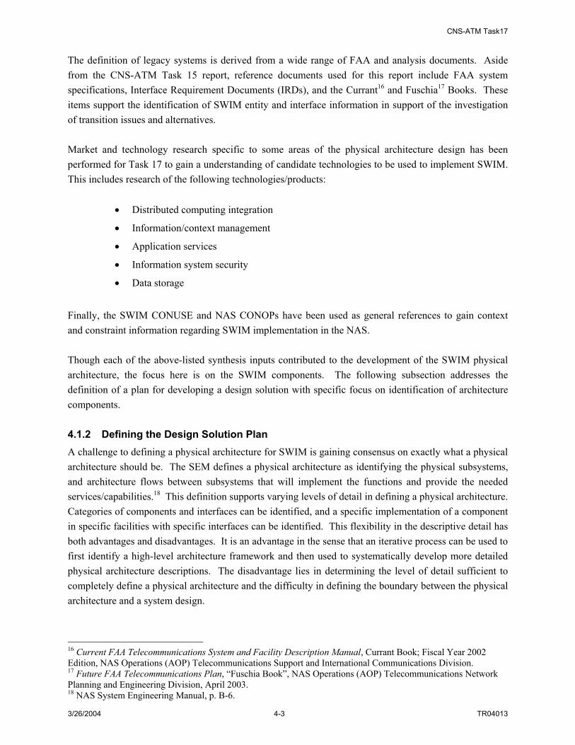
CNS-ATM Task17
3/26/2004 4-3 TR04013
The definition of legacy systems is derived from a wide range of FAA and analysis documents. Aside from the CNS-ATM Task 15 report, reference documents used for this report include FAA system specifications, Interface Requirement Documents (IRDs), and the Currant16 and Fuschia17 Books. These items support the identification of SWIM entity and interface information in support of the investigation of transition issues and alternatives. Market and technology research specific to some areas of the physical architecture design has been performed for Task 17 to gain a understanding of candidate technologies to be used to implement SWIM. This includes research of the following technologies/products:
• Distributed computing integration
• Information/context management
• Application services
• Information system security
• Data storage
Finally, the SWIM CONUSE and NAS CONOPs have been used as general references to gain context and constraint information regarding SWIM implementation in the NAS. Though each of the above-listed synthesis inputs contributed to the development of the SWIM physical architecture, the focus here is on the SWIM components. The following subsection addresses the definition of a plan for developing a design solution with specific focus on identification of architecture components. 4.1.2 Defining the Design Solution Plan A challenge to defining a physical architecture for SWIM is gaining consensus on exactly what a physical architecture should be. The SEM defines a physical architecture as identifying the physical subsystems, and architecture flows between subsystems that will implement the functions and provide the needed services/capabilities.18 This definition supports varying levels of detail in defining a physical architecture. Categories of components and interfaces can be identified, and a specific implementation of a component in specific facilities with specific interfaces can be identified. This flexibility in the descriptive detail has both advantages and disadvantages. It is an advantage in the sense that an iterative process can be used to first identify a high-level architecture framework and then used to systematically develop more detailed physical architecture descriptions. The disadvantage lies in determining the level of detail sufficient to completely define a physical architecture and the difficulty in defining the boundary between the physical architecture and a system design.
16 Current FAA Telecommunications System and Facility Description Manual, Currant Book; Fiscal Year 2002 Edition, NAS Operations (AOP) Telecommunications Support and International Communications Division. 17 Future FAA Telecommunications Plan, “Fuschia Book”, NAS Operations (AOP) Telecommunications Network Planning and Engineering Division, April 2003. 18 NAS System Engineering Manual, p. B-6.

CNS-ATM Task17
3/26/2004 4-4 TR04013
A secondary challenge to the development of the SWIM architecture is aligning terms and perspectives of a system that addresses both information technology and communications (which are typically addressed independently and in different manners) as well as accommodating both the software development perspective and the system engineering perspective. To develop a plan for developing the physical architecture, the system requirements were reviewed and high-level objectives were identified. Design objectives can encompass such criteria as performance, feasibility, reliability, compatibility, extensibility, flexibility, cost, and schedule. At this stage of SWIM development, objectives included feasibility and compatibility with the SWIM and NAS requirements. To address these requirements in the development of the SWIM physical architecture, steps were included to identify technologies required to implement SWIM (to evaluate feasibility) and to develop function and requirement compliance matrices (to ensure compatibility with defined SWIM functions and requirements). Other objectives are naturally considered as part of the design process. As SWIM development work continues, additional design objective drivers can be continuously reviewed and accommodated in the SWIM design process. Several strategies were utilized to meet the challenges and design objectives identified above. First, the system engineering process used as the framework for the analysis methodology was referenced and described (See Section 1.3). Second, a glossary was generated to clearly define terms used in the analysis. Then, after identifying enabling technologies for SWIM, general components and their interfaces were captured in a high-level architecture framework. And finally, a mapping of the components in this framework to information management and communication management SWIM functions was also performed. In later sections of this report (namely, Sections 5 and 6), design decisions specific to the identified components are examined and then candidate architecture alternatives that address components in a more specific manner are developed. 4.2 IDENTIFYING SWIM PHYSICAL ARCHITECTURE COMPONENTS The following sections describe the process of identifying components that comprise SWIM. These include hardware and software elements, data elements, and facility/people elements. 4.2.1 SWIM Enabling Technologies The process of identifying components that accommodate a functional architecture requires the mapping of functionality or the functional domain to the physical domain. One way of initiating this process is to identify the underlying technologies that are needed to provide the SWIM functionality documented in Section 2.3. To do this, an understanding of SWIM functionality in the context of user interaction is useful. This has been accomplished through the development of a context diagram for SWIM. Then, based on this diagram, three categories of enabling technologies have been defined. Specific applicable technologies within each category have been identified and described. 4.2.1.1 SWIM Context Information SWIM functionality supports the efficient exchange of information in the NAS to support a wide range of air traffic control activities including negotiating and tracking flight plans, tracking aircraft movement via surveillance, and sharing weather information with NAS service providers and users. NAS service

CNS-ATM Task17
3/26/2004 4-5 TR04013
providers and users who participant in information exchange via SWIM are designated SWIM members. SWIM members may include NAS sensors such as surveillance and weather radars, radar and flight data processing systems; decision support tools; flight decks; air traffic controllers; and flight operation centers. The following sections address SWIM interface characteristics and performance characteristics. 4.2.1.1.1 SWIM Interface Characteristics SWIM interfaces include interfaces both internal and external to the NAS. These interfaces are summarized as follows:
• SWIM External Interfaces
• Interface to the aircraft
• Telco/network interface to airline Flight Operation Center (FOC) offices
• Telco/network interfaces to Civil Aviation Authorities (CAAs)
• Includes interface to the Aeronautical Telecommunication Network (ATN)
• Telco/network interfaces to military, law enforcement and other US agencies
• Telco/network interface to Internet
• SWIM Internal Interfaces
• Interface to FAA Wide Area Networks (WANs), such as a FAA Telecommunication Infrastructure (FTI) backbone
• Telco/network interfaces to FAA sensors/systems directly or via server/application gateway
• Interface to the NAS Infrastructure Management System (NIMS)
• Interface to the Aeronautical Data Telecommunications Network (ADTN) and FAA Intranet
SWIM services may be specific to particular types of NAS data (e.g. surveillance, weather, flight management, aeronautical) or to specific types of NAS facilities (e.g. Air Route Traffic Control Centers (ARTCCs), Terminal Radar Approach Control Facilities (TRACONs), Air Traffic Control Towers (ATCTs), etc). The SWIM member interface component should provide an interface to SWIM requiring no modification to legacy applications (e.g., platform, language, and location independence). Options for the SWIM member interface function are investigated in Appendix Section G.3. They include:
• Non-intrusive installation of member interface objects
• Local access to member interface as standalone SWIM proxy
• Remote access to member interface as standalone SWIM proxy
In order to identify the interface characteristics of SWIM, SWIM external components and internal components need to be identified. Internal components are the software and hardware components needed to fulfill SWIM functionalities. These components are presented in Section 4.2.2. External components are any entities that participate as end users or providers in the distribution, or exchange of

CNS-ATM Task17
3/26/2004 4-6 TR04013
information via SWIM. An external component can be either a source or a sink of the shared NAS information and services. External components can be further categorized as:
• SWIM Source Components -- Sources of SWIM Information
• Legacy NAS Sensors: Sensors providing raw surveillance and weather information (they interface to SWIM either via a software functionality or an adapter/gateway)
• NAS Automation/Processing Centers (e.g., ATC systems for surveillance and flight data processing)
• Existing NAS databases (e.g., NASR, NOTAM database)
• Pools of data that not currently accessible via a database
• Non-FAA Sources (e.g., government agencies)
• SWIM Sink Components – Consumers of SWIM Information
• NAS Processing Centers/Applications (Can be both a source and a sink)
• NAS Databases (Can be both a source and a sink)
• Non-FAA sources (Can be both a source and a sink)
Some analytical work has been performed to begin categorizing information related to NAS sensors and automation/processing centers. Specifically, these sensors and automation/processing systems have been categorized into five domains: surveillance, weather, aeronautical information, resource management and flight information. These sensor and automation/processing systems are potential SWIM members. Analytical work in the areas listed below influence SWIM architecture design in the identification of specific SWIM members and interfaces, providing guidance for evaluation of SWIM broker topologies, and guidance for evaluation of SWIM processing patterns. Some of these activities have already been performed and some still need to be done.
• Identifying potential SWIM users and data/service providers (data sources, data sinks) (A general list of all the sensors/systems both internal and external to NAS has been developed and presented in Appendix H)
• Identifying SWIM information flows (data flow between sources and sinks ) (This work has been performed and summarized in the CNS-ATM Task 15 report)
• Identifying the distributions of external components (to support physical architecture design decisions)
• Identifying the SWIM traffic characteristics (Related work has been done in CNS-ATM Task 12)
• Types of information requested, frequency, and latency requests/requirements
• Types of information distributed, frequency, and latency request/requirements
• Traffic volume.

CNS-ATM Task17
3/26/2004 4-7 TR04013
4.2.1.1.2 SWIM Performance Characteristics NAS-SR-1000 identifies performance requirements of NAS services that would be enabled by SWIM and therefore imposes performance requirements on SWIM. Previous studies have investigated performance implications for certain aspects of NAS architecture evolution. For example, CNS-ATM Task 12 analyzed existing NAS communications performance requirements and assessed the ability of these requirements to sufficiently specify the performance of new communications architectures. Additionally, CNS-ATM Task 15 (Subtask H) identified and analyzed all existing NAS system level performance requirements from NAS-SR-1000, NAS-SS-1000, and NAS-DD-1000. The objective of an ongoing analysis activity is the identification of a complete and validated set of NAS-level performance requirements that apply to the NAS service architecture. As part of that effort, SWIM concepts are being considered and draft NAS-level information performance criteria/requirements are being developed in the context of a SWIM implementation. Performance requirements allocated to SWIM as a NAS component should be addressed at the subsystem level. In other words, performance requirements for individual SWIM components need to be developed. As these subsystem requirements are developed, the NAS-level requirements that impose constraints on the subsystem requirements need to be considered. Table 4-2 provides sample NAS-SR-1000 requirements that provide performance constraints on SWIM.
Table 4-2: Sample NAS-Level Performance Requirements Applicable to SWIM Section Number
NAS-SR-1000 Requirement Relation to SWIM Requirements
3.1.1.G.2 Hazardous and routine weather information shall be presented to the specialist within 3.0 seconds of a request (mean response time).
Performance Constraint
3.1.1.G.3 Hazardous weather information shall be available to specialists and users within 2 minutes of identification of the hazardous weather phenomenon, and shall be maintained current locally to within 2 minutes. Hazardous weather information shall be maintained current nationally to within 30 minutes or less as conditions warrant thereafter, until the hazard has dissipated.( Essential )
Performance Constraint
3.1.1.G.4 Terminal area hazardous weather information shall be available to specialists and users within one minute of detection and shall be current to within one minute thereafter, until the hazard has moved out of the terminal area or dissipated.
Performance Constraint
3.1.1.H.1 Specialist access to weather information shall be provided with a mean response time of 3.0 seconds from the time a request for information is made.
Performance Constraint
3.1.1.H.3 Once a user has gained access to the NAS, weather information shall be provided with a mean response time of 3.0 seconds from the time a request for information is made.
Performance Constraint
3.1.1.H.4 The NAS is required to meet the expected demand for weather requests (e.g., pilot briefings) during times of peak demand.( Essential )
Performance Constraint
3.1.1.I Weather information shall be continuously (24 hours a day) accessible to users with or without the aid of a specialist.
Performance Constraint
3.1.2.F.2 The time from initiation of a request for aeronautical information by a user and receipt of the requested information shall not exceed 10 seconds.
Performance Constraint
3.1.2.B Aeronautical information shall be continuously (24 hours a day) accessible to specialists.
Performance Constraint
3.1.2.C Aeronautical information shall be continuously (24 hours a day) accessible to users upon request with or without the aid of specialists.
Performance Constraint
3.1.2.F.1 The time from initiation of a request for aeronautical information by a specialist and receipt of the requested information shall not exceed 10 seconds.
Performance Constraint
3.1.3.B.1 Current and forecast weather data shall be available within 10 seconds of a specialist’s request.
Performance Constraint
3.1.3.C.1 Users shall receive requested flow control and delay advisory information Performance

CNS-ATM Task17
3/26/2004 4-8 TR04013
Section Number
NAS-SR-1000 Requirement Relation to SWIM Requirements
within 6 seconds of a request. ATCCC specialists and local traffic management coordinators shall receive requested information within 10 seconds of a request.
Constraint
3.1.4.H.1 The NAS-provided interfaces shall have sufficient capacity for users to be able to gain direct access within 5 seconds after the connection has been made.( Routine )
Performance Constraint
3.1.4.H.2 The NAS shall be capable of validating and processing proposed flight plans and amendments to proposed flight plans and responding to the user/specialist within 10 seconds (99th percentile) of the input.
Performance Constraint
3.1.10.B.1 The NAS shall provide the capability to receive and process requests from military users for special movement activities of military aircraft within 24 hours of the user’s request.( Routine )
Performance Constraint
3.1.10.B.2 The NAS shall be capable of receiving and responding immediately to requests for airspace reservations [i.e., altitude reservation requests (ALTRV) at emergency order of precedence (class three or above)].( Routine )
Performance Constraint
Having identified interface and performance characteristics for SWIM, the focus now turns to the perception of SWIM from the user perspective. To the SWIM member, the interface to SWIM is an interface application (or API) that supports exchange of information to/from the SWIM member. The SWIM processes that manage the information, connections, and information exchange of information should be transparent to the members. 4.2.1.2 Enabling Technologies for SWIM Technologies to implement SWIM have been captured in three general categories based on the SWIM functional architecture and the context information provided above. These categories include:
• Interface Technologies (to address the interface of a SWIM member to SWIM)
• Information and Connection Management Technologies (to address the strategies for implementing, maintaining, and securing member connections and supporting standardized information formats)
• Exchange Technologies (to address the transport of data)
These categories cover the range of SWIM functionality included in the functional architecture. A mapping of technology categories to SWIM functional components (down to the 2nd-level decomposition) is provided in Table 4-3.
Table 4-3: Mapping Technology Categories to Applicable to SWIM Functions SWIM Function Technology Category Manage SWIM Data Information and Connection Management
Technologies Broker Service Requests Information and Connection Management
Technologies Manage Data Storage Information and Connection Management
Technologies
Manage SWIM Information
Manage SWIM Interfaces Interface Technologies Maintain Network Security Exchange Technologies Maintain Service Quality Exchange Technologies Manage Network Configurations Exchange Technologies
Manage SWIM Networks
Manage SWIM Accounts Information and Connection Management Technologies

CNS-ATM Task17
3/26/2004 4-9 TR04013
SWIM Function Technology Category Manage Network Faults Exchange Technologies
Within each technology category, specific and applicable technologies for SWIM have been identified. These technologies along with a brief description are documented in Table 4-4.
Table 4-4: Identification of Enabling Technologies for SWIM Technology Category Technology Description
Browser (web browser) COTS software application used to locate and display information through the use of web pages
Domain-specific middleware/applications
Custom software generated with standard development languages (e.g. Java, C++) that performs user-interface functionality specific to a particular user/application or set of users/applications
Interface Technologies
Data presentation and format translation standards
Standards for associating components of an object/schema definition with specific presentation functions (e.g. XSL, XSLT, Xpath)19
Distribution Middleware (msg-oriented pub/sub; msg-oriented store and forward; request/reply)20
Software that support the isolation of data providers and data consumers to enable asynchronous data exchange; applicable standards include CORBA, EJB, and ActiveX21
Service Middleware Middleware that supports load balancing, scheduling, security and other services
Object/schema definition languages
Standards used to define common information formats (e.g. HTML, XML, ebXML, SGML, RDF)22
Taxonomy and ontology definition languages
Standards used to define terminologies and ways of organizing data into categories (taxonomies) and conceptual relationships among information (ontologies) (e.g. OML, SHOE)23
Wrapper technologies Standards that support the development of software adapters that “isolate a software component from other components and its processing environment” 24
Information and Connection
Management Technologies
Distributed database management/access
Technologies and standards that address the management and access to information stored in Data Warehouses and Data Marts (e.g. RDMS, ODBMS, LDAP)25
IP Networking Standards that address data transport over a network using Internet Protocol (IP) specifications per Internet Engineering Task Force (IETF) Requests for Comment (RFCs)
Exchange Technologies
SNMP/CORBA Network Management
These are different protocols governing network management and the monitoring of network devices and their functions.
19 XSL – eXtensible Stylesheet Language family; XSLT – XSL Transformations; Xpath – XML Path Language; 20 Distribution or messaging middleware “decouples message suppliers from message consumers [supporting] asynchronous communication between system components.” “[This is] a prerequisite for scalability because system components no longer execute in lock-step.” This also provides flexibility to “add and remove event consumers or suppliers dynamically without affecting existing clients”; Open Fusion Notification Service – White Paper, PrismTech Corporation, May 2001, 21 CORBA – Common Object Request Broker Architecture; EJB – Enterprise Java Beans 22 HTML – Hyper Text Markup Language (HTML); XML – eXtensible Markup Language; ebXML – electronic business XML; SGML – Standard General Markup Language; RDF – Resource Description Framework 23 OML – Ontology Markup Language; SHOE – Simple HTML Ontology Extensions 24 “The IULS Approach to Software Wrapper Technology for Upgrading Legacy Systems”, David Corman, CROSSTALK, Dec. 2001 25 RDMS – Relational Database Management Systems; ODBMS – Object-oriented Database Management Systems; LDAP – Lightweight Directory Access Protocol

CNS-ATM Task17
3/26/2004 4-10 TR04013
Technology Category Technology Description VPN Technologies enabling the extension of a local private
network to remote locations using potentially non-private communication connections
Authentication Technologies associated with verification of identity (e.g. passwords, digital signatures)
Distributed Network Management & Self-healing Networks
Technologies supporting the management of distributed networks and supporting efficient, scalable management systems as well as technologies providing a common means for detecting, recording and resolving networking and computing problems26
Subject/content-based routing Technologies associated with the routing of data based on pre-defined subjects or based on predicates that identify a particular content set of interest
Some of these technologies represent new and emerging concepts to support information management and exchange. To fully understand their applicability to SWIM, a more in-depth look at the capability, limitations and use of the technologies were explored. These technologies include:
• Distributed computing integration (e.g. middleware)
• Information/context management
• Application services
• Information system security
• Data storage
A more detailed description of these technologies is provided in Appendix C. 4.2.2 SWIM Physical Architecture Components Three categories of components have been addressed. These include hardware/software components, data components, and facility/people components. Each category is addressed separately in the following subsections followed by a brief discussion of SWIM interface and performance characteristics. 4.2.2.1 SWIM Hardware/Software Components SWIM hardware/software components are those elements that implement the technologies identified in Section 4.2.1.2 to accommodate the SWIM functionality identified in the functional architectures (Section 2.3). The process of selecting components to use as building blocks for developing a SWIM physical architecture began with the identification of general or high-level component types. This first step is addressed in this section. Later, design issues specific to each component type were identified and investigated (see Section 5). As a result of the investigation and analysis, the components were considered in the context of the NAS to develop architecture alternatives (see Section 6). The hardware and software elements that make up SWIM are classified according to their role in the NAS. They are considered one of the following:
26 IBM, Cisco Promote "Self-Healing" Network Standards By Caron Carlson, eWeek, October 10, 2003

CNS-ATM Task17
3/26/2004 4-11 TR04013
• Dedicated Hardware/Software Components – elements whose functionality is unique to SWIM and whose role in the NAS is strictly to support SWIM operations
• Shared Hardware/Software Components – elements required to support SWIM functionality but which are not unique to SWIM (i.e. whose functionality is not entirely within the domain of SWIM)
This distinction is necessary to enable the identification of aspects of SWIM that may be provided by existing NAS hardware/software infrastructure (e.g. communication and maintenance/monitoring systems). SWIM functions of the function architecture were examined in conjunction with the enabling technologies to support the definition of SWIM hardware and software components. Specifically, consideration of SWIM Information Management functions (Manage SWIM Interfaces, Manage SWIM Data, Broker Service Requests, Manage Data Storage)27 along with Interface Technologies and Information and Connection Management Technologies (see Table 4-4), leads to the identification of the following hardware/software elements are provided in Table 4-5. Included in the table is a description of the role of the element in SWIM as well as its categorization as either a dedicated SWIM component or a shared SWIM component (based on the definitions above).
Table 4-5: Partial HW/SW Component List for SWIM HW/SW Component
Name H/W S/W Role Dedicated and/or
Shared Component of the NAS
Member Interface X X Support domain/member-specific services as well as distribution and general exchange services; the H/W supports implementation of the interface S/W on a gateway (as needed)
Dedicated
Browser X Supports standardized information access services
Shared
Web Server X X Supports standardized browser information access
Shared or Dedicated
Data Model Registry (Metadata Registry – MDR)
X X Manages/stores information describing the format, structure, and definition of data
Dedicated
Information Object Repository
X X Manages/stores instances of information objects
Dedicated
Broker X X Supports the exchange of information between information producers and information consumers. Its role may be limited, where the broker simply directs members to where they can send or receive data or may be more substantial, where the broker acts as an intermediary between producers and consumers.
Dedicated
Additional SWIM hardware/software components can be identified considering Network Management SWIM functions (Maintain Network Security, Manage Network Configurations, Manage Network Faults,
27 Reference functional decomposition diagrams and information of Section 2.3.2 as well as the material in Appendix A.

CNS-ATM Task17
3/26/2004 4-12 TR04013
Manage SWIM Accounts, Maintain Performance)28 in conjunction with Exchange Technologies (see Table 4-4). Additional elements include Network Manager Interface software and hardware (server); Network Manager software and hardware (server); and Security software and hardware. A complete list of SWIM hardware and software elements is documented in Table 4-6.
Table 4-6: SWIM HW/SW Component List HW/SW Component
Name H/W S/W Role Dedicated and/or
Shared Component of the NAS
Member Interface X X Supports domain/member-specific services as well as distribution and general exchange services; the H/W supports implementation of the interface S/W on a gateway (as needed)
Dedicated
Browser X Supports standardized information access services
Shared
Web Server X X Supports standardized browser information access
Shared or Dedicated
Data Model Registry (Metadata Repository – MDR)
X X Registers and stores SWIM data model information
Dedicated
Information Object Repository (IOR)
X X Registers and stores SWIM information object schema information
Dedicated
Broker X X Processes members requests such as publish, subscribe and query by matching published information objects with members who have subscribed to or who query the data
Dedicated
Data Storage X X Stores information objects for fast retrieval and temporary storage of exchanged data. Data storage includes Data Marts, or optionally Data Warehouse
Dedicated
Network Manager Interface
X X Enable a network manager to monitor status, test parameter modifications, and implement network parameter changes
Dedicated or Shared
Network Manager X X Provides the means to control SWIM through fault management, configuration management, account management, performance management and security management
Dedicated or Shared
Local and Wide Area Network
X X Provides data transport capability Shared
Security X X Protects SWIM components and connections; detects and corrects security threats and breaches
Dedicated or Shared
In addition to the table above, two alternative views of SWIM hardware and software components have been captured. These include the architecture block diagram view and the schematic block diagram view. These figures along with more detailed descriptions of SWIM hardware and software elements are provided in Appendix D. A general schematic block diagram capturing all of the SWIM hardware and software components is provided in Figure 4-1.
28 Ibid.

CNS-ATM Task17
3/26/2004 4-13 TR04013
NAS Computing Services
SWIM Member InterfaceServices
Operating SystemNetwork Interface(TCP/IP port, etc)
Hardware(CPU, Memory, I/O, etc)
NAS System
SWIM MemberInterfaceServices
SWIM InterfaceHardware
(CPU, Memory, I/O, etc)
NAS User
Local and/or Wide Area Network
NAS Computing Services
Operating SystemNetwork Interface(TCP/IP port, etc)
Hardware(CPU, Memory, I/O, etc)
NAS System
NAS User
Browser Application
Operating SystemNetwork Interface(TCP/IP port, etc)
Hardware(CPU, Memory, I/O, etc)
Computing SystemWith Standard
Browser
NAS User
SWIM BrokerServices
SWIM BrokerHardware
(CPU, Memory, I/O, etc)
SWIM Data ModelRegistry Services
SWIM Data ModelRegistry Hardware
(CPU, Memory, I/O, etc)
IOR MDR
NetworkMngmt
Interface
NetworkMngmt
Interface
NetworkMngmt
Services
SWIM Network ManagerHardware
(CPU, Memory, I/O, etc)
Network ManagementInterface Services
SWIM NetworkManagement
Interface Services
Hardware(CPU, Memory, I/O, etc)
NAS NetworkManagement System
OR
AND/OR
AND/OR
SWIM NetworkManagement System
SWIM WebServer ServicesSWIM Web Server
Hardware(CPU, Memory, I/O, etc)
NetworkMngmt
Interface
MEMBERINTERFACE
BROWSER
WEB SERVER
MDRIOR
BROKER
NETWORK MANAGER INTERFACE
SECURITY
NAS Component
SWIM Component
Key
NAS Component
SWIM Component
Key
NAS Computing Services
SWIM Member InterfaceServices
Operating SystemNetwork Interface(TCP/IP port, etc)
Hardware(CPU, Memory, I/O, etc)
NAS System
SWIM MemberInterfaceServices
SWIM InterfaceHardware
(CPU, Memory, I/O, etc)
NAS User
Local and/or Wide Area Network
NAS Computing Services
Operating SystemNetwork Interface(TCP/IP port, etc)
Hardware(CPU, Memory, I/O, etc)
NAS System
NAS User
Browser Application
Operating SystemNetwork Interface(TCP/IP port, etc)
Hardware(CPU, Memory, I/O, etc)
Computing SystemWith Standard
Browser
NAS User
SWIM BrokerServices
SWIM BrokerHardware
(CPU, Memory, I/O, etc)
SWIM Data ModelRegistry Services
SWIM Data ModelRegistry Hardware
(CPU, Memory, I/O, etc)
IORIOR MDR
NetworkMngmt
Interface
NetworkMngmt
Interface
NetworkMngmt
Services
SWIM Network ManagerHardware
(CPU, Memory, I/O, etc)
Network ManagementInterface Services
SWIM NetworkManagement
Interface Services
Hardware(CPU, Memory, I/O, etc)
NAS NetworkManagement System
OR
AND/OR
AND/OR
SWIM NetworkManagement System
SWIM WebServer ServicesSWIM Web Server
Hardware(CPU, Memory, I/O, etc)
NetworkMngmt
Interface
MEMBERINTERFACE
BROWSER
WEB SERVER
MDRIOR
BROKER
NETWORK MANAGER INTERFACE
SECURITY
NAS Component
SWIM Component
Key
NAS Component
SWIM Component
Key
Figure 4-1: Overview of SWIM Hardware and Software Components

CNS-ATM Task17
3/26/2004 4-14 TR04013
4.2.2.2 SWIM Data Component The SWIM Data Component generally consists of two items, the SWIM common data model and NAS information objects. The common data model in SWIM is a NAS-wide pre-defined and agreed upon definition of data structures that make NAS information understandable by all SWIM members. This model is needed to support exchange of all types of NAS information by a range of SWIM members. It includes such information as:
• Data Source
• Data Destination (optional)
• Data Format
• Data Creation Time
• Data Expiration Time
• Searchable Attributes
A key feature of the common data model structure is the flexibility to be implemented, potentially, as a simple, predefined “wrapper”, with encapsulated NAS information transferred via SWIM and extracted when it reaches its destination. Alternatively the common data model may be more sophisticated and address a NAS-wide agreement to organize NAS information in a uniform format (e.g., a piece of weather information is defined in one format regardless of its source) so it can be used uniformly throughout NAS. A NAS information object represents a subset of NAS information using the common data model with defined searchable context or attributes (each attribute is associated with a value). A NAS information object is NAS information in the standardized format. Users would be provided with the capability to query SWIM to discover NAS information contained in the information objects. Information that describes these objects, called metadata, supports techniques to locate and acquire that information. For example, in a Publish/Subscribe architecture, information is routed to SWIM members based on their announced needs, that is, a client requests information (subscribes) by identifying an information element tag and ranges of values that characterize the element. Whenever an information object that matches the request becomes available or is “published”, SWIM routes the information object to the client. In this way, publish and subscribe mechanisms act on information objects to enable dynamic information flows. With regard to network management, the SWIM data component can be considered to include actual network parameters associated with management applications. Because both the common data model/information object as well as these network management parameters are specific to SWIM, they can be considered dedicated data components (as compared to shared data components). More detailed descriptions and examples of the SWIM data element are provided in Appendix D.

CNS-ATM Task17
3/26/2004 4-15 TR04013
4.2.2.3 SWIM People/Facility Components The third category of SWIM components includes the people and facility elements. SWIM may accommodate a wide range of NAS information sharing services and therefore will be implemented in and interfaced to a wide range of NAS facilities. These include ARTCCs, TRACONs, ATCTs, Remote Equipment Sites, ATCSCC, AFSSs, NAS network operation centers, Regional Offices, and the VNTSC. In addition to NAS facilities, the SWIM interface functionality may be implemented in remote SWIM member facilities including FOCs, Internet Access locations, aircraft, and government facilities. Each facility can be considered a shared SWIM facility component (i.e. there are no facility components specific to SWIM). The people component associated with SWIM includes the end users or SWIM members who access SWIM via the member interface and request SWIM core services such as publish and subscribe. Additionally, the people component includes information and network administrators, who are responsible for setup, update and maintenances of Metadata Repositories (MDRs) and Information Object Repositories (IORs) and for management of networks (including system administration, security management, configuration management, and account management). The information system administrators include database administrators (DBAs) who are responsible for maintaining the operations of SWIM data storage components. The people components may be considered shared components (e.g. end users) that utilize SWIM services or manage SWIM along with other FAA information and networks. As necessary, people components can also be considered dedicated components – if their management and usage roles solely relate to SWIM. 4.2.3 Functional Compliance Matrix To ensure that the set of components developed for SWIM is complete, SWIM functions were mapped to the components. This functional allocation process is illustrated in Figure 4-2.

CNS-ATM Task17
3/26/2004 4-16 TR04013
Figure 4-2: Function Allocation Process 29 The relationships between defined SWIM functionality and SWIM components are captured in the functionality compliance matrix provided in Table 4-7. Table 4-7 shows the allocation or partitioning of the top two levels SWIM functionality to high level SWIM hardware and software components. Lower level SWIM functions can be allocated to specific elements of the SWIM components as they become defined.
Table 4-7: SWIM Functionality Compliance Matrix Function SWIM COMPONENT
LEVEL 1 Member Interface Web Browser Web Server Broker Data Storage IOR (Information Object Repository)
1.0 Information Management
MDR (Metadata Repository) Network manager interface Network Manager (SW and HW) Security
2.0 Network Management
LAN/WAN LEVEL 2
Interface SW Interface HW Web Browser
1.1 Manage SWIM Interfaces
Web Server Broker SW 1.2 Broker Service Requests Broker Server SWIM Common data model MDR
1.3 Manage SWIM Data
IOR Data Mart 1.4 Manage Data Storage Data Warehouse (optional)
2.1 Maintain Network Security Security 2.2 Manage SWIM Accounts Account management SW 2.3 Manage Network
Configurations Configuration management SW
2.4 Maintain Performance Configuration management SW 2.5 Manage Network Faults Fault management SW
29 NAS SEM, p. 4.5-13.

CNS-ATM Task17
3/26/2004 5-1 TR04013
5. SWIM DESIGN DECISION ANALYSIS
5.1 IDENTIFICATION OF DESIGN TRADEOFFS Identification of physical architecture components (see Section 4) is the first step of translating the SWIM functional architecture into a physical architecture. As the next step, associated design issues were identified and evaluated for each of the selected hardware/software and data components. These design issues require decisions that lead to architecture alternatives, refined understanding of the components, and potential implementation options. Design tradeoffs specific to the identified SWIM components and interfaces investigated for this study are summarized in Table 5-1. Figure 5-1 summarizes these design issues pictorially.
Table 5-1: Summary of Investigated Design Trade-offs for SWIM
Trade-Off Designator Description Relation to
Physical Architecture
Methodologies Employed
Data Representation Design and Data Granularity
Investigation of the definition of the SWIM data model; definition of SWM metadata; defining a SWIM subscription language, etc. Data Granularity refers to the investigation of the level of detail available to a subscriber for subscribing/querying to SWIM as well as for data filtering
Supports Identification of Architecture Alternatives
Analysis
Required Broker Functionality and Distribution (Topology)
Investigation and comparison of different means of accommodating SWIM processes (e.g. subscribe, publish, and query). Options include processing with a Pub/Sub Broker, a Lightweight Broker or a VC Broker. Broker Distribution includes identification of options for organizing the broker domain (i.e. topology) when there are multiple brokers in SWIM
Supports Identification of Architecture Alternatives
Analysis; Simulation
Network Management Alternatives
Comparison of different network management protocols options for SWIM (e.g. SNMP vs. CORBA-based); and investigation of network interface, architecture, and security options
Implementation Option
Analysis
Data Storage Methods Investigation of the use of Data Marts vs. Data Warehouses as well as what data (and associated format) is applicable
Architecture Refinement
Analysis
Member Interface Integration Options
Identification and comparison of options for implementing the SWIM member interface
Implementation Option
Analysis
Communications Options Evaluation of alternative methods of providing communication access to information producers and information consumers, specifically: channel-based, subject-based, and content-based subscription mechanisms
Implementation Option
Analysis; Simulation
The table above identifies two methodologies employed to explore these design decisions: analysis and simulation. The analysis methodology used was specific to the type of trade-off or consideration given to the design decision. In certain cases modeling and simulation using the OPNET tool were performed to augment the analyses (see Section 6).
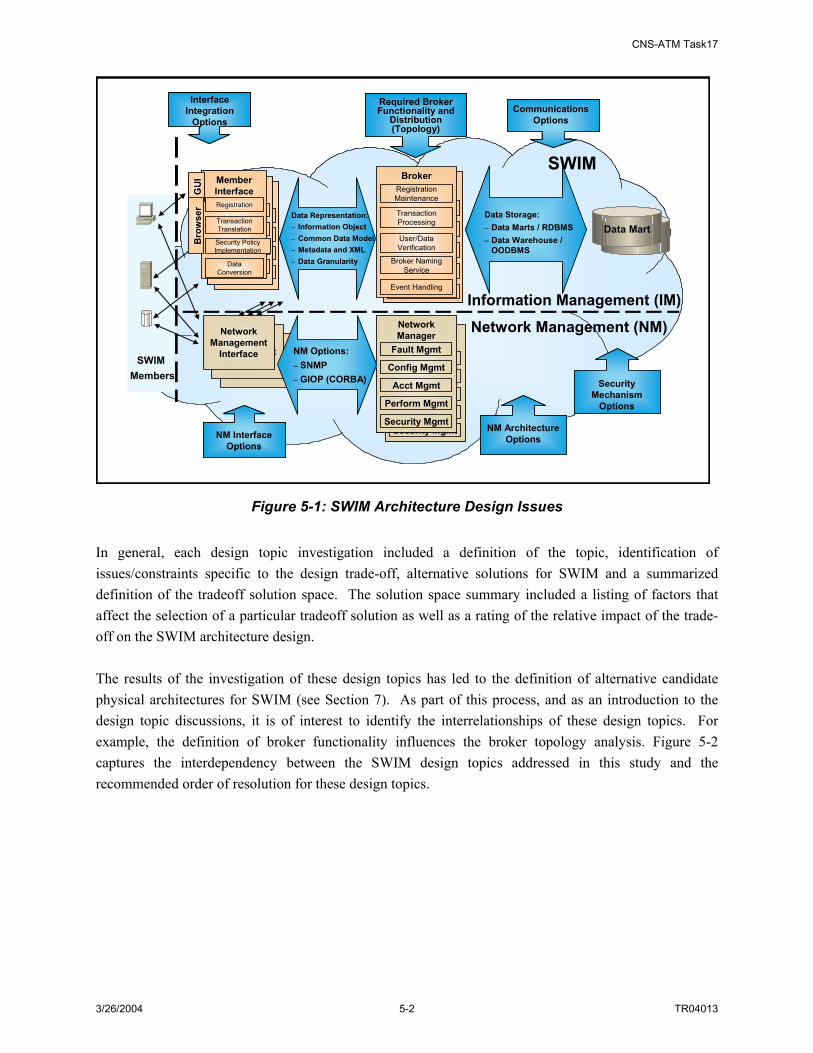
CNS-ATM Task17
3/26/2004 5-2 TR04013
Broker
Registration MaintenanceTransaction ProcessingUser/Data VerificationBroker
Naming Service
Data Mart
Member Interface
Registration
Transaction TranslationSecurity
Policy Implementati
onData Conversion
Member Interface
Registration
Transaction TranslationSecurity
Policy Implementati
onData Conversion
Member InterfaceRegistration
Transaction Translation
Security Policy Implementation
Data Conversion
GU
I
SWIMBroker
Registration Maintenance
Transaction Processing
User/Data Verification
Broker Naming Service
Event Handling
Data Representation:– Information Object– Common Data Model– Metadata and XML– Data Granularity
Data Storage:– Data Marts / RDBMS– Data Warehouse /
OODBMS
Required Broker Functionality and
Distribution (Topology)
NM Interface Options
Information Management (IM)
Network Management (NM)
Interface Integration
Options
Network Management
Interface
Network Management
Interface
Network Management
Interface
Network Manager
Fault Mgmt
Config Mgmt
Security Mgmt
Acct Mgmt
Perform Mgmt
Network Manager
Fault Mgmt
Config Mgmt
Security Mgmt
Acct Mgmt
Perform Mgmt
NM Options:– SNMP– GIOP (CORBA)
NM Architecture Options
SWIM Members
Bro
wse
r
Communications Options
Security Mechanism
Options
Broker
Registration MaintenanceTransaction ProcessingUser/Data VerificationBroker
Naming Service
Broker
Registration MaintenanceTransaction ProcessingUser/Data VerificationBroker
Naming Service
Data MartData Mart
Member Interface
Registration
Transaction TranslationSecurity
Policy Implementati
onData Conversion
Member Interface
Registration
Transaction TranslationSecurity
Policy Implementati
onData Conversion
Member Interface
Registration
Transaction TranslationSecurity
Policy Implementati
onData Conversion
Member Interface
Registration
Transaction TranslationSecurity
Policy Implementati
onData Conversion
Member InterfaceRegistration
Transaction Translation
Security Policy Implementation
Data Conversion
GU
I
SWIMBroker
Registration Maintenance
Transaction Processing
User/Data Verification
Broker Naming Service
Event Handling
Data Representation:– Information Object– Common Data Model– Metadata and XML– Data Granularity
Data Storage:– Data Marts / RDBMS– Data Warehouse /
OODBMS
Required Broker Functionality and
Distribution (Topology)
Required Broker Functionality and
Distribution (Topology)
NM Interface Options
NM Interface Options
Information Management (IM)
Network Management (NM)
Interface Integration
Options
Interface Integration
Options
Network Management
Interface
Network Management
Interface
Network Management
Interface
Network Manager
Fault Mgmt
Config Mgmt
Security Mgmt
Acct Mgmt
Perform Mgmt
Network Manager
Fault Mgmt
Config Mgmt
Security Mgmt
Acct Mgmt
Perform Mgmt
Network Manager
Fault Mgmt
Config Mgmt
Security Mgmt
Acct Mgmt
Perform Mgmt
Network Manager
Fault Mgmt
Config Mgmt
Security Mgmt
Acct Mgmt
Perform Mgmt
NM Options:– SNMP– GIOP (CORBA)
NM Architecture Options
NM Architecture Options
SWIM Members
Bro
wse
r
Communications Options
Communications Options
Security Mechanism
Options
Security Mechanism
Options
Figure 5-1: SWIM Architecture Design Issues In general, each design topic investigation included a definition of the topic, identification of issues/constraints specific to the design trade-off, alternative solutions for SWIM and a summarized definition of the tradeoff solution space. The solution space summary included a listing of factors that affect the selection of a particular tradeoff solution as well as a rating of the relative impact of the trade-off on the SWIM architecture design. The results of the investigation of these design topics has led to the definition of alternative candidate physical architectures for SWIM (see Section 7). As part of this process, and as an introduction to the design topic discussions, it is of interest to identify the interrelationships of these design topics. For example, the definition of broker functionality influences the broker topology analysis. Figure 5-2 captures the interdependency between the SWIM design topics addressed in this study and the recommended order of resolution for these design topics.

CNS-ATM Task17
3/26/2004 5-3 TR04013
Data GranularityData Granularity
Data Representation Design
RequiredBroker Functionality
Broker Distribution(Topology)
NetworkManagement
Options
Data StorageMethods
Interface IntegrationOptions
RequiredCommunication
Capability
ImplementationTechnology
Options
Higher Decision Making Priority Lower
Supports development of physical architecture alternatives (in Task 17)
Supports refinement of the physical architecture
1 2 3 4
Implementation Decision
Figure 5-2: SWIM Design Topic Dependence and Order of Resolution Data Representation addresses the design of the SWIM data model (e.g. common data model), associated metadata to be included in information objects, and the corresponding subscription language. This topic includes a discussion of Data Granularity. Data Representation and Data Granularity topics are mutually dependent. The level of data granularity within SWIM is affected by the design of the data model, metadata attributes, and types of subscriptions that can be submitted and processed. Conversely, data models and data representations are driven and affected by the derived data granularity requirement. Data representation design relates to the definition of Required Communication Capability since, if it is determined that SWIM must support very fine granularity for data queries and subscriptions, then content-based communication networking may be necessary (this, in turn, impacts the design of data model and its representations). The data representation design also affects the selection of the member Interface Integration Options since some data extracting/converting functions may force the need for significant computing power and require a standalone interface server to provide the required services. Additionally, the data granularity aspect of data representation design influences the Broker Distribution (Topology) considerations. For instance, if fine data granularity is required, a larger number of more specific information objects will be published. This provides Members the ability to identify specific information needs with great detail but increases the burden on brokers to filter unwanted data while matching subscriptions. As a result, a larger number of brokers (with a defined topology for intra-broker communications) may be needed.
CNS-ATM Task17
3/26/2004 5-4 TR04013
The topic of Required Broker Functionality defines the role of the broker in matching available information to requested information. Different options define the level of involvement of the broker in supporting information exchange and relate to the amount of knowledge information producers and information consumers have or are required to obtain about each other. The definition of Required Broker Functionality impacts Broker Distribution (Topology) considerations. For instance, fewer brokers would be required if brokers play a minimal role supporting the exchange of information between information producers and consumers. However, if the brokers are true intermediaries and all information passes through brokers as part of an information exchange, then a larger number of brokers would be needed to address latency and processing requirements. The number and role of the brokers impacts an appropriate topology for broker connectivity. The definition of Required Broker Functionality also affects the selection of an appropriate method for Data Storage. The level of involvement of a broker in the actual exchange of NAS information impacts data storage requirements. In addition, different ways of processing real-time/stream data affect how this data will be stored and in what format (e.g. Information Object or raw data format). As alluded to above, Interface Integration Options address how SWIM member interfaces are integrated with NAS systems. This topic is influenced by Data Representation design (see above) as well as Broker Distribution (Topology). With a large number of local brokers, the interface proxy software would likely be able to accommodate all member requests (provide data (e.g. publish), request data (e.g. subscribe), etc.). Alternatively, with fewer brokers, a standalone interface server may be required to provide more powerful interface services. Required Communication Capability is impacted by several other design topics. A possible relationship between data representation and communication capability has been addressed above (i.e. need for content-based networking). Additionally, the choice of subscription mechanism may affect the way the communication network routes SWIM data. Furthermore, the definition of Broker Distribution (Topology) may also impact the extent and topology of supporting communications. For example, an arrangement with a large number of brokers distributed to many NAS facilities and interfacing locally to SWIM members may be supported by a hub and spoke communication network at the local facility level and within an ARTCC region. In this example, the backbone network would be an inter-ARTCC network. All these design issues affect the analysis and selection of an appropriate Implementation Technology. Enabling technologies for SWIM are introduced in Appendix C. Further investigation and trade-off of implementation technologies can be performed as part of the development and evaluation of engineering design models. Principal objectives for SWIM implementation include interoperability and scalability, as well as meeting SWIM performance requirements. Resolution of the all design issues impacts the degree to which these objectives can be met. This section provides a discussion of the investigation of the SWIM design decisions. Specifically, topics addressed include:
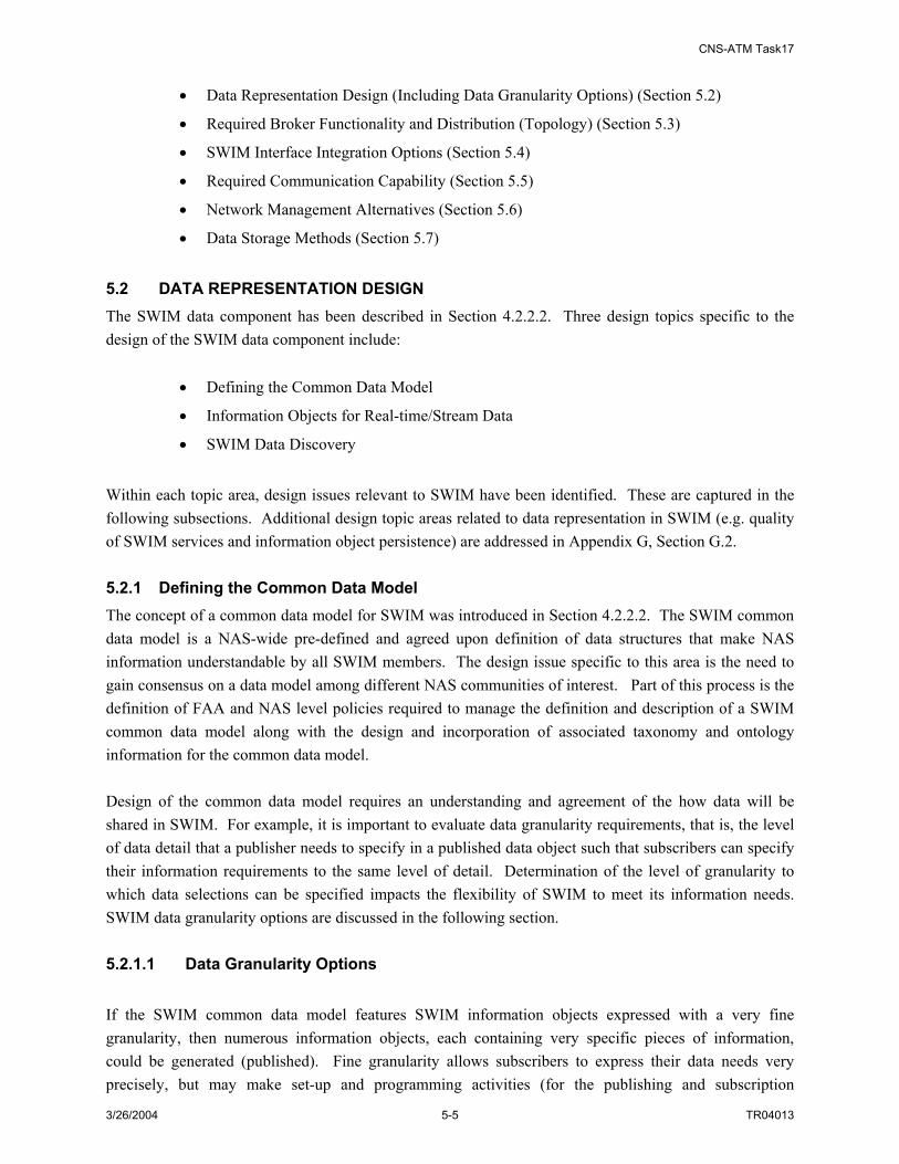
CNS-ATM Task17
3/26/2004 5-5 TR04013
• Data Representation Design (Including Data Granularity Options) (Section 5.2)
• Required Broker Functionality and Distribution (Topology) (Section 5.3)
• SWIM Interface Integration Options (Section 5.4)
• Required Communication Capability (Section 5.5)
• Network Management Alternatives (Section 5.6)
• Data Storage Methods (Section 5.7)
5.2 DATA REPRESENTATION DESIGN The SWIM data component has been described in Section 4.2.2.2. Three design topics specific to the design of the SWIM data component include:
• Defining the Common Data Model
• Information Objects for Real-time/Stream Data
• SWIM Data Discovery
Within each topic area, design issues relevant to SWIM have been identified. These are captured in the following subsections. Additional design topic areas related to data representation in SWIM (e.g. quality of SWIM services and information object persistence) are addressed in Appendix G, Section G.2. 5.2.1 Defining the Common Data Model The concept of a common data model for SWIM was introduced in Section 4.2.2.2. The SWIM common data model is a NAS-wide pre-defined and agreed upon definition of data structures that make NAS information understandable by all SWIM members. The design issue specific to this area is the need to gain consensus on a data model among different NAS communities of interest. Part of this process is the definition of FAA and NAS level policies required to manage the definition and description of a SWIM common data model along with the design and incorporation of associated taxonomy and ontology information for the common data model. Design of the common data model requires an understanding and agreement of the how data will be shared in SWIM. For example, it is important to evaluate data granularity requirements, that is, the level of data detail that a publisher needs to specify in a published data object such that subscribers can specify their information requirements to the same level of detail. Determination of the level of granularity to which data selections can be specified impacts the flexibility of SWIM to meet its information needs. SWIM data granularity options are discussed in the following section. 5.2.1.1 Data Granularity Options If the SWIM common data model features SWIM information objects expressed with a very fine granularity, then numerous information objects, each containing very specific pieces of information, could be generated (published). Fine granularity allows subscribers to express their data needs very precisely, but may make set-up and programming activities (for the publishing and subscription

CNS-ATM Task17
3/26/2004 5-6 TR04013
processes) more complex and reduce the performance of the system. On the other hand, if the granularity is very coarse, subscribers may end up obtaining more information than they need for a given subscription and have to filter received information to find the exact information they require. These two alternative granularity levels are illustrated in Figure 5-3. An example of geographic-based granularity for NAS data is provided in Appendix G, Section G.6. The choice of data granularity affects SWIM functionality as well as SWIM service efficiency. The choice of a coarse data granularity would result in publishing larger information objects (for instance, data are classified based on few pre-defined “subjects”); data classification and broker filtering algorithms would be simple; and subscription mechanisms also would be simple. But SWIM subscriber members may have to further filter out unwanted information to extract the exact match of their desired information. This is shown as the top part of Figure 5-3, where the subscriber member desired information is embedded in a large published information object, which has to be filtered at the subscriber’s end. The choice of fine data granularity would require a publisher to carefully define/refine its information objects so that they can be associated with subjects as well as more detailed values and attributes. Information objects would be more refined and therefore smaller in size. A subscription mechanism has to be carefully designed to allow subscriber members to express their need of information in greater detail. The broker needs to have correspondingly complex algorithms to match subscriptions to published information objects. The amount of filtering responsibility left to the subscribers is relatively low. This is shown as the bottom part of Figure 5-3, where the subscriber’s desired information may have already been defined as information objects; and they can be delivered to the subscriber when the subscriber expresses them in subscriptions. From the discussion above, it can be seen that the choice of data granularity will affect the level of responsibility for data classification and filtering as well as the subscription mechanism. Figure 5-4 shows four granularity options for NAS information. NAS information can be classified by Region (e.g., Cleveland information), by NAS Domain (e.g., Cleveland weather information), by Processing System Product (e.g., Cleveland weather wind shear information), and further by Member-specified Constraints (e.g., Cleveland weather wind shear information from 9:00am to 11:00am). These different levels of information may be processed by different SWIM components. For instance, the SWIM member interface to server (publisher) can classify NAS information by region (assigning network/sub-network addresses to the information objects), by domain (assigning subject field to the information object) and by processing product (by assigning subject field or attribute field to the information object). The broker can filter these three levels of classification by recognizing network address and by reading header fields. Desired information objects are filtered by the broker and delivered to the subscriber. Member-specified information can be further filtered at the subscriber (client) side.
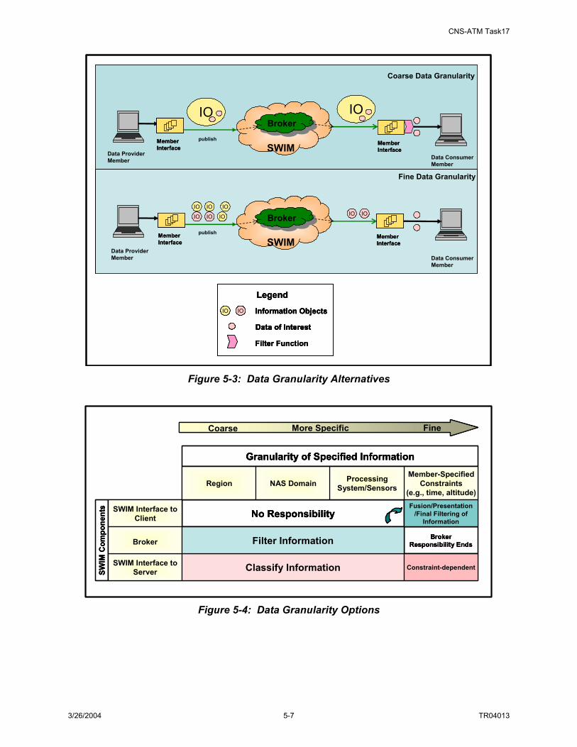
CNS-ATM Task17
3/26/2004 5-7 TR04013
SWIM
BrokerBrokerIOIO
SWIM
BrokerBrokerIO IO IO
IO IO IOIO IO
Coarse Data Granularity
Fine Data Granularity
Data Provider Member Data Consumer
Member
Data Provider Member Data Consumer
Member
publish
publishMemberInterface
Filter Function
Data of Interest
LegendIO IO Information Objects
MemberInterface
MemberInterface
MemberInterface
SWIM
BrokerBrokerIOIO
SWIM
BrokerBrokerIO IO IO
IO IO IOIO IO
Coarse Data Granularity
Fine Data Granularity
Data Provider Member Data Consumer
Member
Data Provider Member Data Consumer
Member
publish
publishMemberInterfaceMemberInterface
Filter Function
Data of Interest
LegendIO IO Information Objects
Filter Function
Data of InterestData of Interest
LegendIO IO Information ObjectsIO IO Information Objects
MemberInterfaceMemberInterface
MemberInterfaceMemberInterface
MemberInterfaceMemberInterface
Figure 5-3: Data Granularity Alternatives
SWIM Interface to Client
SWIM Interface to Server
Broker
SWIM
Com
pone
nts
Region Member-Specified
Constraints (e.g., time, altitude)
Processing System/SensorsNAS Domain
Granularity of Specified Information
More Specific
Classify Information Constraint-dependent
Filter Information
Fusion/Presentation/Final Filtering of
Information
Broker Responsibility Ends
No Responsibility
FineCoarse
SWIM Interface to Client
SWIM Interface to Server
Broker
SWIM
Com
pone
nts
Region Member-Specified
Constraints (e.g., time, altitude)
Processing System/SensorsNAS Domain
Granularity of Specified Information
More Specific
Classify Information Constraint-dependent
Filter Information
Fusion/Presentation/Final Filtering of
Information
Broker Responsibility Ends
No ResponsibilitySWIM Interface to Client
SWIM Interface to Server
Broker
SWIM
Com
pone
nts
Region Member-Specified
Constraints (e.g., time, altitude)
Processing System/SensorsNAS Domain
Granularity of Specified Information
More Specific
Classify Information Constraint-dependent
Filter Information
Fusion/Presentation/Final Filtering of
Information
Broker Responsibility Ends
No Responsibility
FineCoarse
Figure 5-4: Data Granularity Options

CNS-ATM Task17
3/26/2004 5-8 TR04013
Subscription mechanisms can be classified30 into three categories relating to data granularity: channel-based, subject-based, or content-based. These topics are addressed in Section 5.5. Additional discussion of SWIM data granularity options is provided in Appendix G, Section G.6. 5.2.2 Information Objects for Real-time/Stream Data Stream data can be defined as data that is updated very frequently and may be produced in large volume. A NAS specific example of stream data is surveillance data. When a SWIM service requires the use of stream data, two challenges are presented. First, the large volume and/or update frequency may add an extra processing burden to a SWIM broker. Second, the context of stream data can not be queried directly. As a result, stream data may need to be processed differently than non-stream data. For example, before publishing stream data, a stream data publishing information object (SPIO) with no actual payload may need to be sent first to provide subscribers with publisher information; this would enable subscribers to set up a transmission connection directly with the publishers. Additionally, for data that require archiving in Data Marts, stream data samples may be selected and stored. 5.2.3 SWIM Data Discovery The process of discovering data requires a shared vocabulary between data producers and data consumers. This agreed upon vocabulary for exchanging information is designated an ontology. It consists of concepts such as things, events and relations specified in a certain way (such as a specific natural language). In the information technology field, ontology is the working model of entities and interactions in some particular domain of knowledge or practice such as electronic commerce. For a given data taxonomy of the SWIM common data model, it is possible that there may exist different ontologies for different SWIM data consumers. The ability to discover and/or subscribe to the correct information depends on both taxonomy and ontology definitions. This issue may be addressed by developing agreements among different SWIM data consumer communities on domain knowledge to be included in the domain ontology. Then an ontology meta-model associated with the SWIM common data model can be built. The domain knowledge may address domain taxonomy and categories, lexical terms, concepts, relationships and axioms. The domain ontology meta-model may contain information about key elements and attributes, usage of these key elements, and relationships between elements. As an example, this ontology could be built with UML and XML as the ontology language. 5.3 REQUIRED BROKER FUNCTIONALITY AND BROKER DISTRIBUTION 5.3.1 Introduction The broker is a key component of the SWIM architecture, and the definition of the functionality associated with the broker and identification of broker distribution approaches defines the information sharing scheme supported by SWIM. As introduced previously, the SWIM broker enables the exchange
30 Architectures for an Event Notification Service Scalable to Wide-Area Networks”, A. Carzaniga ,PhD Thesis. Politecnico di Milano. December, 1998

CNS-ATM Task17
3/26/2004 5-9 TR04013
of information between information producers and information consumers. To specify broker functionality in more detail requires consideration of the SWIM operating concept, SWIM functionality (as defined in the SWIM functional architecture), and information sharing strategies for large-scale distributed systems. SWIM operating concepts (see Section 2.2) capture the desire for SWIM to provide a common pool of information; allow users to search for and request desired information; support delivery of static and dynamic information on schedule; and accommodate dynamic changes to the user population. These concepts require a decoupling of information producers and information consumers. This decoupling can be accomplished in time (e.g. information producers and information users do not need to be actively participating at the same time), in space (information producers and information consumers do not need to know each other or hold references to each other), and in synchronization (information production and information consumption do not need to happen in a synchronous manner). 31
One way to describe the implementation of this decoupling of information producers and consumers is publish/subscribe. Here, information producers “publish” data into the system and information consumers “subscribe to desired data. Given the operating concepts for SWIM and the defined functionality associated with SWIM “brokering” user service requests, SWIM can be considered a publish/subscribe system. In the strictest sense, publish/subscribe requires a complete decoupling of information producers and information consumers (e.g. the two participants in an information exchange) in time, space and synchronization. Variant schemes of or alternatives to publish/subscribe that address a subset of this decoupling have also been considered. These include:32
• Message Passing: a low-level form of distributed communication that supports asynchronous message sending and reception
• Remote Procedure Call (RPC): supports the ability of a user to perform remote interactions that appear as if they are local; distribution of information is not transparent in RPC (e.g. no decoupling of participants in a transaction)
• Notifications: Supports asynchronous communications where a subscriber registers its interests with a publisher, who manages subscriptions and events
• Shared Spaces: Hosts in a distributed system are provided a common, shared memory space
• Message Queuing: Similar to shared spaces scheme, but uses a more global space; also, these type systems provide transactional, timing and ordering guarantees
Table 5-233 summarizes how a strict publish/subscribe system and its variants satisfy each of the three decoupling constraints. 31 “The Many Faces of Publish/Subscribe”, P.Th. Eugster, P.A. Febler, R. Guerraoui, A.-M. Kermarrec, ACM Computing Surveys (CSUR) Volume 35 , Issue 2 (June 2003), Pages: 114 - 131 32 Ibid.

CNS-ATM Task17
3/26/2004 5-10 TR04013
Table 5-2: Publish/Subscribe Systems and Variant Implementations
Abstraction Space Decoupling? Time Decoupling? Synchronization Decoupling?
Message Passing No No Publisher Side RPC/RMI No No Publisher Side Asynchronous RPC/RMI No No Yes Notifications No No Yes Shared Spaces Yes Yes Publisher Side Message Queuing Yes Yes Publisher Side Publish/Subscribe Yes Yes Yes Additional information on publish/subscribe and the variant strategies as well as specific technologies used to implement these strategies is addressed in Appendix C. The information sharing strategies identified above provide the range of options for how the SWIM Broker component will support information sharing in SWIM. The specific nature of how SWIM operations and interactions are handled is the subject of the next section. 5.3.2 SWIM Alternative Broker Concepts Given the functionality associated with the SWIM Broker and the different brokering strategies for distributed systems (described above), three alternative brokering function concepts have been identified for SWIM. These include:
• Pub/Sub Broker
• Lightweight Broker
• VC Broker
These three brokering concepts are described and compared in the following paragraphs. 5.3.2.1 Pub/Sub Broker Concept In this concept, the Pub/Sub Broker carries out a full set of functions so that the operations/interactions between publishers and subscribers are fully decoupled in all three aspects (space, time and synchronization). Publishers and subscribers do not need to know each other; the broker registers the publisher and subscriber information and provides naming services and location transparency for both publishers and subscribers (space decoupling). The broker accepts publishing and subscribing requests; matches publishing information objects to subscriptions; and delivers those matched information objects to interested subscribers asynchronously (synchronization decoupling). Publishers or subscribers do not need to be actively participating in the interaction at the same time (time decoupling). 5.3.2.2 Lightweight Broker Concept In this concept, the Lightweight Broker carries out a subset of the functionalities of a full Pub/Sub Broker function and leaves some of the functions to some traditional messaging mechanisms (e.g., Remote Procedure Call, Message Queue etc.). Thus the operation/interactions between publishers and subscribers
33 Ibid.
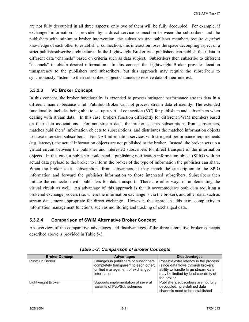
CNS-ATM Task17
3/26/2004 5-11 TR04013
are not fully decoupled in all three aspects; only two of them will be fully decoupled. For example, if exchanged information is provided by a direct service connection between the subscribers and the publishers with minimum broker intervention, the subscriber and publisher members require a priori knowledge of each other to establish a connection; this interaction loses the space decoupling aspect of a strict publish/subscribe architecture. In the Lightweight Broker case publishers can publish their data to different data “channels” based on criteria such as data subject. Subscribers then subscribe to different “channels” to obtain desired information. In this concept the Lightweight Broker provides location transparency to the publishers and subscribers; but this approach may require the subscribers to synchronously “listen” to their subscribed subject channels to receive data of their interest. 5.3.2.3 VC Broker Concept In this concept, the broker functionality is extended to process stringent performance stream data in a different manner because a full Pub/Sub Broker can not process stream data efficiently. The extended functionality includes being able to set up a virtual connection (VC) for publishers and subscribers when dealing with stream data. In this case, brokers function differently for different SWIM members based on their data associations. For non-stream data, the broker accepts subscriptions from subscribers, matches publishers’ information objects to subscriptions, and distributes the matched information objects to those interested subscribers. For NAS information services with stringent performance requirements (e.g. latency), the actual information objects are not published to the broker. Instead, the broker sets up a virtual circuit between the publisher and interested subscribers for direct transport of the information objects. In this case, a publisher could send a publishing notification information object (SPIO) with no actual data payload to the broker to inform the broker of the type of information the publisher can share. When the broker takes subscriptions from subscribers, it may match the subscription to the SPIO information and forward the publisher information to those interested subscribers. Subscribers then initiate the connection with publishers for data transport. There are other ways of implementing the virtual circuit as well. An advantage of this approach is that it accommodates both data requiring a brokered exchange process (i.e. where the information exchange is via the broker), and other data, such as stream data, more appropriate for direct exchange. However, this approach adds extra complexity to information management functions, such as monitoring and tracking of exchanged data. 5.3.2.4 Comparison of SWIM Alternative Broker Concept An overview of the comparative advantages and disadvantages of the three alternative broker concepts described above is provided in Table 5-3.
Table 5-3: Comparison of Broker Concepts Broker Concept Advantages Disadvantages
Pub/Sub Broker Changes in publishers or subscribers completely transparent to each other; unified management of exchanged information
Possible extra latency in the process (since data flows through broker); ability to handle large stream data may be limited by load capability of the broker
Lightweight Broker Supports implementation of several variants of Pub/Sub schemes
Publishers/subscribers are not fully decoupled; pre-defined data channels need to be established

CNS-ATM Task17
3/26/2004 5-12 TR04013
Broker Concept Advantages Disadvantages VC Broker Broker approach is tailored to data
type (i.e. stream or non-stream)
Extra complexity in information management functions such as data monitoring; publisher/subscriber are not fully decoupled (stream data)
The applicability of each of the three broker concepts has been evaluated for SWIM based on the two categories of data that SWIM must accommodate, namely stream data (data that is updated at or nearly real-time in frequency) and non-stream data. An example of stream data is surveillance target reports, while a non-stream data example could be a six hour weather forecast. The following sections describe data sharing in the context of the specified broker concept, identify broker distribution (and topology) considerations specific to each broker category, and provide a comparison of the broker options specific to SWIM. 5.3.3 Description of Broker Scenarios Three SWIM broker concepts have been identified. These include the Pub/Sub Broker, Lightweight Broker and VC Broker. The following subsections describe scenarios providing details of how SWIM operations are accommodated for these three brokering concepts and address broker distribution topics specific to each concept. 5.3.3.1 Pub/Sub Broker Scenario In the non-stream data to Pub/Sub Broker scenario, a subscribing member registers an information request with the SWIM broker. Asynchronously, publishing members register and send information objects to the SWIM broker. The broker matches the information requests with published information objects and forwards appropriate information objects to subscribing members. Information objects may also be forwarded to Data Marts for temporary storage (so that information is available for user query) as well as to other members providing a data warehousing function. For stream data, the same process description applies, with the exception that sampled data may also be forwarded to Data Marts for temporary storage. Figure 5-5 illustrates the Pub/Sub Broker scenarios. These scenarios support complete decoupling of information producers and information consumers. This process has all exchanged information objects pass through the Pub/Sub Broker. Due to the processing load and timing constraints this may entail, for this scenario, a large number of brokers may be required. For this study, four categories of Pub/Sub Broker density in the NAS have been considered. They include:
• Local level density: One broker per ATCT/airport
• Regional level density: One per TRACON/AFSS
• Cross-regional level density: One per ARTCC/Major Facility (e.g. ATCSCC)
• NAS-level density (not shown): A few brokers for the entire NAS
The first three levels are illustrated in Figure 5-6.
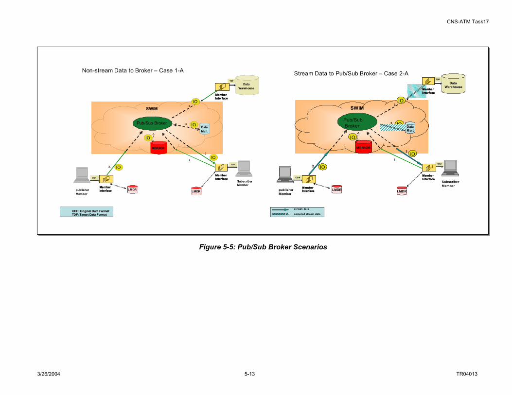
CNS-ATM Task17
3/26/2004 5-13 TR04013
SWIM
DataMart
MDR/IOR
IO
ODF
LMDR LMDRpublisher Member
2.
1.
3
IO3
IO
ODF: Original Data FormatTDF: Target Data FormatODF: Original Data FormatTDF: Target Data Format
IOTDF
SubscriberMember
Data Warehouse
IO
TDF
3
MemberInterfaceMemberInterface
MemberInterfaceMemberInterface
MemberInterfaceMemberInterface
Non-stream Data to Broker – Case 1-A
Pub/Sub Broker
SWIM
DataMart
MDR/IOR
IO
ODF
LMDR LMDRpublisher Member
2.
1.
3
IO3
IO
IO
TDF
Subscriber Member
Data Warehouse
IO
TDF
3
Stream Data to Pub/Sub Broker – Case 2-A
stream data
sampled stream data
stream data
sampled stream data
stream data
sampled stream data
stream data
sampled stream data
MemberInterfaceMemberInterface
MemberInterfaceMemberInterface
MemberInterfaceMemberInterface
Pub/Sub Broker
SWIM
DataMart
MDR/IOR
IO
ODF
LMDR LMDRpublisher Member
2.
1.
3
IO3
IO
ODF: Original Data FormatTDF: Target Data FormatODF: Original Data FormatTDF: Target Data Format
IOTDF
SubscriberMember
Data Warehouse
IO
TDF
3
MemberInterfaceMemberInterface
MemberInterfaceMemberInterface
MemberInterfaceMemberInterface
Non-stream Data to Broker – Case 1-A
Pub/Sub Broker
SWIM
DataMart
MDR/IOR
IO
ODF
LMDR LMDRpublisher Member
2.
1.
3
IO3
IO
IO
TDF
Subscriber Member
Data Warehouse
IO
TDF
3
Stream Data to Pub/Sub Broker – Case 2-A
stream data
sampled stream data
stream data
sampled stream data
stream data
sampled stream data
stream data
sampled stream data
MemberInterfaceMemberInterface
MemberInterfaceMemberInterface
MemberInterfaceMemberInterface
Pub/Sub Broker
Figure 5-5: Pub/Sub Broker Scenarios

CNS-ATM Task17
3/26/2004 5-14 TR04013
Cross-RegionalOne broker per ARTCC level
RegionalOne broker Per TRACCON level
LocalOne brokerper Airport level
RegionalOne broker Per TRACCON level
LocalOne brokerper Airport level
Figure 5-6: Three General Levels of Broker Distribution for the NAS
Besides brokering functionality, other factors affect the required distribution of brokers for SWIM. These include:
• Data Distribution Range: The range is categorized as local or regional; local refers to data published/subscribed within a local FAA node34, while regional refers to data published/subscribed across different FAA nodes.
• Nature of Traffic: This is categorized by whether the published data is considered to be fast or stream data (very high data update rate, e.g., publish/update frequency is over 1 data packet per second), or the data is considered to be slow or non-stream data.
• Variability of Subscribers: Steady or variable indicates whether or not the number and sources of subscribers that subscribe to a particular type of information change frequently.
• Broker Management Complexity: Low or high indicates whether multiple tiers of brokers add extra information management burdens and latency to the architecture
Identification of applicable values for the first three factors identified above for five different NAS data service domains is provided in Table 5-4.
34 In CNS-ATM Task 11, three broad categories of FAA nodes were considered for application of the campus area network development approach. These included:
1. Nodes with TRACONs or Towers. 2. ARTCCs. 3. Nodes comprising remote FAA equipment and facilities.

CNS-ATM Task17
3/26/2004 5-15 TR04013
Table 5-4: Characterizing SWIM Data by Service Domain
Service Domain Data Distribution Range Data Publish/Update Rate Variability of
Subscribers Weather Local Slow non- stream Variable Surveillance Local Stream data Steady Flight Management Regional Fast non-stream Steady Aeronautical Information Regional/Local Slow non-stream Variable Resource Management Local Slow non-stream Steady
Relating the broker density levels to SWIM data characteristics provides a means to evaluate and compare the broker topology solution space for SWIM. Table 5-5 illustrates relationships between the solution space and the identified design factors.
Table 5-5: Comparison of Broker Topology Designs Broker Design
Distribution Broker Layout Data
Distribution Broker
Management Complexity
Data Update
Rate Subscriber Variability
Local broker Requires a large number of brokers; they may be distributed based on NAS facility geographic location; topology can be flat, general peer-to-peer, or hierarchical.
Best suited for situation where data exchange occurs mostly locally, some regionally, and a few across regions
Requires numerous broker linkages resulting in high broker management complexity
May add extra latency for stream data that crosses multiple brokers
Works well when subscribers are steady so that information exchange can be arranged with minimal inter-broker interactions; when subscribers vary, published information may have to traverse multiple brokers before it reaches the target, which may pose a burden to the brokers and affect system performance.
Regional broker
Requires around 20 to 30 brokers distributed regionally (perhaps by ARTCC or other large facility); topology can be flat, general peer-to-peer, or hierarchical.
Best suited for situations where data exchange occurs mostly regionally (between large facilities) and locally with few exchanges across regions
Brokers can be linked fully or partially meshed; medium broker management complexity.
When data exchanges occur mostly regionally, process latency may be reduced to a minimum.
Works well when subscribers are steady so that information exchange can be arranged with minimal inter-broker interactions.
Cross-region broker
Requires fewer than 20 brokers; they are distributed mostly regionally with some across regions; topology can be flat or general peer-to-peer.
Suited for situations where data exchange occurs mostly regionally (between large facilities) and locally with some across regions
Low broker management complexity
For locally exchanged data, it may take non-negligible time for data to be processed by the cross-regional broker
Works for both steady or variable set of subscribers
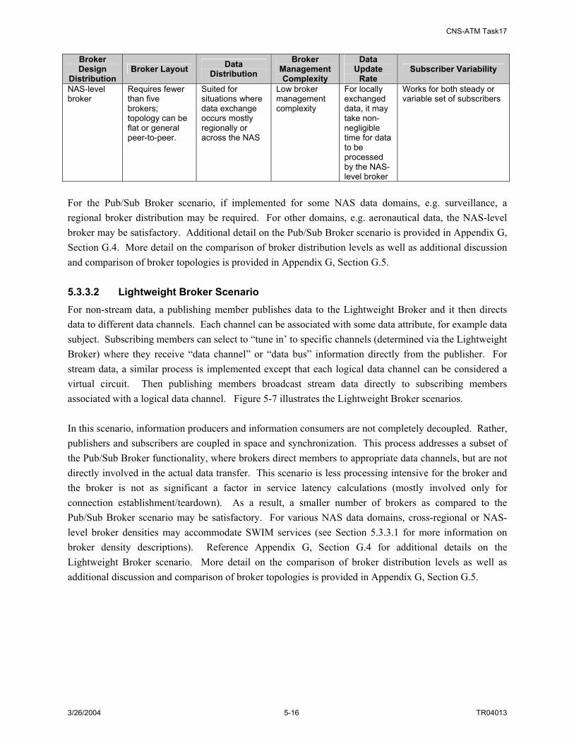
CNS-ATM Task17
3/26/2004 5-16 TR04013
Broker Design
Distribution Broker Layout Data
Distribution Broker
Management Complexity
Data Update
Rate Subscriber Variability
NAS-level broker
Requires fewer than five brokers; topology can be flat or general peer-to-peer.
Suited for situations where data exchange occurs mostly regionally or across the NAS
Low broker management complexity
For locally exchanged data, it may take non-negligible time for data to be processed by the NAS-level broker
Works for both steady or variable set of subscribers
For the Pub/Sub Broker scenario, if implemented for some NAS data domains, e.g. surveillance, a regional broker distribution may be required. For other domains, e.g. aeronautical data, the NAS-level broker may be satisfactory. Additional detail on the Pub/Sub Broker scenario is provided in Appendix G, Section G.4. More detail on the comparison of broker distribution levels as well as additional discussion and comparison of broker topologies is provided in Appendix G, Section G.5. 5.3.3.2 Lightweight Broker Scenario For non-stream data, a publishing member publishes data to the Lightweight Broker and it then directs data to different data channels. Each channel can be associated with some data attribute, for example data subject. Subscribing members can select to “tune in’ to specific channels (determined via the Lightweight Broker) where they receive “data channel” or “data bus” information directly from the publisher. For stream data, a similar process is implemented except that each logical data channel can be considered a virtual circuit. Then publishing members broadcast stream data directly to subscribing members associated with a logical data channel. Figure 5-7 illustrates the Lightweight Broker scenarios. In this scenario, information producers and information consumers are not completely decoupled. Rather, publishers and subscribers are coupled in space and synchronization. This process addresses a subset of the Pub/Sub Broker functionality, where brokers direct members to appropriate data channels, but are not directly involved in the actual data transfer. This scenario is less processing intensive for the broker and the broker is not as significant a factor in service latency calculations (mostly involved only for connection establishment/teardown). As a result, a smaller number of brokers as compared to the Pub/Sub Broker scenario may be satisfactory. For various NAS data domains, cross-regional or NAS-level broker densities may accommodate SWIM services (see Section 5.3.3.1 for more information on broker density descriptions). Reference Appendix G, Section G.4 for additional details on the Lightweight Broker scenario. More detail on the comparison of broker distribution levels as well as additional discussion and comparison of broker topologies is provided in Appendix G, Section G.5.

CNS-ATM Task17
3/26/2004 5-17 TR04013
Figure 5-7: Lightweight Broker Scenarios
Stream Data /Lightweight Broker – Case 2-B
LMDR
MDR/IOR
publisher Member
ODFODF
2 IO2 IO
subscriber Members
TDFTDF
MemberInterface
subscriber Members
TDFTDF
MemberInterfaceMemberInterface
MemberInterfaceMemberInterface
subscriber Members
TDFTDF
MemberInterface
subscriber Members
TDFTDF
MemberInterfaceMemberInterface
Data Channel
3 IO3 IO 4 IO4 IO
4 IO4 IO
4 IO4 IOData Channel
LightweightBroker 1. Subscription/Channel
3 IO3 IO
Non-Stream Data /Lightweight Broker -- Case 1-B–
LMDR
MDR/IOR
publisher Member
ODFODF
2 IO2 IO
subscriber Members
TDFTDF
MemberInterface
subscriber Members
TDFTDF
MemberInterfaceMemberInterface
MemberInterfaceMemberInterface
subscriber Members
TDFTDF
MemberInterface
subscriber Members
TDFTDF
MemberInterfaceMemberInterface
Data Channel
Data Channel
LightweightBroker
3 IO3 IO
3 IO3 IO
1. Subscription/Channel
4 IO4 IO
4 IO4 IO
4 IO4 IO

CNS-ATM Task17
3/26/2004 5-18 TR04013
5.3.3.3 Virtual Circuit Broker Scenario The service steps associated with this scenario are similar to the ‘non-stream data to Pub/Sub Broker’ scenario described above. As before, subscribers send their subscriptions to the VC Broker. When publishing non-stream data, the VC Broker acts just as the Pub/Sub Broker does, matching the information requests with published information objects and forwarding appropriate information objects to subscribing members. For stream data, however, a publisher sends a stream data publishing information object (SPIO) to the VC Broker. The SPIO contains only information about the stream data to be published, with no actual payload (data) in the information object. The VC Broker then matches the SPIO with interested subscribers and informs the subscribers to set up the connection (e.g. virtual circuit) to publishers (e.g. “pull” data from publishers). Alternatively, the Broker also could also inform the publishers to set up the virtual connection with interested subscribers (e.g. “push” data to subscribers). Figure 5-8 illustrates the Lightweight Broker scenarios. In this scenario, non-stream data information producers and information consumers are completely decoupled, similar to the Pub/Sub Broker scenario. For stream data, however, the two are not completely decoupled. Rather, publishers and subscribers are coupled in space and synchronization. For stream data, the VC Broker addresses a subset of the Pub/Sub Broker functionality, where brokers direct members to set up appropriate virtual circuits, but are not directly involved in the actual data transfer. Similar to the Lightweight Broker, this scenario is less processing intensive for the broker and the broker is not as significant a factor in service latency calculations (mostly involved only for connection establishment/teardown). As a result, a smaller number of brokers as compared to the Pub/Sub Broker scenario may be satisfactory. For non-stream data (e.g. weather, aeronautical data domains), the number of brokers that can support the traffic is likely regional or cross-regional densities. For stream data, cross-regional or NAS-level broker densities may be suitable (since the data flow is not “through” the broker). Reference Appendix G, Section G.4 for additional detail on the VC Broker scenario and for more detail on the comparison of broker distribution levels as well as additional discussion and comparison of broker topologies (Section G.5).

CNS-ATM Task17
3/26/2004 5-19 TR04013
Figure 5-8: VC Broker Scenarios
SWIM
DataMart
MDR/IOR
BrokerVC Broker
IOIO
ODF
LMDRLMDR LMDRLMDR
publisher Member
2.
1.
IO3
IO
TDF
SubscriberMember
Data Warehouse
IOIO
TDF
3
Non-Stream Data to VC Broker --Case 1-C
3
MemberInterfaceMemberInterface
MemberInterfaceMemberInterface
MemberInterfaceMemberInterface
IOIO
SWIM
DataMart
MDR/IOR
BrokerVC Broker
SPIOSPIO
ODF
LMDRLMDR LMDRLMDR
publisher Member
2.
1.
4
SPIO3
IO
TDF
SubscriberMember
SPIO3
Stream Data to VC Broker --Case 2-C
3
MemberInterfaceMemberInterface
MemberInterfaceMemberInterface
Data Warehouse
TDF
MemberInterface
Data Warehouse
TDF
MemberInterfaceMemberInterface
SPIOSPIO
VCVC
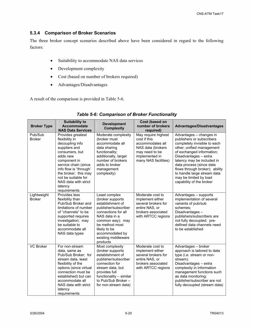
CNS-ATM Task17
3/26/2004 5-20 TR04013
5.3.4 Comparison of Broker Scenarios The three broker concept scenarios described above have been considered in regard to the following factors:
• Suitability to accommodate NAS data services
• Development complexity
• Cost (based on number of brokers required)
• Advantages/Disadvantages
A result of the comparison is provided in Table 5-6.
Table 5-6: Comparison of Broker Functionality
Broker Type Suitability to
Accommodate NAS Data Services
Development Complexity
Cost (based on number of brokers
required) Advantages/Disadvantages
Pub/Sub Broker
Provides greatest flexibility in decoupling info suppliers and consumers, but adds new component in service chain (since info flow is “through’ the broker; this may not be suitable for NAS data with strict latency requirements
Moderate complexity (broker must accommodate all data sharing functionality; additionally, larger number of brokers adds to broker management complexity)
May require highest cost if this accommodates all NAS data (brokers may need to be implemented in many NAS facilities)
Advantages – changes in publishers or subscribers completely invisible to each other; unified management of exchanged information; Disadvantages – extra latency may be included in data process (since data flows through broker); ability to handle large stream data may be limited by load capability of the broker
Lightweight Broker
Provides less flexibility than Pub/Sub Broker and limitations of number of “channels” to be supported requires investigation; may be suitable to accommodate all NAS data types
Least complex (broker supports establishment of publisher/subscriber connections for all NAS data in a common way); may be method most likely to be accommodated by existing middleware products
Moderate cost to implement either several brokers for entire NAS, or brokers associated with ARTCC regions
Advantages – supports implementation of several variants of pub/sub schemes; Disadvantages – publishers/subscribers are not fully decoupled; pre-defined data channels need to be established
VC Broker For non-stream data, same as Pub/Sub Broker; for stream data, least flexibility of the options (since virtual connection must be established) but can accommodate all NAS data with strict latency requirements
Most complexity (broker supports establishment of publisher/subscriber connection for stream data, but provides full functionality – similar to Pub/Sub Broker – for non-stream data)
Moderate cost to implement either several brokers for entire NAS, or brokers associated with ARTCC regions
Advantages – broker approach is tailored to data type (i.e. stream or non-stream); Disadvantages – extra complexity in information management functions such as data monitoring; publisher/subscriber are not fully decoupled (stream data)

CNS-ATM Task17
3/26/2004 5-21 TR04013
Several simulation activities were performed to support the comparison of broker processing options as well as broker distribution densities. A description of the simulation model and the simulation results are presented in Section 6. 5.4 SWIM INTERFACE INTEGRATION OPTIONS Three interface integration methods for potential SWIM members (including FAA legacy components) to access SWIM services have been defined and are illustrated in Figure 5-9. These include:
• Distributed proxy functionality, that is, the member interface function is loaded on an individual SWIM member (NAS system) as proxy software. This is shown as the top connection (red line) in Figure 5-9.
• SWIM member interface implemented in standalone hardware at a SWIM member facility. The member interface is located within the facility (local access) of the associated SWIM member. The standalone SWIM member interface can be viewed as a SWIM Management Unit (SMU) as described in the NAS Target System Description35. This is shown as the middle connection (blue line) in Figure 5-9.
• SWIM member interface implemented in standalone hardware located at a remote facility (remote access). The standalone SWIM member interface can be viewed as a SWIM Management Unit (SMU). This is shown as the bottom connection (green line) in Figure 5-9.
In Figure 5-9, a NAS legacy component could be an automation center, a processing system, a workstation, a database, a sensor, etc. within the NAS. The network capability is provided by FAA WAN services such as FTI.
35 NAS Target System Description (TSD), Steve Bradford, FAA presentation, May 2003

CNS-ATM Task17
3/26/2004 5-22 TR04013
Acc
ess A
ltern
ativ
es
NAS Legacy Component
NAS Legacy Component
Member Interface
(SWIM Proxy)
FAAWAN
Member Interface
(SMU)
Different facilities
Member Interface
(SMU)
NAS Legacy Component
Same facility
SWIM
SWIM Member
SWIM Member
SWIM Member
FAA IP Communication Network (FTI)
SWIM
Acc
ess A
ltern
ativ
es
NAS Legacy Component
NAS Legacy Component
NAS Legacy Component
Member Interface
(SWIM Proxy)
FAAWANFAAWAN
Member Interface
(SMU)
Member Interface
(SMU)
Different facilities
Member Interface
(SMU)
NAS Legacy Component
NAS Legacy Component
Same facility
SWIM
SWIM Member
SWIM Member
SWIM Member
FAA IP Communication Network (FTI)
SWIM
Acc
ess A
ltern
ativ
es
NAS Legacy Component
NAS Legacy Component
Member Interface
(SWIM Proxy)
FAAWAN
Member Interface
(SMU)
Different facilities
Member Interface
(SMU)
NAS Legacy Component
Same facility
SWIM
SWIM Member
SWIM Member
SWIM Member
FAA IP Communication Network (FTI)
SWIM
Acc
ess A
ltern
ativ
es
NAS Legacy Component
NAS Legacy Component
NAS Legacy Component
Member Interface
(SWIM Proxy)
FAAWANFAAWAN
Member Interface
(SMU)
Member Interface
(SMU)
Different facilities
Member Interface
(SMU)
NAS Legacy Component
NAS Legacy Component
Same facility
SWIM
SWIM Member
SWIM Member
SWIM Member
FAA IP Communication Network (FTI)
SWIM
Figure 5-9: SWIM Interface Integration Options These access methods have been assessed based on the following criteria:
• Processing speed
• Memory requirements (for FAA network node)
• Complexity
• Cost
The evaluation of each access method based on these identified criteria is captured in Table 5-7.
Table 5-7: Comparison of SWIM Interface Integration Options Evaluation Criteria Interface
Integration Option Processing Speed Memory
Requirements Complexity Cost
Distributed Proxy implemented in FAA node
High High Med Med/Low
Standalone Proxy in Local Facility
Med Low Med/High High
Standalone Proxy in Remote Facility
Med/Low Low Med/High Med/High
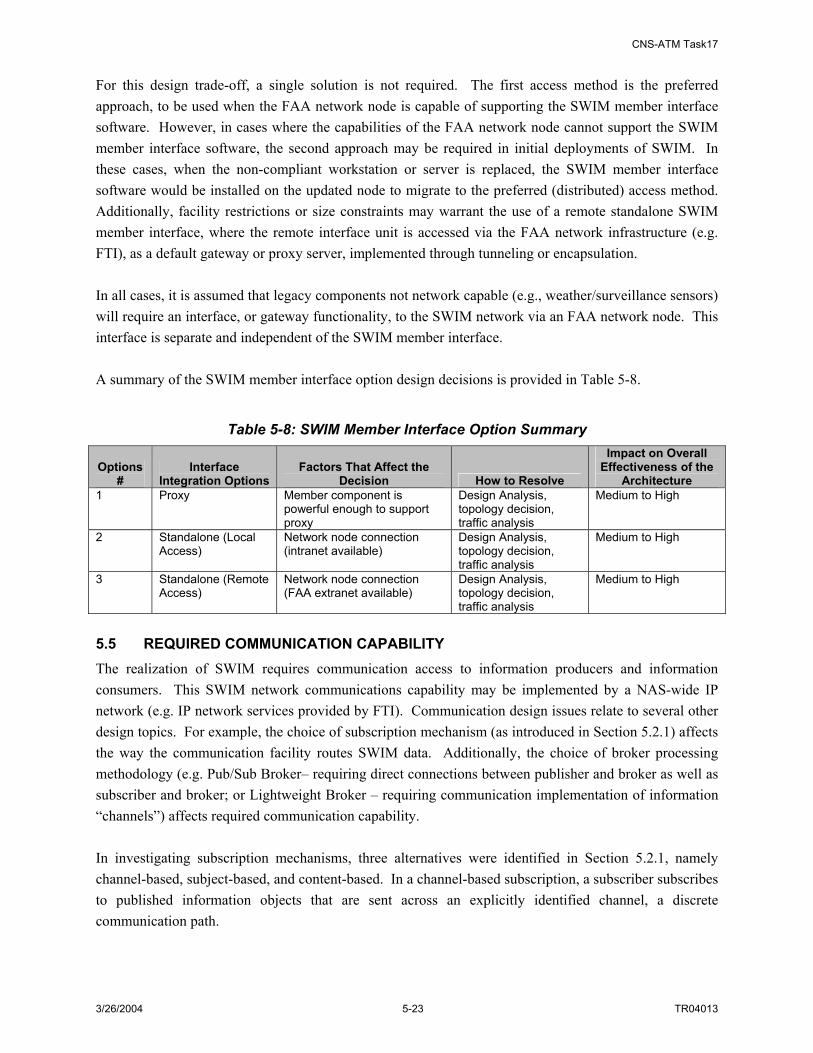
CNS-ATM Task17
3/26/2004 5-23 TR04013
For this design trade-off, a single solution is not required. The first access method is the preferred approach, to be used when the FAA network node is capable of supporting the SWIM member interface software. However, in cases where the capabilities of the FAA network node cannot support the SWIM member interface software, the second approach may be required in initial deployments of SWIM. In these cases, when the non-compliant workstation or server is replaced, the SWIM member interface software would be installed on the updated node to migrate to the preferred (distributed) access method. Additionally, facility restrictions or size constraints may warrant the use of a remote standalone SWIM member interface, where the remote interface unit is accessed via the FAA network infrastructure (e.g. FTI), as a default gateway or proxy server, implemented through tunneling or encapsulation. In all cases, it is assumed that legacy components not network capable (e.g., weather/surveillance sensors) will require an interface, or gateway functionality, to the SWIM network via an FAA network node. This interface is separate and independent of the SWIM member interface. A summary of the SWIM member interface option design decisions is provided in Table 5-8.
Table 5-8: SWIM Member Interface Option Summary
Options #
Interface Integration Options
Factors That Affect the Decision How to Resolve
Impact on Overall Effectiveness of the
Architecture 1 Proxy Member component is
powerful enough to support proxy
Design Analysis, topology decision, traffic analysis
Medium to High
2 Standalone (Local Access)
Network node connection (intranet available)
Design Analysis, topology decision, traffic analysis
Medium to High
3 Standalone (Remote Access)
Network node connection (FAA extranet available)
Design Analysis, topology decision, traffic analysis
Medium to High
5.5 REQUIRED COMMUNICATION CAPABILITY The realization of SWIM requires communication access to information producers and information consumers. This SWIM network communications capability may be implemented by a NAS-wide IP network (e.g. IP network services provided by FTI). Communication design issues relate to several other design topics. For example, the choice of subscription mechanism (as introduced in Section 5.2.1) affects the way the communication facility routes SWIM data. Additionally, the choice of broker processing methodology (e.g. Pub/Sub Broker– requiring direct connections between publisher and broker as well as subscriber and broker; or Lightweight Broker – requiring communication implementation of information “channels”) affects required communication capability. In investigating subscription mechanisms, three alternatives were identified in Section 5.2.1, namely channel-based, subject-based, and content-based. In a channel-based subscription, a subscriber subscribes to published information objects that are sent across an explicitly identified channel, a discrete communication path.

CNS-ATM Task17
3/26/2004 5-24 TR04013
Subject-based mechanisms extend the concept of a channel with a more flexible addressing mechanism; in this case publishing contains an attribute to determine where the information object is heading. In subject-based subscriptions, subscribers can express their interest in many subjects/channels by using some expressions and those expressions are evaluated against the subjects of published information objects. In this case one subscriber can subscribe to multiple subjects and one published information object can match to multiple subscriptions. Content-based subscriptions allow for a great amount of user flexibility in specifying information needs and requirements, and can be described as follows36:
The term “content-based” characterizes those systems whose subscriptions can express predicates over the whole content of a publication. This is in contrast with channel-based and subject-based systems, in which only a few well-known attributes of a publication are available for selection to subscriptions. The strength of content-based publish/subscribe middleware over a multicast network service is the greater expressive power of its data model and of its subscription language. Its weakness is scalability. In fact, only a few content-based publish/subscribe middleware services are implemented as true distributed systems, and none of the existing ones is designed to achieve levels of scalability comparable to those of existing network communication infrastructures, such as IP.
The advantages of content-based systems over subject-based systems can be summarized as follows37:
The content-based model provides more flexibility because of the expressive power of its data model and of its subscription language. A subscriber can choose filtering (selection) criteria along as many dimensions as there are event attributes. In a stock trading example a subscriber could subscribe to any combination of the event attributes such as issue name, price, and volume.
The content-based model does not require the administrative overhead associated with defining and maintaining a large number of subjects.
The content-based model is more general than the subject-based model, as it could be used to implement a subject-based system. In a stock trading example, the event predicated on (issue name = “GE” & price = any) would provide the same information as the subject-based event subscription of subject “GE”.
The major disadvantage of the content-based model is its scalability, that is, it becomes much less efficient as the size of the distributed network and the number of publishers and subscribers increases. This is because38:
It becomes computationally difficult to efficiently match a complex event against a large number of subscribers on a single message broker (router).
It becomes difficult to efficiently multicast events within a network of message brokers when: 1) the geographically distributed network has limited bandwidth, and 2) as the number of publishers and subscribers becomes very large.
These two problems are efficiently handled in subject-based systems as follows: 36 A. Carzaniga and A. Wolf, Content-Based Networking: A New Communication Infrastructure, University of Colorado, 2002. 37 An Efficient Multicast Protocol for Content-Based Publish-Subscribe Systems,; IBM T. J. Watson Research Center, c1999.

CNS-ATM Task17
3/26/2004 5-25 TR04013
• Matching is performed with a look-up table, which consists of a fixed, limited number of subjects.
• Multicasting is handled by assigning a single, separate multicast group per subject and multicasting each event to the appropriate multicasting group.
The preceding discussion has introduced two, often conflicting, and fundamental characteristics of publication-subscription systems: expressiveness and scalability. These can succinctly defined as follows39:
Scalability means that the service must be available over a wide-area network populated by numerous components each one producing and consuming many events. Expressiveness demands a rich subscription language that gives applications a flexible and fine-grained selection mechanism to describe precisely those events or combinations of events in which they are interested.
As described above, expressiveness of a publication/subscription event service is chiefly determined by its subscription language. Two aspects of the subscription language are crucial to the expressiveness of an event service: scope and expressiveness (or power), defined as follows40:
The scope of the selection predicates: The part of the event model that is visible within subscription expressions. In some cases, events have an articulated structure that allows the encoding of much information, but only a limited and/or simple part of that structure can be used as selection criteria in subscriptions.
The expressiveness of the selection predicates: Determines the sophistication of subscriptions. In practice, a subscription language is expressive if it has various basic selection predicates and the ability to combine predicates for the selection of one single event at a time as well as for grouping events into higher-level abstractions.
These two characteristics can be used to classify subscription languages used in publication-subscription systems. Table 5-9 shows how such a classification can be made. Within the table different types of publication-subscription systems are classed according to the scope and expressiveness of their subscription languages. In the table the scope of the subscription language is defined according to whether it uses a single notification of a single field (attribute) or multiple fields, or multiple notifications of multiple fields to match published events to subscriptions. For expressiveness, there are three levels of ascending sophistication: 1) a simple equality or matching test; 2) predicates: multiple filtering expressions with predefined operators for matching; and 3) expressions with user-defined operators, which includes multiple, correlated events forming defined “patterns”.
38 Ibid. 39 Antonio Carzaniga, David S. Rosenblum, and Alexander Wolf, Challenges for Distributed Event Services: Scalability vs. Expressiveness, c1999. 40 Ibid.
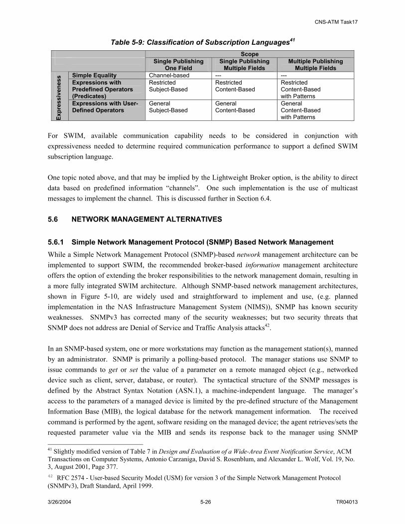
CNS-ATM Task17
3/26/2004 5-26 TR04013
Table 5-9: Classification of Subscription Languages41 Scope Single Publishing
One Field Single Publishing
Multiple Fields Multiple Publishing
Multiple Fields Simple Equality Channel-based --- --- Expressions with Predefined Operators (Predicates)
Restricted Subject-Based
Restricted Content-Based
Restricted Content-Based with Patterns
Expr
essi
vene
ss
Expressions with User-Defined Operators
General Subject-Based
General Content-Based
General Content-Based with Patterns
For SWIM, available communication capability needs to be considered in conjunction with expressiveness needed to determine required communication performance to support a defined SWIM subscription language. One topic noted above, and that may be implied by the Lightweight Broker option, is the ability to direct data based on predefined information “channels”. One such implementation is the use of multicast messages to implement the channel. This is discussed further in Section 6.4. 5.6 NETWORK MANAGEMENT ALTERNATIVES 5.6.1 Simple Network Management Protocol (SNMP) Based Network Management While a Simple Network Management Protocol (SNMP)-based network management architecture can be implemented to support SWIM, the recommended broker-based information management architecture offers the option of extending the broker responsibilities to the network management domain, resulting in a more fully integrated SWIM architecture. Although SNMP-based network management architectures, shown in Figure 5-10, are widely used and straightforward to implement and use, (e.g. planned implementation in the NAS Infrastructure Management System (NIMS)), SNMP has known security weaknesses. SNMPv3 has corrected many of the security weaknesses; but two security threats that SNMP does not address are Denial of Service and Traffic Analysis attacks42. In an SNMP-based system, one or more workstations may function as the management station(s), manned by an administrator. SNMP is primarily a polling-based protocol. The manager stations use SNMP to issue commands to get or set the value of a parameter on a remote managed object (e.g., networked device such as client, server, database, or router). The syntactical structure of the SNMP messages is defined by the Abstract Syntax Notation (ASN.1), a machine-independent language. The manager’s access to the parameters of a managed device is limited by the pre-defined structure of the Management Information Base (MIB), the logical database for the network management information. The received command is performed by the agent, software residing on the managed device; the agent retrieves/sets the requested parameter value via the MIB and sends its response back to the manager using SNMP 41 Slightly modified version of Table 7 in Design and Evaluation of a Wide-Area Event Notification Service, ACM Transactions on Computer Systems, Antonio Carzaniga, David S. Rosenblum, and Alexander L. Wolf, Vol. 19, No. 3, August 2001, Page 377. 42 RFC 2574 - User-based Security Model (USM) for version 3 of the Simple Network Management Protocol (SNMPv3), Draft Standard, April 1999.

CNS-ATM Task17
3/26/2004 5-27 TR04013
responses. The agent may also issue an unsolicited response, or trap, to the manager in the event of pre-defined alarm or error conditions such as a link outage or node failure. SNMP’s suitability for SWIM is summarized as follows:
• SNMP-Based: Network management functions are based on the standard SNMP protocol as shown in Figure 5-10.
• Advantages: SNMP is simple and widely used
• Disadvantages: SNMP has security weaknesses; however, SNMP-v3 has corrected some of the security problems
Manager Managed ObjectAgent
Macros ASN-1
Get/SetTrap
ControlMonitor
MIB
Manager Managed ObjectAgent
Macros ASN-1
Get/SetTrap
ControlMonitor
MIB
Manager Managed ObjectAgent
Macros ASN-1
Get/SetTrap
ControlMonitor
MIB
Figure 5-10: SNMP-based Network Management
5.6.2 Object Oriented Broker Based Network Management In contrast to the SNMP case, an object-oriented, broker based network management architecture, such as the CORBA-based architecture shown in Figure 5-11, is more robust and secure, more extensible and customizable, and could be implemented as an extension to the SWIM Information Management functional components. However, although such architectures have evolved significantly in the past ten years, they are still less widely deployed than SNMP-based systems. The CORBA-based approach eliminates the need for rigidly structured MIB and SNMP-defined commands, because network management commands are issued as transparent operation invocations on managed objects. Furthermore, CORBA can be used to maintain a logical link between multiple network managers to facilitate the distribution of management responsibilities to enhance scalability and to enable the assumption of new responsibilities to support failover. In addition, CORBA supports the flexibility to use legacy SNMP agents and migrate toward CORBA applications in the future. The Object Request Broker (ORB) is responsible for translating the object requests and operations between the manager and managed object, or between to managers. CORBA’s Interface Definition Language (IDL) specifies the interfaces for each object, providing the means for each object to inform clients (e.g., the network manager) which operations are provided and how they can be invoked. These operations may be invoked by clients through IDL stubs. The General Inter-ORB Protocol (GIOP), or the Internet Inter-ORB Protocol (IIOP), allows for the communication between ORBs. It is responsible for ensuring a common data representation and for enabling message transfer. CORBA’s suitability for SWIM is summarized as follows:
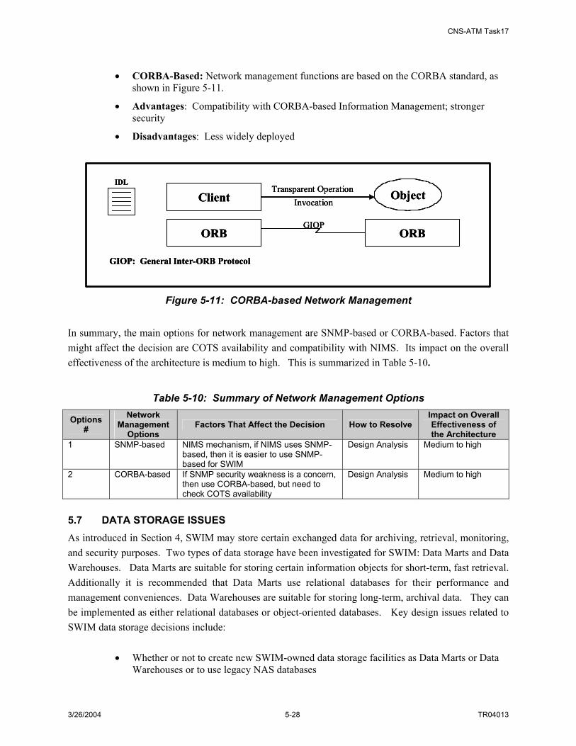
CNS-ATM Task17
3/26/2004 5-28 TR04013
• CORBA-Based: Network management functions are based on the CORBA standard, as
shown in Figure 5-11.
• Advantages: Compatibility with CORBA-based Information Management; stronger security
• Disadvantages: Less widely deployed
IDL
ClientTransparent Operation
Invocation
ORB ORBGIOP
Object
GIOP: General Inter-ORB Protocol
IDL
ClientTransparent Operation
Invocation
ORB ORBGIOP
Object
GIOP: General Inter-ORB Protocol
IDL
ClientTransparent Operation
Invocation
ORB ORBGIOP
Object
GIOP: General Inter-ORB Protocol
Figure 5-11: CORBA-based Network Management
In summary, the main options for network management are SNMP-based or CORBA-based. Factors that might affect the decision are COTS availability and compatibility with NIMS. Its impact on the overall effectiveness of the architecture is medium to high. This is summarized in Table 5-10.
Table 5-10: Summary of Network Management Options
Options #
Network Management
Options Factors That Affect the Decision How to Resolve
Impact on Overall Effectiveness of the Architecture
1 SNMP-based NIMS mechanism, if NIMS uses SNMP-based, then it is easier to use SNMP-based for SWIM
Design Analysis Medium to high
2 CORBA-based If SNMP security weakness is a concern, then use CORBA-based, but need to check COTS availability
Design Analysis Medium to high
5.7 DATA STORAGE ISSUES As introduced in Section 4, SWIM may store certain exchanged data for archiving, retrieval, monitoring, and security purposes. Two types of data storage have been investigated for SWIM: Data Marts and Data Warehouses. Data Marts are suitable for storing certain information objects for short-term, fast retrieval. Additionally it is recommended that Data Marts use relational databases for their performance and management conveniences. Data Warehouses are suitable for storing long-term, archival data. They can be implemented as either relational databases or object-oriented databases. Key design issues related to SWIM data storage decisions include:
• Whether or not to create new SWIM-owned data storage facilities as Data Marts or Data Warehouses or to use legacy NAS databases

CNS-ATM Task17
3/26/2004 5-29 TR04013
• Should SWIM interface to current FAA legacy databases directly through SWIM member interfaces (so that legacy databases are treated as subscribers) or indirectly through legacy processing centers?
• Should Data Warehouses be updated by publishers, by subscribers, or both?
• Should SWIM Data Warehouses store data in a common data format or store data in their original data format or target data format?
The advantages and disadvantages and related issues for these data storage issues are listed in Table 5-11, and a summary of the SWIM decision factors related to data storage is presented in Table 5-12.
Table 5-11: Data Storage Issues - Advantages/Disadvantages and Related Issues Issue 1: Whether or Not to Create SWIM-owned Data Storage
Alternative Advantages Disadvantages Related Issues Create SWIM owned Data Marts
Data Marts can be built based on clearly defined information object structures; easy to build
Can technology provide a “seamless” connection between the database capabilities and the pub/sub system?
• Need to decide what data gets to stored in Data Marts and how many Data Marts to keep for SWIM
• How to do “sample archiving” for stream data?
Create SWIM owned Data Warehouses
Data Warehouses can be “purpose built” to better fit SWIM needs/platforms
Costly; cannot reuse legacy databases
• Management of the Data Warehouses
Transition of SWIM legacy databases to SWIM Data Warehouses
Reuse current legacy databases; may save some cost
May be difficult to implement
• Can all legacy databases be transitioned to SWIM Data Warehouses?
• How to transition? Issue 2: How to Interface to Legacy Databases
Alternative Advantages Disadvantages Related Issues Interface to SWIM directly through member interface so legacy databases can be treated as a regular subscriber
Legacy SWIM databases can be more independent and can subscribe to SWIM data directly
SWIM databases need to be transitioned to be SWIM compliant (data format compliant and management compliant)
• Need to translate SWIM data format to legacy databases
Interface to SWIM indirectly through current systems such as processing centers
No need to change legacy databases
Database update is indirect, may increase latency
• Are these legacy databases redundant when Data Warehouses are used in SWIM?
Issue 3: Are Data Warehouses Kept by Publishers or by Subscribers? Alternative Advantages Disadvantages Related Issues
By publishers Quick update before data even gets published
Data Warehouse either contains one publisher’s data or has to coordinate other publishers’ data so as to keep multiple views of the same data
By subscribers Multiple views of the same data can be kept in the Data Warehouse. Warehouse can subscribe directly to SWIM for data.
Data needs to be filtered and structured to put in a Data Warehouse
Issue 4: What is the Data Format in Data Warehouses, a Common Data Format or any Other Format? Alternative Advantages Disadvantages Related Issues

CNS-ATM Task17
3/26/2004 5-30 TR04013
Common data format Easy to query Need to put information objects in, which may result in more data overhead
Local data format Fast Data needs to translated
Table 5-12: Summary of Data Storage Option Decisions for SWIM Data
Storage Option #
Data Storage Option
Factors That Affect the Decision How to Resolve
Impact on Overall Effectiveness of the Architecture
1 Whether to create SWIM’s own data storage or not
FAA policy Policy making High
2 How to interface to legacy databases
Legacy NAS databases Design analysis Medium
3 Are Data Warehouses kept by publishers or by subscribers?
FAA policy Policy making Medium
4 What is the data format in Data Warehouses, common data format or any other format?
Performance Data analysis, design analysis
High

CNS-ATM Task17
3/26/04 6-1 TR04013
6. SWIM DESIGN DECISION ANALYSIS AND SIMULATION
6.1 INTRODUCTION This section provides an overview of the simulation model tool used to analyze certain design issues presented in Section 5. Specifically, topics addressed include:
• Simulation Overview (Section 6.2)
• Broker Functionality and Distribution (Section 6.3)
• Required Communication Capability (Section 6.4)
6.2 SIMULATION OVERVIEW In this section the methodology for constructing the SWIM process and broker models is described. The descriptions include illustrations of OPNET process model state transition diagrams and state transition tables, where applicable. A brief overview of the OPNET model of the portion of the NAS communications architecture within the Cleveland ZOB ATS and TM area is included since the SWIM models were incorporated into this existing model so that realistic traffic conditions could be simulated as part of the trade studies. 6.2.1 Modeling and Simulation Process To address the design of the SWIM physical architecture and its overall performance in supporting various FAA traffic types, the OPNET modeling tool was used. OPNET supported the development of custom application layer processes necessary to model SWIM concepts; and the existing model of the Cleveland ZOB ATS and TM area, configured with realistic FAA traffic, provided an excellent tool for analysis. In Figure 6-1, the overall OPNET modeling and simulation process is illustrated. Initially, the new broker and SWIM member node models and SWIM processes were developed. These included the SWIM processes and broker model needed to simulate application-layer traffic patterns within a broker architecture. These preliminary models were then refined as additional analytical studies were performed. In parallel, an existing model of the Cleveland ZOB ATS from CNS-ATM Task 12 was updated to run in the latest version of OPNET software (version 10.0), and similarly, changes were made to the Task 12 traffic specifications for ZOB to employ the publish/subscribe information management concepts. Once the new SWIM process models were built and the Task 12 model upgrades completed, the SWIM simulations were performed, and the results were documented for further analysis and inclusion in this report.
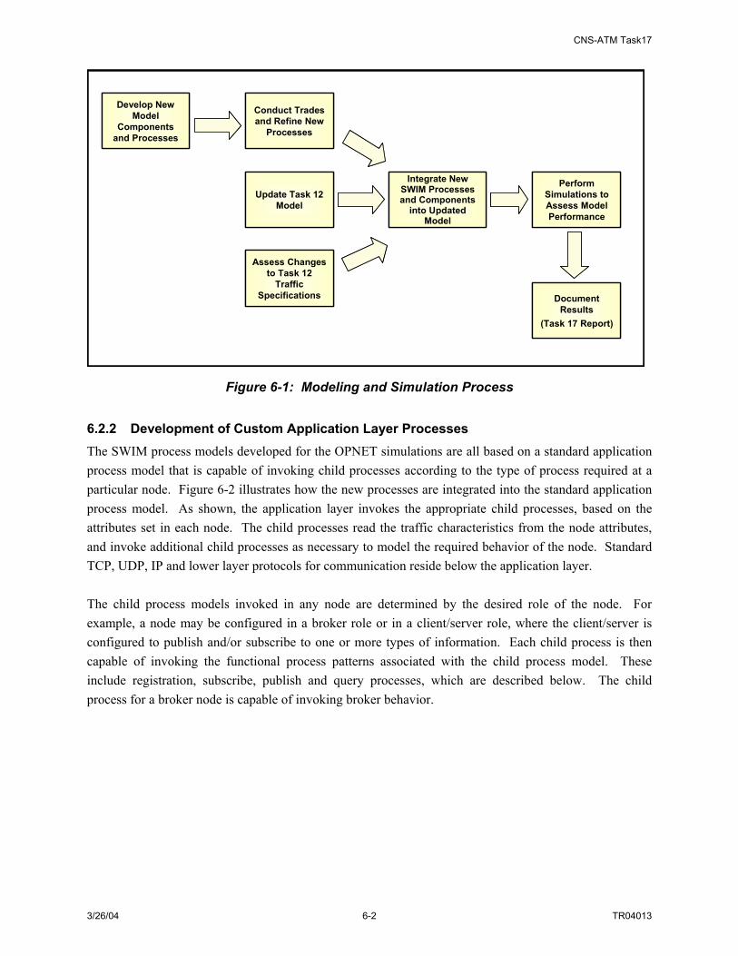
CNS-ATM Task17
3/26/04 6-2 TR04013
Develop New Model
Components and Processes
Conduct Trades and Refine New
Processes
Update Task 12 Model
Integrate New SWIM Processes and Components
into Updated Model
Perform Simulations to Assess Model Performance
Document Results
(Task 17 Report)
Assess Changes to Task 12
Traffic Specifications
Develop New Model
Components and Processes
Conduct Trades and Refine New
Processes
Update Task 12 Model
Integrate New SWIM Processes and Components
into Updated Model
Perform Simulations to Assess Model Performance
Document Results
(Task 17 Report)
Assess Changes to Task 12
Traffic Specifications
Figure 6-1: Modeling and Simulation Process 6.2.2 Development of Custom Application Layer Processes The SWIM process models developed for the OPNET simulations are all based on a standard application process model that is capable of invoking child processes according to the type of process required at a particular node. Figure 6-2 illustrates how the new processes are integrated into the standard application process model. As shown, the application layer invokes the appropriate child processes, based on the attributes set in each node. The child processes read the traffic characteristics from the node attributes, and invoke additional child processes as necessary to model the required behavior of the node. Standard TCP, UDP, IP and lower layer protocols for communication reside below the application layer. The child process models invoked in any node are determined by the desired role of the node. For example, a node may be configured in a broker role or in a client/server role, where the client/server is configured to publish and/or subscribe to one or more types of information. Each child process is then capable of invoking the functional process patterns associated with the child process model. These include registration, subscribe, publish and query processes, which are described below. The child process for a broker node is capable of invoking broker behavior.

CNS-ATM Task17
3/26/04 6-3 TR04013
Single Child Process Model per Client/Server Role; Invokes
Registrations, Subscribes/Unsubscribes
Simulates Broker Behavior
Publish/Query Child Processes for Each Type of Information to Be Published/Queried by the Node
Child Process Models Invoked Depending on the Role of the Node
(Client and/or Server or Broker)
App
Lower Layers
Node Attributes
Traffic Statistics
Received Packets
Traffic Characteristics
Packets to Transmit
Child Process:
Reg; Sub
Child Process:Broker
Child Process:
Pub; Query
Figure 6-2: Context Definition of SWIM Process Models 6.2.2.1 SWIM Process Patterns The information sharing strategies identified in Section 5 provide the range of options for how the SWIM Broker component will support information sharing in SWIM. The specific nature of how SWIM operations and interactions are handled, termed process patterns in this section, have been identified. Five principal SWIM process patterns are defined in Table 6-1.
Table 6-1: SWIM Process Pattern Descriptions SWIM Process Pattern Description
Register A declaration by SWIM member interface of member’s role in SWIM (e.g., publish weather information, store surveillance information.)
Subscribe Request for specific type of information to be published in the future (continuous) Unsubscribe The reversal of previous subscribe request Publish The provision of specific type of information Query Request for specific type of information most recently published (one time) Detailed descriptions of these process patterns are provided in Appendix F. 6.2.3 Integration into NAS Model The model of the western portion of the Cleveland Air Traffic Control (ATC) and Traffic Management (TM) area of control (ZOB), developed under CNS-ATM Task 12, was used as the test bed for SWIM concepts, as well as to provide a baseline for comparison. A portion of the NAS model is shown in Figure 6-3.

CNS-ATM Task17
3/26/04 6-4 TR04013
ZOB
DTW
CLE
ZOB
DTW
CLE
Figure 6-3: NAS Model - Cleveland ATS and TM Area of Control FAA communications in the Cleveland ATC and TM area employs a variety of FAA communication utilities for operational traffic and accommodates a wide range of FAA services that include:
• Automation
• Surveillance
• Weather
• Navigation and Landing
• Operational Voice and Data
• Maintenance
• Administrative Voice and Data
Under CNS-ATM Task 12, this traffic was incorporated into the model using OPNET’s custom application specification utility, which allows traffic to be characterized at the profile, application, and task level with parameters such as inter-arrival times and packet size, and assigned to the appropriate source/destination nodes. For the Task 17 baseline, voice traffic was deleted (as inappropriate for publish/subscribe operation). The remaining data traffic was simulated to establish a non-SWIM baseline.

CNS-ATM Task17
3/26/04 6-5 TR04013
The SWIM model was then built by incorporating the elements of the recommended SWIM physical architecture into the baseline model. The custom SWIM processes were integrated at the node model level. SWIM-aware clients, servers and LANs were created by specifying the new SWIM processes in the application process of the required nodes, which replaced the standard clients, servers and LANs in the baseline model. The traffic demands in the baseline model were then translated into publish/subscribe requests, specified in the node attributes of the appropriate clients, servers and LANs, as shown in Figure 6-4.
Figure 6-4: Traffic Specification Example In order to mitigate the impact of the broker architecture on network resource usage and traffic latencies, the traffic patterns of the baseline model were considered in determining optimal placement of the brokers. Because the majority of surveillance, weather, and automation traffic were transmitted from or to ZOB, the surveillance, weather and automation brokers were placed in the ZOB facility, as shown in Figure 6-5a). Navigation and Landing traffic, however, was centered around the DTW facility; therefore, the Navigation and Landing broker was placed in the DTW facility at the Navigation router, as shown in Figure 6-5b).

CNS-ATM Task17
3/26/04 6-6 TR04013
ZOB DTWZOB DTW
a) ZOB Facility b) DTW Facility
Figure 6-5: Broker Placement in the NAS Model - ZOB and DTW Facilities Results of the simulation have been integrated into applicable design decision discussions addressed below. 6.3 BROKER FUNCTIONALITY AND DISTRIBUTION 6.3.1 Network Performance In order to verify that the incorporation of SWIM processes into NAS operation would not significantly degrade the performance of the network, a simulation was performed where the traffic specified in the Task 12 model was translated to SWIM publish/subscribe processes and the application response times were compared with the Task 12 baseline performance. These comparisons are shown in Figure 6-6 and Figure 6-7. [Note: Application response time graphs show the application response time experienced by a node in seconds on the vertical axis, with respect to the simulation time on the horizontal axis.] As shown, although the traffic in the SWIM model is significantly heavier due to the nature of publish/subscribe operation, the application response times are similar to the baseline application response times. Because the density of the traffic in the SWIM scenarios makes the discrete latency plots difficult to read, cumulative distributions of these latencies are provided in Figure 6-8. As shown in Figure 6-8, 95% of the surveillance traffic experienced latencies less than 0.035 seconds, while 95% of the weather, automation, and navigation traffic experienced latencies less than .08 seconds. [Note: Cumulative Distribution Function (CDF) graphs show the probability (vertical axis) that the value of the parameter (e.g., application response time) is less than or equal to the corresponding point on the horizontal axis.]

CNS-ATM Task17
3/26/04 6-7 TR04013
a) Baseline b) SWIM
Figure 6-6: Surveillance Traffic Latencies
a) Baseline b) SWIM
Figure 6-7: Weather, Automation and Navigation Traffic Latencies

CNS-ATM Task17
3/26/04 6-8 TR04013
a) Surveillance b) Weather, Automation & Navigation
Figure 6-8: Surveillance, Weather, Automation and Navigation Traffic Latency Distributions
6.3.2 Impact of SWIM Processes on Network Resources In addition to the impact of SWIM processes on traffic latency, it is important to consider any migrations or increases in network resource utilization caused by the introduction of a broker architecture. The broker-centric traffic patterns will result in utilization increases at the links and routers between the sources/destinations and the brokers. While this increase can be contained by placing the brokers as close to the normal traffic paths as possible (in the ZOB and DTW facilities, as described in the previous section), an increase in the utilization of the broker’s router is inevitable. These increases must be considered in determining the minimum packet forwarding rates that will be required by the affected routers in transitioning to SWIM. As shown in Figure 6-9 through Figure 6-12, the Campus router in ZOB will process an additional 7000 packets per second (the sum of the packet throughput into and out of the Campus router) on average, with spikes of 200 packets per second. Due to very light traffic demand, the Navigation & Landing broker, however, induces minimal impact on router utilization. [Note: Throughput graphs show the throughput in packets per second or bits per second in one direction of a link on the vertical axis, with respect to the simulation time on the horizontal axis. The link direction (e.g., broker to router or router to broker) for which the throughput statistics apply is indicated by the arrow ( )at the end of the graph title.]

CNS-ATM Task17
3/26/04 6-9 TR04013
Figure 6-9: Throughput at Campus Router Induced by Surveillance Broker
Figure 6-10: Throughput Induced at Campus Router by Weather Broker

CNS-ATM Task17
3/26/04 6-10 TR04013
Figure 6-11: Throughput Induced at Campus Router by Automation Broker
Figure 6-12: Throughput Induced at Navigation Router by Navigation & Landing Broker 6.3.3 SWIM Process Alternatives for Real Time Traffic In order to assess whether the more stringent latency requirements for surveillance traffic can be met in the SWIM architecture, it was necessary to evaluate the potential performance benefits of an alternative SWIM publish process for the dissemination of real-time periodic (non-streaming) information. This alternative process features broker involvement during registration and subscription phases, enabling published information to be transmitted directly to the subscriber, bypassing the broker. Figure 6-13 compares the latencies experienced by surveillance traffic using the standard publish and the real-time publish processes. Figure 6-13a) shows the discrete latency results and the cumulative

CNS-ATM Task17
3/26/04 6-11 TR04013
distributions of the latencies are graphed in Figure 6-13b). As shown, employing the real time publish process (shown in the figures as the red traces) for surveillance traffic results in a 15% reduction in latency over the standard publish process (shown in the figures as the blue traces). The cumulative distribution graph shows that 95% of the traffic experienced latencies less than 0.030 seconds when the real time publish process was used, compared with 0.035 seconds using the standard publish process.
a) Comparison of Discrete Latency Statistics b) Comparison of CDFs of Latency Statistics
Figure 6-13: Reduction in Surveillance Publish Time Using Real-Time Publish Application
6.3.4 Introduction of Additional Brokers As described earlier, the locations of the surveillance, weather, automation, and navigation & landing brokers were chosen as the source or destination facilities of most of the traffic to minimize the impact on network resources. However, although the majority of the surveillance, weather, and automation traffic was either generated in ZOB or transmitted to ZOB, there was some traffic that did not go through ZOB in the baseline model, yet was diverted through ZOB due to the operation of the broker architecture. This diverted traffic experienced increased delays and created an unnecessary burden on the ZOB campus router. Therefore, the benefits of incorporating an additional broker external to the ZOB facility were evaluated. This broker was responsible for any surveillance, weather, or automation traffic that did not originate or terminate within the ZOB facility. Because the majority of this traffic either originated or terminated in DTW, this facility was selected as the location of the additional broker, as shown in Figure 6-14. The throughput into and out of this additional broker, which represents the additional load on the Automation router in DTW, is shown in Figure 6-15. Figure 6-16 and Figure 6-17 illustrate the significant reduction in throughput into and out of the ZOB Campus router; and Figure 6-18 shows a 50% reduction in TCP delays resulting from the introduction of an additional broker in DTW. In the figures, the throughput and TCP delays experienced without the external broker are shown as the blue trace, while the throughput and TCP delays experienced when the additional broker is incorporated in DTW are shown as the red trace.

CNS-ATM Task17
3/26/04 6-12 TR04013
DTWDTW
Figure 6-14: Incorporation of External Broker in DTW
Figure 6-15: Throughput Induced at Navigation Router by External Broker

CNS-ATM Task17
3/26/04 6-13 TR04013
Figure 6-16: Throughput Reduction at Weather Broker
Figure 6-17: Throughput Reduction at Automation Broker

CNS-ATM Task17
3/26/04 6-14 TR04013
Figure 6-18: Reduction in TCP Delay due to External Broker 6.3.5 Impacts of Connection Reuse Policies Because TCP connection reuse is controlled by the invoking application, which issues open and close requests as necessary, investigation of the impact of connection reuse on network performance is necessary to develop connection reuse policies for SWIM processes. When a connection is refreshed with each publish, the connection setup process (the three-way TCP handshake, creating additional overhead of three TCP segments and requiring an additional round trip delay before data transmission can begin) must be performed with each new session. Figure 6-19 and Figure 6-20 compare the impact of TCP connection reuse on the throughput at the weather and automation brokers, respectively, and Figure 6-21 compares the impact of connection reuse on TCP delays. In each graph, the blue trace represents simulation results when the TCP connection is refreshed with each publish and the red trace represents simulation results when the TCP connection is maintained for more frequently transmitted data (with inter-publish times less than a minute) and refreshed for more intermittent data transmissions. As shown, removing the TCP connection establishment overhead from more frequently transmitted data resulted in a significant reduction in throughput and an 11% reduction in TCP delays.
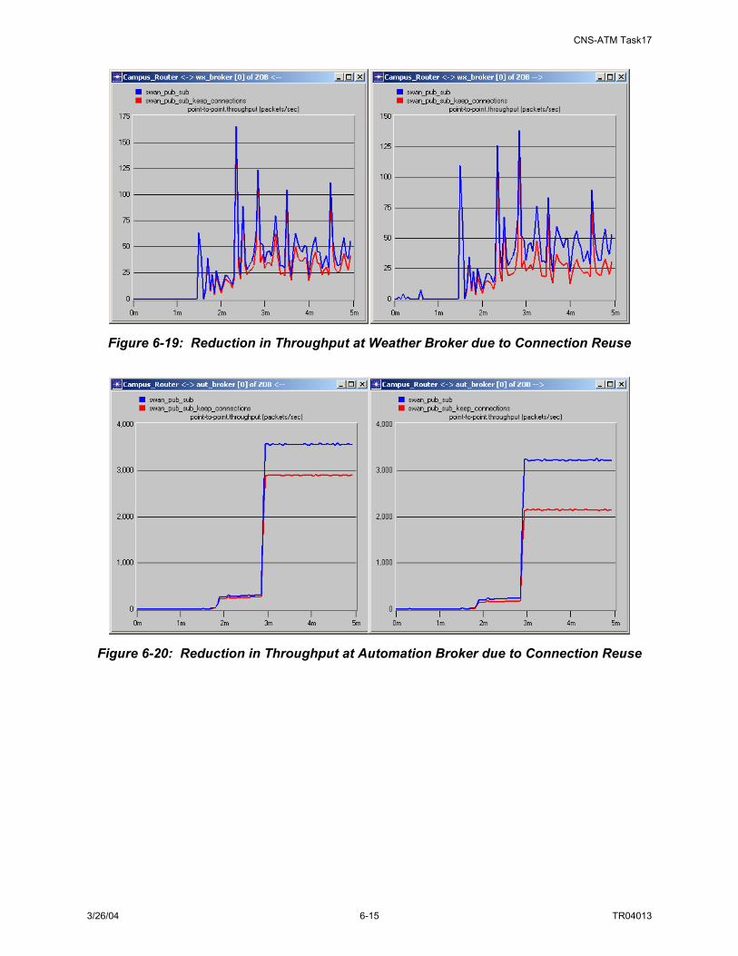
CNS-ATM Task17
3/26/04 6-15 TR04013
Figure 6-19: Reduction in Throughput at Weather Broker due to Connection Reuse
Figure 6-20: Reduction in Throughput at Automation Broker due to Connection Reuse

CNS-ATM Task17
3/26/04 6-16 TR04013
Figure 6-21: Reduction in TCP Delay due to Connection Reuse 6.3.6 Broker Functionality/Distribution Analysis Results Network simulation results indicate that the general SWIM architecture will meet the information management requirements as well as FAA service communication requirements. However, the following refinements to the architecture are recommended:
• Brokers should be located in “hub” facilities where traffic patterns converge, to minimize additional network resource load and propagation latency. Additional brokers should be considered if multiple hubs can be identified.
• Variants of the publish application to support real-time dissemination of periodic information should be employed as needed to meet FAA communication requirements (e.g., for surveillance information); however, the standard publish application should be employed when it will meet requirements to maximize the benefits of the broker architecture and to avoid unnecessary burden at servers.
• Publish applications should be developed to re-use TCP connections for frequently published information (e.g., inter-publish times < 60 seconds) to reduce network overhead traffic.
• Subscribe, register and query processes should employ TCP as the underlying transport protocol; publish processes should employ the transport protocol recommended for the information to be published (e.g., UDP for surveillance information and TCP for weather, automation, and navigation & landing services).

CNS-ATM Task17
3/26/04 6-17 TR04013
• Minimum content granularity should allow subscriptions to specify information type (e.g., weather) and sub-type (e.g., Weather 11), with filters for source of information (e.g., facility name and location).
These results, considered in conjunction with the broker processing scenario described and compared in Sections 5.3.3 and 5.3.4, lead to the conclusion that multiple broker processing patterns may be necessary. Specifically, it is anticipated that both Pub/Sub Brokers and Lightweight Brokers are suitable candidates for SWIM. If multiple broker functionality sets are supported, to ensure interoperability, common functionality (e.g. data monitoring, interface to SWIM Members) must be implemented in a coordinated manner. 6.4 REQUIRED COMMUNICATION CAPABILITY Part of the simulation effort assessed the potential benefits in network performance and resource usage efficiency offered by IP multicast capability (vs. unicast implementations). In the simulation, multicast traffic experienced some reductions in latency, shown by the red traces in Figure 6-22, compared to the scenario without multicast, represented by the blue traces. A significant cause of this reduction in latency is the reduction in TCP retransmissions, evidenced by the two blue points at ~1.6 seconds and ~2.8 seconds in Figure 6-22a). A key advantage of employing IP multicast with one-to-many traffic patterns is the reduction in resource utilization at routers and links upstream from the multicast rendezvous point, as shown in Figure 6-23 through Figure 6-25, with the most significant reductions at the automation broker. This is due to the nature of automation services, providing more one-to-many traffic demands suitable for IP multicast, shown in Figure 6-26. In the scenario simulated, this reduction in throughput due to IP multicast was sufficient to alleviate the congestion that caused TCP retransmissions in the non-multicast scenario.
a) Discrete Latency Comparison b) CDF Comparison
Figure 6-22: Comparison of Traffic Latencies with and without IP Multicast

CNS-ATM Task17
3/26/04 6-18 TR04013
Figure 6-23: Comparison of Throughput at Surveillance Broker
Figure 6-24: Comparison of Throughput at Weather Broker

CNS-ATM Task17
3/26/04 6-19 TR04013
Figure 6-25: Comparison of Throughput at Automation Broker
Figure 6-26: Surveillance, Weather and Automation Multicast Traffic An output of the simulation is the recommendation that IP multicast should be used where applicable to reduce the network load of replicated packets.

CNS-ATM Task17
3/26/04 6-20 TR04013

CNS-ATM Task17
3/26/04 7-1 TR04013
7. PHYSICAL ARCHITECTURE ALTERNATIVES
7.1 PHYSICAL ARCHITECTURE SOLUTION SPACE Section 5 presents an analysis of SWIM physical architecture design issues and tradeoffs. Interrelationships between these design issues are also discussed in Appendix G (as well as how they each affect the physical architecture in different ways). These design tradeoffs support the development of architecture alternatives, refinement of the physical architecture and the identification of implementation options. This section presents some alternative architecture solutions based on specific design decisions. Recall the interrelationships among SWIM design tradeoffs presented in Section 5.1 and repeated here in Figure 7-1.
Data GranularityData Granularity
Data Representation Design
RequiredBroker Functionality
Broker Distribution(Topology)
NetworkManagement
Options
Data StorageMethods
Interface IntegrationOptions
RequiredCommunication
Capability
ImplementationTechnology
Options
Higher Decision Making Priority Lower
Supports development of physical architecture alternatives (in Task 17)
Supports refinement of the physical architecture
1 2 3 4
Implementation Decision
Data GranularityData Granularity
Data Representation Design
RequiredBroker Functionality
Broker Distribution(Topology)
NetworkManagement
Options
Data StorageMethods
Interface IntegrationOptions
RequiredCommunication
Capability
ImplementationTechnology
Options
Higher Decision Making Priority Lower
Supports development of physical architecture alternatives (in Task 17)
Supports refinement of the physical architecture
1 2 3 4
Implementation Decision Figure 7-1: Design Options That Affect Architecture Alternatives
Candidate SWIM architectures have been derived from these sets of key tradeoffs. Table 7-1 lists three candidate SWIM Architecture alternatives and the corresponding design decisions.

CNS-ATM Task17
3/26/04 7-2 TR04013
Table 7-1: Three Candidate Architecture Alternatives Derived from Key Design Tradeoffs Broker Topology
ID Data
Representation Data
Granularity SWIM Broker
Concept Broker
Locations Broker
Connection
Data Storage
Method(s)
NM
Member Interface
Security
A Structural Metadata wrapped in Information Object, corresponding subscription language defined
Fine data granularity (Subject-based and or content-based subscription capability)
Pub/ Sub Broker
Local Hybrid Data Mart & Data Warehouse
SNMP User specified Common network and platform security
B Data classified per “channel” criteria, simple subscription rules for subscribers
Coarse data granularity (Channel-based/ subject-based subscription capability)
Lightweight Broker
Cross-Regional
Peer-to-Peer
Data Warehouse (as needed)
SNMP User specified Common network and platform security
C Structural Metadata wrapped in Information Object, corresponding subscription language defined
Fine data granularity (Subject-based and or content-based subscription capability)
VC Broker Regional Hierarchy Data Mart and Data Warehouse
SNMP User specified Common network and platform security
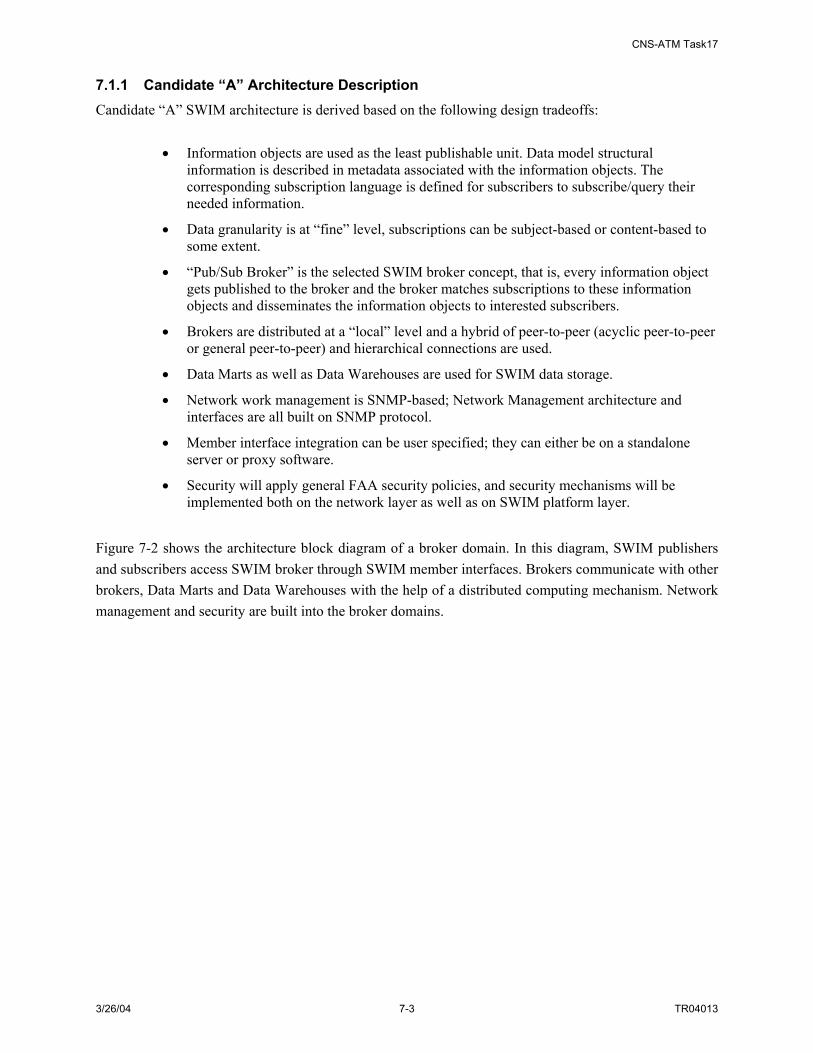
CNS-ATM Task17
3/26/04 7-3 TR04013
7.1.1 Candidate “A” Architecture Description Candidate “A” SWIM architecture is derived based on the following design tradeoffs:
• Information objects are used as the least publishable unit. Data model structural information is described in metadata associated with the information objects. The corresponding subscription language is defined for subscribers to subscribe/query their needed information.
• Data granularity is at “fine” level, subscriptions can be subject-based or content-based to some extent.
• “Pub/Sub Broker” is the selected SWIM broker concept, that is, every information object gets published to the broker and the broker matches subscriptions to these information objects and disseminates the information objects to interested subscribers.
• Brokers are distributed at a “local” level and a hybrid of peer-to-peer (acyclic peer-to-peer or general peer-to-peer) and hierarchical connections are used.
• Data Marts as well as Data Warehouses are used for SWIM data storage.
• Network work management is SNMP-based; Network Management architecture and interfaces are all built on SNMP protocol.
• Member interface integration can be user specified; they can either be on a standalone server or proxy software.
• Security will apply general FAA security policies, and security mechanisms will be implemented both on the network layer as well as on SWIM platform layer.
Figure 7-2 shows the architecture block diagram of a broker domain. In this diagram, SWIM publishers and subscribers access SWIM broker through SWIM member interfaces. Brokers communicate with other brokers, Data Marts and Data Warehouses with the help of a distributed computing mechanism. Network management and security are built into the broker domains.

CNS-ATM Task17
3/26/04 7-4 TR04013
BPub/Sub Broker
Data Mart
Distributed Computing
Network Management
SecurityPub/Sub Broker
Distributed communications and network infrastructure (in blue)
Member interface
Publ
ishe
rs
Subs
crib
ers
BPub/Sub Broker
Data Mart
Distributed Computing
Network Management
SecurityPub/Sub Broker
Distributed communications and network infrastructure (in blue)
Member interfaceMember interface
Publ
ishe
rs
Subs
crib
ers
Figure 7-2: Candidate “A” Broker Domain Block Diagram
For this candidate, the decision on broker topology is to have brokers distributed at local domains (e.g. TRACONs/AFSSs); therefore there are many brokers in one ARTCC region, as shown in Figure 7-3. Each square in the figure is a TRACON/AFSS domain, and each large circle represents an ARTCC region. (Note: The circled “B’s” in Figure 7-3 represent individual Pub/Sub Brokers, as depicted in Figure 7-2). The connections between these brokers are a hybrid of peer-to-peer and hierarchical distribution. The blue lines are the first-level broker hierarchy connection and the red lines are the second-level hierarchy connections. At each level of the hierarchy, there is a “master” broker that is responsible for the next level of communication.

CNS-ATM Task17
3/26/04 7-5 TR04013
Pub/Sub Broker / Local Broker Location / Hybrid Topology
BB
B BB
B
BB
B
B
B
BB
B
B
B
BB
B B
B
B
B
BB
B
B
B
BB
B B
B
BB
B
B
BB
B
B
BB
BB
B B BB
B B
B
BB
B
B
BB
B
B
BB
BB
B B
ARTCC Region
TRACON/AFSS
TRACON/AFSS
TRACON/AFSS
TRACON/AFSS
TRACON/AFSS
TRACON/AFSS
TRACON/AFSS
TRACON/AFSS
TRACON/AFSS
TRACON/AFSS
ARTCC Region
ARTCC Region
ARTCC Region
TRACON/AFSS TRACON/AFSS
TRACON/AFSS
TRACON/AFSS
TRACON/AFSS
TRACON/AFSS
TRACON/AFSS
Figure 7-3: Candidate “A” Broker Distribution 7.1.2 Candidate “B” Architecture Description Candidate “B” SWIM architecture is derived based on the following design tradeoffs:
• Data are classified based on the “channel” definition criteria. Information objects contain information of channel types. The subscription language defines simple rules for subscribers to subscribe to one or more particular channel or channels.
• Data granularity is at “coarse” level; subscriptions can be channel-based or subject-based.
• “Lightweight Broker” is the selected SWIM broker concept; publishers publish to different pre-defined “data channels;” subscribers get their data from desired data channels.
• Brokers are distributed at a “cross-regional” level; and peer-to-peer connections are used.
• Data Marts may be used for SWIM data archiving.
• Network Management is SNMP-based; Network Management architecture and interfaces are all built on SNMP protocol.
• Member interface integration can be user specified; they can either be based on a standalone server or via proxy software.
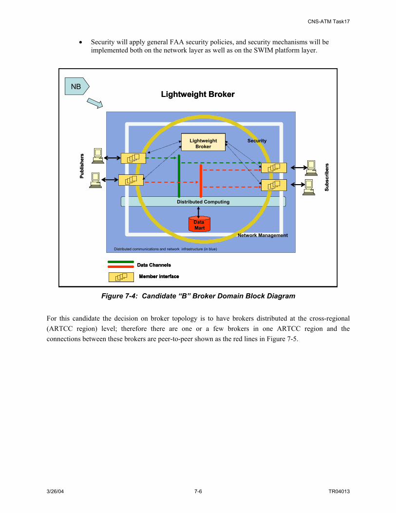
CNS-ATM Task17
3/26/04 7-6 TR04013
• Security will apply general FAA security policies, and security mechanisms will be implemented both on the network layer as well as on the SWIM platform layer.
Distributed Computing
Network Management
Security
Lightweight Broker
Data Channels
Member interface
NB
Distributed communications and network infrastructure (in blue)
Lightweight Broker
Data Mart
Publ
ishe
rs
Subs
crib
ers
Distributed Computing
Network Management
Security
Lightweight Broker
Data ChannelsData Channels
Member interfaceMember interface
NB
Distributed communications and network infrastructure (in blue)
Lightweight Broker
Data Mart
Publ
ishe
rs
Subs
crib
ers
Figure 7-4: Candidate “B” Broker Domain Block Diagram
For this candidate the decision on broker topology is to have brokers distributed at the cross-regional (ARTCC region) level; therefore there are one or a few brokers in one ARTCC region and the connections between these brokers are peer-to-peer shown as the red lines in Figure 7-5.

CNS-ATM Task17
3/26/04 7-7 TR04013
Lightweight Broker / Cross Regional Broker Location / Peer to Peer Topology
LB
LB
LB
LB
ARTCC Region
ARTCC Region
ARTCC Region
ARTCC Region
Lightweight Broker / Cross Regional Broker Location / Peer to Peer Topology
LB
LB
LB
LB
ARTCC Region
ARTCC Region
ARTCC Region
ARTCC Region
Figure 7-5: Candidate “B” Broker Distribution
7.1.3 Candidate “C” Architecture Description Candidate “C” SWIM architecture is derived based on the following design tradeoffs:
• Information objects are used as the least publishable unit. Data model structural information is described in metadata associated with the information objects. The corresponding subscription language is defined for subscribers to subscribe/query their needed information.
• Data granularity is at “fine” level; subscriptions can be subject-based or content-based to some extent.
• “VC Broker” is the selected SWIM broker concept; non-stream data and stream data are processed differently. Non-stream information objects get published to the VC Broker and the broker matches subscriptions to these information objects and disseminate the information objects to interested subscribers. Brokers also set up virtual circuits for publishing stream data to the interested subscribers.
• Brokers are distributed at a “regional” level and hierarchical connections are used.
• Data Marts (and possibly Data Warehouses) are used for SWIM data storage.
• Network Management is SNMP-based; Network Management architecture and interfaces are all built on SNMP protocol.
• Member interface integration can be user specified; they can either be based on a standalone server or proxy software.

CNS-ATM Task17
3/26/04 7-8 TR04013
• Security will apply general FAA security policies, and security mechanisms will be implemented both on network layer as well as on SWIM platform layer.
VCB VC Broker
DM
Distributed Computing
Network Management
SecurityVC Broker
Member interface
Distributed communications and network infrastructure (in blue)
Publ
ishe
rs
Subs
crib
ers
VCB VC Broker
DM
Distributed Computing
Network Management
SecurityVC Broker
Member interface
Distributed communications and network infrastructure (in blue)
DM
Distributed Computing
Network Management
SecurityVC Broker
Member interfaceMember interface
Distributed communications and network infrastructure (in blue)
Publ
ishe
rs
Subs
crib
ers
Figure 7-6: Candidate “C” Broker Domain Block Diagram
As the broker topology is to have brokers distributed on a regional domain basis, there are a few brokers in one region, as shown in Figure 7-7. Each square is a TRACON/AFSS domain, and each circle represents an ARTCC region. The connections between these brokers are hierarchical. The blue lines are the first-level broker hierarchy connections and the red lines are the second-level hierarchy connections. At each level of the hierarchy, there is a “master” broker that is responsible for next level of communications.

CNS-ATM Task17
3/26/04 7-9 TR04013
VC Broker / Regional Broker Location / Hierarchy Topology
VCB
ARTCC Region
ARTCC Region
TRACON/AFSS
TRACON/AFSS
TRACON/AFSS TRACON/AFSS
TRACON/AFSS
TRACON/AFSS
TRACON/AFSS
TRACON/AFSS
TRACON/AFSS
TRACON/AFSSTRACON/AFSS
TRACON/AFSS
TRACON/AFSS
TRACON/AFSS
TRACON/AFSS
VCB
VCB
VCB
VCB
VCB
VCB
VCB
VCB
VCB
VCB
VCB
VCB
VCBVCB
ARTCC Region
ARTCC Region
VCB
TRACON/AFSS
VC Broker / Regional Broker Location / Hierarchy Topology
VCB
ARTCC Region
ARTCC Region
TRACON/AFSSTRACON/AFSS
TRACON/AFSSTRACON/AFSS
TRACON/AFSSTRACON/AFSS TRACON/AFSSTRACON/AFSS
TRACON/AFSS
TRACON/AFSSTRACON/AFSS
TRACON/AFSSTRACON/AFSS
TRACON/AFSSTRACON/AFSS
TRACON/AFSSTRACON/AFSS
TRACON/AFSSTRACON/AFSSTRACON/AFSSTRACON/AFSS
TRACON/AFSS
TRACON/AFSSTRACON/AFSS
TRACON/AFSSTRACON/AFSS
TRACON/AFSSTRACON/AFSS
VCB
VCB
VCB
VCB
VCB
VCB
VCB
VCB
VCB
VCB
VCB
VCB
VCBVCB
ARTCC Region
ARTCC Region
VCB
TRACON/AFSS
Figure 7-7: Candidate “C” Broker Distribution 7.2 PHYSICAL ARCHITECTURE COMPARISONS To contrast the alternative physical architecture candidates, the following primary comparison criteria were identified. These included:
• Requirements compliance – how well does the architecture satisfy the NAS-level and function-level requirements of SWIM?
• Complexity – the implementation and management complexity of the architecture
• Availability of commercial solutions – how much of the architecture implementation can be supported by available COTS products and how much new development is needed?
• Risk – what are the risks associated with the architecture implementation, e.g., security-related risk, performance-related risk, and implementation-related risk?
• Schedule – Is the architecture too complex to be built to meet FAA schedules?
• Cost – What are the costs associated with each architecture alternative? What is the cost/benefit ratio for each architecture alternative?
The comparison of these architecture alternatives has been left for future work, and involves development and testing of engineering demonstration models.

CNS-ATM Task17
3/26/04 7-10 TR04013

CNS-ATM Task17
3/26/04 8-1 TR04013
8. TRANSITION
8.1 INTRODUCTION Transition is a term that can address a range of activities related to the development of and migration to a NAS system. In the NAS SEM, architecture and requirements development activities include functional analysis; requirements management; synthesis of design alternatives with functions and requirements; and performing specialty engineering and trade studies as appropriate. Migration activities would include completion of required FAA documentation: initial Requirements Document (iRD), Requirements Document (RD), and System Requirements Document (SRD)); simulation/trade-off analyses; security engineering to support development of the SCAP; Interface Control Document (ICD) development; and identification of performance requirements. At this stage in the development of SWIM, and in this study, both aspects of transition are addressed in some manner. In regard to development, capturing the scope of the development effort required for SWIM as well as comparison of development methodologies for SWIM have been addressed. For migration, three topics are addressed:
• On-going NAS activities and impact on SWIM migration
• General migration approach
• Example migration/evolution strategies for specific NAS service categories
These topics are addressed in the following subsections. 8.2 TRANSITION TO SWIM – DEVELOPMENT CONSIDERATIONS The SWIM information sharing concept includes support for automatic establishment of user connections; user search for and request of desired information; and dynamic adaptation to changes in information providers and users. The functions developed from these operating concepts have led to the identification of SWIM components that comprise the SWIM physical architecture. An overview of the hardware and software components associated with the SWIM architecture is illustrated in Figure 8-1 below.

CNS-ATM Task17
3/26/04 8-2 TR04013
NAS Computing Services
SWIM Member InterfaceServices
Operating SystemNetwork Interface(TCP/IP port, etc)
Hardware(CPU, Memory, I/O, etc)
NAS System
SWIM MemberInterfaceServices
SWIM InterfaceHardware
(CPU, Memory, I/O, etc)
NAS User
Local and/or Wide Area Network
NAS Computing Services
Operating SystemNetwork Interface(TCP/IP port, etc)
Hardware(CPU, Memory, I/O, etc)
NAS System
NAS User
Browser Application
Operating SystemNetwork Interface(TCP/IP port, etc)
Hardware(CPU, Memory, I/O, etc)
Computing SystemWith Standard
Browser
NAS User
SWIM BrokerServices
SWIM BrokerHardware
(CPU, Memory, I/O, etc)
SWIM Data ModelRegistry Services
SWIM Data ModelRegistry Hardware
(CPU, Memory, I/O, etc)
IOR MDR
NetworkMngmt
Interface
NetworkMngmt
Interface
NetworkMngmt
Services
SWIM Network ManagerHardware
(CPU, Memory, I/O, etc)
Network ManagementInterface Services
SWIM NetworkManagement
Interface Services
Hardware(CPU, Memory, I/O, etc)
NAS NetworkManagement System
OR
AND/OR
AND/OR
SWIM NetworkManagement System
SWIM WebServer ServicesSWIM Web Server
Hardware(CPU, Memory, I/O, etc)
NetworkMngmt
Interface
MEMBERINTERFACE
BROWSER
WEB SERVER
MDRIOR
BROKER
NETWORK MANAGER INTERFACE
SECURITY
NAS Component
SWIM Component
Key
NAS Component
SWIM Component
Key
NAS Computing Services
SWIM Member InterfaceServices
Operating SystemNetwork Interface(TCP/IP port, etc)
Hardware(CPU, Memory, I/O, etc)
NAS System
SWIM MemberInterfaceServices
SWIM InterfaceHardware
(CPU, Memory, I/O, etc)
NAS User
Local and/or Wide Area Network
NAS Computing Services
Operating SystemNetwork Interface(TCP/IP port, etc)
Hardware(CPU, Memory, I/O, etc)
NAS System
NAS User
Browser Application
Operating SystemNetwork Interface(TCP/IP port, etc)
Hardware(CPU, Memory, I/O, etc)
Computing SystemWith Standard
Browser
NAS User
SWIM BrokerServices
SWIM BrokerHardware
(CPU, Memory, I/O, etc)
SWIM Data ModelRegistry Services
SWIM Data ModelRegistry Hardware
(CPU, Memory, I/O, etc)
IORIOR MDR
NetworkMngmt
Interface
NetworkMngmt
Interface
NetworkMngmt
Services
SWIM Network ManagerHardware
(CPU, Memory, I/O, etc)
Network ManagementInterface Services
SWIM NetworkManagement
Interface Services
Hardware(CPU, Memory, I/O, etc)
NAS NetworkManagement System
OR
AND/OR
AND/OR
SWIM NetworkManagement System
SWIM WebServer ServicesSWIM Web Server
Hardware(CPU, Memory, I/O, etc)
NetworkMngmt
Interface
MEMBERINTERFACE
BROWSER
WEB SERVER
MDRIOR
BROKER
NETWORK MANAGER INTERFACE
SECURITY
NAS Component
SWIM Component
Key
NAS Component
SWIM Component
Key
Figure 8-1: SWIM Hardware and Software Physical Architecture Components
This figure illustrates the range of software applications that would implement SWIM functionality. Software development efforts are required to support the development of the SWIM interface, the SWIM broker, the SWIM metadata registries, and SWIM network management services. The SWIM applications identified in the diagram could be developed in one of several ways:
• COTS-based development method
• New development method
• COTS-product method
The methods above apply to the development of the “SWIM Member Interface Services” component in the figure and to the SWIM broker (i.e. “SWIM Broker Services”). This may include ‘middleware’ COTS products to streamline the development process (i.e. COTS-based development method). Middleware products facilitate the implementation of services providing a user interface to an information sharing infrastructure (i.e. the products have pre-developed applications to provide load balancing, scheduling, security services, etc). More information on middleware products is provided in Appendix C. The development methods identified above also could apply to the customization of software supporting database management (for the metadata registries and Information Object Repository, such as the “SWIM Data Model Registry Services”) and network management (i.e. “Network Management Services” and/or “Network Management Interface Services”).

CNS-ATM Task17
3/26/04 8-3 TR04013
The new development method is a scenario where the SWIM interface application, broker applications, metadata registries and/or network manager are completely customized and developed using COTS software tools (e.g. development environment for C++). And finally, the COTS-product method entails no development, but implements plug-and-play type applications. These might only be applicable to the SWIM interface functionality (e.g. provided by standard browser applications). These options for development of the SWIM applications have been compared based on the following factors:
• Ability to support of SWIM services
• Development Cost
• Development Time
• Risk
Results of the comparison are provided in Table 8-1.
Table 8-1: Comparison of Software Development Methods Development
Method Ability to Support SWIM Services Development
Cost Development
Time Risk COTS-based development
Fairly flexible; can be customized to meet most or all NAS services
Medium-High Medium Medium
New Development Most flexible; can be customized to meet most or all NAS services
Medium-High Medium-High High
COTS-product Least flexible; may be appropriate for only a subset of NAS services and may not be sufficient to implement a basic SWIM infrastructure
Low Low Low
Although the COTS-product method provides the lowest risk, cost and development time, this option is unable to support the range of functionality required to implement SWIM. Not all SWIM user interfaces will be able to be supported by standardized browser applications. Additionally, for SWIM broker applications, COTS products do not apply. The minimal level of customization and development for SWIM is significant. As a result, planning of the development process approach is warranted. 8.2.1 SWIM Development Process Approach A systems development life cycle model is one of a number of structured approaches to information system development, created to guide all the processes involved, from an initial feasibility study through maintenance of the completed application. Four candidate development models have been evaluated in this study. They include:
• Waterfall Model: the waterfall model describes a development method that is linear and sequential. Waterfall development has distinct goals for each phase of development. Once a phase of development is completed, the development proceeds to the next phase and there is no turning back.
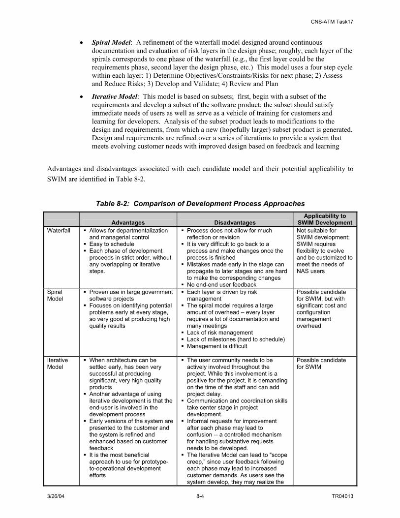
CNS-ATM Task17
3/26/04 8-4 TR04013
• Spiral Model: A refinement of the waterfall model designed around continuous documentation and evaluation of risk layers in the design phase; roughly, each layer of the spirals corresponds to one phase of the waterfall (e.g., the first layer could be the requirements phase, second layer the design phase, etc.) This model uses a four step cycle within each layer: 1) Determine Objectives/Constraints/Risks for next phase; 2) Assess and Reduce Risks; 3) Develop and Validate; 4) Review and Plan
• Iterative Model: This model is based on subsets; first, begin with a subset of the requirements and develop a subset of the software product; the subset should satisfy immediate needs of users as well as serve as a vehicle of training for customers and learning for developers. Analysis of the subset product leads to modifications to the design and requirements, from which a new (hopefully larger) subset product is generated. Design and requirements are refined over a series of iterations to provide a system that meets evolving customer needs with improved design based on feedback and learning
Advantages and disadvantages associated with each candidate model and their potential applicability to SWIM are identified in Table 8-2.
Table 8-2: Comparison of Development Process Approaches
Advantages Disadvantages Applicability to
SWIM Development Waterfall Allows for departmentalization
and managerial control Easy to schedule Each phase of development proceeds in strict order, without any overlapping or iterative steps.
Process does not allow for much reflection or revision
It is very difficult to go back to a process and make changes once the process is finished
Mistakes made early in the stage can propagate to later stages and are hard to make the corresponding changes
No end-end user feedback
Not suitable for SWIM development; SWIM requires flexibility to evolve and be customized to meet the needs of NAS users
Spiral Model
Proven use in large government software projects
Focuses on identifying potential problems early at every stage, so very good at producing high quality results
Each layer is driven by risk management
The spiral model requires a large amount of overhead – every layer requires a lot of documentation and many meetings
Lack of risk management Lack of milestones (hard to schedule) Management is difficult
Possible candidate for SWIM, but with significant cost and configuration management overhead
Iterative Model
When architecture can be settled early, has been very successful at producing significant, very high quality products
Another advantage of using iterative development is that the end-user is involved in the development process
Early versions of the system are presented to the customer and the system is refined and enhanced based on customer feedback
It is the most beneficial approach to use for prototype-to-operational development efforts
The user community needs to be actively involved throughout the project. While this involvement is a positive for the project, it is demanding on the time of the staff and can add project delay.
Communication and coordination skills take center stage in project development.
Informal requests for improvement after each phase may lead to confusion -- a controlled mechanism for handling substantive requests needs to be developed.
The Iterative Model can lead to "scope creep," since user feedback following each phase may lead to increased customer demands. As users see the system develop, they may realize the
Possible candidate for SWIM

CNS-ATM Task17
3/26/04 8-5 TR04013
Advantages Disadvantages Applicability to
SWIM Development potential of other system capabilities which would enhance their work.
8.2.2 Activities Associated with SWIM Development Four activities have been identified to capture the major transition activities associated with SWIM development. These include:
• FAA Policy Making: activities are associated with the FAA Acquisition Management System milestones (including required FAA documentation)
• System Analysis: analysis activities that are needed to understand the current FAA/NAS system elements and their interrelationships (in terms of communication links, communication protocols and transferred data traffic). An initial requirements document will be produced based on the understanding of the current system and the SWIM Operation concepts; then architecture design and security assurance plans are needed for the future development; finally, supporting technologies need to be studied to estimate development effort and cost. System configuration and implementation plans should be generated first as part of the system analysis activities.
• Prototype Development: supports proof-of-concept evaluation. Currently the FAA intends to have a prototype SWIM model. A minimum SWIM model needs to address basic SWIM services including publish, subscriber, broker requests, etc. One or more FAA existing systems can be selected as the SWIM members that can exchange information through the SWIM model; test and evaluations may be carried out when the prototype model is complete
• SWIM Development and Validation: With positive evaluation and user feedback of the prototype SWIM model, SWIM development and validation activities can begin. Data standardization; system & interface design and development; and system integration and testing activities will be required. Once the SWIM system development is complete, FAA/NAS can begin migration to new SWIM services.
A more detailed overview of SWIM software development transition activities is provided in Figure 8-2.

CNS-ATM Task17
3/26/04 8-6 TR04013
SWIM Software Development Transition Activities
FAA Policy Making System Analysis Prototype DevelopmentSWIM Development
and Validation
Mission Statement
Union or Agreements
Resource Requirements
Investment Analysis
Schedule
Risk/Cost Assessment
Initial Requirements Document(Technical, operational, facility)
Legacy System Interdependencies And Interface Analysis
SWIM Operations Concept
Architecture Design Analysis
Security Assurance Plan
Technology Roadmap
Minimum Common Data Model Standardization
and Management
Core SWIM Prototype SystemDesign
Core SWIM Member Interface Design
Prototype Application Integration & Demo
Testing and Evaluation
Data Standardization andManagement
SWIM Interface Control Documentation
Security MechanismImplementation
SWIM Detail Architecture Design
Interface Development and Integration
System Integration
Acquisition/TransitionStrategy
Configuration Management Plan
System ImplementationManagement Plan
FAA Acceptance Testing
FAA Service Transition
Core SWIM Prototype SystemDevelopment
Core SWIM Member Interface Development
Core SWIM Member Interface Document
SWIM Platform Development
Figure 8-2: Overview of SWIM Software Development Transition Activities
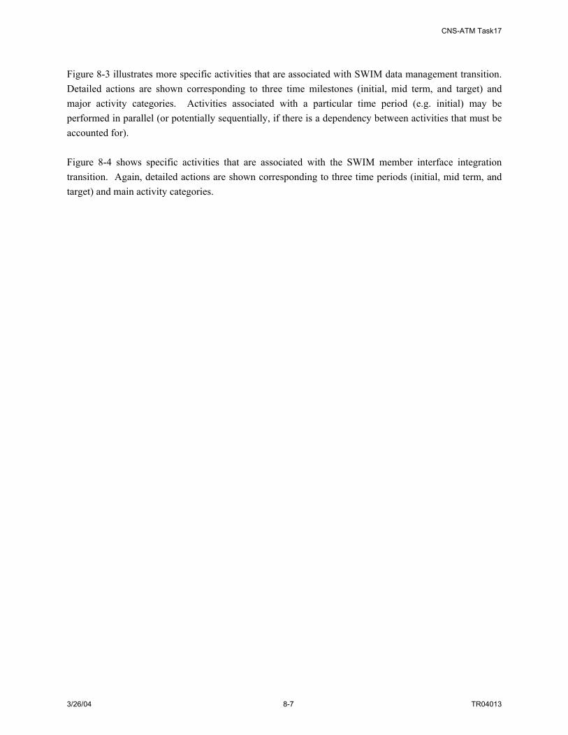
CNS-ATM Task17
3/26/04 8-7 TR04013
Figure 8-3 illustrates more specific activities that are associated with SWIM data management transition. Detailed actions are shown corresponding to three time milestones (initial, mid term, and target) and major activity categories. Activities associated with a particular time period (e.g. initial) may be performed in parallel (or potentially sequentially, if there is a dependency between activities that must be accounted for). Figure 8-4 shows specific activities that are associated with the SWIM member interface integration transition. Again, detailed actions are shown corresponding to three time periods (initial, mid term, and target) and main activity categories.

CNS-ATM Task17
3/26/04 8-8 TR04013
Make Data Management Policy
Standardize NAS Data
Define Common Data Model(Structural)
Define Common Data Model(Descriptive & Admin)
Define MDR/IOR Management
and Security Control
Define Meta Data Schema and Information Object for
Common Data Model
Build MDR (Metadata Registry
Build IOR (Information Object Repository)
Establish NAS wide SWIM data management committee and assign roles, review current NAS data structures
Establish NAS wide SWIM data management committee and assign roles, review current NAS data structures
Review NAS data flow activities, coordinate and develop NAS data standards (may be partial to specific domains)
Review NAS data flow activities, coordinate and develop NAS data standards (may be partial to specific domains)
Coordinate NAS wide data structure and define common data model for a specific domain
Coordinate NAS wide data structure and define common data model for a specific domain
Decide what descriptive and admin information is needed for SWIM common data model (start from a specific information domain)
Decide what descriptive and admin information is needed for SWIM common data model (start from a specific information domain)
Define MDR and IOR management rules Define security control (partial)
Define base information object, define various information objects for a specific information domain.Define associated meta data schemas
Define base information object, define various information objects for a specific information domain.Define associated meta data schemas
Build/implement MDR (partial)
Build/implement IOR (partial)
Set up policy and assign responsibility for policy enforcementSet up policy and assign responsibility for policy enforcement
Incrementally develop NAS standards among all information domainsIncrementally develop NAS standards among all information domains
Coordinate NAS wide data structure and define common data model for more information domains
Coordinate NAS wide data structure and define common data model for more information domains
Define descriptive and admin information is needed for SWIM common data model (more information domains)
Define descriptive and admin information is needed for SWIM common data model (more information domains)
Define security control (partial)Define security control (partial)
Define information objects for more information domains, define associated meta data schemas
Define information objects for more information domains, define associated meta data schemas
Build/implement MDR (partial)
Build/implement IOR (partial)
Finish developing NAS standards in all information domains, open to future data standardization
Finish developing NAS standards in all information domains, open to future data standardization
Coordinate NAS wide data structure and finish defining common data model for all NAS information domains
Define all descriptive and admin information for SWIM common data model (all information domains)
Define all descriptive and admin information for SWIM common data model (all information domains)
Define security control (complete)
Finish all information objects definitions. Define a full SWIM meta data schema
Build/implement MDR (complete)
Build/implement IOR (complete)
Timeline
Main Activity Category
Data Management Transition Activities
Initial Mid Term Target Figure 8-3: Overview of SWIM Data Management Transition Activities
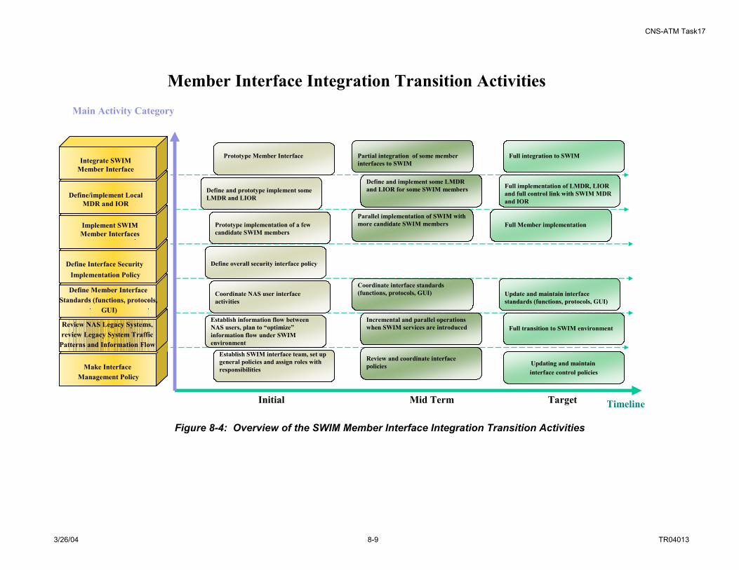
CNS-ATM Task17
3/26/04 8-9 TR04013
Make Interface Management Policy
Review NAS Legacy Systems,review Legacy System Traffic
Patterns and Information Flow
Define Member Interface Standards (functions, protocols,
GUI)
Define Interface SecurityImplementation Policy
Implement SWIM Member Interfaces
Define/implement Local MDR and IOR
Integrate SWIM Member Interface
Establish SWIM interface team, set up general policies and assign roles with responsibilities
Establish SWIM interface team, set up general policies and assign roles with responsibilities
Establish information flow between NAS users, plan to “optimize” information flow under SWIM environment
Establish information flow between NAS users, plan to “optimize” information flow under SWIM environment
Coordinate NAS user interface activities
Define overall security interface policy
Prototype implementation of a few candidate SWIM members
Define and prototype implement some LMDR and LIOR
Prototype Member Interface
Review and coordinate interface policies
Incremental and parallel operations when SWIM services are introducedIncremental and parallel operations when SWIM services are introduced
Coordinate interface standards (functions, protocols, GUI)Coordinate interface standards (functions, protocols, GUI)
Parallel implementation of SWIM with more candidate SWIM membersParallel implementation of SWIM with more candidate SWIM members
Define and implement some LMDR and LIOR for some SWIM membersDefine and implement some LMDR and LIOR for some SWIM members
Partial integration of some member interfaces to SWIM
Full transition to SWIM environment
Update and maintain interface standards (functions, protocols, GUI)
Full Member implementation
Full implementation of LMDR, LIOR and full control link with SWIM MDR and IOR
Full integration to SWIM
Timeline
Member Interface Integration Transition Activities
Updating and maintain interface control policies
Main Activity Category
Initial Mid Term Target
Figure 8-4: Overview of the SWIM Member Interface Integration Transition Activities
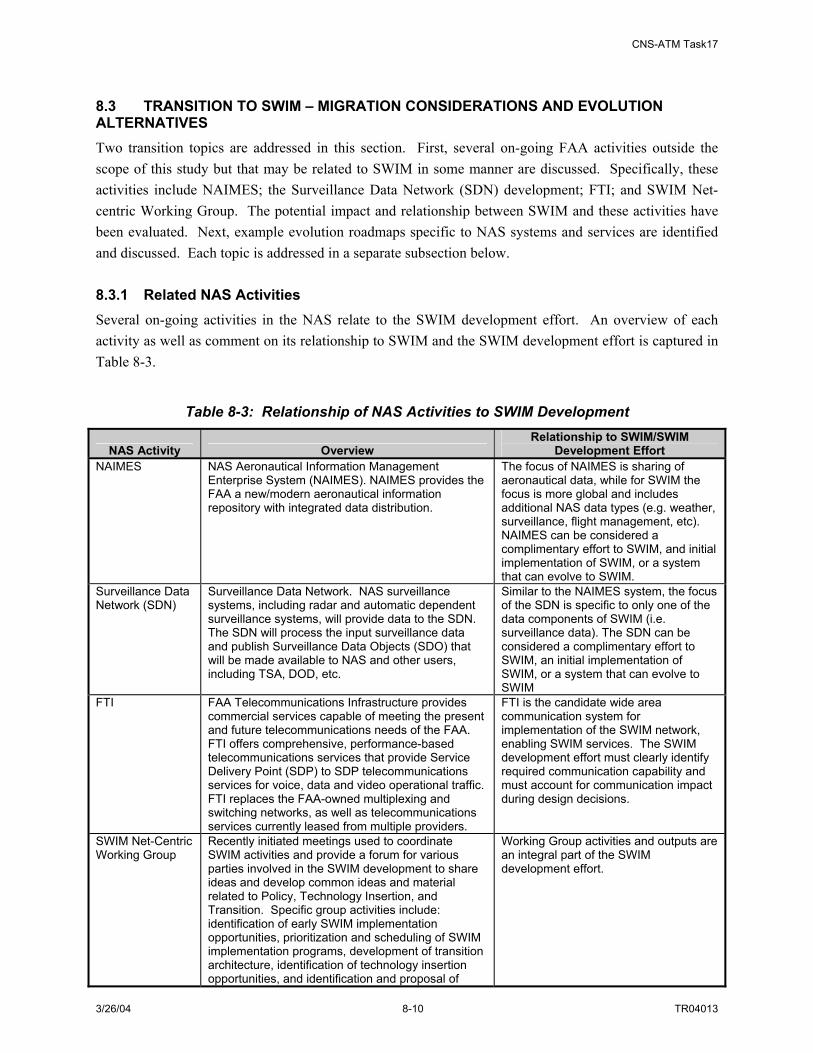
CNS-ATM Task17
3/26/04 8-10 TR04013
8.3 TRANSITION TO SWIM – MIGRATION CONSIDERATIONS AND EVOLUTION ALTERNATIVES Two transition topics are addressed in this section. First, several on-going FAA activities outside the scope of this study but that may be related to SWIM in some manner are discussed. Specifically, these activities include NAIMES; the Surveillance Data Network (SDN) development; FTI; and SWIM Net-centric Working Group. The potential impact and relationship between SWIM and these activities have been evaluated. Next, example evolution roadmaps specific to NAS systems and services are identified and discussed. Each topic is addressed in a separate subsection below. 8.3.1 Related NAS Activities Several on-going activities in the NAS relate to the SWIM development effort. An overview of each activity as well as comment on its relationship to SWIM and the SWIM development effort is captured in Table 8-3.
Table 8-3: Relationship of NAS Activities to SWIM Development
NAS Activity Overview Relationship to SWIM/SWIM
Development Effort NAIMES NAS Aeronautical Information Management
Enterprise System (NAIMES). NAIMES provides the FAA a new/modern aeronautical information repository with integrated data distribution.
The focus of NAIMES is sharing of aeronautical data, while for SWIM the focus is more global and includes additional NAS data types (e.g. weather, surveillance, flight management, etc). NAIMES can be considered a complimentary effort to SWIM, and initial implementation of SWIM, or a system that can evolve to SWIM.
Surveillance Data Network (SDN)
Surveillance Data Network. NAS surveillance systems, including radar and automatic dependent surveillance systems, will provide data to the SDN. The SDN will process the input surveillance data and publish Surveillance Data Objects (SDO) that will be made available to NAS and other users, including TSA, DOD, etc.
Similar to the NAIMES system, the focus of the SDN is specific to only one of the data components of SWIM (i.e. surveillance data). The SDN can be considered a complimentary effort to SWIM, an initial implementation of SWIM, or a system that can evolve to SWIM
FTI FAA Telecommunications Infrastructure provides commercial services capable of meeting the present and future telecommunications needs of the FAA. FTI offers comprehensive, performance-based telecommunications services that provide Service Delivery Point (SDP) to SDP telecommunications services for voice, data and video operational traffic. FTI replaces the FAA-owned multiplexing and switching networks, as well as telecommunications services currently leased from multiple providers.
FTI is the candidate wide area communication system for implementation of the SWIM network, enabling SWIM services. The SWIM development effort must clearly identify required communication capability and must account for communication impact during design decisions.
SWIM Net-Centric Working Group
Recently initiated meetings used to coordinate SWIM activities and provide a forum for various parties involved in the SWIM development to share ideas and develop common ideas and material related to Policy, Technology Insertion, and Transition. Specific group activities include: identification of early SWIM implementation opportunities, prioritization and scheduling of SWIM implementation programs, development of transition architecture, identification of technology insertion opportunities, and identification and proposal of
Working Group activities and outputs are an integral part of the SWIM development effort.

CNS-ATM Task17
3/26/04 8-11 TR04013
NAS Activity Overview Relationship to SWIM/SWIM
Development Effort SWIM services.
8.3.2 SWIM Evolution Roadmaps Section 8.2.2 above captured the range of software and hardware development associated with the SWIM physical architecture. Of particular interest to the topic of migration to SWIM in the NAS is the Member Interface functionality. It is this function that accommodates the interaction of both NAS systems and users with SWIM. Figure 8-5 recaps the interface options.
NAS Computing Services
SWIM InterfaceInfrastructure
Operating System
Network Interface(TCP/IP port, etc)
Hardware(CPU, Memory, I/O, etc)
NAS System
NAS Computing Services
SWIM InterfaceInfrastructure
Services
Operating System
Network Interface(TCP/IP port, etc)
Hardware(CPU, Memory, I/O, etc)
NAS System
SWIM InterfaceHardware
(CPU, Memory, I/O, etc)
NAS User NAS User
BrowserApplication
Operating System
Network Interface(TCP/IP port, etc)
Hardware(CPU, Memory, I/O, etc)
Computing SystemWith Standard
Browser
NAS User
SWIM Wide Area Network
Figure 8-5: SWIM Member Interface Options In the figure above, the SWIM interface is shown in three ways. First, on the far left, the SWIM interface infrastructure is shown as application software that resides within NAS system. In the middle, the SWIM interface is the interface application software that is implemented on a separate hardware system that interfaces with the NAS system. And finally on the right, the SWIM interface is a standard browser application (e.g. web browser). Based on the information in Table 8-1, a combination of options for development of the SWIM interface are recommended for SWIM. Specifically, COTS-based development for developing interface applications that reside either within NAS systems or on a separate gateway systems (i.e. separate hardware) and COTS-product (i.e. browser) to support SWIM services where browser interface technologies can be supported and are an appropriate interface to information.

CNS-ATM Task17
3/26/04 8-12 TR04013
Developing evolution plans requires consideration and comparison of the interface options shown in Figure 8-5 for different NAS systems, NAS facilities, and NAS data. For this study, NAS systems and data (or NAS information services) are addressed in five categories, namely:
• Surveillance
• Weather
• Flight Management
• Aeronautical
• Resource Management
Table 8-4 compares the applicability of the three interface options for each category of NAS systems/data.
Table 8-4: Comparison of SWIM Interface Opportunities by NAS System/Data Domain
NAS System/Data
Category Sample NAS
Systems Sample Data
Applicability of Integrated SWIM
Interface Application
Applicability of Standalone
SWIM Interface (HW & S/W)
Applicability of SWIM browser
Interface Surveillance ASR-9/11;
ARSR-4/5; Mode S; STARS; ARTS; Common-ARTS; HCS
Target Reports, Beacon Reports
May be difficult to integrate S/W interface into existing NAS sensors (especially older sensors); Might be applicable for surveillance processing systems (e.g. STARS, HCS)
Appropriate for interface to sensors; can be used to interface to processing systems during evolution to SWIM
Likely not applicable. Surveillance service users (e.g. controllers, TM specialists) interface to data via custom display applications (not via standard computers with browsers)
Weather ASOS/AWOS; NEXRAD; TDWR; LLWAS; ADAS; ITWS; WARP; FBWTG; AWP; OASIS
Raw Wx observations; Wx forecasts; Wx products (text and graphical)
May be difficult to integrate S/W interface into existing NAS sensors (especially older sensors); Might be applicable to Wx processing systems (e.g. ITWS, WARP) and FBWTG
Appropriate for interface to sensors; can be used to interface to processing systems during evolution to SWIM
May be applicable to certain user populations (e.g. pilots, FOCs)
Flight Management
ETMS; HCS; ARTS; Common-ARTS; STARS; FSDPS; AIS; FDIO; CDM-Net
Flight Plans; Flight Objects (future); Traffic Advisories; Flow Restrictions
May be difficult to integrate S/W interface into older legacy systems; Might be applicable to some processors (e.g. ETMS, STARS, HCS)
Appropriate to interface to older legacy systems and to other NAS systems during evolution to SWIM
Likely not applicable for most users. Flight Management service users (e.g. TM specialists) interface to data via custom display applications (not via standard computers with browsers); May be appropriate for AIS applications
CNS-ATM Task17
3/26/04 8-13 TR04013
NAS System/Data
Category Sample NAS
Systems Sample Data
Applicability of Integrated SWIM
Interface Application
Applicability of Standalone
SWIM Interface (HW & S/W)
Applicability of SWIM browser
Interface Aeronautical NOTAMS DB;
NASR DB NOTAMS Could be used to
implement the interface to aeronautical databases
May not be necessary for these services
May be appropriate for most users; migrate current Specialist display systems to browsers; support pilot/FOC browsers and current internet applications;
Resource Management
NIMS; MPS; MTD
Status messages; Control messages
Could be used to provide interface to NIMS systems; May not be appropriate to interface to older legacy NAS maintenance & monitoring systems
Appropriate to interface to older legacy systems and to other NAS systems during evolution to SWIM
May be appropriate to support remote maintenance interface to specialists (future)
An important transition issue relates to the need to recognize that responsibilities associated with implementing the SWIM interface lie both with the Legacy NAS systems and the SWIM member interface. Table 8-5 and Table 8-6 show the responsibilities of each side.
Table 8-5 Integrate SWIM Interface Application – Legacy NAS System Responsibility Legacy NAS System Responsibilities
Interface Attribute
Legacy System as a Data Publisher
Legacy System as a Data Subscriber
Legacy System as a Publisher and a
Subscriber
Data Provides data to be published to Member Interface
Receives subscribed/queried data from Member Interface
Provides data to be published to Member Interface; receives subscribed/queried data from Member Interface
Data format No format conversion (Member Interface provides the data conversion)
No format conversion (Member Interface provides the data conversion)
No format conversion (Member Interface provides the data conversion)
Configuration Needs to include Member Interface as part of the system configuration
Needs to include Member Interface as part of the system configuration
Needs to include Member Interface as part of the system configuration
Control/Status
Provides Legacy control/status message (regarding to be published data) to SWIM. The messages are translated and sent by Member Interface
Receives SWIM status message (regarding subscribed data). The messages are translated by Member Interface.
Provides Legacy control/status message (regarding to be published data) to SWIM and receives SWIM status message (regarding subscribed data). The messages are translated by Member Interface.
Application Console/Interface
Provides console set up to schedule automatic data publishing service; as well as (optionally) provides application console/interface if data is desired to be manually published.
Provides application console/interface for users to subscribe or query SWIM data.
Provides console set up to schedule automatic data publishing service; as well as (optionally) provides application console/interface if data is desired to be manually published. Provides application console/interface for users to
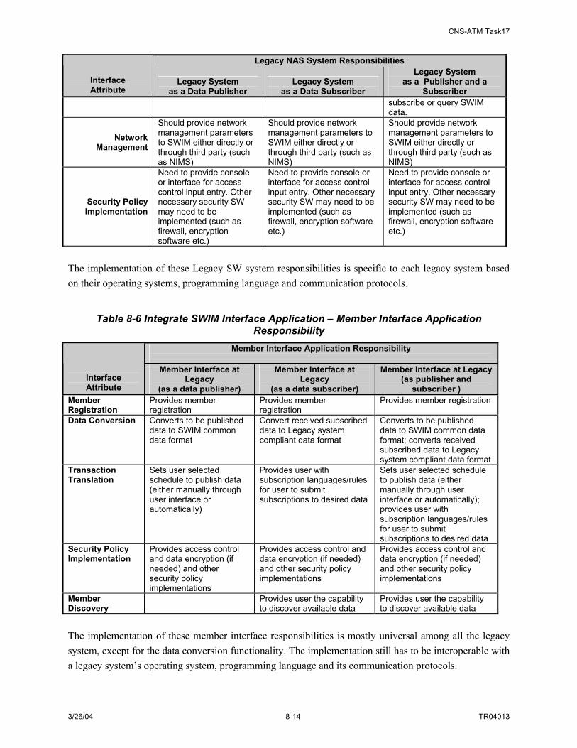
CNS-ATM Task17
3/26/04 8-14 TR04013
Legacy NAS System Responsibilities
Interface Attribute
Legacy System as a Data Publisher
Legacy System as a Data Subscriber
Legacy System as a Publisher and a
Subscriber subscribe or query SWIM data.
Network Management
Should provide network management parameters to SWIM either directly or through third party (such as NIMS)
Should provide network management parameters to SWIM either directly or through third party (such as NIMS)
Should provide network management parameters to SWIM either directly or through third party (such as NIMS)
Security Policy Implementation
Need to provide console or interface for access control input entry. Other necessary security SW may need to be implemented (such as firewall, encryption software etc.)
Need to provide console or interface for access control input entry. Other necessary security SW may need to be implemented (such as firewall, encryption software etc.)
Need to provide console or interface for access control input entry. Other necessary security SW may need to be implemented (such as firewall, encryption software etc.)
The implementation of these Legacy SW system responsibilities is specific to each legacy system based on their operating systems, programming language and communication protocols.
Table 8-6 Integrate SWIM Interface Application – Member Interface Application Responsibility
Member Interface Application Responsibility
Interface Attribute
Member Interface at Legacy
(as a data publisher)
Member Interface at Legacy
(as a data subscriber)
Member Interface at Legacy (as publisher and
subscriber ) Member Registration
Provides member registration
Provides member registration
Provides member registration
Data Conversion Converts to be published data to SWIM common data format
Convert received subscribed data to Legacy system compliant data format
Converts to be published data to SWIM common data format; converts received subscribed data to Legacy system compliant data format
Transaction Translation
Sets user selected schedule to publish data (either manually through user interface or automatically)
Provides user with subscription languages/rules for user to submit subscriptions to desired data
Sets user selected schedule to publish data (either manually through user interface or automatically); provides user with subscription languages/rules for user to submit subscriptions to desired data
Security Policy Implementation
Provides access control and data encryption (if needed) and other security policy implementations
Provides access control and data encryption (if needed) and other security policy implementations
Provides access control and data encryption (if needed) and other security policy implementations
Member Discovery
Provides user the capability to discover available data
Provides user the capability to discover available data
The implementation of these member interface responsibilities is mostly universal among all the legacy system, except for the data conversion functionality. The implementation still has to be interoperable with a legacy system’s operating system, programming language and its communication protocols.

CNS-ATM Task17
3/26/04 8-15 TR04013
In addition to the comparison of interface options specific to NAS systems and services, material in Appendix G also compares the interface options based on cost, schedule, and complexity. As a result of these comparisons, it seems likely that a combination of the interface types will exist in the NAS both during evolution to SWIM as well as in the target state for SWIM. To examine evolution roadmaps for SWIM for certain sets of NAS systems and services in more detail, example initial and target architecture diagrams have been developed (where the target architectures align with the NAS Target System Description). These diagrams focus on the user-interface to SWIM and not on the information, service and communication management aspects of SWIM. Architecture trade-offs that are more specifically related to location of SWIM management components (e.g. SWIM brokers) have been addressed in Section 5. 8.3.2.1 Example Surveillance Architectures The current architecture for surveillance services in the NAS, shown in Figure 8-6, is included to allow for easy comparisons to future SWIM implementations. In this figure, primary surveillance radars (PSRs) and secondary surveillance radars (SSRs) connect via these modems to the HCS, STARS or ARTS automation applications and their interfaces. These systems send surveillance data through gateways via leased lines to other non-FAA government facilities. Note that the shaded arrow points to the data link of primary interest. Surveillance data processed by surveillance processing systems (such as the HCS and STARS) support connections to NAS traffic management systems, via inter-facility data communication connections. For clarity, only the connection between air traffic control centers and the surveillance generating facilities are shown.

CNS-ATM Task17
3/26/04 8-16 TR04013
PSR/SSR
SensorSensor ModemModem ModemModem
HCS/STARS/ARTS/C-ARTS
Automation & Interface
HCS/STARS/ARTS/C-ARTS
Automation & Interface
ARTCC/TRACON(sensor interface facility)
PSR/SSR
SensorSensor ModemModem ModemModem
ARTCC/TRACON(remote facility)
HCS/STARS/ARTSAutomation &
Interface
HCS/STARS/ARTSAutomation &
Interface
Non-FAAGovernment Users
Non-FAAGovernment Users
SS ModemModem
SS ModemModem
ModemModem
ModemModem
ModemModem
ModemModem
PSR – Primary Surveillance RadarSSR – Secondary Surveillance RadarHCS – Host Computer SystemSTARS – Standard Terminal Automation Replacement SystemARTS – Automated Radar Terminal SystemC-ARTS – Common-ARTSS - Splitter
PSR/SSR
SensorSensor ModemModem ModemModem
HCS/STARS/ARTS/C-ARTS
Automation & Interface
HCS/STARS/ARTS/C-ARTS
Automation & Interface
ARTCC/TRACON(sensor interface facility)
PSR/SSR
SensorSensor ModemModem ModemModem
ARTCC/TRACON(remote facility)
HCS/STARS/ARTSAutomation &
Interface
HCS/STARS/ARTSAutomation &
Interface
Non-FAAGovernment Users
Non-FAAGovernment Users
SS ModemModem
SS ModemModem
ModemModem
ModemModem
ModemModem
ModemModem
PSR – Primary Surveillance RadarSSR – Secondary Surveillance RadarHCS – Host Computer SystemSTARS – Standard Terminal Automation Replacement SystemARTS – Automated Radar Terminal SystemC-ARTS – Common-ARTSS - Splitter
Figure 8-6: Current Surveillance Information Sharing in the NAS
As stated in Section 8.3.1 above, activity is already underway in developing a flexible information sharing strategy for NAS surveillance services (i.e. the SDN). The example transition stage architecture provided here is complementary to the SDN architectures that have been produced by NAS surveillance planners. Figure 8-7 illustrates a possible initial architecture for surveillance services in the SWIM environment. In this architecture, both legacy analog radars and modern digital radars are connected through modems to the automation facilities (i.e. maintaining current connectivity). At the control site, the surveillance information is interfaced to SWIM via the SWIM Member Interface. NAS surveillance processing automation applications maintain their existing direct connections to sensors, but are also able to access additional surveillance data and/or aggregated data via a new SWIM Member Interface. The figure also includes a SWIM Member Interface to NAS traffic management systems. As needed, these traffic management systems may access surveillance data directly from SWIM (in lieu of point-to-point inter-facility data connections between surveillance processing systems and traffic management systems).

CNS-ATM Task17
3/26/04 8-17 TR04013
PSR/SSR
SensorSensor ModemModem ModemModem
HCS/STARS/ARTS/C-ARTS
Automation & Interface
HCS/STARS/ARTS/C-ARTS
Automation & Interface
ARTCC/TRACON(sensor interface facility)
PSR/SSR
SensorSensor ModemModem ModemModem
IP Communication Network (FIRMNet/FTI)
Surveillance Data Manager (SDM)
ARTCC/TRACON(remote facility)
Legacy DataConnection
SWIM Data Connection
ATCSCC(remote facility)
HCS/STARS/ARTS/C-ARTS
Automation & Interface
HCS/STARS/ARTS/C-ARTS
Automation & Interface
TrafficManagement
Computer
TrafficManagement
Computer
SWIM
SWIM Surveillance
Broker
Member Interface
Surveillance Data Packaging
Surveillance Data Packaging
Surveillance Data Conversion/Packaging
Surveillance Data Conversion/Packaging
SDM - creates/provides SDOs (Surveillance Data Objects) with trajectories of aircraft using the best information selected from combinedsurveillance data
Member Interface
Member Interface
Member Interface
Member Interface Member
Interface
PSR – Primary Surveillance RadarSSR – Secondary Surveillance RadarHCS – Host Computer SystemSTARS – Standard Terminal Automation Replacement SystemARTS – Automated Radar Terminal SystemC-ARTS – Common ARTSS - Splitter
SS
SS
PSR/SSR
SensorSensor ModemModem ModemModem
HCS/STARS/ARTS/C-ARTS
Automation & Interface
HCS/STARS/ARTS/C-ARTS
Automation & Interface
ARTCC/TRACON(sensor interface facility)
PSR/SSR
SensorSensor ModemModem ModemModem
IP Communication Network (FIRMNet/FTI)
Surveillance Data Manager (SDM)
ARTCC/TRACON(remote facility)
Legacy DataConnection
SWIM Data Connection
ATCSCC(remote facility)
HCS/STARS/ARTS/C-ARTS
Automation & Interface
HCS/STARS/ARTS/C-ARTS
Automation & Interface
TrafficManagement
Computer
TrafficManagement
Computer
SWIM
SWIM Surveillance
Broker
Member Interface
Surveillance Data Packaging
Surveillance Data Packaging
Surveillance Data Conversion/Packaging
Surveillance Data Conversion/Packaging
SDM - creates/provides SDOs (Surveillance Data Objects) with trajectories of aircraft using the best information selected from combinedsurveillance data
Member Interface
Member Interface
Member Interface
Member Interface Member
Interface
PSR – Primary Surveillance RadarSSR – Secondary Surveillance RadarHCS – Host Computer SystemSTARS – Standard Terminal Automation Replacement SystemARTS – Automated Radar Terminal SystemC-ARTS – Common ARTSS - Splitter
SS
SS
Figure 8-7: Example Initial SWIM Surveillance Architecture
In the initial architecture above, legacy data connections continue between surveillance sensors and the control centers to which they currently interface. The interface to SWIM is independent of the current legacy connections. New standalone hardware and software components implement the interface of sensor data and processing systems to SWIM. Table 8-7 presents options available for adding new SWIM member interface components to various legacy NAS systems for the three types of “SWIM Member Interfaces” in the initial surveillance architecture.
Table 8-7: SWIM Interface Options for NAS Surveillance Systems Legacy Interface
Surveillance Information Type
Associated Legacy NAS System(s)
Interface Location Options
Interface Description
(physical/data) Comment Modem Output EIA-449 phys or EIA-
530 or EIA 802.3 (future). CD-ASR format or ASTERIX format
Suitable candidate
Surveillance Sensor Member Interface
ASR/SSR ARSR/SSR
Mode S Format Converter Output (e.g. serial to IP-SDN)
Not Yet Specified Suitable candidate
HID-NAS LAN
EIA/TIA-232 (CD-2 format)
Candidate, but S/W changes required
PAMRI
EIA/TIA-232 (CD-2 format)
Suitable candidate
Surveillance Data Processor Member
Interface
HCS
LCN LAN
Candidate, but S/W changes required

CNS-ATM Task17
3/26/04 8-18 TR04013
DMN UL/WJHTC Candidate, but S/W changes required
STARS STARS LAN Ethernet Suitable candidate Modem Interface
EIA/TIA-232 (CD-2 format)
Suitable candidate ARTS
RWG LAN
Common ARTS C-ARTS LAN Candidate, but S/W changes required
Traffic Management Computer Interface ETMS
ETMS LAN
IP; Ethernet/IEEE 802.3
Candidate, but S/W changes required
Each of these interface options can be explored in more detail; and if the identified standalone member interfaces are developed, the selected interface option can be specified in an Interface Control Document (ICD). In addition to the example initial architecture for SWIM, a possible target architecture also has been developed. This is shown in Figure 8-8. As mentioned previously, the target architecture is based on concepts included in the NAS Target System Description (TSD). In the target system architecture, remaining legacy radars may continue with unaltered connections to surveillance processing system. Others future surveillance components such as ADS-B will connect directly to SWIM’s network using the SWIM sensor member interface. Surveillance processing systems and other surveillance information users may connect to SWIM via an integrated or standalone SWIM Member Interface.
PSR/SSR
SensorSensor ModemModem ModemModem
ARTCC/TRACON(sensor interface facility)
PSR/SSR
ARTCC/TRACON
SWIM Data Connection(additional surveillance reports, aggregated data)
ATCSCC(remote facility)
SWIM
ADS-B/Future sensors
SensorSensor
SensorSensor
NG-TFMNG-TFM
Member Interface
PSR – Primary Surveillance RadarSSR – Secondary Surveillance RadarADS-B – Automatic Dependent Surveillance - BroadcastSAP – Standard Automation PlatformSDP – Surveillance Data ProcessingFOMS – Flight Object Management SystemNG-TFM – Next Generation Traffic Flow Management
SWIM Surveillance
Broker
Surveillance Data Packaging
Surveillance Data Packaging
Member Interface
IP Communication Network (FTI)
Member Interface
Member Interface
SDPSDP
FOMSFOMS
Member Interface
SAP
SAP
SDPSDP
FOMSFOMS
Member Interface
PSR/SSR
SensorSensor ModemModem ModemModem
ARTCC/TRACON(sensor interface facility)
PSR/SSR
ARTCC/TRACON
SWIM Data Connection(additional surveillance reports, aggregated data)
ATCSCC(remote facility)
SWIM
ADS-B/Future sensors
SensorSensor
SensorSensor
NG-TFMNG-TFM
Member Interface
PSR – Primary Surveillance RadarSSR – Secondary Surveillance RadarADS-B – Automatic Dependent Surveillance - BroadcastSAP – Standard Automation PlatformSDP – Surveillance Data ProcessingFOMS – Flight Object Management SystemNG-TFM – Next Generation Traffic Flow Management
SWIM Surveillance
Broker
Surveillance Data Packaging
Surveillance Data Packaging
Member Interface
IP Communication Network (FTI)
Member Interface
Member Interface
SDPSDP
FOMSFOMS
Member Interface
SAP
SAP
SDPSDP
FOMSFOMS
Member Interface
Figure 8-8: Example Target SWIM Surveillance Architecture
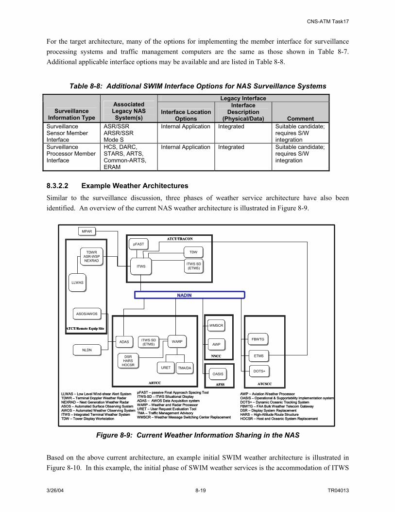
CNS-ATM Task17
3/26/04 8-19 TR04013
For the target architecture, many of the options for implementing the member interface for surveillance processing systems and traffic management computers are the same as those shown in Table 8-7. Additional applicable interface options may be available and are listed in Table 8-8.
Table 8-8: Additional SWIM Interface Options for NAS Surveillance Systems Legacy Interface
Surveillance Information Type
Associated Legacy NAS System(s)
Interface Location Options
Interface Description
(Physical/Data) Comment Surveillance Sensor Member Interface
ASR/SSR ARSR/SSR Mode S
Internal Application Integrated Suitable candidate; requires S/W integration
Surveillance Processor Member Interface
HCS, DARC, STARS, ARTS, Common-ARTS, ERAM
Internal Application Integrated Suitable candidate; requires S/W integration
8.3.2.2 Example Weather Architectures Similar to the surveillance discussion, three phases of weather service architecture have also been identified. An overview of the current NAS weather architecture is illustrated in Figure 8-9.
ATCT/TRACON
ARTCC
NNCC
AFSS ATCSCC
LLWASLLWAS
TDWRASR-WSPNEXRAD
TDWRASR-WSPNEXRAD
NLDNNLDN
ASOS/AWOSASOS/AWOS
NADIN
ATCT/Remote Equip Site
pFASTpFAST
ITWSITWS
TDWTDW
ITWS SD(ETMS)
ITWS SD(ETMS)
ITWS SD(ETMS)
ITWS SD(ETMS)
DSRHARS
HOCSR
DSRHARS
HOCSR
ADASADAS
URETURET TMA/DATMA/DA
ETMSETMS
DOTS+DOTS+
FBWTGFBWTGWARPWARP
WMSCRWMSCR
AWPAWP
OASISOASIS
LLWAS – Low Level Wind-shear Alert SystemTDWR – Terminal Doppler Weather RadarNEXRAD – Next Generation Weather RadarASOS – Automated Surface Observing SystemAWOS – Automated Weather Observing SystemITWS – Integrated Terminal Weather SystemTDW – Tower Display Workstation
MPARMPAR
pFAST – passive Final Approach Spacing ToolITWS-SD – ITWS Situational DisplayADAS – AWOS Data Acquisition systemWARP – Weather and Radar ProcessorURET – User Request Evaluation ToolTMA – Traffic Management AdvisoryWMSCR – Weather Message Switching Center Replacement
AWP – Aviation Weather ProcessorOASIS – Operational & Supportability Implementation systemDOTS+ – Dynamic Oceanic Tracking SystemFBWTG – FAA Bulk Weather Telecom GatewayDSR – Display System ReplacementHARS – High-Altitude Route Structure HOCSR – Host and Oceanic System Replacement
Figure 8-9: Current Weather Information Sharing in the NAS
Based on the above current architecture, an example initial SWIM weather architecture is illustrated in Figure 8-10. In this example, the initial phase of SWIM weather services is the accommodation of ITWS

CNS-ATM Task17
3/26/04 8-20 TR04013
product distribution as well as data coordination among ITWS, WARP and WMSCR. Legacy data connections between weather sensors and both ITWS and WARP are maintained. The interfaces to SWIM are implemented at ITWS processor sites, at sites that use ITWS products (e.g. sites that utilize ITWS situational displays), at WARP processor sites, and at the WMSCR location. The SWIM Member Interface is provided by either standalone components (hardware and/or software) or by new interface applications implemented within the processor and display workstation.
ATCT/TRACON
ARTCCNNCC
AFSS
ATCSCC
SWIMSWIMWeather Broker
LLWASLLWAS
TDWRASR-WSPNEXRAD
TDWRASR-WSPNEXRAD
NLDNNLDN
ASOS/AWOSASOS/AWOS
IP Communication Network (FIRMNet/FTI)
ATCT/Remote Equip Site
pFASTpFAST
ITWSITWS
TDWTDW
ITWS SDITWS SDMember Interface Member
Interface
WARPSD
WARPSD
Member Interface
DSRHARS
HOCSR
DSRHARS
HOCSR
ADASADAS
URETURET TMA/DATMA/DA
ETMSETMS
DOTS+DOTS+
FBWTGFBWTG
Member Interface
WARPWARP
Member Interface
WMSCRWMSCR
AWPAWP
OASISOASIS
LLWAS – Low Level Wind-shear Alert SystemTDWR – Terminal Doppler Weather RadarNEXRAD – Next Generation Weather RadarASOS – Automated Surface Observing SystemAWOS – Automated Weather Observing SystemITWS – Integrated Terminal Weather SystemTDW – Tower Display Workstation
NADIN
NADIN
pFAST – passive Final Approach Spacing ToolITWS-SD – ITWS Situational DisplayADAS – AWOS Data Acquisition systemWARP – Weather and Radar ProcessorURET – User Request Evaluation ToolTMA – Traffic Management AdvisoryWMSCR – Weather Message Switching Center Replacement
AWP – Aviation Weather ProcessorOASIS – Operational & Supportability ImplementationSystem
DOTS+ – Dynamic Oceanic Tracking SystemFBWTG – FAA Bulk Weather Telecom GatewayDSR – Display System ReplacementHARS – High-Altitude Route Structure HOCSR – Host and Oceanic System Replacement
Figure 8-10: Example Initial SWIM Weather Architecture
Options for implementing the new SWIM Member Interface to NAS weather systems for this scenario are presented in Table 8-9.
Table 8-9: SWIM Interface Options for NAS Weather Systems Legacy Interface
Weather Information Type
Associated Legacy NAS System(s)
Interface Location Options
Interface Description (physical/data) Comment
NADIN PSN
EIA/TIA-530, IP HDLC; TCP/IP, Ethernet; RS-232; EIA/TIA-530 X.25, X.25 RS-232
Probably not a suitable candidate
BANDWIDTH MANAGER
EIA/TIA-530 Candidate, but S/W changes required
C-ARTS LAN
EIA/TIA-232
ITWS Member Interface
ITWS
TFM LAN IP Ethernet; Candidate, but S/W

CNS-ATM Task17
3/26/04 8-21 TR04013
Legacy Interface Weather
Information Type
Associated Legacy NAS System(s)
Interface Location Options
Interface Description (physical/data) Comment
changes required Internal Application
Integrated Suitable candidate; requires S/W integration
ITWS SD Member Interface
ITWS Situational Display
DSR LAN
EIA/TIA-530 X.25 (to other WARP, ADAS, WMSCR); Direct Modem connect to NEXRAD WSR-88D sensor; IP, Ethernet V.2 to ATC display and Harris weather data system.
Candidate, but S/W changes required
NADIN PSN
X.25, HDLC,X.21 bits Probably not a suitable candidate
EDI LAN
Candidate, but S/W changes required
TFM LAN Candidate, but S/W changes required
WARP Member Interface
WARP
Internal Application
Integrated Suitable candidate; requires S/W integration
WMSCR Member Interface
ITWS SD NADIN PSN
X.25, HDLC,X.21 bits
NADIN PSN
HDLC X.21 bis, EIA-232F (Application Data Unit)
ADAS Member Interface
ADAS
NADIN MSN Gateway
Modem
T1; EIA-530 X.25 FBWTG Member Interface
FBWTG
NADIN PSN A target example architecture for SWIM weather services includes a direct SWIM interface to all weather service systems, including sensors. This target architecture is based upon concepts in the NAS Target System Description. In this scenario, existing weather data exchanges internal to a NAS facility can be accommodated by existing intra-facility communications, or could be accommodated by SWIM. This example target architecture for SWIM weather services is provided as Figure 8-11.

CNS-ATM Task17
3/26/04 8-22 TR04013
ATCT/TRACON
ARTCC
AFSS ATCSCC
SWIMSWIM
Weather BrokerWeather
DB
LLWASLLWAS
TDWRASR-WSPNEXRAD
TDWRASR-WSPNEXRAD
ASOS/AWOSASOS/AWOS
ATCT/Remote Equip Site
Member Interface
Member Interface
pFASTpFAST ITWSITWSMember Interface
Member Interface
ITWSSD
ITWSSD
Member Interface
SDPSDP
FOMSFOMS
Member Interface
SAP
IIWIIWMember Interface
IP Communication Network (FTI)
WARPSD
WARPSD
Member Interface
ADASADASWARPWARP
Member Interface
Member Interface
IIWIIW
Member Interface
SDPSDP
FOMSFOMS
Member Interface
SAP
NG-TFMNG-TFM
Member Interface
FBWTGFBWTG
Member Interface NG-TFMNG-TFM
DOTS+DOTS+
Member Interface
FASDisplayFAS
Display
Member Interface
GWPGWP
Member Interface
LLWAS – Low Level Wind-shear Alert SystemTDWR – Terminal Doppler Weather RadarASR-WSPNEXRAD – Next Generation Weather RadarASOS – Automated Surface Observing SystemAWOS – Automated Weather Observing SystemITWS – Integrated Terminal Weather SystemITWS-SD – ITWS Situational Display
pFAST – passive Final Approach Spacing ToolWARP – Weather and Radar ProcessorWARP-SD – WARP Situational DisplaySAP – Standard Automation PlatformSDP – Surveillance Data ProcessingFOMS – Flight Object Management SystemNG-TFM – Next Generation Traffic Flow Management
IIW – Integrated Information WorkstationFAS – Flight Advisory ServiceDOTS+ – Dynamic Oceanic Tracking SystemFBWTG – FAA Bulk Weather Telecom GatewayGWP – General Weather Processor
Figure 8-11: Example Target SWIM Weather Architecture In addition to the member interface options described in the Table 8-9 above, additional interface opportunities specific to the target architecture are described in Table 8-10 below.
Table 8-10: Additional SWIM Interface Options for NAS Weather Systems Legacy Interface
Weather Information Type
Associated Legacy NAS System(s)
Interface Location Options
Interface Description
(physical/data) Comment NADIN PSN/MSN
X.25, HDLC,X.21 bits
Probably not a suitable candidate
DMN
Suitable candidate
Weather Sensor Member Interface
TDWR, ASR-WSP, NEXRAD, ASOS, AWOS
Integrated Application
Integrated Suitable candidate
NADIN MSN
X.25, HDLC,X.21 bits
Probably not a suitable candidate
External Vendor Member Interface
NLDN
Internal Application Integrated Suitable candidate OASIS WAN
EIA/TIA-530, X.25 Suitable candidate
NADIN PSN X.25, HDLC,X.21 bits
Probably not a suitable candidate
OASIS Member Interface
OASIS
Internal Application Integrated Suitable candidate

CNS-ATM Task17
3/26/04 8-23 TR04013
8.3.2.3 Example Flight Management Architectures The diagram below in Figure 8-12 shows an overview of the current NAS architecture associated with flight management systems. Due to the large number of essential systems interacting in the area of flight management, the flight management diagrams are at a more detailed level than that for the architecture diagrams that precede them. (For example, NADIN and FIRMNet are distinguishable as separate networks on the next two diagrams.).
ATCSCC NNCC
AFSS/BASOPS
ARTCC
ETMS-HS (Volpe)
Gov’t\Agencies
Gov’t\Agencies
NORADNORAD
ATCT/TRACON
TMU
FOC/Airlines
FSASFSAS
AISRAISR
DSS(POET, ESIS,
FSM)
DSS(POET, ESIS,
FSM)ARTS/
STARS/C-ARTS
ARTS/STARS/C-ARTS
PDCPDC
ETMSETMS
TMU
DSS(POET, ESIS,
FSM)
DSS(POET, ESIS,
FSM)
ETMSETMSHCS
(/DARC)HCS
(/DARC)
DLAP(CPDLC)DLAP
(CPDLC)
DSS(URET)DSS
(URET)
FSDPSFSDPS
ERIDERID
AISWorkstation
AISWorkstation ETMSETMS CDM
Proc/FuncCDM
Proc/Func
Web BrowserWeb Browser Internet
IP Communication Network (FIRMNet)
NAS LAN
NADIN
FPDBFPDB AISRAISR
ETMSProc/Func
ETMSProc/Func
CDM-NetInterface
CDM-NetInterface
CDM-NetInterface
CDM-NetInterface
HCS – Host Computer SystemSTARS – Standard Terminal Automation Replacement SystemARTS – Automated Radar Terminal SystemC-ARTS – Common ARTSPDC – Pre-Departure ClearanceETMS – Enhance Traffic Management System
FSAS – Flight Service Automation SystemDSS – Decision Support SoftwarePOET – Post Operations Evaluation ToolAISR – Aeronautical Information System ReplacementESIS – Enhanced Status Information SystemFSM – Flight Schedule MonitorFSDPS – Flight Service Data Processing System
DLAP – Data Link Application ProcessorURET – User Request Evaluation ToolFP – Flight PlanCDM-Net – Collaborative Decision Making NetworkAISR– Aeronautical Information System ReplacementProc/Func – Processes and FunctionsERID – En Route Informational DisplayIP – Internet Protocol
Figure 8-12: Overview of Current Flight Management Information Sharing in the NAS The example initial transition step to SWIM, shown in Figure 8-13, includes the implementation of a SWIM broker addressing Flight Object (FO) data sharing. This FO SWIM Broker is shown as installed at and ARTCC facility. Additionally, SWIM member interfaces to the CDM-Net are included at the ATCSCC, Volpe and the FOC. In this example, SWIM is accommodating flight information data exchange to/from the CDM-Net.

CNS-ATM Task17
3/26/04 8-24 TR04013
ATCSCC NNCC
AFSS/BASOPS
ARTCC
ETMS-HS (Volpe)
Gov’t\Agencies
Gov’t\Agencies
NORADNORAD
ATCT/TRACON
TMU
FOC/Airlines
FSASFSAS
AISRAISR
DSS(POET, ESIS,
FSM)
DSS(POET, ESIS,
FSM)ARTS/
STARS/C-ARTS
ARTS/STARS/C-ARTS
PDCPDC
ETMSETMS
TMU
DSS(POET, ESIS,
FSM)
DSS(POET, ESIS,
FSM)
ETMSETMSHCS
(/DARC)HCS
(/DARC)
DLAP(CPDLC)DLAP
(CPDLC)
DSS(URET)DSS
(URET)
FSDPSFSDPS
ERIDERID
AISWorkstation
AISWorkstation ETMSETMS
CDMProc/Func
CDMProc/Func
Web BrowserWeb Browser Internet
IP Communication Network (FIRMNet/FTI)N
AS LAN
NADIN
FPDBFPDB AISRAISR
ETMSProc/Func
ETMSProc/Func
CDM-NetInterface
CDM-NetInterface
CDM-NetInterface
CDM-NetInterface
Member Interface
SWIMFlight Object Broker Member
Interface
Member Interface
HCS – Host Computer SystemSTARS – Standard Terminal Automation Replacement SystemARTS – Automated Radar Terminal SystemC-ARTS – Common ARTSPDC – Pre-Departure ClearanceETMS – Enhance Traffic Management System
FSAS – Flight Service Automation SystemDSS – Decision Support SystemPOET – Post Operation Evaluation ToolAISR – Aeronautical Information System ReplacementESIS – Enhance Status Information SystemFSM – Flight Schedule MonitorFSDPS – Flight Service Data Processing System
DLAP – Data Link Application ProcessorURET – User Request Evaluation ToolFP – Flight PlanCDM-Net – Collaborative Decision Making NetworkAIS – Aeronautical Information SystemProc/Func – Processes and FunctionsERID – En Route Informational DisplayIP – Internet Protocol
SWIM
Figure 8-13: Example Initial SWIM Flight Management Information Sharing Architecture
Table 8-11 below identifies and describes the options for interfacing the new SWIM Member Interface to existing NAS components at the initial transition to SWIM.
Table 8-11: SWIM Interface Options for NAS Flight Data Processing/Management Systems
Legacy Interface
Flight Management Information Type
Associated Legacy NAS System(s)
Interface Location Options
Interface Description
(physical/data) Comment CDM Processing system
ETMS LAN IP; Ethernet/IEEE 802.3
Candidate, but may S/W changes required
CDM Net
CDM Interface NADIN MSN/PSN EIA/TIA-232 Probably not a
suitable candidate AWP-DMN EIA/TIA-232 Suitable candidate
FSDPS
AFSS-DMN EIA/TIA-232 Suitable candidate AIS LAN ANSI X3.28-1976,
Subcategory 2.5/A2-A4 TCP/IP over X.25
Candidate, but may S/W changes required
AIS/AIM
NADIN PSN EIA/TIA-530; X.25 Probably not a suitable candidate
Flight Plan Processing Systems
FP DB HID-NAS LAN
EIA/TIA-232 (CD-2 format)
Candidate, but S/W changes required
Flight Data Processor Member Interface
HCS
PAMRI
EIA/TIA-232 (CD-2 format)
Suitable candidate
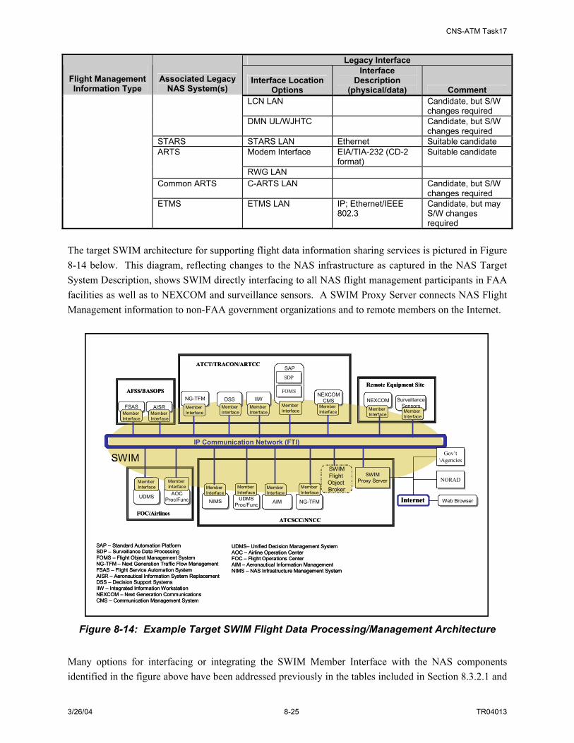
CNS-ATM Task17
3/26/04 8-25 TR04013
Legacy Interface
Flight Management Information Type
Associated Legacy NAS System(s)
Interface Location Options
Interface Description
(physical/data) Comment LCN LAN
Candidate, but S/W changes required
DMN UL/WJHTC Candidate, but S/W changes required
STARS STARS LAN Ethernet Suitable candidate Modem Interface
EIA/TIA-232 (CD-2 format)
Suitable candidate ARTS
RWG LAN Common ARTS C-ARTS LAN Candidate, but S/W
changes required ETMS ETMS LAN IP; Ethernet/IEEE
802.3 Candidate, but may S/W changes required
The target SWIM architecture for supporting flight data information sharing services is pictured in Figure 8-14 below. This diagram, reflecting changes to the NAS infrastructure as captured in the NAS Target System Description, shows SWIM directly interfacing to all NAS flight management participants in FAA facilities as well as to NEXCOM and surveillance sensors. A SWIM Proxy Server connects NAS Flight Management information to non-FAA government organizations and to remote members on the Internet.
ATCSCC/NNCC
AFSS/BASOPS
Gov’t\Agencies
Gov’t\Agencies
NORADNORAD
ATCT/TRACON/ARTCC
FOC/Airlines
AIMAIM NG-TFMNG-TFMUDMSProc/Func
UDMSProc/Func Web BrowserWeb BrowserInternet
IP Communication Network (FTI)
UDMSUDMS
SWIMFlight Object Broker
Member Interface
Remote Equipment Site
NEXCOMNEXCOMMember Interface
AOCProc/Func
AOCProc/Func
Member Interface
NIMSNIMS
Member Interface
Member Interface
Member Interface
Member Interface
SWIMProxy Server
SWIMProxy Server
SAP – Standard Automation PlatformSDP – Surveillance Data ProcessingFOMS – Flight Object Management SystemNG-TFM – Next Generation Traffic Flow ManagementFSAS – Flight Service Automation SystemAISR – Aeronautical Information System ReplacementDSS – Decision Support SystemsIIW – Integrated Information WorkstationNEXCOM – Next Generation CommunicationsCMS – Communication Management System
UDMS– Unified Decision Management SystemAOC – Airline Operation CenterFOC – Flight Operations CenterAIM – Aeronautical Information ManagementNIMS – NAS Infrastructure Management System
SWIM
SurveillanceSensors
SurveillanceSensorsMember Interface
DSSDSSNG-TFMNG-TFM IIWIIW
SDPSDP
FOMSFOMS
Member Interface
SAP
Member Interface
Member Interface
Member Interface
NEXCOMCMS
NEXCOMCMS
Member Interface
FSASFSAS AISRAISRMember Interface
Member Interface
Figure 8-14: Example Target SWIM Flight Data Processing/Management Architecture
Many options for interfacing or integrating the SWIM Member Interface with the NAS components identified in the figure above have been addressed previously in the tables included in Section 8.3.2.1 and

CNS-ATM Task17
3/26/04 8-26 TR04013
Section 8.3.2.2. Additional interface considerations specific to the target flight data processing/management architecture are provided in Table 8-12.
Table 8-12: Additional SWIM Interface Options for NAS Flight Data Processing/Management Systems
Legacy Interface
Flight Management Information Type
Associated Legacy NAS System(s)
Interface Location Options
Interface Description
(physical/data) Comment ETMS Internal Application Integrated Suitable candidate ERAM Internal Application Integrated Suitable candidate FOMS Internal Application Integrated Suitable candidate
Flight Data Processing Systems
NG-TFM Internal Application Integrated Suitable candidate 8.3.2.4 Example Aeronautical Information Architectures Similar to the other NAS domains addressed above, three architecture diagrams have been generated to capture transition of the NAS aeronautical information sharing architecture to the SWIM environment. The current NAS architecture specific to aeronautical information is illustrated in Figure 8-15.
ATCSCC
NNCC
ATCT/TRACON AFSS
NADIN
IP Communication Network (FIRMNet)
ARTCC
NOTAMDBs
NOTAMDBs
NOTAMDistribution
Server
NOTAMDistribution
Server
NAIMESWeb Service
NAIMESWeb Service
AISWorkstation
AISWorkstation
NASRNASR
WMSCRWMSCR
AWPAWP
AISRAISR
Web BrowserWeb Browser
ERIDERID
INTERNET
ACE-IDSACE-IDSAISR
DisplayAISR
Display OASISOASISAISAIS
ATCT/TRACON AFSSARTCC
NOTAM – Notice to AirmanDB – DatabaseNAIMES – NAS Aeronautical Information Management Enterprise SystemAISR – Aeronautical Information System ReplacementNASR – NAS Resource SystemERID – En Route Informational DisplayWMSCR – Weather Message Switching Center Replacement
ACE-IDS – ASOS Controller Equipment – Information Display SystemOASIS – Operational & Supportability Implementation SystemAWP – Aviation Weather Processor
Figure 8-15: Current Aeronautical Information Sharing in the NAS

CNS-ATM Task17
3/26/04 8-27 TR04013
The example initial SWIM architecture to accommodate aeronautical information addresses the delivery of aeronautical information (from NASR, AIS and the NOTAMs database) to NAS users. At the ATCSCC, SWIM interfaces to the AIS, NASR and NOTAM databases of the NAIMES program. At the ATCTs and TRACONs, SWIM interfaces to NAIMES browsers and ADAS. Web browsers also directly connect to the SWIM network to enable remote user access to the aeronautical information stores. The NNCC and AFSSs maintain legacy network connections. This example initial architecture is shown in Figure 8-16.
ATCSCC
NNCC
ATCT/TRACON AFSS
NADIN
IP Communication Network (FIRMNet/FTI)
ARTCC
NOTAMDBs
NOTAMDBs
NOTAMDistribution
Server
NOTAMDistribution
Server
NAIMESWeb Service
NAIMESWeb Service
AISRAISR
NASRNASR
WMSCRWMSCR
AWPAWP
AISRAISR
Web BrowserWeb Browser
ERIDERID
INTERNET
ACE-IDSACE-IDSOASISOASIS
Member Interface
Member Interface
Member Interface
SWIMAIM
Broker
SWIM
Member Interface
AISRDisplayAISR
Display
Member Interface
NOTAM – Notice to AirmanDB – DatabaseNAIMES – NAS Aeronautical Information Management Enterprise SystemAISR – Aeronautical Information System ReplacementNASR – NAS Resource SystemERID – En Route Informational DisplayWMSCR – Weather Message Switching Center Replacement
ACE-IDS – ASOS Controller Equipment – Information Display SystemOASIS – Operational & Supportability Implementation SystemAWP – Aviation Weather Processor
Figure 8-16: Example Initial SWIM Aeronautical Information Sharing Architecture
Table 8-13 below explores the options for implementing SWIM Member Interfaces in the initial architecture.
Table 8-13: SWIM Interface Options for NAS Aeronautical Information Systems Legacy Interface
Aeronautical Information Type
Associated Legacy NAS System(s)
Interface Location Options
Interface Description
(physical/data) Comment NOTAM TCP/IP Ethernet NAIMES interface is
a candidate interface AIS NAIMES interface is
a candidate interface
Databases
NASR NAIMES interface is a candidate interface
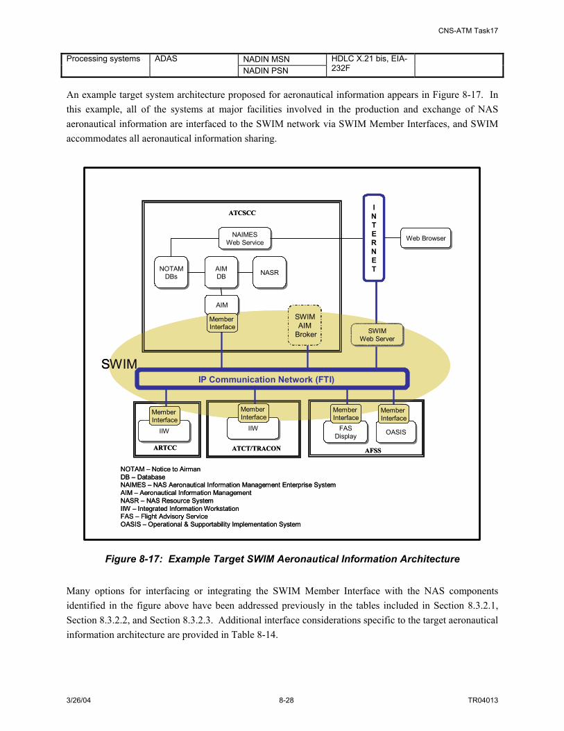
CNS-ATM Task17
3/26/04 8-28 TR04013
NADIN MSN Processing systems ADAS NADIN PSN
HDLC X.21 bis, EIA-232F
An example target system architecture proposed for aeronautical information appears in Figure 8-17. In this example, all of the systems at major facilities involved in the production and exchange of NAS aeronautical information are interfaced to the SWIM network via SWIM Member Interfaces, and SWIM accommodates all aeronautical information sharing.
ATCSCC
ATCT/TRACON AFSS
IP Communication Network (FTI)
ARTCC
NOTAMDBs
NOTAMDBs
NAIMESWeb Service
NAIMESWeb Service
NASRNASR
Web BrowserWeb Browser
INTERNET
IIWIIWOASISOASIS
SWIMAIM
Broker
SWIM
Member Interface
FASDisplayFAS
Display
Member Interface
AIMDB
AIMDB
AIMAIM
Member Interface
IIWIIW
Member Interface
Member Interface
SWIMWeb Server
SWIMWeb Server
NOTAM – Notice to AirmanDB – DatabaseNAIMES – NAS Aeronautical Information Management Enterprise SystemAIM – Aeronautical Information ManagementNASR – NAS Resource SystemIIW – Integrated Information WorkstationFAS – Flight Advisory ServiceOASIS – Operational & Supportability Implementation System
Figure 8-17: Example Target SWIM Aeronautical Information Architecture Many options for interfacing or integrating the SWIM Member Interface with the NAS components identified in the figure above have been addressed previously in the tables included in Section 8.3.2.1, Section 8.3.2.2, and Section 8.3.2.3. Additional interface considerations specific to the target aeronautical information architecture are provided in Table 8-14.
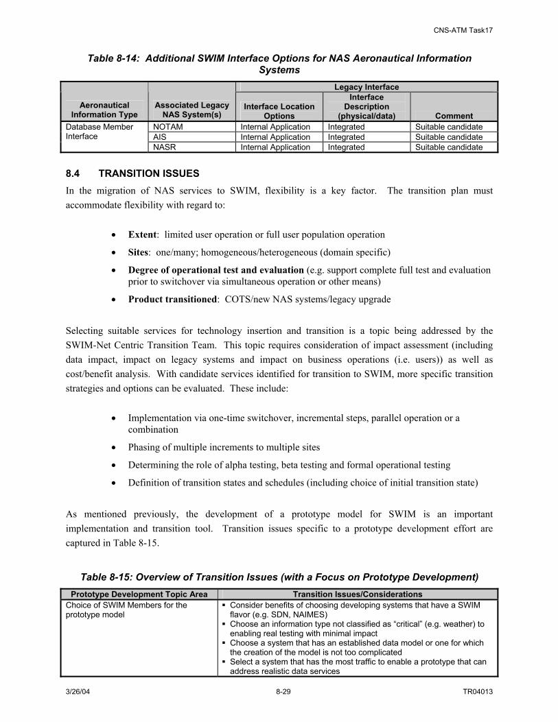
CNS-ATM Task17
3/26/04 8-29 TR04013
Table 8-14: Additional SWIM Interface Options for NAS Aeronautical Information Systems
Legacy Interface
Aeronautical Information Type
Associated Legacy NAS System(s)
Interface Location Options
Interface Description
(physical/data) Comment NOTAM Internal Application Integrated Suitable candidate AIS Internal Application Integrated Suitable candidate
Database Member Interface
NASR Internal Application Integrated Suitable candidate 8.4 TRANSITION ISSUES In the migration of NAS services to SWIM, flexibility is a key factor. The transition plan must accommodate flexibility with regard to:
• Extent: limited user operation or full user population operation
• Sites: one/many; homogeneous/heterogeneous (domain specific)
• Degree of operational test and evaluation (e.g. support complete full test and evaluation prior to switchover via simultaneous operation or other means)
• Product transitioned: COTS/new NAS systems/legacy upgrade
Selecting suitable services for technology insertion and transition is a topic being addressed by the SWIM-Net Centric Transition Team. This topic requires consideration of impact assessment (including data impact, impact on legacy systems and impact on business operations (i.e. users)) as well as cost/benefit analysis. With candidate services identified for transition to SWIM, more specific transition strategies and options can be evaluated. These include:
• Implementation via one-time switchover, incremental steps, parallel operation or a combination
• Phasing of multiple increments to multiple sites
• Determining the role of alpha testing, beta testing and formal operational testing
• Definition of transition states and schedules (including choice of initial transition state)
As mentioned previously, the development of a prototype model for SWIM is an important implementation and transition tool. Transition issues specific to a prototype development effort are captured in Table 8-15.
Table 8-15: Overview of Transition Issues (with a Focus on Prototype Development) Prototype Development Topic Area Transition Issues/Considerations
Choice of SWIM Members for the prototype model
Consider benefits of choosing developing systems that have a SWIM flavor (e.g. SDN, NAIMES)
Choose an information type not classified as “critical” (e.g. weather) to enabling real testing with minimal impact
Choose a system that has an established data model or one for which the creation of the model is not too complicated
Select a system that has the most traffic to enable a prototype that can address realistic data services
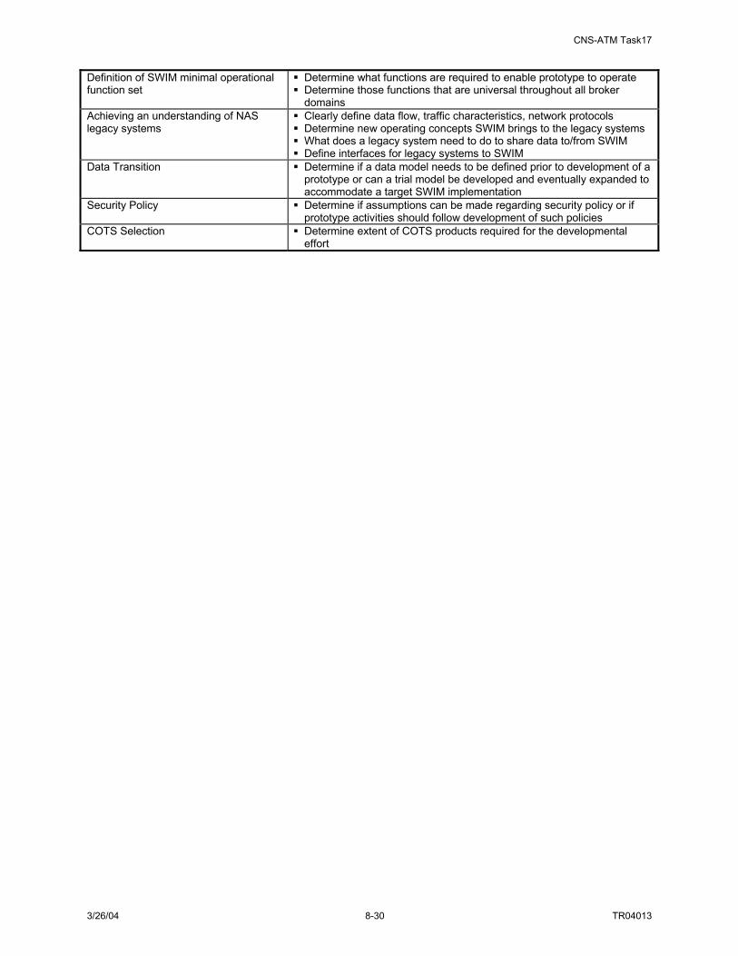
CNS-ATM Task17
3/26/04 8-30 TR04013
Definition of SWIM minimal operational function set
Determine what functions are required to enable prototype to operate Determine those functions that are universal throughout all broker domains
Achieving an understanding of NAS legacy systems
Clearly define data flow, traffic characteristics, network protocols Determine new operating concepts SWIM brings to the legacy systems What does a legacy system need to do to share data to/from SWIM Define interfaces for legacy systems to SWIM
Data Transition Determine if a data model needs to be defined prior to development of a prototype or can a trial model be developed and eventually expanded to accommodate a target SWIM implementation
Security Policy Determine if assumptions can be made regarding security policy or if prototype activities should follow development of such policies
COTS Selection Determine extent of COTS products required for the developmental effort

CNS-ATM Task17
3/26/04 9-1 TR04013
9. CONCLUSIONS AND RECOMMENDATIONS
CNS-ATM Task 17 has addressed the future vision of the NAS by developing a functional architecture, physical architecture and initial set of NAS-level requirements for SWIM. These products have been developed to support a SWIM that supports effective collaboration among all participants, provides flexibility in assigning airspace and infrastructure resources, automates the establishment and teardown of communications connections between NAS systems to support NAS operations, and offers increased NAS information security. The functional architecture has led to the identification of component SWIM functionality addressing both information management as well as network management. To implement the functional architecture, SWIM would be comprised of a range of hardware and software components (and a data component) that may be dedicated to SWIM functionality (e.g. the SWIM Broker) or may be a shared NAS component (e.g. the SWIM communication network, accommodated by a NAS communication resource such as FTI). An illustration of the SWIM physical architecture hardware and software components is provided Figure 9-1.
NAS Computing Services
SWIM Member InterfaceServices
Operating SystemNetwork Interface(TCP/IP port, etc)
Hardware(CPU, Memory, I/O, etc)
NAS System
SWIM MemberInterfaceServices
SWIM InterfaceHardware
(CPU, Memory, I/O, etc)
NAS User
Local and/or Wide Area Network
NAS Computing Services
Operating SystemNetwork Interface(TCP/IP port, etc)
Hardware(CPU, Memory, I/O, etc)
NAS System
NAS User
Browser Application
Operating SystemNetwork Interface(TCP/IP port, etc)
Hardware(CPU, Memory, I/O, etc)
Computing SystemWith Standard
Browser
NAS User
SWIM BrokerServices
SWIM BrokerHardware
(CPU, Memory, I/O, etc)
SWIM Data ModelRegistry Services
SWIM Data ModelRegistry Hardware
(CPU, Memory, I/O, etc)
IOR MDR
NetworkMngmt
Interface
NetworkMngmt
Interface
NetworkMngmt
Services
SWIM Network ManagerHardware
(CPU, Memory, I/O, etc)
Network ManagementInterface Services
SWIM NetworkManagement
Interface Services
Hardware(CPU, Memory, I/O, etc)
NAS NetworkManagement System
OR
AND/OR
AND/OR
SWIM NetworkManagement System
SWIM WebServer ServicesSWIM Web Server
Hardware(CPU, Memory, I/O, etc)
NetworkMngmt
Interface
MEMBERINTERFACE
BROWSER
WEB SERVER
MDRIOR
BROKER
NETWORK MANAGER INTERFACE
SECURITY
NAS Component
SWIM Component
Key
NAS Component
SWIM Component
Key
NAS Computing Services
SWIM Member InterfaceServices
Operating SystemNetwork Interface(TCP/IP port, etc)
Hardware(CPU, Memory, I/O, etc)
NAS System
SWIM MemberInterfaceServices
SWIM InterfaceHardware
(CPU, Memory, I/O, etc)
NAS User
Local and/or Wide Area Network
NAS Computing Services
Operating SystemNetwork Interface(TCP/IP port, etc)
Hardware(CPU, Memory, I/O, etc)
NAS System
NAS User
Browser Application
Operating SystemNetwork Interface(TCP/IP port, etc)
Hardware(CPU, Memory, I/O, etc)
Computing SystemWith Standard
Browser
NAS User
SWIM BrokerServices
SWIM BrokerHardware
(CPU, Memory, I/O, etc)
SWIM Data ModelRegistry Services
SWIM Data ModelRegistry Hardware
(CPU, Memory, I/O, etc)
IORIOR MDR
NetworkMngmt
Interface
NetworkMngmt
Interface
NetworkMngmt
Services
SWIM Network ManagerHardware
(CPU, Memory, I/O, etc)
Network ManagementInterface Services
SWIM NetworkManagement
Interface Services
Hardware(CPU, Memory, I/O, etc)
NAS NetworkManagement System
OR
AND/OR
AND/OR
SWIM NetworkManagement System
SWIM WebServer ServicesSWIM Web Server
Hardware(CPU, Memory, I/O, etc)
NetworkMngmt
Interface
MEMBERINTERFACE
BROWSER
WEB SERVER
MDRIOR
BROKER
NETWORK MANAGER INTERFACE
SECURITY
NAS Component
SWIM Component
Key
NAS Component
SWIM Component
Key
Figure 9-1: SWIM Physical Architecture Hardware/Software Using the components included in the figure above and considering alternative broker concepts, distribution densities and topologies, three candidate physical architectures for SWIM were generated. The alternatives are not necessarily independent, and SWIM may support the implementation of different
CNS-ATM Task17
3/26/04 9-2 TR04013
architectures for different NAS data domains (e.g. surveillance, weather, aeronautical information, etc.) The transition to the identified SWIM physical architecture involves a wide-reaching developmental and migration effort. Thoughtful planning and the use of prototype models can be beneficial in supporting proof-of-concept as well as in identifying constraints and risks. The simulation effort conducted as part of this study found that the recommended SWIM architecture will meet the information management requirements for SWIM as well as FAA service communication requirements. However, the following items are recommended:
• Brokers should be located in “hub” facilities, where traffic patterns converge, to minimize additional network resource load and propagation latency. Additional brokers should be considered if multiple hubs can be identified.
• Variants of the publish application to support real-time dissemination of periodic information should be employed as needed to meet FAA communication requirements (e.g., for surveillance information); however, the standard publish application should be employed when it will meet requirements in order to maximize the benefits of the broker architecture and to avoid unnecessary burden at servers.
• Publish applications should be developed to re-use TCP connections for frequently published information (e.g., inter-publish times < 60 seconds) in order to reduce network overhead traffic.
• Subscribe, register and query processes should employ TCP as the underlying transport protocol; publish processes should employ the transport protocol recommended for the information to be published (e.g., UDP for surveillance information and TCP for weather, automation, and navigation & landing services).
• IP multicast should be used where applicable to reduce the network load of replicated packets.
• Minimum content granularity should allow subscriptions to specify information type (e.g., weather) and sub-type (e.g., Weather 11), with filters for source of information (e.g., facility name and location).
Additionally, new FAA policies that will be required to support SWIM operation were identified:
• Application layer acknowledgement policies, including retransmission and timeout policies.
• Information objects storage policies.
Application layer acknowledgement enables immediate notification that information was not received as expected. However, this comes at the expense of additional network resource utilization and node processing. Because TCP-transported traffic has layer 4 acknowledgements and retransmissions, and because UDP-transported traffic is likely transported via UDP because the information will expire before it can be retransmitted, it may not be necessary to require application layer acknowledgement for all traffic. Application layer acknowledgement policies are therefore required to dictate the types of information that require specific end-user acknowledgement of receipt.

CNS-ATM Task17
3/26/04 9-3 TR04013
Information object storage policies include the requirements or information characteristics that dictate whether the entire information object is stored or a link to the information is stored, as well as policies that control the persistence of the stored information. These policies will affect the utilization of network resources as well as information retrieval time. Simulations underscored the importance of ensuring that the underlying network infrastructure can support the additional load created by SWIM. This study employed the network infrastructure used in the CNS-ATM Task 12 model for the recommended NAS architecture, which assumed an Internet-like backbone. However, as both SWIM and the underlying network infrastructure (e.g., FTI topology and capacity, NAS facility access to FTI, and campus router capacity) evolve, it will be important to ensure that the demands created by SWIM processes do not exceed the capabilities of the network. For instance, routers at the facilities chosen to house brokers (e.g., ZOB) should be assessed to ensure that routing capacity (e.g., router forwarding rates) is adequate to support the additional load induced by the brokers. The developed model can be employed to assess resource requirements as additional FAA services migrate to SWIM. The processing of refining and comparing candidate physical architectures for SWIM as well as the initial work to specify requirements associated with design models of SWIM components necessitates continuation of the physical architecture development work effort. Specifically, required future task items include:
• Interaction with NAS IPTs to explore data model/representation requirements and constraints
• Investigation and definition of data models and query possibilities associated with specific SWIM services
• Further identification of SWIM performance requirements and constraints
• Evaluation and comparison of candidate physical architectures in terms of performance, cost, schedule, and ease of transition
• Development of initial security documentation associated with SWIM in support of SCAP development
• Development of Engineering Demonstration Models of one or more of the architecture candidates using COTS hardware and software.

TR04013 MARCH 26, 2004
System-Wide Information Management (SWIM) Architecture
and Requirements
CNS-ATM TASK 17 FINAL REPORT APPENDICES

CNS-ATM Task17
3/26/2004 ii TR04008

CNS-ATM Task17
3/26/04 i TR04013
TABLE OF CONTENTS
SECTION PAGE Appendix A. Functional Architecture Description..............................................................A-1
A.1 Standard ISO Architecture Model Description..................................................A-1 A.2 Functional Architecture Details .........................................................................A-3
A.2.1 SWIM Highest-Level Functions ........................................................................A-3 A.3 Manage SWIM Information (1.0) and Its Subfunctions ....................................A-4
A.3.1 Manage SWIM Interfaces (1.1) .........................................................................A-5 A.3.1.1 Supply Access Methods (1.1.1) .........................................................................A-5
A.3.1.1.1 Define Access Methods (1.1.1.1).......................................................................A-6 A.3.1.1.2 Maintain Access Methods (1.1.1.2) ...................................................................A-6
A.3.1.2 Control SWIM Access (1.1.2) ...........................................................................A-6 A.3.1.2.1 Register Members (1.1.2.1) ...............................................................................A-7 A.3.1.2.2 Maintain Member List (1.1.2.2).........................................................................A-7 A.3.1.2.3 Identify and Authenticate Members (1.1.2.3)....................................................A-7 A.3.1.2.4 Authorize SWIM Access (1.1.2.4).....................................................................A-7 A.3.1.2.5 Maintain SWIM Access Limitations (1.1.2.5)...................................................A-7
A.3.1.3 Conduct Interface Transactions (1.1.3)..............................................................A-8 A.3.1.3.1 Translate Data Format (1.1.3.1).........................................................................A-9 A.3.1.3.2 Convert Communication Protocols (1.1.3.2) .....................................................A-9 A.3.1.3.3 Process SWIM-to-Member Requests (1.1.3.3) ..................................................A-9 A.3.1.3.4 Process Member-to-SWIM Requests (1.1.3.4) ................................................A-10 A.3.1.3.5 Exchange Status/Control Messages (1.1.3.5) ..................................................A-10
A.3.2 Broker Service Requests (1.2) .........................................................................A-11 A.3.2.1 Maintain Registration (1.2.1)...........................................................................A-11
A.3.2.1.1 Maintain Local SWIM Member Registration (1.2.1.1) ...................................A-11 A.3.2.1.2 Maintain Remote Broker Registration information (1.2.1.2)...........................A-11 A.3.2.1.3 Provide Broker Naming Service (1.2.1.3) .......................................................A-11
A.3.2.2 Process Transactions (1.2.2) ...........................................................................A-11 A.3.2.2.1 Prioritize Requests (1.2.2.1) ............................................................................A-11 A.3.2.2.2 Process Publish Requests (1.2.2.2) ..................................................................A-12 A.3.2.2.3 Process Subscribe Requests (1.2.2.3) ..............................................................A-12 A.3.2.2.4 Process Query Requests (1.2.2.4) ....................................................................A-12 A.3.2.2.5 Perform Discovery Services (1.2.2.5)..............................................................A-12 A.3.2.2.6 Process Control/Status Messages (1.2.2.6) ......................................................A-13 A.3.2.2.7 Balance SWIM Load (1.2.2.7).........................................................................A-13
A.3.2.3 Perform Data Services (1.2.3)..........................................................................A-13 A.3.2.3.1 Validate Member Data (1.2.3.1) ......................................................................A-13 A.3.2.3.2 Process Information Objects (1.2.3.2) .............................................................A-13
A.3.2.4 Provide Core Application Functions (1.2.4) ....................................................A-14 A.3.2.4.1 Handle Events (1.2.4.1) ...................................................................................A-14 A.3.2.4.2 Provide Stream Data Services (1.2.4.2) ...........................................................A-14

CNS-ATM Task17
3/26/04 ii TR04013
A.3.2.4.3 Support Agent Programs (1.2.4.3) ...................................................................A-14 A.3.3 Manage SWIM Data (1.3) ...............................................................................A-14
A.3.3.1 Define SWIM Information Structure (1.3.1) ...................................................A-14 A.3.3.1.1 Define NAS Information Directory (1.3.1.1)...................................................A-15 A.3.3.1.2 Define Common Data Model for NAS Information (1.3.1.2) .........................A-15 A.3.3.1.3 Define NAS Information Objects (1.3.1.3)......................................................A-15
A.3.3.2 Maintain NAS Information Directories (1.3.2)................................................A-16 A.3.3.2.1 Maintain NAS Information Directory (1.3.2.1) ...............................................A-16 A.3.3.2.2 Maintain NAS Information Object Directory (1.3.2.2) ...................................A-16
A.3.4 Manage Data Storage (1.4) ..............................................................................A-16 A.3.4.1 Manage SWIM Databases (1.4.1)....................................................................A-16
A.3.4.1.1 Manage SWIM Database Links (1.4.1.1) ........................................................A-17 A.3.4.1.2 Manage SWIM Database Transactions (1.4.1.2) .............................................A-17 A.3.4.1.3 Backup/Recovery Databases (1.4.1.3) .............................................................A-17 A.3.4.1.4 Access SWIM Databases (1.4.2) .....................................................................A-17
A.4 Manage SWIM Networks (2.0) and Its Subfunctions......................................A-17 A.4.1 Maintain Network Security (2.1) .....................................................................A-18
A.4.1.1 Maintain Security Functions and Data (2.1.1) .................................................A-19 A.4.1.2 Manage Security Attributes (2.1.2)..................................................................A-19 A.4.1.3 Manage Public Key Infrastructure (PKI) (2.1.3) .............................................A-19 A.4.1.4 Maintain Security Audits (2.1.4) .....................................................................A-20
A.4.2 Mange SWIM Accounts (2.2)..........................................................................A-20 A.4.2.1 Maintain Accounts (2.2.1) ...............................................................................A-20 A.4.2.2 Manage Account Security Policy Implementation (2.2.2)...............................A-20 A.4.2.3 Manage Account Monitoring Services (2.2.3).................................................A-20
A.4.3 Manage Network Configuration (2.3)..............................................................A-20 A.4.3.1 Establish Naming Service Directory and Services (2.3.1)...............................A-20 A.4.3.2 Configure SWIM Networks and Services (2.3.2) ............................................A-21 A.4.3.3 Cache Exchanged NAS Information (2.3.3) ....................................................A-22 A.4.3.4 Distribute SWIM Status/Control Messages (2.3.4) .........................................A-22 A.4.3.5 Maintain Operation Monitoring Configuration (2.3.5)....................................A-22 A.4.3.6 Protect SWIM Resource Allocations (2.3.6) ...................................................A-22 A.4.3.7 Manage SWIM Security Functions Infrastructure (2.3.7) ...............................A-22 A.4.3.8 Maintain Secure Communications (Trusted path/Crypto) (2.3.8) ...................A-23
A.4.4 Maintain Performance (2.4) .............................................................................A-23 A.4.4.1 Monitor SWIM Connectivity Status (2.4.1) ....................................................A-24 A.4.4.2 Monitor SWIM Flow of Data Status (2.4.2) ....................................................A-24 A.4.4.3 Monitor SWIM Traffic Performance Status (2.4.3).........................................A-24 A.4.4.4 Collect SWIM Quality Control Data (2.4.4)....................................................A-24 A.4.4.5 Evaluate Service Quality (2.4.5)......................................................................A-24 A.4.4.6 Adjust Communication Load (2.4.6) ...............................................................A-24
A.4.5 Manage Network Faults (2.5) ..........................................................................A-24 A.4.5.1 Detect and Diagnose Faults (2.5.1)..................................................................A-25 A.4.5.2 Remove Faults and Recover System (2.5.2)....................................................A-25
Appendix B. SWIM Requirements....................................................................................... B-1
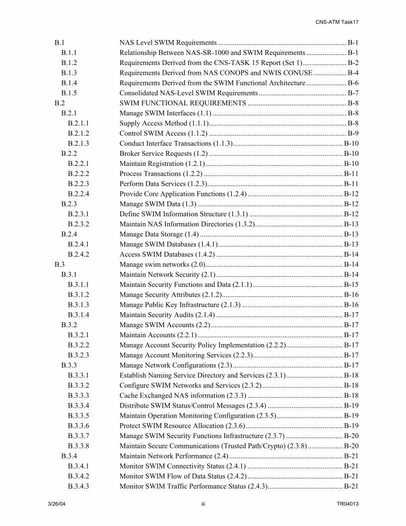
CNS-ATM Task17
3/26/04 iii TR04013
B.1 NAS Level SWIM Requirements ...................................................................... B-1 B.1.1 Relationship Between NAS-SR-1000 and SWIM Requirements ...................... B-1 B.1.2 Requirements Derived from the CNS-TASK 15 Report (Set 1)........................ B-2 B.1.3 Requirements Derived from NAS CONOPS and NWIS CONUSE .................. B-4 B.1.4 Requirements Derived from the SWIM Functional Architecture ...................... B-6 B.1.5 Consolidated NAS-Level SWIM Requirements ................................................ B-7
B.2 SWIM FUNCTIONAL REQUIREMENTS ...................................................... B-8 B.2.1 Manage SWIM Interfaces (1.1) ......................................................................... B-8
B.2.1.1 Supply Access Method (1.1.1)........................................................................... B-8 B.2.1.2 Control SWIM Access (1.1.2) ........................................................................... B-9 B.2.1.3 Conduct Interface Transactions (1.1.3)............................................................ B-10
B.2.2 Broker Service Requests (1.2) ......................................................................... B-10 B.2.2.1 Maintain Registration (1.2.1)........................................................................... B-10 B.2.2.2 Process Transactions (1.2.2) ............................................................................ B-11 B.2.2.3 Perform Data Services (1.2.3).......................................................................... B-11 B.2.2.4 Provide Core Application Functions (1.2.4) .................................................... B-12
B.2.3 Manage SWIM Data (1.3) ............................................................................... B-12 B.2.3.1 Define SWIM Information Structure (1.3.1) ................................................... B-12 B.2.3.2 Maintain NAS Information Directories (1.3.2)................................................ B-13
B.2.4 Manage Data Storage (1.4) .............................................................................. B-13 B.2.4.1 Manage SWIM Databases (1.4.1).................................................................... B-13 B.2.4.2 Access SWIM Databases (1.4.2) ..................................................................... B-14
B.3 Manage swim networks (2.0)........................................................................... B-14 B.3.1 Maintain Network Security (2.1) ..................................................................... B-14
B.3.1.1 Maintain Security Functions and Data (2.1.1) ................................................. B-15 B.3.1.2 Manage Security Attributes (2.1.2).................................................................. B-16 B.3.1.3 Manage Public Key Infrastructure (2.1.3) ....................................................... B-16 B.3.1.4 Maintain Security Audits (2.1.4) ..................................................................... B-17
B.3.2 Manage SWIM Accounts (2.2) ........................................................................ B-17 B.3.2.1 Maintain Accounts (2.2.1) ............................................................................... B-17 B.3.2.2 Manage Account Security Policy Implementation (2.2.2)............................... B-17 B.3.2.3 Manage Account Monitoring Services (2.2.3)................................................. B-17
B.3.3 Manage Network Configurations (2.3) ............................................................ B-17 B.3.3.1 Establish Naming Service Directory and Services (2.3.1)............................... B-18 B.3.3.2 Configure SWIM Networks and Services (2.3.2) ............................................ B-18 B.3.3.3 Cache Exchanged NAS information (2.3.3) .................................................... B-18 B.3.3.4 Distribute SWIM Status/Control Messages (2.3.4) ......................................... B-19 B.3.3.5 Maintain Operation Monitoring Configuration (2.3.5).................................... B-19 B.3.3.6 Protect SWIM Resource Allocation (2.3.6)..................................................... B-19 B.3.3.7 Manage SWIM Security Functions Infrastructure (2.3.7) ............................... B-20 B.3.3.8 Maintain Secure Communications (Trusted Path/Crypto) (2.3.8) ................... B-20
B.3.4 Maintain Network Performance (2.4) .............................................................. B-21 B.3.4.1 Monitor SWIM Connectivity Status (2.4.1) .................................................... B-21 B.3.4.2 Monitor SWIM Flow of Data Status (2.4.2) .................................................... B-21 B.3.4.3 Monitor SWIM Traffic Performance Status (2.4.3)......................................... B-21

CNS-ATM Task17
3/26/04 iv TR04013
B.3.4.4 Collect SWIM Quality Control Data (2.4.4).................................................... B-21 B.3.4.5 Evaluate Service Quality (2.4.5)...................................................................... B-22 B.3.4.6 Adjust Communication Load (2.4.6) ............................................................... B-22
B.3.5 Manage Network Faults (2.5) .......................................................................... B-22 B.3.5.1 Detect and Diagnose Faults ( 2.5.1)................................................................. B-22 B.3.5.2 Remove Faults and Recover System (2.5.2).................................................... B-22
Appendix C. Investigation of Enabling Technologies for SWIM.......................................C-1 C.1 Publish/Subscribe System and Its Variant Implementation Models.................. C-1 C.2 Multi-tiered SWIM Architecture ....................................................................... C-3 C.3 Technology Support........................................................................................... C-5
C.3.1 Data Presentation ............................................................................................... C-5 C.3.2 Application Development .................................................................................. C-7 C.3.3 Distributed Computing (Middleware)................................................................ C-7 C.3.4 COTS Products .................................................................................................. C-9 C.3.5 Data Storage..................................................................................................... C-10
C.3.5.1 Data Marts ....................................................................................................... C-10 C.3.5.2 Data Warehouse............................................................................................... C-12
C.4 Summary of Implementation Technologies and Products ............................... C-12 C.5 Technology Reference ..................................................................................... C-13
C.5.1 Application Development Environment .......................................................... C-13 C.5.1.1 J2EE................................................................................................................. C-13 C.5.1.2 .NET................................................................................................................. C-14
C.5.2 Distributed Middleware Technologies............................................................. C-14 C.5.2.1 Object Request Broker Based Middleware...................................................... C-14
C.5.2.1.1 OMG CORBA ................................................................................................. C-15 C.5.2.1.2 Java RMI.......................................................................................................... C-15 C.5.2.1.3 DCOM ............................................................................................................. C-16 C.5.2.1.4 Enterprise JavaBean (EJB) .............................................................................. C-17
C.5.2.2 RPC-based Middleware ................................................................................... C-17 C.5.2.2.1 SUN ONC........................................................................................................ C-17 C.5.2.2.2 OSF DCE ......................................................................................................... C-18
C.5.2.3 Message-Based Middleware ............................................................................ C-18 C.5.2.3.1 IBM MQSeries................................................................................................. C-18 C.5.2.3.2 Sun ToolTalk ................................................................................................... C-19
Appendix D. Description of SWIM Physical Architecture Components ..........................D-1 D.1 SWIM Hardware/Software Component Descriptions........................................D-1
D.1.1 Information Management Hardware/Software Components .............................D-1 D.1.2 Network Management Hardware/Software Components ..................................D-4
D.2 SWIM Data Component Description.................................................................D-6 D.2.1 Metadata Concept and the SWIM Information Object ......................................D-6
D.2.1.1 Lifecycle of SWIM Information Objects ...........................................................D-8 D.2.1.1.1 Information Object Representation – XML Overview ....................................D-10 D.2.1.1.2 Geographical Index Reference.........................................................................D-12
D.2.2 Processing Metadata ........................................................................................D-13 D.2.2.1 Sample Information Object Description (XML Schema) ................................D-14

CNS-ATM Task17
3/26/04 v TR04013
D.2.2.2 Base Object and Object Type (Structure) ........................................................D-14 D.2.2.3 Structured Fields ..............................................................................................D-15 D.2.2.4 InformationObjectType ...................................................................................D-15
D.2.3 Subscription Language Operations on Information Objects............................D-17 D.2.4 SWIM Data Management Objectives ..............................................................D-19
Appendix E. SWIM Security DiscussioN ............................................................................. E-1 E.1 Need for Information System Security .............................................................. E-1 E.2 Security Goals.................................................................................................... E-2 E.3 Threats to SWIM Security ................................................................................. E-3 E.4 Countermeasures................................................................................................ E-9
E.4.1 SWIM System Policy Guidelines ...................................................................... E-9 E.4.2 SWIM ISS Technologies ................................................................................. E-19 E.4.3 Defense in Depth Applies to SWIM ................................................................ E-27
E.4.3.1 Zone 1 Security Technologies/Processes (Platform Security) ......................... E-28 E.4.3.2 Zone 2 Security Technologies/Processes (NAS Operational Facility Level) .. E-28 E.4.3.3 Zone 3 Security Technologies/Processes (Wide Area Network Level)........... E-28
E.5 SWIM Security Objectives .............................................................................. E-28 E.6 Security Requirements ..................................................................................... E-28
Appendix F. Simulation Description Details ..................................................................... F-28 F.1 Registration Process Model (Register) .............................................................F-28 F.2 Subscription Process Model (Subscribe) ..........................................................F-28 F.3 Publish Process Model......................................................................................F-28
F.3.1 Real-Time Publish Process Model....................................................................F-28 F.4 Query Process Model........................................................................................F-28 F.5 Broker Model....................................................................................................F-28
Appendix G. Design Decision Analysis Details ..................................................................G-28 G.1 Identification of Design Tradeoffs...................................................................G-28 G.2 SWIM Data Representation Design.................................................................G-28
G.2.1 Defining the Common Data Model..................................................................G-28 G.2.1.1 Information Objects for Real-time/Stream Data..............................................G-28 G.2.1.2 SWIM Data Discovery.....................................................................................G-28 G.2.1.3 Quality of SWIM Services...............................................................................G-28 G.2.1.4 Information Object Persistence........................................................................G-28 G.2.1.5 MDR Design....................................................................................................G-28 G.2.1.6 Information Objects Stored in Data Marts and Data Warehouses ...................G-28 G.2.1.7 Representation of Archived Information Objects ............................................G-28
G.2.2 Data Concept and Issues Summary..................................................................G-28 G.3 SWIM Interface Integration Options ...............................................................G-28 G.4 Required Broker Functionality ........................................................................G-28
G.4.1 Introduction......................................................................................................G-28 G.4.2 SWIM Alternative Broker Concepts................................................................G-28
G.4.2.1 Pub/Sub Broker................................................................................................G-28 G.4.2.2 Lightweight Broker..........................................................................................G-28 G.4.2.3 VC Broker........................................................................................................G-28
G.4.3 Non-Stream Data to Pub/Sub Broker Scenario: Case 1-A...............................G-28

CNS-ATM Task17
3/26/04 vi TR04013
G.4.4 Stream Data to Pub/Sub Broker Scenario: Case 2-A.......................................G-28 G.4.5 Non-Stream Data to Lightweight Broker Scenario: Case 1-B.........................G-28 G.4.6 Stream Data to Lightweight Broker Scenario: Case 2-B .................................G-28 G.4.7 Non-Stream Data to VC Broker Scenario: Case 1-C.......................................G-28 G.4.8 Stream Data to VC Broker Scenario: Case 2-C ...............................................G-28 G.4.9 Summary of SWIM Broker Functionality Design Decisions ..........................G-28
G.5 Broker Distribution (Topology).......................................................................G-28 G.5.1 Broker Connection Topology ..........................................................................G-28 G.5.2 Inter-Broker Communications .........................................................................G-28 G.5.3 SWIM Broker Topology Design Decisions.....................................................G-28
G.5.3.1 SWIM Broker Topology Design Steps ............................................................G-28 G.5.3.2 Defining the SWIM Broker Topology Solution Space....................................G-28
G.6 Data Granularity Options.................................................................................G-28 G.7 Data Storage Methods......................................................................................G-28 G.8 Network Management Alternatives .................................................................G-28
Appendix H. NAS Sensors and Systems .............................................................................H-28 Appendix I. Terms and Concepts Used in the Report ...................................................... I-28 Appendix J. List of Abbreviations and Acronyms ............................................................J-28
CNS-ATM Task17
3/26/04 vii TR04013
LIST OF FIGURES
FIGURE PAGE A-1 Logical Multi-Tiered Architecture ...........................................................................A-2 A-2 SWIM Functions at the First Level ..........................................................................A-3 A-3 Second Level SWIM Functions ...............................................................................A-4 A-4 Function 1.0 and Its Subfunctions............................................................................A-5 A-5 Function 2.0 and Its Subfunctions..........................................................................A-18 C-1 Three-Tiered SWIM Software Hierarchy................................................................. C-4 D-1 SWIM Information Management Component Architecture Block Diagram ...........D-2 D-2 SWIM Information Management Component Schematic Diagram (High-Level) ...D-3 D-3 SWIM Network Management Component Architecture Block Diagram ................D-4 D-4 SWIM Network Management Component Schematic Diagram (High-Level) ........D-5 D-5 Example of a SWIM information Object Based on a Common Data Model ...........D-8 D-6 Lifecycle of an Information Object ..........................................................................D-9 D-7 Sample Base Object Structure for SWIM ..............................................................D-14 D-8 Expansion of the Structured Attribute ‘ActivePublishTime’ .................................D-15 D-9 Sample Information Object: ‘FlightMessage’ Core Information ...........................D-16 D-10 Flight Plan Component of FlightMessage..............................................................D-16 D-11 Flight Message Data Structure Example ................................................................D-18 E-1 Security Technologies per Zone............................................................................. E-28 F-1 Registration Process Model.....................................................................................F-28 F-2 Subscription Process Model ....................................................................................F-28 F-3 Publish Process Model ............................................................................................F-28 F-4 Real-Time Publish Process Model ..........................................................................F-28 F-5 Query Process Model ..............................................................................................F-28 F-6 Broker Process Model .............................................................................................F-28 G-1 SWIM Architecture Design Issues .........................................................................G-28 G-2 SWIM Design Topic Dependence and Order of Resolution ..................................G-28 G-3 SWIM Interface Integration Options......................................................................G-28 G-4 SWIM Case 1-A: Non-Stream Data to Broker Scenario........................................G-28 G-5 Case 2-A: Stream Data to Broker Scenario............................................................G-28 G-6 Case 1-B: Non-Stream Data to Lightweight Broker Scenario ...............................G-28 G-7 Case 2-B: Stream Data to Lightweight Broker Scenario........................................G-28 G-8 Case 1-C: Non-Stream Data to VC Broker Scenario .............................................G-28 G-9 Case 2-C: Stream Data to VC Broker Scenario......................................................G-28 G-10 SWIM Process Scenarios .......................................................................................G-28 G-11 VC Broker SWIM Process Scenarios.....................................................................G-28 G-12 “Lightweight Broker” SWIM Process Scenarios ...................................................G-28 G-13 Broker Topology Choices ......................................................................................G-28 G-14 Autonomic Computing Components and Broker Topology ..................................G-28 G-15 Three General Levels of Broker Distribution for the NAS ....................................G-28 G-16 Data Granularity Alternatives ................................................................................G-28

CNS-ATM Task17
3/26/04 viii TR04013
G-17 Data Granularity Options .......................................................................................G-28 G-18 SNMP-based Network Management......................................................................G-28 G-19 CORBA-based Network Management ...................................................................G-28
CNS-ATM Task17
3/26/04 ix TR04013
LIST OF TABLES
TABLE PAGE B-1 Tracing High-Level NWIS Functionality to NAS CONOPs and NWIS CONUSE ....... B-2 B-2 NAS-Level SWIM Requirements Derived from NWIS High-level Functionality
(Set1)............................................................................................................................... B-3 B-3 SWIM Features Described In CONOPS......................................................................... B-4 B-4 SWIM Features Described in the NWIS CONUSE........................................................ B-5 B-5 NAS-Level SWIM Requirements Derived from CONOPS and CONUSE (SET2) ....... B-5 B-6 NAS-Level SWIM Requirements Derived From the SWIM Functional
Architecture (Set3).......................................................................................................... B-6 B-7 Consolidated NAS-Level SWIM Requirements ............................................................. B-7 C-1 Publish/Subscribe Systems and Variant Implementations.............................................. C-3 C-2 Overview of Middleware Categories .............................................................................. C-8 C-3 Middleware Pros/Cons and Product Examples............................................................... C-8 C- 4 COTS Solution Evaluation ............................................................................................. C-9 C-5 A Comparison of Database Management Systems ....................................................... C-11 C-6 Summary of Implementation Options........................................................................... C-12 D-1 Attributes of Sample SWIM Base Object .....................................................................D-15 D-2 SWIM Data Management Objectives ...........................................................................D-19 D-3 SWIM Strategies/Mechanisms to Meet Data Management Objectives........................D-19 E-1 Derived Threats to SWIM Applications ......................................................................... E-4 E-2 Derived Threats to SWIM Systems (Operational Environment Threats) ....................... E-4 E-3 Identified Threats to SWIM............................................................................................ E-6 E-4 Derived SWIM Application Policies ............................................................................ E-10 E-5 Derived SWIM System Policies (operational environment policies) ........................... E-11 E-6 Identified Policies for SWIM........................................................................................ E-12 E-7 STA Matrix: Security Mechanisms vs. Security Attributes.......................................... E-20 E-8 STA Matrix – Security Phases...................................................................................... E-21 E-9 STA per Information Dimension .................................................................................. E-22 E-10 Information Security Summary..................................................................................... E-22 E-11 Security Technologies – What, When, and How.......................................................... E-23 E-12 SWIM Application Security Objectives ....................................................................... E-28 E-13 SWIM System Objectives (Operational Environment) ................................................ E-28 F-1 Broker State Transition Table........................................................................................F-28 G-1 Summary of Investigated Design Trade-offs for SWIM ..............................................G-28 G-2 Summary of Data Concept Issues .................................................................................G-28 G-3 Comparison of SWIM Access Methods .......................................................................G-28 G-4 SWIM Member Interface Option Summary .................................................................G-28 G-5 Primary SWIM Functions .............................................................................................G-28 G-6 SWIM Data Category ...................................................................................................G-28 G-8 SWIM Function Cases ..................................................................................................G-28 G-9 Case 1-A Steps and Advantages/Disadvantages...........................................................G-28
CNS-ATM Task17
3/26/04 x TR04013
G-10 Case 2-A Steps and Advantages/Disadvantages...........................................................G-28 G-11 Case 1-B Steps and Advantages/Disadvantages ...........................................................G-28 G-12 Case 2-B Steps and Advantages/Disadvantages ...........................................................G-28 G-13 Case 1-C Steps and Advantages/Disadvantages ...........................................................G-28 G-14 Case 2-C Steps and Advantages/Disadvantages ...........................................................G-28 G-15 Summary of SWIM Broker Functionality ....................................................................G-28 G-16 Relationship Between Number of Brokers and Interconnection Topology ..................G-28 G-17 Characterizing SWIM Data by Service Domain...........................................................G-28 G-18 Comparison of Broker Topology Designs ....................................................................G-28 G-19 Summary of the Topology Options...............................................................................G-28 G-20 Classification of Subscription Languages.....................................................................G-28 G-21 Summary of Data Granularity Options .........................................................................G-28 G-22 Summary of the Data Granularity Options ...................................................................G-28 G-23 Data Storage Issues - Advantages/Disadvantages and Related Issues..........................G-28 G-24 Summary of Data Storage Option Decisions for SWIM...............................................G-28 G-25 Summary of Network Management Options ................................................................G-28 H-1 Surveillance Sensors/Systems.......................................................................................H-28 H-2 Weather Sensors/Systems .............................................................................................H-28 H-3 Flight Management Sensors/Systems ...........................................................................H-28 H-4 Aeronautical Systems/Sensors ......................................................................................H-28 H-5 Resource Management Systems/Sensors ......................................................................H-28
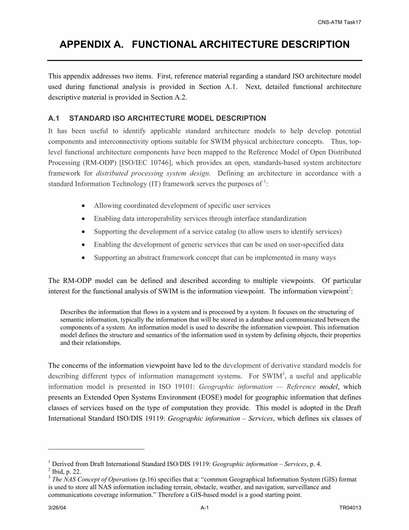
CNS-ATM Task17
3/26/04 A-1 TR04013
APPENDIX A. FUNCTIONAL ARCHITECTURE DESCRIPTION
This appendix addresses two items. First, reference material regarding a standard ISO architecture model used during functional analysis is provided in Section A.1. Next, detailed functional architecture descriptive material is provided in Section A.2. A.1 STANDARD ISO ARCHITECTURE MODEL DESCRIPTION It has been useful to identify applicable standard architecture models to help develop potential components and interconnectivity options suitable for SWIM physical architecture concepts. Thus, top-level functional architecture components have been mapped to the Reference Model of Open Distributed Processing (RM-ODP) [ISO/IEC 10746], which provides an open, standards-based system architecture framework for distributed processing system design. Defining an architecture in accordance with a standard Information Technology (IT) framework serves the purposes of 1:
• Allowing coordinated development of specific user services
• Enabling data interoperability services through interface standardization
• Supporting the development of a service catalog (to allow users to identify services)
• Enabling the development of generic services that can be used on user-specified data
• Supporting an abstract framework concept that can be implemented in many ways
The RM-ODP model can be defined and described according to multiple viewpoints. Of particular interest for the functional analysis of SWIM is the information viewpoint. The information viewpoint2:
Describes the information that flows in a system and is processed by a system. It focuses on the structuring of semantic information, typically the information that will be stored in a database and communicated between the components of a system. An information model is used to describe the information viewpoint. This information model defines the structure and semantics of the information used in system by defining objects, their properties and their relationships.
The concerns of the information viewpoint have led to the development of derivative standard models for describing different types of information management systems. For SWIM3, a useful and applicable information model is presented in ISO 19101: Geographic information — Reference model, which presents an Extended Open Systems Environment (EOSE) model for geographic information that defines classes of services based on the type of computation they provide. This model is adopted in the Draft International Standard ISO/DIS 19119: Geographic information – Services, which defines six classes of
1 Derived from Draft International Standard ISO/DIS 19119: Geographic information – Services, p. 4. 2 Ibid, p. 22. 3 The NAS Concept of Operations (p.16) specifies that a: “common Geographical Information System (GIS) format is used to store all NAS information including terrain, obstacle, weather, and navigation, surveillance and communications coverage information.” Therefore a GIS-based model is a good starting point.

CNS-ATM Task17
3/26/04 A-2 TR04013
IT services used to categorize geographic services. These services, which can also be related to SWIM services, are defined as4:
• Human Interaction Services: services for management of user interfaces
• Model/Information Management Services: services for management of the development, manipulation, and storage of metadata, conceptual schemas, and datasets
• Workflow/Task Services: services that support specific task activities conducted by humans; they support the development of products involving a sequence of steps conducted by different persons
• Processing Services: services that perform computations involving data
• Communication Services: services for encoding and transfer of data across communication networks
• System Management Services: services for the management of system components, applications and networks; includes management of user accounts and access privileges
According to the ISO RM-ODP model, to support flexible deployment, the defined Information Technology (IT) systems information services should be structured as multi-tiered distributed architectures, such as is depicted in Figure A-1.
Workflow taskservices
Shared processingservices
User processingservices
Model/Informationmanagement
services
Human interactionservices
Systemmanagement
services
Communicationservices
Figure A-1: Logical Multi-Tiered Architecture5 4 Draft International Standard ISO/DIS 19119, p. 23

CNS-ATM Task17
3/26/04 A-3 TR04013
A.2 FUNCTIONAL ARCHITECTURE DETAILS The SWIM functional architecture has been captured using functional hierarchy diagrams, functional flow diagrams (to capture the relationships between functions) and data flow diagrams. This section provides an overview of the functions that comprise the functional hierarchy of SWIM prior to presenting the relationship and data flows between these defined functions. This overview, organized by functional levels within each branch of the SWIM functional hierarchy, provides a brief description of the functions. First, the highest-level SWIM functions are introduced. Then, each of these functional areas are decomposed where the function hierarchy capturing the decomposition is shown first, followed by a summary of the functions that comprise the each functional level and a description of each individual function. A.2.1 SWIM Highest-Level Functions Two SWIM functions shown in Figure A-2 have been defined to capture SWIM functionality at the highest level. These functions address the two general roles associated with SWIM – the support for and management of standardized NAS information to enable NAS-wide and dynamic exchange of information – Manage SWIM Information (1.0) – and the management of user accounts, security and SWIM connections – Manage SWIM Networks (2.0)
SWIM
Manage SWIMInformation
1.0
Manage SWIMNetworks
2.0
SWIM
Manage SWIMInformation
1.0
Manage SWIMNetworks
2.0
SWIM
Manage SWIMInformation
1.0
Manage SWIMNetworks
2.0
Figure A-2: SWIM Functions at the First Level Each of these first level functions has been decomposed into second level functions as shown in Figure A-3. The following sections, organized by each highest-level function identified for SWIM, address the second level functions as well as corresponding lower level functions at the third level of functional decomposition.
5 Ibid, p. 35.

CNS-ATM Task17
3/26/04 A-4 TR04013
SWIM
Manage SWIMInformation
1.0
Manage SWIMNetworks
2.0
Manage SWIMData1.3
Manage DataStorage
1.4
Manage SWIMInterfaces
1.1
Maintain NetworkSecurity
2.1
Manage NetworkConfigurations
2.3
Maintain Performance
2.4
Manage NetworkFaults
2.5
Manage SWIMAccounts
2.2
Broker ServiceRequests
1.2
SWIM
Manage SWIMInformation
1.0
Manage SWIMNetworks
2.0
Manage SWIMData1.3
Manage DataStorage
1.4
Manage SWIMInterfaces
1.1
Maintain NetworkSecurity
2.1
Manage NetworkConfigurations
2.3
Maintain Performance
2.4
Manage NetworkFaults
2.5
Manage SWIMAccounts
2.2
Broker ServiceRequests
1.2
Figure A-3: Second Level SWIM Functions A.3 MANAGE SWIM INFORMATION (1.0) AND ITS SUBFUNCTIONS Four functional areas associated with the management of SWIM information (Manage SWIM Information) have been defined. These include:
• Manage SWIM Interfaces
• Broker Service Requests
• Manage SWIM Data
• Manage Data Storage
The decomposition of Function 1.0 and its associated sub-functions is shown in Figure A-4. Each decomposed function is described in the following paragraphs.

CNS-ATM Task17
3/26/04 A-5 TR04013
Manage SWIMInterfaces
1.1
Control SWIM Access1.1.2
Register Member 1.1.2.1
Identify and
Authenticate Members
1.1.2.3
Authorize SWIM Access 1.1.2.4
Maintain Member
List1.1.2.2
Conduct Interface
Transactions1.1.3
Manage SWIMInformation
1.0
Supply Access Method
1.1.1
MaintainAccess Types1.1.1.2
Define Access Types 1.1.1.1
Translate Data
Format 1.1.3.1
Process SWIM-to-Member Requests
1.1.3.3
Process Member-to-
SWIM Requests
1.1.3.4
Exchange Status/Control
Messages1.1.3.5
Convert Communica
tion Protocol1.1.3.2
Manage SWIMData1.3
Manage DataStorage
1.4
Maintain NASInformation Directories
1.3.2
Maintain NAS
Information Object
Directory 1.3.2.2
Maintain NAS Information
Directory1.3.2.1
Define SWIM Information
Structure1.3.1
Define a Common Data
Model for NAS
Information 1.3.1.2
Define NAS Information
Objects 1.3.1.3
Define NAS information Directory
1.3.1.1
Access SWIM
Databases1.4.1
Manage SWIM
Database Links 1.4.1.1
Manage SWIM
Database Transaction
1.4.1.2
Backup/Recover
Databases1.4.1.3
Broker ServiceRequests
1.2
Process Transactions1.2.2
Maintain Registration
1.2.1
Provide Core Application Functions
1.2.4
Prioritize Requests
1.2.2.1
Maintain Local
SWIM Member
Registration1.2.1.1
Maintain Remote Broker
Registration Information
1.2.1.2
Provide Broker NamingService1.2.1.3
Process PublishRequests
1.2.2.2
Process Subscribe Requests
1.2.2.3
Process Query Requests
1.2.2.4
Validate Member
Data1.2.3.1
Perform Data Services
1.2.3
Handle Events1.2.4.1
Provide Stream
Data Services1.2.4.2
Process Informati
on Objects1.2.3.2
Balance SWIM Load
1.2.2.7
Process Control/Status
Messages 1.2.2.6
Perform Discovery Services1.2.2.5
Manage SWIM
Databases1.4.2
Support Agent Progra
ms 1.2.4.3
Maintain SWIM Access
Limitations1.1.2.5
Figure A-4: Function 1.0 and Its Subfunctions A.3.1 Manage SWIM Interfaces (1.1) This function supports the connection or interface between a SWIM Member (NAS system or user) and SWIM. The management of interfaces must define means or methods for Members to access SWIM; accommodate transactions between SWIM and its Members; validate users and control access by member registration and/or authentication; and support the translation of data (formats, protocols, etc) across the interface from non-SWIM or local formats to SWIM formats. A.3.1.1 Supply Access Methods (1.1.1) An access method is a predefined standard that describes the handshake between SWIM and SWIM Members. This includes the definition of the “information interface” (e.g. the data to be exchanged on SWIM). The attributes that make up an access method may include:
• Information identity
• SWIM information/services needed (such as subscribing to SWIM information meeting a specified criteria (i.e. search pattern))
• SWIM information/services provided (such as publishing certain information to SWIM)
• Communication protocol used to interface to SWIM
• Service/data constraints (such as desired quality of service level, required delivery time window, preferred source of information, data transfer rate, etc.)
• Security information (such as dissemination limitations)
CNS-ATM Task17
3/26/04 A-6 TR04013
The use of access methods supports the augmentation of SWIM participants and functionality in a modular (plug-in) fashion. In order to supply access methods to SWIM members, this function further needs to:
• Define access methods
• Maintain access methods
These two tasks become fourth level functions and are described below. A.3.1.1.1 Define Access Methods (1.1.1.1) This function defines the standardized interfaces to SWIM. The formats, attributes, and associated values that comprise SWIM Access Methods need to be identified. Once a general template for an Access Method is developed, specific instances of this template can be defined to address the interface of SWIM to specific SWIM Members or categories of members. A.3.1.1.2 Maintain Access Methods (1.1.1.2) This function creates, deletes, and updates the definition and specification of a SWIM access method upon valid user request. When SWIM receives a request to create a new access method, this function first ensures the validity of the request. It then provides the appropriate access method template format; accepts the data required to define a new interface specification; ensures that all required attributes/parameters are provided; and verifies that the provided parameter values are within their defined boundaries. SWIM then produces and maintains the new access method specification. When SWIM receives a request to delete an unneeded access method, it uses predefined processes and/or qualifications for access method deletion to validate the request. If the validation of the deletion request is successful, SWIM searches for SWIM Members that are associated with the identified access method. SWIM informs these Members of the deletion request and/or determines an alternative interface definition to utilize for the Member. After all affected members have established interface via a different access method, SWIM deletes the access method definition. When SWIM receives a request to change the definition of an access method, a method similar to that defined for access method deletion is used. In this case, after identifying Members associated with the access method of interest, these Members are informed of the change request and/or implications of the change. A.3.1.2 Control SWIM Access (1.1.2) This function categorizes the SWIM Members, assigns access privileges, and authenticates existing Member connections to SWIM. This includes the association of Members with standardized interface specifications (access methods) and the identification of the active Member population. This function
CNS-ATM Task17
3/26/04 A-7 TR04013
registers or expels members and changes authorization as needed. To accomplish this functionality, the following sub-functions are utilized:
• Register Member
• Maintain Member List
• Identify and Authenticate Members
• Authorize SWIM Access (Member Data Protection)
• Maintain SWIM Access Limitations
Each of these sub-functions is described in the following paragraphs. A.3.1.2.1 Register Members (1.1.2.1) This function enrolls in a formal manner authorized NAS users/resources that wish to exchange information via SWIM. When SWIM receives a registration request in the form of member login information, it uses a local member directory to determine the status of the NAS user/resource (e.g. new, existing or denied member). This function includes the generation of an appropriate response the NAS user/resource registration request. A.3.1.2.2 Maintain Member List (1.1.2.2) This function maintains a directory of registered SWIM Members. This may be accommodated at local implementations of SWIM in addition to a SWIM-wide level. If a new Member is created locally, then a registration update is needed to update the general SWIM Member directory. A.3.1.2.3 Identify and Authenticate Members (1.1.2.3) When SWIM receives Member information (e.g. identification, password, other authentication data) as part of a connection request, this information is validated and processed with additional security data. This function provides a response to the connection request and creates and/or modifies the active Member list as necessary. A.3.1.2.4 Authorize SWIM Access (1.1.2.4) To authorize a SWIM Member to participate in SWIM, this function uses access privilege information that may describe an association between specific SWIM Members (or categories of Members) and available standardized interface connection types (i.e. access methods). SWIM provides an inquiring Member with a list of the access methods available to that Member and authorizes access to the appropriate SWIM information for that Member. A.3.1.2.5 Maintain SWIM Access Limitations (1.1.2.5) The mission-critical nature of NAS information demands strict access control of NAS information. This function is responsible for limitations on SWIM access. As access limitations (such as restricting method of access, location or port of access, time of access, resource being access, requested information, etc) are

CNS-ATM Task17
3/26/04 A-8 TR04013
defined or modified, this function will create or update the user/resource access information and ensure integrity and consistency within SWIM. A.3.1.3 Conduct Interface Transactions (1.1.3) This function addresses the communicative actions or activities across a shared interface between SWIM and SWIM Members. Members can access SWIM data and services by performing queries and subscribing to information through the SWIM member interface. Additionally, resource Members can publish information to SWIM through the SWIM member interface. This function accommodates the translation of member requests from a format specific to a local implementation of SWIM to a more generic format that can be accommodated by general SWIM functionality. Sample types of transactions accommodated via the SWIM interface are identified below. Member-to-SWIM requests:
• Search for available SWIM information and services (directory information): This request comes from a SWIM Member to check for specific SWIM information or services available to the Member.
• Query: SWIM Members request a specific type of information previously published (one time) or to be published in the future
• Subscribe: SWIM members request SWIM to deliver a specific type of information in the future (continuous delivery); subscriptions can be episodic or can be regular
• Unsubscribe: Reverse of a previous subscribe request.
• Publish: SWIM Member provide the NAS data/information for SWIM to distribute to subscription/query Members.
SWIM-to-Member requests:
• SWIM sends published information to SWIM members
• SWIM sends the query results back to the querying member
Exchange of Status/Control messages:
• Member status reported to SWIM: A Member status report is a set of health parameters that correspond to a SWIM member; it may be sent to SWIM periodically to inform SWIM of the current status of the member
• Local configuration update to SWIM: This is a report from a SWIM Member to SWIM to report changes to its configuration parameters (such as change of network address(es), temporary or permanent failure of the member’s components, etc.)
• SWIM status report to a SWIM Member: SWIM status report is a set of health parameters of SWIM. It is sent to SWIM Members periodically.
• SWIM control message to a SWIM Member: This is a set of commands sent from SWIM to a SWIM member or members for them to take specified actions (such as reconfigure, recover database, backup database and etc.)
CNS-ATM Task17
3/26/04 A-9 TR04013
• SWIM alert/failure to SWIM Member: A SWIM alert/failure can be defined as a status condition in SWIM such that when a certain condition or threshold is met, SWIM is considered in an “Alert” and/or ”Failure” state; an alert or failure can be used to signal a condition of interest or the inability to perform an expected action at a specified or desired performance level. When a SWIM alert/failure is detected, it is distributed to affected SWIM members for proper action to be taken.
Examples of SWIM requests are:
• On taxi out, the flight’s time-based trajectory is continually updated in SWIM. Members may request trajectory information that is continuously updated.
• SWIM can provide continuously updated information describing NAS resources, including service constraints and infrastructure status.
• SWIM provides pilots with the same flight condition information (e.g. weather reports) available to service providers via datalink.
To conduct interface transactions, this function needs to:
• Translate Data Format
• Convert Communication Protocols
• Process SWIM-to-Member Requests
• Process Member-to-SWIM Requests
• Exchange Status/Control Messages
A description of each sub-function is provided in the following paragraphs. A.3.1.3.1 Translate Data Format (1.1.3.1) When SWIM receives SWIM-to-Member requests or SWIM-to-Member status/control messages, this function uses local data format definitions and the SWIM common data model format to convert SWIM messages to and from local data formats (i.e. formats specific to members or to local implementations of SWIM). A.3.1.3.2 Convert Communication Protocols (1.1.3.2) When receiving Member-to-SWIM requests or Member-to-SWIM status/control messages, this function uses SWIM common interface protocols and protocols specific to members or local implementations or SWIM, to convert SWIM message protocols to and from local communication protocols (i.e. protocols specific to NAS members or to local implementations of SWIM). A.3.1.3.3 Process SWIM-to-Member Requests (1.1.3.3) When a SWIM-to-Member request is received, this function first checks the validity of the request against its data format, data validity (delivered within the given time window), access privileges etc. After initial processing, this function performs actions specific to the request.

CNS-ATM Task17
3/26/04 A-10 TR04013
If the request is asking for local data, this function parses the request against the data supported at the local interface and sends a command to the local system to obtain the requested data. When the requested data is obtained, it is translated back to SWIM common data model format and the requested data is forwarded to SWIM using the SWIM common access protocol. When received SWIM data is addressed to a target SWIM Member, this function checks the source and received data for validity. SWIM extracts the data from the interface language format and converts the data to local format if necessary. As appropriate, this function 1) acknowledges the reception of the data, 2) logs in its reception time and 3) processes the data. When this function receives a routed service request from another SWIM function, it provides the requested information or service to the SWIM element requesting the information or service as well as providing a response to the SWIM function that requested the routed service. A.3.1.3.4 Process Member-to-SWIM Requests (1.1.3.4) When a Member-to-SWIM request (publish, subscribe, unsubscribe, query, or register) is received, this function first checks the validity of the request against its data format, data validity (delivered within the given time window), access privileges and etc. After the initial processing, this function performs actions specific to the request:
• If the request is to register a SWIM member, this function takes required information, forms a local register request, and forwards the request to SWIM.
• If the request is to publish data to SWIM, this function translates the publish request, gathers data, forms publishing information objects and forwards them to SWIM.
• If the request is to subscribe/unsubscribe or query certain SWIM information, this function takes member specified constraints and forms a subscription, then forwards the subscription to SWIM.
A.3.1.3.5 Exchange Status/Control Messages (1.1.3.5) When a Status/Control message is received, this function first checks the validity of the message against its data format, data validity (delivered within the given time window), access privileges and etc. After the initial processing, this function performs actions specific to the request:
• When this function receives a SWIM control message, message requesting local status or alert message, it decides where and how to send the control message (broadcast, multicast or to a single address) locally. It processes any acknowledgement or status reports received in response to the control/status messages and performs local configuration updates as necessary.
• When a local status report or configuration update message is to be sent to SWIM, this function applies the destination information to the messages, translates the message to SWIM common data model format, and forwards the message to SWIM.

CNS-ATM Task17
3/26/04 A-11 TR04013
A.3.2 Broker Service Requests (1.2) Processing or brokering service requests is a key SWIM function. Upon receipt of SWIM Member requests to make information available or to access information, SWIM prioritizes the requests, determines appropriate actions, and then routes the requests and/or instructions to specific processing nodes (databases, cached information, or target SWIM members). To accommodate this functionality, several sub-functions are required. These include:
• Maintain Registration
• Process Transactions
• Perform Data Services
• Provide Core Application Programs
Each of the tasks (sub-functions) are described in the following paragraphs. A.3.2.1 Maintain Registration (1.2.1) This function maintains (creates, adds, deletes, updates) the registration of SWIM Members. The registration process for a specific broker addresses Members interact directly with that broker as well as Members that register through other SWIM brokers, if any. A.3.2.1.1 Maintain Local SWIM Member Registration (1.2.1.1) This function maintains (creates, adds, deletes, updates) the registration of SWIM Members that register directly through the SWIM broker of interest (i.e. the local broker). A.3.2.1.2 Maintain Remote Broker Registration information (1.2.1.2) This function maintains (adds, deletes, updates) the registration of SWIM members that register through SWIM brokers other than the broker of interest (i.e. via a remote broker) if any. A.3.2.1.3 Provide Broker Naming Service (1.2.1.3) This function supports the association or binding of a SWIM component (e.g. Member, broker) name to a physical location (such as IP address). The name binding is stored by the broker naming service. A.3.2.2 Process Transactions (1.2.2) This function addresses the processing of received SWIM Member requests. Actions associated with this function include the prioritization of requests; processing of transaction requests such as publish, subscribe, and query; performing discovery services; processing control/status messages; and finally, addressing load balancing for SWIM. A.3.2.2.1 Prioritize Requests (1.2.2.1) This function manages the processing order of incoming SWIM requests. Many different ordering mechanisms can be defined and used in this function. Examples include:

CNS-ATM Task17
3/26/04 A-12 TR04013
• Priority based: Each request is given a priority level either manually or automatically. Exchange of operational data may be assigned high priority, while administrative data requests may be assigned lower priority levels. Report of alerts and failures may be assigned higher priority for quick response.
• First In First Out (FIFO): Requests are ordered according to the time they are received and processed accordingly.
A.3.2.2.2 Process Publish Requests (1.2.2.2) When an information object is published, this function associates it with matching subscriptions and distributes the information object to those interested subscribers. Certain published information objects (e.g. last published, or designated objects) may be stored in data marts for future fast retrieval. This function also keeps a record of the publish requests and associated responses as part of assessment of service quality. A.3.2.2.3 Process Subscribe Requests (1.2.2.3) When a request for a subscription is received, this function stores the subscription. As information objects are published, they are matched to the stored subscription requests (see Process Publish Requests above). If SWIM has multiple brokers, then subscription requests may also be sent to other brokers. A.3.2.2.4 Process Query Requests (1.2.2.4) When a query request is received, this function follows the following procedure to process the request:
• If requested information is currently being provided in SWIM, then information can be provided to the querying member directly
• If the requested information is associated with a SWIM data mart, then this function issues a data mart query to the data mart and provides the querying member with the response
• If the requested information is mapped to a NAS data warehouse (one type of SWIM Member), then this function issues a data warehouse query and provides the querying member with the response
• If the requested information is not found, then an appropriate response indicating such is provided to the querying member
A.3.2.2.5 Perform Discovery Services (1.2.2.5) This function extracts information “search patterns” defined in SWIM information requests, maps them to available resources for processing, and ensures a response is generated for the requesting Member. Requests may be addressed through examination of registered information in SWIM and/or query of NAS databases which are SWIM Members. This function must address discovery requests for information tracked/managed by a local broker as well as information published via other brokers or other broker domains (if applicable).

CNS-ATM Task17
3/26/04 A-13 TR04013
A.3.2.2.6 Process Control/Status Messages (1.2.2.6) The exchange of control and status messages (defined in function 1.1.3) between SWIM and SWIM Members are addressed by this function. Messages may include: Member-to-SWIM control/status messages:
• Local configuration update report back to SWIM
• Local status report back to SWIM
• Collected local data received by SWIM
• Response messages from SWIM Members to SWIM
SWIM-to-Member control/status messages:
• SWIM status report to SWIM Members
• SWIM control commands to SWIM Members
• SWIM response messages to SWIM Members
For Member-to-SWIM control/status messages, this function parses a message, extracts content and then processes the messages. For SWIM-to-Member control/status messages, this function decides on a distribution method (broadcasting, multicasting, or single delivery), applies a SWIM common data model to the message, and sends the message to appropriate Member(s). A.3.2.2.7 Balance SWIM Load (1.2.2.7) Load balancing is dividing the amount of work that a computer has to do between two or more computers so that more work gets done in the same amount of time and, in general, all members get served faster. Load balancing can be implemented with hardware, software, or a combination of both. When SWIM-to-Member or Member-to-SWIM requests are received, this function provides load balancing when routing member requests. This is achieved by recognizing overloaded servers and sending requests to less burdened servers. A.3.2.3 Perform Data Services (1.2.3) This function addresses the provision of data services for exchanged SWIM data. These services include validation of Members and the data they provide in addition to the packaging of information for exchange over SWIM. A.3.2.3.1 Validate Member Data (1.2.3.1) This function validates data or requests received from SWIM Members. Validation tasks include validating data format and checking data access rights. A.3.2.3.2 Process Information Objects (1.2.3.2) Processing of information objects includes the following:

CNS-ATM Task17
3/26/04 A-14 TR04013
• Transforming metadata so that it can be evaluated with SWIM subscriptions
• Packaging information objects for those data items that come from data marts or from publishing Members so that they can be disseminated to subscribers or querying Members
A.3.2.4 Provide Core Application Functions (1.2.4) This function constitutes the core application functions that support negotiation and management of SWIM services. These applications address event handling (e.g. error events), support for stream data exchange and accommodation of agent programs (where agent programs are a type of dynamic support applications that can be adapted for specific users, systems or facilities). A.3.2.4.1 Handle Events (1.2.4.1) This function addresses SWIM defined events (such as error conditions, exception cases and etc.). When defined event condition thresholds are exceeded, this function will address the event based on pre-defined procedures. It may have to notify corresponding systems or human operators of the events so that the event can be handled automatically or manually. A.3.2.4.2 Provide Stream Data Services (1.2.4.2) This function provides specific services (for instance, processing a Stream-data Publishing-notice Information Object – see Section G.2.1.1) to support the exchange of stream data within SWIM. It supports the set up of virtual direct source-to-sink connection for stream data publishers and subscribers. A.3.2.4.3 Support Agent Programs (1.2.4.3) The role of this function depends on the kinds of agent programs that are supported by SWIM. For example, as NAS conditions change, SWIM may enable a flight planner to access information that can be used to determine the impact of a proposed flight change on the flight and on NAS loading conditions. Intelligent agents may be introduced at some point in the implementation of SWIM to allow the identification of the best alternatives for a flight plan in light of ATM system changes and member preferences. Agent program may also be used for a variety of different purposes. This function needs to:
• Collect data for agent programs
• Distribute messages produced by agent programs
A.3.3 Manage SWIM Data (1.3) The management of SWIM data includes support for the definition of data structures and maintaining dictionaries and information directories. A.3.3.1 Define SWIM Information Structure (1.3.1) This function defines the SWIM common data model, information objects, and ontology associated with the data model.

CNS-ATM Task17
3/26/04 A-15 TR04013
A.3.3.1.1 Define NAS Information Directory (1.3.1.1) This function groups and links data elements that are associated with NAS information structures in a hierarchy so that data elements relationships can be identified. Those data elements that are not usefully grouped into hierarchies are kept as data collections or unstructured data sets. A.3.3.1.2 Define Common Data Model for NAS Information (1.3.1.2) This function defines a common data model for NAS information. The common data model is a SWIM and NAS-wide predefined and agreed upon definition of data structures that is used to make NAS information understandable by all SWIM members. The basic attributes of a common data model may include:
• Data source
• Data Destination
• Data Format
• Data Creation Time
• Data Expiration Time
• Search Attributes
The model structure can be as simple as predefined “wrapper” or “header” fields encapsulating NAS information so that it can be passed via SWIM and the encapsulated NAS information can be extracted when it reaches destination. Alternatively, the common data model can be as complex as a NAS-wide agreement to organize NAS information in a uniform format (e.g., a piece of weather information is defined in one format regardless of its sources) so it can be used uniformly throughout NAS. Once the common data model has been agreed upon, this function will provide its schema or structure. A.3.3.1.3 Define NAS Information Objects (1.3.1.3) This function defines NAS information objects. A NAS information object is a representation of NAS information conforming to the common data model with defined common searchable attributes. It is an instance of an object schema that defines and abstracts a category of data using attribute-value pairs. Object schemas are stored in SWIM. Members can query SWIM to discover the existence of an object and associated metadata values that support querying and establishment of subscriptions service. With in the data model definitions, this function defines common searchable attribute-value pairs so that NAS information can be indexed and searched based on such attributes. The main tasks are to:
• Identify data attributes
• Assign values to attributes
• Define common searchable attributes
• Categorize data with attribute-value pairs

CNS-ATM Task17
3/26/04 A-16 TR04013
A.3.3.2 Maintain NAS Information Directories (1.3.2) This function maintains (creates, update, adds, deletes) the information directories associated with the SWIM common data model, information objects, and the ontology associated with the data model. A.3.3.2.1 Maintain NAS Information Directory (1.3.2.1) This function maintains the NAS information object definitions and directories. SWIM includes a repository of NAS information object definitions, including data schemas. As necessary new information objects can be defined, ensuring that these definitions do not conflict with others. Also, SWIM supports the ability to interrogate the object repository. This function includes:
• Providing temporary storage of information objects
• Interfacing to searches of the SWIM index
A.3.3.2.2 Maintain NAS Information Object Directory (1.3.2.2) This function monitors and updates any proposed changes to the NAS information directory or the NAS information object directory. As necessary, it rejects updates that may degrade their integrity or consistency. A.3.4 Manage Data Storage (1.4) This function manages the access to SWIM data storage (data marts, data warehouses (if applicable)); maintains the links/connections of SWIM data storage devices; processes data storage transactions and performs data recovery and backups. A.3.4.1 Manage SWIM Databases (1.4.1) This function manages the SWIM database(s). These databases can be centralized or distributed. The main tasks of this function are to:
• Manage SWIM database connections
• Manage SWIM databases transactions
• Backup and recover databases
NAS resources in the SWIM environment will be registered in a NAS resource database that can incorporate a common geographical reference shared by other NAS databases such as weather and flight objects. Examples of SWIM Member databases may include:
• Common Weather database (graphical and textual), indexed with NASCR
• Common System Flow Constraint database (i.e., SUA, system outage, flow rate, acceptance rate, etc)
• Common flight track database
• Common surveillance data distribution servers

CNS-ATM Task17
3/26/04 A-17 TR04013
• Common aeronautical data distribution servers (i.e, maps, SIDs, STARs, set)
• eNOTAM
A.3.4.1.1 Manage SWIM Database Links (1.4.1.1) This function manages the connections among SWIM databases. The main tasks for this function are to:
• Manage global names in the distributed system
• Create database links
• Create shared database links
• Manage database links
• View information about database links
• Create location transparency
• Manage statement transparency
• Monitor and report database link health status
A.3.4.1.2 Manage SWIM Database Transactions (1.4.1.2) This function maintains SWIM database consistency and integrity as it receives NAS data or data updates. It answers requests for data or provide inputs updates to SWIM databases. Main tasks for this function are to:
• Control connections established by database links
• Maintain reference integrity in the distributed system
• At the input of a database query, process the query and provide a response back to the request
• Monitor and report database health status
• Synchronize SWIM databases
A.3.4.1.3 Backup/Recovery Databases (1.4.1.3) When SWIM receives database control commands to backup or recover database(s), this function backs up or recovers the SWIM databases; responds back to the control commands; and provides regular (such as daily or weekly) backup operations to the databases as needed. A.3.4.1.4 Access SWIM Databases (1.4.2) This function provides mechanisms to access data from SWIM data marts and data warehouses (if data warehouses are applicable). A.4 MANAGE SWIM NETWORKS (2.0) AND ITS SUBFUNCTIONS The tasks of the Manage SWIM Networks function are to:

CNS-ATM Task17
3/26/04 A-18 TR04013
• Maintain Network Security: This function sets up and maintains a member access privilege directory, the member classification directory, and the NAS info classification directory. This function also manages SWIM security control, defines security algorithms, and maintains security data and logs.
• Manage SWIM Accounts: This function tracks the usage of network resources and establish the associated records and charges (if applicable).
• Manage Network Configurations: This function manages the configuration of SWIM resources, provides naming services, and controls overall SWIM elements and databases.
• Maintain Performance: This function addresses the management of quality control services in SWIM. SWIM resource status, traffic flow, and other parameters related to the defined system alerts and failures are monitored, evaluated and reported.
• Manage Network Faults: This function manages fault recognition, fault diagnosis, fault isolation and fault removal.
The decomposition of Function 2.0 and its associated sub-functions is shown in Figure A-5. Each decomposed function is described in the following paragraphs.
Manage SWIMNetworks
2.0
Maintain NetworkSecurity
2.1
Manage NetworkConfigurations
2.3Maintain Performance
2.4
Manage NetworkFaults
2.5
Manage SWIMAccounts
2.2
Maintain Security Functions and Data
2.1.1
Manage Security Attributes
2.1.2
Manage Public Key Infrastructure (PKI)
2.1.3
Maintain Security Audits 2.1.4
Establish Naming Service Directory and
Services2.3.1
Configure SWIM Networks and Services
2.3.2
Cache Exchanged NAS Information
2.3.3
Distribute SWIM Status/Control
Messages 2.3.4
Monitor SWIM Connectivity
Status 2.4.1
Monitor SWIM Flow of Data
Status2.4.2
Monitor SWIM Traffic
Performance Status 2.4.3
Collect SWIM Quality Control
Data 2.4.4
Evaluate Service Quality
2.4.5
Adjust Communication
Load 2.4.6
Maintain Operation Monitoring
Configuration2.3.5
Detect and Diagnose Faults2.5.1
Remove Faults and Recover System
2.5.2
Maintain Accounts2.2.1
Manage Account Security Policy Implementation
2.2.2
Manage Account Monitoring Services
2.2.3
Protect SWIM Resource Allocations
2.3.6
Manage SWIM Security Functions Infrastructure
2.3.7
Maintain Secure Communications (Trusted
Path/Crypto)2.3.8
Figure A-5: Function 2.0 and Its Subfunctions A.4.1 Maintain Network Security (2.1) The mission-critical nature of the NAS information demands strict access control of NAS information. This function is responsible for SWIM-wide security information control. It maintains the SWIM-wide member directory, NAS information classification directory, and access privilege directory. A local copy

CNS-ATM Task17
3/26/04 A-19 TR04013
of each of these directories is kept for each SWIM Member. This function updates any changes to these directories and maintains the integrity and consistency for these directories. It classifies differing data security levels and correlates access to the validated security level to each member. The main tasks for this function are:
• Maintain the member classification directory
• Maintain the NAS information classification directory
• Maintain the access privilege directory
• Update security control information
• Define authentication algorithms
• Maintain security data and logs
Each of the tasks becomes a sub-function as described in the following paragraphs. A.4.1.1 Maintain Security Functions and Data (2.1.1) SWIM security functions consists of 11 security functional components6, they are: security audit; communication; cryptographic support; user data protection; identification and authentication; security management; privacy; protection of the TOE (Target of Evaluation, i.e., SWIM) security functions; resource utilization; TOE (SWIM) access; and trusted path/channel. This function (2.1.1) manages and maintains the implementations of these security functions and associated data based on SWIM security policies. It ensures that SWIM resources and other information assets are well managed, protected, and distributed within SWIM. It also provides user data protection during import, export, and storage. A.4.1.2 Manage Security Attributes (2.1.2) A security attribute is a piece of information that is needed to establish and describe the protection mechanisms that secure the communications between two entities. Examples of such security attributes are the groups to which a member belongs, the priority of a process, and the access rights belonging to a role or a member. Managing these security attributes will allow SWIM to behave correctly as desired. A.4.1.3 Manage Public Key Infrastructure (PKI) (2.1.3) SWIM is basically a network-centric architecture with connections to data end users (person, applications, servers, etc), data suppliers (surveillance radars, weather radars, etc.), and partners (local law enforcement agencies, airlines, etc.) that brings risks through all these interfaces. PKI, applied in various zones of a network, supports identification, authentication, and encryption mechanisms to counter the potential threats thus reducing the associated risks.
6 Reference to Common Criteria Document -- TBD
CNS-ATM Task17
3/26/04 A-20 TR04013
This function, with the right implementation of PKI, ensures that all the SWIM authorized entities are talking to the right parties to preclude the loss of reasonable control of vital SWIM information. PKI will allow SWIM users to interact with other SWIM users, SWIM specific applications, or other authorized FAA partners, obtain and verify identities and keys, and register with trusted third parties. SWIM PKI will include the following components for its secure operations: Certificate authority (CA), registration authority (RA), public key certificate directory, and certificate revocation list (CRL). A.4.1.4 Maintain Security Audits (2.1.4) This function maintains and logs security data for security audits. Such as:
• Encrypted member passwords
• Tokens and public/private keys generated for the public key infrastructure
• Member login event log
• Others (to be determined)
A.4.2 Mange SWIM Accounts (2.2) This function tracks the usage of different types of services and network resources and establishes the associated usage records and costs (if applicable to SWIM). A.4.2.1 Maintain Accounts (2.2.1) This function maintains member account information, and assigns costs (if applicable) to member accounts. A.4.2.2 Manage Account Security Policy Implementation (2.2.2) This function provides access control to individual resources (i.e., allocate quotas for resource utilization). A.4.2.3 Manage Account Monitoring Services (2.2.3) This function monitors access to networks, resources, and services and tracks usage statistics. A.4.3 Manage Network Configuration (2.3) Management of the SWIM network configuration includes such functionality as establishing and managing naming services; configuration of SWIM service connections; caching of exchange information; distribution of control and status messages; monitor device configurations; protection of resource allocations; management of security infrastructure; and maintaining secure communications. Each of these component functions is addressed separately below. A.4.3.1 Establish Naming Service Directory and Services (2.3.1) The SWIM naming service provides the capability for a NAS member to be able access any NAS information exchanged over SWIM without the member having to know where the information is located. The SWIM naming service provides two types of transparency to SWIM members; one is location transparency, meaning that a NAS resource can be named independently of its physical location. A

CNS-ATM Task17
3/26/04 A-21 TR04013
location is usually expressed in terms of a network address of an underlying network protocol. The other type of transparency is the replication transparency; SWIM members need not know where an information object is replicated; a single name for a replicated information or service could be mapped to multiple (sub) objects or network addresses without the member being aware of this. At the input of resource addresses and resource names, this function sets up and maintains a naming service directory by mapping a resource name to its actual location (expressed in terms of network address of an underlying network protocol). It also provides a name mapping service for requesting parties. The main tasks for this function are to:
• Set up and maintain a naming service directory
• Manage a member-location transparent naming service for SWIM
• Receive network management (e.g. NIMS) update information regarding NAS configuration changes
• Check validity, consistency of the update with current naming service directory
• Update the naming service directory
• When a naming service update is received, update the naming service directory
• Provide naming service mappings to the Broker Service Requests Function (F2.2)
A.4.3.2 Configure SWIM Networks and Services (2.3.2) SWIM configuration describes the structure of the SWIM platform and its distributed members. It specifies how each SWIM resource is to interact with another resource. Some such cross-component dependencies are specified in the configuration files. For example, for two communicating resources implementing a certain version of a protocol, this function could also specify the dependency relationships for the service. It might specify that resource A and B or C together can provide a specific SWIM service, but that B or C alone can not. In this case resource A can never be taken offline for maintenance at the same time as either of the other two resources. These are the main tasks for this function:
• Maintain current SWIM resource configuration files
• Establish a new configuration
• Add a new resource
• Remove an existing resource
• Move a component from one server to another
• Delete unnecessary configuration files
• Accept local configuration updates from members, and modify configuration files as necessary

CNS-ATM Task17
3/26/04 A-22 TR04013
• Command SWIM resources with configuration control commands
• Monitor database health and send messages to control, backup, or recover databases
A.4.3.3 Cache Exchanged NAS Information (2.3.3) Cache means to store something temporarily, most often most recently accessed data or information. This function maintains the cache, that is, the copy of exchanged information updated during the processing. This saved information can be used to satisfy future requests for the same information instead of starting over with the original. Main tasks for this function is are to:
• Identify NAS information to be cached
• Decide the duration of a cached information
• Maintain consistency of cached information
A.4.3.4 Distribute SWIM Status/Control Messages (2.3.4) This function defines actions to be taken corresponding to alert or failure conditions. When an alert or a failure is received or generated, it then issues control commands to database(s), and/or SWIM resources to take the appropriate actions. A.4.3.5 Maintain Operation Monitoring Configuration (2.3.5) This function maintains the monitoring of configurations of devices connected to the network. A.4.3.6 Protect SWIM Resource Allocations (2.3.6) SWIM is a set of services provided by a distributed infrastructure of computers, servers, and networks. Managing and configuring these infrastructure components plays an important role in enabling the availability of SWIM resources to its authorized users such that there is no denial of service by means of monopolization of resources by other users or subjects. This function ensures that SWIM data, SWIM system/sub-system or a SWIM system resource is accessible and usable upon demand by an authorized SWIM entity. It allows the creation of quotas or other means of defining limits on the amount of resource space or time that may be allocated on behalf of specific SWIM users or subjects. The main tasks for this function are to:
Establish naming service directory and services according to users, their rights, what groups they belong to, and what roles they play
Provide configuration control of allocations to SWIM resources A.4.3.7 Manage SWIM Security Functions Infrastructure (2.3.7) The SWIM environment consists of multiple physically-separated components that form a distributed system, where timing issues associated with both user data and security-attribute data can become very
CNS-ATM Task17
3/26/04 A-23 TR04013
complex. The SWIM security infrastructure is the set of hardware, software, and firmware is relied upon for the enforcement of the SWIM security. The monitoring and management of the SWIM security infrastructure ensures proper operation of the SWIM components, and deters/addresses attempts to compromise the integrity of SWIM. The main tasks for this function lies in the following areas:
• Management of general installation and configuration: for example, SWIM configuration, manual recovery, installation of SWIM security fixes, repair and reinstallation of hardware.
• Management of routing control and maintenance of SWIM resources: for example, enabling and disabling peripheral devices, mounting of removable storage media, backup and recovery of user data and system objects.
A.4.3.8 Maintain Secure Communications (Trusted path/Crypto) (2.3.8) As mentioned above, SWIM is a set of services provided by a distributed infrastructure of computer servers and networks. The management and configuration of system and network equipment plays an important role in enabling and maintaining trusted communication between SWIM users and resources, locally or at remote sites. For securing information, maintaining secure communication requires secrecy or privacy to be preserved by preventing from unauthorized access or disclosure of data. For securing transactions, maintaining secure communication requires secrecy or privacy to be preserved by limiting transactions to authorized participants only. This function ensures confidence in the free movement of SWIM data in the SWIM network by employing cryptographic support and setting up trusted path/channels and thus achieving SWIM security objectives of confidentiality, integrity, identification, authentication, and accountability. A.4.4 Maintain Performance (2.4) SWIM enables NAS services, and therefore must provide services that meet NAS performance requirements. Service quality is maintained by definition and monitoring of specific events (i.e. a condition or activity of significance) that can be address any part of SWIM. Individual events defined in SWIM can trigger event handlers. Also, alerts may be triggered as a result of certain events (e.g. NAS information exceeds thresholds). SWIM supports the collection of information that may trigger alerts and subsequent distribution of alert “Alarms” to the appropriate SWIM members. The main tasks of this function are to:
• Monitor SWIM connectivity status
• Monitor SWIM flow of data status
• Monitor SWIM traffic performance status
• Collect data for SWIM defined alert functions, failures and critical thresholds for quality control
• Evaluate service quality
• Adjust Communication Load
CNS-ATM Task17
3/26/04 A-24 TR04013
Each of the tasks becomes a sub-function as described in the following paragraphs. A.4.4.1 Monitor SWIM Connectivity Status (2.4.1) In order to monitor the status of SWIM elements connectivity, this function requests status information from participating NAS resources, or collects information through the network management systems (e.g. FTI or NIMS). If any the local status alerts or failures are received, this function generates a SWIM-specific alert or a failure report as necessary. If a SWIM resource is not available, this function evaluates its relationship with SWIM services and issues service network adjustments commands to request network connection adjustment. A.4.4.2 Monitor SWIM Flow of Data Status (2.4.2) This function monitors the flow of SWIM data supporting SWIM services. If abnormal behavior occurs (e.g. a data item does not reach its target Member), this information is reported to SWIM management functions and alerts are generated as necessary. A.4.4.3 Monitor SWIM Traffic Performance Status (2.4.3) SWIM traffic performance is monitored to guarantee quality of service of operational data. If the traffic load is heavier than design load, or data transfer rate is below the required threshold rate, this function generates an alert and reports this behavior to SWIM management functions. This function also tracks and evaluates SWIM traffic performance status and generates alerts if thresholds are exceeded. It may issue service network adjustments commands to request a network connection adjustment. A.4.4.4 Collect SWIM Quality Control Data (2.4.4) This function collects data for alert functions and other quality of service related information. A.4.4.5 Evaluate Service Quality (2.4.5) This function uses collected parameter data to evaluate alert conditions and failure conditions. If an alert or a failure is detected, it is reported to a SWIM resource management function. A.4.4.6 Adjust Communication Load (2.4.6) This function monitors the SWIM communication load. It requests associated actions to adjust services based on communication load levels and interfaces to communication management systems to adjust communication performance. A.4.5 Manage Network Faults (2.5) This function provides constant monitoring of the network state; reports abnormal conditions (such as those exceeding certain threshold values during normal operations); traces faults through the system and performs diagnostic tests to decide the cause of the fault; and finally isolates the fault from the network and/or removes the fault and recovers the system.

CNS-ATM Task17
3/26/04 A-25 TR04013
A.4.5.1 Detect and Diagnose Faults (2.5.1) This function provides mechanisms (fault threshold setting and poll) to detect fault conditions in the network nodes and links. It also determines the causes of faults, traces a fault through the network, and isolate the faults. This function defines status conditions for SWIM resources such that when special status conditions are met, the SWIM resource is considered to be in an “Alert” or “Failure” state. This function provides access to all known constraint information, including outages, traffic density, weather, and airspace limitations (e.g., Special Use Airspace and commercial space boundaries, and special aviation event restrictions). This function accommodates SWIM support of common situational awareness by providing the mechanisms for alerting based on the existence of certain constraint conditions (e.g. overdue flights). When such conditions are identified, this function automatically searches for and retrieves relevant information for investigation and potential resolution of the constraint condition. This function defines the parameter thresholds associated with the set of “Alert” and “Failure” conditions so they can be collected and evaluated to ensure that any pre-defined abnormal behavior can be detected and reported to SWIM managers. A.4.5.2 Remove Faults and Recover System (2.5.2) This function provides means to remove faults either automatically or manually by reporting to human operators.

CNS-ATM Task17
3/26/04 A-26 TR04013

CNS-ATM Task17
3/26/04 B-1 TR04013
APPENDIX B. SWIM REQUIREMENTS
B.1 NAS LEVEL SWIM REQUIREMENTS This section reports on the methodology employed for deriving NAS level SWIM requirements during Task 17. First, the relationship between the NAS level SWIM requirements and NAS-SR-1000 was examined to determine applicability of existing NAS-SR-1000 requirements to SWIM and to determine where the NAS level SWIM requirements would fit in. Then, three sets of NAS-level SWIM requirements were derived as follows:
• Set 1 - From the sixteen high level functionalities abstracted in CNS-ATM Task 15 report.
• Set 2 - From the CONOPS and NWIS CONUSE documents.
• Set 3 - From the SWIM functions defined in Subtask 17A.
Finally, the three sets of requirements were consolidated to provide a single comprehensive non-overlapping set of NAS level requirements for SWIM. Just as with the NAS level requirements already specified in NAS-SR-1000, the resulting requirements for the most part are levied on the NAS, that is, they are not explicitly allocated to “SWIM”; however in many cases requirements are allocated to SWIM by inclusion of “SWIM” in the requirement statement. Each developed requirement is presented in terms of a statement containing the verb “shall”. Sentences not containing the verb “shall” are presented for informational purposes in order to place the requirement into context. B.1.1 Relationship Between NAS-SR-1000 and SWIM Requirements The existing requirements in NAS-SR-1000 were examined to determine their applicability to SWIM and to find a place in the NAS-SR-1000 documentation structure for NAS level SWIM requirements. This step is important because it serves as a check for backward compatibility and further guidance for the determination of the three sets of NAS level SWIM requirements. Note that the three requirements sets are derived from future information sharing concepts and needs of the NAS; however it is necessary to ensure that derived NAS level requirements for SWIM are compatible with the existing NAS requirements that, in most cases, are not going away. Five categories were used to select applicable requirements:
1. Performance constraint: The NAS-SR-1000 requirement imposes performance requirements on SWIM.
2. Information exchange: The NAS-SR-1000 requirement applies to an information exchange flow that may be assigned to SWIM.
3. Security constraint: The NAS-SR-1000 requirement imposes a security requirement on SWIM.
4. QoS constraint: The NAS-SR-1000 requirement imposes a QoS requirement on SWIM.
5. Backup constraint: The NAS-SR-1000 requirement imposes a backup requirement on SWIM.
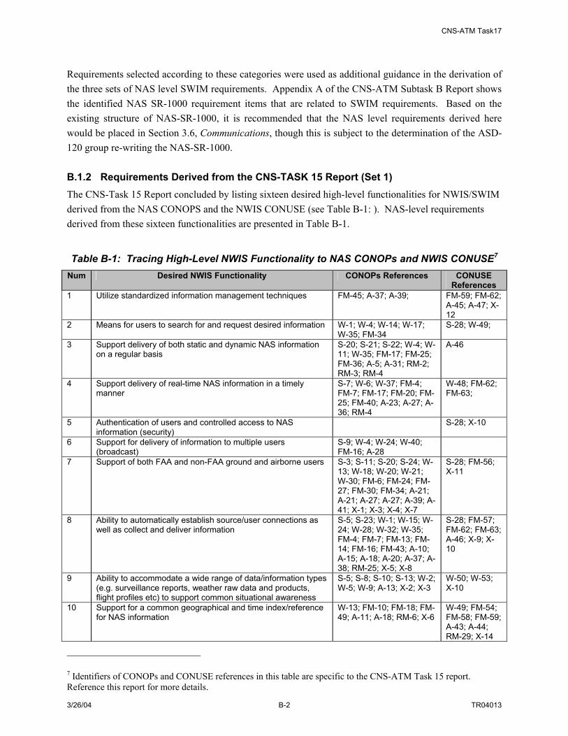
CNS-ATM Task17
3/26/04 B-2 TR04013
Requirements selected according to these categories were used as additional guidance in the derivation of the three sets of NAS level SWIM requirements. Appendix A of the CNS-ATM Subtask B Report shows the identified NAS SR-1000 requirement items that are related to SWIM requirements. Based on the existing structure of NAS-SR-1000, it is recommended that the NAS level requirements derived here would be placed in Section 3.6, Communications, though this is subject to the determination of the ASD-120 group re-writing the NAS-SR-1000. B.1.2 Requirements Derived from the CNS-TASK 15 Report (Set 1) The CNS-Task 15 Report concluded by listing sixteen desired high-level functionalities for NWIS/SWIM derived from the NAS CONOPS and the NWIS CONUSE (see Table B-1: ). NAS-level requirements derived from these sixteen functionalities are presented in Table B-1.
Table B-1: Tracing High-Level NWIS Functionality to NAS CONOPs and NWIS CONUSE7 Num Desired NWIS Functionality CONOPs References CONUSE
References 1 Utilize standardized information management techniques FM-45; A-37; A-39; FM-59; FM-62;
A-45; A-47; X-12
2 Means for users to search for and request desired information W-1; W-4; W-14; W-17; W-35; FM-34
S-28; W-49;
3 Support delivery of both static and dynamic NAS information on a regular basis
S-20; S-21; S-22; W-4; W-11; W-35; FM-17; FM-25; FM-36; A-5; A-31; RM-2; RM-3; RM-4
A-46
4 Support delivery of real-time NAS information in a timely manner
S-7; W-6; W-37; FM-4; FM-7; FM-17; FM-20; FM-25; FM-40; A-23; A-27; A-36; RM-4
W-48; FM-62; FM-63;
5 Authentication of users and controlled access to NAS information (security)
S-28; X-10
6 Support for delivery of information to multiple users (broadcast)
S-9; W-4; W-24; W-40; FM-16; A-28
7 Support of both FAA and non-FAA ground and airborne users S-3; S-11; S-20; S-24; W-13; W-18; W-20; W-21; W-30; FM-6; FM-24; FM-27; FM-30; FM-34; A-21; A-21; A-27; A-27; A-39; A-41; X-1; X-3; X-4; X-7
S-28; FM-56; X-11
8 Ability to automatically establish source/user connections as well as collect and deliver information
S-5; S-23; W-1; W-15; W-24; W-28; W-32; W-35; FM-4; FM-7; FM-13; FM-14; FM-16; FM-43; A-10; A-15; A-18; A-20; A-37; A-38; RM-25; X-5; X-8
S-28; FM-57; FM-62; FM-63; A-46; X-9; X-10
9 Ability to accommodate a wide range of data/information types (e.g. surveillance reports, weather raw data and products, flight profiles etc) to support common situational awareness
S-5; S-8; S-10; S-13; W-2; W-5; W-9; A-13; X-2; X-3
W-50; W-53; X-10
10 Support for a common geographical and time index/reference for NAS information
W-13; FM-10; FM-18; FM-49; A-11; A-18; RM-6; X-6
W-49; FM-54; FM-58; FM-59; A-43; A-44; RM-29; X-14
7 Identifiers of CONOPs and CONUSE references in this table are specific to the CNS-ATM Task 15 report. Reference this report for more details.

CNS-ATM Task17
3/26/04 B-3 TR04013
Num Desired NWIS Functionality CONOPs References CONUSE References
11 Enabled by an integrated data network A-10 W-52; X-11 12 Monitor QoS and maintain specific QoS during network
failures X-11
13 Provide the ability to support legacy systems with minimal changes
S-20; S-21; W-23; FM-28; A-6; A-20
FM-61;
14 Ability to adapt to dynamic changes in information sources and users (sinks)
A-11; RM-6; RM-10; RM-12; RM-16; RM-18; X-4
S-28; FM-50; RM-26; RM-28; RM-29; X-10
15 Avoid single points of failure X-15 16 Provide a scalable and standards-based solution X-12; X-13
Table B-2: NAS-Level SWIM Requirements Derived from NWIS High-level Functionality (Set1)
Num Function Description Req. ID
NAS Level Requirement Statement
SET1-1 The NAS shall use common data standards for information [exchanged over SWIM]
1 Utilize standardized information managements techniques SET1-2 The NAS shall define common searchable attributes for NAS
information 2 Means for users to search
for and request desired information
SET1-3 The NAS shall provide means for users and service providers to request context sensitive information [over SWIM]
SET1-4 Upon a one-time request, the NAS shall deliver information [over SWIM] upon request by authorized user
3 Support delivery of both static and dynamic information on a regular basis
SET1-5 Upon a standing request, the NAS shall deliver information updates automatically (without constant requests) [over SWIM] to authorized users
4 Support delivery of real-time information in a timely manner
SET1-6 Upon a standing request, the NAS shall deliver real-time information on time [over SWIM]
SET1-7 The NAS shall assign different security levels to information to be exchanged [over SWIM]
SET1-8 The NAS shall authenticate users and resources that access NAS information [over SWIM]
5 Authentication of users and controlled access to NAS information (security)
SET1-9 The NAS shall assign authenticated users and resources specific access rights to information to be exchanged [over SWIM]
6 Support for delivery of information to multiple users (broadcast)
SET1-10 The NAS shall deliver information to multiple users and resources [over SWIM]
7 Support of both FAA and non-FAA ground and airborne users
N/A – Covered by other requirements
SET1-11 The NAS shall automatically establish source/user information connections [over SWIM]
SET1-12 Upon a standing request for information, the NAS shall automatically (without manual intervention) collect information [through SWIM]
8 Ability to automatically establish source/user connections as well as collect and deliver information
SET1-13 The NAS shall automatically (without manual intervention) deliver information [over SWIM]
9 Ability to accommodate a wide range of data types (e.g. surveillance reports, weather raw data and products, flight profiles etc) to support common situational awareness
SET1-14 The NAS shall define a common data model for information to be exchanged [over SWIM]
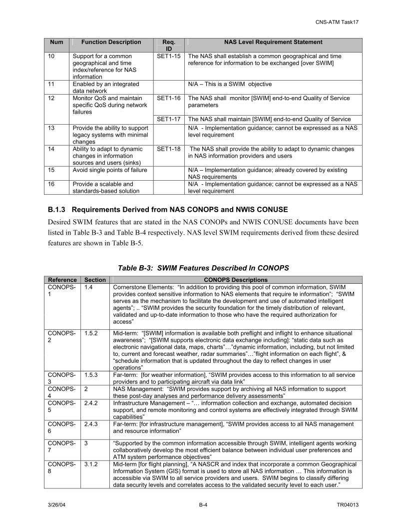
CNS-ATM Task17
3/26/04 B-4 TR04013
Num Function Description Req. ID
NAS Level Requirement Statement
10 Support for a common geographical and time index/reference for NAS information
SET1-15 The NAS shall establish a common geographical and time reference for information to be exchanged [over SWIM]
11 Enabled by an integrated data network
N/A – This is a SWIM objective
SET1-16 The NAS shall monitor [SWIM] end-to-end Quality of Service parameters
12 Monitor QoS and maintain specific QoS during network failures
SET1-17 The NAS shall maintain [SWIM] end-to-end Quality of Service 13 Provide the ability to support
legacy systems with minimal changes
N/A - Implementation guidance; cannot be expressed as a NAS level requirement
14 Ability to adapt to dynamic changes in information sources and users (sinks)
SET1-18 The NAS shall provide the ability to adapt to dynamic changes in NAS information providers and users
15 Avoid single points of failure N/A – Implementation guidance; already covered by existing NAS requirements
16 Provide a scalable and standards-based solution
N/A - Implementation guidance; cannot be expressed as a NAS level requirement
B.1.3 Requirements Derived from NAS CONOPS and NWIS CONUSE Desired SWIM features that are stated in the NAS CONOPs and NWIS CONUSE documents have been listed in Table B-3 and Table B-4 respectively. NAS level SWIM requirements derived from these desired features are shown in Table B-5.
Table B-3: SWIM Features Described In CONOPS Reference Section CONOPS Descriptions CONOPS-1
1.4 Cornerstone Elements: “In addition to providing this pool of common information, SWIM provides context sensitive information to NAS elements that require te information”; “SWIM serves as the mechanism to facilitate the development and use of automated intelligent agents”; .. “SWIM provides the security foundation for the timely distribution of relevant, validated and up-to-date information to those who have the required authorization for access”
CONOPS-2
1.5.2 Mid-term: “[SWIM] information is available both preflight and inflight to enhance situational awareness”; “[SWIM supports electronic data exchange including]: “static data such as electronic navigational data, maps, charts”…”dynamic information, including, but not limited to, current and forecast weather, radar summaries”…”flight information on each flight”, & “schedule information that is updated throughout the day to reflect changes in user operations”
CONOPS-3
1.5.3 Far-term: [for weather information], “SWIM provides access to this information to all service providers and to participating aircraft via data link”
CONOPS-4
2 NAS Management: “SWIM provides support by archiving all NAS information to support these post-day analyses and performance delivery assessments”
CONOPS-5
2.4.2 Infrastructure Management – “… information collection and exchange, automated decision support, and remote monitoring and control systems are effectively integrated through SWIM capabilities”
CONOPS-6
2.4.3 Far-term: [for infrastructure management], “SWIM provides access to all NAS management and resource information”
CONOPS-7
3 “Supported by the common information accessible through SWIM, intelligent agents working collaboratively develop the most efficient balance between individual user preferences and ATM system performance objectives”
CONOPS-8
3.1.2 Mid-term [for flight planning], “A NASCR and index that incorporate a common Geographical Information System (GIS) format is used to store all NAS information … This information is accessible via SWIM to all service providers and users. SWIM begins to classify differing data security levels and correlates access to the validated security level to each user.”
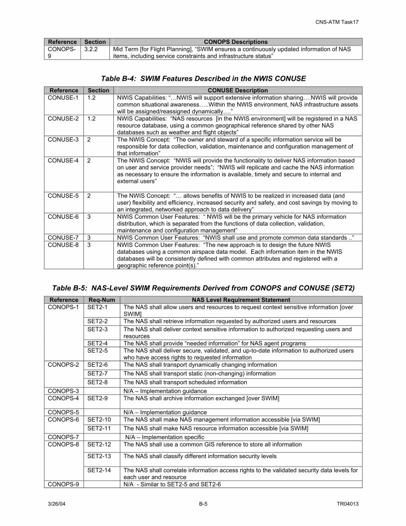
CNS-ATM Task17
3/26/04 B-5 TR04013
Reference Section CONOPS Descriptions CONOPS-9
3.2.2 Mid Term [for Flight Planning], “SWIM ensures a continuously updated information of NAS items, including service constraints and infrastructure status”
Table B-4: SWIM Features Described in the NWIS CONUSE Reference Section CONUSE Description
CONUSE-1 1.2 NWIS Capabilities: “…NWIS will support extensive information sharing….NWIS will provide common situational awareness…..Within the NWIS environment, NAS infrastructure assets will be assigned/reassigned dynamically….”
CONUSE-2 1.2 NWIS Capabilities: “NAS resources [in the NWIS environment] will be registered in a NAS resource database, using a common geographical reference shared by other NAS databases such as weather and flight objects”
CONUSE-3 2 The NWIS Concept: “The owner and steward of a specific information service will be responsible for data collection, validation, maintenance and configuration management of that information”
CONUSE-4 2 The NWIS Concept: “NWIS will provide the functionality to deliver NAS information based on user and service provider needs”; “NWIS will replicate and cache the NAS information as necessary to ensure the information is available, timely and secure to internal and external users”
CONUSE-5 2 The NWIS Concept: “… allows benefits of NWIS to be realized in increased data (and user) flexibility and efficiency, increased security and safety, and cost savings by moving to an integrated, networked approach to data delivery”
CONUSE-6 3 NWIS Common User Features: “ NWIS will be the primary vehicle for NAS information distribution, which is separated from the functions of data collection, validation, maintenance and configuration management”
CONUSE-7 3 NWIS Common User Features: “NWIS shall use and promote common data standards ..” CONUSE-8 3 NWIS Common User Features: “The new approach is to design the future NWIS
databases using a common airspace data model. Each information item in the NWIS databases will be consistently defined with common attributes and registered with a geographic reference point(s).”
Table B-5: NAS-Level SWIM Requirements Derived from CONOPS and CONUSE (SET2) Reference Req-Num NAS Level Requirement Statement
SET2-1 The NAS shall allow users and resources to request context sensitive information [over SWIM]
SET2-2 The NAS shall retrieve information requested by authorized users and resources SET2-3 The NAS shall deliver context sensitive information to authorized requesting users and
resources SET2-4 The NAS shall provide “needed information” for NAS agent programs
CONOPS-1
SET2-5 The NAS shall deliver secure, validated, and up-to-date information to authorized users who have access rights to requested information
SET2-6 The NAS shall transport dynamically changing information SET2-7 The NAS shall transport static (non-changing) information
CONOPS-2
SET2-8 The NAS shall transport scheduled information CONOPS-3 N/A – Implementation guidance CONOPS-4 SET2-9 The NAS shall archive information exchanged [over SWIM]
CONOPS-5 N/A – Implementation guidance
SET2-10 The NAS shall make NAS management information accessible [via SWIM] CONOPS-6 SET2-11 The NAS shall make NAS resource information accessible [via SWIM]
CONOPS-7 N/A – Implementation specific SET2-12 The NAS shall use a common GIS reference to store all information
SET2-13 The NAS shall classify different information security levels
CONOPS-8
SET2-14 The NAS shall correlate information access rights to the validated security data levels for each user and resource
CONOPS-9 N/A - Similar to SET2-5 and SET2-6

CNS-ATM Task17
3/26/04 B-6 TR04013
Reference Req-Num NAS Level Requirement Statement CONUSE-1 N/A – Describes SWIM features CONUSE-2
SET2-15 The NAS shall register NAS resources [in the SWIM environment] using a common geographical reference
CONUSE-3
N/A – Describes SWIM feature
SET2-16 The NAS shall accept requests for information from authorized users and resources SET2-17 The NAS shall deliver requested information to requesting users and resources
CONUSE-4
SET2-18 The NAS shall cache information exchanged [over SWIM] as desired CONUSE-5
N/A – Describes SWIM features
CONUSE-6
N/A – Describes SWIM features
CONUSE-7
SET2-19 The NAS shall use common data standards for information
SET2-20 The NAS shall use common attributes for information transported [over SWIM] CONUSE-8 SET2-21 The NAS shall use common geographic reference attributes for information transported
[over SWIM] B.1.4 Requirements Derived from the SWIM Functional Architecture NAS-level requirements derived from the SWIM functional architecture developed in Subtask 17A are shown in Table B-6. The process of defining NAS level requirements from the SWIM functional architecture was performed by first considering functional requirements specific to each function in the SWIM functional architecture, and then allocating these requirements to either the NAS or to SWIM, as a subsystem of NAS. (SWIM functional requirements are presented in Appendix A of the CNS-ATM Subtask 17B Report). Further refinement of this process and review of these requirements by the FAA may result in changes in this preliminary allocation of requirements. Note that the following table contains the same high level requirements as were presented in the CNS-ATM Subtask C report, but they have been reorganized based on more recent revisions to the SWIM functions as described in Section 2 of this report.
Table B-6: NAS-Level SWIM Requirements Derived From the SWIM Functional Architecture (Set3)
Function Req-ID NAS Level Requirement Statement
SET3-1-1 The NAS shall define standard information access methods for all SWIM members. SET3-1-2 The NAS shall authenticate users and resources who attempt to access SWIM SET3-1-3 The NAS shall assign different access levels to information to be exchanged [over
SWIM] SET3-1-4 The NAS shall correlate information access rights to specific users and resources SET3-1-5 The NAS shall accept user’s request for information SET3-1-6 The NAS shall define a common data model for information SET3-1-7 The NAS shall define common searchable attributes for information SET3-1-8 The NAS shall maintain a common data model SET3-1-9 The NAS shall control SWIM access control information SET3-1-10 The NAS shall process user and resource information requests SET3-1-11 The NAS shall deliver information to authorized users and resources [over SWIM] SET3-1-12 The NAS shall maintain NAS information databases
Manage SWIM Information (1.0)
SET3-1-13 The NAS shall provide means for authorized users and resources to access information databases [for SWIM]
SET3-2-1 The NAS shall provide account management [for SWIM] Manage SWIM SET3-2-2 The NAS shall provide fault management [for SWIM]

CNS-ATM Task17
3/26/04 B-7 TR04013
Function Req-ID NAS Level Requirement Statement
SET3-2-3 The NAS shall provide security functions [for SWIM] SET3-2-4 The NAS shall provide resource management [for SWIM} SET3-2-5 The NAS shall monitor network Quality of Service parameters [for SWIM]
Networks (2.0)
SET3-2-6 The NAS shall maintain network Quality of Service [of SWIM] B.1.5 Consolidated NAS-Level SWIM Requirements The NAS-level SWIM requirements presented as Sets 1 through 3 were combined and consolidated into one table. Table B-7 shows the consolidated requirements. The table organizes the requirements into the same functional areas defined in the Functional Architecture and shown in Table B-6.
Table B-7: Consolidated NAS-Level SWIM Requirements Num Reference NAS Level Requirement Statement
“Manage SWIM Information” Requirements 1 SET3-1-1 The NAS shall define standard “information access methods” for all SWIM members. 2 SET1-8, SET3-1-
2 The NAS shall authenticate users and resources who attempt to access SWIM
3 SET1-9, SET3-1-3, SET2-13
The NAS shall assign different security levels to information to be exchanged [over SWIM]
4 SET2-14, SET3-1-4,
The NAS shall assign authenticated users and resources specific access right to the different levels of information to be exchanged [over SWIM]
5 SET3-1-5, SET2-1, SET2-16
The NAS shall accept users’ and resources’ requests for context sensitive information [over SWIM]
6 SET1-14, SET3-1-6, SET2-19 SET1-1
The NAS shall define a common data model for information to be exchanged [over SWIM]
7 SET2-11, SET1-15
The NAS shall establish a common geographical and time reference for information to be exchanged [over SWIM]
8 SET2-15 The NAS shall register NAS resources [in the SWIM environment] using a common geographical reference
9 SET1-2, SET3-1-7
The NAS shall define common searchable attributes for NAS information
10 SET3-1-8 The NAS shall maintain a common data model 11 SET3-1-12 The NAS shall manage NAS information databases 12 SET3-1-13 The NAS shall provide means for authorized users and resources to access NAS
information databases 13 SET3-1-9 The NAS shall control SWIM security control information 14 SET3-1-10 The NAS shall process user and resource information requests 15 SET1-5, SET1-
13, SET3-1-11 Upon a standing request, the NAS shall automatically deliver updated context sensitive information to authorized requesting users and resources
16 SET1-6 Upon a standing request, the NAS shall automatically deliver real-time information on time [over SWIM] to authorized requesting users and resources
17 SET2-2, SET1-4, SET3-1-11
Upon a one-time request, the NAS shall deliver context sensitive information to authorized requesting users and resources
18 SET1-11 The NAS shall automatically establish source and user connections [over SWIM] for delivery of information
19 SET2-6 The NAS shall transport dynamically changing information 20 SET2-7 The NAS shall transport static (non-changing) information 21 SET2-8 The NAS shall transport scheduled information 22 SET1-10 The NAS shall deliver NAS information to multiple users and resources [over SWIM] 23 SET2-21 The NAS shall use common geographic reference attributes for information
transported [over SWIM] 24 SET2-20 The NAS shall use common data attributes for information transported [over SWIM] 25 SET1-12 Upon standing request, the NAS shall provide the capability to automatically collect
information [through SWIM] 26 SET2-18 The NAS shall cache information exchanged [over SWIM]
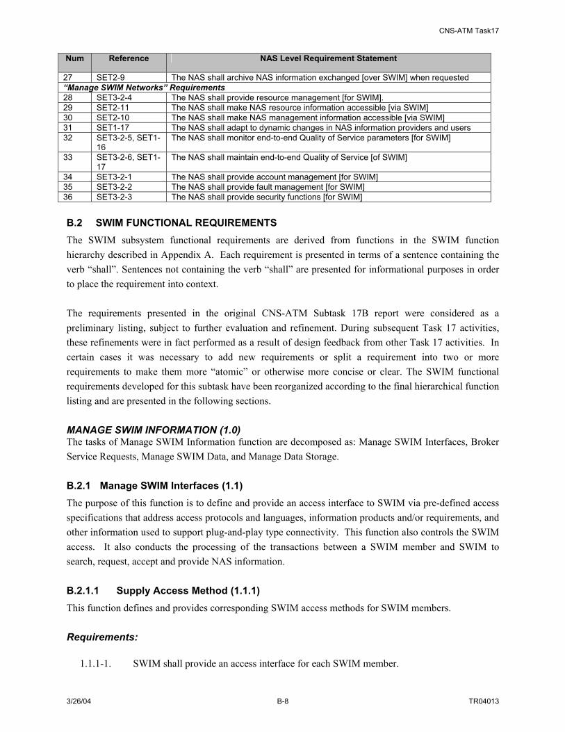
CNS-ATM Task17
3/26/04 B-8 TR04013
Num Reference NAS Level Requirement Statement
27 SET2-9 The NAS shall archive NAS information exchanged [over SWIM] when requested “Manage SWIM Networks” Requirements 28 SET3-2-4 The NAS shall provide resource management [for SWIM]. 29 SET2-11 The NAS shall make NAS resource information accessible [via SWIM] 30 SET2-10 The NAS shall make NAS management information accessible [via SWIM] 31 SET1-17 The NAS shall adapt to dynamic changes in NAS information providers and users 32 SET3-2-5, SET1-
16 The NAS shall monitor end-to-end Quality of Service parameters [for SWIM]
33 SET3-2-6, SET1-17
The NAS shall maintain end-to-end Quality of Service [of SWIM]
34 SET3-2-1 The NAS shall provide account management [for SWIM] 35 SET3-2-2 The NAS shall provide fault management [for SWIM] 36 SET3-2-3 The NAS shall provide security functions [for SWIM] B.2 SWIM FUNCTIONAL REQUIREMENTS The SWIM subsystem functional requirements are derived from functions in the SWIM function hierarchy described in Appendix A. Each requirement is presented in terms of a sentence containing the verb “shall”. Sentences not containing the verb “shall” are presented for informational purposes in order to place the requirement into context. The requirements presented in the original CNS-ATM Subtask 17B report were considered as a preliminary listing, subject to further evaluation and refinement. During subsequent Task 17 activities, these refinements were in fact performed as a result of design feedback from other Task 17 activities. In certain cases it was necessary to add new requirements or split a requirement into two or more requirements to make them more “atomic” or otherwise more concise or clear. The SWIM functional requirements developed for this subtask have been reorganized according to the final hierarchical function listing and are presented in the following sections. MANAGE SWIM INFORMATION (1.0) The tasks of Manage SWIM Information function are decomposed as: Manage SWIM Interfaces, Broker Service Requests, Manage SWIM Data, and Manage Data Storage. B.2.1 Manage SWIM Interfaces (1.1) The purpose of this function is to define and provide an access interface to SWIM via pre-defined access specifications that address access protocols and languages, information products and/or requirements, and other information used to support plug-and-play type connectivity. This function also controls the SWIM access. It also conducts the processing of the transactions between a SWIM member and SWIM to search, request, accept and provide NAS information. B.2.1.1 Supply Access Method (1.1.1) This function defines and provides corresponding SWIM access methods for SWIM members. Requirements:
1.1.1-1. SWIM shall provide an access interface for each SWIM member.

CNS-ATM Task17
3/26/04 B-9 TR04013
1.1.1-2. SWIM shall use a set of predefined access methods for all information to be exchanged over SWIM.
1.1.1-3. SWIM shall provide a set of pre-selected interface protocols that connect a NAS member to SWIM.
1.1.1-4. SWIM shall define a standard data template for each access method. 1.1.1-5. SWIM shall associate each access template with one or more SWIM members. 1.1.1-6. SWIM shall authenticate a SWIM member who tries to modify access methods or
templates. 1.1.1-7. SWIM shall accept authorized requests to modify (add, delete, or change attributes of)
access methods or templates 1.1.1-8. SWIM shall modify the access methods and templates upon validation and verification of
the modification request. 1.1.1-9. SWIM shall maintain integrity and consistency of all access method definitions and
templates. B.2.1.2 Control SWIM Access (1.1.2) This function registers the SWIM members, assigns access privileges, authenticates existing user connections to SWIM, and maintains SWIM access limitations. This function registers or expels users and changes authorization when needed. Requirements:
1.1.2-1. SWIM shall maintain a local SWIM member registration directory with the member’s
information and associated access methods. 1.1.2-2. SWIM shall register any valid local SWIM members that initiate access to SWIM. 1.1.2-3. SWIM shall remove or change an existing local SWIM member upon authorized requests. 1.1.2-4. SWIM shall authenticate a user as valid by comparing and processing with additional security
data 1.1.2-5. SWIM shall update the active user list when a new SWIM member is created or when an
existing SWIM member is removed. 1.1.2-6. SWIM shall provide to an inquiring SWIM member all the available access methods and
templates. 1.1.2-7. SWIM shall authorize a member with access rights to access specific SWIM or NAS
information. 1.1.2-8. The SWIM shall limit or restrict the scope of the session security attributes after three failed
login-attempts from a single workstation. 1.1.2-9. SWIM shall restrict the access to its resources through predefined ports only and all other
queries on unauthorized ports shall be explicitly denied. 1.1.2-10. SWIM shall provide operational protection against any member actions occurring at a time
when proper monitoring or when proper procedural measures may not be in place. 1.1.2-11. SWIM shall restrict the access to its resources through pre-defined protocols only (for
example, FTP, Telnet, etc.).

CNS-ATM Task17
3/26/04 B-10 TR04013
B.2.1.3 Conduct Interface Transactions (1.1.3) This function addresses the communicative actions or activities across a shared interface between SWIM and SWIM members. NAS members can access SWIM data and services by performing queries and requesting information through the SWIM interface. Additionally, NAS members can provide or publish information to SWIM through the SWIM interface. This function accommodates the translation of user requests from a format specific to a local implementation of SWIM to a more generic format that can be accommodated by general SWIM functionality. Requirements:
1.1.3-1. SWIM shall provide means to accept SWIM-to-member requests (request for local information).
1.1.3-2. SWIM shall provide means to accept member-to-SWIM requests (request for NAS information and requested local data).
1.1.3-3. SWIM shall provide means to accept SWIM-to-member status/control messages. 1.1.3-4. SWIM shall provide means to accept member-to-SWIM status/control messages. 1.1.3-5. SWIM shall provide translation of local data format to the SWIM common data model
for member-to-SWIM requests. 1.1.3-6. SWIM shall provide capability to translate SWIM-to-member requests that are in SWIM
common data model format into specific user or resource local data format. 1.1.3-7. SWIM shall provide capability to convert communication protocols specific to NAS
members into SWIM common interface protocols for member-to-SWIM requests. 1.1.3-8. SWIM shall provide capability to issue SWIM control commands to SWIM members. 1.1.3-9. SWIM shall allow NAS users or resources to distribute information through SWIM
interfaces. 1.1.3-10. SWIM shall upon receipt of a routed service request from another SWIM function,
appropriately respond to the service request by supplying the requested information. 1.1.3-11. SWIM shall upon receipt of a member-to-SWIM request, for specific service or
information, translate the request to SWIM compliant format and send it to SWIM using the SWIM common access protocol.
1.1.3-12. SWIM shall process acknowledgements and send or receive status reports. B.2.2 Broker Service Requests (1.2) This function maintains member registration, processes transactions (such as publish, subscribe and etc.), provides data services and also provides some core SWIM functions. B.2.2.1 Maintain Registration (1.2.1) This function maintains (creates, add, delete, update) the registration of SWIM members. The registration includes members that are register directly through the SWIM broker, as well as members that register through other SWIM brokers if any. This function also provides a broker naming service. Requirements:

CNS-ATM Task17
3/26/04 B-11 TR04013
2.3.1-1. SWIM shall maintain a SWIM member registration directory with the member’s information and associated access methods.
2.3.1-2. SWIM shall accept an authorized member’s request to register for services. 2.3.1-3. SWIM shall un-register an existing SWIM member for services upon authorized requests. 2.3.1-4. SWIM shall maintain SWIM member’s registration request. 2.3.1-5. SWIM shall offer a member-location-transparent naming service upon request. 2.3.1-6. SWIM shall create a naming service directory.
B.2.2.2 Process Transactions (1.2.2) This function processes all the received SWIM member requests and prioritizes requests, processes transaction requests such as publish, subscribe, and query. It also performs discovery services, processes control/status messages and balances SWIM loads. Requirements:
1.2.2-1. SWIM shall process incoming requests in a priority order decided manually or automatically based on ordering rules. [Rules can be FIFO, priority-based and etc. This is an implementation decision to be made during the system design phase.]
1.2.2-2. SWIM shall retrieve requested information based on the search pattern defined in the requests.
1.2.2-3. SWIM shall respond to requesting members with the retrieved information within performance limits.
1.2.2-4. SWIM shall provide means to route requests directly to a member that can provide the requested information.
1.2.2-5. SWIM shall allocate requests in a balanced way so that requests can be processed to meet the required performance constraints or failover conditions8.
1.2.2-6. SWIM shall make SWIM-to-member requests for specific information for the evaluation of SWIM alert and failure functions.
1.2.2-7. SWIM shall make SWIM-to-member requests for local SWIM health status information. 1.2.2-8. SWIM shall make SWIM-to-member requests for information that needs to be distributed
to other SWIM members. 1.2.2-9. SWIM shall make member-to-SWIM requests for specific SWIM information services. 1.2.2-10. SWIM shall make member-to-SWIM requests to distribute/publish local data to SWIM. 1.2.2-11. SWIM shall enable the flow of control and status messages between SWIM and SWIM
members. B.2.2.3 Perform Data Services (1.2.3) This function provides data services needed for disseminating SWIM data. 8 Failover is a backup operational mode in which the functions of a system component (such as a processor, server, network, or database, for example) are assumed by secondary system components when the primary component
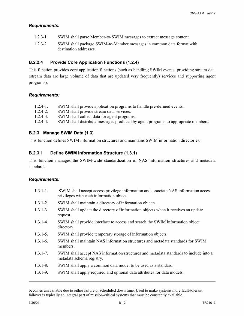
CNS-ATM Task17
3/26/04 B-12 TR04013
Requirements:
1.2.3-1. SWIM shall parse Member-to-SWIM messages to extract message content. 1.2.3-2. SWIM shall package SWIM-to-Member messages in common data format with
destination addresses. B.2.2.4 Provide Core Application Functions (1.2.4) This function provides core application functions (such as handling SWIM events, providing stream data (stream data are large volume of data that are updated very frequently) services and supporting agent programs). Requirements:
1.2.4-1. SWIM shall provide application programs to handle pre-defined events. 1.2.4-2. SWIM shall provide stream data services. 1.2.4-3. SWIM shall collect data for agent programs. 1.2.4-4. SWIM shall distribute messages produced by agent programs to appropriate members.
B.2.3 Manage SWIM Data (1.3) This function defines SWIM information structures and maintains SWIM information directories. B.2.3.1 Define SWIM Information Structure (1.3.1) This function manages the SWIM-wide standardization of NAS information structures and metadata standards. Requirements:
1.3.1-1. SWIM shall accept access privilege information and associate NAS information access privileges with each information object.
1.3.1-2. SWIM shall maintain a directory of information objects. 1.3.1-3. SWIM shall update the directory of information objects when it receives an update
request. 1.3.1-4. SWIM shall provide interface to access and search the SWIM information object
directory. 1.3.1-5. SWIM shall provide temporary storage of information objects. 1.3.1-6. SWIM shall maintain NAS information structures and metadata standards for SWIM
members. 1.3.1-7. SWIM shall accept NAS information structures and metadata standards to include into a
metadata schema registry. 1.3.1-8. SWIM shall apply a common data model to be used as a standard. 1.3.1-9. SWIM shall apply required and optional data attributes for data models.
becomes unavailable due to either failure or scheduled down time. Used to make systems more fault-tolerant, failover is typically an integral part of mission-critical systems that must be constantly available.

CNS-ATM Task17
3/26/04 B-13 TR04013
1.3.1-10. SWIM shall define data attributes. 1.3.1-11. SWIM shall assign values to attributes. 1.3.1-12. SWIM shall define searchable attributes/context for specific information objects such as
Data Source, Destination, Creation and Expiration time. 1.3.1-13. SWIM shall transform NAS data into information objects using the common data model
defined with defined searchable attributes/context as mentioned above. B.2.3.2 Maintain NAS Information Directories (1.3.2) This function maintains (create, update, add, delete) the information directories associated with SWIM common data model, information objects, and ontology associated with the data model. Requirements:
1.3.2-1. SWIM shall accept directory queries. 1.3.2-2. SWIM shall search the appropriate directory based on the accepted queries. 1.3.2-3. SWIM shall provide response to the accepted queries. 1.3.2-4. SWIM members shall develop new information objects as required. 1.3.2-5. SWIM shall provide temporary storage of information objects. 1.3.2-6. SWIM shall interface to searches of the SWIM index. 1.3.2-7. SWIM shall accept NAS directory control messages. 1.3.2-8. SWIM shall provide acknowledgement to NAS directory control messages. 1.3.2-9. SWIM shall configure and reconfigure directories when requested. 1.3.2-10. SWIM shall provide the directory status information. 1.3.2-11. SWIM shall backup and recover NAS directories as requested.
B.2.4 Manage Data Storage (1.4) This function manages SWIM databases (such as data marts as data warehouses (if applicable)) as well as provides access to these databases. B.2.4.1 Manage SWIM Databases (1.4.1) This function manages the SWIM database(s). These databases can be centralized or distributed. The main tasks of this function are to:
• Manage SWIM database connections
• Manage SWIM database transactions
• Backup databases and recover databases
Requirements:
1.4.1-1. SWIM shall manage SWIM database links. 1.4.1-2. SWIM shall manage SWIM database transactions.

CNS-ATM Task17
3/26/04 B-14 TR04013
1.4.1-3. SWIM shall perform backup/recovery of databases. 1.4.1-4. SWIM shall manage global names in the distributed system. 1.4.1-5. SWIM shall create and manage shared database links for SWIM members. 1.4.1-6. SWIM shall monitor database link health status. 1.4.1-7. SWIM shall report database link health status to SWIM members. 1.4.1-8. SWIM shall maintain database consistency and integrity while receiving NAS data or
data updates. 1.4.1-9. SWIM shall process database queries. 1.4.1-10. SWIM shall provide responses to query requests. 1.4.1-11. SWIM shall monitor database health status. 1.4.1-12. SWIM shall report database health status. 1.4.1-13. SWIM shall synchronize distributed SWIM/NAS databases. 1.4.1-14. SWIM shall upon receipt of authorized control commands perform backup/recovery of
databases B.2.4.2 Access SWIM Databases (1.4.2) This function provides the interface access to SWIM databases (data marts). Requirements:
1.4.2-1. SWIM shall create databases. 1.4.2-2. SWIM shall query databases. 1.4.2-3. SWIM shall update databases.
B.3 MANAGE SWIM NETWORKS (2.0) The tasks of Manage SWIM Networks function are to:
• Maintain Network Security
• Manage SWIM Accounts
• Manage Network Configurations
• Maintain Performance
• Manage Network Faults
B.3.1 Maintain Network Security (2.1) This function maintains the network security for SWIM; its tasks include: maintain security functions and data, manage security attributes, manages public Key Infrastructure (PKI) and keeps records of security logs for security audit purpose.

CNS-ATM Task17
3/26/04 B-15 TR04013
B.3.1.1 Maintain Security Functions and Data (2.1.1) SWIM security functions consist of all hardware, software, and firmware of SWIM relied upon for the correct enforcement of the SWIM security. There are 11 security functional components identified in Part 2 of the Common Criteria whose mechanisms enforce the policy and provide necessary capabilities. These include: security audit, communication, cryptographic support, user data protection, identification and authentication, security management, privacy, protection of the TOE (SWIM) security functions, resource utilization, TOE (SWIM) access, and trusted path/channel. This function provides for the integrity and management of the mechanisms that provide the SWIM Target of Evaluation (TOE) Security Functions (TSF) independent of TOE Security Policy (TSP) specifics, and to the integrity of TSF data (independent of the specific contents of the TSP data). Per Part 1 of the CC:
• Target of Evaluation (TOE) is an IT product or system and its associated administrator and user guidance documentation that is the subject of an evaluation. [In this case, it is the SWIM infrastructure]
• TOE Security Policy (TSP) is the set of rules that regulate how assets are managed, protected and distributed within a TOE.
• TOE Security Functions (TSF) is a set consisting of all hardware, software, and firmware of the TOE that must be relied upon for the correct enforcement of the TSP.
• TSF Scope of Control (TSC) is the set of interactions that can occur with or within a TOE and are subject to the rules of the TSP.
Requirements:
• SWIM shall run a suite of tests (during initial start-up, periodically during normal operation, and after each login) to demonstrate the correct operation of the SWIM specific applications and any security assumptions.
• SWIM shall prove reliable time stamps
• SWIM shall provide authorized users with the capability to verify the FAA SWIM data.
• SWIM shall enforce the access control on subjects, objects, and operations among subjects and objects.
• SWIM shall ensure that all operations between any subject in the TSC and any object within the TSC are covered by an access control SWIM security policy
• SWIM shall perform encryption and decryption of all log-in credentials and communications among SWIM security functions.
• SWIM shall verify that all requested access to subjects (functions) is within the scope of privileges defined for the requesting subject.
Definitions per CC part 2:
• Subject: Subjects are the active entities that operate

CNS-ATM Task17
3/26/04 B-16 TR04013
• Object: Objects are the passive entities that are basically the target of the operations performed by subjects.
B.3.1.2 Manage Security Attributes (2.1.2) Security attribute is the information associated with subjects, users and/or objects that is used for the enforcement of the target of evaluation [SWIM in our case] security policy.9 Examples of such security attributes are the groups to which a member belongs, the priority of a process, and the access rights belonging to a role or a member. Managing these security attributes will allow SWIM to behave correctly as desired. Requirements:
• SWIM shall enforce information flow control policies in order to restrict the ability of subjects to query, modify or delete the security attributes of subjects.
• SWIM shall maintain a list of security attributes belonging to individual subjects (such as subject ID, class, access privileges).
• SWIM shall enforce time limits for the validity of security attributes where necessary.
B.3.1.3 Manage Public Key Infrastructure (2.1.3) SWIM’s network-centric architecture with connections to data end users (person, applications, servers, etc), data suppliers (surveillance radars, weather radars, etc.), and partners (local law enforcement agencies, airlines, etc.) incurs risks through all these interfaces. PKI, applied in various zones of a network, supports identification, authentication, and encryption mechanisms to counter the potential threats thus reducing the associated risks. This function, with the right implementation of PKI, ensures that all the SWIM authorized entities are talking to the right parties to preclude the loss of reasonable control of vital SWIM information. PKI will allow SWIM users to interact with other SWIM users, SWIM specific applications, or other authorized FAA partners, obtain and verify identities and keys, and register with trusted third parties. SWIM PKI will include the following components for its secure operations: Certificate authority (CA), registration authority (RA), public key certificate directory, and certificate revocation list (CRL) Requirements:
• SWIM shall provide generation, production, distribution, control, and accounting of public key certificates.
• SWIM PKI shall support SWIM specific applications and products.
• SWIM PKI shall provide secure interface/interoperability throughout SWIM to be able to include FAA partners, including law enforcement agencies, airlines, US Air Force, etc.
• SWIM shall protect the private keys.
9 www.commoncriteria.org/faq/definitions.html

CNS-ATM Task17
3/26/04 B-17 TR04013
• SWIM shall support key exchange with digital signature capability
• SWIM shall support key and data recovery.
B.3.1.4 Maintain Security Audits (2.1.4) This function maintains and logs security data for security audits. Requirements:
2.1.4-1. SWIM shall maintain logs and security data for passwords, tokens, login events. B.3.2 Manage SWIM Accounts (2.2) This function tracks the usage of different types of services and network resources and establishes the associated usage records and costs (if applicable to SWIM). B.3.2.1 Maintain Accounts (2.2.1) This function maintains member account information, and assigns costs or resource quotas (if applicable) to user accounts. Requirements:
2.2.1-1. SWIM shall maintain member accounts and assign service costs or resource quotas (if applicable) to member accounts.
B.3.2.2 Manage Account Security Policy Implementation (2.2.2) This function provides access control to individual accounts. Requirements:
2.2.2-1. SWIM shall provide access control to the member accounts. B.3.2.3 Manage Account Monitoring Services (2.2.3) This function monitors access to networks, resources, and services and tracks usage statistics. Requirements:
2.2.3-1. SWIM shall monitor account access to network, resources, services, and tracks usage statistics.
B.3.3 Manage Network Configurations (2.3) This function addresses the management of SWIM resources. It provides naming services, and controls overall SWIM resources.
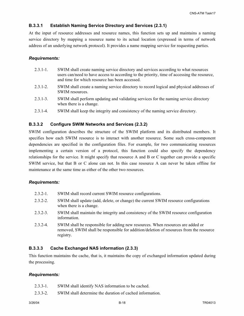
CNS-ATM Task17
3/26/04 B-18 TR04013
B.3.3.1 Establish Naming Service Directory and Services (2.3.1) At the input of resource addresses and resource names, this function sets up and maintains a naming service directory by mapping a resource name to its actual location (expressed in terms of network address of an underlying network protocol). It provides a name mapping service for requesting parties. Requirements:
2.3.1-1. SWIM shall create naming service directory and services according to what resources users can/need to have access to according to the priority, time of accessing the resource, and time for which resource has been accessed.
2.3.1-2. SWIM shall create a naming service directory to record logical and physical addresses of SWIM resources.
2.3.1-3. SWIM shall perform updating and validating services for the naming service directory when there is a change.
2.3.1-4. SWIM shall keep the integrity and consistency of the naming service directory. B.3.3.2 Configure SWIM Networks and Services (2.3.2) SWIM configuration describes the structure of the SWIM platform and its distributed members. It specifies how each SWIM resource is to interact with another resource. Some such cross-component dependencies are specified in the configuration files. For example, for two communicating resources implementing a certain version of a protocol, this function could also specify the dependency relationships for the service. It might specify that resource A and B or C together can provide a specific SWIM service, but that B or C alone can not. In this case resource A can never be taken offline for maintenance at the same time as either of the other two resources. Requirements:
2.3.2-1. SWIM shall record current SWIM resource configurations. 2.3.2-2. SWIM shall update (add, delete, or change) the current SWIM resource configurations
when there is a change. 2.3.2-3. SWIM shall maintain the integrity and consistency of the SWIM resource configuration
information. 2.3.2-4. SWIM shall be responsible for adding new resources. When resources are added or
removed, SWIM shall be responsible for addition/deletion of resources from the resource registry.
B.3.3.3 Cache Exchanged NAS information (2.3.3) This function maintains the cache, that is, it maintains the copy of exchanged information updated during the processing. Requirements:
2.3.3-1. SWIM shall identify NAS information to be cached. 2.3.3-2. SWIM shall determine the duration of cached information.

CNS-ATM Task17
3/26/04 B-19 TR04013
2.3.3-3. SWIM shall maintain the consistency of cached information. 2.3.3-4. SWIM shall cache exchanged information object based on certain criteria (such as more
recently exchanged, or most important data objects and etc.) B.3.3.4 Distribute SWIM Status/Control Messages (2.3.4) This function defines actions to be taken corresponding to alert or failure conditions. When an alert or a failure is received or generated, it then issues control commands to database(s), and/or SWIM resources to take the appropriate actions. Requirements:
2.3.4-1. SWIM shall issue control commands based on the health status reports. 2.3.4-2. SWIM shall issue commands to databases/SWIM resources to take the appropriate
actions upon receipt of an alert or failure notice. B.3.3.5 Maintain Operation Monitoring Configuration (2.3.5) This function maintains the monitoring of configurations of devices connected to the network. Requirements:
2.3.5-1. SWIM shall monitor the health status of local members. 2.3.5-2. SWIM shall monitor the health status of SWIM/NAS resources.
B.3.3.6 Protect SWIM Resource Allocation (2.3.6) SWIM provides a set of services provided by a distributed infrastructure of computers, servers, and networks. Managing and configuring these infrastructure components plays an important role in enabling the availability of SWIM resources to its authorized users such that there is no denial of service by means of monopolization of resources by other members (users or subjects). This function ensures that SWIM data, a SWIM system/sub-system or a SWIM system resource is accessible and usable upon demand by an authorized SWIM member. It allows the creation of quotas or other means of defining limits on the amount of resource space or time that may be allocated on behalf of specific SWIM users or subjects. Requirements:
• SWIM shall discontinue the link to the resource if no activity has been performed for a set time period.
• SWIM shall provide configuration control of allocations to the SWIM resources.
• SWIM shall allot quotas to its members such that they cannot monopolize a controlled resource.
• SWIM shall update the allocation of the resources when there is a change and consequently make the required SWIM resource configurations.
CNS-ATM Task17
3/26/04 B-20 TR04013
• SWIM shall monitor the health status of its resources.
• SWIM shall issue control commands based on health status reports.
• SWIM shall maintain the integrity and consistency of the allocations configured for its members
B.3.3.7 Manage SWIM Security Functions Infrastructure (2.3.7) Managing SWIM security functions infrastructure ensures proper operation of the SWIM components thwarting any attempts on the integrity of SWIM. The main tasks for this function lies in the following areas:
• Management functions that relate to general installation and configuration: for example, SWIM configuration, manual recovery, installation of SWIM security fixes, repair and reinstallation of hardware.
• Management functions that relate to routing control and maintenance of SWIM resources: for example, enabling and disabling peripheral devices, mounting of removable storage media, backup and recovery of user data and system objects.
Requirements: None defined at this time. B.3.3.8 Maintain Secure Communications (Trusted Path/Crypto) (2.3.8) This function ensures confidence in the free movement of SWIM data in the SWIM network by employing cryptographic support and setting up trusted path/channels and thus achieving SWIM security objectives of confidentiality, integrity, identification, authentication, and accountability. Requirements:
• SWIM shall provide a unique communication path between SWIM and a member. Each communication path is logically distinct from others.
• SWIM shall provide a unique communication channel between SWIM and a SWIM data provider. Each communication channel is logically distinct from others.
• SWIM shall generate cryptographic keys in accordance with a specified cryptographic key generation algorithm and specified cryptographic key sizes stated in FAA policy and standards.
• SWIM shall distribute cryptographic keys in accordance with FAA Policy and standards.
• SWIM shall access cryptographic key in accordance with FAA policy and standards.
• SWIM shall destroy cryptographic keys in accordance with FAA standards.
• SWIM shall operate in accordance with a specified cryptographic algorithm and key sizes stated in FAA policy and standards.

CNS-ATM Task17
3/26/04 B-21 TR04013
B.3.4 Maintain Network Performance (2.4) This function addresses the management of quality control services in SWIM. SWIM resource status, traffic flow, and other parameters related to the defined system alerts and failures are monitored, evaluated and reported. B.3.4.1 Monitor SWIM Connectivity Status (2.4.1) This function requests status information for participating NAS resources, or collects information through the network management systems in order to monitor SWIM elements connectivity status. Requirements:
2.4.1-1. SWIM shall collect SWIM connectivity information. 2.4.1-2. SWIM shall monitor SWIM resource connectivity status and NAS resources status. 2.4.1-3. SWIM shall report connectivity abnormalities by generating alerts/failures.
B.3.4.2 Monitor SWIM Flow of Data Status (2.4.2) This function tracks important flow of data (such as flight object information) in order to monitor SWIM flow of data status. Requirements:
2.4.2-1. SWIM shall collect data associated with SWIM flow of data status. 2.4.2-2. SWIM shall monitor SWIM flow of data status. 2.4.2-3. SWIM shall report flow of data abnormalities by generating alerts/failures.
B.3.4.3 Monitor SWIM Traffic Performance Status (2.4.3) This function monitors SWIM traffic performance to guarantee quality of service of operational data. This function tracks and evaluates SWIM traffic performance status, and generates alerts if thresholds are exceeded. It may issue service network adjustments commands to request a network connection adjustment. Requirements:
2.4.3-1. SWIM shall collect data associated with SWIM traffic performance status. 2.4.3-2. SWIM shall monitor SWIM traffic performance status. 2.4.3-3. SWIM shall report traffic performance status abnormalities by generating alerts. 2.4.3-4. SWIM shall evaluate service quality based on performance requirements.
B.3.4.4 Collect SWIM Quality Control Data (2.4.4) This function collects data for alert functions and other quality of service related information.

CNS-ATM Task17
3/26/04 B-22 TR04013
B.3.4.5 Evaluate Service Quality (2.4.5) This function uses collected parameter data to evaluate alert conditions and failure conditions. If an alert or a failure is detected, it reports them to SWIM resource management. B.3.4.6 Adjust Communication Load (2.4.6) This function monitors SWIM communication load. It requests associated actions to adjust services based on communication load levels and interfaces to communication management systems to adjust communication performance. Requirements:
2.5.1-1. SWIM shall adjust services based on communication load levels. 2.5.1-2. SWIM shall further distribute any alerts and failures to the affected parties. 2.5.1-3. SWIM shall interface to communication management systems to adjust communication
performance. B.3.5 Manage Network Faults (2.5) This function provides constant monitoring of the network state, reports abnormal conditions (such as those exceeding certain threshold values during normal operations), traces faults through the system and performs diagnostic tests to decide the cause of the fault, and finally isolates the fault from the network, removes the fault and recovers the system. B.3.5.1 Detect and Diagnose Faults ( 2.5.1) This function provides mechanisms (fault threshold setting and poll) to detect fault conditions in the network nodes and links, it also determines the causes of the fault and traces the fault through the network and isolate the faults. This function defines each status condition in SWIM or a SWIM resource such that when this special status condition is met, SWIM or the SWIM resource is in “Alert” or “Failure” state. Requirements:
2.5.1-1. SWIM shall be provided with pre-defined SWIM alert conditions. 2.5.1-2. SWIM shall be provided with pre-defined SWIM failure conditions.
B.3.5.2 Remove Faults and Recover System (2.5.2) This function provides means to remove faults either automatically or manually by reporting to human operator. Requirements:
2.5.2-1. SWIM shall collect data associated with alerts, failures and critical thresholds.

CNS-ATM Task17
3/26/04 B-23 TR04013
2.5.2-2. SWIM shall issue an alert when alert conditions are met. 2.5.2-3. SWIM shall issue a notice of failure when failure conditions are met. 2.5.2-4. SWIM shall automatically remove faults on receipt of a failure notice. 2.5.2-5. SWIM shall accept manual remove faults commands from an authorized human operator

CNS-ATM Task17
3/26/04 B-24 TR04013

CNS-ATM Task17
3/26/04 C-1 TR04013
APPENDIX C. INVESTIGATION OF ENABLING TECHNOLOGIES FOR SWIM
After completing a functional analysis for SWIM, technologies needed for the implementation of the specified functionality were investigated. These include both information management as well as communication technologies. Table 4-4 in the main body of the report (Section 4.2.1) includes a list of the identified enabling technologies for SWIM. As documented in the NAS Concept of Operations and Target System Description, there is a potential for SWIM to accommodate a wide-range of information exchange within the NAS. Due to the size and distributed nature of the NAS; the numerous participants in the NAS; and cost, maintenance and flexibility considerations, it is envisioned that SWIM be based on and implemented using industry standard technology. The use of standardized technology as a basis for SWIM development is alluded to in the SWIM/NWIS Concept of Use. Using industry standard technologies will enable SWIM to satisfy the following implementation objectives:
• Platform independence
• Language independence
• Protocol independence
• Data portability
• Application portability
• Scalability
• Interoperability
• Flexibility
This appendix addresses several topics. First, the publish/subscribe information sharing strategy and its variant data interaction models are first discussed. Next, a multi-tiered SWIM architecture is introduced. And finally, specific technologies applicable to the implementation of SWIM are discussed. C.1 PUBLISH/SUBSCRIBE SYSTEM AND ITS VARIANT IMPLEMENTATION MODELS SWIM can be described as a distributed publish/subscribe system. Information consumers (e.g. subscribers) can express their interest for NAS information in a subscription and subsequently receive information of interest generated by a information producer or publisher. A strict publish/subscribe architecture provides a full decoupling in time, space, and synchronization between publishers and subscribers10. Space decoupling means that the publishers and the subscribers do not need to know each other (e.g. they do not hold references to each other). Time decoupling means that the publishers and the subscribers do not need to be actively participating in the interaction or exchange at the same time.
10 “The Many Faces of Publish/Subscribe”, P.Th. Eugster, P.A. Febler, R. Guerraoui, A.-M. Kermarrec, ACM Computing Surveys (CSUR) Volume 35 , Issue 2 (June 2003), Pages: 114 - 131

CNS-ATM Task17
3/26/04 C-2 TR04013
Finally, synchronization decoupling means that the production and consumption of data do not happen in a synchronous manner. Based on this definition of a publish/subscribe system, this environment can be considered to provide a loosely coupled form of interaction for large scaled distributed systems. The ability to decouple the production and consumption of information in the three key areas identified above (time, space and synchronization) increases scalability by eliminating explicit dependencies between the interacting participants. It is the removal of these dependencies that make the communication infrastructure well suited to dynamic large scale distributed environments that are, by nature, asynchronous (as is the case in a mobile environment). This type of information sharing environment is in contrast to the synchronous and point-to-point communications which are currently in place in most enterprises and organizations. A synchronous and point-to-point environment make dynamic large scale application development difficult and often lead to the development of disparate, rigid and static applications. To avoid and/or correct this particular situation, many enterprises and organizations are using a dedicated “middleware” infrastructure that is based on a communication pattern that meets their needs. In a sense, the implementation of middleware places an intermediary between information producers and consumers to enable loosely coupled information exchange. This provides the ability to seamlessly integrate the disparate systems across the enterprise or organization. Additionally, it makes the designer and developers tasks easier by masking the difficulty in developing system and application interfaces that require the utilization of various specialized integration tools. While SWIM is to use a publish/subscribe paradigm, it is necessary to understand alternative models that are variants of publish/subscribe. These variants may not satisfy all three decoupling constraints defined for a strict publish/subscribe system (e.g. time, space and synchronization). The variant schemes of publish/subscribe include Message Passing, RPC (Remote Procedure Call), Notifications, Shared Spaces, and Message Queuing. A brief description of each is provided below.
• Message Passing: Message passing is a low level form of distributed communications. Communication is achieved by sending and receiving messages between the participants. Today message passing is rarely used for developing distributed applications because flow control, physical addressing and data marshalling often become visible at the application layer. Message passing is synchronous for the consumer and asynchronous for the producer. The consumer and producer coupled in space and time therefore must both be active at the same time and the message receiver has to know the sender of the message of interest.
• Remote Procedure Call (RPC): Remote Procedure Call is a very popular form of distributed computing. Its popularity comes from making remote interactions appear as if they are taking place locally and thus makes programming of distributed systems very easy. The difference between RPC and the publish/subscribe paradigm is that distribution cannot be made transparent in RPC. There is strong coupling in time, consumer synchronization as well as space due to the fact that the invoking object needs to hold a remote reference for each of its invokers.

CNS-ATM Task17
3/26/04 C-3 TR04013
• Notifications: In the notification scheme, the subscriber registers its interest with the publisher, which manages the subscriptions and events. This scheme is often implemented using asynchronous invocations from the publisher, but the publisher and subscribers remain coupled in space and time. This can become a serious problem as the system becomes very large because the publisher has the responsibility of managing communication in this scheme.
• Shared Spaces: In this paradigm, the hosts in a distributed system are provided a common shared memory space across disjointed address spaces. It is across this shared memory space that synchronization and communication takes place through operations on shared data. The notification model provides space and time decoupling in that the producers and consumers of information do not need to know each other or the future use of the data. The notification paradigm is still coupled synchronously because the consumer still has to retrieve information from the shared memory space in a synchronous manner. This required synchronization between the participants limits scalability of the notification model.
• Message Queuing: Message queuing systems often integrate some elements of publish/ subscribe. It is similar to the shared spaces paradigm, but the message queue is actually more of a global space that is fed with messages from the publishers. Additionally, message queuing systems provide transactional, timing, and ordering guarantees that are often not found in the shared spaces paradigm. Similarly to the shared spaces model, messages are concurrently accessed by subscribers, which is often call point to point queuing. Therefore, the as in the shared spaces paradigm, the publishers and subscribers are decoupled in space and time. However, they are coupled in synchronization because subscribers have to synchronously pull messages from the message queue. There are some message queuing solutions that deliver limited support for asynchronous message delivery, but the mechanisms do not scale well to large populations of subscribers due to additional interactions that will be needed to maintain transactional, timing, and ordering guarantees.
The following table11 summarizes the satisfaction of the three decoupling constraints of a strict publish/subscribe system and its variants.
Table C-1: Publish/Subscribe Systems and Variant Implementations
Abstraction Space Decoupling Time Decoupling Synchronization Decoupling
Message Passing No No Publisher Side RPC/RMI No No Publisher Side Asynchronous RPC/RMI No No Yes Notifications No No Yes Shared Spaces Yes Yes Publisher Side Message Queuing Yes Yes Publisher Side Publish/Subscribe Yes Yes Yes C.2 MULTI-TIERED SWIM ARCHITECTURE There are many ways of describing and understanding the SWIM architecture. The SWIM functional architecture has been described in terms of function definitions, functional hierarchy diagrams and functional interaction diagrams (See Section 2, Appendix A, and CNS-ATM Subtask B Report). The
11 Ibid.

CNS-ATM Task17
3/26/04 C-4 TR04013
SWIM physical architecture has been described in terms of component hierarchy diagrams (see Section D.1) and schematic diagrams (See Section 7). The comfort one has with particular architecture description varies with background knowledge related to the architecture viewpoint. In addition to the architecture viewpoints included in the main body of the report, a representation of SWIM as a multiple-tiered architecture (not to be confused with the ISO OSI protocol stack) has been defined and is shown in Figure C-1. This architecture and a discussion of each of its constituent layers are briefly described in the following paragraphs.
Figure C-1: Three-Tiered SWIM Software Hierarchy 1st Tier -- Presentation Layer The main purpose of a presentation layer is to separate data content from data presentation. Data content is the actual data that is to be shared by SWIM members while data presentation is the formatting of the data so that it can be exchanged through SWIM. The main distinction for SWIM is that the content is universal for an application; the same content is valid no matter what type of formatting must occur. Presentation on the other hand is specific to individual SWIM Members (custom presentation applications, Java Applications, web browser, and etc.). SWIM will be able to provide data not only from system to system, but the presentation functionality of SWIM will support the provision of data to web enabled devices and applications in their appropriate format. 2nd Tier -- Application and Distribution Middleware Layer The application layer implements the “business logic” and can be used to interact with many SWIM members. This layer relies on the third tier (see below) to obtain data from legacy systems, equipment, or databases. The Application Layer handles functionality such as registration, security policy implementations, and system administration. This layer augments distribution middleware by defining
Data Model/Presentation
Application Services
Architecture Topology
Member Interface
MDR IOR Data Marts
Secu
rity
Ass
uran
ce
Data Storage Management SWIM
Net
wor
k M
anag
emen
t
1st
Tier
2nd
Tier
3rd
Tier
Data Model/Presentation
Application Services
Architecture Topology
Member Interface
MDR IOR Data Marts
Secu
rity
Ass
uran
ce
Data Storage Management SWIM
Net
wor
k M
anag
emen
tN
etw
ork
Man
agem
ent
1st
Tier
2nd
Tier
3rd
Tier

CNS-ATM Task17
3/26/04 C-5 TR04013
higher-level domain-independent services that focus on programming “business logic”.12 Examples of application layer technology products are Sun’s J2EE and Microsoft’s .NET. The distribution middleware (Distributed Computing) layer is used by the application layer to access third tier legacy applications, equipment and databases. This part of SWIM software makes the intricate details and incompatibilities of the third tier system transparent to the members and makes publish/subscribe/query/and messaging possible across the NAS. Distribution middleware avoids hard-coding client and server application dependencies on object location, language, OS, protocols, and hardware. Examples of distributed middleware technologies are OMG CORBA, Sun’s Remote Method Invocation (RMI), and Microsoft’s Distributed Component Object Model (DCOM). 3rd Tier -- Resource Layer The third tier, data management, is the resource layer. Its main functions are to extract data and perform actions on data. This layer is transparent to SWIM members; it communicates with the 2nd tier through specific protocols. Security Assurance and Network Management are provided across all three tiers. Security for SWIM is discussed in Appendix E, while Network Management is discussed as part of Section 5 of the report. C.3 TECHNOLOGY SUPPORT A range of information management and communication technologies are needed to meet all SWIM architecture objectives across all three architecture tiers. Potentially useful technologies have been categorized into the following general areas for discussion:
• Data presentation (1st-Tier, presentation layer)
• Application development (2nd-Tier, Application and middleware layer)
• Distributed computing (middleware) (2nd-Tier, Application and middleware layer)
• Data storage (3rd-Tier, Resource layer)
These technology categories and their potential suitability for the SWIM physical architecture are discussed in the following subsections. C.3.1 Data Presentation One of the key objectives for SWIM is data portability. Although SWIM will accommodate the “wrapping” of legacy NAS data into SWIM formats, standardizing on common data formats or information objects can be important to the evolution of SWIM. SWIM will use these objects to aggregate, integrate, and intelligently disseminate all relevant knowledge to support NAS information
12 “Patterns, Frameworks, & Middleware: Their Synergistic Relationships”, Douglas C. Schmidt, Vanderbilt University, Nashville, Tennessee

CNS-ATM Task17
3/26/04 C-6 TR04013
exchange. SWIM will serve as an integrating substrate upon which legacy systems will be linked together to support transparent information exchange across a wide spectrum of NAS activities and functional domains. As part of this process, the presentation of data is decoupled from the application methods that act upon them. Options for data representation include the plain text files or a more flexible, structured means of representing SWIM data. The desire to create, to manage, and to present large amounts of complex data suggests the need for a universal data format. It is this topic that addressed by eXtensible Markup Language, XML. Since, data may be stored in different formats and structures, XML can provide the mechanism that standardizes the way data from various sources is extracted and used. XML is for structuring data, where structured data examples include data arranged in spreadsheets and technical drawings. XML avoids common shortcomings in data description language design: it is extensible, platform-independent, and it supports internationalization and localization. XML can be considered a universal data format because of following reasons:
• Ease of Use: Its text-based nature makes it easy to create tools;
• Open, License-Free, and Cross-Platform Standard: Anyone can create, develop and use tools for XML
• Supports Complex Data Storage: Data is transmitted in computers in many ways; originally it was stored in flat-files with fixed-length or delimited formats but has migrated to databases that can support complex binary formats. XML is a structured data format, supporting storage of complex data including text, binary or object-oriented.
• Compatible with a Range of Applications and Platforms: Because XML tags represent the logical structure of the data (hierarchical), they can be interpreted and used in multiple ways by different applications. For example, one application may gather information, another combines data collected from multiple sources and yet another performs reporting of the same data.
XML can be used for different purposes within SWIM including:
• Information Sharing: XML may allow different information services specific to surveillance, weather, etc to define standard/common data formats in XML, build tools that read data, write data and transform data between XML and other formats. The standard formats can be used by different applications for data exchange
• Content Delivery: XML may support different users and information delivery mechanisms in delivering ‘applications’ to users through a chosen medium. For example, surveillance users and weather users may both need to access the same on-line ‘product catalogue’. Although the information is the same, the visual emphasis can differ. A surveillance user may want to see weather precipitation, which may be a subset of the weather characteristics that a weather user may want to see. All of this weather information can be stored in a single XML document and displayed differently by the different applications (e.g. surveillance applications and weather applications). In other words, if the data was to be viewable from the web, the XML document can be changed into HTML for a browser,

CNS-ATM Task17
3/26/04 C-7 TR04013
or WAP for a PDA. It can also be changed into the appropriate format for a web enabled java application as well as the PDF format for report applications.
C.3.2 Application Development The Application Layer augments distribution middleware by defining higher-level domain-independent services that focus on programming business logic. It is important for application development to provide flexible, portable, language and platform independent services. Java and C++ are the languages of choice because they are both mature, platform independent languages, and there is a rich set of APIs13 that can support and simplify the application services. Examples of application layer technology products are Sun’s J2EE and Microsoft’s .NET. C.3.3 Distributed Computing (Middleware) Of the technologies to be used to establish and operate SWIM, middleware can be considered a key component. Middleware is the entity that supports the transfer of data between sources and destinations in heterogeneous environments. It supports data translation and transport activities and acts as the core infrastructure on which enterprise developers build their applications. The functions of middleware include:14
• Switching data between dissimilar platforms
• Switching data between incompatible databases
• Providing uniform interfaces to connect dissimilar operating systems
• Providing real-time handling of data exchange in mission critical operations
• Providing guaranteed data delivery
Some middleware products and protocols address a range of functions while others address individual pieces. These functions include:
• Application Integration
• Transport Monitor
• Application Management
• Information Push
• Message Broker
• Object Request Broker
13 API: Application Program Interface, is the specific method prescribed by a computer operating system or by an application program by which a programmer writing an application program can make requests of the operating system or another application 14 Everything You Need To Know About Middleware: A Guide to Selection a Real-Time Infrastructure. Talarian Corporation, 5 December 2000, http://www.talarian.com/industry/middleware/whitepaper.shtml> (19 October 2002)

CNS-ATM Task17
3/26/04 C-8 TR04013
• Messaging
• Reliable Multicast
There are three basic types of middleware: message-based middleware, remote procedure call middleware, and object request broker middleware. A description of each category of middleware is provided in Table C-2.15.
Table C-2: Overview of Middleware Categories Type of Middleware Description
Message-based middleware
• Initially created to enable developers to move data messages between applications on different platforms and operating systems
• Exchanges data reliably and securely between applications on different platforms using message queues or message bus
• Message delivery is guaranteed since the middleware controls messages and their progress throughout an exchange
Remote procedure call middleware
• Supports request/reply interaction between applications on different platforms and operating systems
• Supports connection-oriented communications services that utilize Interface Definition Language (IDL) to describe the argument lists for outgoing and incoming parameters
Object request broker middleware
• This category is similar to message-based middleware in that data messages between applications on different operating systems and platforms are supported; however, object request broker middleware goes beyond message oriented middleware by connecting applications not just on a data element level, but at a business logic level
• This type of implementation works best for entirely new architectures • Standards such as CORBA, DCOM, and Java Beans are example
implementations of this type of middleware architecture Middleware advantages, disadvantages and product support examples are shown in Table C-3.
Table C-3: Middleware Pros/Cons and Product Examples Advantages Disadvantages Product Examples
Message-Oriented (Message Queuing)
Message queuing provides safe storage of information and is most appropriate where applications cannot be connected directly
Message queuing tools require considerable configuration to set up correctly and performance can be poor. If access to a queue is lost for any reason, the entire system can be affected
IBM MQseries Sun/ToolTalk
Remote Procedure Call
Application components communicate with each other synchronously, it is easy to understand. Works well for smaller, simple applications where communication is primarily point-to-point (rather than one system to many)
RPCs do not scale well to large, mission-critical applications as they leave many crucial details up to the programmer such as handling network or system failure, handling multiple connections, synchronization between processes, portability, buffering and flow control
SUN ONC Linux RPCs OSF DCE
Object Request Broker
Language independent, object-oriented approach, platform independent. Applications are portable in this environment
Complex to implement, extension (such as real-time CORBA) is needed in order to satisfy the real-time performance constraints
OMG/CORBA Sun/ Java/RMI Microsoft DCOM/COM Sun Enterprise Java Bean
15 Middleware Whitepaper, Hal McIntyre, August 1, 2000, http://64.33.34.189/library/middleware.shtml

CNS-ATM Task17
3/26/04 C-9 TR04013
C.3.4 COTS Products To best select suitable implementation technologies and products, all the SWIM implementation objectives (platform independence, language independence, protocol independence, data portability, application portability, scalability, interoperability and flexibility) need to be considered. Also, selection of implementation options and technologies can only be started after the other design issues are resolved for SWIM (see Section 5). The following commercial off the shelf (COTS) products are widely used, well known, and mature products that have been tested and implemented in different sectors of the Government to support distributed information sharing applications. While this list may not be complete. These products have shown that they can meet the requirements and challenges presented by SWIM. They are based on Open Standards Technologies and they provide a rich suite of development, administrative, and management tools.
1. IONA Technologies ORBIX products are known for their high performance; they are used to seamlessly integrate CORBA, J2EE, mainframe connectivity and Web services and provide a unique set of enterprise services for security, management, transactions, availability, and load balancing.16
2. WebMethods Integration product is used to link processes, systems, databases, workflows and Web services; This solution is used to integrate CORBA, J2EE, .Net and legacy systems; the product is open standards-based and includes a scalable integration platform that is equipped to help build and manage enterprise and government-class integration networks.17
3. TIBCO Rendezvous is a business integration software product that enable users to connect any number or variety of endpoints, coordinate processes of any level of complexity, and streamline activities across technological, organizational, and geographical boundaries.18
Table C- 4 provides a comparison of COTS products that can support SWIM implementation in terms of presentation support, the application and development support, and the distributed computing development support.
Table C- 4 COTS Solution Evaluation Presentation Support Solution
XML XSL XSLT SOAP WSDL UUDI JAX EDI .NET Webmethods Yes Yes Yes Yes Yes Yes Yes Yes Yes
IONA Yes Yes Yes Yes Yes Yes Yes Yes Yes TIBCO Yes Yes Yes Yes Yes Yes Yes Yes Yes
Application Development and Support Solution J2EE C++ Cobol Visual
Basic Visual C++
Visual C# CORBA EJB
Webmethods Yes Yes Yes Yes Yes Yes Yes Yes
16 Iona Technologies, http://www.iona.com 17 Webmethods, http://www.webmethods.com 18 TIBCO, http://www.tibco.com
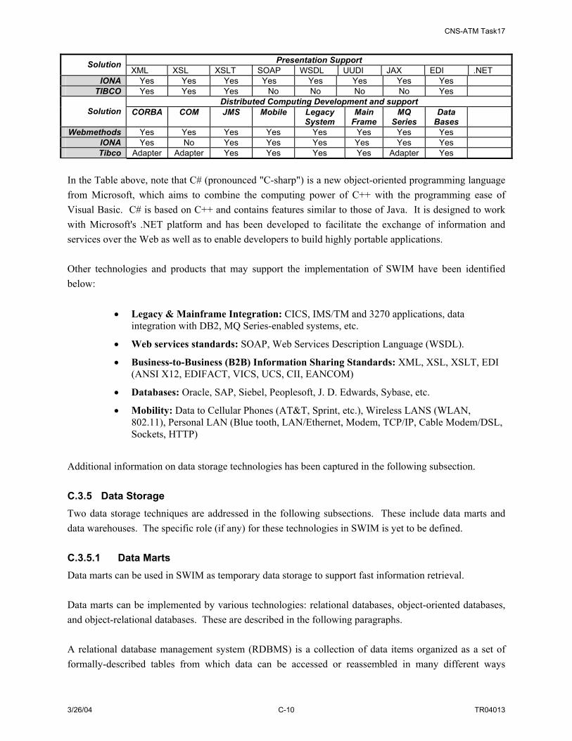
CNS-ATM Task17
3/26/04 C-10 TR04013
Presentation Support Solution XML XSL XSLT SOAP WSDL UUDI JAX EDI .NET
IONA Yes Yes Yes Yes Yes Yes Yes Yes TIBCO Yes Yes Yes No No No No Yes
Distributed Computing Development and support Solution CORBA COM JMS Mobile Legacy
System Main
Frame MQ
Series Data
Bases
Webmethods Yes Yes Yes Yes Yes Yes Yes Yes IONA Yes No Yes Yes Yes Yes Yes Yes Tibco Adapter Adapter Yes Yes Yes Yes Adapter Yes
In the Table above, note that C# (pronounced "C-sharp") is a new object-oriented programming language from Microsoft, which aims to combine the computing power of C++ with the programming ease of Visual Basic. C# is based on C++ and contains features similar to those of Java. It is designed to work with Microsoft's .NET platform and has been developed to facilitate the exchange of information and services over the Web as well as to enable developers to build highly portable applications. Other technologies and products that may support the implementation of SWIM have been identified below:
• Legacy & Mainframe Integration: CICS, IMS/TM and 3270 applications, data integration with DB2, MQ Series-enabled systems, etc.
• Web services standards: SOAP, Web Services Description Language (WSDL).
• Business-to-Business (B2B) Information Sharing Standards: XML, XSL, XSLT, EDI (ANSI X12, EDIFACT, VICS, UCS, CII, EANCOM)
• Databases: Oracle, SAP, Siebel, Peoplesoft, J. D. Edwards, Sybase, etc.
• Mobility: Data to Cellular Phones (AT&T, Sprint, etc.), Wireless LANS (WLAN, 802.11), Personal LAN (Blue tooth, LAN/Ethernet, Modem, TCP/IP, Cable Modem/DSL, Sockets, HTTP)
Additional information on data storage technologies has been captured in the following subsection. C.3.5 Data Storage Two data storage techniques are addressed in the following subsections. These include data marts and data warehouses. The specific role (if any) for these technologies in SWIM is yet to be defined. C.3.5.1 Data Marts Data marts can be used in SWIM as temporary data storage to support fast information retrieval. Data marts can be implemented by various technologies: relational databases, object-oriented databases, and object-relational databases. These are described in the following paragraphs. A relational database management system (RDBMS) is a collection of data items organized as a set of formally-described tables from which data can be accessed or reassembled in many different ways

CNS-ATM Task17
3/26/04 C-11 TR04013
without having to reorganize the database tables.19 Relational databases store data in tables that are two dimensional with rows and columns. RDBMSs use Structured Query Language (SQL, currently SQL2). SQL includes statements for data definition, modification, querying, and constraint specification. The types of queries vary from simple single-table queries to complicated multi-table queries involving joins, nesting, set union/differences, and others. An object oriented database, also called an Object Database Management System (ODBMS), is a database management system that supports the modeling and creation of data as objects.20 Objects basically consist of the following:
• Attributes - Attributes are data that defines the characteristics of an object. This data may be simple such as integers, strings, and real numbers or it may be a reference to a complex object.
• Methods - Methods define the behavior of an object and are what was formally called procedures or functions. 21
The Object Data Management Group (ODMG) has proposed a standard known as ODMG-93 or ODMG 1.0 standard, now revised into ODMG 2.0. This standard consists of the object model, the object defining language (ODL), the object query language (OQL), and the bindings to OO programming languages. The primary interface in an OODBMS for creating and modifying objects is directly via the object language (C++, Java, etc.) using the native language syntax. An Object-Relational Database Management System (ORDBMS) is designed to achieve the benefits of both the relational and the object models such as scalability and support for rich data types. ORDBMSs employ a data model that attempts to incorporate OO features into RDBMSs. All database information is stored in tables, but some of the tabular entries may have richer data structure. An ORDBMS supports an extended form of SQL called SQL3 that is still in the development stages. The comparisons of these RDBMS, OODBMS and ORDBMS are in the Table C-522.
Table C-5: A Comparison of Database Management Systems Criteria RDBMS ODBMS ORDBMS
Defining Standard SQL2 ODMG-2.0 SQL3 (in progress) Support Complex relationships
Does not support abstract data types
Support a wide variety of data types and data with complex inter-relationships
Support abstract data types and complex relationships
Performance Very good Relative slow performance Expect to perform well Product maturity Very mature Relatively mature Less mature Advantages Uses SQL, relatively
simple query optimization hence good performance
Handles all types of complex applications, good code reusability
Ability to query complex applications and to handle large and complex applications
19 http://www.whatis.com 20 http://www.whatis.com 21 http://www.comptechdoc.org/independent/database/basicdb/dataobject.html 22 http://www.acm.org/crossroads/xrds7-3/ordbms.html

CNS-ATM Task17
3/26/04 C-12 TR04013
Criteria RDBMS ODBMS ORDBMS Disadvantages Inability to handle complex
applications Low performance due to complex query optimization, inability to support large-scale systems
Low performance in web applications
C.3.5.2 Data Warehouse A data warehouse is designed to bring together all or a set of all of the data of an enterprise or organization into a single repository. A data warehouse has the potential to give a totally integrated view of the enterprise or organization. A data warehouse can enable NAS users to have different views to information from other groups as well as provide a more integrated fusion and intelligence of the NAS data. This may enable NAS users to make decisions that will optimize global performance in addition to local performance. All of the above mentioned benefits are made more difficult when data is spread out across multiple data sources. For SWIM, it is envisioned that the use of a data warehouse (if at all) would be as a SWIM Member, rather than as a part of SWIM itself. Data warehouses tend to be oriented around important subjects in the enterprise or organization and tend to focus on data modeling and database design. Additionally, the data that is contained in a data warehouse tends to span a range of time, have numerous relationships that are maintained, and can represent many static organizational rules and data relationships. Therefore, the data in a data warehouse is accurate as of a particular time frame. This quality gives an organization the ability to capture data in a long series of snap shots that can be permanently recorded as needed (due to the nonvolatile nature of the data warehouse). In contrast, databases are geared toward more localized use and are designed around processes and functions. C.4 SUMMARY OF IMPLEMENTATION TECHNOLOGIES AND PRODUCTS Table C-6 summarizes the information related to selection of implementation technologies and products, organized by architecture layer (as described in Section C.2).
Table C-6: Summary of Implementation Options
Option Number
Technology/ Implementation
Options
Factors That Affect the Decision of Specific
Technologies and Products How to Resolve
Impact on Overall Effectiveness of the Architecture
1 Data Presentation Technologies/Products
Specification of SWIM data concept
Architecture Refinement, Engineering Design Model
Medium
2 Application Development Technologies/Products
Definition of implementation objectives; technology/COTS features
Architecture Refinement, Engineering Design Model
Medium
3 Distributed Computing Technologies/Products
Definition of implementation objectives; technology/COTS features
Architecture Refinement, Engineering Design Model
High
4 Data Storage Technologies/Products
Specification of SWIM data concept; definition of implementation objectives; technology/COTS features
Architecture Refinement, Engineering Design Model
Medium
CNS-ATM Task17
3/26/04 C-13 TR04013
C.5 TECHNOLOGY REFERENCE The following section provides an overview of candidate enabling technologies for SWIM. These technologies apply to the application development environment (Section C.5.1) and distributed middleware technologies (Section C.5.2). C.5.1 Application Development Environment Two application development standards/platforms are discussed in this section, namely J2EE and .NET. Unless otherwise reference, the material provided is from searchWebServices.com, a TechTarget site for Web Services professionals. C.5.1.1 J2EE J2EE (Java 2 Platform, Enterprise Edition) is a Java platform designed for the mainframe-scale computing typical of large enterprises. Sun Microsystems (together with industry partners such as IBM) designed J2EE to simplify application development in a thin client tiered environment. J2EE simplifies application development and decreases the need for programming and programmer training by creating standardized, reusable modular components and by enabling the tier to handle many aspects of programming automatically. J2EE includes many components of the Java 2 Platform, Standard Edition (J2SE):
• The Java Development Kit (JDK) is included as the core language package.
• Write Once Run Anywhere technology is included to ensure portability.
• Support is provided for Common Object Request Broker Architecture (CORBA), a predecessor of Enterprise JavaBeans (EJB), so that Java objects can communicate with CORBA objects both locally and over a network through its interface broker.
• Java Database Connectivity 2.0 (JDBC), the Java equivalent to Open Database Connectivity (ODBC), is included as the standard interface for Java databases.
• A security model is included to protect data both locally and in Web-based applications.
J2EE also includes a number of components added to the J2SE model, such as the following:
• Full support is included for Enterprise JavaBeans. EJB is a server-based technology for the delivery of program components in an enterprise environment. It supports the Extensible Markup Language (XML) and has enhanced deployment and security features.
• The Java servlet API (application programming interface) enhances consistency for developers without requiring a graphical user interface (GUI).
• Java Server Pages (JSP) is the Java equivalent to Microsoft's Active Server Pages (ASP) and is used for dynamic Web-enabled data access and manipulation.
The J2EE architecture consists of four major elements:

CNS-ATM Task17
3/26/04 C-14 TR04013
• The J2EE Application Programming Model is the standard programming model used to facilitate the development of multi-tier, thin client applications.
• The J2EE Platform includes necessary policies and APIs such as the Java servlets and Java Message Service (JMS).
• The J2EE Compatibility Test Suite ensures that J2EE products are compatible with the platform standards.
• The J2EE Reference Implementation explains J2EE capabilities and provides its operational definition.
C.5.1.2 .NET .NET is both a business strategy from Microsoft and its collection of programming support for what are known as Web Services, the ability to use the Web rather than your own computer for various services. Microsoft's goal is to provide individual and business users with a seamlessly interoperable and Web-enabled interface for applications and computing devices and to make computing activities increasingly Web browser-oriented. The .NET platform includes servers; building-block services, such as Web-based data storage; and device software. It also includes Passport, Microsoft's fill-in-the-form-only-once identity verification service. The .NET platform is expected to provide:
• The ability to make the entire range of computing devices work together and to have user information automatically updated and synchronized on all of them
• Increased interactive capability for Web sites, enabled by greater use of XML (Extensible Markup Language) rather than HTML
• A premium online subscription service, that will feature customized access and delivery of products and services to the user from a central starting point for the management of various applications, such as e-mail, for example, or software, such as Office .NET
• Centralized data storage, which will increase efficiency and ease of access to information, as well as synchronization of information among users and devices
• The ability to integrate various communications media, such as e-mail, faxes, and telephones
• For developers, the ability to create reusable modules, which should increase productivity and reduce the number of programming errors
C.5.2 Distributed Middleware Technologies The implementations of distributed middleware technologies are addressed in this section, namely Object Request Broker-based, Remote Procedure Call-based and Message-based. Technologies and products associated with each of these categories have been identified. As above, unless otherwise referenced, the material provided is extracted from searchWebServices.com. C.5.2.1 Object Request Broker Based Middleware Object Request Broker-based middleware is addressed through description of specific middleware products. These include Object Management Group (OMG) CORBA, Sun’s Remote Method Invocation

CNS-ATM Task17
3/26/04 C-15 TR04013
(RMI), Microsoft’s Distributed Component Object Model (DCOM/COM) and Sun Enterprise Java Bean (EJB). C.5.2.1.1 OMG CORBA Common Object Request Broker Architecture (CORBA) is an architecture and specification for creating, distributing, and managing distributed program objects in a network. It allows programs at different locations and developed by different vendors to communicate in a network through an "interface broker." CORBA was developed by a consortium of vendors through the OMG, which currently includes over 500 member companies. Both International Organization for Standardization (ISO) and X/Open have sanctioned CORBA as the standard architecture for distributed objects (which are also known as components). CORBA 3 is the most recent definition. CORBA satisfies the requirements of location transparency, performance transparency, predictability transparency and reliability transparency. Therefore it is widely used in Enterprise Distributed Computing (EDC) environments. However, as stated before, the NAS is a very dynamic and complex environment that has requirements go beyond that of EDC systems. EDC mainly focuses on usability and developer productivity. While these items are important, EDC does not tend to focus on topics of interest for real-time systems. The OMG has addressed the short comings of general purpose CORBA (including lack of QoS specifications, QoS enforcement, real-time programming features and performance optimizations) with the definition of Real-Time (RT) CORBA. SWIM does and will always have the requirement to deliver data in real time. Therefore it must have an architecture that supports general purpose (e.g. non real-time) as well as special (e.g. real-time or stream data) applications with ease. Real-Time CORBA systems differ from general purpose CORBA systems as the Real-Time implementations dictate a measure of system-wide design control to deliver predictability and therefore also some control over which ORB to deploy. Real-Time CORBA defines a QoS framework that includes policy management for request priority, queuing, message delivery quality, timeouts, etc. Additionally, Real-Time CORBA supports an optional set of extensions to CORBA tailored to equip ORBs to be used as a component of a real-time system. In the development of SWIM, there map be a need for developers to address the allocation of resources and the predictability of system execution because service timeliness will be as important as functionality. Real-Time CORBA provides the handles needed to manage resources and predictability. Real-Time CORBA provides a single compliance point that spans various areas of real time system development such as “hard” and “soft” real-time, different resource contention pools, scheduling algorithms, etc. Real-Time CORBA also brings interoperability, flexibility, and portability to real-time system implementation in addition to end-to-end predictability (which is important for supporting real-time data service performance requirements). C.5.2.1.2 Java RMI RMI (Remote Method Invocation) is a way that a programmer, using the Java programming language and development environment, can write object-oriented programs in which objects on different computers can interact in a distributed network. RMI is the Java version of what is generally known as a remote

CNS-ATM Task17
3/26/04 C-16 TR04013
procedure call (RPC), but with the ability to pass one or more objects along with a request. The object can include information that will change the service that is performed in the remote computer. Sun Microsystems, the inventors of Java, calls this "moving behavior." For example, when a user at a remote computer fills out an expense account, the Java program interacting with the user could communicate, using RMI, with a Java program in another computer that always had the latest policy about expense reporting. In reply, that program would send back an object and associated method information that would enable the remote computer program to screen the user's expense account data in a way that was consistent with the latest policy. The user and the company both would save time by catching mistakes early. Whenever the company policy changed, it would require a change to a program in only one computer. Sun calls its object parameter-passing mechanism object serialization. An RMI request is a request to invoke the method of a remote object. This request has the same syntax as a request to invoke an object method on the same (local) computer. In general, RMI is designed to preserve the object model and its advantages across a network. RMI is implemented as three layers:
• A stub program in the client side of the client/server relationship, and a corresponding skeleton at the server end. The stub appears to the calling program to be the program being called for a service. (Sun uses the term proxy as a synonym for stub.)
• A Remote Reference Layer that can behave differently depending on the parameters passed by the calling program. For example, this layer can determine whether the request is to call a single remote service or multiple remote programs as in a multicast.
• A Transport Connection Layer, which sets up and manages the request.
A single request travels down through the layers on one computer and up through the layers at the other end. RMI is supplied as part of Sun MicroSystem's Java Development Kit (JDK). C.5.2.1.3 DCOM DCOM (Distributed Component Object Model) is a set of Microsoft concepts and program interfaces in which client program objects can request services from server program objects on other computers in a network. DCOM is based on the Component Object Model (COM), which provides a set of interfaces allowing clients and servers to communicate within the same computer (that is running Windows 95 or a later version). For example, you can create a page for a Web site that contains a script or program that can be processed (before being sent to a requesting user) not on the Web site server but on another, more specialized server in the network. Using DCOM interfaces, the Web server site program (now acting as a client object) can forward a Remote Procedure Call (RPC) to the specialized server object, which provides the necessary processing and returns the result to the Web server site. It passes the result on to the Web page viewer.

CNS-ATM Task17
3/26/04 C-17 TR04013
DCOM can also work on a network within an enterprise or on other networks besides the public Internet. It uses TCP/IP and Hypertext Transfer Protocol. It comes as part of the Windows operating systems and is or soon will be available on all major UNIX platforms and on IBM's large server products. DCOM replaces OLE Remote Automation. DCOM is generally equivalent to the Common Object Request Broker Architecture (CORBA) in terms of providing a set of distributed services. It is Microsoft's approach to a network-wide environment for program and data objects. CORBA is sponsored by the rest of the information technology industry under the auspices of the Object Management Group (OMG). C.5.2.1.4 Enterprise JavaBean (EJB) Enterprise JavaBeans (EJB) is an architecture for setting up program components, written in the Java programming language, that run in the server parts of a computer network that uses the client/server model. Enterprise JavaBeans is built on the JavaBeans technology for distributing program components (which are called Beans, using the coffee metaphor) to clients in a network. Enterprise JavaBeans offers to enterprises the advantage of being able to control change at the server rather than having to update each individual computer with a client whenever a new program component is changed or added. EJB components have the advantage of being reusable in multiple applications. To deploy an EJB Bean or component, it must be part of a specific application, which is called a container. Originated by Sun Microsystems, Enterprise JavaBeans is roughly equivalent to Microsoft's Component Object Model/Distributed Component Object Model architecture, but, like all Java-based architectures, programs can be deployed across all major operating systems, not just Windows. EJB's program components are generally known as servlets (little server programs). The application or container that runs the servlets is sometimes called an application server. A typical use of servlets is to replace Web programs that use the common gateway interface (CGI) and a Practical Extraction and Reporting Language script. Another general use is to provide an interface between Web users and a legacy application mainframe application and its database. In Enterprise JavaBeans, there are two types of beans: session beans and entity beans. An entity bean is described as one that, unlike a session bean, has persistence and can retain its original behavior or state. C.5.2.2 RPC-based Middleware RPC-based middleware is addressed through description of specific middleware products. These include SUN ONC and OSF DCE. As above, unless otherwise referenced, the material provided is derived from searchWebServices.com. C.5.2.2.1 SUN ONC23 ONC RPC provides an advanced client/server programming environment that is easy to use, enabling the creation of applications that execute procedures on other network computers without having to address
23 http://www.onc-rpc-xdr.com/

CNS-ATM Task17
3/26/04 C-18 TR04013
the fact that the procedures are not executed locally. ONC RPC provides a mechanism whereby one process (the "client" process) can have another process (the "server" process) execute a procedure call as if it was a subroutine on the local system. C.5.2.2.2 OSF DCE In network computing, DCE (Distributed Computing Environment) is an industry-standard software technology for setting up and managing computing and data exchange in a system of distributed computers. DCE is typically used in a large network of computing systems that include different size servers scattered geographically; and it uses the client/server model. Using DCE, application users can access applications and data at remote servers. Application programmers need not be aware of where their programs will run or where the data will be located. Much of DCE setup requires the preparation of distributed directories so that DCE applications and related data can be located when they are being used. DCE includes security support and some implementations provide support for access to popular databases such as IBM's CICS, IMS, and DB2 databases. DCE was developed by the Open Software Foundation (OSF) using software technologies contributed by some of its member companies. C.5.2.3 Message-Based Middleware RPC-based middleware is addressed through description of specific middleware products. These include IBM MQSeriesand Sun/ToolTalk. As above, unless otherwise referenced, the material provided is derived from searchWebServices.com. C.5.2.3.1 IBM MQSeries MQSeries is an IBM software family whose components are used to link software applications so that they can work together. This type of application is often known as business integration software or middleware. MQSeries consists of three products:
• MQSeries Messaging, which provides the communication mechanism between applications on different platforms
• MQSeries Integrator, which centralizes and applies business operations rules
• MQSeries Workflow, which enables the capture, visualization, and automation of business processes
The objective of business integration is to connect different computer systems, diverse geographical locations, and dissimilar IT infrastructures so that seamless operations can be run. IBM's MQSeries provides communications between applications, or between users and a set of applications on dissimilar

CNS-ATM Task17
3/26/04 C-19 TR04013
systems. It has grown in popularity as applications are made available over the Internet because of its support of over 35 platforms and its ability to integrate disparate automation systems. An additional helpful feature is that its messaging scheme requires the application that receives the message to confirm receipt. If no confirmation materializes, the message is re-sent by the MQSeries. C.5.2.3.2 Sun ToolTalk24 The ToolTalk service enables independent applications to communicate with each other without having direct knowledge of each other. Applications create and send ToolTalk messages to communicate with each other. The ToolTalk service receives these messages, determines the recipients, and then delivers the messages to the appropriate applications. ToolTalk is designed to make it easy to put a messaging interface on any application, regardless of whether the application:
• Runs only on Solaris or also on other popular UNIX platforms;
• Is multi-threaded or single-threaded;
• Has a command-line or graphical user interface;
• Installs signal handlers;
• Is an RPC server; or
• Uses its own event loop, or that of a window system toolkit.
24 http://www.cs.umbc.edu/kqml/toolTalk/toolTalk.html

CNS-ATM Task17
3/26/04 C-20 TR04013

CNS-ATM Task17
3/26/04 D-1 TR04013
APPENDIX D. DESCRIPTION OF SWIM PHYSICAL ARCHITECTURE COMPONENTS
Section 4.2.2 of the report identifies the various physical architecture components developed for SWIM. These include hardware/software components, a data component, and people/facility components. The first two types of components (hardware/software and data) have been described briefly in the main body of the report, but warrant further description. This appendix includes this additional description in the following subsections:
• Section D.1 SWIM Hardware/Software Component Descriptions
a. Section D.1.1 Information Management Hardware/Software Components
b. Section D.1.2 Network Management Hardware/Software Components
• Section D.2 SWIM Data Component Description
D.1 SWIM HARDWARE/SOFTWARE COMPONENT DESCRIPTIONS This section provides a description of the hardware and software components of the SWIM physical architecture. The discussion addresses first those components that support information management functionality followed by those components that support network management functionality.25 D.1.1 Information Management Hardware/Software Components The information management hardware and software components consist of a member interface component, a browser component, a web server component, a broker component, a data model registry, and an information object repository. Section 4.2.2.1 addresses how these components are implemented (in hardware, software, or both) and whether they are a dedicated component of SWIM or a shared NAS component. An architecture block diagram that captures these components and a first level component decomposition is provided in Figure D-1.
25 The “information management” vs “network management” distinction is used as these are the two highest level categories of SWIM functionality defined in the SWIM functional architecture (see Section 2).

CNS-ATM Task17
3/26/04 D-2 TR04013
SWIM Information ManagementSWIM Information Management
Member Interface
Interface S/W
Interface H/W (optional)
Registration
Transaction Translation
Security PolicyImplementation
Data Conversion
Member Discovery
Member Interface
Interface S/W
Interface H/W (optional)
Registration
Transaction Translation
Security PolicyImplementation
Data Conversion
Member Discovery
Data Storage
Data Mart
Data StorageBroker
Broker S/W
Broker Server
Registration Maintenance
Transaction Processing
User/Data Verification
Broker Naming Service
Event Handling
Broker
Broker S/W
Broker Server
Registration Maintenance
Transaction Processing
User/Data Verification
Broker Naming Service
Event Handling
Broker
Broker S/W
Broker Server
Registration Maintenance
Transaction Processing
User/Data Verification
Broker Naming Service
Event Handling
Broker
Broker S/W
Broker Server
Registration Maintenance
Transaction Processing
User/Data Verification
Broker Naming Service
Event Handling
Data Mart
Data StorageData Model
Data Mart
Data Warehouse
Common data model
MDR
Data WarehouseIORData WarehouseIOR
Interface H/W (optional)Web Server (optional)
Member DiscoveryWeb Browser (Optional)
Figure D-1: SWIM Information Management Component Architecture Block Diagram The member interface component provides an entry point for SWIM members to access to SWIM. Its main functions are registering members and data to be published (for data provider members); providing SWIM security checks such as authenticating and authorizing users; and controlling SWIM data access. For publishers, it converts data from the publisher’s data format to a SWIM common data format and creates information objects; for subscribers, it converts the received data in common data format back to the subscriber’s data format. This component also conducts transaction translation for SWIM members to request registration, publish, subscribe, query, and other SWIM service operations. Finally, the member interface component provides the member discovery function for members to accurately express their service requests. The browser and web server components can be used in SWIM when there is a need to provide web service for NAS users to request information through a more convenient interface. Under SWIM context, the web servers act as data consumers SWIM. A Web server is a program that, using the client/server model and the World Wide Web's Hypertext Transfer Protocol (HTTP), serves the files that form Web pages to Web users (whose computers contain HTTP clients that forward their requests). Web servers often come as part of a larger package of Internet- and intranet-related programs for serving e-mail, downloading requests for File Transfer Protocol (FTP) files, and building and publishing Web pages. Considerations in choosing a Web server include how well it works with the operating system and other servers, its ability to handle server-side programming, security characteristics, and publishing, search engine, and site building tools that may come with it. A browser is an application program that provides a way to look at and interact with all the information on the World Wide Web. Technically, a Web browser is a client program that uses the Hypertext Transfer Protocol (HTTP) to make requests of Web servers throughout the Internet on behalf of the browser user. While some browsers also support e-mail (indirectly through e-mail Web sites) and the File Transfer

CNS-ATM Task17
3/26/04 D-3 TR04013
Protocol (FTP), a Web browser is not required for those Internet protocols and more specialized client programs are more popular. The broker component interfaces with the member interface components to receive and process member requests such as publish, subscribe, and query. It matches the published information objects with the subscribers who have subscribed to the data. Typically, this is an asynchronous process. The broker component also searches for matches to published information objects in SWIM data marts or data warehouses for members who query for the data. Broker components can be distributed according to several alternative topologies (see Section G.5.3). Distributed brokers would exchange their subscriber subscription information so that published information objects could be matched to all distributed subscribers. The Information Object Repository is a system that contains the instances of information objects (where SWIM data would be represented by an information object, which is defined in accordance with a SWIM common data model). Typically, it is a software application that uses a database to store and retrieve records that describe data items. SWIM data. A Metadata Registry is a system that contains information describing the format, structure, and definitions of data (rather than holding actual ‘filled-out’ data). Like the IOR, it is often implemented as a software application that uses a database to store and retrieve data as well as document formats, data definitions, and data relationships. A schematic block diagram for the SWIM information management hardware and software components is provided as Figure D-2.
StorageMember Interface
Registration
Transaction Translation
Security Policy Implementation
Data Conversion
Member Interface
Registration
Transaction Translation
Security Policy Implementation
Data Conversion
Member Interface
Registration
Transaction Translation
Security Policy Implementation
Data Conversion
Member Interface
Registration
Transaction Translation
Security Policy Implementation
Data Conversion
Member Interface
Registration
Transaction Translation
Security Policy Implementation
Data Conversion
Broker
Registration Maintenance
Transaction Processing
User/Data Verification
Broker Naming Service
Event Handling
Data Mart
GU
I
SWIMSWIM Members
Member Discovery
Data Model MDRMDRIORIOR
Web
Bro
wse
r
Figure D-2: SWIM Information Management Component Schematic Diagram (High-Level)
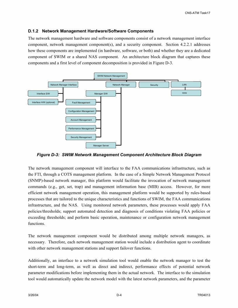
CNS-ATM Task17
3/26/04 D-4 TR04013
D.1.2 Network Management Hardware/Software Components The network management hardware and software components consist of a network management interface component, network management component(s), and a security component. Section 4.2.2.1 addresses how these components are implemented (in hardware, software, or both) and whether they are a dedicated component of SWIM or a shared NAS component. An architecture block diagram that captures these components and a first level of component decomposition is provided in Figure D-3.
SWIM Network Management
Network Manager Interface Network Manager Security
Interface S/W
Interface H/W (optional)
Manager S/W
Manager Server
Fault Management
Configuration Management
Account Management
Performance Management
Security Management
SWIM Network Management
Network Manager Interface Network Manager Security
Interface S/W
Interface H/W (optional)
Manager S/W
Manager Server
Fault Management
Configuration Management
Account Management
Performance Management
Security Management
SecurityLAN
SecurityWAN
Figure D-3: SWIM Network Management Component Architecture Block Diagram The network management component will interface to the FAA communications infrastructure, such as the FTI, through a COTS management platform. In the case of a Simple Network Management Protocol (SNMP)-based network manager, this platform would facilitate the invocation of network management commands (e.g., get, set, trap) and management information base (MIB) access. However, for more efficient network management operation, this management platform would be supported by rules-based processes that are tailored to the unique characteristics and functions of SWIM, the FAA communications infrastructure, and the NAS. Using monitored network parameters, these processes would apply FAA policies/thresholds; support automated detection and diagnosis of conditions violating FAA policies or exceeding thresholds; and perform basic operation, maintenance or configuration network management functions. The network management component would be distributed among multiple network managers, as necessary. Therefore, each network management station would include a distribution agent to coordinate with other network management stations and support failover functions. Additionally, an interface to a network simulation tool would enable the network manager to test the short-term and long-term, as well as direct and indirect, performance effects of potential network parameter modifications before implementing them in the actual network. The interface to the simulation tool would automatically update the network model with the latest network parameters, and the parameter
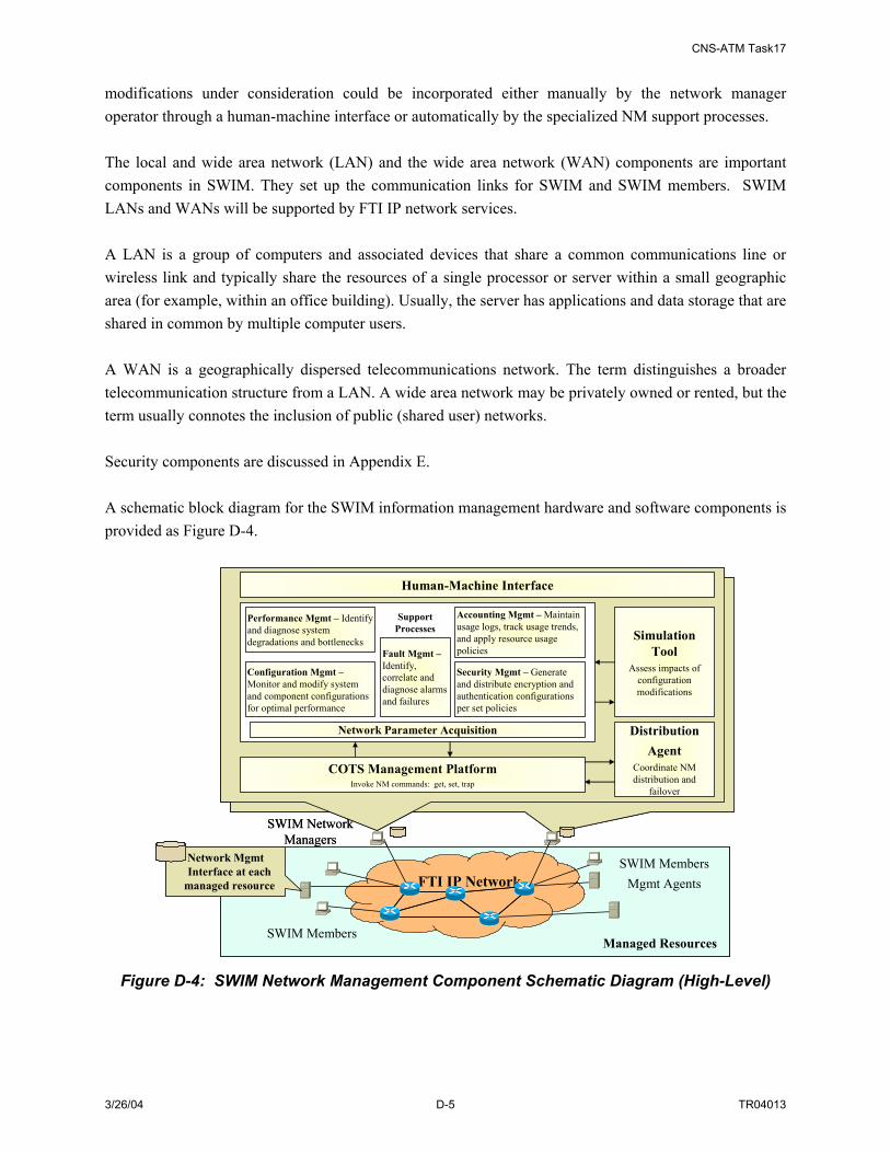
CNS-ATM Task17
3/26/04 D-5 TR04013
modifications under consideration could be incorporated either manually by the network manager operator through a human-machine interface or automatically by the specialized NM support processes. The local and wide area network (LAN) and the wide area network (WAN) components are important components in SWIM. They set up the communication links for SWIM and SWIM members. SWIM LANs and WANs will be supported by FTI IP network services. A LAN is a group of computers and associated devices that share a common communications line or wireless link and typically share the resources of a single processor or server within a small geographic area (for example, within an office building). Usually, the server has applications and data storage that are shared in common by multiple computer users. A WAN is a geographically dispersed telecommunications network. The term distinguishes a broader telecommunication structure from a LAN. A wide area network may be privately owned or rented, but the term usually connotes the inclusion of public (shared user) networks. Security components are discussed in Appendix E. A schematic block diagram for the SWIM information management hardware and software components is provided as Figure D-4.
FTI IP Network
SWIM Members
SWIM MembersMgmt Agents
SWIM Network Managers
Managed Resources
Human-Machine Interface
Performance Mgmt – Identify and diagnose system degradations and bottlenecks
Accounting Mgmt – Maintain usage logs, track usage trends, and apply resource usage policies
Security Mgmt – Generate and distribute encryption and authentication configurations per set policies
Configuration Mgmt –Monitor and modify system and component configurations for optimal performance
Fault Mgmt –Identify, correlate and diagnose alarms and failures
COTS Management PlatformInvoke NM commands: get, set, trap
DistributionAgent
Coordinate NM distribution and
failover
Simulation Tool
Assess impacts of configuration modifications
Network Parameter Acquisition
Support Processes
Network Mgmt Interface at each
managed resource FTI IP Network
SWIM Members
SWIM MembersMgmt Agents
SWIM Network Managers
Managed Resources
Human-Machine Interface
Performance Mgmt – Identify and diagnose system degradations and bottlenecks
Accounting Mgmt – Maintain usage logs, track usage trends, and apply resource usage policies
Security Mgmt – Generate and distribute encryption and authentication configurations per set policies
Configuration Mgmt –Monitor and modify system and component configurations for optimal performance
Fault Mgmt –Identify, correlate and diagnose alarms and failures
COTS Management PlatformInvoke NM commands: get, set, trap
DistributionAgent
Coordinate NM distribution and
failover
Simulation Tool
Assess impacts of configuration modifications
Network Parameter Acquisition
Support Processes
Network Mgmt Interface at each
managed resource
Figure D-4: SWIM Network Management Component Schematic Diagram (High-Level)

CNS-ATM Task17
3/26/04 D-6 TR04013
D.2 SWIM DATA COMPONENT DESCRIPTION SWIM makes the concept of managing information at the NAS system level a reality. This includes the organization and standardization of NAS information to be exchanged over SWIM; the acquisition of exchanged information into SWIM; the dissemination (sharing) of needed information to target SWIM members; and the control, monitoring, preservation, and disposition of the exchanged NAS information. The concepts of SWIM data representation and management are vital to the success of the SWIM enterprise and address the ultimate goal of SWIM – to deliver the right information at the right time. The timeliness, accuracy, understandability, availability, and security of the data are the goals of SWIM data management26. This section describes various elements of SWIM information representation and management concepts including:
• Metadata Concepts
• Processing Metadata
• Sample Information Object Description (XML Schema)
• Subscription Language Operations on Information Objects
• SWIM Data Management Goals
D.2.1 Metadata Concept and the SWIM Information Object Metadata is defined as data that describes other data. The Committee on Institutional Cooperation27 defines three types of metadata:
1. Descriptive metadata: describe the intellectual content and associations of a document or resource in a way that facilitates search, identification, and collocation of information contained within or exemplified by the resource.
2. Structural metadata: define the physical structure of a complex digital entity to facilitate navigation, information retrieval, and display.
3. Administrative metadata: encompass a variety of data related to viewing, interpretation, use, and management of digital objects over time.
In this study, the focus is on structural metadata used in SWIM to define the structural features of NAS data elements and capture the relationships among NAS data elements. This metadata definition includes data attributes and content of data elements that are used to support SWIM data object search features. Specifically, this metadata allows users and application programs to quickly search for and identify data elements that map to their expressed attributes and content of interest. A NAS information object is NAS information in a standardized format. There are two components of an information object, namely the data object (the payload) and structural information that describes the data 26 U.S. Department of Transportation Federal Aviation Administration Order 1375.1C, Subject: Data Management 27 The Committee on Institutional Cooperation, established in 1958, is the academic consortium of twelve major teaching and research universities in the Midwest. Its programs and activities extend to all aspects of university activity except intercollegiate athletics. The CIC headquarters office is located at the University of Illinois at Urbana-Champaign. http://www.cic.uiuc.edu/
CNS-ATM Task17
3/26/04 D-7 TR04013
object (the metadata). The data object is created by classifying and categorizing NAS data to a desired level of detail. The data object is the information being distributed and may range from simple numerals, to text, to an entire digital video file. As noted above, the structure information that describes the data object is the metadata. The pairing of metadata with the payload in an information object makes it possible for the SWIM brokering function to match ongoing requests (subscriptions) and future requests (queries) for data to the information object or objects that satisfy these requests. As described in Section 4.2.2.2, the information object is the basic unit of information management within the SWIM. It is created by publisher members, disseminated to subscriber members and can be archived to support future queries. Also defined in Section 4.2.2.2, a common data model in SWIM is a NAS-wide pre-defined and agreed upon definition of data structures (organized NAS data hierarchies) that make NAS information understandable by all SWIM members. A common data model agreed to by the entire SWIM user community is designed and information objects are derived based on the model. The structural information of the common data model is captured by the metadata in an information object. A data element such as a date has many different representations in today’s NAS, the FAA has already established an FAA Data Registry (FDR) that lists approved data standards in FAA-STD-060 format. Standardized data items have been listed with a preferred name, an identifier, data type (e.g., “string”), a definition, permissible values with value meanings, interchange format, maximum length, and unit of measure with minimum and maximum values where applicable. Each standard data element is listed with a steward organization, such as the FAA’s Aeronautical Information Division, ATA-100. While FDR development is ongoing, only a few hundred data standards have been established. The implementation of SWIM will require increased data stewardship roles in FAA divisions and further standardization of data elements to be shared over SWIM (in information objects using common data models). The common data model is needed to support efficient exchange of all types of NAS information by all SWIM members. An example of an information object that incorporates structural metadata information according to a common data model is shown in Figure D-5. Note that the common data fields can be as complicated as some common fields agreed NAS-wide or can be as simple as a regular header fields that describe the payload and is understood between data providers, SWIM, and data consumers.

CNS-ATM Task17
3/26/04 D-8 TR04013
(payload)Real NAS/SWIM Data
Specific Metadata for this information object type (and its child objects)
Specific Object Type Metadata
SWIM Common Data FieldsMandatory for every SWIM object
Original NAS Data Format
Data RepresentationSuch as XML
Figure D-5: Example of a SWIM information Object Based on a Common Data Model The information object is considered to have a lifecycle that includes four stages. These are creation; validation and verification; publishing, searching and retrieving; and archiving and disposition. More information on each of these lifecycle stages is provided below. D.2.1.1 Lifecycle of SWIM Information Objects Information objects, such as SWIM information objects, go through four distinct lifecycle stages: Creation; Validation & Verification; Publishing, Searching and Retrieving; and Archiving and Disposition. The relationship between these stages is illustrated in Figure D-6.

CNS-ATM Task17
3/26/04 D-9 TR04013
Creation of Information Object
Validation and Verification
Publishing, SearchingRetrieving
Archiving andDisposition
•Inventory of data •Understand data•Identify w hat data means•Identify data set valid time•Identify the resources that create
the data sets •Identify w hat data sets represent •Identify how data sets are represented•Structure data•Define data security levels•Define searchable attributes•Define information object•Represent information objects
•Choose metadata builder•Define metadata schema•Build metadata registry•Define and implement access methods•Define security check point•Validate information objec t
•Publish information objects (SWIM process)•Prov ide searching constraints or language•Define retrieval algorithms•Mapping published information objectsto subscribe and query requests
•Store information objects to data marts•Store information objects payload to data w arehouse•Refresh information objects in data marts•Refresh information objects pay load indata w arehouse•Maintain data integrity•Disposition outdated information objec ts ortheir payloads
Information Object Lifecycle
Figure D-6: Lifecycle of an Information Object During the creation of the information object, strategies and techniques for creating information objects are developed. This process may include:
1. Inventory data: determine the exact data to be exchanged over SWIM
2. Understand data: identify characteristics to consider when creating metadata keeping in mind that thoughtful metadata definition can provide an opportunity to capture information loss during the process of automating data services
• Identify what data means
• Identify data set valid time
• Identify the resources that create the data sets
• Identify what the data sets represent
• Identify how data sets are represented
3. Identify structured metadata: For example, define data security levels as well as searchable attributes
4. Define information objects: Define the actual structure of the information objects
5. Represent information objects: Use a representation language such as XML to represent the information object

CNS-ATM Task17
3/26/04 D-10 TR04013
Some administrative and descriptive metadata may be included by the information object creators. Information objects are organized into the structure of the defined common data model and additional metadata for those objects may be created through registration, repository and indexing processes. Information objects need to be validated and verified before they are published or distributed. Validation and verification is accommodated in various ways in SWIM. Metadata schemas need to be defined and stored in a metadata registry. Identifying those metadata schema or schemas that should be applied to best meet the needs of the information creator, repository and users is an important task (this is a means of verifying the proper information is received by the proper user). In addition to metadata registries, an information objects repository also needs to be defined and built to store the defined information objects. Information access methods will be defined for SWIM members to define the manual or automatic means to request exchange of information over SWIM. These access methods include security access controls to ensure each member accesses only information for which they have been authorized. Information objects that are published or distributed are subject to search and retrieval by SWIM members. SWIM must identify the search language, searchable attributes and constraints to be used by SWIM members to compose their own search predicates to subscribe or query specific information objects. Retrieval algorithms need to be defined in order for SWIM to map published information objects to subscribe or query requests. SWIM will also track retrieval algorithms, user transactions, and system effectiveness in storage and retrieval. Finally, information objects may be archived in data marts for fast retrieval; and certain information objects payloads may be archived in a data warehouse for long term storage. Processes associated with storage and retrieval such as refreshing and integrity checking are needed to ensure the continued availability of valid information. Information objects that are outdated or no longer necessary may be discarded. Metadata can be used to document both preservation and disposition activities. D.2.1.1.1 Information Object Representation – XML Overview To support flexible and efficient data exchange, there is a desire to have a universal communications medium (the Internet), a universal user interface (the browser), and a universal programming language (Java). The desire to create, manage, and present large amounts of complex data has led to a need for a universal data format. It is this topic that is addressed by eXtensible Markup Language, XML. Since data may be stored in different formats and structures, XML can provide the mechanism that standardizes the way data from various sources are extracted and used. XML is used for structuring data. Structured data examples include data arranged in spreadsheets, address books, financial transactions, and technical drawings. XML is not a programming language, but rather provides a set of rules (or conventions) for designing text formats to create structured data. It makes it easy for a computer to generate data, read data, and ensure that the data structure is unambiguous. XML avoids common pitfalls in language design: it is extensible, platform-independent, and it supports internationalization and localization. Finally, XML is fully Unicode-compliant. XML can be considered a universal data format because of following reasons:

CNS-ATM Task17
3/26/04 D-11 TR04013
1. Ease of Use: Its text-based nature makes it easy to create tools;
2. Open, License-Free, and Cross-Platform Standard: Anyone can create, develop and use tools for XML
3. Supports Complex Data Storage: Data is transmitted in computers in many ways; originally it was stored in flat-files with fixed-length or delimited formats but has migrated to databases that can support complex binary formats. XML is a structured data format, supporting storage of complex data including text, binary or object-oriented.
4. Compatible with a Range of Applications and Platforms: Because XML tags represent the logical structure of the data (hierarchical), they can be interpreted and used in multiple ways by different applications. For example, one application may gather information, another combines data collected from multiple sources and yet another performs reporting of the same data. These applications can be developed on different platforms such as .NET or JAVA. Additionally, the architecture of these applications can be based on the client-server model or web application models.
XML encompasses a family of markup languages where any number of markup languages can be defined in it. This means that almost any type of data can be easily defined in XML. This differs from the widely used Hyper-Text Markup Language (HTML) that consists of a pre-defined set of tags with pre-defined roles. This pre-definition of tags makes it a language that is easy to learn and is very accessible, but it also makes it hard to re-use the data. In contrast, as its name indicates, XML is extensible, which means that a set of tags can be defined in a custom manner. This definition of tags can then be shared with other parties (people or programs) to support common knowledge and understanding of the tags. For example, ebXML is an electronic business standard based on well-defined XML messages within the context of standard business processes. Similarly, for SWIM, a set of tags may be defined for specific information services, like surveillance, weather, etc., so that surveillance system users can use their own surveillance-specific applications to use or view data on their systems. XML can be used for different purposes within SWIM including:
1. Information Sharing: XML may allow different information services specific to surveillance, weather, etc to define standard/common data formats in XML, build tools that read data, write data and transform data between XML and other formats. The standard formats can be used by different applications for data exchange
2. Content Delivery: XML may support different users and information delivery mechanisms in delivering ‘applications’ to users through a chosen medium. For example, surveillance users and weather users may both need to access the same on-line ‘product catalogue’. Although the information is the same, the visual emphasis can differ. A surveillance user may want to see weather precipitation, which may be a subset of the weather characteristics that a weather user may want to see. All of this weather information can be stored in a single XML document and displayed differently by the different applications (e.g. surveillance applications and weather applications)
There is a large variety of technologies related to XML that are important to the understanding and development of XML applications. They may also be relevant to the SWIM architecture development effort. XML 1.0 is the specification that defines "tags" and "attributes". Beyond XML 1.0, "the XML
CNS-ATM Task17
3/26/04 D-12 TR04013
family" is a growing set of modules that offer useful services to accomplish important and frequently demanded tasks related to structured data. XLink describes a standard way to add hyperlinks to an XML file. XPointer is a syntax in development for pointing to parts of an XML document. It is like a URL, but instead of pointing to documents on the Web, it points to pieces of data inside an XML file. CSS, the style sheet language, is applicable to XML as well as to HTML. XSL is the advanced language for expressing style sheets. It is based on XSLT, a transformation language used for rearranging, adding and deleting tags and attributes. The DOM is a standard set of function calls for manipulating XML (and HTML) files from a programming language. XML Schemas help developers to precisely define the structures of their own XML-based formats. Other modules and tools are available or are under development.28 As the SWIM architecture is implemented and evolved, various combinations of legacy data formats may be initially accommodated by SWIM. The goal, however, would be to move towards a single, universal data format to provide the most flexible and efficient description of all NAS data. XML is a leading technology candidate for this universal format. XML is becoming widely used in enterprise networks and there are many related technologies that can be used to support a range of data manipulations. Further work in the investigation of SWIM information objects may look towards XML and related technologies to provide a standardized solution to information exchange. This work will include the development and definition of specific XML tags for specific types of NAS information. Some initial work in this area is underway (e.g. NAS Information Markup Language (NIXL) development). These efforts will need to continue and be coordinated to achieve a set of NAS information formats that satisfy the range of SWIM information types and associated subscribers that use the information. D.2.1.1.2 Geographical Index Reference Aircraft trajectories, radar and navigation aid coverage data, air traffic sector boundaries, Special Use Airspace definitions, weather data and most of the other data in the NAS either specify a location or are meaningless without associated spatial information. As a consequence, most if not all SWIM information objects can make use of a Geographical Index Reference which could incorporate a standard reference to latitude, longitude and altitude. The SWIM (NWIS) CONUSE and other documents identify the need for SWIM to provide four-dimensional (three geospatial dimensions and time) references for information to be exchanged over SWIM. This has led to two NAS-level SWIM requirements (generated in Subtask 17B), specifically: “The NAS shall use common geographic reference attributes for information transported [over SWIM]” (Requirement 16) and “The NAS shall establish a common geographical and time reference for information to be exchanged [over SWIM]” (Requirement 30.) Many legacy NAS data items are stored as flat files, which do not provide the semantic structure that allow modern capabilities such as searching based on geographical reference. NAS users and service providers may need to scan through bulky files to obtain needed data, and may even fail to find the data. Geographical referencing provides SWIM with a range of capability. It provides a new means for searching for information (replaces outmoded processes with reliable and efficient ones). Additionally and more significantly, using geographical referencing provides SWIM with the ability to utilize a 28 View W3C’s technical reports page on the internet for more information. http://www.w3.org/Metadata/

CNS-ATM Task17
3/26/04 D-13 TR04013
common airspace data model. Each information item in the SWIM databases can be consistently defined with common attributes and registered with a geographic reference point in accordance with a common reference model. A common reference model defined for the NAS (and useful with geographic referenced information) may include a standard description of the volume to be found at the reference point as well as a time reference. With a new common airspace model in place, future flight planning information such as flow-constrained area, weather, and NOTAMs could be easily accessible to users and service providers without strenuous scanning of information. Additionally, to avoid flow restrictions and severe weather, SWIM could provide flight planners, system applications or intelligent agents the ability to search NAS repositories for information based on geographical reference. The design issue for SWIM with regard to this topic is how to incorporate geographic indexing into the SWIM common data model. D.2.2 Processing Metadata There are many ways to store and process metadata, such as metadata registries and metadata catalogs. A metadata registry (MDR) contains information that describes the format, structure and definitions of data. Typically, a registry is a software application that uses a database to store and search data, document formats, data definitions and data relationships. A metadata registry does not contain actual data; rather it contains information that describes the data format/structure. Typically an architecture for a large enterprise implementation, such as SWIM, would maintain one or more central MDR(s) with multiple Local MDRs (LMDRs) providing a local cache of global metadata. Additionally, the LMDR would store local metadata that does not require public access (i.e. metadata not forwarded to the MDRs) and support local query processing. Although logically there is only one MDR regarded as global and publicly available, physically there could be multiple MDRs distributed with a flat hierarchy, full synchronization, and replication. SWIM also will need to maintain an Information Object Repository (IOR). An IOR is a system that contains the instances of information objects. Typically, it is a software application that uses a database to store and search records that describe data items. While a metadata registry would be used to locate the data attributes relevant to a query, an IOR would support insertion, deletion and selection of database records. Additionally, the IOR would support indexing, synchronization and optimization for optimally storing records in the database. An IOR can use relational databases to represent XML documents as relational structures, for example Oracle’s XML Database packages. Metadata may be embedded in an XML document or in another document format. Metadata element values maybe located within an XML resource, or provided directly in the XML metadata. These approaches may be combined, and are designed to interoperate freely, providing a flexible framework

CNS-ATM Task17
3/26/04 D-14 TR04013
within which to design XML metadata for a specific application, for example, a FAA/SWIM defined metadata standard. The values used for metadata elements are of key importance to a system design, since interoperation of metadata depends as much on the comparability of element values as on the standardization of the metadata elements themselves. The development of a FAA/SWIM metadata standard should include thoughtful consideration of allowed value sets for a defined metadata element. Making value sets accessible to all users of the metadata will be very important for the use of the metadata. The FAA/SWIM metadata framework should use standardized value sets and notations identified in the metadata registries. A FAA ontology study may be needed to help create such value sets. Due to the value of the information included in the metadata registries, maintaining their persistence and integrity is very important. D.2.2.1 Sample Information Object Description (XML Schema) This section describes an example SWIM information object to further explore issues to be considered in the development of the SWIM information object. The base object structure is described first, then an information object called “Flight Plan” is formed based on the base object. The information object is described using the XMLSpy tool. D.2.2.2 Base Object and Object Type (Structure) A representative base object29 developed for SWIM is illustrated in Figure D-7.
Figure D-7: Sample Base Object Structure for SWIM This base object structure for the SWIM information object includes eight attributes. A description of each of these attribute fields is provided in Table D-1.
29 This example is derived from an XML example provided by Josh Hung, FAA ASD-120.

CNS-ATM Task17
3/26/04 D-15 TR04013
Table D-1: Attributes of Sample SWIM Base Object Attributes Description Data Type
PublisherID The unique publisher ID assigned to all SWIM members string PlatformID The unique platformID default to the publisher string PublishTime The actual time the publish request is made date InfoObjectID The unique information Object ID assigned (as part of the common data
model) string
PayLoadFormat The actual payload format, such as binary, text, jpg, gif, etc. string ActivePublishTime The publish time requested such as start, end, frequency, etc. complex InfoObjectType The actual information object to be published complex Signature Digital signature if needed, this is an optional field boolean D.2.2.3 Structured Fields Some of the attributes included in the sample base object are identified as data type ‘complex’ in Table D-1. In other words, they define another level of attributes or structures. For example, ActivePublishTime defines whether the information object needs to be published instantaneously or for a range of time at a certain frequency. In another example the information object could be published from 12/12/2003 12:30:00 to 17:30:00 at a frequency of once per 300 seconds (every 5 minutes). This information can be captured in a structure for ActivePublishTime as shown in Figure D-8.
ActivePublishTimeData
Figure D-8: Expansion of the Structured Attribute ‘ActivePublishTime’ D.2.2.4 InformationObjectType On top of the base object, various information object types can be defined. An example is the FlightMessage object shown in Figure D-9.

CNS-ATM Task17
3/26/04 D-16 TR04013
FlightMessageData
Figure D-9: Sample Information Object: ‘FlightMessage’ Core Information The flight message object contains core information such as flight departure time and flight arrival time. It also includes flight plan information that opens up to another level of detail as shown in Figure D-10.
Figure D-10: Flight Plan Component of FlightMessage

CNS-ATM Task17
3/26/04 D-17 TR04013
D.2.3 Subscription Language Operations on Information Objects Section 5.3.1 identifies a publish/subscribe architecture as the approach to providing SWIM services. In a publish/subscribe system, subscribers require the ability to express their needs to the system so as to receive desired data from the system. A subscription language defines the rules allowing subscribers to describe their interests. Therefore the expressiveness of a subscription language is a very important design aspect of a publish/subscribe system. Additionally, algorithms corresponding to the subscription language need to be established to allow the broker to recognize the constraints expressed in the subscription language and efficiently match the published data to the subscriptions. In a distributed broker topology domain, publishers publish to their local brokers, subscribers subscribe to their local brokers, and brokers in different topology domains subscribe to each other to exchange the references of a publisher or subscriber. Syntax and semantics of subscription language operations such as publish, subscribe and unsubscribe need to be defined for SWIM. For example30, in the SWIM common data model, information objects would contain data elements/attributes. Each element/attribute would be associated with a unique name, a pre-defined type (type sets are defined in common data mode metadata schema), and a value. When a member publishes, the publisher needs to specify the key elements/attributes of the to-be-published information objects. One of the functionalities of the broker(s) is to match published attributes to subscription patterns. If a published information object is matched to a subscription, the broker then routes or directs the information objects towards the interested subscribers. Semantically, a match demands that all attributes in the subscription appear by name in the information object and that they match by type and value. Subscription languages must describe the kind of data elements/attributes that subscribers are interested in for the broker matching evaluation process. Informally, a rule could be defined using the following SQL31-like syntax: search Extension e register e where Constraint(e) -- This rule matches all elements “e” that satisfy the rule’s Constraint(e). For example, in SWIM XML documents have been proposed to express the structural elements of the SWIM common data model. The mechanism to decompose XML documents and set up subscription rules requires definition. For example, this process could accommodate a subscription for all the Flight 30 This example is derived from paper "Achieving Expressiveness and Scalability in an Internet-Scale Event Notification Service," A. Carzaniga, D.S. Rosenblum, and A.L. Wolf, Nineteenth ACM Symposium on Principles of Distributed Computing (PODC2000), Portland, Oregon. July, 2000 31 SQL (Structured Query Language) is a standard interactive and programming language for getting information from and updating a database.

CNS-ATM Task17
3/26/04 D-18 TR04013
Messages (flight plans) where airplanes depart from Dulles International Airport on date Jan. 15, 2004. The XML schema of the FlightMessage description is as follows: ----------------------------------------------------------------------- <xs:element name="FlightMessage"> <xs:complexType> <xs:sequence> <xs:element name="Core-Information"> <xs:complexType> <xs:all> <xs:element name="Identification-Header" type="xs:string"/> <xs:element name="Dep-Airport-ID" type="xs:string"/> <xs:element name="Dep-Date" type="xs:dateTime"/> <xs:element name="Dep-Time" type="xs:dateTime"/> <xs:element name="Arv-Airport-ID" type="xs:string"/> <xs:element name="Arv-Date"> <xs:simpleType> <xs:restriction base="xs:dateTime"> <xs:whiteSpace value="preserve"/> </xs:restriction> </xs:simpleType> </xs:element> <xs:element name="Arv-Time" type="xs:dateTime"/> </xs:all> ------------------------------------------------------------------------- An overview of the Flight Message Data Structure example is illustrated in Figure D-11.
FlightMessage
CoreInformation
FlightPlan
ID-Header
Arv-Date
Dep-Time
Dep-Date
Dep-Airport-ID
Arv-Time
Arv-Airport-ID
Figure D-11: Flight Message Data Structure Example
A pseudo subscription language shows the subscription as follows:

CNS-ATM Task17
3/26/04 D-19 TR04013
search FlightMessage F register F where F.CoreInformation = C AND C.Dep-Airport-ID == ‘IAD’ AND C.Dep-Date ==’01/15/2004’ The broker matching algorithm should determine the affecting rules and carry out iterative evaluation of the rules and then calculate the information objects that satisfy these rules. D.2.4 SWIM Data Management Objectives High-level objectives specific to SWIM data management have been identified. These objectives with associated descriptions are captured in Table D-2.
Table D-2: SWIM Data Management Objectives SWIM Data Management Goals Descriptions
Timeliness Data should be distributed to target members via SWIM within the required threshold
Accuracy Data needs to maintain its integrity through the data management life cycle
Understandability/Interoperability Data exchanged over SWIM should be understandable by SWIM and its members; exchanged SWIM data should be compatible with SWIM and the target systems
Availability SWIM should provide timely, reliable access to data and information services for authorized users
Security Data exchanged over SWIM should be secure and should maintain its integrity
Data Searchable Capability Data exchanged over SWIM should be searchable by SWIM members to maximum extent allowed
Specific data management concepts being developed for SWIM provide the strategies and mechanisms for meeting these objectives. Specifically, a mapping between SWIM data management objectives and the enabling SWIM Data Management concepts are captured in Table D-3.
Table D-3: SWIM Strategies/Mechanisms to Meet Data Management Objectives SWIM Data Management Goals Strategies/Mechanisms to Meet Objectives
Timeliness Differentiate between real-time/stream data and regular data for efficient data processing; provide cache and data marts for fast retrieval
Accuracy Use structural metadata descriptions and validate metadata schema Understandability/Interoperability Use of metadata is to provide understandability and trusted data for SWIM;
SWIM members can understand the exchanged data, both structurally and semantically, and can use the data to best meet their specific needs.
Availability Appropriate use of data marts, data warehouse, and other mechanisms for processing stream data
Security SWIM members will be provided data based on the pedigree, data security level, and user access rights.
Data Searchable Capability MDRs and LMDRs will provide SWIM members with the capability to define and search for needed NAS information; a subscription language allows SWIM members to define ‘search predicates’ for needed information.

CNS-ATM Task17
3/26/04 D-20 TR04013

CNS-ATM Task17
3/26/04 E-1 TR04013
APPENDIX E. SWIM SECURITY DISCUSSION32
According to FAA Order 1370.82, Information Systems Security Program, systems approved to operate in the NAS must first be certified by an appropriate Information System Security Certifier (ISSC) and authorized by a Designated Approving Authority (DAA). Of course, this would apply to SWIM. The purpose of this section is to identify security issues and threats that will be raised with the introduction of the SWIM concept in the NAS. This section identifies SWIM security goals; potential threats that will target these goals; countermeasures in the form of policies and technologies that could be employed to mitigate these threats; and high-level security requirements. This section includes a discussion of the need for one or more Security Certification and Authorization Packages (SCAPs)33 for SWIM to provide the avenue for the security Certification and Authorization mandated by 1370.82. E.1 NEED FOR INFORMATION SYSTEM SECURITY The goal of information system security (ISS) is to enable an organization to meet all of its mission/business objectives by implementing systems with due care considerations of IT-related risks to the organization, its partners and customers. Every security solution is unique to the environment and the enterprise specifics. SWIM, as an enterprise, will have its own unique security requirements, some of which will be defined by the applications SWIM will host, IT systems (H/W, S/W, and communications) SWIM will deploy, and operational security environment SWIM will operate in. The practice of information security is built around the concept of risk management. Risk is typically considered to be a combination of threats and vulnerabilities, where the potential for a threat to act on an information environment is made possible by the vulnerabilities existing in that environment. Determination of specific SWIM vulnerabilities and the impact of information security failures are beyond the scope of this present study but would be performed for the Vulnerability Assessment, a key part of the SCAP.
32 The discussion in this section references these following documents: Nichols, Randall K., Daniel J. Ryan, & Julie J.C.H. Ryan. Defending Your Digital Assets Against jackers, Crackers, Spies & Thieves. New York: McGraw Hill, 2000 Federal Aviation Administration, “Information Systems Security Program Handbook”, Version 2.0, March 2001. Krutz, Ronald L. and Vines, Russel Deans. The CISSP Prep Guide: Mastering the Ten Domains of Computer Security. New York: Wiley, 2001. Department of Navy, “Information Technology Standards Guidance”, Version 99-1, 1999. Federal Aviation Administration, “INFORMATION SYSTEM SECURITY TECHNOLOGY OVERVIEW, The MITRE Corporation for the Office of Information Services , Version 2.0, September 30, 2002. 33 The SCAP is a document presented to the DAA for final authorization of the system. The SCAP includes the ISS plan, vulnerability assessment report, risk assessment, security test plan and security test results, disaster recovery and contingency measures, and ISS certification and authorization statements. Per 1370.82, a Protection Profile is also included in the SCAP. A protection profile is a combination of security requirements, including assurance and functional requirements, with the associated rationale and target environment to meet identified security needs. Each NAS protection profile is to be tailored from protection profiles published by NIST or NSA or under Common Criteria MRA with either agency.

CNS-ATM Task17
3/26/04 E-2 TR04013
The ability for a threat to cause problems can be characterized as a combination of capability and intent, where capability is a combination of access and skill. Threat access can be mitigated through access control mechanisms and threat skill can be mitigated through policies and obscurity of technical details. Managing risk is an iterative process of determining the threats, vulnerabilities, potential countermeasures, and the impact of information security failure. Countermeasures can include not only technologies but policies also. So, the security framework followed for SWIM consists of the following:
• Identifying SWIM security goals
• Identifying potential threats
• Identifying Threat Countermeasures:
– Policies: Identified from NAS Protection Profile (PP) template34 and FAA Order 1370.8235
– Technologies: Identified from CNS-ATM Tasks 11, 14, and 15, FAA ISS Program Handbook, Version 2, March 2001
• Identifying high level SWIM security requirements.
One of the most critical challenges to the SWIM security engineers will be how to pick the best suite of technologies that provides the capabilities required for the unique security challenges in the SWIM operational environment. To do this, it is critical that the contributions of the technologies to specific security goals be understood. For this purpose some technologies are identified that can help achieve security goals of SWIM. E.2 SECURITY GOALS The SWIM concept is based on the principles of delivering the right NAS information to the right place at the right time to facilitate coordination, cooperation and informed decision-making by NAS users and service providers. The overarching SWIM security goals are to allow no harm to SWIM, and likewise, to prevent SWIM from harming other NAS systems. Implementing SWIM with security in mind will meet the multiple aspirations of increased distribution of unchanged or unmodified NAS data (right NAS information) to those with a need to know (right place or right people), and without an undue delay, while providing multi-layered protection. According to Order 1370.82, the FAA “shall ... ensure that systems and applications used by or for the FAA provide appropriate confidentiality, integrity, authenticity, and availability. These are defined as follows: 34 FAA NAS System Protection Profile Template, Ver. 1.0, March 11, 2002. Prepared by The Mitre Corporation for the FAA Office of the Information Services. 35 This order establishes policy and assigns organizational and management responsibilities to ensure implementation of the Computer Security Act of 1987; Office of Management and Budget (OMB) Circular A-130, Management of Federal Information Resources; Department of Transportation (DOT) Handbook, DOT H 1350.2,

CNS-ATM Task17
3/26/04 E-3 TR04013
• Confidentiality - To ensure that enough secrecy or privacy is been maintained. Confidentiality ensures that data are held in confidence and protected from unauthorized disclosure. Confidentiality is often not the most important security goal for SWIM IT systems
• Integrity - To ensure that information delivered is not altered in any way. Integrity is the property that data has not been changed, destroyed, or lost in an unauthorized or accidental manner. Unauthorized change results in an integrity violation. Integrity also includes the notion of accuracy and consistency of the information that data values represent, rather than of the data itself. Integrity is of the utmost importance to the SWIM.
• Authenticity - To ensure that the information is delivered to its intended user (system or person). Authenticity is the verification that the information is accessed, relayed, modified, or created by an authorized entity that may be a person or a device (system). A user’s authentication is determined by its login validity.
• Availability - To ensure that the system and information is accessible when needed without an undue delay. Availability is the property of a system or a system resource being accessible and usable upon demand by an authorized system entity, according to performance specifications for the system; i.e., accessible when needed without undue delay. Threats that affect availability, such as Denial of Service (DoS) attacks, are already considered as a key factor in SWIM System risk assessments.
These goals, which are clearly visible to a SWIM entity, basically serve the purpose of security safeguards. But, at the same time, there also may be a need for a mechanism that ensures that the actions of a system entity (human or IT), already satisfying the goals of integrity, authenticity, availability, and confidentiality, may be traced uniquely to that entity to verify the actions taken. This adds one other ISS goal that SWIM should satisfy, namely:
• Accountability - To ensure that correct actions are been taken by the SWIM system entities. Accountability is a system’s ability to determine the actions and behavior of an individual within a system, and to identify that particular individual. Audit trails and logs support accountability.
E.3 THREATS TO SWIM SECURITY A threat in the SWIM environment is any circumstance or event with the potential to cause harm through the disclosure, modification or destruction of information, or by the denial of critical services that can be either via logical error/attack or physical human error, hardware/software failures, or natural disaster. Threats specific to SWIM have been derived and are documented in the three tables below. Many of the threats identified in these tables are drawn from NAS Protection Profile template (shown with * in column 1) and many others have been developed specifically for the SWIM environment.
Departmental Information Resources Management Manual (DIRMM); and Presidential Decision Directive 63 (PDD 63).

CNS-ATM Task17
3/26/04 E-4 TR04013
Table E-1: Derived Threats to SWIM Applications Threat Threat Description Threat Target
Application Program TSA.IncDes Incorrect Design Design Flaws Integrity
Availability TSA.IncDev Incorrect Development Development Flaws Integrity
Availability TSA.InstallErr Install Errors Application is installed incorrectly
and allows security to be compromised
Confidentiality Integrity Availability
TSA.UseIncorr Incorrect Use End user incorrectly interprets Application
Integrity
TSA.AdminErr Administration Errors Application is incorrectly Administered
Confidentiality Integrity Availability
TSA.UseInapp Inappropriate Use Application user tries to access system files
Confidentiality
TSA.MaintErr Maintenance Errors Application is compromised with a Software Update
Integrity Availability
TSA.ServProgFailure Server Application Program Failure
Software Logic fails or is corrupted Integrity Availability
TSA.ServDataFailure Server Data Failures Backend Data Feeds Disrupted Data Corrupted
Integrity Availability
TSA.ProgIntegrity Program Integrity Program Integrity compromised by data feed, HW, or transmission
Integrity Availability
TSA.ProgAttack Program Attacked Attacked by Backdoor, Logic Bomb, Virus Logic
Integrity Availability
TSA.BufferOverr Buffer Overrun Exploit buffer overruns, file race conditions
Availability
TSA.InputDataInv Input Data Invalid Invalid or unexpectedly large inputs cause program failure or integrity problems
Integrity Availability
TSA.LogCorr Log File Corrupted Loss of audit or historical data. Availability Accountability
TSA.ExcResCons Consumes excess resources
The Application consumes excess system resources
Availability
Client-Server TSA.CSFailure Client-Server Failure Communication connection
disruption Loss of connection integrity
Integrity Availability
Graphical User Interface (GUI) Program TSA.GFailure GUI Failure Graphic User Interface Failure Integrity
Availability
Table E-2: Derived Threats to SWIM Systems (Operational Environment Threats) Threat Name Threat Description Threat Target
Personnel TSS.PerHackRes Unauthorized user
controls system resources
An unauthorized user executes commands, sends data, or performs other operations that make system resources unavailable (denial of service) to authorized users. Resources include bandwidth, processor time, memory, and storage.
Availability
TSS.PerHackAcc Hacker gains external access
Unauthorized external user (hacker) gains undetected access to a system due to missing, weak or incorrectly implemented access control
Confidentiality Integrity Availability
TSS.PerSetErr Install Setup Error System vulnerable to attack Confidentiality Integrity Availability

CNS-ATM Task17
3/26/04 E-5 TR04013
Threat Name Threat Description Threat Target TSS.PerAdmErrCom Administrative errors
of commission An administrator commits errors that directly compromises security policy enforced by the system or application
Confidentiality Integrity Availability
TSS.PerAdmErrOm Administrative errors of omission
The system administrator fails to perform some function essential to security. (i.e. does not keep patches up to date)
Confidentiality Integrity Availability
TSS.PerHosAdmin Hostile administrator modification of user or system data
An administrator maliciously obstructs organizational security objectives or modifies the system's configuration to allow security violations to occur
Confidentiality Integrity Availability
TSS.PerAdmUsrPriv Administrator violates user privacy policy
An administrator learns the identity (or other privacy related information) of user(s) in violation of user privacy policy.
Confidentiality Integrity
Information Technology Hardware TSS.HWServFail Server Failure Critical System Component Fails Availability TSS. HWWsFail Distributed
Workstation Failure Critical System Component Fails Availability
TSS. HWMonFail Monitor Failure Critical System Component Fails Availability TSS. HWPowFail Power Supply
Failures Critical System Component Fails Availability
Software TSS.SWCrash Crash Failure of System Software causes crash Availability TSS.SWSysSpoof Legitimate system
services are spoofed Users are tricked into using spurious system services (Trojan Horse)
Confidentiality Integrity Availability
TSS.SWKeyCapPass Keystroke capture user’s password
Admin Security Risk Confidentiality Integrity
TSS.SWLogCapPass Trojan horse / fake login program to capture passwords
Admin Security Risk Confidentiality Integrity
TSS.SWDicPass Dictionary-based Weak Passwords
Admin Security Risk
Confidentiality Integrity
TSS.SWAdmAbuAcc Administrators Abuse Remote System access
Admin Security Risk Confidentiality Integrity
TSS.SWMsConfig Mis-configuration of Security Attributes
Security Attributes are improperly configured or not configured at all
Confidentiality Integrity Availability
TSS.SWSecRoles No Security Roles Security-relevant roles will be established and individuals will be associated with these roles
Confidentiality Integrity Availability
TSS.SWConfMgmt No Configuration Management
Admin cannot properly maintain systems Confidentiality Integrity
TSS.SWAudRec Full Audit Records Audit records incomplete, as allocated storage space is full
Integrity Availability Accountability
TSS.SWInsuffStor Insufficient Storage Insufficient storage for full system functionality Integrity Availability
Communications TSS.CommDegComm Degraded
Communication
The systems will support a QOS (quality of service) requirement for alerts based on degraded connectivity or bandwidth.
Availability
TSS.CommFailComm Communication Failures
Network connection line disrupted. Availability
TSS.CommConnHij Connection Hijacking
Network Security Risk. Availability
TSS.CommHackComm Hacker eavesdrops communications
Hacker obtains system data by eavesdropping on communications lines.
Confidentiality

CNS-ATM Task17
3/26/04 E-6 TR04013
Threat Name Threat Description Threat Target TSS.CommARPSpoof ARP Spoofing Network Security Risk. Availability TSS.CommIPSniff IP Sniffing Network Security Risk. Availability TSS.CommDialAcc Unauthorized
Modems for Dial-in/out Access
Network Security Risk. Availability
TSS.CommF/WLog Disrupt communications from a firewall logons
Network Security Risk. Availability
Table E-3: Identified Threats to SWIM Threat # (from
NAS PP Template)
Threat Discussion
(from NAS PP Template)
Target Applicable to SWIM
Assigned Description
Assigned Threat Name
Physical T4 Someone may
physically attack the SWIM System and compromise its information security.
Availability YES Terrorists, Theft, etc.
TSS.PhyTerror
T20 Natural disaster or deliberate attack could result in critical operations that are halted and/or SWIM services that are interrupted.
Availability YES Fire, Flood, etc. TSS.PhyNatDisaster
Personnel T1 An unauthorized
person may gain logical access to the SWIM System.
Confidentiality Integrity Availability Authenticity
YES Hacker gains system access
TSS.PerUnLoAccess
T2 An authorized user (insider), or an unauthorized person masquerading as an authorized user, may gain access to the SWIM System resources or perform operations for which no access rights have been granted.
Confidentiality Integrity Availability Authenticity
YES Hacker masquerades
TSS.PerHckMsq
T3 One or more persons may engage in a denial of service attack, which may cause the resources of the SWIM System to become
Availability YES Hacker performs DoS attack
TSS.PerHckDoS

CNS-ATM Task17
3/26/04 E-7 TR04013
Threat # (from NAS PP
Template)
Threat Discussion
(from NAS PP Template)
Target Applicable to SWIM
Assigned Description
Assigned Threat Name
unavailable. T7 Architecture,
design, implementation, and maintenance flaws in the SWIM System may lead to information security failures.
Confidentiality Integrity Authenticity Accountability Availability
YES SWIM development flaws
TSS.PerDevFlw
T9 Someone may introduce unauthorized software into the SWIM System.
Integrity Authenticity
YES Unauthorized software use
TSS.PerUnSoftUse
T10 Someone may tamper with the protection-relevant mechanisms of the SWIM System.
Confidentiality Integrity Availability
YES Unauthorized SWIM security changes
TSS.PerUnChange
T11 People in trusted roles, such as administration and maintenance of the SWIM System, may cause information security failures.
Confidentiality Integrity Availability Authenticity Accountability
YES Administrator’s negligence
TSS.PerAdmNgl
T15 Limitations and flaws in countermeasures and mitigation strategies may be circumvented by a knowledgeable adversary.
Confidentiality Integrity Availability Authenticity Accountability
YES Technological or policy flaws
TSS.PerTchPlcFlaw
T16 An authenticated user may gain non-malicious, unauthorized access using non-technical means.
Confidentiality Authenticity Integrity
YES Unauthorized Non-Malicious access
TSS.PerUnNonMalAcc
T17 An individual, other than an authenticated user, may gain access to processing resources or information using non-technical means.
Confidentiality Authenticity Integrity
YES Unauthorized access
TSS.PerUnAccess
T18 The development and assignment of user roles may be done in a manner that undermines security.
Confidentiality Authenticity
YES Erroneous role assignments
TSS.PerErrRole
T19 User input error Integrity YES Erroneous data TSS.PerErrDtEntry

CNS-ATM Task17
3/26/04 E-8 TR04013
Threat # (from NAS PP
Template)
Threat Discussion
(from NAS PP Template)
Target Applicable to SWIM
Assigned Description
Assigned Threat Name
could result in incorrect data resulting in corrupted output information or denial of service.
Availability entry
Hardware T8 A system crash
may compromise the secure state of the SWIM System.
Confidentiality Integrity Availability Authenticity Accountability
YES SWIM component failure
TSS.HWCmpFailure
Software T5 Security-relevant
events may not be recorded or may not be traceable.
Confidentiality Integrity Authenticity Accountability
YES Untraceable or unrecorded security breaches
TSS.SWSecBreach
T12 Improper operation of the SWIM System may cause information security failures.
Confidentiality Integrity Availability Authenticity Accountability
YES Improper SWIM operation
TSS.SWImprOp
T13 Improper restart and/or recovery from failure of the SWIM System may cause information security failures.
Confidentiality Integrity Availability Authenticity Accountability
YES Improper restart/recovery
TSS.SWImpResRec
Communications T6 Outsiders may
intrude on the SWIM System communications capabilities.
Confidentiality Integrity Availability
YES External spoofing
TSS.CommExtSpoof
General T14 Changes in the
environment of the SWIM System may introduce or exacerbate vulnerabilities.
Confidentiality Integrity Availability
YES Environmental changes
TSS.GenEnvChange
The principal internal NAS threat agents would be SWIM users, who are basically the SWIM application designers, developers, installers, end-users, administrators, and maintenance personnel who may make unintentional errors or have the capability to act with malicious intent. External attackers are also identified as threat agents because SWIM will have numerous external interfaces. Operational environment threats are considered relevant to the SWIM system’s personnel and IT environment. The following potential threat agents have been identified for these:

CNS-ATM Task17
3/26/04 E-9 TR04013
• Personnel
– SWIM system administrators (errors, non-malicious intent)
– System maintenance personnel (errors, non-malicious intent)
– External attackers
• IT System Failure Threats
– Hardware
– Software
– Communications
E.4 COUNTERMEASURES This section identifies and derives countermeasures guidance in the form of policies and technologies that would reduce risk by mitigating potential threats to SWIM and its components/elements. E.4.1 SWIM System Policy Guidelines In simple terms, a risk is realized when a threat takes advantage of a vulnerability to cause harm to the system. Security policy provides the baseline for implementing security controls to reduce vulnerabilities and reduce risk. A security policy specifies how to protect physical and information technology assets. It is often considered to be a "living document," that is, continuously updated as technology and personnel requirements change. The SWIM system policy guidance covers a broad range of security specifications that are needed to meet the four goals. Included in the list are36:
• Mechanisms to associate individual entities (human and information systems) with specific actions. They include notions such as identification, authentication and auditing.
• Mechanisms to ensure resources are available when requested and that there are recovery mechanisms in place when a failure occurs.
• Requirements for protection of information from unauthorized access to information in an information system as well as controlled access to IT processing resources.
• Policy guidance dealing with general secure installation and operation of IT that includes the need for appropriate documentation, training, and review processes to operate a system securely. It also includes a number of specific policy statements that protect IT resources from being compromised.
• Requirements for protecting information as it is transmitted from one point to another over a potentially unprotected medium.
• Policies that describe the rules for identifying when the IT system, executables, or data have been corrupted.
36 FAA NAS System Protection Profile Template, version 1.0, March 2002, prepared by MITRE Corporation

CNS-ATM Task17
3/26/04 E-10 TR04013
Table E-4 presents some generic SWIM policies, which are developed/derived based on the understanding of SWIM and its operations security policies, applicable to the security of the SWIM applications, client-server, and graphical user interface (GUI). Table E-5 has been developed to identify some operational environment SWIM policies, which are developed/derived based on the understanding of SWIM and its operations security policies, applicable to the security of the SWIM applications, client-server, and graphical user interface (GUI). Additionally, identified policies for SWIM generally applicable to any SWIM system/sub-system (Surveillance system, Weather system, etc.) have been identified and are presented in Table E-6. Policy statements discussed in this table have been drawn from FAA and other documents, in particular:
• FAA NAS System PP
• FAA ISSA
To be consistent with the approach of presenting SWIM specific information, the identified policies are segregated into specific areas they fit in, such as physical, personnel or IT. And in order for the policies to be easily recognizable as to what areas they represent, a policy name has been assigned to each policy with a small description.
Table E-4: Derived SWIM Application Policies Policy Name Policy
Description Policy Goals
Achieved Application Program PSA.AppDesign Application
Design Applications must complete a design review, which includes an information security assessment.
Integrity
PSA.AppDoc Application Documentation
Applications must be fully documented to include: application structures, components, dataflow, external components, files, directories, log formats, and locking /permissions
Integrity
PSA.ApplstPriv Application Least Privilege
Application programs, processes and file must use the least privilege capable of supporting the application tasks.
Availability
PSA.AppRev Application Reviews
Application must have their code reviewed and verified. Integrity
PSA.AppTest Application Tests
Application must be fully tested to consider security risks. Confidentiality Integrity Availability
PSA.AppDevTst Application Development and Test Systems
Applications will be developed and tested on systems independent of the operational environment.
Integrity Availability
PSA.AppLog Application Logs
Applications are required to create a log of events (date, time, process, User ID, Workstation ID, IP address, error conditions, etc.
Accountability
PSA.AppPrgInt Application Program Integrity
Executable programs will be automatically validated for integrity while executing.
Integrity
PSA.AppDataInt Applications Data Integrity
Program data input and output will be validated to maximize data integrity.
Integrity
Client-Server PSA.CS Program
Connection “System” connection information is encrypted for transmission between Clients and Server.
Confidentiality Integrity

CNS-ATM Task17
3/26/04 E-11 TR04013
Policy Name Policy Description
Policy Goals Achieved
PSA.CS Data Transfers Data information is encrypted Confidentiality Integrity
Graphical User Interface (GUI) Program PSA.GWxID Workstation
ID’s Each Display station is configured with a unique workstation ID that is validated by the server.
Authenticity
Table E-5: Derived SWIM System Policies (operational environment policies) Policy Name Policy
Description Policy Goals
Achieved Applicable to SWIM
Personnel PSS.PerSecViol All SWIM users
are held accountable for any Security Violations
Controls are in place to mitigate personnel issues.
Accountability YES
PSS.PerUserReg User Registration
Users who are authorized to access SWIM system shall be registered with some SWIM certified authority.
Confidentiality Integrity Availability Authenticity Accountability
YES
PSS.PerSWIMUseTrain SWIM use Training
All users of SWIM applications will be required to attend regular training pertaining to proper functional use of SWIM Applications.
Confidentiality Integrity Availability Authenticity Accountability
YES
PSS.PerSecTrain Security Training
All users of SWIM Applications will be required to attend regular training on security measures in relation to SWIM Applications.
Confidentiality Integrity Availability Authenticity
YES
PSS.PerAdminPlcy Administration Policies
Policies concerning System Administration, maintenance and training (user & administrator) will be strictly enforced and periodically reviewed for update.
Confidentiality Integrity Availability Authenticity Accountability
YES
PSS.PerUserAcct User Accountability
All users of the system will be held accountable for actions and shall comply with proper usage of the system.
Accountability YES
PSS.PerAdt&Logs Auditing & Logs Audit logs will be routinely reviewed to assure the system is operational and secure.
Accountability YES
Information Technology Hardware PSS.HWHardRed Hardware
Redundancy to eliminate single points of failure.
Hardware redundancy is required for mission critical systems.
Availability YES
PSS.HWMaint&Repair Maintenance and repairs shall occur during specified maintenance windows
Maintenance windows shall minimize disruption to system usage.
Availability YES
Software PSS.SWPass Strong
Password Policy Do not write down, share, or use default passwords, and passwords must have some minimum specific length of characters
Confidentiality Integrity Authenticity Accountability
YES
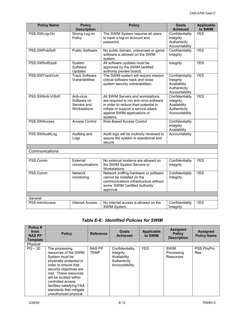
CNS-ATM Task17
3/26/04 E-12 TR04013
Policy Name Policy Description
Policy Goals Achieved
Applicable to SWIM
PSS.SWLog-On Strong Log on Policy
The SWIM System requires all users to have a log-on account and password.
Confidentiality Integrity Authenticity Accountability
YES
PSS.SWPubSoft Public Software No public domain, unlicensed or game software is allowed on the SWIM system.
Confidentiality Integrity
YES
PSS.SWSoftUpdt System Software Updates
All software updates must be approved by the SWIM certified authority (review board).
Integrity YES
PSS.SWTrackVuln Track Software Vulnerabilities
The SWIM system will require mission critical software track and close system security vulnerabilities.
Confidentiality Integrity Availability Authenticity Accountability
YES
PSS.SWAnti-VrSoft Anti-virus Software on Servers and Workstations
All SWIM Servers and workstations are required to run anti-virus software in order to reduce their potential to initiate or support a service attack against SWIM applications or systems.
Confidentiality Integrity Availability Authenticity Accountability
YES
PSS.SWAccess Access Control Role Based Access Control Confidentiality Integrity Availability
PSS.SWAuditLog Auditing and Logs
Audit logs will be routinely reviewed to assure the system is operational and secure
Accountability
Communications PSS.Comm External
communications No external modems are allowed on the SWIM System Servers or Workstations.
Confidentiality Integrity
YES
PSS.Comm Network monitoring
Network sniffing hardware or software cannot be installed on the communications infrastructure without some ‘SWIM Certified Authority’ approval.
Confidentiality Integrity
YES
General PSS.IntrnAccess Internet Access No internet access is allowed on the
SWIM System. Confidentiality Integrity
YES
Table E-6: Identified Policies for SWIM Policy #
from NAS PP
Template Policy Reference Goals
Achieved Applicable to SWIM
Assigned Policy
Description Assigned
Policy Name
Physical PG – 20 The processing
resources of the SWIM System must be physically protected in order to ensure that security objectives are met. These resources will be located within controlled access facilities satisfying FAA standards that mitigate unauthorized physical
NAS PP TEMP
Confidentiality Integrity Availability Authenticity Accountability
YES SWIM Processing Resources
PSS.PhyProRes

CNS-ATM Task17
3/26/04 E-13 TR04013
Policy # from
NAS PP Template
Policy Reference Goals Achieved
Applicable to SWIM
Assigned Policy
Description Assigned
Policy Name
access. Personnel PG – 6 The system shall
implement strong authentication of network users.
ISSA-C2 Confidentiality Integrity
YES Network User Authentication
PSS.PerUsrAuth
PG – 21 Authorized Administrators and Authenticated users of the SWIM System must be adequately trained, enabling them to: (1) effectively implement organizational security policies with respect to their discretionary actions, and (2) support the need for non-discretionary controls implemented to enforce these policies. This will include provisions for periodic and regularly scheduled education and training activities.
NAS PP TEMP, ISSA-M9
Confidentiality Integrity Availability Authenticity Accountability
YES Administrators and users training
PG – 24 The system will have documentation describing the Security Features of the systems that are available for authorized users to employ to protect their information (e.g., a Secure Facility User’s Guide).
ISSA-M10 Confidentiality Integrity Availability Authenticity Accountability
YES SWIM documentation for security features
PSS.PerSecFeaDoc
PG – 25 The system will have documentation describing the Security Configuration parameters that are available to Authorized Security Administrators.
ISSA-M10 Confidentiality Integrity Availability Authenticity Accountability
YES SWIM documentation for security configuration
PSS.PerSecConDoc
PG – 30 Authorized security administrators and users can be reasonably trusted to correctly apply the FAA’s security policies and will be held accountable for security-relevant actions.
NAS PP TEMP
Accountability YES Administrators and users accountability
PSS.PerAdUsAcc
PG – 38 The system shall automatically force a user logoff after an administrator-defined number of minutes of
ISSA-P12 Confidentiality Integrity Availability Authenticity Accountability
YES Automatic log-off from inactivity
PSS.PerAutLogOff

CNS-ATM Task17
3/26/04 E-14 TR04013
Policy # from
NAS PP Template
Policy Reference Goals Achieved
Applicable to SWIM
Assigned Policy
Description Assigned
Policy Name
inactivity and send an alert message to an administrator.
Information Technology Software PG -1 The system shall be
capable of assigning a unique identifier to each authenticated network user, (e.g., humans, devices, and processes).
ISSA-P1, ISSA-P2, ISSA-P13
Authenticity Availability Accountability
YES Assigning identifier
PSS.SWAssgIdent
PG -2 The system shall be capable of authenticating individual entities (humans and, where appropriate, information systems) identity before allowing any user to perform any actions other than a well-defined set of operations (e.g., reading from a public web site).
ISSA-P3, NAS PP TEMP, ISSA-P14
Authenticity YES Network Entity Authentication
PSS.SWEntAuth
PG - 3 If passwords are used for authentication, the system shall proactively maintain “strong” password instantiations and shall not allow the use of dictionary words, numerical representations of dates, and other weak, guessable passwords.
ISSA-M1, ISSA-R2
Integrity Availability
YES Password Protection
PSS.SWPassProt
PG – 4 If passwords are not adequate for authentication, the system shall be capable of strongly authenticating the claimed user identity before allowing any user to perform any actions other than a well-defined set of operations (e.g., reading from a public web site).
ISSA-R1 Authenticity
YES User Authentication
PSS.SW
PG – 5 Passwords shall have a defined lifetime and not be reused.
Confidentiality Integrity
YES Password Life PSS.SWPassLife
PG – 7 The system shall automatically suspend user accounts after an administrator-defined number of failed logon
ISSA-P11 Confidentiality YES Failed Log-on attempts
PSS.SWLogonFail

CNS-ATM Task17
3/26/04 E-15 TR04013
Policy # from
NAS PP Template
Policy Reference Goals Achieved
Applicable to SWIM
Assigned Policy
Description Assigned
Policy Name
attempts. PG – 8 The system shall
display the standard FAA “Logon Warning Banner” (standard FAA requirement) at logon.
ISSA-P15 Accountability n/a Logon Warning Banner
PSS.SWBanner
PG – 9 The system shall be capable of auditing in support of individual accountability and detection and response to insecurity.
ISSA-P6, NAS PP TEMP
Accountability YES Auditing PSS.SWAuditing
PG - 10 The system shall protect audit log files against deletion and modification of audit log records, even by system administrators.
ISSA-P8 Accountability YES Audit-log files protection
PSS.SWlogProt
PG – 11 The system shall maintain and protect comprehensive logs of Security Relevant Events from unauthorized deletion or modification.
ISSA-M2, ISSA-C5
Accountability YES Security relevant event’s logs protection
PSS.SWEventProt
PG – 12 The system shall be capable of providing resource allocation features having a measure of resistance to resource depletion.
ISSA-P9 Availability n/a Resource allocation features
PSS.SWResAlloc
PG – 13 The system shall provide [secure] recovery features providing a measure of survivability in the face of system failures and insecurities.
ISSA-R3 Availability YES System recovery features
PSS.SWRecFeature
PG – 14 The system shall be capable of executing a defined access control policy.
ISSA-P4 Accountability YES Access control policy
PSS.SWAccControl
PG - 15 The system shall be capable of enabling access authorization management; i.e., the initialization, assignment, and modification of access rights (e.g., read, write, execute) to data objects with respect to: (1) active entity name or group membership, and (2) such constraints as time-of-day and port-of-entry.
ISSA-P5, NAS PP TEMP
Accountability YES Access authorization management
PSS.SWAccAuthMgmt
PG – 16 The system shall be capable of enforcing separation of duties through its role-based
NAS PP TEMP
Accountability YES Role-based access control
PSS.SWRBAC

CNS-ATM Task17
3/26/04 E-16 TR04013
Policy # from
NAS PP Template
Policy Reference Goals Achieved
Applicable to SWIM
Assigned Policy
Description Assigned
Policy Name
ability to restrict users to specific data objects and to specific actions upon those objects.
PG – 17 The system shall be capable of controlled sharing of resources, such as printer and mass storage, across a network.
NAS PP TEMP
Availability YES Control resource sharing
PSS.SWCrtlShr
PG – 18 The system shall protect Information system security data and functionality from all unauthorized access.
ISSA-R10, ISSA-C8
Confidentiality YES Security data access control
PSS.SWDataAccCrtl
PG – 19 The system shall employ mechanisms that [support operational procedures to] take into account the risks associated with information being processed based on the results of a Risk Assessment. It shall be capable of performing cryptographic processing based on the results of a Risk Assessment for file encryption, authentication, data integrity, and non-repudiation functionality.
NAS PP TEMP, ISSA-R5
Accountability Confidentiality Integrity Authenticity
YES Cryptographic processing
PS.SWCryptProc
PG – 22 The system shall be the object of periodic host- and network-based vulnerability assessments.
ISSA-R8, ISSA-C4, ISSA-M3
Confidentiality Integrity Availability Authenticity Accountability
YES Host/Network based vulnerability assessment
PSS.SWVulAssess
PG – 23
Following system failure, systems shall recover in a secure state, consistent with PG-49.
ISSA-R12 Confidentiality Integrity Availability Authenticity Accountability
YES System recovery
PSS.SWSysRec
PG – 26 Security configurations shall regularly be assessed and updated as appropriate.
ISSA-M4 Confidentiality Integrity Availability Authenticity Accountability
YES Security configuratio- ns update
PSS.SWConfUpdt
PG – 28 The system shall provide for Configuration Management (CM) of system information security functionality.
ISSA-M11 Confidentiality Integrity Availability Authenticity Accountability
YES Configuration management
PSS.SWConfMgmt
PG – 40 The system shall be capable of centralized security incident
ISSA-M5 Confidentiality Integrity Availability
YES Centralized reporting
PSS.SWCentrrep
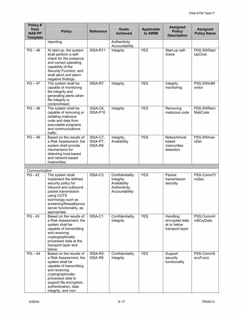
CNS-ATM Task17
3/26/04 E-17 TR04013
Policy # from
NAS PP Template
Policy Reference Goals Achieved
Applicable to SWIM
Assigned Policy
Description Assigned
Policy Name
reporting. Authenticity Accountability
PG – 46 At start-up, the system shall perform a self-check for the presence and correct operating capability of the Security Function, and shall abort and alarm negative findings.
ISSA-R11 Integrity YES Start-up self-check
PSS.SWStartUpChck
PG – 47 The system shall be capable of monitoring file integrity and generating alerts when file integrity is compromised.
ISSA-R7 Integrity YES Integrity monitoring
PSS.SWIntMonitor
PG – 48 The system shall be capable of removing or isolating malicious code and data from executable programs and communications traffic.
ISSA-C6, ISSA-P10
Integrity YES Removing malicious code
PSS.SWRemMaliCode
PG – 49 Based on the results of a Risk Assessment, the system shall provide mechanisms for detecting host-based and network-based insecurities.
ISSA-C7, ISSA-P7, ISSA-R9
Integrity, Availability
YES Network/host based insecurities detection
PSS.SWInsecDet
Communication PG - 42 The system shall
implement the defined security policy for inbound and outbound packet transmission using COTS technology such as screening/firewall/proxy server functionality, as appropriate.
ISSA-C3 Confidentiality Integrity Availability Authenticity Accountability
YES Packet transmission security
PSS.CommTrnsSec
PG - 43 Based on the results of a Risk Assessment, the system shall be capable of transmitting and receiving cryptographically-processed data at the transport layer and below.
ISSA-C1 Confidentiality, Integrity
YES Handling encrypted data at or below transport layer
PSS.CommHndlCryData
PG – 44 Based on the results of a Risk Assessment, the system shall be capable of transmitting and receiving cryptographically-processed data to support file encryption, authentication, data integrity, and non-
ISSA-R5, ISSA-R6
Confidentiality, Integrity
YES Support security functionality
PSS.CommSecuFunct

CNS-ATM Task17
3/26/04 E-18 TR04013
Policy # from
NAS PP Template
Policy Reference Goals Achieved
Applicable to SWIM
Assigned Policy
Description Assigned
Policy Name
repudiation functionality.
PG – 45 Information flow among SWIM System between SWIM System and other non-SWIM IT systems must be in accordance with established FAA information flow policies.
NAS PP TEMP
Confidentiality, Integrity
YES Information flow
PSS.CommInfFlow
General PG – 27 The system shall
maintain policy and procedures for handling security incidents.
ISSA-M6 Confidentiality Integrity Availability Authenticity Accountability
YES Policies for security incidents
PSS.SecIncPol
PG – 29 The system shall undergo periodic ISS-related rectification as prescribed by policy.
ISSA-M12 Confidentiality Integrity Availability Authenticity Accountability
YES Periodic rectification
PSS.PerRectf
PG – 31 The system must be developed to be consistent with current best commercial practice for IT development. The system must be implemented and operated in a manner that represents due care and diligence with respect to risks to the FAA. The system must address secure delivery, installation, generation, and start-up of the SWIM System.
ISSA-R4, NAS PP TEMP
Confidentiality Integrity Availability Authenticity Accountability
YES Best commercial practice for IT development
PSS.ITDevelopment
PG - 32 The system must provide a Life-Cycle Support discipline and control in the processes of refining the SWIM System during development and maintenance in addition to CM, to model development and maintenance procedures contributing to the overall quality and security of the SWIM System.
NAS PP TEMP
Confidentiality Integrity Availability Authenticity Accountability
YES Life-cycle support
PSS.LifeCycleSupport
PG – 33 The system must establish Flaw Remediation procedures for tracking
NAS PP TEMP
Confidentiality Integrity Availability Authenticity
YES Flaw remediation
PSS.FlwRem

CNS-ATM Task17
3/26/04 E-19 TR04013
Policy # from
NAS PP Template
Policy Reference Goals Achieved
Applicable to SWIM
Assigned Policy
Description Assigned
Policy Name
and correcting discovered security-related flaws.
Accountability
PG – 34 The system must employ Security Testing to establish that the SWIM System Security Policy Enforcement Function exhibits the properties necessary to satisfy the functional specifications.
NAS PP TEMP
Confidentiality Integrity Availability Authenticity Accountability
YES Security testing
PSS.SecTest
PG – 35 The system must employ penetration tests to discover vulnerabilities that might be introduced in the development or operation of the SWIM System.
NAS PP TEMP
Confidentiality Integrity Availability Authenticity Accountability
YES Penetration testing
PSS.PentTest
PG – 36 System security must be based on a Vulnerability Assessment that addresses the vulnerability of the SWIM System to misuse or contain incorrect configuration.
NAS PP TEMP
Confidentiality Integrity Availability Authenticity Accountability
YES Vulnerability assessment
PSS.VulnAssess
PG – 37 The SWIM System must be used only for authorized purposes.
NAS PP TEMP
Accountability, Availability
YES Authorized purpose use
PSS.AuthUse
PG – 39 The system shall develop and identify policies and procedures for system-wide compliance monitoring.
ISSA-M7 Confidentiality Integrity Availability Authenticity Accountability
YES Compliance monitoring
PSS.CompMonit
PG – 41 The system shall make use of available information security news-lists, publications, bug fix alerts, CERT advisories, etc., as a recurring set of activities.
ISSA-M8 Confidentiality Integrity Availability Authenticity Accountability
YES Security update activities
PSS.UpdActivity
E.4.2 SWIM ISS Technologies This section looks at security technologies as countermeasures by presenting a methodology of what technology to select first and then show where, when, and how they fit the best. SWIM information systems must have adequate technical safeguards to ensure the security of processed data. Security goals (confidentiality, integrity, authenticity, availability, and accounting), described earlier, are the elements of information security field that are generally recognized as key to preserving data security. In order to achieve the goals for SWIM, proper information security mechanisms must be employed. The following are the five major information security mechanisms:

CNS-ATM Task17
3/26/04 E-20 TR04013
• Encryption: Scrambling understandable data (information) into unintelligible data, for the
purpose of securing it from unauthorized disclosure to an unauthorized entity, and then restoring it back to its original form (decryption).
• Access Control: Controlling access to information, information systems and associated networks, for the preservation of their confidentiality, integrity, and availability, based on user’s identity or their operational role.
• User Identification and Authentication: Securely determining a user’s identity or operational role. A user’s authentication is determined by its login validity.
• Malicious Content Detection: Examining the incoming data for any malicious content it may be carrying and that might need to be blocked, detected, and corrected.
• Physical and Environmental Controls (out of the scope of this study)
One way to assess the effectiveness of available security technologies is to analyze them individually in terms of a framework or model that maps what security technologies satisfy the security mechanisms employed and what goals are achieved. The security technology assessment matrix (STA) below summarizes the most widely used security technologies in terms of what security goals they achieve.
Table E-7: STA Matrix: Security Mechanisms vs. Security Attributes Security Attributes Security
Mechanisms Confidentiality Integrity Availability Authenticity Accountability Encryption • Encryption
System • VPN • Public Key
Infrastructure (PKI)
• Link encryption • Digital Signature
• Public Key Infrastructure (PKI)
• VPN • Digital
Signature
N/A
• Public Key Infrastructure (PKI)
• Digital Signature
• Public Key Infrastructure (PKI)
• Digital Signature
• VPN • Link Encryption
Access Control • Firewall • Network Access
Controller • Access Control
Management System
• Firewall • Access
Control Management System
• Firewall • Network Access
Controller • Access Control
Management System
• Security Monitoring
• Firewall • Network Access
Controller • Password
Service • Access Control
Management System
• Firewall • Network
Access Controller
• Password Service
• Access Control Management System
• Security Monitoring
Identification & Authentication
• Password Service
• Authentication System N/A
• Password Service
• Authentication System
• Security Monitoring
• Password Service
• Authentication System
• Password Service
• Security Monitoring
Malicious Content Detection
N/A
• Virus Detection System
• Intrusion Detection System
• Virus Detection System
• Intrusion Detection System
• Security Monitoring
• Vulnerability Assessment Software
N/A
• Intrusion Detection System
• Security Monitoring

CNS-ATM Task17
3/26/04 E-21 TR04013
Together with analyzing information security measures in terms of their ability to achieve security attributes (goals), which covers the first level of protective actions, it is also important to analyze them in terms of security phases, which covers the processes associated with detecting problems and reacting to them. The phases include:
• Protection – As a first line of defense to mitigate vulnerabilities and threats, the goals are to deny unauthorized users access to information or system and to engineer systems to be resistant to threat actions.
• Detection – As a failure of any security mechanism in place, the goal is to detect any threat and issue an alarm.
• Correction – This phase includes all activities associated with rectifying problems and regaining full operational capabilities. This phase also includes actions like hot-switching entire operations to redundant or back-up systems/facilities.
Table E-8 maps the security technologies to the phases they satisfy.
Table E-8: STA Matrix – Security Phases Security Phases Security Technologies/Processes Protect Detect Correct
Access Control Management System X X N/A Authentication System X X N/A Encryption System X N/A N/A Digital Signature X N/A N/A Firewall System X X N/A Intrusion Detection System X N/A Link Encryption X N/A N/A Network Access Controller X N/A N/A Password Service X N/A N/A Public Key Infrastructure (PKI) System X N/A N/A Routing Table Authentication X N/A N/A Security Monitoring N/A X N/A Virtual Private Network X N/A N/A Virus Detection System X X X Vulnerability Assessment Software N/A X N/A Now, given the list of the security technologies satisfying the specific SWIM goals, it is important to understand what enterprise elements of SWIM these technologies provide protection for. To achieve information protection over the SWIM enterprise, the information architecture can be categorized in dimensions that must be protected. Dimensions can be categorized as:
• Information System: The infrastructure, which comprises of computers, servers, databases, users, etc. either, itself must be protected against unauthorized intrusions, malicious content, and denial of service attacks.
• Information Domain: Communities-of-interest within the infrastructure must be afforded freedom to move and process information within a virtual enclave that provides protection.
• Information Content: At this level the end-to-end security is provided to data, whether at rest or in transit, for the purpose of its security from unauthorized disclosure to an unauthorized entity.

CNS-ATM Task17
3/26/04 E-22 TR04013
Tables E-9 and E-10 provide a list of technologies pertaining to each of these dimensions and the goals they satisfy in that specific dimension.
Table E-9: STA per Information Dimension Security
Dimension Confidentiality Integrity Availability Authenticity
Information System
• Link encryption • VPN • Firewall • Network Access
Controller • Access Control
Management System
• Virus Detection System
• Link encryption • VPN • Firewall • Network Access
Controller • Access Control
Management System
• Virus Detection System
• Routing Table Authentication
• Firewall • Network Access
Controller • Virus Detection
System • Security
Monitoring • Vulnerability
Assessment Software
•
• Link encryption • VPN • Routing Table
Authentication • Firewall • Network Access
Controller • Password Service • PKI • Authentication
System
Information Domain
• Link encryption • VPN • Firewall • Network Access
Controller • Encryption System • Access Control
Management System
• Virus Detection System
•
• Link encryption • VPN • Firewall • Network Access
Controller • Encryption System • Access Control
Management System
• Virus Detection System
• Routing Table Authentication
• Firewall • Network Access
Controller • Authentication
System • Virus Detection
System • Security
Monitoring • Vulnerability
Assessment Software
• Link encryption • VPN • Firewall • Network Access
Controller • Encryption
System • Routing Table
Authentication • Password Service • Authentication
System
Information Content
• Link encryption • Encryption System • VPN • Digital Signature • Access Control
Management System
• Virus Detection System
• Link encryption • Encryption System • VPN • Digital Signature • Content Scanning
System • Access Control
Management System
• Virus Detection System
• Virus Detection Software
• Firewall • Security
Monitoring • Vulnerability
Assessment Software
• Link encryption • Encryption
System • VPN • Digital Signature • Password Service • Firewall • PKI
Table E-10: Information Security Summary Zones Security Mechanism Information Content Information
Domain Information
System 1 2 3 Access Control Management System Confidentiality
Integrity
Confidentiality Integrity
Confidentiality Integrity
X X X
Authentication System Authenticity Availability
Authenticity Availability X X
Digital Signature Confidentiality Integrity Authenticity Non-Repudiation
X
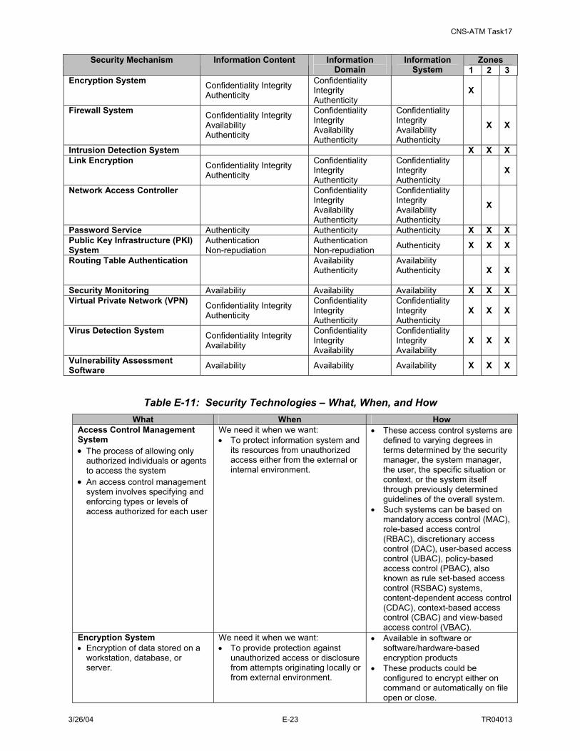
CNS-ATM Task17
3/26/04 E-23 TR04013
Zones Security Mechanism Information Content Information Domain
Information System 1 2 3
Encryption System Confidentiality Integrity Authenticity
Confidentiality Integrity Authenticity
X
Firewall System Confidentiality Integrity Availability Authenticity
Confidentiality Integrity Availability Authenticity
Confidentiality Integrity Availability Authenticity
X X
Intrusion Detection System X X X Link Encryption Confidentiality Integrity
Authenticity
Confidentiality Integrity Authenticity
Confidentiality Integrity Authenticity
X
Network Access Controller
Confidentiality Integrity Availability Authenticity
Confidentiality Integrity Availability Authenticity
X
Password Service Authenticity Authenticity Authenticity X X X Public Key Infrastructure (PKI) System
Authentication Non-repudiation
Authentication Non-repudiation Authenticity X X X
Routing Table Authentication
Availability Authenticity
Availability Authenticity
X X
Security Monitoring Availability Availability Availability X X X Virtual Private Network (VPN) Confidentiality Integrity
Authenticity
Confidentiality Integrity Authenticity
Confidentiality Integrity Authenticity
X X X
Virus Detection System Confidentiality Integrity Availability
Confidentiality Integrity Availability
Confidentiality Integrity Availability
X X X
Vulnerability Assessment Software Availability Availability Availability X X X
Table E-11: Security Technologies – What, When, and How What When How
Access Control Management System • The process of allowing only
authorized individuals or agents to access the system
• An access control management system involves specifying and enforcing types or levels of access authorized for each user
We need it when we want: • To protect information system and
its resources from unauthorized access either from the external or internal environment.
• These access control systems are defined to varying degrees in terms determined by the security manager, the system manager, the user, the specific situation or context, or the system itself through previously determined guidelines of the overall system.
• Such systems can be based on mandatory access control (MAC), role-based access control (RBAC), discretionary access control (DAC), user-based access control (UBAC), policy-based access control (PBAC), also known as rule set-based access control (RSBAC) systems, content-dependent access control (CDAC), context-based access control (CBAC) and view-based access control (VBAC).
Encryption System • Encryption of data stored on a
workstation, database, or server.
We need it when we want: • To provide protection against
unauthorized access or disclosure from attempts originating locally or from external environment.
• Available in software or software/hardware-based encryption products
• These products could be configured to encrypt either on command or automatically on file open or close.

CNS-ATM Task17
3/26/04 E-24 TR04013
What When How Digital Signature • A means to bind information to
an entity
We need it when we want: • To verify that the sender is who
he/she claims to be. • To verify that message has come
from claimed sender. • To timestamp documents to testify
that the document existed at the stated time.
• Digital signature is a block of data, called message digest, that is created using some secret key, and there is a public key that can be used to verify that the signature was really generated using the corresponding private key.
• Establishment of a certificate authority, in the centralized key infrastructure, that has its own key pair.
Firewalls: • A firewall is a checkpoint
between a private network and one or more public networks.
• It is a gateway that selectively decides what information traffic may enter or leave a private network based on pre-defined screening criteria.
We need it when we want: • To control access: Deny access to
unauthorized users, data packets, applications, etc. (Access Control List)
• To protect the network from network attacks, like Denial of Service (DoS) attacks.
• To provide alarm capabilities to the network incase a threat is sensed, like failed login or unauthenticated data packets/applications are trying to enter or leave the network. (Log files)
• To isolate intranet data from extranet or Internet data. (DMZ)
• To hide internal IP addressing scheme so that private IP addresses can be deployed in the internal network. (NAT)
• These can be hardware or software solutions that enforce access control between two or more networks or systems.
• Firewalls are mainly placed at the network perimeters, within physically secured environment.
• Firewalls could be distinguished on the basis of their pre-defined screening criteria as: Packet Filtering firewall Application level firewall Stateful Inspection firewall Dynamic Packet Filtering firewall
Kernel Proxy • There are four types of firewall
architectures that firewalls could be configured in: Packet-Filtering routers Screened-Host firewall system Dual-Homed Host firewall Screened-Subnet firewall
Intrusion Detection System (IDS) • System that scans network
traffic and/or system data for potential computer-based attacks on protected resources.
We need it when we want: • To detect unauthorized activity
(intrusions) throughout a network (including both, external or internal).
• To react to a situation by providing alarm capabilities incase a threat is sensed.
• Capability to severe access to the network resources once threat (attack) is detected.
• IDS basically monitors network traffic or host audit logs to determine if any security policy have been violated by implementing Network based IDS, which scan real time network traffic
Host IDS, which analyzes single computer data for anomalous or unauthorized activity.
• IDS detects the unauthorized activity through 2 mechanisms: Signature based ID or knowledge based ID where signatures or attributes are stored for reference.
Statistical anomaly based ID or behavior based ID where a normal usage profile for the monitored network or host is defined.
• Response to an attack comes from issuing an alarm when suspected attackers are discovered.

CNS-ATM Task17
3/26/04 E-25 TR04013
What When How Link Encryption • Link encryption (sometimes
called link level or link layer encryption) is the data security process of encrypting information at the data link level as it is transmitted between two points within a network.
We need it when we want: • To secure the transmission line
• Data, which is plaintext in the host server, is encrypted when it leaves the host, decrypted at the next link (which may be a host or a relay point), and then re-encrypted before it continues to the next link. Each link may use a different key or even a different algorithm for data encryption. The process is repeated until the data has reached the recipient.
Network Access Controller • A system that provides basic
level of access control based on site’s local security policy
We need it when we want to: • To control access over incoming
network connections and also inter-LAN segments.
• NAC is implemented using filtering routers that has the capability to restrict access based on address or service type, like HTTP, SMTP email, etc.
Password Service • Password is basically a string of
numbers provided to a system, at log-on time, to authenticate or verify that the user’s claimed identity is valid.
We need it when we want to: • To protect access to the network
and its resources from unauthorized users (internal or external to the network)
• Passwords could either be static passwords, that are same for each log on, or dynamic password, which provides the maximum security as a new password is required for each log-on.
• Static or dynamic passwords could be created from the use of tokens, which are in the form of credit-size smart cards or calculators. There are four types of tokens: Static password tokens Synchronous dynamic password tokens
Asynchronous dynamic password tokens
Challenge-response tokens Public Key Infrastructure (PKI) • A PKI is a collection of
components that support the generation and distribution of digital certificates, issuance of Certificate Revocation Lists (CRLs), and the building and running of directories to serve these certificates and CRLs.
We need it when we want: • To authenticate users/systems. • To exchange change keys, used
for encrypting and decrypting data, between trusted parties.
• To make the public keys, of the data recipient, available to the senders.
• To protect impersonators publishing public keys under false identity.
• To protect confidential transaction.
• Depending on the needs and applications used, these components can be managed by FAA or by a trusted third part.
• Full-fledged PKIs consist of several components including a certificate authority (CA), registration authority (RA) and multiple technical and operational components (such as certificate databases and revocation lists).
Routing Table Authentication • It is technology to protect the
routing table updates from being compromised.
We need it when we want: • To protect the network from
Denial of Service (DoS) type of attack, where availability of the network and its resources it lost to its legitimate users.
• To prevent from network intrusions.
• Routers that feature cryptographic authentication of updates for selected routing protocols.
• Example, the routing protocols, such as OSPF and BGP, may use MD-5 or SHA-1 hash algorithms to provide cryptographic authentication.

CNS-ATM Task17
3/26/04 E-26 TR04013
What When How Security Monitoring
We need it when we want: • To protect our network from
unauthorized intrusions. • Capability of reacting to the
alarms generated in case of any threats sensed.
• Systems for performing monitoring and management services are available in both software and services model.
• Manage policy and configuration settings on distributed security devices.
• Others pull alert data from remote devices into a central database, where the information is correlated and analyzed.
Virtual Private Network (VPN) • VPNs are private networks that
use public infrastructure, such as internet, for secure and private communications.
• VPN allows the system to function over public networks essentially through a private tunnel using the secure Internet Engineering Task Force (IETF) IPSec standards and guidelines to provide authentication, integrity and encryption of data.
We need it when we want: • To extend the reach of data or
applications to external users, like partners, or internet users, like remote user logging in to the internal network via Internet.
• To have a cost effective way of securing communications between two sites/facilities connected via IP network.
• To have the confidentiality and integrity of data intact while in transit.
• To have the data origin authentication, Non-Repudiation, replay security, and key management services.
• To have the capability to accommodate future technologies.
• VPN security is achieved by using VPN software applications or VPN hardware devices, called concentrators.
• VPN create an encrypted tunnel between two endpoints – for example, between gateway servers located in two or more regional control centers or between a gateway server and a remote computer or a terminal running VPN client.
• IPSec based VPN solution with Authentication Header (AH) Encapsulating Security Payload (ESP)
Internet Key Exchage • Layer 2 based VPN solution
Layer 2 Forwarding Layer 2 Tunnel Protocol
• Non-IPSec Network Layer based VPN solution Network Address Translation (NAT)
Packet filtering • Non-IPSec application layer
based VPN solution SOCKS Secure Socket Layer Secure HTTP (S-HTTP)

CNS-ATM Task17
3/26/04 E-27 TR04013
What When How Virus Detection System • Software that scans a
computer’s memory and disk drives for the presence of viruses, known by their “signatures.”
• Proactive software that is used when a virus is active to limit the behavior or access of the executable code.
We need it when we want: • To detect any malicious content in
the form of virus, worm, Trojan, known or unknown, that has the capability of either compromising the confidentiality, integrity or availability of data and information systems.
• Virus detection system comes in two flavors: anti-virus and behavior-based.
• Behavior based systems implement policies, such as for mobile code, to protect IT resources. Because behavior-based systems are not signature-based, they do not require on-going signature updates, and they provide protection in the time gap between new viruses and signature updates.
• These systems try to identify malicious scripts, applets and executables, particularly web content such as ActiveX, VBScript, Java and JavaScript.
• Search for the code strings of non-reproducing malware, such as Trojan horses, password cracking systems, etc.
• Could be employed at zone 1, zone 2, or at zone 3, but due to VPN or application layer encryption full virus detection may not be possible at zones 2 and 3.
Vulnerability Assessment Software
We need it when we want: • To detect any weakness in the
system and in its resources. • To limit access to the authorized
entities only. • To prevent network and its
resources from attacks, like Denial of Service (DoS) attack.
• Scans networks, servers and applications for security bugs, holes, and other weaknesses that could be exploited to gain unauthorized access to proprietary data or launch attacks on other systems.
• Some VA scanners examine systems and networks for known vulnerabilities based on a database of signatures, others checks to see if systems are compliant with FAA’s security policies governing configuration and program settings.
E.4.3 Defense in Depth Applies to SWIM In keeping with ISS architecture practices presented in the FAA ISSA, it can be shown that a defense-in-depth approach, which is provided by employing multiple security technologies at various locations (both physical and logical) in an information system, is most appropriate for SWIM. In this approach no single mechanism is relied upon to provide complete information security; security mechanisms are applied layer-by-layer to defeat any attempt by an adversary to compromise the information system. A high level three layer defense in depth representation is shown in Figure E-1. These are briefly described in the following paragraphs.

CNS-ATM Task17
3/26/04 E-28 TR04013
Zone 1: End-Systems (Platform Level SecurityExamples:
Zone 2: Inter/Intra Enclave (Network Level Security)Examples:
Zone 3: FTI (Manage Network Boundary) – (WAN Level Security)Interconnect
Zone 3Security
Interconnect
Zone 2Security
• Access Control Management System• Digital Signature • Encryption System• Intrusion Detection Systems• Password Service• PKI• Security Monitoring• VPN • Virus Detection System• Vulnerability Assessment Software
Zone 1: End-Systems (Platform Level SecurityExamples:
Zone 2: Inter/Intra Enclave (Facility Level Security)Examples:
Zone 3: FTI (Manage Network Boundary) –
Examples:
Interconnect
Zone 3Security
Interconnect
Zone 2Security
• Access Control Management System• Firewalls• Authentication System• Intrusion Detection Systems (IDS)• Network Access Controllers• Password Service• PKI• Routing Table Authentication• Security Monitoring• Virtual Private Networks (VPN)• Virus Detection System• Vulnerability Assessment Software
• Access Control Management System• Firewalls• Authentication System• Intrusion Detection Systems (IDS)• Password Service• PKI• Routing Table Authentication• Virtual Private Networks (VPN)• Security Monitoring• VPN • Virus Detection System• Vulnerability Assessment Software
Zone 1: End-Systems (Platform Level SecurityExamples:
Zone 2: Inter/Intra Enclave (Network Level Security)Examples:
Zone 3: FTI (Manage Network Boundary) – (WAN Level Security)Interconnect
Zone 3Security
Interconnect
Zone 2Security
• Access Control Management System• Digital Signature • Encryption System• Intrusion Detection Systems• Password Service• PKI• Security Monitoring• VPN • Virus Detection System• Vulnerability Assessment Software
Zone 1: End-Systems (Platform Level SecurityExamples:
Zone 2: Inter/Intra Enclave (Facility Level Security)Examples:
Zone 3: FTI (Manage Network Boundary) –
Examples:
Interconnect
Zone 3Security
Interconnect
Zone 2Security
• Access Control Management System• Firewalls• Authentication System• Intrusion Detection Systems (IDS)• Network Access Controllers• Password Service• PKI• Routing Table Authentication• Security Monitoring• Virtual Private Networks (VPN)• Virus Detection System• Vulnerability Assessment Software
• Access Control Management System• Firewalls• Authentication System• Intrusion Detection Systems (IDS)• Password Service• PKI• Routing Table Authentication• Virtual Private Networks (VPN)• Security Monitoring• VPN • Virus Detection System• Vulnerability Assessment Software
Figure E-1: Security Technologies per Zone E.4.3.1 Zone 1 Security Technologies/Processes (Platform Security) Considered to be the inner-most layer defense mechanisms, these security technologies are basically applied at the end-systems, like workstations, servers, databases, and mainframes. The security technologies at this level include:
• Access Control Management System
• Digital Signature
• Encryption System
• Intrusion Detection Systems
• Password Service
• PKI
• Security Monitoring
• VPN
• Virus Detection System
• Vulnerability Assessment Software

CNS-ATM Task17
3/26/04 E-29 TR04013
E.4.3.2 Zone 2 Security Technologies/Processes (NAS Operational Facility Level) Deployed as a part of an intranet, Zone 2 security technologies take care of end user networks that have similar security requirements and provide integrated security for the site LAN. Zone 2 security technologies include:
• Access Control Management System
• Firewalls
• Authentication System
• Intrusion Detection Systems (IDS)
• Network Access Controllers
• Password Service
• PKI
• Routing Table Authentication
• Security Monitoring
• Virtual Private Networks (VPN)
• Virus Detection System
• Vulnerability Assessment Software
E.4.3.3 Zone 3 Security Technologies/Processes (Wide Area Network Level) Deployed at the boundary between SWIM node/facility network (intranet) and the FAA telecommunication network infrastructure (e.g. FTI), Zone 3 security technologies include:
• Access Control Management System
• Firewalls
• Authentication System
• Intrusion Detection Systems (IDS)
• Password Service
• PKI
• Routing Table Authentication
• Virtual Private Networks (VPN)
• Security Monitoring
• VPN
• Virus Detection System
• Vulnerability Assessment Software

CNS-ATM Task17
3/26/04 E-30 TR04013
E.5 SWIM SECURITY OBJECTIVES In general, security objectives are driven by the SWIM security goals. Security objectives offer a more concrete vision of the mechanisms to be implemented by the system. The process of determining SWIM System objectives begins by examining the threats, policies and the rest of the operational and IT environment. SWIM security objectives reflect the stated intent to counter identified threats to SWIM, comply with any organizational security policies, and identify responsibilities for the SWIM system and for its operational environment. Security objectives based on the NAS PP are identified in the table below. They are based on preliminary assessment of the potential threats to SWIM (and its operating environment) and the identified/developed SWIM policies. The Table E-12 also shows the security phases that the stated objectives satisfy.
Table E-12: SWIM Application Security Objectives Security Objective
Name Objectives Protect/Detect/ Correct
Application Programs OWA.AppDesignSec Security Design Reviews. P, D, C OWA.AppDevSec Security Development Reviews. P, D, C OWA.AppTestSec Security Tests to identify & Close vulnerabilities. P, D OWA.ConfigMgmt Implement configuration management to assure storage integrity,
identification of system connectivity, and identification of system components (software, hardware, and firmware).
P, D
OWA.AppInstallSec Security Document to ensure proper install. P, D OWA.AppAvail The application is monitored to determine availability in the 24
hours a day x 7 days a week. D
OWA.AppIntegrity
The programs will implement controls for program and stored application data.
P, C
OWA.AppFailureAlerts Operator Alerts will be provided should any of the applications identify a process failure.
D
OSA.AppAudit The application programs will support a protected audit capability. P OSA.AppAccessControl The application will be protected from unauthorized user or
process access. P
Client-Server OSA.CSAuthentic All sessions between the user stations and the server program will
be authenticated. P, D
OSA.CSAvail The C-S Program is monitored to determine availability in the 24 hours a day x 7 days a week
D
OSA.CSIntegrity The Client-Server Interface will implement controls for program and data integrity.
P, C
OSA.CSAudit The C-S interface will support a protected audit capability. D OSA.CSAccessCont The C-S will not allow unauthorized connections. D, P Graphical User Interface (GUI) Program OSA.GTrust All paths between the GUI program and the application Main
Program will be trusted. P
OSA.GAvail The GUI is monitored to determine application availability on 24x7 scale
D
OSA.GIntegrity The GUI will implement controls for program and data integrity, as well as for integrity controls on User requests.
P, C
OSA.GAudit The GUI interface will support a protected audit capability. D OSA.GUserGuide Provide documentation for the general application-user. P OSA.GAccessCont Terminal workstations are authenticated to the applications
installed. P

CNS-ATM Task17
3/26/04 E-31 TR04013
Table E-13 shows the objectives for SWIM’s operational environment.
Table E-13: SWIM System Objectives (Operational Environment) Security Objectives
Name Objectives Protect/Detect/Correct
Personnel OSS.PerMonitor Operators are required to monitor the SWIM ‘systems’ to
detect, assess and correct impacts to SWIM operations. P, D, C
OSS.PerNetMonitor Operators are required to monitor the SWIM ‘network’ to detect, assess and correct impacts to SWIM operations.
P, D, C
Hardware OSS.HWHighAvail The HW should be optimized to avoid single points of failure. P OSS.HWAssurance Ensure that security-relevant hardware, software and firmware
are correctly functioning through features and procedures. P
OSS.HWServerAvail The server(s) are monitored to track any down-time. Failure or maintenance events on average should be less than some SWIM stipulated time-period.
D
Software OSS.SWUserAuth Uniquely identify and authenticate each user of the system. P OSS.SWID&Auth Provide the basic I&A functions that will support user
accountability. P
OSS.SWIntegrity Provide appropriate integrity protection for stored system data. P OSS.SWLimUseAuth Restrict the actions a user may perform before verifying the
identity of the user. P
OSS.SWPriorityService Control access to resources so that lower-priority activities do not unduly interfere with or delay higher-priority activities.
P
OSS.SWResourceQuota Use resource quotas to limit user and service use of system resources to a level that will prevent degradation or denial of service to other critical users and services.
P
OSS.SWSecurityRoles Maintain security-relevant roles and the association of users with those roles.
P
OSS.SWAccessBanner Inform the user of the possibility of the system monitoring his actions, and that misuse of the system may result job-loss
P
OSS.SWUnusualAcitivities Identify unusual user activity on the system. D OSS.SWUserGuide Provide documentation for the System User. P OSS.SWAdminGuide Deter administrator errors by providing adequate administrator
guidance. P
OSS.SWConfigMgmt Implement a configuration management plan to assure storage integrity, identification of system connectivity (software, hardware, and firmware), and identification of system components (software, hardware, and firmware).
P
OSS.SWAudit Users will be audited for accountability. P, D OSS.SWAuditLoss Respond to possible loss of audit records when audit trail
storage is full or nearly full. P
OSS.SWAuditProtect Protect audit records against unauthorized access, modification, or deletion to ensure accountability of user actions.
P, D
OSS.SWAuditRecords Record in audit records: date and time of action, location of the action, and the entity responsible for the action.
P, D, C
OSS.SWAuditUserAccountable
Provide individual accountability for audited events. Uniquely identify each user so that auditable actions can be traced to a user.
P, C
OSS.SWMaliciousCode Incorporate malicious code prevention procedures and mechanisms.
P
OSS.SWTrustRecoveryDoc
Provide trusted recovery to ensure that data cannot be lost or misplaced.
P
OSS.SWBackup Provide backup procedures to ensure that the system can be reconstructed.
P

CNS-ATM Task17
3/26/04 E-32 TR04013
Security Objectives Name Objectives Protect/Detect
/Correct OSS.SWBackupRestore Provide through frequent backups, restoration of security-
relevant changes to the system between backup and restore, and restoration of the security-relevant system state (e.g. access control list) without destruction of other system data.
P
OSS.SWBackupStorage Provide sufficient backup storage and effective restoration to ensure that the system can be recreated.
P
Communications OSS.CommComPorts Any unused communications software or commonly assigned
ports should be disabled and/or the common ports re-assigned.
P
OSS.CommDataTransfer Provide the ability to have physically protected communications lines and intrusion detection for communications lines.
P, D, C
OSS.CommConfigMgmt Implement a configuration management plan to assure storage integrity, identification of system components (software, hardware, and firmware).
P
OSS.CommUserDataTransfer
Provide the ability to have physically protected communications lines, intrusion detection for communications lines, and/or need-to-know isolation for communications lines.
P
E.6 SECURITY REQUIREMENTS This section briefly describes how high level SWIM security requirements could be developed, based on:
• The Common Criteria for Information Technology Security Evaluations, Version 2.1, August 1999, ISO /IEC 15408: 999.
• NAS PP
The basic methodology to identify and develop security requirements is on the framework of developing a protection profile (PP). Since the PP acts as a record of the security analysis performed during requirement generation process, it assists in conducting a comprehensive analysis of SWIM goals, threats, policies, objectives, and assumptions that derive SWIM requirements in thirteen major functional areas. Since SWIM is still evolving, the threats, policies, objectives identified and developed are very generic, but certainly provide a preliminary evaluation of the framework followed to derive SWIM security requirements. However, in order to generate security requirements for SWIM System/Sub-Systems, a risk assessment will have to be conducted that will determine the security concerns for SWIM. These security concerns will drive the selection of appropriate ISS mechanisms in the form of functional and assurance security requirements. Performing a risk assessment and, thus, developing security requirements is beyond the scope of this task and subject of future work.
CNS-ATM Task17
3/26/04 F-1 TR04013
APPENDIX F. SIMULATION DESCRIPTION DETAILS
The following sections provide a description of the process patterns models used in the SWIM simulation. The process patterns addressed, introduced in Section 6.2.2.1 of the report include:
• Register
• Subscribe
• Unsubscribe
• Publish
• Query
F.1 REGISTRATION PROCESS MODEL (REGISTER) The Registration process model allows servers, including databases, to establish an association with a broker. A server registers with a broker, informing the broker of the type of information it publishes or stores. The broker uses this information to support query operations as well as subscriptions to real-time information. The process model state diagram is shown in Figure F-1. In the Initialization (init) state, the server process model will choose an appropriate broker according to policy or a node attribute. It will retrieve node information about the type of data to be published, and then launch a publish child application for each type of information to be published. The process model then creates registration messages and sends them to the appropriate broker, which will process and maintain the information on the location from which to retrieve data of all types. In the OPNET simulation the first registrations are scheduled at 90 seconds to allow for routing convergence to take place beforehand. This parameter is reconfigurable, and should be chosen based on the dynamic routing protocol to be used. After the first registration is sent, the process model goes into a wait state until the registration is received by the broker (the current phase of registration complete). If additional registrations are to be sent, the model will create and send the registration message and return by default to the wait state until the phase is complete (registration is received by the broker). After all registration phases are complete, the process model enters the end_app state to free any memory that will not be used by child processes. When the simulation is complete, the application frees the remaining memory and terminates.

CNS-ATM Task17
3/26/04 F-2 TR04013
Figure F-1: Registration Process Model
F.2 SUBSCRIPTION PROCESS MODEL (SUBSCRIBE) In the Subscription process model, shown in Figure F-2, a client issues subscriptions for specific types of information to its broker. In the subscription process the number of subscriptions, their type (metadata or constraints), and the timing of subscriptions are required parameters provided by the client to the broker. At the client, the initialization process begins by selecting an appropriate broker according to policy or node attribute. The number and type of subscriptions (metadata or constraints on information), required by the client are then retrieved. If the node will be issuing any queries, the number, type, and timing of the queries are retrieved, and a query child process is created for each type of information to be queried. Once that is accomplished, the first phase of subscriptions is scheduled, to be invoked after all registrations are complete. At this time, the process model creates subscription messages and sends them to the appropriate broker, which will process and maintain the information, to be used in disseminating information in the future as it is published. As subscribe or unsubscribe requests are received, client nodes are added or deleted from publish destination lists, or if multicast is used, from the multicast group. After the first subscription is sent, the process model goes into a wait state until the subscription is received by the broker (the current phase of subscription complete). If additional subscriptions are to be sent, the model will create and send the subscription message and return by default to the wait state until the phase is complete. After all subscription phases are complete, the process model enters the end_app state to free any memory that will not be used by child processes. When the simulation is complete, the application frees the remaining memory and terminates.

CNS-ATM Task17
3/26/04 F-3 TR04013
Figure F-2: Subscription Process Model F.3 PUBLISH PROCESS MODEL The Publish process model is responsible for creating the traffic specified in the publish attributes of the node and transmitting the traffic to the broker associated with the node. A publish process is launched by the registration process for each type of information to be published by a specific node. The first phase publish cycle occurs after registrations are complete, at a uniformly distributed time between 100 and 200 seconds. At this time, the traffic is created according to the traffic characteristics specified in the node’s attributes and the traffic is transmitted to the broker, which will forward the published information to subscribing clients and associated data marts, if any. An interrupt is then scheduled for the next publish phase, according to the inter-publish time specified in the node’s attributes. At the completion of each phase, statistics (e.g., application response time) of the publish process are recorded. At the end of the simulation, memory is freed and the application terminates, as shown in Figure F-3.

CNS-ATM Task17
3/26/04 F-4 TR04013
Figure F-3: Publish Process Model F.3.1 Real-Time Publish Process Model The Real-Time Publish process was developed as variant of the standard Publish process to better support the management and dissemination of periodic (i.e., non-streaming) data with real-time and near real-time delivery requirements. In addition to the functions supported by the Publish process model, the Real-Time Publish process model, shown in Figure F-4, is responsible for accepting and maintaining subscriptions for real-time information “pushed” to the server by the broker in order to meet the strict latency requirements of real-time information such as surveillance information. The broker uses server registrations to determine the appropriate server(s) to whom the real-time subscriptions should be “pushed”. In this way, the broker association and much of the advantages of the broker architecture (e.g., location transparency) are maintained; however, the server accepts additional responsibilities normally performed by the broker. After real-time subscriptions are processed, the publication process proceeds as in the Publish process model, except the traffic that is created is transmitted directly to the subscribing clients, bypassing the broker.
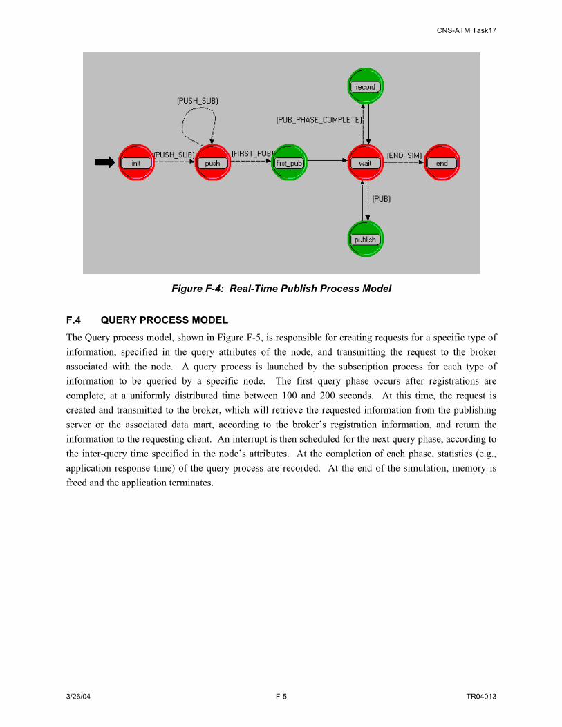
CNS-ATM Task17
3/26/04 F-5 TR04013
Figure F-4: Real-Time Publish Process Model F.4 QUERY PROCESS MODEL The Query process model, shown in Figure F-5, is responsible for creating requests for a specific type of information, specified in the query attributes of the node, and transmitting the request to the broker associated with the node. A query process is launched by the subscription process for each type of information to be queried by a specific node. The first query phase occurs after registrations are complete, at a uniformly distributed time between 100 and 200 seconds. At this time, the request is created and transmitted to the broker, which will retrieve the requested information from the publishing server or the associated data mart, according to the broker’s registration information, and return the information to the requesting client. An interrupt is then scheduled for the next query phase, according to the inter-query time specified in the node’s attributes. At the completion of each phase, statistics (e.g., application response time) of the query process are recorded. At the end of the simulation, memory is freed and the application terminates.

CNS-ATM Task17
3/26/04 F-6 TR04013
Figure F-5: Query Process Model F.5 BROKER MODEL The SWIM Broker process model, shown in Figure F-6, controls the behavior of the broker nodes in response to the receipt of SWIM registration, subscription, publish and query requests. Like the SWIM process models, the Broker process model is a child process invoked by the standard OPNET application process model, which resides on top of OPNET processes that implement the functions of the TCP, UDP, IP and lower layer protocol functions. The Initialization state is executed at the time the broker process is launched, after which the broker transitions to the idle state to wait for the various types of requests (SWIM processes) supported by the broker. The broker will transition to the appropriate event states in response to received requests, and return to the idle state after the necessary information processing is complete and/or the appropriate response is issued, until the end of the simulation. At that time, the process model transitions to the end state, memory is freed, and the application is terminated.

CNS-ATM Task17
3/26/04 F-7 TR04013
Figure F-6: Broker Process Model Table F-1 maps the broker states and events that induce state transitions with the actions taken by the broker in response to those events. For example, if a subscription event occurs while the broker is in the idle state and a server is registered for this type of subscription, the broker will retrieve the interrupt information (pointers to access the received subscription request) and then transition to the subscribe state. Once in the final state, the broker will process the subscription and return to the idle state.
Table F-1: Broker State Transition Table State Event Condition Action Final State
Init BEG_SIM Always Initializations Idle Register Always Get interrupt information Register Sub/unsub req Server registered Get interrupt information Subscribe Idle Publish req Subscriber registered Get interrupt information Publish Query req Server registered Get interrupt information Query END_SIM Always Get interrupt information End Register Default Always Store mapping of metadata to server Idle
Subscribe Default Always Process subscription (add to/create multicast group for info type) or unsubscribe (remove from group)
Idle
Publish Default Always Forward to multicast group Idle
Query Default Request from client Determine server; forward request to server Idle
Default Response from server Forward to requesting client Idle
End None Always Deallocate memory from subscription/registration and connection structures; terminate process
None

CNS-ATM Task17
3/26/04 F-8 TR04013

CNS-ATM Task17
3/26/04 G-1 TR04013
APPENDIX G. DESIGN DECISION ANALYSIS DETAILS
This appendix contains details related to the design decisions that play a role in the development of the SWIM physical architecture. G.1 IDENTIFICATION OF DESIGN TRADEOFFS Identification of physical architecture components (see Section 4) is the first step of translating the functional architecture into a physical architecture for SWIM. For each hardware/software and data component, related design issues requiring investigation as input to the development of a physical architecture for SWIM were identified. These design issues require design decisions that lead to architecture alternatives, refine the understanding of the component, or describe implementation options. Design tradeoffs specific to the identified SWIM components and interfaces investigated as part of this analysis are summarized in Table G-1.
Table G-1: Summary of Investigated Design Trade-offs for SWIM Trade-Off Designator Description Relation to
Physical Architecture
Methodologies Employed
Data Representation Design and Data Granularity
Investigation of the definition of the SWIM data model; definition of SWM metadata; defining a SWIM subscription language, etc. Data Granularity refers to the investigation of the level of detail available to a subscriber for subscribing/querying to SWIM as well as for data filtering
Supports Identification of Architecture Alternatives
Analysis
Required Broker Functionality and Distribution (Topology)
Investigation and comparison of different means of accommodating SWIM processes (e.g. subscribe, publish, and query). Options include processing with a Pub/Sub Broker, a Lightweight Broker or a VC Broker. Broker Distribution includes identification of options for organizing the broker domain (i.e. topology) when there are multiple brokers in SWIM
Supports Identification of Architecture Alternatives
Analysis; Simulation
Network Management Alternatives
Comparison of different network management protocols options for SWIM (e.g. SNMP vs. CORBA-based); and investigation of network interface, architecture, and security options
Implementation Option
Analysis
Data Storage Methods Investigation of the use of Data Marts vs. Data Warehouses as well as what data (and associated format) is applicable
Architecture Refinement
Analysis
Member Interface Integration Options
Identification and comparison of options for implementing the SWIM member interface
Implementation Option
Analysis
Communications Options Evaluation of alternative methods of providing communication access to information producers and information consumers, specifically: channel-based, subject-based, and content-based subscription mechanisms
Implementation Option
Analysis; Simulation
The table above identifies two means by which these design decisions were explore, namely analysis and simulation. The analysis methodology used is specific to the type of trade-off or consideration given to

CNS-ATM Task17
3/26/04 G-2 TR04013
the design decision. Where simulation was warranted, modeling and simulation using the OPNET tool was used. This appendix discusses the design decisions considered for Task 17 in the following sections37:
• Data Representation Design (Section G.2)
• Member Access Options (Section G.3)
• Required Broker Functionality (Section G.4)
• Broker Distribution (Topology) (Section G.5)
• Data Granularity (Section G.6)
• Data Storage Method (Section G.7)
• Network Management Alternatives (Section G.8)
In general, each design topic investigation includes a definition of the topic, identification of issues/constraints specific to the design trade-off, alternative solutions for SWIM and a summarized definition of the tradeoff solution space. The solution space summary includes a listing of factors that affect the selection of a particular tradeoff solution as well as a rating of the relative impact of the trade-off on the SWIM architecture design. Figure G-1 illustrates the design topics addressed in the context of the SWIM architecture framework developed in Section 5.
37 Please note that this information is presented in a slightly different order than that presented in the main body of the report.
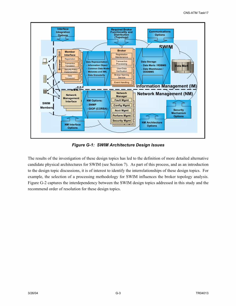
CNS-ATM Task17
3/26/04 G-3 TR04013
Broker
Registration MaintenanceTransaction ProcessingUser/Data VerificationBroker
Naming Service
Data Mart
Member Interface
Registration
Transaction TranslationSecurity
Policy Implementati
onData Conversion
Member Interface
Registration
Transaction TranslationSecurity
Policy Implementati
onData Conversion
Member InterfaceRegistration
Transaction Translation
Security Policy Implementation
Data Conversion
GU
I
SWIMBroker
Registration Maintenance
Transaction Processing
User/Data Verification
Broker Naming Service
Event Handling
Data Representation:– Information Object– Common Data Model– Metadata and XML– Data Granularity
Data Storage:– Data Marts / RDBMS– Data Warehouse /
OODBMS
Required Broker Functionality and
Distribution (Topology)
NM Interface Options
Information Management (IM)
Network Management (NM)
Interface Integration
Options
Network Management
Interface
Network Management
Interface
Network Management
Interface
Network Manager
Fault Mgmt
Config Mgmt
Security Mgmt
Acct Mgmt
Perform Mgmt
Network Manager
Fault Mgmt
Config Mgmt
Security Mgmt
Acct Mgmt
Perform Mgmt
NM Options:– SNMP– GIOP (CORBA)
NM Architecture Options
SWIM Members
Bro
wse
r
Communications Options
Security Mechanism
Options
Broker
Registration MaintenanceTransaction ProcessingUser/Data VerificationBroker
Naming Service
Broker
Registration MaintenanceTransaction ProcessingUser/Data VerificationBroker
Naming Service
Data MartData Mart
Member Interface
Registration
Transaction TranslationSecurity
Policy Implementati
onData Conversion
Member Interface
Registration
Transaction TranslationSecurity
Policy Implementati
onData Conversion
Member Interface
Registration
Transaction TranslationSecurity
Policy Implementati
onData Conversion
Member Interface
Registration
Transaction TranslationSecurity
Policy Implementati
onData Conversion
Member InterfaceRegistration
Transaction Translation
Security Policy Implementation
Data Conversion
GU
I
SWIMBroker
Registration Maintenance
Transaction Processing
User/Data Verification
Broker Naming Service
Event Handling
Data Representation:– Information Object– Common Data Model– Metadata and XML– Data Granularity
Data Storage:– Data Marts / RDBMS– Data Warehouse /
OODBMS
Required Broker Functionality and
Distribution (Topology)
Required Broker Functionality and
Distribution (Topology)
NM Interface Options
NM Interface Options
Information Management (IM)
Network Management (NM)
Interface Integration
Options
Interface Integration
Options
Network Management
Interface
Network Management
Interface
Network Management
Interface
Network Manager
Fault Mgmt
Config Mgmt
Security Mgmt
Acct Mgmt
Perform Mgmt
Network Manager
Fault Mgmt
Config Mgmt
Security Mgmt
Acct Mgmt
Perform Mgmt
Network Manager
Fault Mgmt
Config Mgmt
Security Mgmt
Acct Mgmt
Perform Mgmt
Network Manager
Fault Mgmt
Config Mgmt
Security Mgmt
Acct Mgmt
Perform Mgmt
NM Options:– SNMP– GIOP (CORBA)
NM Architecture Options
NM Architecture Options
SWIM Members
Bro
wse
r
Communications Options
Communications Options
Security Mechanism
Options
Security Mechanism
Options
Figure G-1: SWIM Architecture Design Issues The results of the investigation of these design topics has led to the definition of more detailed alternative candidate physical architectures for SWIM (see Section 7). As part of this process, and as an introduction to the design topic discussions, it is of interest to identify the interrelationships of these design topics. For example, the selection of a processing methodology for SWIM influences the broker topology analysis. Figure G-2 captures the interdependency between the SWIM design topics addressed in this study and the recommend order of resolution for these design topics.
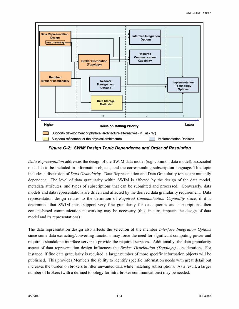
CNS-ATM Task17
3/26/04 G-4 TR04013
Data GranularityData Granularity
Data Representation Design
RequiredBroker Functionality
Broker Distribution(Topology)
NetworkManagement
Options
Data StorageMethods
Interface IntegrationOptions
RequiredCommunication
Capability
ImplementationTechnology
Options
Higher Decision Making Priority Lower
Supports development of physical architecture alternatives (in Task 17)
Supports refinement of the physical architecture
1 2 3 4
Implementation Decision
Data GranularityData Granularity
Data Representation Design
RequiredBroker Functionality
Broker Distribution(Topology)
NetworkManagement
Options
Data StorageMethods
Interface IntegrationOptions
RequiredCommunication
Capability
ImplementationTechnology
Options
Higher Decision Making Priority Lower
Supports development of physical architecture alternatives (in Task 17)
Supports refinement of the physical architecture
1 2 3 4
Implementation Decision
Figure G-2: SWIM Design Topic Dependence and Order of Resolution Data Representation addresses the design of the SWIM data model (e.g. common data model), associated metadata to be included in information objects, and the corresponding subscription language. This topic includes a discussion of Data Granularity. Data Representation and Data Granularity topics are mutually dependent. The level of data granularity within SWIM is affected by the design of the data model, metadata attributes, and types of subscriptions that can be submitted and processed. Conversely, data models and data representations are driven and affected by the derived data granularity requirement. Data representation design relates to the definition of Required Communication Capability since, if it is determined that SWIM must support very fine granularity for data queries and subscriptions, then content-based communication networking may be necessary (this, in turn, impacts the design of data model and its representations). The data representation design also affects the selection of the member Interface Integration Options since some data extracting/converting functions may force the need for significant computing power and require a standalone interface server to provide the required services. Additionally, the data granularity aspect of data representation design influences the Broker Distribution (Topology) considerations. For instance, if fine data granularity is required, a larger number of more specific information objects will be published. This provides Members the ability to identify specific information needs with great detail but increases the burden on brokers to filter unwanted data while matching subscriptions. As a result, a larger number of brokers (with a defined topology for intra-broker communications) may be needed.

CNS-ATM Task17
3/26/04 G-5 TR04013
The topic of Required Broker Functionality defines the role of the broker in matching available information to requested information. Different options define the level of involvement of the broker in supporting information exchange and relate to the amount of knowledge information producers and information consumers have or are required to obtain about each other. The definition of Required Broker Functionality impacts Broker Distribution (Topology) considerations. For instance, fewer brokers would be required if brokers play a minimal role supporting the exchange of information between information producers and consumers. However, if the brokers are true intermediaries and all information passes through brokers as part of an information exchange, then a larger number of brokers would be needed to address latency and processing requirements. The number and role of the brokers impacts an appropriate topology for broker connectivity. The definition of Required Broker Functionality also affects the selection of an appropriate method for Data Storage. The level of involvement of a broker in the actual exchange of NAS information impacts data storage requirements. In addition, different ways of processing real-time/stream data affect how this data will be stored and in what format (e.g. Information Object or raw data format). As alluded to above, Interface Integration Options address how SWIM member interfaces are integrated with NAS systems. This topic is influenced by Data Representation design (see above) as well as Broker Distribution (Topology). With a large number of local brokers, the interface proxy software would likely be able to accommodate all member requests (provide data (e.g. publish), request data (e.g. subscribe), etc.). Alternatively, with fewer brokers, a standalone interface server may be required to provide more powerful interface services. Required Communication Capability is impacted by several other design topics. A possible relationship between data representation and communication capability has been addressed above (i.e. need for content-based networking). Additionally, the choice of subscription mechanism may affect the way the communication network routes SWIM data. Furthermore, the definition of Broker Distribution (Topology) may also impact the extent and topology of supporting communications. For example, an arrangement with a large number of brokers distributed to many NAS facilities and interfacing locally to SWIM members may be supported by a hub and spoke communication network at the local facility level and within an ARTCC region. In this example, the backbone network would be an inter-ARTCC network. All these design issues affect the analysis and selection of an appropriate Implementation Technology. Enabling technologies for SWIM are introduced in Appendix C. Further investigation and trade-off of implementation technologies can be performed as part of the development and evaluation of engineering design models. Principal objectives for SWIM implementation include interoperability and scalability, as well as meeting SWIM performance requirements. Resolution of the all design issues impacts the degree to which these objectives can be met. G.2 SWIM DATA REPRESENTATION DESIGN This section identifies and addresses eight design issues specific to the SWIM data model. These include:

CNS-ATM Task17
3/26/04 G-6 TR04013
• Defining the Common Data Model
• Information Objects for real-time/stream Data
• SWIM Data Discovery
• Quality of SWIM Services
• Information Object Persistence
• MDR Issues
• What information to store in data marts and data warehouses
• Representation of Archived Information Objects
Each design issue is addressed in a separate subsection below. G.2.1 Defining the Common Data Model The concept of a common data model for SWIM has been introduced in Section D.2.1. The SWIM common data model is a NAS-wide pre-defined and agreed upon definition of data structures that make NAS information understandable by all SWIM members. The design issue in this area is focused on gaining consensus on a data model among different NAS communities of interest. Part of this process is the definition of FAA and NAS level policies required to manage the definition and description of a SWIM common data model as well as the design and incorporation of associated taxonomy and ontology information for the common data model. G.2.1.1 Information Objects for Real-time/Stream Data Generally stream data is considered data that is produced in large volume and is updated very frequently. A NAS specific example of stream data is surveillance data. When a SWIM service requires the use of stream data, two challenges are presented. First, the large volume and/or update frequency may add an extra processing burden to the SWIM broker. Second, the context of stream data can not be queried directly. Based on these issues, stream data may need to be processed differently than non-stream data. For example, before publishing stream data, a stream data publishing information object (SPIO) with no actual payload may be sent out first to provide subscribers with publisher information; this would enable subscribers to set up a transmission connection directly with the publishers. Additionally, for data that require archiving in data marts, stream data samples may be selected and stored. G.2.1.2 SWIM Data Discovery The process of discovering data requires a shared vocabulary between data producers and data consumers. This agreed upon vocabulary for exchanging information is designated an ontology. It consists of a set of concepts such as things, events and relations specified in a certain way (such as a specific natural language). In the information technology field, ontology is the working model of entities and interactions in some particular domain of knowledge or practice such as electronic commerce.

CNS-ATM Task17
3/26/04 G-7 TR04013
For a given data taxonomy of the SWIM common data model, it is possible that there may exist different ontologies for different SWIM data consumers. The ability to discover and/or subscribe to the correct information depends on both taxonomy and ontology definitions. This issue may be addressed by developing agreements between different SWIM data consumer communities on domain knowledge to be included in the domain ontology. Then an ontology meta-model associated with the SWIM common data model can be built. The domain knowledge may address domain taxonomy and categories, lexical terms, concepts, relationships and axioms. The domain ontology meta-model may contain information about key elements and attributes, usage of these key elements, relationships between elements. This ontology could be built with UML and XML as the ontology language. G.2.1.3 Quality of SWIM Services The role of SWIM is the delivery of NAS data. Because NAS services have performance requirements, the required performance and quality of the SWIM services that enable these NAS services also need to be specified, that is, the criteria that define the quality of SWIM services needs to be defined. These will include such factors as accuracy and latency, and may include certain metadata parameters that can be associated with the quality of SWIM data. These criteria may be common to all SWIM members or may vary by different groups of SWIM members. Consideration needs to be given to the tradeoffs between quality of SWIM service versus cost and bandwidth constraints (which can be considered policy issues). More metadata can provide better searching ability and flexibility for users but may significantly increase complexity and cost and perhaps add more latency. G.2.1.4 Information Object Persistence Information object persistence relates to the ability to keep information objects around after the information object is published. Typically, information objects are characterized in one of two ways, namely mutable or immutable. An information object is considered mutable if the information carried by the object can be changed as the information object moves and its changing history can be stored. On the other hand, if a new information object is published each time the information that is carried by the object requires change, the information object is considered immutable. This topic can be examined in the context of existing FAA data items and associated databases. For example, the official NAS Resources (NASR) master set of FAA aeronautical data is issued throughout the NAS on a 56-day update cycle. A prototype system is being developed by ATA-100 called Electronic NASR (eNASR). This system provides the functionality that allows authorized FAA information sources to enter proposed changes to the official NASR database electronically from remote field sites rather than phoning or faxing in changes to the National Flight Data Center (NFDC) specialists. With the data already in electronic format in a change request form the NFDC specialist reviews the change form and guides it through the approval process. The eNASR updates items (i.e. information objects) in its database every workweek night. As part of this process, an elaborate history of every change is maintained so that it would be possible to roll back the changes to a former state if desired, and there is accountability for every change. The information objects in this example can be considered mutable.
CNS-ATM Task17
3/26/04 G-8 TR04013
For SWIM, the mutability of SWIM information objects requires definition. Additionally, specific policies are needed to address how changes are handled and recorded. The pedigree of data captures the history associated with an information object. It can address questions such as the origin of the information object and what has been changed since the information object was published; for example, if an information object is received by a subscriber and the subscriber makes changes to the information object (such as a update of the value of a field or change of the presentation). Whether or not to capture pedigree information for SWIM is a design decision. If captured, the specific role of this information requires definition (for example, monitoring pedigree information to check information integrity). This design issue requires consideration in conjunction with the investigation of security issues, as the goal of non-repudiation is related to pedigree data. G.2.1.5 MDR Design Several design issues relate to a SWIM MDR design. First, the types of metadata resources associated with an MDR need to be identified. These could include items such as an XML registry and data dictionary. Second, depending on the architecture and distribution of the MDR (e.g. if there are some centralized MDRs and LMDRs), the means for integrating and synchronizing the registries requires definition. G.2.1.6 Information Objects Stored in Data Marts and Data Warehouses Data marts are relational databases designed to save exchanged information objects for fast retrieval purposes. In contrast, data warehouses are databases designed for long term archive and storage of exchanged information. If used in SWIM, data warehouses could be created new on demand or could be implemented using legacy NAS databases transitioned to accommodate SWIM formats and interactions. The role of data marts in SWIM would be to store certain published information objects for a short period of time to support quick retrieval and possibly to support data monitoring. Due to size and performance constraints, not all SWIM published information objects would be appropriate for storage in data marts. Criteria for selecting appropriate SWIM data in data marts would include the following factors:
• Most often published
• Last published
• Most critical
As data warehouses provide information storage for long term archiving, it is not clear whether data warehouses would be part of SWIM or would be accommodated by individual NAS data managers or applications. This decision is an FAA policy issue; once decided, the SWIM architecture design can be refined to reflect the choice. If included as part of SWIM, data warehouses could be considered a set of SWIM members that could subscribe to certain published information.

CNS-ATM Task17
3/26/04 G-9 TR04013
G.2.1.7 Representation of Archived Information Objects As described above, SWIM information objects may be archived in SWIM in short term and long term repositories. Depending on the role of the archive, the specific information to be stored and its format must be determined. The archived information could include all or part of the information object (including all or part of the metadata and object payload). Additionally, information could be abbreviated during the archival process. In addition to format issues, the storage repository requires design. The information object to be stored could be divided into separate storage areas (for example, a weather information object may be decomposed and different weather products stored in different repositories). Links to these storage areas could support the reconstitution of the object upon query request. Typically, data marts archive complete information objects, including metadata information, but data warehouses archive data in its raw format. If these formats are used, a member interface conversion of raw data format to the common data representation would be required for data warehouses. When designing the short term and long term repositories, database load capacity and processing speeds need to be considered. G.2.2 Data Concept and Issues Summary A summary of design issues related to SWIM data concepts and representation are summarized in Table G-2.
Table G-2: Summary of Data Concept Issues
Issue #
Data Concept Design Issue Factors That Affect the Decision How to Resolve
Impact on Overall
Effectiveness of the
Architecture 1 Who will decide the
data and data format in common data model
Complexity of the overall NAS data; agreement among different Communities of Interest; cost of implementing a common data model; FAA policy
FAA Policy and Data Stewardship
High
2 Information Objects for real-time/stream data
Real-time/stream data traffic characteristics; performance requirements for stream data; available bandwidth
Design Decision High
3 SWIM Data Discovery
Complexity of design ontology for SWIM data; implementation cost
Design Ontology Medium
4 Quality of SWIM Services
Available bandwidth; implementation cost; technology/COTS support
Implementation Decision
Medium
5 Information Object Persistence
FAA need; implementation cost; technology/COTS support
Data Stewardship Low
6 MDR Issues Size of common data model; performance requirement
Implementation Decision
Medium
7 What information objects to store in data marts and data warehouses
Cost; performance requirement; data analysis; FAA data archiving policy; cost
Policy and Implementation Decision
Medium
8 Representation of archived Info Objects
Size of data, performance requirement Implementation Decision
Medium
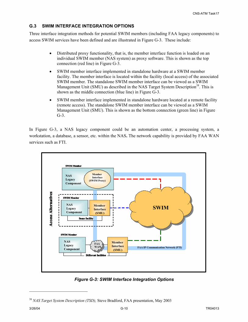
CNS-ATM Task17
3/26/04 G-10 TR04013
G.3 SWIM INTERFACE INTEGRATION OPTIONS Three interface integration methods for potential SWIM members (including FAA legacy components) to access SWIM services have been defined and are illustrated in Figure G-3. These include:
• Distributed proxy functionality, that is, the member interface function is loaded on an individual SWIM member (NAS system) as proxy software. This is shown as the top connection (red line) in Figure G-3.
• SWIM member interface implemented in standalone hardware at a SWIM member facility. The member interface is located within the facility (local access) of the associated SWIM member. The standalone SWIM member interface can be viewed as a SWIM Management Unit (SMU) as described in the NAS Target System Description38. This is shown as the middle connection (blue line) in Figure G-3.
• SWIM member interface implemented in standalone hardware located at a remote facility (remote access). The standalone SWIM member interface can be viewed as a SWIM Management Unit (SMU). This is shown as the bottom connection (green line) in Figure G-3.
In Figure G-3, a NAS legacy component could be an automation center, a processing system, a workstation, a database, a sensor, etc. within the NAS. The network capability is provided by FAA WAN services such as FTI.
Acc
ess A
ltern
ativ
es
NAS Legacy Component
NAS Legacy Component
Member Interface
(SWIM Proxy)
FAAWAN
Member Interface(SMU)
Different facilities
Member Interface(SMU)
NAS Legacy Component
Same facility
SWIM
SWIM Member
SWIM Member
SWIM Member
FAA IP Communication Network (FTI)
SWIM
Acc
ess A
ltern
ativ
es
NAS Legacy Component
NAS Legacy Component
NAS Legacy Component
Member Interface
(SWIM Proxy)
FAAWANFAAWAN
Member Interface(SMU)
Member Interface(SMU)
Different facilities
Member Interface(SMU)
NAS Legacy Component
NAS Legacy Component
Same facility
SWIM
SWIM Member
SWIM Member
SWIM Member
FAA IP Communication Network (FTI)
SWIM
Acc
ess A
ltern
ativ
es
NAS Legacy Component
NAS Legacy Component
Member Interface
(SWIM Proxy)
FAAWAN
Member Interface(SMU)
Different facilities
Member Interface(SMU)
NAS Legacy Component
Same facility
SWIM
SWIM Member
SWIM Member
SWIM Member
FAA IP Communication Network (FTI)
SWIM
Acc
ess A
ltern
ativ
es
NAS Legacy Component
NAS Legacy Component
NAS Legacy Component
Member Interface
(SWIM Proxy)
FAAWANFAAWAN
Member Interface(SMU)
Member Interface(SMU)
Different facilities
Member Interface(SMU)
NAS Legacy Component
NAS Legacy Component
Same facility
SWIM
SWIM Member
SWIM Member
SWIM Member
FAA IP Communication Network (FTI)
SWIM
Figure G-3: SWIM Interface Integration Options
38 NAS Target System Description (TSD), Steve Bradford, FAA presentation, May 2003

CNS-ATM Task17
3/26/04 G-11 TR04013
These access methods have been assessed based on the following criteria:
• Processing speed
• Memory requirements (for FAA network node)
• Complexity
• Cost
The evaluation of each access method based on these identified criteria is captured in Table G-3.
Table G-3: Comparison of SWIM Access Methods Evaluation Criteria
Access Method Processing Speed Memory Requirements Complexity Cost
Distributed Proxy implemented in FAA node
High High Med Med/Low
Standalone Proxy in Local Facility
Med Low Med/High High
Standalone Proxy in Remote Facility
Med/Low Low Med/High Med/High
For this design trade-off, a single solution is not required. The first access method is the preferred approach, to be used when the FAA network node is capable of supporting the SWIM member interface software. However, in cases where the capabilities of the FAA network node cannot support the SWIM member interface software, the second approach may be required in initial deployments of SWIM. In these cases, when the non-compliant workstation or server is replaced, the SWIM member interface software would be installed on the updated node to migrate to the preferred (distributed) access method. Additionally, facility restrictions or size constraints may warrant the use of a remote standalone SWIM member interface, where the remote interface unit is accessed via the FAA network infrastructure (e.g. FTI), as a default gateway or proxy server, implemented through tunneling or encapsulation. In all cases, it is assumed that legacy components not network capable (e.g., weather/surveillance sensors) will require an interface, or gateway functionality, to the SWIM network via an FAA network node. This interface is separate and independent of the SWIM member interface. A summary of the SWIM member interface option design decisions is provided in Table G-4.
Table G-4: SWIM Member Interface Option Summary
Options #
Interface Integration Options
Factors That Affect the Decision How to Resolve
Impact on Overall Effectiveness of the
Architecture 1 Proxy Member component is
powerful enough to support proxy
Design Analysis, topology decision, traffic analysis
Medium to High

CNS-ATM Task17
3/26/04 G-12 TR04013
2 Standalone (local Access)
Network node connection (intranet available)
Design Analysis, topology decision, traffic analysis
Medium to High
3 Standalone (Remote Access)
Network node connection (FTI extranet available)
Design Analysis, topology decision, traffic analysis
Medium to High
G.4 REQUIRED BROKER FUNCTIONALITY G.4.1 Introduction Five primary functions have been defined for SWIM, as identified Table G-5.
Table G-5: Primary SWIM Functions SWIM
Function Definition
Register A SWIM member declares its role in SWIM (e.g., publish weather information, store surveillance information, etc.) A SWIM member may have more than one role.
Subscribe SWIM member requests SWIM to deliver a specific type of information in the future (continuous delivery). Some subscriptions can be episodic, and some (e.g. some weather products) can be regular (and very voluminous), but infrequent.
Unsubscribe Reverse of a previous subscribe request Publish SWIM member provides the NAS data/information for SWIM to distribute to the subscribing
members Query SWIM member requests specific type of information previously published (one time) or to be
published in the future. To gain an understanding of the design tradeoffs related to how SWIM processes data, a basic understanding of the range of data characteristics to be accommodated by SWIM is required. Specifically, the nature of the data volume as well as the update frequency affects data processing operations. Two categories of data volume (large and small) and two categories of update frequency (real-time and non-real-time) have been identified. Different combinations of these categories lead to different data definitions as shown in Table G-6.
Table G-6: SWIM Data Category Data Update Frequency
Real-time Non-real-time
Large Large stream data Large non-stream data Data volume Small Small stream data Small non-stream data
Stream data are updated at or near real-time frequency. An example of such data is surveillance target reports. Stream data are further categorized as large or small based on the data volume. Non-stream data is also classified as having large or small volume. This classification of data is necessary, as stream data may need to be processed differently in order to meet stringent performance requirements. In this report the term “stream data” includes both large and small stream data, and “non-stream data” refers to both large and small non-stream data. SWIM is proposed to be a distributed publish/subscribe system. Subscribers can express their interest of NAS information in their subscriptions and subsequently receive information of interest generated by a publisher. Published data is asynchronously propagated to all the subscribers that registered interest in
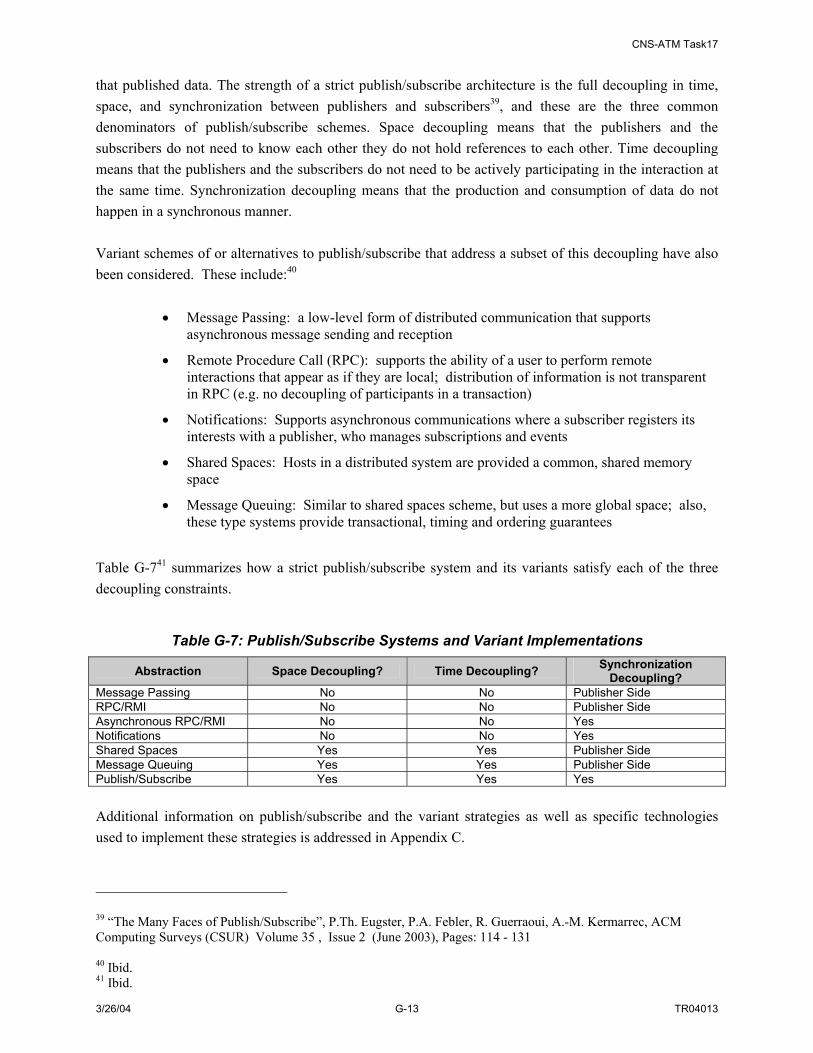
CNS-ATM Task17
3/26/04 G-13 TR04013
that published data. The strength of a strict publish/subscribe architecture is the full decoupling in time, space, and synchronization between publishers and subscribers39, and these are the three common denominators of publish/subscribe schemes. Space decoupling means that the publishers and the subscribers do not need to know each other they do not hold references to each other. Time decoupling means that the publishers and the subscribers do not need to be actively participating in the interaction at the same time. Synchronization decoupling means that the production and consumption of data do not happen in a synchronous manner. Variant schemes of or alternatives to publish/subscribe that address a subset of this decoupling have also been considered. These include:40
• Message Passing: a low-level form of distributed communication that supports asynchronous message sending and reception
• Remote Procedure Call (RPC): supports the ability of a user to perform remote interactions that appear as if they are local; distribution of information is not transparent in RPC (e.g. no decoupling of participants in a transaction)
• Notifications: Supports asynchronous communications where a subscriber registers its interests with a publisher, who manages subscriptions and events
• Shared Spaces: Hosts in a distributed system are provided a common, shared memory space
• Message Queuing: Similar to shared spaces scheme, but uses a more global space; also, these type systems provide transactional, timing and ordering guarantees
Table G-741 summarizes how a strict publish/subscribe system and its variants satisfy each of the three decoupling constraints.
Table G-7: Publish/Subscribe Systems and Variant Implementations
Abstraction Space Decoupling? Time Decoupling? Synchronization Decoupling?
Message Passing No No Publisher Side RPC/RMI No No Publisher Side Asynchronous RPC/RMI No No Yes Notifications No No Yes Shared Spaces Yes Yes Publisher Side Message Queuing Yes Yes Publisher Side Publish/Subscribe Yes Yes Yes Additional information on publish/subscribe and the variant strategies as well as specific technologies used to implement these strategies is addressed in Appendix C.
39 “The Many Faces of Publish/Subscribe”, P.Th. Eugster, P.A. Febler, R. Guerraoui, A.-M. Kermarrec, ACM Computing Surveys (CSUR) Volume 35 , Issue 2 (June 2003), Pages: 114 - 131 40 Ibid. 41 Ibid.

CNS-ATM Task17
3/26/04 G-14 TR04013
The information sharing strategies identified above provide the range of options for how the SWIM Broker component will support information sharing in SWIM. The specific nature of how SWIM operations and interactions are handled is the subject of the next section. G.4.2 SWIM Alternative Broker Concepts Three alternative brokering function concepts have been identified for SWIM. These include:
• Pub/Sub Broker
• Lightweight Broker
• VC Broker
These three brokering concepts are described and compared in the following paragraphs. G.4.2.1 Pub/Sub Broker In this scenario, the Pub/Sub Broker carries out a full set of functions so that the operations/interactions between publishers and subscribers are fully decoupled in all three aspects (space, time and synchronization). Publishers and subscribers do not need to know each other, the broker registers the publisher and subscriber information and provides naming services and location transparency for both publishers and subscribers (space decoupling). The accepts publishing and subscribing requests, matches publishing information objects to subscriptions, and delivers those matched information objects to interested subscribers asynchronously (Synchronization decoupling). Publishers or subscribers do not need to be actively participating in the interaction at the same time (time decoupling). The advantage of this approach is that, since the publishers and subscribers do not need prior knowledge of each other, any changes to either side will be handled by the broker. This reduces the responsibilities of publishers and subscribers. This process also unifies the management of the exchanged information (such as tracking, monitoring and etc.) in the broker. A disadvantage of this approach is that extra latency may be added to data processing since all data flows through the broker. Additionally, the ability to handle large stream data may be restricted by the load capability of the broker. G.4.2.2 Lightweight Broker In this scenario, the Lightweight Broker carries out a subset of the functionalities of a full Pub/Sub Broker function and leaves some of the functions to some traditional messaging mechanisms (e.g., Remote Procedure Call, Message Queue etc.). Therefore the operation/interactions between publishers and subscribers may not be fully decoupled in all three aspects, only two of them will be fully decoupled. For instance, in the case that exchanged information is provided by a direct service connection between the subscribers and the publishers without minimum broker intervention, then subscriber or publisher members require a priori knowledge of each other in order to establish a connection, this interaction loses the space decoupling constraint of a strict publish/subscribe architecture. Another instance is that publishers can publish their data to different data “channels” based on criterion such as data subject. Subscribers then subscribe to different “channels” to obtain desired information. In this scenario, the Lightweight Broker will provide location transparency functions for the publishers and subscribers, but this approach may require the subscribers to synchronously “listen” to their subscribed subject channels to receive data of their interest.

CNS-ATM Task17
3/26/04 G-15 TR04013
The advantage of the “Lightweight Broker” alternative is that SWIM can be implemented more flexibly with COTS products that implement many variants of publish/subscribe schemes (as discussed in Appendix C). A disadvantage, however, is that not all three decoupling constraints of a strict publish/subscribe architecture can be fully satisfied. G.4.2.3 VC Broker In this scenario, the broker functionality is extended to process stringent performance stream data differently in case a full Pub/Sub Broker cannot process stream data efficiently. The extended functionality includes being able to set up virtual connections (VCs) for publishers and subscribers when dealing with stream data. In this case, brokers function differently for different SWIM members based on data associations. For non-stream data, the broker accepts subscriptions from subscribers, matches publishers’ information objects to subscriptions, and distributes the matched information objects to those interested subscribers. For NAS information services with stringent performance requirements (e.g. latency), the actual information objects are not published to the broker. Instead, the broker sets up a virtual circuit between the publisher and interested subscribers for direct transport of information objects. In this case, a publisher could send a publishing notification information object (SPIO) with no actual data payload to the broker to inform the broker of the type of information the publisher can share. When the broker takes subscriptions from subscribers, it may match the subscription to the SPIO information and forward the publisher information to those interested subscribers. Subscribers then initiate the connection with publishers for data transport. There are other ways of implementing the virtual circuit as well. An advantage of this approach is that it accommodates both data requiring a brokered exchange process (i.e. the information exchange is via the broker), and other data, such as stream data, more appropriate for direct exchange. However, this approach adds extra complexity to information management functions, such as monitoring and tracking of exchanged data. Table G-8 shows six SWIM function cases (primary publish and subscribe) that are categorized by data type (non-stream and stream data) and three alternative broker concepts (Pub/Sub Broker, Lightweight Broker, and VC Broker. Each case is illustrated with a diagram, a descriptive paragraph, and a table summarizing the steps associated with each scenario and its associated advantages and disadvantages. For each of the following cases, before publishing an Information Object (IO), publishing members validate the information objects with the LMDR. LMDRs need to be synchronized with the SWIM MDR/IORs on a regular basis.

CNS-ATM Task17
3/26/04 G-16 TR04013
Table G-8: SWIM Function Cases
Case 2-C
Stream Data Lightweight BrokerCase 2-B
Stream data2
Non-stream Data to VC Broker
Non-stream Data
Case 1-B
Non-stream Data to
Case 1-A
Non-stream data 1
HybridC
Without BrokerB
With BrokerA
Stream data to VC Broker Case 2-CCase 2-B
Stream data to Pub/Sub BrokerCase 2-A
Stream data2
Case 1-CCase 1-CCase 1-CCase 1-C
Non-stream Data Lightweight Broker
Case 1-B
Non-stream Data to Pub/Sub BrokerCase 1-A
Non-stream data 1
VC Broker C
Lightweight BrokerB
Pub/Sub BrokerA
G.4.3 Non-Stream Data to Pub/Sub Broker Scenario: Case 1-A In the non-stream data to Pub/Sub Broker scenario, a subscribing member registers an information request with the SWIM broker. Asynchronously, publishing members register and send information objects to the SWIM broker. The broker matches the information requests with published information objects and forwards appropriate information objects to subscribing members. Information objects may also be forwarded to data marts for temporary storage (so that information is available for user query) as well as to other members that may provide a data warehousing function. This scenario is illustrated in Figure G-4 below.
SWIM
DataMart
MDR/IOR
IO
ODF
LMDR LMDRpublisher Member
2.
1.
3
IO3
IO
ODF: Original Data FormatTDF: Target Data FormatODF: Original Data FormatTDF: Target Data Format
IOTDF
SubscriberMember
Data Warehouse
IO
TDF
3
MemberInterfaceMemberInterface
MemberInterfaceMemberInterface
MemberInterfaceMemberInterface
Non-stream Data to Broker – Case 1-A
Pub/Sub Broker
Figure G-4: SWIM Case 1-A: Non-Stream Data to Broker Scenario
A summary of the steps associated with this scenario as well as associated advantages and disadvantages are captured in Table G-9.

CNS-ATM Task17
3/26/04 G-17 TR04013
Table G-9: Case 1-A Steps and Advantages/Disadvantages Steps Case 1-A: Non-stream Data to Broker
Prerequisite Before publishing an IO, the publisher validates the IO with the local metadata registry (LMDR) Step 1 A Subscriber Member subscribes to specified data Step 2 A Publisher Member publishes an IO to the broker Step 3 The broker matches the IO to subscribers and publishes the IO to the subscribers (data marts,
data warehouse are treated as subscribers as well) Advantages Unified information management , location transparency, publishing/subscribing flexibility Disadvantages Extra processing latency, but may be traded off with its benefits G.4.4 Stream Data to Pub/Sub Broker Scenario: Case 2-A The service steps associated with this scenario are similar to the ‘non-stream data to Pub/Sub Broker’ scenario described above (Section G.4.3). Here a subscribing member registers an information request with the SWIM broker. Asynchronously, publishing members register and send information objects to the SWIM broker. Like the previous scenario, the broker matches the information requests with published information objects and forwards appropriate information objects on to subscribing members. Unlike the previous scenario, in this stream data case, sampled data may also be forwarded to data marts for temporary storage (so that information is available for user query) as well as to other members that may provide a data warehousing function. This scenario is illustrated in Figure G-5 below.
SWIM
DataMart
MDR/IOR
IO
ODF
LMDR LMDRpublisher Member
2.
1.
3
IO3
IO
IO
TDF
Subscriber Member
Data Warehouse
IO
TDF
3
Stream Data to Pub/Sub Broker – Case 2-A
stream data
sampled stream data
stream data
sampled stream data
stream data
sampled stream data
stream data
sampled stream data
MemberInterfaceMemberInterface
MemberInterfaceMemberInterface
MemberInterfaceMemberInterface
Pub/Sub Broker
Figure G-5: Case 2-A: Stream Data to Broker Scenario A summary of the steps associated with this scenario as well as associated advantages and disadvantages are captured in Table G-10.
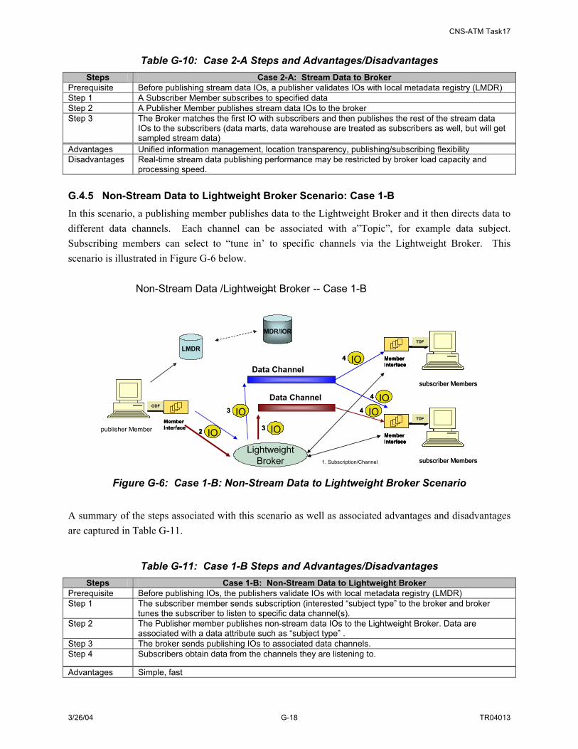
CNS-ATM Task17
3/26/04 G-18 TR04013
Table G-10: Case 2-A Steps and Advantages/Disadvantages Steps Case 2-A: Stream Data to Broker
Prerequisite Before publishing stream data IOs, a publisher validates IOs with local metadata registry (LMDR) Step 1 A Subscriber Member subscribes to specified data Step 2 A Publisher Member publishes stream data IOs to the broker Step 3 The Broker matches the first IO with subscribers and then publishes the rest of the stream data
IOs to the subscribers (data marts, data warehouse are treated as subscribers as well, but will get sampled stream data)
Advantages Unified information management, location transparency, publishing/subscribing flexibility Disadvantages Real-time stream data publishing performance may be restricted by broker load capacity and
processing speed. G.4.5 Non-Stream Data to Lightweight Broker Scenario: Case 1-B In this scenario, a publishing member publishes data to the Lightweight Broker and it then directs data to different data channels. Each channel can be associated with a”Topic”, for example data subject. Subscribing members can select to “tune in’ to specific channels via the Lightweight Broker. This scenario is illustrated in Figure G-6 below.
Non-Stream Data /Lightweight Broker -- Case 1-B–
LMDR
MDR/IOR
publisher Member
ODFODF
2 IO2 IO
subscriber Members
TDFTDF
MemberInterface
subscriber Members
TDFTDF
MemberInterfaceMemberInterface
MemberInterfaceMemberInterface
subscriber Members
TDFTDF
MemberInterface
subscriber Members
TDFTDF
MemberInterfaceMemberInterface
Data Channel
Data Channel
LightweightBroker
3 IO3 IO
3 IO3 IO
1. Subscription/Channel
4 IO4 IO
4 IO4 IO
4 IO4 IO
Figure G-6: Case 1-B: Non-Stream Data to Lightweight Broker Scenario A summary of the steps associated with this scenario as well as associated advantages and disadvantages are captured in Table G-11.
Table G-11: Case 1-B Steps and Advantages/Disadvantages Steps Case 1-B: Non-Stream Data to Lightweight Broker
Prerequisite Before publishing IOs, the publishers validate IOs with local metadata registry (LMDR) Step 1 The subscriber member sends subscription (interested “subject type” to the broker and broker
tunes the subscriber to listen to specific data channel(s). Step 2 The Publisher member publishes non-stream data IOs to the Lightweight Broker. Data are
associated with a data attribute such as “subject type” . Step 3 The broker sends publishing IOs to associated data channels. Step 4 Subscribers obtain data from the channels they are listening to.
Advantages Simple, fast
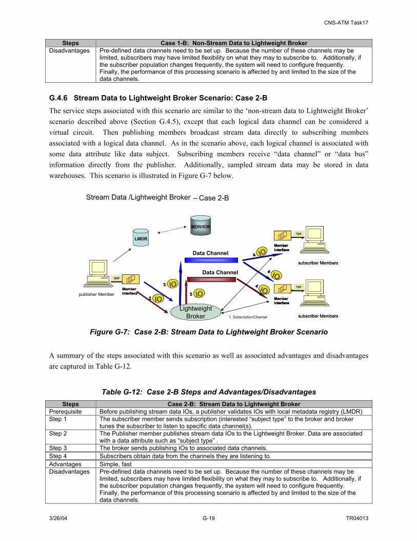
CNS-ATM Task17
3/26/04 G-19 TR04013
Steps Case 1-B: Non-Stream Data to Lightweight Broker Disadvantages Pre-defined data channels need to be set up. Because the number of these channels may be
limited, subscribers may have limited flexibility on what they may to subscribe to. Additionally, if the subscriber population changes frequently, the system will need to configure frequently. Finally, the performance of this processing scenario is affected by and limited to the size of the data channels.
G.4.6 Stream Data to Lightweight Broker Scenario: Case 2-B The service steps associated with this scenario are similar to the ‘non-stream data to Lightweight Broker’ scenario described above (Section G.4.5), except that each logical data channel can be considered a virtual circuit. Then publishing members broadcast stream data directly to subscribing members associated with a logical data channel. As in the scenario above, each logical channel is associated with some data attribute like data subject. Subscribing members receive “data channel” or “data bus” information directly from the publisher. Additionally, sampled stream data may be stored in data warehouses. This scenario is illustrated in Figure G-7 below.
Stream Data /Lightweight Broker – Case 2-B
LMDR
MDR/IOR
publisher Member
ODFODF
2 IO2 IO
subscriber Members
TDFTDF
MemberInterface
subscriber Members
TDFTDF
MemberInterfaceMemberInterface
MemberInterfaceMemberInterface
subscriber Members
TDFTDF
MemberInterface
subscriber Members
TDFTDF
MemberInterfaceMemberInterface
Data Channel
3 IO3 IO 4 IO4 IO
4 IO4 IO
4 IO4 IOData Channel
LightweightBroker 1. Subscription/Channel
3 IO3 IO
Figure G-7: Case 2-B: Stream Data to Lightweight Broker Scenario A summary of the steps associated with this scenario as well as associated advantages and disadvantages are captured in Table G-12.
Table G-12: Case 2-B Steps and Advantages/Disadvantages Steps Case 2-B: Stream Data to Lightweight Broker
Prerequisite Before publishing stream data IOs, a publisher validates IOs with local metadata registry (LMDR) Step 1 The subscriber member sends subscription (interested “subject type” to the broker and broker
tunes the subscriber to listen to specific data channel(s). Step 2 The Publisher member publishes stream data IOs to the Lightweight Broker. Data are associated
with a data attribute such as “subject type” . Step 3 The broker sends publishing IOs to associated data channels. Step 4 Subscribers obtain data from the channels they are listening to. Advantages Simple, fast Disadvantages Pre-defined data channels need to be set up. Because the number of these channels may be
limited, subscribers may have limited flexibility on what they may to subscribe to. Additionally, if the subscriber population changes frequently, the system will need to configure frequently. Finally, the performance of this processing scenario is affected by and limited to the size of the data channels.

CNS-ATM Task17
3/26/04 G-20 TR04013
G.4.7 Non-Stream Data to VC Broker Scenario: Case 1-C The service steps associated with this scenario are similar to the ‘non-stream data to Pub/Sub Broker’ scenario described above (Case 1-A). A subscribing member registers an information request with the SWIM broker. Asynchronously, publishing members register and send information objects to the SWIM broker. The broker matches the information requests with published information objects and forwards appropriate information objects on to subscribing members. Information objects may also be forwarded to data marts for temporary storage (so that information is available for user query) as well as to other members that may provide a data warehousing function. This scenario is illustrated in Figure G-8.
SWIM
DataMart
MDR/IOR
BrokerVC Broker
IOIO
ODF
LMDRLMDR LMDRLMDR
publisher Member
2.
1.
IO3
IO
TDF
SubscriberMember
Data Warehouse
IOIO
TDF
3
Non-Stream Data to VC Broker --Case 1-C
3
MemberInterfaceMemberInterface
MemberInterfaceMemberInterface
MemberInterfaceMemberInterface
IOIO
Figure G-8: Case 1-C: Non-Stream Data to VC Broker Scenario
A summary of the steps associated with this scenario as well as associated advantages and disadvantages are captured in Table G-13.
Table G-13: Case 1-C Steps and Advantages/Disadvantages Steps Case 1-C: Non-stream Data to VC Broker
Prerequisite Before publishing an IO, the publisher validates the IO with the local metadata registry (LMDR) Step 1 A Subscriber Member subscribes to specified data Step 2 A Publisher Member publishes an IO to the VC Broker Step 3 The VC Broker matches the IO to subscribers and publishes the IO to the subscribers (data marts,
data warehouse are treated as subscribers as well) Advantages Location transparency, publishing/subscribing flexibility Disadvantages Extra processing latency, but may be traded off with its benefits. Data management complexity to
process steam and non-stream data G.4.8 Stream Data to VC Broker Scenario: Case 2-C In this scenario, subscribers send their subscriptions to the VC Broker. When publishing stream data, a publisher sends a stream data publishing information object (SPIO) to the VC Broker. The SPIO contains
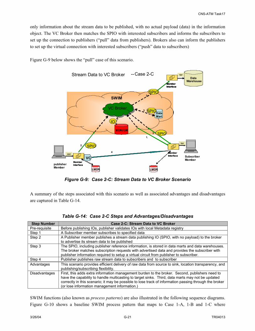
CNS-ATM Task17
3/26/04 G-21 TR04013
only information about the stream data to be published, with no actual payload (data) in the information object. The VC Broker then matches the SPIO with interested subscribers and informs the subscribers to set up the connection to publishers (“pull” data from publishers). Brokers also can inform the publishers to set up the virtual connection with interested subscribers (“push” data to subscribers) Figure G-9 below shows the “pull” case of this scenario.
SWIM
DataMart
MDR/IOR
BrokerVC Broker
SPIOSPIO
ODF
LMDRLMDR LMDRLMDR
publisher Member
2.
1.
4
SPIO3
IO
TDF
SubscriberMember
SPIO3
Stream Data to VC Broker --Case 2-C
3
MemberInterfaceMemberInterface
MemberInterfaceMemberInterface
Data Warehouse
TDF
MemberInterface
Data Warehouse
TDF
MemberInterfaceMemberInterface
SPIOSPIO
VCVC
Figure G-9: Case 2-C: Stream Data to VC Broker Scenario A summary of the steps associated with this scenario as well as associated advantages and disadvantages are captured in Table G-14.
Table G-14: Case 2-C Steps and Advantages/Disadvantages Step Number Case 2-C: Stream Data to VC Broker
Pre-requisite Before publishing IOs, publisher validates IOs with local Metadata registry Step 1 A Subscriber member subscribes to specified data Step 2 A Publisher member publishes a stream data publishing IO (SPIO, with no payload) to the broker
to advertise its stream data to be published Step 3 The SPIO, including publisher reference information, is stored in data marts and data warehouses.
The broker matches subscription requests with advertised data and provides the subscriber with publisher information required to setup a virtual circuit from publisher to subscriber.
Step 4 Publisher publishes raw stream data to subscribers and to subscriber Advantages This scenario provides efficient delivery of raw data from source to sink, location transparency, and
publishing/subscribing flexibility. Disadvantages First, this adds extra information management burden to the broker. Second, publishers need to
have the capability to handle multicasting to target sinks. Third, data marts may not be updated correctly in this scenario; it may be possible to lose track of information passing through the broker (or lose information management information.)
SWIM functions (also known as process patterns) are also illustrated in the following sequence diagrams. Figure G-10 shows a baseline SWIM process pattern that maps to Case 1-A, 1-B and 1-C where
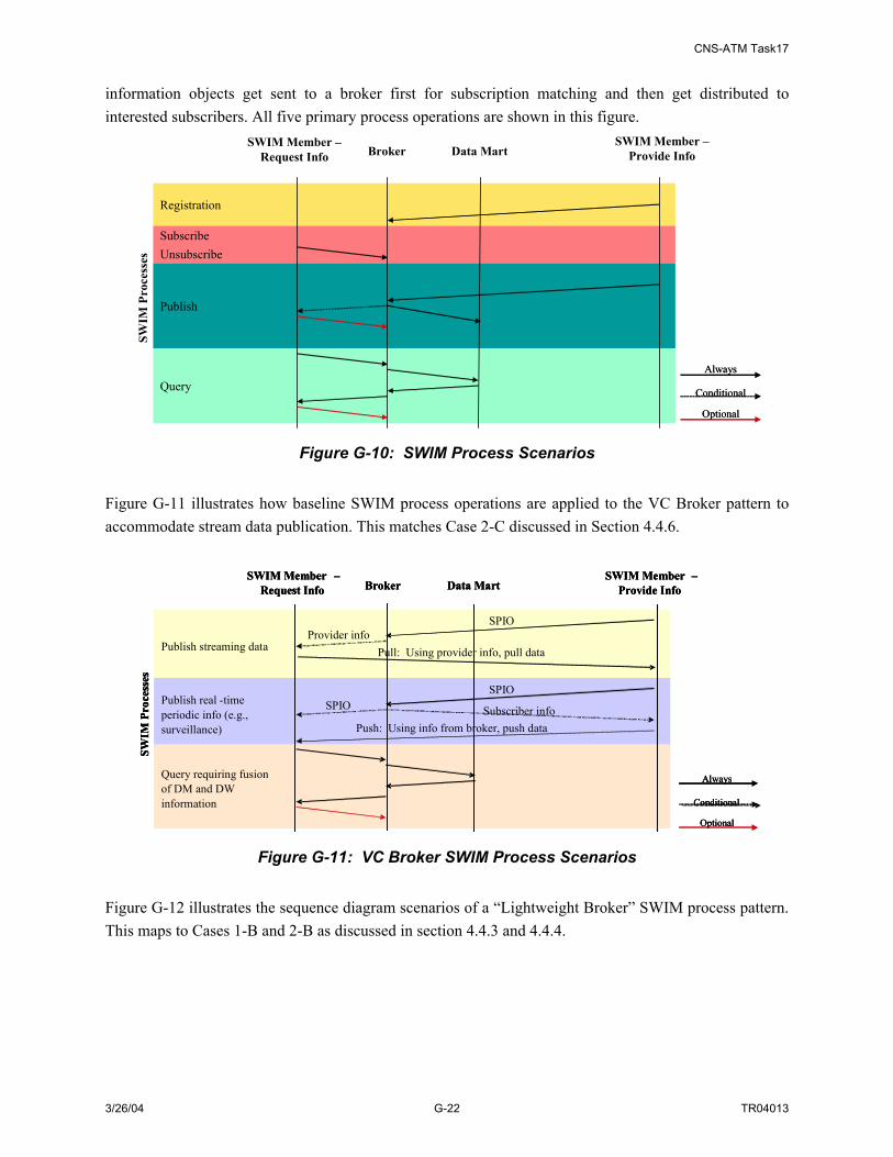
CNS-ATM Task17
3/26/04 G-22 TR04013
information objects get sent to a broker first for subscription matching and then get distributed to interested subscribers. All five primary process operations are shown in this figure.
Conditional
Always
Optional
Conditional
Always
Optional
Registration
SubscribeUnsubscribe
Publish
Query
Broker Data MartSW
IM P
roce
sses
SWIM Member –Request Info
SWIM Member –Provide Info
Figure G-10: SWIM Process Scenarios Figure G-11 illustrates how baseline SWIM process operations are applied to the VC Broker pattern to accommodate stream data publication. This matches Case 2-C discussed in Section 4.4.6.
Conditional
Optional
Always
Publish real -time periodic info (e.g., surveillance)
MetadataMetadata
Push: Using info from broker, provider forwards data
Publish streaming data
MetadataMetadata
Pull: Using metadata, client accesses data
Query requiring fusion of DM and DW information
Broker Data Mart
SWIM
Pro
cess
es
SWIM Member –Request Info
SWIM Member –Provide Info
Subscriber metadata
Conditional
Optional
Always
Conditional
Optional
Always
Publish real -time periodic info (e.g., surveillance)
MetadataMetadata
Push: Using info from broker, provider forwards data
Publish streaming data
MetadataMetadata
Pull: Using metadata, client accesses data
Query requiring fusion of DM and DW information
Broker Data Mart
SWIM
Pro
cess
es
SWIM Member –Request Info
SWIM Member –Provide Info
Subscriber metadataPublish real -time periodic info (e.g., surveillance)
SPIOSPIO
Push: Using info from broker, push data
Publish streaming data
SPIOProvider info
Pull: Using provider info, pull data
Query requiring fusion of DM and DW information
Broker Data Mart
SWIM
Pro
cess
es
SWIM Member –Request Info
SWIM Member –Provide Info
Subscriber info
Figure G-11: VC Broker SWIM Process Scenarios Figure G-12 illustrates the sequence diagram scenarios of a “Lightweight Broker” SWIM process pattern. This maps to Cases 1-B and 2-B as discussed in section 4.4.3 and 4.4.4.

CNS-ATM Task17
3/26/04 G-23 TR04013
Publish real -time periodic info (e.g., surveillance)
MetadataMetadata
Push: Using info from broker, provider forwards data
SWIM
Pro
cess
es
SWIM Member –Request Info
SWIM Member –Provide Info
Subscriber metadataPublish real -time periodic info (e.g., surveillance)
MetadataMetadata
Push: Using info from broker, provider forwards data
SWIM
Pro
cess
es
SWIM Member –Request Info
SWIM Member –Provide Info
Subscriber metadataSubscribe
Data channel1
SWIM
Pro
cess
es
SWIM Member – SWIM Member –Provide Info
Data channel2
Publish streaming data
MetadataMetadata
Pull: Using metadata, client accesses dataPublish streaming data
MetadataMetadata
Pull: Using metadata, client accesses dataPublish data
Lightweight Broker
subscription
Provider InfoPoll Data Poll Data
Publish Data
Data Data
DataData
Figure G-12: “Lightweight Broker” SWIM Process Scenarios
G.4.9 Summary of SWIM Broker Functionality Design Decisions In summary, there are three alternative SWIM broker concepts that perform the primary SWIM functions differently while processing stream or non-stream data. This is a critical design decision; the selection a SWIM function concept affects how the SWIM broker platform is to be built up and how brokers are distributed. SWIM can use the base line (Pub/Sub Broker) case, but can also use the VC Broker to accommodate stream data cases. Factors that affect the tradeoffs of these functions include NAS data traffic patterns, performance requirements (specially those for stream data), and communication network bandwidth limitations.
Table G-15: Summary of SWIM Broker Functionality
Broker Concept Factors That Affect the Decision How to Resolve
Impact on Overall Effectiveness of the Architecture
Pub/Sub Broker Desire of broker functionality and the architecture meets the overall performance requirement.
Traffic analysis; performance requirements; Bandwidth availability, Architecture Design
High
Lightweight Broker
If broker function is minimized and can be replaced by other means, this option maybe used.
Traffic analysis; performance requirements; Bandwidth availability, Architecture Design
High
VC Broker
Desire of broker functionality and the need of virtual connection functionality to compensate special need to meet the performance requirements.
Traffic analysis; performance requirements; Bandwidth availability, Architecture Design
High
G.5 BROKER DISTRIBUTION (TOPOLOGY) SWIM will likely require a number of interconnected brokers to satisfy NAS-wide data exchange services, where each broker would service a subset of the SWIM members. This section focuses on the following topics:
• Interconnection of these brokers, specifically, the SWIM broker topology (Section G.5.1)
• Inter-broker communications to support publish/subscribe (Section G.5.2)

CNS-ATM Task17
3/26/04 G-24 TR04013
G.5.1 Broker Connection Topology The choice of a broker topology is an important part of the overall SWIM physical architecture design. Broker performance (e.g. latency) varies with topology and affects the SWIM objective of guaranteed delivery of the desired information to the right SWIM members within NAS specified performance (e.g. latency) requirements. Broker interconnections can be implemented in a variety of configurations, depending on a range of requirements. When deciding the broker topology, the following requires consideration:
• Communications between brokers: this is the information that needs to be passed between brokers to enable correct publish/subscribe services
• Data processing strategy or algorithms: affects optimization of message traffic
A key challenge in designing the broker topology is scalability. Scalability refers not only to the numbers of publishers and subscribers and the numbers of subscriptions and published information objects, but also the need to meet specified performance requirements given bandwidth constraints, possible heterogeneous platforms, and decentralized control. Three basic interconnection topology architectures and a hybrid case have been studied42:
• Hierarchical
• Peer-to-Peer (Acyclic or General)
• Hybrid.
A derived diagram for each is illustrated in Figure G-13.
42 Carzaniga et al, Design and Evaluation of a Wide-Area Event Notification Service, p. 345
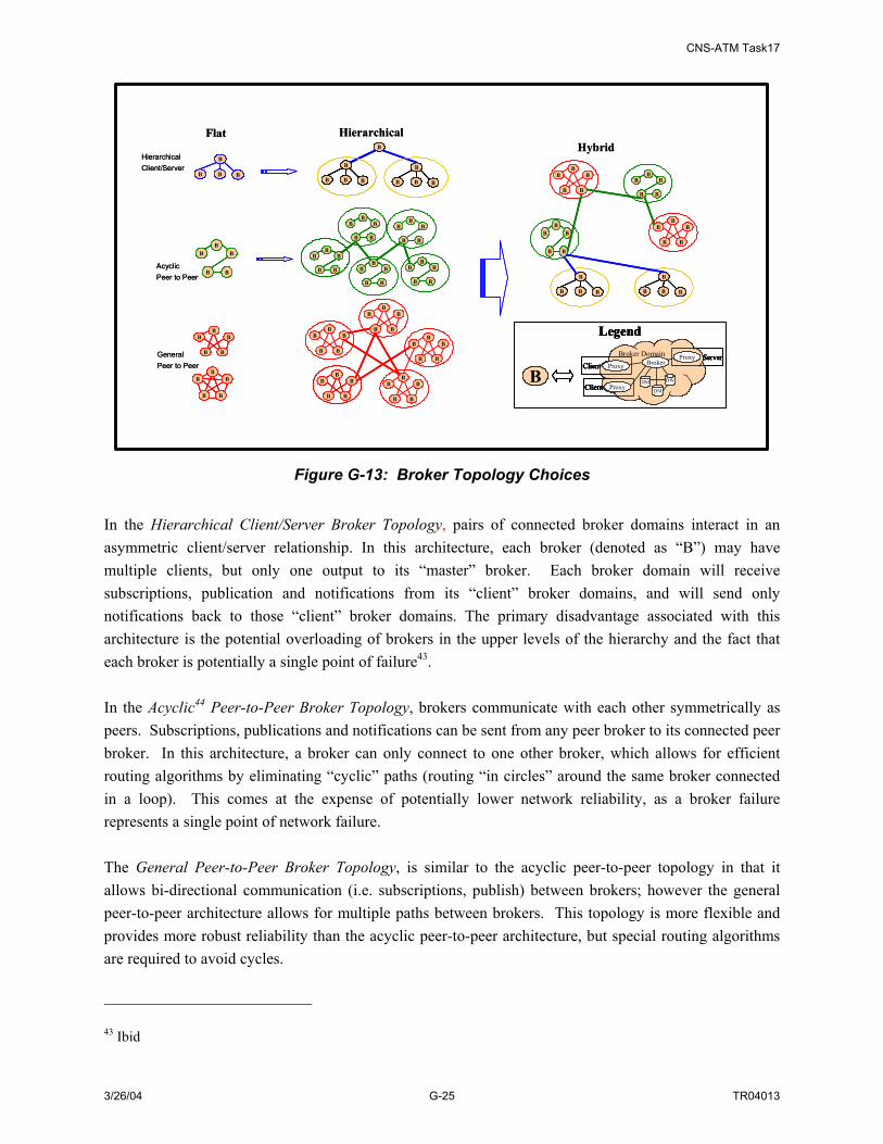
CNS-ATM Task17
3/26/04 G-25 TR04013
B
B
B
BB
B
B
B
BB
B
B
B
BB
B
B
B
BB
B
B
B
BB
B
B
B
BB
B
B
B BB
B
B B
Flat Hierarchical
B
B
B BB
B
B B
B
B
B
B BB
B
B BB
B
B B
B
B
B
BB
B
B
B
BB
B
B
B
BB
B
B
B
BB
B
B
B
BB
B
B
B
BB
B
B
B
BB
B
B
B
BB
B
B
B
BB
B
B
B
BB
B
B
B
BB
B
B
B
BB
B
B
B
BB
B
B
B
BB
B
B
B
BB
B
B
B
BB
Hybrid
B
B
B BB
B
B B
B
B
B
BB
B
B
B
BB
B
B
B
BB
B
B
B BB
B
B B
B
B
B
BB
B
B
B
BB
B
B
B
BB
Broker Domain
Proxy
ProxyProxy
DM
DM
DW
Client
Client
ServerBroker
B
LegendBroker Domain
Proxy
ProxyProxy
DM
DM
DW
Client
Client
ServerBroker
Broker Domain
Proxy
ProxyProxy
DM
DM
DW
Client
Client
ServerBroker
B
Legend
AcyclicPeer to Peer
GeneralPeer to Peer
HierarchicalClient/Server
B
B
B
BB
B
B
B
BB
B
B
B
BB
B
B
B
BB
B
B
B
BB
B
B
B
BB
B
B
B BB
B
B B
Flat Hierarchical
B
B
B BB
B
B B
B
B
B
B BB
B
B BB
B
B B
B
B
B
BB
B
B
B
BB
B
B
B
BB
B
B
B
BB
B
B
B
BB
B
B
B
BB
B
B
B
BB
B
B
B
BB
B
B
B
BB
B
B
B
BB
B
B
B
BB
B
B
B
BB
B
B
B
BB
B
B
B
BB
B
B
B
BB
B
B
B
BB
Hybrid
B
B
B BB
B
B B
B
B
B
BB
B
B
B
BB
B
B
B
BB
B
B
B BB
B
B B
B
B
B
BB
B
B
B
BB
B
B
B
BB
Broker Domain
Proxy
ProxyProxy
DM
DM
DW
Client
Client
ServerBroker
B
LegendBroker Domain
Proxy
ProxyProxy
DM
DM
DW
Client
Client
ServerBroker
Broker Domain
Proxy
ProxyProxy
DM
DM
DW
Client
Client
ServerBroker
B
Legend
AcyclicPeer to Peer
GeneralPeer to Peer
HierarchicalClient/Server
Figure G-13: Broker Topology Choices In the Hierarchical Client/Server Broker Topology, pairs of connected broker domains interact in an asymmetric client/server relationship. In this architecture, each broker (denoted as “B”) may have multiple clients, but only one output to its “master” broker. Each broker domain will receive subscriptions, publication and notifications from its “client” broker domains, and will send only notifications back to those “client” broker domains. The primary disadvantage associated with this architecture is the potential overloading of brokers in the upper levels of the hierarchy and the fact that each broker is potentially a single point of failure43. In the Acyclic44 Peer-to-Peer Broker Topology, brokers communicate with each other symmetrically as peers. Subscriptions, publications and notifications can be sent from any peer broker to its connected peer broker. In this architecture, a broker can only connect to one other broker, which allows for efficient routing algorithms by eliminating “cyclic” paths (routing “in circles” around the same broker connected in a loop). This comes at the expense of potentially lower network reliability, as a broker failure represents a single point of network failure. The General Peer-to-Peer Broker Topology, is similar to the acyclic peer-to-peer topology in that it allows bi-directional communication (i.e. subscriptions, publish) between brokers; however the general peer-to-peer architecture allows for multiple paths between brokers. This topology is more flexible and provides more robust reliability than the acyclic peer-to-peer architecture, but special routing algorithms are required to avoid cycles. 43 Ibid
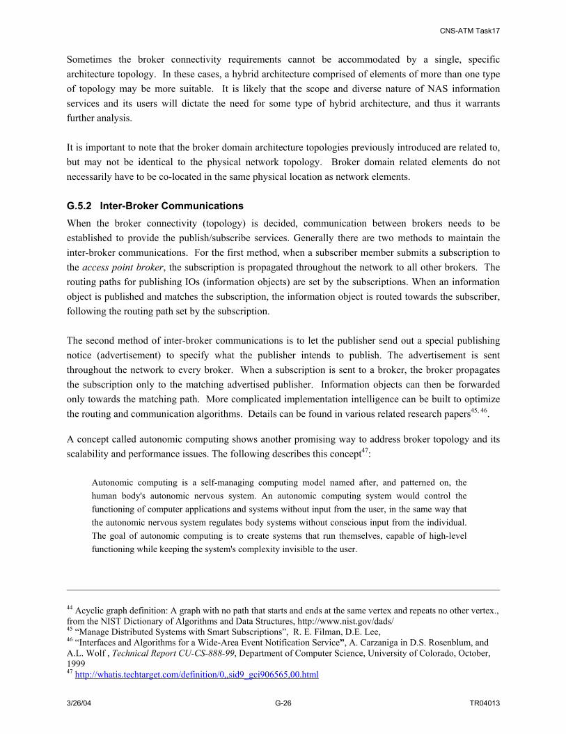
CNS-ATM Task17
3/26/04 G-26 TR04013
Sometimes the broker connectivity requirements cannot be accommodated by a single, specific architecture topology. In these cases, a hybrid architecture comprised of elements of more than one type of topology may be more suitable. It is likely that the scope and diverse nature of NAS information services and its users will dictate the need for some type of hybrid architecture, and thus it warrants further analysis. It is important to note that the broker domain architecture topologies previously introduced are related to, but may not be identical to the physical network topology. Broker domain related elements do not necessarily have to be co-located in the same physical location as network elements. G.5.2 Inter-Broker Communications When the broker connectivity (topology) is decided, communication between brokers needs to be established to provide the publish/subscribe services. Generally there are two methods to maintain the inter-broker communications. For the first method, when a subscriber member submits a subscription to the access point broker, the subscription is propagated throughout the network to all other brokers. The routing paths for publishing IOs (information objects) are set by the subscriptions. When an information object is published and matches the subscription, the information object is routed towards the subscriber, following the routing path set by the subscription. The second method of inter-broker communications is to let the publisher send out a special publishing notice (advertisement) to specify what the publisher intends to publish. The advertisement is sent throughout the network to every broker. When a subscription is sent to a broker, the broker propagates the subscription only to the matching advertised publisher. Information objects can then be forwarded only towards the matching path. More complicated implementation intelligence can be built to optimize the routing and communication algorithms. Details can be found in various related research papers45, 46. A concept called autonomic computing shows another promising way to address broker topology and its scalability and performance issues. The following describes this concept47:
Autonomic computing is a self-managing computing model named after, and patterned on, the human body's autonomic nervous system. An autonomic computing system would control the functioning of computer applications and systems without input from the user, in the same way that the autonomic nervous system regulates body systems without conscious input from the individual. The goal of autonomic computing is to create systems that run themselves, capable of high-level functioning while keeping the system's complexity invisible to the user.
44 Acyclic graph definition: A graph with no path that starts and ends at the same vertex and repeats no other vertex., from the NIST Dictionary of Algorithms and Data Structures, http://www.nist.gov/dads/ 45 “Manage Distributed Systems with Smart Subscriptions”, R. E. Filman, D.E. Lee, 46 “Interfaces and Algorithms for a Wide-Area Event Notification Service”, A. Carzaniga in D.S. Rosenblum, and A.L. Wolf , Technical Report CU-CS-888-99, Department of Computer Science, University of Colorado, October, 1999 47 http://whatis.techtarget.com/definition/0,,sid9_gci906565,00.html
CNS-ATM Task17
3/26/04 G-27 TR04013
Autonomic computing is one of the building blocks of pervasive computing, an anticipated future computing model in which tiny - even invisible - computers will be all around us, communicating through increasingly interconnected networks. Many industry leaders, including IBM, HP, Sun, and Microsoft are researching various components of autonomic computing.
According to IBM, there are eight crucial elements in an autonomic computing system: it must maintain comprehensive and specific knowledge about all its components; it must have the ability to self-configure to suit varying and possibly unpredictable conditions; it must constantly monitor itself for optimal functioning; it must be self-healing and able to find alternate ways to function when it encounters problems; it must be able to detect threats and protect itself from them; it must be able to adapt to environmental conditions; it must be based on open standards rather than proprietary technologies; and it must anticipate demand while remaining transparent to the user. By applying these concepts to the broker topology case, a fully meshed set of autonomic computing components might be added to the broker topology that dynamically establish relationships with broker domains as shown in Figure G-14.
B
B
B
B
B
B
B
BB
B
AC
AC
AC
ACAC
B
B
B
B
B BB
BB
BB
B
BB
B
B
B
B
B
B
B
BB
B
AC
AC
AC
ACAC
AC
AC
AC
ACAC
B
B
B
B
B BB
BB
BB
B
BB
Figure G-14: Autonomic Computing Components and Broker Topology
G.5.3 SWIM Broker Topology Design Decisions This subsection is addressed in two phases. First, design steps are identified, then the definition of the design solution space for SWIM is derived.

CNS-ATM Task17
3/26/04 G-28 TR04013
G.5.3.1 SWIM Broker Topology Design Steps The first step in defining a broker topology for SWIM is determining the number of brokers required. Three general broker distribution levels have been identified for this study corresponding to implementing brokers in different types of NAS facilities. This is illustrated in Figure G-15. The broker distribution levels include:
• Local level: One broker per ATCT/airport
• Regional level: One per TRACON/AFSS
• Cross-regional level: One per ARTCC/Major Facility (e.g. ATCSCC)
Cross-RegionalOne broker per ARTCC level
RegionalOne broker Per TRACCON level
LocalOne brokerper Airport level
RegionalOne broker Per TRACCON level
LocalOne brokerper Airport level
Figure G-15: Three General Levels of Broker Distribution for the NAS After the number of brokers is chosen, the choice of type of interconnections between brokers must be made among:
• Flat peer-to-peer (either acyclic or general peer-to-peer)
• Hierarchical
• Autonomic Computing
The following table shows the suitability of the possible broker interconnection topologies and the level of broker installations.
Table G-16: Relationship Between Number of Brokers and Interconnection Topology Flat peer-to-peer Hierarchical Autonomic Computing Local Not suitable Suitable Suitable Regional Not suitable Suitable Suitable Cross-Regional Suitable Suitable, but may not be
necessary Suitable

CNS-ATM Task17
3/26/04 G-29 TR04013
G.5.3.2 Defining the SWIM Broker Topology Solution Space In order to develop an appropriate broker topology for SWIM, several design factors need to be taken into consideration. Key factors include:
• Data Distribution Range: The range is categorized as local or regional; local refers to data published/subscribed within a local FAA node48, while regional refers to data published/subscribed across different FAA nodes.
• Nature of Traffic: This is categorized by whether the published data is considered to be fast or stream data (very high data update rate, e.g., publish/update frequency is over 1 data packet per second), or the data is considered to be slow or non-stream data.
• Variability of Subscribers: Steady or variable indicate whether or not the number and sources of subscribers that subscribe to a particular type of information change frequently.
• Broker Management Complexity: Low or high indicate whether multiple tiers of brokers add extra information management burdens and latency to the architecture
Identification of applicable values for the first three factors identified above requires investigation of the information to be exchanged via SWIM. Five categories of NAS Information Services have been identified49. These categories are listed below along with associated definitions. The definitions have been made with the intent of ensuring that SWIM development efforts that categorize NAS information can be addressed in categories that do not overlap. In the definitions below, NAS airspace is considered to be the ground surfaces and volumes of airspace that are subject to the NAS ATC system.
• Surveillance information, defined as data about the actual locations of aircraft, and any surface vehicles, buildings and other non-meteorological obstructions to aircraft in the NAS airspace.
• Weather information, defined as data about atmospheric or meteorological conditions in the NAS airspace
• Flight management information, defined as data in, and associated with, flight plans or profiles entered into, being entered into, or being changed in the NAS air traffic control system.
• Aeronautical information, defined as navigational and other data produced for pilots about the NAS airspace and the NAS air traffic control system and its assets. This data includes airspace definitions, navigational and communication aids and procedures, and changes to them.
• Air Traffic Management (ATM) resource management information, defined as data on the infrastructure assets of the NAS and their operational status or performance as well as data used to negotiate, allocate, or modify NAS airspace assets and associated airspace definitions
48 In CNS-ATM Task 11, three broad categories of FAA nodes were considered for application of the campus area network development approach. These included:
1. Nodes with TRACONs or Towers. 2. ARTCCs. 3. Nodes comprising remote FAA equipment and facilities.
49 These categories correspond to the information categories identified in CNS-ATM Task 15.
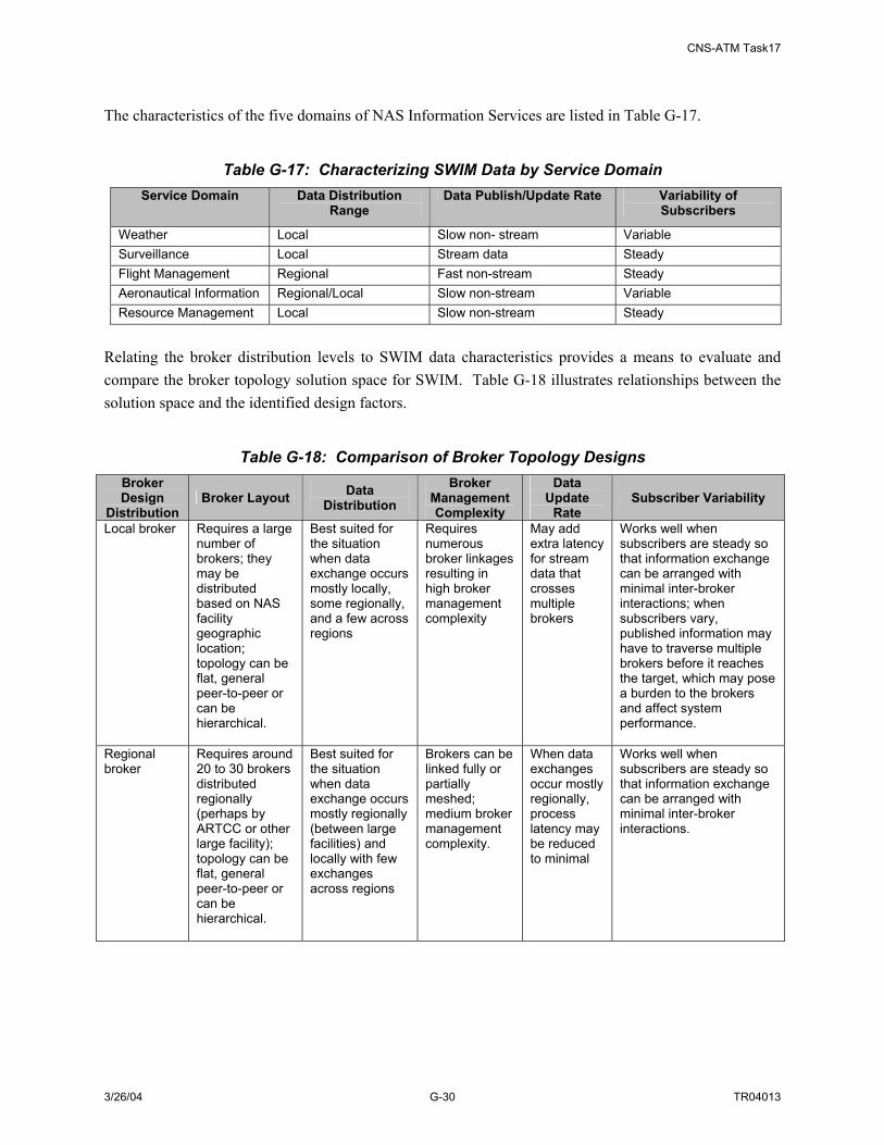
CNS-ATM Task17
3/26/04 G-30 TR04013
The characteristics of the five domains of NAS Information Services are listed in Table G-17.
Table G-17: Characterizing SWIM Data by Service Domain Service Domain Data Distribution
Range Data Publish/Update Rate Variability of
Subscribers
Weather Local Slow non- stream Variable Surveillance Local Stream data Steady Flight Management Regional Fast non-stream Steady Aeronautical Information Regional/Local Slow non-stream Variable Resource Management Local Slow non-stream Steady
Relating the broker distribution levels to SWIM data characteristics provides a means to evaluate and compare the broker topology solution space for SWIM. Table G-18 illustrates relationships between the solution space and the identified design factors.
Table G-18: Comparison of Broker Topology Designs Broker Design
Distribution Broker Layout Data
Distribution Broker
Management Complexity
Data Update
Rate Subscriber Variability
Local broker Requires a large number of brokers; they may be distributed based on NAS facility geographic location; topology can be flat, general peer-to-peer or can be hierarchical.
Best suited for the situation when data exchange occurs mostly locally, some regionally, and a few across regions
Requires numerous broker linkages resulting in high broker management complexity
May add extra latency for stream data that crosses multiple brokers
Works well when subscribers are steady so that information exchange can be arranged with minimal inter-broker interactions; when subscribers vary, published information may have to traverse multiple brokers before it reaches the target, which may pose a burden to the brokers and affect system performance.
Regional broker
Requires around 20 to 30 brokers distributed regionally (perhaps by ARTCC or other large facility); topology can be flat, general peer-to-peer or can be hierarchical.
Best suited for the situation when data exchange occurs mostly regionally (between large facilities) and locally with few exchanges across regions
Brokers can be linked fully or partially meshed; medium broker management complexity.
When data exchanges occur mostly regionally, process latency may be reduced to minimal
Works well when subscribers are steady so that information exchange can be arranged with minimal inter-broker interactions.

CNS-ATM Task17
3/26/04 G-31 TR04013
Broker Design
Distribution Broker Layout Data
Distribution Broker
Management Complexity
Data Update
Rate Subscriber Variability
Cross-region broker
Requires less than 20 brokers; they are distributed mostly regionally with some across regions; topology can be flat, general peer-to-peer.
Suited for the situation when data exchange occurs mostly regionally (between large facilities) and locally with some across regions
Low broker management complexity
For locally exchanged data, it may take non-negligible time for data to be processed by the cross-regional broker
Works for both steady or variable set of subscribers
Based on the above discussion, a summary of the broker topology options and selection information relevant to SWIM is provided in Table G-19. These options and associated characteristics have been used in Section 7 to generate alternative physical architecture alternatives for SWIM.
Table G-19: Summary of the Topology Options Options
# Broker
Topology Options
Factors That Affect the Decision How to Resolve Impact on Overall Effectiveness of the Architecture
1 Local Data Distribution (Best suited for the situation when data exchange occurs mostly locally, some regionally, and a few across regions) Medium broker management complexity, Extra latency for stream data that crosses multiple brokers Works well when subscribers are steady
NAS data flow analysis, performance analysis, technology review (for using autonomic computing components)
High
2 Regional Data Distribution (Best suited for the situation when data exchange occurs mostly regionally (between large facilities) and locally with few exchanges across region). Medium broker management complexity, When data exchanges occur mostly regionally, process latency may be reduced to minimal. Works well when subscribers are steady so that information exchange can be arranged with minimal inter-broker interactions
NAS data flow analysis, performance analysis, technology review (for using autonomic computing components)
High
3 Cross-Regional
Suited for the situation when data exchange occurs mostly regionally (between large facilities) and locally with some across regions Low broker management complexity, For locally exchanged data, it may take non-negligible time for data to be processed by the cross-regional broker Works for both steady or variable set of subscribers
NAS data flow analysis, performance analysis, technology review(for using autonomic computing components)
High
G.6 DATA GRANULARITY OPTIONS Data granularity refers to the level of data detail that a publisher can specify in a published data object such that subscribers can specify their need of data to the same level of detail. A challenge in designing an architecture is determining the required level of the data granularity for a published information object.

CNS-ATM Task17
3/26/04 G-32 TR04013
If the granularity of an information object is very “fine” then many information objects may have to be generated because each contains only a limited amount of information. Fine granularity does allow subscribers to express their data needs more precisely, but it might make the set-up and programming activity more difficult and reduce the performance of the system. On the other hand, if the granularity is very coarse, subscribers can only specify their desired data at the same granularity level. They may end up obtaining more information than they need and may have to filter received information further in order to find the exact information they require. These two alternative granularity levels are illustrated in Figure G-16.
SWIM
BrokerBrokerIOIO
SWIM
BrokerBrokerIO IO IO
IO IO IOIO IO
Coarse Data Granularity
Fine Data Granularity
Data Provider Member Data Consumer
Member
Data Provider Member Data Consumer
Member
publish
publishMemberInterface
Filter Function
Data of Interest
LegendIO IO Information Objects
MemberInterface
MemberInterface
MemberInterface
SWIM
BrokerBrokerIOIO
SWIM
BrokerBrokerIO IO IO
IO IO IOIO IO
Coarse Data Granularity
Fine Data Granularity
Data Provider Member Data Consumer
Member
Data Provider Member Data Consumer
Member
publish
publishMemberInterfaceMemberInterface
Filter Function
Data of Interest
LegendIO IO Information Objects
Filter Function
Data of InterestData of Interest
LegendIO IO Information ObjectsIO IO Information Objects
MemberInterfaceMemberInterface
MemberInterfaceMemberInterface
MemberInterfaceMemberInterface
Figure G-16: Data Granularity Alternatives Four levels of granularity have been defined for NAS data. They are all geographic-based. There could be other types of data granularity such NAS domain-based, but based on current geographical layout of the FAA NAS system, geographic-based data granularity is a best fit for the SWIM services. The four levels of data granularity include:
3. By Region – Data can be queried/subscribed by geographical region. For instance, all Cleveland related information
4. By NAS Data Domain -- Data can be queried/subscribed by NAS data domains. For instance, a subscriber subscribes to all Cleveland Weather Information
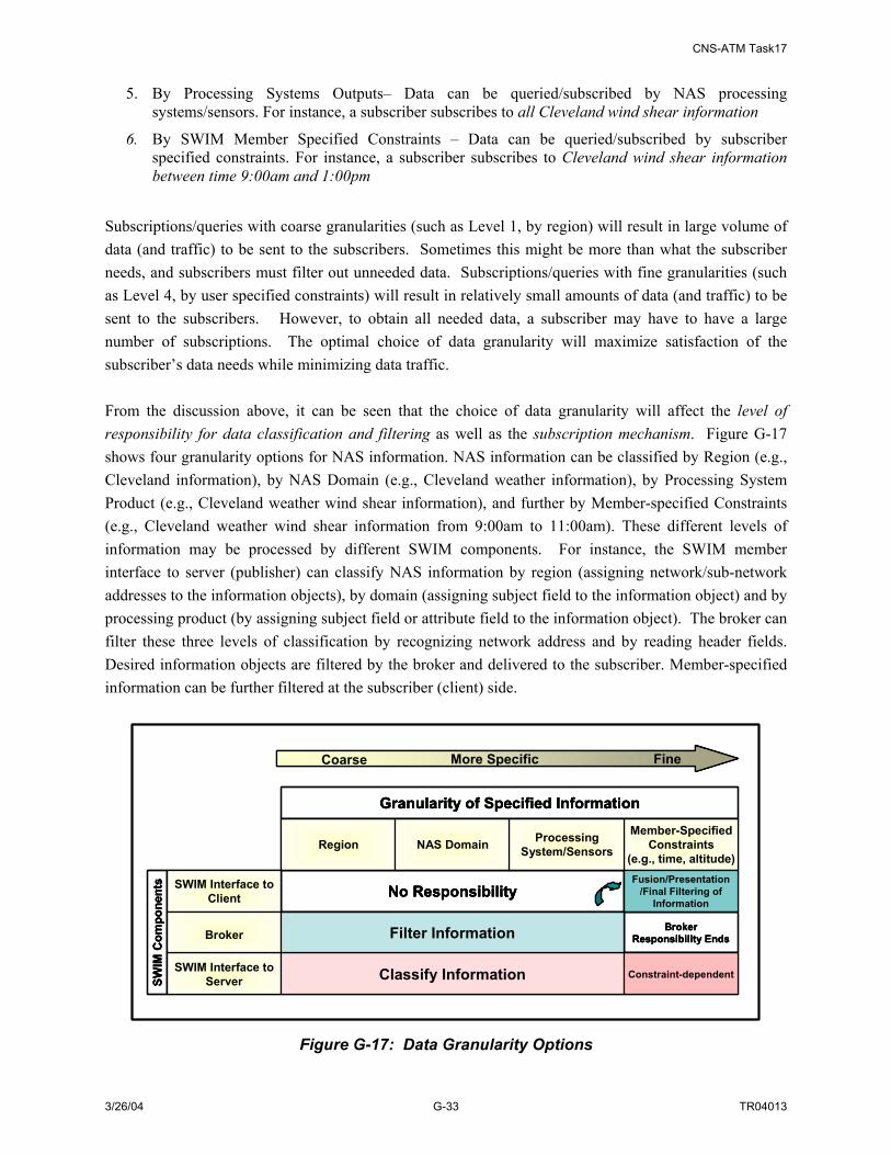
CNS-ATM Task17
3/26/04 G-33 TR04013
5. By Processing Systems Outputs– Data can be queried/subscribed by NAS processing systems/sensors. For instance, a subscriber subscribes to all Cleveland wind shear information
6. By SWIM Member Specified Constraints – Data can be queried/subscribed by subscriber specified constraints. For instance, a subscriber subscribes to Cleveland wind shear information between time 9:00am and 1:00pm
Subscriptions/queries with coarse granularities (such as Level 1, by region) will result in large volume of data (and traffic) to be sent to the subscribers. Sometimes this might be more than what the subscriber needs, and subscribers must filter out unneeded data. Subscriptions/queries with fine granularities (such as Level 4, by user specified constraints) will result in relatively small amounts of data (and traffic) to be sent to the subscribers. However, to obtain all needed data, a subscriber may have to have a large number of subscriptions. The optimal choice of data granularity will maximize satisfaction of the subscriber’s data needs while minimizing data traffic. From the discussion above, it can be seen that the choice of data granularity will affect the level of responsibility for data classification and filtering as well as the subscription mechanism. Figure G-17 shows four granularity options for NAS information. NAS information can be classified by Region (e.g., Cleveland information), by NAS Domain (e.g., Cleveland weather information), by Processing System Product (e.g., Cleveland weather wind shear information), and further by Member-specified Constraints (e.g., Cleveland weather wind shear information from 9:00am to 11:00am). These different levels of information may be processed by different SWIM components. For instance, the SWIM member interface to server (publisher) can classify NAS information by region (assigning network/sub-network addresses to the information objects), by domain (assigning subject field to the information object) and by processing product (by assigning subject field or attribute field to the information object). The broker can filter these three levels of classification by recognizing network address and by reading header fields. Desired information objects are filtered by the broker and delivered to the subscriber. Member-specified information can be further filtered at the subscriber (client) side.
SWIM Interface to Client
SWIM Interface to Server
Broker
SWIM
Com
pone
nts
Region Member-Specified
Constraints (e.g., time, altitude)
Processing System/SensorsNAS Domain
Granularity of Specified Information
More Specific
Classify Information Constraint-dependent
Filter Information
Fusion/Presentation/Final Filtering of
Information
Broker Responsibility Ends
No Responsibility
FineCoarse
SWIM Interface to Client
SWIM Interface to Server
Broker
SWIM
Com
pone
nts
Region Member-Specified
Constraints (e.g., time, altitude)
Processing System/SensorsNAS Domain
Granularity of Specified Information
More Specific
Classify Information Constraint-dependent
Filter Information
Fusion/Presentation/Final Filtering of
Information
Broker Responsibility Ends
No ResponsibilitySWIM Interface to Client
SWIM Interface to Server
Broker
SWIM
Com
pone
nts
Region Member-Specified
Constraints (e.g., time, altitude)
Processing System/SensorsNAS Domain
Granularity of Specified Information
More Specific
Classify Information Constraint-dependent
Filter Information
Fusion/Presentation/Final Filtering of
Information
Broker Responsibility Ends
No Responsibility
FineCoarse
Figure G-17: Data Granularity Options

CNS-ATM Task17
3/26/04 G-34 TR04013
Subscription mechanisms can be classified50 into three categories: channel-based, subject-based, or content-based. In a channel-based subscription, a subscriber subscribes to published information objects that are sent across an explicitly identified channel, a discrete communication path. Subject-based mechanisms extend the concept of a channel with a more flexible addressing mechanism; in this case publishing contains an attribute to determine where the information object is heading. In subject-based subscriptions, subscribers can express their interest in many subjects/channels by using some expressions and those expressions are evaluated against the subjects of published information objects. In this case one subscriber can subscribe to multiple subjects and one published information object can match to multiple subscriptions. Content-based subscriptions allow for a great amount of user flexibility in specifying information needs and requirements, and can be described as follows51: The term “content-based” characterizes those systems whose subscriptions can express predicates over the whole content of a publication. This is in contrast with channel-based and subject-based systems, in which only a few well-known attributes of a publication are available for selection to subscriptions. The strength of content-based publish/subscribe middleware over a multicast network service is the greater expressive power of its data model and of its subscription language. Its weakness is scalability. In fact, only a few content-based publish/subscribe middleware services are implemented as true distributed systems, and none of the existing ones is designed to achieve levels of scalability comparable to those of existing network communication infrastructures, such as IP. The advantages of content-based systems over subject-based systems can be summarized as follows52:
• The content-based model provides more flexibility because of the expressive power of its data model and of its subscription language. A subscriber can choose filtering (selection) criteria along as many dimensions as there are event attributes. In a stock trading example a subscriber could subscribe to any combination of the event attributes such as issue name, price, and volume.
• The content-based model does not require the administrative overhead associated with defining and maintaining a large number of subjects.
• The content-based model is more general than the subject-based model, as it could be used to implement a subject-based system. In a stock trading example, the event predicated on (issue name = “GE” & price = any) would provide the same information as the subject-based event subscription of subject “GE”.
50 Architectures for an Event Notification Service Scalable to Wide-Area Networks”, A. Carzaniga ,PhD Thesis. Politecnico di Milano. December, 1998 51 A. Carzaniga and A. Wolf, Content-Based Networking: A New Communication Infrastructure, University of Colorado, 2002. 52 An Efficient Multicast Protocol for Content-Based Publish-Subscribe Systems,; IBM T. J. Watson Research Center, c1999.
CNS-ATM Task17
3/26/04 G-35 TR04013
The major disadvantage of the content-based model is its scalability, that is, it becomes much less efficient as the size of the distributed network and the number of publishers and subscribers increases. This is because53:
• It becomes computationally difficult to efficiently match a complex event against a large number of subscribers on a single message broker (router).
• It becomes difficult to efficiently multicast events within a network of message brokers when: 1) the geographically distributed network has limited bandwidth, and 2) as the number of publishers and subscribers becomes very large.
These two problems are efficiently handled in subject-based systems as follows:
• Matching is performed with a look-up table, which consists of a fixed, limited number of subjects.
• Multicasting is handled by assigning a single, separate multicast group per subject and multicasting each event to the appropriate multicasting group.
The preceding discussion has introduced two, often conflicting, and fundamental characteristics of publication-subscription systems: expressiveness and scalability. These can succinctly defined as follows54:
Scalability means that the service must be available over a wide-area network populated by numerous components each one producing and consuming many events. Expressiveness demands a rich subscription language that gives applications a flexible and fine-grained selection mechanism to describe precisely those events or combinations of events in which they are interested.
As described above, expressiveness of a publication/subscription event service is chiefly determined by its subscription language. Two aspects of the subscription language are crucial to the expressiveness of an event service: scope and expressiveness (or power), defined as follows55:
• The scope of the selection predicates: The part of the event model that is visible within subscription expressions. In some cases, events have an articulated structure that allows the encoding of much information, but only a limited and/or simple part of that structure can be used as selection criteria in subscriptions.
• The expressiveness of the selection predicates: Determines the sophistication of subscriptions. In practice, a subscription language is expressive if it has various basic selection predicates and the ability to combine predicates for the selection of one single event at a time as well as for grouping events into higher-level abstractions.
53 Ibid. 54 Antonio Carzaniga, David S. Rosenblum, and Alexander Wolf, Challenges for Distributed Event Services: Scalability vs. Expressiveness, c1999. 55 Ibid.

CNS-ATM Task17
3/26/04 G-36 TR04013
These two characteristics can be used to classify subscription languages used in publication-subscription systems. Table G-20 shows how such a classification can be made. Within the table different types of publication-subscription systems are classed according to the scope and expressiveness of their subscription languages. In the figure the scope of the subscription language is defined according to whether it uses a single notification of a single field (attribute) or multiple fields, or multiple notifications of multiple fields to match published events to subscriptions. For expressiveness, there are three levels of ascending sophistication: 1) a simple equality or matching test; 2) predicates: multiple filtering expressions with predefined operators for matching; and 3) expressions with user-defined operators, which includes multiple, correlated events forming defined “patterns”.
Table G-20: Classification of Subscription Languages56 Scope Single Publishing
One Field Single Publishing
Multiple Fields Multiple Publishing
Multiple Fields Simple Equality Channel-based --- --- Expressions with Predefined Operators (Predicates)
Restricted Subject-Based
Restricted Content-Based
Restricted Content-Based with Patterns
Expr
essi
vene
ss
Expressions with User-Defined Operators
General Subject-Based
General Content-Based
General Content-Based with Patterns
To summarize, data granularity can be coarse or fine, and the selection of data granularity level impacts choice of filtering responsibility and the subscription mechanisms to be used in SWIM. This is illustrated in Table G-21.
Table G-21: Summary of Data Granularity Options Data Granularity
Attribute Coarse Fine Publisher duty
Simple classification
Publisher duty
Complex classification
Broker duty
Simple filtering Broker duty
Complex filtering
Complex filtering
Simple filtering
Filtering Responsibility/Complexity Subscriber
duty Simple subscription
Subscriber duty
Complex subscription
Channel-based subscription Subject-based subscription Subscription Mechanism Subject-based subscription Content-based subscription
Factors that affect the data granularity options will be the design of data model, the expressiveness of subscription language, and performance requirements.
Table G-22: Summary of the Data Granularity Options Options Data Factors That Affect the Decision How to Resolve Impact on Overall
56 Slightly modified version of Table 7 in Design and Evaluation of a Wide-Area Event Notification Service, ACM Transactions on Computer Systems, Antonio Carzaniga, David S. Rosenblum, and Alexander L. Wolf, Vol. 19, No. 3, August 2001, Page 377.

CNS-ATM Task17
3/26/04 G-37 TR04013
# Granularity Options
Effectiveness of the Architecture
1 Coarse SWIM users can work find coarse data granularity services
Data analysis and design analysis
Medium to high
2 Refined SWIM users requires refined data granularity services and theses services can meet the overall NAS/SWIM performance requirements
Data analysis and design analysis
Medium to high
G.7 DATA STORAGE METHODS As introduced in Section G.2.1.5, SWIM may store certain exchanged data for archiving, retrieval, monitoring, and security purposes. Two types of data storage have been investigated for SWIM: data marts and data warehouses. Data marts are suitable for storing certain information objects for short-term, fast retrieval. Additionally it is recommended that data marts use relational databases for their performance and management conveniences. Data warehouses are suitable for storing long-term, archival data. They can be implemented as either relational databases or object-oriented databases. Key design issues related to SWIM data storage decisions include:
1. Whether or not to create new SWIM’s own data storage facilities as data marts or data warehouses or to use legacy NAS databases
2. Should SWIM interface to current FAA legacy databases directly through SWIM member interfaces (so that legacy databases are treated as subscribers) or indirectly through legacy processing centers?
3. Should data warehouses be updated by publishers, by subscribers, or both?
4. Should SWIM data warehouses store data in a common data format or store data in its original data format or target data format?
The advantages and disadvantages and related issues for these data storage issues are listed in Table G-23, and a summary of the SWIM decision factors related to data storage is presented in Table G-24.
Table G-23: Data Storage Issues - Advantages/Disadvantages and Related Issues Issue 1: Whether to Create SWIM’s Owned Data Storage or Not
Option Advantages Disadvantages Related Issues Create SWIM owned data marts
Data marts can be built based on clearly defined information object structures; easy to build
Can technology provide a “seamless” connection between the database capabilities and the pub/sub system?
• Need to decide what data gets to stored in data marts and how many data marts to keep for SWIM
• How to do “sample archiving” for stream data?
Create SWIM owned data warehouses
Data warehouses can be “purpose built” to better fit SWIM needs/platforms
Costly; cannot reuse legacy databases
• Management of the data warehouses
Transition of SWIM legacy databases to SWIM data warehouses
Reuse current legacy databases; may save some cost
May be difficult to implement
• Can all legacy databases be transitioned to SWIM data warehouses?
• How to transition? Issue 2: How to interface to Legacy Databases
Option Advantages Disadvantages Related Issues

CNS-ATM Task17
3/26/04 G-38 TR04013
Interface to SWIM directly through member interface so legacy databases can be treated as a regular subscriber
Legacy SWIM databases can be more independent and can subscribe to SWIM data directly
SWIM databases need to be transitioned to be SWIM compliant (data format compliant and management compliant)
• Need to translate SWIM data format to legacy databases
Interface to SWIM indirectly through current systems such as processing centers
No need to change legacy databases
Database update is indirect, may increase latency
• Are these legacy databases redundant when data warehouses are used in SWIM?
Issue 3: Are Data Warehouses Kept by Publishers or by Subscribers? Option Advantages Disadvantages Related Issues
By publishers Quick update before data even gets published
Data warehouse either contains one publisher’s data or has to coordinate other publishers’ data so as to keep multiple views of the same data
By subscribers Multiple views of the same data can be kept in the data warehouse. Warehouse can subscribe directly to SWIM for data.
Data needs to be filtered and structured to put in a data warehouse
Issue 4: What is the Data Format in Data Warehouses, a Common Data Format or any Other Format? Option Advantages Disadvantages Related Issues
Common data format Easy for query Need to put information objects in which may result in more data overhead
Local data format Fast Data needs to translated
Table G-24: Summary of Data Storage Option Decisions for SWIM
Options # Data Storage Options
Factors That Affect the Decision How to Resolve
Impact on Overall Effectiveness of the Architecture
1 Whether to create SWIM’s own data storage or not
FAA policy Policy making High
2 How to interface to legacy databases
Legacy NAS databases Design analysis Medium
3 Are data warehouses kept by publishers or by subscribers?
FAA policy Policy making Medium
4 What is the data format in data warehouses, common data format or any other format?
Performance Data analysis, design analysis
High
G.8 NETWORK MANAGEMENT ALTERNATIVES While a Simple Network Management Protocol (SNMP)-based network management architecture can be implemented to support SWIM, the recommended broker-based information management architecture offers the option of extending the broker responsibilities to the network management domain, resulting in a more fully integrated SWIM architecture. Although SNMP-based network management architectures, shown in Figure G-18, are widely used and straightforward to implement and use, (e.g. planned implementation in the NAS Infrastructure Management System (NIMS)), SNMP has known security

CNS-ATM Task17
3/26/04 G-39 TR04013
weaknesses. SNMPv3 has corrected many of the security weaknesses; but two security threats that SNMP does not address are Denial of Service and Traffic Analysis attacks57. In an SNMP-based system, one or more workstations may function as the management station, manned by an administrator. SNMP is primarily a polling-based protocol. The manager stations use SNMP to issue commands to get or set the value of a parameter on a remote managed object (e.g., networked device such as client, server, database, router). The syntactical structure of the SNMP messages is defined by the Abstract Syntax Notation (ASN.1), a machine-independent language. The manager’s access to the parameters of a managed device is limited by the pre-defined structure of the Management Information Base (MIB), the logical database for the network management information. The received command is performed by the agent, software residing on the managed device; the agent retrieves/sets the requested parameter value via the MIB and sends its response back to the manager using SNMP responses. The agent may also issue an unsolicited response, or trap, to the manager in the event of pre-defined alarm or error conditions such as a link outage or node failure. SNMP’s suitability for SWIM is summarized as follows:
• SNMP-Based: Network management functions are based on the standard SNMP protocol as shown in Figure G-18.
– Advantages: SNMP is simple and widely used
– Disadvantages: SNMP has security weaknesses; however, SNMP-v3 has corrected some of the security problems
Manager Managed ObjectAgent
Macros ASN-1
Get/SetTrap
ControlMonitor
MIB
Manager Managed ObjectAgent
Macros ASN-1
Get/SetTrap
ControlMonitor
MIB
Manager Managed ObjectAgent
Macros ASN-1
Get/SetTrap
ControlMonitor
MIB
Figure G-18: SNMP-based Network Management In contrast, an object-oriented, broker based network management architecture, such as a CORBA-based architecture shown in Figure G-19, is more robust and secure, more extensible and customizable, and could be implemented as an extension to the SWIM Information Management functional component. However, although such architectures have evolved significantly in the past ten years, they are still less widely deployed than SNMP-based systems. The CORBA-based approach eliminates the need for a rigidly structured MIB and SNMP-defined commands, because network management commands are issued as transparent operation invocations on managed objects. Furthermore, CORBA can be used to maintain a logical link between multiple network managers, to facilitate the distribution of management
57 RFC 2574 - User-based Security Model (USM) for version 3 of the Simple Network Management Protocol (SNMPv3), Draft Standard, April 1999.

CNS-ATM Task17
3/26/04 G-40 TR04013
responsibilities to enhance scalability and to enable the assumption of new responsibilities to support failover. In addition, CORBA supports the flexibility to use legacy SNMP agents and migrate toward CORBA applications in the future. The Object Request Broker (ORB) is responsible for translating the object requests and operations between the manager and managed object, or between to managers. CORBA’s Interface Definition Language (IDL) specifies the interfaces for each object, providing the means for each object to inform clients (e.g., the network manager) which operations are provided and how they can be invoked. These operations may be invoked by clients through IDL stubs. The General Inter-ORB Protocol (GIOP), or the Internet Inter-ORB Protocol (IIOP), allows for the communication between ORBs. It is responsible for ensuring a common data representation and for enabling message transfer. CORBA’s suitability for SWIM is summarized as follows:
• CORBA-Based: Network management functions are based on the CORBA standard, as shown in Figure G-19.
– Advantages: Compatibility with CORBA-based Information Management; stronger security
– Disadvantages: Less widely deployed
IDL
ClientTransparent Operation
Invocation
ORB ORBGIOP
Object
GIOP: General Inter-ORB Protocol
IDL
ClientTransparent Operation
Invocation
ORB ORBGIOP
Object
GIOP: General Inter-ORB Protocol
IDL
ClientTransparent Operation
Invocation
ORB ORBGIOP
Object
GIOP: General Inter-ORB Protocol
Figure G-19: CORBA-based Network Management In summary, the main options for network management are SNMP-based or CORBA-based. Factors that might affect the decision are COTS availability and compatibility with NIMS. Its impact on the overall effectiveness of the architecture is medium to high. This is summarized in Table G-25.
Table G-25: Summary of Network Management Options
Options #
Network Management
Options Factors That Affect the Decision How to
Resolve Impact on Overall
Effectiveness of the Architecture
1 SNMP-based NIMS mechanism, if NIMS uses SNMP-based, then it is easier to use SNMP-based for SWIM
Design Analysis
Medium to high
2 CORBA-based
If SNMP security weakness is a concern, then use CORBA-based, but need to check COTS availability
Design Analysis
Medium to high

CNS-ATM Task17
3/26/04 H-1 TR04013
APPENDIX H. NAS SENSORS AND SYSTEMS
To define SWIM interfaces and associated performance requirements, an understanding of the legacy NAS sensors and systems that are candidate SWIM members is required. An initial effort to capture the SWIM information supplier and consumer NAS systems was conducted as part of CNS-ATM Task 15. This task defined an information source/sink model for SWIM. As part of this study, this information has been reviewed and used to develop a comprehensive list of all sensors and systems both internal and external to NAS that are candidate SWIM members. This information is documented in Table H-1 through Table H-5 below. Information in these tables is categorized into five domains. These include Surveillance, Weather, Aeronautical, Resource Management and Flight Information. The data included in the tables has been derived from previous CNS-ATM task reports (Task 12 & Task 15) and from the list of sources identified below:
• NAS Wide Information Services Concept of Use, Federal Aviation Administration, Draft Version dated May 17, 2002.
• National Airspace System Concept of Operations, RTCA Select Committee for Free Flight, December 2000.
• NAS-Wide Information Services (NWIS) Architecture Development: Identification of Information Services, ITT Industries, AES, CNS-ATM Task 15B, August 26 2002
• NAS (National Airspace System) Interfacility Communication System (NICS) Architecture Document Version 1.3, Federal Aviation Administration, ASD-140, April 2002
• National Airspace System Architecture, Version 4.0, US Department of Transportation, Federal Aviation Administration, January 1999.
• Current FAA Telecommunications System and Facility Description Manual, Currant Book; Fiscal Year 2001 Edition, NAS Operations (AOP) Telecommunications Support and International Communications Division.
• Future FAA Telecommunications Plan, “Fuschia Book”, NAS Operations (AOP) Telecommunications Network Planning and Engineering Division, April 2002.
• National Airspace System, System Requirements Specification, NAS-SR-1000 Changes 1-14 (December 1995), US Department of Transportation, Federal Aviation Administration.
• National Airspace System, Functional and Performance Requirements for the National Airspace System, NAS-SS-1000, US Department of Transportation, Federal Aviation Administration, April 1995.
• Future NAS Communications Architecture Validation, ITT Industries, AES, CNS-ATM Task 2, TR01084, December 2001.
• The N2 data flow charts provided by Mike McVeigh, FAA ASD-120

CNS-ATM Task17
3/26/04 H-2 TR04013
Table H-1: Surveillance Sensors/Systems Automation/ Processing
System (SINK) Sensors feeding into
System (SOURCE) Traffic Model Traffic type Data Attributes
ARTS ASR-7,8,9; ASR-11; ATCBI; MODE-S
Surv-1 Surv: 128 bits Surv: Custom Model Peak Loading: peak rate = 544 msgs/sec & avg rate = 70 msgs/sec Busy Loading: peak rate = 544 msgs/sec & avg. rate = 35 msgs/sec
STARS ASR-7,8,9; ASR-11; ATCBI; MODE-S
Surv-1; Surv-3 Product Error Msg.: 112 bits Runway Config.: 192 bits
Uniform (constant) Product Error Msg.: 1 msg./min Runway Config.: 5 msgs/hr
HCS (w/PAMRI) ASR-7,8,9; ASR-11; ATCBI; MODE-S
Surv-1; Surv-3 Product Error Msg.: 112 bits Runway Config.: 192 bits
Uniform (constant) Product Error Msg.: 1 msg./min Runway Config.: 5 msgs/hr
DARC ASR-7,8,9; ASR-11; ATCBI; MODE-S
Surv-1; Surv-3 Product Error Msg.: 112 bits Runway Config.: 192 bits
Uniform (constant) Product Error Msg.: 1 msg./min Runway Config.: 5 msgs/hr
AMASS ASDE-3; ASR-7,8,9; ASR-11;
Surv-1 Surv: 128 bits Surv: Custom Model Peak Loading: peak rate = 544 msgs/sec & avg rate = 70 msgs/sec Busy Loading: peak rate = 544 msgs/sec & avg. rate = 35 msgs/sec
DBRITE TDU DBRITE Surv-7 (Aut-4) DBRITE Display (data message): 704 bits VCU Data: 480 bits
DBRITE Display: Uniform (constant) VCU Data: Negative Binomial DBRITE Display (data message): 10/sec VCU Data: Peak: 2413 msgs/sec Avg: 1073 msgs/sec
STARS TDW STARS Surv-7 (Aut-4) DBRITE Display (data message): 704 bits VCU Data: 480 bits
DBRITE Display: Uniform (constant) VCU Data: Negative Binomial DBRITE Display (data message): 10/sec VCU Data: Peak: 2413 msgs/sec Avg: 1073 msgs/sec
ASR-7,8,9 HCS, STARS, ARTS Surv-9 (Surv-3)
Product Error Msg.: 112 bits Runway Config.: 192 bits
Uniform (constant) Product Error Msg.: 1 msg./min Runway Config.: 5 msgs/hr
ASR-11 HCS, STARS, ARTS Surv-9 (Surv-3)
Product Error Msg.: 112 bits Runway Config.: 192 bits
Uniform (constant) Product Error Msg.: 1 msg./min Runway Config.: 5 msgs/hr
ARSR HCS, STARS, ARTS Surv-9 (Surv-3)
Product Error Msg.: 112 bits Runway Config.: 192 bits
Uniform (constant) Product Error Msg.: 1 msg./min Runway Config.: 5 msgs/hr

CNS-ATM Task17
3/26/04 H-3 TR04013
Table H-2: Weather Sensors/Systems Automation/ Processing
System (SINK) Sensors feeding into
System (SOURCE) Traffic Model Traffic Type Data Attributes
NEXRAD Principal User processor
NWXRAD WSR- 88D Wx-2 Lightening Detection Data: 152 bits
Uniform (constant) Lightening Detection Data: 1/min
NEXRAD WSR-88D
WARP Processor at ARTCC Wx-2 Lightening Detection Data: 152 bits
Uniform (constant) Lightening Detection Data: 1/min
DSR WARP Processor at ARTCC Wx-10 Weather: 64 bits Weather: Negative Binomial Weather: Peak: 75 msgs/sec Busy (avg.): 15 msgs/sec
URET CCLD WARP Processor at ARTCC Wx-10 Weather: 64 bits Weather: Negative Binomial Weather: Peak: 75 msgs/sec Busy (avg.): 15 msgs/sec
CTAS /TMA WARP Processor at ARTCC Wx-10 Weather: 64 bits Weather: Negative Binomial Weather: Peak: 75 msgs/sec Busy (avg.): 15 msgs/sec
CTAS WS WJHTC ( to be replaced by WARP)
Wx-10 Weather: 64 bits Weather: Negative Binomial Weather: Peak: 75 msgs/sec Busy (avg.): 15 msgs/sec
AIS remote AIS WS Wx-10 Weather: 64 bits Weather: Negative Binomial Weather: Peak: 75 msgs/sec Busy (avg.): 15 msgs/sec
AIS WS AIS remote Wx-10 Weather: 64 bits Weather: Negative Binomial Weather: Peak: 75 msgs/sec Busy (avg.): 15 msgs/sec
ASOS ADAS Wx-10 Weather: 64 bits Weather: Negative Binomial Weather: Peak: 75 msgs/sec Busy (avg.): 15 msgs/sec
US Customs WARP Processor at ARTCC Wx-10 Weather: 64 bits Weather: Negative Binomial Weather: Peak: 75 msgs/sec Busy (avg.): 15 msgs/sec
HOST ARINC/AFTN; AWP; ARSR; ASR-7,8,9; ASR-11
Wx-2 Lightening Detection Data: 152 bits
Uniform (constant) Lightening Detection Data: 1/min
STARS/ARTS ARSR; ASR-7,8,9; ASR-11 Wx-2 Lightening Detection Data: 152 bits
Uniform (constant) Lightening Detection Data: 1/min
WMSCR ARINC/AFTN; ADAS; AFSS FSDPS;
Wx-1, Wx-2
ETMS WS & SD ETMCC (Volpe) Wx-10 Weather: 64 bits Weather: Negative Binomial Weather: Peak: 75 msgs/sec Busy (avg.): 15 msgs/sec

CNS-ATM Task17
3/26/04 H-4 TR04013
Automation/ Processing
System (SINK) Sensors feeding into
System (SOURCE) Traffic Model Traffic Type Data Attributes
DOTS+ Kovouras; ETMCC (Volpe) Wx-2 Lightening Detection Data: 152 bits
Uniform (constant) Lightening Detection Data: 1/min
AFTN/FIRs Wx-10 Weather: 64 bits Weather: Negative Binomial Weather: Peak: 75 msgs/sec Busy (avg.): 15 msgs/sec
S1R/ODAPS Wx-2, Wx-10 ODAPS WMSCR Wx-2, Wx-10 ITWS Wx-1, Wx-10 WARP FAABWTG (at ATCSCC)
Wx-10 Weather: 64 bits Weather: Negative Binomial Weather: Peak: 75 msgs/sec Busy (avg.): 15 msgs/sec
WARP Processor (at ARTCC)
Wx-1, Wx-10
ADAS Wx-1 Current surface wx obs: 1600 bits Hourly surface wx obs: 1600 bits Special surface wx obs: 1600
Uniform (constant) Current surface wx obs: 1/min Hourly surface wx obs: 137/hr Special surface wx obs: 10/hr
ARINC/SITA ODL Server
Wx-10 Weather: 64 bits Weather: Negative Binomial Weather: Peak: 75 msgs/sec Busy (avg.): 15 msgs/sec
ARINC Data Network
Wx-10 Weather: 64 bits Weather: Negative Binomial Weather: Peak: 75 msgs/sec Busy (avg.): 15 msgs/sec
ATCT GSD Wx-2 Lightening Detection Data: 152 bits
Uniform (constant) Lightening Detection Data: 1/min
TDWR Wx-10 Weather: 64 bits Weather: Negative Binomial Weather: Peak: 75 msgs/sec Busy (avg.): 15 msgs/sec
ATCT NEXRAD IDS
Wx-5 LLWAS Winds: 800 bits LLWAS Threshold Winds: 2400 bits
Uniform (constant) LLWAS Winds: 6/minute LLWAS Threshold Winds: 6/minute
ATCT ACE Control Cabinet
Wx-2, Wx-5
Kavouris Receiver
Wx-4, Wx-5
AFSS M1FC ARTCC FSDPS Wx-4, Wx-5 FDP2000 ARTCC FSDPS Wx-4, Wx-5
Table H-3: Flight Management Sensors/Systems Automation/ Processing
System (SINK) Sensors feeding into
System (SOURCE) Traffic Model Traffic Type Data Attributes
ETMS (ARTCC) ETMCC, HOST N/A
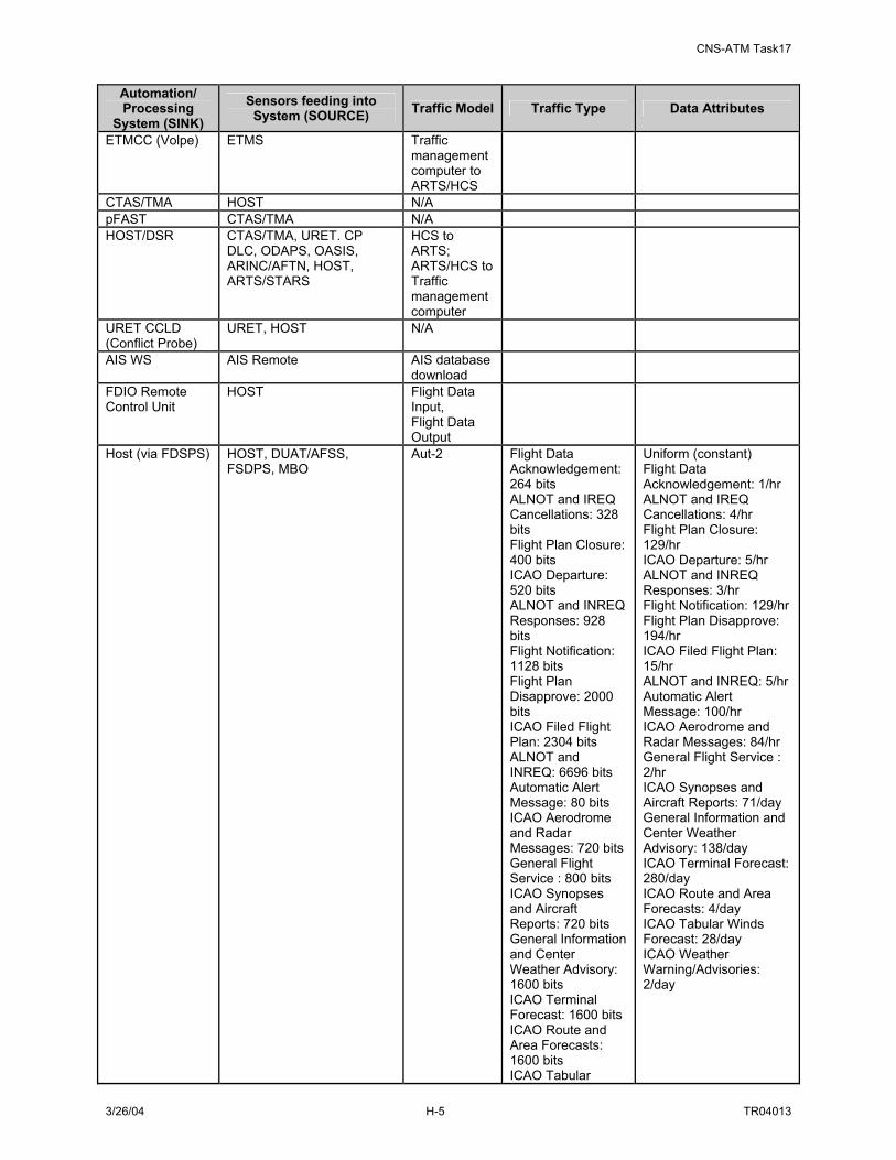
CNS-ATM Task17
3/26/04 H-5 TR04013
Automation/ Processing
System (SINK) Sensors feeding into
System (SOURCE) Traffic Model Traffic Type Data Attributes
ETMCC (Volpe) ETMS Traffic management computer to ARTS/HCS
CTAS/TMA HOST N/A pFAST CTAS/TMA N/A HOST/DSR CTAS/TMA, URET. CP
DLC, ODAPS, OASIS, ARINC/AFTN, HOST, ARTS/STARS
HCS to ARTS; ARTS/HCS to Traffic management computer
URET CCLD (Conflict Probe)
URET, HOST N/A
AIS WS AIS Remote AIS database download
FDIO Remote Control Unit
HOST Flight Data Input, Flight Data Output
Host (via FDSPS) HOST, DUAT/AFSS, FSDPS, MBO
Aut-2 Flight Data Acknowledgement: 264 bits ALNOT and IREQ Cancellations: 328 bits Flight Plan Closure: 400 bits ICAO Departure: 520 bits ALNOT and INREQ Responses: 928 bits Flight Notification: 1128 bits Flight Plan Disapprove: 2000 bits ICAO Filed Flight Plan: 2304 bits ALNOT and INREQ: 6696 bits Automatic Alert Message: 80 bits ICAO Aerodrome and Radar Messages: 720 bits General Flight Service : 800 bits ICAO Synopses and Aircraft Reports: 720 bits General Information and Center Weather Advisory: 1600 bits ICAO Terminal Forecast: 1600 bits ICAO Route and Area Forecasts: 1600 bits ICAO Tabular
Uniform (constant) Flight Data Acknowledgement: 1/hr ALNOT and IREQ Cancellations: 4/hr Flight Plan Closure: 129/hr ICAO Departure: 5/hr ALNOT and INREQ Responses: 3/hr Flight Notification: 129/hr Flight Plan Disapprove: 194/hr ICAO Filed Flight Plan: 15/hr ALNOT and INREQ: 5/hr Automatic Alert Message: 100/hr ICAO Aerodrome and Radar Messages: 84/hr General Flight Service : 2/hr ICAO Synopses and Aircraft Reports: 71/day General Information and Center Weather Advisory: 138/day ICAO Terminal Forecast: 280/day ICAO Route and Area Forecasts: 4/day ICAO Tabular Winds Forecast: 28/day ICAO Weather Warning/Advisories: 2/day

CNS-ATM Task17
3/26/04 H-6 TR04013
Automation/ Processing
System (SINK) Sensors feeding into
System (SOURCE) Traffic Model Traffic Type Data Attributes
Winds Forecast: 2160 bits ICAO Weather Warning/Advisories: 2400 bits
WMSCR ARINC/AFTN US Customs ARTCC Oceanic S1R/TP Server
HOST
NORAD TTY ODAPS ODAPS OFDPS Flight Data
Input
FDP 2000 ARINC/SITA, DUAT/AFSS FSDPS
Flight Data Input, AUT-6
Law Enforcement Alert Cancellation: 824 bits Law Enforcement Alert: 1920 bits Law Enforcement Supplemental Alert: 2384 bits Military Operations Message: 480 bits NOTAMS: 280 bits PIREPS: 720 bits Weather Information Requests: 800 bits
Uniform (constant) Law Enforcement Alert Cancellation: 1/hr Law Enforcement Alert: 1/hr Law Enforcement Supplemental Alert: 1/hr Military Operations Message: 3/hr NOTAMS: 5/hr PIREPS: 11/hr Weather Information Requests: 560/hr
AIDCS ARINC/SITA DOTS+ ARINC/SITA, ETMCC AWP Airlines Aut-3 DOD Surface
Observations: 720 bits PIREPS, ICAO Radar Reports & ICAO Aerodrome Reports: 720 bits Processed NOTAMS: 1040 bits AWOS Hourly Surface Wx Observation: 1600 bits NWS Amendments: 2700 bits NWS SIGMETS and AIRMETS: 4800 bits NWS Surface Observations: 39000 bits DOD Terminal Forecasts: 640 bits ICAO Aircraft Reports & Synopses: 720 bits Center Weather Advisory: 800 bits General Information & Meteorological Impact: 1600 bits ICAO Terminal Area Forecasts:
Uniform (constant) DOD Surface Observations: 165/hr PIREPS, ICAO Radar Reports & ICAO Aerodrome Reports: 514/hr Processed NOTAMS: 165/hr AWOS Hourly Surface Wx Observation: 905/hr NWS Amendments: 107/hr NWS SIGMETS and AIRMETS: 5/hr NWS Surface Observations: 1/hr DOD Terminal Forecasts: 660/day ICAO Aircraft Reports & Synopses: 812/day Center Weather Advisory: 69/day General Information & Meteorological Impact: 138/day ICAO Terminal Area Forecasts: 280/day ICAO Route and Area Forecasts: 142/day ICAO Tabular Winds Forecast: 28/day ICAO Weather

CNS-ATM Task17
3/26/04 H-7 TR04013
Automation/ Processing
System (SINK) Sensors feeding into
System (SOURCE) Traffic Model Traffic Type Data Attributes
1600 bits ICAO Route and Area Forecasts: 1920 bits ICAO Tabular Winds Forecast: 2160 bits ICAO Weather Warning/Advisories: 2400 bits NWS Hurricane/Tropical Storm Advisory: 6400 bits NWS Area Forecasts: 9600 bits NWS Severe Wx Outlook: 12000 bits NWS Prognostic Map Discussion: 22400 bits NWS Terminal Forecasts: 284000 bits NWS Winds/Temperature Aloft Forecast: 460000 bits Airport Reservation Data: 176 bits AWOS Special Surface Wx Observations: 1600 bits DOD Hazardous Weather Information: 26400 bits General Flight Service Message: 800 bits Law Enforcement Alert Cancellation: 720 bits Law Enforcement Alert: 1840 bits Law Enforcement Supplemental Alert: 2300 bits Military Operations Message: 480 bits NWS Weather Warnings and Advisories: 5600 bits Traffic Management Advisories: 5000
Warning/Advisories: 11/day NWS Hurricane/Tropical Storm Advisory: 3/day NWS Area Forecasts: 208/day NWS Severe Wx Outlook: 3/day NWS Prognostic Map Discussion: 4/day NWS Terminal Forecasts: 4/day NWS Winds/Temperature Aloft Forecast: 2/day Airport Reservation Data: 1000/hr AWOS Special Surface Wx Observations: 10/hr DOD Hazardous Weather Information: 2/day General Flight Service Message: 366/hr Law Enforcement Alert Cancellation: 5/hr Law Enforcement Alert: 5/hr Law Enforcement Supplemental Alert: 5/hr Military Operations Message: 65/hr NWS Weather Warnings and Advisories: 1/hr Traffic Management Advisories: 15/hr
STARS display pFAST ARTS/STARS HOST ARTS to HCS TRACON EFSTS ATCT EFSTS N/A TRACON DSP ATCT DSP N/A
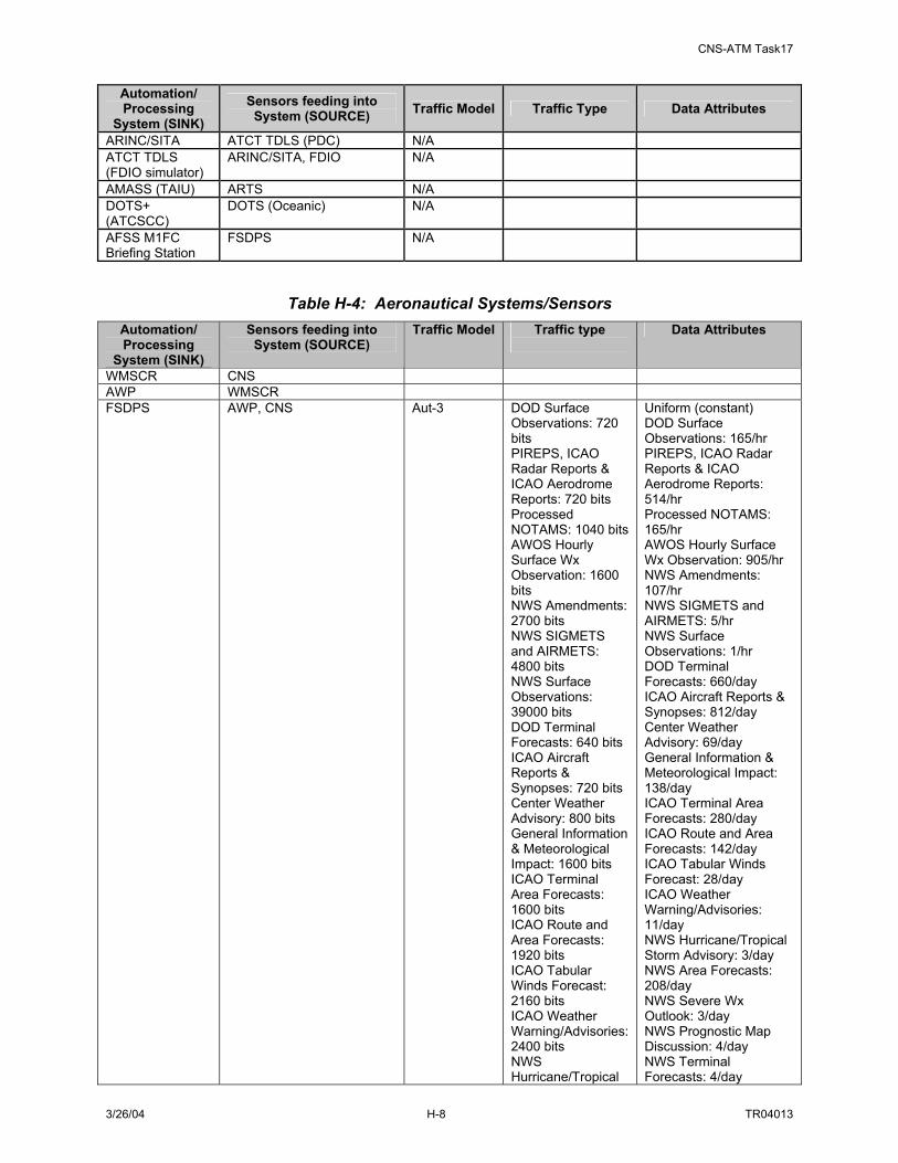
CNS-ATM Task17
3/26/04 H-8 TR04013
Automation/ Processing
System (SINK) Sensors feeding into
System (SOURCE) Traffic Model Traffic Type Data Attributes
ARINC/SITA ATCT TDLS (PDC) N/A ATCT TDLS (FDIO simulator)
ARINC/SITA, FDIO N/A
AMASS (TAIU) ARTS N/A DOTS+ (ATCSCC)
DOTS (Oceanic) N/A
AFSS M1FC Briefing Station
FSDPS N/A
Table H-4: Aeronautical Systems/Sensors Automation/ Processing
System (SINK)
Sensors feeding into System (SOURCE)
Traffic Model Traffic type
Data Attributes
WMSCR CNS AWP WMSCR FSDPS AWP, CNS Aut-3 DOD Surface
Observations: 720 bits PIREPS, ICAO Radar Reports & ICAO Aerodrome Reports: 720 bits Processed NOTAMS: 1040 bits AWOS Hourly Surface Wx Observation: 1600 bits NWS Amendments: 2700 bits NWS SIGMETS and AIRMETS: 4800 bits NWS Surface Observations: 39000 bits DOD Terminal Forecasts: 640 bits ICAO Aircraft Reports & Synopses: 720 bits Center Weather Advisory: 800 bits General Information & Meteorological Impact: 1600 bits ICAO Terminal Area Forecasts: 1600 bits ICAO Route and Area Forecasts: 1920 bits ICAO Tabular Winds Forecast: 2160 bits ICAO Weather Warning/Advisories: 2400 bits NWS Hurricane/Tropical
Uniform (constant) DOD Surface Observations: 165/hr PIREPS, ICAO Radar Reports & ICAO Aerodrome Reports: 514/hr Processed NOTAMS: 165/hr AWOS Hourly Surface Wx Observation: 905/hr NWS Amendments: 107/hr NWS SIGMETS and AIRMETS: 5/hr NWS Surface Observations: 1/hr DOD Terminal Forecasts: 660/day ICAO Aircraft Reports & Synopses: 812/day Center Weather Advisory: 69/day General Information & Meteorological Impact: 138/day ICAO Terminal Area Forecasts: 280/day ICAO Route and Area Forecasts: 142/day ICAO Tabular Winds Forecast: 28/day ICAO Weather Warning/Advisories: 11/day NWS Hurricane/Tropical Storm Advisory: 3/day NWS Area Forecasts: 208/day NWS Severe Wx Outlook: 3/day NWS Prognostic Map Discussion: 4/day NWS Terminal Forecasts: 4/day

CNS-ATM Task17
3/26/04 H-9 TR04013
Automation/ Processing
System (SINK)
Sensors feeding into System (SOURCE)
Traffic Model Traffic type
Data Attributes
Storm Advisory: 6400 bits NWS Area Forecasts: 9600 bits NWS Severe Wx Outlook: 12000 bits NWS Prognostic Map Discussion: 22400 bits NWS Terminal Forecasts: 284000 bits NWS Winds/Temperature Aloft Forecast: 460000 bits Airport Reservation Data: 176 bits AWOS Special Surface Wx Observations: 1600 bits DOD Hazardous Weather Information: 26400 bits General Flight Service Message: 800 bits Law Enforcement Alert Cancellation: 720 bits Law Enforcement Alert: 1840 bits Law Enforcement Supplemental Alert: 2300 bits Military Operations Message: 480 bits NWS Weather Warnings and Advisories: 5600 bits Traffic Management Advisories: 5000
NWS Winds/Temperature Aloft Forecast: 2/day Airport Reservation Data: 1000/hr AWOS Special Surface Wx Observations: 10/hr DOD Hazardous Weather Information: 2/day General Flight Service Message: 366/hr Law Enforcement Alert Cancellation: 5/hr Law Enforcement Alert: 5/hr Law Enforcement Supplemental Alert: 5/hr Military Operations Message: 65/hr NWS Weather Warnings and Advisories: 1/hr Traffic Management Advisories: 15/hr
M1FC FSDPS ISD4 or ACE/ISD NOTAM Distribution Client NOTAM Distribution Client (NAIMES WS)
USNS Distribution Server
SAMS Client SAMS Server SAMS Server SAMS Client ODAPS WMSCR USNS Distribution Server
NOTAM Distribution Client
Consolidated NOTAM System (CNS)
FSDPS, OASIS
ATCT/TRACON Phone /fax
AFSS Phone/Fax
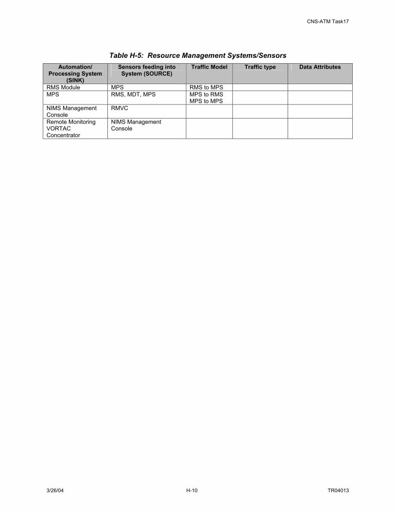
CNS-ATM Task17
3/26/04 H-10 TR04013
Table H-5: Resource Management Systems/Sensors Automation/
Processing System (SINK)
Sensors feeding into System (SOURCE)
Traffic Model Traffic type
Data Attributes
RMS Module MPS RMS to MPS MPS RMS, MDT, MPS MPS to RMS
MPS to MPS
NIMS Management Console
RMVC
Remote Monitoring VORTAC Concentrator
NIMS Management Console

CNS-ATM Task17
3/26/04 I-1 TR04013
APPENDIX I. TERMS AND CONCEPTS USED IN THE REPORT
Broker The broker component of SWIM is a middleware software application (running on a server) whose role is to coordinate the exchange of information between the other logical SWIM components, the SWIM members, data marts and warehouses, the MDR and the IOR. Common data model The SWIM Common Data Model is the set of data structures that are used to represent NAS information so that it is understandable by all SWIM members. Definition of these structures is an important part of the design process for SWIM. Commercial-Off-The-Shelf (COTS) In this document the use of the term COTS also includes Government-Off-The-Shelf (GOTS), or GOTS, which describes systems developed for other government users. COTS systems and subsystems are preferred to those that are custom developed because their broader user base means they are usually cheaper and of high reliability due to their higher probability of user-exposure of latent flaws. However, wide spread use does not always guarantee error free service. Frequent version changes in commercial products also can create problems for systems which integrate various COTS subsystems. Data mart and data warehouse A data mart is a repository of data gathered from operational data and other sources that is designed to serve a particular community of knowledge workers. A data warehouse is a central repository for all or significant parts of the data that an enterprise's various business systems collect. Data marts and data warehouses are components of the logical architecture of SWIM Information Management. The exact structures corresponding to these two terms have not yet been determined for SWIM. In general, a data warehouse provides a database or collection of databases with an enterprise wide scope whose data may range from highly detailed to broadly summarized and archival. On the other hand, the data in a data mart are more limited in scope, more rapidly retrieved, and on average less processed and of more recent origin. The SWIM design will provide data marts in situations where SWIM members require data delivery with lower latencies than the SWIM data warehouse(s) can provide. In practice, subscriptions will normally be served by data marts and queries by data warehouses. Information object (IO) Observational data coming into a NAS facility from a single sensor over a telecommunications channel dedicated to its delivery needs no accompanying descriptive data other than an occasional sensor or channel status report for the facility to have all the information it needs to process that data because the relevant information about the sensor is known from its channel assignment. Heterogeneous networked data, however, must be accompanied by context information to be useable. In SWIM data is exchanged in IOs. An IO has two parts: 1) the data itself, or payload, and 2) information about the data, or metadata, which provides the necessary context, or attributes, of the data. At minimum the metadata identifies the nature of the IO, i.e., the schema used for structuring and formatting it. The two parts of the IO are not necessarily transmitted or stored together but remain logically linked. The following candidate SWIM IO subtypes contribute to efficient data distribution through their specially designed attributes that enable SWIM to provide alternative data sharing strategies:

CNS-ATM Task17
3/26/04 I-2 TR04013
• Publishing information object (PIO) One way a publisher can initiate the publishing of an IO is to send a broker, not the full IO, but a PIO for advertising what is to be published. The PIO corresponds to the IO but has been stripped of all or most of the IO’s payload. The publisher then sends the full IO to a data repository and the broker initiates the distribution of the IO to the proper subscribers based on the information in its corresponding PIO.
• Stream-data publishing information object (SPIO) Stream data, or “fast data”, is data that is updated rapidly over a relatively long period of time. SPIOs are a special case of PIOs for stream data and thus do not contain the payload of their corresponding stream data IOs.
Information object registry (IOR) The IOR is a component of SWIM’s logical architecture for Information Management. It provides a list or index of all NAS IOs that are searchable in SWIM, based on defined attributes in the Common Data Model and associated IO access information. An IOR is a system that contains the instances of information objects. Typically, it is a software application that uses a database to store and retrieve records. Metadata Registry (MDR) The MDR is a component of SWIM’s logical architecture for Information Management. The SWIM MDR is not the same as the FAA Metadata Repository, although its development may be aided by integrating into it information already collected into the FAA MDR, and also by the standardization of FAA data elements in the FAA Data Registry. SWIM’s MDR will provide an index to the metadata schema in SWIM, or the “metadata about the metadata” in SWIM IOs. Network Management Unit (NMU) The NMU is the generic term given to the logical component of SWIM that provides the SWIM functions of Security Management, Configuration Management, Performance Management, Accounting Management and Fault Management. OPNET OPNET Technologies, Inc. of Bethesda, Maryland is a leading commercial provider of predictive software for telecommunication networks. During the execution of CNS-ATM Task 12 the OPNET Modeler, a network simulator, provided the framework for modeling the future NAS communication architecture and simulating its performance. Task 12 modeled the operations of a segment of the facilities attached to the Cleveland ARTCC in Oberlin, Ohio in detail and showed the performance of proposed and actual networks, devices, protocols and applications. In Task 17, an updated version of the OPNET Modeler version allowed inclusion of multicasting under Internet Protocol version 6 and the model was appropriately modified in order to reflect the SWIM environment. Simulations of proposed SWIM architecture choices will provide results of tradeoff studies of different design options. For more details on OPNET simulations, see the Task 12 Report. Object request broker (ORB) ORB is a middleware technology that manages communication and data exchange between objects. ORBs enable system developers to build distributed systems by piecing together individual, independent units of software (objects) with an ORB that enables these objects to communicate with each other. This allows the developers to concern themselves with object interface details and not worry about the communication implementation details that are isolated within the ORB. The most mature and widely used ORB architecture, Common Object Request Broker Architecture

CNS-ATM Task17
3/26/04 I-3 TR04013
(CORBA) is the Object Management Group’s (OMG's) open, vendor-independent architecture (that is, a standard set of specifications that computer applications conform to in order to work together over networks). Using the standard Internet Inner-ORB Protocol (IIOP), “a CORBA-based program from any vendor, on almost any computer, operating system, programming language, and network, can interoperate with a CORBA-based program from the same or another vendor, on almost any other computer, operating system, programming language, and network.” (See http://www.omg.org/) Ontology An ontology is a statement of the conceptual relationships among entities in a domain of interest. Simple Network Management Protocol (SNMP) SNMP is a protocol described in Internet Engineering Task Force (IETF) Request for Comment (RFC) 1157 and other related RFCs. It is a mature and widely used standard that governs network management and the monitoring of network devices. Stream-data Stream data are data, such as observations from sensors, that are updated with high frequency (generally for relatively long durations or indefinitely.) Stream data are produced at a rate of over one data packet a second. SWIM member The term SWIM member is equivalent to the term “SWIM user/resource” in earlier Task 17 reports. A SWIM member is any authorized participant in the exchange of information via SWIM. It can be either a consumer or a provider of the shared NAS information and services and includes networked computers, NAS automation systems (e.g. Host Computer Systems and Decision Support Systems), network systems (FTI communication connections), and NAS users (e.g. pilots, air traffic controllers, traffic specialists), etc. Taxonomy In the context of information technology, taxonomy is the terminology in the domain of interest and the way it is organized into categories and subcategories EXtensible Markup Language (XML) methodology XML is a mature, open, industry standard language for the description of data structures that has become widely adapted for data exchange between independent systems. In addition, there are numerous technologies related to XML that are relevant to the SWIM architecture development. A detailed discussion of XML and its possible application to SWIM may be found in Appendix K of the CNS-ATM Task 15 Report.

CNS-ATM Task17
3/26/04 J-1 TR04013
APPENDIX J. LIST OF ABBREVIATIONS AND ACRONYMS
AFSS Automated Flight Service Station
ARTCC Air Route Traffic Control Center
API Application Program Interface
ASD Office of System Architecture and Investment Analysis
ATCSCC Air Traffic Control System Command Center
ATCT Traffic Control Tower
ATM Air Traffic Management
CNS Communications, Navigation and Surveillance
CONOPS NAS Concept of Operations
CONUSE Concept of Use
CORBA Common Object Request Broker Architecture
COTS Commercial Off-The-Shelf
DAA Designated Approving Authority
DCE Distributed Computing Environment
DNM Distributed Network Management
DOM Document Object Model
DOS Denial of Service
DCOM (Distributed Component Object Model
ebXML Electronic Business eXtensible Markup Language
EJB Enterprise Java Bean
FAA Federal Aviation Administration
FOC Flight Operations Center
FTI FAA Telecommunication Infrastructure
GIOP General Inter- Object Request Broker Protocol (GIOP)
GIS Geographical Information System
HTML Hyper Text Markup Language
IDL Interface Definition Language
IDS Intrusion Detection Systems
IETF Internet Engineering Task Force
IIOP Internet Inter-ORB Protocol
IO Information Object
IOR Information Object Repository
IPP Integrated Program Plan

CNS-ATM Task17
3/26/04 J-2 TR04013
IPT Integrated Product Team
IRD Interface Requirement Document
ISO International Organization for Standardization
ISS Information System Security
ISSA Information System Security Architecture
IT Information Technology
ITT-AES ITT Industries Advanced Engineering and Sciences
J2EE Java 2 Platform, Enterprise Edition
J2SE Java 2 Platform, Standard Edition
JDK Java Development Kit
LMDR Local Metadata Registry
MDR Metadata Registry
MIB Management Information Base
MNS Mission Needs Statement
NAS National Airspace System
NASCR NAS Common Reference
NASR NAS Resources
NIMS NAS Infrastructure Management System
NOTAM Notice To AirMen
NWIS NAS-Wide Information Services
OO Object Oriented
OODBMS Object Oriented Database Management System
ONC Open Network Computing
OQL Object Query Language
ORB Object Request Broker
ORDBMS Object-Relational Database Management System
OSED Operational Services and Environmental Description
OSF Open Software Foundation
PKI Public Key Infrastructure
PP Protection Profile
QoS Quality of Service
RM-ODP Reference Model of Open Distributed Processing
RPC Remote Procedure Call
RT CORBA Real-Time CORBA
SCAP Security Certification and Authorization Package
SE System Engineering

CNS-ATM Task17
3/26/04 J-3 TR04013
SEM System Engineering Manual
SNMP Simple Network Management Protocol
SPIO Stream Data Publishing Information Object
SQL Structured Query Language
STA Security Technology Assessment
SWIM System Wide Information Management
TRACON Terminal Radar Approach CONtrol facility
TCP Transmission Control Protocol
VC Virtual Connection
VPN Virtual Private Network
W3C World Wide Web Consortium
XML eXtensible Markup Language
XSL eXtensible Stylesheet Language family
XSLT eXtensible Stylesheet Language Transformations
Related Documents