A51963AC February 2011 User’s Guide PA 800 plus Pharmaceutical Analysis System System Overview Beckman Coulter, Inc. 250 S. Kraemer Blvd. Brea, CA 92821

Welcome message from author
This document is posted to help you gain knowledge. Please leave a comment to let me know what you think about it! Share it to your friends and learn new things together.
Transcript

User’s Guide
PA 800 plus Pharmaceutical Analysis System
System Overview
February 2011
Beckman Coulter, Inc.250 S. Kraemer Blvd.Brea, CA 92821
A51963AC
User’s Guide PA 800 plus Pharmaceutical Analysis System System OverviewPN A51963AC (February 2011)
Copyright © 2009-2011 Beckman Coulter, Inc.
Beckman Coulter, Inc. grants a limited non-exclusive license to the owner or operator of a PA 800 plus instrument to make a copy, solely for laboratory use, of any portion or all of the online help and electronic documents shipped with the PA 800 plus instrument.
Trademarks:Following is a list of Beckman Coulter trademarks:
• Beckman Coulter®
• 32 Karat™
All other trademarks are the property of their respective owners.
Find us on the World Wide Web at: www.beckmancoulter.com and www.CELeader.com
Beckman Coulter Ireland, Inc.Mervue Business Park, Mervue Galway, Ireland 353 91 774068
Beckman Coulter do Brasil Com e Imp de Prod de Lab LtdaEstr dos Romeiros, 220 - Galpao G3 - Km 38.506501-001 - Sao Paulo - SP - BrasilCNPJ: 42.160.812/0001-44
製造販売元 : ベ ッ ク マ ン・コ ール タ ー株式会社東京都江東区有明三丁目 5 番 7 号TOC 有明ウエス ト タ ワー
贝克曼库尔特有限公司,美国加利福尼亚州,Brea 市,S. Kraemer 大街 250 号,邮编:92821 电话:(001) 714-993-5321

Revision History
Second Revision, A51963AC, February 201132 Karat Software version 9.1 patchPA 800 plus Software version 1.1 patchPA 800 plus Firmware version 9.2Numerous syntax and grammatical edits
First Revision, A51963AB, February 2010Revised corporate address.
Initial Issue, A51963AA, April 200932 Karat Software version 9.1PA 800 plus Software version 1.1PA 800 plus Firmware version 9.0
A51963AC iii

Revision History
A51963ACiv
Safety Notices
Symbols and Labels
Introduction
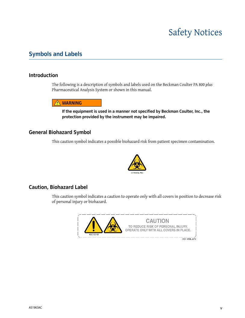
The following is a description of symbols and labels used on the Beckman Coulter PA 800 plus Pharmaceutical Analysis System or shown in this manual.
WARNING
If the equipment is used in a manner not specified by Beckman Coulter, Inc., the protection provided by the instrument may be impaired.
General Biohazard Symbol
This caution symbol indicates a possible biohazard risk from patient specimen contamination.
Caution, Biohazard Label
This caution symbol indicates a caution to operate only with all covers in position to decrease risk of personal injury or biohazard.
A51963AC v

Safety NoticesSymbols and Labels
Caution, Moving Parts Label
This caution symbol warns the user of moving parts that can pinch or crush.
High Voltage Electric Shock Risk Symbol
This symbol indicates that there is high voltage and there is a risk of electric shock when the user works in this area.
Class 1 Laser Caution Label
A label reading “THIS PRODUCT CONFORMS TO APPLICABLE REQUIREMENTS OF 21 CFR 1040 AT THE DATE OF MANUFACTURE” is found near the Name Rating tag. The laser light beam is not visible.
Sharp Object Label
A label reading “CAUTION SHARP OBJECTS” is found on the PA 800 plus.
CAUTIONPARTS MOVEAUTOMATICALLY
A015081L.EPS
144557-AB
A016352L.EPS
A016350L.EPS
CLASS 1 LASER PRODUCTTHIS PRODUCT CONFORMS TO APPLICABLE REQUIREMENTS OF 21 CFR 1040 AT THE DATE OF MANUFACTURE.
MANUFACTURED:
726024-C
CAUTIONSHARP OBJECTS
A16558-AA
A016351L.EPS
A51963ACvi
Safety NoticesSymbols and Labels
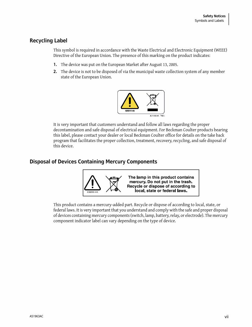
Recycling Label
This symbol is required in accordance with the Waste Electrical and Electronic Equipment (WEEE) Directive of the European Union. The presence of this marking on the product indicates:
1. The device was put on the European Market after August 13, 2005.
2. The device is not to be disposed of via the municipal waste collection system of any member state of the European Union.
It is very important that customers understand and follow all laws regarding the proper decontamination and safe disposal of electrical equipment. For Beckman Coulter products bearing this label, please contact your dealer or local Beckman Coulter office for details on the take back program that facilitates the proper collection, treatment, recovery, recycling, and safe disposal of this device.
Disposal of Devices Containing Mercury Components
This product contains a mercury-added part. Recycle or dispose of according to local, state, or federal laws. It is very important that you understand and comply with the safe and proper disposal of devices containing mercury components (switch, lamp, battery, relay, or electrode). The mercury component indicator label can vary depending on the type of device.
A51963AC vii

Safety NoticesSymbols and Labels
Restriction of Hazardous Substances (RoHS) Labels
These labels and materials declaration table (the Table of Hazardous Substance's Name and Concentration) are to meet People's Republic of China Electronic Industry Standard SJ/T11364-2006 "Marking for Control of Pollution Caused by Electronic Information Products" requirements.
RoHS Caution Label
This logo indicates that this electronic information product contains certain toxic or hazardous elements, and can be used safely during its environmental protection use period. The number in the middle of the logo indicates the environmental protection use period for the product. The outer circle indicates that the product can be recycled. The logo also signifies that the product should be recycled immediately after its environmental protection use period has expired. The date on the label indicates the date of manufacture.
RoHS Environmental Label
This logo indicates that the product does not contain any toxic or hazardous substances or elements. The "e" stands for electrical, electronic, and environmental electronic information products. This logo indicates that this electronic information product does not contain any toxic or hazardous substances or elements, and is green and is environmental. The outer circle indicates that the product can be recycled. The logo also signifies that the product can be recycled after being discarded, and should not be casually discarded.
A51963ACviii
Safety NoticesSymbols and Labels
Alerts for Warning, Caution, Important, and Note
WARNING
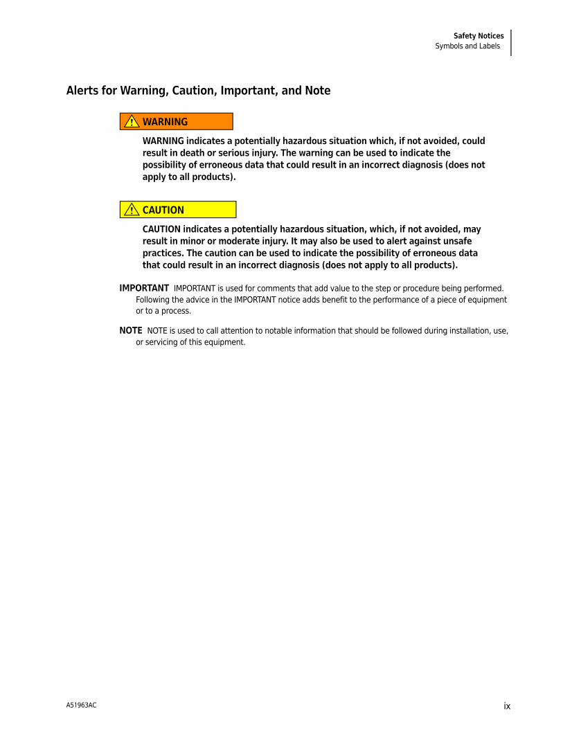
WARNING indicates a potentially hazardous situation which, if not avoided, could result in death or serious injury. The warning can be used to indicate the possibility of erroneous data that could result in an incorrect diagnosis (does not apply to all products).
CAUTION
CAUTION indicates a potentially hazardous situation, which, if not avoided, may result in minor or moderate injury. It may also be used to alert against unsafe practices. The caution can be used to indicate the possibility of erroneous data that could result in an incorrect diagnosis (does not apply to all products).
IMPORTANT IMPORTANT is used for comments that add value to the step or procedure being performed. Following the advice in the IMPORTANT notice adds benefit to the performance of a piece of equipment or to a process.
NOTE NOTE is used to call attention to notable information that should be followed during installation, use, or servicing of this equipment.
A51963AC ix

Safety NoticesSymbols and Labels
A51963ACx
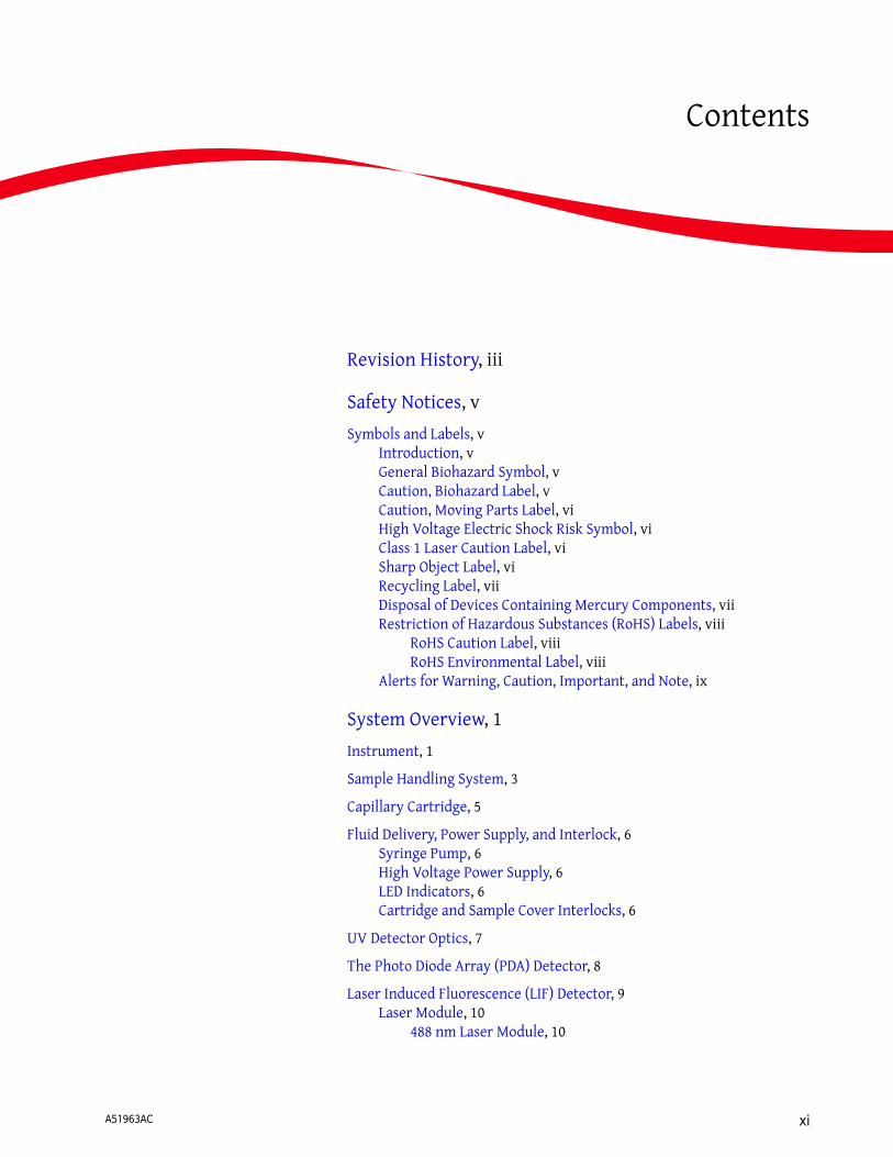
Contents
Revision History, iii
Safety Notices, v
Symbols and Labels, vIntroduction, vGeneral Biohazard Symbol, vCaution, Biohazard Label, vCaution, Moving Parts Label, viHigh Voltage Electric Shock Risk Symbol, viClass 1 Laser Caution Label, viSharp Object Label, viRecycling Label, viiDisposal of Devices Containing Mercury Components, viiRestriction of Hazardous Substances (RoHS) Labels, viii
RoHS Caution Label, viiiRoHS Environmental Label, viii
Alerts for Warning, Caution, Important, and Note, ix
System Overview, 1
Instrument, 1
Sample Handling System, 3
Capillary Cartridge, 5
Fluid Delivery, Power Supply, and Interlock, 6Syringe Pump, 6High Voltage Power Supply, 6LED Indicators, 6Cartridge and Sample Cover Interlocks, 6
UV Detector Optics, 7
The Photo Diode Array (PDA) Detector, 8
Laser Induced Fluorescence (LIF) Detector, 9Laser Module, 10
488 nm Laser Module, 10
A51963AC xi

Contents
Supported Applications, 11IgG Purity/Heterogeneity Assay, 11SDS Molecular Weight Analysis, 11Capillary Isoelectric Focusing (cIEF) Analysis, 11Carbohydrate Analysis, 11
System Operational Procedures/Training Guide, 12Controller and Instrument Start Up, 12
Controller/Network Logon, 12License Key, 12
PA 800 plus Software, 12Enterprise Screen, 13
Instrument Start Up, 13
System Administration, 14Configuration, 16Online vs. Offline, 16
How to Load the Cartridge and Samples, 17
How to Run a Method, 19
Analysis, 23Area Calculation, 27Annotations, 28
Peak Identity, 29
Run Multiple Methods with a Sequence, 29
Viewing Reports, 33Standard Reports, 33Method Custom Reports, 33Sequence Custom Report, 34Advanced Reports, 34Suitability Reports, 35Viewing and Printing Reports, 35
Maintenance, 36
Record of Operator Training, 37Training Summary, 37Checklist, 37
A51963ACxii
System Overview
Instrument
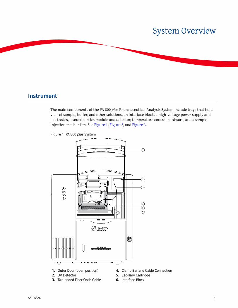
The main components of the PA 800 plus Pharmaceutical Analysis System include trays that hold vials of sample, buffer, and other solutions, an interface block, a high-voltage power supply and electrodes, a source optics module and detector, temperature control hardware, and a sample injection mechanism. See Figure 1, Figure 2, and Figure 3.
Figure 1 PA 800 plus System
1. Outer Door (open position)2. UV Detector3. Two-ended Fiber Optic Cable
4. Clamp Bar and Cable Connection5. Capillary Cartridge6. Interface Block
A51963AC 1

System OverviewInstrument
Figure 2 PA 800 plus System Side View
The main power switch is on the lower-right side of the front of the instrument. All connections for external system components are on the upper-left side panel of the instrument, except for the AC inlet and the fuse holder. Three fans supply cooling air flow for internal system components. Air is exhausted through the vents at the side and back of the instrument. Keep at least six inches of clearance at each vent to ensure adequate air flow.
1. Outer Door or Sample Cover (open)2. Inner Door or Cartridge Cover (open) 3. Indicators4. Fluid Fill Port
5. Sample Trays6. Buffer Trays7. Fluid Bubble Indicator8. Power Switch
A51963AC2
System OverviewSample Handling System
Sample Handling System
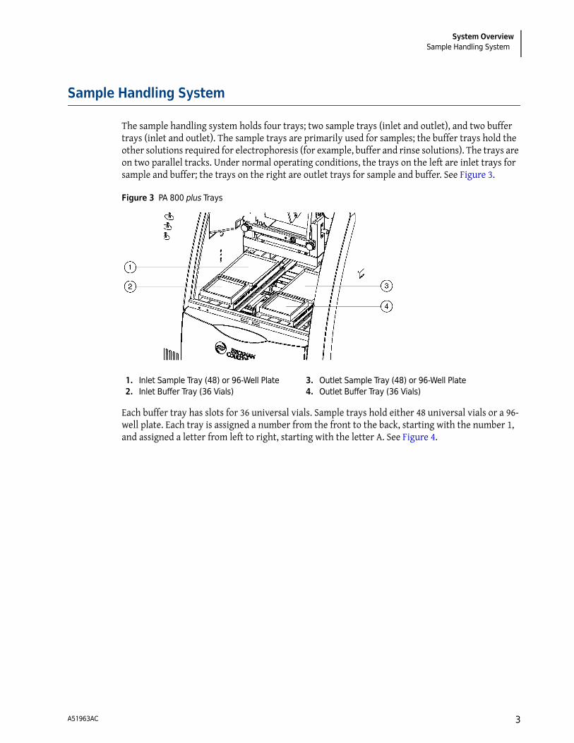
The sample handling system holds four trays; two sample trays (inlet and outlet), and two buffer trays (inlet and outlet). The sample trays are primarily used for samples; the buffer trays hold the other solutions required for electrophoresis (for example, buffer and rinse solutions). The trays are on two parallel tracks. Under normal operating conditions, the trays on the left are inlet trays for sample and buffer; the trays on the right are outlet trays for sample and buffer. See Figure 3.
Figure 3 PA 800 plus Trays
Each buffer tray has slots for 36 universal vials. Sample trays hold either 48 universal vials or a 96-well plate. Each tray is assigned a number from the front to the back, starting with the number 1, and assigned a letter from left to right, starting with the letter A. See Figure 4.
1. Inlet Sample Tray (48) or 96-Well Plate2. Inlet Buffer Tray (36 Vials)
3. Outlet Sample Tray (48) or 96-Well Plate4. Outlet Buffer Tray (36 Vials)
A51963AC 3
System OverviewSample Handling System
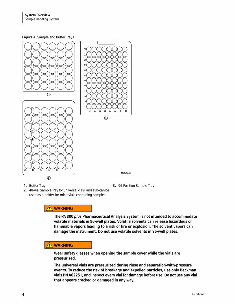
Figure 4 Sample and Buffer Trays
WARNING
The PA 800 plus Pharmaceutical Analysis System is not intended to accommodate volatile materials in 96-well plates. Volatile solvents can release hazardous or flammable vapors leading to a risk of fire or explosion. The solvent vapors can damage the instrument. Do not use volatile solvents in 96-well plates.
WARNING
Wear safety glasses when opening the sample cover while the vials are pressurized.
The universal vials are pressurized during rinse and separation-with-pressure events. To reduce the risk of breakage and expelled particles, use only Beckman vials PN A62251, and inspect every vial for damage before use. Do not use any vial that appears cracked or damaged in any way.
1. Buffer Tray2. 48-Vial Sample Tray for universal vials, and also can be
used as a holder for microvials containing samples.
3. 96-Position Sample Tray
A51963AC4
System OverviewCapillary Cartridge
Capillary Cartridge
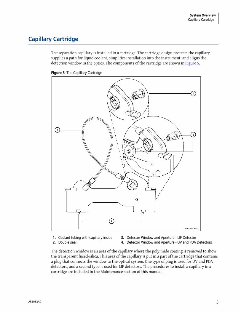
The separation capillary is installed in a cartridge. The cartridge design protects the capillary, supplies a path for liquid coolant, simplifies installation into the instrument, and aligns the detection window in the optics. The components of the cartridge are shown in Figure 5.
Figure 5 The Capillary Cartridge
The detection window is an area of the capillary where the polyimide coating is removed to show the transparent fused-silica. This area of the capillary is put in a part of the cartridge that contains a plug that connects the window to the optical system. One type of plug is used for UV and PDA detectors, and a second type is used for LIF detectors. The procedures to install a capillary in a cartridge are included in the Maintenance section of this manual.
1. Coolant tubing with capillary inside2. Double seal
3. Detector Window and Aperture - LIF Detector4. Detector Window and Aperture - UV and PDA Detectors
A51963AC 5

System OverviewFluid Delivery, Power Supply, and Interlock
The capillary temperature is controlled with an inert liquid that circulates through the cartridge. The temperature is controlled in a range from 10°C below ambient (with a minimum of 15°C) to 60°C. Coolant flows through the cartridge through two openings in the bottom of the housing (found between the ends of the capillary). This fluid removes the heat generated by electrophoresis.
Fluid Delivery, Power Supply, and Interlock
Syringe Pump
The PA 800 plus can generate pressures with an internal pump mechanism. This pump can supply 0.1 to 25 psi to perform pressure injections or low-pressure mobilizations. The pump can apply a maximum of 100 psi to move the fluids through the capillary. Vacuum injections can be performed from 0.1 to 5.0 psi. The pressure can be applied to both ends of the capillary at the same time to prevent outgassing of gels.
High Voltage Power Supply
The high-voltage power supply can deliver a maximum of 30 kV with a maximum current of 300 μA. The voltage range is from 1 to 30 kV in 100 V increments. The polarity is configured in the software. The current range is from 3.0 to 300 μA in 0.1 μA increments. The software allows the user to select current, voltage, or power operation. During operation, the system will ramp the voltage or current up to the programmed value. Limits for voltage, current and power can be entered to protect the capillary. For example, if the user programs a voltage setting for 30 kV, but the setting for current is only 3.0 μA, the system can reach the limit set for current before reaching the voltage setting, and control voltage to keep that current.
LED Indicators
The front panel of the instrument contains LED indicators for Power, UV, and High Voltage. See Figure 2.
Cartridge and Sample Cover Interlocks
The hinged doors of the PA 800 plus have interlock sensors that prevent unsafe access to the inside of the instrument. The first door is called the outer door or sample cover; the second is called the inner door or cartridge cover. See Figure 2.
Opening the Sample cover:
• Stops any tray movement immediately.
• Prevents the execution of any programmed events that require tray movement.
• Aborts a method when a step that requires tray movement is encountered.
A51963AC6

System OverviewUV Detector Optics
Opening the Cartridge cover:
• Turns off the high voltage if it is on.
• Turns off the pump that circulates the capillary coolant.
• Moves the detector filter wheel to the closed position.
UV Detector Optics
The UV optics include an ultraviolet light source, wavelength filters, aperture, capillary, and a photodiode detector, as shown in Figure 6.
The UV source is a deuterium lamp with a wavelength range of 190 to 600 nm. Two lenses focus and direct the output of the lamp through one of the wavelength-selecting filters found in a rotating wheel behind the capillary cartridge. The beam continues through the aperture in the cartridge plug and through a section of the capillary that has been treated to remove the polyimide coating (the detection window). The non-absorbed beam then continues through a fiber optic cable to a photodiode. The light signal is converted to an electrical signal, digitized, and sent to the 32 Karat workstation for processing by the software. This signal is also available as an analog output through a connection on the left side of the instrument.
The design of the instrument insures that the optical system stays in alignment. No user alignments are required.
There are eight positions on the UV filter wheel. UV detector systems are shipped with four standard filters: 200 nm, 214 nm, 254 nm, and 280 nm (10 nm bandwidth). The filters are installed in positions 2, 3, 4 and 5, respectively on the filter wheel. The position 1 is opaque and has the function of a shutter for the detection system.
Additional wavelengths are obtained by placing the appropriate filters in positions 6, 7, and 8. If desired, the standard filters can be replaced. If the instrument is used with a PDA detector, position 8 must be left open (no filter). The filter wheel will accommodate ½ inch (12.7 mm) diameter filters with wavelengths from 190 to 600 nm.
A51963AC 7

System OverviewThe Photo Diode Array (PDA) Detector
Figure 6 UV Optics Layout
The Photo Diode Array (PDA) Detector
The Photo Diode Array detector, like the UV detector, uses the absorbance of light to detect if there are samples as they go through the detection window. Unlike the UV detector, the PDA detector can give spectral analysis of samples.
The PDA detector uses the same cartridge configuration as the UV detector. Refer to the Maintenance section of this manual for a description of the cartridge.
In PDA detection, the full spectrum of light from the deuterium lamp illuminates the capillary. See Figure 7. Light that is not absorbed by samples is delivered by a fiber optic cable to a grating that breaks the light into a spectrum. This spectrum is projected onto an array of 256 photodiodes. With this design, the absorbance profile of the sample is measured. The PDA detector also allows the simultaneous measurement of light at different discrete wavelengths. The photo diode array converts the light signal into an electrical signal. The electrical signal is digitized and sent to the 32 Karat workstation for processing by the software.
The PDA detector always uses filter wheel position #8. When the PDA is in use, it is essential that no filter is in position #8.
1. Capillary Aperture 2. Lenses3. Deuterium Lamp4. Lamp Power Supply5. Photodiode6. Fiber Optic Connection
7. Motor8. Position Filter Wheel9. Filter Position (e.g., 214nm)10. Fiber Optic Cable11. Fiber Optic Connector12. Capillary
A51963AC8

System OverviewLaser Induced Fluorescence (LIF) Detector
The PDA detector is calibrated using discrete emission wavelength bands generated by a mercury lamp. The mercury lamp is an important part of the detector system. When requested by the user, the calibration is performed automatically.
WARNING
Do not put the mercury lamp into the regular trash. Mercury is a hazardous material and must be disposed of in accordance with local, state, and federal laws.
Figure 7 Diode Array Optics Layout
Laser Induced Fluorescence (LIF) Detector
The LIF Detector consists of the LIF Detector Module and a Laser Module. A PA 800 plus capillary cartridge with an LIF Detector plug installed is required for use with this system.
The LIF detector uses an integrated 488 nm laser light source. A fiber cable transmits excitation light from the laser to the capillary in the cartridge. Substances in the capillary that fluoresce at the laser wavelength are detected. The LIF Detector measures and records this fluorescence, which appears
1. Capillary Aperture2. Lenses3. Deuterium Lamp4. Lamp Power Supply5. Concave Holographic Grating6. 256 Element Diode Array7. Motor8. Position Filter Wheel9. Monochromator Entrance Slit10. Fiber Optic Connector
11. 9 by 200 μm Fiber Array (Slit)12. Fiber Optic Connector13. Mercury Calibration Fibers14. Mercury Lamp Power Supply15. Mercury Lamp16. Y-fiber Optic Cable17. Filter wheel in open position 818. Fiber Optic Connector19. Capillary
A51963AC 9

System OverviewLaser Induced Fluorescence (LIF) Detector
as a peak on the electropherogram. For more information on the LIF system, see the PA 800 plus System Maintenance manual.
The initial installation of the LIF Detector is performed by a Beckman Coulter Field Service Engineer. The PA 800 plus can easily be changed between LIF and UV/PDA modes because the detector components are modular. See Figure 8 for a stylized diagram of the LIF Optical System.
Figure 8 LIF Optical System
Laser Module
The following section describes the 488 nm laser module and how it interfaces with the PA 800 plus instrument and the LIF Detector.
WARNING
During normal operation of the LIF Detector, laser light is not accessible to the user. To prevent potentially harmful laser light from being emitted from the end of the fiber cable, an interlock mechanism turns off the laser if the laser fiber optic cable is disconnected from the interconnect module or if the cartridge cover is opened.
Always turn off PA 800 plus instrument before any of the LIF system modules are removed.
488 nm Laser Module
The Beckman Coulter 488 nm laser is a solid state laser mounted inside the instrument. It has a fiber connector and an electrical interlock connector, for an external laser connection, that is accessible from the right side of the instrument. This external laser connection accommodates a fiber coupled external laser source for LIF detection.
1. Laser 12. Spherical Mirror3. Laser 24. Capillary
5. Ball Lens6. Laser Filters7. Emission Filters8. Photo Multiplier Tube
A51963AC10
System OverviewSupported Applications
Supported Applications
IgG Purity/Heterogeneity Assay
The PA 800 plus IgG Purity/Heterogeneity Assay includes methods to resolve both reduced and non-reduced immunoglobulins by size, and to subsequently quantify the heterogeneity and impurities which may exist in a given IgG preparation. The methodology involves heat denaturing of a specified concentration of protein in the presence of SDS. Once denatured, the sample is separated by size in a capillary containing a replaceable SDS polymer matrix, which provides the sieving selectivity for the separation.
SDS Molecular Weight Analysis
Capillary electrophoresis (CE) has become an effective replacement for manual lab gel electrophoresis processes due to its automation, quantitation, fast speed, and high efficiency. Many biomolecules, such as proteins and nucleic acids, are separated by molecular sieving electrophoresis using gel matrices, a method called capillary gel electrophoresis (CGE). The separation results from the differential migration of the analyte through a gel matrix. In this case, smaller molecules move faster than large molecules through the separation gel. For polypeptides and proteins, it is necessary to denature the sample in the presence of SDS, an anionic detergent that binds the proteins in a constant ratio of 1:1.4 of protein. The constant mass-to-charge property of the SDS-bound proteins allows separation according to differences in protein molecular weight.
The PA 800 plus Pharmaceutical Analysis System SDS-MW Analysis assay is designed for the separation of protein-SDS complexes using a replaceable gel matrix. The gel is formulated to give an effective sieving range of approximately 10 kDa to 225 kDa. Within this size range, the logarithm of protein molecular mass is linear with its reciprocal electrophoretic mobility. The molecular weight of an unknown protein can be estimated from a standard curve of known protein sizes. This kit can quantify the amount of protein and calculate the purity of a protein product.
Capillary Isoelectric Focusing (cIEF) Analysis
Isoelectric focusing (IEF) is used for the separation of proteins based on differences in their isoelectric points. The IEF method is accomplished by electrophoresis of proteins or peptides through a stable pH gradient until they reach the pH equal to their isoelectric point (pI), at which point the net charge and mobility are zero.
The Isoelectric point (pI) of an unknown can be calculated from the calibration plot of the migration time of the internal pI markers vs. their known pIs. Therefore, in addition to providing separation with high resolution, the assay can be used for wide-range (pI 4-10) screening and pI identification of proteins and peptides.
Carbohydrate Analysis
Beckman Coulter's “Carbohydrate Labeling and Analysis” assay separates and quantifies oligosaccharides released from glycoproteins.
A51963AC 11
System OverviewSystem Operational Procedures/Training Guide
The assay contains the reagents, buffer, and coated capillaries required to label, separate and quantify oligosaccharides. This assay also provides a glucose size marker for relative size determination and a maltose standard for quantitation and mobility characterization of the released oligosaccharides.
System Operational Procedures/Training Guide
Controller and Instrument Start Up
Controller/Network Logon
PA 800 plus software, which includes 32 Karat™ software, runs on a Windows XP controller. If the instrument is installed on a network, the user name and password will be supplied by the network administrator. 32 Karat software functionality is different when run on a network versus as a stand-alone system. In particular, the system administration features can use network names and passwords automatically. The default network identification is 32 Karat and the work group name is WORKGROUP. If more than one PA 800 plus system is going to be installed on the network, unique network names are required for each workstation. Normally, these changes are performed by the network administrator.
License Key
32 Karat software requires a license to collect and analyze data. Without the license, the software will only operate in 'Demo' mode. In demo mode, only the data supplied with the software under the ‘data samples’ folder can be analyzed and data acquisition is not possible. For instrument control, data acquisition, and analysis, the 32 Karat license key is required. The license key contains the data system serial number and determines other options that can be used with your system. This key is a USB Flash drive that must be put in an available USB slot on the controller.
CAUTION
The flash drive license key must remain in place at all times while the software is running.
The license key can be uninstalled on one controller and installed on another, if desired.
PA 800 plus Software
Launch the PA 800 plus software by double-clicking the PA 800 plus icon on the Windows desktop. The PA 800 plus screen displays. The upper right buttons activate the major functions. Hover the mouse over the buttons to obtain a balloon tip on its function. The Run button runs a method or sequence. The Describe button is used to prepare sequences for ease of running various sample quantities. The Training Videos provide access to visual descriptions of many of the tasks required to prepare and maintain the capillary cartridge. Online Help is also available here. The 32 Karat Enterprise software can be launched from the side menu.
A51963AC12
System OverviewSystem Operational Procedures/Training Guide
Enterprise Screen
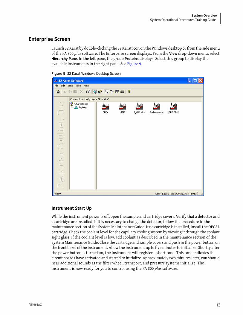
Launch 32 Karat by double-clicking the 32 Karat icon on the Windows desktop or from the side menu of the PA 800 plus software. The Enterprise screen displays. From the View drop-down menu, select Hierarchy Pane. In the left pane, the group Proteins displays. Select this group to display the available instruments in the right pane. See Figure 9.
Figure 9 32 Karat Windows Desktop Screen
Instrument Start Up
While the instrument power is off, open the sample and cartridge covers. Verify that a detector and a cartridge are installed. If it is necessary to change the detector, follow the procedure in the maintenance section of the System Maintenance Guide. If no cartridge is installed, install the OPCAL cartridge. Check the coolant level for the capillary cooling system by viewing it through the coolant sight glass. If the coolant level is low, add coolant as described in the maintenance section of the System Maintenance Guide. Close the cartridge and sample covers and push in the power button on the front bezel of the instrument. Allow the instrument up to five minutes to initialize. Shortly after the power button is turned on, the instrument will register a short tone. This tone indicates the circuit boards have activated and started to initialize. Approximately two minutes later, you should hear additional sounds as the filter wheel, transport, and pressure systems initialize. The instrument is now ready for you to control using the PA 800 plus software.
A51963AC 13
System OverviewSystem Administration
System Administration
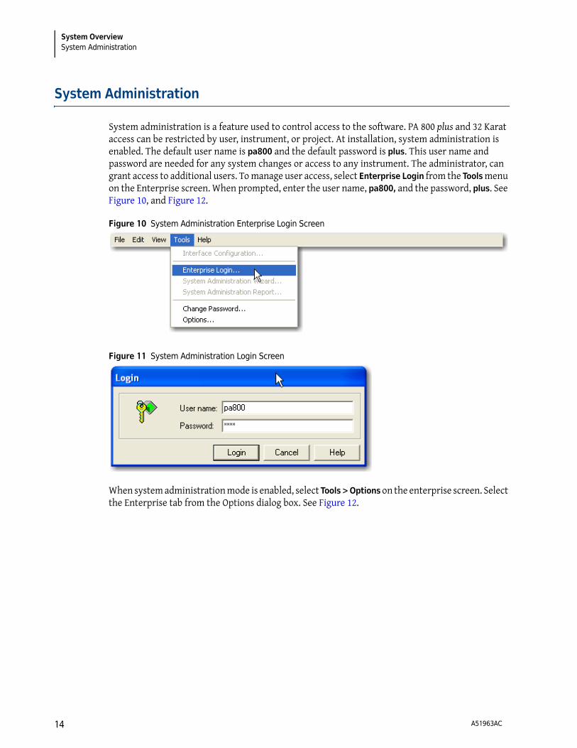
System administration is a feature used to control access to the software. PA 800 plus and 32 Karat access can be restricted by user, instrument, or project. At installation, system administration is enabled. The default user name is pa800 and the default password is plus. This user name and password are needed for any system changes or access to any instrument. The administrator, can grant access to additional users. To manage user access, select Enterprise Login from the Tools menu on the Enterprise screen. When prompted, enter the user name, pa800, and the password, plus. See Figure 10, and Figure 12.
Figure 10 System Administration Enterprise Login Screen
Figure 11 System Administration Login Screen
When system administration mode is enabled, select Tools > Options on the enterprise screen. Select the Enterprise tab from the Options dialog box. See Figure 12.
A51963AC14

System OverviewSystem Administration
Figure 12 Options Enterprise Selection Dialog Box
When a user is added as a system user, the access for this user is customized using the System Administration wizard. To access the system administration wizard, select System Administration Wizard from the Tools menu on the enterprise screen.
A project is a set of folders for file types commonly used in 32 Karat and PA 800 plus software. For example, if you are doing carbohydrate analysis with LIF detection and protein analysis with diode array detection, it would be convenient to store your method and report files in folders with the appropriate names. A project is created for each supported application for the PA 800 plus system.
When opening an instrument, the user is asked to specify a project. When opened, all folders default to this project. This simplifies locating method and data files. When users have logged on to an instrument, they can select any project they have access to from the File drop-down menu. See Figure 13.
A51963AC 15

System OverviewSystem Administration
Figure 13 File Menu, Select Project
Users have the ability to lock the instrument window for security if they step away from the instrument. To lock or unlock the window, select lock from the Window drop-down menu of the instrument screen.
Another advantage of using the system administration features is that it stores your customized settings for each instrument. This is convenient when multiple users run different applications on the same system. System administration enables a much greater degree of security on your system.
Configuration
All of the instrument configurations required to run the supported PA 800 plus applications are pre-defined.
Online vs. Offline
32 Karat has two main modes of operation:
• Online mode gives full instrument control and the ability to collect and analyze the data.
• Offline mode allows full data analysis but no instrument control.
If an instrument is running and collecting data, it is possible to open a second window for the same instrument offline. Similarly, if you need to reprocess the data on a remote computer, you should
A51963AC16

System OverviewHow to Load the Cartridge and Samples
open the instrument offline. The instrument is opened online by double-clicking the instrument icon. To open the instrument offline, right-click on the instrument icon and select Open Offline. For the purpose of basic training, open the Performance instrument online with the Performance project offline.
When a newly configured instrument is launched for the first time, the instrument wizard dialog box displays. See Figure 14.
Figure 14 Instrument Wizard
The instrument window normally starts in a small window. Select the square box button in the top-right corner of this window to display the instrument window in full-screen view.
How to Load the Cartridge and Samples
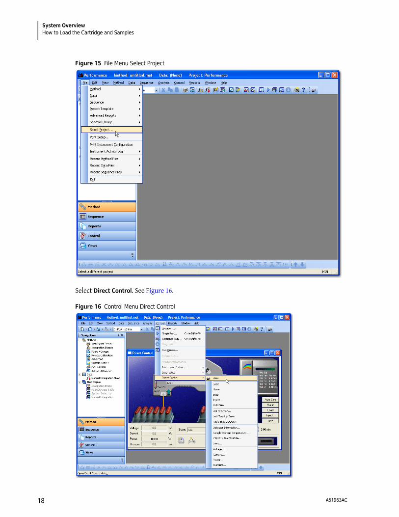
With the instrument and controller initialized, it is good practice to perform some quick checks on the system to make sure performance is correct. In the previous section, the user opened the Performance instrument online. The current project should be Performance. If the instrument is open under a different project, it is possible to select the Performance Tests project from the File menu on the instrument window. See Figure 15.
A51963AC 17
System OverviewHow to Load the Cartridge and Samples
Figure 15 File Menu Select Project
Select Direct Control. See Figure 16.
Figure 16 Control Menu Direct Control
A51963AC18

System OverviewHow to Run a Method
The direct control screen allows manual control and reports the status of the instrument functions. Icons that confirm the status of the sample cover and cartridge are located in the lower part of the screen. See Figure 17. Verify the indicators show the sample cover closed and a cartridge installed. If the sample cover is open, or if no cartridge is installed, the trays cannot move.
Figure 17 Direct Control
Select Load to move the trays to the front of the sample compartment. Inspect the interface block by using an angled mirror and penlight. Clean the interface block as required using the procedure in the PA 800 plus System Maintenance Guide.
For each supported application, this manual contains complete information on the steps required to complete a successful analysis. Before you run any application, the correct capillary and vials must be installed in the instrument. Install the cartridge and vials required to run the selected method and close the sample cover. The instrument automatically detects the trays and moves to a home position in relation to the interface block. It is now ready to run the method.
How to Run a Method
In the previous two sections, the following steps have been taken to prepare the instrument to run a method:
• Start the controller and launch 32 Karat software.
• Verify the instrument has a detector installed.
• Verify the instrument has a cartridge installed
• Turn on the instrument power.
• Open an instrument online.
• Install a cartridge with the capillary as required by the selected application.
• Install the correct vials and trays as described in the application guide.
Once these steps are completed, a method can be run.
p
A51963AC 19
System OverviewHow to Run a Method
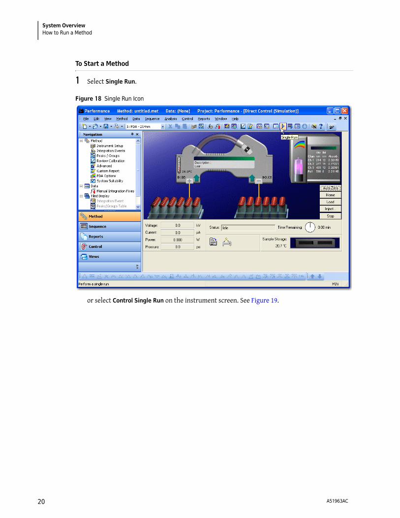
To Start a Method
1 Select Single Run.
Figure 18 Single Run Icon
or select Control Single Run on the instrument screen. See Figure 19.
A51963AC20
System OverviewHow to Run a Method
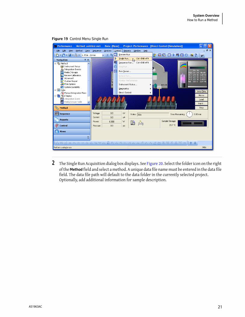
Figure 19 Control Menu Single Run
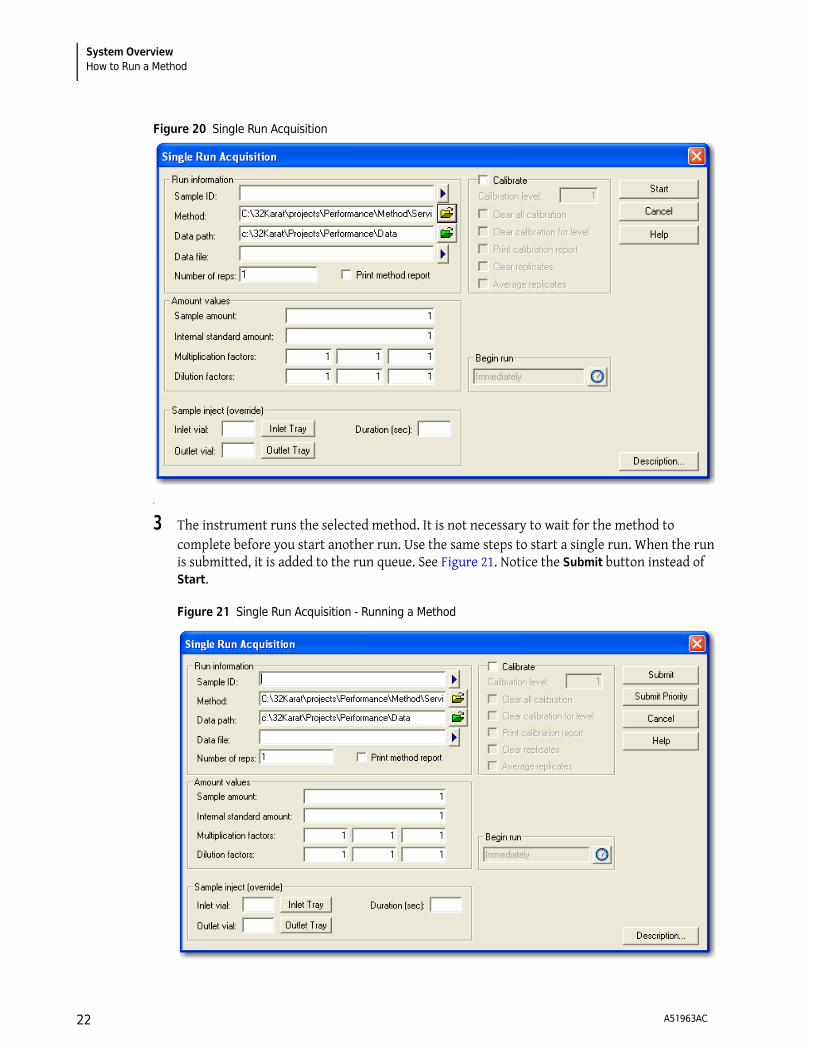
2 The Single Run Acquisition dialog box displays. See Figure 20. Select the folder icon on the right of the Method field and select a method. A unique data file name must be entered in the data file field. The data file path will default to the data folder in the currently selected project. Optionally, add additional information for sample description.
A51963AC 21
System OverviewHow to Run a Method
Figure 20 Single Run Acquisition
3 The instrument runs the selected method. It is not necessary to wait for the method to complete before you start another run. Use the same steps to start a single run. When the run is submitted, it is added to the run queue. See Figure 21. Notice the Submit button instead of Start.
Figure 21 Single Run Acquisition - Running a Method
A51963AC22
System OverviewAnalysis
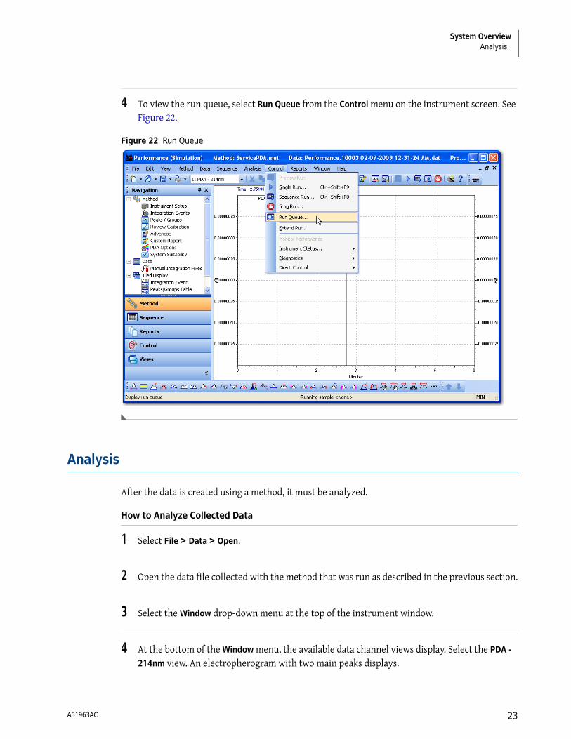
4 To view the run queue, select Run Queue from the Control menu on the instrument screen. See Figure 22.
Figure 22 Run Queue
Analysis
After the data is created using a method, it must be analyzed.
How to Analyze Collected Data
1 Select File > Data > Open.
2 Open the data file collected with the method that was run as described in the previous section.
3 Select the Window drop-down menu at the top of the instrument window.
4 At the bottom of the Window menu, the available data channel views display. Select the PDA -
214nm view. An electropherogram with two main peaks displays.
A51963AC 23
System OverviewAnalysis
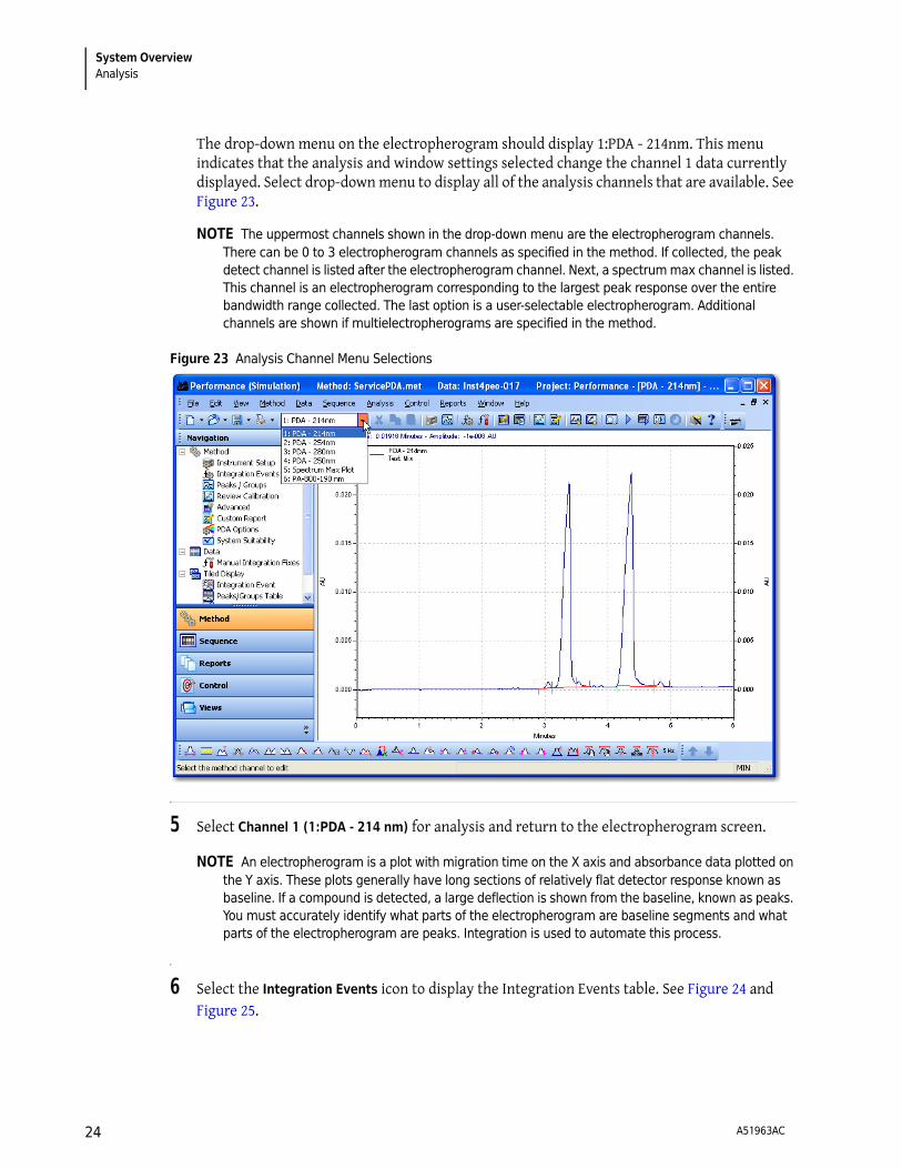
The drop-down menu on the electropherogram should display 1:PDA - 214nm. This menu indicates that the analysis and window settings selected change the channel 1 data currently displayed. Select drop-down menu to display all of the analysis channels that are available. See Figure 23.
NOTE The uppermost channels shown in the drop-down menu are the electropherogram channels. There can be 0 to 3 electropherogram channels as specified in the method. If collected, the peak detect channel is listed after the electropherogram channel. Next, a spectrum max channel is listed. This channel is an electropherogram corresponding to the largest peak response over the entire bandwidth range collected. The last option is a user-selectable electropherogram. Additional channels are shown if multielectropherograms are specified in the method.
Figure 23 Analysis Channel Menu Selections
5 Select Channel 1 (1:PDA - 214 nm) for analysis and return to the electropherogram screen.
NOTE An electropherogram is a plot with migration time on the X axis and absorbance data plotted on the Y axis. These plots generally have long sections of relatively flat detector response known as baseline. If a compound is detected, a large deflection is shown from the baseline, known as peaks. You must accurately identify what parts of the electropherogram are baseline segments and what parts of the electropherogram are peaks. Integration is used to automate this process.
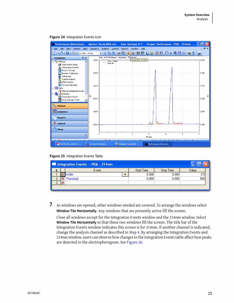
6 Select the Integration Events icon to display the Integration Events table. See Figure 24 and Figure 25.
A51963AC24
System OverviewAnalysis
Figure 24 Integration Events Icon
Figure 25 Integration Events Table
7 As windows are opened, other windows needed are covered. To arrange the windows select Window Tile Horizontally. Any windows that are presently active fill the screen.
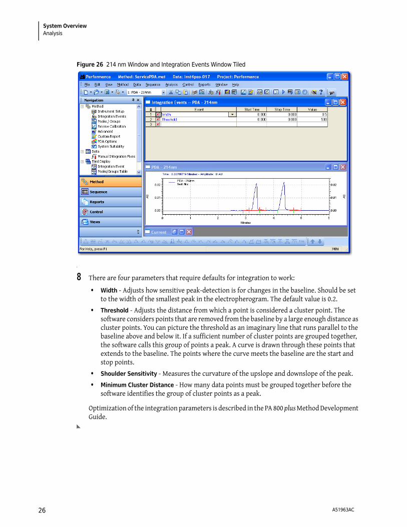
Close all windows except for the Integration Events window and the 214nm window. Select Window Tile Horizontally so that these two windows fill the screen. The title bar of the Integration Events window indicates this screen is for 214nm. If another channel is indicated, change the analysis channel as described in Step 4. By arranging the Integration Events and 214nm window, users can observe how changes to the Integration Events table affect how peaks are detected in the electropherogram. See Figure 26.
A51963AC 25
System OverviewAnalysis
Figure 26 214 nm Window and Integration Events Window Tiled
8 There are four parameters that require defaults for integration to work:
• Width - Adjusts how sensitive peak-detection is for changes in the baseline. Should be set to the width of the smallest peak in the electropherogram. The default value is 0.2.
• Threshold - Adjusts the distance from which a point is considered a cluster point. The software considers points that are removed from the baseline by a large enough distance as cluster points. You can picture the threshold as an imaginary line that runs parallel to the baseline above and below it. If a sufficient number of cluster points are grouped together, the software calls this group of points a peak. A curve is drawn through these points that extends to the baseline. The points where the curve meets the baseline are the start and stop points.
• Shoulder Sensitivity - Measures the curvature of the upslope and downslope of the peak.
• Minimum Cluster Distance - How many data points must be grouped together before the software identifies the group of cluster points as a peak.
Optimization of the integration parameters is described in the PA 800 plus Method Development Guide.
A51963AC26
System OverviewAnalysis
Area Calculation
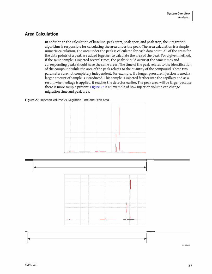
In addition to the calculation of baseline, peak start, peak apex, and peak stop, the integration algorithm is responsible for calculating the area under the peak. The area calculation is a simple numeric calculation. The area under the peak is calculated for each data point. All of the areas for the data points of a peak are added together to calculate the area of the peak. For a given method, if the same sample is injected several times, the peaks should occur at the same times and corresponding peaks should have the same areas. The time of the peak relates to the identification of the compound while the area of the peak relates to the quantity of the compound. These two parameters are not completely independent. For example, if a longer pressure injection is used, a larger amount of sample is introduced. This sample is injected farther into the capillary and as a result, when voltage is applied, it reaches the detector earlier. The peak area will be larger because there is more sample present. Figure 27 is an example of how injection volume can change migration time and peak area.
Figure 27 Injection Volume vs. Migration Time and Peak Area
901499L.AI
A51963AC 27
System OverviewAnalysis
Capillary condition or temperature also affects these parameters. A cooler temperature causes the viscosity of the solutions to change. This in turn causes a change in injection volume and the parameters change as previously described. In these two examples, the performance of the instrument is responsible for the change. If the capillary condition is not good, the migration time can change due to a condition known as electroosmotic flow. This condition is the result of ionization of the capillary wall. This ionization causes a bulk fluid flow through the capillary from the positive to negative electrode. This flow adds or subtracts to the velocity of the compound’s inherent mobility.
The compound reaches the detector at a different time because it moves at a different velocity. The change in velocity causes the compound to stay in front of the detector for a different amount of time. This causes the detector response to be different. A slow moving peak is reported as a larger peak than a similar sized fast-moving peak. This condition is not caused by instrument performance, but is minimized in an optimal method. To further adjust for this condition, the peak area reported with the peak velocity can be corrected. The resultant area value is called corrected area. 32 Karat software can calculate this amount automatically.
Annotations
Select the box near the upper-right corner of the 214 nm window to maximize the 214 nm window. If the data is analyzed, baseline and peak marks are present on the electropherogram. The baseline segments are shown in red across the bottom of the peaks. Short vertical tick marks indicate the peak start and stop locations. The peak start is drawn in red below the baseline segment and the peak stop is drawn in blue above the baseline segment. Right-click on the display and select Annotations. The Trace Annotations Properties dialog box will display. At the bottom of the Trace Annotations Properties dialog box there are options for general graph properties.
A51963AC28
System OverviewPeak Identity
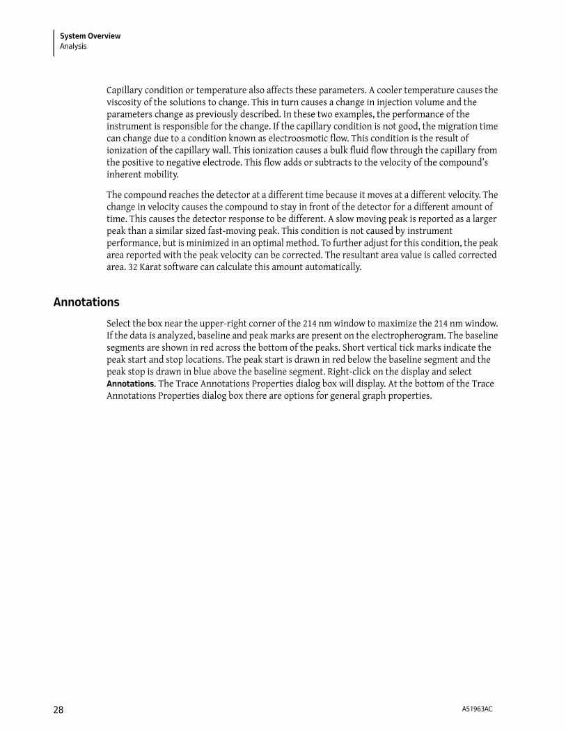
Figure 28 Trace Annotation Properties Dialog Box
By default, the Baseline and Show undetected named peaks options are selected. The Available Annotations option contains parameters that can be displayed for each peak. Select Peak # and Name using the green arrow to move them to the right pane. See Figure 28, then select Apply. As a result the peak numbers are displayed above the peaks. Peak names are displayed on the electropherogram because they are programmed into the method. Depending on the quality of the separation, the peak names may not be associated with the correct peaks at this point in time.
Peak Identity
Add information to the Peak table to name a peak. This information is already entered in the Peak table for the default methods supplied with the PA 800 plus system. In other supported applications with unknown samples, it may be necessary to add new peak information to the Peak table. For details on adding peaks to the peak ID table, see the PA 800 plus Method Development User’s Guide.
Run Multiple Methods with a Sequence
Once the method and analysis are optimized, the method can be run repeatedly on different samples or multiple times on a single sample to calculate the performance. To automate this
A51963AC 29
System OverviewRun Multiple Methods with a Sequence
process, program a sequence. The easiest way to program a sequence is by using the Sequence Wizard. The Sequence Wizard runs the same method the specified number of times. There are many additional selections for run customization using the Sequence Wizard. For details on using the Sequence Wizard see the PA 800 plus Method Development User’s Guide.
Process the Sequence
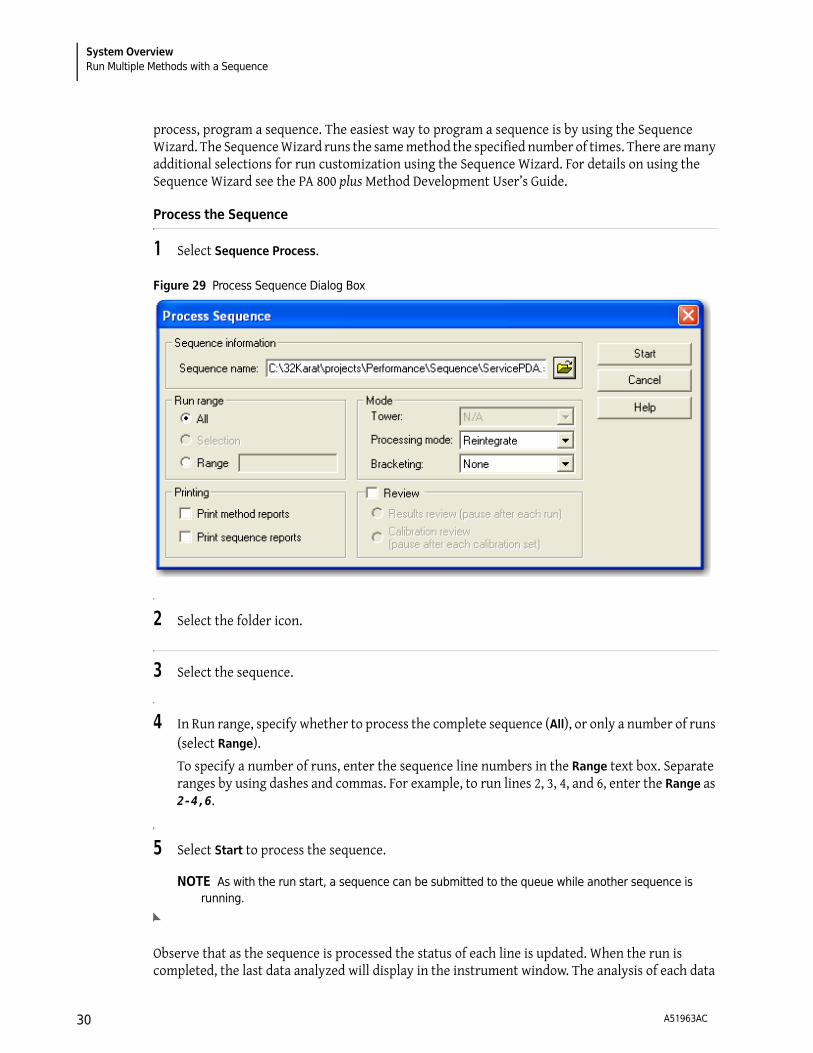
1 Select Sequence Process.
Figure 29 Process Sequence Dialog Box
2 Select the folder icon.
3 Select the sequence.
4 In Run range, specify whether to process the complete sequence (All), or only a number of runs (select Range).
To specify a number of runs, enter the sequence line numbers in the Range text box. Separate ranges by using dashes and commas. For example, to run lines 2, 3, 4, and 6, enter the Range as 2-4,6.
5 Select Start to process the sequence.
NOTE As with the run start, a sequence can be submitted to the queue while another sequence is running.
Observe that as the sequence is processed the status of each line is updated. When the run is completed, the last data analyzed will display in the instrument window. The analysis of each data
A51963AC30
System OverviewRun Multiple Methods with a Sequence
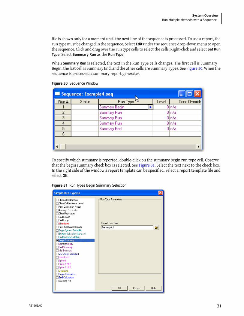
file is shown only for a moment until the next line of the sequence is processed. To use a report, the run type must be changed in the sequence. Select Edit under the sequence drop-down menu to open the sequence. Click and drag over the run type cells to select the cells. Right-click and select Set Run Type. Select Summary Run as the Run Type.
When Summary Run is selected, the text in the Run Type cells changes. The first cell is Summary Begin, the last cell is Summary End, and the other cells are Summary Types. See Figure 30. When the sequence is processed a summary report generates.
Figure 30 Sequence Window
To specify which summary is reported, double-click on the summary begin run type cell. Observe that the begin summary check box is selected. See Figure 31. Select the text next to the check box. In the right side of the window a report template can be specified. Select a report template file and select OK.
Figure 31 Run Types Begin Summary Selection
A51963AC 31
System OverviewRun Multiple Methods with a Sequence
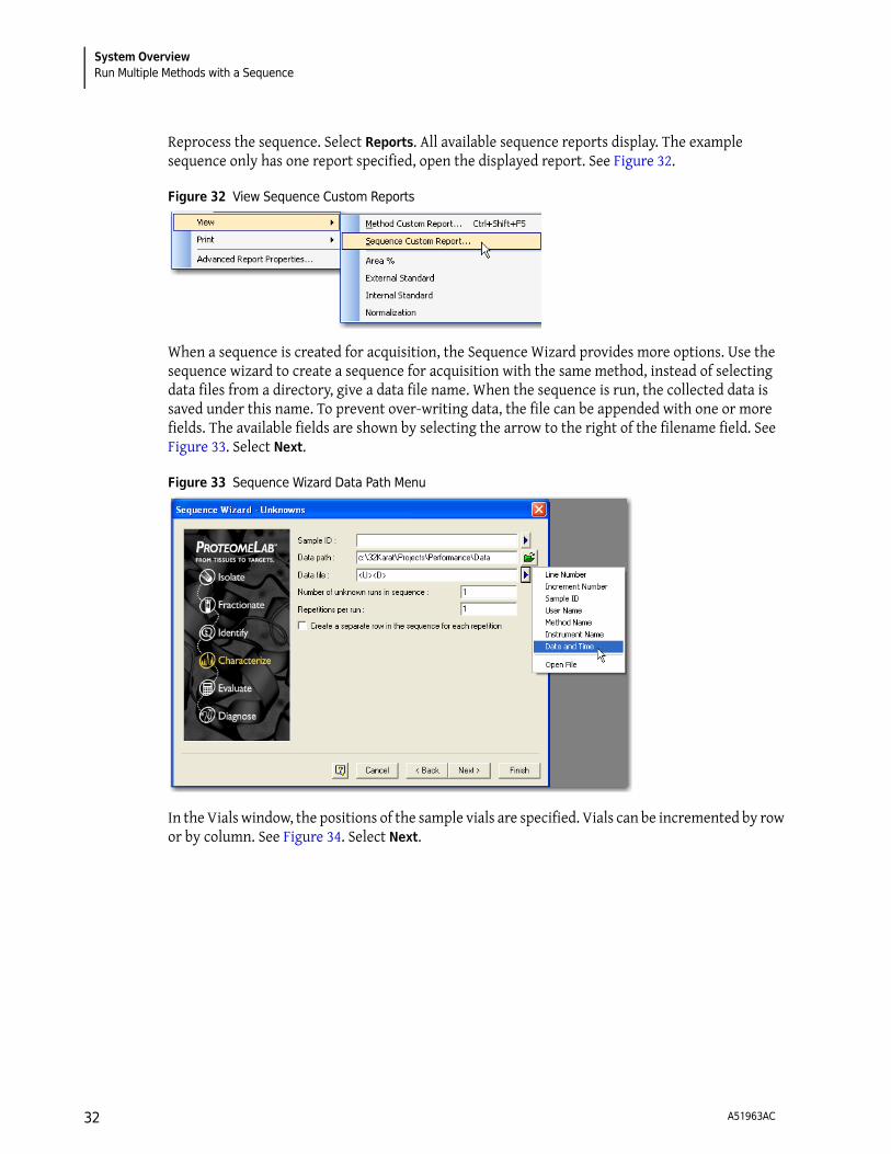
Reprocess the sequence. Select Reports. All available sequence reports display. The example sequence only has one report specified, open the displayed report. See Figure 32.
Figure 32 View Sequence Custom Reports
When a sequence is created for acquisition, the Sequence Wizard provides more options. Use the sequence wizard to create a sequence for acquisition with the same method, instead of selecting data files from a directory, give a data file name. When the sequence is run, the collected data is saved under this name. To prevent over-writing data, the file can be appended with one or more fields. The available fields are shown by selecting the arrow to the right of the filename field. See Figure 33. Select Next.
Figure 33 Sequence Wizard Data Path Menu
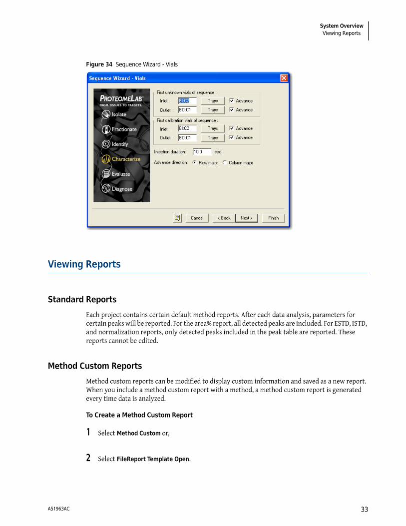
In the Vials window, the positions of the sample vials are specified. Vials can be incremented by row or by column. See Figure 34. Select Next.
A51963AC32
System OverviewViewing Reports
Figure 34 Sequence Wizard - Vials
Viewing Reports
Standard Reports
Each project contains certain default method reports. After each data analysis, parameters for certain peaks will be reported. For the area% report, all detected peaks are included. For ESTD, ISTD, and normalization reports, only detected peaks included in the peak table are reported. These reports cannot be edited.
Method Custom Reports
Method custom reports can be modified to display custom information and saved as a new report. When you include a method custom report with a method, a method custom report is generated every time data is analyzed.
To Create a Method Custom Report
1 Select Method Custom or,
2 Select FileReport Template Open.
A51963AC 33

System OverviewViewing Reports
3 Select the report template, for example the external standard report template, External Standard.Srp.
4 Modify the report by right-clicking on any section of the report.
5 Select FileReport Template Save as.
6 Save the report as CRPtrain.srp.
Sequence Custom Report
On the surface, sequence custom reports look very similar to the custom method reports. However, the available parameters are more particular to the sequence than to the data. These reports only generate after processing a sequence, if the report template is specified as part of the sequence.
Advanced Reports
Detailed information on Advanced Reports is in the PA 800 Data System Help delivered with the PA 800 plus product.
How To Write an Advanced Report
1 Select File Advanced Reports New….
2 Right-click on cell A1 of the report screen and select Table Wizard.
3 Select Sequence Summary Table and select Next.
A list of peak parameters displays.
4 To obtain a sequence summary of Area and Migration Time, select those parameters and select Add to add them to the right panel of the window.
For this example, select Area and Migration Time.
5 The Index is used to select which trace is reported on. When Index is selected, a list of traces displays.
A51963AC34

System OverviewViewing Reports
6 The Precision field, located at the bottom of the screen, determines the number of digits after the decimal point. Select Next.
7 The current screen contains options for the types of peak in the report. Select option 1 name and option 2 name to report all named peaks.
8 On the current screen specify the data file parameters by selecting the data file name and selecting the right arrow. Select Next.
9 The current screen configures the data display on reports (by row or by column). Select Next.
• This screen asks if you want the report to display data by row or by column.
• Click Next.
• The final window asks if you want to display statistics.
10 The current screen contains the option for displaying statistics. Select Yes and Finish.
11 Select File > Advanced reports > Save as….
Save the report as a template using the file name RSD.tpl.
This file is a report shell that is ready to summarize and report a sequence when it is run.
Suitability Reports
A suitability report is a special type of sequence report. To generate a suitability report, create a sequence with Begin Suitability and End Suitability run types. From the Begin Suitability Run Type window, specify the desired template. To change the suitability parameters included in the report, select Method from the instrument drop-down menu.
NOTE System Suitability is only available if System Suitability is selected in the instrument configuration. All default PA 800 plus instrument configurations have System Suitability enabled.
Viewing and Printing Reports
To view or print a report, select the Reports menu on the instrument screen. If the Print Reports option is selected on the Run screen, method or sequence reports are automatically printed.
A51963AC 35

System OverviewMaintenance
Maintenance
Refer to the PA 800 plus System Maintenance Guide for the following procedures. Start with the type of detector to be installed, then proceed to the remaining items.
• Installing the UV or PDA Detectors
• Calibrate PDA Detector
• Installing UV Detector Wavelength Filters
• Installing LIF Detector
• Calibrate LIF Detector
• Capillary Cartridge Procedures
• Filling Vials and Installing Vial Caps
• Cleaning Interface Block and Ejectors
• Replace Electrodes
• Refilling Coolant
• Cleaning Fiber Optics
• Changing the Lamp
• Instrument Care
A51963AC36
System OverviewRecord of Operator Training
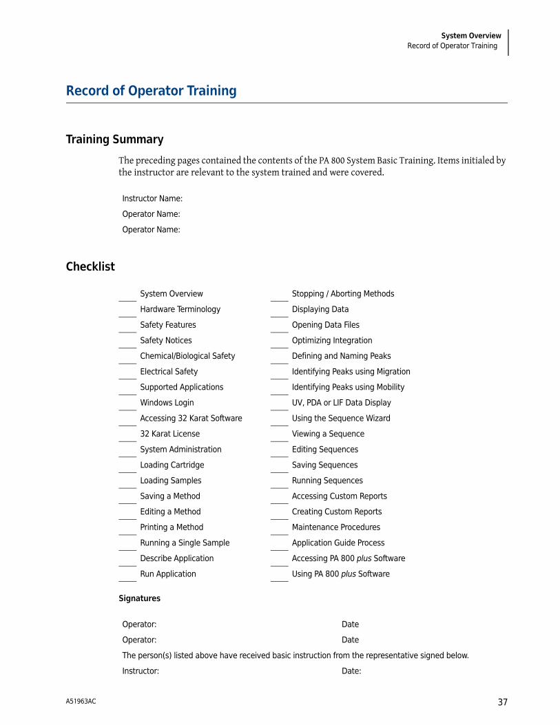
Record of Operator Training
Training Summary
The preceding pages contained the contents of the PA 800 System Basic Training. Items initialed by the instructor are relevant to the system trained and were covered.
Checklist
Signatures
Instructor Name:
Operator Name:
Operator Name:
System Overview Stopping / Aborting Methods
Hardware Terminology Displaying Data
Safety Features Opening Data Files
Safety Notices Optimizing Integration
Chemical/Biological Safety Defining and Naming Peaks
Electrical Safety Identifying Peaks using Migration
Supported Applications Identifying Peaks using Mobility
Windows Login UV, PDA or LIF Data Display
Accessing 32 Karat Software Using the Sequence Wizard
32 Karat License Viewing a Sequence
System Administration Editing Sequences
Loading Cartridge Saving Sequences
Loading Samples Running Sequences
Saving a Method Accessing Custom Reports
Editing a Method Creating Custom Reports
Printing a Method Maintenance Procedures
Running a Single Sample Application Guide Process
Describe Application Accessing PA 800 plus Software
Run Application Using PA 800 plus Software
Operator: Date
Operator: Date
The person(s) listed above have received basic instruction from the representative signed below.
Instructor: Date:
A51963AC 37

System OverviewRecord of Operator Training
A51963AC38


© 2009-2011 Beckman Coulter, Inc.All Rights Reserved
www.beckmancoulter.com
www.beckmancoulter.com andwww.CELeader.com
Related Documents