www.lamtec.de 2ppm 110° 97,4 1.1 % Combustion Made Simple Sensors and systems for combustion engineering System Overview CMS Combustion Management System

Welcome message from author
This document is posted to help you gain knowledge. Please leave a comment to let me know what you think about it! Share it to your friends and learn new things together.
Transcript
www.lamtec.de
2ppm
110°
97,4
1.1 %
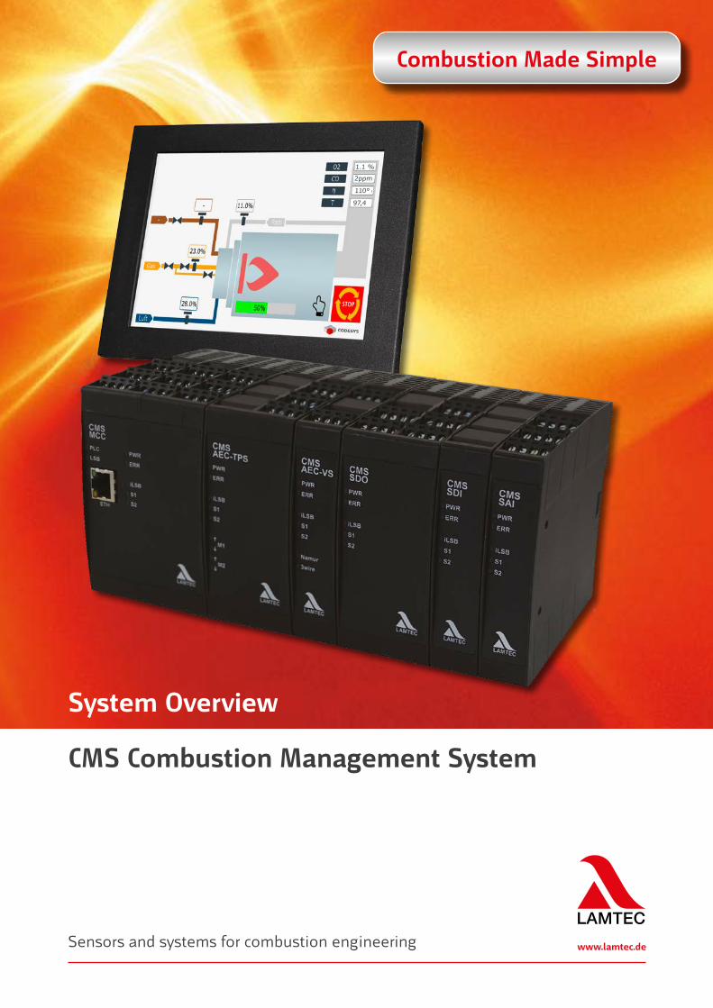
Combustion Made Simple
Sensors and systems for combustion engineering
System Overview
CMS Combustion Management System

2
LAMTEC | CMS Combustion Management System
M
M
M
M
MODBUS TCP
LAMTEC SYSTEM BUS
VISIOCONTROL
Boiler pressure
r.p.m. sensor
Flame sensor
GasOil
User InterfaceUI400
GUI607
Laptop
UI400
GUI607
2ppm
140°
98,4
1.1 %
Ambient temperature
Frequency inverter
LT (for O2 Measurement and CO Detection)
Probe
Air
Function overview CMS.
www.lamtec.de 3
Visualisation when using GUI HMI options
Integrated fault indicator system Fieldbus on-board Centralised or distributed module
architecture
Advantages:
Modular burner management Simple operation From basic to high end applications Freely configurable I/O (Inputs/Outputs) Language neutral by using symbols and
graphics World wide approvals CE/UL/SIL3 CODESYS Soft-PLC integrated
4 Correction inputs e.g. temperature compensation
Fixed ratio mixed combustion for simultaneous combustion of up to 4 fuels
Compliance with current safety requirements
CO/O2 Control for combustion optimisation Integrated flame monitoring
(optical flame sensor or ionisation) Internet security (intrusion protection,
data encryption)
Technical Highlights:
Up to 10 servo motors for fuel/air ratio control
Up to 60 failsafe digital inputs Up to 41 failsafe digital outputs Up to 18 analogue inputs (alternatively up
to 9 failsafe analogue inputs) Up to 16 curve sets 4 Fuel trains Up to 4 valve leakage tests
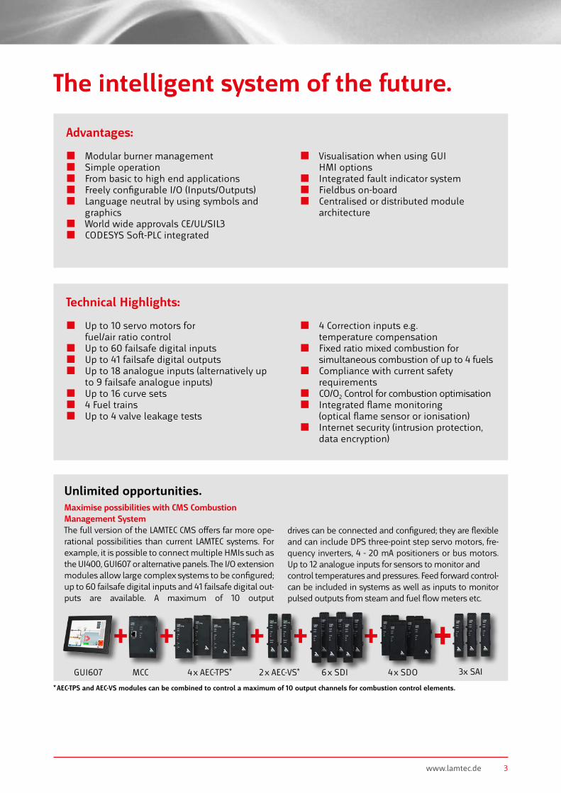
Maximise possibilities with CMS Combustion Management SystemThe full version of the LAMTEC CMS offers far more ope-rational possibilities than current LAMTEC systems. For example, it is possible to connect multiple HMIs such as the UI400, GUI607 or alternative panels. The I/O extension modules allow large complex systems to be configured; up to 60 failsafe digital inputs and 41 failsafe digital out-puts are available. A maximum of 10 output
drives can be connected and configured; they are flexible and can include DPS three-point step servo motors, fre-quency inverters, 4 - 20 mA positioners or bus motors. Up to 12 analogue inputs for sensors to monitor andcontrol temperatures and pressures. Feed forward control-can be included in systems as well as inputs to monitor pulsed outputs from steam and fuel flow meters etc.
* AEC-TPS and AEC-VS modules can be combined to control a maximum of 10 output channels for combustion control elements.
Unlimited opportunities.
The intelligent system of the future.
+ + + + +MCCGUI607 4 x AEC-TPS* 2 x AEC-VS* 4 x SDO6 x SDI 3x SAI
+2ppm
110°
97,4
1.1 %
4
LAMTEC | CMS Combustion Management System
Combustion Management System –The Evolution of Combustion Management.
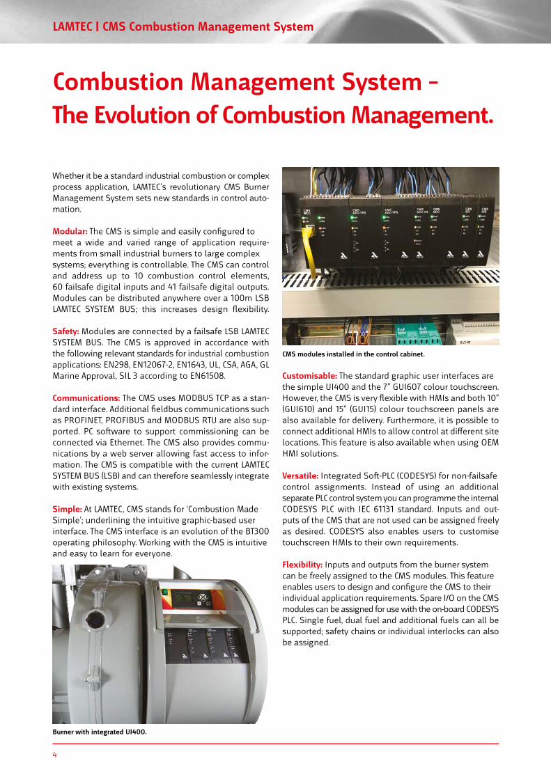
CMS modules installed in the control cabinet.
Burner with integrated UI400.
Whether it be a standard industrial combustion or complex process application, LAMTEC’s revolutionary CMS Burner Management System sets new standards in control auto-mation.
Modular: The CMS is simple and easily configured tomeet a wide and varied range of application require-ments from small industrial burners to large complexsystems; everything is controllable. The CMS can control and address up to 10 combustion control elements, 60 failsafe digital inputs and 41 failsafe digital outputs. Modules can be distributed anywhere over a 100m LSB LAMTEC SYSTEM BUS; this increases design flexibility.
Safety: Modules are connected by a failsafe LSB LAMTEC SYSTEM BUS. The CMS is approved in accordance with the following relevant standards for industrial combustion applications: EN298, EN12067-2, EN1643, UL, CSA, AGA, GL Marine Approval, SIL 3 according to EN61508.
Communications: The CMS uses MODBUS TCP as a stan-dard interface. Additional fieldbus communications such as PROFINET, PROFIBUS and MODBUS RTU are also sup-ported. PC software to support commissioning can be connected via Ethernet. The CMS also provides commu-nications by a web server allowing fast access to infor-mation. The CMS is compatible with the current LAMTEC SYSTEM BUS (LSB) and can therefore seamlessly integrate with existing systems.
Simple: At LAMTEC, CMS stands for ‘Combustion MadeSimple’; underlining the intuitive graphic-based userinterface. The CMS interface is an evolution of the BT300operating philosophy. Working with the CMS is intuitiveand easy to learn for everyone.
Customisable: The standard graphic user interfaces arethe simple UI400 and the 7” GUI607 colour touchscreen.However, the CMS is very flexible with HMIs and both 10”(GUI610) and 15” (GUI15) colour touchscreen panels are also available for delivery. Furthermore, it is possible to connect additional HMIs to allow control at different sitelocations. This feature is also available when using OEMHMI solutions.
Versatile: Integrated Soft-PLC (CODESYS) for non-failsafecontrol assignments. Instead of using an additional separate PLC control system you can programme the internal CODESYS PLC with IEC 61131 standard. Inputs and out-puts of the CMS that are not used can be assigned freely as desired. CODESYS also enables users to customise touchscreen HMIs to their own requirements.
Flexibility: Inputs and outputs from the burner systemcan be freely assigned to the CMS modules. This featureenables users to design and configure the CMS to theirindividual application requirements. Spare I/O on the CMS modules can be assigned for use with the on-board CODESYS PLC. Single fuel, dual fuel and additional fuels can all be supported; safety chains or individual interlocks can also be assigned.
www.lamtec.de 5
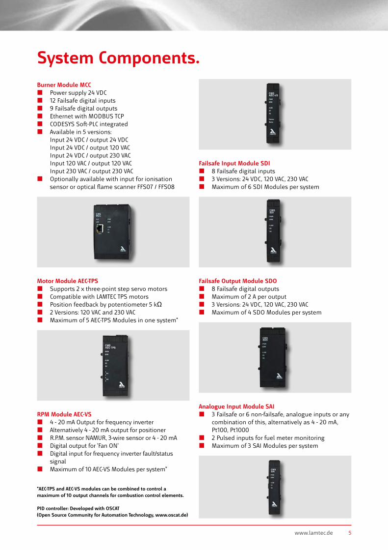
System Components.Burner Module MCC
Power supply 24 VDC 12 Failsafe digital inputs 9 Failsafe digital outputs Ethernet with MODBUS TCP CODESYS Soft-PLC integrated Available in 5 versions:
Input 24 VDC / output 24 VDC Input 24 VDC / output 120 VAC Input 24 VDC / output 230 VAC Input 120 VAC / output 120 VAC Input 230 VAC / output 230 VAC
Optionally available with input for ionisation sensor or optical flame scanner FFS07 / FFS08
RPM Module AEC-VS 4 - 20 mA Output for frequency inverter Alternatively 4 - 20 mA output for positioner R.P.M. sensor NAMUR, 3-wire sensor or 4 - 20 mA Digital output for 'Fan ON' Digital input for frequency inverter fault/status
signal Maximum of 10 AEC-VS Modules per system*
Motor Module AEC-TPS Supports 2 x three-point step servo motors Compatible with LAMTEC TPS motors Position feedback by potentiometer 5 kΩ 2 Versions: 120 VAC and 230 VAC Maximum of 5 AEC-TPS Modules in one system*
Failsafe Input Module SDI 8 Failsafe digital inputs 3 Versions: 24 VDC, 120 VAC, 230 VAC Maximum of 6 SDI Modules per system
Failsafe Output Module SDO 8 Failsafe digital outputs Maximum of 2 A per output 3 Versions: 24 VDC, 120 VAC, 230 VAC Maximum of 4 SDO Modules per system
Analogue Input Module SAI 3 Failsafe or 6 non-failsafe, analogue inputs or any
combination of this, alternatively as 4 - 20 mA, Pt100, Pt1000
2 Pulsed inputs for fuel meter monitoring Maximum of 3 SAI Modules per system
*AEC-TPS and AEC-VS modules can be combined to control a maximum of 10 output channels for combustion control elements. PID controller: Developed with OSCAT (Open Source Community for Automation Technology, www.oscat.de)

6
LAMTEC | CMS Combustion Management System
System Components.Power supplies
Input 110 V - 240 V, Output 24 VDC 15 W - 150 W DIN Rail mounting
Display Module UI400 Low cost HMI Graphic user interface Symbol based - language neutral Easy operation Connection by LAMTEC SYSTEM BUS (LSB) Distance between MCC up to 500 m
Display Module GUI6XX 7“, 10“ and 15“ touchscreen panel Graphic user interface Mostly language neutral Graphic plant display Can be used for CMS backup and restore Graphical display is adaptable to customer
specifications Setup assistant Distance to MCC is unlimited (Ethernet)
PC Software Software for complete configuration Backup and restore of settings Connection to CMS by Ethernet Printing of the wiring diagram Checklist for equipment test Parameter checking against standards
2ppm
110°
97,4
1.1 %
Soft-PLC Individual configuration of non-failsafe functions Integrated in MCC and GUI CODESYS standard software
CO/O2 Control LAMTEC CO/O2 Control connected by LSB Compatible with all LAMTEC combustion analysers
by LSB - LT1, LT2, LT3 & LT3-F Increased combustion efficiency and emissions
reduction Increased safety

www.lamtec.de 7
Flame detection FFS07 / FFS08 are interfaced directly to MCC
(optional) Direct connection for ionisation sensor Connection of compact flame scanner F200K
and F300K by digital inputs Connection of up to 3 main flame scanners
and one pilot flame scanner possible
Measuring systems All LAMTEC O2/COe measuring systems can be
connected to the CMS by LSB Increases safety and combustion efficiency
CMS Actuating motor 6 Nm - 180 Nm Maximum of 10 actuators per CMS system
Fieldbus modules Interface to other Fieldbus systems Protocols available:
MODBUS TCP on-board PROFIBUS DP PROFINET
Cover IP65Cover for UI400, delivery includes fixing nuts
Cover to achieve protection class IP65
8
LAMTEC | CMS Combustion Management System
FUNCTIONS software package
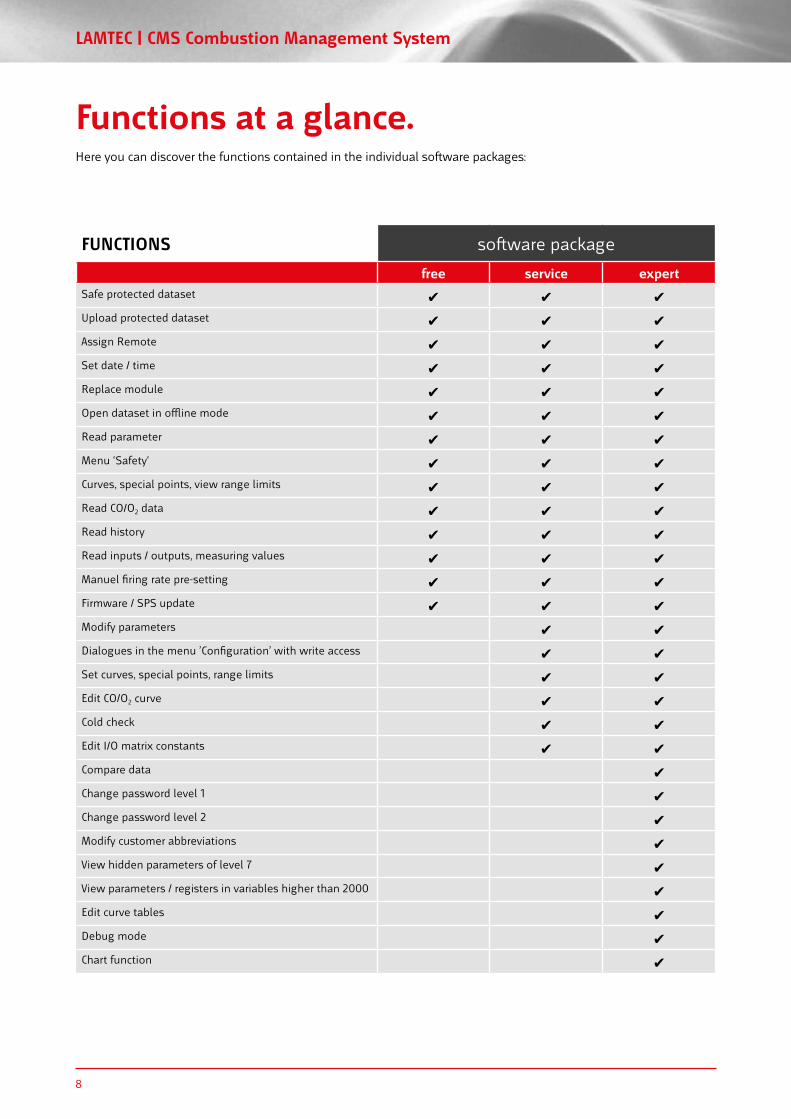
free service expertSafe protected dataset Upload protected dataset Assign Remote Set date / time Replace module Open dataset in offline mode Read parameter Menu ‘Safety‘ Curves, special points, view range limits Read CO/O2 data Read history Read inputs / outputs, measuring values Manuel firing rate pre-setting Firmware / SPS update Modify parameters Dialogues in the menu ’Configuration’ with write access Set curves, special points, range limits Edit CO/O2 curve Cold check Edit I/O matrix constants Compare data Change password level 1 Change password level 2 Modify customer abbreviations View hidden parameters of level 7 View parameters / registers in variables higher than 2000 Edit curve tables Debug mode Chart function
Functions at a glance.Here you can discover the functions contained in the individual software packages:

www.lamtec.de 9
FUNCTIONS software package
free service expertSafe protected dataset Upload protected dataset Assign Remote Set date / time Replace module Open dataset in offline mode Read parameter Menu ‘Safety‘ Curves, special points, view range limits Read CO/O2 data Read history Read inputs / outputs, measuring values Manuel firing rate pre-setting Firmware / SPS update Modify parameters Dialogues in the menu ’Configuration’ with write access Set curves, special points, range limits Edit CO/O2 curve Cold check Edit I/O matrix constants Compare data Change password level 1 Change password level 2 Modify customer abbreviations View hidden parameters of level 7 View parameters / registers in variables higher than 2000 Edit curve tables Debug mode Chart function
Notes.

10
LAMTEC | CMS Combustion Management System
Notes.
www.lamtec.de 11
Notes.

Approvals.
EC Declaration of Conformity 2014/35/EU (Low Voltage Directive) 2014/30/EU (EMC Directive) 2014/68/EU (Pressure Equipment Directive
Kat. 4 Mod. B+D) (EU) 2016/426 Gas Appliances Regulation
EC Type Examination Certificate EU/2009/142/EG DIN EN 298 DIN EN 13611 DIN EN 1643 DIN EN 12067-2
0085
EC Type Examination Certificate
DIN EN 61508 parts 1-7
SIL 3
Publication no. DLT1230-21-aEN-014Printed in Germany I Copyright © 2021 LAMTEC
LAMTEC Meß- und Regeltechnikfür Feuerungen GmbH & Co. KGJosef-Reiert-Straße 26D-69190 WalldorfTelephone: +49 (0) 6227 6052-0Fax: +49 (0) 6227 6052-57 [email protected] www.lamtec.de
2014/68/EU (Modul B)
SIL 3 Certificate
Eurasian Conformity TP TC 016/2011
LAMTEC | CMS Combustion Management System
In Preparation
UL Listed ANSI/UL 60730-2-5 CAN/CSA C22.2 No. 60730-2-5 ANSI/UL 60730-1 CAN/CSA-E60730-1
Related Documents