Dynamic Training Simulator System for a Generic IGCC Plant For DOE NETL’s IGCC DSR&T Center Morgantown, WV Functional Design Specification Generic IGCC Plant Dynamic Training Simulator December 2008 IPS Contacts: Ted Fediw Senior Consultant (713) 329-8459 [email protected] Leslie Burke Consultant II (760) 268-7784 [email protected]

Welcome message from author
This document is posted to help you gain knowledge. Please leave a comment to let me know what you think about it! Share it to your friends and learn new things together.
Transcript

Dynamic Training Simulator System for a Generic IGCC Plant
For
DOE NETL’s IGCC DSR&T Center
Morgantown, WV
Functional Design Specification Generic IGCC Plant
Dynamic Training Simulator
December 2008
IPS Contacts:
Ted Fediw Senior Consultant (713) 329-8459 [email protected] Leslie Burke Consultant II (760) 268-7784 [email protected]
Department of Energy IGCC Dynamic Training Simulator Functional Design
December 2008 1
TABLE OF CONTENTS
1. Introduction ...................................................................................................................... 3
Purpose .............................................................................................................................. 3
2. Scope ................................................................................................................................. 3
General ............................................................................................................................... 3
Location .............................................................................................................................. 4
Work Included .................................................................................................................... 4
Other Work and Support .................................................................................................... 5
3. Simulation Model and Database .................................................................................... 6
General ............................................................................................................................... 6
System Description ............................................................................................................ 6
Simulator Software ............................................................................................................. 6
Controls and Modeling Software ........................................................................................ 7
Component Simulation ....................................................................................................... 7
Model System Summary .................................................................................................. 14
4. Simulator Capabilities ................................................................................................... 41
Instructor Station .............................................................................................................. 41
Trainee Station ................................................................................................................. 42
5. Simulator Performance Criteria ................................................................................... 42
Performance ..................................................................................................................... 42
6. Inspection and Testing .................................................................................................. 43
Model Acceptance Test (MAT)......................................................................................... 44
Factory Acceptance Test (FAT) ....................................................................................... 44
Site Acceptance Test (SAT) ............................................................................................. 44
Department of Energy IGCC Dynamic Training Simulator Functional Design
December 2008 2
7. Documentation ............................................................................................................... 45
Appendix I: Preliminary Malfunction List ........................................................................... 46
Appendix II: Required Data List ........................................................................................... 52
Appendix III: Preliminary Remote Function List ................................................................ 53
Department of Energy IGCC Dynamic Training Simulator Functional Design
December 2008 3
1. Introduction
This functional design specification document (hereafter referred to as the “FDS”) clarifies and expands the requirements listed in the Invensys Operator Training Simulator Proposal to the US Department of Energy’s (DOE) National Energy Technology Laboratory’s (NETL) Integrated Gasifier Combined Cycle (IGCC) Dynamic Simulator Research and Training (DSR&T) Center at Morgantown, West Virginia. The proposal describes general requirements for an operator training simulator for the generic IGCC plant; this FDS presents simulator modeling requirements in greater detail, with supporting Appendices to define simulator scope. The information contained herein is CONFIDENTIAL INFORMATION of DOE and Invensys, and is not to be reproduced in any manner, either electronically or photographically, without written consent of DOE and Invensys.
Purpose
The simulator will be used for 1. promoting the IGCC technology in the United States by demonstrating that
IGCC plants can produce environmentally friendly coal-fueled electricity on a commercial scale while eradicating the emissions created by conventional power plants
2. demonstration, education, and training services such as IGCC process operation, control demonstrations, and hands-on computer-based training.
3. engineering studies 4. evaluating control and process dynamic changes
2. Scope
General
Invensys will provide DOE with a generic IGCC operator training simulator. Invensys will base the process model on the information and data provided by DOE. The simulator is to be a high fidelity simulator that is capable of simulating plant startup, shutdown, normal, and abnormal operation. The simulator shall include a detailed process model including reactors, separators, absorber, fractionators, heat exchangers, and compressors. This model shall be based on fundamental conservation and thermodynamic equations and non-linear characterizations of valves, pumps, fans, etc. All DCS controls will be in the process model. The controls will be interfaced with the InTouch HMI. Emergency Shutdown (ESD) logic will be included with the process model.
Department of Energy IGCC Dynamic Training Simulator Functional Design
December 2008 4
Location
The simulator will be installed and commissioned at the DOE NETL IGCC DSR&T Center in Morgantown, West Virginia. Invensys will coordinate development of the simulator in Houston, Texas. The FAT will be conducted at Invensys’ offices in Houston. The SAT will be conducted at the DSR&T Center in Morgantown.
Work Included
Invensys is responsible for system design, hardware and software procurement, configuration, integration, testing, delivery, installation, commissioning, and training for simulator hardware and software. The following is a summary of the equipment, software, and services that shall be included: 1. Computer System
Invensys will provide all of the hardware required for the DOE IGCC simulator.
2. Operator (Trainee) Stations
The OTS design will use Process Graphics which will be designed specifically for the IGCC simulator. There will be 6 (six) operator stations as specified in the proposal.
3. ESD System ESD logic will be incorporated into the Dynsim and DynsimP process models.
4. Instructor Station Invensys will provide the Sim4Me™ software with its graphical instructor station interface on the master simulation computer (provided by Invensys). The Instructor Station shall include a complete set of functions that shall allow an instructor to setup and conduct training exercises.
5. Process Simulation Initially, individual models (ASU, Gasifier/Selexol, SRU/Tail Gas, CC) will be developed. These individual models will be combined into one complete model. Also, the ASU, Gasifier/Selexol, and SRU/Tail Gas models will be combined into a separate model, standing along from CC. The process models will be constructed in Dynsim™ and DynsimP™ and operate under Invensys’ Sim4Me™ dynamic simulation software environment.
7. Testing
The simulator will be tested as per a comprehensive Acceptance Test Plan (ATP). The testing will consist of a Model Acceptance Test (MAT), a Factory

Department of Energy IGCC Dynamic Training Simulator Functional Design
December 2008 5
Acceptance Test (FAT), and a Site Acceptance Test (SAT), which shall demonstrate to DOE that the simulator fully meets the requirements of these specifications.
8. Training
Invensys will provide instructor training to DOE staff that is sufficient to allow the instructors to fully operate the simulator system. Model building and model maintenance training will also be provided to DOE staff. The training course will be held at Invensys’ facilities in Houston, TX.
Other Work and Support
1. Services and Facilities All services and facilities, such as but not limited to electrical power, HVAC and UPS required at the site will be furnished by DOE.
2. Data for the Simulation Model
Invensys will provide an engineering design for the simulator. The basic data required for developing, testing and validating the simulation model will be provided by DOE. The simulation P&IDs will be developed from the PFDs provided by DOE. Invensys will use industry standards and its own experience to develop more detailed P&IDs. Additional data will be either developed by Invensys through engineering experience or literature data.
3. Control System Configuration
The control system will be designed by Invensys. The DCS interface will use Wonderware’s InTouch system.

Department of Energy IGCC Dynamic Training Simulator Functional Design
December 2008 6
3. Simulation Model and Database
General
System Description
Invensys shall deliver a high fidelity, real-time, unit specific simulator capable of training operators on start-up, shutdown, normal and abnormal operations for a generic IGCC plant. The simulator system shall include a DCS interface using Wonderware’s InTouch system. The simulator will include one complete process model of the Gasifier/Selexol, Sulfur Recovery Unit (SRU)/Tail Gas Treatment, Air Separation Unit (ASU), and combined cycle (CC) plant and two separate models (one model will be the CC plant, the other will be all other units mentioned above), subject to the scope outlined in this FDS. The two individual models will be developed and tested initially. After model acceptance testing has been completed on the individual models, they will be combined into one model. The simulator will consist of the process models and the integrated instructor station software. Each element will be described in more detail below.
Simulator Software
General The simulator will be furnished with all software necessary to operate, maintain, and modify a complete and fully functional simulator. A sufficient number of runtime licenses for Sim4Me™ will be supplied as part of the Invensys deliverable. Please refer to the Proposal for further details. Process Simulation The simulation will be designed on the basis of the simulation scope given in the Model System Summary section of this Specification. The simulator will be capable of reproducing all modeled aspects of a generic IGCC plant. The mathematical models will be based on first principles and will generate all data and variables required for output to external devices or needed by other simulation systems. Sound physical principles will be used in modeling the various plant systems such as columns and reactors and their associated components, such as heat exchangers, pumps, and valves. The simulator will realistically respond to trainee actions during startup, shutdown, or any normal and abnormal operation and malfunction condition, within the scope of the simulation. Mathematical models of the simulated system will determine
Department of Energy IGCC Dynamic Training Simulator Functional Design
December 2008 7
simulated behavior so that complete operator interaction is always possible. No pre-calculated or tabulated transients will be used unless specified in the detailed model descriptions. The trainees may experience startup, shutdown, maneuvering through different production rates, normal, abnormal and emergency operating conditions. Simulated malfunctions will be realistic in nature and represent the result of defined equipment failures or other specifically defined causes. The simulator will be capable of replicating continuously, in real time, a complete startup to design conditions, throughput changes, and shutdown. The simulator will model malfunctions, together with system changes initiated through the actions of the instructors from the Instructor Station.
Controls and Modeling Software
The simulator will be based on Invensys software products Dynsim™, Dynsim P™ (Dynsim Power), Sim4Me™, and InTouch™. Sim4Me™ manages the connection between Invensys’ instructor station computer, the process model engines and InTouch™. The Dynsim™ and DynsimP™ process models are executed on the Process Simulation Computers, while the Sim4Me™ instructor station resides on a separate computer. The process models will be interfaced through InTouch™. A cross-reference table in Sim4Me™ will make the link between the process model variables, the instructor functions, and the HMI input and output (I/O) points (PV, SP or SV, MODE and OUTPUT or MV). Advanced process controls such as DMC are not in this scope. Interlocks and ESD logic will be designed and implemented based on experience and publicly available data.
Component Simulation
The plant systems to be simulated, and their level of detail, are outlined in this section. The model categories used in the summary table and the detailed discussion that follows are based on the following definitions. For a large system, the model type designation defines the level of modeling that will be applied to the majority of that system. Obviously, combinations of these modeling levels are used in major systems. PM Physically based models derived from conservation equations (energy, momentum or mass balance) and rigorous thermodynamics. These models represent the dominant time response characteristics of equipment and subsystems. The state variables that arise from these models are often inputs to the secondary model (SM) correlation. The combination of these two model types is very common in most sections.

Department of Energy IGCC Dynamic Training Simulator Functional Design
December 2008 8
SM Simple equipment or empirical correlation-based models or control diagram or logic diagram based models (from logic drawings, etc.). GM Graphical models that appear only on the graphic display screen and are driven by two or three state inputs controlled from the DCS. Such models may also be undriven. VM Visual models represent constant values that appear on the DCS screen. They are typically used for systems well removed from the modeling scope. NM No model is required for this system. CM Control models are included in the process model, while HMI graphics are available through InTouch. RF Remote functions provide a means to operate field devices or local panel controls that are not included in the DCS. This instructor station provides this functionality. Process Equipment Simulation (Excluding Power Equipment) Unless otherwise indicated in subsequent section, modeling assumptions for equipment common to many systems are as described below. Compressors
The compressor module in Dynsim models a single stage of a compressor. The compressor’s performance is based on the compressor curves. Data from the manufacturer’s performance curves are regressed to provide coefficients for a polynomial curve fit. Surging and stonewall conditions will be simulated. Reactors
Generally, reactors are modeled based on type of reactor (CSTR, for example). The reaction kinetics, equilibrium calculations or yield predictions are performed in an external module which is linked to the proper fluid dynamic representation of that reactor section. Typical reactor variables which may be modeled are temperature, catalyst activity, space velocity, feed composition and other process variables. Pipe Section
The pipe section simulates the hold-up between the inlet and outlet conditions of a pipe. This module is important for modeling the residence time for critical processes.

Department of Energy IGCC Dynamic Training Simulator Functional Design
December 2008 9
Vessels
Vessel models simulate separators, drums, and tanks to provide realistic holdup simulation using the actual vessel geometry and orientation for physical model systems. A vessel simulates a two-phase or three-phase separation of multiple feed streams. Sim4Me™ performs both holdup and pressure calculations for the vessel and automatically corrects abnormal conditions such as overflow or emptying. Entrainment in vapor lines is not rigorously calculated but may be simulated using an instructor function. Rigorous Vapor Liquid Equilibrium (VLE) calculations are performed on feed streams to determine phase splits only on separators (not on drums). The vertical location determines pressure of the product streams based on static head contributions from the liquid level. Pumps
The physical pump model uses data from the manufacturer’s performance curves and design data. The pump curves are approximated using–linear or cubic spline approximations. Design data allows accurate simulation of flow and efficiencies near design conditions. A maximum flow specification provides a limit where the head drops to zero, indicating that the pump is delivering its maximum output. Drivers
In physical model systems, electric motor, steam turbine drivers and process drivers (expanders) are available for compressors and pumps. Drivers may operate a single pump or multiple compressor stages. Steam drivers simulate steam turbine behavior with VLE calculations of outlet steam properties. Efficiencies for both drivers may be specified, as well as other parameters for accurate simulation. Heat Exchangers
Process heat exchangers and utility heat exchangers are available for physical model systems. Process heat exchangers transfer heat between two process streams, while utility exchangers provide fin-fans, water-cooling, or steam heating as well as coils in / jackets on vessels. Heat exchangers perform VLE calculations to determine any phase changes that may occur. Either cocurrent or countercurrent configurations are available. Tube and shell side heat transfer coefficient and pressure-drop specifications allow accurate simulation of heat transfer and pressure drops through heat exchangers. Parameters are also available to specify fouling factors. Valves
Valves provide resistance in streams for valve and pipe simulation within a physical model system. The valves may be easily manipulated for control purposes. Manufacturer and design data allows accurate specification of valve behavior. The pressure-flow interaction through valves is calculated according to
Department of Energy IGCC Dynamic Training Simulator Functional Design
December 2008 10
incompressible and compressible flow theory using valve Cv. The valve equipment contains a contribution from the valve position based on the type of valve being simulated (linear, equal percentage, etc.). Control valves can have fail positions and actual stroke time constants specified for realistic valve responses. A valve may also provide VLE calculations to determine phase splits on valve product streams. Critical flow limitations will apply where required. Relief Valves
A relief valve module is also available. Set and reset pressure and valve area specification allow pressure relief valve simulation. Critical flow limitations will apply where required. Distillation Sections
Distillation sections available in the simulator are Draw Trays. These modules perform vapor liquid equilibrium (VLE) calculations on feed streams to determine the distribution of the components in the vapor and liquid streams exiting each tray. A Draw Tray module models a single tray with options for sidedraws and feeds. Liquid flow is determined by the results of VLE calculations and tray geometry. The user may enter the actual tray information, such as weir heights, downcomer clearances, number of holes, etc. Vapor flow depends upon VLE calculations and the hydraulic contribution of liquid present on each tray. The vapor holdup on each tray is used to simulate the pressure-flow dynamics between the column and the associated equipment. Thermodynamics
Vapor Liquid Equilibrium (VLE) and other fluid property calculations are performed using Simsci-Esscor Dynsim Thermodynamic calculations. Controls and Interlocks
The DCS / ESD systems includes modulating controls such as PID controllers as well as permissives, overrides, interlocks, trips, and alarms. Headers
The header is modeling equipment that allows mixing and splitting of multiple streams and provides pressure calculation. Headers provide a convenient location for relief valves and an effective way to mix and split flows. The product condition is identical to the bulk stream obtained when mixing all feed streams. Composition, temperature and pressure/flow dynamics are simulated based on the system holdup volumes. Sources and Sinks
A source is a boundary entry point that uses a flash to set product stream phase compositions. A source is typically used for any flows entering from outside

Department of Energy IGCC Dynamic Training Simulator Functional Design
December 2008 11
battery limits. A sink is a boundary exit point that specifies downstream pressures. A sink is used for any flows to battery limits. Reverse flow can be modeled in all equipment models. Power Equipment Simulation Unless otherwise indicated in subsequent section, modeling assumptions for equipment common to many systems are as described below. Pumps
The physical pump model uses data from the manufacturer’s performance curves and design data. The pump curves are based on the actual pump performance curves provided and will be recreated using a polynomial fit. Design data allows accurate simulation of flow and efficiencies near design conditions. A maximum flow specification provides a limit where the head drops to zero. A minimum head specification determines the pressure drop that must be overcome before flow is possible and to simulate flow when the pump is not running. A constant discharge pressure may be specified if desired rather than using the performance curves. Filling and venting of pumps is not modeled. In a simple model system, pump performance curves are not used. Flow or pressure may be made a function of pump status. Compressors
The physical compressor model dynamically simulates a single stage of a compressor. Compressor performance is based on a polynomial fit of a normalized representation of the compressor curves. The flow-rate and head are normalized to design values, and data from the manufacturer’s performance curves are regressed to provide coefficients for the polynomial curve fit. Similar surge and stonewall parameters may be specified to simulate extreme compressor behavior when appropriate. Efficiency and power losses may also be simulated. Heat Exchangers
Process heat exchangers and utility heat exchangers are available for physical model systems. Process heat exchangers transfer heat between two process streams, while utility exchangers provide fin-fans, water-cooling, or steam heating as well as coils in / jackets on vessels. Either concurrent or counter-current configurations are available. Tube and shell side heat transfer coefficient and pressure-drop specifications allow accurate simulation of heat transfer and pressure drops through heat exchangers. Parameters are also available to specify fouling factors.
Department of Energy IGCC Dynamic Training Simulator Functional Design
December 2008 12
Valves
Valves provide resistance in streams for valve and pipe simulation within a physical model system. The valves may be easily manipulated for control purposes. Manufacturer and design data allows accurate specification of valve behavior. The pressure-flow interaction through valves is calculated according to incompressible and compressible flow theory using valve Cv. The valve equipment contains a contribution from the valve position based on the type of valve being simulated (linear, equal percentage, etc.). Control valves can have fail positions and time constants specified for realistic valve responses. A valve may also provide VLE calculations to determine phase splits on valve product streams. Critical flow limitations will apply where required. Relief Valves
A relief valve module is also available. Relief valve provides conductance in streams for valve and pipe conductivity simulation within a physical model system. Relief valves may be easily configured for relief purposes. Manufacturer and design data allows accurate specification of relief valve behavior. The pressure-flow interaction through these valves is calculated according to flow theory using the valve and pipe conductivities. The valve conductivity contains a contribution from the valve position based on the type of valve being simulated. Relief valves can have fail positions and time constants specified for realistic valve responses. Set and reset pressure and valve conductivity specification allow pressure relief valve simulation. Thermodynamics
Fluid property calculations are performed using Simsci-Esscor’s Dynsim Thermodynamic calculations. The thermodynamics slate for the purposes of this Dynamic Simulation will be tuned to match design data. Headers
The header is modeling equipment that allows mixing and splitting of multiple streams and provides pressure calculation. Headers provide a convenient location for relief valves and an effective way to mix and split flows. The product condition is identical to the bulk stream obtained when mixing all feed streams. Composition, temperature and pressure/flow dynamics are simulated based on the system hold-up volumes. Sources and Sinks
A source is a boundary entry point that uses a flash to set product stream phase compositions. A source is typically used for any flows entering from outside battery limits. A sink is a boundary exit point that specifies downstream pressures. A sink is used for any flows to battery limits. A source can be used as a flow to a battery limit where this is a possibility of reverse flow. If reverse flow occurs from a sink, the composition is set to the incoming flow at the last point where flow was in the forward direction.

Department of Energy IGCC Dynamic Training Simulator Functional Design
December 2008 13
Rotating Equipment Bearing Temperatures, Vibrations, and Lube Oil
Bearing temperatures for turbines, motors, fans, and other rotating equipment are graphically modeled (GM) as a function of shaft speed. Controls and Interlocks
The generic distributed control system model will include Dynsim based model objects. The control system includes modulating controls such as PID controllers as well as permissives, overrides, and run backs, interlocks, trips, and alarms. The DCS interface will use Wonderware’s InTouch system.
Department of Energy IGCC Dynamic Training Simulator Functional Design
December 2008 14
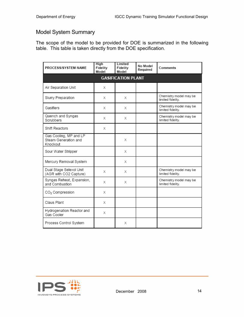
Model System Summary
The scope of the model to be provided for DOE is summarized in the following table. This table is taken directly from the DOE specification.

Department of Energy IGCC Dynamic Training Simulator Functional Design
December 2008 15
Malfunctions See Appendix I for a list of instructor malfunctions.
Department of Energy IGCC Dynamic Training Simulator Functional Design
December 2008 16
Detailed System Modeling Descriptions
This document provides a base level of modeling detail for the simulator. Information from the PFD drawings, the DOE simulator specification document, discussions during the Kickoff Meeting, and our past experience has been condensed here. This information is presented in the following overview sections to provide a basic understanding of the modeling philosophy of different sections of the process and mention key simulation assumptions and techniques to help further define the process modeling scope. Because the actual design has not yet been completed (most critically, the P&IDs and detailed heat and material balance), the techniques to be used for different sections of the model are defined as best as possible. As the work progresses, there may be modifications to some techniques. The fidelity of the model will not be affected. Generally, for most equipment, the design will be based on the design heat and material balance with an overcapacity factor to allow for higher than design rates and reasonable hold-ups.
Department of Energy IGCC Dynamic Training Simulator Functional Design
December 2008 17
1) Air Separation Unit Model (Specification PM) The basis for this description is Exhibit 3-2 Typical ASU Process Schematic, as presented in the Cost and Performance Baseline for Fossil Energy Plants Final Report. There are two production trains (one for each gasifier). The following description is applicable to both trains. The main air compressor is a multi-stage centrifugal compressor which will be physically modeled based on Dynsim default compressor curves adjusted to represent the design material balance. The interstage coolers will be modeled as utility exchangers. The inlet air filter (and, in general, all filters) will be simply modeled as a valve to allow for the possibility of loss of air due to filter pluggage (malfunction only). The cooling of the combined air sources (from the main air compressor and the portion extracted from the gas turbine) will be modeled with heat exchangers. The adsorbent-based pre-purifier system will be modeled simply to allow separation of water and CO2. One pre-purifier will normally be on, and the other one will be in regeneration mode or on stand-by. The sequence of steps to simulate regeneration of the pre-purifiers will be modeled, but there is no regeneration of the adsorbent itself in the model. The pre-purified air is split into three (3) streams. About 70 percent of the air is fed directly to the cold box. The plate and frame heat exchangers inside the cold box will be modeled with the Dynsim multipass heat exchanger. The booster compressor, which chills about 25 percent of the pre-purified air before it is fed to the cold box, will be physically modeled based on Dynsim default compressor curves adjusted to represent the design material balance. The interstage coolers, and after coolers, will be modeled as utility exchangers. Five (5) percent of the air is fed to a single-stage centrifugal booster compressor, which will also be physically modeled based on Dynsim default compressor curves adjusted to represent the design material balance. The turbine driver will be modeled. The after cooler will be modeled as a utility exchanger. Inside the cold box, the air is separated into oxygen and nitrogen in a distillation column. The air separation will be modeled with a rigorous distillation columns and all ancillary equipment. The liquid oxygen cryogenic pump will be modeled with the Dynsim pump object with the default pump curve adjusted to represent the design material balance. The vaporization of the liquid oxygen against the high pressure air feed will be modeled with a heat exchanger. The O2 compressor will be a centrifugal

Department of Energy IGCC Dynamic Training Simulator Functional Design
December 2008 18
compressor (default compressor curve adjusted for design material balance) with interstage cooling. Both the low pressure and high pressure nitrogen streams that leave the cold box are compressed and eventually feed the gas turbine. These compressors will be modeled as centrifugal compressors with default curves adjusted for the design material balance. 2) Gasifier/Selexol Model (Specification PM) The basis for this description is the narrative beginning on page 62 in the Cost and Performance Baseline for Fossil Energy Plants Final Report (3.1.3 Water Gas Shift Reactors). There are two production trains. The following description is for one train, but is applicable to both trains. The slurry preparation train will be modeled as simple mixing of components. Operations such as pulverization of coal will not be modeled. Operations such as selecting which Run Tank is to be filled will be modeled such that an operator will be able to perform the tasks. The Slurry Pump will be a positive displacement pump. There will be a number of reactions considered in the gasifier. These reactions will include a reaction for the feed itself, ammonia and H2S formation, and other reactions. The relationships for the reactions (stoichiometry, heats of reaction, and so forth) will be determined from available public information and experience. The Quench chamber will be modeled as a drum. The drum flash calculation will calculate the mix conditions. The quench water pump will be modeled as a pump with the default pump curve adjusted to represent the design material balance. Pump strainers can be modeled simply as valves to simulate pluggage (malfunction only). The lock hopper and drying conveyor will be simply modeled such that an operator will be able to perform the tasks. The Syngas Scrubber will be modeled as a Tower with several (perhaps 3 or 4) equilibrium trays. The Shift Reactors (SGS) will consider the water-gas shift reaction and hydrolysis of COS. The water-gas shift reaction will be considered in both forward and reverse directions. The syngas leaving the SGS will pass thru heat exchangers which will cool the syngas and produce medium pressure steam (first heat exchanger) and low pressure steam (second heat exchanger). A final cooling water heat exchanger cools the syngas before the syngas goes to the mercury removal system. Because of the possibility of condensate forming after any exchanger (especially during start-up, shutdown, and partial load conditions), a knockout drum will be

Department of Energy IGCC Dynamic Training Simulator Functional Design
December 2008 19
modeled after each exchanger. The carbon beds in the mercury removal system will be simply modeled (mercury breakthrough by malfunction only). The preheater and aftercooler will be modeled as heat exchangers. The Sour Water Stripper (SWS) removes H2S, NH3, and other impurities from the syngas scrubber waste stream as well as other waste streams. The Sour Drum will be modeled as a drum. The SWS is a packed column which will be modeled with a number of theoretical trays to achieve the design separation. The steam reboiler will be modeled as a heat exchanger. The Selexol Acid Gas Removal (AGR) System will consider the H2S absorber, the CO2 absorber, and the Selexol stripper and all ancillary equipment. The absorbers and the strippers will be modeled with a sufficient number of equilibrium trays to give the desired steady state separation. Ancillary equipment such as drums, reboilers, condensers will be modeled with the appropriate Dynsim objects. The separations in the Selexol (AGR) System may be of limited fidelity, depending on the availability of equilibrium data. The CO2 Compression Train is a five stage centrifugal compressor with aftercoolers. The compressor will be modeled with the default compressor curves modified for the design heat and material balance. The aftercoolers will be modeled as utility exchangers. The last stage of the compressor raises the CO2 pressure to 2200 psi, where the CO2 becomes supercritical. This phenomenon will be considered. The Glycol Tower after the fourth stage will be simply modeled. The clean syngas is reheated before passing to a fuel gas expander. The re-heater will be modeled as a heat exchanger. The expander will be modeled the Dynsim expander object. The ability to bypass the expander will be considered. 3) Claus (Sulfur) Model (Specification PM) The basis for this description is the narrative beginning on page 93 in the Cost and Performance Baseline for Fossil Energy Plants Final Report (3.1.6 Sulfur Recovery/Tail Gas Cleanup Process Selection). One Claus plant receives all feeds from all sources. The feeds to the Sulfur Plant are sour gas from the SWS and acid gas from the Syngas Desulfurization plant. Each feed goes to a knockout drum to remove any condensibles. The feeds then pass thru feed heaters and enter the Claus Furnace. Oxygen (O2) from the ASU is also passed thru a heater and fed to the Claus furnace.
Department of Energy IGCC Dynamic Training Simulator Functional Design
December 2008 20
The furnace can be modeled in the Dynsim pipe object with reactions. The reactions to consider are NH3 combustion, CH4 combustion, H2S combustion, Claus reaction (2H2S + SO2 �� 2H2O + 3S), SCOT reaction (SO2 + 3H2 �� H2S + 2H2O), Shift reaction (CO2 + H2 �� CO + H2O), and COS Shift reaction (COS + H2 �� H2S + CO). The Waste Heat Boiler (WHB) will be modeled with a heat stream heat exchanger, with the heat stream going to the steam drum. The reaction gas is further passed thru two more converters to recover more sulfur. Each converter is preceded by a sulfur condenser, which will be modeled as a heat stream heat exchanger, with the heat stream going to a steam drum to produce low pressure steam. The condensed sulfur goes to the sulfur pit (modeled as a drum). In addition to the heat exchanger, the sulfur condenser includes a drum for separation of the sulfur from the feed to the converter preheater (modeled as a heat exchanger) and the converter (modeled with the Dynsim pipe object with reactions). The reaction to be considered is the Claus reaction. The first and second converters are modeled in the same way. The Tail Gas from the final sulfur condenser passes to the hydrogenation reactor preheater, which will be modeled as a steam heat exchanger. The hydrogenation reactor will be modeled with the Dynsim pipe object with reactions. The reactions to be considered are S + H2 � H2S, SCOT, Shift, and COS Shift reactions. The heat of reaction is removed in the reactor aftercooler, which is modeled as a heat stream heat exchanger, with the heat stream going to a steam drum to produce low pressure steam. The reacted tail gas goes to a Direct Contact Condenser, which can be modeled as a tower with several trays. The bottoms recirculation pumps will be modeled with the default pump curve adjusted to reflect the design heat and material balance. The scrubbed gas flows up for direct contact with quench water. The overhead is sent to a knockout drum, then to the Tail Gas Compressor (modeled with the Dynsim default compressor curve adjusted for the design material balance), then back to the AGR unit. 4) Power System (Specification PM)
A. Combustion Turbine The basis for this description is the narrative beginning on page 140 in the DOE/NETL Report – 2008/1324 Volume 2: IGCC Process Descriptions (15.1 Combustion Turbine Units). There are two combustion turbine trains. The following description is for one train, but is applicable to both trains.

Department of Energy IGCC Dynamic Training Simulator Functional Design
December 2008 21
System Description Two independent combustion turbines are used for this IGCC unit. Each turbine is directly coupled to a 3-phase AC generator driven at 3600 rpm by an extension of the inlet compressor shaft. Both turbines have the capability to operate using syngas from the coal gasification process, natural gas, or any combination thereof. The fuel provided to each turbine is independent of the other. The turbines also have the ability to operate without interruption during fuel transfer. Each combustion turbine has an HRSG system that is used to recover heat from the turbine exhaust gas. These turbines are expected to provide 232 MW each using syngas fuel and 185 MW each using natural gas. The turbines units are comprised of a compressor, combustion system, power turbine, and exhaust duct. The axial flow compressor has 18 progressive stages located at the front end of the turbine on a common shaft. The combustion system is made up of 14 combustion chambers–located at the compressor discharge, fuel nozzles, spark plug ignition system, flame detectors, false start drains, and crossfire tubes. The three stage turbine converts the high temperature and pressure gas created in the combustion chamber from thermal to mechanical energy. Equipment required for the turbine assembly includes: turbine rotor, turbine casing, exhaust frame, exhaust diffuser, nozzles (stationary blades), and shrouds. The exhaust duct provides a pathway for the turbine exhaust gas to reach the HRSG system. Air entering the air compressor must first pass through the inlet filters, evaporative cooler, and the inlet guide vanes. The evaporative cooler evaporates water from a wet media and mixes the vapor with air going to the compressor. The amount vapor that is transported to the air is a function of ambient air temperature, humidity, air flow rate, and quantity of wet media. Water to the media is directed by four pumps. The moist air goes through the compressor, and is then directed several locations. Most of the air is sent to the combustion chamber and the combustor bypass valves to the turbine inlet. Some of the air is allowed to pass to the turbine exhaust through bleed valves, while another small portion of the compressed air is routed to the rotor and turbine wheel-spaces for cooling. Another portion of air after the compressor is delivered back to the compressor inlet via Inlet Bleed Heat valve (IHB). A Natural Gas Pressure Regulating Station supplies gas to both CT units which have identical natural gas fuel systems. Gas flows through a pressure-operated safety shutoff valve at the inlet, through a heat exchanger where it is heated with feedwater, through four control valves

Department of Energy IGCC Dynamic Training Simulator Functional Design
December 2008 22
that reduced the gas pressure, and through two parallel filter-separators. After filtration, the gas is distributed by a shared header to both units. The flow of the natural gas is controlled by Stop/Isolation Valves (NGIV) and Control Valves (NGCV) based on load and turbine speed. Operation of the gasification plant dictates the pressure and flow of syngas to each of the combustion turbines. Each turbine receives syngas from its respective gasification plant. When syngas is used for combustion, diluted N2 gas is required from the Air Separation Unit. Flow to the turbine is controlled by four Stop/Speed Ratio Valves (SRV) and four Gas Control Valves (GCV) based on load and turbine speed. Dilution nitrogen, steam, and syngas and/or natural gas enter the combustion chamber by separate sets of nozzles along with the compressed air. Dilution steam is used for NOx control and is supplied from the cold reheat steam. Ignition can be started with any of the 14 spark plugs. In the combustion zone, the fuels get mixed and burned. Four flame detectors will indicate the presence of fire on the HMI screens. During the startup, the field breaker closes to energize the exciter. Another breaker connects the generator to the Load Communicated Inverter (LCI) which drives the generator with variable frequency voltage to 90% of the synchronous speed, after which the control system disconnects the static starter. Many support systems are needed for safe operation of the combustion turbines. During shutdown/startup, the turbines are rolled on a turning gear at roughly 6 rpm to prevent equipment damage. Turbine cooling is achieved in part by using compressed air to cool the turbine rotor, as well as two Exhaust Frame Cooling Air Fans and two Bearing Cooling Air Fans. For each set of fans, one is used as the primary while the other fan is used as a backup. Lube oil is required for the turbine bearings to provide cooling and lubrication. Heat is transferred to the oil from the turbine bearings, and this heat is then rejected to the service water system. A lube oil reservoir with a static liquid level is used to supply the Lubricating and Seal Oil System. The reservoir pressure is controlled by one of two Mist Eliminators, while the temperature is regulated by a heater. Normal oil supply comes from one of two AC Lube Oil Pumps, but an Emergency Lube Oil Pump is available if the AC Pumps malfunction or if there is other cause for loss of lube oil pressure. Seal oil to the generator is usually supplied by the Lube Oil Pumps, but the Main Seal Oil Pump or the DC Seal Oil Pump can provide supply in the event of pressure loss. Hydraulic

Department of Energy IGCC Dynamic Training Simulator Functional Design
December 2008 23
and lift oil is supplied by either of two Hydraulic Oil Pumps. The hydraulic oil comes from the lubricating oil header. Turbine operation is closely monitored to prevent equipment damage and plant downtime. Important areas for monitoring include: bearing oil and metal temperatures, turbine vibrations, and thrust bearing proximitor readings. Model The compressor, combustor, and expander sections of the model will be based on ideal operating conditions. Adjustments to exit gas flow, exit gas temperature, and output power will be made for the following influences:
o Inlet temperature o Inlet pressure o Inlet humidity o Fuel flow o Lower heating value o Inlet guide vanes o Generator losses o System frequency (when synchronized) The combustion turbine compressor inlet filters will be modeled as a resistance in the flow path upstream of the compressor. The resistance will be tuned at the full load for the appropriate pressure drop across the filters. The evaporative cooler, located after the compressor filter, will simulate evaporative cooling, which will be correlated from typical performance curves. Four water pumps supply water to the wet media in the evaporative coolers. The outside air temperature and humidity (i.e. dry bulb and wet bulb temperatures) will affect cooling performance, and will be set by an Instructor remote function. The compressor inlet bleed heat valve will be a physical valve allowing bleed flow to pass from the exit of the compressor to the inlet. A header will allow for mixing of this hot air coming back from the bleed heating valves; the air will increase in temperature and pressure when the bleed heating valve is open.
The combustion turbine inlet guide vanes are simulated as part of the compressor model. The compressor has a built in function for guide vane position. Demand will be fed from the DCS then modified for nonlinearity of guide vane operation and passed to the compressor model. Combustion turbine model will have the ability to operate using syngas produced from the gasification plant, natural gas, or a combination of the two. The natural gas will be modeled as coming from an infinite supply
Department of Energy IGCC Dynamic Training Simulator Functional Design
December 2008 24
header. If natural gas is used, it must pass through a heater exchanger prior to going to the combustion chamber. The combustion gas then passes through the turbine control valves and into the combustion turbine. The heat exchanger is a physical model with heat leaving the feedwater to be supplied to the natural gas. The natural gas composition is specified in the Fuel model object according to available ultimate fuel analyses. Nozzles that deliver diluted N2, steam, syngas, and natural gas will be physically modeled as valve objects. The exhaust duct is also a flow path in the model with a physically defined resistance. A simple model of the lube oil system and hydraulic control pressures will be delivered to demonstrate startup permissives and normal operating behavior to the operator. The LCI starter motor will be modeled as a motor object. Torque will be applied to the shaft from this device during start up operations. The motor will be tied to the appropriate bus in the electrical system and the device will not start if there is no voltage on the bus. A button that controls the on/off function of the turning gear cooling and a temperature bias will be available as Remote Functions. CT emissions are modeled using empirically fitted data for the specific CT, which accounts for operating mode and fuel flow rate A typical vibration monitor signature of each turbine and generator bearing will be correlated vs. turbine speed to illustrate normal operating and startup behavior to the operator (a graphic model). The instructor will be able to bias each bearing’s vibration up or down from the instructor station. Main Shaft bearing temperatures will be simple models based on speed and will rise if turbine lube oil flow is lost.
B. Combustion Turbine Generator and Electrical Systems
System Description The basis for this description is the narrative beginning on page 162 in the DOE/NETL Report – 2008/1324 Volume 2: IGCC Process Descriptions (15.10 Generator). There are two combustion turbine trains. The following description is for one train, but is applicable to both trains. The generator function is to convert mechanical energy from the combustion turbine into electrical energy for supply to the grid. The generator is comprised of a wire-wound rotor that spins inside a wire-
Department of Energy IGCC Dynamic Training Simulator Functional Design
December 2008 25
wound stator. The rotor windings become energized by a separate excitation circuit, which creates a rotating electro-magnetic field. This field passes through the stationary windings of the stator to induce an electrical current and terminal voltage. A transformer is used to match this voltage to the grid voltage. Terminal voltage strength and/or generator reactive power are determined by field excitation, transformer step-up ratios, and grid conditions. The exciter system consists of a static exciter and an electronic automatic voltage regulator (AVR). The generator excitation control can function in automatic and manual modes. The generator stator temperatures are controlled with hydrogen coolers. Hydrogen circulates on a closed loop through the generator. Heat absorbed by the hydrogen gas is rejected to the service water system. The electrical system consists of the switchyard, electrical generators, electrical distribution, 125VDC Battery Charger & Battery, and UPS. The switchyard shall include three 18 kV/230 kV step up transformers, two station service transformers, and five associated sets of 230 kV circuit breakers and motor operated disconnects. Model The generator will be simulated to the extent required to calculate active and reactive power as a consequence of voltage regulator operation. The generator will run at the same model speed as the combustion turbine to be able to control MVARs. Effects of changes in the grid to which the generator is connected will not be simulated. The combustion turbine generator main and auxiliary transformers, breakers, and disconnects will be modeled to the extent required for HMI displays.
The generator model will be developed based on single-phase concepts. The three-phase amperage is derived from single-phase values assuming all phases are balanced. Typical saturation curves and V-curves are used to define voltage and VAR response to excitation. Standard voltage regulator and exciter models will be used for this model. The voltage regulation is controlled by DCS through the exciter. Stator heat load is primarily a function of stator amps or MVA. Effects of the generator hydrogen pumping also contribute a slight heat rise. Hydrogen coolers are used to maintain temperature within the generator. This in turn controls the generator stator temperature. The hydrogen coolers are tied to the closed cooling water network. A loss of coolant allows for rising temperatures in the generator.

Department of Energy IGCC Dynamic Training Simulator Functional Design
December 2008 26
Motors required for cooling the transformer controlled by the DCS will be modeled. If there are no motors controlled from the DCS then a RF toggle button for transformer cooling will be added and this will bias the principal transformer temperatures. Both manual and auto-synchronization logic will be modeled. Generator field breaker logic will be modeled for manual and automatic trip and close operations. Main and auxiliary transformers will be included, where the main transformer have an 18 kV primary and 230 kV secondary and the auxiliary transformers have a 230 kV primary and a 4.16 kV secondary. Generator protection, trip, and lockout relays will be modeled as needed for the DCS HMI. The electrical distribution system will include 4160 V buses that feed 480 V buses in order to supply power to the simulated equipment. Bus protective relays will be modeled in detail required by the DCS. Low voltage systems, the battery, and the battery charger will be simply modeled to satisfy the requirements of the DCS. The primary disconnects for the station service transformers and many feedback indicators-such as battery charged/discharged will be available as Remote Functions.
C. Steam Turbine
System Description The basis for this description is the narrative beginning on page 198 in the DOE/NETL Report – 2008/1324 Volume 2: IGCC Process Descriptions (16.7 Steam Turbine). One steam turbine accepts steam produced from both HRSG trains.
The purpose of the steam turbine is to increase the overall plant efficiency of the combined cycle by converting energy recovered from the combustion turbine exhaust gas into mechanical energy. This mechanical energy is then used to drive the generator rotor. Three turbines are used to achieve this, an HP turbine, IP turbine, and an LP turbine. High pressure steam from the HRSG system is fed to the HP turbine; upon exiting the turbine, this steam is reheated in the HRSG system. This reheat steam is then fed into the IP turbine and afterwards into the LP turbine. Steam flow and main steam pressure to the turbines are controlled by stop/control valves at the entrance to the HP turbine and reheat/intercept

Department of Energy IGCC Dynamic Training Simulator Functional Design
December 2008 27
valves upstream of the IP turbine. These valves also function to control turbine speed, load, and provide emergency protection. Many support systems are needed for safe operation of the steam turbines. During shutdown/startup, the turbine is rolled on a turning gear at roughly 3-5 rpm to prevent rotor bowing, bearing overheating, and to assist steam flow during initial rolling of the turbine. Lube oil is required for the turbine bearings, generator, and exciter to provide cooling and lubrication. Hydraulic power supply is used to operate the turbine control and stop valves. Turbine operation is closely monitored to prevent equipment damage and plant downtime. Important areas for monitoring include: turbine eccentricity – measured as the amount of bow in the turbine rotor at turning gear speed, vibration of the rotating shafts of the turbine and generator, rotor-shell expansion due to differential temperature, turbine temperatures to minimize metal stress, bearing temperature, lube oil temperature, and water induction into the steam path of the turbine.
Model A single steam turbine will be modeled on a separate shaft from the combustion turbines. The steam turbine model will include an HP, IP, and double flow LP sections. High pressure steam from the HRSG units will feed the HP turbine. Control and isolation of the turbine will be achieved by stop valves and control valves located before the HP turbine section and intercept valves that are located between the reheat and IP turbine. Steam exits the LP turbines and drains into the condenser. The LP turbine will be prewarmed by the gland steam system.
The simulation will properly represent turbine startup, operation, and coast down. Turbine extractions will be modeled. Energy storage in the rotating inertia of the turbine generator system will be present. Turbine windage losses will be simulated to represent losses while not synchronized. Turning gear will be simply modeled. The simulation of the steam turbine separates the turbine expansion into composite turbine stages. The composite turbine stages are defined to accommodate extraction points and points of mass or significant external energy addition to the steam flow. The interstage pressures are iterated to satisfy turbine continuity, turbine matching characteristics (effective nozzle sizes), and the downstream extraction pressures states (usually a heat exchanger) based on the main steam inlet conditions and the condenser back pressure. The turbine interstage enthalpies are set based on the expansion pressures and the turbine efficiency correlations. Turbine work

Department of Energy IGCC Dynamic Training Simulator Functional Design
December 2008 28
developed is calculated based on the sum of each composite stage flow multiplied by its enthalpy drop. This power developed is modified slightly by turbine mechanical losses and generator mechanical and electrical losses. The turbine has various motor operated valve (MOV) drains mostly going to the condenser. Only control room position indication, controls, and alarms will be modeled. Turbine drain valves used to control pressure during pre-warming will be simply modeled as flow restrictions. The turbine supervisory instrument system consists of the turbine bearing and lube oil temperatures, turbine vibrations, turbine shell and rotor expansions, and turbine shell temperatures. The turbine metal model will represent the normally occurring axial gradients sensed by the turbine metal thermocouples, but will not predict cover (top) to base (bottom) gradients. The model requires realistic metal mass data for the turbine in order for the rates of stress calculated to be realistic. Steam turbine bearings will be modeled as heat exchangers with heat input from the turbine shaft on one side and convection to the lube oil on the other. If the lube oil system flow is shut down, the bearing temperatures will rise. Turbine lube oil system will be modeled as a flow network with appropriate normal operating and emergency pumps. Lube oil reservoir level and filter pressure drop will be simply modeled. For the purposes of modeling, a constant Cp for the lube oil is assumed. Steam turbine vibrations will be simply modeled based experience and available data for a representative turbine roll chart (including critical speeds). The instructor will be able to bias each bearing’s vibration up or down from the instructor station. Steam turbine seals will be modeled as a flow network supplied by the main steam at startup and later supplied by HP gland leakage. The Steam seal feed valve and the steam seal dump valves will be modeled. The steam flows will connect to appropriate headers in the steam turbine network. Modeling assumptions will be made to neglect certain flows in the seal system. The instructor will have a toggle button for water induction to the inlet of the HP turbine. This will be tied to the IO for water induction present. The turbine metal model will represent the normally occurring axial gradients sensed by the turbine metal thermocouples but will not predict cover (top) to base (bottom) gradients. Thus, water detection will be only graphical.

Department of Energy IGCC Dynamic Training Simulator Functional Design
December 2008 29
D. Steam Turbine Generator & Electrical Systems
System Description The basis for this description is the narrative beginning on page 202 in the DOE/NETL Report – 2008/1324 Volume 2: IGCC Process Descriptions (16.8 Steam Turbine Generator). The generator function is to convert mechanical energy from the turbine into electrical energy for supply to the grid. The generator is comprised of a wire-wound rotor that spins inside a wire-wound stator. The rotor windings become energized by a separate excitation circuit, which creates a rotating electro-magnetic field. This field passes through the stationary windings of the stator to induce an electrical current and terminal voltage. A transformer is used to match this voltage to the grid voltage. Terminal voltage strength and/or generator reactive power are determined by field excitation, transformer step-up ratios, and grid conditions. The exciter system consists of a static exciter and an electronic automatic voltage regulator (AVR). The generator excitation control can function in automatic and manual modes. The generator stator temperatures are controlled with hydrogen coolers. Hydrogen circulates on a closed loop through the generator. Heat absorbed by the hydrogen gas is rejected to the service water system. Model The main generator will be simulated to the extent required to calculate active and reactive power as a consequence of voltage regulator operation. The generator will run at the same model speed as the steam turbine to be able to control MVARs. Effects of changes in the grid to which the generator is connected will not be simulated. The steam turbine generator main and auxiliary transformers, breakers, and disconnects will be modeled to the extent required for HMI displays. The generator model will be developed based on single-phase concepts. The three-phase amperage is derived from single-phase values assuming all phases are balanced. Typical saturation curves and V-curves are used to define voltage and VAR response to excitation. Standard voltage regulator and exciter models will be used for this model. The voltage regulation is controlled by DCS through the exciter. Stator heat load is primarily a function of stator amps or MVA. Effects of the generator hydrogen pumping also contribute a slight heat rise. Hydrogen coolers are used to maintain temperature within the generator. This in turn controls the generator stator temperature. The hydrogen
Department of Energy IGCC Dynamic Training Simulator Functional Design
December 2008 30
coolers are tied to the closed cooling water network. A loss of coolant allows for rising temperatures in the generator. Motors required for cooling the transformer controlled by the DCS will be modeled. If there are no motors controlled from the DCS then a RF toggle button for transformer cooling will be added and this will bias the principal transformer temperatures.
E. Heat Recovery Steam Generator
System Description The basis for this description is the narrative beginning on page 173 in the DOE/NETL Report – 2008/1324 Volume 2: IGCC Process Descriptions (16.1 HRSG Overview). There are two HRSG trains. The following description is for one train, but is applicable to both trains. The HRSG system will model heat transfer from the combustion turbine exhaust gas to the economizers, evaporators, and superheaters that will be modeled in the following HRSG Heat Exchanger Systems. The simulator will include two independent HRSGs, each corresponding to its own combustion turbine and selective catalytic reduction (SCR) grid with ammonia injection. Both HRSGs are designed for triple pressure and natural circulation. The three pressure sections are notated as Low Pressure (LP), Intermediate Pressure (IP), and High Pressure (HP). All sections include evaporator sections, superheater, drum, and economizer, except for the LP section which includes a preheater in place of an economizer. The LP system is fed with water from the condensate system that has been warmed in a condensate preheater. The preheated water enters the LP Drum, where noncondensibles are removed. Two streams exit the drum; one is a suction flow for feedwater pumps while the other stream is the downcomer that goes to the LP Evaporator. The evaporator produces low quality saturated steam that goes back to the LP Drum for separation before being heated further in the LP Superheater and distributed to the low pressure steam system. The feedwater pumps create a high pressure flow at the pump discharge that is directed to the primary and secondary HP Economizers prior to entering the HP Drum. There is also an extraction flow on the feedwater pumps that is directed to the IP Economizer before going to the IP Drum. Water for the main superheat sprays is taken from the pump high pressure discharge, while the reheat sprays are from the pump extraction flow. Discharge water from the primary HP Economizer is used for cooling in the gasifier syngas cooler. The gasifier syngas cooler receives economized feedwater in parallel to

Department of Energy IGCC Dynamic Training Simulator Functional Design
December 2008 31
the secondary HP economizer. Steam, exiting the HP Drum, passes through primary and secondary main steam superheaters before being directed through the main steam sprays and to the final main steam superheater. High pressure steam exiting both HRSG trains is combined and fed to the high pressure steam turbine for power generation. Steam leaving the IP Drum is heated by the primary IP Superheater, which then gets combined with the cold reheat steam exiting the high pressure steam turbine. This stream is reheated by the secondary IP Reheater and passed through the reheat sprays. The steam is passed through the final IP Superheater and then to the intermediate pressure steam turbine. Each HRSG train will include a selective catalytic reduction (SCR) grid with ammonia injection. The SCR system removes nitrogen oxides (NO and NO2) from the boiler combustion gas. The SCR System will catalytically reduce boiler flue gas NOx emissions to nitrogen and water using aqueous ammonia (NH3) as the reducing agent. The catalyst equipment will be installed in the HRSG flow path. The SCR System is composed the following components:
• Flue gas ductwork and dampers
• Ammonia Vaporization and Dilution System
• Ammonia injection grid (AIG)
• SCR reactor housing
• SCR catalyst
• Inlet and outlet NOx sampling grid Aqueous ammonia is supplied from ammonia storage tanks where the ammonia solution is vaporized and diluted with ambient air to produce a gaseous mixture. This gaseous ammonia stream is directed to the ammonia injection grid (AIG). The AIG is a grid of injection nozzles that distribute the gaseous ammonia across the entire cross section of the ductwork. The ammonia flow to each branch of the grid is regulated by a manifold valve station. The SCR system uses a fixed bed catalyst in a vertical down flow multistage reactor. The SCR reactor housing is designed to contain sufficient catalyst to meet the NOx, and ammonia slip emission guarantees over the expected life of the catalyst. Model The heat transfer from the combustion turbine exhaust gas will be assumed to be convection dominated. Radiation will be neglected. All

Department of Energy IGCC Dynamic Training Simulator Functional Design
December 2008 32
necessary piping, valves, tanks, surfaces, and startup bypasses will be physically modeled. Model feedback to the CEMS system will be simply modeled. The HRSG will be capable of operating with syngas, natural gas, or a combination of the two gases. The preheater, evaporators, and superheaters will be modeled using heat exchanger objects, taking into account the number of tubes, length of tubes, tube thickness, number of bundles, and heat transfer information from the heat/mass balance and engineering experience. The feedwater pumps will be modeled with simple pump curves derived from publically available data and engineering experience, which will be tuned to give the desired feedwater flow. The drums will be modeled as tanks with appropriate dimensions, vents, and drains. The drum model will be capable of performing drum shrink and swell. The drum blowdown valves will operate as a Remote Function. Some simplifications will be made to enhance model speed. For example if there are two flow lines running between the evaporator manifold and the intermittent purge tank, these two lines will be represented by one flow in the simulator, provided there are not individual flow measuring devices in the lines. The main steam line’s thermal inertia and mass storage effects will be modeled. All major extraction steam from the main steam header will be modeled. Safety valve location will be taken off of the nearest model header to the valve position. Pop and Reset set points will be configured into the model for the main safeties on the main superheat and reheat lines. For the SCR system, ammonia storage tanks, pumps, dilution air fans, flow control, and associated piping will be physically modeled. Ammonia fill of the storage and offloading system will be accomplished via a Remote Function. Vaporizers will be simply modeled with vapor enthalpy as a function of heat input. The SCR enclosure volume, dampers, ducting, and catalyst bed pressure drops will be physically modeled based on publically available data and engineering experience. The Instructor shall have Remote Functions to vary the pressure drop across each of the catalyst beds. Thermal lag and temperature transients will be physically modeled; however the frame, skin, and catalyst bed metal capacitance nodalization shall be simplified to primary thermocouple locations. Metal node conductance and thermal mass shall be matched to publically available temperature transient data. Chemical reactions will not be physically modeled. However, correlations will be included in the model to emulate the effect of the chemical

Department of Energy IGCC Dynamic Training Simulator Functional Design
December 2008 33
reactions. NOx reduction when the SCR is in service shall be empirically modeled to correlate to available data. SCR performance will be a function of inlet NOx, catalyst bed temperatures, and ammonia injection flow rate. Outlet NOx will be appropriately reduced; other flue gas constituents will remain unaffected. The Instructor may have a Remote Function to degrade catalyst performance. Auxiliary systems such as damper seal air and purge will be graphically modeled, but will satisfy DCS permissives and interlocks.
F. Condensate System
System Description The basis for this description is the narrative beginning on page 185 in the DOE/NETL Report – 2008/1324 Volume 2: IGCC Process Descriptions (16.2 Condensate System). The condensate system is used to provide condensed water to the low pressure deaerator and steam drum for both HRSG trains. It also provides cooling for the steam turbine exhaust hood and absorbs heat from various heat exchangers in the gasification plant. The major equipment for this system includes the condenser, two condensate pumps, gland steam condenser, make-up piping and valves from the condensate storage tank, and two vacuum pumps for noncondensibles removal in the condenser and turbines. Model The condenser modeling will reflect a mass and energy balance that accounts for incoming main turbine exhaust, exhaust hood spray, drains, turbine bypass flow, high pressure steam leaks, condensate makeup flow, condensate pump recirculation flow, circulating water leakage, and exiting condensate pump flows. Miscellaneous steam drains to the condenser may be added to the model in combined and simplified form if heat balances necessitates. The exhaust hood temperatures will be calculated as thermocouple lags based on an algebraic energy solution combining turbine exit flow and exhaust hood spray flows. One air partial pressure will be evaluated to define total pressures for the condenser. Air leakage will be defined as a flow coefficient based on condenser to atmospheric differential pressure. Vacuum breaker valves will be sized based on physical dimensions. Simple correlations will be developed to represent condenser air removal as a function of back pressure. A composite volume that represents condenser, LP and IP turbine shells, and piping will be estimated and adjusted to provide the correct rate of vacuum increase during start up.

Department of Energy IGCC Dynamic Training Simulator Functional Design
December 2008 34
The condensate system hydraulics will be modeled as a network from the hotwell to the LP Drum. Condensate pumps supply condensate through the gasification plant for cooling, condensate pre-heater, and control valves. All condensate extractions will be modeled. The condensate make up tank will have a static level (endless supply), and the makeup flow to the condenser will be controlled using two parallel makeup valves. The gland steam condenser model will not explicitly include air partial pressure effects. The gland steam condenser pressure will be set as a lagged pressure slightly below atmospheric based on whether exhausters are in service.
G. Feedwater System
System Description The basis for this description is the narrative beginning on page 189 in the DOE/NETL Report – 2008/1324 Volume 2: IGCC Process Descriptions (16.3 Feedwater System). There are two feedwater systems; one connected to each HRSG train. The following description is for one system, but is applicable to both trains. The feedwater system is defined as the water flow paths from the LP Drum to the inlet of the IP and HP Economizers. Two variable speed feedwater pumps drive the flow to the economizers. The variable speed is used to control drum level in the HP and IP sections. Feedwater is supplied to many subsystems including: superheater desuperheater (from HP), reheater desuperheater (from IP), steam bypass HP attemperators, and syngas coolers. Each HRSG train has its own feedwater system. Each feedwater pump is protected by a recirculation path that establishes minimum flow. This recirculation flow is dumped into the LP Drum. Model The feedwater system hydraulics will be physically modeled as a network from the LP Drum through the IP and HP Economizers. The feedwater pumps will use pumps curves based on available data and engineering experience. The variable speed will be controlled from the DCS. The feedwater sprays will be modeled, as well as all necessary piping and valves.
H. Circulating Water System (SM)
System Description

Department of Energy IGCC Dynamic Training Simulator Functional Design
December 2008 35
The basis for this description is the narrative beginning on page 192 in the DOE/NETL Report – 2008/1324 Volume 2: IGCC Process Descriptions (16.4 Circulating Water System). The circulating water system is used to remove heat from the condenser, service water system, and the vacuum pump lube oil coolers. Two pumps are used to drive the circulating water flow from and endless supply, such as a river or a lake, to the various heat exchangers and back to the original source to discharge the absorbed heat. Model The flow versus head characteristics of the circulating water pumps will be modeled, if available. Heat transfer from the condensers to the circulating water will be calculated. Circulating water pH and conductivity will not be modeled. The inlet water temperature is controlled as a Remote Function. All required heat exchangers, valves, pumps, and piping will be physically modeled.
I. Service Water System
System Description The basis for this description is the narrative beginning on page 193 in the DOE/NETL Report – 2008/1324 Volume 2: IGCC Process Descriptions (16.5 Service Water System). The service water system is a closed network with a surge/makeup tank and two pumps. Makeup water for the tank is supplied by the condensate system. Service water is used to remove heat from many subsystems including: steam turbine lube oil coolers, steam turbine generator hydrogen coolers, condenser vacuum pump coolers, combustion turbine lube oil coolers, combustion turbine generator coolers, combustion turbine base coolers, boiler feed pump seal oil coolers, boiler feed pump lube oil coolers, condensate recirculation pump seal oil coolers, and LCI cooler. The heat absorbed from these subsystems is rejected to the circulating water system. Model Closed cooling water pumps and flows through the cooling water heat exchangers will be modeled. Hydrogen coolers and Main Turbine lube oil coolers will be modeled at a minimum. Only main coolers with instrumentation visible in the DCS are modeled as physical heat exchangers.

Department of Energy IGCC Dynamic Training Simulator Functional Design
December 2008 36
Pump motor temps will increase if both closed circuit refrigeration pumps are off. This will be a simple model with a preset constant bias if one pump is on. Loss of seal water to a pump will have no effect on flows and or pump temperatures.
J. Instrument/Service Air System
System Description The basis for this description is the narrative beginning on page 159 in the DOE/NETL Report – 2008/1324 Volume 2: IGCC Process Descriptions (15.7 Instrument/Service Air System). The compressed air system provides air to the plant primary and secondary equipment. It consists of a Balance of Plant IA/SA System and two Unit Instrument Air Systems. The service air includes two air compressors. Once air has passed through the compressors, it goes through an air dryer equipped with inlet and outlet filters. Instrument air used in the combustion turbine may be utilized from several sources: Exhaust Cooling Frame Blowers, Bearing Cooling Air Blowers, and discharge from the main compressor. Model Instrument/Service air will be provided by an equation if either of the compressors is on with a lag to a preset system pressure. Compressor start and stop commands are assumed to originate from the DCS. This pressure will be connected to air operated valves in the physically modeled system such that a loss of air pressure causes those valves to fail in operation mode. Clogging of the air dryer filters and other alarms will be available as Remote Functions.
K. Process Control System
System Description The basis for this description is the narrative beginning on pages 160, 196, and 205 in the DOE/NETL Report – 2008/1324 Volume 2: IGCC Process Descriptions (15.8 Controls and Human-Machine Interface (HMI) Screens for Combustion Turbine and Generator Assemblies, 16.6 Controls and Human-Machine Interface (HMI) Screens for HRSG’s and Balance of Plant, and 16.10 Controls and Human-Machine Interface (HMI) Screens for Steam Turbine and Generator Assembly). Both combustion turbine/generator assemblies, the steam turbine/generator assembly, both HRSGs, and the corresponding balance of plant systems will be controlled by a generic distributed control system
Department of Energy IGCC Dynamic Training Simulator Functional Design
December 2008 37
and human machine interface. The controls and graphics for each combustion turbine/HRSG train will be identical with the exception that the A train will use a light tan background for the graphics while the B train will use a light blue background color. A standard naming convention shall be used with all inputs, outputs, constants, and coefficients appropriately labeled. The HMI is expected to require three screens for each combustion turbine/generator assembly, three screens for the steam turbine/generator assembly, and three screens for each HRSG. All HMI screens are to be presented in a mimic format with pop-up faceplates for controllers. All screens are capable of displaying any of the HMI graphics. Alarms will be text based and alert the operator of all abnormal process values or logic states. A priority scale of 1-4 will be used to indicate the severity of the alarm. Priority 1 – Indicates potential equipment damage, impending trip
condition, or current trip. Displayed in red text.
Priority 2 – Indicates a serious condition exists which could cause equipment damage, equipment trip, runback, or load limiting. Displayed in yellow text.
Priority 3 – Indicates unusual or abnormal process values or logic states
resulting from equipment problems, abnormal equipment or system line ups. The potential for a more severe condition is present. Displayed in blue text.
Priority 4 – Indicates the status states and would not likely impact plant operation. Displayed in white text.
Model All the DCS controls for the systems and subsystems to be modeled shall be simulated including controls, interlocks, trips, and alarms which are associated with them. This includes modulating controls such as PID controllers as well as permissives, overrides, and run backs. Four control modes will be provided for the combustion turbine unit: 1). Coordinated Control 2). Gasifier Lead

Department of Energy IGCC Dynamic Training Simulator Functional Design
December 2008 38
3). Combustion Turbine Lead 4). Manual Three control modes will be provided for the steam turbine unit: 1). Coordinated Control 2). Steam Turbine Follow (follows main steam pressure) 3). Manual Specific Control Loops and Logic:
• Engine Speed and Load Control (Fuel and LCI Starter) (Combustion Turbine)
• Exhaust Temperature (Inlet Guide Vanes) (Combustion Turbine)
• Generator Excitation (Combustion Turbine)
• Turbine Speed and Load Control (Steam Turbine)
• Generator Excitation (Steam Turbine)
• Full Arc/Partial Arc Transfer (Steam Turbine)
• Lube Oil Temperature Control (Steam Turbine)
• High Pressure Drum Level Control
• Intermediate Pressure Drum Level Control
• Low Pressure Drum Level Control
• Main Steam Temperature Control
• Reheat Steam Temperature Control
• Feedwater Pressure Control (Feed Pump Spd)
• Condensate Pressure Control (Condensate Pump Spd)
• Hotwell Level Control
• High Pressure Steam Bypass Pressure/Flow Control
• Intermediate Pressure Steam Bypass Pressure/Flow Control
• Low Pressure Steam Bypass Pressure/Flow Control
Specific Logic Arrays:
• Engine Start Permissives (Combustion Turbine)
• Load Limiting and Runbacks (Combustion Turbine)
• Engine Trips (Combustion Turbine)
• Generator Protection (Load, Voltage, and Reactive Limits) (Combustion Turbine)
• Generator Breakers and Synchronization (Combustion Turbine)
• Load Limiting and Runbacks (Steam Turbine)
• Generator Protection (Load, Voltage, and Reactive Limits) (Steam Turbine)
• Generator Breakers and Synchronization (Steam Turbine)
• Condensate Pump Start Permissives
• Feedwater Pump Start Permissives
• SCR System Start Permissives

Department of Energy IGCC Dynamic Training Simulator Functional Design
December 2008 39
• High Pressure Feedwater Control Three Element/Single Element Transfer
• Intermediate Pressure Feedwater Control Three Element/Single Element Transfer
• Condensate Control Three Element/Single Element Transfer
Specific HMI Screen Graphics
• Control, Combustion Turbine o Master Unit Control o Inlet Air Heating/Evaporative Cooler Control o IGV and EGT Control o Fuel Select/Control o Start Check/Permissives o LCI Starter/Turning Gear Control o Lube Oil Temperature Control o Generator Breaker Control/Sync o Excitation Voltage/MVAR & PF Control o Trips/Reset Control
• Control, Steam Turbine – Generator o Steam Turbine – Generator Control o Start Up o Lube Oil Temperature Control o Turning Gear o Turbine Drains o Miscellaneous Auxiliary Equipment Control o Trip/Reset Control o Generator Breaker Control/Sync o Excitation Voltage/MVAR & PF Control
• Control, HRSG o A&B Overview (Common Display) o Master Control o High Pressure Steam System Control o Intermediate Pressure Steam System Control o Low Pressure Steam System Control o High Pressure Steam Bypass o Intermediate & Low Pressure Steam Bypass o SCR Control o Instrument & Service Air Control
• Data Acquisition, Combustion Turbine o Wheel space Temperatures o Bearing Metal/Drain Oil Temperatures
Department of Energy IGCC Dynamic Training Simulator Functional Design
December 2008 40
o Vibration Monitoring o Exhaust Thermocouples o Hydrogen Seal Oil Monitoring o Generator RTD Temperatures
• Data Acquisition, Steam Turbine – Generator o Start Check Permissives o Bearing Metal/Drain Oil Temperatures o Vibration Monitoring o Hydrogen Seal Oil Monitoring o Generator RTD Temperatures
• Data Acquisition, HRSG o Gas & Tube Metal Temperatures o Heat Rate, Thermal Performance o CEMS
An alarm convention with a priority scale of 1 – 4 will be followed with the following color code that will be displayed on the HMI screens. Priority 1 – Red Text Priority 2 – Yellow Text Priority 3 – Blue Text Priority 3 – White Text
5) ESD (Specification PM)
Any ESD logic will be modeled in Dynsim 6) Auxiliary Systems (e.g., for compressors) (Specification NM) The compressor auxiliary systems, such as, lube oil, seal gas, and vibration monitors will not be modeled. 7) Electrical System The external grid is modeled with an elecsource object. The frequency and voltage are fixed to constant values. The electrical system will be modeled with bus and breaker model objects down to the 480 V buses. Individual MCCs are not modeled. Field relay logic will not be modeled unless specified in the FDS remote logic section.

Department of Energy IGCC Dynamic Training Simulator Functional Design
December 2008 41
8) General Modeling Notes 1. All pumps will have a local start/stop switch near the pump (field function). 2. Compressor utilities will be modeled as simply as possible so as to satisfy
interlock and ESD permissives.
4. Simulator Capabilities
Instructor Station
A graphic-based instructor station is provided. All the functions described below shall be possible. The Instructor Station contains the following control and monitoring features: Run/Freeze: Restarts or suspends the simulation. During a freeze, displays continue to show the information that was displayed on the monitors at the time the freeze was initiated. Initialization: Allows the instructor to go to preset conditions in plant operation. The simulator has the capability to store an unlimited number of initialization conditions (subject to disk storage limitations). Snapshot: The snapshot feature allows the instructor to record the current status into an initial condition record. Backtrack: This feature allows the instructor to return to a previous state in the current simulation run. The interval between records is instructor adjustable. The save intervals shall range from one minute to every ten minutes. The system typically stores 10 backtracks slots during a computer session. Malfunction Initiation: Operating abnormalities that include equipment failures, utilities, instrumentation and control failures may be introduced from the Instructor Station. These malfunctions may occur singly, simultaneously, or sequentially at any specific time or with a preset time delay. On variable malfunctions, the severity can be set instantaneously or at a ramp rate. The malfunctions for the simulator are listed in Appendix I. External Parameters and Instructor Controlled Variables: The instructor shall have the capability of manipulating external parameters and controlling certain variables that affect the plant operation. These external parameters include such items as ambient temperature, cooling water temperature and feed conditions.
Department of Energy IGCC Dynamic Training Simulator Functional Design
December 2008 42
Remote Functions: The instructor will be able to operate equipment in the simulation for which the control room operator has no controls. Invensys will provide a final list of remote functions based on the modeling scope defined in the Model System Summary section before the FAT. Trending: The instructor has the capability of trending variables at a specified trend time interval. These parameters will be able to be printed out in groups and be identified as to the parameter name, parameter value scale and time scale. All modeled variables shall be available for trending. Trend data may be exported as ASCII data. Trainee Performance Monitoring: The instructor shall have the capability of monitoring selected variables during a training session. On activation of the Trainee Proficiency Monitoring feature, the system shall record the value of the selected variables and all malfunction activation/deactivation. Whenever a parameter exceeds the specified limits or returns to a normal range, the value of the parameter and time shall be recorded. At the end of the exercise the Trainee Performance Monitoring will also record the following:
• The highest and/or lowest value that each monitored parameter reached outside the normal range.
• The total amount of time each parameter remained outside its limits.
• The number of times each parameter exceeded its limits. The instructor shall be provided with the capability to obtain a printout of the Trainee Proficiency Review. The report will be a formatted text file (ASCII), which may be imported into Excel as a CSV file. All modeled parameters shall be available for the Trainee Proficiency Review.
Trainee Station
The Trainee Station software is InTouch. The control configuration and operator display graphics will be developed during the project.
5. Simulator Performance Criteria
Performance
Steady State Fidelity
Steady state fidelity for the simulator relates to matching the model predicted performance with reference data. For the DOE simulator, the reference data is a steady state simulation of the heat and material balance for the plant at designated conditions. A correct and good heat and material balance is critical to
Department of Energy IGCC Dynamic Training Simulator Functional Design
December 2008 43
developing a correct and good simulator. The reference heat and material balance is based on process PFDs and process data provided in Case 2 in the DOE / NETL report “Cost and Performance Comparison of Fossil Energy Power Plants Volume 1, Bituminous Coal and Natural Gas to Electricity Final Report (DOE/NETL-2007/1281), Rev. 1 August 2007”. Since the dynamic models will represent a generic IGCC plant, the design PFD values will be matched to +/- 5% accuracy. Intermediate streams will be generated from the steady state simulation, but there are no reference points for these intermediate streams. Transient Fidelity
The simulator will accurately simulate instructor-initiated transients, subject to the modeling scope defined herein. The critical and non-critical computed values will trend in the correct direction and will not violate the physical laws of nature.
6. Inspection and Testing
Acceptance Test Plan (ATP) Invensys shall prepare an ATP that will be reviewed and approved by DOE. The final acceptance of the simulator performance will be to the satisfaction of a qualified representative designated by DOE. The plan shall include a testing procedure that includes the following:
• Test preparation and conduct
• Recording of data
• Testing
• Test changes
• Test results
• Success criteria
• Discrepancy reports
• Test approval The plan shall cover hardware, software, integrated, and miscellaneous testing. Hardware testing shall verify the physical construction and the operation of computer, communication, and peripheral equipment. Hardware testing shall include the following tests and checks:
• Items on bill of materials are received
• Simulator is constructed in accordance with the Specification
• Computer, communication, and peripherals pass diagnostic programs provided by equipment Supplier
• Special tools, test equipment, and spare parts are inventoried and operational
• Interfaces function properly

Department of Energy IGCC Dynamic Training Simulator Functional Design
December 2008 44
Integrated testing shall verify the overall operability of the simulator. Integrated testing shall include the following tests and checks:
• Line up
• Reference data
• Flow path
• Logic
• Process dynamic response and transient operation
• Normal operation
• Abnormal operation
• Instructor functions An Invensys representative (the lead engineer or a designated substitute) must witness all testing. This is necessary because the Invensys representative must observe and understand the specific items performed (operational moves, and so forth). In this way, deficiencies can be resolved better.
Model Acceptance Test (MAT)
Approximately thirty days in advance of testing, Invensys shall confirm schedule dates for MAT with DOE. The purpose of the MAT is to give DOE a review of the dynamic responses of the individual models independent of the controls. The models will have sufficient Dynsim controls to allow model operation. Invensys shall prepare a report that documents the results of the MAT. DOE will witness all or part of the MAT at their discretion.
Factory Acceptance Test (FAT)
Approximately thirty days in advance of testing, Invensys shall confirm schedule dates for FAT with DOE. Invensys shall assemble and test the complete simulator in accordance with the approved ATP. Invensys shall prepare a report that documents the results of the FAT. DOE will witness all or part of the FAT at their discretion. Discrepancies identified during FAT will be documented in detail by the testing team. Every effort will be made to resolve any discrepancies during FAT to allow retesting prior to completion of FAT. If open items remain upon completion of FAT, these items will be corrected and retested with DOE during the SAT.
Site Acceptance Test (SAT)
Invensys will deliver, assemble, install, and test the complete simulator in accordance with the SAT plan. DOE will support the assembly, installation, and

Department of Energy IGCC Dynamic Training Simulator Functional Design
December 2008 45
testing of the OTS. Invensys will use a subset of the ATP for the SAT; that is, only open items remaining from the FAT will be retested during the SAT. DOE will be responsible for providing setup space, furniture and power supplies. Invensys will provide support for the process models.
7. Documentation
Simulator documentation (refer to proposal for quantities of hard and soft copies of each document) will include the following:
• Dynsim User Manual
• Dynsim Power User Manual
• Instructor Manual
• Trainee Manual

Department of Energy IGCC Dynamic Training Simulator Functional Design
December 2008 46
Appendix I: Preliminary Malfunction List
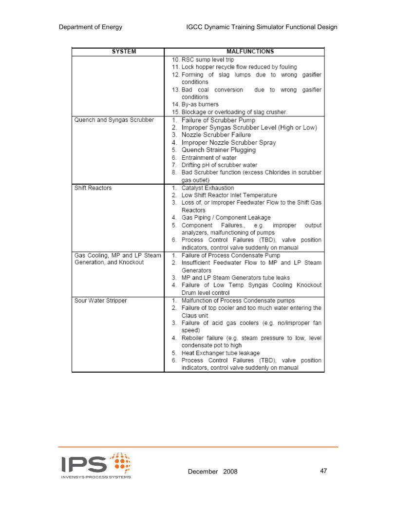
Department of Energy IGCC Dynamic Training Simulator Functional Design
December 2008 47

Department of Energy IGCC Dynamic Training Simulator Functional Design
December 2008 48
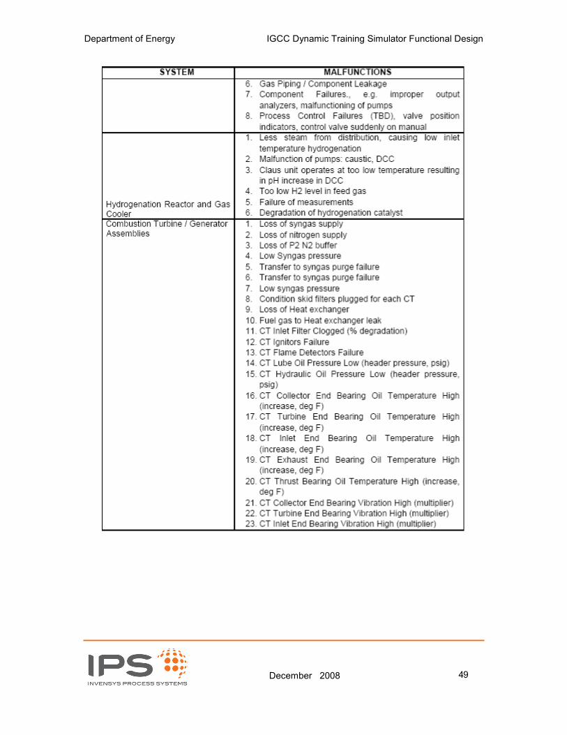
Department of Energy IGCC Dynamic Training Simulator Functional Design
December 2008 49

Department of Energy IGCC Dynamic Training Simulator Functional Design
December 2008 50

Department of Energy IGCC Dynamic Training Simulator Functional Design
December 2008 51
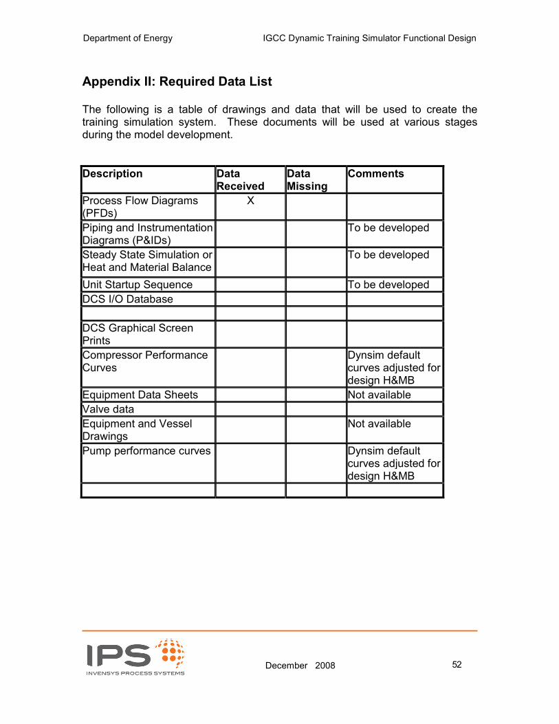
Department of Energy IGCC Dynamic Training Simulator Functional Design
December 2008 52
Appendix II: Required Data List
The following is a table of drawings and data that will be used to create the training simulation system. These documents will be used at various stages during the model development.
Description Data Received
Data Missing
Comments
Process Flow Diagrams (PFDs)
X
Piping and Instrumentation Diagrams (P&IDs)
To be developed
Steady State Simulation or Heat and Material Balance
To be developed
Unit Startup Sequence To be developed
DCS I/O Database
DCS Graphical Screen Prints
Compressor Performance Curves
Dynsim default curves adjusted for design H&MB
Equipment Data Sheets Not available
Valve data
Equipment and Vessel Drawings
Not available
Pump performance curves Dynsim default curves adjusted for design H&MB

Department of Energy IGCC Dynamic Training Simulator Functional Design
December 2008 53
Appendix III: Preliminary Remote Function List
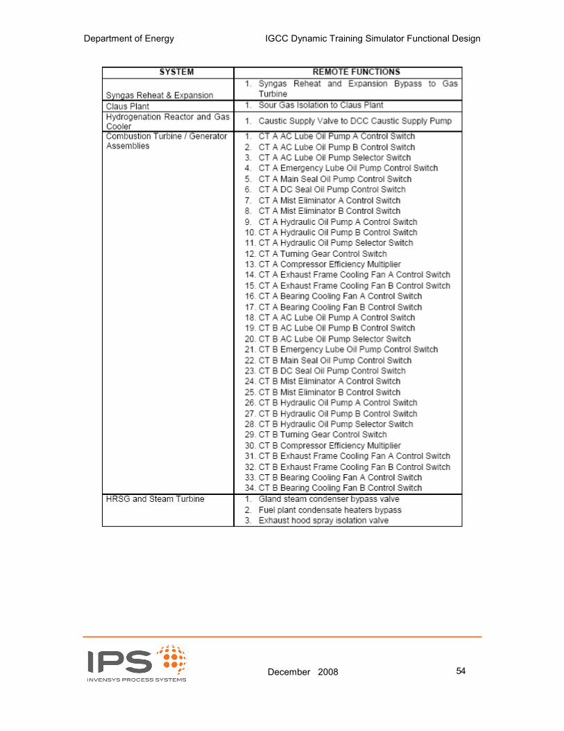
Department of Energy IGCC Dynamic Training Simulator Functional Design
December 2008 54
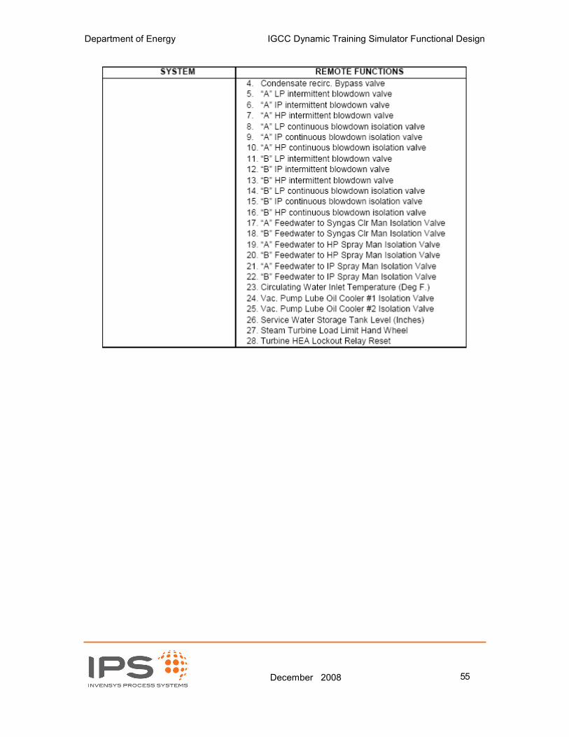
Department of Energy IGCC Dynamic Training Simulator Functional Design
December 2008 55
Related Documents