System Disassembly AMILO D 1845 (257SA0) Rev. A Notebook PC Service Manual System Disassembly Model: - AMILO D 1845 (257SA0) -

System Disassembly
Dec 13, 2015
AMILO D 1845
Welcome message from author
This document is posted to help you gain knowledge. Please leave a comment to let me know what you think about it! Share it to your friends and learn new things together.
Transcript

System Disassembly
AMILO D 1845 (257SA0) Rev. A
Notebook PC Service Manual
System Disassembly
Model:
- AMILO D 1845 (257SA0) -

Chapter 4 System Disassembly
4.1. System Disassembly Procedures…………………………………………… 3 4.2. LCD Display Panel Disassembly Procedure………………….…………... 14
257SA0 Rev : A Page 2 - 17

Chapter 4 System Disassembly
4.1. System Disassembly Procedures
1. Please refer to the disassembly procedures of the 258KA0.
2. Unlock the battery lock and pull out the battery pack.
3. Unlock the ODD lock and pull out the ODD.
257SA0 Rev : A Page 3 - 17

Chapter 4 System Disassembly
4. Unfasten 11 screws and remove the CPU and VGA cover.
5. Unfasten 5 screws and remove CPU Fan.
6. Disconnect CPU Fan cable to the connector.
257SA0 Rev : A Page 4 - 17

Chapter 4 System Disassembly
7. Lift up the CPU lever arm with an angel of 90 degree.
8. Gently remove the CPU.
9. Unfsaten 5 screws of the VGA Fan.
257SA0 Rev : A Page 5 - 17

Chapter 4 System Disassembly
10. Disconnect VGA Fan cable to the connector.
11. Gently remove the 2DDR Module to the DDR Socket.
12. Unfasten 1 screw and push backward the HDD drive and remove it from HDD connector.
257SA0 Rev : A Page 6 - 17

Chapter 4 System Disassembly
13. Unfasten 13 screws and 2 hexnuts.
14. Unfasten 5 screws and 4 hexnuts.
15. Unlock 3 latches of the keyboard and remove the KB board.
257SA0 Rev : A Page 7 - 17
Chapter 4 System Disassembly
16. Disconnect the KB cable to the connector.
17. Gently remove LED cover assembly.
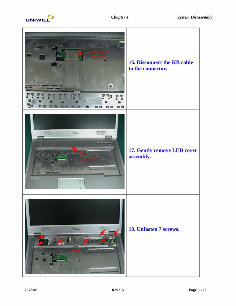
18. Unfasten 7 screws.
257SA0 Rev : A Page 8 - 17

Chapter 4 System Disassembly
19. Gently remove left hinge cover.
20. Gently remove right hinge cover.
21. Disconnect LCD and Inverter cable.
257SA0 Rev : A Page 9 - 17

Chapter 4 System Disassembly
22. Disconnect WLAN cable.
23. Gently remove LCD Panel.
24. Gently remove Top Cabinet.
257SA0 Rev : A Page 10 - 17

Chapter 4 System Disassembly
25. Unfasten 1 screw.
26. Disconnect touchpad cable to the connector. Unfasten 4 screws.
27. Gently remove back cover.
257SA0 Rev : A Page 11 - 17

Chapter 4 System Disassembly
28. Unfasten 1 screw and gently remove the MB to the bracket.
29. System disassembly finished.
257SA0 Rev : A Page 12 - 17

Chapter 4 System Disassembly
4.2 LCD Display disassembly procedure.
1. Remove the 4 rubber stoppers and 2 mylar stoppers.
2. Unfasten 6 screws.
3. Gently remove the LCD Front cabinet.
257SA0 Rev : A Page 13 - 17

Chapter 4 System Disassembly
4. Unfsaten 2 screws from left hinge.
5. Unfasten 2 screws from right hinge.
6. Unfasten 2 screws from Inverter board.
257SA0 Rev : A Page 14 - 17

Chapter 4 System Disassembly
7. Disconnect LCD cable and Inverter cable then remove the inverter.
8. Unfasten 5 screws and remove the LCD Panel from LCD back cabinet.
9. Unfasten 4 screws and remove right and left hinge bracket.
257SA0 Rev : A Page 15 - 17

Chapter 4 System Disassembly
10. Disconnect single LCD cable.
11. LCD display panel disassembly finished.
257SA0 Rev : A Page 16 - 17
Related Documents