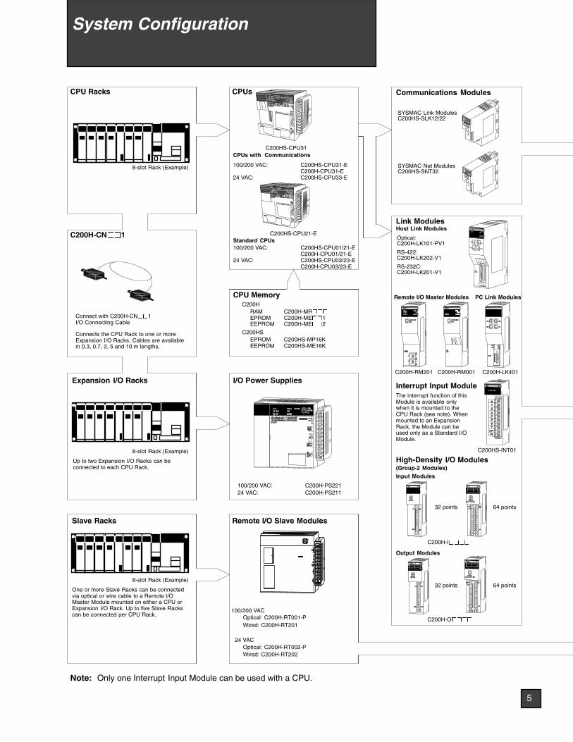
C200H-LK401 RS-232C: C200H-LK201-V1 C200HS-INT01 C200H-RM001 C200H-RM201 Remote I/O Master Modules PC Link Modules Link Modules Output Modules Input Modules Interrupt Input Module The interrupt function of this Module is available only when it is mounted to the CPU Rack (see note). When mounted to an Expansion Rack, the Module can be used only as a Standard I/O Module. Host Link Modules High-Density I/O Modules (Group-2 Modules) Wired: C200H-RT201 Optical: C200H-RT002-P FUSE L2/N L1 Optical: C200H-RT001-P Wired: C200H-RT202 Remote I/O Slave Modules CPUs I/O Power Supplies 100/200 VAC: C200H-PS221 24 VAC: C200H-PS211 RS-422: C200H-LK202-V1 Optical: C200H-LK101-PV1 CPU Racks 8-slot Rack (Example) Expansion I/O Racks Up to two Expansion I/O Racks can be connected to each CPU Rack. 8-slot Rack (Example) 8-slot Rack (Example) Slave Racks One or more Slave Racks can be connected via optical or wire cable to a Remote I/O Master Module mounted on either a CPU or Expansion I/O Rack. Up to five Slave Racks can be connected per CPU Rack. 100/200 VAC 24 VAC Connect with C200H-CN 1 I/O Connecting Cable Connects the CPU Rack to one or more Expansion I/O Racks. Cables are available in 0.3, 0.7, 2, 5 and 10 m lengths. C200H-CN 1 Communications Modules SYSMAC Link Modules C200HS-SLK12/22 C200HS-CPU21-E C200HS-CPU31 100/200 VAC: C200HS-CPU01/21-E C200H-CPU01/21-E 24 VAC: C200HS-CPU03/23-E C200H-CPU03/23-E Note: Only one Interrupt Input Module can be used with a CPU. CPUs with Communications 100/200 VAC: C200HS-CPU31-E C200H-CPU31-E 24 VAC: C200HS-CPU33-E CPU Memory C200H RAM C200H-MR EPROM C200H-ME 1 EEPROM C200H-ME 2 C200HS EPROM C200HS-MP16K EEPROM C200HS-ME16K SYSMAC Net Modules C200HS-SNT32 32 points 64 points 32 points 64 points C200H-I C200H-O Standard CPUs 5 System Configuration

Welcome message from author
This document is posted to help you gain knowledge. Please leave a comment to let me know what you think about it! Share it to your friends and learn new things together.
Transcript
C200H-LK401
RS-232C:C200H-LK201-V1
C200HS-INT01
C200H-RM001C200H-RM201
Remote I/O Master Modules PC Link Modules
Link Modules
Output Modules
Input Modules
Interrupt Input ModuleThe interrupt function of thisModule is available onlywhen it is mounted to theCPU Rack (see note). Whenmounted to an ExpansionRack, the Module can beused only as a Standard I/OModule.
Host Link Modules
High-Density I/O Modules(Group-2 Modules)
Wired: C200H-RT201
Optical: C200H-RT002-P
FUSE
L2/N
L1
Optical: C200H-RT001-P
Wired: C200H-RT202
Remote I/O Slave Modules
CPUs
I/O Power Supplies
100/200 VAC: C200H-PS22124 VAC: C200H-PS211
RS-422:C200H-LK202-V1
Optical:C200H-LK101-PV1
CPU Racks
8-slot Rack (Example)
Expansion I/O Racks
Up to two Expansion I/O Racks can beconnected to each CPU Rack.
8-slot Rack (Example)
8-slot Rack (Example)
Slave Racks
One or more Slave Racks can be connectedvia optical or wire cable to a Remote I/OMaster Module mounted on either a CPU orExpansion I/O Rack. Up to five Slave Rackscan be connected per CPU Rack.
100/200 VAC
24 VAC
Connect with C200H-CN1I/O Connecting Cable
Connects the CPU Rack to one or moreExpansion I/O Racks. Cables are availablein 0.3, 0.7, 2, 5 and 10 m lengths.
C200H-CN1
Communications Modules
SYSMAC Link ModulesC200HS-SLK12/22
C200HS-CPU21-E
C200HS-CPU31
100/200 VAC: C200HS-CPU01/21-EC200H-CPU01/21-E
24 VAC: C200HS-CPU03/23-EC200H-CPU03/23-E
Note: Only one Interrupt Input Module can be used with a CPU.
CPUs with Communications
100/200 VAC: C200HS-CPU31-EC200H-CPU31-E
24 VAC: C200HS-CPU33-E
CPU MemoryC200H
RAM C200H-MREPROM C200H-ME1EEPROM C200H-ME2
C200HSEPROM C200HS-MP16KEEPROM C200HS-ME16K
SYSMAC Net ModulesC200HS-SNT32
32 points 64 points
32 points 64 points
C200H-I
C200H-O
Standard CPUs
5
System Configuration
C200H-AD001/002 C200H-DA001
C200H-TS
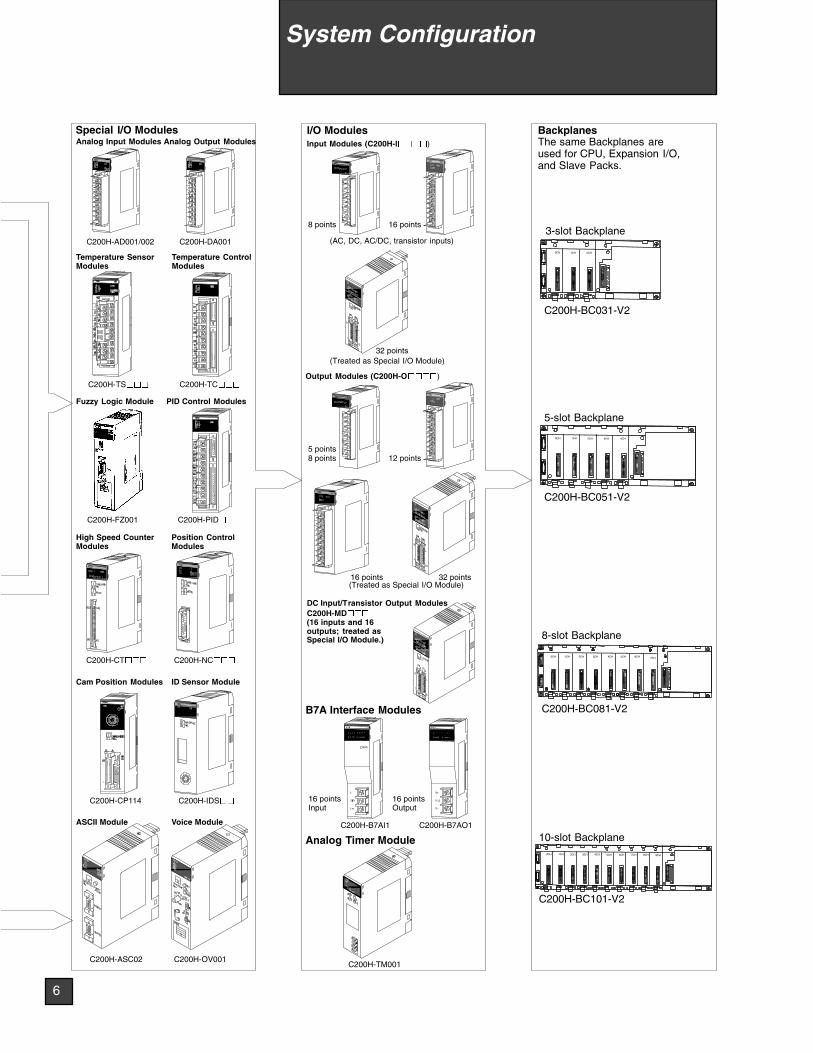
Temperature SensorModules
Analog Input Modules Analog Output Modules
C200H-TC
Temperature ControlModules
C200H-FZ001
Fuzzy Logic Module
C200H-PID
PID Control Modules
C200H-CT
High Speed CounterModules
C200H-NC
Position ControlModules
C200H-CP114
Cam Position Modules
C200H-IDS
ID Sensor Module
C200H-ASC02 C200H-OV001
ASCII Module Voice Module
Special I/O Modules
8 points 16 points
I/O ModulesInput Modules (C200H-I)
(AC, DC, AC/DC, transistor inputs)
32 points(Treated as Special I/O Module)
Output Modules (C200H-O)
8 points 12 points
32 points
5 points
16 points(Treated as Special I/O Module)
DC Input/Transistor Output ModulesC200H-MD(16 inputs and 16outputs; treated asSpecial I/O Module.)
C200H-B7AO1C200H-B7AI1
B7A Interface Modules
Analog Timer Module
C200H-TM001
16 pointsOutput
16 pointsInput
2CH1CH0CH
1CH 2CH 3CH 4CH0CH
1CH 9CH8CH7CH6CH2CH 3CH 5CH4CH0CH
C200H-BC031-V2
C200H-BC051-V2
C200H-BC081-V2
C200H-BC101-V2
BackplanesThe same Backplanes areused for CPU, Expansion I/O,and Slave Packs.
3-slot Backplane
5-slot Backplane
8-slot Backplane
10-slot Backplane
6CH5CH1CH 2CH 3CH0CH 4CH 7CH
6
System Configuration
CPUs 8. . . . . . . . . . . . . . . . . . . . . . . . . . . . . . . . . . . . . . . . . . . . . . . . . .Memory Packs 19. . . . . . . . . . . . . . . . . . . . . . . . . . . . . . . . . . . . . . . . . .Backplanes 21. . . . . . . . . . . . . . . . . . . . . . . . . . . . . . . . . . . . . . . . . . . . .Special I/O Modules 22. . . . . . . . . . . . . . . . . . . . . . . . . . . . . . . . . . . . .Discrete Input/Output Modules 65. . . . . . . . . . . . . . . . . . . . . . . . . . . .I/O Wiring Accessories 73. . . . . . . . . . . . . . . . . . . . . . . . . . . . . . . . . . .Input Wiring Accessories 75. . . . . . . . . . . . . . . . . . . . . . . . . . . . . . . . .Output Wiring Accessories 81. . . . . . . . . . . . . . . . . . . . . . . . . . . . . . .Remote Expansion 89. . . . . . . . . . . . . . . . . . . . . . . . . . . . . . . . . . . . . .Communication Modules 94. . . . . . . . . . . . . . . . . . . . . . . . . . . . . . . . .Link Adapters 103. . . . . . . . . . . . . . . . . . . . . . . . . . . . . . . . . . . . . . . . . . .
7
1
8 Components
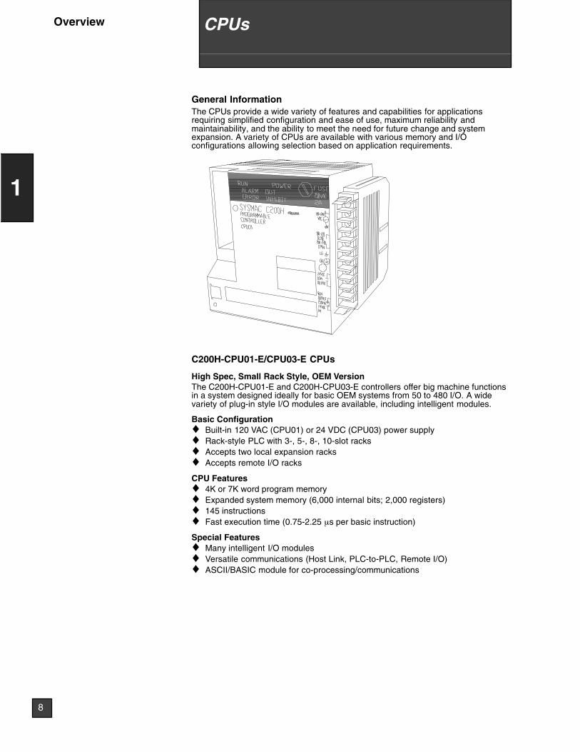
General InformationThe CPUs provide a wide variety of features and capabilities for applicationsrequiring simplified configuration and ease of use, maximum reliability andmaintainability, and the ability to meet the need for future change and systemexpansion. A variety of CPUs are available with various memory and I/Oconfigurations allowing selection based on application requirements.
C200H-CPU01-E/CPU03-E CPUs
High Spec, Small Rack Style, OEM VersionThe C200H-CPU01-E and C200H-CPU03-E controllers offer big machine functionsin a system designed ideally for basic OEM systems from 50 to 480 I/O. A widevariety of plug-in style I/O modules are available, including intelligent modules.
Basic Configuration♦ Built-in 120 VAC (CPU01) or 24 VDC (CPU03) power supply♦ Rack-style PLC with 3-, 5-, 8-, 10-slot racks♦ Accepts two local expansion racks♦ Accepts remote I/O racks
CPU Features♦ 4K or 7K word program memory♦ Expanded system memory (6,000 internal bits; 2,000 registers)♦ 145 instructions♦ Fast execution time (0.75-2.25 µs per basic instruction)
Special Features♦ Many intelligent I/O modules♦ Versatile communications (Host Link, PLC-to-PLC, Remote I/O)♦ ASCII/BASIC module for co-processing/communications
8
1
CPUsOverview
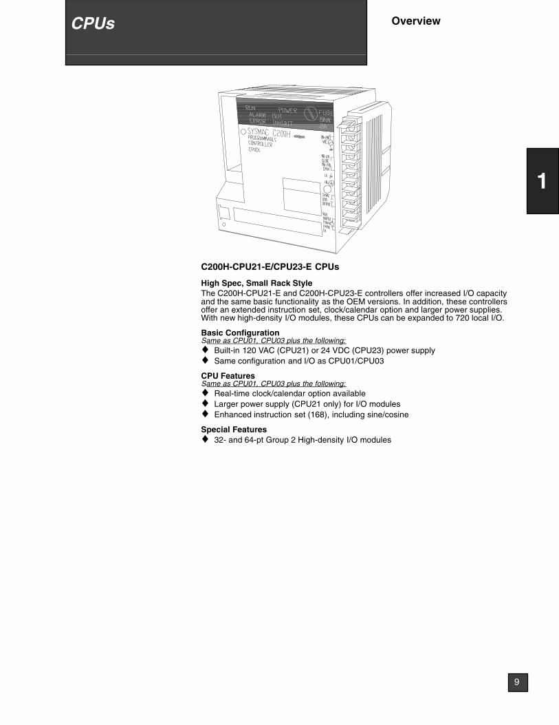
C200H-CPU21-E/CPU23-E CPUs
High Spec, Small Rack StyleThe C200H-CPU21-E and C200H-CPU23-E controllers offer increased I/O capacityand the same basic functionality as the OEM versions. In addition, these controllersoffer an extended instruction set, clock/calendar option and larger power supplies.With new high-density I/O modules, these CPUs can be expanded to 720 local I/O.
Basic ConfigurationSame as CPU01, CPU03 plus the following:♦ Built-in 120 VAC (CPU21) or 24 VDC (CPU23) power supply♦ Same configuration and I/O as CPU01/CPU03
CPU FeaturesSame as CPU01, CPU03 plus the following:♦ Real-time clock/calendar option available♦ Larger power supply (CPU21 only) for I/O modules♦ Enhanced instruction set (168), including sine/cosine
Special Features♦ 32- and 64-pt Group 2 High-density I/O modules
9
1
CPUs Overview
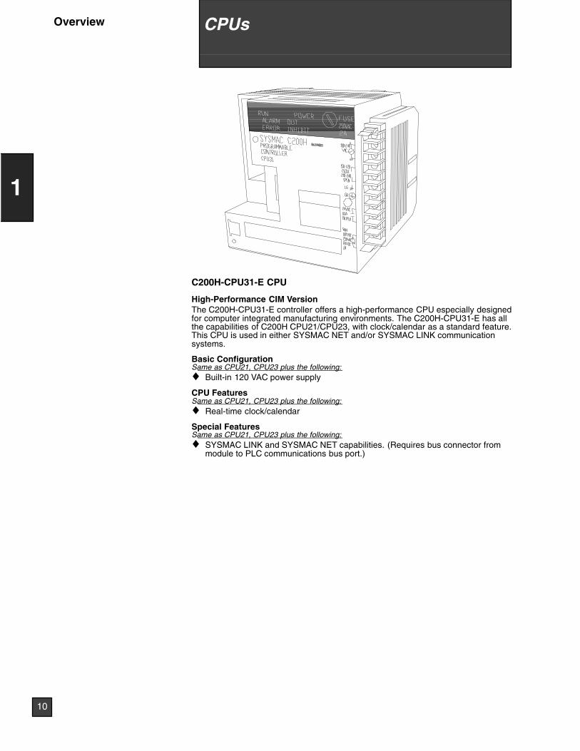
C200H-CPU31-E CPU
High-Performance CIM VersionThe C200H-CPU31-E controller offers a high-performance CPU especially designedfor computer integrated manufacturing environments. The C200H-CPU31-E has allthe capabilities of C200H CPU21/CPU23, with clock/calendar as a standard feature.This CPU is used in either SYSMAC NET and/or SYSMAC LINK communicationsystems.
Basic ConfigurationSame as CPU21, CPU23 plus the following:♦ Built-in 120 VAC power supply
CPU FeaturesSame as CPU21, CPU23 plus the following:♦ Real-time clock/calendar
Special FeaturesSame as CPU21, CPU23 plus the following:♦ SYSMAC LINK and SYSMAC NET capabilities. (Requires bus connector from
module to PLC communications bus port.)
10
1
CPUsOverview
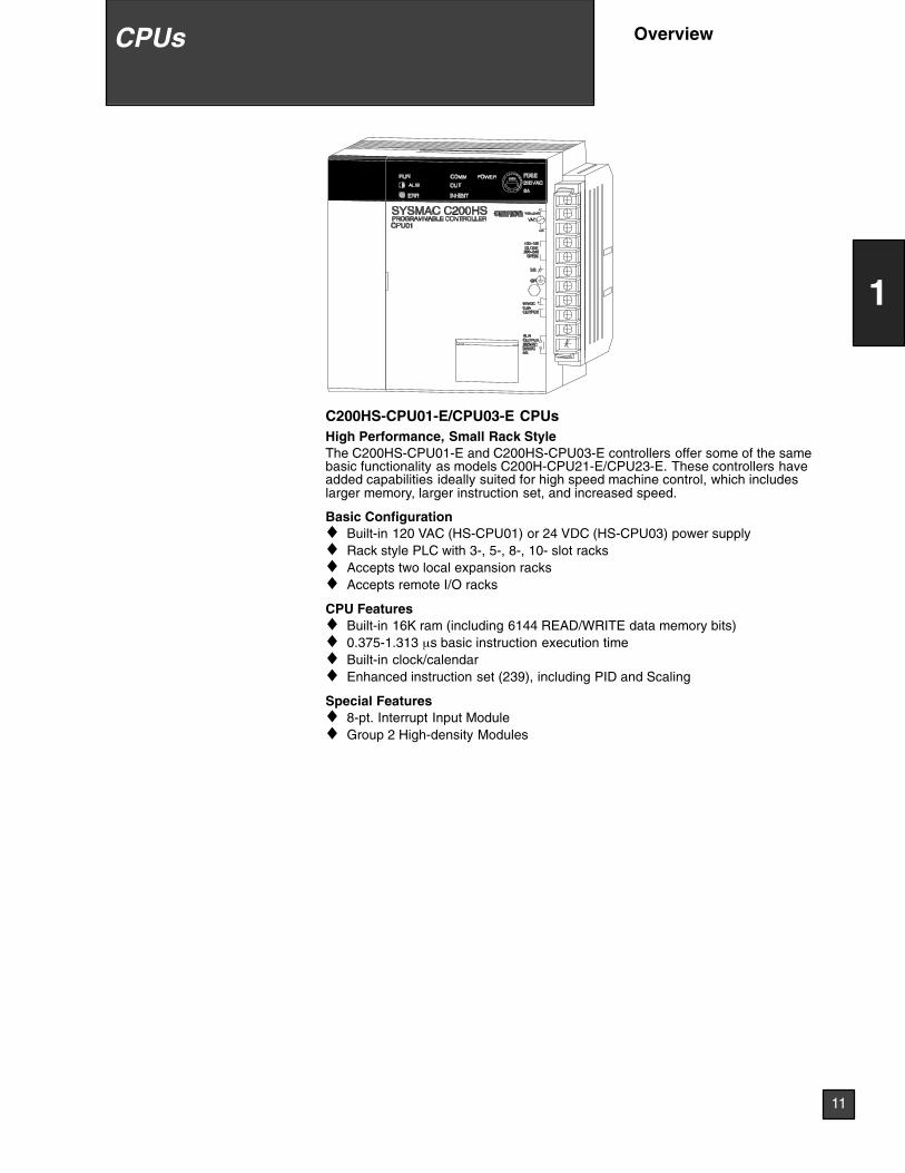
C200HS-CPU01-E/CPU03-E CPUsHigh Performance, Small Rack StyleThe C200HS-CPU01-E and C200HS-CPU03-E controllers offer some of the samebasic functionality as models C200H-CPU21-E/CPU23-E. These controllers haveadded capabilities ideally suited for high speed machine control, which includeslarger memory, larger instruction set, and increased speed.
Basic Configuration♦ Built-in 120 VAC (HS-CPU01) or 24 VDC (HS-CPU03) power supply♦ Rack style PLC with 3-, 5-, 8-, 10- slot racks♦ Accepts two local expansion racks♦ Accepts remote I/O racks
CPU Features♦ Built-in 16K ram (including 6144 READ/WRITE data memory bits)♦ 0.375-1.313 µs basic instruction execution time♦ Built-in clock/calendar♦ Enhanced instruction set (239), including PID and Scaling
Special Features♦ 8-pt. Interrupt Input Module♦ Group 2 High-density Modules
11
1
CPUs Overview
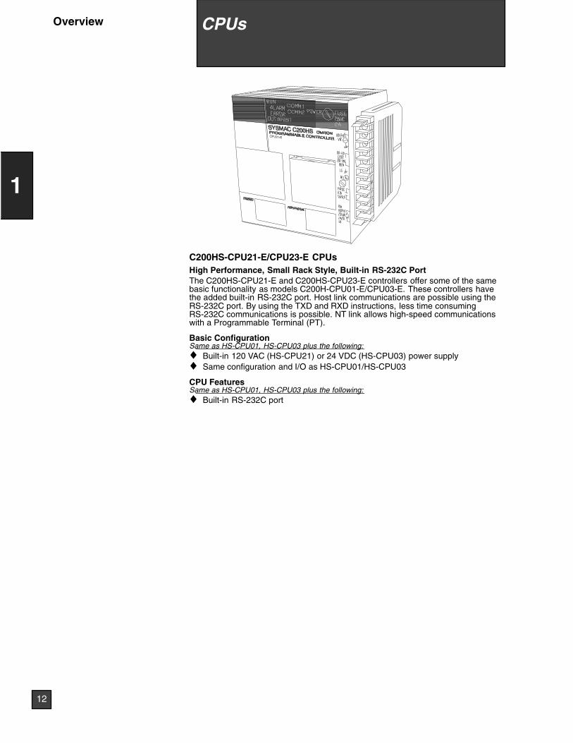
C200HS-CPU21-E/CPU23-E CPUsHigh Performance, Small Rack Style, Built-in RS-232C PortThe C200HS-CPU21-E and C200HS-CPU23-E controllers offer some of the samebasic functionality as models C200H-CPU01-E/CPU03-E. These controllers havethe added built-in RS-232C port. Host link communications are possible using theRS-232C port. By using the TXD and RXD instructions, less time consumingRS-232C communications is possible. NT link allows high-speed communicationswith a Programmable Terminal (PT).
Basic ConfigurationSame as HS-CPU01, HS-CPU03 plus the following:♦ Built-in 120 VAC (HS-CPU21) or 24 VDC (HS-CPU03) power supply♦ Same configuration and I/O as HS-CPU01/HS-CPU03
CPU FeaturesSame as HS-CPU01, HS-CPU03 plus the following:♦ Built-in RS-232C port
12
1
CPUsOverview
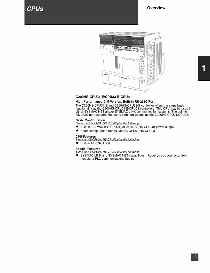
C200HS-CPU31-E/CPU33-E CPUsHigh-Performance CIM Version, Built-in RS-232C PortThe C200HS-CPU31-E and C200HS-CPU33-E controller offers the same basicfunctionality as the C200HS-CPU01-E/CPU03 controllers. This CPU may be used ineither SYSMAC NET and/or SYSMAC LINK communication systems. The built-inRS-232C port supports the same communications as the C200HS-CPU21/CPU23.
Basic ConfigurationSame as HS-CPU01, HS-CPU03 plus the following:♦ Built-in 120 VAC (HS-CPU21) or 24 VDC (HS-CPU03) power supply♦ Same configuration and I/O as HS-CPU01/HS-CPU03
CPU FeaturesSame as HS-CPU01, HS-CPU03 plus the following:♦ Built-in RS-232C port
Special FeaturesSame as HS-CPU01, HS-CPU03 plus the following:♦ SYSMAC LINK and SYSMAC NET capabilities. (Requires bus connector from
module to PLC communications bus port.
13
1
CPUs Overview
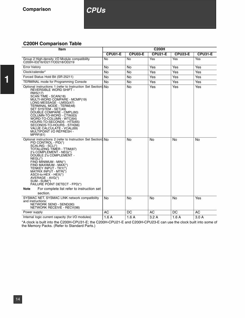
C200H Comparison TableItem C200H
CPU01-E CPU03-E CPU21-E CPU23-E CPU31-EGroup 2 High-density I/O Module compatibilityC200H-ID216/ID217/OD218/OD219
No No Yes Yes Yes
Error history No No Yes Yes YesClock/calendar* No No Yes Yes YesForced Status Hold Bit (SR 25211) No No Yes Yes YesTERMINAL mode for Programming Console No No Yes Yes YesOptional instructions 1 (refer to Instruction Set Section):
REVERSIBLE WORD SHIFT -RWS(17)SCAN TIME - SCAN(18)MULTI-WORD COMPARE - MCMP(19)LONG MESSAGE - LMSG(47)TERMINAL MODE - TERM(48)SET SYSTEM - SET(49)DOUBLE COMPARE - CMPL(60)COLUMN-TO-WORD - CTW(63)WORD-TO-COLUMN - WTC(64)HOURS-TO-SECONDS - HTS(65)SECONDS-TO-HOURS - STH(66)VALUE CALCULATE - VCAL(69)MULTIPOINT I/O REFRESH -MPRF(61)
No No Yes Yes Yes
Optional instructions 2 (refer to Instruction Set Section):PID CONTROL - PID(*)SCALING - SCL(*)TOTALIZING TIMER - TTIM(87)2’s COMPLEMENT - NEG(*)DOUBLE 2’s COMPLEMENT -NEGL(*)FIND MINIMUM - MIN(*)FIND MAXIMUM - MAX(*)TENKEY INPUT - TKY(*)MATRIX INPUT - MTR(*)ASCII-to-HEX - HEX(*)AVERAGE - AVG(*)SUM - SUM(*)FAILURE POINT DETECT - FPD(*)
Note For complete list refer to instruction setsection.
No No No No No
SYSMAC NET, SYSMAC LINK network compatibilityand instructions:
NETWORK SEND - SEND(90)NETWORK RECEIVE - RECV(98)
No No No No Yes
Power supply AC DC AC DC ACInternal logic current capacity (for I/O modules) 1.6 A 1.6 A 3.2 A 1.6 A 3.0 A
*A clock is built into the C200H-CPU31-E; the C200H-CPU21-E and C200H-CPU23-E can use the clock built into some ofthe Memory Packs. (Refer to Standard Parts.)
14
1
CPUsComparison
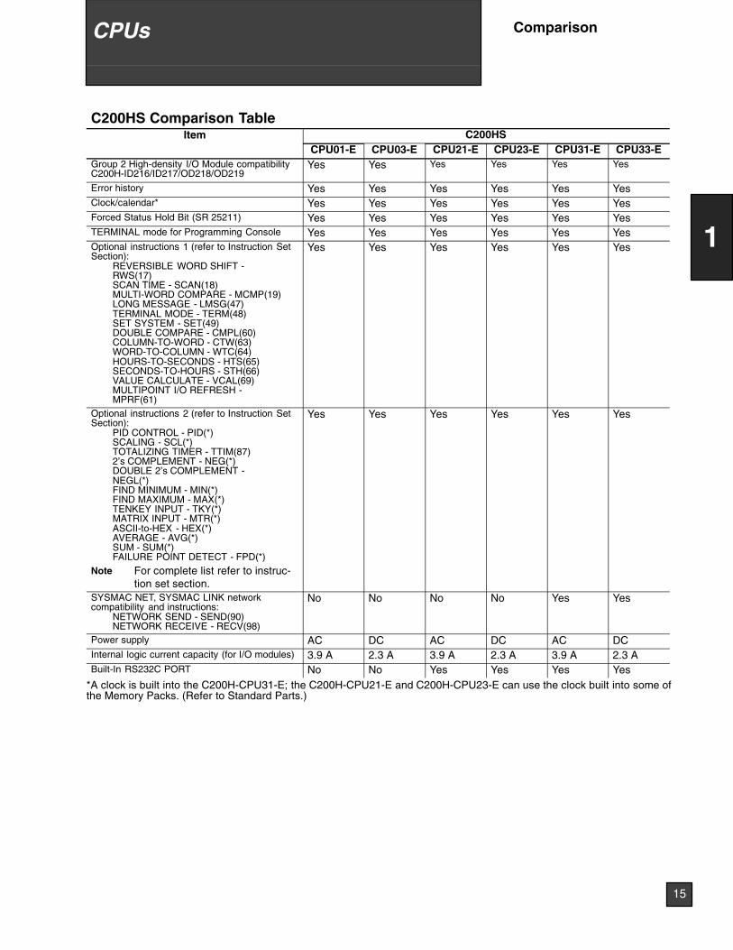
C200HS Comparison TableItem C200HS
CPU01-E CPU03-E CPU21-E CPU23-E CPU31-E CPU33-EGroup 2 High-density I/O Module compatibilityC200H-ID216/ID217/OD218/OD219
Yes Yes Yes Yes Yes Yes
Error history Yes Yes Yes Yes Yes YesClock/calendar* Yes Yes Yes Yes Yes YesForced Status Hold Bit (SR 25211) Yes Yes Yes Yes Yes YesTERMINAL mode for Programming Console Yes Yes Yes Yes Yes YesOptional instructions 1 (refer to Instruction SetSection):
REVERSIBLE WORD SHIFT -RWS(17)SCAN TIME - SCAN(18)MULTI-WORD COMPARE - MCMP(19)LONG MESSAGE - LMSG(47)TERMINAL MODE - TERM(48)SET SYSTEM - SET(49)DOUBLE COMPARE - CMPL(60)COLUMN-TO-WORD - CTW(63)WORD-TO-COLUMN - WTC(64)HOURS-TO-SECONDS - HTS(65)SECONDS-TO-HOURS - STH(66)VALUE CALCULATE - VCAL(69)MULTIPOINT I/O REFRESH -MPRF(61)
Yes Yes Yes Yes Yes Yes
Optional instructions 2 (refer to Instruction SetSection):
PID CONTROL - PID(*)SCALING - SCL(*)TOTALIZING TIMER - TTIM(87)2’s COMPLEMENT - NEG(*)DOUBLE 2’s COMPLEMENT -NEGL(*)FIND MINIMUM - MIN(*)FIND MAXIMUM - MAX(*)TENKEY INPUT - TKY(*)MATRIX INPUT - MTR(*)ASCII-to-HEX - HEX(*)AVERAGE - AVG(*)SUM - SUM(*)FAILURE POINT DETECT - FPD(*)
Note For complete list refer to instruc-tion set section.
Yes Yes Yes Yes Yes Yes
SYSMAC NET, SYSMAC LINK networkcompatibility and instructions:
NETWORK SEND - SEND(90)NETWORK RECEIVE - RECV(98)
No No No No Yes Yes
Power supply AC DC AC DC AC DCInternal logic current capacity (for I/O modules) 3.9 A 2.3 A 3.9 A 2.3 A 3.9 A 2.3 ABuilt-In RS232C PORT No No Yes Yes Yes Yes
*A clock is built into the C200H-CPU31-E; the C200H-CPU21-E and C200H-CPU23-E can use the clock built into some ofthe Memory Packs. (Refer to Standard Parts.)
15
1
CPUs Comparison
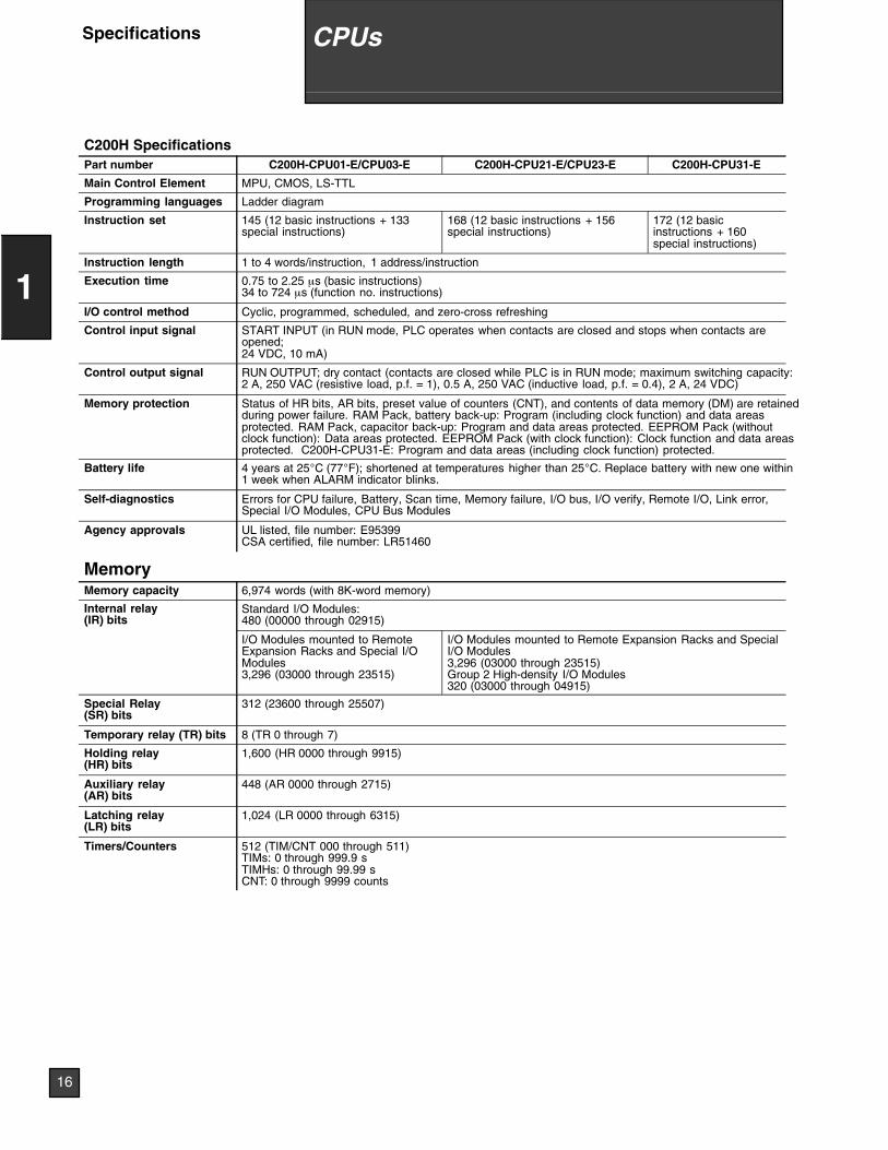
C200H SpecificationsPart number C200H-CPU01-E/CPU03-E C200H-CPU21-E/CPU23-E C200H-CPU31-E
Main Control Element MPU, CMOS, LS-TTL
Programming languages Ladder diagram
Instruction set 145 (12 basic instructions + 133special instructions)
168 (12 basic instructions + 156special instructions)
172 (12 basicinstructions + 160special instructions)
Instruction length 1 to 4 words/instruction, 1 address/instruction
Execution time 0.75 to 2.25 µs (basic instructions)34 to 724 µs (function no. instructions)
I/O control method Cyclic, programmed, scheduled, and zero-cross refreshing
Control input signal START INPUT (in RUN mode, PLC operates when contacts are closed and stops when contacts areopened;24 VDC, 10 mA)
Control output signal RUN OUTPUT; dry contact (contacts are closed while PLC is in RUN mode; maximum switching capacity:2 A, 250 VAC (resistive load, p.f. = 1), 0.5 A, 250 VAC (inductive load, p.f. = 0.4), 2 A, 24 VDC)
Memory protection Status of HR bits, AR bits, preset value of counters (CNT), and contents of data memory (DM) are retainedduring power failure. RAM Pack, battery back-up: Program (including clock function) and data areasprotected. RAM Pack, capacitor back-up: Program and data areas protected. EEPROM Pack (withoutclock function): Data areas protected. EEPROM Pack (with clock function): Clock function and data areasprotected. C200H-CPU31-E: Program and data areas (including clock function) protected.
Battery life 4 years at 25°C (77°F); shortened at temperatures higher than 25°C. Replace battery with new one within1 week when ALARM indicator blinks.
Self-diagnostics Errors for CPU failure, Battery, Scan time, Memory failure, I/O bus, I/O verify, Remote I/O, Link error,Special I/O Modules, CPU Bus Modules
Agency approvals UL listed, file number: E95399CSA certified, file number: LR51460
MemoryMemory capacity 6,974 words (with 8K-word memory)
Internal relay(IR) bits
Standard I/O Modules:480 (00000 through 02915)( )
I/O Modules mounted to RemoteExpansion Racks and Special I/OModules3,296 (03000 through 23515)
I/O Modules mounted to Remote Expansion Racks and SpecialI/O Modules3,296 (03000 through 23515)Group 2 High-density I/O Modules320 (03000 through 04915)
Special Relay(SR) bits
312 (23600 through 25507)
Temporary relay (TR) bits 8 (TR 0 through 7)
Holding relay(HR) bits
1,600 (HR 0000 through 9915)
Auxiliary relay(AR) bits
448 (AR 0000 through 2715)
Latching relay(LR) bits
1,024 (LR 0000 through 6315)
Timers/Counters 512 (TIM/CNT 000 through 511)TIMs: 0 through 999.9 sTIMHs: 0 through 99.99 sCNT: 0 through 9999 counts
16
1
CPUsSpecifications
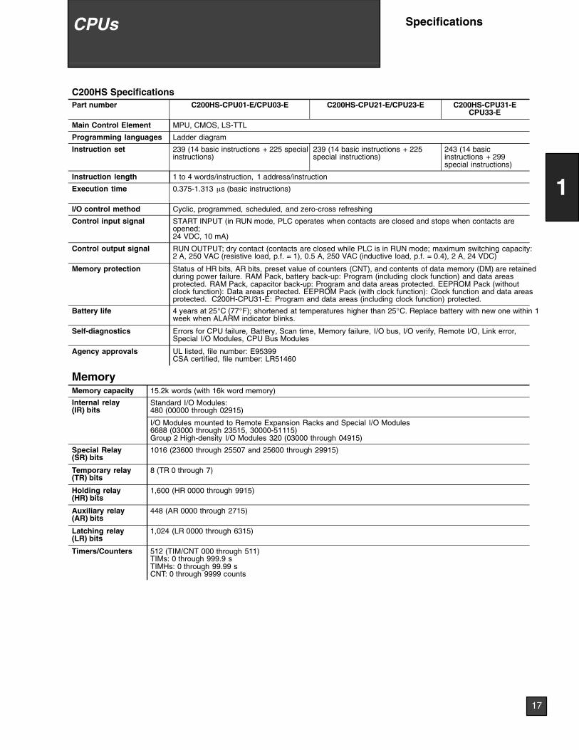
C200HS SpecificationsPart number C200HS-CPU01-E/CPU03-E C200HS-CPU21-E/CPU23-E C200HS-CPU31-E
CPU33-E
Main Control Element MPU, CMOS, LS-TTL
Programming languages Ladder diagram
Instruction set 239 (14 basic instructions + 225 specialinstructions)
239 (14 basic instructions + 225special instructions)
243 (14 basicinstructions + 299special instructions)
Instruction length 1 to 4 words/instruction, 1 address/instruction
Execution time 0.375-1.313 µs (basic instructions)
I/O control method Cyclic, programmed, scheduled, and zero-cross refreshing
Control input signal START INPUT (in RUN mode, PLC operates when contacts are closed and stops when contacts areopened;24 VDC, 10 mA)
Control output signal RUN OUTPUT; dry contact (contacts are closed while PLC is in RUN mode; maximum switching capacity:2 A, 250 VAC (resistive load, p.f. = 1), 0.5 A, 250 VAC (inductive load, p.f. = 0.4), 2 A, 24 VDC)
Memory protection Status of HR bits, AR bits, preset value of counters (CNT), and contents of data memory (DM) are retainedduring power failure. RAM Pack, battery back-up: Program (including clock function) and data areasprotected. RAM Pack, capacitor back-up: Program and data areas protected. EEPROM Pack (withoutclock function): Data areas protected. EEPROM Pack (with clock function): Clock function and data areasprotected. C200H-CPU31-E: Program and data areas (including clock function) protected.
Battery life 4 years at 25°C (77°F); shortened at temperatures higher than 25°C. Replace battery with new one within 1week when ALARM indicator blinks.
Self-diagnostics Errors for CPU failure, Battery, Scan time, Memory failure, I/O bus, I/O verify, Remote I/O, Link error,Special I/O Modules, CPU Bus Modules
Agency approvals UL listed, file number: E95399CSA certified, file number: LR51460
MemoryMemory capacity 15.2k words (with 16k word memory)
Internal relay(IR) bits
Standard I/O Modules:480 (00000 through 02915)( )
I/O Modules mounted to Remote Expansion Racks and Special I/O Modules6688 (03000 through 23515, 30000-51115)Group 2 High-density I/O Modules 320 (03000 through 04915)
Special Relay(SR) bits
1016 (23600 through 25507 and 25600 through 29915)
Temporary relay(TR) bits
8 (TR 0 through 7)
Holding relay(HR) bits
1,600 (HR 0000 through 9915)
Auxiliary relay(AR) bits
448 (AR 0000 through 2715)
Latching relay(LR) bits
1,024 (LR 0000 through 6315)
Timers/Counters 512 (TIM/CNT 000 through 511)TIMs: 0 through 999.9 sTIMHs: 0 through 99.99 sCNT: 0 through 9999 counts
17
1
CPUs Specifications
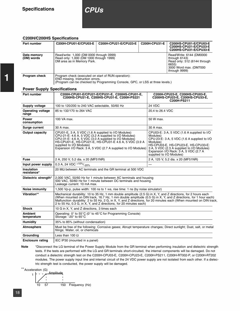
C200H/C200HS SpecificationsPart number C200H-CPU01-E/CPU03-E C200H-CPU21-E/CPU23-E C200H-CPU31-E C200HS-CPU01-E/CPU03-E
C200HS-CPU21-E/CPU23-EC200HS-CPU31-E/CPU33-E
Data memory(DM) words
Read/write: 1,000 (DM 0000 through 0999)Read only: 1,000 (DM 1000 through 1999)DM area as in Memory Park.
Read/Write: 6144 (DM0000through 6143)Read only: 512 (6144 through6655)3000 Word max. (DM7000through 9999)
Program check Program check (executed on start of RUN operation):END missing, Instruction errors,(Program can be checked by Programming Console, GPC, or LSS at three levels.)
Power Supply SpecificationsPart number C200H-CPU01-E/CPU21-E/CPU31-E, C200HS-CPU01-E,
C200HS-CPU21-E, C200HS-CPU31-E, C200H-PS221C200H-CPU23-E, C200HS-CPU03-E,
C200HS-CPU23-E, C200HS-CPU33-E,C200H-PS211
Supply voltage 100 to 120/200 to 240 VAC selectable, 50/60 Hz 24 VDC
Operating voltagerange
85 to 132/170 to 264 VAC 20.4 to 26.4 VDC
Powerconsumption
100 VA max. 50 W max.
Surge current 30 A max. 30 A max.
Output capacity CPU01-E, 3 A, 5 VDC (1.6 A supplied to I/O Modules)CPU-21-E: 4.6 A, 5 VDC (3.2 A supplied to I/O Modules)CPU-31-E: 4.6 A, 5 VDC (3.0 A supplied to I/O Modules)HS-CPU01-E, HS-CPU21-E, HS-CPU31-E 4.6 A, 5 VDC (3.9 Asupplied to I/O Modules)Expansion I/O Rack: 3 A, 5 VDC (2.7 A supplied to I/O Modules)
CPU03-E: 3 A, 5 VDC (1.6 A supplied to I/OModules)CPU-23-E: 3 A, 5 VDC (1.6 A supplied to I/OModules)HS-CPU03-E, HS-CPU23-E, HS-CPU33-E:3 A, 5 VDC (2.3 A supplied to I/O Modules)Expansion I/O Rack: 3 A, 5 VDC (2.7 Asupplied to I/O Modules)
Fuse 2 A, 250 V, 5.2 dia. x 20 (MF51NR) 2 A, 125 V, 5.2 dia. x 20 (MF51NR)
Input power supply 0.3 A, 24 VDC +10%/-20% —
Insulationresistance*
20 MΩ between AC terminals and the GR terminal at 500 VDC
Dielectric strength* 2,000 VAC, 50/60 Hz for 1 minute between AC terminals and housing500 VAC, 50/60 Hz for 1 minute between DC terminals and housing.Leakage current: 10 mA max.
Noise immunity 1,500 Vp-p, pulse width: 100 ns to 1 s, rise time: 1 ns (by noise simulator)
Vibration** Mechanical durability: 10 to 35 Hz, 1 mm double amplitude (2.5 G) in X, Y, and Z directions, for 2 hours each(When mounted on DIN track, 16.7 Hz, 1 mm double amplitude (0.5 G) in X, Y, and Z directions, for 1 hour each)Malfunction durability: 2 to 55 Hz, 2 G, in X, Y, and Z directions, for 20 minutes each (When mounted on DIN track,2 to 55 Hz, 0.3 G, in X, Y, and Z directions, for 20 minutes each)
Shock 10 G in X, Y, and Z directions, 3 times each
Ambienttemperature
Operating: 0° to 55°C (0° to 45°C for Programming Console)Storage: -20° to 65°C
Humidity 35% to 85% (without condensation)
Atmosphere Must be free of the following: Corrosive gases; Abrupt temperature changes; Direct sunlight; Dust, salt, or metalfilings; Water, oil, or chemicals
Grounding Less than 100 Ω
Enclosure rating IEC IP30 (mounted in a panel)
Note *Disconnect the LG terminal of the Power Supply Module from the GR terminal when performing insulation and dielectric strengthtests. If the tests are performed with the LG and GR terminals short-circuited, the internal components will be damaged. Do notconduct a dielectric strength test on the C200H-CPU03-E, C200H-CPU23-E, C200H-PS211, C200H-RT002-P, or C200H-RT202modules. The power supply input line and internal circuit of the 24 VDC power supply are not isolated from each other. If a dielec-tric strength test is conducted, the power supply will be damaged.
**Acceleration (G)
Frequency (Hz)
1
10 57 150
Amplitude
18
1
CPUsSpecifications
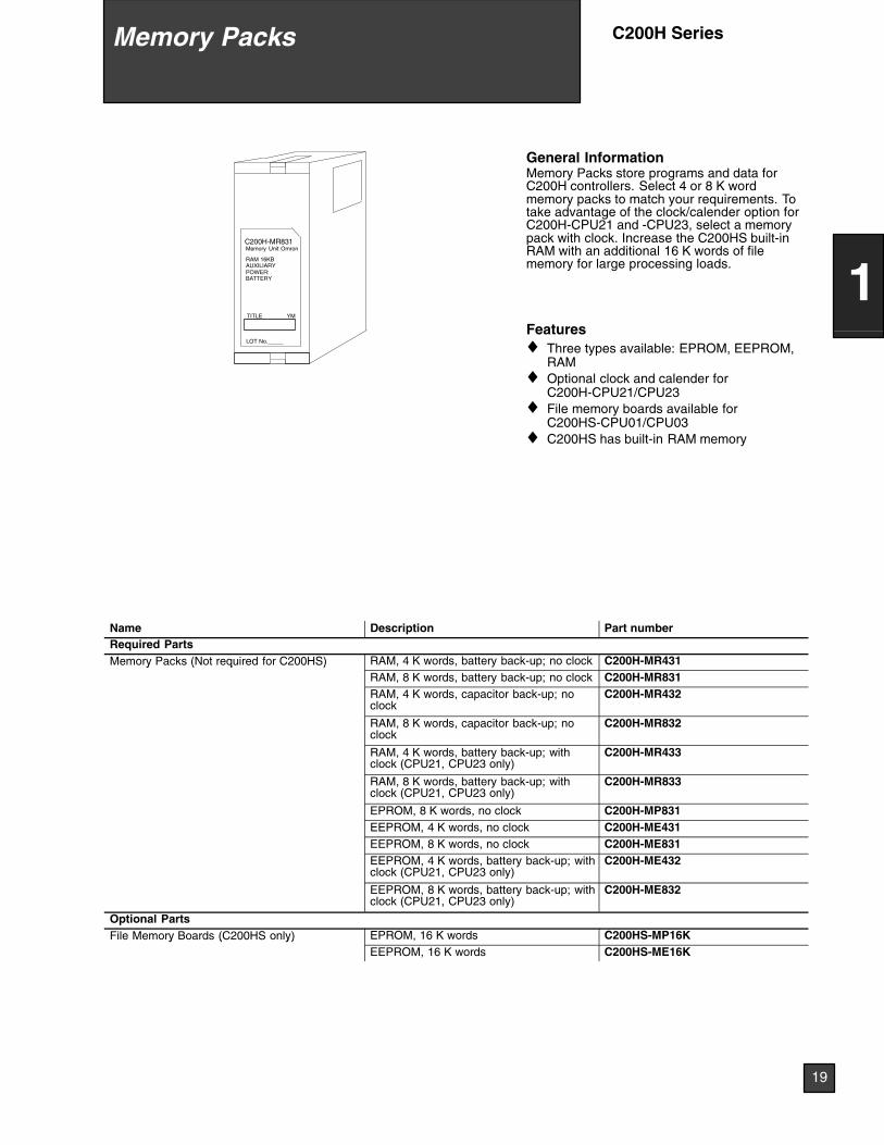
LOT No._____
C200H-MR831Memory Unit Omron
TITLE YM
RAM 16KBAUXILIARYPOWER:BATTERY
General InformationMemory Packs store programs and data forC200H controllers. Select 4 or 8 K wordmemory packs to match your requirements. Totake advantage of the clock/calender option forC200H-CPU21 and -CPU23, select a memorypack with clock. Increase the C200HS built-inRAM with an additional 16 K words of filememory for large processing loads.
Features♦ Three types available: EPROM, EEPROM,
RAM♦ Optional clock and calender for
C200H-CPU21/CPU23♦ File memory boards available for
C200HS-CPU01/CPU03♦ C200HS has built-in RAM memory
Name Description Part numberRequired PartsMemory Packs (Not required for C200HS) RAM, 4 K words, battery back-up; no clock C200H-MR431y ( q )
RAM, 8 K words, battery back-up; no clock C200H-MR831RAM, 4 K words, capacitor back-up; noclock
C200H-MR432
RAM, 8 K words, capacitor back-up; noclock
C200H-MR832
RAM, 4 K words, battery back-up; withclock (CPU21, CPU23 only)
C200H-MR433
RAM, 8 K words, battery back-up; withclock (CPU21, CPU23 only)
C200H-MR833
EPROM, 8 K words, no clock C200H-MP831EEPROM, 4 K words, no clock C200H-ME431EEPROM, 8 K words, no clock C200H-ME831EEPROM, 4 K words, battery back-up; withclock (CPU21, CPU23 only)
C200H-ME432
EEPROM, 8 K words, battery back-up; withclock (CPU21, CPU23 only)
C200H-ME832
Optional PartsFile Memory Boards (C200HS only) EPROM, 16 K words C200HS-MP16Ky ( y)
EEPROM, 16 K words C200HS-ME16K
Memory Packs C200H Series
19
1

Memory PacksC200H Series
20
1
2CH1CH0CH1CH 2CH 3CH 4CH0CH
1CH 9CH8CH7CH6CH2CH 3CH 5CH4CH0CH
6CH5CH1CH 2CH 3CH0CH
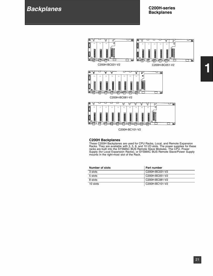
C200H-BC031-V2 C200H-BC051-V2
C200H-BC081-V2
C200H-BC101-V2
4CH 7CH
C200H BackplanesThese C200H Backplanes are used for CPU Racks, Local, and Remote ExpansionRacks. They are available with 3, 5, 8, and 10 I/O slots. The power supplies for theseracks are built into the SYSMAC BUS Remote Slave Modules. The CPU, PowerSupply (for Local Expansion Racks), or SYSMAC BUS Remote Slave/Power Supplymounts in the right-most slot of the Rack.
Number of slots Part number3 slots C200H-BC031-V25 slots C200H-BC051-V28 slots C200H-BC081-V210 slots C200H-BC101-V2
21
1
Backplanes C200H-seriesBackplanes
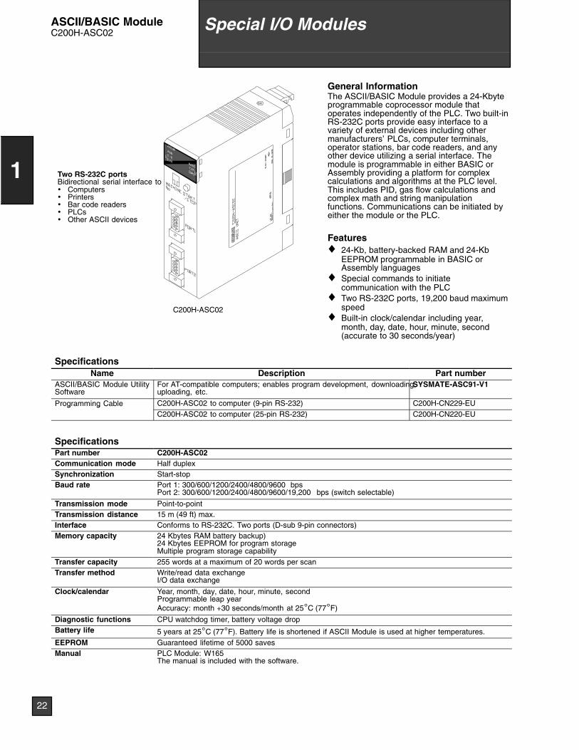
Two RS-232C portsBidirectional serial interface to• Computers• Printers• Bar code readers• PLCs• Other ASCII devices
C200H-ASC02
General InformationThe ASCII/BASIC Module provides a 24-Kbyteprogrammable coprocessor module thatoperates independently of the PLC. Two built-inRS-232C ports provide easy interface to avariety of external devices including othermanufacturers’ PLCs, computer terminals,operator stations, bar code readers, and anyother device utilizing a serial interface. Themodule is programmable in either BASIC orAssembly providing a platform for complexcalculations and algorithms at the PLC level.This includes PID, gas flow calculations andcomplex math and string manipulationfunctions. Communications can be initiated byeither the module or the PLC.
Features♦ 24-Kb, battery-backed RAM and 24-Kb
EEPROM programmable in BASIC orAssembly languages
♦ Special commands to initiatecommunication with the PLC
♦ Two RS-232C ports, 19,200 baud maximumspeed
♦ Built-in clock/calendar including year,month, day, date, hour, minute, second(accurate to 30 seconds/year)
SpecificationsName Description Part number
ASCII/BASIC Module UtilitySoftware
For AT-compatible computers; enables program development, downloading,uploading, etc.
SYSMATE-ASC91-V1
Programming Cable C200H-ASC02 to computer (9-pin RS-232) C200H-CN229-EUg gC200H-ASC02 to computer (25-pin RS-232) C200H-CN220-EU
SpecificationsPart number C200H-ASC02Communication mode Half duplexSynchronization Start-stopBaud rate Port 1: 300/600/1200/2400/4800/9600 bps
Port 2: 300/600/1200/2400/4800/9600/19,200 bps (switch selectable)
Transmission mode Point-to-pointTransmission distance 15 m (49 ft) max.Interface Conforms to RS-232C. Two ports (D-sub 9-pin connectors)Memory capacity 24 Kbytes RAM battery backup)
24 Kbytes EEPROM for program storageMultiple program storage capability
Transfer capacity 255 words at a maximum of 20 words per scanTransfer method Write/read data exchange
I/O data exchange
Clock/calendar Year, month, day, date, hour, minute, secondProgrammable leap yearAccuracy: month +30 seconds/month at 25°C (77°F)
Diagnostic functions CPU watchdog timer, battery voltage dropBattery life 5 years at 25°C (77°F). Battery life is shortened if ASCII Module is used at higher temperatures.EEPROM Guaranteed lifetime of 5000 savesManual PLC Module: W165
The manual is included with the software.
22
1
Special I/O ModulesASCII/BASIC ModuleC200H-ASC02
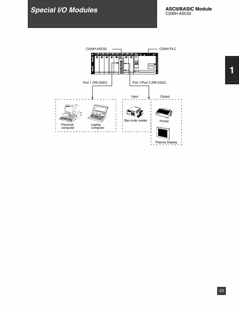
C200H-ASC02
Port 1 (RS-232C)
Bar-code reader
Output
Printer
Plasma Display
Personalcomputer
Laptopcomputer
Input
C200H PLC
Port 1/Port 2 (RS-232C)
23
1
Special I/O Modules ASCII/BASIC ModuleC200H-ASC02
C20
0H--A
D00
1A
/DU
NIT
03Z
0ULO
TN
o.O
MR
ON
Cor
pora
tion
MA
DE
INJA
PA
N
NK
AP
P.
<88
A12
0>
C200H-AD001LO
TN
o.O
MR
ON
Cor
pora
tion
MA
DE
INJA
PA
NN
KA
PP
.<
88A
120>
C200H-AD002
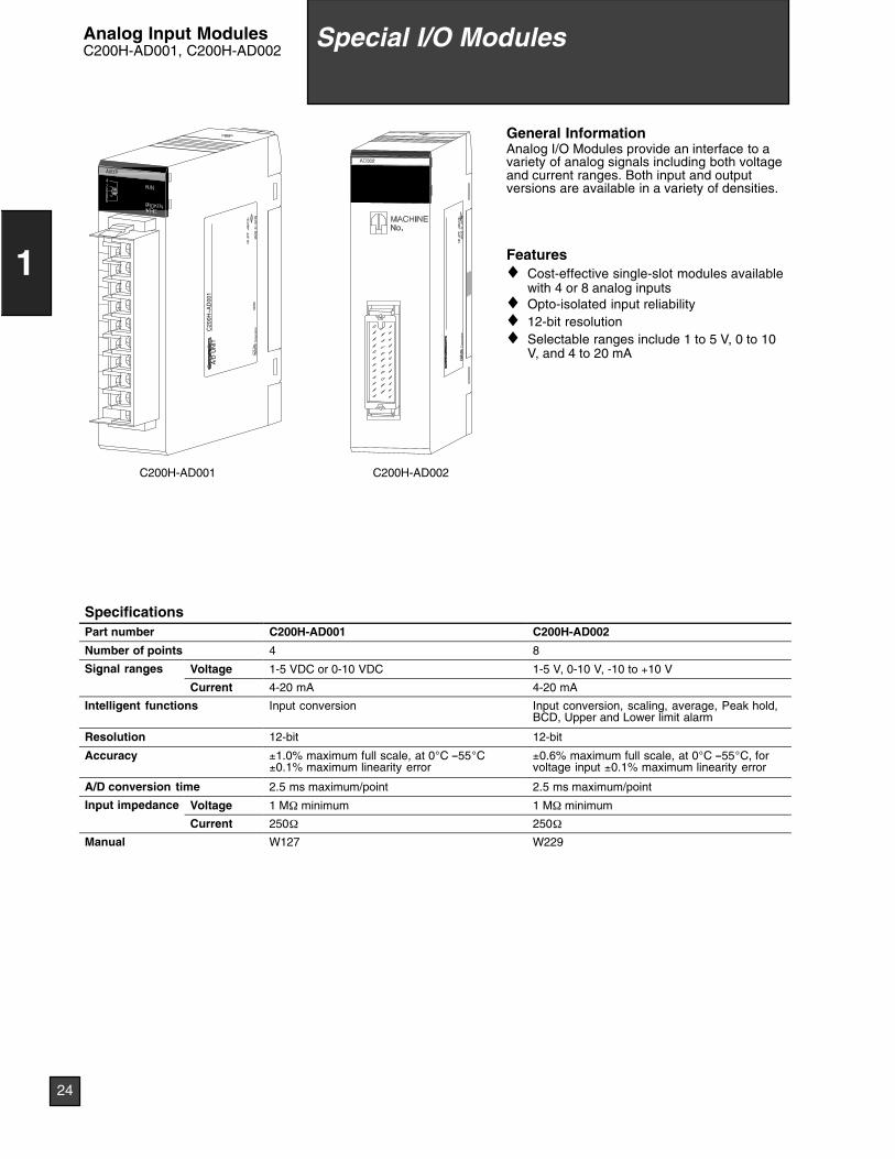
General InformationAnalog I/O Modules provide an interface to avariety of analog signals including both voltageand current ranges. Both input and outputversions are available in a variety of densities.
Features♦ Cost-effective single-slot modules available
with 4 or 8 analog inputs♦ Opto-isolated input reliability♦ 12-bit resolution♦ Selectable ranges include 1 to 5 V, 0 to 10
V, and 4 to 20 mA
SpecificationsPart number C200H-AD001 C200H-AD002
Number of points 4 8
Signal ranges Voltage 1-5 VDC or 0-10 VDC 1-5 V, 0-10 V, -10 to +10 Vg g
Current 4-20 mA 4-20 mA
Intelligent functions Input conversion Input conversion, scaling, average, Peak hold,BCD, Upper and Lower limit alarm
Resolution 12-bit 12-bit
Accuracy ±1.0% maximum full scale, at 0°C --55°C±0.1% maximum linearity error
±0.6% maximum full scale, at 0°C --55°C, forvoltage input ±0.1% maximum linearity error
A/D conversion time 2.5 ms maximum/point 2.5 ms maximum/point
Input impedance Voltage 1 MΩ minimum 1 MΩ minimump p
Current 250Ω 250Ω
Manual W127 W229
24
1
Special I/O ModulesAnalog Input ModulesC200H-AD001, C200H-AD002
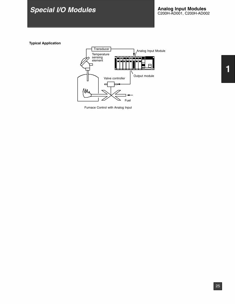
Typical Application
Transducer
Fuel
Temperaturesensingelement
Analog Input Module
Valve controllerOutput module
Furnace Control with Analog Input
25
1
Special I/O Modules Analog Input ModulesC200H-AD001, C200H-AD002
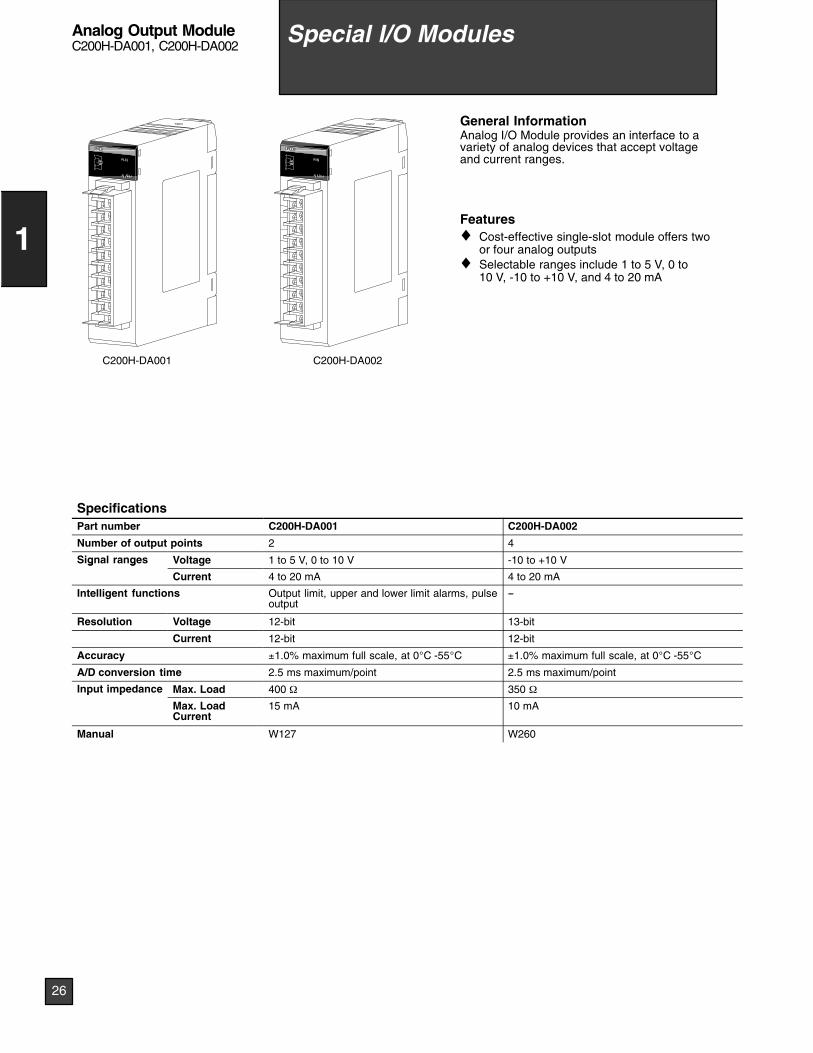
C200H-DA001 C200H-DA002
General InformationAnalog I/O Module provides an interface to avariety of analog devices that accept voltageand current ranges.
Features♦ Cost-effective single-slot module offers two
or four analog outputs♦ Selectable ranges include 1 to 5 V, 0 to
10 V, -10 to +10 V, and 4 to 20 mA
SpecificationsPart number C200H-DA001 C200H-DA002
Number of output points 2 4
Signal ranges Voltage 1 to 5 V, 0 to 10 V -10 to +10 Vg g
Current 4 to 20 mA 4 to 20 mA
Intelligent functions Output limit, upper and lower limit alarms, pulseoutput
--
Resolution Voltage 12-bit 13-bit
Current 12-bit 12-bit
Accuracy ±1.0% maximum full scale, at 0°C -55°C ±1.0% maximum full scale, at 0°C -55°C
A/D conversion time 2.5 ms maximum/point 2.5 ms maximum/point
Input impedance Max. Load 400 Ω 350 Ωp p
Max. LoadCurrent
15 mA 10 mA
Manual W127 W260
26
1
Special I/O ModulesAnalog Output ModuleC200H-DA001, C200H-DA002
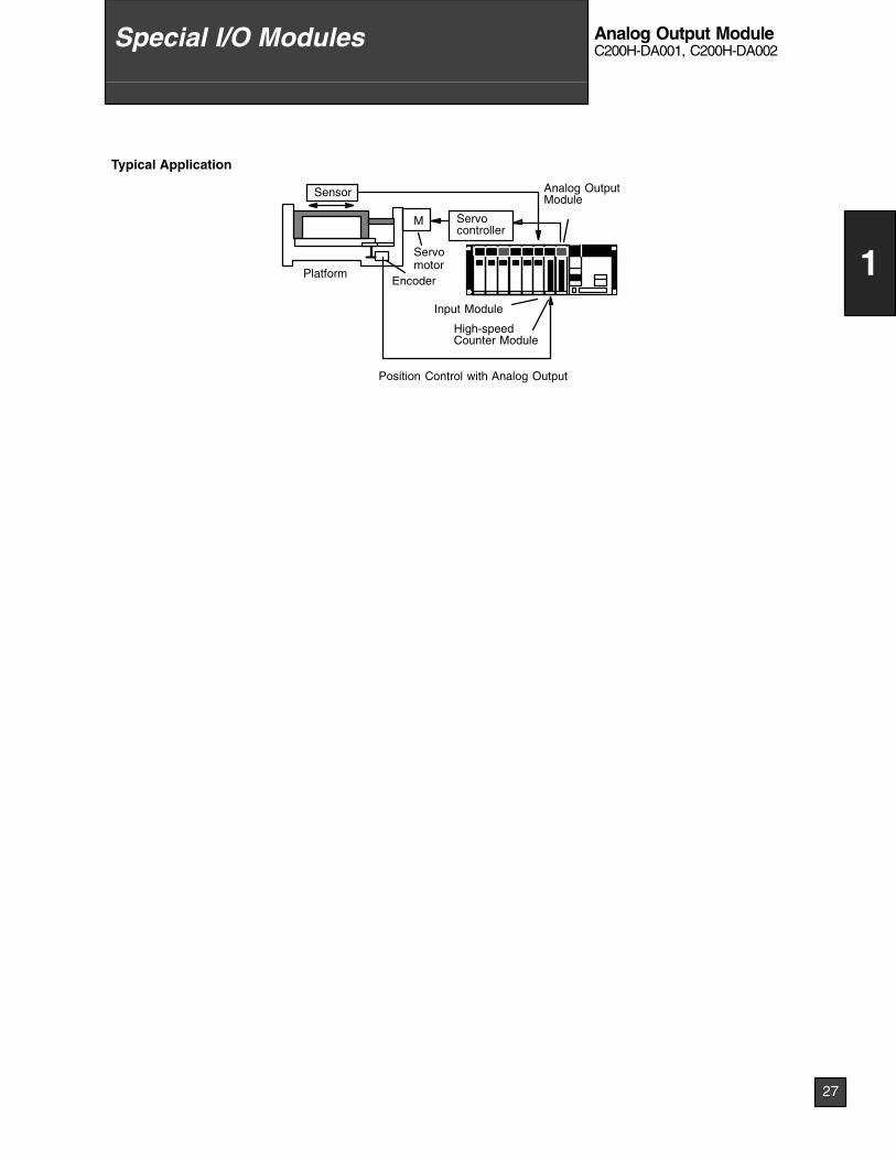
Typical Application
Servocontroller
M
Sensor
Servomotor
EncoderPlatform
Analog OutputModule
High-speedCounter Module
Input Module
Position Control with Analog Output
27
1
Special I/O Modules Analog Output ModuleC200H-DA001, C200H-DA002
C20
0H--C
T00
1--V
1C
OU
NT
ER
UN
IT
3180
LOT
No.
OM
RO
NC
orpo
ratio
nM
AD
EIN
JAP
AN
NK
AP
P.
<88
A12
0>
C20
0H--C
T00
2--V
1U
NIT
0780
LOT
No.
OM
RO
NC
orpo
ratio
nM
AD
EIN
JAP
AN
NK
AP
P.
<88
A12
0>
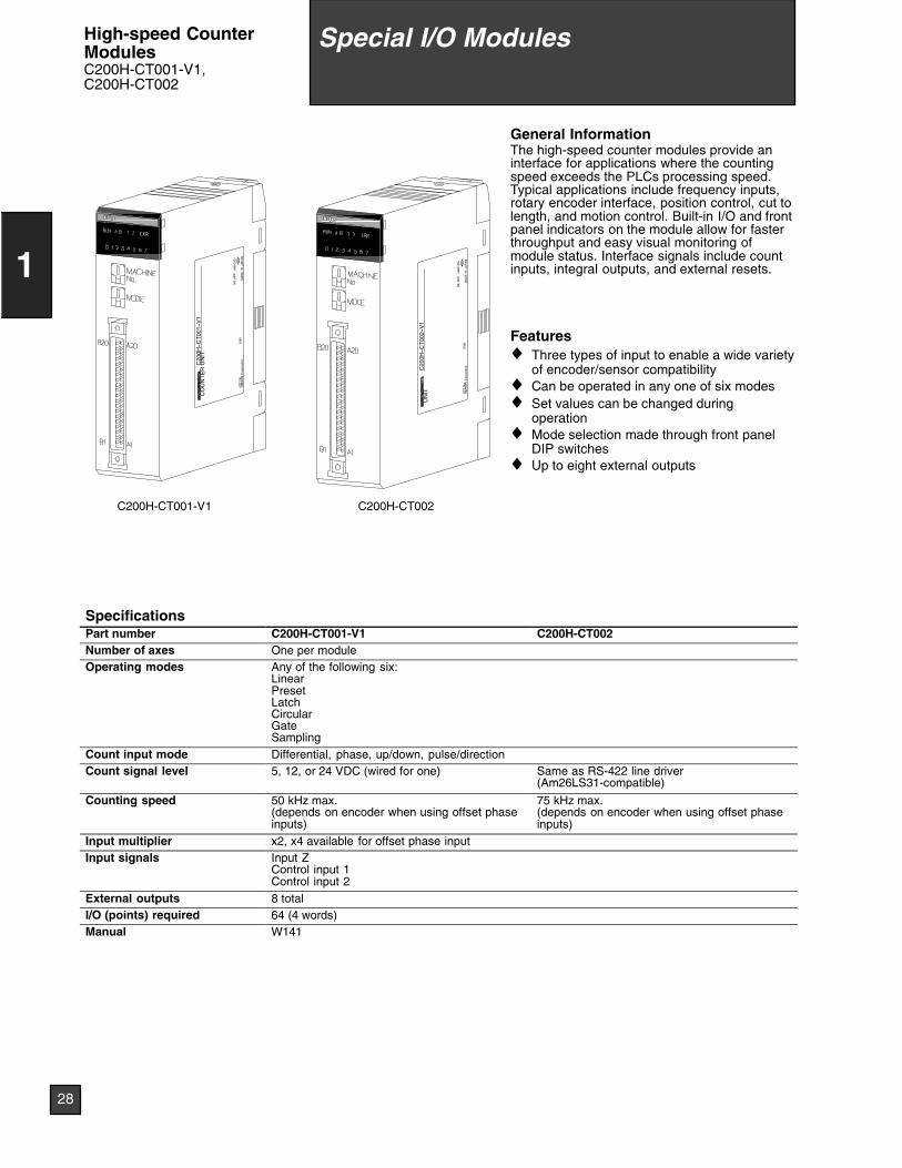
C200H-CT002C200H-CT001-V1
General InformationThe high-speed counter modules provide aninterface for applications where the countingspeed exceeds the PLCs processing speed.Typical applications include frequency inputs,rotary encoder interface, position control, cut tolength, and motion control. Built-in I/O and frontpanel indicators on the module allow for fasterthroughput and easy visual monitoring ofmodule status. Interface signals include countinputs, integral outputs, and external resets.
Features♦ Three types of input to enable a wide variety
of encoder/sensor compatibility♦ Can be operated in any one of six modes♦ Set values can be changed during
operation♦ Mode selection made through front panel
DIP switches♦ Up to eight external outputs
SpecificationsPart number C200H-CT001-V1 C200H-CT002Number of axes One per moduleOperating modes Any of the following six:
LinearPresetLatchCircularGateSampling
Count input mode Differential, phase, up/down, pulse/directionCount signal level 5, 12, or 24 VDC (wired for one) Same as RS-422 line driver
(Am26LS31-compatible)
Counting speed 50 kHz max.(depends on encoder when using offset phaseinputs)
75 kHz max.(depends on encoder when using offset phaseinputs)
Input multiplier x2, x4 available for offset phase inputInput signals Input Z
Control input 1Control input 2
External outputs 8 totalI/O (points) required 64 (4 words)Manual W141
28
1
Special I/O ModulesHigh-speed CounterModulesC200H-CT001-V1,C200H-CT002
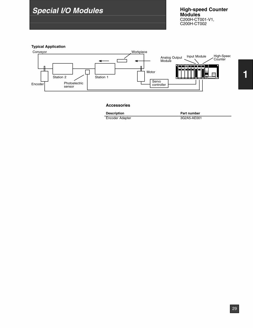
Typical Application
Motor
Encoder
High-SpeedCounterAnalog Output
ModuleInput Module
Photoelectricsensor
Conveyor
Station 2 Station 1
Workpiece
Servocontroller
Accessories
Description Part numberEncoder Adapter 3G2A5-AE001
29
1
Special I/O Modules High-speed CounterModulesC200H-CT001-V1,C200H-CT002

C20
0H--N
C11
2N
CU
NIT
3159
LOT
No.
OM
RO
NC
orpo
ratio
nM
AD
EIN
JAP
AN
NK
AP
P.
<88
A12
0>
C200H-NC112
General InformationPosition control modules provide either a stepand direction pulse train or CW/CCW pulsetrains to control a single-axis stepper or servomotor driver. Interface signals include CW andCCW limits, origin approach, origin stop,emergency stop, and interrupt signals.Automatic backlash and origin offset functionsare now included for precise positioningrequirements. Move parameters can be set upin either ladder logic, or by connecting thehand-held programming console, and arestored in battery-backed memory. Extensivediagnostics are also available to the PLC forquick error detection and troubleshooting.
Features♦ Pulse output for stepper motor or servo
motor driver♦ Origin and backlash compensation for
precision positioning♦ Teach mode or storage of calculated
movement parameters♦ Internal diagnostics♦ External signal interface for CW, CCW,
origin, emergency stop, mode, and interrupt♦ Parameters, speeds, and positions set in
CPU DM area
SpecificationsPart number C200H-NC112Number of axes One axis per moduleControl system Automatic trapezoidal acceleration/decelerationPosition Data points 53
Range -8,388,607 to +8,388,606 pulses
Speed Data points 15pRange 1 to 250,000 pulses per second
Speed adjustment rate 2 to 2,000 pps/sOrigin
hOrigin proximity Selectable; absent, Normally Open, Normally Closedg
search Origin signal Selectable; Normally Open or Normally Closed inputOrigincompensation
0 to 9,999 pulses
Origin searchspeed
High speed and proximity speed available
Backlash compensation 0 to 9,999 pulsesManual operations High-speed jog, low-speed jog, inchingManual W128
30
1
Special I/O ModulesSingle-axis PositionControl ModuleC200H-NC112
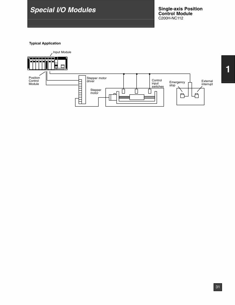
Typical Application
Emergencystop
Externalinterrupt
Controlinputswitches
Stepper motordriver
Input Module
PositionControlModule
Steppermotor
31
1
Special I/O Modules Single-axis PositionControl ModuleC200H-NC112
C20
0H--N
C21
1N
CU
NIT
3159
LOT
No.
OM
RO
NC
orpo
ratio
nM
AD
EIN
JAP
AN
NK
AP
P.
<88
A12
0>
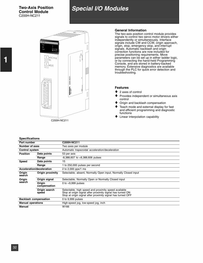
C200H-NC211
General InformationThe two-axis position control module providessignals to control two servo motor drivers eitherindependently or simultaneously. Interfacesignals include CW and CCW, origin approach,origin, stop, emergency stop, and interruptsignals. Automatic backlash and origincorrection functions are now included forprecise positioning requirements. Moveparameters can be set up in either ladder logic,or by connecting the hand-held ProgrammingConsole, and are stored in battery-backedmemory. Extensive diagnostics are availablethrough the PLC for quick error detection andtroubleshooting.
Features♦ 2 axes of control♦ Provides independent or simultaneous axis
control♦ Origin and backlash compensation♦ Teach mode and external display for fast
and efficient programming and diagnosticfunctions
♦ Linear interpolation capability
SpecificationsPart number C200H-NC211Number of axes Two axes per moduleControl system Automatic trapezoidal acceleration/decelerationPosition Data points 53 per axis
Range -8,388,607 to +8,388,606 pulses
Speed Data points 15pRange 1 to 250,000 pulses per second
Acceleration/deceleration 2 to 2,000 pps/1 msOriginsearch
Origin proximity Selectable; absent, Normally Open input, Normally Closed input
Originh
Origin signal Selectable; Normally Open or Normally Closed inputgsearch Origin
compensation0 to +9,999 pulses
Origin searchspeed
Selectable; high speed and proximity speed availableStop at origin signal after proximity signal has turned ONStop at origin signal after proximity signal has turned OFF
Backlash compensation 0 to 9,999 pulsesManual operations High-speed jog, low-speed jog, inchManual W166
32
1
Special I/O ModulesTwo-Axis PositionControl ModuleC200H-NC211
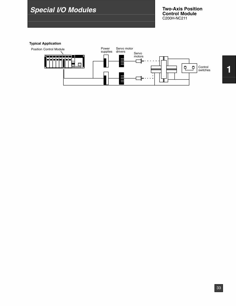
Typical ApplicationServo motordrivers
Position Control Module
Controlswitches
Servomotors
Powersupplies
33
1
Special I/O Modules Two-Axis PositionControl ModuleC200H-NC211

LOT
No.
OM
RO
NC
orpo
ratio
nM
AD
EIN
JAP
AN
NK
AP
P.
<88
A12
0>
C200H-TS001
General InformationMonitor up to 4 temperature inputs directly fromthe PLC rack. Choose thermocouple inputs(types J and K), or platinum RTD inputs. Eachmodule offers multiple ranges and a choice ofFahrenheit or Celsius scaling.
Features♦ Available for thermocouple types J and K, or
platinum RTD temperature sensors♦ Selectable number of inputs♦ Wide range of temperature settings
SpecificationsPart number C200H-TS001 CS200H-TS101Sensing element Thermocouple: Type K or J selectable Platinum RTD: Pt = 100 ΩExternal input points 4 points max. per module (1, 2, or 4 points selectable)Output code to PLC 4-digit BCDAccuracy ±(1% Full scale + 1°C) max.
Conversion time 1.2 sec max. per pointConversion cycle 4.8 sec max. at 4 points per module
2.4 sec max. at 2 points per module1.2 sec max. at 1 point per module
PLC booting time Conversion cycle + 1 PLC scan timeTerminal connections Terminal block (removable)Insulation mode Non-insulated between terminals. Insulated by photocoupler between terminal block and PLC backplane.Diagnostics Outside range, broken wire, temperature setting errorManual W124
34
1
Special I/O ModulesTemperature SensorInput ModulesC200H-TS001,C200H-TS101
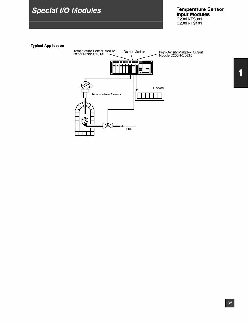
Typical Application
Fuel
Display
Temperature Sensor ModuleC200H-TS001/TS101
Output Module High-Density/Multiplex OutputModule C200H-OD215
Temperature Sensor
35
1
Special I/O Modules Temperature SensorInput ModulesC200H-TS001,C200H-TS101

LOT
No.
OM
RO
NC
orpo
ratio
nM
AD
EIN
JAP
AN
NK
AP
P.
<88
A12
0>
C200H-TC0_ _
General InformationOmron has put two X-Series TemperatureControllers in a single slot module to provideadvanced PID control with auto-tuning directlyon the PLC rack. Display and set parameterswith the C200H-DSC01 Data Setting Console.
Features♦ Auto-tuning of PID constants♦ Eight banks of settings data♦ Heater burnout detection♦ Ten alarm modes♦ Thermocouple or RTD inputs♦ Transistor, current or voltage outputs♦ Optional data setting console
SpecificationsPart numbers C200H-TC0 _ _ C200H-TC1 _ _
Inputs 2 (two independent control loops)
Temperature sensor inputs Thermocouple (R, S, K, J, T, E, B, N, L, V) RTD (JPt 100, Pt 100)
Control mode PID, ON/OFF (Advanced PID with auto-tuning)
Setting indication accuracy ±0.5% of set/indication value or ±2°C whicheveris larger, ±1 digit max.
±0.5% of set/indication value or ±1°C whicheveris larger, ±1 digit max.
Hysteresis 0.0° to 999.9°C/°F (in units of 0.1°C/°F) (during ON/OFF control)
Proportional band 0.0° to 999.9°C/°F (in units of 0.1°C/°F)
Integral (reset) time 0 to 9999 s (in units of 1 s)
Derivative (rate) time 0 to 9999 s (in units of 1 s)
Control period 1 to 99 s (in units of 1 s)
Sampling period 500 ms
Output refresh period 500 ms
Input shift range -99.9° to 999.9°C/°F (in units of 0.1°C/°F)
Alarm output setting range -999° to 9999°C/°F (in units of 1°C/°F) -99.9° to 999.9°C/°F (in units of 0.1°C/°F)
Alarm modes Upper- and lower-limit alarm, upper-limit alarm, lower-limit alarm, upper- and lower-limit range alarm,upper- and lower-limit alarm with standby sequence, upper-limit alarm with standby sequence,lower-limit alarm with standby sequence, absolute-value upper-limit alarm, absolute-value lower-limitalarm
Manual W225
36
1
Special I/O ModulesTemperatureController ModulesC200H-TC_ _ _
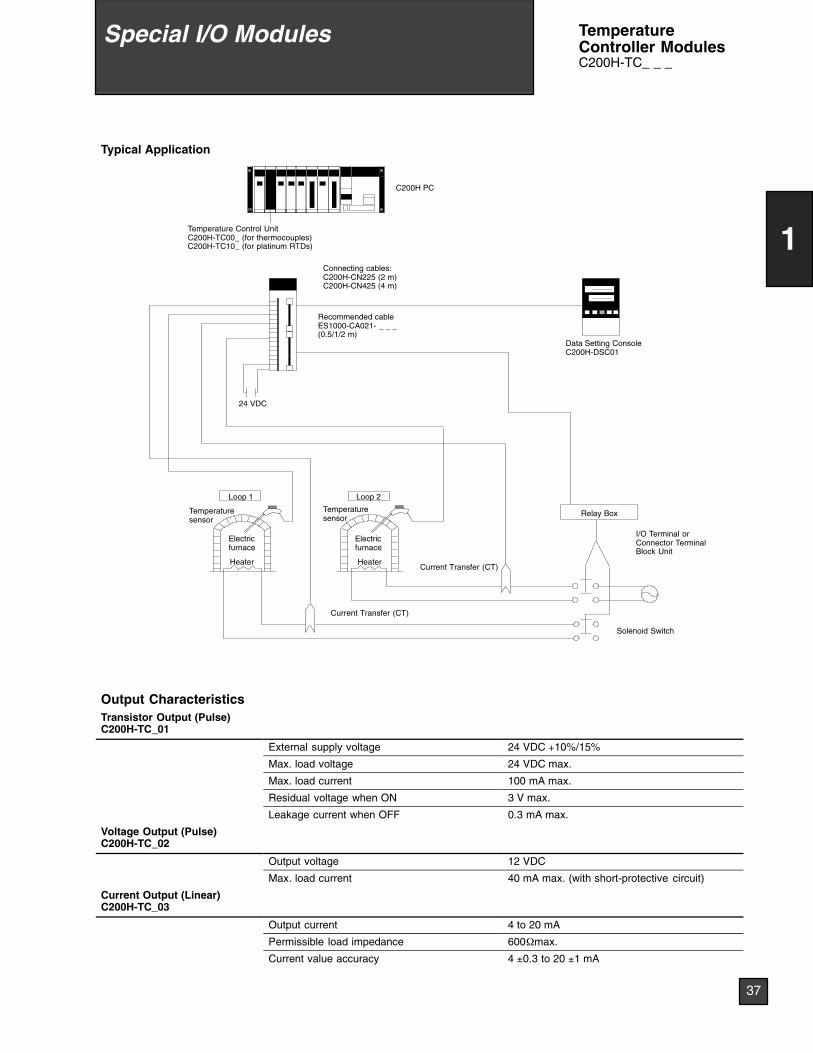
Typical Application
C200H PC
Temperature Control UnitC200H-TC00_ (for thermocouples)C200H-TC10_ (for platinum RTDs)
Recommended cableES1000-CA021- _ _ _(0.5/1/2 m)
Data Setting ConsoleC200H-DSC01
Loop 1 Loop 2
Relay Box
I/O Terminal orConnector TerminalBlock Unit
Electricfurnace
Electricfurnace
Heater Heater
Temperaturesensor
Temperaturesensor
24 VDC
Connecting cables:C200H-CN225 (2 m)C200H-CN425 (4 m)
Current Transfer (CT)
Current Transfer (CT)
Solenoid Switch
Output CharacteristicsTransistor Output (Pulse)C200H-TC_01
External supply voltage 24 VDC +10%/15%
Max. load voltage 24 VDC max.
Max. load current 100 mA max.
Residual voltage when ON 3 V max.
Leakage current when OFF 0.3 mA max.
Voltage Output (Pulse)C200H-TC_02
Output voltage 12 VDC
Max. load current 40 mA max. (with short-protective circuit)
Current Output (Linear)C200H-TC_03
Output current 4 to 20 mA
Permissible load impedance 600Ωmax.
Current value accuracy 4 ±0.3 to 20 ±1 mA
37
1
Special I/O Modules TemperatureController ModulesC200H-TC_ _ _
LOT
No.
OM
RO
NC
orpo
ratio
nM
AD
EIN
JAP
AN
NK
AP
P.
<88
A12
0>
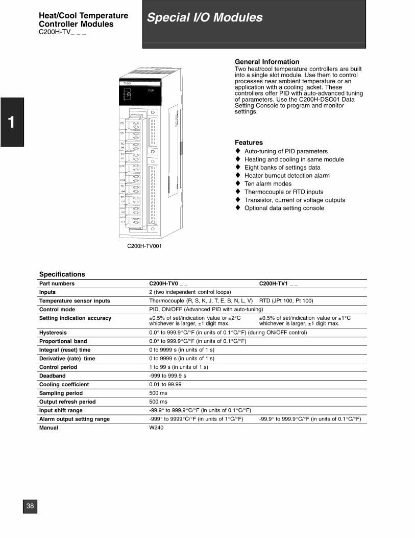
C200H-TV001
General InformationTwo heat/cool temperature controllers are builtinto a single slot module. Use them to controlprocesses near ambient temperature or anapplication with a cooling jacket. Thesecontrollers offer PID with auto-advanced tuningof parameters. Use the C200H-DSC01 DataSetting Console to program and monitorsettings.
Features♦ Auto-tuning of PID parameters♦ Heating and cooling in same module♦ Eight banks of settings data♦ Heater burnout detection alarm♦ Ten alarm modes♦ Thermocouple or RTD inputs♦ Transistor, current or voltage outputs♦ Optional data setting console
SpecificationsPart numbers C200H-TV0 _ _ C200H-TV1 _ _
Inputs 2 (two independent control loops)
Temperature sensor inputs Thermocouple (R, S, K, J, T, E, B, N, L, V) RTD (JPt 100, Pt 100)
Control mode PID, ON/OFF (Advanced PID with auto-tuning)
Setting indication accuracy ±0.5% of set/indication value or ±2°Cwhichever is larger, ±1 digit max.
±0.5% of set/indication value or ±1°Cwhichever is larger, ±1 digit max.
Hysteresis 0.0° to 999.9°C/°F (in units of 0.1°C/°F) (during ON/OFF control)
Proportional band 0.0° to 999.9°C/°F (in units of 0.1°C/°F)
Integral (reset) time 0 to 9999 s (in units of 1 s)
Derivative (rate) time 0 to 9999 s (in units of 1 s)
Control period 1 to 99 s (in units of 1 s)
Deadband -999 to 999.9 s
Cooling coefficient 0.01 to 99.99
Sampling period 500 ms
Output refresh period 500 ms
Input shift range -99.9° to 999.9°C/°F (in units of 0.1°C/°F)
Alarm output setting range -999° to 9999°C/°F (in units of 1°C/°F) -99.9° to 999.9°C/°F (in units of 0.1°C/°F)
Manual W240
38
1
Special I/O ModulesHeat/Cool TemperatureController ModulesC200H-TV_ _ _
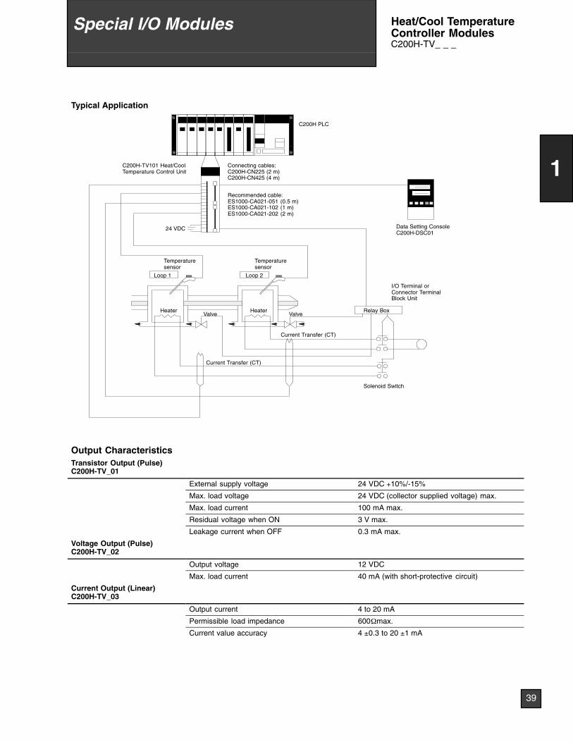
Typical Application
C200H PLC
Recommended cable:ES1000-CA021-051 (0.5 m)ES1000-CA021-102 (1 m)ES1000-CA021-202 (2 m)
Data Setting ConsoleC200H-DSC01
Loop 1 Loop 2
Relay Box
I/O Terminal orConnector TerminalBlock Unit
HeaterHeater
Temperaturesensor
Temperaturesensor
24 VDC
Connecting cables:C200H-CN225 (2 m)C200H-CN425 (4 m)
Current Transfer (CT)
Current Transfer (CT)
Solenoid Switch
C200H-TV101 Heat/CoolTemperature Control Unit
Valve Valve
Output CharacteristicsTransistor Output (Pulse)C200H-TV_01
External supply voltage 24 VDC +10%/-15%
Max. load voltage 24 VDC (collector supplied voltage) max.
Max. load current 100 mA max.
Residual voltage when ON 3 V max.
Leakage current when OFF 0.3 mA max.
Voltage Output (Pulse)C200H-TV_02
Output voltage 12 VDC
Max. load current 40 mA (with short-protective circuit)
Current Output (Linear)C200H-TV_03
Output current 4 to 20 mA
Permissible load impedance 600Ωmax.
Current value accuracy 4 ±0.3 to 20 ±1 mA
39
1
Special I/O Modules Heat/Cool TemperatureController ModulesC200H-TV_ _ _
LOT
No.
OM
RO
NC
orpo
ratio
nM
AD
EIN
JAP
AN
NK
AP
P.
<88
A12
0>
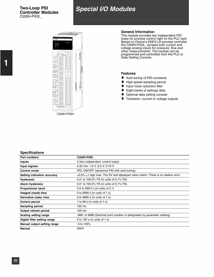
C200H-PID01
General InformationThis module provides two independent PIDloops for process control right on the PLC rack.Based on Omron’s E5EX-LA process controllerthe C200H-PID0_ accepts both current andvoltage analog inputs for pressure, flow andother measurements. The module can beprogrammed and controlled from the PLC orData Setting Console.
Features♦ Auto-tuning of PID constants♦ High-speed sampling period♦ Input noise reduction filter♦ Eight banks of settings data♦ Optional data setting console♦ Transistor, current or voltage outputs
SpecificationsPart numbers C200H-PID0 _
Inputs 2 (two independent control loops)
Input signals 4-20 mA, 1-5 V, 0-5 V, 0-10 V
Control mode PID, ON/OFF (advanced PID with auto-tuning)
Setting indication accuracy ±0.5% ±1 digit max. The SV and displayed value match. There is no relative error.
Hysteresis 0.0° to 100.0% FS (in units of 0.1% FS)
Alarm hysteresis 0.0° to 100.0% FS (in units of 0.1% FS)
Proportional band 0.0 to 999.9 s (in units of 0.1)
Integral (reset) time 0 to 9999 s (in units of 1 s)
Derivative (rate) time 0 to 9999 s (in units of 1 s)
Control period 1 to 99 s (in units of 1 s)
Sampling period 100 ms
Output refresh period 100 ms
Scaling setting range -999° to 9999 (Decimal point position is designated by parameter settting)
Digital filter setting range 0 to 100 s (in units of 1 s)
Manual output setting range -5 to 105%
Manual W241
40
1
Special I/O ModulesTwo-Loop PIDController ModulesC200H-PID0_
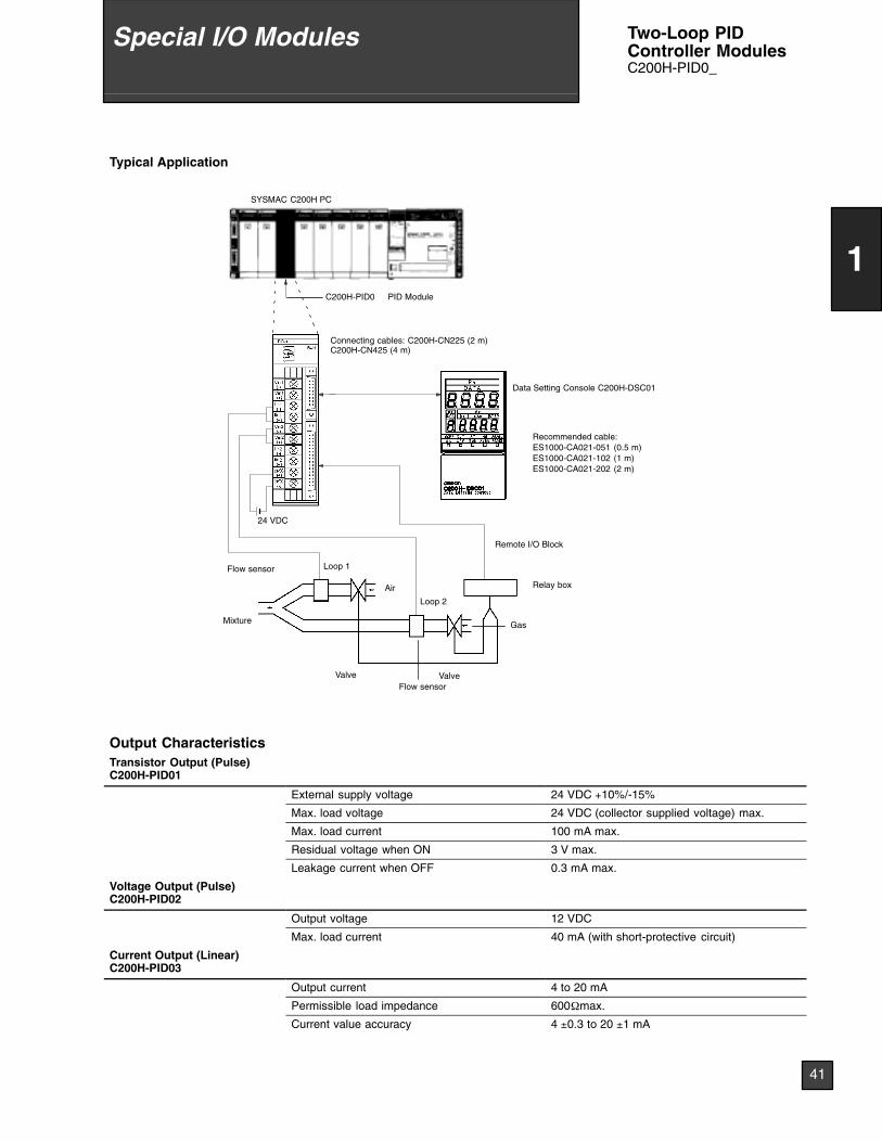
Typical Application
SYSMAC C200H PC
24 VDC
Data Setting Console C200H-DSC01
Loop 1
Loop 2
Relay box
Remote I/O Block
C200H-PID0 PID Module
Connecting cables: C200H-CN225 (2 m)C200H-CN425 (4 m)
Mixture
Flow sensor
Air
Valve
Gas
Flow sensorValve
Recommended cable:ES1000-CA021-051 (0.5 m)ES1000-CA021-102 (1 m)ES1000-CA021-202 (2 m)
Output CharacteristicsTransistor Output (Pulse)C200H-PID01
External supply voltage 24 VDC +10%/-15%
Max. load voltage 24 VDC (collector supplied voltage) max.
Max. load current 100 mA max.
Residual voltage when ON 3 V max.
Leakage current when OFF 0.3 mA max.
Voltage Output (Pulse)C200H-PID02
Output voltage 12 VDC
Max. load current 40 mA (with short-protective circuit)
Current Output (Linear)C200H-PID03
Output current 4 to 20 mA
Permissible load impedance 600Ωmax.
Current value accuracy 4 ±0.3 to 20 ±1 mA
41
1
Special I/O Modules Two-Loop PIDController ModulesC200H-PID0_
C200H-CP114
LOT
No.
OM
RO
NC
orpo
ratio
nM
AD
EIN
JAP
AN
NK
AP
P.
<88
A12
0>
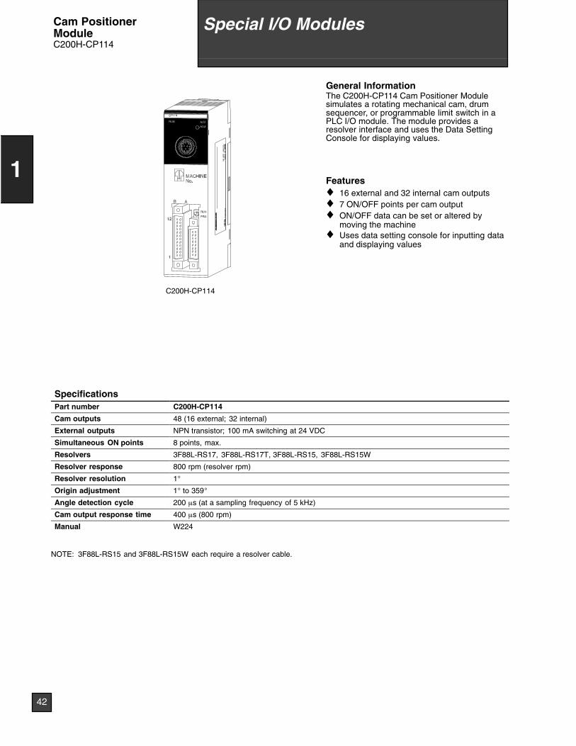
General InformationThe C200H-CP114 Cam Positioner Modulesimulates a rotating mechanical cam, drumsequencer, or programmable limit switch in aPLC I/O module. The module provides aresolver interface and uses the Data SettingConsole for displaying values.
Features♦ 16 external and 32 internal cam outputs♦ 7 ON/OFF points per cam output♦ ON/OFF data can be set or altered by
moving the machine♦ Uses data setting console for inputting data
and displaying values
SpecificationsPart number C200H-CP114
Cam outputs 48 (16 external; 32 internal)
External outputs NPN transistor; 100 mA switching at 24 VDC
Simultaneous ON points 8 points, max.
Resolvers 3F88L-RS17, 3F88L-RS17T, 3F88L-RS15, 3F88L-RS15W
Resolver response 800 rpm (resolver rpm)
Resolver resolution 1°
Origin adjustment 1° to 359°
Angle detection cycle 200 µs (at a sampling frequency of 5 kHz)
Cam output response time 400 µs (800 rpm)
Manual W224
NOTE: 3F88L-RS15 and 3F88L-RS15W each require a resolver cable.
42
1
Special I/O ModulesCam PositionerModuleC200H-CP114
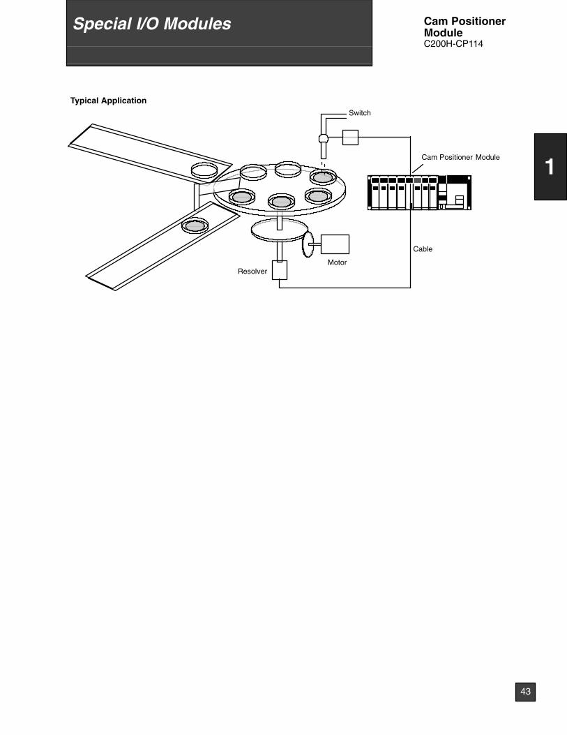
Typical ApplicationSwitch
ResolverMotor
Cam Positioner Module
Cable
43
1
Special I/O Modules Cam PositionerModuleC200H-CP114
C200H-DSC01
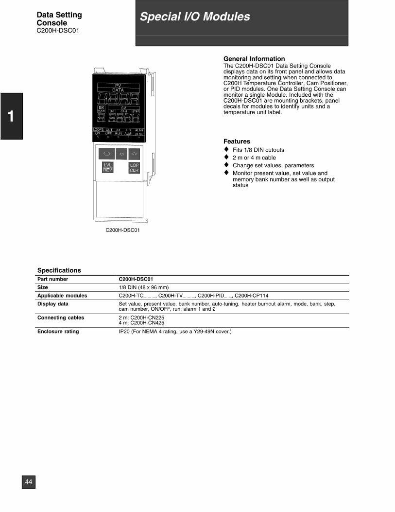
General InformationThe C200H-DSC01 Data Setting Consoledisplays data on its front panel and allows datamonitoring and setting when connected toC200H Temperature Controller, Cam Positioner,or PID modules. One Data Setting Console canmonitor a single Module. Included with theC200H-DSC01 are mounting brackets, paneldecals for modules to identify units and atemperature unit label.
Features♦ Fits 1/8 DIN cutouts♦ 2 m or 4 m cable♦ Change set values, parameters♦ Monitor present value, set value and
memory bank number as well as outputstatus
SpecificationsPart number C200H-DSC01
Size 1/8 DIN (48 x 96 mm)
Applicable modules C200H-TC_ _ _, C200H-TV_ _ _, C200H-PID_ _, C200H-CP114
Display data Set value, present value, bank number, auto-tuning, heater burnout alarm, mode, bank, step,cam number, ON/OFF, run, alarm 1 and 2
Connecting cables 2 m: C200H-CN2254 m: C200H-CN425
Enclosure rating IP20 (For NEMA 4 rating, use a Y29-49N cover.)
44
1
Special I/O ModulesData SettingConsoleC200H-DSC01

45
1
Special I/O Modules Data SettingConsoleC200H-DSC01
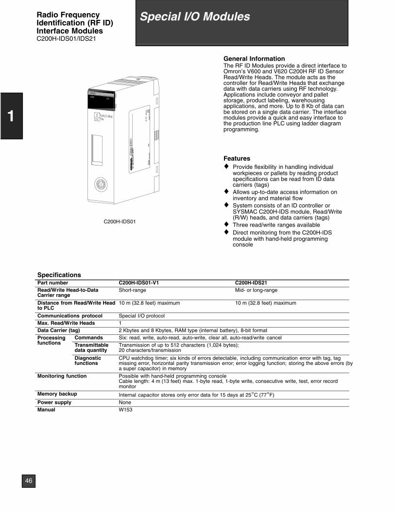
C200H-IDS01
C20
0H--I
DS
O1
IDS
EN
SO
RU
NIT
08X
8LO
TN
o.O
MR
ON
Cor
pora
tion
MA
DE
INJA
PA
N
NK
AP
P.
<88
A12
0>
General InformationThe RF ID Modules provide a direct interface toOmron’s V600 and V620 C200H RF ID SensorRead/Write Heads. The module acts as thecontroller for Read/Write Heads that exchangedata with data carriers using RF technology.Applications include conveyor and palletstorage, product labeling, warehousingapplications, and more. Up to 8 Kb of data canbe stored on a single data carrier. The interfacemodules provide a quick and easy interface tothe production line PLC using ladder diagramprogramming.
Features♦ Provide flexibility in handling individual
workpieces or pallets by reading productspecifications can be read from ID datacarriers (tags)
♦ Allows up-to-date access information oninventory and material flow
♦ System consists of an ID controller orSYSMAC C200H-IDS module, Read/Write(R/W) heads, and data carriers (tags)
♦ Three read/write ranges available♦ Direct monitoring from the C200H-IDS
module with hand-held programmingconsole
SpecificationsPart number C200H-IDS01-V1 C200H-IDS21Read/Write Head-to-DataCarrier range
Short-range Mid- or long-range
Distance from Read/Write Headto PLC
10 m (32.8 feet) maximum 10 m (32.8 feet) maximum
Communications protocol Special I/O protocolMax. Read/Write Heads 1Data Carrier (tag) 2 Kbytes and 8 Kbytes, RAM type (internal battery), 8-bit formatProcessingf ti
Commands Six: read, write, auto-read, auto-write, clear all, auto-read/write cancelgfunctions Transmittable
data quantityTransmission of up to 512 characters (1,024 bytes);20 characters/transmission
Diagnosticfunctions
CPU watchdog timer; six kinds of errors detectable, including communication error with tag, tagmissing error, horizontal parity transmission error; error logging function; storing the above errors (bya super capacitor) in memory
Monitoring function Possible with hand-held programming consoleCable length: 4 m (13 feet) max. 1-byte read, 1-byte write, consecutive write, test, error recordmonitor
Memory backup Internal capacitor stores only error data for 15 days at 25°C (77°F)Power supply NoneManual W153
46
1
Special I/O ModulesRadio FrequencyIdentification (RF ID)Interface ModulesC200H-IDS01/IDS21
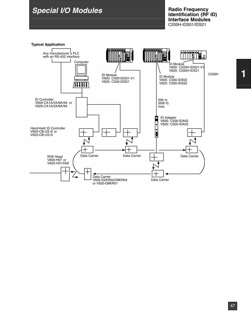
Typical Application
R/W HeadV600-H07 orV620-H01/H02
Data CarrierV600-D2KR04/D8KR04or V620-D8KR01
Computer
ID ControllerV600-CA1A/2A/8A/9A orV620-CA1A/2A/8A/9A
ID ModuleV600: C500-IDS01-V1V620: C500-IDS21
ID ModuleV600: C500-IDS02V620: C500-IDS22
ID AdapterV600: C500-IDA02V620: C500-IDA22
ID ModuleV600: C200H-IDS01-V1V620: C200H-IDS21
C200H
Hand-held ID ControllerV600-CB-US-S orV620-CB-US-S
200 m(656 ft)max.
Data Carrier Data Carrier Data Carrier
Data Carrier
Any manufacturer ’s PLCwith an RS-422 interface
47
1
Special I/O Modules Radio FrequencyIdentification (RF ID)Interface ModulesC200H-IDS01/IDS21
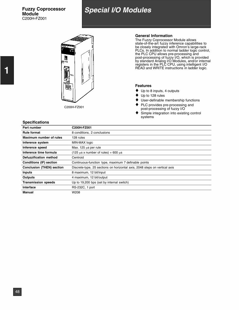
C200H-FZ001
General InformationThe Fuzzy Coprocessor Module allowsstate-of-the-art fuzzy inference capabilities tobe closely integrated with Omron’s large-rackPLCs. In addition to normal ladder logic control,the PLC CPU allows pre-processing andpost-processing of fuzzy I/O, which is providedby standard Analog I/O Modules, and/or internalregisters in the PLC CPU, using intelligent I/OREAD and WRITE instructions in ladder logic.
Features♦ Up to 8 inputs, 4 outputs♦ Up to 128 rules♦ User-definable membership functions♦ PLC provides pre-processing and
post-processing of fuzzy I/O♦ Simple integration into existing control
systems
SpecificationsPart number C200H-FZ001
Rule format 8 conditions, 2 conclusions
Maximum number of rules 128 rules
Inference system MIN-MAX logic
Inference speed Max. 125 µs per rule
Inference time formula (125 µs x number of rules) + 600 µs
Defuzzification method Centroid
Conditions (IF) section Continuous-function type, maximum 7 definable points
Conclusion (THEN) section Discrete-type, 25 sections on horizontal axis, 2048 steps on vertical axis
Inputs 8 maximum, 12 bit/input
Outputs 4 maximum, 12 bit/output
Transmission speeds Up to 19,200 bps (set by internal switch)
Interface RS-232C, 1 port
Manual W208
48
1
Special I/O ModulesFuzzy CoprocessorModuleC200H-FZ001
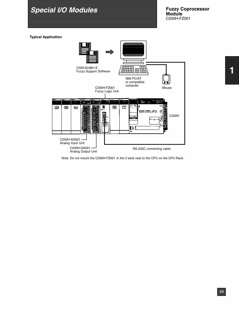
Typical Application
C200H-AD001Analog Input Unit
C200H-DA001Analog Output Unit
C200H-FZ001Fuzzy Logic Unit
IBM PC/ATor compatiblecomputer
C500-SU981-EFuzzy Support Software
RS-232C connecting cable
C200H
Mouse
Note: Do not mount the C200H-FZ001 in the 2 slots next to the CPU on the CPU Rack.
49
1
Special I/O Modules Fuzzy CoprocessorModuleC200H-FZ001
C200HS-INT01
LOT
No.
OM
RO
NC
orpo
ratio
nM
AD
EIN
JAP
AN
NK
AP
P.
<88
A12
0>
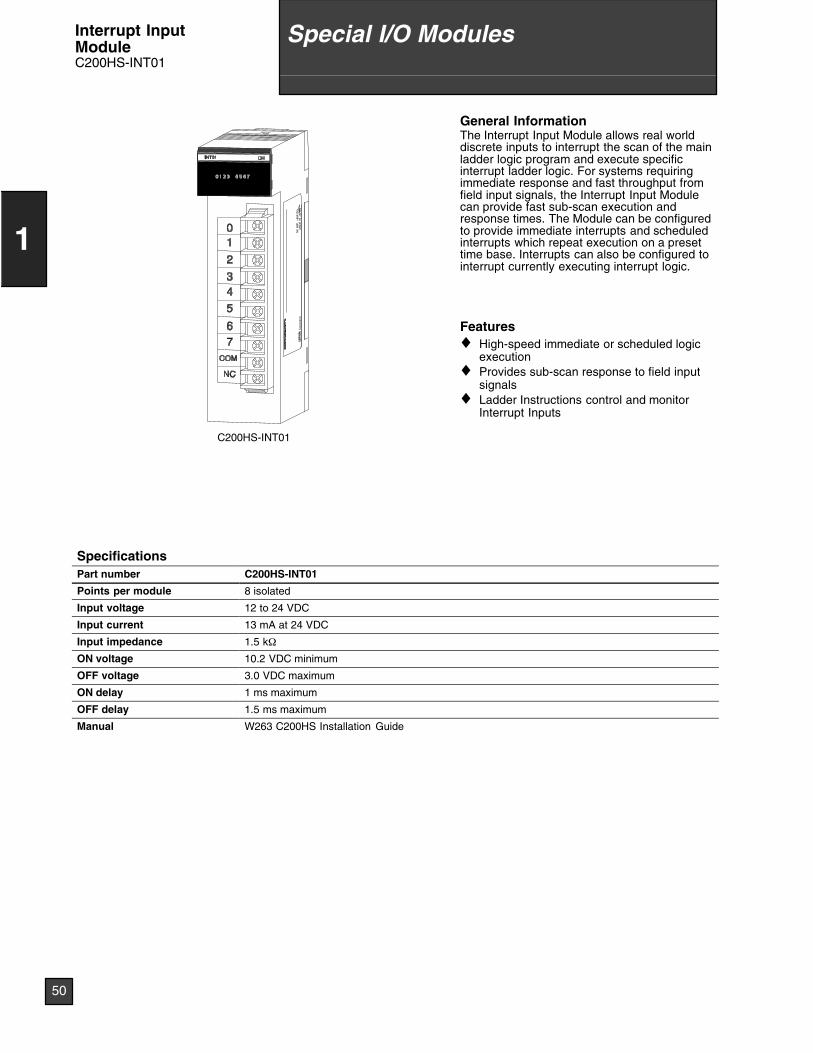
General InformationThe Interrupt Input Module allows real worlddiscrete inputs to interrupt the scan of the mainladder logic program and execute specificinterrupt ladder logic. For systems requiringimmediate response and fast throughput fromfield input signals, the Interrupt Input Modulecan provide fast sub-scan execution andresponse times. The Module can be configuredto provide immediate interrupts and scheduledinterrupts which repeat execution on a presettime base. Interrupts can also be configured tointerrupt currently executing interrupt logic.
Features♦ High-speed immediate or scheduled logic
execution♦ Provides sub-scan response to field input
signals♦ Ladder Instructions control and monitor
Interrupt Inputs
SpecificationsPart number C200HS-INT01
Points per module 8 isolated
Input voltage 12 to 24 VDC
Input current 13 mA at 24 VDC
Input impedance 1.5 kΩ
ON voltage 10.2 VDC minimum
OFF voltage 3.0 VDC maximum
ON delay 1 ms maximum
OFF delay 1.5 ms maximum
Manual W263 C200HS Installation Guide
50
1
Special I/O ModulesInterrupt InputModuleC200HS-INT01
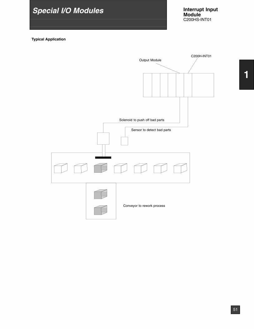
Typical Application
Solenoid to push off bad parts
Sensor to detect bad parts
Conveyor to rework process
Output ModuleC200H-INT01
51
1
Special I/O Modules Interrupt InputModuleC200HS-INT01
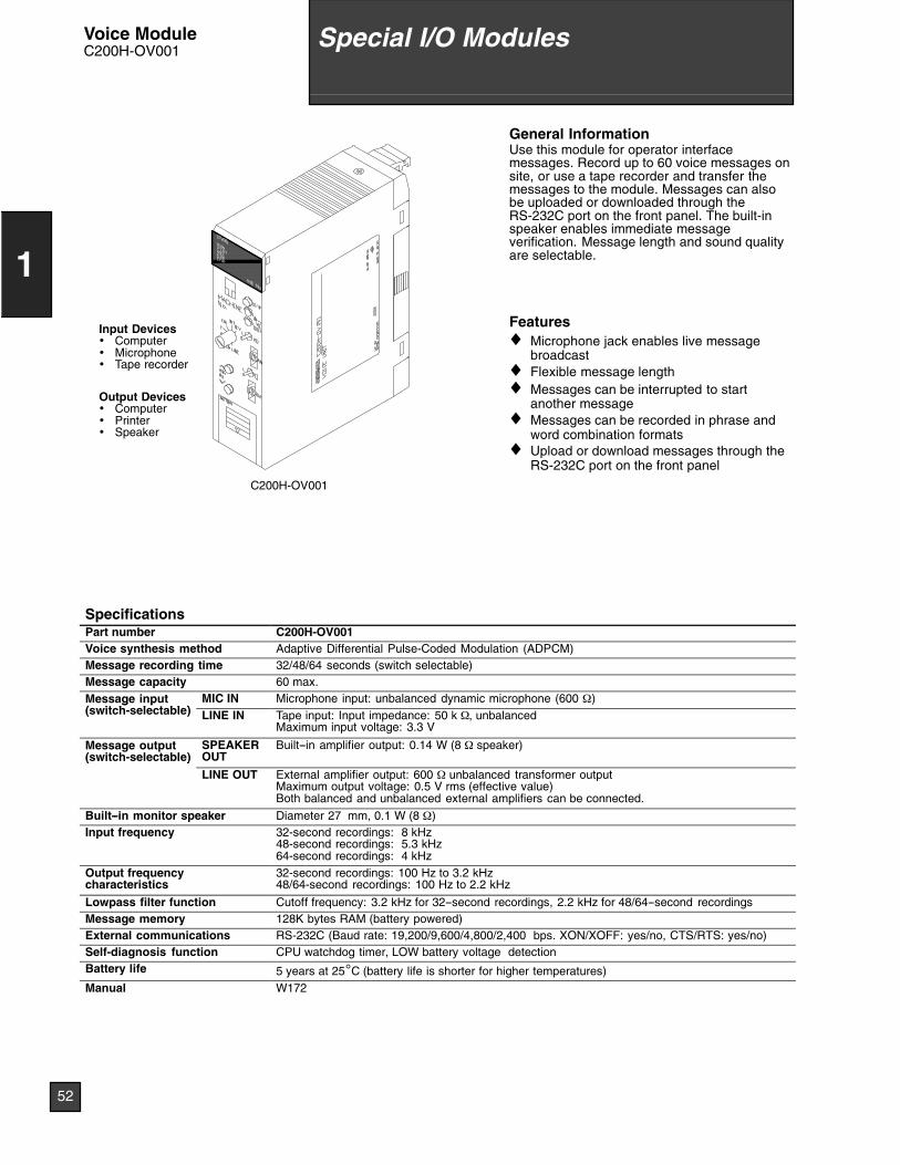
C200H-OV001
Input Devices• Computer• Microphone• Tape recorder
Output Devices• Computer• Printer• Speaker
General InformationUse this module for operator interfacemessages. Record up to 60 voice messages onsite, or use a tape recorder and transfer themessages to the module. Messages can alsobe uploaded or downloaded through theRS-232C port on the front panel. The built-inspeaker enables immediate messageverification. Message length and sound qualityare selectable.
Features♦ Microphone jack enables live message
broadcast♦ Flexible message length♦ Messages can be interrupted to start
another message♦ Messages can be recorded in phrase and
word combination formats♦ Upload or download messages through the
RS-232C port on the front panel
SpecificationsPart number C200H-OV001Voice synthesis method Adaptive Differential Pulse-Coded Modulation (ADPCM)Message recording time 32/48/64 seconds (switch selectable)Message capacity 60 max.Message input( it h l t bl )
MIC IN Microphone input: unbalanced dynamic microphone (600 Ω)g p(switch-selectable) LINE IN Tape input: Input impedance: 50 k Ω, unbalanced
Maximum input voltage: 3.3 V
Message output(switch-selectable)
SPEAKEROUT
Built--in amplifier output: 0.14 W (8 Ω speaker)( )
LINE OUT External amplifier output: 600 Ω unbalanced transformer outputMaximum output voltage: 0.5 V rms (effective value)Both balanced and unbalanced external amplifiers can be connected.
Built--in monitor speaker Diameter 27 mm, 0.1 W (8 Ω)Input frequency 32-second recordings: 8 kHz
48-second recordings: 5.3 kHz64-second recordings: 4 kHz
Output frequencycharacteristics
32-second recordings: 100 Hz to 3.2 kHz48/64-second recordings: 100 Hz to 2.2 kHz
Lowpass filter function Cutoff frequency: 3.2 kHz for 32--second recordings, 2.2 kHz for 48/64--second recordingsMessage memory 128K bytes RAM (battery powered)External communications RS-232C (Baud rate: 19,200/9,600/4,800/2,400 bps. XON/XOFF: yes/no, CTS/RTS: yes/no)Self-diagnosis function CPU watchdog timer, LOW battery voltage detectionBattery life 5 years at 25°C (battery life is shorter for higher temperatures)Manual W172
52
1
Special I/O ModulesVoice ModuleC200H-OV001
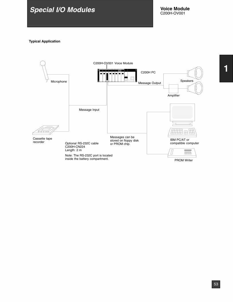
Typical Application
Message Output
Message Input
Microphone
Cassette taperecorder
IBM PC/AT orcompatible computer
PROM Writer
Speakers
Amplifier
Messages can bestored on floppy diskor PROM chip.
C200H PC
C200H-OV001 Voice Module
Optional RS-232C cableC200H-CN224Length: 2 m
Note: The RS-232C port is locatedinside the battery compartment.
53
1
Special I/O Modules Voice ModuleC200H-OV001
C200H-TM001
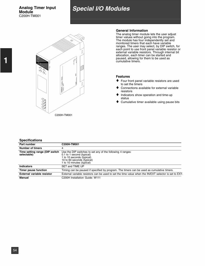
General InformationThe analog timer module lets the user adjusttimer values without going into the program.The module has four independently set andmonitored timers that each have variableranges. The user may select, by DIP switch, foreach point to use front panel variable resistor orexternal variable resistors. Through internal bitallocation, each timer can be started andpaused, allowing for them to be used ascumulative timers.
Features♦ Four front panel variable resistors are used
to set the timers♦ Connections available for external variable
resistors♦ Indicators show operation and time-up
status♦ Cumulative timer available using pause bits
SpecificationsPart number C200H-TM001Number of timers 4Time setting range (DIP switchselectable)
Use the DIP switches to set any of the following 4 ranges:0.1 to 1 second (typical)1 to 10 seconds (typical)10 to 60 seconds (typical)1 to 10 minutes (typical)
Indicators SET and TIME UPTimer pause function Timing can be paused if specified by program. The timers can be used as cumulative timers.External variable resistor External variable resistors can be used to set the time value when the IN/EXT selector is set to EXT.Manual C200H Installation Guide: W111
54
1
Special I/O ModulesAnalog Timer InputModuleC200H-TM001
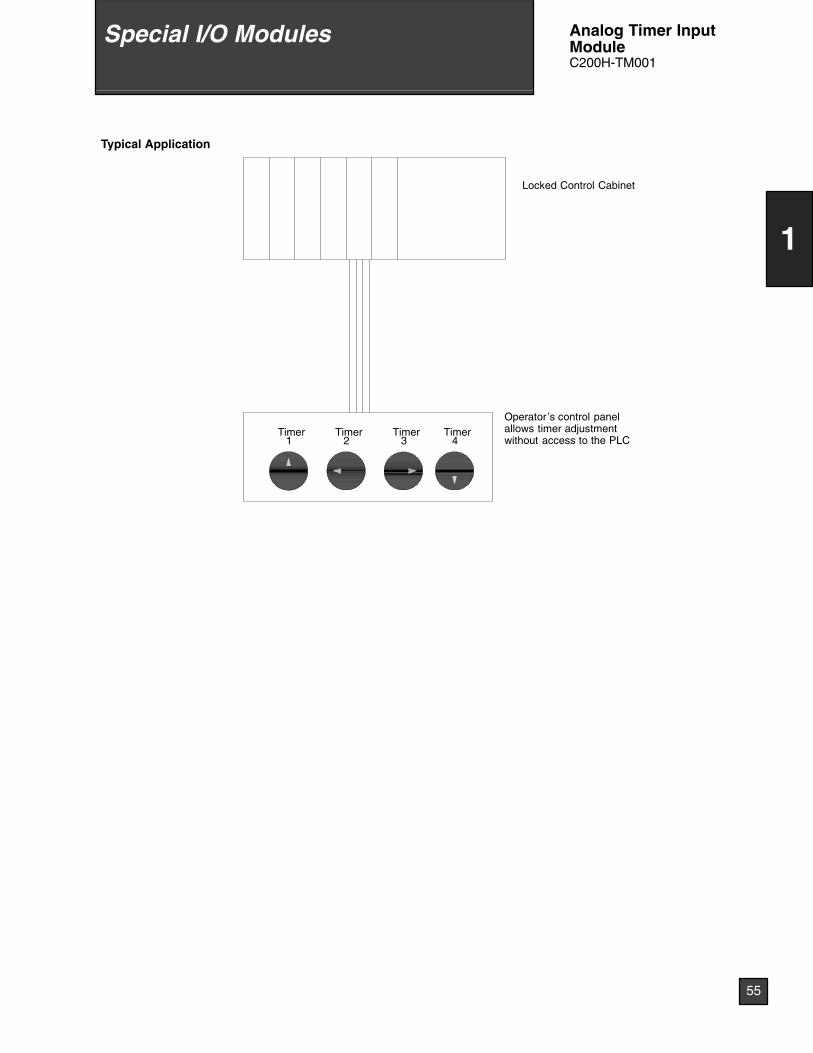
Typical Application
Locked Control Cabinet
Timer1
Timer2
Timer3
Timer4
Operator ’s control panelallows timer adjustmentwithout access to the PLC
55
1
Special I/O Modules Analog Timer InputModuleC200H-TM001
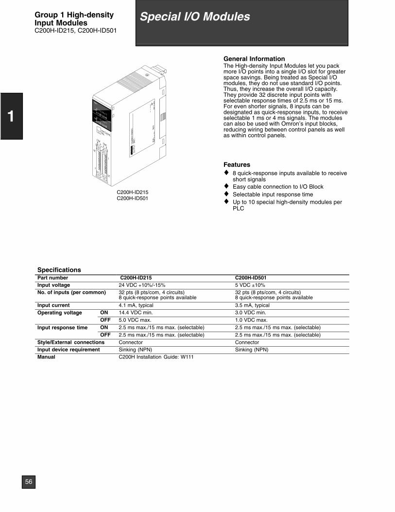
C200H-ID215C200H-ID501
General InformationThe High-density Input Modules let you packmore I/O points into a single I/O slot for greaterspace savings. Being treated as Special I/Omodules, they do not use standard I/O points.Thus, they increase the overall I/O capacity.They provide 32 discrete input points withselectable response times of 2.5 ms or 15 ms.For even shorter signals, 8 inputs can bedesignated as quick-response inputs, to receiveselectable 1 ms or 4 ms signals. The modulescan also be used with Omron’s input blocks,reducing wiring between control panels as wellas within control panels.
Features♦ 8 quick-response inputs available to receive
short signals♦ Easy cable connection to I/O Block♦ Selectable input response time♦ Up to 10 special high-density modules per
PLC
SpecificationsPart number C200H-ID215 C200H-ID501Input voltage 24 VDC +10%/-15% 5 VDC ±10%No. of inputs (per common) 32 pts (8 pts/com, 4 circuits)
8 quick-response points available32 pts (8 pts/com, 4 circuits)8 quick-response points available
Input current 4.1 mA, typical 3.5 mA, typicalOperating voltage ON 14.4 VDC min. 3.0 VDC min.p g g
OFF 5.0 VDC max. 1.0 VDC max.
Input response time ON 2.5 ms max./15 ms max. (selectable) 2.5 ms max./15 ms max. (selectable)p pOFF 2.5 ms max./15 ms max. (selectable) 2.5 ms max./15 ms max. (selectable)
Style/External connections Connector ConnectorInput device requirement Sinking (NPN) Sinking (NPN)Manual C200H Installation Guide: W111
56
1
Special I/O ModulesGroup 1 High-densityInput ModulesC200H-ID215, C200H-ID501
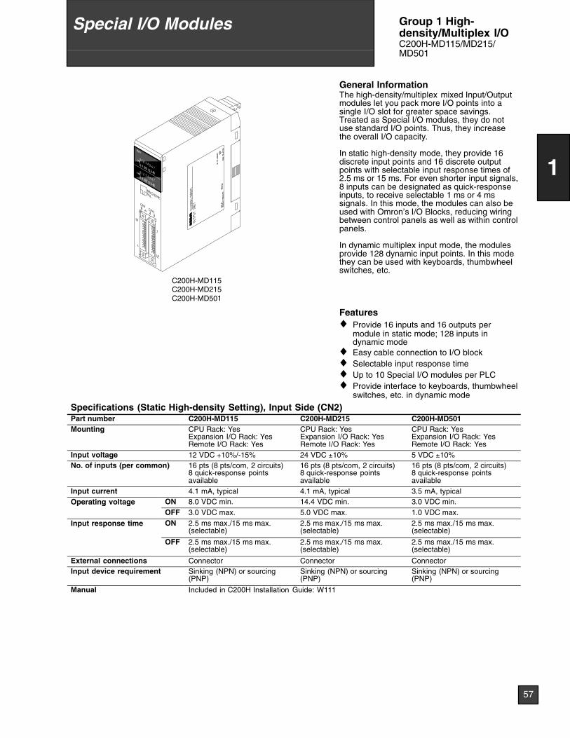
C200H-MD115C200H-MD215C200H-MD501
General InformationThe high-density/multiplex mixed Input/Outputmodules let you pack more I/O points into asingle I/O slot for greater space savings.Treated as Special I/O modules, they do notuse standard I/O points. Thus, they increasethe overall I/O capacity.
In static high-density mode, they provide 16discrete input points and 16 discrete outputpoints with selectable input response times of2.5 ms or 15 ms. For even shorter input signals,8 inputs can be designated as quick-responseinputs, to receive selectable 1 ms or 4 mssignals. In this mode, the modules can also beused with Omron’s I/O Blocks, reducing wiringbetween control panels as well as within controlpanels.
In dynamic multiplex input mode, the modulesprovide 128 dynamic input points. In this modethey can be used with keyboards, thumbwheelswitches, etc.
Features♦ Provide 16 inputs and 16 outputs per
module in static mode; 128 inputs indynamic mode
♦ Easy cable connection to I/O block♦ Selectable input response time♦ Up to 10 Special I/O modules per PLC♦ Provide interface to keyboards, thumbwheel
switches, etc. in dynamic mode
Specifications (Static High-density Setting), Input Side (CN2)Part number C200H-MD115 C200H-MD215 C200H-MD501Mounting CPU Rack: Yes
Expansion I/O Rack: YesRemote I/O Rack: Yes
CPU Rack: YesExpansion I/O Rack: YesRemote I/O Rack: Yes
CPU Rack: YesExpansion I/O Rack: YesRemote I/O Rack: Yes
Input voltage 12 VDC +10%/-15% 24 VDC ±10% 5 VDC ±10%No. of inputs (per common) 16 pts (8 pts/com, 2 circuits)
8 quick-response pointsavailable
16 pts (8 pts/com, 2 circuits)8 quick-response pointsavailable
16 pts (8 pts/com, 2 circuits)8 quick-response pointsavailable
Input current 4.1 mA, typical 4.1 mA, typical 3.5 mA, typicalOperating voltage ON 8.0 VDC min. 14.4 VDC min. 3.0 VDC min.p g g
OFF 3.0 VDC max. 5.0 VDC max. 1.0 VDC max.
Input response time ON 2.5 ms max./15 ms max.(selectable)
2.5 ms max./15 ms max.(selectable)
2.5 ms max./15 ms max.(selectable)
OFF 2.5 ms max./15 ms max.(selectable)
2.5 ms max./15 ms max.(selectable)
2.5 ms max./15 ms max.(selectable)
External connections Connector Connector ConnectorInput device requirement Sinking (NPN) or sourcing
(PNP)Sinking (NPN) or sourcing(PNP)
Sinking (NPN) or sourcing(PNP)
Manual Included in C200H Installation Guide: W111
57
1
Special I/O Modules Group 1 High-density/Multiplex I/OC200H-MD115/MD215/MD501
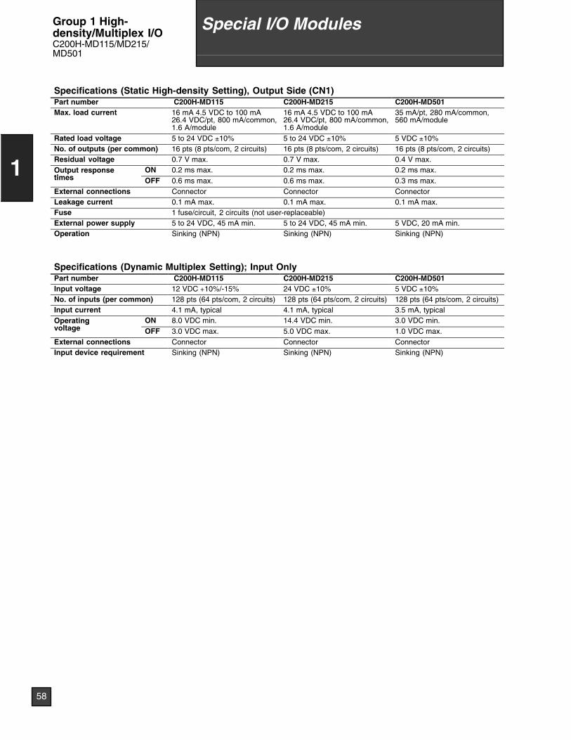
Specifications (Static High-density Setting), Output Side (CN1)Part number C200H-MD115 C200H-MD215 C200H-MD501Max. load current 16 mA 4.5 VDC to 100 mA
26.4 VDC/pt, 800 mA/common,1.6 A/module
16 mA 4.5 VDC to 100 mA26.4 VDC/pt, 800 mA/common,1.6 A/module
35 mA/pt, 280 mA/common,560 mA/module
Rated load voltage 5 to 24 VDC ±10% 5 to 24 VDC ±10% 5 VDC ±10%No. of outputs (per common) 16 pts (8 pts/com, 2 circuits) 16 pts (8 pts/com, 2 circuits) 16 pts (8 pts/com, 2 circuits)Residual voltage 0.7 V max. 0.7 V max. 0.4 V max.Output responseti
ON 0.2 ms max. 0.2 ms max. 0.2 ms max.p ptimes OFF 0.6 ms max. 0.6 ms max. 0.3 ms max.External connections Connector Connector ConnectorLeakage current 0.1 mA max. 0.1 mA max. 0.1 mA max.Fuse 1 fuse/circuit, 2 circuits (not user-replaceable)External power supply 5 to 24 VDC, 45 mA min. 5 to 24 VDC, 45 mA min. 5 VDC, 20 mA min.Operation Sinking (NPN) Sinking (NPN) Sinking (NPN)
Specifications (Dynamic Multiplex Setting); Input OnlyPart number C200H-MD115 C200H-MD215 C200H-MD501Input voltage 12 VDC +10%/-15% 24 VDC ±10% 5 VDC ±10%No. of inputs (per common) 128 pts (64 pts/com, 2 circuits) 128 pts (64 pts/com, 2 circuits) 128 pts (64 pts/com, 2 circuits)Input current 4.1 mA, typical 4.1 mA, typical 3.5 mA, typicalOperating
ltON 8.0 VDC min. 14.4 VDC min. 3.0 VDC min.p g
voltage OFF 3.0 VDC max. 5.0 VDC max. 1.0 VDC max.External connections Connector Connector ConnectorInput device requirement Sinking (NPN) Sinking (NPN) Sinking (NPN)
58
1
Special I/O ModulesGroup 1 High-density/Multiplex I/OC200H-MD115/MD215/MD501
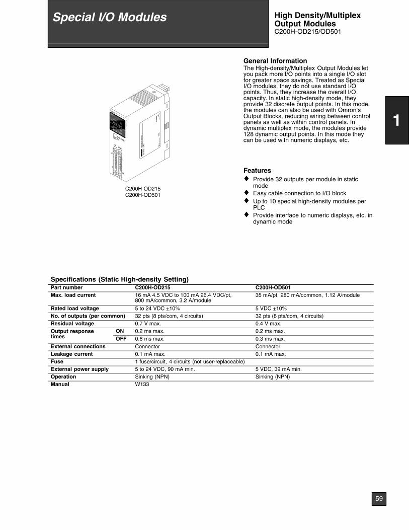
C200H-OD215C200H-OD501
General InformationThe High-density/Multiplex Output Modules letyou pack more I/O points into a single I/O slotfor greater space savings. Treated as SpecialI/O modules, they do not use standard I/Opoints. Thus, they increase the overall I/Ocapacity. In static high-density mode, theyprovide 32 discrete output points. In this mode,the modules can also be used with Omron’sOutput Blocks, reducing wiring between controlpanels as well as within control panels. Indynamic multiplex mode, the modules provide128 dynamic output points. In this mode theycan be used with numeric displays, etc.
Features♦ Provide 32 outputs per module in static
mode♦ Easy cable connection to I/O block♦ Up to 10 special high-density modules per
PLC♦ Provide interface to numeric displays, etc. in
dynamic mode
Specifications (Static High-density Setting)Part number C200H-OD215 C200H-OD501Max. load current 16 mA 4.5 VDC to 100 mA 26.4 VDC/pt,
800 mA/common, 3.2 A/module35 mA/pt, 280 mA/common, 1.12 A/module
Rated load voltage 5 to 24 VDC +10% 5 VDC +10%No. of outputs (per common) 32 pts (8 pts/com, 4 circuits) 32 pts (8 pts/com, 4 circuits)Residual voltage 0.7 V max. 0.4 V max.Output responseti
ON 0.2 ms max. 0.2 ms max.p ptimes OFF 0.6 ms max. 0.3 ms max.External connections Connector ConnectorLeakage current 0.1 mA max. 0.1 mA max.Fuse 1 fuse/circuit, 4 circuits (not user-replaceable)External power supply 5 to 24 VDC, 90 mA min. 5 VDC, 39 mA min.Operation Sinking (NPN) Sinking (NPN)Manual W133
59
1
Special I/O Modules High Density/MultiplexOutput ModulesC200H-OD215/OD501
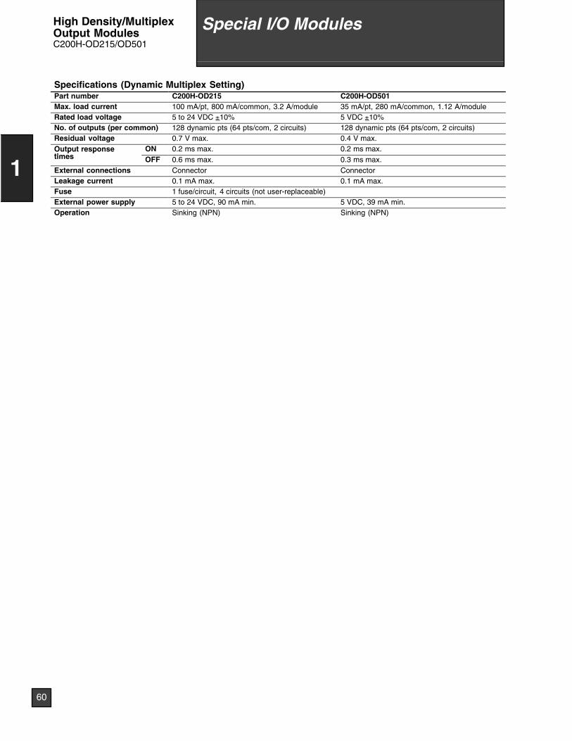
Specifications (Dynamic Multiplex Setting)Part number C200H-OD215 C200H-OD501Max. load current 100 mA/pt, 800 mA/common, 3.2 A/module 35 mA/pt, 280 mA/common, 1.12 A/moduleRated load voltage 5 to 24 VDC ±10% 5 VDC ±10%No. of outputs (per common) 128 dynamic pts (64 pts/com, 2 circuits) 128 dynamic pts (64 pts/com, 2 circuits)Residual voltage 0.7 V max. 0.4 V max.Output responseti
ON 0.2 ms max. 0.2 ms max.p ptimes OFF 0.6 ms max. 0.3 ms max.External connections Connector ConnectorLeakage current 0.1 mA max. 0.1 mA max.Fuse 1 fuse/circuit, 4 circuits (not user-replaceable)External power supply 5 to 24 VDC, 90 mA min. 5 VDC, 39 mA min.Operation Sinking (NPN) Sinking (NPN)
60
1
Special I/O ModulesHigh Density/MultiplexOutput ModulesC200H-OD215/OD501
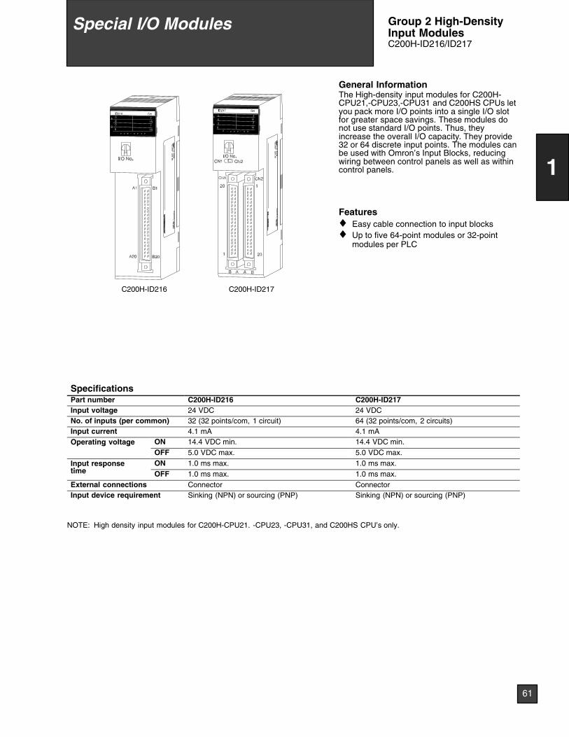
C200H-ID217C200H-ID216
LOT
No.
OM
RO
NC
orpo
ratio
nM
AD
EIN
JAP
AN
NK
AP
P.
<88
A12
0>
LOT
No.
OM
RO
NC
orpo
ratio
nM
AD
EIN
JAP
AN
NK
AP
P.
<88
A12
0>
General InformationThe High-density input modules for C200H-CPU21,-CPU23,-CPU31 and C200HS CPUs letyou pack more I/O points into a single I/O slotfor greater space savings. These modules donot use standard I/O points. Thus, theyincrease the overall I/O capacity. They provide32 or 64 discrete input points. The modules canbe used with Omron’s Input Blocks, reducingwiring between control panels as well as withincontrol panels.
Features♦ Easy cable connection to input blocks♦ Up to five 64-point modules or 32-point
modules per PLC
SpecificationsPart number C200H-ID216 C200H-ID217Input voltage 24 VDC 24 VDCNo. of inputs (per common) 32 (32 points/com, 1 circuit) 64 (32 points/com, 2 circuits)Input current 4.1 mA 4.1 mAOperating voltage ON 14.4 VDC min. 14.4 VDC min.p g g
OFF 5.0 VDC max. 5.0 VDC max.
Input responseti
ON 1.0 ms max. 1.0 ms max.p ptime OFF 1.0 ms max. 1.0 ms max.External connections Connector ConnectorInput device requirement Sinking (NPN) or sourcing (PNP) Sinking (NPN) or sourcing (PNP)
NOTE: High density input modules for C200H-CPU21. -CPU23, -CPU31, and C200HS CPU’s only.
61
1
Special I/O Modules Group 2 High-DensityInput ModulesC200H-ID216/ID217
C200H-OD219C200H-OD218
LOT
No.
OM
RO
NC
orpo
ratio
nM
AD
EIN
JAP
AN
NK
AP
P.
<88
A12
0>
LOT
No.
OM
RO
NC
orpo
ratio
nM
AD
EIN
JAP
AN
NK
AP
P.
<88
A12
0>
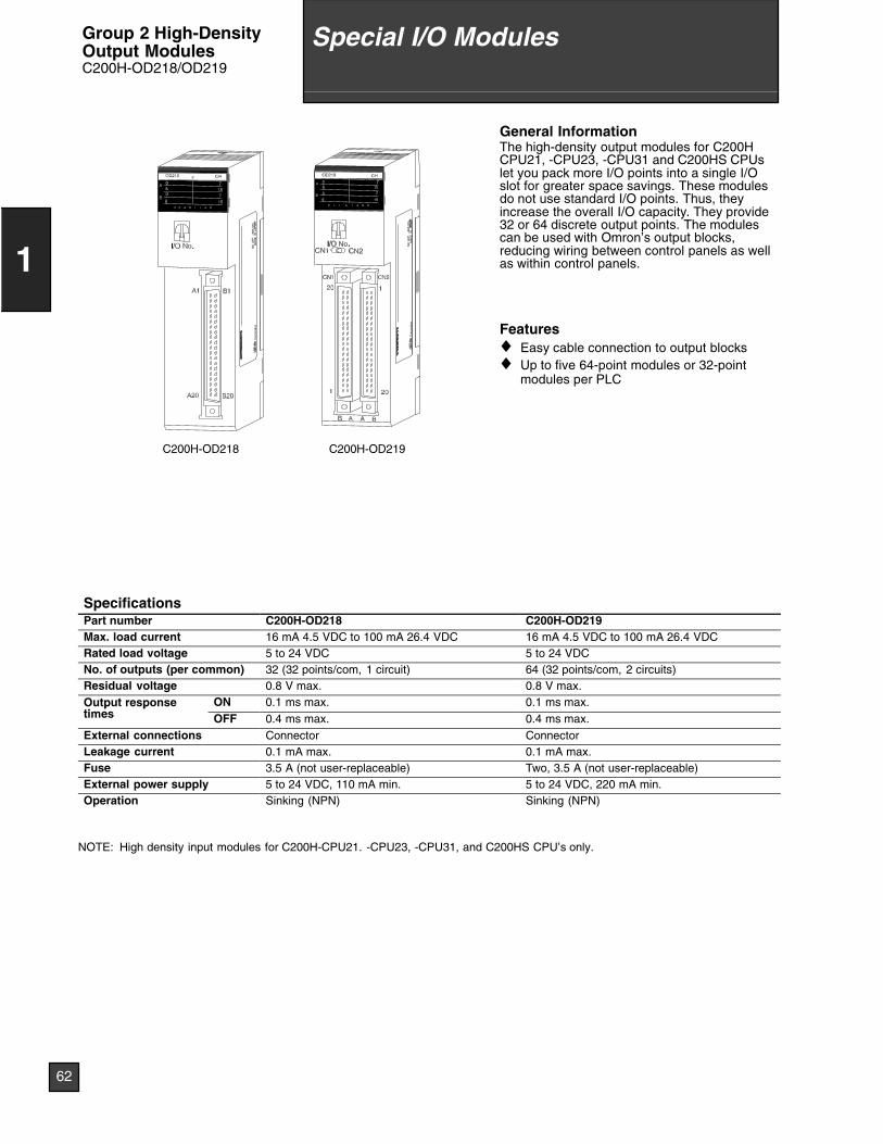
General InformationThe high-density output modules for C200HCPU21, -CPU23, -CPU31 and C200HS CPUslet you pack more I/O points into a single I/Oslot for greater space savings. These modulesdo not use standard I/O points. Thus, theyincrease the overall I/O capacity. They provide32 or 64 discrete output points. The modulescan be used with Omron’s output blocks,reducing wiring between control panels as wellas within control panels.
Features♦ Easy cable connection to output blocks♦ Up to five 64-point modules or 32-point
modules per PLC
SpecificationsPart number C200H-OD218 C200H-OD219Max. load current 16 mA 4.5 VDC to 100 mA 26.4 VDC 16 mA 4.5 VDC to 100 mA 26.4 VDCRated load voltage 5 to 24 VDC 5 to 24 VDCNo. of outputs (per common) 32 (32 points/com, 1 circuit) 64 (32 points/com, 2 circuits)Residual voltage 0.8 V max. 0.8 V max.Output responseti
ON 0.1 ms max. 0.1 ms max.p ptimes OFF 0.4 ms max. 0.4 ms max.External connections Connector ConnectorLeakage current 0.1 mA max. 0.1 mA max.Fuse 3.5 A (not user-replaceable) Two, 3.5 A (not user-replaceable)External power supply 5 to 24 VDC, 110 mA min. 5 to 24 VDC, 220 mA min.Operation Sinking (NPN) Sinking (NPN)
NOTE: High density input modules for C200H-CPU21. -CPU23, -CPU31, and C200HS CPU’s only.
62
1
Special I/O ModulesGroup 2 High-DensityOutput ModulesC200H-OD218/OD219
C200H-B7AO1C200H-B7AI1
LOT
No.
OM
RO
NC
orpo
ratio
nM
AD
EIN
JAP
AN
NK
AP
P.
<88
A12
0>
LOT
No.
OM
RO
NC
orpo
ratio
nM
AD
EIN
JAP
AN
NK
AP
P.
<88
A12
0>
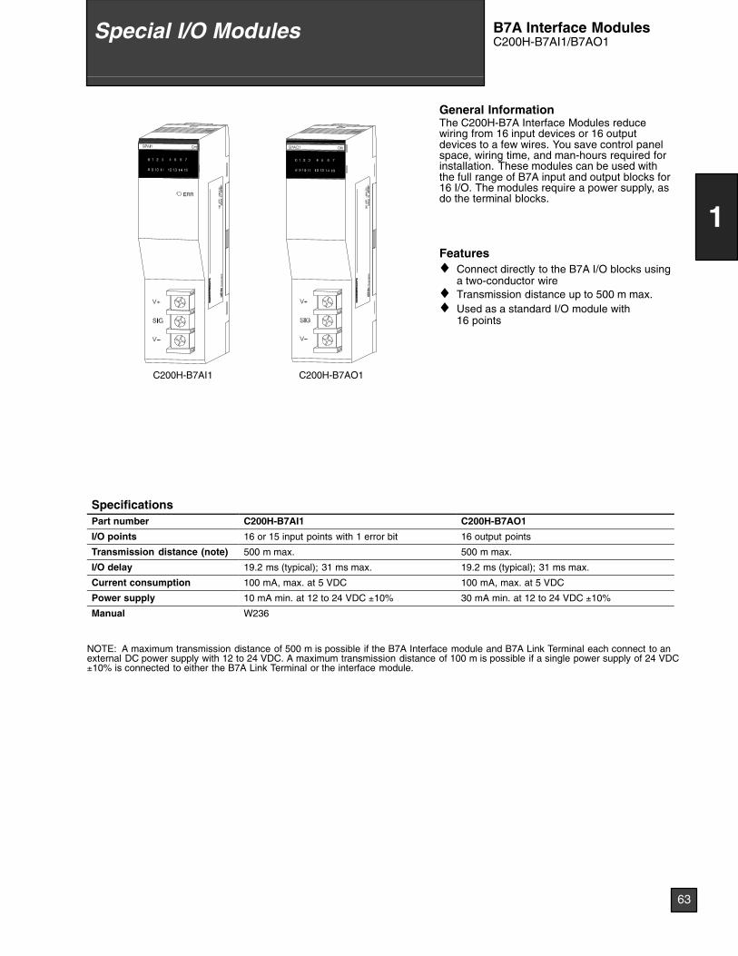
General InformationThe C200H-B7A Interface Modules reducewiring from 16 input devices or 16 outputdevices to a few wires. You save control panelspace, wiring time, and man-hours required forinstallation. These modules can be used withthe full range of B7A input and output blocks for16 I/O. The modules require a power supply, asdo the terminal blocks.
Features♦ Connect directly to the B7A I/O blocks using
a two-conductor wire♦ Transmission distance up to 500 m max.♦ Used as a standard I/O module with
16 points
SpecificationsPart number C200H-B7AI1 C200H-B7AO1
I/O points 16 or 15 input points with 1 error bit 16 output points
Transmission distance (note) 500 m max. 500 m max.
I/O delay 19.2 ms (typical); 31 ms max. 19.2 ms (typical); 31 ms max.
Current consumption 100 mA, max. at 5 VDC 100 mA, max. at 5 VDC
Power supply 10 mA min. at 12 to 24 VDC ±10% 30 mA min. at 12 to 24 VDC ±10%
Manual W236
NOTE: A maximum transmission distance of 500 m is possible if the B7A Interface module and B7A Link Terminal each connect to anexternal DC power supply with 12 to 24 VDC. A maximum transmission distance of 100 m is possible if a single power supply of 24 VDC±10% is connected to either the B7A Link Terminal or the interface module.
63
1
Special I/O Modules B7A Interface ModulesC200H-B7AI1/B7AO1
Typical Application
SIG
SOURCE+ --
POWER
3msNPN
151413121110No. IN
60 1 2 3 4 5 7 8 9
ERR
3ms
SIG
SOURCE+ --
POWER/ERROR
0.1ANPN
151413121110No. OUT
60 1 2 3 4 5 7 8 9
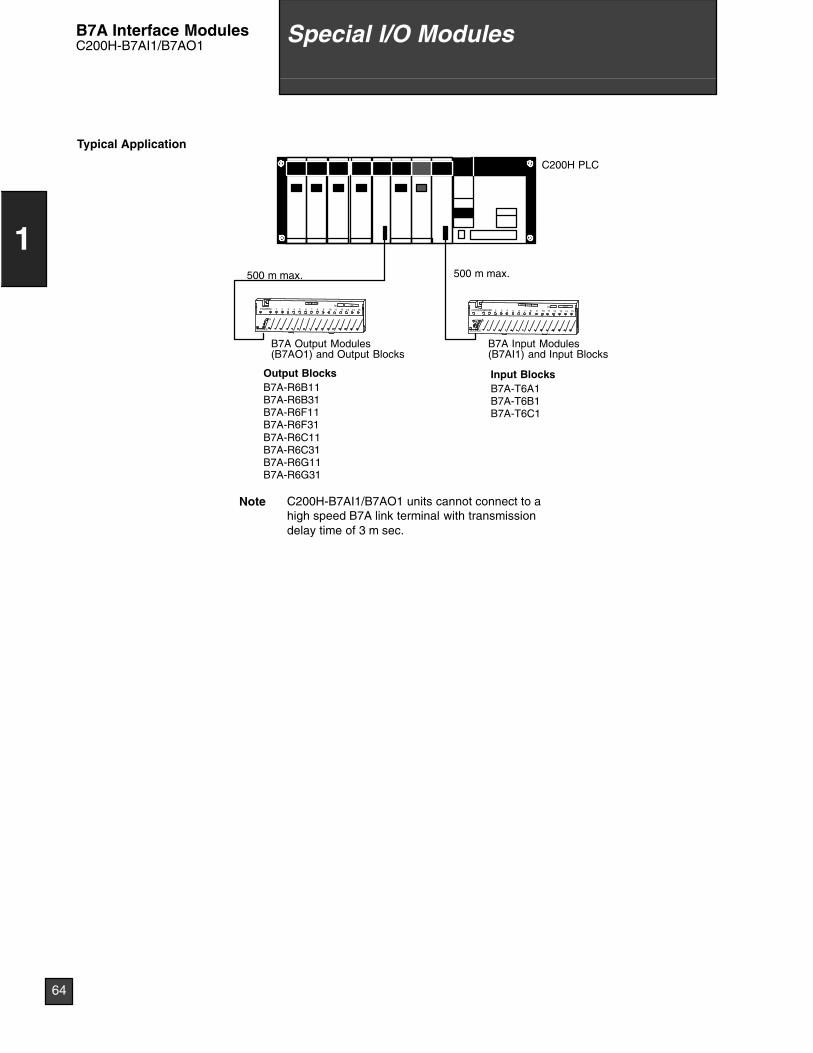
500 m max. 500 m max.
B7A Input Modules(B7AI1) and Input Blocks
B7A Output Modules(B7AO1) and Output Blocks
C200H PLC
Note C200H-B7AI1/B7AO1 units cannot connect to ahigh speed B7A link terminal with transmissiondelay time of 3 m sec.
Output BlocksB7A-R6B11B7A-R6B31B7A-R6F11B7A-R6F31B7A-R6C11B7A-R6C31B7A-R6G11B7A-R6G31
Input BlocksB7A-T6A1B7A-T6B1B7A-T6C1
64
1
Special I/O ModulesB7A Interface ModulesC200H-B7AI1/B7AO1
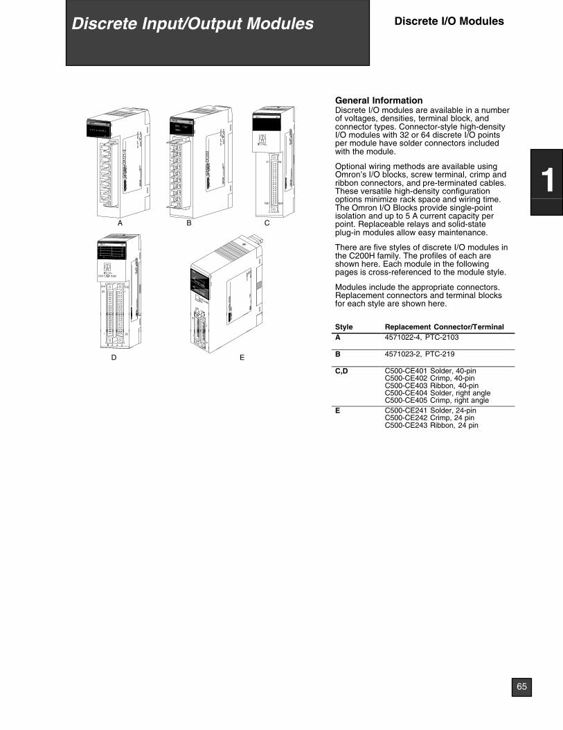
LOT
No.
OM
RO
NC
orpo
ratio
nM
AD
EIN
JAP
AN
NK
AP
P.
<88
A12
0>
C
LOT
No.
OM
RO
NC
orpo
ratio
nM
AD
EIN
JAP
AN
NK
AP
P.
<88
A12
0>
C20
0H--O
A12
1--E
OU
TP
UT
UN
IT
29X
OF
LOT
No.
OM
RO
NC
orpo
ratio
nM
AD
EIN
JAP
AN
NK
AP
P.
<88
A12
0>
A
C20
0H--O
C22
2O
UT
PU
TU
NIT
02X
2FLO
TN
o.O
MR
ON
Cor
pora
tion
MA
DE
INJA
PA
NN
KA
PP
.<
88A
120>
B
General InformationDiscrete I/O modules are available in a numberof voltages, densities, terminal block, andconnector types. Connector-style high-densityI/O modules with 32 or 64 discrete I/O pointsper module have solder connectors includedwith the module.
Optional wiring methods are available usingOmron’s I/O blocks, screw terminal, crimp andribbon connectors, and pre-terminated cables.These versatile high-density configurationoptions minimize rack space and wiring time.The Omron I/O Blocks provide single-pointisolation and up to 5 A current capacity perpoint. Replaceable relays and solid-stateplug-in modules allow easy maintenance.
There are five styles of discrete I/O modules inthe C200H family. The profiles of each areshown here. Each module in the followingpages is cross-referenced to the module style.
Modules include the appropriate connectors.Replacement connectors and terminal blocksfor each style are shown here.
LOT
OM
R
Style Replacement Connector/TerminalA 4571022-4, PTC-2103
D E B 4571023-2, PTC-219
C,D C500-CE401 Solder, 40-pinC500-CE402 Crimp, 40-pinC500-CE403 Ribbon, 40-pinC500-CE404 Solder, right angleC500-CE405 Crimp, right angle
E C500-CE241 Solder, 24-pinC500-CE242 Crimp, 24 pinC500-CE243 Ribbon, 24 pin
Discrete Input/Output Modules Discrete I/O Modules
65
1

SpecificationsPart number C200H-ID001 C200H-ID002
Number of inputs (percommon)
8 pts (8 pts/com, 1 circuit) 8 pts (8 pts/com, 1 circuit)
Input voltage No-voltage contact/NPN output type (negativecommon)
No-voltage contact/NPN output type positivecommon)
Input current 7 mA, typical 7 mA, typical
Operating voltage
ON 14.4 VDC min. 14.4 VDC min.
OFF 5.0 VDC max. 5.0 VDC max.
Input response time
ON 1.5 ms max. 1.5 ms max.
OFF 1.5 ms max. 1.5 ms max.
Style/External connections A/Removable terminal block
Input device requirement -- --
Manual C200H Installation Guide: W111
SpecificationsPart number C200H-ID211 C200H-ID212
Number of inputs (percommon)
8 pts (8 pts/com, 1 circuit) 16 pts (16 pts/com, 1 circuit)
Input voltage 12 to 24 VDC +10%/-15% 24 VDC +10%/-15%
Input current 10 mA, 24 VDC 7 mA, typical 24 VDC
Operating voltage
ON 10.2 VDC min. 14.4 VDC min.
OFF 3.0 VDC max. 5.0 VDC max.
Input response time
ON 1.5 ms max. 1.5 ms max.
OFF 1.5 ms max. 1.5 ms max.
Style/External connections A/Removable terminal block B/Removable terminal block
Input device requirement Sinking (NPN) or sourcing (PNP) Sinking (NPN) or sourcing (PNP)
Manual C200H Installation Guide: W111
Discrete Input/Output Modules
66
1
DC Input Modules
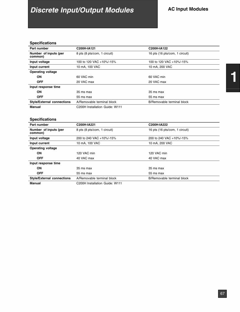
SpecificationsPart number C200H-IA121 C200H-IA122
Number of inputs (percommon)
8 pts (8 pts/com, 1 circuit) 16 pts (16 pts/com, 1 circuit)
Input voltage 100 to 120 VAC +10%/-15% 100 to 120 VAC +10%/-15%
Input current 10 mA, 100 VAC 10 mA, 200 VAC
Operating voltage
ON 60 VAC min 60 VAC min
OFF 20 VAC max 20 VAC max
Input response time
ON 35 ms max 35 ms max
OFF 55 ms max 55 ms max
Style/External connections A/Removable terminal block B/Removable terminal block
Manual C200H Installation Guide: W111
SpecificationsPart number C200H-IA221 C200H-IA222
Number of inputs (percommon)
8 pts (8 pts/com, 1 circuit) 16 pts (16 pts/com, 1 circuit)
Input voltage 200 to 240 VAC +10%/-15% 200 to 240 VAC +10%/-15%
Input current 10 mA, 100 VAC 10 mA, 200 VAC
Operating voltage
ON 120 VAC min 120 VAC min
OFF 40 VAC max 40 VAC max
Input response time
ON 35 ms max 35 ms max
OFF 55 ms max 55 ms max
Style/External connections A/Removable terminal block B/Removable terminal block
Manual C200H Installation Guide: W111
Discrete Input/Output Modules
67
1
AC Input Modules
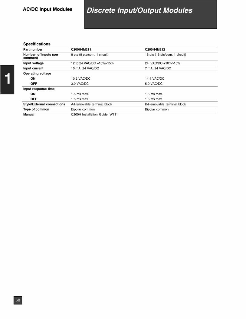
SpecificationsPart number C200H-IM211 C200H-IM212
Number of inputs (percommon)
8 pts (8 pts/com, 1 circuit) 16 pts (16 pts/com, 1 circuit)
Input voltage 12 to 24 VAC/DC +10%/-15% 24 VAC/DC +10%/-15%
Input current 10 mA, 24 VAC/DC 7 mA, 24 VAC/DC
Operating voltage
ON 10.2 VAC/DC 14.4 VAC/DC
OFF 3.0 VAC/DC 5.0 VAC/DC
Input response time
ON 1.5 ms max. 1.5 ms max.
OFF 1.5 ms max. 1.5 ms max.
Style/External connections A/Removable terminal block B/Removable terminal block
Type of common Bipolar common Bipolar common
Manual C200H Installation Guide: W111
Discrete Input/Output Modules
68
1
AC/DC Input Modules
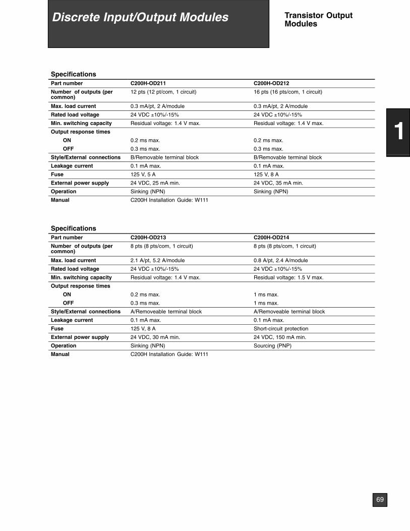
SpecificationsPart number C200H-OD211 C200H-OD212
Number of outputs (percommon)
12 pts (12 pt/com, 1 circuit) 16 pts (16 pts/com, 1 circuit)
Max. load current 0.3 mA/pt, 2 A/module 0.3 mA/pt, 2 A/module
Rated load voltage 24 VDC ±10%/-15% 24 VDC ±10%/-15%
Min. switching capacity Residual voltage: 1.4 V max. Residual voltage: 1.4 V max.
Output response times
ON 0.2 ms max. 0.2 ms max.
OFF 0.3 ms max. 0.3 ms max.
Style/External connections B/Removable terminal block B/Removable terminal block
Leakage current 0.1 mA max. 0.1 mA max.
Fuse 125 V, 5 A 125 V, 8 A
External power supply 24 VDC, 25 mA min. 24 VDC, 35 mA min.
Operation Sinking (NPN) Sinking (NPN)
Manual C200H Installation Guide: W111
SpecificationsPart number C200H-OD213 C200H-OD214
Number of outputs (percommon)
8 pts (8 pts/com, 1 circuit) 8 pts (8 pts/com, 1 circuit)
Max. load current 2.1 A/pt, 5.2 A/module 0.8 A/pt, 2.4 A/module
Rated load voltage 24 VDC ±10%/-15% 24 VDC ±10%/-15%
Min. switching capacity Residual voltage: 1.4 V max. Residual voltage: 1.5 V max.
Output response times
ON 0.2 ms max. 1 ms max.
OFF 0.3 ms max. 1 ms max.
Style/External connections A/Removeable terminal block A/Removeable terminal block
Leakage current 0.1 mA max. 0.1 mA max.
Fuse 125 V, 8 A Short-circuit protection
External power supply 24 VDC, 30 mA min. 24 VDC, 150 mA min.
Operation Sinking (NPN) Sourcing (PNP)
Manual C200H Installation Guide: W111
Discrete Input/Output Modules
69
1
Transistor OutputModules
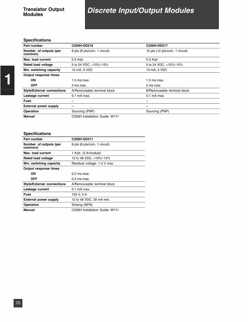
SpecificationsPart number C200H-OD216 C200H-OD217
Number of outputs (percommon)
8 pts (8 pts/com, 1 circuit) 12 pts (12 pts/com, 1 circuit)
Max. load current 0.3 A/pt 0.3 A/pt
Rated load voltage 5 to 24 VDC, +10%/-15% 5 to 24 VDC, +10%/-15%
Min. switching capacity 10 mA, 5 VDC 10 mA, 5 VDC
Output response times
ON 1.5 ms max. 1.5 ms max.
OFF 2 ms max. 2 ms max.
Style/External connections A/Removeable terminal block B/Removeable terminal block
Leakage current 0.1 mA max. 0.1 mA max.
Fuse -- --
External power supply -- --
Operation Sourcing (PNP) Sourcing (PNP)
Manual C200H Installation Guide: W111
SpecificationsPart number C200H-OD411
Number of outputs (percommon)
8 pts (8 pts/com, 1 circuit)
Max. load current 1 A/pt, (3 A/module)
Rated load voltage 12 to 48 VDC, +10%/-15%
Min. switching capacity Residual voltage: 1.4 V max.
Output response times
ON 0.2 ms max.
OFF 0.3 ms max.
Style/External connections A/Removeable terminal block
Leakage current 0.1 mA max.
Fuse 125 V, 5 A
External power supply 12 to 48 VDC, 30 mA min.
Operation Sinking (NPN)
Manual C200H Installation Guide: W111
Discrete Input/Output Modules
70
1
Transistor OutputModules
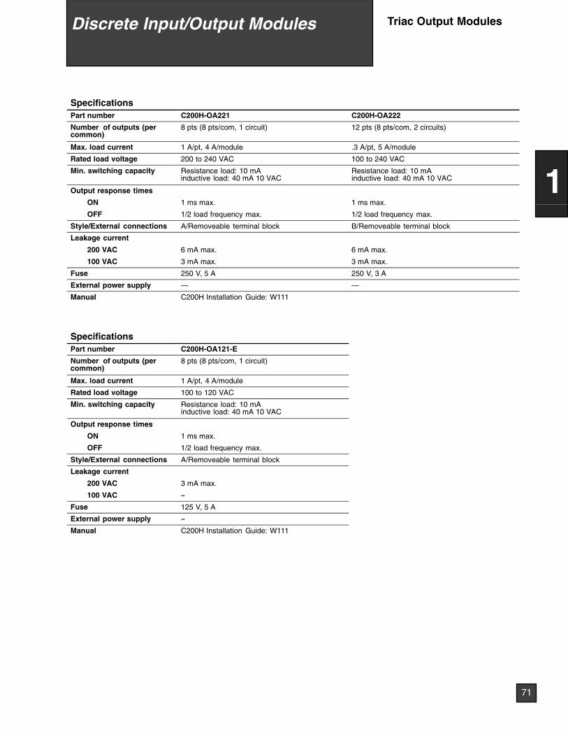
SpecificationsPart number C200H-OA221 C200H-OA222
Number of outputs (percommon)
8 pts (8 pts/com, 1 circuit) 12 pts (8 pts/com, 2 circuits)
Max. load current 1 A/pt, 4 A/module .3 A/pt, 5 A/module
Rated load voltage 200 to 240 VAC 100 to 240 VAC
Min. switching capacity Resistance load: 10 mAinductive load: 40 mA 10 VAC
Resistance load: 10 mAinductive load: 40 mA 10 VAC
Output response times
ON 1 ms max. 1 ms max.
OFF 1/2 load frequency max. 1/2 load frequency max.
Style/External connections A/Removeable terminal block B/Removeable terminal block
Leakage current
200 VAC 6 mA max. 6 mA max.
100 VAC 3 mA max. 3 mA max.
Fuse 250 V, 5 A 250 V, 3 A
External power supply — —
Manual C200H Installation Guide: W111
SpecificationsPart number C200H-OA121-E
Number of outputs (percommon)
8 pts (8 pts/com, 1 circuit)
Max. load current 1 A/pt, 4 A/module
Rated load voltage 100 to 120 VAC
Min. switching capacity Resistance load: 10 mAinductive load: 40 mA 10 VAC
Output response times
ON 1 ms max.
OFF 1/2 load frequency max.
Style/External connections A/Removeable terminal block
Leakage current
200 VAC 3 mA max.
100 VAC --
Fuse 125 V, 5 A
External power supply --
Manual C200H Installation Guide: W111
Discrete Input/Output Modules
71
1
Triac Output Modules
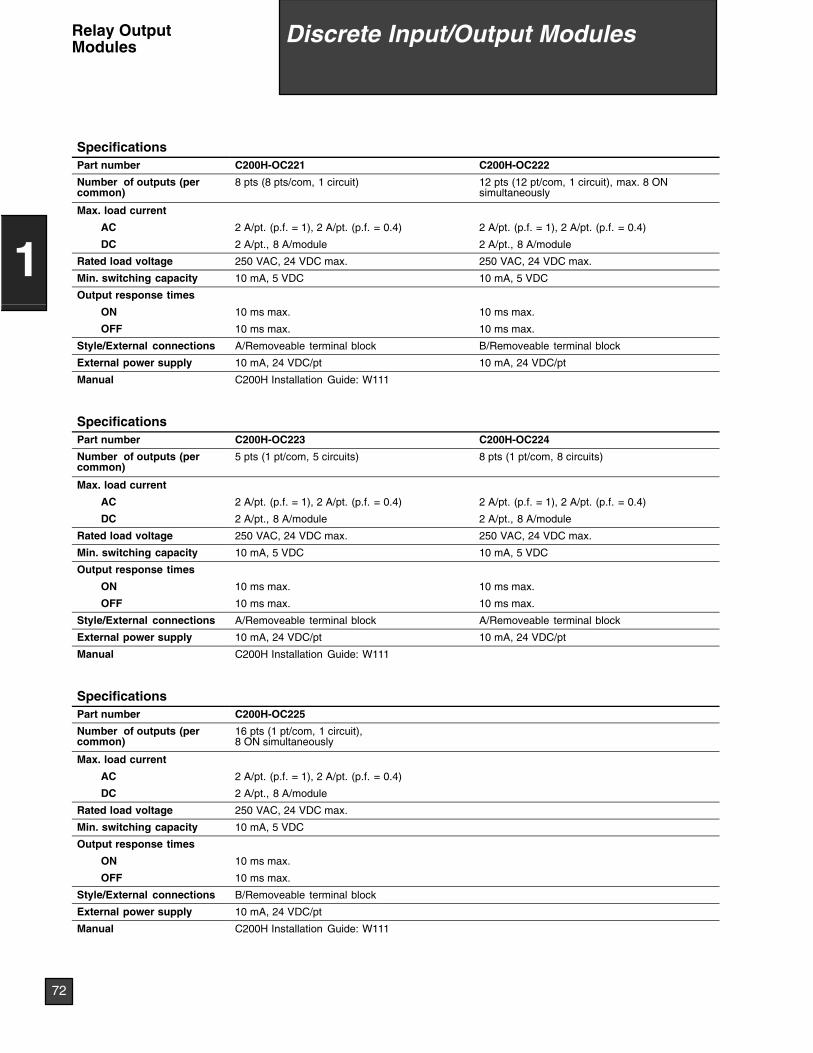
SpecificationsPart number C200H-OC221 C200H-OC222
Number of outputs (percommon)
8 pts (8 pts/com, 1 circuit) 12 pts (12 pt/com, 1 circuit), max. 8 ONsimultaneously
Max. load current
AC 2 A/pt. (p.f. = 1), 2 A/pt. (p.f. = 0.4) 2 A/pt. (p.f. = 1), 2 A/pt. (p.f. = 0.4)
DC 2 A/pt., 8 A/module 2 A/pt., 8 A/module
Rated load voltage 250 VAC, 24 VDC max. 250 VAC, 24 VDC max.
Min. switching capacity 10 mA, 5 VDC 10 mA, 5 VDC
Output response times
ON 10 ms max. 10 ms max.
OFF 10 ms max. 10 ms max.
Style/External connections A/Removeable terminal block B/Removeable terminal block
External power supply 10 mA, 24 VDC/pt 10 mA, 24 VDC/pt
Manual C200H Installation Guide: W111
SpecificationsPart number C200H-OC223 C200H-OC224
Number of outputs (percommon)
5 pts (1 pt/com, 5 circuits) 8 pts (1 pt/com, 8 circuits)
Max. load current
AC 2 A/pt. (p.f. = 1), 2 A/pt. (p.f. = 0.4) 2 A/pt. (p.f. = 1), 2 A/pt. (p.f. = 0.4)
DC 2 A/pt., 8 A/module 2 A/pt., 8 A/module
Rated load voltage 250 VAC, 24 VDC max. 250 VAC, 24 VDC max.
Min. switching capacity 10 mA, 5 VDC 10 mA, 5 VDC
Output response times
ON 10 ms max. 10 ms max.
OFF 10 ms max. 10 ms max.
Style/External connections A/Removeable terminal block A/Removeable terminal block
External power supply 10 mA, 24 VDC/pt 10 mA, 24 VDC/pt
Manual C200H Installation Guide: W111
SpecificationsPart number C200H-OC225
Number of outputs (percommon)
16 pts (1 pt/com, 1 circuit),8 ON simultaneously
Max. load current
AC 2 A/pt. (p.f. = 1), 2 A/pt. (p.f. = 0.4)
DC 2 A/pt., 8 A/module
Rated load voltage 250 VAC, 24 VDC max.
Min. switching capacity 10 mA, 5 VDC
Output response times
ON 10 ms max.
OFF 10 ms max.
Style/External connections B/Removeable terminal block
External power supply 10 mA, 24 VDC/pt
Manual C200H Installation Guide: W111
Discrete Input/Output Modules
72
1
Relay OutputModules
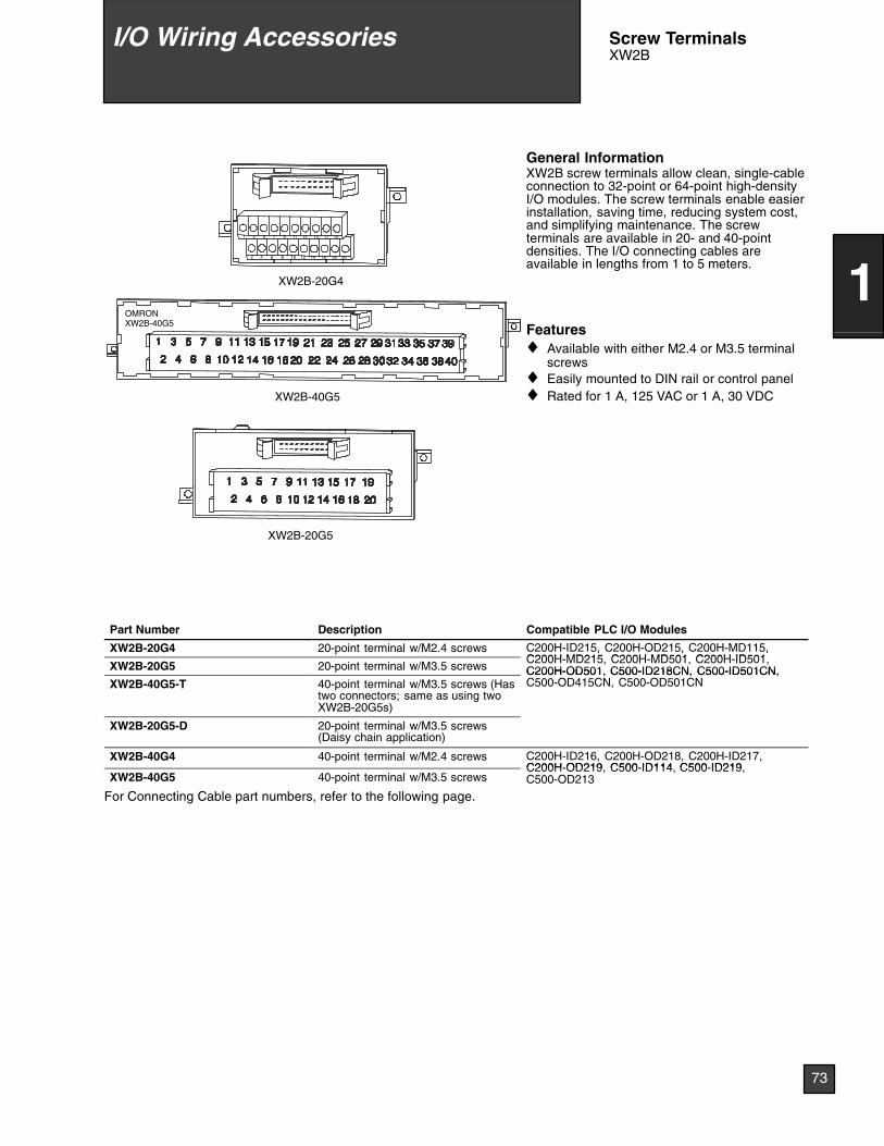
1 3 5 7 9 11 13 15 17 19
2018161412108642
XW2B-20G4
XW2B-40G5
XW2B-20G5
OMRONXW2B-40G5
General InformationXW2B screw terminals allow clean, single-cableconnection to 32-point or 64-point high-densityI/O modules. The screw terminals enable easierinstallation, saving time, reducing system cost,and simplifying maintenance. The screwterminals are available in 20- and 40-pointdensities. The I/O connecting cables areavailable in lengths from 1 to 5 meters.
Features♦ Available with either M2.4 or M3.5 terminal
screws♦ Easily mounted to DIN rail or control panel♦ Rated for 1 A, 125 VAC or 1 A, 30 VDC
Part Number Description Compatible PLC I/O Modules
XW2B-20G4 20-point terminal w/M2.4 screws C200H-ID215, C200H-OD215, C200H-MD115,C200H MD215 C200H MD501 C200H ID501
XW2B-20G5 20-point terminal w/M3.5 screws
, , ,C200H-MD215, C200H-MD501, C200H-ID501,C200H-OD501, C500-ID218CN, C500-ID501CN,
XW2B-40G5-T 40-point terminal w/M3.5 screws (Hastwo connectors; same as using twoXW2B-20G5s)
C200H-OD501, C500-ID218CN, C500-ID501CN,C500-OD415CN, C500-OD501CN
XW2B-20G5-D 20-point terminal w/M3.5 screws(Daisy chain application)
XW2B-40G4 40-point terminal w/M2.4 screws C200H-ID216, C200H-OD218, C200H-ID217,C200H-OD219 C500-ID114 C500-ID219
XW2B-40G5 40-point terminal w/M3.5 screwsC200H-OD219, C500-ID114, C500-ID219,C500-OD213
For Connecting Cable part numbers, refer to the following page.
I/O Wiring Accessories Screw TerminalsXW2B
73
1
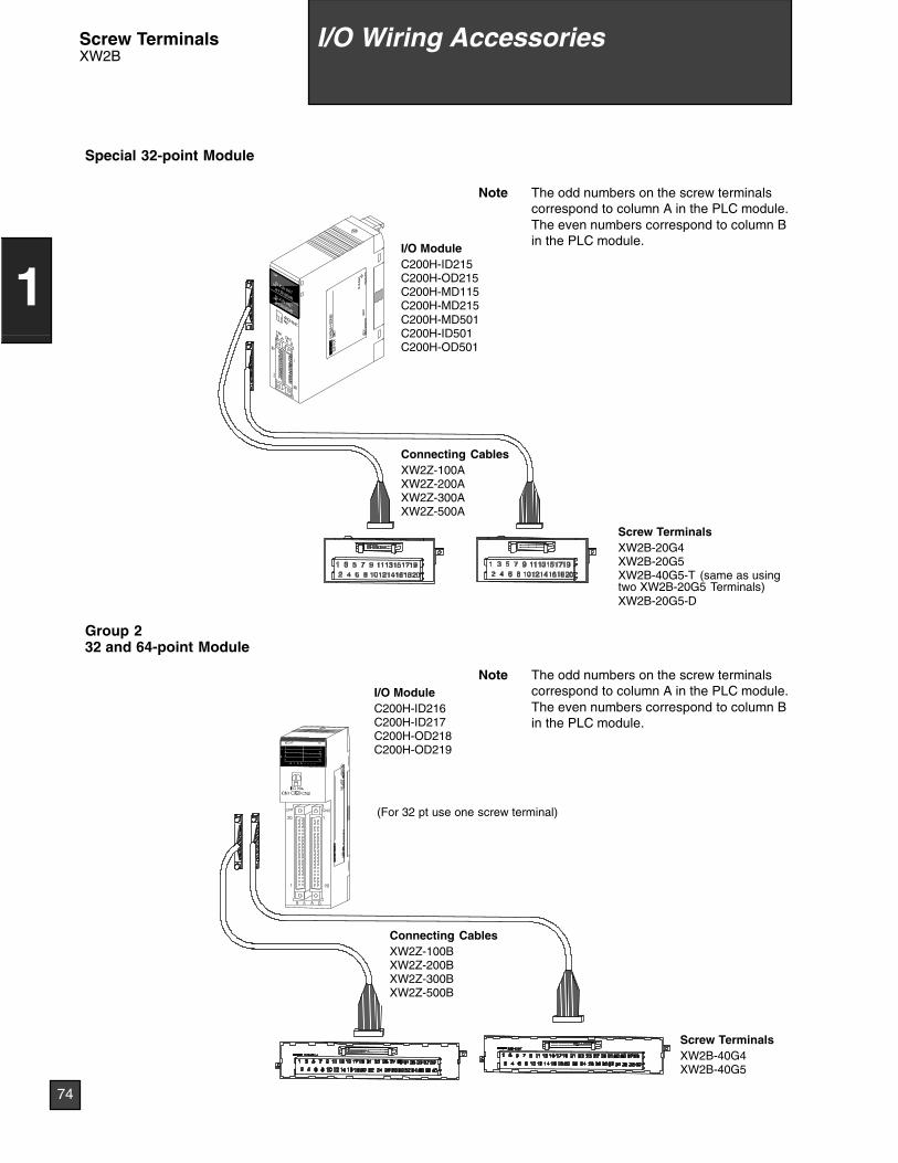
I/O ModuleC200H-ID215C200H-OD215C200H-MD115C200H-MD215C200H-MD501C200H-ID501C200H-OD501
Connecting CablesXW2Z-100AXW2Z-200AXW2Z-300AXW2Z-500A
Screw TerminalsXW2B-20G4XW2B-20G5XW2B-40G5-T (same as usingtwo XW2B-20G5 Terminals)XW2B-20G5-D
I/O ModuleC200H-ID216C200H-ID217C200H-OD218C200H-OD219
Connecting CablesXW2Z-100BXW2Z-200BXW2Z-300BXW2Z-500B
Special 32-point Module
Group 232 and 64-point Module
Screw TerminalsXW2B-40G4XW2B-40G5
(For 32 pt use one screw terminal)
LOT
No.
OM
RO
NC
orpo
ratio
nM
AD
EIN
JAP
AN
NK
AP
P.
<88
A12
0>
Note The odd numbers on the screw terminalscorrespond to column A in the PLC module.The even numbers correspond to column Bin the PLC module.
Note The odd numbers on the screw terminalscorrespond to column A in the PLC module.The even numbers correspond to column Bin the PLC module.
I/O Wiring AccessoriesScrew TerminalsXW2B
74
1
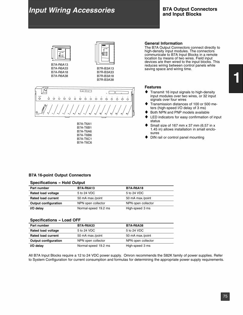
SIG
SOURCE
+ --
POWER
3msNPN
151413121110
No. IN
60 1 2 3 4 5 7 8 9
B7A-T6A1B7A-T6B1B7A-T6A6B7A-T6B6B7A-T6C1B7A-T6C6
B7R-B3A13B7R-B3A33B7R-B3A18B7R-B3A38
B7A-R6A13B7A-R6A33B7A-R6A18B7A-R6A38
General InformationThe B7A Output Connectors connect directly tohigh-density input modules. The connectorscommunicate to B7A Input Blocks in a remotelocation by means of two wires. Field inputdevices are then wired to the input blocks. Thisreduces wiring between control panels whilesaving space and wiring time.
Features♦ Transmit 16 input signals to high-density
input modules over two wires, or 32 inputsignals over four wires
♦ Transmission distances of 100 or 500 me-ters (high-speed I/O delay of 3 ms)
♦ Both NPN and PNP models available♦ LED indicators for easy confirmation of input
status♦ Small size of 167 mm x 37 mm (6.57 in x
1.45 in) allows installation in small enclo-sures
♦ DIN rail or control panel mounting
B7A 16-point Output Connectors
Specifications -- Hold OutputPart number B7A-R6A13 B7A-R6A18
Rated load voltage 5 to 24 VDC 5 to 24 VDC
Rated load current 50 mA max./point 50 mA max./point
Output configuration NPN open collector NPN open collector
I/O delay Normal-speed 19.2 ms High-speed 3 ms
Specifications -- Load OFFPart number B7A-R6A33 B7A-R6A38
Rated load voltage 5 to 24 VDC 5 to 24 VDC
Rated load current 50 mA max./point 50 mA max./point
Output configuration NPN open collector NPN open collector
I/O delay Normal-speed 19.2 ms High-speed 3 ms
All B7A Input Blocks require a 12 to 24 VDC power supply. Omron recommends the S82K family of power supplies. Referto System Configuration for current consumption and formulas for determining the appropriate power supply requirements.
75
1
Input Wiring Accessories B7A Output Connectorsand Input Blocks

B7A 32-point Output Connectors
Specifications -- Hold OutputPart number B7A-R3A13 B7A-R3A18
Rated load voltage 5 to 24 VDC 5 to 24 VDC
Rated load current 50 mA max./point 50 mA max./point
Output configuration NPN open collector NPN open collector
I/O delay Normal-speed 19.2 ms High-speed 3 ms
Specifications -- Load OFFPart number B7A-R3A33 B7A-R3A38
Rated load voltage 5 to 24 VDC 5 to 24 VDC
Rated load current 50 mA max./point 50 mA max./point
Output configuration NPN open collector NPN open collector
I/O delay Normal-speed 19.2 ms High-speed 3 ms
B7A 16-point Input Blocks
SpecificationsPart number B7A-T6A1 B7A-T6B1 B7A-T6A6
Input configuration NPN compatible NPN compatible NPN compatible
Input voltage No-voltage contact, two-wiresensors with DC output, NPNoutput type
No-voltage contact, two-wiresensors with DC output, NPNoutput type
No-voltage contact, two-wiresensors with DC output, NPNoutput type
Input current range 3 to 6 mA 3 to 6 mA 3 to 6 mA
Input voltage range 0 VDC to supply voltage 0 VDC to supply voltage 0 VDC to supply voltage
I/O delay Normal-speed 19.2 ms Normal-speed 19.2 ms High-speed 3 ms
Internal I/O common -- common ± common -- common
SpecificationsPart number B7A-T6B6 B7A-T6C1 B7A-T6C6
Input configuration NPN compatible PNP compatible PNP compatible
Input voltage No-voltage contact, two-wiresensors with DC output, NPNoutput type
No-voltage contact, two-wiresensors with DC output, PNPoutput type
No-voltage contact, two-wiresensors with DC output, PNPoutput type
Input current range 3 to 6 mA 3 to 6 mA 3 to 6 mA
Input voltage range 0 VDC to supply voltage 0 VDC to supply voltage 0 VDC to supply voltage
I/O delay High-speed 3 ms Normal-speed 19.2 ms High-speed 3 ms
Internal I/O common ± common ± common ± common
All B7A Input Blocks require a 24 VDC power supply. Omron recommends the S82K family of power supplies. Refer toStandard Parts for part numbers. Refer to System Configuration for current consumption and formulas for determining theappropriate power supply requirements.
76
1
Input Wiring AccessoriesB7A Output Connectorsand Input Blocks
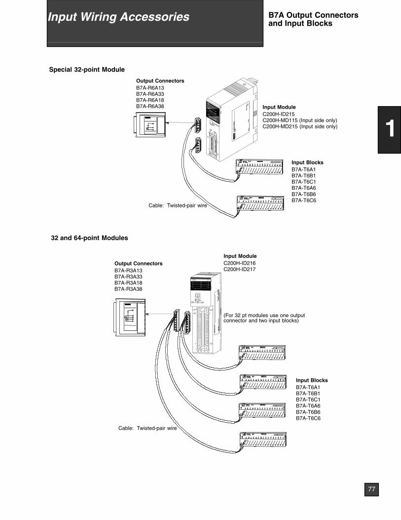
SIG
+--
SIG
+--
SIG
+--
SIG
+--
--+SIG
--+SIGCable: Twisted-pair wire
Input ModuleC200H-ID216C200H-ID217
Input ModuleC200H-ID215C200H-MD115 (Input side only)C200H-MD215 (Input side only)
Output ConnectorsB7A-R6A13B7A-R6A33B7A-R6A18B7A-R6A38
Output ConnectorsB7A-R3A13B7A-R3A33B7A-R3A18B7A-R3A38
Input BlocksB7A-T6A1B7A-T6B1B7A-T6C1B7A-T6A6B7A-T6B6B7A-T6C6
Input BlocksB7A-T6A1B7A-T6B1B7A-T6C1B7A-T6A6B7A-T6B6B7A-T6C6
Special 32-point Module
32 and 64-point Modules
Cable: Twisted-pair wire
(For 32 pt modules use one outputconnector and two input blocks)
LOT
No.
OM
RO
NC
orpo
ratio
nM
AD
EIN
JAP
AN
NK
AP
P.
<88
A12
0>
77
1
Input Wiring Accessories B7A Output Connectorsand Input Blocks
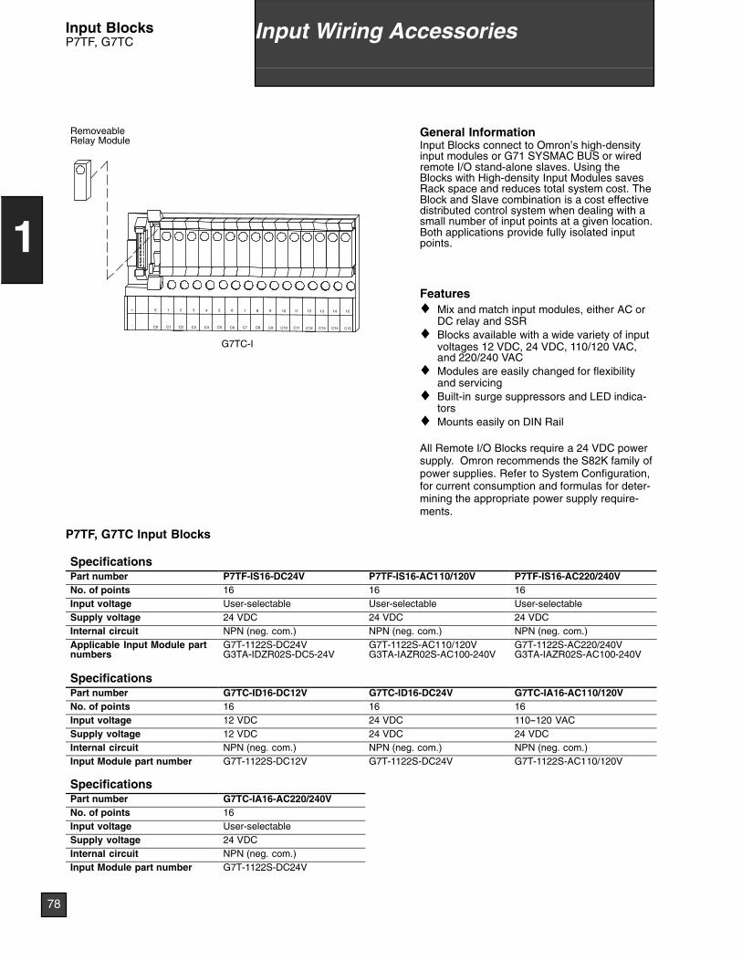
_
+ 15
C15
14
C14
13
C13
12
C12
11
C11
10
C10
9
C9
8
C8
7
C7
6
C6
5
C5
4
C4
3
C3
2
C2
1
C1
0
C0
G7TC-I
RemoveableRelay Module
General InformationInput Blocks connect to Omron’s high-densityinput modules or G71 SYSMAC BUS or wiredremote I/O stand-alone slaves. Using theBlocks with High-density Input Modules savesRack space and reduces total system cost. TheBlock and Slave combination is a cost effectivedistributed control system when dealing with asmall number of input points at a given location.Both applications provide fully isolated inputpoints.
Features♦ Mix and match input modules, either AC or
DC relay and SSR♦ Blocks available with a wide variety of input
voltages 12 VDC, 24 VDC, 110/120 VAC,and 220/240 VAC
♦ Modules are easily changed for flexibilityand servicing
♦ Built-in surge suppressors and LED indica-tors
♦ Mounts easily on DIN Rail
All Remote I/O Blocks require a 24 VDC powersupply. Omron recommends the S82K family ofpower supplies. Refer to System Configuration,for current consumption and formulas for deter-mining the appropriate power supply require-ments.
P7TF, G7TC Input Blocks
SpecificationsPart number P7TF-IS16-DC24V P7TF-IS16-AC110/120V P7TF-IS16-AC220/240VNo. of points 16 16 16Input voltage User-selectable User-selectable User-selectableSupply voltage 24 VDC 24 VDC 24 VDCInternal circuit NPN (neg. com.) NPN (neg. com.) NPN (neg. com.)Applicable Input Module partnumbers
G7T-1122S-DC24VG3TA-IDZR02S-DC5-24V
G7T-1122S-AC110/120VG3TA-IAZR02S-AC100-240V
G7T-1122S-AC220/240VG3TA-IAZR02S-AC100-240V
SpecificationsPart number G7TC-ID16-DC12V G7TC-ID16-DC24V G7TC-IA16-AC110/120VNo. of points 16 16 16Input voltage 12 VDC 24 VDC 110--120 VACSupply voltage 12 VDC 24 VDC 24 VDCInternal circuit NPN (neg. com.) NPN (neg. com.) NPN (neg. com.)Input Module part number G7T-1122S-DC12V G7T-1122S-DC24V G7T-1122S-AC110/120V
SpecificationsPart number G7TC-IA16-AC220/240VNo. of points 16Input voltage User-selectableSupply voltage 24 VDCInternal circuit NPN (neg. com.)Input Module part number G7T-1122S-DC24V
78
1
Input Wiring AccessoriesInput BlocksP7TF, G7TC
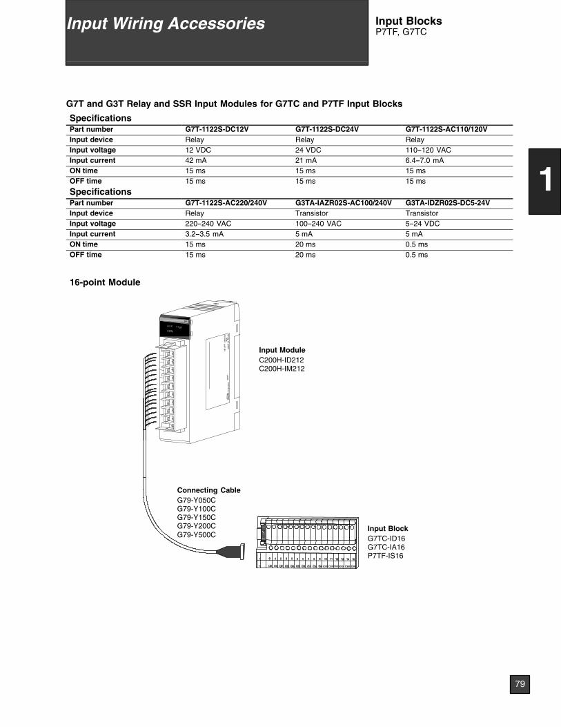
G7T and G3T Relay and SSR Input Modules for G7TC and P7TF Input Blocks
SpecificationsPart number G7T-1122S-DC12V G7T-1122S-DC24V G7T-1122S-AC110/120VInput device Relay Relay RelayInput voltage 12 VDC 24 VDC 110--120 VACInput current 42 mA 21 mA 6.4--7.0 mAON time 15 ms 15 ms 15 msOFF time 15 ms 15 ms 15 ms
SpecificationsPart number G7T-1122S-AC220/240V G3TA-IAZR02S-AC100/240V G3TA-IDZR02S-DC5-24VInput device Relay Transistor TransistorInput voltage 220--240 VAC 100--240 VAC 5--24 VDCInput current 3.2--3.5 mA 5 mA 5 mAON time 15 ms 20 ms 0.5 msOFF time 15 ms 20 ms 0.5 ms
Connecting CableG79-Y050CG79-Y100CG79-Y150CG79-Y200CG79-Y500C
Input BlockG7TC-ID16G7TC-IA16P7TF-IS16
16-point Module
Input ModuleC200H-ID212C200H-IM212
02X
2FLO
TN
o.O
MR
ON
Cor
pora
tion
MA
DE
INJA
PA
N
NK
AP
P.
<88
A12
0>
79
1
Input Wiring Accessories Input BlocksP7TF, G7TC
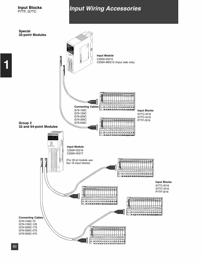
Input ModuleC200H-ID215C200H-MD215 (Input side only)
Input BlocksG7TC-ID16G7TC-IA16P7TF-IS16
Connecting CablesG79-100CG79-150CG79-200CG79-300CG79-500C
Input ModuleC200H-ID216C200H-ID217
Input BlocksG7TC-ID16G7TC-IA16P7TF-IS16
Connecting CablesG79-I100C-75G79-I150C-125G79-I200C-175G79-I300C-275G79-I500C-475
Special32-point Modules
Group 232 and 64-point Modules
(For 32 pt module usetwo 16 input blocks)
LOT
No.
OM
RO
NC
orpo
ratio
nM
AD
EIN
JAP
AN
NK
AP
P.
<88
A12
0>
80
1
Input Wiring AccessoriesInput BlocksP7TF, G7TC
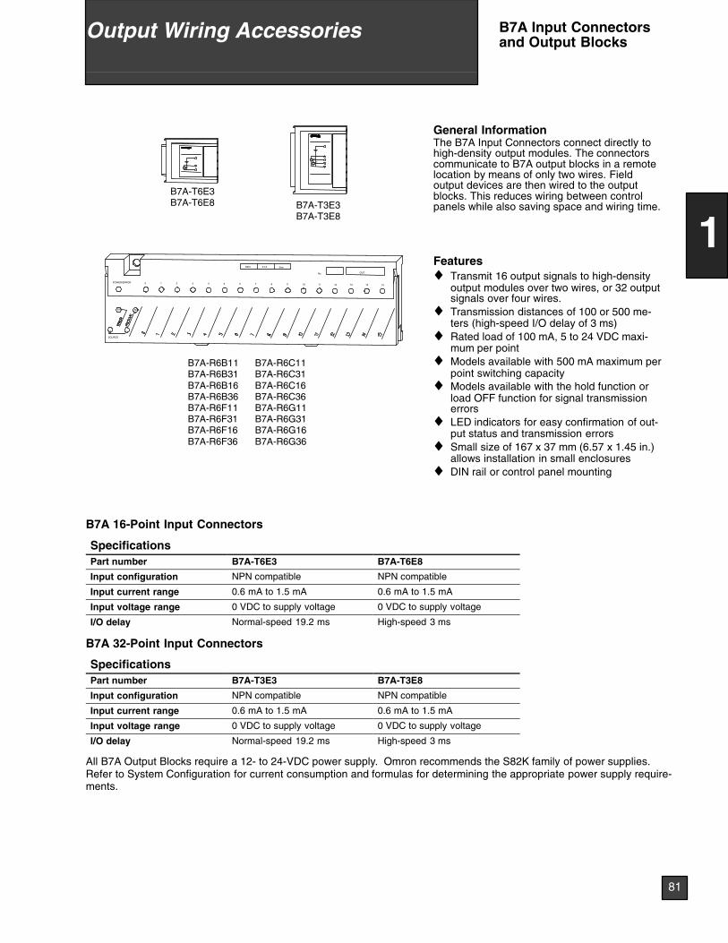
OUTOUT
ERR
3ms
OUT
SIG
SOURCE
+ --
POWER/ERROR
0.1ANPN
151413121110
No. OUT
60 1 2 3 4 5 7 8 9
B7A-R6B11B7A-R6B31B7A-R6B16B7A-R6B36B7A-R6F11B7A-R6F31B7A-R6F16B7A-R6F36
B7A-R6C11B7A-R6C31B7A-R6C16B7A-R6C36B7A-R6G11B7A-R6G31B7A-R6G16B7A-R6G36
B7A-T3E3B7A-T3E8
B7A-T6E3B7A-T6E8
General InformationThe B7A Input Connectors connect directly tohigh-density output modules. The connectorscommunicate to B7A output blocks in a remotelocation by means of only two wires. Fieldoutput devices are then wired to the outputblocks. This reduces wiring between controlpanels while also saving space and wiring time.
Features♦ Transmit 16 output signals to high-density
output modules over two wires, or 32 outputsignals over four wires.
♦ Transmission distances of 100 or 500 me-ters (high-speed I/O delay of 3 ms)
♦ Rated load of 100 mA, 5 to 24 VDC maxi-mum per point
♦ Models available with 500 mA maximum perpoint switching capacity
♦ Models available with the hold function orload OFF function for signal transmissionerrors
♦ LED indicators for easy confirmation of out-put status and transmission errors
♦ Small size of 167 x 37 mm (6.57 x 1.45 in.)allows installation in small enclosures
♦ DIN rail or control panel mounting
B7A 16-Point Input Connectors
SpecificationsPart number B7A-T6E3 B7A-T6E8
Input configuration NPN compatible NPN compatible
Input current range 0.6 mA to 1.5 mA 0.6 mA to 1.5 mA
Input voltage range 0 VDC to supply voltage 0 VDC to supply voltage
I/O delay Normal-speed 19.2 ms High-speed 3 ms
B7A 32-Point Input Connectors
SpecificationsPart number B7A-T3E3 B7A-T3E8
Input configuration NPN compatible NPN compatible
Input current range 0.6 mA to 1.5 mA 0.6 mA to 1.5 mA
Input voltage range 0 VDC to supply voltage 0 VDC to supply voltage
I/O delay Normal-speed 19.2 ms High-speed 3 ms
All B7A Output Blocks require a 12- to 24-VDC power supply. Omron recommends the S82K family of power supplies.Refer to System Configuration for current consumption and formulas for determining the appropriate power supply require-ments.
81
1
Output Wiring Accessories B7A Input Connectorsand Output Blocks
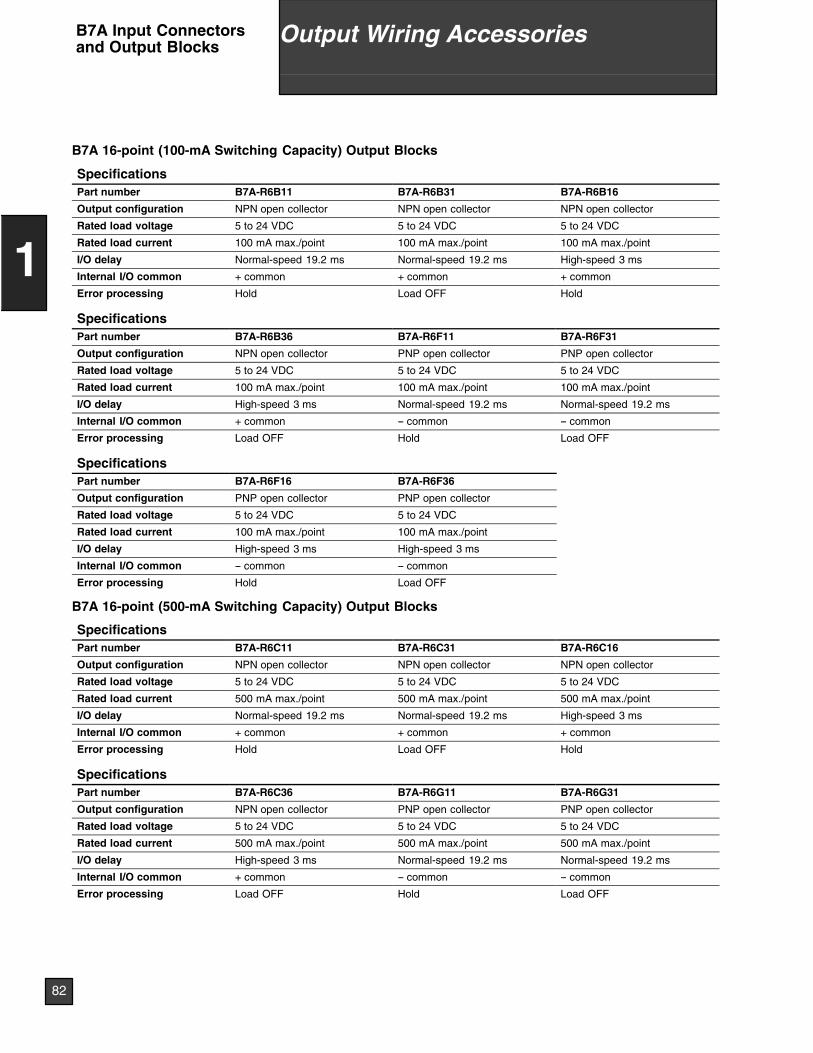
B7A 16-point (100-mA Switching Capacity) Output Blocks
SpecificationsPart number B7A-R6B11 B7A-R6B31 B7A-R6B16
Output configuration NPN open collector NPN open collector NPN open collector
Rated load voltage 5 to 24 VDC 5 to 24 VDC 5 to 24 VDC
Rated load current 100 mA max./point 100 mA max./point 100 mA max./point
I/O delay Normal-speed 19.2 ms Normal-speed 19.2 ms High-speed 3 ms
Internal I/O common + common + common + common
Error processing Hold Load OFF Hold
SpecificationsPart number B7A-R6B36 B7A-R6F11 B7A-R6F31
Output configuration NPN open collector PNP open collector PNP open collector
Rated load voltage 5 to 24 VDC 5 to 24 VDC 5 to 24 VDC
Rated load current 100 mA max./point 100 mA max./point 100 mA max./point
I/O delay High-speed 3 ms Normal-speed 19.2 ms Normal-speed 19.2 ms
Internal I/O common + common -- common -- common
Error processing Load OFF Hold Load OFF
SpecificationsPart number B7A-R6F16 B7A-R6F36
Output configuration PNP open collector PNP open collector
Rated load voltage 5 to 24 VDC 5 to 24 VDC
Rated load current 100 mA max./point 100 mA max./point
I/O delay High-speed 3 ms High-speed 3 ms
Internal I/O common -- common -- common
Error processing Hold Load OFF
B7A 16-point (500-mA Switching Capacity) Output Blocks
SpecificationsPart number B7A-R6C11 B7A-R6C31 B7A-R6C16
Output configuration NPN open collector NPN open collector NPN open collector
Rated load voltage 5 to 24 VDC 5 to 24 VDC 5 to 24 VDC
Rated load current 500 mA max./point 500 mA max./point 500 mA max./point
I/O delay Normal-speed 19.2 ms Normal-speed 19.2 ms High-speed 3 ms
Internal I/O common + common + common + common
Error processing Hold Load OFF Hold
SpecificationsPart number B7A-R6C36 B7A-R6G11 B7A-R6G31
Output configuration NPN open collector PNP open collector PNP open collector
Rated load voltage 5 to 24 VDC 5 to 24 VDC 5 to 24 VDC
Rated load current 500 mA max./point 500 mA max./point 500 mA max./point
I/O delay High-speed 3 ms Normal-speed 19.2 ms Normal-speed 19.2 ms
Internal I/O common + common -- common -- common
Error processing Load OFF Hold Load OFF
82
1
Output Wiring AccessoriesB7A Input Connectorsand Output Blocks
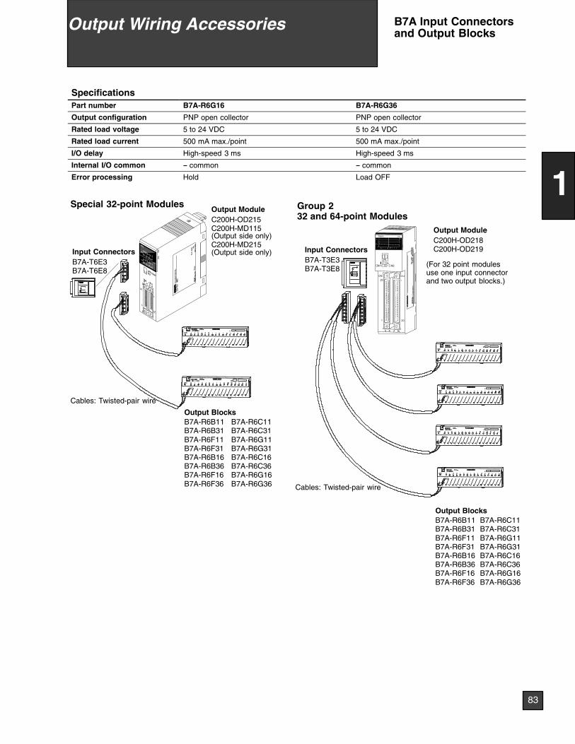
SpecificationsPart number B7A-R6G16 B7A-R6G36
Output configuration PNP open collector PNP open collector
Rated load voltage 5 to 24 VDC 5 to 24 VDC
Rated load current 500 mA max./point 500 mA max./point
I/O delay High-speed 3 ms High-speed 3 ms
Internal I/O common -- common -- common
Error processing Hold Load OFF
SIG
+--
SIG
+--
SIG
+--
SIG
+--
--+SIG
--+SIG
Input ConnectorsB7A-T6E3B7A-T6E8
Input ConnectorsB7A-T3E3B7A-T3E8
Output BlocksB7A-R6B11B7A-R6B31B7A-R6F11B7A-R6F31B7A-R6B16B7A-R6B36B7A-R6F16B7A-R6F36
B7A-R6C11B7A-R6C31B7A-R6G11B7A-R6G31B7A-R6C16B7A-R6C36B7A-R6G16B7A-R6G36
Output BlocksB7A-R6B11B7A-R6B31B7A-R6F11B7A-R6F31B7A-R6B16B7A-R6B36B7A-R6F16B7A-R6F36
B7A-R6C11B7A-R6C31B7A-R6G11B7A-R6G31B7A-R6C16B7A-R6C36B7A-R6G16B7A-R6G36
Output ModuleC200H-OD215C200H-MD115(Output side only)C200H-MD215(Output side only)
Output ModuleC200H-OD218C200H-OD219
Special 32-point Modules Group 232 and 64-point Modules
Cables: Twisted-pair wire
Cables: Twisted-pair wireLO
TN
o.O
MR
ON
Cor
pora
tion
MA
DE
INJA
PA
NN
KA
PP
.<
88A
120>
(For 32 point modulesuse one input connectorand two output blocks.)
83
1
Output Wiring Accessories B7A Input Connectorsand Output Blocks
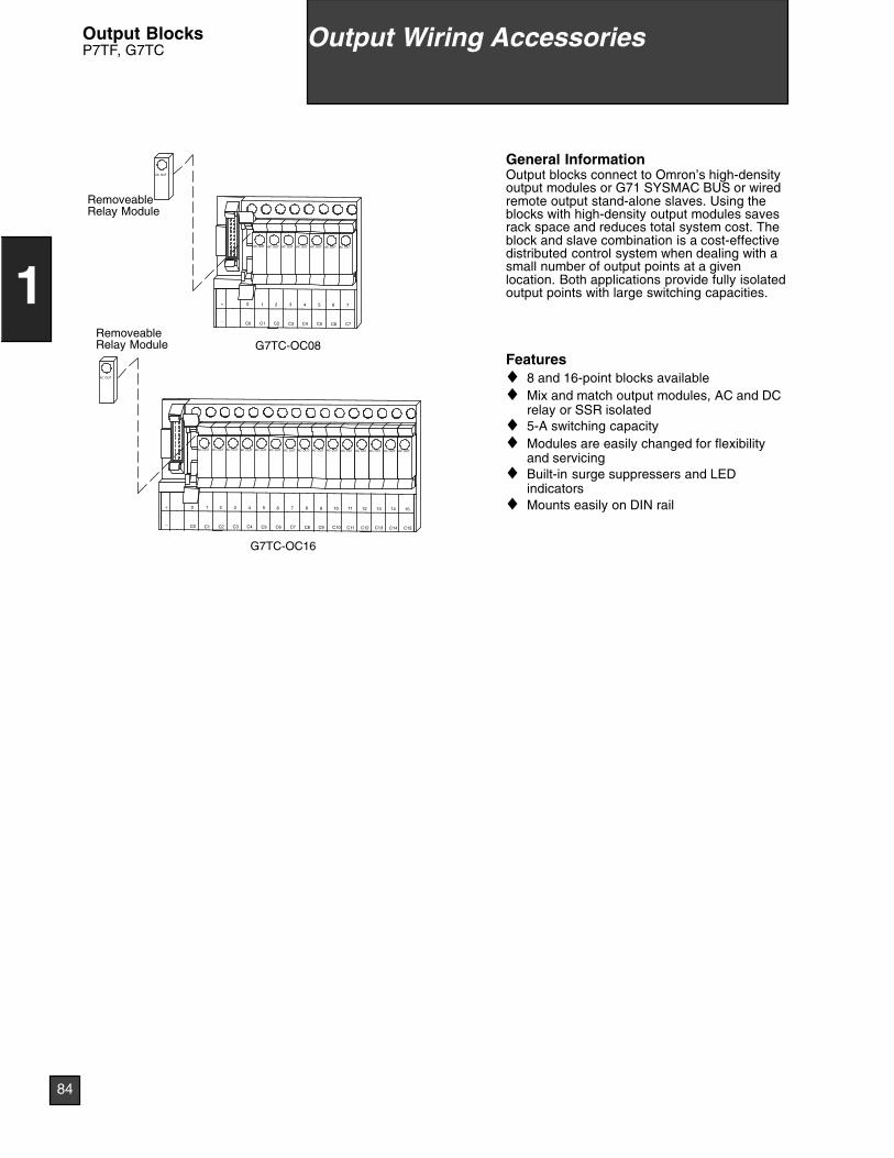
AC OUT
AC OUT
AC OUT AC OUT AC OUT AC OUT AC OUT AC OUT AC OUT AC OUT AC OUT AC OUT AC OUT AC OUT AC OUT AC OUT
_
+ 15
C15
14
C14
13
C13
12
C12
11
C11
10
C10
9
C9
8
C8
7
C7
6
C6
5
C5
4
C4
3
C3
2
C2
1
C1
0
C0
G7TC-OC16
AC OUT
AC OUT
AC OUT AC OUT AC OUT AC OUT AC OUT AC OUT
_
+ 7
C7
6
C6
5
C5
4
C4
3
C3
2
C2
1
C1
0
C0
G7TC-OC08
RemoveableRelay Module
RemoveableRelay Module
General InformationOutput blocks connect to Omron’s high-densityoutput modules or G71 SYSMAC BUS or wiredremote output stand-alone slaves. Using theblocks with high-density output modules savesrack space and reduces total system cost. Theblock and slave combination is a cost-effectivedistributed control system when dealing with asmall number of output points at a givenlocation. Both applications provide fully isolatedoutput points with large switching capacities.
Features♦ 8 and 16-point blocks available♦ Mix and match output modules, AC and DC
relay or SSR isolated♦ 5-A switching capacity♦ Modules are easily changed for flexibility
and servicing♦ Built-in surge suppressers and LED
indicators♦ Mounts easily on DIN rail
84
1
Output Wiring AccessoriesOutput BlocksP7TF, G7TC
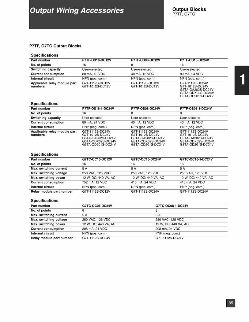
P7TF, G7TC Output Blocks
SpecificationsPart number P7TF-OS16-DC12V P7TF-OS08-DC12V P7TF-OS16-DC24VNo. of points 16 8 16Switching capacity User-selected User-selected User-selectedCurrent consumption 80 mA, 12 VDC 40 mA, 12 VDC 80 mA, 24 VDCInternal circuit NPN (pos. com.) NPN (pos. com.) NPN (pos. com.)Applicable relay module partnumbers
G7T-1112S-DC12VG7T-1012S-DC12V
G7T-1112S-DC12VG7T-1012S-DC12V
G7T-1112S-DC24VG7T-1012S-DC24VG3TA-OA202S-DC24VG3TA-ODX02S-DC24VG3TA-OD201S-DC24V
SpecificationsPart number P7TF-OS16-1-DC24V P7TF-OS08-DC24V P7TF-OS08-1-DC24VNo. of points 16 8 8Switching capacity User-selected User-selected User-selectedCurrent consumption 80 mA, 24 VDC 40 mA, 12 VDC 40 mA, 12 VDCInternal circuit PNP (neg. com.) NPN (pos. com.) PNP (neg. com.)Applicable relay module partnumbers
G7T-1112S-DC24VG7T-1012S-DC24VG3TA-OA202S-DC24VG3TA-ODX02S-DC24VG3TA-OD201S-DC24V
G7T-1112S-DC24VG7T-1012S-DC24VG3TA-OA202S-DC24VG3TA-ODX02S-DC24VG3TA-OD201S-DC24V
G7T-1112S-DC24VG7T-1012S-DC24VG3TA-OA202S-DC24VG3TA-ODX02S-DC24VG3TA-OD201S-DC24V
SpecificationsPart number G7TC-OC16-DC12V G7TC-OC16-DC24V G7TC-OC16-1-DC24VNo. of points 16 16 16Max. switching current 5 A 5 A 5 AMax. switching voltage 250 VAC, 125 VDC 250 VAC, 125 VDC 250 VAC, 125 VDCMax. switching power 12 W, DC; 440 VA, AC 12 W, DC; 440 VA, AC 12 W, DC; 440 VA, ACCurrent consumption 752 mA, 12 VDC 416 mA, 24 VDC 416 mA, 24 VDCInternal circuit NPN (pos. com.) NPN (pos. com.) PNP (neg. com.)Relay module part number G7T-1112S-DC12V G7T-1112S-DC24V G7T-1112S-DC24V
SpecificationsPart number G7TC-OC08-DC24V G7TC-OC08-1-DC24VNo. of points 8 8Max. switching current 5 A 5 AMax. switching voltage 250 VAC, 125 VDC 250 VAC, 125 VDCMax. switching power 12 W, DC; 440 VA, AC 12 W, DC; 440 VA, ACCurrent consumption 208 mA, 24 VDC 208 mA, 24 VDCInternal circuit NPN (pos. com.) PNP (neg. com.)Relay module part number G7T-1112S-DC24V G7T-1112S-DC24V
85
1
Output Wiring Accessories Output BlocksP7TF, G7TC
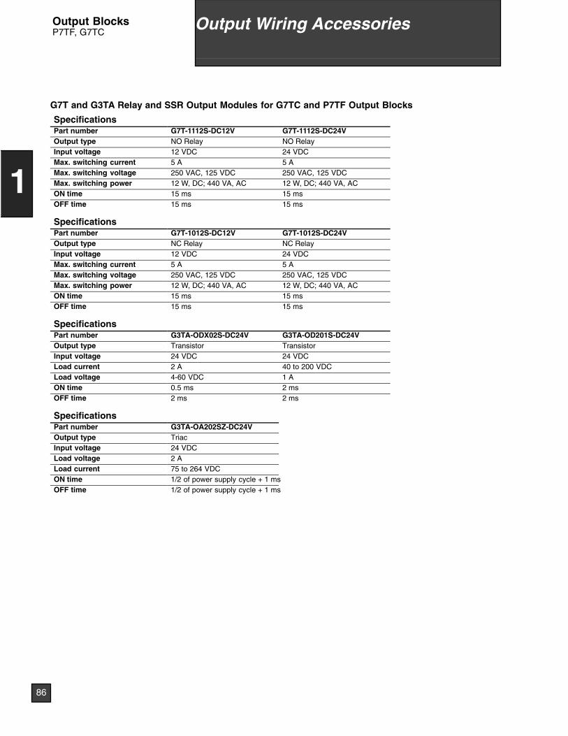
G7T and G3TA Relay and SSR Output Modules for G7TC and P7TF Output Blocks
SpecificationsPart number G7T-1112S-DC12V G7T-1112S-DC24VOutput type NO Relay NO RelayInput voltage 12 VDC 24 VDCMax. switching current 5 A 5 AMax. switching voltage 250 VAC, 125 VDC 250 VAC, 125 VDCMax. switching power 12 W, DC; 440 VA, AC 12 W, DC; 440 VA, ACON time 15 ms 15 msOFF time 15 ms 15 ms
SpecificationsPart number G7T-1012S-DC12V G7T-1012S-DC24VOutput type NC Relay NC RelayInput voltage 12 VDC 24 VDCMax. switching current 5 A 5 AMax. switching voltage 250 VAC, 125 VDC 250 VAC, 125 VDCMax. switching power 12 W, DC; 440 VA, AC 12 W, DC; 440 VA, ACON time 15 ms 15 msOFF time 15 ms 15 ms
SpecificationsPart number G3TA-ODX02S-DC24V G3TA-OD201S-DC24VOutput type Transistor TransistorInput voltage 24 VDC 24 VDCLoad current 2 A 40 to 200 VDCLoad voltage 4-60 VDC 1 AON time 0.5 ms 2 msOFF time 2 ms 2 ms
SpecificationsPart number G3TA-OA202SZ-DC24VOutput type TriacInput voltage 24 VDCLoad voltage 2 ALoad current 75 to 264 VDCON time 1/2 of power supply cycle + 1 msOFF time 1/2 of power supply cycle + 1 ms
86
1
Output Wiring AccessoriesOutput BlocksP7TF, G7TC
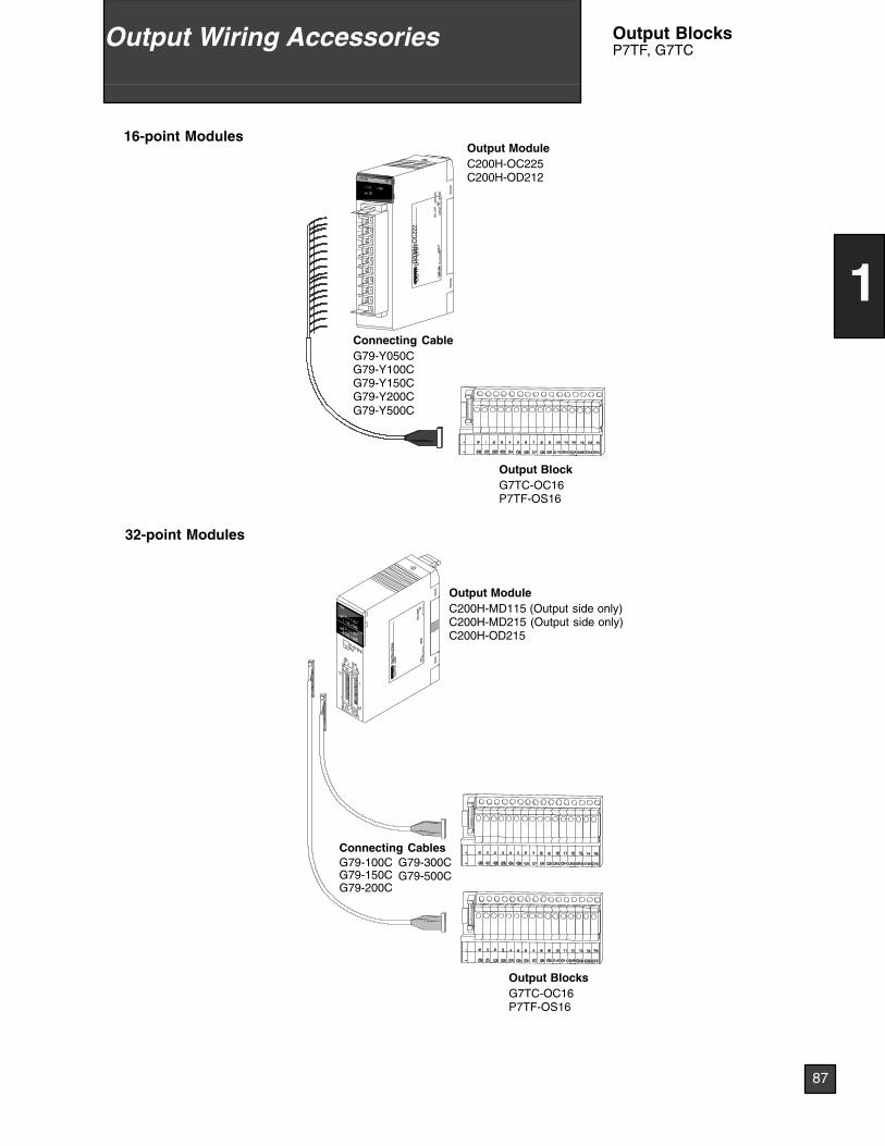
Connecting CableG79-Y050CG79-Y100CG79-Y150CG79-Y200CG79-Y500C
Output ModuleC200H-MD115 (Output side only)C200H-MD215 (Output side only)C200H-OD215
Output BlocksG7TC-OC16P7TF-OS16
Connecting CablesG79-100CG79-150CG79-200C
G79-300CG79-500C
Output BlockG7TC-OC16P7TF-OS16
Output ModuleC200H-OC225C200H-OD212
32-point Modules
16-point Modules
C20
0H--O
C22
2O
UT
PU
TU
NIT
02X
2FLO
TN
o.O
MR
ON
Cor
pora
tion
MA
DE
INJA
PA
N
NK
AP
P.
<88
A12
0>
87
1
Output Wiring Accessories Output BlocksP7TF, G7TC
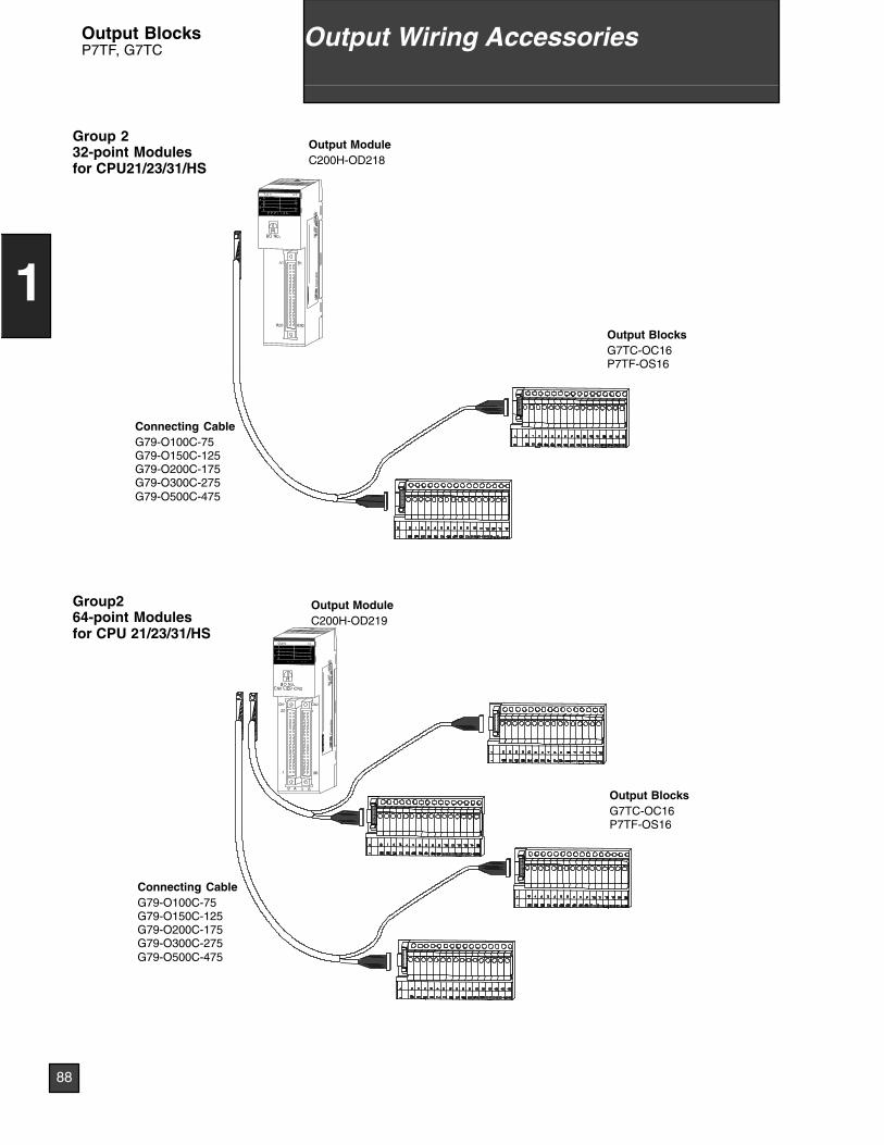
Output BlocksG7TC-OC16P7TF-OS16
Connecting CableG79-O100C-75G79-O150C-125G79-O200C-175G79-O300C-275G79-O500C-475
Output ModuleC200H-OD218
Group 232-point Modulesfor CPU21/23/31/HS
LOT
No.
OM
RO
NC
orpo
ratio
nM
AD
EIN
JAP
AN
NK
AP
P.
<88
A12
0>
Output BlocksG7TC-OC16P7TF-OS16
Connecting CableG79-O100C-75G79-O150C-125G79-O200C-175G79-O300C-275G79-O500C-475
Output ModuleC200H-OD219
LOT
No.
OM
RO
NC
orpo
ratio
nM
AD
EIN
JAP
AN
NK
AP
P.
<88
A12
0>
Group264-point Modulesfor CPU 21/23/31/HS
88
1
Output Wiring AccessoriesOutput BlocksP7TF, G7TC
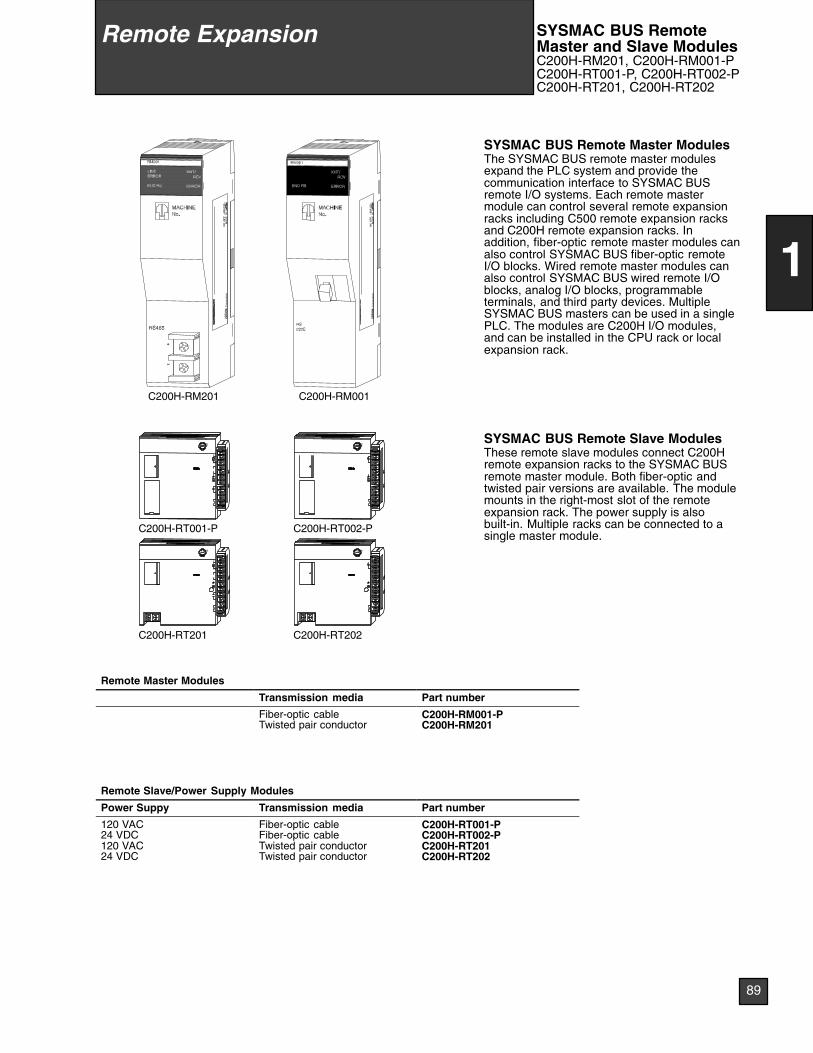
LOT
No.
OM
RO
NC
orpo
ratio
nM
AD
EIN
JAP
AN
NK
AP
P.
<88
A12
0>
C200H-RM001
LOT
No.
OM
RO
NC
orpo
ratio
nM
AD
EIN
JAP
AN
NK
AP
P.
<88
A12
0>
C200H-RM201
SYSMAC BUS Remote Master ModulesThe SYSMAC BUS remote master modulesexpand the PLC system and provide thecommunication interface to SYSMAC BUSremote I/O systems. Each remote mastermodule can control several remote expansionracks including C500 remote expansion racksand C200H remote expansion racks. Inaddition, fiber-optic remote master modules canalso control SYSMAC BUS fiber-optic remoteI/O blocks. Wired remote master modules canalso control SYSMAC BUS wired remote I/Oblocks, analog I/O blocks, programmableterminals, and third party devices. MultipleSYSMAC BUS masters can be used in a singlePLC. The modules are C200H I/O modules,and can be installed in the CPU rack or localexpansion rack.
FUSE
L2/N
L1
C200H-RT201
FUSE
C200H-RT002-P
FUSE
L2/N
L1
C200H-RT001-P
FUSE
C200H-RT202
SYSMAC BUS Remote Slave ModulesThese remote slave modules connect C200Hremote expansion racks to the SYSMAC BUSremote master module. Both fiber-optic andtwisted pair versions are available. The modulemounts in the right-most slot of the remoteexpansion rack. The power supply is alsobuilt-in. Multiple racks can be connected to asingle master module.
Remote Master Modules
Transmission media Part number
Fiber-optic cableTwisted pair conductor
C200H-RM001-PC200H-RM201
Remote Slave/Power Supply Modules
Power Suppy Transmission media Part number
120 VAC24 VDC120 VAC24 VDC
Fiber-optic cableFiber-optic cableTwisted pair conductorTwisted pair conductor
C200H-RT001-PC200H-RT002-PC200H-RT201C200H-RT202
Remote Expansion SYSMAC BUS RemoteMaster and Slave ModulesC200H-RM201, C200H-RM001-PC200H-RT001-P, C200H-RT002-PC200H-RT201, C200H-RT202
89
1
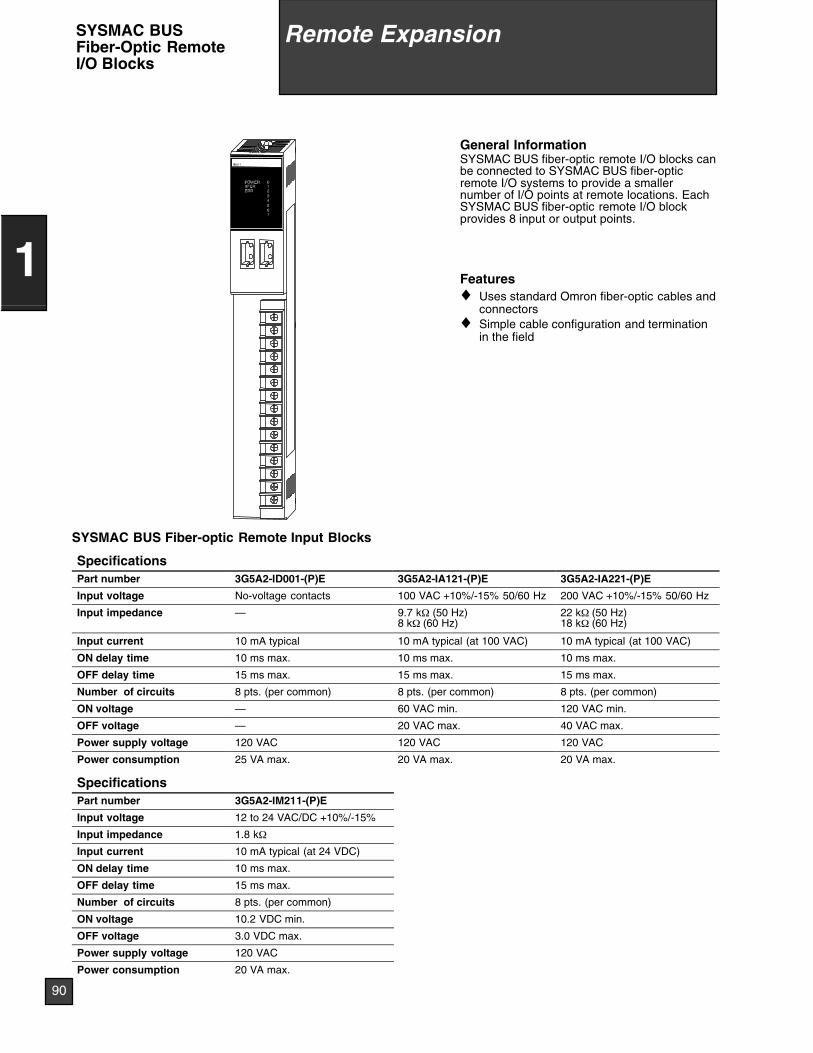
General InformationSYSMAC BUS fiber-optic remote I/O blocks canbe connected to SYSMAC BUS fiber-opticremote I/O systems to provide a smallernumber of I/O points at remote locations. EachSYSMAC BUS fiber-optic remote I/O blockprovides 8 input or output points.
Features♦ Uses standard Omron fiber-optic cables and
connectors♦ Simple cable configuration and termination
in the field
SYSMAC BUS Fiber-optic Remote Input Blocks
SpecificationsPart number 3G5A2-ID001-(P)E 3G5A2-IA121-(P)E 3G5A2-IA221-(P)E
Input voltage No-voltage contacts 100 VAC +10%/-15% 50/60 Hz 200 VAC +10%/-15% 50/60 Hz
Input impedance — 9.7 kΩ (50 Hz)8 kΩ (60 Hz)
22 kΩ (50 Hz)18 kΩ (60 Hz)
Input current 10 mA typical 10 mA typical (at 100 VAC) 10 mA typical (at 100 VAC)
ON delay time 10 ms max. 10 ms max. 10 ms max.
OFF delay time 15 ms max. 15 ms max. 15 ms max.
Number of circuits 8 pts. (per common) 8 pts. (per common) 8 pts. (per common)
ON voltage — 60 VAC min. 120 VAC min.
OFF voltage — 20 VAC max. 40 VAC max.
Power supply voltage 120 VAC 120 VAC 120 VAC
Power consumption 25 VA max. 20 VA max. 20 VA max.
SpecificationsPart number 3G5A2-IM211-(P)E
Input voltage 12 to 24 VAC/DC +10%/-15%
Input impedance 1.8 kΩ
Input current 10 mA typical (at 24 VDC)
ON delay time 10 ms max.
OFF delay time 15 ms max.
Number of circuits 8 pts. (per common)
ON voltage 10.2 VDC min.
OFF voltage 3.0 VDC max.
Power supply voltage 120 VAC
Power consumption 20 VA max.
Remote Expansion
90
1
SYSMAC BUSFiber-Optic RemoteI/O Blocks
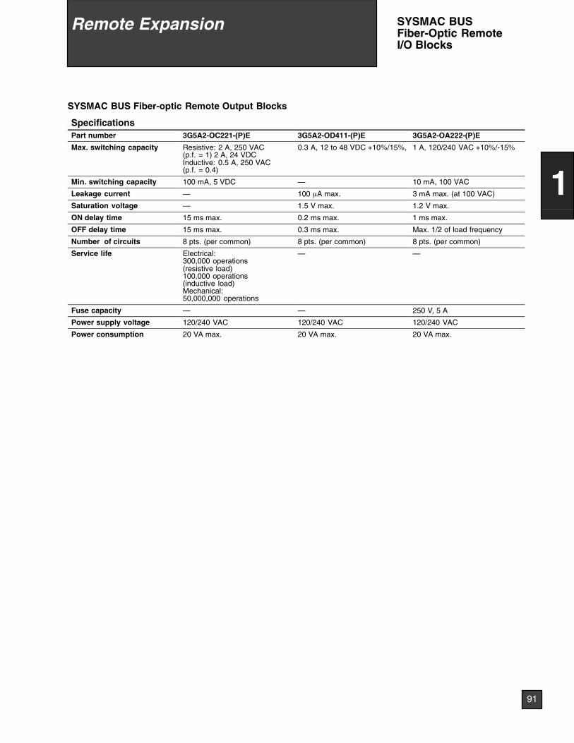
SYSMAC BUS Fiber-optic Remote Output Blocks
SpecificationsPart number 3G5A2-OC221-(P)E 3G5A2-OD411-(P)E 3G5A2-OA222-(P)E
Max. switching capacity Resistive: 2 A, 250 VAC(p.f. = 1) 2 A, 24 VDCInductive: 0.5 A, 250 VAC(p.f. = 0.4)
0.3 A, 12 to 48 VDC +10%/15%, 1 A, 120/240 VAC +10%/-15%
Min. switching capacity 100 mA, 5 VDC — 10 mA, 100 VAC
Leakage current — 100 µA max. 3 mA max. (at 100 VAC)
Saturation voltage — 1.5 V max. 1.2 V max.
ON delay time 15 ms max. 0.2 ms max. 1 ms max.
OFF delay time 15 ms max. 0.3 ms max. Max. 1/2 of load frequency
Number of circuits 8 pts. (per common) 8 pts. (per common) 8 pts. (per common)
Service life Electrical:300,000 operations(resistive load)100,000 operations(inductive load)Mechanical:50,000,000 operations
— —
Fuse capacity — — 250 V, 5 A
Power supply voltage 120/240 VAC 120/240 VAC 120/240 VAC
Power consumption 20 VA max. 20 VA max. 20 VA max.
Remote Expansion
91
1
SYSMAC BUSFiber-Optic RemoteI/O Blocks
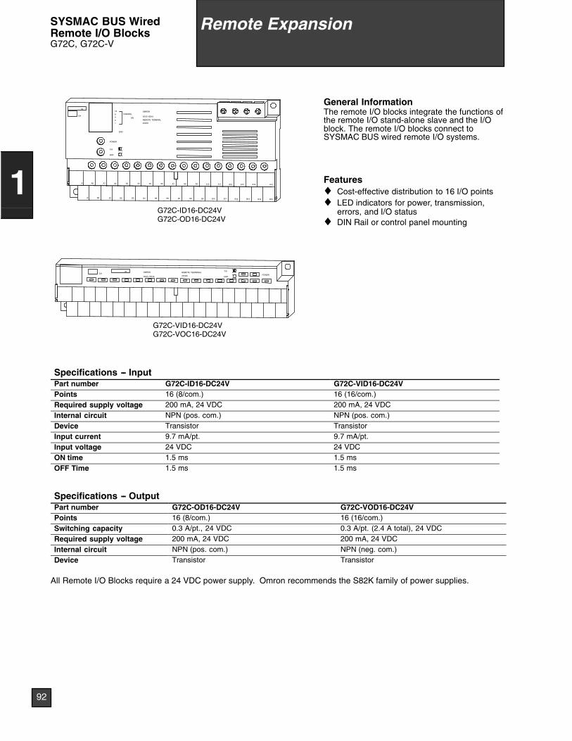
INCH
G72C--VID16
OMRON
24VDC
REMOTE TEERMINAL
ERR
T/R
POWER
G72C-VID16-DC24VG72C-VOC16-DC24V
A A1A0
B B0
A3A2
B1 B2 B4
A5A4
B3
A6
B6B5
A7
B8B7
A10A9A8
B10B9
A12A11
B12B11
A13 A15A14
B13 B14 B15
16
8
4
2
1
CHANNEL
ON
END
24VDC
REMOTE TERMINAL
G72C--OD16
OMRON
POWER
IN
CH
ERR
T/R
G72C-ID16-DC24VG72C-OD16-DC24V
General InformationThe remote I/O blocks integrate the functions ofthe remote I/O stand-alone slave and the I/Oblock. The remote I/O blocks connect toSYSMAC BUS wired remote I/O systems.
Features♦ Cost-effective distribution to 16 I/O points♦ LED indicators for power, transmission,
errors, and I/O status♦ DIN Rail or control panel mounting
Specifications -- InputPart number G72C-ID16-DC24V G72C-VID16-DC24VPoints 16 (8/com.) 16 (16/com.)Required supply voltage 200 mA, 24 VDC 200 mA, 24 VDCInternal circuit NPN (pos. com.) NPN (pos. com.)Device Transistor TransistorInput current 9.7 mA/pt. 9.7 mA/pt.Input voltage 24 VDC 24 VDCON time 1.5 ms 1.5 msOFF Time 1.5 ms 1.5 ms
Specifications -- OutputPart number G72C-OD16-DC24V G72C-VOD16-DC24VPoints 16 (8/com.) 16 (16/com.)Switching capacity 0.3 A/pt., 24 VDC 0.3 A/pt. (2.4 A total), 24 VDCRequired supply voltage 200 mA, 24 VDC 200 mA, 24 VDCInternal circuit NPN (pos. com.) NPN (neg. com.)Device Transistor Transistor
All Remote I/O Blocks require a 24 VDC power supply. Omron recommends the S82K family of power supplies.
Remote Expansion
92
1
SYSMAC BUS WiredRemote I/O BlocksG72C, G72C-V
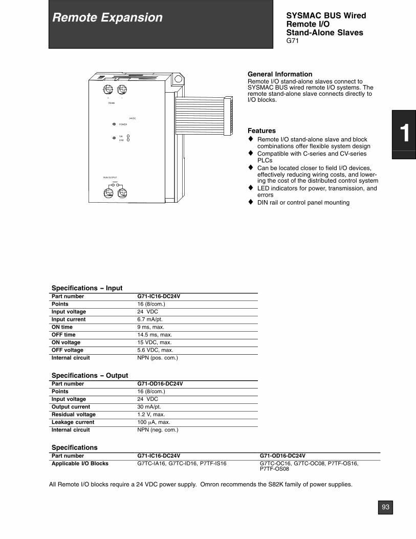
RUN OUTPUT
ERR
T/R
+ --
RS485
POWER
24VDC
General InformationRemote I/O stand-alone slaves connect toSYSMAC BUS wired remote I/O systems. Theremote stand-alone slave connects directly toI/O blocks.
Features♦ Remote I/O stand-alone slave and block
combinations offer flexible system design♦ Compatible with C-series and CV-series
PLCs♦ Can be located closer to field I/O devices,
effectively reducing wiring costs, and lower-ing the cost of the distributed control system
♦ LED indicators for power, transmission, anderrors
♦ DIN rail or control panel mounting
Specifications -- InputPart number G71-IC16-DC24VPoints 16 (8/com.)Input voltage 24 VDCInput current 6.7 mA/pt.ON time 9 ms, max.OFF time 14.5 ms, max.ON voltage 15 VDC, max.OFF voltage 5.6 VDC, max.Internal circuit NPN (pos. com.)
Specifications -- OutputPart number G71-OD16-DC24VPoints 16 (8/com.)Input voltage 24 VDCOutput current 30 mA/pt.Residual voltage 1.2 V, max.Leakage current 100 µA, max.Internal circuit NPN (neg. com.)
SpecificationsPart number G71-IC16-DC24V G71-OD16-DC24VApplicable I/O Blocks G7TC-IA16, G7TC-ID16, P7TF-IS16 G7TC-OC16, G7TC-OC08, P7TF-OS16,
P7TF-OS08
All Remote I/O blocks require a 24 VDC power supply. Omron recommends the S82K family of power supplies.
Remote Expansion
93
1
SYSMAC BUS WiredRemote I/OStand-Alone SlavesG71
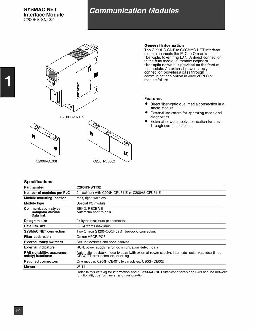
C200HS-SNT32
C200H-CE002C200H-CE001
General InformationThe C200HS-SNT32 SYSMAC NET interfacemodule connects the PLC to Omron’sfiber-optic token ring LAN. A direct connectionto the dual media, automatic loopbackfiber-optic network is provided on the front ofthe module. An external power supplyconnection provides a pass throughcommunications option in case of PLC ormodule failure.
Features♦ Direct fiber-optic dual media connection in a
single module♦ External indicators for operating mode and
diagnostics♦ External power supply connection for pass
through communications
SpecificationsPart number C200HS-SNT32
Number of modules per PLC 2 maximum with C200H-CPU31-E or C200HS-CPU31-E
Module mounting location rack, right two slots
Module type Special I/O module
Communication stylesDatagram serviceData link
SEND, RECEIVEAutomatic peer-to-peer
Datagram size 2k bytes maximum per command
Data link size 3,854 words maximum
SYSMAC NET connection Two Omron S3200-COCH62M fiber-optic connectors
Fiber-optic cable Omron HPCF, PCF
External rotary switches Set unit address and node address
External indicators RUN, power supply, error, communication detect, data
RAS (reliability, assurance,safety) functions:
Automatic loopback, node bypass (with external power supply), internode tests, watchdog timer,CRCCITT error detection, error log
Required connectors One module: C200H-CE001; two modules: C200H-CE002
Manual W114
Refer to this catalog for information about SYSMAC NET fiber-optic token ring LAN and the networkfunctionality , performance, and configuration.
Communication ModulesSYSMAC NETInterface ModuleC200HS-SNT32
94
1
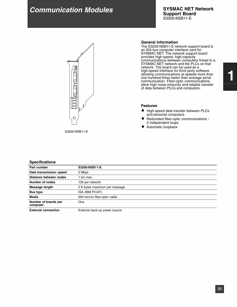
S3200-NSB11-E
General InformationThe S3200-NSB11-E network support board isan ISA bus computer interface card forSYSMAC NET. The network support boardprovides high-speed, high-capacitycommunications between computers linked to aSYSMAC NET network and the PLCs on thatnetwork. The board can be used as ahigh-speed interface for third party softwareallowing communications at speeds more thanone hundred times faster than average serialcommunication. Fiber-optic communicationsallow high noise immunity and reliable transferof data between PLCs and computers.
Features♦ High-speed data transfer between PLCs
and personal computers♦ Redundant fiber-optic communications -
2 independent loops♦ Automatic loopback
SpecificationsPart number S3200-NSB11-E
Data transmission speed 2 Mbps
Distance between nodes 1 km max.
Number of nodes 126 per network
Message length 2 K bytes maximum per message
Bus type ISA (IBM PC/AT)
Media 200 micron fiber-optic cable
Number of boards percomputer
One
External connection External back-up power source
Communication Modules
95
1
SYSMAC NET NetworkSupport BoardS3200-NSB11-E
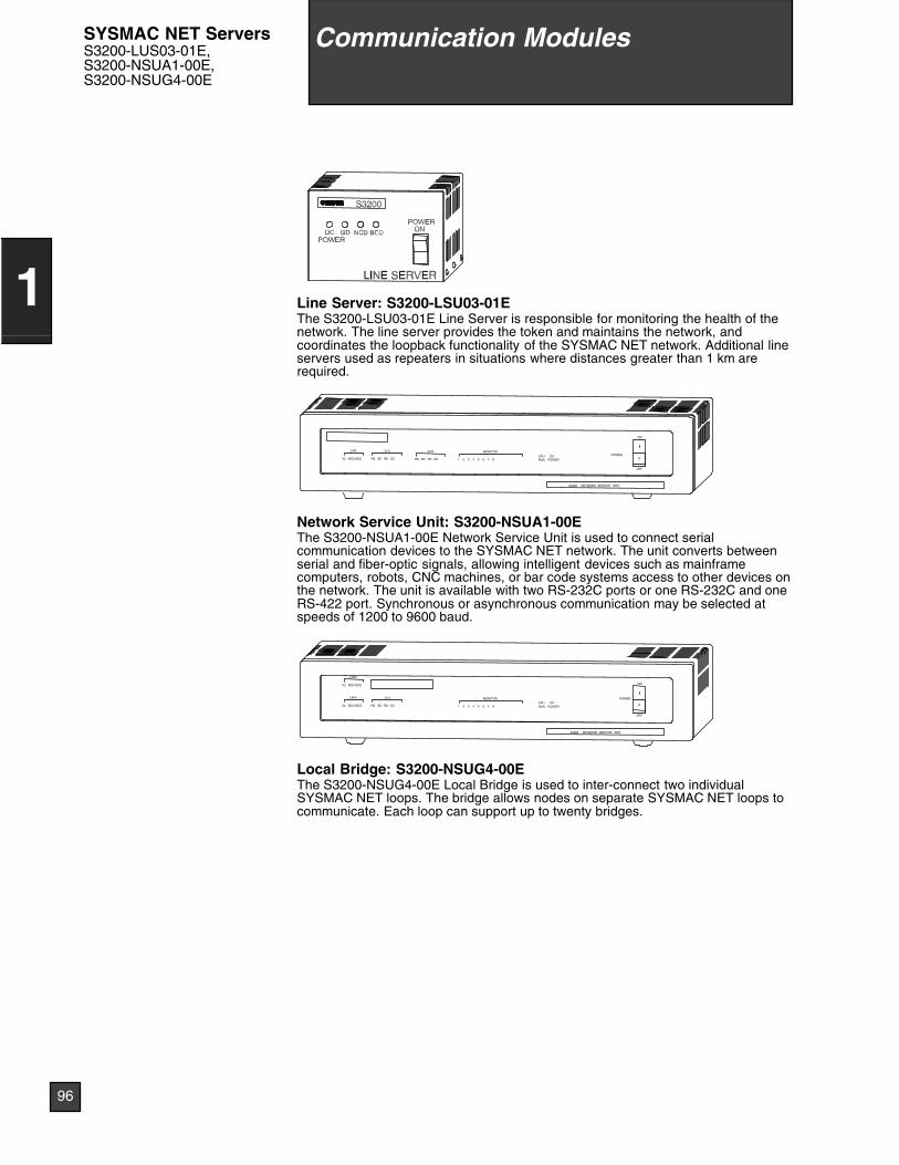
Line Server: S3200-LSU03-01EThe S3200-LSU03-01E Line Server is responsible for monitoring the health of thenetwork. The line server provides the token and maintains the network, andcoordinates the loopback functionality of the SYSMAC NET network. Additional lineservers used as repeaters in situations where distances greater than 1 km arerequired.
MONITORCH2CH1LAN
OPOWER
OFF
ON
RUN POWERCPU DC
1 2 3 4 5 6 7 8RS SD RD CDRS SD RD CDV2 NCD BCD
S3200 NETWORK SERVICE UNIT
Network Service Unit: S3200-NSUA1-00EThe S3200-NSUA1-00E Network Service Unit is used to connect serialcommunication devices to the SYSMAC NET network. The unit converts betweenserial and fiber-optic signals, allowing intelligent devices such as mainframecomputers, robots, CNC machines, or bar code systems access to other devices onthe network. The unit is available with two RS-232C ports or one RS-232C and oneRS-422 port. Synchronous or asynchronous communication may be selected atspeeds of 1200 to 9600 baud.
LAN2
V2 NCD BCD
MONITORCH1LAN1
O
POWER
OFF
ON
RUN POWERCPU DC
1 2 3 4 5 6 7 8RS SD RD CDV2 NCD BCD
S3200 NETWORK SERVICE UNIT
Local Bridge: S3200-NSUG4-00EThe S3200-NSUG4-00E Local Bridge is used to inter-connect two individualSYSMAC NET loops. The bridge allows nodes on separate SYSMAC NET loops tocommunicate. Each loop can support up to twenty bridges.
Communication Modules
96
1
SYSMAC NET ServersS3200-LUS03-01E,S3200-NSUA1-00E,S3200-NSUG4-00E
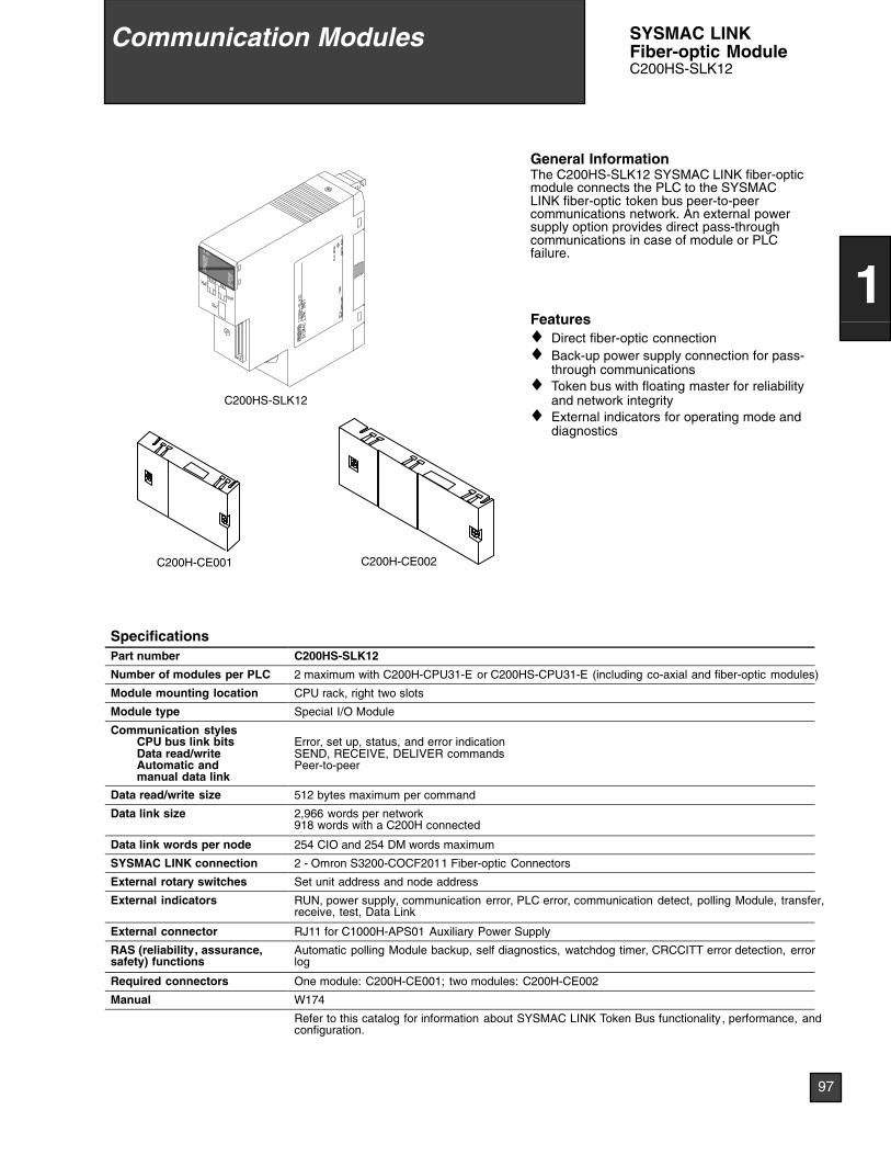
C200HS-SLK12
C200H-CE002C200H-CE001
General InformationThe C200HS-SLK12 SYSMAC LINK fiber-opticmodule connects the PLC to the SYSMACLINK fiber-optic token bus peer-to-peercommunications network. An external powersupply option provides direct pass-throughcommunications in case of module or PLCfailure.
Features♦ Direct fiber-optic connection♦ Back-up power supply connection for pass-
through communications♦ Token bus with floating master for reliability
and network integrity♦ External indicators for operating mode and
diagnostics
SpecificationsPart number C200HS-SLK12
Number of modules per PLC 2 maximum with C200H-CPU31-E or C200HS-CPU31-E (including co-axial and fiber-optic modules)
Module mounting location CPU rack, right two slots
Module type Special I/O Module
Communication stylesCPU bus link bitsData read/writeAutomatic andmanual data link
Error, set up, status, and error indicationSEND, RECEIVE, DELIVER commandsPeer-to-peer
Data read/write size 512 bytes maximum per command
Data link size 2,966 words per network918 words with a C200H connected
Data link words per node 254 CIO and 254 DM words maximum
SYSMAC LINK connection 2 - Omron S3200-COCF2011 Fiber-optic Connectors
External rotary switches Set unit address and node address
External indicators RUN, power supply, communication error, PLC error, communication detect, polling Module, transfer,receive, test, Data Link
External connector RJ11 for C1000H-APS01 Auxiliary Power Supply
RAS (reliability, assurance,safety) functions
Automatic polling Module backup, self diagnostics, watchdog timer, CRCCITT error detection, errorlog
Required connectors One module: C200H-CE001; two modules: C200H-CE002
Manual W174
Refer to this catalog for information about SYSMAC LINK Token Bus functionality , performance, andconfiguration.
Communication Modules
97
1
SYSMAC LINKFiber-optic ModuleC200HS-SLK12
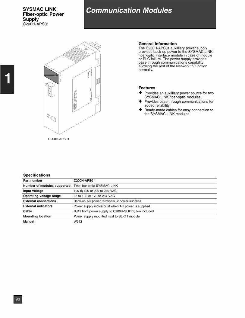
C200H-APS01
General InformationThe C200H-APS01 auxilliary power supplyprovides back-up power to the SYSMAC LINKfiber-optic interface module in case of moduleor PLC failure. The power supply providespass-through communications capabilityallowing the rest of the Network to functionnormally.
Features♦ Provides an auxilliary power source for two
SYSMAC LINK fiber-optic modules♦ Provides pass-through communications for
added reliability♦ Ready-made cables for easy connection to
the SYSMAC LINK modules
SpecificationsPart number C200H-APS01
Number of modules supported Two fiber-optic SYSMAC LINK
Input voltage 100 to 120 or 200 to 240 VAC
Operating voltage range 85 to 132 or 170 to 264 VAC
External connections Back-up AC power terminals, 2 power supplies
External indicators Power supply indicator lit when AC power is supplied
Cable RJ11 from power supply to C200H-SLK11; two included
Mounting location Power supply mounted next to SLK11 module
Manual W212
Communication Modules
98
1
SYSMAC LINKFiber-optic PowerSupplyC200H-APS01
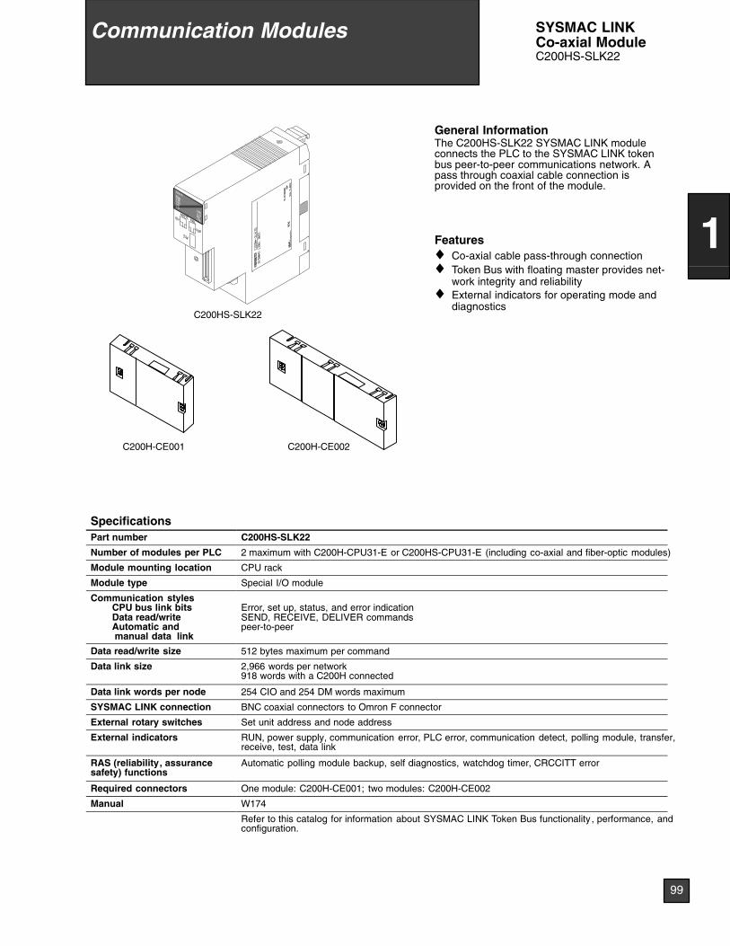
C200HS-SLK22
C200H-CE002C200H-CE001
General InformationThe C200HS-SLK22 SYSMAC LINK moduleconnects the PLC to the SYSMAC LINK tokenbus peer-to-peer communications network. Apass through coaxial cable connection isprovided on the front of the module.
Features♦ Co-axial cable pass-through connection♦ Token Bus with floating master provides net-
work integrity and reliability♦ External indicators for operating mode and
diagnostics
SpecificationsPart number C200HS-SLK22
Number of modules per PLC 2 maximum with C200H-CPU31-E or C200HS-CPU31-E (including co-axial and fiber-optic modules)
Module mounting location CPU rack
Module type Special I/O module
Communication stylesCPU bus link bitsData read/writeAutomatic andmanual data link
Error, set up, status, and error indicationSEND, RECEIVE, DELIVER commandspeer-to-peer
Data read/write size 512 bytes maximum per command
Data link size 2,966 words per network918 words with a C200H connected
Data link words per node 254 CIO and 254 DM words maximum
SYSMAC LINK connection BNC coaxial connectors to Omron F connector
External rotary switches Set unit address and node address
External indicators RUN, power supply, communication error, PLC error, communication detect, polling module, transfer,receive, test, data link
RAS (reliability, assurancesafety) functions
Automatic polling module backup, self diagnostics, watchdog timer, CRCCITT error
Required connectors One module: C200H-CE001; two modules: C200H-CE002
Manual W174
Refer to this catalog for information about SYSMAC LINK Token Bus functionality , performance, andconfiguration.
Communication Modules
99
1
SYSMAC LINKCo-axial ModuleC200HS-SLK22
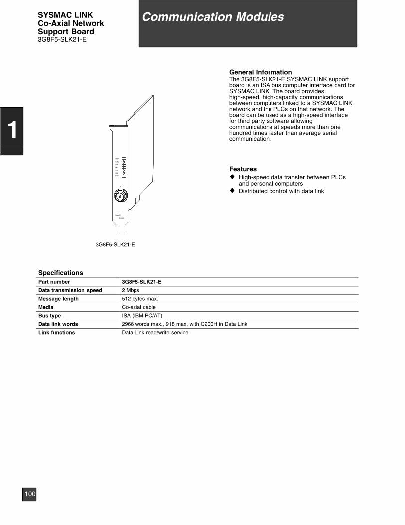
CK000
3G8C2
SL
LNK
RD
SD
M/S
INS
ERC
RUN
3G8F5-SLK21-E
General InformationThe 3G8F5-SLK21-E SYSMAC LINK supportboard is an ISA bus computer interface card forSYSMAC LINK. The board provideshigh-speed, high-capacity communicationsbetween computers linked to a SYSMAC LINKnetwork and the PLCs on that network. Theboard can be used as a high-speed interfacefor third party software allowingcommunications at speeds more than onehundred times faster than average serialcommunication.
Features♦ High-speed data transfer between PLCs
and personal computers♦ Distributed control with data link
SpecificationsPart number 3G8F5-SLK21-E
Data transmission speed 2 Mbps
Message length 512 bytes max.
Media Co-axial cable
Bus type ISA (IBM PC/AT)
Data link words 2966 words max., 918 max. with C200H in Data Link
Link functions Data Link read/write service
Communication Modules
100
1
SYSMAC LINKCo-Axial NetworkSupport Board3G8F5-SLK21-E
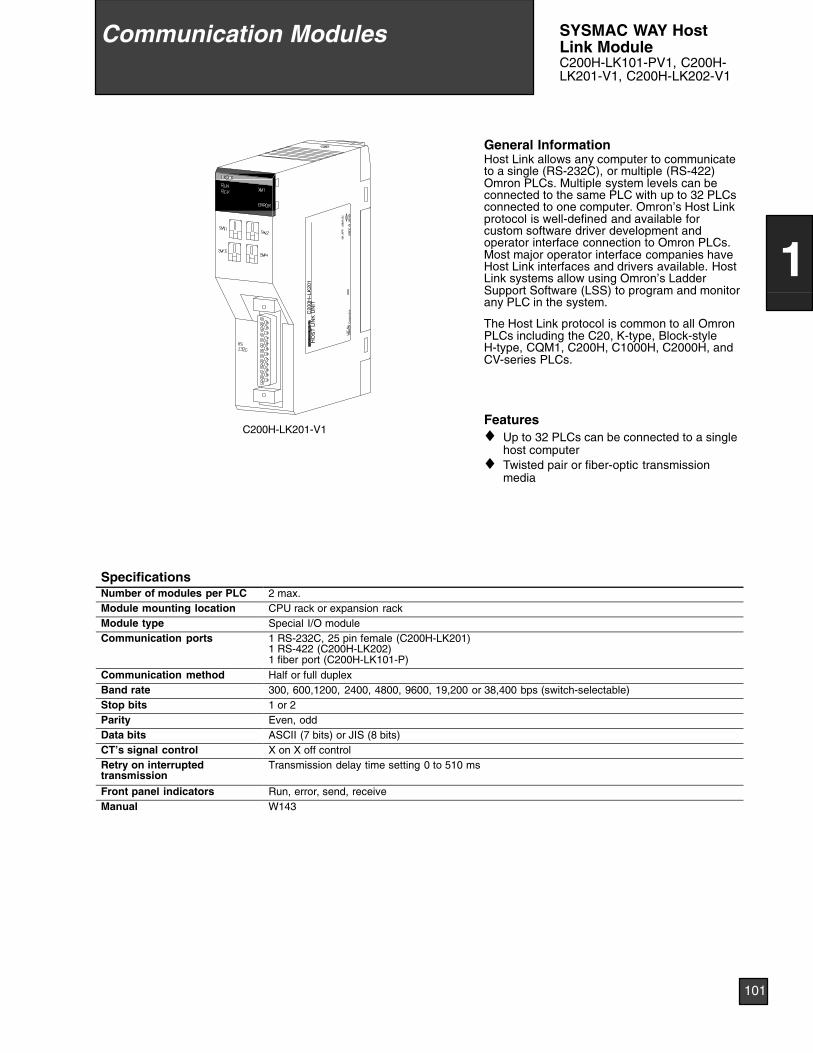
C200H-LK201-V1
C20
0H--L
K20
1H
OS
TLI
NK
UN
IT
0660
LOT
No.
OM
RO
NC
orpo
ratio
nM
AD
EIN
JAP
AN
NK
AP
P.
<88
A12
0>
General InformationHost Link allows any computer to communicateto a single (RS-232C), or multiple (RS-422)Omron PLCs. Multiple system levels can beconnected to the same PLC with up to 32 PLCsconnected to one computer. Omron’s Host Linkprotocol is well-defined and available forcustom software driver development andoperator interface connection to Omron PLCs.Most major operator interface companies haveHost Link interfaces and drivers available. HostLink systems allow using Omron’s LadderSupport Software (LSS) to program and monitorany PLC in the system.
The Host Link protocol is common to all OmronPLCs including the C20, K-type, Block-styleH-type, CQM1, C200H, C1000H, C2000H, andCV-series PLCs.
Features♦ Up to 32 PLCs can be connected to a single
host computer♦ Twisted pair or fiber-optic transmission
media
SpecificationsNumber of modules per PLC 2 max.Module mounting location CPU rack or expansion rackModule type Special I/O moduleCommunication ports 1 RS-232C, 25 pin female (C200H-LK201)
1 RS-422 (C200H-LK202)1 fiber port (C200H-LK101-P)
Communication method Half or full duplexBand rate 300, 600,1200, 2400, 4800, 9600, 19,200 or 38,400 bps (switch-selectable)Stop bits 1 or 2Parity Even, oddData bits ASCII (7 bits) or JIS (8 bits)CT’s signal control X on X off controlRetry on interruptedtransmission
Transmission delay time setting 0 to 510 ms
Front panel indicators Run, error, send, receiveManual W143
Communication Modules
101
1
SYSMAC WAY HostLink ModuleC200H-LK101-PV1, C200H-LK201-V1, C200H-LK202-V1

LOT
No.
OM
RO
NC
orpo
ratio
nM
AD
EIN
JAP
AN
NK
AP
P.
<88
A12
0>
RUNLINKO
THISOTHERERROR
LK401
C200H-LK401
General InformationPC Link is a peer-to-peer communicationsystem allowing high-speed transfer of databetween PLCs over long distances. Both smalland large rack PLCs can be connected to thesame system. Standard link adapters areavailable for fiber-optic media and longertransmission distances. No specialprogramming is required to transfer data andmulti-level systems can be connected to asingle PLC.
Features♦ High-speed data transfer between up to 32
PLCs♦ No special programming required♦ Muti-level capability
SpecificationsPart number C200H-LK401Communication method Peer-to-peerNetwork topology Multi-drop using Omron link adaptersNumber of nodes PLC of polling link Single-level Multilevel
C200H, C1000H, C2000H 32 16C500 8 8
Transimission media Twisted pair; fiber-optic when using Omron link adaptersDistance 500 m (1640 ft) total cable length (without fiber-optic links), including branch lines
Distances can be extended using link adapters
Transmission speed 128 kbpsProtocol Omron PC Link, RS-485PLC interfaces C200H, C500, C1000H, C2000H
Data transfer capacity(bit / d )
PLC of polling link 2 links 3--4 links 5--8 links 9--16 links 17--32 linksp y(bits/node) C200H, C1000H, C2000H 512 256 128 64 32
C500 256 128 64 — —Diagnostic functions CPU watchdog timer, CRC transmission error checkManual W135
Communication Modules
102
1
PC Link ModuleC200H-LK401
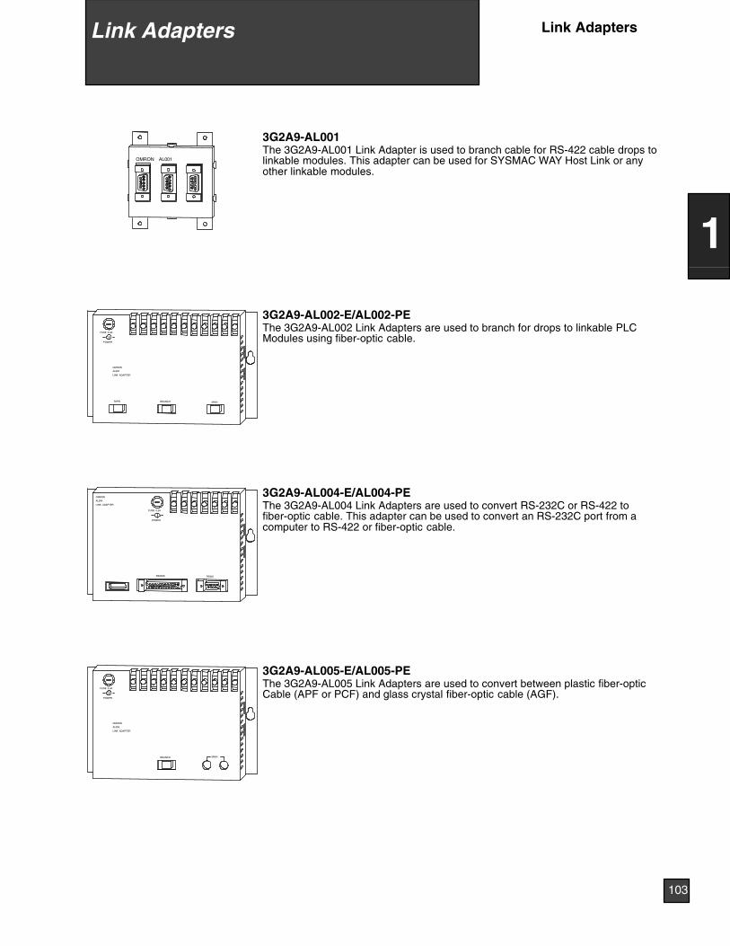
AL001OMRON
3G2A9-AL001The 3G2A9-AL001 Link Adapter is used to branch cable for RS-422 cable drops tolinkable modules. This adapter can be used for SYSMAC WAY Host Link or anyother linkable modules.
MAINMAIN BRANCH
LINK ADAPTER
AL002
OMRON
POWER
FUSE 0.3A
3G2A9-AL002-E/AL002-PEThe 3G2A9-AL002 Link Adapters are used to branch for drops to linkable PLCModules using fiber-optic cable.
RS422RS232D
LINK ADAPTER
AL004
OMRON
POWER
FUSE 0.3A
3G2A9-AL004-E/AL004-PEThe 3G2A9-AL004 Link Adapters are used to convert RS-232C or RS-422 tofiber-optic cable. This adapter can be used to convert an RS-232C port from acomputer to RS-422 or fiber-optic cable.
MAINBRANCH
LINK ADAPTER
AL005
OMRON
POWER
FUSE 0.3A
3G2A9-AL005-E/AL005-PEThe 3G2A9-AL005 Link Adapters are used to convert between plastic fiber-opticCable (APF or PCF) and glass crystal fiber-optic cable (AGF).
Link Adapters Link Adapters
103
1
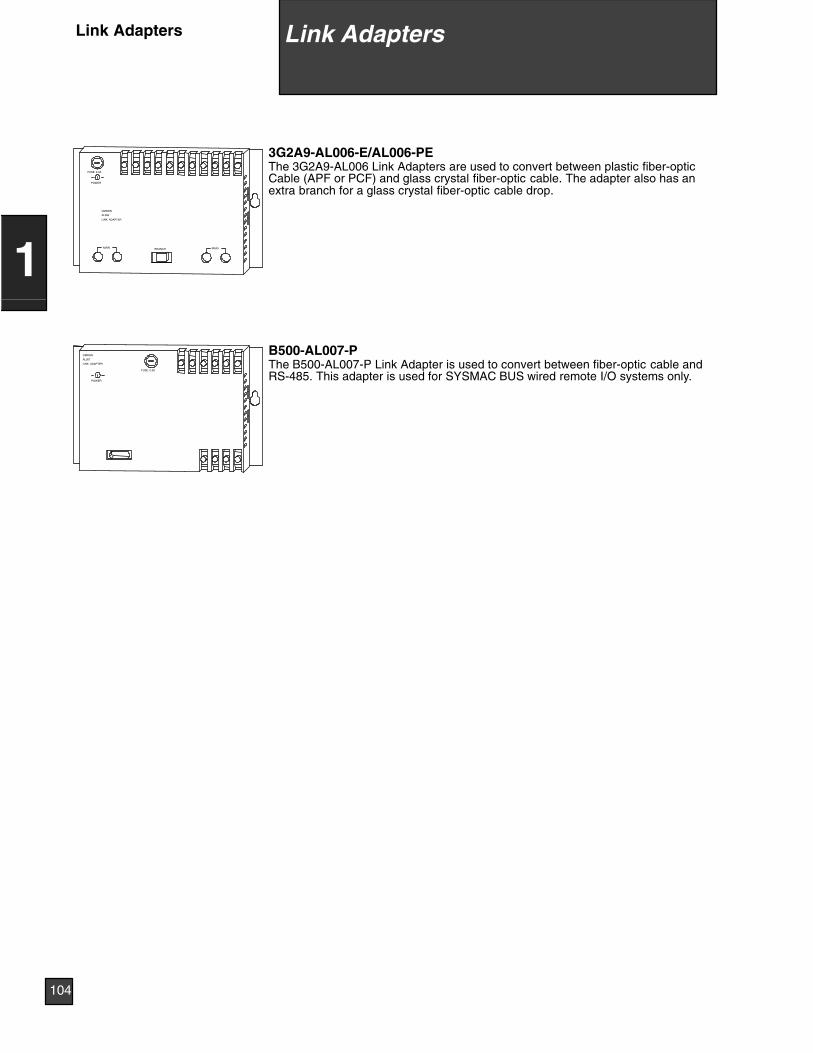
MAIN MAINBRANCH
LINK ADAPTER
AL006
OMRON
POWER
FUSE 0.3A
3G2A9-AL006-E/AL006-PEThe 3G2A9-AL006 Link Adapters are used to convert between plastic fiber-opticCable (APF or PCF) and glass crystal fiber-optic cable. The adapter also has anextra branch for a glass crystal fiber-optic cable drop.
LINK ADAPTER
AL007
OMRON
POWER
FUSE 0.3A
B500-AL007-PThe B500-AL007-P Link Adapter is used to convert between fiber-optic cable andRS-485. This adapter is used for SYSMAC BUS wired remote I/O systems only.
Link AdaptersLink Adapters
104
1
Overview 106. . . . . . . . . . . . . . . . . . . . . . . . . . . . . . . . . . . . . . . . . . . . . . .CPU Rack 107. . . . . . . . . . . . . . . . . . . . . . . . . . . . . . . . . . . . . . . . . . . . . .CPU Rack, Local Expansion Racks 108. . . . . . . . . . . . . . . . . . . . . . . .Configuring Remote I/O Systems 109. . . . . . . . . . . . . . . . . . . . . . . . . .Configuring SYSMAC BUS Fiber-optic Remote I/O Systems 110. .Configuring SYSMAC BUS Wired Remote I/O Systems 112. . . . . .Configuration Summary Tables 114. . . . . . . . . . . . . . . . . . . . . . . . . . . .Current Consumption 116. . . . . . . . . . . . . . . . . . . . . . . . . . . . . . . . . . . .System Configuration Worksheets 124. . . . . . . . . . . . . . . . . . . . . . . . .Dimensions 129. . . . . . . . . . . . . . . . . . . . . . . . . . . . . . . . . . . . . . . . . . . . .
9 System Configuration
105
2
General InformationThe System Configuration section describes the various PLC systemconfigurations possible and assists in selecting the necessary components tocomplete a required parts list. Specific details about configuring PLC systems aredescribed throughout the section. System Configuration Worksheets have alsobeen provided to simplify the configuration and parts selection. Some basiccontrol system application information is required in order to select the propercomponents.♦ Number of I/O♦ Type of I/O: discrete, analog, special I/O, interrupt and communications♦ Distribution of I/O: Local or remote I/O requirements, location of I/O and num-
ber of I/O required at each location♦ Communication system requirements♦ Man-machine interface requirementsThere are several system configurations that are possible with the C200Hsystem. The following paragraphs briefly describe the types of possible C200Hsystem configurations.Additional configuration and technical information can be found in the detailedproduct manuals. Refer to Section 6 of this catalog for a list of publications.
Local I/O SystemsLocal I/O System configurations are designed to accommodate large amounts ofI/O that are located within 12 meters (39 ft.) of the CPU Rack. The CPU rack canbe expanded with two additional racks to accommodate large amounts of I/O.Several different configurations are possible depending on the distance and I/Orequirements of the system.♦ CPU Rack only♦ CPU Rack and Local Expansion Racks
Remote I/O SystemsRemote I/O systems are used in applications requiring I/O to be located at longdistances from the CPU. In a C200H system, remote I/O are counted separatelyfrom local I/O, allowing expansion up to 512 remote I/O points. Multiple remoteI/O systems can be added to a single PLC for additional configuration flexibility.These systems are available in fiber-optic and wired (twisted pair) versions. Thissection includes configuration information for the following:♦ SYSMAC BUS Fiber-optic Remote I/O System♦ SYSMAC BUS Wired Remote I/O System
9 System Configuration
106
2
Overview System Configuration
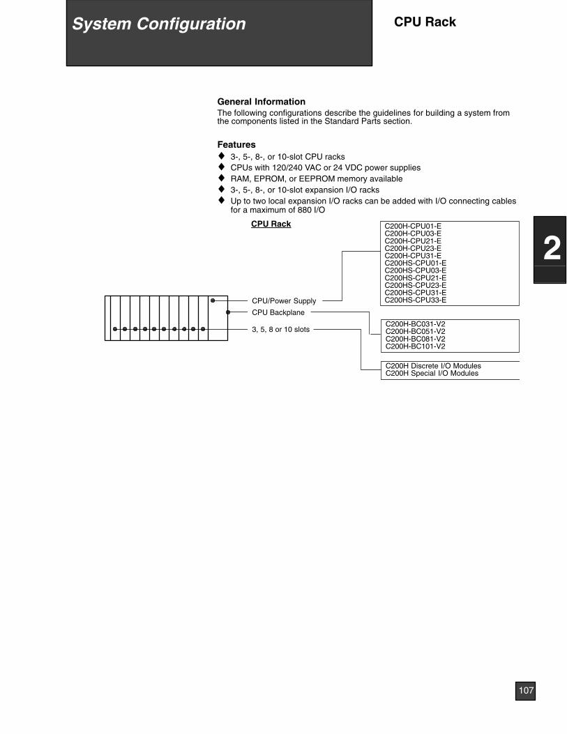
General InformationThe following configurations describe the guidelines for building a system fromthe components listed in the Standard Parts section.
Features♦ 3-, 5-, 8-, or 10-slot CPU racks♦ CPUs with 120/240 VAC or 24 VDC power supplies♦ RAM, EPROM, or EEPROM memory available♦ 3-, 5-, 8-, or 10-slot expansion I/O racks♦ Up to two local expansion I/O racks can be added with I/O connecting cables
for a maximum of 880 I/O
C200H-CPU01-EC200H-CPU03-EC200H-CPU21-EC200H-CPU23-EC200H-CPU31-EC200HS-CPU01-EC200HS-CPU03-EC200HS-CPU21-EC200HS-CPU23-EC200HS-CPU31-EC200HS-CPU33-E
CPU Rack
CPU/Power Supply
CPU Backplane
3, 5, 8 or 10 slotsC200H-BC031-V2C200H-BC051-V2C200H-BC081-V2C200H-BC101-V2
C200H Discrete I/O ModulesC200H Special I/O Modules
9 System Configuration
107
2
System Configuration CPU Rack
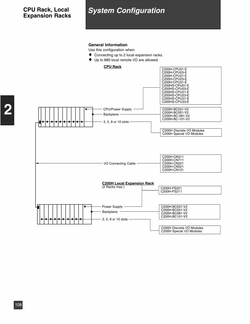
General InformationUse this configuration when:♦ Connecting up to 2 local expansion racks.♦ Up to 880 local remote I/O are allowed.
CPU Rack
I/O Connecting Cable
C200H Local Expansion Rack(2 Racks max.)
C200H-CN311C200H-CN711C200H-CN221C200H-CN521C200H-CN131
C200H-CPU01-EC200H-CPU03-EC200H-CPU21-EC200H-CPU23-EC200H-CPU31-EC200HS-CPU01-EC200HS-CPU03-EC200HS-CPU21-EC200HS-CPU23-EC200HS-CPU31-EC200HS-CPU33-E
CPU/Power Supply
Backplane
3, 5, 8 or 10 slots
C200H-BC031-V2C200H-BC051-V2C200H-BC-081-V2C200H-BC-101-V2
C200H Discrete I/O ModulesC200H Special I/O Modules
C200H-PS221C200H-PS211
Power Supply
Backplane
3, 5, 8 or 10 slots
C200H-BC031-V2C200H-BC051-V2C200H-BC081-V2C200H-BC101-V2
C200H Discrete I/O ModulesC200H Special I/O Modules
9 System Configuration
108
2
System ConfigurationCPU Rack, LocalExpansion Racks
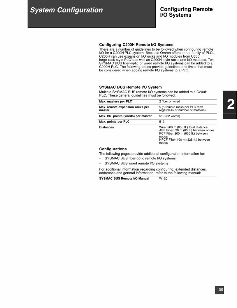
Configuring C200H Remote I/O SystemsThere are a number of guidelines to be followed when configuring remoteI/O for a C200H PLC system. Because Omron offers a true family of PLCs,C200H can use expansion I/O racks and I/O modules from C500large-rack style PLC’s as well as C200H style racks and I/O modules. TwoSYSMAC BUS fiber-optic or wired remote I/O systems can be added to aC200H PLC. The following tables provide guidelines and limits that mustbe considered when adding remote I/O systems to a PLC.
SYSMAC BUS Remote I/O SystemMultiple SYSMAC BUS remote I/O systems can be added to a C200HPLC. These general guidelines must be followed:
Max. masters per PLC 2 fiber or wired
Max. remote expansion racks permaster
5 (5 remote racks per PLC max.,regardless of number of masters)
Max. I/O points (words) per master 512 (32 words)
Max. points per PLC 512
Distances Wire: 200 m (656 ft.) total distanceAPF Fiber: 20 m (65 ft.) between nodesPCF Fiber 200 m (656 ft.) betweennodesHPCF Fiber 100 m (328 ft.) betweennodes
ConfigurationsThe following pages provide additional configuration information for:• SYSMAC BUS fiber-optic remote I/O systems• SYSMAC BUS wired remote I/O systems
For additional information regarding configuring, extended distances,addresses and general information, refer to the following manual:
SYSMAC BUS Remote I/O Manual W120
9 System Configuration
109
2
System Configuration Configuring RemoteI/O Systems
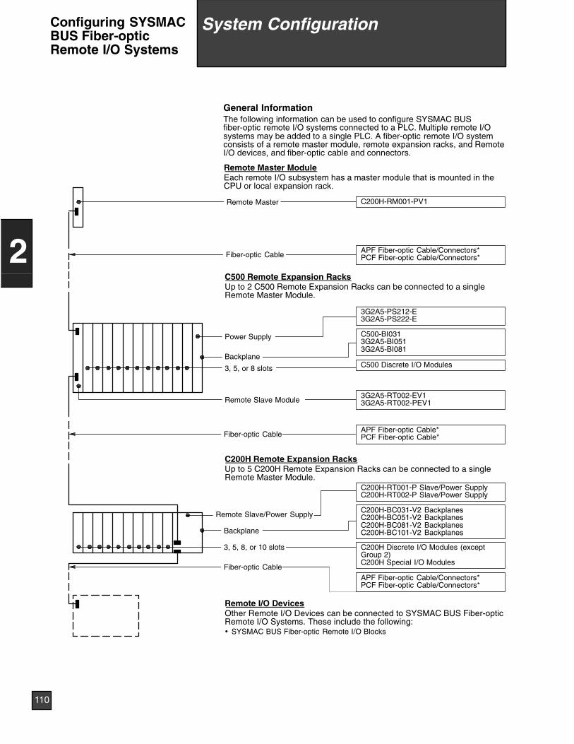
General InformationThe following information can be used to configure SYSMAC BUSfiber-optic remote I/O systems connected to a PLC. Multiple remote I/Osystems may be added to a single PLC. A fiber-optic remote I/O systemconsists of a remote master module, remote expansion racks, and RemoteI/O devices, and fiber-optic cable and connectors.
Remote Master ModuleEach remote I/O subsystem has a master module that is mounted in theCPU or local expansion rack.
Remote I/O DevicesOther Remote I/O Devices can be connected to SYSMAC BUS Fiber-opticRemote I/O Systems. These include the following:• SYSMAC BUS Fiber-optic Remote I/O Blocks
C200H Remote Expansion RacksUp to 5 C200H Remote Expansion Racks can be connected to a singleRemote Master Module.
C500 Remote Expansion RacksUp to 2 C500 Remote Expansion Racks can be connected to a singleRemote Master Module.
C200H-BC031-V2 BackplanesC200H-BC051-V2 BackplanesC200H-BC081-V2 BackplanesC200H-BC101-V2 Backplanes
Remote Slave Module
APF Fiber-optic Cable/Connectors*PCF Fiber-optic Cable/Connectors*
C500-BI0313G2A5-BI0513G2A5-BI081
3G2A5-PS212-E3G2A5-PS222-E
C500 Discrete I/O Modules
3G2A5-RT002-EV13G2A5-RT002-PEV1
3, 5, or 8 slots
Backplane
C200H-RT001-P Slave/Power SupplyC200H-RT002-P Slave/Power Supply
3, 5, 8, or 10 slots
Fiber-optic Cable
C200H Discrete I/O Modules (exceptGroup 2)C200H Special I/O Modules
Fiber-optic Cable
Power Supply
C200H-RM001-PV1Remote Master
Remote Slave/Power Supply
APF Fiber-optic Cable*PCF Fiber-optic Cable*
Fiber-optic CableAPF Fiber-optic Cable/Connectors*PCF Fiber-optic Cable/Connectors*
Backplane
9 System Configuration
110
2
System ConfigurationConfiguring SYSMACBUS Fiber-opticRemote I/O Systems

When Configuring a SYSMAC BUS fiber-optic remote I/O system:♦ A total of 32 words (512 bits) can be connected to a single Remote
master.♦ The following table indicates the number of I/O allowed for each Re-
mote expansion rack and I/O device.
No. of words No. of I/O points
C500 Remote ExpansionRacks
Depends on I/O Modules mounted*
C200H RemoteExpansion Racks
Depends on I/O Modules mounted*
Fiber-optic Remote I/OBlocks
1 (0.5)* 8
*Refer to the SYSMAC BUS Remote I/O System Manual (Cat. No. W120)for additional configuration information.
9 System Configuration
111
2
System Configuration Configuring SYSMACBUS Fiber-opticRemote I/O Systems
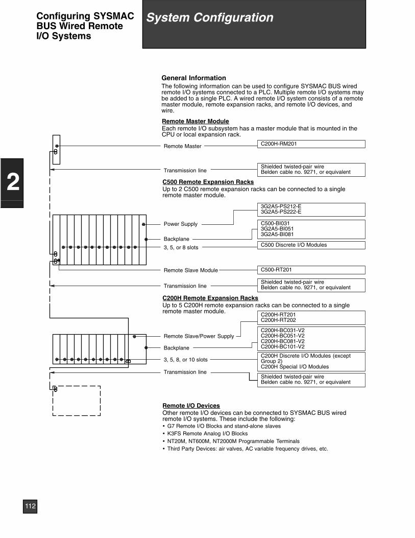
General InformationThe following information can be used to configure SYSMAC BUS wiredremote I/O systems connected to a PLC. Multiple remote I/O systems maybe added to a single PLC. A wired remote I/O system consists of a remotemaster module, remote expansion racks, and remote I/O devices, andwire.
Remote Master ModuleEach remote I/O subsystem has a master module that is mounted in theCPU or local expansion rack.
Remote I/O DevicesOther remote I/O devices can be connected to SYSMAC BUS wiredremote I/O systems. These include the following:• G7 Remote I/O Blocks and stand-alone slaves• K3FS Remote Analog I/O Blocks• NT20M, NT600M, NT2000M Programmable Terminals• Third Party Devices: air valves, AC variable frequency drives, etc.
C200H Remote Expansion RacksUp to 5 C200H remote expansion racks can be connected to a singleremote master module.
C500 Remote Expansion RacksUp to 2 C500 remote expansion racks can be connected to a singleremote master module.
C200H-BC031-V2C200H-BC051-V2C200H-BC081-V2C200H-BC101-V2
Remote Slave Module
Shielded twisted-pair wireBelden cable no. 9271, or equivalent
C500-BI0313G2A5-BI0513G2A5-BI081
3G2A5-PS212-E3G2A5-PS222-E
C500 Discrete I/O Modules
C500-RT201
3, 5, or 8 slots
Backplane
C200H-RT201C200H-RT202
3, 5, 8, or 10 slotsC200H Discrete I/O Modules (exceptGroup 2)C200H Special I/O Modules
Power Supply
C200H-RM201Remote Master
Remote Slave/Power Supply
Transmission line
Shielded twisted-pair wireBelden cable no. 9271, or equivalent
Shielded twisted-pair wireBelden cable no. 9271, or equivalent
Transmission line
Transmission line
Backplane
9 System Configuration
112
2
System ConfigurationConfiguring SYSMACBUS Wired RemoteI/O Systems
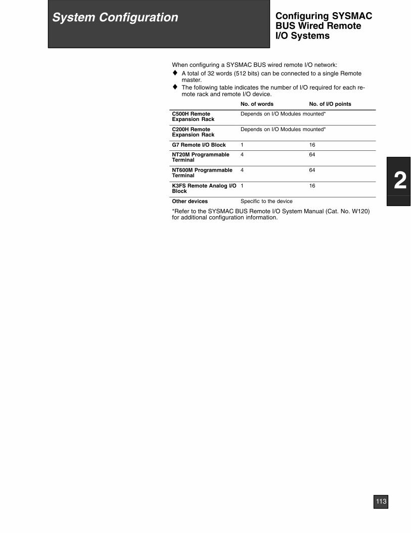
When configuring a SYSMAC BUS wired remote I/O network:♦ A total of 32 words (512 bits) can be connected to a single Remote
master.♦ The following table indicates the number of I/O required for each re-
mote rack and remote I/O device.
No. of words No. of I/O points
C500H RemoteExpansion Rack
Depends on I/O Modules mounted*
C200H RemoteExpansion Rack
Depends on I/O Modules mounted*
G7 Remote I/O Block 1 16
NT20M ProgrammableTerminal
4 64
NT600M ProgrammableTerminal
4 64
K3FS Remote Analog I/OBlock
1 16
Other devices Specific to the device
*Refer to the SYSMAC BUS Remote I/O System Manual (Cat. No. W120)for additional configuration information.
9 System Configuration
113
2
System Configuration Configuring SYSMACBUS Wired RemoteI/O Systems
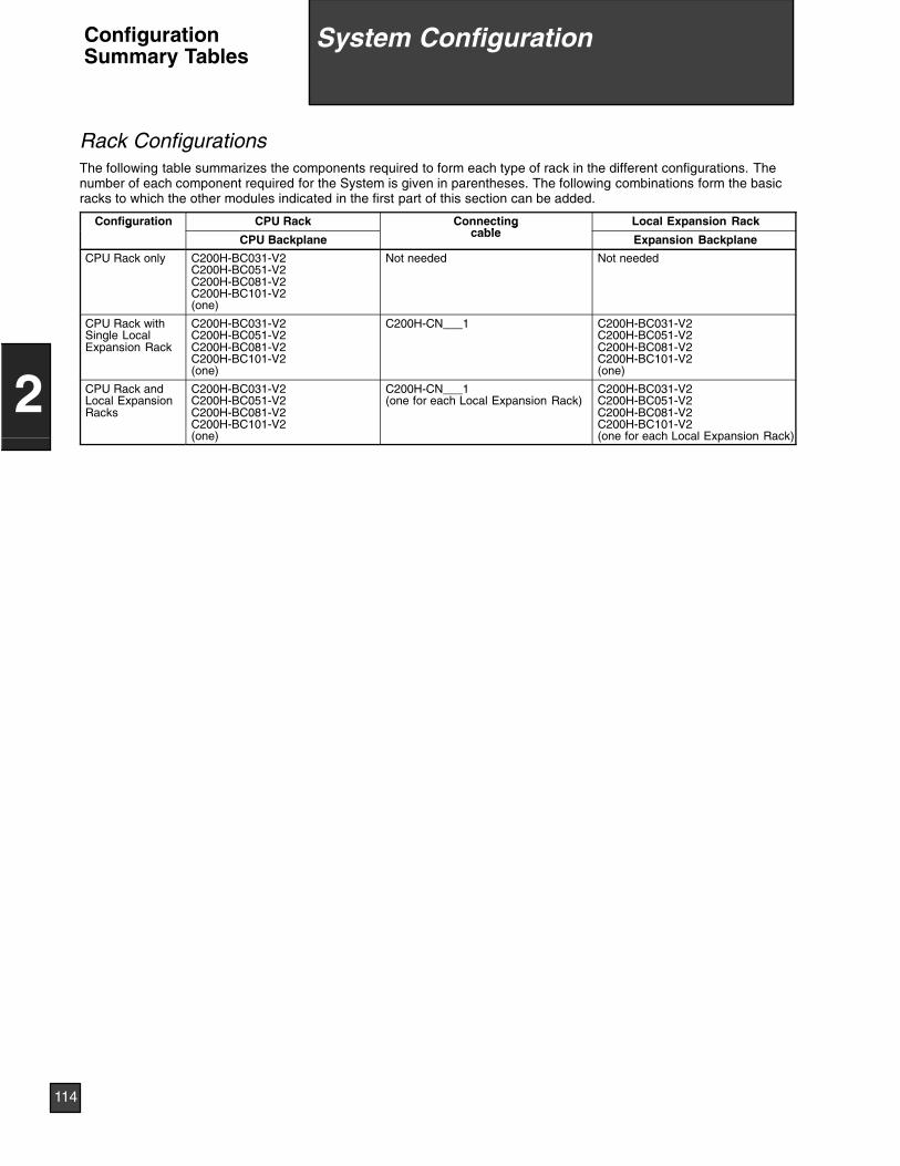
Rack ConfigurationsThe following table summarizes the components required to form each type of rack in the different configurations. Thenumber of each component required for the System is given in parentheses. The following combinations form the basicracks to which the other modules indicated in the first part of this section can be added.
Configuration CPU Rack Connectingbl
Local Expansion Rackg
CPU Backplane
gcable
Expansion Backplane
CPU Rack only C200H-BC031-V2C200H-BC051-V2C200H-BC081-V2C200H-BC101-V2(one)
Not needed Not needed
CPU Rack withSingle LocalExpansion Rack
C200H-BC031-V2C200H-BC051-V2C200H-BC081-V2C200H-BC101-V2(one)
C200H-CN___1 C200H-BC031-V2C200H-BC051-V2C200H-BC081-V2C200H-BC101-V2(one)
CPU Rack andLocal ExpansionRacks
C200H-BC031-V2C200H-BC051-V2C200H-BC081-V2C200H-BC101-V2(one)
C200H-CN___1(one for each Local Expansion Rack)
C200H-BC031-V2C200H-BC051-V2C200H-BC081-V2C200H-BC101-V2(one for each Local Expansion Rack)
9 System Configuration
114
2
System ConfigurationConfigurationSummary Tables
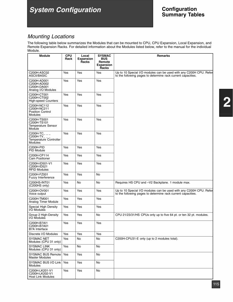
Mounting LocationsThe following table below summarizes the Modules that can be mounted to CPU, CPU Expansion, Local Expansion, andRemote Expansion Racks. For detailed information about the Modules listed below, refer to the manual for the individualModule.
Module CPURack
LocalExpansion
Racks
SYSMACBUS
RemoteExpansion
Racks
Remarks
C200H-ASC02ASCII/BASIC
Yes Yes Yes Up to 10 Special I/O modules can be used with any C200H CPU. Referto the following pages to determine rack current capacities.
C200H-AD001C200H-AD002C200H-DA001Analog I/O Modules
Yes Yes Yes
g g
C200H-CT001C200H-CT002High-speed Counters
Yes Yes Yes
C200H-NC112C200H-NC211Position ControlModules
Yes Yes Yes
C200H-TS001C200H-TS101Temperature SensorModule
Yes Yes Yes
C200H-TC_ _ _C200H-TV_ _ _Temperature ControllerModules
Yes Yes Yes
C200H-PIDPID Module
Yes Yes Yes
C200H-CP114Cam Positioner
Yes Yes Yes
C200H-ID501-V1C200H-ID521RFID Modules
Yes Yes Yes
C200H-FZ001Fuzzy Interference
Yes Yes No
C200HS-INT01(C200HS only)
Yes No No Requires HS CPU and --V2 Backplane. 1 module max.
C200H-OV001Voice output
Yes Yes Yes Up to 10 Special I/O modules can be used with any C200H CPU. Referto the following pages to determine rack current capacities.
C200H-TM001Analog Timer Module
Yes Yes Yes
g g
Special High DensityI/O Modules
Yes Yes Yes
Group 2 High-DensityI/O Modules
Yes Yes No CPU 21/23/31/HS CPUs only up to five 64 pt. or ten 32 pt. modules.
C200H-B7AI1C200H-B7A01B7A Interface
Yes Yes Yes
Discrete I/O Modules Yes Yes Yes
SYSMAC NETModules (CPU 31 only)
Yes No No C200H-CPU31-E only (up to 2 modules total).
SYSMAC LINKModules (CPU 31 only)
Yes No No
SYSMAC BUS RemoteMaster Modules
Yes Yes No
SYSMAC BUS I/O LinkModules
Yes Yes No
C200H-LK201-V1C200H-LK202-V1Host Link Modules
Yes Yes No
9 System Configuration
115
2
System Configuration ConfigurationSummary Tables
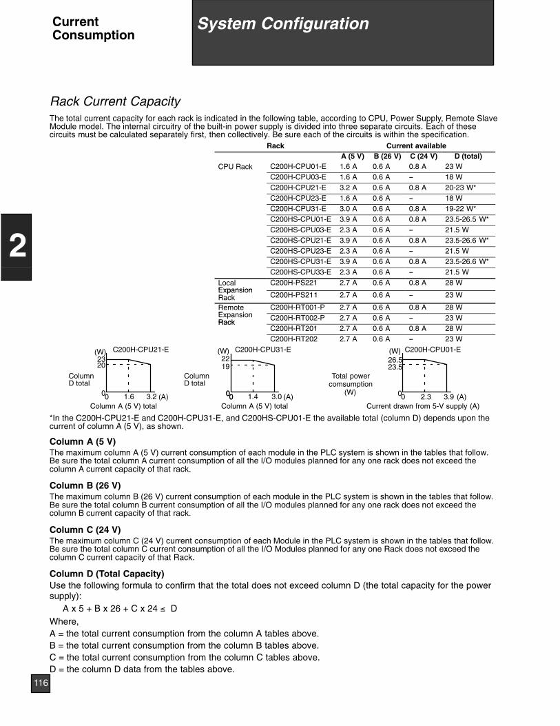
Rack Current CapacityThe total current capacity for each rack is indicated in the following table, according to CPU, Power Supply, Remote SlaveModule model. The internal circuitry of the built-in power supply is divided into three separate circuits. Each of thesecircuits must be calculated separately first, then collectively. Be sure each of the circuits is within the specification.
Rack Current availableA (5 V) B (26 V) C (24 V) D (total)
CPU Rack C200H-CPU01-E 1.6 A 0.6 A 0.8 A 23 WC200H-CPU03-E 1.6 A 0.6 A -- 18 WC200H-CPU21-E 3.2 A 0.6 A 0.8 A 20-23 W*C200H-CPU23-E 1.6 A 0.6 A -- 18 WC200H-CPU31-E 3.0 A 0.6 A 0.8 A 19-22 W*C200HS-CPU01-E 3.9 A 0.6 A 0.8 A 23.5-26.5 W*C200HS-CPU03-E 2.3 A 0.6 A -- 21.5 WC200HS-CPU21-E 3.9 A 0.6 A 0.8 A 23.5-26.6 W*C200HS-CPU23-E 2.3 A 0.6 A -- 21.5 WC200HS-CPU31-E 3.9 A 0.6 A 0.8 A 23.5-26.6 W*C200HS-CPU33-E 2.3 A 0.6 A -- 21.5 W
LocalExpansion
C200H-PS221 2.7 A 0.6 A 0.8 A 28 WExpansionRack C200H-PS211 2.7 A 0.6 A -- 23 W
RemoteE i
C200H-RT001-P 2.7 A 0.6 A 0.8 A 28 WExpansionRack
C200H-RT002-P 2.7 A 0.6 A -- 23 WRack
C200H-RT201 2.7 A 0.6 A 0.8 A 28 WC200H-RT202 2.7 A 0.6 A -- 23 W
C200H-CPU21-E
0
ColumnD total
1.6
2023
3.20
(W)
Column A (5 V) total
ColumnD total
Column A (5 V) total0 1.4
1922
3.00
(W) C200H-CPU31-E
(A)(A)
C200H-CPU01-E(W)
(A)
26.523.5
Current drawn from 5-V supply (A)3.92.3
Total powercomsumption
(W)00 00
*In the C200H-CPU21-E and C200H-CPU31-E, and C200HS-CPU01-E the available total (column D) depends upon thecurrent of column A (5 V), as shown.
Column A (5 V)The maximum column A (5 V) current consumption of each module in the PLC system is shown in the tables that follow.Be sure the total column A current consumption of all the I/O modules planned for any one rack does not exceed thecolumn A current capacity of that rack.
Column B (26 V)The maximum column B (26 V) current consumption of each module in the PLC system is shown in the tables that follow.Be sure the total column B current consumption of all the I/O modules planned for any one rack does not exceed thecolumn B current capacity of that rack.
Column C (24 V)The maximum column C (24 V) current consumption of each Module in the PLC system is shown in the tables that follow.Be sure the total column C current consumption of all the I/O Modules planned for any one Rack does not exceed thecolumn C current capacity of that Rack.
Column D (Total Capacity)Use the following formula to confirm that the total does not exceed column D (the total capacity for the powersupply):
A x 5 + B x 26 + C x 24 ≤ DWhere,A = the total current consumption from the column A tables above.B = the total current consumption from the column B tables above.C = the total current consumption from the column C tables above.D = the column D data from the tables above.
9 System Configuration
116
2
System ConfigurationCurrentConsumption
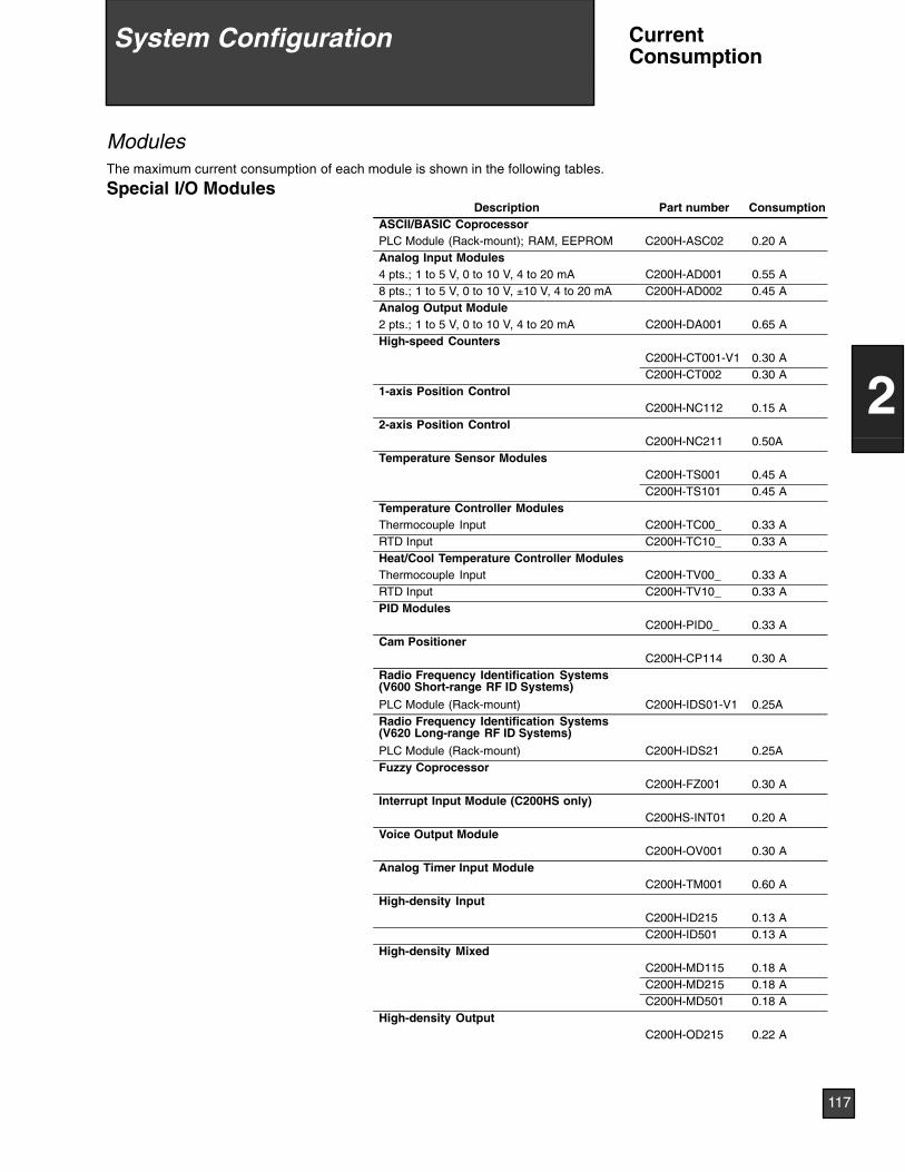
ModulesThe maximum current consumption of each module is shown in the following tables.
Special I/O ModulesDescription Part number Consumption
ASCII/BASIC CoprocessorPLC Module (Rack-mount); RAM, EEPROM C200H-ASC02 0.20 AAnalog Input Modules4 pts.; 1 to 5 V, 0 to 10 V, 4 to 20 mA C200H-AD001 0.55 A8 pts.; 1 to 5 V, 0 to 10 V, ±10 V, 4 to 20 mA C200H-AD002 0.45 AAnalog Output Module2 pts.; 1 to 5 V, 0 to 10 V, 4 to 20 mA C200H-DA001 0.65 AHigh-speed Counters
C200H-CT001-V1 0.30 AC200H-CT002 0.30 A
1-axis Position ControlC200H-NC112 0.15 A
2-axis Position ControlC200H-NC211 0.50A
Temperature Sensor ModulesC200H-TS001 0.45 AC200H-TS101 0.45 A
Temperature Controller ModulesThermocouple Input C200H-TC00_ 0.33 ARTD Input C200H-TC10_ 0.33 AHeat/Cool Temperature Controller ModulesThermocouple Input C200H-TV00_ 0.33 ARTD Input C200H-TV10_ 0.33 APID Modules
C200H-PID0_ 0.33 ACam Positioner
C200H-CP114 0.30 ARadio Frequency Identification Systems(V600 Short-range RF ID Systems)
PLC Module (Rack-mount) C200H-IDS01-V1 0.25ARadio Frequency Identification Systems(V620 Long-range RF ID Systems)
PLC Module (Rack-mount) C200H-IDS21 0.25AFuzzy Coprocessor
C200H-FZ001 0.30 AInterrupt Input Module (C200HS only)
C200HS-INT01 0.20 AVoice Output Module
C200H-OV001 0.30 AAnalog Timer Input Module
C200H-TM001 0.60 AHigh-density Input
C200H-ID215 0.13 AC200H-ID501 0.13 A
High-density MixedC200H-MD115 0.18 AC200H-MD215 0.18 AC200H-MD501 0.18 A
High-density OutputC200H-OD215 0.22 A
9 System Configuration
117
2
System Configuration CurrentConsumption
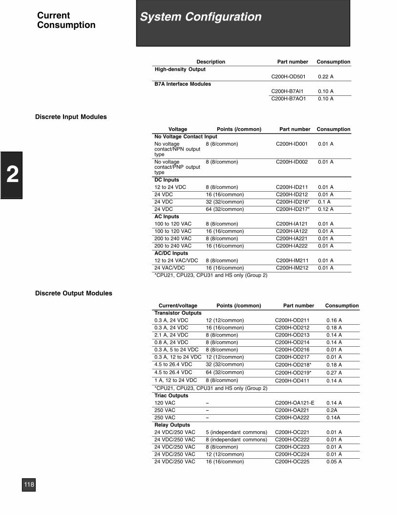
ConsumptionPart numberDescriptionHigh-density Output
C200H-OD501 0.22 AB7A Interface Modules
C200H-B7AI1 0.10 AC200H-B7AO1 0.10 A
Discrete Input Modules
Voltage Points (/common) Part number ConsumptionNo Voltage Contact InputNo voltagecontact/NPN outputtype
8 (8/common) C200H-ID001 0.01 A
No voltagecontact/PNP outputtype
8 (8/common) C200H-ID002 0.01 A
DC Inputs12 to 24 VDC 8 (8/common) C200H-ID211 0.01 A24 VDC 16 (16/common) C200H-ID212 0.01 A24 VDC 32 (32/common) C200H-ID216* 0.1 A24 VDC 64 (32/common) C200H-ID217* 0.12 AAC Inputs100 to 120 VAC 8 (8/common) C200H-IA121 0.01 A100 to 120 VAC 16 (16/common) C200H-IA122 0.01 A200 to 240 VAC 8 (8/common) C200H-IA221 0.01 A200 to 240 VAC 16 (16/common) C200H-IA222 0.01 AAC/DC Inputs12 to 24 VAC/VDC 8 (8/common) C200H-IM211 0.01 A24 VAC/VDC 16 (16/common) C200H-IM212 0.01 A*CPU21, CPU23, CPU31 and HS only (Group 2)
Discrete Output Modules
Current/voltage Points (/common) Part number ConsumptionTransistor Outputs0.3 A, 24 VDC 12 (12/common) C200H-OD211 0.16 A0.3 A, 24 VDC 16 (16/common) C200H-OD212 0.18 A2.1 A, 24 VDC 8 (8/common) C200H-OD213 0.14 A0.8 A, 24 VDC 8 (8/common) C200H-OD214 0.14 A0.3 A, 5 to 24 VDC 8 (8/common) C200H-OD216 0.01 A0.3 A, 12 to 24 VDC 12 (12/common) C200H-OD217 0.01 A4.5 to 26.4 VDC 32 (32/common) C200H-OD218* 0.18 A4.5 to 26.4 VDC 64 (32/common) C200H-OD219* 0.27 A1 A, 12 to 24 VDC 8 (8/common) C200H-OD411 0.14 A*CPU21, CPU23, CPU31 and HS only (Group 2)Triac Outputs120 VAC -- C200H-OA121-E 0.14 A250 VAC -- C200H-OA221 0.2A250 VAC -- C200H-OA222 0.14ARelay Outputs24 VDC/250 VAC 5 (independant commons) C200H-OC221 0.01 A24 VDC/250 VAC 8 (independant commons) C200H-OC222 0.01 A24 VDC/250 VAC 8 (8/common) C200H-OC223 0.01 A24 VDC/250 VAC 12 (12/common) C200H-OC224 0.01 A24 VDC/250 VAC 16 (16/common) C200H-OC225 0.05 A
9 System Configuration
118
2
System ConfigurationCurrentConsumption
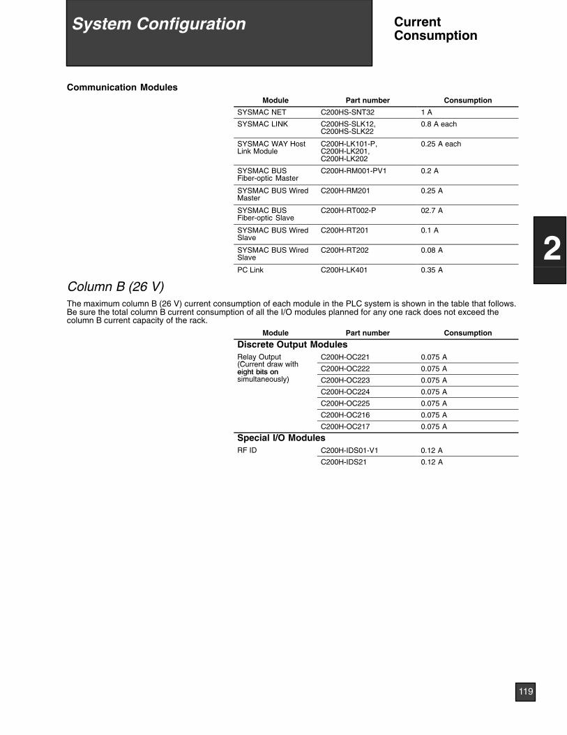
Communication ModulesModule Part number Consumption
SYSMAC NET C200HS-SNT32 1 A
SYSMAC LINK C200HS-SLK12,C200HS-SLK22
0.8 A each
SYSMAC WAY HostLink Module
C200H-LK101-P,C200H-LK201,C200H-LK202
0.25 A each
SYSMAC BUSFiber-optic Master
C200H-RM001-PV1 0.2 A
SYSMAC BUS WiredMaster
C200H-RM201 0.25 A
SYSMAC BUSFiber-optic Slave
C200H-RT002-P 02.7 A
SYSMAC BUS WiredSlave
C200H-RT201 0.1 A
SYSMAC BUS WiredSlave
C200H-RT202 0.08 A
PC Link C200H-LK401 0.35 A
Column B (26 V)The maximum column B (26 V) current consumption of each module in the PLC system is shown in the table that follows.Be sure the total column B current consumption of all the I/O modules planned for any one rack does not exceed thecolumn B current capacity of the rack.
Module Part number Consumption
Discrete Output ModulesRelay Output(C t d ith
C200H-OC221 0.075 Ay(Current draw witheight bits on C200H-OC222 0.075 Aeight bits onsimultaneously) C200H-OC223 0.075 Ay)
C200H-OC224 0.075 A
C200H-OC225 0.075 A
C200H-OC216 0.075 A
C200H-OC217 0.075 A
Special I/O ModulesRF ID C200H-IDS01-V1 0.12 A
C200H-IDS21 0.12 A
9 System Configuration
119
2
System Configuration CurrentConsumption
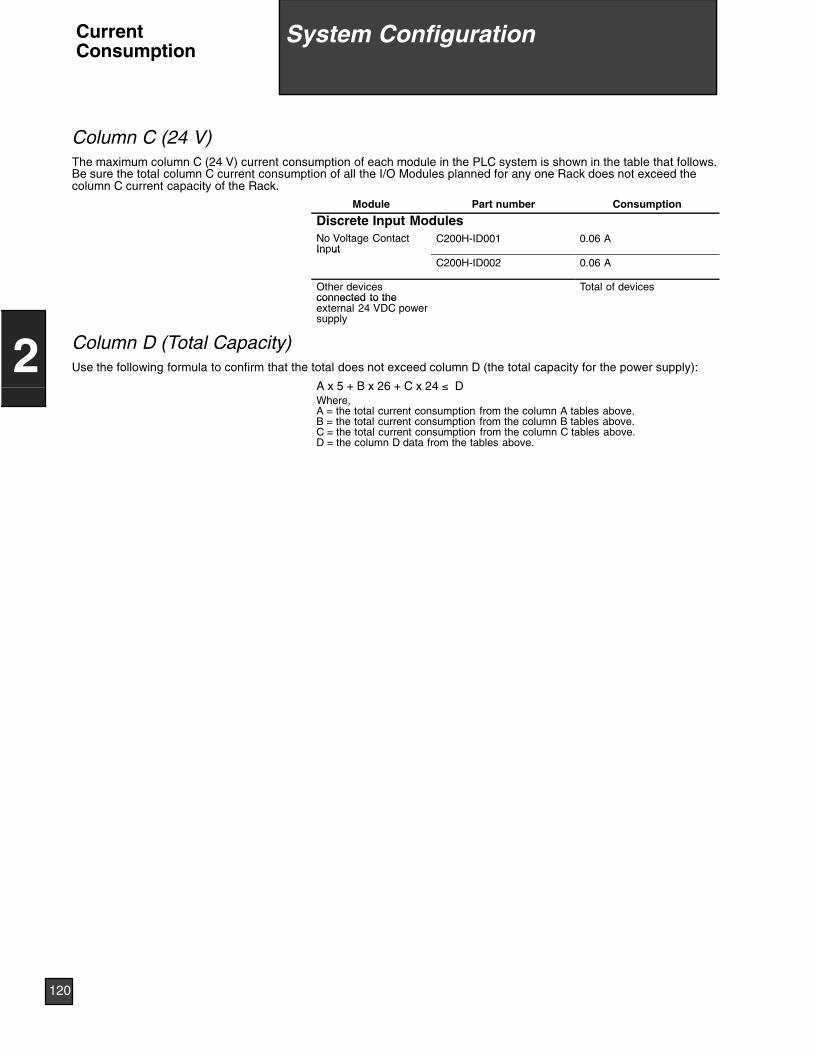
Column C (24 V)The maximum column C (24 V) current consumption of each module in the PLC system is shown in the table that follows.Be sure the total column C current consumption of all the I/O Modules planned for any one Rack does not exceed thecolumn C current capacity of the Rack.
Module Part number Consumption
Discrete Input ModulesNo Voltage ContactInput
C200H-ID001 0.06 AIn ut
C200H-ID002 0.06 A
Other devicesconnected to the
Total of devicesconnected to theexternal 24 VDC powersupply
Column D (Total Capacity)Use the following formula to confirm that the total does not exceed column D (the total capacity for the power supply):
A x 5 + B x 26 + C x 24 ≤ DWhere,A = the total current consumption from the column A tables above.B = the total current consumption from the column B tables above.C = the total current consumption from the column C tables above.D = the column D data from the tables above.
9 System Configuration
120
2
System ConfigurationCurrentConsumption
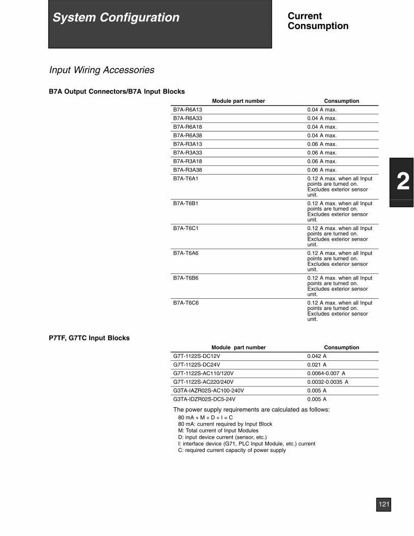
Input Wiring Accessories
B7A Output Connectors/B7A Input BlocksModule part number Consumption
B7A-R6A13 0.04 A max.
B7A-R6A33 0.04 A max.
B7A-R6A18 0.04 A max.
B7A-R6A38 0.04 A max.
B7A-R3A13 0.06 A max.
B7A-R3A33 0.06 A max.
B7A-R3A18 0.06 A max.
B7A-R3A38 0.06 A max.
B7A-T6A1 0.12 A max. when all Inputpoints are turned on.Excludes exterior sensorunit.
B7A-T6B1 0.12 A max. when all Inputpoints are turned on.Excludes exterior sensorunit.
B7A-T6C1 0.12 A max. when all Inputpoints are turned on.Excludes exterior sensorunit.
B7A-T6A6 0.12 A max. when all Inputpoints are turned on.Excludes exterior sensorunit.
B7A-T6B6 0.12 A max. when all Inputpoints are turned on.Excludes exterior sensorunit.
B7A-T6C6 0.12 A max. when all Inputpoints are turned on.Excludes exterior sensorunit.
P7TF, G7TC Input BlocksModule part number Consumption
G7T-1122S-DC12V 0.042 A
G7T-1122S-DC24V 0.021 A
G7T-1122S-AC110/120V 0.0064-0.007 A
G7T-1122S-AC220/240V 0.0032-0.0035 A
G3TA-IAZR02S-AC100-240V 0.005 A
G3TA-IDZR02S-DC5-24V 0.005 A
The power supply requirements are calculated as follows:80 mA + M + D + I = C80 mA: current required by Input BlockM: Total current of Input ModulesD: input device current (sensor, etc.)I: interface device (G71, PLC Input Module, etc.) currentC: required current capacity of power supply
9 System Configuration
121
2
System Configuration CurrentConsumption
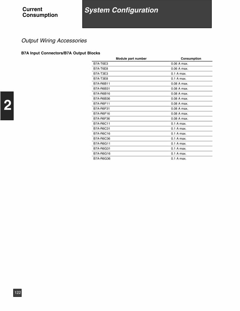
Output Wiring Accessories
B7A Input Connectors/B7A Output BlocksModule part number Consumption
B7A-T6E3 0.06 A max.
B7A-T6E8 0.06 A max.
B7A-T3E3 0.1 A max.
B7A-T3E8 0.1 A max.
B7A-R6B11 0.08 A max.
B7A-R6B31 0.08 A max.
B7A-R6B16 0.08 A max.
B7A-R6B36 0.08 A max.
B7A-R6F11 0.08 A max.
B7A-R6F31 0.08 A max.
B7A-R6F16 0.08 A max.
B7A-R6F36 0.08 A max.
B7A-R6C11 0.1 A max.
B7A-R6C31 0.1 A max.
B7A-R6C16 0.1 A max.
B7A-R6C36 0.1 A max.
B7A-R6G11 0.1 A max.
B7A-R6G31 0.1 A max.
B7A-R6G16 0.1 A max.
B7A-R6G36 0.1 A max.
9 System Configuration
122
2
System ConfigurationCurrentConsumption
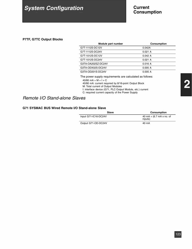
P7TF, G7TC Output BlocksModule part number Consumption
G7T-1112S-DC12V 0.042A
G7T-1112S-DC24V 0.021 A
G7T-1012S-DC12V 0.042 A
G7T-1012S-DC24V 0.021 A
G3TA-OA202SZ-DC24V 0.016 A
G3TA-ODX02S-DC24V 0.005 A
G3TA-OD201S-DC24V 0.005 A
The power supply requirements are calculated as follows:40/80 mA + M + I = C40/80 mA: current required by 8/16-point Output BlockM: Total current of Output ModulesI: interface device (G71, PLC Output Module, etc.) currentC: required current capacity of the Power Supply
Remote I/O Stand-alone Slaves
G71 SYSMAC BUS Wired Remote I/O Stand-alone SlaveSlave Consumption
Input G71-IC16-DC24V 40 mA + (6.7 mA x no. ofinputs)
Output G71-OD-DC24V 40 mA
9 System Configuration
123
2
System Configuration CurrentConsumption
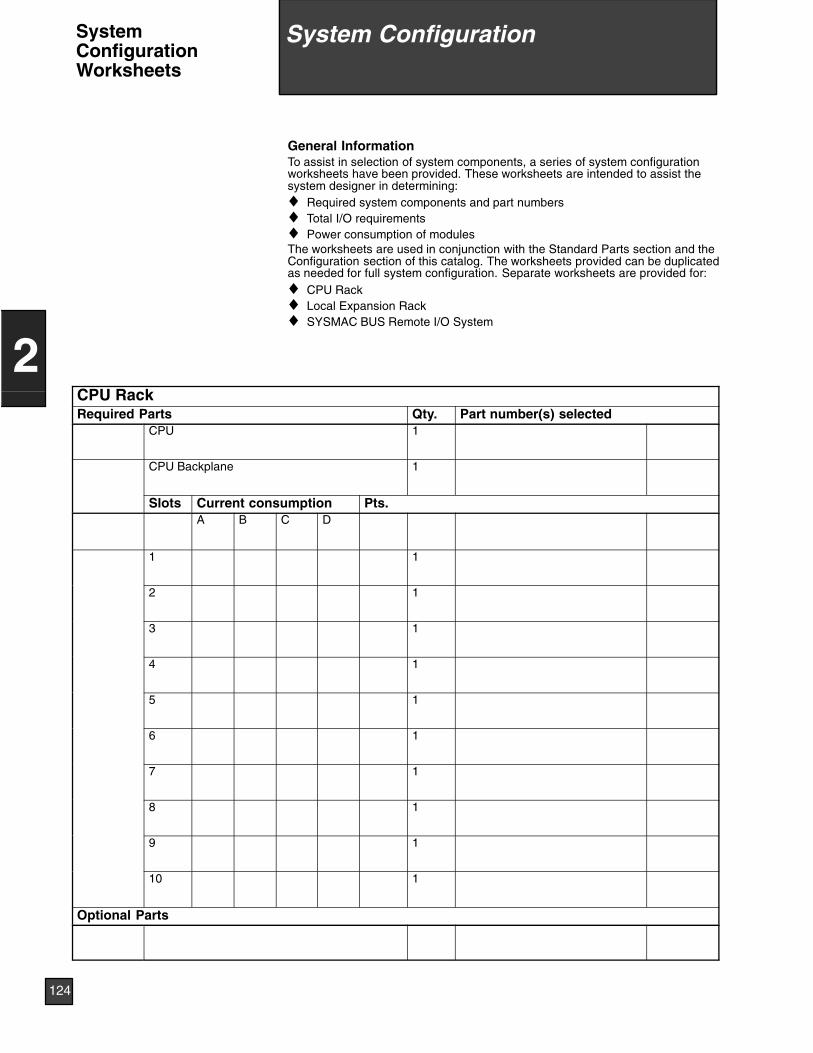
General InformationTo assist in selection of system components, a series of system configurationworksheets have been provided. These worksheets are intended to assist thesystem designer in determining:♦ Required system components and part numbers♦ Total I/O requirements♦ Power consumption of modulesThe worksheets are used in conjunction with the Standard Parts section and theConfiguration section of this catalog. The worksheets provided can be duplicatedas needed for full system configuration. Separate worksheets are provided for:♦ CPU Rack♦ Local Expansion Rack♦ SYSMAC BUS Remote I/O System
CPU RackRequired Parts Qty. Part number(s) selected
CPU 1
CPU Backplane 1
Slots Current consumption Pts.A B C D
1 1
2 1
3 1
4 1
5 1
6 1
7 1
8 1
9 1
10 1
Optional Parts
9 System Configuration
124
2
System ConfigurationSystemConfigurationWorksheets
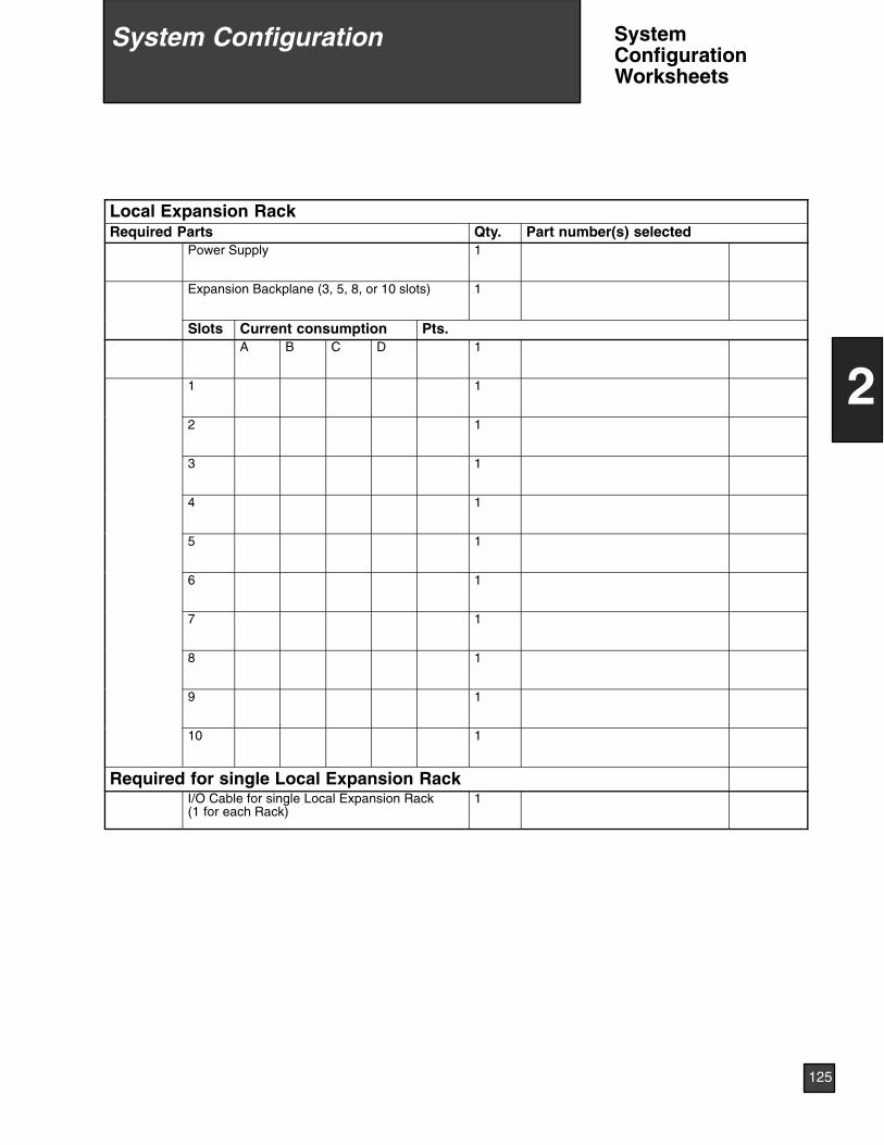
Local Expansion RackRequired Parts Qty. Part number(s) selected
Power Supply 1
Expansion Backplane (3, 5, 8, or 10 slots) 1
Slots Current consumption Pts.A B C D 1
1 1
2 1
3 1
4 1
5 1
6 1
7 1
8 1
9 1
10 1
Required for single Local Expansion RackI/O Cable for single Local Expansion Rack(1 for each Rack)
1
9 System Configuration
125
2
System Configuration SystemConfigurationWorksheets
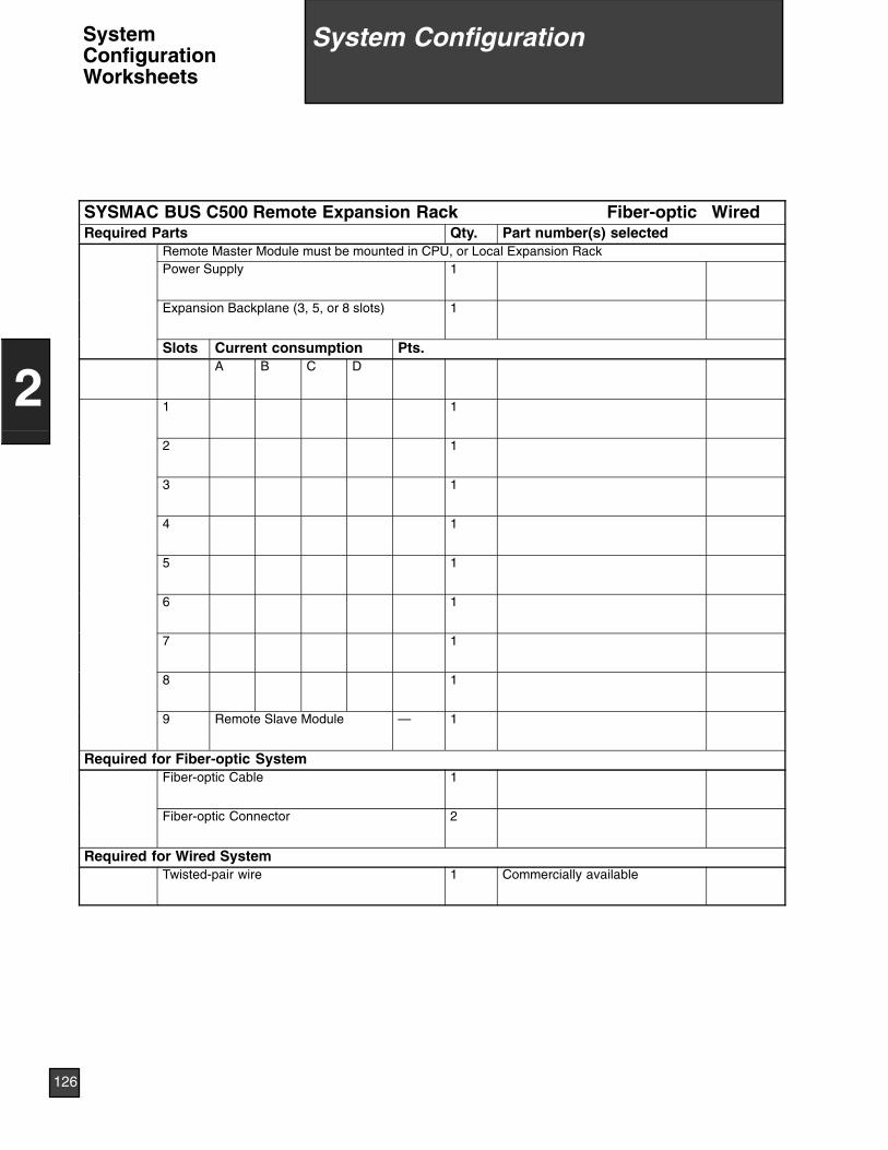
SYSMAC BUS C500 Remote Expansion Rack Fiber-optic WiredRequired Parts Qty. Part number(s) selected
Remote Master Module must be mounted in CPU, or Local Expansion RackPower Supply 1
Expansion Backplane (3, 5, or 8 slots) 1
Slots Current consumption Pts.A B C D
1 1
2 1
3 1
4 1
5 1
6 1
7 1
8 1
9 Remote Slave Module — 1
Required for Fiber-optic SystemFiber-optic Cable 1
Fiber-optic Connector 2
Required for Wired SystemTwisted-pair wire 1 Commercially available
9 System Configuration
126
2
System ConfigurationSystemConfigurationWorksheets
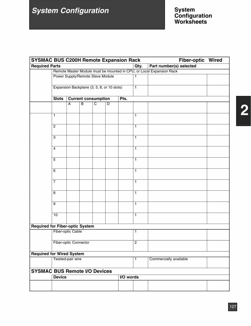
SYSMAC BUS C200H Remote Expansion Rack Fiber-optic WiredRequired Parts Qty. Part number(s) selected
Remote Master Module must be mounted in CPU, or Local Expansion RackPower Supply/Remote Slave Module 1
Expansion Backplane (3, 5, 8, or 10 slots) 1
Slots Current consumption Pts.A B C D
1 1
2 1
3 1
4 1
5 1
6 1
7 1
8 1
9 1
10 1
Required for Fiber-optic SystemFiber-optic Cable 1
Fiber-optic Connector 2
Required for Wired SystemTwisted-pair wire 1 Commercially available
SYSMAC BUS Remote I/O DevicesDevice I/O words
9 System Configuration
127
2
System Configuration SystemConfigurationWorksheets
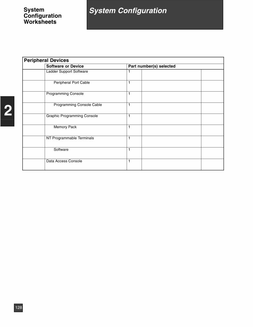
Peripheral DevicesSoftware or Device Part number(s) selectedLadder Support Software 1
Peripheral Port Cable 1
Programming Console 1
Programming Console Cable 1
Graphic Programming Console 1
Memory Pack 1
NT Programmable Terminals 1
Software 1
Data Access Console 1
9 System Configuration
128
2
System ConfigurationSystemConfigurationWorksheets
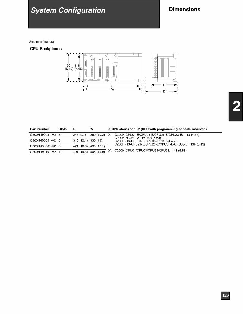
Unit: mm (inches)
CPU Backplanes
LW
130(5.12)
118(4.65)
D
D*
Part number Slots L W D (CPU alone) and D* (CPU with programming console mounted)
C200H-BC031-V2 3 246 (9.7) 260 (10.2) D: C200H-CPU01-E/CPU03-E/CPU21-E/CPU23-E: 118 (4.65)C200H H CPU031 E: 143 (5 63)
C200H-BC051-V2 5 316 (12.4) 330 (13)C200H-H-CPU031-E: 143 (5.63)C200H-HS-CPU01-E/CPU03-E: 113 (4.45)C200H HS CPU21 E/CPU23 E/CPU31 E/CPU33 E 138 (5 43)
C200H-BC081-V2 8 421 (16.6) 435 (17.1)
( )C200H-HS-CPU21-E/CPU23-E/CPU31-E/CPU33-E: 138 (5.43)
D* C H CPU /CPU /CPU /CPU ( )C200H-BC101-V2 10 491 (19.3) 505 (19.9) D*: C200H-CPU01/CPU03/CPU21/CPU23: 148 (5.83)
9 System Configuration
129
2
System Configuration Dimensions
9 System Configuration
130
2
System ConfigurationDimensions

Programmable Terminals 132. . . . . . . . . . . . . . . . . . . . . . . . . . . . . . . . .Data Access Console 136. . . . . . . . . . . . . . . . . . . . . . . . . . . . . . . . . . . .
10 Operator Interfaces
131
3
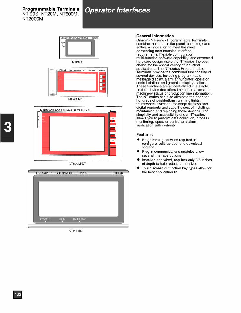
PROGRAMMABLE TERMINALNT600M
BAT LOW
RUN
POWER
NT600M-DT
POWER
RUN
BAT LOW
PROGRAMMABLE TERMINALNT20M
NT20M-DT
NT20S
NT2000M
OMRONPROGRAMMABLE TERMINALNT2000M
PROGRAMMABLE TERMINALNT20S OMRON
Power
Run
General InformationOmron’s NT-series Programmable Terminalscombine the latest in flat panel technology andsoftware innovation to meet the mostdemanding man-machine interfacerequirements. Flexible configuration,multi-function software capability, and advancedhardware design make the NT-series the bestchoice for the widest variety of industrialapplications. The NT-series ProgrammableTerminals provide the combined functionality ofseveral devices, including programmablemessage display, alarm annunciator, operatorcontrol station, and graphics display station.These functions are all centralized in a singleflexible device that offers immediate access tomachinery status or production line information.The NT-series can also eliminate the need forhundreds of pushbuttons, warning lights,thumbwheel switches, message displays anddigital readouts and save the cost of installing,maintaining and replacing those devices. Thesimplicity and accessibility of our NT-seriesallows you to perform data collection, processmonitoring, operator control and alarmverification with certainty.
Features♦ Programming software required to
configure, edit, upload, and downloadscreens
♦ Plug-in communications modules allowseveral interface options
♦ Installed and wired, requires only 3.5 inchesof depth to help reduce panel size
♦ Touch screen or function key types allow forthe best application fit
10 Operator Interfaces
132
3
Programmable TerminalsNT 20S, NT20M, NT600M,NT2000M
Operator Interfaces
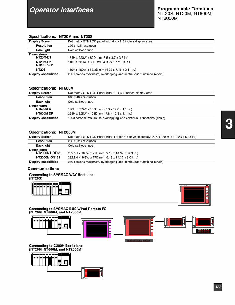
Specifications: NT20M and NT20SDisplay Screen Dot matrix STN LCD panel with 4.4 x 2.2 inches display area
Resolution 256 x 128 resolutionBacklight Cold cathode tube
DimensionsNT20M-DT 164H x 220W x 82D mm (6.5 x 8.7 x 3.3 in.)NT20M-DNNT20-FK201
110H x 220W x 82D mm (4.33 x 8.7 x 3.3 in.)
NT20S 110H x 190W x 53.3D mm (4.33 x 7.48 x 2.11 in.)Display capabilities 250 screens maximum, overlapping and continuous functions (chain)
Specifications: NT600MDisplay Screen Dot matrix STN LCD Panel with 8.1 x 5.1 inches display area
Resolution 640 x 400 resolutionBacklight Cold cathode tube
DimensionsNT600M-DT 198H x 325W x 105D mm (7.8 x 12.8 x 4.1 in.)NT600M-DF 238H x 325W x 105D mm (7.8 x 12.8 x 4.1 in.)
Display capabilities 1000 screens maximum, overlapping and continuous functions (chain)
Specifications: NT2000MDisplay Screen Dot matrix STN LCD Panel with bi-color red or white display, 275 x 138 mm (10.83 x 5.43 in.)
Resolution 256 x 128 resolutionBacklight Cold cathode tube
DimensionsNT2000MT-DT131 232.5H x 365W x 77D mm (9.15 x 14.37 x 3.03 in.)NT2000M-DN131 232.5H x 365W x 77D mm (9.15 x 14.37 x 3.03 in.)
Display capabilities 250 screens maximum, overlapping and continuous functions (chain)
Communications
Connecting to SYSMAC WAY Host Link(NT20S)
Connecting to SYSMAC BUS Wired Remote I/O(NT20M, NT600M, and NT2000M)
RS--232CRS--232C
STOP
ENT
STOP
ENT
F7
F1 F2
F8 F9
F3 F4
F10 F11
F5 F6
F12
Connecting to C200H Backplane(NT20M, NT600M, and NT2000M)
RS--232C
STOP
ENT
10 Operator Interfaces
133
3
Programmable TerminalsNT 20S, NT20M, NT600M,NT2000M
Operator Interfaces
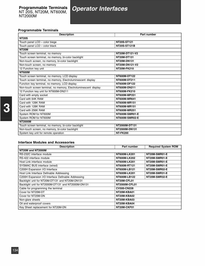
Programmable TerminalsDescription Part number
NT20STouch panel LCD -- color biege NT20S-ST121Touch panel LCD -- color black NT20S-ST121BNT20MTouch screen terminal, no memory NT20M-DT121-V2Touch screen terminal, no memory, bi-color backlight NT20M-DT131Non-touch screen, no memory, bi-color backlight NT20M-DN131Non-touch screen, no memory NT20M-DN121-V212 Function key unit NT20M-FK210NT600MTouch screen terminal, no memory, LCD display NT600M-DT122Touch screen terminal, no memory, Electroluminescent display NT600M-DT211Function key terminal, no memory, LCD display NT600M-DF122Non-touch screen terminal, no memory, Electroluminescent display NT600M-DN21112 Function key unit for NT600M-DN211 NT600M-FK210Card with empty socket NT600M-MP251Card with 64K RAM NT600M-MR641Card with 128K RAM NT600M-MR151Card with 128K RAM NT600M-MR151Card with 256K RAM NT600M-MR251System ROM for NT600M NT600M-SMR01-ESystem ROM for NT600M NT600M-SMR02-ENT2000MTouch screen terminal, no memory, bi-color backlight NT2000M-DT131Non-touch screen, no memory, bi-color backlight NT2000M-DN131System key unit for remote operation NT-FK200
Interface Modules and AccessoriesDescription Part number Required System ROM
NT20M and NT2000MRS-232C interface module NT600M-LK201 NT20M-SMR01-ERS-422 interface module NT600M-LK202 NT20M-SMR01-EHost Link interface module NT600M-LK201 NT20M-SMR01-ESYSMAC BUS interface (wired) NT600M-RT121 NT20M-SMR01-EC200H Expansion I/O Interface NT600M-LB121 NT20M-SMR02-EHost Link Interface Definable Addressing NT600M-LK201 NT20M-SMR31-EC200H Expansion I/O Interface Definable Addressing NT600M-LB122 NT20M-SMR32-EBacklight unit for NT20M-DT131 and NT20M-DN131 NT20M-CFL01Backlight unit for NT2000M-DT131 and NT2000M-DN131 NT2000M-CFL01Cable for programming the terminal CV500-CN228Cover for NT20M-DT NT20M-KBA01Cover for NT20M-DN NT20M-KBA02Non-glare sheets NT20M-KBA03Oil and waterproof covers NT20M-KBA04Key Sheet replacement for NT20M-DN NT20M-CKF01
10 Operator Interfaces
134
3
Programmable TerminalsNT 20S, NT20M, NT600M,NT2000M
Operator Interfaces
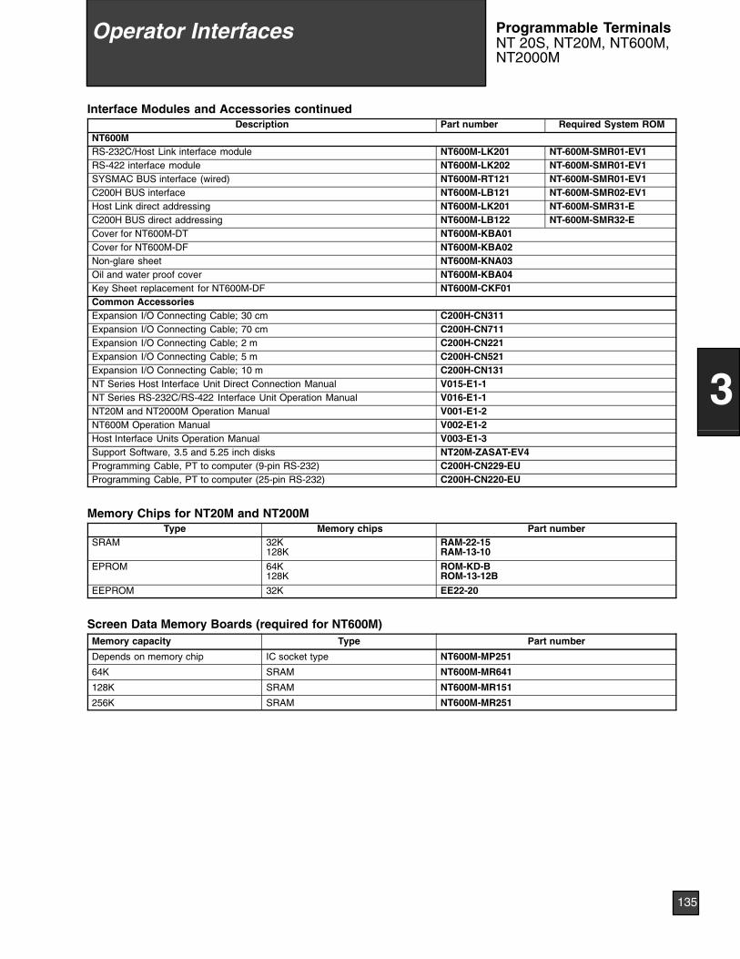
Interface Modules and Accessories continuedDescription Part number Required System ROM
NT600MRS-232C/Host Link interface module NT600M-LK201 NT-600M-SMR01-EV1RS-422 interface module NT600M-LK202 NT-600M-SMR01-EV1SYSMAC BUS interface (wired) NT600M-RT121 NT-600M-SMR01-EV1C200H BUS interface NT600M-LB121 NT-600M-SMR02-EV1Host Link direct addressing NT600M-LK201 NT-600M-SMR31-EC200H BUS direct addressing NT600M-LB122 NT-600M-SMR32-ECover for NT600M-DT NT600M-KBA01Cover for NT600M-DF NT600M-KBA02Non-glare sheet NT600M-KNA03Oil and water proof cover NT600M-KBA04Key Sheet replacement for NT600M-DF NT600M-CKF01Common AccessoriesExpansion I/O Connecting Cable; 30 cm C200H-CN311Expansion I/O Connecting Cable; 70 cm C200H-CN711Expansion I/O Connecting Cable; 2 m C200H-CN221Expansion I/O Connecting Cable; 5 m C200H-CN521Expansion I/O Connecting Cable; 10 m C200H-CN131NT Series Host Interface Unit Direct Connection Manual V015-E1-1NT Series RS-232C/RS-422 Interface Unit Operation Manual V016-E1-1NT20M and NT2000M Operation Manual V001-E1-2NT600M Operation Manual V002-E1-2Host Interface Units Operation Manual V003-E1-3Support Software, 3.5 and 5.25 inch disks NT20M-ZASAT-EV4Programming Cable, PT to computer (9-pin RS-232) C200H-CN229-EUProgramming Cable, PT to computer (25-pin RS-232) C200H-CN220-EU
Memory Chips for NT20M and NT200MType Memory chips Part number
SRAM 32K128K
RAM-22-15RAM-13-10
EPROM 64K128K
ROM-KD-BROM-13-12B
EEPROM 32K EE22-20
Screen Data Memory Boards (required for NT600M)Memory capacity Type Part number
Depends on memory chip IC socket type NT600M-MP251
64K SRAM NT600M-MR641
128K SRAM NT600M-MR151
256K SRAM NT600M-MR251
10 Operator Interfaces
135
3
Programmable TerminalsNT 20S, NT20M, NT600M,NT2000M
Operator Interfaces
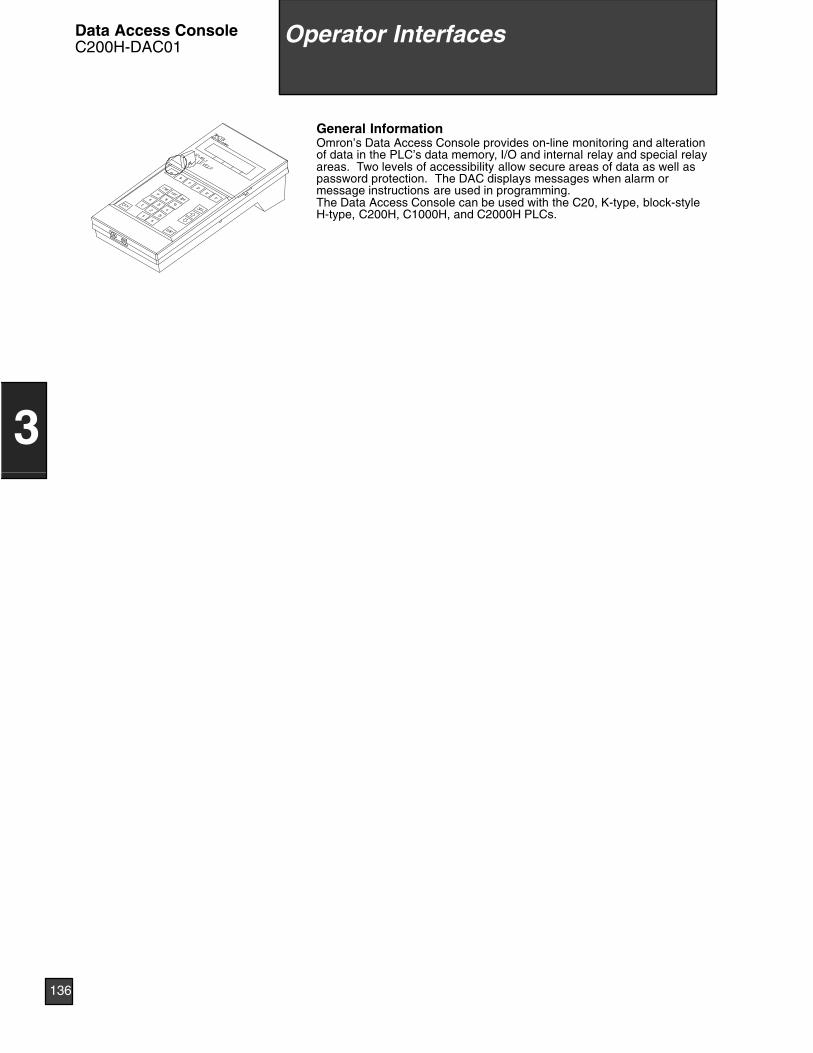
General InformationOmron’s Data Access Console provides on-line monitoring and alterationof data in the PLC’s data memory, I/O and internal relay and special relayareas. Two levels of accessibility allow secure areas of data as well aspassword protection. The DAC displays messages when alarm ormessage instructions are used in programming.The Data Access Console can be used with the C20, K-type, block-styleH-type, C200H, C1000H, and C2000H PLCs.
10 Operator Interfaces
136
3
Operator InterfacesData Access ConsoleC200H-DAC01

Ladder Support Software 138. . . . . . . . . . . . . . . . . . . . . . . . . . . . . . . . .GPC, Programming Consoles 140. . . . . . . . . . . . . . . . . . . . . . . . . . . . .Factory Intelligent Terminal, PROM Writer, Printer Interface 141. . .Programmable Terminal Support Software 142. . . . . . . . . . . . . . . . . .
137
4
11 Peripheral Devices
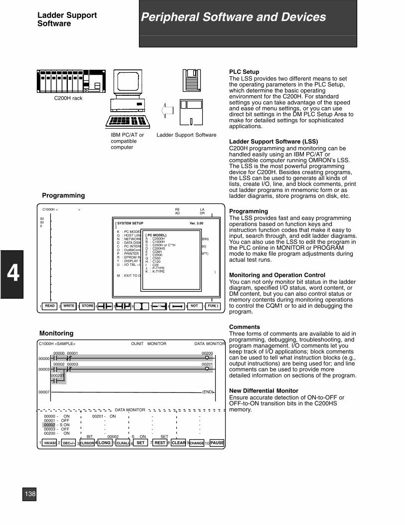
IBM PC/AT orcompatiblecomputer
Ladder Support Software
Monitoring
Programming
HX/ASC
ON
1 2 3 4 5 6 7 8 9
C1000H <SAMPLE> DATA
4
OUNIT MONITOR MONITOR
SET REST CLEAR
DATA MONITOR
-----
-----
-----
-----
0000000001000020000300200
00201ONOFF
S ONOFF
ON00002 ON SET
0020000000 00001
0020100002 00003
000201
(END)
00000
00003
00007
10CHANGE PAUSECLRSOR CLRALLDEC+/-- LONGHX/ASC
BIT S
( )
00000
NOT FUN( )READ WRITE STORE1 2 3 4 5 6 7 8 9 0
C1000H < > READ
LADR
K : PC MODELG : HOST LINK UNITN : NETWORK ADDRESSD : DATA DISK DRIVEC : PC INTERFACEO : OutBitCommentTYPEP : PRINTERR : EPROM INTERFACET : DISPLAY TYPEU : I/O TBL --UM XFER
M : EXIT TO DOS
[ SYSTEM SETUP Ver. 3.00]
(C1000H )(00)(NET000) (NODE001) (BIN)(A)(RS232C) (COM 1) (9600)(INSTCMNT)(WIDE CARRIAGE DRAFT)(COM 1) (9600)(COLOR )( )( )( )
[ PC MODEL]A : C2000HB : C1000HC : C200H or C**HD : C200HSE : CQM1F ; C2000G : C500H : C120I : C20J : P-TYPEK : K-TYPE
C200H rack
PLC SetupThe LSS provides two different means to setthe operating parameters in the PLC Setup,which determine the basic operatingenvironment for the C200H. For standardsettings you can take advantage of the speedand ease of menu settings, or you can usedirect bit settings in the DM PLC Setup Area tomake for detailed settings for sophisticatedapplications.
Ladder Support Software (LSS)C200H programming and monitoring can behandled easily using an IBM PC/AT orcompatible computer running OMRON’s LSS.The LSS is the most powerful programmingdevice for C200H. Besides creating programs,the LSS can be used to generate all kinds oflists, create I/O, line, and block comments, printout ladder programs in mnemonic form or asladder diagrams, store programs on disk, etc.
ProgrammingThe LSS provides fast and easy programmingoperations based on function keys andinstruction function codes that make it easy toinput, search through, and edit ladder diagrams.You can also use the LSS to edit the program inthe PLC online in MONITOR or PROGRAMmode to make file program adjustments duringactual test runs.
Monitoring and Operation ControlYou can not only monitor bit status in the ladderdiagram, specified I/O status, word content, orDM content, but you can also control status ormemory contents during monitoring operationsto control the CQM1 or to aid in debugging theprogram.
CommentsThree forms of comments are available to aid inprogramming, debugging, troubleshooting, andprogram management. I/O comments let youkeep track of I/O applications; block commentscan be used to tell what instruction blocks (e.g.,output instructions) are being used for; and linecomments can be used to provide moredetailed information on sections of the program.
New Differential MonitorEnsure accurate detection of ON-to-OFF orOFF-to-ON transition bits in the C200HSmemory.
138
4
Peripheral Software and DevicesLadder SupportSoftware
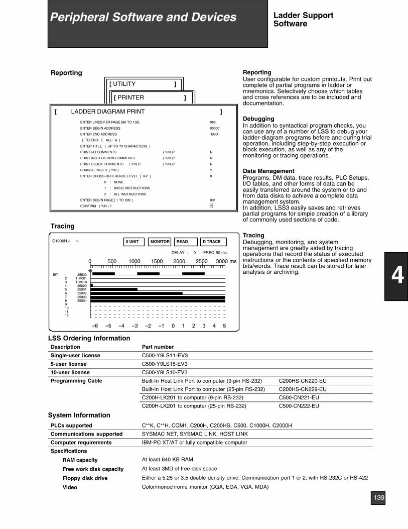
Reporting
[ UTILITY ]
[ PRINTER ]
[ LADDER DIAGRAM PRINT ]
ENTER LINES PER PAGE [66 TO 132] 066
ENTER BEGIN ADDRESS 00000
ENTER END ADDRESS END
[ TO END: E ALL: A ]
ENTER TITLE ( UP TO 70 CHARACTERS )
PRINT I/O COMMENTS ( Y/N )? N
PRINT INSTRUCTION COMMENTS ( Y/N )? N
PRINT BLOCK COMMENTS ( Y/N )? ( Y/N )? N
CHANGE PAGES [ Y/N ] Y
ENTER CROSS-REFERENCE LEVEL [ 0-2 ] 0
0 : NONE
1 : BASIC INSTRUCTIONS
2 : ALL INSTRUCTIONS
ENTER BEGIN PAGE [ 1 TO 999 ] 001
CONFIRM ( Y/N ) ? Y
--6 --5 --4 --3 --2 --1 0 1 2 3 4 5
D TRACEMONITOR0 UNIT READ
0
DELAY: + 0 FREQ 50 ms
3000 ms500 1000 1500 2000 2500
BIT 1 255022 TIM0013 TIM0104 250005 250016 250027 250038 250049101112
C1000H < >
Tracing
ReportingUser configurable for custom printouts. Print outcomplete of partial programs in ladder ormnemonics. Selectively choose which tablesand cross references are to be included anddocumentation.
DebuggingIn addition to syntactical program checks, youcan use any of a number of LSS to debug yourladder-diagram programs before and during trialoperation, including step-by-step execution orblock execution, as well as any of themonitoring or tracing operations.
Data ManagementPrograms, DM data, trace results, PLC Setups,I/O tables, and other forms of data can beeasily transferred around the system or to andfrom data disks to achieve a complete datamanagement system.In addition, LSS3 easily saves and retrievespartial programs for simple creation of a libraryof commonly used sections of code.
TracingDebugging, monitoring, and systemmanagement are greatly aided by tracingoperations that record the status of executedinstructions or the contents of specified memorybits/words. Trace result can be stored for lateranalysis or archiving.
LSS Ordering InformationDescription Part number
Single-user license C500-Y9LS11-EV3
5-user license C500-Y9LS15-EV3
10-user license C500-Y9LS10-EV3
Programming Cable Built-In Host Link Port to computer (9-pin RS-232) C200HS-CN220-EUg g
Built-In Host Link Port to computer (25-pin RS-232) C200HS-CN229-EU
C200H-LK201 to computer (9-pin RS-232) C500-CN221-EU
C200H-LK201 to computer (25-pin RS-232) C500-CN222-EU
System Information
PLCs supported C**K, C**H, CQM1, C200H, C200HS, C500, C1000H, C2000H
Communications supported SYSMAC NET, SYSMAC LINK, HOST LINK
Computer requirements IBM-PC XT/AT or fully compatible computer
Specifications
RAM capacity At least 640 KB RAM
Free work disk capacity At least 3MD of free disk space
Floppy disk drive Either a 5.25 or 3.5 double density drive, Communication port 1 or 2, with RS-232C or RS-422
Video Color/monochrome monitor (CGA, EGA, VGA, MDA)
139
4
Peripheral Software and Devices Ladder SupportSoftware
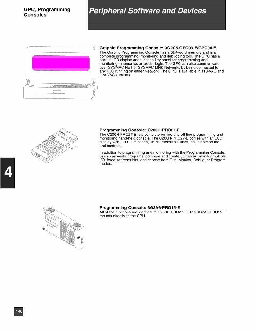
Graphic Programming Console: 3G2C5-GPC03-E/GPC04-EThe Graphic Programming Console has a 32K-word memory and is acomplete programming, monitoring and debugging tool. The GPC has abacklit LCD display and function key panel for programming andmontioring mnemonics or ladder logic. The GPC can also communicateover SYSMAC NET or SYSMAC LINK Networks by being connected toany PLC running on either Network. The GPC is available in 110-VAC and220-VAC versions.
Programming Console: C200H-PRO27-EThe C200H-PRO27-E is a complete on-line and off-line programming andmonitoring hand-held console. The C200H-PRO27-E comes with an LCDdisplay with LED illumination, 16 characters x 2 lines, adjustable soundand contrast.
In addition to programming and monitoring with the Programming Console,users can verify programs, compare and create I/O tables, monitor multipleI/O, force set/reset bits, and choose from Run, Monitor, Debug, or Programmodes.
Programming Console: 3G2A6-PRO15-EAll of the functions are identical to C200H-PRO27-E. The 3G2A6-PRO15-Emounts directly to the CPU.
140
4
Peripheral Software and DevicesGPC, ProgrammingConsoles
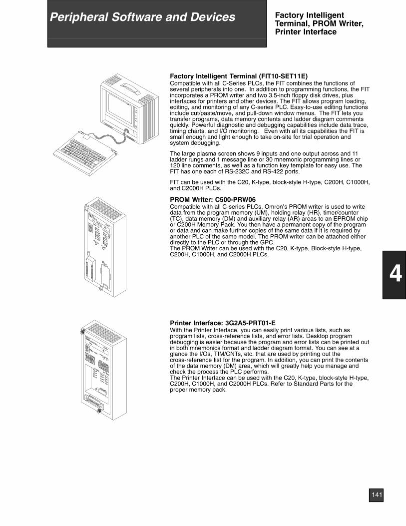
Factory Intelligent Terminal (FIT10-SET11E)Compatible with all C-Series PLCs, the FIT combines the functions ofseveral peripherals into one. In addition to programming functions, the FITincorporates a PROM writer and two 3.5-inch floppy disk drives, plusinterfaces for printers and other devices. The FIT allows program loading,editing, and monitoring of any C-series PLC. Easy-to-use editing functionsinclude cut/paste/move, and pull-down window menus. The FIT lets youtransfer programs, data memory contents and ladder diagram commentsquickly. Powerful diagnostic and debugging capabilities include data trace,timing charts, and I/O monitoring. Even with all its capabilities the FIT issmall enough and light enough to take on-site for trial operation andsystem debugging.
The large plasma screen shows 9 inputs and one output across and 11ladder rungs and 1 message line or 30 mnemonic programming lines or120 line comments, as well as a function key template for easy use. TheFIT has one each of RS-232C and RS-422 ports.
FIT can be used with the C20, K-type, block-style H-type, C200H, C1000H,and C2000H PLCs.
PROM Writer: C500-PRW06Compatible with all C-series PLCs, Omron’s PROM writer is used to writedata from the program memory (UM), holding relay (HR), timer/counter(TC), data memory (DM) and auxiliary relay (AR) areas to an EPROM chipor C200H Memory Pack. You then have a permanent copy of the programor data and can make further copies of the same data if it is required byanother PLC of the same model. The PROM writer can be attached eitherdirectly to the PLC or through the GPC.The PROM Writer can be used with the C20, K-type, Block-style H-type,C200H, C1000H, and C2000H PLCs.
Printer Interface: 3G2A5-PRT01-EWith the Printer Interface, you can easily print various lists, such asprogram lists, cross-reference lists, and error lists. Desktop programdebugging is easier because the program and error lists can be printed outin both mnemonics format and ladder diagram format. You can see at aglance the I/Os, TIM/CNTs, etc. that are used by printing out thecross-reference list for the program. In addition, you can print the contentsof the data memory (DM) area, which will greatly help you manage andcheck the process the PLC performs.The Printer Interface can be used with the C20, K-type, block-style H-type,C200H, C1000H, and C2000H PLCs. Refer to Standard Parts for theproper memory pack.
141
4
Peripheral Software and Devices Factory IntelligentTerminal, PROM Writer,Printer Interface
General InformationProgrammable Terminal Support Software allows the user to configuremessages, operator prompts, alarms, touch switches, indicators, simplegraphics, or any combination of these to provide the best overview of themachine or process to the operator. Control programming is accomplishedusing relay ladder logic (RLL) for SYSMAC BUS and Host Link interfaces,or ASCII characters for RS-232C and RS-422 configurations.
Features♦ Design, upload, and download Programmable Terminal screens♦ IBM-PC XT/AT, or fully compatible computer♦ Either a 5.25” or 3.5” double density disk drive♦ A hard disk with at least 3 MB of free disk space♦ At least 640 Kb RAM♦ PC-DOS, MS-DOS, or equivalent (version 3.2 or higher)♦ Communication port 1 or 2, with RS-232C or RS-422♦ Color/monochrome monitor (CGA, EGA, VGA, MDA)♦ Edit and copy screen layouts♦ Save screen files to disk♦ Configure screen messages, graphics, data display, touch switches
(touch-type only), and indicator lamps
System RequirementsPart number NT20M-ZASAT-EV4System disk 3.5 inch, 2DD and 5 inch, 2HDApplicable computers IBM PC/AT or IBM PC/AT compatibleDOS version MS-DOS Version 3.2 or laterFloppy disk drives necessary 1 minimumRAM 640 Kbytes minmumGraphic monitor VGACommunication settings Baud rate: 9,600 bps
Stop bits: 1 bitData length: 8 bitsParity: NoneThe Intel HEX file format can be used.
PROM writer Commercially available PROM writer
142
4
Peripheral Software and DevicesProgrammable TerminalSupport Software
System Applications 144. . . . . . . . . . . . . . . . . . . . . . . . . . . . . . . . . . . . .SYSMAC NET Token Ring Network 146. . . . . . . . . . . . . . . . . . . . . . . .SYSMAC LINK Token Bus Network 148. . . . . . . . . . . . . . . . . . . . . . . .SYSMAC WAY Host Link 150. . . . . . . . . . . . . . . . . . . . . . . . . . . . . . . . .PC Link System 152. . . . . . . . . . . . . . . . . . . . . . . . . . . . . . . . . . . . . . . . .SYSMAC BUS Remote I/O 153. . . . . . . . . . . . . . . . . . . . . . . . . . . . . . .Fiber-optic Communication Technology 155. . . . . . . . . . . . . . . . . . . .
12 Communication Sys-tems
143
5
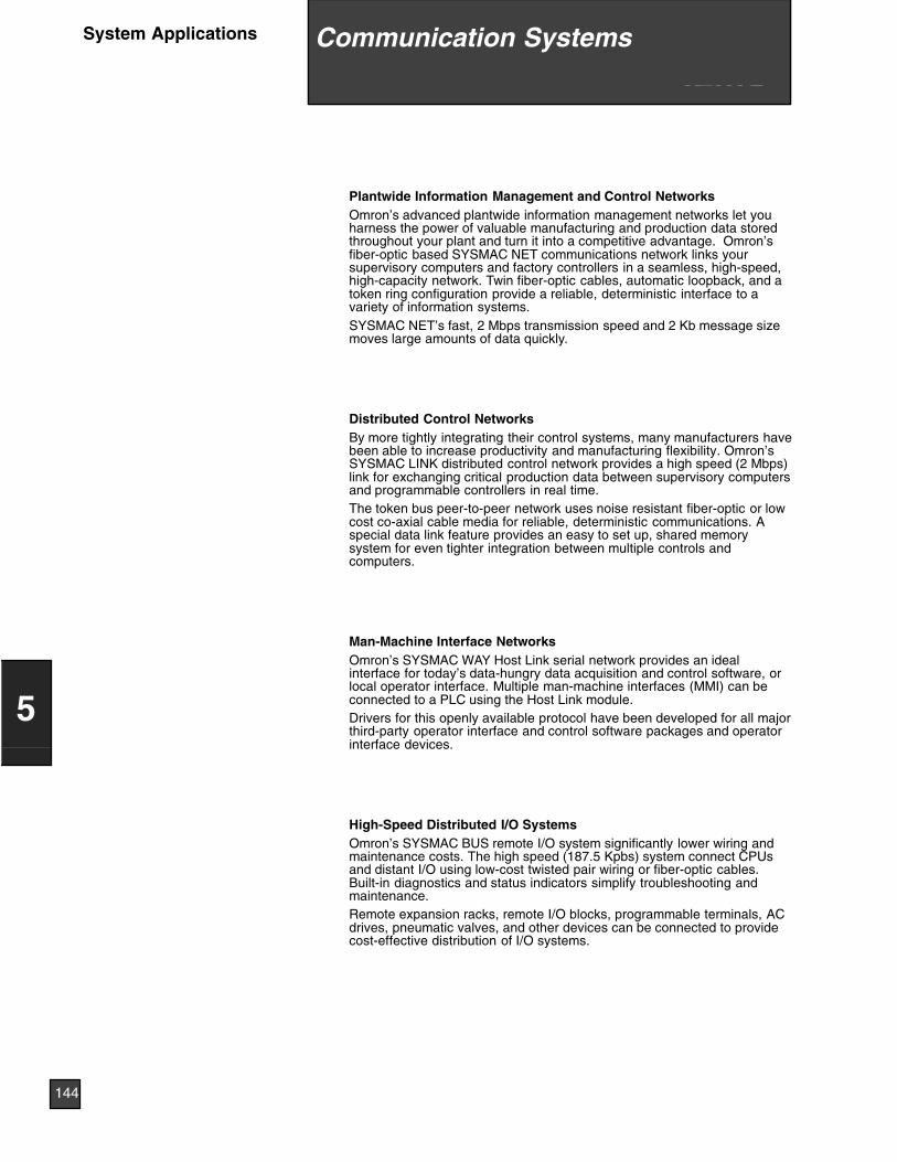
Plantwide Information Management and Control NetworksOmron’s advanced plantwide information management networks let youharness the power of valuable manufacturing and production data storedthroughout your plant and turn it into a competitive advantage. Omron’sfiber-optic based SYSMAC NET communications network links yoursupervisory computers and factory controllers in a seamless, high-speed,high-capacity network. Twin fiber-optic cables, automatic loopback, and atoken ring configuration provide a reliable, deterministic interface to avariety of information systems.SYSMAC NET’s fast, 2 Mbps transmission speed and 2 Kb message sizemoves large amounts of data quickly.
Distributed Control NetworksBy more tightly integrating their control systems, many manufacturers havebeen able to increase productivity and manufacturing flexibility. Omron’sSYSMAC LINK distributed control network provides a high speed (2 Mbps)link for exchanging critical production data between supervisory computersand programmable controllers in real time.The token bus peer-to-peer network uses noise resistant fiber-optic or lowcost co-axial cable media for reliable, deterministic communications. Aspecial data link feature provides an easy to set up, shared memorysystem for even tighter integration between multiple controls andcomputers.
Man-Machine Interface NetworksOmron’s SYSMAC WAY Host Link serial network provides an idealinterface for today’s data-hungry data acquisition and control software, orlocal operator interface. Multiple man-machine interfaces (MMI) can beconnected to a PLC using the Host Link module.Drivers for this openly available protocol have been developed for all majorthird-party operator interface and control software packages and operatorinterface devices.
High-Speed Distributed I/O SystemsOmron’s SYSMAC BUS remote I/O system significantly lower wiring andmaintenance costs. The high speed (187.5 Kpbs) system connect CPUsand distant I/O using low-cost twisted pair wiring or fiber-optic cables.Built-in diagnostics and status indicators simplify troubleshooting andmaintenance.Remote expansion racks, remote I/O blocks, programmable terminals, ACdrives, pneumatic valves, and other devices can be connected to providecost-effective distribution of I/O systems.
12 Communication Sys-tems
144
5
System Applications Communication Systems
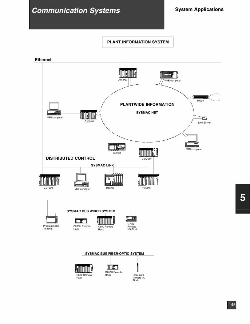
HLTRUNFAILVMECPUV2NCDBCDINSSDRDVALHILOWHILOW
NODENo.SYSNETSOFTLED18764325
(BSDNRD(1LSSL2(DRBDSN
(
CN1(+)(
)CL001
Ethernet
C200H
C2000H
MMI computer
VME computer
Bridge
MMI computer C200H CV1000
C500 RemoteRack
G72CRemoteI/O Block
ProgrammableTerminal
C200H RemoteRack
C200H RemoteRack
C500 RemoteRack
SYSMAC BUS WIRED SYSTEM
SYSMAC BUS FIBER-OPTIC SYSTEM
Fiber-opticRemote I/OBlock
Line Server
CV1000
CV 500
PLANT INFORMATION SYSTEM
CV/CVM1
MMI computer
SYSMAC LINK
PLANTWIDE INFORMATION
SYSMAC NET
DISTRIBUTED CONTROL
12 Communication Sys-tems
145
5
System ApplicationsCommunication Systems
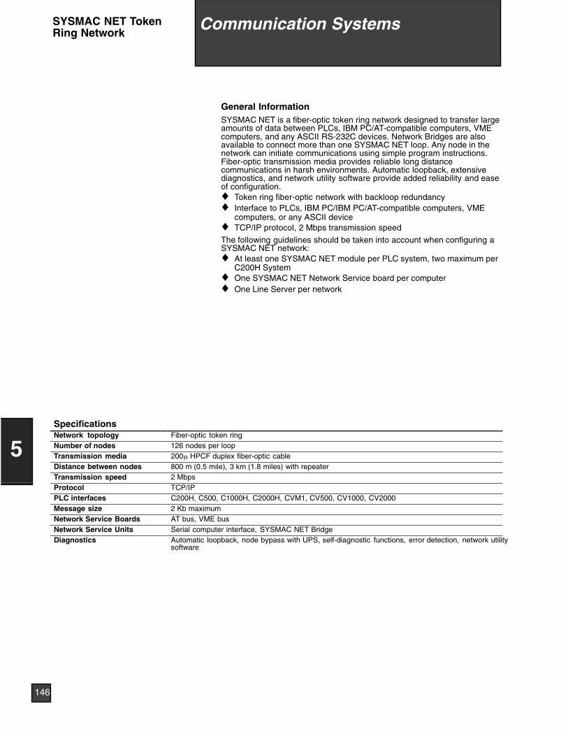
General InformationSYSMAC NET is a fiber-optic token ring network designed to transfer largeamounts of data between PLCs, IBM PC/AT-compatible computers, VMEcomputers, and any ASCII RS-232C devices. Network Bridges are alsoavailable to connect more than one SYSMAC NET loop. Any node in thenetwork can initiate communications using simple program instructions.Fiber-optic transmission media provides reliable long distancecommunications in harsh environments. Automatic loopback, extensivediagnostics, and network utility software provide added reliability and easeof configuration.♦ Token ring fiber-optic network with backloop redundancy♦ Interface to PLCs, IBM PC/IBM PC/AT-compatible computers, VME
computers, or any ASCII device♦ TCP/IP protocol, 2 Mbps transmission speed
The following guidelines should be taken into account when configuring aSYSMAC NET network:♦ At least one SYSMAC NET module per PLC system, two maximum per
C200H System♦ One SYSMAC NET Network Service board per computer♦ One Line Server per network
SpecificationsNetwork topology Fiber-optic token ringNumber of nodes 126 nodes per loopTransmission media 200µ HPCF duplex fiber-optic cableDistance between nodes 800 m (0.5 mile), 3 km (1.8 miles) with repeaterTransmission speed 2 MbpsProtocol TCP/IPPLC interfaces C200H, C500, C1000H, C2000H, CVM1, CV500, CV1000, CV2000Message size 2 Kb maximumNetwork Service Boards AT bus, VME busNetwork Service Units Serial computer interface, SYSMAC NET BridgeDiagnostics Automatic loopback, node bypass with UPS, self-diagnostic functions, error detection, network utility
software
12 Communication Sys-tems
146
5
Communication SystemsSYSMAC NET TokenRing Network
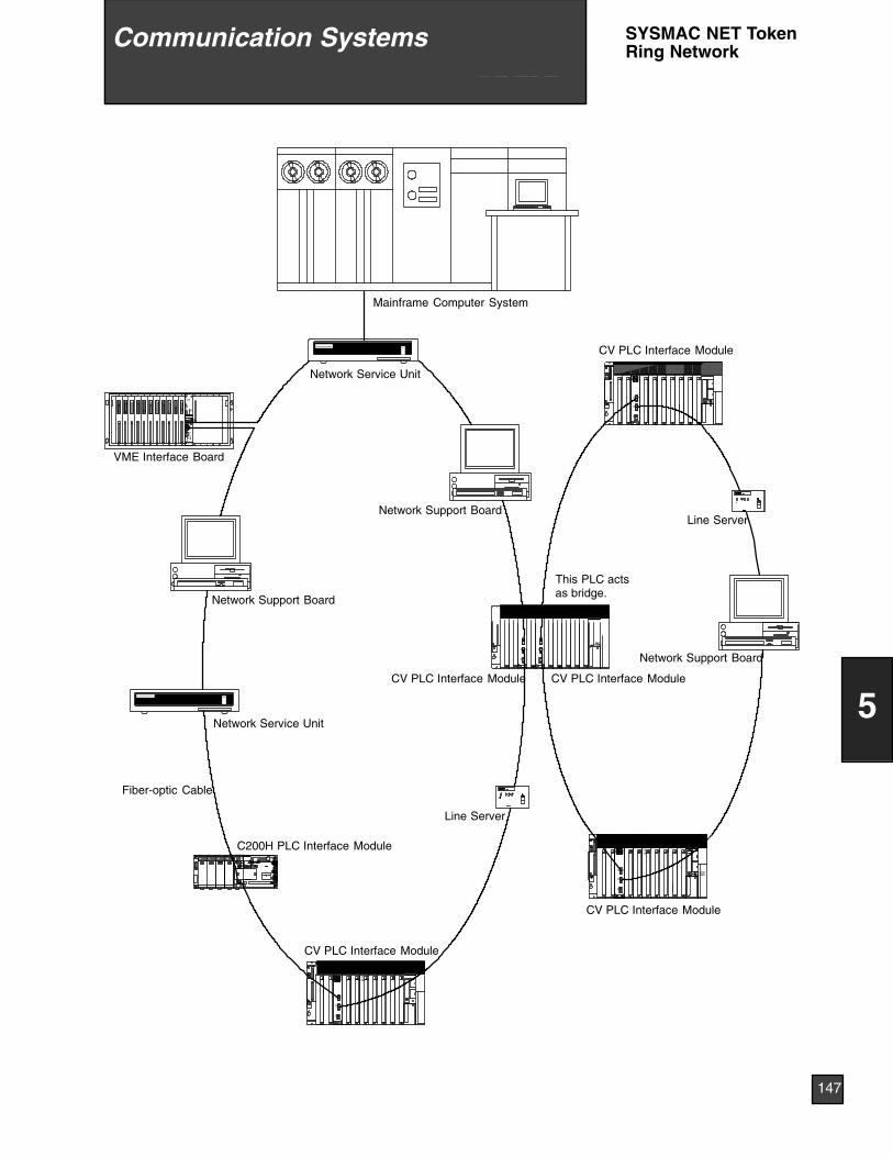
52346781DELTFOS
M/CONEX--DM
CN
SL 2 SL 2
M/CONEX--DM
CN
01No.NODE01No.UNIT
SL 1
SL 2
SL 2
SL 1
UNITNo.X10 X101 0NODENo.X16 X161 0
CN
EX--DMONRS--422RS--232
SL 2
SL 1
UNITNo.X10 X101 0NODENo.X16 X161 0
CN
CL001
(+)(
)
1NC
(NSDBRD(2LS
SL1 (DRNDSB(
o.DON
HI
V2
OC221CHOC221CH OC221CHOC221CHOC221CHOC221CHOC221CHOC221CHOC221CHSNT31
CHOC221CHOC221CHOC221CHOC221CHOC221CHSNT31OC221SNT31CHOC221CHOC221
OC223OC223OC223OC223 SNT31
Mainframe Computer System
Network Service Unit
Network Service Unit
Network Support Board
Network Support Board
Fiber-optic Cable
VME Interface Board
CV PLC Interface Module
Line Server
C200H PLC Interface Module
CV PLC Interface Module
CV PLC Interface Module
Line Server
CV PLC Interface Module
Network Support Board
I891011121314157654321O
I891011121314157654321O
I891011121314157654321O
I891011121314157654321O
I891011121314157654321O
I891011121314157654321O
I891011121314157654321O
I891011121314157654321OO123456715141312111098I O123456715141312111098I I8910111213141576
54321O
I891011121314157654321O
I891011121314157654321O
I891011121314157654321O
I891011121314157654321O
I891011121314157654321O
I891011121314157654321O
I891011121314157654321O
PS221POWER
NORMALPROTECTSYSTEMCOMMOUT INHALARMWDTERRORRUNPOWER
RUN P/SERRINS LINKNCD BCDSD RD
CV PLC Interface Module
This PLC actsas bridge.
12 Communication Sys-tems
147
5
Communication Systems SYSMAC NET TokenRing Network
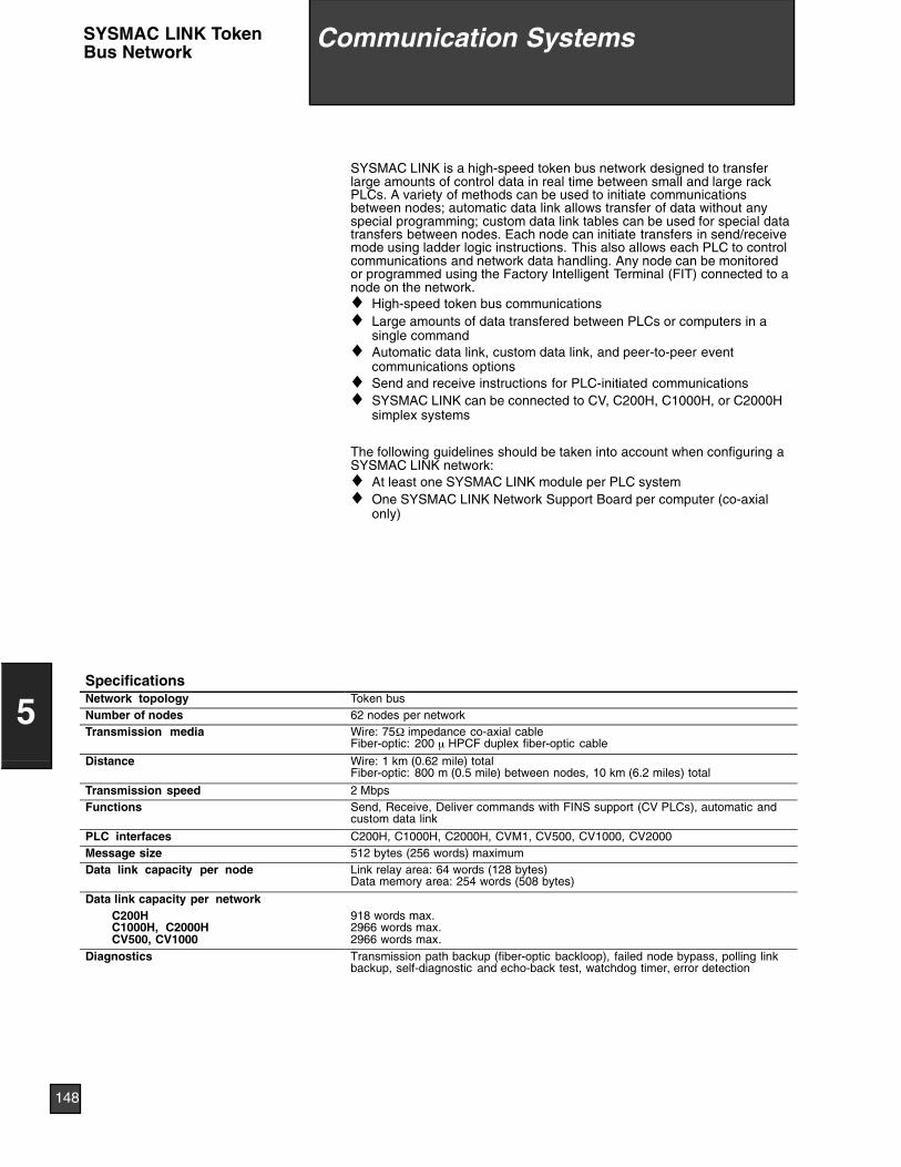
SYSMAC LINK is a high-speed token bus network designed to transferlarge amounts of control data in real time between small and large rackPLCs. A variety of methods can be used to initiate communicationsbetween nodes; automatic data link allows transfer of data without anyspecial programming; custom data link tables can be used for special datatransfers between nodes. Each node can initiate transfers in send/receivemode using ladder logic instructions. This also allows each PLC to controlcommunications and network data handling. Any node can be monitoredor programmed using the Factory Intelligent Terminal (FIT) connected to anode on the network.♦ High-speed token bus communications♦ Large amounts of data transfered between PLCs or computers in a
single command♦ Automatic data link, custom data link, and peer-to-peer event
communications options♦ Send and receive instructions for PLC-initiated communications♦ SYSMAC LINK can be connected to CV, C200H, C1000H, or C2000H
simplex systems
The following guidelines should be taken into account when configuring aSYSMAC LINK network:♦ At least one SYSMAC LINK module per PLC system♦ One SYSMAC LINK Network Support Board per computer (co-axial
only)
SpecificationsNetwork topology Token busNumber of nodes 62 nodes per networkTransmission media Wire: 75Ω impedance co-axial cable
Fiber-optic: 200 µ HPCF duplex fiber-optic cable
Distance Wire: 1 km (0.62 mile) totalFiber-optic: 800 m (0.5 mile) between nodes, 10 km (6.2 miles) total
Transmission speed 2 MbpsFunctions Send, Receive, Deliver commands with FINS support (CV PLCs), automatic and
custom data link
PLC interfaces C200H, C1000H, C2000H, CVM1, CV500, CV1000, CV2000Message size 512 bytes (256 words) maximumData link capacity per node Link relay area: 64 words (128 bytes)
Data memory area: 254 words (508 bytes)
Data link capacity per networkC200HC1000H, C2000HCV500, CV1000
918 words max.2966 words max.2966 words max.
Diagnostics Transmission path backup (fiber-optic backloop), failed node bypass, polling linkbackup, self-diagnostic and echo-back test, watchdog timer, error detection
12 Communication Sys-tems
148
5
Communication SystemsSYSMAC LINK TokenBus Network
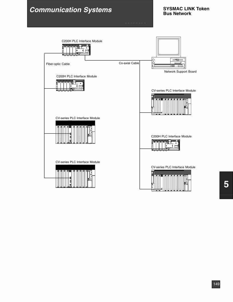
SL
0101
L1L2/N
1 0
Text is White
I891011121314157654321O
I891011121314157654321O
I891011121314157654321O
I891011121314157654321O
I891011121314157654321O
I891011121314157654321O
I891011121314157654321O
I891011121314157654321OO123456715141312111098
I O123456715141312111098I I8910111213141576
54321O
I891011121314157654321O
I891011121314157654321O
I891011121314157654321O
I891011121314157654321O
I891011121314157654321O
I891011121314157654321O
I891011121314157654321O
RUNERC ERHINS M/SSD RDTS LNK
PS221POWER
NORMALPROTECTSYSTEMCOMMOUT INHALARMWDTERRORRUNPOWER
Co-axial CableFiber-optic Cable
C200H PLC Interface Module
Network Support Board
0101
CV-series PLC Interface Module
CV-series PLC Interface Module
C200H PLC Interface Module
CV-series PLC Interface Module
CV-series PLC Interface Module
SL
0101
0101
L1L2/N
1 0
C200H PLC Interface Module
12 Communication Sys-tems
149
5
Communication Systems SYSMAC LINK TokenBus Network
Host Link allows any computer to communicate with one (RS-232C), orseveral (RS-422) Omron PLCs. Multiple system levels can be connected tothe same PLC with up to 32 PLCs connnected to one computer. Omron’sHost Link protocol is well defined and available for custom software driverdevelopment and operator interface connection to Omron PLCs. Mostmajor operator interface companies have Host Link interfaces and driversavailable. Host Link systems allow using Ladder Support Software (LSS) toprogram and monitor any PLC in the system.
The Host Link protocol is common to all Omron PLCs including the C20,K-type, Block-style H-type, C200H, C1000H, C2000H, and CV-seriesPLCs.
♦ Up to 32 PLCs can be connected to a single host computer♦ Twisted pair or fiber-optic transmission media
The following guidelines should be taken into account when configuring aHost Link system:♦ The computer must have one serial port available♦ If a fiber-optic, or RS-422 Host Link module is used, Link Adapters
must be included in the system
SpecificationsCommunications protocol Software: Omron host link protocol
Hardware: RS-232C, RS-422 multi-drop; fiber-optic, or combination using Omron Link Adapters
Synchronization Start-stop (1 or 2 stop bits)Distance RS-232C: 15 m (49 ft.) maximum
RS-422: 10 m (32.8 ft.) maximum for any one cableDistances can be extended using Link Adapters
Transmission speed 300, 600, 1200, 2400, 4800, 9600, 19,200 bps (switch-selectable)PLC interfaces C20, K-type, Block-style H-type (built-in), C200H, C500, C1000H, C2000H, CVM1, CV500, CV1000,
CV2000
Character code ASCII (7 bits) or JIS (8 bits)Error check Parity and frame check sumFunctions Program upload/download, PLC status control, error handling, read (any) memory area, write (any)
memory area, read timer/counter, write timer/counter, etc.
12 Communication Sys-tems
150
5
Communication SystemsSYSMAC WAYHost Link
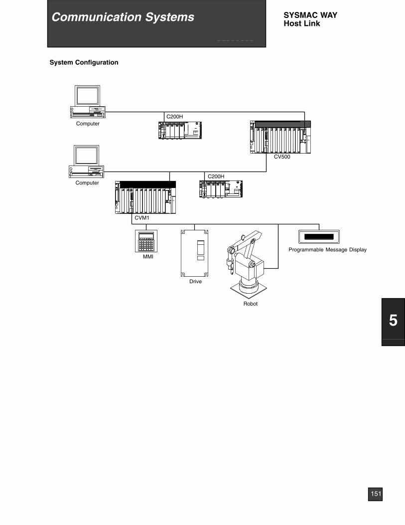
RS--232
RS--232
OC221CHOC221CHOC221CHOC221CHOC221CHOC221CHOC221CHOC221 LK201 CHOC221CH
C200H
CV500
C200H
CVM1
MMI
Drive
Robot
Programmable Message Display
Computer
Computer
System Configuration
12 Communication Sys-tems
151
5
Communication Systems SYSMAC WAYHost Link
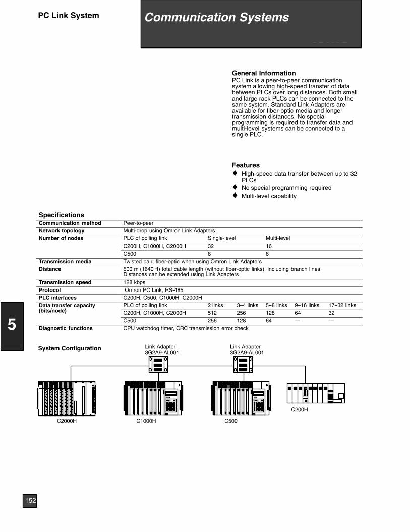
General InformationPC Link is a peer-to-peer communicationsystem allowing high-speed transfer of databetween PLCs over long distances. Both smalland large rack PLCs can be connected to thesame system. Standard Link Adapters areavailable for fiber-optic media and longertransmission distances. No specialprogramming is required to transfer data andmulti-level systems can be connected to asingle PLC.
Features♦ High-speed data transfer between up to 32
PLCs♦ No special programming required♦ Multi-level capability
SpecificationsCommunication method Peer-to-peerNetwork topology Multi-drop using Omron Link AdaptersNumber of nodes PLC of polling link Single-level Multi-level
C200H, C1000H, C2000H 32 16C500 8 8
Transmission media Twisted pair; fiber-optic when using Omron Link AdaptersDistance 500 m (1640 ft) total cable length (without fiber-optic links), including branch lines
Distances can be extended using Link Adapters
Transmission speed 128 kbpsProtocol Omron PC Link, RS-485PLC interfaces C200H, C500, C1000H, C2000HData transfer capacity(bit / d )
PLC of polling link 2 links 3--4 links 5--8 links 9--16 links 17--32 linksp y(bits/node) C200H, C1000H, C2000H 512 256 128 64 32
C500 256 128 64 — —Diagnostic functions CPU watchdog timer, CRC transmission error check
C500C2000H C1000H
C200H
Link Adapter3G2A9-AL001
Link Adapter3G2A9-AL001
System Configuration
12 Communication Sys-tems
152
5
Communication SystemsPC Link System
General InformationThe SYSMAC BUS Remote I/O system is ideal for distribution of I/O andother devices at long distances from the CPU. Multiple remote I/O systemscan be connected to a single CPU allowing maximum configurationflexibility.A SYSMAC BUS Remote I/O system consists of a Remote Master and oneor more Remote Slave modules. Both small and large rack-style I/O can bemixed in the same remote I/O system. Remote terminal blocks allow fordistribution of 8- and 16-point I/O blocks in a wired remote I/O system.Stand-alone fiber-optic I/O modules allow distribution of 8-point I/O blocksin a fiber-optic remote I/O system. I/O Link modules allow connection of aK-type PLC to a fiber-optic remote I/O system. Special link adapters areavailable for extended distances and mixing media types.
Features♦ Wired twisted pair or fiber-optic cable versions♦ Variety of I/O styles and types in a given remote I/O system♦ RS-485 communications at 187.5 Kbps♦ Connect C200H I/O, C500 I/O, G7 remote I/O terminals, programmable
terminals
SpecificationsPLC C200H-RM001/RM002Masters per PLC 2Remote expansion racks permaster
5 Slaves per PLC max
Remote I/O devices per master Up to 32I/O points per master 512I/O points per PLC 512
12 Communication Sys-tems
153
5
Communication Systems SYSMAC BUSRemote I/O

SYSMAC BUS Fiber-optic System SYSMAC BUS Wired SystemFiber-optic Cable Twisted-pair cable
C200H RemoteExpansion Rack
Remote Slave Module
C200H Remote Expansion Rack
Remote Slave Module
C500 Remote Expansion Rack
RemoteSlaveModule
Programmable Terminal
C500 Remote Expansion Rack
C500 Remote Expansion Rack
RemoteSlaveModule
Drive (commercially available)
Valve (commercially available)
K3FS RemoteAnalog I/O Block
G72C G71 G7VC
Fiber-optic Remote I/O Block
Fiber-optic Remote I/O Block
ON
L1
76
POWER 0XFER 1ERR 2345
POWER 0XFER 1ERR 2345
L1
12 Communication Sys-tems
154
5
Communication SystemsSYSMAC BUSRemote I/O
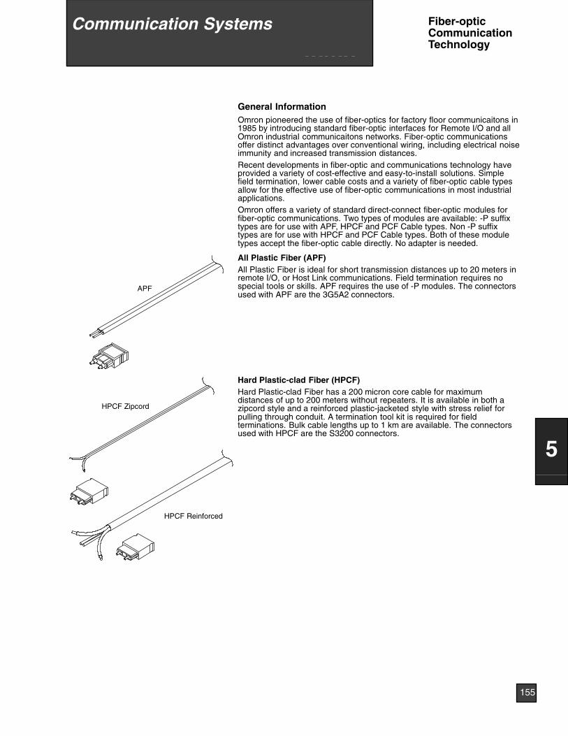
General InformationOmron pioneered the use of fiber-optics for factory floor communicaitons in1985 by introducing standard fiber-optic interfaces for Remote I/O and allOmron industrial communicaitons networks. Fiber-optic communicationsoffer distinct advantages over conventional wiring, including electrical noiseimmunity and increased transmission distances.Recent developments in fiber-optic and communications technology haveprovided a variety of cost-effective and easy-to-install solutions. Simplefield termination, lower cable costs and a variety of fiber-optic cable typesallow for the effective use of fiber-optic communications in most industrialapplications.Omron offers a variety of standard direct-connect fiber-optic modules forfiber-optic communications. Two types of modules are available: -P suffixtypes are for use with APF, HPCF and PCF Cable types. Non -P suffixtypes are for use with HPCF and PCF Cable types. Both of these moduletypes accept the fiber-optic cable directly. No adapter is needed.
APF
All Plastic Fiber (APF)All Plastic Fiber is ideal for short transmission distances up to 20 meters inremote I/O, or Host Link communications. Field termination requires nospecial tools or skills. APF requires the use of -P modules. The connectorsused with APF are the 3G5A2 connectors.
HPCF Zipcord
HPCF Reinforced
Hard Plastic-clad Fiber (HPCF)Hard Plastic-clad Fiber has a 200 micron core cable for maximumdistances of up to 200 meters without repeaters. It is available in both azipcord style and a reinforced plastic-jacketed style with stress relief forpulling through conduit. A termination tool kit is required for fieldterminations. Bulk cable lengths up to 1 km are available. The connectorsused with HPCF are the S3200 connectors.
12 Communication Sys-tems
155
5
Communication Systems Fiber-opticCommunicationTechnology
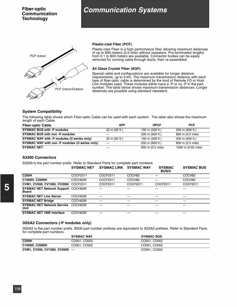
PCF Indoor
PCF Indoor/Outdoor
Plastic-clad Fiber (PCF)Plastic-clad Fiber is a high performance fiber allowing maximum distancesof up to 800 meters (0.5 mile) without repeaters. Pre-terminated lengthsfrom 0.1 to 800 meters are available. Connector bodies can be easilyremoved for running cable through ducts, then re-assembled.
All Glass Crystal Fiber (AGF)Special cable and configurations are available for longer distancerequirements, up to 3 km. The maximum transmission distance with eachtype of fiber-optic cable is determined by the kind of Remote I/O or HostLink modules used. These modules either have a -P or no -P in the partnumber. The table below shows maximum transmission distances. Longerdistances are possible using standard repeaters.
System CompatibilityThe following table shows which Fiber-optic Cable can be used with each system. The table also shows the maximumlength of each Cable.Fiber-optic Cable APF HPCF PCF
SYSMAC BUS with -P modules 20 m (65 ft.) 100 m (328 ft.) 200 m (656 ft.)SYSMAC BUS with non -P modules — 200 m (656 ft.) 800 m (0.5 mile)SYSMAC WAY with -P modules (C-series only) 20 m (65 ft.) 100 m (328 ft.) 200 m (656 ft.)SYSMAC WAY with non -P modules (C-series only) — 200 m (656 ft.) 800 m (0.5 mile)SYSMAC NET — 800 m (0.5 mile) 1000 m (0.62 mile)
S3200 ConnectorsS3200 is the part number prefix. Refer to Standard Parts for complete part numbers.
SYSMAC NET SYSMAC LINK SYSMAC WAY SYSMACBUS/2
SYSMAC BUS
C200H COCF2511 COCF2511 COCH82 — COCH82C1000H, C2000H COCH62M COCF2011 COCH82 — COCH82CVM1, CV500, CV1000, CV2000 COCF2011 COCF2011 COCF2011 COCF2011 COCF2011SYSMAC NET Network SupportBoard
COCH62M — — — —
SYSMAC NET Line Server COCH62M — — — —SYSMAC NET Bridge COCH62M — — — —SYSMAC NET Network ServiceUnit
COCH62M — — — —
SYSMAC NET VME Interface COCH62M — — — —
3G5A2 Connectors (-P modules only)3G5A2 is the part number prefix. B500 part number prefixes are equivalent to 3G5A2 prefixes. Refer to Standard Partsfor complete part numbers.
SYSMAC WAY SYSMAC BUSC200H CO001, CO002 CO001, CO002C1000H, C2000H CO001, CO002 CO001, CO002CVM1, CV500, CV1000, CV2000 — CO001, CO002
12 Communication Sys-tems
156
5
Communication SystemsFiber-opticCommunicationTechnology
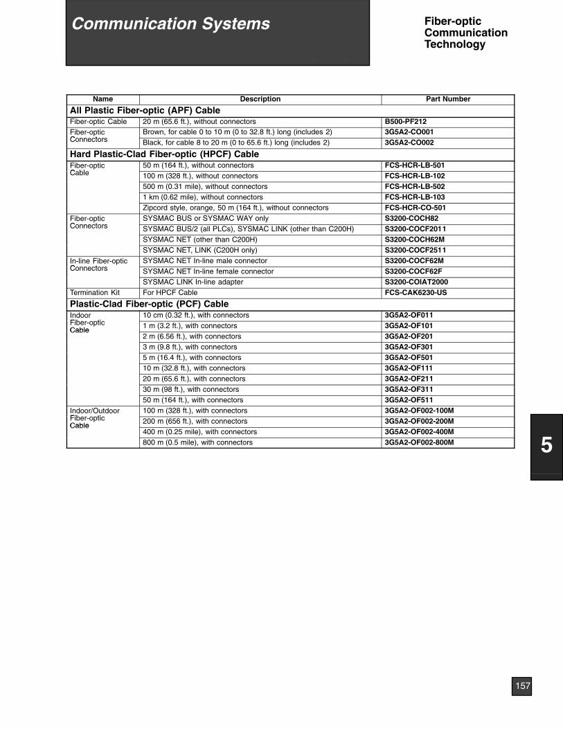
Name Description Part Number
All Plastic Fiber-optic (APF) CableFiber-optic Cable 20 m (65.6 ft.), without connectors B500-PF212Fiber-opticC t
Brown, for cable 0 to 10 m (0 to 32.8 ft.) long (includes 2) 3G5A2-CO001Connectors Black, for cable 8 to 20 m (0 to 65.6 ft.) long (includes 2) 3G5A2-CO002
Hard Plastic-Clad Fiber-optic (HPCF) CableFiber-opticC bl
50 m (164 ft.), without connectors FCS-HCR-LB-501Cable 100 m (328 ft.), without connectors FCS-HCR-LB-102
500 m (0.31 mile), without connectors FCS-HCR-LB-5021 km (0.62 mile), without connectors FCS-HCR-LB-103Zipcord style, orange, 50 m (164 ft.), without connectors FCS-HCR-CO-501
Fiber-opticC t
SYSMAC BUS or SYSMAC WAY only S3200-COCH82Connectors SYSMAC BUS/2 (all PLCs), SYSMAC LINK (other than C200H) S3200-COCF2011
SYSMAC NET (other than C200H) S3200-COCH62MSYSMAC NET, LINK (C200H only) S3200-COCF2511
In-line Fiber-opticC t
SYSMAC NET In-line male connector S3200-COCF62MConnectors SYSMAC NET In-line female connector S3200-COCF62F
SYSMAC LINK In-line adapter S3200-COIAT2000Termination Kit For HPCF Cable FCS-CAK6230-US
Plastic-Clad Fiber-optic (PCF) CableIndoorFib ti
10 cm (0.32 ft.), with connectors 3G5A2-OF011Fiber-opticCable
1 m (3.2 ft.), with connectors 3G5A2-OF101Cable
2 m (6.56 ft.), with connectors 3G5A2-OF2013 m (9.8 ft.), with connectors 3G5A2-OF3015 m (16.4 ft.), with connectors 3G5A2-OF50110 m (32.8 ft.), with connectors 3G5A2-OF11120 m (65.6 ft.), with connectors 3G5A2-OF21130 m (98 ft.), with connectors 3G5A2-OF31150 m (164 ft.), with connectors 3G5A2-OF511
Indoor/OutdoorFib ti
100 m (328 ft.), with connectors 3G5A2-OF002-100MFiber-opticCable
200 m (656 ft.), with connectors 3G5A2-OF002-200MCable
400 m (0.25 mile), with connectors 3G5A2-OF002-400M800 m (0.5 mile), with connectors 3G5A2-OF002-800M
12 Communication Sys-tems
157
5
Communication Systems Fiber-opticCommunicationTechnology

12 Communication Sys-tems
158
5
Communication SystemsFiber-opticCommunicationTechnology
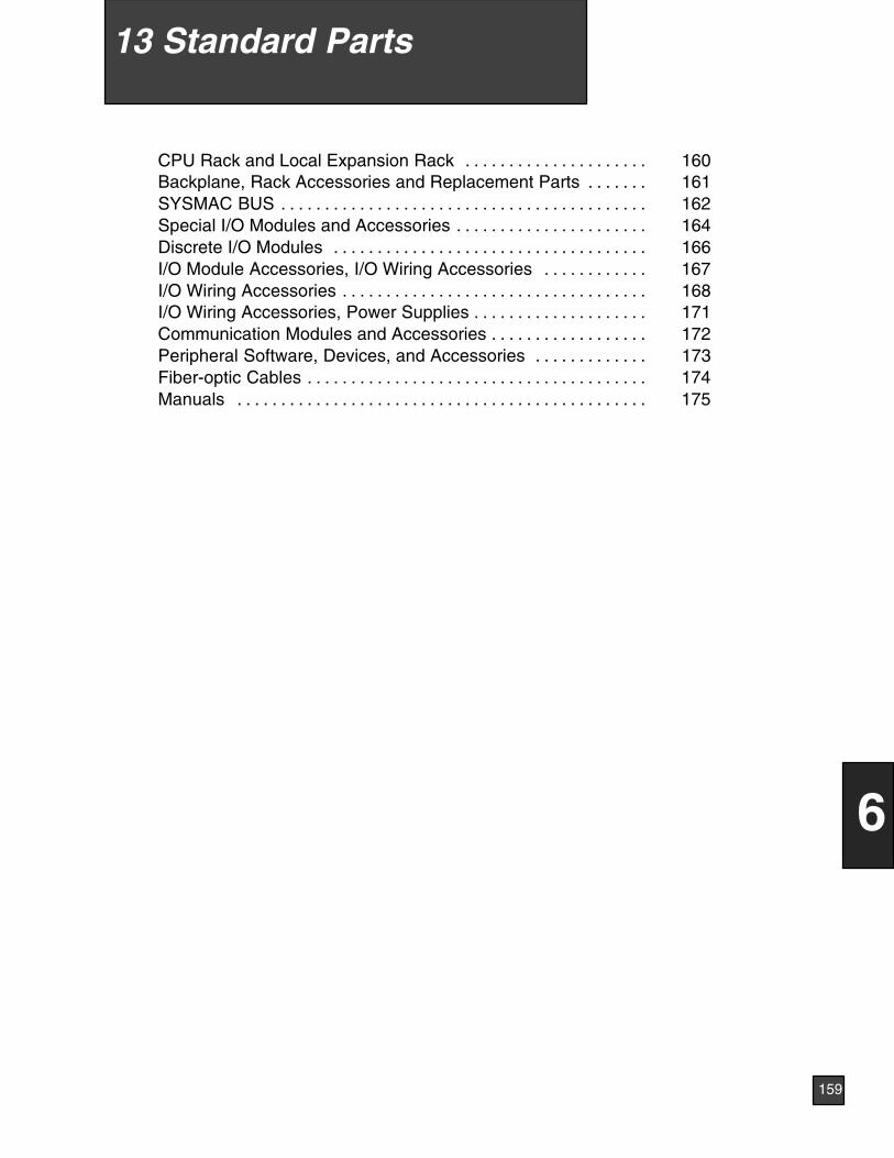
CPU Rack and Local Expansion Rack 160. . . . . . . . . . . . . . . . . . . . .Backplane, Rack Accessories and Replacement Parts 161. . . . . . .SYSMAC BUS 162. . . . . . . . . . . . . . . . . . . . . . . . . . . . . . . . . . . . . . . . . .Special I/O Modules and Accessories 164. . . . . . . . . . . . . . . . . . . . . .Discrete I/O Modules 166. . . . . . . . . . . . . . . . . . . . . . . . . . . . . . . . . . . .I/O Module Accessories, I/O Wiring Accessories 167. . . . . . . . . . . .I/O Wiring Accessories 168. . . . . . . . . . . . . . . . . . . . . . . . . . . . . . . . . . .I/O Wiring Accessories, Power Supplies 171. . . . . . . . . . . . . . . . . . . .Communication Modules and Accessories 172. . . . . . . . . . . . . . . . . .Peripheral Software, Devices, and Accessories 173. . . . . . . . . . . . .Fiber-optic Cables 174. . . . . . . . . . . . . . . . . . . . . . . . . . . . . . . . . . . . . . .Manuals 175. . . . . . . . . . . . . . . . . . . . . . . . . . . . . . . . . . . . . . . . . . . . . . .
159
6
13 Standard Parts
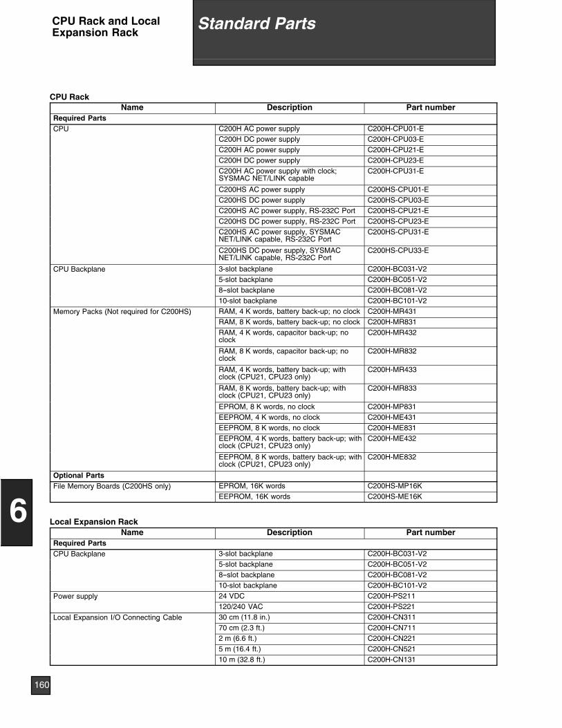
CPU RackName Description Part number
Required PartsCPU C200H AC power supply C200H-CPU01-E
C200H DC power supply C200H-CPU03-EC200H AC power supply C200H-CPU21-EC200H DC power supply C200H-CPU23-EC200H AC power supply with clock;SYSMAC NET/LINK capable
C200H-CPU31-E
C200HS AC power supply C200HS-CPU01-EC200HS DC power supply C200HS-CPU03-EC200HS AC power supply, RS-232C Port C200HS-CPU21-EC200HS DC power supply, RS-232C Port C200HS-CPU23-EC200HS AC power supply, SYSMACNET/LINK capable, RS-232C Port
C200HS-CPU31-E
C200HS DC power supply, SYSMACNET/LINK capable, RS-232C Port
C200HS-CPU33-E
CPU Backplane 3-slot backplane C200H-BC031-V25-slot backplane C200H-BC051-V28--slot backplane C200H-BC081-V210-slot backplane C200H-BC101-V2
Memory Packs (Not required for C200HS) RAM, 4 K words, battery back-up; no clock C200H-MR431y ( q )RAM, 8 K words, battery back-up; no clock C200H-MR831RAM, 4 K words, capacitor back-up; noclock
C200H-MR432
RAM, 8 K words, capacitor back-up; noclock
C200H-MR832
RAM, 4 K words, battery back-up; withclock (CPU21, CPU23 only)
C200H-MR433
RAM, 8 K words, battery back-up; withclock (CPU21, CPU23 only)
C200H-MR833
EPROM, 8 K words, no clock C200H-MP831EEPROM, 4 K words, no clock C200H-ME431EEPROM, 8 K words, no clock C200H-ME831EEPROM, 4 K words, battery back-up; withclock (CPU21, CPU23 only)
C200H-ME432
EEPROM, 8 K words, battery back-up; withclock (CPU21, CPU23 only)
C200H-ME832
Optional PartsFile Memory Boards (C200HS only) EPROM, 16K words C200HS-MP16Ky ( y)
EEPROM, 16K words C200HS-ME16K
Local Expansion RackName Description Part number
Required PartsCPU Backplane 3-slot backplane C200H-BC031-V2
5-slot backplane C200H-BC051-V28--slot backplane C200H-BC081-V210-slot backplane C200H-BC101-V2
Power supply 24 VDC C200H-PS211y120/240 VAC C200H-PS221
Local Expansion I/O Connecting Cable 30 cm (11.8 in.) C200H-CN311g70 cm (2.3 ft.) C200H-CN7112 m (6.6 ft.) C200H-CN2215 m (16.4 ft.) C200H-CN52110 m (32.8 ft.) C200H-CN131
160
6
Standard PartsCPU Rack and LocalExpansion Rack
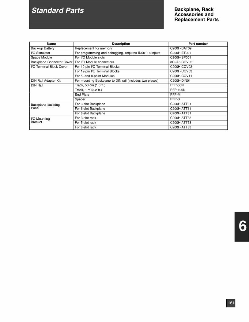
Name Description Part numberBack-up Battery Replacement for memory C200H-BAT09I/O Simulator For programming and debugging, requires ID001; 8 inputs C200H-ETL01Space Module For I/O Module slots C200H-SP001Backplane Connector Cover For I/O Module connectors 3G2A5-COV02I/O Terminal Block Cover For 10-pin I/O Terminal Blocks C200H-COV02
For 19-pin I/O Terminal Blocks C200H-COV03For 5- and 8-point Modules C200H-COV11
DIN Rail Adapter Kit For mounting Backplane to DIN rail (includes two pieces) C200H-DIN01DIN Rail Track, 50 cm (1.6 ft.) PFP-50N
Track, 1 m (3.2 ft.) PFP-100NEnd Plate PFP-MSpacer PFP-S
Backplane Isolating For 3-slot Backplane C200H-ATT31Back lane IsolatingPanel For 5-slot Backplane C200H-ATT51
For 8-slot Backplane C200H-ATT81
I/O Mounting For 3-slot rack C200H-ATT33I/O MountingBracket For 5-slot rack C200H-ATT53
For 8-slot rack C200H-ATT83
161
6
Standard Parts Backplane, RackAccessories andReplacement Parts
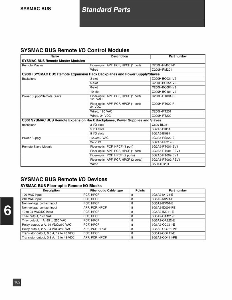
SYSMAC BUS Remote I/O Control ModulesName Description Part number
SYSMAC BUS Remote Master ModulesRemote Master Fiber-optic: APF, PCF, HPCF (1 port) C200H-RM001-P
Wired C200H-RM201
C200H SYSMAC BUS Remote Expansion Rack Backplanes and Power Supply/SlavesBackplane 3-slot C200H-BC031-V2
5-slot C200H-BC051-V28-slot C200H-BC081-V210-slot C200H-BC101-V2
Power Supply/Remote Slave Fiber-optic: APF, PCF, HPCF (1 port)120 VAC
C200H-RT001-P
Fiber-optic: APF, PCF, HPCF (1 port)24 VDC
C200H-RT002-P
Wired, 120 VAC C200H-RT201Wired, 24 VDC C200H-RT202
C500 SYSMAC BUS Remote Expansion Rack Backplanes, Power Supplies and SlavesBackplane 3 I/O slots C500-BL031
5 I/O slots 3G2A5-BI0518 I/O slots 3G2A5-BI081
Power Supply 120/240 VAC 3G2A5-PS222-Ey24 VDC 3G2A5-PS212-E
Remote Slave Module Fiber-optic: PCF, HPCF (1 port) 3G2A5-RT001-EV1Fiber-optic: APF, PCF, HPCF (1 port) 3G2A5-RT001-PEV1Fiber-optic: PCF, HPCF (2 ports) 3G2A5-RT002-EV1Fiber-optic: APF, PCF, HPCF (2 ports) 3G2A5-RT002-PEV1Wired C500-RT201
SYSMAC BUS Remote I/O DevicesSYSMAC BUS Fiber-optic Remote I/O Blocks
Description Fiber-optic Cable type Points Part number120 VAC input PCF, HPCF 8 3G5A2-IA121-E240 VAC input PCF, HPCF 8 3G5A2-IA221-ENon-voltage contact input PCF, HPCF 8 3G5A2-ID001-ENon-voltage contact input APF, PCF, HPCF 8 3G5A2-ID001-PE12 to 24 VAC/DC input PCF, HPCF 8 3G5A2-IM211-ETriac output, 120 VAC PCF, HPCF 8 3G5A2-OA121-ETriac output, 1 A, 85 to 250 VAC PCF, HPCF 8 3G5A2-OA222-ERelay output, 2 A, 24 VDC/250 VAC PCF, HPCF 8 3G5A2-OC221-ERelay output, 2 A, 24 VDC/250 VAC APF, PCF, HPCF 8 3G5A2-OC221-PETransistor output, 0.3 A, 12 to 48 VDC PCF, HPCF 8 3G5A2-OD411-ETransistor output, 0.3 A, 12 to 48 VDC APF, PCF, HPCF 8 3G5A2-OD411-PE
162
6
Standard PartsSYSMAC BUS
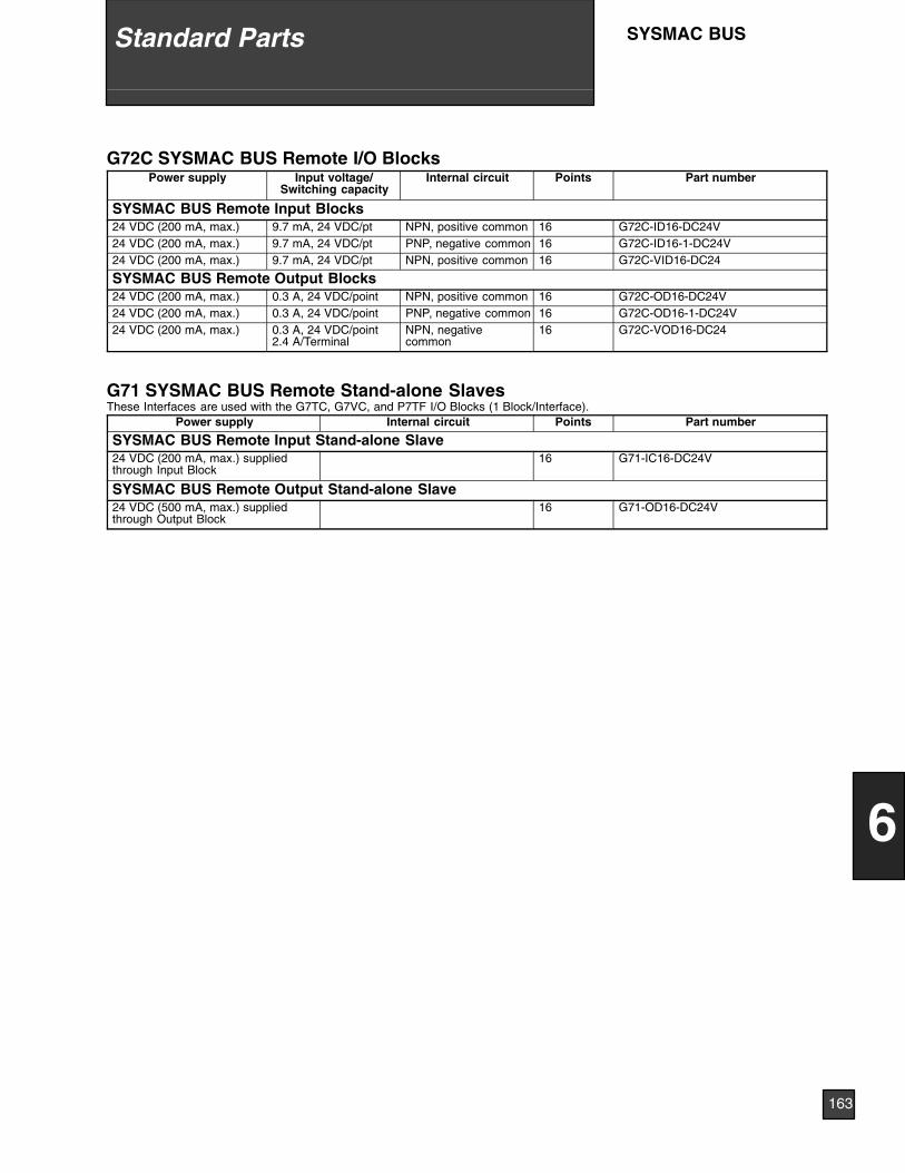
G72C SYSMAC BUS Remote I/O BlocksPower supply Input voltage/
Switching capacityInternal circuit Points Part number
SYSMAC BUS Remote Input Blocks24 VDC (200 mA, max.) 9.7 mA, 24 VDC/pt NPN, positive common 16 G72C-ID16-DC24V24 VDC (200 mA, max.) 9.7 mA, 24 VDC/pt PNP, negative common 16 G72C-ID16-1-DC24V24 VDC (200 mA, max.) 9.7 mA, 24 VDC/pt NPN, positive common 16 G72C-VID16-DC24
SYSMAC BUS Remote Output Blocks24 VDC (200 mA, max.) 0.3 A, 24 VDC/point NPN, positive common 16 G72C-OD16-DC24V24 VDC (200 mA, max.) 0.3 A, 24 VDC/point PNP, negative common 16 G72C-OD16-1-DC24V24 VDC (200 mA, max.) 0.3 A, 24 VDC/point
2.4 A/TerminalNPN, negativecommon
16 G72C-VOD16-DC24
G71 SYSMAC BUS Remote Stand-alone SlavesThese Interfaces are used with the G7TC, G7VC, and P7TF I/O Blocks (1 Block/Interface).
Power supply Internal circuit Points Part number
SYSMAC BUS Remote Input Stand-alone Slave24 VDC (200 mA, max.) suppliedthrough Input Block
16 G71-IC16-DC24V
SYSMAC BUS Remote Output Stand-alone Slave24 VDC (500 mA, max.) suppliedthrough Output Block
16 G71-OD16-DC24V
163
6
Standard Parts SYSMAC BUS
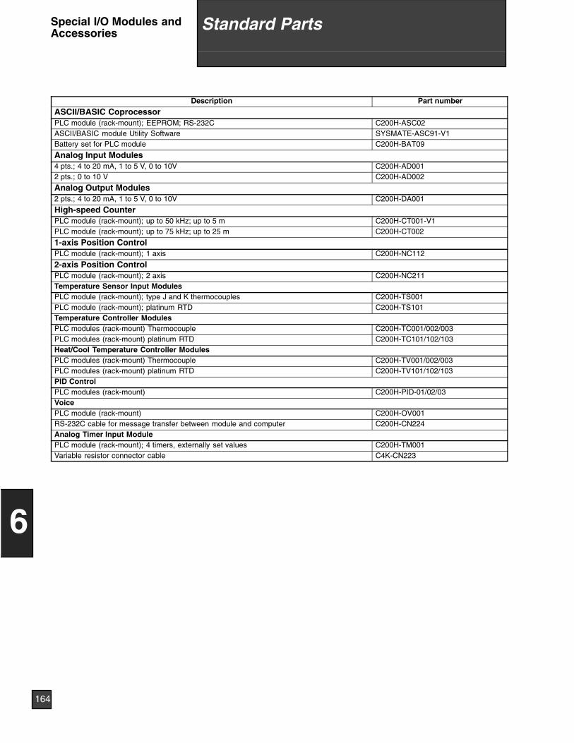
Description Part number
ASCII/BASIC CoprocessorPLC module (rack-mount); EEPROM; RS-232C C200H-ASC02ASCII/BASIC module Utility Software SYSMATE-ASC91-V1Battery set for PLC module C200H-BAT09
Analog Input Modules4 pts.; 4 to 20 mA, 1 to 5 V, 0 to 10V C200H-AD0012 pts.; 0 to 10 V C200H-AD002
Analog Output Modules2 pts.; 4 to 20 mA, 1 to 5 V, 0 to 10V C200H-DA001
High-speed CounterPLC module (rack-mount); up to 50 kHz; up to 5 m C200H-CT001-V1PLC module (rack-mount); up to 75 kHz; up to 25 m C200H-CT002
1-axis Position ControlPLC module (rack-mount); 1 axis C200H-NC112
2-axis Position ControlPLC module (rack-mount); 2 axis C200H-NC211Temperature Sensor Input ModulesPLC module (rack-mount); type J and K thermocouples C200H-TS001PLC module (rack-mount); platinum RTD C200H-TS101Temperature Controller ModulesPLC modules (rack-mount) Thermocouple C200H-TC001/002/003PLC modules (rack-mount) platinum RTD C200H-TC101/102/103Heat/Cool Temperature Controller ModulesPLC modules (rack-mount) Thermocouple C200H-TV001/002/003PLC modules (rack-mount) platinum RTD C200H-TV101/102/103PID ControlPLC modules (rack-mount) C200H-PID-01/02/03VoicePLC module (rack-mount) C200H-OV001RS-232C cable for message transfer between module and computer C200H-CN224Analog Timer Input ModulePLC module (rack-mount); 4 timers, externally set values C200H-TM001Variable resistor connector cable C4K-CN223
164
6
Standard PartsSpecial I/O Modules andAccessories
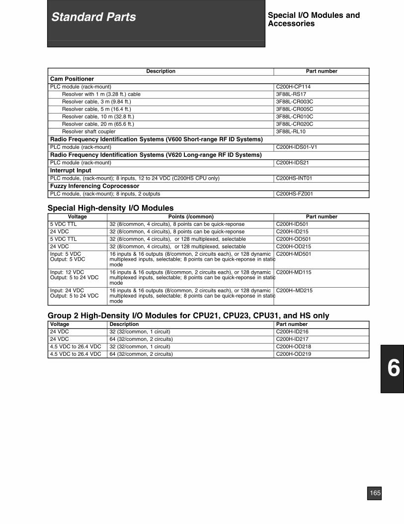
Description Part number
Cam PositionerPLC module (rack-mount) C200H-CP114
Resolver with 1 m (3.28 ft.) cable 3F88L-RS17Resolver cable, 3 m (9.84 ft.) 3F88L-CR003CResolver cable, 5 m (16.4 ft.) 3F88L-CR005CResolver cable, 10 m (32.8 ft.) 3F88L-CR010CResolver cable, 20 m (65.6 ft.) 3F88L-CR020CResolver shaft coupler 3F88L-RL10
Radio Frequency Identification Systems (V600 Short-range RF ID Systems)PLC module (rack-mount) C200H-IDS01-V1
Radio Frequency Identification Systems (V620 Long-range RF ID Systems)PLC module (rack-mount) C200H-IDS21
Interrupt InputPLC module, (rack-mount); 8 inputs, 12 to 24 VDC (C200HS CPU only) C200HS-INT01
Fuzzy Inferencing CoprocessorPLC module, (rack-mount); 8 inputs, 2 outputs C200HS-FZ001
Special High-density I/O ModulesVoltage Points (/common) Part number
5 VDC TTL 32 (8/common, 4 circuits), 8 points can be quick-reponse C200H-ID50124 VDC 32 (8/common, 4 circuits), 8 points can be quick-reponse C200H-ID2155 VDC TTL 32 (8/common, 4 circuits), or 128 multiplexed, selectable C200H-OD50124 VDC 32 (8/common, 4 circuits), or 128 multiplexed, selectable C200H-OD215Input: 5 VDCOutput: 5 VDC
16 inputs & 16 outputs (8/common, 2 circuits each), or 128 dynamicmultiplexed inputs, selectable; 8 points can be quick-reponse in staticmode
C200H-MD501
Input: 12 VDCOutput: 5 to 24 VDC
16 inputs & 16 outputs (8/common, 2 circuits each), or 128 dynamicmultiplexed inputs, selectable; 8 points can be quick-reponse in staticmode
C200H-MD115
Input: 24 VDCOutput: 5 to 24 VDC
16 inputs & 16 outputs (8/common, 2 circuits each), or 128 dynamicmultiplexed inputs, selectable; 8 points can be quick-reponse in staticmode
C200H--MD215
Group 2 High-Density I/O Modules for CPU21, CPU23, CPU31, and HS onlyVoltage Description Part number24 VDC 32 (32/common, 1 circuit) C200H-ID21624 VDC 64 (32/common, 2 circuits) C200H-ID2174.5 VDC to 26.4 VDC 32 (32/common, 1 circuit) C200H-OD2184.5 VDC to 26.4 VDC 64 (32/common, 2 circuits) C200H-OD219
165
6
Standard Parts Special I/O Modules andAccessories
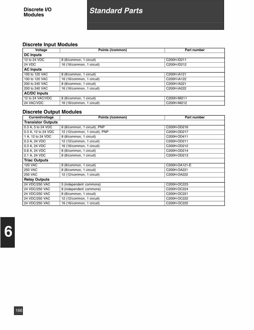
Discrete Input ModulesVoltage Points (/common) Part number
DC Inputs12 to 24 VDC 8 (8/common, 1 circuit) C200H-ID21124 VDC 16 (16/common, 1 circuit) C200H-ID212
AC Inputs100 to 120 VAC 8 (8/common, 1 circuit) C200H-IA121100 to 120 VAC 16 (16/common, 1 circuit) C200H-IA122200 to 240 VAC 8 (8/common, 1 circuit) C200H-IA221200 to 240 VAC 16 (16/common, 1 circuit) C200H-IA222
AC/DC Inputs12 to 24 VAC/VDC 8 (8/common, 1 circuit) C200H-IM21124 VAC/VDC 16 (16/common, 1 circuit) C200H-IM212
Discrete Output ModulesCurrent/voltage Points (/common) Part number
Transistor Outputs0.3 A, 5 to 24 VDC 8 (8/common, 1 circuit), PNP C200H-OD2160.3 A, 12 to 24 VDC 12 (12/common, 1 circuit), PNP C200H-OD2171 A, 12 to 24 VDC 8 (8/common, 1 circuit) C200H-OD4110.3 A, 24 VDC 12 (12/common, 1 circuit) C200H-OD2110.3 A, 24 VDC 16 (16/common, 1 circuit) C200H-OD2120.8 A, 24 VDC 8 (8/common, 1 circuit) C200H-OD2142.1 A, 24 VDC 8 (8/common, 1 circuit) C200H-OD213
Triac Outputs120 VAC 8 (8/common, 1 circuit) C200H-OA121-E250 VAC 8 (8/common, 1 circuit) C200H-OA221250 VAC 12 (12/common, 1 circuit) C200H-OA222
Relay Outputs24 VDC/250 VAC 5 (independent commons) C200H-OC22324 VDC/250 VAC 8 (independent commons) C200H-OC22424 VDC/250 VAC 8 (8/common, 1 circuit) C200H-OC22124 VDC/250 VAC 12 (12/common, 1 circuit) C200H-OC22224 VDC/250 VAC 16 (16/common, 1 circuit) C200H-OC225
166
6
Standard PartsDiscrete I/OModules
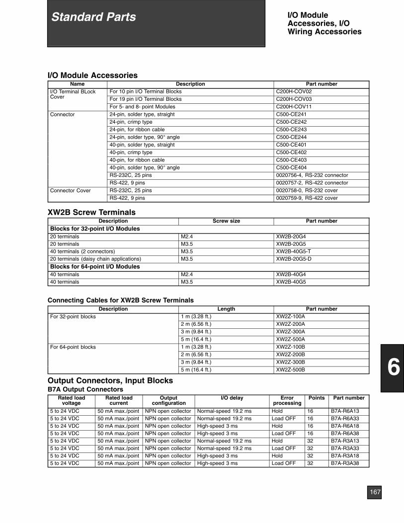
I/O Module AccessoriesName Description Part number
I/O Terminal BLockC
For 10 pin I/O Terminal Blocks C200H-COV02Cover For 19 pin I/O Terminal Blocks C200H-COV03
For 5- and 8- point Modules C200H-COV11
Connector 24-pin, solder type, straight C500-CE24124-pin, crimp type C500-CE24224-pin, for ribbon cable C500-CE24324-pin, solder type, 90° angle C500-CE24440-pin, solder type, straight C500-CE40140-pin, crimp type C500-CE40240-pin, for ribbon cable C500-CE40340-pin, solder type, 90° angle C500-CE404RS-232C, 25 pins 0020756-4, RS-232 connectorRS-422, 9 pins 0020757-2, RS-422 connector
Connector Cover RS-232C, 25 pins 0020758-0, RS-232 coverRS-422, 9 pins 0020759-9, RS-422 cover
XW2B Screw TerminalsDescription Screw size Part number
Blocks for 32-point I/O Modules20 terminals M2.4 XW2B-20G420 terminals M3.5 XW2B-20G540 terminals (2 connectors) M3.5 XW2B-40G5-T20 terminals (daisy chain applications) M3.5 XW2B-20G5-D
Blocks for 64-point I/O Modules40 terminals M2.4 XW2B-40G440 terminals M3.5 XW2B-40G5
Connecting Cables for XW2B Screw TerminalsDescription Length Part number
For 32-point blocks 1 m (3.28 ft.) XW2Z-100A2 m (6.56 ft.) XW2Z-200A3 m (9.84 ft.) XW2Z-300A5 m (16.4 ft.) XW2Z-500A
For 64-point blocks 1 m (3.28 ft.) XW2Z-100B2 m (6.56 ft.) XW2Z-200B3 m (9.84 ft.) XW2Z-300B5 m (16.4 ft.) XW2Z-500B
Output Connectors, Input BlocksB7A Output Connectors
Rated loadvoltage
Rated loadcurrent
Outputconfiguration
I/O delay Errorprocessing
Points Part number
5 to 24 VDC 50 mA max./point NPN open collector Normal-speed 19.2 ms Hold 16 B7A-R6A135 to 24 VDC 50 mA max./point NPN open collector Normal-speed 19.2 ms Load OFF 16 B7A-R6A335 to 24 VDC 50 mA max./point NPN open collector High-speed 3 ms Hold 16 B7A-R6A185 to 24 VDC 50 mA max./point NPN open collector High-speed 3 ms Load OFF 16 B7A-R6A385 to 24 VDC 50 mA max./point NPN open collector Normal-speed 19.2 ms Hold 32 B7A-R3A135 to 24 VDC 50 mA max./point NPN open collector Normal-speed 19.2 ms Load OFF 32 B7A-R3A335 to 24 VDC 50 mA max./point NPN open collector High-speed 3 ms Hold 32 B7A-R3A185 to 24 VDC 50 mA max./point NPN open collector High-speed 3 ms Load OFF 32 B7A-R3A38
167
6
Standard Parts I/O ModuleAccessories, I/OWiring Accessories
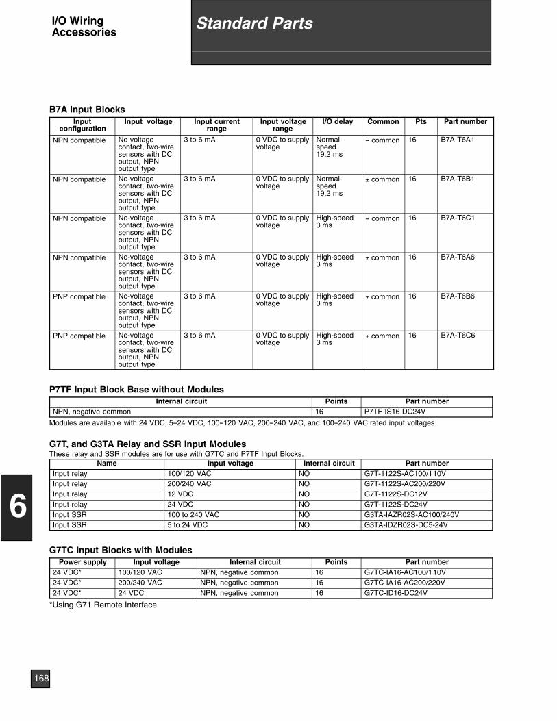
B7A Input BlocksInput
configurationInput voltage Input current
rangeInput voltage
rangeI/O delay Common Pts Part number
NPN compatible No-voltagecontact, two-wiresensors with DCoutput, NPNoutput type
3 to 6 mA 0 VDC to supplyvoltage
Normal-speed19.2 ms
-- common 16 B7A-T6A1
NPN compatible No-voltagecontact, two-wiresensors with DCoutput, NPNoutput type
3 to 6 mA 0 VDC to supplyvoltage
Normal-speed19.2 ms
± common 16 B7A-T6B1
NPN compatible No-voltagecontact, two-wiresensors with DCoutput, NPNoutput type
3 to 6 mA 0 VDC to supplyvoltage
High-speed3 ms
-- common 16 B7A-T6C1
NPN compatible No-voltagecontact, two-wiresensors with DCoutput, NPNoutput type
3 to 6 mA 0 VDC to supplyvoltage
High-speed3 ms
± common 16 B7A-T6A6
PNP compatible No-voltagecontact, two-wiresensors with DCoutput, NPNoutput type
3 to 6 mA 0 VDC to supplyvoltage
High-speed3 ms
± common 16 B7A-T6B6
PNP compatible No-voltagecontact, two-wiresensors with DCoutput, NPNoutput type
3 to 6 mA 0 VDC to supplyvoltage
High-speed3 ms
± common 16 B7A-T6C6
P7TF Input Block Base without ModulesInternal circuit Points Part number
NPN, negative common 16 P7TF-IS16-DC24V
Modules are available with 24 VDC, 5--24 VDC, 100--120 VAC, 200--240 VAC, and 100--240 VAC rated input voltages.
G7T, and G3TA Relay and SSR Input ModulesThese relay and SSR modules are for use with G7TC and P7TF Input Blocks.
Name Input voltage Internal circuit Part numberInput relay 100/120 VAC NO G7T-1122S-AC100/110VInput relay 200/240 VAC NO G7T-1122S-AC200/220VInput relay 12 VDC NO G7T-1122S-DC12VInput relay 24 VDC NO G7T-1122S-DC24VInput SSR 100 to 240 VAC NO G3TA-IAZR02S-AC100/240VInput SSR 5 to 24 VDC NO G3TA-IDZR02S-DC5-24V
G7TC Input Blocks with ModulesPower supply Input voltage Internal circuit Points Part number
24 VDC* 100/120 VAC NPN, negative common 16 G7TC-IA16-AC100/110V24 VDC* 200/240 VAC NPN, negative common 16 G7TC-IA16-AC200/220V24 VDC* 24 VDC NPN, negative common 16 G7TC-ID16-DC24V
*Using G71 Remote Interface
168
6
Standard PartsI/O WiringAccessories
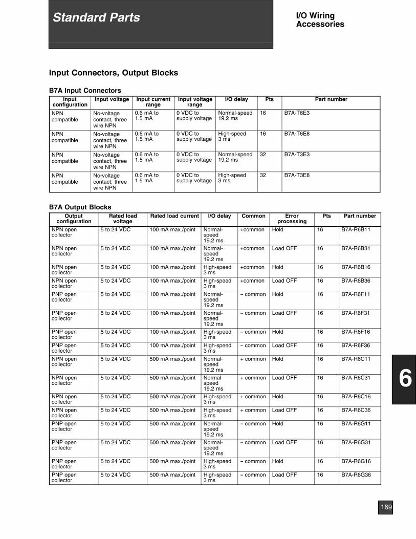
Input Connectors, Output Blocks
B7A Input ConnectorsInput
configurationInput voltage Input current
rangeInput voltage
rangeI/O delay Pts Part number
NPNcompatible
No-voltagecontact, threewire NPN
0.6 mA to1.5 mA
0 VDC tosupply voltage
Normal-speed19.2 ms
16 B7A-T6E3
NPNcompatible
No-voltagecontact, threewire NPN
0.6 mA to1.5 mA
0 VDC tosupply voltage
High-speed3 ms
16 B7A-T6E8
NPNcompatible
No-voltagecontact, threewire NPN
0.6 mA to1.5 mA
0 VDC tosupply voltage
Normal-speed19.2 ms
32 B7A-T3E3
NPNcompatible
No-voltagecontact, threewire NPN
0.6 mA to1.5 mA
0 VDC tosupply voltage
High-speed3 ms
32 B7A-T3E8
B7A Output BlocksOutput
configurationRated load
voltageRated load current I/O delay Common Error
processingPts Part number
NPN opencollector
5 to 24 VDC 100 mA max./point Normal-speed19.2 ms
+common Hold 16 B7A-R6B11
NPN opencollector
5 to 24 VDC 100 mA max./point Normal-speed19.2 ms
+common Load OFF 16 B7A-R6B31
NPN opencollector
5 to 24 VDC 100 mA max./point High-speed3 ms
+common Hold 16 B7A-R6B16
NPN opencollector
5 to 24 VDC 100 mA max./point High-speed3 ms
+common Load OFF 16 B7A-R6B36
PNP opencollector
5 to 24 VDC 100 mA max./point Normal-speed19.2 ms
-- common Hold 16 B7A-R6F11
PNP opencollector
5 to 24 VDC 100 mA max./point Normal-speed19.2 ms
-- common Load OFF 16 B7A-R6F31
PNP opencollector
5 to 24 VDC 100 mA max./point High-speed3 ms
-- common Hold 16 B7A-R6F16
PNP opencollector
5 to 24 VDC 100 mA max./point High-speed3 ms
-- common Load OFF 16 B7A-R6F36
NPN opencollector
5 to 24 VDC 500 mA max./point Normal-speed19.2 ms
+ common Hold 16 B7A-R6C11
NPN opencollector
5 to 24 VDC 500 mA max./point Normal-speed19.2 ms
+ common Load OFF 16 B7A-R6C31
NPN opencollector
5 to 24 VDC 500 mA max./point High-speed3 ms
+ common Hold 16 B7A-R6C16
NPN opencollector
5 to 24 VDC 500 mA max./point High-speed3 ms
+ common Load OFF 16 B7A-R6C36
PNP opencollector
5 to 24 VDC 500 mA max./point Normal-speed19.2 ms
-- common Hold 16 B7A-R6G11
PNP opencollector
5 to 24 VDC 500 mA max./point Normal-speed19.2 ms
-- common Load OFF 16 B7A-R6G31
PNP opencollector
5 to 24 VDC 500 mA max./point High-speed3 ms
-- common Hold 16 B7A-R6G16
PNP opencollector
5 to 24 VDC 500 mA max./point High-speed3 ms
-- common Load OFF 16 B7A-R6G36
169
6
Standard Parts I/O WiringAccessories
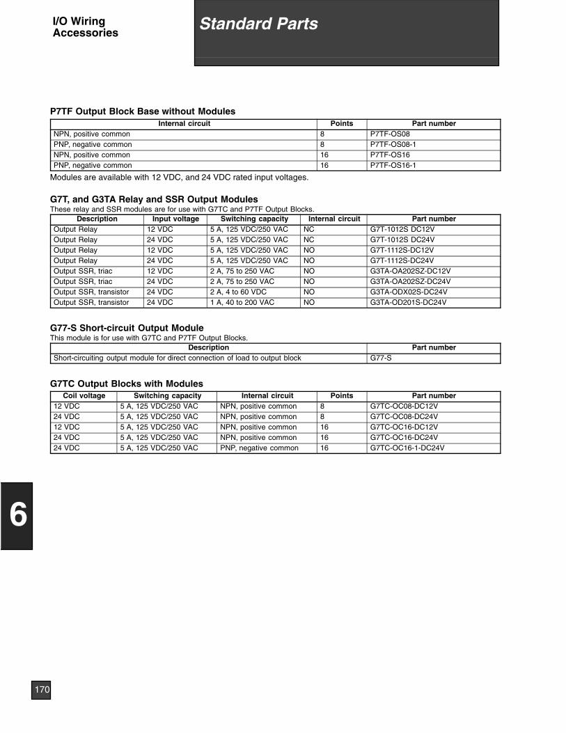
P7TF Output Block Base without ModulesInternal circuit Points Part number
NPN, positive common 8 P7TF-OS08PNP, negative common 8 P7TF-OS08-1NPN, positive common 16 P7TF-OS16PNP, negative common 16 P7TF-OS16-1
Modules are available with 12 VDC, and 24 VDC rated input voltages.
G7T, and G3TA Relay and SSR Output ModulesThese relay and SSR modules are for use with G7TC and P7TF Output Blocks.
Description Input voltage Switching capacity Internal circuit Part numberOutput Relay 12 VDC 5 A, 125 VDC/250 VAC NC G7T-1012S DC12VOutput Relay 24 VDC 5 A, 125 VDC/250 VAC NC G7T-1012S DC24VOutput Relay 12 VDC 5 A, 125 VDC/250 VAC NO G7T-1112S-DC12VOutput Relay 24 VDC 5 A, 125 VDC/250 VAC NO G7T-1112S-DC24VOutput SSR, triac 12 VDC 2 A, 75 to 250 VAC NO G3TA-OA202SZ-DC12VOutput SSR, triac 24 VDC 2 A, 75 to 250 VAC NO G3TA-OA202SZ-DC24VOutput SSR, transistor 24 VDC 2 A, 4 to 60 VDC NO G3TA-ODX02S-DC24VOutput SSR, transistor 24 VDC 1 A, 40 to 200 VAC NO G3TA-OD201S-DC24V
G77-S Short-circuit Output ModuleThis module is for use with G7TC and P7TF Output Blocks.
Description Part numberShort-circuiting output module for direct connection of load to output block G77-S
G7TC Output Blocks with ModulesCoil voltage Switching capacity Internal circuit Points Part number
12 VDC 5 A, 125 VDC/250 VAC NPN, positive common 8 G7TC-OC08-DC12V24 VDC 5 A, 125 VDC/250 VAC NPN, positive common 8 G7TC-OC08-DC24V12 VDC 5 A, 125 VDC/250 VAC NPN, positive common 16 G7TC-OC16-DC12V24 VDC 5 A, 125 VDC/250 VAC NPN, positive common 16 G7TC-OC16-DC24V24 VDC 5 A, 125 VDC/250 VAC PNP, negative common 16 G7TC-OC16-1-DC24V
170
6
Standard PartsI/O WiringAccessories
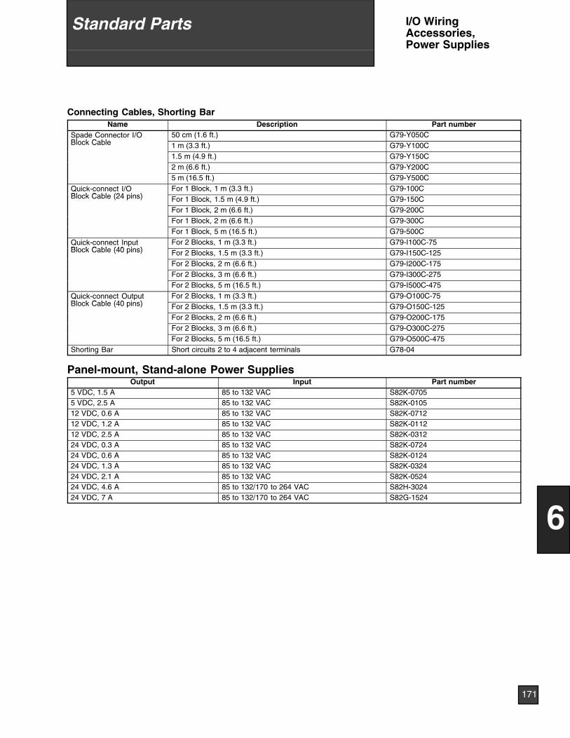
Connecting Cables, Shorting BarName Description Part number
Spade Connector I/OBl k C bl
50 cm (1.6 ft.) G79-Y050CBlock Cable 1 m (3.3 ft.) G79-Y100C
1.5 m (4.9 ft.) G79-Y150C2 m (6.6 ft.) G79-Y200C5 m (16.5 ft.) G79-Y500C
Quick-connect I/OBl k C bl (24 i )
For 1 Block, 1 m (3.3 ft.) G79-100CQBlock Cable (24 pins) For 1 Block, 1.5 m (4.9 ft.) G79-150C
For 1 Block, 2 m (6.6 ft.) G79-200CFor 1 Block, 2 m (6.6 ft.) G79-300CFor 1 Block, 5 m (16.5 ft.) G79-500C
Quick-connect InputBl k C bl (40 i )
For 2 Blocks, 1 m (3.3 ft.) G79-I100C-75QBlock Cable (40 pins) For 2 Blocks, 1.5 m (3.3 ft.) G79-I150C-125
For 2 Blocks, 2 m (6.6 ft.) G79-I200C-175For 2 Blocks, 3 m (6.6 ft.) G79-I300C-275For 2 Blocks, 5 m (16.5 ft.) G79-I500C-475
Quick-connect OutputBl k C bl (40 i )
For 2 Blocks, 1 m (3.3 ft.) G79-O100C-75QBlock Cable (40 pins) For 2 Blocks, 1.5 m (3.3 ft.) G79-O150C-125
For 2 Blocks, 2 m (6.6 ft.) G79-O200C-175For 2 Blocks, 3 m (6.6 ft.) G79-O300C-275For 2 Blocks, 5 m (16.5 ft.) G79-O500C-475
Shorting Bar Short circuits 2 to 4 adjacent terminals G78-04
Panel-mount, Stand-alone Power SuppliesOutput Input Part number
5 VDC, 1.5 A 85 to 132 VAC S82K-07055 VDC, 2.5 A 85 to 132 VAC S82K-010512 VDC, 0.6 A 85 to 132 VAC S82K-071212 VDC, 1.2 A 85 to 132 VAC S82K-011212 VDC, 2.5 A 85 to 132 VAC S82K-031224 VDC, 0.3 A 85 to 132 VAC S82K-072424 VDC, 0.6 A 85 to 132 VAC S82K-012424 VDC, 1.3 A 85 to 132 VAC S82K-032424 VDC, 2.1 A 85 to 132 VAC S82K-052424 VDC, 4.6 A 85 to 132/170 to 264 VAC S82H-302424 VDC, 7 A 85 to 132/170 to 264 VAC S82G-1524
171
6
Standard Parts I/O WiringAccessories,Power Supplies
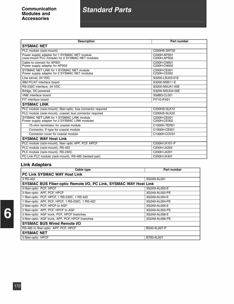
Description Part number
SYSMAC NETPLC module (rack-mount) C200HS-SNT32Power supply adapter for 1 SYSMAC NET module(rack-mount PLC module) for 2 SYSMAC NET modules
C200H-APS01C200H-APS02
Cable to connect for APS01Power supply adapter for APS02
C200H-CN001C200H-CN002
SYSMAC NET LINK for 1 SYSMAC NET modulePower supply adapter for 2 SYSMAC NET modules
C200H-CE001C200H-CE002
Line server, 24 VDC S3200-LSU03-01EIBM PC/AT interface board S3200-NSB11-ERS-232C interface, 24 VDC S3200-NSUA1-00EBridge, DC-powered S3200-NSUG4-00EVME interface board 3G8B3-CL001FIT interface board FIT10-IF401
SYSMAC LINKPLC module (rack-mount), fiber-optic; bus connector required C200HS-SLK12PLC module (rack-mount), coaxial; bus connector required C200HS-SLK22SYSMAC NET LINK for 1 SYSMAC LINK modulePower supply adapter for 2 SYSMAC LINK modules
C200H-CE001C200H-CE002
75-ohm terminator for coaxial module C1000H-TER01Connector, F-type for coaxial module C1000H-CE001Connector cover for coaxial module C1000H-COV01
SYSMAC WAY Host LinkPLC module (rack-mount), fiber optic APF, PCF, HPCF C200H-LK101-PPLC module (rack-mount), RS-422 C200H-LK202PLC module (rack-mount), RS-232C C200H-LK201PC Link PLC module (rack-mount), RS-485 (twisted pair) C200H-LK401
Link AdaptersCable type Part number
PC Link SYSMAC WAY Host Link3 RS-422 3G2A9-AL001
SYSMAC BUS Fiber-optic Remote I/O, PC Link, SYSMAC WAY Host Link3 fiber-optic: PCF, HPCF 3G2A9-AL002-E3 fiber-optic: APF, PCF, HPCF 3G2A9-AL002-PE1 fiber-optic: PCF, HPCF, 1 RS-232C, 1 RS-422 3G2A9-AL004-E1 fiber-optic: APF, PCF, HPCF, 1 RS-232C, 1 RS-422 3G2A9-AL004-PE2 fiber-optic: PCF, HPCF to AGF 3G2A9-AL005-E2 fiber-optic: APF, PCF, HPCF to AGF 3G2A9-AL005-PE3 fiber-optic: AGF trunk, PCF, HPCF branches 3G2A9-AL006-E3 fiber-optic: AGF trunk, APF, PCF, HPCF branches 3G2A9-AL006-PE
SYSMAC BUS Wired Remote I/ORS-485 to fiber-optic: APF, PCF, HPCF B500-AL007-P
SYSMAC NET3 fiber-optic: HPCF B700-AL001
172
6
Standard PartsCommunicationModules andAccessories

Description Part numberSYSMATE LSSLadder diagram programming software for AT-compatible computers (3.5” and 5.25” disks), allC-Series PLCs: Single user license
C500-Y9LS11-EV3
Ladder diagram programming software for AT-compatible computers (3.5” and 5.25” disks), allC-Series PLCs: Five user license
C500-Y9LS15-EV3
Ladder diagram programming software for AT-compatible computers (3.5” and 5.25” disks), allC-Series PLCs: Ten user license
C500-Y9LS10-EV3
Programming CableBuilt-In Host Link Port to computer (9-pin RS-232) C200HS-CN220-EUBuilt-In Host Link Port to computer (25-pin RS-232) C200HS-CN229-EUC200H-LK201 to computer (9-pin RS-232) C500-CN221-EUC200H-LK201 to computer (25-pin RS-232) C500-CN222-EUGraphic Programming ConsoleAll C-Series PLCs, requires memory pack; 120 VAC 3G2C5-GPC03-EAll C-Series PLCs, requires memory pack; 240 VAC 3G2C5-GPC04-ECarrying case, nylon 3G2C5-CS001Memory pack for C20, P-type, C120, C500 C500-MP303-EV2Memory pack for K-type, Block-style H-type, C200H, C1000H, C2000H 3G2C5-MP304-EV3Peripheral interface unit to PLC CPU C200H IP006Peripheral interface cable, 2 m 3G2A2-CN221Peripheral interface cable, 10 m 3G2A5-CN131CRT interface 3G2C5-GDI01Replacement key sheet for GPC Key sheet of 3G2C5-GPC03Factory Intelligent TerminalSet includes FIT, system disks, and FIT MS-DOS disk FIT10-SET11-EMS-DOS floppy disk FIT10-MF001-ESystem floppy disk FIT10-MF101-EV4Peripheral interface to PLC CPU C200H IP006Peripheral interface cable, 2 m 3G2A2-CN221Peripheral interface cable, 10 m 3G2A5-CN131SYSMAC NET interface board for FIT FIT10-IF401ASCII/BASIC Module Utility SoftwareFor AT-compatible computers; enables program development, downloading, uploading, etc. SYSMATE-ASC91-V1Programming Cable C200H-ASC02 to computer (9-pin RS-232) C200H-CN229-EUProgramming Cable C200H-ASC02 to computer (25-pin RS-232) C200H-CN220-EUProgramming ConsoleConsole (CPU-mount) with back-lit LCD 3G2A5-PRO13-EExtension cable for PRO13-E, 1 m (3.28 ft.) 3G2C7-CN122Console (Desk-top, panel-mount) with back-lit LCD, requires cable and interface C200H-PRO27-EPRO27 interface C500-AP003PRO27 extension cable, 2 m C200H-CN222PRO27 extension cable, 4 m C200H-CN422PRO27 panel-mounting bracket C200H-ATT01PROM WriterAll C-Series PLCs C500-PRW06Printer InterfaceAll C-Series PLCs, requires memory pack 3G2A5-PRT01-EMemory pack, C500 C500-MP102-EV3Memory pack, C1000H, C2000H 3G2A5-MP103-EV3Printer cable, RS-232C SCY-CN201Cassette InterfaceAll C-series PLCs 3G2A5-CMT01-E
173
6
Standard Parts Peripheral Software,Devices, andAccessories
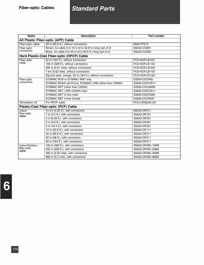
Name Description Part number
All Plastic Fiber-optic (APF) CableFiber-optic cable 20 m (65.6 ft.), without connectors B500-PF212Fiber-optic
tBrown, for cable 0 to 10 m (0 to 32.8 ft.) long (set of 2) 3G5A2-CO001
connectors Black, for cable 8 to 20 m (0 to 65.6 ft.) long (set of 2) 3G5A2-CO002
Hard Plastic-Clad Fiber-optic (HPCF) CableFiber-optic
bl50 m (164 ft.), without connectors FCS-HCR-LB-501
cable 100 m (328 ft.), without connectors FCS-HCR-LB-102500 m (0.31 mile), without connectors FCS-HCR-LB-5021 km (0.62 mile), without connectors FCS-HCR-LB-103Zipcord style, orange, 50 m (164 ft.), without connectors FCS-HCR-CO-501
Fiber-optict
SYSMAC BUS or SYSMAC WAY only S3200-COCH82connectors SYSMAC BUS/2 (all PLCs), SYSMAC LINK (other than C200H) S3200-COCF2011
SYSMAC NET (other than C200H) S3200-COCH62MSYSMAC NET, LINK (C200H only) S3200-COCF2511SYSMAC NET in-line male S3200-COCF62MSYSMAC NET in-line female S3200-COCF62F
Termination kit For HPCF cable FCS-CAK6230-US
Plastic-Clad Fiber-optic (PCF) CableIndoorfib ti
10 cm (0.32 ft.), with connectors 3G5A2-OF011fiber-opticcable
1 m (3.2 ft.), with connectors 3G5A2-OF101cable
2 m (6.56 ft.), with connectors 3G5A2-OF2013 m (9.8 ft.), with connectors 3G5A2-OF3015 m (16.4 ft.), with connectors 3G5A2-OF50110 m (32.8 ft.), with connectors 3G5A2-OF11120 m (65.6 ft.), with connectors 3G5A2-OF21130 m (98 ft.), with connectors 3G5A2-OF31150 m (164 ft.), with connectors 3G5A2-OF511
Indoor/Outdoorfib ti
100 m (328 ft.), with connectors 3G5A2-OF002--100Mfiber-opticcable
200 m (656 ft.), with connectors 3G5A2-OF002--200Mcable
400 m (0.25 mile), with connectors 3G5A2-OF002--400M800 m (0.5 mile), with connectors 3G5A2-OF002--800M
174
6
Standard PartsFiber-optic Cables
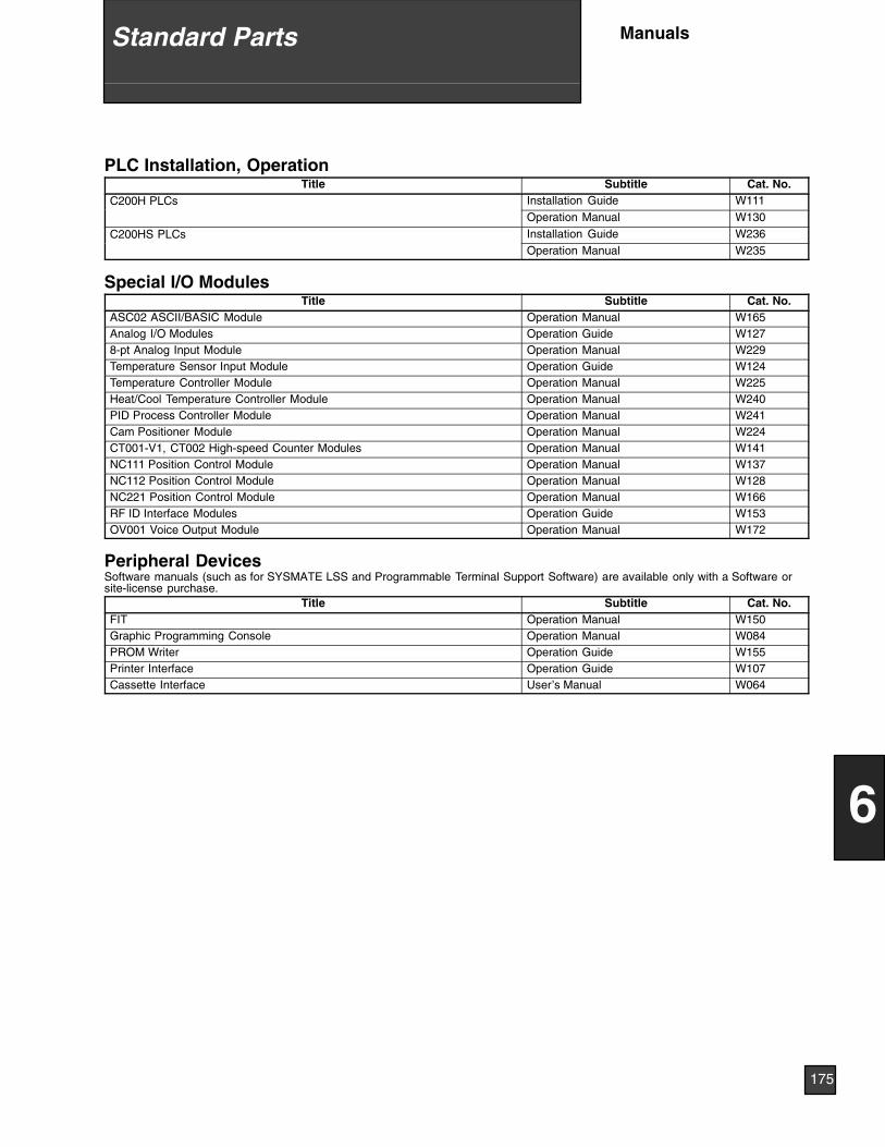
PLC Installation, OperationTitle Subtitle Cat. No.
C200H PLCs Installation Guide W111Operation Manual W130
C200HS PLCs Installation Guide W236Operation Manual W235
Special I/O ModulesTitle Subtitle Cat. No.
ASC02 ASCII/BASIC Module Operation Manual W165Analog I/O Modules Operation Guide W1278-pt Analog Input Module Operation Manual W229Temperature Sensor Input Module Operation Guide W124Temperature Controller Module Operation Manual W225Heat/Cool Temperature Controller Module Operation Manual W240PID Process Controller Module Operation Manual W241Cam Positioner Module Operation Manual W224CT001-V1, CT002 High-speed Counter Modules Operation Manual W141NC111 Position Control Module Operation Manual W137NC112 Position Control Module Operation Manual W128NC221 Position Control Module Operation Manual W166RF ID Interface Modules Operation Guide W153OV001 Voice Output Module Operation Manual W172
Peripheral DevicesSoftware manuals (such as for SYSMATE LSS and Programmable Terminal Support Software) are available only with a Software orsite-license purchase.
Title Subtitle Cat. No.FIT Operation Manual W150Graphic Programming Console Operation Manual W084PROM Writer Operation Guide W155Printer Interface Operation Guide W107Cassette Interface User’s Manual W064
175
6
Standard Parts Manuals
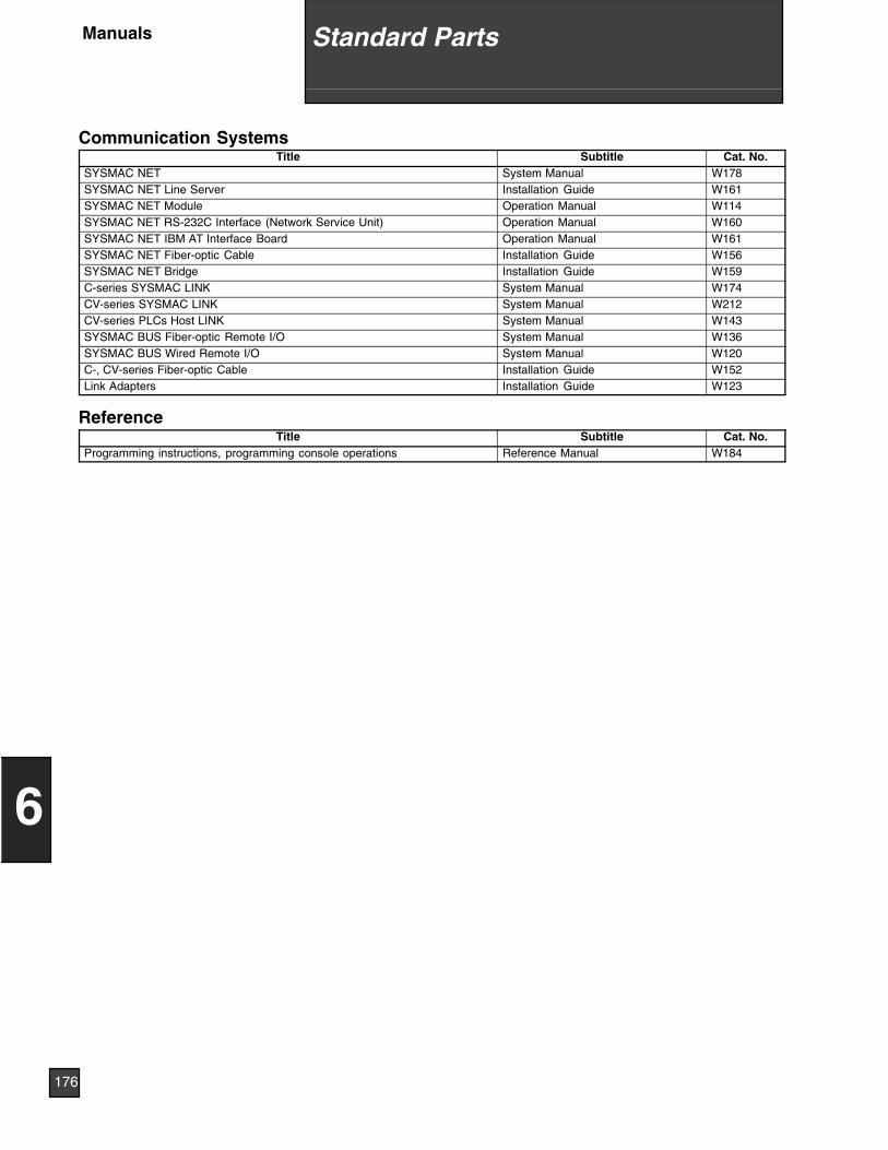
Communication SystemsTitle Subtitle Cat. No.
SYSMAC NET System Manual W178SYSMAC NET Line Server Installation Guide W161SYSMAC NET Module Operation Manual W114SYSMAC NET RS-232C Interface (Network Service Unit) Operation Manual W160SYSMAC NET IBM AT Interface Board Operation Manual W161SYSMAC NET Fiber-optic Cable Installation Guide W156SYSMAC NET Bridge Installation Guide W159C-series SYSMAC LINK System Manual W174CV-series SYSMAC LINK System Manual W212CV-series PLCs Host LINK System Manual W143SYSMAC BUS Fiber-optic Remote I/O System Manual W136SYSMAC BUS Wired Remote I/O System Manual W120C-, CV-series Fiber-optic Cable Installation Guide W152Link Adapters Installation Guide W123
ReferenceTitle Subtitle Cat. No.
Programming instructions, programming console operations Reference Manual W184
176
6
Standard PartsManuals
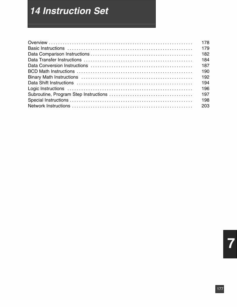
Overview 178. . . . . . . . . . . . . . . . . . . . . . . . . . . . . . . . . . . . . . . . . . . . . . . . . . . . . . . . . . . . . .Basic Instructions 179. . . . . . . . . . . . . . . . . . . . . . . . . . . . . . . . . . . . . . . . . . . . . . . . . . . . . .Data Comparison Instructions 182. . . . . . . . . . . . . . . . . . . . . . . . . . . . . . . . . . . . . . . . . . . .Data Transfer Instructions 184. . . . . . . . . . . . . . . . . . . . . . . . . . . . . . . . . . . . . . . . . . . . . . .Data Conversion Instructions 187. . . . . . . . . . . . . . . . . . . . . . . . . . . . . . . . . . . . . . . . . . . .BCD Math Instructions 190. . . . . . . . . . . . . . . . . . . . . . . . . . . . . . . . . . . . . . . . . . . . . . . . . .Binary Math Instructions 192. . . . . . . . . . . . . . . . . . . . . . . . . . . . . . . . . . . . . . . . . . . . . . . .Data Shift Instructions 194. . . . . . . . . . . . . . . . . . . . . . . . . . . . . . . . . . . . . . . . . . . . . . . . . .Logic Instructions 196. . . . . . . . . . . . . . . . . . . . . . . . . . . . . . . . . . . . . . . . . . . . . . . . . . . . . .Subroutine, Program Step Instructions 197. . . . . . . . . . . . . . . . . . . . . . . . . . . . . . . . . . . .Special Instructions 198. . . . . . . . . . . . . . . . . . . . . . . . . . . . . . . . . . . . . . . . . . . . . . . . . . . . .Network Instructions 203. . . . . . . . . . . . . . . . . . . . . . . . . . . . . . . . . . . . . . . . . . . . . . . . . . . .
177
7
14 Instruction Set
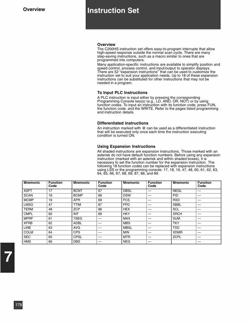
OverviewThe C200HS instruction set offers easy-to-program interrupts that allowhigh-speed response outside the normal scan cycle. There are manystep-saving instructions, such as a macro similar to ones that areprogrammed into computers.Many application-specific instructions are available to simplify position andspeed control, process control, and input/output to operator displays.There are 52 “expansion instructions” that can be used to customize theinstruction set to suit your application needs. Up to 18 of these expansioninstructions can be substituted for other instructions that may not beneeded in a program.
To Input PLC InstructionsA PLC instruction is input either by pressing the correspondingProgramming Console key(s) (e.g., LD, AND, OR, NOT) or by usingfunction codes. To input an instruction with its function code, press FUN,the function code, and the WRITE. Refer to the pages listed programmingand instruction details.
Differentiated InstructionsAn instruction marked with @ can be used as a differentiated instructionthat will be executed only once each time the instruction executingcondition is turned ON.
Using Expansion InstructionsAll shaded instructions are expansion instructions. Those marked with anasterisk do not have default function numbers. Before using any expansioninstruction (marked with an asterisk and within shaded boxes), it isnecessary to set the function number for the expansion instruction. Thefollowing 18 function codes can be replaced with expansion instructionsusing LSS or the programming console: 17, 18, 19, 47, 48, 60, 61, 62, 63,64, 65, 66, 67, 68, 69, 87, 88, and 89.
Mnemonic FunctionCode
Mnemonic FunctionCode
Mnemonic FunctionCode
Mnemonic FunctionCode
ASFT 17 BCNT 67 DBSL — NEGL —SCAN 18 BCMP 68 DSW — PID —MCMP 19 APR 69 FCS — RXD —LMSG 47 TTIM 87 FPD — SBBL —TERM 48 ZCP 88 HEX — SCL —CMPL 60 INT 89 HKY — SRCH —MPRF 61 7SEG — MAX — SUM —XFRB 62 ADBL — MBS — TKY —LINE 63 AVG — MBSL — TXD —COLM 64 CPS — MIN — XDMR —SEC 65 CPSL — MTR — ZCPL —HMS 66 DBS — NEG — —
178
7
Instruction SetOverview
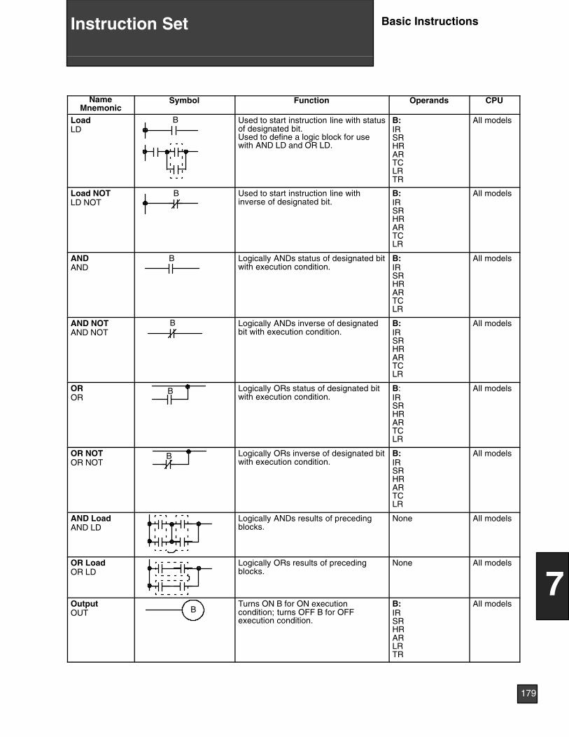
NameMnemonic
Symbol Function Operands CPU
LoadLD
B Used to start instruction line with statusof designated bit.Used to define a logic block for usewith AND LD and OR LD.
B:IRSRHRARTCLRTR
All models
Load NOTLD NOT
B Used to start instruction line withinverse of designated bit.
B:IRSRHRARTCLR
All models
ANDAND
B Logically ANDs status of designated bitwith execution condition.
B:IRSRHRARTCLR
All models
AND NOTAND NOT
B Logically ANDs inverse of designatedbit with execution condition.
B:IRSRHRARTCLR
All models
OROR
B Logically ORs status of designated bitwith execution condition.
B:IRSRHRARTCLR
All models
OR NOTOR NOT
B Logically ORs inverse of designated bitwith execution condition.
B:IRSRHRARTCLR
All models
AND LoadAND LD
Logically ANDs results of precedingblocks.
None All models
OR LoadOR LD
Logically ORs results of precedingblocks.
None All models
OutputOUT B
Turns ON B for ON executioncondition; turns OFF B for OFFexecution condition.
B:IRSRHRARLRTR
All models
179
7
Instruction Set Basic Instructions

Symbol CPUOperandsFunctionNameMnemonic
RESETRESET
RESET B Turns B OFF for ON executioncondition and remains OFF whenexecution condition returns to OFF
B:IRSRARHRLR
HS-CPU01HS-CPU03
SETSET
RESET B Turns B OFF for ON executioncondition and remains OFF whenexecution condition returns to OFF
B:IRSRARHRLR
HS-CPU01HS-CPU03
Output NOTOUT NOT B
Turns B OFF for ON executioncondition; turns B ON for OFF executioncondition (i.e., inverts operation).
B:IRSRHRARLR
All models
No OperationNOP (00)
None Nothing is executed and programmoves to next instruction.
None All models
EndEND(01)
END(01) Required at the end of the program. None All models
Latching RelayKEEP(11)
SKEEP(11)BR
Defines a bit (B) as a latch controlledby set (S) and reset (R) inputs.
B:IRHRARLR
All models
TimerTIM
TIM NSV
ON-delay (decrementing) timeroperation. Set value: 999.9 s;accuracy: +0/--0.1 s. Same TC bitcannot be assigned to more than onetimer/counter. The TC bit is input as aconstant.
N:TC
SV:IRHRARDMLR#
All models
High-speedTimerTIMH(15)
TIMH(15) NSV
A high-speed, ON-delay(decrementing) timer. SV: 0.01 to 99.99s; accuracy: +0/--0.1 s. Must not beassigned the same TC bit as anothertimer or counter. The TC bit is input asa constant.
N:TC
SV:IRSRHRARDMLR#
All models
CounterCNT CNT N
SV
CP
R
A decrementing counter. SV: 0 to 9999;CP: count pulse; R: reset input. The TCbit is input as a constant.
N:TC
SV:IRHRARDMLR#
All models
ReversibleCounterCNTR (12)
II
DI
R
SVCNTR(12) N
Increases or decreases PV by onewhenever the increment input (II) ordecrement input (DI) signals,respectively, go from OFF to ON. SV: 0to 9999; R: reset input. Must notaccess the same TC bit as anothertimer/counter.
N:TC
SV:IRSRHRARDMLR#
All models
180
7
Instruction SetBasic Instructions
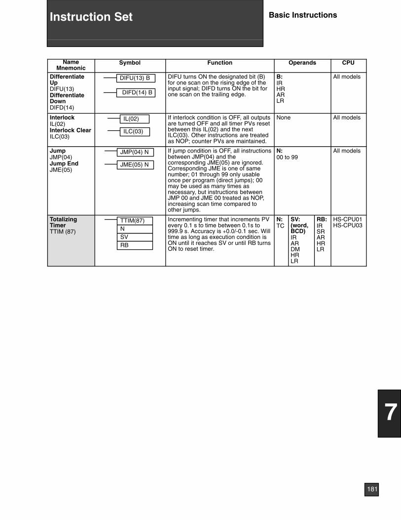
Symbol CPUOperandsFunctionNameMnemonic
DifferentiateUpDIFU(13)DifferentiateDownDIFD(14)
DIFU(13) B
DIFD(14) B
DIFU turns ON the designated bit (B)for one scan on the rising edge of theinput signal; DIFD turns ON the bit forone scan on the trailing edge.
B:IRHRARLR
All models
InterlockIL(02)Interlock ClearILC(03)
IL(02)
ILC(03)
If interlock condition is OFF, all outputsare turned OFF and all timer PVs resetbetween this IL(02) and the nextILC(03). Other instructions are treatedas NOP; counter PVs are maintained.
None All models
JumpJMP(04)Jump EndJME(05)
JMP(04) N
JME(05) N
If jump condition is OFF, all instructionsbetween JMP(04) and thecorresponding JME(05) are ignored.Corresponding JME is one of samenumber; 01 through 99 only usableonce per program (direct jumps); 00may be used as many times asnecessary, but instructions betweenJMP 00 and JME 00 treated as NOP,increasing scan time compared toother jumps.
N:00 to 99
All models
TotalizingTimerTTIM (87)
TTIM(87)
RB
NSV
Incrementing timer that increments PVevery 0.1 s to time between 0.1s to999.9 s. Accuracy is +0.0/-0.1 sec. Willtime as long as execution condition isON until it reaches SV or until RB turnsON to reset timer.
N:TC
SV:(word,BCD)IRARDMHRLR
RB:IRSRARHRLR
HS-CPU01HS-CPU03
181
7
Instruction Set Basic Instructions
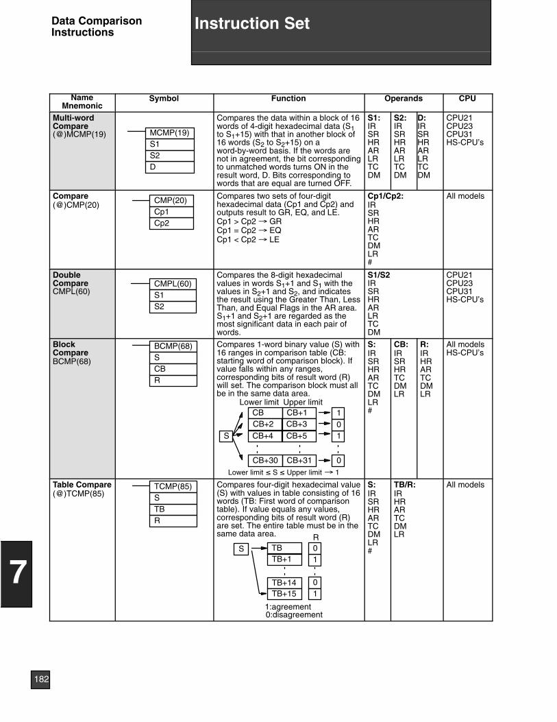
NameMnemonic
Symbol Function Operands CPU
Multi-wordCompare(@)MCMP(19) MCMP(19)
D
S1S2
Compares the data within a block of 16words of 4-digit hexadecimal data (S1to S1+15) with that in another block of16 words (S2 to S2+15) on aword-by-word basis. If the words arenot in agreement, the bit correspondingto unmatched words turns ON in theresult word, D. Bits corresponding towords that are equal are turned OFF.
S1:IRSRHRARLRTCDM
S2:IRSRHRARLRTCDM
D:IRSRHRARLRTCDM
CPU21CPU23CPU31HS-CPU’s
Compare(@)CMP(20) CMP(20)
Cp1Cp2
Compares two sets of four-digithexadecimal data (Cp1 and Cp2) andoutputs result to GR, EQ, and LE.Cp1 > Cp2 → GRCp1 = Cp2 → EQCp1 < Cp2 → LE
Cp1/Cp2:IRSRHRARTCDMLR#
All models
DoubleCompareCMPL(60)
CMPL(60)S1S2
Compares the 8-digit hexadecimalvalues in words S1+1 and S1 with thevalues in S2+1 and S2, and indicatesthe result using the Greater Than, LessThan, and Equal Flags in the AR area.S1+1 and S2+1 are regarded as themost significant data in each pair ofwords.
S1/S2IRSRHRARLRTCDM
CPU21CPU23CPU31HS-CPU’s
BlockCompareBCMP(68)
BCMP(68)SCBR
CB+31
101
0
CB+1CB+3CB+5
Lower limit
Compares 1-word binary value (S) with16 ranges in comparison table (CB:starting word of comparison block). Ifvalue falls within any ranges,corresponding bits of result word (R)will set. The comparison block must allbe in the same data area.
S
Upper limit
Lower limit ≤ S ≤ Upper limit → 1
CB+30
CBCB+2CB+4
S:IRSRHRARTCDMLR#
CB:IRSRHRTCDMLR
R:IRHRARTCDMLR
All modelsHS-CPU’s
Table Compare(@)TCMP(85)
TCMP(85)STBR
Compares four-digit hexadecimal value(S) with values in table consisting of 16words (TB: First word of comparisontable). If value equals any values,corresponding bits of result word (R)are set. The entire table must be in thesame data area.
S
1:agreement0:disagreement
R01
TB+14
TBTB+1
TB+1501
S:IRSRHRARTCDMLR#
TB/R:IRHRARTCDMLR
All models
182
7
Instruction SetData ComparisonInstructions
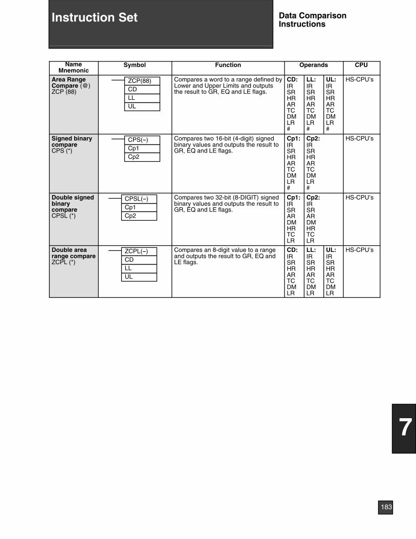
NameMnemonic
CPUOperandsFunctionSymbol
Area RangeCompare (@)ZCP (88)
ZCP(88)CDLLUL
Compares a word to a range defined byLower and Upper Limits and outputsthe result to GR, EQ and LE flags.
CD:IRSRHRARTCDMLR#
LL:IRSRHRARTCDMLR#
UL:IRSRHRARTCDMLR#
HS-CPU’s
Signed binarycompareCPS (*)
CPS(--)Cp1Cp2
Compares two 16-bit (4-digit) signedbinary values and outputs the result toGR, EQ and LE flags.
Cp1:IRSRHRARTCDMLR#
Cp2:IRSRHRARTCDMLR#
HS-CPU’s
Double signedbinarycompareCPSL (*)
CPSL(--)Cp1Cp2
Compares two 32-bit (8-DIGIT) signedbinary values and outputs the result toGR, EQ and LE flags.
Cp1:IRSRARDMHRTCLR
Cp2:IRSRARDMHRTCLR
HS-CPU’s
Double arearange compareZCPL (*)
ZCPL(--)CDLLUL
Compares an 8-digit value to a rangeand outputs the result to GR, EQ andLE flags.
CD:IRSRHRARTCDMLR
LL:IRSRHRARTCDMLR
UL:IRSRHRARTCDMLR
HS-CPU’s
183
7
Instruction Set Data ComparisonInstructions
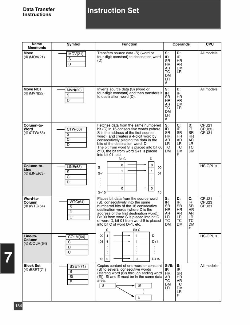
NameMnemonic
Symbol Function Operands CPU
Move(@)MOV(21)
MOV(21)SD
Transfers source data (S) (word orfour-digit constant) to destination word(D).
S:IRSRHRARTCDMLR#
D:IRHRARDMLR
All models
Move NOT(@)MVN(22)
MVN(22)SD
Inverts source data (S) (word orfour-digit constant) and then transfers itto destination word (D).
S:IRSRHRARTCDMLR#
D:IRHRARDMLR
All models
Column-to-Word(@)CTW(63)
CTW(63)SCD
Fetches data from the same numberedbit (C) in 16 consecutive words (whereS is the address of the first sourceword), and creates a 4-digit word byconsecutively placing the data in thebits of the destination word, D.The bit from word S is placed into bit 00of D, the bit from word S+1 is placedinto bit 01, etc.
Bit C D
S:IRSRHRARLRTCDM
C:IRSRHRARLRTCDM#
D:IRSRHRARLRTCDM
CPU21CPU23CPU31
Column-to-Line(@)LINE(63)
LINE(63)SCD
S
S+1
S+15
0
1
0
0
1
0
00
01
15
HS-CPU’s
Word-to-Column(@)WTC(64)
WTC(64)S
CD
Places bit data from the source word(S), consecutively into the samenumbered bits of the 16 consecutivedestination words (where D is theaddress of the first destination word).Bit 00 from word S is placed into bit Cof word D, bit 01 from word S is placedinto bit C of word D+1, etc.
Bit CS
S:IRSRHRARLRTCDM
D:IRSRHRARLRTCDM
C:IRSRHRARLRTCDM#
CPU21CPU23CPU31
Line-to-Column(@)COLM(64)
COLM(64)SDC
D
D+1
D+15
1
1
0
1
1
0
00
01
15
HS-CPU’s
Block Set(@)BSET(71)
BSET(71)SStE
Copies content of one word or constant(S) to several consecutive words(starting word (St) through ending word(E)). St and E must be in the same dataarea.
S St
E
St/E:IRHRARTCDMLR
S:IRSRHRARTCDMLR#
All models
184
7
Instruction SetData TransferInstructions
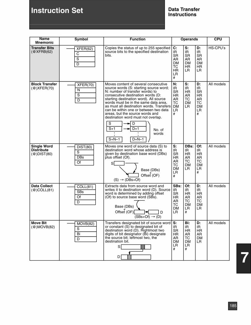
NameMnemonic
CPUOperandsFunctionSymbol
Transfer Bits(@XFRB(62)
XFER(62)CSD
Copies the status of up to 255 specifiedsource bits to the specified destinationbits.
C:IRSRARDMTCHRLR#
S:IRSRARDMHRLR
D:IRSRARDMHRLR
HS-CPU’s
Block Transfer(@)XFER(70)
XFER(70)NSD
Moves content of several consecutivesource words (S: starting source word;N: number of transfer words) toconsecutive destination words (D:starting destination word). All sourcewords must be in the same data area,as must all destination words. Transferscan be within one or between two dataareas, but the source words anddestination word must not overlap.
SS+1
DD+1
S+N--1 D+N--1
No. ofwords
N:IRSRHRARTCDMLR#
S:IRHRARTCDMLR
D:IRSRHRARTCDMLR#
All models
Single WordDistribute(@)DIST(80)
DIST(80)SDBsOf
Moves one word of source data (S) todestination word whose address isgiven by destination base word (DBs)plus offset (Of).
S
Base (DBs)+
Offset (OF)(S) → (DBs+Of)
S:IRSRHRARTCDMLR#
DBs:IRHRARTCDMLR
Of:IRHRARTCDMLR#
All models
Data Collect(@)COLL(81)
COLL(81)SBsOfD
Extracts data from source word andwrites it to destination word (D). Sourceword is determined by adding offset(Of) to source base word (SBs).
Base (DBs)+
Offset (OF)(SBs+Of) → (D)
D
SBs:IRSRHRARTCDMLR
Of:IRHRARTCDMLR#
D:IRHRARTCDMLR
All models
Move Bit(@)MOVB(82)
MOVB(82)SBiD
Transfers designated bit of source wordor constant (S) to designated bit ofdestination word (D). Rightmost twodigits of bit designator (Bi) designatethe source bit; leftmost two, thedestination bit.
S
D
S:IRSRHRARDMLR#
Bi:IRHRARTCDMLR#
D:IRHRARDMLR
All models
185
7
Instruction Set Data TransferInstructions
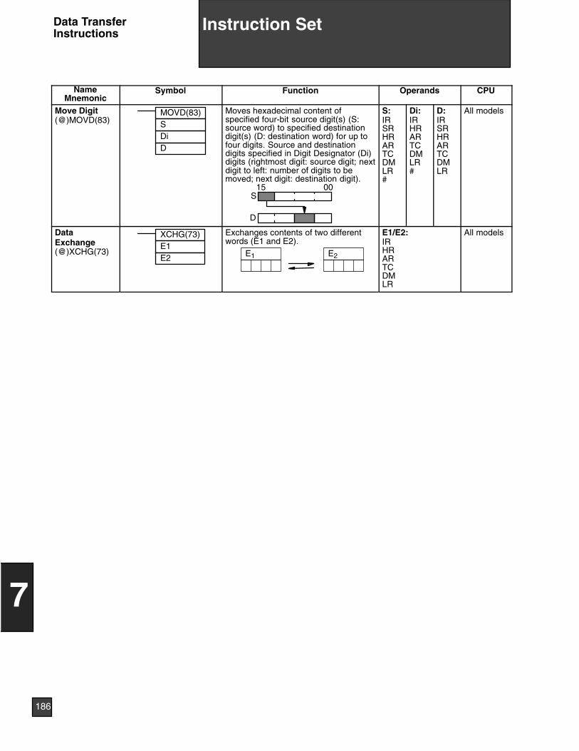
NameMnemonic
CPUOperandsFunctionSymbol
Move Digit(@)MOVD(83)
MOVD(83)SDiD
Moves hexadecimal content ofspecified four-bit source digit(s) (S:source word) to specified destinationdigit(s) (D: destination word) for up tofour digits. Source and destinationdigits specified in Digit Designator (Di)digits (rightmost digit: source digit; nextdigit to left: number of digits to bemoved; next digit: destination digit).
S
D
15 00
S:IRSRHRARTCDMLR#
Di:IRHRARTCDMLR#
D:IRSRHRARTCDMLR
All models
DataExchange(@)XCHG(73)
XCHG(73)E1E2
Exchanges contents of two differentwords (E1 and E2).
E2E1
E1/E2:IRHRARTCDMLR
All models
186
7
Instruction SetData TransferInstructions
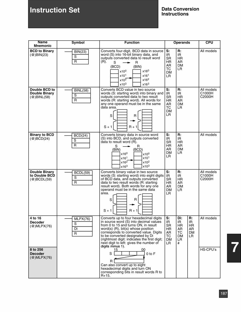
NameMnemonic
Symbol Function Operands CPU
BCD to Binary(@)BIN(23)
BIN(23)SR
Converts four-digit, BCD data in sourceword (S) into 16-bit binary data, andoutputs converted data to result word(R).
x100
x101
x102
x103
x160
x161
x162
x163
(BCD) (BIN)S R
S:IRSRHRARTCDMLR
R:IRHRARDMLR
All models
Double BCD toDouble Binary(@)BINL(58)
BINL(58)SR
Converts BCD value in two sourcewords (S: starting word) into binary andoutputs converted data to two resultwords (R: starting word). All words forany one operand must be in the samedata area.
S
S + 1
R
R + 1
S:IRSRHRARTCDMLR
R:IRHRARDMLR
All modelsC1000HC2000H
Binary to BCD(@)BCD(24)
BCD(24)SR
Converts binary data in source word(S) into BCD, and outputs converteddata to result word (R).
x160
x161
x162
x163
x101
x102
x103
x100
S R(BIN) (BCD)
S:IRSRHRARDMLR
R:IRHRARDMLR
All models
Double Binaryto Double BCD(@)BCDL(59)
BCDL(59)SR
Converts binary value in two sourcewords (S: starting word) into eight digitsof BCD data, and outputs converteddata to two result words (R: startingresult word). Both words for any oneoperand must be in the same dataarea.
S
S + 1
R
R + 1
S:IRSRHRARDMLR
R:IRHRARDMLR
All modelsC1000HC2000H
4 to 16Decoder(@)MLPX(76)
MLPX(76)SDiR
Converts up to four hexadecimal digitsin source word (S) into decimal valuesfrom 0 to 15 and turns ON, in resultword(s) (R), bit(s) whose positioncorresponds to converted value. Digitsto be converted designated by Di(rightmost digit: indicates the first digit;next digit to left: gives the number ofdigits minus 1)
S:IRSRHRARTCDMLR
Di:IRHRARTCDMLR#
R:IRHRARDMLR
All models
8 to 256Decoder(@)MLPX(76)
digits minus 1).
S 0 to F
R
0015
Can also convert up to eighthexadecimal digits and turn ONcorresponding bits in result words R toR+15.
HS-CPU’s
187
7
Instruction Set Data ConversionInstructions
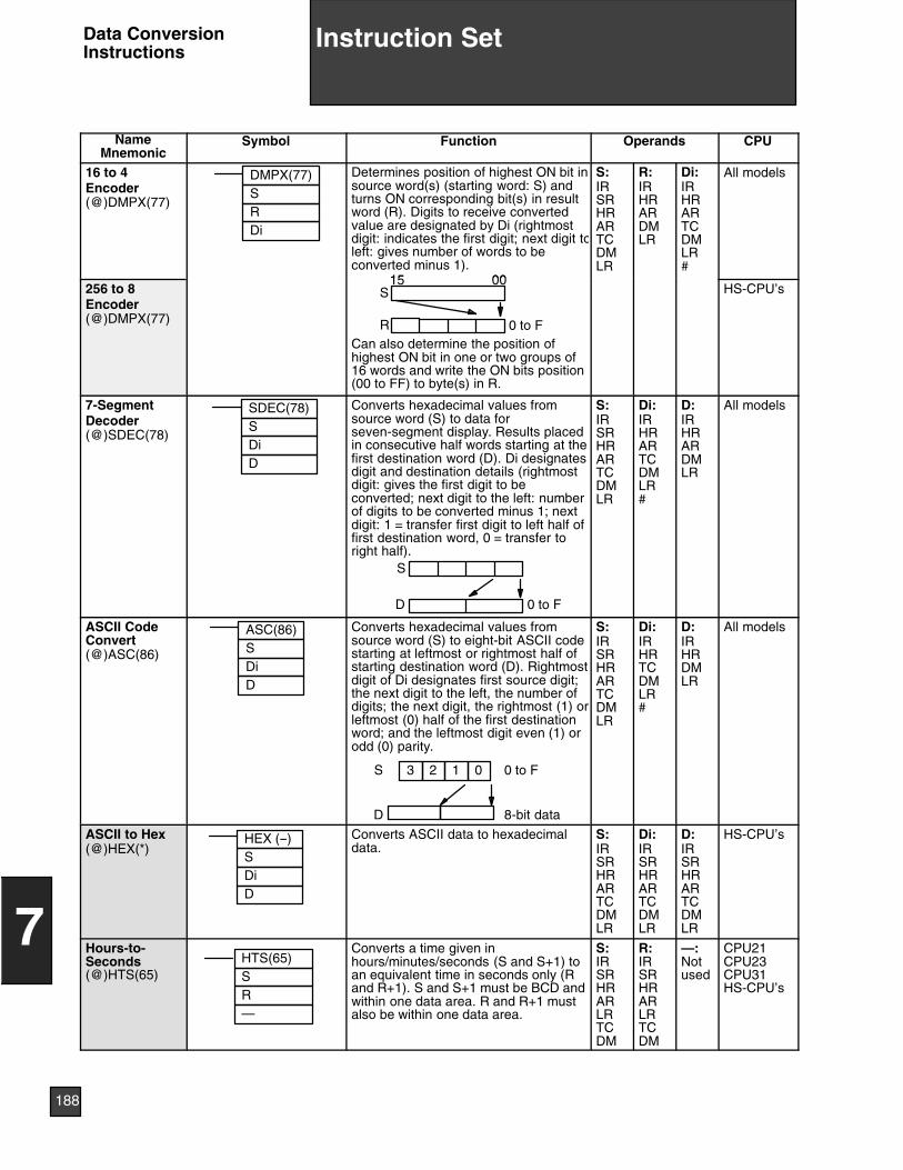
NameMnemonic
CPUOperandsFunctionSymbol
16 to 4Encoder(@)DMPX(77)
DMPX(77)SRDi
Determines position of highest ON bit insource word(s) (starting word: S) andturns ON corresponding bit(s) in resultword (R). Digits to receive convertedvalue are designated by Di (rightmostdigit: indicates the first digit; next digit toleft: gives number of words to beconverted minus 1).
15 00
S:IRSRHRARTCDMLR
R:IRHRARDMLR
Di:IRHRARTCDMLR#
All models
256 to 8Encoder(@)DMPX(77)
S15 00
0 to FRCan also determine the position ofhighest ON bit in one or two groups of16 words and write the ON bits position(00 to FF) to byte(s) in R.
HS-CPU’s
7-SegmentDecoder(@)SDEC(78)
SDEC(78)SDiD
Converts hexadecimal values fromsource word (S) to data forseven-segment display. Results placedin consecutive half words starting at thefirst destination word (D). Di designatesdigit and destination details (rightmostdigit: gives the first digit to beconverted; next digit to the left: numberof digits to be converted minus 1; nextdigit: 1 = transfer first digit to left half offirst destination word, 0 = transfer toright half).
S
D 0 to F
S:IRSRHRARTCDMLR
Di:IRHRARTCDMLR#
D:IRHRARDMLR
All models
ASCII CodeConvert(@)ASC(86)
ASC(86)SDiD
Converts hexadecimal values fromsource word (S) to eight-bit ASCII codestarting at leftmost or rightmost half ofstarting destination word (D). Rightmostdigit of Di designates first source digit;the next digit to the left, the number ofdigits; the next digit, the rightmost (1) orleftmost (0) half of the first destinationword; and the leftmost digit even (1) orodd (0) parity.
D 8-bit data
0 to FS 0123
S:IRSRHRARTCDMLR
Di:IRHRTCDMLR#
D:IRHRDMLR
All models
ASCII to Hex(@)HEX(*)
HEX (--)SDiD
Converts ASCII data to hexadecimaldata.
S:IRSRHRARTCDMLR
Di:IRSRHRARTCDMLR
D:IRSRHRARTCDMLR
HS-CPU’s
Hours-to-Seconds(@)HTS(65)
HTS(65)S
—R
Converts a time given inhours/minutes/seconds (S and S+1) toan equivalent time in seconds only (Rand R+1). S and S+1 must be BCD andwithin one data area. R and R+1 mustalso be within one data area.
S:IRSRHRARLRTCDM
R:IRSRHRARLRTCDM
—:Notused
CPU21CPU23CPU31HS-CPU’s
188
7
Instruction SetData ConversionInstructions
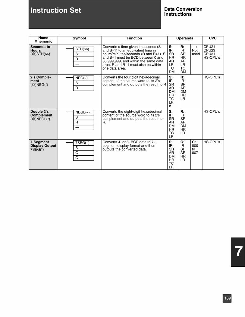
NameMnemonic
CPUOperandsFunctionSymbol
Seconds-to-Hours(@)STH(66)
STH(66)SR—
Converts a time given in seconds (Sand S+1) to an equivalent time inhours/minutes/seconds (R and R+1). Sand S+1 must be BCD between 0 and35,999,999, and within the same dataarea. R and R+1 must also be withinone data area.
S:IRSRHRARLRTCDM
R:IRSRHRARLRTCDM
—:Notused
CPU21CPU23CPU31HS-CPU’s
2’s Comple-ment(@)NEG(*)
NEG(--)SR
Converts the four digit hexadecimalcontent of the source word to its 2’scomplement and outputs the result to R
S:IRSRARDMHRTCLR#
R:IRSRARDMHRLR
HS-CPU’s
Double 2’sComplement(@)NEGL(*)
NEGL(--)SR—
Converts the eight-digit hexadecimalcontent of the source word to its 2’scomplement and outputs the result toR.
S:IRSRARDMHRTCLR
R:IRSRARDMHRLR
HS-CPU’s
7-SegmentDisplay Output7SEG(*)
7SEG(--)SOC
Converts 4- or 8- BCD data to 7-segment display format and thenoutputs the converted data.
S:IRSRARDMHRTCLR
O:IRSRARHRLR
C:000to007
HS-CPU’s
189
7
Instruction Set Data ConversionInstructions
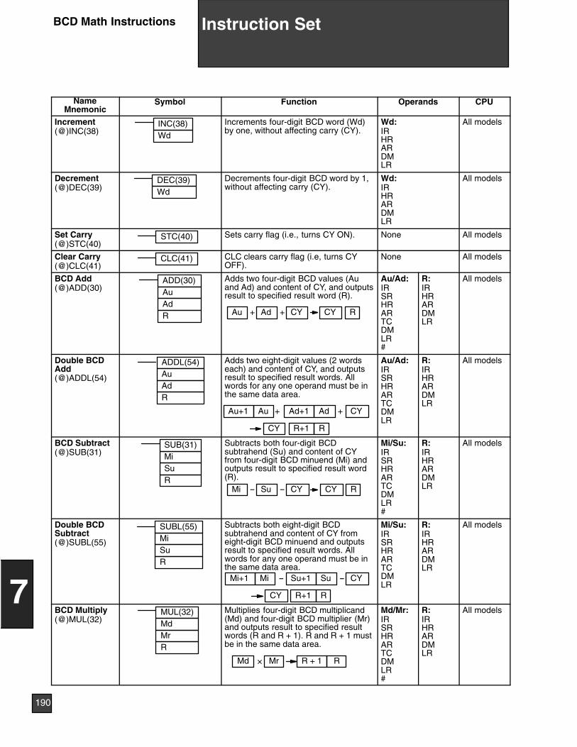
NameMnemonic
Symbol Function Operands CPU
Increment(@)INC(38)
INC(38)Wd
Increments four-digit BCD word (Wd)by one, without affecting carry (CY).
Wd:IRHRARDMLR
All models
Decrement(@)DEC(39)
DEC(39)Wd
Decrements four-digit BCD word by 1,without affecting carry (CY).
Wd:IRHRARDMLR
All models
Set Carry(@)STC(40)
STC(40) Sets carry flag (i.e., turns CY ON). None All models
Clear Carry(@)CLC(41)
CLC(41) CLC clears carry flag (i.e, turns CYOFF).
None All models
BCD Add(@)ADD(30)
ADD(30)AuAdR CY
Adds two four-digit BCD values (Auand Ad) and content of CY, and outputsresult to specified result word (R).
Ad RCYAu + +
Au/Ad:IRSRHRARTCDMLR#
R:IRHRARDMLR
All models
Double BCDAdd(@)ADDL(54)
ADDL(54)AuAdR
Adds two eight-digit values (2 wordseach) and content of CY, and outputsresult to specified result words. Allwords for any one operand must be inthe same data area.
CYAd
R+1CY
Au + +Au+1 Ad+1
R
Au/Ad:IRSRHRARTCDMLR
R:IRHRARDMLR
All models
BCD Subtract(@)SUB(31)
SUB(31)MiSuR
Subtracts both four-digit BCDsubtrahend (Su) and content of CYfrom four-digit BCD minuend (Mi) andoutputs result to specified result word(R).
CYSu RCYMi -- --
Mi/Su:IRSRHRARTCDMLR#
R:IRHRARDMLR
All models
Double BCDSubtract(@)SUBL(55)
SUBL(55)MiSuR
Subtracts both eight-digit BCDsubtrahend and content of CY fromeight-digit BCD minuend and outputsresult to specified result words. Allwords for any one operand must be inthe same data area.
CYSu
R+1CY
Mi -- --Mi+1 Su+1
R
Mi/Su:IRSRHRARTCDMLR
R:IRHRARDMLR
All models
BCD Multiply(@)MUL(32)
MUL(32)MdMrR
Multiplies four-digit BCD multiplicand(Md) and four-digit BCD multiplier (Mr)and outputs result to specified resultwords (R and R + 1). R and R + 1 mustbe in the same data area.
Md R + 1 RMr×
Md/Mr:IRSRHRARTCDMLR#
R:IRHRARDMLR
All models
190
7
Instruction SetBCD Math Instructions
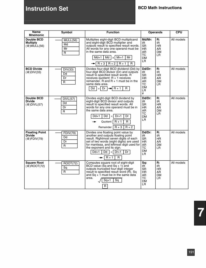
NameMnemonic
CPUOperandsFunctionSymbol
Double BCDMultiply(@)MULL(56)
MULL(56)MdMrR
Multiplies eight-digit BCD multiplicandand eight-digit BCD multiplier andoutputs result to specified result words.All words for any one operand must bein the same data area.
Md
R + 1 R
Mr×Md+1 Mr+1
R + 2R + 3
Md/Mr:IRSRHRARTCDMLR
R:IRHRARDMLR
All models
BCD Divide(@)DIV(33)
R
DIV(33)DdDr
Divides four-digit BCD dividend (Dd) byfour-digit BCD divisor (Dr) and outputsresult to specified result words. Rreceives quotient; R + 1 receivesremainder. R and R + 1 must be in thesame data area.
Dd R + 1 RDr÷
Dd/Dr:IRSRHRARTCDMLR#
R:IRHRARDMLR
All models
Double BCDDivide(@)DIVL(57)
DIVL(57)DdDrR
Divides eight-digit BCD dividend byeight-digit BCD divisor and outputsresult to specified result words. Allwords for any one operand must be inthe same data area.
÷Dd
R + 1 R
DrDd+1 Dr+1
R + 2R + 3
Quotient
Remainder
Dd/Dr:IRSRHRARTCDMLR
R:IRHRARDMLR
All models
Floating PointDivide(@)FDIV(79)
FDIV(79)DdDrR
Divides one floating point value byanother and outputs floating pointresult. Rightmost seven digits of eachset of two words (eight digits) are usedfor mantissa, and leftmost digit used forthe exponent and its sign.
÷Dd
R + 1 R
DrDd+1 Dr+1
Dd/Dr:IRSRHRARTCDMLR
R:IRHRARDMLR
All models
Square Root(@)ROOT(72)
ROOT(72)SqR
Computes square root of eight-digitBCD value (Sq and Sq + 1) andoutputs truncated four-digit integerresult to specified result word (R). Sqand Sq + 1 must be in the same dataarea.
Sq+1 Sq
R
Sq:IRSRHRARTCDMLR
R:IRHRARDMLR
All models
191
7
Instruction Set BCD Math Instructions
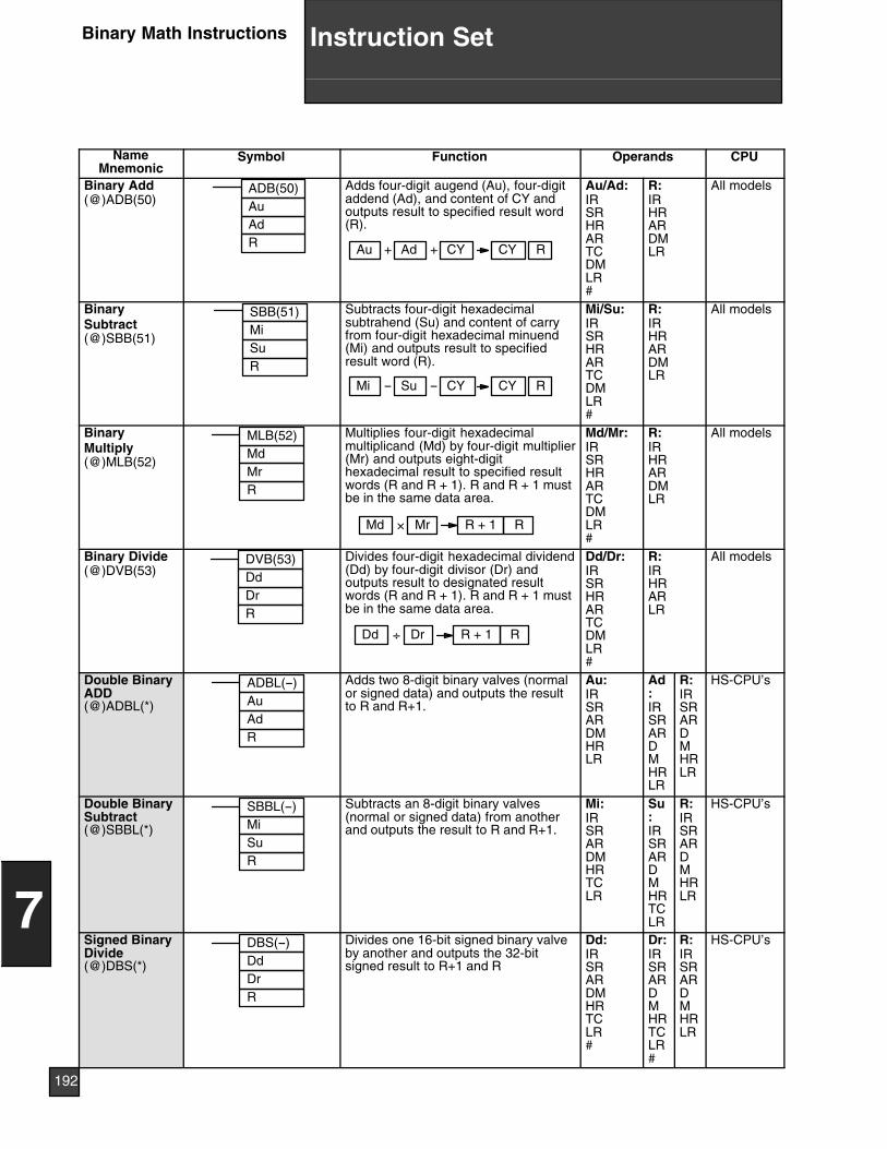
NameMnemonic
Symbol Function Operands CPU
Binary Add(@)ADB(50)
ADB(50)AuAdR
Adds four-digit augend (Au), four-digitaddend (Ad), and content of CY andoutputs result to specified result word(R).
CYAd RCYAu + +
Au/Ad:IRSRHRARTCDMLR#
R:IRHRARDMLR
All models
BinarySubtract(@)SBB(51)
SBB(51)MiSuR
Subtracts four-digit hexadecimalsubtrahend (Su) and content of carryfrom four-digit hexadecimal minuend(Mi) and outputs result to specifiedresult word (R).
CYSu RCYMi -- --
Mi/Su:IRSRHRARTCDMLR#
R:IRHRARDMLR
All models
BinaryMultiply(@)MLB(52)
MLB(52)MdMrR
Multiplies four-digit hexadecimalmultiplicand (Md) by four-digit multiplier(Mr) and outputs eight-digithexadecimal result to specified resultwords (R and R + 1). R and R + 1 mustbe in the same data area.
Md R + 1 RMr×
Md/Mr:IRSRHRARTCDMLR#
R:IRHRARDMLR
All models
Binary Divide(@)DVB(53)
DVB(53)DdDrR
Divides four-digit hexadecimal dividend(Dd) by four-digit divisor (Dr) andoutputs result to designated resultwords (R and R + 1). R and R + 1 mustbe in the same data area.
Dd R + 1 RDr÷
Dd/Dr:IRSRHRARTCDMLR#
R:IRHRARLR
All models
Double BinaryADD(@)ADBL(*)
ADBL(--)AuAdR
Adds two 8-digit binary valves (normalor signed data) and outputs the resultto R and R+1.
Au:IRSRARDMHRLR
Ad:IRSRARDMHRLR
R:IRSRARDMHRLR
HS-CPU’s
Double BinarySubtract(@)SBBL(*)
SBBL(--)MiSuR
Subtracts an 8-digit binary valves(normal or signed data) from anotherand outputs the result to R and R+1.
Mi:IRSRARDMHRTCLR
Su:IRSRARDMHRTCLR
R:IRSRARDMHRLR
HS-CPU’s
Signed BinaryDivide(@)DBS(*)
DBS(--)DdDrR
Divides one 16-bit signed binary valveby another and outputs the 32-bitsigned result to R+1 and R
Dd:IRSRARDMHRTCLR#
Dr:IRSRARDMHRTCLR#
R:IRSRARDMHRLR
HS-CPU’s
192
7
Instruction SetBinary Math Instructions
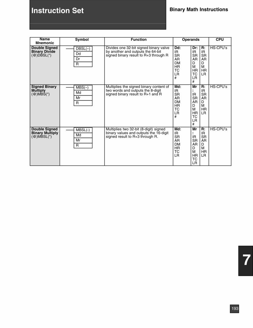
NameMnemonic
CPUOperandsFunctionSymbol
Double SignedBinary Divide(@)DBSL(*)
DBSL(--)DdDrR
Divides one 32-bit signed binary valveby another and outputs the 64-bitsigned binary result to R+3 through R
Dd:IRSRARDMHRTCLR#
Dr:IRSRARDMHRTCLR#
R:IRSRARDMHRLR
HS-CPU’s
Signed BinaryMultiply(@)MBS(*)
MBS(--)MdMrR
Multiplies the signed binary content oftwo words and outputs the 8-digitsigned binary result to R+1 and R
Md:IRSRARDMHRTCLR#
Mr:IRSRARDMHRTCLR#
R:IRSRARDMHRLR
HS-CPU’s
Double SignedBinary Multiply(@)MBSL(*)
MBSL(-)MdMrR
Multiplies two 32-bit (8-digit) signedbinary values and outputs the 16-digitsigned result to R+3 through R.
Md:IRSRARDMHRTCLR
Mr:IRSRARDMHRTCLR
R:IRSRARDMHRLR
HS-CPU’s
193
7
Instruction Set Binary Math Instructions

NameMnemonic
Symbol Function Operands CPU
Shift RegisterSFT(10)
I
P
R
SFT(10)StE
Creates a bit shift register from thestarting word (St) through the endingword (E). I: input bit; P: shift pulse; R:reset input. St must be less than orequal to E and St and E must be in thesame data area.
15 1500In
00E St
St/E:IRHRARLR
All models
ReversibleShift Register(@)SFTR(84)
SFTR(84)CStE
CY
Shifts data in specified word or seriesof words to either left or right. Starting(St) and ending words (E) must bespecified. Control word (C) containsshift direction, reset input, and datainput. St and E must be in the samedata area and St must be less than orequal to E.
15 1500In
00E St
CY
15 1500 00E StIn
St/E/C:IRHRARTCDMLR
All models
ArithmeticShift Left(@)ASL(25)
ASL(25)Wd
Shifts each bit in single word (Wd) ofdata one bit to left, with CY.
WdCY 015 00
Wd:IRHRARDMLR
All models
ArithmeticShift Right(@)ASR(26)
ASR(26)Wd
Shifts each bit in single word (Wd) ofdata one bit to right, with CY.
Wd CY015 00
Wd:IRHRARDMLR
All models
Rotate Left(@)ROL(27)
ROL(27)Wd
Rotates bits in single word (Wd) of dataone bit to left, with carry (CY).
Wd CY15 00
Wd:IRHRARDMLR
All models
Rotate Right(@)ROR(28)
ROR(28)Wd
Rotates bits in single word (Wd) of dataone bit to right, with carry (CY).
WdCY15 00
Wd:IRHRARDMLR
All models
One Digit ShiftLeft(@)SLD(74)
SLD(74)StE
Left shifts data between starting (St)and ending (E) words by one digit (fourbits). St and E must be in the samedata area.
E
StSt + 1
0
St/E:IRHRARDMLR
All models
194
7
Instruction SetData Shift Instructions
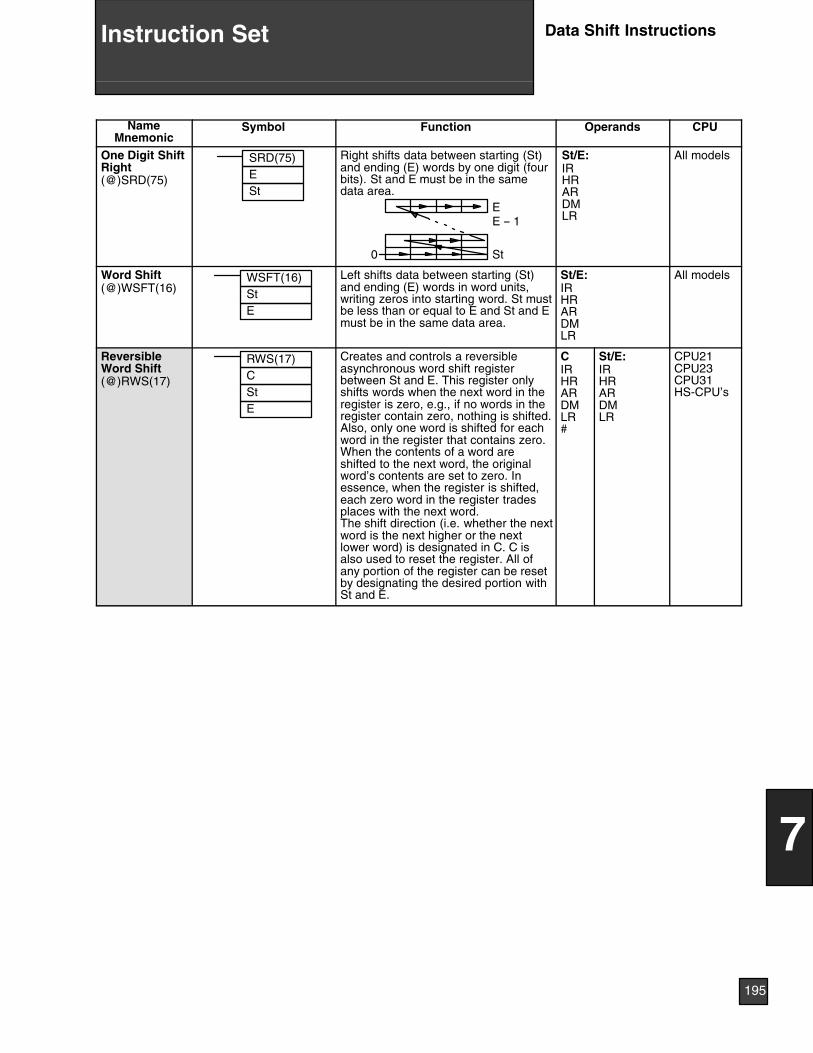
NameMnemonic
CPUOperandsFunctionSymbol
One Digit ShiftRight(@)SRD(75)
SRD(75)ESt
St
Right shifts data between starting (St)and ending (E) words by one digit (fourbits). St and E must be in the samedata area.
EE -- 1
0
St/E:IRHRARDMLR
All models
Word Shift(@)WSFT(16)
WSFT(16)
ESt
Left shifts data between starting (St)and ending (E) words in word units,writing zeros into starting word. St mustbe less than or equal to E and St and Emust be in the same data area.
St/E:IRHRARDMLR
All models
ReversibleWord Shift(@)RWS(17)
RWS(17)
E
CSt
Creates and controls a reversibleasynchronous word shift registerbetween St and E. This register onlyshifts words when the next word in theregister is zero, e.g., if no words in theregister contain zero, nothing is shifted.Also, only one word is shifted for eachword in the register that contains zero.When the contents of a word areshifted to the next word, the originalword’s contents are set to zero. Inessence, when the register is shifted,each zero word in the register tradesplaces with the next word.The shift direction (i.e. whether the nextword is the next higher or the nextlower word) is designated in C. C isalso used to reset the register. All ofany portion of the register can be resetby designating the desired portion withSt and E.
CIRHRARDMLR#
St/E:IRHRARDMLR
CPU21CPU23CPU31HS-CPU’s
195
7
Instruction Set Data Shift Instructions
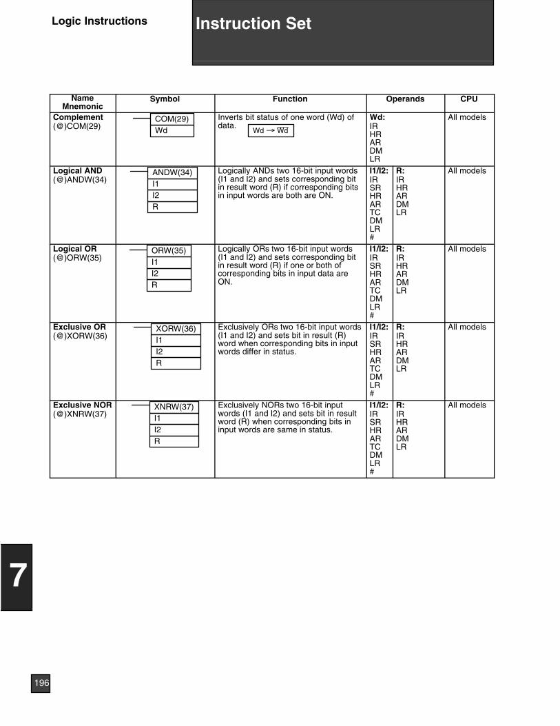
NameMnemonic
Symbol Function Operands CPU
Complement(@)COM(29)
COM(29)Wd
Inverts bit status of one word (Wd) ofdata.
Wd → Wd
Wd:IRHRARDMLR
All models
Logical AND(@)ANDW(34)
ANDW(34)I1I2R
Logically ANDs two 16-bit input words(I1 and I2) and sets corresponding bitin result word (R) if corresponding bitsin input words are both are ON.
I1/I2:IRSRHRARTCDMLR#
R:IRHRARDMLR
All models
Logical OR(@)ORW(35)
ORW(35)I1I2R
Logically ORs two 16-bit input words(I1 and I2) and sets corresponding bitin result word (R) if one or both ofcorresponding bits in input data areON.
I1/I2:IRSRHRARTCDMLR#
R:IRHRARDMLR
All models
Exclusive OR(@)XORW(36)
XORW(36)I1I2R
Exclusively ORs two 16-bit input words(I1 and I2) and sets bit in result (R)word when corresponding bits in inputwords differ in status.
I1/I2:IRSRHRARTCDMLR#
R:IRHRARDMLR
All models
Exclusive NOR(@)XNRW(37) I1
I2R
XNRW(37) Exclusively NORs two 16-bit inputwords (I1 and I2) and sets bit in resultword (R) when corresponding bits ininput words are same in status.
I1/I2:IRSRHRARTCDMLR#
R:IRHRARDMLR
All models
196
7
Instruction SetLogic Instructions
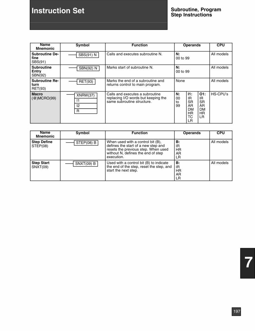
NameMnemonic
Symbol Function Operands CPU
Subroutine De-fineSBS(91)
SBS(91) N Calls and executes subroutine N. N:00 to 99
All models
SubroutineEntrySBN(92)
SBN(92) N Marks start of subroutine N. N:00 to 99
All models
Subroutine Re-turnRET(93)
RET(93) Marks the end of a subroutine andreturns control to main program.
None All models
Macro(@)MCRO(99)
I1I2R
XNRW(37) Calls and executes a subroutinereplacing I/O words but keeping thesame subroutine structure.
N:00to99
I1:IRSRARDMHRTCLR
O1:IRSRARDMHRLR
HS-CPU’s
NameMnemonic
Symbol Function Operands CPU
Step DefineSTEP(08)
STEP(08) B When used with a control bit (B),defines the start of a new step andresets the previous step. When usedwithout N, defines the end of stepexecution.
B:IRHRARLR
All models
Step StartSNXT(09)
SNXT(09) B Used with a control bit (B) to indicatethe end of the step, reset the step, andstart the next step.
B:IRHRARLR
All models
197
7
Instruction Set Subroutine, ProgramStep Instructions
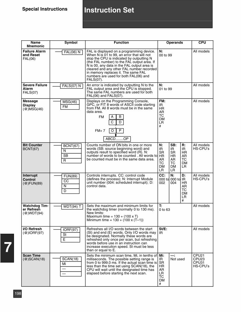
NameMnemonic
Symbol Function Operands CPU
Failure Alarmand ResetFAL(06)
FAL(06) N FAL is displayed on a programming device.When N is 01 to 99, an error that will notstop the CPU is indicated by outputting N(the FAL number) to the FAL output area. IfN is 00, any data in the FAL output area iscleared and any other FAL number recordedin memory replaces it. The same FALnumbers are used for both FAL(06) andFALS(07).
N:00 to 99
All models
Severe FailureAlarmFALS(07)
FALS(07) N An error is indicated by outputting N to theFAL output area and the CPU is stopped.The same FAL numbers are used for bothFAL(06) and FALS(07).
N:01 to 99
All models
MessageDisplay(@)MSG(46)
MSG(46)FM
Displays on the Programming Console,GPC, or FIT 8 words of ASCII code startingfrom FM. All 8 words must be in the samedata area.
FM
FM+ 7
C
A
O
ABCD........OP
D
B
P
FM:IRHRARTCDMLR#
All models
Bit CounterBCNT(67)
BCNT(67)NSBR
Counts number of ON bits in one or morewords (SB: source beginning word) andoutputs result to specified word (R). N:number of words to be counted . All words tobe counted must be in the same data area.
N:IRSRHRARTCDMLR
SB:IRSRHRARTCDMLR
R:IRHRARTCDMLR
All modelsHS-CPU’s
InterruptControl(@)FUN(89)
FUN(89)CCND
Controls interrupts. CC: control code(defines the process); N: Interrupt Moduleunit number (004: scheduled interrupt); D:control data.
CC:000 to002
N:000 to004
D:IRHRARTCDMLR#
All modelsHS-CPU’s
Watchdog Tim-er Refresh(@)WDT(94)
WDT(94) T Sets the maximum and minimum limits forthe watchdog timer (normally 0 to 130 ms).New limits:Maximum time = 130 + (100 x T)Minimum time = 130 + (100 x (T--1))
T:0 to 63
All models
I/O Refresh(@)IORF(97)
IORF(97)StE
Refreshes all I/O words between the start(St) and end (E) words. Only I/O words maybe designated. Normally these words arerefreshed only once per scan, but refreshingwords before use in an instruction canincrease execution speed. St must be lessthan or equal to E.
St/E:IR
All models
Scan Time(@)SCAN(18) SCAN(18)
—
Mi—
Sets the minimum scan time, Mi, in tenths ofmilliseconds. The possible setting range isfrom 0 to 999.0 ms. If the actual scan time isless than the time set using SCAN(18), theCPU will wait until the designated time haselapsed before starting the next scan.
Mi:IRSRHRARLRTCDM#
—:Not used
CPU21CPU23CPU31HS-CPU’s
198
7
Instruction SetSpecial Instructions
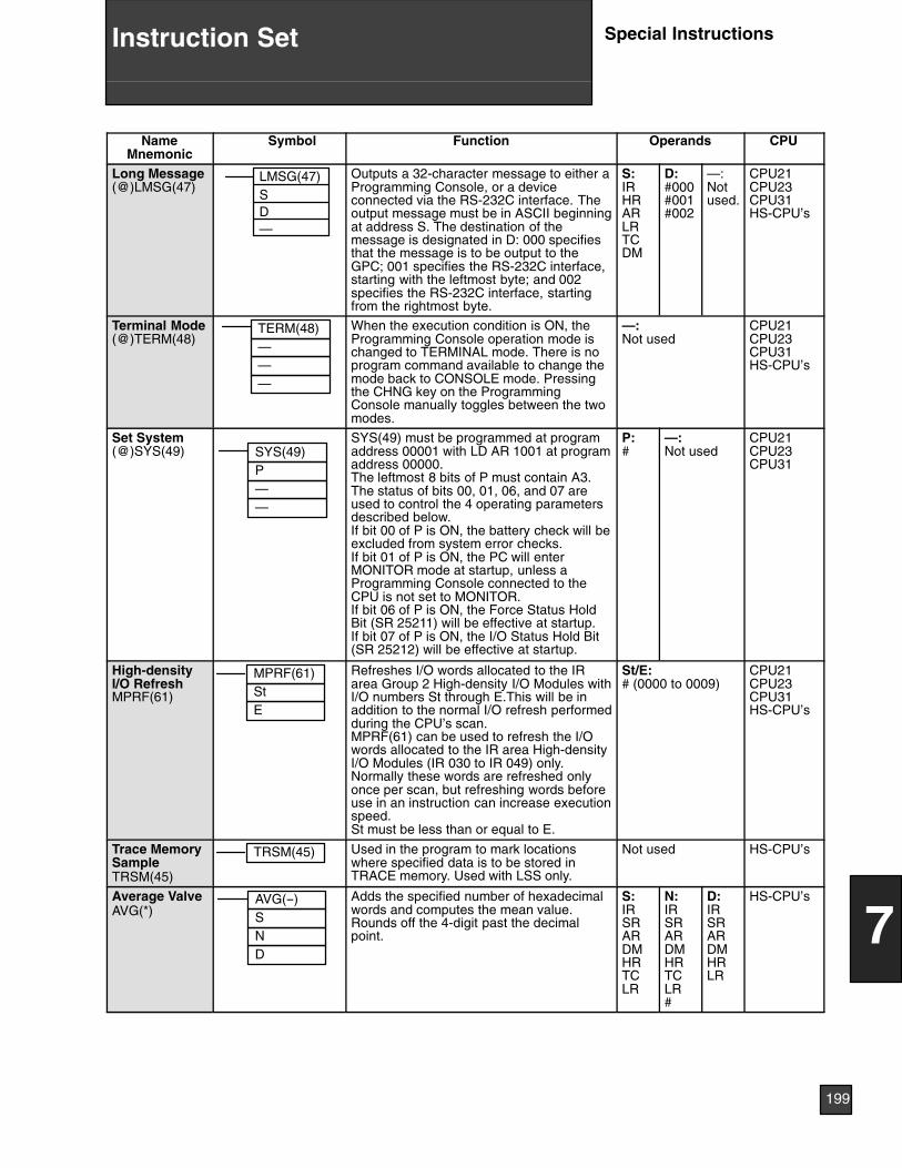
NameMnemonic
CPUOperandsFunctionSymbol
Long Message(@)LMSG(47)
LMSG(47)SD—
Outputs a 32-character message to either aProgramming Console, or a deviceconnected via the RS-232C interface. Theoutput message must be in ASCII beginningat address S. The destination of themessage is designated in D: 000 specifiesthat the message is to be output to theGPC; 001 specifies the RS-232C interface,starting with the leftmost byte; and 002specifies the RS-232C interface, startingfrom the rightmost byte.
S:IRHRARLRTCDM
D:#000#001#002
—:Notused.
CPU21CPU23CPU31HS-CPU’s
Terminal Mode(@)TERM(48)
TERM(48)———
When the execution condition is ON, theProgramming Console operation mode ischanged to TERMINAL mode. There is noprogram command available to change themode back to CONSOLE mode. Pressingthe CHNG key on the ProgrammingConsole manually toggles between the twomodes.
—:Not used
CPU21CPU23CPU31HS-CPU’s
Set System(@)SYS(49) SYS(49)
P——
SYS(49) must be programmed at programaddress 00001 with LD AR 1001 at programaddress 00000.The leftmost 8 bits of P must contain A3.The status of bits 00, 01, 06, and 07 areused to control the 4 operating parametersdescribed below.If bit 00 of P is ON, the battery check will beexcluded from system error checks.If bit 01 of P is ON, the PC will enterMONITOR mode at startup, unless aProgramming Console connected to theCPU is not set to MONITOR.If bit 06 of P is ON, the Force Status HoldBit (SR 25211) will be effective at startup.If bit 07 of P is ON, the I/O Status Hold Bit(SR 25212) will be effective at startup.
P:#
—:Not used
CPU21CPU23CPU31
High-densityI/O RefreshMPRF(61)
MPRF(61)StE
Refreshes I/O words allocated to the IRarea Group 2 High-density I/O Modules withI/O numbers St through E.This will be inaddition to the normal I/O refresh performedduring the CPU’s scan.MPRF(61) can be used to refresh the I/Owords allocated to the IR area High-densityI/O Modules (IR 030 to IR 049) only.Normally these words are refreshed onlyonce per scan, but refreshing words beforeuse in an instruction can increase executionspeed.St must be less than or equal to E.
St/E:# (0000 to 0009)
CPU21CPU23CPU31HS-CPU’s
Trace MemorySampleTRSM(45)
TRSM(45) Used in the program to mark locationswhere specified data is to be stored inTRACE memory. Used with LSS only.
Not used HS-CPU’s
Average ValveAVG(*)
AVG(--)SND
Adds the specified number of hexadecimalwords and computes the mean value.Rounds off the 4-digit past the decimalpoint.
S:IRSRARDMHRTCLR
N:IRSRARDMHRTCLR#
D:IRSRARDMHRLR
HS-CPU’s
199
7
Instruction Set Special Instructions
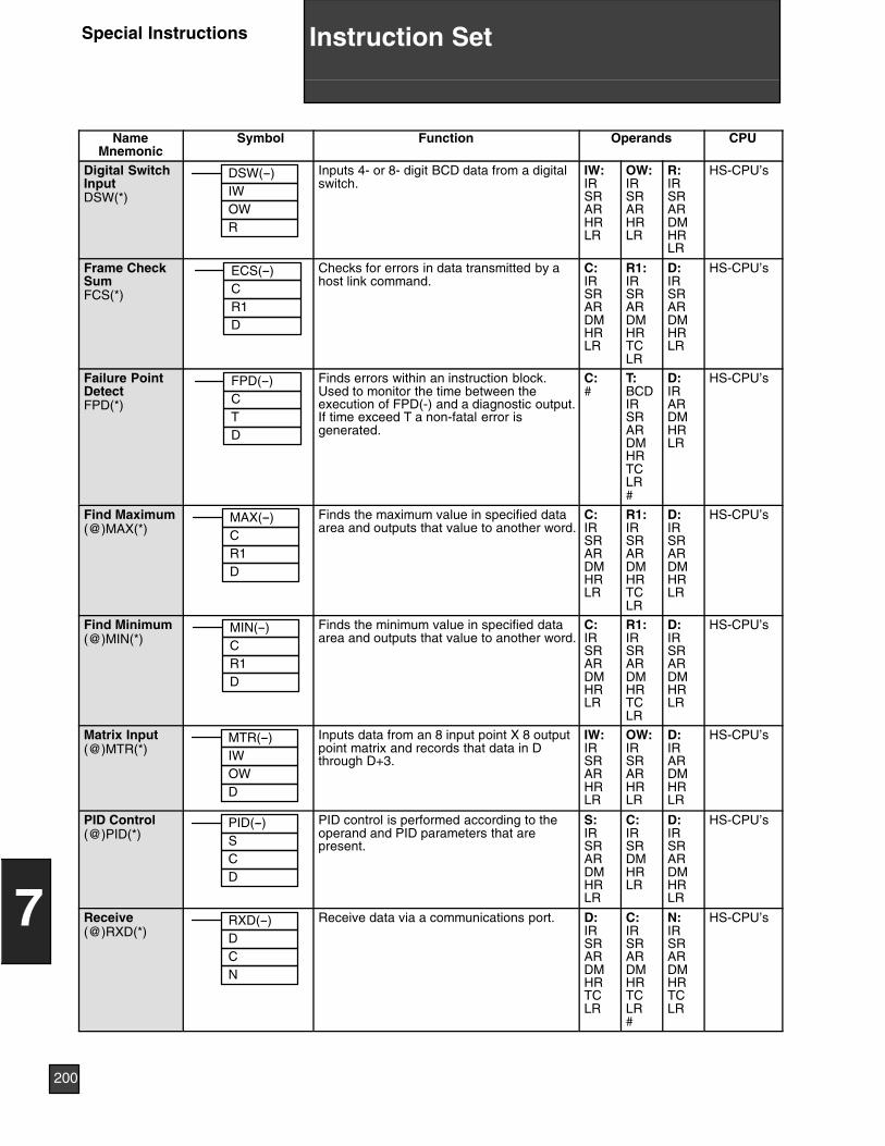
NameMnemonic
CPUOperandsFunctionSymbol
Digital SwitchInputDSW(*)
DSW(--)IWOWR
Inputs 4- or 8- digit BCD data from a digitalswitch.
IW:IRSRARHRLR
OW:IRSRARHRLR
R:IRSRARDMHRLR
HS-CPU’s
Frame CheckSumFCS(*)
ECS(--)CR1D
Checks for errors in data transmitted by ahost link command.
C:IRSRARDMHRLR
R1:IRSRARDMHRTCLR
D:IRSRARDMHRLR
HS-CPU’s
Failure PointDetectFPD(*)
FPD(--)CTD
Finds errors within an instruction block.Used to monitor the time between theexecution of FPD(-) and a diagnostic output.If time exceed T a non-fatal error isgenerated.
C:#
T:BCDIRSRARDMHRTCLR#
D:IRARDMHRLR
HS-CPU’s
Find Maximum(@)MAX(*)
MAX(--)CR1D
Finds the maximum value in specified dataarea and outputs that value to another word.
C:IRSRARDMHRLR
R1:IRSRARDMHRTCLR
D:IRSRARDMHRLR
HS-CPU’s
Find Minimum(@)MIN(*)
MIN(--)CR1D
Finds the minimum value in specified dataarea and outputs that value to another word.
C:IRSRARDMHRLR
R1:IRSRARDMHRTCLR
D:IRSRARDMHRLR
HS-CPU’s
Matrix Input(@)MTR(*)
MTR(--)IWOWD
Inputs data from an 8 input point X 8 outputpoint matrix and records that data in Dthrough D+3.
IW:IRSRARHRLR
OW:IRSRARHRLR
D:IRARDMHRLR
HS-CPU’s
PID Control(@)PID(*)
PID(--)SCD
PID control is performed according to theoperand and PID parameters that arepresent.
S:IRSRARDMHRLR
C:IRSRDMHRLR
D:IRSRARDMHRLR
HS-CPU’s
Receive(@)RXD(*)
RXD(--)DCN
Receive data via a communications port. D:IRSRARDMHRTCLR
C:IRSRARDMHRTCLR#
N:IRSRARDMHRTCLR
HS-CPU’s
200
7
Instruction SetSpecial Instructions
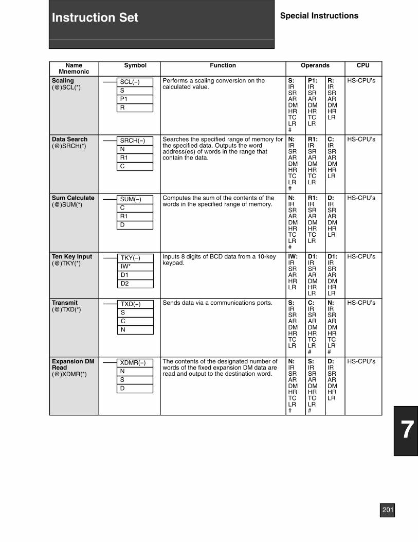
NameMnemonic
CPUOperandsFunctionSymbol
Scaling(@)SCL(*)
SCL(--)SP1R
Performs a scaling conversion on thecalculated value.
S:IRSRARDMHRTCLR#
P1:IRSRARDMHRTCLR
R:IRSRARDMHRLR
HS-CPU’s
Data Search(@)SRCH(*)
SRCH(--)NR1C
Searches the specified range of memory forthe specified data. Outputs the wordaddress(es) of words in the range thatcontain the data.
N:IRSRARDMHRTCLR#
R1:IRSRARDMHRTCLR
C:IRSRARDMHRLR
HS-CPU’s
Sum Calculate(@)SUM(*)
SUM(--)CR1D
Computes the sum of the contents of thewords in the specified range of memory.
N:IRSRARDMHRTCLR#
R1:IRSRARDMHRTCLR
D:IRSRARDMHRLR
HS-CPU’s
Ten Key Input(@)TKY(*)
TKY(--)IW*D1D2
Inputs 8 digits of BCD data from a 10-keykeypad.
IW:IRSRARHRLR
D1:IRSRARDMHRLR
D1:IRSRARDMHRLR
HS-CPU’s
Transmit(@)TXD(*)
TXD(--)SCN
Sends data via a communications ports. S:IRSRARDMHRTCLR
C:IRSRARDMHRTCLR#
N:IRSRARDMHRTCLR#
HS-CPU’s
Expansion DMRead(@)XDMR(*)
XDMR(--)NSD
The contents of the designated number ofwords of the fixed expansion DM data areread and output to the destination word.
N:IRSRARDMHRTCLR#
S:IRSRARDMHRTCLR#
D:IRSRARDMHRLR
HS-CPU’s
201
7
Instruction Set Special Instructions
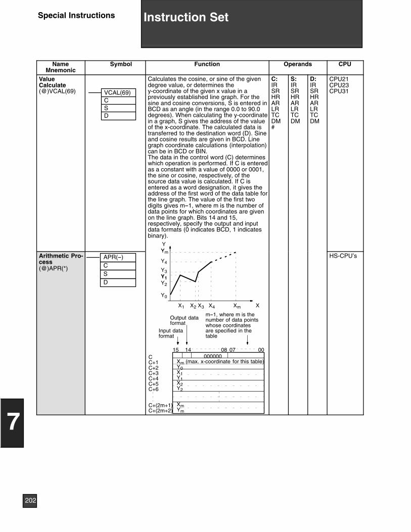
NameMnemonic
CPUOperandsFunctionSymbol
ValueCalculate(@)VCAL(69) VCAL(69)
CSD
Calculates the cosine, or sine of the givendegree value, or determines they-coordinate of the given x value in apreviously established line graph. For thesine and cosine conversions, S is entered inBCD as an angle (in the range 0.0 to 90.0degrees). When calculating the y-coordinatein a graph, S gives the address of the valueof the x-coordinate. The calculated data istransferred to the destination word (D). Sineand cosine results are given in BCD. Linegraph coordinate calculations (interpolation)can be in BCD or BIN.The data in the control word (C) determineswhich operation is performed. If C is enteredas a constant with a value of 0000 or 0001,the sine or cosine, respectively, of thesource data value is calculated. If C isentered as a word designation, it gives theaddress of the first word of the data table forthe line graph. The value of the first twodigits gives m--1, where m is the number ofdata points for which coordinates are givenon the line graph. Bits 14 and 15,respectively, specify the output and inputdata formats (0 indicates BCD, 1 indicatesbinary).
YY
C:IRSRHRARLRTCDM#
S:IRSRHRARLRTCDM
D:IRSRHRARLRTCDM
CPU21CPU23CPU31
Arithmetic Pro-cess(@)APR(*)
APR(--)CSD
Xm (max. x-coordinate for this table)Y0X1Y1X2Y2
XmYm
XXmX4X3X2X1
Ym
Y4
Y3Y1Y2
Y0
15 14 08 07 00000000
Input dataformat
Output dataformat
m--1, where m is thenumber of data pointswhose coordinatesare specified in thetable
CC+1C+2C+3C+4C+5C+6
C+(2m+1)C+(2m+2)
HS-CPU’s
202
7
Instruction SetSpecial Instructions
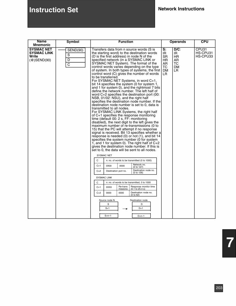
NameMnemonic
Symbol Function Operands CPU
SYSMAC NETSYSMAC LINKWrite(@)SEND(90)
SEND(90)SDC
Transfers data from n source words (S isthe starting word) to the destination words(D is the first address) in node N of thespecified network (in a SYSMAC LINK orSYSMAC NET System). The format of thecontrol words varies depending on the typeof system. In both types of systems, the firstcontrol word (C) gives the number of wordsto be transferred.For SYSMAC NET Systems, in word C+1,bit 14 specifies the system (0 for system 1,and 1 for system 0), and the rightmost 7 bitsdefine the network number. The left half ofword C+2 specifies the destination port (00:NSB, 01/02: NSU), and the right halfspecifies the destination node number. If thedestination node number is set to 0, data istransmitted to all nodes.For SYSMAC LINK Systems, the right halfof C+1 specifies the response monitoringtime (default 00: 2 s, FF: monitoringdisabled), the next digit to the left gives themaximum number of re-transmissions (0 to15) that the PC will attempt if no responsesignal is received. Bit 13 specifies whether aresponse is needed (0) or not (1), and bit 14specifies the system number (0 for system1, and 1 for system 0). The right half of C+2gives the destination node number. If this isset to 0, the data will be sent to all nodes.
n: no. of words to be transmitted, 0 to 1000
Response monitor time(0.1 to 25.4 s)
Destination node no.(0 to 62)
n: no. of words to be transmitted (0 to 1000)
Network no.(0 to 127)Destination node no.(0 to 126)
C
SYSMAC NET
SYSMAC LINK
0X00 0000
Destination port no.
0XX0 Re-transmissions
0000 0000
Destination nodeSource node N
S
S+1
S+n--1
D
D+1
D+n--1
C+1
C+2
C
C+1
C+2
S:IRSRHRARTCDMLR
D/C:IRHRARTCDMLR
CPU31HS-CPU31HS-CPU33
203
7
Instruction Set Network Instructions
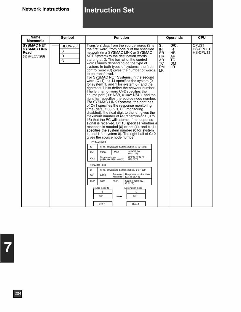
NameMnemonic
CPUOperandsFunctionSymbol
SYSMAC NETSYSMAC LINKRead(@)RECV(98)
RECV(98)SDC
n: no. of words to be transmitted, 0 to 1000
Response monitor time(0.1 to 25.4 s)
Source node no.(0 to 62)
n: no. of words to be transmitted (0 to 1000)
Network no.(0 to 127)Source node no.(0 to 126)
Transfers data from the source words (S isthe first word) from node N of the specifiednetwork (in a SYSMAC LINK or SYSMACNET System) to the destination wordsstarting at D. The format of the controlwords varies depending on the type ofsystem. In both types of systems, the firstcontrol word (C) gives the number of wordsto be transferred.For SYSMAC NET Systems, in the secondword (C+1), bit 14 specifies the system (0for system 1, and 1 for system 0), and therightmost 7 bits define the network number.The left half of word C+2 specifies thesource port (00: NSB, 01/02: NSU), and theright half specifies the source node number.For SYSMAC LINK Systems, the right halfof C+1 specifies the response monitoringtime (default 00: 2 s, FF: monitoringdisabled), the next digit to the left gives themaximum number of re-transmissions (0 to15) that the PC will attempt if no responsesignal is received. Bit 13 specifies whether aresponse is needed (0) or not (1), and bit 14specifies the system number (0 for system1, and 1 for system 0). The right half of C+2gives the source node number.
C
SYSMAC NET
SYSMAC LINK
0X00 0000
Source port no.(NSB: 00, NSU: 01/02)
0XX0 Re-transmissions
0000 0000
Destination nodeSource node N
S
S+1
S+n--1
D
D+1
D+n--1
C+1
C+2
C
C+1
C+2
S:IRSRHRARTCDMLR
D/C:IRHRARTCDMLR
CPU31HS-CPU31HS-CPU33
204
7
Instruction SetNetwork Instructions

Cat. No. P02FAX3 12/94 Specifications subject to change without notice. Printed in U.S.A.
OMRON ELECTRONICS, INC.One East Commerce DriveSchaumburg, IL 60173
NOTE: DIMENSIONS SHOWN ARE IN MILLIMETERS. To convert millimeters to inches divide by 25.4.
1-800-55-OMRON
OMRON CANADA, INC.885 Milner AvenueScarborough, Ontario M1B 5V8
416-286-6465
Related Documents