System Camera Operation 1. Getting Started 1. Preparation for Demonstration 2. 1. System Block Diagram 2. Connection 3. Factory Setting ROP CCU 3. Trouble shooting 1. Operation 2. B/W Screen 3. Format Change 4. Auto Set UP NG 2. Optical System Reliability 3. Camera System Block Diagram , Connection 4. Camera 1. Menu 2. Display Status 3.Flange Back Adjustment 4. White/Black Balance 5. ROP Panel 1. Power On/Off 2. ND/CC Filter 3. Shutter 4. Output Selector 5. Setup (White/Black Balance, Auto Setup) 6. Auto Setup 7. Scene File 8. Master Gain 9. RGB Gain and Black Gain 10. Monitor 11. Mode 12. Joystick 6. ROP Control DRS in GAMMA, SKIN TONE in DTL 1. Pedestal and Shading 2.FLARE and MATRIX 3.Gamma and Black Gamma 4. Gain 5. KNEE/White Clip and SYSTEM 6. Detail and Function 7. Important Function 1.MATRIX 2. SKIN TONE 8. CCU 1. Menu 2. Reference Signal 3. Genlock 4. Incom 5. Pin Assignment 6. 4W/RTS/2W 9. Technical Term 1. What is flange back? 2. What is color temperature? 3. What is white balance? 4. CC Filter 5. What is pedestal? 6. What is shading? 7. What is flare? 8. What is MATRIX? 9. What is gamma? 10. What is knee? 11. What is detail? 12. What is white clip? Content

Welcome message from author
This document is posted to help you gain knowledge. Please leave a comment to let me know what you think about it! Share it to your friends and learn new things together.
Transcript

System Camera Operation
1. Getting Started
1. Preparation for Demonstration
2. 1. System Block Diagram 2. Connection 3. Factory Setting ROP CCU
3. Trouble shooting
1. Operation 2. B/W Screen 3. Format Change 4. Auto Set UP NG
2. Optical System Reliability
3. Camera System Block Diagram , Connection
4. Camera
1. Menu 2. Display Status 3.Flange Back Adjustment 4. White/Black Balance
5. ROP Panel
1. Power On/Off 2. ND/CC Filter 3. Shutter 4. Output Selector
5. Setup (White/Black Balance, Auto Setup) 6. Auto Setup 7. Scene File
8. Master Gain 9. RGB Gain and Black Gain 10. Monitor 11. Mode
12. Joystick
6. ROP Control DRS in GAMMA, SKIN TONE in DTL
1. Pedestal and Shading 2.FLARE and MATRIX 3.Gamma and Black Gamma
4. Gain 5. KNEE/White Clip and SYSTEM 6. Detail and Function
7. Important Function 1.MATRIX 2. SKIN TONE
8. CCU 1. Menu 2. Reference Signal 3. Genlock 4. Incom 5. Pin Assignment 6. 4W/RTS/2W
9. Technical Term 1. What is flange back? 2. What is color temperature? 3. What is white balance? 4. CC Filter
5. What is pedestal? 6. What is shading? 7. What is flare? 8. What is MATRIX?
9. What is gamma? 10. What is knee? 11. What is detail? 12. What is white clip?
Content
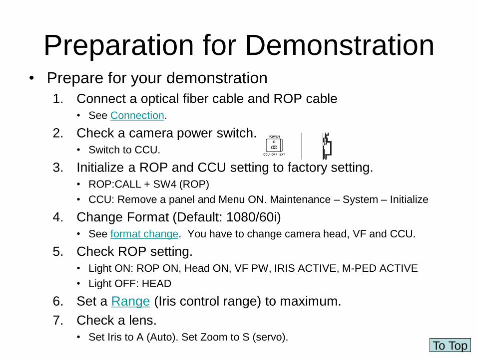
Preparation for Demonstration • Prepare for your demonstration
1. Connect a optical fiber cable and ROP cable
• See Connection.
2. Check a camera power switch.
• Switch to CCU.
3. Initialize a ROP and CCU setting to factory setting.
• ROP:CALL + SW4 (ROP)
• CCU: Remove a panel and Menu ON. Maintenance – System – Initialize
4. Change Format (Default: 1080/60i)
• See format change. You have to change camera head, VF and CCU.
5. Check ROP setting.
• Light ON: ROP ON, Head ON, VF PW, IRIS ACTIVE, M-PED ACTIVE
• Light OFF: HEAD
6. Set a Range (Iris control range) to maximum.
7. Check a lens.
• Set Iris to A (Auto). Set Zoom to S (servo). To Top

Camera System Block Diagram
To Top
Camera Control Unit (CCU)
AK-HCU3550

Connection
To Top

Trouble Shooting: Operation
• Iris doesn’t work by joystick! – Check lens. Lens has manual and auto
iris mode. Set to A (Auto Iris), otherwise it doesn’t work.
– Check the Close button. If it lights on, it doesn’t work.
– Check the AUTO button of ROP. • If it on, it doesn’t work.
– Check IRIS ACTIVE button. • If it is off, it doesn’t work.
• Master pedestal doesn’t work by joystick. – Check the M-PED ACTIVE button.
• If it is off, it doesn’t work.
• ND and CC filter switching don’ work. – Check the head button. It must light off.
To Top

Trouble shooting: B/W screen (PM out)
• The monitor is B/W. 1. PM output is B/W.
– You have to select ENC to get color signal. If you choose R, G or B, it becomes B/W.
2. CCU output is B/W. • OPERATION– Setting3 – MONO SW
You should select OFF. Otherwise output becomes B/W.
3. The monitor mode is B/W. 1. Check the monitor mode.
ROP
CCU menu
To Top

Trouble shooting: Format change
1. NG appears when you change format. 1. You should meet the format each peripherals,
camera, VF, CCU.
In case of 1080i/59.94:
1. Camera: Hold MENU button
– Maintenance – Format – Format
59.94i,50i
Select 59.94i.
2. VF: Change format by physical switch.
– Switch to 1080i/60
3. CCU:Remove the front cover and Turn on menu.
– OPERATION– Setting1 – CCU mode
Select 1080/59.94i(60i)
To Top

Trouble shooting: Auto Set Up NG
1. NG appears when you press Auto Set UP. 1. Check Range (Iris control range) if its position is maximum.
If the position is wrong, iris doesn’t close. So ABB doesn’t work.
To Top
34.Iris sensitivity control [SENSE] This is used to adjust the iris control range of the
joystick.
35.Iris control range control [RANGE] This is used to adjust the iris control position
(shift the
control range) of the joystick.

Factory Setting: ROP • Reference file operations
– The operations which can be performed include calling the default basic camera data settings and registering and calling the basic user settings selected.
• How to call the settings in the reference files – Scene file is not selected.
1. Factory file
1. Press scene file SW4 while holding down CALL. When the LED of scene file SW4 goes off, it signals the completion of the call operation.
2. User files 1, 2 and 3
1. Press scene file SW1, SW2 or SW3 while holding down CALL. When the LED of scene file SW1, SW2 or SW3 goes off, it signals the completion of the call operation.
– Refer to next page to register user files
Next
Page To Top

How to register Factory Setting/ User File
• How to register settings in the reference files
– 1 Factory file
• Adjust the camera to the status in which the settings are to
be registered, and select the settings. When the scene file
STORE SW is pressed, the LED lights up red. When the
SHIFT and scene file SW4 are now pressed together while
holding down CALL, the STORE SW lamp goes off,
signaling the completion of the registration. The factory file
is the file which contains the settings stored at the factory.
Do not undertake the steps described above because the
registration operation is undertaken by the servicing
department.
– 2 User files 1, 2 and 3
• Adjust the camera to the status in which the settings are to
be registered, and select the settings. When the scene file
STORE SW is pressed, the LED lights up red. When
scene file SW1, SW2 or SW3 is now pressed while holding
down CALL, the STORE SW lamp goes off, signaling the
completion of the registration.
Back
Refer to
CCU
Initialize To Top

Factory Setting: CCU
System
This is used to initialize the menu settings.
.
-Initialize
The menu settings can be returned here to the
factory settings using this item.
Selection options: NO?, YES?
After selecting “Initialize”, turn the jog dial to select “YES?”,
and then press the jog dial to initialize the settings.
Notes: The settings of the “Date/Time”, “Network” and
“Version” menus are not initialized.
Back
To Top

Optical System Reliability (ROP) • You can easily check optical system status.
1. Optical transmission alarm. 1. Signal Level Check
2. Cable alarm 1. Connection check between the camera and the CCU.
Refer to “OpticalFiberReliability.ppt”
1. Optical transmission alarm indicator [OPT]
This is the optical transmission indicator.
Green: The indicator lights when the optical
signals received in the transmission between the
camera and CCU are strong enough.
The optical reception strength level is 5.
Orange: The optical reception strength level is 3
to 4.
Red: The optical reception strength level is 1 to 2.
Check the optical connector connections and
mating. If the problem persists, turn off the CCU
power, disconnect the cable between the camera
and CCU, and clean the optical contact area. Use
cotton swabs moistened with alcohol to wipe the
optical fiber part gently.
2. Fan alarm indicator [FAN] This indicates that the CCU’s fan has stopped or
that the camera’s fan is OFF.
Lighted: The CCU’s fan has stopped or the
camera’s fan is OFF.
Off: Both the CCU’s fan and the camera’s fan
are operating normally.
3 Cable alarm indicator [CABLE] This is the camera cable warning indicator.
Lighted: The indicator warns that there is no
connection between the camera and CCU or that the
power supply has been shorted. If it remains lighted,
turn off the CCU’s
main power, and check out the cables and connectors.
If there is no change in the lighting status, contact your
dealer.
Off: This indicates that the camera cable is connected
correctly.
To Top

Optical System Reliability (CCU)
3. Camera cable open alarm indicator
[ALARM OPEN]
This lights when the unit and camera are not
connected by the optical fiber multi cable.
4. Camera cable short-circuit alarm indicator
[ALARM SHORT]
This lights when the cable connecting the unit
and camera has been short-circuited.
5.Fan alarm indicator [ALARM FAN]
This lights when the unit’s cooling fan stops
running.
To Top

Camera Head
To Top

Camera Menu
INCOM Set 1
INCOM Set 2
MIC Gain
To Top
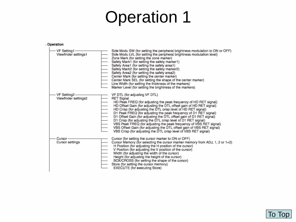
Operation 1
To Top

Operation 2
To Top

Operation 3
To Top

Operation 4
To Top

Paint 1
To Top

Paint 2
To Top

Paint 3
To Top

Maintenance
To Top

Display Status (Camera) 9.Iris f-number display:
The approximate value of the iris setting (f-number) is
displayed here.
<Note>
This display appears when a lens which has an f-number
output is being used.
10.Camera warning or message display:
A message indicating the occurrence of an alarm, the
camera settings, the progress made in the adjustments,
and the adjustment results appear here for about
3 seconds.
11.Focus position display:
The focus position is indicated here in the form of a
number.
<Note>
This display appears only when a lens which has a focus
position output is being used.
12.Zoom position display:
The zoom position is indicated here in the form of a
number.
<Note>
This display appears only when a lens which has a zoom
position output is being used.
13.MONI SEL display:
This indicates the video mode of the monitor output.
14.Optical level display:
This indicates the light sensing level of the optical fiber
cable.
15.5600K display:
This indicates the setting of the electronic color
compensation.
16.Field frequency display:
This indicates the field frequency at which the camera is
operating. Either 50i or 60i is displayed.
1.Extender display:
This appears when the lens extender is being used.
2.Shutter speed/mode display:
This indicates the shutter speed or shutter mode setting.
3.RET SEL display:
This indicates the return mode selected by the grip RET
switch.
4.Voltage display:
This indicates the voltage of the DC IN currently in use.
5.Filter display:
This indicates the type of filter selected.
6.White balance memory display:
This indicates the automatic adjustment memory selected
for the white balance.
A: The WHITE BAL switch is set to “A”.
B: The WHITE BAL switch is set to “B”.
P: The WHITE BAL switch is set to “PRST”.
7.Gain display:
This indicates the video amplifier’s gain setting (in dB)
which has been selected by the gain selector switch.
8.Audio CH1 and CH2 displays:
The audio levels are displayed here (separately for audio
CH1 and audio CH2). To Top

Adjusting the lens flange back
1 Mount the lens on the camera. Do not forget to
connect the lens cable at this time.
2 Set the lens iris to manual, and open the iris.
3 Set the lighting in such a way that the appropriate
video output level is obtained at a distance of about
9.9 ft. (3 m) from the flange back adjustment chart.
If the video level is too high, use a filter or shutter.
4 Loosen the screw that secures the F.f (flange
focus) ring.
Note
Depending on the lens concerned, this ring may be
marked as the “F.b” (flange back) ring.
5 Set the zoom ring to the telephoto position either
by manual or electrical means.
6 Shoot the flange back adjustment chart, and turn
the distance ring to adjust the focus.
7 Set the zoom ring to the wide-angle position, and
turn the F.f ring to adjust the focus. Take care not to
move the distance ring.
8 Repeat steps 5 to 7 until the chart is focused
properly at both the telephoto and wide-angle
positions.
9 Tighten up the screw that secures the F.f ring.
To Top

White/Black Balance
51.Menu switch [MENU]
When this switch is pressed, the camera’s user menu is
output; when it is pressed again, the menu screen display is
cleared.
52.JOG dial button
Turning the JOG dial while the menu screen is displayed
moves the cursor to the setting items. The menu settings are
established by operating this dial button. For details on the
menu operations, refer to the section on the menu operations.
53.Electronic shutter selector switch [SHUTTER]
This is set to ON when the electronic shutter is to be used.
When it is set to the SEL position, the shutter speed is
switched in the preset range and the mode is also switched.
It is not effective when the CCU is connected to the camera.
54.AWB/ABB start switch [AUTO W/B BAL]
This is used for conducting automatic white balance
adjustments (AWB) or automatic black balance adjustments
(ABB). It is not effective when the CCU is connected to the
camera.
55.Lens connector [LENS]
The lens cable is connected to this connector.
Note 2.
No53 [SHUTTER] and No.54[AUTO w/B BAL]
don’t work when CCU is connected.
Note 1.
All side panel switches don’t work when
CCU is connected.
To Top

ROP Operation
To Top

ROP Panel
ND/CC Filter
MODE
Joystick
RGB GAIN
and Black
Control
Master Gain
ROP, Camera and
VF Power ON/OFF
Scene File
Shutter
Output
Selector
Control
-MATRIX
-SKIN TONE
Monitor
White/Black
Balance and
Auto Setup
To Top
CAMERA No.

Power On/Off
to ROP
1.ROP ON switch
This switch enables the
controls on the ROP’s
operation panel to be
operated. Its lamp lights as
soon as the CCU power is
turned on.
2. Camera power switch [HEAD ON]
This switch makes it possible to turn the
camera’s power on and off by remote
control at the ROP. However, it will not
function unless the CCU’s camera power
switch and the power switch of the camera
itself are at the “ON” position. Each time the
switch is pressed, the power setting is
switched between ON (power on: LED
lights) and OFF (power off: LED off).
Green: Power ON
Red Blinking: Camera power off by ROP
(You can turn on by ROP.)
Red: Camera power is off locally. (You need
to turn on camera’s power switch.)
3. VF power OFF switch [VF PW]
This is the camera VF power switch which is
operated by remote control from the ROP.
When it is at the ON setting, its LED is on.
Each time the switch is pressed, the power
setting is switched between ON (power on)
and OFF (power off).
5. Camera number display
[CAMERA No.]
This is where the camera
number information is
displayed.
“–” appears when no camera
number is displayed.
You can change Camera No. at FUNC(SHIFT+DTL)
To Top
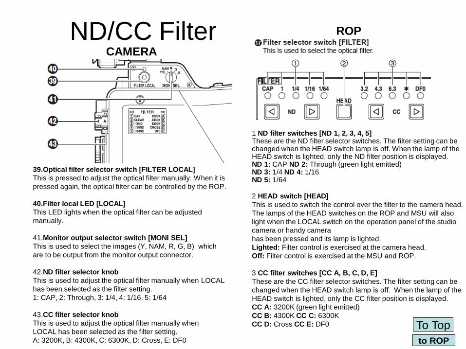
ND/CC Filter CAMERA
ROP
1 ND filter switches [ND 1, 2, 3, 4, 5] These are the ND filter selector switches. The filter setting can be changed when the HEAD switch lamp is off. When the lamp of the HEAD switch is lighted, only the ND filter position is displayed. ND 1: CAP ND 2: Through (green light emitted) ND 3: 1/4 ND 4: 1/16 ND 5: 1/64
2 HEAD switch [HEAD]
This is used to switch the control over the filter to the camera head.
The lamps of the HEAD switches on the ROP and MSU will also
light when the LOCAL switch on the operation panel of the studio
camera or handy camera
has been pressed and its lamp is lighted.
Lighted: Filter control is exercised at the camera head.
Off: Filter control is exercised at the MSU and ROP.
3 CC filter switches [CC A, B, C, D, E]
These are the CC filter selector switches. The filter setting can be
changed when the HEAD switch lamp is off. When the lamp of the
HEAD switch is lighted, only the CC filter position is displayed.
CC A: 3200K (green light emitted)
CC B: 4300K CC C: 6300K
CC D: Cross CC E: DF0
39.Optical filter selector switch [FILTER LOCAL]
This is pressed to adjust the optical filter manually. When it is
pressed again, the optical filter can be controlled by the ROP.
40.Filter local LED [LOCAL]
This LED lights when the optical filter can be adjusted
manually.
41.Monitor output selector switch [MONI SEL]
This is used to select the images (Y, NAM, R, G, B) which
are to be output from the monitor output connector.
42.ND filter selector knob
This is used to adjust the optical filter manually when LOCAL
has been selected as the filter setting.
1: CAP, 2: Through, 3: 1/4, 4: 1/16, 5: 1/64
43.CC filter selector knob
This is used to adjust the optical filter manually when
LOCAL has been selected as the filter setting.
A: 3200K, B: 4300K, C: 6300K, D: Cross, E: DF0 to ROP
To Top

Shutter
Shutter
Speed
1 Electronic shutter speed setting switch [SPD]
This is used to set the electronic shutter mode and
shutter speed. The shutter speed and mode are
displayed on the LCD display.
2 Shutter switch [ON]
This is the ON/OFF switch for the electronic shutter
mode, and its lamp lights when it is set to ON.
14.Adjustment rotary encoders
The data of the adjustment items displayed on the
LCD display ( ) can be changed using the
adjustment rotary ncoders which are positioned
immediately below the display panel.
15.Up/down shift switches
These are used to scroll the menu of the function
selected by the control item selector switches ( ) up
or down. They function when their lamps are lighted.
SYNC: Synchro switch
This is used to select the continuously variable
shutter when the electronic shutter mode is set to
ON.
Selection range: OFF, ON
MODE: Switching settings for SHUTT/V.RES
This is used to switch from SHUTT to V.RES or vice versa.
AK-HC930, AK-HC980: Available
AK-HC931, AK-HC3500: Not available
(fixed at “SHUTT”)
Selection range: SHUTT, V.RES
to ROP
To Top

Output Selector
6 Camera video output selector switch
[CLOSE/BAR/TEST]
This is used to select the mode of the camera video
signals which are to be output from the CCU’s rear
panel. The switches are self-illuminating, and the
lighting of the lamp of a switch indicates that the
switch has been selected.
CLOSE switch lamp lighted:
Camera video output (when the lens is closed)
BAR switch lamp lighted:
Color bar signal output
TEST switch lamp lighted:
Test signal output
Note: Camera viewfinder doesn’t show color
bar signal even if you press Bar button.. (This
is for VE to adjust a monitor or to record color
bar at the top of a tape..)
If you want to show color bar on the camera
viewfinder for VF’s brightness or contrast
adjustment.
to ROP
To Top

White/Black Balance and Auto Setup You need gray scale chart to fulfill
AUTO SET UP.
3 Auto setup switch [AUTO SET UP]
This switch is used to execute auto setup.
The setup status is output to the picture monitor.
“SETUP” selection options are provided on the FUNC
menu, and the OUT FULL or OUT EASY mode is set.
OUT FULL: Standard setup based on an outdoor
shooting chart
<Sequence of operation execution>
AWB ABB BSHD ABB AWB
GAMMA FLARE BSHD ABB AWB
GAMMA FLARE AWB
OUT EASY: Easy setup based on an outdoor
shooting chart
<Sequence of operation execution>
AWB ABB AWB GAMMA FLARE
ABB AWB GAMMA FLARE B
1 Auto white balance switch
[AUTO WHITE]
This is used to automatically adjust
the white balance.
2 Auto black balance switch [AUTO
BLACK]
This is used to automatically adjust the
black balance.
Note: We recommend ASU gray scale chart with
black pattern both side of center white area to
improve FLARE adjustment.
Operation
Next page to ROP
To Top

Operation of Auto Setup
1. Press the auto setup switch.
2. The auto setup switch flashes at 2-second intervals, the auto setup start
preparation mode is established, and a square marker appears in the center
of the camera’s viewfinder. Roughly align this square with the white at the
gray scale center. (To cancel the setup, hold down the switch for at least
one second.)
3. When the auto setup switch is pressed again, its LED lights, and auto setup
begins. (If the switch is pressed at any point during the auto setup
operation, auto setup will be aborted.)
4. If the auto setup is completed successfully, the LED of the auto setup switch
will be extinguished.
1. If the LED flashes at 1-second intervals, it means that the operation has been
terminated without completing the auto setup.
2. During the auto setup operation, the operation status is displayed using
characters on the PM. Setting
Next Page Back
to ROP
To Top

Auto Setup Setting (ASU)
• Auto Setup Setting at FUNC menu is required.
– SETUP (ASU): Auto setup mode setting.
• For further details, refer to previous page.
• Selection range: OUT FULL, OUT EASY
– FSEL (ASU): File select
• This is used to select the file to be referenced when auto setup has been started.
• Selection range: FCTRY, USR1, USR, USR3
– MPED (ASU): Auto setup MPED convergence value
• This is used to set the position where the master
• pedestal is to be converged when auto setup has been started.
• Adjustment range: 0.0 % to 7.5 %
• M.PED: In Japan: 5%. Some users are different. 3%(TBS), 2.5%(NHK)
• In America : 0% (SD:7.5% setup is added by SD product)
– FILTER (ASU): Auto setup filter setting
• This is used to set the operation of the NC/CC filter when auto setup has been started.
• REF: Operation starts with the filter which has been set in the reference file.
• CRRNT: Auto setup starts at the filter position prior to startup.
• Selection range: REF, CRRNT
– Note: Recommend REF because R/B gain variable range affect the result.
Difference between
ASU and Reference
Next Page Back
to ROP
To Top

What’s the difference between ASU and Reference file.
• Auto Setup(ASU): – AWB, ABB,GAMMA,FLARE and BSHD are automatically adjusted by
gray scale chart.
• Reference file: • Read the registered values are read from a reference file and are set
to a camera.
– An example of GAMMA • Reading from Reference file
– R.GAMMA MASTER.GAMMA B.GAMMA
– +2 0.45 -1
• After executing ASU
– R.GAMMA MASTER.GAMMA B.GAMMA
– +6 0.45 -3 (R/B GAMMA is automatically adjusted.)
– If you execute ASU under the actual condition and register it to the
reference file, next time you can use reference file in place of ASU.
– Note: Sony doesn’t have auto setup. They have only camera internal
process set up. HC3500 auto setup is much closer to the actual condition
than Sony’s.
Back to ROP
To Top

Scene File
1 Scene file selector switches [1 to 4,
5 to 8]
These file selector switches enable up
to 8 sets of data
to be stored ahead of time and then to
be called when
the data is needed.
2 Scene file storage switch [STORE]
This is pressed to store data in a scene file.
How to store the current file as the scene file
1. When the STORE switch is pressed, its lamp
lights up.
2. When the switch with the number of the scene
file in which the data is to be saved is pressed
and its lamp is lighted, the storage of the current
file starts and, upon completion, the lamp of the
STORE switch goes off.
3 Scene file 1-4/5-8 selector switch
This is used to switch between scene files 1 to 4
and scene files 5 to 8.
Refer to
next page
to ROP
To Top

How to operate scene file In case of reading scene No.6 from current
setting (scene No.1).
Holding shift and press 6 No.6 is selected. If you want
to select 5,7,8, you can press
5,7,8 without pressing SHIFT
key. In case of off mode, shift
key is being kept.
In case of moving from scene 6 to scene 1
Holding shift key and press 1,2,3,4.
Otherwise you select 5,6,7,8 as a
result.
If all LED is off,
shift key is toggled.
In case of copying scene 1 to scene 6
Press STORE key.
Holding SHIFT key and press 6.
Scene No.1 is copied to Scene
No.6. You can store 5,7,8
without pressing SHIFT key as
well as reading.
Previous
Page to ROP
To Top

Master Gain
This is the selector switch for the video input
sensitivity.
The gain is selected using ◄ and ► . –6 dB: Set input sensitivity to –6 dB
–3 dB: Set input sensitivity to –3 dB
0 dB: Set input sensitivity to 0 dB (standard setting)
+3 dB: Set input sensitivity to 3 dB
+6 dB: Set input sensitivity to 6 dB
+9 dB: Set input sensitivity to 9 dB
+12 dB: Set input sensitivity to 12 dB
to ROP
To Top

RGB GAIN and Black Control
Video Signal = 0.7VP-P
Sync. Signal= 0.3 VP-P
Black Level
PEDESTAL
Change this level Change this level.
20.R, G and, B gain controls [GAIN]
These are used to adjust the red (R), green (G) and
blue (B) of the white balance.
Auto white balance can be initiated, and when the R,
G and B gain controls are turned, the gain control
levels shown on the LCD display are changed.
21.R, G and, B black controls [BLACK]
Select FLARE or PED at FUNC(SHIFT + DTL)
Whether these controls are to be used to adjust the
flare or pedestal can be set on the menu. These are
used to adjust the red (R), green (G) and blue (B) of
the black adjustments.
Auto black balance can be initiated, and when the R,
G and B gain controls are turned, the flare or
pedestal control levels shown on the LCD display
are changed.
22.DTL control [DTL] Select SD or HD .
This is used for incremental or decremental
adjustments (painting) of the detail control
settings (V-DTL and H-DTL adjustment values
adjusted on the LCD display of the ROP).
FUNC
(SHIFT + DTL)
to ROP
To Top

Monitor
Monitor selector switches [R, G, B, SEQ, ENC]
These are used to select what is to be displayed on the waveform monitor (WFM) and picture
monitor (PM). The output mode can be changed by selecting the MLINK settings on the
SYSTEM screen.
If MLINK is set to ON, the monitor display is also switched temporarily in linkage with the R, G
and B shading switches when BLACK SHADING and WHITE SHADING are to be adjusted on
the MSU.
The R, G and B switches can be selected simultaneously. The RGB outputs on the WFM
display are shown as a parade display.
Note: ZEBRA signal of SKIN TONE DTL is shown
Only in the case that SDI4-PM setting is SEQ or ENC.
to ROP
To Top

Mode
1. 5600K switch [5600K]
This is used to change the amplification rate
of the GBR signals by an electrical circuit to
achieve the white balance that corresponds to
the color temperature of 5600K.
This is electric CC Filter. Convert 3200K to
5600K (134mired).
B: Approx. -6dB
R: Approx. 3dB
Note: CC filter must be 3200K.
CC filter: 4300K + ON -- 10,150K
CC filter: 6300K + ON -- 40,400K
MODE ON/OFF switches [MODE]
These switches are for setting the
camera operation modes. 2. Knee OFF switch [KNEE OFF] (P.10)
This is used to cancel the knee function that attenuates
those parts of the video signals where a particular level
(knee point) has been exceeded so that they will not become
saturated as easily.
Lighted: Knee function is canceled. (Knee OFF)
Off: Knee function is valid.
3. White clip OFF switch [W.CLIP OFF] (P.10)
This is used to cancel the white clip function by which the
video signal output is clipped (saturated).
Lighted: White clip function is canceled. (White clip OFF)
Off: White clip function is valid. (White clip ON)
4. Detail OFF switch [DTL OFF] (P.14)
This is used to cancel the function (detail enhancer) for
enhancing the detail (hard/soft) of the image output.
Depending on the setting established by DTL on the FUNC
menu, the effect on the HDTV or SDTV detail is switched.
Lighted: Detail enhancing function is canceled.
(Detail enhancer OFF)
Off: Detail enhancing function is valid.
(Detail enhancer ON)
to ROP
To Top

Joystick 23.Iris joystick control range selector switch
[FULL]
This is used to set the control range of the iris joystick
to FULL (when the switch lamp is lighted: from open to
close). When the switch lamp is off, the control range
of the SENSE control (34) is used for control.
24.Auto iris switch [AUTO]
This is used to activate the auto iris function.
Lighted: The auto iris mode is established.
Off: The lens iris is controlled by the iris/master
pedestal control joystick.
25.Tally indicators
The red tally indicator is at the top and
the green tally indicator is at the bottom.
They light when the respectivetally
signals are input to the INCOM/tally
connector on the CCU.
28.Iris active switch [IRIS ACTIVE] This holds the authority to exercise iris control.
The AUTO IRIS, IRIS COARSE, MEMO and
RECALL settings take effect only when the lamp
of this switch is lighted.
29.Master pedestal active switch
[M-PED ACTIVE] This is used to activate the master pedestal
control functions of the joystick. Its lamp
lights when the functions are activated.
34.Iris sensitivity control [SENSE] This is used to adjust the iris control range of the
joystick.
35.Iris control range control [RANGE] This is used to adjust the iris control position
(shift the
control range) of the joystick.
36.Master pedestal level indicator [M-PED]
This indicates the master pedestal level.
Adjustment range: –64 to 63
37. Iris f-number indicator [IRIS]
This indicates the lens f-number.
25. Tally indicators
The red tally indicator is at the top and the green tally
indicator is at the bottom. They light when the respective
tally signals are input to the INCOM/tally connector on the
CCU. to ROP
To Top

Control
1. Pedestal (PED) , Shading (SHIFT + PED)
2. FLARE , MATRIX(SHIFT + FLARE)
3. GAMMA, Black Gamma (SHIFT + GAMMA)
4. R,G,B GAIN (GAIN)
5. KNEE/White Clip (KNEE/W.CLIP), System (SHIFT + KNEE/W.CLIP)
6. Detail (DTL), Function (SHIFT + DTL)
Control item selector switches [CONTROL]
When these switches are selected (their lamps are
lighted), the corresponding adjustment items and
adjustment values appear on the LCD display.
Up/down (15): To select an item
Dials (14): To change values
to ROP
To Top

Control 1 (Pedestal and Shading)
1 Pedestal control switch [PED]
This is selected to adjust the R, G and B pedestal
levels in relation to the master pedestal position.
When it is selected, its lamp lights.
• LCD display of pedestal adjustments
Shading selector switch [SHIFT + PED →SHD]
This switch is used to correct the black shading
(coloring of black images) and white shading.
Its lamp lights when the switch’s function has been
selected.
The adjustment items for shading are indicated on the
LCD display. The shading correction can be adjusted
using the three rotary encoders for adjustment
purposes immediately below.
Notes:
*Adjust the black shading when the ND filter is at the cap position
or the lens is in the closed status.
*To adjust the white shading, shoot a white object so that it fills the
screen, and use a level close to 100 %.
to ROP
To Top

Control 2 (FLARE and MATRIX)
6-axis
MATRIX
12-axis
MATRIX
2. Flare control switch [FLARE]
This is selected when the flare correction amount is to
be adjusted. Its setting takes effect when the flare
OFF switch on the FUNC menu is at ON.
Its lamp lights when the switch’s function has been
selected.
• LCD display of flare correction adjustments
Matrix control switch [SHIFT + FLARE → MTX]
This is used to change the correction amount for the
saturation and color phase.
to ROP
To Top

Control 3 (Gamma and Black Gamma)
3. Gamma curve control switch [GAMMA]
This is selected when the gamma is to be corrected.
Its setting takes effect when the gamma OFF switch on
the FUNC menu is at ON.
Its lamp lights when the switch’s function has been
selected.
Black gamma control switch
[SHIFT + GAMMA → BLK GMA]
This is selected when the black gamma is to be
corrected.
Its setting takes effect when the black gamma ON
switch on the BLACK GAMMA menu is at ON.
Its lamp lights when the switch’s function has
been selected.
DRS
to ROP
To Top

Control 4 (Gain)
4. Gain control switch [GAIN]
This is selected to adjust the white balance.
When it is selected, its lamp lights.
• LCD display of gain adjustments
GGAN: G gain
This is used to adjust the mount by which the
G gain is to be increased or decreased from its
reference setting.
Adjustment range: –800 to +800
RGAN: R gain
BGAN: B gain
Amount by which the R or B gain is to be increased
or decreased as referenced to their levels of the G
pedestal when the white balance was attained; when
the auto white balance is adjusted, 0 is set as the
adjustment value
Adjustment range: –800 to +800
to ROP
To Top

Control 5 (KNEE/White Clip and SYSTEM)
5 Knee/white clip control switch [KNEE/W.CLIP]
This is selected when the knee slope, knee point or
white clip level is to be adjusted.
Its setting takes effect when the KNEE OFF switch/
W.CLIP OFF switch among the MODE ON/OFF
switches are at ON.
Its lamp lights when the switch’s function has been
selected.
System switches
[SHIFT + KNEE/W.CLIP → SYSTEM]
These switches are used for such purposes
as selecting the down-converter mode and the
up-converter mode and switching between HDTV
video output YPbPr and GBR and between SDTV
video output YPbPr and GBR.
to ROP
To Top

Control 6 (Detail and Function)
6 Detail control switch [DTL]
Depending on the setting selected by DTL on the
FUNC menu, the menu for HD detail (including skin
tones) or SD detail (including skin tones) is
displayed.
HD detail
This switch is selected when the extent of
the detail enhancement (hard/soft) of the
HDTV image output is to be changed.
When the detail OFF switch is lighted, the
effects will not be reflected in the images
and the numerical values will remain
unchanged as well. Since the SDTV video
output is created from the HDTV video
output, the adjustments made by the HD
detail controls are also reflected in the
SDTV video output.
FUNC control switch [SHIFT + DTL → FUNC]
These are used to establish the settings of the
camera and peripheral devices.
Camera No. is here.
to ROP
To Top

MATRIX • Press MTX (SHIFT + FLARE)
MATRIX ON/OFF:
Rotate the dial (14-1).
UP
DOWN
Step1: Select an item by up-down button.
MTX12 (12-axis MATRIX) means color correction of
HPX3100
Step2: Change value by those dials.
Step2: Change menu by the up-down button(No.15).
Step1: Select color axis by the dial(14-1).
Step3: Change value by the dials (14-1,14-2).
1 2 3
6-axis
MATRIX
12-axis
MATRIX
to ROP
To Top

Skin Tone Detail
1. Press DTL (Skin Tone Detail is in DTL menu)
2. Select SKDTL by up-down button.
3. Change OFF to ON by dial (No.14-1)
4. Select an item by up-down button
1 2 3
Note: You have to set SDI4-PM to SEQ or
ENC. Otherwise you cannot see ZEBRA
signal.
to ROP
To Top How to
operate

How to adjust skin tone detail 1. Press DTL button (Skin Tone Detail is in DTL menu.)
2. Set SKDTL to ON.
1. Move to SKDTL by up-down button and set to ON.
3. Set CURSOR to ON.
1. Move to CURSOR by up-down button and set to ON by dial(No.14-1).
4. Move to the place you want to compensate skin tone.
1. Move to POSH,POSV by up-down button and move to the position where you want to get skin tone by dial(No.14-1,14-2).
5. Execute SKIN-GET
1. Move to SKIN-GET by up-down button and rotate the dial (No.14-1).
6. Set ZEBRA to ON to adjust compensation range.
1. Move to ZEBRA by up-down button and rotate the dial (No.14-1) to set it to ON.
7. Adjust WIDTH to get correct compensation range.
1. Move to WIDTH by up-down button and rotate the dial (No.14-1) to adjust compensation range.
8. Set ZEBRA to OFF to check compensation amount.
1. Move to ZEBRA by up-down button and rotate the dial (No.14-1) to set it to OFF.
9. Adjust CRISP to get correct compensation amount.
1. Move to CRISP by up-down button and rotate the dial (No.14-1) to adjust compensation amount.
to ROP
To Top Difference between
HPX3100 and
HC3500 Back

HPX3100
Y MAX, Y MIN
I CENTER, I WIDTH
Q WIDTH, Q PHASE
CRISP: Amount of detail reduction
PHAS: Phase for skin tone
WIDTH: Width of skin tone
SATU: Saturation of skin tone areas
The difference between HPX3100 and HC3500
HPX3100 HC3500
Detection Position Fixed (Center Area) Variable (Any position)
Compensation Amount Fixed Variable (CRISP)
Parameter Y MAX, Y MIN,
I CENTER, I WIDTH,
Q WIDTH, Q PHASE
WIDTH、PHAS、SATU
+ Direction
- Direction
+ Direction
- Direction PHAS
SATU
to ROP
To Top Back

CCU
To Top

Front Panel
Remove the front panel to set a menu.
to Menu

Rear Panel
• Intercom/tally connector [COMMUNICATION]
– This is used to connect the intercom signals and tally
signals to the external system.
To Top

CCU Menu
• Operation
– Format Change (Setting1)
• Frequency: CCU Mode 50i/60i
• HD/SD: SDI OUT – HD/SD
– B/W Screen(Setting3)
• MONO SW – ON/OFF
– Incom Setting
• Incom, Incom/Mic
• Maintenance
– Initialization: System -- Initialize To Top

Reference Signal
• There are 2 kinds of reference signal.
– Black Burst Signal (In case of SD)
– Tri-level Sync (In case of HD)
Color Burst Signal:
NTSC:3.58MHz
PAL: 4.43MHz
Black Signal
Tri-level
Tri-level To Top

Genlock • Gen-lock means synchronization of multiple video
products. – In case of SD: Black burst signal is used for reference signal.
– In case of HD: Tri-level sync is mainly used for reference signal. But actually
black burst signal is used for HD products, too. Because
1. They don’t want to change the current sync generator.
2. HD/SD simulcasting system requires SD products which require black burst signal.
– Advanced sync: • The down-converted SD signal s delayed from HD signal. Advanced sync is used
to make HD signal advanced to SD signal. So if HD signal is advanced from
reference signal, down-converted SD signal timing becomes the same as SD
signal’s.
– HD(SD) Phase: You have to adjust the HD(SD) phase by CCU to get
precise timing of each product.
Reference Signal Black Burst or Tri-level Sync.
Sync Generator
Refer to
next page To Top

Connection for Genlock
Sync Generator
75Ω Termination is
recommended.
VDA
(Distribution Amp.)
We don’ recommend
cascade connection.
Reference Signal Black Burst or Tri-level Sync.
75Ω Termination is
recommended.
Refer to
next page Back To Top

Advanced SYNC About HD and SD signal timing
• Advanced SYNC
– the HD signals are advanced by 90H with 60 Hz or by 75H with 50
Hz for the HTDV signals over the SDTV genlock sync signals.
– The down-converted signal is delayed from HD signal. So if HD
signal is advanced, it becomes the same as SD reference signal.
– Note: This is good for SD main studio. But 0H (No advanced
timing) system becomes more popular now. Because the studio is
changing from SD studio to HD studio.
• Setting
– SD –> HD V Phase: 0H, ADVANCE, 0H_SD_DLAY
– Vertical phase setting between SD/HD
• Select this to set the vertical phase of the HDTV output to that of the
SDTV output.
• ADVANCE : Advanced by 90H with 60 Hz or by 75H with 50 Hz
• 0H_SD_DLAY: The SDTV signals are delayed and set in-phase with
the HDTV signals.
• 0H: The return signal for a camera system is 1 fame delayed.
設定
0H, ADVANCE, 0H_SD_DLAY
90H/75H
Reference
ADVANCE
HD
Reference
0H
Reference
HD:0H
SD: Delayed
HD/SD:0H
Return HD:1 frame delay
0H_SD_DLAY
Back To Top

Incom
• Intercom is used for communication
between a cameraman and a director, a
video engineer and so on.
• 3 kinds of system, 2W, RTS, 4W are
used. – You have to change the setting by dip switch on the
board.
– INCOM ENG I/O
• Selected using SW301, SW303 on the board.
– INCOM PROD I/O
• Selected using SW300, SW302 on the board.
• 2W and RTS systems require crosstalk
adjustment.
To Top

Intercom/tally connector [COMMUNICATION]
TRUNK
To Top

4W/RTS/2W • 4W: Balanced 4 wire shield line.
– TALK and Receive are separated.
• 2W,RTS: unbalanced 2 wire shield line.
– TALK and Receive are the same. So crosstalk
adjustment is required.
• Clear-com system: ClearCom Company
• RTS System: Telex Company (RTS company had
developed. And then Telex company bought RTS.)
4W
2W/RTS
Receive
Talk
Talk/Receive
To Top

Technical Term 1. What is flange back?
2. What is color temperature?
3. What is white balance?
4. The difference between Optical CC filter and Electrical CC Filter (Camera Block Diagram )
5. What is pedestal?
6. What is shading?
7. What is flare?
8. What is MATRIX?
9. What is gamma?
10. What is knee?
11. What is detail?
12. What is white clip?
To Top

What is Flange Back?
• Back Focus: the distance
between the rear element of a lens
and the camera focal plane
• Flange Back (flange focal length):
Distance between the lens mount
and the camera focal plane.
Flange Back
Back Focus
to tech. term
To Top

Flange Back Adjustment
13.2mm
25mm
50mm
Image Plain
Flange focal
Length
Lens Mount
Focal Length
If you change focal length of zoom lens, image plain will change. Flange back
adjustment means to adjust lens position to focus on the same position of image plain.
If flange back error is 0.1mm at 5m distance, the error will become 50mm : 0.8m error (16%) at 50mm lens and
3.2m error (64%) at 25mm lens.
5m
4.2m
0.1mm
2.8m
1.3m
5m
5m
5m
to tech. term
To Top

Color Temperature Color temperatures over 5,000K are called cool colors (blueish white), while lower
color temperatures (2,700–3,000 K) are called warm colors (yellowish white
through red).[1] This relation, however, is a psychological one in contrast to the
physical relation implied by Wien's displacement law, according to which the
spectral peak is shifted towards shorter wavelengths (resulting in a more blueish
white) for higher temperatures.
to tech. term
To Top

RGB Ratio
R=G B=G
Bulb
Tungsten Lamp
Preset
Preset
Cool White/Daylight compact florescent light bulb
Cloudy
Monitor Consumer TV in Japan
to tech. term
To Top

3200Kの色温度補正
0.000
0.500
1.000
1.500
2.000
2.500
3200 白
RGB
比率
R
G
B
昼白色蛍光灯の室内で撮影
0.000
0.500
1.000
1.500
2.000
2.500
5000 3200で室内撮影
色温度
比率
R
G
B
What is White Balance? • Make input signals (R,G,B) same. (R=G=B)
– 3200K Setting:R/1.91,B/0.62 Reduce red(52%) ,Gain up B (61%)
– 5600K Setting:R/0.84,B/0.98 Gain up red. (19%) ,reduce B (almost same)
3200K Setting R’=R/1.91 G’=G B’=B/0.62
Tungsten
3200k
5600K Setting R’=R/0.84 G’=G B’=B/0.98
Daylight
5600k
florescent light bulb
5000k
3200K Setting R’=R/1.91 G’=G B’=B/0.62
5600K Setting R’=R/0.84 G’=G B’=B/0.98
Sunset
3700k
Correct Setting
Wrong Setting
The higher temperature you set , the more reddish a picture becomes. (Vice Versa)
to tech. term
To Top
5600K色温度
0.000
0.500
1.000
1.500
2.000
2.500
5600 白
色温度
比率
R
G
B
5600kの設定で夕方撮影
0.000
0.500
1.000
1.500
2.000
2.500
3700 5600で室内撮影
色温度
比率
R
G
B

Lens
Optical Filter
Prism, CCD
Pre Process • AWB (White Balance)
• ABB
• W/B Shading
• Gain control
DSP • Gamma
• Detail
• Matrix
CCD Drive
Lens Control
SYNC
<Camcorder Block Diagram>
Pre Amp
(CDS)
Output System Control
Pulse
to tech. term
To Top

3200K
5600K
1. Dynamic Range and S/N Ratio (In case of Optical CC filter)
The difference between Electrical CC Filter and Optical CC Filter
White Balance Optical Filter
5600K’s amplifier gain becomes the same
as 3200K’s because color temperature
converts optically.
A camera signal
process is based on
3200K. (reference)
To adjust white
balance, B gain is
around 4dB and R
gain is around -6dB
if G is 0dB
(reference)
Optical filter converts 5600K
to 3200K.
R G B
When color temperature
is 5600K, R component
decrease and B
component increase.
White Balance
R G B
R G B R G B
4dB
0dB
-6dB
4dB
0dB
-6dB
to tech. term
To Top Electrical
Filter

5600K
2. Dynamic Range and S/N (Electrical CC filter)
The difference between Electrical CC Filter and Optical CC Filter
White Balance
Electrical CC Filter
As a result, amplifier
gain changes. That
means dynamic range
becomes small and S/N
becomes worse.
See above figure. B signal
decreases (-3.8dB) and R
signal increases.(7.5B) when
color temperature is 5600K.
No Optical Filter
R G B R G B
0.2dB
0dB
+1.5dB
B= 4dB G= 0dB
R=-6dB
In case of 3200K In case of 5600K
B= 0.2dB G= 0dB
R= 1.5dB
Gain difference
B= -3.8dB G= 0dB
R= 7.5dB
to tech. term
To Top Optical
Filter

Video Signal = 0.7VP-P
Sync. Signal= 0.3 VP-P
BL Level
PEDESTAL
Deference of M PED depend on area and how to set up HPX3000G M PED
NTSC BLACK Spec.: 7.5%±2.5%
① USA: 7.5%( Setup ) + 1% ( Ped ) → Total 8.5% Black at ENC OUT
② Japan: 0% ( Setup ) + 5% ( Ped ) → 5%Black ( W/O SET UP )
③ Europe(Continental): 3% ( Ped ) → 3% Black UK:1% → 1% Black
④ HD: 3%Ped( to unify PAL and NTSC )
PEDESTAL means VASE On Signal.
What is PED (Pedestal)?
to tech. term
To Top

What is shading?
White shading: Edge area is not
white when you shoot white signal.
Black shading: edge area is not
black when you shoot black signal.
shading
To compensate it, we use sawtooth
wave (HSAW, VSAW) and parabolic
wave (HPARA,VPARA). Because
there are 2 kinds of distortion,
sawtooth type distortion and
parabolic type distortion.
VSAW
VPARA
After
Correction Before
Correction
to tech. term
To Top

What is flare?
• Lens flare is the light scattered in lens systems through generally unwanted image formation mechanisms, such as internal reflection and scattering from material inhomogeneities in the lens. – Refer to Wikipedia
to tech. term
To Top

What is MATRIX?
CIE Chromaticity Diagram
W
R
G
B
MATRIX ON
Color reproduction can be
expanded with MATRIX.
To improve color reproduction.
MATRIX OFF
to tech. term
To Top

What is gamma?
INPUT
OU
TP
UT
INPUT
OU
TP
UT
INPUT
OU
TP
UT
INPUT
OU
TP
UT
INPUT
OU
TP
UT
INPUT
OU
TP
UT
INPUT
OU
TP
UT
OU
TP
UT
+
+
+
+
=
=
Gamma = OFF
Gamma=ON
Broadcaster
V=L1/2.2 x 1/2.2=0.45
CRT:
OUTPUT
=(INPUT)2.2
Television Set OUT
INPUT to tech. term
To Top

2. HD Gamma Correction carve equation
V=1.115L0.45-0.1115 (1≧L≧0.0228)
V=4L (0.0228≧L≧0)
1. SD Gamma Correction carve equation
V=L0.45 (1≧L≧0.037703)
V=5L (0.037703≧L≧0)
Initial Gain X5(BBC Spec.)
Initial Gain X4.5(Studio camera)
Initial Gain X4.0~3.5 (ENG camera)
INPUT: L OUTPUT: V
Example:
L=0.31 (Cross Point)
V=(0.31)0.45
=0.59
Example:
L=0.31 (Cross Point)
V=1.115(0.31)0.45-0.1115
=54.7
Gamma Correction equation
to tech. term
To Top

What is KNEE?
White Clip
Knee Point
It compresses high level
signal to within 109% level.
Compression starts from knee
point.
Input
(%)
Video Output
(%)
to tech. term
To Top

What is detail (DTL)?
• To emphasis the rising edge and negative
going edge of wave.
to tech. term
To Top

What is white clip?
• Video signal must be with 109% at HD.
• White clip function limits video signal within
109%.
0
20
40
60
80
100
120
140
1 2 3 4 5 6 7 8 9 10
0
20
40
60
80
100
120
140
1 2 3 4 5 6 7 8 9 10
White Clip
109%
to tech. term
To Top
Related Documents