USER’S MANUAL Cat. No. W480-E1-07 SYSMAC CP Series CP1E-ESD- CP1E-NSD- CP1E-ED- CP1E-ND- CP1E-NAD- CP1E CPU Unit Software

Welcome message from author
This document is posted to help you gain knowledge. Please leave a comment to let me know what you think about it! Share it to your friends and learn new things together.
Transcript
USER’S MANUAL
Cat. No. W480-E1-07
SYSMAC CP Series
CP1E-ESD-
CP1E-NSD-
CP1E-ED-
CP1E-ND-
CP1E-NAD-
CP1E CPU Unit Software

OMRON, 2009All rights reserved. No part of this publication may be reproduced, stored in a retrieval system, or transmitted, in any form, or
by any means, mechanical, electronic, photocopying, recording, or otherwise, without the prior written permission of
OMRON.
No patent liability is assumed with respect to the use of the information contained herein. Moreover, because OMRON is con-
stantly striving to improve its high-quality products, the information contained in this manual is subject to change without
notice. Every precaution has been taken in the preparation of this manual. Nevertheless, OMRON assumes no responsibility
for errors or omissions. Neither is any liability assumed for damages resulting from the use of the information contained in
this publication.

SYSMAC CP SeriesCP1E-ESD-CP1E-NSD-CP1E-ED-CP1E-ND-CP1E-NAD-
CP1E CPU Unit SoftwareUser’s ManualRevised November 2014
1CP1E CPU Unit Software User’s Manual(W480)
Introduction
Thank you for purchasing a SYSMAC CP-series CP1E Programmable Controller.
This manual contains information required to use the CP1E. Read this manual completely and be sureyou understand the contents before attempting to use the CP1E.
This manual is intended for the following personnel, who must also have knowledge of electrical sys-tems (an electrical engineer or the equivalent).
• Personnel in charge of installing FA systems
• Personnel in charge of designing FA systems
• Personnel in charge of managing FA systems and facilities
CP-series CP1E CPU Units• Basic Models CP1E-E (S)D -
A basic model of CPU Unit that support basic control applications using instructions such asbasic, movement, arithmetic, and comparison instructions.
• Application Models CP1E-N/NA (S )D -An application model of CPU Unit that supports connections to Programmable Terminals, invert-ers, and servo drives.
The CP Series is centered around the CP1H, CP1L, and CP1E CPU Units and is designed with thesame basic architecture as the CS and CJ Series.
Always use CP-series Expansion Units and CP-series Expansion I/O Units when expanding I/Ocapacity. I/O words are allocated in the same way as for the CPM1A/CPM2A PLCs, i.e., using fixedareas for inputs and outputs.
Intended Audience
Applicable Products
2 CP1E CPU Unit Software User’s Manual(W480)
CP1E CPU Unit Manuals
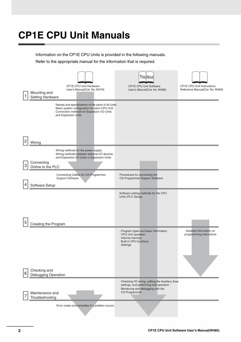
Information on the CP1E CPU Units is provided in the following manuals.
Refer to the appropriate manual for the information that is required.
Mounting and Setting Hardware1
2
3
4
5
6
7
Wiring
Connecting Online to the PLC
Software Setup
Creating the Program
Checking and Debugging Operation
Maintenance and Troubleshooting
CP1E CPU Unit Hardware User’s Manual(Cat. No. W479)
CP1E CPU Unit Software User’s Manual(Cat. No. W480)
This Manual
· Wiring methods for the power supply· Wiring methods between external I/O devices and Expansion I/O Units or Expansion Units
Connecting Cables for CX-Programmer Support Software
Error codes and remedies if a problem occurs
Procedures for connecting the CX-Programmer Support Software
Software setting methods for the CPU Units (PLC Setup)
· Checking I/O wiring, setting the Auxiliary Area settings, and performing trial operation
· Monitoring and debugging with the CX-Programmer
· Program types and basic information· CPU Unit operation· Internal memory· Built-in CPU functions· Settings
· Names and specifications of the parts of all Units· Basic system configuration for each CPU Unit· Connection methods for Expansion I/O Units and Expansion Units
CP1E CPU Unit Instructions Reference Manual(Cat. No. W483)
Detailed information on programming instructions
3CP1E CPU Unit Software User’s Manual(W480)
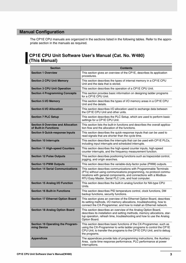
The CP1E CPU manuals are organized in the sections listed in the following tables. Refer to the appro-priate section in the manuals as required.
Manual Configuration
CP1E CPU Unit Software User’s Manual (Cat. No. W480)(This Manual)
Section Contents
Section 1 Overview This section gives an overview of the CP1E, describes its application procedures.
Section 2 CPU Unit Memory This section describes the types of internal memory in a CP1E CPU Unit and the data that is stored.
Section 3 CPU Unit Operation This section describes the operation of a CP1E CPU Unit.
Section 4 Programming Concepts This section provides basic information on designing ladder programs for a CP1E CPU Unit.
Section 5 I/O Memory This section describes the types of I/O memory areas in a CP1E CPU Unit and the details.
Section 6 I/O Allocation This section describes I/O allocation used to exchange data between the CP1E CPU Unit and other units.
Section 7 PLC Setup This section describes the PLC Setup, which are used to perform basic settings for a CP1E CPU Unit.
Section 8 Overview and Allocation of Built-in Functions
This section lists the built-in functions and describes the overall applica-tion flow and the allocation of the functions.
Section 9 Quick-response Inputs This section describes the quick-response inputs that can be used to read signals that are shorter than the cycle time.
Section 10 Interrupts This section describes the interrupts that can be used with CP1E PLCs, including input interrupts and scheduled interrupts.
Section 11 High-speed Counters This section describes the high-speed counter inputs, high-speed counter interrupts, and the frequency measurement function.
Section 12 Pulse Outputs This section describes positioning functions such as trapezoidal control, jogging, and origin searches.
Section 13 PWM Outputs This section describes the variable-duty-factor pulse (PWM) outputs.
Section 14 Serial Communications This section describes communications with Programmable Terminals (PTs) without using communications programming, no-protocol commu-nications with general components, and connections with a Modbus-RTU Easy Master, Serial PLC Link, and host computer.
Section 15 Analog I/O Function This section describes the built-in analog function for NA-type CPU Units.
Section 16 Built-in Functions This section describes PID temperature control, clock functions, DM backup functions, security functions.
Section 17 Ethernet Option Board This section gives an overview of the Ethernet Option Board, describes its setting methods, I/O memory allocations, troubleshooting, how to connect the CX-Programmer, and how to install an Ethernet network.
Section 18 Analog Option Board This section describes an overview of the Analog Option Board, describes its installation and setting methods, memory allocations, star-tup operation, refresh time, troubleshooting and how to use the Analog Option Board.
Section 19 Operating the Program-ming Device
This section describes basic functions of the CX-Programmer, such as using the CX-Programmer to write ladder programs to control the CP1E CPU Unit, to transfer the programs to the CP1E CPU Unit, and to debug the programs.
Appendices The appendices provide lists of programming instructions, the Auxiliary Area, cycle time response performance, PLC performance at power interruptions.
4 CP1E CPU Unit Software User’s Manual(W480)
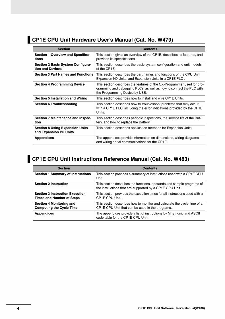
CP1E CPU Unit Hardware User’s Manual (Cat. No. W479)
Section Contents
Section 1 Overview and Specifica-tions
This section gives an overview of the CP1E, describes its features, and provides its specifications.
Section 2 Basic System Configura-tion and Devices
This section describes the basic system configuration and unit models of the CP1E.
Section 3 Part Names and Functions This section describes the part names and functions of the CPU Unit, Expansion I/O Units, and Expansion Units in a CP1E PLC .
Section 4 Programming Device This section describes the features of the CX-Programmer used for pro-gramming and debugging PLCs, as well as how to connect the PLC with the Programming Device by USB.
Section 5 Installation and Wiring This section describes how to install and wire CP1E Units.
Section 6 Troubleshooting This section describes how to troubleshoot problems that may occur with a CP1E PLC, including the error indications provided by the CP1E Units.
Section 7 Maintenance and Inspec-tion
This section describes periodic inspections, the service life of the Bat-tery, and how to replace the Battery.
Section 8 Using Expansion Units and Expansion I/O Units
This section describes application methods for Expansion Units.
Appendices The appendices provide information on dimensions, wiring diagrams, and wiring serial communications for the CP1E.
CP1E CPU Unit Instructions Reference Manual (Cat. No. W483)
Section Contents
Section 1 Summary of Instructions This section provides a summary of instructions used with a CP1E CPU Unit.
Section 2 Instruction This section describes the functions, operands and sample programs of the instructions that are supported by a CP1E CPU Unit.
Section 3 Instruction Execution Times and Number of Steps
This section provides the execution times for all instructions used with a CP1E CPU Unit.
Section 4 Monitoring and Computing the Cycle Time
This section describes how to monitor and calculate the cycle time of a CP1E CPU Unit that can be used in the programs.
Appendices The appendices provide a list of instructions by Mnemonic and ASCII code table for the CP1E CPU Unit.
5CP1E CPU Unit Software User’s Manual(W480)
Manual Structure
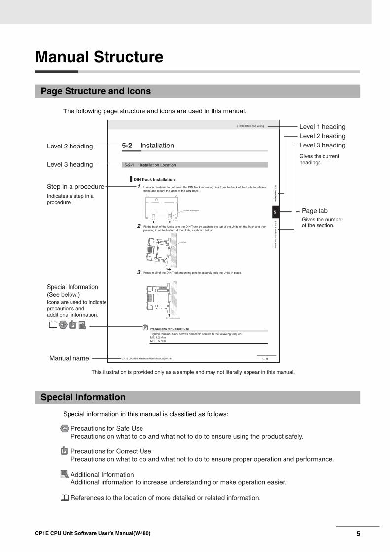
The following page structure and icons are used in this manual.
Special information in this manual is classified as follows:
Page Structure and Icons
Special Information
5 - 3
5 Installation and wiring
CP1E CPU Unit Hardware User’s Manual(W479)
5
5-2 Installation
5-2-1 Installation Location
DIN Track Installation
1
2Release
DIN Track mounting pins
3
DIN Track
DIN Track mounting pins
Precautions for Correct Use
Tighten terminal block screws and cable screws to the following torques.M4: 1.2 N·mM3: 0.5 N·m
Use a screwdriver to pull down the DIN Track mounting pins from the back of the Units to release them, and mount the Units to the DIN Track.
Fit the back of the Units onto the DIN Track by catching the top of the Units on the Track and then pressing in at the bottom of the Units, as shown below.
Press in all of the DIN Track mounting pins to securely lock the Units in place.
5-2 Installatio
n5-2-1 Installation Location
Level 1 headingLevel 2 headingLevel 3 headingLevel 2 heading
Step in a procedure
Manual name
Special Information (See below.)
Level 3 heading
Page tab
Gives the current headings.
Indicates a step in a procedure.
Gives the number of the section.
This illustration is provided only as a sample and may not literally appear in this manual.
Icons are used to indicate precautions and additional information.
Precautions for Safe UsePrecautions on what to do and what not to do to ensure using the product safely.
Precautions for Correct UsePrecautions on what to do and what not to do to ensure proper operation and performance.
Additional InformationAdditional information to increase understanding or make operation easier.
References to the location of more detailed or related information.
6 CP1E CPU Unit Software User’s Manual(W480)
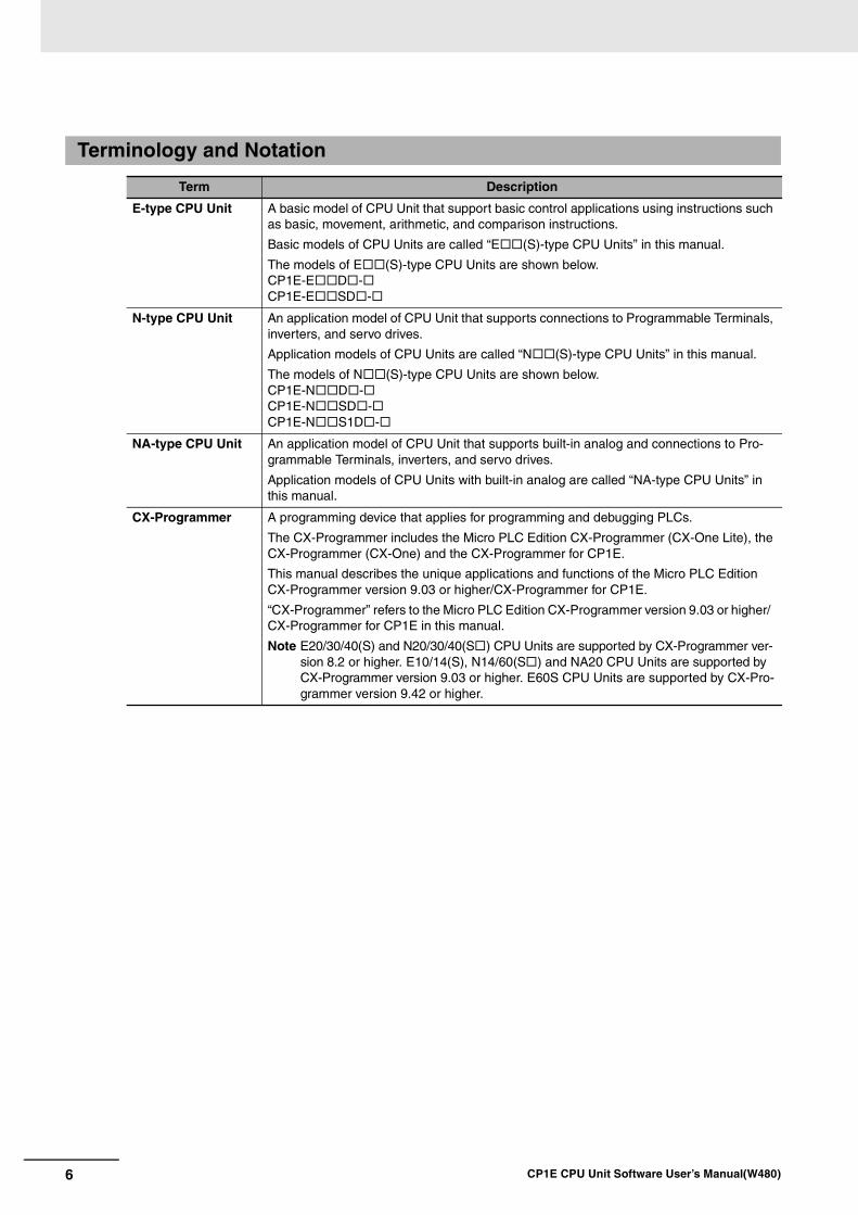
Terminology and Notation
Term Description
E-type CPU Unit A basic model of CPU Unit that support basic control applications using instructions such as basic, movement, arithmetic, and comparison instructions.
Basic models of CPU Units are called “E (S)-type CPU Units” in this manual.
The models of E (S)-type CPU Units are shown below.CP1E-E D -CP1E-E SD -
N-type CPU Unit An application model of CPU Unit that supports connections to Programmable Terminals, inverters, and servo drives.
Application models of CPU Units are called “N (S)-type CPU Units” in this manual.
The models of N (S)-type CPU Units are shown below.CP1E-N D -CP1E-N SD -CP1E-N S1D -
NA-type CPU Unit An application model of CPU Unit that supports built-in analog and connections to Pro-grammable Terminals, inverters, and servo drives.
Application models of CPU Units with built-in analog are called “NA-type CPU Units” in this manual.
CX-Programmer A programming device that applies for programming and debugging PLCs.
The CX-Programmer includes the Micro PLC Edition CX-Programmer (CX-One Lite), the CX-Programmer (CX-One) and the CX-Programmer for CP1E.
This manual describes the unique applications and functions of the Micro PLC Edition CX-Programmer version 9.03 or higher/CX-Programmer for CP1E.
“CX-Programmer” refers to the Micro PLC Edition CX-Programmer version 9.03 or higher/ CX-Programmer for CP1E in this manual.
Note E20/30/40(S) and N20/30/40(S ) CPU Units are supported by CX-Programmer ver-sion 8.2 or higher. E10/14(S), N14/60(S ) and NA20 CPU Units are supported by CX-Programmer version 9.03 or higher. E60S CPU Units are supported by CX-Pro-grammer version 9.42 or higher.

7CP1E CPU Unit Software User’s Manual(W480)
Sections in this Manual
1 11
2
3
4
5
6
7
8
9
12
13
Overview
Quick-response Inputs
Programming Device Operations
Interrupts
High-speed Counters
Pulse Outputs
PWM Outputs
Internal Memory in the CPU Unit
CPU Unit Operation
Understanding Programming
I/O Memory
I/O Allocation
PLC Setup
10
14
15
Serial Communications
Analog I/O Function
16 Other Functions
17 Ethernet Option Board
18 Analog Option Board
19
A Appendices
Overview of Built-in Functions and Allocations
1 11
2 12
3 13
4
5
6
7
8
9
10
14
15
16
17
18
19
AP
P
8 CP1E CPU Unit Software User’s Manual(W480)
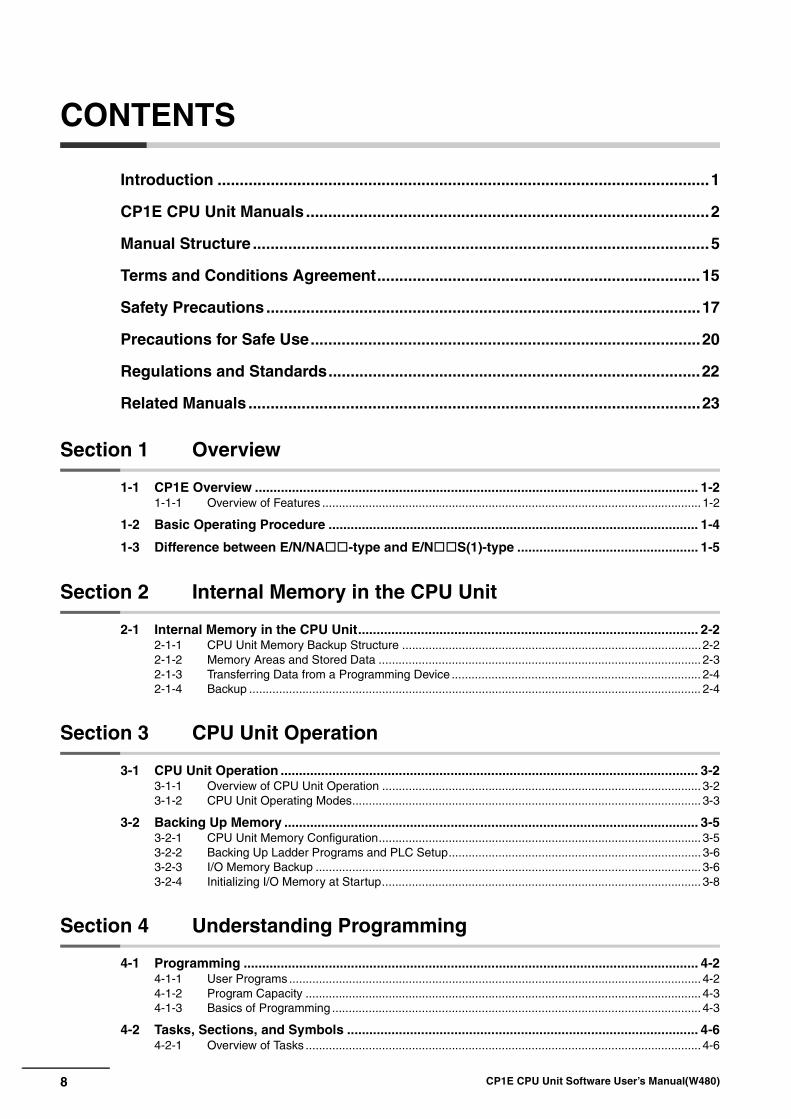
CONTENTS
Introduction ...............................................................................................................1
CP1E CPU Unit Manuals ...........................................................................................2
Manual Structure .......................................................................................................5
Terms and Conditions Agreement.........................................................................15
Safety Precautions..................................................................................................17
Precautions for Safe Use........................................................................................20
Regulations and Standards....................................................................................22
Related Manuals ......................................................................................................23
Section 1 Overview
1-1 CP1E Overview ........................................................................................................................ 1-21-1-1 Overview of Features .................................................................................................................. 1-2
1-2 Basic Operating Procedure .................................................................................................... 1-4
1-3 Difference between E/N/NA-type and E/NS(1)-type ................................................. 1-5
Section 2 Internal Memory in the CPU Unit
2-1 Internal Memory in the CPU Unit............................................................................................ 2-22-1-1 CPU Unit Memory Backup Structure ..........................................................................................2-22-1-2 Memory Areas and Stored Data ................................................................................................. 2-32-1-3 Transferring Data from a Programming Device ........................................................................... 2-42-1-4 Backup ........................................................................................................................................ 2-4
Section 3 CPU Unit Operation
3-1 CPU Unit Operation ................................................................................................................. 3-23-1-1 Overview of CPU Unit Operation ................................................................................................ 3-23-1-2 CPU Unit Operating Modes......................................................................................................... 3-3
3-2 Backing Up Memory ................................................................................................................ 3-53-2-1 CPU Unit Memory Configuration................................................................................................. 3-53-2-2 Backing Up Ladder Programs and PLC Setup............................................................................ 3-63-2-3 I/O Memory Backup .................................................................................................................... 3-63-2-4 Initializing I/O Memory at Startup................................................................................................ 3-8
Section 4 Understanding Programming
4-1 Programming ........................................................................................................................... 4-24-1-1 User Programs............................................................................................................................ 4-24-1-2 Program Capacity ....................................................................................................................... 4-34-1-3 Basics of Programming ............................................................................................................... 4-3
4-2 Tasks, Sections, and Symbols ............................................................................................... 4-64-2-1 Overview of Tasks ....................................................................................................................... 4-6
9CP1E CPU Unit Software User’s Manual(W480)
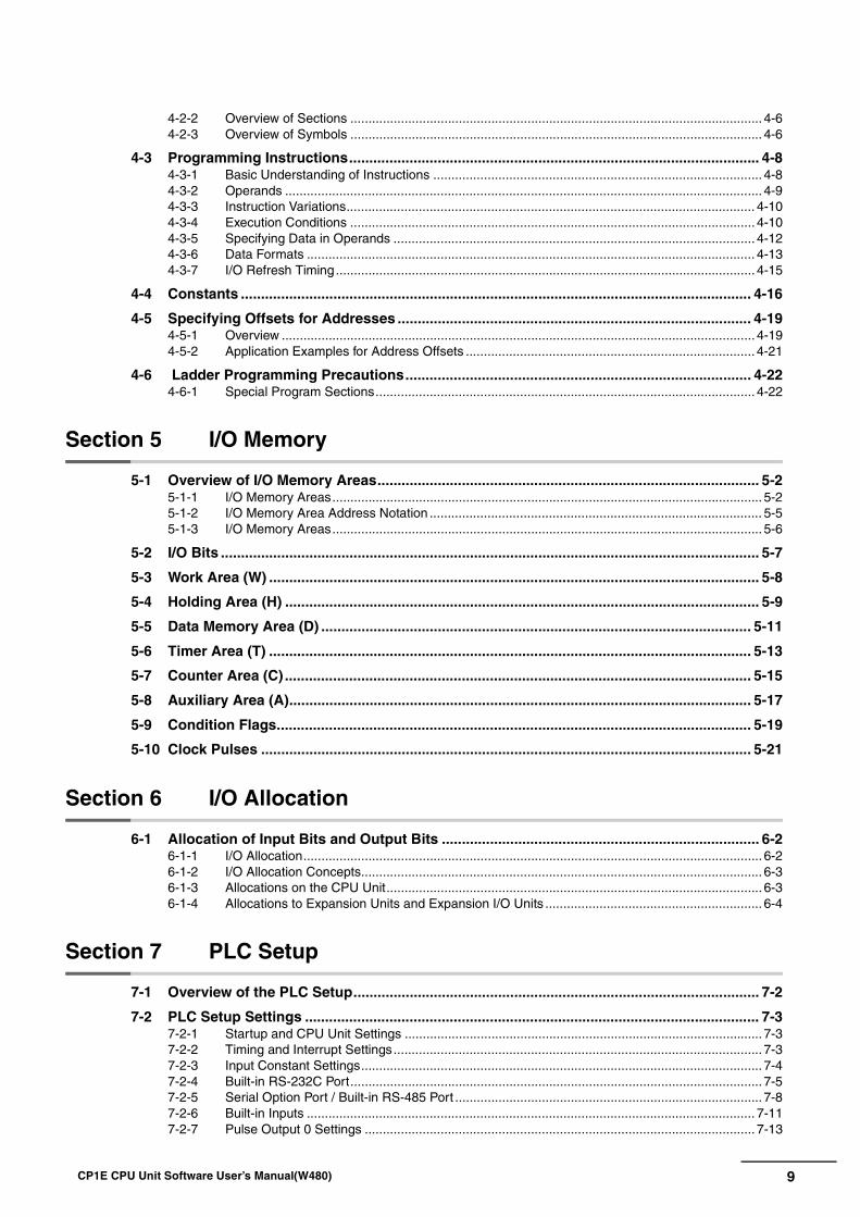
4-2-2 Overview of Sections .................................................................................................................. 4-64-2-3 Overview of Symbols .................................................................................................................. 4-6
4-3 Programming Instructions...................................................................................................... 4-84-3-1 Basic Understanding of Instructions ........................................................................................... 4-84-3-2 Operands .................................................................................................................................... 4-94-3-3 Instruction Variations................................................................................................................. 4-104-3-4 Execution Conditions ................................................................................................................ 4-104-3-5 Specifying Data in Operands .................................................................................................... 4-124-3-6 Data Formats ............................................................................................................................ 4-134-3-7 I/O Refresh Timing.................................................................................................................... 4-15
4-4 Constants ............................................................................................................................... 4-16
4-5 Specifying Offsets for Addresses ........................................................................................ 4-194-5-1 Overview ................................................................................................................................... 4-194-5-2 Application Examples for Address Offsets ................................................................................ 4-21
4-6 Ladder Programming Precautions...................................................................................... 4-224-6-1 Special Program Sections......................................................................................................... 4-22
Section 5 I/O Memory
5-1 Overview of I/O Memory Areas............................................................................................... 5-25-1-1 I/O Memory Areas....................................................................................................................... 5-25-1-2 I/O Memory Area Address Notation ............................................................................................ 5-55-1-3 I/O Memory Areas....................................................................................................................... 5-6
5-2 I/O Bits ...................................................................................................................................... 5-7
5-3 Work Area (W) .......................................................................................................................... 5-8
5-4 Holding Area (H) ...................................................................................................................... 5-9
5-5 Data Memory Area (D) ........................................................................................................... 5-11
5-6 Timer Area (T) ........................................................................................................................ 5-13
5-7 Counter Area (C) .................................................................................................................... 5-15
5-8 Auxiliary Area (A)................................................................................................................... 5-17
5-9 Condition Flags...................................................................................................................... 5-19
5-10 Clock Pulses .......................................................................................................................... 5-21
Section 6 I/O Allocation
6-1 Allocation of Input Bits and Output Bits ............................................................................... 6-26-1-1 I/O Allocation............................................................................................................................... 6-26-1-2 I/O Allocation Concepts............................................................................................................... 6-36-1-3 Allocations on the CPU Unit........................................................................................................ 6-36-1-4 Allocations to Expansion Units and Expansion I/O Units ............................................................ 6-4
Section 7 PLC Setup
7-1 Overview of the PLC Setup..................................................................................................... 7-2
7-2 PLC Setup Settings ................................................................................................................. 7-37-2-1 Startup and CPU Unit Settings ................................................................................................... 7-37-2-2 Timing and Interrupt Settings...................................................................................................... 7-37-2-3 Input Constant Settings............................................................................................................... 7-47-2-4 Built-in RS-232C Port.................................................................................................................. 7-57-2-5 Serial Option Port / Built-in RS-485 Port ..................................................................................... 7-87-2-6 Built-in Inputs ............................................................................................................................ 7-117-2-7 Pulse Output 0 Settings ............................................................................................................ 7-13
10 CP1E CPU Unit Software User’s Manual(W480)
7-2-8 Pulse Output 1 Settings ............................................................................................................ 7-147-2-9 Built-in AD/DA: Built-in Analog I/O Settings .............................................................................. 7-16
Section 8 Overview of Built-in Functions and Allocations
8-1 Built-in Functions .................................................................................................................... 8-2
8-2 Overall Procedure for Using CP1E Built-in Functions ......................................................... 8-3
8-3 Terminal Allocations for Built-in Functions .......................................................................... 8-48-3-1 Specifying the Functions to Use.................................................................................................. 8-48-3-2 Selecting Functions in the PLC Setup......................................................................................... 8-48-3-3 Allocating Built-in Input Terminals ............................................................................................... 8-68-3-4 Allocating Built-in Output Temrinals ............................................................................................ 8-8
Section 9 Quick-response Inputs
9-1 Quick-response Inputs............................................................................................................ 9-29-1-1 Overview ..................................................................................................................................... 9-29-1-2 Flow of Operation........................................................................................................................ 9-3
Section 10 Interrupts
10-1 Interrupts................................................................................................................................ 10-210-1-1 Overview ................................................................................................................................... 10-2
10-2 Input Interrupts ...................................................................................................................... 10-310-2-1 Overview ................................................................................................................................... 10-310-2-2 Flow of Operation...................................................................................................................... 10-410-2-3 Application Example.................................................................................................................. 10-7
10-3 Scheduled Interrupts........................................................................................................... 10-1010-3-1 Overview ................................................................................................................................. 10-1010-3-2 Flow of Operation.................................................................................................................... 10-11
10-4 Precautions for Using Interrupts........................................................................................ 10-1310-4-1 Interrupt Task Priority and Order of Execution ........................................................................ 10-1310-4-2 Related Auxiliary Area Words and Bits ................................................................................... 10-1310-4-3 Duplicate Processing in each Task ......................................................................................... 10-13
Section 11 High-speed Counters
11-1 Overview................................................................................................................................. 11-211-1-1 Overview ................................................................................................................................... 11-211-1-2 Flow of Operation...................................................................................................................... 11-311-1-3 Specifications............................................................................................................................ 11-7
11-2 High-speed Counter Inputs................................................................................................... 11-811-2-1 Pulse Input Methods Settings ................................................................................................... 11-811-2-2 Counting Ranges Settings ...................................................................................................... 11-1011-2-3 Reset Methods........................................................................................................................ 11-1111-2-4 Reading the Present Value ..................................................................................................... 11-1211-2-5 Frequency Measurement ........................................................................................................ 11-13
11-3 High-speed Counter Interrupts........................................................................................... 11-1411-3-1 Overview ................................................................................................................................. 11-1411-3-2 Present Value Comparison ..................................................................................................... 11-1711-3-3 High-speed Counter Interrupt Instruction................................................................................ 11-21
11-4 Related Auxiliary Area Bits and Words ............................................................................. 11-26
11-5 Application Example .......................................................................................................... 11-27
11CP1E CPU Unit Software User’s Manual(W480)
Section 12 Pulse Outputs
12-1 Overview................................................................................................................................. 12-212-1-1 Overview................................................................................................................................... 12-212-1-2 Flow of Operation ..................................................................................................................... 12-412-1-3 Specifications.......................................................................................................................... 12-12
12-2 Positioning Control ............................................................................................................. 12-1312-2-1 Positioning Control Configuration ........................................................................................... 12-1312-2-2 Relative Positioning and Absolute Positioning ........................................................................ 12-1312-2-3 Application Example ............................................................................................................... 12-15
12-3 Jogging................................................................................................................................. 12-1712-3-1 High-speed Jogging................................................................................................................ 12-1712-3-2 Low-speed Jogging................................................................................................................. 12-1712-3-3 Application Example ............................................................................................................... 12-17
12-4 Defining Origin Position...................................................................................................... 12-2012-4-1 Origin Searches...................................................................................................................... 12-2012-4-2 Flow of Operation ................................................................................................................... 12-2112-4-3 Settings in PLC Setup............................................................................................................. 12-2112-4-4 Origin Search Instructions ...................................................................................................... 12-2412-4-5 Origin Search Operations ....................................................................................................... 12-2512-4-6 Origin Return .......................................................................................................................... 12-3212-4-7 Changing the Present Value of the Pulse Output ................................................................... 12-33
12-5 Reading the Pulse Output Present Value .......................................................................... 12-34
12-6 Related Auxiliary Area Flags .............................................................................................. 12-35
12-7 Application Examples ......................................................................................................... 12-3612-7-1 Vertically Conveying PCBs (Multiple Progressive Positioning) ............................................... 12-3612-7-2 Feeding Wrapping Material: Interrupt Feeding ....................................................................... 12-41
12-8 Precautions when Using Pulse Outputs ........................................................................... 12-44
12-9 Pulse Output Pattern ........................................................................................................... 12-4912-9-1 Speed Control (Continuous Mode) ......................................................................................... 12-4912-9-2 Positioning Control (Independent Mode) ................................................................................ 12-51
Section 13 PWM Outputs
13-1 PWM Outputs (Variable-duty-factor Pulse Outputs)........................................................... 13-213-1-1 Flow of Operation ..................................................................................................................... 13-313-1-2 Ladder Program Example......................................................................................................... 13-4
Section 14 Serial Communications
14-1 Serial Communications......................................................................................................... 14-214-1-1 Types of CPU Units and Serial Ports ........................................................................................ 14-214-1-2 Overview of Serial Communications......................................................................................... 14-3
14-2 Program-free Communications with Programmable Terminals ........................................ 14-514-2-1 Overview................................................................................................................................... 14-514-2-2 Flow of Connection ................................................................................................................... 14-614-2-3 PLC Setup and PT System Settings......................................................................................... 14-6
14-3 No-protocol Communications with General Components................................................. 14-814-3-1 Overview................................................................................................................................... 14-814-3-2 Flow of Operation ..................................................................................................................... 14-914-3-3 PLC Setup ................................................................................................................................ 14-914-3-4 Related Auxiliary Area Bits and Words................................................................................... 14-10
14-4 Modbus-RTU Easy Master Function .................................................................................. 14-1114-4-1 Overview................................................................................................................................. 14-1114-4-2 Flow of Operation ................................................................................................................... 14-11
12 CP1E CPU Unit Software User’s Manual(W480)
14-4-3 Setting and Word Allocation.................................................................................................... 14-1214-4-4 Programming Examples.......................................................................................................... 14-14
14-5 Serial PLC Links .................................................................................................................. 14-2014-5-1 Overview ................................................................................................................................. 14-2014-5-2 Flow of Operation.................................................................................................................... 14-2114-5-3 PLC Setup............................................................................................................................... 14-2114-5-4 Operating Specifications ......................................................................................................... 14-2314-5-5 Example Application................................................................................................................ 14-29
14-6 Connecting the Host Computer ......................................................................................... 14-3114-6-1 Overview ................................................................................................................................. 14-3114-6-2 Flow of Operation.................................................................................................................... 14-3114-6-3 Command/response Format and List of Commands .............................................................. 14-32
14-7 Precautions on the usage of RS-485 ................................................................................. 14-34
Section 15 Analog I/O Function
15-1 Overview................................................................................................................................. 15-215-1-1 Flow of Operation...................................................................................................................... 15-215-1-2 Analog I/O Specifications.......................................................................................................... 15-6
15-2 Analog Input and Output Signal Ranges............................................................................. 15-715-2-1 Analog Input Signal Ranges...................................................................................................... 15-715-2-2 Analog Output Signal Ranges................................................................................................... 15-915-2-3 Special functions..................................................................................................................... 15-11
15-3 I/O Allocation and Related Auxiliary Area Flags............................................................... 15-1215-3-1 I/O Allocation........................................................................................................................... 15-1215-3-2 Related Auxiliary Area Flags................................................................................................... 15-12
Section 16 Other Functions
16-1 PID Temperature Control ...................................................................................................... 16-216-1-1 Overview ................................................................................................................................... 16-216-1-2 Flow of Operation...................................................................................................................... 16-316-1-3 Application Example.................................................................................................................. 16-4
16-2 Clock ....................................................................................................................................... 16-7
16-3 DM Backup Function ............................................................................................................. 16-816-3-1 Backing Up and Restoring DM Area Data................................................................................. 16-816-3-2 Procedure................................................................................................................................ 16-10
16-4 Security Functions .............................................................................................................. 16-1216-4-1 Ladder Program Read Protection ...........................................................................................16-12
Section 17 Ethernet Option Board
17-1 Features and Specifications................................................................................................. 17-217-1-1 Ethernet Option Board Function Guide..................................................................................... 17-217-1-2 Features .................................................................................................................................... 17-317-1-3 Specifications............................................................................................................................ 17-517-1-4 Software Configuration.............................................................................................................. 17-517-1-5 FINS Communications .............................................................................................................. 17-617-1-6 Differences in version of the Ethernet Option Board................................................................. 17-8
17-2 Startup Procedure ................................................................................................................. 17-917-2-1 Startup Procedure..................................................................................................................... 17-9
17-3 Settings ................................................................................................................................ 17-1117-3-1 Ethernet Option Board Setup.................................................................................................. 17-1117-3-2 Transferring Data from the CPU Unit ...................................................................................... 17-12
13CP1E CPU Unit Software User’s Manual(W480)
17-3-3 Default Settings ...................................................................................................................... 17-1317-3-4 Web Browser Setting Function ............................................................................................... 17-15
17-4 Memory Allocations ............................................................................................................ 17-2617-4-1 DM Area Allocation................................................................................................................. 17-2617-4-2 CIO Area Allocation ................................................................................................................ 17-31
17-5 Trouble Shooting ................................................................................................................. 17-3317-5-1 Error Log................................................................................................................................. 17-3317-5-2 Error Codes ............................................................................................................................ 17-3417-5-3 Error Status............................................................................................................................. 17-36
17-6 Connection Method with the CX-Programmer.................................................................. 17-37
17-7 Network Installation............................................................................................................. 17-4017-7-1 Devices Required for Constructing a Network........................................................................ 17-4017-7-2 Network Installation ................................................................................................................ 17-40
17-8 Comparison with Previous Models .................................................................................... 17-42
17-9 Buffer Configuration (CP1W-CIF41)................................................................................... 17-43
Section 18 Analog Input/Output Option Board
18-1 General Specifications.......................................................................................................... 18-2
18-2 Part Names............................................................................................................................. 18-3
18-3 Installation and Setting ......................................................................................................... 18-418-3-1 Installation................................................................................................................................. 18-418-3-2 Setting ...................................................................................................................................... 18-418-3-3 Removing.................................................................................................................................. 18-5
18-4 Memory Allocation ................................................................................................................ 18-618-4-1 CIO Area Allocation .................................................................................................................. 18-618-4-2 Auxiliary Area Allocation........................................................................................................... 18-6
18-5 Analog Input Option Board................................................................................................... 18-718-5-1 Main Specifications................................................................................................................... 18-718-5-2 Analog Input Signal Ranges ..................................................................................................... 18-718-5-3 Wiring ....................................................................................................................................... 18-8
18-6 Analog Output Option Board.............................................................................................. 18-1118-6-1 Main Specifications................................................................................................................. 18-1118-6-2 Analog Output Signal Ranges ................................................................................................ 18-1118-6-3 Wiring ..................................................................................................................................... 18-12
18-7 Analog I/O Option Board..................................................................................................... 18-1518-7-1 Main Specifications................................................................................................................. 18-1518-7-2 Analog I/O Signal Ranges ...................................................................................................... 18-1518-7-3 Wiring ..................................................................................................................................... 18-17
18-8 Startup Operation ................................................................................................................ 18-20
18-9 Analog Option Board Refresh Time................................................................................... 18-21
18-10Trouble Shooting ................................................................................................................. 18-22
18-11The Use of Analog Option Board ....................................................................................... 18-2318-11-1 Procedure ............................................................................................................................... 18-2318-11-2 Program Example ................................................................................................................... 18-24
Section 19 Programming Device Operations
19-1 Programming Devices Usable with the CP1E ..................................................................... 19-2
19-2 Overview of CX-Programmer................................................................................................ 19-419-2-1 CX-Programmer........................................................................................................................ 19-419-2-2 CX-Programmer Flow from Startup to Operation ..................................................................... 19-4
14 CP1E CPU Unit Software User’s Manual(W480)
19-2-3 Help........................................................................................................................................... 19-7
19-3 Creating a Ladder Program .................................................................................................. 19-819-3-1 Inputting a Ladder Program ...................................................................................................... 19-819-3-2 Saving and Reading Ladder Programs ................................................................................... 19-1519-3-3 Editing Ladder Programs ........................................................................................................ 19-16
19-4 Connecting Online to the CP1E and Transferring the Program ...................................... 19-1919-4-1 Connecting Online................................................................................................................... 19-1919-4-2 Changing Operating Modes .................................................................................................... 19-2019-4-3 Transferring a Ladder Program and the PLC Setup................................................................ 19-2119-4-4 Starting Operation................................................................................................................... 19-22
19-5 Online Monitoring and Debugging..................................................................................... 19-2419-5-1 Monitoring Status .................................................................................................................... 19-2419-5-2 Force-set/Reset Bits................................................................................................................ 19-2619-5-3 Online Editing.......................................................................................................................... 19-27
Section A Appendices
A-1 Instruction Functions..............................................................................................................A-2A-1-1 Sequence Input Instructions .......................................................................................................A-2A-1-2 Sequence Output Instructions.....................................................................................................A-3A-1-3 Sequence Control Instructions....................................................................................................A-5A-1-4 Timer and Counter Instructions...................................................................................................A-7A-1-5 Comparison Instructions ...........................................................................................................A-10A-1-6 Data Movement Instructions .....................................................................................................A-12A-1-7 Data Shift Instructions...............................................................................................................A-15A-1-8 Increment/Decrement Instructions ............................................................................................A-17A-1-9 Symbol Math Instructions..........................................................................................................A-18A-1-10 Conversion Instructions.............................................................................................................A-22A-1-11 Logic Instructions ......................................................................................................................A-26A-1-12 Special Math Instructions..........................................................................................................A-27A-1-13 Floating-point Math Instructions................................................................................................A-27A-1-14 Table Data Processing Instructions...........................................................................................A-30A-1-15 Data Control Instructions ..........................................................................................................A-31A-1-16 Subroutine Instructions .............................................................................................................A-35A-1-17 Interrupt Control Instructions.....................................................................................................A-36A-1-18 High-speed Counter/Pulse Output Instructions.........................................................................A-37A-1-19 Step Instructions .......................................................................................................................A-44A-1-20 Basic I/O Unit Instructions.........................................................................................................A-45A-1-21 Serial Communications Instructions..........................................................................................A-49A-1-22 Clock Instructions......................................................................................................................A-50A-1-23 Failure Diagnosis Instructions ...................................................................................................A-51A-1-24 Other Instructions......................................................................................................................A-51
A-2 Auxiliary Area Allocations by Address................................................................................A-52A-2-1 Read-only Words ......................................................................................................................A-52A-2-2 Read/Write Words.....................................................................................................................A-70
A-3 Response Performance.........................................................................................................A-80A-3-1 I/O Response Time ...................................................................................................................A-80A-3-2 Interrupt Response Time ..........................................................................................................A-82A-3-3 Serial PLC Link Response Performance...................................................................................A-83A-3-4 Pulse Output Start Time............................................................................................................A-84A-3-5 Pulse Output Change Response Time......................................................................................A-84
A-4 PLC Operation for Power Interruptions ...............................................................................A-85
Index ......................................................................................................................................... 1-1
Revision History ................................................................................Revision-1
15CP1E CPU Unit Software User’s Manual(W480)
Terms and Conditions Agreement
Exclusive WarrantyOmron’s exclusive warranty is that the Products will be free from defects in materials and workman-ship for a period of twelve months from the date of sale by Omron (or such other period expressed in writing by Omron). Omron disclaims all other warranties, express or implied.
LimitationsOMRON MAKES NO WARRANTY OR REPRESENTATION, EXPRESS OR IMPLIED, ABOUT NON-INFRINGEMENT, MERCHANTABILITY OR FITNESS FOR A PARTICULAR PURPOSE OF THE PRODUCTS. BUYER ACKNOWLEDGES THAT IT ALONE HAS DETERMINED THAT THE PRODUCTS WILL SUITABLY MEET THE REQUIREMENTS OF THEIR INTENDED USE.
Omron further disclaims all warranties and responsibility of any type for claims or expenses based on infringement by the Products or otherwise of any intellectual property right.
Buyer RemedyOmron’s sole obligation hereunder shall be, at Omron’s election, to (i) replace (in the form originally shipped with Buyer responsible for labor charges for removal or replacement thereof) the non-com-plying Product, (ii) repair the non-complying Product, or (iii) repay or credit Buyer an amount equal to the purchase price of the non-complying Product; provided that in no event shall Omron be responsible for warranty, repair, indemnity or any other claims or expenses regarding the Products unless Omron’s analysis confirms that the Products were properly handled, stored, installed and maintained and not subject to contamination, abuse, misuse or inappropriate modification. Return of any Products by Buyer must be approved in writing by Omron before shipment. Omron Companies shall not be liable for the suitability or unsuitability or the results from the use of Products in combi-nation with any electrical or electronic components, circuits, system assemblies or any other materi-als or substances or environments. Any advice, recommendations or information given orally or in writing, are not to be construed as an amendment or addition to the above warranty.
See http://www.omron.com/global/ or contact your Omron representative for published information.
OMRON COMPANIES SHALL NOT BE LIABLE FOR SPECIAL, INDIRECT, INCIDENTAL, OR CON-SEQUENTIAL DAMAGES, LOSS OF PROFITS OR PRODUCTION OR COMMERCIAL LOSS IN ANY WAY CONNECTED WITH THE PRODUCTS, WHETHER SUCH CLAIM IS BASED IN CONTRACT, WARRANTY, NEGLIGENCE OR STRICT LIABILITY.
Further, in no event shall liability of Omron Companies exceed the individual price of the Product on which liability is asserted.
Warranty, Limitations of Liability
Warranties
Limitation on Liability; Etc
16 CP1E CPU Unit Software User’s Manual(W480)
Omron Companies shall not be responsible for conformity with any standards, codes or regulations which apply to the combination of the Product in the Buyer’s application or use of the Product. At Buyer’s request, Omron will provide applicable third party certification documents identifying ratings and limitations of use which apply to the Product. This information by itself is not sufficient for a com-plete determination of the suitability of the Product in combination with the end product, machine, sys-tem, or other application or use. Buyer shall be solely responsible for determining appropriateness of the particular Product with respect to Buyer’s application, product or system. Buyer shall take applica-tion responsibility in all cases.
NEVER USE THE PRODUCT FOR AN APPLICATION INVOLVING SERIOUS RISK TO LIFE OR PROPERTY WITHOUT ENSURING THAT THE SYSTEM AS A WHOLE HAS BEEN DESIGNED TO ADDRESS THE RISKS, AND THAT THE OMRON PRODUCT(S) IS PROPERLY RATED AND INSTALLED FOR THE INTENDED USE WITHIN THE OVERALL EQUIPMENT OR SYSTEM.
Omron Companies shall not be responsible for the user’s programming of a programmable Product, or any consequence thereof.
Data presented in Omron Company websites, catalogs and other materials is provided as a guide for the user in determining suitability and does not constitute a warranty. It may represent the result of Omron’s test conditions, and the user must correlate it to actual application requirements. Actual perfor-mance is subject to the Omron’s Warranty and Limitations of Liability.
Product specifications and accessories may be changed at any time based on improvements and other reasons. It is our practice to change part numbers when published ratings or features are changed, or when significant construction changes are made. However, some specifications of the Product may be changed without any notice. When in doubt, special part numbers may be assigned to fix or establish key specifications for your application. Please consult with your Omron’s representative at any time to confirm actual specifications of purchased Product.
Information presented by Omron Companies has been checked and is believed to be accurate; how-ever, no responsibility is assumed for clerical, typographical or proofreading errors or omissions.
Application Considerations
Suitability of Use
Programmable Products
Disclaimers
Performance Data
Change in Specifications
Errors and Omissions
17CP1E CPU Unit Software User’s Manual(W480)
Safety Precautions
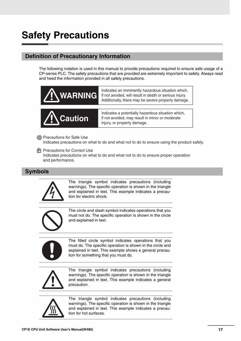
The following notation is used in this manual to provide precautions required to ensure safe usage of aCP-series PLC. The safety precautions that are provided are extremely important to safety. Always readand heed the information provided in all safety precautions.
Definition of Precautionary Information
Symbols
The triangle symbol indicates precautions (includingwarnings). The specific operation is shown in the triangleand explained in text. This example indicates a precau-tion for electric shock.
The circle and slash symbol indicates operations that youmust not do. The specific operation is shown in the circleand explained in text.
The filled circle symbol indicates operations that youmust do. The specific operation is shown in the circle andexplained in text. This example shows a general precau-tion for something that you must do.
The triangle symbol indicates precautions (includingwarnings). The specific operation is shown in the triangleand explained in text. This example indicates a generalprecaution.
The triangle symbol indicates precautions (includingwarnings). The specific operation is shown in the triangleand explained in text. This example indicates a precau-tion for hot surfaces.
WARNING
Caution
Indicates an imminently hazardous situation which, if not avoided, will result in death or serious injury. Additionally, there may be severe property damage.
Indicates a potentially hazardous situation which, if not avoided, may result in minor or moderate injury, or property damage.
Precautions for Safe UseIndicates precautions on what to do and what not to do to ensure using the product safely.
Precautions for Correct UseIndicates precautions on what to do and what not to do to ensure proper operation and performance.
18 CP1E CPU Unit Software User’s Manual(W480)
Be sure to sufficiently confirm the safety at the destination when you transfer the program or I/O memory or perform procedures to change the I/O memory.
Devices connected to PLC outputs may incorrectly operate regardless of the operat-ing mode of the CPU Unit.
With an E(S)-type CPU Unit or with an N/NA(S)-type CPU Unit without a Bat-tery, the contents of the DM Area (D) *, Holding Area (H), the Counter Present Values (C), the status of Counter Completion Flags (C), and the status of bits in the Auxiliary Area (A) related to clock functions may be unstable when the power supply is turned ON.
*This does not apply to areas backed up to EEPROM using the DM backup function.
If the DM backup function is being used, be sure to use one of the following methods for initialization.
1. Clearing All Areas to All Zeros
Select the Clear Held Memory (HR/DM/CNT) to Zero Check Box in the Startup Data Read Area in the PLC Setup.
2. Clearing Specific Areas to All Zeros or Initializing to Specific Values Make the settings from a ladder program.
If the data is not initialized, the unit or device may operate unexpectedly because of unstable data.
Execute online edit only after confirming that no adverse effects will be caused by extending the cycle time.
Otherwise, the input signals may not be readable.
The DM Area (D), Holding Area (H), Counter Completion Flags (C), and Counter Present Values (C) will be held by the Battery if a Battery is mounted in a CP1E-N/NA(S)D- CPU Unit. When the battery voltage is low, however, I/O mem-ory areas that are held (including the DM, Holding, and Counter Areas) will be unsta-ble. The unit or device may operate unexpectedly because of unstable data.
Use the Battery Error Flag or other measures to stop outputs if external out-puts are performed from a ladder program based on the contents of the DM Area or other I/O memory areas.
Sufficiently check safety if I/O bit status or present values are monitored in the Ladder Section Pane or present values are monitored in the Watch Pane.
If bits are set, reset, force-set, or force-reset by inadvertently pressing a shortcut key, devices connected to PLC outputs may operate incorrectly regardless of the operat-ing mode.
CautionCaution

19CP1E CPU Unit Software User’s Manual(W480)
Program so that the memory area of the start address is not exceeded when using a word address or symbol for the offset.
For example, write the program so that processing is executed only when the indirect specification does not cause the final address to exceed the memory area by using an input comparison instruction or other instruction.
If an indirect specification causes the address to exceed the area of the start address, the system will access data in other area, and unexpected operation may occur.
Set the temperature range according to the type of temperature sensor con-nected to the Unit.
Temperature data will not be converted correctly if the temperature range does not match the sensor.
Do not set the temperature range to any values other than those for which tem-perature ranges are given in the following table.
An incorrect setting may cause operating errors.
Caution
20 CP1E CPU Unit Software User’s Manual(W480)
Precautions for Safe Use
Observe the following precautions when using a CP-series PLC.
Handling• To initialize the DM Area, back up the initial contents for the DM Area to backup memory using
one of the following methods.
• Set the number of words of the DM Area to be backed up starting with D0 in the Number of CHof DM for backup Box in the Startup Data Read Area.
• Include programming to back up specified words in the DM Area to built-in EEPROM by turningON A751.15 (DM Backup Save Start Bit).
• Check the ladder program for proper execution before actually running it on the Unit. Not checkingthe program may result in an unexpected operation.
• The ladder program and parameter area data in the CP1E CPU Units are backed up in the built-inEEPROM backup memory. The BKUP indicator will light on the front of the CPU Unit when thebackup operation is in progress. Do not turn OFF the power supply to the CPU Unit when theBKUP indicator is lit. The data will not be backed up if power is turned OFF and a memory errorwill occur the next time the power supply is turned ON.
• With a CP1E CPU Unit, data memory can be backed up to the built-in EEPROM backup memory.The BKUP indicator will light on the front of the CPU Unit when backup is in progress. Do not turnOFF the power supply to the CPU Unit when the BKUP indicator is lit. If the power is turned OFFduring a backup, the data will not be backed up and will not be transferred to the DM Area in RAMthe next time the power supply is turned ON.
• Before replacing the battery, supply power to the CPU Unit for at least 30 minutes and then com-plete battery replacement within 5 minutes. Memory data may be corrupted if this precaution isnot observed.
• The equipment may operate unexpectedly if inappropriate parameters are set. Even if the appro-priate parameters are set, confirm that equipment will not be adversely affected before transfer-ring the parameters to the CPU Unit.
• Before starting operation, confirm that the contents of the DM Area is correct.
• After replacing the CPU Unit, make sure that the required data for the DM Area, Holding Area, andother memory areas has been transferred to the new CPU Unit before restarting operation.
• Do not attempt to disassemble, repair, or modify any Units. Any attempt to do so may result in mal-function, fire, or electric shock.
• Confirm that no adverse effect will occur in the system before attempting any of the following. Notdoing so may result in an unexpected operation.
• Changing the operating mode of the PLC (including the setting of the startup operating mode).
• Force-setting/force-resetting any bit in memory.
• Changing the present value of any word or any set value in memory.
External Circuits• Always configure the external circuits to turn ON power to the PLC before turning ON power to the
control system. If the PLC power supply is turned ON after the control power supply, temporaryerrors may result in control system signals because the output terminals on DC Output Units andother Units will momentarily turn ON when power is turned ON to the PLC.
• Fail-safe measures must be taken by the customer to ensure safety in the event that outputs fromoutput terminals remain ON as a result of internal circuit failures, which can occur in relays, tran-sistors, and other elements.

21CP1E CPU Unit Software User’s Manual(W480)
• If the I/O Hold Bit is turned ON, the outputs from the PLC will not be turned OFF and will maintaintheir previous status when the PLC is switched from RUN or MONITOR mode to PROGRAMmode. Make sure that the external loads will not produce dangerous conditions when this occurs.(When operation stops for a fatal error, including those produced with the FALS instruction, all out-puts from PLC will be turned OFF and only the internal output status in the CPU Unit will be main-tained.)
22 CP1E CPU Unit Software User’s Manual(W480)
Regulations and Standards
SYSMAC is a registered trademark for Programmable Controllers made by OMRON Corporation.
CX-One is a registered trademark for Programming Software made by OMRON Corporation.
Windows is a registered trademark of Microsoft Corporation.
Other system names and product names in this document are the trademarks or registered trademarksof their respective companies.
Trademarks
23CP1E CPU Unit Software User’s Manual(W480)
Related Manuals
The following manuals are related to the CP1E. Use them together with this manual.
Manual name Cat. No. Model numbers Application Contents
SYSMAC CP Series CP1E CPU Unit Soft-ware User’s Manual (this manual)
W480 CP1E-ESD-
CP1E-NSD-
CP1E-ED-
CP1E-ND-
CP1E-NAD-
To learn the software specifications of the CP1E PLCs
Describes the following information for CP1E PLCs.
• CPU Unit operation
• Internal memory
• Programming
• Settings
• CPU Unit built-in functions
• Interrupts
• High-speed counter inputs
• Pulse outputs
• Serial communications
• Analog I/O function
• Other functions
Use this manual together with the CP1E CPU Unit Hardware User’s Manual (Cat. No. W479) and Instructions Reference Manual (Cat. No. W483).
SYSMAC CP Series CP1E CPU Unit Hard-ware User’s Manual
W479 CP1E-ESD-
CP1E-NSD-
CP1E-ED-
CP1E-ND-
CP1E-NAD-
To learn the hard-ware specifications of the CP1E PLCs
Describes the following information for CP1E PLCs.
• Overview and features
• Basic system configuration
• Part names and functions
• Installation and settings
• Troubleshooting
Use this manual together with the CP1E CPU Unit Software User’s Manual (Cat. No. W480) and Instructions Reference Manual (Cat. No. W483).
SYSMAC CP Series CP1E CPU Unit Instruc-tions Reference Manual
W483 CP1E-ESD-
CP1E-NSD-
CP1E-ED-
CP1E-ND-
CP1E-NAD-
To learn program-ming instructions in detail
Describes each programming instruction in detail.
When programming, use this manual together with the CP1E CPU Unit Software User’s Man-ual (Cat. No. W480).
CS/CJ/CP/NSJ Series Communications Com-mands Reference Man-ual
W342 CS1G/H-CPUH
CS1G/H-CPU-V1
CS1D-CPUH
CS1D-CPUS
CS1W-SCU-V1
CS1W-SCB-V1
CJ1G/H-CPUH
CJ1G-CPUP
CJ1M-CPU
CJ1G-CPU
CJ1W-SCU-V1
To learn communica-tions commands for CS/CJ/CP/NSJ-series Controllers in detail
Describes
1) C-mode commands and2) FINS commands in detail.
Read this manual for details on C-mode and FINS commands addressed to CPU Units.
Note This manual describes commands addressed to CPU Units. Itdoes not cover commands addressed to other Units or ports (e.g.,serial communications ports on CPU Units, communications portson Serial Communications Units/Boards, and other Communica-tions Units).
SYSMAC CP Series
CP1L/CP1E CPU Unit
Introduction Manual
W461 CP1L-L10D-
CP1L-L14D-
CP1L-L20D-
CP1L-M30D-
CP1L-M40D-
CP1L-M60D-
CP1E-ED-
CP1E-ND-
CP1E-NAD-
To learn the basic setup methods of the CP1L/CP1E PLCs
Describes the following information for CP1L/CP1E PLCs.
• Basic configuration and component names
• Mounting and wiring
• Programming, data transfer, and debugging using the CX-Programmer
• Application program examples
CX-Simulator Operation
Manual
W366 CXONE-ALC-V4/ALD-V4
Operating procedures for CX-Simulator Simulation Support Software for Windows computersUsing simulation in the CX-Programmer with CX-Programmer
Describes the operating procedures for the
CX-Simulator.

24 CP1E CPU Unit Software User’s Manual(W480)
1-1
1
CP1E CPU Unit Software User’s Manual(W480)
1
This section gives an overview of the CP1E and describes its procedures.
1-1 CP1E Overview . . . . . . . . . . . . . . . . . . . . . . . . . . . . . . . . . . . . . . . . . . . . . . . . 1-21-1-1 Overview of Features . . . . . . . . . . . . . . . . . . . . . . . . . . . . . . . . . . . . . . . . . . . . 1-2
1-2 Basic Operating Procedure . . . . . . . . . . . . . . . . . . . . . . . . . . . . . . . . . . . . . . 1-4
1-3 Difference between E/N/NA -type and E/N S-type . . . . . . . . . . . . . . . 1-5
Overview
1 Overview
1-2 CP1E CPU Unit Software User’s Manual(W480)
1-1 CP1E Overview
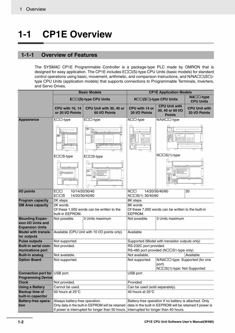
The SYSMAC CP1E Programmable Controller is a package-type PLC made by OMRON that isdesigned for easy application. The CP1E includes E (S)-type CPU Units (basic models) for standardcontrol operations using basic, movement, arithmetic, and comparison instructions, and N/NA (S )-type CPU Units (application models) that supports connections to Programmable Terminals, Inverters,and Servo Drives.
1-1-1 Overview of Features
Basic Models CP1E Application Models
E (S)-type CPU Units N (S )-type CPU UnitsNA -type CPU Units
CPU with 10, 14 or 20 I/O Points
CPU Unit with 30, 40 or 60 I/O Points
CPU with 14 or 20 I/O Points
CPU Unit with 30, 40 or 60 I/O
Points
CPU Unit with 20 I/O Points
Appearance E -type
E S-type
E -type
E S-type
N -type N/NA -type
N S(1)-type
I/O points E 10/14/20/30/40E S 14/20/30/40/60
N 14/20/30/40/60N S(1) 30/40/60
20
Program capacity 2K steps 8K stepsDM Area capacity 2K words
Of these 1,500 words can be written to the built-in EEPROM.
8K wordsOf these 7,000 words can be written to the built-in EEPROM.
Mounting Expan-sion I/O Units and Expansion Units
Not possible. 3 Units maximum Not possible. 3 Units maximum
Model with transis-tor outputs
Available (CPU Unit with 10 I/O points only) Available
Pulse outputs Not supported. Supported (Model with transistor outputs only)Built-in serial com-munications port
Not provided. RS-232C port providedRS-485 port provided (N S1-type only)
Built-in analog Not available. Not available. AvailableOption Board Not supported. Not supported. N/NA -type: Supported (for one
port)N S(1)-type: Not Supported
Connection port for Programming Device
USB port USB port
Clock Not provided. ProvidedUsing a Battery Cannot be used. Can be used (sold separately).Backup time of built-in capacitor
50 hours at 25°C 40 hours at 25°C
Battery-free opera-tion
Always battery-free operation. Only data in the built-in EEPROM will be retained if power is interrupted for longer than 50 hours.
Battery-free operation if no battery is attached. Only data in the built-in EEPROM will be retained if power is interrupted for longer than 40 hours.
1-3
1 Overview
CP1E CPU Unit Software User’s Manual(W480)
1-1 CP
1E O
verview
1
Precautions for Correct UsePrecautions for Correct Use
For CP1E CPU Units, the following I/O memory area will be unstable after a power interruption.
• DM Area (D) (excluding words backed up to the EEPROM using the DM function)
• Holding Area (H)
• Counter Present Values and Completion Flags (C)
• Auxiliary Area related to clock functions(A)
Mount the CP1W-BAT01 Battery (sold separately) to an N/NA (S)-type CPU Unit if data in theabove areas need to be retained after a power interruption. A Battery cannot be mounted to anE (S)-type CPU Unit.
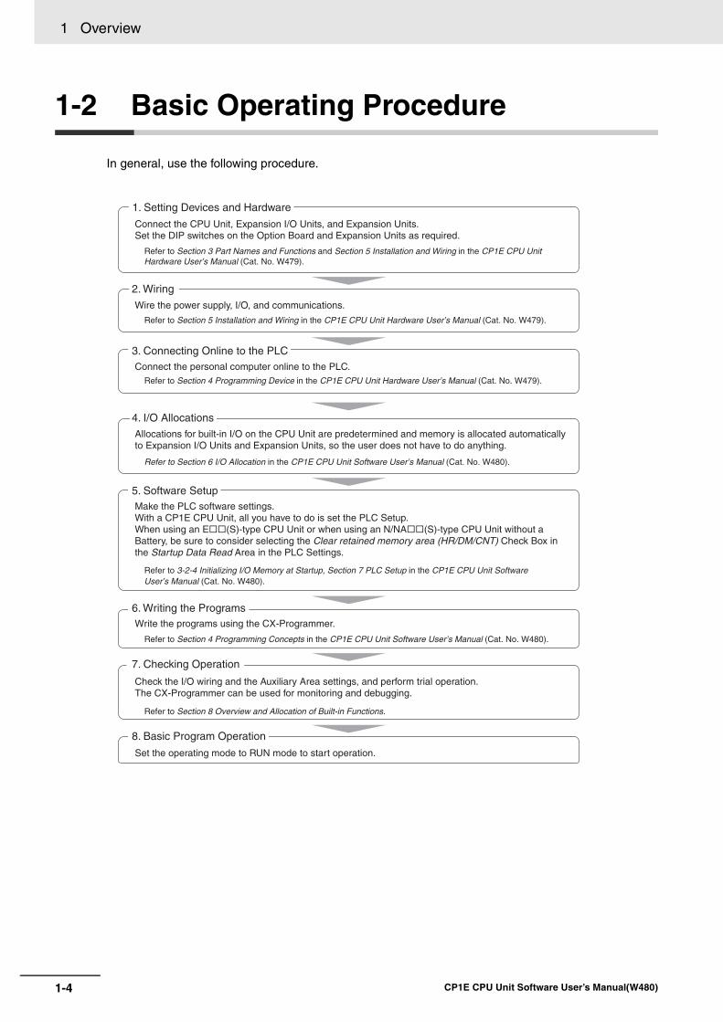
1 Overview
1-4 CP1E CPU Unit Software User’s Manual(W480)
1-2 Basic Operating Procedure
In general, use the following procedure.
1. Setting Devices and Hardware
2. Wiring
3. Connecting Online to the PLC
4. I/O Allocations
5. Software Setup
6. Writing the Programs
8. Basic Program Operation
Connect the CPU Unit, Expansion I/O Units, and Expansion Units.Set the DIP switches on the Option Board and Expansion Units as required.
Wire the power supply, I/O, and communications.
Connect the personal computer online to the PLC.
Allocations for built-in I/O on the CPU Unit are predetermined and memory is allocated automatically to Expansion I/O Units and Expansion Units, so the user does not have to do anything.
Make the PLC software settings.With a CP1E CPU Unit, all you have to do is set the PLC Setup.When using an E(S)-type CPU Unit or when using an N/NA(S)-type CPU Unit without aBattery, be sure to consider selecting the Clear retained memory area (HR/DM/CNT) Check Box in the Startup Data Read Area in the PLC Settings.
Write the programs using the CX-Programmer.
Check the I/O wiring and the Auxiliary Area settings, and perform trial operation.The CX-Programmer can be used for monitoring and debugging.
7. Checking Operation
Set the operating mode to RUN mode to start operation.
Refer to Section 3 Part Names and Functions and Section 5 Installation and Wiring in the CP1E CPU Unit Hardware User’s Manual (Cat. No. W479).
Refer to Section 5 Installation and Wiring in the CP1E CPU Unit Hardware User’s Manual (Cat. No. W479).
Refer to Section 4 Programming Device in the CP1E CPU Unit Hardware User’s Manual (Cat. No. W479).
Refer to Section 6 I/O Allocation in the CP1E CPU Unit Software User’s Manual (Cat. No. W480).
Refer to 3-2-4 Initializing I/O Memory at Startup, Section 7 PLC Setup in the CP1E CPU Unit Software User’s Manual (Cat. No. W480).
Refer to Section 4 Programming Concepts in the CP1E CPU Unit Software User’s Manual (Cat. No. W480).
Refer to Section 8 Overview and Allocation of Built-in Functions.
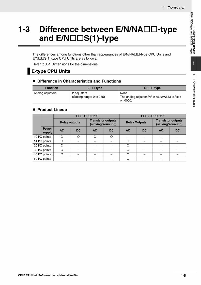
1-5
1 Overview
CP1E CPU Unit Software User’s Manual(W480)
1-3 Difference betw
eenE/N
/NA
-type and E/NS
(1)-type
1
1-1-1 Overview
of Features
1-3 Difference between E/N/NA -type and E/N S(1)-type
The differences among functions other than appearances of E/N/NA -type CPU Units and E/N S(1)-type CPU Units are as follows.
Refer to A-1 Dimensions for the dimensions.
Difference in Characteristics and Functions
Product Lineup
E-type CPU Units
Function E -type E S-type
Analog adjusters 2 adjusters(Setting range: 0 to 255)
NoneThe analog adjuster PV in A642/A643 is fixed on 0000.
E CPU Unit E S CPU Unit
Relay outputsTransistor outputs(sinking/sourcing)
Relay OutputsTransistor outputs(sinking/sourcing)
Power supply
AC DC AC DC AC DC AC DC
10 I/O points − − − −14 I/O points − − − − − −20 I/O points − − − − − −30 I/O points − − − − − −40 I/O points − − − − − −60 I/O points − − − − − − −
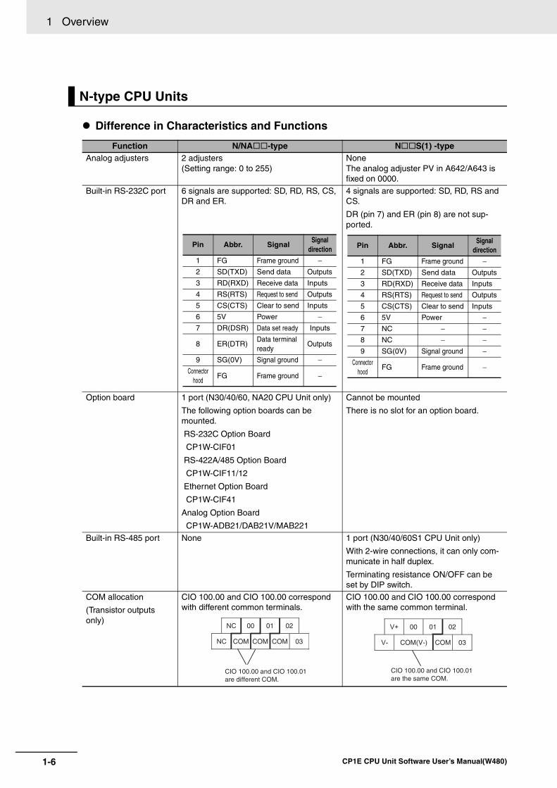
1 Overview
1-6 CP1E CPU Unit Software User’s Manual(W480)
Difference in Characteristics and Functions
N-type CPU Units
Function N/NA -type N S(1) -typeAnalog adjusters 2 adjusters
(Setting range: 0 to 255)NoneThe analog adjuster PV in A642/A643 is fixed on 0000.
Built-in RS-232C port 6 signals are supported: SD, RD, RS, CS, DR and ER.
4 signals are supported: SD, RD, RS and CS.
DR (pin 7) and ER (pin 8) are not sup-ported.
Option board 1 port (N30/40/60, NA20 CPU Unit only)
The following option boards can be mounted.
RS-232C Option Board
CP1W-CIF01
RS-422A/485 Option Board
CP1W-CIF11/12
Ethernet Option Board
CP1W-CIF41
Analog Option Board
CP1W-ADB21/DAB21V/MAB221
Cannot be mounted
There is no slot for an option board.
Built-in RS-485 port None 1 port (N30/40/60S1 CPU Unit only)
With 2-wire connections, it can only com-municate in half duplex.
Terminating resistance ON/OFF can be set by DIP switch.
COM allocation
(Transistor outputs only)
CIO 100.00 and CIO 100.00 correspond with different common terminals.
CIO 100.00 and CIO 100.00 correspond with the same common terminal.
Pin Abbr. SignalSignal
direction
1 FG Frame ground −2 SD(TXD) Send data Outputs
3 RD(RXD) Receive data Inputs
4 RS(RTS) Request to send Outputs
5 CS(CTS) Clear to send Inputs
6 5V Power −7 DR(DSR) Data set ready Inputs
8 ER(DTR)Data terminal ready
Outputs
9 SG(0V) Signal ground −Connector
hoodFG Frame ground −
Pin Abbr. SignalSignal
direction
1 FG Frame ground −2 SD(TXD) Send data Outputs
3 RD(RXD) Receive data Inputs
4 RS(RTS) Request to send Outputs
5 CS(CTS) Clear to send Inputs
6 5V Power −7 NC − −8 NC − −9 SG(0V) Signal ground −
Connector hood
FG Frame ground −
CIO 100.00 and CIO 100.01are different COM.
NC 00 01 02
NC COM COM COM 03
CIO 100.00 and CIO 100.01are the same COM.
V+ 00 01 02
V- COM(V-) COM 03
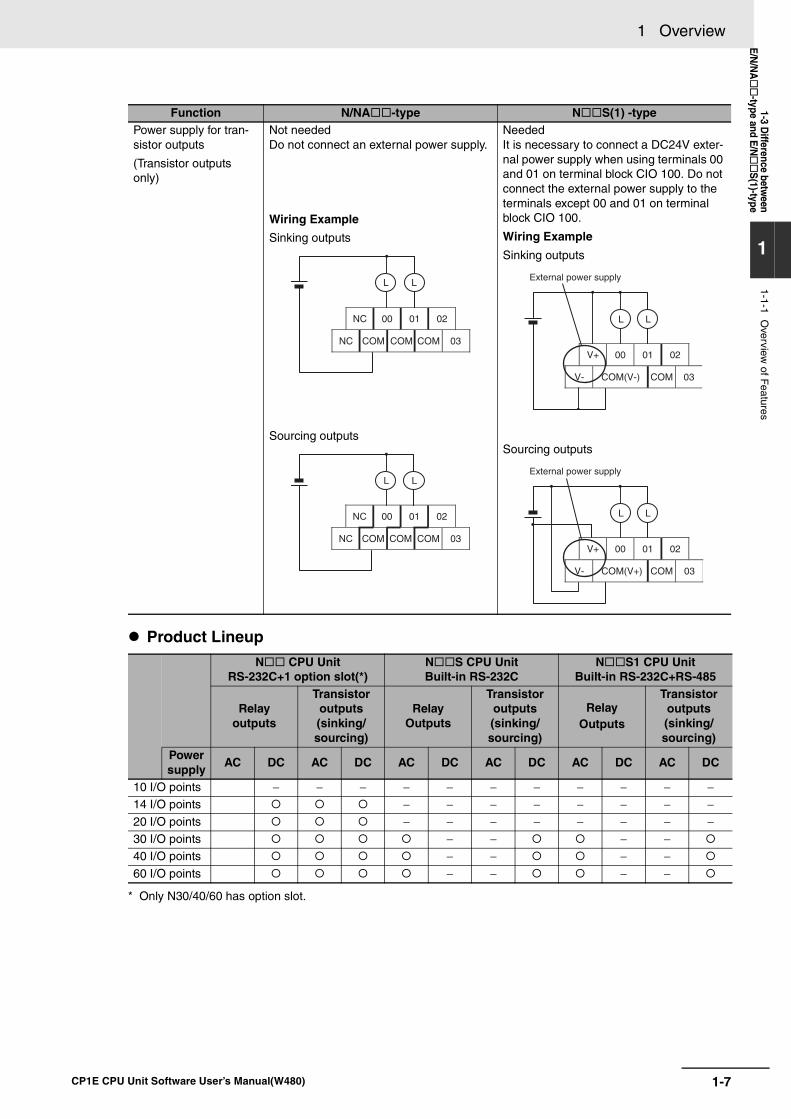
1-7
1 Overview
CP1E CPU Unit Software User’s Manual(W480)
1-3 Difference betw
eenE/N
/NA
-type and E/NS
(1)-type
1
1-1-1 Overview
of Features
Product Lineup
* Only N30/40/60 has option slot.
Power supply for tran-sistor outputs
(Transistor outputs only)
Not neededDo not connect an external power supply.
Wiring Example
Sinking outputs
Sourcing outputs
NeededIt is necessary to connect a DC24V exter-nal power supply when using terminals 00 and 01 on terminal block CIO 100. Do not connect the external power supply to the terminals except 00 and 01 on terminal block CIO 100.
Wiring Example
Sinking outputs
Sourcing outputs
N CPU UnitRS-232C+1 option slot(*)
N S CPU UnitBuilt-in RS-232C
N S1 CPU UnitBuilt-in RS-232C+RS-485
Relayoutputs
Transistor outputs(sinking/sourcing)
RelayOutputs
Transistor outputs(sinking/sourcing)
RelayOutputs
Transistor outputs(sinking/ sourcing)
Power supply
AC DC AC DC AC DC AC DC AC DC AC DC
10 I/O points − − − − − − − − − − −14 I/O points − − − − − − − −20 I/O points − − − − − − − −30 I/O points − − − −40 I/O points − − − −60 I/O points − − − −
Function N/NA -type N S(1) -type
NC 00 01 02
NC COM COM COM 03
L L
NC 00 01 02
NC COM COM COM 03
LL
V+ 01 02
V- COM(V-) COM 03
00
L L
External power supply
V+ 01 02
V- COM(V+) COM 03
00
L L
External power supply

1 Overview
1-8 CP1E CPU Unit Software User’s Manual(W480)
2-1
2
CP1E CPU Unit Software User’s Manual(W480)
2
This section describes the types of internal memory in a CP1E CPU Unit and the datathat is stored.
2-1 Internal Memory in the CPU Unit . . . . . . . . . . . . . . . . . . . . . . . . . . . . . . . . . . 2-22-1-1 CPU Unit Memory Backup Structure . . . . . . . . . . . . . . . . . . . . . . . . . . . . . . . . 2-2
2-1-2 Memory Areas and Stored Data . . . . . . . . . . . . . . . . . . . . . . . . . . . . . . . . . . . . 2-3
2-1-3 Transferring Data from a Programming Device. . . . . . . . . . . . . . . . . . . . . . . . . 2-42-1-4 Backup . . . . . . . . . . . . . . . . . . . . . . . . . . . . . . . . . . . . . . . . . . . . . . . . . . . . . . . 2-4
Internal Memory in the CPU Unit
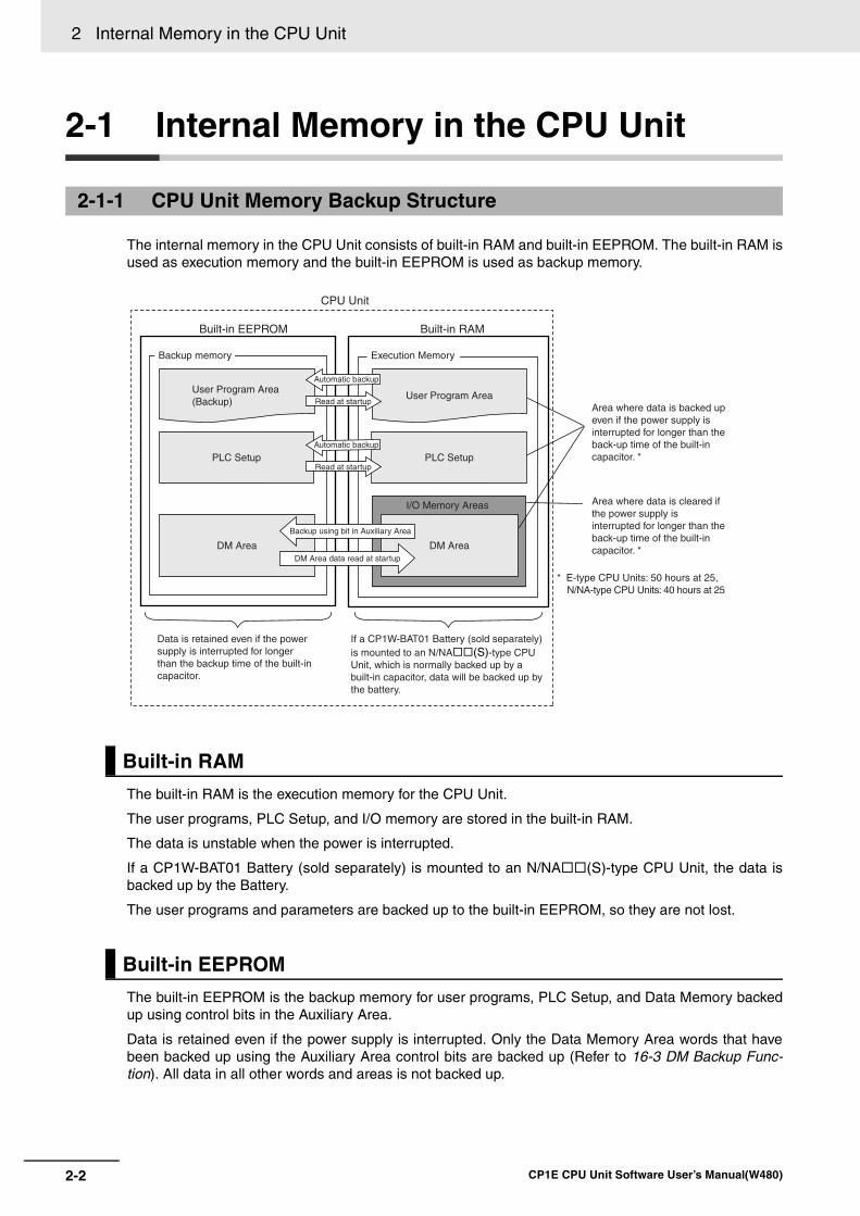
2 Internal Memory in the CPU Unit
2-2 CP1E CPU Unit Software User’s Manual(W480)
2-1 Internal Memory in the CPU Unit
The internal memory in the CPU Unit consists of built-in RAM and built-in EEPROM. The built-in RAM isused as execution memory and the built-in EEPROM is used as backup memory.
The built-in RAM is the execution memory for the CPU Unit.
The user programs, PLC Setup, and I/O memory are stored in the built-in RAM.
The data is unstable when the power is interrupted.
If a CP1W-BAT01 Battery (sold separately) is mounted to an N/NA (S)-type CPU Unit, the data isbacked up by the Battery.
The user programs and parameters are backed up to the built-in EEPROM, so they are not lost.
The built-in EEPROM is the backup memory for user programs, PLC Setup, and Data Memory backedup using control bits in the Auxiliary Area.
Data is retained even if the power supply is interrupted. Only the Data Memory Area words that havebeen backed up using the Auxiliary Area control bits are backed up (Refer to 16-3 DM Backup Func-tion). All data in all other words and areas is not backed up.
2-1-1 CPU Unit Memory Backup Structure
Built-in RAM
Built-in EEPROM
CPU Unit
Built-in EEPROM Built-in RAM
Backup memory
User Program Area (Backup)
PLC Setup PLC Setup
DM Area DM Area
User Program Area
I/O Memory Areas
Data is retained even if the power supply is interrupted for longer than the backup time of the built-in capacitor.
Execution Memory
Automatic backup
Read at startup
Automatic backup
Read at startup
Backup using bit in Auxiliary Area
DM Area data read at startup
If a CP1W-BAT01 Battery (sold separately) is mounted to an N/NA (S)-type CPU Unit, which is normally backed up by a built-in capacitor, data will be backed up by the battery.
Area where data is backed up even if the power supply is interrupted for longer than the back-up time of the built-in capacitor. *
Area where data is cleared if the power supply is interrupted for longer than the back-up time of the built-in capacitor. *
* E-type CPU Units: 50 hours at 25, N/NA-type CPU Units: 40 hours at 25
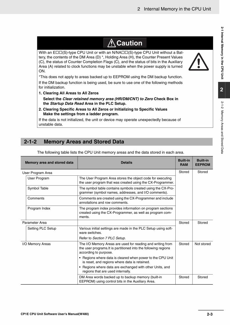
2-3
2 Internal Memory in the CPU Unit
CP1E CPU Unit Software User’s Manual(W480)
2-1 Intern
al Mem
ory in
the C
PU
Un
it
2
2-1-2 Mem
ory Areas and S
tored Data The following table lists the CPU Unit memory areas and the data stored in each area.
With an E (S)-type CPU Unit or with an N/NA (S)-type CPU Unit without a Bat-tery, the contents of the DM Area (D) *, Holding Area (H), the Counter Present Values (C), the status of Counter Completion Flags (C), and the status of bits in the Auxiliary Area (A) related to clock functions may be unstable when the power supply is turned ON.
*This does not apply to areas backed up to EEPROM using the DM backup function.
If the DM backup function is being used, be sure to use one of the following methods for initialization.
1. Clearing All Areas to All Zeros
Select the Clear retained memory area (HR/DM/CNT) to Zero Check Box in the Startup Data Read Area in the PLC Setup.
2. Clearing Specific Areas to All Zeros or Initializing to Specific Values Make the settings from a ladder program.
If the data is not initialized, the unit or device may operate unexpectedly because of unstable data.
2-1-2 Memory Areas and Stored Data
Memory area and stored data DetailsBuilt-in
RAMBuilt-in
EEPROM
User Program Area Stored Stored
User Program The User Program Area stores the object code for executing the user program that was created using the CX-Programmer.
Symbol Table The symbol table contains symbols created using the CX-Pro-grammer (symbol names, addresses, and I/O comments).
Comments Comments are created using the CX-Programmer and include annotations and row comments.
Program Index The program index provides information on program sections created using the CX-Programmer, as well as program com-ments.
Parameter Area Stored Stored
Setting PLC Setup Various initial settings are made in the PLC Setup using soft-ware switches.
Refer to Section 7 PLC Setup.
I/O Memory Areas The I/O Memory Areas are used for reading and writing from the user programs.It is partitioned into the following regions according to purpose.
• Regions where data is cleared when power to the CPU Unit is reset, and regions where data is retained.
• Regions where data are exchanged with other Units, and regions that are used internally.
Stored Not stored
DM Area words backed up to backup memory (built-in EEPROM) using control bits in the Auxiliary Area.
Stored Stored
CautionCaution
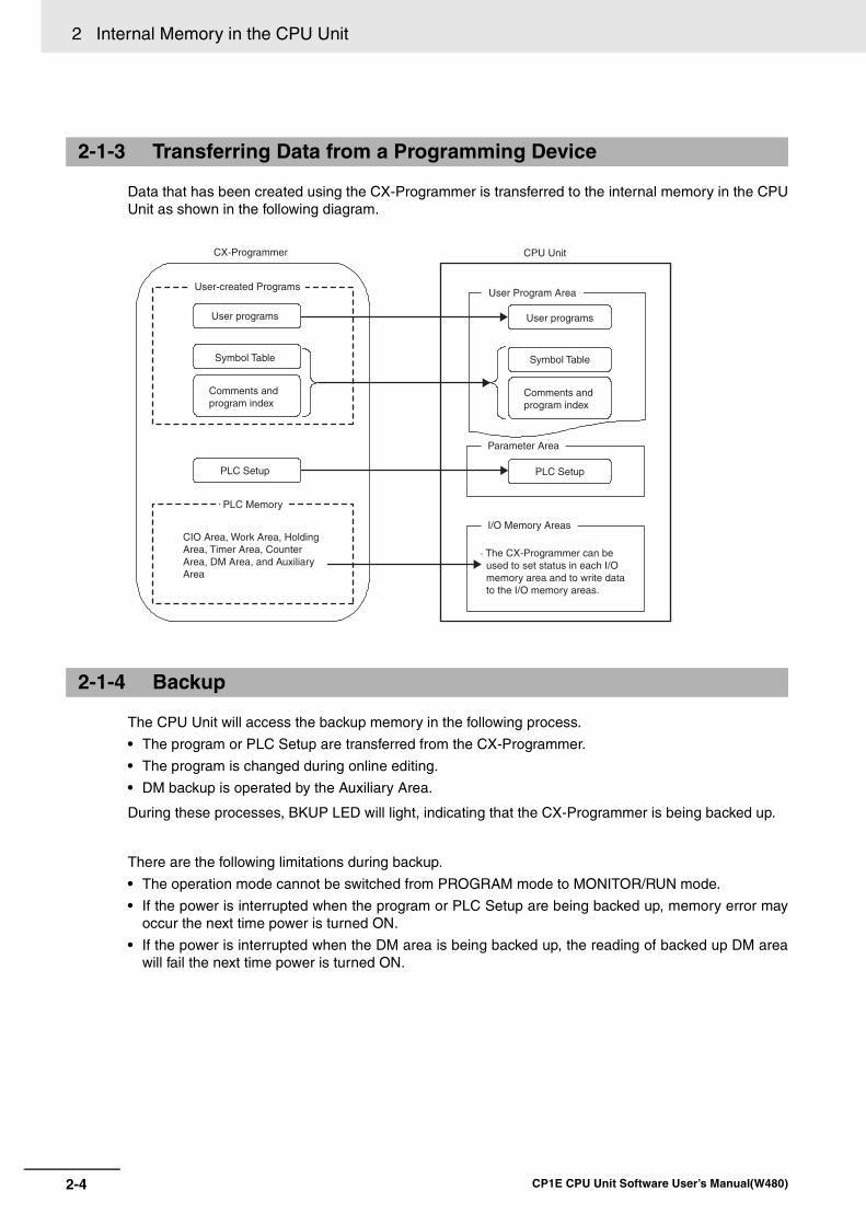
2 Internal Memory in the CPU Unit
2-4 CP1E CPU Unit Software User’s Manual(W480)
Data that has been created using the CX-Programmer is transferred to the internal memory in the CPUUnit as shown in the following diagram.
The CPU Unit will access the backup memory in the following process.
• The program or PLC Setup are transferred from the CX-Programmer.
• The program is changed during online editing.
• DM backup is operated by the Auxiliary Area.
During these processes, BKUP LED will light, indicating that the CX-Programmer is being backed up.
There are the following limitations during backup.
• The operation mode cannot be switched from PROGRAM mode to MONITOR/RUN mode.
• If the power is interrupted when the program or PLC Setup are being backed up, memory error mayoccur the next time power is turned ON.
• If the power is interrupted when the DM area is being backed up, the reading of backed up DM areawill fail the next time power is turned ON.
2-1-3 Transferring Data from a Programming Device
2-1-4 Backup
User-created Programs
User programs
Symbol Table
Comments and program index
Symbol Table
Comments and program index
PLC Memory
CIO Area, Work Area, Holding Area, Timer Area, Counter Area, DM Area, and Auxiliary Area
CPU Unit
User Program Area
User programs
I/O Memory Areas
PLC Setup
Parameter Area
PLC Setup
· The CX-Programmer can be used to set status in each I/O memory area and to write data to the I/O memory areas.
CX-Programmer
3-1
3
CP1E CPU Unit Software User’s Manual(W480)
3
This section describes the operation of the CP1E CPU Unit. Make sure that you under-stand the contents of this section completely before writing ladder programs.
3-1 CPU Unit Operation. . . . . . . . . . . . . . . . . . . . . . . . . . . . . . . . . . . . . . . . . . . . . 3-23-1-1 Overview of CPU Unit Operation . . . . . . . . . . . . . . . . . . . . . . . . . . . . . . . . . . . 3-2
3-1-2 CPU Unit Operating Modes . . . . . . . . . . . . . . . . . . . . . . . . . . . . . . . . . . . . . . . 3-3
3-2 Backing Up Memory . . . . . . . . . . . . . . . . . . . . . . . . . . . . . . . . . . . . . . . . . . . . 3-53-2-1 CPU Unit Memory Configuration . . . . . . . . . . . . . . . . . . . . . . . . . . . . . . . . . . . 3-5
3-2-2 Backing Up Ladder Programs and PLC Setup . . . . . . . . . . . . . . . . . . . . . . . . . 3-6
3-2-3 I/O Memory Backup . . . . . . . . . . . . . . . . . . . . . . . . . . . . . . . . . . . . . . . . . . . . . 3-6
3-2-4 Initializing I/O Memory at Startup . . . . . . . . . . . . . . . . . . . . . . . . . . . . . . . . . . . 3-8
CPU Unit Operation
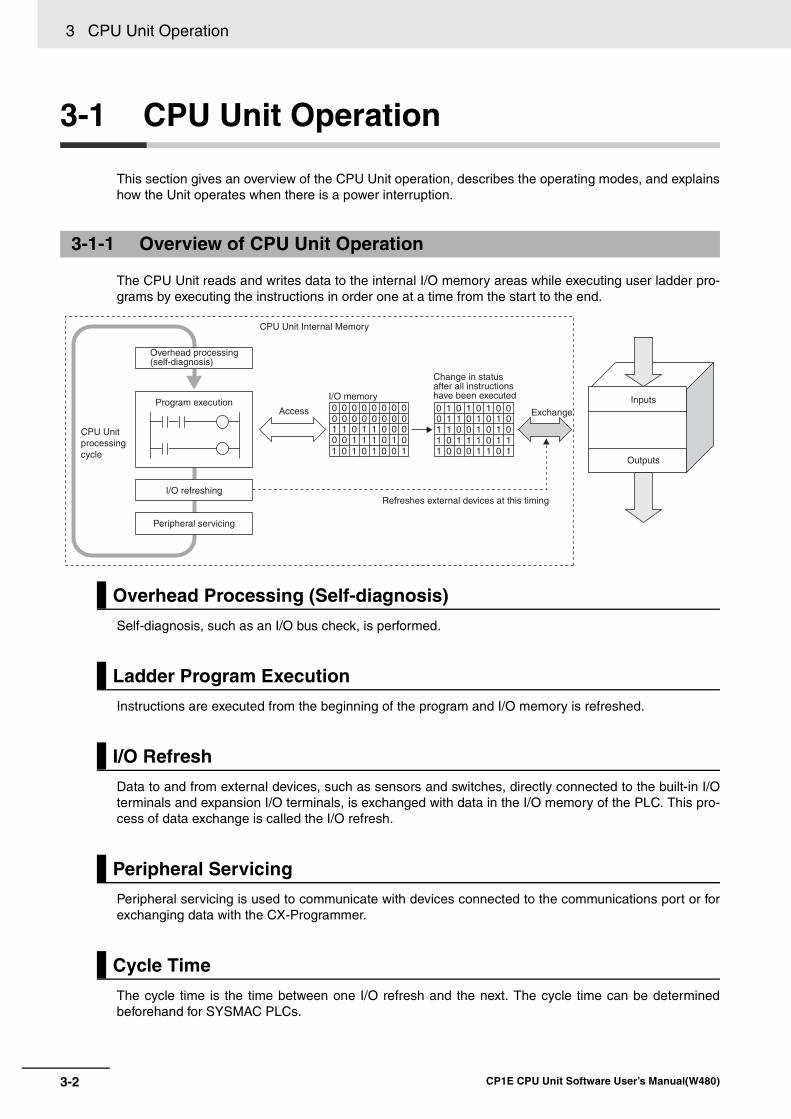
3 CPU Unit Operation
3-2 CP1E CPU Unit Software User’s Manual(W480)
3-1 CPU Unit Operation
This section gives an overview of the CPU Unit operation, describes the operating modes, and explainshow the Unit operates when there is a power interruption.
The CPU Unit reads and writes data to the internal I/O memory areas while executing user ladder pro-grams by executing the instructions in order one at a time from the start to the end.
Self-diagnosis, such as an I/O bus check, is performed.
Instructions are executed from the beginning of the program and I/O memory is refreshed.
Data to and from external devices, such as sensors and switches, directly connected to the built-in I/Oterminals and expansion I/O terminals, is exchanged with data in the I/O memory of the PLC. This pro-cess of data exchange is called the I/O refresh.
Peripheral servicing is used to communicate with devices connected to the communications port or forexchanging data with the CX-Programmer.
The cycle time is the time between one I/O refresh and the next. The cycle time can be determinedbeforehand for SYSMAC PLCs.
3-1-1 Overview of CPU Unit Operation
Overhead Processing (Self-diagnosis)
Ladder Program Execution
I/O Refresh
Peripheral Servicing
Cycle Time
0 0 1 1 1 0 1 01 1 0 1 1 0 0 0
1 0 1 0 1 0 0 1
0 0 0 0 0 0 0 00 0 0 0 0 0 0 0
1 0 1 1 1 0 1 11 1 0 0 1 0 1 0
1 0 0 0 1 1 0 1
0 1 0 1 0 1 0 00 1 1 0 1 0 1 0
CPU Unit Internal Memory
CPU Unit processing cycle
Overhead processing (self-diagnosis)
Program execution
I/O refreshing
Peripheral servicing
Access
I/O memory
Change in status after all instructions have been executed
Exchange
Refreshes external devices at this timing
Inputs
Outputs
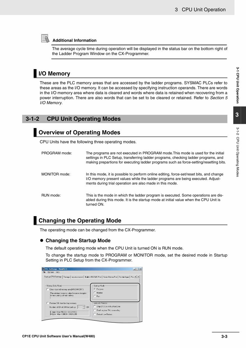
3-3
3 CPU Unit Operation
CP1E CPU Unit Software User’s Manual(W480)
3-1 CP
U U
nit O
peratio
n
3
3-1-2 CP
U U
nit Operating M
odes
Additional Information
The average cycle time during operation will be displayed in the status bar on the bottom right ofthe Ladder Program Window on the CX-Programmer.
These are the PLC memory areas that are accessed by the ladder programs. SYSMAC PLCs refer tothese areas as the I/O memory. It can be accessed by specifying instruction operands. There are wordsin the I/O memory area where data is cleared and words where data is retained when recovering from apower interruption. There are also words that can be set to be cleared or retained. Refer to Section 5I/O Memory.
CPU Units have the following three operating modes.
The operating mode can be changed from the CX-Programmer.
Changing the Startup ModeThe default operating mode when the CPU Unit is turned ON is RUN mode.
To change the startup mode to PROGRAM or MONITOR mode, set the desired mode in StartupSetting in PLC Setup from the CX-Programmer.
I/O Memory
3-1-2 CPU Unit Operating Modes
Overview of Operating Modes
PROGRAM mode: The programs are not executed in PROGRAM mode.This mode is used for the initial settings in PLC Setup, transferring ladder programs, checking ladder programs, and making prepartions for executing ladder programs such as force-setting/resetting bits.
MONITOR mode: In this mode, it is possible to perform online editing, force-set/reset bits, and change I/O memory present values while the ladder programs are being executed. Adjust-ments during trial operation are also made in this mode.
RUN mode: This is the mode in which the ladder program is executed. Some operations are dis-abled during this mode. It is the startup mode at initial value when the CPU Unit is turned ON.
Changing the Operating Mode
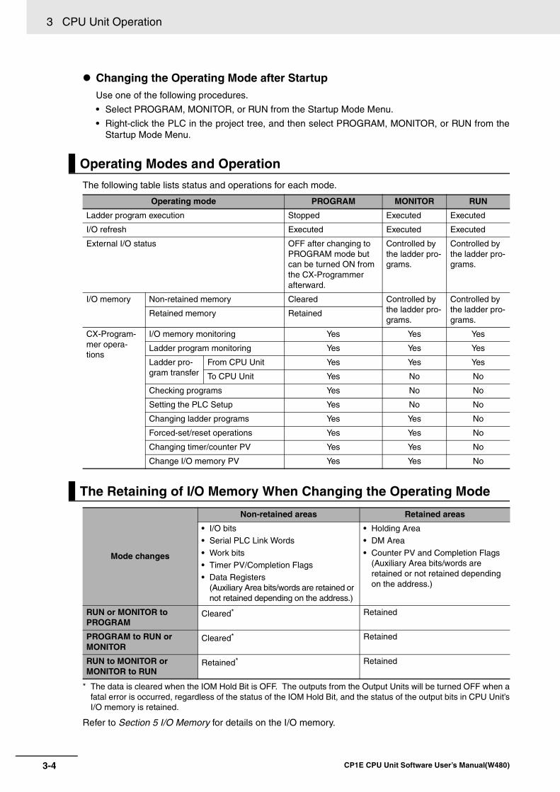
3 CPU Unit Operation
3-4 CP1E CPU Unit Software User’s Manual(W480)
Changing the Operating Mode after StartupUse one of the following procedures.
• Select PROGRAM, MONITOR, or RUN from the Startup Mode Menu.
• Right-click the PLC in the project tree, and then select PROGRAM, MONITOR, or RUN from theStartup Mode Menu.
The following table lists status and operations for each mode.
* The data is cleared when the IOM Hold Bit is OFF. The outputs from the Output Units will be turned OFF when afatal error is occurred, regardless of the status of the IOM Hold Bit, and the status of the output bits in CPU Unit’sI/O memory is retained.
Refer to Section 5 I/O Memory for details on the I/O memory.
Operating Modes and Operation
Operating mode PROGRAM MONITOR RUN
Ladder program execution Stopped Executed Executed
I/O refresh Executed Executed Executed
External I/O status OFF after changing to PROGRAM mode but can be turned ON from the CX-Programmer afterward.
Controlled by the ladder pro-grams.
Controlled by the ladder pro-grams.
I/O memory Non-retained memory Cleared Controlled by the ladder pro-grams.
Controlled by the ladder pro-grams.
Retained memory Retained
CX-Program-mer opera-tions
I/O memory monitoring Yes Yes Yes
Ladder program monitoring Yes Yes Yes
Ladder pro-gram transfer
From CPU Unit Yes Yes Yes
To CPU Unit Yes No No
Checking programs Yes No No
Setting the PLC Setup Yes No No
Changing ladder programs Yes Yes No
Forced-set/reset operations Yes Yes No
Changing timer/counter PV Yes Yes No
Change I/O memory PV Yes Yes No
The Retaining of I/O Memory When Changing the Operating Mode
Mode changes
Non-retained areas Retained areas
• I/O bits• Serial PLC Link Words
• Work bits• Timer PV/Completion Flags• Data Registers
(Auxiliary Area bits/words are retained or not retained depending on the address.)
• Holding Area• DM Area
• Counter PV and Completion Flags (Auxiliary Area bits/words are retained or not retained depending on the address.)
RUN or MONITOR toPROGRAM
Cleared* Retained
PROGRAM to RUN or MONITOR
Cleared* Retained
RUN to MONITOR orMONITOR to RUN
Retained* Retained
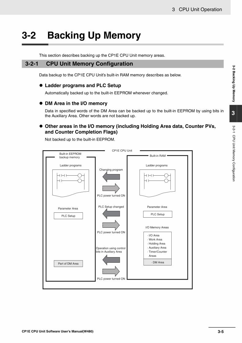
3-5
3 CPU Unit Operation
CP1E CPU Unit Software User’s Manual(W480)
3-2 Backin
g U
p M
emo
ry
3
3-2-1 CP
U U
nit Mem
ory Configuration
3-2 Backing Up Memory
This section describes backing up the CP1E CPU Unit memory areas.
Data backup to the CP1E CPU Unit’s built-in RAM memory describes as below.
Ladder programs and PLC SetupAutomatically backed up to the built-in EEPROM whenever changed.
DM Area in the I/O memoryData in specified words of the DM Area can be backed up to the built-in EEPROM by using bits inthe Auxiliary Area. Other words are not backed up.
Other areas in the I/O memory (including Holding Area data, Counter PVs, and Counter Completion Flags)Not backed up to the built-in EEPROM.
3-2-1 CPU Unit Memory Configuration
Ladder programs
CP1E CPU UnitBuilt-in EEPROM backup memory
Parameter Area
PLC Setup
Parameter Area
PLC Setup
· DM Area
PLC power turned ON
Operation using control bits in Auxiliary Area
PLC power turned ON
PLC power turned ON
PLC Setup changed
Changing program
Built-in RAM
I/O Memory Areas
· I/O Area· Work Area· Holding Area· Auxiliary Area· Timer/Counter
Areas
Part of DM Area
Ladder programs
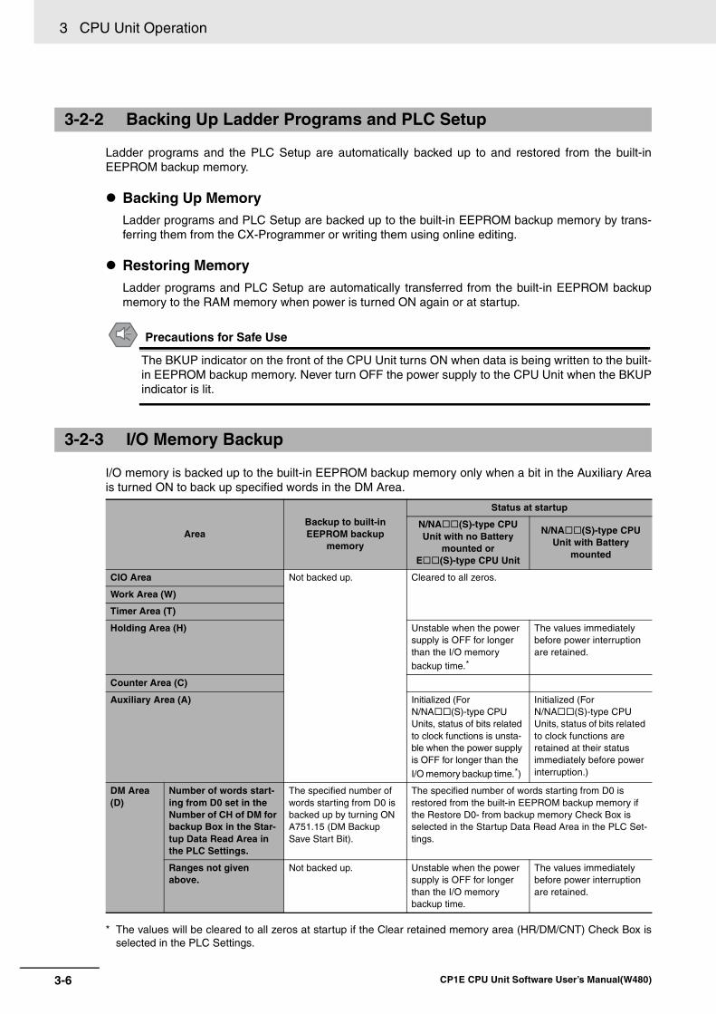
3 CPU Unit Operation
3-6 CP1E CPU Unit Software User’s Manual(W480)
Ladder programs and the PLC Setup are automatically backed up to and restored from the built-inEEPROM backup memory.
Backing Up MemoryLadder programs and PLC Setup are backed up to the built-in EEPROM backup memory by trans-ferring them from the CX-Programmer or writing them using online editing.
Restoring MemoryLadder programs and PLC Setup are automatically transferred from the built-in EEPROM backupmemory to the RAM memory when power is turned ON again or at startup.
Precautions for Safe Use
The BKUP indicator on the front of the CPU Unit turns ON when data is being written to the built-in EEPROM backup memory. Never turn OFF the power supply to the CPU Unit when the BKUPindicator is lit.
I/O memory is backed up to the built-in EEPROM backup memory only when a bit in the Auxiliary Areais turned ON to back up specified words in the DM Area.
* The values will be cleared to all zeros at startup if the Clear retained memory area (HR/DM/CNT) Check Box isselected in the PLC Settings.
3-2-2 Backing Up Ladder Programs and PLC Setup
3-2-3 I/O Memory Backup
Area Backup to built-in EEPROM backup
memory
Status at startup
N/NA (S)-type CPU Unit with no Battery
mounted or E (S)-type CPU Unit
N/NA (S)-type CPU Unit with Battery
mounted
CIO Area Not backed up. Cleared to all zeros.
Work Area (W)
Timer Area (T)
Holding Area (H) Unstable when the power supply is OFF for longer than the I/O memory backup time.*
The values immediately before power interruption are retained.
Counter Area (C)
Auxiliary Area (A) Initialized (For N/NA (S)-type CPU Units, status of bits related to clock functions is unsta-ble when the power supply is OFF for longer than the
I/O memory backup time.*)
Initialized (For N/NA (S)-type CPU Units, status of bits related to clock functions are retained at their status immediately before power interruption.)
DM Area (D)
Number of words start-ing from D0 set in the Number of CH of DM for backup Box in the Star-tup Data Read Area in the PLC Settings.
The specified number of words starting from D0 is backed up by turning ON A751.15 (DM Backup Save Start Bit).
The specified number of words starting from D0 is restored from the built-in EEPROM backup memory if the Restore D0- from backup memory Check Box is selected in the Startup Data Read Area in the PLC Set-tings.
Ranges not given above.
Not backed up. Unstable when the power supply is OFF for longer than the I/O memory backup time.
The values immediately before power interruption are retained.
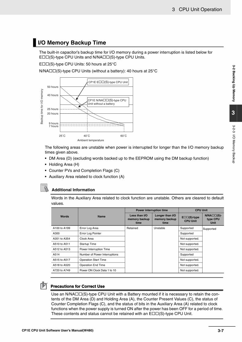
3-7
3 CPU Unit Operation
CP1E CPU Unit Software User’s Manual(W480)
3-2 Backin
g U
p M
emo
ry
3
3-2-3 I/O M
emory B
ackup
The built-in capacitor’s backup time for I/O memory during a power interruption is listed below for E (S)-type CPU Units and N/NA (S)-type CPU Units.
E (S)-type CPU Units: 50 hours at 25°C
N/NA (S)-type CPU Units (without a battery): 40 hours at 25°C
The following areas are unstable when power is interrupted for longer than the I/O memory backuptimes given above.
• DM Area (D) (excluding words backed up to the EEPROM using the DM backup function)
• Holding Area (H)
• Counter PVs and Completion Flags (C)
• Auxiliary Area related to clock function (A)
Additional Information
Words in the Auxiliary Area related to clock function are unstable. Others are cleared to defaultvalues.
Precautions for Correct UsePrecautions for Correct Use
Use an N/NA (S)-type CPU Unit with a Battery mounted if it is necessary to retain the con-tents of the DM Area (D) and Holding Area (A), the Counter Present Values (C), the status of Counter Completion Flags (C), and the status of bits in the Auxiliary Area (A) related to clock functions when the power supply is turned ON after the power has been OFF for a period of time. These contents and status cannot be retained with an E (S)-type CPU Unit.
I/O Memory Backup Time
Words Name
Power interruption time CPU Unit
Less than I/O memory backup
time
Longer than I/O memory backup
time
E (S)-type CPU Unit
N/NA (S)-type CPU
Unit
A100 to A199 Error Log Area Retained Unstable Supported Supported
A300 Error Log Pointer Supported
A351 to A354 Clock Area Not supported.
A510 to A511 Startup Time Not supported.
A512 to A513 Power Interruption Time Not supported.
A514 Number of Power Interruptions Supported
A515 to A517 Operation Start Time Not supported.
A518 to A520 Operation End Time Not supported.
A720 to A749 Power ON Clock Data 1 to 10 Not supported.
25˚C 40˚C 60˚C
50 hours
40 hours
25 hours
20 hours
9 hours7 hours
Bac
kup
time
for
I/O m
emor
y
CP1E E(S)-type CPU Unit
CP1E N/NA(S)-type CPUUnit without a battery
Ambient temperature
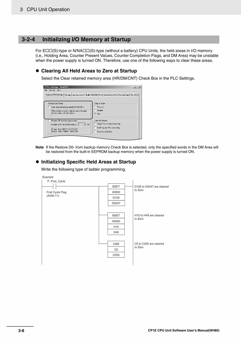
3 CPU Unit Operation
3-8 CP1E CPU Unit Software User’s Manual(W480)
For E (S)-type or N/NA (S)-type (without a battery) CPU Units, the held areas in I/O memory (i.e., Holding Area, Counter Present Values, Counter Completion Flags, and DM Area) may be unstable when the power supply is turned ON. Therefore, use one of the following ways to clear these areas.
Clearing All Held Areas to Zero at StartupSelect the Clear retained memory area (HR/DM/CNT) Check Box in the PLC Settings.
Note If the Restore D0- from backup memory Check Box is selected, only the specified words in the DM Area will be restored from the built-in EEPROM backup memory when the power supply is turned ON.
Initializing Specific Held Areas at StartupWrite the following type of ladder programming.
3-2-4 Initializing I/O Memory at Startup
#0000
BSET
D100
D2047
#0000
BSET
H10
D49
C0
CNR
C255
P_First_Cycle
Example
First Cycle Flag (A200.11)
C0 to C255 are cleared to Zero
H10 to H49 are cleared to Zero
D100 to D2047 are cleared to Zero
4-1
4
CP1E CPU Unit Software User’s Manual(W480)
4
This section provides basic information on ladder programming for CP1E CPU Units.
4-1 Programming. . . . . . . . . . . . . . . . . . . . . . . . . . . . . . . . . . . . . . . . . . . . . . . . . . 4-24-1-1 User Programs . . . . . . . . . . . . . . . . . . . . . . . . . . . . . . . . . . . . . . . . . . . . . . . . . 4-2
4-1-2 Program Capacity . . . . . . . . . . . . . . . . . . . . . . . . . . . . . . . . . . . . . . . . . . . . . . . 4-3
4-1-3 Basics of Programming. . . . . . . . . . . . . . . . . . . . . . . . . . . . . . . . . . . . . . . . . . . 4-3
4-2 Tasks, Sections, and Symbols. . . . . . . . . . . . . . . . . . . . . . . . . . . . . . . . . . . . 4-64-2-1 Overview of Tasks. . . . . . . . . . . . . . . . . . . . . . . . . . . . . . . . . . . . . . . . . . . . . . . 4-6
4-2-2 Overview of Sections . . . . . . . . . . . . . . . . . . . . . . . . . . . . . . . . . . . . . . . . . . . . 4-6
4-2-3 Overview of Symbols . . . . . . . . . . . . . . . . . . . . . . . . . . . . . . . . . . . . . . . . . . . . 4-6
4-3 Programming Instructions . . . . . . . . . . . . . . . . . . . . . . . . . . . . . . . . . . . . . . . 4-84-3-1 Basic Understanding of Instructions . . . . . . . . . . . . . . . . . . . . . . . . . . . . . . . . . 4-8
4-3-2 Operands . . . . . . . . . . . . . . . . . . . . . . . . . . . . . . . . . . . . . . . . . . . . . . . . . . . . . 4-9
4-3-3 Instruction Variations . . . . . . . . . . . . . . . . . . . . . . . . . . . . . . . . . . . . . . . . . . . 4-10
4-3-4 Execution Conditions . . . . . . . . . . . . . . . . . . . . . . . . . . . . . . . . . . . . . . . . . . . 4-10
4-3-5 Specifying Data in Operands . . . . . . . . . . . . . . . . . . . . . . . . . . . . . . . . . . . . . 4-12
4-3-6 Data Formats . . . . . . . . . . . . . . . . . . . . . . . . . . . . . . . . . . . . . . . . . . . . . . . . . 4-13
4-3-7 I/O Refresh Timing . . . . . . . . . . . . . . . . . . . . . . . . . . . . . . . . . . . . . . . . . . . . . 4-15
4-4 Constants. . . . . . . . . . . . . . . . . . . . . . . . . . . . . . . . . . . . . . . . . . . . . . . . . . . . 4-16
4-5 Specifying Offsets for Addresses . . . . . . . . . . . . . . . . . . . . . . . . . . . . . . . . 4-194-5-1 Overview. . . . . . . . . . . . . . . . . . . . . . . . . . . . . . . . . . . . . . . . . . . . . . . . . . . . . 4-19
4-5-2 Application Examples for Address Offsets . . . . . . . . . . . . . . . . . . . . . . . . . . . 4-21
4-6 Ladder Programming Precautions . . . . . . . . . . . . . . . . . . . . . . . . . . . . . . . 4-224-6-1 Special Program Sections . . . . . . . . . . . . . . . . . . . . . . . . . . . . . . . . . . . . . . . 4-22
Understanding Programming
4 Understanding Programming
4-2 CP1E CPU Unit Software User’s Manual(W480)
4-1 Programming
User programs are created by using the CX-Programmer.
The user programs consist of the following parts.
• ProgramsA program consists of more than one instruction and ends with an END instruction.
• Tasks (Smallest Executable Unit) A program is assigned to an interrupt task to execute it. (In the CX-Programmer, the interrupt tasknumber is specified in the program properties.)Tasks include cyclic tasks (executed with normal cyclic processing), interrupt tasks (executed wheninterrupt conditions have been completed) and scheduled interrupt tasks (executed at specified inter-vals).The CP1E can use only one cyclic task.
• SectionsWhen creating and displaying programs with the CX-Programmer, the one program can be dividedinto any number of parts. Each part is called a section. Sections are created mainly to make programs easier to understand.
• Subroutines You can create subroutines within a program.
The user programs are saved in a project file (.CXP) for the CX-Programmer along with other parame-ters, such as the symbol table, PLC Setup data, and I/O memory data.
Programs can be written using only ladder programs.
4-1-1 User Programs
Structure of User Programs
User Program Data
Programming Languages
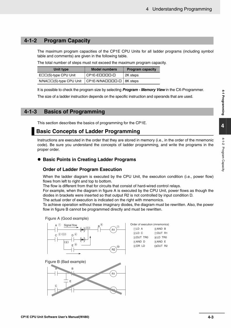
4-3
4 Understanding Programming
CP1E CPU Unit Software User’s Manual(W480)
4-1 Pro
gram
min
g
4
4-1-2 Program
Capacity
The maximum program capacities of the CP1E CPU Units for all ladder programs (including symboltable and comments) are given in the following table.
The total number of steps must not exceed the maximum program capacity.
It is possible to check the program size by selecting Program - Memory View in the CX-Programmer.
The size of a ladder instruction depends on the specific instruction and operands that are used.
This section describes the basics of programming for the CP1E.
Instructions are executed in the order that they are stored in memory (i.e., in the order of the mnemoniccode). Be sure you understand the concepts of ladder programming, and write the programs in theproper order.
Basic Points in Creating Ladder Programs
Order of Ladder Program Execution When the ladder diagram is executed by the CPU Unit, the execution condition (i.e., power flow)flows from left to right and top to bottom. The flow is different from that for circuits that consist of hard-wired control relays. For example, when the diagram in figure A is executed by the CPU Unit, power flows as though thediodes in brackets were inserted so that output R2 is not controlled by input condition D. The actual order of execution is indicated on the right with mnemonics. To achieve operation without these imaginary diodes, the diagram must be rewritten. Also, the powerflow in figure B cannot be programmed directly and must be rewritten.
4-1-2 Program Capacity
Unit type Model numbers Program capacity
E (S)-type CPU Unit CP1E-E - 2K steps
N/NA (S)-type CPU Unit CP1E-N/NA - 8K steps
4-1-3 Basics of Programming
Basic Concepts of Ladder Programming
A B
A
C E
E
C D
B
E
()
()
()R1
R2
R1
R2
AND B
OUT R1
LD TR0
AND E
OUT R2
LD A
LD C
OUT TR0
AND D
OR LD
Figure A (Good example)
Signal flow
Figure B (Bad example)
Order of execution (mnemonics)
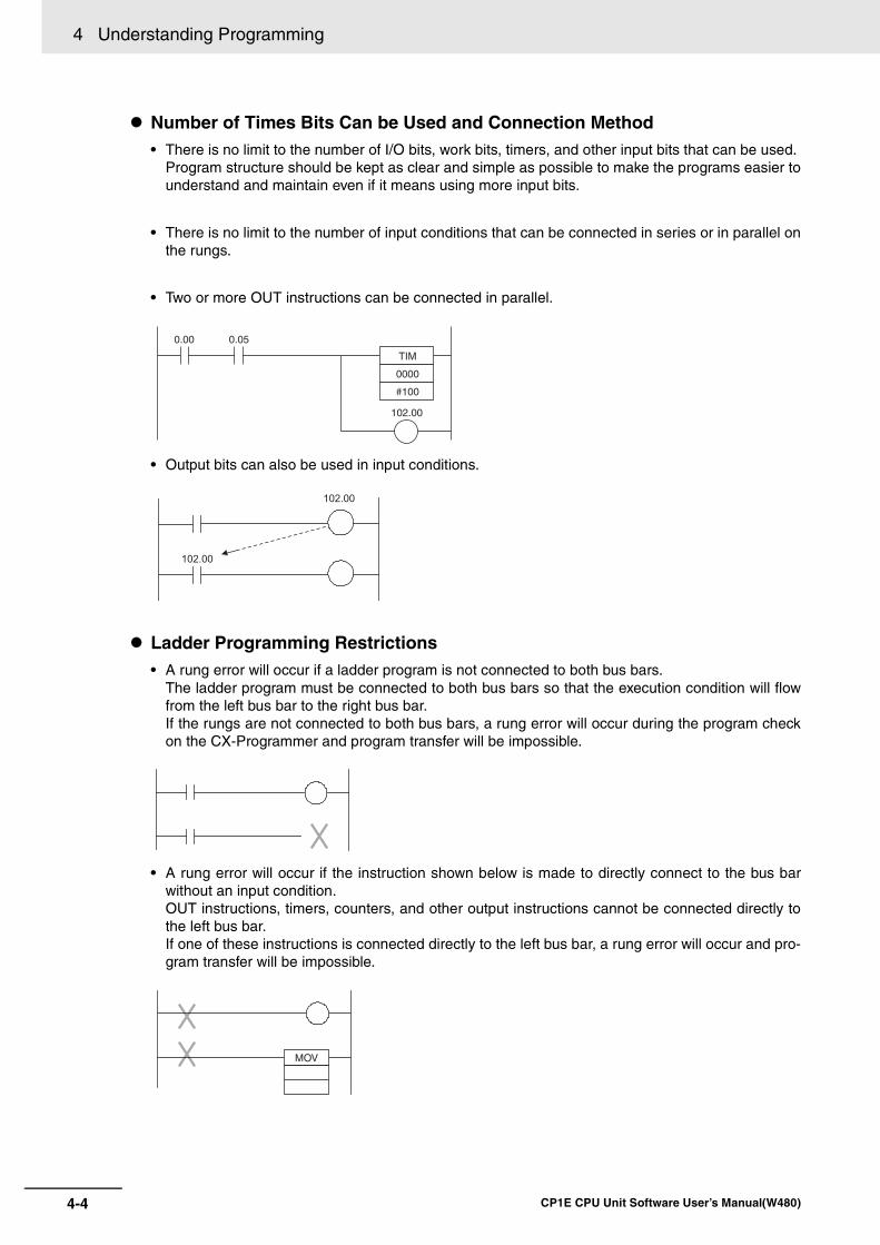
4 Understanding Programming
4-4 CP1E CPU Unit Software User’s Manual(W480)
Number of Times Bits Can be Used and Connection Method • There is no limit to the number of I/O bits, work bits, timers, and other input bits that can be used.
Program structure should be kept as clear and simple as possible to make the programs easier tounderstand and maintain even if it means using more input bits.
• There is no limit to the number of input conditions that can be connected in series or in parallel onthe rungs.
• Two or more OUT instructions can be connected in parallel.
• Output bits can also be used in input conditions.
Ladder Programming Restrictions• A rung error will occur if a ladder program is not connected to both bus bars.
The ladder program must be connected to both bus bars so that the execution condition will flowfrom the left bus bar to the right bus bar. If the rungs are not connected to both bus bars, a rung error will occur during the program checkon the CX-Programmer and program transfer will be impossible.
• A rung error will occur if the instruction shown below is made to directly connect to the bus barwithout an input condition. OUT instructions, timers, counters, and other output instructions cannot be connected directly tothe left bus bar. If one of these instructions is connected directly to the left bus bar, a rung error will occur and pro-gram transfer will be impossible.
0.00 0.05
102.00
TIM
0000
#100
102.00
102.00
MOV
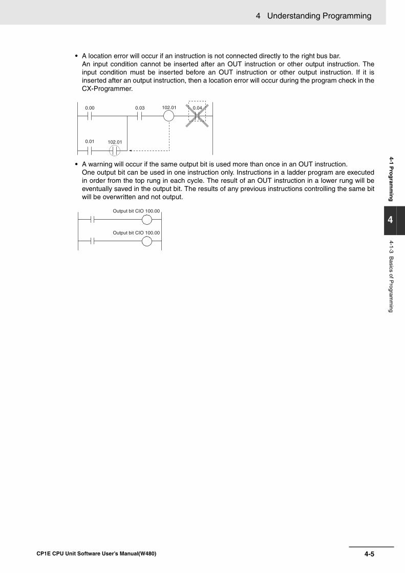
4-5
4 Understanding Programming
CP1E CPU Unit Software User’s Manual(W480)
4-1 Pro
gram
min
g
4
4-1-3 Basics of P
rogramm
ing
• A location error will occur if an instruction is not connected directly to the right bus bar. An input condition cannot be inserted after an OUT instruction or other output instruction. Theinput condition must be inserted before an OUT instruction or other output instruction. If it isinserted after an output instruction, then a location error will occur during the program check in theCX-Programmer.
• A warning will occur if the same output bit is used more than once in an OUT instruction. One output bit can be used in one instruction only. Instructions in a ladder program are executedin order from the top rung in each cycle. The result of an OUT instruction in a lower rung will beeventually saved in the output bit. The results of any previous instructions controlling the same bitwill be overwritten and not output.
0.00 0.03 0.04
0.01 102.01
102.01
Output bit CIO 100.00
Output bit CIO 100.00
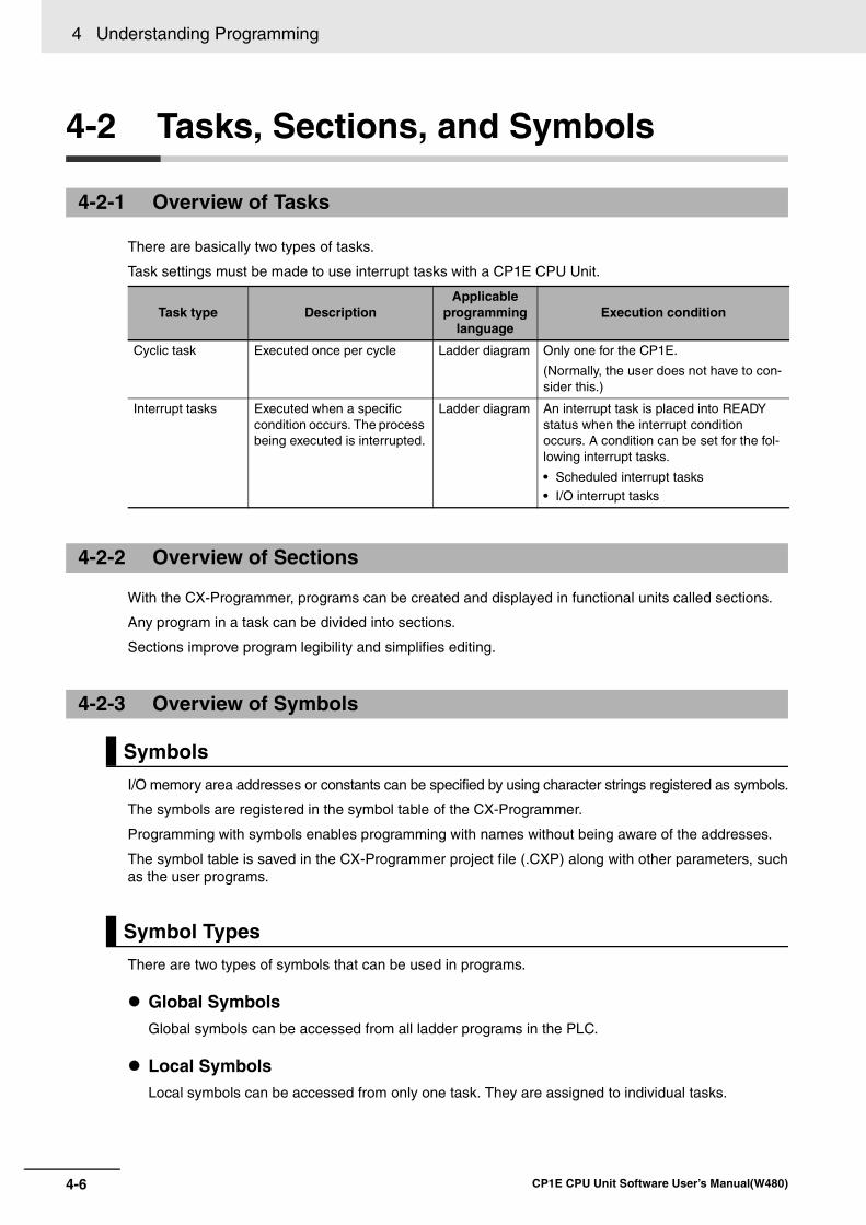
4 Understanding Programming
4-6 CP1E CPU Unit Software User’s Manual(W480)
4-2 Tasks, Sections, and Symbols
There are basically two types of tasks.
Task settings must be made to use interrupt tasks with a CP1E CPU Unit.
With the CX-Programmer, programs can be created and displayed in functional units called sections.
Any program in a task can be divided into sections.
Sections improve program legibility and simplifies editing.
I/O memory area addresses or constants can be specified by using character strings registered as symbols.
The symbols are registered in the symbol table of the CX-Programmer.
Programming with symbols enables programming with names without being aware of the addresses.
The symbol table is saved in the CX-Programmer project file (.CXP) along with other parameters, suchas the user programs.
There are two types of symbols that can be used in programs.
Global SymbolsGlobal symbols can be accessed from all ladder programs in the PLC.
Local SymbolsLocal symbols can be accessed from only one task. They are assigned to individual tasks.
4-2-1 Overview of Tasks
Task type DescriptionApplicable
programming language
Execution condition
Cyclic task Executed once per cycle Ladder diagram Only one for the CP1E.
(Normally, the user does not have to con-sider this.)
Interrupt tasks Executed when a specific condition occurs. The process being executed is interrupted.
Ladder diagram An interrupt task is placed into READY status when the interrupt condition occurs. A condition can be set for the fol-lowing interrupt tasks.
• Scheduled interrupt tasks• I/O interrupt tasks
4-2-2 Overview of Sections
4-2-3 Overview of Symbols
Symbols
Symbol Types
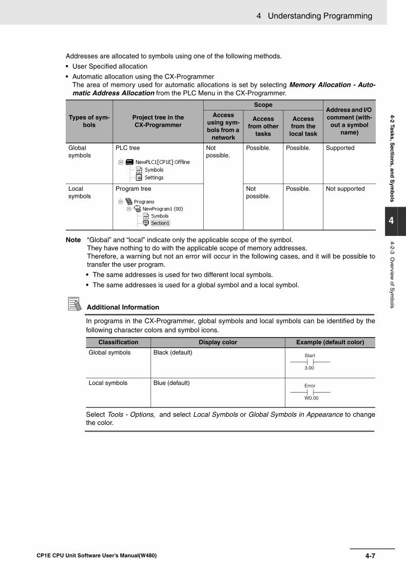
4-7
4 Understanding Programming
CP1E CPU Unit Software User’s Manual(W480)
4-2 Tasks, Sectio
ns, an
d S
ymb
ols
4
4-2-3 Overview
of Sym
bols
Addresses are allocated to symbols using one of the following methods.
• User Specified allocation
• Automatic allocation using the CX-ProgrammerThe area of memory used for automatic allocations is set by selecting Memory Allocation - Auto-matic Address Allocation from the PLC Menu in the CX-Programmer.
Note “Global” and “local” indicate only the applicable scope of the symbol. They have nothing to do with the applicable scope of memory addresses.Therefore, a warning but not an error will occur in the following cases, and it will be possible totransfer the user program.
• The same addresses is used for two different local symbols.
• The same addresses is used for a global symbol and a local symbol.
Additional Information
In programs in the CX-Programmer, global symbols and local symbols can be identified by thefollowing character colors and symbol icons.
Select Tools - Options, and select Local Symbols or Global Symbols in Appearance to changethe color.
Types of sym-bols
Project tree in the CX-Programmer
ScopeAddress and I/O comment (with-
out a symbol name)
Access using sym-bols from a
network
Access from other
tasks
Access from the
local task
Global symbols
PLC tree Not possible.
Possible. Possible. Supported
Local symbols
Program tree Notpossible.
Possible. Not supported
Classification Display color Example (default color)
Global symbols Black (default)
Local symbols Blue (default)
Start
3.00
Error
W0.00
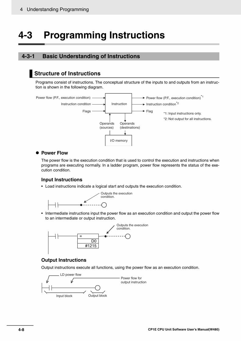
4 Understanding Programming
4-8 CP1E CPU Unit Software User’s Manual(W480)
4-3 Programming Instructions
Programs consist of instructions. The conceptual structure of the inputs to and outputs from an instruc-tion is shown in the following diagram.
Power FlowThe power flow is the execution condition that is used to control the execution and instructions whenprograms are executing normally. In a ladder program, power flow represents the status of the exe-cution condition.
Input Instructions• Load instructions indicate a logical start and outputs the execution condition.
• Intermediate instructions input the power flow as an execution condition and output the power flowto an intermediate or output instruction.
Output InstructionsOutput instructions execute all functions, using the power flow as an execution condition.
4-3-1 Basic Understanding of Instructions
Structure of Instructions
Flags
Instruction
Flag
Power flow (P.F., execution condition)
Instruction condition
Power flow (P.F., execution condition)*1
Instruction condition*2
Operands (sources)
Operands (destinations)
I/O memory
*1: Input instructions only.
*2: Not output for all instructions.
Outputs the execution condition.
=
D0
#1215
Outputs the execution condition.
Input block Output block
Power flow for output instruction
LD power flow
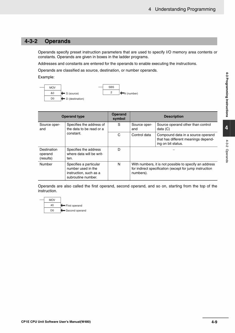
4-9
4 Understanding Programming
CP1E CPU Unit Software User’s Manual(W480)
4-3 Pro
gram
min
g In
structio
ns
4
4-3-2 Operands
Operands specify preset instruction parameters that are used to specify I/O memory area contents orconstants. Operands are given in boxes in the ladder programs.
Addresses and constants are entered for the operands to enable executing the instructions.
Operands are classified as source, destination, or number operands.
Example:
Operands are also called the first operand, second operand, and so on, starting from the top of theinstruction.
4-3-2 Operands
Operand typeOperand symbol
Description
Source oper-and
Specifies the address of the data to be read or a constant.
S Source oper-and
Source operand other than control data (C)
C Control data Compound data in a source operand that has different meanings depend-ing on bit status.
Destination operand (results)
Specifies the address where data will be writ-ten.
D −
Number Specifies a particular number used in the instruction, such as a subroutine number.
N With numbers, it is not possible to specify an address for indirect specification (except for jump instruction numbers).
MOV
&0
D0
S (source)
D (destination)
SBS
2 N (number)
MOV
#0
D0
First operand
Second operand
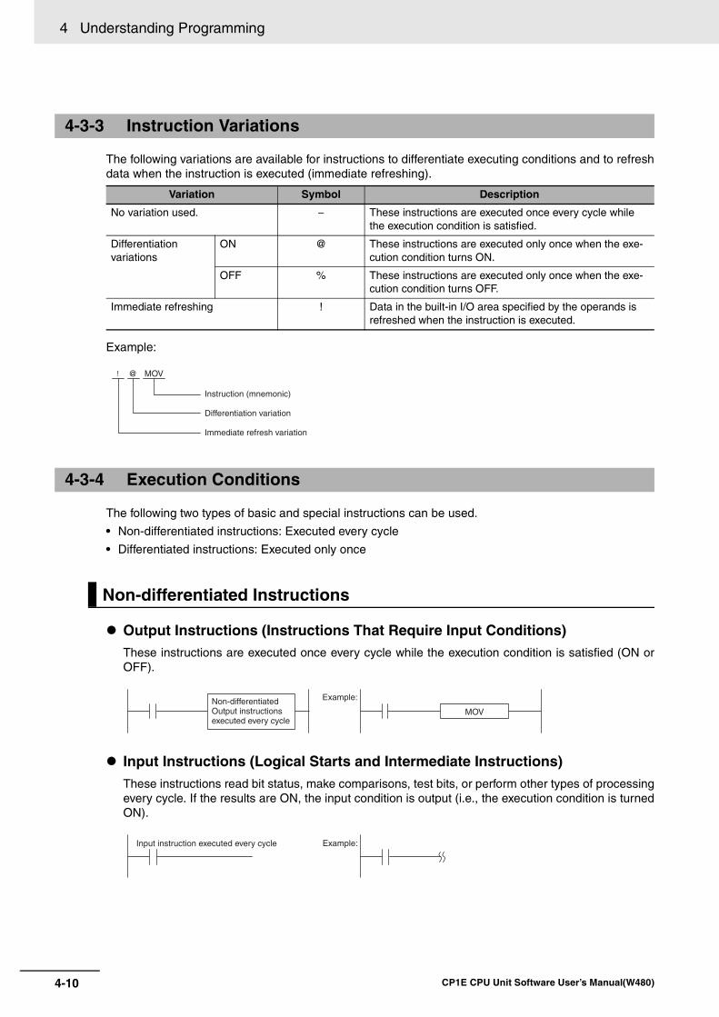
4 Understanding Programming
4-10 CP1E CPU Unit Software User’s Manual(W480)
The following variations are available for instructions to differentiate executing conditions and to refreshdata when the instruction is executed (immediate refreshing).
Example:
The following two types of basic and special instructions can be used.
• Non-differentiated instructions: Executed every cycle
• Differentiated instructions: Executed only once
Output Instructions (Instructions That Require Input Conditions)These instructions are executed once every cycle while the execution condition is satisfied (ON orOFF).
Input Instructions (Logical Starts and Intermediate Instructions)These instructions read bit status, make comparisons, test bits, or perform other types of processingevery cycle. If the results are ON, the input condition is output (i.e., the execution condition is turnedON).
4-3-3 Instruction Variations
Variation Symbol Description
No variation used. − These instructions are executed once every cycle while the execution condition is satisfied.
Differentiation variations
ON @ These instructions are executed only once when the exe-cution condition turns ON.
OFF % These instructions are executed only once when the exe-cution condition turns OFF.
Immediate refreshing ! Data in the built-in I/O area specified by the operands is refreshed when the instruction is executed.
4-3-4 Execution Conditions
Non-differentiated Instructions
MOV
Instruction (mnemonic)
Differentiation variation
Immediate refresh variation
@!
Example:
MOVNon-differentiated Output instructions executed every cycle
Input instruction executed every cycle Example:
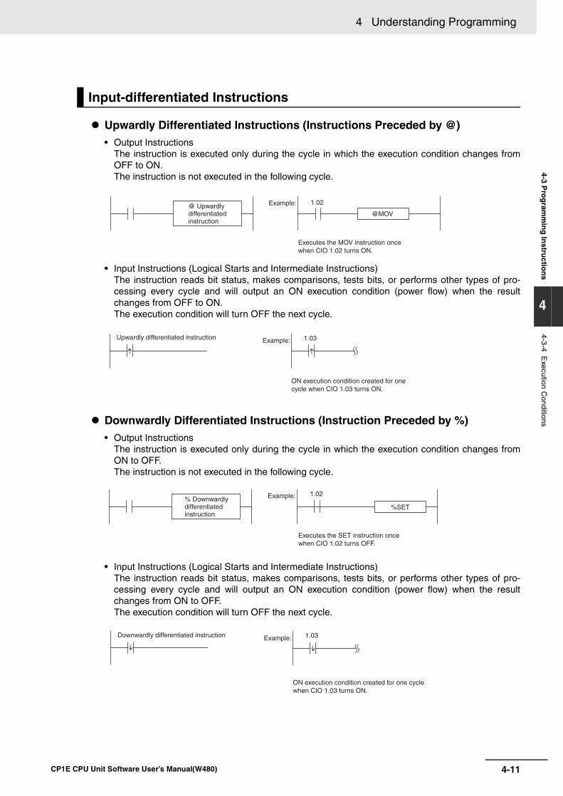
4-11
4 Understanding Programming
CP1E CPU Unit Software User’s Manual(W480)
4-3 Pro
gram
min
g In
structio
ns
4
4-3-4 Execution C
onditions
Upwardly Differentiated Instructions (Instructions Preceded by @) • Output Instructions
The instruction is executed only during the cycle in which the execution condition changes fromOFF to ON. The instruction is not executed in the following cycle.
• Input Instructions (Logical Starts and Intermediate Instructions)The instruction reads bit status, makes comparisons, tests bits, or performs other types of pro-cessing every cycle and will output an ON execution condition (power flow) when the resultchanges from OFF to ON. The execution condition will turn OFF the next cycle.
Downwardly Differentiated Instructions (Instruction Preceded by %)• Output Instructions
The instruction is executed only during the cycle in which the execution condition changes fromON to OFF. The instruction is not executed in the following cycle.
• Input Instructions (Logical Starts and Intermediate Instructions) The instruction reads bit status, makes comparisons, tests bits, or performs other types of pro-cessing every cycle and will output an ON execution condition (power flow) when the resultchanges from ON to OFF. The execution condition will turn OFF the next cycle.
Input-differentiated Instructions
@MOV
Example: 1.02
Executes the MOV instruction once when CIO 1.02 turns ON.
@ Upwardly differentiated instruction
Upwardly differentiated instruction Example: 1.03
ON execution condition created for one cycle when CIO 1.03 turns ON.
%SET
Example: 1.02
Executes the SET instruction once when CIO 1.02 turns OFF.
% Downwardly differentiated instruction
Downwardly differentiated instruction Example: 1.03
ON execution condition created for one cycle when CIO 1.03 turns ON.
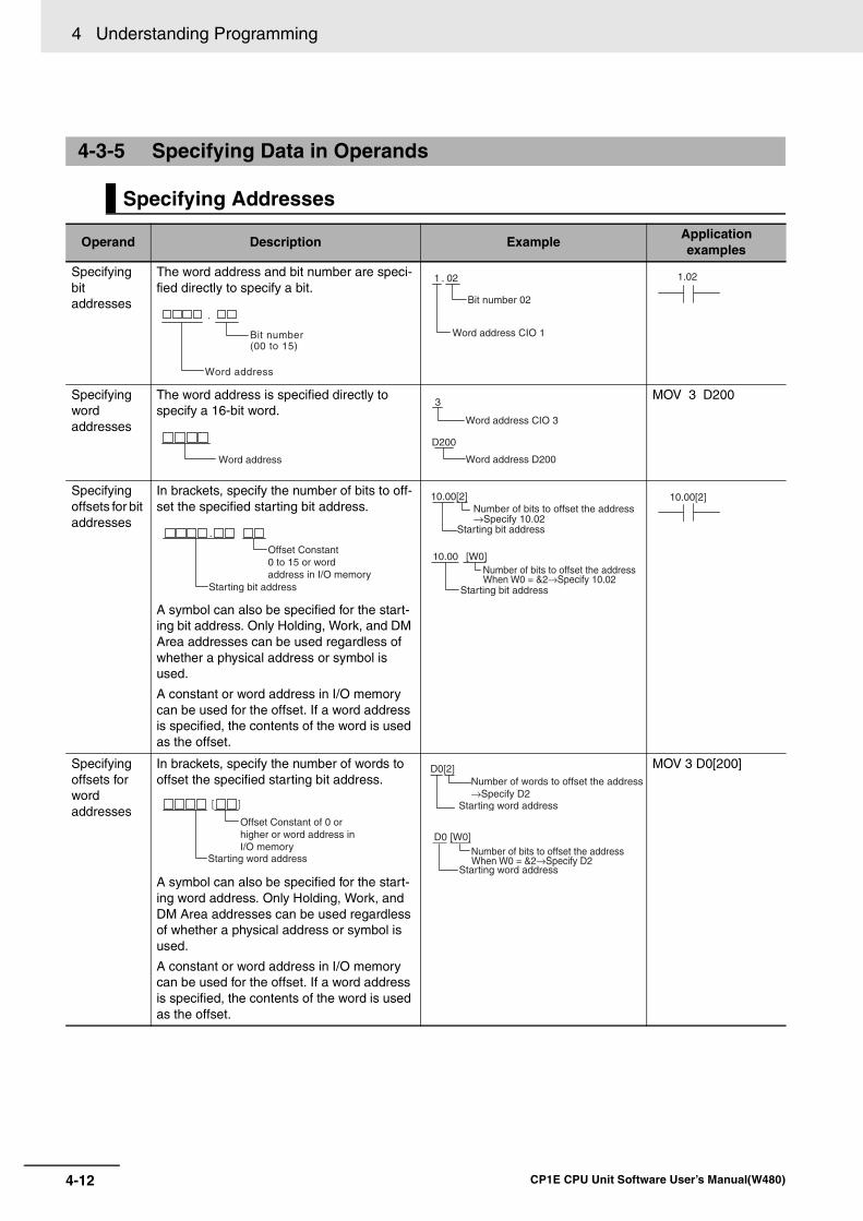
4 Understanding Programming
4-12 CP1E CPU Unit Software User’s Manual(W480)
4-3-5 Specifying Data in Operands
Specifying Addresses
Operand Description ExampleApplicationexamples
Specifying bit addresses
The word address and bit number are speci-fied directly to specify a bit.
Specifying word addresses
The word address is specified directly to specify a 16-bit word.
MOV 3 D200
Specifying offsets for bit addresses
In brackets, specify the number of bits to off-set the specified starting bit address.
A symbol can also be specified for the start-ing bit address. Only Holding, Work, and DM Area addresses can be used regardless of whether a physical address or symbol is used.
A constant or word address in I/O memory can be used for the offset. If a word address is specified, the contents of the word is used as the offset.
Specifying offsets for word addresses
In brackets, specify the number of words to offset the specified starting bit address.
A symbol can also be specified for the start-ing word address. Only Holding, Work, and DM Area addresses can be used regardless of whether a physical address or symbol is used.
A constant or word address in I/O memory can be used for the offset. If a word address is specified, the contents of the word is used as the offset.
MOV 3 D0[200]
Bit number(00 to 15)
Word address
.
Bit number 02
1
Word address CIO 1
. 02 1.02
Word address
3
Word address CIO 3
D200
Word address D200
Offset Constant0 to 15 or wordaddress in I/O memory
Starting bit address
.
10.00[2]Number of bits to offset the address→Specify 10.02
Starting bit address
10.00 [W0]Number of bits to offset the address When W0 = &2→Specify 10.02
Starting bit address
10.00[2]
Starting word address
Offset Constant of 0 or higher or word address in I/O memory
[ ]
D0[2]Number of words to offset the address→Specify D2
Starting word address
D0 [W0]
Starting word address
Number of bits to offset the address When W0 = &2→Specify D2
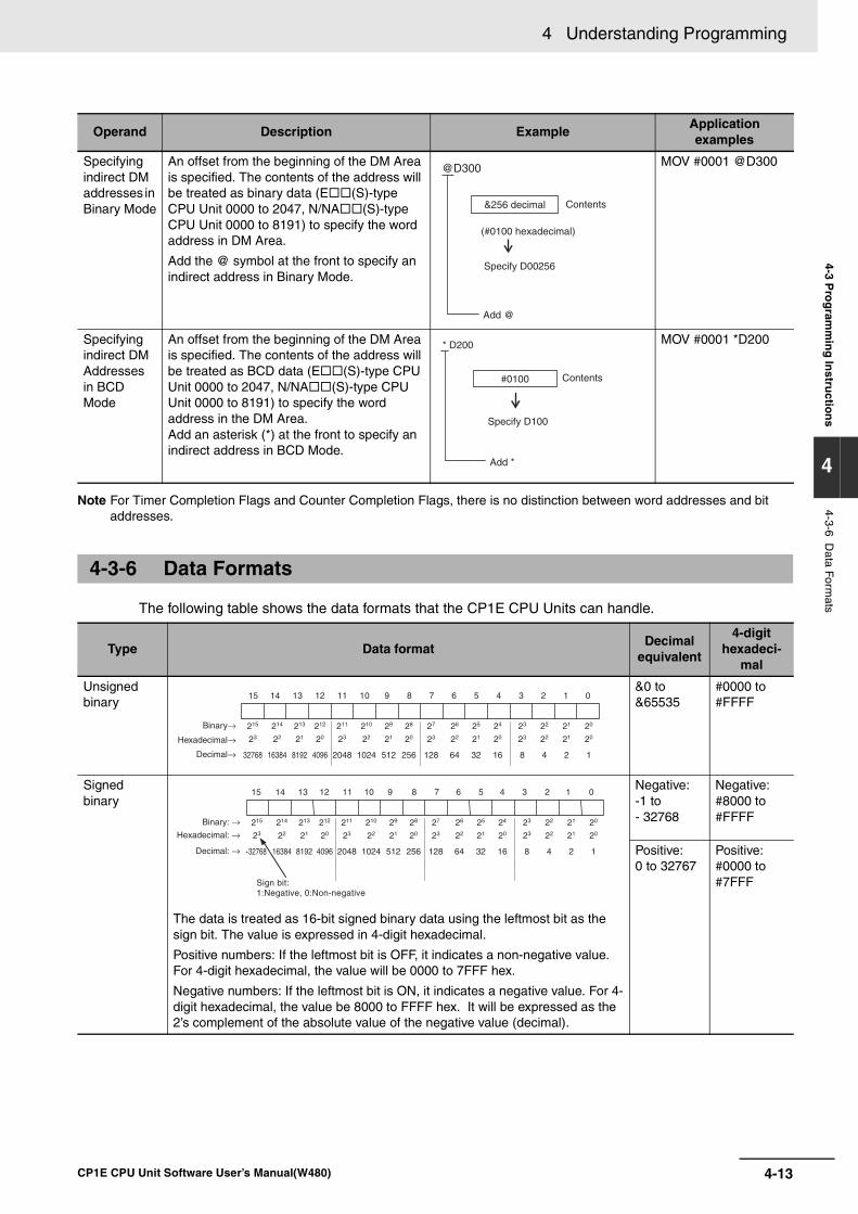
4-13
4 Understanding Programming
CP1E CPU Unit Software User’s Manual(W480)
4-3 Pro
gram
min
g In
structio
ns
4
4-3-6 Data Form
ats
Note For Timer Completion Flags and Counter Completion Flags, there is no distinction between word addresses and bit addresses.
The following table shows the data formats that the CP1E CPU Units can handle.
Operand Description ExampleApplicationexamples
Specifying indirect DM addresses in Binary Mode
An offset from the beginning of the DM Area is specified. The contents of the address will be treated as binary data (E (S)-type CPU Unit 0000 to 2047, N/NA (S)-type CPU Unit 0000 to 8191) to specify the word address in DM Area.
Add the @ symbol at the front to specify an indirect address in Binary Mode.
MOV #0001 @D300
Specifying indirect DM Addresses in BCD Mode
An offset from the beginning of the DM Area is specified. The contents of the address will be treated as BCD data (E (S)-type CPU Unit 0000 to 2047, N/NA (S)-type CPU Unit 0000 to 8191) to specify the word address in the DM Area.Add an asterisk (*) at the front to specify an indirect address in BCD Mode.
MOV #0001 *D200
4-3-6 Data Formats
Type Data formatDecimal
equivalent
4-digit hexadeci-
mal
Unsigned binary
&0 to &65535
#0000 to #FFFF
Signed binary
The data is treated as 16-bit signed binary data using the leftmost bit as the sign bit. The value is expressed in 4-digit hexadecimal.
Positive numbers: If the leftmost bit is OFF, it indicates a non-negative value. For 4-digit hexadecimal, the value will be 0000 to 7FFF hex.
Negative numbers: If the leftmost bit is ON, it indicates a negative value. For 4-digit hexadecimal, the value be 8000 to FFFF hex. It will be expressed as the 2’s complement of the absolute value of the negative value (decimal).
Negative: -1 to- 32768
Negative: #8000 to #FFFF
Positive: 0 to 32767
Positive: #0000 to #7FFF
@D300
Add @
&256 decimal
(#0100 hexadecimal)
Specify D00256
Contents
Contents
Specify D100
* D200
Add *
#0100
215
23
32768
214
22
16384
213
21
8192
212
20
4096
211
23
2048
210
22
1024
29
21
512
28
20
256
27
23
128
26
22
64
25
21
32
24
20
16
23
23
8
22
22
4
21
21
2
20
20
1
Binary→
Hexadecimal→
Decimal→
15 14 13 12 11 10 9 8 7 6 5 4 3 2 1 0
215
23
-32768
214
22
16384
213
21
8192
212
20
4096
211
23
2048
210
22
1024
29
21
512
28
20
256
27
23
128
26
22
64
25
21
32
24
20
16
23
23
8
22
22
4
21
21
2
20
20
1
Binary: →Hexadecimal: →
Decimal: →
15 14 13 12 11 10 9 8 7 6 5 4 3 2 1 0
Sign bit: 1:Negative, 0:Non-negative
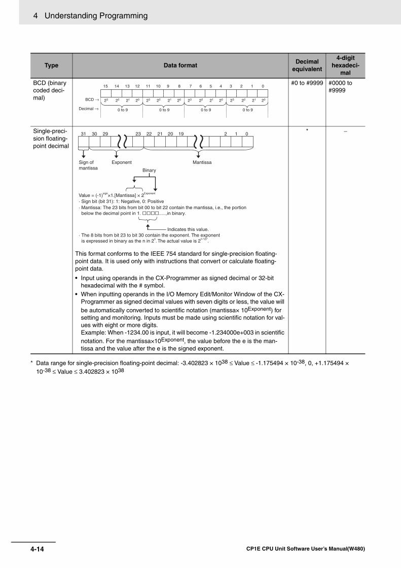
4 Understanding Programming
4-14 CP1E CPU Unit Software User’s Manual(W480)
* Data range for single-precision floating-point decimal: -3.402823 × 1038 ≤ Value ≤ -1.175494 × 10-38, 0, +1.175494 ×10-38 ≤ Value ≤ 3.402823 × 1038
Type Data formatDecimal
equivalent
4-digit hexadeci-
mal
BCD (binary coded deci-mal)
#0 to #9999 #0000 to #9999
Single-preci-sion floating-point decimal
This format conforms to the IEEE 754 standard for single-precision floating-point data. It is used only with instructions that convert or calculate floating-point data.
• Input using operands in the CX-Programmer as signed decimal or 32-bit hexadecimal with the # symbol.
• When inputting operands in the I/O Memory Edit/Monitor Window of the CX-Programmer as signed decimal values with seven digits or less, the value will be automatically converted to scientific notation (mantissa× 10Exponent) for setting and monitoring. Inputs must be made using scientific notation for val-ues with eight or more digits. Example: When -1234.00 is input, it will become -1.234000e+003 in scientific notation. For the mantissa×10Exponent, the value before the e is the man-tissa and the value after the e is the signed exponent.
* −
23 22 21 20BCD →
Decimal →
15 14 13 12 11 10 9 8 7 6 5 4 3 2 1 0
23 22 21 20 23 22 21 20 23 22 21 20
0 to 9 0 to 9 0 to 9 0 to 9
Sign ofmantissa
Exponent Mantissa
Value = (-1)sign×1.[Mantissa] × 2Exponent
· Sign bit (bit 31): 1: Negative, 0: Positive· Mantissa: The 23 bits from bit 00 to bit 22 contain the mantissa, i.e., the portion
below the decimal point in 1. .....,in binary.
Indicates this value.
3031 29 23 2122 20 19 2 1 0
Binary
· The 8 bits from bit 23 to bit 30 contain the exponent. The exponent is expressed in binary as the n in 2n. The actual value is 2n-127.
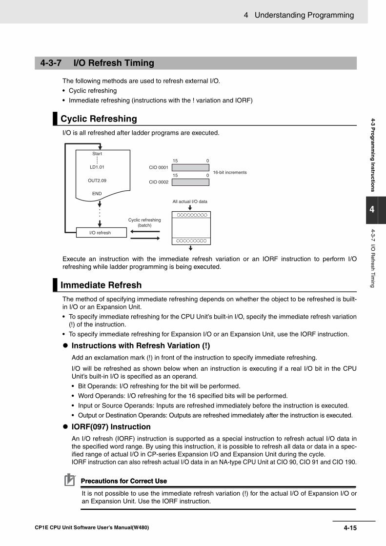
4-15
4 Understanding Programming
CP1E CPU Unit Software User’s Manual(W480)
4-3 Pro
gram
min
g In
structio
ns
4
4-3-7 I/O R
efresh Tim
ing
The following methods are used to refresh external I/O.
• Cyclic refreshing
• Immediate refreshing (instructions with the ! variation and IORF)
I/O is all refreshed after ladder programs are executed.
Execute an instruction with the immediate refresh variation or an IORF instruction to perform I/Orefreshing while ladder programming is being executed.
The method of specifying immediate refreshing depends on whether the object to be refreshed is built-in I/O or an Expansion Unit.
• To specify immediate refreshing for the CPU Unit’s built-in I/O, specify the immediate refresh variation(!) of the instruction.
• To specify immediate refreshing for Expansion I/O or an Expansion Unit, use the IORF instruction.
Instructions with Refresh Variation (!)Add an exclamation mark (!) in front of the instruction to specify immediate refreshing.
I/O will be refreshed as shown below when an instruction is executing if a real I/O bit in the CPUUnit’s built-in I/O is specified as an operand.
• Bit Operands: I/O refreshing for the bit will be performed.
• Word Operands: I/O refreshing for the 16 specified bits will be performed.
• Input or Source Operands: Inputs are refreshed immediately before the instruction is executed.
• Output or Destination Operands: Outputs are refreshed immediately after the instruction is executed.
IORF(097) Instruction An I/O refresh (IORF) instruction is supported as a special instruction to refresh actual I/O data inthe specified word range. By using this instruction, it is possible to refresh all data or data in a spec-ified range of actual I/O in CP-series Expansion I/O and Expansion Unit during the cycle. IORF instruction can also refresh actual I/O data in an NA-type CPU Unit at CIO 90, CIO 91 and CIO 190.
Precautions for Correct UsePrecautions for Correct Use
It is not possible to use the immediate refresh variation (!) for the actual I/O of Expansion I/O oran Expansion Unit. Use the IORF instruction.
4-3-7 I/O Refresh Timing
Cyclic Refreshing
Immediate Refresh
Start
LD1.01
OUT2.09
END
I/O refresh
CIO 0001
15 0
CIO 0002
15 016-bit increments
All actual I/O data
Cyclic refreshing(batch)
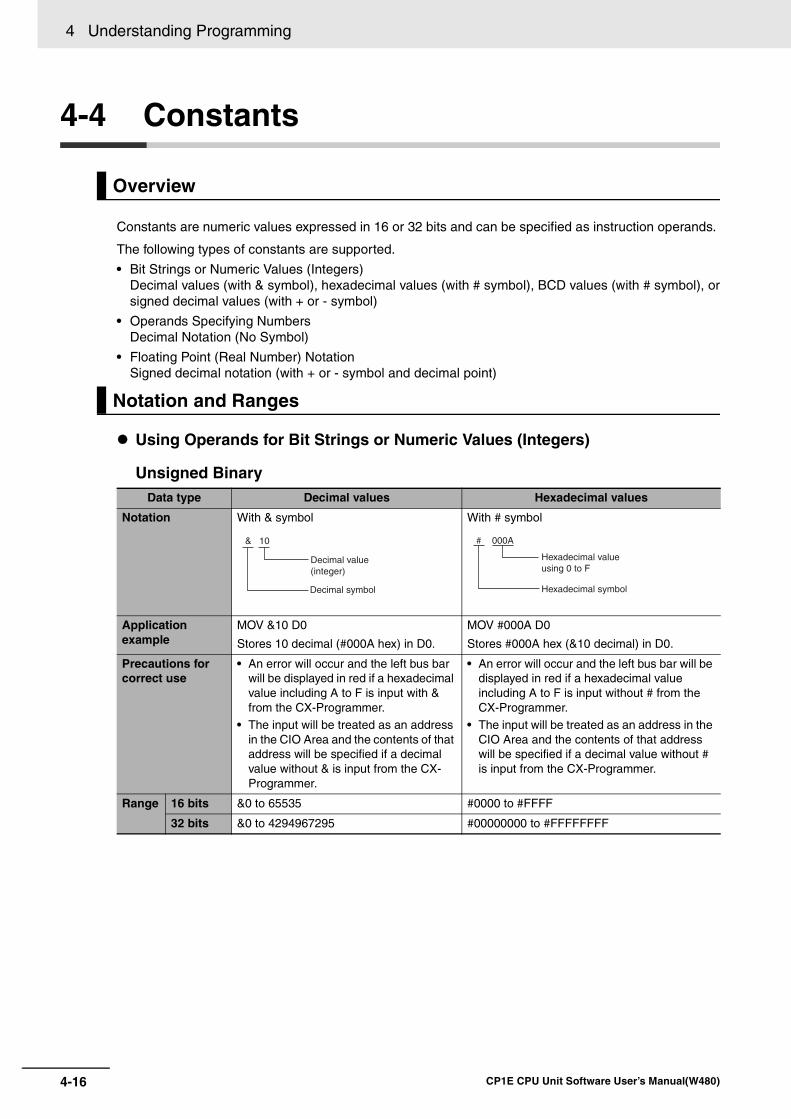
4 Understanding Programming
4-16 CP1E CPU Unit Software User’s Manual(W480)
4-4 Constants
Constants are numeric values expressed in 16 or 32 bits and can be specified as instruction operands.
The following types of constants are supported.
• Bit Strings or Numeric Values (Integers) Decimal values (with & symbol), hexadecimal values (with # symbol), BCD values (with # symbol), orsigned decimal values (with + or - symbol)
• Operands Specifying Numbers Decimal Notation (No Symbol)
• Floating Point (Real Number) Notation Signed decimal notation (with + or - symbol and decimal point)
Using Operands for Bit Strings or Numeric Values (Integers)
Unsigned Binary
Overview
Notation and Ranges
Data type Decimal values Hexadecimal values
Notation With & symbol With # symbol
Application example
MOV &10 D0
Stores 10 decimal (#000A hex) in D0.
MOV #000A D0
Stores #000A hex (&10 decimal) in D0.
Precautions for correct use
• An error will occur and the left bus bar will be displayed in red if a hexadecimal value including A to F is input with & from the CX-Programmer.
• The input will be treated as an address in the CIO Area and the contents of that address will be specified if a decimal value without & is input from the CX-Programmer.
• An error will occur and the left bus bar will be displayed in red if a hexadecimal value including A to F is input without # from the CX-Programmer.
• The input will be treated as an address in the CIO Area and the contents of that address will be specified if a decimal value without # is input from the CX-Programmer.
Range 16 bits &0 to 65535 #0000 to #FFFF
32 bits &0 to 4294967295 #00000000 to #FFFFFFFF
&
Decimal symbol
Decimal value(integer)
10 #
Hexadecimal symbol
Hexadecimal valueusing 0 to F
000A
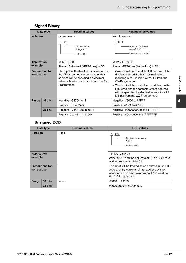
4 - 17
4 Understanding Programming
CP1E CPU Unit Software User’s Manual(W480)
4-4 Co
nstan
ts
4
Signed Binary
Unsigned BCD
Data type Decimal values Hexadecimal values
Notation Signed + or - With # symbol
Application example
MOV -10 D0
Stores 10 decimal (#FFF6 hex) in D0.
MOV # FFF6 D0
Stores #FFF6 hex (10 decimal) in D0.
Precautions for correct use
The input will be treated as an address in the CIO Area and the contents of that address will be specified if a decimal value without + or - is input from the CX-Programmer.
• An error will occur and the left bus bar will be displayed in red if a hexadecimal value including A to F is input without # from the CX-Programmer.
• The input will be treated as an address in the CIO Area and the contents of that address will be specified if a decimal value without # is input from the CX-Programmer.
Range 16 bits Negative: -32768 to -1 Negative: #8000 to #FFFF
Positive: 0 to +32767 Positive: #0000 to #7FFF
32 bits Negative: -2147483648 to -1 Negative: #80000000 to #FFFFFFFF
Positive: 0 to +2147483647 Positive: #00000000 to #7FFFFFFF
Data type Decimal values BCD values
Notation None
Application example
+B #0010 D0 D1
Adds #0010 and the contents of D0 as BCD data and stores the result in D1.
Precautions for correct use
The input will be treated as an address in the CIO Area and the contents of that address will be specified if a decimal value without # is input from the CX-Programmer.
Range 16 bits None #0000 to #9999
32 bits #0000 0000 to #99999999
- 10
+ or - sign
Decimal value(integer)
# FFF6
Hexadecimal symbol
Hexadecimal valueusing 0 to F
# 0010
BCD symbol
Decimal value using0 to 9
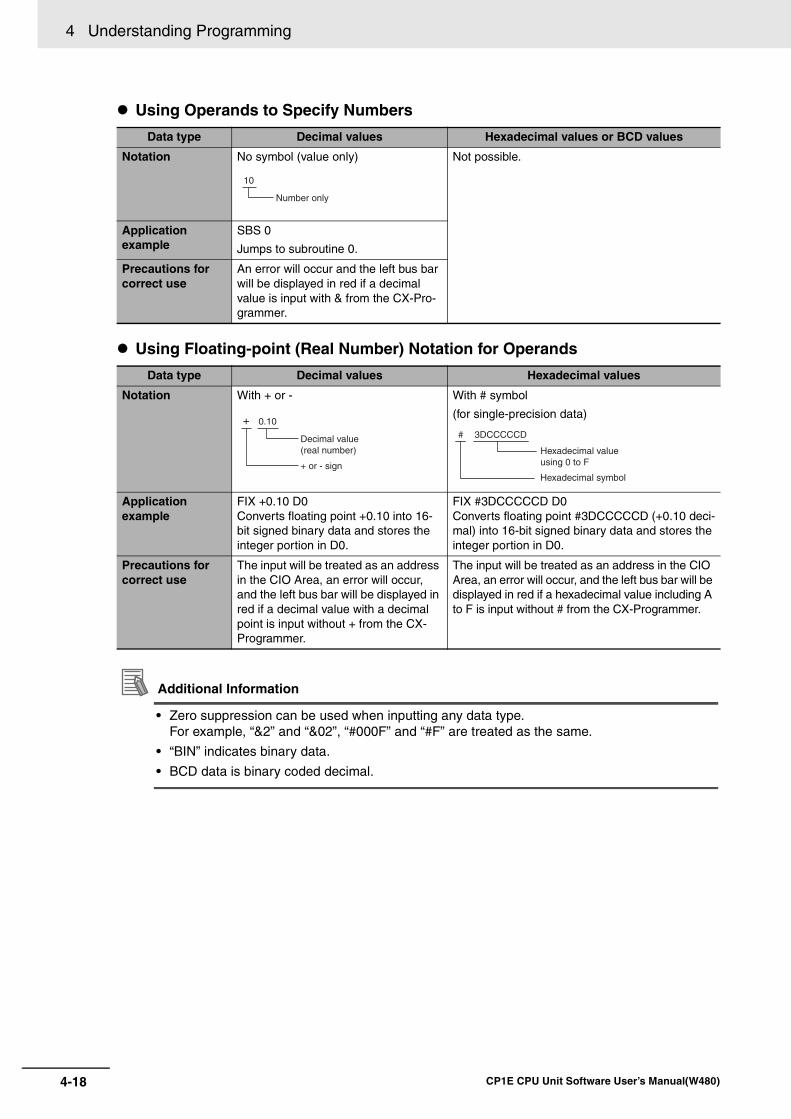
4 Understanding Programming
4-18 CP1E CPU Unit Software User’s Manual(W480)
Using Operands to Specify Numbers
Using Floating-point (Real Number) Notation for Operands
Additional Information
• Zero suppression can be used when inputting any data type. For example, “&2” and “&02”, “#000F” and “#F” are treated as the same.
• “BIN” indicates binary data.
• BCD data is binary coded decimal.
Data type Decimal values Hexadecimal values or BCD values
Notation No symbol (value only) Not possible.
Application example
SBS 0
Jumps to subroutine 0.
Precautions for correct use
An error will occur and the left bus bar will be displayed in red if a decimal value is input with & from the CX-Pro-grammer.
Data type Decimal values Hexadecimal values
Notation With + or - With # symbol
(for single-precision data)
Application example
FIX +0.10 D0Converts floating point +0.10 into 16-bit signed binary data and stores the integer portion in D0.
FIX #3DCCCCCD D0Converts floating point #3DCCCCCD (+0.10 deci-mal) into 16-bit signed binary data and stores the integer portion in D0.
Precautions for correct use
The input will be treated as an address in the CIO Area, an error will occur, and the left bus bar will be displayed in red if a decimal value with a decimal point is input without + from the CX-Programmer.
The input will be treated as an address in the CIO Area, an error will occur, and the left bus bar will be displayed in red if a hexadecimal value including A to F is input without # from the CX-Programmer.
10
Number only
0.10
+ or - sign
Decimal value(real number)
+# 3DCCCCCD
Hexadecimal symbol
Hexadecimal valueusing 0 to F
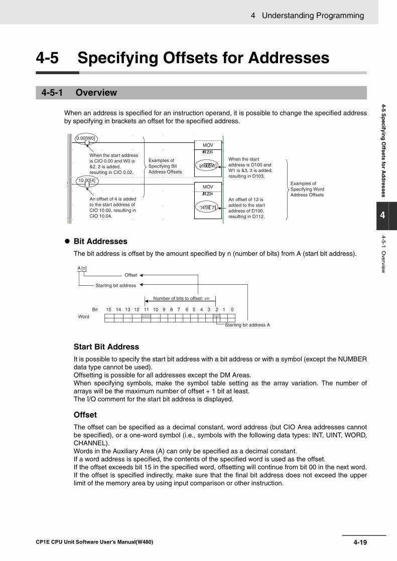
4-19
4 Understanding Programming
CP1E CPU Unit Software User’s Manual(W480)
4-5 Sp
ecifying
Offsets fo
r Ad
dresses
4
4-5-1 Overview
4-5 Specifying Offsets for Addresses
When an address is specified for an instruction operand, it is possible to change the specified addressby specifying in brackets an offset for the specified address.
Bit AddressesThe bit address is offset by the amount specified by n (number of bits) from A (start bit address).
Start Bit AddressIt is possible to specify the start bit address with a bit address or with a symbol (except the NUMBERdata type cannot be used). Offsetting is possible for all addresses except the DM Areas.When specifying symbols, make the symbol table setting as the array variation. The number ofarrays will be the maximum number of offset + 1 bit at least.The I/O comment for the start bit address is displayed.
OffsetThe offset can be specified as a decimal constant, word address (but CIO Area addresses cannotbe specified), or a one-word symbol (i.e., symbols with the following data types: INT, UINT, WORD,CHANNEL).Words in the Auxiliary Area (A) can only be specified as a decimal constant.If a word address is specified, the contents of the specified word is used as the offset.If the offset exceeds bit 15 in the specified word, offsetting will continue from bit 00 in the next word.If the offset is specified indirectly, make sure that the final bit address does not exceed the upperlimit of the memory area by using input comparison or other instruction.
4-5-1 Overview
When the start address is CIO 0.00 and W0 is &2, 2 is added, resulting in CIO 0.02.
When the start address is D100 and W1 is &3, 3 is added, resulting in D103.
An offset of 12 is added to the start address of D100, resulting in D112.
An offset of 4 is added to the start address of CIO 10.00, resulting in CIO 10.04.
Examples of Specifying Bit Address Offsets
Examples of Specifying Word Address Offsets
0.00[W0]
10.00[4]
MOV
MOV
Word
Bit 15 14 13 12 11 10 9 8 7 6 5 4 3 2 1 0
Number of bits to offset: +n
A [n]
Offset
Starting bit address
Starting bit address A
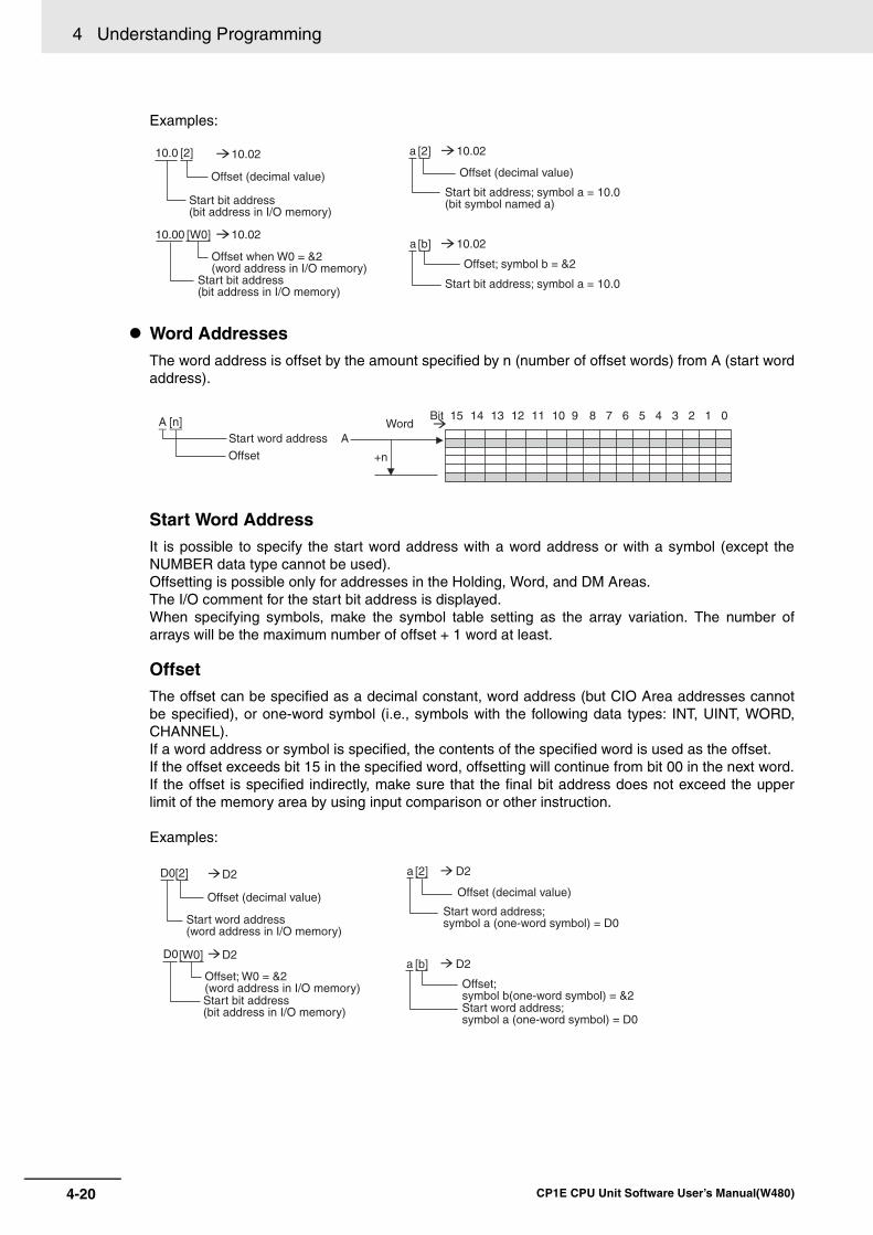
4 Understanding Programming
4-20 CP1E CPU Unit Software User’s Manual(W480)
Examples:
Word AddressesThe word address is offset by the amount specified by n (number of offset words) from A (start wordaddress).
Start Word AddressIt is possible to specify the start word address with a word address or with a symbol (except theNUMBER data type cannot be used).Offsetting is possible only for addresses in the Holding, Word, and DM Areas.The I/O comment for the start bit address is displayed.When specifying symbols, make the symbol table setting as the array variation. The number ofarrays will be the maximum number of offset + 1 word at least.
OffsetThe offset can be specified as a decimal constant, word address (but CIO Area addresses cannotbe specified), or one-word symbol (i.e., symbols with the following data types: INT, UINT, WORD,CHANNEL).If a word address or symbol is specified, the contents of the specified word is used as the offset. If the offset exceeds bit 15 in the specified word, offsetting will continue from bit 00 in the next word.If the offset is specified indirectly, make sure that the final bit address does not exceed the upperlimit of the memory area by using input comparison or other instruction.
Examples:
10.0 [2] 10.02
10.02
a [2] 10.02
10.00 [W0]a [b]
Offset; symbol b = &2
Start bit address; symbol a = 10.0
10.02Offset when W0 = &2(word address in I/O memory)
Start bit address(bit address in I/O memory)
Offset (decimal value)
Start bit address; symbol a = 10.0(bit symbol named a)
Offset (decimal value)
Start bit address(bit address in I/O memory)
WordBit 15 14 13 12 11 10 9 8 7 6 5 0
Start word address
Offset
A [n] 4 3 2 1
A
+n
D0[2] D2
D2
a [2] D2
[W0]a [b]
Offset; symbol b(one-word symbol) = &2Start word address;symbol a (one-word symbol) = D0
D2
Offset (decimal value)
Start word address(word address in I/O memory)
Offset; W0 = &2(word address in I/O memory)Start bit address(bit address in I/O memory)
Offset (decimal value)
Start word address; symbol a (one-word symbol) = D0
D0
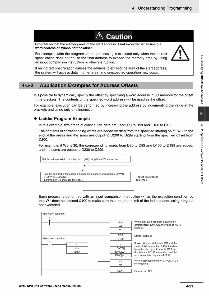
4-21
4 Understanding Programming
CP1E CPU Unit Software User’s Manual(W480)
4-5 Sp
ecifying
Offsets fo
r Ad
dresses
4
4-5-2 Application E
xamples for A
ddress Offsets
It is possible to dynamically specify the offset by specifying a word address in I/O memory for the offsetin the brackets. The contents of the specified word address will be used as the offset.
For example, execution can be performed by increasing the address by incrementing the value in thebrackets and using only one instruction.
Ladder Program ExampleIn this example, two areas of consecutive data are used: D0 to D99 and D100 to D199.
The contents of corresponding words are added starting from the specified starting point, W0, to theend of the areas and the sums are output to D200 to D299 starting from the specified offset fromD200.
For example, if W0 is 30, the corresponding words from D30 to D99 and D130 to D199 are added,and the sums are output to D230 to D299.
Each process is performed with an input comparison instruction (<) as the execution condition sothat W1 does not exceed &100 to make sure that the upper limit of the indirect addressing range isnot exceeded.
Program so that the memory area of the start address is not exceeded when using a word address or symbol for the offset.
For example, write the program so that processing is executed only when the indirectspecification does not cause the final address to exceed the memory area by usingan input comparison instruction or other instruction.
If an indirect specification causes the address to exceed the area of the start address,the system will access data in other area, and unexpected operation may occur.
4-5-2 Application Examples for Address Offsets
Caution
Set the value of W0 to the offset word (W1) using the MOV instruction.
Repeat this process 100 times.
Use the operand of the addition instruction to specify and execute D0[W1] + D100[W1] = D200[W1]. Increment W1 to increase the offset.
MOVW0W1
a
FOR&100
Execution condition
Execution condition
++
W1
a
Starts FOR loop
NEXT Returns to FOR
+
D0[W1]D100[W1]D200[W1]
<
W1&100
When execution condition a (upwardly differentiated) turns ON, the value of W0 is set to W1.
If execution condition a is ON and the value of W1 is less than &100, the data from the start position until D99 and the data until D199 are added, and the sum for each is output until D299.
While execution condition a is ON, W0 is incremented.
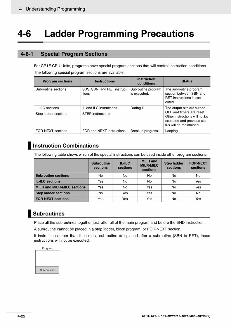
4 Understanding Programming
4-22 CP1E CPU Unit Software User’s Manual(W480)
4-6 Ladder Programming Precautions
For CP1E CPU Units, programs have special program sections that will control instruction conditions.
The following special program sections are available.
The following table shows which of the special instructions can be used inside other program sections.
Place all the subroutines together just after all of the main program and before the END instruction.
A subroutine cannot be placed in a step ladder, block program, or FOR-NEXT section.
If instructions other than those in a subroutine are placed after a subroutine (SBN to RET), thoseinstructions will not be executed.
4-6-1 Special Program Sections
Program sections InstructionsInstructionconditions
Status
Subroutine sections SBS, SBN, and RET instruc-tions
Subroutine program is executed.
The subroutine program section between SBN and RET instructions is exe-cuted.
IL-ILC sections IL and ILC instructions During IL The output bits are turned OFF and timers are reset.Other instructions will not be executed and previous sta-tus will be maintained.
Step ladder sections STEP instructions
FOR-NEXT sections FOR and NEXT instructions Break in progress. Looping
Instruction Combinations
Subroutinesections
IL-ILCsections
MILH and MILR-MILC
sections
Step laddersections
FOR-NEXTsections
Subroutine sections No No No No No
IL-ILC sections Yes No No No Yes
MILH and MILR-MILC sections Yes No Yes No Yes
Step ladder sections No Yes Yes No No
FOR-NEXT sections Yes Yes Yes No Yes
Subroutines
Program
Subroutines
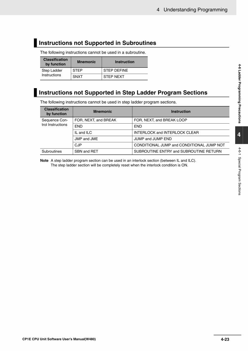
4-23
4 Understanding Programming
CP1E CPU Unit Software User’s Manual(W480)
4-6 Lad
der P
rog
ramm
ing
Precau
tion
s
4
4-6-1 Special P
rogram S
ections
The following instructions cannot be used in a subroutine.
The following instructions cannot be used in step ladder program sections.
Note A step ladder program section can be used in an interlock section (between IL and ILC). The step ladder section will be completely reset when the interlock condition is ON.
Instructions not Supported in Subroutines
Classification by function
Mnemonic Instruction
Step Ladder Instructions
STEP STEP DEFINE
SNXT STEP NEXT
Instructions not Supported in Step Ladder Program Sections
Classification by function
Mnemonic Instruction
Sequence Con-trol Instructions
FOR, NEXT, and BREAK FOR, NEXT, and BREAK LOOP
END END
IL and ILC INTERLOCK and INTERLOCK CLEAR
JMP and JME JUMP and JUMP END
CJP CONDITIONAL JUMP and CONDITIONAL JUMP NOT
Subroutines SBN and RET SUBROUTINE ENTRY and SUBROUTINE RETURN

4 Understanding Programming
4-24 CP1E CPU Unit Software User’s Manual(W480)
5-1
5
CP1E CPU Unit Software User’s Manual(W480)
5
This section describes the types of I/O memory areas in a CP1E CPU Unit and thedetails. Be sure you understand the information in the section before attempting to write ladderdiagrams.Refer to the CP1E CPU Unit Instructions Reference Manual (Cat. No. W483) fordetailed information on programming instructions.
5-1 Overview of I/O Memory Areas . . . . . . . . . . . . . . . . . . . . . . . . . . . . . . . . . . . 5-25-1-1 I/O Memory Areas . . . . . . . . . . . . . . . . . . . . . . . . . . . . . . . . . . . . . . . . . . . . . . 5-2
5-1-2 I/O Memory Area Address Notation . . . . . . . . . . . . . . . . . . . . . . . . . . . . . . . . . 5-5
5-1-3 I/O Memory Areas . . . . . . . . . . . . . . . . . . . . . . . . . . . . . . . . . . . . . . . . . . . . . . 5-6
5-2 I/O Bits . . . . . . . . . . . . . . . . . . . . . . . . . . . . . . . . . . . . . . . . . . . . . . . . . . . . . . . 5-7
5-3 Work Area (W) . . . . . . . . . . . . . . . . . . . . . . . . . . . . . . . . . . . . . . . . . . . . . . . . . 5-8
5-4 Holding Area (H) . . . . . . . . . . . . . . . . . . . . . . . . . . . . . . . . . . . . . . . . . . . . . . . 5-9
5-5 Data Memory Area (D) . . . . . . . . . . . . . . . . . . . . . . . . . . . . . . . . . . . . . . . . . 5-11
5-6 Timer Area (T) . . . . . . . . . . . . . . . . . . . . . . . . . . . . . . . . . . . . . . . . . . . . . . . . 5-13
5-7 Counter Area (C) . . . . . . . . . . . . . . . . . . . . . . . . . . . . . . . . . . . . . . . . . . . . . 5-15
5-8 Auxiliary Area (A) . . . . . . . . . . . . . . . . . . . . . . . . . . . . . . . . . . . . . . . . . . . . . 5-17
5-9 Condition Flags . . . . . . . . . . . . . . . . . . . . . . . . . . . . . . . . . . . . . . . . . . . . . . 5-19
5-10 Clock Pulses . . . . . . . . . . . . . . . . . . . . . . . . . . . . . . . . . . . . . . . . . . . . . . . . . 5-21
I/O Memory
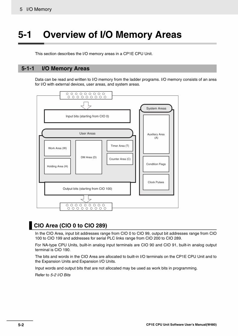
5 I/O Memory
5-2 CP1E CPU Unit Software User’s Manual(W480)
5-1 Overview of I/O Memory Areas
This section describes the I/O memory areas in a CP1E CPU Unit.
Data can be read and written to I/O memory from the ladder programs. I/O memory consists of an areafor I/O with external devices, user areas, and system areas.
In the CIO Area, input bit addresses range from CIO 0 to CIO 99, output bit addresses range from CIO100 to CIO 199 and addresses for serial PLC links range from CIO 200 to CIO 289.
For NA-type CPU Units, built-in analog input terminals are CIO 90 and CIO 91, built-in analog outputterminal is CIO 190.
The bits and words in the CIO Area are allocated to built-in I/O terminals on the CP1E CPU Unit and tothe Expansion Units and Expansion I/O Units.
Input words and output bits that are not allocated may be used as work bits in programming.
Refer to 5-2 I/O Bits
5-1-1 I/O Memory Areas
CIO Area (CIO 0 to CIO 289)
Input bits (starting from CIO 0)
User Areas
Holding Area (H)
DM Area (D)
Timer Area (T)
Counter Area (C)
Output bits (starting from CIO 100)
Work Area (W)
System Areas
Auxiliary Area (A)
Condition Flags
Clock Pulses

5-3
5 I/O Memory
CP1E CPU Unit Software User’s Manual(W480)
5-1 Overview
of I/O
Mem
ory A
reas
5
5-1-1 I/O M
emory A
reas
These areas can be used freely by the user.
Work Area (W)The Word Area is part of the internal memory of the CPU Unit. It is used in programming. Unlike theinput bits and output bits in the CIO Area, I/O to and from external devices is not refreshed for thisarea.
Use this area for work words and bits before using any words in the CIO Area. These words shouldbe used first in programming because they will not be assigned to new functions in future versions ofCP1E CPU Units.
Refer to 5-3 Work Area (W)
Holding Area (H)The Holding Area is part of the internal memory of the CPU Unit. It is used in programming. Unlikethe input bits and output bits in the CIO Area, I/O to and from external devices is not refreshed forthis area.
These words retain their content when the PLC is turned ON or the operating mode is switchedbetween PROGRAM mode and RUN or MONITOR mode.
This data is unstable if power is reset when the battery is not mounted.
Refer to 5-4 Holding Area (H)
Data Memory Area (D)This data area is used for general data storage and manipulation and is accessible only by word (16bits).
These words retain their content when the PLC is turned ON or the operating mode is switchedbetween PROGRAM mode and RUN or MONITOR mode.
Specified words can be retained in the built-in EEPROM backup memory using Auxiliary Area bits.
This data is unstable if power is reset when the battery is not mounted.
Refer to 5-5 Data Memory Area (D)
Timer Area (T)There are two parts to the Timer Area: the Timer Completion Flags and the timer Present Values(PVs).
Up to 256 timers with timer numbers T0 to T255 can be used.
• Timer Completion Flags
Each Timer Completion Flag is accessed as one bit using the timer number. A Completion Flag is turned ON when the set time of the timer elapses.
• Timer PVs
Each timer PV is accessed as one word (16 bits) using the timer number. The PV increases or decreases as the timer operates.
Refer to 5-6 Timer Area (T)
User Areas
5 I/O Memory
5-4 CP1E CPU Unit Software User’s Manual(W480)
Counter Area (C)There are two parts to the Counter Area: the Counter Completion Flags and the Counter PresentValues (PVs).
Up to 256 counters with counter numbers C0 to C255 can be used.
These words retain their content when the PLC is turned ON or the operating mode is switchedbetween PROGRAM mode and RUN or MONITOR mode.
This data is unstable if power is reset, when the battery is not mounted.
• Counter Completion Flags
Each Counter Completion Flag is accessed as one bit using the counter number. A Completion Flag is turned ON when the set value of the counter is reached.
• Counter PVs
Each counter PV is accessed as one word (16 bits) using the timer number. The PVs count up or down as the counter operates.
Refer to 5-7 Counter Area (C)
System Areas contain bits and words with preassigned functions.
Auxiliary Area (A)The words and bits in this area have preassigned functions.
Refer to A-2 Auxiliary Area Allocations by Address
Condition FlagsThe Condition Flags include the flags that indicate the results of instruction execution, as well as theAlways ON and Always OFF Flags.
The Condition Flags are specified with global symbols rather than with addresses. For example: P_on
Clock PulsesThe Clock Pulses are turned ON and OFF by the CPU Unit’s internal timer.
The Clock Pulses are specified with global symbols rather than with addresses. For example: P_0_02
System Areas
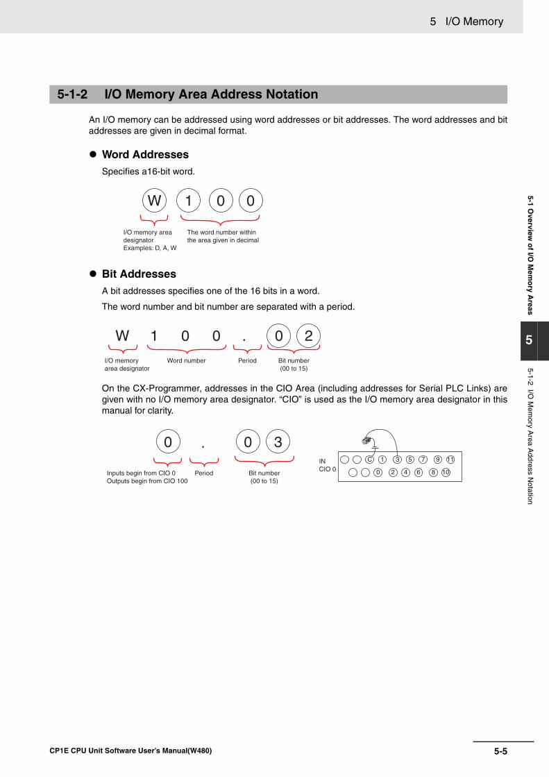
5-5
5 I/O Memory
CP1E CPU Unit Software User’s Manual(W480)
5-1 Overview
of I/O
Mem
ory A
reas
5
5-1-2 I/O M
emory A
rea Address N
otation
An I/O memory can be addressed using word addresses or bit addresses. The word addresses and bitaddresses are given in decimal format.
Word AddressesSpecifies a16-bit word.
Bit AddressesA bit addresses specifies one of the 16 bits in a word.
The word number and bit number are separated with a period.
On the CX-Programmer, addresses in the CIO Area (including addresses for Serial PLC Links) aregiven with no I/O memory area designator. “CIO” is used as the I/O memory area designator in thismanual for clarity.
5-1-2 I/O Memory Area Address Notation
W 1 0 0
I/O memory area designatorExamples: D, A, W
The word number within the area given in decimal
W 1 0 0 0 2
Word number Period Bit number(00 to 15)
.
I/O memory area designator
Period
0 . 0 3C 1
0 2 4 6 8 10
3 5 7 9 11IN CIO 0
Inputs begin from CIO 0 Outputs begin from CIO 100
Bit number(00 to 15)
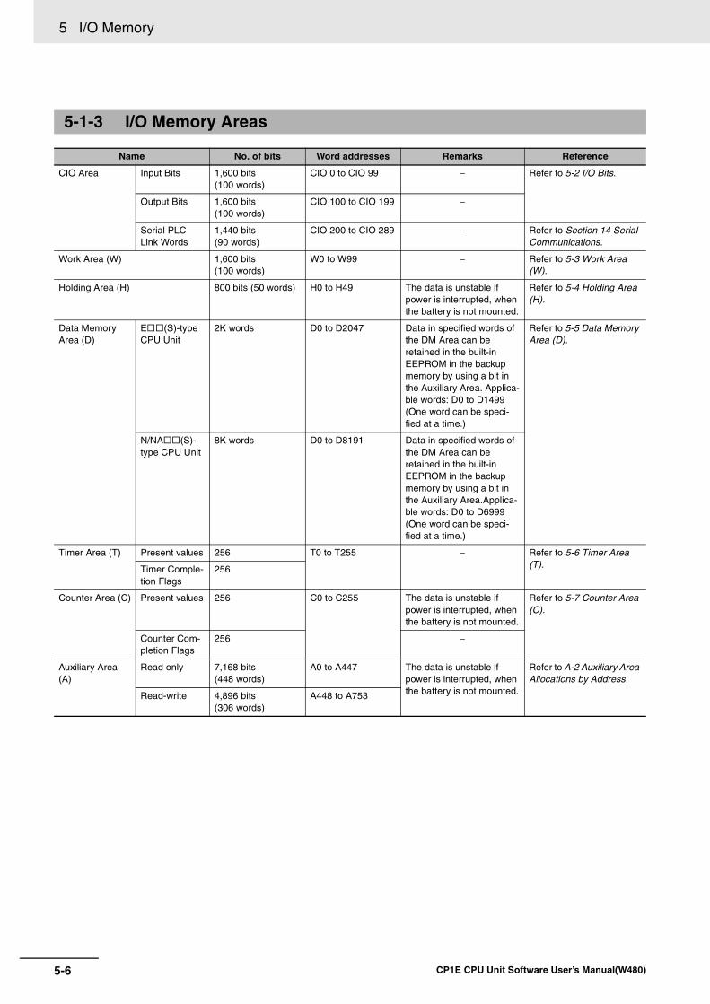
5 I/O Memory
5-6 CP1E CPU Unit Software User’s Manual(W480)
5-1-3 I/O Memory Areas
Name No. of bits Word addresses Remarks Reference
CIO Area Input Bits 1,600 bits(100 words)
CIO 0 to CIO 99 − Refer to 5-2 I/O Bits.
Output Bits 1,600 bits (100 words)
CIO 100 to CIO 199 −
Serial PLC Link Words
1,440 bits (90 words)
CIO 200 to CIO 289 − Refer to Section 14 Serial Communications.
Work Area (W) 1,600 bits (100 words)
W0 to W99 − Refer to 5-3 Work Area (W).
Holding Area (H) 800 bits (50 words) H0 to H49 The data is unstable if power is interrupted, when the battery is not mounted.
Refer to 5-4 Holding Area (H).
Data Memory Area (D)
E (S)-type CPU Unit
2K words D0 to D2047 Data in specified words of the DM Area can be retained in the built-in EEPROM in the backup memory by using a bit in the Auxiliary Area. Applica-ble words: D0 to D1499 (One word can be speci-fied at a time.)
Refer to 5-5 Data Memory Area (D).
N/NA (S)-type CPU Unit
8K words D0 to D8191 Data in specified words of the DM Area can be retained in the built-in EEPROM in the backup memory by using a bit in the Auxiliary Area.Applica-ble words: D0 to D6999 (One word can be speci-fied at a time.)
Timer Area (T) Present values 256 T0 to T255 − Refer to 5-6 Timer Area (T).Timer Comple-
tion Flags256
Counter Area (C) Present values 256 C0 to C255 The data is unstable if power is interrupted, when the battery is not mounted.
Refer to 5-7 Counter Area (C).
Counter Com-pletion Flags
256 −
Auxiliary Area (A)
Read only 7,168 bits (448 words)
A0 to A447 The data is unstable if power is interrupted, when the battery is not mounted.
Refer to A-2 Auxiliary Area Allocations by Address.
Read-write 4,896 bits (306 words)
A448 to A753
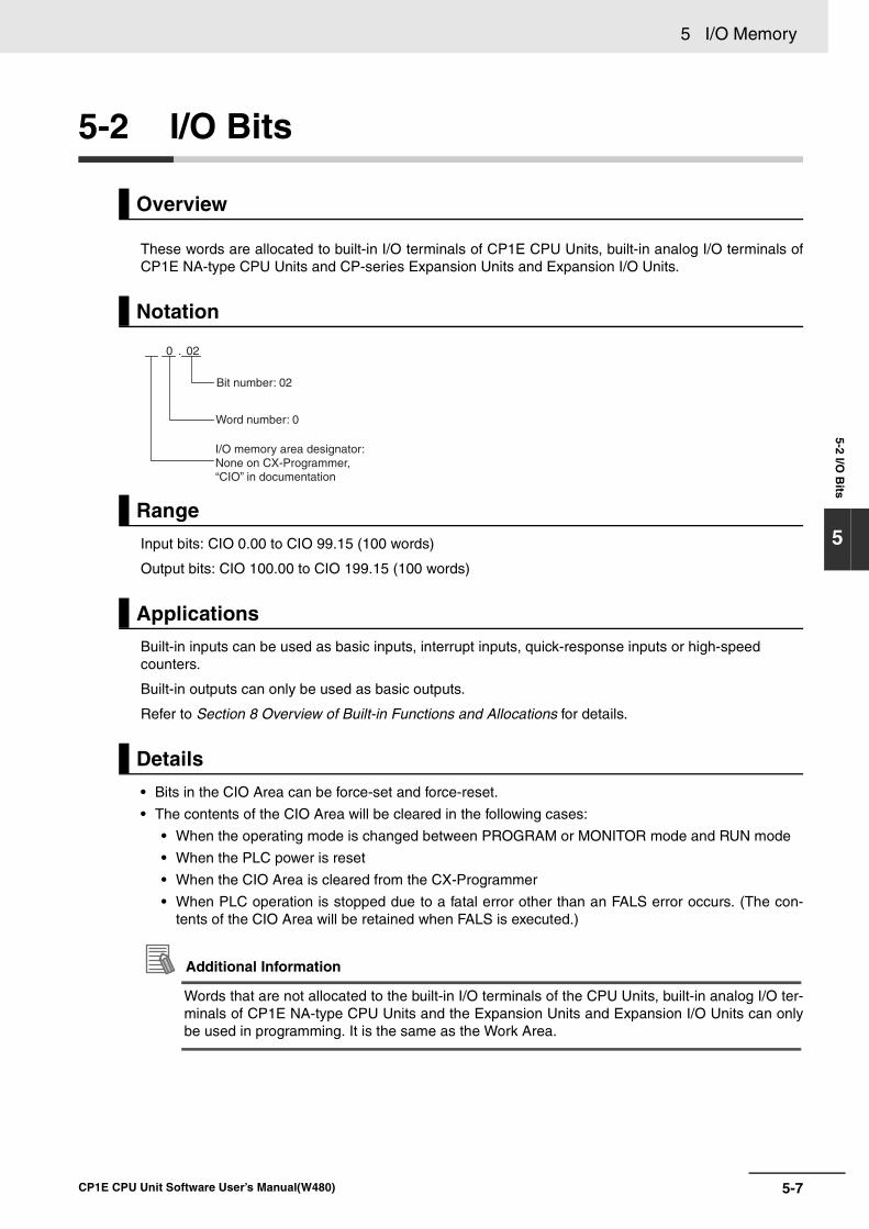
5-7
5 I/O Memory
CP1E CPU Unit Software User’s Manual(W480)
5-2 I/O B
its
5
5-2 I/O Bits
These words are allocated to built-in I/O terminals of CP1E CPU Units, built-in analog I/O terminals ofCP1E NA-type CPU Units and CP-series Expansion Units and Expansion I/O Units.
Input bits: CIO 0.00 to CIO 99.15 (100 words)
Output bits: CIO 100.00 to CIO 199.15 (100 words)
Built-in inputs can be used as basic inputs, interrupt inputs, quick-response inputs or high-speed counters.
Built-in outputs can only be used as basic outputs.
Refer to Section 8 Overview of Built-in Functions and Allocations for details.
• Bits in the CIO Area can be force-set and force-reset.
• The contents of the CIO Area will be cleared in the following cases:
• When the operating mode is changed between PROGRAM or MONITOR mode and RUN mode
• When the PLC power is reset
• When the CIO Area is cleared from the CX-Programmer
• When PLC operation is stopped due to a fatal error other than an FALS error occurs. (The con-tents of the CIO Area will be retained when FALS is executed.)
Additional Information
Words that are not allocated to the built-in I/O terminals of the CPU Units, built-in analog I/O ter-minals of CP1E NA-type CPU Units and the Expansion Units and Expansion I/O Units can onlybe used in programming. It is the same as the Work Area.
Overview
Notation
Range
Applications
Details
Bit number: 02
0 . 02
Word number: 0
I/O memory area designator: None on CX-Programmer, “CIO” in documentation
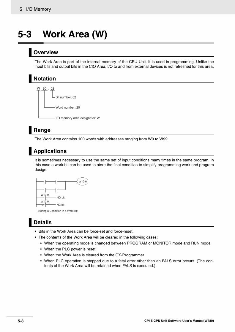
5 I/O Memory
5-8 CP1E CPU Unit Software User’s Manual(W480)
5-3 Work Area (W)
The Work Area is part of the internal memory of the CPU Unit. It is used in programming. Unlike theinput bits and output bits in the CIO Area, I/O to and from external devices is not refreshed for this area.
The Work Area contains 100 words with addresses ranging from W0 to W99.
It is sometimes necessary to use the same set of input conditions many times in the same program. Inthis case a work bit can be used to store the final condition to simplify programming work and programdesign.
• Bits in the Work Area can be force-set and force-reset.
• The contents of the Work Area will be cleared in the following cases:
• When the operating mode is changed between PROGRAM or MONITOR mode and RUN mode
• When the PLC power is reset
• When the Work Area is cleared from the CX-Programmer
• When PLC operation is stopped due to a fatal error other than an FALS error occurs. (The con-tents of the Work Area will be retained when FALS is executed.)
Overview
Notation
Range
Applications
Details
Bit number: 02
W 20 . 02
Word number: 20
I/O memory area designator: W
W10.0
W10.0
W10.0NO bit
NC bit
Storing a Condition in a Work Bit
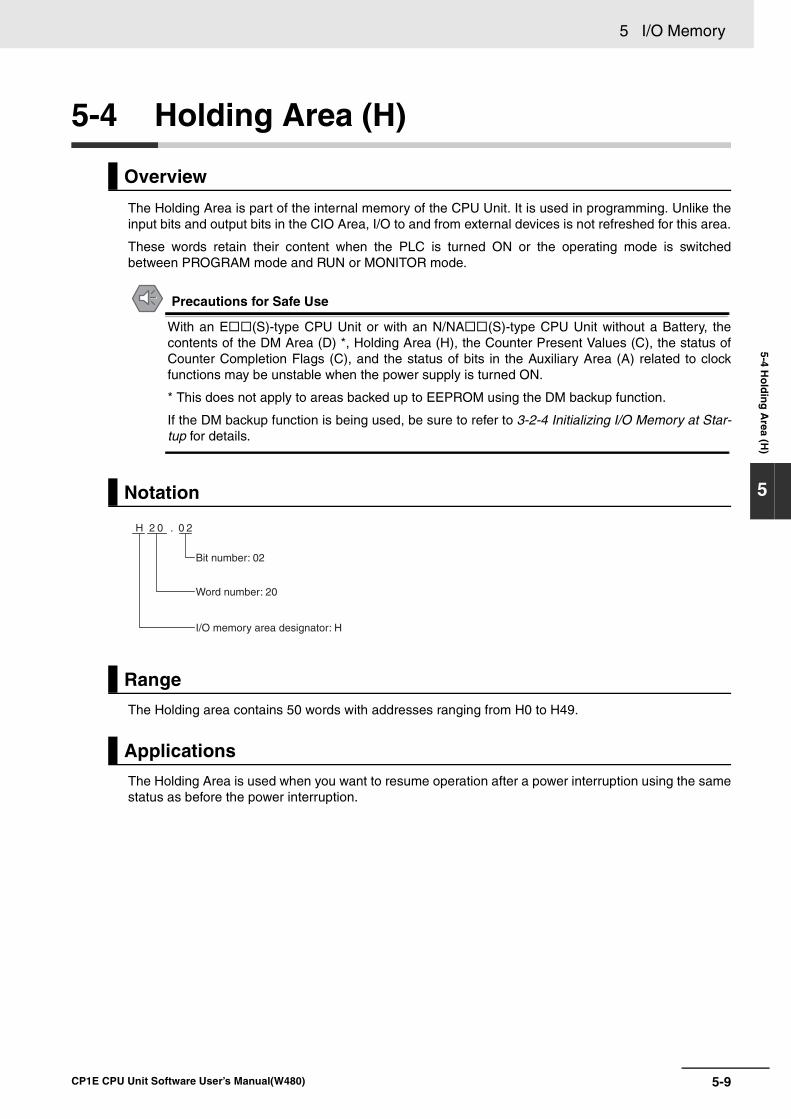
5-9
5 I/O Memory
CP1E CPU Unit Software User’s Manual(W480)
5-4 Ho
ldin
g A
rea (H)
5
5-4 Holding Area (H)
The Holding Area is part of the internal memory of the CPU Unit. It is used in programming. Unlike theinput bits and output bits in the CIO Area, I/O to and from external devices is not refreshed for this area.
These words retain their content when the PLC is turned ON or the operating mode is switchedbetween PROGRAM mode and RUN or MONITOR mode.
Precautions for Safe Use
With an E (S)-type CPU Unit or with an N/NA (S)-type CPU Unit without a Battery, thecontents of the DM Area (D) *, Holding Area (H), the Counter Present Values (C), the status ofCounter Completion Flags (C), and the status of bits in the Auxiliary Area (A) related to clockfunctions may be unstable when the power supply is turned ON.
* This does not apply to areas backed up to EEPROM using the DM backup function.
If the DM backup function is being used, be sure to refer to 3-2-4 Initializing I/O Memory at Star-tup for details.
The Holding area contains 50 words with addresses ranging from H0 to H49.
The Holding Area is used when you want to resume operation after a power interruption using the samestatus as before the power interruption.
Overview
Notation
Range
Applications
H 2 0 . 0 2
Bit number: 02
Word number: 20
I/O memory area designator: H
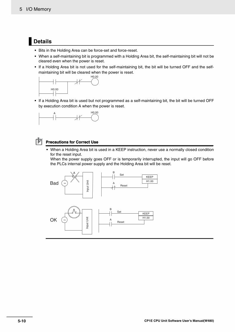
5 I/O Memory
5-10 CP1E CPU Unit Software User’s Manual(W480)
• Bits in the Holding Area can be force-set and force-reset.
• When a self-maintaining bit is programmed with a Holding Area bit, the self-maintaining bit will not becleared even when the power is reset.
• If a Holding Area bit is not used for the self-maintaining bit, the bit will be turned OFF and the self-maintaining bit will be cleared when the power is reset.
• If a Holding Area bit is used but not programmed as a self-maintaining bit, the bit will be turned OFFby execution condition A when the power is reset.
Precautions for Correct UsePrecautions for Correct Use
• When a Holding Area bit is used in a KEEP instruction, never use a normally closed conditionfor the reset input.When the power supply goes OFF or is temporarily interrupted, the input will go OFF beforethe PLCs internal power supply and the Holding Area bit will be reset.
Details
H0.00
H0.00
A H0.00
A B
A
KEEP
H1.00
Set
Set
Reset
Reset
~
A B
A
KEEP
H1.00~
Inpu
t Uni
tIn
put U
nit
Bad
OK
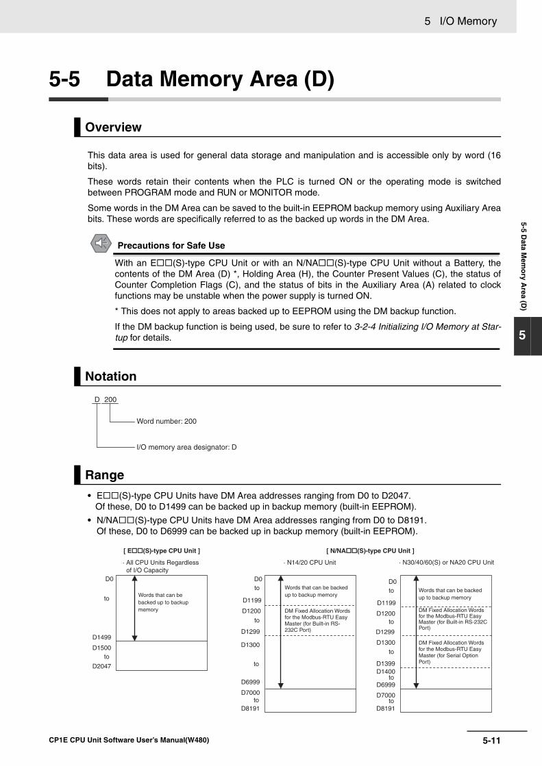
5-11
5 I/O Memory
CP1E CPU Unit Software User’s Manual(W480)
5-5 Data M
emo
ry Area (D
)
5
5-5 Data Memory Area (D)
This data area is used for general data storage and manipulation and is accessible only by word (16bits).
These words retain their contents when the PLC is turned ON or the operating mode is switchedbetween PROGRAM mode and RUN or MONITOR mode.
Some words in the DM Area can be saved to the built-in EEPROM backup memory using Auxiliary Areabits. These words are specifically referred to as the backed up words in the DM Area.
Precautions for Safe Use
With an E (S)-type CPU Unit or with an N/NA (S)-type CPU Unit without a Battery, thecontents of the DM Area (D) *, Holding Area (H), the Counter Present Values (C), the status ofCounter Completion Flags (C), and the status of bits in the Auxiliary Area (A) related to clockfunctions may be unstable when the power supply is turned ON.
* This does not apply to areas backed up to EEPROM using the DM backup function.
If the DM backup function is being used, be sure to refer to 3-2-4 Initializing I/O Memory at Star-tup for details.
• E (S)-type CPU Units have DM Area addresses ranging from D0 to D2047. Of these, D0 to D1499 can be backed up in backup memory (built-in EEPROM).
• N/NA (S)-type CPU Units have DM Area addresses ranging from D0 to D8191. Of these, D0 to D6999 can be backed up in backup memory (built-in EEPROM).
Overview
Notation
Range
D 200
Word number: 200
I/O memory area designator: D
· N30/40/60(S) or NA20 CPU Unit
D1300
D1200
D1399
D0
D1299
· N14/20 CPU Unit
D1300
D1299
D8191
D1400
D8191
D1199
· All CPU Units Regardless of I/O Capacity
D2047
D0
toto
to
D1200
D0
D1199
to
to
to
to
toto
to
[ E(S)-type CPU Unit ]
D6999
D7000D6999
D7000
D1499
D1500
Words that can be backed up to backup memory
Words that can be backed up to backup memory
DM Fixed Allocation Words for the Modbus-RTU Easy Master (for Built-in RS-232C Port)
DM Fixed Allocation Words for the Modbus-RTU Easy Master (for Built-in RS-232C Port)
DM Fixed Allocation Words for the Modbus-RTU Easy Master (for Serial Option Port)
Words that can be backed up to backup memory
to
[ N/NA(S)-type CPU Unit ]
5 I/O Memory
5-12 CP1E CPU Unit Software User’s Manual(W480)
The DM Area is for storing numeric data. It can be used for data exchange with Programmable Termi-nals, serial communications devices, such as Inverters, and Analog I/O Units or Temperature I/O Units.
Bits in the DM Area cannot be addressed individually.
Backing Up to the Built-in EEPROM Backup Memory• The number of words set in the PLC Setup can be saved to the built-in EEPROM backup memory
during operation by turning ON the DM Backup Start bit (A751.15).
• Specify in the PLC Setup whether to read the data in the DM Area words to the RAM as the initialvalues when the power supply is turned ON.
Refer to 16-3 DM Backup Function for how to use DM Area words and bits.
DM Fixed Allocation Words for the Modbus-RTU Easy MasterThe following DM area words are used as command and response storage areas with the Modbus-RTU Easy Master function. These words are used for other applications if the Modbus-RTU EasyMaster function is not served.
Refer to 14-4 Modbus-RTU Easy Master Function for how to use the DM Area words and bits.
Indirect Addressing of the DM AreaIndirect addressing can be used in the DM Area.
There are two modes that can be used.
Binary-mode Addressing (@D)If a “@” symbol is input before a DM Area address, the contents of that DM Area word is treated asa hexadecimal (binary) address and the instruction will operate on the DM Area word at thataddress.
The entire DM Area can be indirectly addressed with hexadecimal values 0000 to 1FFF.
Example:
BCD-mode Addressing (*D)If a * symbol is input before a DM Area address, the content of that DM Area word is treated as aBCD address and the instruction will operate on the DM Area word at that address.
Only part of the DM Area (D0 to D8192) can be indirectly addressed with BCD values 0 to 8192.
Example:
Applications
Details
Address actually used.
0100 D256@D0
Address actually used.
0100 D100*D0
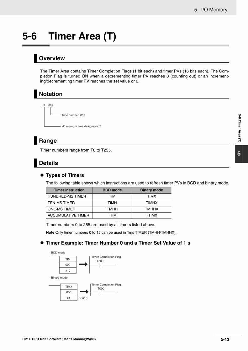
5-13
5 I/O Memory
CP1E CPU Unit Software User’s Manual(W480)
5-6 Tim
er Area (T
)
5
5-6 Timer Area (T)
The Timer Area contains Timer Completion Flags (1 bit each) and timer PVs (16 bits each). The Com-pletion Flag is turned ON when a decrementing timer PV reaches 0 (counting out) or an increment-ing/decrementing timer PV reaches the set value or 0.
Timer numbers range from T0 to T255.
Types of TimersThe following table shows which instructions are used to refresh timer PVs in BCD and binary mode.
Timer numbers 0 to 255 are used by all timers listed above.
Note Only timer numbers 0 to 15 can be used in 1ms TIMER (TMHH/TMHHX).
Timer Example: Timer Number 0 and a Timer Set Value of 1 s
Overview
Notation
Range
Details
Timer instruction BCD mode Binary mode
HUNDRED-MS TIMER TIM TIMX
TEN-MS TIMER TIMH TIMHX
ONE-MS TIMER TMHH TMHHX
ACCUMULATIVE TIMER TTIM TTIMX
T
Time number: 002
I/O memory area designator: T
002
· BCD mode
· Binary mode
Timer Completion Flag
Timer Completion Flag
TIM
000
#10
TIMX
000
#A
T000
T000
or &10
5 I/O Memory
5-14 CP1E CPU Unit Software User’s Manual(W480)
Timer PV Refresh Method
Precautions for Correct UsePrecautions for Correct Use
It is not recommended to use the same timers number in two timer instructions because the tim-ers will not operate correctly if they are operating simultaneously.
Do not use the same timer number for more than one instruction.
If two or more timer instructions use the same timer number, an error will be generated duringthe program check.
Resetting or Maintaining Timers• Timer Completion Flags can be force-set and force-reset.
• Timer PVs cannot be force-set or force-reset, although the PVs can be refreshed indirectly byforce-setting/resetting the Completion Flag.
• There are no restrictions in the order of using timer numbers or in the number of N.C. or N.O. con-ditions that can be programmed.
• Timer PVs can be read as word data and used in programming.
• The following table shows when timers will be reset or maintained.
*1 If the IOM Hold Bit (A500.12) is ON, the PV and Completion Flag will be retained when a fatal error occurs(including execution of FALS instructions) or the operating mode is changed from PROGRAM mode toRUN or MONITOR mode or vice-versa. (The PV and Completion Flag will be cleared when power iscycled.)
*2 Since the TIML/TIMLX instructions do not use timer numbers, they are reset under different conditions. The PV for a TIML/TIMLX instruction is reset to the SV. Refer to the descriptions of these instructions for details.
Timer num-bers
Timer PV refresh method
T0 to T255 The timer PV is refreshed when the instruction is executed. This can cause a delay depending on the cycle time.
• When the cycle time is longer than 100 ms, delay is generated by the TIM/TIMX instruction.• When the cycle time is longer than 10 ms, delay is generated by the TIMH/TIMHX instruction.
• When the cycle time is longer than 1 ms, delay is generated by the TMHH/TMHHX instruction.
InstructionTIM/TIMX TIMH/TIMHX
TMHH/TMHHX
TTIM/TTIMX
HUNDRED-MSTIMER
TEN-MS TIMER ONE-MS TIMERACCUMULATIVE TIMER
When the operating mode is changed between PROGRAM or MONITOR mode and RUN mode*1
PV=0
Flag=OFF
When the PLC power is reset PV=0
Flag=OFF
CNR/CNRX instructions (timer/counter reset)*2
PV= 9999/FFFF
Flag=OFF
Jumps (JMP-JME) Retained
Interlocks (IL-ILC) with OFF inter-lock conditions
Reset (PV = SV, Timer Completion Flag = OFF) Retained
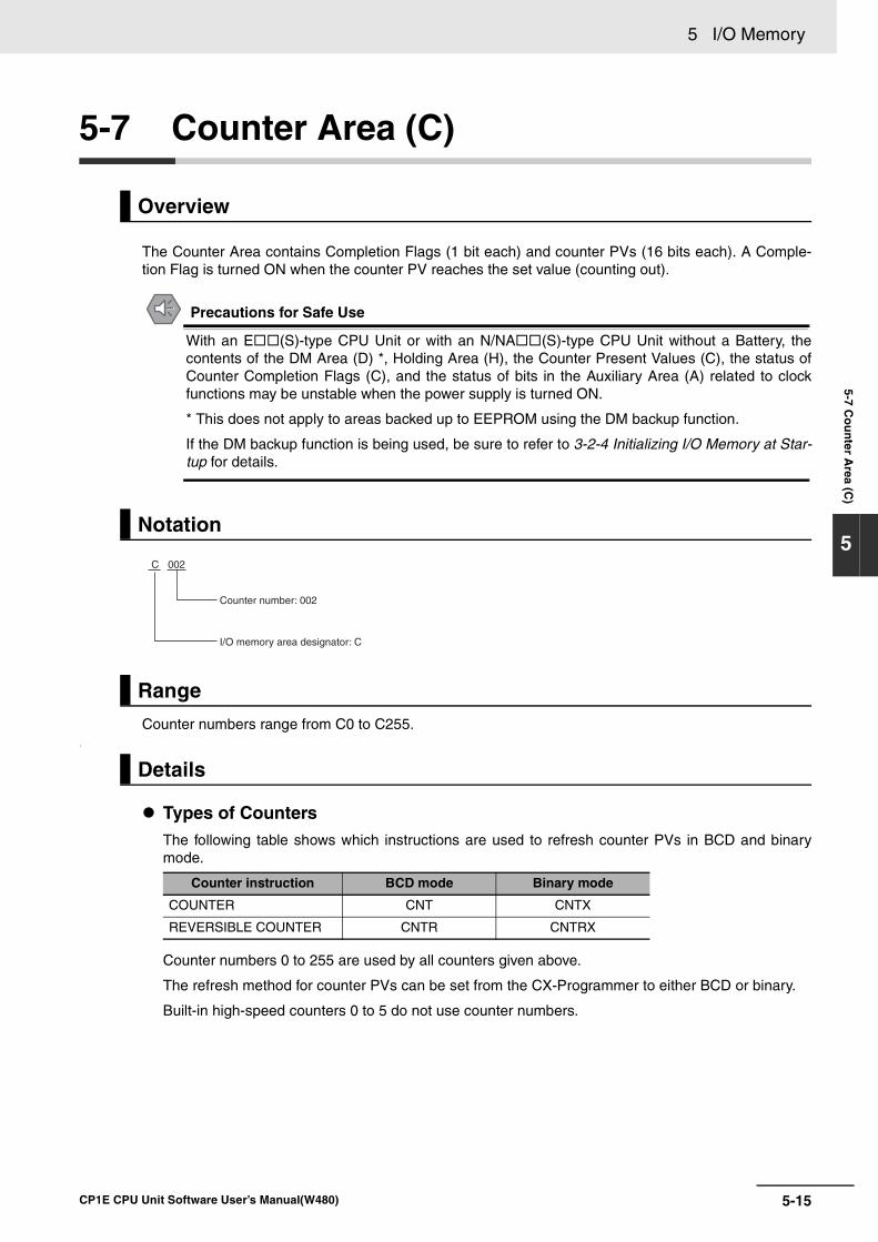
5-15
5 I/O Memory
CP1E CPU Unit Software User’s Manual(W480)
5-7 Co
un
ter Area (C
)
5
5-7 Counter Area (C)
The Counter Area contains Completion Flags (1 bit each) and counter PVs (16 bits each). A Comple-tion Flag is turned ON when the counter PV reaches the set value (counting out).
Precautions for Safe Use
With an E (S)-type CPU Unit or with an N/NA (S)-type CPU Unit without a Battery, thecontents of the DM Area (D) *, Holding Area (H), the Counter Present Values (C), the status ofCounter Completion Flags (C), and the status of bits in the Auxiliary Area (A) related to clockfunctions may be unstable when the power supply is turned ON.
* This does not apply to areas backed up to EEPROM using the DM backup function.
If the DM backup function is being used, be sure to refer to 3-2-4 Initializing I/O Memory at Star-tup for details.
Counter numbers range from C0 to C255..
Types of CountersThe following table shows which instructions are used to refresh counter PVs in BCD and binarymode.
Counter numbers 0 to 255 are used by all counters given above.
The refresh method for counter PVs can be set from the CX-Programmer to either BCD or binary.
Built-in high-speed counters 0 to 5 do not use counter numbers.
Overview
Notation
Range
Details
Counter instruction BCD mode Binary mode
COUNTER CNT CNTX
REVERSIBLE COUNTER CNTR CNTRX
C 002
Counter number: 002
I/O memory area designator: C
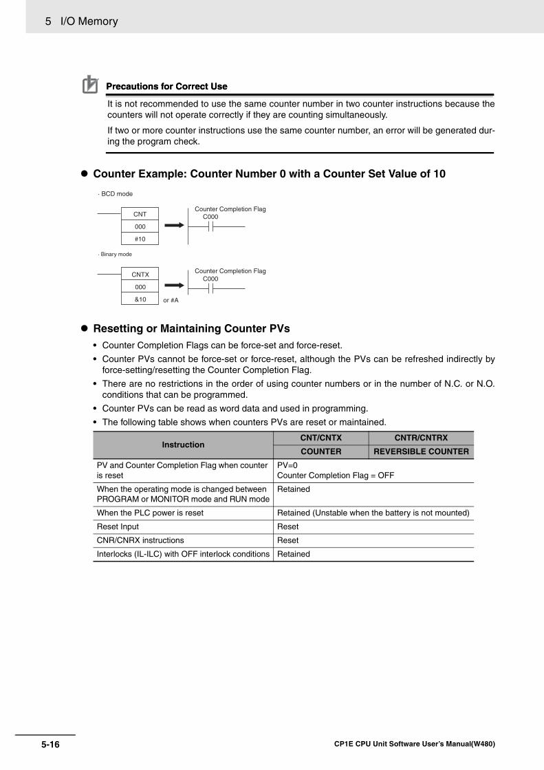
5 I/O Memory
5-16 CP1E CPU Unit Software User’s Manual(W480)
Precautions for Correct UsePrecautions for Correct Use
It is not recommended to use the same counter number in two counter instructions because thecounters will not operate correctly if they are counting simultaneously.
If two or more counter instructions use the same counter number, an error will be generated dur-ing the program check.
Counter Example: Counter Number 0 with a Counter Set Value of 10
Resetting or Maintaining Counter PVs• Counter Completion Flags can be force-set and force-reset.
• Counter PVs cannot be force-set or force-reset, although the PVs can be refreshed indirectly byforce-setting/resetting the Counter Completion Flag.
• There are no restrictions in the order of using counter numbers or in the number of N.C. or N.O.conditions that can be programmed.
• Counter PVs can be read as word data and used in programming.
• The following table shows when counters PVs are reset or maintained.
InstructionCNT/CNTX CNTR/CNTRX
COUNTER REVERSIBLE COUNTER
PV and Counter Completion Flag when counter is reset
PV=0Counter Completion Flag = OFF
When the operating mode is changed between PROGRAM or MONITOR mode and RUN mode
Retained
When the PLC power is reset Retained (Unstable when the battery is not mounted)
Reset Input Reset
CNR/CNRX instructions Reset
Interlocks (IL-ILC) with OFF interlock conditions Retained
CNT
000
#10
or #A
Counter Completion Flag
Counter Completion Flag
· BCD mode
· Binary mode
C000
C000CNTX
000
&10
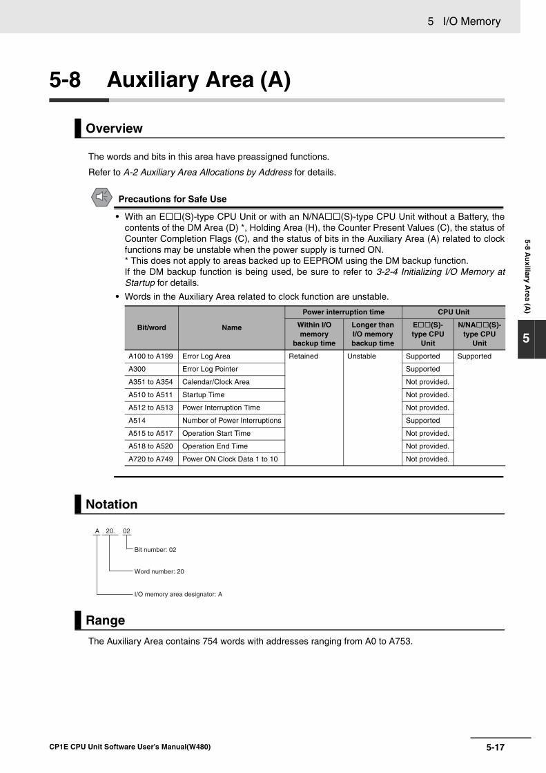
5-17
5 I/O Memory
CP1E CPU Unit Software User’s Manual(W480)
5-8 Au
xiliary Area (A
)
5
5-8 Auxiliary Area (A)
The words and bits in this area have preassigned functions.
Refer to A-2 Auxiliary Area Allocations by Address for details.
Precautions for Safe Use
• With an E (S)-type CPU Unit or with an N/NA (S)-type CPU Unit without a Battery, thecontents of the DM Area (D) *, Holding Area (H), the Counter Present Values (C), the status ofCounter Completion Flags (C), and the status of bits in the Auxiliary Area (A) related to clockfunctions may be unstable when the power supply is turned ON. * This does not apply to areas backed up to EEPROM using the DM backup function.If the DM backup function is being used, be sure to refer to 3-2-4 Initializing I/O Memory atStartup for details.
• Words in the Auxiliary Area related to clock function are unstable.
The Auxiliary Area contains 754 words with addresses ranging from A0 to A753.
Overview
Bit/word Name
Power interruption time CPU Unit
Within I/O memory
backup time
Longer than I/O memory backup time
E (S)-type CPU
Unit
N/NA (S)-type CPU
Unit
A100 to A199 Error Log Area Retained Unstable Supported Supported
A300 Error Log Pointer Supported
A351 to A354 Calendar/Clock Area Not provided.
A510 to A511 Startup Time Not provided.
A512 to A513 Power Interruption Time Not provided.
A514 Number of Power Interruptions Supported
A515 to A517 Operation Start Time Not provided.
A518 to A520 Operation End Time Not provided.
A720 to A749 Power ON Clock Data 1 to 10 Not provided.
Notation
Range
Bit number: 02
A 20. 02
Word number: 20
I/O memory area designator: A
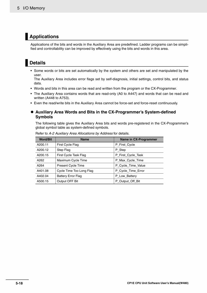
5 I/O Memory
5-18 CP1E CPU Unit Software User’s Manual(W480)
Applications of the bits and words in the Auxiliary Area are predefined. Ladder programs can be simpli-fied and controllability can be improved by effectively using the bits and words in this area.
• Some words or bits are set automatically by the system and others are set and manipulated by theuser.The Auxiliary Area includes error flags set by self-diagnosis, initial settings, control bits, and statusdata.
• Words and bits in this area can be read and written from the program or the CX-Programmer.
• The Auxiliary Area contains words that are read-only (A0 to A447) and words that can be read andwritten (A448 to A753).
• Even the read/write bits in the Auxiliary Area cannot be force-set and force-reset continuously.
Auxiliary Area Words and Bits in the CX-Programmer’s System-defined SymbolsThe following table gives the Auxiliary Area bits and words pre-registered in the CX-Programmer’sglobal symbol table as system-defined symbols.
Refer to A-2 Auxiliary Area Allocations by Address for details.
Applications
Details
Word/Bit Name Name in CX-Programmer
A200.11 First Cycle Flag P_First_Cycle
A200.12 Step Flag P_Step
A200.15 First Cycle Task Flag P_First_Cycle_Task
A262 Maximum Cycle Time P_Max_Cycle_Time
A264 Present Cycle Time P_Cycle_Time_Value
A401.08 Cycle Time Too Long Flag P_Cycle_Time_Error
A402.04 Battery Error Flag P_Low_Battery
A500.15 Output OFF Bit P_Output_Off_Bit
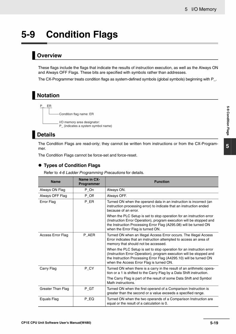
5-19
5 I/O Memory
CP1E CPU Unit Software User’s Manual(W480)
5-9 Co
nd
ition
Flag
s
5
5-9 Condition Flags
These flags include the flags that indicate the results of instruction execution, as well as the Always ONand Always OFF Flags. These bits are specified with symbols rather than addresses.
The CX-Programmer treats condition flags as system-defined symbols (global symbols) beginning with P_.
The Condition Flags are read-only; they cannot be written from instructions or from the CX-Program-mer.
The Condition Flags cannot be force-set and force-reset.
Types of Condition FlagsRefer to 4-6 Ladder Programming Precautions for details.
Overview
Notation
Details
NameName in CX-Programmer
Function
Always ON Flag P_On Always ON.
Always OFF Flag P_Off Always OFF.
Error Flag P_ER Turned ON when the operand data in an instruction is incorrect (an instruction processing error) to indicate that an instruction ended because of an error.
When the PLC Setup is set to stop operation for an instruction error (Instruction Error Operation), program execution will be stopped and the Instruction Processing Error Flag (A295.08) will be turned ON when the Error Flag is turned ON.
Access Error Flag P_AER Turned ON when an Illegal Access Error occurs. The Illegal Access Error indicates that an instruction attempted to access an area of memory that should not be accessed.
When the PLC Setup is set to stop operation for an instruction error (Instruction Error Operation), program execution will be stopped and the Instruction Processing Error Flag (A4295.10) will be turned ON when the Access Error Flag is turned ON.
Carry Flag P_CY Turned ON when there is a carry in the result of an arithmetic opera-tion or a 1 is shifted to the Carry Flag by a Data Shift instruction.
The Carry Flag is part of the result of some Data Shift and Symbol Math instructions.
Greater Than Flag P_GT Turned ON when the first operand of a Comparison Instruction is greater than the second or a value exceeds a specified range.
Equals Flag P_EQ Turned ON when the two operands of a Comparison Instruction are equal or the result of a calculation is 0.
Condition flag name: ER
P_ ER
I/O memory area designator: P_ (indicates a system symbol name)
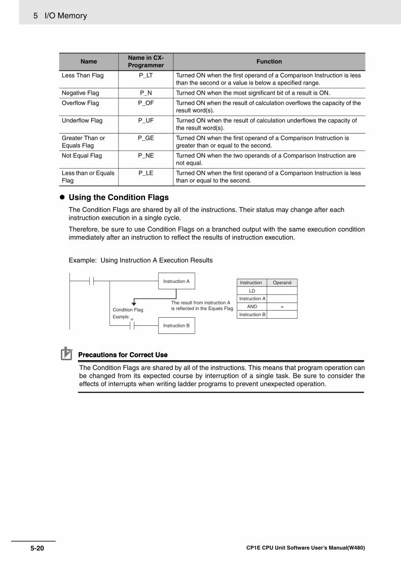
5 I/O Memory
5-20 CP1E CPU Unit Software User’s Manual(W480)
Using the Condition FlagsThe Condition Flags are shared by all of the instructions. Their status may change after each instruction execution in a single cycle.
Therefore, be sure to use Condition Flags on a branched output with the same execution conditionimmediately after an instruction to reflect the results of instruction execution.
Example: Using Instruction A Execution Results
Precautions for Correct UsePrecautions for Correct Use
The Condition Flags are shared by all of the instructions. This means that program operation canbe changed from its expected course by interruption of a single task. Be sure to consider theeffects of interrupts when writing ladder programs to prevent unexpected operation.
Less Than Flag P_LT Turned ON when the first operand of a Comparison Instruction is less than the second or a value is below a specified range.
Negative Flag P_N Turned ON when the most significant bit of a result is ON.
Overflow Flag P_OF Turned ON when the result of calculation overflows the capacity of the result word(s).
Underflow Flag P_UF Turned ON when the result of calculation underflows the capacity of the result word(s).
Greater Than or Equals Flag
P_GE Turned ON when the first operand of a Comparison Instruction is greater than or equal to the second.
Not Equal Flag P_NE Turned ON when the two operands of a Comparison Instruction are not equal.
Less than or Equals Flag
P_LE Turned ON when the first operand of a Comparison Instruction is less than or equal to the second.
NameName in CX-Programmer
Function
Instruction A
Instruction B
Condition Flag
Example: =
Operand
=
Instruction
LD
Instruction A
AND
Instruction B
The result from instruction A is reflected in the Equals Flag
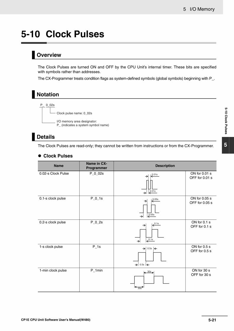
5-21
5 I/O Memory
CP1E CPU Unit Software User’s Manual(W480)
5-10 Clo
ck Pu
lses
5
5-10 Clock Pulses
The Clock Pulses are turned ON and OFF by the CPU Unit’s internal timer. These bits are specifiedwith symbols rather than addresses.
The CX-Programmer treats condition flags as system-defined symbols (global symbols) beginning with P_.
The Clock Pulses are read-only; they cannot be written from instructions or from the CX-Programmer.
Clock Pulses
Overview
Notation
Details
NameName in CX-Programmer
Description
0.02-s Clock Pulse P_0_02s ON for 0.01 s OFF for 0.01 s
0.1-s clock pulse P_0_1s ON for 0.05 s OFF for 0.05 s
0.2-s clock pulse P_0_2s ON for 0.1 sOFF for 0.1 s
1-s clock pulse P_1s ON for 0.5 sOFF for 0.5 s
1-min clock pulse P_1min ON for 30 sOFF for 30 s
P_ 0_02s
Clock pulse name: 0_02s
I/O memory area designator:P_ (indicates a system symbol name)
0.01s
0.01s
0.05s
0.05s
0.1s
0.1s
0.5s
0.5s
30s
30s

5 I/O Memory
5-22 CP1E CPU Unit Software User’s Manual(W480)
Using the Clock PulsesThe following example turns a bit ON and OFF at 0.5-s intervals.
P_1s 100.00 Instruction OperandLD P_1s
OUT 100.00 0.5s 0.5s100.00
6-1
6
CP1E CPU Unit Software User’s Manual(W480)
6
This section describes I/O allocation used to exchange data between the CP1E CPUUnit and other units. Be sure you understand the information in the section before attempting to write ladderdiagrams.
6-1 Allocation of Input Bits and Output Bits . . . . . . . . . . . . . . . . . . . . . . . . . . . 6-26-1-1 I/O Allocation . . . . . . . . . . . . . . . . . . . . . . . . . . . . . . . . . . . . . . . . . . . . . . . . . . 6-2
6-1-2 I/O Allocation Concepts . . . . . . . . . . . . . . . . . . . . . . . . . . . . . . . . . . . . . . . . . . 6-3
6-1-3 Allocations on the CPU Unit . . . . . . . . . . . . . . . . . . . . . . . . . . . . . . . . . . . . . . 6-3
6-1-4 Allocations to Expansion Units and Expansion I/O Units . . . . . . . . . . . . . . . . . 6-4
I/O Allocation
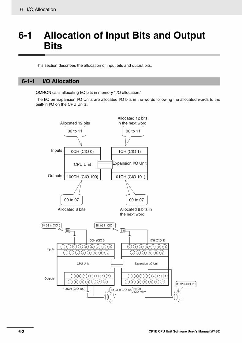
6 I/O Allocation
6-2 CP1E CPU Unit Software User’s Manual(W480)
6-1 Allocation of Input Bits and Output Bits
This section describes the allocation of input bits and output bits.
OMRON calls allocating I/O bits in memory “I/O allocation.”
The I/O on Expansion I/O Units are allocated I/O bits in the words following the allocated words to thebuilt-in I/O on the CPU Units.
6-1-1 I/O Allocation
Inputs
CPU Unit
100CH (CIO 100)Outputs
00 to 11
00 to 07
Expansion I/O Unit
101CH (CIO 101)
00 to 11
00 to 07
Allocated 12 bitsAllocated 12 bits in the next word
Allocated 8 bits Allocated 8 bits in the next word
C C C 3 c 6
0 1 2 4 5 7
C 1 3 5 7 9 11
0 2 4 6 8 10
CPU Unit
0CH (CIO 0)
Inputs
Outputs
Bit 03 in CIO 0
Bit 03 in CIO 100100CH (CIO 100)
C C C 3 c 6
0 1 2 4 5 7
C 1 3 5 7 9 11
0 2 4 6 8 10
Expansion I/O Unit
1CH (CIO 1)
Bit 05 in CIO 1
Bit 02 in CIO 101
101CH(CIO 101)
1CH (CIO 1)0CH (CIO 0)
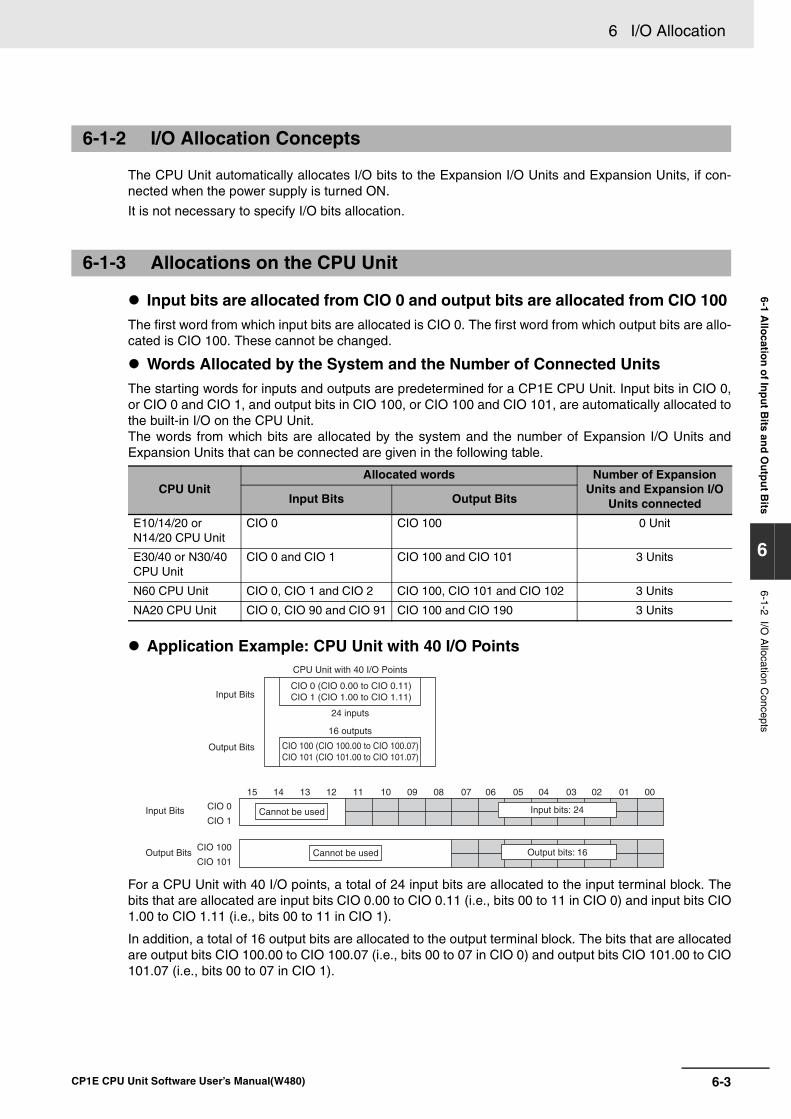
6-3
6 I/O Allocation
CP1E CPU Unit Software User’s Manual(W480)
6-1 Allo
cation
of In
pu
t Bits an
d O
utp
ut B
its
6
6-1-2 I/O A
llocation Concepts
The CPU Unit automatically allocates I/O bits to the Expansion I/O Units and Expansion Units, if con-nected when the power supply is turned ON.
It is not necessary to specify I/O bits allocation.
Input bits are allocated from CIO 0 and output bits are allocated from CIO 100 The first word from which input bits are allocated is CIO 0. The first word from which output bits are allo-cated is CIO 100. These cannot be changed.
Words Allocated by the System and the Number of Connected UnitsThe starting words for inputs and outputs are predetermined for a CP1E CPU Unit. Input bits in CIO 0,or CIO 0 and CIO 1, and output bits in CIO 100, or CIO 100 and CIO 101, are automatically allocated tothe built-in I/O on the CPU Unit. The words from which bits are allocated by the system and the number of Expansion I/O Units andExpansion Units that can be connected are given in the following table.
Application Example: CPU Unit with 40 I/O Points
For a CPU Unit with 40 I/O points, a total of 24 input bits are allocated to the input terminal block. Thebits that are allocated are input bits CIO 0.00 to CIO 0.11 (i.e., bits 00 to 11 in CIO 0) and input bits CIO1.00 to CIO 1.11 (i.e., bits 00 to 11 in CIO 1).
In addition, a total of 16 output bits are allocated to the output terminal block. The bits that are allocatedare output bits CIO 100.00 to CIO 100.07 (i.e., bits 00 to 07 in CIO 0) and output bits CIO 101.00 to CIO101.07 (i.e., bits 00 to 07 in CIO 1).
6-1-2 I/O Allocation Concepts
6-1-3 Allocations on the CPU Unit
CPU UnitAllocated words Number of Expansion
Units and Expansion I/O Units connectedInput Bits Output Bits
E10/14/20 or N14/20 CPU Unit
CIO 0 CIO 100 0 Unit
E30/40 or N30/40 CPU Unit
CIO 0 and CIO 1 CIO 100 and CIO 101 3 Units
N60 CPU Unit CIO 0, CIO 1 and CIO 2 CIO 100, CIO 101 and CIO 102 3 Units
NA20 CPU Unit CIO 0, CIO 90 and CIO 91 CIO 100 and CIO 190 3 Units
15 14 13 1112 09 08 07 06 05 04 02 01 00
Output bits: 16
0310
Cannot be used
CPU Unit with 40 I/O Points
24 inputs
Input Bits
Input Bits
Output Bits
Output Bits
CIO 0 (CIO 0.00 to CIO 0.11) CIO 1 (CIO 1.00 to CIO 1.11)
CIO 100 (CIO 100.00 to CIO 100.07) CIO 101 (CIO 101.00 to CIO 101.07)
16 outputs
CIO 0
CIO 1
CIO 100
CIO 101
Input bits: 24
Cannot be used
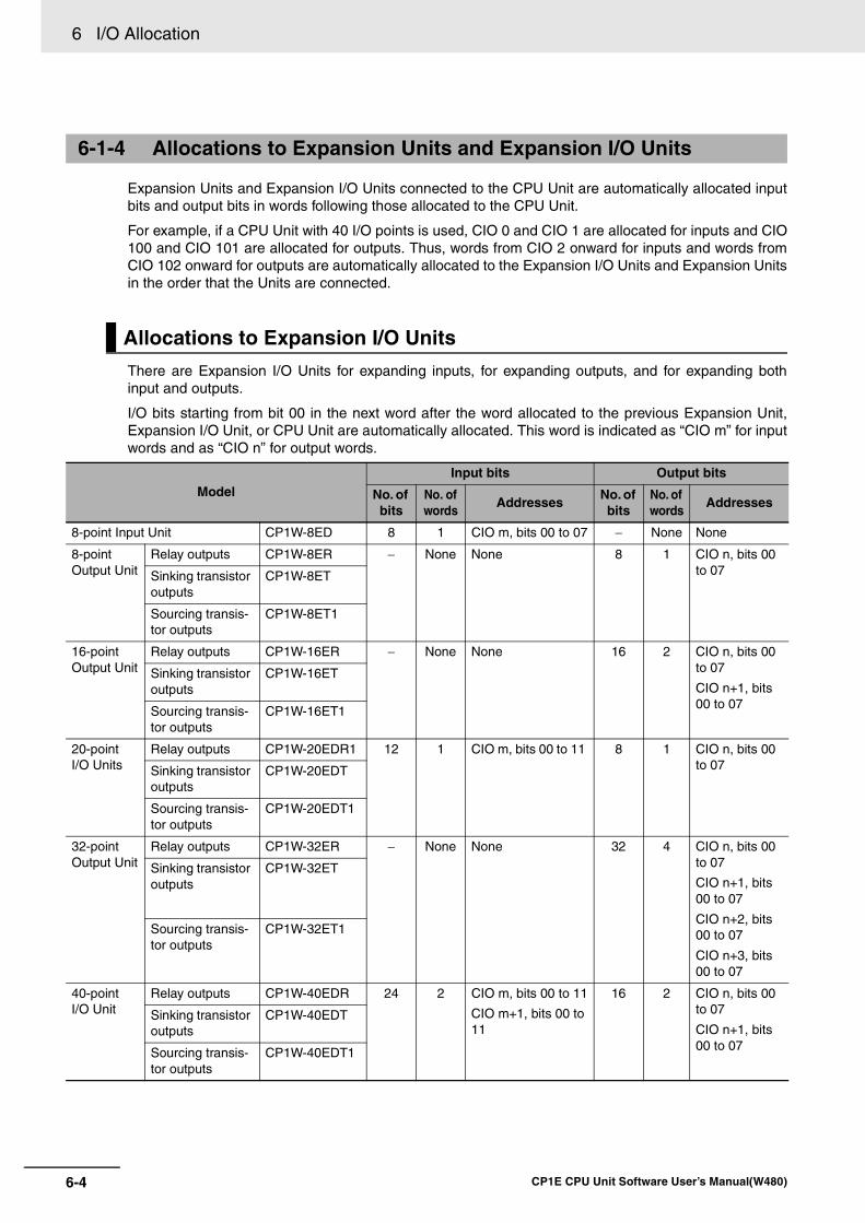
6 I/O Allocation
6-4 CP1E CPU Unit Software User’s Manual(W480)
Expansion Units and Expansion I/O Units connected to the CPU Unit are automatically allocated inputbits and output bits in words following those allocated to the CPU Unit.
For example, if a CPU Unit with 40 I/O points is used, CIO 0 and CIO 1 are allocated for inputs and CIO100 and CIO 101 are allocated for outputs. Thus, words from CIO 2 onward for inputs and words fromCIO 102 onward for outputs are automatically allocated to the Expansion I/O Units and Expansion Unitsin the order that the Units are connected.
There are Expansion I/O Units for expanding inputs, for expanding outputs, and for expanding bothinput and outputs.
I/O bits starting from bit 00 in the next word after the word allocated to the previous Expansion Unit,Expansion I/O Unit, or CPU Unit are automatically allocated. This word is indicated as “CIO m” for inputwords and as “CIO n” for output words.
6-1-4 Allocations to Expansion Units and Expansion I/O Units
Allocations to Expansion I/O Units
ModelInput bits Output bits
No. of bits
No. of words
AddressesNo. of bits
No. of words
Addresses
8-point Input Unit CP1W-8ED 8 1 CIO m, bits 00 to 07 − None None
8-point Output Unit
Relay outputs CP1W-8ER − None None 8 1 CIO n, bits 00 to 07Sinking transistor
outputsCP1W-8ET
Sourcing transis-tor outputs
CP1W-8ET1
16-point Output Unit
Relay outputs CP1W-16ER − None None 16 2 CIO n, bits 00 to 07
CIO n+1, bits 00 to 07
Sinking transistor outputs
CP1W-16ET
Sourcing transis-tor outputs
CP1W-16ET1
20-point I/O Units
Relay outputs CP1W-20EDR1 12 1 CIO m, bits 00 to 11 8 1 CIO n, bits 00 to 07Sinking transistor
outputsCP1W-20EDT
Sourcing transis-tor outputs
CP1W-20EDT1
32-point Output Unit
Relay outputs CP1W-32ER − None None 32 4 CIO n, bits 00 to 07
CIO n+1, bits 00 to 07
CIO n+2, bits 00 to 07
CIO n+3, bits 00 to 07
Sinking transistor outputs
CP1W-32ET
Sourcing transis-tor outputs
CP1W-32ET1
40-point I/O Unit
Relay outputs CP1W-40EDR 24 2 CIO m, bits 00 to 11
CIO m+1, bits 00 to 11
16 2 CIO n, bits 00 to 07
CIO n+1, bits 00 to 07
Sinking transistor outputs
CP1W-40EDT
Sourcing transis-tor outputs
CP1W-40EDT1
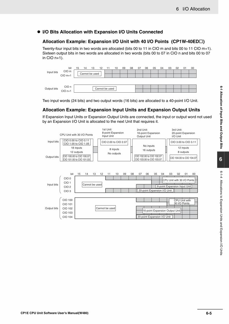
6-5
6 I/O Allocation
CP1E CPU Unit Software User’s Manual(W480)
6-1 Allo
cation
of In
pu
t Bits an
d O
utp
ut B
its
6
6-1-4 Allocations to E
xpansion Units and E
xpansion I/O U
nits
I/O Bits Allocation with Expansion I/O Units Connected
Allocation Example: Expansion I/O Unit with 40 I/O Points (CP1W-40ED )Twenty-four input bits in two words are allocated (bits 00 to 11 in CIO m and bits 00 to 11 CIO m+1).Sixteen output bits in two words are allocated in two words (bits 00 to 07 in CIO n and bits 00 to 07 in CIO n+1).
Two input words (24 bits) and two output words (16 bits) are allocated to a 40-point I/O Unit.
Allocation Example: Expansion Input Units and Expansion Output UnitsIf Expansion Input Units or Expansion Output Units are connected, the input or output word not usedby an Expansion I/O Unit is allocated to the next Unit that requires it.
15 14 13 1112 09 08 07 06 05 04 02 01 00
Cannot be used
0310
Input bits
Output bits
CIO m
CIO m+1
CIO n
CIO n+1
bit
Cannot be used
CPU Unit with 30 I/O Points
Input bits
Output bits
CIO 0.00 to CIO 0.11CIO 1.00 to CIO 1.05
18 inputs
12 outputs
CIO 100.00 to CIO 100.07CIO 101.00 to CIO 101.03
1st Unit: 8-point Expansion Input Unit
CIO 2.00 to CIO 2.07
8 inputs
No outputs
2nd Unit: 16-point Expansion Output Unit
No inputs
16 outputs
CIO 102.00 to CIO 102.07CIO 103.00 to CIO 103.07
3rd Unit: 20-point ExpansionI/O Unit
CIO 3.00 to CIO 3.11
12 inputs
8 outputs
CIO 104.00 to CIO 104.07
bit 15 14 13 1112 09 08 07 06 05 04 02 01 000310
Input bits
Output bits
CIO 0
CIO 1
CIO 2
CIO 3
CIO 100
CIO 101
CIO 102
CIO 103
CIO 104
Cannot be used
Cannot be used
CPU Unit with 30 I/O Points
CPU Unit with 30 I/O Points
8-point Expansion Input Unit
20-point Expansion I/O Unit
20-point Expansion I/O Unit
16-point Expansion Output Unit
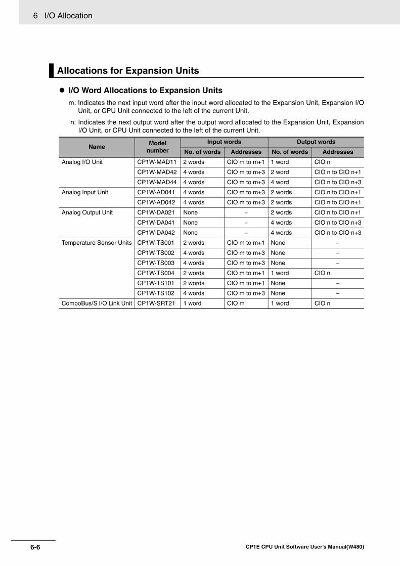
6 I/O Allocation
6-6 CP1E CPU Unit Software User’s Manual(W480)
I/O Word Allocations to Expansion Unitsm: Indicates the next input word after the input word allocated to the Expansion Unit, Expansion I/O
Unit, or CPU Unit connected to the left of the current Unit.
n: Indicates the next output word after the output word allocated to the Expansion Unit, ExpansionI/O Unit, or CPU Unit connected to the left of the current Unit.
Allocations for Expansion Units
NameModel
numberInput words Output words
No. of words Addresses No. of words Addresses
Analog I/O Unit CP1W-MAD11 2 words CIO m to m+1 1 word CIO n
CP1W-MAD42 4 words CIO m to m+3 2 word CIO n to CIO n+1
CP1W-MAD44 4 words CIO m to m+3 4 word CIO n to CIO n+3
Analog Input Unit CP1W-AD041 4 words CIO m to m+3 2 words CIO n to CIO n+1
CP1W-AD042 4 words CIO m to m+3 2 words CIO n to CIO n+1
Analog Output Unit CP1W-DA021 None − 2 words CIO n to CIO n+1
CP1W-DA041 None − 4 words CIO n to CIO n+3
CP1W-DA042 None − 4 words CIO n to CIO n+3
Temperature Sensor Units CP1W-TS001 2 words CIO m to m+1 None −
CP1W-TS002 4 words CIO m to m+3 None −
CP1W-TS003 4 words CIO m to m+3 None −
CP1W-TS004 2 words CIO m to m+1 1 word CIO n
CP1W-TS101 2 words CIO m to m+1 None −
CP1W-TS102 4 words CIO m to m+3 None −
CompoBus/S I/O Link Unit CP1W-SRT21 1 word CIO m 1 word CIO n
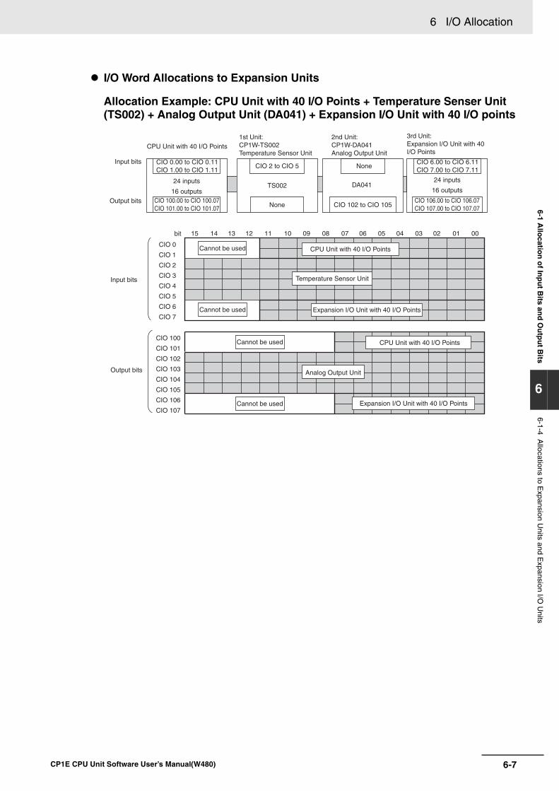
6-7
6 I/O Allocation
CP1E CPU Unit Software User’s Manual(W480)
6-1 Allo
cation
of In
pu
t Bits an
d O
utp
ut B
its
6
6-1-4 Allocations to E
xpansion Units and E
xpansion I/O U
nits
I/O Word Allocations to Expansion Units
Allocation Example: CPU Unit with 40 I/O Points + Temperature Senser Unit (TS002) + Analog Output Unit (DA041) + Expansion I/O Unit with 40 I/O points
TS002 DA041
None
None
CPU Unit with 40 I/O Points
Input bits
Output bits
CIO 0.00 to CIO 0.11CIO 1.00 to CIO 1.11
24 inputs
16 outputsCIO 100.00 to CIO 100.07CIO 101.00 to CIO 101.07
1st Unit:CP1W-TS002 Temperature Sensor Unit
CIO 2 to CIO 5
2nd Unit:CP1W-DA041 Analog Output Unit
3rd Unit: Expansion I/O Unit with 40 I/O Points
CIO 102 to CIO 105
CIO 6.00 to CIO 6.11CIO 7.00 to CIO 7.11
CIO 106.00 to CIO 106.07CIO 107.00 to CIO 107.07
24 inputs
16 outputs
bit
Input bits
Output bits
15 14 13 1112 09 08 07 06 05 04 02 01 000310
CIO 0
CIO 1
CIO 2
CIO 3
CIO 4
CIO 5
CIO 6
CIO 7
CIO 100
CIO 101
CIO 102
CIO 103
CIO 104
CIO 105
CIO 106
CIO 107
CPU Unit with 40 I/O Points
CPU Unit with 40 I/O Points
Temperature Sensor Unit
Expansion I/O Unit with 40 I/O Points
Expansion I/O Unit with 40 I/O Points
Analog Output Unit
Cannot be used
Cannot be used
Cannot be used
Cannot be used

6 I/O Allocation
6-8 CP1E CPU Unit Software User’s Manual(W480)
7-1
7
CP1E CPU Unit Software User’s Manual(W480)
7
This section describes the parameters in the PLC Setup, which are used to make basicsettings for the CP1E CPU Unit.
7-1 Overview of the PLC Setup . . . . . . . . . . . . . . . . . . . . . . . . . . . . . . . . . . . . . . 7-2
7-2 PLC Setup Settings . . . . . . . . . . . . . . . . . . . . . . . . . . . . . . . . . . . . . . . . . . . . 7-37-2-1 Startup and CPU Unit Settings . . . . . . . . . . . . . . . . . . . . . . . . . . . . . . . . . . . . 7-37-2-2 Timing and Interrupt Settings . . . . . . . . . . . . . . . . . . . . . . . . . . . . . . . . . . . . . 7-3
7-2-3 Input Constant Settings . . . . . . . . . . . . . . . . . . . . . . . . . . . . . . . . . . . . . . . . . . 7-47-2-4 Built-in RS-232C Port . . . . . . . . . . . . . . . . . . . . . . . . . . . . . . . . . . . . . . . . . . . 7-57-2-5 Serial Option Port / Built-in RS-485 Port . . . . . . . . . . . . . . . . . . . . . . . . . . . . . 7-8
7-2-6 Built-in Inputs . . . . . . . . . . . . . . . . . . . . . . . . . . . . . . . . . . . . . . . . . . . . . . . . . 7-117-2-7 Pulse Output 0 Settings . . . . . . . . . . . . . . . . . . . . . . . . . . . . . . . . . . . . . . . . . 7-137-2-8 Pulse Output 1 Settings . . . . . . . . . . . . . . . . . . . . . . . . . . . . . . . . . . . . . . . . . 7-14
7-2-9 Built-in AD/DA: Built-in Analog I/O Settings . . . . . . . . . . . . . . . . . . . . . . . . . . 7-16
PLC Setup
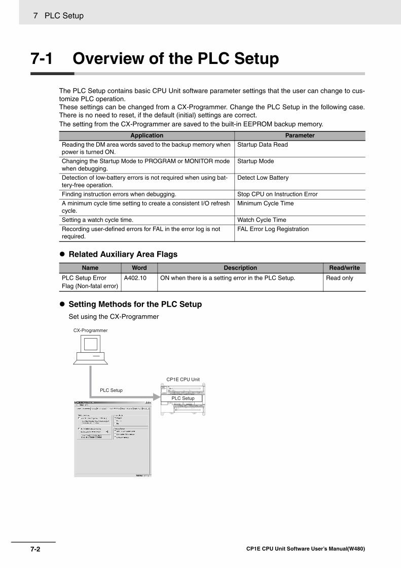
7 PLC Setup
7-2 CP1E CPU Unit Software User’s Manual(W480)
7-1 Overview of the PLC Setup
The PLC Setup contains basic CPU Unit software parameter settings that the user can change to cus-tomize PLC operation.These settings can be changed from a CX-Programmer. Change the PLC Setup in the following case.There is no need to reset, if the default (initial) settings are correct.The setting from the CX-Programmer are saved to the built-in EEPROM backup memory.
Related Auxiliary Area Flags
Setting Methods for the PLC SetupSet using the CX-Programmer
Application Parameter
Reading the DM area words saved to the backup memory when power is turned ON.
Startup Data Read
Changing the Startup Mode to PROGRAM or MONITOR mode when debugging.
Startup Mode
Detection of low-battery errors is not required when using bat-tery-free operation.
Detect Low Battery
Finding instruction errors when debugging. Stop CPU on Instruction Error
A minimum cycle time setting to create a consistent I/O refresh cycle.
Minimum Cycle Time
Setting a watch cycle time. Watch Cycle Time
Recording user-defined errors for FAL in the error log is not required.
FAL Error Log Registration
Name Word Description Read/write
PLC Setup Error Flag (Non-fatal error)
A402.10 ON when there is a setting error in the PLC Setup. Read only
CX-Programmer
PLC Setup
CP1E CPU Unit
PLC Setup
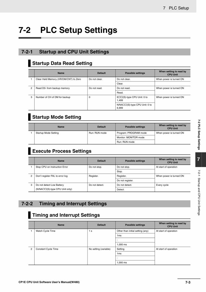
7-3
7 PLC Setup
CP1E CPU Unit Software User’s Manual(W480)
7-2 PL
C S
etup
Settin
gs
7
7-2-1 Startup and C
PU
Unit S
ettings
7-2 PLC Setup Settings
7-2-1 Startup and CPU Unit Settings
Startup Data Read Setting
Name Default Possible settingsWhen setting is read by
CPU Unit
1 Clear Held Memory (HR/DM/CNT) to Zero Do not clear. Do not clear. When power is turned ON
Clear.
2 Read D0- from backup memory Do not read. Do not read. When power is turned ON
Read.
3 Number of CH of DM for backup 0 E (S)-type CPU Unit: 0 to 1,499
When power is turned ON
N/NA (S)-type CPU Unit: 0 to 6,999
Startup Mode Setting
Name Default Possible settingsWhen setting is read by
CPU Unit
1 Startup Mode Setting Run: RUN mode Program: PROGRAM mode When power is turned ON
Monitor: MONITOR mode
Run: RUN mode
Execute Process Settings
Name Default Possible settingsWhen setting is read by
CPU Unit
1 Stop CPU on Instruction Error Do not stop. Do not stop. At start of operation
Stop.
2 Don’t register FAL to error log Register. Register. When power is turned ON
Do not register.
3 Do not detect Low Battery
(N/NA (S)-type CPU Unit only)
Do not detect. Do not detect. Every cycle
Detect.
7-2-2 Timing and Interrupt Settings
Timing and Interrupt Settings
Name Default Possible settingsWhen setting is read by
CPU Unit
1 Watch Cycle Time 1 s Other than initial setting (any) At start of operation
1ms
:
1,000 ms
2 Constant Cycle Time No setting (variable) Setting At start of operation
1ms
:
1,000 ms
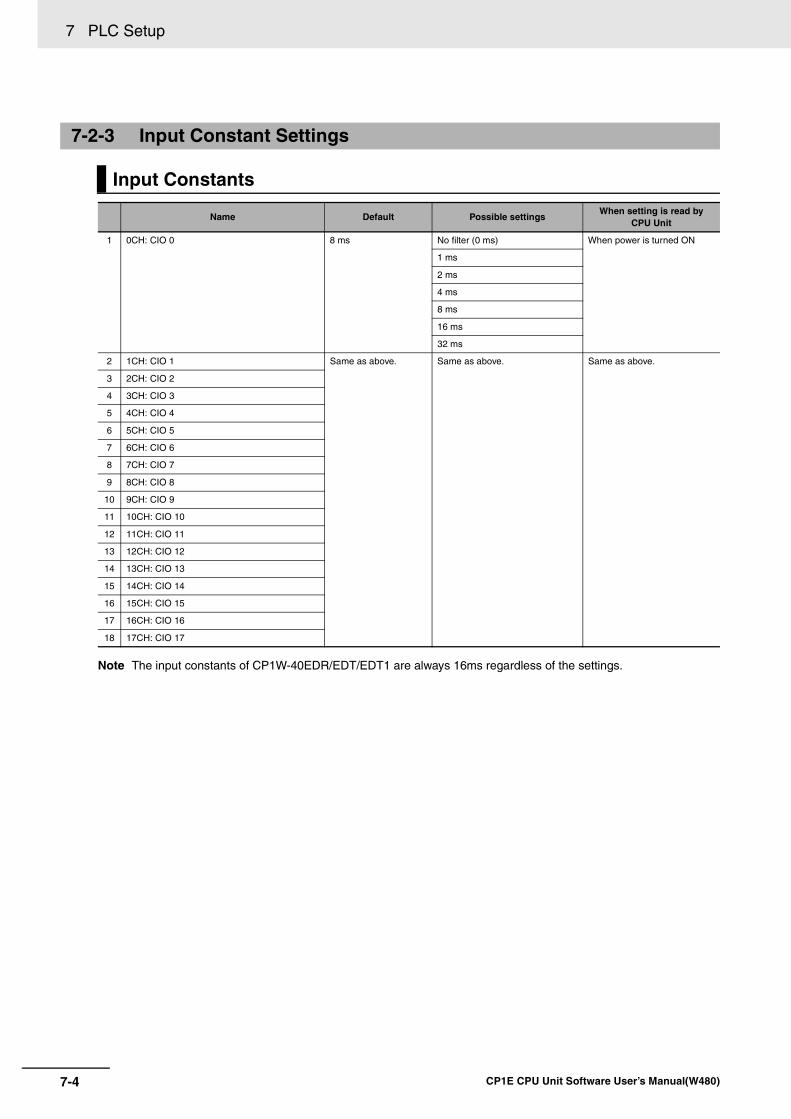
7 PLC Setup
7-4 CP1E CPU Unit Software User’s Manual(W480)
Note The input constants of CP1W-40EDR/EDT/EDT1 are always 16ms regardless of the settings.
7-2-3 Input Constant Settings
Input Constants
Name Default Possible settingsWhen setting is read by
CPU Unit
1 0CH: CIO 0 8 ms No filter (0 ms) When power is turned ON
1 ms
2 ms
4 ms
8 ms
16 ms
32 ms
2 1CH: CIO 1 Same as above. Same as above. Same as above.
3 2CH: CIO 2
4 3CH: CIO 3
5 4CH: CIO 4
6 5CH: CIO 5
7 6CH: CIO 6
8 7CH: CIO 7
9 8CH: CIO 8
10 9CH: CIO 9
11 10CH: CIO 10
12 11CH: CIO 11
13 12CH: CIO 12
14 13CH: CIO 13
15 14CH: CIO 14
16 15CH: CIO 15
17 16CH: CIO 16
18 17CH: CIO 17
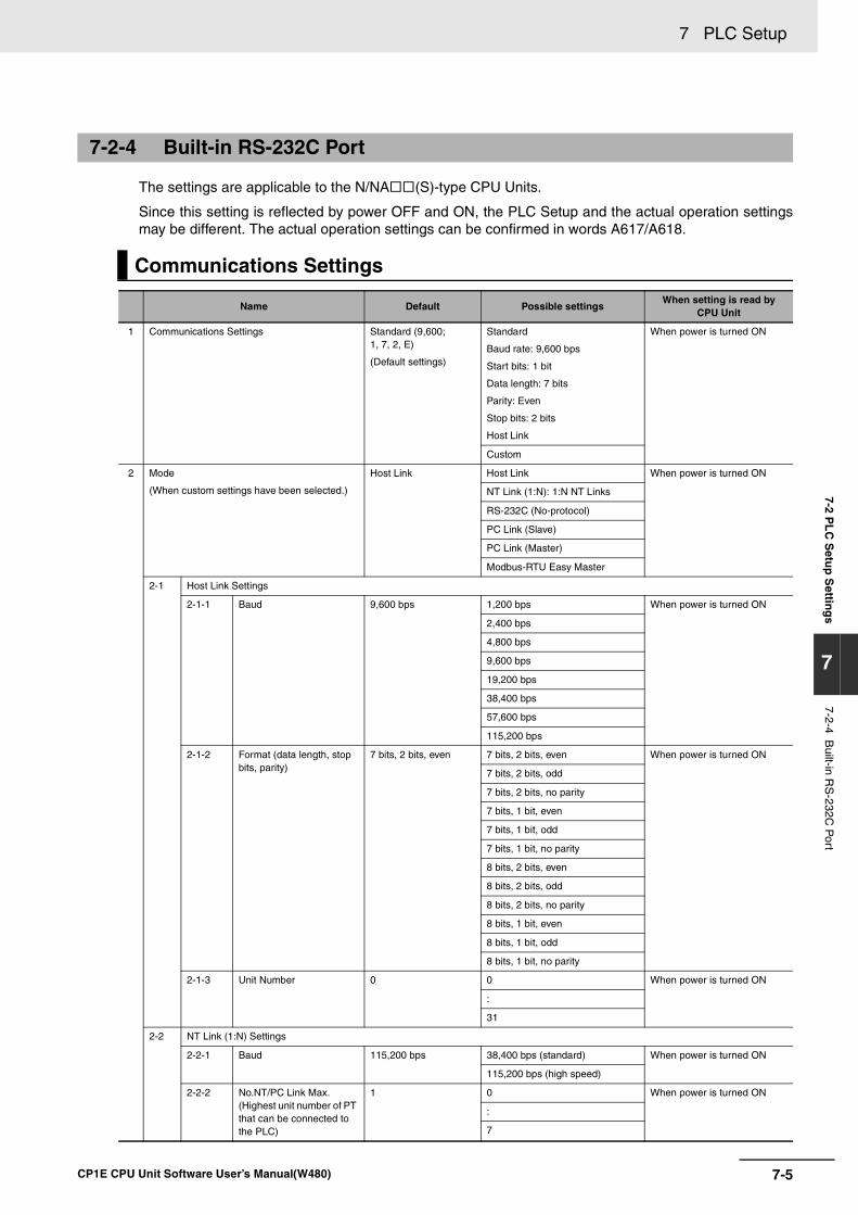
7-5
7 PLC Setup
CP1E CPU Unit Software User’s Manual(W480)
7-2 PL
C S
etup
Settin
gs
7
7-2-4 Built-in R
S-232C
Port
The settings are applicable to the N/NA (S)-type CPU Units.
Since this setting is reflected by power OFF and ON, the PLC Setup and the actual operation settingsmay be different. The actual operation settings can be confirmed in words A617/A618.
7-2-4 Built-in RS-232C Port
Communications Settings
Name Default Possible settingsWhen setting is read by
CPU Unit
1 Communications Settings Standard (9,600; 1, 7, 2, E)
(Default settings)
Standard
Baud rate: 9,600 bps
Start bits: 1 bit
Data length: 7 bits
Parity: Even
Stop bits: 2 bits
Host Link
When power is turned ON
Custom
2 Mode
(When custom settings have been selected.)
Host Link Host Link When power is turned ON
NT Link (1:N): 1:N NT Links
RS-232C (No-protocol)
PC Link (Slave)
PC Link (Master)
Modbus-RTU Easy Master
2-1 Host Link Settings
2-1-1 Baud 9,600 bps 1,200 bps When power is turned ON
2,400 bps
4,800 bps
9,600 bps
19,200 bps
38,400 bps
57,600 bps
115,200 bps
2-1-2 Format (data length, stop bits, parity)
7 bits, 2 bits, even 7 bits, 2 bits, even When power is turned ON
7 bits, 2 bits, odd
7 bits, 2 bits, no parity
7 bits, 1 bit, even
7 bits, 1 bit, odd
7 bits, 1 bit, no parity
8 bits, 2 bits, even
8 bits, 2 bits, odd
8 bits, 2 bits, no parity
8 bits, 1 bit, even
8 bits, 1 bit, odd
8 bits, 1 bit, no parity
2-1-3 Unit Number 0 0 When power is turned ON
:
31
2-2 NT Link (1:N) Settings
2-2-1 Baud 115,200 bps 38,400 bps (standard) When power is turned ON
115,200 bps (high speed)
2-2-2 No.NT/PC Link Max. (Highest unit number of PT that can be connected to the PLC)
1 0 When power is turned ON
:
7
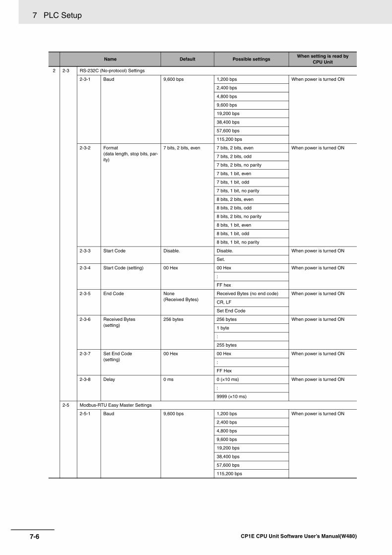
7 PLC Setup
7-6 CP1E CPU Unit Software User’s Manual(W480)
2 2-3 RS-232C (No-protocol) Settings
2-3-1 Baud 9,600 bps 1,200 bps When power is turned ON
2,400 bps
4,800 bps
9,600 bps
19,200 bps
38,400 bps
57,600 bps
115,200 bps
2-3-2 Format (data length, stop bits, par-ity)
7 bits, 2 bits, even 7 bits, 2 bits, even When power is turned ON
7 bits, 2 bits, odd
7 bits, 2 bits, no parity
7 bits, 1 bit, even
7 bits, 1 bit, odd
7 bits, 1 bit, no parity
8 bits, 2 bits, even
8 bits, 2 bits, odd
8 bits, 2 bits, no parity
8 bits, 1 bit, even
8 bits, 1 bit, odd
8 bits, 1 bit, no parity
2-3-3 Start Code Disable. Disable. When power is turned ON
Set.
2-3-4 Start Code (setting) 00 Hex 00 Hex When power is turned ON
:
FF hex
2-3-5 End Code None (Received Bytes)
Received Bytes (no end code) When power is turned ON
CR, LF
Set End Code
2-3-6 Received Bytes (setting)
256 bytes 256 bytes When power is turned ON
1 byte
:
255 bytes
2-3-7 Set End Code (setting)
00 Hex 00 Hex When power is turned ON
:
FF Hex
2-3-8 Delay 0 ms 0 (×10 ms) When power is turned ON
:
9999 (×10 ms)
2-5 Modbus-RTU Easy Master Settings
2-5-1 Baud 9,600 bps 1,200 bps When power is turned ON
2,400 bps
4,800 bps
9,600 bps
19,200 bps
38,400 bps
57,600 bps
115,200 bps
Name Default Possible settingsWhen setting is read by
CPU Unit
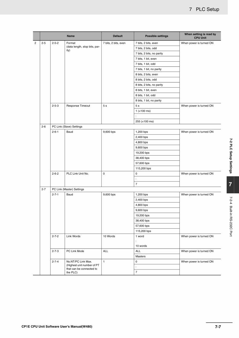
7-7
7 PLC Setup
CP1E CPU Unit Software User’s Manual(W480)
7-2 PL
C S
etup
Settin
gs
7
7-2-4 Built-in R
S-232C
Port
2 2-5 2-5-2 Format (data length, stop bits, par-ity)
7 bits, 2 bits, even 7 bits, 2 bits, even When power is turned ON
7 bits, 2 bits, odd
7 bits, 2 bits, no parity
7 bits, 1 bit, even
7 bits, 1 bit, odd
7 bits, 1 bit, no parity
8 bits, 2 bits, even
8 bits, 2 bits, odd
8 bits, 2 bits, no parity
8 bits, 1 bit, even
8 bits, 1 bit, odd
8 bits, 1 bit, no parity
2-5-3 Response Timeout 5 s 5 s When power is turned ON
1 (×100 ms)
:
255 (×100 ms)
2-6 PC Link (Slave) Settings
2-6-1 Baud 9,600 bps 1,200 bps When power is turned ON
2,400 bps
4,800 bps
9,600 bps
19,200 bps
38,400 bps
57,600 bps
115,200 bps
2-6-2 PLC Link Unit No. 0 0 When power is turned ON
:
7
2-7 PC Link (Master) Settings
2-7-1 Baud 9,600 bps 1,200 bps When power is turned ON
2,400 bps
4,800 bps
9,600 bps
19,200 bps
38,400 bps
57,600 bps
115,200 bps
2-7-2 Link Words 10 Words 1 word
:
10 words
When power is turned ON
2-7-3 PC Link Mode ALL ALL When power is turned ON
Masters
2-7-4 No.NT/PC Link Max. (Highest unit number of PT that can be connected to the PLC)
1 0 When power is turned ON
:
7
Name Default Possible settingsWhen setting is read by
CPU Unit
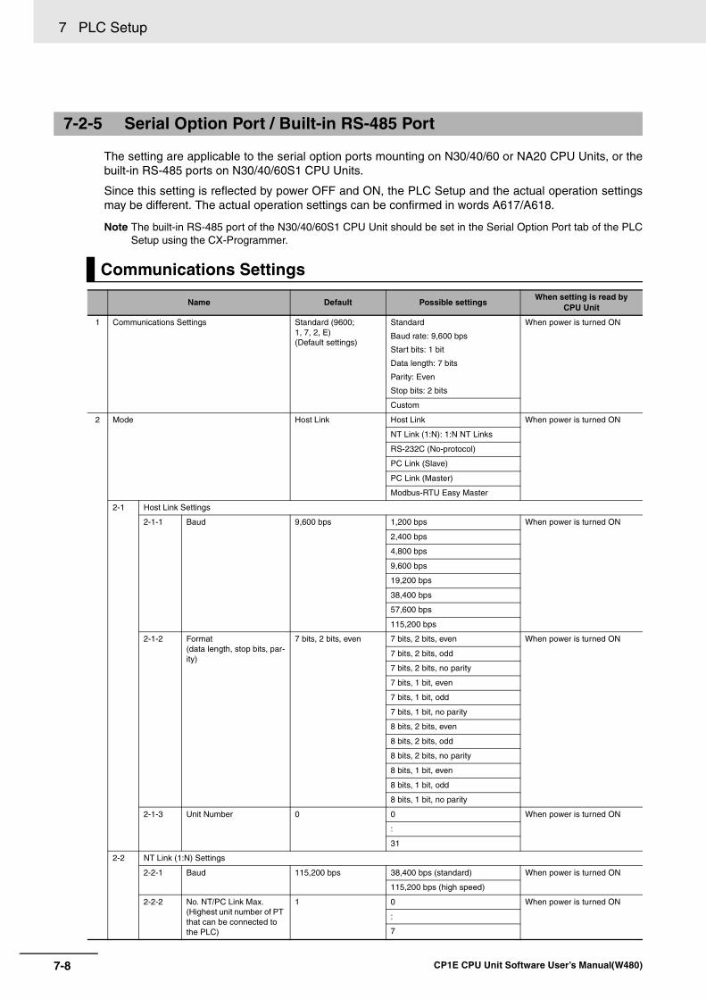
7 PLC Setup
7-8 CP1E CPU Unit Software User’s Manual(W480)
The setting are applicable to the serial option ports mounting on N30/40/60 or NA20 CPU Units, or thebuilt-in RS-485 ports on N30/40/60S1 CPU Units.
Since this setting is reflected by power OFF and ON, the PLC Setup and the actual operation settingsmay be different. The actual operation settings can be confirmed in words A617/A618.
Note The built-in RS-485 port of the N30/40/60S1 CPU Unit should be set in the Serial Option Port tab of the PLCSetup using the CX-Programmer.
7-2-5 Serial Option Port / Built-in RS-485 Port
Communications Settings
Name Default Possible settingsWhen setting is read by
CPU Unit
1 Communications Settings Standard (9600; 1, 7, 2, E) (Default settings)
Standard
Baud rate: 9,600 bps
Start bits: 1 bit
Data length: 7 bits
Parity: Even
Stop bits: 2 bits
When power is turned ON
Custom
2 Mode Host Link Host Link When power is turned ON
NT Link (1:N): 1:N NT Links
RS-232C (No-protocol)
PC Link (Slave)
PC Link (Master)
Modbus-RTU Easy Master
2-1 Host Link Settings
2-1-1 Baud 9,600 bps 1,200 bps When power is turned ON
2,400 bps
4,800 bps
9,600 bps
19,200 bps
38,400 bps
57,600 bps
115,200 bps
2-1-2 Format (data length, stop bits, par-ity)
7 bits, 2 bits, even 7 bits, 2 bits, even When power is turned ON
7 bits, 2 bits, odd
7 bits, 2 bits, no parity
7 bits, 1 bit, even
7 bits, 1 bit, odd
7 bits, 1 bit, no parity
8 bits, 2 bits, even
8 bits, 2 bits, odd
8 bits, 2 bits, no parity
8 bits, 1 bit, even
8 bits, 1 bit, odd
8 bits, 1 bit, no parity
2-1-3 Unit Number 0 0 When power is turned ON
:
31
2-2 NT Link (1:N) Settings
2-2-1 Baud 115,200 bps 38,400 bps (standard) When power is turned ON
115,200 bps (high speed)
2-2-2 No. NT/PC Link Max. (Highest unit number of PT that can be connected to the PLC)
1 0 When power is turned ON
:
7
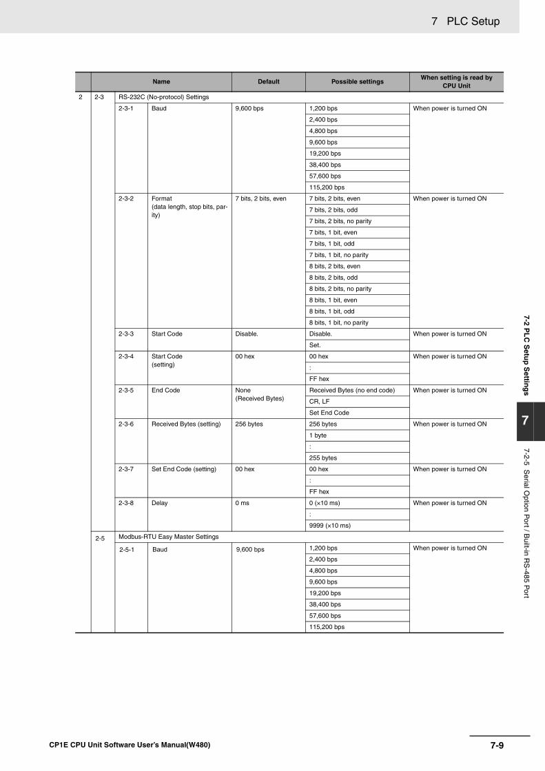
7-9
7 PLC Setup
CP1E CPU Unit Software User’s Manual(W480)
7-2 PL
C S
etup
Settin
gs
7
7-2-5 Serial O
ption Port / B
uilt-in RS
-485 Port
2 2-3 RS-232C (No-protocol) Settings
2-3-1 Baud 9,600 bps 1,200 bps When power is turned ON
2,400 bps
4,800 bps
9,600 bps
19,200 bps
38,400 bps
57,600 bps
115,200 bps
2-3-2 Format (data length, stop bits, par-ity)
7 bits, 2 bits, even 7 bits, 2 bits, even When power is turned ON
7 bits, 2 bits, odd
7 bits, 2 bits, no parity
7 bits, 1 bit, even
7 bits, 1 bit, odd
7 bits, 1 bit, no parity
8 bits, 2 bits, even
8 bits, 2 bits, odd
8 bits, 2 bits, no parity
8 bits, 1 bit, even
8 bits, 1 bit, odd
8 bits, 1 bit, no parity
2-3-3 Start Code Disable. Disable. When power is turned ON
Set.
2-3-4 Start Code (setting)
00 hex 00 hex When power is turned ON
:
FF hex
2-3-5 End Code None(Received Bytes)
Received Bytes (no end code) When power is turned ON
CR, LF
Set End Code
2-3-6 Received Bytes (setting) 256 bytes 256 bytes When power is turned ON
1 byte
:
255 bytes
2-3-7 Set End Code (setting) 00 hex 00 hex When power is turned ON
:
FF hex
2-3-8 Delay 0 ms 0 (×10 ms) When power is turned ON
:
9999 (×10 ms)
2-5 Modbus-RTU Easy Master Settings
2-5-1 Baud 9,600 bps 1,200 bps When power is turned ON
2,400 bps
4,800 bps
9,600 bps
19,200 bps
38,400 bps
57,600 bps
115,200 bps
Name Default Possible settingsWhen setting is read by
CPU Unit
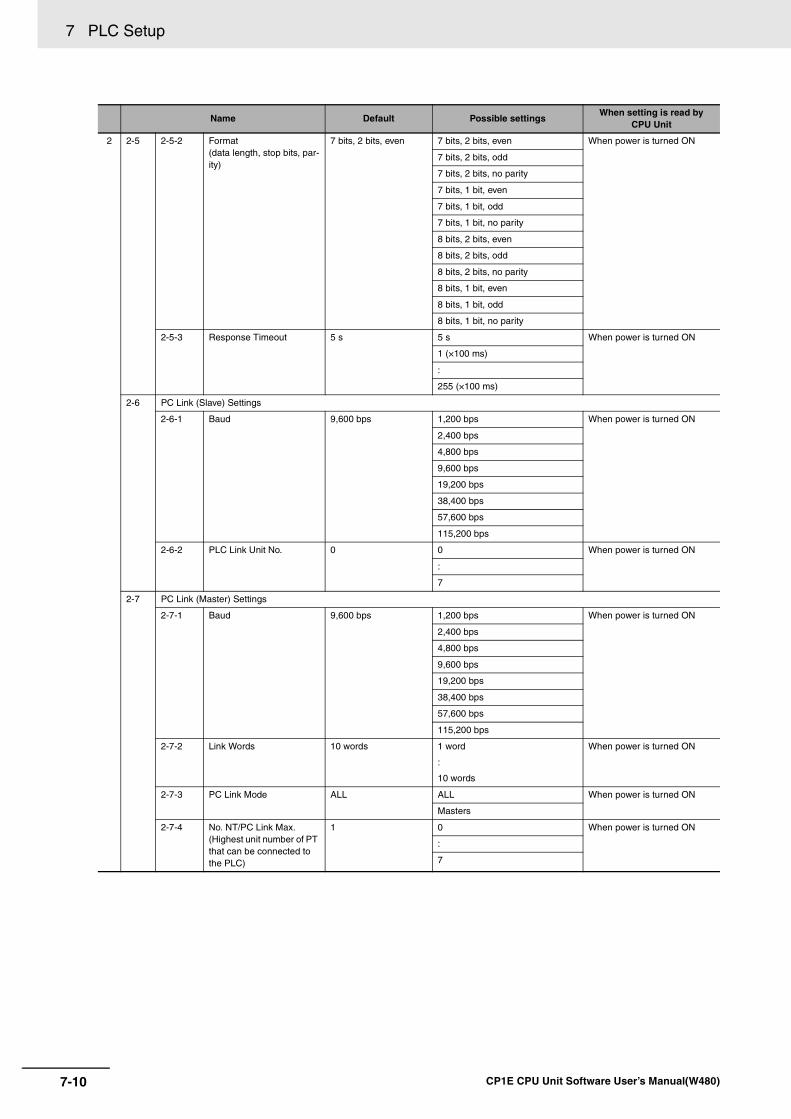
7 PLC Setup
7-10 CP1E CPU Unit Software User’s Manual(W480)
2 2-5 2-5-2 Format(data length, stop bits, par-ity)
7 bits, 2 bits, even 7 bits, 2 bits, even When power is turned ON
7 bits, 2 bits, odd
7 bits, 2 bits, no parity
7 bits, 1 bit, even
7 bits, 1 bit, odd
7 bits, 1 bit, no parity
8 bits, 2 bits, even
8 bits, 2 bits, odd
8 bits, 2 bits, no parity
8 bits, 1 bit, even
8 bits, 1 bit, odd
8 bits, 1 bit, no parity
2-5-3 Response Timeout 5 s 5 s When power is turned ON
1 (×100 ms)
:
255 (×100 ms)
2-6 PC Link (Slave) Settings
2-6-1 Baud 9,600 bps 1,200 bps When power is turned ON
2,400 bps
4,800 bps
9,600 bps
19,200 bps
38,400 bps
57,600 bps
115,200 bps
2-6-2 PLC Link Unit No. 0 0 When power is turned ON
:
7
2-7 PC Link (Master) Settings
2-7-1 Baud 9,600 bps 1,200 bps When power is turned ON
2,400 bps
4,800 bps
9,600 bps
19,200 bps
38,400 bps
57,600 bps
115,200 bps
2-7-2 Link Words 10 words 1 word
:
10 words
When power is turned ON
2-7-3 PC Link Mode ALL ALL When power is turned ON
Masters
2-7-4 No. NT/PC Link Max. (Highest unit number of PT that can be connected to the PLC)
1 0 When power is turned ON
:
7
Name Default Possible settingsWhen setting is read by
CPU Unit
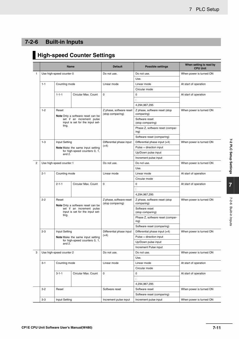
7-11
7 PLC Setup
CP1E CPU Unit Software User’s Manual(W480)
7-2 PL
C S
etup
Settin
gs
7
7-2-6 Built-in Inputs
7-2-6 Built-in Inputs
High-speed Counter Settings
Name Default Possible settingsWhen setting is read by
CPU Unit
1 Use high-speed counter 0 Do not use. Do not use. When power is turned ON
Use.
1-1 Counting mode Linear mode Linear mode At start of operation
Circular mode
1-1-1 Circular Max. Count 0 0 At start of operation
:
4,294,967,295
1-2 Reset
Note Only a software reset can beset if an increment pulseinput is set for the input set-ting.
Z phase, software reset(stop comparing)
Z phase, software reset (stop comparing)
When power is turned ON
Software reset(stop comparing)
Phase Z, software reset (compar-ing)
Software reset (comparing)
1-3 Input Setting
Note Make the same input settingfor high-speed counters 0, 1,and 2.
Differential phase input (×4)
Differential phase input (×4) When power is turned ON
Pulse + direction input
Up/Down pulse input
Increment pulse input
2 Use high-speed counter 1 Do not use. Do not use. When power is turned ON
Use.
2-1 Counting mode Linear mode Linear mode At start of operation
Circular mode
2-1-1 Circular Max. Count 0 0 At start of operation
:
4,294,967,295
2-2 Reset
Note Only a software reset can beset if an increment pulseinput is set for the input set-ting.
Z phase, software reset (stop comparing)
Z phase, software reset (stop comparing)
When power is turned ON
Software reset(stop comparing)
Phase Z, software reset (compar-ing)
Software reset (comparing)
2-3 Input Setting
Note Make the same input settingfor high-speed counters 0, 1,and 2.
Differential phase input (×4)
Differential phase input (×4) When power is turned ON
Pulse + direction input
Up/Down pulse input
Increment Pulse input
3 Use high-speed counter 2 Do not use. Do not use. When power is turned ON
Use.
3-1 Counting mode Linear mode Linear mode At start of operation
Circular mode
3-1-1 Circular Max. Count 0 0 At start of operation
:
4,294,967,295
3-2 Reset Software reset Software reset When power is turned ON
Software reset (comparing)
3-3 Input Setting Increment pulse input Increment pulse input When power is turned ON
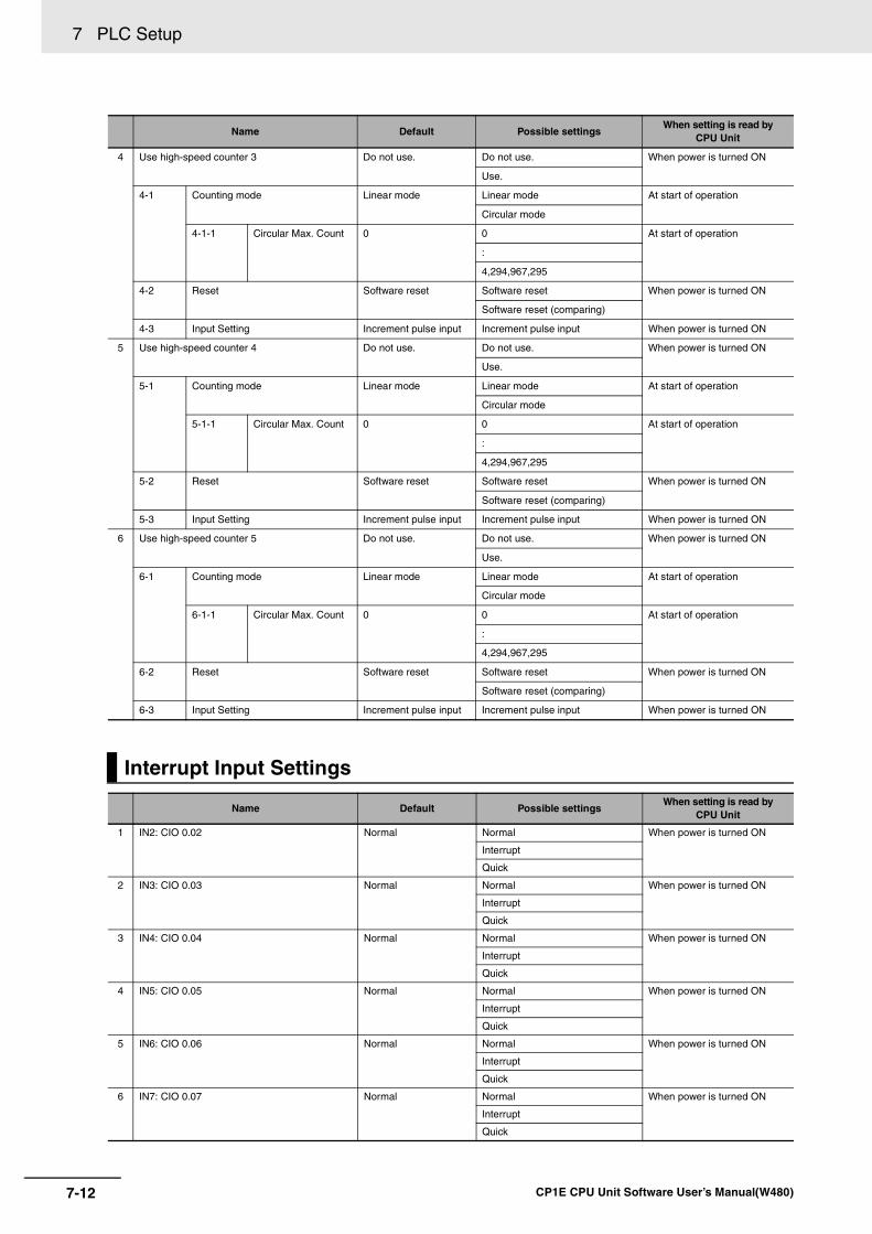
7 PLC Setup
7-12 CP1E CPU Unit Software User’s Manual(W480)
4 Use high-speed counter 3 Do not use. Do not use. When power is turned ON
Use.
4-1 Counting mode Linear mode Linear mode At start of operation
Circular mode
4-1-1 Circular Max. Count 0 0 At start of operation
:
4,294,967,295
4-2 Reset Software reset Software reset When power is turned ON
Software reset (comparing)
4-3 Input Setting Increment pulse input Increment pulse input When power is turned ON
5 Use high-speed counter 4 Do not use. Do not use. When power is turned ON
Use.
5-1 Counting mode Linear mode Linear mode At start of operation
Circular mode
5-1-1 Circular Max. Count 0 0 At start of operation
:
4,294,967,295
5-2 Reset Software reset Software reset When power is turned ON
Software reset (comparing)
5-3 Input Setting Increment pulse input Increment pulse input When power is turned ON
6 Use high-speed counter 5 Do not use. Do not use. When power is turned ON
Use.
6-1 Counting mode Linear mode Linear mode At start of operation
Circular mode
6-1-1 Circular Max. Count 0 0 At start of operation
:
4,294,967,295
6-2 Reset Software reset Software reset When power is turned ON
Software reset (comparing)
6-3 Input Setting Increment pulse input Increment pulse input When power is turned ON
Interrupt Input Settings
Name Default Possible settingsWhen setting is read by
CPU Unit
1 IN2: CIO 0.02 Normal Normal When power is turned ON
Interrupt
Quick
2 IN3: CIO 0.03 Normal Normal When power is turned ON
Interrupt
Quick
3 IN4: CIO 0.04 Normal Normal When power is turned ON
Interrupt
Quick
4 IN5: CIO 0.05 Normal Normal When power is turned ON
Interrupt
Quick
5 IN6: CIO 0.06 Normal Normal When power is turned ON
Interrupt
Quick
6 IN7: CIO 0.07 Normal Normal When power is turned ON
Interrupt
Quick
Name Default Possible settingsWhen setting is read by
CPU Unit
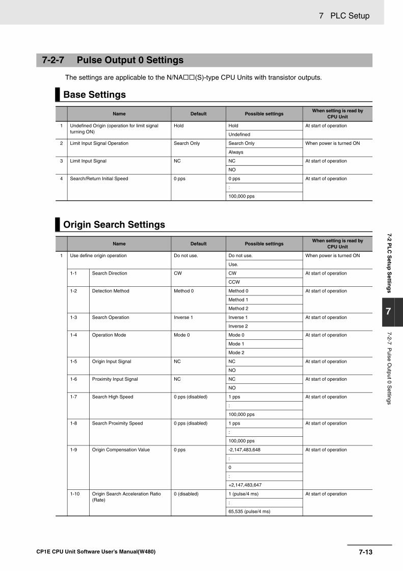
7-13
7 PLC Setup
CP1E CPU Unit Software User’s Manual(W480)
7-2 PL
C S
etup
Settin
gs
7
7-2-7 Pulse O
utput 0 Settings
The settings are applicable to the N/NA (S)-type CPU Units with transistor outputs.
7-2-7 Pulse Output 0 Settings
Base Settings
Name Default Possible settingsWhen setting is read by
CPU Unit
1 Undefined Origin (operation for limit signal turning ON)
Hold Hold At start of operation
Undefined
2 Limit Input Signal Operation Search Only Search Only When power is turned ON
Always
3 Limit Input Signal NC NC At start of operation
NO
4 Search/Return Initial Speed 0 pps 0 pps At start of operation
:
100,000 pps
Origin Search Settings
Name Default Possible settingsWhen setting is read by
CPU Unit
1 Use define origin operation Do not use. Do not use. When power is turned ON
Use.
1-1 Search Direction CW CW At start of operation
CCW
1-2 Detection Method Method 0 Method 0 At start of operation
Method 1
Method 2
1-3 Search Operation Inverse 1 Inverse 1 At start of operation
Inverse 2
1-4 Operation Mode Mode 0 Mode 0 At start of operation
Mode 1
Mode 2
1-5 Origin Input Signal NC NC At start of operation
NO
1-6 Proximity Input Signal NC NC At start of operation
NO
1-7 Search High Speed 0 pps (disabled) 1 pps At start of operation
:
100,000 pps
1-8 Search Proximity Speed 0 pps (disabled) 1 pps At start of operation
:
100,000 pps
1-9 Origin Compensation Value 0 pps -2,147,483,648 At start of operation
:
0
:
+2,147,483,647
1-10 Origin Search Acceleration Ratio (Rate)
0 (disabled) 1 (pulse/4 ms) At start of operation
:
65,535 (pulse/4 ms)
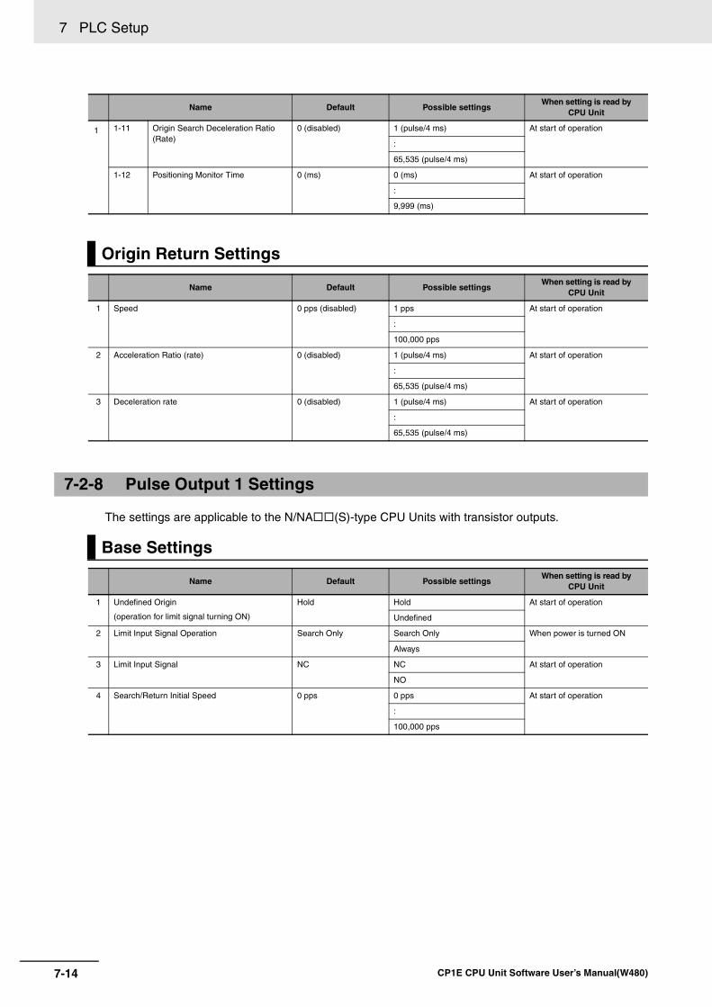
7 PLC Setup
7-14 CP1E CPU Unit Software User’s Manual(W480)
The settings are applicable to the N/NA (S)-type CPU Units with transistor outputs.
1 1-11 Origin Search Deceleration Ratio (Rate)
0 (disabled) 1 (pulse/4 ms) At start of operation
:
65,535 (pulse/4 ms)
1-12 Positioning Monitor Time 0 (ms) 0 (ms) At start of operation
:
9,999 (ms)
Origin Return Settings
Name Default Possible settingsWhen setting is read by
CPU Unit
1 Speed 0 pps (disabled) 1 pps At start of operation
:
100,000 pps
2 Acceleration Ratio (rate) 0 (disabled) 1 (pulse/4 ms) At start of operation
:
65,535 (pulse/4 ms)
3 Deceleration rate 0 (disabled) 1 (pulse/4 ms) At start of operation
:
65,535 (pulse/4 ms)
7-2-8 Pulse Output 1 Settings
Base Settings
Name Default Possible settingsWhen setting is read by
CPU Unit
1 Undefined Origin
(operation for limit signal turning ON)
Hold Hold At start of operation
Undefined
2 Limit Input Signal Operation Search Only Search Only When power is turned ON
Always
3 Limit Input Signal NC NC At start of operation
NO
4 Search/Return Initial Speed 0 pps 0 pps At start of operation
:
100,000 pps
Name Default Possible settingsWhen setting is read by
CPU Unit
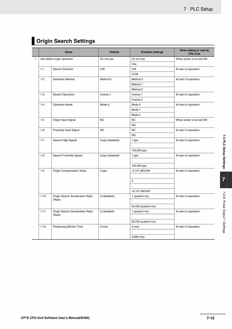
7-15
7 PLC Setup
CP1E CPU Unit Software User’s Manual(W480)
7-2 PL
C S
etup
Settin
gs
7
7-2-8 Pulse O
utput 1 Settings
Origin Search Settings
Name Default Possible settingsWhen setting is read by
CPU Unit
1 Use define origin operation Do not use. Do not use. When power is turned ON
Use.
1-1 Search Direction CW CW At start of operation
CCW
1-2 Detection Method Method 0 Method 0 At start of operation
Method 1
Method 2
1-3 Search Operation Inverse 1 Inverse 1 At start of operation
Inverse 2
1-4 Operation Mode Mode 0 Mode 0 At start of operation
Mode 1
Mode 2
1-5 Origin Input Signal NC NC When power is turned ON
NO
1-6 Proximity Input Signal NC NC At start of operation
NO
1-7 Search High Speed 0 pps (disabled) 1 pps At start of operation
:
100,000 pps
1-8 Search Proximity Speed 0 pps (disabled) 1 pps At start of operation
:
100,000 pps
1-9 Origin Compensation Value 0 pps -2,147,483,648 At start of operation
:
0
:
+2,147,483,647
1-10 Origin Search Acceleration Ratio (Rate)
0 (disabled) 1 (pulse/4 ms) At start of operation
:
65,535 (pulse/4 ms)
1-11 Origin Search Deceleration Ratio (Rate)
0 (disabled) 1 (pulse/4 ms) At start of operation
:
65,535 (pulse/4 ms)
1-12 Positioning Monitor Time 0 (ms) 0 (ms) At start of operation
:
9,999 (ms)
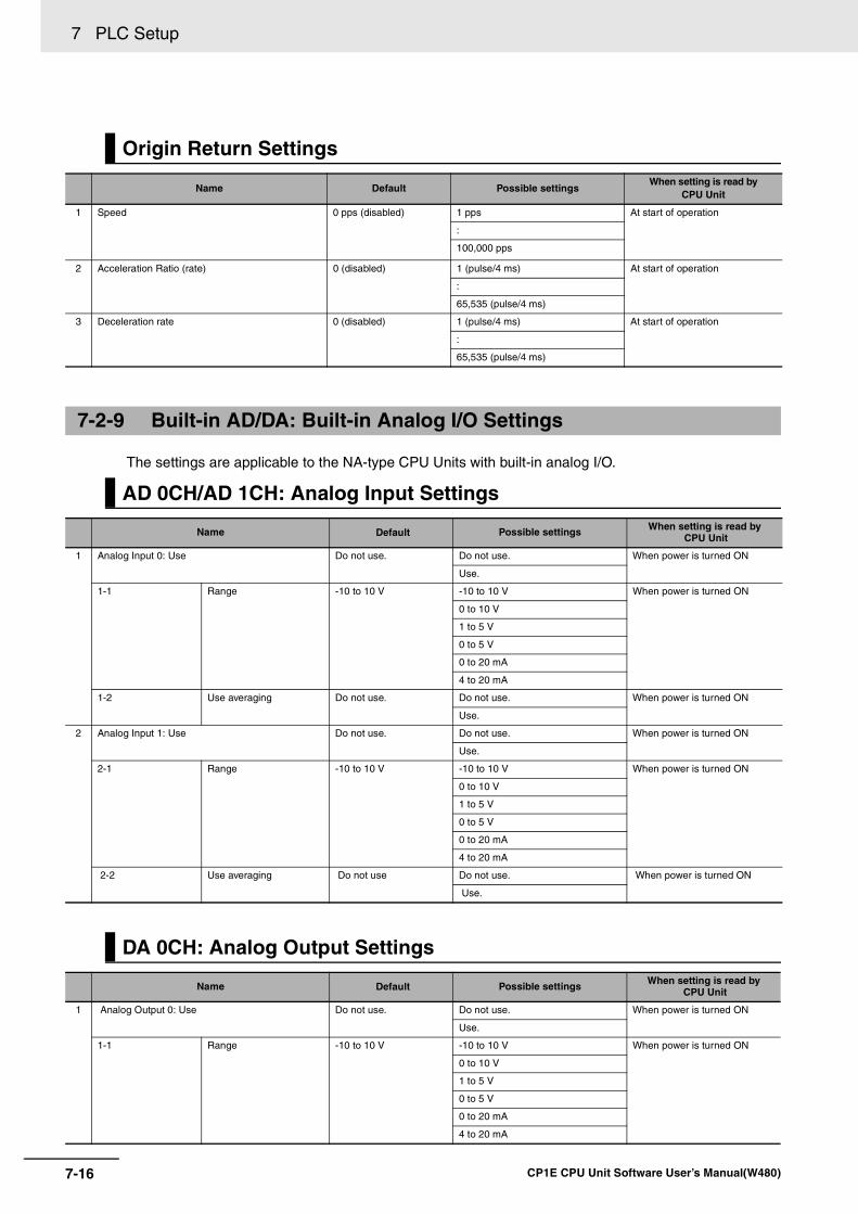
7 PLC Setup
7-16 CP1E CPU Unit Software User’s Manual(W480)
The settings are applicable to the NA-type CPU Units with built-in analog I/O.
Origin Return Settings
Name Default Possible settingsWhen setting is read by
CPU Unit
1 Speed 0 pps (disabled) 1 pps At start of operation
:
100,000 pps
2 Acceleration Ratio (rate) 0 (disabled) 1 (pulse/4 ms) At start of operation
:
65,535 (pulse/4 ms)
3 Deceleration rate 0 (disabled) 1 (pulse/4 ms) At start of operation
:
65,535 (pulse/4 ms)
7-2-9 Built-in AD/DA: Built-in Analog I/O Settings
AD 0CH/AD 1CH: Analog Input Settings
Name Default Possible settings When setting is read by CPU Unit
1 Analog Input 0: Use Do not use. Do not use. When power is turned ON
Use.
1-1 Range -10 to 10 V -10 to 10 V When power is turned ON
0 to 10 V
1 to 5 V
0 to 5 V
0 to 20 mA
4 to 20 mA
1-2 Use averaging Do not use. Do not use. When power is turned ON
Use.
2 Analog Input 1: Use Do not use. Do not use. When power is turned ON
Use.
2-1 Range -10 to 10 V -10 to 10 V When power is turned ON
0 to 10 V
1 to 5 V
0 to 5 V
0 to 20 mA
4 to 20 mA
2-2 Use averaging Do not use Do not use. When power is turned ON
Use.
DA 0CH: Analog Output Settings
Name Default Possible settings When setting is read by CPU Unit
1 Analog Output 0: Use Do not use. Do not use. When power is turned ON
Use.
1-1 Range -10 to 10 V -10 to 10 V When power is turned ON
0 to 10 V
1 to 5 V
0 to 5 V
0 to 20 mA
4 to 20 mA
8-1CP1E CPU Unit Software User’s Manual(W480)
8
8
This section describes the built-in functions, overall procedure, and allocations for func-tions of the CP1E.
8-1 Built-in Functions . . . . . . . . . . . . . . . . . . . . . . . . . . . . . . . . . . . . . . . . . . . . . . 8-2
8-2 Overall Procedure for Using CP1E Built-in Functions. . . . . . . . . . . . . . . . . 8-3
8-3 Terminal Allocations for Built-in Functions . . . . . . . . . . . . . . . . . . . . . . . . . 8-48-3-1 Specifying the Functions to Use . . . . . . . . . . . . . . . . . . . . . . . . . . . . . . . . . . . . 8-48-3-2 Selecting Functions in the PLC Setup . . . . . . . . . . . . . . . . . . . . . . . . . . . . . . . 8-48-3-3 Allocating Built-in Input Terminals. . . . . . . . . . . . . . . . . . . . . . . . . . . . . . . . . . . 8-6
8-3-4 Allocating Built-in Output Temrinals . . . . . . . . . . . . . . . . . . . . . . . . . . . . . . . . . 8-8
Overview of Built-in Functions and Allocations
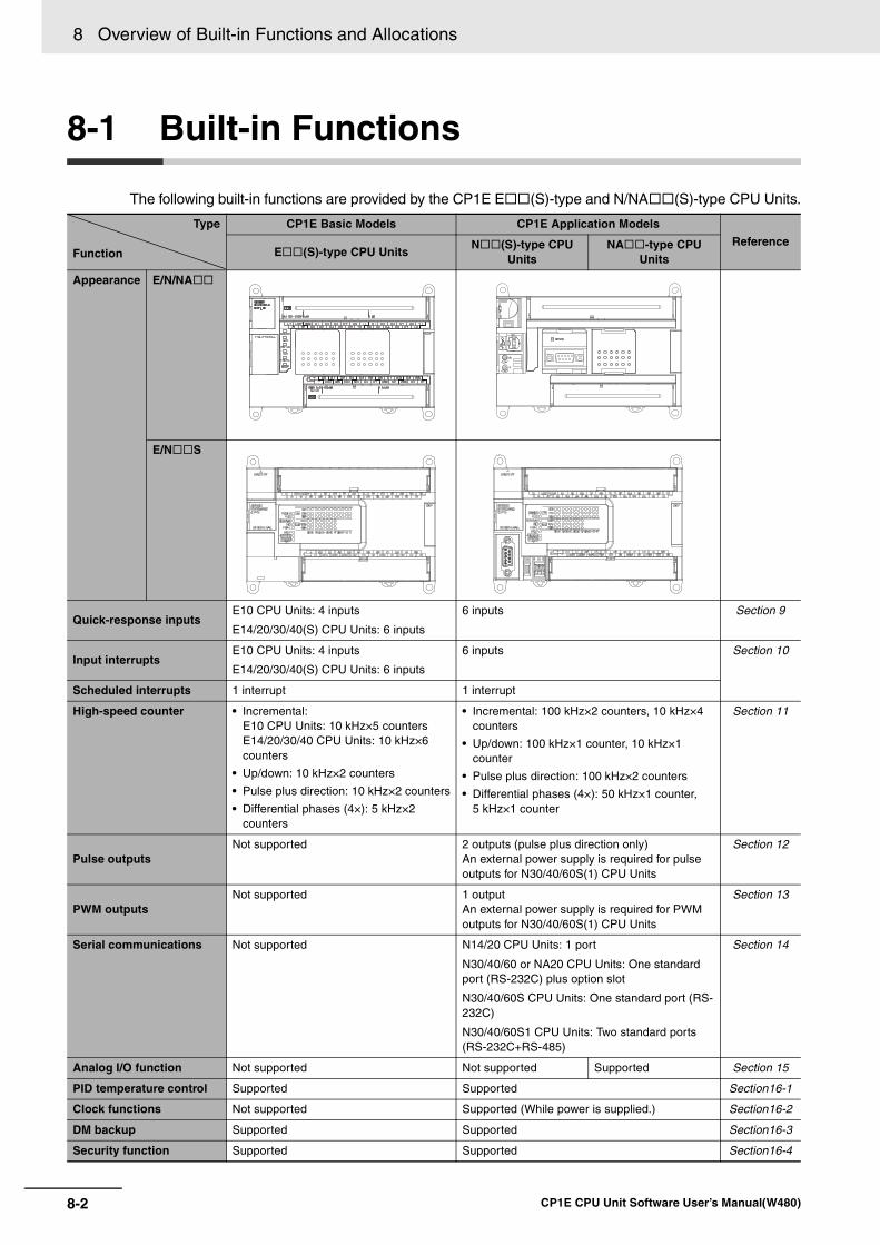
8 Overview of Built-in Functions and Allocations
8-2 CP1E CPU Unit Software User’s Manual(W480)
8-1 Built-in Functions
The following built-in functions are provided by the CP1E E (S)-type and N/NA (S)-type CPU Units.
Type
Function
CP1E Basic Models CP1E Application Models
ReferenceE (S)-type CPU Units
N (S)-type CPU Units
NA -type CPU Units
Appearance E/N/NA
E/N S
Quick-response inputsE10 CPU Units: 4 inputs
E14/20/30/40(S) CPU Units: 6 inputs
6 inputs Section 9
Input interruptsE10 CPU Units: 4 inputs
E14/20/30/40(S) CPU Units: 6 inputs
6 inputs Section 10
Scheduled interrupts 1 interrupt 1 interrupt
High-speed counter • Incremental: E10 CPU Units: 10 kHz×5 countersE14/20/30/40 CPU Units: 10 kHz×6 counters
• Up/down: 10 kHz×2 counters
• Pulse plus direction: 10 kHz×2 counters
• Differential phases (4×): 5 kHz×2 counters
• Incremental: 100 kHz×2 counters, 10 kHz×4 counters
• Up/down: 100 kHz×1 counter, 10 kHz×1 counter
• Pulse plus direction: 100 kHz×2 counters
• Differential phases (4×): 50 kHz×1 counter, 5 kHz×1 counter
Section 11
Pulse outputsNot supported 2 outputs (pulse plus direction only)
An external power supply is required for pulse outputs for N30/40/60S(1) CPU Units
Section 12
PWM outputsNot supported 1 output
An external power supply is required for PWM outputs for N30/40/60S(1) CPU Units
Section 13
Serial communications Not supported N14/20 CPU Units: 1 port
N30/40/60 or NA20 CPU Units: One standard port (RS-232C) plus option slot
N30/40/60S CPU Units: One standard port (RS-232C)
N30/40/60S1 CPU Units: Two standard ports (RS-232C+RS-485)
Section 14
Analog I/O function Not supported Not supported Supported Section 15
PID temperature control Supported Supported Section16-1
Clock functions Not supported Supported (While power is supplied.) Section16-2
DM backup Supported Supported Section16-3
Security function Supported Supported Section16-4
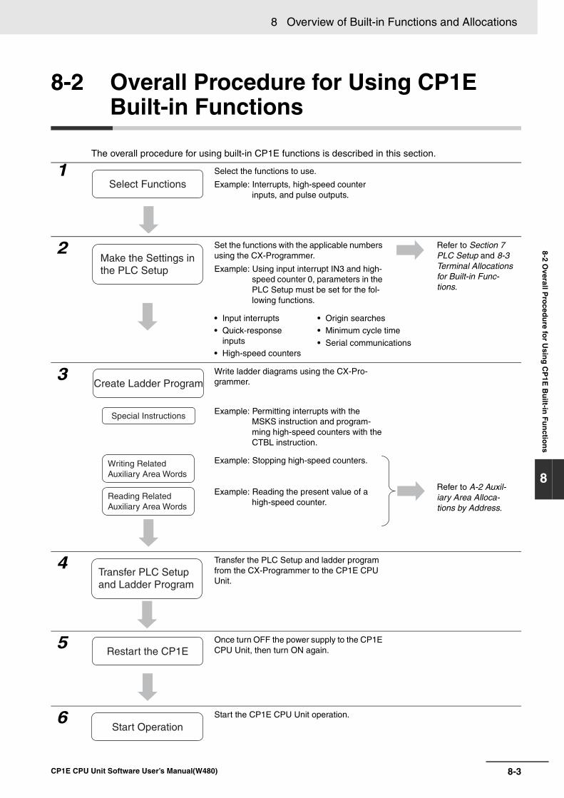
8-3
8 Overview of Built-in Functions and Allocations
CP1E CPU Unit Software User’s Manual(W480)
8-2 Overall P
roced
ure fo
r Usin
g C
P1E
Bu
ilt-in F
un
ction
s
8
8-2 Overall Procedure for Using CP1E Built-in Functions
The overall procedure for using built-in CP1E functions is described in this section.
1 Select the functions to use.
Example: Interrupts, high-speed counter inputs, and pulse outputs.
2 Set the functions with the applicable numbers using the CX-Programmer.
Example: Using input interrupt IN3 and high-speed counter 0, parameters in the PLC Setup must be set for the fol-lowing functions.
Refer to Section 7 PLC Setup and 8-3 Terminal Allocations for Built-in Func-tions.
• Input interrupts• Quick-response
inputs• High-speed counters
• Origin searches• Minimum cycle time
• Serial communications
3 Write ladder diagrams using the CX-Pro-grammer.
Example: Permitting interrupts with the MSKS instruction and program-ming high-speed counters with the CTBL instruction.
Example: Stopping high-speed counters.
Refer to A-2 Auxil-iary Area Alloca-tions by Address.
Example: Reading the present value of a high-speed counter.
4 Transfer the PLC Setup and ladder program from the CX-Programmer to the CP1E CPU Unit.
5 Once turn OFF the power supply to the CP1E CPU Unit, then turn ON again.
6 Start the CP1E CPU Unit operation.
Select Functions
Make the Settings inthe PLC Setup
Special Instructions
Writing Related Auxiliary Area Words
Reading RelatedAuxiliary Area Words
Create Ladder Program
Transfer PLC Setup and Ladder Program
Restart the CP1E
Start Operation
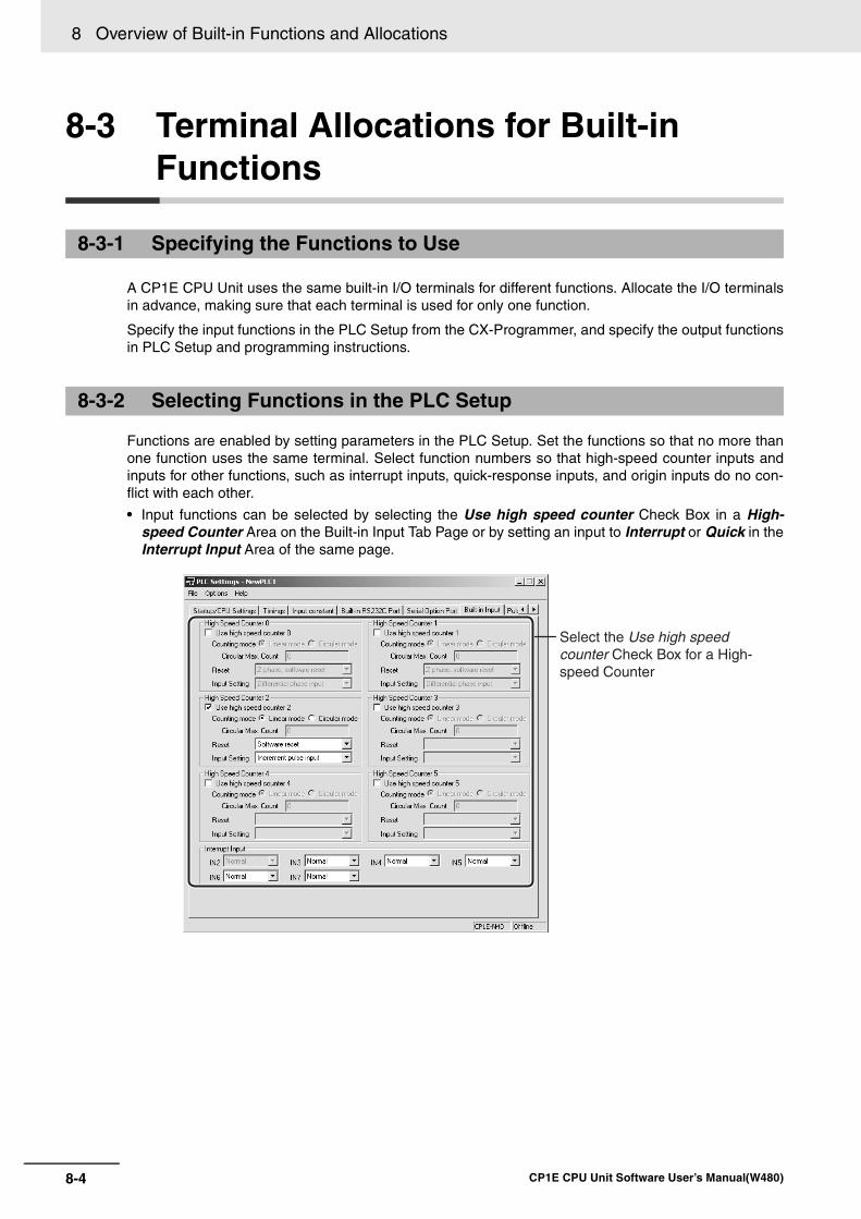
8 Overview of Built-in Functions and Allocations
8-4 CP1E CPU Unit Software User’s Manual(W480)
8-3 Terminal Allocations for Built-in Functions
A CP1E CPU Unit uses the same built-in I/O terminals for different functions. Allocate the I/O terminalsin advance, making sure that each terminal is used for only one function.
Specify the input functions in the PLC Setup from the CX-Programmer, and specify the output functionsin PLC Setup and programming instructions.
Functions are enabled by setting parameters in the PLC Setup. Set the functions so that no more thanone function uses the same terminal. Select function numbers so that high-speed counter inputs andinputs for other functions, such as interrupt inputs, quick-response inputs, and origin inputs do no con-flict with each other.
• Input functions can be selected by selecting the Use high speed counter Check Box in a High-speed Counter Area on the Built-in Input Tab Page or by setting an input to Interrupt or Quick in theInterrupt Input Area of the same page.
8-3-1 Specifying the Functions to Use
8-3-2 Selecting Functions in the PLC Setup
Select the Use high speed counter Check Box for a High-speed Counter
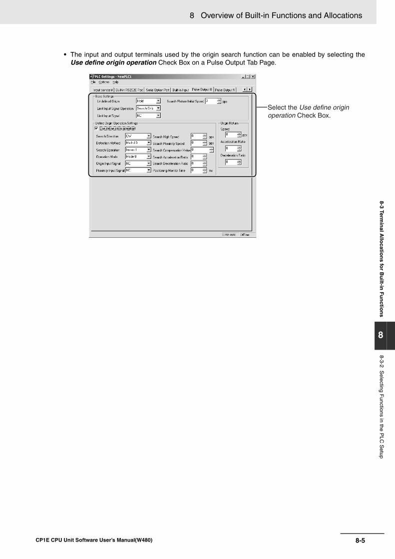
8-5
8 Overview of Built-in Functions and Allocations
CP1E CPU Unit Software User’s Manual(W480)
8-3 Termin
al Allo
cation
s for B
uilt-in
Fu
nctio
ns
8
8-3-2 Selecting F
unctions in the PLC
Setup
• The input and output terminals used by the origin search function can be enabled by selecting theUse define origin operation Check Box on a Pulse Output Tab Page.
Select the Use define origin operation Check Box.
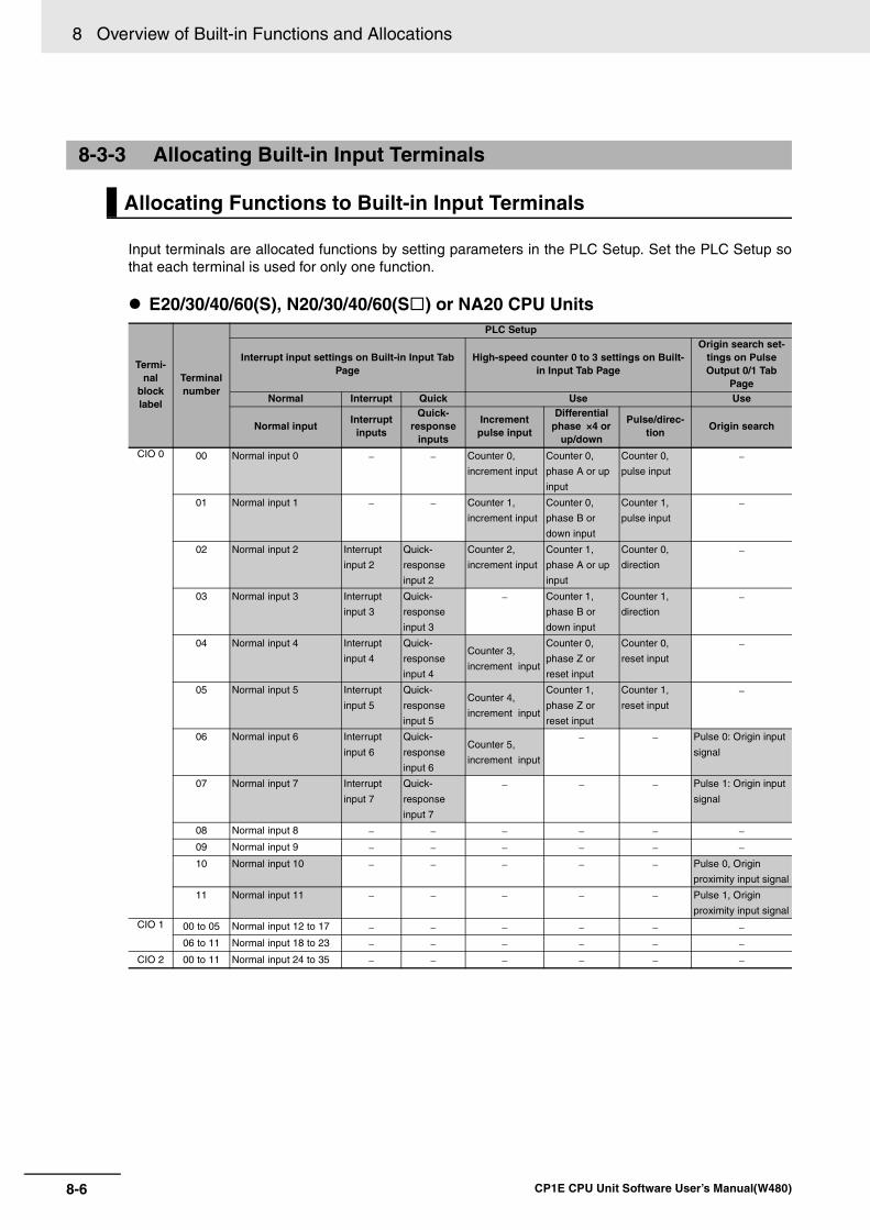
8 Overview of Built-in Functions and Allocations
8-6 CP1E CPU Unit Software User’s Manual(W480)
Input terminals are allocated functions by setting parameters in the PLC Setup. Set the PLC Setup sothat each terminal is used for only one function.
E20/30/40/60(S), N20/30/40/60(S ) or NA20 CPU Units
8-3-3 Allocating Built-in Input Terminals
Allocating Functions to Built-in Input Terminals
Termi-nal
block label
Terminal number
PLC Setup
Interrupt input settings on Built-in Input Tab Page
High-speed counter 0 to 3 settings on Built-in Input Tab Page
Origin search set-tings on Pulse Output 0/1 Tab
PageNormal Interrupt Quick Use Use
Normal inputInterrupt
inputs
Quick-response
inputs
Increment pulse input
Differential phase ×4 or
up/down
Pulse/direc-tion
Origin search
CIO 0 00 Normal input 0 − − Counter 0,
increment input
Counter 0,
phase A or up
input
Counter 0,
pulse input
−
01 Normal input 1 − − Counter 1,
increment input
Counter 0,
phase B or
down input
Counter 1,
pulse input
−
02 Normal input 2 Interrupt
input 2
Quick-
response
input 2
Counter 2,
increment input
Counter 1,
phase A or up
input
Counter 0,
direction
−
03 Normal input 3 Interrupt
input 3
Quick-
response
input 3
− Counter 1,
phase B or
down input
Counter 1,
direction
−
04 Normal input 4 Interrupt
input 4
Quick-
response
input 4
Counter 3,
increment input
Counter 0,
phase Z or
reset input
Counter 0,
reset input
−
05 Normal input 5 Interrupt
input 5
Quick-
response
input 5
Counter 4,
increment input
Counter 1,
phase Z or
reset input
Counter 1,
reset input
−
06 Normal input 6 Interrupt
input 6
Quick-
response
input 6
Counter 5,
increment input
− − Pulse 0: Origin input
signal
07 Normal input 7 Interrupt
input 7
Quick-
response
input 7
− − − Pulse 1: Origin input
signal
08 Normal input 8 − − − − − −09 Normal input 9 − − − − − −10 Normal input 10 − − − − − Pulse 0, Origin
proximity input signal
11 Normal input 11 − − − − − Pulse 1, Origin
proximity input signalCIO 1 00 to 05 Normal input 12 to 17 − − − − − −
06 to 11 Normal input 18 to 23 − − − − − −CIO 2 00 to 11 Normal input 24 to 35 − − − − − −
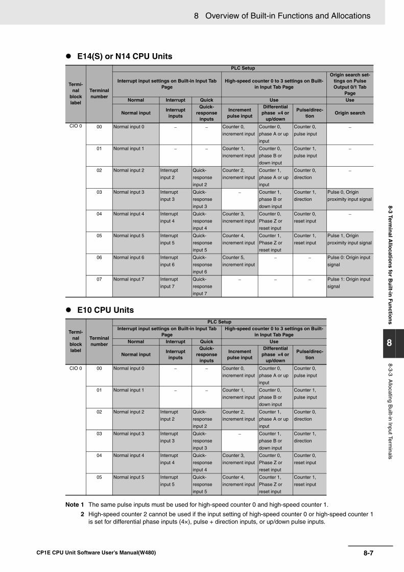
8-7
8 Overview of Built-in Functions and Allocations
CP1E CPU Unit Software User’s Manual(W480)
8-3 Termin
al Allo
cation
s for B
uilt-in
Fu
nctio
ns
8
8-3-3 Allocating B
uilt-in Input Terminals
E14(S) or N14 CPU Units
E10 CPU Units
Note 1 The same pulse inputs must be used for high-speed counter 0 and high-speed counter 1.
2 High-speed counter 2 cannot be used if the input setting of high-speed counter 0 or high-speed counter 1is set for differential phase inputs (4×), pulse + direction inputs, or up/down pulse inputs.
Termi-nal
block label
Terminal number
PLC Setup
Interrupt input settings on Built-in Input Tab Page
High-speed counter 0 to 3 settings on Built-in Input Tab Page
Origin search set-tings on Pulse Output 0/1 Tab
PageNormal Interrupt Quick Use Use
Normal inputInterruptinputs
Quick-response
inputs
Increment pulse input
Differential phase ×4 or
up/down
Pulse/direc-tion
Origin search
CIO 0 00 Normal input 0 − − Counter 0,
increment input
Counter 0,
phase A or up
input
Counter 0,
pulse input
−
01 Normal input 1 − − Counter 1,
increment input
Counter 0,
phase B or
down input
Counter 1,
pulse input
−
02 Normal input 2 Interrupt
input 2
Quick-
response
input 2
Counter 2,
increment input
Counter 1,
phase A or up
input
Counter 0,
direction
−
03 Normal input 3 Interrupt
input 3
Quick-
response
input 3
− Counter 1,
phase B or
down input
Counter 1,
direction
Pulse 0, Origin
proximity input signal
04 Normal input 4 Interrupt
input 4
Quick-
response
input 4
Counter 3,
increment input
Counter 0,
Phase Z or
reset input
Counter 0,
reset input
−
05 Normal input 5 Interrupt
input 5
Quick-
response
input 5
Counter 4,
increment input
Counter 1,
Phase Z or
reset input
Counter 1,
reset input
Pulse 1, Origin
proximity input signal
06 Normal input 6 Interrupt
input 6
Quick-
response
input 6
Counter 5,
increment input
− − Pulse 0: Origin input
signal
07 Normal input 7 Interrupt
input 7
Quick-
response
input 7
− − − Pulse 1: Origin input
signal
Termi-nal
block label
Terminal number
PLC SetupInterrupt input settings on Built-in Input Tab
PageHigh-speed counter 0 to 3 settings on Built-
in Input Tab PageNormal Interrupt Quick Use
Normal inputInterruptinputs
Quick-response
inputs
Increment pulse input
Differential phase ×4 or
up/down
Pulse/direc-tion
CIO 0 00 Normal input 0 − − Counter 0,
increment input
Counter 0,
phase A or up
input
Counter 0,
pulse input
01 Normal input 1 − − Counter 1,
increment input
Counter 0,
phase B or
down input
Counter 1,
pulse input
02 Normal input 2 Interrupt
input 2
Quick-
response
input 2
Counter 2,
increment input
Counter 1,
phase A or up
input
Counter 0,
direction
03 Normal input 3 Interrupt
input 3
Quick-
response
input 3
− Counter 1,
phase B or
down input
Counter 1,
direction
04 Normal input 4 Interrupt
input 4
Quick-
response
input 4
Counter 3,
increment input
Counter 0,
Phase Z or
reset input
Counter 0,
reset input
05 Normal input 5 Interrupt
input 5
Quick-
response
input 5
Counter 4,
increment input
Counter 1,
Phase Z or
reset input
Counter 1,
reset input
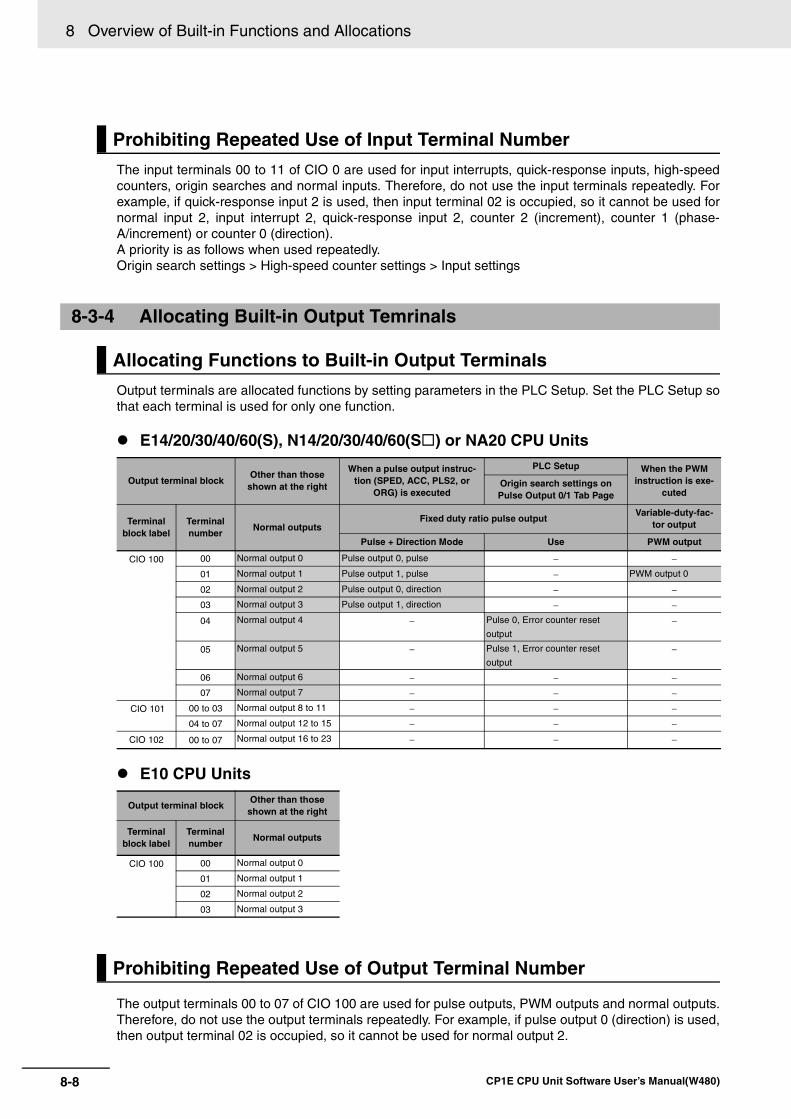
8 Overview of Built-in Functions and Allocations
8-8 CP1E CPU Unit Software User’s Manual(W480)
The input terminals 00 to 11 of CIO 0 are used for input interrupts, quick-response inputs, high-speedcounters, origin searches and normal inputs. Therefore, do not use the input terminals repeatedly. Forexample, if quick-response input 2 is used, then input terminal 02 is occupied, so it cannot be used fornormal input 2, input interrupt 2, quick-response input 2, counter 2 (increment), counter 1 (phase-A/increment) or counter 0 (direction). A priority is as follows when used repeatedly.Origin search settings > High-speed counter settings > Input settings
Output terminals are allocated functions by setting parameters in the PLC Setup. Set the PLC Setup sothat each terminal is used for only one function.
E14/20/30/40/60(S), N14/20/30/40/60(S ) or NA20 CPU Units
E10 CPU Units
The output terminals 00 to 07 of CIO 100 are used for pulse outputs, PWM outputs and normal outputs.Therefore, do not use the output terminals repeatedly. For example, if pulse output 0 (direction) is used,then output terminal 02 is occupied, so it cannot be used for normal output 2.
Prohibiting Repeated Use of Input Terminal Number
8-3-4 Allocating Built-in Output Temrinals
Allocating Functions to Built-in Output Terminals
Output terminal blockOther than those
shown at the right
When a pulse output instruc-tion (SPED, ACC, PLS2, or
ORG) is executed
PLC Setup When the PWM instruction is exe-
cutedOrigin search settings on Pulse Output 0/1 Tab Page
Terminal block label
Terminal number
Normal outputsFixed duty ratio pulse output
Variable-duty-fac-tor output
Pulse + Direction Mode Use PWM output
CIO 100 00 Normal output 0 Pulse output 0, pulse − −
01 Normal output 1 Pulse output 1, pulse − PWM output 0
02 Normal output 2 Pulse output 0, direction − −
03 Normal output 3 Pulse output 1, direction − −
04 Normal output 4 − Pulse 0, Error counter reset
output
−
05 Normal output 5 − Pulse 1, Error counter reset
output
−
06 Normal output 6 − − −
07 Normal output 7 − − −
CIO 101 00 to 03 Normal output 8 to 11 − − −
04 to 07 Normal output 12 to 15 − − −
CIO 102 00 to 07 Normal output 16 to 23 − − −
Output terminal blockOther than those
shown at the right
Terminal block label
Terminal number
Normal outputs
CIO 100 00 Normal output 0
01 Normal output 1
02 Normal output 2
03 Normal output 3
Prohibiting Repeated Use of Output Terminal Number
9-1
9
CP1E CPU Unit Software User’s Manual(W480)
9
This section describes the quick-response inputs that can be used to read signals thatare shorter than the cycle time.
9-1 Quick-response Inputs . . . . . . . . . . . . . . . . . . . . . . . . . . . . . . . . . . . . . . . . . . 9-29-1-1 Overview. . . . . . . . . . . . . . . . . . . . . . . . . . . . . . . . . . . . . . . . . . . . . . . . . . . . . . 9-2
9-1-2 Flow of Operation . . . . . . . . . . . . . . . . . . . . . . . . . . . . . . . . . . . . . . . . . . . . . . . 9-3
Quick-response Inputs
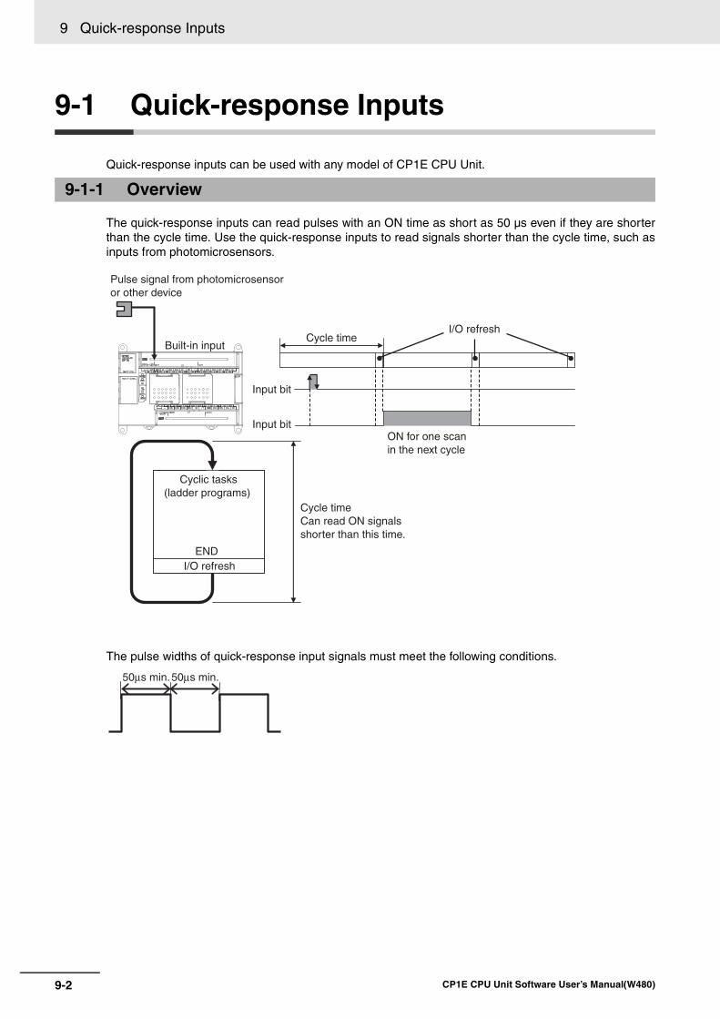
9 Quick-response Inputs
9-2 CP1E CPU Unit Software User’s Manual(W480)
9-1 Quick-response Inputs
Quick-response inputs can be used with any model of CP1E CPU Unit.
The quick-response inputs can read pulses with an ON time as short as 50 µs even if they are shorterthan the cycle time. Use the quick-response inputs to read signals shorter than the cycle time, such asinputs from photomicrosensors.
The pulse widths of quick-response input signals must meet the following conditions.
9-1-1 Overview
END
Cycle timeCan read ON signals shorter than this time.
Pulse signal from photomicrosensor or other device
Built-in inputCycle time
Input bit
Input bitON for one scan in the next cycle
I/O refresh
I/O refresh
Cyclic tasks (ladder programs)
50µs min.50µs min.
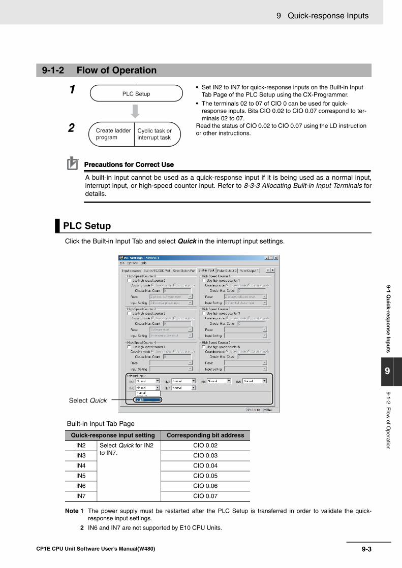
9 Quick-response Inputs
9-3CP1E CPU Unit Software User’s Manual(W480)
9-1 Qu
ick-respo
nse In
pu
ts
9
9-1-2 Flow
of Operation
Precautions for Correct UsePrecautions for Correct Use
A built-in input cannot be used as a quick-response input if it is being used as a normal input,interrupt input, or high-speed counter input. Refer to 8-3-3 Allocating Built-in Input Terminals fordetails.
Click the Built-in Input Tab and select Quick in the interrupt input settings.
Built-in Input Tab Page
Note 1 The power supply must be restarted after the PLC Setup is transferred in order to validate the quick-response input settings.
2 IN6 and IN7 are not supported by E10 CPU Units.
9-1-2 Flow of Operation
1 • Set IN2 to IN7 for quick-response inputs on the Built-in Input Tab Page of the PLC Setup using the CX-Programmer.
• The terminals 02 to 07 of CIO 0 can be used for quick-response inputs. Bits CIO 0.02 to CIO 0.07 correspond to ter-minals 02 to 07.
2 Read the status of CIO 0.02 to CIO 0.07 using the LD instruction or other instructions.
PLC Setup
Quick-response input setting Corresponding bit address
IN2 Select Quick for IN2 to IN7.
CIO 0.02
IN3 CIO 0.03
IN4 CIO 0.04
IN5 CIO 0.05
IN6 CIO 0.06
IN7 CIO 0.07
PLC Setup
Create ladder program
Cyclic task or interrupt task
Select Quick
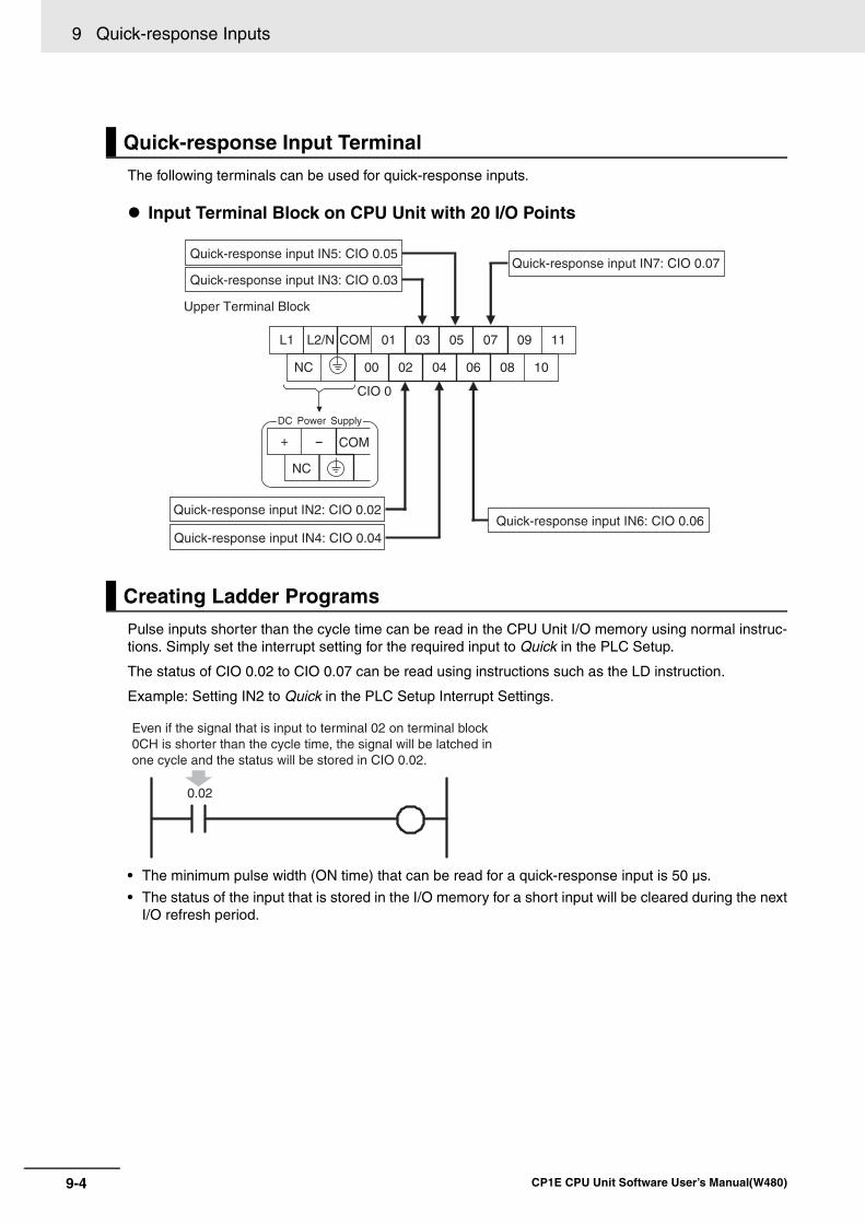
9 Quick-response Inputs
9-4 CP1E CPU Unit Software User’s Manual(W480)
The following terminals can be used for quick-response inputs.
Input Terminal Block on CPU Unit with 20 I/O Points
Pulse inputs shorter than the cycle time can be read in the CPU Unit I/O memory using normal instruc-tions. Simply set the interrupt setting for the required input to Quick in the PLC Setup.
The status of CIO 0.02 to CIO 0.07 can be read using instructions such as the LD instruction.
Example: Setting IN2 to Quick in the PLC Setup Interrupt Settings.
• The minimum pulse width (ON time) that can be read for a quick-response input is 50 µs.
• The status of the input that is stored in the I/O memory for a short input will be cleared during the nextI/O refresh period.
Quick-response Input Terminal
Creating Ladder Programs
L1 L2/N COM 01 03 05 07 09 11
NC 00 02 04 06 08 10
Upper Terminal Block
Quick-response input IN5: CIO 0.05
Quick-response input IN3: CIO 0.03Quick-response input IN7: CIO 0.07
Quick-response input IN6: CIO 0.06Quick-response input IN2: CIO 0.02
Quick-response input IN4: CIO 0.04
CIO 0
COM+ -
NC
DC Power Supply
0.02
Even if the signal that is input to terminal 02 on terminal block 0CH is shorter than the cycle time, the signal will be latched in one cycle and the status will be stored in CIO 0.02.
10-1
10
CP1E CPU Unit Software User’s Manual(W480)
10
This section describes the interrupts that can be used with CP1E PLCs, including inputinterrupts and scheduled interrupts.
10-1 Interrupts . . . . . . . . . . . . . . . . . . . . . . . . . . . . . . . . . . . . . . . . . . . . . . . . . . . 10-210-1-1 Overview . . . . . . . . . . . . . . . . . . . . . . . . . . . . . . . . . . . . . . . . . . . . . . . . . . . . 10-2
10-2 Input Interrupts . . . . . . . . . . . . . . . . . . . . . . . . . . . . . . . . . . . . . . . . . . . . . . . 10-310-2-1 Overview . . . . . . . . . . . . . . . . . . . . . . . . . . . . . . . . . . . . . . . . . . . . . . . . . . . . 10-3
10-2-2 Flow of Operation . . . . . . . . . . . . . . . . . . . . . . . . . . . . . . . . . . . . . . . . . . . . . 10-4
10-2-3 Application Example . . . . . . . . . . . . . . . . . . . . . . . . . . . . . . . . . . . . . . . . . . . 10-7
10-3 Scheduled Interrupts . . . . . . . . . . . . . . . . . . . . . . . . . . . . . . . . . . . . . . . . . 10-1010-3-1 Overview . . . . . . . . . . . . . . . . . . . . . . . . . . . . . . . . . . . . . . . . . . . . . . . . . . . 10-10
10-3-2 Flow of Operation . . . . . . . . . . . . . . . . . . . . . . . . . . . . . . . . . . . . . . . . . . . . 10-11
10-4 Precautions for Using Interrupts . . . . . . . . . . . . . . . . . . . . . . . . . . . . . . . 10-1310-4-1 Interrupt Task Priority and Order of Execution . . . . . . . . . . . . . . . . . . . . . . . 10-13
10-4-2 Related Auxiliary Area Words and Bits . . . . . . . . . . . . . . . . . . . . . . . . . . . . 10-13
10-4-3 Duplicate Processing in each Task . . . . . . . . . . . . . . . . . . . . . . . . . . . . . . . 10-13
Interrupts
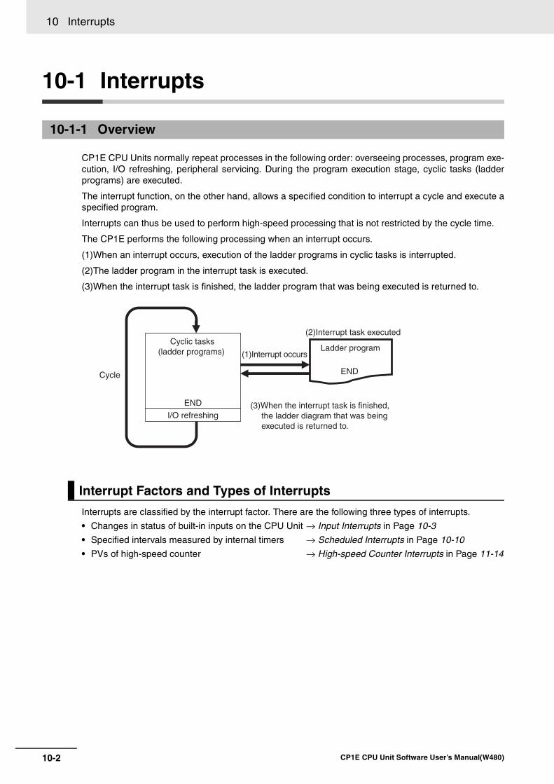
10 Interrupts
10-2 CP1E CPU Unit Software User’s Manual(W480)
10-1 Interrupts
CP1E CPU Units normally repeat processes in the following order: overseeing processes, program exe-cution, I/O refreshing, peripheral servicing. During the program execution stage, cyclic tasks (ladderprograms) are executed.
The interrupt function, on the other hand, allows a specified condition to interrupt a cycle and execute aspecified program.
Interrupts can thus be used to perform high-speed processing that is not restricted by the cycle time.
The CP1E performs the following processing when an interrupt occurs.
(1)When an interrupt occurs, execution of the ladder programs in cyclic tasks is interrupted.
(2)The ladder program in the interrupt task is executed.
(3)When the interrupt task is finished, the ladder program that was being executed is returned to.
Interrupts are classified by the interrupt factor. There are the following three types of interrupts.
• Changes in status of built-in inputs on the CPU Unit → Input Interrupts in Page 10-3
• Specified intervals measured by internal timers → Scheduled Interrupts in Page 10-10
• PVs of high-speed counter → High-speed Counter Interrupts in Page 11-14
10-1-1 Overview
Interrupt Factors and Types of Interrupts
END
ENDCycle
Cyclic tasks (ladder programs)
I/O refreshing
(1)Interrupt occurs
(2)Interrupt task executed
(3)When the interrupt task is finished, the ladder diagram that was being executed is returned to.
Ladder program
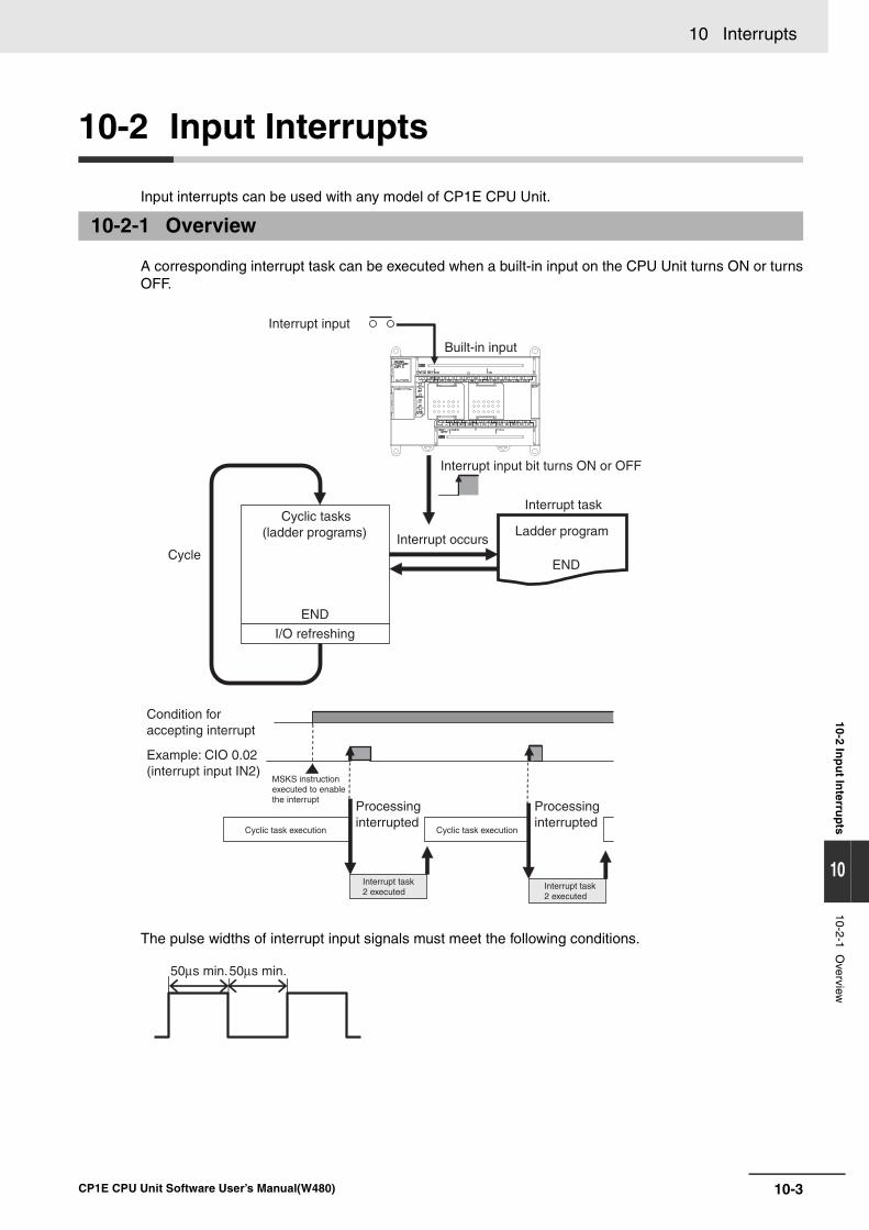
10-3
10 Interrupts
CP1E CPU Unit Software User’s Manual(W480)
10-2 Inp
ut In
terrup
ts
10
10-2-1 Overview
10-2 Input Interrupts
Input interrupts can be used with any model of CP1E CPU Unit.
A corresponding interrupt task can be executed when a built-in input on the CPU Unit turns ON or turnsOFF.
The pulse widths of interrupt input signals must meet the following conditions.
10-2-1 Overview
END
END
Interrupt input
Built-in input
Interrupt input bit turns ON or OFF
Cycle
Cyclic tasks (ladder programs)
I/O refreshing
Interrupt occurs
Interrupt task
Ladder program
Condition for accepting interrupt
Example: CIO 0.02 (interrupt input IN2)
MSKS instruction executed to enable the interrupt
Cyclic task execution Cyclic task execution
Processinginterrupted
Processinginterrupted
Interrupt task 2 executed
Interrupt task 2 executed
50µs min.50µs min.
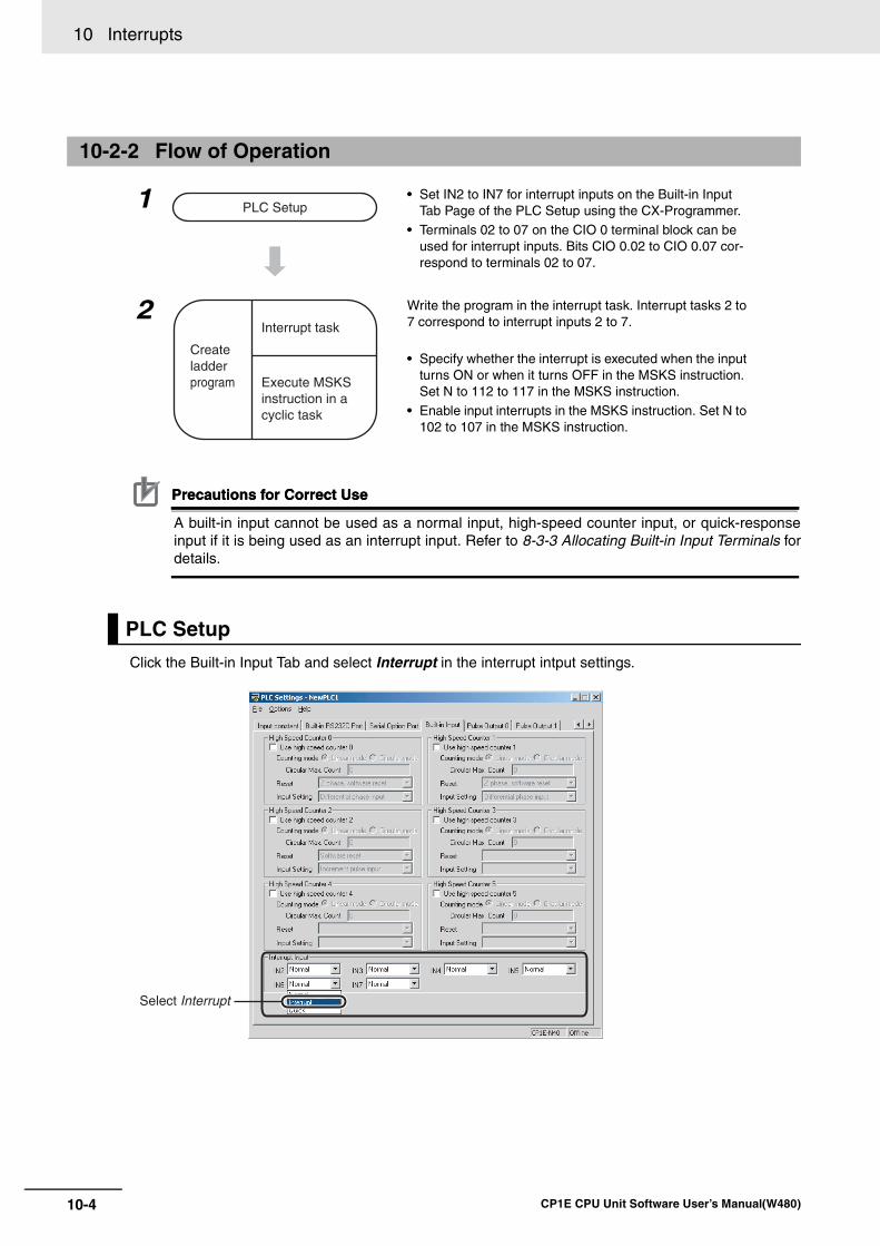
10 Interrupts
10-4 CP1E CPU Unit Software User’s Manual(W480)
Precautions for Correct UsePrecautions for Correct Use
A built-in input cannot be used as a normal input, high-speed counter input, or quick-responseinput if it is being used as an interrupt input. Refer to 8-3-3 Allocating Built-in Input Terminals fordetails.
Click the Built-in Input Tab and select Interrupt in the interrupt intput settings.
10-2-2 Flow of Operation
1 • Set IN2 to IN7 for interrupt inputs on the Built-in Input Tab Page of the PLC Setup using the CX-Programmer.
• Terminals 02 to 07 on the CIO 0 terminal block can be used for interrupt inputs. Bits CIO 0.02 to CIO 0.07 cor-respond to terminals 02 to 07.
2 Write the program in the interrupt task. Interrupt tasks 2 to 7 correspond to interrupt inputs 2 to 7.
• Specify whether the interrupt is executed when the input turns ON or when it turns OFF in the MSKS instruction. Set N to 112 to 117 in the MSKS instruction.
• Enable input interrupts in the MSKS instruction. Set N to 102 to 107 in the MSKS instruction.
PLC Setup
PLC Setup
Create ladder program Execute MSKS
instruction in a cyclic task
Interrupt task
Select Interrupt
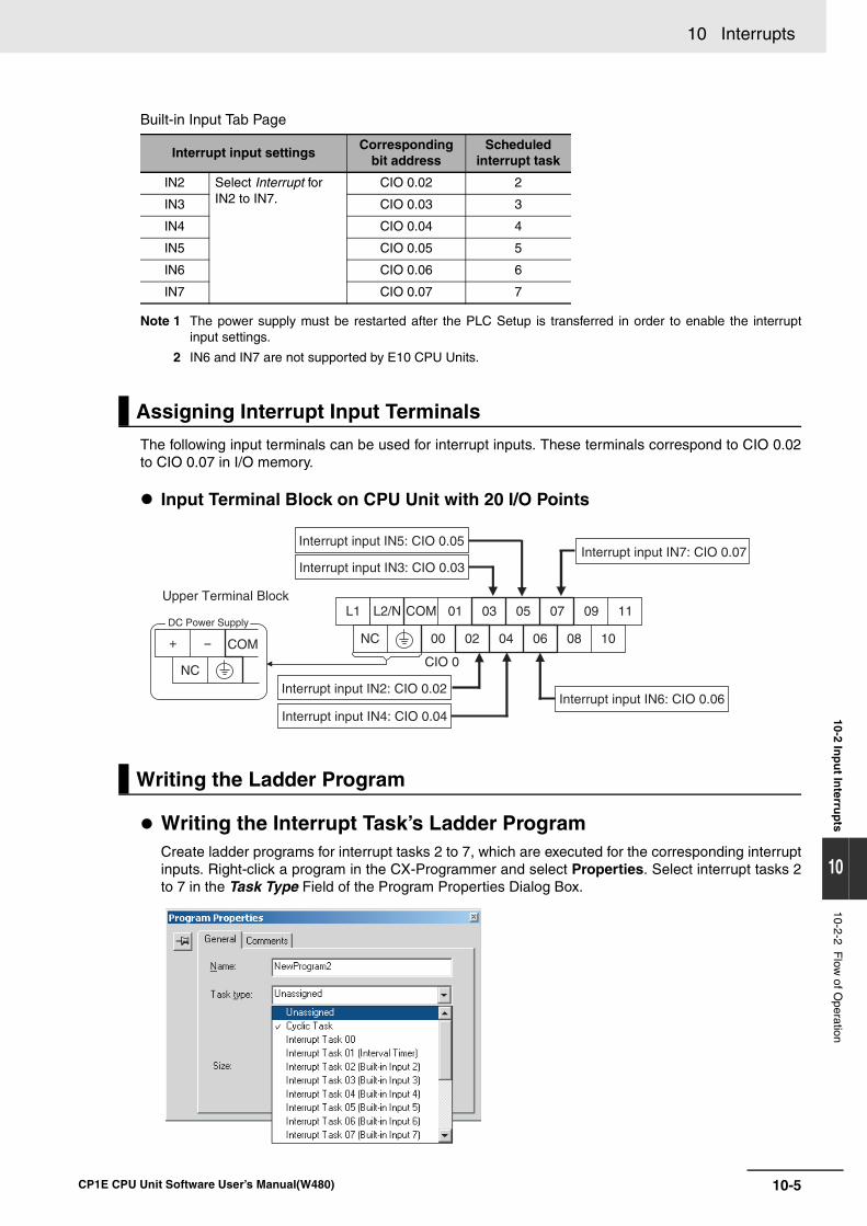
10-5
10 Interrupts
CP1E CPU Unit Software User’s Manual(W480)
10-2 Inp
ut In
terrup
ts
10
10-2-2 Flow
of Operation
Built-in Input Tab Page
Note 1 The power supply must be restarted after the PLC Setup is transferred in order to enable the interruptinput settings.
2 IN6 and IN7 are not supported by E10 CPU Units.
The following input terminals can be used for interrupt inputs. These terminals correspond to CIO 0.02to CIO 0.07 in I/O memory.
Input Terminal Block on CPU Unit with 20 I/O Points
Writing the Interrupt Task’s Ladder ProgramCreate ladder programs for interrupt tasks 2 to 7, which are executed for the corresponding interruptinputs. Right-click a program in the CX-Programmer and select Properties. Select interrupt tasks 2to 7 in the Task Type Field of the Program Properties Dialog Box.
Interrupt input settingsCorresponding
bit addressScheduled
interrupt task
IN2 Select Interrupt for IN2 to IN7.
CIO 0.02 2
IN3 CIO 0.03 3
IN4 CIO 0.04 4
IN5 CIO 0.05 5
IN6 CIO 0.06 6
IN7 CIO 0.07 7
Assigning Interrupt Input Terminals
Writing the Ladder Program
L1 L2/N COM 01 03 05 07 09 11
NC 00 02 04 06 08 10
Upper Terminal Block
Interrupt input IN5: CIO 0.05
Interrupt input IN3: CIO 0.03Interrupt input IN7: CIO 0.07
Interrupt input IN6: CIO 0.06Interrupt input IN2: CIO 0.02
Interrupt input IN4: CIO 0.04
CIO 0COM+ -
NC
DC Power Supply
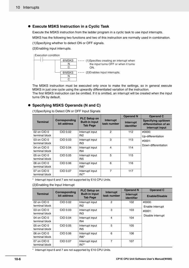
10 Interrupts
10-6 CP1E CPU Unit Software User’s Manual(W480)
Execute MSKS Instruction in a Cyclic TaskExecute the MSKS instruction from the ladder program in a cyclic task to use input interrupts.
MSKS has the following two functions and two of this instruction are normally used in combination.
(1)Specifying whether to detect ON or OFF signals.
(2)Enabling input interrupts.
The MSKS instruction must be executed only once to make the settings, so in general executeMSKS in just one cycle using the upwardly differentiated variation of the instruction. The first MSKS instruction can be omitted. If it is omitted, an interrupt will be created when the inputturns ON by default.
Specifying MSKS Operands (N and C)(1)Specifying to Detect ON or OFF Input Signals
* Interrupt input 6 and 7 are not supported by E10 CPU Units.
(2)Enabling the Input Interrupt
* Interrupt input 6 and 7 are not supported by E10 CPU Units.
TerminalCorresponding
bit address
PLC Setup on Built-in Input
Tab Page
Interrupt task number
Operand N Operand C
Interrupt identifier
Specifying up/down differentiation of an
interrupt input
02 on CIO 0 terminal block
CIO 0.02 Interrupt input IN2
2 112 #0000:
Up-differentiation
#0001:
Down-differentiation
03 on CIO 0 terminal block
CIO 0.03 Interrupt input IN3
3 113
04 on CIO 0 terminal block
CIO 0.04 Interrupt input IN4
4 114
05 on CIO 0 terminal block
CIO 0.05 Interrupt input IN5
5 115
06 on CIO 0 terminal block
CIO 0.06 Interrupt input IN6*
6 116
07 on CIO 0 terminal block
CIO 0.07 Interrupt input IN7*
7 117
TerminalCorresponding
bit address
PLC Setup on Built-in Input
Tab Page
Interrupt task number
Operand N Operand C
Interrupt identifier
Enable/Disable
02 on CIO 0 terminal block
CIO 0.02 Interrupt input IN2
2 102 #0000:
Enable interrupt
#0001:
Disable interrupt
03 on CIO 0 terminal block
CIO 0.03 Interrupt input IN3
3 103
04 on CIO 0 terminal block
CIO 0.04 Interrupt input IN4
4 104
05 on CIO 0 terminal block
CIO 0.05 Interrupt input IN5
5 105
06 on CIO 0 terminal block
CIO 0.06 Interrupt input IN6*
6 106
07 on CIO 0 terminal block
CIO 0.07 Interrupt input IN7*
7 107
@MSKSNC
C
@MSKSN
Execution condition
(1)Specifies creating an interrupt when the input turns OFF or when it turns ON.
(2)Enables input interrupts.
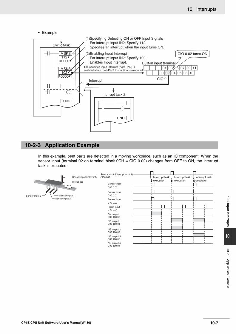
10-7
10 Interrupts
CP1E CPU Unit Software User’s Manual(W480)
10-2 Inp
ut In
terrup
ts
10
10-2-3 Application E
xample
• Example
In this example, bent parts are detected in a moving workpiece, such as an IC component. When thesensor input (terminal 02 on terminal block 0CH = CIO 0.02) changes from OFF to ON, the interrupttask is executed.
10-2-3 Application Example
MSKS112
#0000
END
END
01 03 0705 09 1100 02 04 06 08 10
MSKS102
#0000
Cyclic task
(1)Specifying Detecting ON or OFF Input Signals For interrupt input IN2: Specify 112. Specifies an interrupt when the input turns ON.
(2)Enabling Input InterruptFor interrupt input IN2: Specify 102. Enables Input interrupt.
The specified input interrupt (here, IN2) is enabled when the MSKS instruction is executed.
Interrupt
Interrupt task 2
Built-in input terminal
CIO 0.02 turns ON
CIO 0
Sensor input (interrupt)
Workpiece
Sensor input 1Sensor input 2
Sensor input 3
Sensor input (interrupt input 2)CIO 0.02
Sensor input
Sensor input
Sensor input
CIO 0.00
CIO 0.01
CIO 0.03
Reset inputCIO 0.04
OK outputCIO 100.00
NG output 1CIO 100.01
NG output 2CIO 100.02
NG output 3CIO 100.03
NG output 4CIO 100.04
Interrupt task execution
Interrupt task execution
Interrupt task execution
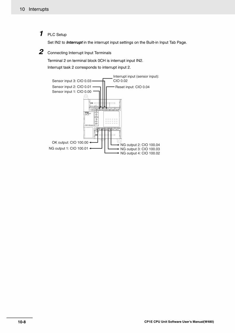
10 Interrupts
10-8 CP1E CPU Unit Software User’s Manual(W480)
1 PLC Setup
Set IN2 to Interrupt in the interrupt input settings on the Built-in Input Tab Page.
2 Connecting Interrupt Input Terminals
Terminal 2 on terminal block 0CH is interrupt input IN2.
Interrupt task 2 corresponds to interrupt input 2.
Sensor input 3: CIO 0.03
Sensor input 2: CIO 0.01Sensor input 1: CIO 0.00
Interrupt input (sensor input):CIO 0.02
Reset input: CIO 0.04
NG output 2: CIO 100.04NG output 3: CIO 100.03NG output 4: CIO 100.02
OK output: CIO 100.00
NG output 1: CIO 100.01
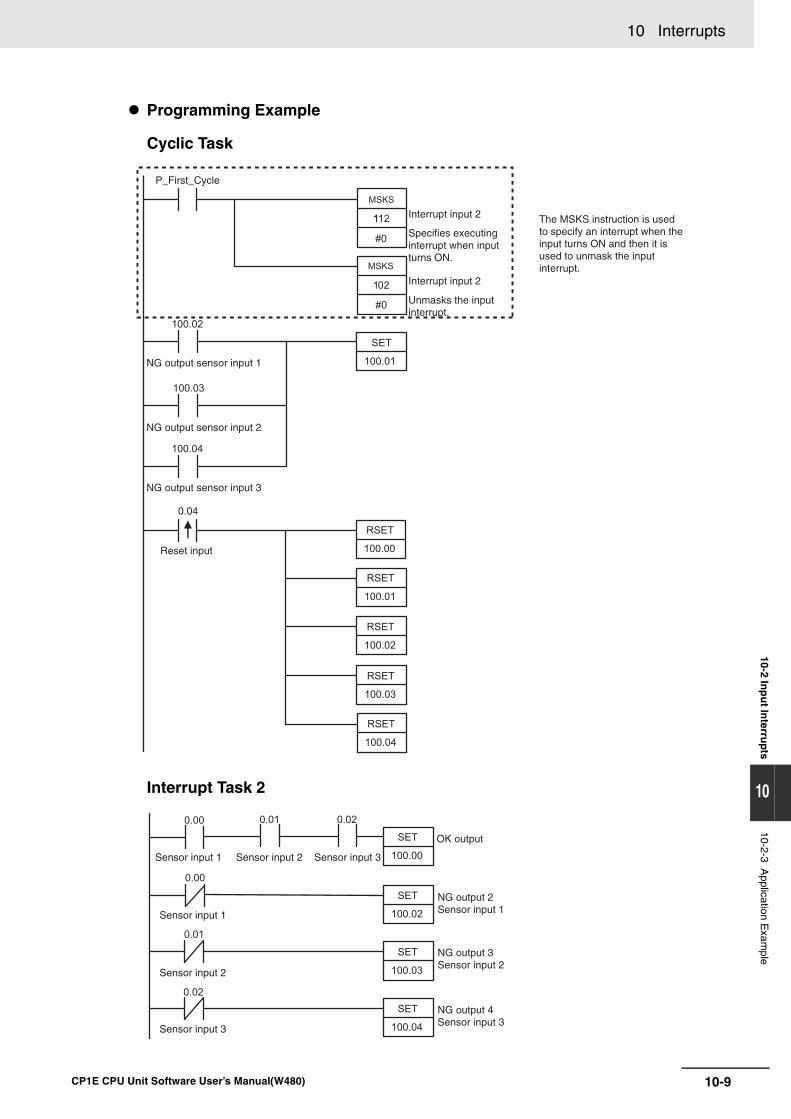
10-9
10 Interrupts
CP1E CPU Unit Software User’s Manual(W480)
10-2 Inp
ut In
terrup
ts
10
10-2-3 Application E
xample
Programming Example
Cyclic Task
Interrupt Task 2
0.04
Interrupt input 2
Interrupt input 2
Specifies executing interrupt when input turns ON.
Unmasks the input interrupt.
The MSKS instruction is used to specify an interrupt when the input turns ON and then it is used to unmask the input interrupt.
NG output sensor input 1
P_First_Cycle
NG output sensor input 2
NG output sensor input 3
Reset input
Sensor input 1
Sensor input 1
Sensor input 2
Sensor input 2
Sensor input 3
Sensor input 3
OK output
NG output 2Sensor input 1
NG output 3Sensor input 2
NG output 4Sensor input 3
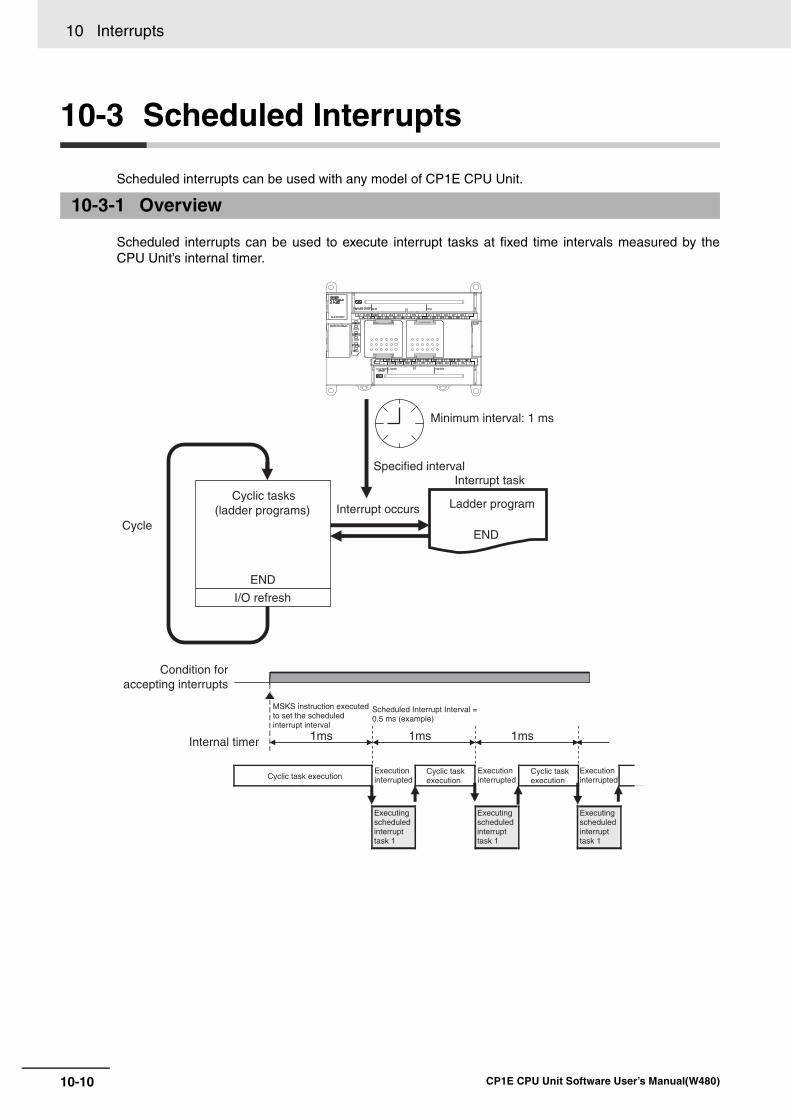
10 Interrupts
10-10 CP1E CPU Unit Software User’s Manual(W480)
10-3 Scheduled Interrupts
Scheduled interrupts can be used with any model of CP1E CPU Unit.
Scheduled interrupts can be used to execute interrupt tasks at fixed time intervals measured by theCPU Unit’s internal timer.
10-3-1 Overview
END
ENDCycle
Cyclic tasks (ladder programs)
I/O refresh
Interrupt occurs
Interrupt task
Ladder program
Specified interval
Minimum interval: 1 ms
1ms 1ms 1ms
Condition foraccepting interrupts
Internal timer
Cyclic task execution
MSKS instruction executed to set the scheduled interrupt interval
Scheduled Interrupt Interval = 0.5 ms (example)
Execution interrupted
Execution interrupted
Execution interrupted
Cyclic task execution
Cyclic task execution
Executing scheduled interrupt task 1
Executing scheduled interrupt task 1
Executing scheduled interrupt task 1
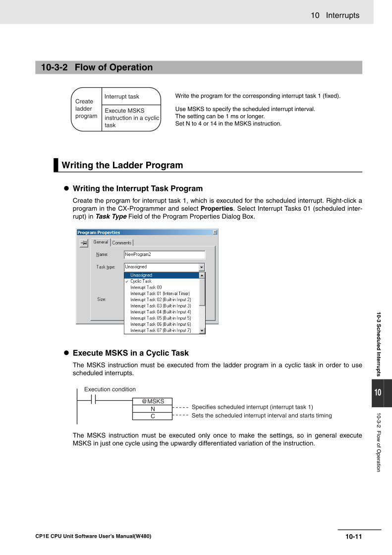
10-11
10 Interrupts
CP1E CPU Unit Software User’s Manual(W480)
10-3 Sch
edu
led In
terrup
ts
10
10-3-2 Flow
of Operation
Writing the Interrupt Task ProgramCreate the program for interrupt task 1, which is executed for the scheduled interrupt. Right-click aprogram in the CX-Programmer and select Properties. Select Interrupt Tasks 01 (scheduled inter-rupt) in Task Type Field of the Program Properties Dialog Box.
Execute MSKS in a Cyclic TaskThe MSKS instruction must be executed from the ladder program in a cyclic task in order to usescheduled interrupts.
The MSKS instruction must be executed only once to make the settings, so in general executeMSKS in just one cycle using the upwardly differentiated variation of the instruction.
10-3-2 Flow of Operation
Write the program for the corresponding interrupt task 1 (fixed).
Use MSKS to specify the scheduled interrupt interval.The setting can be 1 ms or longer. Set N to 4 or 14 in the MSKS instruction.
Writing the Ladder Program
Execute MSKS instruction in a cyclic task
Interrupt taskCreateladder program
@MSKSN C
Execution condition
Specifies scheduled interrupt (interrupt task 1)Sets the scheduled interrupt interval and starts timing
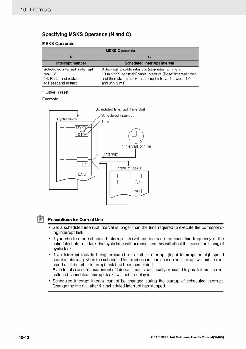
10 Interrupts
10-12 CP1E CPU Unit Software User’s Manual(W480)
Specifying MSKS Operands (N and C)
MSKS Operands
* Either is reset.
Example
Precautions for Correct UsePrecautions for Correct Use
• Set a scheduled interrupt interval is longer than the time required to execute the correspond-ing interrupt task.
• If you shorten the scheduled interrupt interval and increase the execution frequency of thescheduled interrupt task, the cycle time will increase, and this will affect the execution timing ofcyclic tasks.
• If an interrupt task is being executed for another interrupt (input interrupt or high-speedcounter interrupt) when the scheduled interrupt occurs, the scheduled interrupt will not be exe-cuted until the other interrupt task had been completed.Even in this case, measurement of internal timer is continually executed in parallel, so the exe-cution of scheduled interrupt tasks will not be delayed.
• Scheduled interrupt interval cannot be changed during the startup of scheduled interrupt.Change the interval after the scheduled interrupt has stopped.
MSKS Operands
N C
Interrupt number Scheduled interrupt interval
Scheduled interrupt (interrupt task 1)*14: Reset and restart 4: Reset and restart
0 decimal: Disable interrupt (stop internal timer)10 to 9,999 decimal:Enable interrupt (Reset internal timer and then start timer with interrupt interval between 1.0 and 999.9 ms)
MSKS4
&10
END
END
Cyclic tasks
Scheduled Interrupt Time Unit
Scheduled interrupt
1 ms
In intervals of 1 ms
Interrupt task 1
Interrupt
10-13
10 Interrupts
CP1E CPU Unit Software User’s Manual(W480)
10-4 Precau
tion
s for U
sing
Interru
pts
10
10-4-1 Interrupt Task Priority and
Order of E
xecution
10-4 Precautions for Using Interrupts
The priority of interrupt tasks is the same order for input interrupts, scheduled interrupts and high-speedcounter interrupts. Therefore, if interrupt task A (an input interrupt, for example) is being executed wheninterrupt task B (a scheduled interrupt, for example) occurs, task A execution will not be interrupted.Task B execution will be started when task A had been completed.
For example, if an interrupt task is being executed for another interrupt (input interrupt or high-speedcounter interrupt) when a scheduled interrupt occurs, the scheduled interrupt will not be executed untilexecution of the other interrupt task had been completed. Even in this case, internal timer is continuallymeasured in parallel, so the execution of the scheduled interrupt task will not be delayed.
When the processing time of an interrupt task exceeds 0.1ms, the processing time of the interrupt taskand the task number of the interrupt with the maximum processing time can be found in the AuxiliaryArea. The actual processing time can also be checked.
Observe the following precautions, if a word address in I/O memory is manipulated by instructions bothin a cyclic task and an interrupt task.
• If the interrupt task overwrites an I/O memory address used by one of the interrupted instruction’soperands, the data may be overwritten when the saved data is restored when processing returns tothe cyclic task.
• To prevent certain instructions from being interrupted during processing, insert the DI or EI instructionjust before and after the instructions, using the DI or EI instruction before the instructions to disableinterrupts and the DI or EI instruction after the instructions to enable interrupts again.
Additional Information
Normally, if an interrupt occurs, execution of the cyclic task will be interrupted immediately, evenduring execution of an instruction in the cyclic task, and the partially processed data is saved.After the interrupt task had been completed, the cyclic task restarts with the data saved beforethe interrupt processing.
10-4-1 Interrupt Task Priority and Order of Execution
10-4-2 Related Auxiliary Area Words and Bits
Name Addresses Description
Maximum Interrupt Task Processing Time
A440 Contains the maximum interrupt task processing time in units of 0.1 ms. This value is cleared at the start of operation.
Interrupt Task With Maximum Processing Time
A441 Contains the task number of the interrupt task with the maximum processing time. Here, #8000 to #800F correspond to tasks 0 to 15 (00 to 0F hex).A441.15 will turn ON when the first interrupt occurs after the start of operation. The maximum processing time for subsequent interrupt tasks will be stored in the rightmost digit in hexadecimal. This value is cleared at the start of opera-tion.
Total of Interrupt Task Processing Time in One Cycle
A442 Contains the total of interrupt task processing time in one cycle in units of 0.1ms. Sets when the value is bigger than the last one once a cycle by com-mon processing.This value is cleared at the start of operation. The value is unstable for CPU Unit version 1.0 or earlier.
10-4-3 Duplicate Processing in each Task

10 Interrupts
10-14 CP1E CPU Unit Software User’s Manual(W480)
11-1
11
CP1E CPU Unit Software User’s Manual(W480)
11
This section describes the high-speed counter inputs, high-speed counter interrupts,and the frequency measurement function.
11-1 Overview . . . . . . . . . . . . . . . . . . . . . . . . . . . . . . . . . . . . . . . . . . . . . . . . . . . . 11-211-1-1 Overview . . . . . . . . . . . . . . . . . . . . . . . . . . . . . . . . . . . . . . . . . . . . . . . . . . . . 11-2
11-1-2 Flow of Operation . . . . . . . . . . . . . . . . . . . . . . . . . . . . . . . . . . . . . . . . . . . . . 11-3
11-1-3 Specifications . . . . . . . . . . . . . . . . . . . . . . . . . . . . . . . . . . . . . . . . . . . . . . . . . 11-7
11-2 High-speed Counter Inputs . . . . . . . . . . . . . . . . . . . . . . . . . . . . . . . . . . . . . 11-811-2-1 Pulse Input Methods Settings . . . . . . . . . . . . . . . . . . . . . . . . . . . . . . . . . . . . 11-8
11-2-2 Counting Ranges Settings . . . . . . . . . . . . . . . . . . . . . . . . . . . . . . . . . . . . . . 11-10
11-2-3 Reset Methods . . . . . . . . . . . . . . . . . . . . . . . . . . . . . . . . . . . . . . . . . . . . . . . 11-11
11-2-4 Reading the Present Value . . . . . . . . . . . . . . . . . . . . . . . . . . . . . . . . . . . . . 11-12
11-2-5 Frequency Measurement . . . . . . . . . . . . . . . . . . . . . . . . . . . . . . . . . . . . . . . 11-13
11-3 High-speed Counter Interrupts . . . . . . . . . . . . . . . . . . . . . . . . . . . . . . . . . 11-1411-3-1 Overview . . . . . . . . . . . . . . . . . . . . . . . . . . . . . . . . . . . . . . . . . . . . . . . . . . . 11-14
11-3-2 Present Value Comparison . . . . . . . . . . . . . . . . . . . . . . . . . . . . . . . . . . . . . 11-17
11-3-3 High-speed Counter Interrupt Instruction . . . . . . . . . . . . . . . . . . . . . . . . . . 11-21
11-4 Related Auxiliary Area Bits and Words . . . . . . . . . . . . . . . . . . . . . . . . . . 11-26
11-5 Application Example . . . . . . . . . . . . . . . . . . . . . . . . . . . . . . . . . . . . . . . . . 11-27
High-speed Counters
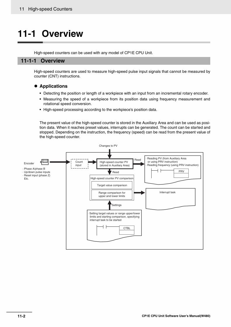
11 High-speed Counters
11-2 CP1E CPU Unit Software User’s Manual(W480)
11-1 Overview
High-speed counters can be used with any model of CP1E CPU Unit.
High-speed counters are used to measure high-speed pulse input signals that cannot be measured bycounter (CNT) instructions.
Applications• Detecting the position or length of a workpiece with an input from an incremental rotary encoder.
• Measuring the speed of a workpiece from its position data using frequency measurement androtational speed conversion.
• High-speed processing according to the workpiece’s position data.
The present value of the high-speed counter is stored in the Auxiliary Area and can be used as posi-tion data. When it reaches preset values, interrupts can be generated. The count can be started andstopped. Depending on the instruction, the frequency (speed) can be read from the present value ofthe high-speed counter.
11-1-1 Overview
Encoder
· Phase A/phase B· Up/down pulse inputs· Reset input (phase Z) Etc.
High-speed counter PV (stored in Auxiliary Area)
Changes to PV
Target value comparison
Interrupt task
· Reading PV (from Auxiliary Area or using PRV instruction)
· Reading frequency (using PRV instruction)
· Setting target values or range upper/lowerlimits and starting comparison, specifying interrupt task to be started
Read
PRV
CTBL
Count input
High-speed counter PV comparison
Read
Settings
Range comparison for upper and lower limits

11-3
11 High-speed Counters
CP1E CPU Unit Software User’s Manual(W480)
11-1 Overview
11
11-1-2 Flow
of Operation Precautions for Correct UsePrecautions for Correct Use
A built-in input cannot be used as a normal input, interrupt input, or quick-response input if it isbeing used as a high-speed counter input. Refer to 8-3-3 Allocating Built-in Input Terminals fordetails.
Click the Built-in Input Tab and select the Use high speed counter Check Box for high-speed counters0 to 5. Set the counting mode, reset method, and input setting.
11-1-2 Flow of Operation
1 • Enable the required high-speed counters.• Select the Use high speed counter Check Box for high-
speed counters 0 to 5. Set the input setting, counting mode and reset method on the Built-in Input Tab Page of the PLC Setup using the CX-Programmer.
• Terminals 00 to 06 on the CIO 0 terminal block can be used for high-speed counters. High-speed counters 0 to 5 correspond to terminals 00 to 06.
2 • Read the PV from Auxiliary Area or by executing a PRV instruction.
• Execute a PRV instruction.
PLC Setup
PLC Setup
Read counter PVCreateladder program Read counter frequency
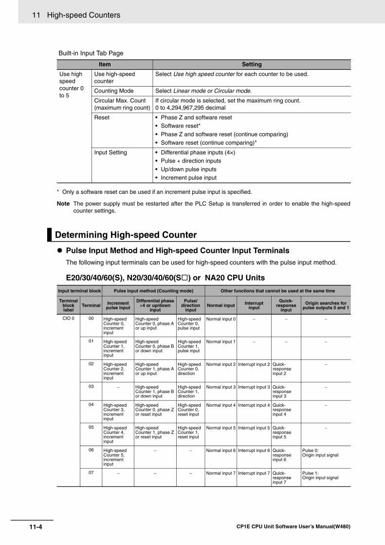
11 High-speed Counters
11-4 CP1E CPU Unit Software User’s Manual(W480)
Built-in Input Tab Page
* Only a software reset can be used if an increment pulse input is specified.
Note The power supply must be restarted after the PLC Setup is transferred in order to enable the high-speedcounter settings.
Pulse Input Method and High-speed Counter Input TerminalsThe following input terminals can be used for high-speed counters with the pulse input method.
E20/30/40/60(S), N20/30/40/60(S ) or NA20 CPU Units
Item Setting
Use high speed counter 0 to 5
Use high-speed counter
Select Use high speed counter for each counter to be used.
Counting Mode Select Linear mode or Circular mode.
Circular Max. Count(maximum ring count)
If circular mode is selected, set the maximum ring count. 0 to 4,294,967,295 decimal
Reset • Phase Z and software reset• Software reset*
• Phase Z and software reset (continue comparing)• Software reset (continue comparing)*
Input Setting • Differential phase inputs (4×)• Pulse + direction inputs
• Up/down pulse inputs• Increment pulse input
Determining High-speed Counter
Input terminal block Pulse input method (Counting mode) Other functions that cannot be used at the same time
Terminal block label
Terminal Increment pulse input
Differential phase ×4 or up/down
input
Pulse/direction
inputNormal input Interrupt
input
Quick-response
input
Origin searches for pulse outputs 0 and 1
CIO 0 00 High-speed Counter 0, increment input
High-speed Counter 0, phase A or up input
High-speed Counter 0, pulse input
Normal input 0 − − −
01 High-speed Counter 1, increment input
High-speed Counter 0, phase B or down input
High-speed Counter 1, pulse input
Normal input 1 − − −
02 High-speed Counter 2, increment input
High-speed Counter 1, phase A or up input
High-speed Counter 0, direction
Normal input 2 Interrupt input 2 Quick-response input 2
−
03 − High-speed Counter 1, phase B or down input
High-speed Counter 1, direction
Normal input 3 Interrupt input 3 Quick-response input 3
−
04 High-speed Counter 3, increment input
High-speed Counter 0, phase Z or reset input
High-speed Counter 0, reset input
Normal input 4 Interrupt input 4 Quick-response input 4
−
05 High-speed Counter 4, increment input
High-speed Counter 1, phase Z or reset input
High-speed Counter 1, reset input
Normal input 5 Interrupt input 5 Quick-response input 5
−
06 High-speed Counter 5, increment input
− − Normal input 6 Interrupt input 6 Quick-response input 6
Pulse 0: Origin input signal
07 − − − Normal input 7 Interrupt input 7 Quick-response input 7
Pulse 1: Origin input signal
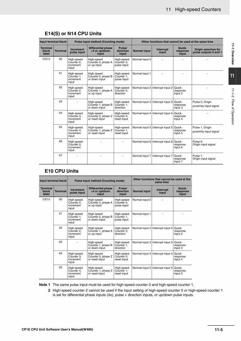
11-5
11 High-speed Counters
CP1E CPU Unit Software User’s Manual(W480)
11-1 Overview
11
11-1-2 Flow
of Operation
E14(S) or N14 CPU Units
E10 CPU Units
Note 1 The same pulse input must be used for high-speed counter 0 and high-speed counter 1.
2 High-speed counter 2 cannot be used if the input setting of high-speed counter 0 or high-speed counter 1is set for differential phase inputs (4x), pulse + direction inputs, or up/down pulse inputs.
Input terminal block Pulse input method (Counting mode) Other functions that cannot be used at the same time
Terminal block label
Terminal Increment pulse input
Differential phase ×4 or up/down
input
Pulse/direction
inputNormal input Interrupt
input
Quick-response
input
Origin searches for pulse outputs 0 and 1
CIO 0 00 High-speed Counter 0, increment input
High-speed Counter 0, phase A or up input
High-speed Counter 0, pulse input
Normal input 0 − − −
01 High-speed Counter 1, increment input
High-speed Counter 0, phase B or down input
High-speed Counter 1, pulse input
Normal input 1 − − −
02 High-speed Counter 2, increment input
High-speed Counter 1, phase A or up input
High-speed Counter 0, direction
Normal input 2 Interrupt input 2 Quick-response input 2
−
03 − High-speed Counter 1, phase B or down input
High-speed Counter 1, direction
Normal input 3 Interrupt input 3 Quick-response input 3
Pulse 0, Origin
proximity input signal
04 High-speed Counter 3, increment input
High-speed Counter 0, phase Z or reset input
High-speed Counter 0, reset input
Normal input 4 Interrupt input 4 Quick-response input 4
−
05 High-speed Counter 4, increment input
High-speed Counter 1, phase Z or reset input
High-speed Counter 1, reset input
Normal input 5 Interrupt input 5 Quick-response input 5
Pulse 1, Origin
proximity input signal
06 High-speed Counter 5, increment input
− − Normal input 6 Interrupt input 6 Quick-response input 6
Pulse 0: Origin input signal
07 − − − Normal input 7 Interrupt input 7 Quick-response input 7
Pulse 1: Origin input signal
Input terminal block Pulse input method (Counting mode) Other functions that cannot be used at the same time
Terminal block label
Terminal Increment pulse input
Differential phase ×4 or up/down
input
Pulse/direction
inputNormal input Interrupt
input
Quick-response
input
CIO 0 00 High-speed Counter 0, increment input
High-speed Counter 0, phase A or up input
High-speed Counter 0, pulse input
Normal input 0 − −
01 High-speed Counter 1, increment input
High-speed Counter 0, phase B or down input
High-speed Counter 1, pulse input
Normal input 1 − −
02 High-speed Counter 2, increment input
High-speed Counter 1, phase A or up input
High-speed Counter 0, direction
Normal input 2 Interrupt input 2 Quick-response input 2
03 − High-speed Counter 1, phase B or down input
High-speed Counter 1, direction
Normal input 3 Interrupt input 3 Quick-response input 3
04 High-speed Counter 3, increment input
High-speed Counter 0, phase Z or reset input
High-speed Counter 0, reset input
Normal input 4 Interrupt input 4 Quick-response input 4
05 High-speed Counter 4, increment input
High-speed Counter 1, phase Z or reset input
High-speed Counter 1, reset input
Normal input 5 Interrupt input 5 Quick-response input 5
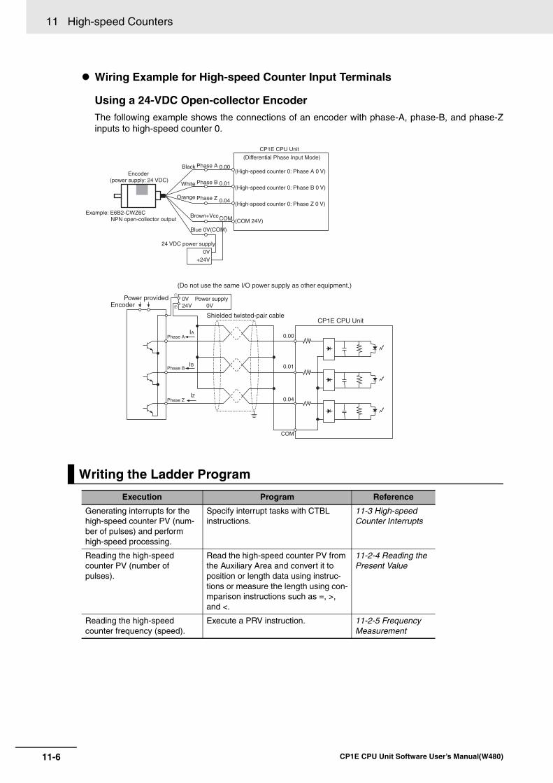
11 High-speed Counters
11-6 CP1E CPU Unit Software User’s Manual(W480)
Wiring Example for High-speed Counter Input Terminals
Using a 24-VDC Open-collector EncoderThe following example shows the connections of an encoder with phase-A, phase-B, and phase-Zinputs to high-speed counter 0.
Writing the Ladder Program
Execution Program Reference
Generating interrupts for the high-speed counter PV (num-ber of pulses) and perform high-speed processing.
Specify interrupt tasks with CTBL instructions.
11-3 High-speed Counter Interrupts
Reading the high-speed counter PV (number of pulses).
Read the high-speed counter PV from the Auxiliary Area and convert it to position or length data using instruc-tions or measure the length using con-mparison instructions such as =, >, and <.
11-2-4 Reading the Present Value
Reading the high-speed counter frequency (speed).
Execute a PRV instruction. 11-2-5 Frequency Measurement
0V+24V
0.00
0.01
0.04
COM (COM 24V)
0.00
0.01
0.04
COM
0V24V 0V
IA
IB
IZ
Encoder (power supply: 24 VDC)
Example: E6B2-CWZ6CNPN open-collector output
Black Phase A
White Phase B
Orange Phase Z
Brown+Vcc
Blue 0V(COM)
24 VDC power supply
CP1E CPU Unit
(Differential Phase Input Mode)
(High-speed counter 0: Phase A 0 V)
(High-speed counter 0: Phase B 0 V)
(High-speed counter 0: Phase Z 0 V)
Power providedEncoder
(Do not use the same I/O power supply as other equipment.)
Power supply
Shielded twisted-pair cableCP1E CPU Unit
Phase A
Phase B
Phase Z
1
2
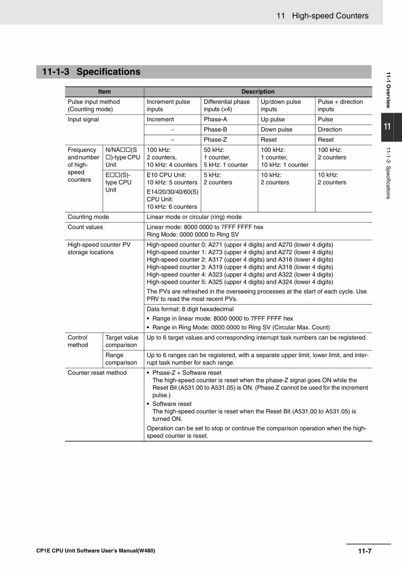
11-7
11 High-speed Counters
CP1E CPU Unit Software User’s Manual(W480)
11-1 Overview
11
11-1-3 Specifications
11-1-3 Specifications
Item Description
Pulse input method (Counting mode)
Increment pulse inputs
Differential phase inputs (×4)
Up/down pulse inputs
Pulse + direction inputs
Input signal Increment Phase-A Up pulse Pulse
− Phase-B Down pulse Direction
− Phase-Z Reset Reset
Frequency and number of high-speed counters
N/NA (S)-type CPU
Unit
100 kHz: 2 counters,10 kHz: 4 counters
50 kHz: 1 counter,5 kHz: 1 counter
100 kHz: 1 counter,10 kHz: 1 counter
100 kHz: 2 counters
E (S)-type CPU Unit
E10 CPU Unit: 10 kHz: 5 counters
E14/20/30/40/60(S)CPU Unit: 10 kHz: 6 counters
5 kHz: 2 counters
10 kHz: 2 counters
10 kHz: 2 counters
Counting mode Linear mode or circular (ring) mode
Count values Linear mode: 8000 0000 to 7FFF FFFF hexRing Mode: 0000 0000 to Ring SV
High-speed counter PV storage locations
High-speed counter 0: A271 (upper 4 digits) and A270 (lower 4 digits)High-speed counter 1: A273 (upper 4 digits) and A272 (lower 4 digits)High-speed counter 2: A317 (upper 4 digits) and A316 (lower 4 digits)High-speed counter 3: A319 (upper 4 digits) and A318 (lower 4 digits)High-speed counter 4: A323 (upper 4 digits) and A322 (lower 4 digits)High-speed counter 5: A325 (upper 4 digits) and A324 (lower 4 digits)
The PVs are refreshed in the overseeing processes at the start of each cycle. Use PRV to read the most recent PVs.
Data format: 8 digit hexadecimal
• Range in linear mode: 8000 0000 to 7FFF FFFF hex
• Range in Ring Mode: 0000 0000 to Ring SV (Circular Max. Count)
Control method
Target value comparison
Up to 6 target values and corresponding interrupt task numbers can be registered.
Range comparison
Up to 6 ranges can be registered, with a separate upper limit, lower limit, and inter-rupt task number for each range.
Counter reset method • Phase-Z + Software resetThe high-speed counter is reset when the phase-Z signal goes ON while the Reset Bit (A531.00 to A531.05) is ON. (Phase Z cannot be used for the increment pulse.)
• Software resetThe high-speed counter is reset when the Reset Bit (A531.00 to A531.05) is turned ON.
Operation can be set to stop or continue the comparison operation when the high-speed counter is reset.
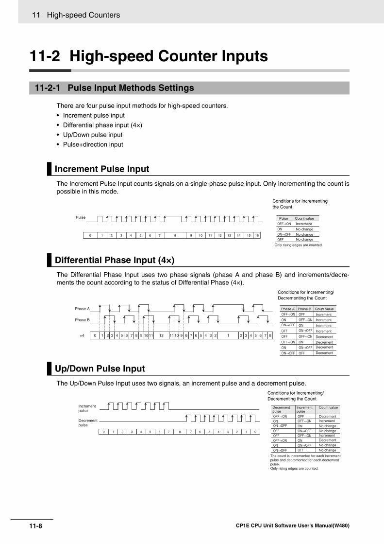
11 High-speed Counters
11-8 CP1E CPU Unit Software User’s Manual(W480)
11-2 High-speed Counter Inputs
There are four pulse input methods for high-speed counters.
• Increment pulse input
• Differential phase input (4×)
• Up/Down pulse input
• Pulse+direction input
The Increment Pulse Input counts signals on a single-phase pulse input. Only incrementing the count ispossible in this mode.
The Differential Phase Input uses two phase signals (phase A and phase B) and increments/decre-ments the count according to the status of Differential Phase (4×).
The Up/Down Pulse Input uses two signals, an increment pulse and a decrement pulse.
11-2-1 Pulse Input Methods Settings
Increment Pulse Input
Conditions for Incrementing the Count
Differential Phase Input (4×)
Conditions for Incrementing/Decrementing the Count
Up/Down Pulse Input
Conditions for Incrementing/Decrementing the Count
Pulse
142 151 160 9 10876 115 124 133
Pulse Count value
Increment
No change
No changeNo change
· Only rising edges are counted.
OFF→ON
ON
ON→OFF
OFF
111211 1010 99 888 777 666 555 444 333 222 110
Phase A
Phase B
×4
Phase A Phase B Count value
Increment
Increment
Increment
Increment
Decrement
DecrementDecrement
Decrement
OFF
ON
OFF→ON
ON→OFF
ON→OFF
ON→OFF
ON→OFF
OFF→ON
OFF→ON
ON
OFF
OFF
OFF→ON ON
ON
OFF
Increment pulse
Decrement pulse
22 11 00 7 6876 55 44 33
Increment pulse
Decrement pulse
Count value
DecrementIncrement
Increment
· The count is incremented for each increment pulse and decremented for each decrement pulse.
· Only rising edges are counted.
No changeNo change
No changeNo change
Decrement
OFFON
ONOFFOFF
ONON
OFF
ON→OFF
ON→OFFON→OFF
ON→OFF
OFF→ON
OFF→ONOFF→ON
OFF→ON
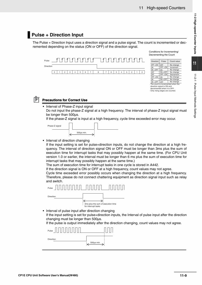
11-9
11 High-speed Counters
CP1E CPU Unit Software User’s Manual(W480)
11-2 Hig
h-sp
eed C
ou
nter In
pu
ts
11
11-2-1 Pulse Input M
ethods Settings
The Pulse + Direction Input uses a direction signal and a pulse signal. The count is incremented or dec-remented depending on the status (ON or OFF) of the direction signal.
Precautions for Correct UsePrecautions for Correct Use
• Interval of Phase-Z input signalDo not input the phase-Z signal at a high frequency. The interval of phase-Z input signal mustbe longer than 500µs.If the phase-Z signal is input at a high frequency, cycle time exceeded error may occur.
• Interval of direction changingIf the input setting is set for pulse+direction inputs, do not change the direction at a high fre-quency. The interval of direction signal ON or OFF must be longer than 3ms plus the sum ofexecution time for interrupt tasks that may possibly happen at the same time. (For CPU Unitversion 1.0 or earlier, the interval must be longer than 6 ms plus the sum of execution time forinterrupt tasks that may possibly happen at the same time.)The sum of execution time for interrupt tasks in one cycle is stored in A442. If the direction signal is ON or OFF at a high frequency, count values may not agree.Cycle time exceeded error possibly occurs when changing the direction at a high frequency.Therefore, please do not connect chattering equipment as direction signal input such as relayand switch.
• Interval of pulse input after direction changingIf the input setting is set for pulse+direction inputs, the Interval of pulse input after the directionchanging must be longer than 500µs.If the pulse is output immediately after the direction changing, count values may not agree.
Pulse + Direction Input
Conditions for Incrementing/Decrementing the Count
Pulse
Direction
22 11 00 7 6876 55 44 33
Direction Pulse Count value
No change
No changeNo change
No changeNo changeNo change
Decrement
Increment
· The count is incremented when the direction signal is ON and decremented when it is OFF.
· Only rising edges are counted.
OFF
ON
ON
OFF
ON→OFF
ON→OFF
OFF→ON
OFF→ONON
OFFOFF
ONON→OFF
ON→OFF
OFF→ON
OFF→ON
500µs min.
Phase-Z signal
3ms plus the sum of execution time for interrupt tasks
Pulse
Direction
500µs min.
Pulse
Direction
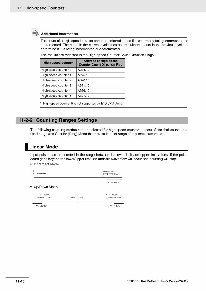
11 High-speed Counters
11-10 CP1E CPU Unit Software User’s Manual(W480)
Additional Information
The count of a high-speed counter can be monitored to see if it is currently being incremented ordecremented. The count in the current cycle is compared with the count in the previous cycle todetermine if it is being incremented or decremented.
The results are reflected in the High-speed Counter Count Direction Flags.
* High-speed counter 5 is not supported by E10 CPU Units.
The following counting modes can be selected for high-speed counters: Linear Mode that counts in afixed range and Circular (Ring) Mode that counts in a set range of any maximum value.
Input pulses can be counted in the range between the lower limit and upper limit values. If the pulsecount goes beyond the lower/upper limit, an underflow/overflow will occur and counting will stop.
• Increment Mode
• Up/Down Mode
High-speed counterAddress of High-speed
Counter Count Direction Flag
High-speed counter 0 A274.10
High-speed counter 1 A275.10
High-speed counter 2 A320.10
High-speed counter 3 A321.10
High-speed counter 4 A326.10
High-speed counter 5* A327.10
11-2-2 Counting Ranges Settings
Linear Mode
0(000000 Hex)
4294967295(FFFFFFFF Hex)
PV overflow
+2147483647(7FFFFFFF Hex)
-2147483648(80000000 Hex)
0(00000000 Hex)
PV underflow PV overflow
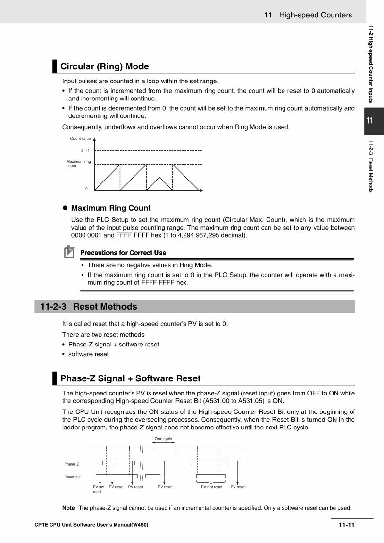
11-11
11 High-speed Counters
CP1E CPU Unit Software User’s Manual(W480)
11-2 Hig
h-sp
eed C
ou
nter In
pu
ts
11
11-2-3 Reset M
ethods
Input pulses are counted in a loop within the set range.
• If the count is incremented from the maximum ring count, the count will be reset to 0 automaticallyand incrementing will continue.
• If the count is decremented from 0, the count will be set to the maximum ring count automatically anddecrementing will continue.
Consequently, underflows and overflows cannot occur when Ring Mode is used.
Maximum Ring CountUse the PLC Setup to set the maximum ring count (Circular Max. Count), which is the maximumvalue of the input pulse counting range. The maximum ring count can be set to any value between0000 0001 and FFFF FFFF hex (1 to 4,294,967,295 decimal).
Precautions for Correct UsePrecautions for Correct Use
• There are no negative values in Ring Mode.
• If the maximum ring count is set to 0 in the PLC Setup, the counter will operate with a maxi-mum ring count of FFFF FFFF hex.
It is called reset that a high-speed counter’s PV is set to 0.
There are two reset methods
• Phase-Z signal + software reset
• software reset
The high-speed counter’s PV is reset when the phase-Z signal (reset input) goes from OFF to ON whilethe corresponding High-speed Counter Reset Bit (A531.00 to A531.05) is ON.
The CPU Unit recognizes the ON status of the High-speed Counter Reset Bit only at the beginning ofthe PLC cycle during the overseeing processes. Consequently, when the Reset Bit is turned ON in theladder program, the phase-Z signal does not become effective until the next PLC cycle.
Note The phase-Z signal cannot be used if an incremental counter is specified. Only a software reset can be used.
Circular (Ring) Mode
11-2-3 Reset Methods
Phase-Z Signal + Software Reset
0
2 32-1
Maximum ring count
Count value
One cycle
Phase Z
Reset bit
PV not reset
PV not resetPV reset PV reset PV reset PV reset
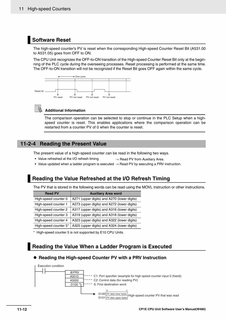
11 High-speed Counters
11-12 CP1E CPU Unit Software User’s Manual(W480)
The high-speed counter’s PV is reset when the corresponding High-speed Counter Reset Bit (A531.00to A531.05) goes from OFF to ON.
The CPU Unit recognizes the OFF-to-ON transition of the High-speed Counter Reset Bit only at the begin-ning of the PLC cycle during the overseeing processes. Reset processing is performed at the same time.The OFF-to-ON transition will not be recognized if the Reset Bit goes OFF again within the same cycle.
Additional Information
The comparison operation can be selected to stop or continue in the PLC Setup when a high-speed counter is reset. This enables applications where the comparison operation can berestarted from a counter PV of 0 when the counter is reset.
The present value of a high-speed counter can be read in the following two ways.
The PV that is stored in the following words can be read using the MOVL instruction or other instructions.
* High-speed counter 5 is not supported by E10 CPU Units.
Reading the High-speed Counter PV with a PRV Instruction
Software Reset
11-2-4 Reading the Present Value
• Value refreshed at the I/O refresh timing → Read PV from Auxiliary Area.• Value updated when a ladder program is executed → Read PV by executing a PRV instruction.
Reading the Value Refreshed at the I/O Refresh Timing
Read PV Auxiliary Area word
High-speed counter 0 A271 (upper digits) and A270 (lower digits)
High-speed counter 1 A273 (upper digits) and A272 (lower digits)
High-speed counter 2 A317 (upper digits) and A316 (lower digits)
High-speed counter 3 A319 (upper digits) and A318 (lower digits)
High-speed counter 4 A323 (upper digits) and A322 (lower digits)
High-speed counter 5* A325 (upper digits) and A324 (lower digits)
Reading the Value When a Ladder Program is Executed
One cycle
Reset bit
PV reset PV not reset PV not reset PV not reset
@PRV#0010#0000D100
15 0
D100D101
C1: Port specifier (example for high-speed counter input 0 (fixed))C2: Control data (for reading PV)S: First destination word
PV data lower bytes
PV data upper bytesHigh-speed counter PV that was read
Execution condition
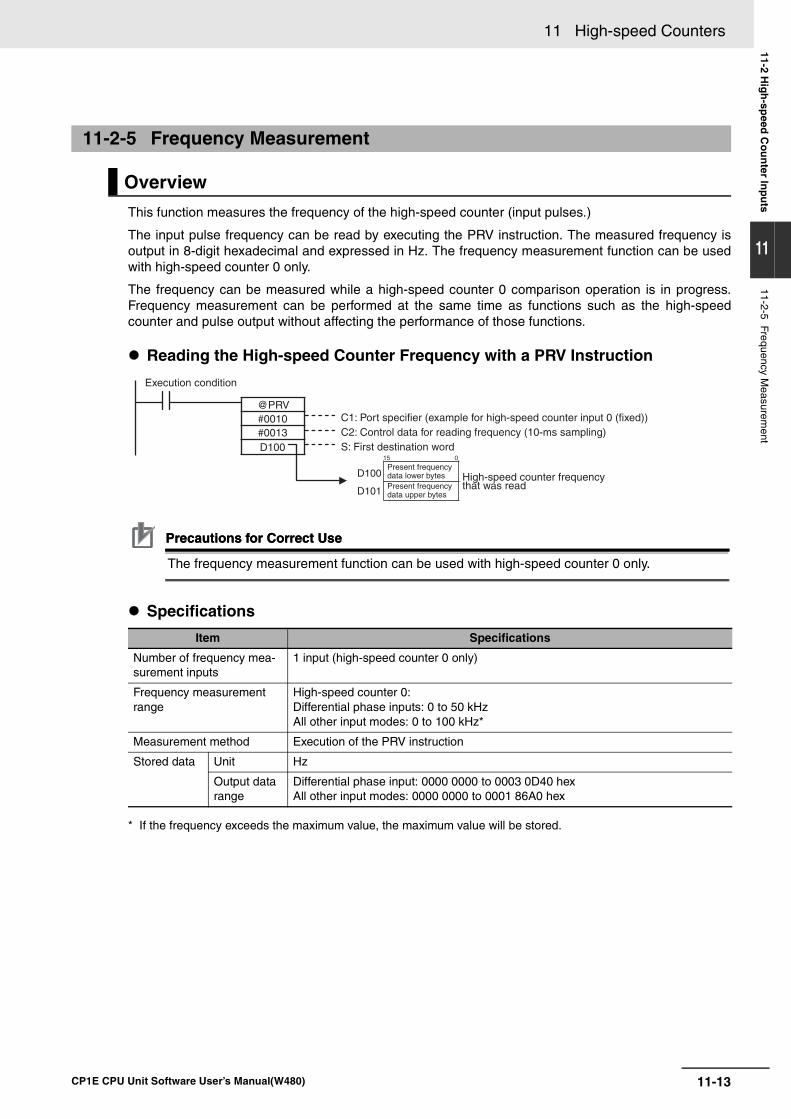
11-13
11 High-speed Counters
CP1E CPU Unit Software User’s Manual(W480)
11-2 Hig
h-sp
eed C
ou
nter In
pu
ts
11
11-2-5 Frequency Measurem
ent
This function measures the frequency of the high-speed counter (input pulses.)
The input pulse frequency can be read by executing the PRV instruction. The measured frequency isoutput in 8-digit hexadecimal and expressed in Hz. The frequency measurement function can be usedwith high-speed counter 0 only.
The frequency can be measured while a high-speed counter 0 comparison operation is in progress.Frequency measurement can be performed at the same time as functions such as the high-speedcounter and pulse output without affecting the performance of those functions.
Reading the High-speed Counter Frequency with a PRV Instruction
Precautions for Correct UsePrecautions for Correct Use
The frequency measurement function can be used with high-speed counter 0 only.
Specifications
* If the frequency exceeds the maximum value, the maximum value will be stored.
11-2-5 Frequency Measurement
Overview
Item Specifications
Number of frequency mea-surement inputs
1 input (high-speed counter 0 only)
Frequency measurement range
High-speed counter 0:Differential phase inputs: 0 to 50 kHzAll other input modes: 0 to 100 kHz*
Measurement method Execution of the PRV instruction
Stored data Unit Hz
Output data range
Differential phase input: 0000 0000 to 0003 0D40 hex All other input modes: 0000 0000 to 0001 86A0 hex
@PRV#0010#0013D100
15 0
D100
D101 Present frequency data upper bytes
Execution condition
C1: Port specifier (example for high-speed counter input 0 (fixed))C2: Control data for reading frequency (10-ms sampling)S: First destination word
Present frequency data lower bytes High-speed counter frequency
that was read
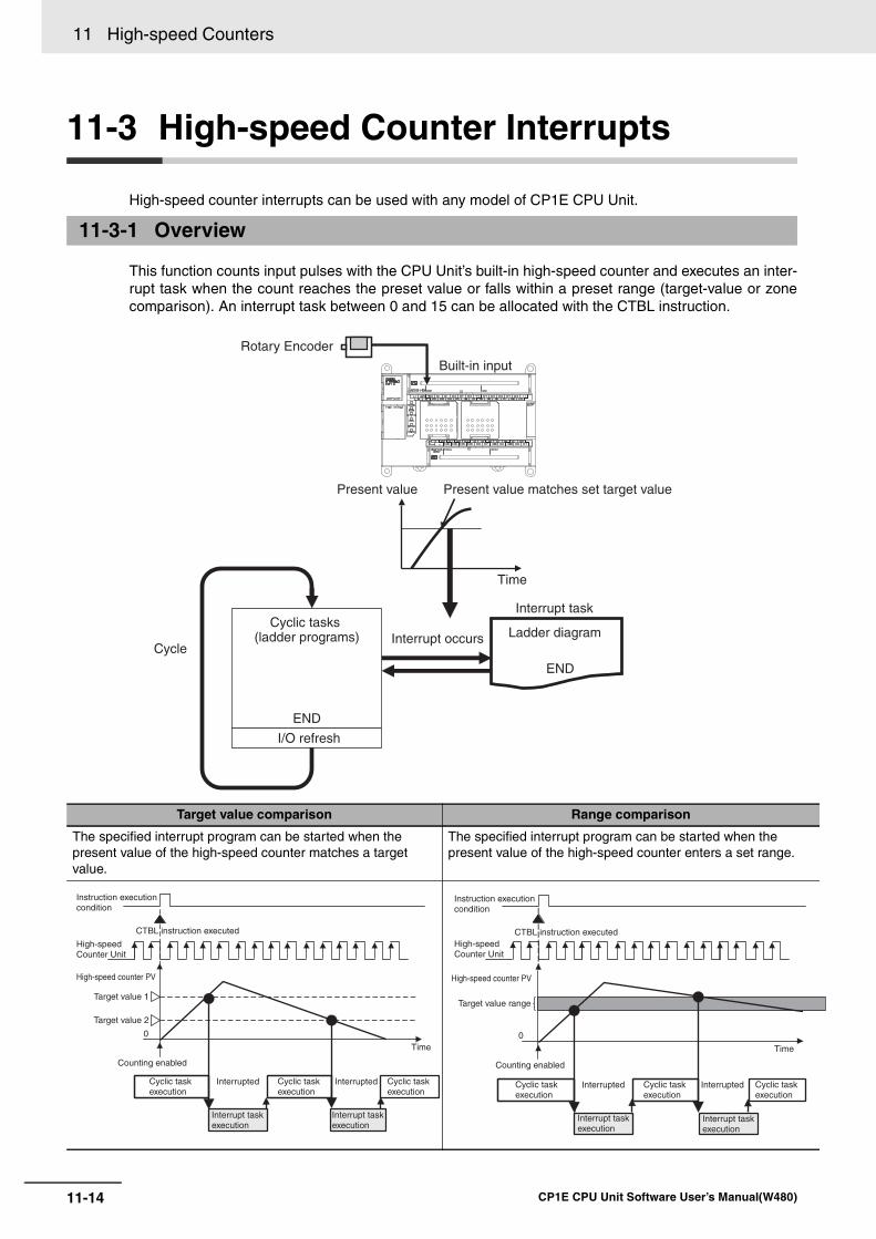
11 High-speed Counters
11-14 CP1E CPU Unit Software User’s Manual(W480)
11-3 High-speed Counter Interrupts
High-speed counter interrupts can be used with any model of CP1E CPU Unit.
This function counts input pulses with the CPU Unit’s built-in high-speed counter and executes an inter-rupt task when the count reaches the preset value or falls within a preset range (target-value or zonecomparison). An interrupt task between 0 and 15 can be allocated with the CTBL instruction.
11-3-1 Overview
Target value comparison Range comparison
The specified interrupt program can be started when the present value of the high-speed counter matches a target value.
The specified interrupt program can be started when the present value of the high-speed counter enters a set range.
END
END
Cycle
Rotary Encoder
Built-in input
Present value Present value matches set target value
Time
Interrupt task
Ladder diagramInterrupt occursCyclic tasks
(ladder programs)
I/O refresh
0
Instruction execution condition
CTBL instruction executed
High-speed Counter Unit
High-speed counter PV
Target value 1
Target value 2
Counting enabled
Time
Cyclic task execution
Cyclic task execution
Cyclic task execution
Interrupted Interrupted
Interrupt task execution
Interrupt task execution
0
Instruction execution condition
CTBL instruction executedHigh-speed Counter Unit
High-speed counter PV
Target value range
Counting enabled
Cyclic task execution
Cyclic task execution
Cyclic task execution
Interrupted Interrupted
Interrupt task execution
Interrupt task execution
Time
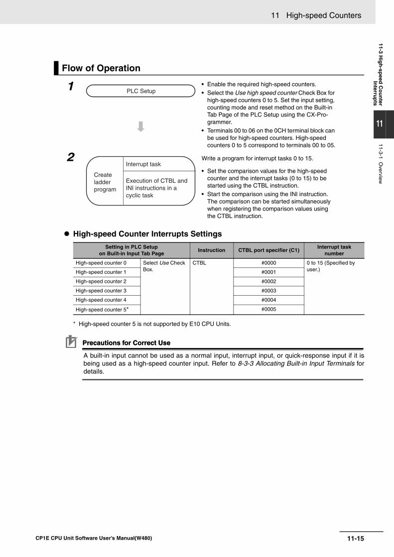
11-15
11 High-speed Counters
CP1E CPU Unit Software User’s Manual(W480)
11-3 Hig
h-sp
eed C
ou
nter
Interru
pts
11
11-3-1 Overview
High-speed Counter Interrupts Settings
* High-speed counter 5 is not supported by E10 CPU Units.
Precautions for Correct UsePrecautions for Correct Use
A built-in input cannot be used as a normal input, interrupt input, or quick-response input if it isbeing used as a high-speed counter input. Refer to 8-3-3 Allocating Built-in Input Terminals fordetails.
Flow of Operation
1 • Enable the required high-speed counters.• Select the Use high speed counter Check Box for
high-speed counters 0 to 5. Set the input setting, counting mode and reset method on the Built-in Tab Page of the PLC Setup using the CX-Pro-grammer.
• Terminals 00 to 06 on the 0CH terminal block can be used for high-speed counters. High-speed counters 0 to 5 correspond to terminals 00 to 05.
2 Write a program for interrupt tasks 0 to 15.
• Set the comparison values for the high-speed counter and the interrupt tasks (0 to 15) to be started using the CTBL instruction.
• Start the comparison using the INI instruction. The comparison can be started simultaneously when registering the comparison values using the CTBL instruction.
Setting in PLC Setupon Built-in Input Tab Page
Instruction CTBL port specifier (C1)Interrupt task
number
High-speed counter 0 Select Use Check Box.
CTBL #0000 0 to 15 (Specified by user.) High-speed counter 1 #0001
High-speed counter 2 #0002
High-speed counter 3 #0003
High-speed counter 4 #0004
High-speed counter 5* #0005
PLC Setup
Createladder program
Interrupt task
Execution of CTBL and INI instructions in a cyclic task
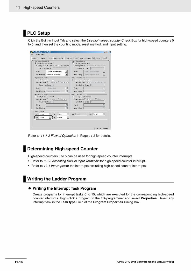
11 High-speed Counters
11-16 CP1E CPU Unit Software User’s Manual(W480)
Click the Built-in Input Tab and select the Use high-speed counter Check Box for high-speed counters 0to 5, and then set the counting mode, reset method, and input setting.
Refer to 11-1-2 Flow of Operation in Page 11-3 for details.
High-speed counters 0 to 5 can be used for high-speed counter interrupts.
• Refer to 8-3-3 Allocating Built-in Input Terminals for high-speed counter interrupt.
• Refer to 10-1 Interrupts for the interrupts excluding high-speed counter interrupts.
Writing the Interrupt Task ProgramCreate programs for interrupt tasks 0 to 15, which are executed for the corresponding high-speedcounter interrupts. Right-click a program in the CX-programmer and select Properties. Select anyinterrupt task in the Task type Field of the Program Properties Dialog Box.
PLC Setup
Determining High-speed Counter
Writing the Ladder Program
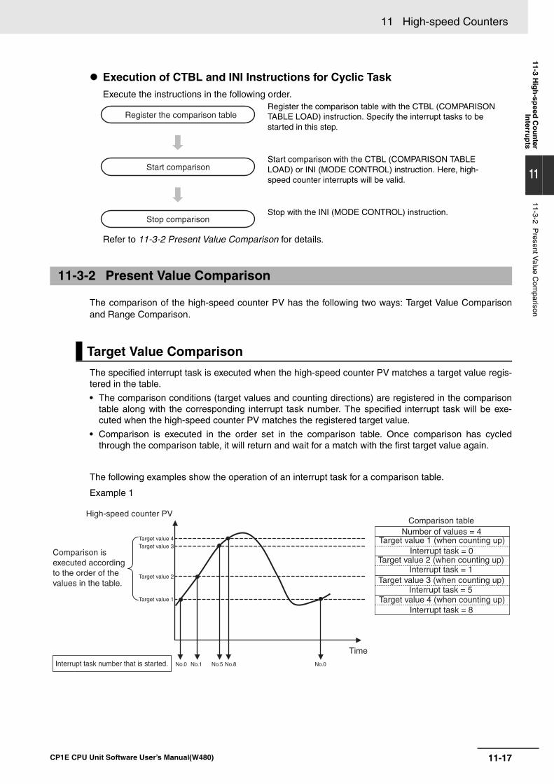
11-17
11 High-speed Counters
CP1E CPU Unit Software User’s Manual(W480)
11-3 Hig
h-sp
eed C
ou
nter
Interru
pts
11
11-3-2 Present V
alue Com
parison
Execution of CTBL and INI Instructions for Cyclic TaskExecute the instructions in the following order.
Refer to 11-3-2 Present Value Comparison for details.
The comparison of the high-speed counter PV has the following two ways: Target Value Comparisonand Range Comparison.
The specified interrupt task is executed when the high-speed counter PV matches a target value regis-tered in the table.
• The comparison conditions (target values and counting directions) are registered in the comparisontable along with the corresponding interrupt task number. The specified interrupt task will be exe-cuted when the high-speed counter PV matches the registered target value.
• Comparison is executed in the order set in the comparison table. Once comparison has cycledthrough the comparison table, it will return and wait for a match with the first target value again.
The following examples show the operation of an interrupt task for a comparison table.
Example 1
Register the comparison table with the CTBL (COMPARISON TABLE LOAD) instruction. Specify the interrupt tasks to be started in this step.
Start comparison with the CTBL (COMPARISON TABLE LOAD) or INI (MODE CONTROL) instruction. Here, high-speed counter interrupts will be valid.
Stop with the INI (MODE CONTROL) instruction.
11-3-2 Present Value Comparison
Target Value Comparison
Register the comparison table
Start comparison
Stop comparison
No.0 No.1 No.5 No.8 No.0
High-speed counter PV
Comparison is executed according to the order of the values in the table.
Target value 4Target value 3
Target value 2
Target value 1
Interrupt task number that is started.
Time
Comparison tableNumber of values = 4
Target value 1 (when counting up)Interrupt task = 0
Target value 2 (when counting up)Interrupt task = 1
Target value 3 (when counting up)Interrupt task = 5
Target value 4 (when counting up)Interrupt task = 8
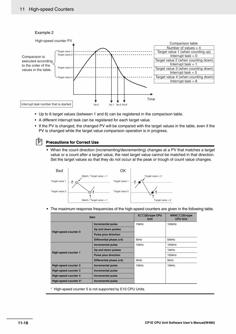
11 High-speed Counters
11-18 CP1E CPU Unit Software User’s Manual(W480)
Example 2
• Up to 6 target values (between 1 and 6) can be registered in the comparison table.
• A different interrupt task can be registered for each target value.
• If the PV is changed, the changed PV will be compared with the target values in the table, even if thePV is changed while the target value comparison operation is in progress.
Precautions for Correct UsePrecautions for Correct Use
• When the count direction (incrementing/decrementing) changes at a PV that matches a targetvalue or a count after a target value, the next target value cannot be matched in that direction.Set the target values so that they do not occur at the peak or trough of count value changes.
• The maximum response frequencies of the high-speed counters are given in the following table.
* High-speed counter 5 is not supported by E10 CPU Units.
ItemE (S)-type CPU
UnitN/NA (S)-type
CPU Unit
High-speed counter 0
Incremental pulse 10kHz 100kHz
Up and down pulses
Pulse plus direction
Differential phase (×4) 5kHz 50kHz
High-speed counter 1
Incremental pulse 10kHz 100kHz
Up and down pulses 10kHz
Pulse plus direction 100kHz
Differential phase (×4) 5kHz 5kHz
High-speed counter 2 Incremental pulse 10kHz 10kHz
High-speed counter 3 Incremental pulse
High-speed counter 4 Incremental pulse
High-speed counter 5* Incremental pulse
No.1 No.5 No.8No.0
High-speed counter PV
Comparison is executed according to the order of the values in the table.
Target value 1Target value 2
Target value 3
Target value 4
Interrupt task number that is started.
Time
Comparison tableNumber of values = 4
Target value 1 (when counting up)Interrupt task = 0
Target value 2 (when counting down)Interrupt task = 1
Target value 3 (when counting down)Interrupt task = 5
Target value 4 (when counting down)Interrupt task = 8
Match / Target value + 1 Target value + 2
Target value 1 Target value 1
Target value 2 Target value 2
Match / Target value + 1 Target value + 2
Bad OK
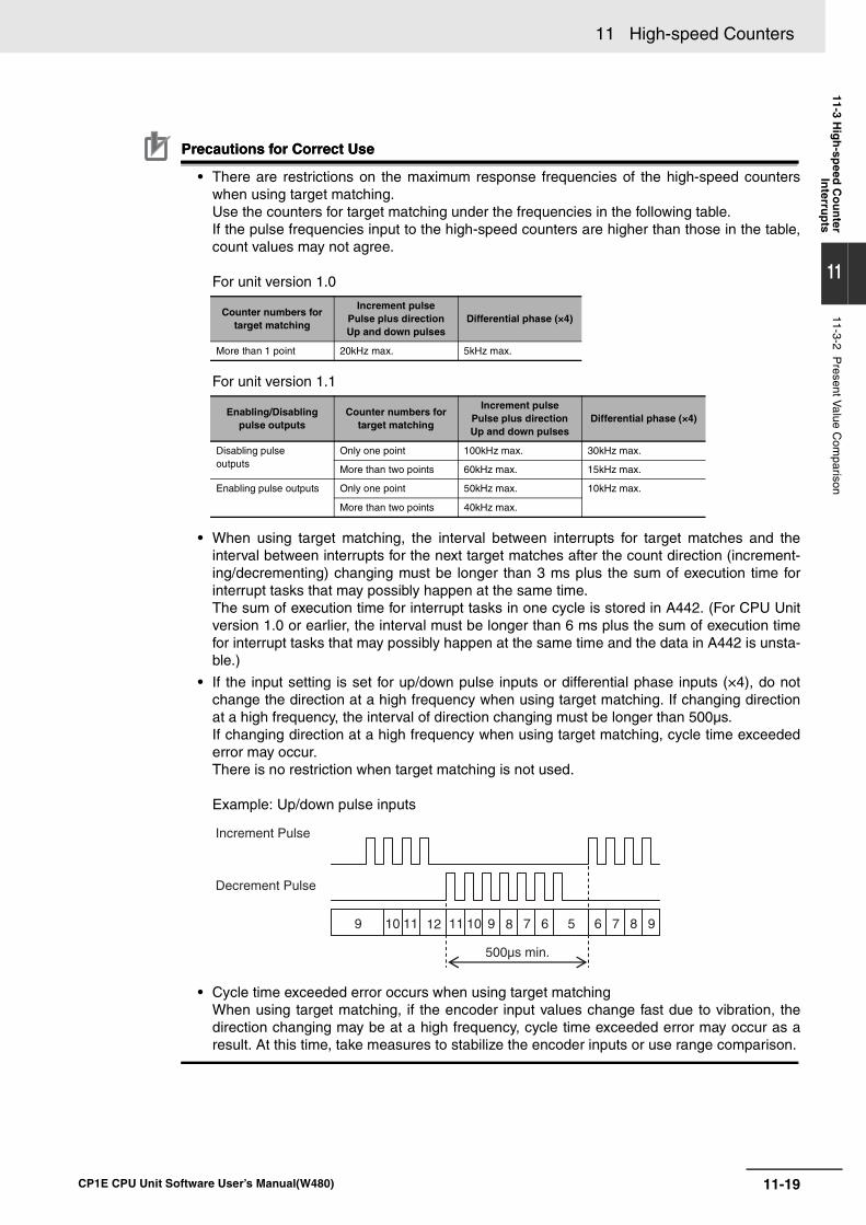
11-19
11 High-speed Counters
CP1E CPU Unit Software User’s Manual(W480)
11-3 Hig
h-sp
eed C
ou
nter
Interru
pts
11
11-3-2 Present V
alue Com
parison
Precautions for Correct UsePrecautions for Correct Use
• There are restrictions on the maximum response frequencies of the high-speed counterswhen using target matching.Use the counters for target matching under the frequencies in the following table.If the pulse frequencies input to the high-speed counters are higher than those in the table,count values may not agree.
For unit version 1.0
For unit version 1.1
• When using target matching, the interval between interrupts for target matches and theinterval between interrupts for the next target matches after the count direction (increment-ing/decrementing) changing must be longer than 3 ms plus the sum of execution time forinterrupt tasks that may possibly happen at the same time.The sum of execution time for interrupt tasks in one cycle is stored in A442. (For CPU Unitversion 1.0 or earlier, the interval must be longer than 6 ms plus the sum of execution timefor interrupt tasks that may possibly happen at the same time and the data in A442 is unsta-ble.)
• If the input setting is set for up/down pulse inputs or differential phase inputs (×4), do notchange the direction at a high frequency when using target matching. If changing directionat a high frequency, the interval of direction changing must be longer than 500µs.If changing direction at a high frequency when using target matching, cycle time exceedederror may occur.There is no restriction when target matching is not used.
Example: Up/down pulse inputs
• Cycle time exceeded error occurs when using target matchingWhen using target matching, if the encoder input values change fast due to vibration, thedirection changing may be at a high frequency, cycle time exceeded error may occur as aresult. At this time, take measures to stabilize the encoder inputs or use range comparison.
Counter numbers for target matching
Increment pulsePulse plus directionUp and down pulses
Differential phase (×4)
More than 1 point 20kHz max. 5kHz max.
Enabling/Disabling pulse outputs
Counter numbers for target matching
Increment pulsePulse plus directionUp and down pulses
Differential phase (×4)
Disabling pulse outputs
Only one point 100kHz max. 30kHz max.
More than two points 60kHz max. 15kHz max.
Enabling pulse outputs Only one point 50kHz max. 10kHz max.
More than two points 40kHz max.
12 11 10 9 891011 7 6 5 6 7 8 9
Increment Pulse
Decrement Pulse
500µs min.
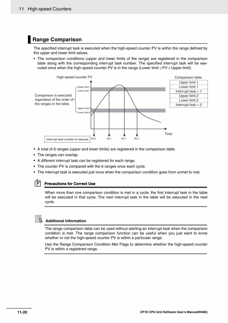
11 High-speed Counters
11-20 CP1E CPU Unit Software User’s Manual(W480)
The specified interrupt task is executed when the high-speed counter PV is within the range defined bythe upper and lower limit values.
• The comparison conditions (upper and lower limits of the range) are registered in the comparisontable along with the corresponding interrupt task number. The specified interrupt task will be exe-cuted once when the high-speed counter PV is in the range (Lower limit ≤ PV ≤ Upper limit).
• A total of 6 ranges (upper and lower limits) are registered in the comparison table.
• The ranges can overlap.
• A different interrupt task can be registered for each range.
• The counter PV is compared with the 6 ranges once each cycle.
• The interrupt task is executed just once when the comparison condition goes from unmet to met.
Precautions for Correct UsePrecautions for Correct Use
When more than one comparison condition is met in a cycle, the first interrupt task in the tablewill be executed in that cycle. The next interrupt task in the table will be executed in the nextcycle.
Additional Information
The range comparison table can be used without starting an interrupt task when the comparisoncondition is met. The range comparison function can be useful when you just want to knowwhether or not the high-speed counter PV is within a particular range.
Use the Range Comparison Condition Met Flags to determine whether the high-speed counterPV is within a registered range.
Range Comparison
No.2 No.1 No.1 No.2
High-speed counter PV
Comparison is executed regardless of the order of the ranges in the table.
Upper limit 1
Lower limit 1
Upper limit 2
Lower limit 2
Interrupt task number to execute
Time
Comparison tableUpper limit 1Lower limit 1
Interrupt task = 1Upper limit 2Lower limit 2
Interrupt task = 2
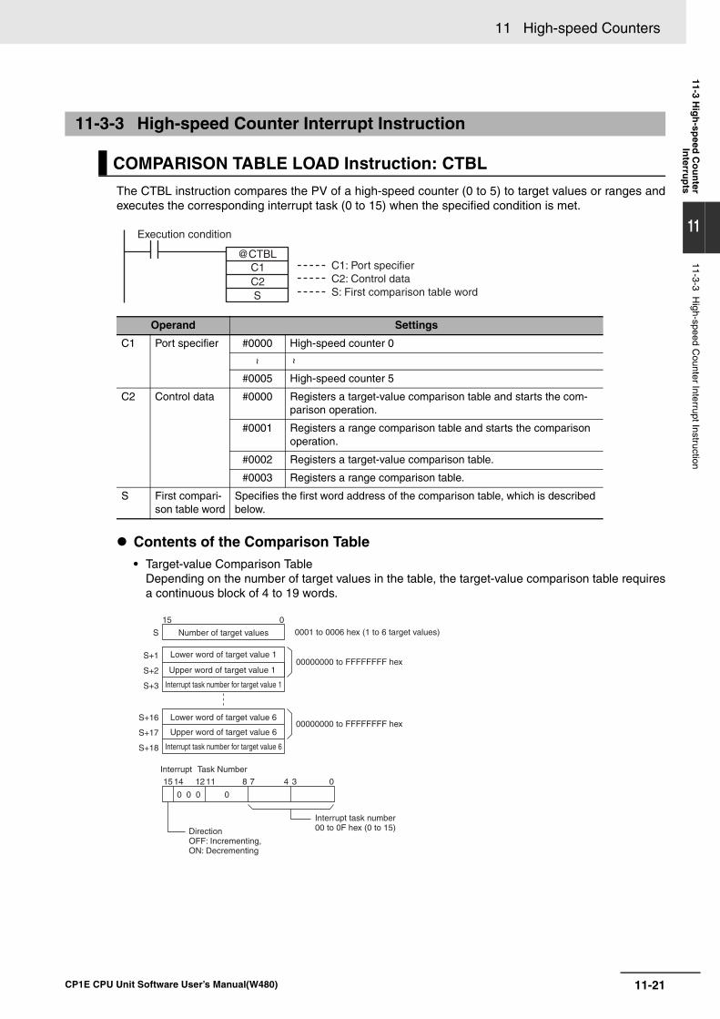
11-21
11 High-speed Counters
CP1E CPU Unit Software User’s Manual(W480)
11-3 Hig
h-sp
eed C
ou
nter
Interru
pts
11
11-3-3 High-speed C
ounter Interrupt Instruction
The CTBL instruction compares the PV of a high-speed counter (0 to 5) to target values or ranges andexecutes the corresponding interrupt task (0 to 15) when the specified condition is met.
Contents of the Comparison Table• Target-value Comparison Table
Depending on the number of target values in the table, the target-value comparison table requiresa continuous block of 4 to 19 words.
11-3-3 High-speed Counter Interrupt Instruction
COMPARISON TABLE LOAD Instruction: CTBL
Operand Settings
C1 Port specifier #0000 High-speed counter 0
~ ~
#0005 High-speed counter 5
C2 Control data #0000 Registers a target-value comparison table and starts the com-parison operation.
#0001 Registers a range comparison table and starts the comparison operation.
#0002 Registers a target-value comparison table.
#0003 Registers a range comparison table.
S First compari-son table word
Specifies the first word address of the comparison table, which is described below.
@CTBLC1C2S
Execution condition
C1: Port specifierC2: Control dataS: First comparison table word
S+1
S+2
S+3
S
015
03478
0 0 0 0
11121415
S+16
S+17
S+18
Upper word of target value 1
Interrupt task number for target value 1
00000000 to FFFFFFFF hex
00000000 to FFFFFFFF hex
Number of target values 0001 to 0006 hex (1 to 6 target values)
Interrupt Task Number
Interrupt task number00 to 0F hex (0 to 15)Direction
OFF: Incrementing, ON: Decrementing
Upper word of target value 6
Interrupt task number for target value 6
Lower word of target value 1
Lower word of target value 6
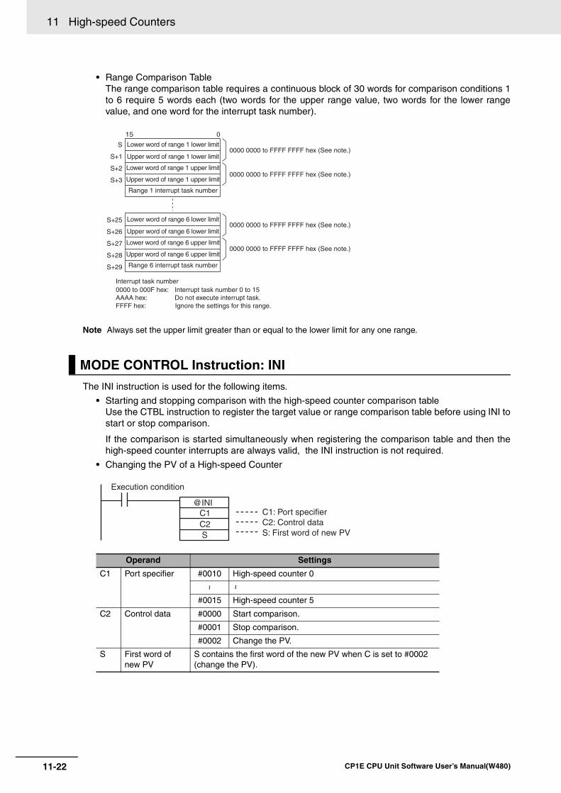
11 High-speed Counters
11-22 CP1E CPU Unit Software User’s Manual(W480)
• Range Comparison TableThe range comparison table requires a continuous block of 30 words for comparison conditions 1to 6 require 5 words each (two words for the upper range value, two words for the lower rangevalue, and one word for the interrupt task number).
Note Always set the upper limit greater than or equal to the lower limit for any one range.
The INI instruction is used for the following items.
• Starting and stopping comparison with the high-speed counter comparison tableUse the CTBL instruction to register the target value or range comparison table before using INI tostart or stop comparison.
If the comparison is started simultaneously when registering the comparison table and then thehigh-speed counter interrupts are always valid, the INI instruction is not required.
• Changing the PV of a High-speed Counter
MODE CONTROL Instruction: INI
Operand Settings
C1 Port specifier #0010 High-speed counter 0
~ ~
#0015 High-speed counter 5
C2 Control data #0000 Start comparison.
#0001 Stop comparison.
#0002 Change the PV.
S First word of new PV
S contains the first word of the new PV when C is set to #0002 (change the PV).
S
S+1
S+2
S+3
015
S+25
S+26
S+27
S+28
S+29
Range 1 interrupt task number
0000 0000 to FFFF FFFF hex (See note.)
0000 0000 to FFFF FFFF hex (See note.)
0000 0000 to FFFF FFFF hex (See note.)
0000 0000 to FFFF FFFF hex (See note.)
Interrupt task number 0000 to 000F hex: Interrupt task number 0 to 15AAAA hex: Do not execute interrupt task. FFFF hex: Ignore the settings for this range.
Lower word of range 1 lower limit
Upper word of range 1 lower limit
Lower word of range 1 upper limit
Upper word of range 1 upper limit
Range 6 interrupt task number
Lower word of range 6 lower limit
Upper word of range 6 lower limit
Lower word of range 6 upper limit
Upper word of range 6 upper limit
@INIC1C2S
Execution condition
C1: Port specifierC2: Control dataS: First word of new PV
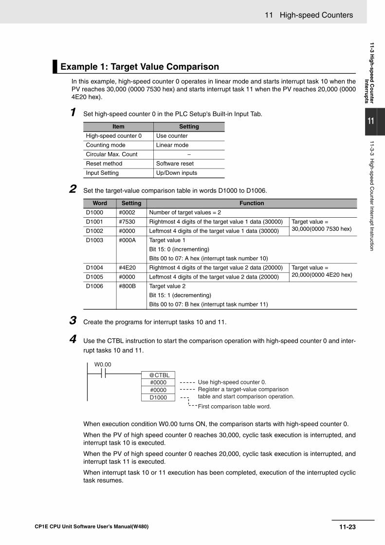
11-23
11 High-speed Counters
CP1E CPU Unit Software User’s Manual(W480)
11-3 Hig
h-sp
eed C
ou
nter
Interru
pts
11
11-3-3 High-speed C
ounter Interrupt Instruction
In this example, high-speed counter 0 operates in linear mode and starts interrupt task 10 when thePV reaches 30,000 (0000 7530 hex) and starts interrupt task 11 when the PV reaches 20,000 (00004E20 hex).
1 Set high-speed counter 0 in the PLC Setup's Built-in Input Tab.
2 Set the target-value comparison table in words D1000 to D1006.
3 Create the programs for interrupt tasks 10 and 11.
4 Use the CTBL instruction to start the comparison operation with high-speed counter 0 and inter-
rupt tasks 10 and 11.
When execution condition W0.00 turns ON, the comparison starts with high-speed counter 0.
When the PV of high speed counter 0 reaches 30,000, cyclic task execution is interrupted, andinterrupt task 10 is executed.
When the PV of high speed counter 0 reaches 20,000, cyclic task execution is interrupted, andinterrupt task 11 is executed.
When interrupt task 10 or 11 execution has been completed, execution of the interrupted cyclictask resumes.
Example 1: Target Value Comparison
Item Setting
High-speed counter 0 Use counter
Counting mode Linear mode
Circular Max. Count −Reset method Software reset
Input Setting Up/Down inputs
Word Setting Function
D1000 #0002 Number of target values = 2
D1001 #7530 Rightmost 4 digits of the target value 1 data (30000) Target value = 30,000(0000 7530 hex)D1002 #0000 Leftmost 4 digits of the target value 1 data (30000)
D1003 #000A Target value 1
Bit 15: 0 (incrementing)
Bits 00 to 07: A hex (interrupt task number 10)
D1004 #4E20 Rightmost 4 digits of the target value 2 data (20000) Target value = 20,000(0000 4E20 hex)D1005 #0000 Leftmost 4 digits of the target value 2 data (20000)
D1006 #800B Target value 2
Bit 15: 1 (decrementing)
Bits 00 to 07: B hex (interrupt task number 11)
@CTBL#0000#0000D1000
W0.00
Use high-speed counter 0.Register a target-value comparison table and start comparison operation.
First comparison table word.
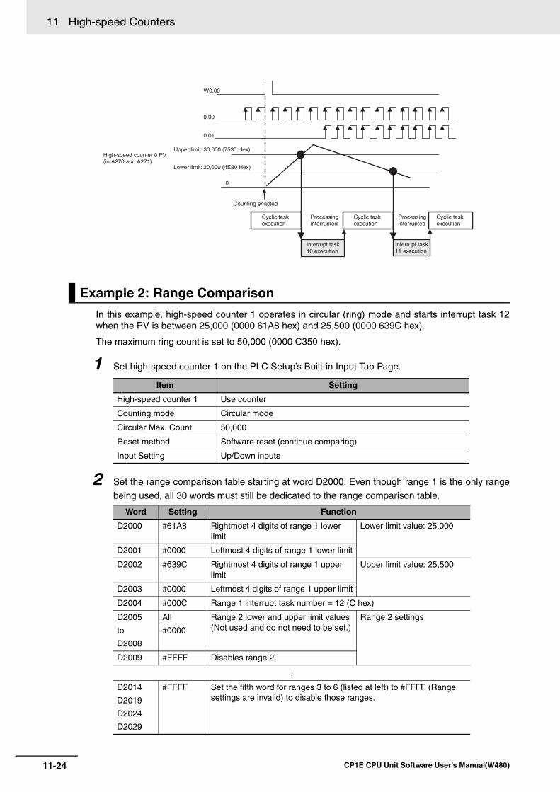
11 High-speed Counters
11-24 CP1E CPU Unit Software User’s Manual(W480)
In this example, high-speed counter 1 operates in circular (ring) mode and starts interrupt task 12when the PV is between 25,000 (0000 61A8 hex) and 25,500 (0000 639C hex).
The maximum ring count is set to 50,000 (0000 C350 hex).
1 Set high-speed counter 1 on the PLC Setup’s Built-in Input Tab Page.
2 Set the range comparison table starting at word D2000. Even though range 1 is the only range
being used, all 30 words must still be dedicated to the range comparison table.
Example 2: Range Comparison
Item Setting
High-speed counter 1 Use counter
Counting mode Circular mode
Circular Max. Count 50,000
Reset method Software reset (continue comparing)
Input Setting Up/Down inputs
Word Setting Function
D2000 #61A8 Rightmost 4 digits of range 1 lower limit
Lower limit value: 25,000
D2001 #0000 Leftmost 4 digits of range 1 lower limit
D2002 #639C Rightmost 4 digits of range 1 upper limit
Upper limit value: 25,500
D2003 #0000 Leftmost 4 digits of range 1 upper limit
D2004 #000C Range 1 interrupt task number = 12 (C hex)
D2005
to
D2008
All
#0000
Range 2 lower and upper limit values (Not used and do not need to be set.)
Range 2 settings
D2009 #FFFF Disables range 2.
~
D2014
D2019
D2024
D2029
#FFFF Set the fifth word for ranges 3 to 6 (listed at left) to #FFFF (Range settings are invalid) to disable those ranges.
W0.00
0
0.00
0.01
High-speed counter 0 PV (in A270 and A271)
Counting enabled
Cyclic task execution
Cyclic task execution
Cyclic task execution
Processing interrupted
Processing interrupted
Interrupt task 10 execution
Interrupt task 11 execution
Lower limit: 20,000 (4E20 Hex)
Upper limit: 30,000 (7530 Hex)
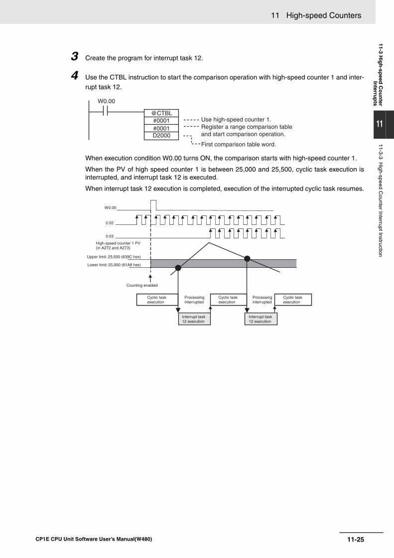
11-25
11 High-speed Counters
CP1E CPU Unit Software User’s Manual(W480)
11-3 Hig
h-sp
eed C
ou
nter
Interru
pts
11
11-3-3 High-speed C
ounter Interrupt Instruction
3 Create the program for interrupt task 12.
4 Use the CTBL instruction to start the comparison operation with high-speed counter 1 and inter-
rupt task 12.
When execution condition W0.00 turns ON, the comparison starts with high-speed counter 1.
When the PV of high speed counter 1 is between 25,000 and 25,500, cyclic task execution isinterrupted, and interrupt task 12 is executed.
When interrupt task 12 execution is completed, execution of the interrupted cyclic task resumes.
W0.00
@CTBL#0001#0001D2000
Use high-speed counter 1.Register a range comparison table and start comparison operation.
First comparison table word.
W0.00
0.02
0.03
High-speed counter 1 PV (in A272 and A273)
Lower limit: 25,000 (61A8 hex)
Upper limit: 25,500 (639C hex)
Counting enabled
Cyclic task execution
Cyclic task execution
Cyclic task execution
Processing interrupted
Processing interrupted
Interrupt task 12 execution
Interrupt task 12 execution
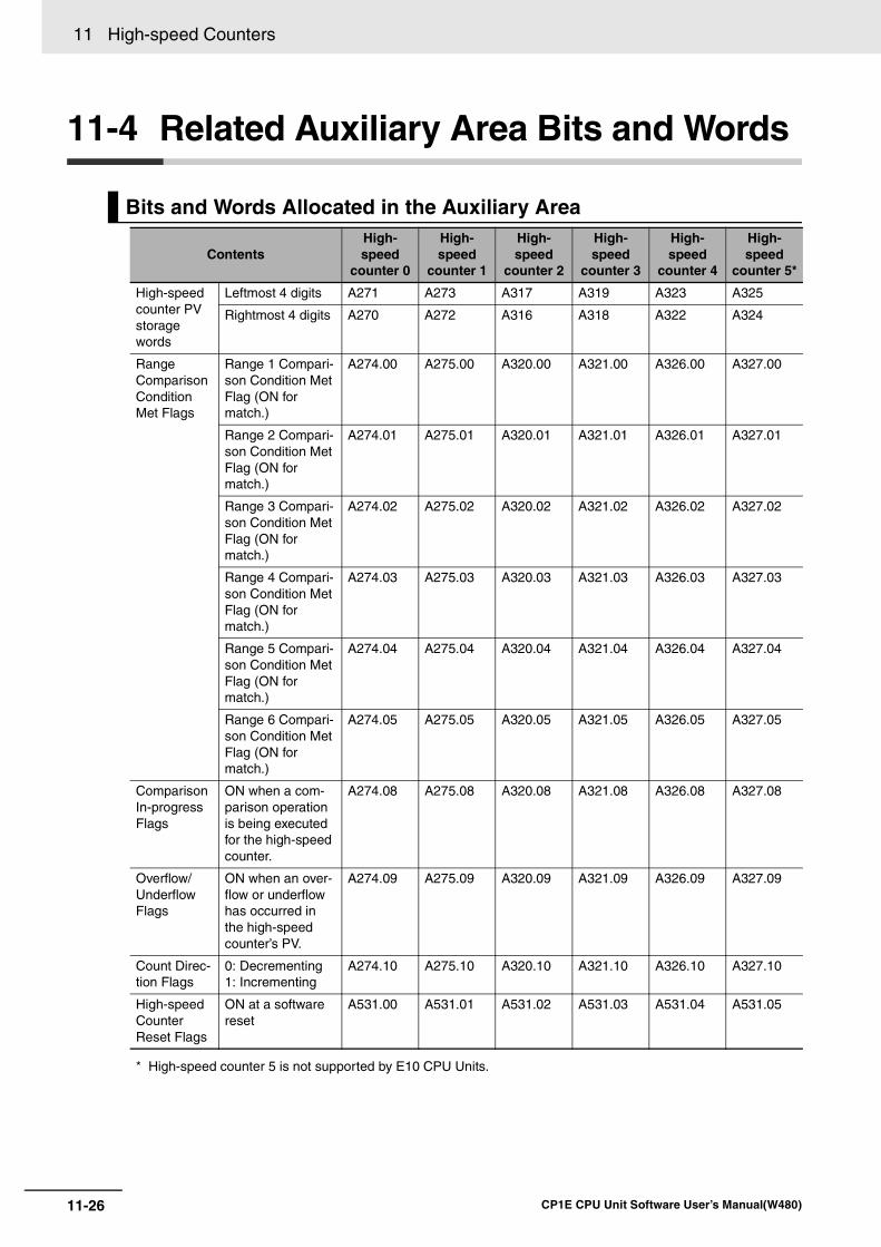
11 High-speed Counters
11-26 CP1E CPU Unit Software User’s Manual(W480)
11-4 Related Auxiliary Area Bits and Words
Bits and Words Allocated in the Auxiliary Area
ContentsHigh-speed
counter 0
High-speed
counter 1
High-speed
counter 2
High-speed
counter 3
High-speed
counter 4
High-speed
counter 5*
High-speed counter PV storage words
Leftmost 4 digits A271 A273 A317 A319 A323 A325
Rightmost 4 digits A270 A272 A316 A318 A322 A324
Range Comparison Condition Met Flags
Range 1 Compari-son Condition Met Flag (ON for match.)
A274.00 A275.00 A320.00 A321.00 A326.00 A327.00
Range 2 Compari-son Condition Met Flag (ON for match.)
A274.01 A275.01 A320.01 A321.01 A326.01 A327.01
Range 3 Compari-son Condition Met Flag (ON for match.)
A274.02 A275.02 A320.02 A321.02 A326.02 A327.02
Range 4 Compari-son Condition Met Flag (ON for match.)
A274.03 A275.03 A320.03 A321.03 A326.03 A327.03
Range 5 Compari-son Condition Met Flag (ON for match.)
A274.04 A275.04 A320.04 A321.04 A326.04 A327.04
Range 6 Compari-son Condition Met Flag (ON for match.)
A274.05 A275.05 A320.05 A321.05 A326.05 A327.05
Comparison In-progress Flags
ON when a com-parison operation is being executed for the high-speed counter.
A274.08 A275.08 A320.08 A321.08 A326.08 A327.08
Overflow/Underflow Flags
ON when an over-flow or underflow has occurred in the high-speed counter’s PV.
A274.09 A275.09 A320.09 A321.09 A326.09 A327.09
Count Direc-tion Flags
0: Decrementing1: Incrementing
A274.10 A275.10 A320.10 A321.10 A326.10 A327.10
High-speed Counter Reset Flags
ON at a software reset
A531.00 A531.01 A531.02 A531.03 A531.04 A531.05
* High-speed counter 5 is not supported by E10 CPU Units.
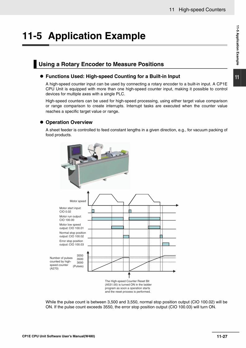
11-27
11 High-speed Counters
CP1E CPU Unit Software User’s Manual(W480)
11-5 Ap
plicatio
n E
xamp
le
11
11-5 Application Example
Functions Used: High-speed Counting for a Built-in InputA high-speed counter input can be used by connecting a rotary encoder to a built-in input. A CP1ECPU Unit is equipped with more than one high-speed counter input, making it possible to controldevices for multiple axes with a single PLC.
High-speed counters can be used for high-speed processing, using either target value comparisonor range comparison to create interrupts. Interrupt tasks are executed when the counter valuereaches a specific target value or range.
Operation OverviewA sheet feeder is controlled to feed constant lengths in a given direction, e.g., for vacuum packing offood products.
While the pulse count is between 3,500 and 3,550, normal stop position output (CIO 100.02) will beON. If the pulse count exceeds 3550, the error stop position output (CIO 100.03) will turn ON.
Using a Rotary Encoder to Measure Positions
Motor speed
Motor start input: CIO 0.02
Motor run output: CIO 100.00
Motor low speed output: CIO 100.01
Normal stop position output: CIO 100.02
Error stop position output: CIO 100.03
Number of pulses counted by high-speed counter (A270)
(Pulses)
The High-speed Counter Reset Bit (A531.00) is turned ON in the ladder program as soon a operation starts and the reset process is performed.
355035003000
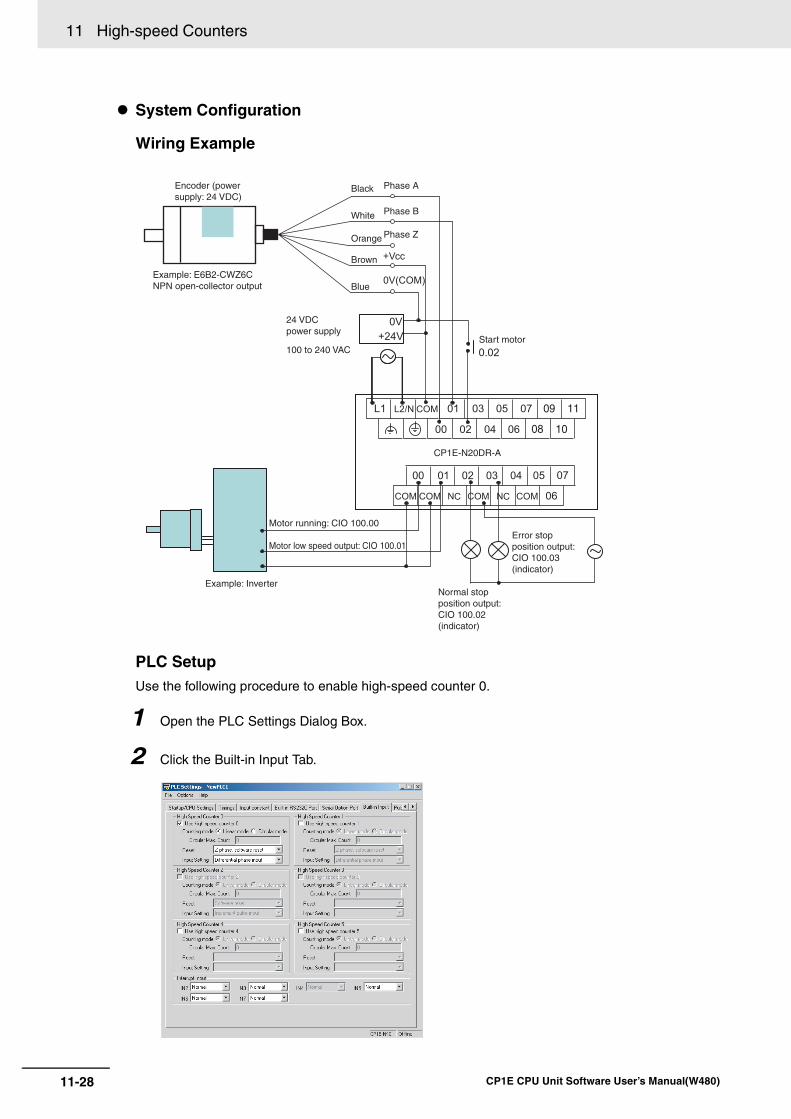
11 High-speed Counters
11-28 CP1E CPU Unit Software User’s Manual(W480)
System Configuration
Wiring Example
PLC Setup Use the following procedure to enable high-speed counter 0.
1 Open the PLC Settings Dialog Box.
2 Click the Built-in Input Tab.
Encoder (power supply: 24 VDC)
Example: E6B2-CWZ6CNPN open-collector output
Phase ABlack
White Phase B
Orange Phase Z
Brown
Blue
100 to 240 VAC
24 VDC power supply
Start motor
Motor running: CIO 100.00
Motor low speed output: CIO 100.01
Example: Inverter
CP1E-N20DR-A
Error stop position output: CIO 100.03 (indicator)
Normal stop position output: CIO 100.02 (indicator)
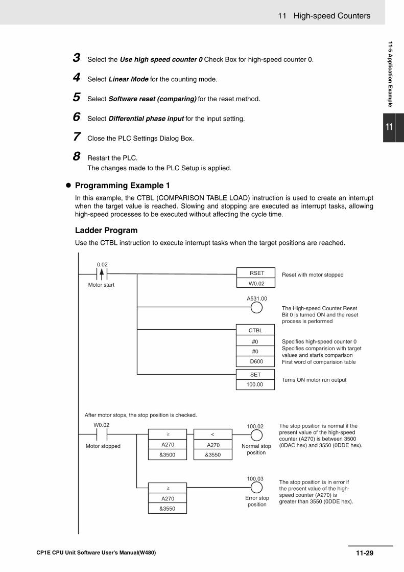
11-29
11 High-speed Counters
CP1E CPU Unit Software User’s Manual(W480)
11-5 Ap
plicatio
n E
xamp
le
11
3 Select the Use high speed counter 0 Check Box for high-speed counter 0.
4 Select Linear Mode for the counting mode.
5 Select Software reset (comparing) for the reset method.
6 Select Differential phase input for the input setting.
7 Close the PLC Settings Dialog Box.
8 Restart the PLC.
The changes made to the PLC Setup is applied.
Programming Example 1In this example, the CTBL (COMPARISON TABLE LOAD) instruction is used to create an interruptwhen the target value is reached. Slowing and stopping are executed as interrupt tasks, allowinghigh-speed processes to be executed without affecting the cycle time.
Ladder Program Use the CTBL instruction to execute interrupt tasks when the target positions are reached.
Motor start
Reset with motor stopped
The High-speed Counter Reset Bit 0 is turned ON and the reset process is performed
Specifies high-speed counter 0Specifies comparision with target values and starts comparisonFirst word of comparision table
Turns ON motor run output
After motor stops, the stop position is checked.
Motor stopped Normal stop position
Error stop position
The stop position is normal if the present value of the high-speed counter (A270) is between 3500 (0DAC hex) and 3550 (0DDE hex).
The stop position is in error if the present value of the high-speed counter (A270) is greater than 3550 (0DDE hex).
&3500
&3550
&3550
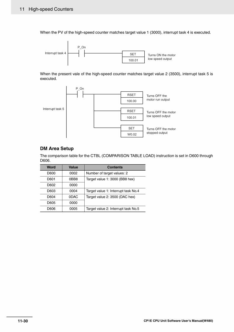
11 High-speed Counters
11-30 CP1E CPU Unit Software User’s Manual(W480)
When the PV of the high-speed counter matches target value 1 (3000), interrupt task 4 is executed.
When the present vale of the high-speed counter matches target value 2 (3500), interrupt task 5 isexecuted.
DM Area Setup The comparison table for the CTBL (COMPARISON TABLE LOAD) instruction is set in D600 throughD606.
Word Value Contents
D600 0002 Number of target values: 2
D601 0BB8 Target value 1: 3000 (BB8 hex)
D602 0000
D603 0004 Target value 1: Interrupt task No.4
D604 0DAC Target value 2: 3500 (DAC hex)
D605 0000
D606 0005 Target value 2: Interrupt task No.5
Interrupt task 4Turns ON the motor low speed output
Interrupt task 5
Turns OFF the motor run output
Turns OFF the motor low speed output
Turns OFF the motor stopped output
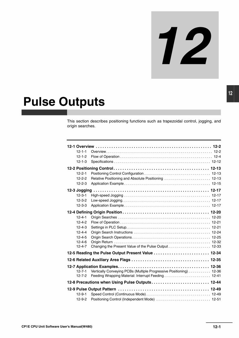
12-1
12
CP1E CPU Unit Software User’s Manual(W480)
12
This section describes positioning functions such as trapezoidal control, jogging, andorigin searches.
12-1 Overview . . . . . . . . . . . . . . . . . . . . . . . . . . . . . . . . . . . . . . . . . . . . . . . . . . . . 12-212-1-1 Overview. . . . . . . . . . . . . . . . . . . . . . . . . . . . . . . . . . . . . . . . . . . . . . . . . . . . . 12-212-1-2 Flow of Operation . . . . . . . . . . . . . . . . . . . . . . . . . . . . . . . . . . . . . . . . . . . . . . 12-412-1-3 Specifications . . . . . . . . . . . . . . . . . . . . . . . . . . . . . . . . . . . . . . . . . . . . . . . . 12-12
12-2 Positioning Control . . . . . . . . . . . . . . . . . . . . . . . . . . . . . . . . . . . . . . . . . . . 12-1312-2-1 Positioning Control Configuration . . . . . . . . . . . . . . . . . . . . . . . . . . . . . . . . . 12-1312-2-2 Relative Positioning and Absolute Positioning . . . . . . . . . . . . . . . . . . . . . . . 12-1312-2-3 Application Example . . . . . . . . . . . . . . . . . . . . . . . . . . . . . . . . . . . . . . . . . . . 12-15
12-3 Jogging . . . . . . . . . . . . . . . . . . . . . . . . . . . . . . . . . . . . . . . . . . . . . . . . . . . . 12-1712-3-1 High-speed Jogging . . . . . . . . . . . . . . . . . . . . . . . . . . . . . . . . . . . . . . . . . . . 12-1712-3-2 Low-speed Jogging. . . . . . . . . . . . . . . . . . . . . . . . . . . . . . . . . . . . . . . . . . . . 12-1712-3-3 Application Example . . . . . . . . . . . . . . . . . . . . . . . . . . . . . . . . . . . . . . . . . . . 12-17
12-4 Defining Origin Position . . . . . . . . . . . . . . . . . . . . . . . . . . . . . . . . . . . . . . . 12-2012-4-1 Origin Searches . . . . . . . . . . . . . . . . . . . . . . . . . . . . . . . . . . . . . . . . . . . . . . 12-2012-4-2 Flow of Operation . . . . . . . . . . . . . . . . . . . . . . . . . . . . . . . . . . . . . . . . . . . . . 12-2112-4-3 Settings in PLC Setup. . . . . . . . . . . . . . . . . . . . . . . . . . . . . . . . . . . . . . . . . . 12-2112-4-4 Origin Search Instructions . . . . . . . . . . . . . . . . . . . . . . . . . . . . . . . . . . . . . . 12-2412-4-5 Origin Search Operations . . . . . . . . . . . . . . . . . . . . . . . . . . . . . . . . . . . . . . . 12-2512-4-6 Origin Return . . . . . . . . . . . . . . . . . . . . . . . . . . . . . . . . . . . . . . . . . . . . . . . . 12-3212-4-7 Changing the Present Value of the Pulse Output . . . . . . . . . . . . . . . . . . . . . 12-33
12-5 Reading the Pulse Output Present Value . . . . . . . . . . . . . . . . . . . . . . . . . 12-34
12-6 Related Auxiliary Area Flags . . . . . . . . . . . . . . . . . . . . . . . . . . . . . . . . . . . 12-35
12-7 Application Examples. . . . . . . . . . . . . . . . . . . . . . . . . . . . . . . . . . . . . . . . . 12-3612-7-1 Vertically Conveying PCBs (Multiple Progressive Positioning) . . . . . . . . . . . 12-3612-7-2 Feeding Wrapping Material: Interrupt Feeding . . . . . . . . . . . . . . . . . . . . . . . 12-41
12-8 Precautions when Using Pulse Outputs . . . . . . . . . . . . . . . . . . . . . . . . . . 12-44
12-9 Pulse Output Pattern . . . . . . . . . . . . . . . . . . . . . . . . . . . . . . . . . . . . . . . . . 12-4912-9-1 Speed Control (Continuous Mode) . . . . . . . . . . . . . . . . . . . . . . . . . . . . . . . . 12-4912-9-2 Positioning Control (Independent Mode) . . . . . . . . . . . . . . . . . . . . . . . . . . . 12-51
Pulse Outputs
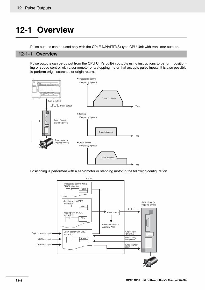
12 Pulse Outputs
12-2 CP1E CPU Unit Software User’s Manual(W480)
12-1 Overview
Pulse outputs can be used only with the CP1E N/NA (S)-type CPU Unit with transistor outputs.
Pulse outputs can be output from the CPU Unit's built-in outputs using instructions to perform position-ing or speed control with a servomotor or a stepping motor that accepts pulse inputs. It is also possibleto perform origin searches or origin returns.
Positioning is performed with a servomotor or stepping motor in the following configuration.
12-1-1 Overview
Built-in output
Pulse output
Servo Drive (or stepping driver)
Servomotor (or stepping motor)
Trapezoidal control
Frequency (speed)
Frequency (speed)
Frequency (speed)
Travel distance
Time
Travel distance
Time
Travel distance
Time
Jogging
Origin search
ORG
PLS2
SPED
ACC
CP1E
·Trapezoidal control with a PLS2 instruction
·Jogging with a SPED instruction
·Jogging with an ACC instruction
Pulse output
Pulse output PV in Auxiliary Area
Servo Drive (or stepping driver)
Origin proximity input
CW limit input
CCW limit input
·Origin search with ORG instruction
Origin input (phase-Z)
(Positioning completed)
Error counter reset
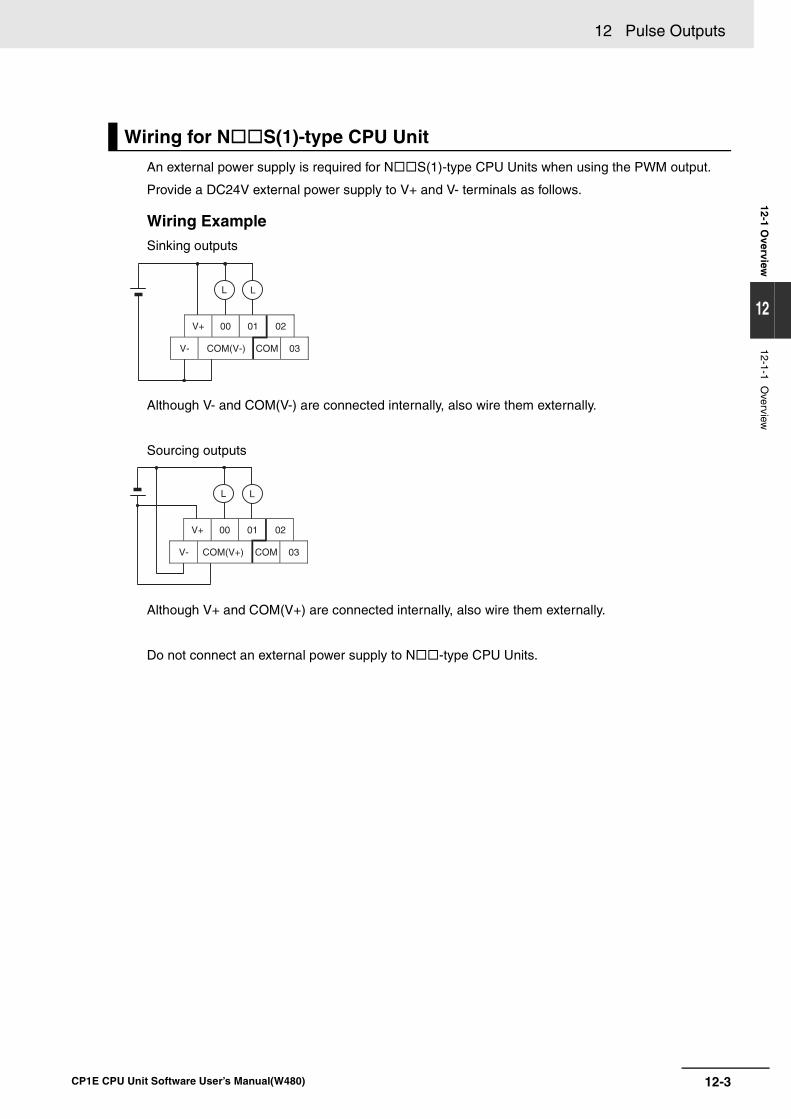
12-3
12 Pulse Outputs
CP1E CPU Unit Software User’s Manual(W480)
12-1 Overview
12
12-1-1 Overview
An external power supply is required for N S(1)-type CPU Units when using the PWM output.
Provide a DC24V external power supply to V+ and V- terminals as follows.
Wiring ExampleSinking outputs
Although V- and COM(V-) are connected internally, also wire them externally.
Sourcing outputs
Although V+ and COM(V+) are connected internally, also wire them externally.
Do not connect an external power supply to N -type CPU Units.
Wiring for N S(1)-type CPU Unit
V+ 00 01 02
V- COM(V-) COM 03
L L
V+ 00 01 02
V- COM(V+) COM 03
L L
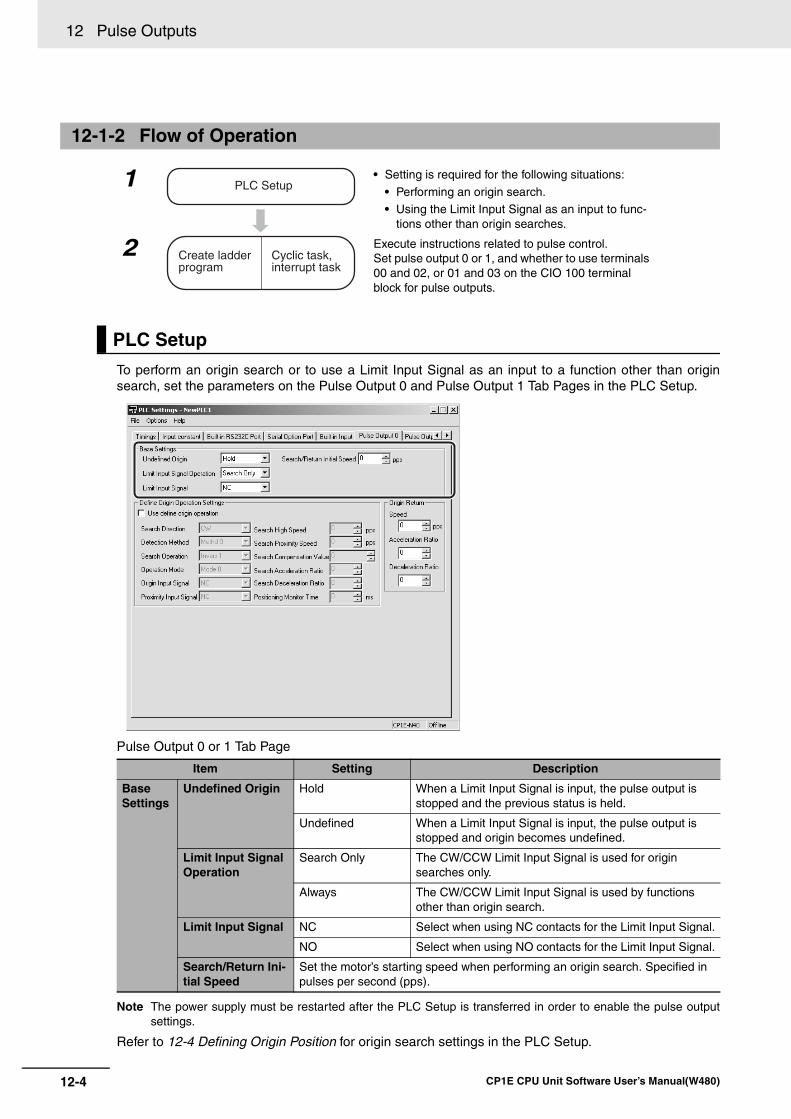
12 Pulse Outputs
12-4 CP1E CPU Unit Software User’s Manual(W480)
To perform an origin search or to use a Limit Input Signal as an input to a function other than originsearch, set the parameters on the Pulse Output 0 and Pulse Output 1 Tab Pages in the PLC Setup.
Pulse Output 0 or 1 Tab Page
Note The power supply must be restarted after the PLC Setup is transferred in order to enable the pulse outputsettings.
Refer to 12-4 Defining Origin Position for origin search settings in the PLC Setup.
12-1-2 Flow of Operation
1 • Setting is required for the following situations:
• Performing an origin search.• Using the Limit Input Signal as an input to func-
tions other than origin searches.
2 Execute instructions related to pulse control.Set pulse output 0 or 1, and whether to use terminals 00 and 02, or 01 and 03 on the CIO 100 terminal block for pulse outputs.
PLC Setup
Item Setting Description
Base Settings
Undefined Origin Hold When a Limit Input Signal is input, the pulse output is stopped and the previous status is held.
Undefined When a Limit Input Signal is input, the pulse output is stopped and origin becomes undefined.
Limit Input Signal Operation
Search Only The CW/CCW Limit Input Signal is used for origin searches only.
Always The CW/CCW Limit Input Signal is used by functions other than origin search.
Limit Input Signal NC Select when using NC contacts for the Limit Input Signal.
NO Select when using NO contacts for the Limit Input Signal.
Search/Return Ini-tial Speed
Set the motor’s starting speed when performing an origin search. Specified in pulses per second (pps).
PLC Setup
Create ladder program
Cyclic task, interrupt task
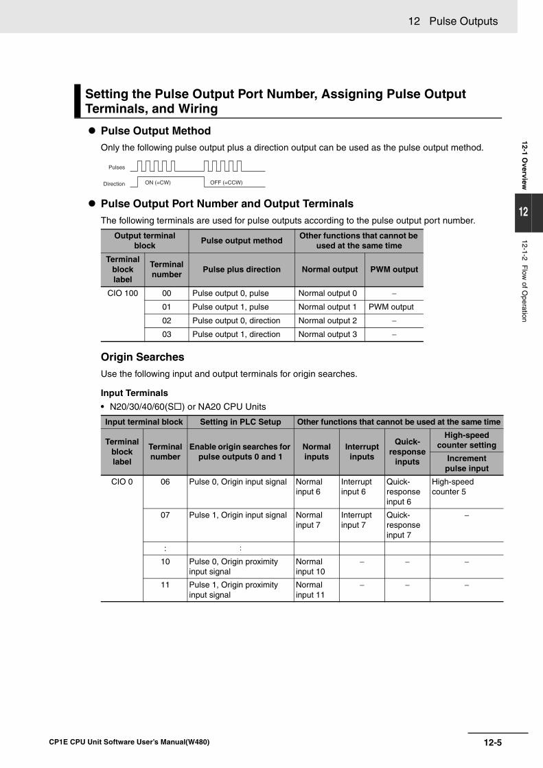
12-5
12 Pulse Outputs
CP1E CPU Unit Software User’s Manual(W480)
12-1 Overview
12
12-1-2 Flow
of Operation
Pulse Output MethodOnly the following pulse output plus a direction output can be used as the pulse output method.
Pulse Output Port Number and Output TerminalsThe following terminals are used for pulse outputs according to the pulse output port number.
Origin SearchesUse the following input and output terminals for origin searches.
Input Terminals
• N20/30/40/60(S ) or NA20 CPU Units
Setting the Pulse Output Port Number, Assigning Pulse Output Terminals, and Wiring
Output terminal block
Pulse output methodOther functions that cannot be
used at the same time
Terminal block label
Terminal number
Pulse plus direction Normal output PWM output
CIO 100 00 Pulse output 0, pulse Normal output 0 −
01 Pulse output 1, pulse Normal output 1 PWM output
02 Pulse output 0, direction Normal output 2 −
03 Pulse output 1, direction Normal output 3 −
Input terminal block Setting in PLC Setup Other functions that cannot be used at the same time
Terminal block label
Terminal number
Enable origin searches for pulse outputs 0 and 1
Normal inputs
Interrupt inputs
Quick-response
inputs
High-speed counter setting
Increment pulse input
CIO 0 06 Pulse 0, Origin input signal Normal input 6
Interrupt input 6
Quick-response input 6
High-speed counter 5
07 Pulse 1, Origin input signal Normal input 7
Interrupt input 7
Quick-response input 7
−
: :
10 Pulse 0, Origin proximity input signal
Normal input 10
− − −
11 Pulse 1, Origin proximity input signal
Normal input 11
− − −
Pulses
Direction ON (=CW) OFF (=CCW)
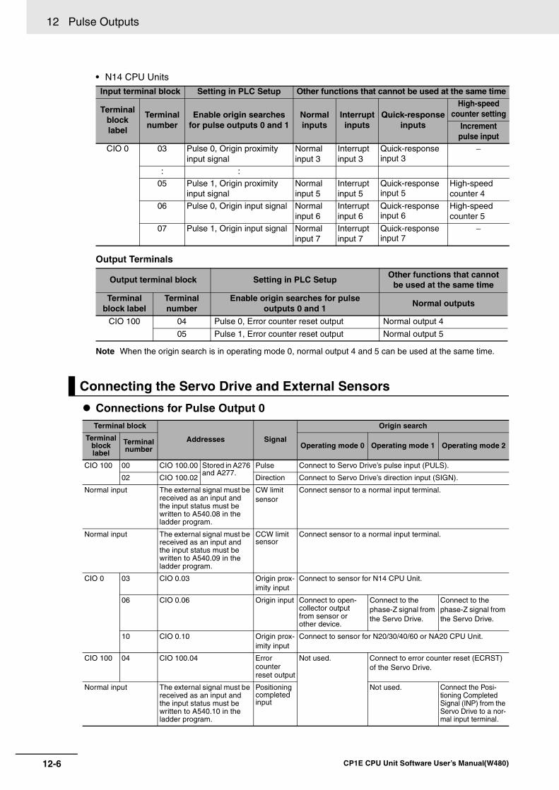
12 Pulse Outputs
12-6 CP1E CPU Unit Software User’s Manual(W480)
• N14 CPU Units
Output Terminals
Note When the origin search is in operating mode 0, normal output 4 and 5 can be used at the same time.
Connections for Pulse Output 0
Input terminal block Setting in PLC Setup Other functions that cannot be used at the same time
Terminal block label
Terminal number
Enable origin searches for pulse outputs 0 and 1
Normal inputs
Interrupt inputs
Quick-response inputs
High-speed counter setting
Increment pulse input
CIO 0 03 Pulse 0, Origin proximity input signal
Normal input 3
Interrupt input 3
Quick-response input 3
−
: :
05 Pulse 1, Origin proximity input signal
Normal input 5
Interrupt input 5
Quick-response input 5
High-speed counter 4
06 Pulse 0, Origin input signal Normal input 6
Interrupt input 6
Quick-response input 6
High-speed counter 5
07 Pulse 1, Origin input signal Normal input 7
Interrupt input 7
Quick-response input 7
−
Output terminal block Setting in PLC SetupOther functions that cannot
be used at the same time
Terminal block label
Terminal number
Enable origin searches for pulse outputs 0 and 1
Normal outputs
CIO 100 04 Pulse 0, Error counter reset output Normal output 4
05 Pulse 1, Error counter reset output Normal output 5
Connecting the Servo Drive and External Sensors
Terminal block
Addresses Signal
Origin search
Terminal block label
Terminal number Operating mode 0 Operating mode 1 Operating mode 2
CIO 100 00 CIO 100.00 Stored in A276 and A277.
Pulse Connect to Servo Drive’s pulse input (PULS).
02 CIO 100.02 Direction Connect to Servo Drive’s direction input (SIGN).
Normal input The external signal must be received as an input and the input status must be written to A540.08 in the ladder program.
CW limitsensor
Connect sensor to a normal input terminal.
Normal input The external signal must be received as an input and the input status must be written to A540.09 in the ladder program.
CCW limit sensor
Connect sensor to a normal input terminal.
CIO 0 03 CIO 0.03 Origin prox-imity input
Connect to sensor for N14 CPU Unit.
06 CIO 0.06 Origin input Connect to open-collector output from sensor or other device.
Connect to the phase-Z signal from the Servo Drive.
Connect to the phase-Z signal from the Servo Drive.
10 CIO 0.10 Origin prox-imity input
Connect to sensor for N20/30/40/60 or NA20 CPU Unit.
CIO 100 04 CIO 100.04 Error counter reset output
Not used. Connect to error counter reset (ECRST) of the Servo Drive.
Normal input The external signal must be received as an input and the input status must be written to A540.10 in the ladder program.
Positioning completed input
Not used. Connect the Posi-tioning Completed Signal (INP) from the Servo Drive to a nor-mal input terminal.
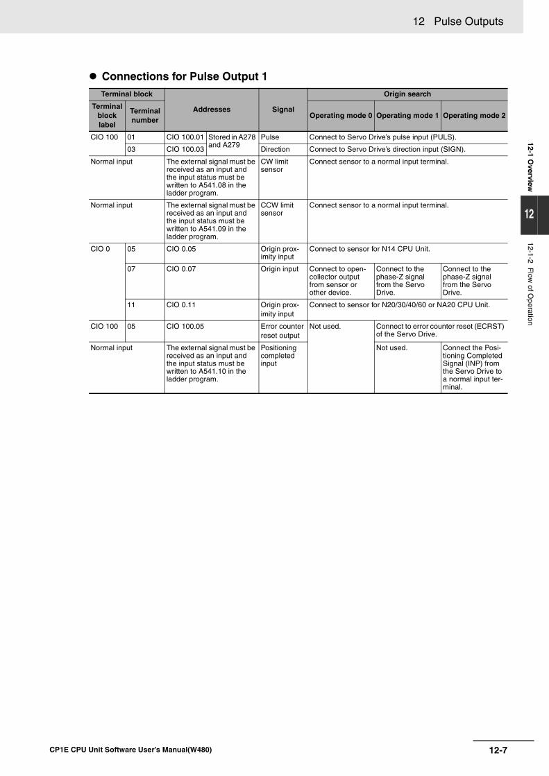
12-7
12 Pulse Outputs
CP1E CPU Unit Software User’s Manual(W480)
12-1 Overview
12
12-1-2 Flow
of Operation
Connections for Pulse Output 1Terminal block
Addresses Signal
Origin search
Terminal block label
Terminal number
Operating mode 0 Operating mode 1 Operating mode 2
CIO 100 01 CIO 100.01 Stored in A278 and A279
Pulse Connect to Servo Drive’s pulse input (PULS).
03 CIO 100.03 Direction Connect to Servo Drive’s direction input (SIGN).
Normal input The external signal must be received as an input and the input status must be written to A541.08 in the ladder program.
CW limit sensor
Connect sensor to a normal input terminal.
Normal input The external signal must be received as an input and the input status must be written to A541.09 in the ladder program.
CCW limit sensor
Connect sensor to a normal input terminal.
CIO 0 05 CIO 0.05 Origin prox-imity input
Connect to sensor for N14 CPU Unit.
07 CIO 0.07 Origin input Connect to open-collector output from sensor or other device.
Connect to the phase-Z signal from the Servo Drive.
Connect to the phase-Z signal from the Servo Drive.
11 CIO 0.11 Origin prox-imity input
Connect to sensor for N20/30/40/60 or NA20 CPU Unit.
CIO 100 05 CIO 100.05 Error counter reset output
Not used. Connect to error counter reset (ECRST) of the Servo Drive.
Normal input The external signal must be received as an input and the input status must be written to A541.10 in the ladder program.
Positioning completed input
Not used. Connect the Posi-tioning Completed Signal (INP) from the Servo Drive to a normal input ter-minal.
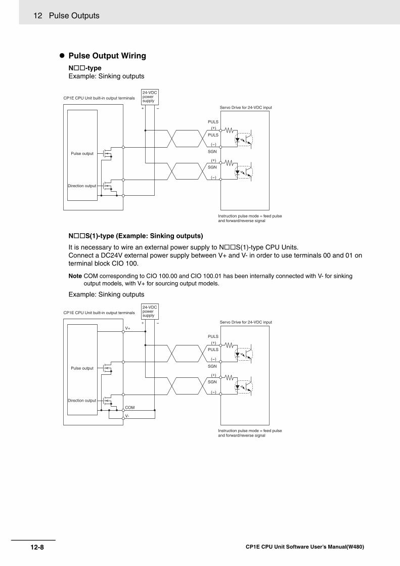
12 Pulse Outputs
12-8 CP1E CPU Unit Software User’s Manual(W480)
Pulse Output WiringN -typeExample: Sinking outputs
N S(1)-type (Example: Sinking outputs)
It is necessary to wire an external power supply to N S(1)-type CPU Units.Connect a DC24V external power supply between V+ and V- in order to use terminals 00 and 01 on terminal block CIO 100.
Note COM corresponding to CIO 100.00 and CIO 100.01 has been internally connected with V- for sinkingoutput models, with V+ for sourcing output models.
Example: Sinking outputs
PULS
PULS
SGN
SGN
(+)
(+)
(-)
(-)
+ -
CP1E CPU Unit built-in output terminals
Pulse output
Direction output
24-VDC power supply
Servo Drive for 24-VDC input
Instruction pulse mode = feed pulse and forward/reverse signal
PULS
PULS
SGN
SGN
(+)
(+)
(-)
(-)
+V+
COM
V-
-
CP1E CPU Unit built-in output terminals
Pulse output
Direction output
24-VDC power supply
Servo Drive for 24-VDC input
Instruction pulse mode = feed pulse and forward/reverse signal
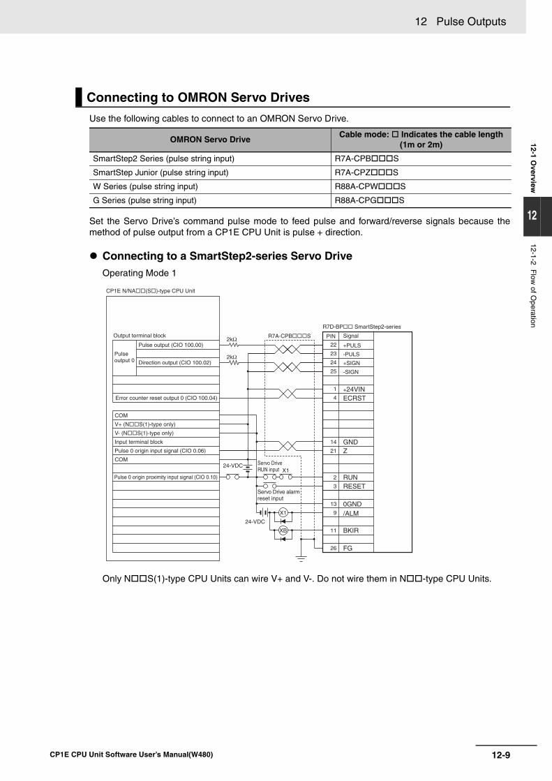
12-9
12 Pulse Outputs
CP1E CPU Unit Software User’s Manual(W480)
12-1 Overview
12
12-1-2 Flow
of Operation
Use the following cables to connect to an OMRON Servo Drive.
Set the Servo Drive’s command pulse mode to feed pulse and forward/reverse signals because themethod of pulse output from a CP1E CPU Unit is pulse + direction.
Connecting to a SmartStep2-series Servo DriveOperating Mode 1
Only N S(1)-type CPU Units can wire V+ and V-. Do not wire them in N -type CPU Units.
Connecting to OMRON Servo Drives
OMRON Servo DriveCable mode: Indicates the cable length
(1m or 2m)
SmartStep2 Series (pulse string input) R7A-CPB S
SmartStep Junior (pulse string input) R7A-CPZ S
W Series (pulse string input) R88A-CPW S
G Series (pulse string input) R88A-CPG S
+PULS
-PULS
+24VINECRST
GNDZ
RUNRESET
0GND/ALM
FG
X1
XB
24-VDCX1
24-VDC
BKIR
+SIGN
-SIGN
2kΩ
2kΩ
PIN
22
23
24
25
1
4
14
21
2
3
13
9
11
26
Output terminal block
CP1E N/NA(S)-type CPU Unit
Pulse output 0
Pulse output (CIO 100.00)
Direction output (CIO 100.02)
Error counter reset output 0 (CIO 100.04)
COM
V+ (NS(1)-type only)
V- (NS(1)-type only)
Input terminal block
Pulse 0 origin input signal (CIO 0.06)
COM
Pulse 0 origin proximity input signal (CIO 0.10)
R7D-BP SmartStep2-series
R7A-CPBS Signal
Servo Drive RUN input
Servo Drive alarm reset input
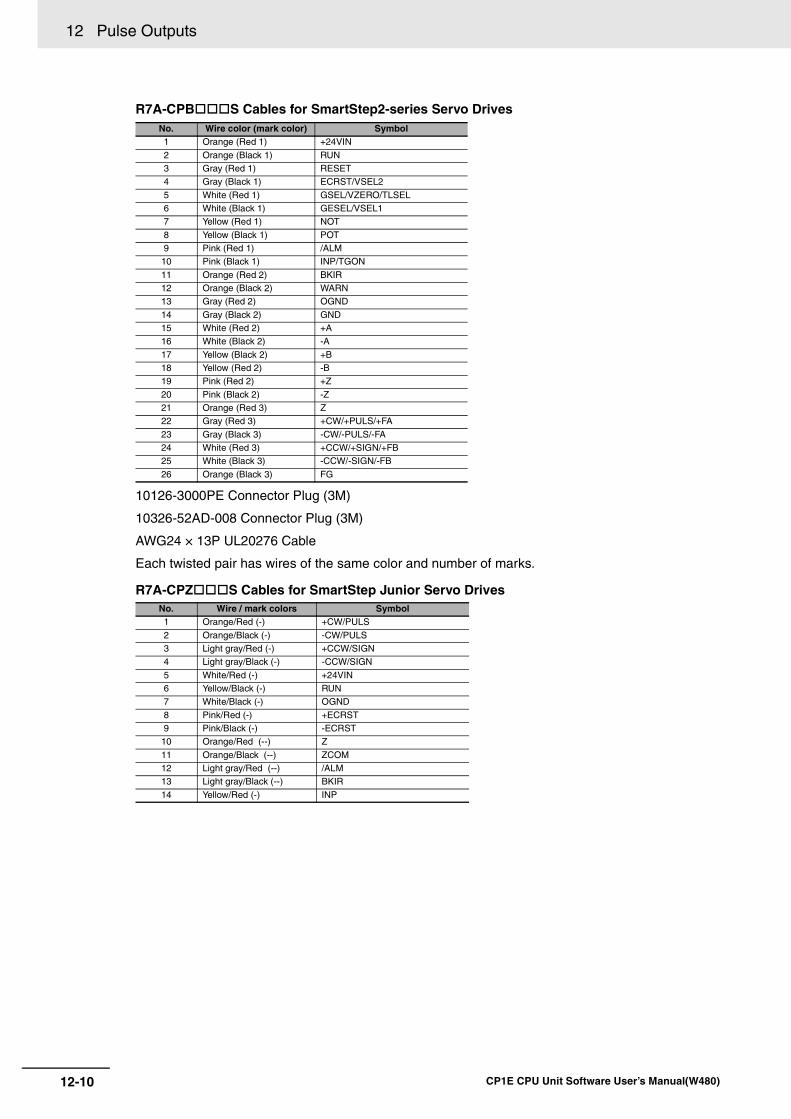
12 Pulse Outputs
12-10 CP1E CPU Unit Software User’s Manual(W480)
R7A-CPB S Cables for SmartStep2-series Servo Drives
10126-3000PE Connector Plug (3M)
10326-52AD-008 Connector Plug (3M)
AWG24 × 13P UL20276 Cable
Each twisted pair has wires of the same color and number of marks.
R7A-CPZ S Cables for SmartStep Junior Servo Drives
No. Wire color (mark color) Symbol1 Orange (Red 1) +24VIN
2 Orange (Black 1) RUN3 Gray (Red 1) RESET4 Gray (Black 1) ECRST/VSEL2
5 White (Red 1) GSEL/VZERO/TLSEL6 White (Black 1) GESEL/VSEL17 Yellow (Red 1) NOT
8 Yellow (Black 1) POT9 Pink (Red 1) /ALM10 Pink (Black 1) INP/TGON
11 Orange (Red 2) BKIR12 Orange (Black 2) WARN13 Gray (Red 2) OGND
14 Gray (Black 2) GND15 White (Red 2) +A16 White (Black 2) -A
17 Yellow (Black 2) +B18 Yellow (Red 2) -B19 Pink (Red 2) +Z
20 Pink (Black 2) -Z21 Orange (Red 3) Z22 Gray (Red 3) +CW/+PULS/+FA
23 Gray (Black 3) -CW/-PULS/-FA24 White (Red 3) +CCW/+SIGN/+FB25 White (Black 3) -CCW/-SIGN/-FB
26 Orange (Black 3) FG
No. Wire / mark colors Symbol1 Orange/Red (-) +CW/PULS
2 Orange/Black (-) -CW/PULS3 Light gray/Red (-) +CCW/SIGN4 Light gray/Black (-) -CCW/SIGN
5 White/Red (-) +24VIN6 Yellow/Black (-) RUN7 White/Black (-) OGND
8 Pink/Red (-) +ECRST9 Pink/Black (-) -ECRST10 Orange/Red (--) Z
11 Orange/Black (--) ZCOM12 Light gray/Red (--) /ALM13 Light gray/Black (--) BKIR
14 Yellow/Red (-) INP
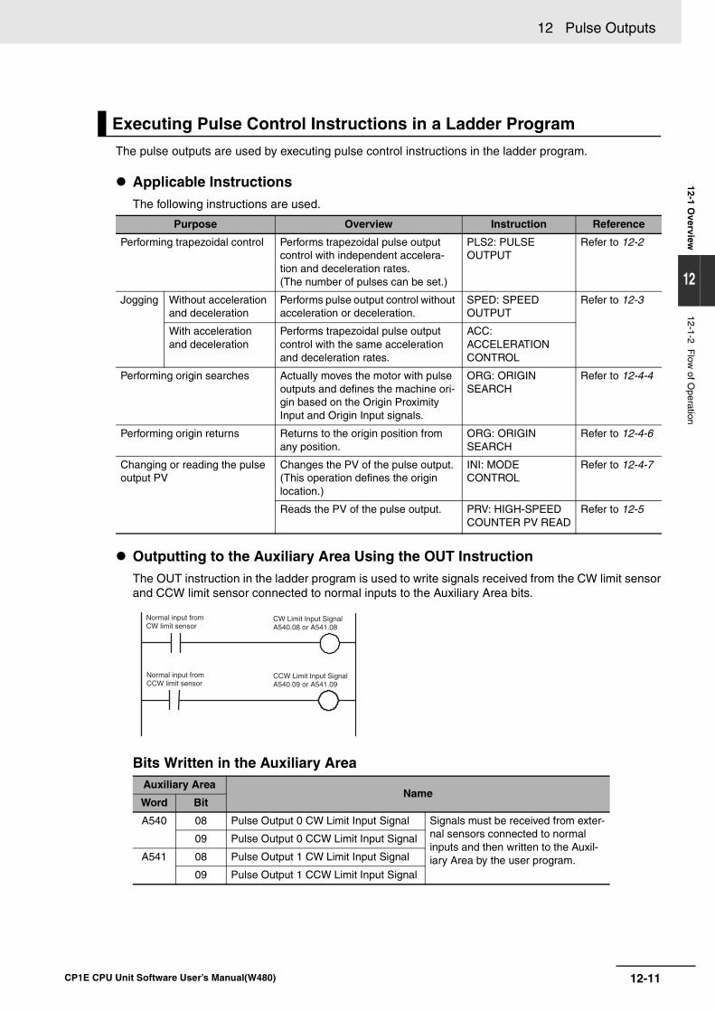
12-11
12 Pulse Outputs
CP1E CPU Unit Software User’s Manual(W480)
12-1 Overview
12
12-1-2 Flow
of Operation
The pulse outputs are used by executing pulse control instructions in the ladder program.
Applicable InstructionsThe following instructions are used.
Outputting to the Auxiliary Area Using the OUT InstructionThe OUT instruction in the ladder program is used to write signals received from the CW limit sensorand CCW limit sensor connected to normal inputs to the Auxiliary Area bits.
Bits Written in the Auxiliary Area
Executing Pulse Control Instructions in a Ladder Program
Purpose Overview Instruction Reference
Performing trapezoidal control Performs trapezoidal pulse output control with independent accelera-tion and deceleration rates. (The number of pulses can be set.)
PLS2: PULSEOUTPUT
Refer to 12-2
Jogging Without acceleration and deceleration
Performs pulse output control without acceleration or deceleration.
SPED: SPEED OUTPUT
Refer to 12-3
With acceleration and deceleration
Performs trapezoidal pulse output control with the same acceleration and deceleration rates.
ACC: ACCELERATION CONTROL
Performing origin searches Actually moves the motor with pulse outputs and defines the machine ori-gin based on the Origin Proximity Input and Origin Input signals.
ORG: ORIGIN SEARCH
Refer to 12-4-4
Performing origin returns Returns to the origin position from any position.
ORG: ORIGIN SEARCH
Refer to 12-4-6
Changing or reading the pulse output PV
Changes the PV of the pulse output. (This operation defines the origin location.)
INI: MODECONTROL
Refer to 12-4-7
Reads the PV of the pulse output. PRV: HIGH-SPEED COUNTER PV READ
Refer to 12-5
Auxiliary AreaName
Word Bit
A540 08 Pulse Output 0 CW Limit Input Signal Signals must be received from exter-nal sensors connected to normal inputs and then written to the Auxil-iary Area by the user program.
09 Pulse Output 0 CCW Limit Input Signal
A541 08 Pulse Output 1 CW Limit Input Signal
09 Pulse Output 1 CCW Limit Input Signal
Normal input from CW limit sensor
CW Limit Input Signal A540.08 or A541.08
Normal input from CCW limit sensor
CCW Limit Input Signal A540.09 or A541.09
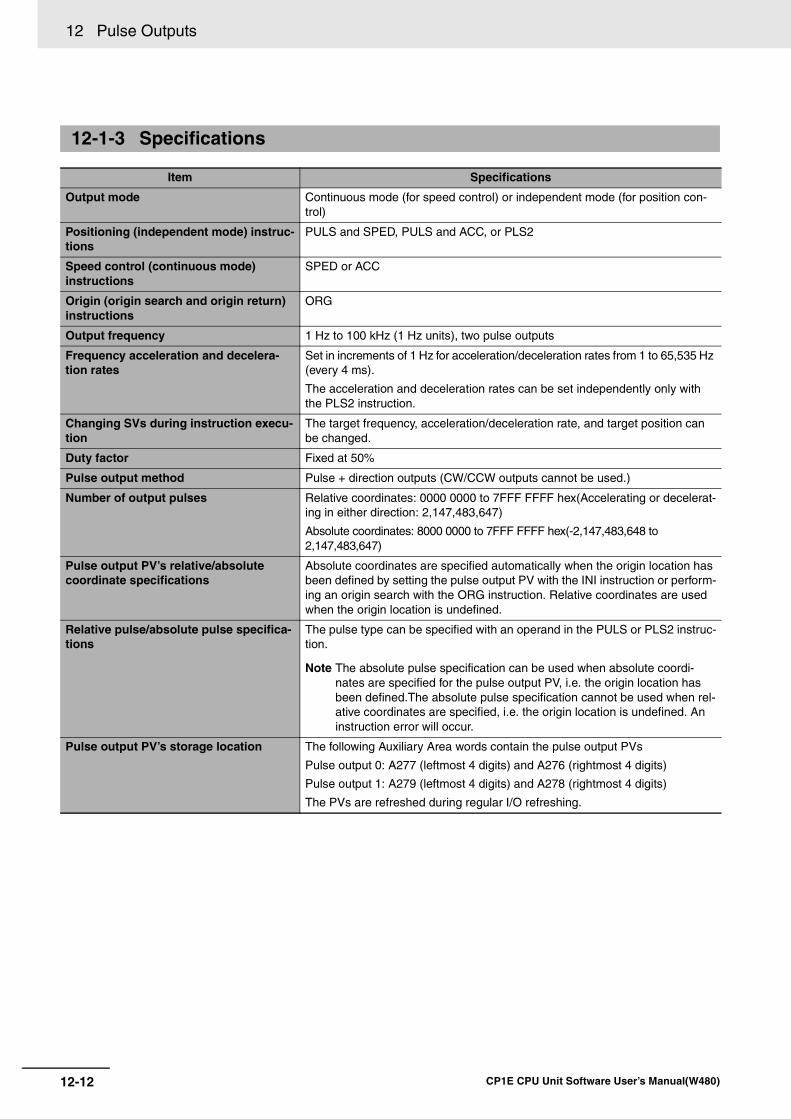
12 Pulse Outputs
12-12 CP1E CPU Unit Software User’s Manual(W480)
12-1-3 Specifications
Item Specifications
Output mode Continuous mode (for speed control) or independent mode (for position con-trol)
Positioning (independent mode) instruc-tions
PULS and SPED, PULS and ACC, or PLS2
Speed control (continuous mode) instructions
SPED or ACC
Origin (origin search and origin return) instructions
ORG
Output frequency 1 Hz to 100 kHz (1 Hz units), two pulse outputs
Frequency acceleration and decelera-tion rates
Set in increments of 1 Hz for acceleration/deceleration rates from 1 to 65,535 Hz (every 4 ms).
The acceleration and deceleration rates can be set independently only with the PLS2 instruction.
Changing SVs during instruction execu-tion
The target frequency, acceleration/deceleration rate, and target position can be changed.
Duty factor Fixed at 50%
Pulse output method Pulse + direction outputs (CW/CCW outputs cannot be used.)
Number of output pulses Relative coordinates: 0000 0000 to 7FFF FFFF hex(Accelerating or decelerat-ing in either direction: 2,147,483,647)
Absolute coordinates: 8000 0000 to 7FFF FFFF hex(-2,147,483,648 to 2,147,483,647)
Pulse output PV’s relative/absolute coordinate specifications
Absolute coordinates are specified automatically when the origin location has been defined by setting the pulse output PV with the INI instruction or perform-ing an origin search with the ORG instruction. Relative coordinates are used when the origin location is undefined.
Relative pulse/absolute pulse specifica-tions
The pulse type can be specified with an operand in the PULS or PLS2 instruc-tion.
Note The absolute pulse specification can be used when absolute coordi-nates are specified for the pulse output PV, i.e. the origin location has been defined.The absolute pulse specification cannot be used when rel-ative coordinates are specified, i.e. the origin location is undefined. An instruction error will occur.
Pulse output PV’s storage location The following Auxiliary Area words contain the pulse output PVs
Pulse output 0: A277 (leftmost 4 digits) and A276 (rightmost 4 digits)
Pulse output 1: A279 (leftmost 4 digits) and A278 (rightmost 4 digits)
The PVs are refreshed during regular I/O refreshing.
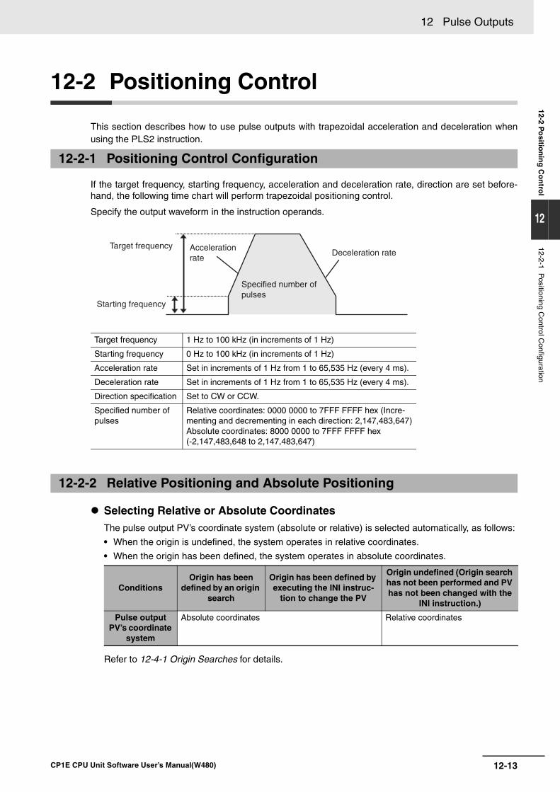
12-13
12 Pulse Outputs
CP1E CPU Unit Software User’s Manual(W480)
12-2 Po
sition
ing
Co
ntro
l
12
12-2-1 Positioning C
ontrol Configuration
12-2 Positioning Control
This section describes how to use pulse outputs with trapezoidal acceleration and deceleration whenusing the PLS2 instruction.
If the target frequency, starting frequency, acceleration and deceleration rate, direction are set before-hand, the following time chart will perform trapezoidal positioning control.
Specify the output waveform in the instruction operands.
Selecting Relative or Absolute CoordinatesThe pulse output PV’s coordinate system (absolute or relative) is selected automatically, as follows:
• When the origin is undefined, the system operates in relative coordinates.
• When the origin has been defined, the system operates in absolute coordinates.
Refer to 12-4-1 Origin Searches for details.
12-2-1 Positioning Control Configuration
Target frequency 1 Hz to 100 kHz (in increments of 1 Hz)
Starting frequency 0 Hz to 100 kHz (in increments of 1 Hz)
Acceleration rate Set in increments of 1 Hz from 1 to 65,535 Hz (every 4 ms).
Deceleration rate Set in increments of 1 Hz from 1 to 65,535 Hz (every 4 ms).
Direction specification Set to CW or CCW.
Specified number of pulses
Relative coordinates: 0000 0000 to 7FFF FFFF hex (Incre-menting and decrementing in each direction: 2,147,483,647)Absolute coordinates: 8000 0000 to 7FFF FFFF hex (-2,147,483,648 to 2,147,483,647)
12-2-2 Relative Positioning and Absolute Positioning
ConditionsOrigin has been
defined by an origin search
Origin has been defined by executing the INI instruc-
tion to change the PV
Origin undefined (Origin search has not been performed and PV has not been changed with the
INI instruction.)
Pulse output PV’s coordinate
system
Absolute coordinates Relative coordinates
Target frequency
Starting frequency
Acceleration rate
Specified number of pulses
Deceleration rate
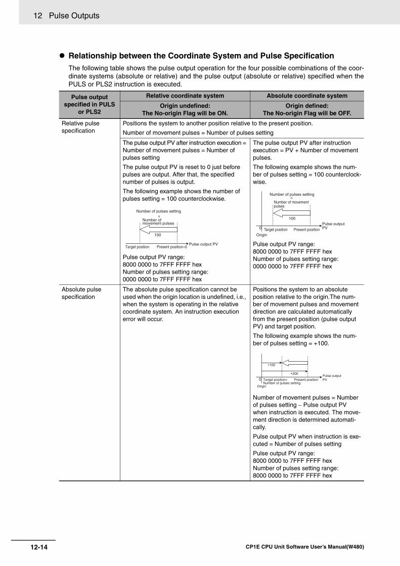
12 Pulse Outputs
12-14 CP1E CPU Unit Software User’s Manual(W480)
Relationship between the Coordinate System and Pulse SpecificationThe following table shows the pulse output operation for the four possible combinations of the coor-dinate systems (absolute or relative) and the pulse output (absolute or relative) specified when thePULS or PLS2 instruction is executed.
Pulse outputspecified in PULS
or PLS2
Relative coordinate system Absolute coordinate system
Origin undefined:The No-origin Flag will be ON.
Origin defined:The No-origin Flag will be OFF.
Relative pulsespecification
Positions the system to another position relative to the present position.
Number of movement pulses = Number of pulses setting
The pulse output PV after instruction execution = Number of movement pulses = Number of pulses setting
The pulse output PV is reset to 0 just before pulses are output. After that, the specified number of pulses is output.
The following example shows the number of pulses setting = 100 counterclockwise.
Pulse output PV range:8000 0000 to 7FFF FFFF hexNumber of pulses setting range:0000 0000 to 7FFF FFFF hex
The pulse output PV after instruction execution = PV + Number of movement pulses.
The following example shows the num-ber of pulses setting = 100 counterclock-wise.
Pulse output PV range:8000 0000 to 7FFF FFFF hexNumber of pulses setting range:0000 0000 to 7FFF FFFF hex
Absolute pulse specification
The absolute pulse specification cannot be used when the origin location is undefined, i.e., when the system is operating in the relative coordinate system. An instruction execution error will occur.
Positions the system to an absolute position relative to the origin.The num-ber of movement pulses and movement direction are calculated automatically from the present position (pulse output PV) and target position.
The following example shows the num-ber of pulses setting = +100.
Number of movement pulses = Number of pulses setting − Pulse output PV when instruction is executed. The move-ment direction is determined automati-cally.
Pulse output PV when instruction is exe-cuted = Number of pulses setting
Pulse output PV range:8000 0000 to 7FFF FFFF hexNumber of pulses setting range:8000 0000 to 7FFF FFFF hex
100
=
Number of pulses setting
Number of movement pulses
Target positionPulse output PV
Present position=0
0
100
Number of pulses setting=
Number of movement pulses
Target positionOrigin
Present positionPulse output PV
+100
0
+200
Target position=Number of pulses setting
Origin
Present positionPulse output PV
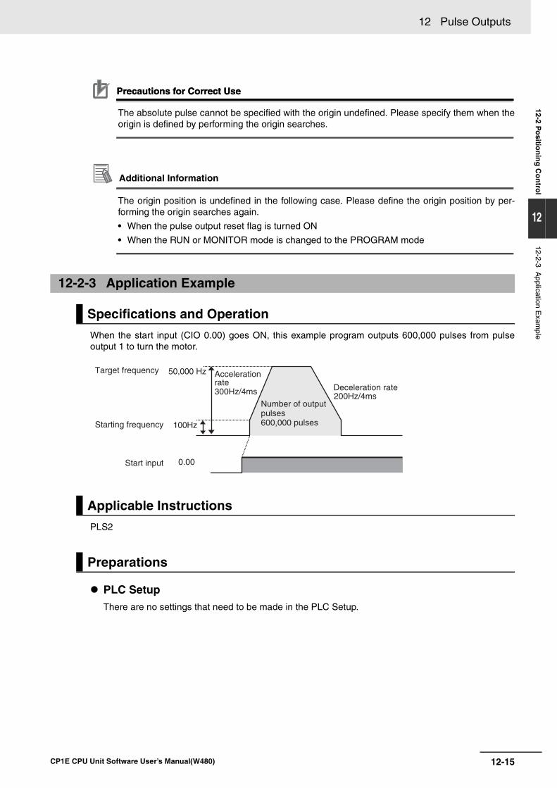
12-15
12 Pulse Outputs
CP1E CPU Unit Software User’s Manual(W480)
12-2 Po
sition
ing
Co
ntro
l
12
12-2-3 Application E
xample
Precautions for Correct UsePrecautions for Correct Use
The absolute pulse cannot be specified with the origin undefined. Please specify them when theorigin is defined by performing the origin searches.
Additional Information
The origin position is undefined in the following case. Please define the origin position by per-forming the origin searches again.
• When the pulse output reset flag is turned ON
• When the RUN or MONITOR mode is changed to the PROGRAM mode
When the start input (CIO 0.00) goes ON, this example program outputs 600,000 pulses from pulseoutput 1 to turn the motor.
PLS2
PLC SetupThere are no settings that need to be made in the PLC Setup.
12-2-3 Application Example
Specifications and Operation
Applicable Instructions
Preparations
0.00
200Hz/4ms
100Hz
50,000 Hz
300Hz/4ms
Target frequency
Starting frequency
Start input
Acceleration rate
Number of output pulses600,000 pulses
Deceleration rate
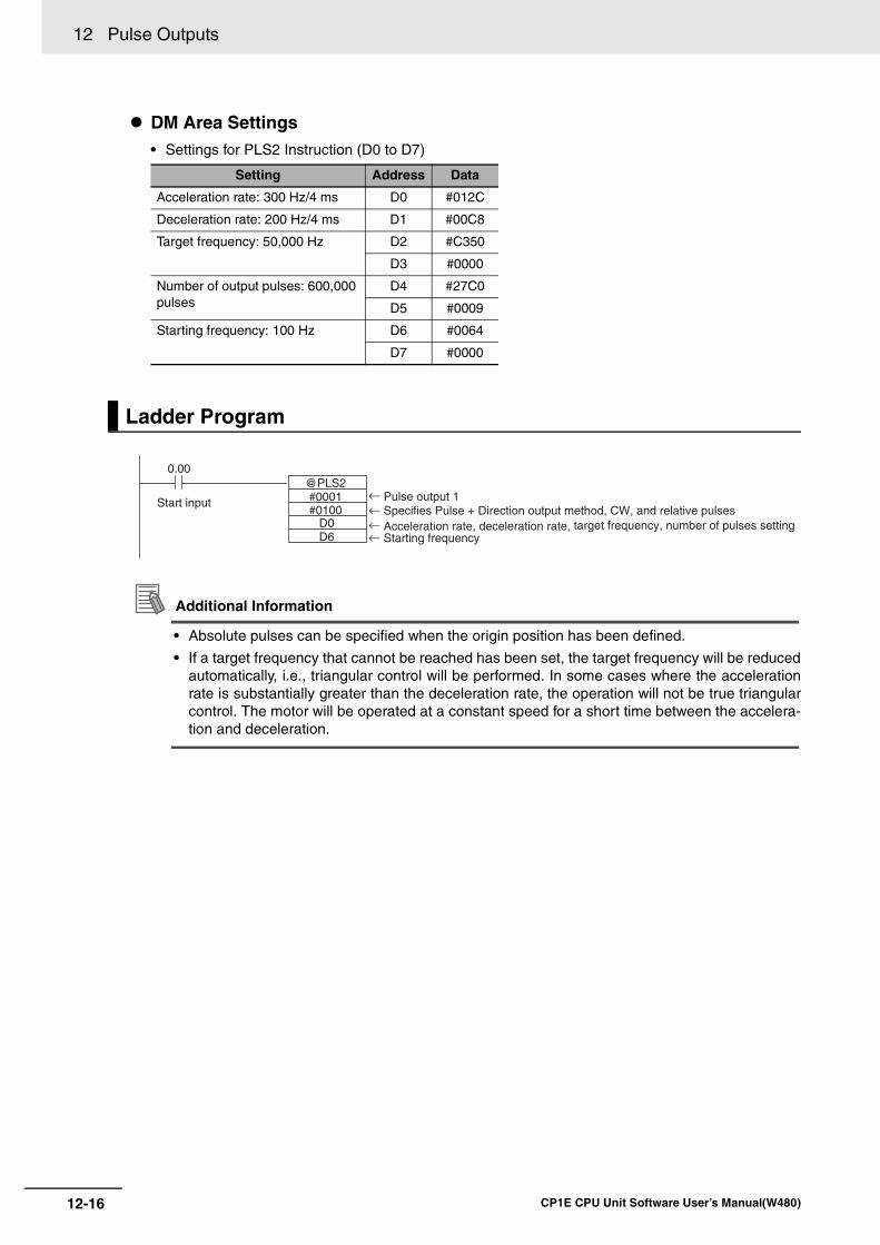
12 Pulse Outputs
12-16 CP1E CPU Unit Software User’s Manual(W480)
DM Area Settings• Settings for PLS2 Instruction (D0 to D7)
Additional Information
• Absolute pulses can be specified when the origin position has been defined.
• If a target frequency that cannot be reached has been set, the target frequency will be reducedautomatically, i.e., triangular control will be performed. In some cases where the accelerationrate is substantially greater than the deceleration rate, the operation will not be true triangularcontrol. The motor will be operated at a constant speed for a short time between the accelera-tion and deceleration.
Setting Address Data
Acceleration rate: 300 Hz/4 ms D0 #012C
Deceleration rate: 200 Hz/4 ms D1 #00C8
Target frequency: 50,000 Hz D2 #C350
D3 #0000
Number of output pulses: 600,000 pulses
D4 #27C0
D5 #0009
Starting frequency: 100 Hz D6 #0064
D7 #0000
Ladder Program
#0001#0100
D0D6
0.00 @PLS2
Start input← Pulse output 1
← Starting frequency← Acceleration rate, deceleration rate, target frequency, number of pulses setting← Specifies Pulse + Direction output method, CW, and relative pulses
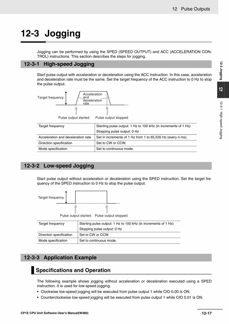
12-17
12 Pulse Outputs
CP1E CPU Unit Software User’s Manual(W480)
12-3 Jog
gin
g
12
12-3-1 High-speed Jogging
12-3 Jogging
Jogging can be performed by using the SPED (SPEED OUTPUT) and ACC (ACCELERATION CON-TROL) instructions. This section describes the steps for jogging.
Start pulse output with acceleration or deceleration using the ACC instruction. In this case, accelerationand deceleration rate must be the same. Set the target frequency of the ACC instruction to 0 Hz to stopthe pulse output.
Start pulse output without acceleration or deceleration using the SPED instruction. Set the target fre-quency of the SPED instruction to 0 Hz to stop the pulse output.
The following example shows jogging without acceleration or deceleration executed using a SPEDinstruction. It is used for low-speed jogging.
• Clockwise low-speed jogging will be executed from pulse output 1 while CIO 0.00 is ON.
• Counterclockwise low-speed jogging will be executed from pulse output 1 while CIO 0.01 is ON.
12-3-1 High-speed Jogging
Target frequency Starting pulse output: 1 Hz to 100 kHz (in increments of 1 Hz)
Stopping pulse output: 0 Hz
Acceleration and deceleration rate Set in increments of 1 Hz from 1 to 65,535 Hz (every 4 ms).
Direction specification Set to CW or CCW.
Mode specification Set to continuous mode.
12-3-2 Low-speed Jogging
Target frequency Starting pulse output: 1 Hz to 100 kHz (in increments of 1 Hz)
Stopping pulse output: 0 Hz
Direction specification Set to CW or CCW.
Mode specification Set to continuous mode.
12-3-3 Application Example
Specifications and Operation
Target frequency
Pulse output started Pulse output stopped
Acceleration and deceleration rate
Target frequency
Pulse output started Pulse output stopped
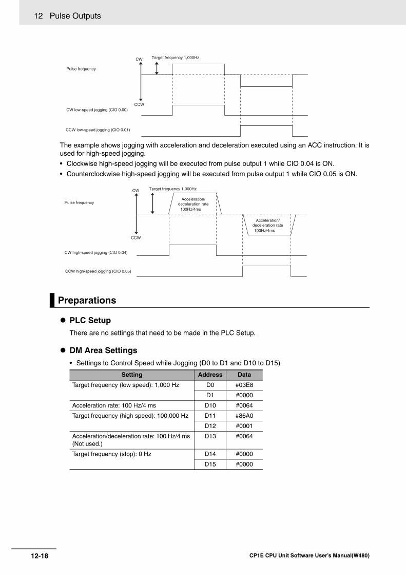
12 Pulse Outputs
12-18 CP1E CPU Unit Software User’s Manual(W480)
The example shows jogging with acceleration and deceleration executed using an ACC instruction. It isused for high-speed jogging.
• Clockwise high-speed jogging will be executed from pulse output 1 while CIO 0.04 is ON.
• Counterclockwise high-speed jogging will be executed from pulse output 1 while CIO 0.05 is ON.
PLC SetupThere are no settings that need to be made in the PLC Setup.
DM Area Settings• Settings to Control Speed while Jogging (D0 to D1 and D10 to D15)
Preparations
Setting Address Data
Target frequency (low speed): 1,000 Hz D0 #03E8
D1 #0000
Acceleration rate: 100 Hz/4 ms D10 #0064
Target frequency (high speed): 100,000 Hz D11 #86A0
D12 #0001
Acceleration/deceleration rate: 100 Hz/4 ms (Not used.)
D13 #0064
Target frequency (stop): 0 Hz D14 #0000
D15 #0000
CW
CCW
Pulse frequency
Target frequency 1,000Hz
CW low-speed jogging (CIO 0.00)
CCW low-speed jogging (CIO 0.01)
100Hz/4ms
100Hz/4ms
CW high-speed jogging (CIO 0.04)
CCW high-speed jogging (CIO 0.05)
Acceleration/deceleration rate
Acceleration/deceleration rate
CW
CCW
Pulse frequency
Target frequency 1,000Hz
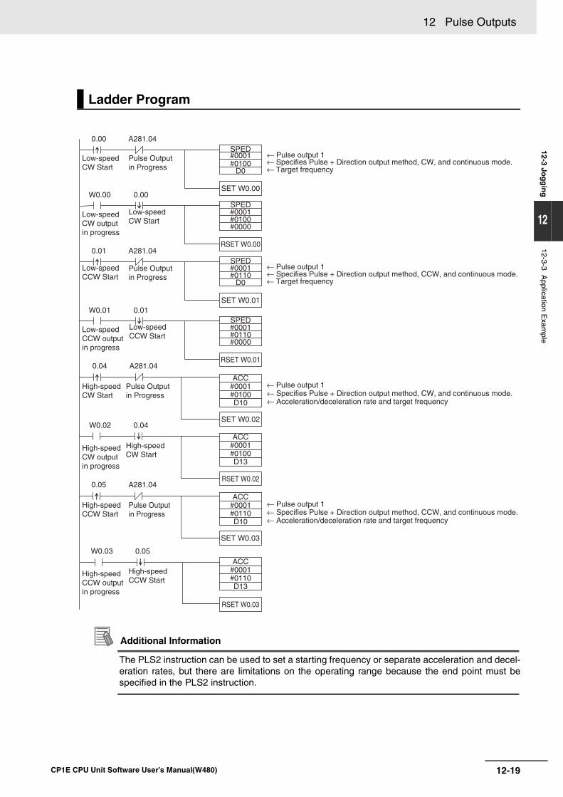
12-19
12 Pulse Outputs
CP1E CPU Unit Software User’s Manual(W480)
12-3 Jog
gin
g
12
12-3-3 Application E
xample
Additional Information
The PLS2 instruction can be used to set a starting frequency or separate acceleration and decel-eration rates, but there are limitations on the operating range because the end point must bespecified in the PLS2 instruction.
Ladder Program
SPED#0001#0100
D0
0.00
SET W0.00
A281.04
SPED
SPED
SPED
#0001#0100#0000
W0.00
RSET W0.00
0.00
#0001#0110
D0
0.01
SET W0.01
A281.04
#0001#0110#0000
W0.01
RSET W0.01
0.01
ACC#0001#0100D10
0.04
SET W0.02
A281.04
ACC#0001#0100D13
W0.02
RSET W0.02
0.04
ACC#0001#0110D10
0.05
SET W0.03
A281.04
ACC#0001#0110D13
W0.03
RSET W0.03
0.05
Low-speed CW Start
Low-speed CW Start
Pulse Output in Progress
Pulse Output in Progress
Pulse Output in Progress
Pulse Output in Progress
Low-speed CW output in progress
Low-speed CCW Start
Low-speed CCW output in progress
High-speed CW Start
High-speed CW Start
Low-speed CCW Start
High-speed CW output in progress
High-speed CCW Start
High-speed CCW Start
High-speed CCW output in progress
← Pulse output 1← Specifies Pulse + Direction output method, CW, and continuous mode.← Target frequency
← Specifies Pulse + Direction output method, CW, and continuous mode.← Acceleration/deceleration rate and target frequency
← Pulse output 1← Specifies Pulse + Direction output method, CCW, and continuous mode.← Acceleration/deceleration rate and target frequency
← Target frequency← Specifies Pulse + Direction output method, CCW, and continuous mode.← Pulse output 1
← Pulse output 1
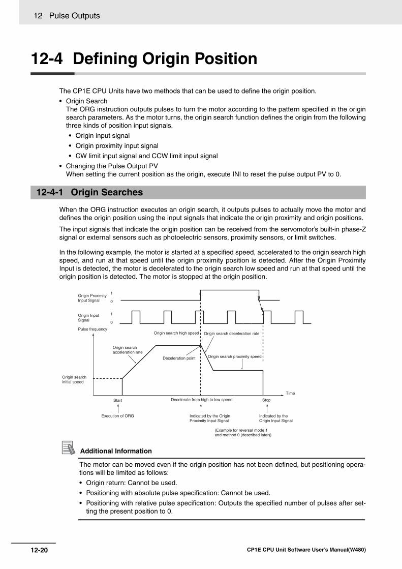
12 Pulse Outputs
12-20 CP1E CPU Unit Software User’s Manual(W480)
12-4 Defining Origin Position
The CP1E CPU Units have two methods that can be used to define the origin position.
• Origin SearchThe ORG instruction outputs pulses to turn the motor according to the pattern specified in the originsearch parameters. As the motor turns, the origin search function defines the origin from the followingthree kinds of position input signals.
• Origin input signal
• Origin proximity input signal
• CW limit input signal and CCW limit input signal
• Changing the Pulse Output PVWhen setting the current position as the origin, execute INI to reset the pulse output PV to 0.
When the ORG instruction executes an origin search, it outputs pulses to actually move the motor anddefines the origin position using the input signals that indicate the origin proximity and origin positions.
The input signals that indicate the origin position can be received from the servomotor’s built-in phase-Zsignal or external sensors such as photoelectric sensors, proximity sensors, or limit switches.
In the following example, the motor is started at a specified speed, accelerated to the origin search highspeed, and run at that speed until the origin proximity position is detected. After the Origin ProximityInput is detected, the motor is decelerated to the origin search low speed and run at that speed until theorigin position is detected. The motor is stopped at the origin position.
Additional Information
The motor can be moved even if the origin position has not been defined, but positioning opera-tions will be limited as follows:
• Origin return: Cannot be used.
• Positioning with absolute pulse specification: Cannot be used.
• Positioning with relative pulse specification: Outputs the specified number of pulses after set-ting the present position to 0.
12-4-1 Origin Searches
1
0
1
0
Origin Proximity Input Signal
Origin Input Signal
Pulse frequency
Origin search acceleration rate
Origin search high speed
Deceleration point
Origin search deceleration rate
Origin search proximity speed
Origin search initial speed
Start
Execution of ORG
Decelerate from high to low speed
Indicated by the Origin Proximity Input Signal
Stop
Indicated by the Origin Input Signal
Time
(Example for reversal mode 1 and method 0 (described later))
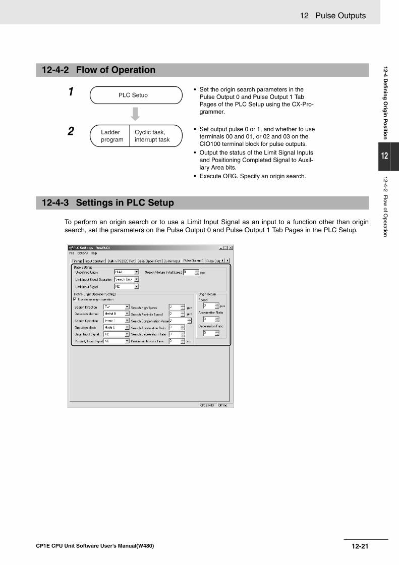
12-21
12 Pulse Outputs
CP1E CPU Unit Software User’s Manual(W480)
12-4 Defin
ing
Orig
in P
ositio
n
12
12-4-2 Flow
of Operation
To perform an origin search or to use a Limit Input Signal as an input to a function other than originsearch, set the parameters on the Pulse Output 0 and Pulse Output 1 Tab Pages in the PLC Setup.
12-4-2 Flow of Operation
1 • Set the origin search parameters in the Pulse Output 0 and Pulse Output 1 Tab Pages of the PLC Setup using the CX-Pro-grammer.
2 • Set output pulse 0 or 1, and whether to use terminals 00 and 01, or 02 and 03 on the CIO100 terminal block for pulse outputs.
• Output the status of the Limit Signal Inputs and Positioning Completed Signal to Auxil-iary Area bits.
• Execute ORG. Specify an origin search.
12-4-3 Settings in PLC Setup
PLC Setup
Ladder program
Cyclic task, interrupt task
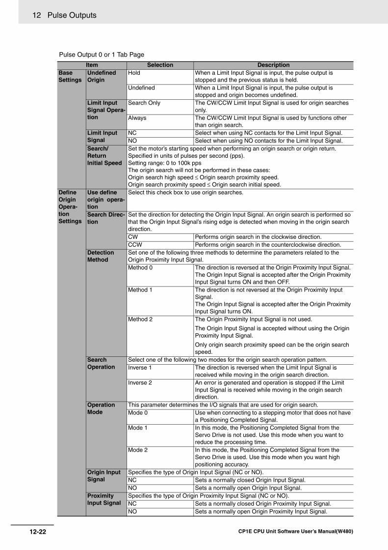
12 Pulse Outputs
12-22 CP1E CPU Unit Software User’s Manual(W480)
Pulse Output 0 or 1 Tab Page
Item Selection DescriptionBase Settings
Undefined Origin
Hold When a Limit Input Signal is input, the pulse output is stopped and the previous status is held.
Undefined When a Limit Input Signal is input, the pulse output is stopped and origin becomes undefined.
Limit Input Signal Opera-tion
Search Only The CW/CCW Limit Input Signal is used for origin searches only.
Always The CW/CCW Limit Input Signal is used by functions other than origin search.
Limit Input Signal
NC Select when using NC contacts for the Limit Input Signal.NO Select when using NO contacts for the Limit Input Signal.
Search/ReturnInitial Speed
Set the motor’s starting speed when performing an origin search or origin return.Specified in units of pulses per second (pps).Setting range: 0 to 100k ppsThe origin search will not be performed in these cases:Origin search high speed ≤ Origin search proximity speed.Origin search proximity speed ≤ Origin search initial speed.
Define Origin Opera-tionSettings
Use define origin opera-tion
Select this check box to use origin searches.
Search Direc-tion
Set the direction for detecting the Origin Input Signal. An origin search is performed so that the Origin Input Signal’s rising edge is detected when moving in the origin search direction. CW Performs origin search in the clockwise direction.CCW Performs origin search in the counterclockwise direction.
Detection Method
Set one of the following three methods to determine the parameters related to theOrigin Proximity Input Signal.Method 0 The direction is reversed at the Origin Proximity Input Signal.
The Origin Input Signal is accepted after the Origin Proximity Input Signal turns ON and then OFF.
Method 1 The direction is not reversed at the Origin Proximity InputSignal. The Origin Input Signal is accepted after the Origin Proximity Input Signal turns ON.
Method 2 The Origin Proximity Input Signal is not used.
The Origin Input Signal is accepted without using the Origin Proximity Input Signal.
Only origin search proximity speed can be the origin search speed.
SearchOperation
Select one of the following two modes for the origin search operation pattern.Inverse 1 The direction is reversed when the Limit Input Signal is
received while moving in the origin search direction.Inverse 2 An error is generated and operation is stopped if the Limit
Input Signal is received while moving in the origin search direction.
Operation Mode
This parameter determines the I/O signals that are used for origin search.Mode 0 Use when connecting to a stepping motor that does not have
a Positioning Completed Signal.Mode 1 In this mode, the Positioning Completed Signal from the
Servo Drive is not used. Use this mode when you want to reduce the processing time.
Mode 2 In this mode, the Positioning Completed Signal from the Servo Drive is used. Use this mode when you want highpositioning accuracy.
Origin Input Signal
Specifies the type of Origin Input Signal (NC or NO).NC Sets a normally closed Origin Input Signal.NO Sets a normally open Origin Input Signal.
Proximity Input Signal
Specifies the type of Origin Proximity Input Signal (NC or NO).NC Sets a normally closed Origin Proximity Input Signal.NO Sets a normally open Origin Proximity Input Signal.
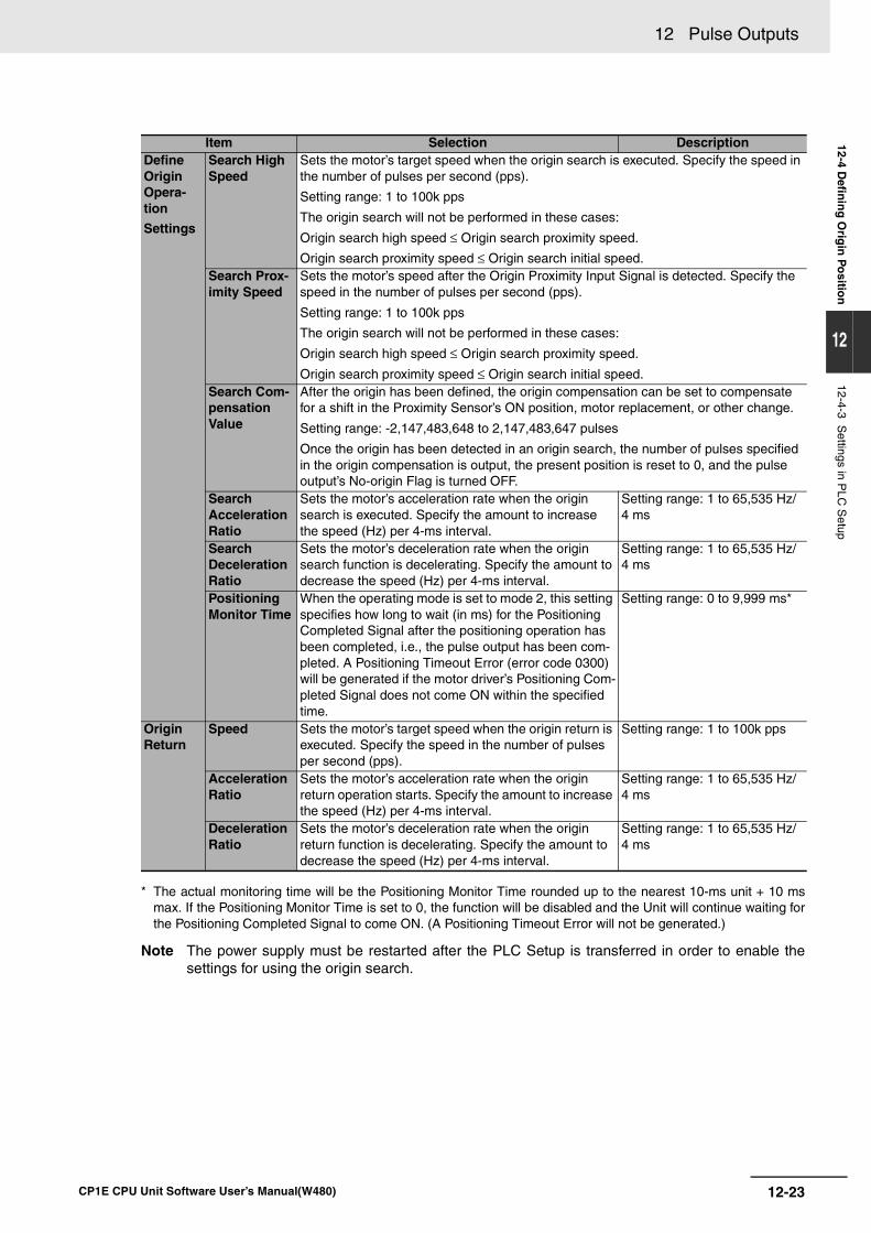
12-23
12 Pulse Outputs
CP1E CPU Unit Software User’s Manual(W480)
12-4 Defin
ing
Orig
in P
ositio
n
12
12-4-3 Settings in P
LC S
etup
* The actual monitoring time will be the Positioning Monitor Time rounded up to the nearest 10-ms unit + 10 msmax. If the Positioning Monitor Time is set to 0, the function will be disabled and the Unit will continue waiting forthe Positioning Completed Signal to come ON. (A Positioning Timeout Error will not be generated.)
Note The power supply must be restarted after the PLC Setup is transferred in order to enable thesettings for using the origin search.
Item Selection DescriptionDefine Origin Opera-tion
Settings
Search High Speed
Sets the motor’s target speed when the origin search is executed. Specify the speed in the number of pulses per second (pps).
Setting range: 1 to 100k pps
The origin search will not be performed in these cases:
Origin search high speed ≤ Origin search proximity speed.
Origin search proximity speed ≤ Origin search initial speed.Search Prox-imity Speed
Sets the motor’s speed after the Origin Proximity Input Signal is detected. Specify the speed in the number of pulses per second (pps).
Setting range: 1 to 100k pps
The origin search will not be performed in these cases:
Origin search high speed ≤ Origin search proximity speed.
Origin search proximity speed ≤ Origin search initial speed.Search Com-pensation Value
After the origin has been defined, the origin compensation can be set to compensate for a shift in the Proximity Sensor’s ON position, motor replacement, or other change.
Setting range: -2,147,483,648 to 2,147,483,647 pulses
Once the origin has been detected in an origin search, the number of pulses specified in the origin compensation is output, the present position is reset to 0, and the pulse output’s No-origin Flag is turned OFF.
Search Acceleration Ratio
Sets the motor’s acceleration rate when the origin search is executed. Specify the amount to increase the speed (Hz) per 4-ms interval.
Setting range: 1 to 65,535 Hz/4 ms
Search Deceleration Ratio
Sets the motor’s deceleration rate when the origin search function is decelerating. Specify the amount to decrease the speed (Hz) per 4-ms interval.
Setting range: 1 to 65,535 Hz/4 ms
Positioning Monitor Time
When the operating mode is set to mode 2, this setting specifies how long to wait (in ms) for the Positioning Completed Signal after the positioning operation has been completed, i.e., the pulse output has been com-pleted. A Positioning Timeout Error (error code 0300) will be generated if the motor driver’s Positioning Com-pleted Signal does not come ON within the specified time.
Setting range: 0 to 9,999 ms*
Origin Return
Speed Sets the motor’s target speed when the origin return is executed. Specify the speed in the number of pulses per second (pps).
Setting range: 1 to 100k pps
Acceleration Ratio
Sets the motor’s acceleration rate when the origin return operation starts. Specify the amount to increase the speed (Hz) per 4-ms interval.
Setting range: 1 to 65,535 Hz/4 ms
Deceleration Ratio
Sets the motor’s deceleration rate when the origin return function is decelerating. Specify the amount to decrease the speed (Hz) per 4-ms interval.
Setting range: 1 to 65,535 Hz/4 ms
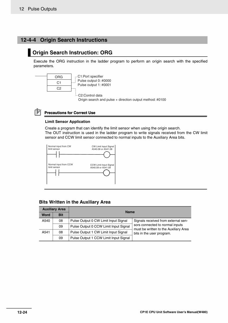
12 Pulse Outputs
12-24 CP1E CPU Unit Software User’s Manual(W480)
Execute the ORG instruction in the ladder program to perform an origin search with the specifiedparameters.
Precautions for Correct UsePrecautions for Correct Use
Limit Sensor Application
Create a program that can identify the limit sensor when using the origin search.The OUT instruction is used in the ladder program to write signals received from the CW limitsensor and CCW limit sensor connected to normal inputs to the Auxiliary Area bits.
Bits Written in the Auxiliary Area
12-4-4 Origin Search Instructions
Origin Search Instruction: ORG
Auxiliary AreaName
Word Bit
A540 08 Pulse Output 0 CW Limit Input Signal Signals received from external sen-sors connected to normal inputs must be written to the Auxiliary Area bits in the user program.
09 Pulse Output 0 CCW Limit Input Signal
A541 08 Pulse Output 1 CW Limit Input Signal
09 Pulse Output 1 CCW Limit Input Signal
ORG
C1
C2
C1:Port specifierPulse output 0: #0000Pulse output 1: #0001
C2:Control dataOrigin search and pulse + direction output method: #0100
Normal input from CW limit sensor
CW Limit Input Signal A540.08 or A541.08
Normal input from CCW limit sensor
CCW Limit Input Signal A540.09 or A541.09
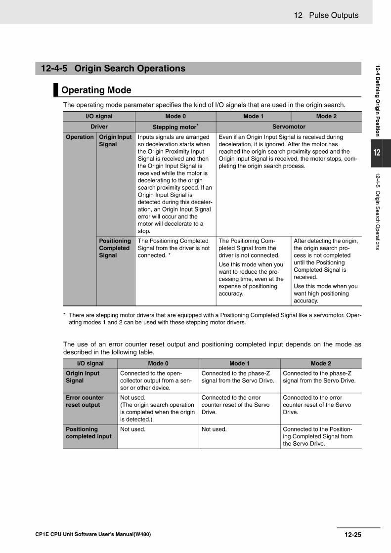
12-25
12 Pulse Outputs
CP1E CPU Unit Software User’s Manual(W480)
12-4 Defin
ing
Orig
in P
ositio
n
12
12-4-5 Origin S
earch Operations
The operating mode parameter specifies the kind of I/O signals that are used in the origin search.
* There are stepping motor drivers that are equipped with a Positioning Completed Signal like a servomotor. Oper-ating modes 1 and 2 can be used with these stepping motor drivers.
The use of an error counter reset output and positioning completed input depends on the mode asdescribed in the following table.
12-4-5 Origin Search Operations
Operating Mode
I/O signal Mode 0 Mode 1 Mode 2
Driver Stepping motor* Servomotor
Operation Origin Input Signal
Inputs signals are arranged so deceleration starts when the Origin Proximity Input Signal is received and then the Origin Input Signal is received while the motor is decelerating to the origin search proximity speed. If an Origin Input Signal is detected during this deceler-ation, an Origin Input Signal error will occur and the motor will decelerate to a stop.
Even if an Origin Input Signal is received during deceleration, it is ignored. After the motor has reached the origin search proximity speed and the Origin Input Signal is received, the motor stops, com-pleting the origin search process.
Positioning Completed Signal
The Positioning Completed Signal from the driver is not connected. *
The Positioning Com-pleted Signal from the driver is not connected.
Use this mode when you want to reduce the pro-cessing time, even at the expense of positioning accuracy.
After detecting the origin, the origin search pro-cess is not completed until the Positioning Completed Signal is received.
Use this mode when you want high positioning accuracy.
I/O signal Mode 0 Mode 1 Mode 2
Origin InputSignal
Connected to the open-collector output from a sen-sor or other device.
Connected to the phase-Z signal from the Servo Drive.
Connected to the phase-Z signal from the Servo Drive.
Error counter reset output
Not used.(The origin search operation is completed when the origin is detected.)
Connected to the error counter reset of the Servo Drive.
Connected to the error counter reset of the Servo Drive.
Positioningcompleted input
Not used. Not used. Connected to the Position-ing Completed Signal from the Servo Drive.
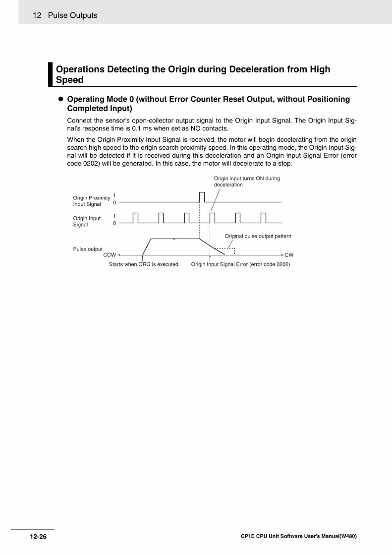
12 Pulse Outputs
12-26 CP1E CPU Unit Software User’s Manual(W480)
Operating Mode 0 (without Error Counter Reset Output, without Positioning Completed Input)Connect the sensor’s open-collector output signal to the Origin Input Signal. The Origin Input Sig-nal’s response time is 0.1 ms when set as NO contacts.
When the Origin Proximity Input Signal is received, the motor will begin decelerating from the originsearch high speed to the origin search proximity speed. In this operating mode, the Origin Input Sig-nal will be detected if it is received during this deceleration and an Origin Input Signal Error (errorcode 0202) will be generated. In this case, the motor will decelerate to a stop.
Operations Detecting the Origin during Deceleration from High Speed
CCW CW
10
10
Origin Proximity Input Signal
Origin Input Signal
Pulse output
Original pulse output pattern
Starts when ORG is executed Origin Input Signal Error (error code 0202)
Origin input turns ON during deceleration
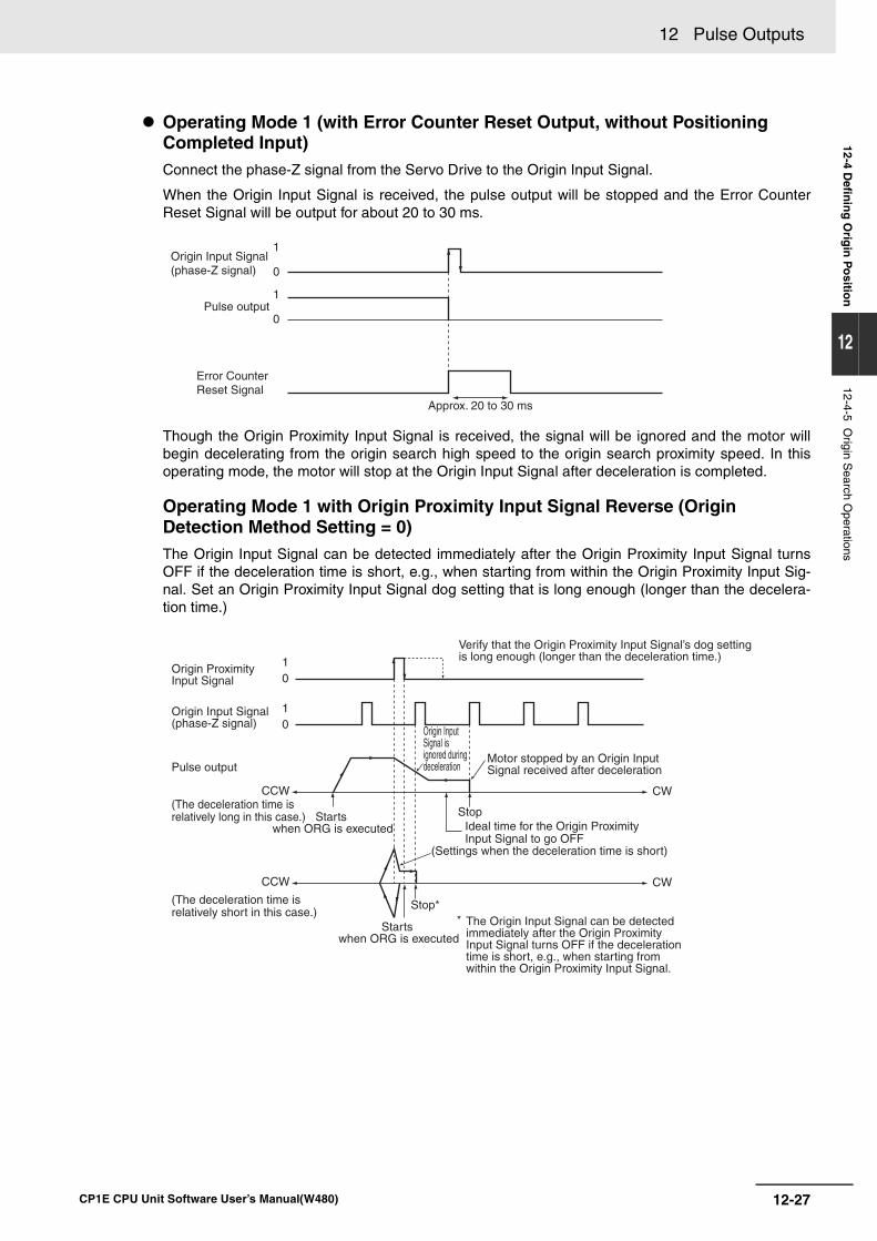
12-27
12 Pulse Outputs
CP1E CPU Unit Software User’s Manual(W480)
12-4 Defin
ing
Orig
in P
ositio
n
12
12-4-5 Origin S
earch Operations
Operating Mode 1 (with Error Counter Reset Output, without Positioning Completed Input)Connect the phase-Z signal from the Servo Drive to the Origin Input Signal.
When the Origin Input Signal is received, the pulse output will be stopped and the Error CounterReset Signal will be output for about 20 to 30 ms.
Though the Origin Proximity Input Signal is received, the signal will be ignored and the motor willbegin decelerating from the origin search high speed to the origin search proximity speed. In thisoperating mode, the motor will stop at the Origin Input Signal after deceleration is completed.
Operating Mode 1 with Origin Proximity Input Signal Reverse (Origin Detection Method Setting = 0)The Origin Input Signal can be detected immediately after the Origin Proximity Input Signal turnsOFF if the deceleration time is short, e.g., when starting from within the Origin Proximity Input Sig-nal. Set an Origin Proximity Input Signal dog setting that is long enough (longer than the decelera-tion time.)
1
0
1
0Origin Input Signal (phase-Z signal)
Pulse output
Error Counter Reset Signal
Approx. 20 to 30 ms
CCW
CCW
CW
CW
10
10
Origin Proximity Input Signal
Origin Input Signal (phase-Z signal)
Pulse output
Verify that the Origin Proximity Input Signal’s dog setting is long enough (longer than the deceleration time.)
Origin Input Signal is ignored during deceleration
Motor stopped by an Origin Input Signal received after deceleration
Starts when ORG is executed
Starts when ORG is executed
StopIdeal time for the Origin Proximity Input Signal to go OFF
(Settings when the deceleration time is short)
Stop*The Origin Input Signal can be detected immediately after the Origin Proximity Input Signal turns OFF if the deceleration time is short, e.g., when starting from within the Origin Proximity Input Signal.
*
(The deceleration time is relatively long in this case.)
(The deceleration time is relatively short in this case.)
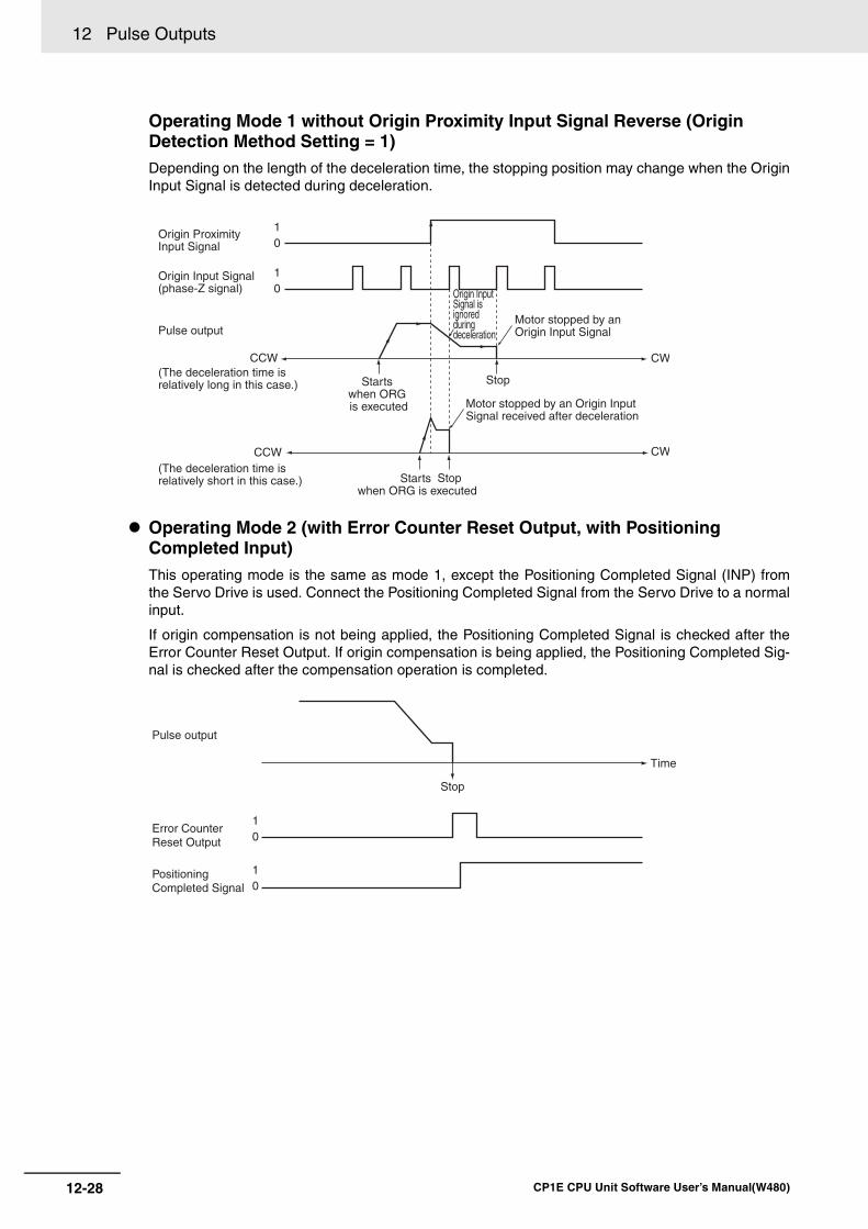
12 Pulse Outputs
12-28 CP1E CPU Unit Software User’s Manual(W480)
Operating Mode 1 without Origin Proximity Input Signal Reverse (Origin Detection Method Setting = 1)Depending on the length of the deceleration time, the stopping position may change when the OriginInput Signal is detected during deceleration.
Operating Mode 2 (with Error Counter Reset Output, with Positioning Completed Input)This operating mode is the same as mode 1, except the Positioning Completed Signal (INP) fromthe Servo Drive is used. Connect the Positioning Completed Signal from the Servo Drive to a normalinput.
If origin compensation is not being applied, the Positioning Completed Signal is checked after theError Counter Reset Output. If origin compensation is being applied, the Positioning Completed Sig-nal is checked after the compensation operation is completed.
10
10
CCW
CCW
CW
CW
Origin Proximity Input Signal
Origin Input Signal (phase-Z signal)
Pulse output
(The deceleration time is relatively long in this case.)
(The deceleration time is relatively short in this case.)
Origin Input Signal is ignored during deceleration
Motor stopped by an Origin Input Signal
Motor stopped by an Origin Input Signal received after deceleration
Starts when ORG is executed
Starts when ORG is executed
Stop
Stop
10
10
Pulse output
Error Counter Reset Output
Positioning Completed Signal
Stop
Time
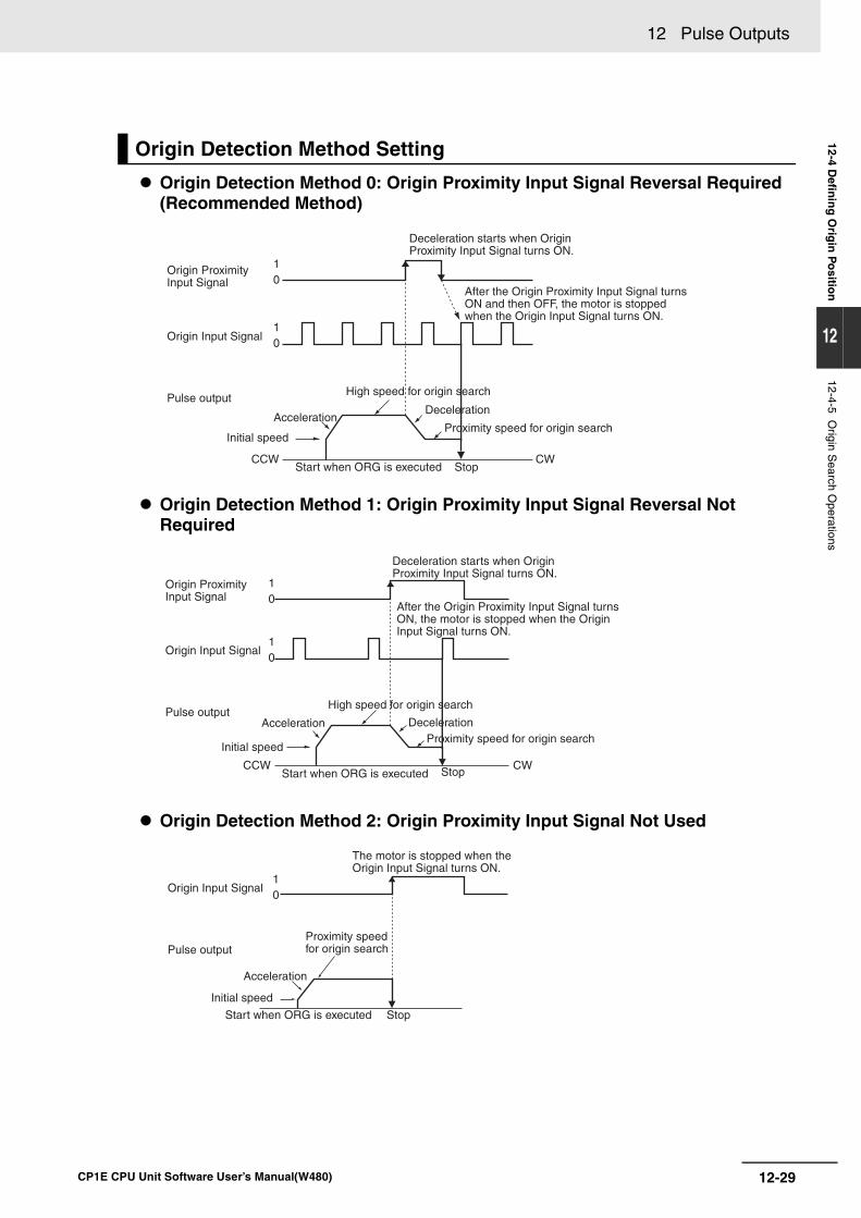
12-29
12 Pulse Outputs
CP1E CPU Unit Software User’s Manual(W480)
12-4 Defin
ing
Orig
in P
ositio
n
12
12-4-5 Origin S
earch Operations
Origin Detection Method 0: Origin Proximity Input Signal Reversal Required (Recommended Method)
Origin Detection Method 1: Origin Proximity Input Signal Reversal Not Required
Origin Detection Method 2: Origin Proximity Input Signal Not Used
Origin Detection Method Setting
10
10
CCW CW
Origin Proximity Input Signal
Origin Input Signal
Pulse output
Deceleration starts when Origin Proximity Input Signal turns ON.
After the Origin Proximity Input Signal turns ON and then OFF, the motor is stopped when the Origin Input Signal turns ON.
Initial speed
Acceleration
High speed for origin search
Deceleration
Proximity speed for origin search
Start when ORG is executed Stop
10
10
CCW CW
Origin Proximity Input Signal
Origin Input Signal
Pulse output
Deceleration starts when Origin Proximity Input Signal turns ON.
Initial speed
Acceleration
High speed for origin search
DecelerationProximity speed for origin search
Start when ORG is executed Stop
After the Origin Proximity Input Signal turns ON, the motor is stopped when the Origin Input Signal turns ON.
10
Origin Input Signal
Pulse output
Initial speed
Acceleration
Start when ORG is executed Stop
Proximity speed for origin search
The motor is stopped when the Origin Input Signal turns ON.
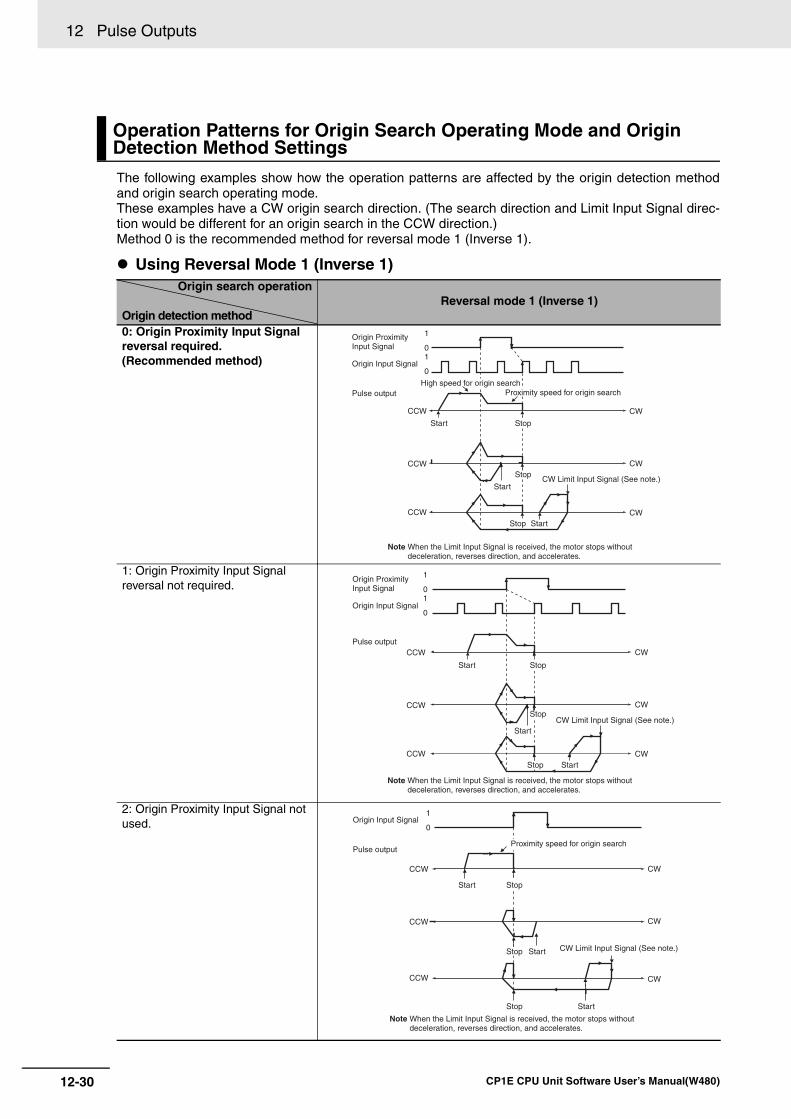
12 Pulse Outputs
12-30 CP1E CPU Unit Software User’s Manual(W480)
The following examples show how the operation patterns are affected by the origin detection methodand origin search operating mode.These examples have a CW origin search direction. (The search direction and Limit Input Signal direc-tion would be different for an origin search in the CCW direction.)Method 0 is the recommended method for reversal mode 1 (Inverse 1).
Using Reversal Mode 1 (Inverse 1)
Operation Patterns for Origin Search Operating Mode and Origin Detection Method Settings
Origin search operation
Origin detection methodReversal mode 1 (Inverse 1)
0: Origin Proximity Input Signal reversal required.(Recommended method)
1: Origin Proximity Input Signal reversal not required.
2: Origin Proximity Input Signal not used.
1
01
0
CCW
CCW
CCW
CW
CW
CW
Origin Proximity Input Signal
Origin Input Signal
Pulse outputHigh speed for origin search
Proximity speed for origin search
Start
Start
Start
Stop
Stop
Stop
CW Limit Input Signal (See note.)
Note When the Limit Input Signal is received, the motor stops without deceleration, reverses direction, and accelerates.
1
01
0
CCW
CCW
CCW
CW
CW
CW
Origin Proximity Input Signal
Origin Input Signal
Pulse output
Note When the Limit Input Signal is received, the motor stops without deceleration, reverses direction, and accelerates.
Start
Start
Start
Stop
Stop
Stop
CW Limit Input Signal (See note.)
1
0
CCW
CCW
CCW
CW
CW
CW
Origin Input Signal
Pulse outputProximity speed for origin search
Start
Start
Start
Stop
Stop
Stop
CW Limit Input Signal (See note.)
Note When the Limit Input Signal is received, the motor stops without deceleration, reverses direction, and accelerates.
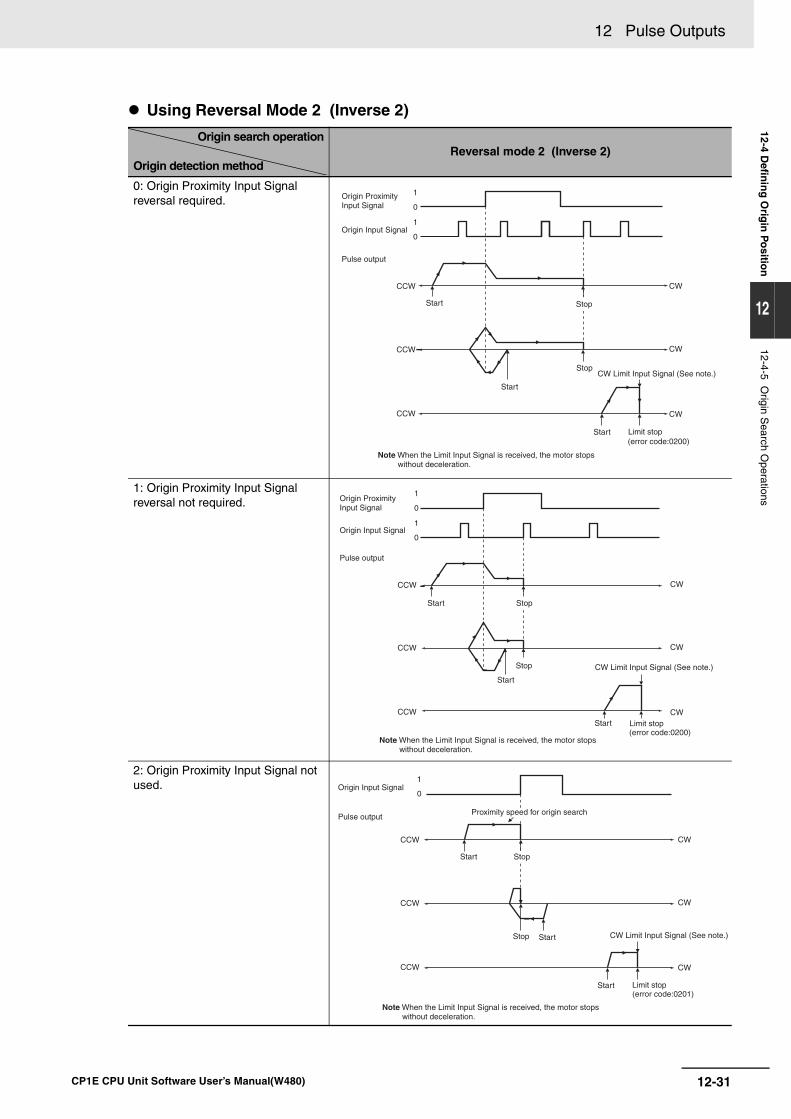
12-31
12 Pulse Outputs
CP1E CPU Unit Software User’s Manual(W480)
12-4 Defin
ing
Orig
in P
ositio
n
12
12-4-5 Origin S
earch Operations
Using Reversal Mode 2 (Inverse 2)
Origin search operation
Origin detection methodReversal mode 2 (Inverse 2)
0: Origin Proximity Input Signal reversal required.
1: Origin Proximity Input Signal reversal not required.
2: Origin Proximity Input Signal not used.
1
0
1
0
CCW
CCW
CCW
CW
CW
CW
Origin Proximity Input Signal
Origin Input Signal
Pulse output
Start Stop
Start
Stop
Start
CW Limit Input Signal (See note.)
Limit stop (error code:0200)
Note When the Limit Input Signal is received, the motor stops without deceleration.
1
0
1
0
CCW
CCW
CCW
CW
CW
CW
Origin Proximity Input Signal
Origin Input Signal
Pulse output
Start Stop
Stop
Start
Start
CW Limit Input Signal (See note.)
Limit stop (error code:0200)
Note When the Limit Input Signal is received, the motor stops without deceleration.
1
0
CCW
CCW
CCW
CW
CW
CW
Origin Input Signal
Pulse outputProximity speed for origin search
Start Stop
Stop Start
Start
CW Limit Input Signal (See note.)
Limit stop (error code:0201)
Note When the Limit Input Signal is received, the motor stops without deceleration.
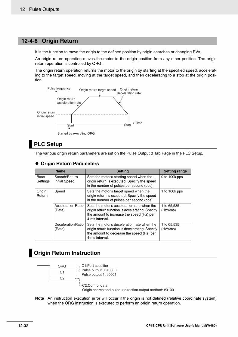
12 Pulse Outputs
12-32 CP1E CPU Unit Software User’s Manual(W480)
It is the function to move the origin to the defined position by origin searches or changing PVs.
An origin return operation moves the motor to the origin position from any other position. The originreturn operation is controlled by ORG.
The origin return operation returns the motor to the origin by starting at the specified speed, accelerat-ing to the target speed, moving at the target speed, and then decelerating to a stop at the origin posi-tion.
The various origin return parameters are set on the Pulse Output 0 Tab Page in the PLC Setup.
Origin Return Parameters
Note An instruction execution error will occur if the origin is not defined (relative coordinate system)when the ORG instruction is executed to perform an origin return operation.
12-4-6 Origin Return
PLC Setup
Name Setting Setting range
Base Settings
Search/ReturnInitial Speed
Sets the motor’s starting speed when theorigin return is executed. Specify the speed in the number of pulses per second (pps).
0 to 100k pps
Origin Return
Speed Sets the motor’s target speed when theorigin return is executed. Specify the speed in the number of pulses per second (pps).
1 to 100k pps
Acceleration Ratio (Rate)
Sets the motor’s acceleration rate when the origin return function is accelerating. Specify the amount to increase the speed (Hz) per 4-ms interval.
1 to 65,535(Hz/4ms)
Deceleration Ratio (Rate)
Sets the motor’s deceleration rate when the origin return function is decelerating. Specify the amount to decrease the speed (Hz) per 4-ms interval.
1 to 65,535(Hz/4ms)
Origin Return Instruction
Pulse frequency
Origin returninitial speed
Start
Started by executing ORG
Origin returnacceleration rate
Origin return target speed Origin returndeceleration rate
StopTime
ORG
C1
C2
C1:Port specifierPulse output 0: #0000Pulse output 1: #0001
C2:Control dataOrigin search and pulse + direction output method: #0100
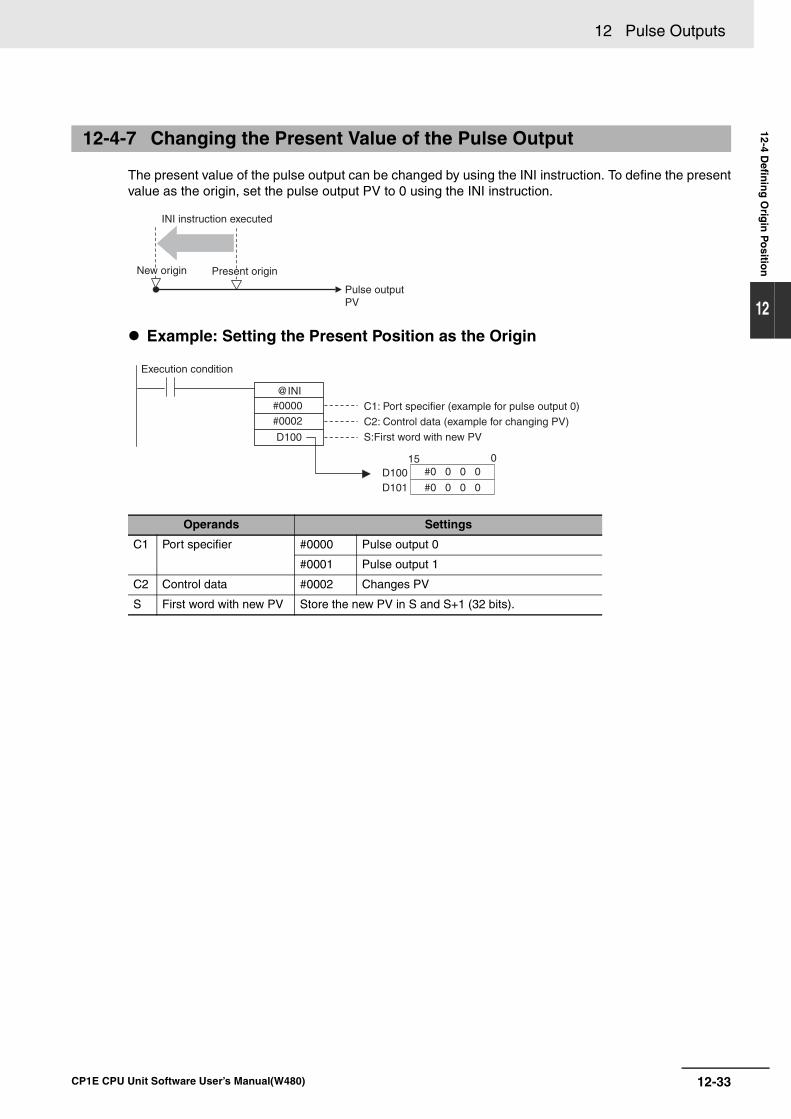
12-33
12 Pulse Outputs
CP1E CPU Unit Software User’s Manual(W480)
12-4 Defin
ing
Orig
in P
ositio
n
12
The present value of the pulse output can be changed by using the INI instruction. To define the presentvalue as the origin, set the pulse output PV to 0 using the INI instruction.
Example: Setting the Present Position as the Origin
12-4-7 Changing the Present Value of the Pulse Output
Operands Settings
C1 Port specifier #0000 Pulse output 0
#0001 Pulse output 1
C2 Control data #0002 Changes PV
S First word with new PV Store the new PV in S and S+1 (32 bits).
INI instruction executed
Pulse outputPV
New origin Present origin
#0000 #0002
D100
D100D101
@INI
15 0#0 0 0 0
#0 0 0 0
Execution condition
C1: Port specifier (example for pulse output 0)
C2: Control data (example for changing PV)
S:First word with new PV
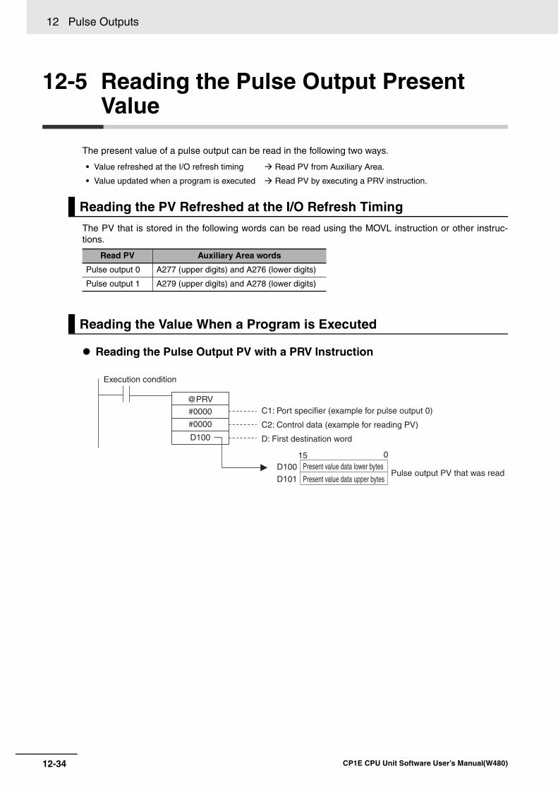
12 Pulse Outputs
12-34 CP1E CPU Unit Software User’s Manual(W480)
12-5 Reading the Pulse Output Present Value
The present value of a pulse output can be read in the following two ways.
The PV that is stored in the following words can be read using the MOVL instruction or other instruc-tions.
Reading the Pulse Output PV with a PRV Instruction
• Value refreshed at the I/O refresh timing Read PV from Auxiliary Area.
• Value updated when a program is executed Read PV by executing a PRV instruction.
Reading the PV Refreshed at the I/O Refresh Timing
Read PV Auxiliary Area words
Pulse output 0 A277 (upper digits) and A276 (lower digits)
Pulse output 1 A279 (upper digits) and A278 (lower digits)
Reading the Value When a Program is Executed
#0000
#0000
D100
D100
D101
@PRV
15 0
Pulse output PV that was read
C1: Port specifier (example for pulse output 0)
C2: Control data (example for reading PV)
D: First destination word
Present value data lower bytes
Present value data upper bytes
Execution condition
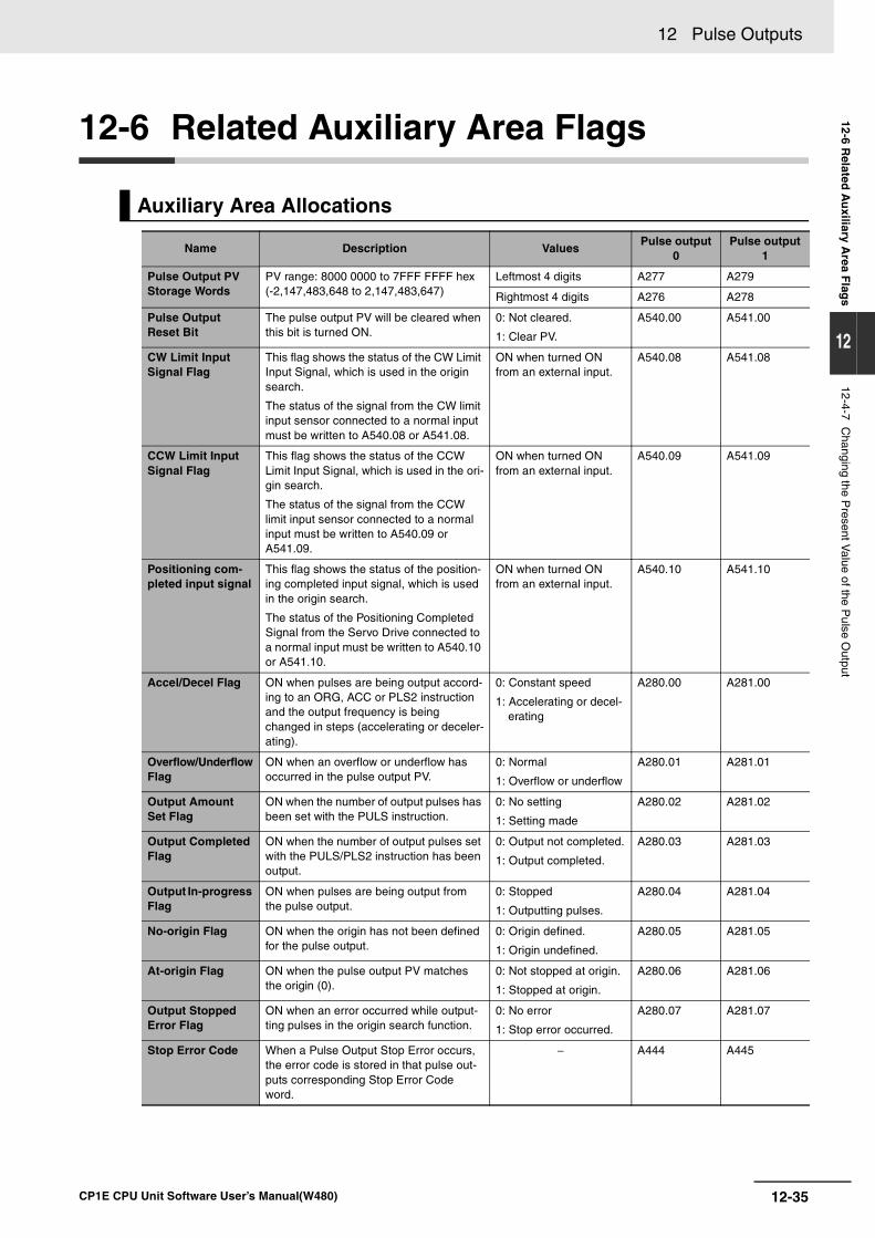
12-35
12 Pulse Outputs
CP1E CPU Unit Software User’s Manual(W480)
12-6 Related
Au
xiliary Area F
lags
12
12-4-7 Changing the P
resent Value of the P
ulse Output
12-6 Related Auxiliary Area Flags
Auxiliary Area Allocations
Name Description ValuesPulse output
0Pulse output
1
Pulse Output PV Storage Words
PV range: 8000 0000 to 7FFF FFFF hex(-2,147,483,648 to 2,147,483,647)
Leftmost 4 digits A277 A279
Rightmost 4 digits A276 A278
Pulse Output Reset Bit
The pulse output PV will be cleared when this bit is turned ON.
0: Not cleared.
1: Clear PV.
A540.00 A541.00
CW Limit Input Signal Flag
This flag shows the status of the CW Limit Input Signal, which is used in the origin search.
The status of the signal from the CW limit input sensor connected to a normal input must be written to A540.08 or A541.08.
ON when turned ON from an external input.
A540.08 A541.08
CCW Limit Input Signal Flag
This flag shows the status of the CCW Limit Input Signal, which is used in the ori-gin search.
The status of the signal from the CCW limit input sensor connected to a normal input must be written to A540.09 or A541.09.
ON when turned ON from an external input.
A540.09 A541.09
Positioning com-pleted input signal
This flag shows the status of the position-ing completed input signal, which is used in the origin search.
The status of the Positioning Completed Signal from the Servo Drive connected to a normal input must be written to A540.10 or A541.10.
ON when turned ON from an external input.
A540.10 A541.10
Accel/Decel Flag ON when pulses are being output accord-ing to an ORG, ACC or PLS2 instruction and the output frequency is being changed in steps (accelerating or deceler-ating).
0: Constant speed
1: Accelerating or decel-erating
A280.00 A281.00
Overflow/UnderflowFlag
ON when an overflow or underflow has occurred in the pulse output PV.
0: Normal
1: Overflow or underflow
A280.01 A281.01
Output Amount Set Flag
ON when the number of output pulses has been set with the PULS instruction.
0: No setting
1: Setting made
A280.02 A281.02
Output Completed Flag
ON when the number of output pulses set with the PULS/PLS2 instruction has been output.
0: Output not completed.
1: Output completed.
A280.03 A281.03
Output In-progress Flag
ON when pulses are being output from the pulse output.
0: Stopped
1: Outputting pulses.
A280.04 A281.04
No-origin Flag ON when the origin has not been defined for the pulse output.
0: Origin defined.
1: Origin undefined.
A280.05 A281.05
At-origin Flag ON when the pulse output PV matches the origin (0).
0: Not stopped at origin.
1: Stopped at origin.
A280.06 A281.06
Output Stopped Error Flag
ON when an error occurred while output-ting pulses in the origin search function.
0: No error
1: Stop error occurred.
A280.07 A281.07
Stop Error Code When a Pulse Output Stop Error occurs, the error code is stored in that pulse out-puts corresponding Stop Error Code word.
− A444 A445
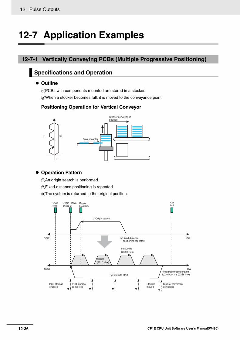
12 Pulse Outputs
12-36 CP1E CPU Unit Software User’s Manual(W480)
12-7 Application Examples
OutlinePCBs with components mounted are stored in a stocker.
When a stocker becomes full, it is moved to the conveyance point.
Positioning Operation for Vertical Conveyor
Operation PatternAn origin search is performed.
Fixed-distance positioning is repeated.
The system is returned to the original position.
12-7-1 Vertically Conveying PCBs (Multiple Progressive Positioning)
Specifications and Operation
From mounter
Stocker conveyance position
Return to start
CWCCW
Origin search
CWCCW
Originproximity
10,000 (2710 Hex)
50,000 Hz(C350 Hex)
CCW limit
Origin (servo phase Z)
Fixed-distance positioning repeated
CW limit
PCB storage completed
PCB storage enabled
Stocker moved
Stocker movement completed
Acceleration/deceleration: 1,000 Hz/4 ms (03E8 hex)
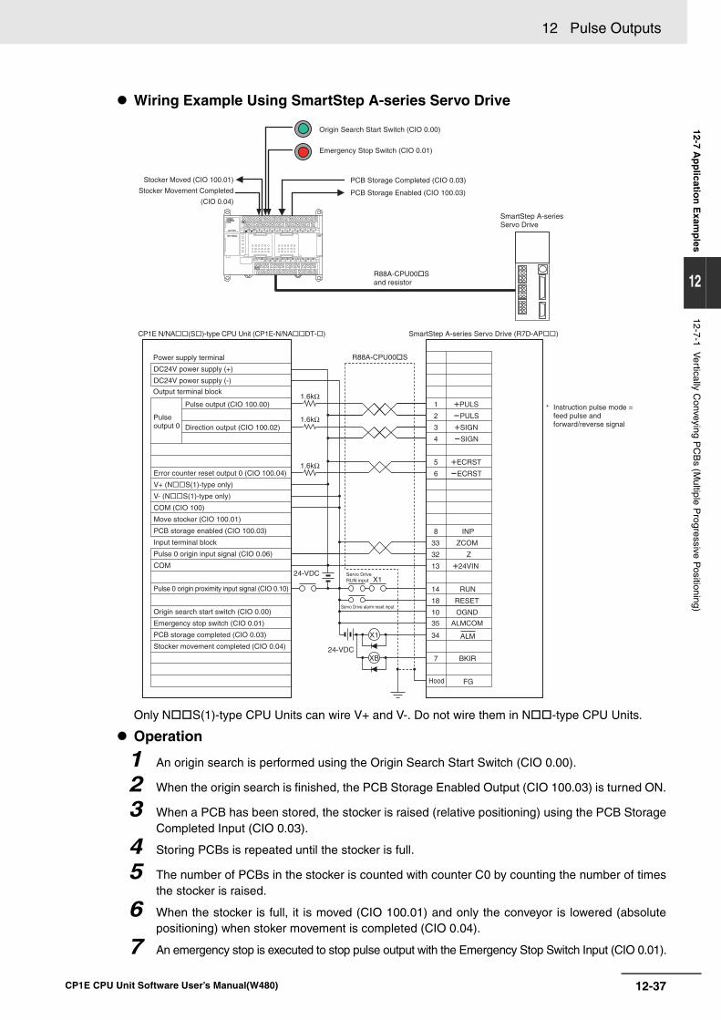
12-37
12 Pulse Outputs
CP1E CPU Unit Software User’s Manual(W480)
12-7 Ap
plicatio
n E
xamp
les
12
12-7-1 Vertically C
onveying PC
Bs (M
ultiple Progressive P
ositioning)
Wiring Example Using SmartStep A-series Servo Drive
Only N S(1)-type CPU Units can wire V+ and V-. Do not wire them in N -type CPU Units.
Operation
1 An origin search is performed using the Origin Search Start Switch (CIO 0.00).
2 When the origin search is finished, the PCB Storage Enabled Output (CIO 100.03) is turned ON.
3 When a PCB has been stored, the stocker is raised (relative positioning) using the PCB StorageCompleted Input (CIO 0.03).
4 Storing PCBs is repeated until the stocker is full.
5 The number of PCBs in the stocker is counted with counter C0 by counting the number of timesthe stocker is raised.
6 When the stocker is full, it is moved (CIO 100.01) and only the conveyor is lowered (absolutepositioning) when stoker movement is completed (CIO 0.04).
7 An emergency stop is executed to stop pulse output with the Emergency Stop Switch Input (CIO 0.01).
Emergency Stop Switch (CIO 0.01)
PCB Storage Completed (CIO 0.03)
PCB Storage Enabled (CIO 100.03)
SmartStep A-seriesServo Drive
R88A-CPU00Sand resistor
Stocker Moved (CIO 100.01)
Stocker Movement Completed
(CIO 0.04)
Origin Search Start Switch (CIO 0.00)
1
2
5
6
8
13
14
18
10
35
34
7
+PULS
-PULS
+ECRST
-ECRST
INP
33 ZCOM
32 Z
+24VIN
RUN
RESET
OGND
ALMCOM
ALM
FG
X1
XB
24-VDCX1
24-VDCBKIR
Pulse output (CIO 100.00)
Direction output (CIO 100.02)
4
3 +SIGN
-SIGN
1.6kΩ
1.6kΩ
1.6kΩ
CP1E N/NA(S)-type CPU Unit (CP1E-N/NADT-)
Output terminal block
Power supply terminal
Pulse output 0
Servo Drive RUN input
Servo Drive alarm reset input
SmartStep A-series Servo Drive (R7D-AP)
R88A-CPU00S
Hood
Error counter reset output 0 (CIO 100.04)
V+ (NS(1)-type only)
V- (NS(1)-type only)
COM (CIO 100)
Move stocker (CIO 100.01)
PCB storage enabled (CIO 100.03)
Input terminal block
Pulse 0 origin input signal (CIO 0.06)
COM
Pulse 0 origin proximity input signal (CIO 0.10)
Origin search start switch (CIO 0.00)
Emergency stop switch (CIO 0.01)
PCB storage completed (CIO 0.03)
Stocker movement completed (CIO 0.04)
Instruction pulse mode = feed pulse and forward/reverse signal
*
DC24V power supply (+)
DC24V power supply (-)
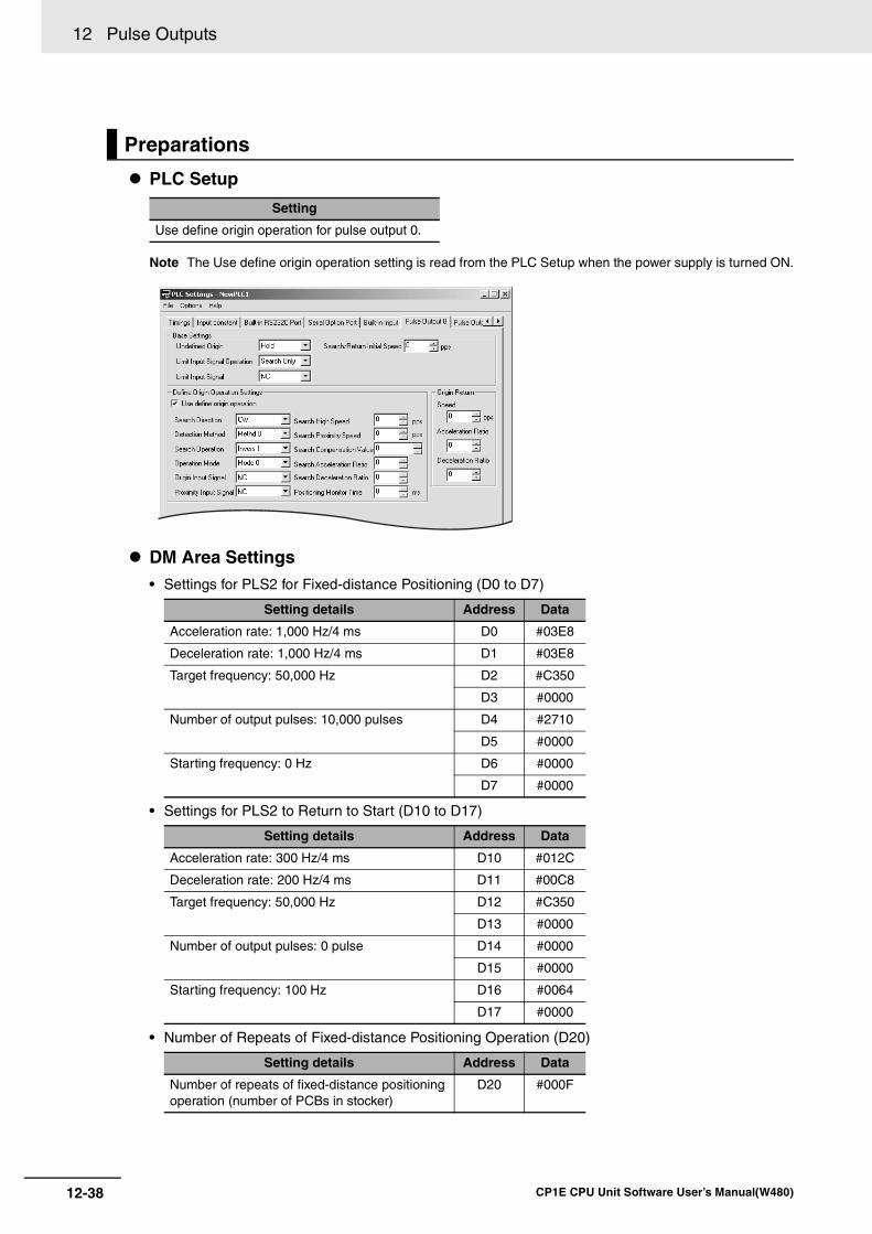
12 Pulse Outputs
12-38 CP1E CPU Unit Software User’s Manual(W480)
PLC Setup
Note The Use define origin operation setting is read from the PLC Setup when the power supply is turned ON.
DM Area Settings• Settings for PLS2 for Fixed-distance Positioning (D0 to D7)
• Settings for PLS2 to Return to Start (D10 to D17)
• Number of Repeats of Fixed-distance Positioning Operation (D20)
Preparations
Setting
Use define origin operation for pulse output 0.
Setting details Address Data
Acceleration rate: 1,000 Hz/4 ms D0 #03E8
Deceleration rate: 1,000 Hz/4 ms D1 #03E8
Target frequency: 50,000 Hz D2 #C350
D3 #0000
Number of output pulses: 10,000 pulses D4 #2710
D5 #0000
Starting frequency: 0 Hz D6 #0000
D7 #0000
Setting details Address Data
Acceleration rate: 300 Hz/4 ms D10 #012C
Deceleration rate: 200 Hz/4 ms D11 #00C8
Target frequency: 50,000 Hz D12 #C350
D13 #0000
Number of output pulses: 0 pulse D14 #0000
D15 #0000
Starting frequency: 100 Hz D16 #0064
D17 #0000
Setting details Address Data
Number of repeats of fixed-distance positioning operation (number of PCBs in stocker)
D20 #000F
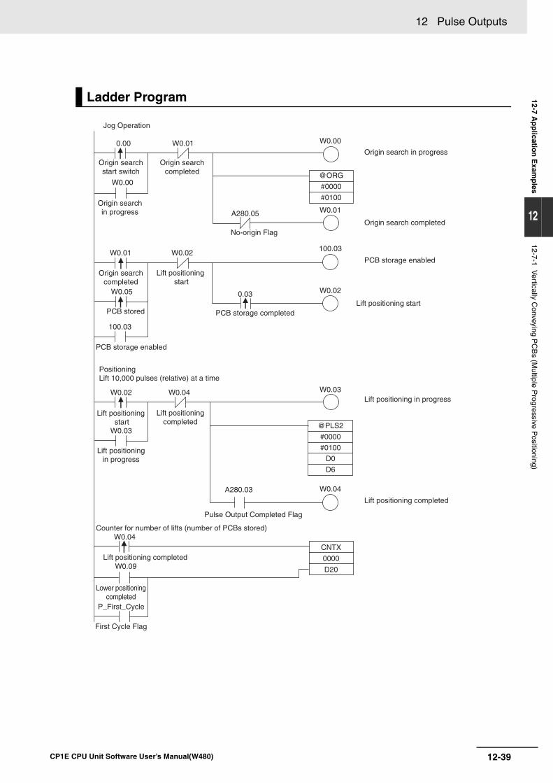
12-39
12 Pulse Outputs
CP1E CPU Unit Software User’s Manual(W480)
12-7 Ap
plicatio
n E
xamp
les
12
12-7-1 Vertically C
onveying PC
Bs (M
ultiple Progressive P
ositioning)
Ladder Program
0.00
0.03
Jog Operation
Origin searchstart switch
W0.00
W0.00
W0.01
W0.01
W0.01
W0.05
W0.03
W0.02
W0.02
W0.02
W0.03W0.04
W0.04
W0.04
W0.09
Origin searchin progress
Origin searchcompleted
Origin searchcompleted
PCB stored
100.03
100.03
PCB storage enabled
PositioningLift 10,000 pulses (relative) at a time
Lift positioningcompleted
Lift positioning completed
Lift positioningin progress
P_First_Cycle
First Cycle Flag
A280.03
Pulse Output Completed Flag
Counter for number of lifts (number of PCBs stored)
Lower positioningcompleted
No-origin Flag
Lift positioning start
Lift positioning start
Lift positioning start
PCB storage completed
A280.05
Origin search in progress
Origin search completed
PCB storage enabled
Lift positioning in progress
Lift positioning completed
@PLS2
#0000
#0100
D0
D6
CNTX
0000
D20
@ORG
#0000
#0100
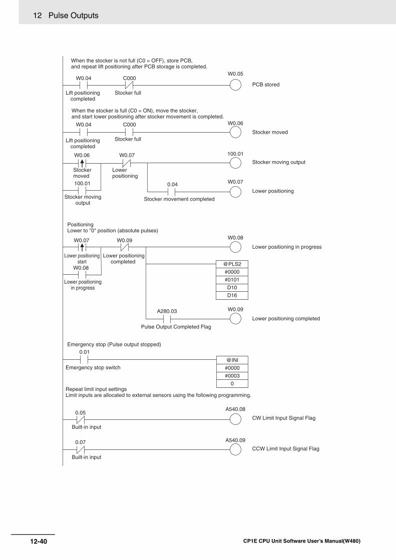
12 Pulse Outputs
12-40 CP1E CPU Unit Software User’s Manual(W480)
A540.08
When the stocker is not full (C0 = OFF), store PCB,and repeat lift positioning after PCB storage is completed.
W0.04
Lift positioningcompleted
Lift positioningcompleted
C000
W0.04
W0.06 W0.07
W0.05
W0.06C000
Stocker full
Stocker full
When the stocker is full (C0 = ON), move the stocker,and start lower positioning after stocker movement is completed.
100.01
100.01
Stocker moved
Lower positioning
Stocker movingoutput
0.04
Stocker movement completed
PositioningLower to "0" position (absolute pulses)
W0.09
W0.09
W0.07
W0.07
W0.08
W0.08
Lower positioningcompleted
Lower positioningstart
Lower positioningin progress
A280.03
Pulse Output Completed Flag
Emergency stop (Pulse output stopped)
Repeat limit input settingsLimit inputs are allocated to external sensors using the following programming.
Emergency stop switch
0.01
0.05
0.07
Built-in input
Built-in input
A540.09
CW Limit Input Signal Flag
CCW Limit Input Signal Flag
Lower positioning completed
Lower positioning in progress
Lower positioning
PCB stored
Stocker moving output
Stocker moved
@PLS2
#0000
#0101
D10
D16
@INI
#0000
#0003
0
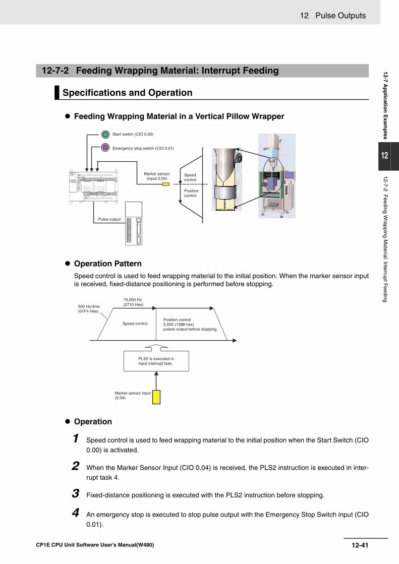
12-41
12 Pulse Outputs
CP1E CPU Unit Software User’s Manual(W480)
12-7 Ap
plicatio
n E
xamp
les
12
12-7-2 Feeding Wrapping M
aterial: Interrupt Feeding
Feeding Wrapping Material in a Vertical Pillow Wrapper
Operation PatternSpeed control is used to feed wrapping material to the initial position. When the marker sensor inputis received, fixed-distance positioning is performed before stopping.
Operation
1 Speed control is used to feed wrapping material to the initial position when the Start Switch (CIO
0.00) is activated.
2 When the Marker Sensor Input (CIO 0.04) is received, the PLS2 instruction is executed in inter-
rupt task 4.
3 Fixed-distance positioning is executed with the PLS2 instruction before stopping.
4 An emergency stop is executed to stop pulse output with the Emergency Stop Switch input (CIO
0.01).
12-7-2 Feeding Wrapping Material: Interrupt Feeding
Specifications and Operation
Start switch (CIO 0.00)
Emergency stop switch (CIO 0.01)
Pulse output
Marker sensor(input 0.04)
Speedcontrol
Positioncontrol
10,000 Hz(2710 Hex) 500 Hz/4ms
(01F4 Hex)
Speed controlPosition control5,000 (1388 hex)pulses output before stopping.
PLS2 is executed ininput interrupt task.
Marker sensor input(0.04)
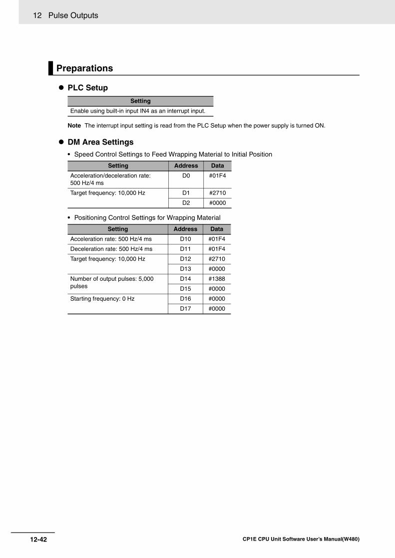
12 Pulse Outputs
12-42 CP1E CPU Unit Software User’s Manual(W480)
PLC Setup
Note The interrupt input setting is read from the PLC Setup when the power supply is turned ON.
DM Area Settings• Speed Control Settings to Feed Wrapping Material to Initial Position
• Positioning Control Settings for Wrapping Material
Preparations
Setting
Enable using built-in input IN4 as an interrupt input.
Setting Address Data
Acceleration/deceleration rate: 500 Hz/4 ms
D0 #01F4
Target frequency: 10,000 Hz D1 #2710
D2 #0000
Setting Address Data
Acceleration rate: 500 Hz/4 ms D10 #01F4
Deceleration rate: 500 Hz/4 ms D11 #01F4
Target frequency: 10,000 Hz D12 #2710
D13 #0000
Number of output pulses: 5,000 pulses
D14 #1388
D15 #0000
Starting frequency: 0 Hz D16 #0000
D17 #0000
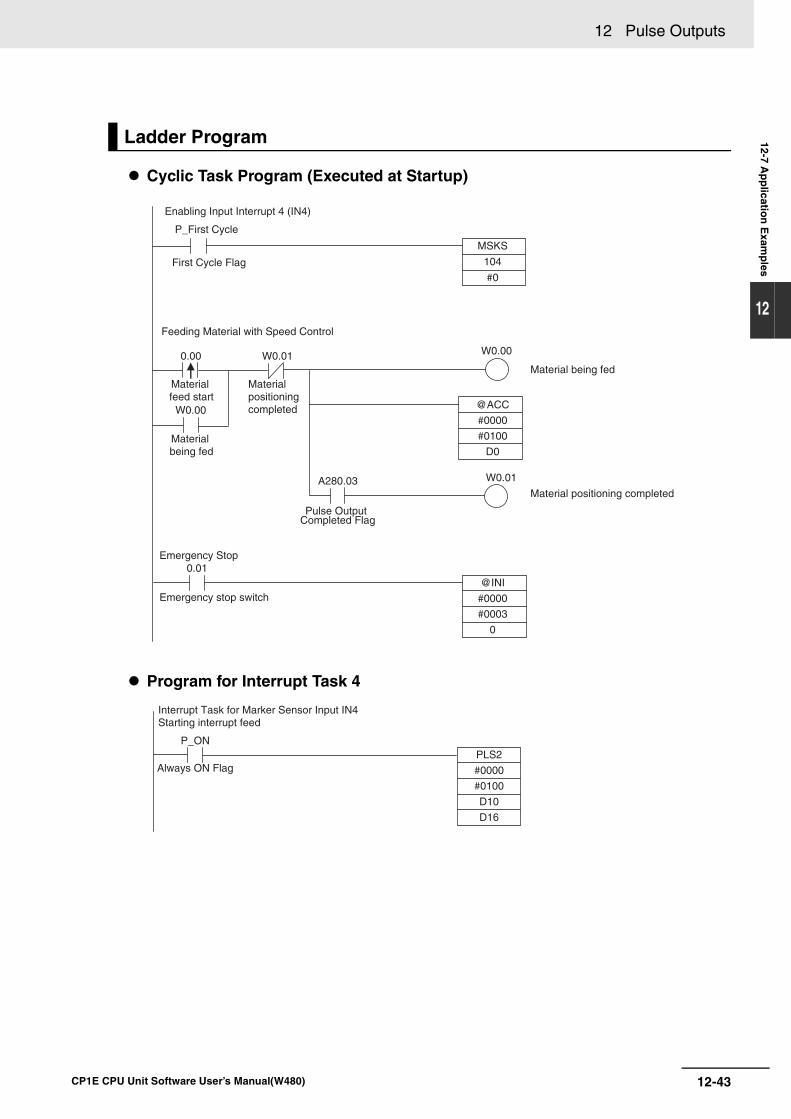
12-43
12 Pulse Outputs
CP1E CPU Unit Software User’s Manual(W480)
12-7 Ap
plicatio
n E
xamp
les
12
Cyclic Task Program (Executed at Startup)
Program for Interrupt Task 4
Ladder Program
P_First Cycle
Enabling Input Interrupt 4 (IN4)
First Cycle Flag
Feeding Material with Speed Control
0.00 W0.01
W0.00
Material feed start
Material being fed
Material positioning completed
Pulse OutputCompleted Flag
A280.03
Emergency Stop 0.01
Emergency stop switch
W0.00
W0.01
Material being fed
Material positioning completed
@ACC
#0000
#0100
D0
MSKS
104
#0
@INI
#0000
#0003
0
PLS2
#0000
#0100
D10
D16
Interrupt Task for Marker Sensor Input IN4Starting interrupt feed
P_ON
Always ON Flag
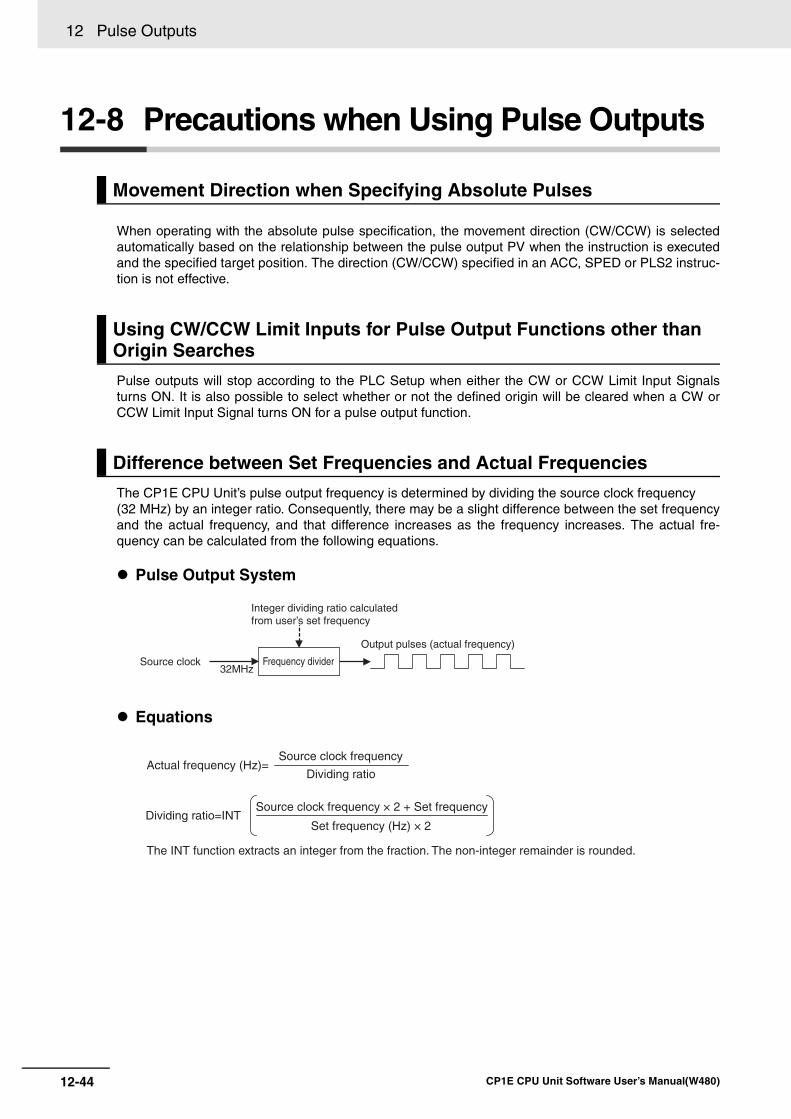
12 Pulse Outputs
12-44 CP1E CPU Unit Software User’s Manual(W480)
12-8 Precautions when Using Pulse Outputs
When operating with the absolute pulse specification, the movement direction (CW/CCW) is selectedautomatically based on the relationship between the pulse output PV when the instruction is executedand the specified target position. The direction (CW/CCW) specified in an ACC, SPED or PLS2 instruc-tion is not effective.
Pulse outputs will stop according to the PLC Setup when either the CW or CCW Limit Input Signalsturns ON. It is also possible to select whether or not the defined origin will be cleared when a CW orCCW Limit Input Signal turns ON for a pulse output function.
The CP1E CPU Unit’s pulse output frequency is determined by dividing the source clock frequency (32 MHz) by an integer ratio. Consequently, there may be a slight difference between the set frequencyand the actual frequency, and that difference increases as the frequency increases. The actual fre-quency can be calculated from the following equations.
Pulse Output System
Equations
Movement Direction when Specifying Absolute Pulses
Using CW/CCW Limit Inputs for Pulse Output Functions other than Origin Searches
Difference between Set Frequencies and Actual Frequencies
32MHz
Integer dividing ratio calculated from user’s set frequency
Source clock Frequency divider
Output pulses (actual frequency)
Actual frequency (Hz)=Source clock frequency
Dividing ratio
Dividing ratio=INTSource clock frequency × 2 + Set frequency
Set frequency (Hz) × 2
The INT function extracts an integer from the fraction. The non-integer remainder is rounded.
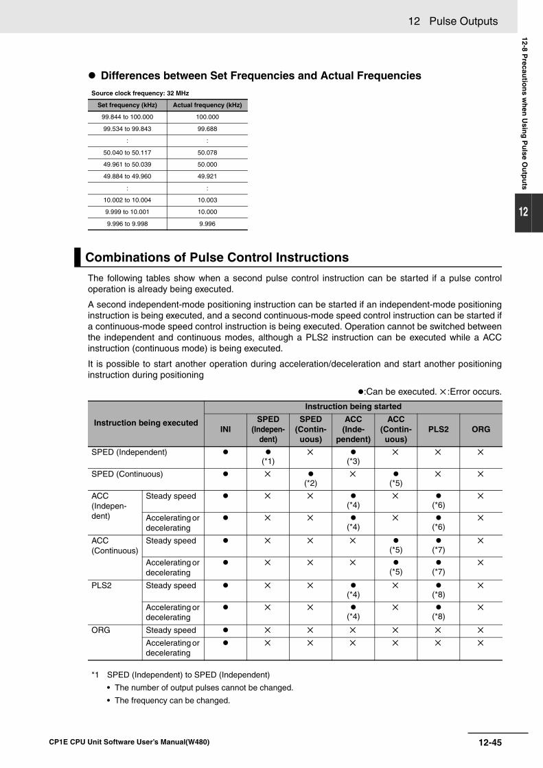
12-45
12 Pulse Outputs
CP1E CPU Unit Software User’s Manual(W480)
12-8 Precau
tion
s wh
en U
sing
Pu
lse Ou
tpu
ts
12
Differences between Set Frequencies and Actual Frequencies
The following tables show when a second pulse control instruction can be started if a pulse controloperation is already being executed.
A second independent-mode positioning instruction can be started if an independent-mode positioninginstruction is being executed, and a second continuous-mode speed control instruction can be started ifa continuous-mode speed control instruction is being executed. Operation cannot be switched betweenthe independent and continuous modes, although a PLS2 instruction can be executed while a ACCinstruction (continuous mode) is being executed.
It is possible to start another operation during acceleration/deceleration and start another positioninginstruction during positioning
:Can be executed. :Error occurs.
Source clock frequency: 32 MHz
Set frequency (kHz) Actual frequency (kHz)
99.844 to 100.000 100.000
99.534 to 99.843 99.688
: :
50.040 to 50.117 50.078
49.961 to 50.039 50.000
49.884 to 49.960 49.921
: :
10.002 to 10.004 10.003
9.999 to 10.001 10.000
9.996 to 9.998 9.996
Combinations of Pulse Control Instructions
Instruction being executed
Instruction being started
INISPED
(Indepen-dent)
SPED (Contin-
uous)
ACC (Inde-
pendent)
ACC (Contin-uous)
PLS2 ORG
SPED (Independent)(*1)
(*3)
SPED (Continuous) (*2)
(*5)
ACC(Indepen-dent)
Steady speed (*4)
(*6)
Accelerating or decelerating
(*4)
(*6)
ACC(Continuous)
Steady speed (*5) (*7)
Accelerating or decelerating
(*5) (*7)
PLS2 Steady speed (*4)
(*8)
Accelerating or decelerating
(*4)
(*8)
ORG Steady speed
Accelerating or decelerating
*1 SPED (Independent) to SPED (Independent)
• The number of output pulses cannot be changed.
• The frequency can be changed.
12 Pulse Outputs
12-46 CP1E CPU Unit Software User’s Manual(W480)
The CP1E CPU Unit’s pulse output function performs a basic error check before starting to outputpulses (when the instruction is executed) and will not output pulses if the settings are incorrect.
There are other errors that can occur with the origin search function during pulse output, which maystop the pulse output.
If an error occurs that stops pulse output, the pulse output’s Output Stopped Error Flag will be turnedON and the Pulse Output Stop Error Code will be written to Error Code word. Use these flags and errorcodes to identify the cause of the error.
The Pulse Output Stop Errors will not affect the CPU Unit’s operating status. (The Pulse Output StopErrors do not cause a fatal or non-fatal error in the CPU Unit.)
*2 SPED (Continuous) to SPED (Continuous)
• The frequency can be changed.
*3 SPED (Independent) to ACC (Independent)
• The number of output pulses cannot be changed.
• The frequency can be changed.
• The acceleration/deceleration rate can be changed.
*4 ACC (Independent) to ACC (Independent) or PLS2 to ACC (Independent)
• The number of output pulses cannot be changed.
• The frequency can be changed.
• The acceleration/deceleration rate can be changed. (The rate can even be changed during acceleration ordeceleration.)
*5 SPED (Continuous) to ACC (Continuous) or ACC (Continuous) to ACC (Continuous)
• The frequency can be changed. (The target frequency can even be changed during acceleration or decel-eration.)
• The acceleration/deceleration rate can be changed. (The rate can even be changed during acceleration ordeceleration.)
*6 ACC (Independent) to PLS2
• The number of output pulses can be changed. (The setting can even be changed during acceleration ordeceleration.)
• The frequency can be changed. (The target frequency can even be changed during acceleration or decel-eration.)
• The acceleration/deceleration rate can be changed. (The rate can even be changed during acceleration ordeceleration.)
*7 ACC (Continuous) to PLS2
• The frequency can be changed. (The target frequency can even be changed during acceleration or decel-eration.)
• The acceleration/deceleration rate can be changed. (The rate can even be changed during acceleration ordeceleration.)
*8 PLS2 to PLS2
• The number of output pulses can be changed. (The setting can even be changed during acceleration ordeceleration.)
• The frequency can be changed. (The target frequency can even be changed during acceleration or decel-eration.)
• The acceleration/deceleration rate can be changed. (The rate can even be changed during acceleration ordeceleration.)
Origin Search Error Processing
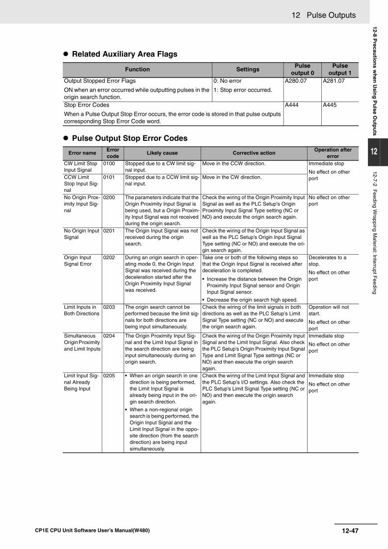
12-47
12 Pulse Outputs
CP1E CPU Unit Software User’s Manual(W480)
12-8 Precau
tion
s wh
en U
sing
Pu
lse Ou
tpu
ts
12
12-7-2 Feeding Wrapping M
aterial: Interrupt Feeding
Related Auxiliary Area Flags
Pulse Output Stop Error Codes
Function SettingsPulse
output 0Pulse
output 1Output Stopped Error Flags
ON when an error occurred while outputting pulses in the origin search function.
0: No error
1: Stop error occurred.
A280.07 A281.07
Stop Error Codes
When a Pulse Output Stop Error occurs, the error code is stored in that pulse outputs corresponding Stop Error Code word.
A444 A445
Error nameError code
Likely cause Corrective actionOperation after
errorCW Limit Stop Input Signal
0100 Stopped due to a CW limit sig-nal input.
Move in the CCW direction. Immediate stop
No effect on other portCCW Limit
Stop Input Sig-nal
0101 Stopped due to a CCW limit sig-nal input.
Move in the CW direction.
No Origin Prox-imity Input Sig-nal
0200 The parameters indicate that the Origin Proximity Input Signal is being used, but a Origin Proxim-ity Input Signal was not received during the origin search.
Check the wiring of the Origin Proximity Input Signal as well as the PLC Setup’s Origin Proximity Input Signal Type setting (NC or NO) and execute the origin search again.
No effect on other port
No Origin Input Signal
0201 The Origin Input Signal was not received during the origin search.
Check the wiring of the Origin Input Signal as well as the PLC Setup’s Origin Input Signal Type setting (NC or NO) and execute the ori-gin search again.
Origin Input Signal Error
0202 During an origin search in oper-ating mode 0, the Origin Input Signal was received during the deceleration started after the Origin Proximity Input Signal was received.
Take one or both of the following steps so that the Origin Input Signal is received after deceleration is completed.
• Increase the distance between the Origin Proximity Input Signal sensor and Origin Input Signal sensor.
• Decrease the origin search high speed.
Decelerates to a stop.
No effect on other port
Limit Inputs in Both Directions
0203 The origin search cannot be performed because the limit sig-nals for both directions are being input simultaneously.
Check the wiring of the limit signals in both directions as well as the PLC Setup’s Limit Signal Type setting (NC or NO) and execute the origin search again.
Operation will not start.
No effect on other port
Simultaneous Origin Proximity and Limit Inputs
0204 The Origin Proximity Input Sig-nal and the Limit Input Signal in the search direction are being input simultaneously during an origin search.
Check the wiring of the Origin Proximity Input Signal and the Limit Input Signal. Also check the PLC Setup’s Origin Proximity Input Signal Type and Limit Signal Type settings (NC or NO) and then execute the origin search again.
Immediate stop
No effect on other port
Limit Input Sig-nal Already Being Input
0205 • When an origin search in one direction is being performed, the Limit Input Signal is already being input in the ori-gin search direction.
• When a non-regional origin search is being performed, the Origin Input Signal and the Limit Input Signal in the oppo-site direction (from the search direction) are being input simultaneously.
Check the wiring of the Limit Input Signal and the PLC Setup’s I/O settings. Also check the PLC Setup’s Limit Signal Type setting (NC or NO) and then execute the origin search again.
Immediate stop
No effect on other port
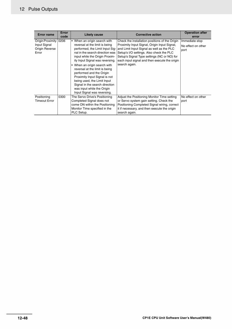
12 Pulse Outputs
12-48 CP1E CPU Unit Software User’s Manual(W480)
Origin Proximity Input Signal Origin Reverse Error
0206 • When an origin search with reversal at the limit is being performed, the Limit Input Sig-nal in the search direction was input while the Origin Proxim-ity Input Signal was reversing.
• When an origin search with reversal at the limit is being performed and the Origin Proximity Input Signal is not being used, the Limit Input Signal in the search direction was input while the Origin Input Signal was reversing.
Check the installation positions of the Origin Proximity Input Signal, Origin Input Signal, and Limit Input Signal as well as the PLC Setup’s I/O settings. Also check the PLC Setup’s Signal Type settings (NC or NO) for each input signal and then execute the origin search again.
Immediate stop
No effect on other port
Positioning Timeout Error
0300 The Servo Drive’s Positioning Completed Signal does not come ON within the Positioning Monitor Time specified in the PLC Setup.
Adjust the Positioning Monitor Time setting or Servo system gain setting. Check the Positioning Completed Signal wiring, correct it if necessary, and then execute the origin search again.
No effect on other port
Error nameError code
Likely cause Corrective actionOperation after
error
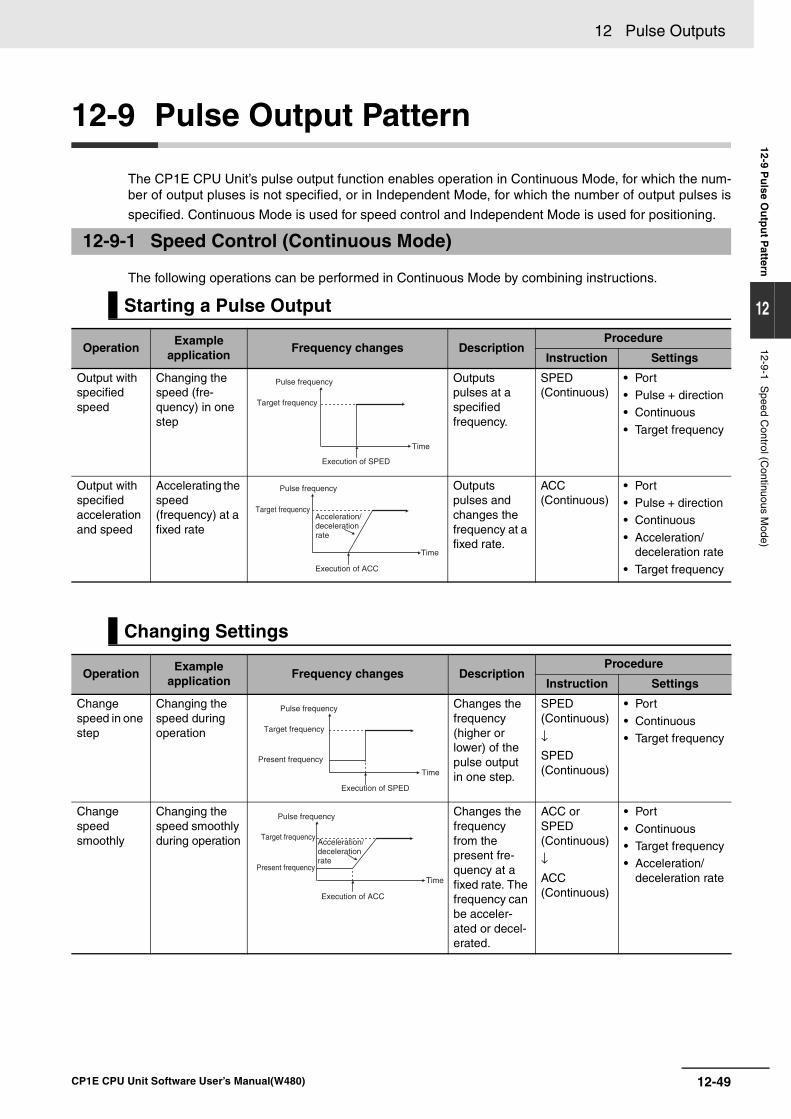
12-49
12 Pulse Outputs
CP1E CPU Unit Software User’s Manual(W480)
12-9 Pu
lse Ou
tpu
t Pattern
12
12-9-1 Speed C
ontrol (Continuous M
ode)
12-9 Pulse Output Pattern
The CP1E CPU Unit’s pulse output function enables operation in Continuous Mode, for which the num-ber of output pluses is not specified, or in Independent Mode, for which the number of output pulses is
specified. Continuous Mode is used for speed control and Independent Mode is used for positioning.
The following operations can be performed in Continuous Mode by combining instructions.
12-9-1 Speed Control (Continuous Mode)
Starting a Pulse Output
OperationExample
applicationFrequency changes Description
Procedure
Instruction Settings
Output with specified speed
Changing the speed (fre-quency) in one step
Outputs pulses at a specifiedfrequency.
SPED(Continuous)
• Port• Pulse + direction• Continuous
• Target frequency
Output with specified acceleration and speed
Accelerating the speed(frequency) at a fixed rate
Outputs pulses and changes the frequency at a fixed rate.
ACC(Continuous)
• Port• Pulse + direction • Continuous
• Acceleration/deceleration rate
• Target frequency
Changing Settings
OperationExample
applicationFrequency changes Description
Procedure
Instruction Settings
Change speed in one step
Changing the speed during operation
Changes the frequency (higher or lower) of the pulse output in one step.
SPED(Continuous)
↓SPED(Continuous)
• Port
• Continuous• Target frequency
Change speed smoothly
Changing the speed smoothly during operation
Changes the frequency from the present fre-quency at a fixed rate. The frequency can be acceler-ated or decel-erated.
ACC or SPED(Continuous)
↓ACC(Continuous)
• Port
• Continuous• Target frequency• Acceleration/
deceleration rate
Pulse frequency
Target frequency
Execution of SPED
Time
Pulse frequency
Target frequency
Execution of ACC
Time
Acceleration/deceleration rate
Pulse frequency
Target frequency
Present frequency
Execution of SPED
Time
Pulse frequency
Target frequency
Present frequency
Execution of ACC
Time
Acceleration/decelerationrate
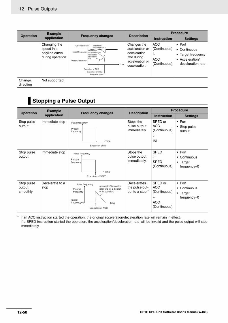
12 Pulse Outputs
12-50 CP1E CPU Unit Software User’s Manual(W480)
* If an ACC instruction started the operation, the original acceleration/deceleration rate will remain in effect.If a SPED instruction started the operation, the acceleration/deceleration rate will be invalid and the pulse output will stopimmediately.
Changing the speed in a polyline curve during operation
Changes the acceleration or deceleration rate during acceleration or deceleration.
ACC(Continuous)
↓ACC(Continuous)
• Port
• Continuous• Target frequency• Acceleration/
deceleration rate
Change direction
Not supported.
Stopping a Pulse Output
OperationExample
applicationFrequency changes Description
Procedure
Instruction Settings
Stop pulse output
Immediate stop Stops the pulse output immediately.
SPED or ACC(Continuous)
↓INI
• Port• Stop pulse
output
Stop pulse output
Immediate stop Stops the pulse output immediately.
SPED↓SPED(Continuous)
• Port• Continuous• Target
frequency=0
Stop pulse output smoothly
Decelerate to a stop
Decelerates the pulse out-put to a stop.*
SPED or ACC(Continuous)
↓ACC(Continuous)
• Port
• Continuous• Target
frequency=0
OperationExample
applicationFrequency changes Description
Procedure
Instruction Settings
Pulse frequency
Target frequency
Present frequency
Execution of ACC
Execution of ACCExecution of ACC
Time
Acceleration/deceleration rate n
Acceleration/deceleration rate 2Acceleration/decelerationrate 1
Pulse frequency
Presentfrequency
Execution of INI
Time
Pulse frequency
Presentfrequency
Execution of SPED
Time
Pulse frequency
Presentfrequency
Execution of ACC
TimeTargetfrequency=0
Acceleration/deceleration rate (Rate set at the start of the operation.)
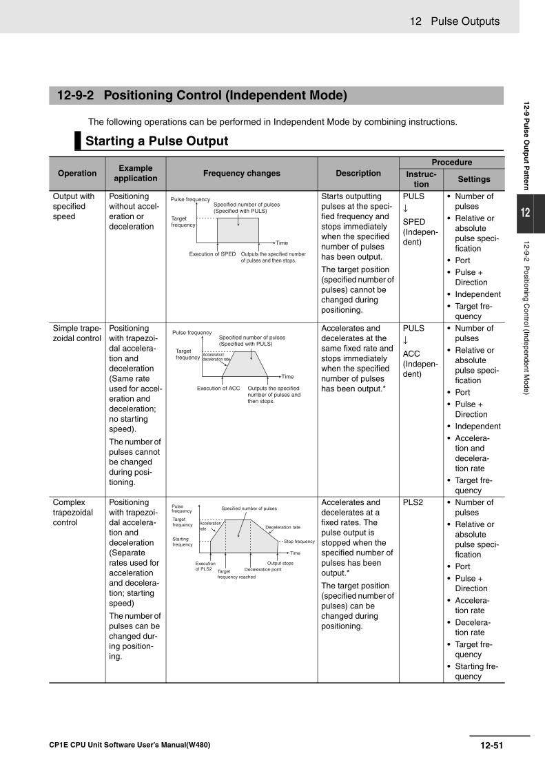
12-51
12 Pulse Outputs
CP1E CPU Unit Software User’s Manual(W480)
12-9 Pu
lse Ou
tpu
t Pattern
12
12-9-2 Positioning C
ontrol (Independent Mode)
The following operations can be performed in Independent Mode by combining instructions.
12-9-2 Positioning Control (Independent Mode)
Starting a Pulse Output
OperationExample
applicationFrequency changes Description
ProcedureInstruc-
tionSettings
Output with specified speed
Positioning without accel-eration or deceleration
Starts outputting pulses at the speci-fied frequency and stops immediately when the specified number of pulses has been output.
The target position (specified number of pulses) cannot be changed during positioning.
PULS
↓SPED(Indepen-dent)
• Number of pulses
• Relative or absolute pulse speci-fication
• Port • Pulse +
Direction• Independent
• Target fre-quency
Simple trape-zoidal control
Positioning with trapezoi-dal accelera-tion and deceleration (Same rate used for accel-eration and deceleration; no starting speed).
The number of pulses cannot be changed during posi-tioning.
Accelerates and decelerates at the same fixed rate and stops immediately when the specified number of pulses has been output.*
PULS
↓ACC(Indepen-dent)
• Number of pulses
• Relative or absolute pulse speci-fication
• Port• Pulse +
Direction• Independent
• Accelera-tion and decelera-tion rate
• Target fre-quency
Complex trapezoidal control
Positioning with trapezoi-dal accelera-tion and deceleration (Separate rates used for acceleration and decelera-tion; starting speed)
The number of pulses can be changed dur-ing position-ing.
Accelerates and decelerates at a fixed rates. The pulse output is stopped when the specified number of pulses has been output.*
The target position (specified number of pulses) can be changed during positioning.
PLS2 • Number of pulses
• Relative or absolute pulse speci-fication
• Port
• Pulse + Direction
• Accelera-tion rate
• Decelera-tion rate
• Target fre-quency
• Starting fre-quency
Pulse frequency
Targetfrequency
Execution of SPED
Time
Specified number of pulses (Specified with PULS)
Outputs the specified number of pulses and then stops.
Time
Pulse frequency
Target frequency
Acceleration/deceleration rate
Specified number of pulses (Specified with PULS)
Outputs the specified number of pulses and then stops.
Execution of ACC
Execution of PLS2
Time
Acceleration rate
Targetfrequency
Starting frequency
Deceleration rate
Specified number of pulses
Target frequency reached
Deceleration pointOutput stops
Stop frequency
Pulse frequency
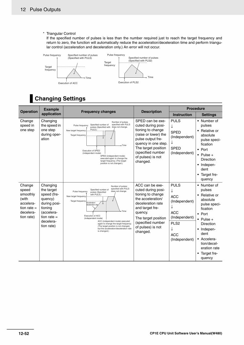
12 Pulse Outputs
12-52 CP1E CPU Unit Software User’s Manual(W480)
* Triangular ControlIf the specified number of pulses is less than the number required just to reach the target frequency andreturn to zero, the function will automatically reduce the acceleration/deceleration time and perform triangu-lar control (acceleration and deceleration only.) An error will not occur.
Changing Settings
OperationExample
applicationFrequency changes Description
Procedure
Instruction Settings
Change speed in one step
Changing the speed in one step during oper-ation
SPED can be exe-cuted during posi-tioning to change (raise or lower) the pulse output fre-quency in one step.The target position (specified number of pulses) is not changed.
PULS
↓SPED(Independent)
↓SPED(Independent)
• Number of pulses
• Relative or absolute pulse speci-fication
• Port• Pulse +
Direction• Indepen-
dent• Target fre-
quency
Change speed smoothly (with accelera-tion rate = decelera-tion rate)
Changing the target speed (fre-quency) during posi-tioning(accelera-tion rate = decelera-tion rate)
ACC can be exe-cuted during posi-tioning to change the acceleration/deceleration rate and target fre-quency.
The target position (specified number of pulses) is not changed.
PULS
↓ACC(Independent)
↓ACC(Independent)
• Number of pulses
• Relative or absolute pulse speci-fication
• Port
• Pulse + Direction
• Indepen-dent
• Accelera-tion/decel-eration rate
• Target fre-quency
PLS2
↓ACC(Independent)
Pulse frequency
Target frequency
Execution of ACC
Time
Specified number of pulses (Specified with PULS)
Pulse frequency
Target frequency
Execution of PLS2
Specified number of pulses (Specified with PLS2)
Time
Pulse frequency
New target frequency
Target frequency
Execution of SPED (independent mode)
SPED (independent mode) executed again to change the target frequency. (The target position is not changed.)
Time
Specified number of pulses (Specified with PULS.)
Number of pulses specified with PULS does not change.
Pulse frequency
New target frequency
Target frequency
Time
Specified number of pulses (Specified with PULS.)
Number of pulses specified with PULS does not change.
Execution of ACC (independent mode)
ACC (independent mode) executed again to change the target frequency. (The target position is not changed, but the acceleration/deceleration rate is changed.)
Acceleration/deceleration rate
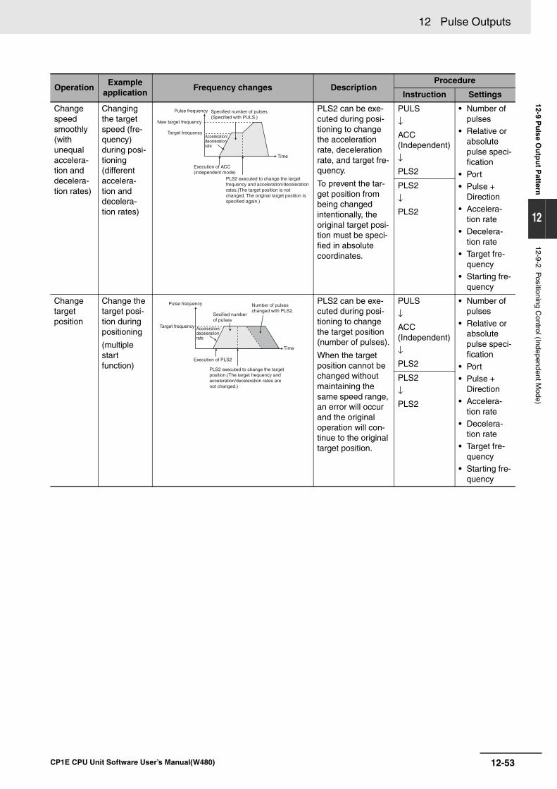
12-53
12 Pulse Outputs
CP1E CPU Unit Software User’s Manual(W480)
12-9 Pu
lse Ou
tpu
t Pattern
12
12-9-2 Positioning C
ontrol (Independent Mode)
Change speed smoothly (with unequal accelera-tion and decelera-tion rates)
Changing the target speed (fre-quency) during posi-tioning(different accelera-tion and decelera-tion rates)
PLS2 can be exe-cuted during posi-tioning to change the acceleration rate, deceleration rate, and target fre-quency.
To prevent the tar-get position from being changed intentionally, the original target posi-tion must be speci-fied in absolute coordinates.
PULS
↓ACC (Independent)
↓PLS2
• Number of pulses
• Relative or absolute pulse speci-fication
• Port• Pulse +
Direction• Accelera-
tion rate• Decelera-
tion rate• Target fre-
quency• Starting fre-
quency
PLS2
↓PLS2
Change targetposition
Change the target posi-tion duringpositioning
(multiple start function)
PLS2 can be exe-cuted during posi-tioning to change the target position (number of pulses).
When the target position cannot be changed without maintaining the same speed range, an error will occur and the original operation will con-tinue to the original target position.
PULS
↓ACC(Independent)
↓PLS2
• Number of pulses
• Relative or absolute pulse speci-fication
• Port• Pulse +
Direction • Accelera-
tion rate• Decelera-
tion rate• Target fre-
quency• Starting fre-
quency
PLS2
↓PLS2
OperationExample
applicationFrequency changes Description
Procedure
Instruction Settings
Pulse frequency
New target frequency
Target frequency
Execution of ACC (independent mode)
PLS2 executed to change the target frequency and acceleration/deceleration rates.(The target position is not changed. The original target position is specified again.)
Time
Acceleration/deceleration rate
Specified number of pulses (Specified with PULS.)
Pulse frequency
Target frequency
Execution of PLS2
PLS2 executed to change the target position.(The target frequency and acceleration/deceleration rates are not changed.)
Time
Acceleration/deceleration rate
Secified number of pulses
Number of pulses changed with PLS2.

12 Pulse Outputs
12-54 CP1E CPU Unit Software User’s Manual(W480)
OperationExample applica-
tionFrequency changes Description
Procedure
Instruc-tion
Settings
Change target posi-tion and speed smoothly
Change the target position and target speed (fre-quency) during positioning (multiple start func-tion)
PLS2 can be executed during positioning to change the target position (number of pulses), acceleration rate, decel-eration rate, and target frequency.
When the settings cannot be changed without main-taining the same speed range, an error will occur and the original opera-tion will continue to the original target position.
PULS
↓ACC (Indepen-dent)
↓PLS2
• Number of pulses
• Relative or absolute pulse spec-ification
• Port• Pulse +
Direction • Accelera-
tion rate• Decelera-
tion rate• Target fre-
quency• Starting
frequency
Change the accel-eration and decelera-tion rates during positioning (multiple start func-tion)
PLS2 can be executed during positioning (accel-eration or deceleration) to change the acceleration rate or deceleration rate.
PLS2
↓PLS2
• Number of pulses
• Accelera-tion rate
• Decelera-tion rate
Change direction
Change the direc-tion during positioning
PLS2 can be executed during positioning with absolute pulse specifica-tion to change to absolute pulses and reverse direc-tion.
PULS
↓ACC (Indepen-dent)
↓PLS2
• Number of pulses
• Absolute pulse spec-ification
• Port• Pulse +
Direction • Accelera-
tion rate• Decelera-
tion rate• Target fre-
quency• Starting
frequency
PLS2
↓PLS2
Pulse frequency
New target frequency
Target frequency
Execution of ACC(Independent mode)
PLS2 executed to change the target position, target frequency, and acceleration/deceleration rates
Time
Acceleration/deceleration rate
Specified number of pulses
Number of pulses changed with PLS2.
Pulse frequency
New target frequency
Target frequency
Execution of PLS2
Execution of PLS2
Execution of PLS2
Execution of PLS2
Time
Acceleration/deceleration rate 3
Acceleration/deceleration rate 2Acceleration/deceleration rate 1
Acceleration/deceleration rate n
Number of pulses specified by PLS2.
Pulse frequency
Targetfrequency
Execution of PLS2
Execution of PLS2
Time
Secified number of pulses
Change of direction at the specified deceleration rate
Number of pulses (position) changed by PLS2
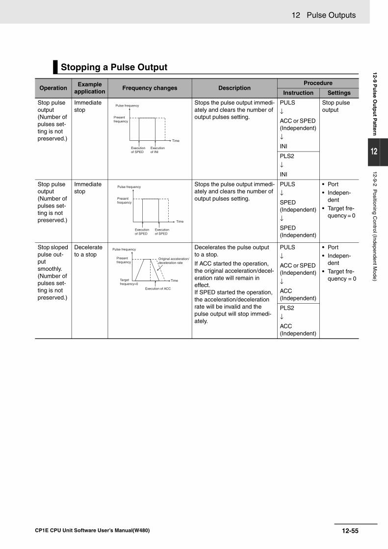
12-55
12 Pulse Outputs
CP1E CPU Unit Software User’s Manual(W480)
12-9 Pu
lse Ou
tpu
t Pattern
12
12-9-2 Positioning C
ontrol (Independent Mode)
Stopping a Pulse Output
OperationExample
applicationFrequency changes Description
Procedure
Instruction Settings
Stop pulse output (Number of pulses set-ting is not preserved.)
Immediate stop
Stops the pulse output immedi-ately and clears the number of output pulses setting.
PULS
↓ACC or SPED (Independent)
↓INI
Stop pulse output
PLS2
↓INI
Stop pulse output(Number of pulses set-ting is not preserved.)
Immediate stop
Stops the pulse output immedi-ately and clears the number of output pulses setting.
PULS
↓SPED(Independent)
↓SPED(Independent)
• Port• Indepen-
dent• Target fre-
quency = 0
Stop sloped pulse out-put smoothly. (Number of pulses set-ting is not preserved.)
Decelerate to a stop
Decelerates the pulse output to a stop.
If ACC started the operation, the original acceleration/decel-eration rate will remain in effect.If SPED started the operation, the acceleration/deceleration rate will be invalid and the pulse output will stop immedi-ately.
PULS
↓ACC or SPED (Independent)
↓ACC(Independent)
• Port• Indepen-
dent• Target fre-
quency = 0
PLS2
↓ACC(Independent)
Pulse frequency
Present frequency
Execution of SPED
Execution of INI
Time
Pulse frequency
Present frequency
Execution of SPED
Execution of SPED
Time
Pulse frequency
Present frequency
Target frequency=0
Original acceleration/deceleration rate
Execution of ACC
Time
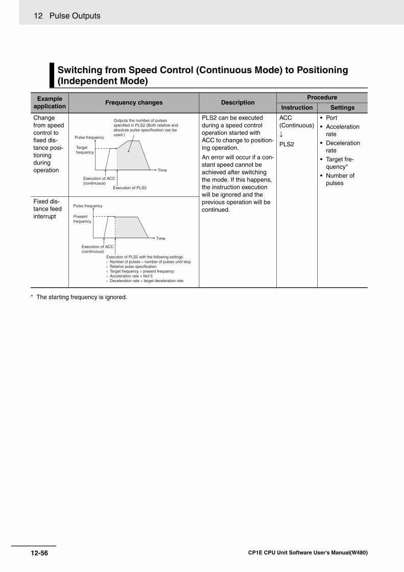
12 Pulse Outputs
12-56 CP1E CPU Unit Software User’s Manual(W480)
* The starting frequency is ignored.
Switching from Speed Control (Continuous Mode) to Positioning (Independent Mode)
Example application
Frequency changes DescriptionProcedure
Instruction Settings
Change from speed control to fixed dis-tance posi-tioning during operation
PLS2 can be executed during a speed control operation started with ACC to change to position-ing operation.
An error will occur if a con-stant speed cannot be achieved after switching the mode. If this happens, the instruction execution will be ignored and the previous operation will be continued.
ACC(Continuous)
↓PLS2
• Port
• Acceleration rate
• Deceleration rate
• Target fre-quency*
• Number of pulses
Fixed dis-tance feed interrupt
Time
Targetfrequency
Execution of ACC(continuous)
Execution of PLS2
Pulse frequency
Outputs the number of pulses specified in PLS2 (Both relative and absolute pulse specification can be used.)
Pulse frequency
Time
Presentfrequency
Execution of ACC(continuous)
Execution of PLS2 with the following settings Number of pulses = number of pulses until stop Relative pulse specification Target frequency = present frequency Acceleration rate = Not 0 Deceleration rate = target deceleration rate
13-1
13
CP1E CPU Unit Software User’s Manual(W480)
13
This section describes the PWM Outputs (variable-duty-factor pulse outputs).
13-1 PWM Outputs (Variable-duty-factor Pulse Outputs) . . . . . . . . . . . . . . . . . 13-213-1-1 Flow of Operation . . . . . . . . . . . . . . . . . . . . . . . . . . . . . . . . . . . . . . . . . . . . . . 13-3
13-1-2 Ladder Program Example. . . . . . . . . . . . . . . . . . . . . . . . . . . . . . . . . . . . . . . . 13-4
PWM Outputs
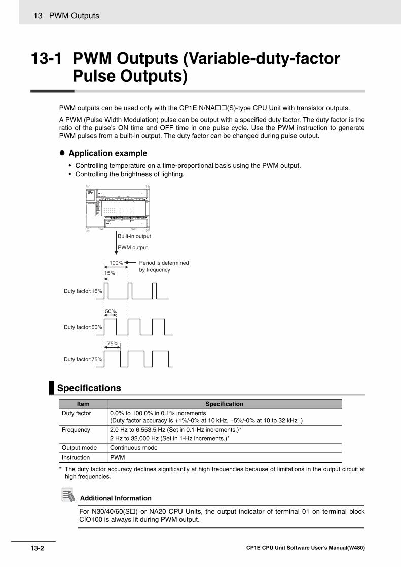
13 PWM Outputs
13-2 CP1E CPU Unit Software User’s Manual(W480)
13-1 PWM Outputs (Variable-duty-factor Pulse Outputs)
PWM outputs can be used only with the CP1E N/NA (S)-type CPU Unit with transistor outputs.
A PWM (Pulse Width Modulation) pulse can be output with a specified duty factor. The duty factor is theratio of the pulse’s ON time and OFF time in one pulse cycle. Use the PWM instruction to generatePWM pulses from a built-in output. The duty factor can be changed during pulse output.
Application example• Controlling temperature on a time-proportional basis using the PWM output.• Controlling the brightness of lighting.
* The duty factor accuracy declines significantly at high frequencies because of limitations in the output circuit athigh frequencies.
Additional Information
For N30/40/60(S ) or NA20 CPU Units, the output indicator of terminal 01 on terminal blockCIO100 is always lit during PWM output.
Specifications
Item Specification
Duty factor 0.0% to 100.0% in 0.1% increments(Duty factor accuracy is +1%/-0% at 10 kHz, +5%/-0% at 10 to 32 kHz .)
Frequency 2.0 Hz to 6,553.5 Hz (Set in 0.1-Hz increments.)*
2 Hz to 32,000 Hz (Set in 1-Hz increments.)*
Output mode Continuous mode
Instruction PWM
Duty factor:50%
100%
50%
75%
15%
Duty factor:15%
Duty factor:75%
Built-in output
PWM output
Period is determinedby frequency
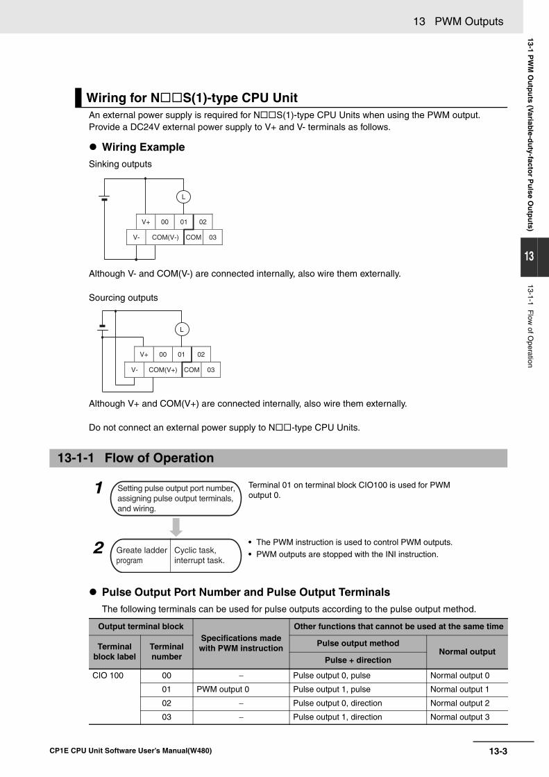
13-3
13 PWM Outputs
CP1E CPU Unit Software User’s Manual(W480)
13-1 PW
M O
utp
uts (V
ariable-d
uty-facto
r Pu
lse Ou
tpu
ts)
13
13-1-1 Flow
of Operation
An external power supply is required for N S(1)-type CPU Units when using the PWM output.Provide a DC24V external power supply to V+ and V- terminals as follows.
Wiring ExampleSinking outputs
Although V- and COM(V-) are connected internally, also wire them externally.
Sourcing outputs
Although V+ and COM(V+) are connected internally, also wire them externally.
Do not connect an external power supply to N -type CPU Units.
Pulse Output Port Number and Pulse Output TerminalsThe following terminals can be used for pulse outputs according to the pulse output method.
Wiring for N S(1)-type CPU Unit
13-1-1 Flow of Operation
1
2
Terminal 01 on terminal block CIO100 is used for PWM output 0.
• The PWM instruction is used to control PWM outputs.
• PWM outputs are stopped with the INI instruction.
Output terminal blockSpecifications made with PWM instruction
Other functions that cannot be used at the same time
Terminal block label
Terminal number
Pulse output methodNormal output
Pulse + direction
CIO 100 00 − Pulse output 0, pulse Normal output 0
01 PWM output 0 Pulse output 1, pulse Normal output 1
02 − Pulse output 0, direction Normal output 2
03 − Pulse output 1, direction Normal output 3
V+ 00
V- COM(V-) COM 03
0201
L
V+ 00
V- COM(V+) COM 03
0201
L
Setting pulse output port number,assigning pulse output terminals,and wiring.
Greate ladderprogram
Cyclic task,interrupt task.
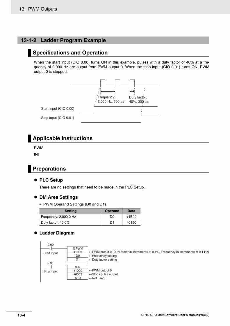
13 PWM Outputs
13-4 CP1E CPU Unit Software User’s Manual(W480)
When the start input (CIO 0.00) turns ON in this example, pulses with a duty factor of 40% at a fre-quency of 2,000 Hz are output from PWM output 0. When the stop input (CIO 0.01) turns ON, PWMoutput 0 is stopped.
PWM
INI
PLC SetupThere are no settings that need to be made in the PLC Setup.
DM Area Settings• PWM Operand Settings (D0 and D1)
Ladder Diagram
13-1-2 Ladder Program Example
Specifications and Operation
Applicable Instructions
Preparations
Setting Operand Data
Frequency: 2,000.0 Hz D0 #4E20
Duty factor: 40.0% D1 #0190
Start input (CIO 0.00)
Frequency: 2,000 Hz, 500 µs
Stop input (CIO 0.01)
Duty factor: 40%, 200 µs
@PWM#1000
D0D1
#1000#0003D10
0.00
0.01
Start input
Stop input
←PWM output 0 (Duty factor in increments of 0.1%, Frequency in increments of 0.1 Hz)←Frequency setting←Duty factor setting
←PWM output 0←Stops pulse output←Not used.
@INI

14-1
14
CP1E CPU Unit Software User’s Manual(W480)
14
This section describes communications with Programmable Terminals (PTs) withoutusing communications programming, no-protocol communications with general compo-nents, and connections with a Modbus-RTU Easy Master, Serial PLC Link, and hostcomputer.
14-1 Serial Communications . . . . . . . . . . . . . . . . . . . . . . . . . . . . . . . . . . . . . . . . 14-214-1-1 Types of CPU Units and Serial Ports . . . . . . . . . . . . . . . . . . . . . . . . . . . . . . . 14-2
14-1-2 Overview of Serial Communications . . . . . . . . . . . . . . . . . . . . . . . . . . . . . . . 14-3
14-2 Program-free Communications with Programmable Terminals . . . . . . . 14-514-2-1 Overview . . . . . . . . . . . . . . . . . . . . . . . . . . . . . . . . . . . . . . . . . . . . . . . . . . . . 14-514-2-2 Flow of Connection . . . . . . . . . . . . . . . . . . . . . . . . . . . . . . . . . . . . . . . . . . . . 14-614-2-3 PLC Setup and PT System Settings . . . . . . . . . . . . . . . . . . . . . . . . . . . . . . . 14-6
14-3 No-protocol Communications with General Components . . . . . . . . . . . . 14-814-3-1 Overview . . . . . . . . . . . . . . . . . . . . . . . . . . . . . . . . . . . . . . . . . . . . . . . . . . . . 14-8
14-3-2 Flow of Operation . . . . . . . . . . . . . . . . . . . . . . . . . . . . . . . . . . . . . . . . . . . . . 14-914-3-3 PLC Setup . . . . . . . . . . . . . . . . . . . . . . . . . . . . . . . . . . . . . . . . . . . . . . . . . . . 14-914-3-4 Related Auxiliary Area Bits and Words . . . . . . . . . . . . . . . . . . . . . . . . . . . . 14-10
14-4 Modbus-RTU Easy Master Function . . . . . . . . . . . . . . . . . . . . . . . . . . . . . 14-1114-4-1 Overview . . . . . . . . . . . . . . . . . . . . . . . . . . . . . . . . . . . . . . . . . . . . . . . . . . . 14-11
14-4-2 Flow of Operation . . . . . . . . . . . . . . . . . . . . . . . . . . . . . . . . . . . . . . . . . . . . 14-1114-4-3 Setting and Word Allocation . . . . . . . . . . . . . . . . . . . . . . . . . . . . . . . . . . . . 14-1214-4-4 Programming Examples . . . . . . . . . . . . . . . . . . . . . . . . . . . . . . . . . . . . . . . 14-14
14-5 Serial PLC Links . . . . . . . . . . . . . . . . . . . . . . . . . . . . . . . . . . . . . . . . . . . . . 14-2014-5-1 Overview . . . . . . . . . . . . . . . . . . . . . . . . . . . . . . . . . . . . . . . . . . . . . . . . . . . 14-20
14-5-2 Flow of Operation . . . . . . . . . . . . . . . . . . . . . . . . . . . . . . . . . . . . . . . . . . . . 14-2114-5-3 PLC Setup . . . . . . . . . . . . . . . . . . . . . . . . . . . . . . . . . . . . . . . . . . . . . . . . . . 14-2114-5-4 Operating Specifications . . . . . . . . . . . . . . . . . . . . . . . . . . . . . . . . . . . . . . . 14-23
14-5-5 Example Application . . . . . . . . . . . . . . . . . . . . . . . . . . . . . . . . . . . . . . . . . . 14-29
14-6 Connecting the Host Computer . . . . . . . . . . . . . . . . . . . . . . . . . . . . . . . . 14-3114-6-1 Overview . . . . . . . . . . . . . . . . . . . . . . . . . . . . . . . . . . . . . . . . . . . . . . . . . . . 14-3114-6-2 Flow of Operation . . . . . . . . . . . . . . . . . . . . . . . . . . . . . . . . . . . . . . . . . . . . 14-3114-6-3 Command/response Format and List of Commands . . . . . . . . . . . . . . . . . . 14-32
14-7 Precautions on the usage of RS-485 . . . . . . . . . . . . . . . . . . . . . . . . . . . . 14-34
Serial Communications
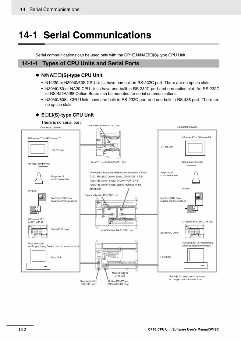
14 Serial Communications
14-2 CP1E CPU Unit Software User’s Manual(W480)
14-1 Serial Communications
Serial communications can be used only with the CP1E N/NA(S)-type CPU Unit.
N/NA(S)-type CPU Unit• N14/20 or N30/40/60S CPU Units have one built-in RS-232C port. There are no option slots.
• N30/40/60 or NA20 CPU Units have one built-in RS-232C port and one option slot. An RS-232Cor RS-422A/485 Option Board can be mounted for serial communications.
• N30/40/60S1 CPU Units have one bulit-in RS-232C port and one bulit-in RS-485 port. There areno option slots.
E(S)-type CPU UnitThere is no serial port.
14-1-1 Types of CPU Units and Serial Ports
NS-series PT or NP-series PT
1:N NT Link
General component
No-protocolcommunications
Modbus-RTU EasyMaster communications
Inverter
Host computer (A Programming Device cannot be connected.)
Host Link
Standard built-in RS-232C port
N14/20 or N30/40/60S CPU Unit
One Option Board for serial communications (CP1W-
CIF01 RS-232C Option Board, CP1W-CIF11 RS-
422A/485 Option Board, or CP1W-CIF12 RS-
422A/485 Option Board) can be mounted in the
option slot.
Standard built-in RS-232C port
N30/40/60 or NA20 CPU Unit
Connected devices Connected devices
NS-series PT or NP-series PT
1:N NT Link
General component
Inverter
No-protocolcommunications
Modbus-RTU EasyMaster communications
Host computer (A ProgrammingDevice cannot be connected.)
Host Link
* Serial PLC Links cannot be usedon two ports at the same time.
CP-series PLCor CJ1M PLC CP-series PLC or CJ1M PLC
Serial PLC Links*Serial PLC Links*
Standard built-in RS-232C port
N30/40/60S(1)CPU Unit
Built-in RS-485 port (N30/40/60S1 only)
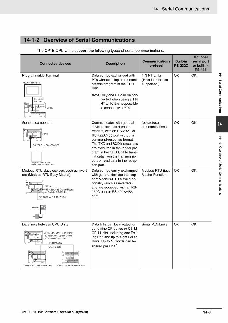
14-3
14 Serial Communications
CP1E CPU Unit Software User’s Manual(W480)
14-1 Serial C
om
mu
nicatio
ns
14
14-1-2 Overview
of Serial C
omm
unications
The CP1E CPU Units support the following types of serial communications.
14-1-2 Overview of Serial Communications
Connected devices DescriptionCommunications
protocolBuilt-in
RS-232C
Optional serial port or built-in
RS-485
Programmable Terminal Data can be exchanged with PTs without using a communi-cations program in the CPU Unit.
Note Only one PT can be con-nected when using a 1:N NT Link. It is not possible to connect two PTs.
1:N NT Links (Host Link is also supported.)
OK OK
General component Communicates with general devices, such as barcode readers, with an RS-232C or RS-422A/485 port without a command-response format. The TXD and RXD instructions are executed in the ladder pro-gram in the CPU Unit to trans-mit data from the transmission port or read data in the recep-tion port.
No-protocol communications
OK OK
Modbus-RTU slave devices, such as invert-ers (Modbus-RTU Easy Master)
Data can be easily exchanged with general devices that sup-port Modbus-RTU slave func-tionality (such as inverters) and are equipped with an RS-232C port or RS-422A/485 port.
Modbus-RTU Easy Master Function
OK OK
Data links between CPU Units Data links can be created for up to nine CP-series or CJ1M CPU Units, including one Poll-ing Unit and up to eight Polled Units. Up to 10 words can be shared per Unit.*
Serial PLC Links OK OK
CP1E
RS-232C
NS/NP-series PT
NT Link
CP1E
RS-232C or RS-422A/485
General device withserial communications
CP1E
RS-232C or RS-422A/485
RS-422A/485 Option Boardor Bulit-in RS-485 Port
Inverter
RS-422A/485
CP1E CPU Unit Polling UnitRS-422A/485 Option Boardor Bulit-in RS-485 Port
Shared data
CP1E CPU Unit Polled Unit CP1L CPU Unit Polled Unit
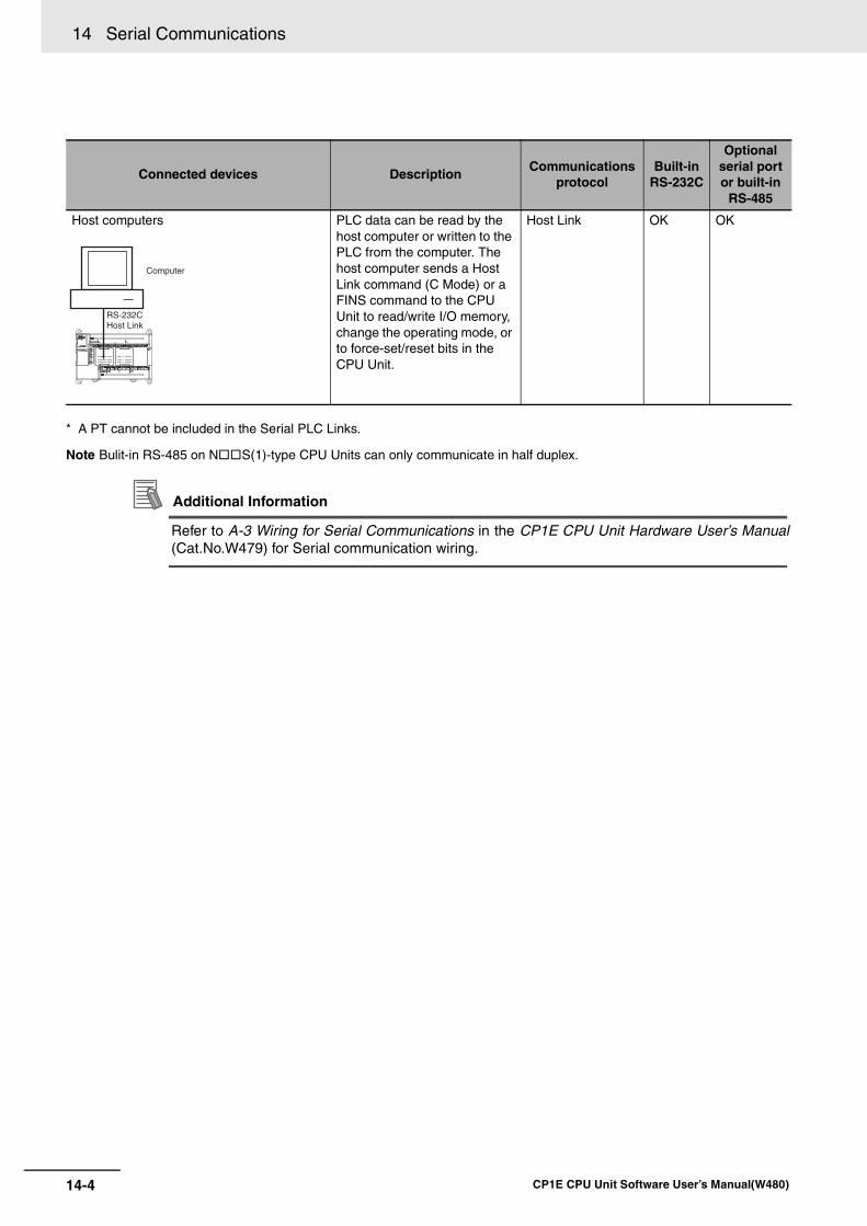
14 Serial Communications
14-4 CP1E CPU Unit Software User’s Manual(W480)
* A PT cannot be included in the Serial PLC Links.
Note Bulit-in RS-485 on NS(1)-type CPU Units can only communicate in half duplex.
Additional Information
Refer to A-3 Wiring for Serial Communications in the CP1E CPU Unit Hardware User’s Manual(Cat.No.W479) for Serial communication wiring.
Connected devices DescriptionCommunications
protocolBuilt-in
RS-232C
Optional serial port or built-in
RS-485
Host computers PLC data can be read by the host computer or written to the PLC from the computer. The host computer sends a Host Link command (C Mode) or a FINS command to the CPU Unit to read/write I/O memory, change the operating mode, or to force-set/reset bits in the CPU Unit.
Host Link OK OK
RS-232C
Computer
Host Link
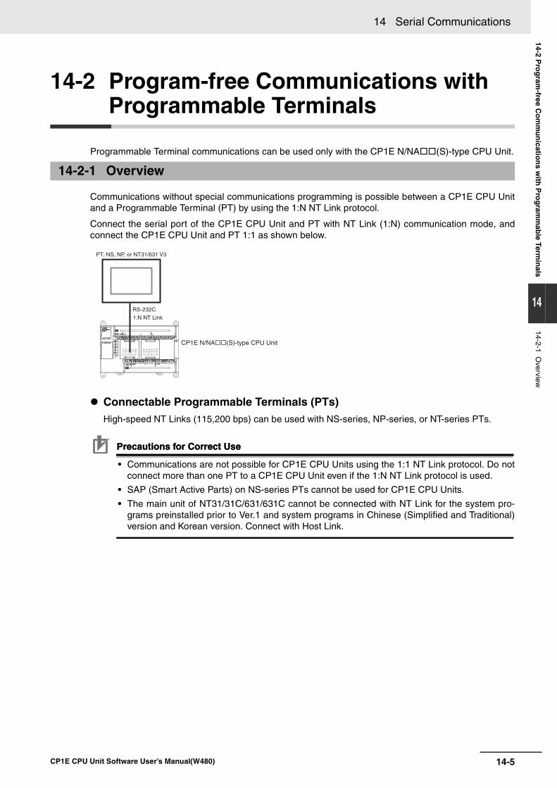
14-5
14 Serial Communications
CP1E CPU Unit Software User’s Manual(W480)
14-2 Pro
gram
-free Co
mm
un
ication
s with
Pro
gram
mab
le Termin
als
14
14-2-1 Overview
14-2 Program-free Communications with Programmable Terminals
Programmable Terminal communications can be used only with the CP1E N/NA(S)-type CPU Unit.
Communications without special communications programming is possible between a CP1E CPU Unitand a Programmable Terminal (PT) by using the 1:N NT Link protocol.
Connect the serial port of the CP1E CPU Unit and PT with NT Link (1:N) communication mode, andconnect the CP1E CPU Unit and PT 1:1 as shown below.
Connectable Programmable Terminals (PTs) High-speed NT Links (115,200 bps) can be used with NS-series, NP-series, or NT-series PTs.
Precautions for Correct UsePrecautions for Correct Use
• Communications are not possible for CP1E CPU Units using the 1:1 NT Link protocol. Do notconnect more than one PT to a CP1E CPU Unit even if the 1:N NT Link protocol is used.
• SAP (Smart Active Parts) on NS-series PTs cannot be used for CP1E CPU Units.
• The main unit of NT31/31C/631/631C cannot be connected with NT Link for the system pro-grams preinstalled prior to Ver.1 and system programs in Chinese (Simplified and Traditional)version and Korean version. Connect with Host Link.
14-2-1 Overview
CP1E N/NA(S)-type CPU Unit
RS-232C1:N NT Link
PT: NS, NP, or NT31/631 V3
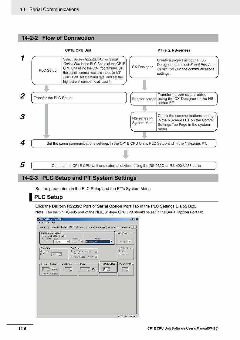
14 Serial Communications
14-6 CP1E CPU Unit Software User’s Manual(W480)
Set the parameters in the PLC Setup and the PT’s System Menu.
Click the Built-in RS232C Port or Serial Option Port Tab in the PLC Settings Dialog Box.
Note The built-in RS-485 port of the NS1-type CPU Unit should be set in the Serial Option Port tab.
14-2-2 Flow of Connection
CP1E CPU Unit PT (e.g. NS-series)
1
2
3
4
5
14-2-3 PLC Setup and PT System Settings
PLC Setup
Connect the CP1E CPU Unit and external devices using the RS-232C or RS-422A/485 ports.
CX-Designer
Transfer the PLC Setup.
NS-series PTSystem Menu
Set the same communications settings in the CP1E CPU Unit’s PLC Setup and in the NS-series PT.
PLC Setup
Select Built-in RS232C Port or Serial Option Port in the PLC Setup of the CP1E CPU Unit using the CX-Programmer. Set the serial communications mode to NT Link (1:N), set the baud rate, and set the highest unit number to at least 1.
Create a project using the CX-Designer and select Serial Port A or Serial Port B in the communications settings.
Transfer screenTransfer screen data created using the CX-Designer to the NS-series PT.
Check the communications settings in the NS-series PT on the Comm Settings Tab Page in the system menu.
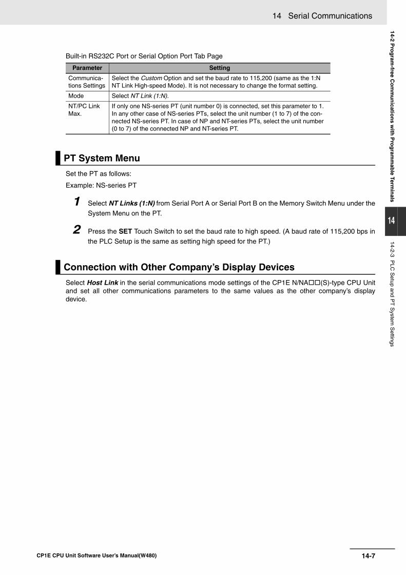
14-7
14 Serial Communications
CP1E CPU Unit Software User’s Manual(W480)
14-2 Pro
gram
-free Co
mm
un
ication
s with
Pro
gram
mab
le Termin
als
14
14-2-3 PLC
Setup and P
T S
ystem S
ettings
Built-in RS232C Port or Serial Option Port Tab Page
Set the PT as follows:
Example: NS-series PT
1 Select NT Links (1:N) from Serial Port A or Serial Port B on the Memory Switch Menu under the
System Menu on the PT.
2 Press the SET Touch Switch to set the baud rate to high speed. (A baud rate of 115,200 bps in
the PLC Setup is the same as setting high speed for the PT.)
Select Host Link in the serial communications mode settings of the CP1E N/NA(S)-type CPU Unitand set all other communications parameters to the same values as the other company’s displaydevice.
Parameter Setting
Communica-tions Settings
Select the Custom Option and set the baud rate to 115,200 (same as the 1:N NT Link High-speed Mode). It is not necessary to change the format setting.
Mode Select NT Link (1:N).
NT/PC Link Max.
If only one NS-series PT (unit number 0) is connected, set this parameter to 1. In any other case of NS-series PTs, select the unit number (1 to 7) of the con-nected NS-series PT. In case of NP and NT-series PTs, select the unit number (0 to 7) of the connected NP and NT-series PT.
PT System Menu
Connection with Other Company’s Display Devices
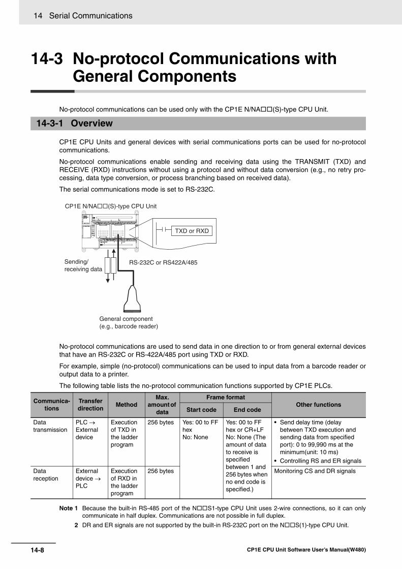
14 Serial Communications
14-8 CP1E CPU Unit Software User’s Manual(W480)
14-3 No-protocol Communications with General Components
No-protocol communications can be used only with the CP1E N/NA(S)-type CPU Unit.
CP1E CPU Units and general devices with serial communications ports can be used for no-protocolcommunications.
No-protocol communications enable sending and receiving data using the TRANSMIT (TXD) andRECEIVE (RXD) instructions without using a protocol and without data conversion (e.g., no retry pro-cessing, data type conversion, or process branching based on received data).
The serial communications mode is set to RS-232C.
No-protocol communications are used to send data in one direction to or from general external devicesthat have an RS-232C or RS-422A/485 port using TXD or RXD.
For example, simple (no-protocol) communications can be used to input data from a barcode reader oroutput data to a printer.
The following table lists the no-protocol communication functions supported by CP1E PLCs.
Note 1 Because the built-in RS-485 port of the NS1-type CPU Unit uses 2-wire connections, so it can onlycommunicate in half duplex. Communications are not possible in full duplex.
2 DR and ER signals are not supported by the built-in RS-232C port on the NS(1)-type CPU Unit.
14-3-1 Overview
Communica-tions
Transfer direction
Method Max.
amount of data
Frame format Other functions
Start code End code
Data transmission
PLC → External device
Execution of TXD in the ladder program
256 bytes Yes: 00 to FF hexNo: None
Yes: 00 to FF hex or CR+LFNo: None (The amount of data to receive is specified between 1 and 256 bytes when no end code is specified.)
• Send delay time (delay between TXD execution and sending data from specified port): 0 to 99,990 ms at the minimum(unit: 10 ms)
• Controlling RS and ER signals
Data reception
External device → PLC
Execution of RXD in the ladder program
256 bytes Monitoring CS and DR signals
CP1E N/NA(S)-type CPU Unit
Sending/receiving data
TXD or RXD
RS-232C or RS422A/485
General component (e.g., barcode reader)
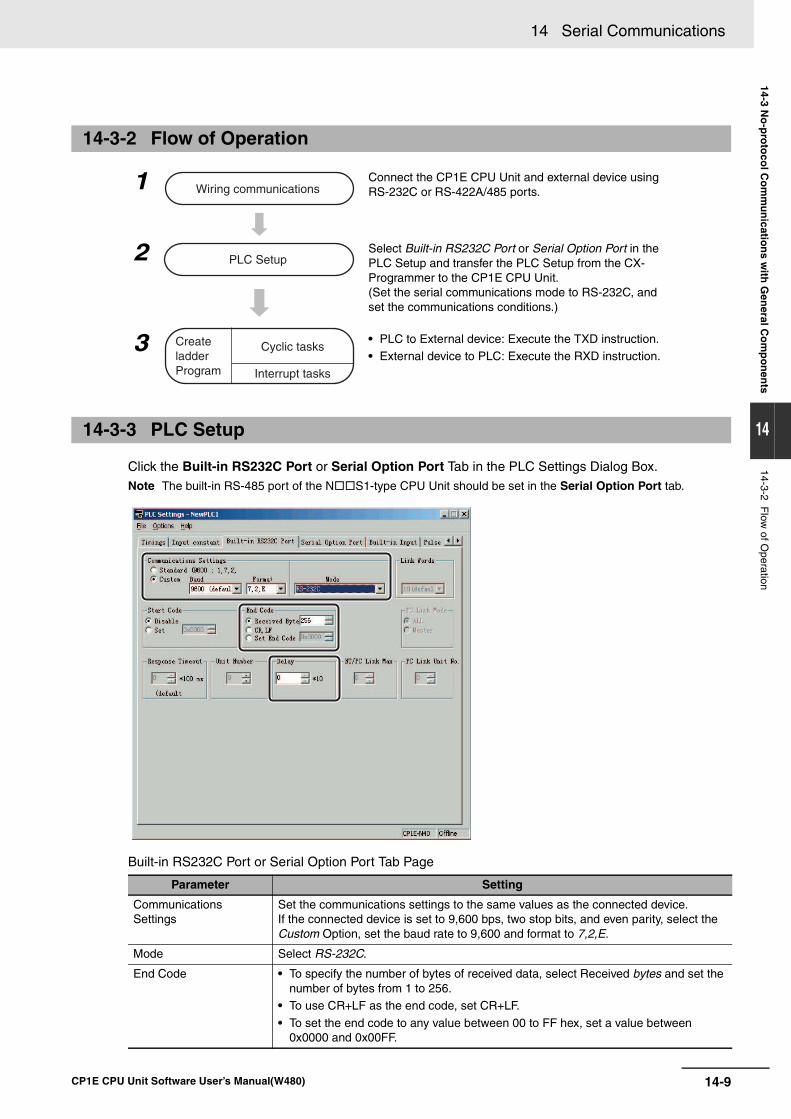
14-9
14 Serial Communications
CP1E CPU Unit Software User’s Manual(W480)
14-3 No
-pro
toco
l Co
mm
un
ication
s with
Gen
eral Co
mp
on
ents
14
14-3-2 Flow
of Operation
Click the Built-in RS232C Port or Serial Option Port Tab in the PLC Settings Dialog Box. Note The built-in RS-485 port of the NS1-type CPU Unit should be set in the Serial Option Port tab.
Built-in RS232C Port or Serial Option Port Tab Page
14-3-2 Flow of Operation
1 Connect the CP1E CPU Unit and external device using RS-232C or RS-422A/485 ports.
2 Select Built-in RS232C Port or Serial Option Port in the PLC Setup and transfer the PLC Setup from the CX-Programmer to the CP1E CPU Unit. (Set the serial communications mode to RS-232C, and set the communications conditions.)
3 • PLC to External device: Execute the TXD instruction.• External device to PLC: Execute the RXD instruction.
14-3-3 PLC Setup
Parameter Setting
Communications Settings
Set the communications settings to the same values as the connected device.If the connected device is set to 9,600 bps, two stop bits, and even parity, select the Custom Option, set the baud rate to 9,600 and format to 7,2,E.
Mode Select RS-232C.
End Code • To specify the number of bytes of received data, select Received bytes and set the number of bytes from 1 to 256.
• To use CR+LF as the end code, set CR+LF.
• To set the end code to any value between 00 to FF hex, set a value between 0x0000 and 0x00FF.
Wiring communications
PLC Setup
Create ladder Program
Cyclic tasks
Interrupt tasks
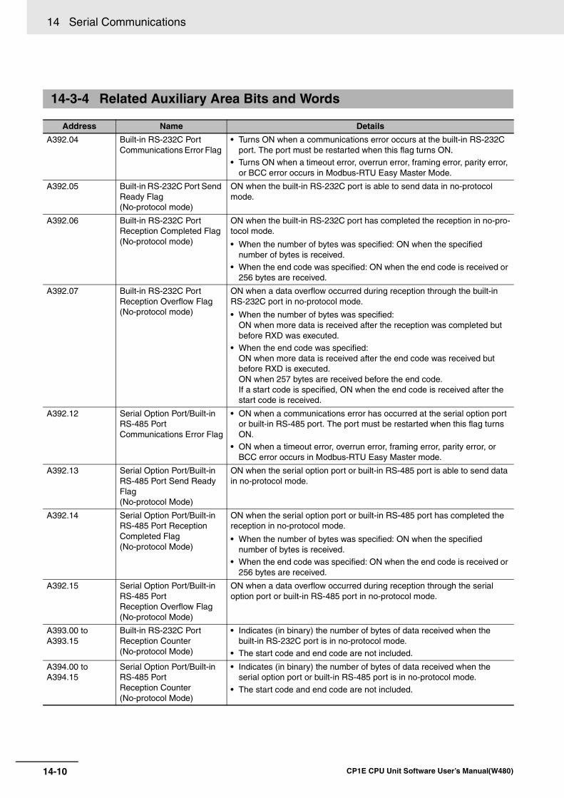
14 Serial Communications
14-10 CP1E CPU Unit Software User’s Manual(W480)
14-3-4 Related Auxiliary Area Bits and Words
Address Name Details
A392.04 Built-in RS-232C Port Communications Error Flag
• Turns ON when a communications error occurs at the built-in RS-232C port. The port must be restarted when this flag turns ON.
• Turns ON when a timeout error, overrun error, framing error, parity error, or BCC error occurs in Modbus-RTU Easy Master Mode.
A392.05 Built-in RS-232C Port Send Ready Flag (No-protocol mode)
ON when the built-in RS-232C port is able to send data in no-protocol mode.
A392.06 Built-in RS-232C Port Reception Completed Flag(No-protocol mode)
ON when the built-in RS-232C port has completed the reception in no-pro-tocol mode.
• When the number of bytes was specified: ON when the specified number of bytes is received.
• When the end code was specified: ON when the end code is received or 256 bytes are received.
A392.07 Built-in RS-232C Port Reception Overflow Flag (No-protocol mode)
ON when a data overflow occurred during reception through the built-in RS-232C port in no-protocol mode.
• When the number of bytes was specified: ON when more data is received after the reception was completed but before RXD was executed.
• When the end code was specified: ON when more data is received after the end code was received but before RXD is executed. ON when 257 bytes are received before the end code. If a start code is specified, ON when the end code is received after the start code is received.
A392.12 Serial Option Port/Built-in RS-485 Port Communications Error Flag
• ON when a communications error has occurred at the serial option port or built-in RS-485 port. The port must be restarted when this flag turns ON.
• ON when a timeout error, overrun error, framing error, parity error, or BCC error occurs in Modbus-RTU Easy Master mode.
A392.13 Serial Option Port/Built-in RS-485 Port Send Ready Flag (No-protocol Mode)
ON when the serial option port or built-in RS-485 port is able to send data in no-protocol mode.
A392.14 Serial Option Port/Built-in RS-485 Port Reception Completed Flag (No-protocol Mode)
ON when the serial option port or built-in RS-485 port has completed the reception in no-protocol mode.
• When the number of bytes was specified: ON when the specified number of bytes is received.
• When the end code was specified: ON when the end code is received or 256 bytes are received.
A392.15 Serial Option Port/Built-in RS-485 PortReception Overflow Flag (No-protocol Mode)
ON when a data overflow occurred during reception through the serialoption port or built-in RS-485 port in no-protocol mode.
A393.00 to A393.15
Built-in RS-232C PortReception Counter (No-protocol Mode)
• Indicates (in binary) the number of bytes of data received when the built-in RS-232C port is in no-protocol mode.
• The start code and end code are not included.
A394.00 to A394.15
Serial Option Port/Built-in RS-485 PortReception Counter (No-protocol Mode)
• Indicates (in binary) the number of bytes of data received when the serial option port or built-in RS-485 port is in no-protocol mode.
• The start code and end code are not included.
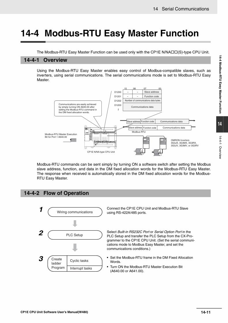
14-11
14 Serial Communications
CP1E CPU Unit Software User’s Manual(W480)
14-4 Mo
dbu
s-RT
U E
asy Master F
un
ction
14
14-4-1 Overview
14-4 Modbus-RTU Easy Master Function
The Modbus-RTU Easy Master Function can be used only with the CP1E N/NA(S)-type CPU Unit.
Using the Modbus-RTU Easy Master enables easy control of Modbus-compatible slaves, such asinverters, using serial communications. The serial communications mode is set to Modbus-RTU EasyMaster.
Modbus-RTU commands can be sent simply by turning ON a software switch after setting the Modbusslave address, function, and data in the DM fixed allocation words for the Modbus-RTU Easy Master.The response when received is automatically stored in the DM fixed allocation words for the Modbus-RTU Easy Master.
14-4-1 Overview
14-4-2 Flow of Operation
1 Connect the CP1E CPU Unit and Modbus-RTU Slave using RS-422A/485 ports.
2 Select Built-in RS232C Port or Serial Option Port in the PLC Setup and transfer the PLC Setup from the CX-Pro-grammer to the CP1E CPU Unit. (Set the serial communi-cations mode to Modbus Easy Master, and set the communications conditions.)
3 • Set the Modbus-RTU frame in the DM Fixed Allocation Words.
• Turn ON the Modbus-RTU Master Execution Bit (A640.00 or A641.00).
Modbus-RTU
15 08 07 00
D1200 --
D1201 --
D1202
D1203Communications are easily achieved by simply turning ON A640.00 after setting the Modbus-RTU command in the DM fixed allocation words.
Modbus-RTU Master Execution Bit for Port 1 A640.00
CP1E N/NA-type CPU Unit
Slave address
Slave address
Slave address Function code
Function code
Function code Communications data
Communications data
Communications data
OMRON Inverters3G3JX, 3G3MX, 3G3RX, 3G3JV, 3G3MV, or 3G3RV
Number of communications data bytes
~
Wiring communications
PLC Setup
Create ladder Program
Cyclic tasks
Interrupt tasks
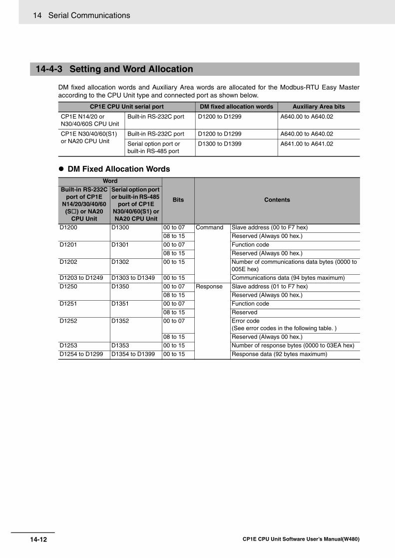
14 Serial Communications
14-12 CP1E CPU Unit Software User’s Manual(W480)
DM fixed allocation words and Auxiliary Area words are allocated for the Modbus-RTU Easy Masteraccording to the CPU Unit type and connected port as shown below.
DM Fixed Allocation Words
14-4-3 Setting and Word Allocation
CP1E CPU Unit serial port DM fixed allocation words Auxiliary Area bits
CP1E N14/20 or N30/40/60S CPU Unit
Built-in RS-232C port D1200 to D1299 A640.00 to A640.02
CP1E N30/40/60(S1) or NA20 CPU Unit
Built-in RS-232C port D1200 to D1299 A640.00 to A640.02
Serial option port or built-in RS-485 port
D1300 to D1399 A641.00 to A641.02
Word
Bits Contents
Built-in RS-232Cport of CP1E
N14/20/30/40/60(S) or NA20
CPU Unit
Serial option port or built-in RS-485
port of CP1E N30/40/60(S1) or NA20 CPU Unit
D1200 D1300 00 to 07 Command Slave address (00 to F7 hex) 08 to 15 Reserved (Always 00 hex.)
D1201 D1301 00 to 07 Function code 08 to 15 Reserved (Always 00 hex.)
D1202 D1302 00 to 15 Number of communications data bytes (0000 to 005E hex)
D1203 to D1249 D1303 to D1349 00 to 15 Communications data (94 bytes maximum)
D1250 D1350 00 to 07 Response Slave address (01 to F7 hex) 08 to 15 Reserved (Always 00 hex.)
D1251 D1351 00 to 07 Function code
08 to 15 Reserved D1252 D1352 00 to 07 Error code
(See error codes in the following table. )08 to 15 Reserved (Always 00 hex.)
D1253 D1353 00 to 15 Number of response bytes (0000 to 03EA hex)
D1254 to D1299 D1354 to D1399 00 to 15 Response data (92 bytes maximum)
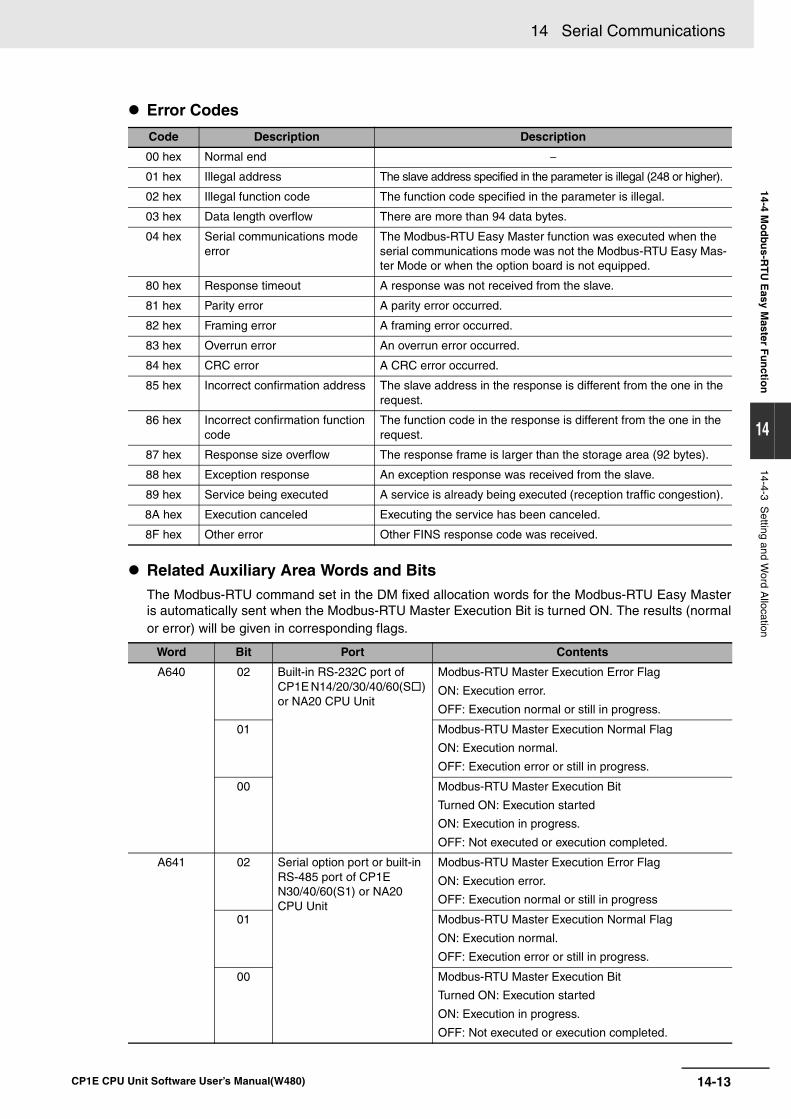
14-13
14 Serial Communications
CP1E CPU Unit Software User’s Manual(W480)
14-4 Mo
dbu
s-RT
U E
asy Master F
un
ction
14
14-4-3 Setting and W
ord Allocation
Error Codes
Related Auxiliary Area Words and Bits The Modbus-RTU command set in the DM fixed allocation words for the Modbus-RTU Easy Masteris automatically sent when the Modbus-RTU Master Execution Bit is turned ON. The results (normalor error) will be given in corresponding flags.
Code Description Description
00 hex Normal end −
01 hex Illegal address The slave address specified in the parameter is illegal (248 or higher).
02 hex Illegal function code The function code specified in the parameter is illegal.
03 hex Data length overflow There are more than 94 data bytes.
04 hex Serial communications mode error
The Modbus-RTU Easy Master function was executed when the serial communications mode was not the Modbus-RTU Easy Mas-ter Mode or when the option board is not equipped.
80 hex Response timeout A response was not received from the slave.
81 hex Parity error A parity error occurred.
82 hex Framing error A framing error occurred.
83 hex Overrun error An overrun error occurred.
84 hex CRC error A CRC error occurred.
85 hex Incorrect confirmation address The slave address in the response is different from the one in the request.
86 hex Incorrect confirmation function code
The function code in the response is different from the one in the request.
87 hex Response size overflow The response frame is larger than the storage area (92 bytes).
88 hex Exception response An exception response was received from the slave.
89 hex Service being executed A service is already being executed (reception traffic congestion).
8A hex Execution canceled Executing the service has been canceled.
8F hex Other error Other FINS response code was received.
Word Bit Port Contents
A640 02 Built-in RS-232C port of CP1E N14/20/30/40/60(S) or NA20 CPU Unit
Modbus-RTU Master Execution Error Flag
ON: Execution error.
OFF: Execution normal or still in progress.
01 Modbus-RTU Master Execution Normal Flag
ON: Execution normal.
OFF: Execution error or still in progress.
00 Modbus-RTU Master Execution Bit
Turned ON: Execution started
ON: Execution in progress.
OFF: Not executed or execution completed.
A641 02 Serial option port or built-in RS-485 port of CP1E N30/40/60(S1) or NA20 CPU Unit
Modbus-RTU Master Execution Error Flag
ON: Execution error.
OFF: Execution normal or still in progress
01 Modbus-RTU Master Execution Normal Flag
ON: Execution normal.
OFF: Execution error or still in progress.
00 Modbus-RTU Master Execution Bit
Turned ON: Execution started
ON: Execution in progress.
OFF: Not executed or execution completed.
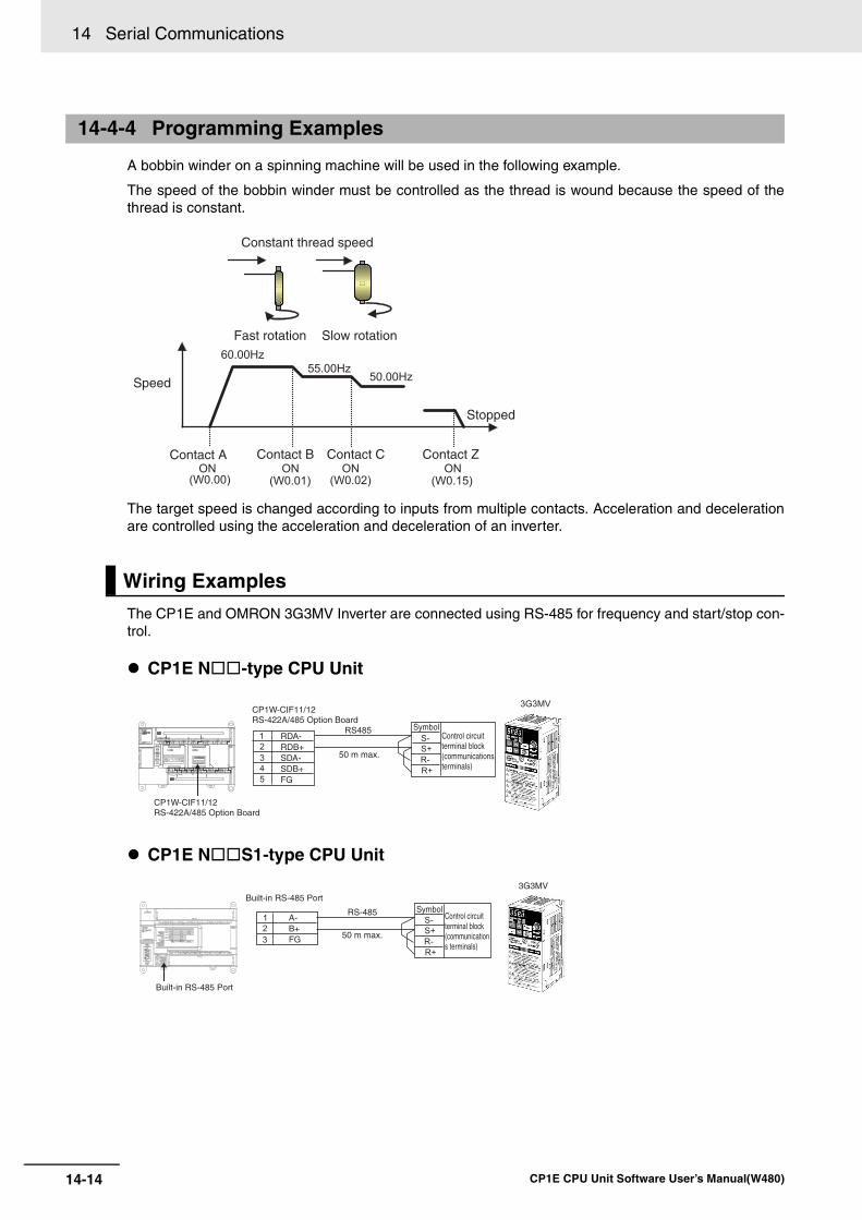
14 Serial Communications
14-14 CP1E CPU Unit Software User’s Manual(W480)
A bobbin winder on a spinning machine will be used in the following example.
The speed of the bobbin winder must be controlled as the thread is wound because the speed of thethread is constant.
The target speed is changed according to inputs from multiple contacts. Acceleration and decelerationare controlled using the acceleration and deceleration of an inverter.
The CP1E and OMRON 3G3MV Inverter are connected using RS-485 for frequency and start/stop con-trol.
CP1E N-type CPU Unit
CP1E NS1-type CPU Unit
14-4-4 Programming Examples
Wiring Examples
Constant thread speed
Fast rotation Slow rotation
Speed
Stopped
Contact A Contact B Contact C Contact Z
CP1W-CIF11/12RS-422A/485 Option Board
CP1W-CIF11/12RS-422A/485 Option Board
50 m max.
SymbolControl circuit terminal block (communications terminals)
RDA-RDB+SDA-SDB+FG
RS-485
3G3MV
Built-in RS-485 Port
Built-in RS-485 PortSymbol
Control circuit terminal block (communications terminals)
50 m max.
A-B+FG
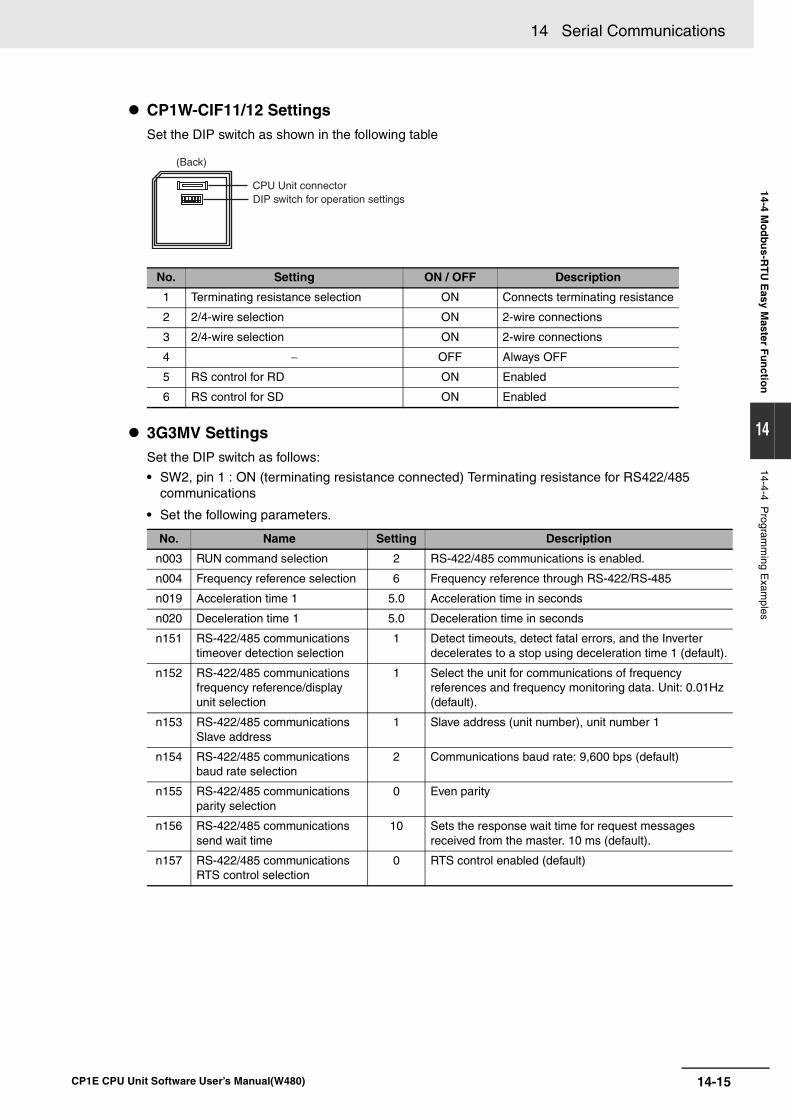
14-15
14 Serial Communications
CP1E CPU Unit Software User’s Manual(W480)
14-4 Mo
dbu
s-RT
U E
asy Master F
un
ction
14
14-4-4 Program
ming E
xamples
CP1W-CIF11/12 SettingsSet the DIP switch as shown in the following table
3G3MV SettingsSet the DIP switch as follows:
• SW2, pin 1 : ON (terminating resistance connected) Terminating resistance for RS422/485 communications
• Set the following parameters.
No. Setting ON / OFF Description
1 Terminating resistance selection ON Connects terminating resistance
2 2/4-wire selection ON 2-wire connections
3 2/4-wire selection ON 2-wire connections
4 − OFF Always OFF
5 RS control for RD ON Enabled
6 RS control for SD ON Enabled
No. Name Setting Description
n003 RUN command selection 2 RS-422/485 communications is enabled.
n004 Frequency reference selection 6 Frequency reference through RS-422/RS-485
n019 Acceleration time 1 5.0 Acceleration time in seconds
n020 Deceleration time 1 5.0 Deceleration time in seconds
n151 RS-422/485 communications timeover detection selection
1 Detect timeouts, detect fatal errors, and the Inverter decelerates to a stop using deceleration time 1 (default).
n152 RS-422/485 communications frequency reference/display unit selection
1 Select the unit for communications of frequency references and frequency monitoring data. Unit: 0.01Hz (default).
n153 RS-422/485 communications Slave address
1 Slave address (unit number), unit number 1
n154 RS-422/485 communications baud rate selection
2 Communications baud rate: 9,600 bps (default)
n155 RS-422/485 communications parity selection
0 Even parity
n156 RS-422/485 communications send wait time
10 Sets the response wait time for request messages received from the master. 10 ms (default).
n157 RS-422/485 communications RTS control selection
0 RTS control enabled (default)
(Back)
CPU Unit connectorDIP switch for operation settings
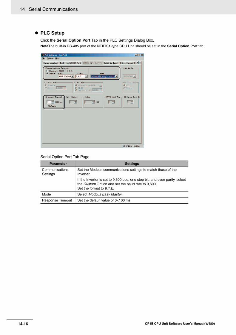
14 Serial Communications
14-16 CP1E CPU Unit Software User’s Manual(W480)
PLC SetupClick the Serial Option Port Tab in the PLC Settings Dialog Box.NoteThe built-in RS-485 port of the NS1-type CPU Unit should be set in the Serial Option Port tab.
Serial Option Port Tab Page
Parameter Settings
Communications Settings
Set the Modbus communications settings to match those of the Inverter.
If the Inverter is set to 9,600 bps, one stop bit, and even parity, select the Custom Option and set the baud rate to 9,600. Set the format to 8,1,E.
Mode Select Modbus Easy Master.
Response Timeout Set the default value of 0×100 ms.
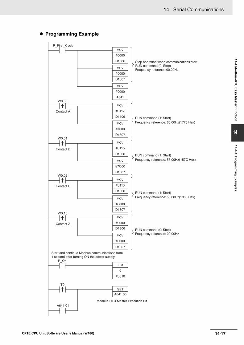
14-17
14 Serial Communications
CP1E CPU Unit Software User’s Manual(W480)
14-4 Mo
dbu
s-RT
U E
asy Master F
un
ction
14
14-4-4 Program
ming E
xamples
Programming Example
Contact A
Contact B
Contact C
Contact Z
Stop operation when communications start.RUN command (0: Stop)Frequency reference:00.00Hz
RUN command (1: Start)Frequency reference: 60.00Hz(1770 Hex)
RUN command (1: Start)Frequency reference: 55.00Hz(157C Hex)
RUN command (1: Start)Frequency reference: 50.00Hz(1388 Hex)
Frequency reference: 00.00HzRUN command (0: Stop)
Start and continue Modbus communications from1 second after turning ON the power supply.
Modbus-RTU Master Execution Bit
D1306
D1307
D1306
A641
D1307
D1306
D1307
D1306
D1307
D1306
D1307
SET
A641.00
A641.01
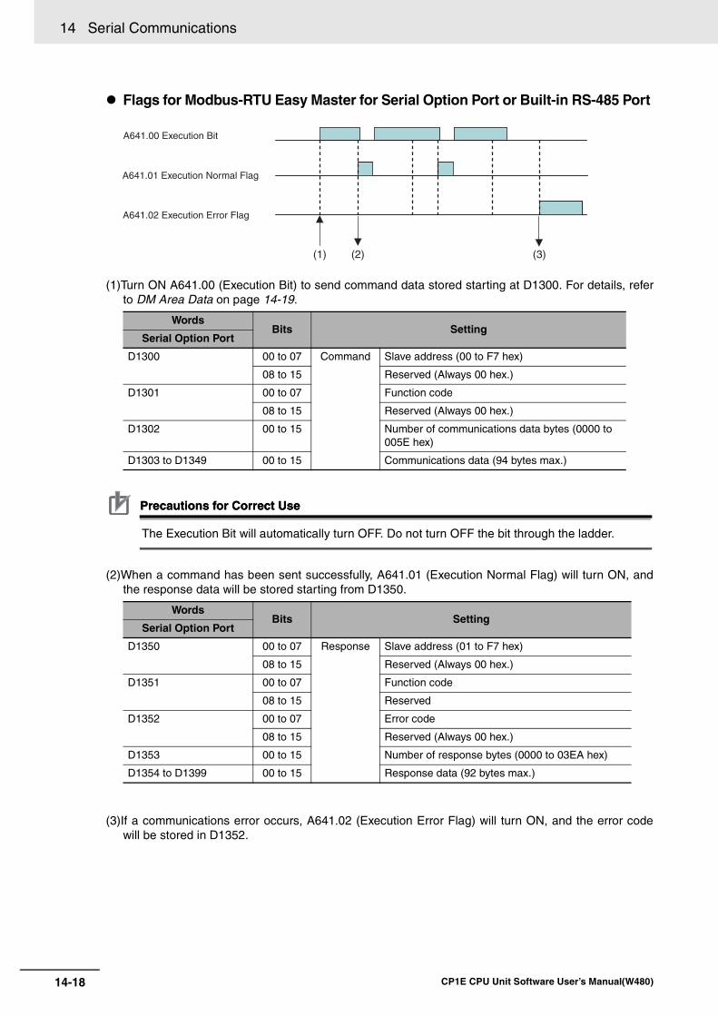
14 Serial Communications
14-18 CP1E CPU Unit Software User’s Manual(W480)
Flags for Modbus-RTU Easy Master for Serial Option Port or Built-in RS-485 Port
(1)Turn ON A641.00 (Execution Bit) to send command data stored starting at D1300. For details, referto DM Area Data on page 14-19.
Precautions for Correct UsePrecautions for Correct Use
The Execution Bit will automatically turn OFF. Do not turn OFF the bit through the ladder.
(2)When a command has been sent successfully, A641.01 (Execution Normal Flag) will turn ON, andthe response data will be stored starting from D1350.
(3)If a communications error occurs, A641.02 (Execution Error Flag) will turn ON, and the error codewill be stored in D1352.
WordsBits Setting
Serial Option Port
D1300 00 to 07 Command Slave address (00 to F7 hex)
08 to 15 Reserved (Always 00 hex.)
D1301 00 to 07 Function code
08 to 15 Reserved (Always 00 hex.)
D1302 00 to 15 Number of communications data bytes (0000 to 005E hex)
D1303 to D1349 00 to 15 Communications data (94 bytes max.)
WordsBits Setting
Serial Option Port
D1350 00 to 07 Response Slave address (01 to F7 hex)
08 to 15 Reserved (Always 00 hex.)
D1351 00 to 07 Function code
08 to 15 Reserved
D1352 00 to 07 Error code
08 to 15 Reserved (Always 00 hex.)
D1353 00 to 15 Number of response bytes (0000 to 03EA hex)
D1354 to D1399 00 to 15 Response data (92 bytes max.)
A641.00 Execution Bit
A641.01 Execution Normal Flag
A641.02 Execution Error Flag
(1) (2) (3)
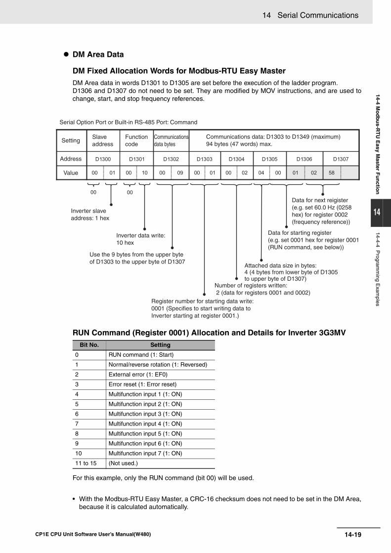
14-19
14 Serial Communications
CP1E CPU Unit Software User’s Manual(W480)
14-4 Mo
dbu
s-RT
U E
asy Master F
un
ction
14
14-4-4 Program
ming E
xamples
DM Area Data
DM Fixed Allocation Words for Modbus-RTU Easy MasterDM Area data in words D1301 to D1305 are set before the execution of the ladder program.D1306 and D1307 do not need to be set. They are modified by MOV instructions, and are used tochange, start, and stop frequency references.
RUN Command (Register 0001) Allocation and Details for Inverter 3G3MV
For this example, only the RUN command (bit 00) will be used.
• With the Modbus-RTU Easy Master, a CRC-16 checksum does not need to be set in the DM Area,because it is calculated automatically.
Bit No. Setting
0 RUN command (1: Start)
1 Normal/reverse rotation (1: Reversed)
2 External error (1: EF0)
3 Error reset (1: Error reset)
4 Multifunction input 1 (1: ON)
5 Multifunction input 2 (1: ON)
6 Multifunction input 3 (1: ON)
7 Multifunction input 4 (1: ON)
8 Multifunction input 5 (1: ON)
9 Multifunction input 6 (1: ON)
10 Multifunction input 7 (1: ON)
11 to 15 (Not used.)
Serial Option Port or Built-in RS-485 Port: Command
Setting
Address
Value
Slave address
Functioncode
Communicationsdata bytes
Communications data: D1303 to D1349 (maximum)94 bytes (47 words) max.
Inverter slave address: 1 hex
Inverter data write: 10 hex
Use the 9 bytes from the upper byte of D1303 to the upper byte of D1307
Register number for starting data write: 0001 (Specifies to start writing data to Inverter starting at register 0001.)
Number of registers written: 2 (data for registers 0001 and 0002)
Attached data size in bytes: 4 (4 bytes from lower byte of D1305 to upper byte of D1307)
Data for starting register (e.g. set 0001 hex for register 0001 (RUN command, see below))
Data for next reigister (e.g. set 60.0 Hz (0258 hex) for register 0002 (frequency reference))
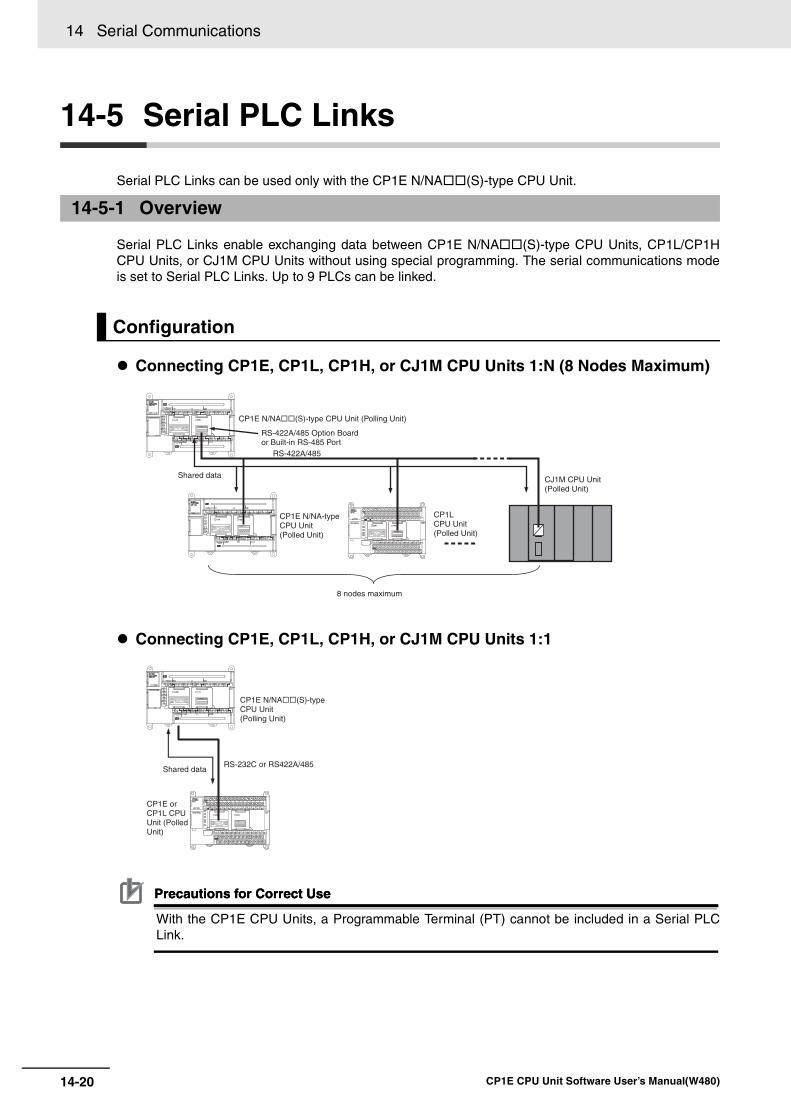
14 Serial Communications
14-20 CP1E CPU Unit Software User’s Manual(W480)
14-5 Serial PLC Links
Serial PLC Links can be used only with the CP1E N/NA(S)-type CPU Unit.
Serial PLC Links enable exchanging data between CP1E N/NA(S)-type CPU Units, CP1L/CP1HCPU Units, or CJ1M CPU Units without using special programming. The serial communications modeis set to Serial PLC Links. Up to 9 PLCs can be linked.
Connecting CP1E, CP1L, CP1H, or CJ1M CPU Units 1:N (8 Nodes Maximum)
Connecting CP1E, CP1L, CP1H, or CJ1M CPU Units 1:1
Precautions for Correct UsePrecautions for Correct Use
With the CP1E CPU Units, a Programmable Terminal (PT) cannot be included in a Serial PLCLink.
14-5-1 Overview
Configuration
RS-422A/485
CP1E N/NA(S)-type CPU Unit (Polling Unit)
RS-422A/485 Option Board or Built-in RS-485 Port
Shared data
CP1E N/NA-typeCPU Unit(Polled Unit)
CJ1M CPU Unit (Polled Unit)
CP1LCPU Unit(Polled Unit)
8 nodes maximum
CP1E N/NA(S)-typeCPU Unit(Polling Unit)
RS-232C or RS422A/485Shared data
CP1E or CP1L CPU Unit (Polled Unit)
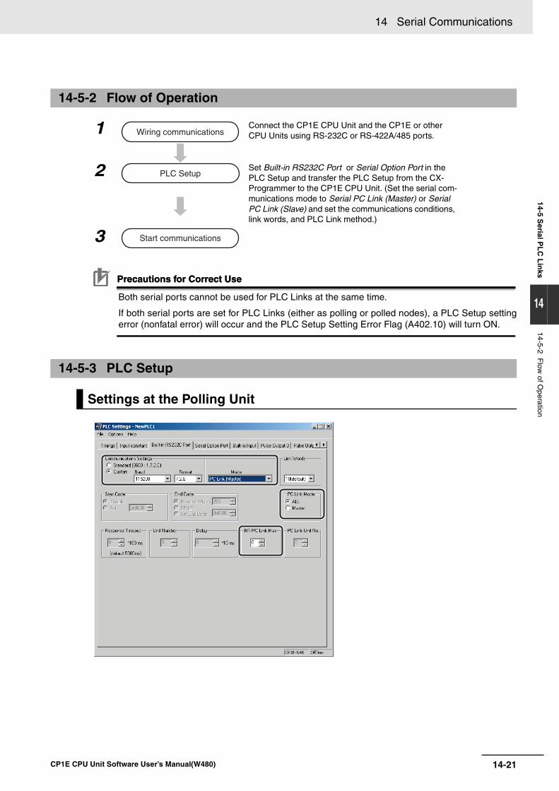
14-21
14 Serial Communications
CP1E CPU Unit Software User’s Manual(W480)
14-5 Serial P
LC
Lin
ks
14
14-5-2 Flow
of Operation
Precautions for Correct UsePrecautions for Correct Use
Both serial ports cannot be used for PLC Links at the same time.
If both serial ports are set for PLC Links (either as polling or polled nodes), a PLC Setup settingerror (nonfatal error) will occur and the PLC Setup Setting Error Flag (A402.10) will turn ON.
14-5-2 Flow of Operation
1 Connect the CP1E CPU Unit and the CP1E or other CPU Units using RS-232C or RS-422A/485 ports.
2 Set Built-in RS232C Port or Serial Option Port in the PLC Setup and transfer the PLC Setup from the CX-Programmer to the CP1E CPU Unit. (Set the serial com-munications mode to Serial PC Link (Master) or Serial PC Link (Slave) and set the communications conditions, link words, and PLC Link method.)
3
14-5-3 PLC Setup
Settings at the Polling Unit
Wiring communications
PLC Setup
Start communications
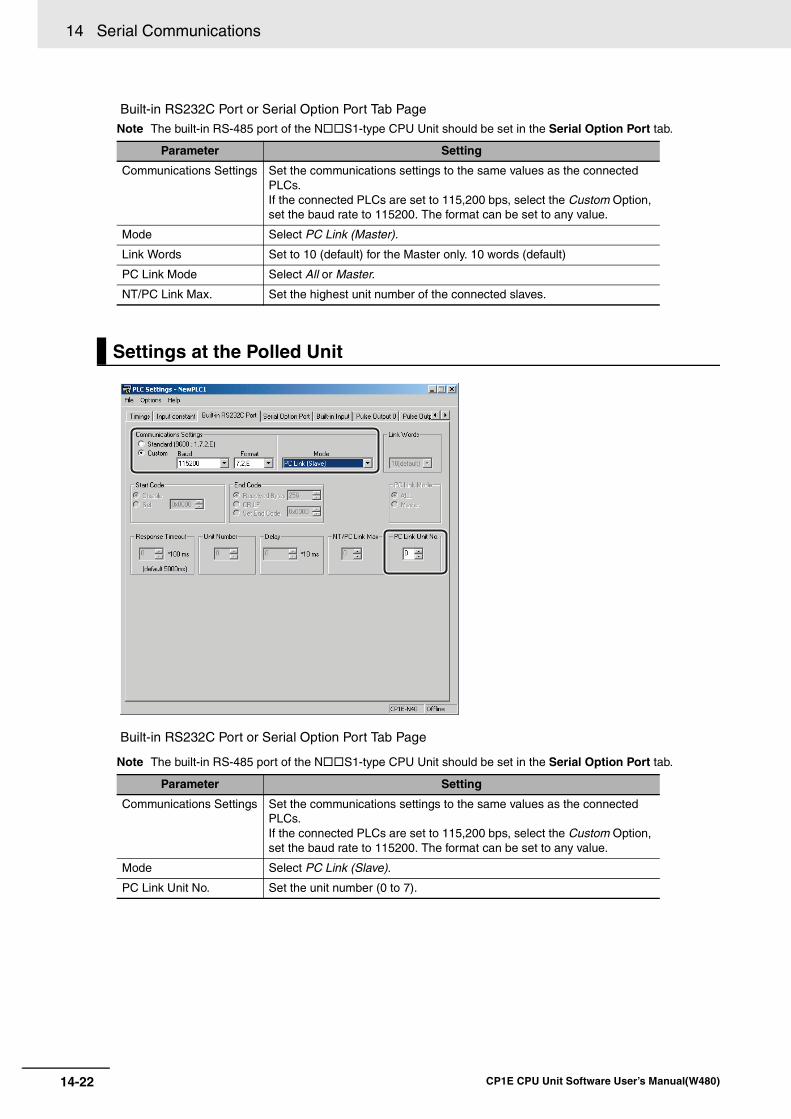
14 Serial Communications
14-22 CP1E CPU Unit Software User’s Manual(W480)
Built-in RS232C Port or Serial Option Port Tab Page
Note The built-in RS-485 port of the NS1-type CPU Unit should be set in the Serial Option Port tab.
Built-in RS232C Port or Serial Option Port Tab Page
Note The built-in RS-485 port of the NS1-type CPU Unit should be set in the Serial Option Port tab.
Parameter Setting
Communications Settings Set the communications settings to the same values as the connected PLCs. If the connected PLCs are set to 115,200 bps, select the Custom Option, set the baud rate to 115200. The format can be set to any value.
Mode Select PC Link (Master).
Link Words Set to 10 (default) for the Master only. 10 words (default)
PC Link Mode Select All or Master.
NT/PC Link Max. Set the highest unit number of the connected slaves.
Settings at the Polled Unit
Parameter Setting
Communications Settings Set the communications settings to the same values as the connected PLCs. If the connected PLCs are set to 115,200 bps, select the Custom Option, set the baud rate to 115200. The format can be set to any value.
Mode Select PC Link (Slave).
PC Link Unit No. Set the unit number (0 to 7).
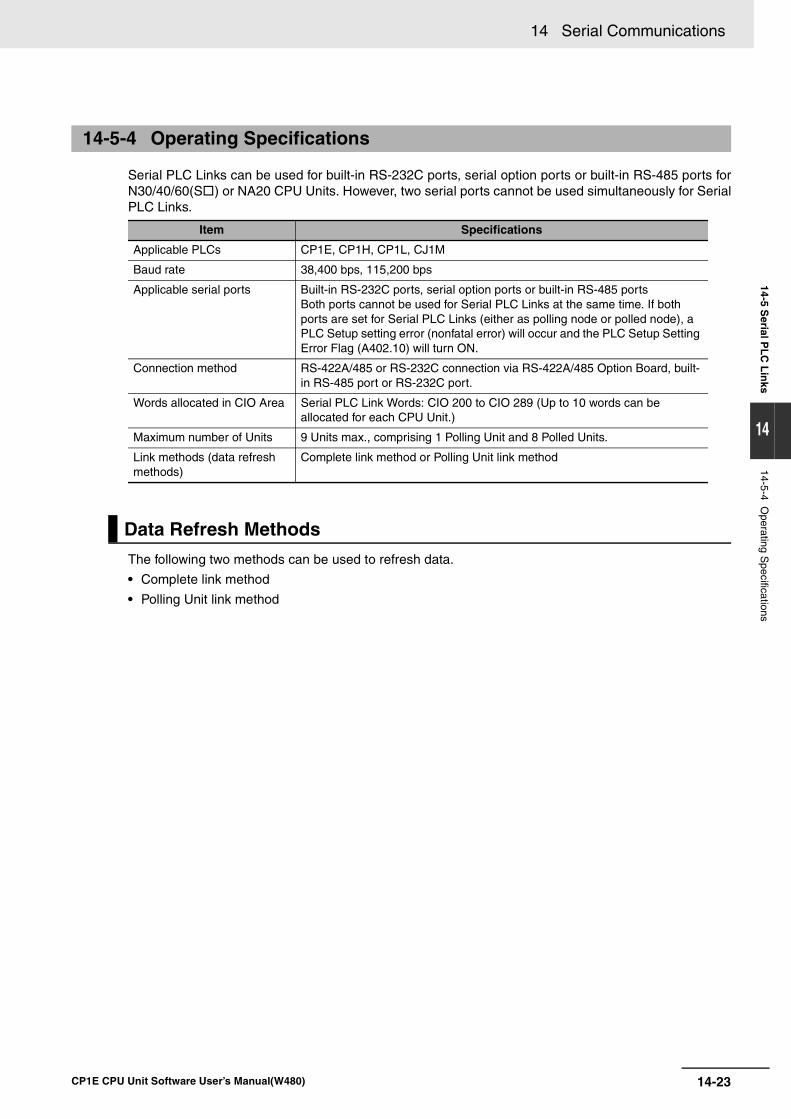
14-23
14 Serial Communications
CP1E CPU Unit Software User’s Manual(W480)
14-5 Serial P
LC
Lin
ks
14
14-5-4 Operating S
pecifications
Serial PLC Links can be used for built-in RS-232C ports, serial option ports or built-in RS-485 ports forN30/40/60(S) or NA20 CPU Units. However, two serial ports cannot be used simultaneously for SerialPLC Links.
The following two methods can be used to refresh data.
• Complete link method
• Polling Unit link method
14-5-4 Operating Specifications
Item Specifications
Applicable PLCs CP1E, CP1H, CP1L, CJ1M
Baud rate 38,400 bps, 115,200 bps
Applicable serial ports Built-in RS-232C ports, serial option ports or built-in RS-485 portsBoth ports cannot be used for Serial PLC Links at the same time. If both ports are set for Serial PLC Links (either as polling node or polled node), a PLC Setup setting error (nonfatal error) will occur and the PLC Setup Setting Error Flag (A402.10) will turn ON.
Connection method RS-422A/485 or RS-232C connection via RS-422A/485 Option Board, built-in RS-485 port or RS-232C port.
Words allocated in CIO Area Serial PLC Link Words: CIO 200 to CIO 289 (Up to 10 words can be allocated for each CPU Unit.)
Maximum number of Units 9 Units max., comprising 1 Polling Unit and 8 Polled Units.
Link methods (data refresh methods)
Complete link method or Polling Unit link method
Data Refresh Methods
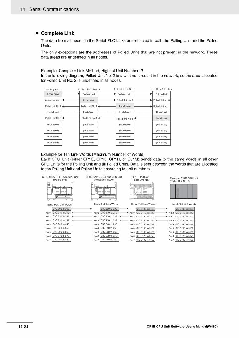
14 Serial Communications
14-24 CP1E CPU Unit Software User’s Manual(W480)
Complete LinkThe data from all nodes in the Serial PLC Links are reflected in both the Polling Unit and the PolledUnits.
The only exceptions are the addresses of Polled Units that are not present in the network. Thesedata areas are undefined in all nodes.
Example: Complete Link Method, Highest Unit Number: 3In the following diagram, Polled Unit No. 2 is a Unit not present in the network, so the area allocatedfor Polled Unit No. 2 is undefined in all nodes.
Example for Ten Link Words (Maximum Number of Words) Each CPU Unit (either CP1E, CP1L, CP1H, or CJ1M) sends data to the same words in all otherCPU Units for the Polling Unit and all Polled Units. Data is sent between the words that are allocatedto the Polling Unit and Polled Units according to unit numbers.
Pol l ing Uni t
Local area
Polled Unit No. 0
Polled Unit No. 1
Polled Unit No. 3
Undefined
(Not used)
(Not used)
(Not used)
(Not used)
Polling Unit
Local area
Pol led Uni t No. 0
Polled Unit No. 1
Polled Unit No. 3
Undefined
(Not used)
(Not used)
(Not used)
(Not used)
Polling Unit
Local area
Polled Unit No. 0
Pol led Uni t No. 1
Polled Unit No. 3
Undefined
(Not used)
(Not used)
(Not used)
(Not used)
Polling Unit
Local area
Polled Unit No. 0
Polled Unit No. 1
Pol led Uni t No. 3
Undefined
(Not used)
(Not used)
(Not used)
(Not used)
CP1E N/NA(S)-type CPU Unit(Polling Unit)
CP1E N/NA(S)-type CPU Unit(Polled Unit No. 0)
Serial PLC Link Words Serial PLC Link Words Serial PLC Link WordsSerial PLC Link Words
No.0
No.1
No.2
No.3
No.4
No.5
No.6
No.7
No.0
No.1
No.2
No.3
No.4
No.5
No.6
No.7
No.0
No.1
No.2
No.3
No.4
No.5
No.6
No.7
No.0
No.1
No.2
No.3
No.4
No.5
No.6
No.7
CP1L CPU Unit (Polled Unit No. 1)
Example: CJ1M CPU Unit (Polled Unit No. 2)
CIO 200 to 209
CIO 210 to 219
CIO 220 to 229
CIO 230 to 239
CIO 240 to 249
CIO 250 to 259
CIO 260 to 269
CIO 270 to 279
CIO 280 to 289
CIO 200 to 209
CIO 210 to 219
CIO 220 to 229
CIO 230 to 239
CIO 240 to 249
CIO 250 to 259
CIO 260 to 269
CIO 270 to 279
CIO 280 to 289
CIO 3100 to 3109
CIO 3110 to 3119
CIO 3120 to 3129
CIO 3130 to 3139
CIO 3140 to 3149
CIO 3150 to 3159
CIO 3160 to 3169
CIO 3170 to 3179
CIO 3180 to 3189
CIO 3100 to 3109
CIO 3110 to 3119
CIO 3120 to 3129
CIO 3130 to 3139
CIO 3140 to 3149
CIO 3150 to 3159
CIO 3160 to 3169
CIO 3170 to 3179
CIO 3180 to 3189
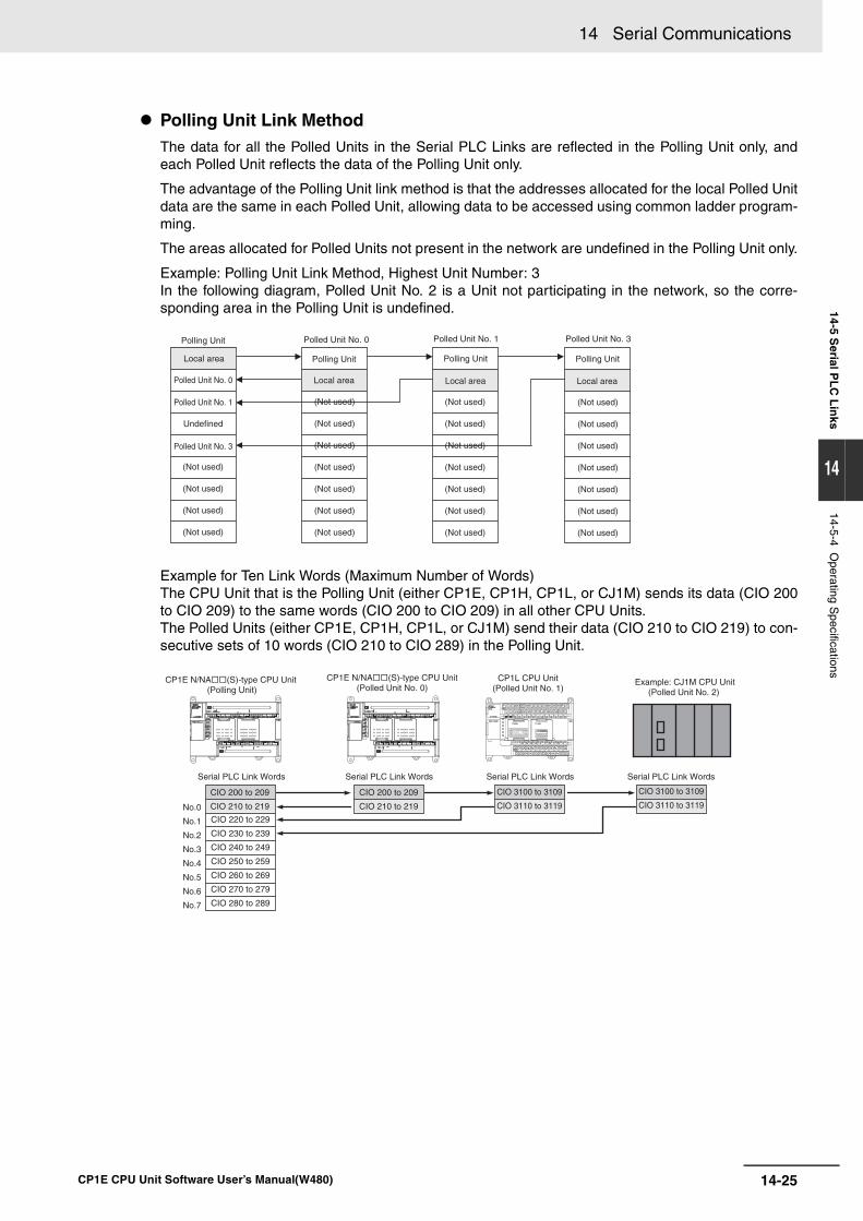
14-25
14 Serial Communications
CP1E CPU Unit Software User’s Manual(W480)
14-5 Serial P
LC
Lin
ks
14
14-5-4 Operating S
pecifications
Polling Unit Link MethodThe data for all the Polled Units in the Serial PLC Links are reflected in the Polling Unit only, andeach Polled Unit reflects the data of the Polling Unit only.
The advantage of the Polling Unit link method is that the addresses allocated for the local Polled Unitdata are the same in each Polled Unit, allowing data to be accessed using common ladder program-ming.
The areas allocated for Polled Units not present in the network are undefined in the Polling Unit only.
Example: Polling Unit Link Method, Highest Unit Number: 3 In the following diagram, Polled Unit No. 2 is a Unit not participating in the network, so the corre-sponding area in the Polling Unit is undefined.
Example for Ten Link Words (Maximum Number of Words) The CPU Unit that is the Polling Unit (either CP1E, CP1H, CP1L, or CJ1M) sends its data (CIO 200to CIO 209) to the same words (CIO 200 to CIO 209) in all other CPU Units. The Polled Units (either CP1E, CP1H, CP1L, or CJ1M) send their data (CIO 210 to CIO 219) to con-secutive sets of 10 words (CIO 210 to CIO 289) in the Polling Unit.
Polling Unit
Local area
Polled Unit No. 0
(Not used)
(Not used)
(Not used)
(Not used)
(Not used)
(Not used)
(Not used)
Polling Unit
Local area
Polled Unit No. 0
Polled Unit No. 1
Polled Unit No. 3
Undefined
(Not used)
(Not used)
(Not used)
(Not used)
Polling Unit
Local area
Polled Unit No. 1
(Not used)
(Not used)
(Not used)
(Not used)
(Not used)
(Not used)
(Not used)
Polling Unit
Local area
Polled Unit No. 3
(Not used)
(Not used)
(Not used)
(Not used)
(Not used)
(Not used)
(Not used)
No.0
No.1
No.2
No.3
No.4
No.5
No.6
No.7
CP1E N/NA(S)-type CPU Unit (Polling Unit)
Serial PLC Link Words Serial PLC Link WordsSerial PLC Link Words Serial PLC Link Words
CP1E N/NA(S)-type CPU Unit (Polled Unit No. 0)
CP1L CPU Unit (Polled Unit No. 1)
Example: CJ1M CPU Unit (Polled Unit No. 2)
CIO 200 to 209
CIO 210 to 219
CIO 200 to 209
CIO 210 to 219
CIO 3100 to 3109
CIO 3110 to 3119
CIO 3100 to 3109
CIO 3110 to 3119
CIO 220 to 229
CIO 230 to 239
CIO 240 to 249
CIO 250 to 259
CIO 260 to 269
CIO 270 to 279
CIO 280 to 289
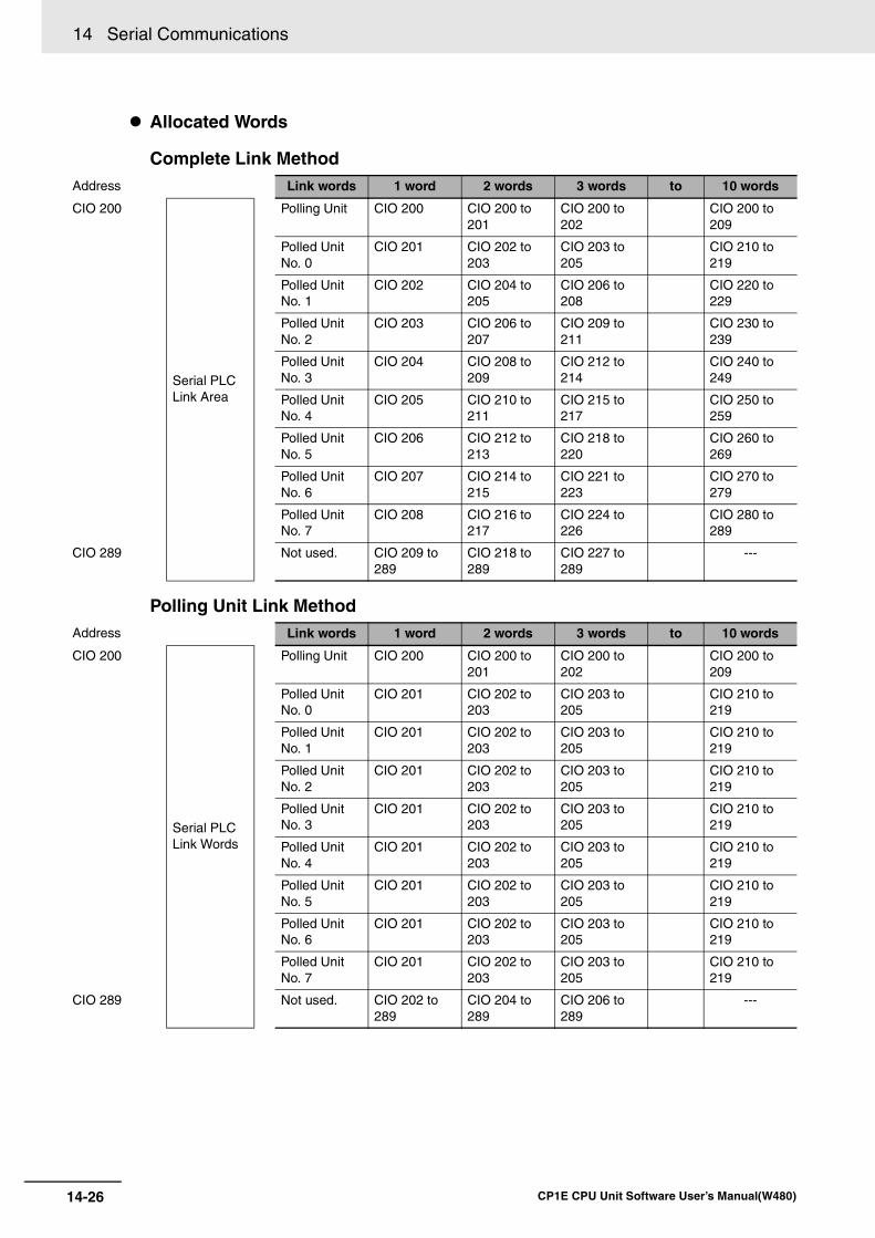
14 Serial Communications
14-26 CP1E CPU Unit Software User’s Manual(W480)
Allocated Words
Complete Link Method
Polling Unit Link Method
Address Link words 1 word 2 words 3 words to 10 words
CIO 200
Serial PLC Link Area
Polling Unit CIO 200 CIO 200 to 201
CIO 200 to 202
CIO 200 to 209
Polled Unit No. 0
CIO 201 CIO 202 to 203
CIO 203 to 205
CIO 210 to 219
Polled Unit No. 1
CIO 202 CIO 204 to 205
CIO 206 to 208
CIO 220 to 229
Polled Unit No. 2
CIO 203 CIO 206 to 207
CIO 209 to 211
CIO 230 to 239
Polled Unit No. 3
CIO 204 CIO 208 to 209
CIO 212 to 214
CIO 240 to 249
Polled Unit No. 4
CIO 205 CIO 210 to 211
CIO 215 to 217
CIO 250 to 259
Polled Unit No. 5
CIO 206 CIO 212 to 213
CIO 218 to 220
CIO 260 to 269
Polled Unit No. 6
CIO 207 CIO 214 to 215
CIO 221 to 223
CIO 270 to 279
Polled Unit No. 7
CIO 208 CIO 216 to 217
CIO 224 to 226
CIO 280 to 289
CIO 289 Not used. CIO 209 to 289
CIO 218 to 289
CIO 227 to 289
---
Address Link words 1 word 2 words 3 words to 10 words
CIO 200
Serial PLCLink Words
Polling Unit CIO 200 CIO 200 to 201
CIO 200 to 202
CIO 200 to 209
Polled Unit No. 0
CIO 201 CIO 202 to 203
CIO 203 to 205
CIO 210 to 219
Polled Unit No. 1
CIO 201 CIO 202 to 203
CIO 203 to 205
CIO 210 to 219
Polled Unit No. 2
CIO 201 CIO 202 to 203
CIO 203 to 205
CIO 210 to 219
Polled Unit No. 3
CIO 201 CIO 202 to 203
CIO 203 to 205
CIO 210 to 219
Polled Unit No. 4
CIO 201 CIO 202 to 203
CIO 203 to 205
CIO 210 to 219
Polled Unit No. 5
CIO 201 CIO 202 to 203
CIO 203 to 205
CIO 210 to 219
Polled Unit No. 6
CIO 201 CIO 202 to 203
CIO 203 to 205
CIO 210 to 219
Polled Unit No. 7
CIO 201 CIO 202 to 203
CIO 203 to 205
CIO 210 to 219
CIO 289 Not used. CIO 202 to 289
CIO 204 to 289
CIO 206 to 289
---
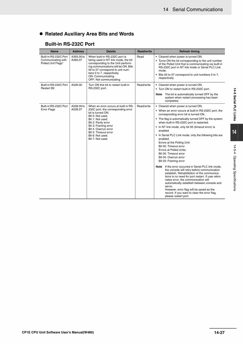
14-27
14 Serial Communications
CP1E CPU Unit Software User’s Manual(W480)
14-5 Serial P
LC
Lin
ks
14
14-5-4 Operating S
pecifications
Related Auxiliary Area Bits and Words
Built-in RS-232C Port Name Address Details Read/write Refresh timing
Built-in RS-232C Port Communicating with Polled Unit Flags*
A393.00 to A393.07
When built-in RS-232C port is being used in NT link mode, the bit corresponding to the Unit perform-ing communications will be ON. Bits 00 to 07 correspond to unit num-bers 0 to 7, respectively.ON: CommunicatingOFF: Not communicating
Read • Cleared when power is turned ON.• Turns ON the bit corresponding to the unit number
of the Polled Unit that is communicating via built-in RS-232C port in NT link mode or Serial PLC Link mode.
• Bits 00 to 07 correspond to unit numbers 0 to 7, respectively.
Built-in RS-232C Port Restart Bit
A526.00 Turn ON this bit to restart built-in RS-232C port.
Read/write • Cleared when power is turned ON.• Turn ON to restart built-in RS-232C port.
Note The bit is automatically turned OFF by the system when restart processing has been completed.
Built-in RS-232C Port Error Flags
A528.00 to A528.07
When an error occurs at built-in RS-232C port, the corresponding error bit is turned ON. Bit 0: Not used. Bit 1: Not used. Bit 2: Parity error Bit 3: Framing error Bit 4: Overrun errorBit 5: Timeout error Bit 6: Not used.Bit 7: Not used.
Read/write • Cleared when power is turned ON.
• When an error occurs at built-in RS-232C port, the corresponding error bit is turned ON.
• The flag is automatically turned OFF by the system when built-in RS-232C port is restarted.
• In NT link mode, only bit 05 (timeout error) is enabled.
• In Serial PLC Link mode, only the following bits are enabled.Errors at the Polling Unit:Bit 05: Timeout errorErrors at Polled Units:Bit 05: Timeout errorBit 04: Overrun errorBit 03: Framing error
Note If the error occurred in Serial PLC link mode, the console will retry before communication establish. Rehabilitation of the communica-tions is no need for port restart. If user elimi-nates error, the communication will automatically establish between console and servo.However, error flag will be saved as the record. If you want to clear the error flag, please restart port.
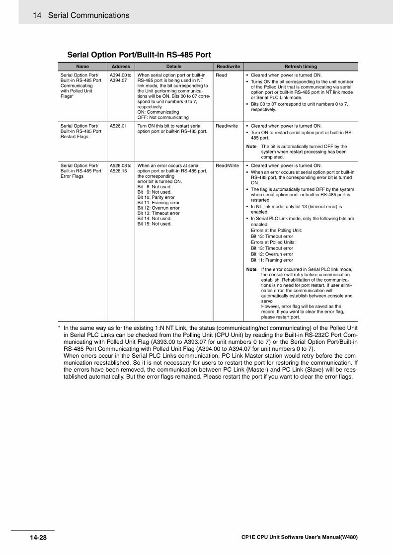
14 Serial Communications
14-28 CP1E CPU Unit Software User’s Manual(W480)
Serial Option Port/Built-in RS-485 Port
* In the same way as for the existing 1:N NT Link, the status (communicating/not communicating) of the Polled Unitin Serial PLC Links can be checked from the Polling Unit (CPU Unit) by reading the Built-in RS-232C Port Com-municating with Polled Unit Flag (A393.00 to A393.07 for unit numbers 0 to 7) or the Serial Option Port/Built-inRS-485 Port Communicating with Polled Unit Flag (A394.00 to A394.07 for unit numbers 0 to 7).When errors occur in the Serial PLC Links communication, PC Link Master station would retry before the com-munication reestablished. So it is not necessary for users to restart the port for restoring the communication. Ifthe errors have been removed, the communication between PC Link (Master) and PC Link (Slave) will be rees-tablished automatically. But the error flags remained. Please restart the port if you want to clear the error flags.
Name Address Details Read/write Refresh timing
Serial Option Port/Built-in RS-485 PortCommunicatingwith Polled Unit Flags*
A394.00 to A394.07
When serial option port or built-in RS-485 port is being used in NT link mode, the bit corresponding to the Unit performing communica-tions will be ON. Bits 00 to 07 corre-spond to unit numbers 0 to 7, respectively.ON: CommunicatingOFF: Not communicating
Read • Cleared when power is turned ON.• Turns ON the bit corresponding to the unit number
of the Polled Unit that is communicating via serial option port or built-in RS-485 port in NT link mode or Serial PLC Link mode.
• Bits 00 to 07 correspond to unit numbers 0 to 7, respectively.
Serial Option Port/Built-in RS-485 Port Restart Flags
A526.01 Turn ON this bit to restart serial option port or built-in RS-485 port.
Read/write • Cleared when power is turned ON.
• Turn ON to restart serial option port or built-in RS-485 port.
Note The bit is automatically turned OFF by the system when restart processing has been completed.
Serial Option Port/Built-in RS-485 Port Error Flags
A528.08 to A528.15
When an error occurs at serial option port or built-in RS-485 port, the correspondingerror bit is turned ON. Bit 8: Not used.Bit 9: Not used.Bit 10: Parity errorBit 11: Framing errorBit 12: Overrun errorBit 13: Timeout errorBit 14: Not used.Bit 15: Not used.
Read/Write • Cleared when power is turned ON.
• When an error occurs at serial option port or built-in RS-485 port, the corresponding error bit is turned ON.
• The flag is automatically turned OFF by the system when serial option port or built-in RS-485 port is restarted.
• In NT link mode, only bit 13 (timeout error) is enabled.
• In Serial PLC Link mode, only the following bits are enabled.Errors at the Polling Unit:Bit 13: Timeout errorErrors at Polled Units:Bit 13: Timeout errorBit 12: Overrun errorBit 11: Framing error
Note If the error occurred in Serial PLC link mode, the console will retry before communication establish. Rehabilitation of the communica-tions is no need for port restart. If user elimi-nates error, the communication will automatically establish between console and servo.However, error flag will be saved as the record. If you want to clear the error flag, please restart port.
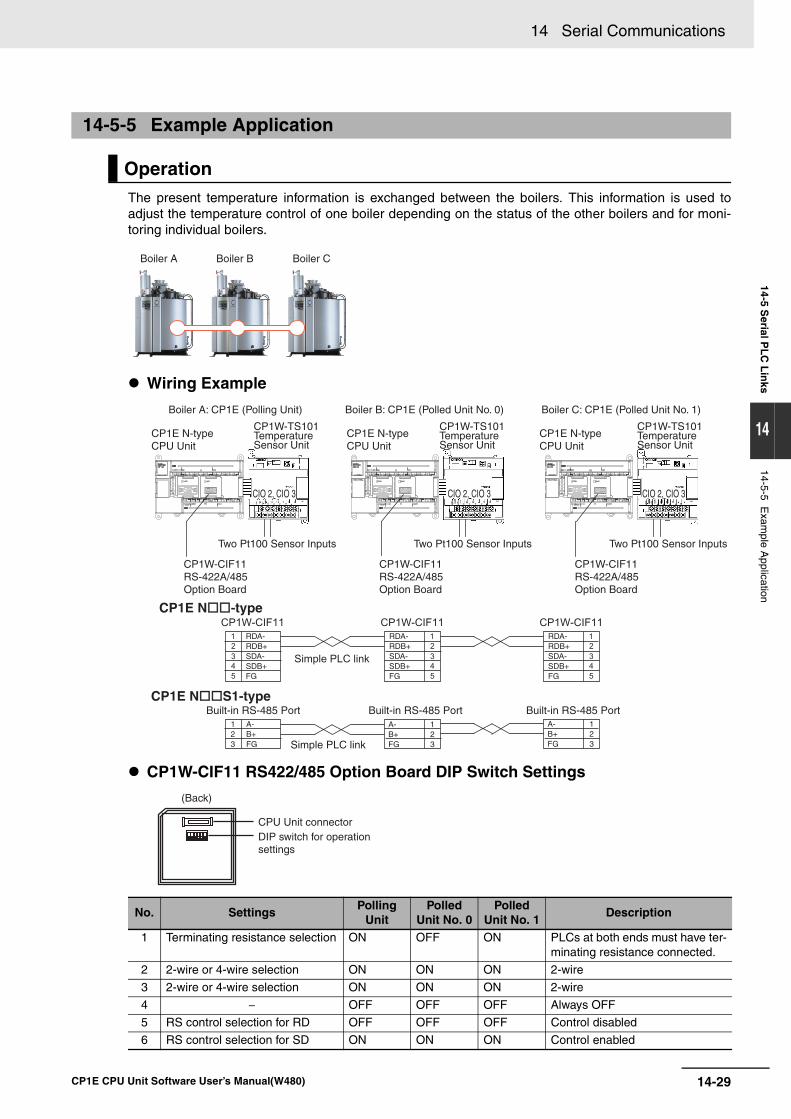
14-29
14 Serial Communications
CP1E CPU Unit Software User’s Manual(W480)
14-5 Serial P
LC
Lin
ks
14
14-5-5 Exam
ple Application
The present temperature information is exchanged between the boilers. This information is used toadjust the temperature control of one boiler depending on the status of the other boilers and for moni-toring individual boilers.
Wiring Example
CP1W-CIF11 RS422/485 Option Board DIP Switch Settings
14-5-5 Example Application
Operation
No. SettingsPolling
UnitPolled
Unit No. 0Polled
Unit No. 1Description
1 Terminating resistance selection ON OFF ON PLCs at both ends must have ter-minating resistance connected.
2 2-wire or 4-wire selection ON ON ON 2-wire
3 2-wire or 4-wire selection ON ON ON 2-wire
4 − OFF OFF OFF Always OFF
5 RS control selection for RD OFF OFF OFF Control disabled
6 RS control selection for SD ON ON ON Control enabled
Boiler A Boiler B Boiler C
Boiler A: CP1E (Polling Unit)
CP1E N-type CPU Unit
CP1E N-type CPU Unit
CP1E N-type CPU Unit
CP1W-CIF11 RS-422A/485 Option Board
CP1W-CIF11 RS-422A/485 Option Board
CP1W-CIF11 RS-422A/485 Option Board
CP1W-TS101 Temperature Sensor Unit
CP1W-TS101 Temperature Sensor Unit
CP1W-TS101 Temperature Sensor Unit
Two Pt100 Sensor Inputs Two Pt100 Sensor Inputs Two Pt100 Sensor Inputs
CIO 2, CIO 3 CIO 2, CIO 3 CIO 2, CIO 3
Boiler B: CP1E (Polled Unit No. 0) Boiler C: CP1E (Polled Unit No. 1)
RDA-RDB+SDA-SDB+FG
RDA-RDB+SDA-SDB+FG
RDA-RDB+SDA-SDB+FG
1 A-2 B+3 FG
A-B+FG
123
A-B+FG
123Simple PLC link
Built-in RS-485 PortBuilt-in RS-485 PortCP1E NS1-type
CP1E N-type
Built-in RS-485 Port
CPU Unit connectorDIP switch for operationsettings
(Back)
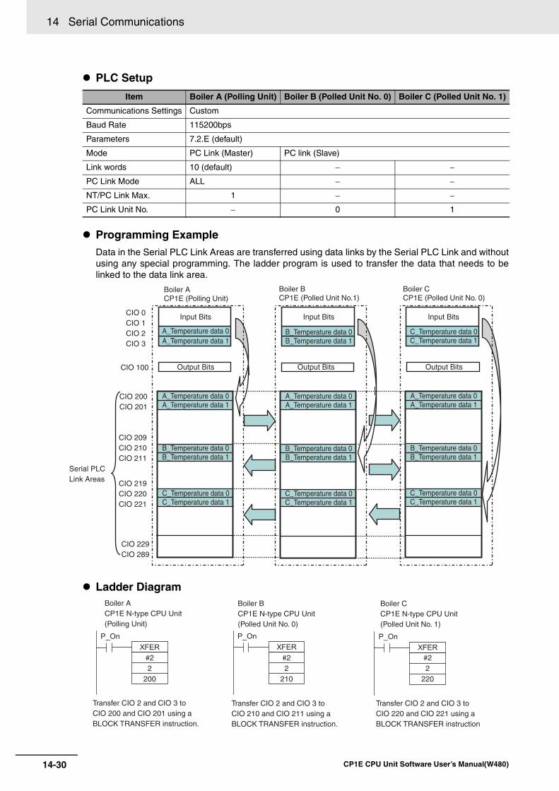
14 Serial Communications
14-30 CP1E CPU Unit Software User’s Manual(W480)
PLC Setup
Programming ExampleData in the Serial PLC Link Areas are transferred using data links by the Serial PLC Link and withoutusing any special programming. The ladder program is used to transfer the data that needs to belinked to the data link area.
Ladder Diagram
Item Boiler A (Polling Unit) Boiler B (Polled Unit No. 0) Boiler C (Polled Unit No. 1)
Communications Settings Custom
Baud Rate 115200bps
Parameters 7.2.E (default)
Mode PC Link (Master) PC link (Slave)
Link words 10 (default) − −
PC Link Mode ALL − −
NT/PC Link Max. 1 − −
PC Link Unit No. − 0 1
Boiler ACP1E (Polling Unit)
Boiler BCP1E (Polled Unit No.1)
Boiler CCP1E (Polled Unit No. 0)
Input Bits Input Bits Input Bits
A_Temperature data 0A_Temperature data 1
A_Temperature data 0A_Temperature data 1
B_Temperature data 0B_Temperature data 1
C_Temperature data 0C_Temperature data 1
A_Temperature data 0A_Temperature data 1
B_Temperature data 0B_Temperature data 1
C_Temperature data 0C_Temperature data 1
A_Temperature data 0A_Temperature data 1
B_Temperature data 0B_Temperature data 1
C_Temperature data 0C_Temperature data 1
B_Temperature data 0B_Temperature data 1
C_Temperature data 0C_Temperature data 1
Output Bits Output Bits Output Bits
CIO 0CIO 1CIO 2CIO 3
CIO 100
CIO 200CIO 201
CIO 209CIO 210CIO 211
CIO 219CIO 220CIO 221
CIO 229CIO 289
Serial PLC Link Areas
#22
200
#22
210
#22
220
Boiler ACP1E N-type CPU Unit (Polling Unit)
Transfer CIO 2 and CIO 3 to CIO 200 and CIO 201 using a BLOCK TRANSFER instruction.
Boiler BCP1E N-type CPU Unit (Polled Unit No. 0)
Transfer CIO 2 and CIO 3 to CIO 210 and CIO 211 using a BLOCK TRANSFER instruction.
Boiler CCP1E N-type CPU Unit (Polled Unit No. 1)
Transfer CIO 2 and CIO 3 to CIO 220 and CIO 221 using a BLOCK TRANSFER instruction
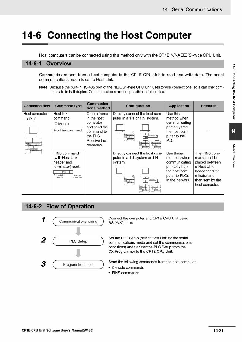
14-31
14 Serial Communications
CP1E CPU Unit Software User’s Manual(W480)
14-6 Co
nn
ecting
the H
ost C
om
pu
ter
14
14-6-1 Overview
14-6 Connecting the Host Computer
Host computers can be connected using this method only with the CP1E N/NA(S)-type CPU Unit.
Commands are sent from a host computer to the CP1E CPU Unit to read and write data. The serialcommunications mode is set to Host Link.
Note Because the built-in RS-485 port of the NS1-type CPU Unit uses 2-wire connections, so it can only com-municate in half duplex. Communications are not possible in full duplex.
14-6-1 Overview
Command flow Command typeCommunica-tions method
Configuration Application Remarks
Host computer → PLC
Host link command
(C Mode)
Create frame in the host computerand send the command to the PLC. Receive the response.
Directly connect the host com-puter in a 1:1 or 1:N system.
Use this method when communicatingprimarily from the host com-puter to the PLC.
−
FINS command (with Host Link header andterminator) sent.
Directly connect the host com-puter in a 1:1 system or 1:N system.
Use these methods when communicatingprimarily from the host com-puter to PLCs in the network.
The FINS com-mand must be placed between a Host Link header and ter-minator and then sent by the host computer.
14-6-2 Flow of Operation
1 Connect the computer and CP1E CPU Unit using RS-232C ports.
Set the PLC Setup (select Host Link for the serial communications mode and set the communications conditions) and transfer the PLC Setup from the CX-Programmer to the CP1E CPU Unit.
2
Send the following commands from the host computer.
• C-mode commands • FINS commands
3
Host link commandOR
Command
FINS
Host Linkheader
Host Link terminator
OR
Command
Communications wiring
PLC Setup
Program from host
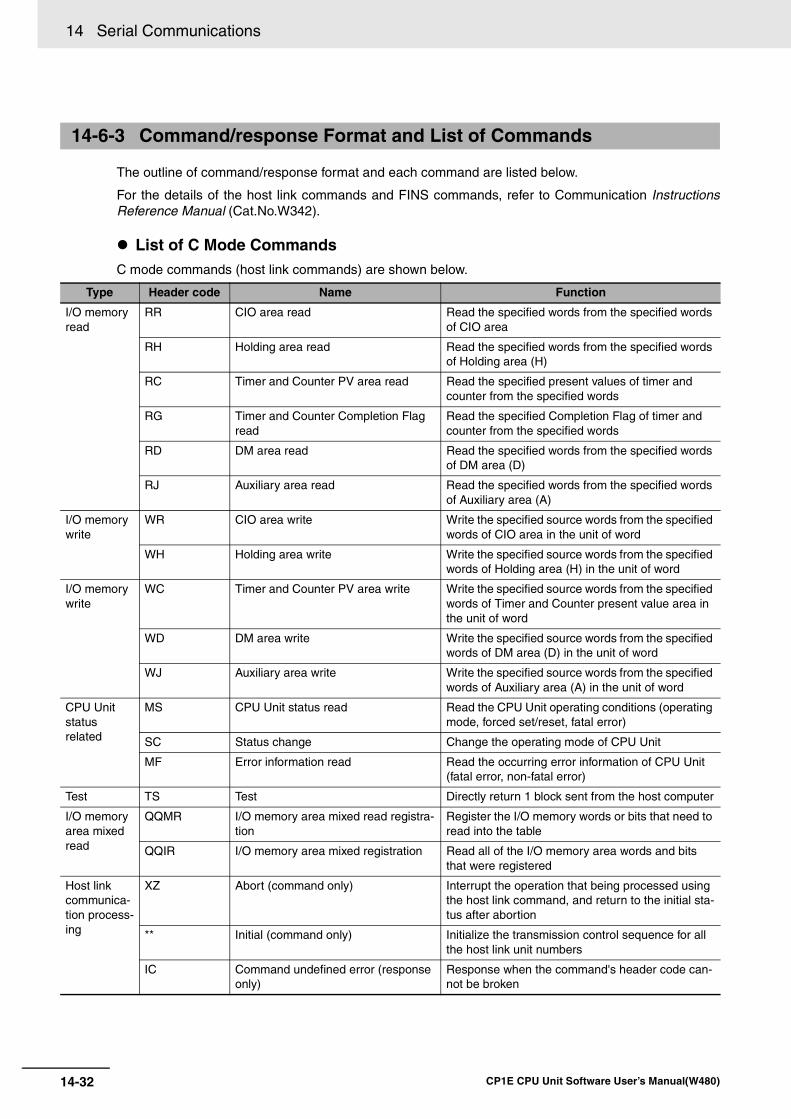
14 Serial Communications
14-32 CP1E CPU Unit Software User’s Manual(W480)
The outline of command/response format and each command are listed below.
For the details of the host link commands and FINS commands, refer to Communication InstructionsReference Manual (Cat.No.W342).
List of C Mode CommandsC mode commands (host link commands) are shown below.
14-6-3 Command/response Format and List of Commands
Type Header code Name Function
I/O memory read
RR CIO area read Read the specified words from the specified words of CIO area
RH Holding area read Read the specified words from the specified words of Holding area (H)
RC Timer and Counter PV area read Read the specified present values of timer and counter from the specified words
RG Timer and Counter Completion Flag read
Read the specified Completion Flag of timer and counter from the specified words
RD DM area read Read the specified words from the specified words of DM area (D)
RJ Auxiliary area read Read the specified words from the specified words of Auxiliary area (A)
I/O memory write
WR CIO area write Write the specified source words from the specified words of CIO area in the unit of word
WH Holding area write Write the specified source words from the specified words of Holding area (H) in the unit of word
I/O memory write
WC Timer and Counter PV area write Write the specified source words from the specified words of Timer and Counter present value area in the unit of word
WD DM area write Write the specified source words from the specified words of DM area (D) in the unit of word
WJ Auxiliary area write Write the specified source words from the specified words of Auxiliary area (A) in the unit of word
CPU Unit status related
MS CPU Unit status read Read the CPU Unit operating conditions (operating mode, forced set/reset, fatal error)
SC Status change Change the operating mode of CPU Unit
MF Error information read Read the occurring error information of CPU Unit (fatal error, non-fatal error)
Test TS Test Directly return 1 block sent from the host computer
I/O memory area mixed read
QQMR I/O memory area mixed read registra-tion
Register the I/O memory words or bits that need to read into the table
QQIR I/O memory area mixed registration Read all of the I/O memory area words and bits that were registered
Host link communica-tion process-ing
XZ Abort (command only) Interrupt the operation that being processed using the host link command, and return to the initial sta-tus after abortion
** Initial (command only) Initialize the transmission control sequence for all the host link unit numbers
IC Command undefined error (response only)
Response when the command's header code can-not be broken
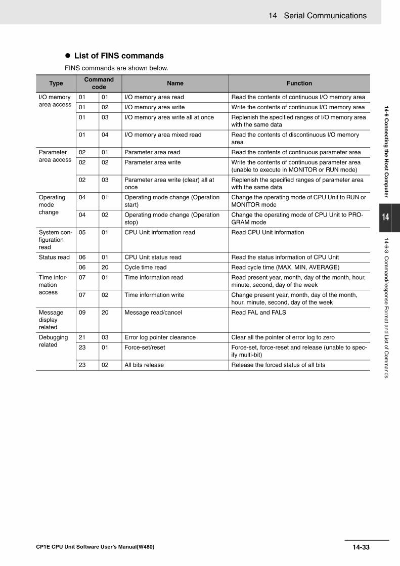
14-33
14 Serial Communications
CP1E CPU Unit Software User’s Manual(W480)
14-6 Co
nn
ecting
the H
ost C
om
pu
ter
14
14-6-3 Com
mand/response F
ormat and List of C
omm
ands
List of FINS commandsFINS commands are shown below.
TypeCommand
codeName Function
I/O memory area access
01 01 I/O memory area read Read the contents of continuous I/O memory area
01 02 I/O memory area write Write the contents of continuous I/O memory area
01 03 I/O memory area write all at once Replenish the specified ranges of I/O memory area with the same data
01 04 I/O memory area mixed read Read the contents of discontinuous I/O memory area
Parameter area access
02 01 Parameter area read Read the contents of continuous parameter area
02 02 Parameter area write Write the contents of continuous parameter area (unable to execute in MONITOR or RUN mode)
02 03 Parameter area write (clear) all at once
Replenish the specified ranges of parameter area with the same data
Operating mode change
04 01 Operating mode change (Operation start)
Change the operating mode of CPU Unit to RUN or MONITOR mode
04 02 Operating mode change (Operation stop)
Change the operating mode of CPU Unit to PRO-GRAM mode
System con-figuration read
05 01 CPU Unit information read Read CPU Unit information
Status read 06 01 CPU Unit status read Read the status information of CPU Unit
06 20 Cycle time read Read cycle time (MAX, MIN, AVERAGE)
Time infor-mation access
07 01 Time information read Read present year, month, day of the month, hour, minute, second, day of the week
07 02 Time information write Change present year, month, day of the month, hour, minute, second, day of the week
Message display related
09 20 Message read/cancel Read FAL and FALS
Debugging related
21 03 Error log pointer clearance Clear all the pointer of error log to zero
23 01 Force-set/reset Force-set, force-reset and release (unable to spec-ify multi-bit)
23 02 All bits release Release the forced status of all bits
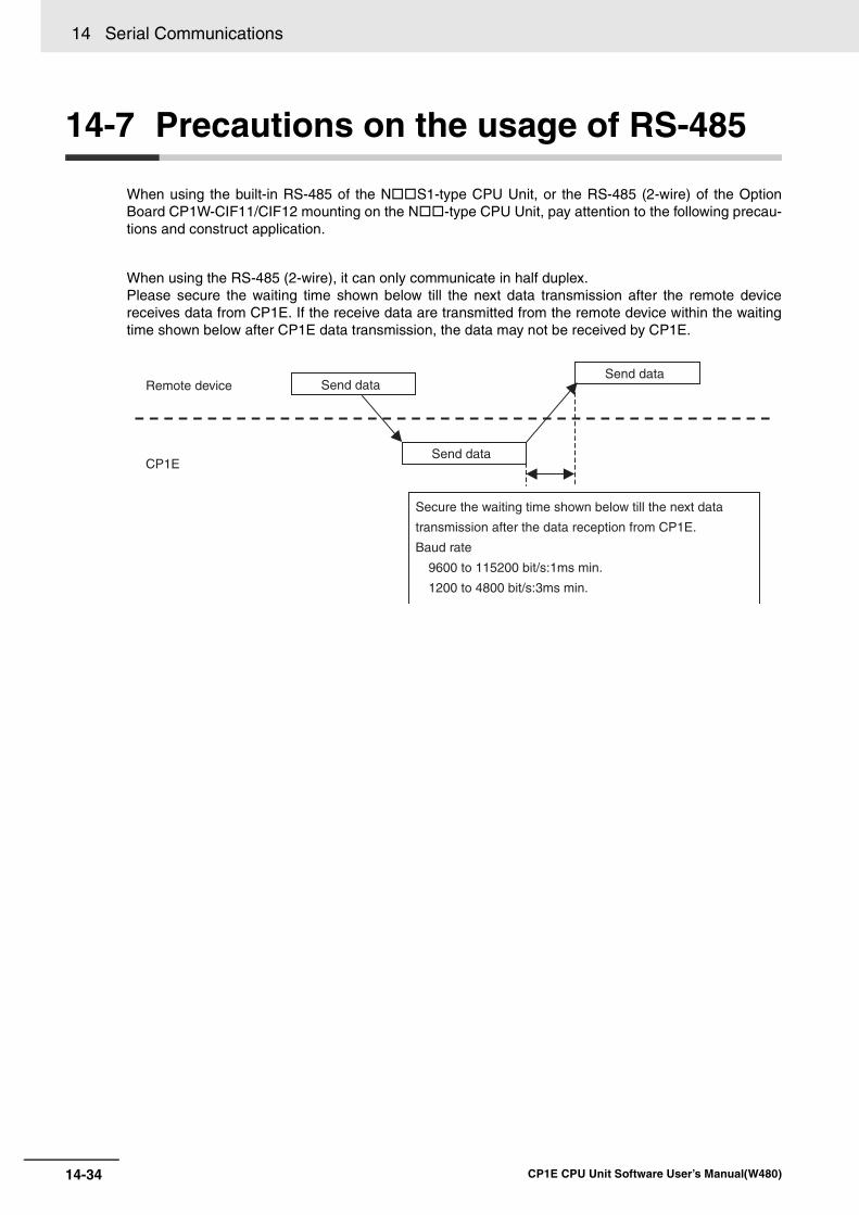
14 Serial Communications
14-34 CP1E CPU Unit Software User’s Manual(W480)
14-7 Precautions on the usage of RS-485
When using the built-in RS-485 of the NS1-type CPU Unit, or the RS-485 (2-wire) of the OptionBoard CP1W-CIF11/CIF12 mounting on the N-type CPU Unit, pay attention to the following precau-tions and construct application.
When using the RS-485 (2-wire), it can only communicate in half duplex.Please secure the waiting time shown below till the next data transmission after the remote devicereceives data from CP1E. If the receive data are transmitted from the remote device within the waitingtime shown below after CP1E data transmission, the data may not be received by CP1E.
Remote device
CP1E
Send dataSend data
Send data
Secure the waiting time shown below till the next data
transmission after the data reception from CP1E.
Baud rate
9600 to 115200 bit/s:1ms min.
1200 to 4800 bit/s:3ms min.
15-1
15
CP1E CPU Unit Software User’s Manual(W480)
15
-
This section describes the built-in analog function for NA-type CPU Units.
15-1 Overview . . . . . . . . . . . . . . . . . . . . . . . . . . . . . . . . . . . . . . . . . . . . . . . . . . . . 15-215-1-1 Flow of Operation . . . . . . . . . . . . . . . . . . . . . . . . . . . . . . . . . . . . . . . . . . . . . 15-2
15-1-2 Analog I/O Specifications . . . . . . . . . . . . . . . . . . . . . . . . . . . . . . . . . . . . . . . . 15-6
15-2 Analog Input and Output Signal Ranges . . . . . . . . . . . . . . . . . . . . . . . . . . 15-715-2-1 Analog Input Signal Ranges . . . . . . . . . . . . . . . . . . . . . . . . . . . . . . . . . . . . . 15-715-2-2 Analog Output Signal Ranges . . . . . . . . . . . . . . . . . . . . . . . . . . . . . . . . . . . . 15-915-2-3 Special functions . . . . . . . . . . . . . . . . . . . . . . . . . . . . . . . . . . . . . . . . . . . . . 15-11
15-3 I/O Allocation and Related Auxiliary Area Flags . . . . . . . . . . . . . . . . . . . 15-1215-3-1 I/O Allocation . . . . . . . . . . . . . . . . . . . . . . . . . . . . . . . . . . . . . . . . . . . . . . . . 15-12
15-3-2 Related Auxiliary Area Flags . . . . . . . . . . . . . . . . . . . . . . . . . . . . . . . . . . . . 15-12
Analog I/O Function
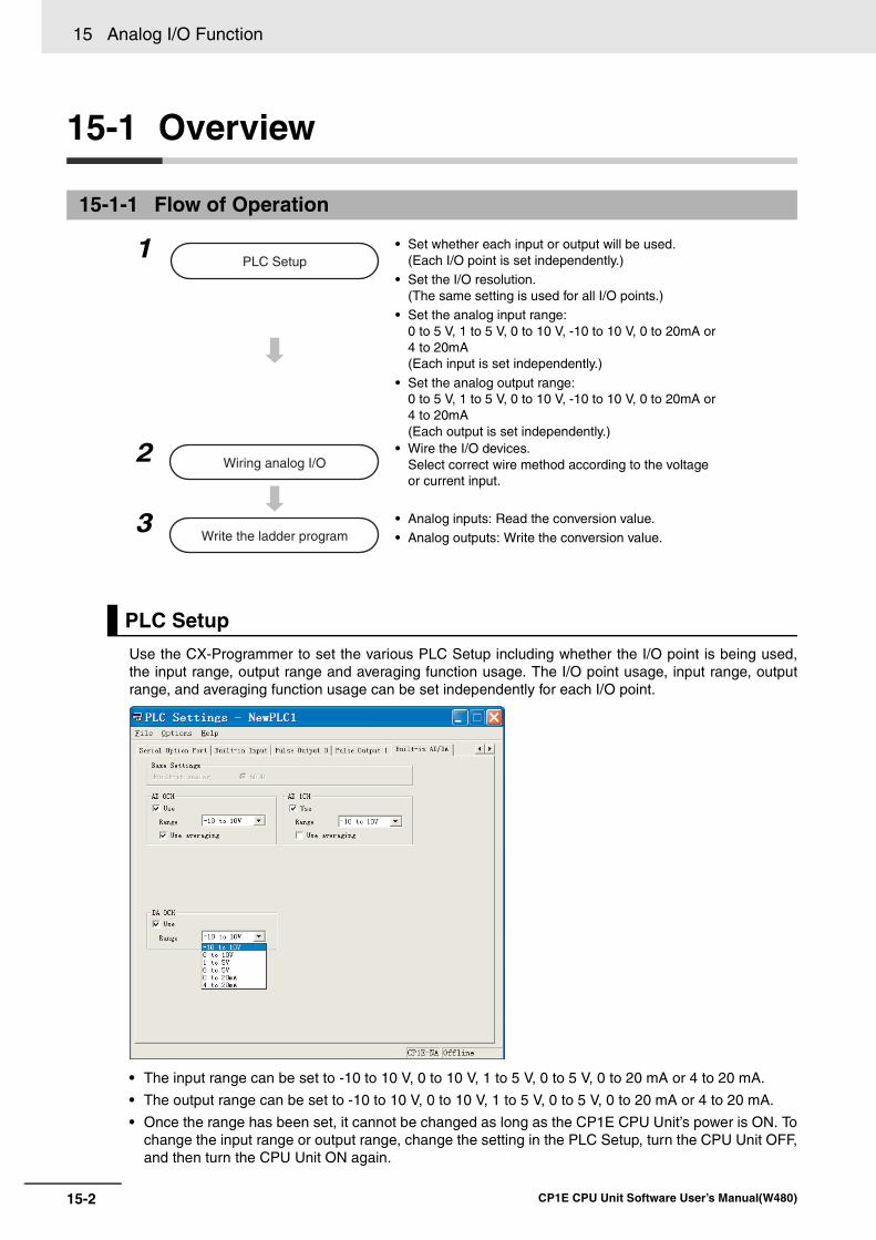
15 Analog I/O Function
15-2 CP1E CPU Unit Software User’s Manual(W480)
15-1 Overview
Use the CX-Programmer to set the various PLC Setup including whether the I/O point is being used,the input range, output range and averaging function usage. The I/O point usage, input range, outputrange, and averaging function usage can be set independently for each I/O point.
• The input range can be set to -10 to 10 V, 0 to 10 V, 1 to 5 V, 0 to 5 V, 0 to 20 mA or 4 to 20 mA.
• The output range can be set to -10 to 10 V, 0 to 10 V, 1 to 5 V, 0 to 5 V, 0 to 20 mA or 4 to 20 mA.
• Once the range has been set, it cannot be changed as long as the CP1E CPU Unit’s power is ON. Tochange the input range or output range, change the setting in the PLC Setup, turn the CPU Unit OFF,and then turn the CPU Unit ON again.
15-1-1 Flow of Operation
1 • Set whether each input or output will be used.(Each I/O point is set independently.)
• Set the I/O resolution.(The same setting is used for all I/O points.)
• Set the analog input range:0 to 5 V, 1 to 5 V, 0 to 10 V, -10 to 10 V, 0 to 20mA or 4 to 20mA(Each input is set independently.)
• Set the analog output range:0 to 5 V, 1 to 5 V, 0 to 10 V, -10 to 10 V, 0 to 20mA or 4 to 20mA(Each output is set independently.)
2 • Wire the I/O devices.Select correct wire method according to the voltage or current input.
3 • Analog inputs: Read the conversion value.• Analog outputs: Write the conversion value.
PLC Setup
PLC Setup
Wiring analog I/O
Write the ladder program
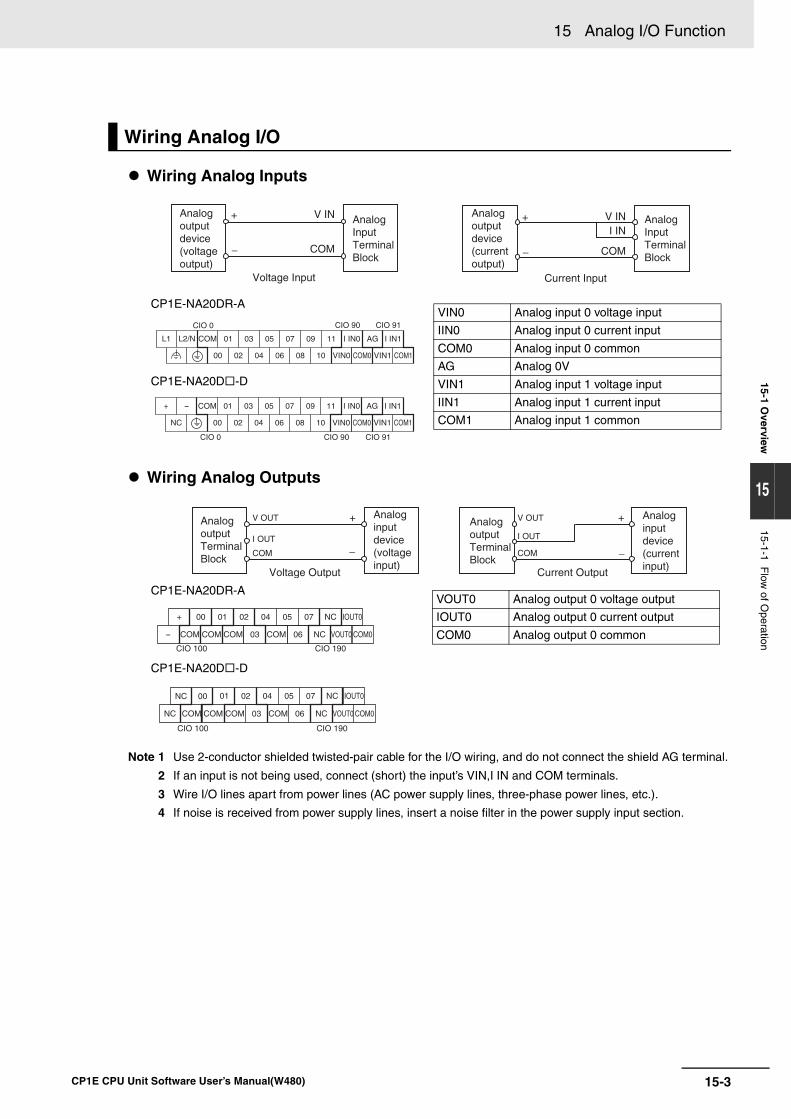
15-3
15 Analog I/O Function
CP1E CPU Unit Software User’s Manual(W480)
15-1 Overview
15
15-1-1 Flow
of Operation
Wiring Analog Inputs
Wiring Analog Outputs
Note 1 Use 2-conductor shielded twisted-pair cable for the I/O wiring, and do not connect the shield AG terminal.
2 If an input is not being used, connect (short) the input’s VIN,I IN and COM terminals.
3 Wire I/O lines apart from power lines (AC power supply lines, three-phase power lines, etc.).
4 If noise is received from power supply lines, insert a noise filter in the power supply input section.
Wiring Analog I/O
CP1E-NA20DR-A
CP1E-NA20D -D
CP1E-NA20DR-A
CP1E-NA20D -D
+
COM
Voltage Input
−
Analogoutputdevice(voltageoutput)
V IN AnalogInputTerminalBlock
+
COM
Current Input
−
V INI IN
Analogoutputdevice(currentoutput)
AnalogInputTerminalBlock
CIO 0 CIO 90 CIO 91
L1 L2/N COM
COM1
01 03 05 07 09 11
00 02 04 06 08 10
I IN0 AG I IN1
VIN0 COM0 VIN1
CIO 0 CIO 90 CIO 91
+ - COM
COM1
01 03 05 07 09 11
00NC 02 04 06 08 10
I IN0 AG I IN1
VIN0 COM0 VIN1
VIN0 Analog input 0 voltage input
IIN0 Analog input 0 current input
COM0 Analog input 0 common
AG Analog 0V
VIN1 Analog input 1 voltage input
IIN1 Analog input 1 current input
COM1 Analog input 1 common
V OUT
COM
I OUT
V OUT
COM
I OUT
+
−
+
−
AnalogoutputTerminalBlock
Analoginputdevice(voltageinput)
AnalogoutputTerminalBlock
Analoginputdevice(currentinput)
Voltage Output Current Output
CIO 100 CIO 190
00 01 02 04 05 07 NC
03 06
IOUT0
VOUT0 COM0
+
- COM COMCOM COM NC
CIO 100 CIO 190
0201 04 05 07 NC IOUT000
COM COM COM COM NCNC
NC
03 06 VOUT0 COM0
VOUT0 Analog output 0 voltage output
IOUT0 Analog output 0 current output
COM0 Analog output 0 common
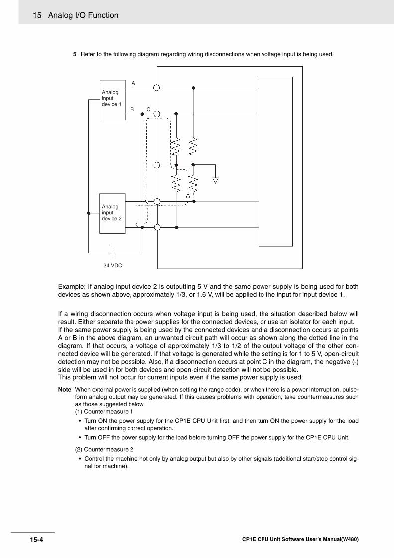
15 Analog I/O Function
15-4 CP1E CPU Unit Software User’s Manual(W480)
5 Refer to the following diagram regarding wiring disconnections when voltage input is being used.
Example: If analog input device 2 is outputting 5 V and the same power supply is being used for bothdevices as shown above, approximately 1/3, or 1.6 V, will be applied to the input for input device 1.
If a wiring disconnection occurs when voltage input is being used, the situation described below willresult. Either separate the power supplies for the connected devices, or use an isolator for each input.If the same power supply is being used by the connected devices and a disconnection occurs at pointsA or B in the above diagram, an unwanted circuit path will occur as shown along the dotted line in thediagram. If that occurs, a voltage of approximately 1/3 to 1/2 of the output voltage of the other con-nected device will be generated. If that voltage is generated while the setting is for 1 to 5 V, open-circuitdetection may not be possible. Also, if a disconnection occurs at point C in the diagram, the negative (-)side will be used in for both devices and open-circuit detection will not be possible.This problem will not occur for current inputs even if the same power supply is used.
Note When external power is supplied (when setting the range code), or when there is a power interruption, pulse-form analog output may be generated. If this causes problems with operation, take countermeasures suchas those suggested below.(1) Countermeasure 1
• Turn ON the power supply for the CP1E CPU Unit first, and then turn ON the power supply for the loadafter confirming correct operation.
• Turn OFF the power supply for the load before turning OFF the power supply for the CP1E CPU Unit.
(2) Countermeasure 2
• Control the machine not only by analog output but also by other signals (additional start/stop control sig-nal for machine).
24 VDC
A
CB
Analog input device 1
Analog input device 2
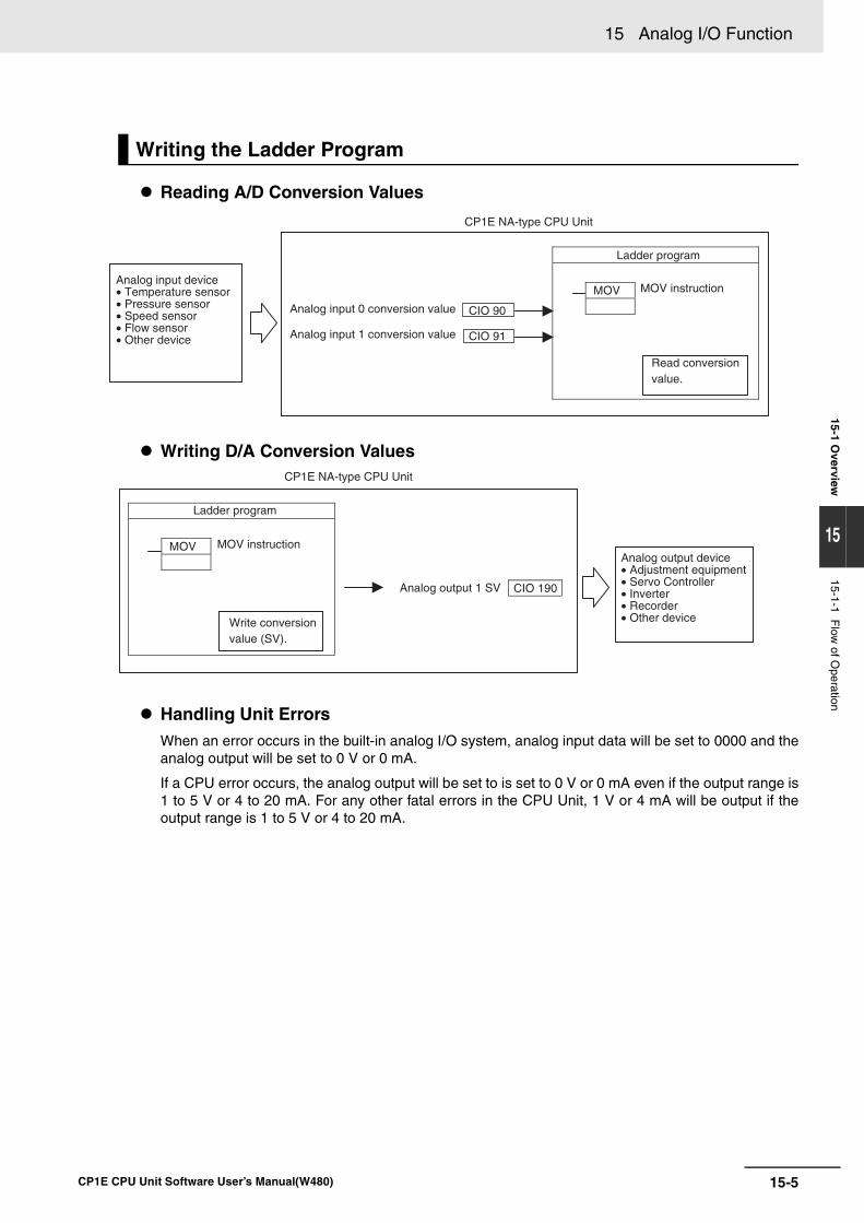
15-5
15 Analog I/O Function
CP1E CPU Unit Software User’s Manual(W480)
15-1 Overview
15
15-1-1 Flow
of Operation
Reading A/D Conversion Values
Writing D/A Conversion Values
Handling Unit ErrorsWhen an error occurs in the built-in analog I/O system, analog input data will be set to 0000 and theanalog output will be set to 0 V or 0 mA.
If a CPU error occurs, the analog output will be set to is set to 0 V or 0 mA even if the output range is1 to 5 V or 4 to 20 mA. For any other fatal errors in the CPU Unit, 1 V or 4 mA will be output if theoutput range is 1 to 5 V or 4 to 20 mA.
Writing the Ladder Program
MOVAnalog input device• Temperature sensor• Pressure sensor• Speed sensor• Flow sensor• Other device
Analog input 0 conversion value
Analog input 1 conversion value
CIO 90
CIO 91
CP1E NA-type CPU Unit
MOV instruction
Ladder program
Read conversionvalue.
CP1E NA-type CPU Unit
Analog output device• Adjustment equipment• Servo Controller• Inverter• Recorder• Other device
Analog output 1 SV CIO 190
MOV MOV instruction
Write conversion value (SV).
Ladder program
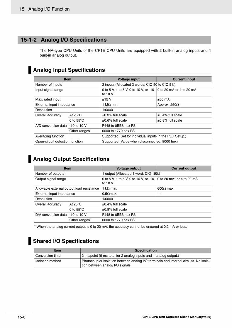
15 Analog I/O Function
15-6 CP1E CPU Unit Software User’s Manual(W480)
The NA-type CPU Units of the CP1E CPU Units are equipped with 2 built-in analog inputs and 1built-in analog output.
* When the analog current output is 0 to 20 mA, the accuracy cannot be ensured at 0.2 mA or less.
15-1-2 Analog I/O Specifications
Analog Input Specifications
Item Voltage input Current input
Number of inputs 2 inputs (Allocated 2 words: CIO 90 to CIO 91.)
Input signal range 0 to 5 V, 1 to 5 V, 0 to 10 V, or -10 to 10 V
0 to 20 mA or 4 to 20 mA
Max. rated input ±15 V ±30 mA
External input impedance 1 MΩ min. Approx. 250Ω
Resolution 1/6000
Overall accuracy At 25°C ±0.3% full scale ±0.4% full scale
0 to 55°C ±0.6% full scale ±0.8% full scale
A/D conversion data -10 to 10 V F448 to 0BB8 hex FS
Other ranges 0000 to 1770 hex FS
Averaging function Supported (Set for individual inputs in the PLC Setup.)
Open-circuit detection function Supported (Value when disconnected: 8000 hex)
Analog Output Specifications
Item Voltage output Current output
Number of outputs 1 output (Allocated 1 word: CIO 190.)
Output signal range 0 to 5 V, 1 to 5 V, 0 to 10 V, or -10 to 10 V
0 to 20 mA* or 4 to 20 mA
Allowable external output load resistance 1 kΩ min. 600Ω max.
External input impedance 0.5Ωmax. ---
Resolution 1/6000
Overall accuracy At 25°C ±0.4% full scale
0 to 55°C ±0.8% full scale
D/A conversion data -10 to 10 V F448 to 0BB8 hex FS
Other ranges 0000 to 1770 hex FS
Shared I/O Specifications
Item Specification
Conversion time 2 ms/point (6 ms total for 2 analog inputs and 1 analog output.)
Isolation method Photocoupler isolation between analog I/O terminals and internal circuits. No isola-tion between analog I/O signals.
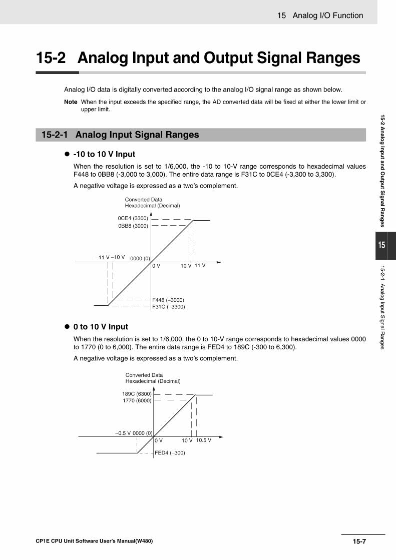
15-7
15 Analog I/O Function
CP1E CPU Unit Software User’s Manual(W480)
15-2 An
alog
Inp
ut an
d O
utp
ut S
ign
al Ran
ges
15
15-2-1 Analog Input S
ignal Ranges
15-2 Analog Input and Output Signal Ranges
Analog I/O data is digitally converted according to the analog I/O signal range as shown below.
Note When the input exceeds the specified range, the AD converted data will be fixed at either the lower limit orupper limit.
-10 to 10 V InputWhen the resolution is set to 1/6,000, the -10 to 10-V range corresponds to hexadecimal valuesF448 to 0BB8 (-3,000 to 3,000). The entire data range is F31C to 0CE4 (-3,300 to 3,300).
A negative voltage is expressed as a two’s complement.
0 to 10 V InputWhen the resolution is set to 1/6,000, the 0 to 10-V range corresponds to hexadecimal values 0000to 1770 (0 to 6,000). The entire data range is FED4 to 189C (-300 to 6,300).
A negative voltage is expressed as a two’s complement.
15-2-1 Analog Input Signal Ranges
0 V 10 V 11 V
−11 V −10 V
F448 (−3000)F31C (−3300)
0CE4 (3300)0BB8 (3000)
0000 (0)
Converted DataHexadecimal (Decimal)
0 V 10 V 10.5 V−0.5 V
FED4 (−300)
189C (6300)1770 (6000)
0000 (0)
Converted DataHexadecimal (Decimal)
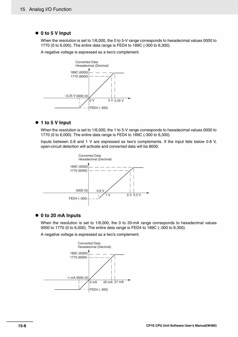
15 Analog I/O Function
15-8 CP1E CPU Unit Software User’s Manual(W480)
0 to 5 V InputWhen the resolution is set to 1/6,000, the 0 to 5-V range corresponds to hexadecimal values 0000 to1770 (0 to 6,000). The entire data range is FED4 to 189C (-300 to 6,300).
A negative voltage is expressed as a two’s complement.
1 to 5 V InputWhen the resolution is set to 1/6,000, the 1 to 5-V range corresponds to hexadecimal values 0000 to1770 (0 to 6,000). The entire data range is FED4 to 189C (-300 to 6,300).
Inputs between 0.8 and 1 V are expressed as two’s complements. If the input falls below 0.8 V,open-circuit detection will activate and converted data will be 8000.
0 to 20 mA InputsWhen the resolution is set to 1/6,000, the 0 to 20-mA range corresponds to hexadecimal values0000 to 1770 (0 to 6,000). The entire data range is FED4 to 189C (−300 to 6,300).
A negative voltage is expressed as a two’s complement.
0 V 5 V 5.25 V
−0.25 V
FED4 (−300)
189C (6300)1770 (6000)
0000 (0)
Converted DataHexadecimal (Decimal)
1 V 5 V 5.2 V0.8 V
FED4 (−300)
189C (6300)1770 (6000)
0000 (0)
Converted DataHexadecimal (Decimal)
0 mA 20 mA 21 mA−1 mA
FED4 (−300)
189C (6300)1770 (6000)
0000 (0)
Converted DataHexadecimal (Decimal)
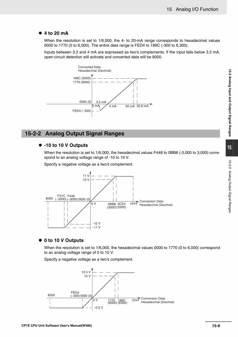
15-9
15 Analog I/O Function
CP1E CPU Unit Software User’s Manual(W480)
15-2 An
alog
Inp
ut an
d O
utp
ut S
ign
al Ran
ges
15
15-2-2 Analog O
utput Signal R
anges
4 to 20 mAWhen the resolution is set to 1/6,000, the 4- to 20-mA range corresponds to hexadecimal values0000 to 1770 (0 to 6,000). The entire data range is FED4 to 189C (-300 to 6,300).
Inputs between 3.2 and 4 mA are expressed as two’s complements. If the input falls below 3.2 mA,open-circuit detection will activate and converted data will be 8000.
-10 to 10 V OutputsWhen the resolution is set to 1/6,000, the hexadecimal values F448 to 0BB8 (-3,000 to 3,000) corre-spond to an analog voltage range of -10 to 10 V.
Specify a negative voltage as a two’s complement.
0 to 10 V OutputsWhen the resolution is set to 1/6,000, the hexadecimal values 0000 to 1770 (0 to 6,000) correspondto an analog voltage range of 0 to 10 V.
Specify a negative voltage as a two’s complement.
15-2-2 Analog Output Signal Ranges
4 mA 20 mA 20.8 mA3.2 mA
FED4 (−300)
189C (6300)1770 (6000)
0000 (0)0 mA
Converted DataHexadecimal (Decimal)
0 V
10 V11 V
−11 V−10 V
F448(−3000)
F31C(−3300)
0CE4 (3300)
0BB8(3000)
0000 (0)8000
7FFFConversion DataHexadecimal (Decimal)
0 V
10 V10.5 V
−0.5 V
FED4 (−300)
189C(6300)
1770(6000)
0000 (0)8000
7FFFConversion DataHexadecimal (Decimal)
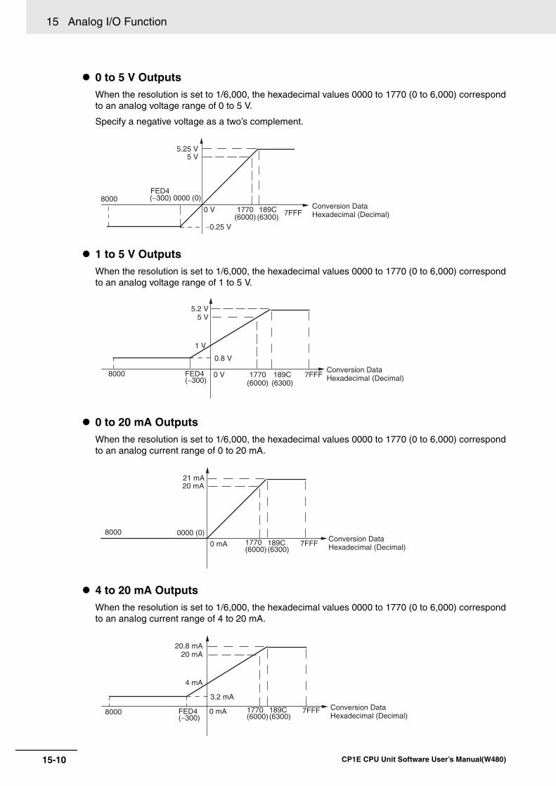
15 Analog I/O Function
15-10 CP1E CPU Unit Software User’s Manual(W480)
0 to 5 V OutputsWhen the resolution is set to 1/6,000, the hexadecimal values 0000 to 1770 (0 to 6,000) correspondto an analog voltage range of 0 to 5 V.
Specify a negative voltage as a two’s complement.
1 to 5 V OutputsWhen the resolution is set to 1/6,000, the hexadecimal values 0000 to 1770 (0 to 6,000) correspondto an analog voltage range of 1 to 5 V.
0 to 20 mA OutputsWhen the resolution is set to 1/6,000, the hexadecimal values 0000 to 1770 (0 to 6,000) correspondto an analog current range of 0 to 20 mA.
4 to 20 mA OutputsWhen the resolution is set to 1/6,000, the hexadecimal values 0000 to 1770 (0 to 6,000) correspondto an analog current range of 4 to 20 mA.
0 V
5 V5.25 V
−0.25 V
FED4 (−300)
189C(6300)
1770(6000)
0000 (0)8000
7FFFConversion DataHexadecimal (Decimal)
1 V
5 V5.2 V
0.8 V
189C(6300)
1770(6000)
0 V 7FFFFED4(−300)
8000 Conversion DataHexadecimal (Decimal)
0 mA
20 mA21 mA
0000 (0)189C(6300)
1770(6000)
7FFF
8000Conversion DataHexadecimal (Decimal)
4 mA
20 mA20.8 mA
3.2 mA
189C(6300)
1770(6000)
0 mA 7FFFFED4(−300)
8000Conversion DataHexadecimal (Decimal)
15-11
15 Analog I/O Function
CP1E CPU Unit Software User’s Manual(W480)
15-2 An
alog
Inp
ut an
d O
utp
ut S
ign
al Ran
ges
15
15-2-3 Special functions
Averaging Function for Analog InputsThe averaging function stores the average (a moving average) of the last eight input values as theconverted value. Use this function to smooth inputs that vary at a short interval.
Use the CX-Programmer to set the averaging function in the PLC Setup. The averaging function canbe set independently for each input.
Open-circuit Detection Function for Analog InputsThe open-circuit detection function is activated when the input range is set to 1 to 5 V and the volt-age drops below 0.8 V, or when the input range is set to 4 to 20 mA and the current drops below 3.2mA. When the open-circuit detection function is activated, the converted data will be set to 8,000.
The time for enabling or clearing the open-circuit detection function is the same as the time for con-verting the data. If the input returns to the convertible range, the open-circuit detection is clearedautomatically and the output returns to the normal range.
Auxiliary Area bits A434.00 to A434.01 are allocated as open-circuit detection flags.
15-2-3 Special functions
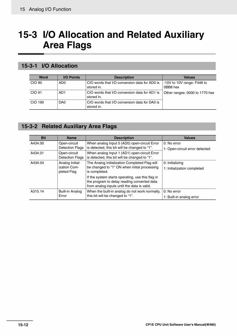
15 Analog I/O Function
15-12 CP1E CPU Unit Software User’s Manual(W480)
15-3 I/O Allocation and Related Auxiliary Area Flags
15-3-1 I/O Allocation
Word I/O Points Description Values
CIO 90 AD0 CIO words that I/O conversion data for AD0 is stored in.
-10V to 10V range: F448 to 0BB8 hex
Other ranges: 0000 to 1770 hexCIO 91 AD1 CIO words that I/O conversion data for AD1 is stored in.
CIO 190 DA0 CIO words that I/O conversion data for DA0 is stored in.
15-3-2 Related Auxiliary Area Flags
Bit Name Description Values
A434.00 Open-circuit Detection Flags
When analog Input 0 (AD0) open-circuit Error is detected, this bit will be changed to “1”.
0: No error
1: Open-circuit error detectedA434.01 Open-circuit
Detection FlagsWhen analog Input 1 (AD1) open-circuit Error is detected, this bit will be changed to “1”.
A434.04 Analog Initial-ization Com-pleted Flag
The Analog Initialization Completed Flag will be changed to “1” ON when initial processing is completed.
If the system starts operating, use this flag in the program to delay reading converted data from analog inputs until the data is valid.
0: Initializing
1: Initialization completed
A315.14 Built-in Analog Error
When the built-in analog do not work normally, this bit will be changed to “1”.
0: No error
1: Built-in analog error
16-1
16
CP1E CPU Unit Software User’s Manual(W480)
16
This section describes PID temperature control, clock functions, DM backup functions,security functions.
16-1 PID Temperature Control . . . . . . . . . . . . . . . . . . . . . . . . . . . . . . . . . . . . . . . 16-216-1-1 Overview . . . . . . . . . . . . . . . . . . . . . . . . . . . . . . . . . . . . . . . . . . . . . . . . . . . . 16-2
16-1-2 Flow of Operation . . . . . . . . . . . . . . . . . . . . . . . . . . . . . . . . . . . . . . . . . . . . . 16-316-1-3 Application Example . . . . . . . . . . . . . . . . . . . . . . . . . . . . . . . . . . . . . . . . . . . 16-4
16-2 Clock . . . . . . . . . . . . . . . . . . . . . . . . . . . . . . . . . . . . . . . . . . . . . . . . . . . . . . . 16-7
16-3 DM Backup Function . . . . . . . . . . . . . . . . . . . . . . . . . . . . . . . . . . . . . . . . . . 16-816-3-1 Backing Up and Restoring DM Area Data . . . . . . . . . . . . . . . . . . . . . . . . . . . 16-816-3-2 Procedure . . . . . . . . . . . . . . . . . . . . . . . . . . . . . . . . . . . . . . . . . . . . . . . . . . 16-10
16-4 Security Functions . . . . . . . . . . . . . . . . . . . . . . . . . . . . . . . . . . . . . . . . . . . 16-1216-4-1 Ladder Program Read Protection . . . . . . . . . . . . . . . . . . . . . . . . . . . . . . . . 16-12
Other Functions
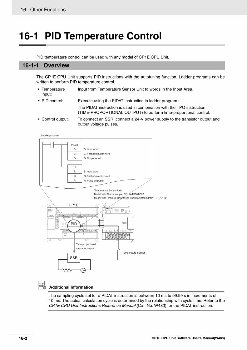
16 Other Functions
16-2 CP1E CPU Unit Software User’s Manual(W480)
16-1 PID Temperature Control
PID temperature control can be used with any model of CP1E CPU Unit.
The CP1E CPU Unit supports PID instructions with the autotuning function. Ladder programs can bewritten to perform PID temperature control.
Additional Information
The sampling cycle set for a PIDAT instruction is between 10 ms to 99.99 s in increments of 10 ms. The actual calculation cycle is determined by the relationship with cycle time. Refer to theCP1E CPU Unit Instructions Reference Manual (Cat. No. W483) for the PIDAT instruction.
16-1-1 Overview
• Temperature input:
Input from Temperature Sensor Unit to words in the Input Area.
• PID control: Execute using the PIDAT instruction in ladder program.
The PIDAT instruction is used in combination with the TPO instruction (TIME-PROPORTIONAL OUTPUT) to perform time-proportional control.
• Control output: To connect an SSR, connect a 24-V power supply to the transistor output and output voltage pulses.
SSR
PIDAT
S
C
D
TPO
S
C
R
PID
CP1E
S: Input word
C: First parameter word
D: Output word
S: Input word
C: First parameter word
R: Pulse output bit
Temperature Sensor Unit
Model with Thermocouple: CP1W-TS001/002
Model with Platinum Resistance Thermometer: CP1W-TS101/102
Ladder program
Time-proportional
transistor output
Temperature Sensor
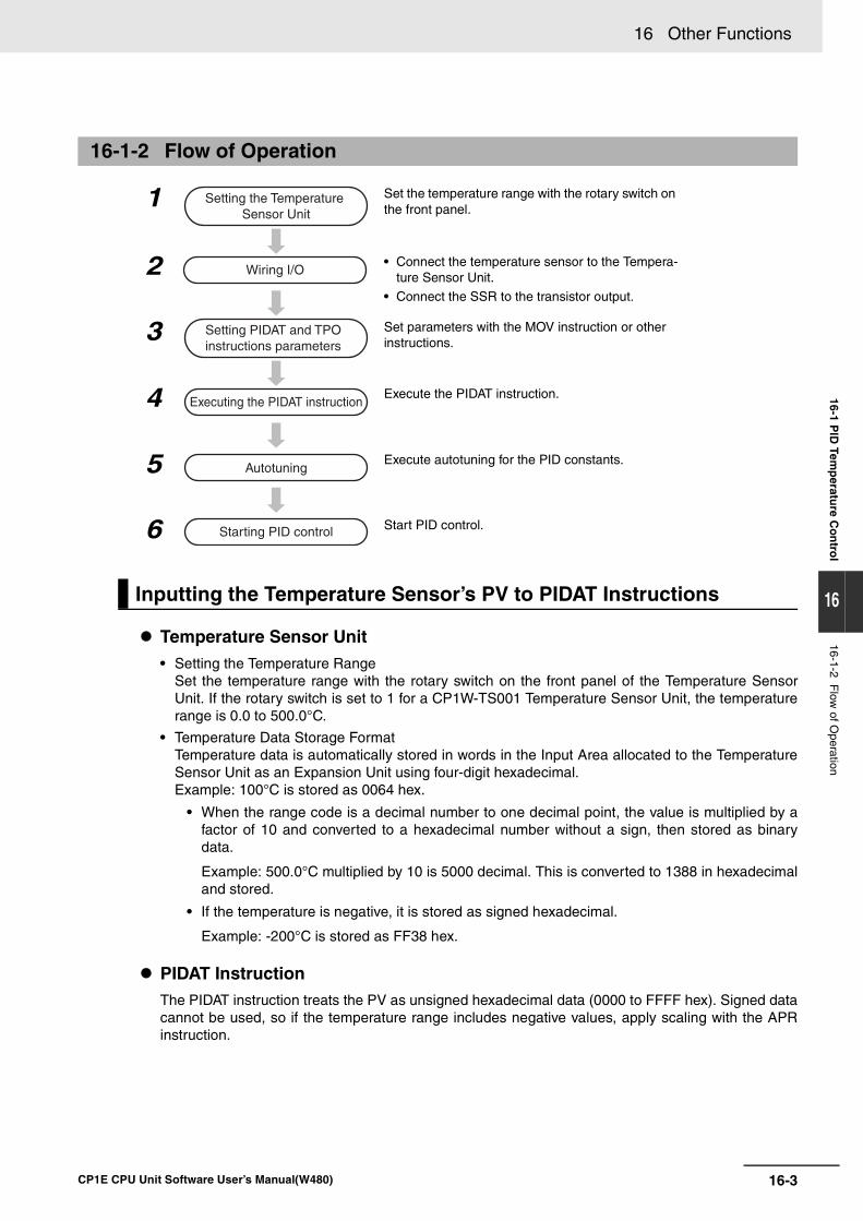
16-3
16 Other Functions
CP1E CPU Unit Software User’s Manual(W480)
16-1 PID
Temp
erature C
on
trol
16
16-1-2 Flow
of Operation
Temperature Sensor Unit• Setting the Temperature Range
Set the temperature range with the rotary switch on the front panel of the Temperature SensorUnit. If the rotary switch is set to 1 for a CP1W-TS001 Temperature Sensor Unit, the temperaturerange is 0.0 to 500.0°C.
• Temperature Data Storage FormatTemperature data is automatically stored in words in the Input Area allocated to the TemperatureSensor Unit as an Expansion Unit using four-digit hexadecimal.Example: 100°C is stored as 0064 hex.
• When the range code is a decimal number to one decimal point, the value is multiplied by afactor of 10 and converted to a hexadecimal number without a sign, then stored as binarydata.
Example: 500.0°C multiplied by 10 is 5000 decimal. This is converted to 1388 in hexadecimaland stored.
• If the temperature is negative, it is stored as signed hexadecimal.
Example: -200°C is stored as FF38 hex.
PIDAT InstructionThe PIDAT instruction treats the PV as unsigned hexadecimal data (0000 to FFFF hex). Signed datacannot be used, so if the temperature range includes negative values, apply scaling with the APRinstruction.
16-1-2 Flow of Operation
1 Set the temperature range with the rotary switch on the front panel.
2 • Connect the temperature sensor to the Tempera-ture Sensor Unit.
• Connect the SSR to the transistor output.
3 Set parameters with the MOV instruction or other instructions.
4 Execute the PIDAT instruction.
5 Execute autotuning for the PID constants.
6 Start PID control.
Inputting the Temperature Sensor’s PV to PIDAT Instructions
Setting the Temperature Sensor Unit
Wiring I/O
Setting PIDAT and TPO instructions parameters
Executing the PIDAT instruction
Autotuning
Starting PID control
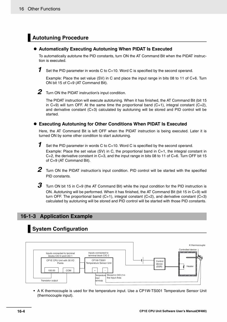
16 Other Functions
16-4 CP1E CPU Unit Software User’s Manual(W480)
Automatically Executing Autotuning When PIDAT Is ExecutedTo automatically autotune the PID constants, turn ON the AT Command Bit when the PIDAT instruc-tion is executed.
1 Set the PID parameter in words C to C+10. Word C is specified by the second operand.
Example: Place the set value (SV) in C and place the input range in bits 08 to 11 of C+6. TurnON bit 15 of C+9 (AT Command Bit).
2 Turn ON the PIDAT instruction’s input condition.
The PIDAT instruction will execute autotuning. When it has finished, the AT Command Bit (bit 15in C+9) will turn OFF. At the same time the proportional band (C+1), integral constant (C+2),and derivative constant (C+3) calculated by autotuning will be stored and PID control will bestarted.
Executing Autotuning for Other Conditions When PIDAT Is ExecutedHere, the AT Command Bit is left OFF when the PIDAT instruction is being executed. Later it isturned ON by some other condition to start autotuning.
1 Set the PID parameter in words C to C+10. Word C is specified by the second operand.
Example: Place the set value (SV) in C, the proportional band in C+1, the integral constant inC+2, the derivative constant in C+3, and the input range in bits 08 to 11 of C+6. Turn OFF bit 15of C+9 (AT Command Bit).
2 Turn ON the PIDAT instruction’s input condition. PID control will be started with the specified
PID constants.
3 Turn ON bit 15 in C+9 (the AT Command Bit) while the input condition for the PID instruction is
ON. Autotuning will be performed. When it has finished, the AT Command Bit (bit 15 in C+9) willturn OFF. The proportional band (C+1), integral constant (C+2), and derivative constant (C+3)calculated by autotuning will be stored and PID control will be started with those PID constants.
• A K thermocouple is used for the temperature input. Use a CP1W-TS001 Temperature Sensor Unit(thermocouple input).
Autotuning Procedure
16-1-3 Application Example
System Configuration
100.00 COM -
Inputs connected to terminalblocks CIO 0 and CIO 1
CP1E CPU Unit with 30 I/O Points
Transistor output
Inputs connected to terminal block CIO 2
CP1W-TS001 Temperature Sensor Unit
Temperature input terminals
Stored in CIO 2 in the Input Area
Control device (SSR)
Controlled device
Heater
K thermocouple
+
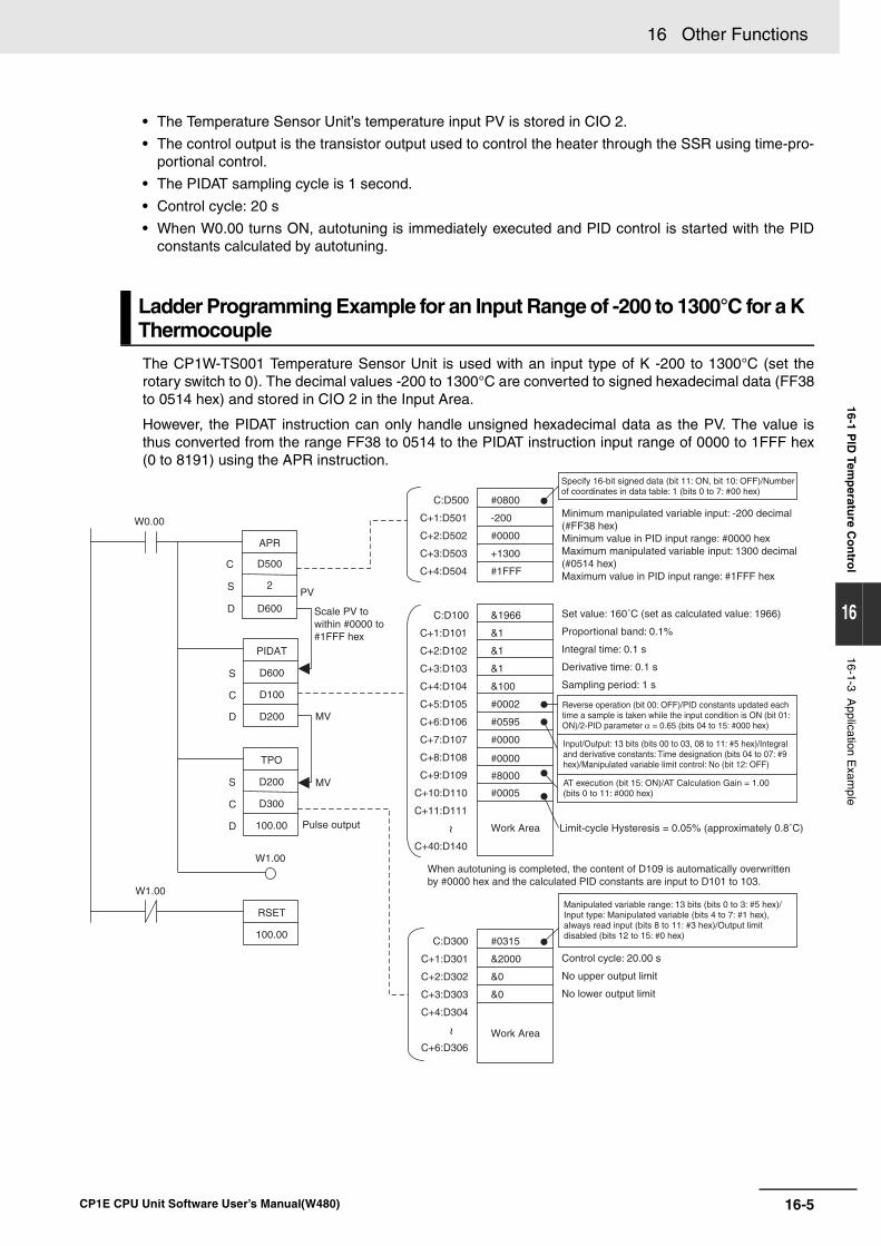
16-5
16 Other Functions
CP1E CPU Unit Software User’s Manual(W480)
16-1 PID
Temp
erature C
on
trol
16
16-1-3 Application E
xample
• The Temperature Sensor Unit’s temperature input PV is stored in CIO 2.
• The control output is the transistor output used to control the heater through the SSR using time-pro-portional control.
• The PIDAT sampling cycle is 1 second.
• Control cycle: 20 s
• When W0.00 turns ON, autotuning is immediately executed and PID control is started with the PIDconstants calculated by autotuning.
The CP1W-TS001 Temperature Sensor Unit is used with an input type of K -200 to 1300°C (set therotary switch to 0). The decimal values -200 to 1300°C are converted to signed hexadecimal data (FF38to 0514 hex) and stored in CIO 2 in the Input Area.
However, the PIDAT instruction can only handle unsigned hexadecimal data as the PV. The value isthus converted from the range FF38 to 0514 to the PIDAT instruction input range of 0000 to 1FFF hex(0 to 8191) using the APR instruction.
Ladder Programming Example for an Input Range of -200 to 1300°C for a K Thermocouple
PIDAT
S D600
C D100
D D200
TPO
S D200
C D300
D 100.00
RSET
100.00
W1.00
W1.00
W0.00
C:D100 &1966
C+1:D101 &1
C+2:D102 &1
C+3:D103 &1
C+4:D104 &100
C+5:D105 #0002
C+6:D106 #0595
C+7:D107 #0000
C+8:D108
C+9:D109
C+10:D110 #0005
C+11:D111
C+40:D140
C:D300 #0315
C+1:D301 &2000
C+2:D302 &0
C+3:D303 &0
C+4:D304
C+6:D306
APR
S 2
C D500
D D600
C:D500 #0800
C+1:D501 -200
C+2:D502 #0000
C+3:D503 +1300
C+4:D504 #1FFF
#0000
#8000
Pulse output Work Area
Work Area
PV
Scale PV to within #0000 to #1FFF hex
MV
MV
Specify 16-bit signed data (bit 11: ON, bit 10: OFF)/Number of coordinates in data table: 1 (bits 0 to 7: #00 hex)
Minimum manipulated variable input: -200 decimal (#FF38 hex)Minimum value in PID input range: #0000 hexMaximum manipulated variable input: 1300 decimal (#0514 hex)Maximum value in PID input range: #1FFF hex
Set value: 160˚C (set as calculated value: 1966)
Proportional band: 0.1%
Integral time: 0.1 s
Derivative time: 0.1 s
Sampling period: 1 s
Reverse operation (bit 00: OFF)/PID constants updated each time a sample is taken while the input condition is ON (bit 01: ON)/2-PID parameter α = 0.65 (bits 04 to 15: #000 hex)
Input/Output: 13 bits (bits 00 to 03, 08 to 11: #5 hex)/Integral and derivative constants: Time designation (bits 04 to 07: #9 hex)/Manipulated variable limit control: No (bit 12: OFF)
AT execution (bit 15: ON)/AT Calculation Gain = 1.00(bits 0 to 11: #000 hex)
Limit-cycle Hysteresis = 0.05% (approximately 0.8˚C)
When autotuning is completed, the content of D109 is automatically overwritten by #0000 hex and the calculated PID constants are input to D101 to 103.
Manipulated variable range: 13 bits (bits 0 to 3: #5 hex)/ Input type: Manipulated variable (bits 4 to 7: #1 hex), always read input (bits 8 to 11: #3 hex)/Output limit disabled (bits 12 to 15: #0 hex)
Control cycle: 20.00 s
No upper output limit
No lower output limit
~~
16 Other Functions
16-6 CP1E CPU Unit Software User’s Manual(W480)
Description• When W0.00 turns ON, the work area in D111 to D140 is initialized (cleared) according to the
parameters set in D100 to D110. After the work area has been initialized, autotuning is startedand the PID constants are calculated from the results from changing the manipulated variable.After autotuning has been completed, PID control is executed according to the calculated PIDconstants set in D101 to D103. The manipulated variable is output to D200. The manipulated vari-able in D200 is divided by the manipulated variable range using the TPO instruction. This value istreated as the duty factor which is converted to a time-proportional output and output toCIO100.00 as a pulse output.
• When W0.00 turns OFF, PID is stopped and CIO100.00 turns OFF.
• When W0.00 is ON, the Thermocouple’s PV (-200 to 1300) is scaled to the PIDAT instruction inputrange (#0 to #1FFF hex). The set values must be input according to the scaled PV. For example, ifthe PV is 160°C, it is set as [8191/(1300+200)] × (160+200) = 1966].
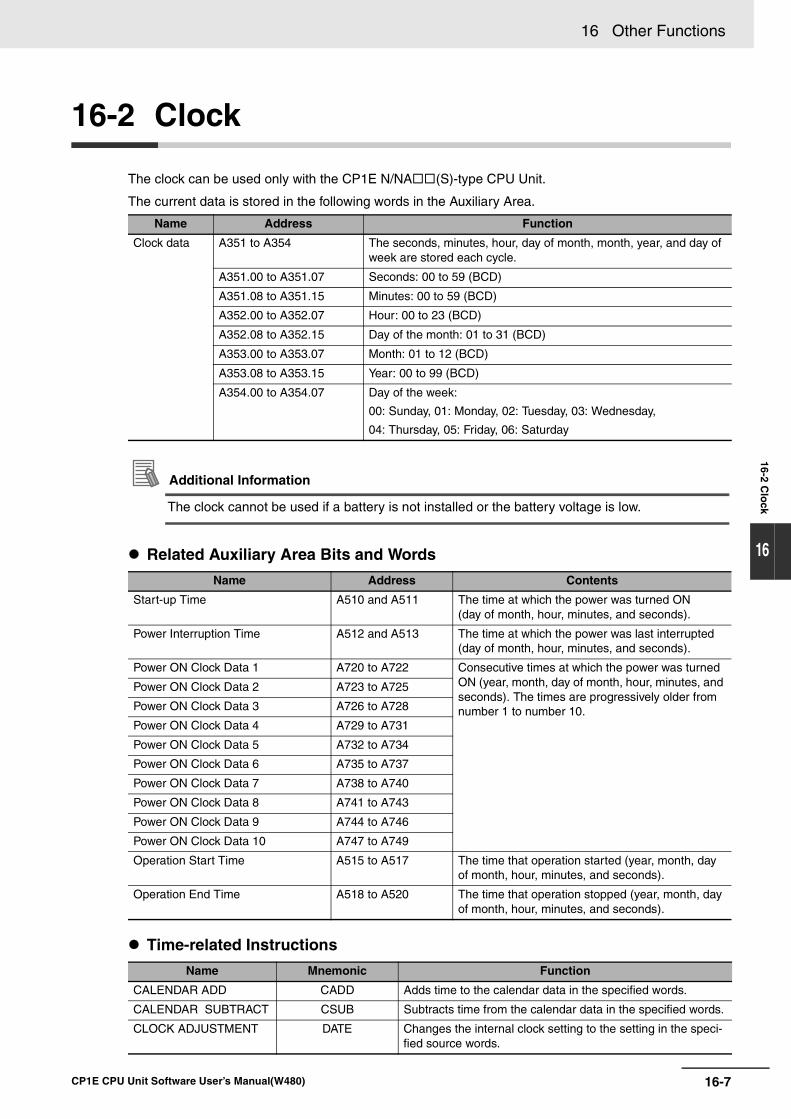
16-7
16 Other Functions
CP1E CPU Unit Software User’s Manual(W480)
16-2 Clo
ck
16
16-2 Clock
The clock can be used only with the CP1E N/NA (S)-type CPU Unit.
The current data is stored in the following words in the Auxiliary Area.
Additional Information
The clock cannot be used if a battery is not installed or the battery voltage is low.
Related Auxiliary Area Bits and Words
Time-related Instructions
Name Address Function
Clock data A351 to A354 The seconds, minutes, hour, day of month, month, year, and day of week are stored each cycle.
A351.00 to A351.07 Seconds: 00 to 59 (BCD)
A351.08 to A351.15 Minutes: 00 to 59 (BCD)
A352.00 to A352.07 Hour: 00 to 23 (BCD)
A352.08 to A352.15 Day of the month: 01 to 31 (BCD)
A353.00 to A353.07 Month: 01 to 12 (BCD)
A353.08 to A353.15 Year: 00 to 99 (BCD)
A354.00 to A354.07 Day of the week:
00: Sunday, 01: Monday, 02: Tuesday, 03: Wednesday,
04: Thursday, 05: Friday, 06: Saturday
Name Address Contents
Start-up Time A510 and A511 The time at which the power was turned ON (day of month, hour, minutes, and seconds).
Power Interruption Time A512 and A513 The time at which the power was last interrupted (day of month, hour, minutes, and seconds).
Power ON Clock Data 1 A720 to A722 Consecutive times at which the power was turned ON (year, month, day of month, hour, minutes, and seconds). The times are progressively older from number 1 to number 10.
Power ON Clock Data 2 A723 to A725
Power ON Clock Data 3 A726 to A728
Power ON Clock Data 4 A729 to A731
Power ON Clock Data 5 A732 to A734
Power ON Clock Data 6 A735 to A737
Power ON Clock Data 7 A738 to A740
Power ON Clock Data 8 A741 to A743
Power ON Clock Data 9 A744 to A746
Power ON Clock Data 10 A747 to A749
Operation Start Time A515 to A517 The time that operation started (year, month, day of month, hour, minutes, and seconds).
Operation End Time A518 to A520 The time that operation stopped (year, month, day of month, hour, minutes, and seconds).
Name Mnemonic Function
CALENDAR ADD CADD Adds time to the calendar data in the specified words.
CALENDAR SUBTRACT CSUB Subtracts time from the calendar data in the specified words.
CLOCK ADJUSTMENT DATE Changes the internal clock setting to the setting in the speci-fied source words.
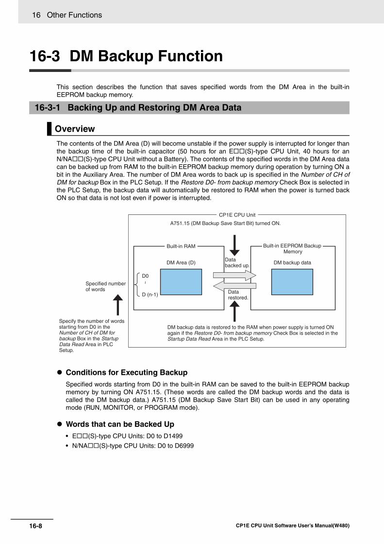
16 Other Functions
16-8 CP1E CPU Unit Software User’s Manual(W480)
16-3 DM Backup Function
This section describes the function that saves specified words from the DM Area in the built-inEEPROM backup memory.
The contents of the DM Area (D) will become unstable if the power supply is interrupted for longer thanthe backup time of the built-in capacitor (50 hours for an E (S)-type CPU Unit, 40 hours for anN/NA (S)-type CPU Unit without a Battery). The contents of the specified words in the DM Area datacan be backed up from RAM to the built-in EEPROM backup memory during operation by turning ON abit in the Auxiliary Area. The number of DM Area words to back up is specified in the Number of CH ofDM for backup Box in the PLC Setup. If the Restore D0- from backup memory Check Box is selected inthe PLC Setup, the backup data will automatically be restored to RAM when the power is turned backON so that data is not lost even if power is interrupted.
Conditions for Executing BackupSpecified words starting from D0 in the built-in RAM can be saved to the built-in EEPROM backupmemory by turning ON A751.15. (These words are called the DM backup words and the data iscalled the DM backup data.) A751.15 (DM Backup Save Start Bit) can be used in any operatingmode (RUN, MONITOR, or PROGRAM mode).
Words that can be Backed Up• E (S)-type CPU Units: D0 to D1499
• N/NA (S)-type CPU Units: D0 to D6999
16-3-1 Backing Up and Restoring DM Area Data
Overview
CP1E CPU Unit
A751.15 (DM Backup Save Start Bit) turned ON.
Built-in RAM
DM Area (D)
Specified number of words
DM backup dataData backed up.
Data restored.
Built-in EEPROM Backup Memory
~
D0
D (n-1)
Specify the number of words starting from D0 in the Number of CH of DM for backup Box in the Startup Data Read Area in PLC Setup.
DM backup data is restored to the RAM when power supply is turned ON again if the Restore D0- from backup memory Check Box is selected in the Startup Data Read Area in the PLC Setup.
16-9
16 Other Functions
CP1E CPU Unit Software User’s Manual(W480)
16-3 DM
Backu
p F
un
ction
16
16-3-1 Backing U
p and Restoring D
M A
rea Data
Number of Words to Back Up The number of words to back up starting from D0 is set in the Number of CH of DM for backup Boxin the Startup Data Read Area in the PLC Setup.
Restoring DM Backup Data to the Built-in RAM When Power is Turned ONThe DM backup data can be restored to the built-in RAM when power is turned ON by selecting theRestore D0- from backup memory Check Box in the Startup Data Read Area in the PLC Setup.
The DM backup data will be read from the backup memory even if the Clear retained memory area(HR/DM/CNT) Check Box is selected in the PLC Setup.
Related Auxiliary Area Bits
Name Address Description
DM Backup Save Start Bit
A751.15 The number of words in the DM Area specified in the Number of CH of DM for backup Box in the Startup Data Read Area in the PLC Setup are saved from the built-in RAM to the built-in EEPROM backup mem-ory when this bit is turned ON.
This bit will not automatically turn OFF again if the bit turns ON. Design the ladder program so that this bit is turned ON and OFF again using upwardly differentiated bits.
If this bit is turned ON and OFF while the DM Backup Save Flag (A751.14) is ON, it will be ignored and the data will not be backed up again. To backup the data again, make sure that A751.14 is OFF and then turn ON A751.15. A751.15 is turned OFF when the power supply is turned ON.
DM Backup Save Flag
A751.14 This flag turns ON when A751.15 is turned ON to start the saving operation. This flag stays ON while data is being saved and turns OFF when finished.
Use this flag to confirm when the DM backup operation has been com-pleted.
The flag is turned OFF when the power supply is turned ON.
DM Backup Restore Failed Flag
A751.11 This flag turns ON if the DM backup data could not be restored cor-rectly. If this flag turns ON, data will not be read from the built-in EEPROM backup memory to the RAM.
For example, if power was interrupted while data was being backed up, the DM Area data would not be backed up properly and the next time power is turned ON, the DM backup data will not be restored. If this happens, this flag will be turned ON.
If the number of the backed up DM area words is different from the Number of CH of DM for backup in the PLC Setup, this flag will be turned ON.
This flag turns OFF in the following cases:
• Data is successfully restored from the built-in EEPROM backup memory to the RAM when the power supply is turned ON.
• All memory is cleared.
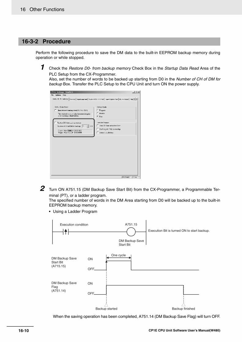
16 Other Functions
16-10 CP1E CPU Unit Software User’s Manual(W480)
Perform the following procedure to save the DM data to the built-in EEPROM backup memory duringoperation or while stopped.
1 Check the Restore D0- from backup memory Check Box in the Startup Data Read Area of the
PLC Setup from the CX-Programmer. Also, set the number of words to be backed up starting from D0 in the Number of CH of DM forbackup Box. Transfer the PLC Setup to the CPU Unit and turn ON the power supply.
2 Turn ON A751.15 (DM Backup Save Start Bit) from the CX-Programmer, a Programmable Ter-
minal (PT), or a ladder program. The specified number of words in the DM Area starting from D0 will be backed up to the built-inEEPROM backup memory.
• Using a Ladder Program
When the saving operation has been completed, A751.14 (DM Backup Save Flag) will turn OFF.
16-3-2 Procedure
Execution condition A751.15
DM Backup Save Start Bit
DM Backup Save Start Bit (A715.15)
ONOne cycle
Backup started Backup finished
OFF
ON
OFF
DM Backup Save Flag (A751.14)
Execution Bit is turned ON to start backup.
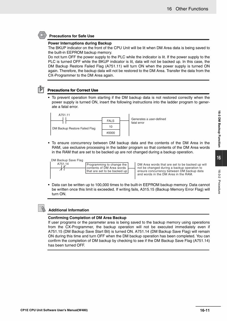
16-11
16 Other Functions
CP1E CPU Unit Software User’s Manual(W480)
16-3 DM
Backu
p F
un
ction
16
16-3-2 Procedure
Precautions for Safe Use
Power Interruptions during BackupThe BKUP indicator on the front of the CPU Unit will be lit when DM Area data is being saved tothe built-in EEPROM backup memory. Do not turn OFF the power supply to the PLC while the indicator is lit. If the power supply to thePLC is turned OFF while the BKUP indicator is lit, data will not be backed up. In this case, theDM Backup Restore Failed Flag (A751.11) will turn ON when the power supply is turned ONagain. Therefore, the backup data will not be restored to the DM Area. Transfer the data from theCX-Programmer to the DM Area again.
Precautions for Correct UsePrecautions for Correct Use
• To prevent operation from starting if the DM backup data is not restored correctly when thepower supply is turned ON, insert the following instructions into the ladder program to gener-ate a fatal error.
• To ensure concurrency between DM backup data and the contents of the DM Area in theRAM, use exclusive processing in the ladder program so that contents of the DM Area wordsin the RAM that are set to be backed up are not changed during a backup operation.
• Data can be written up to 100,000 times to the built-in EEPROM backup memory. Data cannotbe written once this limit is exceeded. If writing fails, A315.15 (Backup Memory Error Flag) willturn ON.
Additional Information
Confirming Completion of DM Area BackupIf user programs or the parameter area is being saved to the backup memory using operationsfrom the CX-Programmer, the backup operation will not be executed immediately even ifA751.15 (DM Backup Save Start Bit) is turned ON. A751.14 (DM Backup Save Flag) will remainON during this time and turn OFF when the DM backup operation has been completed. You canconfirm the completion of DM backup by checking to see if the DM Backup Save Flag (A751.14)has been turned OFF.
A751.11
DM Backup Restore Failed Flag
Generates a user-defined fatal error
FALS
10
#0000
DM Backup Save Flag A751.14 Programming to change the
contents of DM Area words that are set to be backed up
DM Area words that are set to be backed up will not be changed during a backup operation to ensure concurrency between DM backup data and words in the DM Area in the RAM.
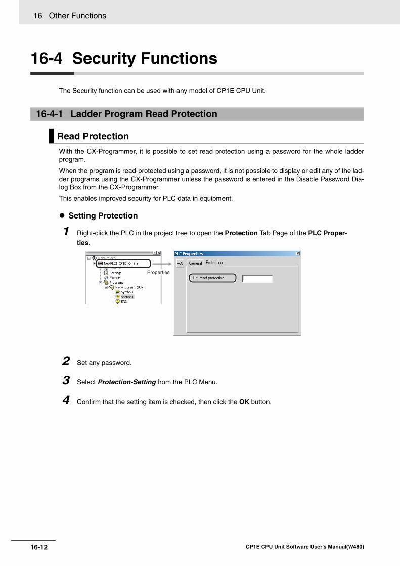
16 Other Functions
16-12 CP1E CPU Unit Software User’s Manual(W480)
16-4 Security Functions
The Security function can be used with any model of CP1E CPU Unit.
With the CX-Programmer, it is possible to set read protection using a password for the whole ladderprogram.
When the program is read-protected using a password, it is not possible to display or edit any of the lad-der programs using the CX-Programmer unless the password is entered in the Disable Password Dia-log Box from the CX-Programmer.
This enables improved security for PLC data in equipment.
Setting Protection
16-4-1 Ladder Program Read Protection
Read Protection
1 Right-click the PLC in the project tree to open the Protection Tab Page of the PLC Proper-ties.
2 Set any password.
3 Select Protection-Setting from the PLC Menu.
4 Confirm that the setting item is checked, then click the OK button.
Properties
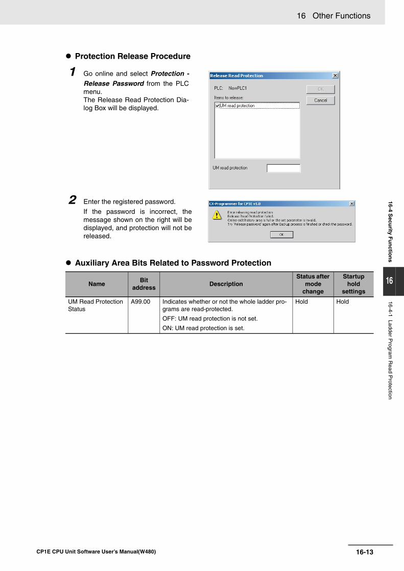
16-13
16 Other Functions
CP1E CPU Unit Software User’s Manual(W480)
16-4 Secu
rity Fu
nctio
ns
16
16-4-1 Ladder Program
Read P
rotection
Protection Release Procedure
Auxiliary Area Bits Related to Password Protection
1 Go online and select Protection -Release Password from the PLCmenu. The Release Read Protection Dia-log Box will be displayed.
2 Enter the registered password.
If the password is incorrect, themessage shown on the right will bedisplayed, and protection will not bereleased.
NameBit
address Description
Status after mode
change
Startup hold
settings
UM Read Protection Status
A99.00 Indicates whether or not the whole ladder pro-grams are read-protected.
OFF: UM read protection is not set.
ON: UM read protection is set.
Hold Hold

16 Other Functions
16-14 CP1E CPU Unit Software User’s Manual(W480)
17-1
17
CP1E CPU Unit Software User’s Manual(W480)
17
This section gives an overview of the Ethernet Option Board, describes its settingmethods, I/O memory allocations, troubleshooting, how to connect the CX-Program-mer, and how to install an Ethernet network.
17-1 Features and Specifications . . . . . . . . . . . . . . . . . . . . . . . . . . . . . . . . . . . . 17-217-1-1 Ethernet Option Board Function Guide . . . . . . . . . . . . . . . . . . . . . . . . . . . . . 17-217-1-2 Features . . . . . . . . . . . . . . . . . . . . . . . . . . . . . . . . . . . . . . . . . . . . . . . . . . . . . 17-317-1-3 Specifications . . . . . . . . . . . . . . . . . . . . . . . . . . . . . . . . . . . . . . . . . . . . . . . . . 17-5
17-1-4 Software Configuration . . . . . . . . . . . . . . . . . . . . . . . . . . . . . . . . . . . . . . . . . 17-517-1-5 FINS Communications . . . . . . . . . . . . . . . . . . . . . . . . . . . . . . . . . . . . . . . . . . 17-617-1-6 Differences in version of the Ethernet Option Board . . . . . . . . . . . . . . . . . . . 17-8
17-2 Startup Procedure . . . . . . . . . . . . . . . . . . . . . . . . . . . . . . . . . . . . . . . . . . . . 17-917-2-1 Startup Procedure . . . . . . . . . . . . . . . . . . . . . . . . . . . . . . . . . . . . . . . . . . . . . 17-9
17-3 Settings . . . . . . . . . . . . . . . . . . . . . . . . . . . . . . . . . . . . . . . . . . . . . . . . . . . . 17-1117-3-1 Ethernet Option Board Setup . . . . . . . . . . . . . . . . . . . . . . . . . . . . . . . . . . . 17-11
17-3-2 Transferring Data from the CPU Unit . . . . . . . . . . . . . . . . . . . . . . . . . . . . . . 17-1217-3-3 Default Settings . . . . . . . . . . . . . . . . . . . . . . . . . . . . . . . . . . . . . . . . . . . . . . 17-1317-3-4 Web Browser Setting Function . . . . . . . . . . . . . . . . . . . . . . . . . . . . . . . . . . 17-15
17-4 Memory Allocations . . . . . . . . . . . . . . . . . . . . . . . . . . . . . . . . . . . . . . . . . . 17-2617-4-1 DM Area Allocation . . . . . . . . . . . . . . . . . . . . . . . . . . . . . . . . . . . . . . . . . . . 17-26
17-4-2 CIO Area Allocation . . . . . . . . . . . . . . . . . . . . . . . . . . . . . . . . . . . . . . . . . . . 17-31
17-5 Trouble Shooting . . . . . . . . . . . . . . . . . . . . . . . . . . . . . . . . . . . . . . . . . . . . 17-3317-5-1 Error Log . . . . . . . . . . . . . . . . . . . . . . . . . . . . . . . . . . . . . . . . . . . . . . . . . . . 17-3317-5-2 Error Codes . . . . . . . . . . . . . . . . . . . . . . . . . . . . . . . . . . . . . . . . . . . . . . . . . 17-3417-5-3 Error Status . . . . . . . . . . . . . . . . . . . . . . . . . . . . . . . . . . . . . . . . . . . . . . . . . 17-36
17-6 Connection Method with the CX-Programmer . . . . . . . . . . . . . . . . . . . . 17-37
17-7 Network Installation . . . . . . . . . . . . . . . . . . . . . . . . . . . . . . . . . . . . . . . . . . 17-4017-7-1 Devices Required for Constructing a Network . . . . . . . . . . . . . . . . . . . . . . . 17-4017-7-2 Network Installation . . . . . . . . . . . . . . . . . . . . . . . . . . . . . . . . . . . . . . . . . . . 17-40
17-8 Comparison with Previous Models . . . . . . . . . . . . . . . . . . . . . . . . . . . . . 17-42
17-9 Buffer Configuration (CP1W-CIF41) . . . . . . . . . . . . . . . . . . . . . . . . . . . . . 17-43
Ethernet Option Board
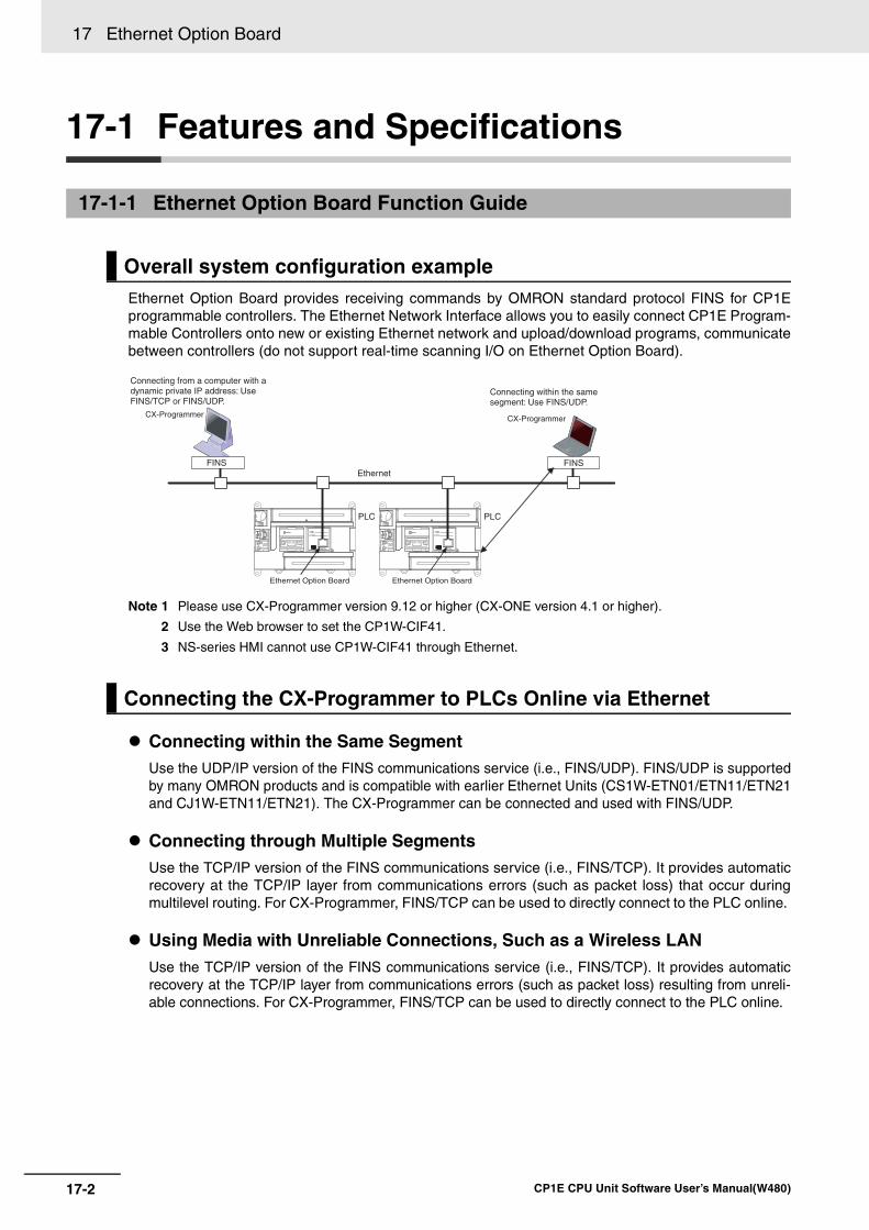
17 Ethernet Option Board
17-2 CP1E CPU Unit Software User’s Manual(W480)
17-1 Features and Specifications
Ethernet Option Board provides receiving commands by OMRON standard protocol FINS for CP1Eprogrammable controllers. The Ethernet Network Interface allows you to easily connect CP1E Program-mable Controllers onto new or existing Ethernet network and upload/download programs, communicatebetween controllers (do not support real-time scanning I/O on Ethernet Option Board).
Note 1 Please use CX-Programmer version 9.12 or higher (CX-ONE version 4.1 or higher).
2 Use the Web browser to set the CP1W-CIF41.
3 NS-series HMI cannot use CP1W-CIF41 through Ethernet.
Connecting within the Same SegmentUse the UDP/IP version of the FINS communications service (i.e., FINS/UDP). FINS/UDP is supportedby many OMRON products and is compatible with earlier Ethernet Units (CS1W-ETN01/ETN11/ETN21and CJ1W-ETN11/ETN21). The CX-Programmer can be connected and used with FINS/UDP.
Connecting through Multiple SegmentsUse the TCP/IP version of the FINS communications service (i.e., FINS/TCP). It provides automaticrecovery at the TCP/IP layer from communications errors (such as packet loss) that occur duringmultilevel routing. For CX-Programmer, FINS/TCP can be used to directly connect to the PLC online.
Using Media with Unreliable Connections, Such as a Wireless LANUse the TCP/IP version of the FINS communications service (i.e., FINS/TCP). It provides automaticrecovery at the TCP/IP layer from communications errors (such as packet loss) resulting from unreli-able connections. For CX-Programmer, FINS/TCP can be used to directly connect to the PLC online.
17-1-1 Ethernet Option Board Function Guide
Overall system configuration example
Connecting the CX-Programmer to PLCs Online via Ethernet
FINSEthernet
Connecting within the same segment: Use FINS/UDP.
PLCPLC
FINS
Connecting from a computer with a dynamic private IP address: Use FINS/TCP or FINS/UDP.
CX-Programmer
Ethernet Option Board Ethernet Option Board
CX-Programmer
17-3
17 Ethernet Option Board
CP1E CPU Unit Software User’s Manual(W480)
17-1 Featu
res and
Sp
ecification
s
17
17-1-2 Features
Connecting from a Personal Computer with a Dynamic Private IP AddressDepending on whether or not the connection will be within the same segment, either use an IPaddress conversion method for dynamic IP addresses in the UDP/IP version of the FINS communi-cations service or use the TCP/IP version of the FINS communications service.
It is possible to connect online to a PLC using the CX-Programmer from a computer serving as atemporarily connected node or a permanent DHCP client.
For CX-Programmer, FINS/TCP can be used to directly connect to the PLC online.
The CP1W-CIF41 Ethernet Option Board can only support receiving FINS commands from OMRONPLCs using Ethernet.
Note The SEND(090), RECV(098) and CMND(490) instructions cannot be used in the CP1E CPU Unit .
Connecting within the Same SegmentUse the UDP/IP version of the FINS communications service (i.e., FINS/UDP), and construct appli-cations using the SEND(090), RECV(098), and CMND(490) instructions in the ladder program.FINS/UDP is supported by many OMRON products, and is compatible with earlier Ethernet Units(CS1W-ETN01/ETN11/ETN21 and CJ1W-ETN11/ETN21). The protocol processing for FINS/UDP issimpler than for FINS/TCP, giving FINS/UDP certain advantages in terms of performance. Anotherfeature of FINS/UDP is that it can be used for broadcasting.
On the other hand, with FINS/UDP it is necessary to provide measures, such as retries, for handlingcommunications errors.
Connecting through Multiple SegmentsUse the TCP/IP version of the FINS communications service (i.e., FINS/TCP), and construct appli-cations using the SEND(090), RECV(098), and CMND(490) instructions in the ladder program.FINS/TCP is the initial function supported by this Ethernet Option Board (CP1W-CIF41). It providesautomatic recovery at the TCP/IP layer from communications errors (such as packet loss) that occurduring multilevel routing.
The transmission medium of Ethernet side has been upgraded to 100Base-TX, while compatibility withsome functions and application interfaces of the existing Ethernet Unit models for CS/CJ series hasbeen maintained.
Limited by the Host Link protocol used on the serial side, the processing speed is only 115.2kbps,slower than the existing Ethernet Unit. The FINS frame length is less than 540 bytes, so the systemresponse performance for the same FINS message applications is longer than the existing EthernetUnit.
Receiving Data from OMRON PLCs using Ethernet
17-1-2 Features
Compatibility and Speed
17 Ethernet Option Board
17-4 CP1E CPU Unit Software User’s Manual(W480)
A variety of protocols make a wide range of applications for use on an Ethernet network. The protocolsthat can be selected include receiving commands by OMRON’s standard protocol FINS and readingEthernet Option Board settings and status by HTTP.
A communications service can be selected according to need, allowing the PLC to be flexibly integratedwith the Ethernet information network.
The following functions have been maintained according to the existing Ethernet Unit models for CS/CJseries.
• The maximum number of nodes is 254.
• Communications are enabled even if the host computer’s IP address is dynamic.
• An automatic client FINS node address allocation function makes it possible to connect online to thePLC even if no FINS node address has been set for the host computer.
• FINS message communications is enabled in both UDP/IP and TCP/IP, but it is only enabled inTCP/IP with up to 2 simultaneous connections (only used as server).
→Previously it is enabled in TCP/IP with up to 16 simultaneous connections and all can be set toclient.
• Multiple FINS applications, such as the CX-Programmer, on the same computer can be connectedonline to the PLC via Ethernet.
A Web function is provided in Ethernet Option Board.
This enables use of a Web browser to read the Ethernet Option Board’s system settings and statuses.
A full range of functions is provided for promptly handling any troubles.
• Self-diagnostic function when power is turned ON.
• Error log for recording error information when an error occurs.
Various Protocols Available on Ethernet
Improved FINS Message Communications
Use Web Function to Read Ethernet Option Board Settings and Status
Full Range of Functions for Handling Troubles
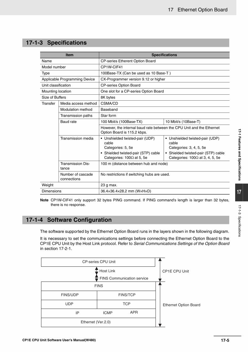
17-5
17 Ethernet Option Board
CP1E CPU Unit Software User’s Manual(W480)
17-1 Featu
res and
Sp
ecification
s
17
17-1-3 Specifications
Note CP1W-CIF41 only support 32 bytes PING command. If PING command's length is larger than 32 bytes,there is no response.
The software supported by the Ethernet Option Board runs in the layers shown in the following diagram.
It is necessary to set the communications settings before connecting the Ethernet Option Board to theCP1E CPU Unit by the Host Link protocol. Refer to Serial Communications Settings of the Option Boardin section 17-2-1.
17-1-3 Specifications
Item Specifications
Name CP-series Etherent Option Board
Model number CP1W-CIF41
Type 100Base-TX (Can be used as 10 Base-T )
Applicable Programming Device CX-Programmer version 9.12 or higher
Unit classification CP-series Option Board
Mounting location One slot for a CP-series Option Board
Size of Buffers 8K bytes
Transfer Media access method CSMA/CD
Modulation method Baseband
Transmission paths Star form
Baud rate 100 Mbit/s (100Base-TX) 10 Mbit/s (10Base-T)
However, the internal baud rate between the CPU Unit and the Ethernet Option Board is 115.2 kbps.
Transmission media • Unshielded twisted-pair (UDP) cable Categories: 5, 5e
• Shielded twisted-pair (STP) cable Categories: 100Ω at 5, 5e
• Unshielded twisted-pair (UDP) cableCategories: 3, 4, 5, 5e
• Shielded twisted-pair (STP) cable Categories: 100Ω at 3, 4, 5, 5e
Transmission Dis-tance
100 m (distance between hub and node)
Number of cascade connections
No restrictions if switching hubs are used.
Weight 23 g max.
Dimensions 36.4×36.4×28.2 mm (W×H×D)
17-1-4 Software Configuration
CP-series CPU Unit
FINS
FINS/UDP FINS/TCP
UDP TCP
IP ICMP
Ethernet (Ver.2.0)
CP1E CPU Unit
Ethernet Option Board
FINS Communication service
Host Link
APR
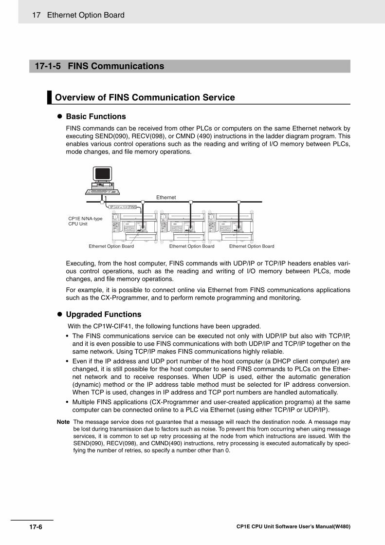
17 Ethernet Option Board
17-6 CP1E CPU Unit Software User’s Manual(W480)
Basic FunctionsFINS commands can be received from other PLCs or computers on the same Ethernet network byexecuting SEND(090), RECV(098), or CMND (490) instructions in the ladder diagram program. Thisenables various control operations such as the reading and writing of I/O memory between PLCs,mode changes, and file memory operations.
Executing, from the host computer, FINS commands with UDP/IP or TCP/IP headers enables vari-ous control operations, such as the reading and writing of I/O memory between PLCs, modechanges, and file memory operations.
For example, it is possible to connect online via Ethernet from FINS communications applicationssuch as the CX-Programmer, and to perform remote programming and monitoring.
Upgraded Functions With the CP1W-CIF41, the following functions have been upgraded.
• The FINS communications service can be executed not only with UDP/IP but also with TCP/IP,and it is even possible to use FINS communications with both UDP/IP and TCP/IP together on thesame network. Using TCP/IP makes FINS communications highly reliable.
• Even if the IP address and UDP port number of the host computer (a DHCP client computer) arechanged, it is still possible for the host computer to send FINS commands to PLCs on the Ether-net network and to receive responses. When UDP is used, either the automatic generation(dynamic) method or the IP address table method must be selected for IP address conversion.When TCP is used, changes in IP address and TCP port numbers are handled automatically.
• Multiple FINS applications (CX-Programmer and user-created application programs) at the samecomputer can be connected online to a PLC via Ethernet (using either TCP/IP or UDP/IP).
Note The message service does not guarantee that a message will reach the destination node. A message maybe lost during transmission due to factors such as noise. To prevent this from occurring when using messageservices, it is common to set up retry processing at the node from which instructions are issued. With theSEND(090), RECV(098), and CMND(490) instructions, retry processing is executed automatically by speci-fying the number of retries, so specify a number other than 0.
17-1-5 FINS Communications
Overview of FINS Communication Service
Ethernet
Ethernet Option Board Ethernet Option Board Ethernet Option Board
IP UDP or TCP FINS
CP1E N/NA-type CPU Unit
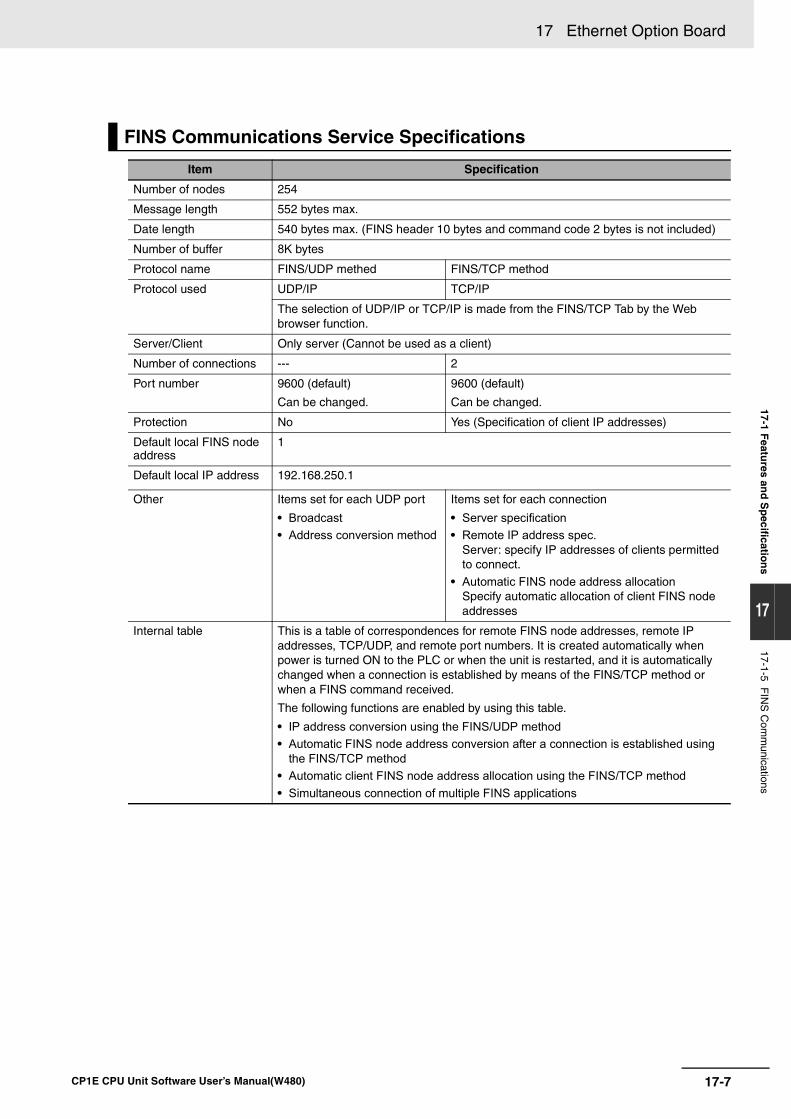
17-7
17 Ethernet Option Board
CP1E CPU Unit Software User’s Manual(W480)
17-1 Featu
res and
Sp
ecification
s
17
17-1-5 FIN
S C
omm
unications
FINS Communications Service Specifications
Item Specification
Number of nodes 254
Message length 552 bytes max.
Date length 540 bytes max. (FINS header 10 bytes and command code 2 bytes is not included)
Number of buffer 8K bytes
Protocol name FINS/UDP methed FINS/TCP method
Protocol used UDP/IP TCP/IP
The selection of UDP/IP or TCP/IP is made from the FINS/TCP Tab by the Web browser function.
Server/Client Only server (Cannot be used as a client)
Number of connections --- 2
Port number 9600 (default)
Can be changed.
9600 (default)
Can be changed.
Protection No Yes (Specification of client IP addresses)
Default local FINS node address
1
Default local IP address 192.168.250.1
Other Items set for each UDP port
• Broadcast• Address conversion method
Items set for each connection
• Server specification• Remote IP address spec.
Server: specify IP addresses of clients permitted to connect.
• Automatic FINS node address allocationSpecify automatic allocation of client FINS node addresses
Internal table This is a table of correspondences for remote FINS node addresses, remote IP addresses, TCP/UDP, and remote port numbers. It is created automatically when power is turned ON to the PLC or when the unit is restarted, and it is automatically changed when a connection is established by means of the FINS/TCP method or when a FINS command received.
The following functions are enabled by using this table.
• IP address conversion using the FINS/UDP method• Automatic FINS node address conversion after a connection is established using
the FINS/TCP method• Automatic client FINS node address allocation using the FINS/TCP method• Simultaneous connection of multiple FINS applications
17 Ethernet Option Board
17-8 CP1E CPU Unit Software User’s Manual(W480)
Precautions for Correct UsePrecautions for Correct Use
The differences between the Ethernet Option Board and the CS/CJ series Ethernet Unit are as follows.
• Connect with the CPU Unit by the Host Link (serial communications) whose internal baud rate is 115.2 kbps.
• The size of communications buffers is 8K bytes, one fifty of that of the CS/CJ series Ethernet Unit.Therefore, the communication performance is slower than the CS/CJ series Ethernet Unit.
Refer to the following processing time (Netwok delay is not included), when accessing to the CP-series CPU Unit through the Ethernet Option Board.
When accessing to the CP1E CPU Unit and reading 269 words from the DM area, if the cycle time of the CPU Unit is 10 ms, the processing time will be more than 225 ms and less than 356 ms.
For the CS/CJ series CPU Unit who installs the Ethernet Unit, when executing the same task, the process-ing time will be approximately 20 ms, up to 17 times faster.
CP1W-CIF41 Ethernet Option Board has two versions: version 1 and version 2. Only version 2 can beused on the CP1E CPU Unit.
The CP1E CPU Unit does not support the Toolbus protocol, so the Ethernet Option Board version 1.0cannot be used.
17-1-6 Differences in version of the Ethernet Option Board
Comparison with CP1W-CIF41 Version 1.0
Item CP1W-CIF41 version 1.0 CP1W-CIF41 version 2.0
Communications mode Toolbus (CP1L/CP1H) Toolbus (CP1L/CP1H)
Host Link (CP1E)
Reset system settings function Not supported Turn ON the Reset Flag A525.01 in the Auxiliary Area.
Restart function Click the Restart Button from the Web browser.
• Click the Restart Button from the Web browser.
• Turn ON the Restart Flag A525.09 in the Auxiliary Area.
Max. number of units that can be mounted
Cannot be used 1 set
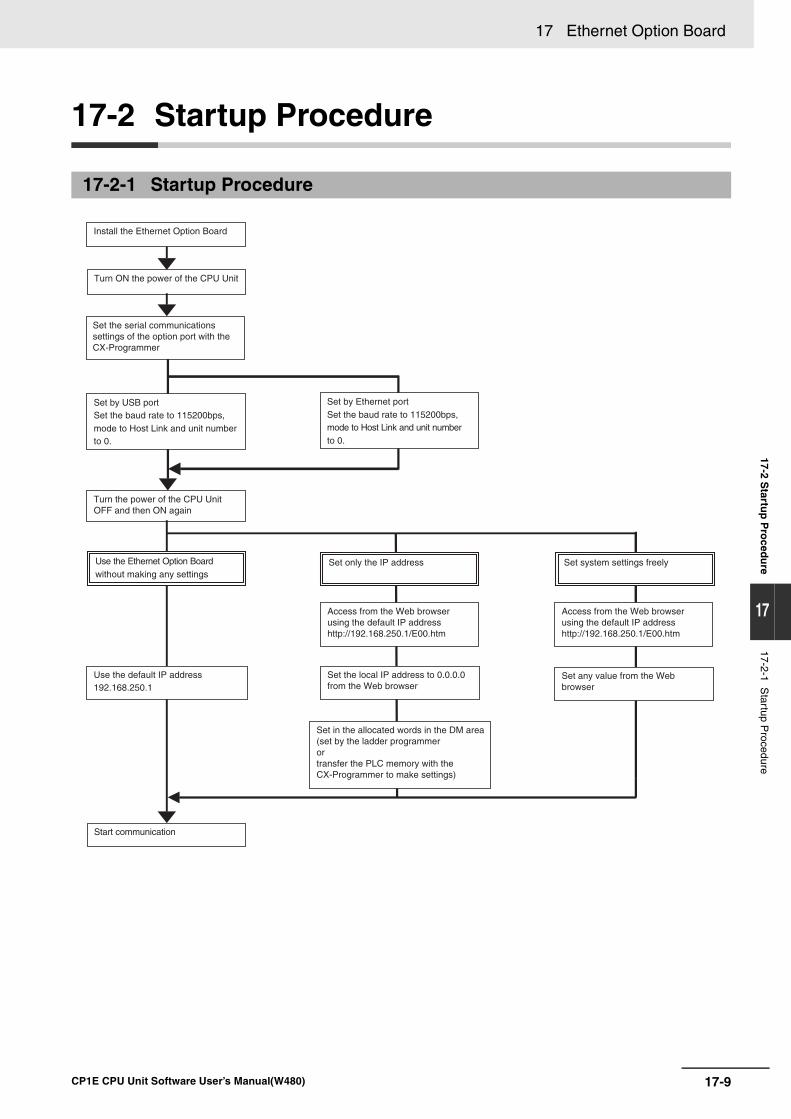
17-9
17 Ethernet Option Board
CP1E CPU Unit Software User’s Manual(W480)
17-2 Startu
p P
roced
ure
17
17-2-1 Startup P
rocedure
17-2 Startup Procedure
17-2-1 Startup Procedure
Turn the power of the CPU Unit OFF and then ON again
Use the Ethernet Option Board without making any settings
Use the default IP address 192.168.250.1
Set only the IP address
Access from the Web browser using the default IP address http://192.168.250.1/E00.htm
Set any value from the Web browser
Set system settings freely
Start communication
Set in the allocated words in the DM area(set by the ladder programmer or transfer the PLC memory with the CX-Programmer to make settings)
Access from the Web browser using the default IP address http://192.168.250.1/E00.htm
Set the local IP address to 0.0.0.0 from the Web browser
Set the serial communications settings of the option port with the CX-Programmer
Turn ON the power of the CPU Unit
Install the Ethernet Option Board
Set by USB port Set the baud rate to 115200bps, mode to Host Link and unit number to 0.
Set by Ethernet port Set the baud rate to 115200bps, mode to Host Link and unit number to 0.
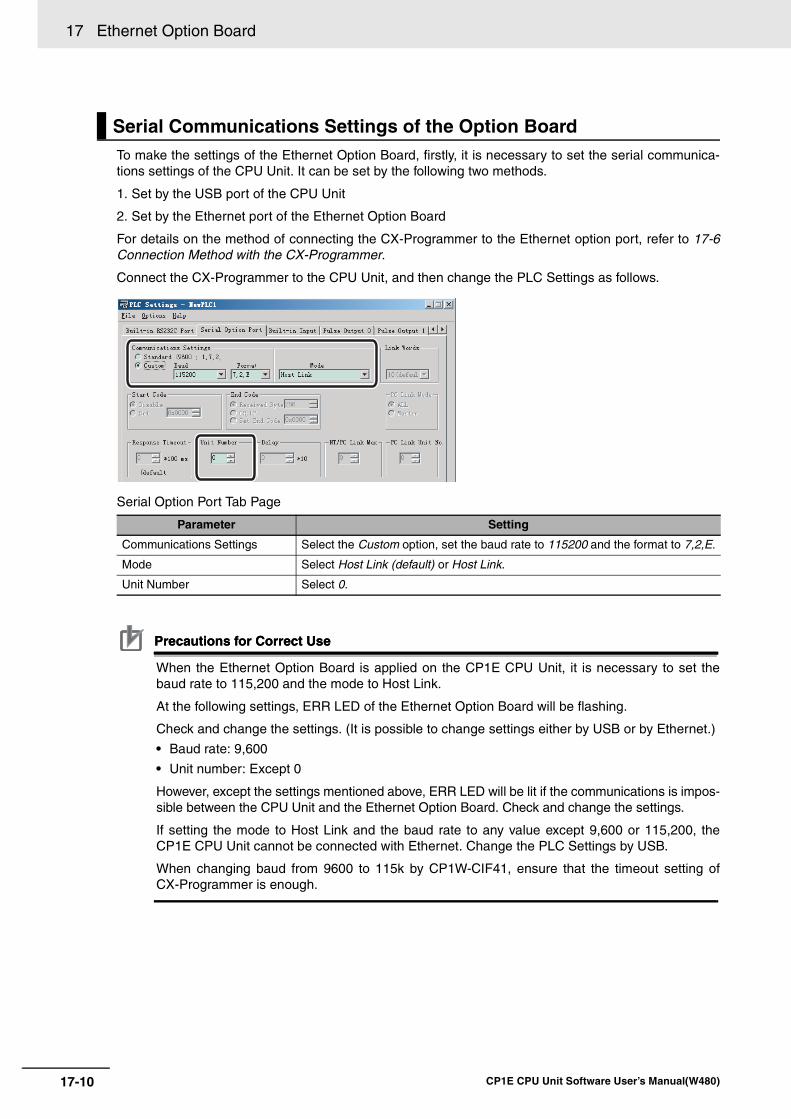
17 Ethernet Option Board
17-10 CP1E CPU Unit Software User’s Manual(W480)
To make the settings of the Ethernet Option Board, firstly, it is necessary to set the serial communica-tions settings of the CPU Unit. It can be set by the following two methods.
1. Set by the USB port of the CPU Unit
2. Set by the Ethernet port of the Ethernet Option Board
For details on the method of connecting the CX-Programmer to the Ethernet option port, refer to 17-6Connection Method with the CX-Programmer.
Connect the CX-Programmer to the CPU Unit, and then change the PLC Settings as follows.
Serial Option Port Tab Page
Precautions for Correct UsePrecautions for Correct Use
When the Ethernet Option Board is applied on the CP1E CPU Unit, it is necessary to set thebaud rate to 115,200 and the mode to Host Link.
At the following settings, ERR LED of the Ethernet Option Board will be flashing.
Check and change the settings. (It is possible to change settings either by USB or by Ethernet.)
• Baud rate: 9,600
• Unit number: Except 0
However, except the settings mentioned above, ERR LED will be lit if the communications is impos-sible between the CPU Unit and the Ethernet Option Board. Check and change the settings.
If setting the mode to Host Link and the baud rate to any value except 9,600 or 115,200, theCP1E CPU Unit cannot be connected with Ethernet. Change the PLC Settings by USB.
When changing baud from 9600 to 115k by CP1W-CIF41, ensure that the timeout setting ofCX-Programmer is enough.
Serial Communications Settings of the Option Board
Parameter Setting
Communications Settings Select the Custom option, set the baud rate to 115200 and the format to 7,2,E.
Mode Select Host Link (default) or Host Link.
Unit Number Select 0.
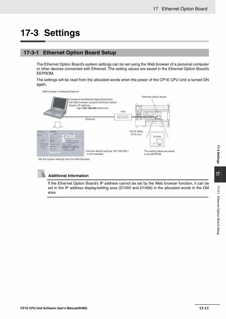
17-11
17 Ethernet Option Board
CP1E CPU Unit Software User’s Manual(W480)
17-3 Settin
gs
17
17-3-1 Ethernet O
ption Board S
etup
17-3 Settings
The Ethernet Option Board’s system settings can be set using the Web browser of a personal computeror other devices connected with Ethernet. The setting values are saved in the Ethernet Option Board’sEEPROM.
The settings will be read from the allocated words when the power of the CP1E CPU Unit is turned ONagain.
Additional Information
If the Ethernet Option Board’s IP address cannot be set by the Web browser function, it can beset in the IP address display/setting area (D1455 and D1456) in the allocated words in the DMarea.
17-3-1 Ethernet Option Board Setup
CP1E N/NA CPU Unit
Web browser of Internet Explorer
Connect to the Ethernet Option Board from the Web browser using the Ethernet Option Board’s IP address
http://192.168.250.1/E00.htm
Ethernet
Set the system settings from the Web Browser.
* Use the default settings 192.168.250.1 in this example.
Hub
The setting values are saved in the EEPROM.
IP ADDRESS:
SUBNET MASK:
COMMERR10BASE-T
100BASE-TX
EEPROM
Ethernet Option Board
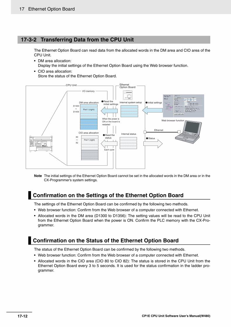
17 Ethernet Option Board
17-12 CP1E CPU Unit Software User’s Manual(W480)
The Ethernet Option Board can read data from the allocated words in the DM area and CIO area of theCPU Unit.
• DM area allocation:Display the initial settings of the Ethernet Option Board using the Web browser function.
• CIO area allocation:Store the status of the Ethernet Option Board.
Note The initial settings of the Ethernet Option Board cannot be set in the allocated words in the DM area or in theCX-Programmer’s system settings.
The settings of the Ethernet Option Board can be confirmed by the following two methods.
• Web browser function: Confirm from the Web browser of a computer connected with Ethernet.
• Allocated words in the DM area (D1300 to D1356): The setting values will be read to the CPU Unitfrom the Ethernet Option Board when the power is ON. Confirm the PLC memory with the CX-Pro-grammer.
The status of the Ethernet Option Board can be confirmed by the following two methods.
• Web browser function: Confirm from the Web browser of a computer connected with Ethernet.
• Allocated words in the CIO area (CIO 80 to CIO 82): The status is stored in the CPU Unit from theEthernet Option Board every 3 to 5 seconds. It is used for the status confirmation in the ladder pro-grammer.
17-3-2 Transferring Data from the CPU Unit
Confirmation on the Settings of the Ethernet Option Board
Confirmation on the Status of the Ethernet Option Board
I/O memory
EthernetOption Board
CPU Unit
Web browser function
CIO area allocation
80
82
Internal status
DM area allocationD1300
D1454
Read the initial settings
Port (right)
Internal system setup
Initial settings
When the power is
ON or the board is
restarted
Each cycle
Ethernet
Status Read the status
Port (right)
IP ADDRESS:
SUBNET MASK:
COMM ERR10BASE-T
100BASE-TX
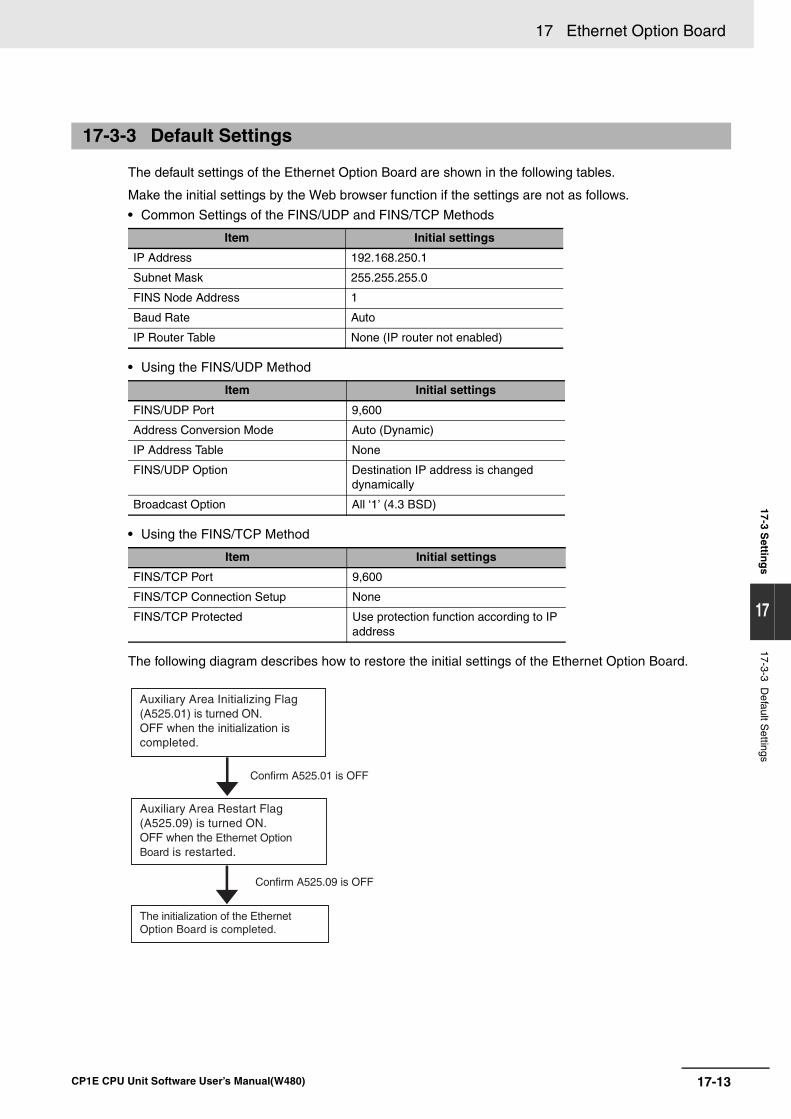
17-13
17 Ethernet Option Board
CP1E CPU Unit Software User’s Manual(W480)
17-3 Settin
gs
17
17-3-3 Default S
ettings
The default settings of the Ethernet Option Board are shown in the following tables.
Make the initial settings by the Web browser function if the settings are not as follows.
• Common Settings of the FINS/UDP and FINS/TCP Methods
• Using the FINS/UDP Method
• Using the FINS/TCP Method
The following diagram describes how to restore the initial settings of the Ethernet Option Board.
17-3-3 Default Settings
Item Initial settings
IP Address 192.168.250.1
Subnet Mask 255.255.255.0
FINS Node Address 1
Baud Rate Auto
IP Router Table None (IP router not enabled)
Item Initial settings
FINS/UDP Port 9,600
Address Conversion Mode Auto (Dynamic)
IP Address Table None
FINS/UDP Option Destination IP address is changed dynamically
Broadcast Option All ‘1’ (4.3 BSD)
Item Initial settings
FINS/TCP Port 9,600
FINS/TCP Connection Setup None
FINS/TCP Protected Use protection function according to IP address
The initialization of the Ethernet Option Board is completed.
Auxiliary Area Restart Flag (A525.09) is turned ON. OFF when the Ethernet Option Board is restarted.
Auxiliary Area Initializing Flag (A525.01) is turned ON. OFF when the initialization is completed.
Confirm A525.01 is OFF
Confirm A525.09 is OFF
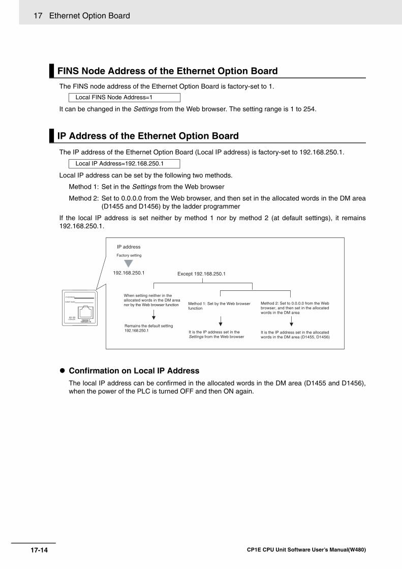
17 Ethernet Option Board
17-14 CP1E CPU Unit Software User’s Manual(W480)
The FINS node address of the Ethernet Option Board is factory-set to 1.
It can be changed in the Settings from the Web browser. The setting range is 1 to 254.
The IP address of the Ethernet Option Board (Local IP address) is factory-set to 192.168.250.1.
Local IP address can be set by the following two methods.
Method 1: Set in the Settings from the Web browser
Method 2: Set to 0.0.0.0 from the Web browser, and then set in the allocated words in the DM area(D1455 and D1456) by the ladder programmer
If the local IP address is set neither by method 1 nor by method 2 (at default settings), it remains192.168.250.1.
Confirmation on Local IP AddressThe local IP address can be confirmed in the allocated words in the DM area (D1455 and D1456),when the power of the PLC is turned OFF and then ON again.
FINS Node Address of the Ethernet Option Board
Local FINS Node Address=1
IP Address of the Ethernet Option Board
Local IP Address=192.168.250.1
Factory setting
192.168.250.1
When setting neither in the allocated words in the DM area nor by the Web browser function
Remains the default setting 192.168.250.1
Except 192.168.250.1
Method 1: Set by the Web browser function
IP address
Method 2: Set to 0.0.0.0 from the Web browser, and then set in the allocated words in the DM area
It is the IP address set in the Settings from the Web browser
It is the IP address set in the allocated words in the DM area (D1455, D1456)
IP ADDRESS:
SUBNET MASK:
COMM ERR10BASE-T
100BASE-TX
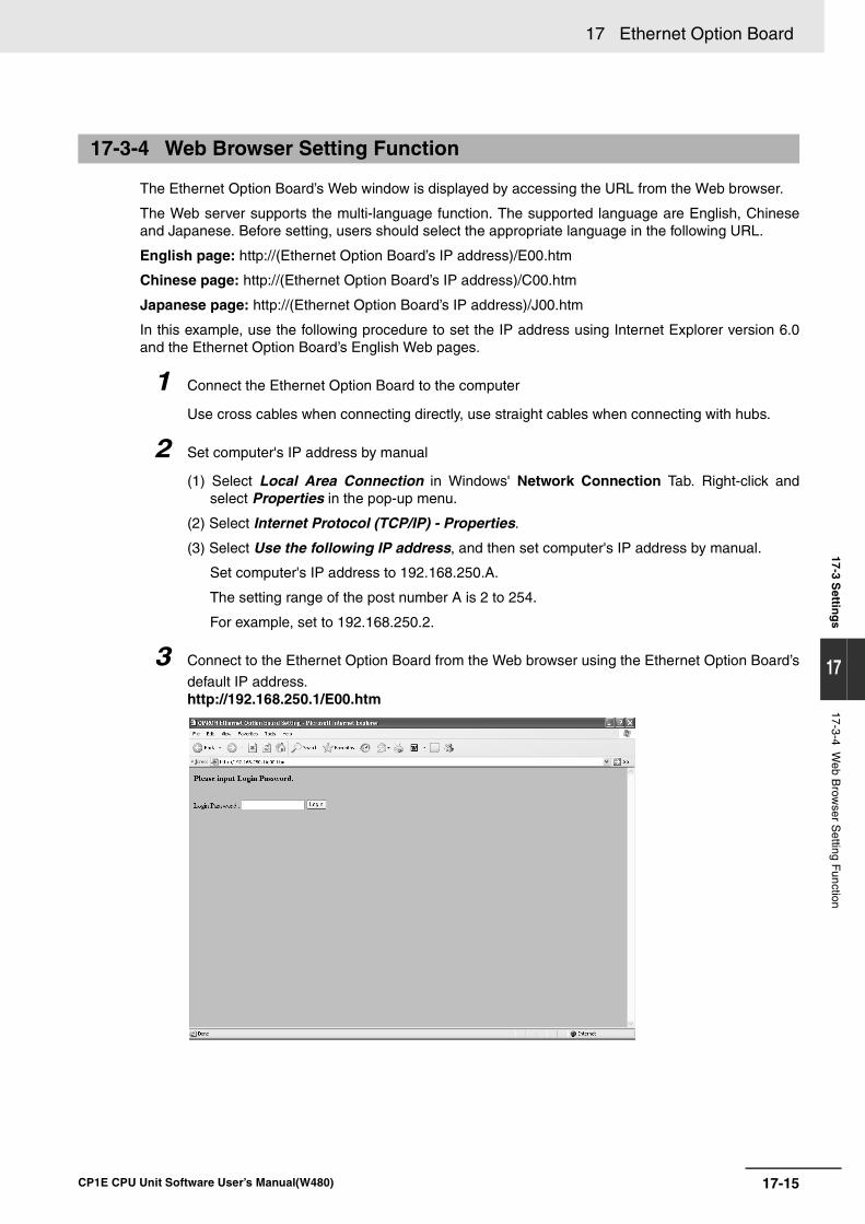
17-15
17 Ethernet Option Board
CP1E CPU Unit Software User’s Manual(W480)
17-3 Settin
gs
17
17-3-4 Web B
rowser S
etting Function
The Ethernet Option Board’s Web window is displayed by accessing the URL from the Web browser.
The Web server supports the multi-language function. The supported language are English, Chineseand Japanese. Before setting, users should select the appropriate language in the following URL.
English page: http://(Ethernet Option Board’s IP address)/E00.htm
Chinese page: http://(Ethernet Option Board’s IP address)/C00.htm
Japanese page: http://(Ethernet Option Board’s IP address)/J00.htm
In this example, use the following procedure to set the IP address using Internet Explorer version 6.0and the Ethernet Option Board’s English Web pages.
1 Connect the Ethernet Option Board to the computer
Use cross cables when connecting directly, use straight cables when connecting with hubs.
2 Set computer's IP address by manual
(1) Select Local Area Connection in Windows' Network Connection Tab. Right-click andselect Properties in the pop-up menu.
(2) Select Internet Protocol (TCP/IP) - Properties.
(3) Select Use the following IP address, and then set computer's IP address by manual.
Set computer's IP address to 192.168.250.A.
The setting range of the post number A is 2 to 254.
For example, set to 192.168.250.2.
3 Connect to the Ethernet Option Board from the Web browser using the Ethernet Option Board’s
default IP address.http://192.168.250.1/E00.htm
17-3-4 Web Browser Setting Function
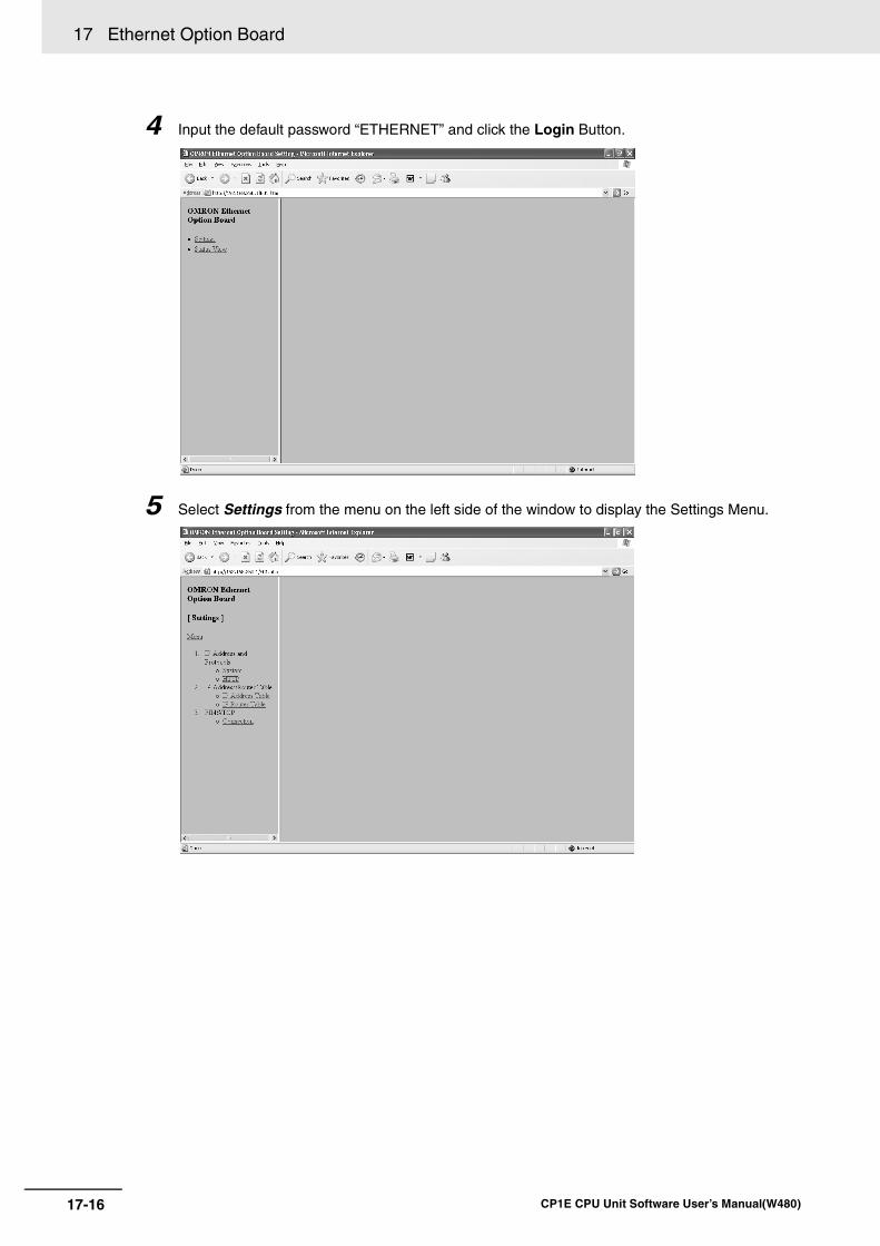
17 Ethernet Option Board
17-16 CP1E CPU Unit Software User’s Manual(W480)
4 Input the default password “ETHERNET” and click the Login Button.
5 Select Settings from the menu on the left side of the window to display the Settings Menu.
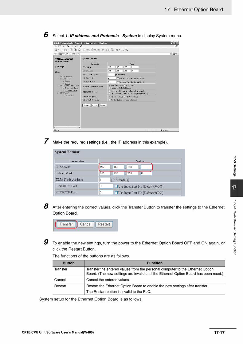
17-17
17 Ethernet Option Board
CP1E CPU Unit Software User’s Manual(W480)
17-3 Settin
gs
17
17-3-4 Web B
rowser S
etting Function
6 Select 1. IP address and Protocols - System to display System menu.
7 Make the required settings (i.e., the IP address in this example).
8 After entering the correct values, click the Transfer Button to transfer the settings to the Ethernet
Option Board.
9 To enable the new settings, turn the power to the Ethernet Option Board OFF and ON again, or
click the Restart Button.
The functions of the buttons are as follows.
System setup for the Ethernet Option Board is as follows.
Button Function
Transfer Transfer the entered values from the personal computer to the Ethernet Option Board. (The new settings are invalid until the Ethernet Option Board has been reset.)
Cancel Cancel the entered values.
Restart Restart the Ethernet Option Board to enable the new settings after transfer.
The Restart button is invalid to the PLC.
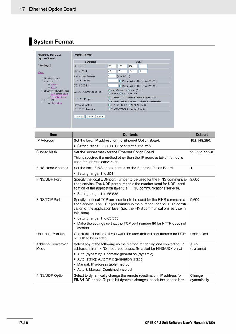
17 Ethernet Option Board
17-18 CP1E CPU Unit Software User’s Manual(W480)
System Format
Item Contents Default
IP Address Set the local IP address for the Ethernet Option Board.
• Setting range: 00.00.00.00 to 223.255.255.255
192.168.250.1
Subnet Mask Set the subnet mask for the Ethernet Option Board.
This is required if a method other than the IP address table method is used for address conversion.
255.255.255.0
FINS Node Address Set the local FINS node address for the Ethernet Option Board.
• Setting range: 1 to 254
1
FINS/UDP Port Specify the local UDP port number to be used for the FINS communica-tions service. The UDP port number is the number used for UDP identi-fication of the application layer (i.e., FINS communications service).
• Setting range: 1 to 65,535
9,600
FINS/TCP Port Specify the local TCP port number to be used for the FINS communica-tions service. The TCP port number is the number used for TCP identifi-cation of the application layer (i.e., the FINS communications service in this case).
• Setting range: 1 to 65,535• Make the settings so that the TCP port number 80 for HTTP does not
overlap.
9,600
Use Input Port No. Check this checkbox, if you want the user defined port number for UDP or TCP to be in effect.
Unchecked
Address Conversion Mode
Select any of the following as the method for finding and converting IP addresses from FINS node addresses. (Enabled for FINS/UDP only.)
• Auto (dynamic): Automatic generation (dynamic)• Auto (static): Automatic generation (static)• Manual: IP address table method
• Auto & Manual: Combined method
Auto (dynamic)
FINS/UDP Option Select to dynamically change the remote (destination) IP address for FINS/UDP or not. To prohibit dynamic changes, check the second box.
Change dynamically
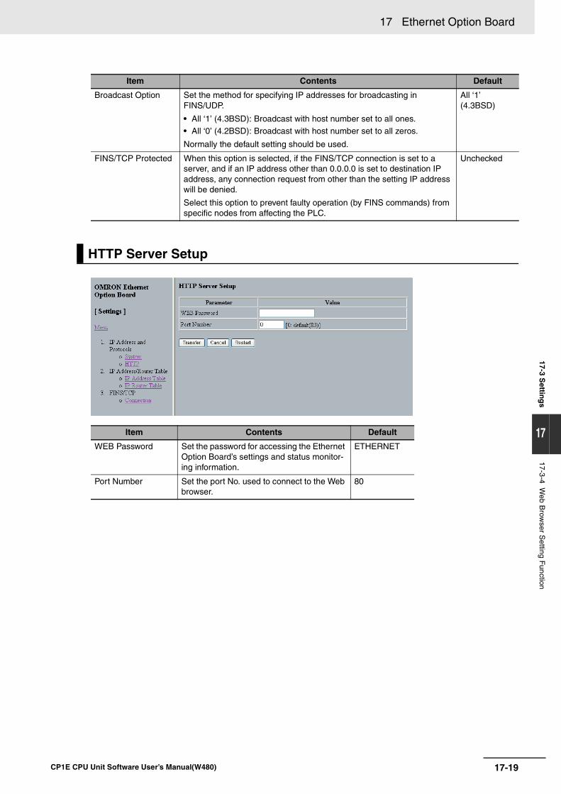
17-19
17 Ethernet Option Board
CP1E CPU Unit Software User’s Manual(W480)
17-3 Settin
gs
17
17-3-4 Web B
rowser S
etting Function
Item Contents Default
Broadcast Option Set the method for specifying IP addresses for broadcasting in FINS/UDP.
• All ‘1’ (4.3BSD): Broadcast with host number set to all ones.• All ‘0’ (4.2BSD): Broadcast with host number set to all zeros.
Normally the default setting should be used.
All ‘1’ (4.3BSD)
FINS/TCP Protected When this option is selected, if the FINS/TCP connection is set to a server, and if an IP address other than 0.0.0.0 is set to destination IP address, any connection request from other than the setting IP address will be denied.
Select this option to prevent faulty operation (by FINS commands) from specific nodes from affecting the PLC.
Unchecked
HTTP Server Setup
Item Contents Default
WEB Password Set the password for accessing the Ethernet Option Board’s settings and status monitor-ing information.
ETHERNET
Port Number Set the port No. used to connect to the Web browser.
80
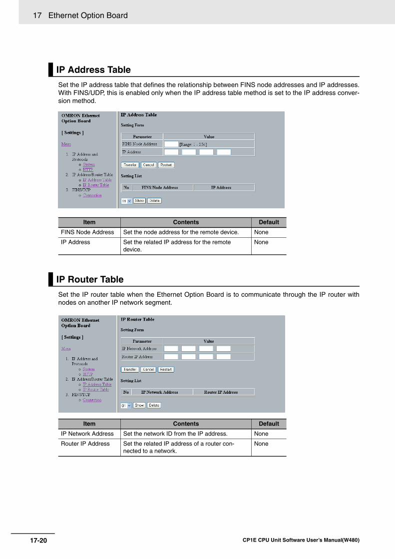
17 Ethernet Option Board
17-20 CP1E CPU Unit Software User’s Manual(W480)
Set the IP address table that defines the relationship between FINS node addresses and IP addresses.With FINS/UDP, this is enabled only when the IP address table method is set to the IP address conver-sion method.
Set the IP router table when the Ethernet Option Board is to communicate through the IP router withnodes on another IP network segment.
IP Address Table
Item Contents Default
FINS Node Address Set the node address for the remote device. None
IP Address Set the related IP address for the remote device.
None
IP Router Table
Item Contents Default
IP Network Address Set the network ID from the IP address. None
Router IP Address Set the related IP address of a router con-nected to a network.
None
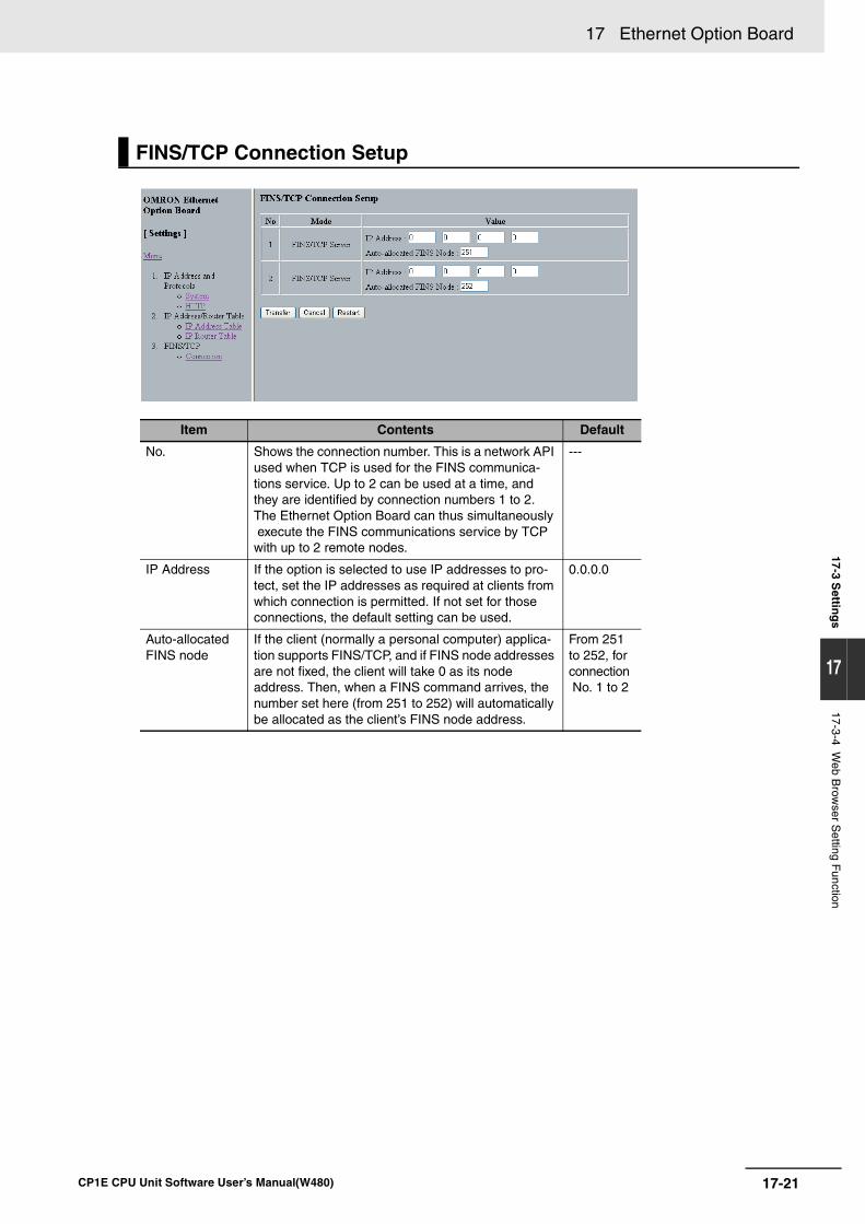
17-21
17 Ethernet Option Board
CP1E CPU Unit Software User’s Manual(W480)
17-3 Settin
gs
17
17-3-4 Web B
rowser S
etting Function
FINS/TCP Connection Setup
Item Contents Default
No. Shows the connection number. This is a network API used when TCP is used for the FINS communica-tions service. Up to 2 can be used at a time, and they are identified by connection numbers 1 to 2. The Ethernet Option Board can thus simultaneously execute the FINS communications service by TCP with up to 2 remote nodes.
---
IP Address If the option is selected to use IP addresses to pro-tect, set the IP addresses as required at clients from which connection is permitted. If not set for those connections, the default setting can be used.
0.0.0.0
Auto-allocated FINS node
If the client (normally a personal computer) applica-tion supports FINS/TCP, and if FINS node addresses are not fixed, the client will take 0 as its node address. Then, when a FINS command arrives, the number set here (from 251 to 252) will automatically be allocated as the client’s FINS node address.
From 251 to 252, for connection No. 1 to 2
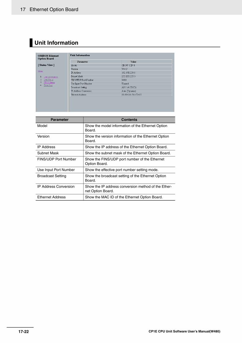
17 Ethernet Option Board
17-22 CP1E CPU Unit Software User’s Manual(W480)
Unit Information
Parameter Contents
Model Show the model information of the Ethernet Option Board.
Version Show the version information of the Ethernet Option Board.
IP Address Show the IP address of the Ethernet Option Board.
Subnet Mask Show the subnet mask of the Ethernet Option Board.
FINS/UDP Port Number Show the FINS/UDP port number of the Ethernet Option Board.
Use Input Port Number Show the effective port number setting mode.
Broadcast Setting Show the broadcast setting of the Ethernet Option Board.
IP Address Conversion Show the IP address conversion method of the Ether-net Option Board.
Ethernet Address Show the MAC ID of the Ethernet Option Board.
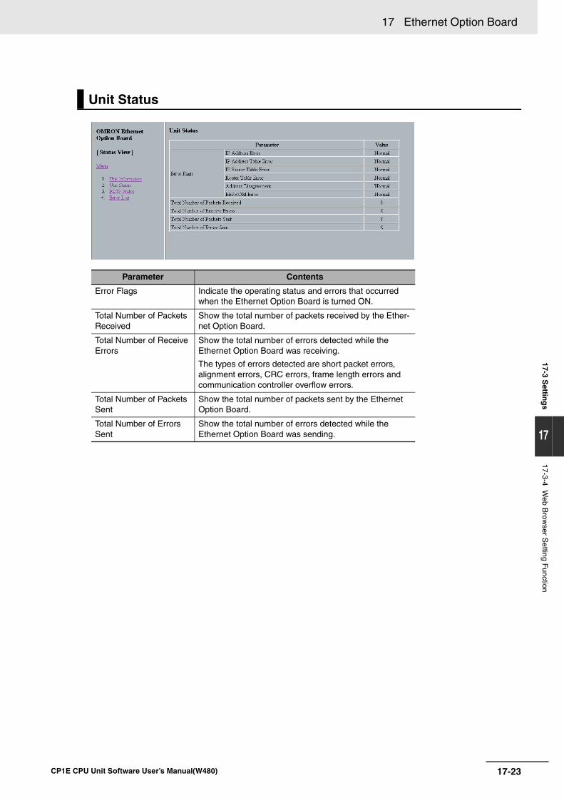
17-23
17 Ethernet Option Board
CP1E CPU Unit Software User’s Manual(W480)
17-3 Settin
gs
17
17-3-4 Web B
rowser S
etting Function
Unit Status
Parameter Contents
Error Flags Indicate the operating status and errors that occurred when the Ethernet Option Board is turned ON.
Total Number of Packets Received
Show the total number of packets received by the Ether-net Option Board.
Total Number of Receive Errors
Show the total number of errors detected while the Ethernet Option Board was receiving.
The types of errors detected are short packet errors, alignment errors, CRC errors, frame length errors and communication controller overflow errors.
Total Number of Packets Sent
Show the total number of packets sent by the Ethernet Option Board.
Total Number of Errors Sent
Show the total number of errors detected while the Ethernet Option Board was sending.
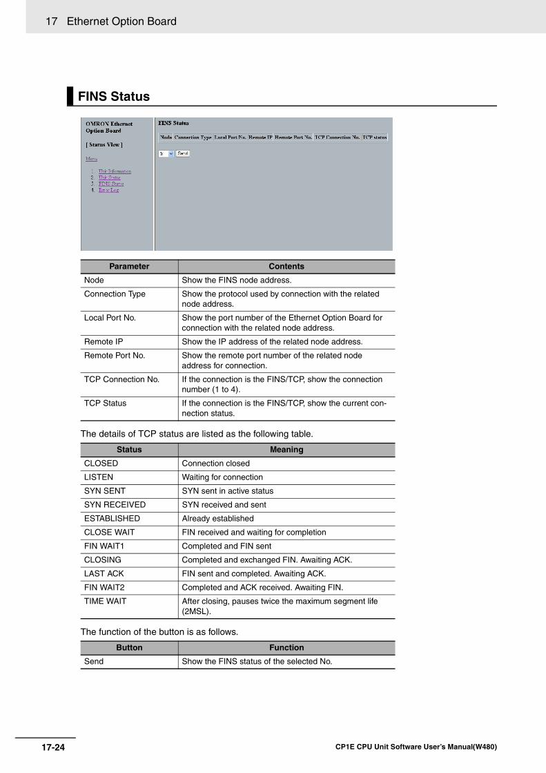
17 Ethernet Option Board
17-24 CP1E CPU Unit Software User’s Manual(W480)
The details of TCP status are listed as the following table.
The function of the button is as follows.
FINS Status
Parameter Contents
Node Show the FINS node address.
Connection Type Show the protocol used by connection with the related node address.
Local Port No. Show the port number of the Ethernet Option Board for connection with the related node address.
Remote IP Show the IP address of the related node address.
Remote Port No. Show the remote port number of the related node address for connection.
TCP Connection No. If the connection is the FINS/TCP, show the connection number (1 to 4).
TCP Status If the connection is the FINS/TCP, show the current con-nection status.
Status Meaning
CLOSED Connection closed
LISTEN Waiting for connection
SYN SENT SYN sent in active status
SYN RECEIVED SYN received and sent
ESTABLISHED Already established
CLOSE WAIT FIN received and waiting for completion
FIN WAIT1 Completed and FIN sent
CLOSING Completed and exchanged FIN. Awaiting ACK.
LAST ACK FIN sent and completed. Awaiting ACK.
FIN WAIT2 Completed and ACK received. Awaiting FIN.
TIME WAIT After closing, pauses twice the maximum segment life (2MSL).
Button Function
Send Show the FINS status of the selected No.
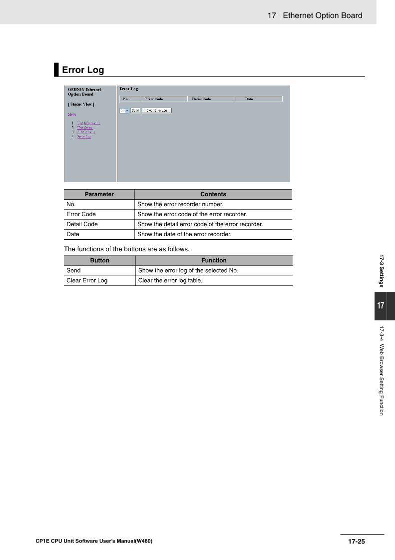
17-25
17 Ethernet Option Board
CP1E CPU Unit Software User’s Manual(W480)
17-3 Settin
gs
17
17-3-4 Web B
rowser S
etting Function
The functions of the buttons are as follows.
Error Log
Parameter Contents
No. Show the error recorder number.
Error Code Show the error code of the error recorder.
Detail Code Show the detail error code of the error recorder.
Date Show the date of the error recorder.
Button Function
Send Show the error log of the selected No.
Clear Error Log Clear the error log table.
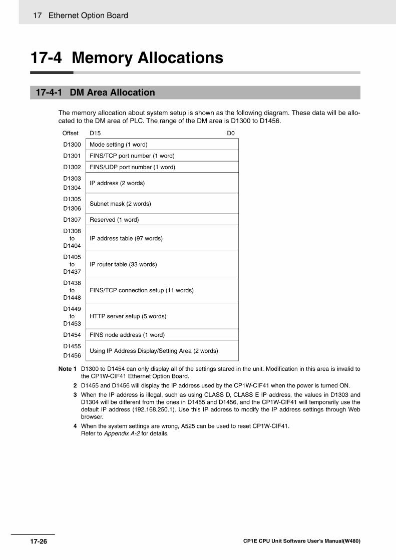
17 Ethernet Option Board
17-26 CP1E CPU Unit Software User’s Manual(W480)
17-4 Memory Allocations
The memory allocation about system setup is shown as the following diagram. These data will be allo-cated to the DM area of PLC. The range of the DM area is D1300 to D1456.
Note 1 D1300 to D1454 can only display all of the settings stared in the unit. Modification in this area is invalid tothe CP1W-CIF41 Ethernet Option Board.
2 D1455 and D1456 will display the IP address used by the CP1W-CIF41 when the power is turned ON.
3 When the IP address is illegal, such as using CLASS D, CLASS E IP address, the values in D1303 andD1304 will be different from the ones in D1455 and D1456, and the CP1W-CIF41 will temporarily use thedefault IP address (192.168.250.1). Use this IP address to modify the IP address settings through Webbrowser.
4 When the system settings are wrong, A525 can be used to reset CP1W-CIF41.Refer to Appendix A-2 for details.
17-4-1 DM Area Allocation
Offset D15 D0
D1300 Mode setting (1 word)
D1301 FINS/TCP port number (1 word)
D1302 FINS/UDP port number (1 word)
D1303
D1304IP address (2 words)
D1305
D1306Subnet mask (2 words)
D1307 Reserved (1 word)
D1308to
D1404IP address table (97 words)
D1405to
D1437IP router table (33 words)
D1438to
D1448FINS/TCP connection setup (11 words)
D1449to
D1453HTTP server setup (5 words)
D1454 FINS node address (1 word)
D1455
D1456Using IP Address Display/Setting Area (2 words)
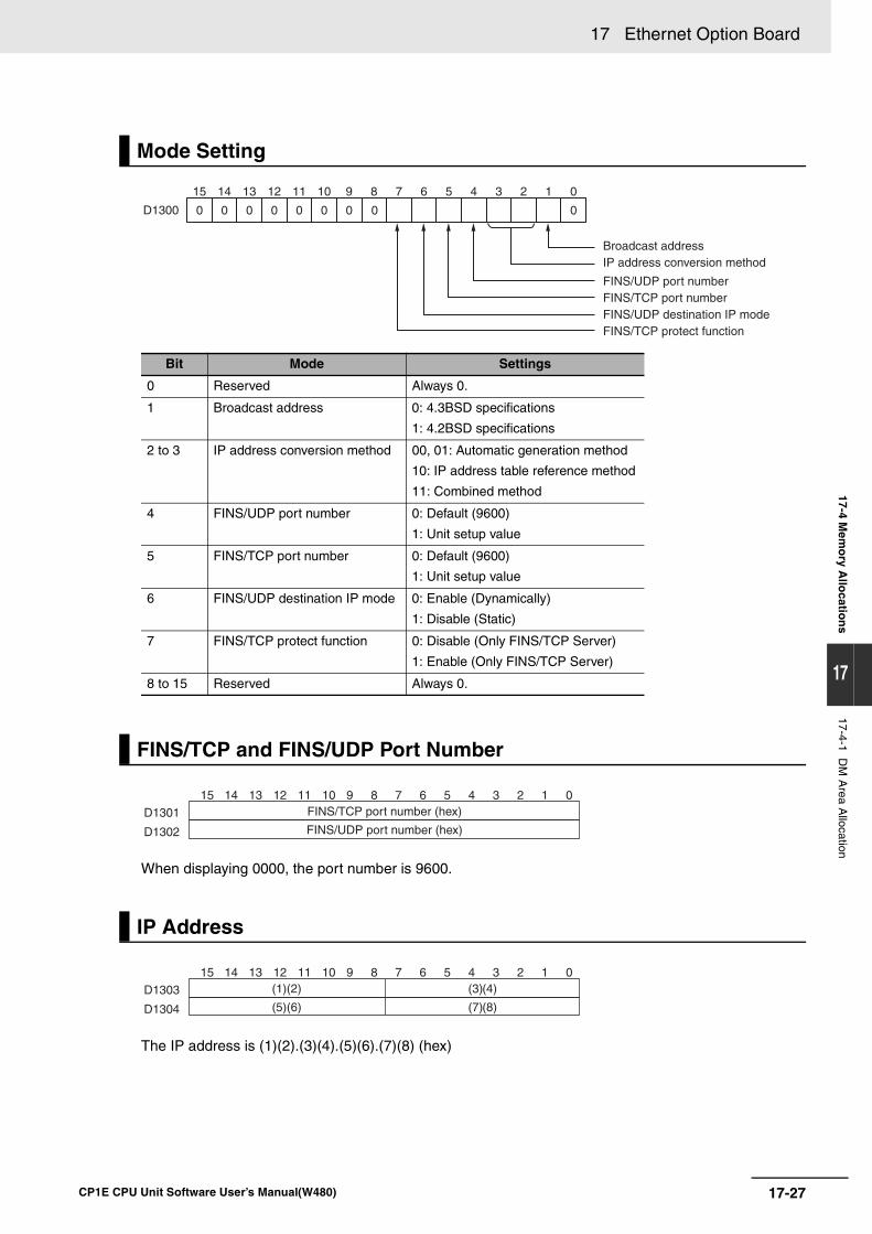
17-27
17 Ethernet Option Board
CP1E CPU Unit Software User’s Manual(W480)
17-4 Mem
ory A
llocatio
ns
17
17-4-1 DM
Area A
llocation
When displaying 0000, the port number is 9600.
The IP address is (1)(2).(3)(4).(5)(6).(7)(8) (hex)
Mode Setting
Bit Mode Settings
0 Reserved Always 0.
1 Broadcast address 0: 4.3BSD specifications
1: 4.2BSD specifications
2 to 3 IP address conversion method 00, 01: Automatic generation method
10: IP address table reference method
11: Combined method
4 FINS/UDP port number 0: Default (9600)
1: Unit setup value
5 FINS/TCP port number 0: Default (9600)
1: Unit setup value
6 FINS/UDP destination IP mode 0: Enable (Dynamically)
1: Disable (Static)
7 FINS/TCP protect function 0: Disable (Only FINS/TCP Server)
1: Enable (Only FINS/TCP Server)
8 to 15 Reserved Always 0.
FINS/TCP and FINS/UDP Port Number
IP Address
D1300
15 14 13 12 11 10 9 8 7 6 5 4 3 2 1 0
0 0 0 0 0 0 0 0 0
Broadcast addressIP address conversion method
FINS/UDP port number
FINS/UDP destination IP mode FINS/TCP protect function
FINS/TCP port number
15 14 13 12 11 10 9 8 7 6 5 4 3 2 1 0
D1301
D1302
FINS/TCP port number (hex)
FINS/UDP port number (hex)
15 14 13 12 11 10 9 8 7 6 5 4 3 2 1 0
D1303
D1304
(1)(2) (3)(4)
(5)(6) (7)(8)
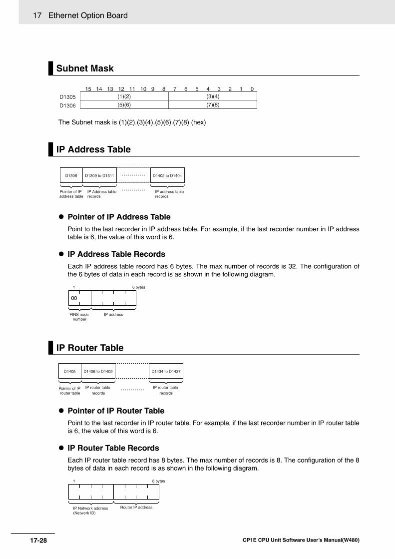
17 Ethernet Option Board
17-28 CP1E CPU Unit Software User’s Manual(W480)
The Subnet mask is (1)(2).(3)(4).(5)(6).(7)(8) (hex)
Pointer of IP Address TablePoint to the last recorder in IP address table. For example, if the last recorder number in IP addresstable is 6, the value of this word is 6.
IP Address Table RecordsEach IP address table record has 6 bytes. The max number of records is 32. The configuration ofthe 6 bytes of data in each record is as shown in the following diagram.
Pointer of IP Router TablePoint to the last recorder in IP router table. For example, if the last recorder number in IP router tableis 6, the value of this word is 6.
IP Router Table RecordsEach IP router table record has 8 bytes. The max number of records is 8. The configuration of the 8bytes of data in each record is as shown in the following diagram.
Subnet Mask
IP Address Table
IP Router Table
15 14 13 12 11 10 9 8 7 6 5 4 3 2 1 0
D1305
D1306
(1)(2) (3)(4)
(5)(6) (7)(8)
Pointer of IP address table
IP Address table records
IP address table records
D1309 to D1311D1308 D1402 to D1404
FINS node number
1
00
IP address
6 bytes
Pointer of IP router table
IP router table records
IP router table records
D1406 to D1409D1405 D1434 to D1437
IP Network address(Network ID)
Router IP address
1 8 bytes
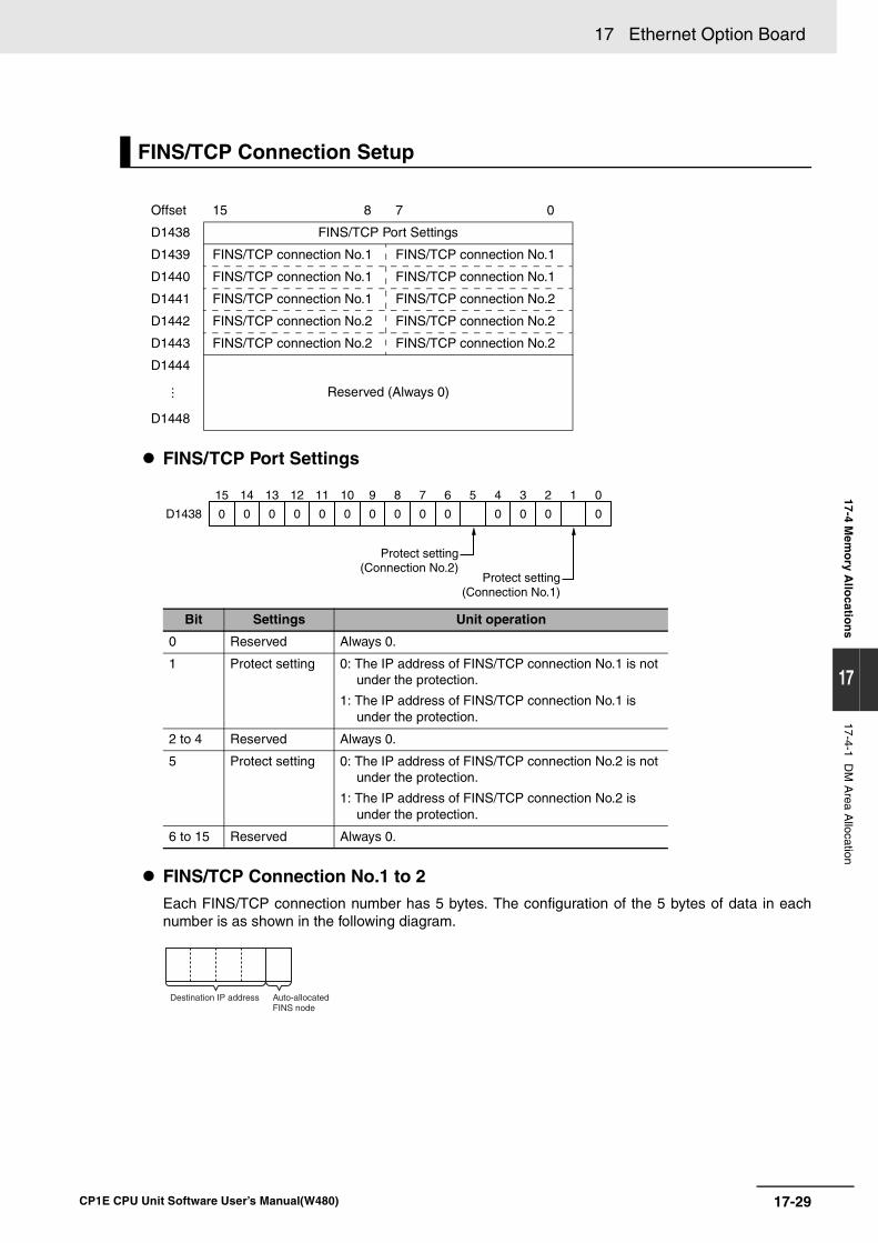
17-29
17 Ethernet Option Board
CP1E CPU Unit Software User’s Manual(W480)
17-4 Mem
ory A
llocatio
ns
17
17-4-1 DM
Area A
llocation
FINS/ TCP Port Settings
FINS/TCP Connection No.1 to 2Each FINS/TCP connection number has 5 bytes. The configuration of the 5 bytes of data in eachnumber is as shown in the following diagram.
FINS/TCP Connection Setup
Offset 15 8 7 0
D1438 FINS/TCP Port Settings
D1439 FINS/TCP connection No.1 FINS/TCP connection No.1
D1440 FINS/TCP connection No.1 FINS/TCP connection No.1
D1441 FINS/TCP connection No.1 FINS/TCP connection No.2
D1442 FINS/TCP connection No.2 FINS/TCP connection No.2
D1443 FINS/TCP connection No.2 FINS/TCP connection No.2
D1444
Reserved (Always 0)⋅⋅⋅
D1448
Bit Settings Unit operation
0 Reserved Always 0.
1 Protect setting 0: The IP address of FINS/TCP connection No.1 is not under the protection.
1: The IP address of FINS/TCP connection No.1 is under the protection.
2 to 4 Reserved Always 0.
5 Protect setting 0: The IP address of FINS/TCP connection No.2 is not under the protection.
1: The IP address of FINS/TCP connection No.2 is under the protection.
6 to 15 Reserved Always 0.
D1438 0000000 0 0 0 0 0 0 0
15 14 13 12 11 10 9 8 7 6 5 4 3 2 1 0
Protect setting(Connection No.1)
Protect setting(Connection No.2)
Destination IP address Auto-allocated FINS node
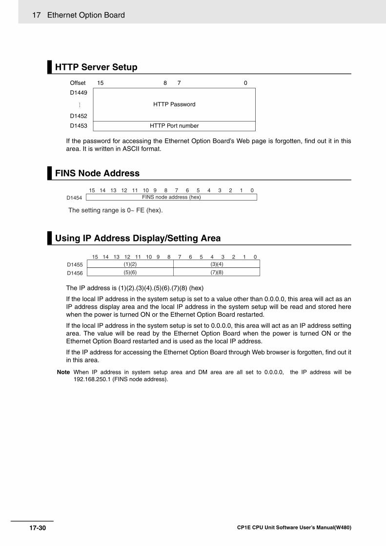
17 Ethernet Option Board
17-30 CP1E CPU Unit Software User’s Manual(W480)
If the password for accessing the Ethernet Option Board’s Web page is forgotten, find out it in thisarea. It is written in ASCII format.
The IP address is (1)(2).(3)(4).(5)(6).(7)(8) (hex)
If the local IP address in the system setup is set to a value other than 0.0.0.0, this area will act as anIP address display area and the local IP address in the system setup will be read and stored herewhen the power is turned ON or the Ethernet Option Board restarted.
If the local IP address in the system setup is set to 0.0.0.0, this area will act as an IP address settingarea. The value will be read by the Ethernet Option Board when the power is turned ON or theEthernet Option Board restarted and is used as the local IP address.
If the IP address for accessing the Ethernet Option Board through Web browser is forgotten, find out itin this area.
Note When IP address in system setup area and DM area are all set to 0.0.0.0, the IP address will be192.168.250.1 (FINS node address).
HTTP Server Setup
Offset 15 8 7 0
D1449
HTTP Password⋅⋅⋅
D1452
D1453 HTTP Port number
FINS Node Address
Using IP Address Display/Setting Area
D1454 FINS node address (hex)
The setting range is 0~ FE (hex).
15 14 13 12 11 10 9 8 7 6 5 4 3 2 1 0
15 14 13 12 11 10 9 8 7 6 5 4 3 2 1 0
D1455
D1456
(1)(2) (3)(4)
(5)(6) (7)(8)
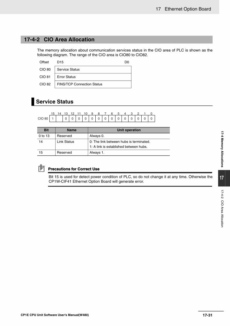
17-31
17 Ethernet Option Board
CP1E CPU Unit Software User’s Manual(W480)
17-4 Mem
ory A
llocatio
ns
17
17-4-2 CIO
Area A
llocation
The memory allocation about communication services status in the CIO area of PLC is shown as thefollowing diagram. The range of the CIO area is CIO80 to CIO82.
Precautions for Correct UsePrecautions for Correct Use
Bit 15 is used for detect power condition of PLC, so do not change it at any time. Otherwise theCP1W-CIF41 Ethernet Option Board will generate error.
17-4-2 CIO Area Allocation
Offset D15 D0
CIO 80 Service Status
CIO 81 Error Status
CIO 82 FINS/TCP Connection Status
Service Status
Bit Name Unit operation
0 to 13 Reserved Always 0.
14 Link Status 0: The link between hubs is terminated.1: A link is established between hubs.
15 Reserved Always 1.
CIO 80
15 14 13 12 11 10 9 8 7 6 5 4 3 2 1 0
1 0 0 0 0 0 0 0 0 0 0 0 0 0 0
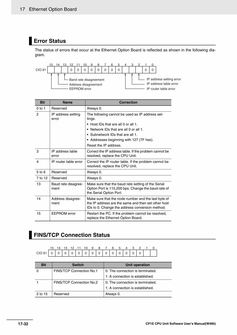
17 Ethernet Option Board
17-32 CP1E CPU Unit Software User’s Manual(W480)
The status of errors that occur at the Ethernet Option Board is reflected as shown in the following dia-gram.
Error Status
Bit Name Correction
0 to 1 Reserved Always 0.
2 IP address setting error
The following cannot be used as IP address set-tings.
• Host IDs that are all 0 or all 1.• Network IDs that are all 0 or all 1.
• Subnetwork IDs that are all 1.• Addresses beginning with 127 (7F hex).
Reset the IP address.
3 IP address table error
Correct the IP address table. If the problem cannot be resolved, replace the CPU Unit.
4 IP router table error Correct the IP router table. If the problem cannot be resolved, replace the CPU Unit.
5 to 6 Reserved Always 0.
7 to 12 Reserved Always 0.
13 Baud rate disagree-ment
Make sure that the baud rate setting of the Serial Option Port is 115,200 bps. Change the baud rate of the Serial Option Port.
14 Address disagree-ment
Make sure that the node number and the last byte of the IP address are the same and then set other host IDs to 0. Change the address conversion method.
15 EEPROM error Restart the PC. If the problem cannot be resolved, replace the Ethernet Option Board.
FINS/TCP Connection Status
Bit Switch Unit operation
0 FINS/TCP Connection No.1 0: The connection is terminated.
1: A connection is established.
1 FINS/TCP Connection No.2 0: The connection is terminated.
1: A connection is established.
2 to 15 Reserved Always 0.
CIO 81
15 14 13 12 11 10 9 8 7 6 5 4 3 2 1 0
0 0 0 0 0 0 0 0 0 0
IP address setting errorIP address table error
IP router table errorAddress disagreementEEPROM error
Band rate disagreement
CIO 81
15 14 13 12 11 10 9 8 7 6 5 4
0 0 0 0 0 0 0 0 0 0 0 0
3 2
0 0
1 0
17-33
17 Ethernet Option Board
CP1E CPU Unit Software User’s Manual(W480)
17-5 Trou
ble S
ho
otin
g
17
17-5-1 Error Log
17-5 Trouble Shooting
The Ethernet Option Board provides an error log that records errors occurred during Ethernet OptionBoard operation. The contents of the error log can be read or cleared from the Web Brower.
The following errors are recorded in the error log.
• Errors in network operation
• Errors in data transfers
• Error in the CPU unit
Each error is recorded as one record in an error log table. Up to 20 records can be saved. If more than20 errors occur, the oldest errors will be deleted from the error log and the most recent error will berecorded.
The following information is recorded in the error log table.
• Main error code (see table later in this section)
• Detailed error code (see table later in this section)
• Time stamp (from the clock in the CPU unit)
Note During the initialization of the Ethernet Option Board, if an error occurs, the error log time stamp will recordas 2000-00-00 00:00:00.
When an error is detected, the error codes and time stamp are recorded in the error log in RAM insidethe Ethernet Option Board. Serious errors are also recorded in EEPROM. The maximum number oferrors that can be saved to EEPROM is 20 for the CP1L and CP1H. The errors recorded in EEPROMwill be saved even if the unit is restarted or power is turned OFF.
17-5-1 Error Log
Logged Errors
Error Log Table
Error Log Location
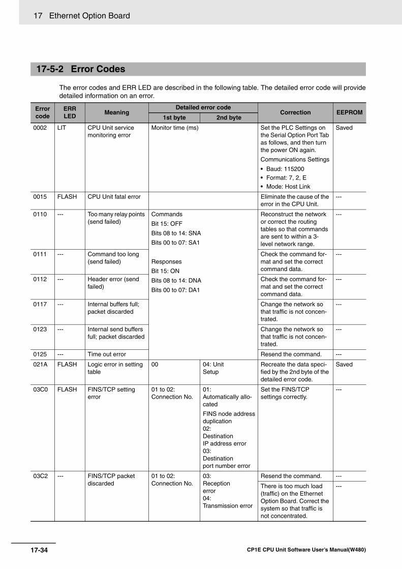
17 Ethernet Option Board
17-34 CP1E CPU Unit Software User’s Manual(W480)
The error codes and ERR LED are described in the following table. The detailed error code will providedetailed information on an error.
17-5-2 Error Codes
Errorcode
ERRLED
MeaningDetailed error code
Correction EEPROM1st byte 2nd byte
0002 LIT CPU Unit service monitoring error
Monitor time (ms) Set the PLC Settings on the Serial Option Port Tab as follows, and then turn the power ON again.
Communications Settings
• Baud: 115200• Format: 7, 2, E
• Mode: Host Link
Saved
0015 FLASH CPU Unit fatal error Eliminate the cause of the error in the CPU Unit.
---
0110 --- Too many relay points (send failed)
Commands
Bit 15: OFF
Bits 08 to 14: SNA
Bits 00 to 07: SA1
Responses
Bit 15: ON
Bits 08 to 14: DNA
Bits 00 to 07: DA1
Reconstruct the network or correct the routing tables so that commands are sent to within a 3- level network range.
---
0111 --- Command too long (send failed)
Check the command for-mat and set the correct command data.
---
0112 --- Header error (send failed)
Check the command for-mat and set the correct command data.
---
0117 --- Internal buffers full; packet discarded
Change the network so that traffic is not concen-trated.
---
0123 --- Internal send buffers full; packet discarded
Change the network so that traffic is not concen-trated.
---
0125 --- Time out error Resend the command. ---
021A FLASH Logic error in setting table
00 04: UnitSetup
Recreate the data speci-fied by the 2nd byte of the detailed error code.
Saved
03C0 FLASH FINS/TCP setting error
01 to 02: Connection No.
01: Automatically allo-cated
FINS node addressduplication02: DestinationIP address error03: Destinationport number error
Set the FINS/TCP settings correctly.
---
03C2 --- FINS/TCP packet discarded
01 to 02: Connection No.
03:Receptionerror04:Transmission error
Resend the command. ---
There is too much load (traffic) on the Ethernet Option Board. Correct the system so that traffic is not concentrated.
---
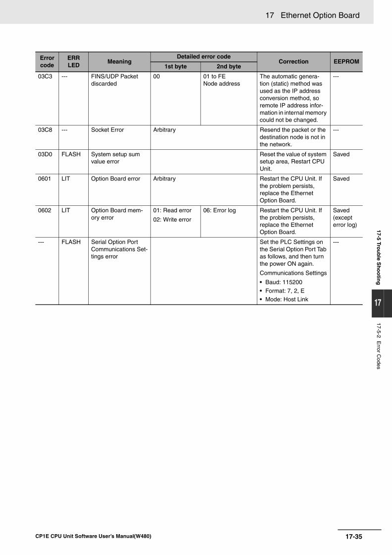
17-35
17 Ethernet Option Board
CP1E CPU Unit Software User’s Manual(W480)
17-5 Trou
ble S
ho
otin
g
17
17-5-2 Error C
odes
03C3 --- FINS/UDP Packet discarded
00 01 to FENode address
The automatic genera-tion (static) method was used as the IP address conversion method, so remote IP address infor-mation in internal memory could not be changed.
---
03C8 --- Socket Error Arbitrary Resend the packet or the destination node is not in the network.
---
03D0 FLASH System setup sum value error
Reset the value of system setup area, Restart CPU Unit.
Saved
0601 LIT Option Board error Arbitrary Restart the CPU Unit. If the problem persists, replace the Ethernet Option Board.
Saved
0602 LIT Option Board mem-ory error
01: Read error
02: Write error
06: Error log Restart the CPU Unit. If the problem persists, replace the Ethernet Option Board.
Saved (except error log)
--- FLASH Serial Option Port Communications Set-tings error
Set the PLC Settings on the Serial Option Port Tab as follows, and then turn the power ON again.
Communications Settings
• Baud: 115200
• Format: 7, 2, E• Mode: Host Link
---
Errorcode
ERRLED
MeaningDetailed error code
Correction EEPROM1st byte 2nd byte
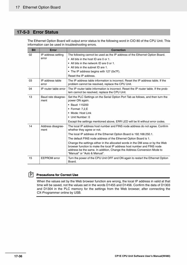
17 Ethernet Option Board
17-36 CP1E CPU Unit Software User’s Manual(W480)
The Ethernet Option Board will output error status to the following word in CIO 80 of the CPU Unit. Thisinformation can be used in troubleshooting errors.
Precautions for Correct UsePrecautions for Correct Use
When the values set by the Web browser function are wrong, the local IP address in valid at thattime will be saved, not the values set in the words D1455 and D1456. Confirm the data of D1303and D1304 in the PLC memory for the settings from the Web browser, after connecting theCX-Programmer online by USB.
17-5-3 Error Status
Bit Error Correction
02 IP address setting error
The following cannot be used as the IP address of the Ethernet Option Board.
• All bits in the host ID are 0 or 1.
• All bits in the network ID are 0 or 1.• All bits in the subnet ID are 1.• The IP address begins with 127 (0x7F).
Reset the IP address.
03 IP address table error
The IP address table information is incorrect. Reset the IP address table. If the problem cannot be resolved, replace the CPU Unit.
04 IP router table error The IP router table information is incorrect. Reset the IP router table. If the prob-lem cannot be resolved, replace the CPU Unit.
13 Baud rate disagree-ment
Set the PLC Settings on the Serial Option Port Tab as follows, and then turn the power ON again.
• Baud: 115200• Format: 7,2,E• Mode: Host Link
• Unit Number: 0
Except the settings mentioned above, ERR LED will be lit without error codes.
14 Address disagree-ment
The local IP address host number and FINS node address do not agree. Confirm whether they agree or not.
The local IP address of the Ethernet Option Board is 192.168.250.1.
The default FINS node address of the Ethernet Option Board is 1.
Change the settings either in the allocated words in the DM area or by the Web browser function to make the local IP address host number and FINS node address be the same. In addition, Change the Address Conversion Mode to “Manual” or “Auto & Manual”.
15 EEPROM error Turn the power of the CPU Unit OFF and ON again to restart the Ethernet Option Board.
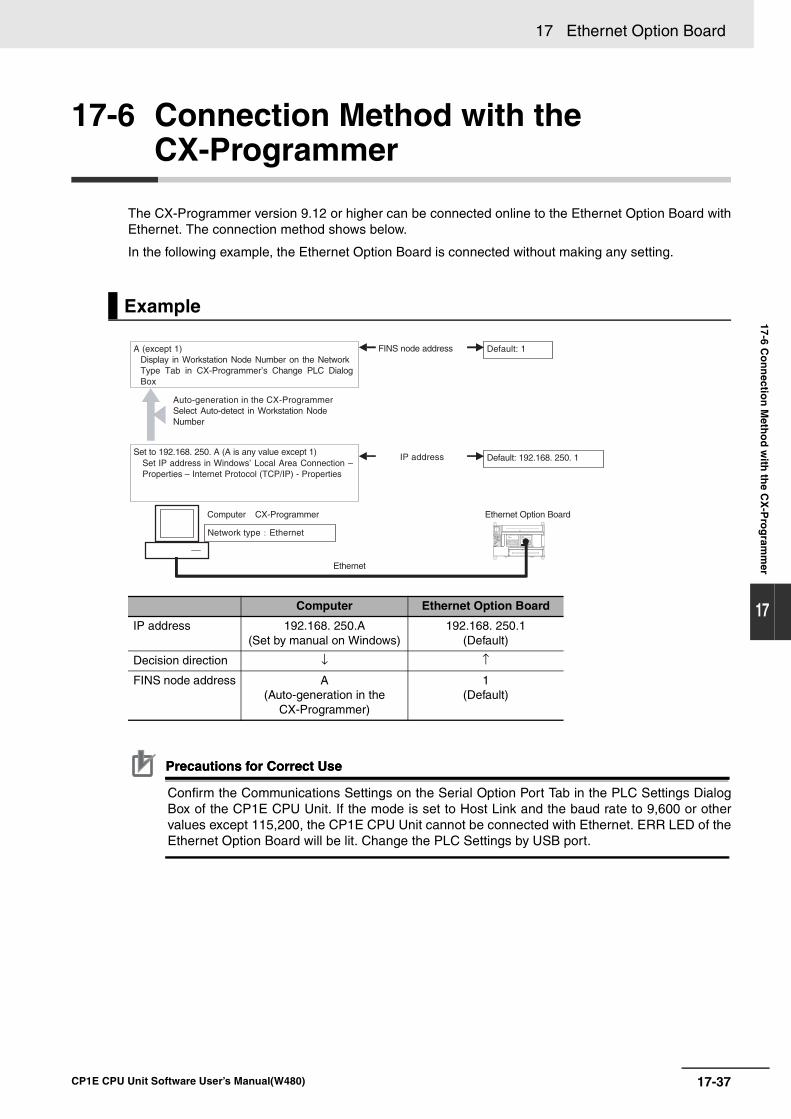
17-37
17 Ethernet Option Board
CP1E CPU Unit Software User’s Manual(W480)
17-6 Co
nn
ection
Meth
od
with
the C
X-P
rog
ramm
er
17
17-6 Connection Method with the CX-Programmer
The CX-Programmer version 9.12 or higher can be connected online to the Ethernet Option Board withEthernet. The connection method shows below.
In the following example, the Ethernet Option Board is connected without making any setting.
Precautions for Correct UsePrecautions for Correct Use
Confirm the Communications Settings on the Serial Option Port Tab in the PLC Settings DialogBox of the CP1E CPU Unit. If the mode is set to Host Link and the baud rate to 9,600 or othervalues except 115,200, the CP1E CPU Unit cannot be connected with Ethernet. ERR LED of theEthernet Option Board will be lit. Change the PLC Settings by USB port.
Example
Computer Ethernet Option Board
IP address 192.168. 250.A(Set by manual on Windows)
192.168. 250.1(Default)
Decision direction ↓ ↑
FINS node address A(Auto-generation in the
CX-Programmer)
1(Default)
Computer CX-Programmer
Ethernet
Default: 1
Set to 192.168. 250. A (A is any value except 1) Set IP address in Windows’ Local Area Connection –Properties – Internet Protocol (TCP/IP) - Properties
A (except 1) Display in Workstation Node Number on the Network Type Tab in CX-Programmer’s Change PLC Dialog Box
Ethernet Option Board
FINS node address
IP address Default: 192.168. 250. 1
Auto-generation in the CX-Programmer Select Auto-detect in Workstation Node Number
Network type Ethernet
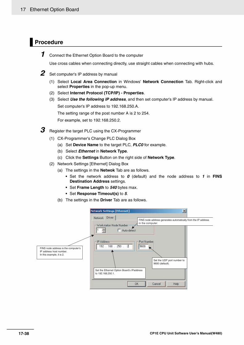
17 Ethernet Option Board
17-38 CP1E CPU Unit Software User’s Manual(W480)
1 Connect the Ethernet Option Board to the computer
Use cross cables when connecting directly, use straight cables when connecting with hubs.
2 Set computer's IP address by manual
(1) Select Local Area Connection in Windows' Network Connection Tab. Right-click andselect Properties in the pop-up menu.
(2) Select Internet Protocol (TCP/IP) - Properties.
(3) Select Use the following IP address, and then set computer's IP address by manual.
Set computer's IP address to 192.168.250.A.
The setting range of the post number A is 2 to 254.
For example, set to 192.168.250.2.
3 Register the target PLC using the CX-Programmer
(1) CX-Programmer's Change PLC Dialog Box
(a) Set Device Name to the target PLC, PLC0 for example.
(b) Select Ethernet in Network Type.
(c) Click the Settings Button on the right side of Network Type.
(2) Network Settings [Ethernet] Dialog Box
(a) The settings in the Netwok Tab are as follows.
• Set the network address to 0 (default) and the node address to 1 in FINSDestination Address settings.
• Set Frame Length to 540 bytes max.
• Set Response Timeout(s) to 5.
(b) The settings in the Driver Tab are as follows.
Procedure
FINS node address generates automatically from the IP address in the computer.
Set the Ethernet Option Board’s IPaddress to 192.168.250.1.
Set the UDP port number to 9600 (default).
FINS node address is the computer’s IP address host number. In this example, it is 2.

17-39
17 Ethernet Option Board
CP1E CPU Unit Software User’s Manual(W480)
17-6 Co
nn
ection
Meth
od
with
the C
X-P
rog
ramm
er
17
• The default setting for Address Conversion Mode of the Ethernet Option Board isAuto (Dynamic), so slecet Auto-detect in the field of Workstation Node Number.Therefore, according to computer's IP address, computer's FINS node address is setautomatically in the CX-Programmer. At that time, IP address post number and FINSnode address are the same. In this example, 2 is displayed according to the host number of computer's IPaddress 192.168.250.2 set by manual, and it is invalid to change the setting.
• Set IP address to 192.168.250.1, which is the Ethernet Option Board's IP address.
• Set FINS/UDP Port to 9600 (default), which is the UDP port number in the FINScommunications service.
4 Connect the target PLC online
Select Work Online in the PLC menu.
17 Ethernet Option Board
17-40 CP1E CPU Unit Software User’s Manual(W480)
17-7 Network Installation
The basic configuration for a 100Base-TX Ethernet System consists of one hub to which nodes areattached in star form using twisted-pair cable. The devices shown in the following table are required toconfigure a network with 100Base-TX-type CP1W-CIF41, so prepared them in advance.
• Take the greatest care when installing the Ethernet System, being sure to follow ISO 802-3 specifica-tions. You must obtain a copy of these specifications and be sure you understand them beforeattempting to install an Ethernet System. Unless you are already experienced in installing communi-cations systems, we strongly recommend that you employ a professional to install your system.
• Do not install Ethernet equipment near sources of noise. If noise-prone environments are unavoid-able, be sure to take adequate measures against noise interference, such as installing network com-ponents in grounded metal cases, using optical links in the system, etc.
Basic Precautions• Press the cable connector in firmly until it locks into place at both the hub and the Ethernet Option
Board.
• After laying the twisted-pair cable, check the connection with a 10Base-T cable tester.
Environment Precautions• The UTP cable is not shielded, and the hub is designed for use in OA environments. In environ-
ments subject to noise, construct a system with shielded twisted-pair (STP) cable and hubs suit-able for an FA environment.
• Do not lay the twisted-pair cable together with high-voltage lines.
• Do not lay the twisted-pair cable near devices that generate noise.
• Do not lay the twisted-pair cable in locations subject to high temperature or high humidity.
• Do not lay the twisted-pair cable in locations subject to excessive dirt and dust or to oil mist orother contaminants.
17-7-1 Devices Required for Constructing a Network
Network device Contents
1. Ethernet Option Board (CP1W-CIF41)
The Ethernet Option Board is a Communication Unit that connects a CP1E N/NA-type CPU Unit to 100Base-TX Ethernet networks.
(They can also be used as 10Base-T.)
2. Twisted-pair cable This is twisted-pair cable for connecting 100Base-TX type Ethernet Option Board to the hub, with an RJ45 Modular Connector at each end.
Use a category 3, 4, 5, or 5e UTP (unshielded twisted pair) or STP (shielded twisted-pair) cable.
3. Hub This is a relay device for connecting multiple nodes in a star LAN.
17-7-2 Network Installation
Basic Installation Precautions
Precautions on Laying Twisted-pair Cable
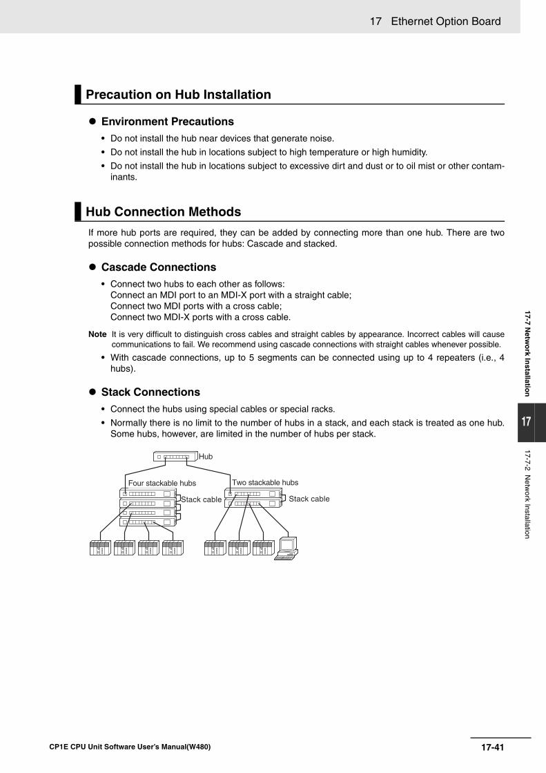
17-41
17 Ethernet Option Board
CP1E CPU Unit Software User’s Manual(W480)
17-7 Netw
ork In
stallation
17
17-7-2 Netw
ork Installation
Environment Precautions• Do not install the hub near devices that generate noise.
• Do not install the hub in locations subject to high temperature or high humidity.
• Do not install the hub in locations subject to excessive dirt and dust or to oil mist or other contam-inants.
If more hub ports are required, they can be added by connecting more than one hub. There are twopossible connection methods for hubs: Cascade and stacked.
Cascade Connections• Connect two hubs to each other as follows:
Connect an MDI port to an MDI-X port with a straight cable;Connect two MDI ports with a cross cable; Connect two MDI-X ports with a cross cable.
Note It is very difficult to distinguish cross cables and straight cables by appearance. Incorrect cables will causecommunications to fail. We recommend using cascade connections with straight cables whenever possible.
• With cascade connections, up to 5 segments can be connected using up to 4 repeaters (i.e., 4hubs).
Stack Connections• Connect the hubs using special cables or special racks.
• Normally there is no limit to the number of hubs in a stack, and each stack is treated as one hub.Some hubs, however, are limited in the number of hubs per stack.
Precaution on Hub Installation
Hub Connection Methods
Hub
Four stackable hubs Two stackable hubs
Stack cable Stack cable
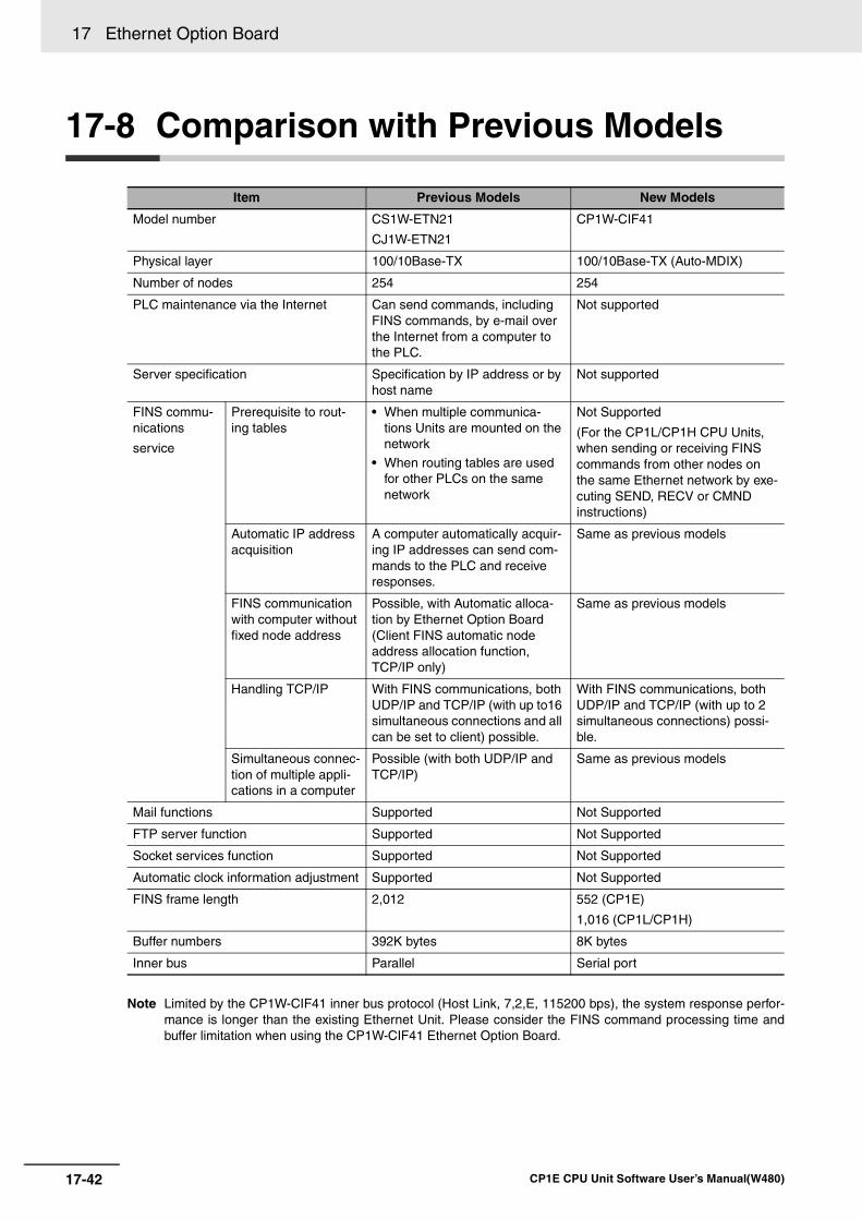
17 Ethernet Option Board
17-42 CP1E CPU Unit Software User’s Manual(W480)
17-8 Comparison with Previous Models
Note Limited by the CP1W-CIF41 inner bus protocol (Host Link, 7,2,E, 115200 bps), the system response perfor-mance is longer than the existing Ethernet Unit. Please consider the FINS command processing time andbuffer limitation when using the CP1W-CIF41 Ethernet Option Board.
Item Previous Models New Models
Model number CS1W-ETN21
CJ1W-ETN21
CP1W-CIF41
Physical layer 100/10Base-TX 100/10Base-TX (Auto-MDIX)
Number of nodes 254 254
PLC maintenance via the Internet Can send commands, including FINS commands, by e-mail over the Internet from a computer to the PLC.
Not supported
Server specification Specification by IP address or by host name
Not supported
FINS commu-nications
service
Prerequisite to rout-ing tables
• When multiple communica-tions Units are mounted on the network
• When routing tables are used for other PLCs on the same network
Not Supported
(For the CP1L/CP1H CPU Units, when sending or receiving FINS commands from other nodes on the same Ethernet network by exe-cuting SEND, RECV or CMND instructions)
Automatic IP address acquisition
A computer automatically acquir-ing IP addresses can send com-mands to the PLC and receive responses.
Same as previous models
FINS communication with computer without fixed node address
Possible, with Automatic alloca-tion by Ethernet Option Board (Client FINS automatic node address allocation function, TCP/IP only)
Same as previous models
Handling TCP/IP With FINS communications, both UDP/IP and TCP/IP (with up to16 simultaneous connections and all can be set to client) possible.
With FINS communications, both UDP/IP and TCP/IP (with up to 2 simultaneous connections) possi-ble.
Simultaneous connec-tion of multiple appli-cations in a computer
Possible (with both UDP/IP and TCP/IP)
Same as previous models
Mail functions Supported Not Supported
FTP server function Supported Not Supported
Socket services function Supported Not Supported
Automatic clock information adjustment Supported Not Supported
FINS frame length 2,012 552 (CP1E)
1,016 (CP1L/CP1H)
Buffer numbers 392K bytes 8K bytes
Inner bus Parallel Serial port
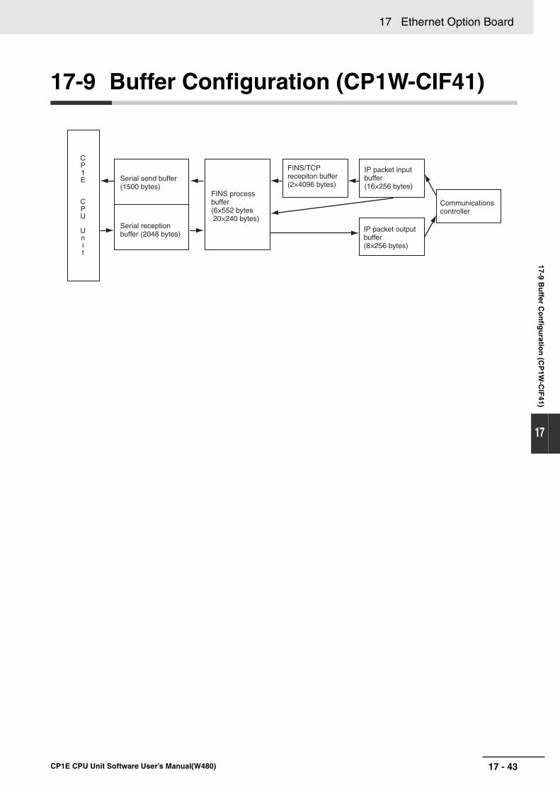
17 - 43
17 Ethernet Option Board
CP1E CPU Unit Software User’s Manual(W480)
17-9 Bu
ffer Co
nfig
uratio
n (C
P1W
-CIF
41)
17
17-9 Buffer Configuration (CP1W-CIF41)
CP1E
CPU
Unit
Serial send buffer (1500 bytes)
Serial reception buffer (2048 bytes)
FINS process buffer (6×552 bytes 20×240 bytes)
FINS/TCP recepiton buffer (2×4096 bytes)
IP packet input buffer(16×256 bytes)
Communications controller
IP packet output buffer(8×256 bytes)

17 Ethernet Option Board
17-44 CP1E CPU Unit Software User’s Manual(W480)
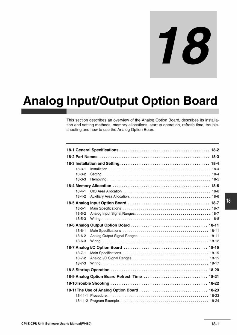
18-1
18
CP1E CPU Unit Software User’s Manual(W480)
18
This section describes an overview of the Analog Option Board, describes its installa-tion and setting methods, memory allocations, startup operation, refresh time, trouble-shooting and how to use the Analog Option Board.
18-1 General Specifications . . . . . . . . . . . . . . . . . . . . . . . . . . . . . . . . . . . . . . . . . 18-2
18-2 Part Names . . . . . . . . . . . . . . . . . . . . . . . . . . . . . . . . . . . . . . . . . . . . . . . . . . 18-3
18-3 Installation and Setting. . . . . . . . . . . . . . . . . . . . . . . . . . . . . . . . . . . . . . . . . 18-418-3-1 Installation. . . . . . . . . . . . . . . . . . . . . . . . . . . . . . . . . . . . . . . . . . . . . . . . . . . . 18-418-3-2 Setting. . . . . . . . . . . . . . . . . . . . . . . . . . . . . . . . . . . . . . . . . . . . . . . . . . . . . . . 18-418-3-3 Removing . . . . . . . . . . . . . . . . . . . . . . . . . . . . . . . . . . . . . . . . . . . . . . . . . . . . 18-5
18-4 Memory Allocation . . . . . . . . . . . . . . . . . . . . . . . . . . . . . . . . . . . . . . . . . . . . 18-618-4-1 CIO Area Allocation . . . . . . . . . . . . . . . . . . . . . . . . . . . . . . . . . . . . . . . . . . . . 18-6
18-4-2 Auxiliary Area Allocation . . . . . . . . . . . . . . . . . . . . . . . . . . . . . . . . . . . . . . . . . 18-6
18-5 Analog Input Option Board . . . . . . . . . . . . . . . . . . . . . . . . . . . . . . . . . . . . . 18-718-5-1 Main Specifications. . . . . . . . . . . . . . . . . . . . . . . . . . . . . . . . . . . . . . . . . . . . . 18-718-5-2 Analog Input Signal Ranges . . . . . . . . . . . . . . . . . . . . . . . . . . . . . . . . . . . . . . 18-718-5-3 Wiring . . . . . . . . . . . . . . . . . . . . . . . . . . . . . . . . . . . . . . . . . . . . . . . . . . . . . . . 18-8
18-6 Analog Output Option Board . . . . . . . . . . . . . . . . . . . . . . . . . . . . . . . . . . . 18-1118-6-1 Main Specifications. . . . . . . . . . . . . . . . . . . . . . . . . . . . . . . . . . . . . . . . . . . . 18-11
18-6-2 Analog Output Signal Ranges . . . . . . . . . . . . . . . . . . . . . . . . . . . . . . . . . . . 18-1118-6-3 Wiring . . . . . . . . . . . . . . . . . . . . . . . . . . . . . . . . . . . . . . . . . . . . . . . . . . . . . . 18-12
18-7 Analog I/O Option Board . . . . . . . . . . . . . . . . . . . . . . . . . . . . . . . . . . . . . . 18-1518-7-1 Main Specifications. . . . . . . . . . . . . . . . . . . . . . . . . . . . . . . . . . . . . . . . . . . . 18-1518-7-2 Analog I/O Signal Ranges . . . . . . . . . . . . . . . . . . . . . . . . . . . . . . . . . . . . . . 18-15
18-7-3 Wiring . . . . . . . . . . . . . . . . . . . . . . . . . . . . . . . . . . . . . . . . . . . . . . . . . . . . . . 18-17
18-8 Startup Operation . . . . . . . . . . . . . . . . . . . . . . . . . . . . . . . . . . . . . . . . . . . . 18-20
18-9 Analog Option Board Refresh Time . . . . . . . . . . . . . . . . . . . . . . . . . . . . . 18-21
18-10Trouble Shooting . . . . . . . . . . . . . . . . . . . . . . . . . . . . . . . . . . . . . . . . . . . . 18-22
18-11The Use of Analog Option Board . . . . . . . . . . . . . . . . . . . . . . . . . . . . . . . 18-2318-11-1 Procedure . . . . . . . . . . . . . . . . . . . . . . . . . . . . . . . . . . . . . . . . . . . . . . . . . . . 18-2318-11-2 Program Example . . . . . . . . . . . . . . . . . . . . . . . . . . . . . . . . . . . . . . . . . . . . . 18-24
Analog Input/Output Option Board
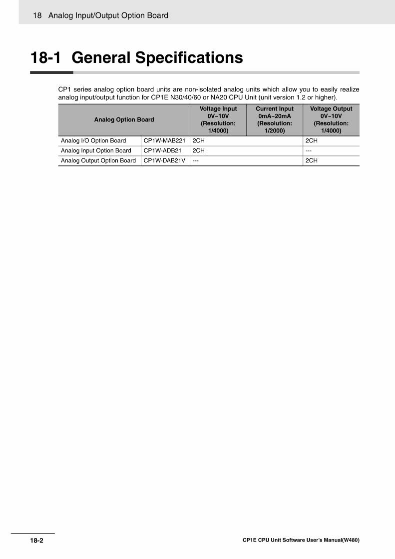
18 Analog Input/Output Option Board
18-2 CP1E CPU Unit Software User’s Manual(W480)
18-1 General Specifications
CP1 series analog option board units are non-isolated analog units which allow you to easily realizeanalog input/output function for CP1E N30/40/60 or NA20 CPU Unit (unit version 1.2 or higher).
Analog Option Board
Voltage Input0V~10V
(Resolution:1/4000)
Current Input0mA~20mA(Resolution:
1/2000)
Voltage Output0V~10V
(Resolution:1/4000)
Analog I/O Option Board CP1W-MAB221 2CH 2CH
Analog Input Option Board CP1W-ADB21 2CH ---
Analog Output Option Board CP1W-DAB21V --- 2CH
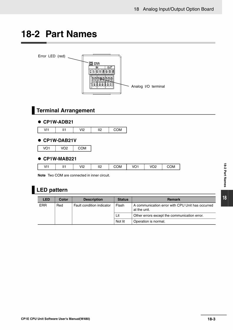
18-3
18 Analog Input/Output Option Board
CP1E CPU Unit Software User’s Manual(W480)
18-2 Part N
ames
18
18-2 Part Names
CP1W-ADB21
CP1W-DAB21V
CP1W-MAB221
Note Two COM are connected in inner circuit.
Terminal Arrangement
VI1 II1 VI2 II2 COM
VO1 VO2 COM
VI1 II1 VI2 II2 COM VO1 VO2 COM
LED pattern
LED Color Description Status Remark
ERR Red Fault condition indicator Flash A communication error with CPU Unit has occurred at the unit.
Lit Other errors except the communication error.
Not lit Operation is normal.
Analog I/O terminal
Error LED (red)
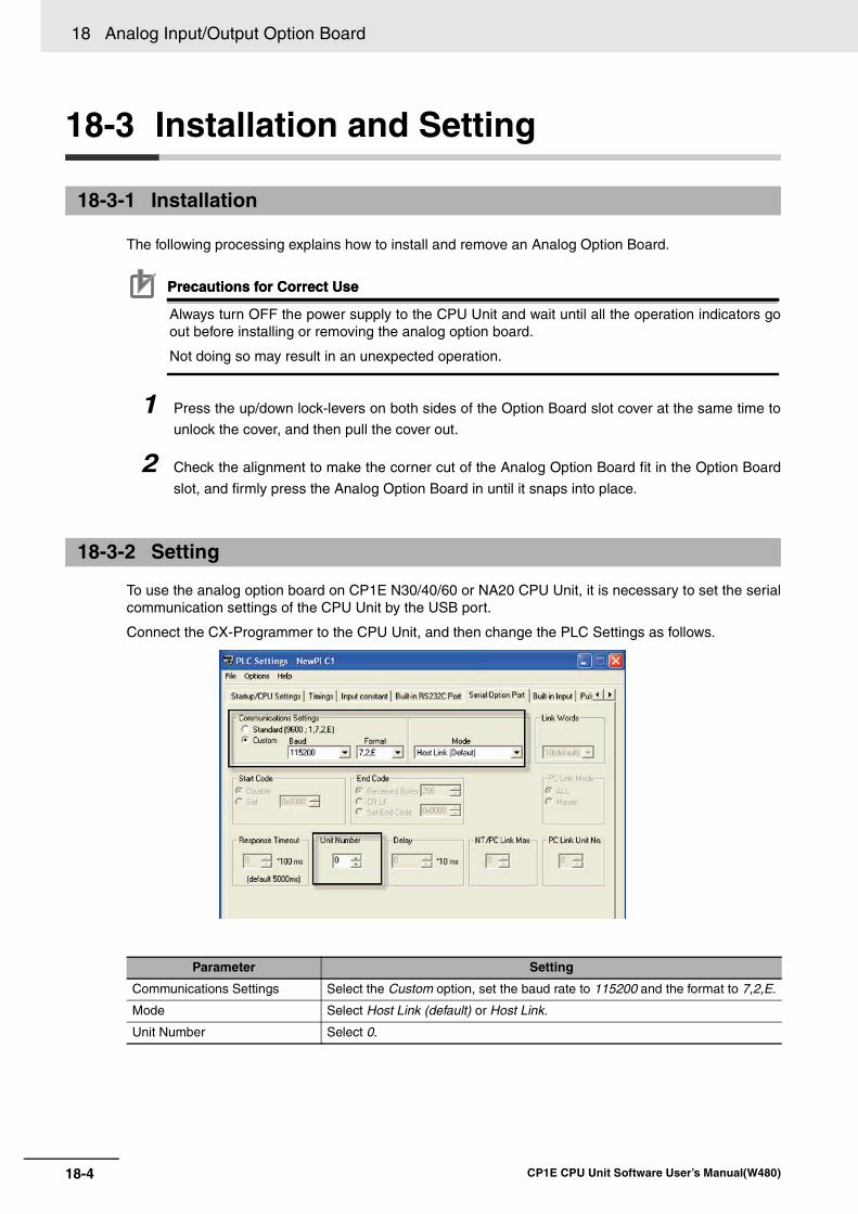
18 Analog Input/Output Option Board
18-4 CP1E CPU Unit Software User’s Manual(W480)
18-3 Installation and Setting
The following processing explains how to install and remove an Analog Option Board.
Precautions for Correct UsePrecautions for Correct Use
Always turn OFF the power supply to the CPU Unit and wait until all the operation indicators goout before installing or removing the analog option board.
Not doing so may result in an unexpected operation.
1 Press the up/down lock-levers on both sides of the Option Board slot cover at the same time to
unlock the cover, and then pull the cover out.
2 Check the alignment to make the corner cut of the Analog Option Board fit in the Option Board
slot, and firmly press the Analog Option Board in until it snaps into place.
To use the analog option board on CP1E N30/40/60 or NA20 CPU Unit, it is necessary to set the serialcommunication settings of the CPU Unit by the USB port.
Connect the CX-Programmer to the CPU Unit, and then change the PLC Settings as follows.
18-3-1 Installation
18-3-2 Setting
Parameter Setting
Communications Settings Select the Custom option, set the baud rate to 115200 and the format to 7,2,E.
Mode Select Host Link (default) or Host Link.
Unit Number Select 0.
18-5
18 Analog Input/Output Option Board
CP1E CPU Unit Software User’s Manual(W480)
18-3 Installatio
n an
d S
etting
18
18-3-3 Rem
oving
Precautions for Correct UsePrecautions for Correct Use
When the Analog Option Board is applied on the CP1E CPU Unit, it is necessary to set the baudrate to 115,200 and the mode to Host Link.
However, except the settings mentioned above, ERR LED will be lit if the communications isimpossible between the CPU Unit and the Analog Option Board. Check and change the settings.
If setting the mode to Host Link and the baud rate to any value except 115,200, change the PLCSettings by USB.
Always turn OFF the power supply to the CPU unit and wait until all the operation indicators go out.
Press the up/down lock-levers on both sides of the Analog Option Board at the same time to unlock theOption Board, and then pull it out.
18-3-3 Removing
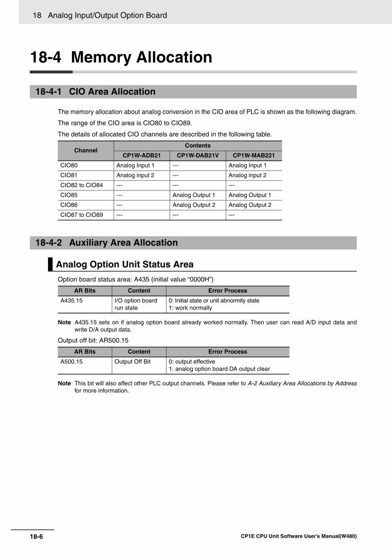
18 Analog Input/Output Option Board
18-6 CP1E CPU Unit Software User’s Manual(W480)
18-4 Memory Allocation
The memory allocation about analog conversion in the CIO area of PLC is shown as the following diagram.
The range of the CIO area is CIO80 to CIO89.
The details of allocated CIO channels are described in the following table.
Option board status area: A435 (initial value “0000H”)
Note A435.15 sets on if analog option board already worked normally. Then user can read A/D input data andwrite D/A output data.
Output off bit: AR500.15
Note This bit will also affect other PLC output channels. Please refer to A-2 Auxiliary Area Allocations by Addressfor more information.
18-4-1 CIO Area Allocation
ChannelContents
CP1W-ADB21 CP1W-DAB21V CP1W-MAB221
CIO80 Analog Input 1 --- Analog Input 1
CIO81 Analog input 2 --- Analog input 2
CIO82 to CIO84 --- --- ---
CIO85 --- Analog Output 1 Analog Output 1
CIO86 --- Analog Output 2 Analog Output 2
CIO87 to CIO89 --- --- ---
18-4-2 Auxiliary Area Allocation
Analog Option Unit Status Area
AR Bits Content Error Process
A435.15 I/O option board run state
0: Initial state or unit abnormity state1: work normally
AR Bits Content Error Process
A500.15 Output Off Bit 0: output effective1: analog option board DA output clear
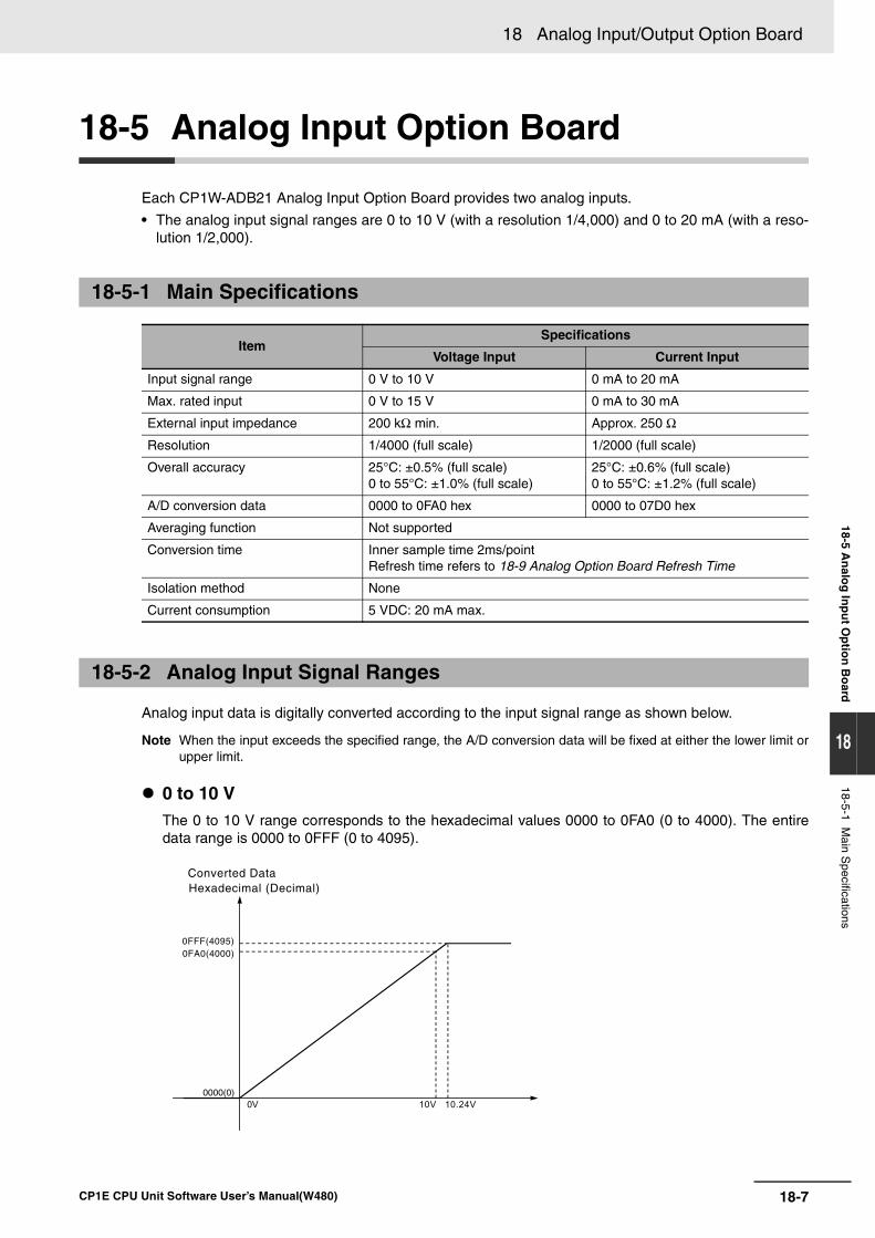
18-7
18 Analog Input/Output Option Board
CP1E CPU Unit Software User’s Manual(W480)
18-5 An
alog
Inp
ut O
ptio
n B
oard
18
18-5-1 Main S
pecifications
18-5 Analog Input Option Board
Each CP1W-ADB21 Analog Input Option Board provides two analog inputs.
• The analog input signal ranges are 0 to 10 V (with a resolution 1/4,000) and 0 to 20 mA (with a reso-lution 1/2,000).
Analog input data is digitally converted according to the input signal range as shown below.
Note When the input exceeds the specified range, the A/D conversion data will be fixed at either the lower limit orupper limit.
0 to 10 VThe 0 to 10 V range corresponds to the hexadecimal values 0000 to 0FA0 (0 to 4000). The entiredata range is 0000 to 0FFF (0 to 4095).
18-5-1 Main Specifications
ItemSpecifications
Voltage Input Current Input
Input signal range 0 V to 10 V 0 mA to 20 mA
Max. rated input 0 V to 15 V 0 mA to 30 mA
External input impedance 200 kΩ min. Approx. 250 Ω
Resolution 1/4000 (full scale) 1/2000 (full scale)
Overall accuracy 25°C: ±0.5% (full scale)0 to 55°C: ±1.0% (full scale)
25°C: ±0.6% (full scale)0 to 55°C: ±1.2% (full scale)
A/D conversion data 0000 to 0FA0 hex 0000 to 07D0 hex
Averaging function Not supported
Conversion time Inner sample time 2ms/pointRefresh time refers to 18-9 Analog Option Board Refresh Time
Isolation method None
Current consumption 5 VDC: 20 mA max.
18-5-2 Analog Input Signal Ranges
Converted Data Hexadecimal (Decimal)
10V 10.24V
0FA0(4000)0FFF(4095)
0000(0)0V
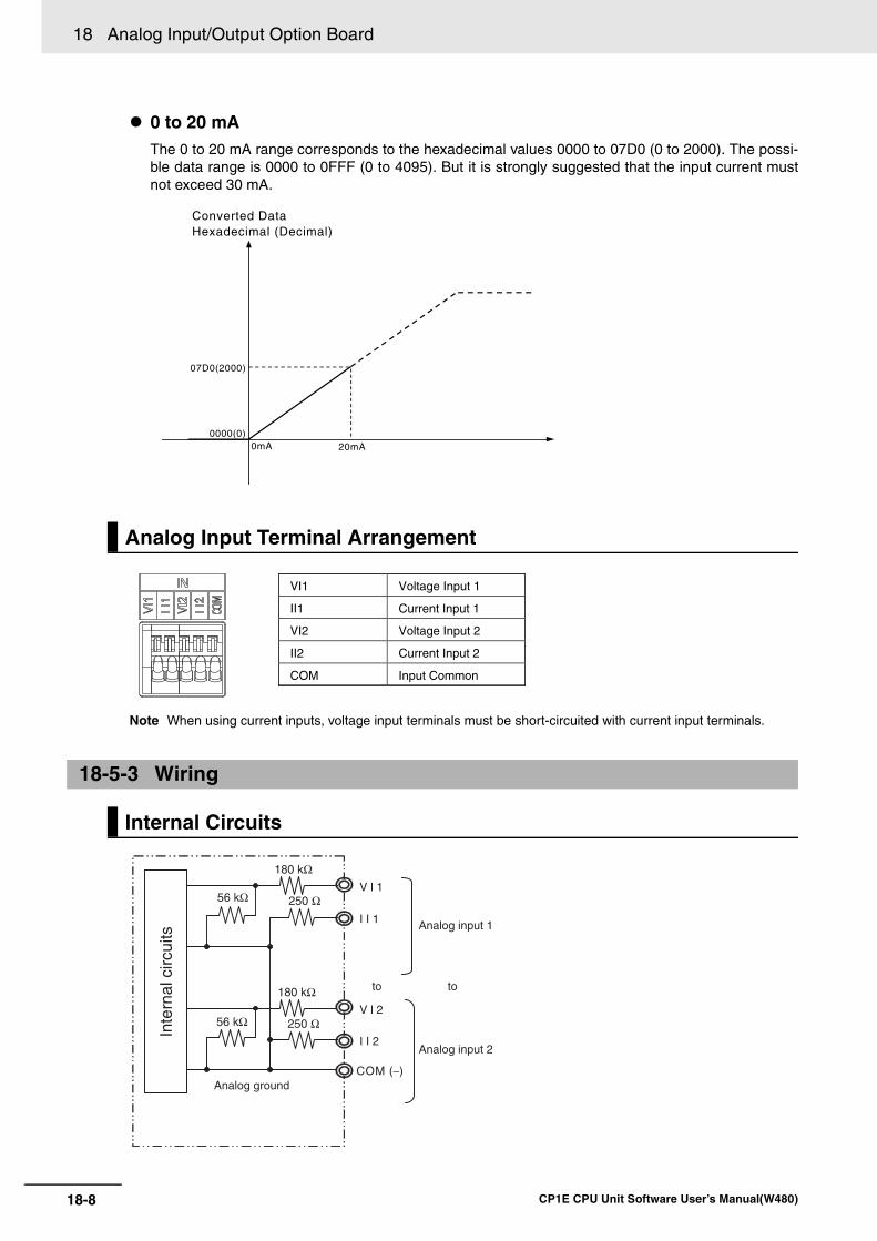
18 Analog Input/Output Option Board
18-8 CP1E CPU Unit Software User’s Manual(W480)
0 to 20 mAThe 0 to 20 mA range corresponds to the hexadecimal values 0000 to 07D0 (0 to 2000). The possi-ble data range is 0000 to 0FFF (0 to 4095). But it is strongly suggested that the input current mustnot exceed 30 mA.
Note When using current inputs, voltage input terminals must be short-circuited with current input terminals.
Analog Input Terminal Arrangement
18-5-3 Wiring
Internal Circuits
Converted DataHexadecimal (Decimal)
0mA 20mA
07D0(2000)
0000(0)
VI1 Voltage Input 1
Current Input 1
Voltage Input 2
Current Input 2
II1
VI2
II2
COM Input Common
Analog input 2
Analog ground
I I 1
V I 1
COM (−)
I I 2
V I 2
56 kΩ 250 Ω
250 Ω
180 kΩ
180 kΩ
Inte
rnal
circ
uits
Analog input 1
toto
56 kΩ
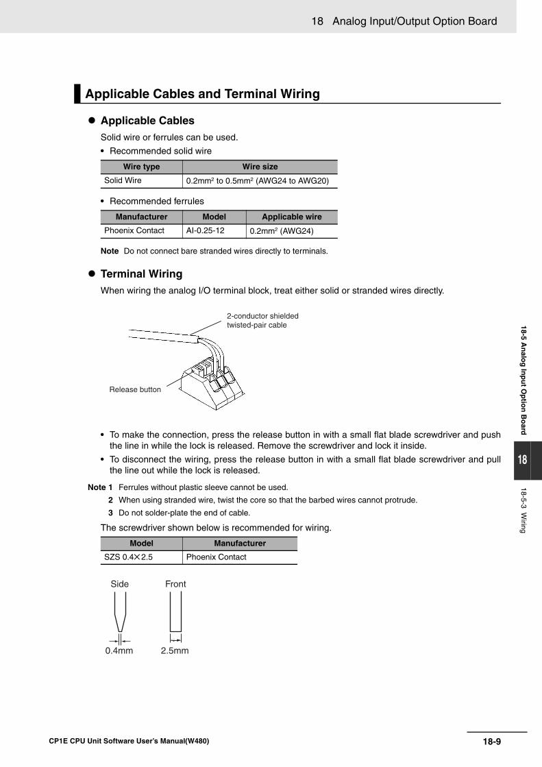
18-9
18 Analog Input/Output Option Board
CP1E CPU Unit Software User’s Manual(W480)
18-5 An
alog
Inp
ut O
ptio
n B
oard
18
18-5-3 Wiring
Applicable CablesSolid wire or ferrules can be used.
• Recommended solid wire
• Recommended ferrules
Note Do not connect bare stranded wires directly to terminals.
Terminal WiringWhen wiring the analog I/O terminal block, treat either solid or stranded wires directly.
• To make the connection, press the release button in with a small flat blade screwdriver and pushthe line in while the lock is released. Remove the screwdriver and lock it inside.
• To disconnect the wiring, press the release button in with a small flat blade screwdriver and pullthe line out while the lock is released.
Note 1 Ferrules without plastic sleeve cannot be used.
2 When using stranded wire, twist the core so that the barbed wires cannot protrude.
3 Do not solder-plate the end of cable.
The screwdriver shown below is recommended for wiring.
Applicable Cables and Terminal Wiring
Wire type Wire size
Solid Wire 0.2mm2 to 0.5mm2 (AWG24 to AWG20)
Manufacturer Model Applicable wire
Phoenix Contact AI-0.25-12 0.2mm2 (AWG24)
Model Manufacturer
SZS 0.4 2.5 Phoenix Contact
Release button
2-conductor shielded twisted-pair cable
0.4mm
Side Front
2.5mm
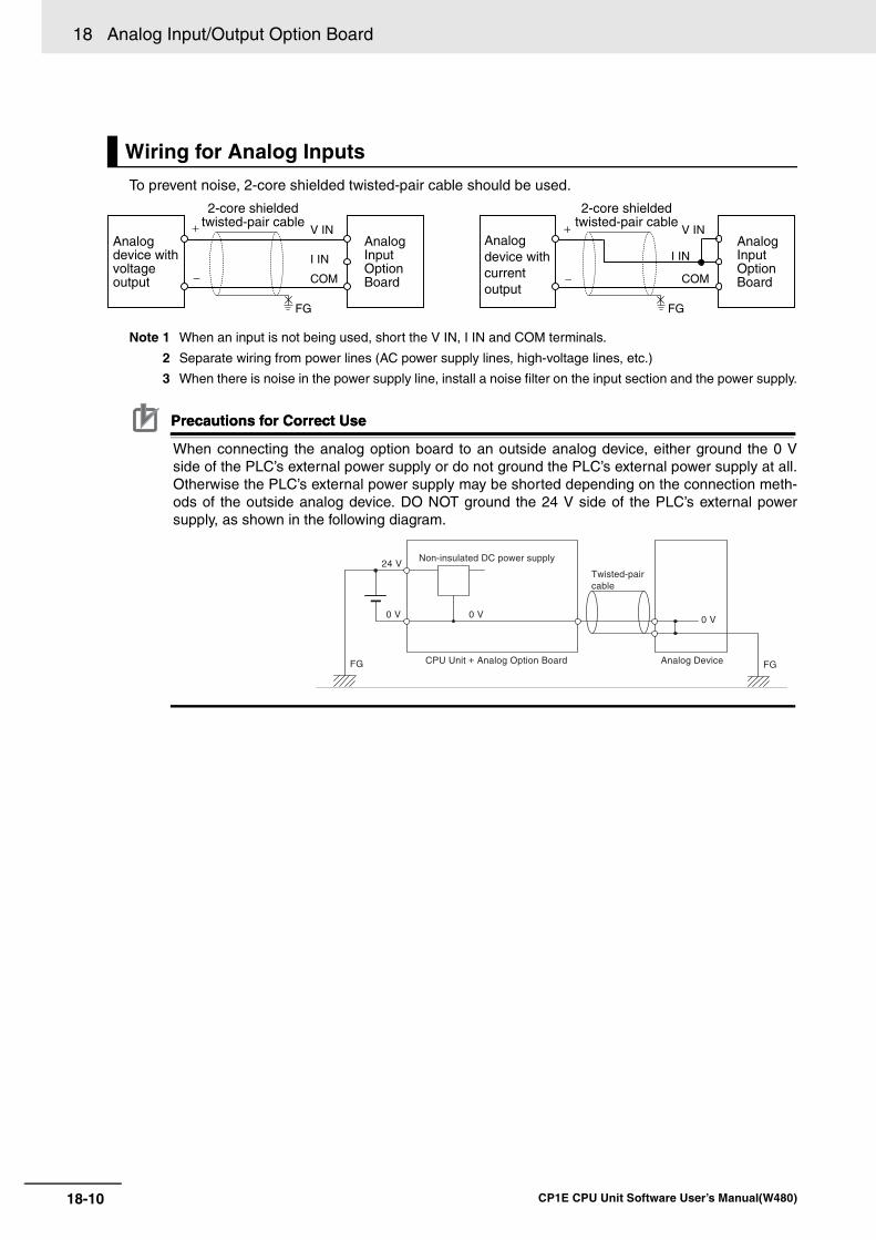
18 Analog Input/Output Option Board
18-10 CP1E CPU Unit Software User’s Manual(W480)
To prevent noise, 2-core shielded twisted-pair cable should be used.
Note 1 When an input is not being used, short the V IN, I IN and COM terminals.
2 Separate wiring from power lines (AC power supply lines, high-voltage lines, etc.)
3 When there is noise in the power supply line, install a noise filter on the input section and the power supply.
Precautions for Correct UsePrecautions for Correct Use
When connecting the analog option board to an outside analog device, either ground the 0 Vside of the PLC’s external power supply or do not ground the PLC’s external power supply at all.Otherwise the PLC’s external power supply may be shorted depending on the connection meth-ods of the outside analog device. DO NOT ground the 24 V side of the PLC’s external powersupply, as shown in the following diagram.
Wiring for Analog Inputs
V IN
COM
I IN
V IN
COM
I INAnalog device with voltage output
Analog Input Option Board
+
−
+
−
Analog device with current output
Analog Input Option Board
2-core shieldedtwisted-pair cable
2-core shieldedtwisted-pair cable
FG FG
24 V
0 V 0 V
Non-insulated DC power supply
0 V
Analog Device FG FG
Twisted-pair cable
CPU Unit + Analog Option Board
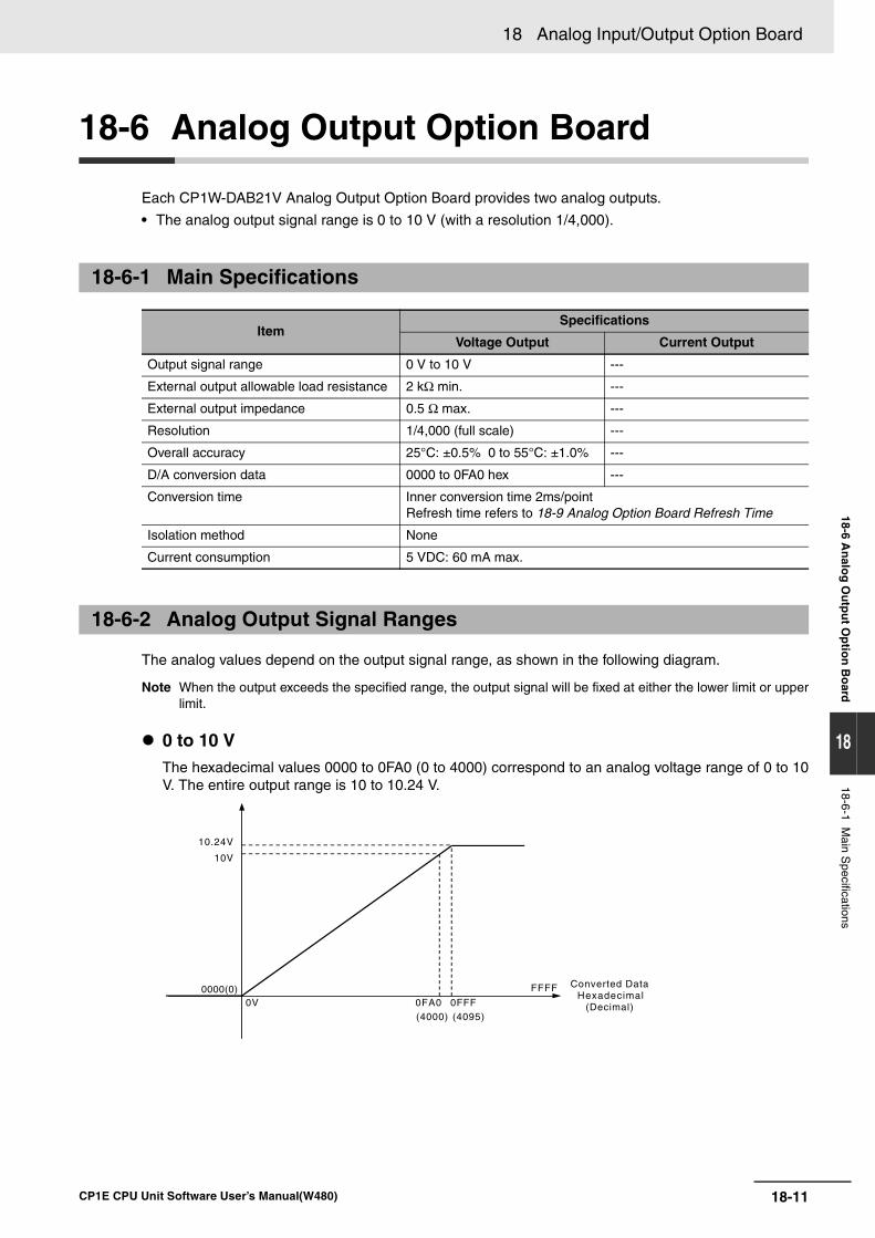
18-11
18 Analog Input/Output Option Board
CP1E CPU Unit Software User’s Manual(W480)
18-6 An
alog
Ou
tpu
t Op
tion
Bo
ard
18
18-6-1 Main S
pecifications
18-6 Analog Output Option Board
Each CP1W-DAB21V Analog Output Option Board provides two analog outputs.
• The analog output signal range is 0 to 10 V (with a resolution 1/4,000).
The analog values depend on the output signal range, as shown in the following diagram.
Note When the output exceeds the specified range, the output signal will be fixed at either the lower limit or upperlimit.
0 to 10 V The hexadecimal values 0000 to 0FA0 (0 to 4000) correspond to an analog voltage range of 0 to 10V. The entire output range is 10 to 10.24 V.
18-6-1 Main Specifications
ItemSpecifications
Voltage Output Current Output
Output signal range 0 V to 10 V ---
External output allowable load resistance 2 kΩ min. ---
External output impedance 0.5 Ω max. ---
Resolution 1/4,000 (full scale) ---
Overall accuracy 25°C: ±0.5% 0 to 55°C: ±1.0% ---
D/A conversion data 0000 to 0FA0 hex ---
Conversion time Inner conversion time 2ms/pointRefresh time refers to 18-9 Analog Option Board Refresh Time
Isolation method None
Current consumption 5 VDC: 60 mA max.
18-6-2 Analog Output Signal Ranges
0V
10V
0FA0
FFFF
0FFF(4000) (4095)
0000(0) Converted Data Hexadecimal
(Decimal)
10.24V
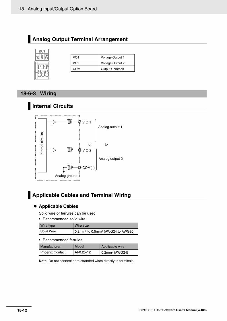
18 Analog Input/Output Option Board
18-12 CP1E CPU Unit Software User’s Manual(W480)
Applicable CablesSolid wire or ferrules can be used.
• Recommended solid wire
• Recommended ferrules
Note Do not connect bare stranded wires directly to terminals.
Analog Output Terminal Arrangement
18-6-3 Wiring
Internal Circuits
Applicable Cables and Terminal Wiring
Wire type Wire size
Solid Wire 0.2mm2 to 0.5mm2 (AWG24 to AWG20)
Manufacturer Model Applicable wire
Phoenix Contact AI-0.25-12 0.2mm2 (AWG24)
VO1 Voltage Output 1
VO2 Voltage Output 2
COM Output Common
Analog output 1
Analog ground
V O 1
COM(−)
V O 2
Analog output 2
toto
Inte
rnal
circ
uits
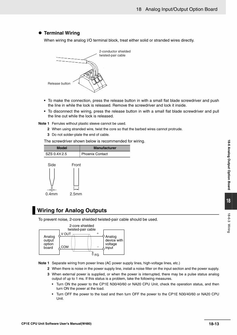
18-13
18 Analog Input/Output Option Board
CP1E CPU Unit Software User’s Manual(W480)
18-6 An
alog
Ou
tpu
t Op
tion
Bo
ard
18
18-6-3 Wiring
Terminal WiringWhen wiring the analog I/O terminal block, treat either solid or stranded wires directly.
• To make the connection, press the release button in with a small flat blade screwdriver and pushthe line in while the lock is released. Remove the screwdriver and lock it inside.
• To disconnect the wiring, press the release button in with a small flat blade screwdriver and pullthe line out while the lock is released.
Note 1 Ferrules without plastic sleeve cannot be used.
2 When using stranded wire, twist the core so that the barbed wires cannot protrude.
3 Do not solder-plate the end of cable.
The screwdriver shown below is recommended for wiring.
To prevent noise, 2-core shielded twisted-pair cable should be used.
Note 1 Separate wiring from power lines (AC power supply lines, high-voltage lines, etc.)
2 When there is noise in the power supply line, install a noise filter on the input section and the power supply.
3 When external power is supplied, or when the power is interrupted, there may be a pulse status analogoutput of up to 1 ms. If this status is a problem, take the following measures.
• Turn ON the power to the CP1E N30/40/60 or NA20 CPU Unit, check the operation status, and thenturn ON the power at the load.
• Turn OFF the power to the load and then turn OFF the power to the CP1E N30/40/60 or NA20 CPUUnit.
Model Manufacturer
SZS 0.4 2.5 Phoenix Contact
Wiring for Analog Outputs
Release button
2-conductor shielded twisted-pair cable
0.4mm
Side Front
2.5mm
COM
V OUTAnalog output option board
Analog device with voltage input
FG
2-core shieldedtwisted-pair cable
+
−
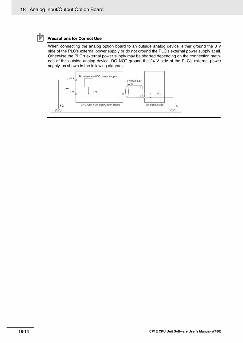
18 Analog Input/Output Option Board
18-14 CP1E CPU Unit Software User’s Manual(W480)
Precautions for Correct UsePrecautions for Correct Use
When connecting the analog option board to an outside analog device, either ground the 0 Vside of the PLC’s external power supply or do not ground the PLC’s external power supply at all.Otherwise the PLC’s external power supply may be shorted depending on the connection meth-ods of the outside analog device. DO NOT ground the 24 V side of the PLC’s external powersupply, as shown in the following diagram.
24 V
0 V 0 V
Non-insulated DC power supply
0 V
Analog Device FG FG
Twisted-pair cable
CPU Unit + Analog Option Board
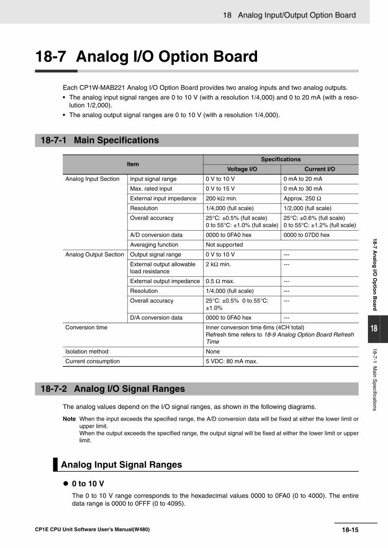
18-15
18 Analog Input/Output Option Board
CP1E CPU Unit Software User’s Manual(W480)
18-7 An
alog
I/O O
ptio
n B
oard
18
18-7-1 Main S
pecifications
18-7 Analog I/O Option Board
Each CP1W-MAB221 Analog I/O Option Board provides two analog inputs and two analog outputs.
• The analog input signal ranges are 0 to 10 V (with a resolution 1/4,000) and 0 to 20 mA (with a reso-lution 1/2,000).
• The analog output signal ranges are 0 to 10 V (with a resolution 1/4,000).
The analog values depend on the I/O signal ranges, as shown in the following diagrams.
Note When the input exceeds the specified range, the A/D conversion data will be fixed at either the lower limit orupper limit.When the output exceeds the specified range, the output signal will be fixed at either the lower limit or upperlimit.
0 to 10 VThe 0 to 10 V range corresponds to the hexadecimal values 0000 to 0FA0 (0 to 4000). The entiredata range is 0000 to 0FFF (0 to 4095).
18-7-1 Main Specifications
ItemSpecifications
Voltage I/O Current I/O
Analog Input Section Input signal range 0 V to 10 V 0 mA to 20 mA
Max. rated input 0 V to 15 V 0 mA to 30 mA
External input impedance 200 kΩ min. Approx. 250 Ω
Resolution 1/4,000 (full scale) 1/2,000 (full scale)
Overall accuracy 25°C: ±0.5% (full scale)0 to 55°C: ±1.0% (full scale)
25°C: ±0.6% (full scale)0 to 55°C: ±1.2% (full scale)
A/D conversion data 0000 to 0FA0 hex 0000 to 07D0 hex
Averaging function Not supported
Analog Output Section Output signal range 0 V to 10 V ---
External output allowable load resistance
2 kΩ min. ---
External output impedance 0.5 Ω max. ---
Resolution 1/4,000 (full scale) ---
Overall accuracy 25°C: ±0.5% 0 to 55°C: ±1.0%
---
D/A conversion data 0000 to 0FA0 hex ---
Conversion time Inner conversion time 6ms (4CH total)Refresh time refers to 18-9 Analog Option Board Refresh Time
Isolation method None
Current consumption 5 VDC: 80 mA max.
18-7-2 Analog I/O Signal Ranges
Analog Input Signal Ranges
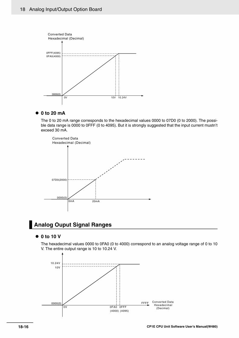
18 Analog Input/Output Option Board
18-16 CP1E CPU Unit Software User’s Manual(W480)
0 to 20 mAThe 0 to 20 mA range corresponds to the hexadecimal values 0000 to 07D0 (0 to 2000). The possi-ble data range is 0000 to 0FFF (0 to 4095). But it is strongly suggested that the input current mustn’texceed 30 mA.
0 to 10 V The hexadecimal values 0000 to 0FA0 (0 to 4000) correspond to an analog voltage range of 0 to 10V. The entire output range is 10 to 10.24 V.
Analog Ouput Signal Ranges
Converted Data Hexadecimal (Decimal)
10V 10.24V
0FA0(4000)0FFF(4095)
0000(0)0V
Converted DataHexadecimal (Decimal)
0mA 20mA
07D0(2000)
0000(0)
0V
10V
0FA0
FFFF
0FFF(4000) (4095)
0000(0) Converted Data Hexadecimal
(Decimal)
10.24V
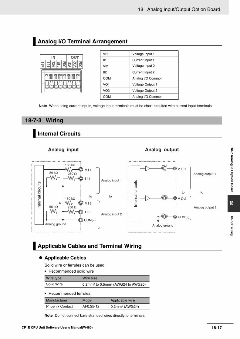
18-17
18 Analog Input/Output Option Board
CP1E CPU Unit Software User’s Manual(W480)
18-7 An
alog
I/O O
ptio
n B
oard
18
18-7-3 Wiring
Note When using current inputs, voltage input terminals must be short-circuited with current input terminals.
Applicable CablesSolid wire or ferrules can be used.
• Recommended solid wire
• Recommended ferrules
Note Do not connect bare stranded wires directly to terminals.
Analog I/O Terminal Arrangement
18-7-3 Wiring
Internal Circuits
Applicable Cables and Terminal Wiring
Wire type Wire size
Solid Wire 0.2mm2 to 0.5mm2 (AWG24 to AWG20)
Manufacturer Model Applicable wire
Phoenix Contact AI-0.25-12 0.2mm2 (AWG24)
VI1 Voltage Input 1
II1 Current Input 1
VI2 Voltage Input 2
II2 Current Input 2
COM Analog I/O Common
VO1 Voltage Output 1
VO2 Voltage Output 2
COM Analog I/O Common
Analog input Analog output
Analog input 2
Analog ground
I I 1
V I 1
COM(−)
I I 2
V I 2
56 kΩ 250 Ω
250 Ω
180 kΩ
180 kΩ
Inte
rnal
circ
uits
Analog input 1
to
56 kΩ
Analog output 1
Analog ground
V O 1
COM(−)
V O 2
Analog output 2
tototo
Inte
rnal
circ
uits
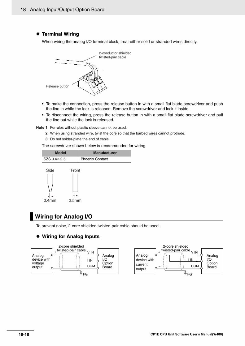
18 Analog Input/Output Option Board
18-18 CP1E CPU Unit Software User’s Manual(W480)
Terminal WiringWhen wiring the analog I/O terminal block, treat either solid or stranded wires directly.
• To make the connection, press the release button in with a small flat blade screwdriver and pushthe line in while the lock is released. Remove the screwdriver and lock it inside.
• To disconnect the wiring, press the release button in with a small flat blade screwdriver and pullthe line out while the lock is released.
Note 1 Ferrules without plastic sleeve cannot be used.
2 When using stranded wire, twist the core so that the barbed wires cannot protrude.
3 Do not solder-plate the end of cable.
The screwdriver shown below is recommended for wiring.
To prevent noise, 2-core shielded twisted-pair cable should be used.
Wiring for Analog Inputs
Model Manufacturer
SZS 0.4 2.5 Phoenix Contact
Wiring for Analog I/O
Release button
2-conductor shielded twisted-pair cable
0.4mm
Side Front
2.5mm
V IN
COM
I IN
V IN
COM
I INAnalog device with voltage output
Analog I/O Option Board
+
−
+
−
Analog device with current output
Analog I/O Option Board
2-core shieldedtwisted-pair cable
2-core shieldedtwisted-pair cable
FG FG
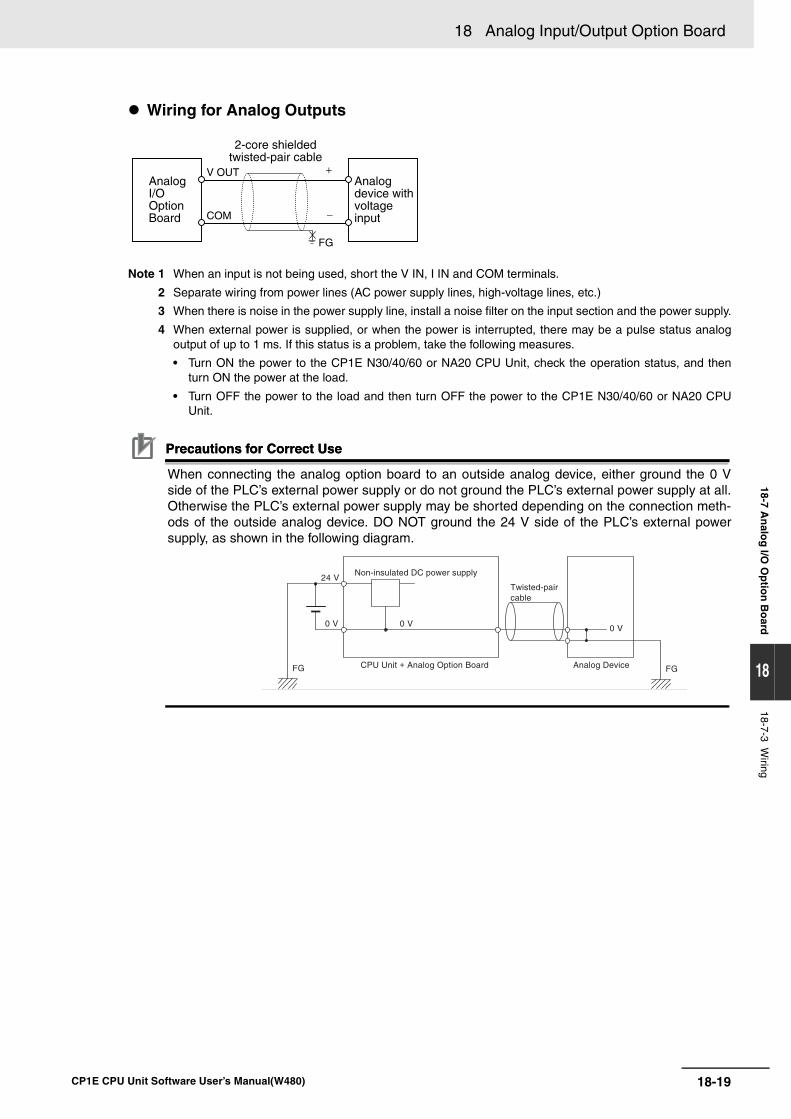
18-19
18 Analog Input/Output Option Board
CP1E CPU Unit Software User’s Manual(W480)
18-7 An
alog
I/O O
ptio
n B
oard
18
18-7-3 Wiring
Wiring for Analog Outputs
Note 1 When an input is not being used, short the V IN, I IN and COM terminals.
2 Separate wiring from power lines (AC power supply lines, high-voltage lines, etc.)
3 When there is noise in the power supply line, install a noise filter on the input section and the power supply.
4 When external power is supplied, or when the power is interrupted, there may be a pulse status analogoutput of up to 1 ms. If this status is a problem, take the following measures.
• Turn ON the power to the CP1E N30/40/60 or NA20 CPU Unit, check the operation status, and thenturn ON the power at the load.
• Turn OFF the power to the load and then turn OFF the power to the CP1E N30/40/60 or NA20 CPUUnit.
Precautions for Correct UsePrecautions for Correct Use
When connecting the analog option board to an outside analog device, either ground the 0 Vside of the PLC’s external power supply or do not ground the PLC’s external power supply at all.Otherwise the PLC’s external power supply may be shorted depending on the connection meth-ods of the outside analog device. DO NOT ground the 24 V side of the PLC’s external powersupply, as shown in the following diagram.
COM
V OUTAnalog I/O Option Board
Analog device with voltage input
FG
2-core shieldedtwisted-pair cable
+
−
24 V
0 V 0 V
Non-insulated DC power supply
0 V
Analog Device FG FG
Twisted-pair cable
CPU Unit + Analog Option Board
18 Analog Input/Output Option Board
18-20 CP1E CPU Unit Software User’s Manual(W480)
18-8 Startup Operation
After the power is turned ON, analog option board starts the initialization process. If the initialization fin-ishes normally, the initialization completed flag in related status area (Refer to 18-4-2 Auxiliary AreaAllocation: A435) will be set. Therefore, status monitor content must be added in ladder. Only when theinitialization process has finished, user can use the A/D conversion data or write the output data.
The analog input data will be 0000 until the initial processing is completed.
It takes about 1.9 seconds from the CP1E CPU Unit running to the Analog Option Board initializationcompleted.
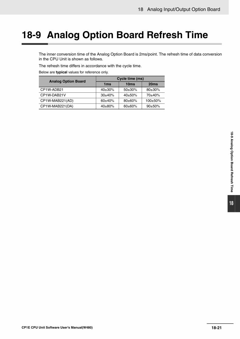
18-21
18 Analog Input/Output Option Board
CP1E CPU Unit Software User’s Manual(W480)
18-9 An
alog
Op
tion
Bo
ard R
efresh T
ime
18
18-9 Analog Option Board Refresh Time
The inner conversion time of the Analog Option Board is 2ms/point. The refresh time of data conversionin the CPU Unit is shown as follows.
The refresh time differs in accordance with the cycle time.
Below are typical values for reference only.
Analog Option BoardCycle time (ms)
1ms 10ms 20ms
CP1W-ADB21 40±30% 50±30% 80±30%
CP1W-DAB21V 30±40% 40±50% 70±40%
CP1W-MAB221(AD) 60±40% 80±60% 100±50%
CP1W-MAB221(DA) 40±80% 60±60% 90±50%
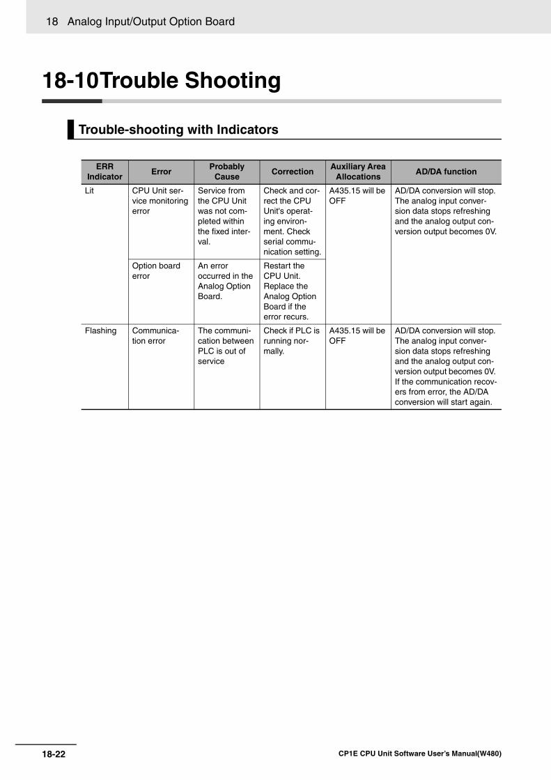
18 Analog Input/Output Option Board
18-22 CP1E CPU Unit Software User’s Manual(W480)
18-10Trouble Shooting
Trouble-shooting with Indicators
ERRIndicator
ErrorProbably
CauseCorrection
Auxiliary Area Allocations
AD/DA function
Lit CPU Unit ser-vice monitoring error
Service from the CPU Unit was not com-pleted within the fixed inter-val.
Check and cor-rect the CPU Unit's operat-ing environ-ment. Check serial commu-nication setting.
A435.15 will be OFF
AD/DA conversion will stop. The analog input conver-sion data stops refreshing and the analog output con-version output becomes 0V.
Option board error
An error occurred in the Analog Option Board.
Restart the CPU Unit. Replace the Analog Option Board if the error recurs.
Flashing Communica-tion error
The communi-cation between PLC is out of service
Check if PLC is running nor-mally.
A435.15 will be OFF
AD/DA conversion will stop. The analog input conver-sion data stops refreshing and the analog output con-version output becomes 0V. If the communication recov-ers from error, the AD/DA conversion will start again.
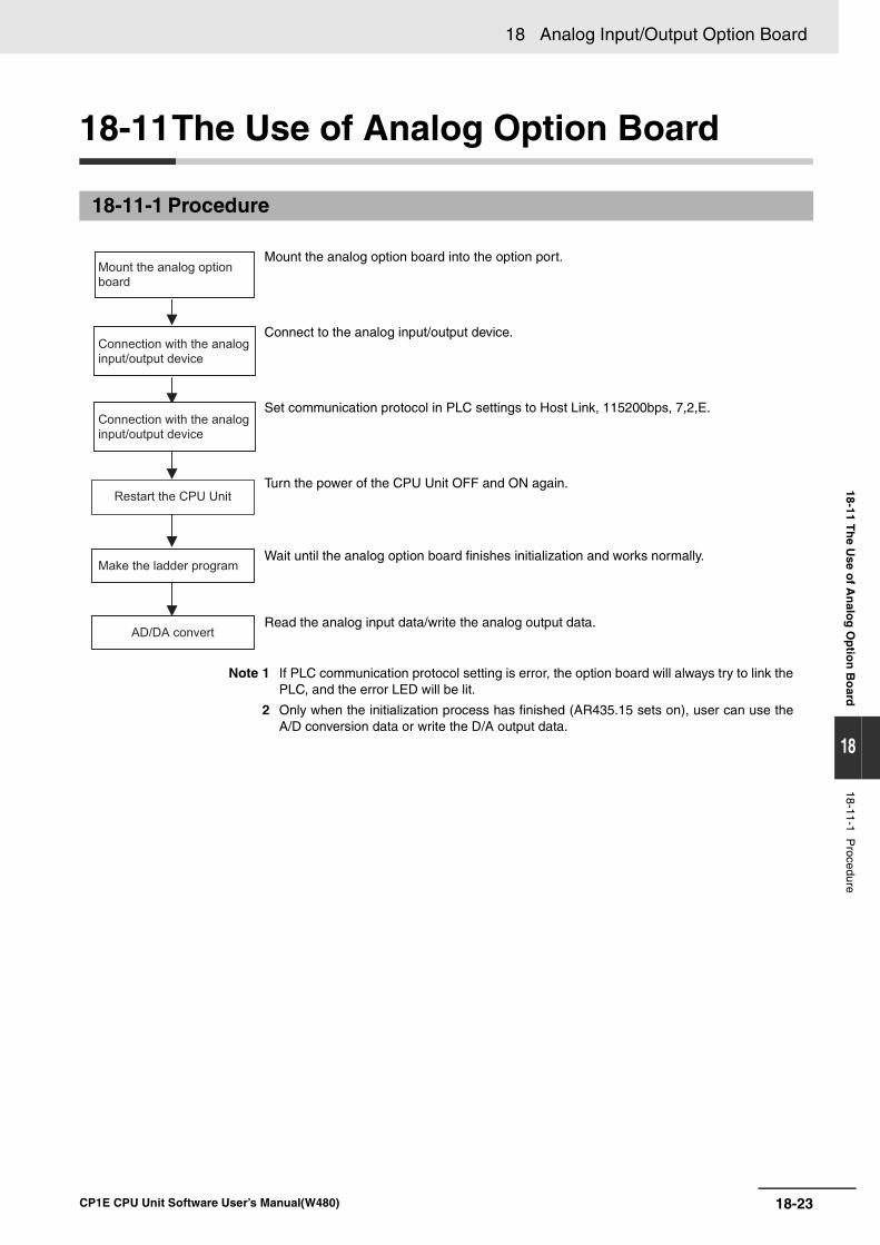
18-23
18 Analog Input/Output Option Board
CP1E CPU Unit Software User’s Manual(W480)
18-11 Th
e Use o
f An
alog
Op
tion
Bo
ard
18
18-11-1 Procedure
18-11The Use of Analog Option Board
18-11-1 Procedure
Connection with the analog
input/output device
Make the ladder program
Connection with the analog
input/output device
Mount the analog option
board
Restart the CPU Unit
AD/DA convert
Mount the analog option board into the option port.
Connect to the analog input/output device.
Set communication protocol in PLC settings to Host Link, 115200bps, 7,2,E.
Turn the power of the CPU Unit OFF and ON again.
Wait until the analog option board finishes initialization and works normally.
Read the analog input data/write the analog output data.
Note 1 If PLC communication protocol setting is error, the option board will always try to link thePLC, and the error LED will be lit.
2 Only when the initialization process has finished (AR435.15 sets on), user can use theA/D conversion data or write the D/A output data.
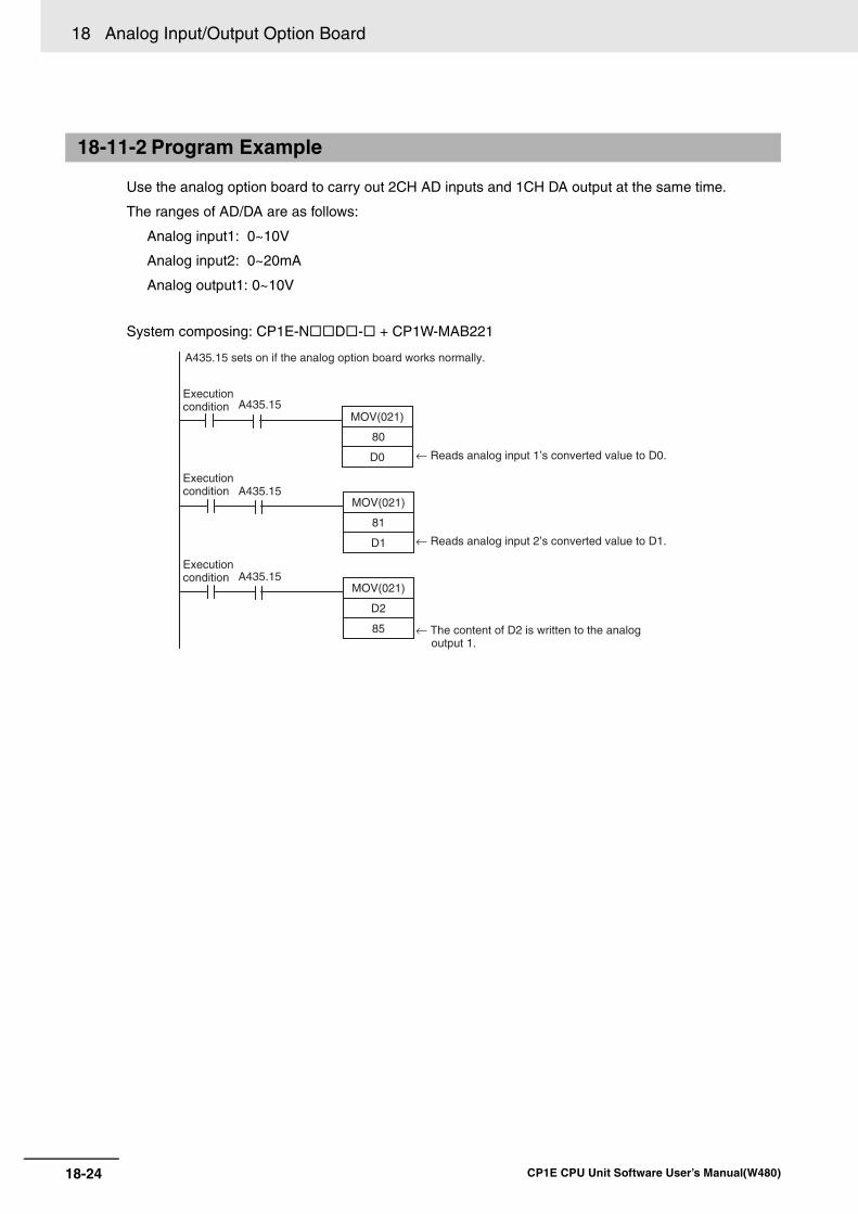
18 Analog Input/Output Option Board
18-24 CP1E CPU Unit Software User’s Manual(W480)
Use the analog option board to carry out 2CH AD inputs and 1CH DA output at the same time.
The ranges of AD/DA are as follows:
Analog input1: 0~10V
Analog input2: 0~20mA
Analog output1: 0~10V
System composing: CP1E-N D - + CP1W-MAB221
18-11-2 Program Example
80
D0
MOV(021)
81
D1
MOV(021)
D2
85
MOV(021)
Execution condition
Execution condition
Execution condition
← Reads analog input 1’s converted value to D0.
← Reads analog input 2’s converted value to D1.
← The content of D2 is written to the analog output 1.
A435.15
A435.15
A435.15
A435.15 sets on if the analog option board works normally.
19-1
19
CP1E CPU Unit Software User’s Manual(W480)
19
This section describes the use of the CX-Programmer to create a ladder programs tooperate the CP1E, transfer the program to the CP1E, and debug the program. It alsodescribes other basic functions of the CX-Programmer.
19-1 Programming Devices Usable with the CP1E. . . . . . . . . . . . . . . . . . . . . . . 19-2
19-2 Overview of CX-Programmer . . . . . . . . . . . . . . . . . . . . . . . . . . . . . . . . . . . . 19-419-2-1 CX-Programmer . . . . . . . . . . . . . . . . . . . . . . . . . . . . . . . . . . . . . . . . . . . . . . . 19-419-2-2 CX-Programmer Flow from Startup to Operation . . . . . . . . . . . . . . . . . . . . . . 19-4
19-2-3 Help . . . . . . . . . . . . . . . . . . . . . . . . . . . . . . . . . . . . . . . . . . . . . . . . . . . . . . . . 19-7
19-3 Creating a Ladder Program . . . . . . . . . . . . . . . . . . . . . . . . . . . . . . . . . . . . . 19-819-3-1 Inputting a Ladder Program . . . . . . . . . . . . . . . . . . . . . . . . . . . . . . . . . . . . . . 19-819-3-2 Saving and Reading Ladder Programs. . . . . . . . . . . . . . . . . . . . . . . . . . . . . 19-1519-3-3 Editing Ladder Programs . . . . . . . . . . . . . . . . . . . . . . . . . . . . . . . . . . . . . . . 19-16
19-4 Connecting Online to the CP1E and Transferring the Program . . . . . . . 19-1919-4-1 Connecting Online . . . . . . . . . . . . . . . . . . . . . . . . . . . . . . . . . . . . . . . . . . . . 19-19
19-4-2 Changing Operating Modes . . . . . . . . . . . . . . . . . . . . . . . . . . . . . . . . . . . . . 19-2019-4-3 Transferring a Ladder Program and the PLC Setup . . . . . . . . . . . . . . . . . . . 19-2119-4-4 Starting Operation . . . . . . . . . . . . . . . . . . . . . . . . . . . . . . . . . . . . . . . . . . . . 19-22
19-5 Online Monitoring and Debugging . . . . . . . . . . . . . . . . . . . . . . . . . . . . . . 19-2419-5-1 Monitoring Status . . . . . . . . . . . . . . . . . . . . . . . . . . . . . . . . . . . . . . . . . . . . . 19-24
19-5-2 Force-set/Reset Bits . . . . . . . . . . . . . . . . . . . . . . . . . . . . . . . . . . . . . . . . . . . 19-2619-5-3 Online Editing . . . . . . . . . . . . . . . . . . . . . . . . . . . . . . . . . . . . . . . . . . . . . . . . 19-27
Programming Device Operations
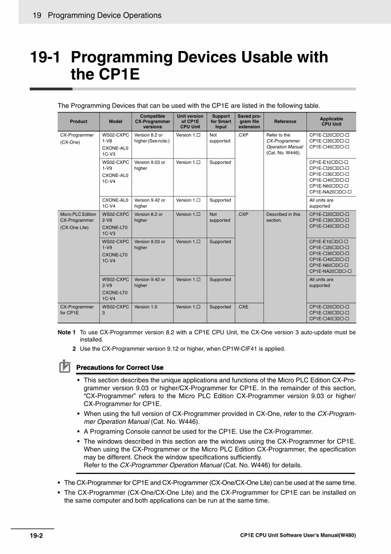
19 Programming Device Operations
19-2 CP1E CPU Unit Software User’s Manual(W480)
19-1 Programming Devices Usable with the CP1E
The Programming Devices that can be used with the CP1E are listed in the following table.
Note 1 To use CX-Programmer version 8.2 with a CP1E CPU Unit, the CX-One version 3 auto-update must beinstalled.
2 Use the CX-Programmer version 9.12 or higher, when CP1W-CIF41 is applied.
Precautions for Correct UsePrecautions for Correct Use
• This section describes the unique applications and functions of the Micro PLC Edition CX-Pro-grammer version 9.03 or higher/CX-Programmer for CP1E. In the remainder of this section,“CX-Programmer” refers to the Micro PLC Edition CX-Programmer version 9.03 or higher/CX-Programmer for CP1E.
• When using the full version of CX-Programmer provided in CX-One, refer to the CX-Program-mer Operation Manual (Cat. No. W446).
• A Programing Console cannot be used for the CP1E. Use the CX-Programmer.
• The windows described in this section are the windows using the CX-Programmer for CP1E.When using the CX-Programmer or the Micro PLC Edition CX-Programmer, the specificationmay be different. Check the window specifications sufficiently.Refer to the CX-Programmer Operation Manual (Cat. No. W446) for details.
• The CX-Programmer for CP1E and CX-Programmer (CX-One/CX-One Lite) can be used at the same time.
• The CX-Programmer (CX-One/CX-One Lite) and the CX-Programmer for CP1E can be installed onthe same computer and both applications can be run at the same time.
Product ModelCompatible
CX-Programmer versions
Unit version of CP1E CPU Unit
Support for Smart
Input
Saved pro-gram file extension
Reference Applicable CPU Unit
CX-Programmer
(CX-One)
WS02-CXPC1-V8
CXONE-AL01C-V3
Version 8.2 or higher (See note.)
Version 1. Not supported
.CXP Refer to the CX-Programmer Operation Manual (Cat. No. W446).
CP1E- 20 D -CP1E- 30 D -CP1E- 40 D -
WS02-CXPC1-V9
CXONE-AL01C-V4
Version 9.03 or higher
Version 1. Supported CP1E-E10 D -CP1E- 20 D -CP1E- 30 D -CP1E- 40 D -CP1E-N60 D -CP1E-NA20 D -
CXONE-AL01C-V4
Version 9.42 or higher
Version 1. Supported All units are supported
Micro PLC Edition CX-Programmer
(CX-One Lite)
WS02-CXPC2-V8
CXONE-LT01C-V3
Version 8.2 or higher
Version 1. Not supported
.CXP Described in this section.
CP1E- 20 D -CP1E- 30 D -CP1E- 40 D -
WS02-CXPC1-V9
CXONE-LT01C-V4
Version 9.03 or higher
Version 1. Supported CP1E-E10 D -CP1E- 20 D -CP1E- 30 D -CP1E- 40 D -CP1E-N60 D -CP1E-NA20 D -
WS02-CXPC2-V9
CXONE-LT01C-V4
Version 9.42 or higher
Version 1. Supported All units are supported
CX-Programmer for CP1E
WS02-CXPC3
Version 1.0 Version 1. Supported .CXE CP1E- 20 D -CP1E- 30 D -CP1E- 40 D -
19-3
19 Programming Device Operations
CP1E CPU Unit Software User’s Manual(W480)
19-1 Pro
gram
min
g D
evices Usab
le with
the C
P1E
19
Using Project Files Saved with the CX-Programmer (.CXP) on the CX-Programmer for CP1EThe CX-Programmer for CP1E cannot open a .CXP project created on the CX-Programmer(CX-One/CX-One Lite). Use programming from a project saved in a .CXP file on the CX-Program-mer for CP1E according to the following procedure.
1 Start the CX-Programmer (CX-One/CX-One Lite) and CX-Programmer for CP1E together.
2 Copy the rungs of the program to be used from the Ladder Programming Window of the CX-Pro-
grammer (CX-One/CX-One Lite), and paste them into the CX-Programmer for CP1E.
Additional Information
Files created with the CX-Programmer for CP1E (.CXE) can be opened with CX-Programmerversion 8.2 and higher.
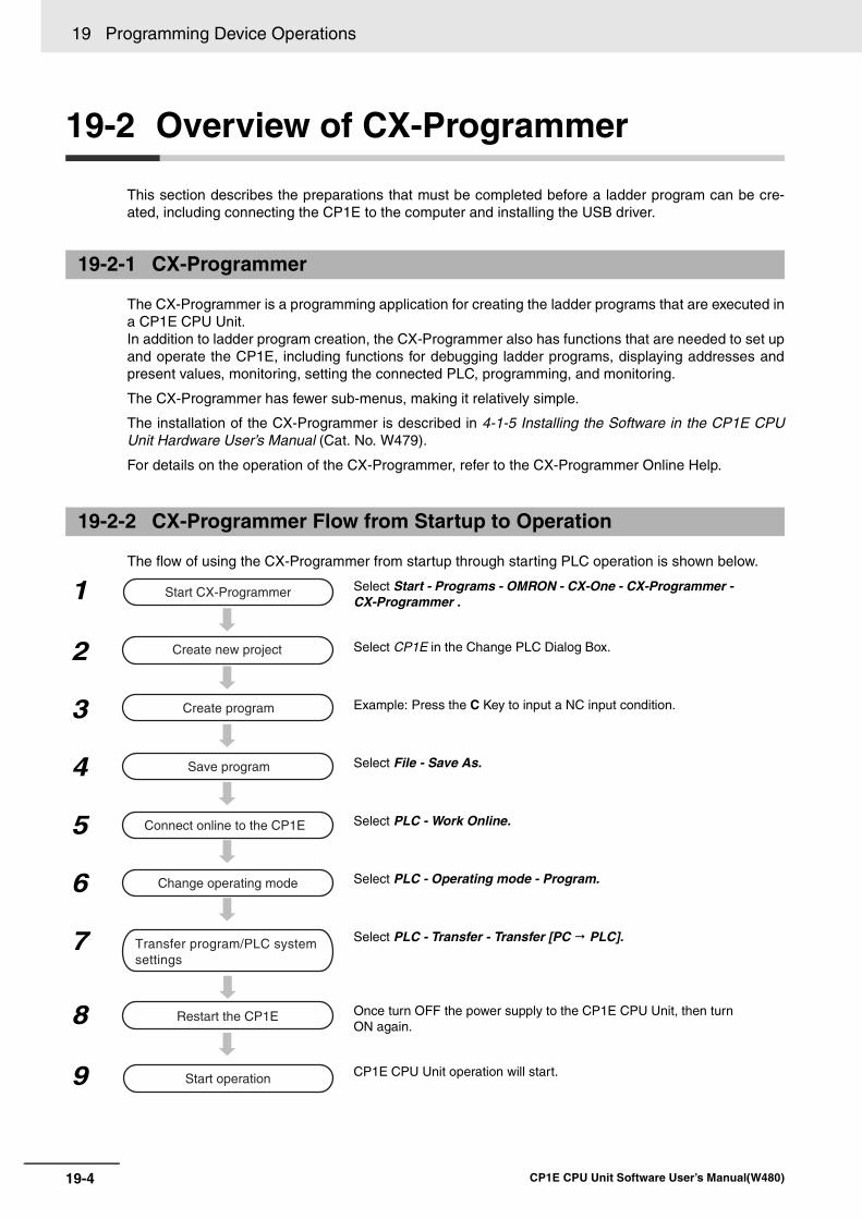
19 Programming Device Operations
19-4 CP1E CPU Unit Software User’s Manual(W480)
19-2 Overview of CX-Programmer
This section describes the preparations that must be completed before a ladder program can be cre-ated, including connecting the CP1E to the computer and installing the USB driver.
The CX-Programmer is a programming application for creating the ladder programs that are executed ina CP1E CPU Unit. In addition to ladder program creation, the CX-Programmer also has functions that are needed to set upand operate the CP1E, including functions for debugging ladder programs, displaying addresses andpresent values, monitoring, setting the connected PLC, programming, and monitoring.
The CX-Programmer has fewer sub-menus, making it relatively simple.
The installation of the CX-Programmer is described in 4-1-5 Installing the Software in the CP1E CPUUnit Hardware User’s Manual (Cat. No. W479).
For details on the operation of the CX-Programmer, refer to the CX-Programmer Online Help.
The flow of using the CX-Programmer from startup through starting PLC operation is shown below.
19-2-1 CX-Programmer
19-2-2 CX-Programmer Flow from Startup to Operation
1 Select Start - Programs - OMRON - CX-One - CX-Programmer - CX-Programmer .
2 Select CP1E in the Change PLC Dialog Box.
3 Example: Press the C Key to input a NC input condition.
4 Select File - Save As.
5 Select PLC - Work Online.
6 Select PLC - Operating mode - Program.
7 Select PLC - Transfer - Transfer [PC PLC].
8 Once turn OFF the power supply to the CP1E CPU Unit, then turn ON again.
9 CP1E CPU Unit operation will start.
Start CX-Programmer
Create new project
Create program
Save program
Connect online to the CP1E
Change operating mode
Transfer program/PLC system settings
Restart the CP1E
Start operation
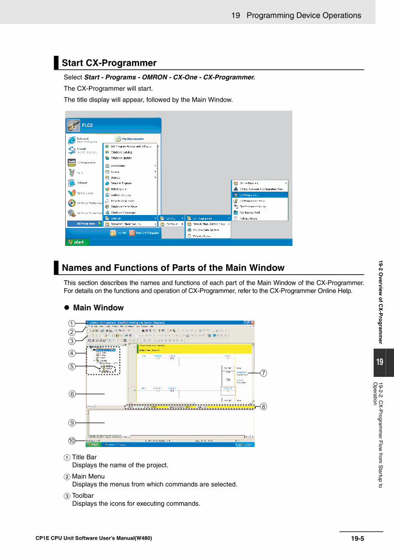
19-5
19 Programming Device Operations
CP1E CPU Unit Software User’s Manual(W480)
19-2 Overview
of C
X-P
rog
ramm
er
19
19-2-2 CX
-Program
mer F
low from
Startup to
Operation
Select Start - Programs - OMRON - CX-One - CX-Programmer.
The CX-Programmer will start.
The title display will appear, followed by the Main Window.
This section describes the names and functions of each part of the Main Window of the CX-Programmer.For details on the functions and operation of CX-Programmer, refer to the CX-Programmer Online Help.
Main Window
Title BarDisplays the name of the project.
Main MenuDisplays the menus from which commands are selected.
ToolbarDisplays the icons for executing commands.
Start CX-Programmer
Names and Functions of Parts of the Main Window
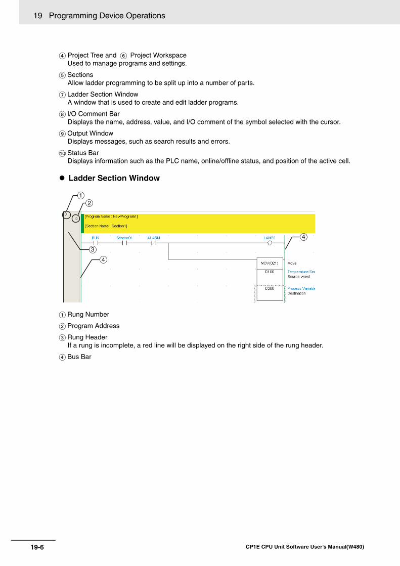
19 Programming Device Operations
19-6 CP1E CPU Unit Software User’s Manual(W480)
Project Tree and Project WorkspaceUsed to manage programs and settings.
SectionsAllow ladder programming to be split up into a number of parts.
Ladder Section WindowA window that is used to create and edit ladder programs.
I/O Comment BarDisplays the name, address, value, and I/O comment of the symbol selected with the cursor.
Output WindowDisplays messages, such as search results and errors.
Status BarDisplays information such as the PLC name, online/offline status, and position of the active cell.
Ladder Section Window
Rung Number
Program Address
Rung HeaderIf a rung is incomplete, a red line will be displayed on the right side of the rung header.
Bus Bar
3
4
4
12
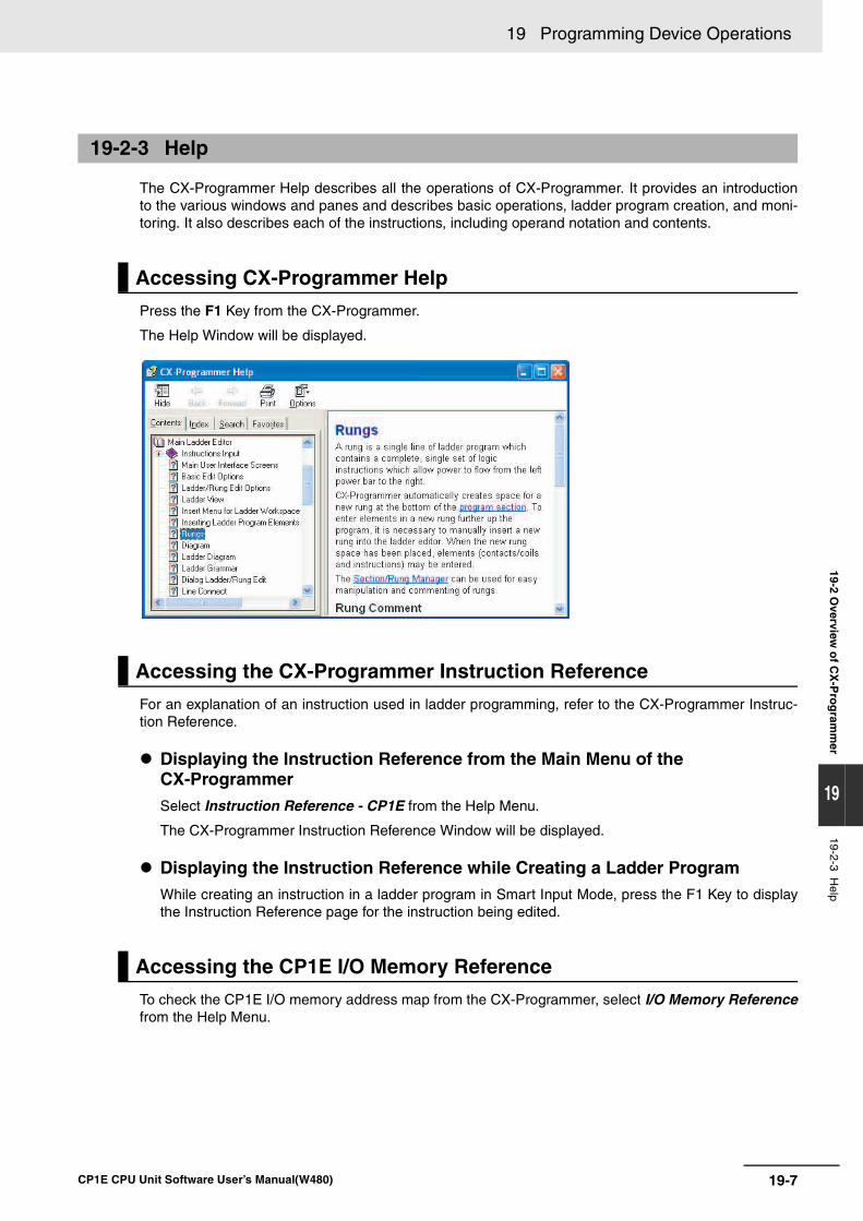
19-7
19 Programming Device Operations
CP1E CPU Unit Software User’s Manual(W480)
19-2 Overview
of C
X-P
rog
ramm
er
19
19-2-3 Help
The CX-Programmer Help describes all the operations of CX-Programmer. It provides an introductionto the various windows and panes and describes basic operations, ladder program creation, and moni-toring. It also describes each of the instructions, including operand notation and contents.
Press the F1 Key from the CX-Programmer.
The Help Window will be displayed.
For an explanation of an instruction used in ladder programming, refer to the CX-Programmer Instruc-tion Reference.
Displaying the Instruction Reference from the Main Menu of the CX-ProgrammerSelect Instruction Reference - CP1E from the Help Menu.
The CX-Programmer Instruction Reference Window will be displayed.
Displaying the Instruction Reference while Creating a Ladder ProgramWhile creating an instruction in a ladder program in Smart Input Mode, press the F1 Key to displaythe Instruction Reference page for the instruction being edited.
To check the CP1E I/O memory address map from the CX-Programmer, select I/O Memory Referencefrom the Help Menu.
19-2-3 Help
Accessing CX-Programmer Help
Accessing the CX-Programmer Instruction Reference
Accessing the CP1E I/O Memory Reference
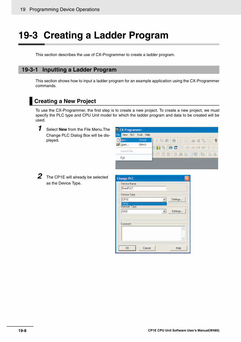
19 Programming Device Operations
19-8 CP1E CPU Unit Software User’s Manual(W480)
19-3 Creating a Ladder Program
This section describes the use of CX-Programmer to create a ladder program.
This section shows how to input a ladder program for an example application using the CX-Programmercommands.
To use the CX-Programmer, the first step is to create a new project. To create a new project, we mustspecify the PLC type and CPU Unit model for which the ladder program and data to be created will beused.
19-3-1 Inputting a Ladder Program
Creating a New Project
1 Select New from the File Menu.The
Change PLC Dialog Box will be dis-played.
2 The CP1E will already be selected
as the Device Type.
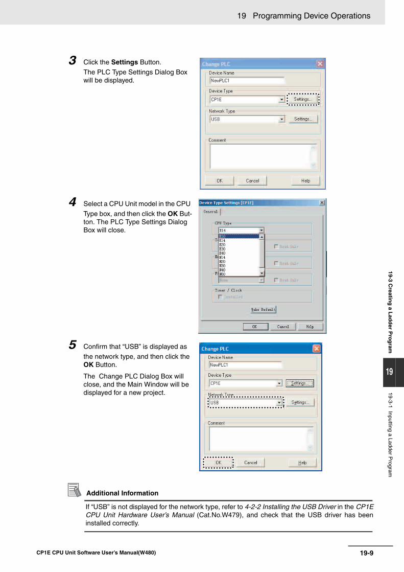
19-9
19 Programming Device Operations
CP1E CPU Unit Software User’s Manual(W480)
19-3 Creatin
g a L
add
er Pro
gram
19
19-3-1 Inputting a Ladder Program
Additional Information
If “USB” is not displayed for the network type, refer to 4-2-2 Installing the USB Driver in the CP1ECPU Unit Hardware User’s Manual (Cat.No.W479), and check that the USB driver has beeninstalled correctly.
3 Click the Settings Button.
The PLC Type Settings Dialog Box will be displayed.
4 Select a CPU Unit model in the CPU
Type box, and then click the OK But-ton. The PLC Type Settings Dialog Box will close.
5 Confirm that “USB” is displayed as
the network type, and then click the OK Button.
The Change PLC Dialog Box will close, and the Main Window will be displayed for a new project.
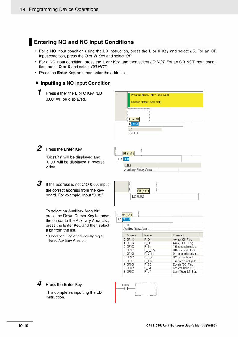
19 Programming Device Operations
19-10 CP1E CPU Unit Software User’s Manual(W480)
• For a NO input condition using the LD instruction, press the L or C Key and select LD. For an ORinput condition, press the O or W Key and select OR.
• For a NC input condition, press the L or / Key, and then select LD NOT. For an OR NOT input condi-tion, press O or X and select OR NOT.
• Press the Enter Key, and then enter the address.
Inputting a NO Input Condition
Entering NO and NC Input Conditions
1 Press either the L or C Key. “LD
0.00” will be displayed.
2 Press the Enter Key.
“Bit (1/1)” will be displayed and “0.00” will be displayed in reverse video.
3 If the address is not CIO 0.00, input
the correct address from the key-board. For example, input “0.02.”
To select an Auxiliary Area bit*, press the Down Cursor Key to move the cursor to the Auxiliary Area List, press the Enter Key, and then select a bit from the list.* Condition Flag or previously regis-
tered Auxiliary Area bit.
4 Press the Enter Key.
This completes inputting the LD instruction.
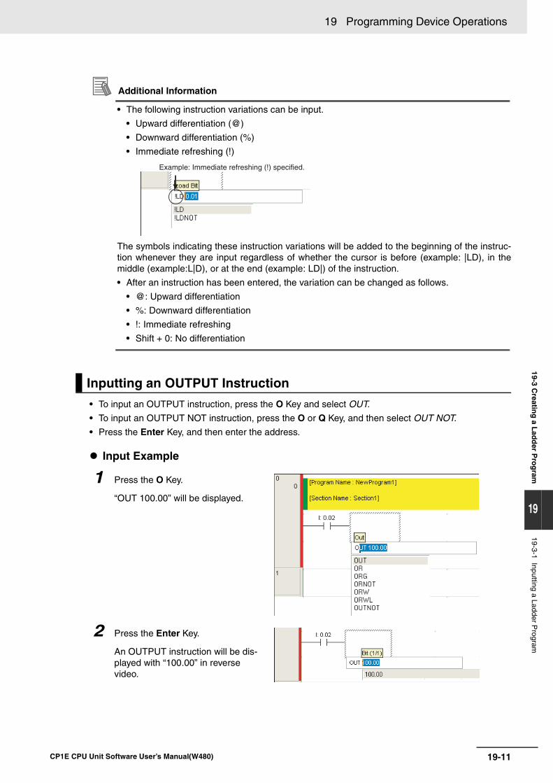
19-11
19 Programming Device Operations
CP1E CPU Unit Software User’s Manual(W480)
19-3 Creatin
g a L
add
er Pro
gram
19
19-3-1 Inputting a Ladder Program
Additional Information
• The following instruction variations can be input.
• Upward differentiation (@)
• Downward differentiation (%)
• Immediate refreshing (!)
The symbols indicating these instruction variations will be added to the beginning of the instruc-tion whenever they are input regardless of whether the cursor is before (example: |LD), in themiddle (example:L|D), or at the end (example: LD|) of the instruction.
• After an instruction has been entered, the variation can be changed as follows.
• @: Upward differentiation
• %: Downward differentiation
• !: Immediate refreshing
• Shift + 0: No differentiation
• To input an OUTPUT instruction, press the O Key and select OUT.
• To input an OUTPUT NOT instruction, press the O or Q Key, and then select OUT NOT.
• Press the Enter Key, and then enter the address.
Input Example
Inputting an OUTPUT Instruction
1 Press the O Key.
“OUT 100.00” will be displayed.
2 Press the Enter Key.
An OUTPUT instruction will be dis-played with “100.00” in reverse video.
Example: Immediate refreshing (!) specified.
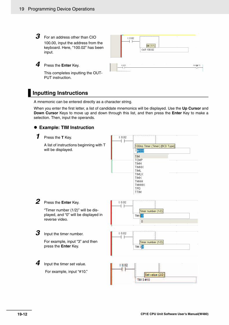
19 Programming Device Operations
19-12 CP1E CPU Unit Software User’s Manual(W480)
A mnemonic can be entered directly as a character string.
When you enter the first letter, a list of candidate mnemonics will be displayed. Use the Up Cursor andDown Cursor Keys to move up and down through this list, and then press the Enter Key to make aselection. Then, input the operands.
Example: TIM Instruction
3 For an address other than CIO
100.00, input the address from the keyboard. Here, “100.02” has been input.
4 Press the Enter Key.
This completes inputting the OUT-PUT instruction.
Inputting Instructions
1 Press the T Key.
A list of instructions beginning with T will be displayed.
2 Press the Enter Key.
“Timer number (1/2)” will be dis-played, and “0” will be displayed in reverse video.
3 Input the timer number.
For example, input “3” and then press the Enter Key.
4 Input the timer set value.
For example, input “#10.”
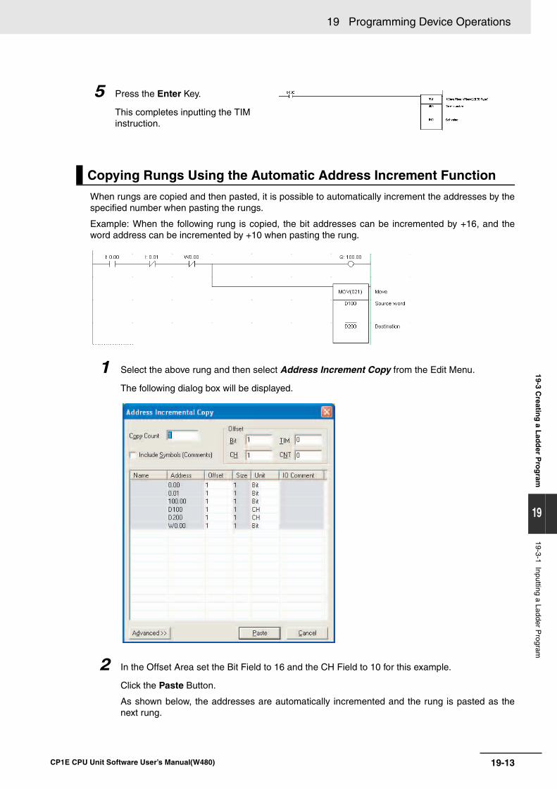
19-13
19 Programming Device Operations
CP1E CPU Unit Software User’s Manual(W480)
19-3 Creatin
g a L
add
er Pro
gram
19
19-3-1 Inputting a Ladder Program
When rungs are copied and then pasted, it is possible to automatically increment the addresses by thespecified number when pasting the rungs.
Example: When the following rung is copied, the bit addresses can be incremented by +16, and theword address can be incremented by +10 when pasting the rung.
1 Select the above rung and then select Address Increment Copy from the Edit Menu.
The following dialog box will be displayed.
2 In the Offset Area set the Bit Field to 16 and the CH Field to 10 for this example.
Click the Paste Button.
As shown below, the addresses are automatically incremented and the rung is pasted as thenext rung.
5 Press the Enter Key.
This completes inputting the TIM instruction.
Copying Rungs Using the Automatic Address Increment Function
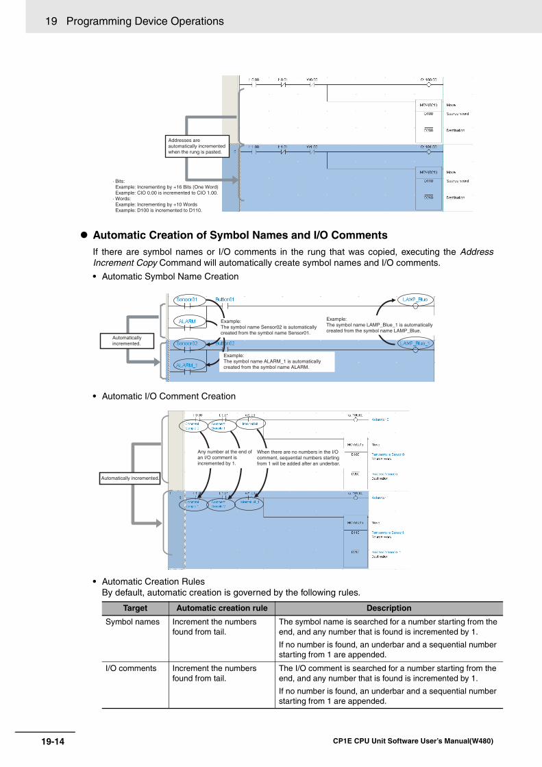
19 Programming Device Operations
19-14 CP1E CPU Unit Software User’s Manual(W480)
Automatic Creation of Symbol Names and I/O CommentsIf there are symbol names or I/O comments in the rung that was copied, executing the AddressIncrement Copy Command will automatically create symbol names and I/O comments.
• Automatic Symbol Name Creation
• Automatic I/O Comment Creation
• Automatic Creation RulesBy default, automatic creation is governed by the following rules.
Target Automatic creation rule Description
Symbol names Increment the numbers found from tail.
The symbol name is searched for a number starting from the end, and any number that is found is incremented by 1.
If no number is found, an underbar and a sequential number starting from 1 are appended.
I/O comments Increment the numbers found from tail.
The I/O comment is searched for a number starting from the end, and any number that is found is incremented by 1.
If no number is found, an underbar and a sequential number starting from 1 are appended.
Addresses are automatically incremented when the rung is pasted.
· Bits:Example: Incrementing by +16 Bits (One Word)Example: CIO 0.00 is incremented to CIO 1.00.
· Words:Example: Incrementing by +10 WordsExample: D100 is incremented to D110.
Automatically incremented.
Example: The symbol name Sensor02 is automatically created from the symbol name Sensor01.
Example: The symbol name ALARM_1 is automatically created from the symbol name ALARM.
Example:The symbol name LAMP_Blue_1 is automatically created from the symbol name LAMP_Blue.
Automatically incremented.
Any number at the end of an I/O comment is incremented by 1.
When there are no numbers in the I/O comment, sequential numbers starting from 1 will be added after an underbar.
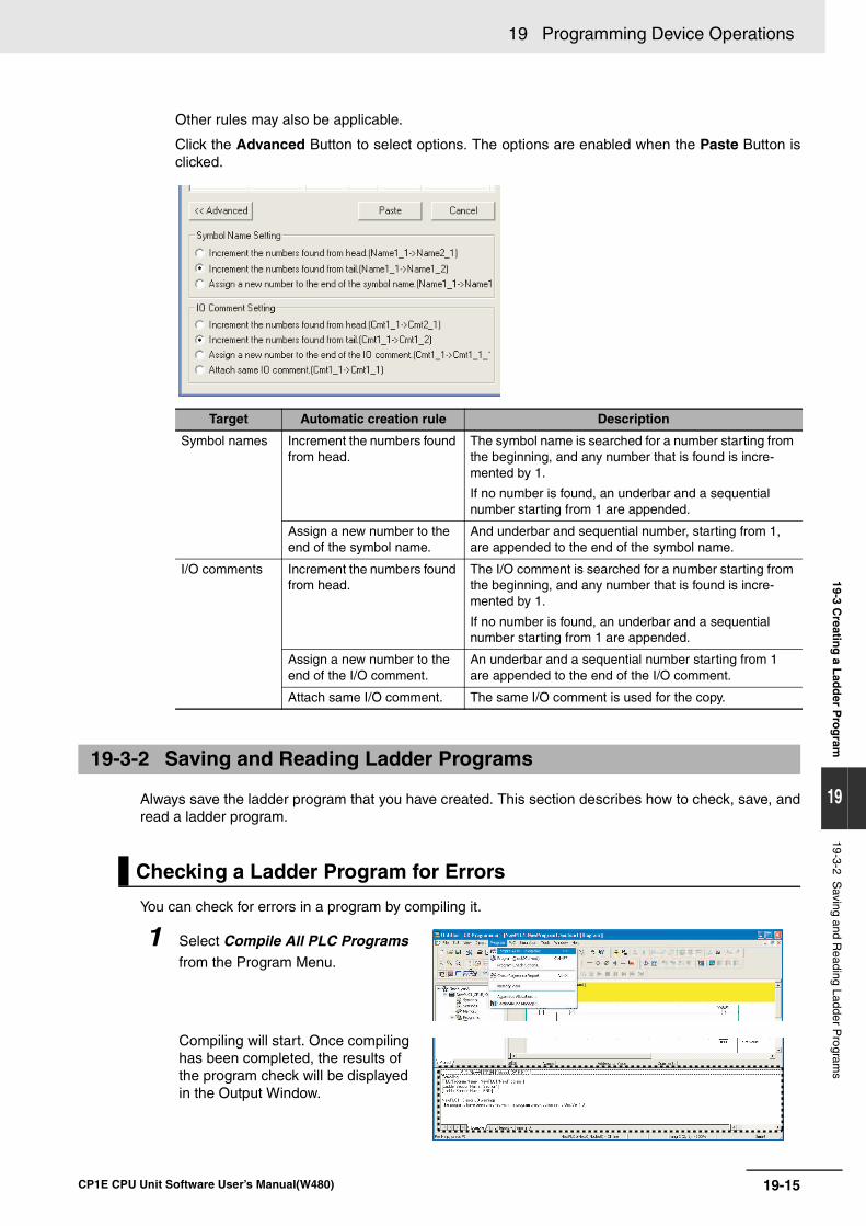
19-15
19 Programming Device Operations
CP1E CPU Unit Software User’s Manual(W480)
19-3 Creatin
g a L
add
er Pro
gram
19
19-3-2 Saving and R
eading Ladder Program
s
Other rules may also be applicable.
Click the Advanced Button to select options. The options are enabled when the Paste Button isclicked.
Always save the ladder program that you have created. This section describes how to check, save, andread a ladder program.
You can check for errors in a program by compiling it.
Target Automatic creation rule Description
Symbol names Increment the numbers found from head.
The symbol name is searched for a number starting from the beginning, and any number that is found is incre-mented by 1.
If no number is found, an underbar and a sequential number starting from 1 are appended.
Assign a new number to the end of the symbol name.
And underbar and sequential number, starting from 1, are appended to the end of the symbol name.
I/O comments Increment the numbers found from head.
The I/O comment is searched for a number starting from the beginning, and any number that is found is incre-mented by 1.
If no number is found, an underbar and a sequential number starting from 1 are appended.
Assign a new number to the end of the I/O comment.
An underbar and a sequential number starting from 1 are appended to the end of the I/O comment.
Attach same I/O comment. The same I/O comment is used for the copy.
19-3-2 Saving and Reading Ladder Programs
Checking a Ladder Program for Errors
1 Select Compile All PLC Programs from the Program Menu.
Compiling will start. Once compiling has been completed, the results of the program check will be displayed in the Output Window.
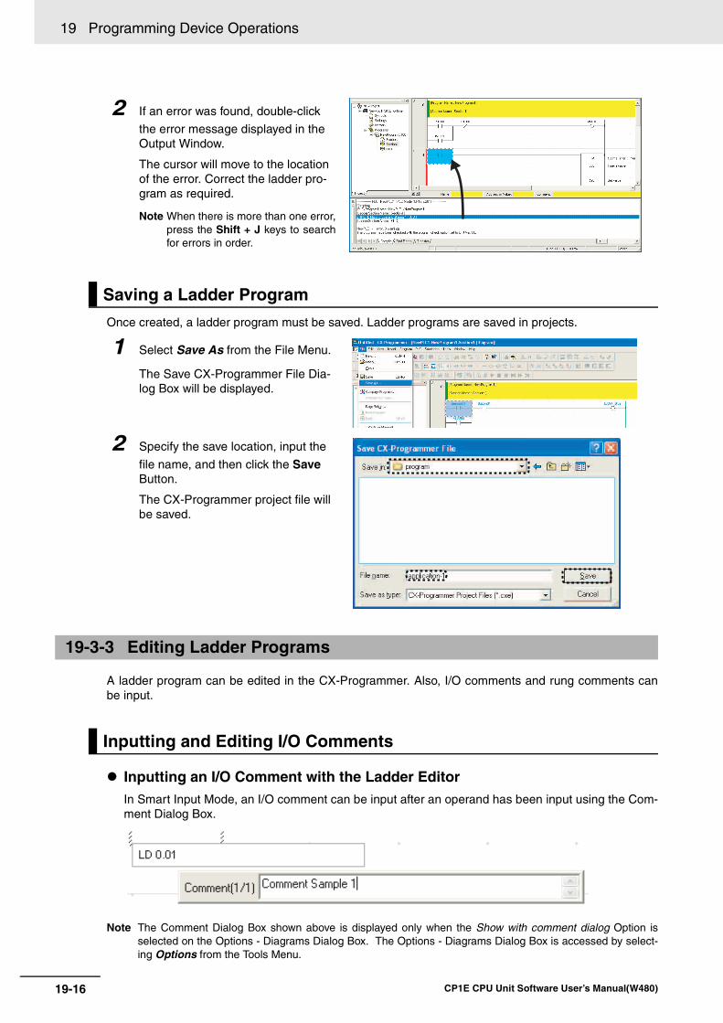
19 Programming Device Operations
19-16 CP1E CPU Unit Software User’s Manual(W480)
Once created, a ladder program must be saved. Ladder programs are saved in projects.
A ladder program can be edited in the CX-Programmer. Also, I/O comments and rung comments canbe input.
Inputting an I/O Comment with the Ladder EditorIn Smart Input Mode, an I/O comment can be input after an operand has been input using the Com-ment Dialog Box.
Note The Comment Dialog Box shown above is displayed only when the Show with comment dialog Option isselected on the Options - Diagrams Dialog Box. The Options - Diagrams Dialog Box is accessed by select-ing Options from the Tools Menu.
2 If an error was found, double-click
the error message displayed in the Output Window.
The cursor will move to the location of the error. Correct the ladder pro-gram as required.
Note When there is more than one error,press the Shift + J keys to searchfor errors in order.
Saving a Ladder Program
1 Select Save As from the File Menu.
The Save CX-Programmer File Dia-log Box will be displayed.
2 Specify the save location, input the
file name, and then click the Save Button.
The CX-Programmer project file will be saved.
19-3-3 Editing Ladder Programs
Inputting and Editing I/O Comments
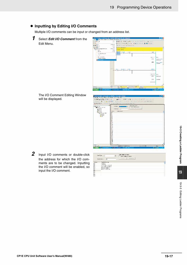
19-17
19 Programming Device Operations
CP1E CPU Unit Software User’s Manual(W480)
19-3 Creatin
g a L
add
er Pro
gram
19
19-3-3 Editing Ladder P
rograms
Inputting by Editing I/O CommentsMultiple I/O comments can be input or changed from an address list.
1 Select Edit I/O Comment from the
Edit Menu.
The I/O Comment Editing Window will be displayed.
2 Input I/O comments or double-click
the address for which the I/O com-ments are to be changed. Inputtingthe I/O comment will be enabled, soinput the I/O comment.
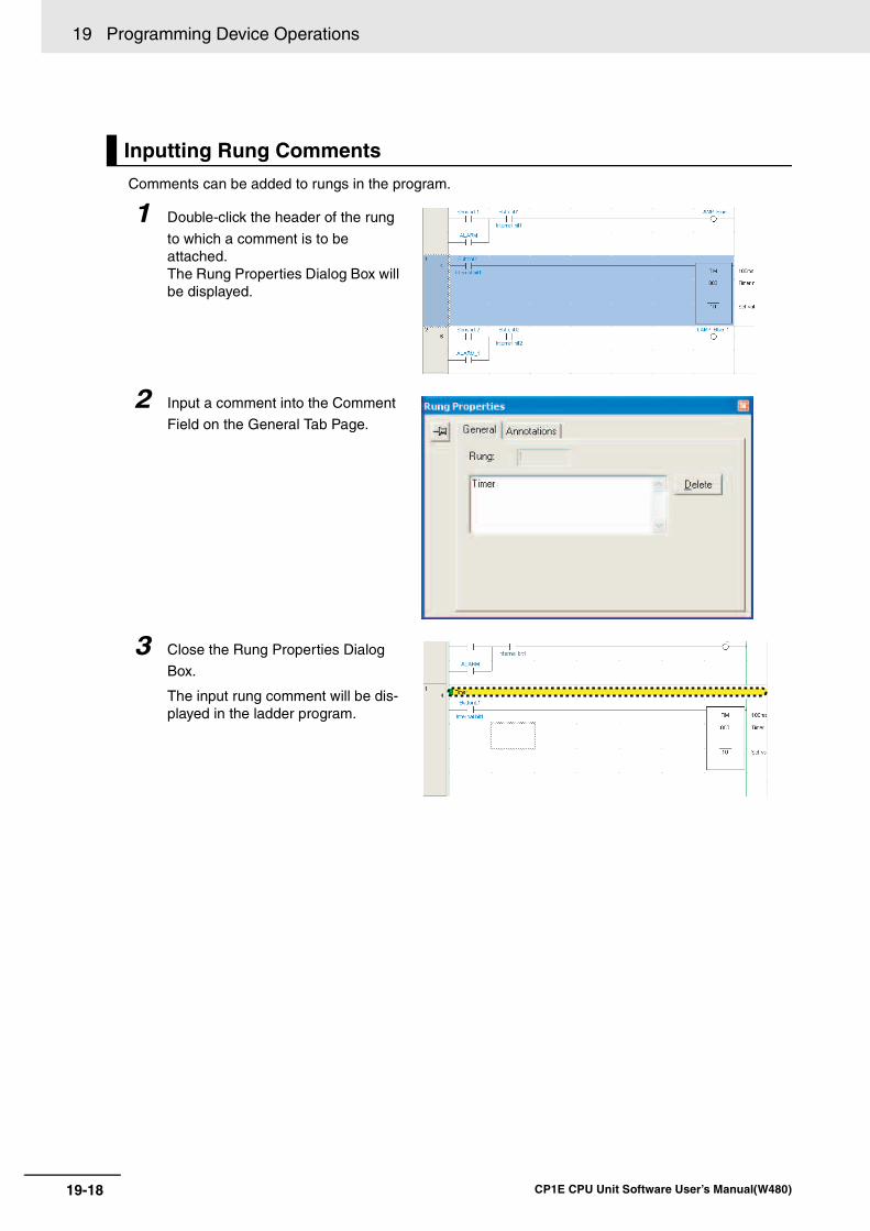
19 Programming Device Operations
19-18 CP1E CPU Unit Software User’s Manual(W480)
Comments can be added to rungs in the program.
Inputting Rung Comments
1 Double-click the header of the rung
to which a comment is to be attached.The Rung Properties Dialog Box will be displayed.
2 Input a comment into the Comment
Field on the General Tab Page.
3 Close the Rung Properties Dialog
Box.
The input rung comment will be dis-played in the ladder program.
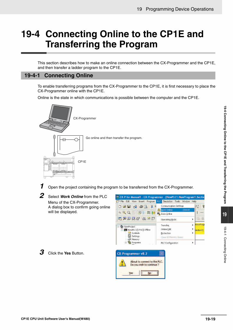
19-19
19 Programming Device Operations
CP1E CPU Unit Software User’s Manual(W480)
19-4 Co
nn
ecting
On
line to
the C
P1E
and
Transferrin
g th
e Pro
gram
19
19-4-1 Connecting O
nline
19-4 Connecting Online to the CP1E and Transferring the Program
This section describes how to make an online connection between the CX-Programmer and the CP1E,and then transfer a ladder program to the CP1E.
To enable transferring programs from the CX-Programmer to the CP1E, it is first necessary to place theCX-Programmer online with the CP1E.
Online is the state in which communications is possible between the computer and the CP1E.
19-4-1 Connecting Online
1 Open the project containing the program to be transferred from the CX-Programmer.
2 Select Work Online from the PLC
Menu of the CX-Programmer.A dialog box to confirm going online will be displayed.
3 Click the Yes Button.
CP1E
CX-Programmer
Go online and then transfer the program.
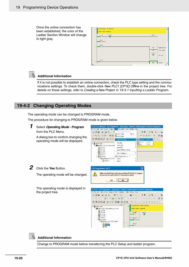
19 Programming Device Operations
19-20 CP1E CPU Unit Software User’s Manual(W480)
Additional Information
If it is not possible to establish an online connection, check the PLC type setting and the commu-nications settings. To check them, double-click New PLC1 [CP1E] Offline in the project tree. Fordetails on these settings, refer to Creating a New Project in 19-3-1 Inputting a Ladder Program.
The operating mode can be changed to PROGRAM mode.
The procedure for changing to PROGRAM mode is given below.
Additional Information
Change to PROGRAM mode before transferring the PLC Setup and ladder program.
Once the online connection has been established, the color of the Ladder Section Window will change to light gray.
19-4-2 Changing Operating Modes
1 Select Operating Mode - Program
from the PLC Menu.
A dialog box to confirm changing the operating mode will be displayed.
2 Click the Yes Button.
The operating mode will be changed.
The operating mode is displayed in the project tree.
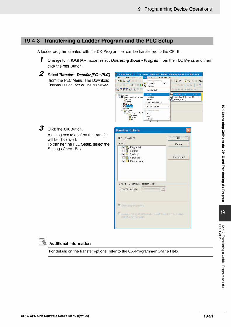
19-21
19 Programming Device Operations
CP1E CPU Unit Software User’s Manual(W480)
19-4 Co
nn
ecting
On
line to
the C
P1E
and
Transferrin
g th
e Pro
gram
19
19-4-3 Transferring a Ladder Program
and the P
LC S
etup
A ladder program created with the CX-Programmer can be transferred to the CP1E.
Additional Information
For details on the transfer options, refer to the CX-Programmer Online Help.
19-4-3 Transferring a Ladder Program and the PLC Setup
1 Change to PROGRAM mode, select Operating Mode - Program from the PLC Menu, and then
click the Yes Button.
2 Select Transfer - Transfer [PC PLC] from the PLC Menu. The Download Options Dialog Box will be displayed.
3 Click the OK Button.
A dialog box to confirm the transfer will be displayed.To transfer the PLC Setup, select the Settings Check Box.
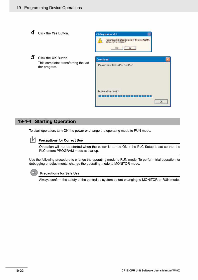
19 Programming Device Operations
19-22 CP1E CPU Unit Software User’s Manual(W480)
To start operation, turn ON the power or change the operating mode to RUN mode.
Precautions for Correct UsePrecautions for Correct Use
Operation will not be started when the power is turned ON if the PLC Setup is set so that thePLC enters PROGRAM mode at startup.
Use the following procedure to change the operating mode to RUN mode. To perform trial operation fordebugging or adjustments, change the operating mode to MONITOR mode.
Precautions for Safe Use
Always confirm the safety of the controlled system before changing to MONITOR or RUN mode.
4 Click the Yes Button.
5 Click the OK Button.
This completes transferring the lad-der program.
19-4-4 Starting Operation
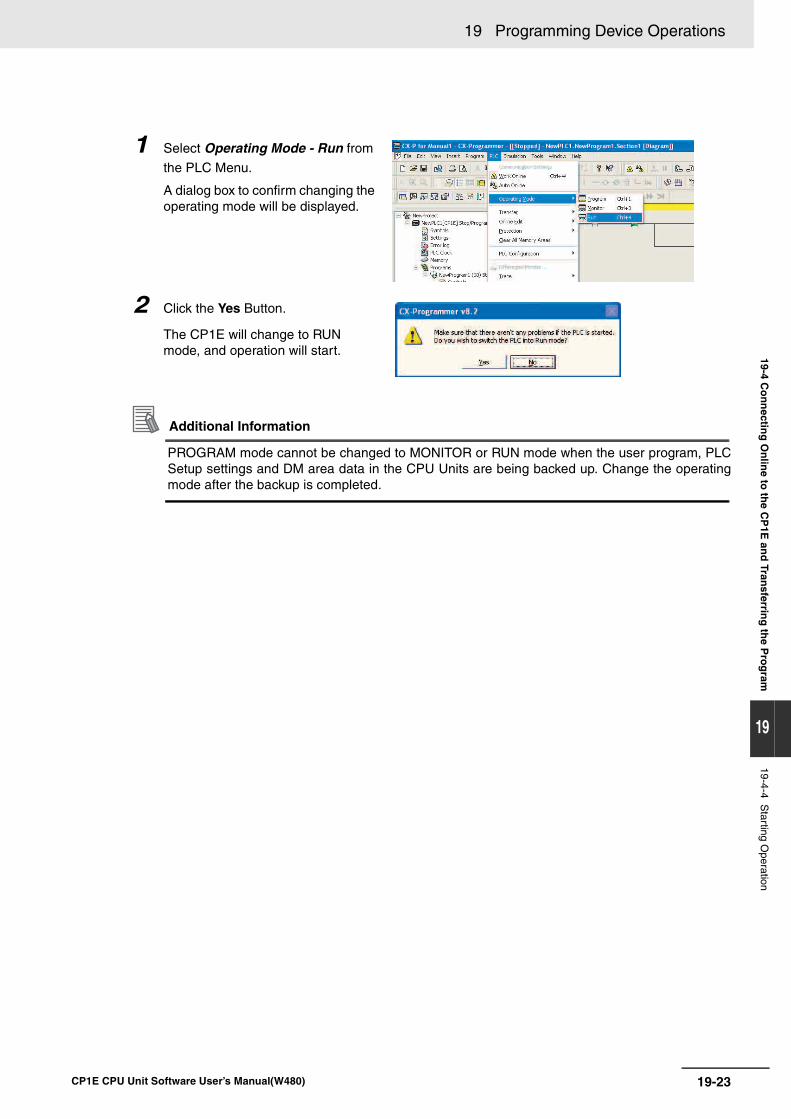
19-23
19 Programming Device Operations
CP1E CPU Unit Software User’s Manual(W480)
19-4 Co
nn
ecting
On
line to
the C
P1E
and
Transferrin
g th
e Pro
gram
19
19-4-4 Starting O
peration
Additional Information
PROGRAM mode cannot be changed to MONITOR or RUN mode when the user program, PLCSetup settings and DM area data in the CPU Units are being backed up. Change the operatingmode after the backup is completed.
1 Select Operating Mode - Run from
the PLC Menu.
A dialog box to confirm changing the operating mode will be displayed.
2 Click the Yes Button.
The CP1E will change to RUN mode, and operation will start.
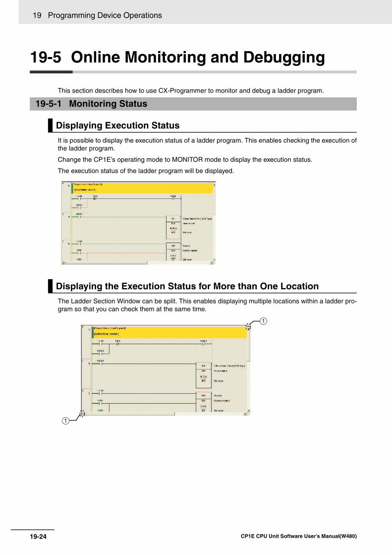
19 Programming Device Operations
19-24 CP1E CPU Unit Software User’s Manual(W480)
19-5 Online Monitoring and Debugging
This section describes how to use CX-Programmer to monitor and debug a ladder program.
It is possible to display the execution status of a ladder program. This enables checking the execution ofthe ladder program.
Change the CP1E’s operating mode to MONITOR mode to display the execution status.
The execution status of the ladder program will be displayed.
The Ladder Section Window can be split. This enables displaying multiple locations within a ladder pro-gram so that you can check them at the same time.
19-5-1 Monitoring Status
Displaying Execution Status
Displaying the Execution Status for More than One Location
1
1
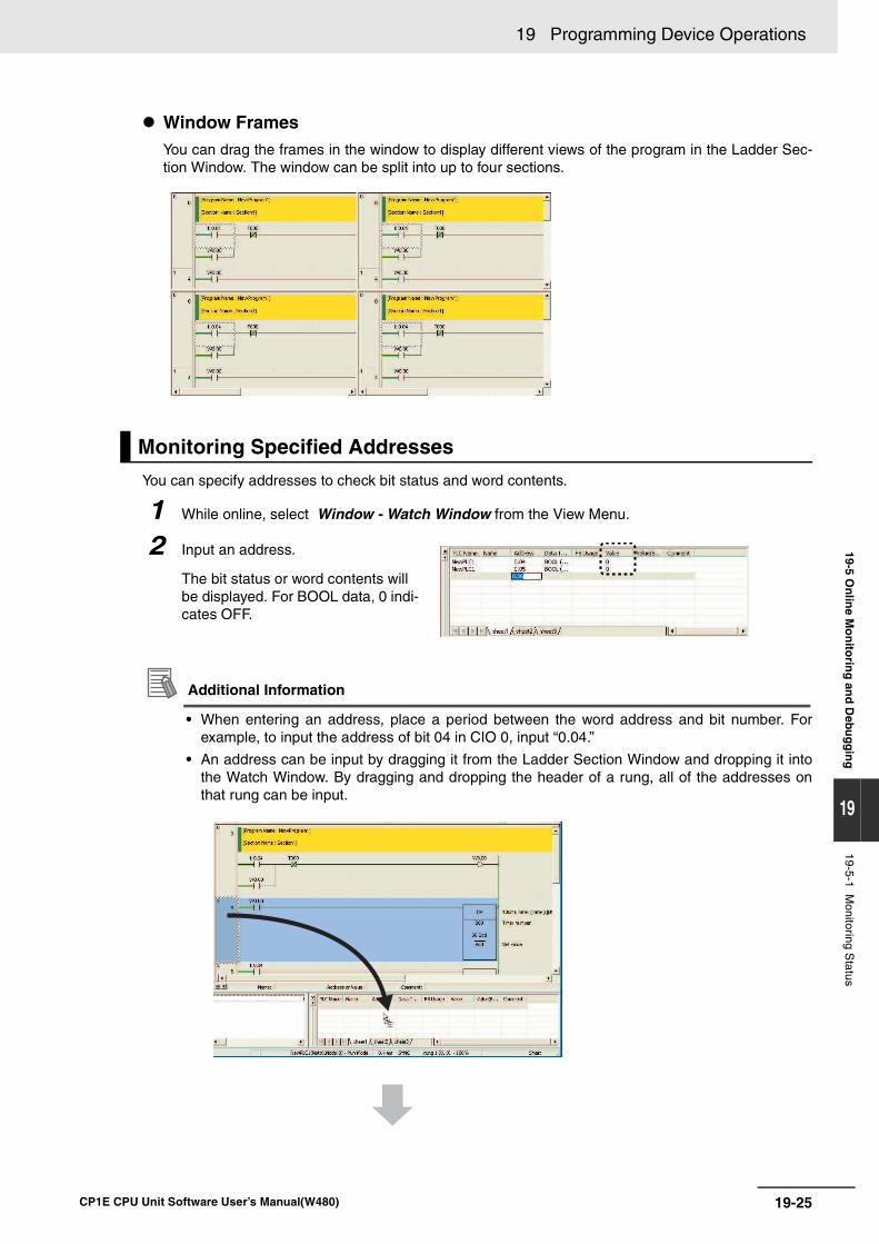
19-25
19 Programming Device Operations
CP1E CPU Unit Software User’s Manual(W480)
19-5 On
line M
on
itorin
g an
d D
ebug
gin
g
19
19-5-1 Monitoring S
tatus
Window FramesYou can drag the frames in the window to display different views of the program in the Ladder Sec-tion Window. The window can be split into up to four sections.
You can specify addresses to check bit status and word contents.
Additional Information
• When entering an address, place a period between the word address and bit number. Forexample, to input the address of bit 04 in CIO 0, input “0.04.”
• An address can be input by dragging it from the Ladder Section Window and dropping it intothe Watch Window. By dragging and dropping the header of a rung, all of the addresses onthat rung can be input.
Monitoring Specified Addresses
1 While online, select Window - Watch Window from the View Menu.
2 Input an address.
The bit status or word contents will be displayed. For BOOL data, 0 indi-cates OFF.
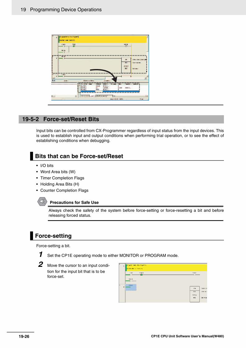
19 Programming Device Operations
19-26 CP1E CPU Unit Software User’s Manual(W480)
Input bits can be controlled from CX-Programmer regardless of input status from the input devices. Thisis used to establish input and output conditions when performing trial operation, or to see the effect ofestablishing conditions when debugging.
• I/O bits
• Word Area bits (W)
• Timer Completion Flags
• Holding Area Bits (H)
• Counter Completion Flags
Precautions for Safe Use
Always check the safety of the system before force-setting or force-resetting a bit and beforereleasing forced status.
Force-setting a bit.
19-5-2 Force-set/Reset Bits
Bits that can be Force-set/Reset
Force-setting
1 Set the CP1E operating mode to either MONITOR or PROGRAM mode.
2 Move the cursor to an input condi-
tion for the input bit that is to be force-set.
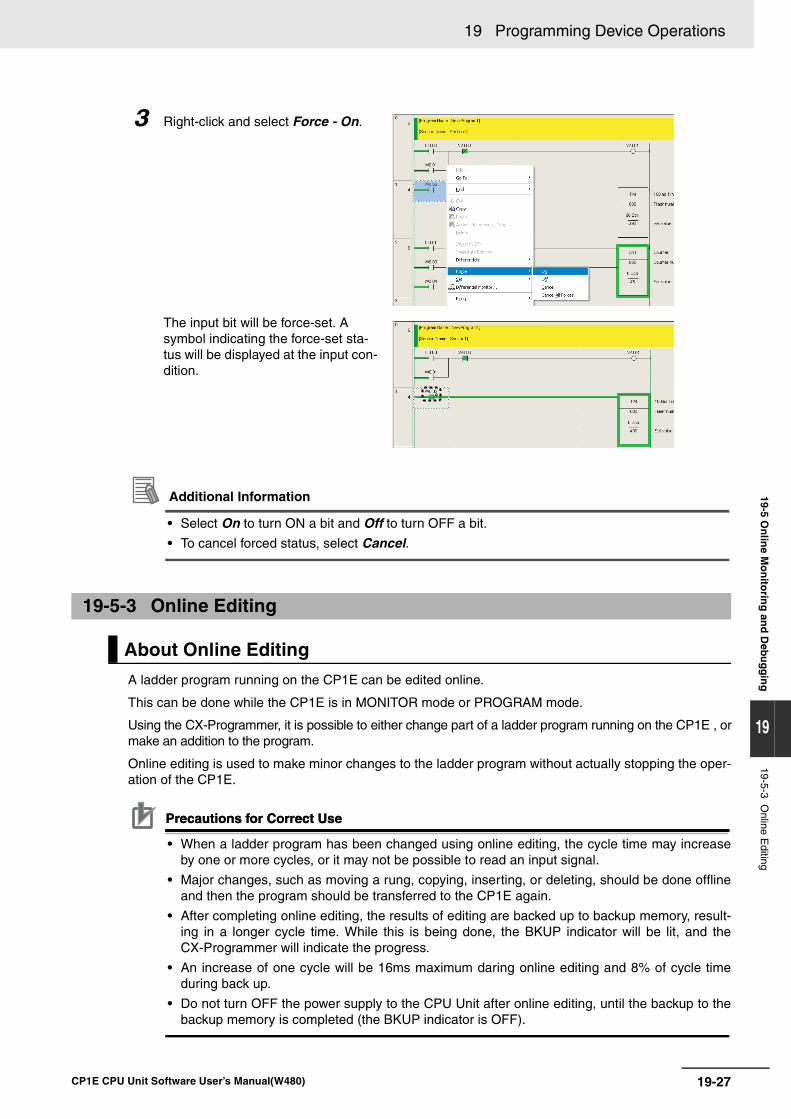
19-27
19 Programming Device Operations
CP1E CPU Unit Software User’s Manual(W480)
19-5 On
line M
on
itorin
g an
d D
ebug
gin
g
19
19-5-3 Online E
diting
Additional Information
• Select On to turn ON a bit and Off to turn OFF a bit.
• To cancel forced status, select Cancel.
A ladder program running on the CP1E can be edited online.
This can be done while the CP1E is in MONITOR mode or PROGRAM mode.
Using the CX-Programmer, it is possible to either change part of a ladder program running on the CP1E , ormake an addition to the program.
Online editing is used to make minor changes to the ladder program without actually stopping the oper-ation of the CP1E.
Precautions for Correct UsePrecautions for Correct Use
• When a ladder program has been changed using online editing, the cycle time may increaseby one or more cycles, or it may not be possible to read an input signal.
• Major changes, such as moving a rung, copying, inserting, or deleting, should be done offlineand then the program should be transferred to the CP1E again.
• After completing online editing, the results of editing are backed up to backup memory, result-ing in a longer cycle time. While this is being done, the BKUP indicator will be lit, and theCX-Programmer will indicate the progress.
• An increase of one cycle will be 16ms maximum daring online editing and 8% of cycle timeduring back up.
• Do not turn OFF the power supply to the CPU Unit after online editing, until the backup to thebackup memory is completed (the BKUP indicator is OFF).
3 Right-click and select Force - On.
The input bit will be force-set. A symbol indicating the force-set sta-tus will be displayed at the input con-dition.
19-5-3 Online Editing
About Online Editing
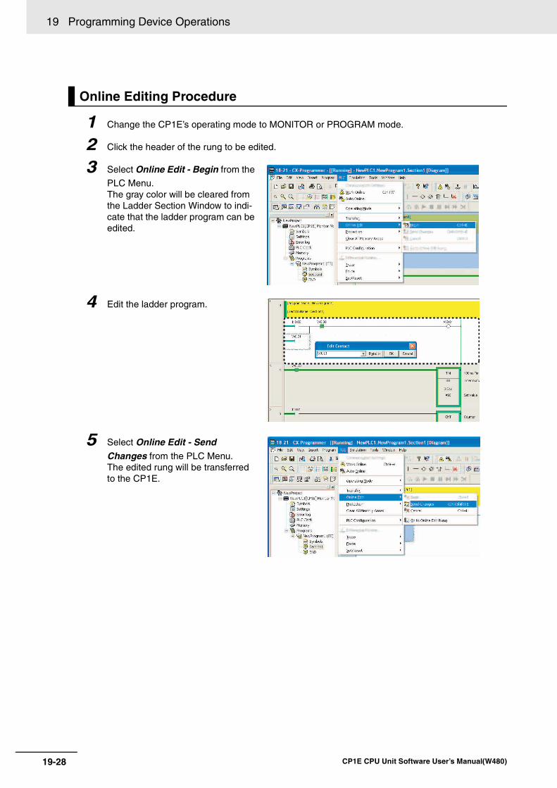
19 Programming Device Operations
19-28 CP1E CPU Unit Software User’s Manual(W480)
Online Editing Procedure
1 Change the CP1E’s operating mode to MONITOR or PROGRAM mode.
2 Click the header of the rung to be edited.
3 Select Online Edit - Begin from the
PLC Menu. The gray color will be cleared from the Ladder Section Window to indi-cate that the ladder program can be edited.
4 Edit the ladder program.
5 Select Online Edit - Send Changes from the PLC Menu.The edited rung will be transferred to the CP1E.
A-1
App
CP1E CPU Unit Software User’s Manual(W480)
Ap
p
A-1 Instruction Functions . . . . . . . . . . . . . . . . . . . . . . . . . . . . . . . . . . . . . . . . . . A-2A-1-1 Sequence Input Instructions . . . . . . . . . . . . . . . . . . . . . . . . . . . . . . . . . . . . . . A-2A-1-2 Sequence Output Instructions . . . . . . . . . . . . . . . . . . . . . . . . . . . . . . . . . . . . . A-3A-1-3 Sequence Control Instructions . . . . . . . . . . . . . . . . . . . . . . . . . . . . . . . . . . . . A-5A-1-4 Timer and Counter Instructions . . . . . . . . . . . . . . . . . . . . . . . . . . . . . . . . . . . . A-7A-1-5 Comparison Instructions . . . . . . . . . . . . . . . . . . . . . . . . . . . . . . . . . . . . . . . . A-10A-1-6 Data Movement Instructions . . . . . . . . . . . . . . . . . . . . . . . . . . . . . . . . . . . . . A-12A-1-7 Data Shift Instructions . . . . . . . . . . . . . . . . . . . . . . . . . . . . . . . . . . . . . . . . . . A-15A-1-8 Increment/Decrement Instructions . . . . . . . . . . . . . . . . . . . . . . . . . . . . . . . . . A-17A-1-9 Symbol Math Instructions . . . . . . . . . . . . . . . . . . . . . . . . . . . . . . . . . . . . . . . A-18A-1-10 Conversion Instructions . . . . . . . . . . . . . . . . . . . . . . . . . . . . . . . . . . . . . . . . . A-22A-1-11 Logic Instructions . . . . . . . . . . . . . . . . . . . . . . . . . . . . . . . . . . . . . . . . . . . . . . A-26A-1-12 Special Math Instructions . . . . . . . . . . . . . . . . . . . . . . . . . . . . . . . . . . . . . . . A-27A-1-13 Floating-point Math Instructions . . . . . . . . . . . . . . . . . . . . . . . . . . . . . . . . . . . A-27A-1-14 Table Data Processing Instructions . . . . . . . . . . . . . . . . . . . . . . . . . . . . . . . . A-30A-1-15 Data Control Instructions . . . . . . . . . . . . . . . . . . . . . . . . . . . . . . . . . . . . . . . . A-31A-1-16 Subroutine Instructions . . . . . . . . . . . . . . . . . . . . . . . . . . . . . . . . . . . . . . . . . A-35A-1-17 Interrupt Control Instructions . . . . . . . . . . . . . . . . . . . . . . . . . . . . . . . . . . . . . A-36A-1-18 High-speed Counter/Pulse Output Instructions . . . . . . . . . . . . . . . . . . . . . . . A-37A-1-19 Step Instructions . . . . . . . . . . . . . . . . . . . . . . . . . . . . . . . . . . . . . . . . . . . . . . A-44A-1-20 Basic I/O Unit Instructions . . . . . . . . . . . . . . . . . . . . . . . . . . . . . . . . . . . . . . . A-45A-1-21 Serial Communications Instructions . . . . . . . . . . . . . . . . . . . . . . . . . . . . . . . A-49A-1-22 Clock Instructions . . . . . . . . . . . . . . . . . . . . . . . . . . . . . . . . . . . . . . . . . . . . . A-50A-1-23 Failure Diagnosis Instructions . . . . . . . . . . . . . . . . . . . . . . . . . . . . . . . . . . . . A-51A-1-24 Other Instructions . . . . . . . . . . . . . . . . . . . . . . . . . . . . . . . . . . . . . . . . . . . . . A-51
A-2 Auxiliary Area Allocations by Address . . . . . . . . . . . . . . . . . . . . . . . . . . . A-52A-2-1 Read-only Words . . . . . . . . . . . . . . . . . . . . . . . . . . . . . . . . . . . . . . . . . . . . . . A-52A-2-2 Read/Write Words . . . . . . . . . . . . . . . . . . . . . . . . . . . . . . . . . . . . . . . . . . . . . A-70
A-3 Response Performance . . . . . . . . . . . . . . . . . . . . . . . . . . . . . . . . . . . . . . . . A-80A-3-1 I/O Response Time . . . . . . . . . . . . . . . . . . . . . . . . . . . . . . . . . . . . . . . . . . . . A-80A-3-2 Interrupt Response Time . . . . . . . . . . . . . . . . . . . . . . . . . . . . . . . . . . . . . . . . A-82A-3-3 Serial PLC Link Response Performance . . . . . . . . . . . . . . . . . . . . . . . . . . . . A-83A-3-4 Pulse Output Start Time . . . . . . . . . . . . . . . . . . . . . . . . . . . . . . . . . . . . . . . . A-84A-3-5 Pulse Output Change Response Time . . . . . . . . . . . . . . . . . . . . . . . . . . . . . A-84
A-4 PLC Operation for Power Interruptions . . . . . . . . . . . . . . . . . . . . . . . . . . . A-86
Appendices
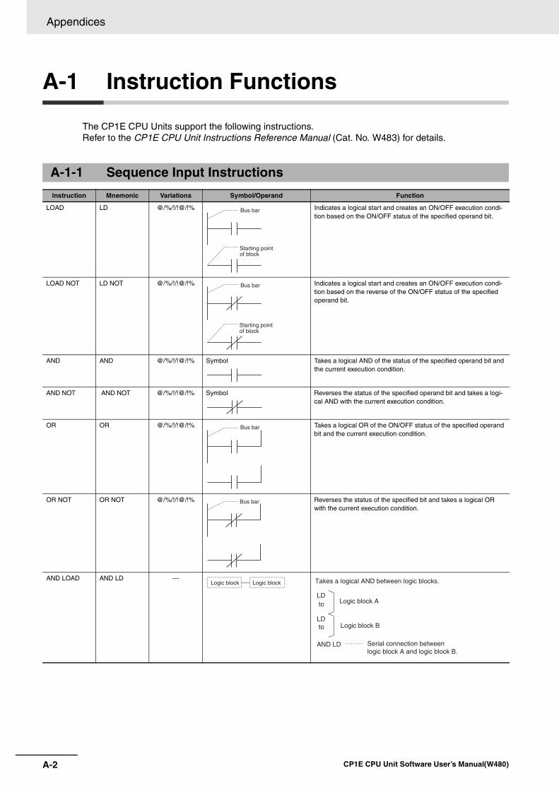
Appendices
A-2 CP1E CPU Unit Software User’s Manual(W480)
A-1 Instruction Functions
The CP1E CPU Units support the following instructions. Refer to the CP1E CPU Unit Instructions Reference Manual (Cat. No. W483) for details.
A-1-1 Sequence Input Instructions
Instruction Mnemonic Variations Symbol/Operand Function
LOAD LD @/%/!/!@/!% Indicates a logical start and creates an ON/OFF execution condi-tion based on the ON/OFF status of the specified operand bit.
LOAD NOT LD NOT @/%/!/!@/!% Indicates a logical start and creates an ON/OFF execution condi-tion based on the reverse of the ON/OFF status of the specified operand bit.
AND AND @/%/!/!@/!% Symbol Takes a logical AND of the status of the specified operand bit and the current execution condition.
AND NOT AND NOT @/%/!/!@/!% Symbol Reverses the status of the specified operand bit and takes a logi-cal AND with the current execution condition.
OR OR @/%/!/!@/!% Takes a logical OR of the ON/OFF status of the specified operand bit and the current execution condition.
OR NOT OR NOT @/%/!/!@/!% Reverses the status of the specified bit and takes a logical OR with the current execution condition.
AND LOAD AND LD ---
Bus bar
Starting point of block
Bus bar
Starting point of block
Bus bar
Bus bar
Logic block Logic block
AND LD
Takes a logical AND between logic blocks.
Serial connection between logic block A and logic block B.
LD
LD
to
to
Logic block A
Logic block B
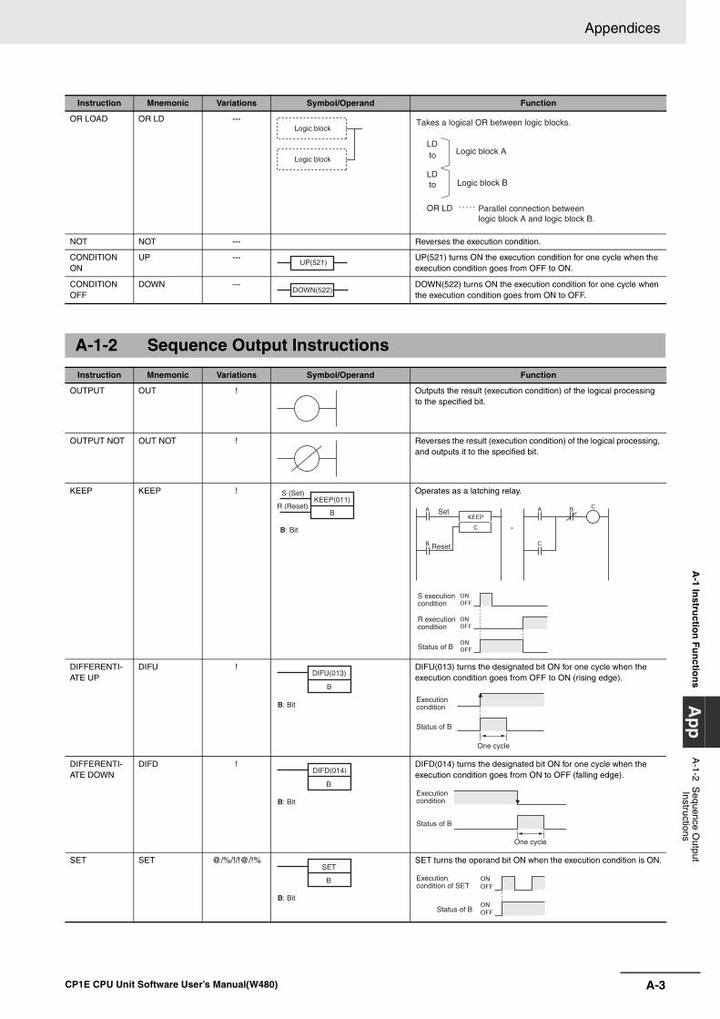
A-3
Appendices
CP1E CPU Unit Software User’s Manual(W480)
A-1 In
structio
n F
un
ction
sA
pp
A-1-2 S
equence Output
Instructions
OR LOAD OR LD ---
NOT NOT --- Reverses the execution condition.
CONDITION ON
UP --- UP(521) turns ON the execution condition for one cycle when the execution condition goes from OFF to ON.
CONDITION OFF
DOWN --- DOWN(522) turns ON the execution condition for one cycle when the execution condition goes from ON to OFF.
A-1-2 Sequence Output Instructions
Instruction Mnemonic Variations Symbol/Operand Function
OUTPUT OUT ! Outputs the result (execution condition) of the logical processing to the specified bit.
OUTPUT NOT OUT NOT ! Reverses the result (execution condition) of the logical processing, and outputs it to the specified bit.
KEEP KEEP ! Operates as a latching relay.
DIFFERENTI-ATE UP
DIFU ! DIFU(013) turns the designated bit ON for one cycle when the execution condition goes from OFF to ON (rising edge).
DIFFERENTI-ATE DOWN
DIFD ! DIFD(014) turns the designated bit ON for one cycle when the execution condition goes from ON to OFF (falling edge).
SET SET @/%/!/!@/!% SET turns the operand bit ON when the execution condition is ON.
Instruction Mnemonic Variations Symbol/Operand Function
Logic block
Logic block
LD
LD
OR LD
to
to
Takes a logical OR between logic blocks.
Logic block A
Logic block B
Parallel connection between logic block A and logic block B.
UP(521)
DOWN(522)
KEEP(011)S (Set)
R (Reset)B
B: Bit
Reset
Status of B
S execution condition
R execution condition
Set
DIFU(013)
B
B: Bit
Status of B
One cycle
Execution condition
B
B: Bit
DIFD(014)
Status of B
One cycle
Execution condition
B
B: Bit
SET
Status of B
Execution condition of SET
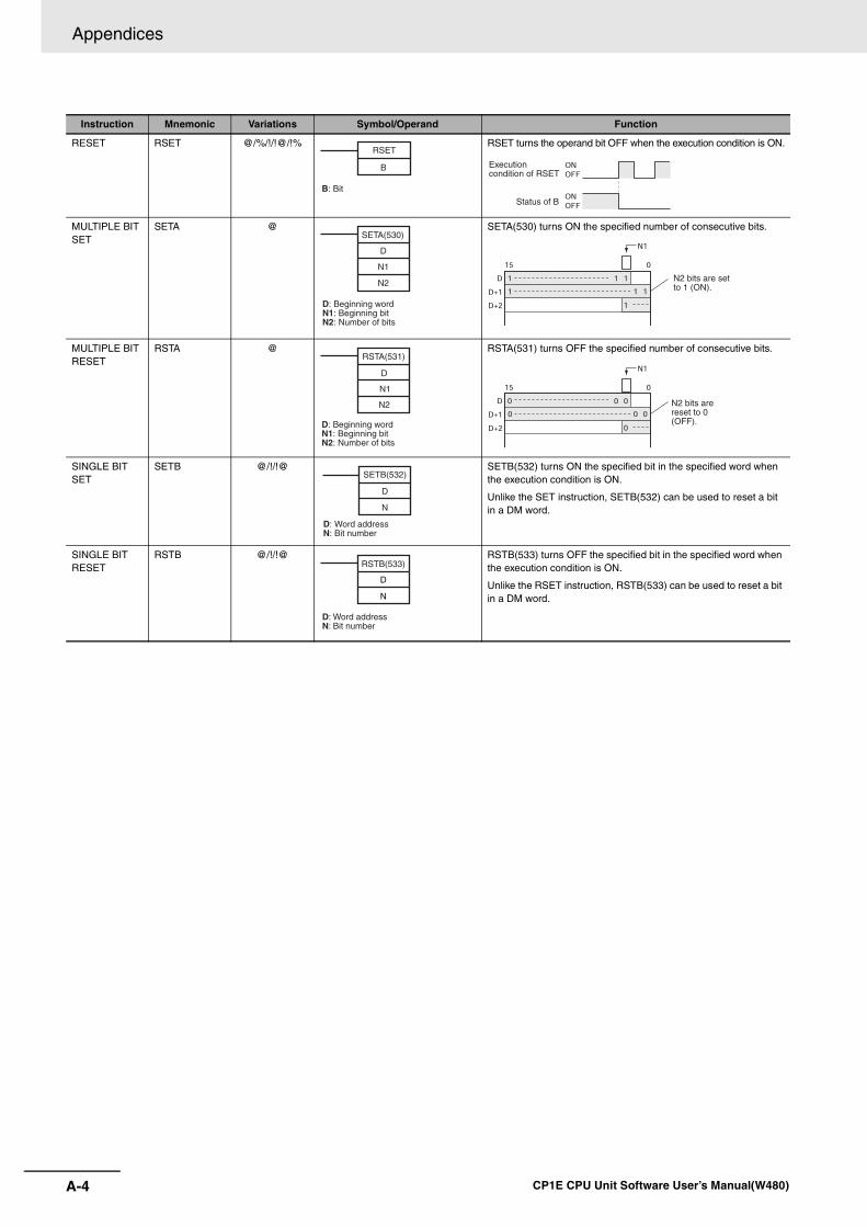
Appendices
A-4 CP1E CPU Unit Software User’s Manual(W480)
RESET RSET @/%/!/!@/!% RSET turns the operand bit OFF when the execution condition is ON.
MULTIPLE BIT SET
SETA @ SETA(530) turns ON the specified number of consecutive bits.
MULTIPLE BIT RESET
RSTA @ RSTA(531) turns OFF the specified number of consecutive bits.
SINGLE BIT SET
SETB @/!/!@ SETB(532) turns ON the specified bit in the specified word when the execution condition is ON.
Unlike the SET instruction, SETB(532) can be used to reset a bit in a DM word.
SINGLE BIT RESET
RSTB @/!/!@ RSTB(533) turns OFF the specified bit in the specified word when the execution condition is ON.
Unlike the RSET instruction, RSTB(533) can be used to reset a bit in a DM word.
Instruction Mnemonic Variations Symbol/Operand Function
B
B: Bit
RSET
Status of B
Execution condition of RSET
D: Beginning wordN1: Beginning bitN2: Number of bits
D
N1
N2
SETA(530)
N2 bits are set to 1 (ON).
D: Beginning wordN1: Beginning bitN2: Number of bits
D
N1
N2
RSTA(531)
N2 bits are reset to 0 (OFF).
D: Word addressN: Bit number
D
N
SETB(532)
D
N
RSTB(533)
D: Word addressN: Bit number

A-5
Appendices
CP1E CPU Unit Software User’s Manual(W480)
A-1 In
structio
n F
un
ction
sA
pp
A-1-3 S
equence Control
Instructions
A-1-3 Sequence Control Instructions
Instruction Mnemonic Variations Symbol/Operand Function
END END --- Indicates the end of a program.
NO OPERA-TION
NOP --- --- This instruction has no function. (No processing is performed for NOP(000).)
INTERLOCK IL --- Interlocks all outputs between IL(002) and ILC(003) when the exe-cution condition for IL(002) is OFF. IL(002) and ILC(003) are nor-mally used in pairs.
INTERLOCK CLEAR
ILC --- All outputs between IL(002) and ILC(003) are interlocked when the execution condition for IL(002) is OFF. IL(002) and ILC(003) are normally used in pairs.
MULTI-INTER-LOCK DIFFER-ENTIATION HOLD
MILH --- When the execution condition for MILH(517) is OFF, the outputs for all instructions between that MILH(517) instruction and the next MILC(519) instruction are interlocked. MILH(517) and MILC(519) are used as a pair.
MILH(517)/MILC(519) interlocks can be nested (e.g., MILH(517)-MILH(517)-MILC(519)-MILC(519)).
If there is a differentiated instruction (DIFU, DIFD, or instruction with a @ or % prefix) between MILH(517) and the corresponding MILC(519), that instruction will be executed after the interlock is cleared if the differentiation condition of the instruction was estab-lished.
MULTI-INTER-LOCK DIFFER-ENTIATION RELEASE
MILR --- When the execution condition for MILR(518) is OFF, the outputs for all instructions between that MILR(518) instruction and the next MILC(519) instruction are interlocked.MILR(518) and MILC(519) are used as a pair.
MILR(518)/MILC(519) interlocks can be nested (e.g., MILR(518)-MILR(518)-MILC(519)-MILC(519)).
If there is a differentiated instruction (DIFU, DIFD, or instruction with a @ or % prefix) between MILR(518) and the corresponding MILC(519), that instruction will not be executed after the interlock is cleared even if the differentiation condition of the instruction was established.
MULTI-INTER-LOCK CLEAR
MILC --- Clears an interlock started by an MILH(517) or MILR(518) with the same interlock number.
All outputs between MILH(517)/MILR(518) and the corresponding MILC(519) with the same interlock number are interlocked when the execution condition for MILH(517)/MILR(518) is OFF.
JUMP JMP --- When the execution condition for JMP(004) is OFF, program exe-cution jumps directly to the first JME(005) in the program with the same jump number. JMP(004) and JME(005) are used in pairs.
END(001)
IL(002)
Interlocked section of the program
Normal execution
Outputs interlocked.
Execution condition OFF
Execution condition ONExecution
condition
ILC(003)
MILH (517)
N
D
N: Interlock numberD: Interlock Status Bit
N: Interlock numberD: Interlock Status Bit
MILR (518)
N
D
MILC (519)
N
N: Interlock number
JMP(004)
N
N: Interlock number
Instructions in this section are not executed and out-put status is maintained. The instruction execution time for these instructions is eliminated.
Instructionsjumped
Execution condition
Instruc-tionsex-ecuted
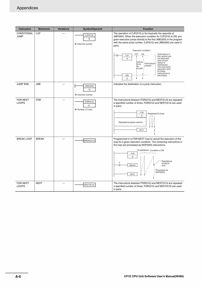
Appendices
A-6 CP1E CPU Unit Software User’s Manual(W480)
CONDITIONALJUMP
CJP --- The operation of CJP(510) is the basically the opposite of JMP(004). When the execution condition for CJP(510) is ON, pro-gram execution jumps directly to the first JME(005) in the program with the same jump number. CJP(510) and JME(005) are used in pairs.
JUMP END JME --- Indicates the destination of a jump instruction.
FOR-NEXT LOOPS
FOR --- The instructions between FOR(512) and NEXT(513) are repeated a specified number of times. FOR(512) and NEXT(513) are used in pairs.
BREAK LOOP BREAK --- Programmed in a FOR-NEXT loop to cancel the execution of the loop for a given execution condition. The remaining instructions in the loop are processed as NOP(000) instructions.
FOR-NEXT LOOPS
NEXT --- The instructions between FOR(512) and NEXT(513) are repeated a specified number of times. FOR(512) and NEXT(513) are used in pairs.
Instruction Mnemonic Variations Symbol/Operand Function
N: Interlock number
CJP(510)
N
Instructionsjumped
Execution condition
Instruc-tionsex-ecuted
Instructions in this section are not executed and out-put status is maintained. The instruction execution time for these instructions is eliminated.
N: Interlock number
JME(005)
N
FOR(512)
N
N: Number of loops
Repeated program section
Repeated N times
BREAK(514)
N repetitions Condition a ON
Repetitions forced to end.
Processed as NOP(000).
NEXT(513)
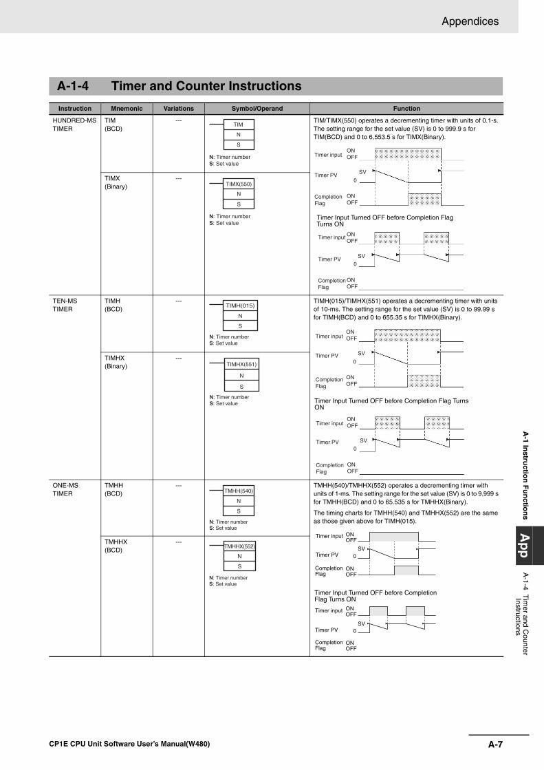
A-7
Appendices
CP1E CPU Unit Software User’s Manual(W480)
A-1 In
structio
n F
un
ction
sA
pp
A-1-4 T
imer and C
ounter Instructions
A-1-4 Timer and Counter Instructions
Instruction Mnemonic Variations Symbol/Operand Function
HUNDRED-MSTIMER
TIM (BCD)
--- TIM/TIMX(550) operates a decrementing timer with units of 0.1-s. The setting range for the set value (SV) is 0 to 999.9 s for TIM(BCD) and 0 to 6,553.5 s for TIMX(Binary).
TIMX(Binary)
---
TEN-MS TIMER
TIMH (BCD)
--- TIMH(015)/TIMHX(551) operates a decrementing timer with units of 10-ms. The setting range for the set value (SV) is 0 to 99.99 s for TIMH(BCD) and 0 to 655.35 s for TIMHX(Binary).
TIMHX(Binary)
---
ONE-MS TIMER
TMHH(BCD)
--- TMHH(540)/TMHHX(552) operates a decrementing timer with units of 1-ms. The setting range for the set value (SV) is 0 to 9.999 s for TMHH(BCD) and 0 to 65.535 s for TMHHX(Binary).
The timing charts for TMHH(540) and TMHHX(552) are the same as those given above for TIMH(015).
TMHHX(BCD)
---
TIM
N
S
N: Timer numberS: Set value
SV
SV
Timer inputONOFF
0
0
ONOFF
ONOFF
ONOFF
Timer PV
Completion Flag
Timer input
Timer PV
Completion Flag
Timer Input Turned OFF before Completion Flag Turns ON
TIMX(550)
N
S
N: Timer numberS: Set value
TIMH(015)
N
S
N: Timer numberS: Set value
SV
SV
ONOFF
0
0
ONOFF
ONOFF
ONOFF
Timer input
Timer PV
Completion Flag
Timer input
Timer PV
Completion Flag
Timer Input Turned OFF before Completion Flag Turns ON
TIMHX(551)
N
S
N: Timer numberS: Set value
TMHH(540)
N
S
N: Timer numberS: Set value
0
0
Timer input
Timer PV
Completion Flag
Completion Flag
Timer input ONOFF
ONOFF
SV
ONOFF
ONOFF
SV
Timer PV
Timer Input Turned OFF before Completion Flag Turns ON
TMHHX(552)
N
S
N: Timer numberS: Set value
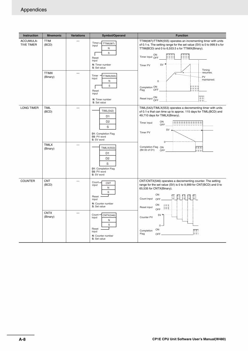
Appendices
A-8 CP1E CPU Unit Software User’s Manual(W480)
ACCUMULA-TIVE TIMER
TTIM(BCD)
--- TTIM(087)/TTIMX(555) operates an incrementing timer with units of 0.1-s. The setting range for the set value (SV) is 0 to 999.9 s for TTIM(BCD) and 0 to 6,553.5 s for TTIMX(Binary).
TTIMX(Binary)
---
LONG TIMER TIML(BCD)
--- TIML(542)/TIMLX(553) operates a decrementing timer with units of 0.1-s that can time up to approx. 115 days for TIML(BCD) and 49,710 days for TIMLX(Binary).
TIMLX(Binary)
---
COUNTER CNT(BCD)
--- CNT/CNTX(546) operates a decrementing counter. The setting range for the set value (SV) is 0 to 9,999 for CNT(BCD) and 0 to 65,535 for CNTX(Binary).
CNTX(Binary)
---
Instruction Mnemonic Variations Symbol/Operand Function
TTIM(087)
N
S
N: Timer numberS: Set value
Reset input
Timer input
Timer input
Timer PV SV
Reset input
PV maintained.
Timing resumes.
Completion Flag
ONOFF
0
ONOFF
ONOFF
TTIMX(555)
N
S
N: Timer numberS: Set value
Reset input
Timer input
TIML(542)
D1
D2
S
D1: Completion FlagD2: PV wordS: SV word
Timer input
Timer PVSV
Completion Flag (Bit 00 of D1)
ONOFF
0
ONOFF
TIMLX(553)
D1
D2
S
D1: Completion FlagD2: PV wordS: SV word
CNT
N
S
N: Counter numberS: Set value
Reset input
Count input
SV
Count input
Counter PV
Completion Flag
Reset input
ON
OFF
ON
OFF
0
ON
OFF
CNTX(546)
N
S
Count input
Reset input
N: Counter numberS: Set value
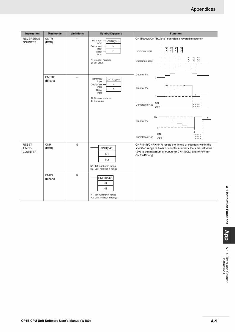
A-9
Appendices
CP1E CPU Unit Software User’s Manual(W480)
A-1 In
structio
n F
un
ction
sA
pp
A-1-4 T
imer and C
ounter Instructions
REVERSIBLE COUNTER
CNTR(BCD)
--- CNTR(012)/CNTRX(548) operates a reversible counter.
CNTRX(Binary)
---
RESET TIMER/ COUNTER
CNR(BCD)
@ CNR(545)/CNRX(547) resets the timers or counters within the specified range of timer or counter numbers. Sets the set value (SV) to the maximum of #9999 for CNR(BCD) and #FFFF for CNRX(Binary).
CNRX(Binary)
@
Instruction Mnemonic Variations Symbol/Operand Function
CNTR(012)
N
S
Increment input
Decrement input
Reset input
N: Counter numberS: Set value
SV
SV
+1
1
Increment input
Counter PV
Decrement input
Counter PV
Completion Flag
Counter PV
Completion Flag
ON
OFF
ON
OFF
0
0
0CNTRX(548)
N
S
Increment input
Decrement input
Reset input
N: Counter numberS: Set value
CNR(545)
N1
N2
N1: 1st number in rangeN2: Last number in range
CNRX(547)
N1
N2
N1: 1st number in rangeN2: Last number in range
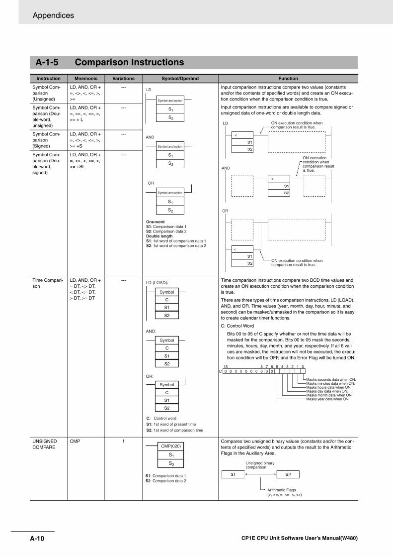
Appendices
A-10 CP1E CPU Unit Software User’s Manual(W480)
A-1-5 Comparison Instructions
Instruction Mnemonic Variations Symbol/Operand Function
Symbol Com-parison (Unsigned)
LD, AND, OR + =, <>, <, <=, >, >=
--- Input comparison instructions compare two values (constants and/or the contents of specified words) and create an ON execu-tion condition when the comparison condition is true.
Input comparison instructions are available to compare signed or unsigned data of one-word or double length data.
Symbol Com-parison (Dou-ble-word, unsigned)
LD, AND, OR + =, <>, <, <=, >, >= + L
---
Symbol Com-parison (Signed)
LD, AND, OR + =, <>, <, <=, >, >= +S
---
Symbol Com-parison (Dou-ble-word, signed)
LD, AND, OR + =, <>, <, <=, >, >= +SL
---
Time Compari-son
LD, AND, OR + = DT, <> DT, < DT, <= DT, > DT, >= DT
--- Time comparison instructions compare two BCD time values and create an ON execution condition when the comparison condition is true.
There are three types of time comparison instructions, LD (LOAD), AND, and OR. Time values (year, month, day, hour, minute, and second) can be masked/unmasked in the comparison so it is easy to create calendar timer functions.
C: Control Word
Bits 00 to 05 of C specify whether or not the time data will be masked for the comparison. Bits 00 to 05 mask the seconds, minutes, hours, day, month, and year, respectively. If all 6 val-ues are masked, the instruction will not be executed, the execu-tion condition will be OFF, and the Error Flag will be turned ON.
UNSIGNED COMPARE
CMP ! Compares two unsigned binary values (constants and/or the con-tents of specified words) and outputs the result to the Arithmetic Flags in the Auxiliary Area.
S1
S2
Symbol and option
LD
S1
S2
Symbol and option
S1
S2
Symbol and option
AND
OR
One-wordS1: Comparison data 1S2: Comparison data 2Double lengthS1: 1st word of comparison data 1S2: 1st word of comparison data 2
<
<
<
LD
AND
OR
ON execution condition when comparison result is true.
ON execution condition when comparison result is true.
ON execution condition when comparison result is true.
S1
C
S2
LD (LOAD):
AND:
OR:
S1
C
S2
S1
C
S2
C: Control word
S1: 1st word of present time
S2: 1st word of comparison time
Symbol
Symbol
SymbolMasks seconds data when ON.Masks minutes data when ON.Masks hours data when ON.Masks day data when ON.Masks month data when ON.Masks year data when ON.
0 0 0 0 0 0 0 0 0 08 7 6 5 4 3 2 1 015
C
CMP(020)
S1
S2
S1: Comparison data 1S2: Comparison data 2
(>, >=, =, <=, <, <>)
Unsigned binary comparison
Arithmetic Flags
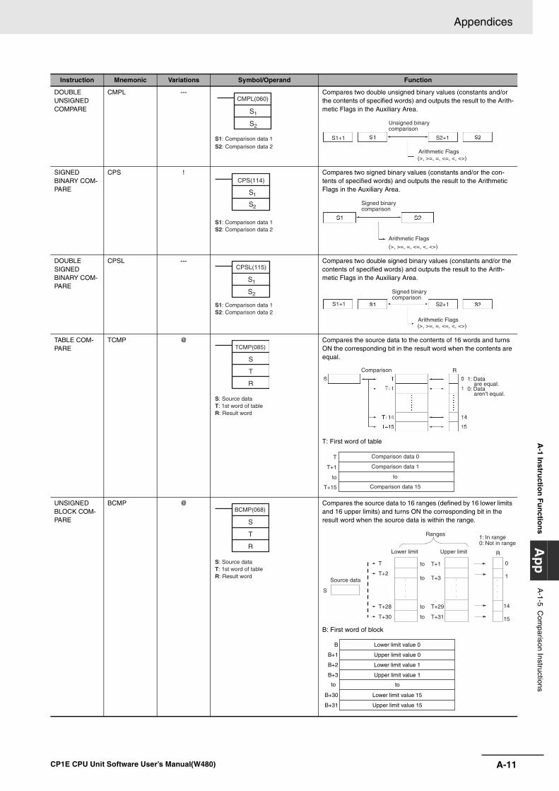
A-11
Appendices
CP1E CPU Unit Software User’s Manual(W480)
A-1 In
structio
n F
un
ction
sA
pp
A-1-5 C
omparison Instructions
DOUBLE UNSIGNEDCOMPARE
CMPL --- Compares two double unsigned binary values (constants and/or the contents of specified words) and outputs the result to the Arith-metic Flags in the Auxiliary Area.
SIGNED BINARY COM-PARE
CPS ! Compares two signed binary values (constants and/or the con-tents of specified words) and outputs the result to the Arithmetic Flags in the Auxiliary Area.
DOUBLE SIGNED BINARY COM-PARE
CPSL --- Compares two double signed binary values (constants and/or the contents of specified words) and outputs the result to the Arith-metic Flags in the Auxiliary Area.
TABLE COM-PARE
TCMP @ Compares the source data to the contents of 16 words and turns ON the corresponding bit in the result word when the contents are equal.
T: First word of table
UNSIGNED BLOCK COM-PARE
BCMP @ Compares the source data to 16 ranges (defined by 16 lower limits and 16 upper limits) and turns ON the corresponding bit in the result word when the source data is within the range.
B: First word of block
Instruction Mnemonic Variations Symbol/Operand Function
CMPL(060)
S1
S2
S1: Comparison data 1S2: Comparison data 2
S1+1 S2+1
(>, >=, =, <=, <, <>)
Unsigned binary comparison
Arithmetic Flags
CPS(114)
S1
S2
S1: Comparison data 1S2: Comparison data 2
(>, >=, =, <=, <, <>)
Signed binary comparison
Arithmetic Flags
CPSL(115)
S1
S2
S1: Comparison data 1S2: Comparison data 2
S1+1 S2+1
(>, >=, =, <=, <, <>)
Signed binary comparison
Arithmetic Flags
TCMP(085)
S
T
R
S: Source dataT: 1st word of tableR: Result word
RComparison
1: Data are equal.
0: Data aren't equal.
Comparison data 0
Comparison data 1
to
Comparison data 15
T
T+1
to
T+15
BCMP(068)
S
T
R
S: Source dataT: 1st word of tableR: Result word T+3 1
0
14
15
T+29
T+31
T+1
T+2
T+28
T+30
T
S
R
to
to
to
to
Ranges
Upper limit
Source data
Lower limit
1: In range0: Not in range
B
B+1
B+2
B+3
to
B+30
B+31
Lower limit value 0
Upper limit value 0
Lower limit value 1
Upper limit value 1
to
Lower limit value 15
Upper limit value 15
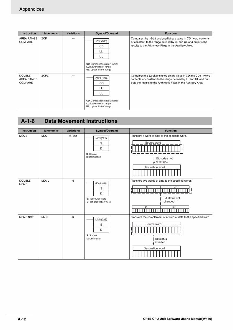
Appendices
A-12 CP1E CPU Unit Software User’s Manual(W480)
AREA RANGE COMPARE
ZCP --- Compares the 16-bit unsigned binary value in CD (word contents or constant) to the range defined by LL and UL and outputs the results to the Arithmetic Flags in the Auxiliary Area.
DOUBLE AREA RANGE COMPARE
ZCPL --- Compares the 32-bit unsigned binary value in CD and CD+1 (word contents or constant) to the range defined by LL and UL and out-puts the results to the Arithmetic Flags in the Auxiliary Area.
A-1-6 Data Movement Instructions
Instruction Mnemonic Variations Symbol/Operand Function
MOVE MOV @/!/!@ Transfers a word of data to the specified word.
DOUBLE MOVE
MOVL @ Transfers two words of data to the specified words.
MOVE NOT MVN @ Transfers the complement of a word of data to the specified word.
Instruction Mnemonic Variations Symbol/Operand Function
ZCP(088)
CD
LL
UL
CD: Comparison data (1 word)LL: Lower limit of rangeUL: Upper limit of range
ZCPL(116)
CD
LL
UL
CD: Comparison data (2 words)LL: Lower limit of rangeUL: Upper limit of range
MOV(021)
S
D
S: SourceD: Destination
Destination word
Source word
Bit status not changed.
MOVL(498)
S
D
S: 1st source wordD: 1st destination word
S
D
S+1
D+1
Bit status not changed.
MVN(022)
S
D
S: SourceD: Destination
Source word
Destination word
Bit status inverted.
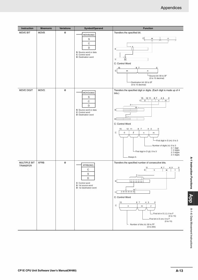
A-13
Appendices
CP1E CPU Unit Software User’s Manual(W480)
A-1 In
structio
n F
un
ction
sA
pp
A-1-6 D
ata Movem
ent Instructions
MOVE BIT MOVB @ Transfers the specified bit.
C: Control Word
MOVE DIGIT MOVD @ Transfers the specified digit or digits. (Each digit is made up of 4 bits.)
C: Control Word
MULTIPLE BIT TRANSFER
XFRB @ Transfers the specified number of consecutive bits.
C: Control Word
Instruction Mnemonic Variations Symbol/Operand Function
S
C
D
MOVB(082)
S: Source word or dataC: Control wordD: Destination word
C m n
Source bit: 00 to 0F (0 to 15 decimal)
Destination bit: 00 to 0F (0 to 15 decimal)
07815
S
C
D
MOVD(083)
S: Source word or dataC: Control wordD: Destination word
Sm
n
Dl
C 0 l8111215
n m0347
15 8 011 37 412
C 0
First digit in S (m): 0 to 3
Number of digits (n): 0 to 30: 1 digit 1: 2 digits2: 3 digits3: 4 digits
First digit in D ( ): 0 to 3
Always 0.
n m
XFRB(062)
C
S
D
C: Control wordS: 1st source wordD: 1st destination word
First bit in S ( ): 0 to F(0 to 15)
15 8 037 4
C n m
First bit in D (m): 0 to F(0 to 15)
Number of bits (n): 00 to FF (0 to 255)
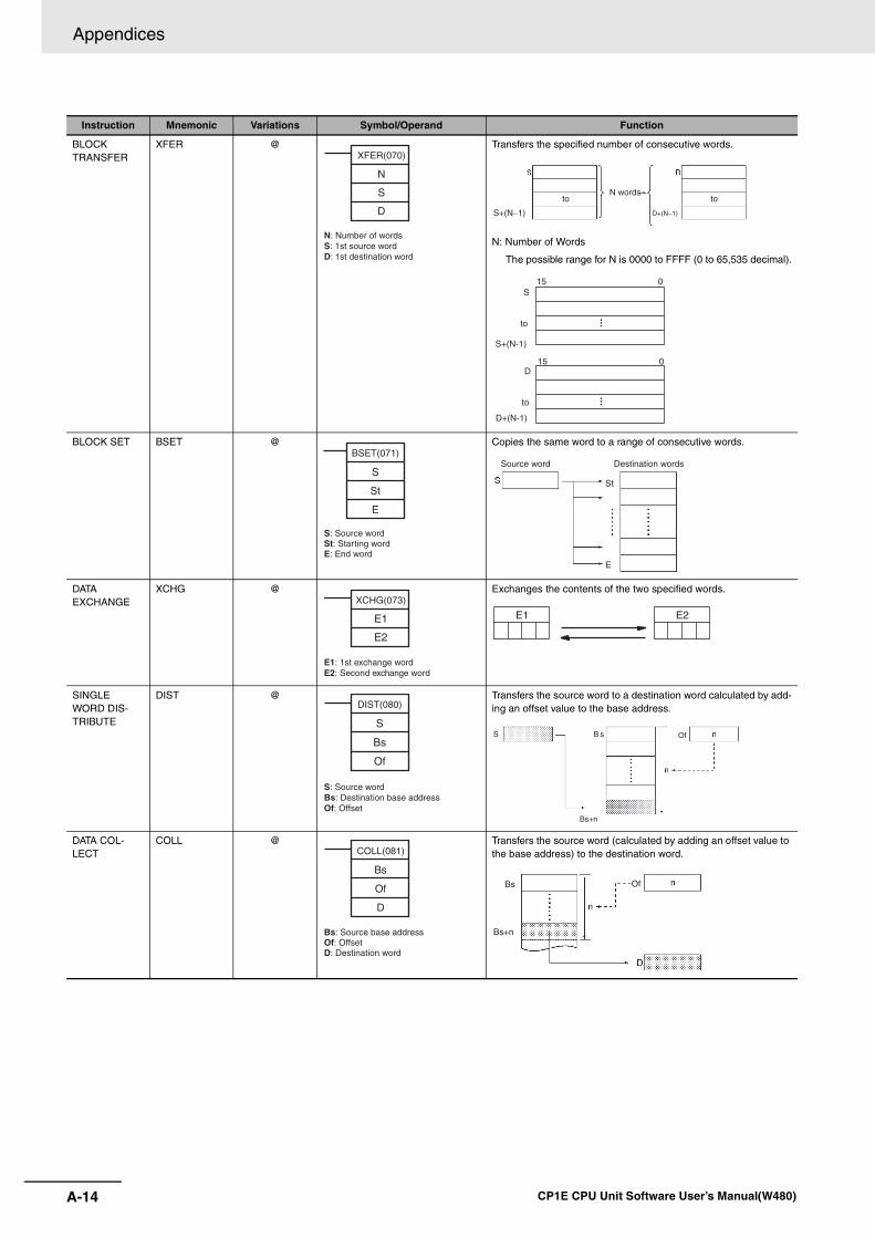
Appendices
A-14 CP1E CPU Unit Software User’s Manual(W480)
BLOCK TRANSFER
XFER @ Transfers the specified number of consecutive words.
N: Number of Words
The possible range for N is 0000 to FFFF (0 to 65,535 decimal).
BLOCK SET BSET @ Copies the same word to a range of consecutive words.
DATA EXCHANGE
XCHG @ Exchanges the contents of the two specified words.
SINGLE WORD DIS-TRIBUTE
DIST @ Transfers the source word to a destination word calculated by add-ing an offset value to the base address.
DATA COL-LECT
COLL @ Transfers the source word (calculated by adding an offset value to the base address) to the destination word.
Instruction Mnemonic Variations Symbol/Operand Function
XFER(070)
N
S
D
N: Number of wordsS: 1st source wordD: 1st destination word
S+(N 1) D+(N 1)− −
to toN words
15 0S
S+(N-1)
to
15 0D
D+(N-1)
to
BSET(071)
S
St
E
S: Source wordSt: Starting wordE: End word
St
E
Source word Destination words
XCHG(073)
E1
E2
E1: 1st exchange wordE2: Second exchange word
E2E1
DIST(080)
S
Bs
Of
S: Source wordBs: Destination base addressOf: Offset
S B
Bs+n
s Of
COLL(081)
Bs
Of
D
Bs: Source base addressOf: OffsetD: Destination word
Bs
Bs+n
Of
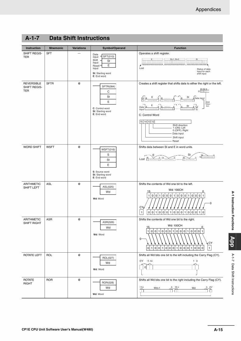
A-15
Appendices
CP1E CPU Unit Software User’s Manual(W480)
A-1 In
structio
n F
un
ction
sA
pp
A-1-7 D
ata Shift Instructions
A-1-7 Data Shift Instructions
Instruction Mnemonic Variations Symbol/Operand Function
SHIFT REGIS-TER
SFT --- Operates a shift register.
REVERSIBLE SHIFT REGIS-TER
SFTR @ Creates a shift register that shifts data to either the right or the left.
C: Control Word
WORD SHIFT WSFT @ Shifts data between St and E in word units.
ARITHMETIC SHIFT LEFT
ASL @ Shifts the contents of Wd one bit to the left.
ARITHMETIC SHIFT RIGHT
ASR @ Shifts the contents of Wd one bit to the right.
ROTATE LEFT ROL @ Shifts all Wd bits one bit to the left including the Carry Flag (CY).
ROTATE RIGHT
ROR @ Shifts all Wd bits one bit to the right including the Carry Flag (CY).
SFT(010)
St
E
Data inputShift inputReset input
St: Starting wordE: End word
E St+1, St+2 St
Status of data input for each shift input
Lost
SFTR(084)
C
St
E
C: Control wordSt: Starting wordE: End word
StE
StE
Data input
Shift direc-tion
Data input
Data input
Reset
Shift input
Shift direction1 (ON): Left0 (OFF): Right
15 14 13 12
WSFT(016)
S
St
E
S: Source wordSt: Starting wordE: End word
StELost
ASL(025)
Wd
Wd: Word
0 15
1 0 0 1 0 0 0 1 0 0 0 1 0 0 0 1
0
CY
0 0 11 0 0 0 1 0 0 0 1 0 0 0 01
Wd: 100CH
ASR(026)
Wd
Wd: Word
015
1 0 0 1 0 0 0 1 0 0 0 1 0 0 0 1
0
CY
0 1
Wd: 100CH
1 0 0 1 0 0 0 1 0 0 0 1 0 0 0
Wd
ROL(027)
Wd: Word
ROR(028)
Wd
Wd: Word
WdWd+1
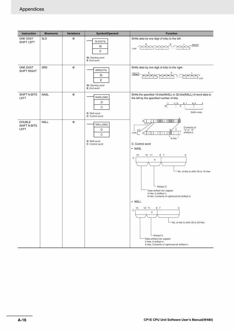
Appendices
A-16 CP1E CPU Unit Software User’s Manual(W480)
ONE DIGIT SHIFT LEFT
SLD @ Shifts data by one digit (4 bits) to the left.
ONE DIGIT SHIFT RIGHT
SRD @ Shifts data by one digit (4 bits) to the right.
SHIFT N-BITS LEFT
NASL @ Shifts the specified 16 bits(NASL) or 32 bits(NSLL) of word data to the left by the specified number of bits.
C: Control word
• NASL
• NSLL
DOUBLE SHIFT N-BITS LEFT
NSLL @
Instruction Mnemonic Variations Symbol/Operand Function
SLD(074)
St
E
St: Starting wordE: End word
E S t
Lost
SRD(075)
St
E
St: Starting wordE: End word
E S t
Lost
NASL(580)
D
C
D: Shift wordC: Control word
Shift n-bits
Lost
N bits
Contents of "a" or "0" shifted in
15 8 011 712C
0
No. of bits to shift: 00 to 10 Hex
Always 0.
Data shifted into register0 Hex: 0 shifted in 8 Hex: Contents of rightmost bit shifted in
15 8 011 712C
0
No. of bits to shift: 00 to 20 Hex
Always 0.Data shifted into register0 Hex: 0 shifted in 8 Hex: Contents of rightmost bit shifted in
NSLL(582)
D
C
D: Shift wordC: Control word
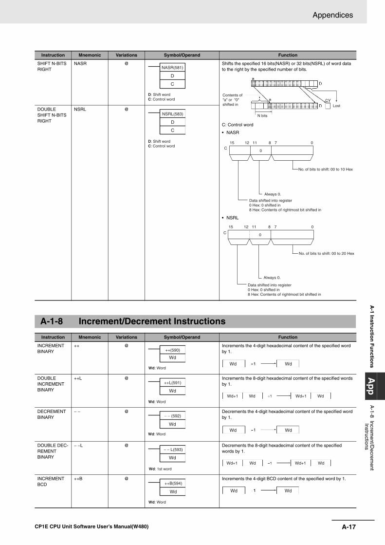
A-17
Appendices
CP1E CPU Unit Software User’s Manual(W480)
A-1 In
structio
n F
un
ction
sA
pp
A-1-8 Increm
ent/Decrem
ent Instructions
SHIFT N-BITS RIGHT
NASR @ Shifts the specified 16 bits(NASR) or 32 bits(NSRL) of word data to the right by the specified number of bits.
C: Control word
• NASR
• NSRL
DOUBLE SHIFT N-BITS RIGHT
NSRL @
A-1-8 Increment/Decrement Instructions
Instruction Mnemonic Variations Symbol/Operand Function
INCREMENT BINARY
++ @ Increments the 4-digit hexadecimal content of the specified word by 1.
DOUBLE INCREMENT BINARY
++L @ Increments the 8-digit hexadecimal content of the specified words by 1.
DECREMENT BINARY
− − @ Decrements the 4-digit hexadecimal content of the specified word by 1.
DOUBLE DEC-REMENT BINARY
− −L @ Decrements the 8-digit hexadecimal content of the specified words by 1.
INCREMENT BCD
++B @ Increments the 4-digit BCD content of the specified word by 1.
Instruction Mnemonic Variations Symbol/Operand Function
NASR(581)
D
C
D: Shift wordC: Control word
Lost
N bits
Contents of "a" or "0" shifted in
15 8 011 712C
0
No. of bits to shift: 00 to 10 Hex
Always 0.
Data shifted into register0 Hex: 0 shifted in 8 Hex: Contents of rightmost bit shifted in
15 8 011 712
C 0
No. of bits to shift: 00 to 20 Hex
Always 0.
Data shifted into register0 Hex: 0 shifted in 8 Hex: Contents of rightmost bit shifted in
NSRL(583)
D
C
D: Shift wordC: Control word
++(590)
Wd
Wd: WordWd Wd
++L(591)
Wd
Wd: WordWd+1 Wd Wd+1 Wd
− − (592)
Wd
Wd: WordWd Wd
− − L(593)
Wd
Wd: 1st word
Wd+1 Wd Wd+1 Wd
++B(594)
Wd
Wd: Word
Wd Wd
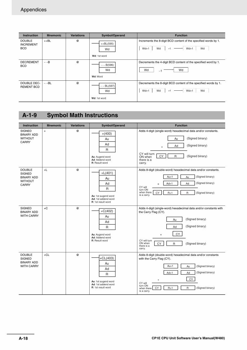
Appendices
A-18 CP1E CPU Unit Software User’s Manual(W480)
DOUBLE INCREMENT BCD
++BL @ Increments the 8-digit BCD content of the specified words by 1.
DECREMENT BCD
− −B @ Decrements the 4-digit BCD content of the specified word by 1.
DOUBLE DEC-REMENT BCD
− −BL @ Decrements the 8-digit BCD content of the specified words by 1.
A-1-9 Symbol Math Instructions
Instruction Mnemonic Variations Symbol/Operand Function
SIGNED BINARY ADD WITHOUT CARRY
+ @ Adds 4-digit (single-word) hexadecimal data and/or constants.
DOUBLE SIGNED BINARY ADD WITHOUT CARRY
+L @ Adds 8-digit (double-word) hexadecimal data and/or constants.
SIGNED BINARY ADD WITH CARRY
+C @ Adds 4-digit (single-word) hexadecimal data and/or constants with the Carry Flag (CY).
DOUBLE SIGNED BINARY ADD WITH CARRY
+CL @ Adds 8-digit (double-word) hexadecimal data and/or constants with the Carry Flag (CY).
Instruction Mnemonic Variations Symbol/Operand Function
++BL(595)
Wd
Wd: 1st word
Wd+1 Wd Wd+1 Wd
− − B(596)
Wd
Wd: Word
−1Wd Wd
− − BL(597)
Wd
Wd: 1st word
Wd+1 Wd Wd+1 Wd
+(400)
Au
Ad
R
Au: Augend wordAd: Addend wordR: Result word
Au
Ad
RCY
+
(Signed binary)
(Signed binary)
(Signed binary)CY will turn ON when there is a carry.
+L(401)
Au
Ad
R
Au: 1st augend wordAd: 1st addend wordR: 1st result word
Ad+1
R+1CY
+
Au
Ad
R
Au+1
CY will turn ON when there is a carry.
(Signed binary)
(Signed binary)
(Signed binary)
+C(402)
Au
Ad
R
Au: Augend wordAd: Addend wordR: Result word
CY+
Au
Ad
RCYCY will turn ON when there is a carry.
(Signed binary)
(Signed binary)
(Signed binary)
+CL(403)
Au
Ad
R
Au: 1st augend wordAd: 1st addend wordR: 1st result word
Ad+1
R+1
CY+
Au
Ad
RCY
Au+1 (Signed binary)
(Signed binary)
(Signed binary)
CY will turn ON when there is a carry.
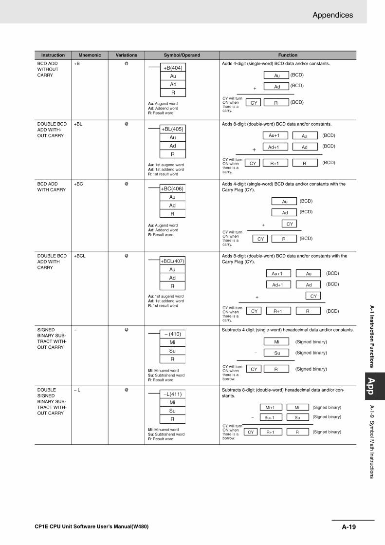
A-19
Appendices
CP1E CPU Unit Software User’s Manual(W480)
A-1 In
structio
n F
un
ction
sA
pp
A-1-9 S
ymbol M
ath Instructions
BCD ADD WITHOUT CARRY
+B @ Adds 4-digit (single-word) BCD data and/or constants.
DOUBLE BCD ADD WITH-OUT CARRY
+BL @ Adds 8-digit (double-word) BCD data and/or constants.
BCD ADD WITH CARRY
+BC @ Adds 4-digit (single-word) BCD data and/or constants with the Carry Flag (CY).
DOUBLE BCD ADD WITH CARRY
+BCL @ Adds 8-digit (double-word) BCD data and/or constants with the Carry Flag (CY).
SIGNED BINARY SUB-TRACT WITH-OUT CARRY
− @ Subtracts 4-digit (single-word) hexadecimal data and/or constants.
DOUBLE SIGNED BINARY SUB-TRACT WITH-OUT CARRY
− L @ Subtracts 8-digit (double-word) hexadecimal data and/or con-stants.
Instruction Mnemonic Variations Symbol/Operand Function
+B(404)
Au
Ad
R
Au: Augend wordAd: Addend wordR: Result word
Au
Ad
RCY
+
(BCD)
(BCD)
(BCD)CY will turn ON when there is a carry.
+BL(405)
Au
Ad
R
Au: 1st augend wordAd: 1st addend wordR: 1st result word
Ad+1
R+1CY
+
Au
Ad
R
Au+1 (BCD)
(BCD)
(BCD)CY will turn ON when there is a carry.
+BC(406)
Au
Ad
R
Au: Augend wordAd: Addend wordR: Result word
CY+
Au
Ad
RCY
(BCD)
(BCD)
(BCD)CY will turn ON when there is a carry.
+BCL(407)
Au
Ad
R
Au: 1st augend wordAd: 1st addend wordR: 1st result word
Ad+1
R+1
CY+
Au
Ad
RCY
(BCD)
(BCD)
(BCD)
Au+1
CY will turn ON when there is a carry.
− (410)
Mi
Su
R
Mi: Minuend wordSu: Subtrahend wordR: Result word
Mi
Su
RCY
−
(Signed binary)
(Signed binary)
(Signed binary)CY will turn ON when there is a borrow.
−L(411)
Mi
Su
R
Mi: Minuend wordSu: Subtrahend wordR: Result word
Mi+1
Su+1
R+1CY
Mi
Su
R
(Signed binary)
(Signed binary)
(Signed binary)CY will turn ON when there is a borrow.
−
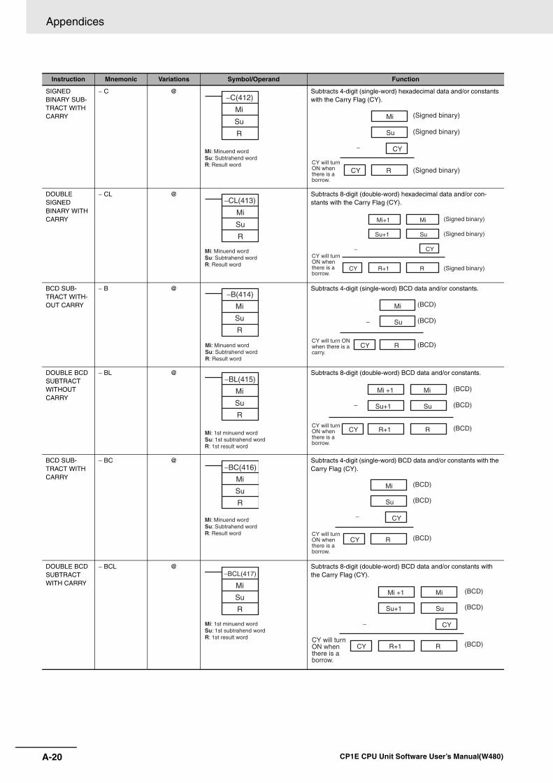
Appendices
A-20 CP1E CPU Unit Software User’s Manual(W480)
SIGNED BINARY SUB-TRACT WITH CARRY
− C @ Subtracts 4-digit (single-word) hexadecimal data and/or constants with the Carry Flag (CY).
DOUBLE SIGNED BINARY WITH CARRY
− CL @ Subtracts 8-digit (double-word) hexadecimal data and/or con-stants with the Carry Flag (CY).
BCD SUB-TRACT WITH-OUT CARRY
− B @ Subtracts 4-digit (single-word) BCD data and/or constants.
DOUBLE BCD SUBTRACT WITHOUT CARRY
− BL @ Subtracts 8-digit (double-word) BCD data and/or constants.
BCD SUB-TRACT WITH CARRY
− BC @ Subtracts 4-digit (single-word) BCD data and/or constants with the Carry Flag (CY).
DOUBLE BCD SUBTRACT WITH CARRY
− BCL @ Subtracts 8-digit (double-word) BCD data and/or constants with the Carry Flag (CY).
Instruction Mnemonic Variations Symbol/Operand Function
−C(412)
Mi
Su
R
Mi: Minuend wordSu: Subtrahend wordR: Result word
CY
Mi
Su
RCY
(Signed binary)
(Signed binary)
(Signed binary)CY will turn ON when there is a borrow.
−
−CL(413)
Mi
Su
R
Mi: Minuend wordSu: Subtrahend wordR: Result word
Mi+1
Su+1
R+1
CY
Mi
Su
RCY
(Signed binary)
(Signed binary)
(Signed binary)
CY will turn ON when there is a borrow.
−
−B(414)
Mi
Su
R
Mi: Minuend wordSu: Subtrahend wordR: Result word
Mi
Su
RCY
(BCD)
(BCD)
(BCD)CY will turn ON when there is a carry.
−
−BL(415)
Mi
Su
R
Mi: 1st minuend wordSu: 1st subtrahend wordR: 1st result word
Mi +1
Su+1
R+1CY
Mi
Su
R
(BCD)
(BCD)
(BCD)CY will turn ON when there is a borrow.
−
−BC(416)
Mi
Su
R
Mi: Minuend wordSu: Subtrahend wordR: Result word
CY
Mi
Su
RCY
(BCD)
(BCD)
(BCD)CY will turn ON when there is a borrow.
−
−BCL(417)
Mi
Su
R
Mi: 1st minuend wordSu: 1st subtrahend wordR: 1st result word
Mi +1
Su+1
R+1
CY
Mi
Su
RCY
(BCD)
(BCD)
(BCD)CY will turn ON when there is a borrow.
−
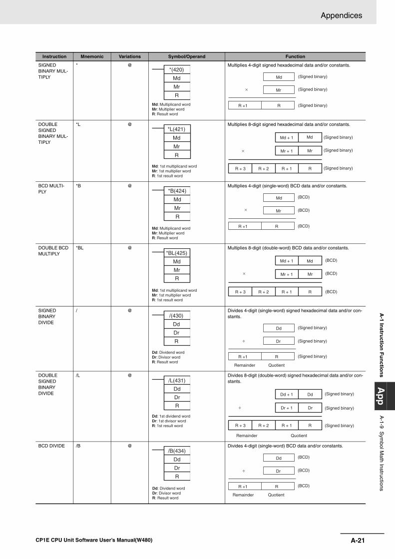
A-21
Appendices
CP1E CPU Unit Software User’s Manual(W480)
A-1 In
structio
n F
un
ction
sA
pp
A-1-9 S
ymbol M
ath Instructions
SIGNED BINARY MUL-TIPLY
* @ Multiplies 4-digit signed hexadecimal data and/or constants.
DOUBLE SIGNED BINARY MUL-TIPLY
*L @ Multiplies 8-digit signed hexadecimal data and/or constants.
BCD MULTI-PLY
*B @ Multiplies 4-digit (single-word) BCD data and/or constants.
DOUBLE BCD MULTIPLY
*BL @ Multiplies 8-digit (double-word) BCD data and/or constants.
SIGNED BINARY DIVIDE
/ @ Divides 4-digit (single-word) signed hexadecimal data and/or con-stants.
DOUBLE SIGNED BINARY DIVIDE
/L @ Divides 8-digit (double-word) signed hexadecimal data and/or con-stants.
BCD DIVIDE /B @ Divides 4-digit (single-word) BCD data and/or constants.
Instruction Mnemonic Variations Symbol/Operand Function
*(420)
Md
Mr
R
Md: Multiplicand wordMr: Multiplier wordR: Result word
Md
Mr
R +1 R
(Signed binary)
(Signed binary)
(Signed binary)
×
*L(421)
Md
Mr
R
Md: 1st multiplicand wordMr: 1st multiplier wordR: 1st result word
Md + 1
Mr + 1
R + 1 RR + 3 R + 2
Md
Mr
(Signed binary)
(Signed binary)
(Signed binary)
×
*B(424)
Md
Mr
R
Md: Multiplicand wordMr: Multiplier wordR: Result word
Md
Mr
R +1 R
(BCD)
(BCD)
(BCD)
×
*BL(425)
Md
Mr
R
Md: 1st multiplicand wordMr: 1st multiplier wordR: 1st result word
Md + 1
Mr + 1
R + 1 RR + 3 R + 2
(BCD)
(BCD)
(BCD)
Md
Mr×
/(430)
Dd
Dr
R
Dd: Dividend wordDr: Divisor wordR: Result word
Dd
Dr
R +1 R
÷
Remainder Quotient
(Signed binary)
(Signed binary)
(Signed binary)
/L(431)
Dd
Dr
R
Dd: 1st dividend wordDr: 1st divisor wordR: 1st result word
Dd + 1
Dr + 1
R + 1 RR + 3 R + 2
÷
Dd
Dr
Remainder Quotient
(Signed binary)
(Signed binary)
(Signed binary)
/B(434)
Dd
Dr
R
Dd: Dividend wordDr: Divisor wordR: Result word
Dd
Dr
R +1 R
÷
(BCD)
(BCD)
(BCD)
Remainder Quotient
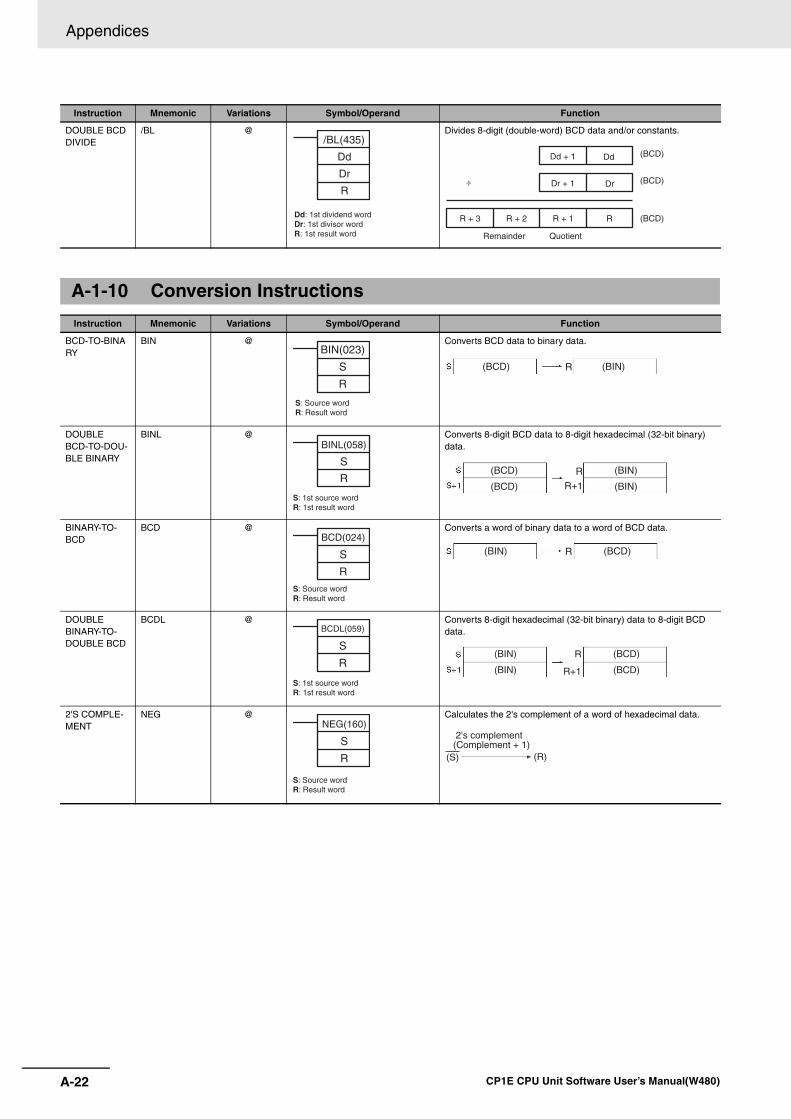
Appendices
A-22 CP1E CPU Unit Software User’s Manual(W480)
DOUBLE BCD DIVIDE
/BL @ Divides 8-digit (double-word) BCD data and/or constants.
A-1-10 Conversion Instructions
Instruction Mnemonic Variations Symbol/Operand Function
BCD-TO-BINARY
BIN @ Converts BCD data to binary data.
DOUBLE BCD-TO-DOU-BLE BINARY
BINL @ Converts 8-digit BCD data to 8-digit hexadecimal (32-bit binary) data.
BINARY-TO-BCD
BCD @ Converts a word of binary data to a word of BCD data.
DOUBLE BINARY-TO-DOUBLE BCD
BCDL @ Converts 8-digit hexadecimal (32-bit binary) data to 8-digit BCD data.
2'S COMPLE-MENT
NEG @ Calculates the 2's complement of a word of hexadecimal data.
Instruction Mnemonic Variations Symbol/Operand Function
/BL(435)
Dd
Dr
R
Dd: 1st dividend wordDr: 1st divisor wordR: 1st result word
Dd + 1
Dr + 1
R + 1 RR + 3 R + 2
(BCD)
(BCD)
(BCD)
÷
Dd
Dr
Remainder Quotient
BIN(023)
S
R
S: Source wordR: Result word
(BCD) (BIN)R
BINL(058)
S
R
S: 1st source wordR: 1st result word
(BCD) (BIN)
(BCD) (BIN)
R
R+1
BCD(024)
S
R
S: Source wordR: Result word
(BCD)(BIN) R
BCDL(059)
S
R
S: 1st source wordR: 1st result word
(BIN) (BCD)
(BIN) (BCD)
R
R+1
NEG(160)
S
R
S: Source wordR: Result word
2's complement (Complement + 1)
(S) (R)
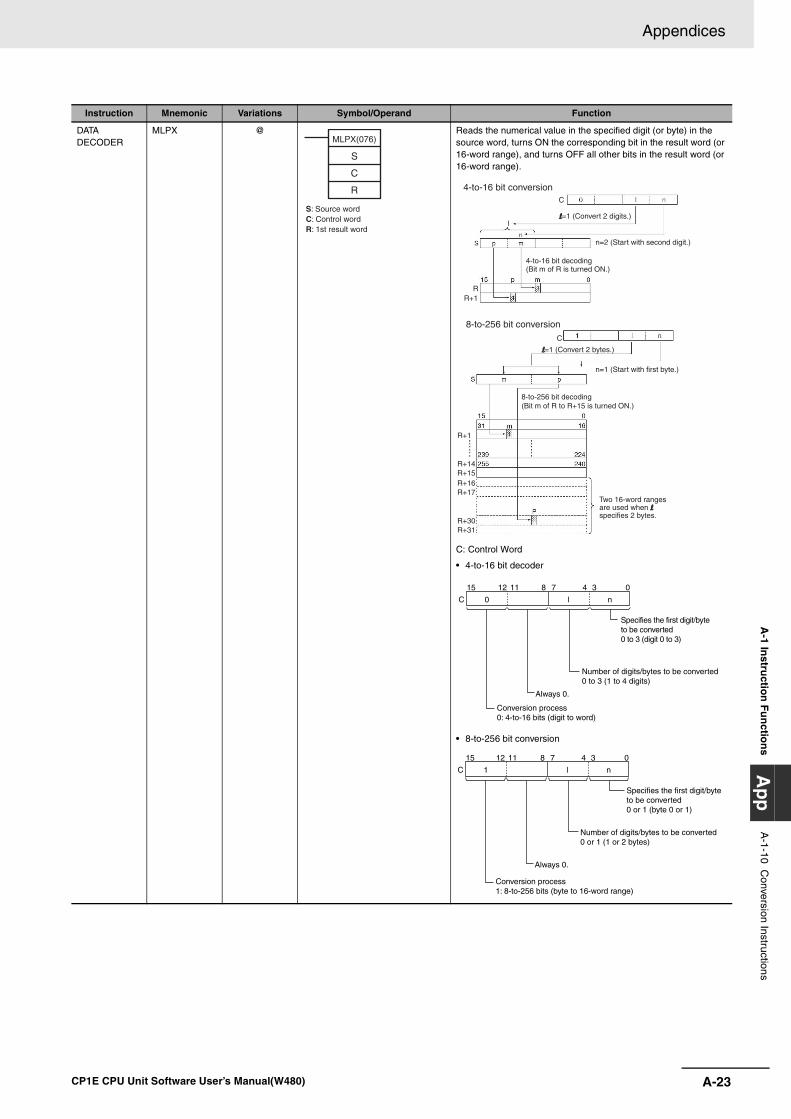
A-23
Appendices
CP1E CPU Unit Software User’s Manual(W480)
A-1 In
structio
n F
un
ction
sA
pp
A-1-10 C
onversion Instructions
DATA DECODER
MLPX @ Reads the numerical value in the specified digit (or byte) in the source word, turns ON the corresponding bit in the result word (or 16-word range), and turns OFF all other bits in the result word (or 16-word range).
C: Control Word
• 4-to-16 bit decoder
• 8-to-256 bit conversion
Instruction Mnemonic Variations Symbol/Operand Function
MLPX(076)
S
C
R
S: Source wordC: Control wordR: 1st result word
R+1
R+14R+15R+16R+17
R+30R+31
RR+1
C
C
Two 16-word ranges are used when l specifies 2 bytes.
8-to-256 bit decoding(Bit m of R to R+15 is turned ON.)
n=1 (Start with first byte.)
8-to-256 bit conversion
l=1 (Convert 2 bytes.)
n=2 (Start with second digit.)
4-to-16 bit decoding (Bit m of R is turned ON.)
l=1 (Convert 2 digits.)
4-to-16 bit conversion
C 0
8111215
l n
0347
Conversion process0: 4-to-16 bits (digit to word)
Always 0.
Number of digits/bytes to be converted0 to 3 (1 to 4 digits)
Specifies the first digit/byte to be converted0 to 3 (digit 0 to 3)
C 1
8111215
l n
0347
Conversion process1: 8-to-256 bits (byte to 16-word range)
Always 0.
Number of digits/bytes to be converted0 or 1 (1 or 2 bytes)
Specifies the first digit/byte to be converted0 or 1 (byte 0 or 1)
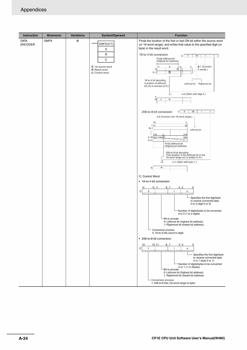
Appendices
A-24 CP1E CPU Unit Software User’s Manual(W480)
DATA ENCODER
DMPX @ FInds the location of the first or last ON bit within the source word (or 16-word range), and writes that value to the specified digit (or byte) in the result word.
C: Control Word
• 16-to-4 bit conversion
• 256-to-8 bit conversion
Instruction Mnemonic Variations Symbol/Operand Function
DMPX(077)
S
R
C
S: 1st source wordR: Result wordC: Control word
C
R
C
R
FInds leftmost bit(Highest bit address)
Finds leftmost bit(Highest bit address)
Leftmost bit Rightmost bit
Leftmost bit
16-to-4 bit conversion
l=1 (Convert 2 words.)
16-to-4 bit decoding (Location of leftmost bit (m) is writ-ten to R.)
n=2 (Start with digit 2.)
256-to-8 bit conversion
l=0 (Convert one 16-word range.)
256-to-8 bit decoding(The location of the leftmost bit in the 16-word range (m) is written to R.)
n=1 (Start with byte 1.)
C 0
8111215
l n
0347
Conversion process0: 16-to-4 bits (word to digit)
Bit to encode0: Leftmost bit (highest bit address)1: Rightmost bit (lowest bit address)
Number of digits/bytes to be converted0 to 3 (1 to 4 digits)
Specifies the first digit/byte to receive converted data.0 to 3 (digit 0 to 3)
C 1
Specifies the first digit/byteto receive converted data.0 or 1 (byte 0 or 1)
Number of digits/bytes to be converted0 or 1 (1 or 2bytes)
8111215
l n
0347
Bit to encode0: Leftmost bit (highest bit address)1: Rightmost bit (lowest bit address)
Conversion process1: 256-to-8 bits (16-word range to byte)
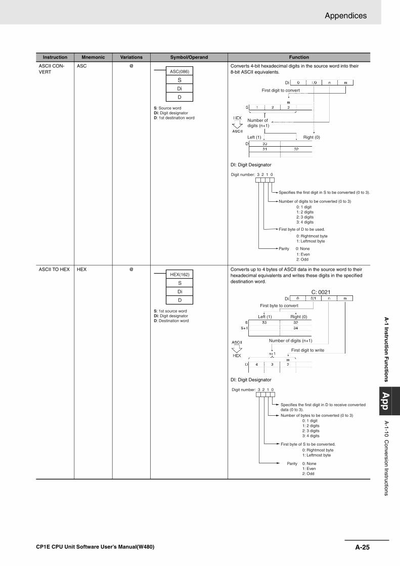
A-25
Appendices
CP1E CPU Unit Software User’s Manual(W480)
A-1 In
structio
n F
un
ction
sA
pp
A-1-10 C
onversion Instructions
ASCII CON-VERT
ASC @ Converts 4-bit hexadecimal digits in the source word into their 8-bit ASCII equivalents.
DI: Digit Designator
ASCII TO HEX HEX @ Converts up to 4 bytes of ASCII data in the source word to their hexadecimal equivalents and writes these digits in the specified destination word.
DI: Digit Designator
Instruction Mnemonic Variations Symbol/Operand Function
ASC(086)
S
Di
D
S: Source wordDi: Digit designatorD: 1st destination word
Di
Right (0)Left (1)
First digit to convert
Number of digits (n+1)
Specifies the first digit in S to be converted (0 to 3).
Number of digits to be converted (0 to 3) 0: 1 digit 1: 2 digits 2: 3 digits 3: 4 digits
First byte of D to be used.
0: Rightmost byte 1: Leftmost byte
Parity 0: None 1: Even2: Odd
Digit number: 3 2 1 0
HEX(162)
S
Di
D
S: 1st source wordDi: Digit designatorD: Destination word
C: 0021Di
Number of digits (n+1)
Right (0)Left (1)
First byte to convert
First digit to write
Digit number: 3 2 1 0
Specifies the first digit in D to receive converted data (0 to 3).Number of bytes to be converted (0 to 3)
0: 1 digit 1: 2 digits 2: 3 digits 3: 4 digits
0: Rightmost byte1: Leftmost byte
Parity 0: None 1: Even 2: Odd
First byte of S to be converted.
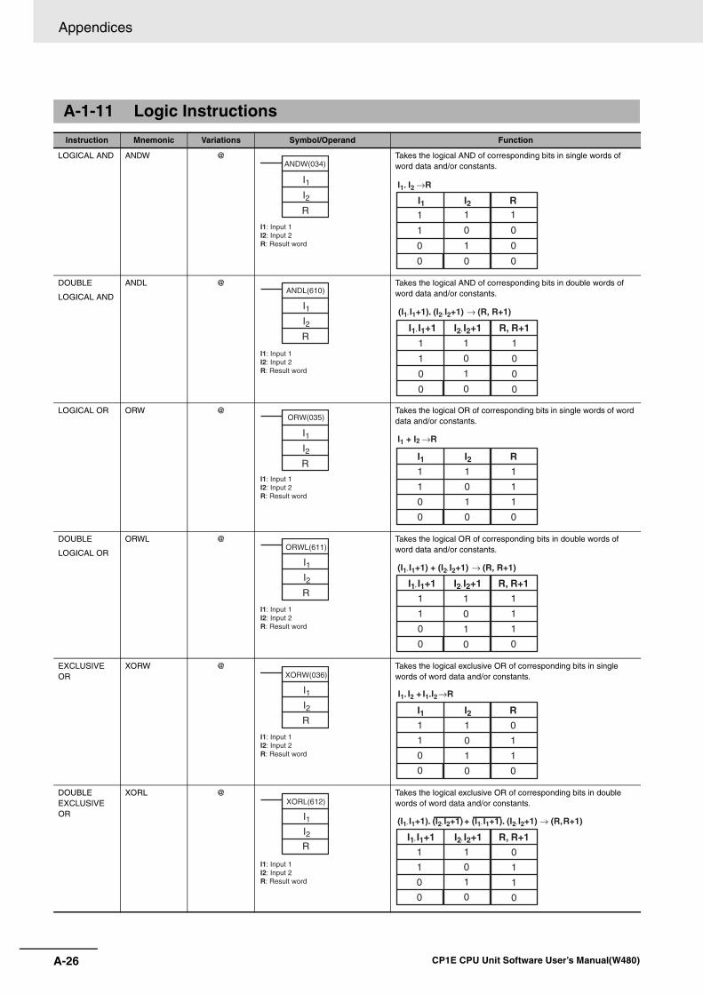
Appendices
A-26 CP1E CPU Unit Software User’s Manual(W480)
A-1-11 Logic Instructions
Instruction Mnemonic Variations Symbol/Operand Function
LOGICAL AND ANDW @ Takes the logical AND of corresponding bits in single words of word data and/or constants.
DOUBLE
LOGICAL AND
ANDL @ Takes the logical AND of corresponding bits in double words of word data and/or constants.
LOGICAL OR ORW @ Takes the logical OR of corresponding bits in single words of word data and/or constants.
DOUBLE
LOGICAL OR
ORWL @ Takes the logical OR of corresponding bits in double words of word data and/or constants.
EXCLUSIVE OR
XORW @ Takes the logical exclusive OR of corresponding bits in single words of word data and/or constants.
DOUBLE EXCLUSIVE OR
XORL @ Takes the logical exclusive OR of corresponding bits in double words of word data and/or constants.
I1I2R
ANDW(034)
I1: Input 1I2: Input 2R: Result word
I1. I2 →R
I11
1
0
0
I21
0
1
0
R1
0
0
0
ANDL(610)
I1I2R
I1: Input 1I2: Input 2R: Result word
(I1, I1+1). (I2, I2+1) → (R, R+1)
I1, I1+1
1
1
0
0
I2, I2+1
1
0
1
0
R, R+1
1
0
0
0
I1I2R
ORW(035)
I1: Input 1I2: Input 2R: Result word
I11
1
0
0
I21
0
1
0
R
1
1
1
0
I1 + I2 →R
I1I2R
ORWL(611)
I1: Input 1I2: Input 2R: Result word
(I1, I1+1) + (I2, I2+1) → (R, R+1)
I1, I1+1
1
1
0
0
I2, I2+1
1
0
1
0
R, R+1
1
1
1
0
I1I2R
XORW(036)
I1: Input 1I2: Input 2R: Result word
I1. I2 + I1.I2→R
I11
1
0
0
I21
0
1
0
R
0
1
1
0
XORL(612)
I1I2R
I1: Input 1I2: Input 2R: Result word
(I1, I1+1). (I2, I2+1) + (I1, I1+1). (I2, I2+1) → (R, R+1)
I1, I1+1
1
1
0
0
I2, I2+1
1
0
1
0
R, R+1
0
1
1
0
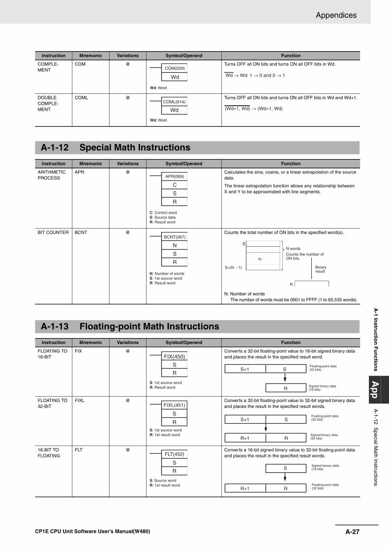
A-27
Appendices
CP1E CPU Unit Software User’s Manual(W480)
A-1 In
structio
n F
un
ction
sA
pp
A-1-12 S
pecial Math Instructions
COMPLE-MENT
COM @ Turns OFF all ON bits and turns ON all OFF bits in Wd.
DOUBLE COMPLE-MENT
COML @ Turns OFF all ON bits and turns ON all OFF bits in Wd and Wd+1.
A-1-12 Special Math Instructions
Instruction Mnemonic Variations Symbol/Operand Function
ARITHMETIC PROCESS
APR @ Calculates the sine, cosine, or a linear extrapolation of the source data.
The linear extrapolation function allows any relationship between X and Y to be approximated with line segments.
BIT COUNTER BCNT @ Counts the total number of ON bits in the specified word(s).
N: Number of wordsThe number of words must be 0001 to FFFF (1 to 65,535 words).
A-1-13 Floating-point Math Instructions
Instruction Mnemonic Variations Symbol/Operand Function
FLOATING TO 16-BIT
FIX @ Converts a 32-bit floating-point value to 16-bit signed binary data and places the result in the specified result word.
FLOATING TO 32-BIT
FIXL @ Converts a 32-bit floating-point value to 32-bit signed binary data and places the result in the specified result words.
16-BIT TO FLOATING
FLT @ Converts a 16-bit signed binary value to 32-bit floating-point data and places the result in the specified result words.
Instruction Mnemonic Variations Symbol/Operand Function
COM(029)
Wd
Wd: Word
Wd → Wd: 1 → 0 and 0 → 1
COML(614)
Wd
Wd: Word
(Wd+1, Wd) → (Wd+1, Wd)
APR(069)
C
S
R
C: Control wordS: Source dataR: Result word
BCNT(067)
N
S
R
N: Number of wordsS: 1st source wordR: Result word
S+(N 1)−
to
R
N words
Counts the number of ON bits.
Binary result
FIX(450)
S
R
S: 1st source wordR: Result word
S+1 S
RSigned binary data (16 bits)
Floating-point data (32 bits)
FIXL(451)
S
RS: 1st source wordR: 1st result word
S+1 S
R+1 RSigned binary data (32 bits)
Floating-point data (32 bits)
S
R
FLT(452)
S: Source wordR: 1st result word
R+1 R
SSigned binary data (16 bits)
Floating-point data (32 bits)
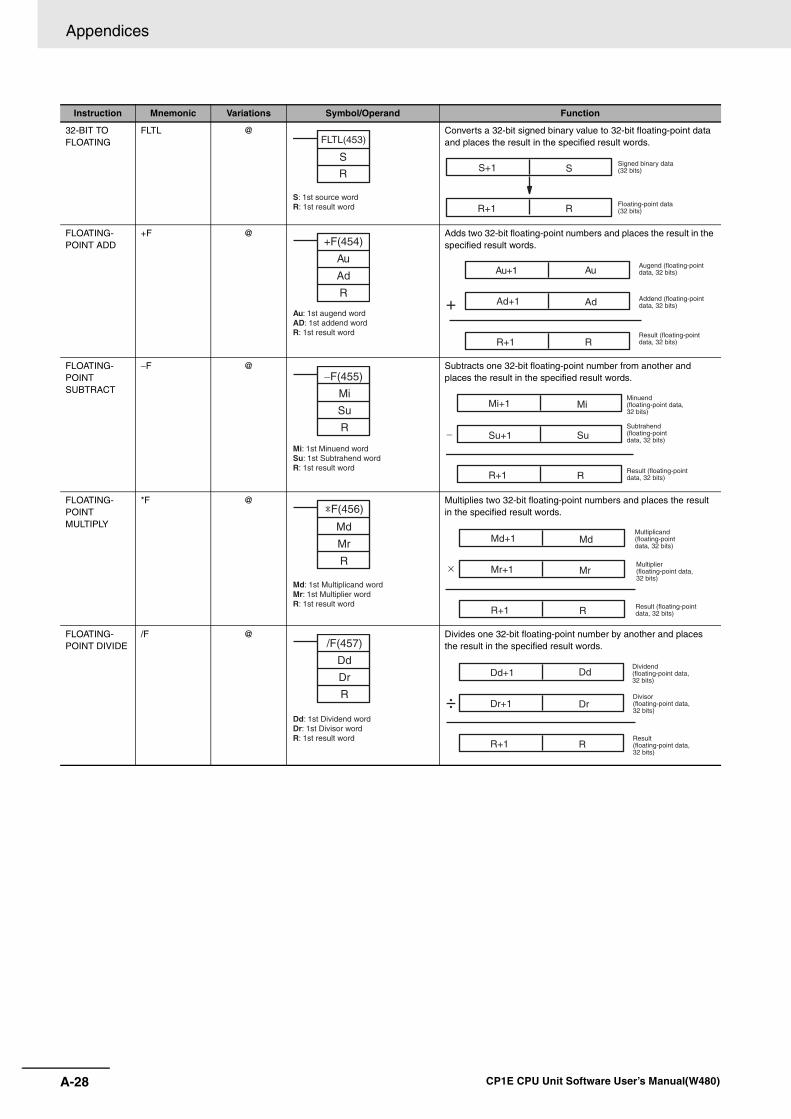
Appendices
A-28 CP1E CPU Unit Software User’s Manual(W480)
32-BIT TO FLOATING
FLTL @ Converts a 32-bit signed binary value to 32-bit floating-point data and places the result in the specified result words.
FLOATING-POINT ADD
+F @ Adds two 32-bit floating-point numbers and places the result in the specified result words.
FLOATING-POINT SUBTRACT
−F @ Subtracts one 32-bit floating-point number from another and places the result in the specified result words.
FLOATING- POINT MULTIPLY
*F @ Multiplies two 32-bit floating-point numbers and places the result in the specified result words.
FLOATING- POINT DIVIDE
/F @ Divides one 32-bit floating-point number by another and places the result in the specified result words.
Instruction Mnemonic Variations Symbol/Operand Function
S
R
FLTL(453)
S: 1st source wordR: 1st result word R+1 R
SS+1 Signed binary data (32 bits)
Floating-point data (32 bits)
+F(454)
Au
Ad
R
Au: 1st augend wordAD: 1st addend wordR: 1st result word
R+1 R
Au
AdAd+1+
Au+1Augend (floating-point data, 32 bits)
Addend (floating-point data, 32 bits)
Result (floating-point data, 32 bits)
−F(455)
Mi
Su
R
Mi: 1st Minuend wordSu: 1st Subtrahend wordR: 1st result word
R+1 R
MiMi+1
SuSu+1−
Minuend (floating-point data, 32 bits)
Subtrahend (floating-point data, 32 bits)
Result (floating-point data, 32 bits)
Md
Mr
R
*F(456)
Md: 1st Multiplicand wordMr: 1st Multiplier wordR: 1st result word
R+1 R
MdMd+1
MrMr+1
Result (floating-point data, 32 bits)
Multiplier (floating-point data, 32 bits)
Multiplicand (floating-point data, 32 bits)
×
/F(457)
Dd
Dr
R
Dd: 1st Dividend wordDr: 1st Divisor wordR: 1st result word
R+1 R
DdDd+1
DrDr+1÷
Dividend (floating-point data, 32 bits)
Divisor (floating-point data, 32 bits)
Result (floating-point data, 32 bits)
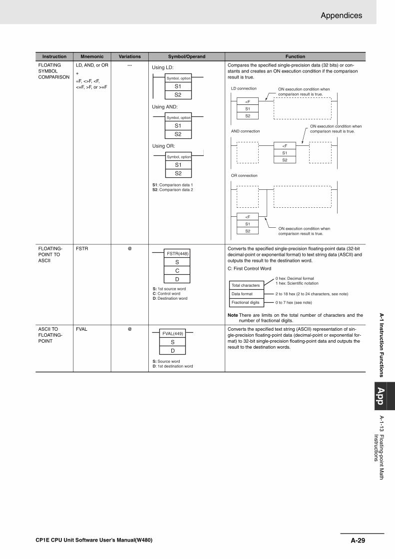
A-29
Appendices
CP1E CPU Unit Software User’s Manual(W480)
A-1 In
structio
n F
un
ction
sA
pp
A-1-13 F
loating-point Math
Instructions
FLOATING SYMBOL COMPARISON
LD, AND, or OR
+
=F, <>F, <F, <=F, >F, or >=F
--- Compares the specified single-precision data (32 bits) or con-stants and creates an ON execution condition if the comparison result is true.
FLOATING- POINT TO ASCII
FSTR @ Converts the specified single-precision floating-point data (32-bit decimal-point or exponential format) to text string data (ASCII) and outputs the result to the destination word.
C: First Control Word
Note There are limits on the total number of characters and thenumber of fractional digits.
ASCII TO FLOATING-POINT
FVAL @ Converts the specified text string (ASCII) representation of sin-gle-precision floating-point data (decimal-point or exponential for-mat) to 32-bit single-precision floating-point data and outputs the result to the destination words.
Instruction Mnemonic Variations Symbol/Operand Function
S1
S1
S2
S1
S2
S1: Comparison data 1S2: Comparison data 2
S2
Using LD:
Using AND:
Using OR:
Symbol, option
Symbol, option
Symbol, option
<F
S1
S2
<F
S1
S2
<F
S1
S2
LD connection
AND connection
OR connection
ON execution condition when comparison result is true.
ON execution condition when comparison result is true.
ON execution condition when comparison result is true.
FSTR(448)
S
C
D
S: 1st source wordC: Control wordD: Destination word
Total characters
Data format
Fractional digits
0 hex: Decimal format1 hex: Scientific notation
2 to 18 hex (2 to 24 characters, see note)
0 to 7 hex (see note)
FVAL(449)
S
D
S: Source wordD: 1st destination word
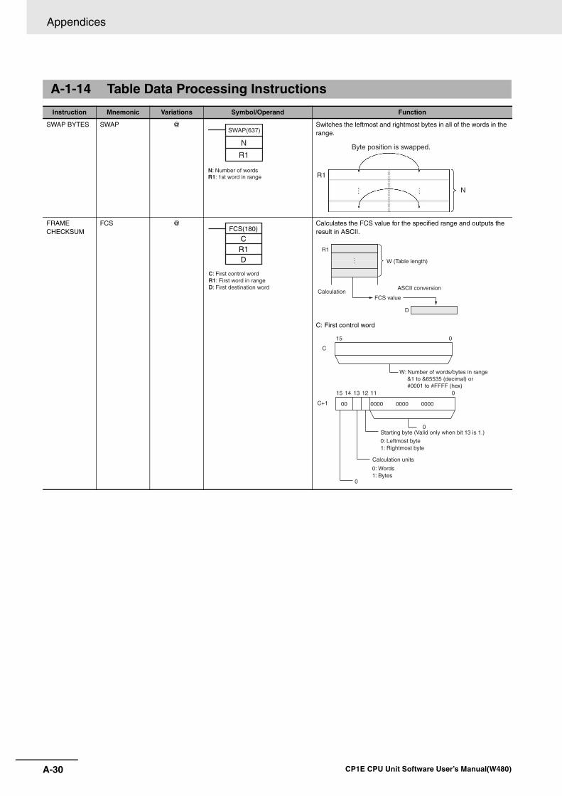
Appendices
A-30 CP1E CPU Unit Software User’s Manual(W480)
A-1-14 Table Data Processing Instructions
Instruction Mnemonic Variations Symbol/Operand Function
SWAP BYTES SWAP @ Switches the leftmost and rightmost bytes in all of the words in the range.
FRAME CHECKSUM
FCS @ Calculates the FCS value for the specified range and outputs the result in ASCII.
C: First control word
N
R1
SWAP(637)
N: Number of wordsR1: 1st word in range
N
R1
Byte position is swapped.
C: First control wordR1: First word in rangeD: First destination word
FCS(180)
CR1D
R1
Calculation
W (Table length)
ASCII conversion
FCS value
D
15 0
C
15 014
0
C+1
13 12 11
0000 0000 000000
0
Calculation units
W: Number of words/bytes in range &1 to &65535 (decimal) or #0001 to #FFFF (hex)
Starting byte (Valid only when bit 13 is 1.)
0: Leftmost byte1: Rightmost byte
0: Words 1: Bytes
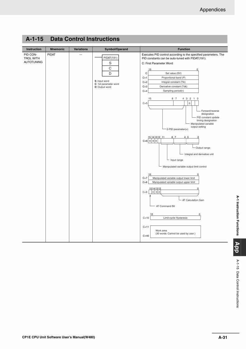
A-31
Appendices
CP1E CPU Unit Software User’s Manual(W480)
A-1 In
structio
n F
un
ction
sA
pp
A-1-15 D
ata Control Instructions
A-1-15 Data Control Instructions
Instruction Mnemonic Variations Symbol/Operand Function
PID CON-TROL WITH AUTOTUNING
PIDAT --- Executes PID control according to the specified parameters. The PID constants can be auto-tuned with PIDAT(191).
C: First Parameter Word
PIDAT(191)
S
C
D
S: Input wordC: 1st parameter wordD: Output word
15 8 07
C+5 0
3 14
C
C+1
C+2
C+3
C+4
015
C+6
81112131415
0 0 0
0347
2
Set value (SV)
Proportional band (P)
Integral constant (Tik)
Derivative constant (Tdk)
Sampling period(τ)
Forward/reverse designation
PID constant update timing designation
Manipulated variable output setting
Output range
Integral and derivative unit
Input range
Manipulated variable output limit control
2-PID parameter(α)
C+7
C+8
015
C+11
C+40
C+9
C+10015
015 1214130 0 0
Limit-cycle Hysteresis
Manipulated variable output lower limit
Manipulated variable output upper limit
Work area (30 words: Cannot be used by user.)
AT Calculation Gain
AT Command Bit
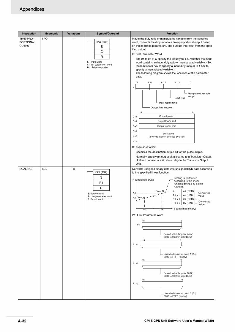
Appendices
A-32 CP1E CPU Unit Software User’s Manual(W480)
TIME-PRO-PORTIONAL OUTPUT
TPO --- Inputs the duty ratio or manipulated variable from the specified word, converts the duty ratio to a time-proportional output based on the specified parameters, and outputs the result from the spec-ified output.
C: First Parameter Word
Bits 04 to 07 of C specify the input type, i.e., whether the input word contains an input duty ratio or manipulated variable. (Set these bits to 0 hex to specify a input duty ratio or to 1 hex to specify a manipulated variable.)The following diagram shows the locations of the parameter data.
R: Pulse Output Bit
Specifies the destination output bit for the pulse output.
Normally, specify an output bit allocated to a Transistor Output Unit and connect a solid state relay to the Transistor Output Unit.
SCALING SCL @ Converts unsigned binary data into unsigned BCD data according to the specified linear function.
P1: First Parameter Word
Instruction Mnemonic Variations Symbol/Operand Function
TPO (685)
S
C
RS: Input wordC: 1st parameter wordR: Pulse output bit
C
815 12 11 0347
Manipulated variable range
Input type
Input read timing
Output limit function
C+1
C+2
C+3
C+4
C+5
C+6
015
Control period
Output lower limit
Output upper limit
Work area(3 words, cannot be used by user)
SCL(194)
S
P1
R
S: Source wordP1: 1st parameter wordR: Result word
(BCD)
(BIN)
(BCD)
(BIN)
PP1 + 1 P1 + 2P1 + 3
R (unsigned BCD)
Point B
Point A
Scaling is performed according to the linear function defined by points A and B.
Converted value
Converted value
S (unsigned binary)
P1
P1+1
P1+2
P1+3
15 0
15 0
15 0
15 0
Scaled value for point A (Ar) 0000 to 9999 (4-digit BCD)
Unscaled value for point A (As) 0000 to FFFF (binary)
Scaled value for point B (Br) 0000 to 9999 (4-digit BCD)
Unscaled value for point B (Bs) 0000 to FFFF (binary)
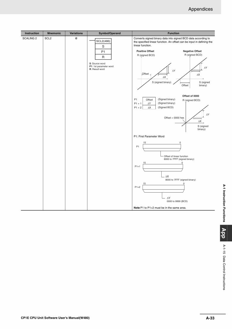
A-33
Appendices
CP1E CPU Unit Software User’s Manual(W480)
A-1 In
structio
n F
un
ction
sA
pp
A-1-15 D
ata Control Instructions
SCALING 2 SCL2 @ Converts signed binary data into signed BCD data according to the specified linear function. An offset can be input in defining the linear function.
P1: First Parameter Word
Note P1 to P1+2 must be in the same area.
Instruction Mnemonic Variations Symbol/Operand Function
SCL2(486)
S
P1
R
S: Source wordP1: 1st parameter wordR: Result word ∆Y
∆X
∆Y
∆X
∆Y
∆X
∆Y
∆X
P1
P1 + 1
P1 + 2
R (signed BCD)
Offset
R (signed BCD)
Offset
R (signed BCD)
Offset of 0000
Offset
(Signed BCD)
(Signed binary)
(Signed binary)
Offset = 0000 hex
S (signed binary)
S (signed binary)
S (signed binary)
Positive Offset Negative Offset
P1
P1+1
P1+2
15 0
15 0
15 0
Offset of linear function8000 to 7FFF (signed binary)
8000 to 7FFF (signed binary)
0000 to 9999 (BCD)
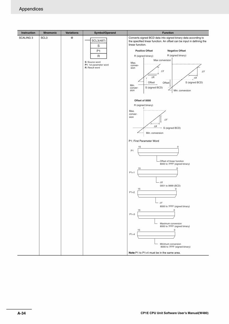
Appendices
A-34 CP1E CPU Unit Software User’s Manual(W480)
SCALING 3 SCL3 @ Converts signed BCD data into signed binary data according to the specified linear function. An offset can be input in defining the linear function.
P1: First Parameter Word
Note P1 to P1+4 must be in the same area.
Instruction Mnemonic Variations Symbol/Operand Function
SCL3(487)
S
P1
R
S: Source wordP1: 1st parameter word R: Result word
∆X
∆Y
∆X
∆Y
∆X
∆Y
S (signed BCD)
Offset S (signed BCD)
Negative Offset
Offset
S (signed BCD)
Offset of 0000
Positive Offset
R (signed binary) R (signed binary)
Max conversionMax. conver-sion
Min. conver-sion Min. conversion
R (signed binary)
Max. conver-sion
Min. conversion
P1
P1+1
P1+2
P1+3
P1+4
15 0
15 0
15 0
15 0
15 0
∆X
∆Y
Offset of linear function 8000 to 7FFF (signed binary)
0001 to 9999 (BCD)
8000 to 7FFF (signed binary)
Maximum conversion8000 to 7FFF (signed binary)
Minimum conversion 8000 to 7FFF (signed binary)
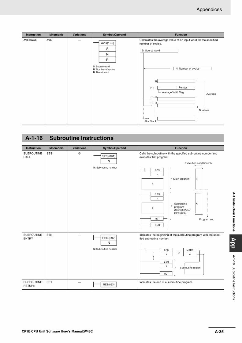
A-35
Appendices
CP1E CPU Unit Software User’s Manual(W480)
A-1 In
structio
n F
un
ction
sA
pp
A-1-16 S
ubroutine Instructions
AVERAGE AVG --- Calculates the average value of an input word for the specified number of cycles.
A-1-16 Subroutine Instructions
Instruction Mnemonic Variations Symbol/Operand Function
SUBROUTINE CALL
SBS @ Calls the subroutine with the specified subroutine number and executes that program.
SUBROUTINE ENTRY
SBN --- Indicates the beginning of the subroutine program with the speci-fied subroutine number.
SUBROUTINE RETURN
RET --- Indicates the end of a subroutine program.
Instruction Mnemonic Variations Symbol/Operand Function
S
N
R
AVG(195)
S: Source wordN: Number of cyclesR: Result word
R + N + 1
R
R + 1
R + 2
R + 3
S: Source word
N: Number of cycles
Average
N values
Average Valid Flag
Pointer
SBS(091)
N
N: Subroutine number
Execution condition ON
Main program
Subroutine program(SBN(092) to RET(093))
Program end
SBN(092)
N
N: Subroutine number
Subroutine region
or
RET(093)
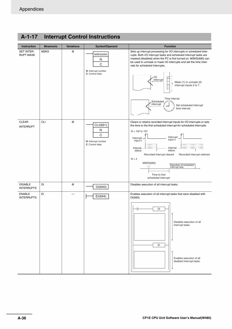
Appendices
A-36 CP1E CPU Unit Software User’s Manual(W480)
A-1-17 Interrupt Control Instructions
Instruction Mnemonic Variations Symbol/Operand Function
SET INTER-RUPT MASK
MSKS @ Sets up interrupt processing for I/O interrupts or scheduled inter-rupts. Both I/O interrupt tasks and scheduled interrupt tasks are masked (disabled) when the PC is first turned on. MSKS(690) can be used to unmask or mask I/O interrupts and set the time inter-vals for scheduled interrupts.
CLEAR
INTERRUPT
CLI @ Clears or retains recorded interrupt inputs for I/O interrupts or sets the time to the first scheduled interrupt for scheduled interrupts.
DISABLE INTERRUPTS
DI @ Disables execution of all interrupt tasks.
ENABLE INTERRUPTS
EI --- Enables execution of all interrupt tasks that were disabled with DI(693).
MSKS(690)
N
C
N: Interrupt numberC: Control data
Set scheduled interrupt time interval.
Mask (1) or unmask (0) interrupt inputs 2 to 7.
Time intervalScheduled interrupt
I/O interrupt
CLI(691)
N
C
N: Interrupt numberC: Control data
Recorded interrupt cleared Recorded interrupt retained
MSKS(690)
N = 102 to 107
N = 4
Time to first scheduled interrupt
Execution of scheduled interrupt task.
Internalstatus
Interruptinput n
Interrupt input n
Internal status
DI(693)
EI(694)
Disables execution of all interrupt tasks.
Enables execution of all disabled interrupt tasks.
DI
EI
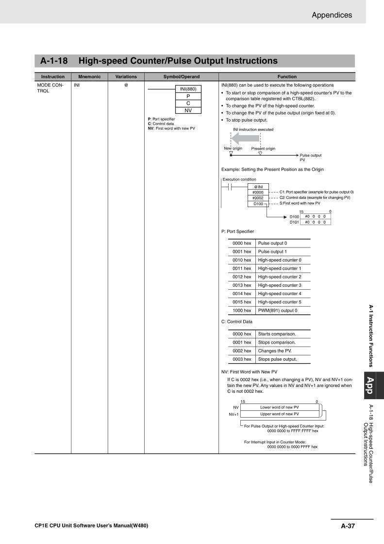
A-37
Appendices
CP1E CPU Unit Software User’s Manual(W480)
A-1 In
structio
n F
un
ction
sA
pp
A-1-18 H
igh-speed Counter/P
ulse O
utput Instructions
A-1-18 High-speed Counter/Pulse Output Instructions
Instruction Mnemonic Variations Symbol/Operand Function
MODE CON-TROL
INI @ INI(880) can be used to execute the following operations
• To start or stop comparison of a high-speed counter's PV to the comparison table registered with CTBL(882).
• To change the PV of the high-speed counter.
• To change the PV of the pulse output (origin fixed at 0).
• To stop pulse output.
Example: Setting the Present Position as the Origin
P: Port Specifier
C: Control Data
NV: First Word with New PV
If C is 0002 hex (i.e., when changing a PV), NV and NV+1 con-tain the new PV. Any values in NV and NV+1 are ignored when C is not 0002 hex.
INI(880)
PC
NV
P: Port specifierC: Control dataNV: First word with new PV INI instruction executed
Pulse outputPV
New origin Present origin
#0000 #0002
D100
D100D101
@INI
15 0#0 0 0 0
#0 0 0 0
Execution condition
C1: Port specifier (example for pulse output 0)C2: Control data (example for changing PV)S:First word with new PV
0000 hex Pulse output 0
0001 hex Pulse output 1
0010 hex High-speed counter 0
0011 hex High-speed counter 1
0012 hex High-speed counter 2
0013 hex High-speed counter 3
0014 hex High-speed counter 4
0015 hex High-speed counter 5
1000 hex PWM(891) output 0
0000 hex Starts comparison.
0001 hex Stops comparison.
0002 hex Changes the PV.
0003 hex Stops pulse output.
NV
NV+1
015
For Pulse Output or High-speed Counter Input: 0000 0000 to FFFF FFFF hex
For Interrupt Input in Counter Mode: 0000 0000 to 0000 FFFF hex
Lower word of new PV
Upper word of new PV
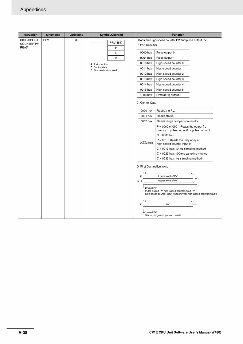
Appendices
A-38 CP1E CPU Unit Software User’s Manual(W480)
HIGH-SPEED COUNTER PV READ
PRV @ Reads the High-speed counter PV and pulse output PV.
P: Port Specifier
C: Control Data
D: First Destination Word
Instruction Mnemonic Variations Symbol/Operand Function
PRV(881)
P
C
D
P: Port specifierC: Control dataD: First destination word
0000 hex Pulse output 0
0001 hex Pulse output 1
0010 hex High-speed counter 0
0011 hex High-speed counter 1
0012 hex High-speed counter 2
0013 hex High-speed counter 3
0014 hex High-speed counter 4
0015 hex High-speed counter 5
1000 hex PWM(891) output 0
0000 hex Reads the PV.
0001 hex Reads status.
0002 hex Reads range comparison results.
00 3 hex
P = 0000 or 0001: Reads the output fre-quency of pulse output 0 or pulse output 1.
C = 0003 hex
P = 0010: Reads the frequency of high-speed counter input 0.
C = 0013 hex: 10-ms sampling method
C = 0023 hex: 100-ms sampling method
C = 0033 hex: 1-s sampling method
D
D+1
015
D PV
015
Lower word of PV
Upper word of PV
2-word PVPulse output PV, high-speed counter input PV, high-speed counter input frequency for high-speed counter input 0
1-word PVStatus, range comparison results
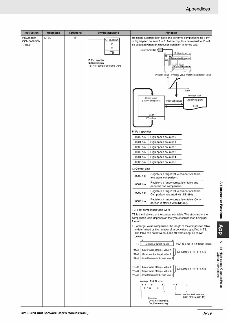
A-39
Appendices
CP1E CPU Unit Software User’s Manual(W480)
A-1 In
structio
n F
un
ction
sA
pp
A-1-18 H
igh-speed Counter/P
ulse O
utput Instructions
REGISTER COMPARISON TABLE
CTBL @ Registers a comparison table and performs comparisons for a PV of high-speed counter 0 to 5. An interrupt task between 0 to 15 will be executed when an execution condition is turned ON.
P: Port specifier
C: Control data
TB: First comparison table word
TB is the first word of the comparison table. The structure of the comparison table depends on the type of comparison being per-formed.
• For target value comparison, the length of the comparison table is determined by the number of target values specified in TB. The table can be between 4 and 19 words long, as shown below.
Instruction Mnemonic Variations Symbol/Operand Function
P: Port specifierC: Control dataTB: First comparison table word
CTBL(882)
PC
TB
END
END
Rotary Encoder
Built-in input
Present value Present value matches set target value
Time
Interrupt task
Ladder diagramInterrupt occursCyclic tasks
(ladder programs)
I/O refresh
0000 hex High-speed counter 0
0001 hex High-speed counter 1
0002 hex High-speed counter 2
0003 hex High-speed counter 3
0004 hex High-speed counter 4
0005 hex High-speed counter 5
0000 hexRegisters a target value comparison table and starts comparison.
0001 hexRegisters a range comparison table and performs one comparison.
0002 hexRegisters a target value comparison table. Comparison is started with INI(880).
0003 hexRegisters a range comparison table. Com-parison is started with INI(880).
TB+1
TB+2
TB+3
TB
015
03478
0 0 0 011121415
TB+16
TB+17
TB+18
Upper word of target value 1
Interrupt task number for target value 1
00000000 to FFFFFFFF hex
00000000 to FFFFFFFF hex
Number of target values 0001 to 6 hex (1 to 6 target values)
Interrupt Task Number
Interrupt task number 00 to 0F hex (0 to 15)Direction
OFF: Incrementing, ON: Decrementing
Upper word of target value 6
Interrupt task number for target value 6
Lower word of target value 1
Lower word of target value 6
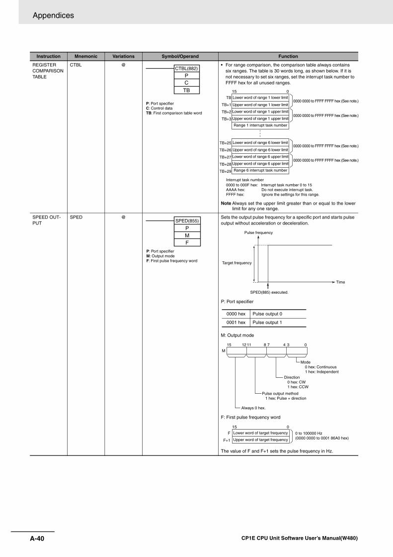
Appendices
A-40 CP1E CPU Unit Software User’s Manual(W480)
REGISTER COMPARISON TABLE
CTBL @ • For range comparison, the comparison table always contains six ranges. The table is 30 words long, as shown below. If it is not necessary to set six ranges, set the interrupt task number to FFFF hex for all unused ranges.
Note Always set the upper limit greater than or equal to the lowerlimit for any one range.
SPEED OUT-PUT
SPED @ Sets the output pulse frequency for a specific port and starts pulse output without acceleration or deceleration.
P: Port specifier
M: Output mode
F: First pulse frequency word
The value of F and F+1 sets the pulse frequency in Hz.
Instruction Mnemonic Variations Symbol/Operand Function
P: Port specifierC: Control dataTB: First comparison table word
CTBL(882)
PC
TBTB
TB+1
TB+2
TB+3
015
TB+25
TB+26
TB+27
TB+28
TB+29
Range 1 interrupt task number
0000 0000 to FFFF FFFF hex (See note.)
0000 0000 to FFFF FFFF hex (See note.)
0000 0000 to FFFF FFFF hex (See note.)
0000 0000 to FFFF FFFF hex (See note.)
Interrupt task number 0000 to 000F hex: Interrupt task number 0 to 15AAAA hex: Do not execute interrupt task.FFFF hex: Ignore the settings for this range.
Lower word of range 1 lower limit
Upper word of range 1 lower limit
Lower word of range 1 upper limit
Upper word of range 1 upper limit
Range 6 interrupt task number
Lower word of range 6 lower limit
Upper word of range 6 lower limit
Lower word of range 6 upper limit
Upper word of range 6 upper limit
SPED(855)
PMF
P: Port specifierM: Output modeF: First pulse frequency word Target frequency
Time
SPED(885) executed.
Pulse frequency
0000 hex Pulse output 0
0001 hex Pulse output 1
03478111215
M
Mode 0 hex: Continuous 1 hex: Independent
Direction 0 hex: CW 1 hex: CCW
Pulse output method 1 hex: Pulse + direction
Always 0 hex.
F
F+1
015
Lower word of target frequency
Upper word of target frequency
0 to 100000 Hz (0000 0000 to 0001 86A0 hex)
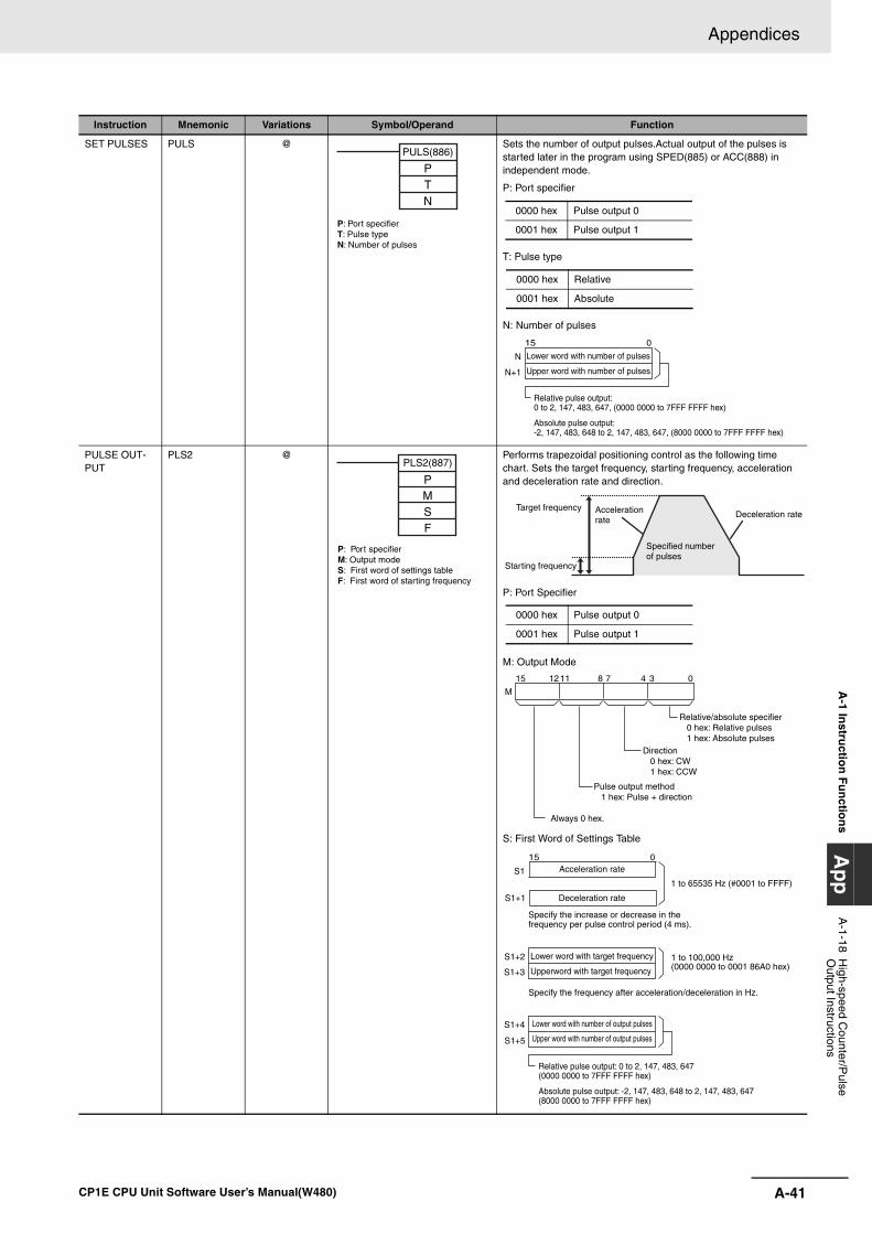
A-41
Appendices
CP1E CPU Unit Software User’s Manual(W480)
A-1 In
structio
n F
un
ction
sA
pp
A-1-18 H
igh-speed Counter/P
ulse O
utput Instructions
SET PULSES PULS @ Sets the number of output pulses.Actual output of the pulses is started later in the program using SPED(885) or ACC(888) in independent mode.
P: Port specifier
T: Pulse type
N: Number of pulses
PULSE OUT-PUT
PLS2 @ Performs trapezoidal positioning control as the following time chart. Sets the target frequency, starting frequency, acceleration and deceleration rate and direction.
P: Port Specifier
M: Output Mode
S: First Word of Settings Table
Instruction Mnemonic Variations Symbol/Operand Function
PULS(886)
PTN
P: Port specifierT: Pulse typeN: Number of pulses
0000 hex Pulse output 0
0001 hex Pulse output 1
0000 hex Relative
0001 hex Absolute
N
N+1
015
Lower word with number of pulses
Upper word with number of pulses
Relative pulse output:0 to 2, 147, 483, 647, (0000 0000 to 7FFF FFFF hex)
Absolute pulse output:-2, 147, 483, 648 to 2, 147, 483, 647, (8000 0000 to 7FFF FFFF hex)
P: Port specifierM: Output modeS: First word of settings tableF: First word of starting frequency
PLS2(887)
PMSF
Target frequency
Starting frequency
Acceleration rate
Specified number of pulses
Deceleration rate
0000 hex Pulse output 0
0001 hex Pulse output 1
03478111215
M
Relative/absolute specifier 0 hex: Relative pulses 1 hex: Absolute pulses
Direction 0 hex: CW 1 hex: CCW
Pulse output method 1 hex: Pulse + direction
Always 0 hex.
S1+4
S1+5
S1+2
S1+3
S1
015
S1+1
1 to 100,000 Hz(0000 0000 to 0001 86A0 hex)
Specify the frequency after acceleration/deceleration in Hz.
1 to 65535 Hz (#0001 to FFFF)
Specify the increase or decrease in the frequency per pulse control period (4 ms).
Lower word with number of output pulses
Upper word with number of output pulses
Lower word with target frequency
Upperword with target frequency
Deceleration rate
Acceleration rate
Relative pulse output: 0 to 2, 147, 483, 647(0000 0000 to 7FFF FFFF hex)
Absolute pulse output: -2, 147, 483, 648 to 2, 147, 483, 647(8000 0000 to 7FFF FFFF hex)
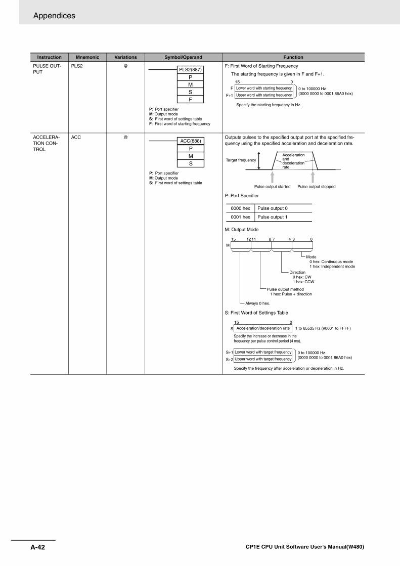
Appendices
A-42 CP1E CPU Unit Software User’s Manual(W480)
PULSE OUT-PUT
PLS2 @ F: First Word of Starting Frequency
The starting frequency is given in F and F+1.
ACCELERA-TION CON-TROL
ACC @ Outputs pulses to the specified output port at the specified fre-quency using the specified acceleration and deceleration rate.
P: Port Specifier
M: Output Mode
S: First Word of Settings Table
Instruction Mnemonic Variations Symbol/Operand Function
P: Port specifierM: Output modeS: First word of settings tableF: First word of starting frequency
PLS2(887)
PMSF
F
F+1
015
Lower word with starting frequency
Upper word with starting frequency
0 to 100000 Hz (0000 0000 to 0001 86A0 hex)
Specify the starting frequency in Hz.
P: Port specifierM: Output modeS: First word of settings table
ACC(888)
PMS
Target frequency
Pulse output started Pulse output stopped
Acceleration and deceleration rate
0000 hex Pulse output 0
0001 hex Pulse output 1
03478111215
M
Mode 0 hex: Continuous mode 1 hex: Independent mode
Direction 0 hex: CW 1 hex: CCW
Pulse output method 1 hex: Pulse + direction
Always 0 hex.
S+1
S+2
S
015
Lower word with target frequency
Upper word with target frequency
0 to 100000 Hz (0000 0000 to 0001 86A0 hex)
Specify the frequency after acceleration or deceleration in Hz.
Acceleration/deceleration rate
Specify the increase or decrease in the frequency per pulse control period (4 ms).
1 to 65535 Hz (#0001 to FFFF)
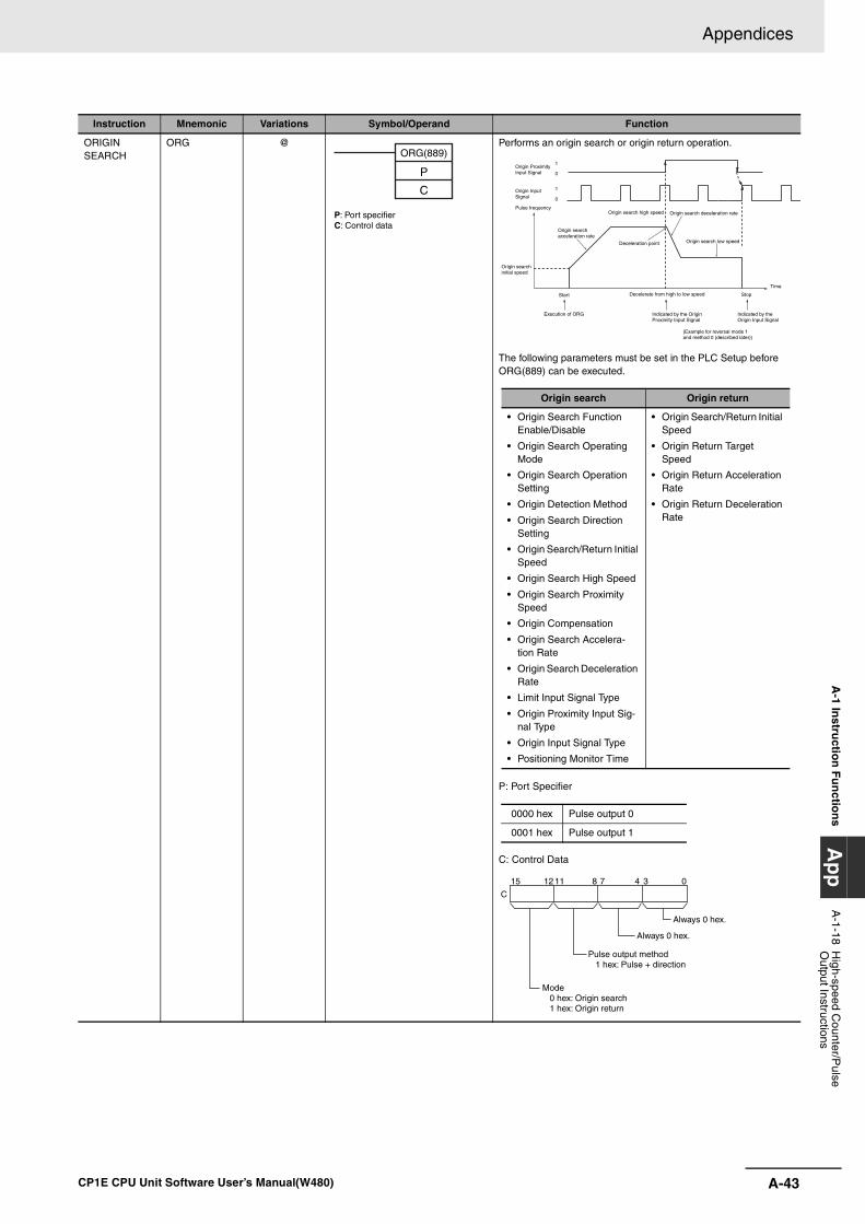
A-43
Appendices
CP1E CPU Unit Software User’s Manual(W480)
A-1 In
structio
n F
un
ction
sA
pp
A-1-18 H
igh-speed Counter/P
ulse O
utput Instructions
ORIGIN SEARCH
ORG @ Performs an origin search or origin return operation.
The following parameters must be set in the PLC Setup before ORG(889) can be executed.
P: Port Specifier
C: Control Data
Instruction Mnemonic Variations Symbol/Operand Function
P: Port specifierC: Control data
ORG(889)
P
C
1
0
1
0
Origin Proximity Input Signal
Origin Input Signal
Pulse frequency
Origin search acceleration rate
Origin search high speed
Deceleration point
Origin search deceleration rate
Origin search low speed
Origin search initial speed
Start
Execution of ORG
Decelerate from high to low speed
Indicated by the Origin Proximity Input Signal
Stop
Indicated by the Origin Input Signal
Time
(Example for reversal mode 1 and method 0 (described later))
Origin search Origin return
• Origin Search Function Enable/Disable
• Origin Search Operating Mode
• Origin Search Operation Setting
• Origin Detection Method
• Origin Search Direction Setting
• Origin Search/Return Initial Speed
• Origin Search High Speed
• Origin Search Proximity Speed
• Origin Compensation
• Origin Search Accelera-tion Rate
• Origin Search Deceleration Rate
• Limit Input Signal Type
• Origin Proximity Input Sig-nal Type
• Origin Input Signal Type
• Positioning Monitor Time
• Origin Search/Return Initial Speed
• Origin Return Target Speed
• Origin Return Acceleration Rate
• Origin Return DecelerationRate
0000 hex Pulse output 0
0001 hex Pulse output 1
03478111215
C
Always 0 hex.
Always 0 hex.
Pulse output method
Mode 0 hex: Origin search 1 hex: Origin return
1 hex: Pulse + direction
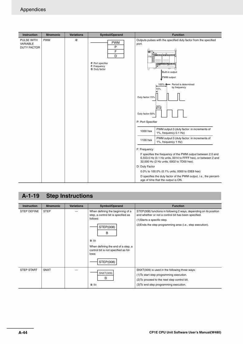
Appendices
A-44 CP1E CPU Unit Software User’s Manual(W480)
PULSE WITH VARIABLE DUTY FACTOR
PWM @ Outputs pulses with the specified duty factor from the specified port.
P: Port Specifier
F: Frequency
F specifies the frequency of the PWM output between 2.0 and 6,553.5 Hz (0.1 Hz units, 0014 to FFFF hex), or between 2 and 32,000 Hz (2 Hz units, 0002 to 7D00 hex).
D: Duty Factor
0.0% to 100.0% (0.1% units, 0000 to 03E8 hex)
D specifies the duty factor of the PWM output, i.e., the percent-age of time that the output is ON.
A-1-19 Step Instructions
Instruction Mnemonic Variations Symbol/Operand Function
STEP DEFINE STEP --- When defining the beginning of a step, a control bit is specified as follows:
When defining the end of a step, a control bit is not specified as fol-lows:
STEP(008) functions in following 2 ways, depending on its position and whether or not a control bit has been specified.
(1)Starts a specific step.
(2)Ends the step programming area (i.e., step execution).
STEP START SNXT --- SNXT(009) is used in the following three ways:
(1)To start step programming execution.
(2)To proceed to the next step control bit.
(3)To end step programming execution.
Instruction Mnemonic Variations Symbol/Operand Function
P: Port specifierF: FrequencyD: Duty factor
PWMPFD
Duty factor:50%
100%
50%
15%
Duty factor:15%
Built-in output
PWM output
Period is determinedby frequency
1000 hexPWM output 0 (duty factor: in increments of 1%, frequency 0.1 Hz)
1100 hexPWM output 0 (duty factor: in increments of 1%, frequency 1 Hz)
STEP(008)
B
B: Bit
STEP(008)
SNXT(009)
B
B: Bit
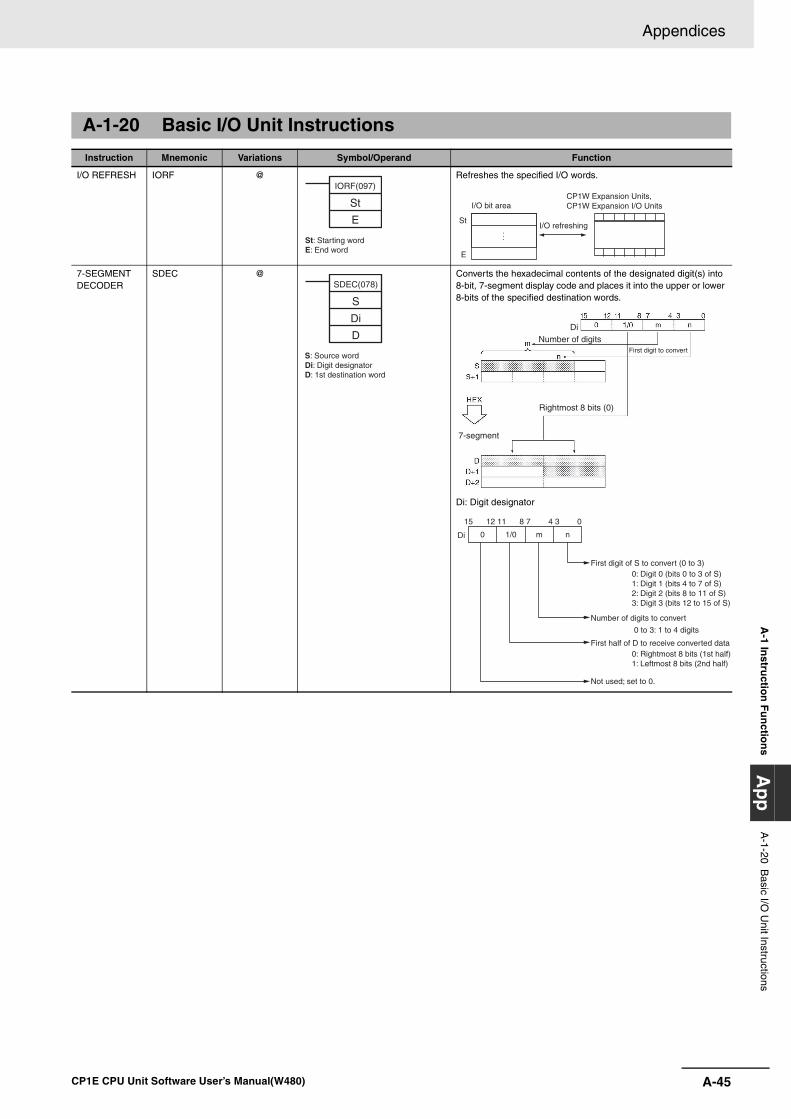
A-45
Appendices
CP1E CPU Unit Software User’s Manual(W480)
A-1 In
structio
n F
un
ction
sA
pp
A-1-20 B
asic I/O U
nit Instructions
A-1-20 Basic I/O Unit Instructions
Instruction Mnemonic Variations Symbol/Operand Function
I/O REFRESH IORF @ Refreshes the specified I/O words.
7-SEGMENT DECODER
SDEC @ Converts the hexadecimal contents of the designated digit(s) into 8-bit, 7-segment display code and places it into the upper or lower 8-bits of the specified destination words.
Di: Digit designator
IORF(097)
St
E
St: Starting wordE: End word
St
E
I/O refreshing
I/O bit areaCP1W Expansion Units, CP1W Expansion I/O Units
SDEC(078)
S
Di
D
S: Source wordDi: Digit designatorD: 1st destination word
Number of digits
Rightmost 8 bits (0)
Di
7-segment
First digit to convert
0 1/0 m n
15 12 11 8 7 4 3 0
Di
First digit of S to convert (0 to 3)0: Digit 0 (bits 0 to 3 of S) 1: Digit 1 (bits 4 to 7 of S) 2: Digit 2 (bits 8 to 11 of S) 3: Digit 3 (bits 12 to 15 of S)
Number of digits to convert
0 to 3: 1 to 4 digits
First half of D to receive converted data0: Rightmost 8 bits (1st half) 1: Leftmost 8 bits (2nd half)
Not used; set to 0.
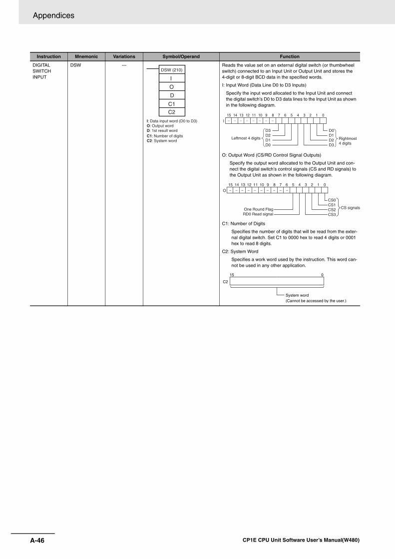
Appendices
A-46 CP1E CPU Unit Software User’s Manual(W480)
DIGITAL SWITCH INPUT
DSW --- Reads the value set on an external digital switch (or thumbwheel switch) connected to an Input Unit or Output Unit and stores the 4-digit or 8-digit BCD data in the specified words.
I: Input Word (Data Line D0 to D3 Inputs)
Specify the input word allocated to the Input Unit and connect the digital switch’s D0 to D3 data lines to the Input Unit as shown in the following diagram.
O: Output Word (CS/RD Control Signal Outputs)
Specify the output word allocated to the Output Unit and con-nect the digital switch’s control signals (CS and RD signals) to the Output Unit as shown in the following diagram.
C1: Number of Digits
Specifies the number of digits that will be read from the exter-nal digital switch. Set C1 to 0000 hex to read 4 digits or 0001 hex to read 8 digits.
C2: System Word
Specifies a work word used by the instruction. This word can-not be used in any other application.
Instruction Mnemonic Variations Symbol/Operand Function
DSW (210)
I
O
D
C1
C2
I: Data input word (D0 to D3)O: Output wordD: 1st result wordC1: Number of digitsC2: System word
0123456789101112131415
I
D0D1D2D3
D3D2D1D0
Rightmost 4 digits
Leftmost 4 digits
0123456789101112131415
O
CS0CS1CS2CS3
CS signalsOne Round FlagRD0 Read signal
C2
15 0
System word(Cannot be accessed by the user.)
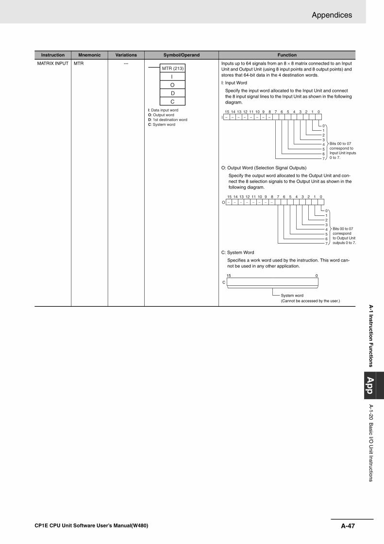
A-47
Appendices
CP1E CPU Unit Software User’s Manual(W480)
A-1 In
structio
n F
un
ction
sA
pp
A-1-20 B
asic I/O U
nit Instructions
MATRIX INPUT MTR --- Inputs up to 64 signals from an 8 × 8 matrix connected to an Input Unit and Output Unit (using 8 input points and 8 output points) and stores that 64-bit data in the 4 destination words.
I: Input Word
Specify the input word allocated to the Input Unit and connect the 8 input signal lines to the Input Unit as shown in the following diagram.
O: Output Word (Selection Signal Outputs)
Specify the output word allocated to the Output Unit and con-nect the 8 selection signals to the Output Unit as shown in the following diagram.
C: System Word
Specifies a work word used by the instruction. This word can-not be used in any other application.
Instruction Mnemonic Variations Symbol/Operand Function
MTR (213)
I
O
D
C
I: Data input wordO: Output wordD: 1st destination wordC: System word
0123456789101112131415
I
01234567
Bits 00 to 07 correspond to Input Unit inputs0 to 7.
0123456789101112131415
O
01234567
Bits 00 to 07 correspond to Output Unit outputs 0 to 7.
C
15 0
System word(Cannot be accessed by the user.)
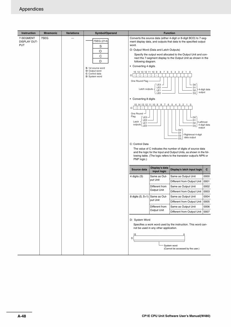
Appendices
A-48 CP1E CPU Unit Software User’s Manual(W480)
7-SEGMENT DISPLAY OUT-PUT
7SEG --- Converts the source data (either 4-digit or 8-digit BCD) to 7-seg-ment display data, and outputs that data to the specified output word.
O: Output Word (Data and Latch Outputs)
Specify the output word allocated to the Output Unit and con-nect the 7-segment display to the Output Unit as shown in the following diagram.
• Converting 4 digits
• Converting 8 digits
C: Control Data
The value of C indicates the number of digits of source data and the logic for the Input and Output Units, as shown in the fol-lowing table. (The logic refers to the transistor output’s NPN or PNP logic.)
D: System Word
Specifies a work word used by the instruction. This word can-not be used in any other application.
Instruction Mnemonic Variations Symbol/Operand Function
7SEG (214)
S
O
C
D
S: 1st source wordO: Output wordC: Control dataD: System word
0123456789101112131415
O
D0D1D2D3
LE3LE2LE1LE0
4-digit data output
Latch outputs
One Round Flag
0123456789101112131415
O
D0D1D2D3
LE3LE2LE1LE0
D0D1D2D3
Leftmost 4-digit dataoutput
Rightmost 4-digit data output
Latch outputs
One RoundFlag
Source dataDisplay’s data
input logicDisplay’s latch input logic C
4 digits (S) Same as Out-put Unit
Same as Output Unit 0000
Different from Output Unit 0001
Different from Output Unit
Same as Output Unit 0002
Different from Output Unit 0003
8 digits (S, S+1) Same as Out-put Unit
Same as Output Unit 0004
Different from Output Unit 0005
Different from Output Unit
Same as Output Unit 0006
Different from Output Unit 0007
D
15 0
System word(Cannot be accessed by the user.)
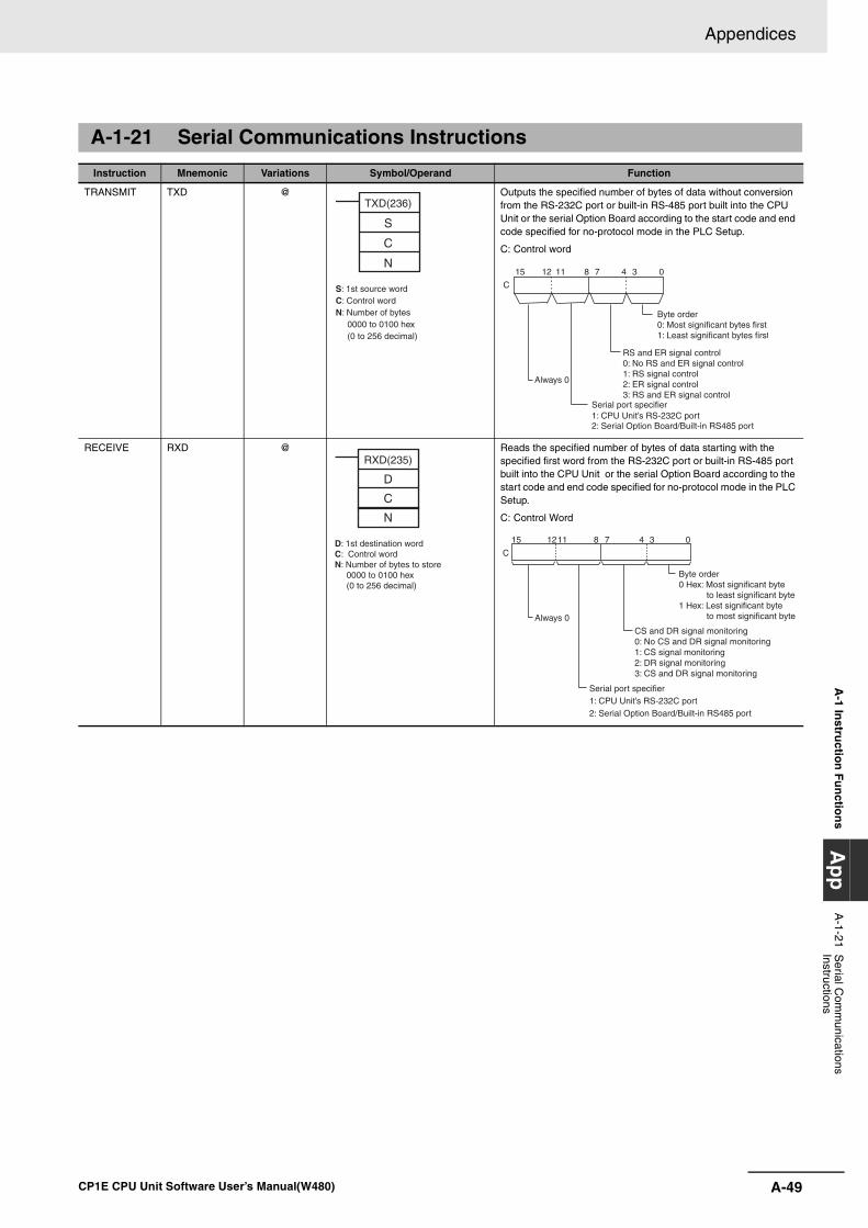
A-49
Appendices
CP1E CPU Unit Software User’s Manual(W480)
A-1 In
structio
n F
un
ction
sA
pp
A-1-21 S
erial Com
munications
Instructions
A-1-21 Serial Communications Instructions
Instruction Mnemonic Variations Symbol/Operand Function
TRANSMIT TXD @ Outputs the specified number of bytes of data without conversion from the RS-232C port or built-in RS-485 port built into the CPU Unit or the serial Option Board according to the start code and end code specified for no-protocol mode in the PLC Setup.
C: Control word
RECEIVE RXD @ Reads the specified number of bytes of data starting with the specified first word from the RS-232C port or built-in RS-485 port built into the CPU Unit or the serial Option Board according to the start code and end code specified for no-protocol mode in the PLC Setup.
C: Control Word
TXD(236)
S
C
N
S: 1st source wordC: Control wordN: Number of bytes
0000 to 0100 hex (0 to 256 decimal)
15 8 011 37 412
C
Byte order0: Most significant bytes first1: Least significant bytes first
RS and ER signal control0: No RS and ER signal control 1: RS signal control2: ER signal control3: RS and ER signal control
Always 0
Serial port specifier1: CPU Unit’s RS-232C port2: Serial Option Board/Built-in RS485 port
RXD(235)
D
C
N
D: 1st destination word C: Control wordN: Number of bytes to store
0000 to 0100 hex(0 to 256 decimal)
C
812 3415 0711
Byte order0 Hex: Most significant byte
to least significant byte1 Hex: Lest significant byte
to most significant byte
CS and DR signal monitoring 0: No CS and DR signal monitoring 1: CS signal monitoring 2: DR signal monitoring 3: CS and DR signal monitoring
Always 0
Serial port specifier1: CPU Unit’s RS-232C port2: Serial Option Board/Built-in RS485 port
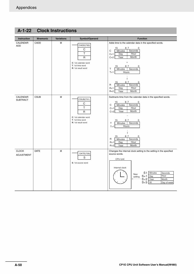
Appendices
A-50 CP1E CPU Unit Software User’s Manual(W480)
A-1-22 Clock Instructions
Instruction Mnemonic Variations Symbol/Operand Function
CALENDAR ADD
CADD @ Adds time to the calendar data in the specified words.
CALENDAR SUBTRACT
CSUB @ Subtracts time from the calendar data in the specified words.
CLOCK
ADJUSTMENT
DATE @ Changes the internal clock setting to the setting in the specified source words.
C: 1st calendar wordT: 1st time wordR: 1st result word
CADD(730)
C
T
RC+1C
15 8 7 0
15 8 7 0
15 8 7 0
C+2
T+1T
R+1R
R+2
+
Hours
Minutes Seconds
Minutes Seconds
Day Hour
Year Month
Minutes SecondsDay Hour
Year Month
C: 1st calendar wordT: 1st time wordR: 1st result word
CSUB(731)
C
T
R
15 8 7 0
15 8 7 0
15 8 7 0
Hours
Minutes
Minutes
Seconds
Seconds
Day Hour
Year Month
Minutes SecondsDay Hour
Year Month
C+1C
C+2
T+1T
R+1R
R+2
−
S
DATE(735)
S: 1st source word
CPU Unit
Internal clock
New setting
Minutes
DayYear
00
SecondsHour
Month
Day of week
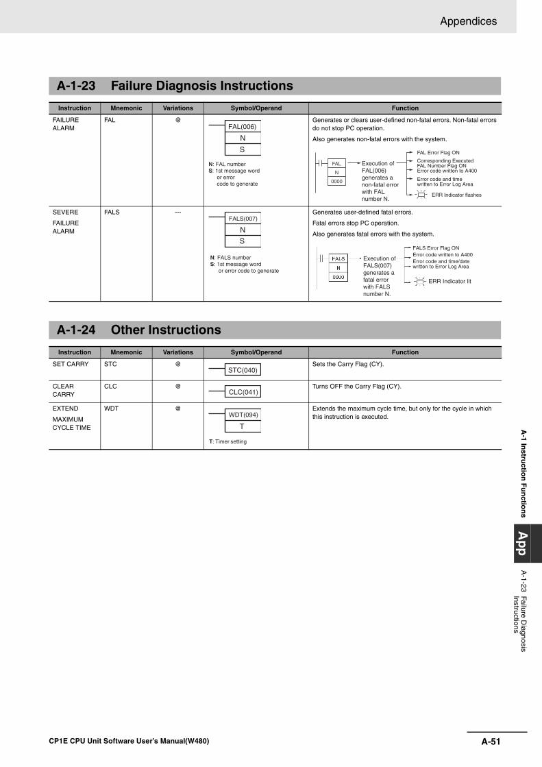
A-51
Appendices
CP1E CPU Unit Software User’s Manual(W480)
A-1 In
structio
n F
un
ction
sA
pp
A-1-23 Failure D
iagnosis Instructions
A-1-23 Failure Diagnosis Instructions
Instruction Mnemonic Variations Symbol/Operand Function
FAILURE ALARM
FAL @ Generates or clears user-defined non-fatal errors. Non-fatal errors do not stop PC operation.
Also generates non-fatal errors with the system.
SEVERE
FAILURE ALARM
FALS --- Generates user-defined fatal errors.
Fatal errors stop PC operation.
Also generates fatal errors with the system.
A-1-24 Other Instructions
Instruction Mnemonic Variations Symbol/Operand Function
SET CARRY STC @ Sets the Carry Flag (CY).
CLEAR CARRY
CLC @ Turns OFF the Carry Flag (CY).
EXTEND
MAXIMUM CYCLE TIME
WDT @ Extends the maximum cycle time, but only for the cycle in which this instruction is executed.
N
S
FAL(006)
N: FAL numberS: 1st message word
or error code to generate
FAL Error Flag ON
Corresponding Executed FAL Number Flag ONError code written to A400
Error code and time written to Error Log Area
ERR Indicator flashes
FAL
N
0000
Execution of FAL(006) generates a non-fatal error with FAL number N.
N
S
FALS(007)
N: FALS numberS: 1st message word
or error code to generate
ERR Indicator lit
Execution of FALS(007) generates a fatal error with FALS number N.
Error code and time/date written to Error Log Area
Error code written to A400FALS Error Flag ON
STC(040)
CLC(041)
T: Timer setting
WDT(094)
T
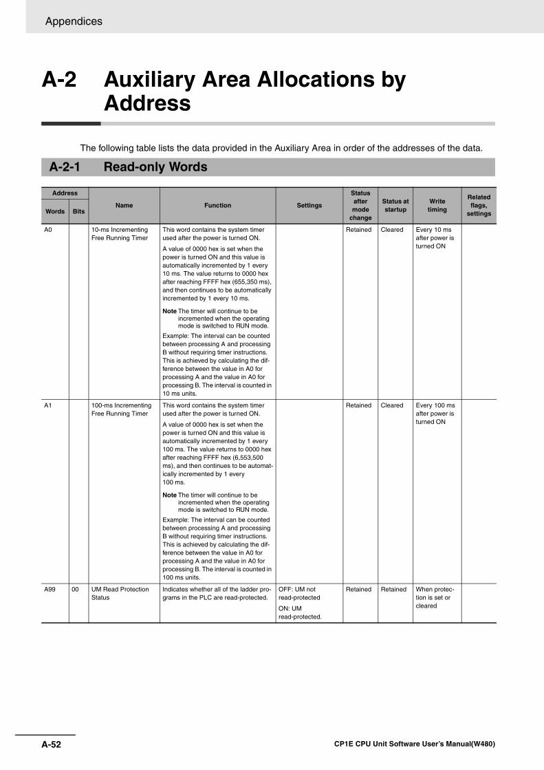
Appendices
A-52 CP1E CPU Unit Software User’s Manual(W480)
A-2 Auxiliary Area Allocations by Address
The following table lists the data provided in the Auxiliary Area in order of the addresses of the data.
A-2-1 Read-only Words
Address
Name Function Settings
Status after mode
change
Status at startup
Writetiming
Related flags,
settingsWords Bits
A0 10-ms Incrementing Free Running Timer
This word contains the system timer used after the power is turned ON.
A value of 0000 hex is set when the power is turned ON and this value is automatically incremented by 1 every 10 ms. The value returns to 0000 hex after reaching FFFF hex (655,350 ms), and then continues to be automatically incremented by 1 every 10 ms.
Note The timer will continue to be incremented when the operating mode is switched to RUN mode.
Example: The interval can be counted between processing A and processing B without requiring timer instructions. This is achieved by calculating the dif-ference between the value in A0 for processing A and the value in A0 for processing B. The interval is counted in 10 ms units.
Retained Cleared Every 10 ms after power is turned ON
A1 100-ms Incrementing Free Running Timer
This word contains the system timer used after the power is turned ON.
A value of 0000 hex is set when the power is turned ON and this value is automatically incremented by 1 every 100 ms. The value returns to 0000 hex after reaching FFFF hex (6,553,500 ms), and then continues to be automat-ically incremented by 1 every 100 ms.
Note The timer will continue to be incremented when the operating mode is switched to RUN mode.
Example: The interval can be counted between processing A and processing B without requiring timer instructions. This is achieved by calculating the dif-ference between the value in A0 for processing A and the value in A0 for processing B. The interval is counted in 100 ms units.
Retained Cleared Every 100 ms after power is turned ON
A99 00 UM Read Protection Status
Indicates whether all of the ladder pro-grams in the PLC are read-protected.
OFF: UM not read-protected
ON: UM read-protected.
Retained Retained When protec-tion is set or cleared
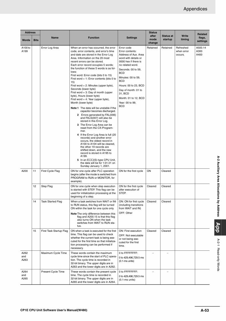
A-53
Appendices
CP1E CPU Unit Software User’s Manual(W480)
A-2 A
uxiliary A
rea Allo
cation
s by Ad
dress
Ap
pA
-2-1 Read-only W
ords
A100 to A199
Error Log Area When an error has occurred, the error code, error contents, and error's time and date are stored in the Error Log Area. Information on the 20 most recent errors can be stored.Each error record occupies 5 words; the function of these 5 words is as fol-lows: First word: Error code (bits 0 to 15)First word + 1: Error contents (bits 0 to 15)First word + 2: Minutes (upper byte), Seconds (lower byte)First word + 3: Day of month (upper byte), Hours (lower byte)First word + 4: Year (upper byte), Month (lower byte)
Note 1 The data will be unstable if the capacitor becomes discharged.
2 Errors generated by FAL(006) and FALS(007) will also be stored in this Error Log.
3 The Error Log Area can be reset from the CX-Program-mer.
4 If the Error Log Area is full (20 records) and another error occurs, the oldest record in A100 to A104 will be cleared, the other 19 records are shifted down, and the new record is stored in A195 to A199.
5 In an E (S)-type CPU Unit, the data will be for 1:01.01 on Sunday January 1, 2001.
Error codeError contents: Address of Aux. Area word with details or 0000 hex if there is no related word.
Seconds: 00 to 59, BCD
Minutes: 00 to 59, BCD
Hours: 00 to 23, BCD
Day of month: 01 to 31, BCD
Month: 01 to 12, BCD
Year: 00 to 99, BCD
Retained Retained Refreshed when error occurs.
A500.14A300A400
A200 11 First Cycle Flag ON for one cycle after PLC operation begins (after the mode is switched from PROGRAM to RUN or MONITOR, for example).
ON for the first cycle ON Cleared
12 Step Flag ON for one cycle when step execution is started with STEP. This flag can be used for initialization processing at the beginning of a step.
ON for the first cycle after execution of STEP.
Cleared Cleared
14 Task Started Flag When a task switches from WAIT or INI to RUN status, this flag will be turned ON within the task for one cycle only.
Note The only difference between this flag and A200.15 is that this flag also turns ON when the task switches from WAIT to RUN sta-tus.
ON: ON for first cycle (including transitions from WAIT and IN)
OFF: Other
Cleared Cleared
15 First Task Startup Flag ON when a task is executed for the first time. This flag can be used to check whether the current task is being exe-cuted for the first time so that initializa-tion processing can be performed if necessary.
ON: First execution
OFF: Not executableor not being exe-cuted for the first time.
Cleared Cleared
A262 and A263
Maximum Cycle Time These words contain the maximum cycle time since the start of PLC opera-tion. The cycle time is recorded in 32-bit binary. The upper digits are in A263 and the lower digits are in A262.
0 to FFFFFFFF:
0 to 429,496,729.5 ms(0.1-ms units)
− −
A264 and A265
Present Cycle Time These words contain the present cycle time. The cycle time is recorded in 32-bit binary. The upper digits are in A265 and the lower digits are in A264.
0 to FFFFFFFF:
0 to 429,496,729.5 ms (0.1-ms units)
− −
Address
Name Function Settings
Status after mode
change
Status at startup
Writetiming
Related flags,
settingsWords Bits
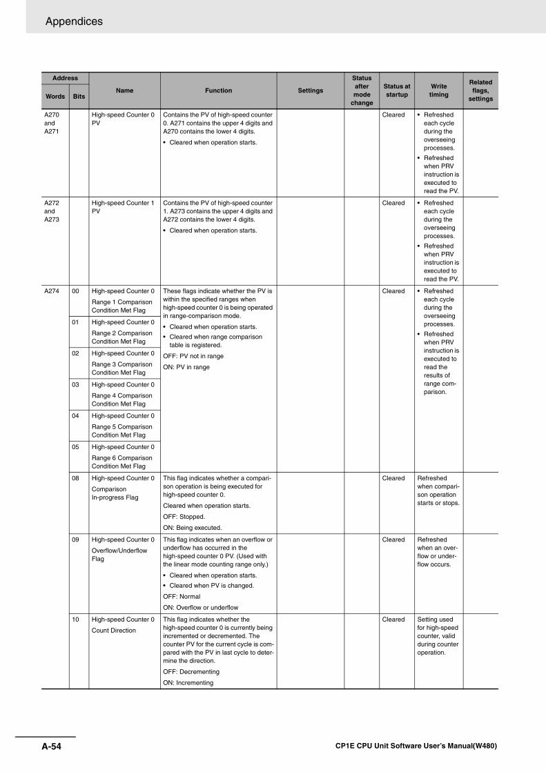
Appendices
A-54 CP1E CPU Unit Software User’s Manual(W480)
A270 andA271
High-speed Counter 0 PV
Contains the PV of high-speed counter 0. A271 contains the upper 4 digits and A270 contains the lower 4 digits.
• Cleared when operation starts.
Cleared • Refreshed each cycle during the overseeing processes.
• Refreshed when PRV instruction is executed to read the PV.
A272 andA273
High-speed Counter 1 PV
Contains the PV of high-speed counter 1. A273 contains the upper 4 digits and A272 contains the lower 4 digits.
• Cleared when operation starts.
Cleared • Refreshed each cycle during the overseeing processes.
• Refreshed when PRV instruction is executed to read the PV.
A274 00 High-speed Counter 0
Range 1 Comparison Condition Met Flag
These flags indicate whether the PV is within the specified ranges when high-speed counter 0 is being operated in range-comparison mode.
• Cleared when operation starts.
• Cleared when range comparison table is registered.
OFF: PV not in range
ON: PV in range
Cleared • Refreshed each cycle during the overseeing processes.
• Refreshed when PRV instruction is executed to read the results of range com-parison.
01 High-speed Counter 0
Range 2 Comparison Condition Met Flag
02 High-speed Counter 0
Range 3 Comparison Condition Met Flag
03 High-speed Counter 0
Range 4 Comparison Condition Met Flag
04 High-speed Counter 0
Range 5 Comparison Condition Met Flag
05 High-speed Counter 0
Range 6 Comparison Condition Met Flag
08 High-speed Counter 0
Comparison In-progress Flag
This flag indicates whether a compari-son operation is being executed for high-speed counter 0.
Cleared when operation starts.
OFF: Stopped.
ON: Being executed.
Cleared Refreshed when compari-son operation starts or stops.
09 High-speed Counter 0
Overflow/Underflow Flag
This flag indicates when an overflow or underflow has occurred in the high-speed counter 0 PV. (Used with the linear mode counting range only.)
• Cleared when operation starts.
• Cleared when PV is changed.
OFF: Normal
ON: Overflow or underflow
Cleared Refreshed when an over-flow or under-flow occurs.
10 High-speed Counter 0
Count Direction
This flag indicates whether the high-speed counter 0 is currently being incremented or decremented. The counter PV for the current cycle is com-pared with the PV in last cycle to deter-mine the direction.
OFF: Decrementing
ON: Incrementing
Cleared Setting used for high-speed counter, valid during counter operation.
Address
Name Function Settings
Status after mode
change
Status at startup
Writetiming
Related flags,
settingsWords Bits
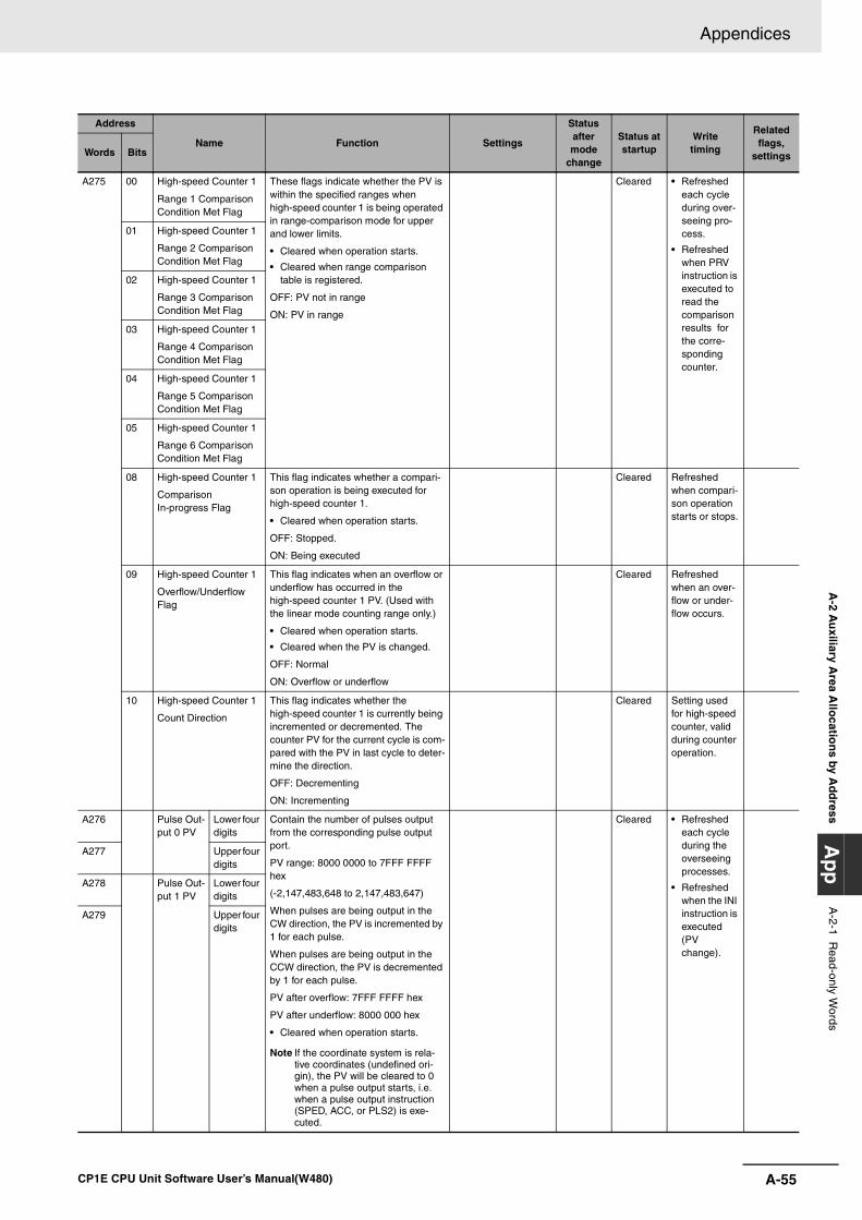
A-55
Appendices
CP1E CPU Unit Software User’s Manual(W480)
A-2 A
uxiliary A
rea Allo
cation
s by Ad
dress
Ap
pA
-2-1 Read-only W
ords
A275 00 High-speed Counter 1
Range 1 Comparison Condition Met Flag
These flags indicate whether the PV is within the specified ranges when high-speed counter 1 is being operated in range-comparison mode for upper and lower limits.
• Cleared when operation starts.
• Cleared when range comparison table is registered.
OFF: PV not in range
ON: PV in range
Cleared • Refreshed each cycle during over-seeing pro-cess.
• Refreshed when PRV instruction is executed to read the comparison results for the corre-sponding counter.
01 High-speed Counter 1
Range 2 Comparison Condition Met Flag
02 High-speed Counter 1
Range 3 Comparison Condition Met Flag
03 High-speed Counter 1
Range 4 Comparison Condition Met Flag
04 High-speed Counter 1
Range 5 Comparison Condition Met Flag
05 High-speed Counter 1
Range 6 Comparison Condition Met Flag
08 High-speed Counter 1
Comparison In-progress Flag
This flag indicates whether a compari-son operation is being executed for high-speed counter 1.
• Cleared when operation starts.
OFF: Stopped.
ON: Being executed
Cleared Refreshed when compari-son operation starts or stops.
09 High-speed Counter 1
Overflow/Underflow Flag
This flag indicates when an overflow or underflow has occurred in the high-speed counter 1 PV. (Used with the linear mode counting range only.)
• Cleared when operation starts.
• Cleared when the PV is changed.
OFF: Normal
ON: Overflow or underflow
Cleared Refreshed when an over-flow or under-flow occurs.
10 High-speed Counter 1
Count Direction
This flag indicates whether the high-speed counter 1 is currently being incremented or decremented. The counter PV for the current cycle is com-pared with the PV in last cycle to deter-mine the direction.
OFF: Decrementing
ON: Incrementing
Cleared Setting used for high-speed counter, valid during counter operation.
A276 Pulse Out-put 0 PV
Lower four digits
Contain the number of pulses output from the corresponding pulse output port.
PV range: 8000 0000 to 7FFF FFFF hex
(-2,147,483,648 to 2,147,483,647)
When pulses are being output in the CW direction, the PV is incremented by 1 for each pulse.
When pulses are being output in the CCW direction, the PV is decremented by 1 for each pulse.
PV after overflow: 7FFF FFFF hex
PV after underflow: 8000 000 hex
• Cleared when operation starts.
Note If the coordinate system is rela-tive coordinates (undefined ori-gin), the PV will be cleared to 0 when a pulse output starts, i.e. when a pulse output instruction (SPED, ACC, or PLS2) is exe-cuted.
Cleared • Refreshed each cycle during the overseeing processes.
• Refreshed when the INI instruction is executed (PV change).
A277 Upper four digits
A278 Pulse Out-put 1 PV
Lower four digits
A279 Upper four digits
Address
Name Function Settings
Status after mode
change
Status at startup
Writetiming
Related flags,
settingsWords Bits
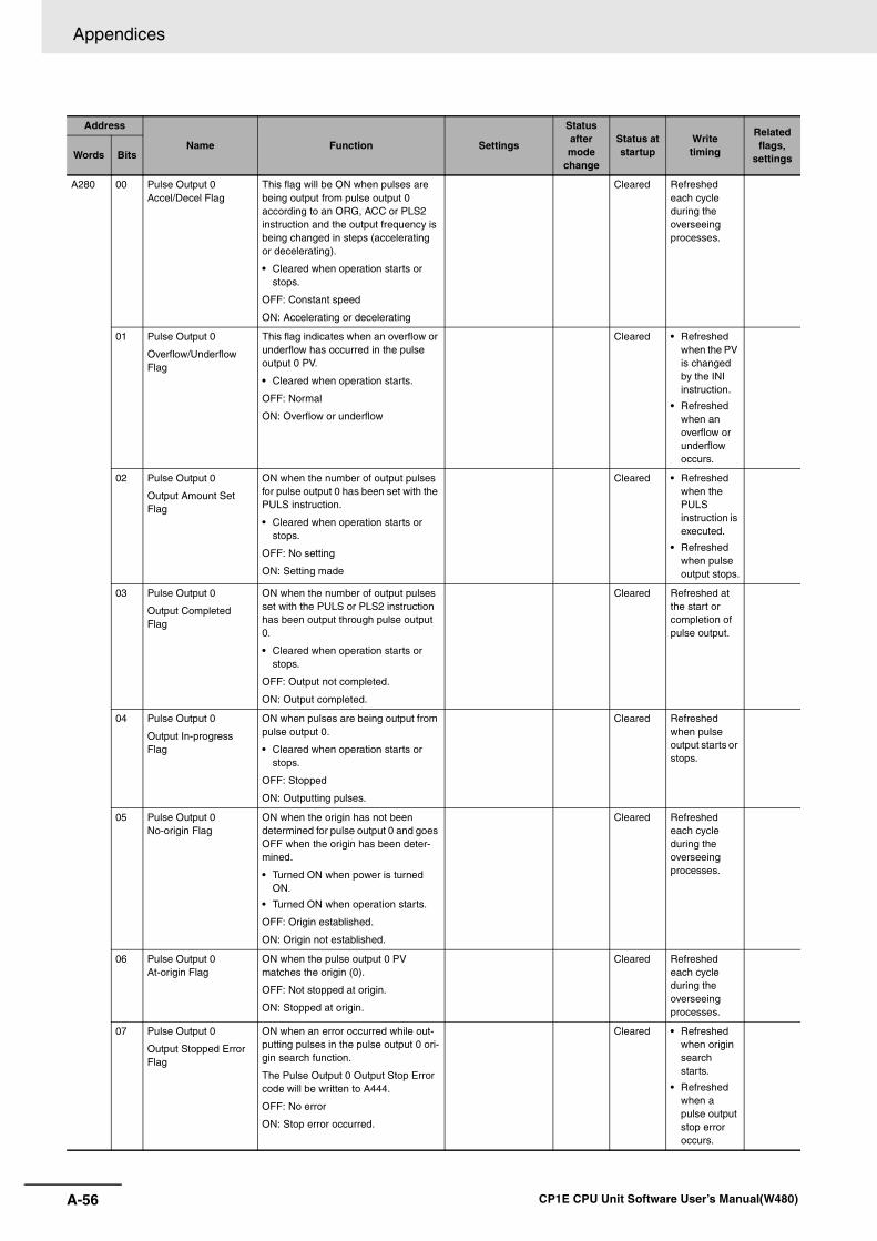
Appendices
A-56 CP1E CPU Unit Software User’s Manual(W480)
A280 00 Pulse Output 0 Accel/Decel Flag
This flag will be ON when pulses are being output from pulse output 0 according to an ORG, ACC or PLS2 instruction and the output frequency is being changed in steps (accelerating or decelerating).
• Cleared when operation starts or stops.
OFF: Constant speed
ON: Accelerating or decelerating
Cleared Refreshed each cycle during the overseeing processes.
01 Pulse Output 0
Overflow/Underflow Flag
This flag indicates when an overflow or underflow has occurred in the pulse output 0 PV.
• Cleared when operation starts.
OFF: Normal
ON: Overflow or underflow
Cleared • Refreshed when the PV is changed by the INI instruction.
• Refreshed when an overflow or underflow occurs.
02 Pulse Output 0
Output Amount Set Flag
ON when the number of output pulses for pulse output 0 has been set with the PULS instruction.
• Cleared when operation starts or stops.
OFF: No setting
ON: Setting made
Cleared • Refreshed when the PULS instruction is executed.
• Refreshed when pulse output stops.
03 Pulse Output 0
Output Completed Flag
ON when the number of output pulses set with the PULS or PLS2 instruction has been output through pulse output 0.
• Cleared when operation starts or stops.
OFF: Output not completed.
ON: Output completed.
Cleared Refreshed at the start or completion of pulse output.
04 Pulse Output 0
Output In-progress Flag
ON when pulses are being output from pulse output 0.
• Cleared when operation starts or stops.
OFF: Stopped
ON: Outputting pulses.
Cleared Refreshed when pulse output starts or stops.
05 Pulse Output 0 No-origin Flag
ON when the origin has not been determined for pulse output 0 and goes OFF when the origin has been deter-mined.
• Turned ON when power is turned ON.
• Turned ON when operation starts.
OFF: Origin established.
ON: Origin not established.
Cleared Refreshed each cycle during the overseeing processes.
06 Pulse Output 0 At-origin Flag
ON when the pulse output 0 PV matches the origin (0).
OFF: Not stopped at origin.
ON: Stopped at origin.
Cleared Refreshed each cycle during the overseeing processes.
07 Pulse Output 0
Output Stopped Error Flag
ON when an error occurred while out-putting pulses in the pulse output 0 ori-gin search function.
The Pulse Output 0 Output Stop Error code will be written to A444.
OFF: No error
ON: Stop error occurred.
Cleared • Refreshed when origin search starts.
• Refreshed when a pulse output stop error occurs.
Address
Name Function Settings
Status after mode
change
Status at startup
Writetiming
Related flags,
settingsWords Bits
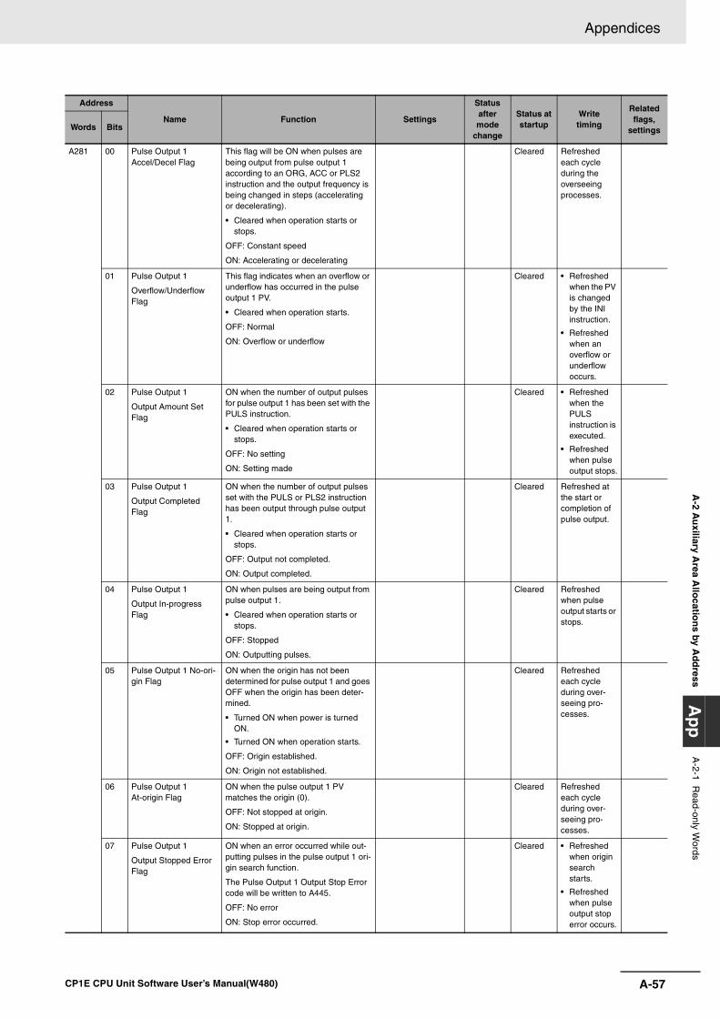
A-57
Appendices
CP1E CPU Unit Software User’s Manual(W480)
A-2 A
uxiliary A
rea Allo
cation
s by Ad
dress
Ap
pA
-2-1 Read-only W
ords
A281 00 Pulse Output 1 Accel/Decel Flag
This flag will be ON when pulses are being output from pulse output 1 according to an ORG, ACC or PLS2 instruction and the output frequency is being changed in steps (accelerating or decelerating).
• Cleared when operation starts or stops.
OFF: Constant speed
ON: Accelerating or decelerating
Cleared Refreshed each cycle during the overseeing processes.
01 Pulse Output 1
Overflow/Underflow Flag
This flag indicates when an overflow or underflow has occurred in the pulse output 1 PV.
• Cleared when operation starts.
OFF: Normal
ON: Overflow or underflow
Cleared • Refreshed when the PV is changed by the INI instruction.
• Refreshed when an overflow or underflow occurs.
02 Pulse Output 1
Output Amount Set Flag
ON when the number of output pulses for pulse output 1 has been set with the PULS instruction.
• Cleared when operation starts or stops.
OFF: No setting
ON: Setting made
Cleared • Refreshed when the PULS instruction is executed.
• Refreshed when pulse output stops.
03 Pulse Output 1
Output Completed Flag
ON when the number of output pulses set with the PULS or PLS2 instruction has been output through pulse output 1.
• Cleared when operation starts or stops.
OFF: Output not completed.
ON: Output completed.
Cleared Refreshed at the start or completion of pulse output.
04 Pulse Output 1
Output In-progress Flag
ON when pulses are being output from pulse output 1.
• Cleared when operation starts or stops.
OFF: Stopped
ON: Outputting pulses.
Cleared Refreshed when pulse output starts or stops.
05 Pulse Output 1 No-ori-gin Flag
ON when the origin has not been determined for pulse output 1 and goes OFF when the origin has been deter-mined.
• Turned ON when power is turned ON.
• Turned ON when operation starts.
OFF: Origin established.
ON: Origin not established.
Cleared Refreshed each cycle during over-seeing pro-cesses.
06 Pulse Output 1 At-origin Flag
ON when the pulse output 1 PV matches the origin (0).
OFF: Not stopped at origin.
ON: Stopped at origin.
Cleared Refreshed each cycle during over-seeing pro-cesses.
07 Pulse Output 1
Output Stopped Error Flag
ON when an error occurred while out-putting pulses in the pulse output 1 ori-gin search function.
The Pulse Output 1 Output Stop Error code will be written to A445.
OFF: No error
ON: Stop error occurred.
Cleared • Refreshed when origin search starts.
• Refreshed when pulse output stop error occurs.
Address
Name Function Settings
Status after mode
change
Status at startup
Writetiming
Related flags,
settingsWords Bits
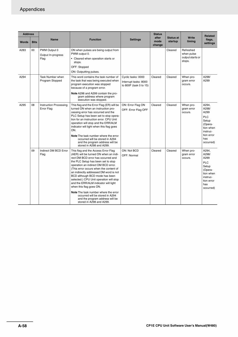
Appendices
A-58 CP1E CPU Unit Software User’s Manual(W480)
A283 00 PWM Output 0
Output In-progress Flag
ON when pulses are being output from PWM output 0.
• Cleared when operation starts or stops.
OFF: Stopped
ON: Outputting pulses.
Cleared Refreshed when pulse output starts or stops.
A294 Task Number when Program Stopped
This word contains the task number of the task that was being executed when program execution was stopped because of a program error.
Note A298 and A299 contain the pro-gram address where program execution was stopped.
Cyclic tasks: 0000
Interrupt tasks: 8000 to 800F (task 0 to 15)
Cleared Cleared When pro-gram error occurs.
A298/A299
A295 08 Instruction Processing Error Flag
This flag and the Error Flag (ER) will be turned ON when an instruction pro-cessing error has occurred and the PLC Setup has been set to stop opera-tion for an instruction error. CPU Unit operation will stop and the ERR/ALM indicator will light when this flag goes ON.
Note The task number where the error occurred will be stored in A294 and the program address will be stored in A298 and A299.
ON: Error Flag ON
OFF: Error Flag OFF
Cleared Cleared When pro-gram error occurs.
A294, A298/ A299
PLC Setup (Opera-tion when instruc-tion error has occurred)
09 Indirect DM BCD Error Flag
This flag and the Access Error Flag (AER) will be turned ON when an indi-rect DM BCD error has occurred and the PLC Setup has been set to stop operation an indirect DM BCD error. (This error occurs when the content of an indirectly addressed DM word is not BCD although BCD mode has been selected.) CPU Unit operation will stop and the ERR/ALM indicator will light when this flag goes ON.
Note The task number where the error occurred will be stored in A294 and the program address will be stored in A298 and A299.
ON: Not BCD
OFF: Normal
Cleared Cleared When pro-gram error occurs.
A294, A298/ A299
PLC Setup (Opera-tion when instruc-tion error has occurred)
Address
Name Function Settings
Status after mode
change
Status at startup
Writetiming
Related flags,
settingsWords Bits
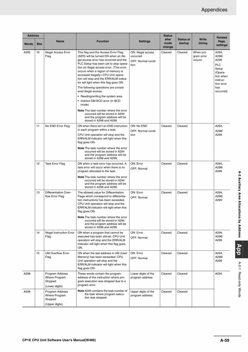
A-59
Appendices
CP1E CPU Unit Software User’s Manual(W480)
A-2 A
uxiliary A
rea Allo
cation
s by Ad
dress
Ap
pA
-2-1 Read-only W
ords
A295 10 Illegal Access Error Flag
This flag and the Access Error Flag (AER) will be turned ON when an ille-gal access error has occurred and the PLC Setup has been set to stop opera-tion an illegal access error. (This error occurs when a region of memory is accessed illegally.) CPU Unit opera-tion will stop and the ERR/ALM indica-tor will light when this flag goes ON.
The following operations are consid-ered illegal access:
• Reading/writing the system area
• Indirect DM BCD error (in BCD mode)
Note The task number where the error occurred will be stored in A294 and the program address will be stored in A298 and A299.
ON: Illegal access occurred
OFF: Normal condi-tion
Cleared Cleared When pro-gram error occurs.
A294, A298/A299
PLC Setup (Opera-tion when instruc-tion error has occurred)
11 No END Error Flag ON when there isn’t an END instruction in each program within a task.
CPU Unit operation will stop and the ERR/ALM indicator will light when this flag goes ON.
Note The task number where the error occurred will be stored in A294 and the program address will be stored in A298 and A299.
ON: No END
OFF: Normal condi-tion
Cleared Cleared A294,
A298/A299
12 Task Error Flag ON when a task error has occurred. A task error will occur when there is no program allocated to the task.
Note The task number where the error occurred will be stored in A294 and the program address will be stored in A298 and A299.
ON: Error
OFF: Normal
Cleared Cleared A294, A298/A299
13 Differentiation Over-flow Error Flag
The allowed value for Differentiation Flags which correspond to differentia-tion instructions has been exceeded. CPU Unit operation will stop and the ERR/ALM indicator will light when this flag goes ON.
Note The task number where the error occurred will be stored in A294 and the program address will be stored in A298 and A299.
ON: Error
OFF: Normal
Cleared Cleared A294, A298/A299
14 Illegal Instruction Error Flag
ON when a program that cannot be executed has been stored. CPU Unit operation will stop and the ERR/ALM indicator will light when this flag goes ON.
ON: Error
OFF: Normal
Cleared Cleared A294, A298/A299
15 UM Overflow Error Flag
ON when the last address in UM (User Memory) has been exceeded. CPU Unit operation will stop and the ERR/ALM indicator will light when this flag goes ON.
ON: Error
OFF: Normal
Cleared Cleared A294, A298/A299
A298 Program Address Where Program Stopped
(Lower digits)
These words contain the program address of the instruction where pro-gram execution was stopped due to a program error.
Note A294 contains the task number of the task where program execu-tion was stopped.
Lower digits of the program address
Cleared Cleared A294
A299 Program Address Where Program Stopped
(Upper digits)
Upper digits of the program address
Cleared Cleared
Address
Name Function Settings
Status after mode
change
Status at startup
Writetiming
Related flags,
settingsWords Bits
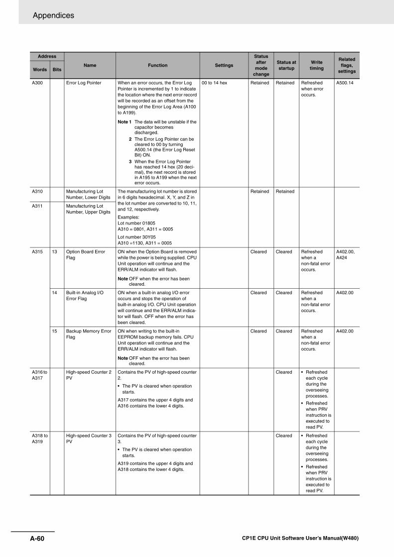
Appendices
A-60 CP1E CPU Unit Software User’s Manual(W480)
A300 Error Log Pointer When an error occurs, the Error Log Pointer is incremented by 1 to indicate the location where the next error record will be recorded as an offset from the beginning of the Error Log Area (A100 to A199).
Note 1 The data will be unstable if the capacitor becomes discharged.
2 The Error Log Pointer can be cleared to 00 by turning A500.14 (the Error Log Reset Bit) ON.
3 When the Error Log Pointer has reached 14 hex (20 deci-mal), the next record is stored in A195 to A199 when the next error occurs.
00 to 14 hex Retained Retained Refreshed when error occurs.
A500.14
A310 Manufacturing Lot Number, Lower Digits
The manufacturing lot number is stored in 6 digits hexadecimal. X, Y, and Z in the lot number are converted to 10, 11, and 12, respectively.
Examples: Lot number 01805A310 = 0801, A311 = 0005
Lot number 30Y05A310 =1130, A311 = 0005
Retained Retained
A311 Manufacturing Lot Number, Upper Digits
A315 13 Option Board Error Flag
ON when the Option Board is removed while the power is being supplied. CPU Unit operation will continue and the ERR/ALM indicator will flash.
Note OFF when the error has been cleared.
Cleared Cleared Refreshed when a non-fatal error occurs.
A402.00,A424
14 Built-in Analog I/O Error Flag
ON when a built-in analog I/O error occurs and stops the operation of built-in analog I/O. CPU Unit operation will continue and the ERR/ALM indica-tor will flash. OFF when the error has been cleared.
Cleared Cleared Refreshed when a non-fatal error occurs.
A402.00
15 Backup Memory Error Flag
ON when writing to the built-in EEPROM backup memory fails. CPU Unit operation will continue and the ERR/ALM indicator will flash.
Note OFF when the error has been cleared.
Cleared Cleared Refreshed when a non-fatal error occurs.
A402.00
A316 to A317
High-speed Counter 2 PV
Contains the PV of high-speed counter 2.
• The PV is cleared when operation starts.
A317 contains the upper 4 digits and A316 contains the lower 4 digits.
Cleared • Refreshed each cycle during the overseeing processes.
• Refreshed when PRV instruction is executed to read PV.
A318 toA319
High-speed Counter 3 PV
Contains the PV of high-speed counter 3.
• The PV is cleared when operation starts.
A319 contains the upper 4 digits and A318 contains the lower 4 digits.
Cleared • Refreshed each cycle during the overseeing processes.
• Refreshed when PRV instruction is executed to read PV.
Address
Name Function Settings
Status after mode
change
Status at startup
Writetiming
Related flags,
settingsWords Bits
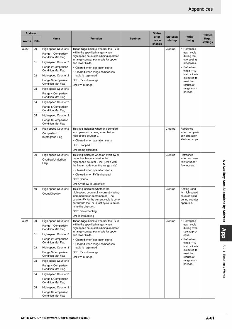
A-61
Appendices
CP1E CPU Unit Software User’s Manual(W480)
A-2 A
uxiliary A
rea Allo
cation
s by Ad
dress
Ap
pA
-2-1 Read-only W
ords
A320 00 High-speed Counter 2
Range 1 Comparison Condition Met Flag
These flags indicate whether the PV is within the specified ranges when high-speed counter 2 is being operated in range-comparison mode for upper and lower limits.
• Cleared when operation starts.
• Cleared when range comparison table is registered.
OFF: PV not in range
ON: PV in range
Cleared • Refreshed each cycle during the overseeing processes.
• Refreshed when PRV instruction is executed to read the results of range com-parison.
01 High-speed Counter 2
Range 2 Comparison Condition Met Flag
02 High-speed Counter 2
Range 3 Comparison Condition Met Flag
03 High-speed Counter 2
Range 4 Comparison Condition Met Flag
04 High-speed Counter 2
Range 5 Comparison Condition Met Flag
05 High-speed Counter 2
Range 6 Comparison Condition Met Flag
08 High-speed Counter 2
Comparison In-progress Flag
This flag indicates whether a compari-son operation is being executed for high-speed counter 2.
• Cleared when operation starts.
OFF: Stopped.
ON: Being executed.
Cleared Refreshed when compari-son operation starts or stops.
09 High-speed Counter 2
Overflow/Underflow Flag
This flag indicates when an overflow or underflow has occurred in the high-speed counter 2 PV. (Used with the linear mode counting range only.)
• Cleared when operation starts.
• Cleared when PV is changed.
OFF: Normal
ON: Overflow or underflow
Cleared Refreshed when an over-flow or under-flow occurs.
10 High-speed Counter 2
Count Direction
This flag indicates whether the high-speed counter 2 is currently being incremented or decremented. The counter PV for the current cycle is com-pared with the PV in last cycle to deter-mine the direction.
OFF: Decrementing
ON: Incrementing
Cleared Setting used for high-speed counter, valid during counter operation.
A321 00 High-speed Counter 3
Range 1 Comparison Condition Met Flag
These flags indicate whether the PV is within the specified ranges when high-speed counter 3 is being operated in range-comparison mode for upper and lower limits.
• Cleared when operation starts.
• Cleared when range comparison table is registered.
OFF: PV not in range
ON: PV in range
Cleared • Refreshed each cycle during over-seeing pro-cess.
• Refreshed when PRV instruction is executed to read the results of range com-parison.
01 High-speed Counter 3
Range 2 Comparison Condition Met Flag
02 High-speed Counter 3
Range 3 Comparison Condition Met Flag
03 High-speed Counter 3
Range 4 Comparison Condition Met Flag
04 High-speed Counter 3
Range 5 Comparison Condition Met Flag
05 High-speed Counter 3
Range 6 Comparison Condition Met Flag
Address
Name Function Settings
Status after mode
change
Status at startup
Writetiming
Related flags,
settingsWords Bits
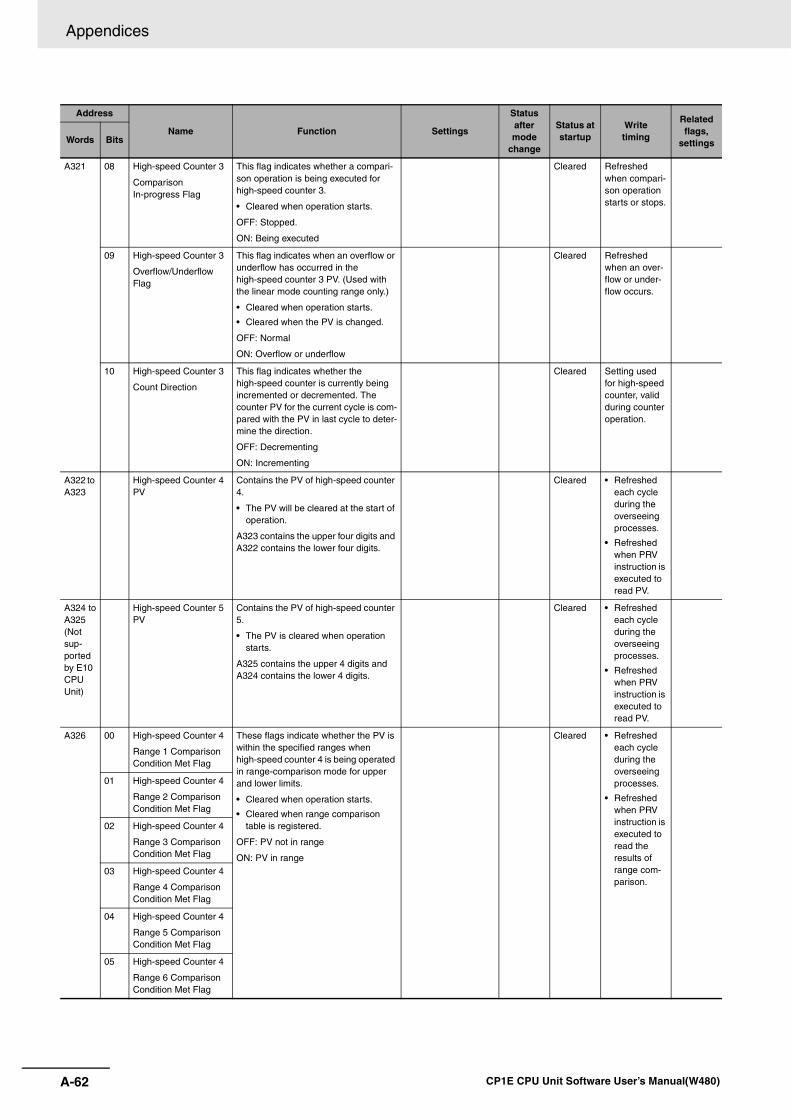
Appendices
A-62 CP1E CPU Unit Software User’s Manual(W480)
A321 08 High-speed Counter 3
ComparisonIn-progress Flag
This flag indicates whether a compari-son operation is being executed for high-speed counter 3.
• Cleared when operation starts.
OFF: Stopped.
ON: Being executed
Cleared Refreshed when compari-son operation starts or stops.
09 High-speed Counter 3
Overflow/Underflow Flag
This flag indicates when an overflow or underflow has occurred in the high-speed counter 3 PV. (Used with the linear mode counting range only.)
• Cleared when operation starts.
• Cleared when the PV is changed.
OFF: Normal
ON: Overflow or underflow
Cleared Refreshed when an over-flow or under-flow occurs.
10 High-speed Counter 3
Count Direction
This flag indicates whether the high-speed counter is currently being incremented or decremented. The counter PV for the current cycle is com-pared with the PV in last cycle to deter-mine the direction.
OFF: Decrementing
ON: Incrementing
Cleared Setting used for high-speed counter, valid during counter operation.
A322 to A323
High-speed Counter 4 PV
Contains the PV of high-speed counter 4.
• The PV will be cleared at the start of operation.
A323 contains the upper four digits and A322 contains the lower four digits.
Cleared • Refreshed each cycle during the overseeing processes.
• Refreshed when PRV instruction is executed to read PV.
A324 toA325(Not sup-ported by E10 CPU Unit)
High-speed Counter 5 PV
Contains the PV of high-speed counter 5.
• The PV is cleared when operation starts.
A325 contains the upper 4 digits and A324 contains the lower 4 digits.
Cleared • Refreshed each cycle during the overseeing processes.
• Refreshed when PRV instruction is executed to read PV.
A326 00 High-speed Counter 4
Range 1 Comparison Condition Met Flag
These flags indicate whether the PV is within the specified ranges when high-speed counter 4 is being operated in range-comparison mode for upper and lower limits.
• Cleared when operation starts.
• Cleared when range comparison table is registered.
OFF: PV not in range
ON: PV in range
Cleared • Refreshed each cycle during the overseeing processes.
• Refreshed when PRV instruction is executed to read the results of range com-parison.
01 High-speed Counter 4
Range 2 Comparison Condition Met Flag
02 High-speed Counter 4
Range 3 Comparison Condition Met Flag
03 High-speed Counter 4
Range 4 Comparison Condition Met Flag
04 High-speed Counter 4
Range 5 Comparison Condition Met Flag
05 High-speed Counter 4
Range 6 Comparison Condition Met Flag
Address
Name Function Settings
Status after mode
change
Status at startup
Writetiming
Related flags,
settingsWords Bits
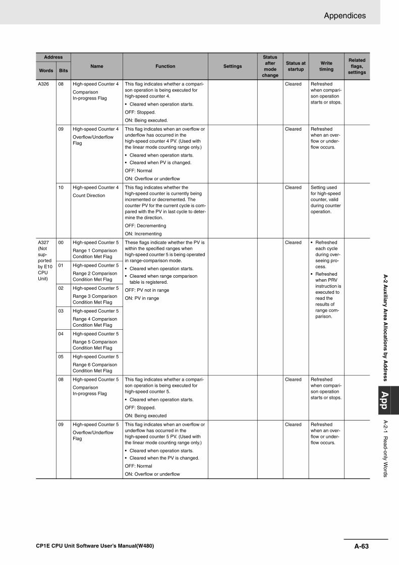
A-63
Appendices
CP1E CPU Unit Software User’s Manual(W480)
A-2 A
uxiliary A
rea Allo
cation
s by Ad
dress
Ap
pA
-2-1 Read-only W
ords
A326 08 High-speed Counter 4
Comparison In-progress Flag
This flag indicates whether a compari-son operation is being executed for high-speed counter 4.
• Cleared when operation starts.
OFF: Stopped.
ON: Being executed.
Cleared Refreshed when compari-son operation starts or stops.
09 High-speed Counter 4
Overflow/Underflow Flag
This flag indicates when an overflow or underflow has occurred in the high-speed counter 4 PV. (Used with the linear mode counting range only.)
• Cleared when operation starts.
• Cleared when PV is changed.
OFF: Normal
ON: Overflow or underflow
Cleared Refreshed when an over-flow or under-flow occurs.
10 High-speed Counter 4
Count Direction
This flag indicates whether the high-speed counter is currently being incremented or decremented. The counter PV for the current cycle is com-pared with the PV in last cycle to deter-mine the direction.
OFF: Decrementing
ON: Incrementing
Cleared Setting used for high-speed counter, valid during counter operation.
A327(Not sup-ported by E10 CPU Unit)
00 High-speed Counter 5
Range 1 Comparison Condition Met Flag
These flags indicate whether the PV is within the specified ranges when high-speed counter 5 is being operated in range-comparison mode.
• Cleared when operation starts.
• Cleared when range comparison table is registered.
OFF: PV not in range
ON: PV in range
Cleared • Refreshed each cycle during over-seeing pro-cess.
• Refreshed when PRV instruction is executed to read the results of range com-parison.
01 High-speed Counter 5
Range 2 Comparison Condition Met Flag
02 High-speed Counter 5
Range 3 Comparison Condition Met Flag
03 High-speed Counter 5
Range 4 Comparison Condition Met Flag
04 High-speed Counter 5
Range 5 Comparison Condition Met Flag
05 High-speed Counter 5
Range 6 Comparison Condition Met Flag
08 High-speed Counter 5
Comparison In-progress Flag
This flag indicates whether a compari-son operation is being executed for high-speed counter 5.
• Cleared when operation starts.
OFF: Stopped.
ON: Being executed
Cleared Refreshed when compari-son operation starts or stops.
09 High-speed Counter 5
Overflow/Underflow Flag
This flag indicates when an overflow or underflow has occurred in the high-speed counter 5 PV. (Used with the linear mode counting range only.)
• Cleared when operation starts.
• Cleared when the PV is changed.
OFF: Normal
ON: Overflow or underflow
Cleared Refreshed when an over-flow or under-flow occurs.
Address
Name Function Settings
Status after mode
change
Status at startup
Writetiming
Related flags,
settingsWords Bits
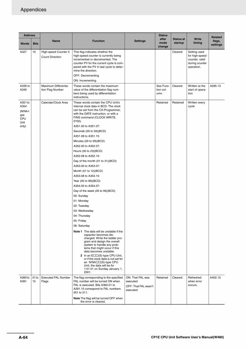
Appendices
A-64 CP1E CPU Unit Software User’s Manual(W480)
A327 10 High-speed Counter 5
Count Direction
This flag indicates whether the high-speed counter is currently being incremented or decremented. The counter PV for the current cycle is com-pared with the PV in last cycle to deter-mine the direction.
OFF: Decrementing
ON: Incrementing
Cleared Setting used for high-speed counter, valid during counter operation.
A339 toA340
Maximum Differentia-tion Flag Number
These words contain the maximum value of the differentiation flag num-bers being used by differentiation instructions.
See Func-tion col-umn.
Cleared Written at the start of opera-tion
A295.13
A351 to A354
(N/NA-type CPU Unit only)
Calendar/Clock Area These words contain the CPU Unit’s internal clock data in BCD. The clock can be set from the CX-Programmer, with the DATE instruction, or with a FINS command (CLOCK WRITE, 0702).
A351.00 to A351.07:
Seconds (00 to 59)(BCD)
A351.08 to A351.15:
Minutes (00 to 59)(BCD)
A352.00 to A352.07:
Hours (00 to 23)(BCD)
A352.08 to A352.15:
Day of the month (01 to 31)(BCD)
A353.00 to A353.07:
Month (01 to 12)(BCD)
A353.08 to A353.15:
Year (00 to 99)(BCD)
A354.00 to A354.07:
Day of the week (00 to 06)(BCD)
00: Sunday
01: Monday
02: Tuesday
03: Wednesday
04: Thursday
05: Friday
06: Saturday
Note 1 The data will be unstable if the capacitor becomes dis-charged. Write the ladder pro-gram and design the overall system to handle any prob-lems that might occur if this data becomes unstable.
2 In an E (S)-type CPU Uint, or if the clock data is not set for an N/NA (S)-type CPU Unit, the data will be for 1:01.01 on Sunday January 1, 2001.
Retained Retained Written every cycle
A360 to A391
01 to 15
Executed FAL Number Flags
The flag corresponding to the specified FAL number will be turned ON when FAL is executed. Bits A360.01 to A391.15 correspond to FAL numbers 001 to 511.
Note The flag will be turned OFF when the error is cleared.
ON: That FAL was executed
OFF: That FAL wasn’t executed
Retained Cleared Refreshed when error occurs.
A402.15
Address
Name Function Settings
Status after mode
change
Status at startup
Writetiming
Related flags,
settingsWords Bits
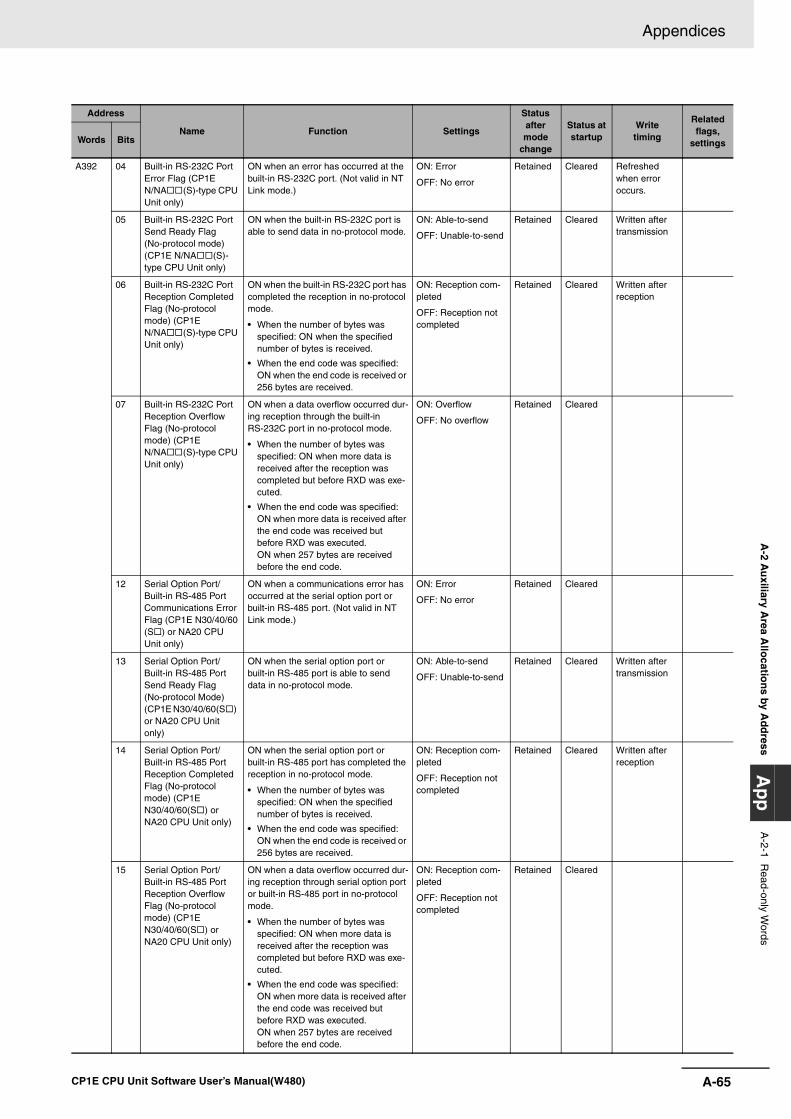
A-65
Appendices
CP1E CPU Unit Software User’s Manual(W480)
A-2 A
uxiliary A
rea Allo
cation
s by Ad
dress
Ap
pA
-2-1 Read-only W
ords
A392 04 Built-in RS-232C Port Error Flag (CP1E N/NA (S)-type CPU Unit only)
ON when an error has occurred at the built-in RS-232C port. (Not valid in NT Link mode.)
ON: Error
OFF: No error
Retained Cleared Refreshed when error occurs.
05 Built-in RS-232C Port Send Ready Flag (No-protocol mode) (CP1E N/NA (S)-type CPU Unit only)
ON when the built-in RS-232C port is able to send data in no-protocol mode.
ON: Able-to-send
OFF: Unable-to-send
Retained Cleared Written after transmission
06 Built-in RS-232C Port Reception Completed Flag (No-protocol mode) (CP1E N/NA (S)-type CPU Unit only)
ON when the built-in RS-232C port has completed the reception in no-protocol mode.
• When the number of bytes was specified: ON when the specified number of bytes is received.
• When the end code was specified: ON when the end code is received or 256 bytes are received.
ON: Reception com-pleted
OFF: Reception not completed
Retained Cleared Written after reception
07 Built-in RS-232C Port Reception Overflow Flag (No-protocol mode) (CP1E N/NA (S)-type CPU Unit only)
ON when a data overflow occurred dur-ing reception through the built-in RS-232C port in no-protocol mode.
• When the number of bytes was specified: ON when more data is received after the reception was completed but before RXD was exe-cuted.
• When the end code was specified: ON when more data is received after the end code was received but before RXD was executed.ON when 257 bytes are received before the end code.
ON: Overflow
OFF: No overflow
Retained Cleared
12 Serial Option Port/Built-in RS-485 Port Communications Error Flag (CP1E N30/40/60(S ) or NA20 CPU Unit only)
ON when a communications error has occurred at the serial option port or built-in RS-485 port. (Not valid in NT Link mode.)
ON: Error
OFF: No error
Retained Cleared
13 Serial Option Port/Built-in RS-485 Port Send Ready Flag (No-protocol Mode) (CP1E N30/40/60(S ) or NA20 CPU Unit only)
ON when the serial option port or built-in RS-485 port is able to send data in no-protocol mode.
ON: Able-to-send
OFF: Unable-to-send
Retained Cleared Written after transmission
14 Serial Option Port/Built-in RS-485 Port Reception Completed Flag (No-protocol mode) (CP1E N30/40/60(S ) or NA20 CPU Unit only)
ON when the serial option port or built-in RS-485 port has completed the reception in no-protocol mode.
• When the number of bytes was specified: ON when the specified number of bytes is received.
• When the end code was specified: ON when the end code is received or 256 bytes are received.
ON: Reception com-pleted
OFF: Reception not completed
Retained Cleared Written after reception
15 Serial Option Port/Built-in RS-485 Port Reception Overflow Flag (No-protocol mode) (CP1E N30/40/60(S ) or NA20 CPU Unit only)
ON when a data overflow occurred dur-ing reception through serial option port or built-in RS-485 port in no-protocol mode.
• When the number of bytes was specified: ON when more data is received after the reception was completed but before RXD was exe-cuted.
• When the end code was specified: ON when more data is received after the end code was received but before RXD was executed.ON when 257 bytes are received before the end code.
ON: Reception com-pleted
OFF: Reception not completed
Retained Cleared
Address
Name Function Settings
Status after mode
change
Status at startup
Writetiming
Related flags,
settingsWords Bits
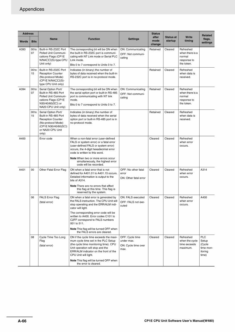
Appendices
A-66 CP1E CPU Unit Software User’s Manual(W480)
A393 00 to 07
Built-in RS-232C Port Polled Unit Communi-cations Flags (CP1E N/NA (S)-type CPU Unit only)
The corresponding bit will be ON when the built-in RS-232C port is communi-cating with NT Link mode or Serial PLC Link mode.
Bits 0 to 7 correspond to Units 0 to 7.
ON: Communicating
OFF: Not communi-cating
Retained Cleared Refreshed when there is a normal response to the token.
00 to 15
Built-in RS-232C Port Reception Counter (No-protocol Mode) (CP1E N/NA (S)-type CPU Unit only)
Indicates (in binary) the number of bytes of data received when the built-in RS-232C port is in no-protocol mode.
Retained Cleared Refreshed when data is received.
A394 00 to 07
Serial Option Port/Built-in RS-485 Port Polled Unit Communi-cations Flags (CP1E N30/40/60(S ) or NA20 CPU Unit only)
The corresponding bit will be ON when the serial option port or built-in RS-485 port is communicating with NT link mode.
Bits 0 to 7 correspond to Units 0 to 7.
ON: Communicating
OFF: Not communi-cating
Retained Cleared Refreshed when there is a normal response to the token.
00 to 15
Serial Option Port/Built-in RS-485 Port Reception Counter (No-protocol Mode) (CP1E N30/40/60(S ) or NA20 CPU Unit only)
Indicates (in binary) the number of bytes of data received when the serial option port or built-in RS-485 port is in no-protocol mode.
Retained Cleared Refreshed when data is received.
A400 Error code When a non-fatal error (user-defined FALS or system error) or a fatal error (user-defined FALS or system error) occurs, the 4-digit hexadecimal error code is written to this word.
Note When two or more errors occur simultaneously, the highest error code will be recorded.
Cleared Cleared Refreshed when error occurs.
A401 00 Other Fatal Error Flag ON when a fatal error that is not defined for A401.01 to A401.15 occurs. Detailed information is output to the bits of A314.
Note There are no errors that affect this flag at this time. This flag is reserved by the system.
OFF: No other fatal error
ON: Other fatal error
Cleared Cleared Refreshed when error occurs.
A314
06 FALS Error Flag
(fatal error)
ON when a fatal error is generated by the FALS instruction. The CPU Unit will stop operating and the ERR/ALM indi-cator will light.
The corresponding error code will be written to A400. Error codes C101 to C2FF correspond to FALS numbers 001 to 511.
Note This flag will be turned OFF when the FALS errors are cleared.
ON: FALS executed
OFF: FALS not exe-cuted
Cleared Cleared Refreshed when error occurs.
A400
08 Cycle Time Too Long Flag
(fatal error)
ON if the cycle time exceeds the maxi-mum cycle time set in the PLC Setup (the cycle time monitoring time). CPU Unit operation will stop and the ERR/ALM indicator on the front of the CPU Unit will light.
Note This flag will be turned OFF when the error is cleared.
OFF: Cycle time under max.
ON: Cycle time over max.
Cleared Cleared Refreshed when the cycle time exceeds maximum.
PLC Setup (Cycle time mon-itoring time)
Address
Name Function Settings
Status after mode
change
Status at startup
Writetiming
Related flags,
settingsWords Bits
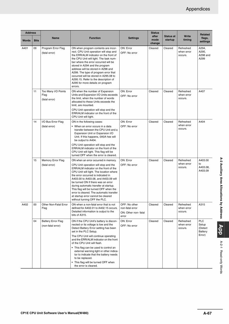
A-67
Appendices
CP1E CPU Unit Software User’s Manual(W480)
A-2 A
uxiliary A
rea Allo
cation
s by Ad
dress
Ap
pA
-2-1 Read-only W
ords
A401 09 Program Error Flag
(fatal error)
ON when program contents are incor-rect. CPU Unit operation will stop and the ERR/ALM indicator on the front of the CPU Unit will light. The task num-ber where the error occurred will be stored in A294 and the program address will be stored in A298 and A299. The type of program error that occurred will be stored in A295.08 to A295.15. Refer to the description of A295 for more details on program errors.
ON: Error
OFF: No error
Cleared Cleared Refreshed when error occurs.
A294, A295, A298 and A299
11 Too Many I/O Points Flag
(fatal error)
ON when the number of Expansion Units and Expansion I/O Units exceeds the limit, when the number of words allocated to these Units exceeds the limit, are mounted.
CPU Unit operation will stop and the ERR/ALM indicator on the front of the CPU Unit will light.
ON: Error
OFF: No error
Cleared Cleared Refreshed when error occurs.
A407
14 I/O Bus Error Flag
(fatal error)
ON in the following cases:
• When an error occurs in a data transfer between the CPU Unit and a Expansion Unit or Expansion I/O Unit. If this happens, 0A0A hex will be output to A404.
CPU Unit operation will stop and the ERR/ALM indicator on the front of the CPU Unit will light. This flag will be turned OFF when the error is cleared.
ON: Error
OFF: No error
Cleared Cleared Refreshed when error occurs.
A404
15 Memory Error Flag
(fatal error)
ON when an error occurred in memory.
CPU Unit operation will stop and the ERR/ALM indicator on the front of the CPU Unit will light. The location where the error occurred is indicated in A403.00 to A403.08, and A403.09 will be turned ON if there was an error during automatic transfer at startup. This flag will be turned OFF when the error is cleared. The automatic transfer at startup error cannot be cleared without turning OFF the PLC.
ON: Error
OFF: No error
Cleared Cleared Refreshed when error occurs.
A403.00 to A403.08, A403.09
A402 00 Other Non-Fatal Error Flag
ON when a non-fatal error that is not defined for A402.01 to A402.15 occurs. Detailed information is output to the bits of A315.
OFF: No other non-fatal error
ON: Other non- fatal error
Cleared Cleared Refreshed when error occurs.
A315
04 Battery Error Flag
(non-fatal error)
ON if the CPU Unit’s battery is discon-nected or its voltage is low and the Detect Battery Error setting has been set in the PLC Setup.
The CPU Unit will continue operating and the ERR/ALM indicator on the front of the CPU Unit will flash.
• This flag can be used to control an external warning light or other indica-tor to indicate that the battery needs to be replaced.
• This flag will be turned OFF when the error is cleared.
ON: Error
OFF: No error
Cleared Cleared Refreshed when error occurs.
PLC Setup (Detect Battery Error)
Address
Name Function Settings
Status after mode
change
Status at startup
Writetiming
Related flags,
settingsWords Bits
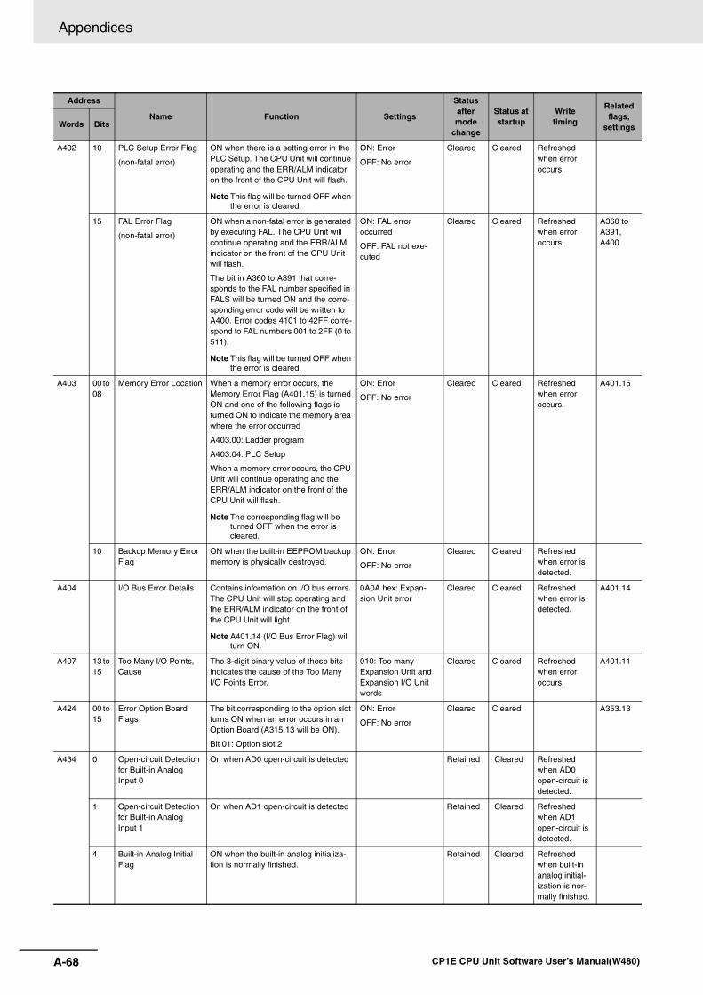
Appendices
A-68 CP1E CPU Unit Software User’s Manual(W480)
A402 10 PLC Setup Error Flag
(non-fatal error)
ON when there is a setting error in the PLC Setup. The CPU Unit will continue operating and the ERR/ALM indicator on the front of the CPU Unit will flash.
Note This flag will be turned OFF when the error is cleared.
ON: Error
OFF: No error
Cleared Cleared Refreshed when error occurs.
15 FAL Error Flag
(non-fatal error)
ON when a non-fatal error is generated by executing FAL. The CPU Unit will continue operating and the ERR/ALM indicator on the front of the CPU Unit will flash.
The bit in A360 to A391 that corre-sponds to the FAL number specified in FALS will be turned ON and the corre-sponding error code will be written to A400. Error codes 4101 to 42FF corre-spond to FAL numbers 001 to 2FF (0 to 511).
Note This flag will be turned OFF when the error is cleared.
ON: FAL error occurred
OFF: FAL not exe-cuted
Cleared Cleared Refreshed when error occurs.
A360 to A391, A400
A403 00 to 08
Memory Error Location When a memory error occurs, the Memory Error Flag (A401.15) is turned ON and one of the following flags is turned ON to indicate the memory area where the error occurred
A403.00: Ladder program
A403.04: PLC Setup
When a memory error occurs, the CPU Unit will continue operating and the ERR/ALM indicator on the front of the CPU Unit will flash.
Note The corresponding flag will be turned OFF when the error is cleared.
ON: Error
OFF: No error
Cleared Cleared Refreshed when error occurs.
A401.15
10 Backup Memory Error Flag
ON when the built-in EEPROM backup memory is physically destroyed.
ON: Error
OFF: No error
Cleared Cleared Refreshed when error is detected.
A404 I/O Bus Error Details Contains information on I/O bus errors. The CPU Unit will stop operating and the ERR/ALM indicator on the front of the CPU Unit will light.
Note A401.14 (I/O Bus Error Flag) will turn ON.
0A0A hex: Expan-sion Unit error
Cleared Cleared Refreshed when error is detected.
A401.14
A407 13 to 15
Too Many I/O Points, Cause
The 3-digit binary value of these bits indicates the cause of the Too Many I/O Points Error.
010: Too many Expansion Unit and Expansion I/O Unit words
Cleared Cleared Refreshed when error occurs.
A401.11
A424 00 to 15
Error Option Board Flags
The bit corresponding to the option slot turns ON when an error occurs in an Option Board (A315.13 will be ON).
Bit 01: Option slot 2
ON: Error
OFF: No error
Cleared Cleared A353.13
A434 0 Open-circuit Detection for Built-in Analog Input 0
On when AD0 open-circuit is detected Retained Cleared Refreshed when AD0 open-circuit is detected.
1 Open-circuit Detection for Built-in Analog Input 1
On when AD1 open-circuit is detected Retained Cleared Refreshed when AD1 open-circuit is detected.
4 Built-in Analog Initial Flag
ON when the built-in analog initializa-tion is normally finished.
Retained Cleared Refreshed when built-in analog initial-ization is nor-mally finished.
Address
Name Function Settings
Status after mode
change
Status at startup
Writetiming
Related flags,
settingsWords Bits
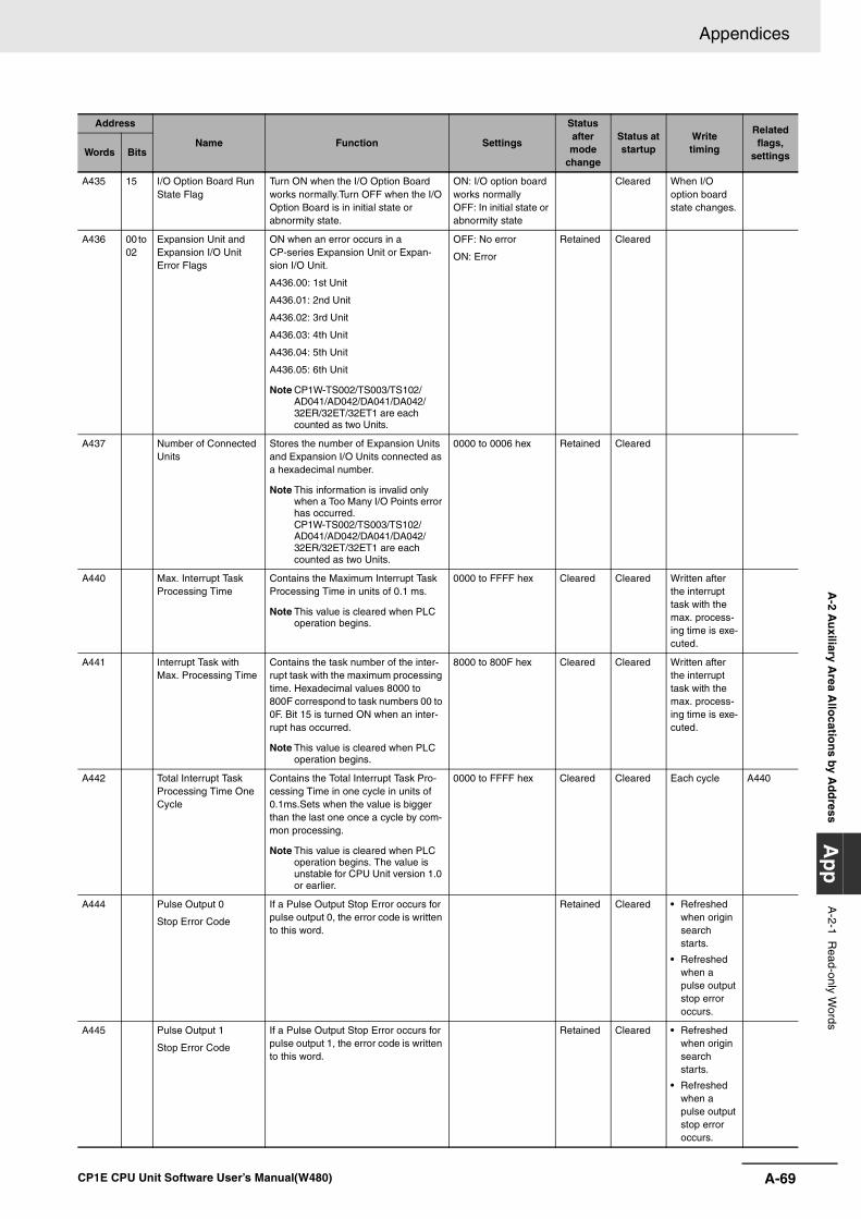
A-69
Appendices
CP1E CPU Unit Software User’s Manual(W480)
A-2 A
uxiliary A
rea Allo
cation
s by Ad
dress
Ap
pA
-2-1 Read-only W
ords
A435 15 I/O Option Board Run State Flag
Turn ON when the I/O Option Board works normally.Turn OFF when the I/O Option Board is in initial state or abnormity state.
ON: I/O option board works normally OFF: In initial state or abnormity state
Cleared When I/O option board state changes.
A436 00 to 02
Expansion Unit and Expansion I/O Unit Error Flags
ON when an error occurs in a CP-series Expansion Unit or Expan-sion I/O Unit.
A436.00: 1st Unit
A436.01: 2nd Unit
A436.02: 3rd Unit
A436.03: 4th Unit
A436.04: 5th Unit
A436.05: 6th Unit
Note CP1W-TS002/TS003/TS102/AD041/AD042/DA041/DA042/32ER/32ET/32ET1 are each counted as two Units.
OFF: No error
ON: Error
Retained Cleared
A437 Number of Connected Units
Stores the number of Expansion Units and Expansion I/O Units connected as a hexadecimal number.
Note This information is invalid only when a Too Many I/O Points error has occurred.CP1W-TS002/TS003/TS102/AD041/AD042/DA041/DA042/32ER/32ET/32ET1 are each counted as two Units.
0000 to 0006 hex Retained Cleared
A440 Max. Interrupt Task Processing Time
Contains the Maximum Interrupt Task Processing Time in units of 0.1 ms.
Note This value is cleared when PLC operation begins.
0000 to FFFF hex Cleared Cleared Written after the interrupt task with the max. process-ing time is exe-cuted.
A441 Interrupt Task with Max. Processing Time
Contains the task number of the inter-rupt task with the maximum processing time. Hexadecimal values 8000 to 800F correspond to task numbers 00 to 0F. Bit 15 is turned ON when an inter-rupt has occurred.
Note This value is cleared when PLC operation begins.
8000 to 800F hex Cleared Cleared Written after the interrupt task with the max. process-ing time is exe-cuted.
A442 Total Interrupt Task Processing Time One Cycle
Contains the Total Interrupt Task Pro-cessing Time in one cycle in units of 0.1ms.Sets when the value is bigger than the last one once a cycle by com-mon processing.
Note This value is cleared when PLC operation begins. The value is unstable for CPU Unit version 1.0 or earlier.
0000 to FFFF hex Cleared Cleared Each cycle A440
A444 Pulse Output 0
Stop Error Code
If a Pulse Output Stop Error occurs for pulse output 0, the error code is written to this word.
Retained Cleared • Refreshed when origin search starts.
• Refreshed when a pulse output stop error occurs.
A445 Pulse Output 1
Stop Error Code
If a Pulse Output Stop Error occurs for pulse output 1, the error code is written to this word.
Retained Cleared • Refreshed when origin search starts.
• Refreshed when a pulse output stop error occurs.
Address
Name Function Settings
Status after mode
change
Status at startup
Writetiming
Related flags,
settingsWords Bits
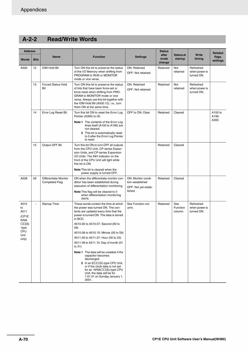
Appendices
A-70 CP1E CPU Unit Software User’s Manual(W480)
A-2-2 Read/Write Words
Address
Name Function Settings
Status after mode
change
Status at startup
Writetiming
Related flags,
settingsWords Bits
A500 12 IOM Hold Bit Turn ON this bit to preserve the status of the I/O Memory when shifting from PROGRAM to RUN or MONITOR mode or vice versa.
ON: Retained
OFF: Not retained
Retained Not retained
Refreshed when power is turned ON.
13 Forced Status Hold Bit
Turn ON this bit to preserve the status of bits that have been force-set or force-reset when shifting from PRO-GRAM to MONITOR mode or vice versa. Always use this bit together with the IOM Hold Bit (A500.12), i.e., turn them ON at the same time.
ON: Retained
OFF: Not retained
Retained Not retained
Refreshed when power is turned ON.
14 Error Log Reset Bit Turn this bit ON to reset the Error Log Pointer (A300) to 00.
Note 1 The contents of the Error Log Area itself (A100 to A199) are not cleared.
2 This bit is automatically reset to 0 after the Error Log Pointer is reset.
OFF to ON: Clear Retained Cleared A100 to A199, A300
15 Output OFF Bit Turn this bit ON to turn OFF all outputs from the CPU Unit, CP-series Expan-sion Units, and CP-series Expansion I/O Units. The INH indicator on the front of the CPU Unit will light while this bit is ON.
Note This bit is cleared when the power supply is turned OFF.
Retained Cleared
A508 09 Differentiate Monitor Completed Flag
ON when the differentiate monitor con-dition has been established during execution of differentiation monitoring.
Note This flag will be cleared to 0 when differentiation monitoring starts.
ON: Monitor condi-tion established
OFF: Not yet estab-lished
Retained Cleared
A510 to A511
(CP1E N/NA
(S)-type CPU Unit only)
− Startup Time These words contain the time at which the power was turned ON. The con-tents are updated every time that the power is turned ON. The data is stored in BCD.
A510.00 to A510.07: Second (00 to 59)
A510.08 to A510.15: Minute (00 to 59)
A511.00 to A511.07: Hour (00 to 23)
A511.08 to A511.15: Day of month (01 to 31)
Note 1 The data will be unstable if the capacitor becomes discharged.
2 In an E (S)-type CPU Unit, or if the clock data is not set for an N/NA (S)-type CPU Unit, the data will be for 1:01.01 on Sunday January 1, 2001.
See Function col-umn.
Retained See Function column.
Refreshed when power is turned ON.
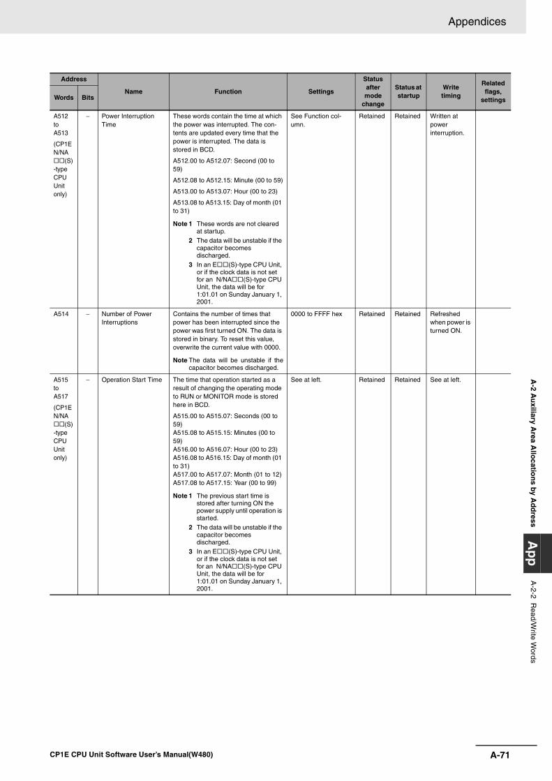
A-71
Appendices
CP1E CPU Unit Software User’s Manual(W480)
A-2 A
uxiliary A
rea Allo
cation
s by Ad
dress
Ap
pA
-2-2 Read/W
rite Words
A512 to A513
(CP1E N/NA
(S)-type CPU Unit only)
− Power Interruption Time
These words contain the time at which the power was interrupted. The con-tents are updated every time that the power is interrupted. The data is stored in BCD.
A512.00 to A512.07: Second (00 to 59)
A512.08 to A512.15: Minute (00 to 59)
A513.00 to A513.07: Hour (00 to 23)
A513.08 to A513.15: Day of month (01 to 31)
Note 1 These words are not cleared at startup.
2 The data will be unstable if the capacitor becomes discharged.
3 In an E (S)-type CPU Unit, or if the clock data is not set for an N/NA (S)-type CPU Unit, the data will be for 1:01.01 on Sunday January 1, 2001.
See Function col-umn.
Retained Retained Written at power interruption.
A514 − Number of Power Interruptions
Contains the number of times that power has been interrupted since the power was first turned ON. The data is stored in binary. To reset this value, overwrite the current value with 0000.
Note The data will be unstable if thecapacitor becomes discharged.
0000 to FFFF hex Retained Retained Refreshed when power is turned ON.
A515 to A517
(CP1E N/NA
(S)-type CPU Unit only)
− Operation Start Time The time that operation started as a result of changing the operating mode to RUN or MONITOR mode is stored here in BCD.
A515.00 to A515.07: Seconds (00 to 59)A515.08 to A515.15: Minutes (00 to 59)A516.00 to A516.07: Hour (00 to 23)A516.08 to A516.15: Day of month (01 to 31)A517.00 to A517.07: Month (01 to 12)A517.08 to A517.15: Year (00 to 99)
Note 1 The previous start time is stored after turning ON the power supply until operation is started.
2 The data will be unstable if the capacitor becomes discharged.
3 In an E (S)-type CPU Unit, or if the clock data is not set for an N/NA (S)-type CPU Unit, the data will be for 1:01.01 on Sunday January 1, 2001.
See at left. Retained Retained See at left.
Address
Name Function Settings
Status after mode
change
Status at startup
Writetiming
Related flags,
settingsWords Bits
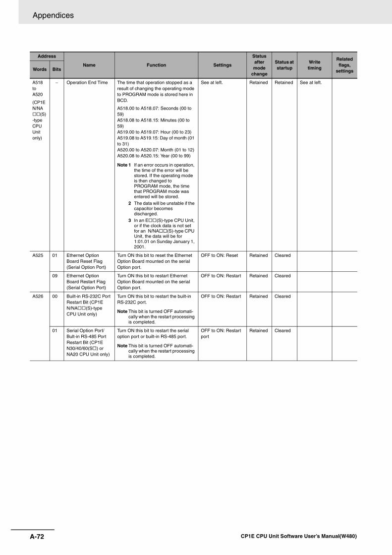
Appendices
A-72 CP1E CPU Unit Software User’s Manual(W480)
A518 to A520
(CP1E N/NA
(S)-type CPU Unit only)
− Operation End Time The time that operation stopped as a result of changing the operating mode to PROGRAM mode is stored here in BCD.
A518.00 to A518.07: Seconds (00 to 59)A518.08 to A518.15: Minutes (00 to 59)A519.00 to A519.07: Hour (00 to 23)A519.08 to A519.15: Day of month (01 to 31)A520.00 to A520.07: Month (01 to 12)A520.08 to A520.15: Year (00 to 99)
Note 1 If an error occurs in operation, the time of the error will be stored. If the operating mode is then changed to PROGRAM mode, the time that PROGRAM mode was entered will be stored.
2 The data will be unstable if the capacitor becomes discharged.
3 In an E (S)-type CPU Unit, or if the clock data is not set for an N/NA (S)-type CPU Unit, the data will be for 1:01.01 on Sunday January 1, 2001.
See at left. Retained Retained See at left.
A525 01 Ethernet Option Board Reset Flag (Serial Option Port)
Turn ON this bit to reset the Ethernet Option Board mounted on the serial Option port.
OFF to ON: Reset Retained Cleared
09 Ethernet Option Board Restart Flag (Serial Option Port)
Turn ON this bit to restart Ethernet Option Board mounted on the serial Option port.
OFF to ON: Restart Retained Cleared
A526 00 Built-in RS-232C Port Restart Bit (CP1E N/NA (S)-type CPU Unit only)
Turn ON this bit to restart the built-in RS-232C port.
Note This bit is turned OFF automati-cally when the restart processing is completed.
OFF to ON: Restart Retained Cleared
01 Serial Option Port/Bult-in RS-485 Port Restart Bit (CP1E N30/40/60(S ) or NA20 CPU Unit only)
Turn ON this bit to restart the serial option port or built-in RS-485 port.
Note This bit is turned OFF automati-cally when the restart processing is completed.
OFF to ON: Restart port
Retained Cleared
Address
Name Function Settings
Status after mode
change
Status at startup
Writetiming
Related flags,
settingsWords Bits
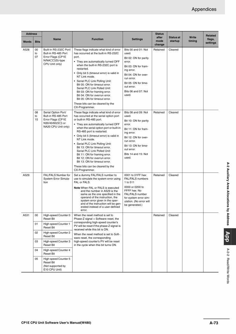
A-73
Appendices
CP1E CPU Unit Software User’s Manual(W480)
A-2 A
uxiliary A
rea Allo
cation
s by Ad
dress
Ap
pA
-2-2 Read/W
rite Words
A528 00 to 07
Built-in RS-232C Port/Bult-in RS-485 Port Error Flags (CP1E N/NA (S)-type CPU Unit only)
These flags indicate what kind of error has occurred at the built-in RS-232C port.
• They are automatically turned OFF when the built-in RS-232C port is restarted.
• Only bit 5 (timeout error) is valid in NT Link mode.
• Serial PLC Link Polling Unit:Bit 05: ON for timeout error.Serial PLC Link Polled Unit:Bit 03: ON for framing error.Bit 04: ON for overrun error.Bit 05: ON for timeout error.
These bits can be cleared by the CX-Programmer.
Bits 00 and 01: Not used.
Bit 02: ON for parity error.
Bit 03: ON for fram-ing error.
Bit 04: ON for over-run error.
Bit 05: ON for time-out error.
Bits 06 and 07: Not used.
Retained Cleared
08 to 15
Serial Option Port/Bult-in RS-485 Port Error Flags (CP1E N30/40/60(S ) or NA20 CPU Unit only)
These flags indicate what kind of error has occurred at the serial option port or built-in RS-485 port.
• They are automatically turned OFF when the serial option port or built-in RS-485 port is restarted.
• Only bit 5 (timeout error) is valid in NT Link mode.
• Serial PLC Link Polling Unit:Bit 13: ON for timeout error.Serial PLC Link Polled Unit:Bit 11: ON for framing error.Bit 12: ON for overrun error.Bit 13: ON for timeout error.
These bits can be cleared by the CX-Programmer.
Bits 08 and 09: Not used.
Bit 10: ON for parity error.
Bit 11: ON for fram-ing error.
Bit 12: ON for over-run error.
Bit 13: ON for time-out error.
Bits 14 and 15: Not used.
Retained Cleared
A529 FAL/FALS Number for System Error Simula-tion
Set a dummy FAL/FALS number to use to simulate the system error using FAL or FALS.
Note When FAL or FALS is executed and the number in A529 is the same as the one specified in the operand of the instruction, the system error given in the oper-and of the instruction will be gen-erated instead of a user-defined error.
0001 to 01FF hex: FAL/FALS numbers 1 to 511
0000 or 0200 to FFFF hex: No FAL/FALS number for system error sim-ulation. (No error will be generated.)
Retained Cleared
A531 00 High-speed Counter 0 Reset Bit
When the reset method is set to Phase-Z signal + Software reset, the corresponding high-speed counter's PV will be reset if the phase-Z signal is received while this bit is ON.
When the reset method is set to Soft-ware reset, the corresponding high-speed counter's PV will be reset in the cycle when this bit turns ON.
Retained Cleared
01 High-speed Counter 1 Reset Bit
02 High-speed Counter 2 Reset Bit
03 High-speed Counter 3 Reset Bit
04 High-speed Counter 4 Reset Bit
05 High-speed Counter 5 Reset Bit(Not supported by E10 CPU Unit)
Address
Name Function Settings
Status after mode
change
Status at startup
Writetiming
Related flags,
settingsWords Bits
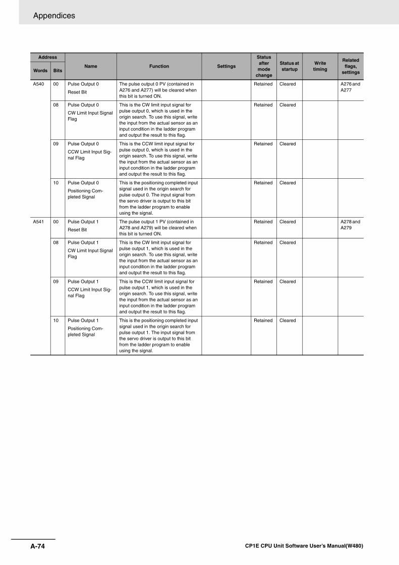
Appendices
A-74 CP1E CPU Unit Software User’s Manual(W480)
A540 00 Pulse Output 0
Reset Bit
The pulse output 0 PV (contained in A276 and A277) will be cleared when this bit is turned ON.
Retained Cleared A276 and A277
08 Pulse Output 0
CW Limit Input Signal Flag
This is the CW limit input signal for pulse output 0, which is used in the origin search. To use this signal, write the input from the actual sensor as an input condition in the ladder program and output the result to this flag.
Retained Cleared
09 Pulse Output 0
CCW Limit Input Sig-nal Flag
This is the CCW limit input signal for pulse output 0, which is used in the origin search. To use this signal, write the input from the actual sensor as an input condition in the ladder program and output the result to this flag.
Retained Cleared
10 Pulse Output 0
Positioning Com-pleted Signal
This is the positioning completed input signal used in the origin search for pulse output 0. The input signal from the servo driver is output to this bit from the ladder program to enable using the signal.
Retained Cleared
A541 00 Pulse Output 1
Reset Bit
The pulse output 1 PV (contained in A278 and A279) will be cleared when this bit is turned ON.
Retained Cleared A278 and A279
08 Pulse Output 1
CW Limit Input Signal Flag
This is the CW limit input signal for pulse output 1, which is used in the origin search. To use this signal, write the input from the actual sensor as an input condition in the ladder program and output the result to this flag.
Retained Cleared
09 Pulse Output 1
CCW Limit Input Sig-nal Flag
This is the CCW limit input signal for pulse output 1, which is used in the origin search. To use this signal, write the input from the actual sensor as an input condition in the ladder program and output the result to this flag.
Retained Cleared
10 Pulse Output 1
Positioning Com-pleted Signal
This is the positioning completed input signal used in the origin search for pulse output 1. The input signal from the servo driver is output to this bit from the ladder program to enable using the signal.
Retained Cleared
Address
Name Function Settings
Status after mode
change
Status at startup
Writetiming
Related flags,
settingsWords Bits
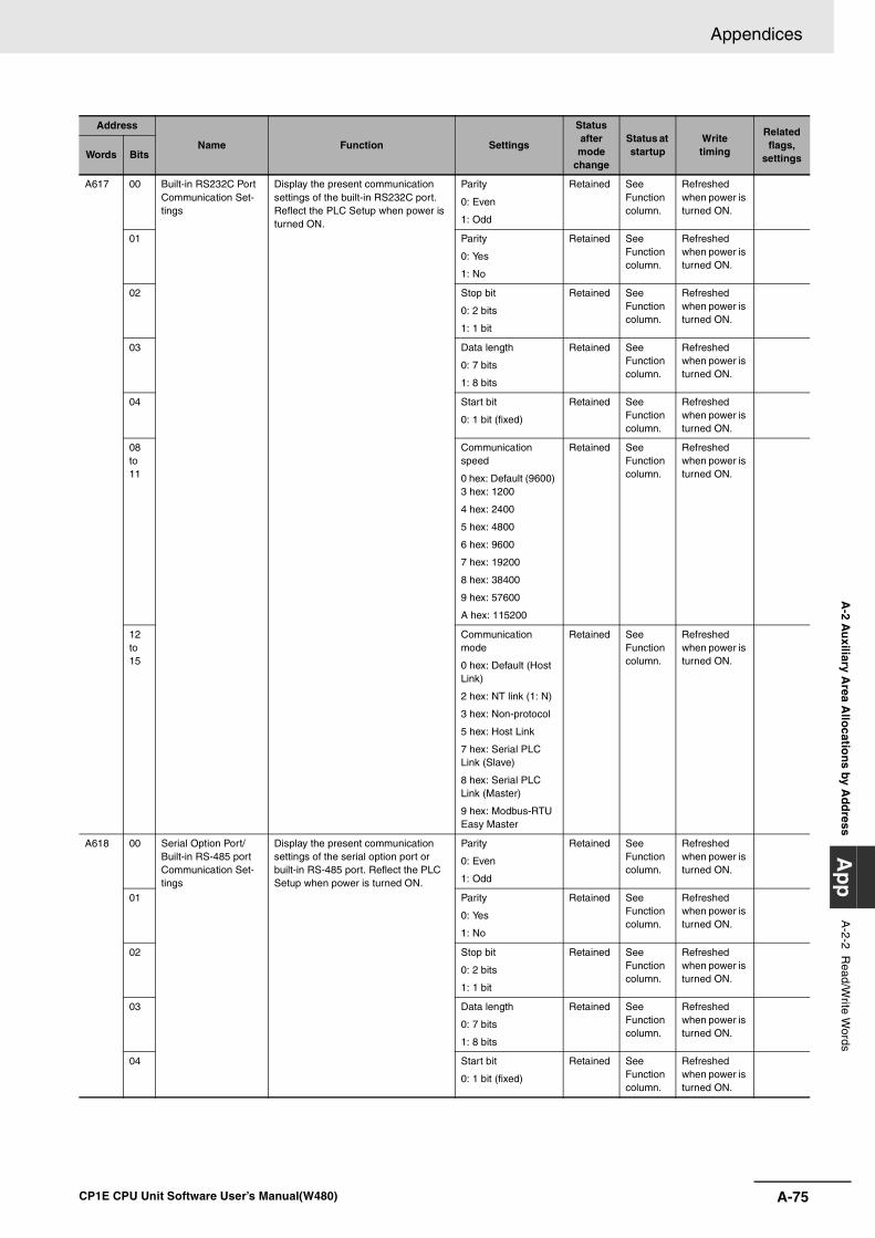
A-75
Appendices
CP1E CPU Unit Software User’s Manual(W480)
A-2 A
uxiliary A
rea Allo
cation
s by Ad
dress
Ap
pA
-2-2 Read/W
rite Words
A617 00 Built-in RS232C Port Communication Set-tings
Display the present communication settings of the built-in RS232C port. Reflect the PLC Setup when power is turned ON.
Parity
0: Even
1: Odd
Retained See Function column.
Refreshed when power is turned ON.
01 Parity
0: Yes
1: No
Retained See Function column.
Refreshed when power is turned ON.
02 Stop bit
0: 2 bits
1: 1 bit
Retained See Function column.
Refreshed when power is turned ON.
03 Data length
0: 7 bits
1: 8 bits
Retained See Function column.
Refreshed when power is turned ON.
04 Start bit
0: 1 bit (fixed)
Retained See Function column.
Refreshed when power is turned ON.
08 to 11
Communication speed
0 hex: Default (9600) 3 hex: 1200
4 hex: 2400
5 hex: 4800
6 hex: 9600
7 hex: 19200
8 hex: 38400
9 hex: 57600
A hex: 115200
Retained See Function column.
Refreshed when power is turned ON.
12 to 15
Communication mode
0 hex: Default (Host Link)
2 hex: NT link (1: N)
3 hex: Non-protocol
5 hex: Host Link
7 hex: Serial PLC Link (Slave)
8 hex: Serial PLC Link (Master)
9 hex: Modbus-RTU Easy Master
Retained See Function column.
Refreshed when power is turned ON.
A618 00 Serial Option Port/Built-in RS-485 port Communication Set-tings
Display the present communication settings of the serial option port or built-in RS-485 port. Reflect the PLC Setup when power is turned ON.
Parity
0: Even
1: Odd
Retained See Function column.
Refreshed when power is turned ON.
01 Parity
0: Yes
1: No
Retained See Function column.
Refreshed when power is turned ON.
02 Stop bit
0: 2 bits
1: 1 bit
Retained See Function column.
Refreshed when power is turned ON.
03 Data length
0: 7 bits
1: 8 bits
Retained See Function column.
Refreshed when power is turned ON.
04 Start bit
0: 1 bit (fixed)
Retained See Function column.
Refreshed when power is turned ON.
Address
Name Function Settings
Status after mode
change
Status at startup
Writetiming
Related flags,
settingsWords Bits
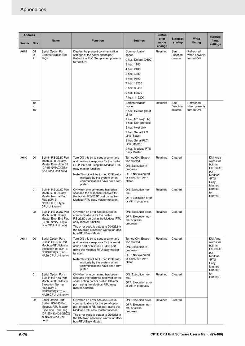
Appendices
A-76 CP1E CPU Unit Software User’s Manual(W480)
A618 08 to 11
Serial Option Port Communication Set-tings
Display the present communication settings of the serial option port. Reflect the PLC Setup when power is turned ON.
Communication speed
0 hex: Default (9600)
3 hex: 1200
4 hex: 2400
5 hex: 4800
6 hex: 9600
7 hex: 19200
8 hex: 38400
9 hex: 57600
A hex: 115200
Retained See Function column.
Refreshed when power is turned ON.
12 to 15
Communication mode
0 hex: Default (Host Link)
2 hex: NT link(1: N) 3 hex: Non-protocol
5 hex: Host Link
7 hex: Serial PLC Link (Slave)
8 hex: Serial PLC Link (Master)
9 hex: Modbus-RTU Easy Master
Retained See Function column.
Refreshed when power is turned ON.
A640 00 Built-in RS-232C Port Modbus-RTU Easy Master Execution Bit (CP1E N/NA (S)-type CPU Unit only)
Turn ON this bit to send a command and receive a response for the built-in RS-232C port using the Modbus-RTU easy master function.
Note This bit will be turned OFF auto-matically by the system when communications have been com-pleted.
Turned ON: Execu-tion started
ON: Execution in progress.
OFF: Not executed or execution com-pleted.
Retained Cleared DM Area words for built-in RS -232C port Modbus -RTU Easy Master: D01200 to D01299
01 Built-in RS-232C Port Modbus-RTU Easy Master Normal End Flag (CP1E N/NA- (S) type CPU Unit only)
ON when one command has been sent and the response received for the built-in RS-232C port using the Modbus-RTU easy master function.
ON: Execution nor-mal.
OFF: Execution error or still in progress.
Retained Cleared
02 Built-in RS-232C Port Modbus-RTU Easy Master Error End Flag (CP1E N/NA (S)-type CPU Unit only)
ON when an error has occurred in communications for the built-in RS-232C port using the Modbus-RTU easy master function.
The error code is output to D01252 in the DM fixed allocation words for Mod-bus-RTU Easy Master.
ON: Execution error.
OFF: Execution nor-mal or still in progress.
Retained Cleared
A641 00 Serial Option Port/Built-in RS-485 Port Modbus-RTU Master Execution Bit (CP1E N30/40/60(S ) or NA20 CPU Unit only)
Turn ON this bit to send a command and receive a response for the serial option port or built-in RS-485 port using the Modbus-RTU easy master function.
Note This bit will be turned OFF auto-matically by the system when communications have been com-pleted.
Turned ON: Execu-tion started
ON: Execution in progress.
OFF: Not executed or execution com-pleted.
Retained Cleared DM Area words for built-in RS -232C port Modbus -RTU Easy Master: D01300 to D01399
01 Serial Option Port/Built-in RS-485 Port Modbus-RTU Master Execution Normal Flag (CP1E N30/40/60(S )) or NA20 CPU Unit only)
ON when one command has been sent and the response received for the serial option port or built-in RS-485 port using the Modbus-RTU easy master function.
ON: Execution nor-mal.
OFF: Execution error or still in progress.
Retained Cleared
02 Serial Option Port/Built-in RS-485 Port Modbus-RTU Master Execution Error Flag (CP1E N30/40/60(S ))or NA20 CPU Unit only)
ON when an error has occurred in communications for the serial option port or built-in RS-485 port using the Modbus-RTU easy master function.
The error code is output to D01352 in the DM fixed allocation words for Mod-bus-RTU Easy Master.
ON: Execution error.
OFF: Execution nor-mal or still in progress.
Retained Cleared
Address
Name Function Settings
Status after mode
change
Status at startup
Writetiming
Related flags,
settingsWords Bits
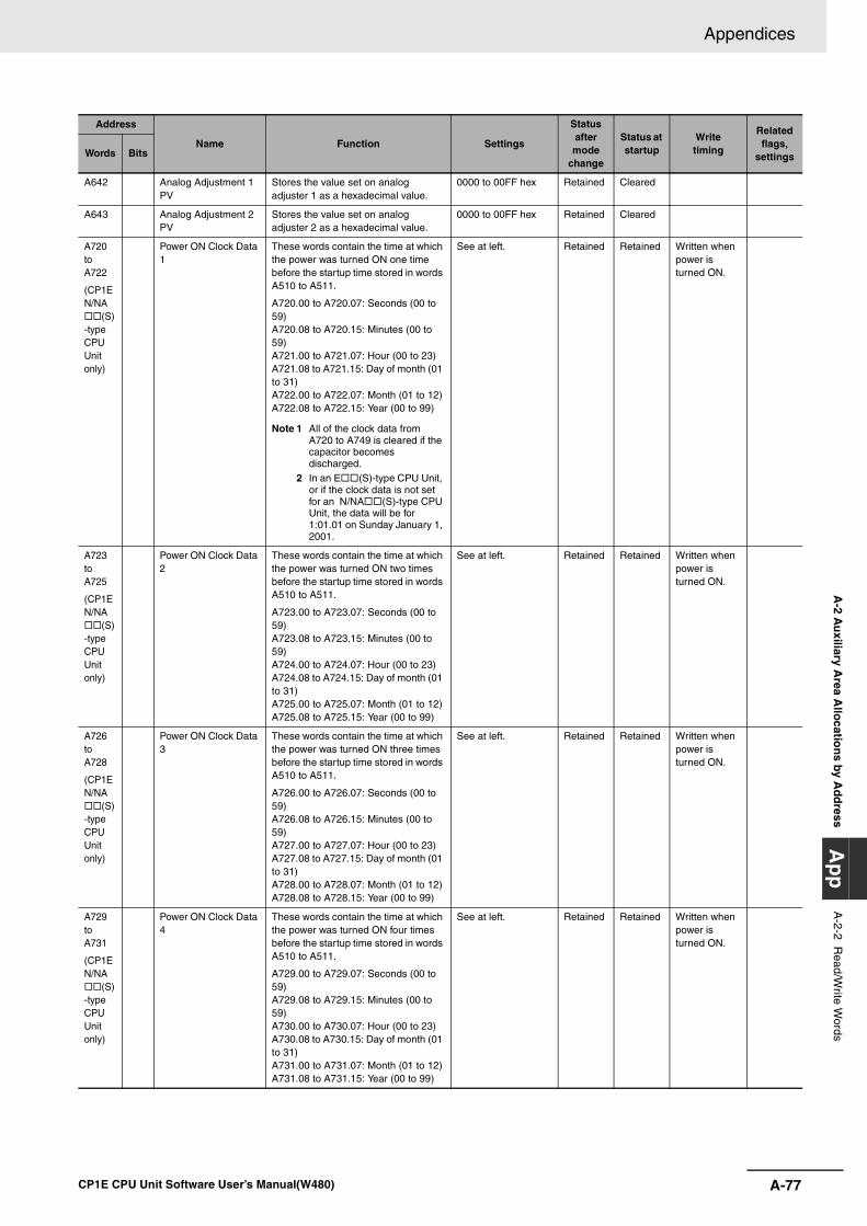
A-77
Appendices
CP1E CPU Unit Software User’s Manual(W480)
A-2 A
uxiliary A
rea Allo
cation
s by Ad
dress
Ap
pA
-2-2 Read/W
rite Words
A642 Analog Adjustment 1 PV
Stores the value set on analog adjuster 1 as a hexadecimal value.
0000 to 00FF hex Retained Cleared
A643 Analog Adjustment 2 PV
Stores the value set on analog adjuster 2 as a hexadecimal value.
0000 to 00FF hex Retained Cleared
A720 to A722
(CP1E N/NA
(S)-type CPU Unit only)
Power ON Clock Data 1
These words contain the time at which the power was turned ON one time before the startup time stored in words A510 to A511.
A720.00 to A720.07: Seconds (00 to 59)A720.08 to A720.15: Minutes (00 to 59)A721.00 to A721.07: Hour (00 to 23)A721.08 to A721.15: Day of month (01 to 31)A722.00 to A722.07: Month (01 to 12)A722.08 to A722.15: Year (00 to 99)
Note 1 All of the clock data from A720 to A749 is cleared if the capacitor becomes discharged.
2 In an E (S)-type CPU Unit, or if the clock data is not set for an N/NA (S)-type CPU Unit, the data will be for 1:01.01 on Sunday January 1, 2001.
See at left. Retained Retained Written when power is turned ON.
A723 toA725
(CP1E N/NA
(S)-type CPU Unit only)
Power ON Clock Data 2
These words contain the time at which the power was turned ON two times before the startup time stored in words A510 to A511.
A723.00 to A723.07: Seconds (00 to 59)A723.08 to A723.15: Minutes (00 to 59)A724.00 to A724.07: Hour (00 to 23)A724.08 to A724.15: Day of month (01 to 31)A725.00 to A725.07: Month (01 to 12)A725.08 to A725.15: Year (00 to 99)
See at left. Retained Retained Written when power is turned ON.
A726 to A728
(CP1E N/NA
(S)-type CPU Unit only)
Power ON Clock Data 3
These words contain the time at which the power was turned ON three times before the startup time stored in words A510 to A511.
A726.00 to A726.07: Seconds (00 to 59)A726.08 to A726.15: Minutes (00 to 59)A727.00 to A727.07: Hour (00 to 23)A727.08 to A727.15: Day of month (01 to 31)A728.00 to A728.07: Month (01 to 12)A728.08 to A728.15: Year (00 to 99)
See at left. Retained Retained Written when power is turned ON.
A729 to A731
(CP1E N/NA
(S)-type CPU Unit only)
Power ON Clock Data 4
These words contain the time at which the power was turned ON four times before the startup time stored in words A510 to A511.
A729.00 to A729.07: Seconds (00 to 59)A729.08 to A729.15: Minutes (00 to 59)A730.00 to A730.07: Hour (00 to 23)A730.08 to A730.15: Day of month (01 to 31)A731.00 to A731.07: Month (01 to 12)A731.08 to A731.15: Year (00 to 99)
See at left. Retained Retained Written when power is turned ON.
Address
Name Function Settings
Status after mode
change
Status at startup
Writetiming
Related flags,
settingsWords Bits
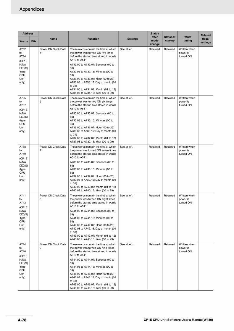
Appendices
A-78 CP1E CPU Unit Software User’s Manual(W480)
A732 to A734
(CP1E N/NA
(S)-type CPU Unit only)
Power ON Clock Data 5
These words contain the time at which the power was turned ON five times before the startup time stored in words A510 to A511.
A732.00 to A732.07: Seconds (00 to 59)A732.08 to A732.15: Minutes (00 to 59)A733.00 to A733.07: Hour (00 to 23)A733.08 to A733.15: Day of month (01 to 31)A734.00 to A734.07: Month (01 to 12)A734.08 to A734.15: Year (00 to 99)
See at left. Retained Retained Written when power is turned ON.
A735 to A737
(CP1E N/NA
(S)-type CPU Unit only)
Power ON Clock Data 6
These words contain the time at which the power was turned ON six times before the startup time stored in words A510 to A511.
A735.00 to A735.07: Seconds (00 to 59)A735.08 to A735.15: Minutes (00 to 59)A736.00 to A736.07: Hour (00 to 23)A736.08 to A736.15: Day of month (01 to 31)A737.00 to A737.07: Month (01 to 12)A737.08 to A737.15: Year (00 to 99)
See at left. Retained Retained Written when power is turned ON.
A738 to A740
(CP1E N/NA
(S)-type CPU Unit only)
Power ON Clock Data 7
These words contain the time at which the power was turned ON seven times before the startup time stored in words A510 to A511.
A738.00 to A738.07: Seconds (00 to 59)A738.08 to A738.15: Minutes (00 to 59)A739.00 to A739.07: Hour (00 to 23)A739.08 to A739.15: Day of month (01 to 31)A740.00 to A740.07: Month (01 to 12)A740.08 to A740.15: Year (00 to 99)
See at left. Retained Retained Written when power is turned ON.
A741 to A743
(CP1E N/NA
(S)-type CPU Unit only)
Power ON Clock Data 8
These words contain the time at which the power was turned ON eight times before the startup time stored in words A510 to A511.
A741.00 to A741.07: Seconds (00 to 59)A741.08 to A741.15: Minutes (00 to 59)A742.00 to A742.07: Hour (00 to 23)A742.08 to A742.15: Day of month (01 to 31)A743.00 to A743.07: Month (01 to 12)A743.08 to A743.15: Year (00 to 99)
See at left. Retained Retained Written when power is turned ON.
A744 to A746
(CP1E N/NA
(S)-type CPU Unit only)
Power ON Clock Data 9
These words contain the time at which the power was turned ON nine times before the startup time stored in words A510 to A511.
A744.00 to A744.07: Seconds (00 to 59)A744.08 to A744.15: Minutes (00 to 59)A745.00 to A745.07: Hour (00 to 23)A745.08 to A745.15: Day of month (01 to 31)A746.00 to A746.07: Month (01 to 12)A746.08 to A746.15: Year (00 to 99)
See at left. Retained Retained Written when power is turned ON.
Address
Name Function Settings
Status after mode
change
Status at startup
Writetiming
Related flags,
settingsWords Bits
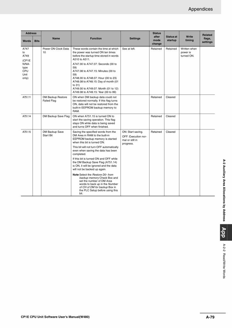
A-79
Appendices
CP1E CPU Unit Software User’s Manual(W480)
A-2 A
uxiliary A
rea Allo
cation
s by Ad
dress
Ap
pA
-2-2 Read/W
rite Words
A747 to A749
(CP1E N/NA-type CPU Unit only)
Power ON Clock Data 10
These words contain the time at which the power was turned ON ten times before the startup time stored in words A510 to A511.
A747.00 to A747.07: Seconds (00 to 59)A747.08 to A747.15: Minutes (00 to 59)A748.00 to A748.07: Hour (00 to 23)A748.08 to A748.15: Day of month (01 to 31)A749.00 to A749.07: Month (01 to 12)A749.08 to A749.15: Year (00 to 99)
See at left. Retained Retained Written when power is turned ON.
A751.11 DM Backup Restore Failed Flag
ON when DM backup data could not be restored normally. If this flag turns ON, data will not be restored from the built-in EEPROM backup memory to RAM.
Retained Cleared
A751.14 DM Backup Save Flag ON when A751.15 is turned ON to start the saving operation. This flag stays ON while data is being saved and turns OFF when finished.
Retained Cleared
A751.15 DM Backup Save Start Bit
Saving the specified words from the DM Area in RAM to the built-in EEPROM backup memory is started when this bit is turned ON.
This bit will not turn OFF automatically even when saving the data has been completed.
If this bit is turned ON and OFF while the DM Backup Save Flag (A751.14) is ON, it will be ignored and the data will not be backed up again.
Note Select the Restore D0- from backup memory Check Box and set the number of DM Area words to back up in the Number of CH of DM for backup Box in the PLC Setup before using this bit.
ON: Start saving.
OFF: Execution nor-mal or still in progress.
Retained Cleared
Address
Name Function Settings
Status after mode
change
Status at startup
Writetiming
Related flags,
settingsWords Bits
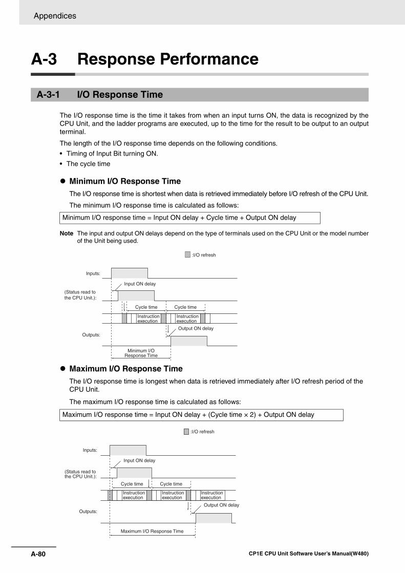
Appendices
A-80 CP1E CPU Unit Software User’s Manual(W480)
A-3 Response Performance
The I/O response time is the time it takes from when an input turns ON, the data is recognized by theCPU Unit, and the ladder programs are executed, up to the time for the result to be output to an outputterminal.
The length of the I/O response time depends on the following conditions.
• Timing of Input Bit turning ON.
• The cycle time
Minimum I/O Response TimeThe I/O response time is shortest when data is retrieved immediately before I/O refresh of the CPU Unit.
The minimum I/O response time is calculated as follows:
Note The input and output ON delays depend on the type of terminals used on the CPU Unit or the model numberof the Unit being used.
Maximum I/O Response TimeThe I/O response time is longest when data is retrieved immediately after I/O refresh period of the CPU Unit.
The maximum I/O response time is calculated as follows:
A-3-1 I/O Response Time
Minimum I/O response time = Input ON delay + Cycle time + Output ON delay
Maximum I/O response time = Input ON delay + (Cycle time × 2) + Output ON delay
Inputs:
Outputs:
:I/O refresh
Input ON delay
Cycle time Cycle time
Output ON delay
Minimum I/OResponse Time
(Status read to the CPU Unit.):
Instruction execution
Instruction execution
Inputs:
Outputs:
:I/O refresh
Input ON delay
Cycle time Cycle time
Output ON delay
Maximum I/O Response Time
(Status read to the CPU Unit.):
Instruction execution
Instruction execution
Instruction execution
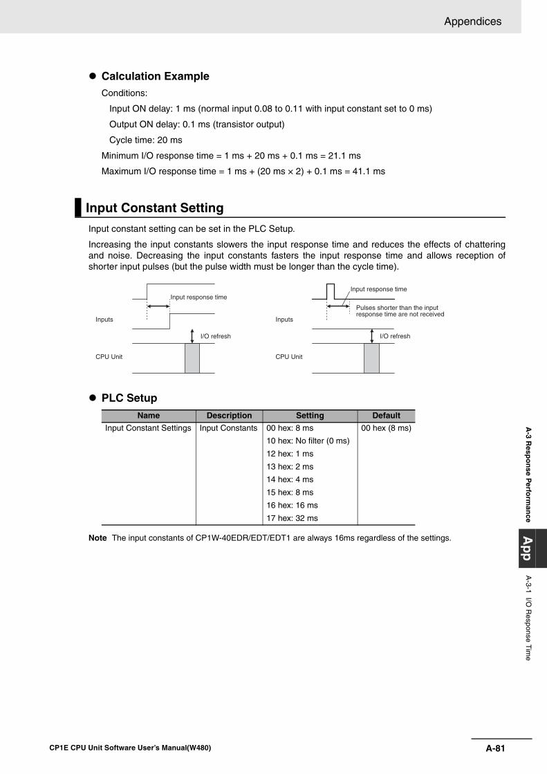
A-81
Appendices
CP1E CPU Unit Software User’s Manual(W480)
A-3 R
espo
nse P
erform
ance
Ap
pA
-3-1 I/O R
esponse Tim
e
Calculation ExampleConditions:
Input ON delay: 1 ms (normal input 0.08 to 0.11 with input constant set to 0 ms)
Output ON delay: 0.1 ms (transistor output)
Cycle time: 20 ms
Minimum I/O response time = 1 ms + 20 ms + 0.1 ms = 21.1 ms
Maximum I/O response time = 1 ms + (20 ms × 2) + 0.1 ms = 41.1 ms
Input constant setting can be set in the PLC Setup.
Increasing the input constants slowers the input response time and reduces the effects of chatteringand noise. Decreasing the input constants fasters the input response time and allows reception ofshorter input pulses (but the pulse width must be longer than the cycle time).
PLC Setup
Note The input constants of CP1W-40EDR/EDT/EDT1 are always 16ms regardless of the settings.
Input Constant Setting
Name Description Setting Default
Input Constant Settings Input Constants 00 hex: 8 ms
10 hex: No filter (0 ms)
12 hex: 1 ms
13 hex: 2 ms
14 hex: 4 ms
15 hex: 8 ms
16 hex: 16 ms
17 hex: 32 ms
00 hex (8 ms)
Input response timeInput response time
I/O refresh I/O refresh
Inputs Inputs
CPU Unit CPU Unit
Pulses shorter than the input response time are not received
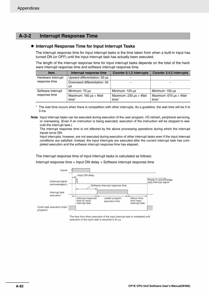
Appendices
A-82 CP1E CPU Unit Software User’s Manual(W480)
Interrupt Response Time for Input Interrupt TasksThe interrupt response time for input interrupt tasks is the time taken from when a built-in input hasturned ON (or OFF) until the input interrupt task has actually been executed.
The length of the interrupt response time for input interrupt tasks depends on the total of the hard-ware interrupt response time and software interrupt response time.
* The wait time occurs when there is competition with other interrupts. As a guideline, the wait time will be 0 to3 ms.
Note Input interrupt tasks can be executed during execution of the user program, I/O refresh, peripheral servicing,or overseeing. (Even if an instruction is being executed, execution of the instruction will be stopped to exe-cute the interrupt task.) The interrupt response time is not affected by the above processing operations during which the interruptinputs turns ON.Input interrupts, however, are not executed during execution of other interrupt tasks even if the input interruptconditions are satisfied. Instead, the input interrupts are executed after the current interrupt task has com-pleted execution and the software interrupt response time has elapsed.
The interrupt response time of input interrupt tasks is calculated as follows:
Interrupt response time = Input ON delay + Software interrupt response time
A-3-2 Interrupt Response Time
Item Interrupt response time Counter 0,1,2 interrupts Counter 3,4,5 interrupts
Hardware interrupt response time
Upward differentiation: 50 µs − −Downward differentiation: 50 µs
− −
Software interrupt response time
Minimum: 70 µs Minimum: 120 µs Minimum: 150 µs
Maximum: 160 µs + Wait time*
Maximum: 230 µs + Wait time*
Maximum: 670 µs + Wait time*
Input ON delay
Inputs:
(Interrupt signalacknowledged.):
Interrupt taskexecution:
Software interrupt response time
Cyclic task execution (main program):
Interrupt response time for input interrupt task
Ladder program execution time
Return time from input interrupt task
Ready to acknowledge next interrupt signal
The time from when execution of the input interrupt task is completed until execution of the cyclic task is resumed is 24 µs.
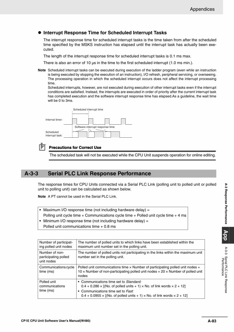
A-83
Appendices
CP1E CPU Unit Software User’s Manual(W480)
A-3 R
espo
nse P
erform
ance
Ap
pA
-3-3 Serial P
LC Link R
esponse P
erformance
Interrupt Response Time for Scheduled Interrupt TasksThe interrupt response time for scheduled interrupt tasks is the time taken from after the scheduledtime specified by the MSKS instruction has elapsed until the interrupt task has actually been exe-cuted.
The length of the interrupt response time for scheduled interrupt tasks is 0.1 ms max.
There is also an error of 10 µs in the time to the first scheduled interrupt (1.0 ms min.).
Note Scheduled interrupt tasks can be executed during execution of the ladder program (even while an instructionis being executed by stopping the execution of an instruction), I/O refresh, peripheral servicing, or overseeing.The processing operation in which the scheduled interrupt occurs does not affect the interrupt processingtime.Scheduled interrupts, however, are not executed during execution of other interrupt tasks even if the interruptconditions are satisfied. Instead, the interrupts are executed in order of priority after the current interrupt taskhas completed execution and the software interrupt response time has elapsed.As a guideline, the wait timewill be 0 to 3ms.
Precautions for Correct UsePrecautions for Correct Use
The scheduled task will not be executed while the CPU Unit suspends operation for online editing.
The response times for CPU Units connected via a Serial PLC Link (polling unit to polled unit or polledunit to polling unit) can be calculated as shown below.
Note A PT cannot be used in the Serial PLC Link.
A-3-3 Serial PLC Link Response Performance
• Maximum I/O response time (not including hardware delay) =Polling unit cycle time + Communications cycle time + Polled unit cycle time + 4 ms
• Minimum I/O response time (not including hardware delay) = Polled unit communications time + 0.8 ms
Number of participat-ing polled unit nodes
The number of polled units to which links have been established within the maximum unit number set in the polling unit.
Number of non-participating polled unit nodes
The number of polled units not participating in the links within the maximum unit number set in the polling unit.
Communications cycle time (ms)
Polled unit communications time × Number of participating polled unit nodes + 10 × Number of non-participating polled unit nodes + 20 × Number of polled unit nodes
Polled unit communications time (ms)
• Communications time set to Standard:0.4 + 0.286 × [(No. of polled units + 1) × No. of link words × 2 + 12]
• Communications time set to Fast:0.4 + 0.0955 × [(No. of polled units + 1) × No. of link words × 2 + 12]
Internal timer:
Scheduledinterrupt task:
Scheduled interrupt time
Software interrupt response time
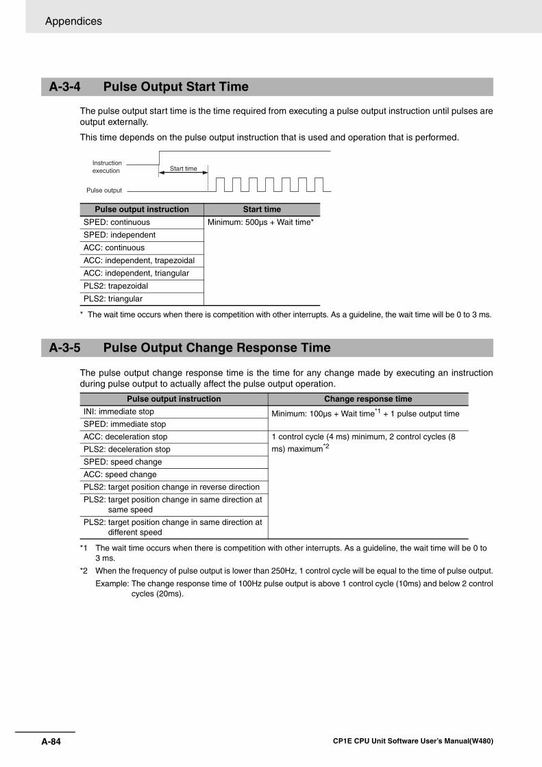
Appendices
A-84 CP1E CPU Unit Software User’s Manual(W480)
The pulse output start time is the time required from executing a pulse output instruction until pulses areoutput externally.
This time depends on the pulse output instruction that is used and operation that is performed.
* The wait time occurs when there is competition with other interrupts. As a guideline, the wait time will be 0 to 3 ms.
The pulse output change response time is the time for any change made by executing an instructionduring pulse output to actually affect the pulse output operation.
*1 The wait time occurs when there is competition with other interrupts. As a guideline, the wait time will be 0 to 3 ms.
*2 When the frequency of pulse output is lower than 250Hz, 1 control cycle will be equal to the time of pulse output.
Example: The change response time of 100Hz pulse output is above 1 control cycle (10ms) and below 2 controlcycles (20ms).
A-3-4 Pulse Output Start Time
Pulse output instruction Start time
SPED: continuous Minimum: 500µs + Wait time*
SPED: independent
ACC: continuous
ACC: independent, trapezoidal
ACC: independent, triangular
PLS2: trapezoidal
PLS2: triangular
A-3-5 Pulse Output Change Response Time
Pulse output instruction Change response time
INI: immediate stop Minimum: 100µs + Wait time*1 + 1 pulse output timeSPED: immediate stop
ACC: deceleration stop 1 control cycle (4 ms) minimum, 2 control cycles (8
ms) maximum*2PLS2: deceleration stop
SPED: speed change
ACC: speed change
PLS2: target position change in reverse direction
PLS2: target position change in same direction at same speed
PLS2: target position change in same direction at different speed
Start timeInstructionexecution
Pulse output
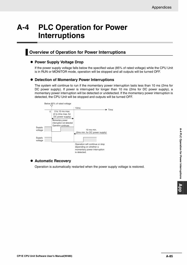
A-85
Appendices
CP1E CPU Unit Software User’s Manual(W480)
A-4 P
LC
Op
eration
for P
ow
er Interru
ptio
ns
Ap
p
A-4 PLC Operation for Power Interruptions
Power Supply Voltage DropIf the power supply voltage falls below the specified value (85% of rated voltage) while the CPU Unitis in RUN or MONITOR mode, operation will be stopped and all outputs will be turned OFF.
Detection of Momentary Power InterruptionsThe system will continue to run if the momentary power interruption lasts less than 10 ms (2ms forDC power supply). If power is interruped for longer than 10 ms (2ms for DC power supply), amomentary power interruption will be detected or undetected. If the momentary power interruption isdetected, the CPU Unit will be stopped and outputs will be turned OFF.
Automatic RecoveryOperation is automatically restarted when the power supply voltage is restored.
Overview of Operation for Power Interruptions
10ms
10 ms min.(2ms min. for DC power supply)
0
Below 85% of rated voltage
0 to 10 ms max.(0 to 2ms max. for DC power supply)
Momentary power interruption not detected Operation continues
Supply voltage
Supply voltage
Operation will continue or stop depending on whether a momentary power interruption is detected.
Time
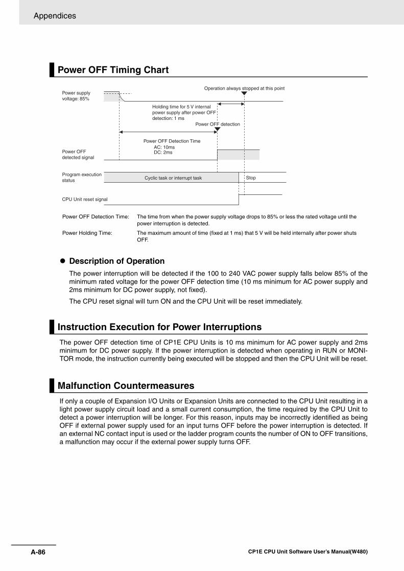
Appendices
A-86 CP1E CPU Unit Software User’s Manual(W480)
Description of OperationThe power interruption will be detected if the 100 to 240 VAC power supply falls below 85% of theminimum rated voltage for the power OFF detection time (10 ms minimum for AC power supply and2ms minimum for DC power supply, not fixed).
The CPU reset signal will turn ON and the CPU Unit will be reset immediately.
The power OFF detection time of CP1E CPU Units is 10 ms minimum for AC power supply and 2msminimum for DC power supply. If the power interruption is detected when operating in RUN or MONI-TOR mode, the instruction currently being executed will be stopped and then the CPU Unit will be reset.
If only a couple of Expansion I/O Units or Expansion Units are connected to the CPU Unit resulting in alight power supply circuit load and a small current consumption, the time required by the CPU Unit todetect a power interruption will be longer. For this reason, inputs may be incorrectly identified as beingOFF if external power supply used for an input turns OFF before the power interruption is detected. Ifan external NC contact input is used or the ladder program counts the number of ON to OFF transitions,a malfunction may occur if the external power supply turns OFF.
Power OFF Timing Chart
Power OFF Detection Time: The time from when the power supply voltage drops to 85% or less the rated voltage until the power interruption is detected.
Power Holding Time: The maximum amount of time (fixed at 1 ms) that 5 V will be held internally after power shuts OFF.
Instruction Execution for Power Interruptions
Malfunction Countermeasures
AC: 10msDC: 2ms
Power supply voltage: 85%
Operation always stopped at this point
Holding time for 5 V internal power supply after power OFF detection: 1 ms
Power OFF detection
Power OFF Detection Time
Power OFF detected signal
Program execution status
CPU Unit reset signal
Cyclic task or interrupt task Stop
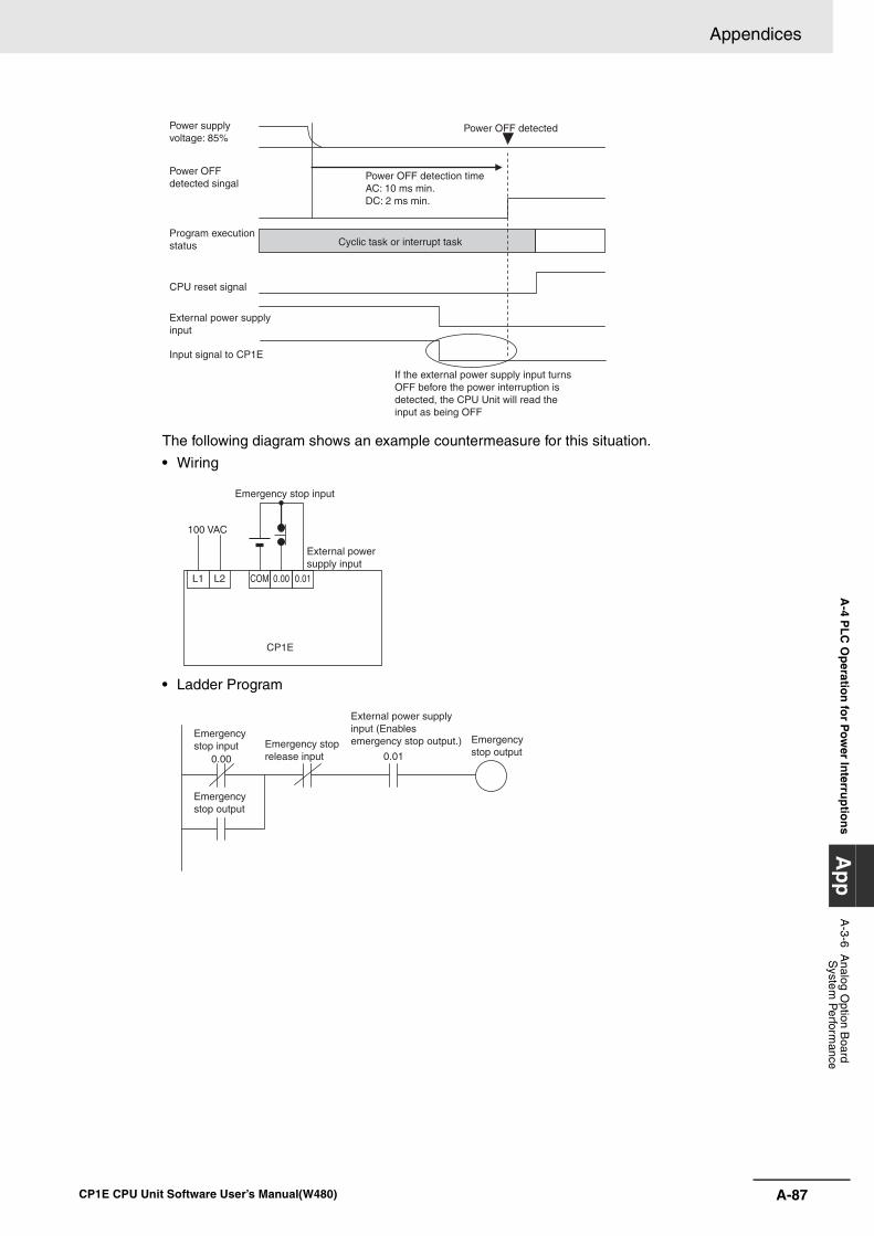
A-87
Appendices
CP1E CPU Unit Software User’s Manual(W480)
A-4 P
LC
Op
eration
for P
ow
er Interru
ptio
ns
Ap
pA
-3-6 Analog O
ption Board
System
Perform
ance
The following diagram shows an example countermeasure for this situation.
• Wiring
• Ladder Program
Power supply voltage: 85%
Power OFF detected singal
Program execution status
CPU reset signal
External power supplyinput
Input signal to CP1E
Power OFF detection timeAC: 10 ms min.DC: 2 ms min.
Power OFF detected
Cyclic task or interrupt task
If the external power supply input turns OFF before the power interruption is detected, the CPU Unit will read the input as being OFF
CP1E
COM 0.00 0.01L1 L2
Emergency stop input
100 VAC
External power supply input
0.00 0.01
Emergencystop input Emergency stop
release input
External power supply input (Enables emergency stop output.) Emergency
stop output
Emergency stop output

Appendices
A-88 CP1E CPU Unit Software User’s Manual(W480)
Index-1CP1E CPU Unit Software User’s Manual(W480)
Index
Symbols*D(Specifying indirect addresses
in BCD Mode)...................................................4-13, 5-12@D(Specifying indirect addresses
in Binary Mode)................................................4-13, 5-12
Numerics1: N NT Links ......................................................14-3, 14-5
AAbsolute coordinates .................................................12-13Absolute positioning...................................................12-13ACC instruction ...............................................12-11, 12-17Access Error Flag(P_AER) ..........................................5-19Allocated words
CPU Unit ..................................................................6-3Expansion I/O Unit ...................................................6-4
Allocating functions to built-in input terminals ................8-6Allocating functions to built-in output terminals..............8-8Allocations for Expansion I/O Units................................6-4Allocations for Expansion Units .....................................6-6Always OFF Flag(P_Off) ..............................................5-19Always ON Flag(P_On)................................................5-19Analog I/O Option Board............................................18-15Analog Input Option Board...........................................18-7Analog Output Option Board......................................18-11Automatic I/O comment creation................................19-14Automatic symbol name creation...............................19-14Auxiliary Area........................................................5-4, 5-17
BBacking up memory .......................................................3-5Backup .........................................................................5-12
Backup area .............................................................3-5I/O memory backup time ..........................................3-7
Backup memory ....................................................3-6, 16-8Backup time ...................................................................1-2Bit addresses .................................................................5-5Built-in EEPROM .......................... 2-2, 2-3, 3-6, 5-12, 16-8Built-in RAM .................................................... 1-5, 2-2, 2-3Built-in RS-232C Port.....................................................7-5
CC Mode command.............................................14-4, 14-31Carry Flag(P_CY) ........................................................5-19CIO Area .................................................................5-2, 5-7
Allocation..................................................................6-2Circular (Ring) mode(high-speed counter).................11-11Clock function ..............................................................16-7Clock Pulses .........................................................5-4, 5-21Communications settings........................................7-5, 7-8Condition Flags .....................................................5-4, 5-19Connecting the Servo Drive and external sensors.......12-6Constants.....................................................................4-16Counter Area..................................................................5-4
Resetting or maintaining ........................................5-16Types......................................................................5-15
Counter Completion Flags .............................................5-4Counter PVs...................................................................5-4Counting ranges.........................................................11-10
CPU UnitI/O allocation ............................................................6-3Internal memory .......................................................2-2Memory areas and stored data ................................2-3Operating modes......................................................3-3Operation..................................................................3-2
CTBL instruction ........................................................11-21CX-Programmer
Help ........................................................................19-7Cycle time ......................................................................3-2
I/O response time.................................................. A-80Interrupt response time ......................................... A-82
Cycle time response performance .............................. A-80Cyclic refreshing ..........................................................4-15
DData formats ................................................................4-13Data Memory Area................................................5-3, 5-11Data refresh method ..................................................14-23Defining origin position...............................................12-20
Operating mode....................................................12-25Operation pattern .................................................12-30Origin return .........................................................12-32Origin search operation setting ............................12-29PLC Setup ............................................................12-21
Differential phase input (4×).........................................11-8DM Area capacity...........................................................1-2DM backup function .....................................................16-8
EEnd code(No-protocol communications) ......................14-8Equals Flag(P_EQ) ......................................................5-19Error Flag(P_ER) .........................................................5-19E-type CPU Unit.............................................................1-2Execute process settings ...............................................7-3
FFINS command .................................................14-4, 14-31Forced set/reset .................................. 18-11, 18-15, 19-26Functions allocation
Selecting functions in the PLC Setup .......................8-4Specifying method....................................................8-4
GGlobal symbols ..............................................................4-6Greater Than Flag(P_GT)............................................5-19Greater Than or Equals Flag(P_GE) ...........................5-20
HHigh-speed counter interrupts...........................11-2, 11-14
Application example .............................................11-27Functions allocation................................................11-4PLC Setup ...................................................11-3, 11-16Related Auxiliary Area..........................................11-26Specifications .........................................................11-7Writing the ladder program..........................11-6, 11-16
High-speed counter settings ........................................7-11High-speed counters
Counting ranges ...................................................11-10Frequency measurement......................................11-13
Index-2 CP1E CPU Unit Software User’s Manual(W480)
Pulse input methods .............................................. 11-8Reading the present value................................... 11-12Reset method ...................................................... 11-11
Holding Area........................................................... 5-3, 5-9Host Link .......................................................... 14-4, 14-31Host Link command.......................................... 14-4, 14-31
II/O allocation ................................................................. 6-2
CPU Unit.................................................................. 6-3Expansion I/O Unit................................................... 6-4Expansion Unit ........................................................ 6-6
I/O memory ............................................................ 3-3, 5-2Backup time............................................................. 3-7I/O memory Areas ................................................... 5-6Initializing method.................................................... 3-8
I/O refresh ..................................................................... 3-2I/O refresh timing......................................................... 4-15I/O response time........................................................ A-80Immediate refresh ....................................................... 4-15Increment pulse input .................................................. 11-8Indirect addressing ...................................................... 5-12INI instruction ........................................ 11-22, 12-11, 13-3Input constant................................................................ 7-4Input constant setting .................................................. A-81Input interrupts ............................................................ 10-5
Functions allocation............................................... 10-5PLC Setup ............................................................. 10-4Writing the ladder program .................................... 10-5
Input-differentiated instructions ................................... 4-11instruction functions....................................................... A-2Instructions
Basic understanding ................................................ 4-8Execution conditions.............................................. 4-10Operands................................................................. 4-9Specifying addresses ............................................ 4-12Variations............................................................... 4-10
Internal memory ............................................................ 2-2Interrupt input settings................................................. 7-12Interrupt response time ............................................... A-82Interrupt task ............................................................. 10-11Interrupt task priority and order of execution............. 10-13Interrupt task with maximum processing time
(A441CH)................................................................ 10-13Interrupts
Input interrupts....................................................... 10-3Precautions.......................................................... 10-13Scheduled interrupts............................................ 10-10Types ..................................................................... 10-2
Interrupts functionsInterrupt response time.......................................... A-82
IORF instruction(I/O refresh) ....................................... 4-15
JJogging...................................................................... 12-17
Application example............................................. 12-17
LLadder program
Editing.................................................................. 19-16Input....................................................................... 19-8Saving and reading.............................................. 19-15Transferring.......................................................... 19-19Writing ................................................................... 19-8
Less Than Flag(P_LT) ................................................. 5-20
Less than or Equals Flag(P_LE) ................................. 5-20Linear mode(high-speed counter) ............................. 11-10Local symbols................................................................ 4-6
MMaximum interrupt task processing time(A440CH)... 10-13Memory areas and stored data ..................................... 2-3Modbus-RTU Easy Master .......................................... 14-3
DM fixed allocation words........................... 5-12, 14-12Error codes .......................................................... 14-13Programming examples....................................... 14-14Related Auxiliary Area ......................................... 14-13
Monitor mode ................................................................ 3-3Monitoring and debugging......................................... 19-24
Forced set/reset................................................... 19-26Monitoring status ................................................. 19-24Online editing....................................................... 19-27
MSKS instruction.............................................. 10-6, 10-11
NN/NA-type CPU Unit ...................................................... 1-2Negative Flag(P_N)..................................................... 5-20Non-differentiated instructions..................................... 4-10No-protocol communications.............................. 14-3, 14-8
PLC Setup ............................................................. 14-9Related Auxiliary Area ......................................... 14-10
Not Equal Flag(P_NE)................................................. 5-20Number of connected Units........................................... 6-3
OOnline editing ................................................... 18-8, 19-27Operands....................................................................... 4-9Operating mode at startup............................................. 7-3Operating modes
Changing method .................................................... 3-3Operating modes and operation .............................. 3-4The retaining of I/O memory when changing........... 3-4
Operation for power interruptions ................................ A-85Timing Chart .......................................................... A-86
ORG instruction................................... 12-11, 12-24, 12-32Origin return settings.......................................... 7-14, 7-16Origin search settings......................................... 7-13, 7-15OUT instruction .............................................. 12-11, 12-24Output interrupts.......................................................... 10-2Overflow Flag(P_OF)................................................... 5-20
PP_AER(Access Error Flag).......................................... 5-19P_CY(Carry Flag)........................................................ 5-19P_EQ(Equals Flag) ..................................................... 5-19P_ER(Error Flag)......................................................... 5-19P_GE(Greater Than or Equals Flag)........................... 5-20P_GT(Greater Than Flag) ........................................... 5-19P_LE(Less than or Equals Flag) ................................. 5-20P_LT(Less Than Flag) ................................................. 5-20P_N(Negative Flag) ..................................................... 5-20P_NE(Not Equal Flag)................................................. 5-20P_OF(Overflow Flag)................................................... 5-20P_Off(Always OFF Flag) ............................................. 5-19P_On(Always ON Flag) ............................................... 5-19P_UF(Underflow Flag)................................................. 5-20Peripheral servicing....................................................... 3-2Phase-Z signal + software reset................................ 11-11PID temperature control .............................................. 16-2PIDAT instruction ......................................................... 16-3

Index-3CP1E CPU Unit Software User’s Manual(W480)
PLC Setup......................................................................7-2Base Settings ................................................7-13, 7-14Communications settings ..................................7-5, 7-8Execute process settings .........................................7-3High-speed counter settings ..................................7-11Input constant...........................................................7-4Interrupt input settings............................................7-12Origin return settings..............................................7-16Origin search settings ......................... 7-13, 7-14, 7-15Settings ....................................................................7-3Startup data read setting..........................................7-3Startup mode setting ................................................7-3Timing and interrupt settings....................................7-3
PLS2 instruction..............................................12-11, 12-13Positioning control......................................................12-13Positioning control (independent mode).....................12-51Precautions
Ladder programming precautions ..........................4-22Precautions for using interrupts............................10-13Special program sections.......................................4-22
Program capacity ....................................................1-2, 4-3Program mode ...............................................................3-3Program-free communications with PTs ......................14-5
PLC Setup and PT system settings .......................14-6Programmer device......................................................19-4Programming .................................................................4-2PRV instruction ................................... 11-12, 12-11, 12-34Pulse + Direction input .................................................11-9Pulse input methods ....................................................11-8Pulse output change response time............................ A-84Pulse output Start Time .............................................. A-84Pulse outputs ...............................................................12-2
Application example .............................................12-36Changing the present value of the pulse output...12-33Defining origin position.........................................12-20Functions allocation ......................................12-3, 12-5Jogging.................................................................12-17Output pattern ......................................................12-49PLC Setup..............................................................12-4Positioning control ................................................12-13Positioning control (independent mode)...............12-51Precautions when using pulse outputs.................12-44Reading the pulse output present value...............12-34Related Auxiliary Area..........................................12-35Specifications .......................................................12-12Speed control (continuous mode) ........................12-49Triangular control..................................................12-52Writing the ladder program...................................12-11
PWM instruction...........................................................13-3PWM outputs ...............................................................13-2
QQuick-response inputs ...................................................9-2
Functions allocation .................................................9-4PLC Setup................................................................9-3Writing the ladder program.......................................9-4
RRange comparison..........................................11-14, 11-20Read protection..........................................................16-12Relative coordinates ..................................................12-13Relative positioning....................................................12-13Run mode ......................................................................3-3
SScheduled interrupts ..................................................10-10
Writing the ladder program...................................10-11Sections ..................................................................4-2, 4-6Security function ........................................................16-12Self-diagnosis ................................................................3-2Serial communications
Connecting the host computer .............................14-31Modbus-RTU Easy Master ........................14-10, 14-11No-protocol communications
with general components.....................................14-8Program-free communications with PTs ................14-5Serial PLC Links...................................................14-20Types of communication.........................................14-3
Serial Option Port...........................................................7-8Serial PLC Link response performance ...................... A-83Serial PLC Links ...............................................14-3, 14-20
Allocated words ....................................................14-26Data refresh method.............................................14-23Example application .............................................14-29PLC Setup ............................................................14-21Related Auxiliary Area..........................................14-27
Software reset............................................................11-12Specifying addresses...................................................4-12Specifying offsets for addresses ..................................4-19SPED instruction.............................................12-11, 12-17Speed control (continuous mode) ..............................12-49Startup data read setting ...............................................7-3Step ladder program sections ......................................4-23Subroutines...........................................................4-2, 4-22Switching from speed control (continuous mode)
to positioning (independent mode)..........................12-56Symbols
Global symbols.........................................................4-6Local symbols...........................................................4-6
TTarget value comparison.................................11-14, 11-17Tasks.......................................................................4-2, 4-6Timer Area .....................................................................5-3
PV refresh method .................................................5-14Resetting or maintaining.........................................5-14Types ......................................................................5-13
Timing and interrupt settings..........................................7-3Triangular control .......................................................12-52
UUnderflow Flag(P_UF) .................................................5-20Up/Down pulse input....................................................11-8
VVariable-duty-factor pulse outputs(PWM outputs)........13-2Variations .....................................................................4-10
WWord address.................................................................5-5Work Area ...............................................................5-3, 5-8

Index-4 CP1E CPU Unit Software User’s Manual(W480)
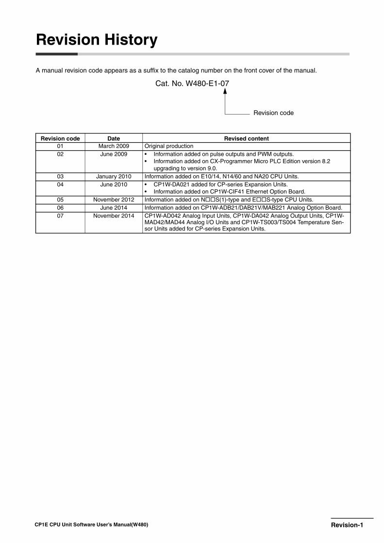
Revision-1CP1E CPU Unit Software User’s Manual(W480)
Revision History
A manual revision code appears as a suffix to the catalog number on the front cover of the manual.
Revision code Date Revised content01 March 2009 Original production02 June 2009 • Information added on pulse outputs and PWM outputs.
• Information added on CX-Programmer Micro PLC Edition version 8.2 upgrading to version 9.0.
03 January 2010 Information added on E10/14, N14/60 and NA20 CPU Units.04 June 2010 • CP1W-DA021 added for CP-series Expansion Units.
• Information added on CP1W-CIF41 Ethernet Option Board.05 November 2012 Information added on NS(1)-type and ES-type CPU Units.06 June 2014 Information added on CP1W-ADB21/DAB21V/MAB221 Analog Option Board.07 November 2014 CP1W-AD042 Analog Input Units, CP1W-DA042 Analog Output Units, CP1W-
MAD42/MAD44 Analog I/O Units and CP1W-TS003/TS004 Temperature Sen-sor Units added for CP-series Expansion Units.
Cat. No. W480-E1-07
Revision code

Revision-2 CP1E CPU Unit Software User’s Manual(W480)


Authorized Distributor:
In the interest of product improvement, specifications are subject to change without notice.
Cat. No. W480-E1-07
© OMRON Corporation 2009 All Rights Reserved.
1114
OMRON Corporation Industrial Automation Company
OMRON ELECTRONICS LLC2895 Greenspoint Parkway, Suite 200 Hoffman Estates, IL 60169 U.S.ATel: (1) 847-843-7900/Fax: (1) 847-843-7787
Regional HeadquartersOMRON EUROPE B.V.Wegalaan 67-69, 2132 JD HoofddorpThe NetherlandsTel: (31)2356-81-300/Fax: (31)2356-81-388
Contact: www.ia.omron.com Tokyo, JAPAN
OMRON ASIA PACIFIC PTE. LTD. No. 438A Alexandra Road # 05-05/08 (Lobby 2), Alexandra Technopark, Singapore 119967 Tel: (65) 6835-3011/Fax: (65) 6835-2711
OMRON (CHINA) CO., LTD. Room 2211, Bank of China Tower, 200 Yin Cheng Zhong Road, PuDong New Area, Shanghai, 200120, China Tel: (86) 21-5037-2222/Fax: (86) 21-5037-2200
Related Documents