English Deutsch Español Italiano Français Air Cooled Water Chillers and Heat Pumps Refroidisseurs de liquide à condensation par air et pompes à chaleur air-eau Luftgekühlte Flüssigkeitskühler und Wärmepumpen Refrigeratori d’Acqua e Pompe di Calore Raffreddati ad Aria Enfriadores de Agua y Bomba de Calor Condensadas con Aire Водяные чиллеры с воздушным охлаждением и тепловые насосы Installation and maintenance manual Manuel d’installation et de maintenance Installations- und Wartungshandbuch Manuale di installazione e di manutenzione Manual de instalación y de mantenimiento Инструкция по монтажу и техобслуживанию SYSCROLL 20-30 AIR EVO HP Part number / Code / Code / Codice / Código / Номер детали: 364321/I Supersedes / Annule et remplace / Annulliert und ersetzt / Annulla e sostituisce / Anula y sustituye / Замена: 364321/H Notified Body / Organisme Notifié / Benannte Zertifizierungsstelle / Organismo Notificato / Organismo Notificado / Уведомленный орган N°. 0425 ISO 9001:2015 certified management system Русское издание 7 33 kW 7 35 kW

Welcome message from author
This document is posted to help you gain knowledge. Please leave a comment to let me know what you think about it! Share it to your friends and learn new things together.
Transcript
English Deutsch EspañolItalianoFrançais
Air Cooled Water Chillers and Heat PumpsRefroidisseurs de liquide à condensation par air et pompes à chaleur air-eauLuftgekühlte Flüssigkeitskühler und WärmepumpenRefrigeratori d’Acqua e Pompe di Calore Raffreddati ad AriaEnfriadores de Agua y Bomba de Calor Condensadas con AireВодяные чиллеры с воздушным охлаждением и тепловые насосы
Installation and maintenance manualManuel d’installation et de maintenanceInstallations- und WartungshandbuchManuale di installazione e di manutenzioneManual de instalación y de mantenimientoИнструкция по монтажу и техобслуживанию
SYSCROLL 20-30 AIR EVO HP
Part number / Code / Code / Codice / Código / Номер детали: 364321/ISupersedes / Annule et remplace / Annulliert und ersetzt / Annulla e sostituisce / Anula y sustituye / Замена: 364321/HNotified Body / Organisme Notifié / Benannte Zertifizierungsstelle / Organismo Notificato / Organismo Notificado / Уведомленный орган N°. 0425 ISO 9001:2015 certified management system
Русское издание
7
33 kW
7
35 kW
1
Engl
ish
Table of Contents
1 - FOREWORD
1.1 Introduction ..........................................................................2
1.2 Warranty ..............................................................................2
1.3 Emergency stop / Normal stop .............................................2
1.4 An introduction to this manual ..............................................2
2 - SAFETY
2.1 Foreword ..............................................................................3
2.2 Definitions ............................................................................4
2.3 Access to the unit ...............................................................4
2.4 General precautions..............................................................4
2.5 Precautions against residual risks .........................................4
2.6 Precautions during maintenance operations ..........................5
2.7 Safety labels ................................................................. 6 & 7
2.8 Safety regulations ........................................................8 to 10
3 - TRANSPORT, HANDLING AND STORAGE
3.1 Inspection ..........................................................................11
3.2 Handling ............................................................................11
3.3 Anchoring ..........................................................................12
3.4 Storage ..............................................................................12
4 - INSTALLATION
4.1 Installation site ...................................................................13
4.2 External water circuit .................................................13 to 15
4.3 Water connections .............................................................15
4.4 Defrost water drainage .......................................................15
4.5 Water buffer tank ...................................................... 15 & 16
4.6 Power supply ............................................................ 16 & 17
4.7 Electrical connections................................................ 18 & 19
5 - START-UP
5.1 Preliminary checks .............................................................20
5.2 Start-up .............................................................................20
5.3 Checking the operation .......................................................20
5.4 Delivery to the customer .....................................................20
6 - CONTROL
6.1 Control of SYSCROLL 20/30 AIR EVO HP single compressor, variable speed ....................................................................21
6.2 Alarms ...............................................................................22
6.3 Menus ......................................................................22 to 25
6.4 Alarm list ...........................................................................25
7 - PRODUCT DESCRIPTION
7.1 General information ............................................................26
7.2 Accessories ..............................................................27 to 29
7.3 Refrigeration circuits ..........................................................30
8 - TECHNICAL DATA
8.1 Hydraulic features ..............................................................31
8.2 Physical data......................................................................33
8.3 Electrical data .....................................................................34
8.4 Dimensional Drawings ............................................... 35 & 36
8.5 Space requirements ...........................................................37
9 - MAINTENANCE
9.1 General requirements .......................................................38
9.2 Planned maintenance ........................................................38
9.3 Refrigerant charge .............................................................39
9.4 Compressor ......................................................................39
9.5 Condenser .......................................................................39
9.6 Fans .................................................................................39
9.7 Dehydrating filter ...............................................................39
9.8 Sight glass ........................................................................40
9.9 Thermostatic expansion valve............................................40
9.10 Evaporator ........................................................................40
10 - TROUBLESHOOTING .......................................... 41
11 - SPARE PARTS
11.1 Spare part list.....................................................................42
11.2 Oil for compressors ............................................................42
11.3 Wiring diagrams .................................................................42
12 - DISMANTLING, DEMOLITION AND SCRAPPING
12.1 Generalities ........................................................................43
12.2 RAEE Directive ....................................................................43
2
1 - Foreword
1.1 IntroductionUnits, manufactured to state-of-the-art design and implementation standards, ensure top performance, reliability and fitness to any type of air-conditioning systems.
These units are designed for cooling water or glycoled water (and for water heating in heat pump models) and are unfit for any purposes other than those specified in this manual.
This manual includes all the information required for a proper installation of the units, as well as the relevant operating and maintenance instructions.
It is therefore recommended to read this manual carefully before installation or any operation on the machine. The chiller installation and maintenance must be carried out by skilled personnel only (where possible, by one of Authorised Service Centers).
The manufacturer may not be held liable for any damage to people or property caused by improper installation, start-up and/or improper use of the unit and/or failure to implement the procedures and instructions included in this manual.
1.2 WarrantyThese units are delivered complete, tested and ready for being operated. Any form of warranty will become null and void in the event that the appliance is modified without manufacturer’s preliminary written authorisation.
This warranty shall apply providing that the installation instructions have been complied with (either issued by manufacturer, or deriving from the current practice), and the Form 1 (“Start-up”) has been filled-in and mailed to manufacturer (attn. After-Sales Service).
In order for this warranty to be valid, the following conditions shall be met:
n The machine must be operated only by skilled personnel from Authorised After-Sales Service.
n Maintenance must be performed only by skilled personnel - from one of Authorised After-Sales Centers.
n Use only original spare parts.
n Carry out all the planned maintenance provided for by this manual in a timely and proper way.
Failure to comply with any of these conditions will automatically void the warranty.
1.3 Emergency stop / Normal stopThe emergency stop of the unit can be enabled using the master switch on the control panel (move down the lever).
For a normal stop, press the relevant push-buttons.
To restart the appliance, follow the procedure detailed in this manual.
1.4 An introduction to the manualFor safety reasons, it is imperative to follow the instructions given in this manual. In case of any damage caused by non-compliance with these instructions, the warranty will immediately become null and void.
Conventions used throughout the manual:
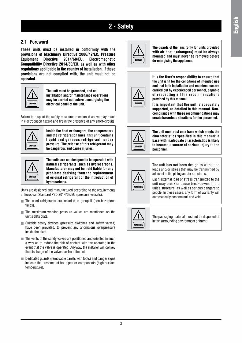
DANGER
The DANGER sign recalls your attention to a certain procedure or practice which, if not followed, may result in serious damage to people and property.
WARNING
The WARNING sign precedes those procedures that, if not followed, may result in serious damage to the appliance.
NOTE
The NOTE contain important observations.
USEFUL TIPS
The USEFUL TIPS provide valuable information that optimises the efficiency of the appliance.
This manual and its contents, as well as the documentation which accompanies the unit, are and remain the property of manufacturer, which reserves any and all rights thereon. This manual may not be copied, in whole or in part, without manufacturer’s written authorization.
3
Engl
ish
2 - Safety
2.1 ForewordThese units must be installed in conformity with the provisions of Machinery Directive 2006/42/EC, Pressure Equipment Directive 2014/68/EU, Electromagnetic Compatibility Directive 2014/30/EU, as well as with other regulations applicable in the country of installation. If these provisions are not complied with, the unit must not be operated.
DANGER
The unit must be grounded, and no installation and/or maintenance operations may be carried out before deenergising the electrical panel of the unit.
Failure to respect the safety measures mentioned above may result in electrocution hazard and fire in the presence of any short-circuits.
DANGER
Inside the heat exchangers, the compressors and the refrigeration lines, this unit contains l iquid and gaseous refr igerant under pressure. The release of this refrigerant may be dangerous and cause injuries.
DANGER
The units are not designed to be operated with natural refrigerants, such as hydrocarbons. Manufacturer may not be held liable for any problems deriving from the replacement of original refrigerant or the introduction of hydrocarbons.
Units are designed and manufactured according to the requirements of European Standard PED 2014/68/EU (pressure vessels).
n The used refrigerants are included in group II (non-hazardous fluids).
n The maximum working pressure values are mentioned on the unit’s data plate.
n Suitable safety devices (pressure switches and safety valves) have been provided, to prevent any anomalous overpressure inside the plant.
n The vents of the safety valves are positioned and oriented in such a way as to reduce the risk of contact with the operator, in the event that the valve is operated. Anyway, the installer will convey the discharge of the valves far from the unit.
n Dedicated guards (removable panels with tools) and danger signs indicate the presence of hot pipes or components (high surface temperature).
DANGER
The guards of the fans (only for units provided with air heat exchangers) must be always mounted and must never be removed before de-energising the appliance.
DANGER
It is the User’s responsibility to ensure that the unit is fit for the conditions of intended use and that both installation and maintenance are carried out by experienced personnel, capable of respecting all the recommendations provided by this manual.
It is important that the unit is adequately supported, as detailed in this manual. Non-compliance with these recommendations may create hazardous situations for the personnel.
DANGER
The unit must rest on a base which meets the characteristics specified in this manual; a base with inadequate characteristics is likely to become a source of serious injury to the personnel.
WARNING
The unit has not been design to withstand loads and/or stress that may be transmitted by adjacent units, piping and/or structures.
Each external load or stress transmitted to the unit may break or cause breakdowns in the unit’s structure, as well as serious dangers to people. In these cases, any form of warranty will automatically become null and void.
WARNING
The packaging material must not be disposed of in the surrounding environment or burnt.
4
2 - Safety
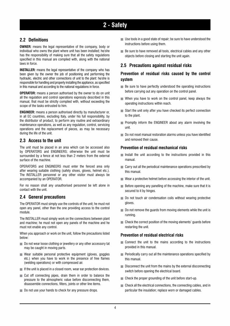
2.2 DefinitionsOWNER: means the legal representative of the company, body or individual who owns the plant where unit has been installed; he/she has the responsibility of making sure that all the safety regulations specified in this manual are complied with, along with the national laws in force.
INSTALLER: means the legal representative of the company who has been given by the owner the job of positioning and performing the hydraulic, electric and other connections of unit to the plant: he/she is responsible for handling and properly installing the appliance, as specified in this manual and according to the national regulations in force.
OPERATOR: means a person authorised by the owner to do on unit all the regulation and control operations expressly described in this manual, that must be strictly complied with, without exceeding the scope of the tasks entrusted to him.
ENGINEER: means a person authorised directly by manufacturer or, in all EC countries, excluding Italy, under his full responsibility, by the distributor of product, to perform any routine and extraordinary maintenance operations, as well as any regulation, control, servicing operations and the replacement of pieces, as may be necessary during the life of the unit.
2.3 Access to the unitThe unit must be placed in an area which can be accessed also by OPERATORS and ENGINEERS; otherwise the unit must be surrounded by a fence at not less than 2 meters from the external surface of the machine.
OPERATORS and ENGINEERS must enter the fenced area only after wearing suitable clothing (safety shoes, gloves, helmet etc.). The INSTALLER personnel or any other visitor must always be accompanied by an OPERATOR.
For no reason shall any unauthorised personnel be left alone in contact with the unit.
2.4 General precautionsThe OPERATOR must simply use the controls of the unit; he must not open any panel, other than the one providing access to the control module.
The INSTALLER must simply work on the connections between plant and machine; he must not open any panels of the machine and he must not enable any control.
When you approach or work on the unit, follow the precautions listed below:
n Do not wear loose clothing or jewellery or any other accessory tat may be caught in moving parts.
n Wear suitable personal protective equipment (gloves, goggles etc.) when you have to work in the presence of free flames (welding operations) or with compressed air.
n If the unit is placed in a closed room, wear ear protection devices.
n Cut off connecting pipes, drain them in order to balance the pressure to the atmospheric value before disconnecting them, disassemble connections, filters, joints or other line items.
n Do not use your hands to check for any pressure drops.
n Use tools in a good state of repair; be sure to have understood the instructions before using them.
n Be sure to have removed all tools, electrical cables and any other objects before closing and starting the unit again.
2.5 Precautions against residual risks
Prevention of residual risks caused by the control system
n Be sure to have perfectly understood the operating instructions before carrying out any operation on the control panel.
n When you have to work on the control panel, keep always the operating instructions within reach.
n Start the unit only after you have checked its perfect connection to the plant.
n Promptly inform the ENGINEER about any alarm involving the unit.
n Do not reset manual restoration alarms unless you have identified and removed their cause.
Prevention of residual mechanical risks
n Install the unit according to the instructions provided in this manual.
n Carry out all the periodical maintenance operations prescribed by this manual.
n Wear a protective helmet before accessing the interior of the unit.
n Before opening any panelling of the machine, make sure that it is secured to it by hinges.
n Do not touch air condensation coils without wearing protective gloves.
n Do not remove the guards from moving elements while the unit is running.
n Check the correct position of the moving elements’ guards before restarting the unit.
Prevention of residual electrical risks
n Connect the unit to the mains according to the instructions provided in this manual.
n Periodically carry out all the maintenance operations specified by this manual.
n Disconnect the unit from the mains by the external disconnecting switch before opening the electrical board.
n Check the proper grounding of the unit before start-up.
n Check all the electrical connections, the connecting cables, and in particular the insulation; replace worn or damaged cables.
5
Engl
ish
2 - Safety
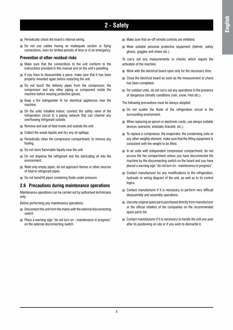
n Periodically check the board’s internal wiring.
n Do not use cables having an inadequate section or flying connections, even for limited periods of time or in an emergency.
Prevention of other residual risksn Make sure that the connections to the unit conform to the
instructions provided in this manual and on the unit’s panelling.
n If you have to disassemble a piece, make sure that it has been properly mounted again before restarting the unit.
n Do not touch the delivery pipes from the compressor, the compressor and any other piping or component inside the machine before wearing protective gloves.
n Keep a fire extinguisher fir for electrical appliances near the machine.
n On the units installed indoor, connect the safety valve of the refrigeration circuit to a piping network that can channel any overflowing refrigerant outside.
n Remove and leak of fluid inside and outside the unit.
n Collect the waste liquids and dry any oil spillage.
n Periodically clean the compressor compartment, to remove any fouling.
n Do not store flammable liquids near the unit.
n Do not disperse the refrigerant and the lubricating oil into the environment.
n Weld only empty pipes; do not approach flames or other sources of heat to refrigerant pipes.
n Do not bend/hit pipes containing fluids under pressure.
2.6 Precautions during maintenance operationsMaintenance operations can be carried out by authorised technicians only.
Before performing any maintenance operations:
n Disconnect the unit from the mains with the external disconnecting switch.
n Place a warning sign “do not turn on - maintenance in progress” on the external disconnecting switch.
n Make sure that on-off remote controls are inhibited.
n Wear suitable personal protective equipment (helmet, safety gloves, goggles and shoes etc.).
To carry out any measurements or checks which require the activation of the machine:
n Work with the electrical board open only for the necessary time.
n Close the electrical board as soon as the measurement or check has been completed.
n For outdoor units, do not carry out any operations in the presence of dangerous climatic conditions (rain, snow, mist etc.).
The following precautions must be always adopted:
n Do not scatter the fluids of the refrigeration circuit in the surrounding environment.
n When replacing an eprom or electronic cards, use always suitable devices (extractor, antistatic bracelet, etc.).
n To replace a compressor, the evaporator, the condensing coils or any other weighty element, make sure that the lifting equipment is consistent with the weight to be lifted.
n In air units with independent compressor compartment, do not access the fan compartment unless you have disconnected the machine by the disconnecting switch on the board and you have placed a warning sign “do not turn on - maintenance in progress”.
n Contact manufacturer for any modifications to the refrigeration, hydraulic or wiring diagram of the unit, as well as to its control logics.
n Contact manufacturer if it is necessary to perform very difficult disassembly and assembly operations.
n Use only original spare parts purchased directly from manufacturer or the official retailers of the companies on the recommended spare parts list.
n Contact manufacturer if it is necessary to handle the unit one year after its positioning on site or if you wish to dismantle it.
6
2 - Safety
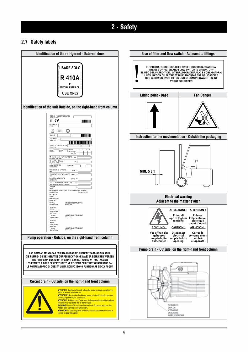
2.7 Safety labels
Identification of the refrigerant - External door
Identification of the unit Outside, on the right-hand front column
Pump operation - Outside, on the right-hand front column
LAS BOMBAS MONTADAS EN ESTA UNIDAD NO PUEDEN TRABAJAR SIN AGUADIE PUMPEN DIESES GERÄTES DÜRFEN NICHT OHNE WASSER BETRIEBEN WERDEN
THE PUMPS ON BOARD OF THIS UNIT CAN NOT WORK WITHOUT WATERLES POMPES A BORD DE CETTE UNITE NE PEUVENT PAS FONCTIONNER SANS EAULE POMPE ABORDO DI QUESTA UNITÀ NON POSSONO FUNZIONARE SENZA ACQUA
Circuit drain - Outside, on the right-hand front column
Use of filter and flow switch - Adjacent to fittings
È OBBLIGATORIO L’USO DI FILTRO E FLUSSOSTATO ACQUATHE USE OF FILTER AND FLOW SWITCH IS MANDATORY
EL USO DEL FILTRO Y DEL INTERRUPTOR DE FLUJO ES OBLIGATORIOL’UTILISATION DU FILTRE ET DU FLUXOSTAT EST OBLIGATOIREDER GEBRAUCH VON FILTER UND STRÖMUNGSWÄCHTER IST
VORGESCHRIEBEN
Lifting point - Base Fan Danger
Instruction for the movimentation - Outside the packaging
Electrical warningAdjacent to the master switch
Pump drain - Outside, on the right-hand front column
USARE SOLO
R 410AE
RECU
PERA
RE F
LUID
O - N
ON D
ISPE
RDER
E NE
LL’A
MBIE
NTE
- REG
OLAM
ENTO
CEE
N° 3
093/9
4
RECO
VER
- DO
NOT
VENT
- EE
C RE
GULA
TION
N° 3
093/9
4
SPECIAL ESTER OIL
USE ONLY
CODICE PRODOTTO NEUTROPRODUCT CODE
MODELLOMODEL
0425
MO.NO
MATRICOLASERIAL NO.
ANNO DI COSTRUZIONEManuf. Year
REFR. GWPCIRCUIT 1 2 3 4
CHARGE (Kg)
PS (LATO ALTA / LATO BASSA)PS (HIGH / LOW SIDE)
TS (ALTA / BASSA)TS (HIGH / LOW)
ALIM. POTENZAMAIN SUPPLY
CORRENTE DI SPUNTOLRA
CORRENTE A PIENO CARICOFLA
POTENZA ASSORBITAPOWER INPUT
PRESS. MAX ESERCIZIO ACQUAMAX WATER OPERATING PRESSURE
MASSAMASS
SYSTEMAIR S.r.l. Via XXV Aprile 29 20825 BARLASSINA MB ITALIAMADE IN ITALY COD.NO: P35952
MODELLO:MODEL
MATRICOLA:SERIAL NO.
CODICE:PRODUCT CODE
MODELLO:MODEL
MATRICOLA:SERIAL NO.
CODICE:PRODUCT CODE
MODELLO:MODEL
MATRICOLA:SERIAL NO.
CODICE:PRODUCT CODE
bar
°C
V / PH / Hz
(max) A
(max) A
(max) Kw
bar
Kg
ANNO DI COSTRUZIONEManuf. Year
ANNO DI COSTRUZIONEManuf. Year
ANNO DI COSTRUZIONEManuf. Year
(tCO₂eq)
ATTENTION! Don’t leave the unit with water inside hydraulic circuit during winter or when it is in stand by.ATTENZIONE! Non lasciare l’unità con acqua nel circuito idraulico durantel’inverno o quando non è funzionante.ATTENTION! Ne laissez pas l’unitè avec de l’eau dans le circuit hydrauliquependant l’hiver ou quand elle ne travaille pas.WARNUNG! Lassen Sie nicht das Wasser in die Schaltung während desWinters oder wenn es nicht funktionient.¡ATENCÍON! No deje el agua en el circuito hidráulico durante el invierno ocuando no esta trabajando.
ATTENZIONE !
Prima di aprire togliere
tensione
CAUTION !
Disconnectelectrical
supply before opening
ACHTUNG !
Vor offnen des gehauses
hauptschalter ausschalten
ATENCION !
Cortar la corrente antes
de abrirel aparato
ATTENTION !
Enlever l’alimentation
electrique avant d’ouvrir
MIN. 5 cm
7
Engl
ish
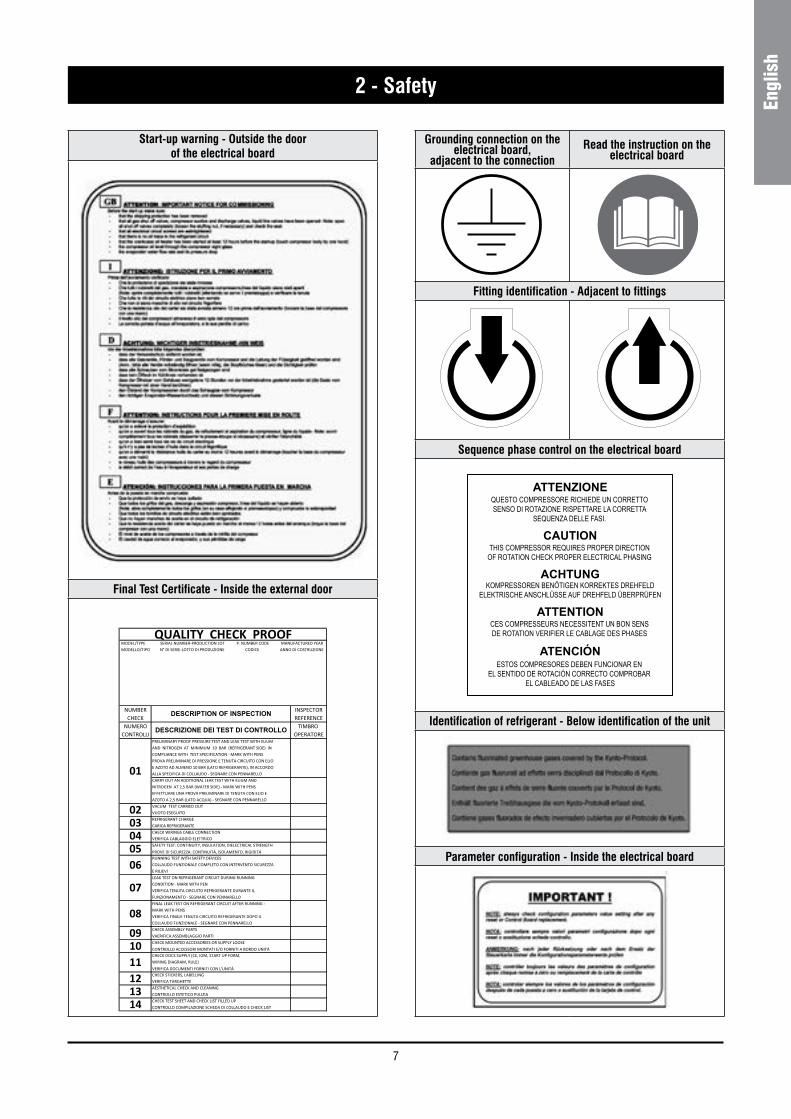
2 - Safety
Grounding connection on the electrical board,
adjacent to the connectionRead the instruction on the
electrical board
Fitting identification - Adjacent to fittings
Sequence phase control on the electrical board
Identification of refrigerant - Below identification of the unit
Parameter configuration - Inside the electrical board
Start-up warning - Outside the door of the electrical board
Final Test Certificate - Inside the external door
ATTENZIONEQUESTO COMPRESSORE RICHIEDE UN CORRETTOSENSO DI ROTAZIONE RISPETTARE LA CORRETTA
SEQUENZA DELLE FASI.
THIS COMPRESSOR REQUIRES PROPER DIRECTIONOF ROTATION CHECK PROPER ELECTRICAL PHASING
CAUTION
KOMPRESSOREN BENÖTIGEN KORREKTES DREHFELDELEKTRISCHE ANSCHLÜSSE AUF DREHFELD ÜBERPRÜFEN
ACHTUNG
CES COMPRESSEURS NECESSITENT UN BON SENSDE ROTATION VERIFIER LE CABLAGE DES PHASES
ATTENTION
ESTOS COMPRESORES DEBEN FUNCIONAR EN EL SENTIDO DE ROTACIÓN CORRECTO COMPROBAR
EL CABLEADO DE LAS FASES
ATENCIÓN
8
2 - Safety
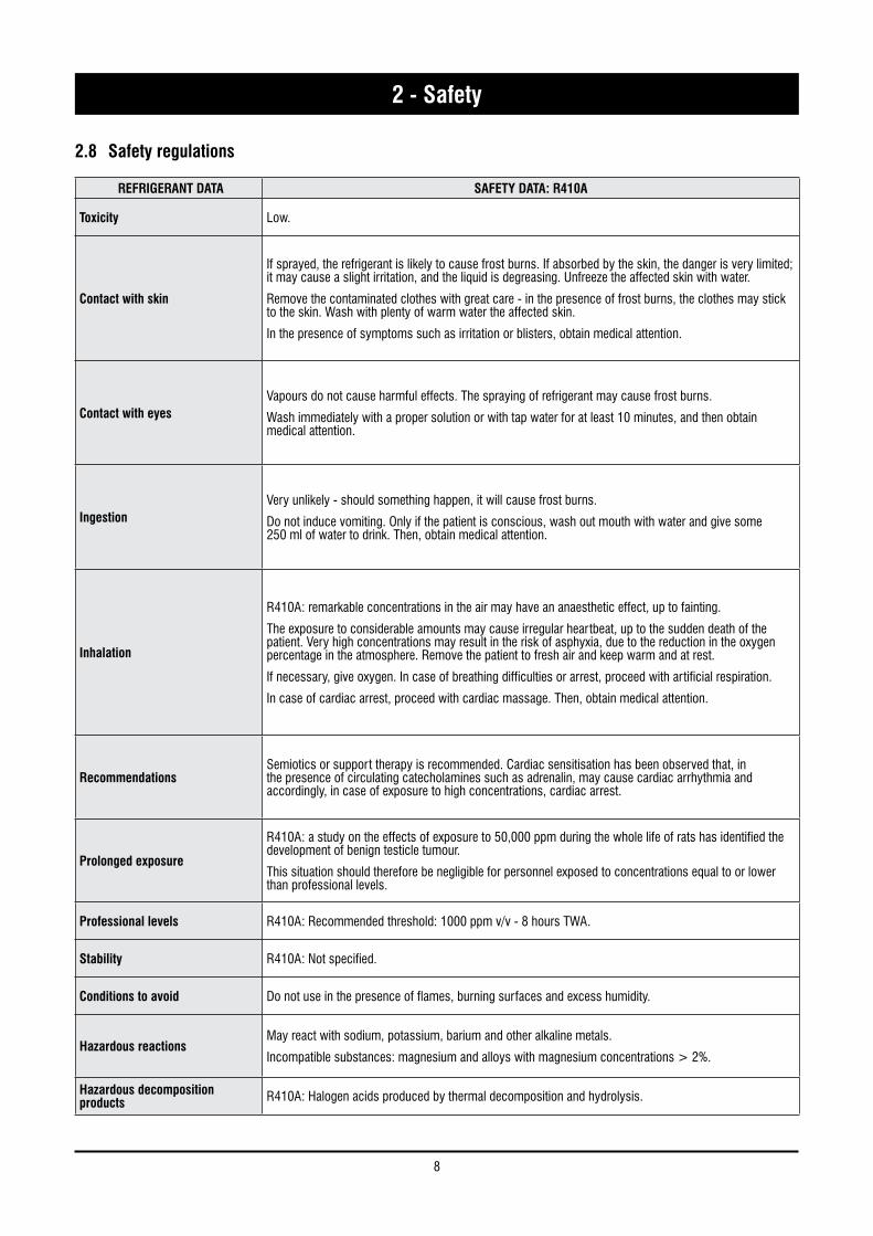
REFRIGERANT DATA SAFETY DATA: R410A
Toxicity Low.
Contact with skin
If sprayed, the refrigerant is likely to cause frost burns. If absorbed by the skin, the danger is very limited; it may cause a slight irritation, and the liquid is degreasing. Unfreeze the affected skin with water.
Remove the contaminated clothes with great care - in the presence of frost burns, the clothes may stick to the skin. Wash with plenty of warm water the affected skin.
In the presence of symptoms such as irritation or blisters, obtain medical attention.
Contact with eyesVapours do not cause harmful effects. The spraying of refrigerant may cause frost burns.
Wash immediately with a proper solution or with tap water for at least 10 minutes, and then obtain medical attention.
IngestionVery unlikely - should something happen, it will cause frost burns.
Do not induce vomiting. Only if the patient is conscious, wash out mouth with water and give some 250 ml of water to drink. Then, obtain medical attention.
Inhalation
R410A: remarkable concentrations in the air may have an anaesthetic effect, up to fainting.
The exposure to considerable amounts may cause irregular heartbeat, up to the sudden death of the patient. Very high concentrations may result in the risk of asphyxia, due to the reduction in the oxygen percentage in the atmosphere. Remove the patient to fresh air and keep warm and at rest.
If necessary, give oxygen. In case of breathing difficulties or arrest, proceed with artificial respiration.
In case of cardiac arrest, proceed with cardiac massage. Then, obtain medical attention.
RecommendationsSemiotics or support therapy is recommended. Cardiac sensitisation has been observed that, in the presence of circulating catecholamines such as adrenalin, may cause cardiac arrhythmia and accordingly, in case of exposure to high concentrations, cardiac arrest.
Prolonged exposure
R410A: a study on the effects of exposure to 50,000 ppm during the whole life of rats has identified the development of benign testicle tumour.
This situation should therefore be negligible for personnel exposed to concentrations equal to or lower than professional levels.
Professional levels R410A: Recommended threshold: 1000 ppm v/v - 8 hours TWA.
Stability R410A: Not specified.
Conditions to avoid Do not use in the presence of flames, burning surfaces and excess humidity.
Hazardous reactionsMay react with sodium, potassium, barium and other alkaline metals.
Incompatible substances: magnesium and alloys with magnesium concentrations > 2%.
Hazardous decomposition products R410A: Halogen acids produced by thermal decomposition and hydrolysis.
2.8 Safety regulations
9
Engl
ish
2 - Safety
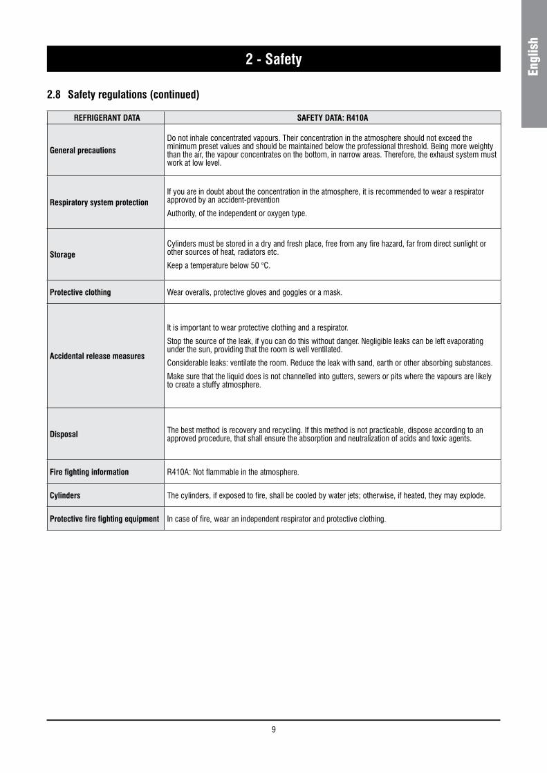
REFRIGERANT DATA SAFETY DATA: R410A
General precautionsDo not inhale concentrated vapours. Their concentration in the atmosphere should not exceed the minimum preset values and should be maintained below the professional threshold. Being more weighty than the air, the vapour concentrates on the bottom, in narrow areas. Therefore, the exhaust system must work at low level.
Respiratory system protectionIf you are in doubt about the concentration in the atmosphere, it is recommended to wear a respirator approved by an accident-prevention
Authority, of the independent or oxygen type.
StorageCylinders must be stored in a dry and fresh place, free from any fire hazard, far from direct sunlight or other sources of heat, radiators etc.
Keep a temperature below 50 °C.
Protective clothing Wear overalls, protective gloves and goggles or a mask.
Accidental release measures
It is important to wear protective clothing and a respirator.
Stop the source of the leak, if you can do this without danger. Negligible leaks can be left evaporating under the sun, providing that the room is well ventilated.
Considerable leaks: ventilate the room. Reduce the leak with sand, earth or other absorbing substances.
Make sure that the liquid does is not channelled into gutters, sewers or pits where the vapours are likely to create a stuffy atmosphere.
Disposal The best method is recovery and recycling. If this method is not practicable, dispose according to an approved procedure, that shall ensure the absorption and neutralization of acids and toxic agents.
Fire fighting information R410A: Not flammable in the atmosphere.
Cylinders The cylinders, if exposed to fire, shall be cooled by water jets; otherwise, if heated, they may explode.
Protective fire fighting equipment In case of fire, wear an independent respirator and protective clothing.
2.8 Safety regulations (continued)
10
2 - Safety
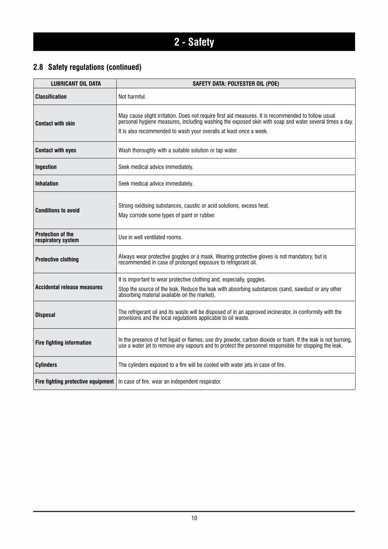
LUBRICANT OIL DATA SAFETY DATA: POLYESTER OIL (POE)
Classification Not harmful.
Contact with skinMay cause slight irritation. Does not require first aid measures. It is recommended to follow usual personal hygiene measures, including washing the exposed skin with soap and water several times a day.
It is also recommended to wash your overalls at least once a week.
Contact with eyes Wash thoroughly with a suitable solution or tap water.
Ingestion Seek medical advice immediately.
Inhalation Seek medical advice immediately.
Conditions to avoidStrong oxidising substances, caustic or acid solutions, excess heat.
May corrode some types of paint or rubber.
Protection of therespiratory system Use in well ventilated rooms.
Protective clothing Always wear protective goggles or a mask. Wearing protective gloves is not mandatory, but is recommended in case of prolonged exposure to refrigerant oil.
Accidental release measuresIt is important to wear protective clothing and, especially, goggles.
Stop the source of the leak. Reduce the leak with absorbing substances (sand, sawdust or any other absorbing material available on the market).
Disposal The refrigerant oil and its waste will be disposed of in an approved incinerator, in conformity with the provisions and the local regulations applicable to oil waste.
Fire fighting information In the presence of hot liquid or flames, use dry powder, carbon dioxide or foam. If the leak is not burning, use a water jet to remove any vapours and to protect the personnel responsible for stopping the leak.
Cylinders The cylinders exposed to a fire will be cooled with water jets in case of fire.
Fire fighting protective equipment In case of fire, wear an independent respirator.
2.8 Safety regulations (continued)
11
Engl
ish
3 - Transport, Handling and Storage
SYSCROLL AIR EVO HP units are supplied fully assembled and tested (except for accessories supplied loose in the units – absorbers, filter, etc.). They are ready to be installed and started on the field.
R410A units are only charged with liquid refrigerant and with oil in the quantity required for operation.
WARNING
The low pressure side of the refrigerating circuit on R410A units shall be charged by means of the service valve arranged on the thermal expansion valve before the device is operated.
3.1 InspectionThe unit shall be immediately inspected upon receipt to find out any damage since it has been delivered ex works and transported at the customer’s risk. It is also necessary to make sure that all the parcels specified on the delivery note have been delivered.
Any damage you may find out shall be immediately reported in writing to the carrier. Even if the damage is only on the surface, please notify our local representative too.
The manufacturer disclaims all responsibility for the shipment even if it has provided for its organisation.
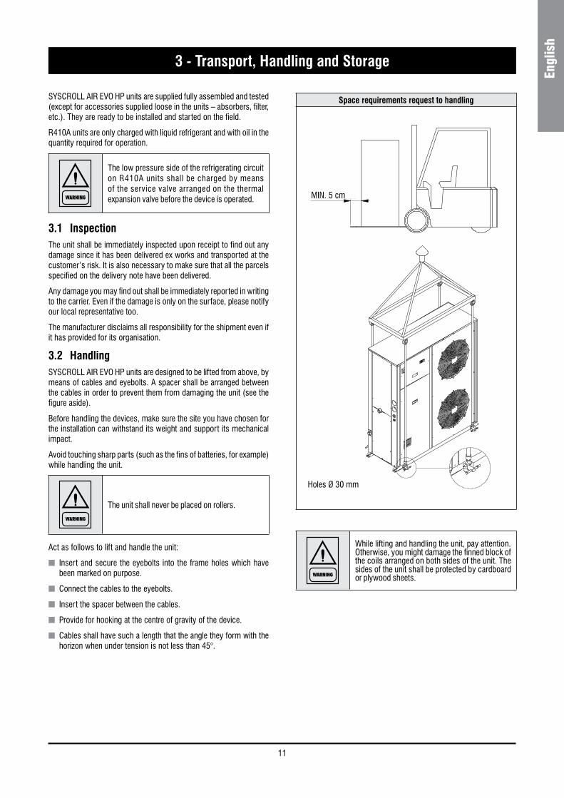
3.2 HandlingSYSCROLL AIR EVO HP units are designed to be lifted from above, by means of cables and eyebolts. A spacer shall be arranged between the cables in order to prevent them from damaging the unit (see the figure aside).
Before handling the devices, make sure the site you have chosen for the installation can withstand its weight and support its mechanical impact.
Avoid touching sharp parts (such as the fins of batteries, for example) while handling the unit.
WARNING
The unit shall never be placed on rollers.
Act as follows to lift and handle the unit:
n Insert and secure the eyebolts into the frame holes which have been marked on purpose.
n Connect the cables to the eyebolts.
n Insert the spacer between the cables.
n Provide for hooking at the centre of gravity of the device.
n Cables shall have such a length that the angle they form with the horizon when under tension is not less than 45°.
Holes Ø 30 mm
WARNING
While lifting and handling the unit, pay attention. Otherwise, you might damage the finned block of the coils arranged on both sides of the unit. The sides of the unit shall be protected by cardboard or plywood sheets.
Space requirements request to handling
MIN. 5 cm
SOLLEVAMENTO SYSCL 20-35
MIN. 5 cm
12
3 - Transport, Handling and Storage
WARNING
Until the unit is ready for operation, do not remove the plastic envelope and the coi l protections which are intended to prevent dirt, dust and any foreign matter from penetrating into the unit through the inlets of fans or from damaging the external surfaces.
3.3 AnchoringIt is not essential to secure the unit to the foundations, unless in areas where there is a serious risk of earth-quake, or if the appliance is installed on the top of a steel frame.
3.4 StorageIf the unit is to be stored before the installation for some time, take at least the following precautions to prevent damage, corrosion and/or deterioration:
n Make sure all openings, such as for example water connections, are well plugged and sealed.
n Never store the units in a room where temperature is above 50 °C (R410A units) or where the units are directly exposed to the sunlight.
n Minimum storage temperature is -25 °C.
n It is recommended to leave the finned coils covered to protect them against any risk of corrosion, especially if building works are still in progress.
n Store the units in areas where minimum activity is likely to take place in order to avoid any risk of accidental damage.
n Never use steam to clean the unit.
n Remove all the keys required to have access to the control panel and give them to the person in charge of the field.
It is also recommended to provide for visual inspections at regular intervals.
13
Engl
ish
4 - Installation
4.1 Installation Site
DANGER
Before installing the unit, make sure that the building structure and/or the supporting surface can withstand the weight of the device. The weights of the units are detailed by Chapter 9 of this manual.
These units have been designed to be installed on the floor, in the open air. As a standard, they are equipped with rubber vibration-damping supports which shall be arranged in the middle, beneath the supporting plates.
When the unit is to be installed on the ground, provide for a concrete bedplate which shall assure a uniform distribution of the weights. No special subbase is generally required.
When selecting the installation site, never forget to consider as follows:
n The longitudinal axis of the unit shall be parallel to the direction of the prevailing winds so as to assure a uniform air distribution on finned exchangers.
n The unit shall never be installed in the proximity of chimneys for the discharge of boiler flue gases.
n The unit shall never be installed downwind of sources of grease contaminated air, such as for example the outlets of large-kitchen extractors. Otherwise, grease might build up on the fins of refrigerant / air exchangers or condensers, act as a fixing agent for any sort of atmospheric impurity and rapidly cause the exchangers to clog.
n The unit shall never be installed in areas exposed to heavy snowfalls.
n The unit shall never be installed in areas exposed to flooding or beneath drip stones, etc.
n The unit shall never be installed in narrow inner court yards or in any other restricted space where the noise may be reflected by the walls or where the air expelled by the fans may short-circuit on the refrigerant/air heat exchangers or condensers.
n The installation site shall be characterised by the presence of the space required for air circulation and for the performance of maintenance operations (see chapter 9 for further details).
4.2 External Water Circuit
WARNING
The external water circuit shall guarantee a constant water flow rate through the circulating refrigerant/water heat exchanger (evaporator) under steady operating conditions and in case of a load variation.
The circuit shall be composed by the following elements:
n A circulation pump which can ensure the necessary flow rate and head.
n The total content of the primary water circuit shall never be lower than 2.5 lt/kW in terms of refrigerating capacity. If the total water volume in the primary circuit should be unable to reach such a value, an additional heat-insulated storage tank should be installed. This tank is intended to avoid any repetitive start of the compressor.
n A membrane expansion tank complete with a safety valve and a drain which shall be visible.
NOTE
The expansion tank shall be dimensioned in such a way that it can absorb a 2% expansion of the total volume of the water in the plant (exchanger, pipelines, uses and storage tank, if available). The expansion tank shall never be insulated when the circulating fluid is not flowing through it.
A differential pressure switch is mounted as a standard. It will stop the unit whenever it senses a load loss through the heat exchanger which may result in a flow rate problem.
In addition:
n Install on/off valves (accessory) on the lines at the inlet and outlet of the manifolds of the exchangers (evaporator).
n Arrange a by-pass complete with an on/off valve between the manifolds of the heat exchangers.
n Arrange air vent valves at the high points of the water lines.
n Arrange drain points complete with plugs, clocks, etc. in the proximity of the low points of the water lines.
n Insulate the water lines to prevent the heat from blowing back into the unit.
14
4 - Installation
WARNING
Before filling the installation, remove any impurity, such as sand, crushed stones and welding scales, coating drops and any other material which might damage the evaporator.
It is advisable to flush with disposable water bypassing the exchanger to avoid clogging.
NOTE
The water used to fill the circuit shall be treated in such as way that the pH will have the correct value.
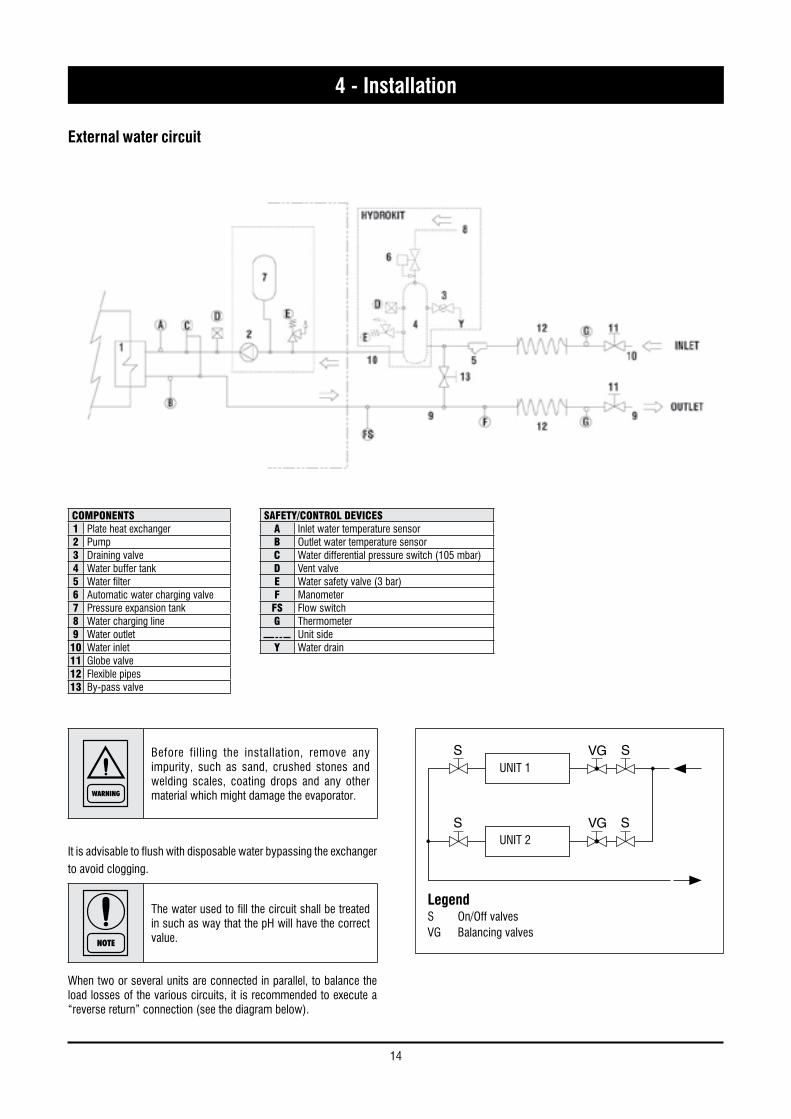
When two or several units are connected in parallel, to balance the load losses of the various circuits, it is recommended to execute a “reverse return” connection (see the diagram below).
External water circuit
SAFETY/CONTROL DEVICESA Inlet water temperature sensorB Outlet water temperature sensorC Water differential pressure switch (105 mbar)D Vent valveE Water safety valve (3 bar)F ManometerFS Flow switchG Thermometer
Unit sideY Water drain
COMPONENTS1 Plate heat exchanger2 Pump3 Draining valve4 Water buffer tank5 Water filter6 Automatic water charging valve7 Pressure expansion tank8 Water charging line9 Water outlet
10 Water inlet11 Globe valve12 Flexible pipes13 By-pass valve
UNIT 1
UNIT 2
LegendS On/Off valvesVG Balancing valves
15
Engl
ish
4 - Installation
4.3 Water connectionsThe flow switch and the filter water, although not included in the supply, must always be fitted such as plant components. Their installation is mandatory for warranty.
WARNING
The attachments at the water inlet and outlet shall be connected in compliance with the instructions which can be found on the labels in the proximity of the attachments.
Connect the water lines of the plants with the attachments of the unit whose diameters and positions are shown in Chapter 9.
4.4 Defrost water drainageWhen heat pump units work in heating mode, during defrosting cycles, they may discharge water from the base. This is why the units should be installed at least 200 mm above the floor level, so as to allow the free drainage of waste water, without the risk of producing ice banks.
The heat pump units must be installed in positions where the defrosting water cannot create any damage.
4.5 Water buffer tankThe accumulation tank which has been designed to be mounted on units is complete with all the hydraulic and electrical components required for the correct operation of the system.
These systems are carefully assembled and tested at works. They are ready for operation after having correctly realised all electrical and hydraulic connections.
WARNING
Don’t leave the unit with water inside the circuit during the winter or when it is in stand by, unless water is properly mixed with glycol.
4.5.1 FeaturesUnits have one single tank. The kit will include an Antifreeze Electric Heater, a drain valve, an automatic filling unit and an automatic air vent.
No pump is arranged on the kit since it is mounted on the unit.
A tank arranged for mounting a heating booster resistance kit may be optionally required (5 traps).
The tank is completely insulated with 30 Kg/m3 closed cell polyethylene in a silver colour and enclosed by a bearing structure made of passivated and painted plates. The box is equipped with bulkheads which can be easily opened for internal inspection.
The kit is installed beneath the unit. It is an integral part of the unit without changing the support area.
4.5.2 Supplied MaterialThe kits will be supplied with pipelines ready for installation. An antifreeze resistance with wiring, an automatic water filling valve, a 3 bar safety valve, a drain valve and a vent valve have already been assembled.
Hydrokit is shipped with a film to protect it from atmospheric agents. Packaging has been designed in order to stack it up.
4.5.3 Antifreeze Electric HeaterThe antifreeze resistance of the tank (TEH) shall be wired with the panel as it is shown by the diagram attached to the unit.
4.5.4 Water FilterThe kit will use the water filter of the unit.
RECOMMENDED WATER COMPOSITIONPH 7,5 - 9Electrical conductivity 10 - 500 μS/cmTotal hardness 4,5 - 8,5 dHTemperature < 60 [°C]Alkalinity (HCO3
-) 70-300 ppmAlkalinity / Sulphates (HCO3
-/ SO42-) > 1 ppm
Sulphates (SO42-) < 70 ppm
Chlorides (Cl-) < 50 ppmFree Chlorine < 0,5 ppmPhosphates (PO4
3-) < 2 ppmAmmonia (NH3) < 0,5 ppmAmmonium Ion (NH4
+) < 2 ppmManganese Ion (Mn2+) < 0,05 ppmFree Carbon Dioxide (CO2) < 5 ppmHydrogen Sufide (H2S) < 0,05 ppmOxygen Content < 0,1 ppmNitrates (NO3
-) < 100 ppmManganese (Mn) < 0,1 ppmIron (Fe) < 0,2 ppmAluminium (Al) < 0,2 ppm
CautionIf the water circuit is to be drained for a time exceeding one month, the circuit must be fully charged with nitrogen to prevent any risk of corrosion by differential venting
16
4.6 Power supply
DANGER
Before carrying out any operations on the electrical system, make sure that the unit is deenergized.
DANGER
It is important that the appliance is grounded.
WARNING
The company in charge of the installation shall conform to the standards applicable to outdoor electrical connections.
The manufacturer may not be held liable for any damage and/or injury caused by failure to comply with these precautions.
The unit conforms to EN 60204-1.
The following connections shall be provided:
n A 3-phase and grounding connection for the power supply circuit.
n The electrical distribution system shall meet the power absorbed by the appliance.
n The disconnecting and magnetothermal switches must be sized to control the starting current of the unit.
n The power supply lines and the insulation devices must be designed in such a way that every line independent.
n It is recommended to install differential switches, to prevent any damage caused by phase drops.
n The fans and compressors are supplied through contactors controlled from the control panel.
n Each motor is provided with an internal safety thermal device and external fuses.
n The power supply cables must be inserted into dedicated openings on the front of the unit, and the will enter the electrical board through holes drilled on the bottom of the board.
4 - Installation
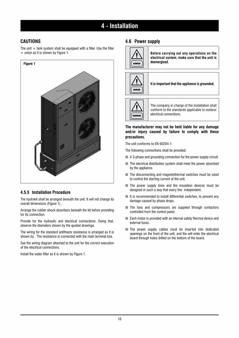
CAUTIONSThe unit + tank system shall be equipped with a filter. Use the filter + union as it is shown by Figure 1.
4.5.5 Installation ProcedureThe hydrokit shall be arranged beneath the unit. It will not change its overall dimensions (Figure 1).
Arrange the rubber shock absorbers beneath the kit before providing for its connection.
Provide for the hydraulic and electrical connections. Doing that, observe the diameters shown by the quoted drawings.
The wiring for the standard antifreeze resistance is arranged as it is shown by . The resistance is connected with the main terminal box.
See the wiring diagram attached to the unit for the correct execution of the electrical connections.
Install the water filter as it is shown by Figure 1.
Figure 1
17
Engl
ish
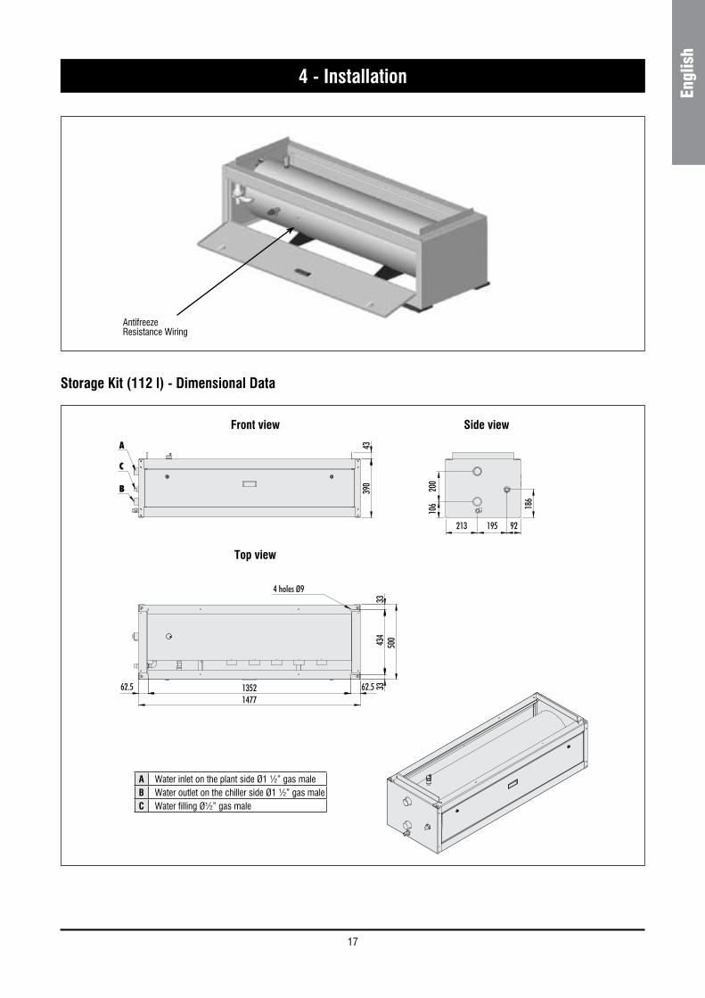
AntifreezeResistance Wiring
Storage Kit (112 l) - Dimensional Data
4 - Installation
1352
4 holes Ø9
1477
92 213 195
62.5 62.5 33
33
434
390
186
200
106
43
500
A
C
B
Front view Side view
Top view
A Water inlet on the plant side Ø1 ½” gas maleB Water outlet on the chiller side Ø1 ½” gas maleC Water filling ؽ” gas male
18
4 - Installation
4.7 Electrical connectionsThe unit must be installed on site according to the usual procedures and standards applicable in the place of installation. The unit must not be operated if its installation has not been carried out according to the instructions provided in this manual.
The power supply lines must consist of insulated copper conductors, dimensioned for the maximum absorbed current.
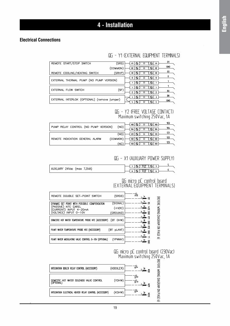
Connection to terminals must be performed according to the diagram of connections (User’s Terminal Box) provided in this manual and according to the wiring diagram which accompanies the unit.
WARNING
Before connecting the power supply lines, check that the available voltage value does not exceed the range specified in the Electric Data (Chapter 9).
For 3-phase systems, check also that the unbalance between the phases does not exceed 2%. To perform this check, measure the differences between the voltage of each phase couple and their mean value during operation. The maximum % value of these differences (unbalance) must not exceed 2% of the mean voltage.
If the unbalance is unacceptable, contact the Energy Distributor to solve this problem.
WARNING
Supplying the uni t through a l ine whose unbalance exceeds the permissible value will automatically void the warranty.
The unit conforms to EN 61000-3-12: Electromagnetic compatibility (EMC) Part 3-12: Limits - Limits for harmonic currents produced by equipment connected to public low voltage systems with input current ›16 A and ← 75 A per phase. Conformity depends on public mains power supply with short-circuit power Ssc ≥1.9MVA at the point of connection (see table 4 of the standard with Rsce ≥120).
19
Engl
ish
Electrical Connections
4 - Installation
20
5 - Start-up
WARNING
The unit must be started for the first time by personnel suitably trained by one of Authorised Service Centre. Failure to meet this requirement will immediately void the warranty.
NOTE
The operations carried out by authorised personnel are limited to the start-up of the unit, and do not include any other operation on the plant, such as, for example, electrical and hydraulic connections etc. All the other operations before start-up, including oil pre-heating for at least 12 hours, must be performed by the Installer.
5.1 Preliminary checkThe checks listed below shall be performed before starting the unit and before the arrival of the personnel authorised.
n Check the section of power supply and grounding cables; make sure that terminals are tightened and check the correct operation of contactors, with the main switch open.
n Check that any voltage and phase variation in the power supply does not exceed the prefixed thresholds.
n Connect the contacts of the flow switch and the thermal relay of the pump and of the other devices (if any), to terminals 1-2 and 3-4, respectively.
n Check that the components of the external water circuit (pump, user equipment, filters, power supply tank and reservoir, if any) have been installed properly, and according to the manufacturer’s instructions.
n Check the filling of the hydraulic circuits, and make sure that the fluid circulation is correct, without any trace of leaks and air bubbles. If you use ethylene glycol as antifreeze, check that its percentage is correct (do not exceed 35% glycol percentage).
n Check that the direction of rotation of the pumps is correct, and that fluids have been circulating for at least 12 hours for both pumps. Then, clean the filters on the suction side of the pumps.
n Adjust the liquid distribution network in such a way that the flow rate is within the specified range.
n Check that the water quality is up to the specifications.
n Check that oil heaters, if any, have been turned on at least 12 hours
before.
5.2 Start-upStart-up sequence:
n Turn on the Main switch (at least 12 hours before).
n Check that the oil in the compressor has reached the requested temperature (the minimum temperature outside the pan must be approx. 40°C) and that the auxiliary control circuit is energised.
n Check the operation of all the external equipment, and make sure that the control devices of the plant are properly calibrated.
n Start the pump and check that the water flow is correct.
n Set the desired fluid temperature on the control board.
n Start the appliance (see Chapter 6).
n Check the correct direction of rotation of compressors. Scroll compressors cannot compress the refrigerant when they rotate in the opposite direction. To make sure that they are rotating in the correct direction, simply check that, just after the start-up of the compressor, the pressure drops on the LP side and rises on the HP side. Furthermore, if a scroll compressor rotate in the opposite direction, there is a considerable rise in the sound level of the unit, as well as in a dramatic reduction of current absorption compared to normal values. In case of wrong rotation, the scroll compressor can be definitely damaged.
n After about 15 minutes of operation check that there are no bubbles, through the sight glass on the liquid line.
WARNING
The presence of bubbles may indicate that a part of the refrigerant charge has been released in one or more points. It is important to remove these leaks before proceeding.
n Repeat the start-up procedure after removing the leaks.
5.3 Checking the operation Check the following:
n The temperature of the water entering the evaporator.
n The temperature of the water leaving the evaporator.
n The level of the water flow rate in the evaporator, if possible.
n The current absorption upon the start of the compressor and in case of stabilised operation.
n The fan’s current absorption.
Check that the condensing and evaporation temperatures, during operation at high and low pressure detected by the pressure gauges of the refrigerant, are within the following range :
(On the units not provided with HP/LP pressure gauges for the refrigerant, connect a pressure gauge to the Shrader valves on the refrigeration circuit).
HP side Approx. 15 to 21 °C above the temperature of the air entering the condenser, for R410A units.
LP side Approx. 2 to 4 °C below the temperature of the leaving chilled water, for R410A units.
5.4 Delivery to the customern Train the user according to the instructions provided in Section 6.
21
Engl
ish
IntroductionThis document contains informations and operating instructions for SYSCROLL 20/30 AIR EVO HP units.
Main characteristics
Microprocessor control:
n User-friendly terminal and keypad;
n Backlighted LCD;
n Counting of the pump/compressor operating hours;
n History of stored alarms;
n Display of pressure and temperature values;
n Display of compressor’s main values.
The following accessories can be also connected:
n Wire remote control;
n Mixing valve;
n Domestic Hot Water (DHW).
6.1 Control of SYSCROLL 20/30 AIR EVO HP single compressor, variable speed
SYSCROLL 20/30 AIR EVO HP units are provided with a microprocessor card, which is fully programmed for the control of the units.
General information
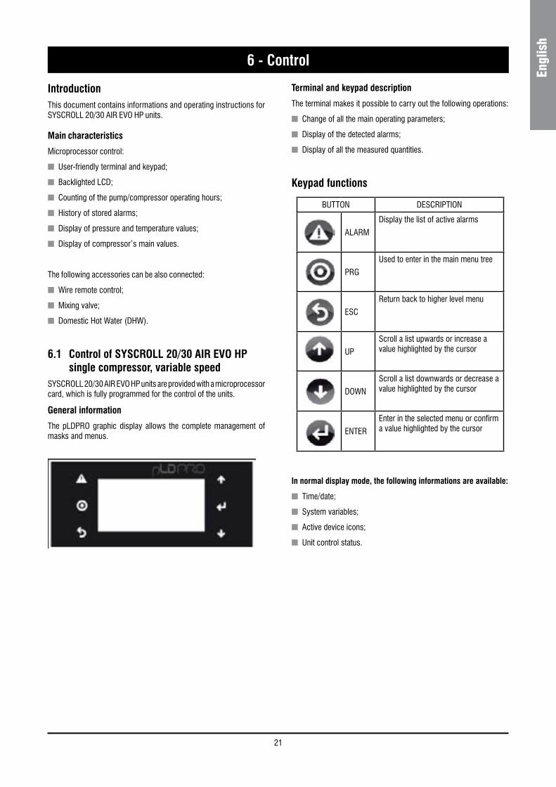
The pLDPRO graphic display allows the complete management of masks and menus.
6 - Control
Terminal and keypad description
The terminal makes it possible to carry out the following operations:
n Change of all the main operating parameters;
n Display of the detected alarms;
n Display of all the measured quantities.
Keypad functions
In normal display mode, the following informations are available:
n Time/date;
n System variables;
n Active device icons;
n Unit control status.
BUTTON DESCRIPTION
ALARM
Display the list of active alarms
PRG
Used to enter in the main menu tree
ESC
Return back to higher level menu
UP
Scroll a list upwards or increase a value highlighted by the cursor
DOWN
Scroll a list downwards or decrease a value highlighted by the cursor
ENTER
Enter in the selected menu or confirm a value highlighted by the cursor
22
6 - Control
6.2 Alarms
All alarms have the following behavior:
n When an alarm is activated, the red LED flashes and the buzzer and alarm relay are activated (when configured).
n Pressing the ALARM button, the red LED stays on steady, the buzzer is muted and the alarm screen is shown.
n If there is more than one active alarm, all the active alarms can be scrolled using UP and DOWN buttons.
n Pressing the ALARM button again for at least 3 seconds, the alarm displayed manually reset and then cleared from the display unless others are active (they are saved in the log).
Alarm Reset:
Alarms can have a manual or automatic reset:
n Manual: alarm is reset by pressing the ALARM button twice:
n first pressure displays the corresponding alarm screen and mutes the buzzer;
n the second pressure (extended for at least 3 seconds) erases the alarm (which is saved in the log). If the alarm condition is still active, the reset has no effect and the alarm signal doesn’t disappear.
n Automatic: when the alarm condition ceases, the alarm is automatically reset, the LED comes on steady and the corresponding screen remains displayed until the button ALARM is pressed and held; the alarm is saved in the log.
For manual reset, the functions associated with the alarm will not be activated again unless the alarm is reset, while for automatic reset, the functions are reactivated as soon as the alarm condition ceases.
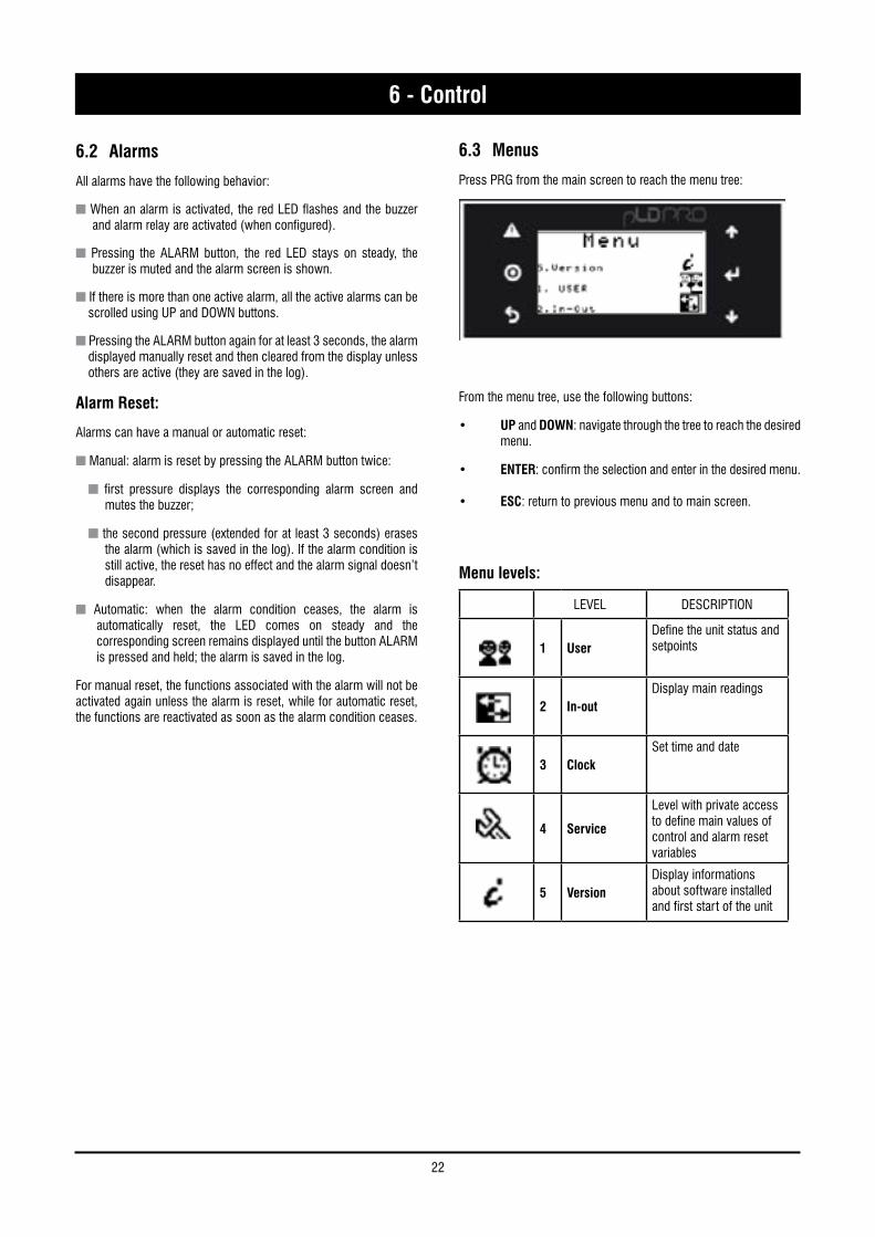
6.3 Menus
Press PRG from the main screen to reach the menu tree:
From the menu tree, use the following buttons:
• UP and DOWN: navigate through the tree to reach the desired menu.
• ENTER: confirm the selection and enter in the desired menu.
• ESC: return to previous menu and to main screen.
LEVEL DESCRIPTION
1 UserDefine the unit status and setpoints
2 In-outDisplay main readings
3 ClockSet time and date
4 Service
Level with private access to define main values of control and alarm reset variables
5 VersionDisplay informations about software installed and first start of the unit
Menu levels:
23
Engl
ish
6 - Control
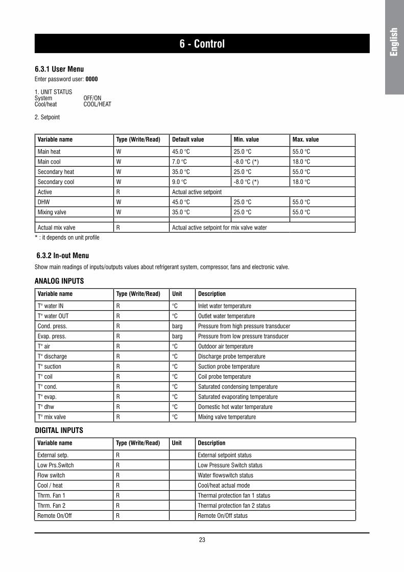
6.3.2 In-out Menu
Enter password user: 0000
1. UNIT STATUS System OFF/ON Cool/heat COOL/HEAT
2. Setpoint
Variable name Type (Write/Read) Default value Min. value Max. value
Main heat W 45.0 °C 25.0 °C 55.0 °C
Main cool W 7.0 °C -8.0 °C (*) 18.0 °C
Secondary heat W 35.0 °C 25.0 °C 55.0 °C
Secondary cool W 9.0 °C -8.0 °C (*) 18.0 °C
Active R Actual active setpoint
DHW W 45.0 °C 25.0 °C 55.0 °C
Mixing valve W 35.0 °C 25.0 °C 55.0 °C
Actual mix valve R Actual active setpoint for mix valve water
* : it depends on unit profile
Show main readings of inputs/outputs values about refrigerant system, compressor, fans and electronic valve.
ANALOG INPUTS
Variable name Type (Write/Read) Unit Description
T° water IN R °C Inlet water temperature
T° water OUT R °C Outlet water temperature
Cond. press. R barg Pressure from high pressure transducer
Evap. press. R barg Pressure from low pressure transducer
T° air R °C Outdoor air temperature
T° discharge R °C Discharge probe temperature
T° suction R °C Suction probe temperature
T° coil R °C Coil probe temperature
T° cond. R °C Saturated condensing temperature
T° evap. R °C Saturated evaporating temperature
T° dhw R °C Domestic hot water temperature
T° mix valve R °C Mixing valve temperature
DIGITAL INPUTS
Variable name Type (Write/Read) Unit Description
External setp. R External setpoint status
Low Prs.Switch R Low Pressure Switch status
Flow switch R Water flowswitch status
Cool / heat R Cool/heat actual mode
Thrm. Fan 1 R Thermal protection fan 1 status
Thrm. Fan 2 R Thermal protection fan 2 status
Remote On/Off R Remote On/Off status
6.3.1 User Menu
24
6 - Control
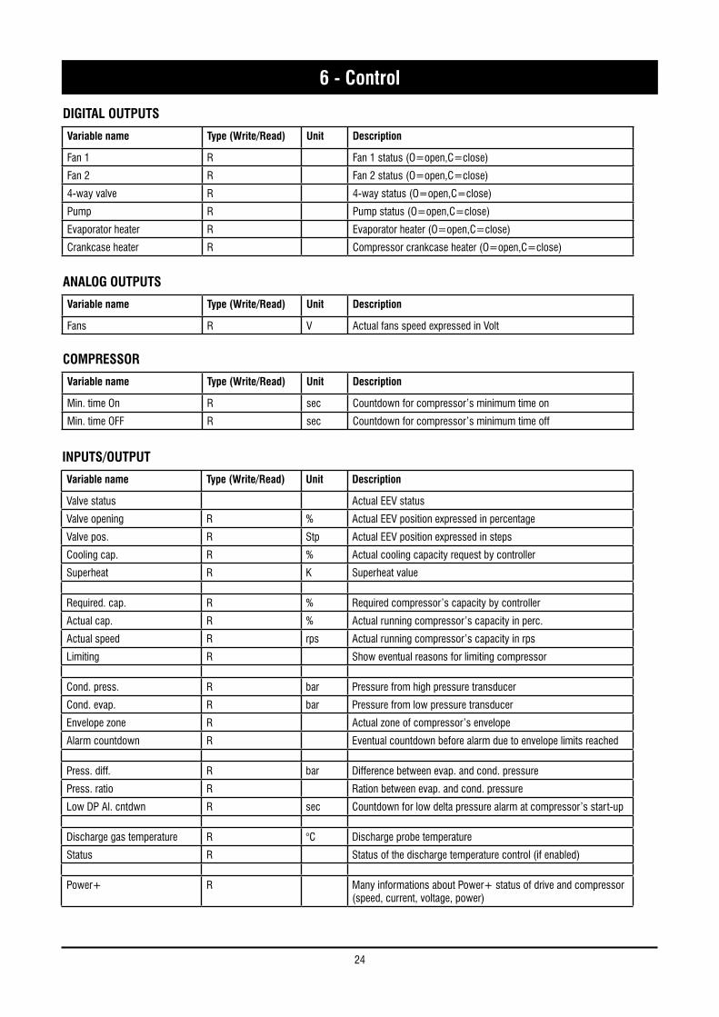
DIGITAL OUTPUTS
Variable name Type (Write/Read) Unit Description
Fan 1 R Fan 1 status (O=open,C=close)
Fan 2 R Fan 2 status (O=open,C=close)
4-way valve R 4-way status (O=open,C=close)
Pump R Pump status (O=open,C=close)
Evaporator heater R Evaporator heater (O=open,C=close)
Crankcase heater R Compressor crankcase heater (O=open,C=close)
ANALOG OUTPUTS
Variable name Type (Write/Read) Unit Description
Fans R V Actual fans speed expressed in Volt
COMPRESSOR
Variable name Type (Write/Read) Unit Description
Min. time On R sec Countdown for compressor’s minimum time on
Min. time OFF R sec Countdown for compressor’s minimum time off
INPUTS/OUTPUT
Variable name Type (Write/Read) Unit Description
Valve status Actual EEV status
Valve opening R % Actual EEV position expressed in percentage
Valve pos. R Stp Actual EEV position expressed in steps
Cooling cap. R % Actual cooling capacity request by controller
Superheat R K Superheat value
Required. cap. R % Required compressor’s capacity by controller
Actual cap. R % Actual running compressor’s capacity in perc.
Actual speed R rps Actual running compressor’s capacity in rps
Limiting R Show eventual reasons for limiting compressor
Cond. press. R bar Pressure from high pressure transducer
Cond. evap. R bar Pressure from low pressure transducer
Envelope zone R Actual zone of compressor’s envelope
Alarm countdown R Eventual countdown before alarm due to envelope limits reached
Press. diff. R bar Difference between evap. and cond. pressure
Press. ratio R Ration between evap. and cond. pressure
Low DP Al. cntdwn R sec Countdown for low delta pressure alarm at compressor’s start-up
Discharge gas temperature R °C Discharge probe temperature
Status R Status of the discharge temperature control (if enabled)
Power+ R Many informations about Power+ status of drive and compressor (speed, current, voltage, power)
25
Engl
ish
6 - Control
6.3.3 Clock MenuSet clock time and date; set time tables (day by day, up to four different timings each day).
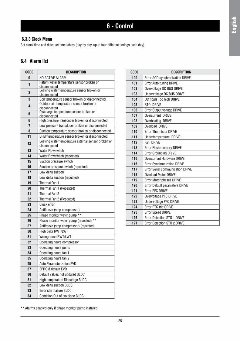
6.4 Alarm list
CODE DESCRIPTION
0 NO ACTIVE ALARM
1Return water temperature sensor broken or disconnected
2Leaving water temperature sensor broken or disconnected
3 Coil temperature sensor broken or disconnected
4Outdoor air temperature sensor broken or disconnected
5Discharge temperature sensor broken or disconnected
6 High pressure transducer broken or disconnected7 Low pressure transducer broken or disconnected8 Suction temperature sensor broken or disconnected11 DHW temperature sensor broken or disconnected
12 Leaving water temperature external sensor broken or disconnected
13 Water Flowswitch14 Water Flowswitch (repeated)15 Suction pressure switch16 Suction pressure switch (repeated)17 Low delta suction18 Low delta suction (repeated)19 Thermal Fan 1 20 Thermal Fan 1 (Repeated)21 Thermal Fan 2 22 Thermal Fan 2 (Repeated)23 Clock error24 Antifreeze (stop compressor)25 Phase monitor water pump **26 Phase monitor water pump (repeated) **27 Antifreeze (stop compressor) (repeated)30 High delta RWT/LWT31 Wrong trend RWT/LWT32 Operating hours compressor33 Operating hours pump34 Operating hours fan 135 Operating hours fan 255 Auto Parameterization EVD57 EPROM default EVD80 Default values not updated BLDC81 High temperature Discahrge BLDC82 Low delta suction BLDC83 Error start failure BLDC84 Condition Out of envelope BLDC
CODE DESCRIPTION
100 Error ACD synchronization DRIVE101 Error Auto tuning DRIVE102 Overvoltage DC BUS DRIVE103 Undervoltage DC BUS DRIVE104 DC ripple Too high DRIVE105 STO DRIVE106 Error Output voltage DRIVE107 Overcurrent DRIVE108 Overheating DRIVE109 Overload DRIVE110 Error Thermistor DRIVE111 Undertemperature DRIVE112 Fan DRIVE113 Error Flash memory DRIVE114 Error Grounding DRIVE115 Overcurrent Hardware DRIVE116 Error Synchronization DRIVE117 Error Serial communication DRIVE118 Overload Motor DRIVE119 Error Motor phases DRIVE120 Error Default parameters DRIVE121 Error PFC DRIVE122 Overvoltage PFC DRIVE123 Undervoltage PFC DRIVE124 Error PTC trip DRIVE125 Error Speed DRIVE126 Error Detection STO 1 DRIVE127 Error Detection STO 2 DRIVE
** Alarms enabled only if phase monitor pump installed
26
7 - Product Description
7.1 General InformationSYSCROLL AIR EVO HP units are one-block type with one refrigerant circuit. They are intended to cool down the water required for any air-conditioning application as well as any other fluid, such as for example glycol water.
These units are completely assembled at works. They are equipped with all the refrigerating connections and the internal electrical wiring required for a rapid installation on the field.
An operation test is performed after assembly, with water flowing through the refrigerant/water exchanger in order to make sure that every refrigerating circuit is properly working. The refrigerating circuits of every unit are pressure tested before inspection, drained and charged with R410A.
A low noise level is the result of a careful study. It is achieved on chillers by using technologically advanced components without negatively affecting the operation performances and limits of the units.
SYSCROLL AIR EVO HP models can cool down chilled water at a temperature between + 18 and - 8 °C.
SYSCROLL AIR EVO HP heat pump models can warm up water at a temperature between 20 °C and 55 °C.
All units can operate with a double set point.
Body and Frame
The base and frame of these units are made with galvanized steel elements, assembled with stainless steel screws. All panels can be removed to ensure easy access to internal components. All galvanized steel parts are protected by epoxy powder paint.
Compressors
Units are equipped with a scroll compressors, with brushless direct current motor (BLDC) type.
The compressors are assembled on rubber shock absorbers. They are cooled down by the refrigerant gas.
Compressors are powered on and off by the microprocessor of the unit control system which is intended to control the delivery of the thermal refrigerating capacity.
Evaporators
Evaporators are made of stainless steel plates. They are thermally insulated by means of a thick flexible insulating mattress with closed cells. The maximum operating pressures correspond to 10 bar
for the water side and to 45 bar for the refrigerant side. Antifreeze protection for the water in the exchangers is ensured by electrical heaters and differential pressure switches. The water side of these exchangers is connected by manifolds which will provide for the connection to the plant by means of one single 1”1 gas threaded attachment.
Condensing coils
Condensers are coils made of copper tubes arranged in staggered rows and mechanically expanded inside an aluminium finned pack with blue fins treatment as a standard.
The maximum operating pressure on the refrigerant side of the condensing batteries is 45 bar.
Condenser Fans
The condenser fans are of a helical type. They are directly coupled and have an impeller with wing contoured aluminium blades. Each fan is equipped with a galvanised steel accident-prevention protection which is painted after manufacture. The fans motors are completely closed. They have an IP54 protection degree and a protection thermostat embedded in the windings.
Fans Control
All models are equipped with a single-phase voltage fan speed controller using the principle of phase control to adjust the effective voltage output to the load, based on the phase of the PWM control signal according the pressure measured on the heat exchanger.
Refrigerating Circuits
Each unit has a single refrigerating circuit equipped with an external service valves intended to measure the refrigerant pressure and charge, a sight glass with a humidity indicator, a dryer filter and a electronic expansion valve.
Refrigerating circuits are also complete with a high and low pressure switch as well as a high and low transducer.
Control Supply Panel
All components of the control system and those necessary to start the motors are shop connected and tested. The control compartment contains an electronic card and a control board with an external keyboard and display, to show the operational functions, as well as the intervention of the alarms and the working blocks.
27
Engl
ish
7 - Product Description
7.2 Accessories
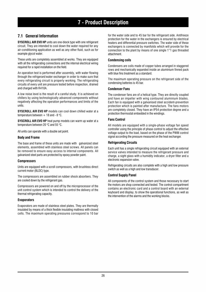
Water Filter
1-1/4” filter is included in the supplied equipment. It is supplied loose and has to be mounted by the customer.
Flow switch kit
Flow switch kit is available as an accessory. It is supplied loose and as to be mounted by the customer. Connect terminals 1-2 of the flow switch with terminals 1-2 of the electrical box.
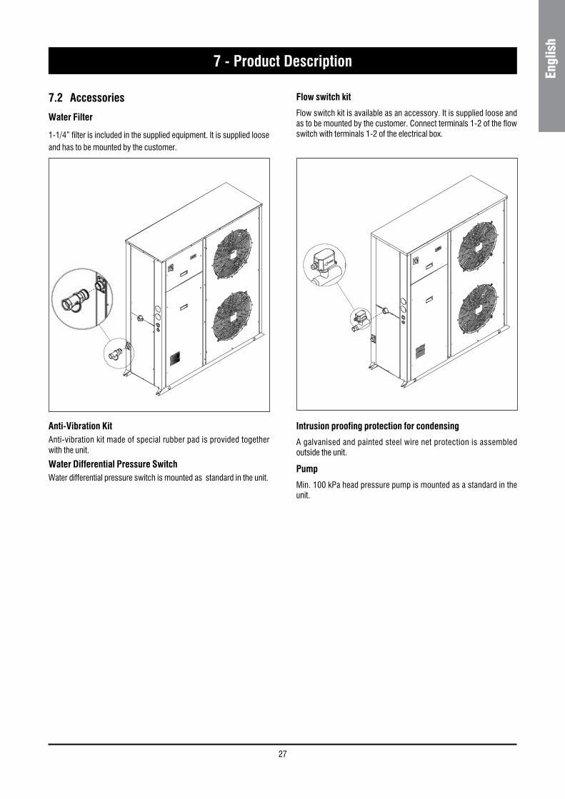
Anti-Vibration Kit Anti-vibration kit made of special rubber pad is provided together with the unit.
Water Differential Pressure SwitchWater differential pressure switch is mounted as standard in the unit.
Intrusion proofing protection for condensing
A galvanised and painted steel wire net protection is assembled outside the unit.
Pump
Min. 100 kPa head pressure pump is mounted as a standard in the unit.
28
7 - Product Description
Airway Packaging
Complete wooden package for units without refrigerant and with nitrogen precharge. No refrigerant charge is shipped loose with the unit. The customer has to fill the unit through the apposite connection.
Water buffer tank
The hydro module is available for the units with a pump. It is installed beneath the unit through the connection pipe supplied with the unit.
The module is entirely enclosed in a galvanised and painted steel body. The tank is completely insulated with 30 Kg/m3 closed cell polyethylene in a silver colour.
Antifreeze resistances or a heating booster kit are installed in the tank (upon request).
On/Off Remote Kit
It enables the operator to power on the unit when it is in standby mode, to display alarms and to switch over cooling – heat pump. The kit will include a 3 metre long cable for installation on the wall.
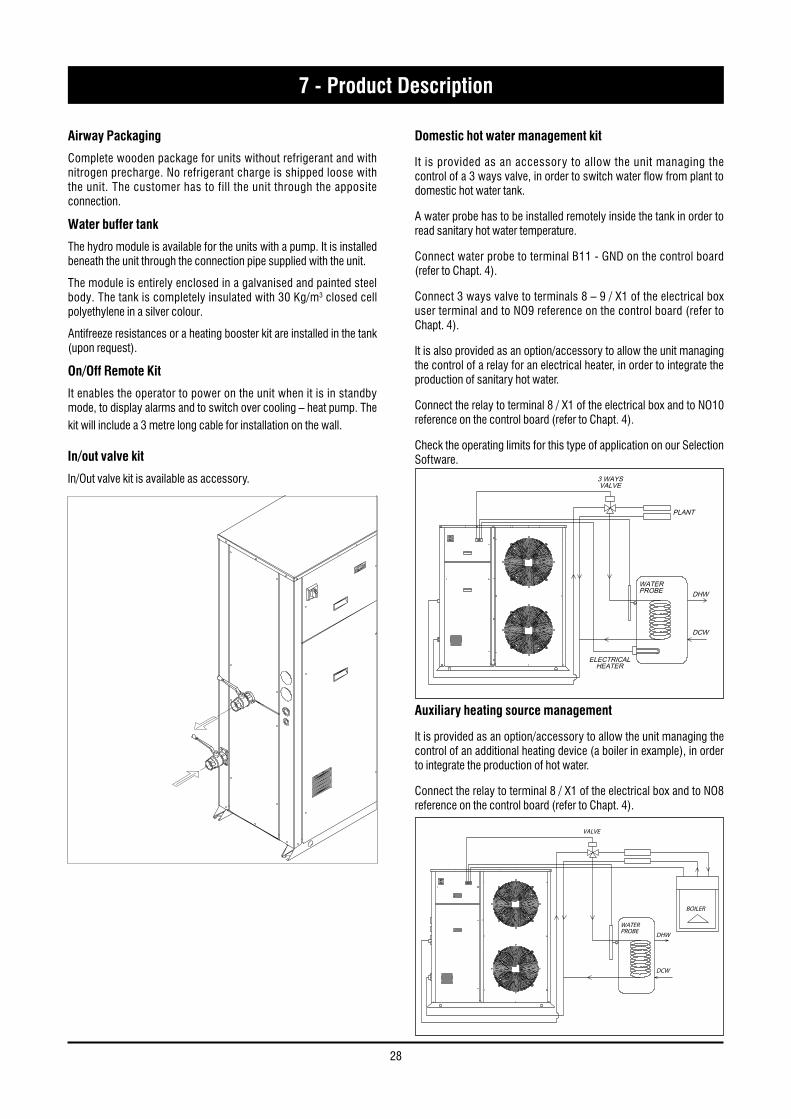
In/out valve kit
In/Out valve kit is available as accessory.
PLANT
WATERPROBE DHW
DCW
3 WAYSVALVE
ELECTRICALHEATER
DHW INTEGRATION KITJ3
4839
Domestic hot water management kit
It is provided as an accessory to allow the unit managing the control of a 3 ways valve, in order to switch water flow from plant to domestic hot water tank.
A water probe has to be installed remotely inside the tank in order to read sanitary hot water temperature.
Connect water probe to terminal B11 - GND on the control board (refer to Chapt. 4).
Connect 3 ways valve to terminals 8 – 9 / X1 of the electrical box user terminal and to NO9 reference on the control board (refer to Chapt. 4).
It is also provided as an option/accessory to allow the unit managing the control of a relay for an electrical heater, in order to integrate the production of sanitary hot water.
Connect the relay to terminal 8 / X1 of the electrical box and to NO10 reference on the control board (refer to Chapt. 4).
Check the operating limits for this type of application on our Selection Software.
BOILER
WATERPROBE DHW
DCW
3 WAYSVALVE
Auxiliary heating source management
It is provided as an option/accessory to allow the unit managing the control of an additional heating device (a boiler in example), in order to integrate the production of hot water.
Connect the relay to terminal 8 / X1 of the electrical box and to NO8 reference on the control board (refer to Chapt. 4).
29
Engl
ish
7 - Product Description
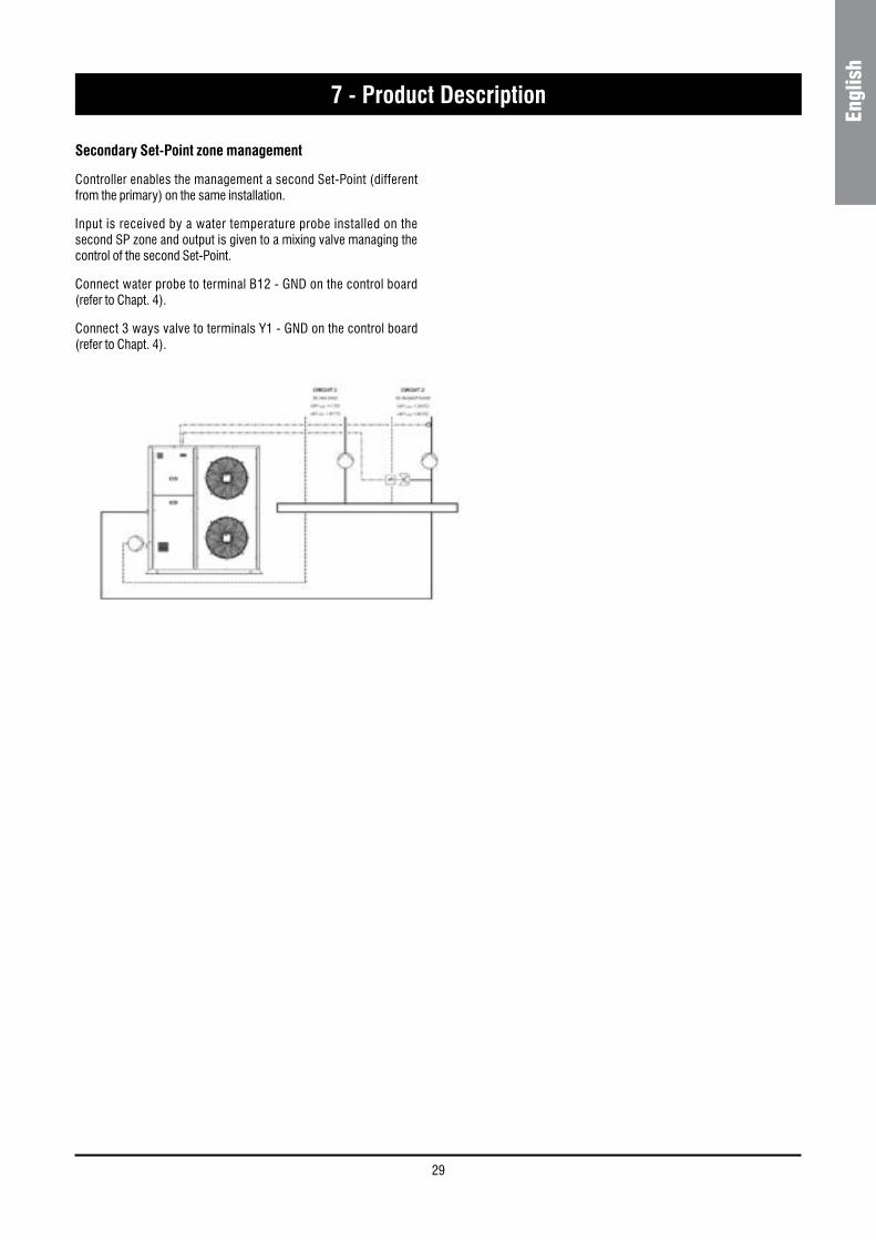
Secondary Set-Point zone management
Controller enables the management a second Set-Point (different from the primary) on the same installation.
Input is received by a water temperature probe installed on the second SP zone and output is given to a mixing valve managing the control of the second Set-Point.
Connect water probe to terminal B12 - GND on the control board (refer to Chapt. 4).
Connect 3 ways valve to terminals Y1 - GND on the control board (refer to Chapt. 4).
30
7 - Product Description
3
2
ON
H
45
67
8
ATA1
C
FS
N
11
N
L
L
12 10
15
1514
16
13
HYDROKIT
9
17
S
F
E
D
I SBSKM
KMS
ST BT
UNITCONTROL
18
INVERTERM
EEVCONTROL
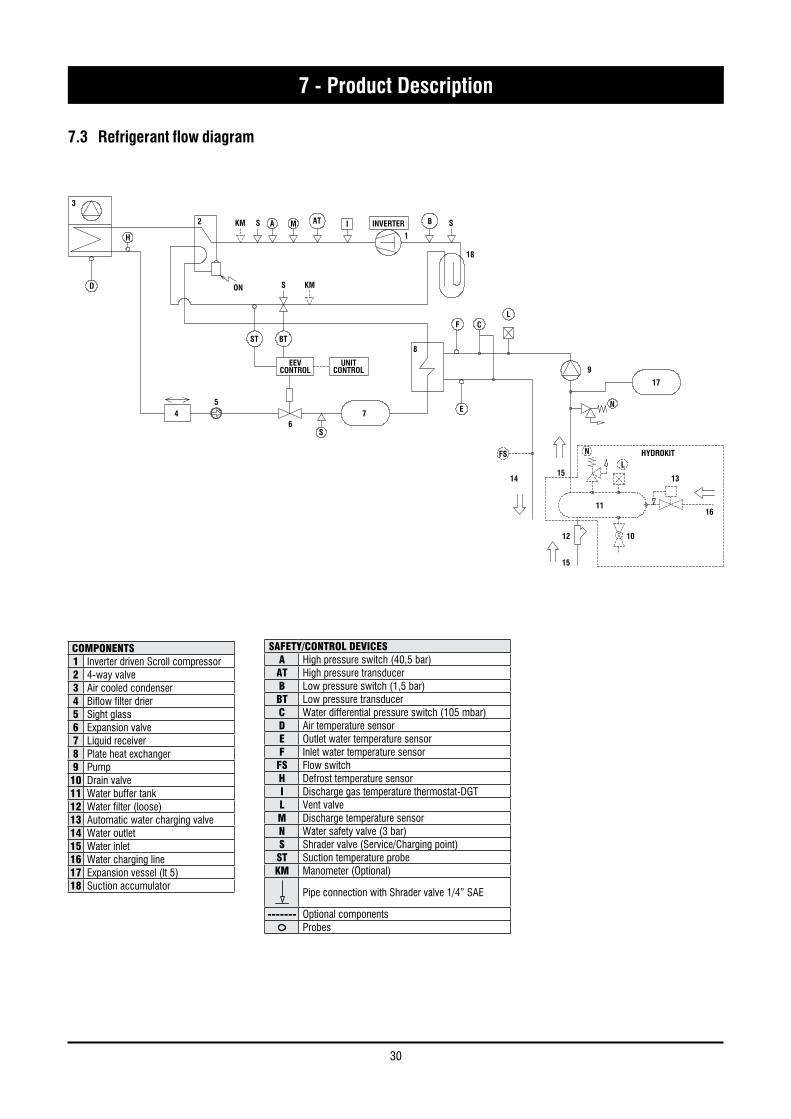
7.3 Refrigerant flow diagram
SAFETY/CONTROL DEVICESA High pressure switch (40,5 bar)AT High pressure transducerB Low pressure switch (1,5 bar)BT Low pressure transducerC Water differential pressure switch (105 mbar)D Air temperature sensorE Outlet water temperature sensorF Inlet water temperature sensorFS Flow switchH Defrost temperature sensorI Discharge gas temperature thermostat-DGTL Vent valveM Discharge temperature sensorN Water safety valve (3 bar)S Shrader valve (Service/Charging point)ST Suction temperature probeKM Manometer (Optional)
Pipe connection with Shrader valve 1/4” SAE
------- Optional componentsProbes
COMPONENTS1 Inverter driven Scroll compressor2 4-way valve3 Air cooled condenser4 Biflow filter drier5 Sight glass6 Expansion valve7 Liquid receiver8 Plate heat exchanger9 Pump
10 Drain valve11 Water buffer tank12 Water filter (loose)13 Automatic water charging valve14 Water outlet15 Water inlet16 Water charging line17 Expansion vessel (lt 5)18 Suction accumulator
31
Engl
ish
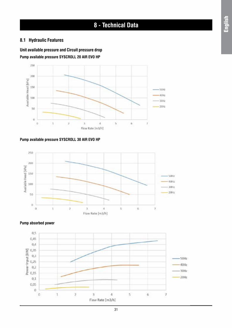
8.1 Hydraulic Features
Unit available pressure and Circuit pressure drop
Pump available pressure SYSCROLL 20 AIR EVO HP
8 - Technical Data
Pump available pressure SYSCROLL 30 AIR EVO HP
Pump absorbed power
32
8 - Technical Data
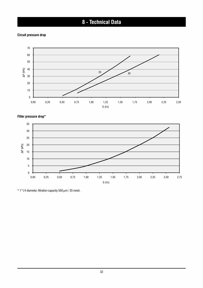
Circuit pressure drop
0
5
10
15
20
25
30
35
0,00 0,25 0,50 0,75 1,00 1,25 1,50 1,75 2,00 2,25 2,50 2,75
G (l/s)
∆P
(kPa
)
Filter pressure drop*
0
70
60
50
40
30
20
10
0,00
G (l/s)
∆P
(kPa
)
0,20 0,50 0,75 1,00 1,25 1,50 1,75 2,00 2,25 2,50
20 30
* 1”1/4 diameter, filtration capacity 500 μm / 35 mesh.
33
Engl
ish
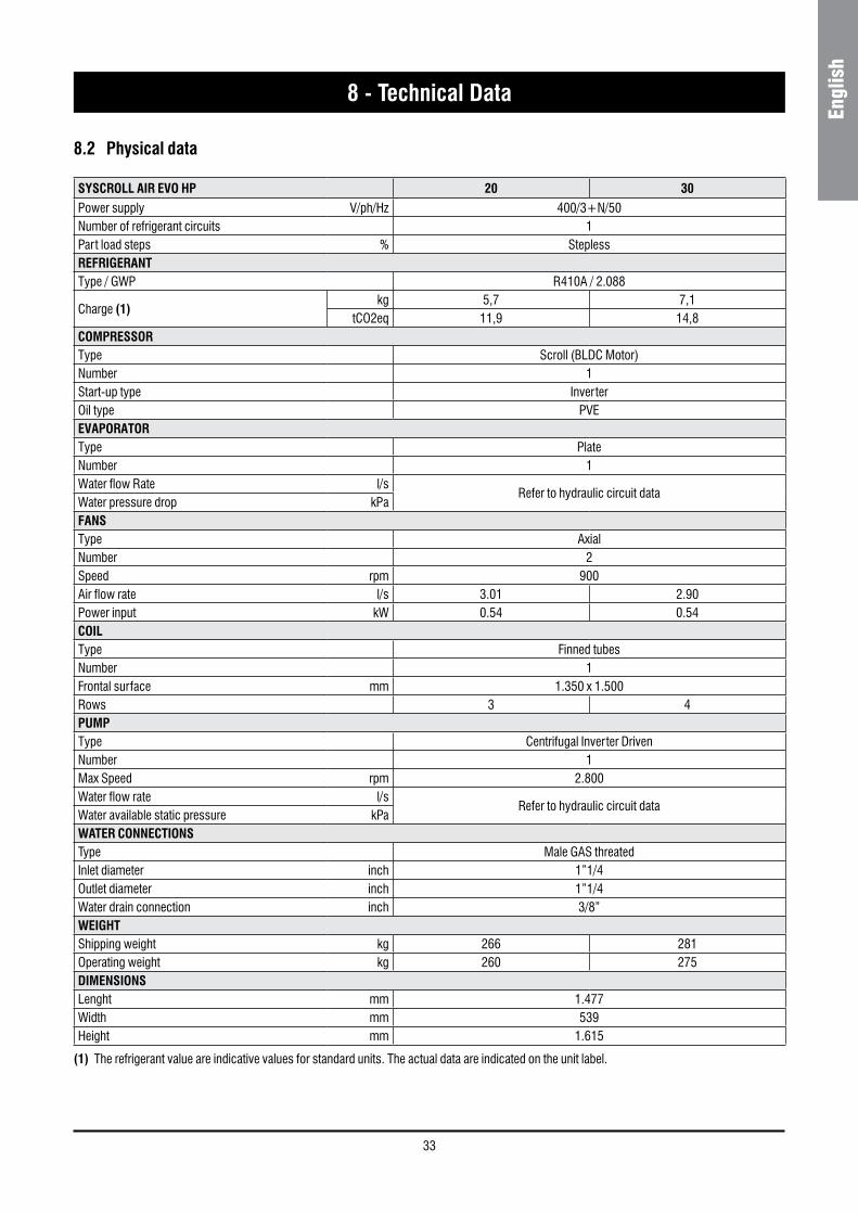
SYSCROLL AIR EVO HP 20 30Power supply V/ph/Hz 400/3+N/50Number of refrigerant circuits 1Part load steps % SteplessREFRIGERANTType / GWP R410A / 2.088
Charge (1)kg 5,7 7,1
tCO2eq 11,9 14,8COMPRESSORType Scroll (BLDC Motor)Number 1Start-up type InverterOil type PVEEVAPORATORType PlateNumber 1Water flow Rate l/s
Refer to hydraulic circuit dataWater pressure drop kPaFANSType AxialNumber 2Speed rpm 900Air flow rate l/s 3.01 2.90Power input kW 0.54 0.54COILType Finned tubesNumber 1Frontal surface mm 1.350 x 1.500Rows 3 4PUMPType Centrifugal Inverter DrivenNumber 1Max Speed rpm 2.800Water flow rate l/s
Refer to hydraulic circuit dataWater available static pressure kPaWATER CONNECTIONSType Male GAS threatedInlet diameter inch 1”1/4Outlet diameter inch 1”1/4Water drain connection inch 3/8”WEIGHTShipping weight kg 266 281Operating weight kg 260 275DIMENSIONSLenght mm 1.477Width mm 539Height mm 1.615
8.2 Physical data
8 - Technical Data
(1) The refrigerant value are indicative values for standard units. The actual data are indicated on the unit label.
34
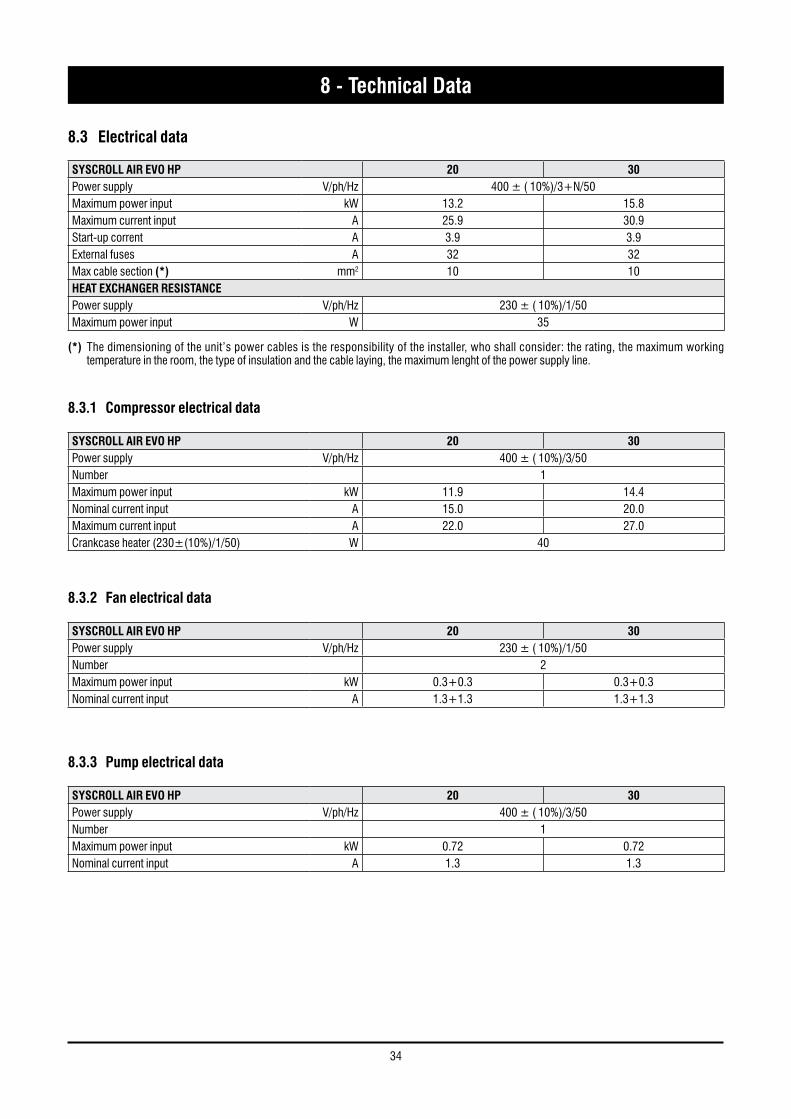
SYSCROLL AIR EVO HP 20 30Power supply V/ph/Hz 400 ± ( 10%)/3+N/50Maximum power input kW 13.2 15.8Maximum current input A 25.9 30.9Start-up corrent A 3.9 3.9External fuses A 32 32Max cable section (*) mm2 10 10HEAT EXCHANGER RESISTANCEPower supply V/ph/Hz 230 ± ( 10%)/1/50Maximum power input W 35
8 - Technical Data
(*) The dimensioning of the unit’s power cables is the responsibility of the installer, who shall consider: the rating, the maximum working temperature in the room, the type of insulation and the cable laying, the maximum lenght of the power supply line.
8.3 Electrical data
8.3.1 Compressor electrical data
SYSCROLL AIR EVO HP 20 30Power supply V/ph/Hz 400 ± ( 10%)/3/50Number 1Maximum power input kW 11.9 14.4Nominal current input A 15.0 20.0Maximum current input A 22.0 27.0Crankcase heater (230±(10%)/1/50) W 40
8.3.2 Fan electrical data
SYSCROLL AIR EVO HP 20 30Power supply V/ph/Hz 230 ± ( 10%)/1/50Number 2Maximum power input kW 0.3+0.3 0.3+0.3Nominal current input A 1.3+1.3 1.3+1.3
8.3.3 Pump electrical data
SYSCROLL AIR EVO HP 20 30Power supply V/ph/Hz 400 ± ( 10%)/3/50Number 1Maximum power input kW 0.72 0.72Nominal current input A 1.3 1.3
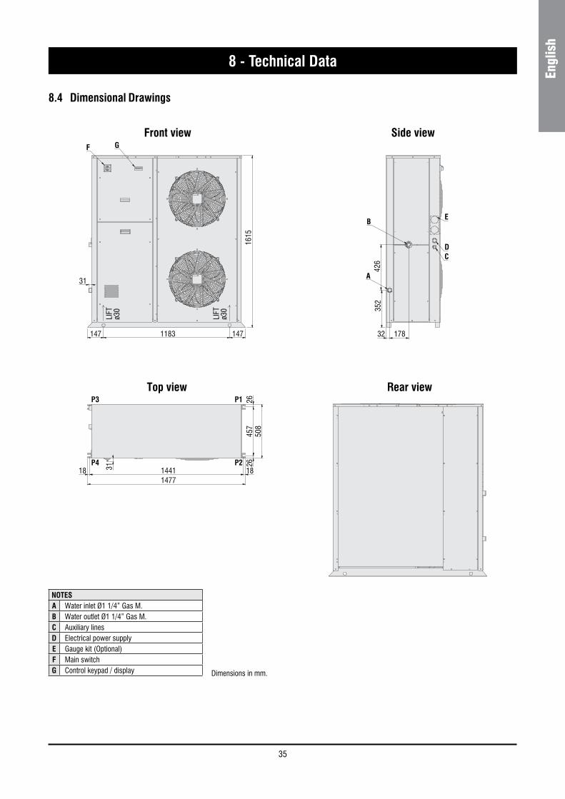
35
Engl
ish
1615
147 1183 147
31
LIFT
ø30
LIFT
ø30
457
2626
508
1441 18181477
31
352
426
32 178
F G
A
BE
DC
P3 P1
P4 P2
8.4 Dimensional Drawings
8 - Technical Data
Front view Side view
Dimensions in mm.
NOTESA Water inlet Ø1 1/4” Gas M.B Water outlet Ø1 1/4” Gas M.C Auxiliary linesD Electrical power supplyE Gauge kit (Optional)F Main switchG Control keypad / display
1615
147 1183 147
31
LIFT
ø30
LIFT
ø30
457
2626
508
1441 18181477
31
352
426
32 178
F G
A
BE
DC
P3 P1
P4 P2
Top view Rear view
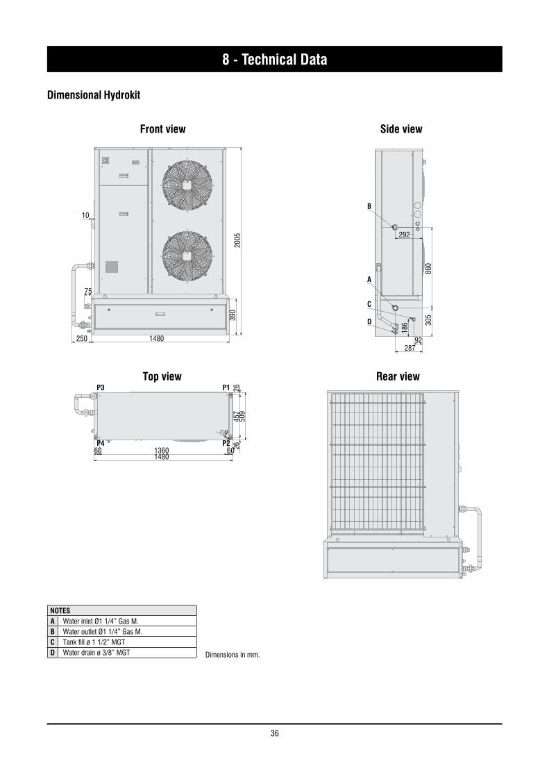
36
8 - Technical Data
75
10
250 1480
390
2005
1480
509
1360 60 2645
726
60
9
305
860
92287
292
B
A
C
D
186
P3 P1
P4 P2
75
10
250 148039
020
05
148050
91360 60 26
457
2660
9
305
860
92287
292
B
A
C
D
186
P3 P1
P4 P2
Front view Side view
Top view
Dimensions in mm.
NOTESA Water inlet Ø1 1/4” Gas M.B Water outlet Ø1 1/4” Gas M.C Tank fill ø 1 1/2” MGTD Water drain ø 3/8” MGT
Dimensional Hydrokit
Rear view
75
10
250 1480
390
2005
1480
509
1360 60 2645
726
60
9
305
860
92287
292
B
A
C
D
186
P3 P1
P4 P2
75
10
250 1480
390
2005
1480
509
1360 60 2645
726
60
9
305
860
92287
292
B
A
C
D
186
P3 P1
P4 P2
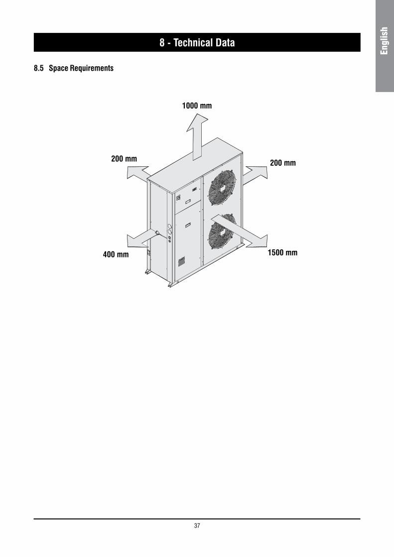
37
Engl
ish
8.5 Space Requirements
8 - Technical Data
1500 mm400 mm
200 mm
1000 mm
200 mm
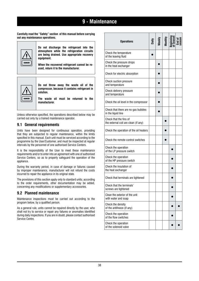
38
9 - Maintenance
Carefully read the “Safety” section of this manual before carrying out any maintenance operations.
DANGER
Do not discharge the refrigerant into the atmosphere while the refrigeration circuits are being drained. Use appropriate recovery equipment.
When the recovered refrigerant cannot be re-used, return it to the manufacturer.
DANGER
Do not throw away the waste oil of the compressor, because it contains refrigerant in solution.
The waste oil must be returned to the manufacturer.
Unless otherwise specified, the operations described below may be carried out only by a trained maintenance operator.
9.1 General requirements
Units have been designed for continuous operation, providing that they are subjected to regular maintenance, within the limits specified in this manual. Each unit must be serviced according to the programme by the User/Customer, and must be inspected at regular intervals by the personnel of one authorised Service Centers.
It is the responsibility of the User to meet these maintenance requirements and/or to enter into an agreement with one of authorised Service Centers, so as to properly safeguard the operation of the appliance.
During the warranty period, in case of damage or failures caused by improper maintenance, manufacturer will not refund the costs incurred to repair the appliance in its original state.
The provisions of this section apply only to standard units; according to the order requirements, other documentation may be added, concerning any modifications or supplementary accessories.
9.2 Planned maintenanceMaintenance inspections must be carried out according to the program below, by a qualified person.
As a general rule, units cannot be repaired directly by the user, who shall not try to service or repair any failures or anomalies identified during daily inspections. If you are in doubt, please contact authorised Service Centre.
Operations
Daily
Wee
kly
Mon
thly
Begi
nnin
g of
sea
son
End
of
seas
on
Check the temperatureof the leaving fluid •Check the pressure dropsin the heat exchanger •Check for electric absorption •Check suction pressureand temperature •Check delivery pressureand temperature •Check the oil level in the compressor •Check that there are no gas bubbles in the liquid line •Check that the fins ofthe external coil are clean (if any) •Check the operation of the oil heaters •Check the remote control switches •Check the operationof the LP pressure switch •Check the operationof the HP pressure switch •Check the insulation ofthe heat exchanger •Check that terminals are tightened •Check that the terminals’screws are tightened •Clean the exterior of the unitwith water and soap •Check the densityof the antifreeze (if any) • •Check the operationof the flow switches •Check the operationof the solenoid valve • •
39
Engl
ish
9 - Maintenance
9.3 Refrigerant charge
WARNING
Do not inject refrigerant liquid into the LP side of the circuit. Be very careful, and charge the circuit properly.
If the charge is insufficient, the efficiency of the unit will be lower than expected. In the worst of cases the LP transducer may stop the unit.
In the presence of an excess charge, the condensing pressure will rise (in the worst of cases, the HP pressure switch may be activated, resulting in the stop of the equipment), and the consumption will increase as well.
WARNING
It is strictly forbidden to use the compressor as a vacuum pump to drain the plant.
Fill the refrigeration circuit after it has been drained for maintenance purposes (leaks, replacement of the compressor etc.). The amount of the charge is indicated on the plate affixed to the unit.
Before refilling, it is important to drain and de-hydrate the circuit, thus obtaining a minimum abs. pressure value of 50 Pa.
Inject the refrigerant fluid before removing the vacuum, then fill the circuit up to 90% of the total gas requirement (in liquid form). The appliance must be filled through the filling valve on the liquid line, on the outlet side of the condenser.
It is recommended to connect the refrigerant cylinder to the filling valve on the liquid line, and to arrange it in such a way as to inject only liquid refrigerant.
9.4 CompressorCompressors are delivered with the necessary charge of lubricating oil. During normal operation, this charge is sufficient for the whole life of the unit, providing that the efficiency of the refrigeration circuit is satisfactory and if it has not been overhauled.
If the compressor needs to be replaced (following a mechanical failure or if burnt), contact one of authorised Service Centers.
WARNING
Compressors use polyester oil. During maintenance operations on the compressor, or if you have to open the refrigerant circuit in any point, remember that this type of oil is highly hygroscopic, and accordingly it is important that it is not left exposed to the weather for prolonged periods, as this would require the replacement of the oil.
9.5 CondenserThe condenser’s coils consist of copper pipes and aluminium fins. In the presence of leaks caused by any damage or shock, the coils shall be repaired or replaced by one authorised Service Center. To ensure the effective and correct operation of the condenser coils, it is important to keep the condenser’s surface perfectly clean, and to check that there is no foreign matter, such as leafs, wires, insects, waste etc. If the coil becomes dirty, there is an increase in the absorption of electric energy. Furthermore, the maximum pressure alarm may be activated and may halt the unit.
WARNING
Be careful not to damage the aluminium fins during cleaning.
The condenser must be cleaned with a LP compressed air jet, parallel to the aluminium fins, in the direction opposite to the air circulation.
To clean the coil you can use also a vacuum cleaner, or a jet of water and soap.
9.6 FansThe fans of the condenser, of axial type, are complete with impeller with aerodynamic profile blades and a cylindrical nozzle. The motor’s bearings are lubricated forever.
9.7 Dehydrating filterThe refrigeration circuits are provided with dehydrating filters.
The filter clogging is marked by the presence of air bubbles in the sight glass, or by the difference between the temperatures measured downstream from and upstream of the drying filter. If, once the cartridge has been cleaned, there are still some air bubbles, the appliance has lost a part of the refrigerant charge in one or more points, that must be identified and serviced.
40
9 - Maintenance
9.8 Sight glassThe sight glass is used for inspecting the refrigerant flow and the humidity % of the refrigerant. The presence of bubbles indicates that the dehydrating filter is clogged or the charge insufficient.
A colour indicator is positioned inside the sight glass. If you compare the colour of the indicator to the scale on the ring of the sight glass, you can calculate the percentage of humidity of the refrigerant. If it is excessive, replace the filter’s cartridge, operate the appliance for 1 day and then check the humidity % again. When the humidity % is within the pre-determined range, no other operations are required. If the humidity % is still too high, replace the dehydrating filter again, start the unit and operate it for another day.
9.9 Electonic expansion valveThe circuit of the unit is equipped with a thermostatic expansion valve, with external equalizer.
The valve is factory calibrated for an overheating of 5 °C.
Procedure to check for overheating :
– Measure the suction pressure with the pressure gauges on the board of the unit o using a pressure gauge connected to the service valve on the suction side.
– From the pressure gauge’s temperature scale, measure the saturated suction temperature (Tsa) which corresponds to the pressure value.
– Using a contact pressure gauge affixed to the outlet fitting of the gas of the evaporator, measure the actual temperature (Tse).
Overheating calculation (S):
S = Tse - Tsa
Overheating is regulated through the driver.
If the expansion valve cannot be regulated, it is probably broken, and shall be replaced. The replacement must be carried out by a Service Centre.
9.10 EvaporatorCheck at regular intervals that the water side of the heat exchanger is perfectly clean. To do this, measure the pressure drop, water side (see Section 8) or measure the temperature of the liquid leaving and entering the heat exchanger, and compare it to the evaporation temperature.
To obtain an effective heat exchange, the difference between the temperature of the leaving water and the saturated evaporating temperature must be in the 2 - 4 °C range. A greater difference would indicate a low efficiency of the heat exchanger (i.e. the heat exchanger is dirty).
In this case, the heat exchanger must be subjected to chemical cleaning, an operation that shall be carried out by authorised engineers.
For other maintenance operations (extraordinary overhauling, replacement of the heat exchanger etc.), contact an authorised Service Centre.
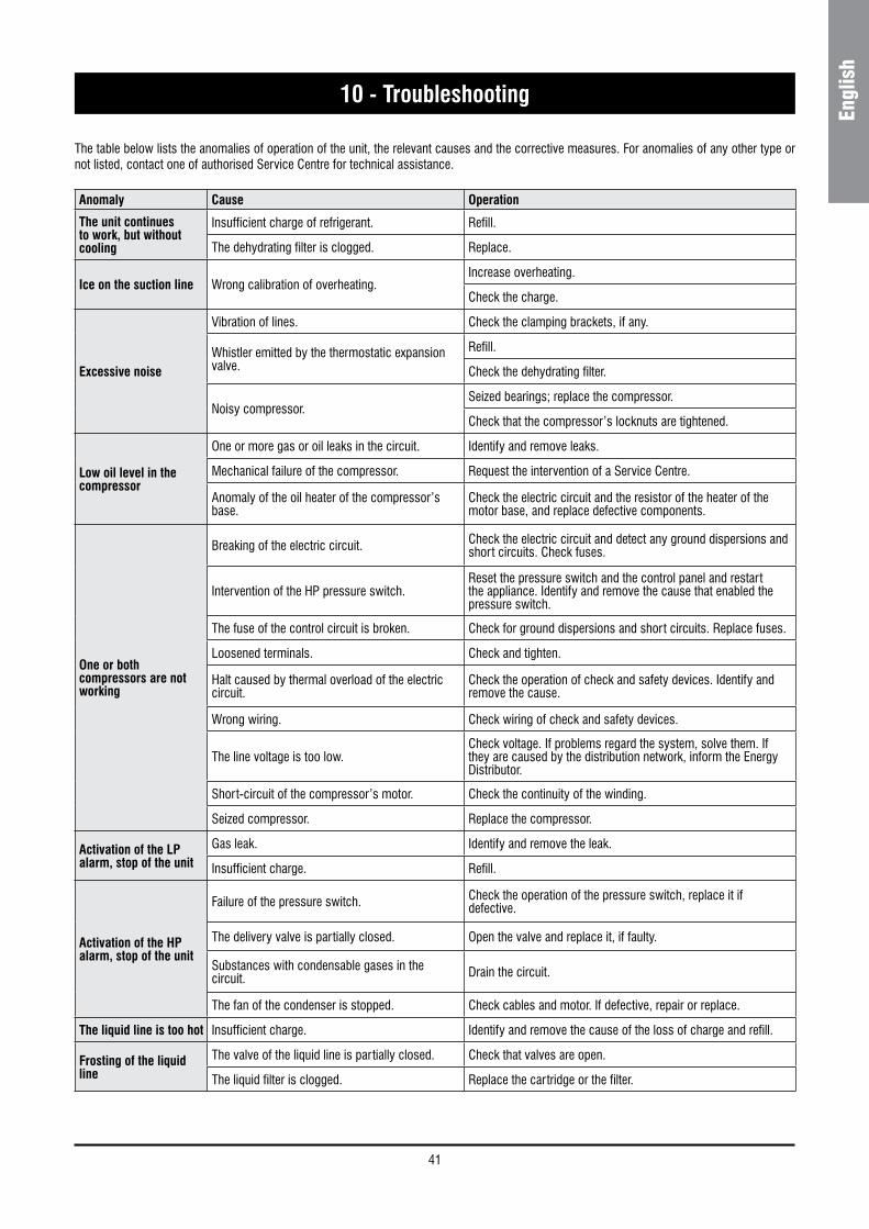
41
Engl
ish
10 - Troubleshooting
The table below lists the anomalies of operation of the unit, the relevant causes and the corrective measures. For anomalies of any other type or not listed, contact one of authorised Service Centre for technical assistance.
Anomaly Cause Operation
The unit continues to work, but without cooling
Insufficient charge of refrigerant. Refill.
The dehydrating filter is clogged. Replace.
Ice on the suction line Wrong calibration of overheating.Increase overheating.
Check the charge.
Excessive noise
Vibration of lines. Check the clamping brackets, if any.
Whistler emitted by the thermostatic expansion valve.
Refill.
Check the dehydrating filter.
Noisy compressor.Seized bearings; replace the compressor.
Check that the compressor’s locknuts are tightened.
Low oil level in the compressor
One or more gas or oil leaks in the circuit. Identify and remove leaks.
Mechanical failure of the compressor. Request the intervention of a Service Centre.
Anomaly of the oil heater of the compressor’s base.
Check the electric circuit and the resistor of the heater of the motor base, and replace defective components.
One or both compressors are not working
Breaking of the electric circuit. Check the electric circuit and detect any ground dispersions and short circuits. Check fuses.
Intervention of the HP pressure switch.Reset the pressure switch and the control panel and restart the appliance. Identify and remove the cause that enabled the pressure switch.
The fuse of the control circuit is broken. Check for ground dispersions and short circuits. Replace fuses.
Loosened terminals. Check and tighten.
Halt caused by thermal overload of the electric circuit.
Check the operation of check and safety devices. Identify and remove the cause.
Wrong wiring. Check wiring of check and safety devices.
The line voltage is too low.Check voltage. If problems regard the system, solve them. If they are caused by the distribution network, inform the Energy Distributor.
Short-circuit of the compressor’s motor. Check the continuity of the winding.
Seized compressor. Replace the compressor.
Activation of the LP alarm, stop of the unit
Gas leak. Identify and remove the leak.
Insufficient charge. Refill.
Activation of the HP alarm, stop of the unit
Failure of the pressure switch. Check the operation of the pressure switch, replace it if defective.
The delivery valve is partially closed. Open the valve and replace it, if faulty.
Substances with condensable gases in the circuit. Drain the circuit.
The fan of the condenser is stopped. Check cables and motor. If defective, repair or replace.
The liquid line is too hot Insufficient charge. Identify and remove the cause of the loss of charge and refill.
Frosting of the liquid line
The valve of the liquid line is partially closed. Check that valves are open.
The liquid filter is clogged. Replace the cartridge or the filter.
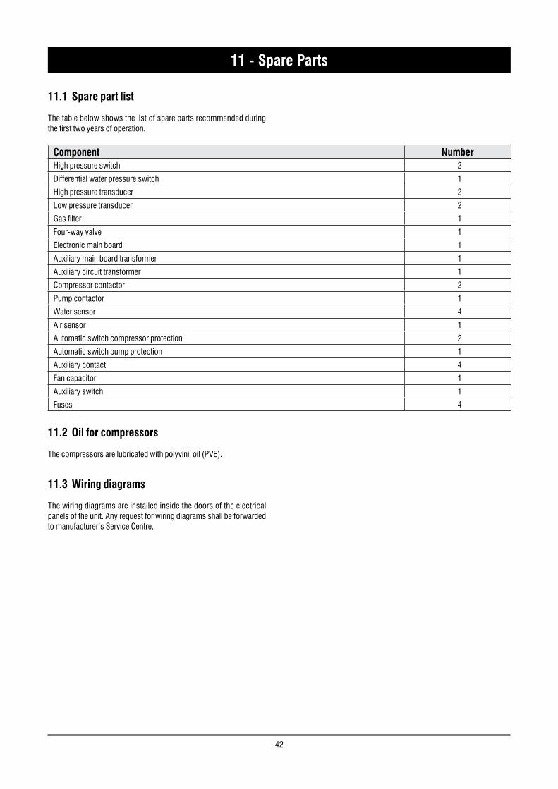
42
11.1 Spare part list
The table below shows the list of spare parts recommended during the first two years of operation.
11.2 Oil for compressors
The compressors are lubricated with polyvinil oil (PVE).
11.3 Wiring diagrams
The wiring diagrams are installed inside the doors of the electrical panels of the unit. Any request for wiring diagrams shall be forwarded to manufacturer’s Service Centre.
Component NumberHigh pressure switch 2
Differential water pressure switch 1
High pressure transducer 2
Low pressure transducer 2
Gas filter 1
Four-way valve 1
Electronic main board 1
Auxiliary main board transformer 1
Auxiliary circuit transformer 1
Compressor contactor 2
Pump contactor 1
Water sensor 4
Air sensor 1
Automatic switch compressor protection 2
Automatic switch pump protection 1
Auxiliary contact 4
Fan capacitor 1
Auxiliary switch 1
Fuses 4
11 - Spare Parts
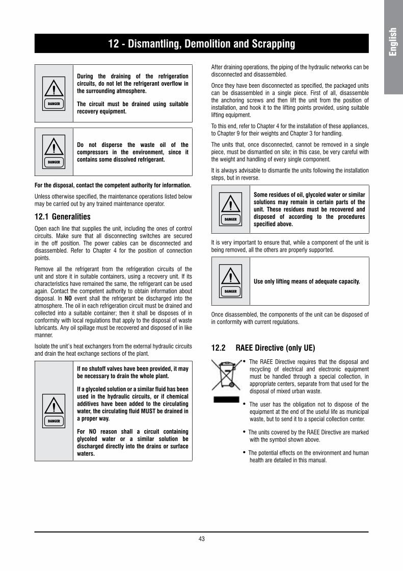
43
Engl
ish
12 - Dismantling, Demolition and Scrapping
DANGER
During the draining of the refrigeration circuits, do not let the refrigerant overflow in the surrounding atmosphere.
The circuit must be drained using suitable recovery equipment.
DANGER
Do not disperse the waste oil of the compressors in the environment, since it contains some dissolved refrigerant.
For the disposal, contact the competent authority for information.
Unless otherwise specified, the maintenance operations listed below may be carried out by any trained maintenance operator.
12.1 GeneralitiesOpen each line that supplies the unit, including the ones of control circuits. Make sure that all disconnecting switches are secured in the off position. The power cables can be disconnected and disassembled. Refer to Chapter 4 for the position of connection points.
Remove all the refrigerant from the refrigeration circuits of the unit and store it in suitable containers, using a recovery unit. If its characteristics have remained the same, the refrigerant can be used again. Contact the competent authority to obtain information about disposal. In NO event shall the refrigerant be discharged into the atmosphere. The oil in each refrigeration circuit must be drained and collected into a suitable container; then it shall be disposes of in conformity with local regulations that apply to the disposal of waste lubricants. Any oil spillage must be recovered and disposed of in like manner.
Isolate the unit’s heat exchangers from the external hydraulic circuits and drain the heat exchange sections of the plant.
DANGER
If no shutoff valves have been provided, it may be necessary to drain the whole plant.
If a glycoled solution or a similar fluid has been used in the hydraulic circuits, or if chemical additives have been added to the circulating water, the circulating fluid MUST be drained in a proper way.
For NO reason shall a circuit containing glycoled water or a similar solution be discharged directly into the drains or surface waters.
After draining operations, the piping of the hydraulic networks can be disconnected and disassembled.
Once they have been disconnected as specified, the packaged units can be disassembled in a single piece. First of all, disassemble the anchoring screws and then lift the unit from the position of installation, and hook it to the lifting points provided, using suitable lifting equipment.
To this end, refer to Chapter 4 for the installation of these appliances, to Chapter 9 for their weights and Chapter 3 for handling.
The units that, once disconnected, cannot be removed in a single piece, must be dismantled on site; in this case, be very careful with the weight and handling of every single component.
It is always advisable to dismantle the units following the installation steps, but in reverse.
DANGER
Some residues of oil, glycoled water or similar solutions may remain in certain parts of the unit. These residues must be recovered and disposed of according to the procedures specified above.
It is very important to ensure that, while a component of the unit is being removed, all the others are properly supported.
DANGER
Use only lifting means of adequate capacity.
Once disassembled, the components of the unit can be disposed of in conformity with current regulations.
12.2 RAEE Directive (only UE)
• The RAEE Directive requires that the disposal and recycling of electrical and electronic equipment must be handled through a special collection, in appropriate centers, separate from that used for the disposal of mixed urban waste.
• The user has the obligation not to dispose of the equipment at the end of the useful life as municipal waste, but to send it to a special collection center.
• The units covered by the RAEE Directive are marked with the symbol shown above.
• The potential effects on the environment and human health are detailed in this manual.
As part of our ongoing product improvement programme, our products are subject to change without prior notice. Non contractual photos.Dans un souci d’amélioration constante, nos produits peuvent être modifiés sans préavis. Photos non contractuelles.In dem Bemühen um ständige Verbesserung können unsere Erzeugnisse ohne vorherige Ankündigung geändert werden. Fotos nicht vertraglich bindend.A causa della politica di continua miglioria posta in atto dal costruttore, questi prodotti sono soggetti a modifiche senza alcun obbligo di preavviso. Le foto pubblicate non danno luogo ad alcun vincolo contrattuale.Con objeto de mejorar constantemente, nuestros productos pueden ser modificados sin previo aviso. Fotos no contractuales.Согласно программе постоянного улучшения продукции, наши изделия могут быть изменены без предварительного уведомления. Фотографии приведены только в целях иллюстрации.
Systemair srlVia XXV Aprile, 2920825 Barlassina (MB) Italy
Tel. +39 0362 680 1Fax +39 0362 680 693
www.systemair.com
Related Documents