212 International Journal on Advances in Software, vol 5 no 3 & 4, year 2012, http://www.iariajournals.org/software/ 2012, © Copyright by authors, Published under agreement with IARIA - www.iaria.org Synthesizing Control Software from Boolean Relations Federico Mari, Igor Melatti, Ivano Salvo, and Enrico Tronci Department of Computer Science Sapienza University of Rome Via Salaria 113, 00198 Rome, Italy Email: {mari,melatti,salvo,tronci}@di.uniroma1.it Abstract—Many software as well digital hardware automatic synthesis methods define the set of implementations meeting the given system specifications with a boolean relation K. In such a context a fundamental step in the software (hardware) synthesis process is finding effective solutions to the functional equation defined by K. This entails finding a (set of) boolean function(s) F (typically represented using OBDDs, Ordered Binary Decision Diagrams) such that: 1) for all x for which K is satisfiable, K(x, F (x)) = 1 holds; 2) the implementation of F is efficient with respect to given implementation parameters such as code size or execution time. While this problem has been widely studied in digital hardware synthesis, little has been done in a software synthesis context. Unfortunately, the approaches developed for hardware synthesis cannot be directly used in a software context. This motivates investigation of effective methods to solve the above problem when F has to be implemented with software. In this paper, we present an algorithm that, from an OBDD representation for K, generates a C code implementation for F that has the same size as the OBDD for F and a worst case execution time linear in nr, being n = |x| the number of input arguments for functions in F and r the number of functions in F . Moreover, a formal proof of the proposed algorithm correctness is also shown. Finally, we present experimental results showing effectiveness of the proposed algorithm. Keywords-Control Software Synthesis; Embedded Systems; Model Checking I. I NTRODUCTION Many software as well digital hardware automatic syn- thesis methods define the set of implementations meeting the given system specifications with a boolean relation K. Given an n-bits (resp., r-bits) binary encoding of states (resp., actions) of the system as it is usually done in Model Checking [7] (see Sect. III-B), such relation typically takes as input the n-bits encoding of a state x and the r-bits encoding of a proposed action to be performed u, and returns true (i.e., 1) if and only if the system specifications are met when performing action u in state x. In such a context, a fundamental step in the software (hardware) synthesis pro- cess is finding effective solutions to the functional equation defined by K, i.e., K(x, u)=1. This entails finding a tuple of boolean functions F = 〈f 1 ,...,f r 〉 (typically represented using OBDDs, Ordered Binary Decision Diagrams [2]) such that 1) for all x for which K is satisfiable (i.e., it enables at least one action), K(x, F (x)) = 1 holds, and 2) the implementation of F is efficient with respect to given implementation parameters such as code size or execution time. While this problem has been widely studied in digital hardware synthesis [3][4], little has been done in a software synthesis context. This is not surprising since software synthesis from formal specifications is still in its infancy. Unfortunately the approaches developed for hardware syn- thesis cannot be directly used in a software context. In fact, synthesis methods targeting a hardware implementation typically aim at minimizing the number of digital gates and of hierarchy levels. Since in the same hierarchy level gates output computation is parallel, the hardware implementation WCET (Worst Case Execution Time) is given by the number of levels. On the other hand, a software implementation will have to sequentially compute the gates outputs. This implies that the software implementation WCET is the number of gates used, while a synthesis method targeting a software implementation may obtain a better WCET. This motivates investigation of effective methods to solve the above problem when F has to be implemented with software. A. Our Contribution In this paper, we present an algorithm that, from an OBDD representation for K, effectively generates a C code implementation for K that has the same size as the OBDD for F and a WCET linear in linear in nr, being n = |x| the number of bits encoding state x and r = |u| the number of bits encoding action u. This is done in two steps: 1) from an OBDD representation for K we effectively compute an OBDD representation for F , following the lines of [5]; 2) we generate a C code implementation for F with the above described properties of code size and WCET. We formally prove both steps 1 and 2 to be correct. This allows us to synthesize correct-by-construction con- trol software, provided that K is provably correct with respect to initial formal specifications. This is the case of [6], where an algorithm is presented to synthesize K starting from a) the formal specification of a Discrete-Time Linear Hybrid System (DTLHS in the following) modeling the system (plant) to be controlled, b) its system level formal specifications (specifying the goal to be reached and the safe states to be traversed in order to reach it)

Welcome message from author
This document is posted to help you gain knowledge. Please leave a comment to let me know what you think about it! Share it to your friends and learn new things together.
Transcript
212
International Journal on Advances in Software, vol 5 no 3 & 4, year 2012, http://www.iariajournals.org/software/
2012, © Copyright by authors, Published under agreement with IARIA - www.iaria.org
Synthesizing Control Software from Boolean Relations
Federico Mari, Igor Melatti, Ivano Salvo, and Enrico TronciDepartment of Computer Science
Sapienza University of RomeVia Salaria 113, 00198 Rome, Italy
Email: mari,melatti,salvo,[email protected]
Abstract—Many software as well digital hardware automaticsynthesis methods define the set of implementations meetingthe given system specifications with a boolean relationK. Insuch a context a fundamental step in the software (hardware)synthesis process is finding effective solutions to the functionalequation defined byK. This entails finding a (set of) booleanfunction(s) F (typically represented using OBDDs, OrderedBinary Decision Diagrams) such that: 1) for all x for which Kis satisfiable,K(x, F (x)) = 1 holds; 2) the implementation ofF is efficient with respect to given implementation parameterssuch as code size or execution time. While this problem hasbeen widely studied in digital hardware synthesis, little hasbeen done in a software synthesis context. Unfortunately, theapproaches developed for hardware synthesis cannot be directlyused in a software context. This motivates investigation ofeffective methods to solve the above problem whenF has tobe implemented with software. In this paper, we present analgorithm that, from an OBDD representation for K, generatesa C code implementation forF that has the same size as theOBDD for F and a worst case execution time linear innr,being n = |x| the number of input arguments for functions inF and r the number of functions in F . Moreover, a formalproof of the proposed algorithm correctness is also shown.Finally, we present experimental results showing effectivenessof the proposed algorithm.
Keywords-Control Software Synthesis; Embedded Systems;Model Checking
I. I NTRODUCTION
Many software as well digital hardware automatic syn-thesis methods define the set of implementations meetingthe given system specifications with a boolean relationK.Given an n-bits (resp.,r-bits) binary encodingof states(resp.,actions) of the system as it is usually done in ModelChecking [7] (see Sect. III-B), such relation typically takesas input then-bits encoding of a statex and ther-bitsencoding of a proposed action to be performedu, and returnstrue (i.e., 1) if and only if the system specifications are metwhen performing actionu in statex. In such a context, afundamental step in the software (hardware) synthesis pro-cess is finding effective solutions to the functional equationdefined byK, i.e.,K(x, u) = 1. This entails finding a tupleof boolean functionsF = 〈f1, . . . , fr〉 (typically representedusing OBDDs, Ordered Binary Decision Diagrams[2])such that 1) for allx for which K is satisfiable (i.e., itenables at least one action),K(x, F (x)) = 1 holds, and 2)the implementation ofF is efficient with respect to given
implementation parameters such as code size or executiontime.
While this problem has been widely studied in digitalhardware synthesis [3][4], little has been done in a softwaresynthesis context. This is not surprising since softwaresynthesis from formal specifications is still in its infancy.Unfortunately the approaches developed for hardware syn-thesis cannot be directly used in a software context. Infact, synthesis methods targeting a hardware implementationtypically aim at minimizing the number of digital gates andof hierarchy levels. Since in the same hierarchy level gatesoutput computation isparallel, the hardware implementationWCET (Worst Case Execution Time) is given by the numberof levels. On the other hand, a software implementation willhave tosequentiallycompute the gates outputs. This impliesthat the software implementation WCET is the number ofgates used, while a synthesis method targeting a softwareimplementation may obtain a better WCET. This motivatesinvestigation of effective methods to solve the above problemwhenF has to be implemented with software.
A. Our Contribution
In this paper, we present an algorithm that, from anOBDD representation forK, effectively generates a C codeimplementation forK that has the same size as the OBDDfor F and a WCET linear in linear innr, beingn = |x| thenumber of bits encoding statex andr = |u| the number ofbits encoding actionu. This is done in two steps:
1) from an OBDD representation forK we effectivelycompute an OBDD representation forF , following thelines of [5];
2) we generate a C code implementation forF with theabove described properties of code size and WCET.
We formally prove both steps 1 and 2 to be correct.This allows us to synthesize correct-by-constructioncon-
trol software, provided thatK is provably correct withrespect to initial formal specifications. This is the caseof [6], where an algorithm is presented to synthesizeKstarting from a) the formal specification of a Discrete-TimeLinear Hybrid System (DTLHS in the following) modelingthe system (plant) to be controlled, b) its system levelformal specifications (specifying the goal to be reachedand the safe states to be traversed in order to reach it)
213
International Journal on Advances in Software, vol 5 no 3 & 4, year 2012, http://www.iariajournals.org/software/
2012, © Copyright by authors, Published under agreement with IARIA - www.iaria.org
Figure 1. Control Software Synthesis Flow
and c) the quantization schema (i.e., the number of bitsavailable for analog-to-digital conversion). The frameworkin [6] is depicted in Figure 1. With respect to Figure 1, theapproach proposed in this paper may be used to perform step3. Thus, this methodology allows a correct-by-constructioncontrol software to be synthesized, starting from formalspecifications for DTLHSs.
Note that the problem of solving the functional equationK(x, F (x)) = 1 with respect toF is trivially decidable,since there are finitely manyF . However, trying to explicitlyenumerate allF requires timeΩ(2r2
n
). By using OBDD-based computations, we are able to computeF in timeO(r2n) in the worst case. However, in many interestingcases OBDD sizes and computations are much lower thanthe theoretical worst case (e.g., in Model Checking applica-tions, see [7]).
Furthermore, once the OBDD representation forF hasbeen computed, a trivial implementation ofF could usea look-up table in RAM. While this solution would yielda better WCET, it would imply aΩ(r2n) RAM usage.Unfortunately, implementations forF in real-world cases aretypically implemented on microcontrollers (this is the case,e.g., forembedded systems). Since microcontrollers usuallyhave a small RAM, the look-up table based solution is notfeasible in many interesting cases. The approach we presenthere will rely on OBDDs compression to overcome suchobstruction.
Moreover, F : Bn → B
r is composed byr booleanfunctions, thus it is represented byr OBDDs. Such OBDDstypically share nodes among them. If a trivial implementa-tion of F in C code is used, i.e., each OBDD is translated asa stand-alone C function, such inter-OBDDs nodes sharing
will not be exploited. In our approach, we exploit inter-OBDDs nodes sharing, thus the control software we generatefully takes advantage of OBDDs compression.
Finally, we present experimental results showing effec-tiveness of the proposed algorithm. As an example, in lessthan 1 second and within 350 MB of RAM we are ableto synthesize the control software for a functionK of 25boolean variables, divided inn = 20 state variables andr = 5 action variables, represented by an OBDD withabout6.6× 104 nodes. SuchK represents the set of correctimplementations for a real-world system, namely a multi-input buck DC/DC converter [8], obtained as describedin [6]. The control software we synthesize in such a casehas about1.7× 104 lines of code, whilst a control softwarenot taking into account OBDDs nodes sharing would havehad about2.1 × 104 lines of code. Thus, we obtain a20%gain towards a trivial implementation.
This paper is organized as follows. In Section III wegive the basic notions to understand our approach. In Sec-tion IV we formally define the problem we want to solve.In Section V we give definition and main properties ofCOBDDs (i.e., Complemented edges OBDDs), on whichour approach is based. Section VI describes the algorithmsour approach consists of, whilst Section VII proves it to becorrect. Section VIII presents experimental results showingeffectiveness of the proposed approach. Finally, Section IXpresents the concluding remarks and gives some ideas forfuture work.
II. RELATED WORK
This paper is an extended version of [1]. With respectto [1], this paper provides more details in the introduction
214
International Journal on Advances in Software, vol 5 no 3 & 4, year 2012, http://www.iariajournals.org/software/
2012, © Copyright by authors, Published under agreement with IARIA - www.iaria.org
and in the related work description, extends basic defini-tions and algorithms descriptions, shows omitted proofs fortheorems and provides a revised version of the experiments.
Synthesis of boolean functionsF satisfying a givenboolean relationK in a way such thatK(x, F (x)) = 1 isalso addressed in [3]. However, [3] targets a hardware set-ting, whereas we are interested in a software implementationfor F . Due to structural differences between hardware andsoftware based implementations (see the discussion in Sec-tion I), the method in [3] is not directly applicable here. AnOBDD-based method for synthesis of boolean (reversible)functions is presented in [4] (see also citations thereof).Again, the method in [4] targets a hardware implementation,thus it is not applicable here.
An algorithm for the synthesis of C control software isalso presented in [9]. However, in [9] the starting pointis a (multioutput) boolean function, rather than a booleanrelation. That is to say, the starting point isF rather thanK(with respect to the discussion in Section I-A, it is supposedthat step 1 has already been performed). Moreover, thealgorithm in [9], though OBDD-based, does not generatea software with the same size of the OBDDs forF , noran estimation of its WCET (in the sense explained inSection I) is provided. Finally, an implementation of thealgorithm in [9] is not provided, thus we cannot make adirect experimental comparison with our method.
Synthesis of control software is also addressed in [10],where the focus is on the generation of control protocols.Such method cannot be applied in our context, where weneed a C software implementation.
In [6], an algorithm is presented which, starting froma formal specification of a DTLHS, synthesizes a correct-by-construction boolean relationK, and then a correct-by-construction control software implementation forK (seeFigure 1). However, in [6] the implementation ofK isnot described in detail. Furthermore, the implementationsynthesis described in [6] has not the same size of the OBDDfor F , i.e., it does not exploit OBDD nodes sharing.
Many other works in the literature has the goal of syn-thesizing controllers as boolean relationsK, under verydifferent assumptions for the target dynamic system to becontrolled. Such works do not deal with the effective imple-mentation ofK, thus they may use the approach describedhere in order to have an effective software implementationof K. As an example, the following works may be citedas closer to ours. In [11] controllers are generated startingfrom finite-state nondeterministic dynamic systems (arisingfrom planning problems). In [12] a method to synthesizenon-optimal (but smaller in size) controllers is presented.
In [5], an algorithm is presented which computes booleanfunctionsF satisfying a given boolean relationK in a waysuch thatK(x, F (x)) = 1. This approach is very similarto ours. However [5] does not generate the C code controlsoftware and it does not exploit OBDD nodes sharing.
Finally, we note that our work lies in the wider area ofsoftware synthesis, which has been widely studied since along time in many contexts. For a survey on such (non-control) software synthesis works, see [13][14].
III. B ASIC DEFINITIONS
In the following, we denote withB = 0, 1 the booleandomain, where0 stands forfalse and 1 for true. We willdenote boolean functionsf : B
n → B with booleanexpressions on boolean variables involving+ (logical OR),· (logical AND, usually omitted thusxy = x · y), ¯ (log-ical complementation) and⊕ (logical XOR). We will alsodenote vectors of boolean variables in boldface, e.g.,x =〈x1, . . . , xn〉. Moreover, we also denote withf |xi=g(x) theboolean functionf(x1, . . . , xi−1, g(x), xi+1, . . . , xn) andwith ∃xi f(x) the boolean functionf |xi=0(x)+f |xi=1(x).
Finally, we denote with[n] the set1, . . . , n.
A. Most General Optimal Controllers
A Labeled Transition System(LTS) is a tuple S =(S,A, T ) whereS is a finite set ofstates, A is a finite set ofactions, andT is the (possibly non-deterministic)transitionrelation of S. A controller for an LTS S is a functionK : S×A→ B enabling actions in a given state. We denotewith Dom(K) the set of states for which a control actionis enabled. An LTScontrol problemis a tripleP = (S, I,G), whereS is an LTS andI,G ⊆ S. A controllerK forS is a strong solutionto P if and only if it drives eachinitial states ∈ I in a goal statet ∈ G, notwithstandingnondeterminism ofS. A strong solutionK∗ to P is optimalif and only if it minimizes path lengths. An optimal strongsolutionK∗ to P is themost general optimal controller(wecall such solution anmgo) if and only if in each state itenables all actions enabled by other optimal controllers. Formore formal definitions of such concepts, see [15].
Efficient algorithms, typically reminiscent of early workon minimum paths by Dijkstra [16], to compute controllersstarting from suitable (nondeterministic) LTS control prob-lems have been proposed in the literature: e.g., [11] presentsan algorithm to generate mgos, while [12] show an algorithmfor non-optimal (but smaller in size) controllers. Once acontrollerK has been computed, solving and implementingthe functional equationK(x,u) = 1 allows a correct-by-construction control software to be synthesized.
B. Binary Encoding for States and Actions
Vectors of boolean valuesx ∈ Bn (resp.,u ∈ B
r) maybe used to represent statess ∈ S (resp., actionsa ∈ A)of an LTS S = (S,A, T ) (and thus of a controller forS) as follows. Letn = ⌊log2(|S|)⌋ + 1. Then,n booleanvalues (bits) may be used to represent anys ∈ S. As anexample, in Model Checking applications [7] an order onS = s1, . . . , sm is fixed (let s1 < . . . < sm be suchorder), and then the binary encodingη : S → B
n is defined
215
International Journal on Advances in Software, vol 5 no 3 & 4, year 2012, http://www.iariajournals.org/software/
2012, © Copyright by authors, Published under agreement with IARIA - www.iaria.org
asη(si) = b such that∑n
j=1 2j−1bj = i− 1. An analogous
construction may be applied to actions.
C. OBDD Representation for Boolean Functions
A Binary Decision Diagram(BDD) R is a rooted directedacyclic graph (DAG) with the following properties. EachR nodev is labeled either with a boolean variablevar(v)(internal node) or with a boolean constantval(v) ∈ B
(terminal node). EachR internal nodev has exactly twochildren, labeled withhigh(v) and low(v). Let x1, . . . , xn
be the boolean variables labelingR internal nodes. Eachterminal nodev representsfv(x) = val(v). Each internalnode v representsfv(x) = xifhigh(v)(x) + xiflow(v)(x),being xi = var(v). An Ordered BDD(OBDD) is a BDDwhere, on each path from the root to a terminal node, thevariables labeling each internal node must follow the sameordering.
IV. SOLVING A BOOLEAN FUNCTIONAL EQUATION
Let K(x1, . . . , xn, u1, . . . , ur) be the mgo for a givencontrol problem P = (S, I, G). We want to solvethe boolean functional equationK(x,u) = 1 with re-spect to variablesu, that is we want to obtain booleanfunctions f1, . . . , fr such thatK(x, f1(x), . . . , fr(x)) =K|u1=f1(x),...,ur=fr(x)(x,u) = 1. This problem may besolved in different ways, depending on thetarget imple-mentation(hardware or software) for functionsfi. In bothcases, it is crucial to be able to bound the WCET (WorstCase Execution Time) of the obtained controller. In fact,controllers must work in an endless closed loop with thesystemS (plant) they control. This implies that, everyTseconds (sampling time), the controller has to determine theactions to be sent toS. Thus, in order for the entire system(plant + control software) to properly work, the controllerWCET upper bound must be at mostT .
In [3], f1, . . . , fr are generated in order to optimizea hardware implementation. In this paper, we focus onsoftware implementations forfi (control software). As itis discussed in Section I, simply translating an hardwareimplementation into a software implementation would re-sult in a too high WCET. Thus, a method directly tar-geting software is needed. An easy solution would beto set up, for a given statex, a SAT problem instanceC = CK1, . . . , CKt, c1, . . . , cn, where CK1 ∧ . . . ∧ CKt
is equisatisfiable toK and each clauseci is either xi (ifxi is 1) or xi (otherwise). ThenC may be solved using aSAT solver, and the values assigned tou in the computedsatisfying assignment may be returned as the action to betaken. However, it would be hard to estimate a WCET forsuch an implementation. The method we propose in thispaper overcomes such obstructions by achieving a WCETproportional torn.
u0
u1
x0
x1
x2
K
0x17
0x120x16
0x10
0x11
0x15
1
0xf
0xe
0x13 0x14
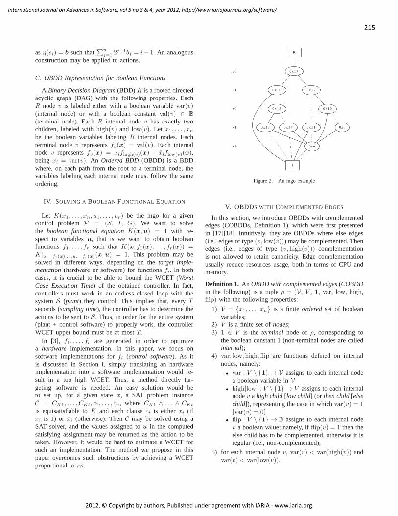
Figure 2. An mgo example
V. OBDDS WITH COMPLEMENTED EDGES
In this section, we introduce OBDDs with complementededges (COBDDs, Definition 1), which were first presentedin [17][18]. Intuitively, they are OBDDs where else edges(i.e., edges of type(v, low(v))) may be complemented. Thenedges (i.e., edges of type(v, high(v))) complementationis not allowed to retain canonicity. Edge complementationusually reduce resources usage, both in terms of CPU andmemory.
Definition 1. An OBDD with complemented edges(COBDDin the following) is a tupleρ = (V, V , 1, var, low, high,flip) with the following properties:
1) V = x1, . . . , xn is a finite ordered set of booleanvariables;
2) V is a finite set ofnodes;3) 1 ∈ V is the terminal node of ρ, corresponding to
the boolean constant1 (non-terminal nodes are calledinternal);
4) var, low, high, flip are functions defined on internalnodes, namely:
• var : V \ 1 → V assigns to each internal nodea boolean variable inV
• high[low] : V \ 1 → V assigns to each internalnodev a high child [low child] (or then child[elsechild]), representing the case in whichvar(v) = 1[var(v) = 0]
• flip : V \ 1 → B assigns to each internal nodev a boolean value; namely, ifflip(v) = 1 then theelse child has to be complemented, otherwise it isregular (i.e., non-complemented);
5) for each internal nodev, var(v) < var(high(v)) andvar(v) < var(low(v)).
216
International Journal on Advances in Software, vol 5 no 3 & 4, year 2012, http://www.iariajournals.org/software/
2012, © Copyright by authors, Published under agreement with IARIA - www.iaria.org
A. COBDDs Associated Multigraphs
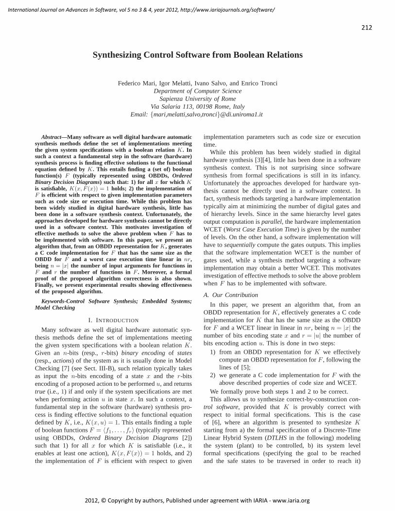
We associate to a COBDDρ = (V, V , 1, var, low, high,flip) a labeled directed multigraphG(ρ) = (V,E) such thatV is the same set of nodes ofρ and there is an edge(v, w) ∈E if and only if w is a child ofv. Moreover, each edgee =(v, w) ∈ E has a typetype(e), indicating if e is a then edge(i.e., if w is a then child ofv), a regular else edge(i.e., if wis an else child ofv with flip(v) = 0), or a complementedelse edge(i.e., if w is an else child ofv with flip(v) = 1).Figure 2 shows an example of a COBDD depicted via itsassociated multigraph, where edges are directed downwards.Moreover, in Figure 2 then edges are solid lines, regularelse edges are dashed lines and complemented else edgesare dotted lines.
The graph associated to a given COBDDρ = (V, V , 1,var, low, high, flip) may be seen as a forest with multiplerooted multigraphs. In order to select one root vertex andthus one rooted multigraph, we define theCOBDD restrictedto v ∈ V as the COBDDρv = (V, Vv, 1, var, low, high,flip) such thatVv = w ∈ V | there exists a path fromv tow in G(ρ) (note thatv ∈ Vv).
B. COBDDs Properties
For a given COBDDρ = (V, V , 1, var, low, high, flip)the following properties follow from definitions given above:
1) G(ρ) is a rooted directed acyclic (multi)graph (DAG);2) each path inG(ρ) starting from an internal node ends
in 1;3) let v1, . . . , vk be a path inG(ρ), thenvar(v1) < . . . <
var(vk).We define theheight of a nodev in a COBDDρ (notation
heightρ(v), or simply height(v) if ρ is understood) as theheight of the DAGG(ρv), i.e., the length of the longest pathfrom v to 1 in G(ρ).
C. Semantics of a COBDD
In Definition 2, we define the semanticsJ·K of each nodev of a given COBDDρ as the boolean function representedby v, given the parityb of complemented edges seen on thepath from a root tov.
Definition 2. Let ρ = (V, V , 1, var, low, high, flip)be a COBDD. Thesemantics of the terminal node1 withrespect to a flipping bitb is a boolean function defined asJ1, bKρ := b. The semantics of an internal nodev ∈ V withrespect to a flipping bitb is a boolean function defined asJv, bKρ := xiJhigh(v), bKρ + xiJlow(v), b ⊕ flip(v)Kρ, beingxi = var(v). Whenρ is understood, we will writeJ·K insteadof J·Kρ.
Note that the semantics of a node of a COBDDρ isa function of variables inV and of an additional booleanvariable b. Thus, on each nodetwo boolean functions onV are defined (one for each value ofb). It can be shown(see [15]) that such boolean functions are complementary.
Example 1. Letρ be the COBDD depicted in Figure 2. If wepick node0xe we haveJ0xe, bK = x2J1, bK+ x2J1, b⊕ 1K =x2b+ x2b = x2 ⊕ b.
D. Reduced COBDDs and COBDDs Canonicity
Two COBDDs areisomorphicif and only if there exists amapping from nodes to nodes preserving attributesvar, flip,high and low. A COBDD is calledreducedif and only if itcontains no vertexv with low(v) = high(v) ∧ flip(v) = 0,nor does it contains distinct verticesv andv′ such thatρv andρv′ are isomorphic. Note that, differently from OBDDs, it ispossible thathigh(v) = low(v) for somev ∈ V , providedthat flip(v) = 1 (e.g., see nodes0xf and0xe in Figure 2).
Theorem 1 states that reduced COBDDs are acanonicalrepresentation for boolean functions (see [17][18]). As aconsequence, software packages implementing COBDDs op-erations only deal with reduced COBDDs, since this allowsvery fast equality tests between COBDDs (it is sufficientto check if the (root node, flipping bit) pair is the same).Accordingly, in the following we will deal with reducedCOBDDs only.
Theorem 1. Let f : Bn → B be a boolean function. Thenthere exists a reduced COBDDρ = (V, V , 1, var, low,high, flip), a nodev ∈ V and a flipping bitb ∈ B such thatJv, bK = f(x). Moreover, letρ = (V, V , 1, var, low, high,flip) be a reduced COBDD, letv1, v2 ∈ V be nodes andb1, b2 ∈ B be flipping bits. ThenJv1, b1K = Jv2, b2K if andonly if v1 = v2 ∧ b1 = b2.
VI. SYNTHESIS OFC CODE FROM A COBDD
Let K(x1, . . . , xn, u1, . . . , ur) be a controller for a givencontrol problem. Letρ = (V, V , 1, var, low, high, flip)be a COBDD such that there existv ∈ V , b ∈ B suchthat Jv, bK = K(x1, . . . , xn, u1, . . . , ur). Thus,V = X ·∪U = x1, . . . , xn ·∪u1, . . . , ur (we denote with ·∪ thedisjoint union operator, thusX ∩ U = ∅). We will callvariablesxi ∈ X asstate variablesand variablesuj ∈ U asaction variables.
We want to solve the boolean functional equation problemintroduced in Sect. IV targeting asoftwareimplementation.We do this by using a COBDD representing all our booleanfunctions. This allows us to exploit COBDD nodes sharing.This results in an improvement for the method in [5], whichtargets a software implementation but which does not exploitsharing. Finally, we also synthesize the software (i.e., Ccode) implementation forf1, . . . , fr, which is not consideredin [5]. This allows us to finally have acontrol softwareforthe starting LTS. IfK is an mgo, this results in anoptimalcontrol softwarefor the starting LTS.
A. Synthesis Algorithm: Overview
Our methodSynthesizetakes as inputρ, v and b suchthat Jv, bK = K(x,u). Then, it returns as output a Cfunctionvoid K(int *x, int *u) with the following
217
International Journal on Advances in Software, vol 5 no 3 & 4, year 2012, http://www.iariajournals.org/software/
2012, © Copyright by authors, Published under agreement with IARIA - www.iaria.org
property: if, before a call toK, ∀i x[i−1]= xi holds (arrayindexes in C language begin from0) with x ∈ Dom(K), andafter the call toK, ∀i u[i−1]= ui holds, thenK(x,u) = 1.Moreover, the WCET of functionK is O(nr).
Note that our methodSynthesizeprovides an effectiveimplementationof the controllerK, i.e., a C function whichtakes as input the current state of the LTS and outputs theaction to be taken. Thus,K is indeed a control software.
Function Synthesizeis organized in two phases. First,starting fromρ, v and b (thus fromK(x,u)), we generateCOBDD nodesv1, . . . , vr and flipping bitsb1, . . . , br forboolean functionsf1, . . . , fr such that eachfi = Jvi, biKtakes as input the state bit vectorx and computes thei-thbit ui of an output action bit vectoru, whereK(x,u) = 1,provided thatx ∈ Dom(K). This computation is carriedout in functionSolveFunctionalEq. Second,f1, . . . , fr aretranslated inside functionvoid K(int *x, int *u).This step is performed by maintaining the structure of theCOBDD nodes representingf1, . . . , fr. This allows us toexploit COBDD nodes sharing in the generated software.This phase is performed by functionGenerateCCode.
Thus, functionSynthesizeis organized as in Algorithm 1.Correctness for functionSynthesizeis stated in Theorem 6.
Algorithm 1 Translating COBDDs to a C functionRequire: COBDD ρ, nodev, booleanbEnsure: Synthesize(ρ, v, b):
1: 〈v1, b1, . . . , vr, br〉 ← SolveFunctionalEq(ρ, v, b)2: GenerateCCode(ρ, v1, b1, . . . , vr, br)
B. Synthesis Algorithm: Solving a Functional Equation
In this phase, starting fromρ, v andb (thus fromJv, bK =K(x,u)), we compute functionsf1, . . . , fr such that for allx ∈ Dom(K), K(x, f1(x), . . . , fr(x)) = 1.
To this aim, we follow an approach similar to theone presented in [5], which is reminiscent of early workon minimum paths by Dijkstra. Namely, we computefi using f1, . . . , fi−1, in the following way: fi(x) =∃ui+1, . . . , un K(x, f1(x), . . . , fi−1(x), 1, ui+1, . . . , un).Thus, functionSolveFunctionalEq(ρ, v, b) computes and re-turns 〈v1, b1, . . . , vr, br〉 such that for alli ∈ [r], Jvi, biK =fi(x). This is effectively performed by Algorithm 2, wherewe use the following COBDDs manipulation functions:
• COBDD APP (instantiation) such that 〈vAPP ,bAPP 〉 = COBDD APP(xi1 , . . . , xik ,v1, b1, . . . , vk, bk, v, b) if and only ifJvAPP , bAPP K = Jv, bK|xi1
=Jv1,b1K,...,xik=Jvk,bkK;
• COBDD EX (existential quantifier elimination) suchthat 〈vEX , bEX〉 = COBDD EX(xi1 , . . . , xik , v, b)if and only if JvEX , bEXK = ∃xi1 , . . . , xik Jv, bK.
We note that efficient (i.e., at mostO(|V | log |V |)) al-gorithms [17][18] exist to compute the above defined func-tions. Moreover, the above defined functions may create new
COBDD nodes. We assume that such functions also properlyupdateV , var, low, high, flip inside COBDDρ (1 andVare not affected).
Algorithm 2 Solving a boolean functional equationRequire: COBDD ρ, nodev, booleanbEnsure: SolveFunctionalEq(ρ, v, b):
1: for all i ∈ [r] do2: Jvi, biK ← COBDD EX(ui+1, . . . , un,
COBDD APP(u1, . . . , ui, v1, b1, . . . , vi−1, bi−1,1, 0, v, b))
3: return 〈v1, b1, . . . , vr, br〉
Correctness for functionSolveFunctionalEqis proved inLemma 3.
C. Synthesis Algorithm: Generating C Code
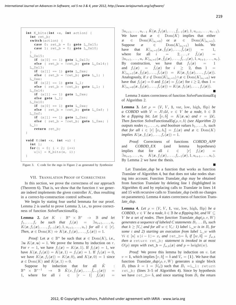
In this phase, starting from COBDD nodesv1, . . . , vr andflipping bits b1, . . . , br for functions f1, . . . , fr generatedin the first phase, we generate two C functions: i)voidK(int *x, int *u), which is the required output func-tion for our methodSynthesize; ii) int K_bits(int *x,int action), which is an auxiliary function called byK. A call to K_bits(x, i) returnsfi(x), beingx[j −1]= xj for all j ∈ [n]. This phase is detailed in Algs. 3(function GenerateCCode) and 4 (functionTranslate). Insuch algorithms we suppose to be able to print a nodev,e.g., by printing the exadecimal value of a pointer tov.
Algorithm 3 Generating C functionsRequire: COBDD ρ, v1, . . . , vr, boolean valuesb1, . . . , brEnsure: GenerateCCode(ρ, v1, b1, . . . , vr, br):
1: print “int K_bits(int *x, int action) int ret_b; switch(action) ”
2: for all i ∈ [r] do3: print “case ”, i− 1, “:”4: print “ret_b = ”, bi, “; goto L_”, vi,“;”5: print “” /* end of the switch block */6: W ← ∅
7: for all i ∈ [r] do8: W ←Translate(ρ, vi,W )9: print “ K(int* x, int* u) int i;”
10: print “ for(i=0; i<”,r,“; i++)”11: print “ u[i] = K_bits(x, i);”
Details of FunctionGenerateCCode(Algorithm 3):Given inputsρ, v1, b1, . . . , vr, br (output by SolveFunc-tionalEq), Algorithm 3 works as follows. First, functionint K_bits(int *x, int action) is generated. Ifx[j − 1]= xj for all j ∈ [n], the call K_bits(x, i)has to returnfi(x). In order to do this, the graphG(ρvi
)
is traversed by taking, in each nodev, the then edge ifx[j−1] = 1 (with j such thatvar(v) = xj) and the else edge
218
International Journal on Advances in Software, vol 5 no 3 & 4, year 2012, http://www.iariajournals.org/software/
2012, © Copyright by authors, Published under agreement with IARIA - www.iaria.org
otherwise. When node1 is reached, then1 is returned if andonly if the integer sumc+ bi is even, beingc the number ofcomplemented else edges traversed. Note that parity ofc+bimay be maintained by initializing a C variableret_b to bi,then complementingret_b (i.e., by performing aret_b= !ret_b statement) when a complemented else edge istraversed, and finally returningret_b.
This mechanism is implemented inside functionK_bitsby properly translating each COBDD nodev ∈
⋃ri=1 Vvi
ina C code block. Each block is labeled with a unique labeldepending onv, and maintains in variableret_b the currentparity of c+ bi as described above. This is done by functionTranslate, called on line 8 and detailed in Algorithm 4.
Thus, the initial part of functionK_bits consists of aswitch block (generated in lines 1–5 of Algorithm 3),which initializesret_b to bi and then jumps to the labelcorresponding to nodevi. Then, the C code blocks cor-responding to COBDD nodes are generated in lines 6–8of Algorithm 3, by callingr times functionTranslate(seeAlgorithm 4) with parametersv1, . . . , vr. Note thatW main-tains the already translated COBDD nodes. Since functionTranslateonly translates nodes not inW , this allows us toexploit sharing not only inside eachG(ρvi
), but also insideG(ρv1
), . . . , G(ρvr ).Finally, functionK is generated in lines 9–11. Function
K simply consists in afor loop filling each entryu[i]of the output arrayu with the boolean values returned byK_bits(x, i). Correctness of functionGenerateCCodeis proved in Lemma 5.
Algorithm 4 COBDD nodes translationRequire: COBDD ρ, nodev, nodes setWEnsure: Translate(ρ, v,W ):
1: if v ∈W then return W2: W ←W ∪ v3: print “L_”, v, “:”4: if v = 1 then5: print “return ret_b;”6: else7: let i be such thatvar(v) = xi
8: print “if(x[”,i− 1,“]==1)goto L_”, high(v)9: if flip(v) then
10: print “else ret_b = !ret_b;’’11: print “goto L_”, low(v),“;”12: else13: print “else goto L_”, low(v)14: W ←Translate(ρ, high(v),W )15: W ←Translate(ρ, low(v),W )16: return W
Details of FunctionTranslate(Algorithm 4): Given in-putsρ, v,W , Algorithm 4 performs a recursive graph traver-sal ofG(ρv) as follows.
The C code block for internal nodev is generated inlines 3 and 7–13. The block consists of a labelL_v: andan if-then-else C construct. Note that labelL_v uni-vocally identifies the C code block related to nodev. Thismay be implemented by printing the exadecimal value of apointer tov.
The if-then-else C construct is generated so as totraverse nodev in graph G(ρv) in the following way. Inline 8 the checkx[i−1]= 1 is generated, beingi such thatvar(v) = xi. The code to take the then edge ofv is also gen-erated. Namely, it is sufficient to generate agoto statementto the C code block related to nodehigh(v). In lines 10–11and 13 the code to take the else edge is generated, in the casex[i− 1]= 1 is false. In this case, if the else edge is com-plemented, i.e.,flip(v) holds (lines 10–11), it is necessaryto complementret_b and then perform agoto statementto the C code block related to nodelow(v) (lines 10–11).Otherwise, it is sufficient to generate agoto statement tothe C code block related to nodelow(v) (line 13).
Thus, the block generated for an internal nodev, forproperi, l andh, has one of the following forms, dependingon flip(v):
• L_v: if (x[i − 1]) goto L_h; else gotoL_l;
• L_v: if (x[i−1]) goto L_h; else ret_b= !ret_b; goto L_l;.
There are two base cases for the recursion of functionTranslate:
• v ∈W (line 1), i.e.,v has already been translated intoa C code block as above. In this case, the set of visitedCOBDD nodesW is directly returned (line 1) withoutgenerating any C code. This allows us to retain COBDDnode sharing;
• v = 1 (line 4), i.e., the terminal node1 has beenreached. In this case, the C code block to be generatedis simply L_1: return ret_b;. Note that such ablock will be generated only once.
In all other cases, functionTranslateends with the recur-sive calls on the then and else edges (lines 14–15). Notethat the visited nodes setW passed to the second recursivecall is the result of the first recursive call. Correctness offunction Translateis proved in Lemma 5.
D. An Example of Translation
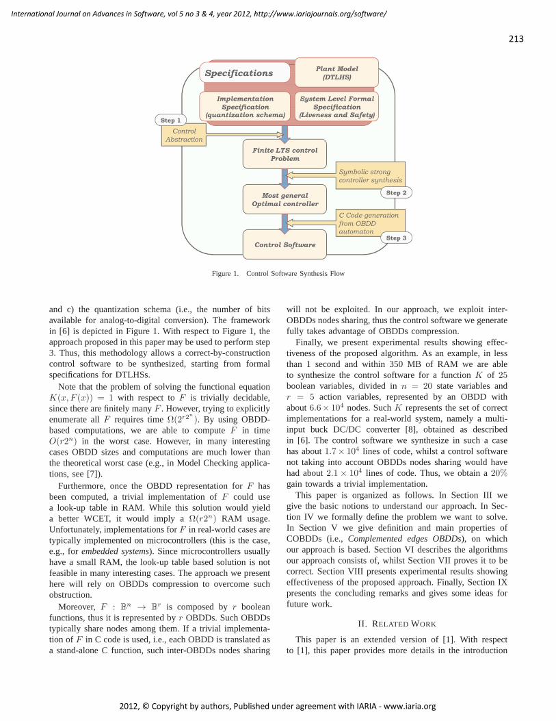
Consider the COBDDρ shown in Figure 2. Withinρ,consider mgoK(x0, x1, x2, u0, u1) = J0x17, 1K. Byapplying SolveFunctionalEq, we obtainf1(x0, x1, x2) =J0x15, 1K and f2(x0, x1, x2) = J0x10, 1K. Note that0xeis shared betweenG(ρ0x15) andG(ρ0x10). Finally, by callingGenerateCCode(see Algorithm 3) onf1, f2, we have the Ccode in Figure 3.
219
International Journal on Advances in Software, vol 5 no 3 & 4, year 2012, http://www.iariajournals.org/software/
2012, © Copyright by authors, Published under agreement with IARIA - www.iaria.org
i n t K_bits( i n t *x, i n t action) i n t ret_b;sw i tch(action)
case 0: ret_b = 0; goto L_0x15;case 1: ret_b = 0; goto L_0x10;
L_0x15:
i f (x[0] == 1) goto L_0x13;e l s e ret_b = !ret_b; goto L_0x14;
L_0x13:i f (x[1] == 1) goto L_0xe;e l s e ret_b = !ret_b; goto L_1;
L_0xe:i f (x[2] == 1) goto L_1;e l s e ret_b = !ret_b; goto L_1;
L_0x14:i f (x[1] == 1) goto L_0xe;e l s e goto L_1;
L_0x10:i f (x[0] == 1) goto L_0xe;e l s e ret_b = !ret_b; goto L_0xf;
L_0xf:i f (x[1] == 1) goto L_0xe;e l s e ret_b = !ret_b; goto L_0xe;
L_1:re turn ret_b;
vo id K( i n t *x, i n t *u) i n t i;f o r (i = 0; i < 2; i++)u[i] = K_bits(x, i);
Figure 3. C code for the mgo in Figure 2 as generated bySynthesize
VII. T RANSLATION PROOF OFCORRECTNESS
In this section, we prove the correctness of our approach(Theorem 6). That is, we show that the functionK we gener-ate indeed implements the given controllerK, thus resultingin a correct-by-construction control software.
We begin by stating four useful lemmata for our proof.Lemma 2 is useful to prove Lemma 3, i.e., to prove correct-ness of functionSolveFunctionalEq.
Lemma 2. Let K : Bn × B
r → B and letf1, . . . , fr be such that fi(x) = ∃ui+1, . . . , ur
K(x, f1(x), . . . , fi−1(x), 1, ui+1, . . . , ur) for all i ∈ [r].Then,x ∈ Dom(K) ⇒ K(x, f1(x), . . . , fr(x)) = 1.
Proof: Let x ∈ Bn be such thatx ∈ Dom(K), i.e.,
∃u K(x,u) = 1. We prove the lemma by induction onr.For r = 1, we havef1(x) = K(x, 1). If f1(x) = 1, wehaveK(x, f1(x)) = K(x, 1) = f1(x) = 1. If f1(x) = 0,we haveK(x, f1(x)) = K(x, 0), andK(x, 0) = 1 sincex ∈ Dom(K) andK(x, 1) = 0.
Suppose by induction that for all K :Bn × B
r−1 → B K(x, f1(x), . . . , fr−1(x)) =1, where for all i ∈ [r − 1] fi(x) =
∃ui+1, . . . , ur−1 K(x, f1(x), . . . , fi−1(x), 1, ui+1, . . . , ur−1).We have that x ∈ Dom(K) implies that eitherx ∈ Dom(K|u1=0) or x ∈ Dom(K|u1=1).Suppose x ∈ Dom(K|u1=1) holds. Wehave that K|u1=1(x, f2(x), . . . , fr(x)) = 1,where for all i = 2, . . . , r fi(x) =∃ui+1, . . . , ur K|u1=1(x, f2(x), . . . , fi−1(x), 1, ui+1, . . . , ur).By construction, we have that f1(x) = 1and fi(x) = fi(x) for i ≥ 2, thus 1 =K|u1=1(x, f2(x), . . . , fr(x)) = K(x, f1(x), . . . , fr(x)).Analogously, ifx /∈ Dom(K|u1=1)∧x ∈ Dom(K|u1=0) wehave thatf1(x) = 0 andfi(x) = fi(x) for i ≥ 2, thus1 =K|u1=0(x, f2(x), . . . , fr(x)) = K(x, f1(x), . . . , fr(x)).
Lemma 3 states correctness of functionSolveFunctionalEqof Algorithm 2.
Lemma 3. Let ρ = (V, V , 1, var, low, high, flip) bea COBDD with V = X ·∪U , v ∈ V be a node,b ∈ B
be a flipping bit. LetJv, bK = K(x,u) and r = |U|.Then functionSolveFunctionalEq(ρ, v, b) (see Algorithm 2)outputs nodesv1, . . . , vr and boolean valuesb1, . . . , br suchthat for all i ∈ [r] Jvi, biK = fi(x) and x ∈ Dom(K)impliesK(x, f1(x), . . . , fr(x)) = 1.
Proof: Correctness of functions COBDD APPand COBDD EX (and lemma hypotheses)implies that for all i ∈ [r] fi(x) =∃ui+1, . . . , ur K(x, f1(x), . . . , fi−1(x), 1, ui+1, . . . , ur).By Lemma 2 we have the thesis.
Let Translatedup be a function that works as functionTranslateof Algorithm 4, but that does not take nodes shar-ing into account. FunctionTranslatedup may be obtainedfrom function Translateby deleting line 1 (highlighted inAlgorithm 4) and by replacing calls toTranslatein lines 14and 15 with recursive calls toTranslatedup (with no changeson parameters). Lemma 4 states correctness of functionTrans-late dup.
Lemma 4. Let ρ = (V, V , 1, var, low, high, flip) be aCOBDD,v ∈ V be a node,b ∈ B be a flipping bit, andW ⊆V be a set of nodes. Then functionTranslatedup(ρ, v,W )generates a sequence of labeled C statementsB1 . . . Bk suchthat k ≥ |Vv| and for all w ∈ Vv: 1) label L_w is in Bi forsomei and 2) starting an execution from labelL_w with∀i ∈ [n] x[i − 1]= xi and ret_b= b, if Jw, bK = fw,b
then areturn ret_b; statement is invoked in at mostO(p) steps withret b = fw,b(x) and p = height(w).
Proof: We prove this lemma by induction onv. Letv = 1, which impliesJv, bK = b andVv = 1. We have thatfunction Translatedup(ρ, v,W ) generates a single blockB1 (thus k = 1 = |V1|) such thatB1 =L_1: returnret_b; (lines 3–5 of Algorithm 4). Since by hypothesiswe haveret_b= b, and since starting fromB1 the return
220
International Journal on Advances in Software, vol 5 no 3 & 4, year 2012, http://www.iariajournals.org/software/
2012, © Copyright by authors, Published under agreement with IARIA - www.iaria.org
statement is invoked inO(1) steps, the base case of theinduction is proved.
Let v be an internal node withvar(v) = xi and letf(x) = Jv, bK. Since w ∈ Vv if and only if w =v ∨ w ∈ Vhigh(v) ∨ w ∈ Vlow(v), by induction hypothesiswe only have to prove the thesis forw = v. We havethat f(x) = xiJhigh(v), bK + xiJlow(v), b ⊕ flip(v)K, i.e.,f(x) = xiJhigh(v), bK + xiJlow(v), bK if flip(v) = 0 andf(x) = xiJhigh(v), bK + xiJlow(v), bK if flip(v) = 1. Sincef(x) = xif |xi=1(x) + xif |xi=0(x), by Theorem 1 wehave thatJhigh(v), bK = f |xi=1(x), and thatJlow(v), bK =f |xi=0(x) if flip(v) = 0 and Jlow(v), bK = f |xi=0(x) ifflip(v) = 1.
By lines 3 and 8–13 of Algorithm 4, we havethat function Translatedup(ρ, v,W ) generates blocksBB11 . . . B1hB21 . . . B2l such thatB =L_v: if (x[i −1] == 1) goto L_high(v); else BE where BE iseither goto L_low(v); if flip(v) = 0 or ret_b= !ret_b; goto L_low(v); if flip(v) = 1, andB11 . . . B1h (B21 . . . B2l) are generated by the recur-sive call Translatedup(ρ, high(v),W ) in line 14 (Trans-late dup(ρ, low(v),W ) in line 15). By induction hypothesisand the above reasoning, if the execution starts at labelL_high(v) andret_b= b, then areturn ret_b; state-ment is invoked in at mostO(p − 1) steps withret b =f |xi=1(x). As for the else case, we have that starting fromL_low(v) with ret_b= b (ret_b= ¯b) if flip(v) = 0(flip(v) = 1), then areturn ret_b; statement is in-voked in at mostO(p−1) steps withret b = f |xi=0(x). Byconstruction of blockB, starting from labelL_v, areturnret_b; statement is invoked in at mostO(p−1+1) = O(p)steps withret b = xif |xi=1(x) + xif |xi=0(x) = f(x).Finally, note that by induction hypothesish ≥ |Vhigh(v)|and l ≥ |Vlow(v)|, thus we have thatk = 1 + h + l ≥1 + |Vhigh(v)|+ |Vlow(v)| ≥ |Vv|.
Lemma 5 extends Lemma 4 by also considering nodessharing, thus stating correctness of functionGenerateCCodeof Algorithm 3 and functionTranslateof Algorithm 4.
Lemma 5. Let ρ = (V, V , 1, var, low, high, flip)be a COBDD andv1, . . . , vr ∈ V be r nodes andb1, . . . , br ∈ B be r flipping bits. Then lines 6–8 of functionGenerateCCode(ρ, v1, b1, . . . , vr, br) generate a sequence oflabeled C statementsB1 . . . Bk such thatk = | ∪ri=1 Vvi
|and for all v ∈ ∪ri=1Vvi
: 1) the label L_v is in Bj forsomej and 2) starting an execution from labelL_v with∀j ∈ [n] x[j − 1]= xj and ret_b= b, if Jv, bK = fv,bthen areturn ret_b; statement is invoked in at mostO(p) steps withret b = fv,b(x) and p = height(w).
Proof: We begin by proving thatk = | ∪ri=1 Vvi|.
To this aim, we prove that for each nodev ∈ ∪ri=1Vvi,
a unique blockBv is generated. This follows by how thenodes setW is managed by functionTranslatein lines 1–3
of Algorithm 4 and by functionGenerateCCodein lines 6–8 of Algorithm 3. In fact, functionTranslate, when calledon parametersρ, v,W , returns a setW ′ ⊇W , and functionGenerateCCodecalls Translateby always passing theWresulting by the previous call. Since a block is generated fornodev only if v is not in W , and v is added toW onlywhen a block is generated for nodev, this proves this partof the lemma.
As for correctness, we prove this lemma by induction onm, being m the number of times that thereturn W;statement in line 1 of Algorithm 4 is executed. As base of theinduction, letm = 1 and letρ, v,W be the parameters of therecursive call executing the firstreturn W; statement.Then, by construction of functionTranslate, v has beenadded toW in some previous recursive call with parametersρ, v, W . In this previous recursive call, a blockBv withlabel L_v has been generated. Moreover, for this previousrecursive call, thus for parametersρ, v, W , we are in thehypothesis of Lemma 4, which implies that the inductionbase is proved.
Suppose now that the thesis holds for the firstm exe-cutions of thereturn W; statement in line 1 of Algo-rithm 4. Then, by construction of functionTranslate, v hasbeen added toW in some previous recursive call with pa-rametersρ, v, W . In this previous recursive call, a blockBv
with labelL_v has been generated. Letw1,W1, . . . , wm,Wm,be such that them recursive calls executing thereturnW; statement have parametersρ, vi,Wi (note that they arenot necessarily distinct). By induction hypothesis, for all i ∈[m] starting from labelL_wi with ∀j ∈ [n] x[j − 1]= xj
andret_b= b, a return ret_b; statement is invokedin at mostO(p) steps withret b = fwi,b(x). By Lemma 4and its proof, the same holds for allv ∈ Vv \w1, . . . , wm,thus it holds for allv ∈ Vv.
Finally, Theorem 6 states and proves correctness for func-tion Synthesizeof Algorithm 1.
Theorem 6. Let ρ = (V, V , 1, var, low, high, flip) be aCOBDD with V = X ·∪U , v ∈ V be a node,b ∈ B be aboolean. LetJv, bK = K(x,u), r = |U| and n = |X |. Thenfunction Synthesize(ρ, v, b) generates a C functionvoidK(int *x, int *u) with the following property: for allx ∈ Dom(K), if before a call toK ∀i ∈ [n] x[i − 1]=xi, and after the call toK ∀i ∈ [r] u[i − 1]= ui, thenK(x,u) = 1.
Furthermore, functionK has WCET∑r
i=1 O(height(vi)),being v1, . . . , vr the nodes output by functionSolveFunc-tionalEq.
Proof: Let x ∈ Dom(K) (i.e., ∃u K(x,u) = 1) andsuppose that for allj ∈ [n] x[j − 1]= xj . By lines 9–11 of Algorithm 3, for all i ∈ [r], u[i − 1] will takethe value returned byK_bits(x, i). In turn, by lines 3and 4 of Algorithm 3, eachK_bits(x, i) setsret_b
221
International Journal on Advances in Software, vol 5 no 3 & 4, year 2012, http://www.iariajournals.org/software/
2012, © Copyright by authors, Published under agreement with IARIA - www.iaria.org
R
+vOL
iD
Vi
Vi−1
Vj
V1
Iui
Iui−1
Iuj
+vui ui
D0
D1
Dj
Di−1
iL rL
+vC C
rCiC
+vuj
ui−1
uj
+vD
...
...
Iu1
+vD1
+vDj
+vui−1 +vDi−1
+vu1 u1
Figure 4. Multi-input Buck DC-DC converter.
to bi and makes a jump to labelL_vi. By Lemma 3 and byconstruction ofSynthesize, such b1, . . . , br and v1, . . . , vrare such that thatJv1, b1K = f1(x), . . . , Jvr, brK = fr(x)and K(x, f1(x), . . . , fr(x)) = 1. By Lemma 5, the se-quence of callsK_bits(x, 1), . . . , K_bits(x, r)will indeed return, in at most
∑rj=1 O(height(vi)) steps,
f1(x), . . . , fr(x).
Corollary 7. Let ρ = (V, V , 1, var, low, high, flip) be aCOBDD with V = X ·∪U , v ∈ V be a node,b ∈ B be aboolean. LetJv, bK = K(x,u), r = |U| and n = |X |. Thenthe C functionK output by functionSynthesize(ρ, v, b) hasWCETO(rn).
Proof: The corollary immediately follows from Theo-rem 6 and from the fact that, for allv ∈ V , height(v) ≤ n.
VIII. E XPERIMENTAL RESULTS
We implemented our synthesis algorithm in C program-ming language, using the CUDD (Colorado University De-cision Diagram [19]) package for OBDD based computa-tions and BLIF (Berkeley Logic Interchange Format [20])files to represent input OBDDs. We name the resulting toolKSS (Kontrol Software Synthesizer). KSS is part of a moregeneral tool named QKS (Quantized feedback Kontrol Syn-thesizer[6]).
A. Experimental Settings
We present experimental results obtained by using KSSon given COBDDsρ1, . . . , ρ5 such that for alli ∈ [5] ρirepresents the mgoKi(x,u) for a buck DC/DC converterwith i inputs.
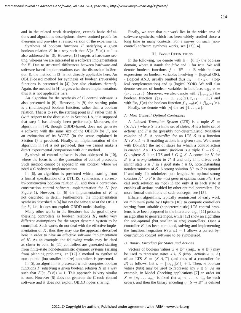
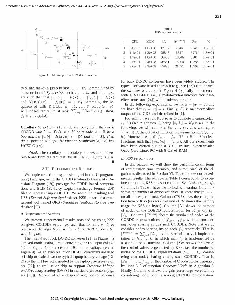
Themulti-inputbuck DC-DC converter [21] in Figure 4 isa mixed-mode analog circuit converting the DC input voltage(Vi in Figure 4) to a desired DC output voltage (vO inFigure 4). As an example, buck DC-DC converters are usedoff-chip to scale down the typical laptop battery voltage (12-24) to the just few volts needed by the laptop processor (e.g.,see [22]) as well as on-chip to supportDynamic Voltageand Frequency Scaling(DVFS) in multicore processors (e.g.,see [23]). Because of its widespread use, control schemas
Table IKSS PERFORMACES
r CPU MEM |K| |Funsh| |Sw| %
1 3.0e-02 1.0e+08 12137 2646 2646 0.0e+002 1.1e-01 1.3e+08 25848 5827 5076 1.3e+013 1.7e-01 1.8e+08 36430 10346 8606 1.7e+014 2.5e-01 2.4e+08 46551 15004 12285 1.8e+015 3.6e-01 3.3e+08 65835 21031 16768 2.0e+01
for buck DC-DC converters have been widely studied. Thetypical software based approach (e.g., see [22]) is to controlthe switchesu1, . . . , ui in Figure 4 (typically implementedwith a MOSFET, i.e., a metal-oxide-semiconductor field-effect transistor [24]) with a microcontroller.
In the following experiments, we fixn = |x| = 20 andwe have thatri = |u| = i. Finally, Ki is an intermediateoutput of the QKS tool described in [6].
For eachρi, we run KSS so as to computeSynthesize(ρi,vi, bi) (see Algorithm 1), beingJvi, biK = Ki(x,u). In thefollowing, we will call 〈v1i, b1i, . . . , vii, bii〉, with vji ∈Vi, bji ∈ B, the output of functionSolveFunctionalEq(ρi, vi,bi). Moreover, we callf1i, . . . , fii : Bn → B the i booleanfunctions such thatJvji, bjiK = fji(x). All our experimentshave been carried out on a 3.0 GHz Intel hyperthreadedQuad Core Linux PC with 8 GB of RAM.
B. KSS Performance
In this section, we will show the performance (in termsof computation time, memory, and output size) of the al-gorithms discussed in Section VI. Table I show our experi-mental results. Thei-th row in Table I corresponds to exper-iments running KSS so as to computeSynthesize(ρi, vi, bi).Columns in Table I have the following meaning. Columnrshows the number of action variables|u| (note that|x| = 20on all our experiments). ColumnCPU shows the computa-tion time of KSS (in secs). ColumnMEM shows the memoryusage for KSS (in bytes). Column|K| shows the numberof nodes of the COBDD representation forKi(x,u), i.e.,|Vvi|. Column |Funsh| shows the number of nodes of the
COBDD representations off1i, . . . , fii, without consider-ing nodes sharing among such COBDDs. Note that we doconsider nodes sharing inside eachfji separately. That is,|Funsh| =
∑ij=1 |Vvji
| is the size of a trivial implemen-tation of f1i, . . . , fii in which eachfji is implemented bya stand-alone C function. Column|Sw| shows the size ofthe control software generated by KSS, i.e., the number ofnodes of the COBDD representationsf1i, . . . , fii, consid-ering also nodes sharing among such COBDDs. That is,|Sw| = |∪ij=1Vvji
| is the number of C code blocks generatedby lines 6–8 of functionGenerateCCodein Algorithm 3.Finally, Column% shows the gain percentage we obtain byconsidering nodes sharing among COBDD representations
222
International Journal on Advances in Software, vol 5 no 3 & 4, year 2012, http://www.iariajournals.org/software/
2012, © Copyright by authors, Published under agreement with IARIA - www.iaria.org
for f1i, . . . , fii, i.e., (1− |Sw||Funsh|
)100.From Table I we can see that, in less than 1 second
and within 350 MB of RAM we are able to synthesize thecontrol software for the multi-input buck withr = 5 actionvariables, starting from a COBDD representation ofK withabout6.6× 104 nodes. The control software we synthesizein such a case has about1.7 × 104 lines of code, whilsta control software not taking into account COBDD nodessharing would have had about2.1×104 lines of code. Thus,we obtain a20% gain towards a trivial implementation.
IX. CONCLUSION AND FUTURE WORK
In this paper, we presented an algorithm which, startingfrom a boolean relationK representing the set of implemen-tations meeting the given system specifications, generatesacorrect-by-construction C code implementingK. This en-tails finding boolean functionsF such thatK(x, F (x)) = 1holds, and then implement suchF . WCET for the generatedcontrol software is linear linear innr, beingr the numberof functions inF and n = |x|. Furthermore, we formallyproved that our algorithm is correct.
We implemented our algorithm in a tool named KSS.Given our algorithm properties explained above, by usingKSS it is possible to synthesize correct-by-constructioncontrol software, provided thatK is provably correct withrespect to initial formal specifications. This is the case in[6],thus this methodology, e.g., allows to synthesize correct-by-construction control software starting from formal spec-ifications for DTLHSs. We have shown feasibility of ourproposed approach by presenting experimental results onusing it to synthesize C controllers for a multi-input buckDC-DC converter.
The WCET of the resulting control software may be toohigh for some systems in whichnr is high, or for whichthe control software has to provide actions with an highfrequency. In order to speed-up the WCET, a natural possiblefuture research direction is to investigate how to parallelizethe generated control software.
ACKNOWLEDGMENTS
This work has received funding both from MIUR projectTRAMP and the FP7/2007-2013 project ULISSE (grant agree-ment no218815).
REFERENCES
[1] F. Mari, I. Melatti, I. Salvo, and E. Tronci, “From booleanrelations to control software,” inICSEA 2011, pp. 528–533.
[2] R. Bryant, “Graph-based algorithms for boolean functionmanipulation,”IEEE Trans. on Computers, vol. C-35, no. 8,1986, pp. 677–691.
[3] D. Baneres, J. Cortadella, and M. Kishinevsky, “A recursiveparadigm to solve boolean relations,”IEEE Trans. on Com-puters, vol. 58, no. 4, 2009, pp. 512–527.
[4] R. Wille and R. Drechsler, “Bdd-based synthesis of reversiblelogic for large functions,” inDAC 2009, pp. 270–275.
[5] E. Tronci, “Automatic synthesis of controllers from formalspecifications,” inICFEM 1998, pp. 134–143.
[6] F. Mari, I. Melatti, I. Salvo, and E. Tronci, “Synthesis ofquantized feedback control software for discrete time linearhybrid systems,” inCAV 2010, ser. LNCS 6174, pp. 180–195.
[7] E. M. Clarke, O. Grumberg, and D. A. Peled,Model Check-ing. The MIT Press, 1999.
[8] F. Mari, I. Melatti, I. Salvo, and E. Tronci, “Quantizedfeedback control software synthesis from system level for-mal specifications for buck dc/dc converters,”CoRR, vol.abs/1105.5640, 2011.
[9] M. Chiodo, P. Giusto, H. Hsieh, A. Jurecska, L. Lavagno,A. Sangiovanni-Vincentelli, E. Sentovich, and K. Suzuki,“Synthesis of software programs for embedded control ap-plications,” IEEE Trans. CAD, vol. 18, 1995, pp. 834–849.
[10] T. Wongpiromsarn, U. Topcu, and R. M. Murray, “Formalsynthesis of embedded control software: Application to ve-hicle management systems,” inAIAA Infotech@Aerospace,2011.
[11] A. Cimatti, M. Roveri, and P. Traverso, “Strong planningin non-deterministic domains via model checking,” inAIPS1998, pp. 36–43.
[12] V. Alimguzhin, F. Mari, I. Melatti, I. Salvo, and E. Tronci,“On model based synthesis of embedded control software,”in EMSOFT 2012, pp. 227–236.
[13] A. Pnueli and R. Rosner, “On the synthesis of an asyn-chronous reactive module,” inICALP 1989, pp. 652–671.
[14] A. Girault andE. Rutten, “Automating the addition of faulttolerance with discrete controller synthesis,”Formal Methodsin System Design, vol. 35, no. 2, 2009, pp. 190–225.
[15] ——, “From boolean functional equations to control soft-ware,” CoRR, vol. abs/1106.0468, 2011.
[16] T. H. Cormen, C. E. Leiserson, R. L. Rivest, and C. Stein,Introduction to Algorithms (3. ed.). MIT Press, 2009.
[17] K. S. Brace, R. L. Rudell, and R. E. Bryant, “Efficientimplementation of a bdd package,” inDAC 1990, pp. 40–45.
[18] S. Minato, N. Ishiura, and S. Yajima, “Shared binary decisiondiagram with attributed edges for efficient boolean functionmanipulation,” inDAC 1990, pp. 52–57.
[19] “CUDD Web Page,” http://vlsi.colorado.edu/ fabio/CUDD,last accessed 20th dec 2012
[20] “Berkeley logic interchange format (BLIF),“bear.ces.cwru.edu/eecscad/sisblif.pdf, last accessed 20thdec 2012.
223
International Journal on Advances in Software, vol 5 no 3 & 4, year 2012, http://www.iariajournals.org/software/
2012, © Copyright by authors, Published under agreement with IARIA - www.iaria.org
[21] M. Rodriguez, P. Fernandez-Miaja, A. Rodriguez, and J. Se-bastian, “A multiple-input digitally controlled buck converterfor envelope tracking applications in radiofrequency poweramplifiers,” IEEE Trans. on Power Electronics, vol. 25, no. 2,2010, pp. 369–381.
[22] W.-C. So, C. Tse, and Y.-S. Lee, “Development of a fuzzylogic controller for dc/dc converters: design, computer simu-lation, and experimental evaluation,”IEEE Trans. on Power
Electronics, vol. 11, no. 1, 1996, pp. 24–32.
[23] W. Kim, M. S. Gupta, G.-Y. Wei, and D. M. Brooks, “En-abling on-chip switching regulators for multi-core processorsusing current staggering,” inASGI 2007.
[24] Y. Cheng and C. Hu,MOSFET Modeling and Bsim3 User’sGuide. Kluwer Academic Publishers, 1999.
Related Documents