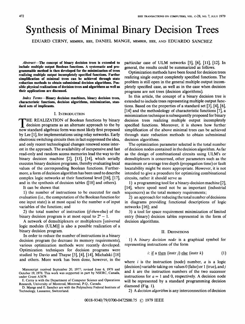
IEEE TRANSACTIONS ON COMPUTERS, VOL. c-28, NO. 7, JULY 1979 Synthesis of Minimal Binary Decision Trees EDUARD CERNY, MEMBER, IEEE, DANIEL MANGE, MEMBER, IEEE, AND EDUARDO SANCHEZ Abstract-The concept of binary decision trees is extended to include multiple output Boolean functions. A systematic and pro- grammable method is then developed for the minimization of trees realizing multiple output incompletely specified functions. Further simplification of minimal trees can be achieved through state reduction methods to obtain subminimal decision algorithms. Pos- sible physical realizations of decision trees and algorithms as well as their applications are discussed. Index Terms-Binary decision machines, binary decision trees, characteristic functions, decision algorithms, minimization, stan- dard sets of implicants. I. INTRODUCTION T HE REALIZATION of Boolean functions by binary decision programs as an alternate approach to the by now standard algebraic form was most likely first proposed by Lee [1], for implementations using relay networks. Early electronic switching circuits then in fact suppressed the idea, and only recent technological changes renewed some inter- est in the approach. The availability of inexpensive and fast read-only and random access memories lead the way to the binary decision machine [2], [13], [14], which serially executes binary decision programs, thereby evaluating local values of the corresponding Boolean functions. Further- more, a form of decision algorithm has been used to describe complex logic networks at their functional level [16], [17], and in the synthesis of decision tables ([18] and others). It can be shown that 1) the number of instructions to be executed for each evaluation (i.e., the computation of the Boolean function for one input state) is at most equal to the number n of input variables of the function; and 2) the total number of instruction (if-then-else) of the binary decision program is at most equal to 2' - 1. A network of demultiplexers or multiplexers [universal logic modules (ULM)] is also a possible realization of a binary decision program. In order to reduce the number of instructions in a binary decision program (to decrease its memory requirements), various optimization methods were recently developed. Optimization techniques for decision programs were studied by Davio and Thayse [3], [4], [14], Michalski [18] and others. More work has been done, however, in the Manuscript received September 20, 1977; revised June 6, 1978 and October 19, 1978. This work was supported in part by NSERC, Canada, under Grant A3879. E. Cemy is with the Department of Computer Science and Operations Research, University of Montreal, Montreal, P.Q., Canada. D. Mange and E. Sanchez are with the Polytechnic Federal Institute of Technology, Lausanne, Switzerland. particular case of ULM networks [5], [6], [11], [12]. In general, the results could be summarized as follows. Optimization methods have been found for decision trees realizing single output completely specified functions. The problem is still open in the general multiple output incom- pletely specified case, as well as in the case when decision programs are not trees (decision algorithms). In this article, the concept of a binary decision tree is extended to include trees representing multiple output func- tions. Based on the properties of a standard set [3], [4], [6], [14] and the methodology of characteristic functions [7], a minimization technique is subsequently proposed for binary decision trees realizing multiple output incompletely specified functions. Moreover, it is shown how further simplification of the above minimal trees can be achieved through state reduction methods to obtain subminimal decision algorithms. The optimization parameter selected is the total number of decision nodes contained in the decision algorithm. As far as the design of combinational circuits using ULM's or demultiplexers is concerned, other parameters such as the maximum or average tree depth (propagation time) or fault locatability might be more appropriate. However, it is not intended to give a procedure for optimizing combinational circuits, rather it should serve as 1) a programming tool for a binary-decision machine [2], [14], where speed need not be as important (industrial sequencers) as the total memory requirements; 2) an approach for reducing the total number of decisions in diagrams providing functional descriptions of logic networks [16]; and 3) a tool for space requirement minimization of limited entry (binary) decision tables represented in the form of decision algorithms. II. DEFINITIONS 1) A binary decision node is a graphical symbol for representing instructions of the form i: if a then (instr j) else (instr k) (1) where i is the instruction (node) number, a is a logic (decision) variable taking on values 0 (false) or 1 (true), andj and k are the instruction numbers of the two successor instructions for a = 1 and 0, respectively. A decision node will be represented by a standard programming decision diamond (Fig. 1). 2) A decision algorithm is any interconnection of decision 0018-9340/79/0700-0472$00.75 ©) 1979 IEEE 472

Welcome message from author
This document is posted to help you gain knowledge. Please leave a comment to let me know what you think about it! Share it to your friends and learn new things together.
Transcript
IEEE TRANSACTIONS ON COMPUTERS, VOL. c-28, NO. 7, JULY 1979
Synthesis of Minimal Binary Decision TreesEDUARD CERNY, MEMBER, IEEE, DANIEL MANGE, MEMBER, IEEE, AND EDUARDO SANCHEZ
Abstract-The concept of binary decision trees is extended toinclude multiple output Boolean functions. A systematic and pro-grammable method is then developed for the minimization of treesrealizing multiple output incompletely specified functions. Furthersimplification of minimal trees can be achieved through statereduction methods to obtain subminimal decision algorithms. Pos-sible physical realizations of decision trees and algorithms as well astheir applications are discussed.
Index Terms-Binary decision machines, binary decision trees,characteristic functions, decision algorithms, minimization, stan-dard sets of implicants.
I. INTRODUCTIONT HE REALIZATION of Boolean functions by binary
decision programs as an alternate approach to the bynow standard algebraic form was most likely first proposedby Lee [1], for implementations using relay networks. Earlyelectronic switching circuits then in fact suppressed the idea,and only recent technological changes renewed some inter-est in the approach. The availability of inexpensive and fastread-only and random access memories lead the way to thebinary decision machine [2], [13], [14], which seriallyexecutes binary decision programs, thereby evaluating localvalues of the corresponding Boolean functions. Further-more, a form ofdecision algorithm has been used to describecomplex logic networks at their functional level [16], [17],and in the synthesis of decision tables ([18] and others).
It can be shown that1) the number of instructions to be executed for each
evaluation (i.e., the computation of the Boolean function forone input state) is at most equal to the number n of inputvariables of the function; and
2) the total number of instruction (if-then-else) of thebinary decision program is at most equal to 2' - 1.A network of demultiplexers or multiplexers [universal
logic modules (ULM)] is also a possible realization of abinary decision program.
In order to reduce the number of instructions in a binarydecision program (to decrease its memory requirements),various optimization methods were recently developed.Optimization techniques for decision programs werestudied by Davio and Thayse [3], [4], [14], Michalski [18]and others. More work has been done, however, in the
Manuscript received September 20, 1977; revised June 6, 1978 andOctober 19, 1978. This work was supported in part by NSERC, Canada,under Grant A3879.
E. Cemy is with the Department of Computer Science and OperationsResearch, University of Montreal, Montreal, P.Q., Canada.
D. Mange and E. Sanchez are with the Polytechnic Federal Institute ofTechnology, Lausanne, Switzerland.
particular case of ULM networks [5], [6], [11], [12]. Ingeneral, the results could be summarized as follows.
Optimization methods have been found for decision treesrealizing single output completely specified functions. Theproblem is still open in the general multiple output incom-pletely specified case, as well as in the case when decisionprograms are not trees (decision algorithms).
In this article, the concept of a binary decision tree isextended to include trees representing multiple output func-tions. Based on the properties of a standard set [3], [4], [6],[14] and the methodology of characteristic functions [7], aminimization technique is subsequently proposed for binarydecision trees realizing multiple output incompletelyspecified functions. Moreover, it is shown how furthersimplification of the above minimal trees can be achievedthrough state reduction methods to obtain subminimaldecision algorithms.The optimization parameter selected is the total number
of decision nodes contained in the decision algorithm. As faras the design of combinational circuits using ULM's ordemultiplexers is concerned, other parameters such as themaximum or average tree depth (propagation time) or faultlocatability might be more appropriate. However, it is notintended to give a procedure for optimizing combinationalcircuits, rather it should serve as
1) a programming tool for a binary-decision machine [2],[14], where speed need not be as important (industrialsequencers) as the total memory requirements;
2) an approach for reducing the total number ofdecisionsin diagrams providing functional descriptions of logicnetworks [16]; and
3) a tool for space requirement minimization of limitedentry (binary) decision tables represented in the form ofdecision algorithms.
II. DEFINITIONS
1) A binary decision node is a graphical symbol forrepresenting instructions of the form
i: if a then (instr j) else (instr k) (1)
where i is the instruction (node) number, a is a logic(decision) variable taking on values 0 (false) or 1 (true), andjand k are the instruction numbers of the two successorinstructions for a = 1 and 0, respectively. A decision nodewill be represented by a standard programming decisiondiamond (Fig. 1).
2) A decision algorithm is any interconnection ofdecision
0018-9340/79/0700-0472$00.75 ©) 1979 IEEE
472
CERNY et al.: MINIMAL BINARY DECISION TREES
fn brxwtch
from predecessornode
to successornode j\
outbranch~a
to successornode k
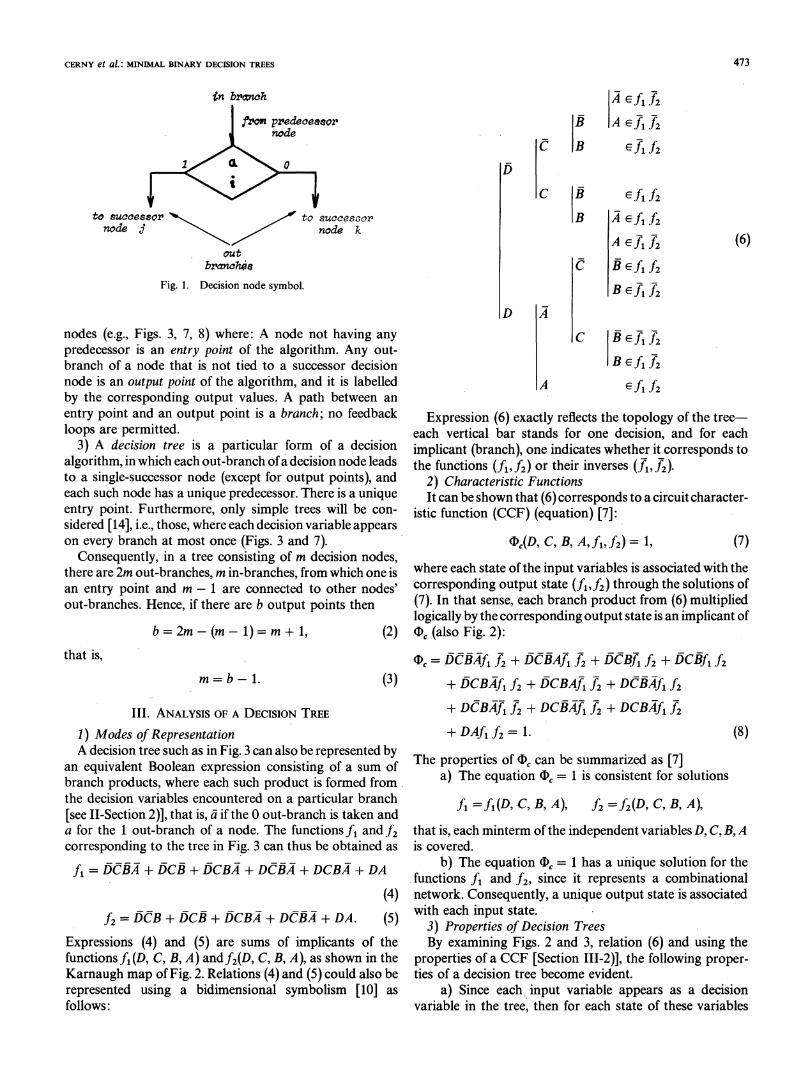
Fig. 1. Decision node symbol.
nodes (e.g., Figs. 3, 7, 8) where: A node not having anypredecessor is an entry point of the algorithm. Any out-branch of a node that is not tied to a successor decisionnode is an output point of the algorithm, and it is labelledby the corresponding output values. A path between anentry point and an output point is a branch; no feedbackloops are permitted.
3) A decision tree is a particular form of a decisionalgorithm, in which each out-branch ofa decision node leadsto a single-successor node (except for output points), andeach such node has a unique predecessor. There is a uniqueentry point. Furthermore, only simple trees will be con-sidered [14], i.e., those, where each decision variable appearson every branch at most once (Figs. 3 and 7).
Consequently, in a tree consisting of m decision nodes,there are 2m out-branches, m in-branches, from which one isan entry point and m - 1 are connected to other nodes'out-branches. Hence, if there are b output points then
b = 2m-(m-1)= m + 1, (2)that is,
m=b-1. (3)
III. ANALYSIS OF A DECISION TREE
1) Modes of RepresentationA decision tree such as in Fig. 3 can also be represented by
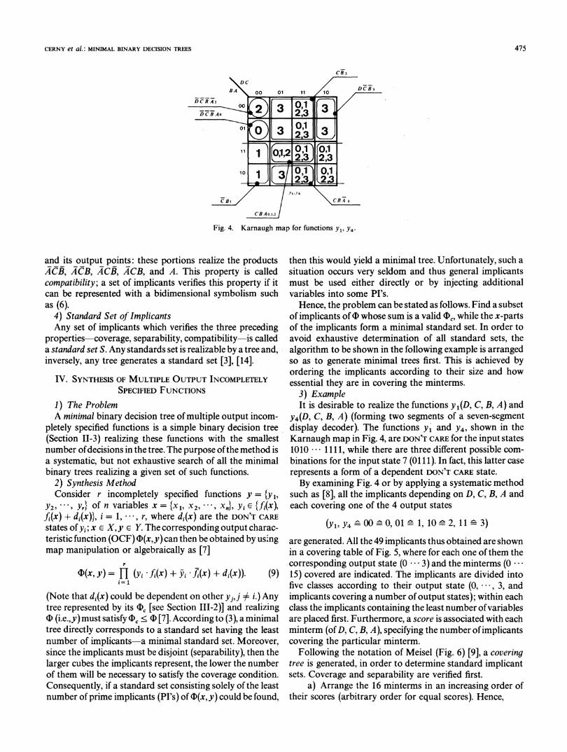
an equivalent Boolean expression consisting of a sum ofbranch products, where each such product is formed fromthe decision variables encountered on a particular branch[see I-Section 2)], that is, a- if the 0 out-branch is taken anda for the 1 out-branch of a node. The functions f1 and f2corresponding to the tree in Fig. 3 can thus be obtained as
fi = DCBA + DCB + DCBA + DCBA + DCBA + DA
(4)f2=DCB+DCB+DCBA +DCBA +DA. (5)
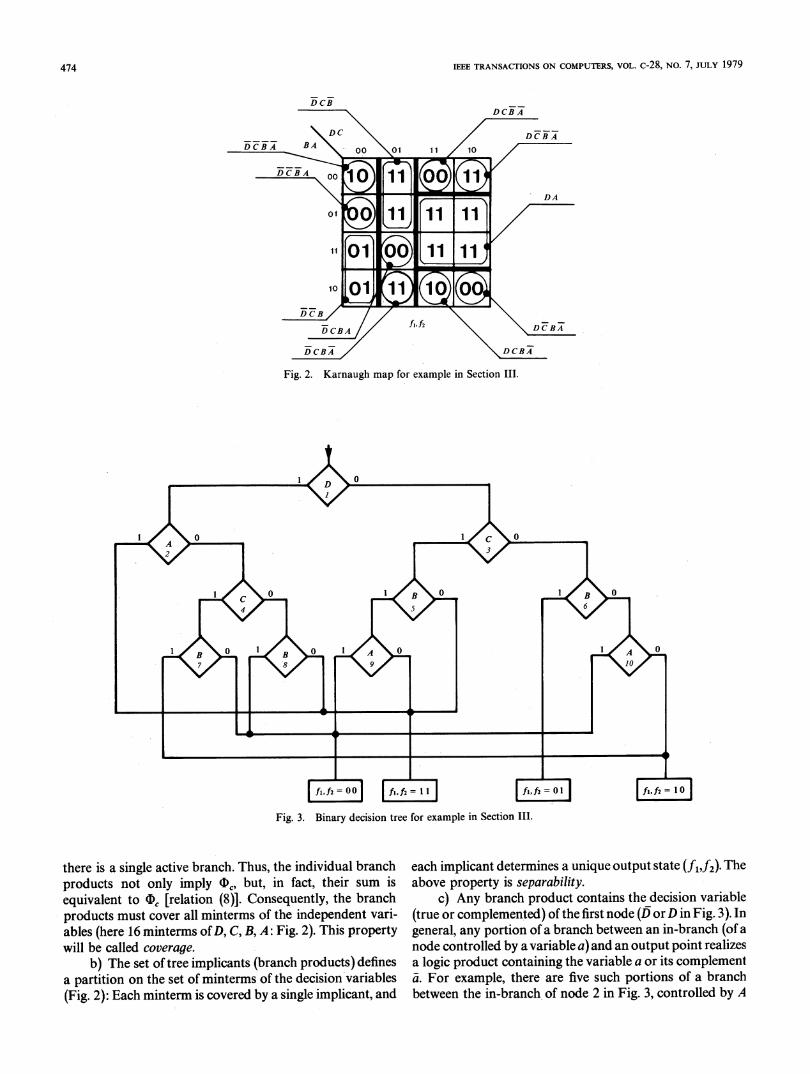
Expressions (4) and (5) are sums of implicants of thefunctions f1(D, C, B, A) andf2(D, C, B, A), as shown in theKarnaugh map of Fig. 2. Relations (4) and (5) could also berepresented using a bidimensional symbolism [10] asfollows:
B
C B
C BB
A ef1 f2
A eflf2jf, f2
e fl f2A4 Effi 2
A ef1f 2 (6)
C B fi f2B f1 f2
D
C CBef1 2
B ef1 f2
A Ef fl 2
Expression (6) exactly reflects the topology of the tree-each vertical bar stands for one decision, and for eachimplicant (branch), one indicates whether it corresponds tothe functions (f1,f2) or their inverses (f1, f2).
2) Characteristic FunctionsIt can be shown that (6) corresponds to a circuit character-
istic function (CCF) (equation) [7]:
Oc(D, C, B, A.f1,f2) = 1, (7)where each state of the input variables is associated with thecorresponding output state (f1,f2) through the solutions of(7). In that sense, each branch product from (6) multipliedlogically by the corresponding output state is an implicant of(D (also Fig. 2):
= DCBAf fT2 + DCBAA f2+ DCBf1 f2 + DCBfl f2+ DCBAfi f2 + DCBAJf f2 + DCBAf, f2+ DCBAfi f2 + DCBAJfi f2 + DCBAf, f2+ DAf1f2 = 1. (8)
The properties of (D can be summarized as [7]a) The equation FD = 1 is consistent for solutions
f1 =fl(D, C, B, A), f2 = f2(D, C, B, A),
that is, each minterm of the independent variables D, C, B, Ais covered.
b) The equation ID, = 1 has a unique solution for thefunctions ft and f2, since it represents a combinationalnetwork. Consequently, a unique output state is associatedwith each input state.
3) Properties of Decision TreesBy examining Figs. 2 and 3, relation (6) and using the
properties of a CCF [Section III-2)], the following proper-ties of a decision tree become evident.
a) Since each input variable appears as a decisionvariable in the tree, then for each state of these variables
473
IEEE TRANSACTIONS ON COMPUTERS, VOL. c-28, NO. 7, JULY 1979
C \
DCBA _00 01
D CBTA
Fig. 2. Karnaugh map for example in Section III.
fl, f2 =o5 fl, 2 = I I fl, f2 = O
Fig. 3. Binary decision tree for example in Section III.
there is a single active branch. Thus, the individual branchproducts not only imply FD, but, in fact, their sum isequivalent to (D, [relation (8)]. Consequently, the branchproducts must cover all minterms of the independent vari-ables (here 16 minterms of D, C, B, A: Fig. 2). This propertywill be called coverage.
b) The set of tree implicants (branch products) definesa partition on the set of minterms of the decision variables(Fig. 2): Each minterm is covered by a single implicant, and
each implicant determines a unique output state (fi,f2). Theabove property is separability.
c) Any branch product contains the decision variable(true or complemented) of the first node (D orD in Fig. 3). Ingeneral, any portion of a branch between an in-branch (of anode controlled by a variable a) and an output point realizesa logic product containing the variable a or its complementa. For example, there are five such portions of a branchbetween the in-branch, of node 2 in Fig. 3, controlled by A
474
CERNY et al.: MINIMAL BINARY DECISION TREES
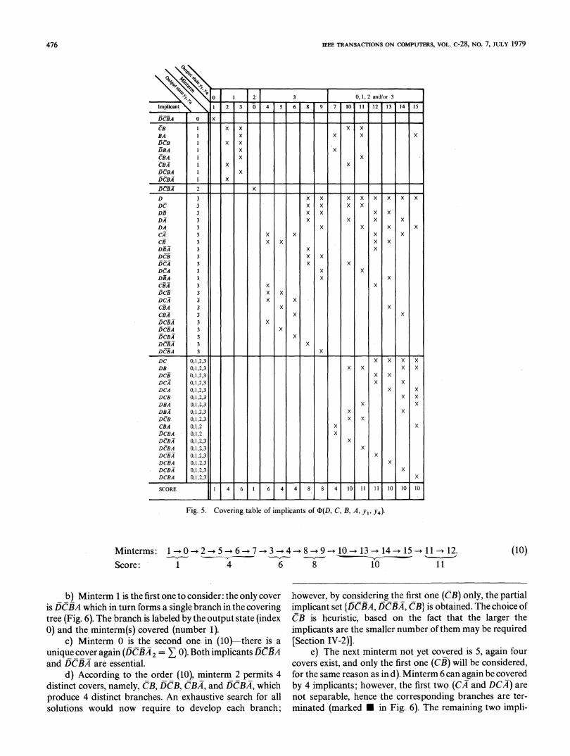
Fig. 4. Karnaugh map for functions Y1, Y4.
and its output points: these portions realize the products
ACB, ACB, ACB, ACB, and A. This property is calledcompatibility; a set of implicants verifies this property if itcan be represented with a bidimensional symbolism suchas (6).
4) Standard Set of ImplicantsAny set of implicants which verifies the three preceding
properties-coverage, separability, compatibility-is calleda standard set S. Any standards set is realizable by a tree and,inversely, any tree generates a standard set [3], [14].
IV. SYNTHESIS OF MULTIPLE OUTPUT INCOMPLETELYSPECIFIED FUNCTIONS
1) The ProblemA minimal binary decision tree of multiple output incom-
pletely specified functions is a simple binary decision tree(Section 11-3) realizing these functions with the smallestnumber ofdecisions in the tree. The purpose ofthe method isa systematic, but not exhaustive search of all the minimalbinary trees realizing a given set of such functions.
2) Synthesis MethodConsider r incompletely specified functions y = {y1,
Y2, Yr} of n variables x = {x1, x2, , x"}, Yi e {fi(x),f1(x) + di(x)}, i = 1, , r, where di(x) are the DON'T CARE
states of yi; x E X, y E Y. The corresponding output charac-teristic function (OCF) F(x,y) can then be obtained by usingmap manipulation or algebraically as [7]
r
D(x, y)= H (yi fi(x) + -i -fi(x)+ di(x)). (9)i= 1
(Note that d,(x) could be dependent on other yj,j $ i.) Anytree represented by its F, [see Section 111-2)] and realizing1D (i.e.,y) must satisfy , <.D [7]. According to (3), a minimaltree directly corresponds to a standard set having the leastnumber of implicants a minimal standard set. Moreover,since the implicants must be disjoint (separability), then thelarger cubes the implicants represent, the lower the numberof them will be necessary to satisfy the coverage condition.Consequently, if a standard set consisting solely of the leastnumber of prime implicants (PI's) of D(x,y) could be found,
then this would yield a minimal tree. Unfortunately, such asituation occurs very seldom and thus general implicantsmust be used either directly or by injecting additionalvariables into some PI's.
Hence, the problem can be stated as follows. Find a subsetof implicants of D whose sum is a valid (>, while the x-partsof the implicants form a minimal standard set. In order toavoid exhaustive determination of all standard sets, thealgorithm to be shown in the following example is arrangedso as to generate minimal trees first. This is achieved byordering the implicants according to their size and howessential they are in covering the minterms.
3) ExampleIt is desirable to realize the functions y1(D, C, B, A) and
y4(D, C, B, A) (forming two segments of a seven-segmentdisplay decoder). The functions y and y4, shown in theKarnaugh map in Fig. 4, are DON'T CARE for the input states1010 1111, while there are three different possible com-binations for the input state 7 (0111). In fact, this latter caserepresents a form of a dependent DON'T CARE state.By examining Fig. 4 or by applying a systematic method
such as [8], all the implicants depending on D, C, B, A andeach covering one of the 4 output states
(Yi, y4 00 0, 01 1, 10 -2, 11 3)are generated. All the 49 implicants thus obtained are shownin a covering table of Fig. 5, where for each one ofthem thecorresponding output state (0 ... 3) and the minterms (0 ...
15) covered are indicated. The implicants are divided intofive classes according to their output state (0, , 3, andimplicants covering a number of output states); within eachclass the implicants containing the least number ofvariablesare placed first. Furthermore, a score is associated with eachminterm (of D, C, B, A), specifying the number ofimplicantscovering the particular minterm.
Following the notation of Meisel (Fig. 6) [9], a coveringtree is generated, in order to determine standard implicantsets. Coverage and separability are verified first.
a) Arrange the 16 minterms in an increasing order oftheir scores (arbitrary order for equal scores). Hence,
475
IEEE TRANSACTIONS ON COMPUTERS, VOL. c-28, NO. 7, JuLY 1979
I \
0
2
213 1 0 1 4 1 5
3
6 100,1,2 and/or 3
11 1 12 1 13 1 14 1 15
DCIIA 0 X
BA I X X X X
DBA 1 X X
CfBA 1 X X
DCBA 1 X
DCfBA 1 X
CBfFA 2 X
D 3 X X X X X X X XDCf 3 X X X XDRI 3 X X X XDA; 3 X X X XDA 3 X X X XCA 3 X X X XCII 3 X X X XD.§A 3 X XDENI 3 X X15A 3 X X
DCA 3 X XDIIA 3 X XCRiA 3 X XDCII 3 X XDCA 3 X XCRiA 3 X XCBRA 3 X XD5CiIA 3 XDCBA 3 XDCBAi 3 XDCBA 3 XDCIIA 3 X
DC 0,1,2,3 X X X XDB 0,1,2,3 X X X XDCiI 0,1,2,3 x xDCA 0,1,2,3 x xDCA 0,1,2,3 X XDCB 0,1,2,3 x xDBA 0,1,2,3 X XDBA 0,1,2,3 X XDCB 0,1,2,3 X XCBA 0,1,2 X XDCBA 0,1,2 xDCBA 0,1,2,3 x
DCfBA 0,1,2,3 XDCIIA 0,1,2,3 X
DCBIA 0,1,2,3 xDCBIA 0,1,2,3 XDCBA 0,1,2,3 X
SCORE 1 4 6 1 6 4 4 8 8 4 10 11 11 10 10 10
Fig. 5. Covering table of implicants of CD(D, C, B, A, Y1, Y4).
Minterms: 1 0256734 10- 13- 14- 15-+ 11 - 12.Score: 1 4 6 8 10 11
b) Minterm 1 is the first one to consider: the only cover
is DCBA which in turn forms a single branch in the coveringtree (Fig. 6). The branch is labeled by the output state (index0) and the minterm(s) covered (number 1).
c) Minterm 0 is the second one in (10)-there is a
unique cover again (DCRA2 = 0). Both implicants DCBAand DCBA are essential.
d) According to the order (10), minterm 2 permits 4distinct covers, namely, CB, DCB, CBA, and DCBA, whichproduce 4 distinct branches. An exhaustive search for allsolutions would now require to develop each branch;
however, by considering the first one (CB) only, the partialimplicant set {DCBA, DCBA, CB} is obtained. The choice ofCB is heuristic, based on the fact that the larger the
implicants are the smaller number of them may be required[Section IV-2)].
e) The next minterm not yet covered is 5, again four
covers exist, and only the first one (CB) will be considered,for the same reason as in d). Minterm 6 can again be coveredby 4 implicants; however, the first two (CA and DCA) are
not separable, hence the corresponding branches are ter-
minated (marked in Fig. 6). The remaining two impli-
(10)
L 0
k0
.
476
1
8 F-.j 7
CERNY et al.: MINIMAL BINARY DECISION TREES
fAO DCBA2ICE1 CB3(1) (0) (2,3,10,11) (4,5,12,13)
_CA3 -
(4,6,12,14)
DCA3
(4,6)
- CBA3 . BAl X(6,14) 1 (3,7,11,15)
_.DCBA3 _.(6)
,DBA1-I(3,7)
_CBAo,1,2 D3(7,15) (8,9,10,11,12,13,14,15)
DC3(8,9,10,11)
_DB3_a(8,9,12,13)
_DA3,s(8,10,12,14)
_ DBA3 l(8,12)
EDCB3 p(8,9)
DCA3 -(8,10)
_DCBA3- -- -
(8)
.DCBAO,1,2 - --
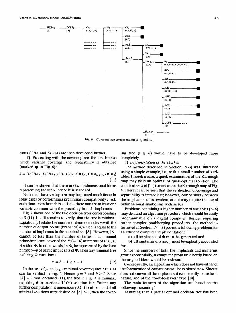
(7)Fig. 6. Covering tree corresponding to y1 and y4.
cants (CBA and DCBA) are then developed further.f) Proceeding with the covering tree, the first branch
which satisfies coverage and separability is obtained(marked 0 in Fig. 6):S = {DCBAO, DCBA2, CB1, CB3, CBA3, CBAO 12, DCB3}.
- ~~~~~~~~~(11)It can be shown that there are two bidimensional forms
representing the set S, hence it is standard.Note that the covering tree may be pruned much faster in
some cases by performing a preliminary compatibility checkeach time a new branch is added-there must be at least onevariable common with the preceding branch implicants.
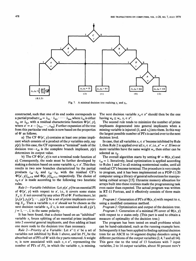
Fig. 7 shows one of the two decision trees correspondingto S (11). It still remains to verify, that the tree is minimal.Equation (3) relates the number ofdecision nodes m with thenumber of output points (branches) b, which is equal to thenumber of implicants in the standard set S . However, S Icannot be less than the number of terms in a minimalprime-implicant cover of the 2" (= 16) minterms of D, C, B,A within (. In other words, let (D, be represented by the leastnumber-p of prime implicants of (D. Then any minimal treerealizing (D must have
m= b-1 2 p-1. (12)In the case of y1 and y4, a minimal cover requires 7 PI's, as
can be verified in Fig. 4. Hence, p = 7 and b . 7. SinceS I = 7 was obtained (11), the tree in Fig. 7 is minimal,
requiring 6 instructions. If this solution is sufficient, anyfurther computation is unnecessary. On the other hand, if allminimal solutions were desired or S > 7, then the cover-
ing tree (Fig. 6) would have to be developed morecompletely.
4) Implementation of the MethodThe method described in Section IV-3) was illustrated
using a simple example, i.e., with a small number of vari-ables. In such a case, a quick examination of the Karnaughmap may yield an optimal or quasi-optimal solution. Thestandard set S of (1 1) is marked on the Karnaugh map ofFig.4. There it can be seen that the verification of coverage andseparability is immediate; however, compatibility betweenthe implicants is less evident, and it may require the use ofbidimensional symbolism such as (6).
Problems containing a higher number of variables (> 6)may demand an algebraic procedure which should be easilyprogrammable on a digital computer. Besides requiringrather complex bookkeeping procedures, the method il-lustrated in Section IV-3) poses the following problems foran efficient computer implementation:
a) all implicants of (D must be generated andb) all minterms ofx andy must be explicitly accounted
for.Since the numbers of both the implicants and minterms
grow exponentially, a computer program directly based onthe original ideas would be awkward.
Consequently, an algorithm which does not have either ofthe forementioned constraints will be explored now. Since itdoes not known all the implicants, it is inherently heuristic innature, and of the "root-to-leaves" type [14].The main features of the algorithm are based on the
following reasoning:'Assuming that a partial optimal decision tree has been
477
IEEE TRANSACrIONS ON COMPUTERS, VOL. c-28, NO. 7, JULY 1979
(3) (1) (0) (2)
(0,1,2)
Fig. 7. A minimal decision tree realizing Yi and Y4.
constructed, such that one of its end nodes corresponds toa partial product txk = Xkl * Xk2 . Xkm, where 5kjis eitherXkj or Xkj, with a residual characteristic function (D'(x', y),where x' = x-{Xkl, - , x,k,,}. Further expansion of the treefrom this particular end node is now based on the propertiesof (D' as follows.
a) The CF (D'(x', y) contains at least one prime impli-cant which consists of a product of they variables only, sayp(y). In this case, the CF represents a "terminal" node of thedecision tree-t-Xjk is the complete branch implicant, p(y)determines its output value.
b) The CF (D'(x', y) is not a terminal node function ofa). Consequently, the node must be further developed bymaking a decision based on some variable xd E x'. This thenresults in two new branches characterized by the partialproducts txk xd and txk Xd, with the residual CF's(D'(x', y) d=o and (D(x, y) IXd= 1, respectively. The choice ofXd E x' is made according to the following two heuristicrules.
Rule I-Variable Inhibition: Let p(x', y) be an essential PIof 4D'(x', y) with respect to x', i.e., it covers some statesXp c X not covered by any other PI of O'. Furthermore, let{p (X ), p2(X'), * * , p1(x')} be a set of prime implicants cover-ing Xp. Then a variable xi E x' should not be chosen as thenext decision variable Xd if xi is not contained in all pJ{x'),j = 1, , 1, in the same polarity.
It has been found, that a choice based on an "inhibited"variable xI forces splitting of an essential prime implicantinto 2 essential general implicants, and thus adding at leastone more node to the decision tree than necessary.
Rule 2-Priority of a Variable: Let x" c x' be a set ofvariables not inhibited by Rule 1 above, and let PI. be theabsorbed set of PI's of (D' with they parts removed. A weightwi is now associated with each xi E x", representing thenumber of PI's of PIX in which the variable xi is missing.
The next decision variable xd E x" should then be the onehaving wd < wi, xi E x".The second rule tends to minimize the number of prime
implicants degenerated into general implicants when amissing variable is injected (xi and xi) into them. In this waythe largest possible number of PI's is carried over to the nextdecision level.
In case, that all variables xi E x' become inhibited by Rule1, then Rule 2 is applied over all xi E x', i.e., x" = x'. Iftwo ormore variables have the same weight wi, then either can beselected as xd.The overall algorithm starts by setting F' = ((x, y) and
txk = 1. Iteratively, local optimization is applied accordingto Rules 1 and 2 to all existing nonterminal nodes, until allresidual CF's become terminal. The procedure is very simpleto program, and it has been implemented on a PDP-1 1/20computer using a library of general subroutines for manipu-lating cubical arrays [15]. Dynamic memory allocation forarrays built into these routines made the programming taskeven easier than expected. The actual program was writtenin RT-l1 Fortran, and it effectively consists of three mainparts:Program 1: Generation ofPI's of((x, y) with respect to x,
using a modified consensus method.Program 2: Optimization and output of the decision tree.Program 3: Generation of a minimal PI cover of ¢(x, y)
with respect to x states only. (This part is used to obtain ameasure of optimality of the decision tree.)The program has been tested on small problems which
can be hand-calculated, such as the running example here.Subsequently it has been applied to finding optimal decisiontrees for an ASCII to 14 segment display decoders using 4different partitions of the output variables (2,4,7 and all 14).This gave rise to the total of 13 functions with 7 inputvariables, 2 to 14 output variables, about 50 percent DON'T
478
I
CERNY et al.: MINIMAL BINARY DECISION TREES
CARE terms. The trees obtained were less than 4 decisions offthe ideal minimum determined by Program 3, and on theaverage they contained about 80 nodes. The execution timesfor Program 2 were approximately 1 minute, not countingconsole I/O. It is interesting to note, that the execution ofProgram 3 required about 3 times as much time to completethan Program 2. A number of variations in calculating theweights wi have been tested; however, each time the resultsobtained were much worse than with the algorithm justdescribed.
Considering that the algorithm is based on heuristic rules,the amount of testing performed is far from sufficient.However, further evaluation is under way and its results will'be made available at a later date. Placing the description ofthe algorithm here was meant to primarily illustrate theevolution of the multiple output function decision treeoptimization. The fact that heuristic reasoning was used inplace of the former deterministic approach [see SectionIV-3)] follows directly from the complexity of the problem,and it is in agreement with conclusions reached by otherresearchers [14]. In order to appreciate the relative speed ofthe algorithm, an example is shown in the Appendix.
V. BINARY DECISION ALGORITHMS1) Example of a Binary Decision TreeLet
Z(D, C, B, A)= E {0, 3, 5, 6, 9, 10,12, 15}. (13)
The 16 minterms ofthe corresponding OCF (D form a uniqueminimal standard set (no simplification possible); a pro-gram corresponding to its decision tree is
if
1
2345
678.9
101112131415
a
DC
C
BBBBAAAAAAAA
then j(a= 1)
35
79111315
Z=0Z = 1Z = 1Z=0Z = 1Z=0Z=0Z = 1
else k(a = 0)
2468101214
Z = 1Z =0Z=0Z = 1
Z=0Z = 1Z = 1Z=0
outputpoints
2) Transformation of a Decision Tree in a DecisionAlgorithm
Reduction of a program such as (14) is possible, if thereare two instructions i and j such that ai= aj= a, and thesuccessor nodes are identical for a = 1 and a = 0. It is saidthat the two instructions are equivalent.
Iterative application of the equivalence relation to theoriginal program (14) (first 9 10 12 15; thereafter8 _ 11 13 _ 14, and 4_ 7, 5 6, and a proper replace-ment of indices yield the following program:
ifa
then j(a= 1)
else k(a = 0)
1 D 3 22 C 5 43 C 4 54 B 9 85 B 8 98 A Z = 0 Z = 19 A Z=1 Z=0J
outputpoints
(15)As much as Boolean algebra did not permit any
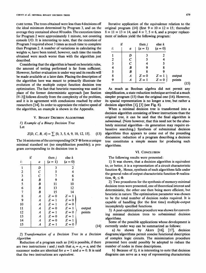
simplification, a state reduction technique arrived at a muchsimpler program (15) than the original one (14). However,its spacial representation is no longer a tree, but rather adecision algorithm [1], [3] (see Fig. 8).When a minimal decision tree is transformed into a
decision algorithm consisting of fewer instructions than theoriginal tree, it can be said that the final algorithm issubminimal. (Note however, that this need not be the abso-lutely minimal algorithm-its generation may require ex-haustive searching.) Synthesis of subminimal decisionalgorithms thus appears to come out of the precedingdiscussion: reduction of a program describing a decisiontree constitutes a simple means for producing suchalgorithms.
VI. CONCLUSION
The following results were presented:1) It was shown, that a decision algorithm is equivalent
to, or better, it is a representation of a circuit characteristicfunction SD. Hence, synthesis of such algorithms falls underthe general rules of output characteristic function (D realiza-tion, (c < (
2) Two procedures for the synthesis ofmemory-minimaldecision trees were presented, one oftheoretical interest anddeterministic, the other one then being more efficient, butheuristic in nature. The optimization parameter was chosento be the total number of decision nodes required. It iscapable of handling (for the first time) multiple-outputincompletely specified functions.
3) A post-optimization procedure was shown forconvert-ing minimal decision trees to subminimal decisionalgorithms.Some of the possible applications whose development is
currently under way can be summarized as follows:a) As shown by Akers [16], [17], decision
diagrams/algorithms permit concise functional descriptionof complex logic circuits. The minimization procedurepresented here could possibly be adopted to reduce thenumber of nodes in these descriptions.
b) Because of 1), it is interesting to note that decisiondiagrams can serve as a way of representing characteristic
479
IEEE TRANSACTIONS ON COMPUTERS, VOL. c-28, NO. 7, JULY 1979
Fig. 8. Decision algorithm obtained by "state" reduction techniques.
functions in fault detection procedures for modularnetworks discussed in [19]. In this way, the problem ofexcessive storage requirements [19] by cubical array re-presentations oflogic functions could be alleviated [16], [17].It requires though, that the decomposition rules for charac-teristic functions be transcribed for treating decisionalgorithms.
c) The binary decision machine [2], [13], [14] can beeasily modified for the multiple output (in parallel) case,thus producing a general serio-parallel decision machine.The minimization algorithm presented here serves as a toolfor programming such a machine. Because of a sequentialnature of executing a decision program, the machine is notsuited for high speed applications; its domain lies in theslower region, with simplicity ofreprogramming (e.g., indus-trial sequencers). In such a case, the most meaningfuloptimization parameter is the memory space requirement.
d) Reduction of binary decision tables for variousapplications. Possible generalization to n-valued logicwould for instance permit reduction ofpattern classificationdecision tables.
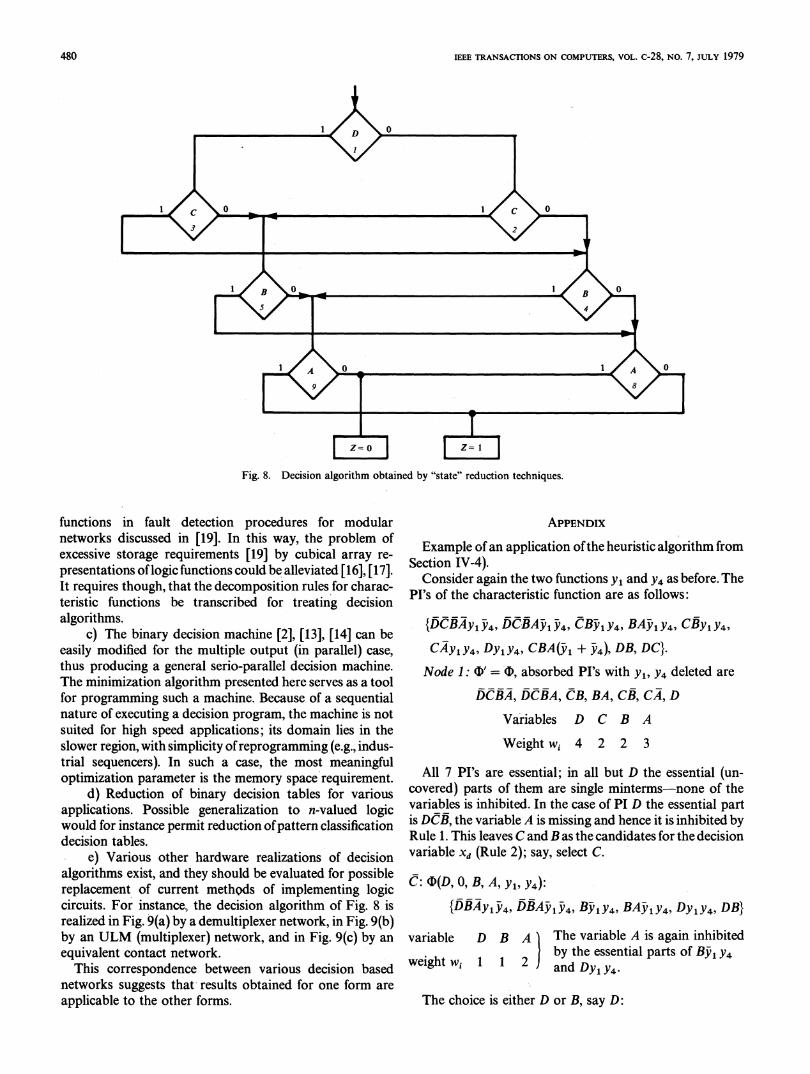
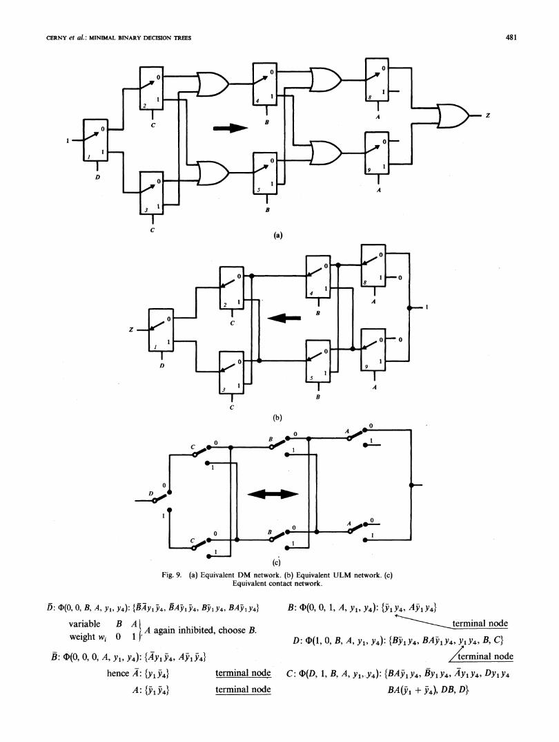
e) Various other hardware realizations of decisionalgorithms exist, and they should be evaluated for possiblereplacement of current methods of implementing logiccircuits. For instance, the decision algorithm of Fig. 8 isrealized in Fig. 9(a) by a demultiplexer network, in Fig. 9(b)by an ULM (multiplexer) network, and in Fig. 9(c) by anequivalent contact network.
This correspondence between various decision basednetworks suggests that results obtained for one form areapplicable to the other forms.
APPENDIX
Example of an application ofthe heuristic algorithm fromSection IV-4).Consider again the two functions Yi and y4 as before. The
PI's of the characteristic function are as follows:
{DCBAyI Y4, DCBAyl Y4, CBjly4, BA'1y4, CBYI Y4,
CAy1y4, Dy1y4, CBA(yj + y4, DB, DC}.Node 1: O' = F, absorbed PI's with Yi, y4 deleted are
DCBA, DCBA, CB, BA, CB, CA, D
Variables D C B A
Weight wi 4 2 2 3
All 7 PI's are essential; in all but D the essential (un-covered) parts of them are single minterms-none of thevariables is inhibited. In the case of PI D the essential partis DCB, the variable A is missing and hence it is inhibited byRule 1. This leaves C and B as the candidates for the decisionvariable Xd (Rule 2); say, select C.
C: D(D, 0, B, A, YI, Y4):{DBAYiY4YDBA4,AY4, Bj'y4, BAIyY4, Dy,y4, DB}
variable D B A The variable A is again inhibitedw
by the essential parts of Bj1 y4weight W1 1 1 2 l and Dy1y4-
The choice is either D or B, say D:
480
CERNY et al.: MINIMAL BINARY DECISION TREES
z
C (a)
z
C
(b)
(cjFig. 9. (a) Equivalent DM network. (b) Equivalent ULM network. (c)
Equivalent contact network.
D5: $(O, 0, B, A, Yl, Y4): {BAyy14, BA 1y4, BjIy4, BAJIy4} B: (I(O, 0, 1, A, Y, Y4): {Y1Y4, A51y4}variable B A terminal node
weigth 0 1(,A again inhibited, choose B.weight w, ,1 D: tD(1, O, B, A, Y1, Y4): {BjV1y4, BAj1y4, Y1Y4, B, C}B: $(O, 0, 0, A, Yl, Y4): {Ay1y4, Ay1- } terminal node
hence A: {y1534} terminal node C: tb(D, 1, B, A, Yi,Y4): {BA51y4, By1y4, Ay1y4, Dy1y4
A: {iV1iV4} terminal node BA(5' + 44), DB, D1
481
,IEEE TRANSACTIONS ON COMPUTERS, VOL. c-28, NO. 7, JuLY 1979
variable D B Aweight w, 3 2 2
no variable is inhibited, select B.
B: D(D, 1, 0, A, Yi, Y4): {Yl 4' AY1Y4, Dyly4, D}
B: (D(D, 1, 1, A, Yi, Y4): {A1y4,4AY1Y4, Dy1Y4, D}
eightl 2 1A no variable is inhibited, select A:
A: D(D, 1, 1, 0, Yl, Y4): {Y1Y4, Dy1Y4, DII terminal node
A: O(D, 1, 1, 1, Yi, Y4): {Y1Y4, Dy1Y4, D}
|terminal node
Since all branches have been terminated by residual CF'swith a PI containing none of the independent variables, theprocedure is concluded. The corresponding bidimensionalform is
A e Y1Y4
A E Y14
|C B eyjy4
D CEy1Y4
| B eY1Y4C A e Y1Y4
B
A e Y1Y4Ifthe alternate variables were chosen when equal weights
were encountered, the forms (13) and (14) would have beenobtained. Note also, that the choice of Xd = D at the firstlevel would also yield a minimal tree. This is not the case
with Xd = A, however.
REFERENCES
[1] C. Y. Lee, "Representation of switching circuits by binary-decisionprograms," Bell Syst. Tech. J., vol. 38, pp. 985-999, July 1959.
[2] R. T. Boute, "The binary decision machine as programmable control-ler," Euromicro Newslett., vol. 2, pp. 16-22, 1976.
[3] M. Davio and A. Thayse, "Sequential evaluation of Boolean func-tions," MBLE Res. Lab., Brussels, Rep. R341, Mar. 1977.
[4] A. Thayse, "Optimization of binary decision algorithms," MBLERes. Lab., Brussels, Rep. R348, May 1977.
[5] R. P. Voith, "ULM implicants for minimization of universal logicmodule circuits," IEEE Trans. Comput., vol. C-26, pp. 417-424, May1977.
[6] D. Mange and E. Sanchez, "Synthese des fonctions logiques avec desmultiplexeurs," Digital Processes, no. 1, vol. 4, Spring 1978.
[7] E. Cerny and M. A. Marin, "An approach to unified methodology ofcombinational switching circuits," IEEE Trans. Comput., voL C-26,pp. 745-756, Aug. 1977.
[8] E. J. McCluskey, "Minimization of Boolean functions," Bell Syst.Tech. J., vol. 35, no. 5, pp. 1417-1444, Nov. 1956.
[9] W. S. Meisel, "A note on internal state minimization incompletelyspecified sequential networks," IEEE Trans. Electron. Comput., vol.EC-16, pp. 508-509, Aug. 1967.
[10] R. L. VallUe, "Analyse binaire, tome 1: Theorie et applications aux
circuits combinatoires," Masson, Paris, 1970.
[11] T. F. Tabloski and F. J. Mowle, "A numerical expansion techniqueand its applcation to minimal multiplexer logic circuits," IEEETrans. Comput., vol. C-25, pp. 684-702, July 1976.
[12] S. S. Yau and C. K. Tang, "Universal logic modules and their appli-cations," IEEE Trans. Comput., vol. C-19, pp. 141-149, 1970.
[13] C. R. Clare, Designing Logic Systems Using State Machines. NewYork: McGraw-Hill, 1973.
[14] M. Davio and A. Thayse, "Optimization of multivalued decisionalgorithms," MBLE Res. Lab., Brussels, Rep. R357, Sept. 1977; alsopresented at the 1978 Symp. on Multi-Valued Logic.
[15] J. Kozlowski and E. Cerny, "Subroutines for Boolean array opera-tions," Fall 1976 Local Rep., Dep. Elec. Eng., Concordia Univ.,Montreal, 1977.
[16] S. B. Akers, "Binary decision diagrams," IEEE Trans. Comput., vol.C-27, June 1978; also, FTCS-7, June 1977.
[17] -, "Functional testing with binary decision diagrams," presentedat the 8th Fault-Tolerant Comput. Symp., Toulouse, France, June1978.
[18] R. S. Michalski, "Designing extended entry decision tables and opti-mal decision tables and optimal decision trees using decision dia-grams," IEEE Computer Rep., R78-126, June 1978.
[19] E. Cerny, "Controllability and fault observability in modular com-binational circuits," IEEE Trans. Comput., vol. C-27, pp. 896-903,Oct. 1978.
* ? N;!| Eduard Cerny (M'73) was born in 1946 inCzechoslovakia. He received the B.Sc. (Eng.)
r _ (1970) from Loyola College, University ofMontreaL MontreaL P.Q, Canada, the M.Eng.(1971) and the Ph.D. (1975) degrees, both fromMcGill University, Montreal, P.Q., Canada.From 1971 to 1978 he was employed at the
Department of Electrical Engineering, ConcordiaUniversity; presently he assumes the position ofan Assistant Professor at Department of Informa-tion Sciences, University of MontreaL His in-
terests are digital systems design and real-time computer applications.Dr. Cerny is a member of DECUS and a Registered Engineer in the
Province of Quebec.
Daniel Mange (S'68-M'69) received the diplomaof electrical engineer and the Ph.D. degree inelectrical engineering from the Federal Poly-technic Institute of Technology, Lausanne, Swit-zerland, in 1964 and 1968, respectively.
Since 1969 he has been a Professor of DigitalSystems at the Polytechnic Institute of Tech-nology, where he is engaged in teaching and re-search in the areas of switching circuits, logicaldesign, universaL and programmable digitalmodules. He is the author of Analyse et syntbese
des systemes logiques pubLished in 1978 as the # 5 of the "Traited'Electricite de rEcole polytechnique Federale de Lausanne."
2gI.'.^2.@i_L'.i W Eduardo Sanchez received the diploma ofelectricalengineer from the Universidad Del Valle, Cali,Colombia, in 1975.He worked as assistant of Digital Systems at
the Universidad Del Valle from 1975 to 1976 and,since 1977, as an assistant of the Federal Poly-technic Institute of Technology, Lausanne,Switzerland. He is currently working on program-mable digital systems design.
482
Related Documents