Synthesis of Embedded Networks for Building Automation and Control Alessandro Pinto * , Massimiliano D’Angelo † , Carlo Fischione * , Eelco Scholte ‡ , Alberto Sangiovanni-Vincentelli * * Department of Electrical and Computer Sciences, University of California, Berkeley, CA, USA {apinto,fischion,alberto}@eecs.berkeley.edu † University of L’Aquila, L’Aquila, Italy and PARADES GEIE, Rome, Italy [email protected] ‡ United Technologies Research Center, East Hartford, CT 06108, USA [email protected] Abstract—We present a methodology and a software frame- work for the automatic design exploration of the commu- nication network among sensors, actuators and controllers in building automation systems. Given 1) a set of end-to- end latency, throughput and packet error rate constraints between nodes, 2) the building geometry, and 3) a library of communication components together with their performance and cost characterization, a synthesis algorithm produces a network implementation that satisfies all end-to-end constraints and that is optimal with respect to installation and maintenance cost. The methodology is applied to the synthesis of wireless networks for an essential step in any control algorithm in a distributed environment: the estimation of control variables such as temperature and air-flow in buildings. I. INTRODUCTION A building automation system is the interconnection of a large number of sensors, actuators and controllers distributed on thousands of square feet. Communication among these components takes place over a network, whose design is subject to several constraints. The control algorithm for ap- plications such as fire detection systems, temperature control, distributed control of air flow in buildings imposes end- to-end communication constraints from the sensors to the controllers, and from these to the actuators. The constraints imposed by the application include latency, bandwidth and packet error rate. The building geometry imposes constraints on the possible location of nodes, on the wires’ layout and on the wireless communication between nodes. The cost of the communication network constitutes a large portion of the overall cost of a building automation system. Therefore, it is desirable to tailor the network architecture to both the control algorithm and the building geometry, avoiding to waste costly communication resources. A variety of network components is available on the market to achieve this goal. In recent years, many wired and wireless protocol standards for building automation have emerged [7], [8], [9], [10], as well as a number of companies providing compo- nents that are compliant with these protocol specifications. This is an opportunity for engineers to design networks that are application-specific. However, the difficulty resides in the ability to match the application and physical constraints to the performance offered by network components, while minimizing the total network cost. In fact, to avoid long verification cycles, engineers tend to use architectures that have been already tested in previous designs. Moreover, the network is purposely over-designed to make the communi- cation delay negligible compared to the time-scale of the control algorithms. The result is a network that is far from being cost-effective. Therefore, an automatic synthesis flow that is able to find an optimal network implementation starting from the con- straints and the available communication components would provide invaluable help to build cost-effective and correct- by-construction building automation networks. We propose a methodology and a companion software framework that facilitates the design exploration of control networks. The application is captured by a set of point-to-point communi- cation constraints between nodes that have a fixed position in the building. The implementation space (i.e., the set of pos- sible network implementations) is implicitly captured by a library of components characterized by cost and performance models. The building geometry is also taken into account by capturing the position of the walls, restrictions on the positions of nodes, and wiring constraints. This methodology has been used in the context of wired networks for building automation systems; we refer the reader to [6] for the details. In this paper, we focus on wireless networks. We formulate an optimization problem to find an optimal wireless network implementation that satisfies all the constraints. The imple- mentation is optimal in the sense that it minimizes a cost function that consists of actual dollar cost for components and installation. We derive an Integer Linear Programming (ILP) formulation of the optimization problem and we solve it using CPLEX [12], leaving the development of efficient heuristics to minimize computation time and increase the size of the problems that can be tackled by our approach for future work. We apply the methodology to an essential step in any distributed control algorithm: the distributed estimation of physical control variables such as temperature and air- flow. II. CASE STUDY:DISTRIBUTED ESTIMATION IN BUILDINGS We use a distributed estimation example to illustrate our work. Figure 1 shows the input of our design flow, which 2008 American Control Conference Westin Seattle Hotel, Seattle, Washington, USA June 11-13, 2008 WeB07.6 978-1-4244-2079-7/08/$25.00 ©2008 AACC. 920

Welcome message from author
This document is posted to help you gain knowledge. Please leave a comment to let me know what you think about it! Share it to your friends and learn new things together.
Transcript

Synthesis of Embedded Networks for Building Automation and Control
Alessandro Pinto∗, Massimiliano D’Angelo†, Carlo Fischione∗, Eelco Scholte‡, Alberto Sangiovanni-Vincentelli∗∗ Department of Electrical and Computer Sciences, University of California, Berkeley, CA, USA
apinto,fischion,[email protected]† University of L’Aquila, L’Aquila, Italy and PARADES GEIE, Rome, Italy
[email protected]‡United Technologies Research Center, East Hartford, CT 06108, USA
Abstract— We present a methodology and a software frame-work for the automatic design exploration of the commu-nication network among sensors, actuators and controllersin building automation systems. Given 1) a set of end-to-end latency, throughput and packet error rate constraintsbetween nodes, 2) the building geometry, and 3) a library ofcommunication components together with their performanceand cost characterization, a synthesis algorithm produces anetwork implementation that satisfies all end-to-end constraintsand that is optimal with respect to installation and maintenancecost. The methodology is applied to the synthesis of wirelessnetworks for an essential step in any control algorithm in adistributed environment: the estimation of control variablessuch as temperature and air-flow in buildings.
I. INTRODUCTION
A building automation system is the interconnection of alarge number of sensors, actuators and controllers distributedon thousands of square feet. Communication among thesecomponents takes place over a network, whose design issubject to several constraints. The control algorithm for ap-plications such as fire detection systems, temperature control,distributed control of air flow in buildings imposes end-to-end communication constraints from the sensors to thecontrollers, and from these to the actuators. The constraintsimposed by the application include latency, bandwidth andpacket error rate. The building geometry imposes constraintson the possible location of nodes, on the wires’ layout andon the wireless communication between nodes.
The cost of the communication network constitutes a largeportion of the overall cost of a building automation system.Therefore, it is desirable to tailor the network architectureto both the control algorithm and the building geometry,avoiding to waste costly communication resources. A varietyof network components is available on the market to achievethis goal. In recent years, many wired and wireless protocolstandards for building automation have emerged [7], [8], [9],[10], as well as a number of companies providing compo-nents that are compliant with these protocol specifications.This is an opportunity for engineers to design networks thatare application-specific. However, the difficulty resides in theability to match the application and physical constraintsto the performance offered by network components, whileminimizing the total network cost. In fact, to avoid long
verification cycles, engineers tend to use architectures thathave been already tested in previous designs. Moreover, thenetwork is purposely over-designed to make the communi-cation delay negligible compared to the time-scale of thecontrol algorithms. The result is a network that is far frombeing cost-effective.
Therefore, an automatic synthesis flow that is able to findan optimal network implementation starting from the con-straints and the available communication components wouldprovide invaluable help to build cost-effective and correct-by-construction building automation networks. We proposea methodology and a companion software framework thatfacilitates the design exploration of control networks. Theapplication is captured by a set of point-to-point communi-cation constraints between nodes that have a fixed position inthe building. The implementation space (i.e., the set of pos-sible network implementations) is implicitly captured by alibrary of components characterized by cost and performancemodels. The building geometry is also taken into accountby capturing the position of the walls, restrictions on thepositions of nodes, and wiring constraints. This methodologyhas been used in the context of wired networks for buildingautomation systems; we refer the reader to [6] for the details.
In this paper, we focus on wireless networks. We formulatean optimization problem to find an optimal wireless networkimplementation that satisfies all the constraints. The imple-mentation is optimal in the sense that it minimizes a costfunction that consists of actual dollar cost for componentsand installation. We derive an Integer Linear Programming(ILP) formulation of the optimization problem and we solveit using CPLEX [12], leaving the development of efficientheuristics to minimize computation time and increase thesize of the problems that can be tackled by our approach forfuture work. We apply the methodology to an essential step inany distributed control algorithm: the distributed estimationof physical control variables such as temperature and air-flow.
II. CASE STUDY: DISTRIBUTED ESTIMATION INBUILDINGS
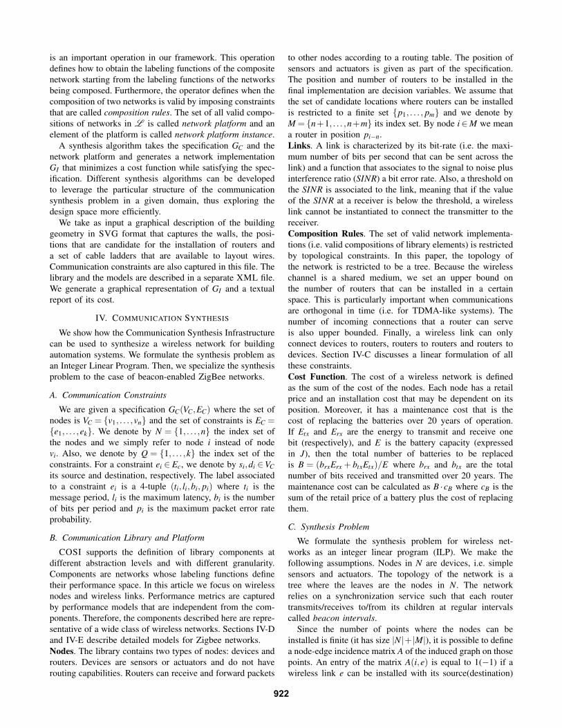
We use a distributed estimation example to illustrate ourwork. Figure 1 shows the input of our design flow, which
2008 American Control ConferenceWestin Seattle Hotel, Seattle, Washington, USAJune 11-13, 2008
WeB07.6
978-1-4244-2079-7/08/$25.00 ©2008 AACC. 920

l = t = 2.5sb = 16p = 10!5
l = 0.5st = 1sb = 16p = 10!5
32m
70m
Sensor
Gateway
Router Position
a)
b)
Fig. 1. The two test cases used in our experiments: a) Distributedestimation, b) Centralized estimation.
includes the floor-plan of a building and a set of sensorslocated in predefined positions.
The centralized estimation dynamics (Figure 1(a)) can bedescribed by the following set of equations:
xk+1 = f (xk,uk,wk)yk = h(xk,uk,vk)
where uk represents the measure from the sensors, wk and vkmodel noise, and xk is the state of the system, and k is thetime index. The measures uk are sent to a central gateway thatcomputes the estimate xk+1 and, in the case of closed loopcontrol, the output yk to be sent to actuators. Communicationsbetween the sensors and the gateway are represented byconnectors annotated with the required quality of service:To guarantee estimation accuracy, the delay and packet errorrate of the communication cannot exceed a certain upperbound that depends on the application.
In the distributed estimation case (Figure 1(b)), the dy-namics can be described as follows:
xk+1,i = f (xk,i,xk,Γk ,uk,i,wk,i)yk,i = h(xk,i,xk,Γk ,uk,i,vk,i)
where i denotes the index in space (and would be of size 3for a 3D building). In the previous equations, Γk denotes theset of indexes of the states that influence the one in positioni (e.g. its nearest neighbors). In the case of a flat hierarchy,the set Γk generally contains only its nearest neighborsΓk = [i, i + 1, i− 1] (for a single dimension), however, inthe case of decentralized estimation [5], possibly augmentedwith multi-scale consensus [4], the set Γk will contain alarger set of states, which are not necessarily close in space,since now nodes might have to communicate at slower scaleswith locations that are further away. Therefore, a sensor inposition i communicates with its neighbors exchanging thevalue of the state variables.
Spec Parser
Walls, Installation Surfaces, Routing
Points
Walls, floors
Application1Application2
spec.svg
Network Components Models
library.xml
Library Parser
Algorithm1
Algorithm2
Algorithm3
Svg Code Generator
Report Generatorsynth.svg synth.rep
GC !L"
GI
Fig. 2. Design flow for building automation networks implemented in theCommunication Synthesis Infrastructure (COSI) [11].
Assuming the estimator and control algorithm can toleratea maximum delay ∆Tmax, the requirements for the networkcan be formulated, for the nominal case, as an end-to-endmaximum delay. Additionally, the amount of data, and therequired redundancy translate into a minimum bandwidth andmaximum packet error rate requirement.
III. METHODOLOGY AND SYNTHESIS FLOW
Figure 2 shows the design flow and software infrastructurethat we use to synthesize communication networks. We adoptthe platform-based design methodology [3]. This method-ology advocates the separation of specification (i.e whatthe communication network is supposed to do), and imple-mentation platform which is the set of realizable networks(i.e., how the specification is implemented). We capture thespecification and the platform using a formal model. For thesake of simplicity, in this section we present a simplifiedview of this model, but a full-fledged model is presented indetail in [2].
In our framework, a network is a directed graph G(V,E)together with labeling functions. The vertexes representnetwork nodes such as sources/destinations, routers, andrepeaters, and the edges represent communication linksconnecting the nodes. Nodes and links together are calledcomponents. A labeling function is a map V ∪E→D whereD is the domain of the components’ label. A label is a tupleof metrics that characterize a component like latency, packet-error rate and position. For instance, the initial specificationof a communication problem is defined by a point-to-pointnetwork GC(VC,EC) with associated position and types of thenodes, and bandwidth, latency, message length and packeterror rate of the links.
The network library L is a collection of networks. Thelabeling functions of a library element are used to capture itsperformance envelope. For instance, a network GP(VP,EP)∈L can be annotated with the maximum bandwidth (alsocalled capacity) that the links EP can support. Usually, manylabeling functions can characterize the performance of thesame library element. For instance, the position of a nodecan be assigned to many points inside a building.
The elements of L can be instantiated and composedto form larger networks. The composition of two networks
921
is an important operation in our framework. This operationdefines how to obtain the labeling functions of the compositenetwork starting from the labeling functions of the networksbeing composed. Furthermore, the operator defines when thecomposition of two networks is valid by imposing constraintsthat are called composition rules. The set of all valid compo-sitions of networks in L is called network platform and anelement of the platform is called network platform instance.
A synthesis algorithm takes the specification GC and thenetwork platform and generates a network implementationGI that minimizes a cost function while satisfying the spec-ification. Different synthesis algorithms can be developedto leverage the particular structure of the communicationsynthesis problem in a given domain, thus exploring thedesign space more efficiently.
We take as input a graphical description of the buildinggeometry in SVG format that captures the walls, the posi-tions that are candidate for the installation of routers anda set of cable ladders that are available to layout wires.Communication constraints are also captured in this file. Thelibrary and the models are described in a separate XML file.We generate a graphical representation of GI and a textualreport of its cost.
IV. COMMUNICATION SYNTHESIS
We show how the Communication Synthesis Infrastructurecan be used to synthesize a wireless network for buildingautomation systems. We formulate the synthesis problem asan Integer Linear Program. Then, we specialize the synthesisproblem to the case of beacon-enabled ZigBee networks.
A. Communication Constraints
We are given a specification GC(VC,EC) where the set ofnodes is VC = v1, . . . ,vn and the set of constraints is EC =e1, . . . ,ek. We denote by N = 1, . . . ,n the index set ofthe nodes and we simply refer to node i instead of nodevi. Also, we denote by Q = 1, . . . ,k the index set of theconstraints. For a constraint ei ∈ Ec, we denote by si,di ∈VCits source and destination, respectively. The label associatedto a constraint ei is a 4-tuple (ti, li,bi, pi) where ti is themessage period, li is the maximum latency, bi is the numberof bits per period and pi is the maximum packet error rateprobability.
B. Communication Library and Platform
COSI supports the definition of library components atdifferent abstraction levels and with different granularity.Components are networks whose labeling functions definetheir performance space. In this article we focus on wirelessnodes and wireless links. Performance metrics are capturedby performance models that are independent from the com-ponents. Therefore, the components described here are repre-sentative of a wide class of wireless networks. Sections IV-Dand IV-E describe detailed models for Zigbee networks.Nodes. The library contains two types of nodes: devices androuters. Devices are sensors or actuators and do not haverouting capabilities. Routers can receive and forward packets
to other nodes according to a routing table. The position ofsensors and actuators is given as part of the specification.The position and number of routers to be installed in thefinal implementation are decision variables. We assume thatthe set of candidate locations where routers can be installedis restricted to a finite set p1, . . . , pm and we denote byM = n+1, . . . ,n+m its index set. By node i∈M we meana router in position pi−n.Links. A link is characterized by its bit-rate (i.e. the maxi-mum number of bits per second that can be sent across thelink) and a function that associates to the signal to noise plusinterference ratio (SINR) a bit error rate. Also, a threshold onthe SINR is associated to the link, meaning that if the valueof the SINR at a receiver is below the threshold, a wirelesslink cannot be instantiated to connect the transmitter to thereceiver.Composition Rules. The set of valid network implementa-tions (i.e. valid compositions of library elements) is restrictedby topological constraints. In this paper, the topology ofthe network is restricted to be a tree. Because the wirelesschannel is a shared medium, we set an upper bound onthe number of routers that can be installed in a certainspace. This is particularly important when communicationsare orthogonal in time (i.e. for TDMA-like systems). Thenumber of incoming connections that a router can serveis also upper bounded. Finally, a wireless link can onlyconnect devices to routers, routers to routers and routers todevices. Section IV-C discusses a linear formulation of allthese constraints.Cost Function. The cost of a wireless network is definedas the sum of the cost of the nodes. Each node has a retailprice and an installation cost that may be dependent on itsposition. Moreover, it has a maintenance cost that is thecost of replacing the batteries over 20 years of operation.If Etx and Erx are the energy to transmit and receive onebit (respectively), and E is the battery capacity (expressedin J), then the total number of batteries to be replacedis B = (brxErx + btxEtx)/E where brx and btx are the totalnumber of bits received and transmitted over 20 years. Themaintenance cost can be calculated as B ·cB where cB is thesum of the retail price of a battery plus the cost of replacingthem.
C. Synthesis Problem
We formulate the synthesis problem for wireless net-works as an integer linear program (ILP). We make thefollowing assumptions. Nodes in N are devices, i.e. simplesensors and actuators. The topology of the network is atree where the leaves are the nodes in N. The networkrelies on a synchronization service such that each routertransmits/receives to/from its children at regular intervalscalled beacon intervals.
Since the number of points where the nodes can beinstalled is finite (it has size |N|+ |M|), it is possible to definea node-edge incidence matrix A of the induced graph on thosepoints. An entry of the matrix A(i,e) is equal to 1(−1) if awireless link e can be installed with its source(destination)
922

being i, and 0 otherwise. Let xi be a binary variable thatis equal to 1 if node i is installed and 0 otherwise. Let ei jbe a binary variable that is equal to 1 if a wireless link isinstantiated between node i and node j, where j is the parentof i. Moreover, let yi jq be a binary variable that is equal to1 if the path from sq to dq uses a wireless link availablebetween node i and node j, and yq be the column vector ofsuch variables 1 for all the edges. A path from sq to dq is anassignment to the components of yq that satisfies Aqyq = bq,where bq is a vector such that bq(i) = 1 for i = sq, b1(i) =−1for i = dq and b1(i) = 0 otherwise. The components of yqthat are equal to 1 are the wireless links belonging to thepath, thus we simply refer to a solution of Aqyq = bq as apath.
Given a path and given an additive quantity w(i, j) definedon each link, we can compute the end-to-end value of thequantity with a linear expression w(sq,dq) = ∑i j yi jqw(i, j).Because we assume synchronization, each wireless link ischaracterized by an upper bound on the delay that is equalto the beacon interval. Instead of using the packet error ratep as a measure of the quality of a path, we consider theprobability of success p′ = 1− p, which can be expressedas:
p′(sq,dq) = ∏i j:yi jq=1
p′(i, j) ,
which is not a linear expression. Therefore we use thelogarithm of p′ in the formulation of the problem:
log p′(sq,dq) = ∑i j
yi jq log p′(i, j) .
The following ILP models the synthesis problem:
P : minx,yq Fs.t.
1. xi + x j−2ei, j ≥ 0 ∀i, j ∈ N∪M2. ei j + e ji ≤ 1 ∀i, j ∈ N∪M3. ei j = 0 ∀ j ∈ N4. ∑i j ei j−∑i xi =−1 ∀i ∈ N∪M5. ∑i ei j ≤ inmax ∀ j ∈M6. ei j + e ji− yi jq ≥ 0 ∀i, j ∈ N∪M,∀q ∈ Q7. ei j + e ji− y jiq ≥ 0 ∀i, j ∈ N∪M,∀q ∈ Q8. Aqyq = bq ∀q ∈ Q9. ∑q yi jq(bq +O)≤ bmax ∀i, j ∈ N∪M10. ∑i∈M xi ≤ nmax11. ∑i j yi jql(i, j)≤ lq ∀q ∈ Q12. ∑i j yi jq log p′(i, j)≤ log(1− pq) ∀q ∈ Q13. xi, ei j, yi jq ∈ 0,1 ∀i, j ∈ N∪M,∀q ∈ Q
where the cost function can be expressed as follows:
F = ∑i
cixi +∑i j
ci j ∑q
yi jq ,
The cost ci includes the cost to install a node while ci jcontribute to the maintenance cost of nodes i and j (thatobviously depends on the number of bits transmitted by iand received by j).
Constraints 1 through 5 define the tree topology of thenetwork. Constraint 1 says that a link can be installedonly between two installed nodes. Constraint 2 imposes a
1We assume a fixed ordering of the edges.
Fig. 3. Structure of a superframe as defined by the ZigBee protocolstandard.
unidirectional parent-children relationship while constraint3 says that sensors cannot be parent nodes. Constraint 4forces the topology to be a tree by imposing the number ofedges to be one less than the number of nodes. Constraint 5limits the maximum number of children per node. Constraint6 and 7 say that a path can be routed on a link only ifthat link is installed. Constraint 8 is the classical balanceequation. Constraint 9 is a constraint on the maximumutilization of a link (where O denotes the protocol overhead)and constraint 10 limits the maximum number of routersthat can be installed. Constraints 11 and 12 are the end-to-end constraints on the delay and packet error rate. Finallyconstraint 13 requires all variables to be binary. Notice thatthis problem is still very general and can be directly writtenby interpreting the constraints given by the platform in termsof the available components, the building structure and theperformance and cost models of each component. In fact,the ILP formulation represents a class of problems. Oneinstance of the ILP corresponds to one particular building andone particular network configuration. The rest of this sectiondescribes how to determine the parameters of problem Pfor ZigBee [10] networks and for a general channel model.
D. Performance models for ZigBee networks: MAC andNetwork layers
The protocol stack of a ZigBee node is composed ofthe physical layer and Medium Access Control (MAC)Layer described in the IEEE802.15.4 standard, and a net-work layer and an application framework defined by theZigBee Alliance. At the physical layer, the IEEE802.15.4standard offers a total of 27 channels, with a peak rate of250Kbit/s (parameter bmax in problem P). At the MAClayer, nodes are grouped in PANs (Personal Area Networks).While simultaneous transmissions in different PANs can notcollide, because they take place on different channels, intra-PAN transmissions need to be coordinated. The superframestructure (see Fig.3) is a flexible way to manage mediumaccess control inside a PAN. A PAN is started by a node thatassumes the role of PAN Coordinator, which establishes thevalues of a set of configuration parameters of the superframe.These parameters have to be adopted by all the nodes thatwant to be associated with such a PAN. The coordinator fixesthe physical channel, the Beacon Order (BO) and SuperframeOrder (SO) of the superframe structure.
The PAN coordinator can periodically transmit a beaconframe (beacon-enabled mode). The time interval between
923

two consecutive beacons is called Beacon Interval (BI)and it is defined as BI = aBaseSuper f rameDuration× 2BO
symbols. The aBaseSuper f rameDuration has a constantduration of 960 symbols. The beacon order BO can rangefrom 0 to 14 (and BO = 15 means that no beacon has tobe transmitted, i.e. non beacon-enabled mode). The beaconinterval BI is composed of an active part and an (optional)inactive part. The duration of the active part is determinedby the Superframe Duration (SD), which is defined as SD =aBaseSuper f rameDuration× 2SO symbols. The superframeorder SO can range from 0 to BO (no inactive period).
The active period can be further divided in two parts:• A Contention Access Period, in which transmissions are
ruled by a slotted CSMA/CA algorithm and thereforecollisions can occur. A minimum length (440 symbols)of the contention access period has to be guaranteed forthe transmission of management frames.
• An (optional) Contention Free Period, which is com-posed of up to 7 Guaranteed Time Slots (GTSs) (pa-rameter inmax in problem P). A GTS can be used bya device for transmission (reception) of data to (from)the coordinator. Transmissions in the GTS is uniquelyallocated to a device, and concurrent transmissions byother devices in the same PAN are forbidden.
In the inactive part, nodes can put the transceiver in asleep state and save energy. Optionally, a device can assumethe role of coordinator, which has to adopt the same BOand SO as the PAN coordinator. In a beacon-enabled PAN(BO 6= 15), such a device will start transmitting its ownbeacon. Its active part must not overlap with the active part ofother coordinators in the network. Therefore, the maximumnumber of coordinators in a beacon-enabled PAN, includingthe PAN coordinator itself, can be no more than BI/SD(parameter nmax in problem P).
ZigBee supports three network topologies. In the startopology configuration the Zigbee coordinator controls theentire network and all devices directly communicate withthe ZigBee coordinator. In the mesh topology, peer-to-peercommunications between devices are allowed. The ZigBeecoordinator is still responsible for starting the network thatcan be extended by adding ZigBee routers. When a meshtopology is used, coordinators shall not send beacons. In thetree topology configuration, ZigBee routers move data andcontrol messages through the network using a hierarchicalrouting strategy. Beacon-enabled communications within thePAN are allowed which makes possible to synchronizecommunications and implement a contention-free PAN. Thisis our preferred configuration since it allows to use duty-cycling to save energy and to precisely characterize the delaybetween nodes.
E. Performance models for ZigBee networks: the physicallayer
Consider a node i of the network transmitting packetswith a radio power level Pi toward node j. The distancebetween node i and j is denoted with di, j. We denote withPL(di, j) dB the path loss attenuation between the transmitter
and the receiver. For example, for the Telos Sky wirelesssensors [15], the following generic yet representative modelof the path-loss can be used [13]:
PL(di, j) dB = PL(d0) dB +10β log10
(di, j
d0
)+Ωi, j +PLmw ,
where PL(d0) is the path loss computed at a referencedistance d0, β is the path loss exponent, and Ωi, j is theshadowing attenuation, which is modeled as a Gaussianrandom variable having zero average and variance σ2
i, j. Weadopt a multi-wall model [1] to account for the path loss dueto the presence of walls between a transmitter and a receiver.Therefore, PLmw = LC +nW LW where LC is a constant, nw isthe number of walls intersected by the line of sight betweenthe transmitter and the receiver, and Lw is 3.4dB or 6.9dBdepending on the thickness of the wall.
The Signal to Interference plus Noise Ratio (SINR) in dBcan be modeled as follows:
10log10 SINRi, j = 10log10 Pi, j−Pn dB , (1)
where Pi, j(d) is the radio power received at the node j fromthe node i:
10 log10 Pi, j = 10log10 Pi−PL(di, j) dB ,
In Equation (1), we make the assumption that nodes arenot simultaneously transmitting (i.e the network operates inbeacon-enabled mode and its topology is a tree), so that thecollision probability can be neglected and Pn summarizes thethermal noise and the power of the interference coming fromco-channel radio systems (as, e.g., WIFI networks). Hence,we assume that the power of the noise term is a constantterm N0. A typical value for the power of the thermal noisefor the Telos Sky receivers is N0 =−170dBm.
The bit error probability of the link from node i to nodej can be expressed as
pb(SINRi j) , f1(SINRi j) , (2)
where f1(·) is a function that accounts for the relationamong the modulation format, the statistical distribution ofthe SINR, and the bit error rate. The bit error probabilityfor O-QPSK modulation (also adopted by the Telos Skynodes) with coherent demodulation in a slow Rayleigh fadingenvironment (corresponding to slow moving objects), whichexhibits non-selective behavior both in frequency and in time,can be expressed by [13]
f1(SINRi, j)≈12
(1−
√SINRi, j
1+SINRi, j
),
Using (2), it is possible to express the packet loss probabil-ity. Assume that a packet at the data-link layer is composedof O bits of protocol overhead and a payload of bi bits.Under the assumption that the CRC code is always able todetect erroneous packets (see [14] for an experimental sup-port), the packet loss probability, without any retransmissionmechanism, can be expressed as
p′(i, j) , f2(SINRi j) = 1− [1− pb(SINRi j)]O+bi . (3)
Equation (3) can be easily extended to include FEC.
924

BO SO Cost ($ in 20 yr) Tcpu (s) Gap7 3 23760 1400 5%8 3 15150 590 4.9%8 4 22900 1400 6%
TABLE IRESULTS FOR THE CENTRALIZED ESTIMATION CASE.
V. A CASE STUDY: DISTRIBUTED ESTIMATIONIN BUILDINGS
As a case study, we consider the centralized and distributedestimation of a physical quantity in the building shown inFigure 1. This building is one floor of a business premiseswith 25 rooms and a total dimension of 32×70 m2. Greendots represent sensors, the red dot corresponds to a centralgateway and yellow dots are the positions where routers canbe installed. A connector between two dots corresponds toa communication constraint with associated latency, period,number of bits and packet error rate requirements. Thenumber of sensors in the distributed case is less than thenumber of sensors in the centralized case but there is mutualinteraction between sensors corresponding to neighboringstates. The mutual interaction is considered bidirectional andtakes place at a higher rate than the communication with thecentral gateway.
Table I shows the results of the optimization for thecentralized case. We report the beacon order BO, the su-perframe order SO, the total network cost over 20 years,the computation time Tcpu in seconds (on an Intel Xeon@ 2.8 GHz, 512 MB of RAM) and the optimality gap.The problem is unfeasible for SO < 3 due to the bandwidthrequirements and for BO > 8 due to the latency requirements.The minimum difference between BO and SO must be 4because the minimum number of routers needed for thisnetwork is greater than 8. This is due not only to the numberof sensors, but also to the packet error rate constraint and thebuilding geometry that limits the maximum length of a hopintersecting multiple walls. We also mention that the wirednetwork implementation for this application has a total costof $18000.
In the distributed estimation case, the number of sensors isreduced by half. However, the stringent latency requirementsbetween neighbor nodes limits the maximum beacon orderto 5. The reduced bandwidth requirement at the gatewayallows a superframe order of 1 making the duty-cycle equalto 6.25%. This instance of the problem has been solved tothe global optimum for a total cost of $23400. We noticethat this is the only combination of values for BO and SOthat is feasible.
VI. CONCLUSIONS AND FUTURE WORK
We presented a general framework for the design explo-ration of wireless communication infrastructures for buildingautomation. We captured the communication requirementsas end-to-end constraints among sensors, actuators and com-putational units. The building geometry is also captured toaccount for the degradation of the communication channel
due to radio power attenuation. We formulated an opti-mization problem whose decision variables are the routersand the wireless links to be installed. The problem wasspecialized to the case of ZigBee networks for distributedestimation. The methodology is very general; it was alsoused to synthesize wired networks in buildings [6]. Theproposed framework will allow designers to populate thelibrary with network components and to use automatic syn-thesis algorithms to decide the best network technology for aspecific application and a specific building. Being based ona formal model, the design flow generates solutions that arecorrect-by-construction, relieving designers from the burdenof long manual verification cycles. We plan to extend thismethodology to the case of non beacon-enable networkstaking into account several interactive radio parameters suchas power levels, modulation formats and coding.
VII. ACKNOWLEDGMENTS
A. Pinto, C. Fischione and A. Sangiovanni-Vincentelli ac-knowledge the support of the NSF ITR CHESS, the MICROprogram of the State of California, UTRC and the GSRC.M. D’Angelo acknowledges the support of the FondazioneFerdinando Filauro of the University of L’Aquila, Italy.
REFERENCES
[1] European COST Action 231. ”Digital Mobile Radio Towards FutureGeneration Systems (COST 231 Final Report)”. 1999, Available athttp://www.lx.it.pt/cost231/,
[2] A. Pinto, L. P. Carloni, and A. L. S. Vincentelli. ”A methodologyand an open software infrastructure for the constraint-driven synthesisof on-chip communications”. Technical Report UCB/EECS-2007-130,University of California, Berkeley, November 2007.
[3] Alberto L. Sangiovanni Vincentelli ”Quo Vadis SLD: Reasoning aboutTrends and Challenges of System-Level Design”, Proceedings of theIEEE, pp. 467–506, March 2007
[4] J.-H. Kim, M. West, E. Scholte and S. Narayanan ”Multi-scale Con-sensus for Decentralized Estimation and its Application to BuildingSystems”, American Control Conference, 2008.
[5] R. Olfati-Saber, ”Distributed Kalman Filter with Embedded ConsensusFilters,” in Proc. of 44th IEEE Conference on Decision and Control,and the European Control Conference, pp. 8179-8184, Dec. 2005.
[6] A. Pinto, L. P. Carloni, A. L. Sangiovanni-Vincentelli, ”A Communi-cation Synthesis Infrastructure for Heterogeneous Networked ControlSystems and Its Application to Building Automation and Control”,Proceedings of the Seventh International Conference on EmbeddedSoftware (EMSOFT), October, 2007.
[7] W. Kastner and G. Neugschwandtner and S. Soucek and H. MichaelNewman, ”Communication systems for building automation and con-trol”, Proceedings of the IEEE, pp. 1178–1203, June 2005.
[8] LonWorks Core Technology(http://www.echelon.com/developers/lonworks/default.htm).
[9] Steven T. Bushby, ”BACnetT M - A standard communication infras-tructure for intelligent buildings”, Automation in Construction, pp.529–540, vol.6, 1997.
[10] ZigBee Alliance (http://www.zigbee.org).[11] COSI (http://embedded.eecs.berkeley.edu/cosi/).[12] ILOG CPLEX Optimization tool
(http://www.ilog.com/products/optimization/archive.cfm).[13] G. L. Stuber, ”Principles of Mobile Communication”, Kluwer Aca-
demic Publishers, 1996.[14] J. Jeong, and C. T. Ee, ”Forward Error Correction in Sensor Net-
works”, University of California at Berkeley, 2003.[15] ”Tmote Sky Data Sheet”, Moteiv, San Francisco, CA, 2006
(http://www.moteiv.com/products/docs/tmote-sky-datasheet.pdf).
925
Related Documents