SYNTHESIS OF DESIGN, TESTING AND ANALYSIS RESEARCH ON STEEL COLUMN BASE PLATE CONNECTIONS IN HIGH-SEISMIC ZONES Jorge E. Grauvilardell Department of Civil Engineering University of Minnesota Minneapolis, Minnesota Daeyong Lee Steel Structure Research Laboratory Research Institute of Industrial Science & Technology Hwaseong, Kyeonggi-Do South Korea 445-813 Jerome F. Hajjar Department of Civil Engineering University of Minnesota Minneapolis, Minnesota Robert J. Dexter Department of Civil Engineering University of Minnesota Minneapolis, Minnesota Structural Engineering Report No. ST-04-02 Department of Civil Engineering 500 Pillsbury Drive SE University of Minnesota Minneapolis, Minnesota 55455-0116 http://www.ce.umn.edu October 1, 2005

Welcome message from author
This document is posted to help you gain knowledge. Please leave a comment to let me know what you think about it! Share it to your friends and learn new things together.
Transcript

SYNTHESIS OF DESIGN, TESTING AND ANALYSIS RESEARCH ON STEEL COLUMN BASE PLATE CONNECTIONS IN HIGH-SEISMIC ZONES
Jorge E. Grauvilardell Department of Civil Engineering University of Minnesota Minneapolis, Minnesota
Daeyong Lee Steel Structure Research Laboratory Research Institute of Industrial Science & Technology Hwaseong, Kyeonggi-Do South Korea 445-813 Jerome F. Hajjar Department of Civil Engineering University of Minnesota Minneapolis, Minnesota Robert J. Dexter Department of Civil Engineering University of Minnesota Minneapolis, Minnesota
Structural Engineering Report No. ST-04-02 Department of Civil Engineering 500 Pillsbury Drive SE University of Minnesota Minneapolis, Minnesota 55455-0116 http://www.ce.umn.edu October 1, 2005

Grauvilardell, Lee, Hajjar, and Dexter Department of Civil Engineering Synthesis of Research on Steel Column Base Plate Connections University of Minnesota
October 1, 2005 ii
Abstract
Column base connections in steel structures under seismic loading are critical to
successfully transferring inertia forces from the structure to the ground. Significant damage and
failure of column base-plate connections has been reported in recent major earthquakes in the
U.S. and Japan, emphasizing not only the importance of their function but also the lack of
knowledge on their true behavior. This report summarizes conclusions regarding the behavior of
several configurations of column bases according to experimental and analytical studies
conducted internationally. A detailed description of the status of knowledge on topics such as the
monotonic and cyclic response of column bases, progression of damage, types of failure, and
design procedures, is made. An appendix also contains brief summarizes of significant prior
research conducted on column bases. Particular attention has been given to the influence of the
different components and parameters (i.e., dimensions, material properties, layouts, etc) on the
overall behavior of the column base and the structure. This report also includes a summary of
current design procedures in countries already known for their contributions to the understanding
of column base behavior. A comprehensive description of the main issues not resolved in
practice or in prior research studies is presented. This description addresses topics of structural
design of the connection as well as its mathematical modeling. Based on this analysis, a
prioritized plan for future research in the United States has been developed.

Grauvilardell, Lee, Hajjar, and Dexter Department of Civil Engineering Synthesis of Research on Steel Column Base Plate Connections University of Minnesota
October 1, 2005 iii
Acknowledgments
The authors thank Dr. Toko Hitaka, Prof. Masayoshi Nakashima, Prof. Subhash
Goel, Mr. Richard Drake, Mr. Lanny Flynn, Mr. Timothy Fraser, and Ms. Elisa Gustafson,
for their generous sharing of information and their assistance in the preparation of this
report. Funding for this research was provided by the University of Minnesota.

Grauvilardell, Lee, Hajjar, and Dexter Department of Civil Engineering Synthesis of Research on Steel Column Base Plate Connections University of Minnesota
October 1, 2005 iv
Table of Contents
Abstract………………………………………………………………………………….. ii
Acknowledgments……………………………………………………………………….. iii
List of Figures…………………………………………………………………………… vii
List of Tables……………………………………………………………………………. viii
Chapter 1: Introduction…………………………………………………………………. 1
1.1. Background ……………………………………………………………………… 1
1.2. Research Objectives…………………………………………………………….. 2
1.3. Organization of the Report……………………………………………………… 3
Chapter 2: Classification of Column Base Plate Connections…………………………. 5
2.1. General Classification…………………………………………………………… 5
2.2. Classification of Exposed Column Base Plates………………………………... 8
2.2.1. Classification According to the Base Plate Behavior……………………….. 8
2.2.2. Classification According to the Amount of Restraint Provided…………… 10
2.2.3. Classification According to the Steel Failure Mode………………………… 12
2.2.4. Classification According to the Concrete Failure Mode…………………… 14
2.2.5. Classification According to the Energy Dissipation Capacity ……………. 15
2.2.6. Classification According to the Type of Frame……………………………. 16
2.3. Classification of Embedded Column Base Plates……………………………. 17
2.3.1. Classification According to the Length of the Embedment……………….. 17
2.3.2. Classification According to the Column Position in the Frame…………... 20
2.3.3. Classification According to the Failure Mechanisms……………………… 21
2.3.3.1. Deeply embedded column base plates…………………………………… 22
2.3.3.2. Shallowly embedded column base plates……………………………….. 22
2.3.4. Classification According to Ductility………………………………………. 23

Grauvilardell, Lee, Hajjar, and Dexter Department of Civil Engineering Synthesis of Research on Steel Column Base Plate Connections University of Minnesota
October 1, 2005 v
Chapter 3: Design Considerations for Column Base Connections …………………. 24
3.1. Introduction……………………………………………………………………. 24
3.2. Investigation of Column Base Structural Design……………………………. 25
3.3. Investigation of Column Base Design Parameters ………………………….. 28
3.3.1. Exposed Base Plate Type of Column Bases………………………………... 28
3.3.2. Deeply Embedded Base Plate Type Column Bases ……………………….. 31
3.3.3. Shallowly Embedded Base Plate Type Column Bases…………………….. 33
3.4. Investigation of Column Base Design Procedures …………………………… 34
3.4.1. Column Bases with Exposed Base Plates………………………………….. 35
3.4.2. Column Bases with Embedded Base Plates……………………………….. 44
Chapter 4: Analysis of Issues to be Addressed………………………………………. 49
4.1. Introduction…………………………………………………………………… 49
4.2. Numerical Evaluation of the Partial Fixity Provided by the Column Base. 50
4.3. Analytical Evaluation of the Column Base Resistant Mechanisms……….. 51
4.4. Investigation of the Progression of Failure Modes…………………………. 55
4.5. Investigation of the Requirements to Avoid Brittle Behavior……………… 59
4.6. Issues Not Covered in Prior U.S. Research…………………………………. 60
Chapter 5: Research Plan……………………………………………………………. 65
5.1. Introduction……………………………………………………………………. 65
5.2. Column Bases with Embedded Base Plates………………………………….. 65
5.2.1. Research Description………………………………………………………… 65
5.2.2. Research Parameters………………………………………………………… 69
5.2.3. Expected Outcome…………………………………………………………… 71
5.3. Column Bases with Exposed Base Plates…………………………………….. 73
5.3.1. Research Description………………………………………………………… 73
5.3.2. Research Parameters ……………………………………………………….. 76
5.3.3. Expected Outcome…………………………………………………………… 78
5.4. Final considerations…………………………………………………………… 78

Grauvilardell, Lee, Hajjar, and Dexter Department of Civil Engineering Synthesis of Research on Steel Column Base Plate Connections University of Minnesota
October 1, 2005 vi
Chapter 6: Conclusions……………………………………………………………….. 80
Appendix A: Synopses of Column Base Experimental and Analytical Studies…… 83
A.1. Exposed Type Column Base in Unbraced Frames…………………………….. 83
A.2 Embedded-Type Column Base in Unbraced Frames…………………………… 128
A.3. Exposed-Type Column Base in Braced Frames………………………………… 140
A.4. Embedded-Type Column Base in Braced Frames……………………………… 141
A.5. Seismic Analysis and Design of Column Bases…………………………………. 142
Appendix B: Table of Experimental Parameters…………………………………….. 148
B.1. Exposed Type Column Base in Unbraced Frames………………………………. 148
B.2. Embedded Type Column Base in Unbraced Frames……………………………. 159
Appendix C: Bibliography of Experimental and Analytical Research on
Column Bases…………………………………………………………… 163
Appendix D: Supplemental Bibliography…………………………………………….. 168
Appendix E: References……………………………………………………………….. 170

Grauvilardell, Lee, Hajjar, and Dexter Department of Civil Engineering Synthesis of Research on Steel Column Base Plate Connections University of Minnesota
October 1, 2005 vii
List of Figures
Fig. 2.1. Typical column base with exposed base plate……………………………….. 5
Fig. 2.2. Embedded column bases configurations……………………………………… 7
Fig. 2.3. Exposed base plate types of behavior………………………………………… 8
Fig. 2.4. Internal force distribution for three patterns of base plate joint in initial and
collapse stages…………………………………………………………………. 14
Fig. 2.5. Special detail for gusset plate and exposed base plate in a braced frame…….. 17
Fig. 2.6. Distribution of the bearing stress in the foundation due to a moment
applied to the column…………………………………………………………… 18
Fig. 2.7. Steel column shallowly embedded in a grade beam…………………………… 20
Fig. 2.8. Steel column shallowly embedded in a reinforced slab……………………….. 20
Fig. 3.1. Base plate design variables……………………………………………………. 38
Fig. 3.2. Area of equivalent T-stub in compression for short and large projection…….. 40
Fig. 3.3. Force resultants in exposed base plate column bases…………………………. 41
Fig. 3.4. Dimensions for an exposed base plate column base………………………….. 43
Fig. 3.5. Elastic and plastic bearing stress distributions……………………………….. 46
Fig. 3.6. Elastic bearing stress distribution on the foundation and tension forces on
the steel reinforcement ………………………………………………………. 46
Fig. 3.7. Plastic bearing stress distribution on the foundation and tension forces on
the steel reinforcement ………………………………………………………. 47
Fig. 4.1. Junction embedded base plate in a grade beam with the footing…………….. 61
Fig. 4.2. Junction embedded base plate in a reinforced slab with the footing…………. 61
Fig. 4.3. Gusset plate-base plate interaction in a braced frame………………………… 63
Fig. 4.4. Embedded column base connection in a braced frame………………………. 64
Fig. 5.1. Unbraced and braced W steel columns embedded in concrete………………. 66
Fig. 5.2. Typical configurations of column bases with grade beams………………….. 67
Fig. 5.3. Typical test specimen configurations for embedded column bases ………… 70
Fig. 5.4. Column bases with exposed base plates in unbraced and braced frames……. 74
Fig. 5.5. Unbraced frame column base connection with steel grade beam and
exposed base plate…………………………………………………………….. 75

Grauvilardell, Lee, Hajjar, and Dexter Department of Civil Engineering Synthesis of Research on Steel Column Base Plate Connections University of Minnesota
October 1, 2005 viii
Fig. 5.6. Typical test specimen for braced frame column base connection …….……… 77
List of Tables
Table B.1. Exposed Type Column Base in Unbraced Frames………………………… 148
Table B.2. Embedded Type Column Base in Unbraced Frames……………………… 160

Grauvilardell, Lee, Hajjar, and Dexter Department of Civil Engineering Synthesis of Research on Steel Column Base Plate Connections University of Minnesota
October 1, 2005 1
Chapter 1
Introduction
1.1. Background
Steel Moment Resisting Frames (MRFs) and Braced Frames (BFs) are both commonly
used in the U.S to withstand seismic excitation. The similarity between predicted and actual
behavior of these structures depends upon the accuracy of the design assumptions and the
detailing of each of their structural components. One of the most important structural
components of these steel structures is the column-base plate connection. However, there have
been limited unified seismic design provisions for these connections in the U.S., in spite of the
significant role of the column-base plate connections for the seismic performance of steel MRFs
and BFs. The lack of unified provisions is particularly acute when considering the lack of
information on the progression of damage in base plate connections relative to the remainder of
the system that is implicit within the design of specific structural systems identified for seismic
zones in ASCE 7-02 (ASCE, 2002) (e.g., special moment frames, concentrically braced frames,
and eccentrically braced frames).
Recent major earthquakes have raised concern as to the need for improved understanding
of the column base behavior under earthquake excitations. As reported by the Technical Council
on Lifeline Earthquake Engineering (1995) and the Northridge Reconnaissance Team (1996),
several column-base connections designed following previous design practices and guidelines
did not perform satisfactorily during the Northridge, California earthquake of January 17, 1994.
The damage to the base connections consisted mostly of excessive anchor rod elongation,
unexpected early anchor rod failure, shear key failure, brittle base plate fracture, and concrete

Grauvilardell, Lee, Hajjar, and Dexter Department of Civil Engineering Synthesis of Research on Steel Column Base Plate Connections University of Minnesota
October 1, 2005 2
crushing (including grout crushing). Based on a statistical investigation of the damage in steel
structures compiled after the 1995 Hyogo-ken Nanbu (Kobe, Japan) earthquake, Midorikawa et
al. (1997) reported a relatively high incidence of damage to column-base plate connections.
These facts emphasize that it is necessary to derive more reliable design methods and to develop
more ductile column base connection details.
1.2. Research Objectives
To address the aforementioned needs, this research is divided into two phases. The first
phase, summarized in this report, includes identifying the major engineering problems in the U.S
related to column base design practice in high seismic zones and providing a comprehensive
research plan to guide the direction of the second phase.
A literature investigation has been carried out to document the behavior of column bases
(in experimental studies) and the response of column bases as part of multistory frames (in
computational studies) under simulated earthquake forces and to identify the failure mechanisms
of column bases reported from experiments. This investigation also included an analysis of the
performance of column bases in steel MRFs and BFs during past earthquakes.
In addition, a survey of state-of-the-art column base design practices for both steel MRFs
and BFs in high seismic regions has been carried out through contact with practitioners within
the U.S., identifying major engineering and technical problems in the design and detailing of
column bases in these regions. Procedures for the seismic design of column base plates from
around the world are also summarized.
A synopsis of research findings is provided with a brief description of the objectives of
each research, the main parameters that were analyzed, and the overall conclusions of the study.
Tables with the range of parameters, material properties, and experimental failure modes of
column base connections are also provided, in order to give a general overview and a practical
sense of the general direction adopted in column base research.
Finally, a comprehensive analysis of design issues and a prioritized research plan for the
second phase of this project have been developed, including recommendations for the major

Grauvilardell, Lee, Hajjar, and Dexter Department of Civil Engineering Synthesis of Research on Steel Column Base Plate Connections University of Minnesota
October 1, 2005 3
directions of future research on column base design for high seismic zones in the U.S, and
proposals for the characteristics and scope of the necessary research.
1.3. Organization of the Report
This report is composed of six chapters and five appendices. Chapter 2 offers
classifications of exposed and embedded column base plates. This categorization has been
developed on the basis of the main characteristics (i.e., properties, behavior, failure modes)
reported by worldwide studies and particular configurations obtained from the surveys. This
manner of presenting the results has proven helpful for understanding what aspects of the
performance of column bases have already been clarified and for highlighting areas where
further research is needed.
Chapter 3 proposes additional classifications focusing on topics related to the design
process. The discussion has been organized under three main headings, including:
1) Design considerations that should be accounted for when the structural analysis and
consequent design are carried out;
2) Design parameters that affect the behavior of the column base with a brief
explanation as to how the behavior is modified; and
3) Design procedures that are being used worldwide.
The last topic has been divided in two subsections. For the case of exposed column base
plates, provisions and guidelines from the most recognized countries in this matter already exist
(i.e., Japan, Europe, and the United States); consequently, a comparison between the accepted
procedures from those sources can be made. However, for the case of embedded column base
plate, a much more limited amount of information is available and only design procedures from
Japan are reported.
Chapter 4 contains an outline and a discussion of the issues to be addressed. Issues
identified after synthesizing past analytical and experimental research are included as well as
those derived from the investigation of past base plate response and current design procedures.
Chapter 5 is a prioritized discussion of future research and Chapter 6 summarizes the
conclusions of the research.

Grauvilardell, Lee, Hajjar, and Dexter Department of Civil Engineering Synthesis of Research on Steel Column Base Plate Connections University of Minnesota
October 1, 2005 4
Appendix A includes the synopsis of the most important research to date, while Appendix
B summarizes in tabular format the column base properties selected in past experiments on
column base assemblages, as well as the relevant test results.
Appendix C presents the corresponding bibliography for the outlined documents.
Appendix D contains a supplemental bibliography about related topics; and finally, references
are incorporated in Appendix E.

Grauvilardell, Lee, Hajjar, and Dexter Department of Civil Engineering Synthesis of Research on Steel Column Base Plate Connections University of Minnesota
October 1, 2005 5
Chapter 2 Classification of Column Base Plate Connections
2.1. General Classification
Column base plates may generally be classified into two groups: 1) Exposed column base
plates and 2) Embedded column base plates. Even though this division is determined by the
position of the base plate in relationship to the foundation element, it is considered representative
of two traditionally recognized support conditions: “pinned” supports and “fixed” supports,
respectively.
Fig. 2.1. Typical column base with exposed base plate
Grauvilardell, Lee, Hajjar, and Dexter Department of Civil Engineering Synthesis of Research on Steel Column Base Plate Connections University of Minnesota
October 1, 2005 6
In the first group, in which the goal is to attain a pinned condition, a thin steel base plate
welded to the end of the column is widely used to transfer, as smoothly as possible, axial
compression, axial tension, and shear loads from the structure to the foundation. Exposed base
plates have been particularly popular for industrial construction. Historically, two anchor rods
have been used inside the portion bounded by wide-flange flanges and web to resist tension
(uplift forces) and in some cases also shearing action. Frequently, the ability of these types of
connections to resist moments is neglected, a fact that has been analytically and experimentally
shown to be a wrong assumption in many circumstances (Galambos, 1960; Picard and Beaulieu,
1985). Proof exists that these theoretically pinned connections have failed when moments due to
earthquake excitations were transferred by the base plate to a foundation not prepared for such a
demand (Hitaka et al., 2003). The use of this type of column base, the configuration of which
can be seen in Fig. 2.1., has not been limited to that of simple supports. The ensuing use of
thicker and bigger base plates and greater and more numerous anchor rods has resulted in the full
range of use of this connection from non-moment resisting to fixed conditions. This wide span
of responses, which could be considered a virtue of the system, has led to failures due to
unexpected behavior. Recent research (e.g., Astaneh et al., 1992; Burda and Itani, 1999; Fahmy,
1999; Lee and Goel, 2001) has confirmed that most column bases exhibit “partial-fixity”. As a
consequence of the actual behavior, exposed column base plates, when assumed to respond as
fixed supports, proved to be able to resist the required loads only after significant deformations
that were neither modeled in the structural analysis nor considered in the design. This resulted in
larger than expected story drifts, greater than assumed joint connection deformations, and at
times structural collapses. The consequences of these assumptions have been recorded at length
in reconnaissance reports after important earthquakes (Northridge, California, 1994; Hyogo-ken
Nanbu, Kobe, Japan, 1995).
The regulations of the U.S. Occupational Safety and Health Administration (OSHA) -
Safety Standards for Steel Erection (OSHA, 2001), effective on January 18, 2002, require a
minimum of four anchor rods in column-base plate connections. The possibility of achieving
pinned behavior, in the linear range, in an exposed base plate is then less likely using such
construction practices (Astaneh et al., 1992). Researchers have estimated the initial rotational
stiffness in exposed column base plates experimentally, analytically, and using finite element
models (Picard and Beaulieu, 1985; Sato, 1987; Melchers, 1992; Targowski et al., 1993; Wald et

Grauvilardell, Lee, Hajjar, and Dexter Department of Civil Engineering Synthesis of Research on Steel Column Base Plate Connections University of Minnesota
October 1, 2005 7
al., 1995). The initial stiffness of regular column base plates with two anchor rods has been
reported to be as high as 50% of the corresponding theoretical fixed support stiffness, whereas
for very stiff base plates, in which the rotation of the connections results primarily from the
elongation of the anchor rods, a fixed condition was almost achieved. Current U.S. steel design
guidelines (DeWolf and Ricker, 1990) acknowledge the capacity of exposed base plates to
withstand axial forces with significant eccentricities (i.e., more than one sixth the dimension of
the base plate in the direction of loading), but no guidelines are given for calculating the
rotational stiffness of the connection.
Fig. 2.2. Embedded column bases configurations
The second group includes columns embedded directly in a reinforced concrete
foundation or in a grade beam. Embedded base plates have been more commonly used in office
and other commercial building applications. Figure 2.2 show typical arrangements of column
bases with embedded base plates. Moments, axial forces and shear are resisted mostly by the
bearing of the column and the base plate against the concrete. The function of the base plate in
the resistance mechanism is different, helping to increase the axial resistance of the connection.
The anchor rods are designed for construction loads. They have a significant influence in the
overall behavior only in the case of shallowly embedded column bases, in which the resultant

Grauvilardell, Lee, Hajjar, and Dexter Department of Civil Engineering Synthesis of Research on Steel Column Base Plate Connections University of Minnesota
October 1, 2005 8
mechanism is the superposition of the behavior of the embedded part of the column and the base
plate-anchor rod action. Even though the stiffness of deeply embedded column bases better
approximates the desired fixed condition, the more ductile behavior and easier construction of
shallowly embedded column bases make these a very advantageous choice. Most of the column
base research in the U.S. has concentrated on exposed column-base plate connections, even
though shallowly-embedded or deeply-embedded column-base plate connections have been
common for both the steel MRFs and BFs in high seismic regions. A classification of the column
base connections is presented below. It has been made following the division and categorization
presented in several papers by many different investigators.
2.2. Classification of Exposed Column Base Plates
2.2.1. Classification According to the Base Plate Behavior
Astaneh et al. (1992) and Fahmy (1999) have proposed a classification that many other
researchers agree with. Base plates are roughly sorted according to whether the thickness is
smaller, equal to, or greater than that required to form a plastic hinge in the plate. Figure 2.3.
shows the three types of base plates described below and a schematic representation of their
deformed shapes.
Fig. 2.3. Exposed base plate types of behavior [after Astaneh et al. (1992)]

Grauvilardell, Lee, Hajjar, and Dexter Department of Civil Engineering Synthesis of Research on Steel Column Base Plate Connections University of Minnesota
October 1, 2005 9
Rigid or Thick Plates
Column base connections having thick base plates are expected to be the strongest and
most rigid of the three types summarized in this classification. However, these are the ones most
likely to present a non-ductile behavior due to fracture of anchor rods, often the weakest link in
the design, or the development of crushing and spalling failure of the grout for large rotations
(i.e., larger than 0.03 rad.). The tension forces in the anchor rods as well as concentrated
compression forces in the concrete increase with the thickness of the plate. For this reason,
typical detailing is recommended for the reinforcement of the foundation.
If ductile behavior of the anchor rods is desired, some particular considerations can be
found in the literature. A parameter called the “yield ratio” has been defined to design anchor
rods in such a way that they present ductile behavior (Sato, 1987). When subjected to tension,
the threaded part of the bolt yields first. Brittle behavior occurs when the non-threaded part is
not able to yield before the threaded portion fractures (Balut and Moldovan, 1997). In order to
avoid this undesirable behavior, the yield ratio -- defined as the quotient between the yield
strength and the tensile strength of the bolt metal – has been used as a test parameter. Ductile
behavior of the anchor rods can be achieved when the area ratio between the threaded and the
non-threaded cross section area of the bolt is greater than the yield ratio. The higher the area
ratio, the higher the deformation the column base is able to withstand without fracture of the
anchor rods. Experiments have been conducted with column tubes and stiff manufactured base
plates (Sato, 1987). This high stiffness of the base plate guarantees that the rotation of the
column is indeed the result only of the elongation of the anchor rods and the concrete
compressive deformation. In the case of these experiments under cyclic loading, when low yield
ratio anchor rods were used (i.e., on the order of 0.66), a ductile behavior with pinched hysteresis
loops was obtained. No rupture was reached at the end of the test and rotations of about 0.1 rad
were reported. Anchor rods with higher yield ratios (i.e., on the order of 0.94) resulted in full
loops, but they ruptured at lower rotations (i.e., 0.03 rad).
Flexible or Thin Plates
Column base connections having thin base plates are characterized by flexible, ductile
behavior, in which the inelasticity is concentrated in the base plate itself. Yield lines are formed

Grauvilardell, Lee, Hajjar, and Dexter Department of Civil Engineering Synthesis of Research on Steel Column Base Plate Connections University of Minnesota
October 1, 2005 10
along the flanges and if the base plate is thin enough, 45º yield lines can form at the corners of
the base plate. The rest of the components (e.g., anchor rods, concrete foundation) remain elastic.
Due to the important inelastic deformation of the base plate, the connection may act as an
isolator for the structure from ground motion, helping to reduce seismic response.
Semi-rigid or Intermediate Plates.
There is some agreement among U.S. investigators that a base plate designed according
to current AISC provisions (AISC-LRFD, 1999; AISC Seismic, 2002) and guidelines (DeWolf
and Ricker, 1990) will have intermediate thickness and semi-rigid stiffness and strength. Some
concerns have been expressed as to the possibility that base plates designed by current methods
may behave more rigidly than expected, not attaining the yielding of the base plate that is sought
(Lee and Goel, 2001). The failure of anchor rods in tension, which may govern, needs to be
taken into account. Experimental observations have confirmed that less flexible base plates, with
less bending deformation can cause damage to the grout and can result in the tension fracture of
the anchor rods (Astaneh et al., 1992).
2.2.2. Classification According to the Amount of Restraint Provided
Pinned As mentioned in the general classification, there is no exposed base plate that behaves as
a pure simple connection. The importance of modeling the partial base fixity in frame analysis
has been pointed out (Galambos, 1960; Picard and Beaulieu, 1985; Picard et al., 1987). Some of
the documented advantages are that the buckling strength of the frame is higher, that the
foundation can be designed for moments that the base plate is going to transfer, and that the
overall design will result in more economical structures. Some experiments have been
conducted: (1) to demonstrate that connections with two anchor rods, commonly assumed as
pinned, show a stable partial restraint behavior (Picard and Beaulieu, 1985), and (2) to derive
moment-rotation diagrams in order to give to the designer a formulation to use in the frame
analysis (Melchers, 1992).
Alternative connection systems, considered as smart connections due to their adjusted
response to different external disturbances, have been developed for both types of frames, braced
and unbraced. These detailed connections in effect behave as pinned supports and have been

Grauvilardell, Lee, Hajjar, and Dexter Department of Civil Engineering Synthesis of Research on Steel Column Base Plate Connections University of Minnesota
October 1, 2005 11
proven to reduce the response of the structures to seismic actions. The so-called “rocking
systems” with yielding base plates, one of the simplest smart connections, have been investigated
in Japan in order to understand their behavior (Midorikawa et al., 2001; Midorikawa et al.,
2003).
Fixed Rigid column base plates and fixed connections are closely related. Parametric studies
have been carried out to demonstrate that frames designed with detailed column base
connections with rigid base plates will respond with drifts and develop moments very close to
those obtained from frames with theoretical fixed supports (Fahmy, 1999). Theoretical studies
for simple configurations of column base plates have been made (Salmon et al., 1957).
However, this analysis shows a high initial stiffness that should be considered as an upper bound
according to most recent experimental reports. In order to classify a column base connection as
rigid, Wald and Jaspart (1998) have proposed limit values for the connection’s initial stiffness
Sj,ini (calculated based upon Eurocode 3 Standards). This classification is based on the criterion
that a partially-rigid column base connection may be classified as rigid when its inclusion in the
frame analysis does not affect the ultimate resistance of the frame (i.e., the flexural buckling
resistance of the column for which the partial restraint is taken into account) by more than 5%
when compared with the situation in which a fully rigid column base is used. By applying this
criterion, the investigators consider that a stiffness Sj,ini ≥ 12 EIc/Lc is the domain of rigid
connections for non-sway frames. For sway frames, they considered that lateral deflection rather
than the buckling resistance should be used as criterion for the classification. Using a 10%
increase in lateral displacement as the limit for the initial stiffness, the domain of the rigid
connections for sway frames was found to be Sj,ini ≥ 30 EIc/Lc. Column bases with initial
stiffness lower than the proposed limits are in the range of semi-rigid behavior. Eurocode 3
(CEN, 1992) uses a limiting value of Sj,ini ≥ 25 EIc/Lc to establish a rigid connection, and Sj,ini ≥
0.5 EIc/Lc for pinned connections.
Partial Restrained
Only structures subject to gravity and moderate lateral loads (i.e., wind) may present a
behavior of their column base connections that allows the typical simple classifications “fixed”
Grauvilardell, Lee, Hajjar, and Dexter Department of Civil Engineering Synthesis of Research on Steel Column Base Plate Connections University of Minnesota
October 1, 2005 12
or “pinned.” Under severe conditions (i.e., seismic loads), the column base plate will be
subjected to inelastic cycles and will act as a “semi-rigid” connection (Astaneh et al., 1992).
Almost any report about exposed column base plates concludes that the exposed base plate must
be modeled as a semi-rigid connection in order to more accurately represent the behavior of
frames subjected to important lateral forces. In addition, emphatic recommendations have been
made to include this behavior in the design of seismic loading. Some of the benefits of taking
into account semi-rigid behavior in the structural analysis have been considered by Yamada and
Akiyama (1997) and Kawano and Matsui (1998). These investigators have shown through
analytical studies that story drift and formation of plastic hinges are more equally distributed
along the height of the frame when partially restrained column bases rather than perfectly fixed
ones are used. Fahmy (1999) has suggested that the initial stiffness of column bases with
exposed base plate designed according to current U.S. design practice may be calculated as Sj,ini
≥ 2 EIc/Lc. Only European and Japanese provisions define the initial stiffness of the connection
and take into account its influence in the selection of design seismic forces and the
corresponding behavior of the structures.
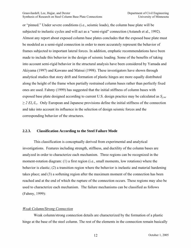
2.2.3. Classification According to the Steel Failure Mode
This classification is conceptually derived from experimental and analytical
investigations. Features including strength, stiffness, and ductility of the column bases are
analyzed in order to characterize each mechanism. Three regions can be recognized in the
moment-rotation diagram: (1) a first region (i.e., small moments, low rotations) where the
behavior is elastic; (2) a transition region where the behavior is inelastic and material hardening
takes place; and (3) a softening region after the maximum moment of the connection has been
reached and at the end of which the rupture of the connection occurs. These regions may also be
used to characterize each mechanism. The failure mechanisms can be classified as follows
(Fahmy, 1999):
Weak Column/Strong Connection
Weak column/strong connection details are characterized by the formation of a plastic
hinge at the base of the steel column. The rest of the elements in the connection remain basically

Grauvilardell, Lee, Hajjar, and Dexter Department of Civil Engineering Synthesis of Research on Steel Column Base Plate Connections University of Minnesota
October 1, 2005 13
elastic or exhibit incipient yielding. Some of the tests carried out by Fahmy (1999) and Adany et
al. (2000) performed in this way. These experiments have shown that with this behavior the
post-yield deformation reaches maximum values with high strengths. Even though all the
components (i.e., the base plate, anchor rods, and column) reached the yield stress, the hinge did
form only in the column. The tests failed mainly by premature fracture of the welds due to the
deformation of the flanges at the column base. However, specimens where sound weld details
with notch toughness weld metal were used did perform satisfactorily. Based on these
observations, it was reported that welds play an important role in this kind of connection. The
mechanical characteristics that can be highlighted are: (1) high ductility with stable hysteresis
loops, and (2) increase of the strength of the connection with an efficient use of each of its
components.
Strong Column/Weak Connection
The performance of strong column/weak connection details, characterized by the inelastic
deformation of one or more components of the column base assemblage, as well as the potential
brittle failures that are more likely to occur (e.g., concrete crushing, anchor rod fracture) has
been evaluated in several reports (DeWolf and Sarisley, 1980; Picard and Beaulieu, 1985;
Thambiratnam and Paramisivam, 1986; Astaneh et al., 1992; Jaspart and Vandegans, 1998;
Burda and Itani, 1999). Undersized specimens showed the behavior included in this failure
mode. With the formation of two or more yield lines, the connection in general shows
significant ductility, a higher reduction of the initial stiffness, and a marked drop in the post-peak
behavior. These types of connections are the ones that best resemble a pinned condition when
the connection behaves in the nonlinear range. Some of the characteristics that this type of
column base connection may exhibit are low strength and initial stiffness, pinched hysteresis
loops, but a good amount of energy dissipation. With the increase of the thickness, the strength
of the connection is augmented and the ductility reduced.
Balanced Mechanism
This is an intermediate mechanism that targets achieving simultaneous and concurrent
behavior from that discussed in the two classifications of connections above. The column yields
Grauvilardell, Lee, Hajjar, and Dexter Department of Civil Engineering Synthesis of Research on Steel Column Base Plate Connections University of Minnesota
October 1, 2005 14
at approximately the same time as one or more of the elements of the connection (i.e., the base
plate or anchor rods). Thus, in this connection, not only one component is subjected to extreme
deformations, but all of them undergo moderate inelastic behavior.
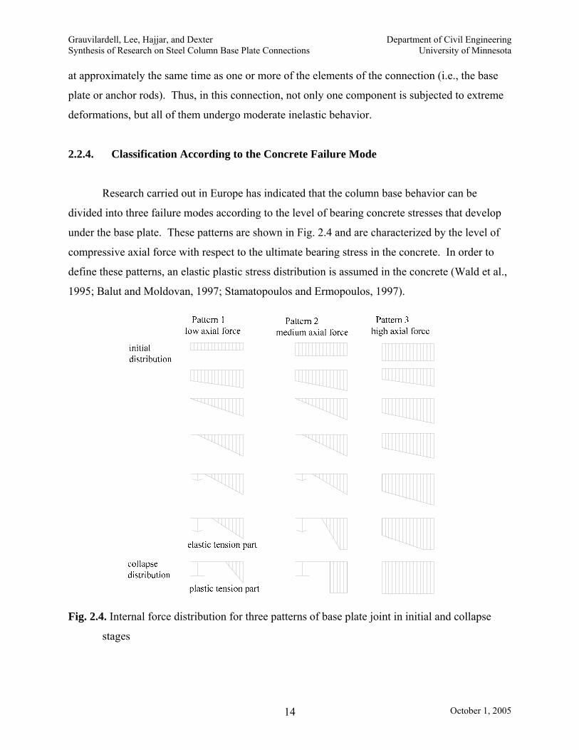
2.2.4. Classification According to the Concrete Failure Mode
Research carried out in Europe has indicated that the column base behavior can be
divided into three failure modes according to the level of bearing concrete stresses that develop
under the base plate. These patterns are shown in Fig. 2.4 and are characterized by the level of
compressive axial force with respect to the ultimate bearing stress in the concrete. In order to
define these patterns, an elastic plastic stress distribution is assumed in the concrete (Wald et al.,
1995; Balut and Moldovan, 1997; Stamatopoulos and Ermopoulos, 1997).
Fig. 2.4. Internal force distribution for three patterns of base plate joint in initial and collapse
stages

Grauvilardell, Lee, Hajjar, and Dexter Department of Civil Engineering Synthesis of Research on Steel Column Base Plate Connections University of Minnesota
October 1, 2005 15
Low Axial Loads (Pattern # 1)
For low axial loads, the bearing capacity of the concrete is never reached. The collapse
occurs either when anchor rods yield or when the plastic mechanism forms in the base plate.
Medium Axial Loads (Pattern # 2)
In the case of medium axial loads, the behavior is characterized by the anchor rod
reaching yielding and the concrete attaining its bearing strength.
High Axial Loads (Pattern # 3)
The failure mode for high axial loads is identified by the fact that at collapse only the
concrete bearing capacity is reached.
2.2.5. Classification According to the Energy Dissipation Capacity
Fahmy (1999) provided a classification for base plates according to their energy
dissipation characteristics. This classification may be an important consideration when a capacity
design of the column base connection is carried out. In that case, a progression of failure should
be proposed and each component designed accordingly. The following is a brief summary of
this classification:
Non-dissipative Mechanisms
Non-dissipative mechanisms are failure mechanisms that do not provide outstanding
energy dissipation. Some of the mechanisms reported in the literature when brittle behavior is
observed are: (1) cracking of welds, (2) fracture of anchor rods (3) fracture of base plate and (4)
crushing of the concrete or grouting. For mechanisms that are somewhat more ductile, excessive
local buckling of the column flange may be included in this category. It is difficult to develop a
stable plastic hinge with excessive local buckling. This in turn leads to a lower than expected
strength capacity in the connection.

Grauvilardell, Lee, Hajjar, and Dexter Department of Civil Engineering Synthesis of Research on Steel Column Base Plate Connections University of Minnesota
October 1, 2005 16
Dissipative Mechanisms
Dissipative mechanisms are able to provide stable energy dissipation. Generally
speaking, the typical failure mode involves yielding of one or more connection components. This
group may include 1) yielding of the base plate, 2) yielding of the anchor rod, and 3)
plastification of the base of the column (i.e., forming a hinge in the column).
2.2.6. Classification According to the Type of Frame
The overall behavior of the exposed base plates and the nature of the forces acting on the
column base will vary depending on the type of structure to which the column base is attached.
This variation is analyzed in the next classification:
Column Bases Attached to Moment Resisting Frames
A base plate that works as part of a MRF column base will be subjected to the action of
moments in addition to axial forces and shear. The literature presented in the appendices reveals
that much research has focused on this kind of connection, and for that reason almost every
conclusion that is mentioned for exposed base plates under the action of moments in Chapter 2
and Chapter 3 is applicable for this case. However, one of the most relevant topics that has not
received attention, as will be emphasized in the discussion of issues related to exposed base
plates in Chapter 4, is the combined action of moments and pull out axial forces. When gravity
loads at the sides of the frames are low and the lateral forces are important, this load combination
may be the most demanding for this type of column bases.
Column Bases Attached to Braced Frames
Column bases attached to braced frames have received almost no significant attention in
prior research. An important set of tests have been carried out on exposed base plates subjected
to axial forces only (DeWolf, 1978; Murray, 1983; Wald et al., 1994), and shear resistance has
been studied when the moment was studied obtained as a result of an applied lateral load (Sato,
1987; Astaneh et al., 1992; Fahmy, 1999; Lee and Goel, 2001). However, the specific nature of
this connection, e.g., the fact that in a braced frame the column base with an exposed base plate
will include the interaction and force transfer from a gusset plate, has not been experientially
studied. Two reports (Goldman, 1983 and Tronzo, 1983) have addressed the design of this type

Grauvilardell, Lee, Hajjar, and Dexter Department of Civil Engineering Synthesis of Research on Steel Column Base Plate Connections University of Minnesota
October 1, 2005 17
of connection analytically, focusing on the design of the anchor rods, shear lugs, and the gusset
plate, but none of them have considered that the attachment of the gusset plate to the base plate
could be a particular issue to account for (i.e., the stiffening provided by the gusset plate, or the
force flow from the gusset plate to the base plate). Fig. 2.5. shows a situation in which the gusset
plate is particularly large and where additional considerations could be needed (e.g., the use of 6
bolts instead of only 4 or the efficiency of the overhang portion of the base plate for transferring
forces to the column base connection).
Fig. 2.5. Special detail for gusset plate and exposed base plate in a braced frame
[courtesy of R. Drake, 2003]
2.3. Classification of Embedded Column Base Plates
2.3.1. Classification According to the Length of the Embedment
Deeply Embedded
In deeply embedded column base plate connections, the length of embedment of the
column in the foundation or concrete grade beam is sufficient to guarantee that the behavior of
the column base can be considered fixed. Recommendations on this length have been made for

Grauvilardell, Lee, Hajjar, and Dexter Department of Civil Engineering Synthesis of Research on Steel Column Base Plate Connections University of Minnesota
October 1, 2005 18
different column shapes. Steel tube box columns can be considered fixed when the embedment
length is no less than 2D, with D being the lateral dimension of the column cross section in the
plane of bending (Nakashima and Igarashi, 1986; Morino et al., 2003). Recommendations have
also been given for wide-flange profiles with embedment lengths ranging from 1D to 2D (Pertold
et al., 2000a, 2000b). The failure mode observed is the column “pull-out”, when embedment
lengths of less than 1D are used. Finite element models have been used to investigate the
behavior of connections with different embedment lengths.
Bearing (horizontal) stress in concrete normalized by concrete strength σxx/f’
c
Fig. 2.6. Distribution of the bearing stress in the foundation due to a moment applied to the
column. [after (Pertold et al., 2000b)]
Generally speaking, the first conclusion drawn from these analyses is that both flanges are
involved in the moment resistance. The distribution of the bearing stresses along the flanges can
be divided into two regions as shown in Fig. 2.6: the upper region of the embedment, where the
stresses are oriented in the same direction as the lateral applied force, and the lower region,
where the stresses are oriented in the opposite direction. For the case of embedment lengths

Grauvilardell, Lee, Hajjar, and Dexter Department of Civil Engineering Synthesis of Research on Steel Column Base Plate Connections University of Minnesota
October 1, 2005 19
greater than 2D, it has been found that the bearing stress due to column flexure in the concrete
along the lower part of the steel column decreases due to the flexibility of the column, reaching a
value of almost zero for an embedment length of 3.5D. On the other hand, when considering the
response to axial forces, the base plate plays an important role. According to Pertold et al.
(2000a, 2000b), the axial strength of the connection is the result of two mechanisms: (1) for
compression, the bearing of the end of the column on the bottom of the concrete foundation, and
(2) for compression or tension, the bond strength between the steel and concrete. The presence of
the base plate enhances the first mechanism by providing a greater bearing area; whereas the
addition of studs welded to the face of the column or reinforcing bars welded to the face of the
column and anchored in the grade beam or foundation are important requirements in order to
improve the second mechanism (Nakashima and Igarashi, 1986).
Shallowly Embedded
The process of constructing an embedded column to ensure full fixity has been found to
have some drawbacks. One of the most important is the fact that one advantage of traditional
steel construction, that the steel erection starts when the casting of the concrete foundation has
been completed, is often lost (Morino et al., 2003). For that reason the shallow embedment
concept was developed. The foundations are cast with the anchor rods arranged and a small box
is left for placing the steel column. Once the steel column has been erected and bolted the box is
filled with grout. Two procedures have been reported in the literature. In the first one the nuts as
well as the base plate are embedded in this box (Nakashima, 1996). In the second, the nuts and
the base plate are left outside of the foundation. The shape of the column is cut in the base plate,
and the column is inserted through the plate and welded. Longer anchor rods are used and the
connection, once completed, has the appearance of an exposed base plate. That means that
technically only the column is embedded (Morino et al., 2003). Both systems have been
investigated in Japan for steel tube box columns and concrete-filled steel tube (CFT) columns,
and sketches of both were shown in Fig. 2.2. By embedding the column at a depth of one time
its width using either system, substantially smaller base plates are required, and consequently
fewer and smaller anchor rods are required as compared with exposed base connections. The
column may be shallowly embedded in a concrete foundation, studied by Morino et al. (2003), in

Grauvilardell, Lee, Hajjar, and Dexter Department of Civil Engineering Synthesis of Research on Steel Column Base Plate Connections University of Minnesota
October 1, 2005 20
a grade beam, studied by Nakashima (1996), or in a reinforced concrete slab. The last two
options are shown in Fig. 2.7 and Fig. 2.8, respectively.
Fig. 2.7. Steel column shallowly embedded in a grade beam [after (Nakashima, 1996)]
Fig. 2.8. Steel column shallowly embedded in a reinforced slab
2.3.2. Classification According to the Column Position in the Frame
Exterior Columns

Grauvilardell, Lee, Hajjar, and Dexter Department of Civil Engineering Synthesis of Research on Steel Column Base Plate Connections University of Minnesota
October 1, 2005 21
This classification is included in order to highlight the effect of an additional parameter
for embedded base plate connections in columns placed on the perimeter of the structure, i.e., the
end distance from the column to the external side or face of the concrete foundation or grade
beam. Research has shown that this end distance needs to be taken into account in the analysis
of the behavior of these columns. If the end distance is small or if a careful detail of the joint has
not been made, the unsupported concrete might crack when subjected to bearing forces due to
prying action when the column is bent toward the external face of the foundation causing sudden
strength deterioration of the column base. In addition, external columns are the most likely to be
subjected to pulling forces, in which case this brittle behavior is especially undesirable. In order
to minimize this effect, the minimum end distance recommended is 1.5 times the depth D of the
column cross section in the plane of bending. When the end distance is less than 1.5 D, the
detailing should include bars welded to the face of the columns, anchored on the interior side of
the foundation and able to resist by tension the bearing stress that the concrete cannot handle
(Nakashima and Igarashi, 1986).
Interior Columns
Embedded base plate connections of interior columns in the plane of bending often
exhibit symmetric behavior (i.e., independent of the sign of shear or moment). This symmetric
behavior is based on the fact that the concrete foundation (or grade beam) has sufficient length
on both sides of the column to produce equal hysteretic responses, i.e., deformations or rotations,
for both signs of moment and shear. Past research on interior columns has generally analyzed
only the general parameters that affect the behavior of embedded columns (i.e., embedment
length, reinforcement methods, etc).
2.3.3. Classification According to the Failure Mechanisms
With respect to a classification according to the failure mechanisms, generally speaking,
the desired behavior sought for embedded column bases is that in which the column in flexure
yields at its ultimate state, forming a plastic hinge at the foundation level. In other words, the
embedded column base is expected to be able to transfer the full plastic moment (plus axial force
and associated shear) of the steel column. This behavior results in a column base connection

Grauvilardell, Lee, Hajjar, and Dexter Department of Civil Engineering Synthesis of Research on Steel Column Base Plate Connections University of Minnesota
October 1, 2005 22
capable of providing full rigidity (Pertold et al., 2000a, 2000b). The failure modes reported from
experiments agree in many ways with this statement and are discussed below.
2.3.3.1. Deeply embedded column base plates
Plastification of the Steel Column Base
Plastification of the steel column base can be guaranteed when the embedment length is
greater than 2 times the depth D of the column shape, and the flexural strength of the column
base is greater than 1.3 times the plastic moment strength of the column (Hitaka et al., 2003).
However, external columns without adequate reinforcement may not achieve this failure mode
due to cracking of the concrete.
2.3.3.2. Shallowly embedded column base plates
Plastification of the Steel Column Base
Plastification of the steel column base has been found only when thicker embedded base
plates and bigger or more numerous anchor rods were used. In general, a plastic hinge in the
column is not an isolated behavior, but is simultaneously accompanied with heavy cracking in
the concrete. However, if a stronger base plate-anchor rod subassemblage is used, the concrete
will not crack due to the flexibility of the base plate or elongation of the anchor rods, and the
concrete will withstand the transfer of the full plastic moment from the column (Nakashima,
1996).
Cracking on Concrete
Concrete cracking is the controlling failure mode for the case of completely embedded
base plates (i.e., when both the base plate and nuts are embedded) when weaker base plates or no
anchor rods were used. The overhanging part of a base plate (i.e., the base plate planar
dimensions greater than the column dimensions), when present, has been shown to cause the
formation of cracks in the concrete and its consequent degradation and failure. The action of
vertical reinforcement does not seem to help avoid the development of cracks. However,
horizontal reinforcement did help to reduce cracks on the top of the concrete (Nakashima, 1996).

Grauvilardell, Lee, Hajjar, and Dexter Department of Civil Engineering Synthesis of Research on Steel Column Base Plate Connections University of Minnesota
October 1, 2005 23
Concrete cracking was found in tests reproducing the performance of exterior columns
(i.e., with asymmetrical foundations or end grade beams) with short end distances (i.e., less than
0.5D) and small embedment lengths (i.e., less than 1.5D). When a lateral force was applied
toward the outside face of the column, the bearing stresses on the concrete, acting in the same
direction as that lateral force, were found in the upper region of the embedment, and the
unsupported concrete on the top of the foundation failed. When this lateral force was applied in
the opposite direction, the bearing stresses on the same side were then located in the lower part
of the embedment. Cracks in the concrete also developed in this lower region when no special
detailing was used (Nakashima and Igarashi, 1986).
Yielding of Anchor Rods - Cracking of Welds
Once the concrete around the embedded column has crushed, yielding of the anchor rods
and cracking of the welds represents the next step in the progression of damage. As mentioned
earlier, these mechanisms may occur simultaneously with the failure of the concrete, and the
governing failure mode is a function of the ratio between the concrete strength capacity and the
strength of each mechanism (Nakashima, 1996). However, no guidelines have been given in the
literature as to this relationship. Due to the rigid nature of the union between the steel column
and base plate in the case of the exposed type of shallowly embedded column base connection
tests, only yielding of the anchor rods (i.e., no crack of the welds) has been reported as a failure
mode (Morino et al., 2003), always in conjunction with crushed concrete.
2.3.4. Classification According to Ductility
The common factor reported in the hysteretic response of column bases with embedded
plates is the ductile behavior that the specimens show. When deeply embedded column base
plates are used in cyclic experiments, ductile behavior with full hysteresis loops very frequently
result. The reports on shallowly embedded base plate behavior will vary from pinched to full
loops, depending on the relationship of the components. For example, pinched behavior results
when the base plate-anchor rod subassemblage is predominant, whereas full loops are the
characteristic response when the embedded contribution is dominant (Nakashima, 1996).

Grauvilardell, Lee, Hajjar, and Dexter Department of Civil Engineering Synthesis of Research on Steel Column Base Plate Connections University of Minnesota
October 1, 2005 24
Similar conclusions are drawn for the case of the exposed type of shallowly embedded column
bases (Morino et al., 2003).

Grauvilardell, Lee, Hajjar, and Dexter Department of Civil Engineering Synthesis of Research on Steel Column Base Plate Connections University of Minnesota
October 1, 2005 25
Chapter 3
Design Considerations for Column Base Connections
3.1. Introduction
The reflection on topics and issues related to the design of column base connections may
be analyzed from many points of view. For purposes of clarity, three have been considered in
this report. The first point of view, the most basic one, analyzes structural design from the
perspective of the technical goals desired, and thus establishes a reference point for reporting
issues that are not taken into account in current provisions applied in the U.S. On the one hand,
the objective is to highlight, based on the research, several design assumptions that although
widely accepted are very often breached, and on the other hand to raise the awareness of the
importance of some topics that are neglected in practice. The second point of view focuses on
the effect, according to experimental literature, that the geometry and material properties of the
column base components have on the behavior and response of the base connection. Based on
this analysis, it will be possible to comment on the importance of the inclusion of some
parameters in the design process of the connection. From the third point of view, the
investigation summarizes a brief overview of the force transmission mechanisms and shows how
the three design codes worldwide, specifically those from Japan, Europe, and the United States,
approach the design of column base connections and their components. Using the
aforementioned three points of view, which are based on documented information, a final
discussion, in Chapter 4, highlights the need for finding answers to several issues that are not
Grauvilardell, Lee, Hajjar, and Dexter Department of Civil Engineering Synthesis of Research on Steel Column Base Plate Connections University of Minnesota
October 1, 2005 26
solved in practice and specific topics drawn from practical considerations and rational
observations.
3.2. Investigation of Column Base Structural Design
The purpose of the structural design process is a final product in which performance
closely follows the expected behavior expressed through mathematical formulations and
approximations. If that performance deviates from the assumptions embedded in the analytical
models, the expectation is that the actual behavior will at least be within a safe range (i.e., on the
conservative side). In order to be aware of the level of safety that a structure possesses, the
designer should be able to verify the integrity of the hypotheses applied. This section
summarizes the associated goals of the design process for column base plates.
Resistance Capacity of the Connection
Every component of the column base (e.g., base plate, anchor rods, welds, and footings)
must be able to withstand the forces that the frame imposes on them. In order to conduct a
rational design, designers usually have the freedom to choose the behavior and consequent
failure mode that they want for the connection. This decision allows the identification of the
component or components that are expected to be the weakest link in the progression of failure
and to design it or them accordingly. The remaining components will then be designed assuring
higher strength in the parts one does not wish to fail in the adopted failure scenario (e.g., weld
fracture, concrete cracking). In this light, seismic recommendations have been made in the U.S.
that emphasize that yielding should be limited to the base plate (Astaneh et al., 1992; Burda and
Itani, 1999). As such, current provisions (AISC Seismic, 2002, Section 8.5) emphasize the
design for strength of each column base component, but a more formal strength capacity design
of the connection is not explicitly required. As an example to illustrate the importance of a
capacity design approach for column bases, it was mentioned previously that the stiffer the base
plate the greater the tension forces delivered to the anchor rods. If a base plate is stiffer than
assumed (e.g., because the formulation to find the thickness of the plate is conservative, or
because the designer decided to use a thicker plate for other reasons), the anchor rods may yield,
even though elastic behavior might have been expected. The designer needs to be cognizant of

Grauvilardell, Lee, Hajjar, and Dexter Department of Civil Engineering Synthesis of Research on Steel Column Base Plate Connections University of Minnesota
October 1, 2005 27
the relationship between the behaviors of the different components when sizing them and
guidelines should be provided to help in the decisions.
Rigidity of the Connection
In the structural analysis of frames, theoretical support conditions are usually adopted
(i.e., pinned, fixed). The reasons for this simplification in the treatment of the support condition
may be found not only in the certainty that easier models can be used but also in the fact that the
codes promote their use. For nonlinear response history analysis the structure shall be assumed to
have a fixed base according to current provisions (FEMA 368, 2001, Section 5.7). Even though
the use of realistic assumptions with regard to the stiffness and load carrying characteristics is
permitted, the designer who chooses to model the structure with more accurate assumptions is
penalized by having to satisfy the same drift limits, regardless of the assumed support conditions.
It has been shown -analytically as well as experimentally- that the behavior of the column base is
better represented when modeled as providing partial restraint (Astaneh et al., 1992; Burda and
Itani, 1999; Fahmy, 1999; Lee and Goel, 2001). Many attempts with different approaches have
been made to describe the linear and nonlinear behavior of the column base connection subject to
monotonic and cyclic loads (Salmon et al., 1957). Finite element analysis has shown, for the
case of exposed base plates, that even using an unrealistically thick base plate, the practical rigid
stiffness limit cannot be achieved. In fact, some attempts have been made to provide an
analytical estimate of the initial stiffness of a column base designed according to the current
design practice in the U.S. (Fahmy, 1999). Many mechanical and mathematical models have
been proposed for the formulation of the rotational stiffness for column bases with exposed base
plates (Salmon et al., 1957; Sato, 1987; Wald et al., 1995; Fahmy, 1999). The important effect of
the semi-rigidity of column base connections in the seismic response of MRFs has also been
analytically quantified (Wald et al., 1995; Fahmy, 1999). Sometimes, in order to overcome these
issues, embedded column bases or grade beams have been used. Their use could be considered
to provide a higher safety level, in the sense that the mentioned assumptions could be attained;
however, there is no experimental research about these topics in the U.S. and none of all the
previously mentioned considerations have been included in design provisions so far.

Grauvilardell, Lee, Hajjar, and Dexter Department of Civil Engineering Synthesis of Research on Steel Column Base Plate Connections University of Minnesota
October 1, 2005 28
In addition to responses like story drifts or moment distribution, the semi-rigid behavior
of a column base also has an effect on the assessment of the effective length of the beam-
columns on the first floor, in both braced and unbraced frames. Consequently, the true level of
restraint imposed on the designed column base might play an important role in the frame stability
since the effective length will increase as the level of restraint decreases (Galambos, 1960;
Picard et al., 1987). As an example of this point it can be mentioned that while the G factor in
AISC LRFD Specification (AISC, 1999) theoretically approaches infinity for a pin condition,
values closer to 2, for non-sway columns, and to 5, for sway columns, have been experimentally
determined from tests in exposed base plate type column bases. This finding shows that the G
value for partial fixity of this kind of column bases correlates better with the proposed practical
G value for fixed supports (i.e., G = 1; AISC, 1999) rather than the proposed practical G value
for pinned supports (i.e., G = 10) (Picard et al., 1987).
Ductility and Energy Dissipation
Ductility may be defined as “the capability of a column base connection to withstand
inelastic cyclic rotations without significant strength deterioration, stiffness degradation, or
fracture of its components” (Astaneh et al., 1992). This consideration is particularly important in
seismic design. The seismic design loads acting on a frame are highly dependent on the expected
ductile behavior of the structure. In turn, the ductility of the structure is the result of the
concurrent ductility of each of its components. Whereas quantification for the required ductility
has been made clear for the behavior of joint connections and many recommendations can be
found for the evaluation of this property (e.g., AISC, 1999; AISC, 2002), it is not equally clear
for base plates undergoing large rotations. Only a few suggestions, in the context of exposed
base plates, have been proposed for column base ductility criteria (Sato, 1987; Astaneh et al.,
1992), but no equivalent work has been developed for other types of column bases (i.e.,
embedded base plate), and consequently no unified guideline is given to test if the expected
ductility demand is met.
Even though high-energy dissipation is often associated with high ductility, a wide range
of hysteretic responses results from experiments on column base assemblages. Pinched hysteresis
loops as well as full loops (i.e., an important deformation still remains when the reversal cycle

Grauvilardell, Lee, Hajjar, and Dexter Department of Civil Engineering Synthesis of Research on Steel Column Base Plate Connections University of Minnesota
October 1, 2005 29
passes through the zero load point) can be found. Attempts have been made to correlate key
parameters with the behavior sought. Some of the conclusions are presented in the next section.
3.3. Investigation of Column Base Design Parameters
The parameters involved in a column base design (i.e., geometry and material properties
of the components) have a much more important effect than only the change in strength of the
connection. Investigators have reported that responses like failure modes, damage progression,
ductility, and stiffness will also be changed, and the need to consider these effects will be
emphasized.
3.3.1. Exposed Base Plate Type of Column Bases
Thickness of the Base Plate
As stated in Chapter 2, the thickness of the base plate determines the behavior, strength
and stiffness, and consequently the failure mode of the column base connection. It may be noted
that despite reports about brittle failures of actual column base plates in buildings subjected to
strong earthquakes (Northridge Reconnaissance Team, 1996), investigations consistently report
that the thickness designed following current procedures is conservative when yielding of the
base plate is expected (Fling, 1970; DeWolf, 1982; Lee and Goel, 2001). Besides the resistance,
the thickness of the base plate is also associated with the ductility and hysteretic behavior of the
connection (i.e., more pinched hysteresis loops are seen with thicker base plates) (Astaneh et al.,
1992). Furthermore, the thickness has also been related to the distance from the edge of the base
plate to the edge of the flange of the column (overhang). When the ratio of thickness to overhang
distance becomes larger, the effect of the plate bending in the stress distribution becomes less
significant (DeWolf, 1982).
Size of the Base Plate
The size of the base plate has a relevant and already known effect on the maximum
bearing stress that the concrete foundation can reach. At present, guidelines in the U.S. recognize
that the maximum bearing stress is proportional to the square root of the ratio of the concrete
foundation area to the plate area (DeWolf, 1978). However, the size of the base plate has an

Grauvilardell, Lee, Hajjar, and Dexter Department of Civil Engineering Synthesis of Research on Steel Column Base Plate Connections University of Minnesota
October 1, 2005 30
additional effect that has been considered in research. For given loads and a constant thickness,
the increase in the length of the base plate may be used to increase the distance between the face
of the column and the center of the anchor. A series of tests with different base plate sizes
concluded that this effect, although slight, corresponds to an increase in ductility of the
connection with less degradation at the ultimate load. This was achieved due to more energy
dissipation on the post-peak region (i.e., the drop of the moment-rotation curve after the
maximum moment was not as sharp) based on larger flexural deformations in the base plate.
The behavior in the elastic region and in the nonlinear range up to the maximum load was found
to be similar in all the specimens (Burda and Itani, 1999).
Size and Number of Anchor Rods
As the diameter and the number of anchor rods increases, the initial rigidity of the
column base connection as well as the connection flexural strength increase. Improvement of as
much as 200% in rigidity and 100% in flexural strength have been reported (Melchers, 1992).
Also, as the diameter of anchor rods varies, the ratio between the threaded and non-threaded
areas consequently varies and according to Sato (1987) this fact has an effect on the ductile
behavior of the column base when anchor rods are the weakest link in the failure mode.
Anchorage of Anchor Rods
Some experiments have been conducted to test the influence of the type of anchorage of
the anchor rods on the final resistance of the column base. Round bars, “J” type anchors, and
deformed bars, both with and without plates at the end of the bolt have been tested (Igarashi et
al., 1992). The best performance (i.e., higher resistance) was obtained when deformed bars with
end plates where used. The greater bond resistance offered by the rod is believed to contribute to
this enhancement. For the case of base plates built on a pedestal, deformed bars helps to increase
the durability of the concrete base. The other types of anchor rods yielded simultaneously with
the crushing of the concrete (Igarashi et al., 1992). The minimum required embedment of anchor
rods indicated in some studies is 8 times the diameter of the bolt (Salmon, 1957; Sato, 1987).
The anchor rod embedment length, as shown in parametric studies, influences the rigidity of the
connection (Wald et al., 1995). The contribution to the rigidity of the connection is smaller
when the embedment length is greater. Finite element research has similarly shown that the

Grauvilardell, Lee, Hajjar, and Dexter Department of Civil Engineering Synthesis of Research on Steel Column Base Plate Connections University of Minnesota
October 1, 2005 31
connection performance is sensitive to the bolt embedment and bond length (Krishnamurthy and
Thambiratnam, 1990).
Depth of the Concrete Foundation
Only a small number of experiments have shown the effect of the concrete depth on the
behavior and strength of the connection. These experiments have been conducted only for the
case of high axial loads with small moments. However, it is believed to be a significant variable
for the determination of the ultimate strength for column base plate connections; the deeper the
foundation the smaller the ultimate bearing stress of the concrete (DeWolf, 1982).
Concrete Compressive Strength
In typical base plate design calculations, a linear relationship is assumed between the
concrete compressive strength (i.e., fc’) and the ultimate bearing strength of the concrete. DeWolf
(1982) indicates that this relation may be a good assumption for estimating the bearing strength
for concrete of up to 6000 psi. However, it has been noted (DeWolf, 1978) that for flexible plates
(i.e., when the plate bending affects the ultimate load), the capacity increases in proportion to
(fc’) 0.7.
Amount of Axial Load
The most important effect of the axial load on column base plate behavior is that the
stiffness of the connection increases with the increase of the compressive axial load (Sato, 1987;
Piccard et al., 1987: Li et al., 2000). The initial stiffness of column bases with exposed plates is
directly related to the bond between the anchor rods and concrete and the union between the base
plate and the concrete foundation. The beneficial effect of the axial load is found in delaying
bond loss in the first case and the ability to maintain compatibility between the steel and concrete
in the second case. This is one of the reasons why pretension of anchor rods is used. It has a
similar effect on the overall response of the connection that the axial load has, i.e., enhancing the
initial rotational rigidity of the connection and minimizing the swaying of the building against
wind or minor vibrations (Igarashi, 1992; values of thirty percent of the yield strength of the
anchor rods were used in the experiments). When thick base plates are used, a compressive axial
load increases the flexural strength of the connection (Sato, 1987; Astaneh et al., 1992; Li et al.,

Grauvilardell, Lee, Hajjar, and Dexter Department of Civil Engineering Synthesis of Research on Steel Column Base Plate Connections University of Minnesota
October 1, 2005 32
2000). However, attention must be paid to the response of the concrete. The more rigid the base
plate, the higher the bearing stresses (i.e., the bearing area decreases) and this situation may
result in a decrease of the strength of the connection instead of the assumed increase (Wolf,
1982). In tests on rigid base plates, the detrimental effect of the action of tensile axial loads on
the capacity of the column base has also been noted. Lower moment strength and rotation
capacity as compared to tests with constant axial load and cyclic moments were obtained in
cyclic loading experiments (i.e., tests having cyclically applied moment and axial force) where
the axial load was varied with the cycles (i.e., from higher to lower compression or even reversed
from compression to tension in each cycle) (Sato, 1987).
Weld detailing
The weld metal has been shown to have a critical effect on the behavior of the column
base assemblage. Experimental column base connections in which the notch toughness of the
weld metal was not controlled failed prematurely (Fahmy, 1999). The design of the welds is also
of great importance. Astaneh et al. (1992) recommended, in addition to the use of notch
toughness weld metal, to design the welds for 1.25 times the combined simultaneous effects of
axial load, moment, and shear.
3.3.2. Deeply Embedded Base Plate Type Column Bases
Embedment length
The embedment length plays a fundamental role in the response of embedded column
bases. The strength of the connection, as well as its stiffness, are directly related to this length.
Ductile behavior is obtained when embedment lengths greater than 2D are used. Embedment
lengths close to the minimum limit (i.e., 2D) yield more pinched hysteresis loops, whereas full
loops can be achieved with longer embedment lengths. In the case of exterior columns, the
embedment length has an additional effect. When a shorter embedment length was used,
noticeable differences in strength capacity were observed when the lateral loads or moments
were applied from opposite directions, and the connection showed a greater deterioration under
cyclic loads for the same end distance (Nakashima and Igarashi, 1986).

Grauvilardell, Lee, Hajjar, and Dexter Department of Civil Engineering Synthesis of Research on Steel Column Base Plate Connections University of Minnesota
October 1, 2005 33
Reinforcement Methods
It has been mentioned that the mechanism by which moments are transferred from the
column to the foundation in deeply embedded column bases is predominantly by bearing of the
faces of the column on the concrete. Even though the concrete has good capacity for
withstanding these actions, some of the deformations that occur (i.e., in particular under cyclic
actions) may subject the foundation to tensile stresses that the concrete is not able to handle. The
consequence is a rapid degradation of the column base. The need for special reinforcement is
even more important in the case of exterior and corner embedded column base plate connections,
where the support provided by the external portion of the foundation is weaker compared with
the internal part (i.e., provided that eccentric footings are designed). The concept of
reinforcement must be understood not only for its application in maintaining the integrity of the
foundation or grade beam. Its importance, in the case of embedded columns, extends to
developing a capacity for maintaining the bond between the steel and the concrete (this is
especially important when cyclic behavior is considered). In order to compare the effects of both
types of reinforcements, it has been found that pinched hysteresis loops were obtained when only
traditional reinforcement (i.e., reinforcement bent around the column) was used. Full loops were
obtained with the use of studs welded to the face of the column. In particular, the use of
reinforcement welded to the face of the column and anchored in the body of the concrete works
in conjunction with anchor rods to achieve good restoring force characteristics under cyclic
loading (Nakashima and Igarashi, 1986).
End distance
As mentioned in Chapter 2, the behavior of external column bases is affected by the end
distance (i.e., the distance between the external face of an exterior column and the external edge
of the foundation or grade beam). When a lateral force is applied to the column in the plane of
the frame acting toward the exterior of the frame, shorter end distances result in decreased
strength and a rapid deterioration of the column base flexural strength. This fact implies that
special precautions need to be taken in detailing the foundation reinforcement when the
dimension (i.e. end distance) is short (Nakashima and Igarashi, 1986). It was found that for end
distances greater than 2D the cyclic behavior of exterior column base connections was identical
to that of the interior column base connections.

Grauvilardell, Lee, Hajjar, and Dexter Department of Civil Engineering Synthesis of Research on Steel Column Base Plate Connections University of Minnesota
October 1, 2005 34
Base Plates and Anchor Bolts
Generally speaking, it could be stated that one of the main purposes of the use of anchor
rods in embedded columns is to maintain the column in position until the concrete has hardened.
However, some tests carried out by Nakashima and Igarashi (1986) have shown that the presence
of base plates and anchor rods, in addition to contributing to the embedment length (i.e., 2.5D for
these tests), has a slight effect in helping to attain a stable hysteretic behavior, with hysteretic
loops that are less pinched.
3.3.3. Shallowly Embedded Base Plate Type Column Bases
Embedment length
The embedment length of shallowly-embedded column base connections noticeably
influences the ductile response of the connection. Embedment lengths of approximately 1D (i.e.,
one time the depth of the column cross section) have lower ductility and a marked degradation of
the connection behavior compared with higher lengths (Nakashima, 1996). For that reason, it is
recommended to embed the column more than one time the depth of the cross column in order to
avoid “pull out” of the column and to obtain a stable hysteretic behavior. The maximum
recommended embedment length, in order to consider the embedment as shallow, is 1.5D (where
D is equal to the depth of the column profile), because for greater values the bearing mechanism
starts to become predominant (i.e., the connection becomes deeply embedded), thus not taking
advantage of the presence of the base plate and anchor rods to collaborate in the flexural
resistance.
Reinforcement Method
The same general considerations already mentioned on the role of the reinforcement in
deeply embedded column base plates (i.e., integrity of the foundation or grade beam and
preservation of the steel concrete bond resistance) could be applied for shallowly embedded
column bases. However, tests have shown that the need for a good detailing of the reinforcement
is more crucial in this type of embedded connections. The formation of cracks in the concrete
has a detrimental effect on the behavior of the concrete and must be resolved. For the case of

Grauvilardell, Lee, Hajjar, and Dexter Department of Civil Engineering Synthesis of Research on Steel Column Base Plate Connections University of Minnesota
October 1, 2005 35
grade beams, reinforced bars welded directly to the faces of the embedded part of the steel
column and anchored deep in the body of the beam have shown the most effective performance
in increasing strength, rigidity and energy dissipation in the tests carried out by Nakashima
(1996). The anchorage provided by this type of reinforcement and the anchorage provided by
the anchor rods was found to have the same effect on the final performance of the column base
(i.e., flexural strength and rigidity). A less effective anchorage is obtained when the
reinforcement is bent around the column and not welded to it.
Base Plate and Anchor Rod Dimensions
Since there is a shared resistance mechanism in shallowly-embedded column base
connections (i.e., base plate-anchor rods and embedded column behavior), the larger the base
plate dimensions the more strength and energy dissipation the connection can develop
(Nakashima, 1996). Despite this statement, it has also been also found that during the post-peak
behavior the strength drops more dramatically for the case of larger base plates, reaching almost
the same ductility and final strength at rupture as those with smaller base plates. Concurrent
with these findings, it was observed that larger base plates (i.e., with the planar dimensions
exceeding the sides of the cross section of the column) caused the occurrence of horizontal
cracks in the footing. All the aforementioned conclusions were obtained from tests that did not
use anchor rods. The presence of anchor rods helps to improve the typical hysteretic behavior of
this kind of connection, shifting the response from pinched to almost full loops. Larger anchor
rods also increased the strength, rigidity, ductility and energy dissipation capacity of these
connections.
3.4. Investigation of Column Base Design Procedures
Most column-base plate connections resisting large column moments in MRFs have been
designed in the U.S. by referring to previous scattered journal papers, textbooks, and design
guidelines. For the design of column bases in BFs in high seismic zones, insufficient research
results have been provided to structural design engineers. As a possible result of not having
sufficient, reliable, and comprehensive design provisions for column bases, several column-base
plate connections designed following the design practices and guidelines outlined above did not

Grauvilardell, Lee, Hajjar, and Dexter Department of Civil Engineering Synthesis of Research on Steel Column Base Plate Connections University of Minnesota
October 1, 2005 36
perform satisfactorily during the Northridge earthquake (Northridge Reconnaissance Team,
1996).
Several analytical and experimental studies have been conducted in the U.S. to
understand the complex force flow and stress distribution in the column base under large column
lateral displacements in MRFs. These include DeWolf and Sarisley (1980), DeWolf (1982),
Astaneh et al. (1992), Astaneh and Bergsma (1993), Burda and Itani (1999), Fahmy (1999), and
Lee and Goel (2001). There are even fewer U.S. studies for the column-base plate connections
in BFs, and no studies at all for any type of embedded base plate column bases. For that reason,
prior to the analysis of possible approaches for the design of each general type of column base
(i.e. exposed or embedded types), the conclusions about force transmission presented in the
aforementioned papers are discussed.
3.4.1. Column Bases with Exposed Base Plates
Shear. The first mechanism used to transmit shear force in exposed base plates is the frictional
resistance between the steel base plate and the concrete foundation. Pretension of bolts may be
used to increase this resistance. When shear is combined with high moments, the contact area
which provides friction may be reduced due to elongation of the anchor rods. When the frictional
resistance is not sufficient to resist the design loads a variety of alternatives are possible. The
addition of a shear key that takes the lateral force and transmits it by bearing on the concrete in
which the tab is embedded is one option. Another possibility is to embed the base plate very
shallowly. In this way the lateral face of the base plate plus the embedded part of the column will
bear on the concrete. Another option is to rely on the shear capacity of the bolts. However, since
the holes in the base plate are generally oversized, a gap is more likely to exist between the
contour of the hole and the face of the anchor rods. Before both parts are in contact a slide must
occur, leading to a decrease in the initial stiffness of the connection. Furthermore, if only some
of the bolts are bearing against the side of the hole, these bolts will be overloaded unless an
additional slip of the base plate may allow the distribution of the shear force among all the
anchor rods present.

Grauvilardell, Lee, Hajjar, and Dexter Department of Civil Engineering Synthesis of Research on Steel Column Base Plate Connections University of Minnesota
October 1, 2005 37
Compressive Axial Force. The base plate is the element used to distribute the column loads to
concrete foundations. For low axial loads, the size of the base plate is almost equal to the size of
the column and the distribution of the bearing stress could be considered constant if the base
plate is stiff. For more slender plates or for higher axial loads, the unsupported portion between
flanges and web of the column will bend. The redistribution of bearing stress will lead to a
decrease of the stresses in that region and a concentration under the column shape (Stockwell,
1975; Murray, 1983).
Interaction of Axial Force and Moment. Considering a constant compression force acting on the
base plate, when the bending moment is small all the plate is in contact with the concrete and the
anchor rods are unloaded. For the case of large axial compressive loads, the bearing strength of
the concrete governs the strength of the connection and the behavior of the footing has more
influence on the overall behavior of the connection. On the other hand, for light axial loads, the
response is driven by anchor rods and base plate (Melcher, 1992). As the moment increases, the
bearing stress of the concrete shifts to one side of the base plate as anchor rods come under
tension. For further moment increases, a nonuniform distribution of stress may result as a
function of the flexural behavior of the base plate, even leading to small or zero stresses at the
edge of the plates (DeWolf, 1978). The bearing stress distribution assumes a pressure bulb-like
shape for flexible foundations (Krishnamurthy and Thambiratnam, 1990). Some investigators
approximate this shape to a parabola (Sato, 1987), and for design purposes this curve is replaced
by a constant stress distribution. As the moment continues to increase, the maximum stress will
shift toward the compression edge of the base plate. This maximum bearing stress is considered
to be located underneath or beyond the compression flange of the column. The transfer of this
moment from the bottom of the column to the foundation is a function of the thickness of the
base plate. More slender base plates will transform a portion of the moment into defomration of
the base plate, transferring the rest to the anchor rods; while stiffer base plates will transfer most
of the moment to the anchor rods in tension. This tension is primarily resisted by the bond
resistance between the shaft of the anchor rod and the concrete. If round smooth rods are used,
this resistance is rapidly exceeded and a small plate that is usually located at the embedded end
of the anchor rod acts as an anchoring mechanism and the anchor rods start to elongate. For that
reason it has generally been assumed in practice that this type of rods (i.e. round smooth rods) is
free to elongate in tension from the beginning of the loading (Jaspart and Vandegans, 1998). On
Grauvilardell, Lee, Hajjar, and Dexter Department of Civil Engineering Synthesis of Research on Steel Column Base Plate Connections University of Minnesota
October 1, 2005 38
the other hand when deformed bars are used, the bond resistance is higher, and the tension force
is broadly transferred to the concrete, enhancing the durability of the foundation. Once the bond
resistance has vanished, the anchor rods start to elongate and the separation of the base plate
from the concrete occurs. This reduces the bearing surface and shifts the resultant bearing stress
outward. If on the basis of the design analysis (i.e., ductile behavior of anchor rods) anchor rods
are to be free to elongate from the beginning of the loading, sleeves around the embedded part of
the anchor rods may be provided to avoid the bond between steel and concrete.
U.S. Design Procedures
Earlier publications, such as Gaylord and Gaylord (1957, 1972), Salmon et al. (1957),
Blodgett (1966), Soifer (1966), McGuire (1968), Maitra (1978), DeWolf and Sarisley (1980),
DeWolf (1982), Ballio and Mazzolani (1983), and Thambiratnam and Paramasivam (1986), or
more recent publications such as the AISC Design Guide No. 1, Column Base Plates (DeWolf
and Ricker, 1990) are the most common guidelines used to design column-base plate connections
resisting large column moments. For the design of column bases in BFs, insufficient past
research has only provided information primarily focused on anchor rod and shear key resisting
mechanisms and their capacities under large shear forces, but not for designing and detailing of
column-base plate connections and attached gusset plates in these BFs. Several
recommendations for the column-base plate connection design for axial column tension (or
uplift), shear, or moment have been added in Part 14 of the 2001 AISC Manual of Steel
Construction (AISC, 2001); and more recently, the 2002 AISC Seismic Provisions (AISC
Seismic, 2002) briefly addressed seismic design criteria for column bases in Section 8.5 and its
Commentary. However, these generalized provisions and recommendations have not strongly
impacted current design practices for column bases, especially in high seismic zones, due to lack
of detailed practical information.
Drake and Elkin (1999) presented a design procedure based on an LRFD approach. The
applied factored loads (Mu and Pu) at the base of the column are resisted by bearing in concrete
and tension in the anchor rod. For a given plate size, the design unknowns are the magnitude of
the anchor rod ultimate force Tu and the bearing length Y. Two equilibrium equations are then
used to determine the two unknowns, as follows:
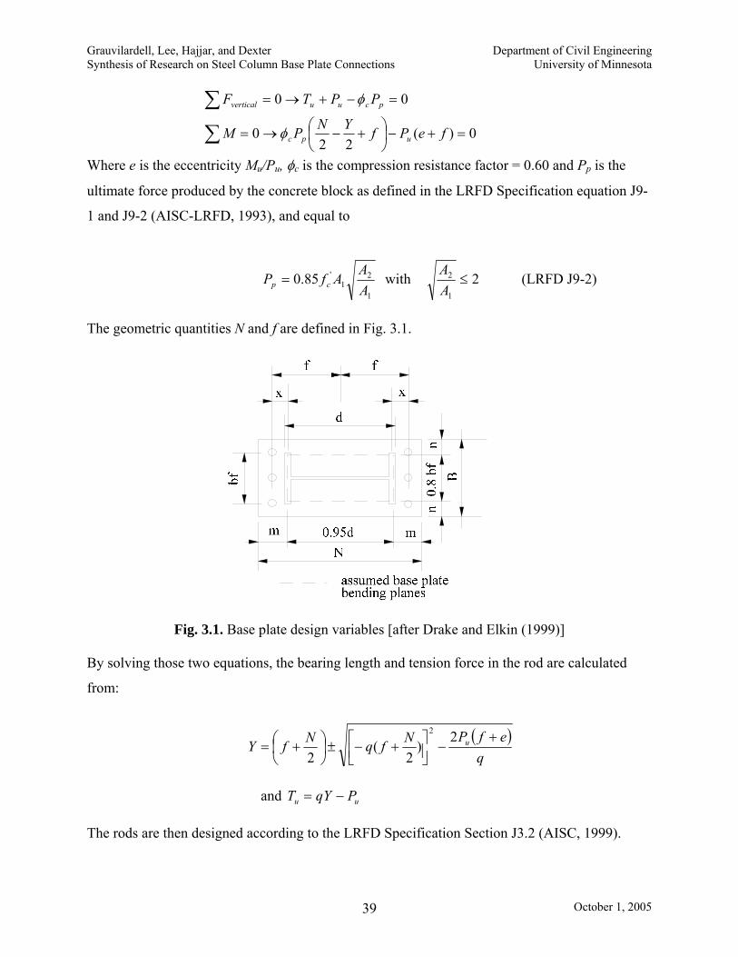
Grauvilardell, Lee, Hajjar, and Dexter Department of Civil Engineering Synthesis of Research on Steel Column Base Plate Connections University of Minnesota
October 1, 2005 39
0)(
220
00
=+−⎟⎠⎞
⎜⎝⎛ +−→=
=−+→=
∑
∑fePfYNPM
PPTF
upc
pcuuvertical
φ
φ
Where e is the eccentricity Mu/Pu, φc is the compression resistance factor = 0.60 and Pp is the
ultimate force produced by the concrete block as defined in the LRFD Specification equation J9-
1 and J9-2 (AISC-LRFD, 1993), and equal to
1
21
'85.0AA
AfP cp = with 21
2 ≤AA (LRFD J9-2)
The geometric quantities N and f are defined in Fig. 3.1.
Fig. 3.1. Base plate design variables [after Drake and Elkin (1999)] By solving those two equations, the bearing length and tension force in the rod are calculated
from:
( )q
efPNfqNfY u +−⎥⎦
⎤⎢⎣⎡ +−±⎟
⎠⎞
⎜⎝⎛ +=
2)
2(
2
2
and uu PqYT −= The rods are then designed according to the LRFD Specification Section J3.2 (AISC, 1999).

Grauvilardell, Lee, Hajjar, and Dexter Department of Civil Engineering Synthesis of Research on Steel Column Base Plate Connections University of Minnesota
October 1, 2005 40
btub
bvub
AFTAFV
φφ
≤≤
Where Fv is the nominal shear strength, Ft is the nominal tensile strength, and Ab is the rod area.
The base plate is then designed following flexural yielding limit states in Section F1 of the AISC
(1999): pbpl MM φ≤
where Mp is the nominal plastic moment. The plate thickness is then taken as the larger of:
( )
( )
( )
2.11
If 1.49
2If 2.11
up req
y
up req
y
p reqy
T xtBF
PY m t cBYF
YPu mY m t
BF
≥
> ≥
⎛ ⎞−⎜ ⎟⎝ ⎠< ≥
where Fy is the yield stress of the base plate, and all the geometric quantities are shown in Fig.
3.1.
European Design Procedures
Column base design provisions published in ENV1993 Eurocode 3 (ENV, or EuroNorm
Vornorm, represents a European pre-standard) (CEN, 1992) and the background of these
provisions are well described in Wald et al. (1995). These provisions were developed mostly
based on the COST C1 database of European research and they cover only the exposed base
plate type of column base design provisions. Eurocode 3 has recently been converted to EN1993
Eurocode 3 (EN, or EuroNorm, represents a European standard) (CEN, 2003). However,
Eurocode 3 provisions do not address seismic loading conditions, and Eurocode 8 which
addresses seismic design does not address column base design.
The design of exposed base plate column bases is dealt with in Section 8 of Eurocode 3
(prEN1993-1-8). The design for connection strength as well as for stiffness is defined as a
component based approach, in which the connection is considered to be an assembly of
individual components. The components considered, the design resistances of which are used,
are: (1) column web in transverse tension under the column flange (e.g., due to a brace framing
in), (2) the base plate in bending under the column flange, (3) the concrete in compression under
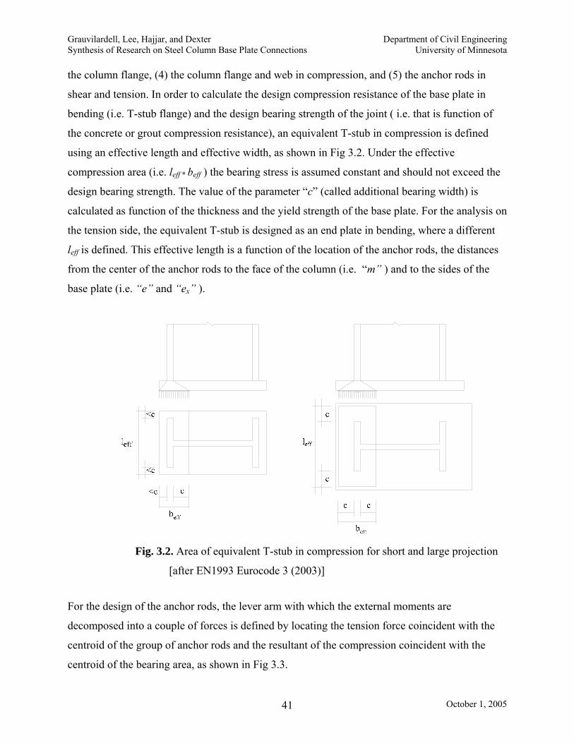
Grauvilardell, Lee, Hajjar, and Dexter Department of Civil Engineering Synthesis of Research on Steel Column Base Plate Connections University of Minnesota
October 1, 2005 41
the column flange, (4) the column flange and web in compression, and (5) the anchor rods in
shear and tension. In order to calculate the design compression resistance of the base plate in
bending (i.e. T-stub flange) and the design bearing strength of the joint ( i.e. that is function of
the concrete or grout compression resistance), an equivalent T-stub in compression is defined
using an effective length and effective width, as shown in Fig 3.2. Under the effective
compression area (i.e. leff * beff ) the bearing stress is assumed constant and should not exceed the
design bearing strength. The value of the parameter “c” (called additional bearing width) is
calculated as function of the thickness and the yield strength of the base plate. For the analysis on
the tension side, the equivalent T-stub is designed as an end plate in bending, where a different
leff is defined. This effective length is a function of the location of the anchor rods, the distances
from the center of the anchor rods to the face of the column (i.e. “m” ) and to the sides of the
base plate (i.e. “e” and “ex” ).
Fig. 3.2. Area of equivalent T-stub in compression for short and large projection
[after EN1993 Eurocode 3 (2003)]
For the design of the anchor rods, the lever arm with which the external moments are
decomposed into a couple of forces is defined by locating the tension force coincident with the
centroid of the group of anchor rods and the resultant of the compression coincident with the
centroid of the bearing area, as shown in Fig 3.3.

Grauvilardell, Lee, Hajjar, and Dexter Department of Civil Engineering Synthesis of Research on Steel Column Base Plate Connections University of Minnesota
October 1, 2005 42
Fig. 3.3. Force resultants in exposed base plate column bases [after EN1993 Eurocode 3 (2003)]
If the anchor rods are anchored by means of a washer plate located at the embedded end
of the anchor, the total axial load is considered to be transferred by this device. If another means
of anchoring is used (i.e. hooks) the anchorage distance is calculated to resist the axial force by
bonding. Whichever is the smaller of the two, -the design tension resistance of the anchor rod or
the design bond resistance of the concrete on the anchor rod, is taken as the resistance of the
anchor. Finally, once the individual resistances of each component have been calculated, the
design moment resistance of the column base is considered to be a function of them, the lever
arm “z”, and the end distance “e” previously defined.
As the strength, the stiffness is also estimated –according to the same approach- through
analytical simulation of mechanical model components. In this model, the base plate is idealized
as a rigid bar resting on three springs. One of these springs represents the concrete stiffness and
is in parallel with two other springs. These two springs in series represent the stiffness of anchor
rods and the base plate in tension. The stiffness of the three springs is expressed as:

Grauvilardell, Lee, Hajjar, and Dexter Department of Civil Engineering Synthesis of Research on Steel Column Base Plate Connections University of Minnesota
October 1, 2005 43
3
3
15 tensionin plate 425.0m
tlKK peff==
s
effeffcconcrete E
lbEKK
127513 ==
eff
bbolts L
AKK 216 ==
The rotational stiffness is then calculated as:
∑
==
K
ZES s
1stifness Rotational
2
µ
where µ is a ratio of the initial rotational stiffness to the current rotational stiffness of the base
plate connection.
The mechanical model considers the simulation of three collapse modes classified
according to the level of axial load and moment acting on the connection.
Japanese Design Procedures
Many different types and details of column bases have also been studied in Japan.
Major Japanese column base research is found in the Journal of Structural and Construction
Engineering, Transactions of Architectural Institute of Japan, written in Japanese. Extensive
column base research in Japan has revealed that column base design in high seismic regions is
characterized by a wide variation of different parameters and that seismic behavior and
performance of the column bases are highly dependent on connection details.
The estimation of the design moments Mla for the column base is done by modeling the
rotational stiffness of the base plate connection. The formula for the column base stiffness
provided by the Provisions is
b
ctbtBS l
ddAnEK
2)( 2+∗∗
=
Some of the symbols are shown in the Fig. 3.4.; Ab is the cross section area of the anchor rods; lb
is the embedded length of the anchor rods; and nt is the number of anchor rods on the tension
side.

Grauvilardell, Lee, Hajjar, and Dexter Department of Civil Engineering Synthesis of Research on Steel Column Base Plate Connections University of Minnesota
October 1, 2005 44
Fig. 3.4. Dimensions for an exposed base plate column base [after AIJ(2001)]
The next step is to decide which part of the column base is to yield and design it
accordingly. If a plastic hinge is desired on the lower end of the column, two conditions must be
satisfied: (1) the bending strength of the column base must be greater than or at least equal to 1.3
times the plastic moment of the column and (2) ductile anchor rods shall be used. If the column
base is designed to yield before the column develops its plastic moment at the base, that yielding
must occur due to the yielding of the anchor rods. In order to design the column base connection,
its bending strength must be greater or equal to two times the design moment Mla. Depending on
the type of anchor rods used, the bending strength of the column base is defined as follows. If no
ductile anchor rods are used, then the connection must resist the demand 2Mla by means of its
yielding strength My only. However, if ductile anchor rods are utilized, the Provisions allow
using for the design the ultimate strength of the base plate connection Mu. Plastic stress
distribution (i.e. fc=0.85fc’) is used to calculate Mu and triangular elastic distribution for the
calculation of My. Three cases are differentiated for the calculation of Mu, namely
a) Compression controls uuu TNNN −>≥
with Nu = maximum compression strength of the concrete under the base plate.
'85.0 cu BDfN =
Tu= maximum tensile strength of anchor rods
Then tuu dNNM )( −=

Grauvilardell, Lee, Hajjar, and Dexter Department of Civil Engineering Synthesis of Research on Steel Column Base Plate Connections University of Minnesota
October 1, 2005 45
b) Tension controls uu TNT 2−>≥−
Then tuu dTNM )2( +=
c) Intermediate cases uuu TNTN −>≥−
Then ⎟⎟⎠
⎞⎜⎜⎝
⎛ +−
++=
u
uutuu N
TNDTNdTM 1
2)(
In order to define ductile anchor rods a limit yield ratio of the steel equal to 0.75 is used
(See Section 2.2.1). In other words, the anchor rod is designed in such a way that the yield
strength of the unthreaded part be greater than the strength at fracture of the threaded section.
Finally, the thickness of the base plate is calculated assuming the overhang of the base plate as a
cantilever beam, with a uniform load applied equal to the maximum bearing stress.
3.4.2. Column Bases with Embedded Base Plates
Compressive and Tensile Axial Forces. Two mechanisms are involved in the transfer of
compressive axial forces in embedded column base plates. These are the bond resistance
between the faces of the column and the concrete foundation and the resistance of the reinforced
concrete to the punching action on the bottom of the foundation (Pertold et al., 2000a). For the
transfer of tensile axial forces, bond resistance acts in the same way it does for compressive
forces, but the base plate still bearing on the concrete will subject the foundation to pull out
forces. The use of shear studs welded to the face of the column helps to maintain the bond
resistance. The use of vertical rebars in the foundation will transfer the pull out forces after the
concrete has cracked.
Axial Loads and Moments. It has been shown in research (Pertold et al., 2000a, 2000b;
Nakashima et al., 1986) that there is no noticeable interaction between axial loads and moments.
For that reason the resistant mechanism for these two actions can be treated independently.

Grauvilardell, Lee, Hajjar, and Dexter Department of Civil Engineering Synthesis of Research on Steel Column Base Plate Connections University of Minnesota
October 1, 2005 46
Shear and Moment. The stress distribution due to moments and shear in embedded column base
connections has been investigated using finite element analysis with different embedment
lengths (Pertold et al., 2000a, 2000b). The mechanism by which both types of forces are
transferred is essentially the same. The exterior flange directly bears on the concrete while the
interior face acts through the concrete that fills the space in between both flanges. While some
investigators recognize a triangular distribution of the bearing stresses in the foundation
(Nakasima et al., 1986) others identify the distribution with a trapezoidal or rectangular shape
(see Fig. 2.8.) (Pertold et al., 2000b). Only Japanese provisions have addressed this topic and a
brief description of their design procedure is presented below.
Japanese Design Procedures
As mentioned in the explanation of the Japanese design procedure for exposed base
plates, the first step in the design of a column base connection is the estimation of the elastic
rotational stiffness for the structural analysis purposes. Embedded columns with an embedment
length equal or greater than 2 times the depth of the column D are assumed to be fixed, locating
the rigid point at a distance equal to 1.5 times D below the concrete surface . There is no
estimation of the elastic rotational stiffness proposed in the Provisions for shallowly embedded
column bases (i.e. embedment length less than 2D) and particular recommendations are given
about avoiding the pullout rupture of column bases
Due to the expected behavior of the connection, the column base is designed upon the
nominal strength capacities of the column (i.e. flexure and axial) rather than for the demands
obtained from the structural analysis. The design is divided into two parts: interior and exterior
columns. For interior columns the elastic and the plastic flexural strength of the column are
compared to those of the foundation. The ratio must be greater than 1.
Column: - Elastic flexural strength = ysyc FZM ⋅= (where Z is the section modulus)
- Plastic flexural strength = yppc FZM ⋅= (where Zp is the plastic section modulus)
Foundation: -Elastic Flexural Strength = )23(2
2
dldlBF
M ccyy +
⋅⋅⋅= (where l is the distance from the
inflexion point of the column to the level of the concrete, Fcy is the yielding
compressive strength of the concrete taken as 2/3 of the specified compressive

Grauvilardell, Lee, Hajjar, and Dexter Department of Civil Engineering Synthesis of Research on Steel Column Base Plate Connections University of Minnesota
October 1, 2005 47
strength of the concrete Fc and the geometric dimensions can be found in
Fig. 3.5.)
- Plastic Flexural Strength = [ ])2()2( 22 dlddllBFM ccu +−++⋅⋅= (where Fc
is the specified compressive strength of the concrete)
Fig. 3.5. Elastic and plastic bearing stress distributions [after AIJ (2001)]
For exterior columns, steel reinforcement must be calculated to resist the demands that
the concrete, subject to tension, cannot transfer. Fig. 3.6. and Fig. 3.7 show the elastic and plastic
distribution of the bearing stress and the tension force in the steel.
Fig. 3.6. Elastic bearing stress distribution on the foundation and tension forces on the steel
Reinforcement [after AIJ (2001)]

Grauvilardell, Lee, Hajjar, and Dexter Department of Civil Engineering Synthesis of Research on Steel Column Base Plate Connections University of Minnesota
October 1, 2005 48
Fig. 3.7. Plastic bearing stress distribution on the foundation and tension forces on the
steel reinforcement [after AIJ (2001)]
The plastic moment that the column can develop is calculated taking into account the
axial loads acting on the column. The equation to calculate this plastic moment is given by:
⎥⎥
⎦
⎤
⎢⎢
⎣
⎡
⎟⎟⎠
⎞⎜⎜⎝
⎛
+−=
22
)4(1
ywwfyppc N
NAAA
AFZM valid for 5.0<⎟⎟⎠
⎞⎜⎜⎝
⎛
yNN
Where A, Af and Aw are the total, flange and web cross section areas of the column;
Ny is the squash load and N is the design axial load (tension or compression);
Zp is the plastic section modulus
When the tension is on top of the foundation, the elastic tensile strength of the steel
reinforcements is equal to Ty=at Fry and its plastic tensile strength is given by Tp= at Fy
The elastic flexural strength of the foundation My, which will be compared to the elastic flexural
strength of the column cMsy, is calculated using the following expression:
ldlTBFdlBFdlBFTM tyccyccyccyyy ⋅⎥⎦
⎤⎢⎣
⎡+−+++−= )(
23)(
169)(
43 222
When the tension is on the bottom, the expression for My changes as follows:

Grauvilardell, Lee, Hajjar, and Dexter Department of Civil Engineering Synthesis of Research on Steel Column Base Plate Connections University of Minnesota
October 1, 2005 49
lddlTBFlBFTlBFM tyccyccyyccyy ⋅⎥⎦
⎤⎢⎣
⎡−++++−= )(
23
169)
43( 222
The corresponding plastic flexure strength Mu with tension on top and bottom is given
by:
⎥⎥⎦
⎤
⎢⎢⎣
⎡ +−++−−=
cc
ty
cc
yccu BF
dlTdldl
BFT
lBFM)(2
)( 2 tension on the top of the foundation
⎥⎥⎦
⎤
⎢⎢⎣
⎡ −++++−=
cc
tyccyccu BF
ddlTllBFlTlBFM
)(2)( 22 tension on the bottom of the foundation
Where the ratio Mu/cMpc must be greater than 1.3.
Finally, the axial strength of the foundation is checked. For elastic design, the
compressive strength capacity Ny is obtained by multiplying the area of the base plate times 2/3
the specified compressive strength of the concrete Fc. The plastic strength capacity cNu uses the
same procedure but applying 1.0 Fc.
The ultimate tensile strength capacity of the connection tNu is carefully considered.
Three quantities are compared to determine this capacity, i.e. the bearing action of the base
plate’s neat area (i.e. base plate area minus the column section area) on the concrete = Abp Fc, the
tensile capacity of the anchor rods = aabFab, and the punching shear strength Tp. The maximum of
the two first parameters is compared with the last. The minimum of these two is selected as the
tensile strength of the connection.
{ }pababcbput TFaFAN ),,max(min=
The thickness of the base plate is designed following the same procedure explained for exposed
base plate connections.

Grauvilardell, Lee, Hajjar, and Dexter Department of Civil Engineering Synthesis of Research on Steel Column Base Plate Connections University of Minnesota
October 1, 2005 50
Chapter 4
Analysis of Issues to be Addressed 4.1. Introduction
Through the analysis presented in the previous chapters, it has been demonstrated that
numerous unresolved structural issues related to the seismic as well as non-seismic behavior of
column bases in the U.S. exist. Most of these topics fit into three main gaps in current U.S.
seismic design provisions on column bases, applicable both to braced frames and to moment
frames.
First, previous research on column bases has only started to comprehensively address all
of the key issues for how to best design a column base for combined axial force (including pull-
out effects as well as axial compression effects), moment, and shear.
Second, in spite of the significant role of the partial fixity (i.e., partial rigidity) of the
column base in seismic behavior and performance of multi-story building structures, little has
been done to synthesize prior worldwide column base research, to quantify the partial fixity for
different types of column bases, and to investigate the effects of partial-fixity on the stability of
columns and frames under seismic forces (Stojadinovic et al., 1998).
Third, most of the column base research in the U.S. has concentrated on exposed column-
base plate connections, even though shallowly-embedded or deeply-embedded column-base plate
connections have been common for both the steel MRFs and BFs in high seismic regions in the
U.S. Following the damage to exposed column-base plate connections during the 1994
Northridge earthquake, U.S. engineers in high seismic regions have been developing alternative

Grauvilardell, Lee, Hajjar, and Dexter Department of Civil Engineering Synthesis of Research on Steel Column Base Plate Connections University of Minnesota
October 1, 2005 51
column base details to assure a fixed joint and to transfer large column moments in MRFs (and
forces in the bracing member in the case of BFs) to the foundation (Cochran, 2003b). These
topics leave important gaps in the understanding of the performance of these critical structural
components.
This chapter summarizes the key issues in more detail for column base plate design that
have not yet been studied and solidified in U.S. seismic design provisions.
4.2. Numerical Evaluation of the Partial Fixity Provided by the Column Base
A reasonable starting point for improving the treatment of the column base in design is
investigating how to obtain a more accurate assessment of the amount of restraint that is
provided. In seismic behavior, as addressed by Astaneh et al. (1992), the column base serves to
fulfill two structural purposes. It transmits active loading from the soil to the structure and
returns inertia forces from the structure back to its foundation. This phenomenon may be
analyzed from the perspective of three important topics that have already been mentioned in this
report. First, the seismic response is a function of the ability of the structure to dissipate the
energy from dynamic actions and to tolerate large deformations without collapse. Thus, the
response of a seismically designed column base should be taken into account when seismic
design actions are determined. In addition, there is little benefit in taking extra care to detail
ductile frame connections if the column base does not accompany that capability and collapses
after a few cycles of loading. Certainty needs to be provided that the column base will behave in
the expected manner. Secondly numerous analytical studies have shown that the performance of
the structure changes – and sometimes noticeably- with the column base behavior (Galambos,
1960; Sato 1987; Yamada, 1997; Kawano and Matsui, 1998; Burda and Itani, 1999; Fahmy,
1999; Stojadinovic et al., 1998). Finally, the forces for which the column base itself has to be
designed will vary with the rigidity. Evidence has shown hat neither the adoption of theoretical
failure mechanisms nor the overdesign of each component will necessarily produce a final design
on the conservative side (Hitaka et al., 2003). Following this line of thought, some of the
parameters that need to be evaluated are:

Grauvilardell, Lee, Hajjar, and Dexter Department of Civil Engineering Synthesis of Research on Steel Column Base Plate Connections University of Minnesota
October 1, 2005 52
Initial Elastic Stiffness
Initial elastic stiffness of the base plate is one of the first quantities that characterizes the
behavior of the structure and allows a more realistic assessment of the forces transmitted to the
soil under service loading. Research has also shown that providing a minimum amount of
stiffness results in response that is nearly fixed and may thus be modeled as such (Picard and
Beaulieu, 1985; Picard et al., 1987). It has been noted in some reports (Hitaka et al. 2003;
Morino et al., 2003) that understanding the initial elastic stiffness of the column base connection
is important not only to quantify the sidesway stiffness of the frame, but also to assess the
strength of the critical first story (e.g., the flexural response of the first story columns).
Formulation of Moment-Rotation Characteristics
When a second-order inelastic analysis is carried out, at least two responses are sought:
a) the progression in the formation of plastic hinges in the members; and b) the loading that
produces instability. After advanced stages of nonlinear behavior have occurred, it is not
uncommon to find plastic hinges developing at the base of the first story columns with fixed
supports. Depending on the location of inelasticity in the column base connection, it is thus
important to consider appropriate monotonic and cyclic nonlinear formulations to simulate this
response, as the nonlinear response of the column base may not be the same as the response of a
steel beam-column forming a plastic hinge (which is what may typically be modeled, e.g., in a
push-over analysis).
4.3. Analytical Evaluation of the Column Base Resistant Mechanisms
The second area in which research should continue is on the subject of column design for
complex combinations of required strengths or deformations that are typically seen in column
bases subjected to seismic loading. For some combinations of external actions (i.e., axial
compressive force plus monotonically-applied flexure and shear), more detailed experimentation
has been completed, whereas for other cases (i.e., axial tension pull-out forces plus flexure and
shear), the analysis has been more limited. Furthermore, the dynamic effect of these actions has
been considered in scattered research for only some types of column bases and mainly for

Grauvilardell, Lee, Hajjar, and Dexter Department of Civil Engineering Synthesis of Research on Steel Column Base Plate Connections University of Minnesota
October 1, 2005 53
moments acting with compressive axial forces. The issues, therefore, remain unanswered,
specifically are current design provisions that were developed mainly for monotonic loading
adaptable to cyclic loading, and are the provisions too conservative? Based on these
considerations the analysis of the problem is clarified in the following outline.
Combinations of Axial Compression, Flexure, and Shear
Chapters 2 and 3 document that research has been conducted on exposed base plates
subjected either to combined cyclic axial force and flexure, or to combined cyclic axial force and
shear. This decomposition is rational since the components used to resist these two groups of
external actions are essentially different. With the axial compressive load playing normally a
beneficial role in the enhancement of the connection strength, the strengths of the anchor rods in
tension and the base plate in bending are used to transfer moments, and the friction between the
base plate and the concrete foundation plus the anchor rods in shear and, at times, the use of a
shear key, are used to resist shear. However, it has been shown that current design procedures
in the United States (Drake and Elkin, 1999) for monotonically-loaded base plates and anchor
rods in general yield conservative approximations (Famhy, 1999; Lee, 2001).
On the other hand, there has been a lack of research on embedded column bases subjected
to combined loadings, particularly work in the U.S. using steel wide-flange columns. Whereas
the axial compressive load has been found to have an important effect on the overall response of
column bases with exposed base plates, little effect, either beneficial or detrimental, has been
reported for the case of embedded column bases (neither deeply embedded nor shallowly
embedded) (Nakashima and Igarashi, 1986; Nakashima, 1992) . The two internal mechanisms
found to develop the axial strength capacity (i.e., the concrete-steel bond and the bearing of the
base plate on the concrete above and below it) are only related to that action (i.e. compressive or
tensile axial forces) and not coupled to other actions (Pertold et al., 2000a). However, for the
other force components (i.e. shear and flexure), the internal mechanism to resist the external
forces in embedded connections is primarily the same: the bearing resistance of the concrete
surrounding the faces of the embedded column. This fact may mark a difference in the
consideration of which forces will be superimposed in order to define the most demanding
actions. For example, the maximum bearing stress on the face of the column flange could be the
resultant of the stresses due to moment plus shear. Detailing of the reinforcement in foundations

Grauvilardell, Lee, Hajjar, and Dexter Department of Civil Engineering Synthesis of Research on Steel Column Base Plate Connections University of Minnesota
October 1, 2005 54
and grade beams, as well as shear connectors between the steel column and the concrete
encasement, are critical. Moreover, complementary considerations need to be addressed when
analyzing the resisting mechanisms, e.g., should the system overstrength factor for seismic
design (AISC, 2002) be used for the design of any components in embedded column-base plate
connections?
For shallowly embedded column bases, the resistance is accomplished by the
simultaneous action of the concrete and the base plate-anchor rod system. As with embedded
column bases, concern should be focused especially on the design of the steel reinforcement of
the foundation, which will be the element responsible for ensuring ductility without significant
strength degradation of the assemblage when subjected to combined loadings. The crack
patterns in the foundation or grade beam should be made clear in order to provide an appropriate
steel reinforcement to sustain the concrete contribution beyond its cracking. In addition, the
shear connectors between the steel column and the concrete now play a significant role in the
cyclic performance; these connectors may be subjected to combined cyclic shear and axial force,
which can be detrimental to the shear stud ductility and strength. While significant research has
been conducted on the cyclic strength of shear connectors in steel-reinforced concrete columns,
composite wall systems, and composite beams (e.g., see Roeder et al., 2002; Saari et al., 2004),
little has been done for the specific details being assessed for column bases, and thus adequate
assessment must be made of the applicability of past work on shear connectors for column base
details.
Some key questions that should thus be addressed for deeply and shallowly embedded
base plate connections subjected to combined cyclic loadings include:
1. How should the interactive design strengths and interactive deformation demands of
the anchor rods and base plates be calculated for embedded column base plate
connections subjected to combined cyclic loadings?
2. What welding details are economical for the joint between the column and base plate
in embedded column-base plate connections subjected to combined cyclic loadings?
3. What kinds of column stiffener details are recommended for embedded column-base
plate connections subjected to combined cyclic loadings?

Grauvilardell, Lee, Hajjar, and Dexter Department of Civil Engineering Synthesis of Research on Steel Column Base Plate Connections University of Minnesota
October 1, 2005 55
4. What are appropriate detailing requirements for the concrete foundation and concrete
grade beams, particularly for size of the grade beam and steel reinforcement
detailing?
5. Are the current methods for evaluating the composite action applicable to shear stud
design in column bases?
6. Does the embedment length have any influence on the stud behavior?
7. If a steel grade beam is used, what is the appropriate size and connection detailing for
a steel grade beam when the column base is subjected to combined loadings?
8. If a brace connection is used, including a gusset plate, does the axial force still have
little effect on the performance?
9. Do the forces from the brace more quickly degrade the strength of the embedment
details?
10. Do columns at the exterior of the building, with a truncated embedment on one side,
need different design provisions than those on the interior?
Combinations of Axial Tension (Pull-Out), Flexure, and Shear
Combined axial tension (pull-out) plus flexure and shear potentially cause the largest
demands on almost all types of column bases (Nakashima and Igarashi, 1986; Sato, 1987) .
However, little attention has been given to this issue for both exposed and embedded base plates
in both moment and braced frames. It is known that this kind of loading does not appear as an
isolated action, but is found most in external columns during seismic loading (Hitaka et al.,
2003).
For the case of exposed base plate type column bases, some components of the
assemblage as well as the resistance mechanisms will be affected by the action of axial tensile
forces. The shear resistance of the assemblage cannot count on the friction under the base plate
from the contact surface with the concrete due to an earlier separation of both surfaces. Shear
keys, a commonly used system to transfer lateral loads to the foundation, are designed as
cantilever beams. If uplift occurs and the base plate is bent upwards, then the shear lug will be
subjected to higher moments due to the deformation of the base plate. Another consequence is
the decrease of the rotational stiffness of the connection. This reduction has been ascribed to the
separation of the base plate from the concrete underneath. With less stiffness, the assemblage

Grauvilardell, Lee, Hajjar, and Dexter Department of Civil Engineering Synthesis of Research on Steel Column Base Plate Connections University of Minnesota
October 1, 2005 56
will undergo higher rotations. Consequently the range of deformations and stresses acting on the
welds will likely increase, requiring particular consideration of their design. In the case of
embedded columns in a concrete foundation, shear stud connectors may be used to offset the
effects of axial tension on the column base connection. The composite action of the shear studs,
welded to the column, helps to increase the pull-out resistance of the connection as well as the
overall capacity to withstand several loading cycles without strength degradation (Nakashima
and Igarashi, 1986). Finally, in the analysis of shallowly-embedded columns, the presence of
pull-out forces has been considered the reason for defining the minimum required embedment
length (i.e., 1D) (Pertold et al., 2000b).
4.4. Investigation of the Progression of Failure Modes
The literature on column base connections offers no unified acknowledgment of what a
preferred progression of damage is in a base plate connection, or what parameters could help in
the selection of the progression of damage, or how to design a column base in order to produce a
specific mechanism that is sought. Capacity design principles consistent with the AISC Seismic
Provisions (2002) provides one means of controlling the progression of damage in the concrete,
anchor rods, steel base, steel column, steel stiffeners, and grade beam. For unbraced frames
some possible options for the progression of failure are:
OPTION 1: The Base of the Column is Designed to Fail First
A column base connection, assumed as theoretically fixed or providing large partial
restraint should be strong enough to allow the formation of a plastic hinge at the base of the
column. It has already been discussed previously that ductility and energy dissipation can be
achieved by means of this mechanism. Even though all types of column bases described in this
study can be designed to provide this level of restraint, the most suitable type to be used for a
weak column-strong column base connection mechanism is one in which the column base is
deeply embedded. Some of the advantages of this kind of connection are:
(a) It is a straightforward connection with components that are designed to fail that
include the column, followed by the shear connectors to the concrete, followed by
crushing of the concrete or yielding of the steel reinforcement; typically the

Grauvilardell, Lee, Hajjar, and Dexter Department of Civil Engineering Synthesis of Research on Steel Column Base Plate Connections University of Minnesota
October 1, 2005 57
column base plate itself, or the stiffening components of the column section do
not fail in this type of connection (Nakashima and Igarashi, 1986).
(b) The component of the column base that must maintain extra strength during
failure of the column and shear connectors is the concrete foundation or grade
beam; this is easily achievable due to the intrinsic strength and stiffness of
reinforced concrete.
The drawbacks of this design approach have been pointed out in Chapter 2 and 3, namely:
(a) Embedded connections require pouring of the concrete at similar times to the
erection of the steel superstructure, thus potentially causing conflicts on the job
site.
(b) The time needed for the curing of the concrete potentially delays the steel
erection.
(c) The detailing of the connection needs to be implemented more carefully in order
to offset the poor performance of the concrete in tension.
Some drawbacks can be solved by using shallowly embedded base plates (i.e., drawbacks
topic (a) and (b)); however, the detailing of these connections (i.e., shear studs, reinforcement
bars, anchor rod layout, etc) becomes more critical. The use of column bases with an exposed
base plate, although always feasible has some shortcomings that should be considered, namely:
(a) The number of components that are affected by the progressive damage that
involves a weak column-strong column base connection is greater than embedded
connections, including the column plastic hinge, the weld details to the base plate,
the base plate, the anchor rods, and the concrete foundation.
(b) The cost of the connection may increase considerably due to the requirement that
some elements must remain serviceable under ultimate loads, according to a
capacity design approach.
(c) Larger rotations are more likely to occur in earlier stages of the deformation, a
drawback whose consequences could be avoided if a more accurate assessment of
the partial restraint of the connection is feasible.
For this type of damage progression, it is necessary to ascertain how much strength the
column base must have so as to allow the column to develop its plastic hinge when subjected to
combined cyclic loading. In the case of embedded base plates in particular (i.e., either deeply or

Grauvilardell, Lee, Hajjar, and Dexter Department of Civil Engineering Synthesis of Research on Steel Column Base Plate Connections University of Minnesota
October 1, 2005 58
shallowly embedded) geometric and strength requirements necessary to avoid degradation of the
foundation (i.e., concrete strength, depth of the foundation, column embedment length,
connection strength) must be developed. In addition, the recommendations must include
guidelines on reinforcement detailing (i.e., reinforcement layout, anchorage, design and position
of shear studs) according to the structural element to which the column is attached (i.e., footings,
grade beams, or reinforced slabs) and to the different position in the frame (i.e., perimeter or
internal columns). For the case of shallowly embedded base plates, it is also necessary to
document the interaction of the response of the additional resisting mechanisms acting in this
type of configuration (i.e., anchor rod-base plate action versus the embedded concrete
resistance). The variation of the parameters involved (i.e., embedment length, size of base plate
and anchor rods, reinforcement details) causes particularly different responses in this type of
connection relative to achieving the weak column-strong column base connection progression of
damage. For that reason, definition of the boundaries of applicability of each configuration and
their consequences on the final performance of the connection should be described. In addition,
although a brittle failure of the concrete usually entails a sudden strength degradation of the
column base, it should be noted that for shallowly-embedded base plates this failure is more
critical and should be considered in more detail.
OPTION 2: The Column Base Connection is Designed to Fail First
Exposed base plate column base connections are the only option for developing a
capacity design approach based upon a strong column-weak column base connection mechanism.
Generally speaking, only three components of this kind of column base connection could exhibit
extensive nonlinear response:
(a) the base of the steel column, as covered in option 1 above;
(b) the base plate in flexure;
(c) the anchor rods in tension.
The yielding of the base plate provides one of the most efficient mechanisms for
delivering high ductility with important amounts of energy dissipation, as presumed in one of the
design procedures most used in practice (i.e., the Drake and Elkin method). The design of the
base plate assumes that this element will be transforming part of the external moment into
deformation energy, while the anchor rods in tension and concrete are designed to resist the full

Grauvilardell, Lee, Hajjar, and Dexter Department of Civil Engineering Synthesis of Research on Steel Column Base Plate Connections University of Minnesota
October 1, 2005 59
external moment, they will be able to resist forces higher than the ones that will actually be
acting on them. However, as mentioned in Chapter 3, some reports pointed out that base plates
designed with the Drake and Elkin method might be too stiff and not develop the desired plastic
behavior at failure (Famhy, 1999; Lee and Goel, 2001) or withstand higher loads prior to
yielding.
However, no rational criteria have been made available to ensure that plastification of the
base plate will take place before that of the base of the column.
The use of yielding of anchor rods as the principal failure mode is been more widely
studied. In Japan, for example, designing to achieve ductile failure in the anchor rods prior to
failure elsewhere in the connection is encouraged. In this approach, the base plate is considered
as a rigid link that transfers the full external moment into tension in the anchor rods and
compression on the concrete, and the corresponding final strength prediction is relatively simple
(Sato, 1987). As identified in Chapter 2, the concerns of some investigators with this solution
are related to the high stresses to which the compressed concrete is subjected to and the
intrinsically less ductile behavior of the anchor rods (Astaneh at al, 1992). Additional issues that
should be investigated for this design approach include:
(a) Is it important to allow the anchor rods freedom to elongate as soon as loading
begins?
(b) How stiff does the base plate need to be in order to transfer the full external
moment without significant deformation?
(c) How should the anchor rods be designed to resist shear as well as being the
weakest link in tension?
(d) What special detailing is needed to help the concrete withstand the larger
compression stress it is subjected to?
OPTION 3: Combined mechanisms
The literature (Fahmy, 1999) mentions the existence of several tests in past research
where a simultaneous occurrence of the aforementioned mechanism was reported. This possible
combination should be considered in the present analysis.

Grauvilardell, Lee, Hajjar, and Dexter Department of Civil Engineering Synthesis of Research on Steel Column Base Plate Connections University of Minnesota
October 1, 2005 60
On the other hand, for the case of braced frames, the lack of research on the behavior of
column bases with gusset plates framing into the connection has already been mentioned. This
implies that together with the comprehensive research plan that needs to be implemented for
column bases in braced frames, the investigation of possible progression of failure modes should
be included.
4.5. Investigation of the Requirements to Avoid Brittle Behavior
According to experimental findings (e.g., Sato, 1987; Burda and Itani, 1999; Fahmy, 1999;
Lee and Goel, 2001), the most common source of brittle behavior in column bases may be found
in a poor performance of the welds, anchor rods, or concrete. However, after the Northridge
Earthquake, the Northridge Reconnaissance Team (1996) reported an additional type of brittle
behavior not reproduced in experiments, namely fracture of a thick base plate. Even though
premature buckling of the column flanges was found to be another possible failure mode with
low energy dissipation, the use of columns with compact sections eliminates the probability of
this type of failure (Fahmy, 1999). Issues related to preventing these brittle failure modes are
discussed below.
Fracture of Welds
Extensive work has been completed on assessment of the fracture resistance of welds
over the last decade. The AISC Seismic Provisions (2002) already have included
recommendations on the use of welds with notch tough weld metal in connections in the Seismic
Load Resisting System (AISC, 2002). However, according to recent investigations (Fahmy,
1999), alternative details (i.e., modified partial joint penetration welds), could be used in addition
to the CVN requirement of AISC (2002) that could improve the behavior of the column base.
Fracture of Anchor Rods
Investigation is needed in order to clarify practical recommendations for avoiding the
fracture of anchor rods. The analysis of the relationship between the threaded and non-threaded
part of the anchor rods, as pointed out in Chapter 2 and 3, would help the development of these
recommendations.

Grauvilardell, Lee, Hajjar, and Dexter Department of Civil Engineering Synthesis of Research on Steel Column Base Plate Connections University of Minnesota
October 1, 2005 61
Degradation of the Concrete Support
Without adequate reinforcement, the behavior of the concrete under cyclic loading
deteriorates rapidly. The development of certain cracking patterns has been shown to generate a
sudden deterioration of the strength of the column base (Nakashima, 1996). However, such
studies available have been conducted on box sections and the particular considerations for W
shapes are needed for columns embedded in the foundation, including crushing below and above
the base plate, surrounding the column, and in or surrounding the grade beam.
Fracture of the Base Plates
The fracture of the exposed base plate is a brittle behavior found after some earthquakes
and reported as an unexpected and undesirable failure mode. This failure mode has not received
experimental treatment and the precise reason of its occurrence is not entirely understood and
could be investigated further.
4.6. Issues Not Covered in Prior U.S. Research.
Aside from the evaluation of the typical characteristics of different types of column bases,
other issues related to the structural elements attached to the column base have not been covered
adequately in prior research, particularly within the U.S. These issues are summarized in this
section.
Use of Grade Beams or Reinforced Concrete Slabs to Strengthen the Connection
The use of grade beams has received widespread use when the goal is to transfer to the
foundation axial forces and shear, with the grade beam absorbing the majority of the bending
moment in the column. Reinforced concrete slabs have also been used to provide monolithic
characteristics to column base connection region. Investigation of the procedures found in
practice shows that both steel and reinforced concrete are used to construct grade beams.

Grauvilardell, Lee, Hajjar, and Dexter Department of Civil Engineering Synthesis of Research on Steel Column Base Plate Connections University of Minnesota
October 1, 2005 62
Fig. 4.1. Junction embedded base plate in a grade beam with the footing [after Cochran (2003)]
Anchor rod
Footing
SlabReinforcement
Dowel
Hairpin
Steel Column
Fig. 4.2. Junction embedded base plate in a reinforced slab with the footing
Examples of some of these techniques are shown in Fig. 4.1 and Fig. 4.2. However,
neither the junction of a steel grade beam with column base connections (either exposed or
embedded) nor the interaction of a reinforced concrete grade beam with either a deeply- or
shallowly-embedded column base plate have been verified experimentally in the U.S. for W-
shape or tubular columns (for both strong and weak axis flexure), although all such
configurations are used in practice. When a reinforced concrete grade beam is used, the
anchorage of the connection to the foundation is usually designed by using anchor rods.

Grauvilardell, Lee, Hajjar, and Dexter Department of Civil Engineering Synthesis of Research on Steel Column Base Plate Connections University of Minnesota
October 1, 2005 63
Additionally rebar dowels may be used to tie also a portion of the grade beam to the footing, as
shown in Fig. 4.1. Therefore, issues to be addressed include:
(a) Are there additional considerations needed in order to model the presence of the
grade beam in the structural analysis (i.e., the action of an elastic or rigid
foundation underneath the beam)?
(b) What major considerations exist in designing a concrete grade beam, including
the column base embedment depth, and the steel reinforcement detailing around
the column base embedded in the grade beam?
(c) How large must the concrete grade beam be?
(d) What additional considerations (dimensions and reinforcement) must be given to
exterior (i.e., perimeter) column-grade beam connections?
Generally speaking, the same analysis and the same questions can be used to outline the
investigation of the connection between a column and a reinforced concrete slab-on-grade,
although details must be investigated related to the shallow nature of the embedment for this type
of configuration.
If steel grade beams are used, the issues to be addressed include:
(a) Are there additional considerations needed in order to model the presence of the
grade beam in the structural analysis (i.e., the action of an elastic or rigid
foundation underneath the beam)?
(b) Are the design procedures used for steel moment-resisting connections directly
applicable to the design of the grade beam-base column connection?
(c) What is the proper size of steel grade beams?
(d) What are the column stiffening recommendations?
Interaction of Exposed Base Plates and Gusset Plate in Braced Frames
An important topic that has not received adequate attention in past research is the
behavior of an exposed base plate to which a gusset plate is attached. Figure 4.3. shows a
common connection detail where a large gusset plate forces the use of an extended base plate.

Grauvilardell, Lee, Hajjar, and Dexter Department of Civil Engineering Synthesis of Research on Steel Column Base Plate Connections University of Minnesota
October 1, 2005 64
Fig. 4.3. Gusset plate-base plate interaction in a braced frame [courtesy of R.Drake, 2003]
Configurations like the one presented raise issues to be investigated, including:
(a) Are force distributions within this configuration understood adequately to assess
the likely inelastic deformations of each of the components.
(b) For the extended base plate, what kinds of anchor rod arrangements are
recommended and how can the anchor rod size best be designed?
(c) How should the size of an extended base plate best be determined?
(d) Does the overhang portion of the base plate (i.e., outside of the area delimited by
the anchor rods) provide sufficient stiffening for the load transfer?
(e) Are conventional gusset plate design methodologies (developed mostly for gusset
plates in beam-to-column joints) directly applicable for the design of gusset plates
in the column bases?
(f) Where is the Working Point (WP) to be assumed for the design of the brace and
gusset plate in both the exposed and embedded column-base plate connections in
BFs?
(g) How much brace eccentricity from the assumed WP, causing secondary moment
in the connection, can be permitted in the gusset plate design and how does this
brace eccentricity influence the sizing of the gusset plate in the column base?

Grauvilardell, Lee, Hajjar, and Dexter Department of Civil Engineering Synthesis of Research on Steel Column Base Plate Connections University of Minnesota
October 1, 2005 65
(h) What are the recommended gusset stiffener details for W-shape (for both the
strong and weak axis cases) and tubular columns?
Behavior of Encased Column Base Connections in Braced Frames
It is common, in commercial or institutional buildings, to find the column base
connection in braced frames encased in concrete (e.g. due to the grade slab). Dowels may be
used to tie this encasement to the footing. This configuration requires additional analysis due to
the restraint that the concrete confers to the behavior of the connection compared with the
exposed braced connection presented in the previous section. Figure 4.4. shows a probable
appearance of this type of connections.
Fig. 4.4. Embedded Column base connection in a braced frame
The next chapter will summarize a general research plan for addressing the issues
outlined in this chapter, prioritizing the most important issues relative to U.S. practice.

Grauvilardell, Lee, Hajjar, and Dexter Department of Civil Engineering Synthesis of Research on Steel Column Base Plate Connections University of Minnesota
October 1, 2005 66
Chapter 5
Research Plan
5.1. Introduction
The discussion of the issues presented in Chapter 4 and the analysis of the information
about past research contained in Appendix B are the basis for the general plan presented in this
chapter. The main classification given in Chapter 2 as the representative subdivision for the two
traditionally recognized support conditions (i.e., “pinned” supports and “fixed” supports) is
maintained here not only for consistency but because this organization also helps to emphasize
which areas need prioritized attention.
5.2. Column Bases with Embedded Base Plates
5.2.1. Research Description
This section outlines analytical and experimental studies proposed for steel wide-flange
columns in which the lower portion is embedded in the concrete foundation or grade slab (see
Figure 5.1 for common configurations of unbraced and braced frame column base
connections). Other research around the world has included studies of embedded HSS and
concrete-filled steel tube columns. Therefore it was decided to focus this proposed research
on steel wide-flange columns, which are very common in U.S. building structures in seismic
zones. Several configurations could be adopted for the design of this type of column base.
However, as shown in the figures below, configurations commonly found in U.S. practice are

Grauvilardell, Lee, Hajjar, and Dexter Department of Civil Engineering Synthesis of Research on Steel Column Base Plate Connections University of Minnesota
October 1, 2005 67
recommended for study. For columns with embedded base plates, research is particularly
needed in the following four areas:
- Investigation of the structural component in which the column is embedded;
- Investigation of the effect of the structural system on the response of the column
base connection;
- Reproducing the position of the column in the frame;
- Simulating the loading to which the column base is subjected.
Before each of these topics is considered specifically, some details will be mentioned that
are common to all the tests to be performed. According to national safety requirements, the steel
column shall be welded to a steel base plate anchored in the concrete by means of four anchor
rods (OSHA, 2001) that should be designed to resist at least the construction loads. All the
reinforced concrete elements should be designed and detailed following all applicable ACI 318
requirements related to quality of the concrete and steel (ACI 318 Chapters 3 and 5), strength
(Chapter 9), composite action (Chapter 10), seismic design (Chapter 21), footings (Chapter 15)
and associated topics (ACI-318, 2002). Based on common practice, shear studs should be welded
to the faces of the embedded part of the column.
Fig. 5.1. Unbraced and braced W steel columns embedded in concrete

Grauvilardell, Lee, Hajjar, and Dexter Department of Civil Engineering Synthesis of Research on Steel Column Base Plate Connections University of Minnesota
October 1, 2005 68
Concerning the structural component to which the column is attached, two general
categories of embedded column bases can be differentiated: (1) columns that are embedded
directly in a footing (Fig. 5.1.(a)); (2) columns that are attached to a footing and covered by a
grade beam. In the former case, (i.e., Fig. 5.1.(a)), the column can be deeply or shallowly
embedded in the footing (i.e., its structural response is a function of the embedment length). In
the latter case, the grade beam could be made of reinforced concrete (Fig. 5.2case (a)) or of steel
shape encased in concrete (Fig 5.2 case (b)). Finally the structural element that ties the grade
beam-column joint to the foundation can be the anchor rods acting alone (Fig. 5.2 cases (a) or
(b)) or a reinforced concrete short column (Fig. 5.2 case (c)).
Fig. 5.2. Typical configurations of column bases with grade beams

Grauvilardell, Lee, Hajjar, and Dexter Department of Civil Engineering Synthesis of Research on Steel Column Base Plate Connections University of Minnesota
October 1, 2005 69
Fig. 5.2. Typical configurations of column bases with grade beams (continued)
The second issue listed above relates to the effect of the structural system on the behavior
of the column base connection. While most past work on embedded column base connections
has focused on columns in unbraced frames, Fig. 5.1.(b) shows a typical configuration for a
braced frame where the whole connection is encased. The study should include investigation of
the effect of this encasement as well as the action of the bracing and gusset plate on the
performance of the whole connection.
The third aspect is the position of the column within the frame. The fact that external
footings or grade beams may need additional tensile reinforcement has been emphasized in
previous chapters. For that reason, besides replicating symmetric conditions (i.e., behavior that is
independent of the direction of the moment, such as with interior columns), attention should be
given to external columns embedded in their foundations.
Finally, the load combinations and type of loading must be considered. As mentioned in
Chapters 3 and 4, the combination of shear and moment produces concurrent bearing actions on
the concrete (i.e., bearing on the concrete from the faces of the embedded portion of the column),
while the axial load seems to act uncoupled (i.e., the bearing is localized on the faces of the base

Grauvilardell, Lee, Hajjar, and Dexter Department of Civil Engineering Synthesis of Research on Steel Column Base Plate Connections University of Minnesota
October 1, 2005 70
plate). The behavior of the connection under pull-out forces as well as compressive forces should
be studied. Given how little past work has been done on embedded connections based on U.S.
construction practices, investigation should be directed both to monotonic as well as cyclic
behavior. Concrete degradation, found to be an important parameter particularly in shallowly
embedded box columns (Nakashima, 1996), needs to be studied as well, due to its influence on
column base strength and stiffness degradation after some cycles of loading. Stiffening methods
(i.e., shear studs) and their effects in preventing strength degradation should be analyzed.
5.2.2. Research Parameters
The parameters that should be taken into account in research on the seismic response of
embedded column base plate connections to reflect current practice include:
Top Priority (in approximate order of priority)
- Strength of the concrete: fc’= 4 to 6 ksi (for footings). fc’= 6 to 8 ksi (for grade
beams); the strength of the concrete relative to the column strength may be
important in ensuring a desired progression of failure
- Column size: Deep columns my pose unique transfer mechanisms relative to
standard size columns
- Embedment length: Minimum recommended = 1D (D = depth of the steel column
section, assuming strong axis flexure); maximum recommended = 3D.
- Presence of grade beam: Encased steel and reinforced concrete grade beams are
common; connection details of grade beam-to-column connection (including
documentation of the likely required moment strength of grade beam) also should
be included in the study
- Presence of diagonal brace, with a corresponding extension of the base plate
- Moment/shear ratios: Low ratios are representative of the expected behavior in
braced frames. High ratios are more characteristic of the force combinations in
unbraced frames.
- Axial loads (tensile and compressive)
- Welding details for base plate welds

Grauvilardell, Lee, Hajjar, and Dexter Department of Civil Engineering Synthesis of Research on Steel Column Base Plate Connections University of Minnesota
October 1, 2005 71
- Tensile steel reinforcement and shear ties in embedment and grade beam
- Composite action of shear studs
- Interior and exterior column placement
Lower Priority (i.e., less variation in these parameters is required to achieve useful results)
- Strength of the column steel
- Strength of the base plate steel
- Column shapes: W shapes (the research may be expanded to HSS, hollow or
filled with concrete, as feasible)
- Strength of shear key
Note that investigation of the base plate and anchor rods themselves are of less value in
embedded connections, as the surrounding concrete diminishes the range of stress seen in these
components. Sample test configurations are shown in Fig. 5.3.
embe
dmen
t len
gth
Case (a)
Fig. 5.3. Typical test specimen configurations for embedded column bases

Grauvilardell, Lee, Hajjar, and Dexter Department of Civil Engineering Synthesis of Research on Steel Column Base Plate Connections University of Minnesota
October 1, 2005 72
Case (b)
Fig. 5.3. Typical test specimen configurations for embedded column bases (continued)
5.2.3. Expected Outcome
By conducting the tests detailed in the preceding sections, the research should be framed
to yield the following information about embedded column base connections, in approximate
order of priority:
- Formulation of the resistance mechanisms for flexure, shear and axial loads, in
order to document the progression of damage (to ensure components fail in the
desired order, e.g., can anchor rod yielding occur prior to significant concrete

Grauvilardell, Lee, Hajjar, and Dexter Department of Civil Engineering Synthesis of Research on Steel Column Base Plate Connections University of Minnesota
October 1, 2005 73
crushing) and ultimate strength of the connection and deformation for these
actions.
- Quantitative classification of the connection as a function of the embedded length.
This statement implies the quantitative description of the performance of the
connection in the whole range of feasible embedment lengths (i.e., when the
embedded behavior controls or when the combined embedded and base plate-
anchor behavior controls).
- Evaluation of the contribution of the anchor rod-base plate assemblage to the total
strength and stiffness of the system, particularly in connections with short
embedment lengths. In particular, it is important to assess the geometric and
strength requirements for fully-embedded column base connections to provide a
fully restrained support with the occurrence of a hinge formation at the base of the
column. In addition, a method should be established for evaluating the partial
restraint provided by the connection when full fixity is not achievable (i.e.,
column bases with short embedment lengths in which collapse is due to failure in
the concrete).
- Description of the moment-rotation responses for monotonic and cyclic loading.
- Recommendations for establishing the required moment strength in the grade
beam
- Recommendations for grade beam-to-column connection details.
- Recommended column base weld details, particularly important for the cases
where the anchor rod-base plate behavior contributes significantly to the total
strength.
- Recommendations as to the adequacy of the ACI 318-02 requirements for the
design of these types of connections in order to withstand the whole range of
possible demands (e.g., interior and exterior columns, footing and grade beam,
deep and shallow embedments, monotonic and cyclic loading)
- Formulation of the required forces for designing the tensile reinforcement of
footings or grade beams, when the actions transferred from the column to the
concrete render them necessary.
- Contribution of shear stud composite action to the connection’s behavior.

Grauvilardell, Lee, Hajjar, and Dexter Department of Civil Engineering Synthesis of Research on Steel Column Base Plate Connections University of Minnesota
October 1, 2005 74
- Contribution of a shear key to the behavior.
In addition to the experimental results, analytical studies are needed (e.g., theoretical
derivations, finite element analyses) in order to propose how to calculate the required moments
in a grade beam, knowing that the beam is not free to rotate when, due to the external forces, it is
forced to bear against the soil or foundations. Additional tests, intended to confirm these
analytical results, could also be conducted, in which this restrained deformation is simulated
more comprehensively than the sample configurations shown in Fig. 5.3.
5.3. Column Bases with Exposed Base Plates
5.3.1. Research Description
The second group of experimental investigations to be carried out consists of
assemblages in which the base plate is welded to the bottom of the column and anchored to the
footing by means of embedded anchor rods. The base plate, as well as the upper part of the
anchor rods with the nuts, are left exposed. This configuration is most common in the U.S. in
industrial structures. Figures 5.4.(a) and (b) show that it is feasible to use this type of connection
in unbraced frames as well as braced frames; the behavior of both types should be studied.

Grauvilardell, Lee, Hajjar, and Dexter Department of Civil Engineering Synthesis of Research on Steel Column Base Plate Connections University of Minnesota
October 1, 2005 75
Fig. 5.4. Column bases with exposed base plates in unbraced and braced frames
In order to conduct research pertinent to U.S. practice, a minimum of four anchor rods
should be used in the tests (OSHA, 2001), as well as using the ACI 318-02 (ACI, 2002)
requirements for the design of the footings and steel reinforcement. While some experiments
have been carried out in the U.S. on this type of assemblage with W-shape columns, as well as
research on H–shapes in Europe and Japan (as tabulated in Appendix B and discussed in the
prior chapters), the scope of the investigation should be broadened as follows:
- Investigation of the structural system to which the column base is attached
(unbraced and braced frames);
- Description of the recommended progressions of failure and the requirements to
achieve these progressions;
- Investigation of the partial restraint provided by the column connection;
- Emulating the type of loading to which the column base is subjected.

Grauvilardell, Lee, Hajjar, and Dexter Department of Civil Engineering Synthesis of Research on Steel Column Base Plate Connections University of Minnesota
October 1, 2005 76
It has been stated in previous chapters that prior research has focused on the behavior of
exposed base plate column bases in unbraced frames, particularly on documentation of the
ultimate strength limit states and associated design procedures for a combination of axial force,
flexure, and shear. However, there still are areas in which the investigation on column bases in
unbraced frames needs to expand to include alternative configurations. Figure 5.5. shows a
common case in seismic zones where a steel grade beam is added to the structural system acting
in such a way that allows the use of an exposed base plate. Additionally, the testing of column
bases in braced frames presents another area in which almost no work has been carried out. For
these reasons, future research should focus on developing design procedures that accurately
represent the behavior of the connection (i.e. expected failure modes, anticipated progression of
damage, predicted partial restraint and ultimate strength, etc), for both unbraced as well as
braced frames.
Fig. 5.5. Unbraced frame column base connection with steel grade beam and exposed
base plate.
The second topic mentioned in the above listing intends to highlight the fact that a
majority of the research effort should focus on the analysis of the progression of damage and
ultimate failure modes. Appendix B shows that of a total of nineteen specimens tested in the
U.S., thirteen failed due to fracture of the welds. This has been shown to be a brittle, and not a
desirable, failure mode. Even though some tests were deliberately conceived to show the
inadequacy of common weld details, and a number of them showed fracture after yielding of
some of the column base components (i.e., the base plate), brittle failures are not desired for this

Grauvilardell, Lee, Hajjar, and Dexter Department of Civil Engineering Synthesis of Research on Steel Column Base Plate Connections University of Minnesota
October 1, 2005 77
type of connection. Additionally, despite the fact that several reports (as shown in Chapter 2 and
Chapter 3) have pointed out that the use of thicker base plates leads to an increase in strength,
ductility, and rotational stiffness of the connection, which are desirable features in high seismic
areas; and that thicker base plates are more likely to produce a weak anchor rod failure mode
(i.e., a ductile failure mode when ductile anchor rods are used), almost no research has been
carried out to study this behavior and make appropriate recommendations for their use.
The third aspect of the investigation of exposed base plate performance aims to address
the development of a methodology for accurately assessing the calculation of the forces the
connection will be subjected to and reliably reproducing the behavior of the structure (i.e.,
member forces, sway displacements) through establishing a more accurate assessment of the
stiffness of exposed column base connections.
Finally, as stated in the Commentary, Section 8.5 of the 2002 AISC Seismic Provisions
(AISC, 2002) the emphasis of future research should be on the investigation of structures under
cyclic loading where seismic conditions are simulated and larger prototypes are tested.
5.3.2. Research Parameters
The parameters that shall be varied or taken into account are described in the next
outline:
Top Priority (in approximate order of priority)
- Strength of the concrete: fc’= 4 to 6 ksi (for footings).
- Strength of the anchor rod steel
- Welding details for base plate welds
- Size of the base plate
- Presence of diagonal brace, with a corresponding extension of the base plate and
extended layout of anchor rods (i.e., use of six anchor rods)
- Column size: Deep columns may pose unique transfer mechanisms relative to
standard size columns
- Moment/shear ratios: Low ratios are representative of the expected behavior in
braced frames, and lead to necessary further investigation of shear transfer in

Grauvilardell, Lee, Hajjar, and Dexter Department of Civil Engineering Synthesis of Research on Steel Column Base Plate Connections University of Minnesota
October 1, 2005 78
these types of base connections (e.g., design of shear keys, etc.). High ratios are
more characteristic of the force combinations in unbraced frames.
- Axial loads (tensile and compressive)
Lower Priority (i.e., less variation in these parameters is required to achieve useful results)
- Strength of the column steel
- Strength of the base plate steel
- Column shapes: W shapes (the research may be expanded to HSS, hollow or
filled with concrete, as feasible)
- Strength of shear key
A sample test configuration for a braced frame connection is shown in Fig. 5.6.
Fig. 5.6. Typical test specimen for braced frame column base connection

Grauvilardell, Lee, Hajjar, and Dexter Department of Civil Engineering Synthesis of Research on Steel Column Base Plate Connections University of Minnesota
October 1, 2005 79
5.3.3. Expected Outcome
By conducting the tests detailed in the preceding sections, the research should be framed
to yield the following information about exposed column base connections, in approximate order
of priority:
- Development of design procedures that consider alternative progressions of
damage for the assessment of the strength of the connection, ensuring the
occurrence of desired ultimate failure modes. These design procedures and
assessments of the likely progression of damage should be provided for both
unbraced and braced.
- Assessment of the stiffness and ductility of a column base with exposed base
plates in unbraced frames.
- Design recommendations about welding details, stiffening methods, and feasible
assembly configurations for connections that will perform in seismic areas.
Besides the expected experimental results mentioned, analytical studies are needed (e.g.,
theoretical derivations, finite element analyses) in order to propose how to calculate the required
moments in a grade beam, knowing that the beam is not free to rotate when, due to the external
forces, it is forced to bear against the soil or foundations. Additional tests, intended to confirm
these analytical results, could also be conducted, in which this restrained deformation is
simulated.
5.4. Final considerations.
The preceding sections have analyzed potential research topics in a general prioritized
fashion (i.e., embedded column base behavior analysis is deemed to be a higher priority than the
exposed base plate case, and parameters and issues are prioritized within each section). The
manner of presentation aims to offer a simplified and clear overview of all the aspects to be
included. However, not all the topics of embedded connections should be considered as having
precedence over all of those for exposed base plates. In view of that, a final and more detailed
outline is presented herein, with the intention of specifying the research path that should be
followed. This list is presented based on an assessment of the current state-of-the-art of research

Grauvilardell, Lee, Hajjar, and Dexter Department of Civil Engineering Synthesis of Research on Steel Column Base Plate Connections University of Minnesota
October 1, 2005 80
on column bases and on prevalent design practices in the U.S. In order of importance, these
topics are:
(1) Design procedures and seismic recommendations for deeply- and shallowly-
embedded base plate column bases in unbraced frames under monotonic and cyclic
load combinations.
(2) Design procedures and seismic recommendations for exposed base plate column
bases in braced frames under monotonic and cyclic load combinations.
(3) Design procedures and seismic recommendations for exposed base plate column
bases in unbraced frames under monotonic and cyclic load combinations (with
particular emphasis on uplift forces).
(4) Progression of damage and feasible failure modes in column bases with deeply-
embedded base plates in unbraced frames.
(5) Progression of damage and feasible failure modes in column bases with deeply-
embedded base plates in braced frames.
(6) Progression of damage and feasible failure modes in column bases with exposed and
shallowly-embedded base plates in unbraced frames.
(7) Progression of damage and feasible failure modes in column bases with exposed and
shallowly-embedded base plates in braced frames.
(8) Evaluation of partial fixity in column bases with exposed or shallowly-embedded
bases plates in unbraced frames under monotonic and cyclic load combinations.
(9) Evaluation of partial fixity in column bases with deeply-embedded bases plates in
unbraced frames under monotonic and cyclic load combinations.
(10) Design procedures and seismic recommendations for deeply-embedded column
bases in braced frames under monotonic and cyclic load combinations.

Grauvilardell, Lee, Hajjar, and Dexter Department of Civil Engineering Synthesis of Research on Steel Column Base Plate Connections University of Minnesota
October 1, 2005 81
Chapter 6
Conclusions Extensive column base research has contributed to understanding the significant
parameters that govern the varied responses of different types and arrangements of column bases
under representative loading conditions. A number of investigators worldwide have made
substantial contributions and at the same time have highlighted the nature of the research that is
left to be done. As has been highlighted throughout this report, some of the issues are critical
and their clarification is urgent; others are intended to refine the prediction of the overall
behavior of structure or the assessment of damage progression in column base connections.
Chapter 2 has presented a classification of the different types of column bases. From the
exposed base plate type, in which the base plate is one of the most important links in the force
transfer mechanism, to the deeply embedded type, in which the base plate plays practically no
role, all the range of feasible configurations have been considered, such as:
(1) A column base connection with a thick exposed base plate that acts as a rigid link,
transferring the external moments directly to the anchor rods that can be designed to act as a
ductile component.
(2) A flexible exposed base plate that dissipates significant energy in bending
deformation, thus reducing the forces to which the anchor rods are subject.
(3) A shallowly embedded base plate that improves its strength and stiffness by adding
the bearing resistance of the concrete in which the base plate and a portion of the column is
embedded.

Grauvilardell, Lee, Hajjar, and Dexter Department of Civil Engineering Synthesis of Research on Steel Column Base Plate Connections University of Minnesota
October 1, 2005 82
(4) A deeply embedded base plate in which the strength of the connection is the result of
the bearing resistance of the concrete, and its high stiffness is the consequence of the ability of
the concrete to fix the column, allowing smaller rotations.
Additionally, classifications of the column bases in terms of the grade of restraint
provided, the ability to dissipate energy, the failure mechanisms observed, and the structure or
structural element in which the column bases act completed the summary of performance.
Chapter 3 has focused on structural design topics, highlighting the properties that a
column base should satisfy (i.e., strength, stiffness, and ductility) as well as the effects, already
recognized in many experiments, that the main parameters in the column base design (i.e., size of
the base plate, size and layout of anchor rods, material properties, embedment length, steel
reinforcement, weld detailing) have on the final response of the connection. In order to broaden
the overview and compare with U.S. practice, current design procedures from Japan and Europe
have been described, showing how their specifications approach some of the most relevant issues
in column base design (e.g., initial stiffness, stress distributions, behavior assumptions).
Chapter 4 has summarized the main concerns related to understanding the behavior and
design of the components of the whole spectrum of column bases. It is critical to design these
components knowing the progression of damage that will be expected as the loading increases.
It is also vital to provide engineers with the tools for designing and accurately evaluating the
alternative configurations that are used to emulate the theoretical support conditions assumed in
the structural analysis (e.g., deeply embedded column base to reproduce fixed conditions). It is
important for seismic design to improve the evaluation of the contribution of the partial restraint
offered by the column base to the final response of the building. It is also pertinent to evaluate
the feasibility of alternative column base design procedures that may produce equivalent
structural responses with more economic and reliable configurations (e.g., rigid exposed base
plates with ductile anchor rods).
Lastly, Chapter 5 has provided a prioritized research plan to guide the study of the more
critical problems and unresolved issues found in current U.S. seismic practice on column base
connections, namely:
(1) The design of embedded column bases.
(2) The additional topics needed to thoroughly evaluate the behavior of column
bases with exposed base plates.

Grauvilardell, Lee, Hajjar, and Dexter Department of Civil Engineering Synthesis of Research on Steel Column Base Plate Connections University of Minnesota
October 1, 2005 83
(3) The design of grade beams.
(4) The design of braced frame column base connections.
It is hoped that the breakdown analysis and further recommendations carried out in this
report may help to clarify that future research in the U.S. needs to take place and that the topics
that need to be investigated will generate a better understanding of the behavior of the column
base connection, a more accurate assessment of its effect, and a greater confidence in the final
behavior of the structure consistent with the assumptions made in the design procedures.
Grauvilardell, Lee, Hajjar, and Dexter Department of Civil Engineering Synthesis of Research on Steel Column Base Plate Connections University of Minnesota
October 1, 2005 84
Appendix A: Synopses of Column Base Experimental and Analytical Studies
A.1. Exposed Type Column Base in Unbraced Frames
Salmon, C. G., Schenker, L., and Johnston, B. G. (1957)
Introduction
The authors conducted a theoretical study to investigate moment-rotation characteristics of
column anchorages that are commonly found in light industrial buildings. Rectangular and
circular base plates were selected for this study.
Theoretical Study
Methods of determining the moment-rotation characteristics of column anchorages were
presented. Upper and lower bounds for maximum resisting moment and maximum rotation,
respectively, were developed. Horizontal shear effect on a simple anchorage was also
investigated and was found to have little effect on the ultimate resisting moment but somewhat
more effect on the maximum rotation. Formulation of the complete moment-rotation curve was
developed in five stages and the use of the formulae was illustrated in appendixes. In the
conclusion, the authors noted that the procedure developed might be a first approximation until
experimental data became available.
Voce, G. J. (1958)
Introduction
The author questioned the assumption of a uniform bearing stress distribution when some
restraints exist at stanchion bases. It was noted that a moment should exist at the bottom of the
column in order to keep the base plate flat and the column shaft vertical. Simplified equations
were proposed for the calculation of moment and shear forces for designing the stanchion shaft.
An example was also provided to show how the maximum combined stress could be calculated.

Grauvilardell, Lee, Hajjar, and Dexter Department of Civil Engineering Synthesis of Research on Steel Column Base Plate Connections University of Minnesota
October 1, 2005 85
Fling R. S. (1970)
Introduction
When load is applied with a wide flange column, the area between the column flanges is
often subjected to bending. In this paper, a minimum column base plate thickness for that case
was provided on the basis of an analytical study.
Theoretical Study
For lightly loaded columns, the required plate dimensions are approximately equal to or
smaller than the overall cross-sectional dimensions of the column. In these cases, the design of
the base plate thickness is usually governed by the bending in the region between the column
flanges. The author proposed the use of yield line theory and provided an equation that could
calculate the minimum thickness of the base plate. He assumed that plate bending was elastic
and used a safety factor of 2.0. In a discussion, Gogate (1970) noted that Fling neglected the
favorable influence of the anchor rods. In reply, Fling stated it would be difficult to account for
the anchor rods due to the variance in actual base plate designs.
Sandhu, B. S. (1973)
Introduction
Based on the procedures given on page 3-95 of the AISC Manual, 7th Edition, the author
developed an alignment chart for designing base plates of axially loaded columns. Two
examples were provided to illustrate the use of the alignment chart.
Stockwell, F. W. (1975)
Introduction
The author developed design aids for the rapid selection of base plates. Those design aids
are included in the AISC Design Guide No. 1 – Column Base Plates. Two concrete compressive
strengths (i.e., 3 ksi and 4 ksi) were considered for the design. The author also proposed a design

Grauvilardell, Lee, Hajjar, and Dexter Department of Civil Engineering Synthesis of Research on Steel Column Base Plate Connections University of Minnesota
October 1, 2005 86
procedure for lightly loaded columns. The method proposed assumed that only the H-shaped
portion of the base plate under the column was effective. He noted that the assumed width of the
strip was a matter of engineering judgment and should be highly dependent on column size, base
plate overhang, bearing stress, etc.
Bird, W. R. (1976)
Introduction
A graphic approach to design was presented in this paper, providing rapid and accurate
solutions for the design of steel bearing plates that could be expanded to cover all column
sections and loading conditions. Two examples were provided to illustrate the application of the
charts to the sizing of the base plates.
DeWolf, J. T. (1978)
Introduction
In this work, both experimental and analytical studies were performed. A simple empirical
design approach was developed on the basis of the experimental results. The test results were
also compared with the allowable bearing stresses estimated from the AISC Specification.
Experimental Study
This paper presented results of 19 tests of axially loaded base plates. Six sets of tests were
conducted using Ac/Ab ratios of 1.0, 2.0, and 4.0. Three thicknesses were chosen for each set.
Test No. 2 was a repeat of Test No. 1 with a different concrete strength. Unreinforced concrete
cubes were used as pedestals, so additional confinement could be considered when the pedestal
was reinforced. The typical failure mode was an inverted cone failure of the concrete under the
base plate.
Theoretical Study
In order to predict the average bearing stress at failure, a simple empirical equation was
developed. This equation was a function of: (1) concrete strength, (2) ratio of concrete to base
plate area, and (3) ratio of the distance between the edge of the loading plate and the plate

Grauvilardell, Lee, Hajjar, and Dexter Department of Civil Engineering Synthesis of Research on Steel Column Base Plate Connections University of Minnesota
October 1, 2005 87
thickness. The experimental study indicated that the AISC Specification was conservative. The
author concluded that a larger safety factor was desirable for the design of base plates than for
beams and columns. It was also noted that the proposed method should not be used for lightly
loaded W-shape columns because the effects of base plate bending between the flanges are
significant for those cases.
Maitra, N. (1978)
Introduction
In this paper, the author provided a graphical aid for the design of base plates subject to
moments. A triangular shape was assumed for the bearing stress distribution under the base
plate. The design aid is included in the AISC Design Guide No. 1 (DeWolf and Ricker, 1990).
DeWolf, J. T. and Sarisley E. F. (1980)
Introduction
An experimental investigation was performed to review the design practice for steel column
base plates subjected to axial loads and moments. Comparisons between the experimental
outputs and the estimations from two different design methods (i.e., the working stress method
and the ultimate strength method) were made.
Experimental Study
A total of 16 specimens were tested. The variables in the test series were (1) anchor rod
size, (2) base plate thickness, and (3) load eccentricity. In all the tests, the ratio of the concrete
area to that of the base plate was 2.0. The concrete was not reinforced. A TS 4 x 4 x 0.5 in. tube
of ASTM A618 steel, with a yield stress of 50 ksi, was used for the column section. Fillet welds
were used for all connections. The anchor rods were cut from standard hot-rolled A36 bar and
the nuts were hand-tightened prior to testing.
Typical failure modes were: (1) crushing of the concrete; (2) yielding of the anchor rod; or
(3) formation of a plastic hinge in the base plate. When failure was governed by yielding of the

Grauvilardell, Lee, Hajjar, and Dexter Department of Civil Engineering Synthesis of Research on Steel Column Base Plate Connections University of Minnesota
October 1, 2005 88
anchor rods, yielding occurred within the concrete, not in the threaded part. Three major
conclusions were obtained from the study:
(1) When the anchor rod strength is relatively large, the distance between the anchor rod on the
tension side and the bearing zone on the compression side is small.
(2) Effect of the concrete confinement should be included in the design.
(3) Increasing the base plate thickness can lead to decrease of the connection capacity due to
large bearing stresses under the base plate and consequent premature concrete (grout) crushing.
DeWolf, J. T. (1982)
Introduction
The author discussed studies on column base design practice, focusing on how well design
approaches modeled the actual behavior and suggesting areas in need of modification. Axially
loaded base plates were discussed first. To begin, the basic design approach was outlined and
then the effects of the variables were discussed. These variables included concrete compressive
strength, ratio of concrete area to plate area, plate thickness, base plate yield stress, and concrete
pedestal depth. For the axial load plus moment cases, the effect of one additional variable (i.e.,
anchor rod force) was added.
Results indicated that consideration should be given to some additional variables and that
the designer should be cognizant of the limitations of the existing design procedures. Based on
previous research and discussions within the paper, several conclusions were drawn.
(1) For pedestals with a depth greater than the lesser of the horizontal dimensions, reinforcement
should be provided for both, the axially loaded case and the axial load plus moment case. This
reinforcement should consist of longitudinal bars and stirrups or ties, and the first stirrup should
be placed below the base plate.
(2) The author recommended using the ultimate strength method for column base design,
especially for the axial load plus moment case.
(3) For the ultimate strength method, 1.0 could be conservatively used for the ratio of concrete
area to plate area.

Grauvilardell, Lee, Hajjar, and Dexter Department of Civil Engineering Synthesis of Research on Steel Column Base Plate Connections University of Minnesota
October 1, 2005 89
(4) For the ultimate strength method, the base plate thickness should be designed using the full
plastic moment capacity of the plate.
Murray, T. M. (1983)
Introduction
The author conducted a numerical and experimental study to investigate the effective
bearing area under the base plate. He also conducted another set of analytical and experimental
studies in order to examine the base plate behavior and capacity under the uplift loading.
Computational Study (For Gravity Loading)
An elastic finite element analysis was performed. Springs were used to connect the plate to
a rigid foundation, and they were then disconnected when uplift occurred. A separation of
approximately 28% of the contact area between the base plate and the foundation was observed.
Experimental Study (For Gravity Loading)
Two gravity load tests were conducted to verify the finite element analysis results. The
column and base plate sections were fabricated from A572 Gr.50 steel. Specimen BP1 had a 6 x
8 x 3/8 in. base plate and Specimen BP2 an 8 x 12 x 3/8 in. base plate. Reinforced concrete
pedestals were cast and a layer of expansive grout was placed between the plate and concrete to
provide a uniform bearing surface. Two ¾ in. diameter A307 anchor rods were cast in the
specimens. Reasonable agreement was found between the measured and predicted deflections
and separations. Based on the numerical and experimental study, the author proposed that
Stockwell’s approach should be used. He also defined an effective bearing portion of the base
plate under the column.
Theoretical Study (For Uplift Loading)
Based on a yield line analysis, a design approach for base plates subject to uplift was
developed. One design example was provided for this case.
Experimental Study (For Uplift Loading)
Tests were conducted on four base plate specimens, each one consisting of two column/base
plate sections, separated by a 1 in. grout and bolted with two 1 in. A36 threaded studs. The
reference column consisted of a short column section and a 1 in. thick base plate. In all tests, the

Grauvilardell, Lee, Hajjar, and Dexter Department of Civil Engineering Synthesis of Research on Steel Column Base Plate Connections University of Minnesota
October 1, 2005 90
maximum load applied was approximately equal to the predicted ultimate load from the yield
line analysis.
Akiyama, H., Kurosawa, M., Wakuni, N., and Nishimura, I. (1984)
Introduction
A total of 25 exposed-type column base connection specimens were tested under reversal
cyclic loads. These specimens consisted of 1-HAP type, 2-HAB type, 3-HBB type, 2-TB type,
2-SB type, 6-HC type, 4-TC type, and 5-ST type specimen configurations. The HAP and HAB
series consisted of anchor blocks at the end of anchor rods. The HBB series were attached to the
concrete foundation using deformed round anchor rods. The TB series were made of circular
tube columns. The SB series were fixed to the concrete foundation with only two anchor rods
and assumed as a pinned condition. The HC and TC series were seated on a concrete riser.
Lastly, the ST series consisted of nuts (ST-1) or anchor block of 100 x 100 x 26 mm (ST-2).
Also, equations were developed for the design of column base connections under column
moments and axial loads. Ultimate strength and deformability of the exposed-type column base
connections were examined in various combinations of base plate, anchor rods, and concrete
strength. Empirical formulas for strength, stiffness, and ultimate deformability of the column
base connection were derived and applicability of these equations was verified by comparison
with the experimental outputs. In the conclusions, the authors also proposed two conditions that
can prevent undesirable connection failure modes (i.e., failure in the concrete foundation and pull
out of the anchor rods).
Picard, A. and Beaulieu, D. (1985)
Introduction
An experimental study was conducted to quantitatively determine the influence of the
column axial load on the flexibility factors for bending about the principal axes of column base
connections with two or four anchor rods. Comparisons were made between the experimental
moment-rotation curves and the derived corresponding theoretical curves.

Grauvilardell, Lee, Hajjar, and Dexter Department of Civil Engineering Synthesis of Research on Steel Column Base Plate Connections University of Minnesota
October 1, 2005 91
Experimental Study
The authors tested fifteen specimens to investigate the behavior of column-base plate
connections under various loading conditions and to determine the influence of column axial
loads on the connection rigidity. Three different column sections (i.e., M, W, and HSS) and two
different anchor rod layouts (i.e., 2-rod type and 4-rod type) were selected as main experimental
parameters. Two different loading conditions were applied: (1) lateral loads only and (2) axial
loads with different eccentricities.
The tests were performed on 1220 mm long column stubs. Specified yield strengths of
column wide-flange sections and hollow sections were 300 and 350 MPa, respectively. The
dimensions of the base plate tested in this experimental study were 130 x 140 x 11 mm for the M
100 x 19 column section (with 2 anchor rods) and 190 x 300 x 29 mm for both the W 150 x 37
and HSS 152.4 x 152.4 x 12.7 column sections (with 4 anchor rods). Specified yield strength of
the steel base plate was 250 MPa. Smooth round bars of 19 mm diameter, threaded at both ends,
were used as anchor rods for all specimens. The anchorage was designed to develop the tensile
capacity of the anchor rod steel. Cement grout was placed between the base plate and the
concrete footing (except for specimen 3F). The grout thickness was approximately 20 mm.
The test results indicated that the axial loads applied to the column significantly increase the
rotational stiffness of the connection, and this rotational restraint in the connection is sufficient to
affect frame responses. The authors insisted that consideration of the partial rotational restraint
offered by the so-called pinned column base connections might lead to a significant decrease in
lateral displacements and P-∆ effects in a given structure. The results also showed that the
method of analysis used to determine the ultimate moment capacity of the base connection in this
study was conservative.
Thambiratnam, D. P. and Paramasivam, P. (1986)
Introduction

Grauvilardell, Lee, Hajjar, and Dexter Department of Civil Engineering Synthesis of Research on Steel Column Base Plate Connections University of Minnesota
October 1, 2005 92
Experiments were conducted to study the behavior of base plates under the action of axial
loads and moments by eccentric loading on the column. Test results were compared with the
predictions from the Working Stress Method.
Experimental Study
In a total of 16 tests, the behavior of 12 distinct specimens was studied in depth. Some of
the tests were repeated to check consistency and symmetry of strains with respect to the X-X
axis. Columns were made up of a 4 x 4 x 1/2 in. box section. Main variables in the test series
were the eccentricity of the loading and the base plate thickness. Three sets of tests were
conducted. Three thicknesses (7/8 in., 3/4 in., and 5/8 in.) were chosen for each set. Loads were
applied at eccentricities of 1 in., 3 in., 5 in., and 7 in.
Dimensions of the concrete block were 12 x 12 x 11 in. and the concrete blocks had a
concrete compressive strength f’c of 7 ksi. Reinforcement was not used. In order to effectively
distribute the bearing force transferred from the base plate, a layer of 3/8 in. grout was placed
between the base plate and concrete. Anchor rods that were 17 in. long, 3/4 in. diameter, with
both ends threaded, were cast in the concrete. Each anchor rod was hand-tightened prior to the
testing. The anchor rod was intentionally over-designed so that yielding of the anchor rod would
be avoided.
At the lowest eccentricity, cracking of the concrete controlled the failure, while at other
eccentricities the primary failure mode was yielding of the base plate. The test results showed
that the safety factor of the specimens that failed by yielding of the base plate, ranged from 1.09
to 1.89.
Except at the lowest eccentricity, the concrete block did not reach its limit state at primary
failure of the specimens. It was also observed that the critical section of the base plate was the
lateral section under the foot of the column face on the side of the load. On the basis of the
results, the authors noted that flexible base plates, loaded at high eccentricities, could fail from
yielding of the plate and might not always behave as predicted by contemporary design practice.
They also confirmed one of the conclusions from DeWolf and Sarisley (1980): relatively thick
base plates behave like rigid plates causing larger bearing stresses and premature grout crushing.

Grauvilardell, Lee, Hajjar, and Dexter Department of Civil Engineering Synthesis of Research on Steel Column Base Plate Connections University of Minnesota
October 1, 2005 93
Picard, A. and Beaulieu, D. (1987)
Introduction
An experimental study was conducted to determine the value of the rigidity ratio at the
column base (GL). It was found that the flexural stiffness of an exposed-type column base
connection, which was generally considered as pinned condition, had a very beneficial effect on
column stability and frame response. To illustrate the advantages of the actual column base
restraints in analysis and design a design example was provided.
Experimental Study
In order to investigate the effects on the connection rigidity ratio (GL) of typical column
base connections fixed to the footing by two or four anchor rods, a total of fourteen specimens
were tested under combined axial loads and bending moments.
The tests were performed on 2000 mm long columns. Specified yield strength was 300 MPa
for column flange sections and steel base plates, and 350 MPa for hollow sections. The
specimens were attached to a steel pedestal or reinforced concrete footing by means of two or
four anchor rods. 19 mm round bars, threaded at both ends, were used as anchor rods for all the
specimens. Cement grout approximately 25 mm thick was used between the base plate and steel
pedestal. The axial load was first applied to the column using a vertical hydraulic jack and kept
constant during the test. Then a horizontal load was applied at its midpoint. From the moment-
rotation curves plotted, it can be seen that the slope of the curves increased with the column axial
loads. Consequently the flexibility factor, which is the inverse of the slope, and the rigidity ratio,
decreased.
It has been generally admitted that the type of connections described above behave like a
hinge and a GL = 10.0 is recommended for the calculation of the column effective length. The
test results however indicated that for weak axis buckling, a conservative value of the rigidity
ratio would be GLY = 0.50 and for strong axis buckling GLX = 1.50 for the case of non-sway

Grauvilardell, Lee, Hajjar, and Dexter Department of Civil Engineering Synthesis of Research on Steel Column Base Plate Connections University of Minnesota
October 1, 2005 94
frames. The effective length of the column could therefore be reduced. A design example
provided in this paper showed that the calculated column strength could be increased by up to
30% due to the change in the rigidity ratio.
Sato, K. (1987)
Introduction
A series of experimental and analytical studies were performed to investigate ultimate
capacities of several column base connection components and effects of column base hysteresis
characteristics on the seismic behavior of superstructures in moment frames. Two preliminary
experimental studies were conducted to examine the concrete bearing strength under the base
plate and the behavior of tension-induced anchor rods under the selected cyclic loads. Another
experimental investigation was also conducted with full-scale column base specimens to verify
the results from the two preliminary experimental studies and to evaluate the fixity of the
connection. Finally, the behavior of multi-story frame buildings and the effect of partial fixity of
the column base were investigated.
Experimental Study
It has been known from past experiments that the bearing stress under the base plate has a
rectangular shape when the connection reaches its ultimate state. An experimental study was
performed in order to investigate the bearing capacity of concrete. Two variables were selected
for this study, distance between the edge of the base plate and the edge of the concrete and
bearing width. A total of 12 specimens were tested. Based on experimental observation, an
empirical formula relating that distance and the bearing concrete stress was proposed.
The main objective of the second experimental test was to investigate the effects of tension-
induced anchor rods on the initial fixity of a column base connection. Eight anchor rod assembly
tests were performed. When the tensile force T was applied to the anchor rod at the base plate
level, an additional tensile force ∆T was generated. A formula was provided in this study for the
calculation of ∆T.
The full-scale column base specimens were tested under combined axial, shear, and bending
moments. The concrete pedestal was designed to be adequately reinforced for force transfer

Grauvilardell, Lee, Hajjar, and Dexter Department of Civil Engineering Synthesis of Research on Steel Column Base Plate Connections University of Minnesota
October 1, 2005 95
even under the ultimate state of the connection. The column was also selected so as to not yield
at the ultimate state. The main experimental parameters were base plate dimensions, column
axial load, and yield ratio of anchor rod. Based on an evaluation of the connection fixity against
rotation, the author proposed a column base rotational stiffness equation. Evaluation formulas
for the ultimate moment were also developed for five different bearing stress conditions on the
compression side.
Lastly, the author performed a dynamic frame analysis to investigate the effect of column
base hysteresis characteristics on the behavior of superstructures in moment frames. For this
study, three different frame models with 2, 4, and 6 stories were configured and analyzed loading
them with El Centro (NS) and Taft (EW) earthquake data. For the column base fixity against
rotation, the proposed analysis model was used. From the results of the analyses, several design
considerations were made for the aseismic design of the column base connections. In the
conclusion, the author noted that further investigation should be made to solve severe excitation
problems in frames with a short fundamental period under specific earthquake waves.
Hon, K. K. and Melchers, R. E. (1988)
Introduction
The authors presented experimental findings for pinned column base connection behavior
under axial and bending moment. The results demonstrated the important role of base plate
thickness and rod size in moment resistance and stiffness of the connection, and the insignificant
role of the grout layer and packing.
Experimental Study
A total of 26 full-size connections were tested to understand the behavior of pinned base
plates (with 2-anchor rods) under axial and bending moments and to investigate the main factors
which influence that behavior. The test program included three different column sizes (460 UB,
310 UC, and 310 UB), base plate thicknesses of 12 mm, 16 mm, 20 mm, 25 mm, and 30 mm,
and rod sizes of M20 and M24. The concrete foundation was reinforced and clamped to the
laboratory strong floor.

Grauvilardell, Lee, Hajjar, and Dexter Department of Civil Engineering Synthesis of Research on Steel Column Base Plate Connections University of Minnesota
October 1, 2005 96
For relatively thinner base plates, overall connection behavior was ductile due to the
formation of yield lines in the base plate. Three different base plate yielding patterns were
observed with this experimental study. For thicker base plates, overall connection behavior
tended to be governed by the anchor rod characteristics and the failure mode was somewhat
brittle. No failure of the column-to-base plate fillet welds was observed under the axial forces
and moments applied.
Several major findings in this experimental study were summarized:
(1) Larger base plate planar dimensions led to a slight increase in connection stiffness and some
mild increase in moment capacity, due to the longer resisting moment arm under the base plate.
(2) The increase of the anchor rod size led to the increase of the connection stiffness.
(3) An increase in the column size resulted in an increase of the bending stiffness and the
moment capacity of the connection, provided that the base plate was the critical element in the
resisting mechanism.
(4) When loaded with small moments, the base plate deformation did lead to relatively small
prying forces, but as loading continued to increase, the base plate commenced to lift off the grout
and thus the prying forces were diminished. At large moments, prying forces did not exist due to
separation between the base plate and the grout in the region of the anchor rod line.
Sato, K. and Kamagata, S. (1988)
Introduction
Through his previous experiments, the first author investigated the effects of base plate size,
column axial load, and yield ratio of the anchor rod on hysteretic column base connection
behavior, finding an inelastic column base hysteretic curve with low energy dissipation capacity
until yielding of the anchor rods occurred. Based on these experimental results, some practical
design formulae were proposed to evaluate fixity and ultimate strength of the column base
connections.
In this paper, the moment-rotation relationship was idealized as a tri-linear curve, with two
inflection points defined 1) by the separation (debonding) of the anchor rod and, 2) by the

Grauvilardell, Lee, Hajjar, and Dexter Department of Civil Engineering Synthesis of Research on Steel Column Base Plate Connections University of Minnesota
October 1, 2005 97
yielding of the threaded part of the anchor rod. For design applications, the authors proposed a
simplified formula for evaluating column base fixity. In order to investigate the validity of the
proposed formula, a dynamic frame analysis was conducted. Seismic response analyses were
performed on three different frame models (2, 4, and 6 stories). The seismic waves used in this
analysis were El Centro (NS) and Taft (EW). The results showed that seismic response of the
two storey model could be significantly affected by the hysteresis of the column base.
Penserini, P. and Colson, A. (1989)
Introduction
A mathematical model, determining the ultimate limit strength (ULS) of a column base
connection, was developed based on the limit analysis method. Comparison with experimental
results was made for “fixed” and “pinned” connection cases. The estimated ULS curves are in
good agreement with the selected experimental failure points.
Ricker, D. T. (1989)
Introduction
Many practical aspects for the design of column-base plate connections are covered in this
paper. The contents form the second part of the AISC Design Guide No. 1.
Thambiratnam, D. P. and Krishnamurthy, N. (1989)
Introduction
A three-dimensional finite element analysis was carried out on exposed-type column base
plate connections under column axial loads and moments. A special purpose analysis program,
FEABOC (Finite Element Analysis of Bolted Connections), was used for this numerical
parametric study. Twelve distinctive specimens were analyzed, and the effect of the base plate
thickness and eccentricity of the loads on global connection responses was investigated. This
study was focused on strain distributions in the base plate.

Grauvilardell, Lee, Hajjar, and Dexter Department of Civil Engineering Synthesis of Research on Steel Column Base Plate Connections University of Minnesota
October 1, 2005 98
Lifting of the base plate is one of the phenomena that can be easily seen from the
experimental studies. After the bond between the anchor rod and the concrete is broken, lifting
of the base plate will certainly cause localized pressure distributions under the base plate on the
compression side. The FEABOC program was able to provide a good simulation of this case.
The authors noted that classical analytical methods were unable to bring out these effects.
Ahmed, S. and Kreps, R. R. (1990)
Introduction
The author noted that the new approach suggested in the AISC Manual, 9th Edition, was
sometimes overly conservative and even inconsistent. Considering the width to length ratios of
usual column sections, the authors suggested a moment coefficient of 0.022 so that the maximum
moment in the base plate is 0.022 x fp x d² kip-in./in., where d is the depth of the column.
Krishnamurthy, N. and Thambiratnam, D. P. (1990)
Introduction
The authors studied steel base plates under vertical eccentric loads. Effects of different plate
thicknesses and load eccentricities were investigated using a two-dimensional linear elastic finite
element analysis tool. Because of the type of analysis, failure was defined as first yield in the
connection. Computed results were evaluated with the limited experimental data available. No
strong agreement was observed between the computed and measured results, but the authors
indicated, however, that the behavior patterns predicted by the finite element tool and those
observed in the tests were qualitatively similar.
From the analytical study, the authors noted that the actual behavior of steel base plates was
considerably different from the assumed rigid plate behavior implied in the design practice. This
paper also concluded that the finite element method could be a powerful tool for the study of
column base plates under various loading conditions and for the development of more realistic
design methods.

Grauvilardell, Lee, Hajjar, and Dexter Department of Civil Engineering Synthesis of Research on Steel Column Base Plate Connections University of Minnesota
October 1, 2005 99
Thornton, W. A. (1990A)
Introduction
Two analytical models for the design of base plate thickness were formulated. The
estimations were compared with a method suggested by Ahmed and Kreps (1990) and the
method of the AISC Manual, 8th Edition.
Theoretical Study
A design equation (Model 1) for the determination of the base plate thickness was presented.
This equation was derived on the basis of a yield line method, assuming the three supported
edges (i.e., column flanges and column web along the side of length d) as completely fixed, and
with a safety factor of 2.0. Another equation (Model 2) was also derived based on a different
assumption. The plate was completely fixed to the column web along the side of length d but
simply supported along the sides of half of the column flange. Based on comparisons with the
method of Ahmed and Kreps (1990), and the method of the AISC Manual, 8th Edition, the
second model was recommended for use to replace the AISC Manual, 9th Edition, for design of
base plates under axial loads.
Thornton, W. A. (1990B)
Introduction
An analytical study was conducted to maximize the benefit of the Murray-Stockwell method
(Murray, 1983) for the lightly loaded plate, to define the boundary between lightly and heavily
loaded plates, and to combine the two approaches based on different bearing stress distributions
(i.e., H-shaped distribution and uniform distribution).
Theoretical Study
The Murray-Stockwell method posed two problems. First, the boundary between lightly and
heavily loaded plates was not defined. Second, the Murray-Stockwell method assumes a peak
pressure of Fp over an H-shaped region whereas the conventional assumed a uniform pressure

Grauvilardell, Lee, Hajjar, and Dexter Department of Civil Engineering Synthesis of Research on Steel Column Base Plate Connections University of Minnesota
October 1, 2005 100
over the entire contact area. These two approaches were combined and a new variable λ was
newly introduced to limit the lightly loaded base plate.
Robertson, A. P. (1991)
Introduction
Base fixity effects on portal frame behavior were studied experimentally. This paper
described the experimental facility and the test procedures and results for the column base fixity
studies conducted.
The centroidal line geometry of the tested frame was: span 12 m, eave height 4 m, frame
spacing 4 m, roof pitch 10 degrees. Facility overall frame length (seven frames) was 24 m. This
frame, profiled steel clad portal building, was intensively instrumented with strain gauges,
displacement transducers, and wind pressure sensors. Special column bases that enabled the
frames to be connected to the concrete footing pad with varying degrees of rotational restraint
were designed and installed.
Three different column base fixities (pinned, intermediate, and fixed) were considered. The
portal frame was tested under different static loading arrangements. The experimental results
(bending moment distribution in the frame and column displacements) for each of the three base
connection test cases were compared with theoretical results for each of three selected rotational
restraint conditions. The rotational stiffnesses selected for this study were 150 kNm/rad for
pinned bases, 1500 kNm/rad for intermediate bases, and 3300 kNm/rad for the fixed bases.
The study showed that the base fixities provided by typical two and four rod connections are
significant, particularly with regard to sway displacements. It also showed that partial base fixity
could be adequately modeled by a simple rotational spring.
Astaneh, A., Bergsma, G., and Shen, J. H. (1992)
Introduction
An experimental and analytical study was performed to generate information on actual
cyclic behavior and ductility of column base connections and to develop design
recommendations to achieve better seismic performance. The main objectives of this study were

Grauvilardell, Lee, Hajjar, and Dexter Department of Civil Engineering Synthesis of Research on Steel Column Base Plate Connections University of Minnesota
October 1, 2005 101
to generate experimental data on the cyclic behavior of one of the most common types of column
bases, to use experimental data to develop more realistic column base design models, and to
investigate seismic design recommendations.
Experimental Study
The authors tested six column-base plate connection assemblages consisting of W-shape
column sections to study their cyclic behavior under axial loads and cyclic lateral displacements.
The columns were W6x25, A36 steel. All base plates were 9 x 12 in. with thicknesses of 1/4 in.,
1/2 in., and 3/4 in. Two identical plate specimens for each thickness were tested with different
axial loads. Four ASTM A307 anchor rods bent 90° at the bottom were used to connect the base
plate to the grout and concrete foundation. Only two variables in this experimental study were
considered: 1) the amount of axial load; and 2) the thickness of the base plate.
The experimental results including the moment-rotation response of the base plates, the
behavior of the anchor rods, the effects of column axial load on the cyclic connection behavior,
and the connection behavior against shear force were discussed. Based on the six tests carried
out under combined column axial and moment loads, the following general observations were
made:
(1) Larger moment resistance of base plates developed with larger column axial loads.
(2) The moment-rotation behavior was more stable under lighter axial loads.
(3) Yielding in the base plate could be a good source of energy dissipation for ductile connection
behavior.
(4) Tension forces in the anchor rods increased significantly with the increase of the base plate
thickness.
Nine limit states in the column base connections were also discussed: 1) plastic hinge
formation in the column; 2) yielding failure of the base plate; 3) compression failure of grout in
bearing; 4) tension fracture of anchor rods; 5) failure of grout under combined compression and
shear; 6) bearing failure of concrete; 7) failure of column base welds; 8) failure of the
foundation; and 9) failure of soil or piles supporting the foundation.

Grauvilardell, Lee, Hajjar, and Dexter Department of Civil Engineering Synthesis of Research on Steel Column Base Plate Connections University of Minnesota
October 1, 2005 102
Based on the analyses of the test results and the experience with actual performance of base
plates during previous earthquakes, several seismic design recommendations were formulated.
The authors classified the base plate behavior into one of three categories, i.e., thin, intermediate,
and thick base plate. For each category, they suggested a simplified base plate behavior model.
Several conclusions were drawn from the experimental and analytical studies:
(1) In order to ensure that welds connecting the column to the base plate are not the weakest link,
they should have the capacity to resist 1.25 times the combined simultaneous effects of axial
load, bending, and shear developed in the column or the base plate, whichever is smaller.
(2) Tension fracture in the anchor rods should be avoided.
(3) Use of the ultimate strength design procedure was recommended for the design of column
base connections due to inelasticity in the base plates.
(4) The base plates that are usually assumed as “pinned joint” can develop significant moment
resistance. Hence, it was recommended to model base plates as semi-rigid connections and not
as “pinned” or “fixed” conditions.
Igarashi, S., Kadoya, H., Nakashima, S., and Suzuki, M. (1992)
Introduction
Mechanical behavior of exposed type column base connections were investigated under
repeated bending and shearing forces applied to the top of the column with zero axial forces.
Four different anchorage methods were tested: specimen No.1) hooked anchor rod with round
steel; specimen No. 2) anchorage plate placed at the bottom of the round steel; specimen No. 3)
same as in (2), plus 30% pretension in the anchor rod; and specimen No. 4) threaded deformed
bar with anchorage plate.
Based on the experimental investigation, the authors noted that the type of anchorage
selected can significantly affect the rigidity and durability of the exposed type column base
connections when concrete foundations with a riser are used. The experimental results showed
that deformed bars (specimen No. 4) were most effective in enhancing the durability of the
connection.

Grauvilardell, Lee, Hajjar, and Dexter Department of Civil Engineering Synthesis of Research on Steel Column Base Plate Connections University of Minnesota
October 1, 2005 103
Melchers, R. E. (1992)
Introduction
The author presented the results of 10 reversal cyclic load tests on “pinned” column base
connections (with two or four anchor rods inside the column flanges). This paper also presented
a simple mathematical model for the prediction of the elastic stiffness of the connection.
Comparisons were made between the test results and the estimations from the proposed stiffness
model.
Experimental Study
10 specimens were tested under cyclic column bending without axial load. All the
specimens consisted of 200 UB 25 column stubs and 300 x 200 mm base plates. Effects of three
different base plate thicknesses and two different anchor rod sizes were primarily investigated in
the experimental program. The test results showed that the connection moment capacity was
governed by base plate yielding. Comparison between tests with similar base plate thickness
also indicated that an increase of the anchor rod diameter can increase the rotational stiffness of
the connection.
Theoretical Study
In order to predict elastic stiffness of the column base connection, a simple mathematical
model was developed. Rod extension, base plate deformation, and prying effects were assumed
as major contributors to the elastic connection response. The contributions of the extension of
the base plate beyond the column flange and the deformation in the column stub between the
point of rotation measurement and the base plate were ignored. The proposed model was
verified by comparison with the reported test results in this paper as well as with earlier tests
done by Hon and Melchers (1988) on larger column sections and thicker base plates.

Grauvilardell, Lee, Hajjar, and Dexter Department of Civil Engineering Synthesis of Research on Steel Column Base Plate Connections University of Minnesota
October 1, 2005 104
Sputo, T. (1993)
Introduction
A design procedure for determining base plate thickness under a round pipe column section
was developed. Allowable Stress Design criteria were primarily targeted for their application.
An example was provided to illustrate the design procedure.
Theoretical Study
The required thickness for a square base plate supporting a round pipe column was derived
on the basis of a yield line theory. Three different cases were considered for this study: 1) plate
bending within the area enclosed by the column; 2) bending of the base plate outside the column;
and 3) lightly loaded base plate. For each case, an equation for the calculation of the base plate
thickness was provided.
Targowski, R., Lamblin, D., and Guerlement, G. (1993)
Introduction
An experimental and numerical study was conducted to identify the limit state of an
unstiffened base plate connection for various column sections, to investigate associated base
plate yield line distribution, and to analyze the unilateral contact between the base plate and the
concrete foundation.
Experimental Study
A total of twelve connection assemblages consisting of six different column sections (i.e.,
square, rectangular, circular, channel, and two different I-sections) and two different base plate
thicknesses (i.e., 6 mm and 10 mm) were prepared and tested under pure bending of the column.
Each connection assemblage was connected to the concrete foundation using four anchor rods.
No grout layer was cast between the base plate and the concrete footing. A rectangular 400 x 300
mm base plate was selected, fillet welded to the end of column stub with a continuous 6 mm
weld throat.
When external loading was initiated and the base plate began to bend, some regions of the
lower surface of the plate lifted up and lost contact with the foundation. With the load increase,

Grauvilardell, Lee, Hajjar, and Dexter Department of Civil Engineering Synthesis of Research on Steel Column Base Plate Connections University of Minnesota
October 1, 2005 105
base plate yielding was observed. At the next stage of loading, the continuous bending and
lifting up of the base plate caused a change of load distribution in the system. Based on the
experimental results, two base plate yield mechanisms were suggested and limit loads for the
base plate were theoretically calculated. The authors noted that the kinematical theorem of limit
analysis could provide a powerful and simple method for obtaining an upper bound of the limit
bending moment applied to the column that produces failure of the base plate.
Finite Element Analysis
A finite element analysis was conducted to investigate the nonlinear behavior of base plates
under pure column bending and to predict the contact force distribution between the base plate
and the concrete foundation. Only the case of square column sections was studied. For the finite
element model, the concrete foundation was assumed as a rigid plate and the anchor rod was
simplified as a special nonlinear one-dimensional element. Perfect adhesion was also assumed
between the base plate and the rod head. The friction between the base plate and the foundation
was neglected.
Based on observation of the stress distribution under the base plate, unexpected transverse
deformation of the base plate on the compression side was noted. This analytical study also
found non-uniform prying force distribution on the tension side. The authors concluded that to
investigate this problem more precisely it was necessary to change the finite element model,
especially in the contact region between the base plate and anchor rods.
Chhabra, S. (1994)
Introduction
Design tables were presented to compare the base plate dimensions provided by the AISC
Manual, 8th and 9th Editions. The tables were generated only for W14 column sections, A36 steel
base plates and a 4.0 ksi concrete strength. A study of these tables showed that, in the lower
column size range, the 9th Edition method generally produced lighter base plates than the 8th
Edition. The author noted, however, that the 9th Edition led to the same design as the 8th Edition
in the case of higher loads.

Grauvilardell, Lee, Hajjar, and Dexter Department of Civil Engineering Synthesis of Research on Steel Column Base Plate Connections University of Minnesota
October 1, 2005 106
Melchers, R. E. and Maas, G. (1994)
Introduction
The authors reported results obtained from in situ observations of the behavior of a steel
portal frame under winter wind conditions. This portal frame was a symmetric structure of 30.5
m span, 5.13 m eave height, and consisting of 11 frames spaced 6.1 m. The recorded wind (gust)
speed was 2 m/s and it was corrected to the standard 10 m gradient height.
The strain gauge readings were converted to moments for each instrumented column and
rafter section. As expected, the base plate and rod did not show visually observable
deformations under the applied wind load conditions. This revealed that all the deformations
remained in the elastic range. The degree of base fixity was estimated by relating the observed
change in moment values to the applied loading and then comparing these with the theoretically
calculated results. The stiffness of the column base was reasonably well predicted using the
algorithm outlined in Appendix A.
The observed base stiffnesses were consistent with the theoretically predicted values. The
results obtained confirm that column bases in real portal frames, nominally assumed as “pinned”
joints, could have significant rotational stiffness. Since the frame remained elastic during the
test, the base stiffness of the selected portal frame could have been modeled as a linear rotational
spring in a computer analysis. The experiments and analytical study also indicated that, at low
loads, “pinned” base plates essentially act as “fixed” connections due to the presence of the
structure’s weight.
Wald, F., Simek, I., and Seifert, J. (1994)
Introduction
An experimental program for the study of column base connection behavior under various
loading conditions was briefly summarized. Three different sets of experimental studies were
performed. In order to study the stiffness and resistance that develops in column base
connections, full-scale connection specimens consisting of two or four anchor rods were tested.
Component tests were performed with test setup simulating the resisting mechanism on the

Grauvilardell, Lee, Hajjar, and Dexter Department of Civil Engineering Synthesis of Research on Steel Column Base Plate Connections University of Minnesota
October 1, 2005 107
tension and compression sides to investigate the contribution of each connection element to the
global connection response.
Wald, F., Sokol, Z., and Steenhuis, M. (1995)
Introduction
This paper proposed a stiffness column base design model. Based on the component
method, it was derived to be compatible with stress design methodology according to Eurocode
3, Annex L, and with the beam-to-column connection stiffness prediction included in Annex J.
Calculation of the stiffness coefficient for each connection component was presented, and values
that should be considered for the stiffness calculation were tabulated.
The proposed design model was able to calculate a moment-rotation curve for a given
column base connection under constant axial forces. In order to verify the accuracy of the
proposed prediction model, the analytical estimations were compared with published
experimental observations. A parametric study was also conducted to investigate the influence
of main design variables on the column base connection behavior under combined column axial
loads and bending moments. These variables included embedded length of rods, base plate
thickness, concrete quality, and column axial force.
Ermopoulos, J. Ch. and Stamatopoulos, G. N. (1996a)
Introduction
The authors proposed an analytical procedure that could develop M- φ curve diagram of the
column base connections under combined axial and moment loads. In addition, a simple formula
was developed that was adequately accurate to the M- φ curves obtained by the analytical
procedure.
Analytical Study
Based on the level of concrete bearing stresses under the base plate, column-base plate
connections were classified into three types and an analytical model for each connection type
was developed. The main parameters included in the three analytical models were: (1) the size

Grauvilardell, Lee, Hajjar, and Dexter Department of Civil Engineering Synthesis of Research on Steel Column Base Plate Connections University of Minnesota
October 1, 2005 108
and thickness of the base plate, 2) the size, length, and location of anchor rods, 3) material
properties of the connection elements, 4) the geometry of the concrete foundation, and 5) the
amount of axial loads.
The authors developed a generalized analytical procedure, which led to the relation between
moment M and rotation φ of the connection for a selected combination of axial load and
moment. Keeping the value of axial load N constant and increasing the value of M, additional
points of the M-φ are obtained. In order to verify the accuracy of their models, the analytical
estimations were compared with the results of the tests conducted by Astaneh et al. (1992).
For easy application of this analytical procedure, a simple nonlinear formula to predict the
M-φ curves was proposed. The authors insisted that this formula, which describes a better
approximation of the degree of fixity in the column base connection, could be easily introduced
in the equilibrium system of any frame.
Ermopoulos, J. Ch. and Stamatopoulos, G. N. (1996b)
Introduction
The authors expanded their previous study (Ermopoulos and Stamatopoulos, 1996a) to
cyclic loading cases. M-φ curves for a given cyclic sequence of loading were plotted and the
accuracy of the results was verified based on comparisons with existing experimental results.
Analytical Study
An analytical procedure that could show the cyclic nonlinear responses of column base
connections was proposed. In order to determine the hysteretic loop of each loading cycle, a
formula accounting for the horizontal hysteretic effect was proposed. By using the new formula,
a final relation for the determination of the connection behavior under cyclic loading was
formulated.
In order to determine the M-φ curve for a given cyclic loading, the M-φ curve for the case of
monotonic loading should be calculated first. From this curve, the characteristic quantities, Mo
and φo, and the curve fitting coefficient, α, are easily obtained. By plugging these values into the
final equation, the M-φ curve for the given cyclic loading can be plotted. To verify the accuracy

Grauvilardell, Lee, Hajjar, and Dexter Department of Civil Engineering Synthesis of Research on Steel Column Base Plate Connections University of Minnesota
October 1, 2005 109
of the results, the estimations from this analysis procedure were compared with existing
experimental outputs, including Astaneh et al. (1992). The authors concluded that the proposed
equations should be further verified for broader design applications.
Surtees, J. O. and Yeap, S. H. (1996)
Introduction
The authors provided useful design charts for preliminary sizing of members in pitched roof
portal frames. They also provided an independent means of checking simple plastic collapse
strength derived from computer analysis. Those design aids allowed for the effect of partial
column base restraint and enabled the direct determination of the minimum length of eave
haunch. Three examples of their use were offered in this paper. However, the computer-
independent design charts are applicable only to pinned-base portal frames.
Balut, N. and Moldovan, A. (1997)
Introduction
The authors discussed the contribution of concrete, column base, and anchoring rods on the
column base connection behavior. Particularly for the column base, two general factors that
could significantly affect the connection deformation capacity in the post-elastic range (i.e.
instability and strain hardening effects) were discussed in depth. The discussions were expanded
to several desirable aspects of behavior of column base–anchor rod assemblies and concrete–
column base–anchor rod assemblies. A computer program named ROMB 96 (Rotation and
Moment at the column Base), which was developed based on the above approach, was
introduced at the end of this paper and illustrated with two examples.
In the conclusion, the authors noted that the column base connection should be capable of
enough post-elastic deformability if a plastic hinge at the column base was expected. Another
major conclusion of their study was that a weaker link in the connection should be located at the
column base rather than in the anchor rods.

Grauvilardell, Lee, Hajjar, and Dexter Department of Civil Engineering Synthesis of Research on Steel Column Base Plate Connections University of Minnesota
October 1, 2005 110
Stamatopoulos, G. N. and Ermopoulos, J. Ch. (1997)
Introduction
This paper presented a procedure for the development of M-P interaction curves. This
methodology was developed on the basis of three proposed failure modes according to the level
of bearing stresses under the base plate on the compression side. The authors also included a
typical procedure for the analysis of a structure consisting of semi-rigid column base
connections.
Analytical Study
The authors studied the ultimate behavior of exposed-type column base connections under
combined axial loads and moments and proposed three failure modes for the connection. For
each failure mode and corresponding bearing stress diagram, unknown design variables were
solved and the solutions were generalized. The parameters considered in this study were size
and thickness of the plate; size, length and location of the anchor rods; material properties and
the amount of column axial load.
A procedure for the determination of M-P interaction curves was also described in this
paper. The whole procedure with the three different modes was illustrated in a flowchart form.
For various configurations of column bases, M-P curves were obtained. In order to verify the
accuracy of the proposed method, the results were compared with DeWolf and Sarisley (1980),
Thambiratnam and Paramasivam (1986) and other analytical results.
In conclusion, the authors summarized the typical procedure for the analysis of the structure,
including semi-rigid column base connections, and provided a design example to illustrate how a
sway frame with a semi-rigid column base could be analyzed.

Grauvilardell, Lee, Hajjar, and Dexter Department of Civil Engineering Synthesis of Research on Steel Column Base Plate Connections University of Minnesota
October 1, 2005 111
Wald, F. and Sokol, Z. (1997)
Introduction
A column base pre-design model for convenient design practice was developed and
presented in this paper. Highlights of the pre-design model were:
Column depth / base plate thickness (hc / t) ≤ 25
Base plate thickness / anchor rod diameter (t / d) ≤ 2
Base plate thickness / distance of the anchor rod to the column flange (t / ea) ≤ 0.7
Initial stiffness of the connection = E z² t / 20
This paper focused on a comparison between the pre-design model and the component
method for the estimation of the bending stiffness of column base connections. The component
method was developed from the Eurocode 3-Annex J stiffness model based on component
stiffness prediction of beam-to-column connections. The use was extended to the column base
connection design by introduction of the normal force. The authors introduced several
connection component stiffnesses, based on the component deformability prediction, and these
values were tabulated for different connection response patterns.
In conclusion, it was noted that the prediction of column base stiffness by the component
method is a practical method with good accuracy for frame analysis. The authors also concluded
that the error of pre-designed stiffnesses with respect to the values calculated by the component
method after the final detailing was acceptable.
Akiyama, H., Yamada, S., Takahashi, M., Katsura, D., Kimura, K., and Yahata, S. (1998)
Introduction
Full-scale shaking table tests of exposed-type column bases were carried out to verify major
experimental observations from previous static tests and to examine the applicability of column
base connections with weak (thin) base plates. Two base plate specimens consisting of different
thicknesses (60 mm and 30 mm) were tested. 760 x 760 mm SM 490 base plates were connected
to a rigid bottom using 20-SS400 (M33) anchor rods. A relatively strong column was selected so

Grauvilardell, Lee, Hajjar, and Dexter Department of Civil Engineering Synthesis of Research on Steel Column Base Plate Connections University of Minnesota
October 1, 2005 112
that most plastic yields and deformations could be concentrated on the other components of the
connection.
The stronger (thicker) base plate specimen showed slip-type connection responses because
its plastic deformation was caused by monotonic tensile deformation of the anchor rods. This
characteristic response was also observed in previous static tests on exposed-type column base
connections and this dynamic experiment study did not change those observations. The test
results of the first specimen proved the applicability of static experiments for the prediction of
the dynamic response of exposed type column bases. On the other hand, the hysteresis of the
weaker (thinner) base plate specimen showed spindle shape connection responses due to plastic
deformation of the base plate under repeated bending. The experimental results clearly showed
that the energy absorbing capacity of a column base with a weak (thin) base plate could be
greater than the capacity of a weak anchor rod type column base.
Ermopoulos, J. Ch. and Michaltsos, G. T. (1998)
Introduction
A new methodology, leading to an analytical model to describe the non-linear stress
distribution under base plates, was proposed in this paper. Both elastic and elasto-plastic
behaviors of the connection were covered by this analytical model. Three different connection
behavior models (rigid, semi-rigid, and flexible) were also proposed and a computer program
was written to calculate unknown design variables (i.e., the maximum compressive stress on the
concrete, the width of the compressive area, the tension force in the anchor rods, and the
plastified part of the stress distribution diagram).
Analytical Study
The author classified the column base connections according to three different types; rigid
(type D1), semi-rigid (type D2), and flexible (type D3). The corresponding stress distribution
under the base plate for each particular type had the general form shown in the Astaneh (1992).
Bearing stress distribution curves were proposed for the application of equilibrium equations for
the design of base plates.

Grauvilardell, Lee, Hajjar, and Dexter Department of Civil Engineering Synthesis of Research on Steel Column Base Plate Connections University of Minnesota
October 1, 2005 113
The deformation, di, consisting of the depth of the bearing stress distribution, had to be
determined in order to establish the necessary equilibrium equations of the elastic system. From
equilibrium and compatibility equations, the length of the compressed area under the base plate
could be calculated. For the plastic analysis, it was assumed that the maximum compressive
stress σc is equal to the yield stress of concrete σf. The plastic length dp was calculated with an
iterative procedure and the stresses out of the length dp were multiplied by the magnification
factor (σn / σf), where σn is the ideal max σc obtained from the elastic analysis.
Based on results of a given design example, the authors concluded that the proposed stress
distribution diagram provides a more accurate analysis which is closer to the actual connection
behavior, instead of the uniformly distributed bearing stress assumption.
Jaspart, J. P. and Vandegans, D. (1998)
Introduction
A mechanical spring model which could predict the moment-rotation response of column
base connections was briefly introduced. To develop this model, the component method
described in Annex J of Eurocode 3 was used and extended. The proposed model was then
compared with experimental laboratory tests.
Experimental Study
Twelve I-shaped columns column-base plate connections were tested under combined non-
cyclic loads (i.e., axial loads plus moments). Two anchor rod layouts (i.e., 2-rod type and 4-rod
type) were used for the test specimens, and the effects of three main parameters (i.e., axial load,
base plate thickness, and number of anchor rods) were studied. The same loading history was
applied to all the tests, with full compressive axial force on the column applied first and later a
progressive column bending moment applied until collapse.
The steel profile HE160B, with S355 steel grade, was used as column member. The base
plates were welded to the column with 6 mm fillet welds. Two different base plate thicknesses
(i.e., 15mm and 30 mm) were tested in this experimental study. The steel grade of the base plate
was S235. The difference in grades between column and base plate was intended to force the
collapse in the base plates and not in the column. For the anchor rods, M20 10-9 were used. A

Grauvilardell, Lee, Hajjar, and Dexter Department of Civil Engineering Synthesis of Research on Steel Column Base Plate Connections University of Minnesota
October 1, 2005 114
grout layer was placed between the base plate and the concrete block so as to ensure good
contact between them.
Three typical failure modes were observed in this experiment; failure of anchor rods,
yielding of the base plate, and crushing of the concrete. The experimental study showed that the
bond stresses between anchor rod and concrete foundation could vanish quickly at the beginning
of loading. They also found that the contact zone on the compression side changes with the
increase of the axial load.
Mechanical Model
Based on their experimental observations and using the component method described in
Annex J of Eurocode 3, the authors developed a mechanical model that could estimate the
moment-rotation responses of a column base connection. In this model, each component of the
column base was represented by means of component springs. Each of these springs was
characterized by its own deformability curve. Comparisons were made between the proposed
mechanical model and the 12 experimental test results.
Wald, F. and Jaspart, J. (1998)
Introduction
An overview of the recent progress of the ECCS / COST C1 ad-hoc working group for the
development of column base connection design methodologies was presented in this paper.
Influence of the rotational behavior of column bases on the structural response of non-sway and
sway frames was first discussed and a specific classification for the rotational stiffness of the
connection (rigid, semi-rigid, and pinned) was suggested. In order to demonstrate the benefit
which could result from a refined design approach based on the actual rotational characteristics
of the column bases, an industrial portal frame was chosen as an example. Column base
connections with two rods and four rods were considered in this example.
The authors listed several components that should be taken into account for the development
of a more realistic column base design methodology. Those were the concrete block in
compression, base plate bending in the compression zone, base plate bending in the tension zone,
anchor rods in tension, anchor rods in shear, and column web and flange in compression. In

Grauvilardell, Lee, Hajjar, and Dexter Department of Civil Engineering Synthesis of Research on Steel Column Base Plate Connections University of Minnesota
October 1, 2005 115
conclusion, the authors assured that design rules for the characterization of column bases should
be available through the activities of an ECCS / COST C1 ad-hoc working group. They also
noted that their research effort would be done in accordance with the component method used in
Eurocode 3 - revised Annex J for beam-to-column joints and beam splices.
Burda, J. J. and Itani, A. M. (1999)
Introduction
An experimental and analytical study was carried out to investigate the cyclic behavior of
column-base plate assemblies and to examine the static and dynamic responses of a steel moment
resisting frame with different base plate fixities. Based on these investigations, a design
procedure that limits the inelastic activity in the base plate was recommended.
Experimental Study
Six one-half scale column-base plate assemblies were tested under constant gravity load and
lateral cyclic column deformations. A W8x48 profile was chosen to represent the one-half scale
model of the selected prototype column. Two base plate sizes, 14.5 x 14.5 in. and 19.5 x 19.5 in,
and three different base plate thicknesses, 0.75 in., 1 in., and 1.25 in., were selected for each base
plate. The thickness of the base plate was determined by utilizing the proposed limit state
procedure to ensure that the plastic moment capacity of the base plate is less than that of the
column. ASTM A193 Gr. B7 threaded rods with a diameter of 1-1/2 in. and yield stress of 105
ksi were used to fix the base plate to the concrete footing.
The test results showed that the column-base plate assemblies were able to dissipate
significant amounts of energy by base plate bending. Thinner base plates showed more ductile
behavior than thicker base plates. In addition, these tests showed the vulnerability of the welds
between the column and the base plate. The primary failure mode of the tested base plates was
fracture of the weld between the column and base plate.
Analytical Study
In order to understand the stress distribution profile beneath the base plate, nonlinear finite
element analyses were conducted. Six finite element models were created to replicate each of

Grauvilardell, Lee, Hajjar, and Dexter Department of Civil Engineering Synthesis of Research on Steel Column Base Plate Connections University of Minnesota
October 1, 2005 116
the column-base plate assemblies used in the experimental study. From this study it was
observed that the compressive stress distribution concentrated underneath the column flange and
varied significantly depending on the base plate thickness.
Drain-3DX program was also utilized to investigate the nonlinear static and linear dynamic
responses of a four-story building. For the dynamic time history analysis, three different
earthquake records were used: El Centro (1940), Loma Prieta (1989), and Northridge (1994). A
total of five moment-resisting frame models were developed, two with fixed and pinned base
restraints and three with realistic rotational spring restraints at the base. It was shown that the
column base fixity has a significant effect on the design of building frames.
At the end of this paper, a design procedure was proposed for steel base plates subject to
both axial load and bending moment. Through experimental observation and analytical studies,
the applicability of this design procedure was verified. An example of a base plate design using
the proposed guidelines was also presented, and the newly designed connection geometries were
compared with results from other existing design procedures.
Drake, R. and Elkin, S. (1999)
Introduction
The authors suggested a design procedure that adopted an equivalent rectangular bearing
stress block, instead of a triangular shape, for the application of the LRFD approach. Two
design examples were provided to illustrate the design procedures.
Theoretical Study
This paper presented a design approach that uses the factored load directly in a method
consistent with the equations of static equilibrium and the 1993 AISC LRFD Specification. Four
different loading cases were considered for the design of base plate thickness. Those loading
cases were axial load-no moment-no uplift (Case A), small moment without uplift (Case B),
maximum moment without uplift (Case C), and moment with uplift (Case D). General solutions
were provided for each case. Two limit states were considered for the design of the base plate,
i.e., concrete bearing limit state and base plate flexural yielding limit state. In addition, yield line

Grauvilardell, Lee, Hajjar, and Dexter Department of Civil Engineering Synthesis of Research on Steel Column Base Plate Connections University of Minnesota
October 1, 2005 117
theory was used for the analysis of bending in the base plate in the area between the column
flanges.
Fahmy, M. (1999)
Introduction
An analytical and experimental study was conducted to investigate the force flow in the
column base connection under combined moment, shear and axial force, to identify the failure
modes of a column base connection, and to develop seismic design recommendations for column
base connections bending about their strong axis. These studies were focused on typical exposed
column base connections. Both analytical and experimental research phases were extended into
parametric studies with various combinations of independent parameters. These parameters were
base plate, anchor rods, axial load magnitude, column size, and concrete foundation properties.
Three conceptually different connection mechanisms were defined. The first mechanism
was characterized by a plastic hinge formation in the column (weak column/strong connection).
The second mechanism was distinguished by simultaneous yielding of the column and one or
more elements of the connection (balanced mechanism). The third mechanism was distinguished
by inelastic deformation of one or more elements: anchor rods, concrete foundation, and/or base
plate (strong column/ weak connection). A connection strength ratio Γ was introduced in this
dissertation to help designers define the desired failure mode of the column base connection.
Analytical Study
The analytical study was divided into three parts: (1) development of a finite element model;
(2) investigation of the global and local mechanical characteristics of the connection; and (3)
steel moment-resisting frame analysis. Especially for the frame analysis, a typical three-story
four-bay steel moment-resisting frame was designed according to the U.S. building codes
applicable in Los Angeles, California. Push-over analysis was used to compare the strength and
stiffness of different building models as well as to study plastic hinge sequence and deformation
mechanisms of the building. A series of time-history analyses were also carried out to evaluate
the response of buildings with respect to the maximum values of the inter-story drifts. Semi-

Grauvilardell, Lee, Hajjar, and Dexter Department of Civil Engineering Synthesis of Research on Steel Column Base Plate Connections University of Minnesota
October 1, 2005 118
rigid column base connections were used to evaluate the effects of semi-rigidity on nonlinear
static and dynamic response of steel moment-resisting frames.
Based on intensive nonlinear frame analysis, the following conclusions were obtained:
(1) Use of realistic semi-rigid column base models could reduce the stiffness of the frame by up
to 10 % compared to the fixed support model.
(2) The frames with realistic semi-rigid column bases satisfied the 1994 UBC drift requirements.
(3) The frames responded predominantly in their first vibration mode.
Experimental Study
Three exposed-type column base specimens were tested under cyclic lateral column
displacements. The specimens were designed and detailed for a hypothetical steel frame
building with W10x77 columns and a story height of 14 ft. These three specimens consisted of
20x20x2 ¾ in. A36 base plates. The base plate of the first specimen was anchored using six 1 ¼
in. ASTM A354 Gr. BD anchor rods, while the other two specimens were anchored using four
2.0 in. anchor rods. The only difference between the second and third specimens was the type of
weld metal used to connect the column to the base plate (i.e. E70T-7 (NR311) and E70TG-K2
(NR311Ni)).
The experimental results showed that the weak column / strong connection mechanism can
maximize the post-yield deformation and can be considered as desirable connection behavior
under earthquake excitations. The weld metal was shown to have a great effect on the
connection behavior.
Kontoleon, M. J., Mistakidis, E. S., Baniotopoulos, C. C., and Panagiotopoulos, P. D (1999)
Introduction
A numerical parametric investigation was conducted using a two-dimensional finite element
plane stress model developed in this study. This model contained all essential features that could
characterize the base plate separation problems under large moment loads. Material yielding,
contact interface slip, and interface interaction were taken into account in this model. The static

Grauvilardell, Lee, Hajjar, and Dexter Department of Civil Engineering Synthesis of Research on Steel Column Base Plate Connections University of Minnesota
October 1, 2005 119
behavior of the discrete model and the iterative scheme for the solution of the problem were also
detailed in this paper.
The connection studied in the numerical analysis consisted of an RHS 120/200/10 steel
column connected to a concrete block through a steel plate and six M20-5.6 anchor rods. Three
different base plate thicknesses (20, 25, and 30 mm) and six different column axial loads (0, 100,
200, 300, 400, and 500 kN) were considered as critical parameters. At each increment, a lateral
column displacement of 2 mm was applied to the connection. From the numerical parametric
study, the authors found that the stiffness (thickness) of the base plate was a significant
parameter, affecting the development of prying action at the active contact areas of the base plate
on its tension side.
Adany, S., Calado, L., and Dunai, L. (2000)
Introduction
An experimental study was conducted to investigate the cyclic behavior of end-plate type
connections and their failure modes. The general behavior of four major column base
components was discussed and four different modes of connection failure were defined. The test
specimens were designed to achieve the defined failure modes. Based on the experimental
moment-rotation relationship, the cyclic characteristics of each specimen were investigated, and
the cyclic performance of each was analyzed.
Experimental Study
Five end-plate type joint specimens were tested under lateral cyclic loads. These specimens
were mounted on an H-shaped steel base element, simulating the concrete foundation, and fixed
with short anchor rods. Due to deterioration of the nut thread in one of the five specimens (CB1)
this test was repeated with the rods and nuts replaced.
A practically rigid base made of an H-shaped column section with four anchor rods was
selected for this study. The main geometrical dimensions of the specimens were tabulated. In
order to connect the column to the base plate, butt welds were used to minimize the risk of weld
failure during the test.

Grauvilardell, Lee, Hajjar, and Dexter Department of Civil Engineering Synthesis of Research on Steel Column Base Plate Connections University of Minnesota
October 1, 2005 120
Through the experimental study, the moment-rotation responses of the specimens were
investigated and the effects of rod elongation and slip between the base plate and base element
on cyclic connection behavior were discussed. Furthermore, four characteristic joint parameters
(full ductility ratio, resistance ratio, rigidity ratio, and absorbed energy ratio) were calculated and
the results examined.
From the experimental observation, the authors noted that the cracks in the weld between the
column section and the base plate could significantly degrade the moment resistance and energy
absorption capacity of the connection. Rod pre-tensioning was noted to have had no significant
effect on the cyclic connection behavior. The authors concluded that the most advantageous
connection performance could be obtained if the deformations were concentrated in the column
section, forming a plastic hinge.
Adany, S. and Dunai, L. (2000)
Introduction
Two monotonic loading analytical studies were completed on steel-to-steel and steel-to-
concrete T-stubs in parallel with experimental testing. In order to determine the stiffness of
different T-stubs with snug-tightened and pre-tensioned anchor rods, an experimental study was
performed. A total of 16 T-stub specimens were tested in a standard arrangement. For the
analytical study, only six specimens were numerically modeled and the analyses were done for
snug-tightened cases. The axial load-displacement relationships were calculated for each case.
A good agreement between the experimental and numerical stiffness values was observed within
the linear axial load-displacement range. In the non-linear range, however, the difference was
bigger between the experimental and numerical secant stiffness values. A comparison was also
made between the experimental and numerical analyses on base plate T-stubs in tension force.
The measured and calculated curves showed very similar responses even though a noticeable
difference was found on the initial part of the curves.
The numerical analysis model was then applied for a cyclic parametric study of T-stubs with
different anchor rod / base plate stiffness ratios. The main purpose of this parametric study was
to examine the rod-end plate interaction and its effect on the cyclic behavior of T-stubs. Four

Grauvilardell, Lee, Hajjar, and Dexter Department of Civil Engineering Synthesis of Research on Steel Column Base Plate Connections University of Minnesota
October 1, 2005 121
specimens (TS1, TS2, TS3, and TS4) were prepared and numerically analyzed. TS1
corresponded to the case of strong anchor rods that remained elastic during the whole applied
loading history. TS4 consisted of a stiff plate that remained elastic under the loads. Based on
the analysis results, two possible T-stub behaviors (strong rod and weak rod cases) were further
discussed.
From the above monotonic and cyclic study on T-stubs, the authors concluded that
application of the proposed numerical model could be extended to the analyses of complex end-
plate type joints under various loading conditions.
Kontoleon, M. J. and Baniotopoulos, C. C. (2000)
Introduction
This paper presented an iterative numerical method for solving frictional contact between a
loaded elastic body and a rigid obstacle. The method developed was based on the theoretical
results of non-smooth mechanics and intended to effectively simulate the frictional unilateral
contact problem that arises on a steel base plate connection. The proposed method was
illustrated by means of a numerical example of a two-dimensional finite element model of a
column base connection.
Li, T., Sakai, J., and Matsui, C. (2000)
Introduction
In order to better understand the behavior of steel-concrete composite column bases under
combined axial and cyclic lateral loads and to provide suitable formulas for the evaluation of
flexural strength and rotational stiffness of the connections, an experimental study was
conducted. The experimental responses were compared with three different flexural strength
models developed from previous Japanese column base researches.
Experimental study
Seven specimens consisting of different column types (concrete filled steel tube, empty steel
tube, rectangular section, and circular section) were tested. Test setup was composed of concrete

Grauvilardell, Lee, Hajjar, and Dexter Department of Civil Engineering Synthesis of Research on Steel Column Base Plate Connections University of Minnesota
October 1, 2005 122
filled steel tube column or steel tube column, reinforced footing beam, high base unit of cast
steel designed by Hitachi Metal Corporation, and 4 high strength anchor rods. The test
specimens were subjected to cyclic lateral loads at the column top under a constant axial load.
The yield flexural strength of the column base was defined as the flexural moment when the
threaded portions of the tensile anchor rods first reached their yield stress. The ultimate flexural
strength of the column base was defined as the flexural moment when the non-threaded portions
of the tensile anchor rods first reached their yield stress.
From the experimental results, it was confirmed that the rotational stiffness and flexural
strength of the concrete filled tube column base calculated according to the formulas given by
High Base Manual (Hitachi Metal Corporation, 1986) coincided with the test results in the case
of lower column axial loads. For the specimens with higher axial loads, however, the formulas
underestimated their rotation stiffness and flexural strength. The comparison also indicated that
several modifications should be taken into consideration in the column base design formulas for
the application to the concrete filled tube column bases, especially for the column bases under
high axial loads.
Several conclusions from this experimental study are summarized below:
(1) The ultimate flexural strength of specimens under high axial force could be almost twice of
that of specimens under lower axial force.
(2) The different column types (concrete filled steel tube, empty steel tube, rectangular section,
or circular section) tested in this experimental study did not influence the behavior of the
composite column bases.
(3) The rotational stiffness and ultimate strength of the specimens increased with higher axial
loads or stronger anchor rods.
(4) The rotational stiffness of the composite column bases can be well estimated by the Equation
2 proposed by Kato et al. (1984).
Wald, F., Bouguin, V., Sokol, Z., and Muzeau, J. (2000)
Introduction

Grauvilardell, Lee, Hajjar, and Dexter Department of Civil Engineering Synthesis of Research on Steel Column Base Plate Connections University of Minnesota
October 1, 2005 123
The application of the component method to the design of column bases supporting RHS
columns was presented in this paper. For this application, several possible failure modes of T-
stubs were explained and the effective length of T-stubs in tension was analytically derived.
This analytical model was verified through the comparison with a finite element simulation.
Other possible models for connection resistance and rotational stiffness under combined column
axial loads and bending moments were also presented in this paper.
In earlier work, one of the authors proposed a column base design model in his thesis and
this model was compared with the published moment-rotation experimental outputs. The results
exhibited a good agreement of the prediction model to the existing tests. The authors concluded
that the Eurocode 3 procedure based on Annex J and Annex L procedures could be used to
determine the resistance and stiffness of column bases supporting RHS columns.
Lee, D. and Goel, S. C. (2001)
Introduction
An analytical and experimental study was conducted to evaluate the Drake and Elkin's
design method (the D&E method, 1999) and to develop a more reliable design method, if
available for the weak axis bending case. Two typical exposed-type column-base plate
connections were selected to evaluate the D&E method numerically and experimentally.
In this report, a new column-base plate connection design method was also developed based
on a proposed new design force profile and the concept of relative strength ratios among the
connection elements. Also, two limit states of column-base plate connections were defined to
prevent undesirable connection failures and to maximize the cyclic connection ductility.
Numerical Parametric Study
A parametric study was conducted using the D&E method for the design of exposed-type
column-base plate connections bending about the weak axis, to investigate the effects of the
relative strength ratio among the connection elements (i.e., column, base plate, and anchor rods)
on the connection behavior under large column lateral displacements. For this numerical study, a
finite element analysis model that could effectively simulate force transfer at major contact
interfaces in the connection was developed. A total of 43 three-dimensional finite element

Grauvilardell, Lee, Hajjar, and Dexter Department of Civil Engineering Synthesis of Research on Steel Column Base Plate Connections University of Minnesota
October 1, 2005 124
meshes with different base plate thicknesses, anchor rod sizes (stiffnesses), and grout
compressive strengths were configured and analyzed. The study revealed several possible
limitations in the basic assumptions of the D&E method and the subsequent design calculations,
and concurrently pointed to several important design considerations needed to develop rational
and reliable design methods.
Experimental Study
Four exposed-type column-base plate connection sub-assemblages (two for 6-rod connection
and two for 4-rod connection) were tested under the SAC Phase II loading history in the
direction of the column weak axis. W12x96 Gr. 50 columns were connected to 20x20x2.25 in.
A36 base plate using PJP groove welds, and fixed to the foundation with two different anchor
rod sizes.
The global cyclic performance of each test specimen and the behavior of major connection
elements under large column lateral displacements were analyzed. The effects of different
numbers of anchor rods, different relative strength between base plate and anchor rods, and
different filler metal and welding detail on the cyclic ductility of the connection were also
examined. Only one of the four specimens completed the entire loading history without
significant strength degradation and formed a plastic hinge at the bottom of the column. The
other three specimens showed a limited ductility in the connection.
New Design Method and Two Limit States
A new design force profile that more realistically describes the actual force distribution in
the column-base plate connection was developed on the basis of the numerical parametric study
and experimental observation. With this profile and the concept of relative strength ratios among
the connection elements, a new design methodology was proposed.
In order to prevent undesirable connection failures and to maximize the cyclic connection
ductility, two limit states of the column-base plate connection were also defined in this report.
The first limit state was defined on the tension side based on the local stresses around the anchor
rods, and the second on the compression side based on the proposed effective bearing areas on
the grout.

Grauvilardell, Lee, Hajjar, and Dexter Department of Civil Engineering Synthesis of Research on Steel Column Base Plate Connections University of Minnesota
October 1, 2005 125
In the proposed design method the use of flexible base plates is considered desirable.
However, since thinner base plates might cause increase of local stress concentration in the
anchor rods and could result in undesirable anchor rod failure, a minimum thickness of the base
plate is provided to be determined with two different approaches (i.e., numerical and theoretical).
The second limit state of the connection is defined on the compression side in order to
provide the required minimum compressive strength of the grout. Based on the numerical
analysis results and the experimental observations, effective areas for the bearing forces were
proposed to calculate the nominal bearing strength of the grout.
Midorikawa, M., Azuhata, T., Ishihara, T., and Wada, A. (2001)
Introduction
When weak base plates yield during a strong earthquake, a rocking vibration can be caused
in structural frames. Nonlinear time history analyses of the rocking systems with weak base
plates were examined in this paper based on comparison with the analysis results of the simple
rocking systems and the fixed base systems. One bay, five-story reduced-scale frame models
were configured and analyzed. The earthquake motions used for the analyses were 1940 El
Centro NS and 1995 Kobe NS.
From the analysis, it was observed that story shear forces of the base plate yielding systems
were reduced as much as those of the simple rocking systems. In addition, the roof displacement
and axial force of the first story column were less than those of the simple rocking system. The
authors concluded that the rocking system with weak base plates could be effective to reduce
seismic responses of the building.
Miyasaka, H., Arai, S., Uchiyama, M., Yamada, T., and Hashimoto, A. (2001)
Introduction
In order to investigate the behavior of anchor rods and base plates in exposed-type column
base connections, an experimental study was conducted. Tensile test of four SS490 anchor rods
with different diameters was performed first to examine the nonlinear behavior after yielding.

Grauvilardell, Lee, Hajjar, and Dexter Department of Civil Engineering Synthesis of Research on Steel Column Base Plate Connections University of Minnesota
October 1, 2005 126
For the study of the base plate behavior and the interaction between the base plate and anchor
rods, 4-point bending tests were executed using full-scale mirror specimens. A total of 8
specimens were configured and two specimens tested at the same time under column bending
without axial loads. Main experimental parameters were anchor rod location, anchor rod length,
and base plate thickness. All columns were made of SN490B 400 x 400 x 32 tube section and
five different thicknesses (20, 30, 40, 50, 60 mm) of the SN490B base plate were selected for
this study.
An effort was made to relate the deflection of the base plates to the tensile force of the
anchor rods under large column moments. Based on the experimental observations, the authors
proposed analytical equations which could predict ultimate strength of the exposed-type column
base connection and its rotational rigidity. The authors showed that the relative dimension (size)
ratio between the base plate and the anchor rod is one of the most important factors affecting the
nonlinear connection behavior. It was also confirmed that the exact evaluation of the anchor rod
tensile characteristics could be a key feature for estimating more accurately the connection
behavior above the elastic range.
Somiya, Y., Fukuchi, Y., and Chin, B. (2002)
Introduction
This paper presented an experimental observation on exposed-type column base connections
under column axial and horizontal forces. The connection detail included a tube column, a
square base plate, and four anchor rods. Two different set of tests were performed. The main
experimental parameter of the first test group considered four different initial column axial
forces. A total of five specimens were tested up to 6/100 rad. lateral cyclic deformation of the
column tip. Another seven specimens were prepared and tested within the second test group.
The main experimental parameters of the second set were the rate of change of the column axial
force, the column tube thickness, and the base plate thickness.
In this study, the authors focused on non-linear behavior and ultimate strength of the
exposed-type column base connections with variable column axial forces. From experimental
observation, the significance of the axial force variation and the un-symmetric connection global
Grauvilardell, Lee, Hajjar, and Dexter Department of Civil Engineering Synthesis of Research on Steel Column Base Plate Connections University of Minnesota
October 1, 2005 127
responses were noted. The authors also proposed several simplified equations to estimate the
ultimate strength of the connection and its rotational stiffness.
Tamai, H. (2003)
Introduction
The author proposed a one-dimensional (cantilever) numerical analysis model that could
estimate resisting capacity of exposed-type column bases under bending moments and variable
column axial forces. Applicability and availability of the numerical model was confirmed
through cyclic loading tests on exposed-type column base specimens. Influence of variable axial
force on the rotational stiffness and ultimate moment capacity of the column base were also
investigated.
Comparisons between the analytical estimation and the experimental outputs yielded the
following several conclusions:
(1) The exposed-type column base tested showed approximately 50% of the elastic rotational
stiffness of the fixed column base.
(2) The variation of the column axial force can significantly affect the rotational stiffness and the
bending moment capacity of the exposed-type column bases.
(3) The increase of the column tensile axial force resulted in concentration of plastic deformation
in anchor rods and the deterioration of the bending moment capacity in the connection.
(4) The proposed analytical method satisfactorily simulated the hysteresis characteristics of the
slip-type connection that resulted from the variation of the rotational stiffness and bending
moment capacity. This variation results from the change of the column axial loads and from the
plastic deformation of the anchor rod.
Cowie, K., Hyland, C., and Mago, N. (2004)

Grauvilardell, Lee, Hajjar, and Dexter Department of Civil Engineering Synthesis of Research on Steel Column Base Plate Connections University of Minnesota
October 1, 2005 128
Introduction
An analytical investigation was carried out in order to develop a design procedure to
calculate the bearing stress on the concrete under an exposed column base plate. The design
procedure, named “Lapping Strip Method” by the authors, is based on the T-stub model used in
the annex L, Eurocode 3 (1993). According to a FEA model developed by the authors, there are
two regions in an H-section (i.e. where the web and the flanges meet), where a higher
concentration of bearing stresses is observed. The rigid area concept and the T-stub method is
then modified to account for these increased stresses in those regions. The flange and the web are
considered independently and then the bearing pressures are superimposed in the lapping zones
to produce the required bearing capacity which is set equal to the concrete bearing capacity. The
effective cantilever length “c” of the equivalent rigid area (see Eurocode 3 design procedure in
Section 3.4.1. and Fig. 3.2. for notations) is defined using the elastic capacity of the base plate.
Formulations are provided to show how the rigid bearing areas are calculated for H-sections,
channel sections and rectangular and circular hollow sections. Finally, the Finite Element
Analysis results are provided.

Grauvilardell, Lee, Hajjar, and Dexter Department of Civil Engineering Synthesis of Research on Steel Column Base Plate Connections University of Minnesota
October 1, 2005 129
A.2 Embedded-Type Column Base in Unbraced Frames
Nakashima, S. and Igarashi, S. (1986)
Introduction
In order to examine the bearing mechanism in embedded-type column base connections and
to investigate the effects of various reinforcing methods on the connection strength, stiffness, and
hysteretic characteristics, a total of 93 embedded-type column base specimens were tested. All
the specimens consisted of steel tube section with or without concrete filling. Only column shear
forces and moments developed from the cyclic column lateral displacements were applied in this
experimental study.
Three main variables were selected for the study of the bearing mechanism and these were
(1) embedment length, (2) column width to thickness ratio, and (3) concrete filling. For the
study of the effects of reinforcing methods, the main variables were: (4) size and thickness of the
base plate, (5) spacing between the anchor rods, (6) hoops, (7) ribs, and (8) welded
reinforcements.
The authors compared force-displacement (rotation) responses of the specimens and the
major observations were summarized as follows:
(1) The load-displacement curves showed behavior that exhibited slip of the column base relative
to the concrete when the embedment length was short.
(2) The presence of anchor rods or base plates had little effect on the load-displacement curves,
when the embedment length was twice the tubular depth.
(3) The thickness of the base plate and the reinforcing hoop did not significantly affect the cyclic
connection responses, while the concrete strength mildly changed the hysteretic characteristics in
the connection.
(4) The presence of welded reinforcements, welded rib or concrete filling slightly increased the
stiffness of the connection, with more stable softening responses of the hysteresis loops
compared to the loop without any reinforcements.

Grauvilardell, Lee, Hajjar, and Dexter Department of Civil Engineering Synthesis of Research on Steel Column Base Plate Connections University of Minnesota
October 1, 2005 130
(5) In the case of unreinforced details, the column embedment length needed for the formation of
a plastic hinge in the steel column at the maximum load was influenced by the column width to
thickness ratio, the existence of concrete filling, the yield strength of the column, and the
compressive strength of the concrete.
Suzuki, T. and Nakashima, S. (1986)
Introduction
Embedded-type column base connections consisting of H-shaped column cross sections (H-
125 x 125 x 6.5 x 9) were tested under cyclic horizontal loading. For this experimental study, a
total of 38 column base specimens were encased inside of the concrete riser with various
reinforcing details. Two different test series were carried out. “A” series tests (18 specimens)
included both the 2 rod and 4 rod connections. The main experimental parameters for the “A”
series were height and section of the main reinforcement in the concrete riser and steel ratio of
the hoop. The study focused on force transfer and deformation characteristics of the main
reinforcement under large connection deformations and development of an equation for the
connection ultimate strength. “B” series tests included 2 rod connections only. The main
experimental parameters for the “B” series were height of the main reinforcement, steel ratio of
the hoop, use of stud dowels, reinforcing details around the top of the concrete riser, and section
area of the concrete riser. This study focused on concrete shear failure and the effects of shear
reinforcement.
In order to estimate the ultimate moment and shear capacities of embedded column base
connections under column horizontal forces, several equations were derived and presented in this
paper. Three basic assumptions were used for the development of these equations:
(1) Bond stress between the steel column and concrete was ignorable.
(2) Bearing stress under the base plate on the compression side is ignorable.
(3) Base plates have enough strength to resist the forces transferred from the other connection
elements.
Grauvilardell, Lee, Hajjar, and Dexter Department of Civil Engineering Synthesis of Research on Steel Column Base Plate Connections University of Minnesota
October 1, 2005 131
The experimental results were compared with the estimations from the equations introduced
in this paper. From the direct comparison, it was found that the estimated values underestimated
the experimental results and the experimental to estimated ratios averaged 1.3 for the 2-rod
connections and 1.7 for the 4-rod connections. Other general conclusions from this experimental
study were:
(1) A significant strength degradation of the connection can develop after yielding in the shear
reinforcement (hoop).
(2) The elastic stiffness of the connection could be highly affected by the height of the main
reinforcement and the section area of the concrete riser, but was less affected by the steel ratio of
the main reinforcement and the shear reinforcement and reinforcing details selected for this
experimental study.
(3) Reinforcement around the top of the concrete riser increased the shear resistance in the
connection and thus resulted in increase of the ultimate strength and plastic deformation capacity
of the connection.
Nakashima, S. and Igarashi, S. (1987)
Introduction
In order to study the behavior of steel tubular exterior columns embedded in a steel
reinforced footing a total of 29 embedded-type column base specimens were tested. The
investigation concentrated on the effects of the embedment length, end distance (i.e., the distance
on the unsupported side) and various reinforcing methods on the connection strength, stiffness,
and hysteretic characteristics. The specimens were subjected to axial and shear forces and
moments developed from the cyclic column lateral displacements.
Two main variables were selected for the study of the resistance mechanism: (1) embedment
length and (2) end distance. For the study of the effects of reinforcing methods, the main
variables were: (1) ring anchor bars (2) welded anchor bars and ribs for wall reinforcement, and
(3) welded shear studs.

Grauvilardell, Lee, Hajjar, and Dexter Department of Civil Engineering Synthesis of Research on Steel Column Base Plate Connections University of Minnesota
October 1, 2005 132
The authors compared force-displacement (rotation) responses of the specimens and the
major observations were summarized as follows:
(1) The load-displacement curves showed slip type behavior when the embedment length was
short. Additionally, for shorter embedment lengths, when the load was applied toward the
unsupported end, lower connection strength was obtained.
(2) For end distances greater than 2.00 times the depth of the column D, the hysteretic behavior
of the column base was similar for both directions of the applied lateral load. Consequently,
adequate reinforcement is needed for end distances lesser than 1.00 D.
(3) The presence of welded reinforcements, welded rib, or shear studs provided the strength
needed for the connection to show similar hysteretic behavior for both directions of the applied
lateral load.
Nakashima, S. (1992)
Introduction
Two different sets of experimental studies were conducted to investigate the effects of column
base encasement on the cyclic connection performance. The hysteresis loop of each specimen
was studied and an expression for estimating the ultimate strength of the encased column base
connections was provided. Empirical values and calculated values were compared. The ratio of
the empirical value to the calculated value was approximately 1.2, indicating that the empirical
value was on the conservative side.
Experimental Study
The first set of the experimental study tested a total of ten column base specimens. Four
different column base connection types (pinned, fixed, exposed, and encased) were selected for
the study, but this paper mainly discussed mechanical properties of the encased column bases. A
pair of specimens formed a 1-story 1-span rigid frame approximately ¼ scale. Dimensions and
material properties of the connection elements were tabulated, including tubular column and
rectangular base plates.

Grauvilardell, Lee, Hajjar, and Dexter Department of Civil Engineering Synthesis of Research on Steel Column Base Plate Connections University of Minnesota
October 1, 2005 133
The hysteretic performance, stress distribution, and height of the column inflection point of
a 1-story 1-span rigid frame under lateral loading were investigated and the results were
discussed. From the experimental study, the author concluded that the column base encasement
into the reinforced concrete was very effective in reinforcing or repairing the connections
damaged due to the application of lateral forces. He also found that the height of the inflection
point decreases as the horizontal force increases, and this could be affected by the height and the
section of the encasement. In addition, it was noted that the mechanical properties of the column
base connection could be changed depending on the type of reinforcement adopted.
A second set of encased column bases were tested under lateral cyclic forces. Test results of
only fourteen representative specimens out of the total thirty were presented in this paper. Main
parameters investigated in this study were presence/absence of anchor rods, amount of steel
reinforcement for shear reinforcement, height and section of the encasement, presence/absence
of main reinforcing hooks, and column axial force/yield load ratio. Prior to the application of the
horizontal force, axial pressures corresponding to 0, 1/6, 1/3 and 2/3 times the yield load of the
column section were applied.
From the second experimental study, the author concluded that if the height of the
encasement is approximately 3 times the outside dimension of the steel tube, its rigidity would
exceed that of the fixed column base case. He also noted that vertical reinforcing and shear
reinforcing steel would not affect the initial rigidity of the connection but could affect the
maximum strength and the strength beyond the expected maximum strength.
Nakashima, S. (1996)
Introduction
Shallowly embedded column base connections were studied in this paper. Base plate sizes,
anchor rod layouts, and methods of reinforcing the embedded portions of the column bases were
the experimental parameters. This study focused on investigating how the mechanical properties
of the column bases could be influenced by those parameters.
Experimental Study

Grauvilardell, Lee, Hajjar, and Dexter Department of Civil Engineering Synthesis of Research on Steel Column Base Plate Connections University of Minnesota
October 1, 2005 134
A total of 20 shallowly embedded and 2 exposed column base specimens, scaled to 1/3 – 1/4
of the full size, were tested under lateral cyclic loads with no column axial loads. Two different
embedment depth were considered, L/D = 1.0 and 1.5, where L is the embedment depth and D is
the side dimension of the steel tube. Six different anchor rod layouts and six different base plate
dimensions were selected as main experimental parameters. All columns were made of a cold-
formed square steel tube of 100 x 100 x 6 mm. The author included detailed layouts of anchor
rods, base plates, and reinforcements.
From the experiments, several observations were made:
(1) The hysteretic loops for the exposed column base specimens were characterized by slips
while those for the embedded column bases had bulges near the zero displacement.
(2) The exposed column bases were superior to the embedded column bases in connection
rigidity but the embedded column bases showed a higher maximum strength.
(3) The mechanical properties of embedded column bases with L/D = 1.0 were substantially
affected by the bottom end detailing of steel columns.
(4) Direct anchorage of steel column bases was found to be as effective as anchorage by means
of anchor rods
(5) The presence of base plates and anchor rods significantly affected the strength and ductility
of the shallowly embedded column bases.
(6) Anchor bars directly connected to the steel columns were highly effective for both connection
performance and maximum strength, whereas hoops and slab reinforcing bars were less
effective.
Based on general experimental observations, the author concluded that by shallowly
embedding the column bases in concrete footing, enough rigidity, strength, and ductility in the
connection can be achieved with proper joint detailing. He also noted that the dimension of the
embedded base plates can be reduced compared to the exposed column bases.
Kallolil, J. J., Chakrabarti, S. K., and Mishra, R. C. (1998)
Introduction

Grauvilardell, Lee, Hajjar, and Dexter Department of Civil Engineering Synthesis of Research on Steel Column Base Plate Connections University of Minnesota
October 1, 2005 135
An experimental study was performed to investigate the behavior of a shallowly embedded
base plate-anchor assembly under several typical loading conditions. Comparisons were made
between the experimental results and the estimations from the concrete beam analogy method for
the design of the shallowly embedded base plates.
Experimental Study
The authors tested three full-scale specimens under eccentric vertical and horizontal loads.
This experiment primarily observed the strains in anchor and base plate and the deformation of
the base plate.
Three identical reinforced concrete supports, the external dimensions of which were of 2 x
0.42 x 0.6 m, were cast with an embedded base plate–anchor assembly. Each specimen
consisted of 16 mm thick mild steel plate with a planar dimension of 250 x 400 mm. These
plates were fixed to the reinforced concrete support with six 12 mm diameter mild steel J anchors
welded to the plate. For the column of Specimen I, a box section with outer dimensions 200 x
100 mm was fabricated using four rolled steel channels. The other two specimens were made of
rolled I-sections. These three specimens were tested with vertical load eccentricities of 400, 300,
and 200 mm, respectively. While the vertical loads were applied gradually in small increments
until failure of the specimen, the horizontal loads were kept within a proportion of 0.2 times the
vertical loads.
Throughout the experiment, it was observed that the ultimate failure in the connection was
triggered mainly by the yielding of the anchors and embedded base plates before the concrete
bearing pressure reached its critical value. Consequently, the authors noted that the experimental
values of the ultimate load and moment were lower than the values obtained from the concrete
beam analogy method. The authors concluded, however, that the concrete beam analogy method
could generally be acceptable for the design of the embedded base plate.
Pertold, J., Xiao, R. Y., and Wald, F. (2000a)
Introduction
Experimental and numerical parametric studies were carried out with two different sets of
experimental tests analyzed first. The specimens were specifically designed so that the bond

Grauvilardell, Lee, Hajjar, and Dexter Department of Civil Engineering Synthesis of Research on Steel Column Base Plate Connections University of Minnesota
October 1, 2005 136
and punching resistance of the embedded column base could be quantified. Numerical
parametric analysis using a finite element analysis tool was also conducted to investigate
behavior of the column base connections under various load and column embedment conditions.
The numerical modeling developed in this paper provided a basis for the design model that was
introduced in part II of this paper (Pertold, Xiao, and Wald, 2000B).
Experimental Study
The authors conducted an experimental study to measure the resistance of the embedded
column base under vertical compression loads. Two sets of specimens were designed and
constructed for this experiment. The first set of specimens was designed to investigate the bond
strength between the embedded steel column and concrete base. The second set of specimens
was designed to measure the resistance of the lower part of the concrete block against the column
punching force.
An HEB 100 column section was used for all the specimens. The design strength of the
steel column used was S235. The vertical load was applied through the column center line.
Each loading step was applied after the progressive column deflection due to the previous
loading step stopped.
Three specimens were tested in the first set. Base plates were not added to the bottom of the
column in these specimens. A void was created at the bottom of the column so that the column
could slide down to the bottom of the concrete foundation. The depth of the concrete block was
500 mm and the length of the column embedment 400 mm. The experimental results showed
that a very high vertical force could be supported by the bond between the column flange and the
concrete base. The average initial stiffness for the three tests was 2165 N/mm. After the elastic
response range, the stiffness decreased by approximately 50%. When the maximum capacity
was reached, there was a sudden decrease in the bond strength, leaving almost zero of residual
strength.
Another three specimens were tested to measure the resistance of the concrete base against
the column punching force. To exclude the bonding effect from the interface between the
column flanges and concrete base, the surface of the column was greased. The column
embedment length was 180 mm. The depth of the concrete base was 300 mm for the first two
specimens and 400 mm for the third specimen. The initial stiffness in the punching test was

Grauvilardell, Lee, Hajjar, and Dexter Department of Civil Engineering Synthesis of Research on Steel Column Base Plate Connections University of Minnesota
October 1, 2005 137
similar to the values obtained from the previous bond strength tests. The reduction in stiffness of
the column base connection was very small until failure occurred, indicating a brittle connection
failure. The failure mode for the three specimens was punching of the concrete base. The
authors concluded that the punching resistance of the embedded concrete base could be less
efficient in resisting the vertical column axial force as compared with the bond resistance.
Numerical Modeling
Three different sets of numerical parametric studies were conducted to investigate the
behavior of column bases and their components under various embedment conditions.
1) For the study of the mechanism of horizontal shear transfer between column flanges and
concrete, two finite element models were configured and analyzed: the first had concrete filling
between the column flanges and the second had a void between the flanges. Comparing the
stresses and maximum resistances from these two analysis results, it was concluded that the
internal part of the column flanges could participate in the horizontal stress transfer by nearly
50%.
2) In order to investigate the effects of the embedment of column and base plates on the
resistance of the column to axial compression loads, two other finite element models were
studied. The first model checked the behavior of an embedded base plate and the second model
studied the behavior of a base plate on the concrete surface. The embedded base plate had 16%
higher plastic load capacity than the base plate on the concrete surface. Based on this, the
authors recommended using the existing non-embedded base plate design methods for the design
of embedded base plate cases.
3) Numerical models with three different column embedment lengths, 1 bc, 2 bc, and 3.5 bc
(where bc is the width of column cross section) were analyzed to understand the influence of
embedment length on stress distribution inside the concrete base. By integrating the horizontal
stress distributions and simplifying the results, the authors suggested a rectangular bearing stress
distribution pattern. In this proposed stress profile, the value of horizontal stress was truncated
to 67% of fck.
Pertold, J., Xiao, R. Y., and Wald, F. (2000b)

Grauvilardell, Lee, Hajjar, and Dexter Department of Civil Engineering Synthesis of Research on Steel Column Base Plate Connections University of Minnesota
October 1, 2005 138
Introduction
A design model for embedded column base connections under combined loading conditions
was proposed in this paper. Firstly, methods for the calculation of the moment, shear, and
vertical resistance were introduced. The proposed method focused on improvement of shear and
vertical resistance calculation. As a result, the length of embedded column needed to transfer the
given design forces decreased.
Comparing with existing experimental and numerical results, the proposed design model
was found to be accurate and satisfactory. After extensive validation, it was concluded that this
model was safe and relatively simple for a column embedment greater than 100 mm. Finally, the
authors emphasized that the proposed design model incorporated the vertical resistance of the
column base, which hasn’t been included in current design codes.
Hitaka, T., Suita, K., and Kato, M. (2003)
Introduction
The authors introduced a brief history of steel column base design in Japan and described
three different types of column base connections popularly used by Japanese engineers. This
paper also presented current Building Center of Japan (BCJ) design procedure for the exposed-
type column base and embedded column connections. The last chapter of this paper briefly
introduced a recent experimental research on CFT column bases in Japan (Morino et al., 2003)
In Japan, three types of column base connections are used: 1) exposed-type, 2) encased base
plate, and 3) embedded column. Unfortunately, extensive damage to the column base
connections was reported after the 1995 Kobe earthquake. The typical connection failure modes
were anchor rod elongation or fracture, large base plate plastification, and fracture at welds
between the column and base plate. Efforts have been made after the event to investigate proper
seismic design force into the column base connection. The results were reflected in the BCJ
design procedure.
In their expansion of the discussion about the BCJ design procedures, the authors introduced
a two-step design procedure. For the explanation, an equation for the calculation of the
rotational stiffness was described and the expected behavior from several connection

Grauvilardell, Lee, Hajjar, and Dexter Department of Civil Engineering Synthesis of Research on Steel Column Base Plate Connections University of Minnesota
October 1, 2005 139
components was detailed. The authors also discussed other design and detailing issues related to
the exposed-type column base connection and the embedded column connection. It was noted in
this paper that the “ductile” anchor rods (yield ratio of no more than 0.75) were specified in the
Japanese Industrial Standard in 2002 although they are not yet readily available.
Morino, S., Kawaguchi, J., Tsuji, A., and Kadoya, H. (2003)
Introduction
In order to investigate strength and stiffness of a CFT semi-embedded column base
connection, an experimental and analytical study was conducted. Monotonic and cyclic loading
tests were carried out for the study of the connection resisting mechanism under column lateral
displacements without axial loads. Equations that could estimate the connection strength and
stiffness were developed and these equations were verified through comparison with the
experimental outputs.
Experimental Study
A total of 8 shallowly-embedded type column base specimens were tested. Four specimens
were tested under monotonic column lateral displacements and four specimens under cyclic
column lateral displacements. The main experimental parameter was the embedded depth of the
CFT column in the concrete foundation. A 200 x 200 x 9 mm cold -rolled square tube made of
BCR295 steel (Japanese Standard) was used for the CFT column. The column tube passed
through the base plate, and the boundary was fillet welded. The anchor rods were designed to
yield when the column end moment reached the full-plastic capacity.
Through the experiments, four different types of connection failure modes were observed.
These were (1) anchor rod yield only, (2) anchor rod yield and concrete cracking, (3) anchor rod
and column yield (with local buckling) and concrete cracking, and (4) column yield only. It was
observed that the global load-rotation responses under cyclic loading were similar to those under
monotonic loading even though slight differences appeared after the measured maximum
strengths. The authors noted that local buckling of the column tube did not affect the global
connection behavior much.

Grauvilardell, Lee, Hajjar, and Dexter Department of Civil Engineering Synthesis of Research on Steel Column Base Plate Connections University of Minnesota
October 1, 2005 140
Analytical Study
The failure modes of the connection were further investigated, and a theoretical model
which could estimate the maximum connection strength was developed. Three connection
resisting mechanisms were considered, i.e., anchor rod-base plate interaction, prying action of
the embedded portion of the CFT column, and tension of vertical reinforcing bars in the concrete
foundation. Based on the deformations of anchor rods and base plate, and accounting for the
concrete bearing stress caused by the base plate and the embedded column tube, two initial
connection stiffness models (one for the shallowly embedded case and one for the deeply
embedded case) were also developed. Through comparison with the experimental results, it was
shown that the maximum strength and initial stiffness of each specimen were fairly well
estimated by the proposed equations.

Grauvilardell, Lee, Hajjar, and Dexter Department of Civil Engineering Synthesis of Research on Steel Column Base Plate Connections University of Minnesota
October 1, 2005 141
A.3. Exposed-Type Column Base in Braced Frames
Goldman, C. (1983)
Introduction
The author discussed common design problems related to column bases subjected to shear
and uplift forces only. These forces could be the result of braced systems resisting horizontal
and overturning action originated by winds and earthquakes. General solutions that had been
used successfully by the author in these situations were discussed in this paper.
Shear capacity of anchor rods and shear lugs was discussed first, and an example was
provided to illustrate how to design the anchor rod, the base plate, and the shear lug. An
alternative solution was also illustrated for the case of a column base depressed into a concrete
pocket. Following these two examples several general notes were made, but no conclusions
were provided in this paper. Instead, the author proposed general design criteria for anchor rods
and shear lugs.
Tronzo, T. M. (1984)
Introduction
Design of column bases carrying axial compression load only or axial plus shear loads were
discussed in general. The contents included anchor rod embedment length, shear lug design
stress, anchor rod design, gusset plate analysis, and stresses due to heavy welds. Two design
examples (one for the axial load and one for axial plus shear load case) were provided to
illustrate the design procedures given by the author. The second example covered the design of a
shear plate, connected to the base plate, and shear lug. In the conclusion, the author noted that
there was no absolutely correct method for designing large column bases.

Grauvilardell, Lee, Hajjar, and Dexter Department of Civil Engineering Synthesis of Research on Steel Column Base Plate Connections University of Minnesota
October 1, 2005 142
A.4. Embedded-Type Column Base in Braced Frames
Kohzu, I., Kaneta, K., Fujii, A., Fujii, K., and Kida, T. (1991)
Introduction
The authors conducted an experimental study to investigate the behavior and ductility of
shallowly embedded-type steel column-to-footing connections subjected to cyclic bending
moments as well as column axial and diagonal brace forces. Four specimens (Type E, F, G, and
H) with H-shaped column sections and six anchor rods were prepared and tested in this
experimental study. Type E and Type F Specimens were designed to simulate typical column
base connections in moment frames and Type G and Type H Specimens were designed to
simulate a column base connection in braced frames. Loading conditions were decided from the
dynamic analysis of the model frame.
The experimental study focused on investigating the effects on the cyclic performance and
the ultimate capacity of the connection of the concrete cover and the reinforcement over the base
plate. The connections embedded about 0.6 times the steel column depth exhibited ductile cyclic
performance. This experimental study also showed that the stiffness of the column-to-footing
connection could be significantly increased by the concrete cover and the reinforcement. Based
on the observation, the authors noted that if the amount of the reinforcement of the column stub
was properly determined, the shear and moment capacity of the connection could be significantly
increased. This was so even after the punching shear failure of the concrete cover above the base
plate. In the last part of this study the authors proposed an analytical model which could
estimate the ultimate strength and rigidity of the connection under complex loading conditions.
The analytical estimations, when compared with the experimental outputs, showed a good
agreement of the results.

Grauvilardell, Lee, Hajjar, and Dexter Department of Civil Engineering Synthesis of Research on Steel Column Base Plate Connections University of Minnesota
October 1, 2005 143
A.5. Seismic Analysis and Design of Column Bases
Yamada, S. and Akiyama, H. (1997)
Introduction
The effects of column base rigidity on earthquake resistance of multi-story steel frames were
investigated. 9-story steel frames were configured for this study and El Centro (NS) and El
Centro (EW) earthquake records were used for the time history analysis. Column base rigidity
was defined as the ratio between rotational stiffness of the column and rotational stiffness of the
connection. Five different column base rigidities (i.e., h, 2.0, 1.0, 0.5, 0.0) were selected for this
analytical study. Two major observations were summarized:
(1) When the rigidity of the column base becomes smaller, concentration of damage on the lower
end of the column of the first story decreases and, instead, damage in upper beams and panels
increases.
(2) Decreasing column base rigidity could improve the ultimate earthquake resistance of the steel
moment frame.
Yamada, S., Akiyama, H., and Sadamoto, M. (1997)
Introduction
A study was conducted to investigate the influence of the non-linear behavior of a column
base with slip-type hysteresis characteristics on the ultimate earthquake resistance of steel
moment frames. The authors carried out a series of inelastic response analysis of multi-story
steel frames consisting of exposed-type column bases with weak anchor rods.
From the analytical results, the following conclusions were drawn:
(1) The exposed-type column base with weak anchor rods could mitigate possible damage at the
bottom of the 1st story columns and damage concentration at the 1st story beams and panel zones.
(2) A value of 0.03 rad. was reasonable for the limit rotational deformation (story drift) of the
exposed-type column base in mid-rise steel moment frames.

Grauvilardell, Lee, Hajjar, and Dexter Department of Civil Engineering Synthesis of Research on Steel Column Base Plate Connections University of Minnesota
October 1, 2005 144
(3) The intensity of damage concentration at the structural elements of the 1st story in the frames
with exposed type column bases was much less than that of frames with pinned or fixed type
column bases.
(4) The ultimate earthquake resistance of frames with exposed type column bases was similar to
that of frames with pinned type column bases.
(5) If the frame columns were ductile, ultimate earthquake resistance of the frames with exposed
type column bases were similar to or a little better than that of the frames with fixed column
bases. If the frame columns were not ductile, ultimate earthquake resistance of the frames with
exposed type column bases was much better than that of the frames with fixed column bases.
(6) The energy absorbing capacity of the exposed type column bases was much smaller than that
of other structural elements.
Kawano, A. and Matsui, C. (1998)
Introduction
A numerical response analysis was conducted to study inelastic behavior of weak-beam steel
frames with different column base restoring force characteristics, i.e., slip-type and degrading
stiffness-type. The analytical study was carried out with 1-story and 5-story frame models.
From this study, the authors noted no significant differences on the frame responses between
the two types of column base restoring force characteristics. The authors observed that the two
restoring force characteristics selected did not significantly change the maximum rotation of the
column base connection, maximum plastic ratio, and accumulated plastic deformations. The
authors also noted that the response of the frame under earthquake excitation could be more
directly affected by plastic deformation of the column base connection and upper story frame
elements than by the column base restoring force characteristics (i.e., type of the connection).

Grauvilardell, Lee, Hajjar, and Dexter Department of Civil Engineering Synthesis of Research on Steel Column Base Plate Connections University of Minnesota
October 1, 2005 145
Stojadinovic, B., Spacone, E., Goel, S. C., and Kwon, M. (1998)
Introduction
Two typical 3-story steel moment-resisting frame buildings consisting of different column
base semi-rigidities were analyzed. Push-over analyses were used to compare the strength and
stiffness of the frame models as well as to study the plastic hinge formation sequence and the
deformation mechanism of the frames. A series of time-history analyses was also conducted to
evaluate the effects of different semi-rigid column base models on the seismic response of the
frames.
Analytical Study
This paper presented the results of a parametric study that proposed to evaluate the
consequences of using semi-rigid column base models for steel moment-resisting frames. For
this study, two typical three-story steel moment-resisting frame buildings designed according to
U.S. Codes were modeled and analyzed using SNAP-2D and FEAP. The column bases were
modeled as rotational springs with a varying degree of stiffness and strength.
Eight frame models, each with a different column base semi-rigidity, were generated for
each building. Based on the computed fundamental periods, the UBC-94 base shear coefficients
and the equivalent lateral force distribution for each frame model were calculated. A comparison
of the fundamental periods showed that the use of realistic semi-rigid column base models
reduces the stiffness of the frames by approximately 10 – 16 %, compared to the fixed support
models.
Time history analysis was also performed with one semi-rigid column base model and both
the fixed and pinned column base models. This evaluation provided useful information on how
the maximum values of inter-story drift, roof displacement, and rotation demands on the plastic
hinge formation depended on the degree of column base semi-rigidity.
From the observation of the analytical study, it was found that buildings with realistic semi-
rigid column base models behave in a manner similar to buildings with fixed supports. The
authors also observed that a reduction of column base stiffness and strength could result in an
increase of rotational demand on the first floor beams during the push-over analyses, and this
was confirmed by the results of the time-history analyses. In the conclusion, the authors noted

Grauvilardell, Lee, Hajjar, and Dexter Department of Civil Engineering Synthesis of Research on Steel Column Base Plate Connections University of Minnesota
October 1, 2005 146
that unintended reduction of column base stiffness, often due to poor workmanship, might cause
an increase of rotation demands on the first story connections and might result in a soft-story
mechanism.
Hasegawa, T. (2000)
Introduction
In order to investigate the seismic response of steel frames consisting of exposed-type
column bases, a time history analysis using a fish-bone shaped frame model was carried out.
Three different buildings were selected for this study with 3-story, 6-story, and 9-story
structures. For the ground motions, El Centro NS component, JMA Kobe NS component, and
Hachinohe EW component were applied with intensities for the input earthquake of 150 cm/sec
and 300 cm/sec.
Based on the results of the analysis, the author proposed a required plastic rotation capacity
of exposed-type column bases against the applied strong earthquake ground motions. In order to
evaluate the applicability of the proposed plastic rotation capacity, new time history response
analyses were performed with two steel frames (e.g., a 4-bay and 3-story frame) that consisted of
different member sizes and column base dimensions. No discussions and conclusions were
stated in this paper regarding the results from this analysis.
Yamada, S. (2000)
Introduction
A series of inelastic response analyses of 9-story steel moment resisting frames were carried
out. Six weak beam type 9-story moment resisting frames and five weak panel type 9-story
moment resisting frames were prepared for this analytical study, and responses from the actions
of the NS component of the 1940 El Centro earthquake record and the EW component of the
1968 Hachinohe record were calculated. Three different types of column bases (exposed type,
fixed type, and pinned type) were considered but the study was mostly focused on the case of
multi-story steel moment resisting frames with exposed type column bases, especially with weak

Grauvilardell, Lee, Hajjar, and Dexter Department of Civil Engineering Synthesis of Research on Steel Column Base Plate Connections University of Minnesota
October 1, 2005 147
anchor rods. The hysteresis characteristics of the frame members and column bases applied in
the analyses were referred to previous experimental results.
Several conclusions were obtained from this analytical study:
(1) The intensity of damage concentration at the structural element of the 1st story in the frames
with exposed type column bases was much smaller than that of the frames with pinned column
bases or with fixed column bases.
(2) Ultimate earthquake resistance of the frames with exposed type column bases was similar to
that of the frames with pinned column bases.
(3) Ultimate earthquake resistance of the frames with exposed type column bases was much
better than that of the frames with fixed column bases.
(4) Absorbed energy by the exposed type column bases was much smaller than that of other
structural elements.
Michaltsos, G. T. and Ermopoulos, J. C. (2001)
Introduction
The authors conducted an analytical study to investigate the dynamic behavior of a column
base connection simulated by a cantilever. The support was considered to be elastically
restrained against rotation and horizontal displacements by two linear springs, one rotational and
one translational. A lateral distributed dynamic loading along the cantilever height and
earthquake ground motions were considered for the external excitations.
For the proposed analysis model, a computer program was developed and a numerical
analysis conducted. From the analysis, the following three facts were observed: (1) increase of
the load P corresponded to a decrease of ω1 up to 30%; (2) increase of the concentrated mass M
corresponded to a decrease of ω1 up to 400%; and (3) increase of the rotational inertia J
corresponded to a decrease of ω1 up to 700%. In the conclusion, it was noted that the proposed
analysis model should be verified using finite element analysis.

Grauvilardell, Lee, Hajjar, and Dexter Department of Civil Engineering Synthesis of Research on Steel Column Base Plate Connections University of Minnesota
October 1, 2005 148
Arlekar, J. N. and Murty, C. V. R (2002)
Introduction
This paper first presented P-V-M interaction curves generated for different levels of axial
loads using the hysteretic steel stress-strain curves. Secondly, the authors proposed a truss
analogy model for the design of column base connections. Finally, a general procedure for the
capacity design of the column base connections was provided.
Theoretical Study
Normalized P-V-M interaction curves were developed. Appropriate strength factors were
applied to the moment capacity to account for several uncertainties. It was found that the worst
case for column base connection design would be when P=0 based on the observation that the
generated P-M-V interaction was symmetric about P=0 plane. During earthquake generated
shaking, the column might go through the load level P=0. The authors noted that, in such cases,
the column base connections should be designed for the moment and shear capacity of the
column corresponding to P=0.
In order to better present the flow of forces near the column base connections, a new truss
analogy model was proposed. Based on finite element analysis, two different trusses were
considered for the design calculation: one for the normal force in the column flange and the
other for the shear. The authors introduced a comprehensive design procedure based on the
capacity design concept for the design of column base connections. A connection configuration
consisting of outer flange cover plates and vertical rib plates was used for the explanation of the
design procedure.

Grauvilardell, Lee, Hajjar, and Dexter Department of Civil Engineering Synthesis of Research on Steel Column Base Plate Connections University of Minnesota
October 1, 2005 149
Appendix B: Table of Experimental Parameters
Table B.1. Exposed Type Column Base in Unbraced Frames
Article No. of Test Column Type and
Size
Column Grade (ksi)
Base Plate Area, L x W (inch)
Base Plate Thickness,
tp (inch)
DeWolf (1978)
19 (Three sets of
tests) Test No. 2 was a repeat of Test
No. 1
Short loading plate instead of column
1.52 x 1.52 in. 2.08 x 2.08in.
N.A. 4.88 x 4.88 5.81 x 5.81 6.56 x 6.56 7.81 x 7.81 9.25 x 9.25
0.625 0.750 0.875 1.000 1.125
DeWolf & Sarisley (1980)
16 TS4x4x0.5 A618 Gr. 50 (nominal)
9 x 7 0.754 0.884 0.990
Murray (1983)
Column Compression
2 Web 7.5 x 0.1799
11.5 x 0.25 in. Flange
6 x 0.25 in.
A572 Gr. 50 8 x 6 12 x 8
3/8
Murray (1983)
Column Tension
4 Web thickness 0.183 – 0.316
Flange 6 x 0.25
8 x 0.315
A 572 Gr. 50 8 x 6 10 x 8 12 x 6 12 x 8
0.364 – 0.377
Akiyama et al.
(1984)
25 2 H-9.84x9.84x0.35
x0.55 H-9.84x9.84x0.35
x0.55
N.A. 13.78 x 13.78 16.14 x 16.14 19.29 x 19.29 Circular Dia.
14.17
0.47- 1.26 - 1.57 - 2.36
Picard & Beaulieu
(1985)
15 M3.94x0.75 W5.91x1.46 HSS6.0x6.0
x0.5
43.51 (flange sections)
50.76 (hollow sections)
5.51 x 5.12 11.81 x 7.48
0.43 - 1.14
Thambirat- nam & Para-
masivam (1986)
12 4 x 4 x 1/2 in. Box section
N.A. 9 x 7 7/8 - 3/4 - 5/8

Grauvilardell, Lee, Hajjar, and Dexter Department of Civil Engineering Synthesis of Research on Steel Column Base Plate Connections University of Minnesota
October 1, 2005 150
Base Plate
Grade (ksi)
Concrete Foundation Area, L x W
(inch)
Concrete Foundation
Depth, D (inch)
Strength of Concrete,
f’c
(ksi)
No. of Anchor
Rods
Anchor Rod Diameter
(inch)
27.4 – 44.3 (tested)
6.88 x 6.88 8.25 x 8.25 9.25 x 9.25 9.75 x 9.75
11.00 x 11.00 13.12 x 13.12
6.88 8.25 9.25 9.75 11.00 13.12
2.72 – 3.52 N.A. N.A.
33.7 – 38.8 (tested)
12 x 10.5 Total depth of concrete block is
24 in. (mirror type test
specimen)
2.98 – 3.38 1 (outside of column)
0.465 0.748 0.995
A 572 Gr. 50
14 x 12 18 x 14
18 Grout (7day) 4.7
Foundation (7day)
1.4-1.7 (BP1) 3.7-3.8 (BP2)
2 (inside of column
flanges)
3/4
A 572 Gr. 50
N.A. N.A. N.A. 2 (inside of column
flanges)
1
N.A.
N.A. 35.43 (for HC and TC series)
31.50 (for all the other series)
1.56 – 4.16
2- 4- 6-8-10 0.79- 0.87- 1.42
36.26 (nominal)
50 x 24 18.1
3.28 4.39
2, 4 0.75
35 (tested
12 x 12 11
7 1 0.75

Grauvilardell, Lee, Hajjar, and Dexter Department of Civil Engineering Synthesis of Research on Steel Column Base Plate Connections University of Minnesota
October 1, 2005 151
Anchor Rod
Grade (ksi)
Loading Type
Main Test Parameters
Typical Failure Mode(s)
Results Reported
N.A. - Axial only - Aconc/Arod - Base plate thickness
- Concrete cube cracking
- Test failure load - Comparison between test output and analysis - A simple empirical design approach
A36
- Axial plus moment (from eccentricity)
- Axial load eccentricity - Anchor rod diameter - plate thickness
- Concrete crushing - Anchor rod yielding - Base plate yielding
- Test failure load - P-M interaction curve - Comparison between test output and estimations from two different design approach(WSD and USD)
A307
- Axial only - Area of column - Column web thickness
- Grout crushing (BP1) - Out of test setup capacity (BP2)
- Base plate penetration into grout - Effective bearing area
A36
- Axial tension only
- Base plate area - Column dimension
- Base plate yielding
- Base plate deflection - Comparison between test output and estimations from yield line theory
42.24– 64.15
- Axial plus moment (cyclic)
- End detail and depth of anchor rod - Shape of column and base plate
- Concrete crushing - Anchor rod pull-out
- Moment-rotation - Anchor rod deformation - Equations for connection elastic stiffness, ultimate capacity, and maximum inelastic deformation capacity
44.67 (tested)
- Bending moment only - Axial plus moment (from eccentricity)
- Column section - No. of anchor rods
- grout crushing - rupture of anchor rod
- Moment-rotation - Experimental flexibility factor at column base - Comparison between theoretical and experimental flexibility factor
35 (tested)
- Axial plus moment (from eccentricity)
- Base plate thickness - Eccentricity of axial load
- Concrete block failure - Base plate yielding - Anchor rod yielding
- Longitudinal strain variation in base plate - P-M interaction curve - Comparison between test results and predictions from the Working Stress Method

Grauvilardell, Lee, Hajjar, and Dexter Department of Civil Engineering Synthesis of Research on Steel Column Base Plate Connections University of Minnesota
October 1, 2005 152
Article No. of Test Column Type and
Size
Column Grade (ksi)
Base Plate Area, L x W (inch)
Base Plate Thickness,
tp (inch)
Picard & Beaulieu
(1985)
14 W5.91x1.18 W7.87x1.42 HSS4.0x4.0
x1/4
43.51 (flange sections)
50.76 (hollow sections)
9.84 x 8.86 12.99 x 10.83
12.8x 12.8 12.8 x 9.84
13.78 x 13.78 15.75 x 13.78
0.71- 0.87- 1-1.02- 1.06-1.14
Sato (1987)
11.81x 11.81ٱ 6(for B-3-4) x 7.87 7.87ٱ
(for the other specimens)
N.A. 21.65 x 21.65 (for B-3-4) 14.9 x 14.9
(for the other specimens)
2.40 (for B-3-4)
1.26 (for the other specimens)
Hon & Melchers
(1988)
26 460UB (18.1 in) 310UC (12.2 in) 310UB (12.2 in)
Flange 37.71 – 42.79
Web 43.08 – 48.88
19.68x 11.81 19.68 x 15.75 23.62 x 11.81
0.47- 0.63- 0.79-0.98- 1.18
Astaneh et al.
(1992)
6 W6x25 A36 12 x 9 1/4 - 1/2- 3/4
Igarashi et al.
(1992)
7.87x7.87x0.35ٱ 4
59.47 14.96 x 14.96 1.42
Melchers (1992)
10 200UB25 (7.87 x 0.98)
N.A. 11.81 x 7.87 0.24- 0.39- 0.47
Targowski et al.
(1993)
12 Square Rectangular
Circular Channel
I-section A I-section B
N.A. 15.75 x 11.81 0.24- 0.39

Grauvilardell, Lee, Hajjar, and Dexter Department of Civil Engineering Synthesis of Research on Steel Column Base Plate Connections University of Minnesota
October 1, 2005 153
Base Plate Grade (ksi)
Concrete Foundation Area, L x W
(inch)
Concrete Foundation
Depth, D (inch)
Strength of Concrete,
f’c
(ksi)
No. of Anchor
Rods
Anchor Rod Diameter
(inch)
43.51
50 x 24 Steel pedestals
were also used to fix column base
18.11 Grout 5.95
(at the time of test)
2, 4 0.75
N.A.
29.53 x 29.53 (for B-3-4)
22.83 x 22.83 (for the other specimens)
51.18 (for B-3-4)
31.50 (for the other specimens)
3.23 (for B-2-OS)
4.41 (for the other specimens)
4 1.18- 1.65
34.81 – 56.56
Length 26.77
35.04 4.86 2 0.79- 0.94
N.A.
24 x 24 12 3 4 0.75
55.12
20.47 x 20.47 (concrete riser
area)
39.37 4.06 (concrete riser)
7.76 (grout)
4 1.18
43.51, 77.31, 83.11
Length 15.75
23.62 N.A. 2-4 (inside of column
flanges)
0.47- 0.63
39.89 (0.24 in.)
45.11 (0.39 in.)
39.37 x 39.37 39.37 (including steel beam pedestal)
N.A. 4 0.94 (0.63 at threaded
part)

Grauvilardell, Lee, Hajjar, and Dexter Department of Civil Engineering Synthesis of Research on Steel Column Base Plate Connections University of Minnesota
October 1, 2005 154
Anchor Rod Grade (ksi)
Loading Type
Main Test Parameters
Typical Failure Mode(s)
Results Reported
N.A.
- Axial plus moment
- Shape of column - Base plate area and tp - No. of anchor rods
- Column buckling in the direction of weak axis
- Moment-rotation - Experimental flexibility factor - Variation of rigidity ratio with column axial load
41.24 (for B-2-OS)
81.07 (for the other specimens)
- Axial plus moment (cyclic)
- Size of base plate - Column axial load - Yield ratio of anchor rod
- Anchor rod breakage - Concrete failure - Anchor rod yielding
- Moment-rotation - Equation of column fixity - Evaluation equation for connection ultimate bending moment
73.24 – 100.51
- Axial plus moment (eccentricity)
- Base plate thickness - Anchor rod size
- Anchor rod failure - Base plate yield mechanism
- Moment-rotation - Effects of each connection element on connection behavior
A307
- Axial plus moment (cyclic)
- Base plate thickness - Column axial load
- Column and plate yielding - Rod and weld fracture - Grout crushing
- Moment-rotation - Behavior of anchor rod - Effects of column axial and shear forces - Development of seismic design recommendation
52.21
- Moment (cyclic)
- Type of anchor rod
- Concrete riser and grout cracking and crushing - Anchor rod yielding
- Force-displacement - Effects of anchor rod type on column base durability
28.28- 50.62-51.34
- Moment (cyclic)
- Base plate thickness - No. and size of anchor rod - Anchor rod yield strength
- Base plate yielding - Anchor rod yielding
- Moment-rotation - Estimation of initial (elastic) stiffness
N.A.
- Moment - Different column section - Base plate thickness
- Base plate yielding - Anchor rod elongation
- Base plate deformation and yielding - Discussion on bi-axial bending of base plate - Comparison with finite element analysis

Grauvilardell, Lee, Hajjar, and Dexter Department of Civil Engineering Synthesis of Research on Steel Column Base Plate Connections University of Minnesota
October 1, 2005 155
Article No. of Test Column Type and
Size
Column Grade (ksi)
Base Plate Area, L x W (inch)
Base Plate Thickness,
tp (inch)
Wald et al.
(1994)
14 H100 (3.94 in.) H160 (6.3 in.)
N.A. 8.66 x 8.66 11.81 x 8.66
0.39- 0.47-0.78
Akiyama et al.
(1998) Shaking
19.69x19.69ٱ 2x0.87
70.83 29.92 x 29.92 1.18- 2.36
Jaspart & Vandegans
(1998)
12 HE160B (6.3 in.)
S355 13.39 x 8.66 8.66 x 8.66
0.59-1.18
Burda & Itani
(1999)
6 W8x48 A36 14.5 x 14.5 19.5 x 19.5
0.75- 1.0-1.25
Fahmy (1999)
Michigan Strong Axis
3 W10x77 A572 Gr. 50 20 x 20 2.75
Adany et al.
(2000)
5 HEA200 (7.87 in.)
N.A. 14.57 x 7.87 0.47- 0.63- 0.98
Li et al.
(2000)
7 Square and Circular
CFT9.84x9.84 (t=0.47)
N.A. 16.93 x 16.93 2.16 (cast steel base
plate)

Grauvilardell, Lee, Hajjar, and Dexter Department of Civil Engineering Synthesis of Research on Steel Column Base Plate Connections University of Minnesota
October 1, 2005 156
Base Plate Grade (ksi)
Concrete Foundation Area, L x W
(inch)
Concrete Foundation
Depth, D (inch)
Strength of Concrete,
f’c
(ksi)
No. of Anchor
Rods
Anchor Rod Diameter
(inch)
N.A.
21.65 x 21.65 19.68 N.A. 0, 2, 4 0.94
45.23– 47.65
N.A. N.A. N.A. 20 1.30
S235
47.24 x 23.62 23.62 N.A. 2 (inside of column
flange) 4
0.79
37.6 – 47.3
72 x 72 24 52- 57 4 1.5
A36
74 x 74 36 6 4, 6 2.0 (for 6 anchor
rods) 1.25
(for 4 anchor N.A.
S235 was assumed for preliminary calculations
N.A. N.A. N.A. 4 N.A.
N.A.
70.87 x 23.62 27.56 3.44– 4.26 4 1.18

Grauvilardell, Lee, Hajjar, and Dexter Department of Civil Engineering Synthesis of Research on Steel Column Base Plate Connections University of Minnesota
October 1, 2005 157
Anchor Rod Grade (ksi)
Loading Type
Main Test Parameters
Typical Failure Mode(s)
Results Reported
N.A.
- Axial - Axial plus moment -Moment
- Base plate thickness
N.A. - Deformation of base plate along the neutral axis
41.67
- Moment (transferred from shaking table)
- Base plate thickness
- Anchor rod elongation - Base plate yielding
- Moment-rotation - Comparison between thin and thick base pate cases
M20 10-9
- Axial plus moment
- Base plate thickness - No. of anchor rods
- Failure of anchor rod and concrete - Yielding of base plate and column
- Moment-rotation - Development of spring model - Comparison with experimental results
105 (A193 Gr. B7)
- Axial plus moment (cyclic)
- Base plate area - Base plate thickness
- Fracture of the weld between column and base plate
- Force-displacement - Development of a design methodology - Time history frame analysis with different column base fixity
130 (nominal) (A354 Gr. BD)
- Moment (cyclic)
- No. of anchor rods - Weld material
- Fracture of the weld between column and base plate
- Force-displacement - Push-over and time history analysis for a model frame - Classification of failure mechanism and introduction of a design approach
N.A.
- Moment (cyclic)
- End-plate thickness - Anchor bolt pre-tensioning
- Base plate yielding - Anchor rod yielding - Column local buckling
- Moment-rotation - Ductility ratio - Resistance ratio - Rigidity ratio - Absorbed energy ratio
83.54 (SD490& H-AB490)
48.73 (SS490)
- Axial plus moment (cyclic)
- Column section - Concrete filling - Anchor rod strength
- Anchor rod yielding - Buckling of steel tube
- P-M interaction curve - Moment-rotation - Verification of the existing rotational stiffness equation

Grauvilardell, Lee, Hajjar, and Dexter Department of Civil Engineering Synthesis of Research on Steel Column Base Plate Connections University of Minnesota
October 1, 2005 158
Article No. of Test Column Type and
Size
Column Grade (ksi)
Base Plate Area, L x W (inch)
Base Plate Thickness,
tp (inch)
Lee & Goel (2001)
(2001)
4 W12x96 49.2 – 51.5 (tested)
20 x 20 2.25
Miyasaka et al.
(2001)
15.75x15.75ٱ 8x1.26
SN490B 23.62 x 23.62 25.20 x 25.20 27.56 x 27.56 29.92 x 29.92
0.79- 1.18-1.57-1.99- 2.36
Somiya et al.
(2002)
5 (test group 1)
7 (test group 2)
7.87x7.87x0.24ٱ 7.87x7.87x0.35ٱ 7.87x7.87x0.47ٱ
N.A. 15.75 x 15.75 1.42- 1.53- 1.57- 1.77

Grauvilardell, Lee, Hajjar, and Dexter Department of Civil Engineering Synthesis of Research on Steel Column Base Plate Connections University of Minnesota
October 1, 2005 159
Base Plate Grade (ksi)
Concrete Foundation Area, L x W
(inch)
Concrete Foundation
Depth, D (inch)
Strength of Concrete,
f’c
(ksi)
No. of Anchor
Rods
Anchor Rod Diameter
(inch)
A36
74 x 74 36 6 4- 6 2.0 (for 6 anchor
rods) 1.25
(for 4 anchor rods)
48.30 – 50.18 (SN490B)
N.A. Total concrete block depth is 40 cm (mirror type test specimen)
N.A. 4 N.A.
37.42– 62.57
23.62 x 23.62 31.50 N.A. 4 0.87

Grauvilardell, Lee, Hajjar, and Dexter Department of Civil Engineering Synthesis of Research on Steel Column Base Plate Connections University of Minnesota
October 1, 2005 160
Anchor Rod Grade (ksi)
Loading Type
Main Test Parameters
Typical Failure Mode(s)
Results Reported
130 (nominal) (A354 Gr. BD)
- Moment (cyclic)
- No. of anchor rods - Weld material
- Fracture of the weld between column and base plate
- Numerical and experimental evaluation of the D&E method (Drake and Elkin, 1999) - New design approach based on relative strength ratio among the connection elements
SS490
- Moment - Base plate thickness - Location of anchor rod
- Base plate deformation and yielding
- Moment-rotation - Base plate out-of-plane deformation - Evaluation of connection ultimate strength and rotational rigidity
N.A.
- Axial and moment
- Different initial axial load and load rate - Plate and tube thickness
- Base plate yielding - Anchor rod yielding
- Force-displacement with different initial axial load - Simplified equations for connection ultimate strength and rotational stiffness

Grauvilardell, Lee, Hajjar, and Dexter Department of Civil Engineering Synthesis of Research on Steel Column Base Plate Connections University of Minnesota
October 1, 2005 161
Table B.2. Embedded Type Column Base in Unbraced Frames
Article No. of Test Column
Type and Size
Column Grade (ksi)
Base Plate Area, L x W (inch)
Base Plate Thickness,
tp (inch)
Nakashima & Igarashi (1986)
93
ٱ5 .9 x 5.9 x 0.24
x 0.17 x 0.09
ٱ3 .94 x 3.94 x 0.24 x 0.17 x 0.09
STKR41 46.02-57.1
6.30 x 6.30 9.84 x 6.30 11.22 x 6.30
0.23-0.47- 0.75
Suzuki & Nakashima
(1986)
38 H125x125x6.5x9 SS41 54.6-55.3-58.7
7.9 x 10.2 6.3 x 6.3 5.5 x 5.5
0.75 0.75 0.75
Nakashima & Igarashi (1987)
29
ٱ3 .94 x 3.94 x 0.24 STKR41 57.9-57.3
5.12 x 5.12 0.47- 0.75
Nakashima (1992)
10
30
ٱ3 .94 x 3.94 x 0.24
ٱ5 .91 x 5.91 x 0.24
57.9
STKR40 50.5-56.3
5.12 x 5.12 7.48 x 7.48
N.A.
0.47- 0.63
N.A.
Nakashima (1996)
ٱ3 23 .94 x 3.94 x 0.24
STKR40 52.7-64.8
3.94 x 3.94 4.33 x 4.33 5.12 x 5.12 7.48 x 7.48
0.47- 0.63
Kallolil et al.
(1998)
3 4 C 3.94 x 1.97 I 7.88 x 1.97
N.A. 15.75 x 9.84
0.63
Pertold et al.
(2000)
3 (bond)
3 (punching)
HEB100 (H 3.94 in.)
S235 34.08
N.A. N.A.
Morino et al.
(2003)
ٱ7.88 8 x 7.88 x 0.35
BCR295 45.3-54.6
- 1.26

Grauvilardell, Lee, Hajjar, and Dexter Department of Civil Engineering Synthesis of Research on Steel Column Base Plate Connections University of Minnesota
October 1, 2005 162
Base Plate
Grade (ksi)
Concrete Foundation Area, L x W
(inch)
Concrete Foundation
Depth, D (inch)
Strength of Concrete,
f’c
(ksi)
No. of Anchor
Rods
Anchor Rod Diameter
(inch)
SS41 51.0 – 56.4
17.32 (footing width)
15.75 3.20-3.73 4 0.47
SS41 54.11
11.81 x 14.96 (pedestal)
11.81 x 13.78 (pedestal)
18.70
18.70
2.5-2.6-2.8 2-4 0.63
SS41
46.2 – 48.4
11.81 (footing width)
15.75 4.28 4 0.47
41.2
N.A.
11.81 (beam width)
11.81 x 11.81
15.75
17.72 (3D)
3.36 (beam) 3.66
(Encasement) 3.16-3.77
(Encasement)
4-8
4
0.47
0.63
SS40 38.4-50.76
11.81 (beam width)
11.81 x 15.75
15.75 3.67 4-8-12 0.39-0.47-0.63
-
78.74 x 16.53 23.62 6.45 (cube) 6 0.47
-
19.68 x 19.68 19.68, 11.81
4.87 N.A. N.A.
-
62.99 x 23.62 37.40
4.23-5.38 4 0.47- 1.06 - 1.18

Grauvilardell, Lee, Hajjar, and Dexter Department of Civil Engineering Synthesis of Research on Steel Column Base Plate Connections University of Minnesota
October 1, 2005 163
Anchor Rod Grade (ksi)
Loading Type
Main Test Parameters
Typical Failure Mode(s)
Results Reported
SS41 56.0
- Bending and shear force
- Embedment length - D/t ratio - Concrete filling - Base plate size - Reinforc. methods - Anchor rods.
- Base of column yield - Local Buckling - Concrete bearing - Yielding of web - Yielding of rein- forcement bars
- Moment-rotation curves - Concrete cracking patterns
SS41 60.2
Bending and shear force
(Cyclic)
- Embedment length - Base plate size - Number of anchor rods - Reinforc. methods
- Concrete bearing
- Moment-rotation curves - Concrete cracking patterns - Stress and Strain distribution in pedestal
SS41 40.80 -44.38
- Axial , bending and shear force - Pulling force
- Embedment length - End distance - Loading method - Effect of concrete filling - Reinforc. methods - Anchor rods.
- Base of column yield - Local Buckling - Concrete bearing - Column web yield - Reinforcement bars yield
- Strain distribution in Steel column - Strain distribution in Hoop reinforcement - Bearing Stress distribution at top of footing
47.42
- Axial , bending and shear force - Axial only
- Supports conditions - - - - - - - - - - - - - - - Anchor rods -shear reinforcem. -Encasement size -Axial force ratio - Bar hooks
-
- - - - - - - - - - - - - - - Concrete encasement cracking
- Horizontal Force, story deflection angle curve - Inflection point height ratios - Q load deflections curves - Envelope curves
46.41-60.91
- Bending - Base plate area - Anchor rod layout - Reinforc. methods
- - Moment-rotation - Envelope curves of M/Mp-R/Rp relations
-
- Axial plus moment (cyclic)
- End detail and depth of anchor rod - Shape of column and base plate
- - Plate Deformations - Anchor stress variation
N.A.
- Axial load
- Embedment length - Bond - Punching shear
-Load-displacements relations -Numerical modeling of the test
43.80-46.41
- Monotonic and Cyclic horizontal load
- Embedment length - Anchor rods yield - Anchor rods and column yielding - Anchor rods yield and concrete cracks - Concrete cracking
- H/Hcu-R relations

Grauvilardell, Lee, Hajjar, and Dexter Department of Civil Engineering Synthesis of Research on Steel Column Base Plate Connections University of Minnesota
October 1, 2005 164
Appendix C: Bibliography of Experimental and Analytical Research on Column Bases Adany, S., Calado, L., and Dunai, L. (2000). “Experimental Studies on Cyclic Behavior Modes
of Base-Plate Connections,” Proceedings of the Third International Conference on the Behavior of Steel Structures in Seismic Areas ( STESSA 2000), Montreal, Canada, 97-104.
Adany, S. and Dunai, L. (2000). “Monotonic and cyclic loading analysis of bolted T-stubs,” Proceedings of the Third International Conference on the Behavior of Steel Structures in Seismic Areas (STESSA 2000), Montreal, Canada, pp 89-96.
Ahmed, S. and Kreps, R.R. (1990). “Inconsistencies in Column Base Plate Design in the New AISC ASD Manual,” Engineering Journal, AISC, Vol. 27, No. 3, Third Quarter, pp. 106-107.
Akiyama, H., Kurosawa, M., Wakuni, N., and Nishinura, I. (1984). “Strength and Deformation of Exposed Type of Steel Column Bases,” Journal of Structural and Construction Engineering, Transactions of AIJ, No. 342, pp. 46-54.
Akiyama, H., Yamada, S., Takahashi, M., Katsura, D., Kumura, K., and Yahata, S. (1998). “Full Scale Shaking Test of the Exposed-Type Column Bases,” Journal of Structural and Construction Engineering, Transactions of AIJ, No. 514, pp. 185-192.
Arlekar, J. N. and Murty, C. V. (2002). “P-V-M Interaction Curves for Seismic Design of Steel Column Base Connections,” Engineering Journal, AISC, Vol. 39, Third Quarter, pp. 154-165.
Astaneh, A., Bergsma, G., and Shen J. H. (1992). “Behavior and Design of Base Plates for Gravity, Wind and Seismic Loads,” Proceedings of the National Steel Construction Conference, Las Vegas, Nevada, AISC, Chicago, Illinois.
Balut, N. and Moldovan, A. (1997). “A Model for the Behavior of Column Base Connections,” Proceedings of the Second Conference STESSA, Kyoto, Japan.
Bird, W. R. (1976). “Rapid Selection of Column Base Plates,” Engineering Journal, AISC, Volume 13, No. 2, Second Quarter, pp. 43-47.
Burda, J. J. and Itani, A. M. (1999). “Studies of Seismic Behavior of Steel Base Plates,” Report No. CCEER 99-7, Center for Civil Engineering Earthquake Research, Dept. of Civil Engineering, Univ. of Nevada, Reno, Nevada.
Chhabra S. J. (1994). “Column Base Plate Design Table,” Engineering Journal, AISC, Vol. 31, No. 1, First Quarter, pp. 12-20.
Cowie, K., Hyland, C., and Mago, N. (2004). “Column Base Plate Design-Lapping Strip Method”, Proceedings of the 2004 Pacific Structural Steel Conference, Long Beach, California.
DeWolf, J. T. (1978). “Axially Loaded Column Base Plates,” Journal of the Structural Division, ASCE, Vol. 104, No. ST5, May, pp. 781-794.
DeWolf, J.T. and Sarisley, E. F. (1980). “Column Base Plates with Axial Loads and Moments,” Journal of the Structural Division, ASCE, Vol. 106, No. ST11, November, pp. 2167-2184.
DeWolf, J. T. (1982). “Column Base Plates,” Structural Engineering Practice, Vol. 1, No. 1, pp. 39-51.
Drake, R. M. and Elkin, S. J. (1999). “Beam-Column Base Plate Design - LRFD Method,” Engineering Journal, AISC, Vol. 36, No. 1, First Quarter, pp. 29-38.

Grauvilardell, Lee, Hajjar, and Dexter Department of Civil Engineering Synthesis of Research on Steel Column Base Plate Connections University of Minnesota
October 1, 2005 165
Ermopoulos, J. and Stamatopoulos, G. (1996a). “Mathematical Modeling of Column Base Plate Connections,” Journal of Constructional Steel Research, Vol. 36, No. 2, pp. 79-100.
Ermopoulos, J. and Stamatopoulos, G. (1996b). “Analytical Modeling of Column Base Plates under Cyclic Loading,” Journal of Constructional Steel Research, Vol. 40, No. 3, pp. 225-238.
Ermopoulos, J. and Michaltsos, G. T. (1998). “Analytical Modeling of Stress Distribution under Column Base Plates,” Journal of Constructional Steel Research, Vol. 46, No. 1-3, Paper No. 136
Fahmy, M. (1999). “Seismic Behavior of Moment-resisting Steel Column Bases,” Ph.D. Dissertation, Department of Civil and Environmental Engineering, University of Michigan, Ann Arbor, Michigan.
Fling R. S. (1970). “Design of Steel Bearing Plates,” Engineering Journal, AISC, Vol. 7, April, pp. 37-40.
Goldman, C. (1983). “Design of Column Base Plates and Anchor Bolts for Uplift and Shear,” Structural Engineering Practice, Vol. 2, No. 2, pp. 103-115.
Hasegawa, T. (2000). “Seismic Response Behavior Steel Rigid Frames Having Exposed-Type Column Base,” Proceedings of the U.S.-Japan Workshop on Seismic Fracture Issues in Steel Structures, San Francisco, California.
Hitaka, T., Suitaa K., and Kato M. (2003). “CFT Column Base Design and Practice in Japan,” Proceedings of the International Workshop on Steel and Concrete Composite Construction (IWSCCC-2003), Report No. NCREE-03-026, National Center for Research in Earthquake Engineering, Taipei, Taiwan, October 8-9, 2003, National Center for Research in Earthquake Engineering, Taipei, Taiwan, pp. 35-45.
Hon, K.K. and Melchers, R.E. (1988). “Experimental Behavior of Steel Column Bases” Journal of Constructional Steel Research, Vol. 9, Paper No. 143, pp. 35-50.
Igarashi, S., Kadoya, H., Nakashima, S., and Suzuki, M. (1992). “Behavior of Exposed-Type Fixed Column Base Connected to Riser Foundation,” Proceedings of the Tenth World Conference on Earthquake Engineering, Madrid, Spain.
Jaspart, J. P. and Vandegans, D. (1998). “Application of Component Method to Column Bases,” Journal of Constructional Steel Research, Vol. 48, pp. 89-106.
Kallolil, J. J., Chakrabarti, S. K., and Mishra, R. C. (1998). “Experimental Investigation of Embedded Steel Plates in Reinforced Concrete Structures,” Engineering Structures, Vol. 20, No. 1-2, pp. 105-112.
Kawano, A. and Matsui, C. (1998). “On the Effect of Restoring Force Characteristics of Column-Base on Inelastic Response Behavior of Weak-Beam Steel Frame under Earthquake Ground Motion,” Journal of Structural and Construction Engineering, Transactions of AIJ, No. 507, pp. 139-146.
Kohzu, I., Kaneta, K., Fujii, A., Fujii, K., and Kida, T. (1991). “Experimental Study on Very Shallowly Embedded Type Steel Column-to-Footing Connections,” Journal of Structural and Construction Engineering, Transactions of AIJ, No. 421, pp. 59-68.
Kontoleon, M. J., Mistakidis, E.S., Baniotopoulos, C. C., and Panagiotopoulos, P. D. (1999). “Parametric Analysis of the Structural Response of Steel Base Connections,” Computers and Structures, Vol. 71, pp. 87-103.

Grauvilardell, Lee, Hajjar, and Dexter Department of Civil Engineering Synthesis of Research on Steel Column Base Plate Connections University of Minnesota
October 1, 2005 166
Kontoleon, M. J., and Baniotopoulos, C. C., (2000). “Computational Aspects on the Frictional Unilateral Contact Problem Arising on Steel Base Plate Connections,” Computers and Structures, Vol. 78, pp. 303-309.
Krishnamurthy, N. and Thambiratnam, D. P. (1990). “Finite Element Analysis of Column Base Plates,” Computers and Structures, Vol. 34, No. 2, pp. 215-223.
Lee, D. (2001), “Seismic Behavior of Column-Base Plate Connections Bending about Weak Axis,” Doctoral Dissertation, Dept. of Civil and Environmental Engineering, Univ. of Michigan, Ann Arbor, Michigan.
Li, T., Sakai, J., and Matsui, C (2000). “Seismic Behavior of Steel-Concrete Composite Column Bases,” Proceedings of the 12th World Conference on Earthquake Engineering, Paper 1072.
Maitra, N. (1978). “Graphical Aid for Design of Base Plate Subjected to Moment,” Engineering Journal, AISC, Vol. 15, No. 2, Second Quarter, pp. 50-53.
Melchers, R. E. (1992). “Column-Base Response under Applied Moment,” Journal of Constructional Steel Research, Vol. 23, pp. 127-143.
Melchers, R. E. and Maas, G. (1994). “Column Base Restraint Effect for a Steel Portal Frame,” The Structural Engineer, Vol. 72, Nos. 4/15, February, pp. 61-67.
Michaltsos, G. T. and Ermopoulos, J. C. (2001). “Dynamic Response of Column Bases,” Engineering Structures, Vol. 23, pp. 58-71.
Midorikawa, M., Azuhata, T., Ishihara, T., and Wada, A. (2001). “Effects of Base Plate Yielding on Seismic Response of Rocking Structural Systems,” Proceedings of U.S.-Japan Cooperative Research on Urban Earthquake Disaster Mitigation, Seattle, Washington
Miyasaka, H., Arai, S., Uchiyama, M., Yamada, T., and Hashimoto, A. (2001). “Elasto-Plastic Behavior of Structural Elements Consist in Exposure Fixed-Type Steel Column Base. Part I – Behavior to Bending Moment,” Journal of Structural and Construction Engineering, Transactions of AIJ, No 550, December 2001, pp.167-174.
Morino, S., Kawaguchi, J., Tsuji, A., and Kadoya, H. (2003). “Strength and Stiffness of CFT Semi-embedded Type Column Base,” Proceedings of ASSCCA 2003 Conference, Sydney, Australia, A. A. Balkema, Sydney, Australia.
Murray, T. M. (1983). “Design of Lightly Loaded Steel Column Base Plates,” Engineering Journal, AISC, Vol. 20, No. 4, Fourth Quarter, pp. 143-152.
Nakashima, S. and Igarashi, S. (1986). “Behavior of Steel Square Tubular Column Bases Embedded in Concrete Footings under Bending Moment and Shearing Force: Part 1 – Test Program and Load-Displacement relations,” Journal of Structural and Construction Engineering, Transactions of AIJ, No. 366, pp. 106-118.
Nakashima, S. and Igarashi, S. (1987). “Behavior of Steel Square Tubular Column Bases of Corner Columns Embedded in Concrete Footings,” Proceedings of International Conference on Steel and Aluminum Structures, Cardiff, July 1987, pp.376-385.
Nakashima, S. (1992). “Mechanical Characteristics of Steel Column-Base Connections Repaired by Concrete Encasement,” Proceedings of the Tenth World Conference on Earthquake Engineering, Madrid, Spain.
Nakashima, S. (1996). “Response of Steel Column Bases Embedded Shallowly into Foundation Beams,” Proceedings of the Eleventh World Conference on Earthquake Engineering, Acapulco, Mexico.

Grauvilardell, Lee, Hajjar, and Dexter Department of Civil Engineering Synthesis of Research on Steel Column Base Plate Connections University of Minnesota
October 1, 2005 167
Picard, A. and Beaulieu, D. (1985). “Behavior of a Simple Column Base Connection,” Canadian Journal of Civil Engineering, Vol. 12, pp. 126-136.
Picard, A., Beaulieu, D., and Perusse, B. (1987). “Rotational Restraint of a Simple Column Base Connection,” Canadian Journal of Civil Engineering, Vol. 14, pp. 49-57.
Penserini, P. and Colson, A. (1989). “Ultimate Limit Strength of Column-Base Connections,” Journal of Constructional Steel Research, Vol. 14, pp. 301-320.
Pertold J., Xiao, R. Y., and Wald, F. (2000a). “Embedded Steel Column Bases – I. Experiments and Numerical Simulation,” Journal of Constructional Steel Research, Vol. 56, pp. 253-270.
Pertold J., Xiao, R. Y., and Wald, F. (2000b). “Embedded Steel Column Bases – II. Design Model Proposal,” Journal of Constructional Steel Research, Vol. 56, pp. 271-286.
Ricker, D. T. (1989). “Some Practical Aspects of column Base Selection,” Engineering Journal, AISC, Vol. 26, No. 3, Third Quarter, pp. 81-89.
Robertson, A. P. (1991). “A Study of Base Fixity Effects on Portal Frame Behaviour,” The Structural Engineer, Vol. 69, No. 2/22, January 1991, pp. 17-24.
Salmon, C. G., Shaker, L., and Johnston, B. G. (1957). “Moment-Rotation Characteristics of Column Anchorages,” Transactions, ASCE, Vol. 122, pp. 132-154.
Sandhog, B. S., (1973). “Steel Column Base Plate Design,” Engineering Journal, AISC, Vol. 10, No. 4, Fourth Quarter, pp. 48-51.
Sato, K. (1987). “A Research on the Aseismic Behavior of Steel Column Base for Evaluating Its Strength Capacity and Fixity,” Report No. 69, Kajima Institute of Construction Technology, Tokyo, Japan.
Sato, K. and Kamagata, S. (1988). “The Aseismic Behavior of Steel Column-Base,” Proceedings of the Ninth World Conference on Earthquake Engineering, Tokyo, Japan.
Somiya, Y., Fukuchi, Y., and Chin, B. (2002). “Experimental Study on Elasto-Plastic Behavior and Strength Estimation of Exposed-Type Column Base with Variable Axial Force,” Journal of Structural and Construction Engineering, Transactions of AIJ, No. 562, pp. 137-143.
Sputo, T. (1993). “Design of Pipe Column Base Plates under Gravity Load,” Engineering Journal, AISC, Vol. 30, No. 2, Second Quarter, pp. 41-43.
Stamatopoulos, G. and Ermopoulos, J. (1997). “Interaction Curves for Column Base-Plate Connections,” Journal of Constructional Steel Research, Vol. 44, No. 1-2, pp. 69-89.
Stockwell, F. W. Jr. (1975). “Preliminary Base Plate Selection,” Engineering Journal, AISC, Vol. 12, No. 3, Third Quarter, pp. 92-99.
Stojadinovic, B., Spacone, E., Goel, S. C., and Kwon, M. (1998). “Influence of Semi-Rigid Column Base Models on the Response of Steel MRF Buildings,” Proceedings of the Sixth U.S. National Conference on Earthquake Engineering, Seattle, Washington, EERI, Oakland, California.
Surtees, J. O. and Yeap, S. H. (1996). “Load-strength charts for pitched roof, haunched steel portal frames with partial base restraint,” The Structural Engineer, Volume 74/No 1/2, January 1996, pp. 9-13.
Suzuki, T. and Nakashima, S. (1986). “An Experimental Study on Steel Column Bases Consolidated with Reinforced Concrete Stud: Part 1 – Tests on Steel Column Base under

Grauvilardell, Lee, Hajjar, and Dexter Department of Civil Engineering Synthesis of Research on Steel Column Base Plate Connections University of Minnesota
October 1, 2005 168
Bending Moment and Shearing Force,” Journal of Structural and Construction Engineering, Transactions of AIJ, No. 368, pp. 37-48.
Tamai, H (2003). “Loading test on Exposed-Type Column Base Subjected to Cyclic Bending Moment and Variable Axial Force,” Journal of Structural and Construction Engineering, Transactions of AIJ, No. 567, pp. 149-156.
Targowski, R., Lamblin, D., and Guerlement, G. (1993). “Base plate Column Connection under Bending: Experimental and Numerical Study,” Journal of Constructional Steel Research, Vol. 27, pp. 37-54.
Thambiratnam, D. P. and Paramasivam, P. (1986). “Base Plates under Axial Loads and Moments,” Journal of Structural Engineering, ASCE, Vol. 112, No. 5, pp. 1166-1181.
Thambiratnam, D. P. and Krishnamurthy N. (1989). “Computer Analysis of Column Base Plates,” Computers and Structures, Vol. 33, No. 3, pp. 839-850.
Thornton, W. A. (1990a). “Design of Small Base Plates for Wide Flange Columns,” Engineering Journal, AISC, Vol. 27, No. 3, Third Quarter, pp. 108-110.
Thornton, W. A. (1990b), “Design of Base Plates for Wide Flange Columns- A Concatenation of Methods,” Engineering Journal, AISC, Vol. 27, No. 4, Fourth Quarter, pp. 173-174.
Tronzo, T. M. (1984). “Design of Heavy Steel Column Bases: Handling Forces- Some Practical Procedures,” Structural Engineering Practice, Vol. 2, No. 4, pp. 279-300.
Voce, G.J. (1958). ). “Restraint at Stanchion Bases,” The Structural Engineer, April 1958, pp. 136-137.
Wald, F., Simek, I., and Seifert, J. (1994). “The Tests of the Column-Base Components,” Proceedings of the First International Conference STESSA, Timisoara, Romania.
Wald, F., Sokol, Z., and Steenhuis, M. (1995). “Proposal of the Stiffness Design Model of the Column Bases,” Proceedings of the Third International Workshop on Connections in Steel Structures, Trento, Italy.
Wald, F. and Sokol, Z. (1997). “Model of the Column-Base Stiffness,” Proceedings of the Second International Conference STESSA, Kyoto, Japan.
Wald, F. and Jaspart, J. (1998). “Stiffness Design of Column Bases,” Journal of Constructional Steel Research, Vol. 46, Nos. 1-3, Paper No. 135
Wald, F., Bouguin, V., Sokol, Z., and Muzeau, J. (2000). “Effective Length of T-Stub of RHS Column Base Plates,” Proceedings of Connections in Steel Structures IV, Roanoke, Virginia.
Yamada, S. and Akiyama, H. (1997). “Influence of the Rigidity of Column Bases on the Ultimate Earthquake Resistance of Multi-Story Steel Moment Frames,” Journal of Structural and Construction Engineering, Transactions of AIJ, No. 496, pp. 113.
Yamada, S., Akiyama, H., and Sadamoto, M. (1997). “Influence of the Elasto-Plastic Behavior of Column Bases with Slip-Type Hysteresis Characteristics on the Ultimate Earthquake Resistance of Multi-Story Steel Moment Frames,” Journal of Structural and Construction Engineering, Transactions of AIJ, No. 502, pp. 141-147.
Yamada, S. (2000). “Influence of the Elasto-Plastic Behavior of Column Bases on the Ultimate Earthquake Resistance of Multi-Story Steel Moment Frames,” Proceedings of the Twelfth World Conference on Earthquake Engineering, Auckland, New Zealand, January 30-February 4, 2000.

Grauvilardell, Lee, Hajjar, and Dexter Department of Civil Engineering Synthesis of Research on Steel Column Base Plate Connections University of Minnesota
October 1, 2005 169
Appendix D: Supplemental Bibliography American Concrete Institute (ACI) (1991), “State-of-the Art Report on Anchorage to Concrete,”
(ACI, 355.1R-91), ACI, Farmington Hill, Michigan. American Concrete Institute (ACI) (2001), “Code Requirements for Nuclear Safety Related
Concrete Structures” (ACI, 349-01), ACI, Farmington Hill, Michigan. Astaneh, A. and Bergsma, G. (1993), "Cyclic Behavior and Seismic Design of Steel Base
Plates," Proceedings of Structures Congress, ASCE, Vol. 1, pp. 409-414. Balio, G. and Mazzolani, F. M. (1983), “Theory and Design of Steel Structures, 1st Ed”,
Chapman and Hall, New York, New York, pp. 257-264. Fahmy, M., Stojadinovic, B., Goel, S. C., and Sokol, T. (1998), "Load Path and Deformation
Mechanism of Moment Resisting Steel Column Bases," Proceedings of the Sixth U.S. National Conference on Earthquake Engineering, EERI, Seattle, Washington.
Fahmy, M., Stojadinovic, B., Goel, S. C., and Sokol, T. (1998), “Seismic Behavior of Moment Resisting Steel Column Bases,” Proceedings of the 11th European Conference on Earthquake Engineering, Balkema, Rotterdam.
Fahmy, M., Stojadinovic, B., and Goel, S. C., (1999), “Analytical and Experimental Studies on the Seismic Response of Steel Column Bases,” Proceedings of the 8th Canadian Conference on Earthquake Engineering, Vancouver, Canada.
Fisher, J. M., “Structural Details in Industrial Buildings,” Engineering Journal, AISC, Third Quarter 1981, pp. 83-89.
Kawano, A., Matsui, C., and Takaki, Y. (1998). “Inelastic Response Behavior of Multi-Story Frame Considered Restoring Force Characteristics of Column-Base under Ground Motion,” Proceedings of the Tenth Earthquake Engineering Symposium, Vol. 2, Paper No. G1-12, pp. 2347-2352, Tokyo, Japan.
Kawano, H, Kutani, K., and Masuda, K. (2003), “Experimental Studies on the Shear Resistance of Anchor Bolts in Exposed Type of Steel Column Bases,” Journal of Structural and Construction Engineering, Transactions of AIJ, No. 567, May, 2003, pp. 141-148. (in Japanese)
Lee, D., Goel, S. C., and Stojadinovic, B. (2000), "Seismic Behavior of Column-Base Plate Connections about Weak Axis Bending," Proceedings of the U.S.-Japan Workshop on Seismic Fracture Issues in Steel Structures, San Francisco, California.
Lee, D. and Goel, S. C. (2001). “Seismic Behavior of Column-Base Plate Connections Bending about Weak Axis,” Report No. UMCEE 01-09, Department of Civil and Environmental Engineering, University of Michigan, Ann Arbor, Michigan.
Lee, D., Goel, S. C., and Stojadinovic, B. (2001), "Analytical Evaluation of Seismic Behavior of Column-Base Plate Connections under Weak Axis Bending in Moment Resisting Frames," Proceedings of the First International Conference on Steel & Composite Structures, Pusan, Korea.
Lee, D., Goel, S. C., and Stojadinovic, B. (2002), "Relative Strength Effects on Seismic Behavior of Column-Base Plate Connections under Weak Axis Bending," Proceedings of the Seventh U.S. National Conference on Earthquake Engineering, EERI, Boston, Massachusetts.

Grauvilardell, Lee, Hajjar, and Dexter Department of Civil Engineering Synthesis of Research on Steel Column Base Plate Connections University of Minnesota
October 1, 2005 170
Melchers, R. E. (1987). “Modelling of Column-Base Behavior,” Proceedings of the First Conference on Connections in Steel Structures, Cachan, France.
Midorikawa, M., Hasegawa, T., Mukai, A., Nishiyama, I., Fukuta, T., and Yamanouchi, H. (1997). “Damage Investigation of Steel Buildings in Specific Areas Observed from the 1995 Hyogoken-Nanbu Earthquake,” Proceedings of the U.S.-Japan Joint Workshop on Brittle Fracture of Steel Building Subject to Earthquakes, San Francisco, California.
Nakashima, S, (1998). “Mechanical Characteristics of Exposed Portions of Anchor Bolts in Steel Column Bases under Combined Tension and Shear,” Journal of Constructional Steel Research, 1998, Vol. 46, No.1-3, Paper No.277.
Ohi, K., Tanaka, H., and Takanashi, K. (1981). “Ultimate Strength of Steel Column Bases,” Bulletin No. 14, Earthquake Resistant Structure Research Center, Tokyo, Japan.
Technical Council on Lifeline Earthquake Engineering (1995). Northridge Earthquake – Lifeline Performance and Post-Earthquake Response, Monograph No. 8, ASCE, New York, New York.
Wald, F. (1995). “Column-Bases, 1st ed.,” CVUT, Praha, Czech Republic.

Grauvilardell, Lee, Hajjar, and Dexter Department of Civil Engineering Synthesis of Research on Steel Column Base Plate Connections University of Minnesota
October 1, 2005 171
Appendix E: References1
American Concrete Institute (ACI) (2002), “Building Code Requirements for Structural Concrete (ACI 318-02) and Commentary (ACI 318R-02),” ACI, Farmington Hill, Michigan.
American Institute of Steel Construction (AISC) (1999). “Load and Resistance Factor Design Specification for Structural Steel Buildings,” AISC, Chicago, Illinois.
American Institute of Steel Construction (AISC) (2001). “Load and Resistance Factor Design Manual of Steel Construction,” 3rd Ed., AISC, Chicago, Illinois.
American Institute of Steel Construction (AISC) (2002). “Seismic Provisions for Structural Steel Buildings,” AISC, Chicago, Illinois.
American Society of Civil Engineers (ASCE) (2002). “Minimum Design Loads for Buildings and Other Structures,” Publication No. ASCE 7-02, ASCE, Reston, Virginia.
Architectural Institute of Japan (AIJ)(2001). “Recommendations for Design of Connections in Steel Structures”, Tokyo (in Japanese)
Astaneh, A. and Bergsma, G. (1993). “Cyclic Behavior and Seismic Design of Steel Base Plates,” Proceedings of the ASCE Structures Congress 1993, Vol. 1, ASCE, New York, New York, pp. 409-414.
Ballio, G. and Mazzolani, F. M. (1983). “Theory and Design of Steel Structures, 1st Ed,” Chapman and Hall, New York, New York, pp. 257-264.
Blodgett, O. W. (1966). “Design of Welded Structures,” The James F. Lincoln Arc Welding Foundation, Cleveland, Ohio, pp. 3.3-1 – 3.3-32.
Cochran, M.L. (2003a). “Seismic Design and Steel Connection Detailing,” Proceedings of North American Steel Construction Conference, AISC, Baltimore, Maryland.
Cochran, M. L. (2003b). Personal communication to Daeyong Lee, NASCC 2003, Baltimore, Maryland.
Comité Européen de Normalisation (CEN) (1992). “ENV1993 Eurocode 3; Design of Steel Structures,” Brussels, Belgium.
Comité Européen de Normalisation (CEN) (2003). “EN1993 Eurocode 3; Design of Steel Structures,” Brussels, Belgium.
DeWolf, J. T., and Ricker, D. T. (1990). “Column Base Plates,” Steel Design Guide Series No. 1, AISC, Chicago, Illinois.
Federal Emergency Management Agency (FEMA) (2000). “NEHRP Recommended Provisions for seismic Regulations for New Buildings and Other Structures,” Building Seismic Safety Council, Washington, D.C.
Galambos, T.V. (1960). “Influence of Partial Base Fixity on Frame Stability,” Journal of the Structural Division, May 1960.
Gaylord, E. H. and Gaylord, C. N. (1957). “Design of Steel Structures, 1st ed.,” McGraw-Hill, New York, New York, pp. 304-315.
Gaylord, E. H. and Gaylord, C. N. (1972). “Design of Steel Structures, 2nd ed.,” McGraw-Hill, New York, New York, pp. 479-485.
1 When not listed in Appendices C or D.

Grauvilardell, Lee, Hajjar, and Dexter Department of Civil Engineering Synthesis of Research on Steel Column Base Plate Connections University of Minnesota
October 1, 2005 172
McGuire, W. (1968). “Steel Structures, 1st ed.,” Prentice-Hall, Inc., Englewood Cliffs, New Jersey, pp. 987-1004.
Northridge Reconnaissance Team (1996). “Earthquake Spectra, Northridge Earthquake of January 17, 1994,” Reconnaissance Report, Supplement C-2, Volume 11, pp. 25-47.
Occupational Safety and Health Administration (OSHA) (2001). “Safety Standards for Steel Erection,” 29 CFR Part 1926 and Subpart R of 29 CFR Part 1926, RIN No. 1218-AA65, OSHA, U.S. Department of Labor.
Roeder, C. W., Chmielowski, R., and Brown, C. B. (1999). “Shear Connector Requirements for Embedded Steel Sections,” Journal of Structural Engineering, ASCE, Vol. 125, No. 2, February 1999, pp. 142-151.
Saari, W., Hajjar, J. F., Schultz, A. E., and Shield, C. K. (2004). “Behavior of Shear Studs in Steel Frames with Reinforced Concrete Infill Walls,” Journal of Constructional Steel Research, in press.
Soifer, H. (1966). “Design of Base Plates and Anchor Bolts with Simple Assumptions,” Civil Engineering, ASCE, Vol. 36, No. 4, pp. 63.
Related Documents