SYNTHESIS, MODELING, ANALYSIS AND SIMULATION OF STAIR CLIMBING MECHANISM A S Shriwaskar 1 * and S K Choudhary 1 *Corresponding Author: A S Shriwaskar, [email protected] Today due to people loses their body parts due to various reasons it may be trauma or due to accident. The person who loses legs use wheel chair for moment from one place to another. There are various types of chairs available in the market but most of them do not provide any support while climbing support so patient must have to be depending on other people. This paper present stair climbing mechanism by which chair will climb on stair without any assistance. This consist of several mechanisms like star wheel, cylinder piston mechanism, etc. Keywords: Stair climbing mechanism, Analysis and Simulation, Star wheel, Cylinder position INTRODUCTION This project revels about synthesis, modeling and simulation of mechanism for guiding wheels for climbing mechanism. Machines consist of number of mechanisms for their successful operation and to give desired output. Mechanisms like four bar mechanism, single slider crank mechanism, double slider crank mechanism, etc., are used for transmitting motion, force, torque, etc... Generally a mechanism is designed for the desired performance output of the machine and these mechanisms are being used in case of climbing wheels. In cities the buildings are generally three or four storied and it is not convenient and also financially not easy to fit ISSN 2278 – 0149 www.ijmerr.com Vol. 2, No. 4, October 2013 © 2013 IJMERR. All Rights Reserved Int. J. Mech. Eng. & Rob. Res. 2013 1 KDKCE, Nagpur, India. electric lifts everywhere. A chain lift can be used by old or disabled person to clime one floor as subjected to lift. In the field of providing mobility for the elderly and disabled, the aspect of dealing with stairs continues largely un- resolved. This project focuses on presenting the development of a stair-climbing wheelchair. This wheel chair is adaptable to climbing and descending stair and slopes. Operation on level ground is similar to the operation of a conventional wheel chair. IDENTIFICATION OF THE PROBLEM The following devices are used with assistant for stair climbing and descending commonly, Research Paper

Welcome message from author
This document is posted to help you gain knowledge. Please leave a comment to let me know what you think about it! Share it to your friends and learn new things together.
Transcript

330
Int. J. Mech. Eng. & Rob. Res. 2013 A S Shriwaskar and S K Choudhary, 2013
SYNTHESIS, MODELING, ANALYSIS ANDSIMULATION OF STAIR CLIMBING MECHANISM
A S Shriwaskar1* and S K Choudhary1
*Corresponding Author: A S Shriwaskar,[email protected]
Today due to people loses their body parts due to various reasons it may be trauma or due toaccident. The person who loses legs use wheel chair for moment from one place to another.There are various types of chairs available in the market but most of them do not provide anysupport while climbing support so patient must have to be depending on other people. Thispaper present stair climbing mechanism by which chair will climb on stair without any assistance.This consist of several mechanisms like star wheel, cylinder piston mechanism, etc.
Keywords: Stair climbing mechanism, Analysis and Simulation, Star wheel, Cylinder position
INTRODUCTIONThis project revels about synthesis, modelingand simulation of mechanism for guidingwheels for climbing mechanism. Machinesconsist of number of mechanisms for theirsuccessful operation and to give desiredoutput. Mechanisms like four bar mechanism,single slider crank mechanism, double slidercrank mechanism, etc., are used fortransmitting motion, force, torque, etc...Generally a mechanism is designed for thedesired performance output of the machineand these mechanisms are being used in caseof climbing wheels. In cities the buildings aregenerally three or four storied and it is notconvenient and also financially not easy to fit
ISSN 2278 – 0149 www.ijmerr.comVol. 2, No. 4, October 2013
© 2013 IJMERR. All Rights Reserved
Int. J. Mech. Eng. & Rob. Res. 2013
1 KDKCE, Nagpur, India.
electric lifts everywhere. A chain lift can beused by old or disabled person to clime onefloor as subjected to lift. In the field of providingmobility for the elderly and disabled, the aspectof dealing with stairs continues largely un-resolved. This project focuses on presentingthe development of a stair-climbing wheelchair.This wheel chair is adaptable to climbing anddescending stair and slopes. Operation onlevel ground is similar to the operation of aconventional wheel chair.
IDENTIFICATION OF THEPROBLEMThe following devices are used with assistantfor stair climbing and descending commonly,
Research Paper

331
Int. J. Mech. Eng. & Rob. Res. 2013 A S Shriwaskar and S K Choudhary, 2013
these have many of disadvantages and it isdescribed below,
Two common care-worker/assistant basedapproaches to negotiating stairs are shown inFigure (a) Carrying a person on one’s backand Figures (b) and (c), carrying a person in alightweight wheelchair. Carrying an elderly ordisabled person on ones’ back represents avery efficient and cost effective approachhowever it also presents high risk of injury for
both persons, back injury is often associatedwith long term care – despite using all the “right”lifting. Techniques, and combined with the riskof suffering a fall.
When carrying a person in a lightweightwheelchair the number of assistants may varyfrom two to four, depending on the weight ofthe passenger and the strength of theassistants vary. Means for stair climbing anddescending requires more than single
Figure 1: Climbing – Current Techniques
Figure 2: Curb and Stair Negotiation – Current Techniques

332
Int. J. Mech. Eng. & Rob. Res. 2013 A S Shriwaskar and S K Choudhary, 2013
person. It is not economical and riskyoperation.
EARLIER WORK ON STAIRCLIMBING MECHANISMMurray Lawn and Takakazu Ishimatsu (2003)provide mobility for the elderly and disabledthe aspect of dealing with stairs continueslargely unresolved. This paper focuses onpresenting the development of a stair-climbingwheelchair mechanism with high single stepcapability. The mechanism is based on frontand rear wheel clusters connected to the base(chair) via powered linkages so as to permitboth autonomous stair ascent and descent inthe forward direction, and high single stepfunctionality for such as direct entry to and froma van. Primary considerations were inherentstability, provision of a mechanism that isphysically no larger than a standard poweredwheelchair, aesthetics and being based onreadily available low cost components.
Moghadam and Mojtaba (2007) givestechnological advances of robotic applicationsin human life, it is necessary to overcome
natural and virtual obstacles such as stairswhich are the most known obstacles to themotion of such robots. Several research havebeen conducted toward the design of stairclimbing and obstacle traversing robots duringthe past decade. A number of robots haverobots have been built for climbing stairs andtraversing obstacles, such as quadruped andhexapod robots. Although these robots canclimb stairs and traverse obstacles, they donot have smooth motion on flat surfaces, whichis due to the motion of their legs.
Subhasis Behera and Ananda Sendhil(2003) says that walking machines areadvanced alternatives to wheeled locomotionwhich find applications where wheeledsystems cannot be operated. Of these, Stair-climbing machines have come out to be thefield, to have been revolutionized in the recentpast. Basic purpose of these machinesremains serving the handicapped whichbecomes the objective of the modeldemonstrated in this paper. The motionanalysis has been initiated with its calculationof Degree of freedom and checking the
Figure 3: Slope Negotiation Current Techniques

333
Int. J. Mech. Eng. & Rob. Res. 2013 A S Shriwaskar and S K Choudhary, 2013
customized constrains. The success of themodel would be realized when the dynamicforce analysis of the model is completed andthe stability established in the original modelwhich would follow as our next work.
Murray John (2002) gives as we enter thesecond millennium since the time of Christthere is an increasing mindfulness of the needto focus technology on helping people. Thishas been in part on account of many countriescurrently experiencing what is referred to asan “aging population,” that is the number ofchildren born has continued to reduce over along period of time. The result of this along withmany other factors has caused the need for areducing number of care workers to care foran increasing number of persons. One specificarea of need is that of providing increasedfreedom in terms of mobility for the elderly ordisabled. The reasons being to provide anoptimum quality of life for the disabled orelderly, and to reduce the load on care workers,the two aspects being closely linked by theconscious sense of being a “burden”.
Autonomy in the area of mobility has alwaysbeen highly valued, but is sometimes impairedby some form of disability. In many cases thisresults in reliance on some form of externaltransport mechanism. In this regard traditionalwheelchairs and powered wheelchairscontinue to play a vital role. Howeverwheelchairs to date provide a high level ofmobility only in artificial or “barrier free”environments. That is there remains asignif icant gap between the obstaclenegotiating ability of a wheelchair and that ofthe average able bodied person. This aspectis perhaps most apparent when consideringstair-climbing. While modern architecture and
new policies continue to make newly builtareas as “accessible” as possible to personswith a wide variety of disabilities steps willalways be a reality in the “real world”. Thisthesis focuses on the study of stair-climbingcapable mechanisms for the elderly ordisabled.
NEW MECHANISM FORSTAIR CLIMBINGA self propelled wheel chair is adaptable toclimbing and descending stairs and slopes.Operation on level ground is similar to theoperation of a conventional wheel chair.Propulsion power for both conventional leveloperation and stair climbing operation istransmitted through the motor and hand
Figure 4: Complete Mechanismof Stair Climbing Chair
334
Int. J. Mech. Eng. & Rob. Res. 2013 A S Shriwaskar and S K Choudhary, 2013
wheels. The front wheels are star wheelswhich takes power form crank with the helpof motor and are mainly used for climbing thestairs. Back star wheels are supporting typewhich are used to support the chair whileclimbing and used for travelling on ground orplain surface.
Various parts of the chair are:
• Star wheel
• Connecting rod
• Crank
• Frame
• Supporting star wheel
DESIGN OF THE STARWHEELStar-wheels have been designed for traversingstairs with 10 cm in height and 15 cm in width(a = 10, b = 15 cm).
3
22 baR
31510 22
R
R = 10.44 cm
Minimum radius of regular wheel
ba
abaRtr3333
336min
15*3310*33
10*315*3102*40.10*6
rmin = 4.80 cm
Maximum radius of regular wheel
2
15102
2222
max
ba
r
rmax = 9.01 cm
Mean radius r = 5.85 cm
Maximum height of stair
222max rbaa
223 rR
= 13.40 cm
Total Wt of Whole System = 5 (Weight ofStar Wheel) + 7 (Weight of Bracket) + Weightof Drive Gear Motor + 3 (Weight of ConnectingLink) + Weight of Shaft 1 + Weight of Shaft 2 +3 (Weight of Rotary Plate)
= 5 x 5.71 + 7 x 1.92 + 4.1 + 3 x 1.33 + 0.95+ 0.3 + 0.45 + 3 x 1.33
= 55.77 kg
Chair weight = 5 kg
Person weight = 70 kg
For rolling applications, generally preferredvalue the coefficient of friction is 0.2.
Total pulling Weight = Tot. wt of wholesystem + chair weight + person weight
= 55.77 + 5 + 70
= 130.77 kg

335
Int. J. Mech. Eng. & Rob. Res. 2013 A S Shriwaskar and S K Choudhary, 2013
Hence,
Total pulling weight = 130.77 kg
Maximum Pull = Total pulling weight ×Coefficient of friction
= 130.77 × 0.2
= 26.154 kg
= 260 N
where, consider g = 10 m/s2
For PCD of sprocket,
Conveyor chain pitch (P) = 12.5 mm
Number of teeth on sprockets (z) = 13
Pitch between stairs (Pc) = 215 mm
Time to travel pitch (t) = 3 sec.
Pitch Circle Diameter of Sprocket, (PCD)= Pitch (P)/sin (180/z)
Hence,
PCD of Sprocket = 12.5/sin (180/13)
= 52.30 mm
= 0.053 m
Required torque = Maximum pull × (PCDof Sprocket/2)
= 260 × (0.053/2)
= 6.89 Nm
= 7 Nm
Required RPM = Pc/(t/60)/z/P
= 215/3/60/13/12.5
= 26.4
= 26
Consider the service factor for the chainis 1.5
Hence,
Final output Torque (T) = Required torque× Service factor
= 7 N × 1.5
= 10.5 Nm
Final output RPM (n) = 26 rpm
Final output Power (HP) = (2 × × n × T)/45000
= (2 × × 0.5 × 10.5)/45000
= 7.326 e–4 HP
SYNTHESIS OF MECHANISMThe four bar mechanism for climbing wheelchair to be fitted on all four wheels is shown inFigure 1. The length of driver link AB isassumed to be 220 mm. The other link lengthsare synthesized by using Fraudensteinsequation and Chebechevs spacing method.For synthesizing the mechanism four inputoutput relations assumed are:
1. Y = X2
2. Y = 1/X
For each of this function the four barmechanism is synthesized.
Figure 5: Line Diagram of Mechanism

336
Int. J. Mech. Eng. & Rob. Res. 2013 A S Shriwaskar and S K Choudhary, 2013
The problem consider here is the design ofa four bar linkages to generate the functions Y= X2 in the interval 0 < X < 360. Three accuracypoints are taken in the interval using chebyshevspacing graphical method.
X3 = X2 + Rcos30
= 180 + (180 cos30)
= 335.88
Now,
For Y = X2
X0 = 0 Y0 = 0
X1 = 24.11 Y1 = 5.81*102
X2 = 180 Y2 = 3.24*104
X3 = 335.88 Y3 = 1.1*105
X4 = 360 Y4 = 1.2*105
The range of variation of and arechosen as = 360° and = 360°
With linear relationship between X and and Y and
89.155360*360
11.24180*121
X
XX
88.155360*360
18088.335*232
X
XX
12.24360*360
88.335360*343
X
XX
257.94360*10*2.1
10*81.510*24.3* 5
2412
1
YYY
234360*10*2.1
10*24.310*1.1* 5
4523
2
YYY
90360*10*2.1
10*1.110*2.1* 5
5534
3
YYY
Now by Fraudeinsteins equations
K1Cos1 + K2Cos1 + K3 = –Cos(1–1)
We have,
– 0.91K1 – 0.07K2 + K3 = –0.475
– 0.91K1 – 0.58K2 + K3 = –0.20
Figure 6: Method for Precision Points
From above figure
X = X4 – X0
= 360 – 0
= 360
1802
3602
XR
Calculated from graphically,
X0 = 0,
X2 = X0 + R
= 0 + 180
= 180
X1 = X2 – Rcos30
= 180 – (180 cos30)
= 24.11
337
Int. J. Mech. Eng. & Rob. Res. 2013 A S Shriwaskar and S K Choudhary, 2013
0.91K1 + 0.86K2 + K3 = –0.99ThereforeK1 = 0.80, K2 = –0.53, K3 = –0.51We haveK1 = Z1/Z4
K2 = –Z1/Z2
K3 = Z32 – Z2
2 – Z12 – Z4
2/2*Z2*Z4
SolvingZ1 = 83.2 mm,Z4 = 104 mm,Z2 = 156.98 mm,
Z3 = 242.96 mm
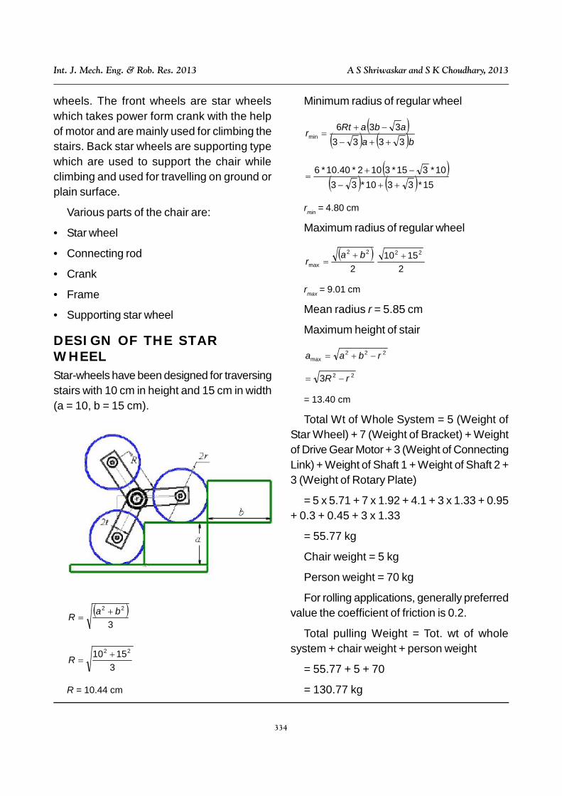
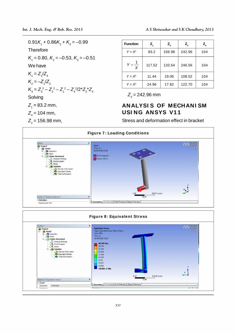
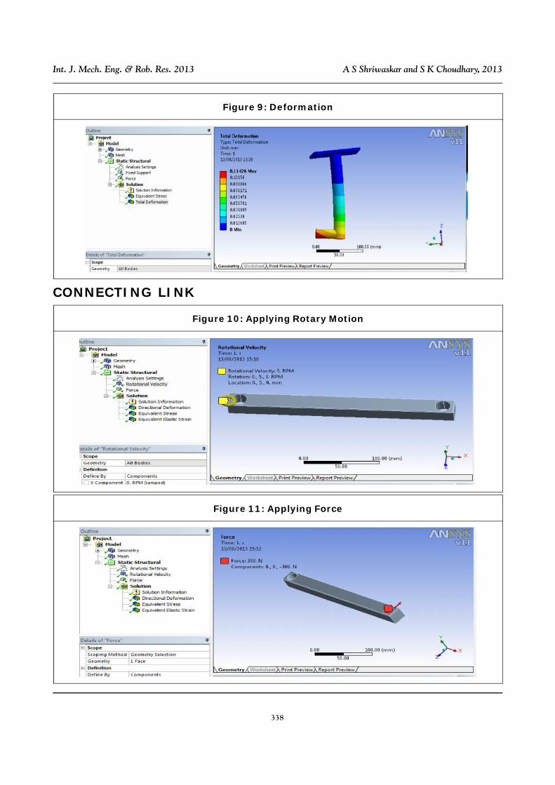
ANALYSIS OF MECHANISMUSING ANSYS V11Stress and deformation effect in bracket
Function Z1 Z2 Z3 Z4
Y = X2 83.2 156.98 242.96 104
XY 1 117.52 133.54 246.56 104
Y = X5 11.44 19.06 108.52 104
Y = X3 24.96 17.82 122.70 104
Figure 7: Loading Conditions
Figure 8: Equivalent Stress
338
Int. J. Mech. Eng. & Rob. Res. 2013 A S Shriwaskar and S K Choudhary, 2013
CONNECTING LINK
Figure 9: Deformation
Figure 10: Applying Rotary Motion
Figure 11: Applying Force

339
Int. J. Mech. Eng. & Rob. Res. 2013 A S Shriwaskar and S K Choudhary, 2013
Figure 12: Equivalent Stress
Figure 13: Equivalent Elastic Strain
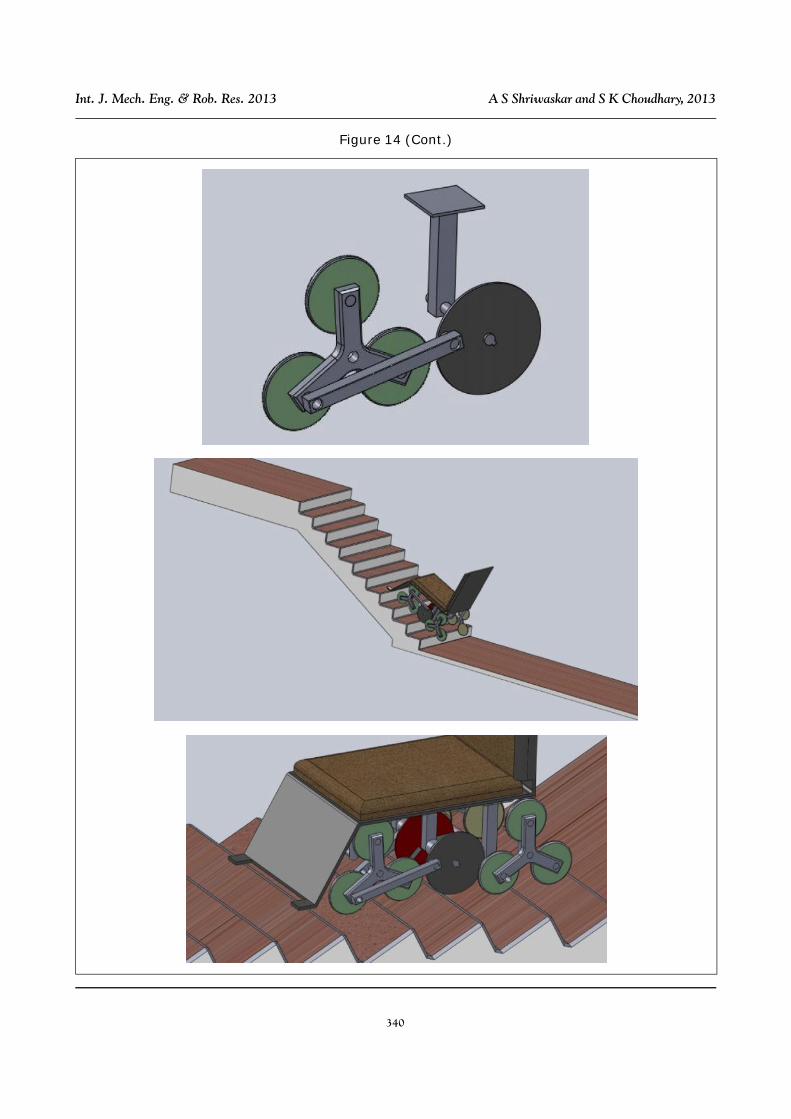
Figure 14: Simulation Result
340
Int. J. Mech. Eng. & Rob. Res. 2013 A S Shriwaskar and S K Choudhary, 2013
Figure 14 (Cont.)
341
Int. J. Mech. Eng. & Rob. Res. 2013 A S Shriwaskar and S K Choudhary, 2013
CONCLUSIONNew chair with three mechanisms like, starwheel and simple driving mechanism will helpto prepare a chair that will be able to climbchair without anyone’s assistance or withassistance. This chair will helpful to climb chairwith a particular height and width. Accordingto the dimensions of stairs we can changedimensions of chair parts.
REFERENCES1. Isabelle Laffont, Bruno Guillon, Christophe
Fermanian, Sophie Pouillot, Alexia Even-Schneider, François Boyer, Maria Ruquet,Philippe Aegerter, Olivier Dizien andFrédéric Lofaso (2008), “Evaluation of aStair-Climbing Power Wheelchair in 25People with Tetraplegia”, Arch. Phys.Med. Rehabil., Vol. 89, October.
2. Murray J Lawn (2002), “Study of Stair-Climbing Assistive Mechanisms for theDisabled Dissertation”, December.
3. Murray J Lawn and Takakazu Ishimatsu(2003), “Modeling of a Stair-ClimbingWheelchair Mechanism with High SingleStep Capability”, Transactions on NeuralSystems and RehabilitationEngineering, Vol. 11, No. 3, September.
4. Moghadam M and Mojtaba Ahmadi(2007), “Climbing Robots”, MajidBioinspiration and Robotics: Walkingand Climbing Robots, September,p. 544.
5. Subhasis Behera and Ananda Sendhil S(2003), “Stair Climbing Mechanism-Thesis”, Dr B R Ambedkar NationalInstitute of Technology, Jalandhar.
Related Documents