Synthesis and coating of micro-metal-matrix composite by combined laser sol–gel processing Tamer Ezz a, ⁎ , Philip Crouse a , Lin Li a , Zhu Liu b a Laser Processing Research Centre, School of Mechanical, Aerospace, and Civil Engineering, University of Manchester, Sackville Street, Manchester, M60 1QD, United Kingdom b Corrosion and Protection Centre, School of Materials Science University of Manchester, The Mill, Manchester, M60 1QD, United Kingdom Received 6 February 2006; accepted in revised form 18 October 2006 Available online 28 November 2006 Abstract Of the many methods of laser treatment for improving materials surface properties that have been reported, very few have addressed laser-assisted chemical reaction. In this work laser deposition of metal-matrix composites is reported, using chromium oxide and silicon carbide powders mixed in silica sol–gel mixtures, on EN43 mild steel substrates. Very fine SiC particles ≤ 1 μm and M 7 C 3 carbides were synthesised in situ and dispersed in ferrite matrix by this process. A diode laser at different powers and scanning speeds was applied to specimens coated with slurries of different chemical compositions. The effect of solution composition and bath depths were examined in order to achieve optimum experimental parameters. Surface morphology and microstructure of the deposited coatings and substrate surface layers were examined using optical microscopy, scanning electron microscopy (SEM) and field emission gun scanning electron microscope (FEG-SEM). Chemical composition was determined by energy dispersive X-ray analysis (EDX). The different phases were identified by X-ray diffraction (XRD). Results of microhardness measurements and wear properties of the coatings are also reported. Thermodynamic analysis of the reactions taking place is also given. © 2006 Elsevier B.V. All rights reserved. Keywords: Laser-sol/gel-metal matrix composites 1. Introduction During the last few years, considerable research effort has been directed towards the production of metal-matrix compo- sites (MMCs) and/or surface alloying with fine ceramic particle coatings by laser cladding or laser alloying. These types of coatings provide exceptional physical and mechanical proper- ties, improving wear and corrosion resistance in many industrial applications. It combines metal alloy properties such as tough- ness and ductility with ceramic characteristics like high strength, hardness and thermal stability. Several types of ceramic phases including WC, TiC, TiN, Cr 3 C and SiC can be introduced into various compositions of metal matrix alloys by either laser alloying or laser cladding [1–8]. It was reported that laser surface alloying of H13 die steel with micro-size TiC particles increases the wear resistance by more than 100%, and that surface alloying with nanoparticle size TiC decreases the hardness by 25% [9,10]. This is explained by the dissolution of the very fine particles into Ti and C in the Fe matrix during laser processing, causing stabilization of the ferrite phase as Ti is a strong ferrite-former. Thus the microstructure produced in this case consists of ferrite instead of martensite and undissolved TiC. Molian and Jiang, [9] report that other coating techniques for producing ceramic coatings such as chemical and physical vapour deposition, thermal spraying and ion implantation are not capable of meeting all the requirements for effective coat- ings. These include: excellent bonding; adequate thickness; absence of flaws; suitable mechanical properties; thermal shock resistance; and high temperature stability. Tjong and Ma [11] state that in situ MMCs, where reinforce- ments are synthesised in a metallic matrix by chemical reaction between elements or between elements and compounds, exhibit advantages which include: thermodynamic stability of the rein- forcement particles in the metal matrix; strong interfacial Surface & Coatings Technology 201 (2007) 5809 – 5814 www.elsevier.com/locate/surfcoat ⁎ Corresponding author. University of Manchester, School of Mechanical, Aerospace and Civil Engineering, Laser Processing Research Centre (LPRC), A26D, Sackville Street Building, PO Box 88, Manchester M60 1QD, United Kingdom. Tel.: +44 161 306 3828; fax: +44 161 306 3803. E-mail address: [email protected] (T. Ezz). 0257-8972/$ - see front matter © 2006 Elsevier B.V. All rights reserved. doi:10.1016/j.surfcoat.2006.10.030

Welcome message from author
This document is posted to help you gain knowledge. Please leave a comment to let me know what you think about it! Share it to your friends and learn new things together.
Transcript
201 (2007) 5809–5814www.elsevier.com/locate/surfcoat
Surface & Coatings Technology
Synthesis and coating of micro-metal-matrix composite bycombined laser sol–gel processing
Tamer Ezz a,⁎, Philip Crouse a, Lin Li a, Zhu Liu b
a Laser Processing Research Centre, School of Mechanical, Aerospace, and Civil Engineering, University of Manchester,Sackville Street, Manchester, M60 1QD, United Kingdom
b Corrosion and Protection Centre, School of Materials Science University of Manchester, The Mill, Manchester, M60 1QD, United Kingdom
Received 6 February 2006; accepted in revised form 18 October 2006Available online 28 November 2006
Abstract
Of the manymethods of laser treatment for improving materials surface properties that have been reported, very few have addressed laser-assistedchemical reaction. In this work laser deposition of metal-matrix composites is reported, using chromium oxide and silicon carbide powders mixed insilica sol–gel mixtures, on EN43 mild steel substrates. Very fine SiC particles ≤1 μm and M7C3 carbides were synthesised in situ and dispersed inferrite matrix by this process. A diode laser at different powers and scanning speeds was applied to specimens coated with slurries of differentchemical compositions. The effect of solution composition and bath depths were examined in order to achieve optimum experimental parameters.Surface morphology and microstructure of the deposited coatings and substrate surface layers were examined using optical microscopy, scanningelectron microscopy (SEM) and field emission gun scanning electron microscope (FEG-SEM). Chemical composition was determined by energydispersive X-ray analysis (EDX). The different phases were identified by X-ray diffraction (XRD). Results of microhardness measurements and wearproperties of the coatings are also reported. Thermodynamic analysis of the reactions taking place is also given.© 2006 Elsevier B.V. All rights reserved.
Keywords: Laser-sol/gel-metal matrix composites
1. Introduction
During the last few years, considerable research effort hasbeen directed towards the production of metal-matrix compo-sites (MMCs) and/or surface alloying with fine ceramic particlecoatings by laser cladding or laser alloying. These types ofcoatings provide exceptional physical and mechanical proper-ties, improving wear and corrosion resistance in many industrialapplications. It combines metal alloy properties such as tough-ness and ductility with ceramic characteristics like high strength,hardness and thermal stability. Several types of ceramic phasesincluding WC, TiC, TiN, Cr3C and SiC can be introduced intovarious compositions of metal matrix alloys by either laseralloying or laser cladding [1–8]. It was reported that laser surface
⁎ Corresponding author. University of Manchester, School of Mechanical,Aerospace and Civil Engineering, Laser Processing Research Centre (LPRC),A26D, Sackville Street Building, PO Box 88, Manchester M60 1QD, UnitedKingdom. Tel.: +44 161 306 3828; fax: +44 161 306 3803.
E-mail address: [email protected] (T. Ezz).
0257-8972/$ - see front matter © 2006 Elsevier B.V. All rights reserved.doi:10.1016/j.surfcoat.2006.10.030
alloying of H13 die steel with micro-size TiC particles increasesthe wear resistance bymore than 100%, and that surface alloyingwith nanoparticle size TiC decreases the hardness by 25% [9,10].This is explained by the dissolution of the very fine particlesinto Ti and C in the Fe matrix during laser processing, causingstabilization of the ferrite phase as Ti is a strong ferrite-former.Thus the microstructure produced in this case consists of ferriteinstead of martensite and undissolved TiC.
Molian and Jiang, [9] report that other coating techniques forproducing ceramic coatings such as chemical and physicalvapour deposition, thermal spraying and ion implantation arenot capable of meeting all the requirements for effective coat-ings. These include: excellent bonding; adequate thickness;absence of flaws; suitable mechanical properties; thermal shockresistance; and high temperature stability.
Tjong and Ma [11] state that in situ MMCs, where reinforce-ments are synthesised in a metallic matrix by chemical reactionbetween elements or between elements and compounds, exhibitadvantages which include: thermodynamic stability of the rein-forcement particles in the metal matrix; strong interfacial
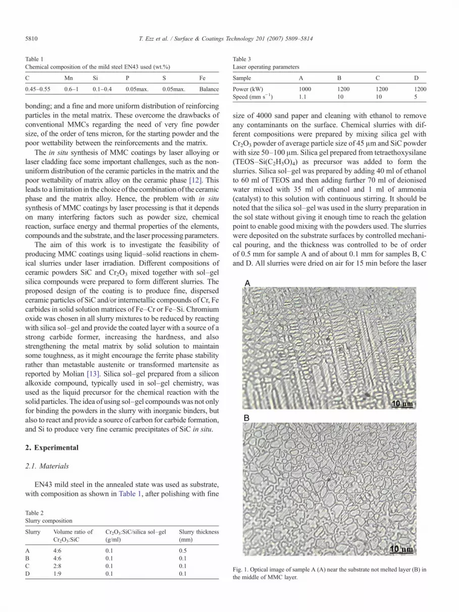
Table 1Chemical composition of the mild steel EN43 used (wt.%)
C Mn Si P S Fe
0.45–0.55 0.6–1 0.1–0.4 0.05max. 0.05max. Balance
Table 3Laser operating parameters
Sample A B C D
Power (kW) 1000 1200 1200 1200Speed (mm s−1) 1.1 10 10 5
5810 T. Ezz et al. / Surface & Coatings Technology 201 (2007) 5809–5814
bonding; and a fine and more uniform distribution of reinforcingparticles in the metal matrix. These overcome the drawbacks ofconventional MMCs regarding the need of very fine powdersize, of the order of tens micron, for the starting powder and thepoor wettability between the reinforcements and the matrix.
The in situ synthesis of MMC coatings by laser alloying orlaser cladding face some important challenges, such as the non-uniform distribution of the ceramic particles in the matrix and thepoor wettability of matrix alloy on the ceramic phase [12]. Thisleads to a limitation in the choice of the combination of the ceramicphase and the matrix alloy. Hence, the problem with in situsynthesis of MMC coatings by laser processing is that it dependson many interfering factors such as powder size, chemicalreaction, surface energy and thermal properties of the elements,compounds and the substrate, and the laser processing parameters.
The aim of this work is to investigate the feasibility ofproducing MMC coatings using liquid–solid reactions in chem-ical slurries under laser irradiation. Different compositions ofceramic powders SiC and Cr2O3 mixed together with sol–gelsilica compounds were prepared to form different slurries. Theproposed design of the coating is to produce fine, dispersedceramic particles of SiC and/or intermetallic compounds of Cr, Fecarbides in solid solution matrices of Fe–Cr or Fe–Si. Chromiumoxide was chosen in all slurry mixtures to be reduced by reactingwith silica sol–gel and provide the coated layer with a source of astrong carbide former, increasing the hardness, and alsostrengthening the metal matrix by solid solution to maintainsome toughness, as it might encourage the ferrite phase stabilityrather than metastable austenite or transformed martensite asreported by Molian [13]. Silica sol–gel prepared from a siliconalkoxide compound, typically used in sol–gel chemistry, wasused as the liquid precursor for the chemical reaction with thesolid particles. The idea of using sol–gel compoundswas not onlyfor binding the powders in the slurry with inorganic binders, butalso to react and provide a source of carbon for carbide formation,and Si to produce very fine ceramic precipitates of SiC in situ.
2. Experimental
2.1. Materials
EN43 mild steel in the annealed state was used as substrate,with composition as shown in Table 1, after polishing with fine
Table 2Slurry composition
Slurry Volume ratio ofCr2O3:SiC
Cr2O3:SiC/silica sol–gel(g/ml)
Slurry thickness(mm)
A 4:6 0.1 0.5B 4:6 0.1 0.1C 2:8 0.1 0.1D 1:9 0.1 0.1
size of 4000 sand paper and cleaning with ethanol to removeany contaminants on the surface. Chemical slurries with dif-ferent compositions were prepared by mixing silica gel withCr2O3 powder of average particle size of 45 μm and SiC powderwith size 50–100 μm. Silica gel prepared from tetraethoxysilane(TEOS–Si(C2H5O)4) as precursor was added to form theslurries. Silica sol–gel was prepared by adding 40 ml of ethanolto 60 ml of TEOS and then adding further 70 ml of deionisedwater mixed with 35 ml of ethanol and 1 ml of ammonia(catalyst) to this solution with continuous stirring. It should benoted that the silica sol–gel was used in the slurry preparation inthe sol state without giving it enough time to reach the gelationpoint to enable good mixing with the powders used. The slurrieswere deposited on the substrate surfaces by controlled mechani-cal pouring, and the thickness was controlled to be of orderof 0.5 mm for sample A and of about 0.1 mm for samples B, Cand D. All slurries were dried on air for 15 min before the laser
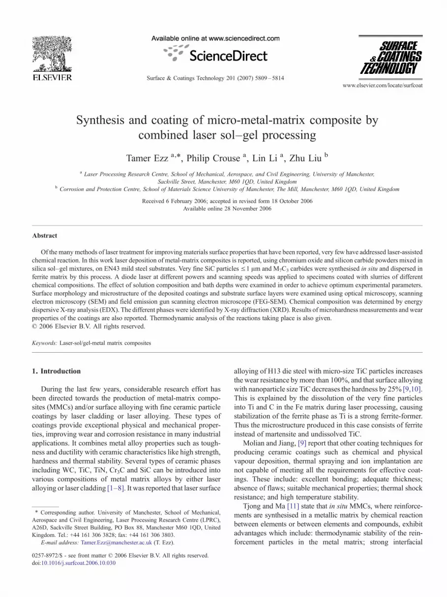
Fig. 1. Optical image of sample A (A) near the substrate not melted layer (B) inthe middle of MMC layer.
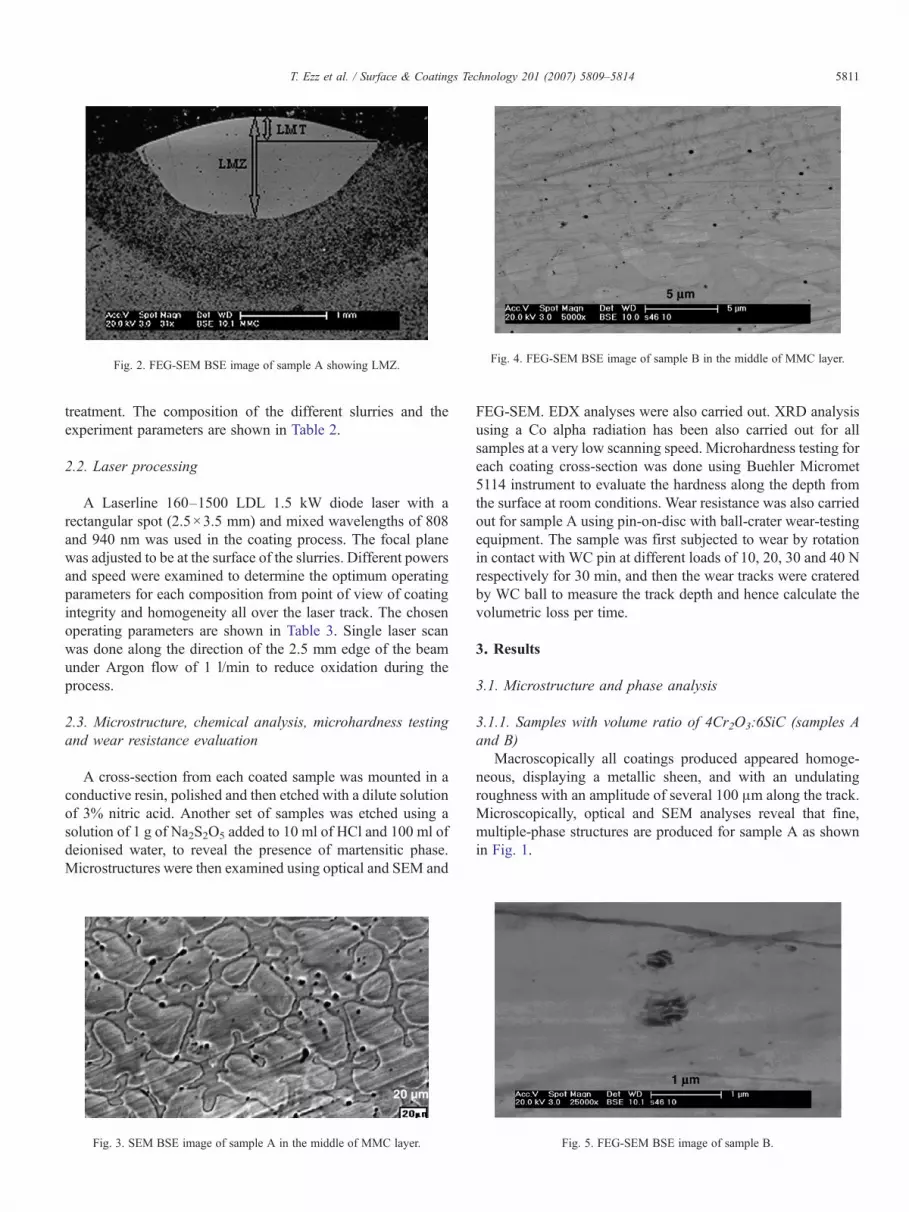
Fig. 2. FEG-SEM BSE image of sample A showing LMZ.Fig. 4. FEG-SEM BSE image of sample B in the middle of MMC layer.
5811T. Ezz et al. / Surface & Coatings Technology 201 (2007) 5809–5814
treatment. The composition of the different slurries and theexperiment parameters are shown in Table 2.
2.2. Laser processing
A Laserline 160–1500 LDL 1.5 kW diode laser with arectangular spot (2.5×3.5 mm) and mixed wavelengths of 808and 940 nm was used in the coating process. The focal planewas adjusted to be at the surface of the slurries. Different powersand speed were examined to determine the optimum operatingparameters for each composition from point of view of coatingintegrity and homogeneity all over the laser track. The chosenoperating parameters are shown in Table 3. Single laser scanwas done along the direction of the 2.5 mm edge of the beamunder Argon flow of 1 l/min to reduce oxidation during theprocess.
2.3. Microstructure, chemical analysis, microhardness testingand wear resistance evaluation
A cross-section from each coated sample was mounted in aconductive resin, polished and then etched with a dilute solutionof 3% nitric acid. Another set of samples was etched using asolution of 1 g of Na2S2O5 added to 10 ml of HCl and 100 ml ofdeionised water, to reveal the presence of martensitic phase.Microstructures were then examined using optical and SEM and
Fig. 3. SEM BSE image of sample A in the middle of MMC layer.
FEG-SEM. EDX analyses were also carried out. XRD analysisusing a Co alpha radiation has been also carried out for allsamples at a very low scanning speed. Microhardness testing foreach coating cross-section was done using Buehler Micromet5114 instrument to evaluate the hardness along the depth fromthe surface at room conditions. Wear resistance was also carriedout for sample A using pin-on-disc with ball-crater wear-testingequipment. The sample was first subjected to wear by rotationin contact with WC pin at different loads of 10, 20, 30 and 40 Nrespectively for 30 min, and then the wear tracks were crateredby WC ball to measure the track depth and hence calculate thevolumetric loss per time.
3. Results
3.1. Microstructure and phase analysis
3.1.1. Samples with volume ratio of 4Cr2O3:6SiC (samples Aand B)
Macroscopically all coatings produced appeared homoge-neous, displaying a metallic sheen, and with an undulatingroughness with an amplitude of several 100 μm along the track.Microscopically, optical and SEM analyses reveal that fine,multiple-phase structures are produced for sample A as shownin Fig. 1.
Fig. 5. FEG-SEM BSE image of sample B.
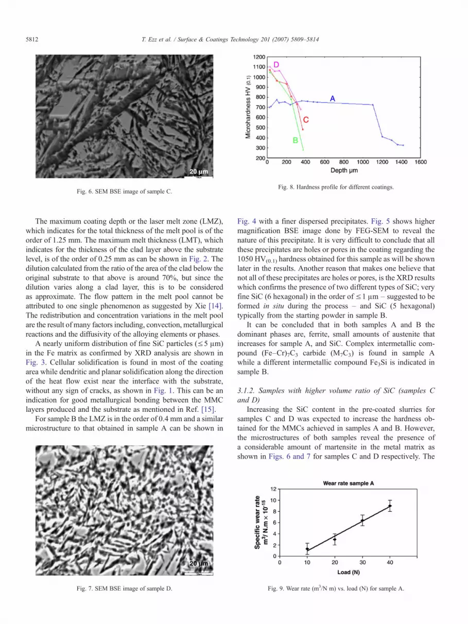
Fig. 6. SEM BSE image of sample C.Fig. 8. Hardness profile for different coatings.
5812 T. Ezz et al. / Surface & Coatings Technology 201 (2007) 5809–5814
The maximum coating depth or the laser melt zone (LMZ),which indicates for the total thickness of the melt pool is of theorder of 1.25 mm. The maximum melt thickness (LMT), whichindicates for the thickness of the clad layer above the substratelevel, is of the order of 0.25 mm as can be shown in Fig. 2. Thedilution calculated from the ratio of the area of the clad below theoriginal substrate to that above is around 70%, but since thedilution varies along a clad layer, this is to be consideredas approximate. The flow pattern in the melt pool cannot beattributed to one single phenomenon as suggested by Xie [14].The redistribution and concentration variations in the melt poolare the result of many factors including, convection, metallurgicalreactions and the diffusivity of the alloying elements or phases.
A nearly uniform distribution of fine SiC particles (≤5 μm)in the Fe matrix as confirmed by XRD analysis are shown inFig. 3. Cellular solidification is found in most of the coatingarea while dendritic and planar solidification along the directionof the heat flow exist near the interface with the substrate,without any sign of cracks, as shown in Fig. 1. This can be anindication for good metallurgical bonding between the MMClayers produced and the substrate as mentioned in Ref. [15].
For sample B the LMZ is in the order of 0.4 mm and a similarmicrostructure to that obtained in sample A can be shown in
Fig. 7. SEM BSE image of sample D.
Fig. 4 with a finer dispersed precipitates. Fig. 5 shows highermagnification BSE image done by FEG-SEM to reveal thenature of this precipitate. It is very difficult to conclude that allthese precipitates are holes or pores in the coating regarding the1050 HV(0.1) hardness obtained for this sample as will be shownlater in the results. Another reason that makes one believe thatnot all of these precipitates are holes or pores, is the XRD resultswhich confirms the presence of two different types of SiC; veryfine SiC (6 hexagonal) in the order of ≤1 μm – suggested to beformed in situ during the process – and SiC (5 hexagonal)typically from the starting powder in sample B.
It can be concluded that in both samples A and B thedominant phases are, ferrite, small amounts of austenite thatincreases for sample A, and SiC. Complex intermetallic com-pound (Fe–Cr)7C3 carbide (M7C3) is found in sample Awhile a different intermetallic compound Fe3Si is indicated insample B.
3.1.2. Samples with higher volume ratio of SiC (samples Cand D)
Increasing the SiC content in the pre-coated slurries forsamples C and D was expected to increase the hardness ob-tained for the MMCs achieved in samples A and B. However,the microstructures of both samples reveal the presence ofa considerable amount of martensite in the metal matrix asshown in Figs. 6 and 7 for samples C and D respectively. The
Fig. 9. Wear rate (m3/N m) vs. load (N) for sample A.
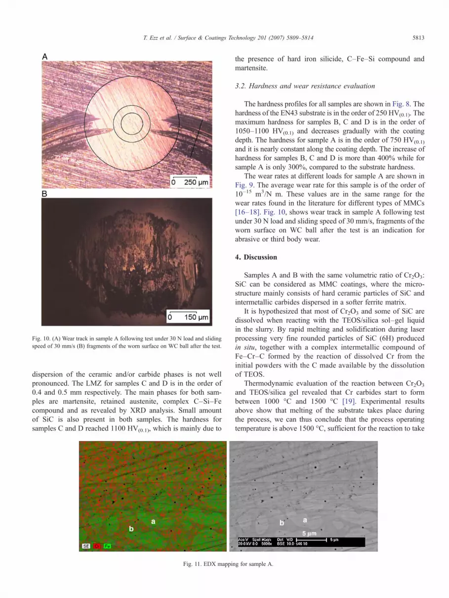
Fig. 10. (A) Wear track in sample A following test under 30 N load and slidingspeed of 30 mm/s (B) fragments of the worn surface on WC ball after the test.
5813T. Ezz et al. / Surface & Coatings Technology 201 (2007) 5809–5814
dispersion of the ceramic and/or carbide phases is not wellpronounced. The LMZ for samples C and D is in the order of0.4 and 0.5 mm respectively. The main phases for both sam-ples are martensite, retained austenite, complex C–Si–Fecompound and as revealed by XRD analysis. Small amountof SiC is also present in both samples. The hardness forsamples C and D reached 1100 HV(0.1), which is mainly due to
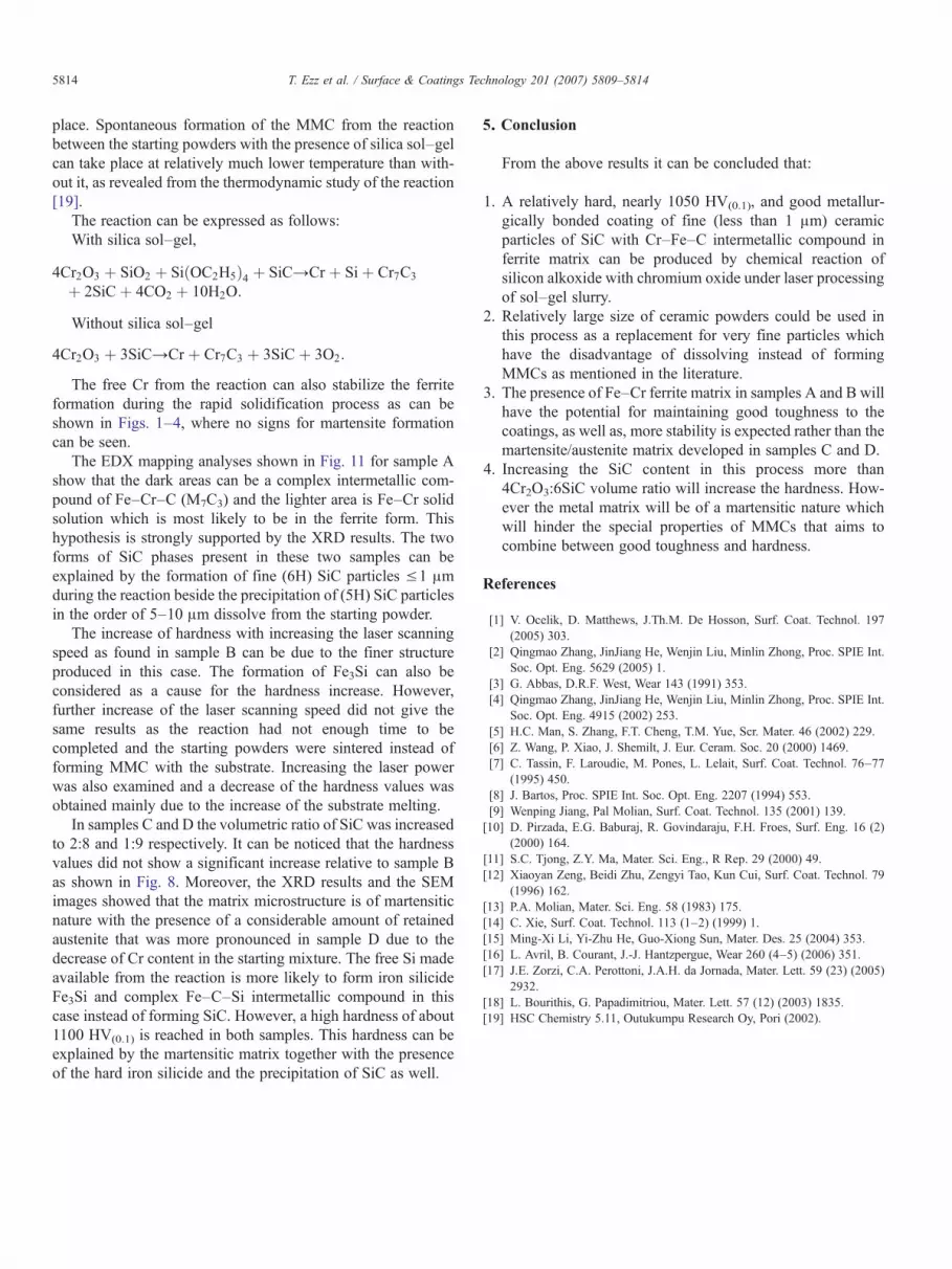
Fig. 11. EDX mappin
the presence of hard iron silicide, C–Fe–Si compound andmartensite.
3.2. Hardness and wear resistance evaluation
The hardness profiles for all samples are shown in Fig. 8. Thehardness of the EN43 substrate is in the order of 250 HV(0.1). Themaximum hardness for samples B, C and D is in the order of1050–1100 HV(0.1) and decreases gradually with the coatingdepth. The hardness for sample A is in the order of 750 HV(0.1)
and it is nearly constant along the coating depth. The increase ofhardness for samples B, C and D is more than 400% while forsample A is only 300%, compared to the substrate hardness.
The wear rates at different loads for sample A are shown inFig. 9. The average wear rate for this sample is of the order of10–15 m3/N m. These values are in the same range for thewear rates found in the literature for different types of MMCs[16–18]. Fig. 10, shows wear track in sample A following testunder 30 N load and sliding speed of 30 mm/s, fragments of theworn surface on WC ball after the test is an indication forabrasive or third body wear.
4. Discussion
Samples A and B with the same volumetric ratio of Cr2O3:SiC can be considered as MMC coatings, where the micro-structure mainly consists of hard ceramic particles of SiC andintermetallic carbides dispersed in a softer ferrite matrix.
It is hypothesized that most of Cr2O3 and some of SiC aredissolved when reacting with the TEOS/silica sol–gel liquidin the slurry. By rapid melting and solidification during laserprocessing very fine rounded particles of SiC (6H) producedin situ, together with a complex intermetallic compound ofFe–Cr–C formed by the reaction of dissolved Cr from theinitial powders with the C made available by the dissolutionof TEOS.
Thermodynamic evaluation of the reaction between Cr2O3
and TEOS/silica gel revealed that Cr carbides start to formbetween 1000 °C and 1500 °C [19]. Experimental resultsabove show that melting of the substrate takes place duringthe process, we can thus conclude that the process operatingtemperature is above 1500 °C, sufficient for the reaction to take
g for sample A.
5814 T. Ezz et al. / Surface & Coatings Technology 201 (2007) 5809–5814
place. Spontaneous formation of the MMC from the reactionbetween the starting powders with the presence of silica sol–gelcan take place at relatively much lower temperature than with-out it, as revealed from the thermodynamic study of the reaction[19].
The reaction can be expressed as follows:With silica sol–gel,
4Cr2O3 þ SiO2 þ SiðOC2H5Þ4 þ SiC→Cr þ Si þ Cr7C3
þ 2SiC þ 4CO2 þ 10H2O:
Without silica sol–gel
4Cr2O3 þ 3SiC→Cr þ Cr7C3 þ 3SiC þ 3O2:
The free Cr from the reaction can also stabilize the ferriteformation during the rapid solidification process as can beshown in Figs. 1–4, where no signs for martensite formationcan be seen.
The EDX mapping analyses shown in Fig. 11 for sample Ashow that the dark areas can be a complex intermetallic com-pound of Fe–Cr–C (M7C3) and the lighter area is Fe–Cr solidsolution which is most likely to be in the ferrite form. Thishypothesis is strongly supported by the XRD results. The twoforms of SiC phases present in these two samples can beexplained by the formation of fine (6H) SiC particles ≤1 μmduring the reaction beside the precipitation of (5H) SiC particlesin the order of 5–10 μm dissolve from the starting powder.
The increase of hardness with increasing the laser scanningspeed as found in sample B can be due to the finer structureproduced in this case. The formation of Fe3Si can also beconsidered as a cause for the hardness increase. However,further increase of the laser scanning speed did not give thesame results as the reaction had not enough time to becompleted and the starting powders were sintered instead offorming MMC with the substrate. Increasing the laser powerwas also examined and a decrease of the hardness values wasobtained mainly due to the increase of the substrate melting.
In samples C and D the volumetric ratio of SiC was increasedto 2:8 and 1:9 respectively. It can be noticed that the hardnessvalues did not show a significant increase relative to sample Bas shown in Fig. 8. Moreover, the XRD results and the SEMimages showed that the matrix microstructure is of martensiticnature with the presence of a considerable amount of retainedaustenite that was more pronounced in sample D due to thedecrease of Cr content in the starting mixture. The free Si madeavailable from the reaction is more likely to form iron silicideFe3Si and complex Fe–C–Si intermetallic compound in thiscase instead of forming SiC. However, a high hardness of about1100 HV(0.1) is reached in both samples. This hardness can beexplained by the martensitic matrix together with the presenceof the hard iron silicide and the precipitation of SiC as well.
5. Conclusion
From the above results it can be concluded that:
1. A relatively hard, nearly 1050 HV(0.1), and good metallur-gically bonded coating of fine (less than 1 μm) ceramicparticles of SiC with Cr–Fe–C intermetallic compound inferrite matrix can be produced by chemical reaction ofsilicon alkoxide with chromium oxide under laser processingof sol–gel slurry.
2. Relatively large size of ceramic powders could be used inthis process as a replacement for very fine particles whichhave the disadvantage of dissolving instead of formingMMCs as mentioned in the literature.
3. The presence of Fe–Cr ferrite matrix in samples A and B willhave the potential for maintaining good toughness to thecoatings, as well as, more stability is expected rather than themartensite/austenite matrix developed in samples C and D.
4. Increasing the SiC content in this process more than4Cr2O3:6SiC volume ratio will increase the hardness. How-ever the metal matrix will be of a martensitic nature whichwill hinder the special properties of MMCs that aims tocombine between good toughness and hardness.
References
[1] V. Ocelik, D. Matthews, J.Th.M. De Hosson, Surf. Coat. Technol. 197(2005) 303.
[2] Qingmao Zhang, JinJiang He, Wenjin Liu, Minlin Zhong, Proc. SPIE Int.Soc. Opt. Eng. 5629 (2005) 1.
[3] G. Abbas, D.R.F. West, Wear 143 (1991) 353.[4] Qingmao Zhang, JinJiang He, Wenjin Liu, Minlin Zhong, Proc. SPIE Int.
Soc. Opt. Eng. 4915 (2002) 253.[5] H.C. Man, S. Zhang, F.T. Cheng, T.M. Yue, Scr. Mater. 46 (2002) 229.[6] Z. Wang, P. Xiao, J. Shemilt, J. Eur. Ceram. Soc. 20 (2000) 1469.[7] C. Tassin, F. Laroudie, M. Pones, L. Lelait, Surf. Coat. Technol. 76–77
(1995) 450.[8] J. Bartos, Proc. SPIE Int. Soc. Opt. Eng. 2207 (1994) 553.[9] Wenping Jiang, Pal Molian, Surf. Coat. Technol. 135 (2001) 139.[10] D. Pirzada, E.G. Baburaj, R. Govindaraju, F.H. Froes, Surf. Eng. 16 (2)
(2000) 164.[11] S.C. Tjong, Z.Y. Ma, Mater. Sci. Eng., R Rep. 29 (2000) 49.[12] Xiaoyan Zeng, Beidi Zhu, Zengyi Tao, Kun Cui, Surf. Coat. Technol. 79
(1996) 162.[13] P.A. Molian, Mater. Sci. Eng. 58 (1983) 175.[14] C. Xie, Surf. Coat. Technol. 113 (1–2) (1999) 1.[15] Ming-Xi Li, Yi-Zhu He, Guo-Xiong Sun, Mater. Des. 25 (2004) 353.[16] L. Avril, B. Courant, J.-J. Hantzpergue, Wear 260 (4–5) (2006) 351.[17] J.E. Zorzi, C.A. Perottoni, J.A.H. da Jornada, Mater. Lett. 59 (23) (2005)
2932.[18] L. Bourithis, G. Papadimitriou, Mater. Lett. 57 (12) (2003) 1835.[19] HSC Chemistry 5.11, Outukumpu Research Oy, Pori (2002).
Related Documents