1. Rev. 4.0 April 2019 Renesas Synergy™ Platform Synergy Software Software Quality Assurance www.renesas.com All information contained in these materials, including products and product specifications, represents information on the product at the time of publication and is subject to change by Renesas Electronics Corp. without notice. Please review the latest information published by Renesas Electronics Corp. through various means, including the Renesas Electronics Corp. website (http://www.renesas.com). Synergy Software Quality Handbook

Welcome message from author
This document is posted to help you gain knowledge. Please leave a comment to let me know what you think about it! Share it to your friends and learn new things together.
Transcript
Notice
1.
Rev. 4.0 April 2019
Renesas Synergy™ Platform
Synergy Software
Software Quality Assurance
Use
r’s M
an
ua
l
www.renesas.com
All information contained in these materials, including products and product specifications, represents
information on the product at the time of publication and is subject to change by Renesas Electronics
Corp. without notice. Please review the latest information published by Renesas Electronics Corp.
through various means, including the Renesas Electronics Corp. website (http://www.renesas.com).
Synergy Software Quality Handbook
User’s Manual
Synergy Software Quality Handbook
IoT-SQH-00304 Rev. 4.0 Page 2 of 2 April 2019April 2019
Descriptions of circuits, software and other related information in this document are provided only to illustrate the operation of
semiconductor products and application examples. You are fully responsible for the incorporation or any other use of the circuits,
software, and information in the design of your product or system. Renesas Electronics disclaims any and all liability for any
losses and damages incurred by you or third parties arising from the use of these circuits, software, or information.
2. Renesas Electronics hereby expressly disclaims any warranties against and liability for infringement or any other disputes
involving patents, copyrights, or other intellectual property rights of third parties, by or arising from the use of Renesas
Electronics products or technical information described in this document, including but not limited to, the product data, drawing,
chart, program, algorithm, application examples.
3. No license, express, implied or otherwise, is granted hereby under any patents, copyrights or other intellectual property rights of
Renesas Electronics or others.
4. You shall not alter, modify, copy, or otherwise misappropriate any Renesas Electronics product, whether in whole or in part.
Renesas Electronics disclaims any and all liability for any losses or damages incurred by you or third parties arising from such
alteration, modification, copy or otherwise misappropriation of Renesas Electronics products.
5. Renesas Electronics products are classified according to the following two quality grades: "Standard" and "High Quality". The
intended applications for each Renesas Electronics product depends on the product’s quality grade, as indicated below.
"Standard": Computers; office equipment; communications equipment; test and measurement equipment; audio and visual
equipment; home electronic appliances; machine tools; personal electronic equipment; and industrial robots etc.
"High Quality": Transportation equipment (automobiles, trains, ships, etc.); traffic control (traffic lights); large-scale
communication equipment; key financial terminal systems; safety control equipment; etc.
Renesas Electronics products are neither intended nor authorized for use in products or systems that may pose a direct threat to human
life or bodily injury (artificial life support devices or systems, surgical implantations etc.), or may cause serious property damages
(space and undersea repeaters; nuclear power control systems; aircraft control systems; key plant systems; military equipment;
etc.). Renesas Electronics disclaims any and all liability for any damages or losses incurred by you or third parties arising from
the use of any Renesas Electronics product for which the product is not intended by Renesas Electronics.
6. When using the Renesas Electronics products, refer to the latest product information (data sheets, user’s manuals, application
notes, "General Notes for Handling and Using Semiconductor Devices" in the reliability handbook, etc.), and ensure that usage
conditions are within the ranges specified by Renesas Electronics with respect to maximum ratings, operating power supply
voltage range, heat radiation characteristics, installation, etc. Renesas Electronics disclaims any and all liability for any
malfunctions or failure or accident arising out of the use of Renesas Electronics products beyond such specified ranges.
7. Although Renesas Electronics endeavors to improve the quality and reliability of Renesas Electronics products, semiconductor
products have specific characteristics such as the occurrence of failure at a certain rate and malfunctions under certain use
conditions. Further, Renesas Electronics products are not subject to radiation resistance design. Please ensure to implement safety
measures to guard them against the possibility of bodily injury, injury or damage caused by fire, and social damage in the event of
failure or malfunction of Renesas Electronics products, such as safety design for hardware and software including but not limited
to redundancy, fire control and malfunction prevention, appropriate treatment for aging degradation or any other appropriate
measures by your own responsibility as warranty for your products/system. Because the evaluation of microcomputer software
alone is very difficult and not practical, please evaluate the safety of the final products or systems manufactured by you.
8. Please contact a Renesas Electronics sales office for details as to environmental matters such as the environmental compatibility
of each Renesas Electronics product. Please investigate applicable laws and regulations that regulate the inclusion or use of
controlled substances, including without limitation, the EU RoHS Directive carefully and sufficiently and use Renesas Electronics
products in compliance with all these applicable laws and regulations. Renesas Electronics disclaims any and all liability for
damages or losses occurring as a result of your noncompliance with applicable laws and regulations.
9. Renesas Electronics products and technologies shall not be used for or incorporated into any products or systems whose
manufacture, use, or sale is prohibited under any applicable domestic or foreign laws or regulations. You shall not use Renesas
Electronics products or technologies for (1) any purpose relating to the development, design, manufacture, use, stockpiling, etc.,
of weapons of mass destruction, such as nuclear weapons, chemical weapons, or biological weapons, or missiles (including
unmanned aerial vehicles (UAVs)) for delivering such weapons, (2) any purpose relating to the development, design,
manufacture, or use of conventional weapons, or (3) any other purpose of disturbing international peace and security, and you
shall not sell, export, lease, transfer, or release Renesas Electronics products or technologies to any third party whether directly or
indirectly with knowledge or reason to know that the third party or any other party will engage in the activities described above.
When exporting, selling, transferring, etc., Renesas Electronics products or technologies, you shall comply with any applicable
export control laws and regulations promulgated and administered by the governments of the countries asserting jurisdiction over
the parties or transactions.
10. Please acknowledge and agree that you shall bear all the losses and damages which are incurred from the misuse or violation of
the terms and conditions described in this document, including this notice, and hold Renesas Electronics harmless, if such misuse
or violation results from your resale or making Renesas Electronics products available any third party.
11. This document shall not be reprinted, reproduced or duplicated in any form, in whole or in part, without prior written consent of
Renesas Electronics.
12. Please contact a Renesas Electronics sales office if you have any questions regarding the information contained in this document
or Renesas Electronics products.
(Note 1) "Renesas Electronics" as used in this document means Renesas Electronics Corporation and also includes its majority-owned
subsidiaries.
(Note 2) "Renesas Electronics product(s)" means any product developed or manufactured by or for Renesas Electronics.
Synergy Software Quality Handbook Contents
IoT-SQH-00304 Rev. 4.0 Page 2 of 4 April 2019April 2019
Contents
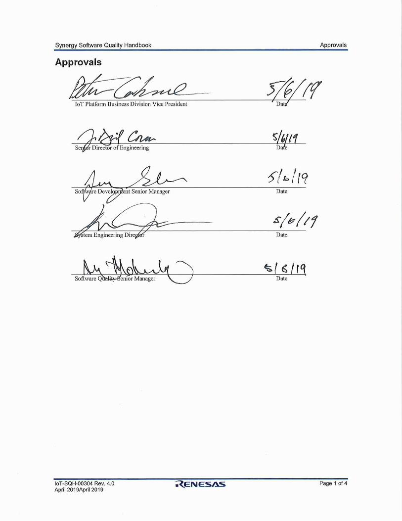
Approvals ............................................................................................................................................... 1
Contents ................................................................................................................................................. 2
1. Introduction .................................................................................................................................. 1
2. Definitions .................................................................................................................................... 2
2.1 Software .................................................................................................................................................................... 2
2.2 Software Quality ....................................................................................................................................................... 2
2.3 Software Quality Assurance ...................................................................................................................................... 2
2.4 Quality Factors .......................................................................................................................................................... 2
3. Software Development Life Cycle Activities .............................................................................. 4
3.1 Planning Phase .......................................................................................................................................................... 4
3.2 Software Development Plan (IoT-SDP-00217) ........................................................................................................ 4
3.3 Software Verification Plan (IoT-SVP-00174) ........................................................................................................... 5
3.4 Software Configuration Management Plan (IoT-SCP-00172) .................................................................................. 5
3.5 Software Quality Assurance Plan (IoT-SQP-00173) ................................................................................................ 6
3.6 Software Development Phase ................................................................................................................................... 6
3.6.1 Software Requirements Specification (IoT-STD-00xxx) ............................................................................... 6
3.6.2 Software Design Description (IoT-STD-00006) ............................................................................................ 7
3.6.3 Software Implementation ............................................................................................................................... 8
3.6.4 Software development verification ................................................................................................................. 8
3.6.5 Code Operation/Maintenance Standards ........................................................................................................ 9
3.6.6 Standards ........................................................................................................................................................ 9
3.6.7 Review............................................................................................................................................................ 9
3.6.8 Audit ............................................................................................................................................................... 9
3.7 Software Configuration Management Phase ............................................................................................................. 9
3.7.1 Problem Reporting and Corrective Action (IoT-PRP-00247) ........................................................................ 9
3.7.2 Corrective Action Procedures....................................................................................................................... 10
3.7.3 SCM Activities ............................................................................................................................................. 10
3.7.4 Configuration Identification ......................................................................................................................... 10
3.7.5 Configuration Change Control ..................................................................................................................... 11
3.7.6 Configuration Status Accounting and Reporting .......................................................................................... 11
3.7.7 Configuration Audits and Reviews .............................................................................................................. 11
3.7.8 Code Control ................................................................................................................................................ 11
3.8 Software Verification Phase .................................................................................................................................... 11
3.8.1 Independent Verification per Specification .................................................................................................. 12
3.8.2 Requirement Based Testing .......................................................................................................................... 12
3.8.3 Testing and the Software Development Life Cycle ...................................................................................... 12
3.8.4 Characteristics of Testable Requirements ............................................................................................. 13
3.8.5 Traceability of Software Requirement ......................................................................................................... 14
3.8.6 Baselines Must Be Congruent ................................................................................................................. 15
3.8.7 Software Unit test ......................................................................................................................................... 15
3.8.8 Functional Tests ........................................................................................................................................... 15
3.8.9 Software Integration ..................................................................................................................................... 15
3.8.10 Software Performance Tests ......................................................................................................................... 16
3.8.11 Regression Tests (IoT-LED-00289) ............................................................................................................. 16
3.8.12 Testing Guidelines ........................................................................................................................................ 17
3.8.13 Dynamic Analysis ........................................................................................................................................ 17
3.8.14 Static Analysis .............................................................................................................................................. 17
Synergy Software Quality Handbook Contents
IoT-SQH-00304 Rev. 4.0 Page 3 of 4 April 2019April 2019
3.8.15 Review.......................................................................................................................................................... 18
3.8.16 Audit ............................................................................................................................................................. 18
3.9 Software Release Phase .......................................................................................................................................... 18
3.10 Scope Restriction .................................................................................................................................................... 18
4. Documentation Quality .............................................................................................................. 19
4.1 Documentation Standards ....................................................................................................................................... 19
4.2 Documentation Review ........................................................................................................................................... 19
4.3 Documentation Maintenance .................................................................................................................................. 19
4.4 Documentation Control ........................................................................................................................................... 19
5. Standards, Practices, and Conventions .............................................................................. 20
6. Reviews, Audits, and Controls ................................................................................................... 21
6.1.1 Technical Reviews ....................................................................................................................................... 21
6.1.2 Review Team Members................................................................................................................................ 21
6.1.3 Review Procedures ....................................................................................................................................... 21
6.2 Audits ...................................................................................................................................................................... 22
6.2.1 Functional Configuration Audit ................................................................................................................... 22
6.2.2 Physical Configuration Audit ....................................................................................................................... 22
6.2.3 In-Process Audits ......................................................................................................................................... 22
6.2.4 SQA Audits .................................................................................................................................................. 22
6.2.5 Corrective Action ......................................................................................................................................... 22
7. Software Maintenance Phase ..................................................................................................... 23
7.1 Internal problems .................................................................................................................................................... 23
7.1.1 Defect and Bug Life Cycle ........................................................................................................................... 23
7.1.2 Reporting – Defect, Bug ............................................................................................................................... 23
7.1.3 Defect, Bug – Types ..................................................................................................................................... 23
7.1.4 Investigation – Defect, Bug .......................................................................................................................... 24
7.1.5 Resolve and Close – Defect, Bug ................................................................................................................. 24
7.2 Customer reported problems ................................................................................................................................... 24
7.2.1 Warranty Claims .......................................................................................................................................... 24
7.2.2 Support requests ........................................................................................................................................... 24
8. Software Metrics ........................................................................................................................ 26
8.1 Complexity of Software .......................................................................................................................................... 26
8.1.1 Module Software Complexity Index ............................................................................................................ 27
8.2 Clean Build ............................................................................................................................................................. 28
8.2.1 Module Software Warning Index ................................................................................................................. 28
8.3 Structural Decision Coverage ................................................................................................................................. 28
8.3.1 Module Software Code Coverage Index ...................................................................................................... 28
8.4 Coding Standards .................................................................................................................................................... 29
8.4.1 Module Software Coding Standard Index .................................................................................................... 30
8.5 Software Verification .............................................................................................................................................. 30
8.5.1 Module Software Verification Index ............................................................................................................ 30
8.6 Software Backward Compatibility .......................................................................................................................... 30
8.6.1 Module Software Backward Compatibility Index ........................................................................................ 30
9. Requirements Management Solution Tool ................................................................................ 31
10. SSP Software Qualification and Verification Packages ............................................................ 32

Synergy Software Quality Handbook Contents
IoT-SQH-00304 Rev. 4.0 Page 4 of 4 April 2019April 2019
Appendix A - Simulated Verification Reports ............................................................................... 33
11. Functional Tests Reports ............................................................................................................ 33
11.1 Coverage Report ..................................................................................................................................................... 33
11.2 Verification Results ................................................................................................................................................ 34
12. Performance and Benchmark Report ......................................................................................... 35
13. Integration Report ...................................................................................................................... 36
14. Complexity Report ..................................................................................................................... 37
15. Coding Standard Report ............................................................................................................. 38
16. Unit Test Report ......................................................................................................................... 39
17. Regression and Quality Report .................................................................................................. 40
Synergy Software Quality Handbook 1. Introduction
IoT-SQH-00304 Rev. 4.0 Page 1 of 40 April 2019April 2019
1. Introduction
This handbook defines a set of guidelines for Software Quality Assurance (SQA) activities as applied to the
Renesas Synergy Software, and is intended for use by developers, managers, vendors, and quality teams
who use the Synergy Platform in their own end-products.
Developing quality software requires everyone's involvement. Anyone who has faced the challenge of
developing a software system understands that the task of producing quality software is harder than it
appears, and certainly harder than the user thinks it should be. The road to functional software is filled with
many pitfalls and the risk of failure is significant.
Much of the difficulty and part of the challenge of developing software stem from its intangibility; a person can't
simply draw a blueprint or describe its physical characteristics. Although the process of developing software
borrows much from established engineering disciplines, some of the process remains undefined. Software
developers often have strong convictions about the proper mix of engineering and art, but these vary from
person to person. At Renesas, sharing a consistent set of ideas about what constitutes software quality and
using consistent methods to achieve that end are critical to a successful product. These ideas and methods
also play an important part in making a project successful.
As we will discuss in this handbook, the benefits of SQA are very real. We strive for better software quality
and for consistency in the engineering process to lower the risk of failure. Developing software may never
become easy. If, however, we improve the process for development and the methods for checking quality, we
can significantly raise the level of success that can be achieved. Conducting a software quality assurance
program can significantly reduce the number of errors introduced into the software product and ensure that
more errors are detected earlier in the system development life cycle.
Synergy Software Quality Handbook 2. Definitions
IoT-SQH-00304 Rev. 4.0 Page 2 of 40 April 2019April 2019
2. Definitions
2.1 Software
Software is "computer programs, procedures, rules, and possibly associated documentation and data
pertaining to the operation of a computer system." The definition of software includes not only the computer
(microcontroller) code, but also the accompanying documentation. This definition encompasses both in-line
comments in the code as well as requirements specifications, design documents, user manuals, and
maintenance guides. Good software must not only work well but must be documented well, too.
2.2 Software Quality
Renesas has established processes to ensure the ability of the software to comply with defined requirements.
This differs from a definition based on the fitness for use of the software. Defined requirements act as the
foundation for determining the level of quality. Emphasis on establishing the requirements in the first place,
rather than on determining what to do after the damage is done and the system works inadequately. This
definition of quality affects two areas of action:
1. Ensure that the product correctly meets customer needs. 2. Verify that reasonable steps were taken to ensure the quality of the product.
The goal of quality is to meet specified requirements rather than achieve an absolute level of quality. The
purpose is not to guarantee 100% reliability or zero defects; rather, it is to verify that every reasonable step
has been taken during the life cycle to achieve a desired level of quality in the end product.
2.3 Software Quality Assurance
SQA is "a systematic set of actions that provide confidence that the software conforms to established
technical requirements." This definition encompasses the following:
1. All necessary activities that can contribute to the quality of software during entire software development life cycle.
2. Systematic execution of the Plan to achieve the objectives of software quality. 3. Developing techniques to demonstrate the effectiveness of process in practice.
Renesas’ quality plan for Synergy Software involves the entire software development process, from early
stage of market requirements validation to software verification and maintenance. Most importantly, changes
are aligned with market requirements and software architecture, to ensure consistency and backward
compatibility. All changes are monitored and reviewed for correctness, completeness, and traced within each
fully verified release product. This includes defects analysis and verification of defects, which demands
specification testing, procedures, categories, types of tests, and methods of testing. The major pitfall of such a
test-oriented program is:
Quality cannot be tested into the software product; quality is built into the software product.
2.4 Quality Factors
Quality factors are grouped according to performance, design, or adaptation concerns. These are the general
categories that inherently characterize the nature of a software project's quality.
Performance quality factors characterize how well the software functions. The performance factors are
efficiency, integrity, reliability, survivability, and usability.
Design quality factors characterize the software design. The design factors are correctness, maintainability,
and verifiability.
Synergy Software Quality Handbook 2. Definitions
IoT-SQH-00304 Rev. 4.0 Page 3 of 40 April 2019April 2019
Adaptation quality factors characterize the adaptability of the software. The adaptation factors are
expandability, flexibility, interoperability, portability, and reusability.
1. Efficiency - The amount of computing resources and code required by the software to perform a
function.
2. Integrity - The extent to which access to software or data by unauthorized persons is being
controlled.
3. Reliability - The extent to which the software performs its intended function without failures for a
given time period.
4. Survivability - The extent to which the software will perform and support criterial functions when a
portion of the system is inoperable.
5. Usability - The effort required to learn, operate, prepare input, and interpret output of the software.
6. Correctness – The extent to which the software satisfies its specifications and fulfills the user
objectives.
7. Maintainability - The effort required to locate and fix an error in the operational software.
8. Verifiability - The effort required to test and verify that the software performs its intended function.
9. Expandability - The effort required to increase the software capability or performance by enhancing
current functions or by adding new functions or data.
10. Flexibility - The effort required to modify operational software.
11. Portability - The effort required to transport the software for use in another environment.
12. Reusability - The extent to which the software can be used in other applications.
13. Interoperability - The effort required to couple the software of one system to the software of another
system.
SQA uses these quality factors to determine the extent that the project is satisfying its quality objectives.
Synergy Software Quality Handbook 3. Software Development Life Cycle Activities
IoT-SQH-00304 Rev. 4.0 Page 4 of 40 April 2019April 2019
3. Software Development Life Cycle Activities
The development process is comprised of a number of stages that are broken into deliberate steps. All
software development life cycles exhibit similar characteristics, regardless of what the specific stages are
called, or the format of the documentation that results.
The stages are as follows:
Requirements Includes understanding the target environment and gathering and analyzing the requirements.
Design Includes both the logical and physical aspects of the system.
Implementation Includes defining the details of the design, coding the system, testing, and installing it.
Release Includes using the system in production and maintaining and controlling the corrections,
enhancements, and additions.
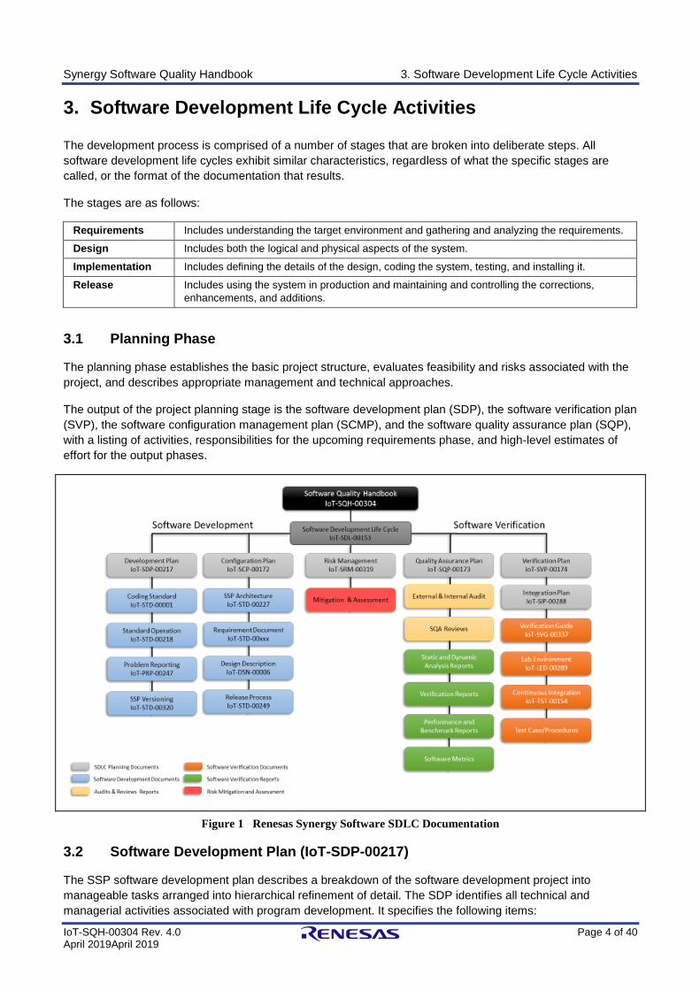
3.1 Planning Phase
The planning phase establishes the basic project structure, evaluates feasibility and risks associated with the
project, and describes appropriate management and technical approaches.
The output of the project planning stage is the software development plan (SDP), the software verification plan
(SVP), the software configuration management plan (SCMP), and the software quality assurance plan (SQP),
with a listing of activities, responsibilities for the upcoming requirements phase, and high-level estimates of
effort for the output phases.
Figure 1 Renesas Synergy Software SDLC Documentation
3.2 Software Development Plan (IoT-SDP-00217)
The SSP software development plan describes a breakdown of the software development project into
manageable tasks arranged into hierarchical refinement of detail. The SDP identifies all technical and
managerial activities associated with program development. It specifies the following items:

Synergy Software Quality Handbook 3. Software Development Life Cycle Activities
IoT-SQH-00304 Rev. 4.0 Page 5 of 40 April 2019April 2019
• Activity description
• Activity deliverables and associated completion criteria
• Prerequisite deliverables from prior activities
• Interrelationship among activities
The development process output documents:
• Software requirement document (SRD)
• Software design description (SDD)
• Requirements Traceability Matrix (RTM)
• Source codes
• Executable object code
• Dev Unit Tests
• Dev Unit Test Results
Note: Traceability is from Market Use Cases to Market Requirements Document (MRD) to Software
Requirements Document (SRD) to Software Design Description (SDD) to source code section or executable
object codes, verification cases and results.
All the software product requirements to be developed during the requirements definition stage flow from one
or more of the market requirements. The minimum information for each market requirement consists of a title
and textual description, although additional information and references to external documents may be
included.
3.3 Software Verification Plan (IoT-SVP-00174)
The SSP software verification document provides the planning and guidance for the performance of
requirements verification. It will provide documentation demonstrating compliance with the processes defined
herein, and provide documentation demonstrating compliance of the software with the high-level (Functional,
Integration, Performance, and Regression tests) and low-level (Unit tests) software requirements.
The verification process output documents:
• Software Verification Cases and Procedures (SVCP) o Functional Module testing o Integration testing o Performance testing o Regression testing
• Software Verification Results (SVR): o Review requirements, design, code, test cases and test results o Testing of executable object code o Review requirement coverage o Code coverage analysis
3.4 Software Configuration Management Plan (IoT-SCP-00172)
The Software Configuration Management Plan (SCP) provides an operational plan to initiate and maintain
software configuration identification, software configuration control, software configuration status, accounting
records, and software configuration audits.
The Software Configuration Management activities include configuration identification, change control,
baseline establishment in Configuration System, and archiving of software lifecycle data. The SCP will detail
how these activities will be performed. This plan also addresses the method of storage, handling, and delivery
of project media, configuration status accounting, and configuration audits.
SCM requirements established by this plan apply to all software product/development phases over the life of
the product and through any post software release activities.
Synergy Software Quality Handbook 3. Software Development Life Cycle Activities
IoT-SQH-00304 Rev. 4.0 Page 6 of 40 April 2019April 2019
Renesas’ Configuration System will manage the configured portion of the software data repository. The
configuration system is capable of managing multiple variants of evolving software systems, tracking which
versions were used in software builds, performing builds of individual programs or entire releases according to
user-defined version specifications, and enforcing site-specific development policies.
The Renesas’ Configuration System toolset will be used to:
• Provide a mechanism for tracking baseline software and documentation
• Maintain a history and record of each software or documentation change
• Initiate changes to the baseline through the use of Action Requests
• Identify and control all released configuration of software
3.5 Software Quality Assurance Plan (IoT-SQP-00173)
The SSP Software Quality Assurance Plan addresses activities to be used by Development Process Assurance (DPA) to ensure that all software development is done in accordance with the approved methods described in the corresponding software plans.
Output documents from the quality assurance process:
• Software quality assurance records (SQAR)
• Software conformity review (SCR)
• Software Release Notes (SRN)
3.6 Software Development Phase
The Software Development Phase consists of:
1. Requirements Specification stage which identifies the requirements that the computer program must satisfy
2. Design Description stage which determines the design of the software 3. Software Implementation stage is the execution of stage one and two 4. Software development verification stage is the verification of stage 3 to meet the requirements
The first two stages produce a statement of the project objectives, system functional specification, and design
constraints.
3.6.1 Software Requirements Specification (IoT-STD-00xxx)
The requirements gathering process takes as its input the requirements identified in the market requirements
document (MRD). Each market requirement will be refined into a set of one or more software requirement(s).
The requirements are fully described in the primary deliverables for this stage, the requirements document
and the requirements traceability matrix (RTM). The requirements document contains complete descriptions of
each requirement, including diagrams and references to external documents as necessary.
The software requirements review takes place at software release planning phase in which the software
requirements specification is generated. The software requirements review constitutes an evaluation of the
SRD. It is conducted to assure the adequacy, technical feasibility, and completeness of the requirements
stated in the SRD. The software requirements review is held to evaluate the SRD to ensure that it is complete,
verifiable, consistent, maintainable, modifiable, traceable, and usable during the operation and maintenance
phases. The review ensures that sufficient detail is available to complete the software design. The results of
the software requirements review are documented including a record of all deficiencies identified, and a plan
and schedule for corrective action. After the software requirements review is updated to correct these
deficiencies, the document is placed under configuration control, establishing the baseline to be used for
software design and other efforts throughout the life cycle. Additional changes to the SRD are permitted
during software design and its implementation.
Synergy Software Quality Handbook 3. Software Development Life Cycle Activities
IoT-SQH-00304 Rev. 4.0 Page 7 of 40 April 2019April 2019
The SSP’s SRD is created based on Market Requirements Document and Renesas Synergy MCU family
datasheet(s) to ensure:
1. Every requirement is uniquely identifying a verifiable behavior of software 2. Requirements are forward and backward compatible with design 3. Requirements identify required software interfaces based on hardware capabilities 4. Requirements identify data coupling for internal and external communication interfaces 5. Requirements identify internal and external control coupling 6. Safety requirements and error management scenarios to meet mission critical applications as
applicable
3.6.2 Software Design Description (IoT-STD-00006)
The design stage takes as its initial input the requirements identified in the approved requirements document.
For each requirement, a set of one or more design elements will be produced.
Design elements describe the desired software features in detail, and include functional hierarchy diagrams,
screen layout diagrams, tables of business rules, business process diagrams, pseudo code, and a complete
entity-relationship diagram with a full data dictionary. These design elements are intended to describe the
software in sufficient detail that skilled programmers may develop the software with minimal additional input.
The Software Design Description (SDD) captures verifiable design details of all software requirements (SRD),
to ensure only required functionalities are implemented and documented.
The preliminary design review is held at the end of the functional specification stage. The preliminary design
review evaluates the technical adequacy of the preliminary design as a prelude to the detailed design. The
review assesses the technical adequacy of the selected design approach; checks the design compatibility with
the functional and performance requirements of the SRD; and verifies the existence and compatibility of the
interfaces between software, hardware, and user.
All organizational elements that impose requirements or that are impacted by the design provide
representatives to participate in this review. Documentation of the results contains a record of all deficiencies
identified in the review, and a plan and schedule for their corrective action. The updated SDD document is
placed under configuration control, establishing a baseline for the detailed software design effort. Changes to
the high-level design that become necessary during detailed design, implementation or testing, are
incorporated into the design documentation, with appropriate reviews made to determine the impact of these
changes.
The critical design review is held at the end of the detailed software design phase. The critical design review
evaluates the technical adequacy, completeness, and correctness of the detailed design before the start of
actual coding. The purpose of the critical design review is to evaluate the acceptability of the detailed design
depicted in the software design description to establish that the detailed design satisfies the requirements of
the SRD; to review compatibility with other software and hardware with which the product is required to
interact; and to assess the technical, cost, and schedule risks of the product's design.
The organizational elements that impose requirements or that are impacted by the design participate in the
review. Documentation of the results of the review identifies the discrepancies found during the review and
presents schedules and plans for their resolution. The updated SDD is then placed under configuration control
to establish a baseline for the next phase of implementation and coding.
Synergy Software Quality Handbook 3. Software Development Life Cycle Activities
IoT-SQH-00304 Rev. 4.0 Page 8 of 40 April 2019April 2019
The software designs are created with the following objectives:
1. Provide conceptual software product architecture with all interfaces - hardware, software and system. 2. Unique Software architecture for all layers – BSP, HAL, Application Framework, Interfaces, etc. 3. Software Component Initialization. 4. Description of steps that uses formulas and computational logic for statistical decisions. 5. Follows standard design principles for data flow and control coupling. 6. Common industry design patterns - component driven designs to support multiple Synergy MCU Groups. 7. Standard API descriptions, data structure methods that meets Renesas Synergy Software coding
standards. 8. Vivid error management. 9. Interface definitions - Inter-module, inter-processor, inter-components. 10. Memory requirements and partitioning details. 11. Description of any communication protocol. 12. Design constraints.
3.6.3 Software Implementation
When the design document is finalized and accepted, the RTM is updated to show that each design element
is formally associated with a specific requirement. The output of the design stage is the design document. For
each design element, a set of one or more software artifacts will be produced. Appropriate unit test cases will
be developed for each set of functionally related software artifacts.
The output of the development stage includes a fully functional set of software that satisfies the requirements
and design elements previously documented, unit test cases to be used to validate the correctness and
completeness of the software, and an updated RTM.
The SSP code implementation is based on ‘C’ programing language. Software developers follow the Software
Developer Guide for the development environment (maintainability and usability).
All software components and artifacts are maintained using a secure version control (Integrity and Reliability).
New development and changes must comply with Renesas Synergy Software coding standards. The coding
standard compliance is checked by using a static code analysis (usability and portability). In addition, newly
developed and changed code, or any associated artifacts are subjected to peer-review and independent
review to ensure changes are traceable to requirement, design and verification results (compatibility and
correctness).
3.6.4 Software development verification
Software development verification is requirement-based testing. Basically, all development verification cases
are traced to at least one software requirement and all software requirements are traced to a verification case
(100% requirements coverage) and execution of verification cases provide 100% data and control coupling.
This objective is achieved by full traceability of verification cases to software requirements and executing
verification cases against instrumented code to collect coverage data.
The software development exit criteria:
1. All SRD items are traced at least to one SDD item. 2. All SRD and SDD are reviewed and baselined. 3. All planned requirements are implemented. 4. All implementations are traceable to at least one SDD item. 5. All requirements are traceable to a verification case which fully verifies the requirement which it is traced
to. 6. All implementations are in compliance with Renesas Synergy Software coding standards. 7. All software components, specifications, and verifications are version controlled and baselined. 8. All verification cases are executed and satisfy pass/fail criteria. 9. All test cases, verification results, and coverage reports are reviewed. 10. All deficiencies are reported and dispositioned.
Synergy Software Quality Handbook 3. Software Development Life Cycle Activities
IoT-SQH-00304 Rev. 4.0 Page 9 of 40 April 2019April 2019
11. All software components are compiled and linked with no warning. 12. 100% requirements coverage provides 100% data and control coupling coverage.
3.6.5 Code Operation/Maintenance Standards
There are two types of maintenance: repair and enhancement. Repair corrects a defect found in the software
or incorporates changes required by a change in the environment; enhancement adds some feature to the
requirement specification. When considering an operation/maintenance standard, a new kind of maintenance
known as preventative maintenance needs to be considered.
Once a program or module has been identified as a candidate for preventative maintenance, a peer review is
held to ensure there is no redundant code and decision complexity is in an acceptable range.
3.6.6 Standards
All developed code is in compliance with Renesas Synergy Software coding standards. Standards are
“documented agreements containing technical specifications or other precise criteria to be used consistently
as rules, guidelines, or definitions of characteristics, to ensure that materials, products, processes and
services are fulfil their purpose.”
3.6.7 Review
The initial version of documentation or code is subject to a full review and changes are subject to an
incremental review. The purpose of review is to evaluate the conceptual and technical approach to the system
solution and ensure that the quality factors previously defined for the project are satisfied. The peer review
attempts to identify problems before they appear as error in software product.
3.6.8 Audit
An audit is an inspection of the documentation and associated development methods to verify that the process
and its documentation are in accordance with the SQA plan and organizational policies and procedures.
3.7 Software Configuration Management Phase
This section presents a general discussion of software configuration management (SCM) and code control,
including problem reporting and corrective actions.
3.7.1 Problem Reporting and Corrective Action (IoT-PRP-00247)
The formal Renesas procedure for software problem reporting and corrective action is established for all
software to measure and promptly identify failures, malfunctions, deficiencies, deviations, defective materials
and equipment, and nonconformance. The problem reporting system interfaces with software configuration
management procedures to ensure formal processing to resolve these problems.
Problems encountered during software development or operation may result from defects in software, in
hardware, or in system operations. Because of the large number of possible defects, defect sources, and
means of detection, a centrally located system for monitoring software defects is necessary.
The objective of the software problem reporting, and tracking system are:
▪ To assure that the defects are documented, corrected, and not forgotten
▪ To assure that the defects are assessed for their validity
▪ To assure that all defect corrections are approved by a review team or change control board before changes to the software configuration are made
▪ To facilitate measuring the defect correction process
▪ To inform the designer and user of the defect's status
▪ To provide a method of setting priorities for defect correction and scheduling appropriate actions

Synergy Software Quality Handbook 3. Software Development Life Cycle Activities
IoT-SQH-00304 Rev. 4.0 Page 10 of 40 April 2019April 2019
▪ To provide management with knowledge of the status of software defects
▪ To provide data for measuring and predicting software quality and reliability
Standard forms or documents are encouraged for reporting problems and proposed changes for software.
These forms include the following items as a minimum:
▪ A description of the problem and proposed corrective action
▪ Authorization to implement the change
▪ A list of all items expected to be affected by the change
▪ An estimate of the resources required for the change
▪ Identification of the personnel involved in the origination and disposition of the problem report and in the resolution of the problem
▪ An identification number and date
▪ Any finding during review is reported as an action item within the issue tracking system. The action items are specific to artifact(s) under the review. An action item shall clearly specify what needs to be done to change a NO answer in the checklist to YES.
3.7.2 Corrective Action Procedures
Corrective action procedures deal with the process of correcting software discrepancies. All corrective actions
are supported by software development. Corrective actions allow developers enough latitude so that their
productivity and creativity are not encumbered. Significant negative impacts on the cost and reliability of
software can occur if corrective action is not timely or is improperly administered. Software errors that go
uncorrected until the system is implemented cost far more to correct than those that are uncovered during
software development. The corrective action process is established early in the Software Development
Planning phase. Prompt detection and early correction of software deficiencies cannot be overemphasized.
Corrective action procedures aid rather than hinder the systematic identification and correction of software
discrepancies and anomalies. The baselines established in the SCM system permits systematic incorporation
of corrective action procedures. These procedures include steps for identifying the discrepancy in writing,
documenting the proposed changes, independently reviewing the proposed changes for adequacy and
retesting of the affected code and all interfacing modules.
Corrective action procedures establish a mechanism for feedback to users on the error analysis of individual
problems, and information about recurrent types of problems. Conversely, corrective action procedures
require software users to inform the program developer when errors are discovered in the computer program,
so that the developer can examine and assess the overall effects of the error.
The program developer is ultimately responsible for the resolution of errors discovered during software
development and use. Furthermore, the developer decides if the error can be corrected with a minor change,
or if a significant revision that requires reverification of the software is necessary.
Effective corrective action procedures require input from software designers, developers, and testers, as well
as SQA and configuration management organizations. This input helps determine what in the original
development process went wrong. Existing methodologies can be reexamined by project management to
determine actions to be taken to minimize recurrence of such defects. In particular, any points in the software
development life cycle that tend to be error-prone are identified.
3.7.3 SCM Activities
SCM activities consist of the following:
3.7.4 Configuration Identification
All components, units, or documents associated with software are version controlled and labeled per releases.
The SSP package uses the versioning scheme of X.Y.Z-maturitylevel+ buildmetadata where:
Synergy Software Quality Handbook 3. Software Development Life Cycle Activities
IoT-SQH-00304 Rev. 4.0 Page 11 of 40 April 2019April 2019
X: Major (Upgrade) release Number, Y: Minor (Update) release number, and Z: Patch (Bug) release number
Maturity Level String: Each release will go through different levels of maturity. For example: Alpha, Beta,
Custom, Release Candidate (RC) and finally the Gold or General Availability (GA).
Build Metadata String: Incremented every time a release is made to outside the development team but within
Renesas. This is an internal tracking number and not necessarily provided to anyone outside Renesas.
The concept of baselines is important in this function because it allows everyone associated with a project to
have a common point of reference when they are defining, developing, or changing a software product.
3.7.5 Configuration Change Control
Configuration change control provides the controls necessary to manage and control the change process. The
mechanics of processing changes are defined by the SCM plan. Appropriate signoff procedures are
incorporated. A Change Control Review Board (CCRB) monitors and approves changes for each release.
3.7.6 Configuration Status Accounting and Reporting
Configuration status accounting is used to develop and maintain records of the status of software as it moves
through the software life cycle. CSA may be thought of as an accounting system.
3.7.7 Configuration Audits and Reviews
The SCM processes are audited and reviewed for each release. The configuration items are audited when the
baseline is released. The number of audits involved will vary according to the baseline being released. The
criteria for the audit, including the roles of its participants, is set in the SCM plan. At a minimum, audits are
performed whenever a product baseline is established, whenever the product baseline is changed, or
whenever a new version of the software is released.
3.7.8 Code Control
Code control encompasses the procedures necessary to distribute, protect, and ensure the validity of the
operating software and associated documentation. Once a code baseline is established, the operating code
and associated artifacts are placed in a centralized computer program library. SQA ensures that adequate
controls and security measures are established for software changes and for protection from inadvertent
alteration after the code has been baselined.
New version implementation is to follow the documented procedures. Accurate and unique identification of all
versions of a computer program is being ensured. Controls are established to record the changing of source
or object code or related material. The software library assigns and tracks identification numbers of computer
programs and documentation, including revisions. The library provides documentation of release
authorization. The software library assists with the arrangements for marking, labeling, and packing software
shipments, and maintains logs and records of the distribution, inventory, and configuration control/status
accounting for deliverables. A central index lists the documents composing the project file.
3.8 Software Verification Phase
The software verification is “(1) The process of determining whether the products of a given phase of the
software development cycle fulfill the requirements established during the previous phase. (2) Formal proof of
program correctness. (3) The act of reviewing, inspection, testing, checking, auditing, or otherwise
establishing and documenting whether or not items, processes, services, or documents confirm to specified
requirements.” This approach is known as requirements-based testing (RBT).
Synergy Software Quality Handbook 3. Software Development Life Cycle Activities
IoT-SQH-00304 Rev. 4.0 Page 12 of 40 April 2019April 2019
3.8.1 Independent Verification per Specification
Verification is intended to check that a product, service, or system (or portion thereof, or set thereof) meets a
set of design specifications. In the development phase, verification procedures involve performing special
tests to model or simulate a portion, or the entirety, of a product, service or system, then performing a review
or analysis of the modeling results. In the post-development phase, verification procedures involve regularly
repeating tests devised specifically to ensure that the product, service, or system continues to meet the initial
design requirements, specifications, and regulations as time progresses. It is a process that is used to
evaluate whether a product, service, or system complies with regulations, specifications, or conditions
imposed at the start of a development phase.
3.8.2 Requirement Based Testing
The RBT approach validates that the requirements are correct, complete, unambiguous, and logically
consistent. It also reduces the immensely large number of potential tests down to a reasonable number and
ensures that the tests got the right answer for the right reason.
The overall RBT strategy is to integrate testing throughout the development life cycle and focus on the quality
of the Requirements Specification. This leads to early defect detection which has been shown to be much less
expensive than finding defects during integration testing or later. The RBT process also has a focus on defect
prevention, not just defect detection.
To put the RBT process into perspective, testing is divided into the following eight activities:
1. Define Test Completion Criteria. The test effort has specific, quantitative and qualitative goals. Testing
is completed only when the goals have been reached (for example, testing is complete when all functional
variations, fully sensitized for the detection of defects, and 100% of all statements and branch vectors
have executed successfully in single run or set of runs with no code changes in between).
2. Design Test Cases. Logical test cases are defined by five characteristics: the initial state of the system
prior to executing the test, the data in the data base, the inputs, the expected outputs, and the final
system state.
3. Build Test Cases. There are two parts needed to build test cases from logical test cases: creating the
necessary data, and building the components to support testing (for example, build the navigation to get
to the portion of the program being tested).
4. Execute Tests. Execute the test-case steps against the system being tested and document the results.
5. Verify Test Results. Verify that the test results are as expected.
6. Verify Test Coverage. Track the amount of functional coverage and code coverage achieved by the
successful execution of the set of tests.
7. Manage and Track Defects. Any defects detected during the testing process are tracked to resolution.
Statistics are maintained concerning the overall defect trends and status.
8. Manage the Test Library. The test manager maintains the relationships between the test cases and the
programs being tested. The test manager keeps track of what tests have or have not been executed, and
whether the executed tests have passed or failed.
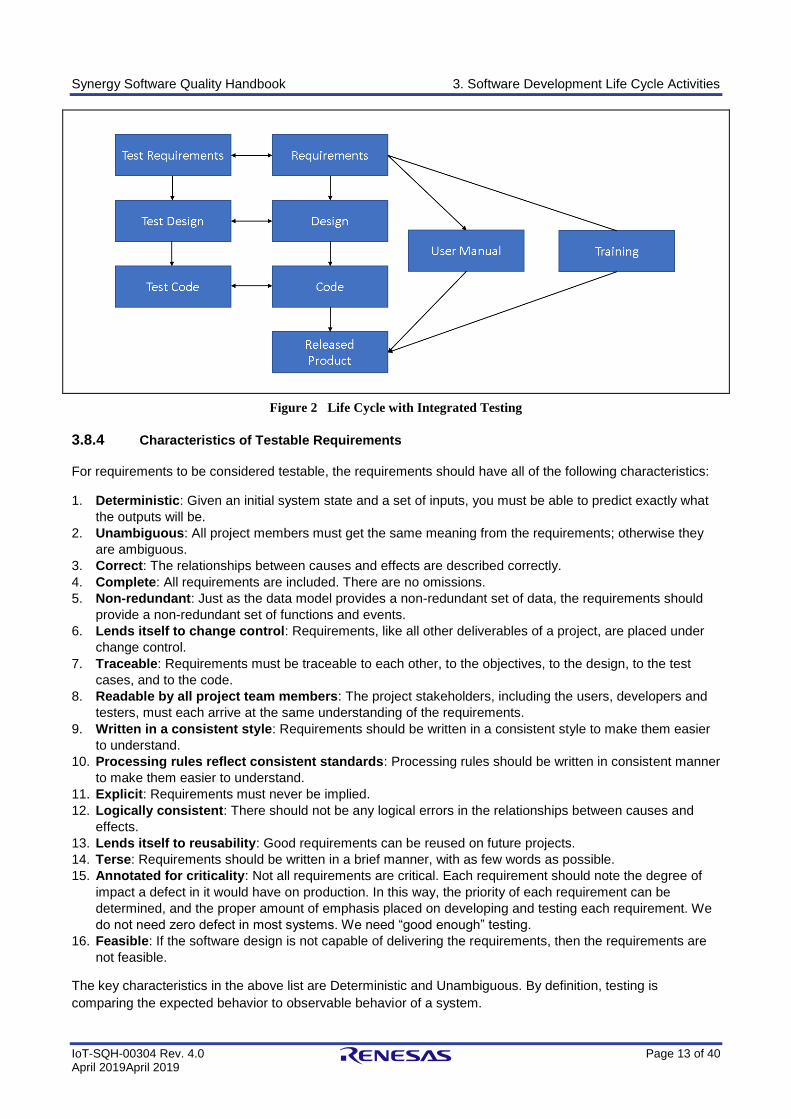
3.8.3 Testing and the Software Development Life Cycle
In most software development life cycles, the bulk of testing occurs only when code becomes available. With
the RBT process, testing is integrated throughout the life cycle (Figure 2).
Synergy Software Quality Handbook 3. Software Development Life Cycle Activities
IoT-SQH-00304 Rev. 4.0 Page 13 of 40 April 2019April 2019
Figure 2 Life Cycle with Integrated Testing
3.8.4 Characteristics of Testable Requirements
For requirements to be considered testable, the requirements should have all of the following characteristics:
1. Deterministic: Given an initial system state and a set of inputs, you must be able to predict exactly what
the outputs will be.
2. Unambiguous: All project members must get the same meaning from the requirements; otherwise they
are ambiguous.
3. Correct: The relationships between causes and effects are described correctly.
4. Complete: All requirements are included. There are no omissions.
5. Non-redundant: Just as the data model provides a non-redundant set of data, the requirements should
provide a non-redundant set of functions and events.
6. Lends itself to change control: Requirements, like all other deliverables of a project, are placed under
change control.
7. Traceable: Requirements must be traceable to each other, to the objectives, to the design, to the test
cases, and to the code.
8. Readable by all project team members: The project stakeholders, including the users, developers and
testers, must each arrive at the same understanding of the requirements.
9. Written in a consistent style: Requirements should be written in a consistent style to make them easier
to understand.
10. Processing rules reflect consistent standards: Processing rules should be written in consistent manner
to make them easier to understand.
11. Explicit: Requirements must never be implied.
12. Logically consistent: There should not be any logical errors in the relationships between causes and
effects.
13. Lends itself to reusability: Good requirements can be reused on future projects.
14. Terse: Requirements should be written in a brief manner, with as few words as possible.
15. Annotated for criticality: Not all requirements are critical. Each requirement should note the degree of
impact a defect in it would have on production. In this way, the priority of each requirement can be
determined, and the proper amount of emphasis placed on developing and testing each requirement. We
do not need zero defect in most systems. We need “good enough” testing.
16. Feasible: If the software design is not capable of delivering the requirements, then the requirements are
not feasible.
The key characteristics in the above list are Deterministic and Unambiguous. By definition, testing is
comparing the expected behavior to observable behavior of a system.
Synergy Software Quality Handbook 3. Software Development Life Cycle Activities
IoT-SQH-00304 Rev. 4.0 Page 14 of 40 April 2019April 2019
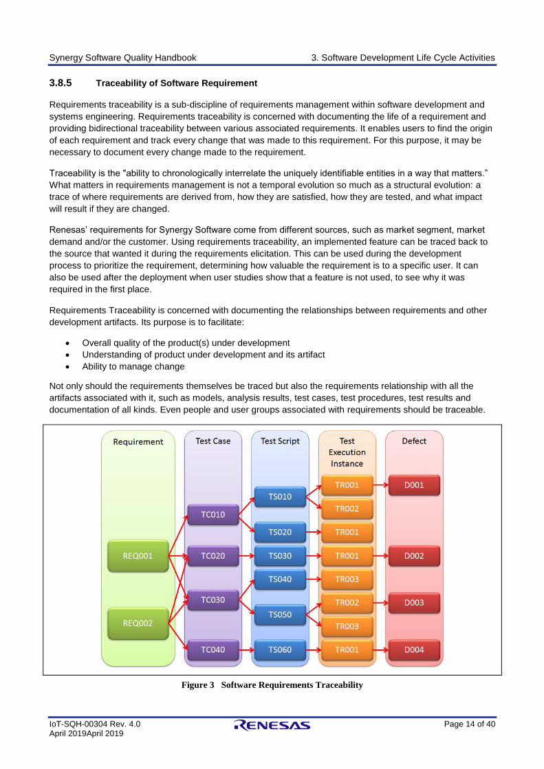
3.8.5 Traceability of Software Requirement
Requirements traceability is a sub-discipline of requirements management within software development and
systems engineering. Requirements traceability is concerned with documenting the life of a requirement and
providing bidirectional traceability between various associated requirements. It enables users to find the origin
of each requirement and track every change that was made to this requirement. For this purpose, it may be
necessary to document every change made to the requirement.
Traceability is the "ability to chronologically interrelate the uniquely identifiable entities in a way that matters.”
What matters in requirements management is not a temporal evolution so much as a structural evolution: a
trace of where requirements are derived from, how they are satisfied, how they are tested, and what impact
will result if they are changed.
Renesas’ requirements for Synergy Software come from different sources, such as market segment, market
demand and/or the customer. Using requirements traceability, an implemented feature can be traced back to
the source that wanted it during the requirements elicitation. This can be used during the development
process to prioritize the requirement, determining how valuable the requirement is to a specific user. It can
also be used after the deployment when user studies show that a feature is not used, to see why it was
required in the first place.
Requirements Traceability is concerned with documenting the relationships between requirements and other
development artifacts. Its purpose is to facilitate:
• Overall quality of the product(s) under development
• Understanding of product under development and its artifact
• Ability to manage change
Not only should the requirements themselves be traced but also the requirements relationship with all the
artifacts associated with it, such as models, analysis results, test cases, test procedures, test results and
documentation of all kinds. Even people and user groups associated with requirements should be traceable.
Figure 3 Software Requirements Traceability
Synergy Software Quality Handbook 3. Software Development Life Cycle Activities
IoT-SQH-00304 Rev. 4.0 Page 15 of 40 April 2019April 2019
3.8.6 Baselines Must Be Congruent
Verification must check the consistency between successive levels of detail within and between successive
baselines (that is, products of successive life cycle phases). The extent to which this can be accomplished
depends on the information contained at each level in the respective baselines. The design specification, for
example, can only be verified against an unambiguous and complete SRD. In this manner, verification
ensures that what is intended in one baseline or life cycle phase is actually achieved in the succeeding one. In
other terms, the verification process must establish traceability between life cycle phases. A systematic
method for carrying out this traceability also be included within a software configuration management
program.
3.8.7 Software Unit test
The software artifacts and unit test data from the development environment are migrated to a separate
Continuous Integration environment. All unit test cases are run to verify the correctness and completeness of
software components.
The Continuous Integration environment is integrated with a Commercial-off-the-shelf (COTS) tools such as
Liverpool Data Research Associates (LDRA) to perform continuous Dynamic and Static Analysis.
3.8.8 Functional Tests
Functional tests are developed based on SDD on LDRA test harness environment. These cases include
Boundary, Range, and Robustness cases. The objective of this type of test is to verify behavior of software
based on SDD for nominal and robustness cases.
Therefore, the objective of functional tests is to achieve 100% decision coverage when all design descriptions
are tested independently. The completeness objective of boundary, range, and robustness cases are
achieved by peer-review.
The Functional Tests exit criteria:
1. All SDD are traced to at least one SRD. 2. All SDD are traced to at least one test case 3. All software component, specifications, and verification are version controlled and baselined 4. All verification cases are executed and satisfy pass/fail criteria 5. Achieved 100% Decision Coverage by execution all test cases 6. All test cases, verification results, and coverage report are reviewed 7. All deficiencies are reported and dispositioned
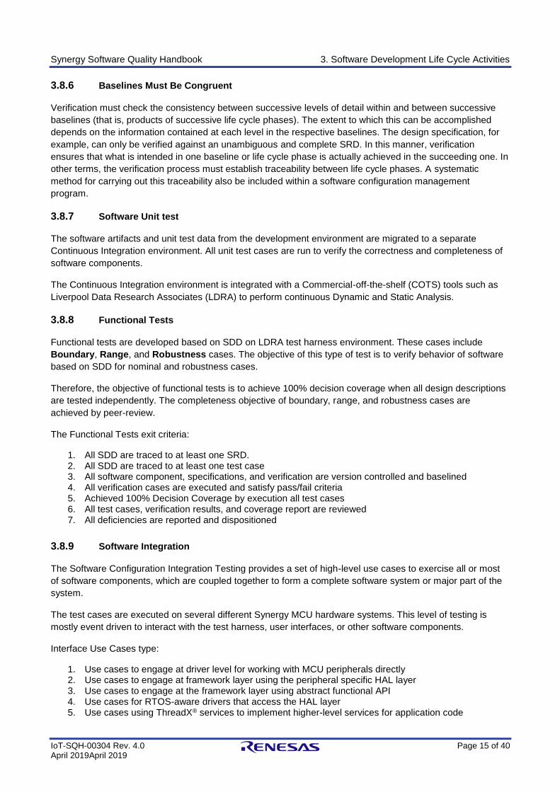
3.8.9 Software Integration
The Software Configuration Integration Testing provides a set of high-level use cases to exercise all or most
of software components, which are coupled together to form a complete software system or major part of the
system.
The test cases are executed on several different Synergy MCU hardware systems. This level of testing is
mostly event driven to interact with the test harness, user interfaces, or other software components.
Interface Use Cases type:
1. Use cases to engage at driver level for working with MCU peripherals directly 2. Use cases to engage at framework layer using the peripheral specific HAL layer 3. Use cases to engage at the framework layer using abstract functional API 4. Use cases for RTOS-aware drivers that access the HAL layer 5. Use cases using ThreadX® services to implement higher-level services for application code
Synergy Software Quality Handbook 3. Software Development Life Cycle Activities
IoT-SQH-00304 Rev. 4.0 Page 16 of 40 April 2019April 2019
The Software Configuration Integration exit criteria:
1. All use cases are version controlled and baselined 2. All use cases are reviewed 3. All cases are executed and satisfy pass/fail criteria 4. All verification results are reviewed 5. All deficiencies are reported and dispositioned
Figure 4 Software integration diagram
3.8.10 Software Performance Tests
SSP components are tested for performance to fulfill market requirements to which they are traced. The test
cases are executed on several different Synergy MCU hardware systems to report scalability and stability
characteristic of a software components.
The Software Performance Tests exit criteria:
1. All tests are traced to at least one MRD 2. All tests are version controlled 3. All tests are reviewed 4. All tests are executed and satisfy pass/fail criteria 5. All tests reports are reviewed 6. All deficiencies are reported and dispositioned
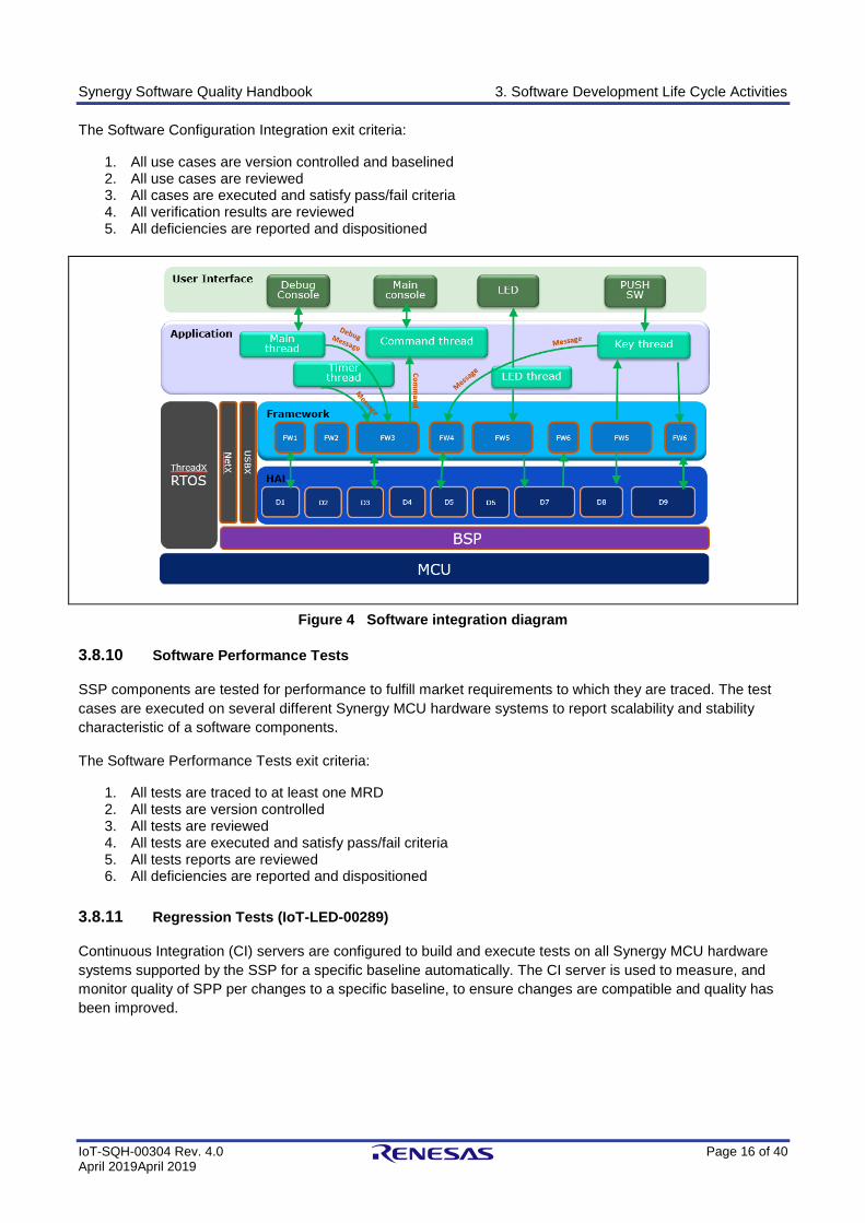
3.8.11 Regression Tests (IoT-LED-00289)
Continuous Integration (CI) servers are configured to build and execute tests on all Synergy MCU hardware
systems supported by the SSP for a specific baseline automatically. The CI server is used to measure, and
monitor quality of SPP per changes to a specific baseline, to ensure changes are compatible and quality has
been improved.
Synergy Software Quality Handbook 3. Software Development Life Cycle Activities
IoT-SQH-00304 Rev. 4.0 Page 17 of 40 April 2019April 2019
Test Code
IAR
GCC
Compiler
Build
Config
Renesas
Partners
HW
Platform
LDRA Source Code Instrumentation
HW Platform
Integration Test
Coverage Report
Functional Test
Coverage Report
Unit Test Test
Coverage Report
Unit Test
Functional
Test
Performance
Test
Regression
Test
Integration
Test
MISRA C: 2012
Cycloramic
Complexity
CERT
LDRA
Static
Analysis
Continuous Integration
Server
Figure 5 Continuous integration server
3.8.12 Testing Guidelines
The standards, practices, and conventions to be used during the testing phase is described in a set of
guidelines for unit, integration, regression, and system testing. The criteria for test repeatability and test
coverage is addressed, perhaps by including requirements that specify testing every requirement, user
procedure, and programming statement.
The guidelines indicate whether support software may be used. A testing guideline contains specific criteria
governing the program testing to be performed. It assures that programs are uniformly tested by all
programmers.
3.8.13 Dynamic Analysis
Dynamic Analysis explores the semantics of the program-under-test via test data selection. It uses control and
data flow models and compares them with the actual control and data flow as the program executes. Dynamic
Analysis therefore forces the selection of test data which explores the structure of the source code. The LDRA
tool suite includes a Dynamic Coverage Analysis module. It is used for beneficial effect on software
robustness and reliability during both development and maintenance cycles.
3.8.14 Static Analysis
Static Analysis initiates LDRA Testbed activity by undertaking lexical and syntactic analysis of the source code
for a single file or a complete system. The adherence to Renesas Synergy Software coding standards is
Synergy Software Quality Handbook 3. Software Development Life Cycle Activities
IoT-SQH-00304 Rev. 4.0 Page 18 of 40 April 2019April 2019
automatically checked by the LDRA Testbed. Main Static Analysis searches the source code for any coding
standard violations, by checking the source file(s).
LDRA Testbed reports violations of the chosen set of standards in both textual reports and as annotations to
graphical displays.
3.8.15 Review
The initial version of documentation or code is subject to a full review and changes are subject to an
incremental review. The purpose of review is to evaluate the conceptual and technical approach to the system
solution and ensure that the quality factors previously defined for the project are satisfied. The review attempts
to identify problems in verification approach.
3.8.16 Audit
An inspection of the documentation and associated verification methods to verify that the process and its
documentation are in accordance with the SQA plan and organizational policies and procedures
3.9 Software Release Phase
The primary outputs of the integration stage include a production application, a completed acceptance test
suite, and a Release Note for the software. Finally, the DPA enters the last of the actual labor data into the
project schedule and locks the project as a permanent project record. At this point the DPA "locks" the project
by archiving all software items, the Implementation map, the source code, and the documentation for future
reference.
3.10 Scope Restriction
The project scope is established by the requirements listed in an approved MRD. These market requirements
are subsequently refined into system and software requirement, then design elements, then software artifacts.
This hierarchy of requirements, elements, and artifacts is documented in a Requirements Traceability Matrix
(RTM). The RTM serves as a control element to restrict the project to the originally defined scope.
Project participants are restricted to addressing those requirements, elements, and artifacts that are directly
traceable to market requirements listed in the MRD. This prevents the substantial occurrence of scope creep,
which is the leading cause of software project failure.
Any changes to scope need to be approved by CCRB before such a change is implemented.
Synergy Software Quality Handbook 4. Documentation Quality
IoT-SQH-00304 Rev. 4.0 Page 19 of 40 April 2019April 2019
4. Documentation Quality
The overall quality of a development project is dependent on the quality of its documentation. The effective
SQA plan specifies uniform requirements for all project and software documents. These standards define the
scope and format of each document. The standard also addresses the issue of technical writing style to
improve document clarity and consistency. Because of the necessity for traceability, paragraph numbering by
means of a decimal system is used.
4.1 Documentation Standards
Documentation is formatted per appropriate standards. Standards provide a means for the author to
determine exactly what needs to be included in the document as well as the form it is to take.
4.2 Documentation Review
Upon completion, all documentation is peer reviewed for correctness and reviewed by an independent
reviewer who has not been part of documentation generation for completeness.
4.3 Documentation Maintenance
All documentation associated with SSP are maintained online. Maintenance of documentation online allows
developer to obtain the most up-to-date copy directly when it is needed.
4.4 Documentation Control
SSP documentation is considered a software product as much as the computer program itself and is subject
to the same configuration management and control. All documentation changes follow the approval process
by the appropriate librarian or responsible person.
Synergy Software Quality Handbook 5. Standards, Practices, and Conventions
IoT-SQH-00304 Rev. 4.0 Page 20 of 40 April 2019April 2019
5. Standards, Practices, and Conventions
The establishment, implementation, and enforcement of sound standards, practice, and conventions are
essential for the certification of a program. Software Development Life Cycle (SDLC) standards include
procedures and rules employed and enforced that prescribe a disciplined, uniform approach to complete a
specific task.
Renesas Synergy Software SDLC is developed based on IEC12207, which is a common industry standard for
Developing Software Life Cycle and compliance with other highly regulated standards such as IEC61508, and
IEC62304.
Renesas Synergy Software processes are agreed-upon methods or techniques for developing and using
software, established to ensure uniformity of our product. As a best practice specifies methods, techniques,
conventions with uniform patterns or forms for arranging data or presenting information to provide consistency
and to facilitate understanding.
These standards serve both technical and managerial functions. They facilitate program readability, software
verification and validation, interface definition, and management review of software development. Renesas
Synergy Software processes clearly identify required procedures and activities to satisfy these standards
objectives.
A primary function of SQA consists of monitoring the software products and software development process to
ensure that they comply with the adopted standards. The standards adopted constitute a thread that links one
event to another throughout the software life cycle and shows how the particular requirement has been
implemented in the ultimate product.
If a standard or procedure is revised while the project is under way, the effect of the revised standard on the
project is evaluated and presented to CCRB, a decision made whether to continue to comply with the previous
standard or with the new one. However, records clearly the state which procedure is always being followed
during the course of the project.
Synergy Software Quality Handbook 6. Reviews, Audits, and Controls
IoT-SQH-00304 Rev. 4.0 Page 21 of 40 April 2019April 2019
6. Reviews, Audits, and Controls
Software development, operation, and maintenance efforts are reviewed and audited periodically to determine
conformance to SQA requirements. Technical reviews and audits are being concluded periodically to evaluate
the status and quality of the engineering efforts and to assure the generation of required engineering
documentation and adherence to adopted standards.
The specific technical reviews and audits of software development plans and schedules are identified in the
SQA plan. The procedures to be used in reviews and audits are described in a guideline. The participants and
their specific responsibilities are to be identified as well. As a minimum, the following reviews and audits are
being conducted:
1. Market requirements review 2. Software requirements review 3. Preliminary design review 4. Critical design review 5. Software verification review 6. Functional configuration audit 7. Physical configuration audit 8. In-process audit 9. Managerial reviews
6.1.1 Technical Reviews
Technical reviews serve many purposes beyond helping to establish software quality. They allow several
individuals to share their experience with the creators of a product. The software review has the effect of
improving the technical capabilities of the individuals, as well as the team associated with the development
project. The members of the group gradually come to know and understand their colleagues, how they think in
certain situations, where they routinely make mistakes, etc. Such mutual understanding creates a better
technical team and can keep the same types of problems from recurring. The organization of people into
teams allows projects to proceed smoothly. The process of assembling the teams and assigning work can
compensate for differences in individual capabilities. A team can often find defects overlooked by individuals.
6.1.2 Review Team Members
The review is performed by individuals with sufficient technical expertise to provide a thorough review of all
activities. Independent checking is performed by an engineering or technical group rather than by an SQA
organization, which normally performs the auditing function. Review participants are independent of those
developing the program logic and are technically competent in areas related to the program tasks.
6.1.3 Review Procedures
The reviews and audits are clearly identified, scheduled, and properly sequenced. The procedures to be used
for reviews and audits identify the participants, their specific responsibilities, and the types of information to be
collected and reviewed. They also specify the preparation of a written report for each review and identify who
is to prepare the reports. In addition, the report format, who is to receive the reports, and the associated
management responsibilities are to be described along with any follow-up actions assure that
recommendations made during the reviews and audits are properly implemented. The time interval between
the review and the follow-up action are prescribed, as well as the personnel responsible for performing the
follow-up actions.
Checklists are effectively used in the course of the technical review. The participants in the review inspect all
available documentation against these checklists before the formal review meeting.
Synergy Software Quality Handbook 6. Reviews, Audits, and Controls
IoT-SQH-00304 Rev. 4.0 Page 22 of 40 April 2019April 2019
6.2 Audits
The following sections describe audits of the SQA program and the SQA function.
6.2.1 Functional Configuration Audit
A functional configuration audit is held prior to software delivery to verify that all requirements specified in the
software requirements specification have been met. The functional audit compares the code with the
requirements stated in the current software requirements document. Its intent is to determine that the code
addresses all documented requirements. Documentation of the results include any discrepancies and the plan
and schedule for their resolution. Once the discrepancies have been resolved, the software can be delivered
to the user.
6.2.2 Physical Configuration Audit
The principal purpose of a physical configuration audit is to determine if all the technical products of the
computer program development effort are complete and formally adhere to approved processes. The material
audited during a physical audit includes the technical products related to the computer program are available,
such as the final SRD, the software design description, and all other documentation formally prepared for
each release.
6.2.3 In-Process Audits
The objective of these audits is to verify the consistency of the product as it evolves during development or as
it is changed during the maintenance phase. The results of all the in-process audits are documented and all
discrepancies found are identified with the plans and schedule for their resolution.
6.2.4 SQA Audits
These audits evaluate the adherence to and effectiveness of the prescribed procedures, standards, and
conventions provided in SQA documentation. The internal procedures, the SQA plans, configuration
management, and contractually required deliverables from both the physical and functional aspects are
audited throughout the life cycle. The SQA audit consists of visual inspection of documents to determine if
they meet accepted standards and requirements. The SQA audit is not intended to review the conceptual
approach to a solution of a problem or to a design. Rather, the auditor checks the format of each document for
conformance with its prescribed outline as well as for omissions, apparent contradictions, and items that may
be sources of confusion in later work. The auditors verify the existence of all required documents and that the
quality of each is acceptable. A formal SQA audit report is generated and submitted to the cognizant project
manager for information and action. When such audits are carried on concurrently with design, coding,
documentation, etc., they decrease the possibility of oversights or inadvertent misconceptions that could result
in major rework and cost overruns.
6.2.5 Corrective Action
Plans and schedules for correction of deficiencies are necessary to complete the review and audit process.
Corrective action is subjected to CCRB approval. If it has been decided that the corrective action is not
necessary or can be deferred, then the issue is included in the release notes and captured in the problem
report system as a known issue.
Synergy Software Quality Handbook 7. Software Maintenance Phase
IoT-SQH-00304 Rev. 4.0 Page 23 of 40 April 2019April 2019
7. Software Maintenance Phase
The purpose of the maintenance phase is to collect and respond to problems found after the software is
released. The problems may be discovered internally in the reproduction and shipping of the software or
reported by a customer after they have installed the software. The following sections have brief description of
each of these.
7.1 Internal problems
When a problem is discovered internally it is reported as a defect in the tracking system. These problems are
reported and tracked per IOT-PRP-00247 Problem Reporting Procedure. These problems are tracked to
resolution by following this procedure.
7.1.1 Defect and Bug Life Cycle
The following explains the workflow for any defect or bug reported in the Problem Tracking System. Please
refer to IOT-PRP-00247 for procedural details of issue management in the problem tracking system.
1. The problem is reported. 2. The state of the problem is changed to open to allow work to be done. 3. When work is started, the state is changed to In Progress. 4. If more information is needed or there is a delay in starting the work on the problem the state is
changed to Waiting. Once the work is restarted the state is changed back to In Progress. 5. When a solution for the problem has been determined, the state is changed to Review. 6. If the problem resolution is acceptable, the state is changed to Resolved. If further verification is
needed the problem is referred to SQA for verification. If no further verification is needed, the state is changed to Closed. If the solution is not acceptable the state is changed to Reopen and work is resumed to find the acceptable solution.
7. Once the problem has been resolved it receives a final verification by SQA. If the resolution is verified by SQA, the state is changed to Closed. If there is a discrepancy discovered in the verification, the state is changed to Reopen and further work is needed.
7.1.2 Reporting – Defect, Bug
A Defect/Bug has to be reported clearly so that it is interpreted and reproduced, which enables investigation
and resolution. The reporter must provide details of classification of the Defect/Bug. The description will
contain following details:
1. A brief summary 2. Artifact’s identification and the version in which the Defect/Bug is observed 3. Method/steps to re-create the Defect/Bug 4. Deviation description from expected results. Reference to test case ID if any test cases are used to
execute the test 5. Attach any images or error information for better clarification
7.1.3 Defect, Bug – Types
Defects/Bugs can be separated into the following types:
1. Documentation 2. Build/Package 3. Review and Peer Review 4. Coding Guidelines 5. Unit Test (UT) 6. Integration Test (IT) 7. Performance Test 8. Test/Development Environment
Synergy Software Quality Handbook 7. Software Maintenance Phase
IoT-SQH-00304 Rev. 4.0 Page 24 of 40 April 2019April 2019
9. Structural coverage and Code Complexity 10. Undesired Functional Behavior
7.1.4 Investigation – Defect, Bug
Any Defect/Bug that is reported in the Problem Tracking System is investigated and dispositioned to
respective stakeholders. The Defect/Bug investigation has following steps:
1. Validate the Defect/Bug 2. Root cause analysis (RCA) 3. Impact Analysis 4. Propose a Resolution
During the investigation of the issue, relevance and similarity to other known or potential issues needs to be
considered. Similar issues are tracked by explicit links or by making them as sub-issues of the main problem.
7.1.5 Resolve and Close – Defect, Bug
Defects DO NOT require Change Control Review Board (CCRB) approval and will be fixed by assignee and
verified/closed by reporter (independent reviewer).
Bugs require CCRB approval to be fixed. When the Bug is fixed, it verified by reporter, and closed by SQA.
1. CCRB’s approval for Bug records 2. Implementation of suggested Resolution 3. Changes to artifacts are traced to a unique Defect/Bug ID 4. Independent Review by reporter 5. Defects can be closed by reporter after review 6. Bugs can be closed by SQA after review
Refer to IOT-PRP-00247 Problem Reporting Procedure for a detailed description of the procedure that is
followed.
7.2 Customer reported problems
Problems discovered by the customer may be warranty claims or requests for support.
7.2.1 Warranty Claims
When a warranty claim is submitted by a customer, it is investigated first by the Renesas regional support
teams. Before the customer can submit a warranty claim, they must reproduce the problem using a Synergy
Development Kit (DK). This may be in conjunction with regional support. A warranty claim can only be against
SSP behavior that is specified in the Performance section of the SSP datasheet, and while operating on the
MCU hardware system that is also specified in the Performance section. Once the problem has been
confirmed by Renesas to be a defect in the SSP against behavior specified in the SSP datasheet
Performance section, the customer is notified of this acknowledgement by Renesas within 24 hours (excluding
weekends). Renesas will continue to work to resolve the defect and within 7 business days Renesas will either
provide a solution to the customer, or Renesas will provide an update on resolution to the defect with a best
estimate of the additional time to provide a solution.
7.2.2 Support requests
When support is requested by a customer on an SSP software problem, it will be entered in Renesas’ problem
reporting and tracking system and a ticket is created.
The following are the goals for support tickets:
1. All tickets should receive a first response to the requester within 24 hours
Synergy Software Quality Handbook 7. Software Maintenance Phase
IoT-SQH-00304 Rev. 4.0 Page 25 of 40 April 2019April 2019
2. All tickets should be solved or pending within 72 hours 3. Any ticket open more than 1 week will be escalated to a manager
Tickets are assigned to agents automatically by the system based on keywords in the ticket. If this assignment
is incorrect then the ticket is reassigned to the correct agent.
Tickets have the following status:
• When the ticket is received by the agent it will have a status of NEW.
• When the agent opens the ticket to read it or start responding with the originator, the status changes
to OPEN. The ticket status will stay OPEN unless it is manually changed.
• If the agent is waiting for information they will change the status to PENDING.
• When the problem is resolved, the status is moved to SOLVED.
⎯ If the customer responds within 24 hours of the ticket moving to SOLVED, the status is changed
to OPEN and work continues.
⎯ If the customer doesn’t respond within 24 hours, the status is changed to CLOSED.
⎯ If the customer responds after the 24-hour period, the system will generate a new ticket.
While resolving the ticket, the Agent will search the knowledge database to see if there is an answer to the
problem. If not, after the problem is resolved the agent will determine if there needs to be any additional
information added to the knowledge database.
Some tickets may be added to the internal problem reporting system for further follow-up.
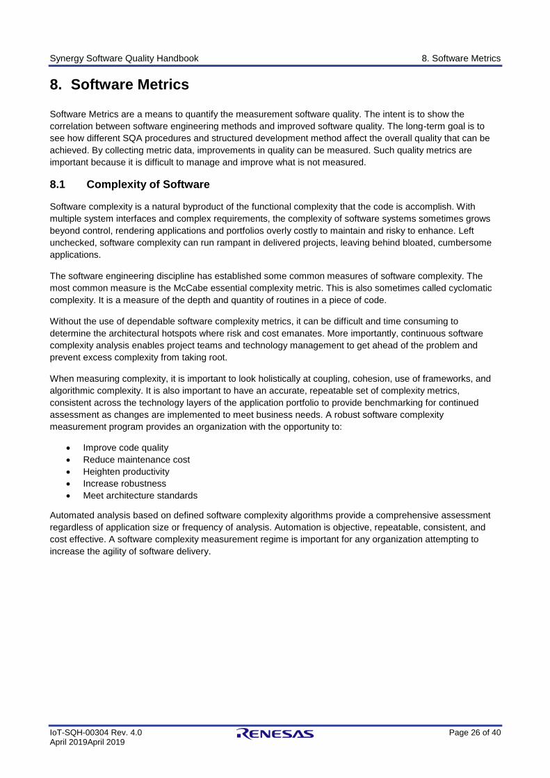
Synergy Software Quality Handbook 8. Software Metrics
IoT-SQH-00304 Rev. 4.0 Page 26 of 40 April 2019April 2019
8. Software Metrics
Software Metrics are a means to quantify the measurement software quality. The intent is to show the
correlation between software engineering methods and improved software quality. The long-term goal is to
see how different SQA procedures and structured development method affect the overall quality that can be
achieved. By collecting metric data, improvements in quality can be measured. Such quality metrics are
important because it is difficult to manage and improve what is not measured.
8.1 Complexity of Software
Software complexity is a natural byproduct of the functional complexity that the code is accomplish. With
multiple system interfaces and complex requirements, the complexity of software systems sometimes grows
beyond control, rendering applications and portfolios overly costly to maintain and risky to enhance. Left
unchecked, software complexity can run rampant in delivered projects, leaving behind bloated, cumbersome
applications.
The software engineering discipline has established some common measures of software complexity. The
most common measure is the McCabe essential complexity metric. This is also sometimes called cyclomatic
complexity. It is a measure of the depth and quantity of routines in a piece of code.
Without the use of dependable software complexity metrics, it can be difficult and time consuming to
determine the architectural hotspots where risk and cost emanates. More importantly, continuous software
complexity analysis enables project teams and technology management to get ahead of the problem and
prevent excess complexity from taking root.
When measuring complexity, it is important to look holistically at coupling, cohesion, use of frameworks, and
algorithmic complexity. It is also important to have an accurate, repeatable set of complexity metrics,
consistent across the technology layers of the application portfolio to provide benchmarking for continued
assessment as changes are implemented to meet business needs. A robust software complexity
measurement program provides an organization with the opportunity to:
• Improve code quality
• Reduce maintenance cost
• Heighten productivity
• Increase robustness
• Meet architecture standards
Automated analysis based on defined software complexity algorithms provide a comprehensive assessment
regardless of application size or frequency of analysis. Automation is objective, repeatable, consistent, and
cost effective. A software complexity measurement regime is important for any organization attempting to
increase the agility of software delivery.
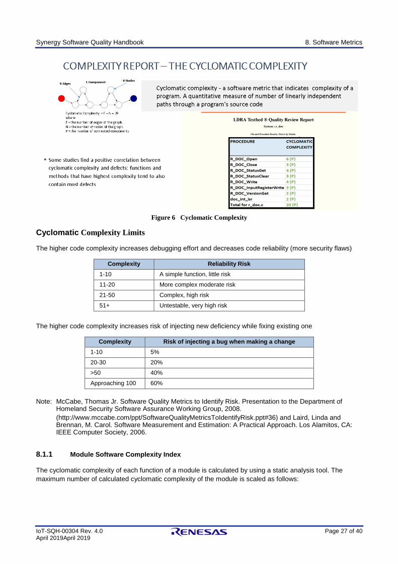
Synergy Software Quality Handbook 8. Software Metrics
IoT-SQH-00304 Rev. 4.0 Page 27 of 40 April 2019April 2019
Figure 6 Cyclomatic Complexity
Cyclomatic Complexity Limits
The higher code complexity increases debugging effort and decreases code reliability (more security flaws)
Complexity Reliability Risk
1-10 A simple function, little risk
11-20 More complex moderate risk
21-50 Complex, high risk
51+ Untestable, very high risk
The higher code complexity increases risk of injecting new deficiency while fixing existing one
Complexity Risk of injecting a bug when making a change
1-10 5%
20-30 20%
>50 40%
Approaching 100 60%
Note: McCabe, Thomas Jr. Software Quality Metrics to Identify Risk. Presentation to the Department of Homeland Security Software Assurance Working Group, 2008.
(http://www.mccabe.com/ppt/SoftwareQualityMetricsToIdentifyRisk.ppt#36) and Laird, Linda and Brennan, M. Carol. Software Measurement and Estimation: A Practical Approach. Los Alamitos, CA: IEEE Computer Society, 2006.
8.1.1 Module Software Complexity Index
The cyclomatic complexity of each function of a module is calculated by using a static analysis tool. The
maximum number of calculated cyclomatic complexity of the module is scaled as follows:
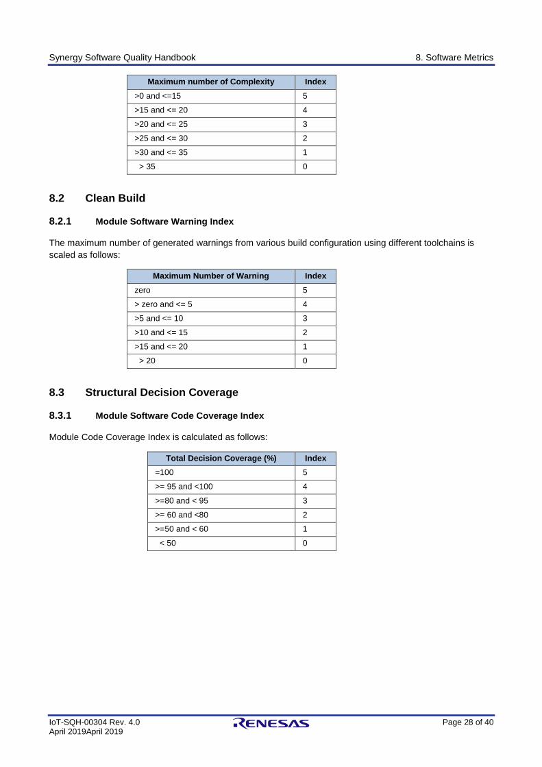
Synergy Software Quality Handbook 8. Software Metrics
IoT-SQH-00304 Rev. 4.0 Page 28 of 40 April 2019April 2019
Maximum number of Complexity Index
>0 and <=15 5
>15 and <= 20 4
>20 and <= 25 3
>25 and <= 30 2
>30 and <= 35 1
> 35 0
8.2 Clean Build
8.2.1 Module Software Warning Index
The maximum number of generated warnings from various build configuration using different toolchains is
scaled as follows:
Maximum Number of Warning Index
zero 5
> zero and <= 5 4
>5 and <= 10 3
>10 and <= 15 2
>15 and <= 20 1
> 20 0
8.3 Structural Decision Coverage
8.3.1 Module Software Code Coverage Index
Module Code Coverage Index is calculated as follows:
Total Decision Coverage (%) Index
=100 5
>= 95 and <100 4
>=80 and < 95 3
>= 60 and <80 2
>=50 and < 60 1
< 50 0
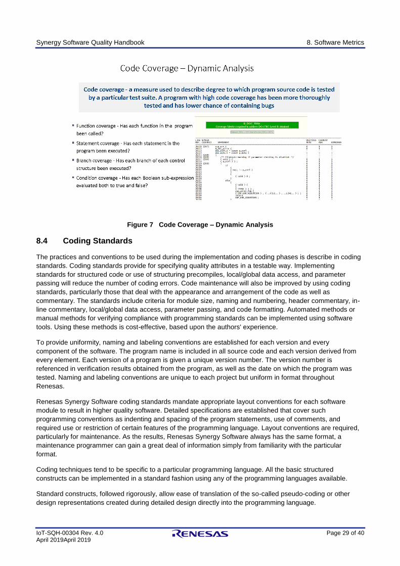
Synergy Software Quality Handbook 8. Software Metrics
IoT-SQH-00304 Rev. 4.0 Page 29 of 40 April 2019April 2019
Figure 7 Code Coverage – Dynamic Analysis
8.4 Coding Standards
The practices and conventions to be used during the implementation and coding phases is describe in coding
standards. Coding standards provide for specifying quality attributes in a testable way. Implementing
standards for structured code or use of structuring precompiles, local/global data access, and parameter
passing will reduce the number of coding errors. Code maintenance will also be improved by using coding
standards, particularly those that deal with the appearance and arrangement of the code as well as
commentary. The standards include criteria for module size, naming and numbering, header commentary, in-
line commentary, local/global data access, parameter passing, and code formatting. Automated methods or
manual methods for verifying compliance with programming standards can be implemented using software
tools. Using these methods is cost-effective, based upon the authors' experience.
To provide uniformity, naming and labeling conventions are established for each version and every
component of the software. The program name is included in all source code and each version derived from
every element. Each version of a program is given a unique version number. The version number is
referenced in verification results obtained from the program, as well as the date on which the program was
tested. Naming and labeling conventions are unique to each project but uniform in format throughout
Renesas.
Renesas Synergy Software coding standards mandate appropriate layout conventions for each software
module to result in higher quality software. Detailed specifications are established that cover such
programming conventions as indenting and spacing of the program statements, use of comments, and
required use or restriction of certain features of the programming language. Layout conventions are required,
particularly for maintenance. As the results, Renesas Synergy Software always has the same format, a
maintenance programmer can gain a great deal of information simply from familiarity with the particular
format.
Coding techniques tend to be specific to a particular programming language. All the basic structured
constructs can be implemented in a standard fashion using any of the programming languages available.
Standard constructs, followed rigorously, allow ease of translation of the so-called pseudo-coding or other
design representations created during detailed design directly into the programming language.
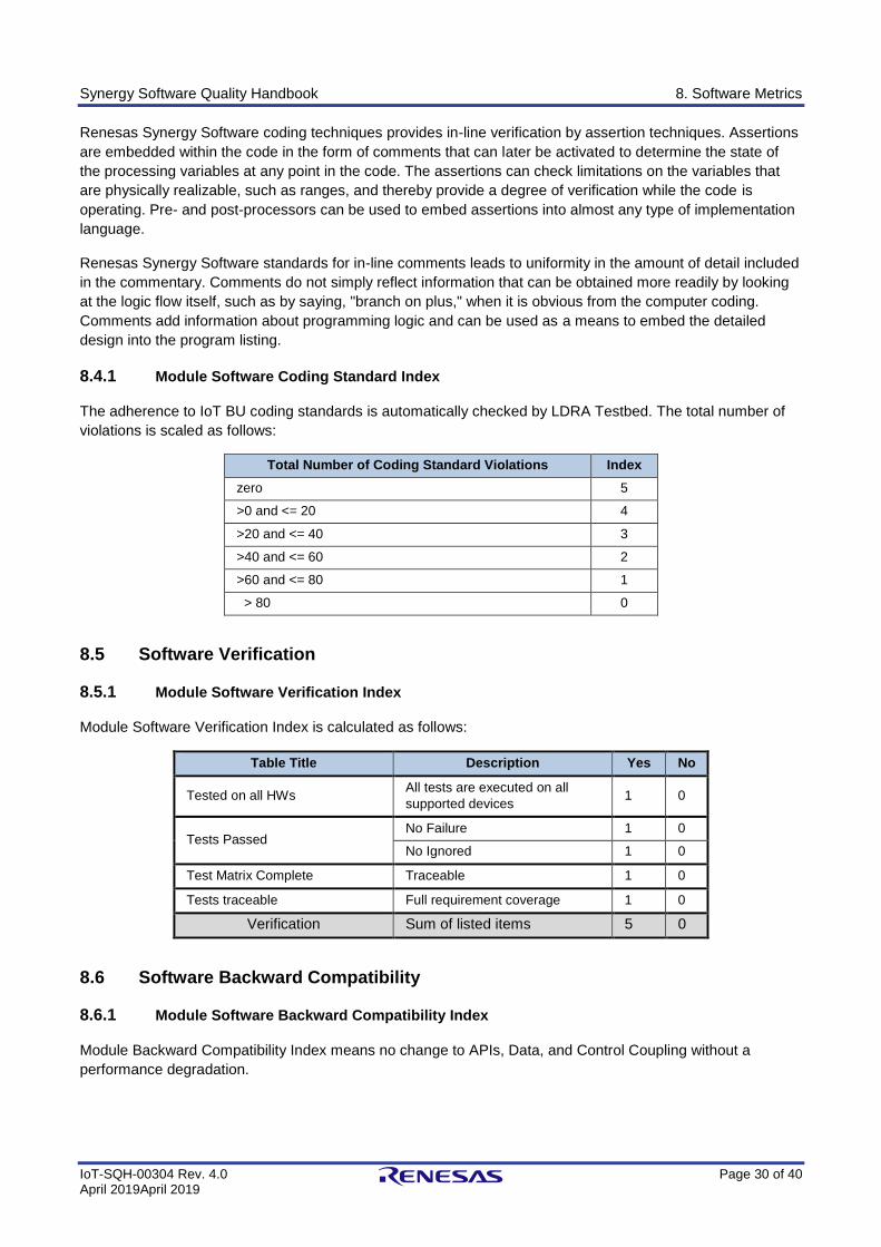
Synergy Software Quality Handbook 8. Software Metrics
IoT-SQH-00304 Rev. 4.0 Page 30 of 40 April 2019April 2019
Renesas Synergy Software coding techniques provides in-line verification by assertion techniques. Assertions
are embedded within the code in the form of comments that can later be activated to determine the state of
the processing variables at any point in the code. The assertions can check limitations on the variables that
are physically realizable, such as ranges, and thereby provide a degree of verification while the code is
operating. Pre- and post-processors can be used to embed assertions into almost any type of implementation
language.
Renesas Synergy Software standards for in-line comments leads to uniformity in the amount of detail included
in the commentary. Comments do not simply reflect information that can be obtained more readily by looking
at the logic flow itself, such as by saying, "branch on plus," when it is obvious from the computer coding.
Comments add information about programming logic and can be used as a means to embed the detailed
design into the program listing.
8.4.1 Module Software Coding Standard Index
The adherence to IoT BU coding standards is automatically checked by LDRA Testbed. The total number of
violations is scaled as follows:
Total Number of Coding Standard Violations Index
zero 5
>0 and <= 20 4
>20 and <= 40 3
>40 and <= 60 2
>60 and <= 80 1
> 80 0
8.5 Software Verification
8.5.1 Module Software Verification Index
Module Software Verification Index is calculated as follows:
Table Title Description Yes No
Tested on all HWs All tests are executed on all
supported devices 1 0
Tests Passed No Failure 1 0
No Ignored 1 0
Test Matrix Complete Traceable 1 0
Tests traceable Full requirement coverage 1 0
Verification Sum of listed items 5 0
8.6 Software Backward Compatibility
8.6.1 Module Software Backward Compatibility Index
Module Backward Compatibility Index means no change to APIs, Data, and Control Coupling without a
performance degradation.
Synergy Software Quality Handbook 9. Requirements Management Solution Tool
IoT-SQH-00304 Rev. 4.0 Page 31 of 40 April 2019April 2019
9. Requirements Management Solution Tool
A requirements management solution tool is being used to meet the needs of Renesas' complex products with
the following features:
• Capture, discuss, review, approve and manage all requirements in one central place.
• Understand coverage and track relationships between requirements, use cases, test cases, defects and other related items to demonstrate compliance and assure quality.
• Embrace an open, modern approach to product delivery with the tool collaborative Review Center.
• Save time setting up new projects by reusing existing strategic assets.
• Provide real-time product status to stakeholders across the organization.
• Control scope and track change requests with full version history.
Synergy Software Quality Handbook 10. SSP Software Qualification and Verification
Packages
IoT-SQH-00304 Rev. 4.0 Page 32 of 40 April 2019April 2019
10. SSP Software Qualification and Verification Packages
SSP qualification package contains:
1. Software Quality Presentation 2. Software Quality Handbook 3. Software Quality Summary Report
SSP software verification package is available per customer request under NDA and includes:
1. Software Development Life Cycle 2. Software Coding Standard 3. Software Specification Reports 4. Software Static Analysis Report 5. Software Dynamic Analysis Report 6. Software Performance and Benchmark Reports 7. Software Metrics
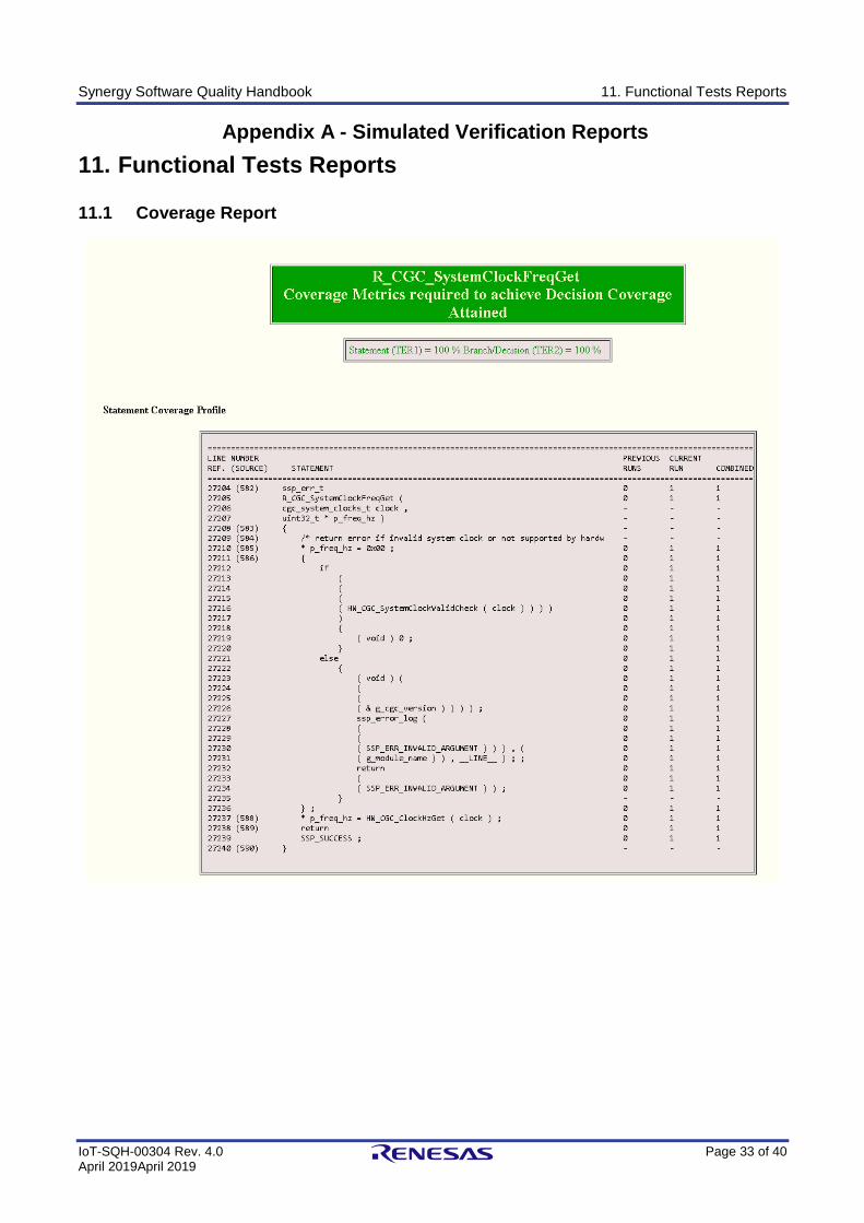
Synergy Software Quality Handbook 11. Functional Tests Reports
IoT-SQH-00304 Rev. 4.0 Page 33 of 40 April 2019April 2019
Appendix A - Simulated Verification Reports
11. Functional Tests Reports
11.1 Coverage Report
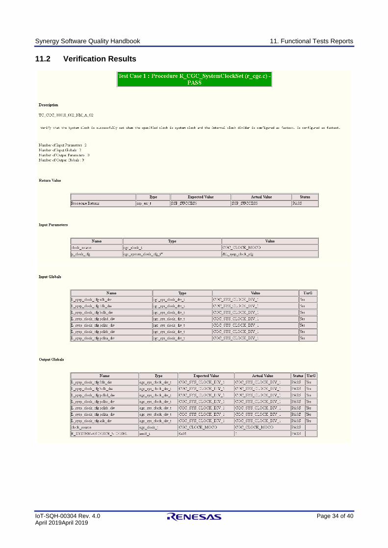
Synergy Software Quality Handbook 11. Functional Tests Reports
IoT-SQH-00304 Rev. 4.0 Page 34 of 40 April 2019April 2019
11.2 Verification Results
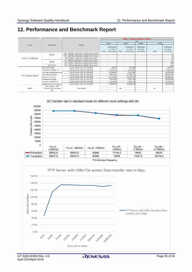
Synergy Software Quality Handbook 12. Performance and Benchmark Report
IoT-SQH-00304 Rev. 4.0 Page 35 of 40 April 2019April 2019
12. Performance and Benchmark Report
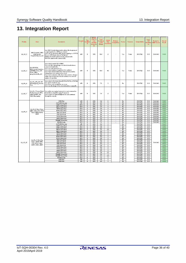
Synergy Software Quality Handbook 13. Integration Report
IoT-SQH-00304 Rev. 4.0 Page 36 of 40 April 2019April 2019
13. Integration Report
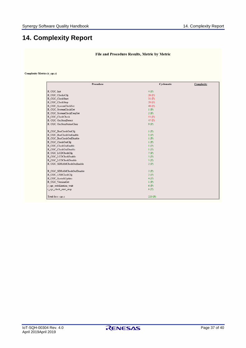
Synergy Software Quality Handbook 14. Complexity Report
IoT-SQH-00304 Rev. 4.0 Page 37 of 40 April 2019April 2019
14. Complexity Report
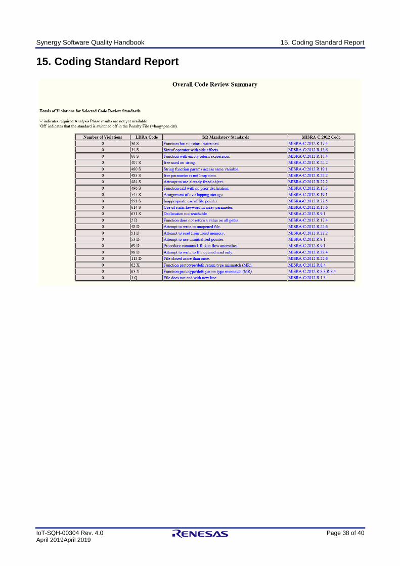
Synergy Software Quality Handbook 15. Coding Standard Report
IoT-SQH-00304 Rev. 4.0 Page 38 of 40 April 2019April 2019
15. Coding Standard Report
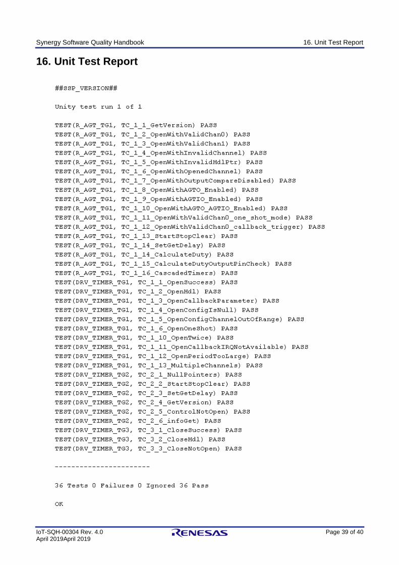
Synergy Software Quality Handbook 16. Unit Test Report
IoT-SQH-00304 Rev. 4.0 Page 39 of 40 April 2019April 2019
16. Unit Test Report
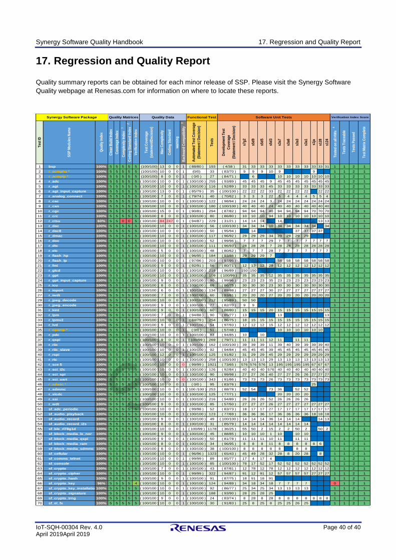
Synergy Software Quality Handbook 17. Regression and Quality Report
IoT-SQH-00304 Rev. 4.0 Page 40 of 40 April 2019April 2019
17. Regression and Quality Report
Quality summary reports can be obtained for each minor release of SSP. Please visit the Synergy Software
Quality webpage at Renesas.com for information on where to locate these reports.
1 bsp 100% 5 5 5 5 5 (100/100) 13 0 0 1 ( 88/80 ) 193 ( 4/38 ) 31 33 33 33 33 33 33 33 33 33 31 1 1 2 1
2 r_acmphs * 100% 5 5 5 5 5 (100/100) 10 0 0 1 (0/0) 33 ( 83/70 ) 9 9 9 10 9 9 1 1 2 1
3 r_acmplp * 100% 5 5 5 5 5 (100/100) 8 0 0 1 ( 0/0 ) 27 ( 84/71 ) 6 10 10 10 10 10 10 10 1 1 2 1
4 r_adc 100% 5 5 5 5 5 ( 100/100 ) 10 0 0 1 ( 100/100 ) 255 ( 93/89 ) 45 45 45 9 45 45 45 45 45 45 45 1 1 2 1
5 r_agt 100% 5 5 5 5 5 ( 100/100 ) 10 0 0 1 ( 100/100 ) 116 ( 92/89 ) 33 33 33 45 33 33 33 33 33 33 33 1 1 2 1
6 r_agt_input_capture 100% 5 5 5 5 5 ( 100/100 ) 13 0 0 1 ( 85/79 ) 35 ( 100/100 ) 22 22 22 33 22 22 22 22 22 22 1 1 2 1
7 r_analog_connect 100% 5 5 5 5 5 ( 100/100 ) 7 0 0 1 ( 79/74 ) 40 ( 70/62 ) 3 3 3 22 5 4 4 4 5 5 4 1 1 2 1
8 r_cac 100% 5 5 5 5 5 ( 100/100 ) 10 0 0 1 ( 100/100 ) 122 ( 98/94 ) 24 24 24 3 24 24 24 24 24 24 24 1 1 2 1
9 r_can 100% 5 5 5 5 5 ( 100/100 ) 10 0 0 1 ( 100/100 ) 180 ( 100/100 ) 40 40 40 24 40 40 40 40 40 40 40 1 1 2 1
10 r_cgc 100% 5 5 5 5 5 ( 100/100 ) 15 0 0 1 ( 90/81 ) 294 ( 87/82 ) 94 94 94 40 94 94 94 94 70 70 70 1 1 2 1
11 r_crc 100% 5 5 5 5 5 ( 100/100 ) 8 0 0 1 ( 100/100 ) 80 ( 86/80 ) 10 10 10 94 10 10 10 10 10 10 10 1 1 2 1
12 r_ctsu 60% 5 5 0 0 5 ( 100/100 ) 84 247 0 1 ( 94/87 ) 229 ( 31/21 ) 14 14 14 14 13 13 1 1 2 1
13 r_dac 100% 5 5 5 5 5 ( 100/100 ) 10 0 0 1 ( 100/100 ) 56 ( 100/100 ) 34 34 34 10 34 34 34 34 34 34 1 1 2 1
14 r_dac8 100% 5 5 5 5 5 ( 100/100 ) 10 0 0 1 ( 100/100 ) 50 ( 95/94 ) 14 37 37 37 37 1 1 2 1
15 r_dmac 100% 5 5 5 5 5 ( 100/100 ) 10 0 0 1 ( 100/100 ) 117 ( 96/92 ) 29 29 29 34 29 29 29 29 1 1 2 1
16 r_doc 100% 5 5 5 5 5 ( 100/100 ) 10 0 0 1 ( 100/100 ) 52 ( 99/96 ) 7 7 7 29 7 7 7 7 7 7 7 1 1 2 1
17 r_dtc 100% 5 5 5 5 5 ( 100/100 ) 10 0 0 1 ( 100/100 ) 111 ( 96/93 ) 28 28 28 7 28 28 28 28 28 28 28 1 1 2 1
18 r_elc 100% 5 5 5 5 5 ( 100/100 ) 5 0 0 1 ( 100/100 ) 48 ( 80/62 ) 7 7 7 28 7 7 7 7 7 7 7 1 1 2 1
19 r_flash_hp 100% 5 5 5 5 5 ( 100/100 ) 10 0 0 1 ( 96/95 ) 184 ( 93/86 ) 29 29 29 7 1 1 2 1
20 r_flash_lp 100% 5 5 5 5 5 ( 100/100 ) 10 0 0 1 ( 97/96 ) 203 ( 97/95 ) 58 58 58 58 58 58 58 1 1 2 1
21 r_fmi 100% 5 5 5 5 5 ( 100/100 ) 9 0 0 1 ( 92/91 ) 56 ( 80/71 ) 12 13 12 29 12 12 12 12 12 12 12 1 1 2 1
22 r_glcd 100% 5 5 5 5 5 ( 100/100 ) 10 0 0 1 ( 100/100 ) 218 ( 96/89 ) 150 150 1 1 2 1
23 r_gpt 100% 5 5 5 5 5 ( 100/100 ) 10 0 0 1 ( 100/100 ) 109 ( 100/99 ) 35 35 35 12 35 35 35 35 35 35 35 1 1 2 1
24 r_gpt_input_capture 100% 5 5 5 5 5 ( 100/100 ) 9 0 0 1 ( 100/100 ) 90 ( 99/96 ) 23 23 23 35 23 23 23 23 23 23 23 1 1 2 1
25 r_icu 100% 5 5 5 5 5 ( 100/100 ) 8 0 0 1 ( 100/100 ) 69 ( 86/75 ) 30 30 30 23 30 30 30 30 30 30 30 1 1 2 1
26 r_ioport 100% 5 5 5 5 5 ( 100/100 ) 6 0 0 1 ( 100/100 ) 134 ( 89/88 ) 27 27 27 30 27 27 27 27 27 27 27 1 1 2 1
27 r_iwdt 100% 5 5 5 5 5 ( 100/100 ) 7 0 0 1 ( 100/100 ) 60 ( 93/81 ) 20 20 20 27 20 20 20 20 20 20 20 1 1 2 1
29 r_jpeg_decode 100% 5 5 5 5 5 ( 100/100 ) 10 0 0 1 ( 100/100 ) 212 ( 95/89 ) 50 50 1 1 2 1
30 r_jpeg_encode 100% 5 5 5 5 5 ( 100/100 ) 9 0 0 1 ( 100/100 ) 77 ( 82/70 ) 9 9 1 1 2 1
31 r_kint 100% 5 5 5 5 5 ( 100/100 ) 9 0 0 1 ( 100/100 ) 60 ( 88/80 ) 15 15 15 20 15 15 15 15 15 15 15 1 1 2 1
32 r_lpm 100% 5 5 5 5 5 ( 100/100 ) 7 0 0 1 ( 94/88 ) 90 ( 85/77 ) 13 13 13 1 1 2 1
33 r_lpmv2 100% 5 5 5 5 5 ( 100/100 ) 10 0 0 1 ( 84/79 ) 254 ( 86/75 ) 18 15 15 15 15 15 15 15 15 15 15 1 1 2 1
34 r_lvd 100% 5 5 5 5 5 ( 100/100 ) 9 0 0 1 ( 100/100 ) 54 ( 97/93 ) 12 12 12 15 12 12 12 12 12 12 12 1 1 2 1
35 r_opamp * 100% 5 5 5 5 5 ( 100/100 ) 10 0 0 1 ( 0/0 ) 51 ( 57/48 ) 10 10 10 10 10 10 1 1 2 1
36 r_pdc 100% 5 5 5 5 5 ( 100/100 ) 10 0 0 1 ( 100/100 ) 83 ( 94/85 ) 10 10 1 1 2 1
37 r_qspi 100% 5 5 5 5 5 ( 100/100 ) 9 0 0 1 ( 100/99 ) 269 ( 79/71 ) 11 11 11 12 11 11 11 1 1 2 1
38 r_riic 100% 5 5 5 5 5 ( 100/100 ) 10 0 0 1 ( 100/100 ) 162 ( 100/100 ) 39 39 39 11 39 40 39 39 39 39 40 1 1 2 1
39 r_riic_slave 100% 5 5 5 5 5 ( 100/100 ) 10 0 0 1 ( 100/100 ) 92 ( 94/84 ) 45 45 45 39 45 45 45 45 45 45 45 1 1 2 1
40 r_rspi 100% 5 5 5 5 5 ( 100/100 ) 12 0 0 1 ( 100/100 ) 125 ( 91/82 ) 31 29 29 45 29 29 29 29 29 29 29 1 1 2 1
41 r_rtc 100% 5 5 5 5 5 ( 100/100 ) 10 0 0 1 ( 100/100 ) 258 ( 100/100 ) 13 13 13 29 13 13 13 13 13 13 13 1 1 2 1
42 r_sce 5 100% 5 5 5 5 5 ( 100/100 ) 10 0 0 0 ( 99/99 ) 1921 ( 73/65 ) 576 576 576 13 195 195 195 195 67 67 67 1 1 2 1
43 r_sci_i2c 100% 5 5 5 5 5 ( 100/100 ) 10 0 0 1 ( 100/100 ) 126 ( 92/84 ) 40 40 40 576 40 40 40 40 40 40 40 1 1 2 1
44 r_sci_spi 100% 5 5 5 5 5 ( 100/100 ) 10 0 0 1 ( 100/100 ) 90 ( 99/98 ) 27 27 26 40 27 27 26 26 27 27 27 1 1 2 1
45 r_sci_uart 100% 5 5 5 5 5 ( 100/100 ) 10 0 0 0 ( 100/100 ) 343 ( 91/86 ) 73 73 73 26 73 73 73 73 73 73 73 1 1 2 1
46 r_sdadc * 100% 5 5 5 5 5 ( 100/100 ) 10 0 0 1 ( 0/0 ) 95 ( 83/76 ) 25 1 1 2 1
47 r_sdmmc 100% 5 5 5 5 5 ( 100/100 ) 10 0 0 1 ( 100 /100 ) 253 ( 88/78 ) 52 54 73 36 52 52 1 1 2 1
48 r_slcdc 100% 5 5 5 5 5 ( 100/100 ) 10 0 0 1 ( 100/100 ) 125 ( 77/71 ) 20 20 20 20 1 1 2 1
49 r_ssi 100% 5 5 5 5 5 ( 100/100 ) 10 0 0 1 ( 100/100 ) 216 ( 94/89 ) 26 26 26 52 26 26 26 26 1 1 2 1
50 r_wdt 100% 5 5 5 5 5 ( 100/100 ) 9 0 0 1 ( 100/100 ) 85 ( 57/50 ) 27 27 27 26 27 27 27 27 27 27 27 1 1 2 1
51 sf_adc_periodic 100% 5 5 5 5 5 ( 100/100 ) 10 0 0 1 ( 99/98 ) 52 ( 83/73 ) 18 17 17 27 17 17 17 17 17 17 17 1 1 2 1
52 sf_audio_playback 100% 5 5 5 5 5 ( 100/100 ) 10 0 0 1 ( 100/100 ) 123 ( 77/69 ) 36 36 36 17 36 36 36 36 18 18 18 1 1 2 1
53 sf_audio_record 100% 5 5 5 5 5 ( 100/100 ) 9 0 0 1 ( 100/100 ) 49 ( 100/100 ) 14 14 14 36 14 14 14 14 13 1 1 2 1
54 sf_audio_record_i2s 100% 5 5 5 5 5 ( 100/100 ) 8 0 0 1 ( 100/100 ) 31 ( 85/79 ) 14 14 14 14 14 14 14 14 1 1 2 1
55 sf_ble_rl78g1d 100% 5 5 5 5 5 ( 100/100 ) 10 0 0 1 ( 100/99 ) 1178 ( 36/25 ) 55 50 2 15 2 2 50 2 50 2 1 1 2 1
56 sf_block_media_lx_nor 100% 5 5 5 5 5 ( 100/100 ) 9 0 0 1 ( 100/100 ) 45 ( 88/85 ) 10 10 10 1 10 10 10 1 1 2 1
57 sf_block_media_qspi 100% 5 5 5 5 5 ( 100/100 ) 9 0 0 1 ( 100/100 ) 50 ( 81/78 ) 11 11 11 10 11 11 11 1 1 2 1
58 sf_block_media_ram 100% 5 5 5 5 5 ( 100/100 ) 8 0 0 1 ( 100/100 ) 34 ( 96/95 ) 8 8 8 11 8 8 8 8 8 6 1 1 2 1
59 sf_block_media_sdmmc 100% 5 5 5 5 5 ( 100/100 ) 8 0 0 1 ( 100/100 ) 38 ( 100/100 ) 8 8 8 8 8 8 8 1 1 2 1
60 sf_cellular 100% 5 5 5 5 5 ( 100/100 ) 10 0 0 1 ( 96/96 ) 1323 ( 65/43 ) 45 49 28 32 28 8 20 28 8 1 1 2 1
61 sf_comms_telnet 100% 5 5 5 5 5 ( 100/100 ) 10 0 0 1 ( 99/99 ) 89 ( 85/77 ) 17 4 17 4 1 1 2 1
62 sf_console 100% 5 5 5 5 5 ( 100/100 ) 10 0 0 1 ( 100/100 ) 85 ( 100/100 ) 78 17 52 17 52 52 52 52 52 52 52 1 1 2 1
63 sf_crypto 100% 5 5 5 5 5 ( 100/100 ) 7 0 0 1 ( 100/100 ) 43 ( 87/81 ) 12 78 12 78 12 12 12 12 12 12 12 1 1 2 1
64 sf_crypto_cipher 100% 5 5 5 5 5 ( 100/100 ) 10 0 0 1 ( 99/99 ) 322 ( 94/87 ) 91 12 91 12 57 57 57 57 27 27 27 1 1 2 1
65 sf_crypto_hash 100% 5 5 5 5 5 ( 100/100 ) 9 0 0 1 ( 100/100 ) 91 ( 87/75 ) 18 91 18 91 1 1 2 1
66 sf_crypto_key 96% 5 5 5 5 4 ( 100/100 ) 10 0 0 1 ( 100/100 ) 124 ( 94/89 ) 34 18 34 18 7 7 7 7 0 1 2 1
67 sf_crypto_key_installation100% 5 5 5 5 5 ( 100/100 ) 10 0 0 1 ( 100/100 ) 92 ( 86/77 ) 25 34 25 34 13 13 13 13 1 1 2 1
68 sf_crypto_signature 100% 5 5 5 5 5 ( 100/100 ) 10 0 0 1 ( 100/100 ) 188 ( 93/90 ) 28 25 28 25 1 1 2 1
69 sf_crypto_trng 100% 5 5 5 5 5 ( 100/100 ) 9 0 0 1 ( 100/100 ) 24 ( 83/74 ) 8 28 8 28 8 8 8 8 8 8 8 1 1 2 1
70 sf_el_fx 100% 5 5 5 5 5 ( 100/100 ) 10 0 0 1 ( 100/100 ) 30 ( 91/83 ) 25 8 25 8 25 25 26 25 1 1 2 1
Co
din
g S
tan
dar
d In
dex
2
Ver
ifica
tion
Ind
ex
Tes
t Co
vera
ge
(sta
tem
ent/D
ecis
ion
)
Synergy Software Package
Tes
t ID
SS
P M
od
ule
s N
ame
Qu
ality
Ind
ex
Cle
an B
uild
Ind
ex
Co
vera
ge
Ind
ex
Au
tom
ated
Tes
t Co
vera
ge
(Sta
tem
ent /
Dec
isio
n)
Dev
elo
pm
ent T
est
Co
vera
ge
(Sta
tem
ent /
Dec
isio
n)
s3a3
s3a1
s5d
5
s7g
2
s5d
9
Tes
ts T
race
able
s3a7
s3a6
Tes
ted
on
all
HW
s 4
s1ja
s128
s124
Verification Index Score
Tes
t Mat
rix
Co
mp
lete
Quality DataQuality Matrices
Tes
ts P
asse
d
Functional Test Software Unit Tests
Co
mp
lexi
ty In
dex
1
Max
Co
mp
lexi
ty
Co
din
g S
tan
dar
d
war
nin
g
s5d
3
Bac
kwar
d C
om
pat
ibili
ty
3
Tes
ts
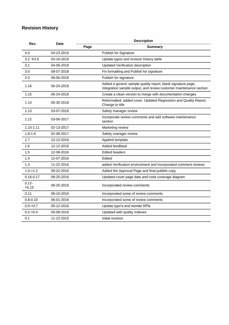
Revision History
Rev. Date Description
Page Summary
4.0 04-23-2019 Publish for Signature
3.2 →3.6 04-16-2019 Update typos and revision history table
3.1 04-06-2019 Updated Verification description
3.0 08-07-2018 Fix formatting and Publish for signature
2.0 08-06-2018 Publish for signature
1.16 06-24-2018 Added a generic sample quality report, blank signature page,
integration sample output, and review customer maintenance section
1.15 06-24-2018 Create a clean version to merge with documentation changes
1.14 05-30-2018 Reformatted, added cover, Updated Regression and Quality Report,
Change to title
1.13 03-07-2018 Safety manager review
1.12 03-06-2017 Incorporate review comments and add software maintenance
section
1.10-1.11 02-13-2017 Marketing review
1.8-1.9 02-08-2017 Safety manager review
1.7 12-12-2016 Applied template
1.6 12-12-2016 Added feedback
1.5 12-08-2016 Edited headers
1.4 12-07-2016 Edited
1.3 11-22-2016 added Verification environment and incorporated comment reviews
1.0->1.2 09-22-2016 Added the Approval Page and final publish copy
0.16-0.17 08-25-2016 Updated cover page date and code coverage diagram
0.12-
>0.15 08-25-2016 Incorporated review comments
0.11 08-10-2016 Incorporated some of review comments
0.8-0.10 06-01-2016 Incorporated some of review comments
0.5->0.7 05-12-2016 Update typo’s and reorder KPIs
0.2->0.4 05-08-2016 Updated with quality Indexes
0.1 11-22-2015 Initial revision
All trademarks and registered trademarks are the property of their respective owners.
Synergy Software Quality Handbook
Publication Date: Rev. 4.0 April 2019
Published by: Renesas Electronics Corporation
http://www.renesas.com
Refer to "http://www.renesas.com/" for the latest and detailed information.
Renesas Electronics America Inc.2801 Scott Boulevard Santa Clara, CA 95050-2549, U.S.A.Tel: +1-408-588-6000, Fax: +1-408-588-6130
Renesas Electronics Canada Limited9251 Yonge Street, Suite 8309 Richmond Hill, Ontario Canada L4C 9T3Tel: +1-905-237-2004
Renesas Electronics Europe LimitedDukes Meadow, Millboard Road, Bourne End, Buckinghamshire, SL8 5FH, U.KTel: +44-1628-585-100, Fax: +44-1628-585-900
Renesas Electronics Europe GmbH
Arcadiastrasse 10, 40472 Düsseldorf, GermanyTel: +49-211-6503-0, Fax: +49-211-6503-1327
Renesas Electronics (China) Co., Ltd.Room 1709, Quantum Plaza, No.27 ZhiChunLu Haidian District, Beijing 100191, P.R.ChinaTel: +86-10-8235-1155, Fax: +86-10-8235-7679
Renesas Electronics (Shanghai) Co., Ltd.Unit 301, Tower A, Central Towers, 555 Langao Road, Putuo District, Shanghai, P. R. China 200333Tel: +86-21-2226-0888, Fax: +86-21-2226-0999
Renesas Electronics Hong Kong LimitedUnit 1601-1611, 16/F., Tower 2, Grand Century Place, 193 Prince Edward Road West, Mongkok, Kowloon, Hong KongTel: +852-2265-6688, Fax: +852 2886-9022
Renesas Electronics Taiwan Co., Ltd.13F, No. 363, Fu Shing North Road, Taipei 10543, TaiwanTel: +886-2-8175-9600, Fax: +886 2-8175-9670
Renesas Electronics Singapore Pte. Ltd.80 Bendemeer Road, Unit #06-02 Hyflux Innovation Centre, Singapore 339949Tel: +65-6213-0200, Fax: +65-6213-0300
Renesas Electronics Malaysia Sdn.Bhd.Unit 1207, Block B, Menara Amcorp, Amcorp Trade Centre, No. 18, Jln Persiaran Barat, 46050 Petaling Jaya, Selangor Darul Ehsan, MalaysiaTel: +60-3-7955-9390, Fax: +60-3-7955-9510
Renesas Electronics India Pvt. Ltd.No.777C, 100 Feet Road, HAL II Stage, Indiranagar, Bangalore, IndiaTel: +91-80-67208700, Fax: +91-80-67208777
Renesas Electronics Korea Co., Ltd.12F., 234 Teheran-ro, Gangnam-Gu, Seoul, 135-080, KoreaTel: +82-2-558-3737, Fax: +82-2-558-5141
SALES OFFICES
© 2017 Renesas Electronics Corporation. All rights reserved.
Colophon 4.1
Renesas Synergy™ Platform Synergy Software Quality Handbook
IoT-SQH-00304
Related Documents


