This is an Accepted Manuscript, which has been through the Royal Society of Chemistry peer review process and has been accepted for publication. Accepted Manuscripts are published online shortly after acceptance, before technical editing, formatting and proof reading. Using this free service, authors can make their results available to the community, in citable form, before we publish the edited article. We will replace this Accepted Manuscript with the edited and formatted Advance Article as soon as it is available. You can find more information about Accepted Manuscripts in the Information for Authors. Please note that technical editing may introduce minor changes to the text and/or graphics, which may alter content. The journal’s standard Terms & Conditions and the Ethical guidelines still apply. In no event shall the Royal Society of Chemistry be held responsible for any errors or omissions in this Accepted Manuscript or any consequences arising from the use of any information it contains. Accepted Manuscript NJC www.rsc.org/njc View Article Online View Journal This article can be cited before page numbers have been issued, to do this please use: I. Aslam, C. Cao, W. S. Khan, M. Tanvir, M. Tahir, M. Abid, F. Idrees, F. K. Butt, Z. Ali and N. Mahmood, New J. Chem., 2014, DOI: 10.1039/C4NJ01370K.

Welcome message from author
This document is posted to help you gain knowledge. Please leave a comment to let me know what you think about it! Share it to your friends and learn new things together.
Transcript

This is an Accepted Manuscript, which has been through the Royal Society of Chemistry peer review process and has been accepted for publication.
Accepted Manuscripts are published online shortly after acceptance, before technical editing, formatting and proof reading. Using this free service, authors can make their results available to the community, in citable form, before we publish the edited article. We will replace this Accepted Manuscript with the edited and formatted Advance Article as soon as it is available.
You can find more information about Accepted Manuscripts in the Information for Authors.
Please note that technical editing may introduce minor changes to the text and/or graphics, which may alter content. The journal’s standard Terms & Conditions and the Ethical guidelines still apply. In no event shall the Royal Society of Chemistry be held responsible for any errors or omissions in this Accepted Manuscript or any consequences arising from the use of any information it contains.
Accepted Manuscript
NJC
www.rsc.org/njc
View Article OnlineView Journal
This article can be cited before page numbers have been issued, to do this please use: I. Aslam, C. Cao,
W. S. Khan, M. Tanvir, M. Tahir, M. Abid, F. Idrees, F. K. Butt, Z. Ali and N. Mahmood, New J. Chem., 2014,
DOI: 10.1039/C4NJ01370K.

Manuscript ID NJ-ART-08-2014-001370
Title: Synergistic effect between WO3 and g-C3N4 towards efficient
visible-light-driven photocatalytic performance
TOC
The first time fabricated morphology-based WO3/g-C3N4 photocatalyst showed efficient
enhanced photocatalytic performance for the degradation of Rhodamine B under visible light.
The apparent activity was 3.65 and 3.72 times greater than pure WO3 and g-C3N4 respectively.
Page 1 of 9 New Journal of Chemistry
New
Jour
nalo
fChe
mis
try
Acc
epte
dM
anus
crip
t
Publ
ishe
d on
02
Sept
embe
r 20
14. D
ownl
oade
d by
Bei
jing
Uni
vers
ity o
n 02
/09/
2014
13:
42:0
0.
View Article OnlineDOI: 10.1039/C4NJ01370K

Journal Name
Cite this: DOI: 10.1039/c0xx00000x
www.rsc.org/xxxxxx
Dynamic Article Links►
ARTICLE TYPE
This journal is © The Royal Society of Chemistry [year] [journal], [year], [vol], 00–00 |1
Synergistic effect between WO3 and g-C3N4 towards efficient visible-
light-driven photocatalytic performance
Imran Aslam[a]
, Chuanbao Cao*[a]
, Muhammad Tanveer[a]
, Waheed Samraiz Khan[a]
, Muhammad Tahir
[a], Muhammad Abid
[b], Faryal Idrees
[a], Faheem Khurshied Butt
[a], Zulfiqar Ali
[a] and Nasir
Mahmood[c]
5
Received (in XXX, XXX) XthXXXXXXXXX 20XX, Accepted Xth XXXXXXXXX 20XX
DOI: 10.1039/b000000x
We have developed a facile, scaled up, efficient and morphology-based novel WO3/g-C3N4 photocatalyst with different mass ratios of
WO3 and g-C3N4. It was used for the photodegradation of Rhodamine B (RhB) under visible light irradiation and it showed excellent
enhanced photocatalytic efficiency as compared to pure g-C3N4 and WO3. The apparent performance of the (composite/hybrid) was 3.65 10
times greater than pure WO3 and 3.72 times than pure g-C3N4 respectively, and it was also found to be much higher than the previously
reported ones. Further, the optical properties of composite samples were evaluated. The bandgap of composite samples lies in the range
of 2.3-2.5 eV which was favourable for photodegradation. The possible mechanism for enhanced catalytic efficiency of the WO3/g-C3N4
photocatalyst is discussed in detail. It was found that the enhanced performance is due to synergistic effect between WO3 and g-C3N4
interface, improved optical absorption in visible region and suitable band positions of WO3/g-C3N4 composites. 15
Introduction
The fabrication of semiconductor photocatalysts with high
performance for pollutant degradation has become an attractive
topic for researchers nowadays. The visible-light-driven
photocatalysts have received a great attention in this regard [1–3]. 20
After the report of Fujishima and Honda [4], TiO2 became the
most widely used semiconductor photocatalyst [5, 6] due to its
low price, non-toxicity and good performance. However, low
solar energy conversion efficiency due to wide band gap (3.2 eV)
and high recombination rate of photogenerated electron–hole 25
pairs have hampered its industrial applications [7, 8]. Therefore,
efforts are still being carried out to synthesize novel
photocatalysts that have strong visible light response and high
catalytic efficiency as well.
Tungsten trioxide (WO3), a transition metal oxide semiconductor 30
with a band gap 2.6-2.8 eV, has been introduced as an alternative
photocatalyst with a lot of potential applications such as visible-
light-driven photocatalysts and related technological applications
[9-13]. However, it has been observed that under visible light it
shows a limited catalytic activity because its conduction band 35
edge lies in a position not favourable for single-electron reduction
of O2 which makes it a less efficient photocatalyst for organic
degradation [14]. On the other hand, graphite-like carbon nitride
(g-C3N4) [15-17] a metal free and nontoxic material has emerged
as one of the promising candidates for photocatalysis especially 40
after the report of Wang et al. [18]. Although g-C3N4 has shown a
great potential for catalytic activities but small surface area and
high recombination rate of photogenerated electron-hole pairs are
the factors that limit its performance [19, 20]. Two-dimensional
(2D) nanostructures, the analogous to graphene have acquired 45
remarkable interest due to their extraordinary optoelectronic and
mechanical properties. The unique feature of 2D anisotropy helps
to gain new physiochemical properties. It is reported that g-C3N4
nanosheets can have an electronic band structure with band edges
straddling the water redox potentials making them a promising 50
catalyst for water-splitting to produce hydrogen under sunlight
[21, 22]. g-C3N4 is a soft polymer, can easily be coated on the
surface of others compounds which may help for the transport of
photogenerated charge carriers and hence can be used as an
efficient co-catalyst for semiconductor-based photocatalysts to 55
improve their catalytic activity [23]. One-dimensional (1D) single
crystalline structures are of great importance, as they have a
potential ability to provide direct path to photogenerated charges,
with reduced grain boundaries and results in superior charge
transport properties [24-26]. Further, 1D nanostructures can 60
provide high surface to volume ratio with less defects. Recently,
the coupling of two kinds of photocatalysts with small band gap
has become a novel technique to overcome the problems of
traditional photocatalysts [27, 28]. Hybrid/heterostructured
materials are considered to be good candidates for photon-to-fuel 65
conversion. They provide excellent charge separation and slow
down recombination and high separation of photo-induced
electron-hole pairs at the interface between two semiconductors
which eventually causes the enhanced catalytic activity [29-32].
A lot of efforts including size-controlling [33, 34], noble-metal-70
loading [35, 36], coupling with other semiconductors have been
devoted to enhance the photocatalytic activity of WO3 [14, 37-
40]. Among these studies, it has been confirmed that WO3 is a
good candidate for fabricating semiconductor heterojunctions to
achieve higher catalytic efficiency. For example, the 75
semiconductors Fe2O3 [14], TiO2 [37], CuO [38], CuBi2O4 [39],
and CaFe2O4 [40] etc., have been coupled with WO3 to make the
heterostructured/hybrid photocatalysts and they exhibited
Page 2 of 9New Journal of Chemistry
New
Jour
nalo
fChe
mis
try
Acc
epte
dM
anus
crip
t
Publ
ishe
d on
02
Sept
embe
r 20
14. D
ownl
oade
d by
Bei
jing
Uni
vers
ity o
n 02
/09/
2014
13:
42:0
0.
View Article OnlineDOI: 10.1039/C4NJ01370K

2|Journal Name, [year], [vol], 00–00 This journal is © The Royal Society of Chemistry [year]
catalytic performance under visible light. It has been reported that
synthesizing the heterostructures by mixing C3N4 with other
semiconductors facilitates an easy path to promote the separation
of photo-induced charge carriers and provides enhanced activity
[41, 42]. So, keeping in mind the importance of 1D 5
nanostructures and the problems regarding the traditional
photocatalysts, we came up with an idea of synergetic approach
to form a such hybrid system. There are only a few reports [43-
45] on WO3/C3N4 composites but not with some specific
morphological structure. In these reports, they used powder or 10
irregular shaped materials to make the composite and compared
the performance of the prepared composite with
powdered/irregular structured WO3 and g-C3N4. We fabricated
1D WO3 microrods and mixed them with 2D g-C3N4 sheets to
gain the advantage of such geometry. This morphological-based 15
synergism of 1D WO3 microrods and 2D g-C3N4 sheets may
increase the specific surface area and decrease the number of
defects. As a result, the enhanced degradation activities were
attained. Moreover, in the synergism of WO3/g-C3N4, the former
component helps to reduce the recombination rate of electron-20
hole pairs while the later one enhances the active sites of the
catalyst surface [43, 44].
Herein, we have presented for the first time morphology-based
novel WO3/g-C3N4 (1D/2D) synergetic hybrid system fabricated
by a simple hydrothermal and annealing method which exhibited 25
superior photocatalytic activity and stability for the degradation
of RhB under visible light irradiation. It can be found that after
mixing g-C3N4 with WO3, the catalytic efficiency and photo
stability of the WO3 microrods were substantially improved. The
performance (rate constant 0.06912 min-1 or 4.1472 h-1) of the 30
present composite WO3/g-C3N4 was much higher than that of the
reported value [43]. The work provides new possibilities for
hybrid geometries of nanostructures to enhance their properties
by synergistic effect. Further, it may provide new insights for the
practical application of WO3 in hydrogen production. In the end, 35
possible mechanism for the enhanced activity of WO3/g-C3N4
composite on the behalf of experimental results is discussed in
detail.
Experimental Section
Fabrication of WO3/g-C3N4 40
WO3 microrods were prepared by hydrothermal treatment,
initially 1.0314 g of NaWO4.2H2O and 0.3714 g of NaCl were
dissolved in 2 mL of 2 M HCl solution and stirred for 30 minutes,
during the stirring add 23 mL distilled water and a light sky blue
solution was transferred to autoclave and heated it at 180 ˚C for 45
48 hours. The obtained material was washed three times with
distilled water and absolute ethanol respectively. The g-C3N4
powder was prepared according to literature [46]. Typically, 5.0 g
of melamine were taken into an alumina crucible. The crucible
was covered and heated at 550 ˚C in a muffle furnace with a rate 50
of 2 ˚C min-1 for 4 hours.
The WO3/g-C3N4 composite was synthesized as follows: the
specific amounts of g-C3N4 and WO3 were dispersed in 10 mL of
ethanol separately in beakers and sonificated for 1 hour to obtain
well dispersed homogeneous suspension. The g-C3N4 solution 55
was then poured into the WO3 solution and magnetically stirred it
for 1 hour. The obtained solution was dried at 80 ˚C for 12 hours
and then annealed at 350 ˚C for 4 hours with a rate of 5
˚C/minutes. According to this method, we prepared the following
samples with different mass ratios of WO3/g-C3N4; 1:0 (S1), 0:1 60
(S2), 1:0.2 (S3), 1:0.5 (S4), 0.2:1 (S5), 0.5:1 (S6) and 1:1 (S7).
Characterization
The as-synthesized WO3/g-C3N4 composite phase
characterization was done by X-ray diffraction (XRD; Philips
X’Pert Pro MPD), using a Cu Kα radiation source (λ = 0.15418 65
nm) with 2θ from 10˚ to 80˚. The morphology and composition of
the as-prepared sample were analyzed by field emission scanning
electron microscopy (FESEM), transmission electron microscope
(TEM, H-600-II, and Hitachi) and the chemical composition of
the samples was determined by an energy dispersive X-ray 70
(EDX) analysis (Hitachi S-3500). Fourier transform infrared
(FTIR) spectra of samples were recorded using a Nicolet Avatar-
370 spectrometer at room temperature. The UV-VIS-NIR
(Hitachi-4100) spectrophotometer was used to measure the
optical absorption spectra and energy band gap and room 75
temperature photoluminescence (PL) spectra were measured with
a Hitachi FL-4500 fluorescence spectrometer.
Photocatalytic test
The photocatalytic properties of the as-synthesized WO3/g-C3N4 80
were evaluated by the degradation of RhB under visible light. A
500 W Xenon lamp was used as a visible light source. In order to
study the concentration of RhB in solution, the UV-VIS-NIR
(Hitachi U-4100) spectrophotometer was used. For photocatalytic
test, 0.40 L of 0.01 M RhB was taken in a glass beaker and 0.05 g 85
of the sample material was dissolved in this solution. Prior to
irradiation, the solution were magnetically stirred in the dark for
30 minutes to obtain the saturated absorption of RhB onto the
catalysts and then brought this solution to the visible light. At the
irradiation time intervals of every 10 minutes, 3 mL of the 90
suspension were collected and centrifuged to remove the
photocatalyst particles every time before measuring the
absorption spectra. The initial concentration (C0) was the
maximum absorption peak of the RhB which was recorded as 554
nm. Further detail about the RhB dye can be found in supporting 95
information (ESI†).
Results and discussion
Phase characterization and morphology
In the present work, we first synthesized WO3 and g-C3N4
separately by hydrothermal and annealing method and then 100
developed a novel hybrid system/composite WO3/g-C3N4 using a
simple physical mixing and annealing method by choosing
different mass ratios of g-C3N4 and WO3. Fig. 1 (a) shows the
XRD pattern of WO3 (S1) microrods, well-defined peaks with
specific intensities can be indexed to hexagonal phase of WO3 105
(JCPDS Card No. 75-2187 with lattice constants a=b=7.2980 Å,
c=3.8990 Å and α=β =90°, γ =120°) with the following
distinctive peaks at 14.0°, 22.83°, 28.17° and 36.57°
Page 3 of 9 New Journal of Chemistry
New
Jour
nalo
fChe
mis
try
Acc
epte
dM
anus
crip
t
Publ
ishe
d on
02
Sept
embe
r 20
14. D
ownl
oade
d by
Bei
jing
Uni
vers
ity o
n 02
/09/
2014
13:
42:0
0.
View Article OnlineDOI: 10.1039/C4NJ01370K

This journal is © The Royal Society of Chemistry [year] Journal Name, [year], [vol], 00–00 |3
corresponding to (100), (001), (200) and (201) planes
respectively. Fig. 1 (b) shows the XRD pattern of g-C3N4 (S2),
there is only one broad peak appearing at 27.1° corresponding to
g-(002) planes. Fig. 1 (c) represents the XRD patterns for all the
samples of WO3/g-C3N4 composites (S3-S7) and the highest peak 5
was observed at 28.06° for all samples, which means that after
the introduction of g-C3N4 the main peak of WO3 slightly
changed from original position and appeared with decreased
intensities. But surprisingly not any peak of g-C3N4 was observed
in the WO3/g-C3N4 composites at all, which may be due to very 10
low intensity of g-C3N4 as compared to WO3. Since the main
peak of pure WO3 is much intense than g-C3N4, so when it was
mixed with g-C3N4 to make composite, the peak of pure g-C3N4
couldn’t appear there. Secondly, there is an interesting reason
about the absence of g-C3N4 peak in the composite samples. As 15
the main peak of g-C3N4 centred at 27.1° lies between the two
WO3 peaks positioned at 26.8° and 28.17° corresponding to (101)
and (200) planes respectively. So, it is simply impossible for g-
C3N4 peak to appear in the composite samples within a very small
d-spacing interval. However, the presence of g-C3N4 can be 20
confirmed from Fig. 1 (d). It shows a close view of main peaks of
all the samples (S3-S7), and one can clearly see that the main
peak of WO3 is gradually decreased with the increase of g-C3N4
content. As g-C3N4 has low crystalline nature, so the addition of
g-C3N4 into WO3 affects the crytallinity of the as-prepared 25
composites and decreases their peak intensity.
Figure 1 (a) XRD pattern of WO3 (b) XRD pattern of g-C3N4 (c)
XRD patterns of composite samples (S3-S7) (d) XRD patterns of
composite samples in short range 30
Fig. 2 depicts the EDX spectrum of the composite WO3/g-C3N4
(sample S5) while the inset of Fig. 2 shows elemental
composition (wt %) contained by S5. It can be noticed that the as-
synthesized composite is composed of only C, N, O and W 35
elements which means that the as-prepared sample is pure and not
any kind of impurity is present.
Figure 2 EDX spectrum of WO3/g-C3N4 (S5) 40
The morphologies of the as-prepared materials are shown in Fig
3. Fig. 3 (a) shows the SEM image of pure WO3 rods like
structure. It can be observed from figure that the as-synthesized
WO3 rods are very dense and uniform. The diameter of these rods
is in the range of 200-300 nm while the length in the range of 4-7 45
µm (Fig. S1 ESI†). Fig. 3 (b) shows the TEM image of sheets
like structure of g-C3N4. It can be seen from figure that these
sheets are arranged in layers. Fig. 3 (c-e) shows the FESEM
images of the fabricated composite WO3/g-C3N4 at different
magnifications. The FESEM images in Fig. 3 (c-e) show the 50
combination of rods and sheets like structure of WO3/g-C3N4. In
addition, we can see more clearly the rods and sheets like
structure of WO3/g-C3N4 (S5) from the TEM image in Fig. 3 (f).
55
Figure 3 (a) SEM image of WO3 rods, (b) TEM image of g-C3N4
sheets (c-e) FESEM images of the as-synthesized composite
WO3/g-C3N4 (sample S5) at different magnifications (f) TEM
image of S5.
60
FTIR analysis
To further confirm the composition information and chemical
bonding present in WO3, g-C3N4 and WO3/g-C3N4 composite
samples, the FTIR spectra of all the samples were measured, as
indicated in Fig. 4. Fig. 4 (a-c) shows the FTIR spectra of all the 65
Page 4 of 9New Journal of Chemistry
New
Jour
nalo
fChe
mis
try
Acc
epte
dM
anus
crip
t
Publ
ishe
d on
02
Sept
embe
r 20
14. D
ownl
oade
d by
Bei
jing
Uni
vers
ity o
n 02
/09/
2014
13:
42:0
0.
View Article OnlineDOI: 10.1039/C4NJ01370K

4|Journal Name, [year], [vol], 00–00 This journal is © The Royal Society of Chemistry [year]
samples, for WO3 (S1), the absorption band around 820 cm−1 is
clearly shown which corresponds to O–W–O stretching vibration
in a monoclinic-type WO3 crystal [47]. For g-C3N4 (S2), the
FTIR confirms the presence of two main bonds in the products.
The absorption peaks ranging from 800 to 1600 cm-1 are the 5
strong indication of the heterocycles present in g-C3N4 [48, 49],
these peaks are due to the breathing mode of s-triazine, sp3 C–N
bonds and sp2 C=N. The peaks because of the stretching vibration
modes of NH and NH2 groups are observed in the range of 2500-
3500 cm-1 in S2 [50, 51]. In the case of all other samples the 10
intensity of peaks around 820 are not so high that may be due to
presence of g-C3N4 [52] which can clearly be seen in Fig. 4 (b).
The peaks observed in the range of 3000–3550 cm-1 may be
attributed to the O–H stretching vibrations of physically absorbed
water [53-55] and around 1380-1660 cm−1 could be correspond to 15
H–O–H bending and O–H stretching vibrations of the adsorbed
water molecules on the surface [56, 57].
Figure 4 (a) FTIR of all the samples (b) FTIR of all the samples
in short range (c) FTIR of all the samples in short range. 20
Optical absorption properties
Further, the UV spectra of WO3, g-C3N4 and all the composite
samples were examined, as can be seen in Fig. 5 (a-c). It can be
noted that the absorption band edge for the case of pure WO3 lies
around 400 nm while for pure g-C3N4 around 410 nm as can be 25
seen in Fig. 5 (c). The introduction of g-C3N4 into WO3 causes
the absorption edge shift towards the longer wavelength range
and the absorption band edges for composite samples were
recorded around 460 nm as shown in Fig. 5 (c). This shifting of
absorption edges resulted in the decrement of band gaps. The 30
decreased band gap of the composite samples can absorb more
energy than pure samples which will excite more number of
electrons from valence bands to conduction bands. As a result,
more number of electron-hole pairs will be produced at the
interface between two semiconductors and hence the catalytic 35
performance will be improved. Fig. 5 (d) represents band gaps of
all the samples as a function of g-C3N4 content. The graph is
almost linear in the middle section from 0.16 to 0.66; we have
thus controlled the band gap within the range 2.3-2.5 eV by
suitable mass ratio of g-C3N4. Also it is strongly suggested that 40
the band gap of composite of g-C3N4 with any other material can
be reduced by following these mass ratios. It can be seen from
figure that if we increase the concentration of g-C3N4 from a
specific value, the band gap of the samples again started to
increase which can be noticed from part of graph after 0.66 in 45
Fig. 5 (d).
Figure 5 (a) UV spectrum of WO3 (b) UV spectrum of g-C3N4 (c)
UV spectra all the samples (S3-S7) (d) band gap of all the
samples with respect to content ratio of g-C3N4. 50
The PL spectra of WO3, g-C3N4 and all other samples were
examined, as can be seen in Fig. 6 (a-c). The excitation
wavelength for PL spectra was set at 300 nm. Both g-C3N4 and
WO3 separately have peaks around 460 nm which is due to their 55
corresponding band gap. Fig. 6 (c) shows the PL of all other
samples. It can be seen that when g-C3N4 sheets were added to
WO3 microrods, the emission intensity of the PL spectra for the
WO3/g-C3N4 composite was decreased which indicates that the
Page 5 of 9 New Journal of Chemistry
New
Jour
nalo
fChe
mis
try
Acc
epte
dM
anus
crip
t
Publ
ishe
d on
02
Sept
embe
r 20
14. D
ownl
oade
d by
Bei
jing
Uni
vers
ity o
n 02
/09/
2014
13:
42:0
0.
View Article OnlineDOI: 10.1039/C4NJ01370K
This journal is © The Royal Society of Chemistry [year] Journal Name, [year], [vol], 00–00 |5
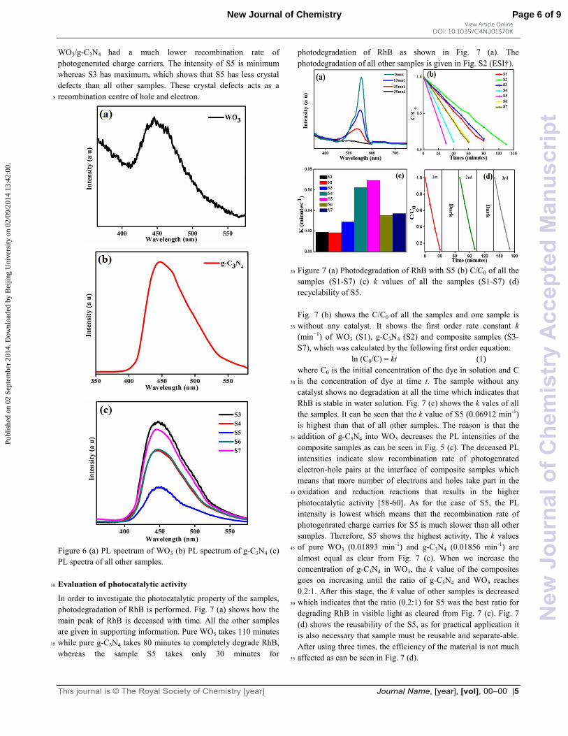
WO3/g-C3N4 had a much lower recombination rate of
photogenerated charge carriers. The intensity of S5 is minimum
whereas S3 has maximum, which shows that S5 has less crystal
defects than all other samples. These crystal defects acts as a
recombination centre of hole and electron. 5
Figure 6 (a) PL spectrum of WO3 (b) PL spectrum of g-C3N4 (c)
PL spectra of all other samples.
Evaluation of photocatalytic activity 10
In order to investigate the photocatalytic property of the samples,
photodegradation of RhB is performed. Fig. 7 (a) shows how the
main peak of RhB is deceased with time. All the other samples
are given in supporting information. Pure WO3 takes 110 minutes
while pure g-C3N4 takes 80 minutes to completely degrade RhB, 15
whereas the sample S5 takes only 30 minutes for
photodegradation of RhB as shown in Fig. 7 (a). The
photodegradation of all other samples is given in Fig. S2 (ESI†).
Figure 7 (a) Photodegradation of RhB with S5 (b) C/C0 of all the 20
samples (S1-S7) (c) k values of all the samples (S1-S7) (d)
recyclability of S5.
Fig. 7 (b) shows the C/C0 of all the samples and one sample is
without any catalyst. It shows the first order rate constant k 25
(min−1) of WO3 (S1), g-C3N4 (S2) and composite samples (S3-
S7), which was calculated by the following first order equation:
ln (C0/C) = kt (1)
where C0 is the initial concentration of the dye in solution and C
is the concentration of dye at time t. The sample without any 30
catalyst shows no degradation at all the time which indicates that
RhB is stable in water solution. Fig. 7 (c) shows the k vales of all
the samples. It can be seen that the k value of S5 (0.06912 min-1)
is highest than that of all other samples. The reason is that the
addition of g-C3N4 into WO3 decreases the PL intensities of the 35
composite samples as can be seen in Fig. 5 (c). The deceased PL
intensities indicate slow recombination rate of photogenrated
electron-hole pairs at the interface of composite samples which
means that more number of electrons and holes take part in the
oxidation and reduction reactions that results in the higher 40
photocatalytic activity [58-60]. As for the case of S5, the PL
intensity is lowest which means that the recombination rate of
photogenrated charge carries for S5 is much slower than all other
samples. Therefore, S5 shows the highest activity. The k values
of pure WO3 (0.01893 min-1) and g-C3N4 (0.01856 min-1) are 45
almost equal as clear from Fig. 7 (c). When we increase the
concentration of g-C3N4 in WO3, the k value of the composites
goes on increasing until the ratio of g-C3N4 and WO3 reaches
0.2:1. After this stage, the k value of other samples is decreased
which indicates that the ratio (0.2:1) for S5 was the best ratio for 50
degrading RhB in visible light as cleared from Fig. 7 (c). Fig. 7
(d) shows the reusability of the S5, as for practical application it
is also necessary that sample must be reusable and separate-able.
After using three times, the efficiency of the material is not much
affected as can be seen in Fig. 7 (d). 55
Page 6 of 9New Journal of Chemistry
New
Jour
nalo
fChe
mis
try
Acc
epte
dM
anus
crip
t
Publ
ishe
d on
02
Sept
embe
r 20
14. D
ownl
oade
d by
Bei
jing
Uni
vers
ity o
n 02
/09/
2014
13:
42:0
0.
View Article OnlineDOI: 10.1039/C4NJ01370K

6|Journal Name, [year], [vol], 00–00 This journal is © The Royal Society of Chemistry [year]
Proposed mechanism for enhanced photocatalytic
performance of WO3/g-C3N4
Fig. 7 shows the results of RhB degradation under visible light
irradiation in the presence of the synthesized composite WO3/g-5
C3N4 (S5). The excellent photodegradation of organic dye on the
surface of WO3/g-C3N4 composite under the visible light was
occurred due to several factors. Firstly, there is a well-known
factor that the heterostructured photocatalysts generally provide
more reactive sites for catalysis and as well as for adsorption, so 10
more organic pollutants are adsorbed that ultimately results in the
fast photodegradation of the organic dye. Secondly, the very
close contact of WO3 rods and g-C3N4 sheets with each other in
the synthesized composite facilitates the transfer of
photogenerated electron hole pairs from one semiconductor to 15
other. Because the single crystal structured WO3 microrods
provide a direct path for the transport of electrons to the
composite surface unlike in a polycrystalline structure which is
restricted by the grain boundaries. So, this easy transfer induces
the high separation of the photogenerated charge carriers and 20
enhances the photocatalytic reaction rate. Fig. 8 shows the energy
band structure diagram of the fabricated WO3/g-C3N4
composite/hybrid system. It can be noted from figure that the
transfer of photogenerated electrons takes place from the
conduction band (CB) of g-C3N4 to the CB of WO3 and the 25
photogenerated holes are transferred from the valence band (VB)
of WO3 to the VB of g-C3N4. When the composite samples were
exposed to visible light source, electrons in the VB of WO3 and
g-C3N4 were excited to CB of WO3 and g-C3N4 respectively. As a
result, the holes were left in the VB of both materials, as can be 30
seen in Fig. 8.
Figure 8 Schematic illustration of proposed mechanism for the
photodegradation of RhB on WO3/g-C3N4 composite
35
The valence and conduction band potentials of the pure g-C3N4
were found to be 1.57 eV and -1.12 eV [61], whereas for pure
WO3 their values were 3.18 eV and 0.41 eV respectively [62]. As
the CB potential of g-C3N4 (−1.12 eV) is lower than that of WO3
(0.41 eV), so the excited-state electrons from CB of g-C3N4 can 40
directly transfer into the CB of WO3. On the other hand, the VB
potential of WO3 (3.18 eV) is higher than that of g-C3N4 (1.57
eV), so the photogenerated holes from the VB of WO3 can move
to the VB of g-C3N4. The transfer of photo-induced electron hole
pairs was accompanied by the consecutive reduction of W6+ into 45
W5+ with the capture of photo-induced electrons at the trapping
sites in WO3 [63]. Simultaneously, the W5+ ions contained by
WO3 surface were re-oxidized into W6+ by the oxygen which was
finally converted into O2−•. This movement results in the efficient
separation of photogenerated electron-hole pairs and a slow-down 50
recombination rate which consequently promotes the photonic
efficiency for the degradation of organic pollutants. As hydroxyl
radicals (•OH) are well known strong oxidants, that can
contribute to the degradation process of RhB in the presence of
water vapor in air. The molecules of water further reacting with 55
photogenerated holes (h+) or superoxide radicals (O2−•) at the
photocatalyst surface can be converted to •OH by the following
reactions [64];
h+ + H2O → •OH + H+ (2)
2O2−• + 2H2O → 2•OH + 2OH− + O2 (3) 60
The photogenerated holes were captured by hydroxyl groups
(OH−) on the surface of photocatalyst and produced hydroxyl
radicals •OH [65]. Similarly, hydrogen peroxide (H2O2) is also a
strong oxidant, the oxygen molecules react with photo-excited
electrons at the surface of WO3 to be transformed into H2O2 65
through the following reaction [35];
O2 + 2H+ + 2e- → H2O2 (4)
The as-produced superoxide anions (O2−•) either directly react
with RhB or produce the hydroxyl radicals (•OH) by reacting
with photo-induced electrons and hydrogen ions (H+) [66, 67]. 70
The strong oxidants, hydroxyl radicals (•OH), finally degraded
the organic pollutant RhB. In addition, the excellent separation of
photogenerated electron-hole pairs can be verified from the PL
spectra of the photocatalyst. It can be noted from Fig. 5 (c) that
the coupling of g-C3N4 with WO3 microrods had an obvious 75
effect on the PL intensities of the composite samples, the PL
intensities were dramatically decreased which is strong evident of
the slow recombination rate of photogenerated electron-hole
pairs. As a result of this slow recombination the charge separation
increases at the interface between two semiconductors, and the 80
catalytic activity of WO3/g-C3N4 composites thus enhanced was
much higher than that of bare WO3 and bare g-C3N4. The
efficient separation of the charge carriers induced by hybrid
effect, the low energy optical absorption under visible light and
enhanced adsorption were some of the factors for significant 85
enhancement in the photocatalytic activity. However, it has been
noted that the separation of photo-induced electron-hole pairs
depends on the suitable band-edge positions of the two
semiconductors, because the band structure of the photocatalyst
plays an important role in the separation process of the electron–90
hole pairs [68, 69]. The suitable band structure alignment of such
semiconductors is favourable for charge accumulation/depletion
at the interfaces which induces the separation of photo-induced
electrons and holes [70] and as a result their photocatalytic
efficiency is enhanced. We anticipate that the fabricated 95
composite may also be useful for the hydrogen production via
water splitting due to its favourable band gap, less recombination
rate of electron-hole pairs and less number of crystal defects.
Page 7 of 9 New Journal of Chemistry
New
Jour
nalo
fChe
mis
try
Acc
epte
dM
anus
crip
t
Publ
ishe
d on
02
Sept
embe
r 20
14. D
ownl
oade
d by
Bei
jing
Uni
vers
ity o
n 02
/09/
2014
13:
42:0
0.
View Article OnlineDOI: 10.1039/C4NJ01370K

This journal is © The Royal Society of Chemistry [year] Journal Name, [year], [vol], 00–00 |7
Conclusions
We have successfully prepared a novel WO3/g-C3N4 visible-light-
driven photocatalyst and used it for the photodegradation of
Rhodamine B. The sample S5 of the as-prepared WO3/g-C3N4
photocatalyst showed the highest photocatalytic efficiency. It has 5
been noted that the as-synthesized WO3/g-C3N4 composite (S5)
exhibited performance 3.6 and 3.7 times as high as those of bare
WO3 and g-C3N4 under visible light irradiation respectively. The
enhancement in the photocatalytic activity occurs by coupling g-
C3N4 with WO3 and is mainly due to following factors: (i) the 10
synergistic effect between WO3 and g-C3N4 (ii) high separation
and easy transfer of photo-induced electron-hole pairs at the
interface of composite, and (iii) the lower number of defects. The
composite (WO3/g-C3N4) can be easily synthesized by a simple
physical mixing and annealing method and it can exhibit efficient 15
photocatalytic performance under a variety of environments,
particularly under visible (fluorescent) light. Moreover, it can be
a good reference to develop more superior photocatalysts with
high potential of using cheap solar light to utilize the energy and
environmental problems. 20
Acknowledgements
This work was supported by National Natural Science Foundation
of China (23171023,50972017) and the Research Fund for the
Doctoral Program of Higher Education of China
(20101101110026). 25
Notes and references
aResearch Center of Materials Science, Beijing Institute of Technology,
Beijing 100081, P. R. China
Email: [email protected]; bSchool of Physics, Beijing Institute of Technology, Beijing 100081, P. R. 30
China
cDepartment of Materials Science and Engineering, College of
EngineeringPeking University, Beijing 100871, P. R. China
Electronic Supplementary Information (ESI) available: [Introduction of
RhB, SEM images with lenth and diameter measurements, and 35
photodegradation curves of WO3/g-C3N4 (samples S1, S2, S3, S4, S6 and
S7) can be seen in the supporting information].
[1] M. R. Hoffmann, S. T. Martin, W. Choi and D. W.
Bahnemann, Chem. Rev., 1995, 95,69. 40
[2] (a) H. Choi, A. C. Sofranko and D. D. Dionysiou, Adv.
Funct. Mater., 2006, 16, 1067; (b) M. Tanveer, Chuanbao Cao,
Imran Aslam, Zulfiqar Ali, Faryal Idrees, Waheed S. Khan,
Faheem K. Butt, Muhammad Tahir and Asif Mahmood, Sci.
Adv. Mater., 2014, doi:10.1166/sam.2014.1988. 45
[3] (a) Faryal Idrees, Chuanbao Cao, Faheem K. Butt,
Muhammad Tahir, M. Tanveer, Imran Aslam, Zulfiqar Ali,
Tariq Mahmood and Jianhua Hou, CrystEngComm., 2013, 15,
8146; (b) Faryal Idrees, Chuanbao Cao, R. Ahmed, Faheem K.
Butt, Sajid Butt, Muhammad Tahir, Muhammad Tanvir, Imran 50
Aslam, and Zulfiqar Ali, Sci. Adv. Mater., 2014,
doi:10.1166/sam.2014.2044.
[4] A. Fujishima and K. Honda, Nature, 1972, 238, 37.
[5] (a) Shan Zheng, Wenjun Jiang, Yong Cai, Dionysios D.
Dionysiou and Kevin E. O’Sheab, Catalysis Today, 2014, 224, 55
88; (b) Faheem K. Butt, Muhammad Tahir, Chuanbao Cao,
Faryal Idrees, R. Ahmed, Waheed Samraiz Khan, Zulfiqar Ali,
Nasir Mahmood, Muhammad Tanveer, Asif Mahmood, and
Imran Aslam, ACS Appl. Mater. Interfaces, 2014, DOI:
10.1021/am503136h. 60
[6] Wenjun Jiang, Jeffrey A. Joens, Dionysios D. Dionysiou
and Kevin E. O’Shea, J. Photochem. Photobiol. A: Chem.,
2013, 262, 13.
[7] (a) A. L. Linsebigler, G. Lu and J. T. Yates, Chem. Rev.,
1995, 95, 735; (b) M. Tanveer, Chuanbao Cao, Zulfiqar Ali, 65
Imran Aslam, Faryal Idrees, Waheed S. Khan, Faheem K. But,
Muhammad Tahir and Nasir Mahmood, CrystEngComm, 2014,
16, 5290.
[8] X. Chen and S. S. Mao, Chem. Rev., 2007, 10, 2891.
[9] Z. G. Zhao and M. Miyauchi, Angew. Chem. Int. Ed., 2008, 70
47, 7051.
[10] R. Liu, Y. Yin, L. Y. Chou, S. W. Sheehan, W. He, F.
Zhang,H. J. Hou and D. Wang, Angew. Chem. Int. Ed., 2011,
50, 499.
[11] S. Wang, X. Feng, J. Yao and L. Jiang, Angew. Chem. Int. 75
Ed., 2006, 45, 1264.
[12] Bing Zhang, Chuanbao Cao, Hailin Qiu, Yajie Xu,
Yingchun Wang and Hesun Zhu, Chemistry Letters, 2005, 34,
154.
[13] (a) Imran Aslam, Chuanbao Cao, Waheed S. Khan, 80
Muhammad Tanveer, M. Abid, Faryal Idrees, Rabia Riasat,
Muhammad Tahir, Faheem K. Butt and Zulfiqar Ali, RSC Adv.,
2014, 4, 37914; (b) Kang Mingyang, Cao Chuanbao, Xu
Xingyan and Liao Bo, Chinese Science Bulletin, 2008, 53, 335.
[14] D. Bi and Y. Xu, Langmuir, 2011, 27, 9359. 85
[15] Li Chao, Cao Chuanbao and Zhu Hesun, Chinese Science
Bulletin, 2003, 48, 1737.
[16] Jie Li, Chuanbao Cao, and Hesun Zhu, Nanotechnology,
2007, 18, 115605.
[17] Fulin Huang, Chuanbao Cao, Xu Xiang, Ruitao Lv and 90
Hesun Zhu, Diamond and Related Materials, 2004, 13, 1757.
[18] X. Wang, K. Maeda, X. Chen, K. Takanabe, K. Domen,
Y. Hou, X. Fu and M. Antonietti, J. Am. Chem. Soc., 2009,
131, 1680.
[19] (a) Muhammad Tahir, Chuanbao Cao, Faheem K. Butt, 95
Faryal Idrees, Nasir Mahmood, Zulfiqar Ali, Imran Aslam, M.
Tanveer, Muhammad Rizwan and Tariq Mahmood, J. Mater.
Chem. A, 2013, 1, 13949; (b) Muhammad Tahir, Chuanbao
Cao, Faheem K. Butt, Sajid Butt,Faryal Idrees, Zulfiqar Ali,
Imran Aslam, M. Tanveer, Asif Mahmood and Nasir 100
Mahmood, CrystEngComm, 2014, 16, 1825.
[20] (a) J. D. Hong, X. Y. Xia, Y. S. Wang and R. Xu, J.
Mater. Chem., 2012, 22, 15006; (b) Muhammad Tahir,
Chuanbao Cao,,Nasir Mahmood, Faheem K. Butt, Asif
Mahmood, Faryal Idrees, Sajad Hussain, M. Tanveer, Zulfiqar 105
Ali, Imran Aslam, ACS Appl. Mater. Interfaces, 2014, 6, 1258.
[21] Shubin Yang, Yongji Gong, Jinshui Zhang, Liang Zhan,
Lulu Ma, Zheyu Fang, Robert Vajtai , Xinchen Wang, and
Pulickel M. Ajayan, Adv. Mater., 2013, 25, 2452.
[22] P. Niu, L. L. Zhang, G. Liu and H. M. Cheng, Adv. 110
Funct. Mater., 2012, 22, 4763.
[23] Liying Huang, Hui Xu, Rongxian Zhang, Xiaonong
Cheng, Jiexiang Xia, Yuangguo Xu and Huaming Li, Appl.
Surf. Sci., 2013, 283, 25.
[24] M. Law, L. E. Greene, J. C. Johnson, R. Saykally and P. 115
D. Yang, Nat. Mater., 2005, 4, 455.
[25] F. Qian, G. M. Wang and Y. Li, Nano Lett., 2010, 10,
4686.
Page 8 of 9New Journal of Chemistry
New
Jour
nalo
fChe
mis
try
Acc
epte
dM
anus
crip
t
Publ
ishe
d on
02
Sept
embe
r 20
14. D
ownl
oade
d by
Bei
jing
Uni
vers
ity o
n 02
/09/
2014
13:
42:0
0.
View Article OnlineDOI: 10.1039/C4NJ01370K

8|Journal Name, [year], [vol], 00–00 This journal is © The Royal Society of Chemistry [year]
[26] G. M. Wang, X. Y. Yang, F. Qian, J. Z. Zhang and Y. Li,
Nano Lett., 2010, 10, 1088.
[27] J. Cao, B. Xu, B. Luo, H. Lin and S. Chen, Catal.
Commun., 2011, 13, 63.
[28] L. Zhang, K. H. Wonga, Z. Chen, J. C. Yu, J. Zhao, C. Hu, 5
C. Y. Chan and P. K. Wong, Appl. Catal. A: Gen., 2009, 363,
221.
[29] J. Jiang, X. Zhang, P. B. Sun and L. Z. Zhang, J. Phys.
Chem. C, 2011, 115, 20564.
[30] Y. Y. Wen, H. M. Ding and Y. K. Shan, Nanoscale, 2011, 10
3, 4417.
[31] K. H. Reddy, S. Martha and K. M. Parida, Inorg. Chem.,
2013, 52, 6401.
[32] J. J. Guo, S. X. Ouyang, P. Li, Y. J. Zhang, T. Kako and J.
H. Ye, Appl. Catal., B, 2013, 134–135, 292. 15
[33] W. Morales, M. Cason, O. Aina, N. R. de Tacconi and
K. Rajeshwar, J. Am. Chem. Soc., 2008, 130, 6319.
[34] D. Hidayat, A. Purwanto, W. N. Wang and K. Okuyama,
Mater. Res. Bull., 2010, 45, 173.
[35] R. Abe, H. Takami, N. Murakami and B. Ohtani, J. Am. 20
Chem. Soc., 2008, 130, 7781.
[36] M. Qamar, M. A. Gondal and Z. H. Yamani, Catal.
Commun., 2010, 11, 772.
[37] S. A. K. Leghari, S. Sajjad, F. Chen and J. Zhang, Chem.
Eng. J., 2011, 166, 915. 25
[38] H. Widiyandari, A. Purwanto, R. Balgis, T. Ogi and K.
Okuyama, Chem. Eng. J., 2012, 180, 329.
[39] T. Arai, M. Yanagida, Y. Konishi, Y. Iwasaki, H.
Sugihara and K. Sayama, J. Phys. Chem. C, 2007, 111, 7577.
[40] Z. F. Liu, Z. G. Zhao and M. Miyauchi, J. Phys. Chem. C, 30
2009, 113, 17132–17137.
[41] S. Yan, S. Lv, Z. Li and Z. Zou, Dalton Trans., 2010, 39,
1488.
[42] C. Pan, J. Xu, Y. Wang, D. Li and Y. Zhu, Adv. Funct.
Mater., 2012, 22, 1518. 35
[43] Liying Huang, Hui Xu, Yeping Li, Huaming Li,
Xiaonong Cheng, Jixiang Xia, Yuanguo Xua and Guobin Cai,
Dalton Trans., 2013, 42, 8606.
[44] Yipeng Zang, Liping Li, Ying Zuo, Haifeng Lin,
Guangshe Li and Xiangfeng Gua, RSC Advances, 2013, 3, 40
13646.
[45] Ken-ichi Katsumata, Ryosuke Motoyoshi, Nobuhiro
Matsushita, Kiyoshi Okada, J. Hazard. Mater., 2013, 260, 475.
[46] Y. Wang, R. Shi, J. Lin and Y. Zhu, Energy. Environ. Sci.,
2011, 4, 2922. 45
[47] C. Guéry, C. Choquet, F. Dujeancourt, J. M. Tarascon
and J. C. Lassègues, J. Solid State Electrochem., 1997, 1, 199.
[48] V.N. Khabashesku, J.L. Zimmerman and J.L. Margrave,
Chem. Mater., 2000,12, 3264.
[49] X. Li, J. Zhang, L. Shen, Y. Ma, W. Lei, Q. Cui and G. 50
Zou, Appl. Phys. A, 2009, 94, 387.
[50] S.C. Yan, Z.S. Li and Z.G. Zou, Langmuir, 2009, 25,
10397.
[51] M. J. Bojdys, J.O. Müller, M. Antonietti, A. Thomas,
Chem. Eur. J., 2008, 14, 8177. 55
[52] M. Yang, Q. Huang and X. Jin, Mater. Sci. Eng. B,
2012,177, 600.
[53] Yan, S. C.; Li, Z. S.; Zou, Z. G. Langmuir 2009, 25,
10397-10401.
[54] Fu, J.; Tian, Y. L.; Chang, B. B.; Xi, F. N.; Dong, X. P. J. 60
Mater. Chem. 2012, 22, 21159-21166.
[55] Bojdys, M. J.; Muller, J. O.; Antonietti, M.; Thomas, A.
Chem. Eur. J. 2008, 14, 8177-8182.
[56] Kumar, S.; Surendar, T.; Baruah, A.; Shanker, V. J.
Mater. Chem. A 2013, 1, 5333-5340. 65
[57] H. I. S. Nogueira, A. M. V. Cavaleiro, J. Rocha, T.
Trindade, J. D. P. D. Jesus, Mater. Res. Bull., 2004, 39, 683.
[58] Y. Yang, G. Zhang, S. Yu and X. Shen, Chem.–Eng. J.,
2010, 162, 171–177.
[59] S. F. Chen, W. Zhao, W. Liu, H. Y. Zhang and X. L. Yu, 70
J. Hazard. Mater., 2009, 172, 1415–1423.
[60] H. Huang, D. Li, Q. Lin, W. Zhang, Y. Shao, Y. Chen, M.
Sun and X. Fu, Environ. Sci. Technol., 2009, 43, 4164–4168.
[61] L. Ge, C. C. Han and J. Liu, Appl. Catal., B, 2011, 108,
100. 75
[62] S. J. Hong, S. Lee, J. S. Jang and J. S. Lee, Energy
Environ. Sci., 2011, 4, 1781.
[63] V. Keller, P. Bernhardt and F. Garin, J. Catal., 2003, 215,
129.
[64] G. Vincent, P.M. Marquaire and O. Zahraa, J. Hazard. 80
Mater., 2009, 161, 1173.
[65] N. Zhang, S. Q. Liu, X. Z. Fu and Y. J. Xu, J. Phys. Chem.
C, 2011, 115, 9136.
[66] L. R. Zheng, Y. H. Zheng, C. Q. Chen, Y. Y. Zhan, X.Y.
Lin, Q. Zheng, K. M. Wei and J. F. Zhu, Inorg. Chem., 2009, 85
48, 1819.
[67] O. Legrini, E. Oliveros and A. M. Braun,Chem. Rev.,
1993, 93, 671.
[68] J. Tersoff, Phys. Rev. B, 1984, 30, 4874.
[69] Z. Alferov, Semiconductors, 1998, 32, 1. 90
[70] J. Zhang, M. Zhang, R. Q. Sun and X. Wang, Angew.
Chem. Int. Ed., 2012, 51, 10145.
Page 9 of 9 New Journal of Chemistry
New
Jour
nalo
fChe
mis
try
Acc
epte
dM
anus
crip
t
Publ
ishe
d on
02
Sept
embe
r 20
14. D
ownl
oade
d by
Bei
jing
Uni
vers
ity o
n 02
/09/
2014
13:
42:0
0.
View Article OnlineDOI: 10.1039/C4NJ01370K
Related Documents