Synchronous Counter

Welcome message from author
This document is posted to help you gain knowledge. Please leave a comment to let me know what you think about it! Share it to your friends and learn new things together.
Transcript

Synchronous Counter

Synchronous (Parallel) Counters Synchronous (parallel) counters: the flip-flops are
clocked at the same time by a common clock pulse.
We can design these counters using the sequential logic design process (covered in Lecture #12).
Example: 2-bit synchronous binary counter (using T flip-flops, or JK flip-flops with identical J,K inputs).
Present Next Flip-flopstate state inputs
A1 A0 A1+ A0
+ TA1 TA0
0 0 0 1 0 10 1 1 0 1 11 0 1 1 0 11 1 0 0 1 1
0100
1011
Synchronous (Parallel) Counters Example: 2-bit synchronous binary counter (using T
flip-flops, or JK flip-flops with identical J,K inputs).
Synchronous (Parallel) Counters 3
Present Next Flip-flopstate state inputs
A1 A0 A1+ A0
+ TA1 TA0
0 0 0 1 0 10 1 1 0 1 11 0 1 1 0 11 1 0 0 1 1
TA1 = A0
TA0 = 1
1
K
J
K
J A1A0
CC
CLK
Q
Q'
Q
Q'
Q
Q'

Synchronous (Parallel) Counters Example: 3-bit synchronous binary counter (using T
flip-flops, or JK flip-flops with identical J, K inputs).
CS1104-13 Synchronous (Parallel) Counters 4
Present Next Flip-flopstate state inputs
A2 A1 A0 A2+ A1
+ A0+ TA2 TA1 TA0
0 0 0 0 0 1 0 0 10 0 1 0 1 0 0 1 10 1 0 0 1 1 0 0 10 1 1 1 0 0 1 1 11 0 0 1 0 1 0 0 11 0 1 1 1 0 0 1 11 1 0 1 1 1 0 0 11 1 1 0 0 0 1 1 1
TA2 = A1.A0
A2
A1
A0
11
TA1 = A0 TA0 = 1
A2
A1
A0
11 1
1
A2
A1
A0
1 1 111 1 1
1

Synchronous (Parallel) Counters Example: 3-bit synchronous binary counter (cont’d).
TA2 = A1.A0 TA1 = A0TA0 = 1
Synchronous (Parallel) Counters 5
1
A2
CP
A1 A0
K
Q
J K
Q
J K
Q
J

Synchronous (Parallel) Counters Note that in a binary counter, the nth bit (shown
underlined) is always complemented whenever011…11 100…00
or 111…11 000…00
Hence, Xn is complemented whenever Xn-1Xn-2 ... X1X0 = 11…11.
As a result, if T flip-flops are used, then TXn = Xn-1 . Xn-2 . ... . X1 . X0
Synchronous (Parallel) Counters 6
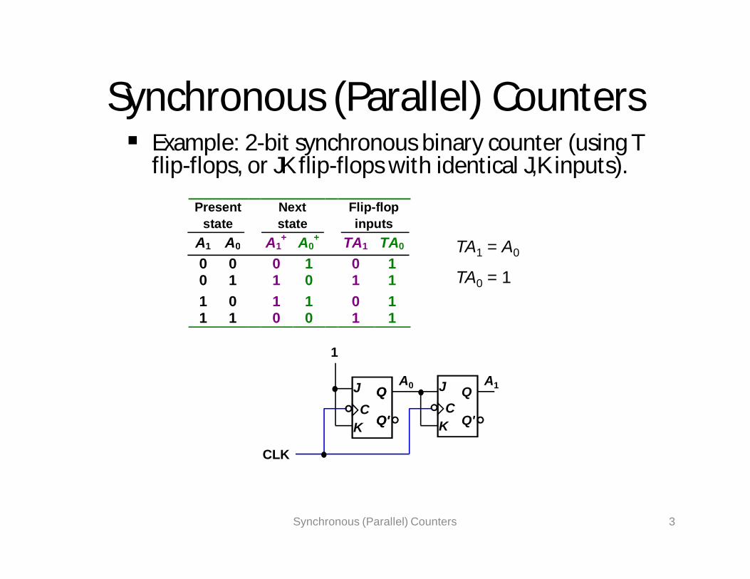
Synchronous (Parallel) Counters Example: 4-bit synchronous binary counter.
TA3 = A2 . A1 . A0
TA2 = A1 . A0
TA1 = A0
TA0 = 1
Synchronous (Parallel) Counters 7
1
K
J
K
J A1A0
CC
CLK
Q
Q'
Q
Q'
Q
Q' K
J A2
CQ
Q' K
J A3
CQ
Q'
A1.A0 A2.A1.A0
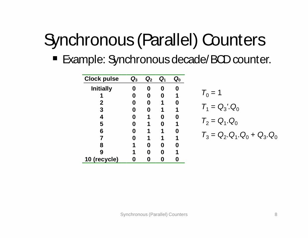
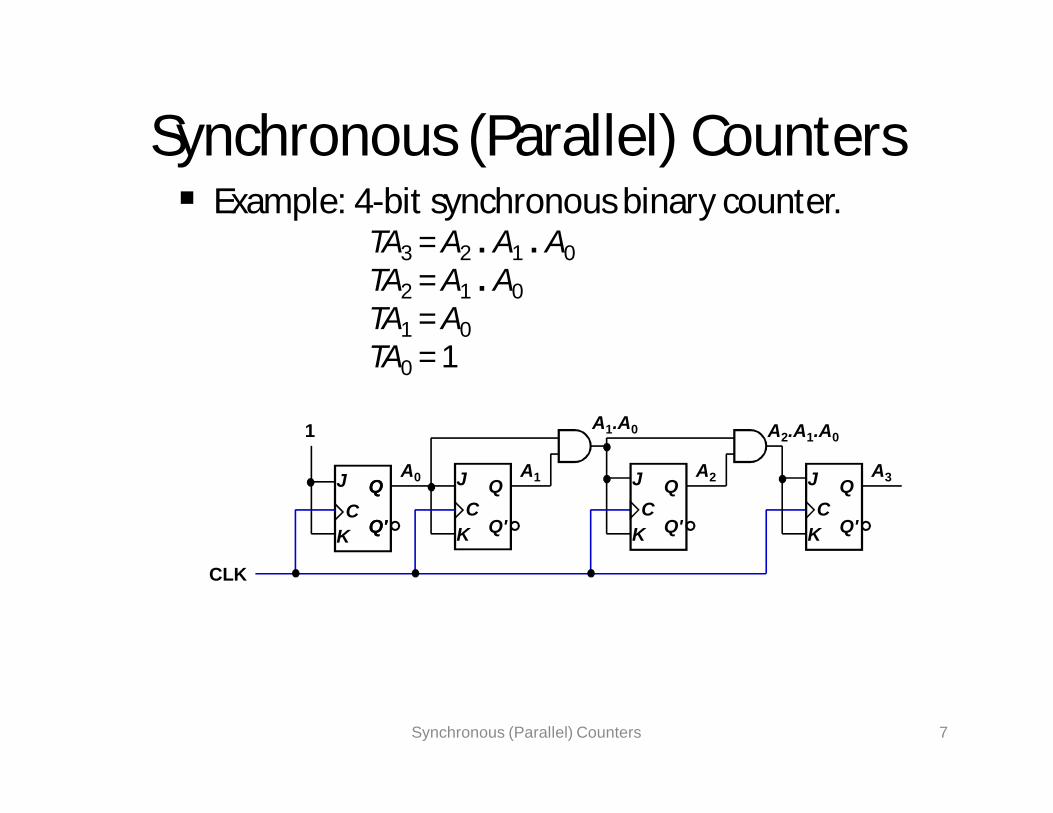
Synchronous (Parallel) Counters Example: Synchronous decade/BCD counter.
Synchronous (Parallel) Counters 8
Clock pulse Q3 Q2 Q1 Q0
Initially 0 0 0 01 0 0 0 12 0 0 1 03 0 0 1 14 0 1 0 05 0 1 0 16 0 1 1 07 0 1 1 18 1 0 0 09 1 0 0 1
10 (recycle) 0 0 0 0
T0 = 1
T1 = Q3'.Q0
T2 = Q1.Q0
T3 = Q2.Q1.Q0 + Q3.Q0

Synchronous (Parallel) Counters Example: Synchronous decade/BCD counter
(cont’d).
Synchronous (Parallel) Counters 9
T0 = 1T1 = Q3'.Q0
T2 = Q1.Q0
T3 = Q2.Q1.Q0 + Q3.Q0
1 Q1
Q0
CLK
TC
Q
Q'
Q
Q'
Q2 Q3TC
Q
Q'
Q
Q'
TC
Q
Q'
Q
Q'
TC
Q
Q'
Q
Q'

Up/Down Synchronous Counters Up/down synchronous counter: a
bidirectional counter that is capable of counting either up or down.
An input (control) line Up/Down (or simply Up) specifies the direction of counting.Up/Down = 1 Count upward
Up/Down = 0 Count downward
Up/Down Synchronous Counters 10

Up/Down Synchronous Counters Example: A 3-bit up/down synchronous
binary counter.
CS1104-13 Up/Down Synchronous Counters 11
Clock pulse Up Q2 Q1 Q0 Down0 0 0 01 0 0 12 0 1 03 0 1 14 1 0 05 1 0 16 1 1 07 1 1 1
TQ0 = 1TQ1 = (Q0.Up) + (Q0'.Up' )TQ2 = ( Q0.Q1.Up ) + (Q0'. Q1'. Up' )
Up counterTQ0 = 1TQ1 = Q0
TQ2 = Q0.Q1
Down counterTQ0 = 1TQ1 = Q0’TQ2 = Q0’.Q1’
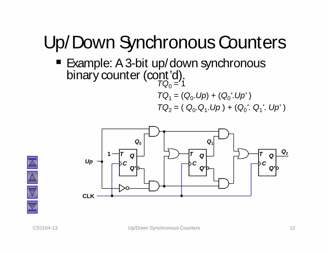
Up/Down Synchronous Counters Example: A 3-bit up/down synchronous
binary counter (cont’d).
CS1104-13 Up/Down Synchronous Counters 12
TQ0 = 1TQ1 = (Q0.Up) + (Q0'.Up' )TQ2 = ( Q0.Q1.Up ) + (Q0'. Q1'. Up' )
1
Q1Q0
CLK
TC
Q
Q'
Q
Q'
TC
Q
Q'
Q
Q'
TC
Q
Q'
Q
Q'Up
Q2

Designing Synchronous Counters Covered in Lecture #12.
Example: A 3-bit Gray code counter (using JK flip-flops).
CS1104-13 Designing Synchronous Counters 13
100000
001
101
111110
011
010
Present Next Flip-flopstate state inputs
Q2 Q1 Q0 Q2+ Q1
+ Q0+ JQ2 KQ2 JQ1 KQ1 JQ0 KQ0
0 0 0 0 0 1 0 X 0 X 1 X0 0 1 0 1 1 0 X 1 X X 00 1 0 1 1 0 1 X X 0 0 X0 1 1 0 1 0 0 X X 0 X 11 0 0 0 0 0 X 1 0 X 0 X1 0 1 1 0 0 X 0 0 X X 11 1 0 1 1 1 X 0 X 0 1 X1 1 1 1 0 1 X 0 X 1 X 0

Designing Synchronous Counters 3-bit Gray code counter: flip-flop inputs.
CS1104-13 Designing Synchronous Counters 14
0
1
00 01 11 10Q2
Q1Q0
X X X X1
JQ2 = Q1.Q0'
0
1
00 01 11 10Q2
Q1Q0
X X X X1
KQ2 = Q1'.Q0'
0
1
00 01 11 10Q2
Q1Q0
X XX X1
JQ1 = Q2'.Q0
0
1
00 01 11 10Q2
Q1Q0
X XX X
1
KQ1 = Q2.Q0
0
1
00 01 11 10Q2
Q1Q0
XXXX1
JQ0 = Q2.Q1 + Q2'.Q1'= (Q2 Q1)'
1
0
1
00 01 11 10Q2
Q1Q0
XXXX 1
1
KQ0 = Q2.Q1' + Q2'.Q1= Q2 Q1

Designing Synchronous Counters 3-bit Gray code counter: logic diagram.
JQ2 = Q1.Q0' JQ1 = Q2'.Q0 JQ0 = (Q2 Q1)'KQ2 = Q1'.Q0' KQ1 = Q2.Q0 KQ0 = Q2 Q1
CS1104-13 Designing Synchronous Counters 15
Q1Q0
CLK
Q2J
C
Q
Q'K
J
C
Q
Q'K
J
C
Q
Q'KQ2'
Q0'
Q1'

Decoding A Counter Decoding a counter involves determining
which state in the sequence the counter is in.
Differentiate between active-HIGH and active-LOW decoding.
Active-HIGH decoding: output HIGH if the counter is in the state concerned.
Active-LOW decoding: output LOW if the counter is in the state concerned.
CS1104-13 Decoding A Counter 16

Decoding A Counter Example: MOD-8 ripple counter (active-
HIGH decoding).
CS1104-13 Decoding A Counter 17
A'B'C'
1 2 3 4 5 6 7 8 9Clock
HIGH only on count of ABC = 000
A'B'C
HIGH only on count of ABC = 001
A'BC'
HIGH only on count of ABC = 010
100
ABC
HIGH only on count of ABC = 111
...
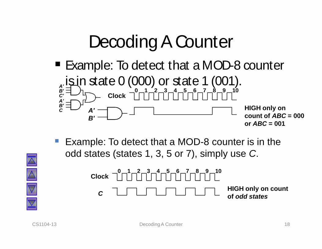
Decoding A Counter Example: To detect that a MOD-8 counter
is in state 0 (000) or state 1 (001).
CS1104-13 Decoding A Counter 18
A'B'
1 2 3 4 5 6 7 8 9Clock
HIGH only on count of ABC = 000 or ABC = 001
100
Example: To detect that a MOD-8 counter is in the odd states (states 1, 3, 5 or 7), simply use C.
C
1 2 3 4 5 6 7 8 9Clock
HIGH only on count of odd states
100
A'B'C'A'B'C

Counters with Parallel Load Counters could be augmented with parallel
load capability for the following purposes:To start at a different state
To count a different sequence
As more sophisticated register with increment/decrement functionality.
CS1104-13 Counters with Parallel Load 19

Counters with Parallel Load Different ways of getting a MOD-6 counter:
CS1104-13 Counters with Parallel Load 20
Count = 1Load = 0CPI4 I3 I2 I1
Count = 1Clear = 1CP
A4 A3 A2 A1
Inputs = 0
Load
(a) Binary states 0,1,2,3,4,5.
I4 I3 I2 I1
A4 A3 A2 A1
Inputs have no effect
Clear
(b) Binary states 0,1,2,3,4,5.
I4 I3 I2 I1
Count = 1Clear = 1CP
A4 A3 A2 A1
0 0 1 1
Load
(d) Binary states 3,4,5,6,7,8.
I4 I3 I2 I1
Count = 1Clear = 1CP
A4 A3 A2 A1
1 0 1 0
Load
Carry-out
(c) Binary states 10,11,12,13,14,15.
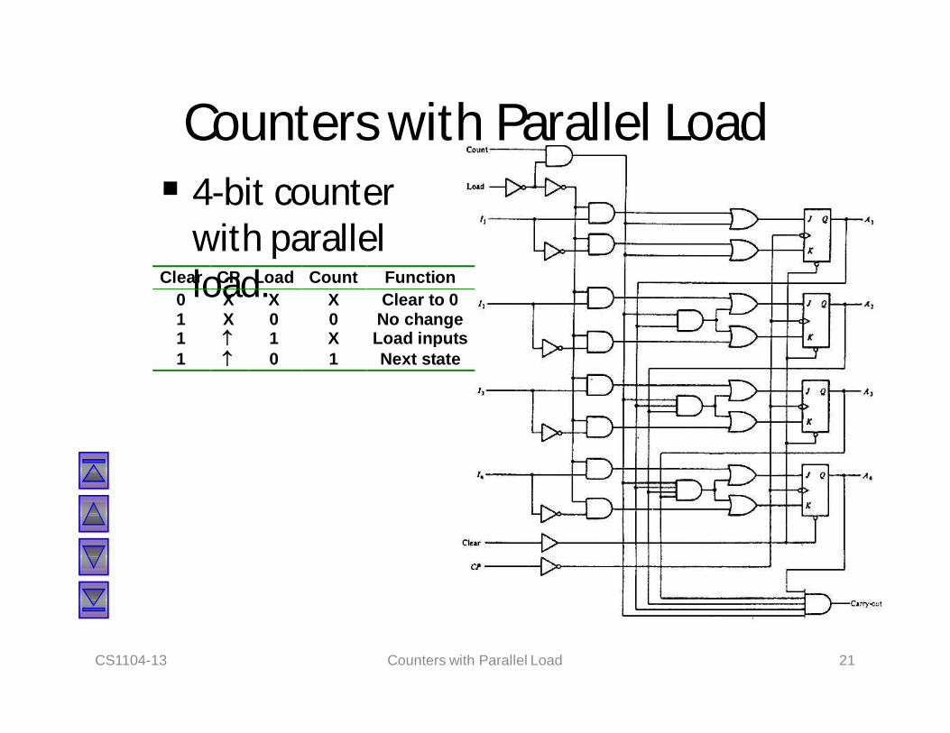
Counters with Parallel Load 4-bit counter
with parallel load.
CS1104-13 Counters with Parallel Load 21
Clear CP Load Count Function0 X X X Clear to 01 X 0 0 No change1 1 X Load inputs1 0 1 Next state
Introduction: Registers An n-bit register has a group of n flip-flops
and some logic gates and is capable of storing n bits of information.
The flip-flops store the information while the gates control when and how new information is transferred into the register.
Some functions of register:retrieve data from register
store/load new data into register (serial or parallel)
shift the data within register (left or right)CS1104-13 Introduction: Registers 22

Simple Registers No external gates.
Example: A 4-bit register. A new 4-bit data is loaded every clock cycle.
CS1104-13 Simple Registers 23
A3
CP
A1 A0
D
Q
D
Q Q
D
A2
D
Q
I3 I1 I0I2

Registers With Parallel Load Instead of loading the register at every
clock pulse, we may want to control when to load.
Loading a register: transfer new information into the register. Requires a load control input.
Parallel loading: all bits are loaded simultaneously.
CS1104-13 Registers With Parallel Load 24

Registers With Parallel Load
CS1104-13 Registers With Parallel Load 25
A0
CLK
D Q
Load
I0
A1D Q
A2D Q
A3D Q
CLEAR
I1
I2
I3
Load'.A0 + Load. I0

Using Registers to implement Sequential Circuits
A sequential circuit may consist of a register (memory) and a combinational circuit.
CS1104-13 Using Registers to implement Sequential Circuits 26
Register Combin-ational circuit
Clock
Inputs Outputs
Next-state value
The external inputs and present states of the register determine the next states of the register and the external outputs, through the combinational circuit.
The combinational circuit may be implemented by any of the methods covered in MSI components and Programmable Logic Devices.

Using Registers to implement Sequential Circuits
Example 1:A1
+ = S m(4,6) = A1.x'A2
+ = S m(1,2,5,6) = A2.x' + A2'.x = A2 xy = S m(3,7) = A2.x
CS1104-13 Using Registers to implement Sequential Circuits 27
Present Nextstate Input State Output
A1 A2 x A1+ A2
+ y0 0 0 0 0 00 0 1 0 1 00 1 0 0 1 00 1 1 0 0 11 0 0 1 0 01 0 1 0 1 01 1 0 1 1 01 1 1 0 0 1
A1
A2
x y
A1.x'
A2x
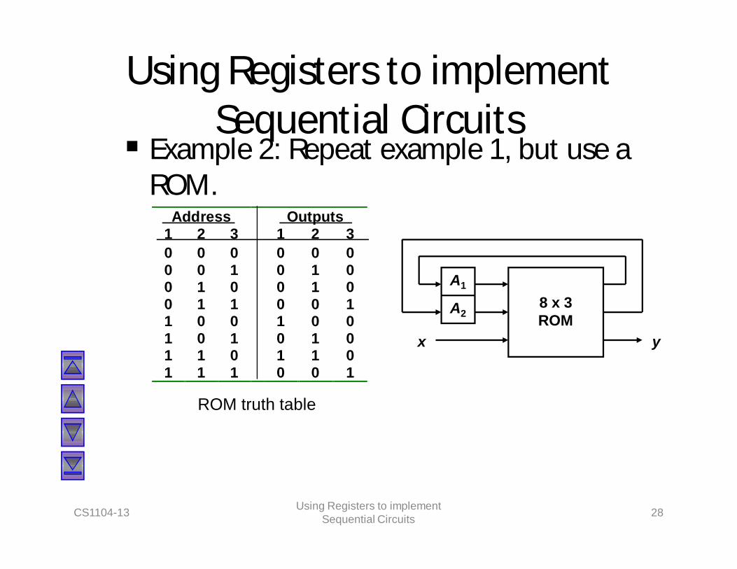
Using Registers to implement Sequential Circuits
Example 2: Repeat example 1, but use a ROM.
CS1104-13 Using Registers to implement Sequential Circuits 28
Address Outputs1 2 3 1 2 30 0 0 0 0 00 0 1 0 1 00 1 0 0 1 00 1 1 0 0 11 0 0 1 0 01 0 1 0 1 01 1 0 1 1 01 1 1 0 0 1
ROM truth table
A1
A2
x y
8 x 3 ROM
Shift Registers Another function of a register, besides
storage, is to provide for data movements.
Each stage (flip-flop) in a shift register represents one bit of storage, and the shifting capability of a register permits the movement of data from stage to stage within the register, or into or out of the register upon application of clock pulses.
CS1104-13 Shift Registers 29

Shift Registers Basic data movement in shift registers (four
bits are used for illustration).
CS1104-13 Shift Registers 30
Data in Data out
(a) Serial in/shift right/serial out
Data inData out
(b) Serial in/shift left/serial out
Data in
Data out
(c) Parallel in/serial outData out
Data in
(d) Serial in/parallel outData out
Data in
(e) Parallel in / parallel out
(f) Rotate right (g) Rotate left

Serial In/Serial Out Shift Registers Accepts data serially – one bit at a time –
and also produces output serially.
CS1104-13 Serial In/Serial Out Shift Registers 31
Q0
CLK
D
C
QQ1 Q2 Q3Serial data
inputSerial data
outputD
C
Q D
C
Q D
C
Q

Serial In/Serial Out Shift Registers Application: Serial transfer of data from
one register to another.
CS1104-13 Serial In/Serial Out Shift Registers 32
Shift register A Shift register BSI SISO SO
ClockShift control
CP
Wordtime
T1 T2 T3 T4CP
Clock
Shift control

Serial In/Serial Out Shift Registers Serial-transfer example.
CS1104-13 Serial In/Serial Out Shift Registers 33
Timing Pulse Shift register A Shift register B Serial output of BInitial value 1 0 1 1 0 0 1 0 0
After T1 1 1 0 1 1 0 0 1 1After T2 1 1 1 0 1 1 0 0 0After T3 0 1 1 1 0 1 1 0 0After T4 1 0 1 1 1 0 1 1 1

Serial In/Parallel Out Shift Registers Accepts data serially.
Outputs of all stages are available simultaneously.
CS1104-13 Serial In/Parallel Out Shift Registers 34
Q0
CLK
D
C
Q
Q1
D
C
Q
Q2
D
C
Q
Q3
D
C
QData input
D
CCLKData input
Q0 Q1 Q2 Q3
SRG 4Logic symbol

Parallel In/Serial Out Shift Registers Bits are entered simultaneously, but output
is serial.
CS1104-13 Parallel In/Serial Out Shift Registers 35
D0
CLK
D
C
Q
D1
D
C
Q
D2
D
C
Q
D3
D
C
Q
Data input
Q0 Q1 Q2 Q3
Serial data out
SHIFT/LOAD
SHIFT.Q0 + SHIFT'.D1

Parallel In/Serial Out Shift Registers Bits are entered simultaneously, but output
is serial.
CS1104-13 Parallel In/Serial Out Shift Registers 36
Logic symbol
CCLKSHIFT/LOAD
D0 D1 D2 D3
SRG 4Serial data out
Data in
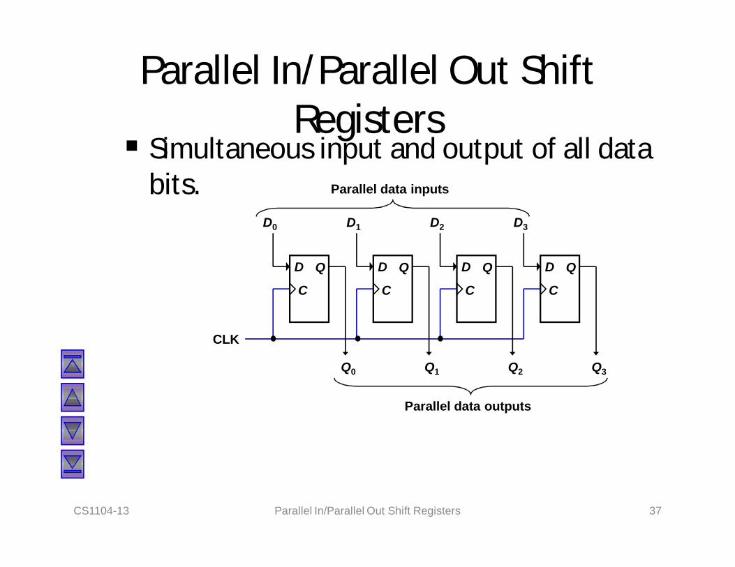
Parallel In/Parallel Out Shift Registers
Simultaneous input and output of all data bits.
CS1104-13 Parallel In/Parallel Out Shift Registers 37
Q0
CLK
D
C
Q
Q1
D
C
Q
Q2
D
C
Q
Q3
D
C
Q
Parallel data inputs
D0 D1 D2 D3
Parallel data outputs

Bidirectional Shift Registers Data can be shifted either left or right, using
a control line RIGHT/LEFT (or simply RIGHT) to indicate the direction.
CS1104-13 Bidirectional Shift Registers 38
CLK
D
C
Q D
C
Q D
C
Q D
C
Q
Q0
Q1 Q2Q3
RIGHT/LEFT
Serial data in
RIGHT.Q0 + RIGHT'.Q2

Bidirectional Shift Registers 4-bit bidirectional shift register with parallel
load.
CS1104-13 Bidirectional Shift Registers 39
CLK
I4 I3 I2 I1
Serial input for
shift-right
DQ
DQ
DQ
DQ
Clear
4x1 MUX
s1
s03 2 1 0
4x1 MUX
3 2 1 0
4x1 MUX
3 2 1 0
4x1 MUX
3 2 1 0
A4 A3 A2 A1
Serial input for shift-left
Parallel inputs
Parallel outputs

Bidirectional Shift Registers 4-bit bidirectional shift register with parallel
load.
CS1104-13 Bidirectional Shift Registers 40
Mode Controls1 s0 Register Operation0 0 No change0 1 Shift right1 0 Shift left1 1 Parallel load

An Application – Serial Addition Most operations in digital computers are
done in parallel. Serial operations are slower but require less equipment.
A serial adder is shown below. A A + B.
CS1104-13 An Application – Serial Addition 41
FAxyz
SC
Shift-register AShift-rightCP
SI
Shift-register B
SIExternal input SO
SO
Q D
Clear

An Application – Serial Addition A = 0100; B = 0111. A + B = 1011 is stored
in A after 4 clock pulses.
CS1104-13 An Application – Serial Addition 42
Initial: A: 0 1 0 0B: 0 1 1 1
Q: 0
Step 1: 0 + 1 + 0S = 1, C = 0
A: 1 0 1 0B: x 0 1 1
Q: 0
Step 2: 0 + 1 + 0S = 1, C = 0
A: 1 1 0 1B: x x 0 1
Q: 0
Step 3: 1 + 1 + 0S = 0, C = 1
A: 0 1 1 0B: x x x 0
Q: 1
Step 4: 0 + 0 + 1S = 1, C = 0
A: 1 0 1 1B: x x x x
Q: 0

Shift Register Counters Shift register counter: a shift register with
the serial output connected back to the serial input.
They are classified as counters because they give a specified sequence of states.
Two common types: the Johnson counterand the Ring counter.
CS1104-13 Shift Register Counters 43
Ring Counters One flip-flop (stage) for each state in the
sequence.
The output of the last stage is connected to the D input of the first stage.
An n-bit ring counter cycles through nstates.
No decoding gates are required, as there is an output that corresponds to every state the counter is in.
CS1104-13 Ring Counters 44

Ring Counters Example: A 6-bit (MOD-6) ring counter.
CS1104-13 Ring Counters 45
CLK
Q0D Q D Q D Q D Q D Q D Q
Q1 Q2 Q3 Q4 Q5
CLR
PRE
Clock Q0 Q1 Q2 Q3 Q4 Q5
0 1 0 0 0 0 01 0 1 0 0 0 02 0 0 1 0 0 03 0 0 0 1 0 04 0 0 0 0 1 05 0 0 0 0 0 1
100000
010000
001000
000100
000010
000001

Johnson Counters The complement of the output of the last
stage is connected back to the D input of the first stage.
Also called the twisted-ring counter.
Require fewer flip-flops than ring counters but more flip-flops than binary counters.
An n-bit Johnson counter cycles through 2nstates.
Require more decoding circuitry than ring counter but less than binary counters.
CS1104-13 Johnson Counters 46

Johnson Counters Example: A 4-bit (MOD-8) Johnson counter.
CS1104-13 Johnson Counters 47
Clock Q0 Q1 Q2 Q3
0 0 0 0 01 1 0 0 02 1 1 0 03 1 1 1 04 1 1 1 15 0 1 1 16 0 0 1 17 0 0 0 1
CLK
Q0D Q D Q D Q D Q
Q1 Q2
Q3'CLR
Q'
0000
0001
0011
0111
1111
1110
1100
1000

Johnson Counters Decoding logic for a 4-bit Johnson counter.
CS1104-13 Johnson Counters 48
Clock A B C D Decoding0 0 0 0 0 A'.D'1 1 0 0 0 A.B'2 1 1 0 0 B.C'3 1 1 1 0 C.D'4 1 1 1 1 A.D5 0 1 1 1 A'.B6 0 0 1 1 B'.C7 0 0 0 1 C'.D
A'D' State 0
AD State 4
BC' State 2
CD' State 3
AB' State 1
A'B State 5
B'C State 6
C'D State 7

Random Access Memory (RAM) A memory unit stores binary information in
groups of bits called words.
The data consists of n lines (for n-bit words). Data input lines provide the information to be stored (written) into the memory, while data output lines carry the information out (read) from the memory.
The address consists of k lines which specify which word (among the 2k words available) to be selected for reading or writing.
The control lines Read and Write (usually CS1104-13 Random Access Memory (RAM) 49

Random Access Memory (RAM) Block diagram of a memory unit:
CS1104-13 Random Access Memory (RAM) 50
Memory unit2k words
n bits per word
k address linesk
Read/Write
n
n
n data input lines
n data output lines

Random Access Memory (RAM) Content of a 1024 x 16-bit memory:
CS1104-13 Random Access Memory (RAM) 51
101101011101110110100001100001100010011101110001
::
111001010101001000111110101011101011000110010101
Memory contentdecimal
012::
102110221023
000000000000000000010000000010
::
111111110111111111101111111111
binaryMemory address

Random Access Memory (RAM) The Write operation:Transfers the address of the desired word to
the address lines
Transfers the data bits (the word) to be stored in memory to the data input lines
Activates the Write control line (set Read/Write to 0)
The Read operation:Transfers the address of the desired word to
the address lines
Activates the Read control line (set Read/Writeto 1)
CS1104-13 Random Access Memory (RAM) 52

Random Access Memory (RAM) The Read/Write operation:
CS1104-13 Random Access Memory (RAM) 53
Memory Enable Read/Write Memory Operation0 X None1 0 Write to selected word1 1 Read from selected word
Two types of RAM: Static and dynamic. Static RAMs use flip-flops as the memory cells.
Dynamic RAMs use capacitor charges to represent data. Though simpler in circuitry, they have to be constantly refreshed.

Random Access Memory (RAM) A single memory cell of the static RAM has
the following logic and block diagrams.
CS1104-13 Random Access Memory (RAM) 54
R
S QInput
Select
Output
Read/Write
BC OutputInput
Select
Read/Write
Logic diagram Block diagram
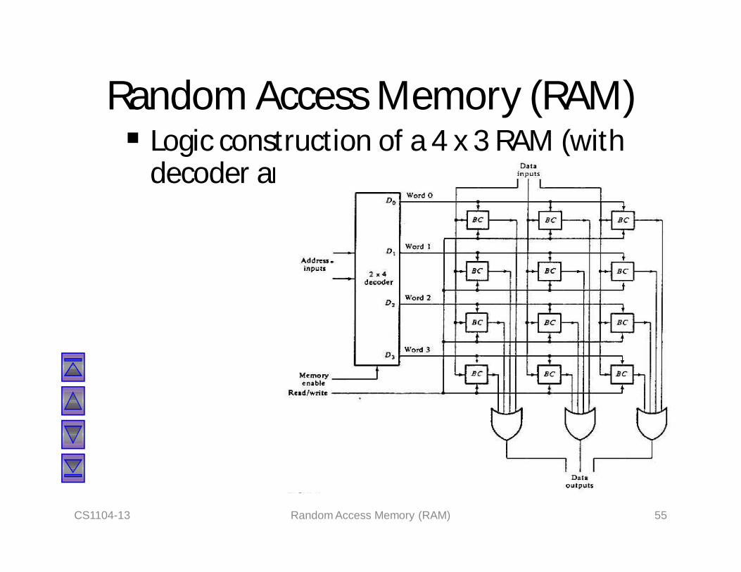
Random Access Memory (RAM) Logic construction of a 4 x 3 RAM (with
decoder and OR gates):
CS1104-13 Random Access Memory (RAM) 55
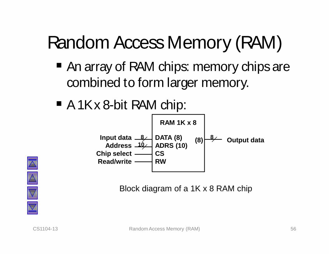
Random Access Memory (RAM) An array of RAM chips: memory chips are
combined to form larger memory.
A 1K x 8-bit RAM chip:
CS1104-13 Random Access Memory (RAM) 56
Block diagram of a 1K x 8 RAM chip
RAM 1K x 8
DATA (8)ADRS (10)CSRW
Input dataAddress
Chip selectRead/write
(8) Output data8 810

Random Access Memory (RAM)
4K x 8 RAM.
CS1104-13 Random Access Memory (RAM) 57
1K x 8
DATA (8)ADRS (10)CSRW
Read/write
(8)
Output data
1K x 8
DATA (8)ADRS (10)CSRW
(8)
1K x 8
DATA (8)ADRS (10)CSRW
(8)
1K x 8
DATA (8)ADRS (10)CSRW
(8)
0–1023
1024 – 2047
2048 – 3071
3072 – 4095
Input data8 lines
0123
2x4 decoder
Lines Lines0 – 911 10
S0
S1
Address

End of segment
Related Documents