Welcome message from author
This document is posted to help you gain knowledge. Please leave a comment to let me know what you think about it! Share it to your friends and learn new things together.
Transcript


8
This article can be downloaded from http://www.ijerst.com/currentissue.php
Int. J. Engg. Res. & Sci. & Tech. 2013 G M Prabhu and Chandru Iyer, 2013
SYNCHRONIZING EQUIVALENT CLOCKSACROSS INERTIAL FRAMES
Chandru Iyer1 and G M Prabhu2*
The second postulate of special relativity, namely, the equivalence of inertial frames, impliesthat all clocks must run identically across inertial frames. Under this principle, global clocksynchronization may be feasible if an appropriate procedure can be developed. It is well-knownthat synchronization within an inertial frame using the methods of light rays or slow separationof clocks results in synchronization that is specific to that inertial frame. This paper describes anew procedure to synchronize clocks co-moving with different inertial frames, and analyzes itseffectiveness.
Keywords: Special relativity, Lorentz transformation, Clock synchronization
*Corresponding Author: G M Prabhu,[email protected]
INTRODUCTIONDistances between spatial locations within an
inertial frame are measured by an observer “by
marking off his measuring-rod in a straight line
as many times as is necessary to take him from
the one marked point to the other. Then the
number which tells us how often the rod has to
be laid down is the required distance” (Einstein,
1961). It is also simple to measure the time
interval between two events happening at the
same location in an inertial frame by using a single
clock present at that location. However, the
measurement of a time interval between events
taking place at different locations in an inertial
1 Techink Industries, C-42, phase-II, Noida, 201305, India. E-mail: [email protected] Department of Computer Science, Iowa State University, Ames, IA 50011, USA.
Int. J. Engg. Res. & Sci. & Tech. 2013
ISSN 2319-5991 www.ijerst.comVol. 2, No. 2, May 2013
© 2013 IJERST. All Rights Reserved
Research Paper
frame requires a multitude of clocks situated at
various locations. The other option is to send a
signal to a location where the reference or
standard clock is present. The latter option is
generally avoided because it involves knowing the
distance between the locations as well as prior
knowledge of the signal speed.
Synchronizing a number of clocks at one
location and latter separating them to different
locations is another option. This option was
acceptable under classical physics. However with
the advent of special and general relativity this
option has its limitations because of the effect of
motion on clocks.

9
This article can be downloaded from http://www.ijerst.com/currentissue.php
Int. J. Engg. Res. & Sci. & Tech. 2013 G M Prabhu and Chandru Iyer, 2013
Under the first postulate of special relativity,
the signal speed of a light ray is constant in all
inertial frames and therefore this has been used
in thought experiments by many authors to
synchronize clocks equidistant from a reference
point by sending a light signal from that reference
point (Bohm, 1965; Resnick, 1968).
The other possibility is to separate identical
clocks very slowly with a limiting speed tending
to zero, so that their running is not affected. This
option was examined by Lorentz (Bohm, 1965,
pp. 32-34) who demonstrated that even under
slow separation, clocks in a ‘moving’ reference
frame will become asynchronous, whereas they
will remain synchronous in an inertial frame at
‘rest’.
Both the above procedures give specific
synchronicities that are unique to a given inertial
frame but different for inertial frames in relative
motion. Further, both procedures give identical
results in a given inertial frame. The resultant
synchronicity is widely known as standard
Einstein synchronization (Ohanian, 2004).
Reichenbach (1958, originally in 1927) had argued
that this is only a conventional synchronicity and
there is no compelling reason to adopt this
particular synchronicity. He had proposed that
alternate synchronicities can be developed by
assuming different onward and return speeds for
light without affecting causality. The Reichenbach
synchronization, as it has been called in Ohanian
(2004), has a parameter, epsilon, 0<<1 and in
this method, if the round trip speed of light is c,
the onward speed is assumed to be c/(2) and
the return speed as c/[2(1 – )]. The total round
trip time (2s/c) is thus divided into two parts
[(2s/c)] for the onward journey and [(2s/c)
(1–)] for the return journey. With the value of
= 1/2, the onward and return speeds of light
become identical and this leads to the Einsteinian
synchronization. For other values of , with the
restriction that it is positive and less than 1, we
get the Reichenbach synchronization (Ohanian,
2004).
Selleri (1996) has argued in favor of an
absolute simultaneity. Rowland (2006), in his
concluding remarks makes the observation that
“a uniformly accelerating, effectively rigid rod only
has instantaneous rest inertial frames, as one
might expect it to, if inertial frames use Einstein
synchronicity.” However, he immediately adds
that “while this observation provides yet another
argument for accepting Einstein synchronicity as
the ‘natural’ choice for a simultaneity convention,
it is acknowledged that it does not in fact defeat
the ‘conventionality of simultaneity’ thesis.”
Ohanian (2004) has given a complete review
of the debate on the conventions relating to
synchronization. He also argues that the
dynamical considerations forbid any
synchronization other than the Einsteinian one,
and if an inertial frame adopts a Reichenbach
synchronization, Newton’s laws would be violated.
However, Martinez (2005) and Macdonald (2005)
are not in complete agreement with Ohanian
(2004).
Martinez (2005) has discussed the origin of
the Einsteinian synchronization. He observes that
the original German word ‘festsetzung’ used by
Einstein (1905) to prescribe the Einsteinian
synchronization has been translated into English
as ‘stipulation’ and into French as ‘convention.’
Eddington also advanced the concept that the
Michelson-Morley experiment only determined the
round trip speed of a light ray as a constant and a
synchronization convention was needed to further
specify that the speed of light remained constant

10
This article can be downloaded from http://www.ijerst.com/currentissue.php
Int. J. Engg. Res. & Sci. & Tech. 2013 G M Prabhu and Chandru Iyer, 2013
on both the onward and return trips (Martinez,
2005). Macdonald (2005) argues that Einstein
definitely intended the synchronization proposed
by him as a method or definition. And this is the
reason Einstein emphasized that his definition “is
in reality neither a supposition nor a hypothesis
about the physical nature of light, but a stipulation
(festsetzung) which I can make of my own free
will in order to arrive at a definition of simultaneity.”
In his reply to the comments by Martinez
(2005) and Macdonald (2005), Ohanian (2005)
has argued that when the Einsteinian
synchronization convention is adopted in all
inertial reference frames, it “permits us to express
the laws of physics in their simplest form.” He
further states that “the adoption of a preferential
inertial reference frame in which all the laws of
physics take their simplest form compels the E
(Einsteinian) synchronization and forbids the R
(Reichenbach) synchronization” (Ohanian, 2005).
In this paper we propose a constructive
procedure for synchronizing a three-clock system
using the second postulate of special relativity.
We assume that all clocks (even if in relative
motion) run at the same rate. All the three clocks
are under uniform relative motion in relation to
each other and each one of them falls strictly
under the purview of special relativity and the
Lorentz transformations. The success of the
procedure is checked using the Lorentz
transformations and it is concluded that clocks
in relative motion do not run identically.
RELATION BETWEENSIMULTANEITY ANDLENGTH CONTRACTIONTime dilation is the phenomenon where the
observed time rate of an observer’s reference
frame is different from that of a different reference
frame. In special relativity, clocks that are moving
with speed v with respect to an inertial system of
observations are found to be running slower
(Møller, 1952). The formula for determining time
dilation in special relativity is:
t0 = t 2 21 /v c , where
t0 is a time interval as measured with a
‘moving’ clock that is physically present at the two
events under consideration,
t is the same time interval as measured by
another ‘stationary’ inertial frame with spatially
separated clocks,
v is the relative speed between the clock and
the stationary system, and
c is the speed of light.
The Lorentz transformations of spatial and
temporal event coordinates between two inertial
frames in relative motion ordain that a particular
clock of one frame observed from another frame
appears to run slow, and the set of clocks in one
frame appears asynchronous as well as slowing
down when viewed from the other frame. The
asynchronicity and the slowing down seem to
combine to create a symmetric perception of
each other’s frame.
The question whether a moving clock runs
slow or only appears to run slow is an intriguing
one. For all practical purposes a moving clock
runs slow. However, if an observer A is attached
to the moving clock, his perception will be that
the set of clocks in the inertial frame B that is
observing him are asynchronous and for this
reason B concludes that the moving clock A is
slowing down. For the observer attached to the
moving clock, the rate at which his clock is
running is indeed the ‘correct’ rate, and any

11
This article can be downloaded from http://www.ijerst.com/currentissue.php
Int. J. Engg. Res. & Sci. & Tech. 2013 G M Prabhu and Chandru Iyer, 2013
worthwhile to note that a “moving” frame in spite
of ‘contracted’ lengths and ‘slow running’ clocks
measures the relative velocity correctly. The
‘stationary’ observers on the train explain this as
follows. The apparent “movement” of a point
object in the train’s inertial frame by a distance x
will be interpreted as a movement by a distance
x' = x / 2 21 /v c by the platform due to the
contraction of rulers in the platform. The time
interval will be measured by spatially separated
clocks on the platform as
T' = (x/v) 2 21 /v c + (vx)/(c2 2 21 /v c ).
The first term indicates the slow running of
clocks on the platform and the second term
indicates the asynchronicity in spatially separated
clocks on the platform. Simplifying, we get
T' = (x/(v 2 21 /v c ))
The platform correctly measures the relative
speed v = x'/ T'. According to observers on the train,
observers on the platform wrongly measured both
the distance and the time, but they correctly
estimated the relative speed. Thus we find that the
apparent asynchronicity and slow running of clocks
in a moving frame is the cause of all discrepancies
in length and time-interval measurements. But it also
has the compensating effect of the relative velocity
between the frames to be observed as the same
value by both the frames.
PROCEDURE TO SYNCHRONIZEA THREE CLOCK SYSTEMWe describe a three-clock system from some
arbitrary inertial frame in the following fashion.
Three identical clocks k, m and n are in relative
motion with velocities v, u, and w, and at some
instant appear as below:
conclusion to the contrary is due to improper
synchronization, which indeed is the result of the
slowing down of the clocks that are ‘moving,’ in B
according to A’s perception. According to Sears
et al. (1980), there is no difficulty in synchronizing
two clocks in the same frame of reference; only
when a clock is moving relative to a given frame
of reference do ambiguities of synchronization
or simultaneity arise.
The perceived slowing down of clocks and
possible asynchronicities between them also
contribute to discrepancies in length
measurements (Resnick, 1968). Consider a train
moving at a velocity v and whose length is L as
measured by observers on the train. A person on
the platform measures the length of this train as
L 2 21 /v c . Observers on the train explain this
discrepancy by the ‘errors’ associated with the
measurements made on the platform. They
contend that: “A person on the platform stands at
one location with a stop watch and measures the
time elapsed between the passing of the two ends
of the train at his location. Let this measurement
be T. This person calculates the length of the train
as vT. Since the clocks on the platform are
running slow, he calculates a smaller value for
length.” However, observers on the platform have
the following explanation to offer: “The length of
the train was L, when it was stationary. While
moving at v, it has contracted to L 2 21 /v c .
Since all rulers on the train have also contracted
by the same factor, the train continues to measure
its length as L, which is in actuality L 2 21 /v c(while the train is moving).”
Thus we find that the observation of length
contraction in moving frames is closely related
to the observed slow running of clocks. It is also

12
This article can be downloaded from http://www.ijerst.com/currentissue.php
Int. J. Engg. Res. & Sci. & Tech. 2013 G M Prabhu and Chandru Iyer, 2013
k v m u n w
such that v > u > w. Furthermore we assume
that the spatial separation of the clocks are such
that the events E1 (k passing m), E2 (k passing
n), and E3 (m passing n) happen in the order E1,
E2, E3. We design our thought experiment so that
when E1 occurs (that is, when k and m pass each
other), m synchronizes its clock with k; similarly
when E2 occurs (that is, when k and n pass each
other), n synchronizes its clock with k. Thus we
presume that after the event E2, both clocks m
and n are also synchronized as they are both
synchronized with clock k.
We would like to examine the correctness of
this presumption by applying the Lorentz
transformations and in particular by the actual
observations of m and n as they pass each other
at the occurrence of event E3.
We denote the co-moving frames attached
with the clocks k, m, and n as K, M, and N,
respectively. For simplicity we take our inertial
reference frame to be the co-moving frame N
attached with clock n. Thus we have w = 0, and
we assume the velocities of clocks k and m to
be v and u respectively as observed by frame N.
ANALYSIS OF THE PROPOSEDSYNCHRONIZATION PROCEDURELet us assume that event E1 occurs at a distance
s from clock n (in frame N). At this event we
synchronize clocks k and m so that tk = 0 and
tm = 0. Clock k will reach clock n (event E2) after a
time of (s/v).
However, clock k will show a time of tk =
(s/v) 2 21 /v c when it reaches clock n because
of time dilation. According to the procedure set
out in our thought experiment, we synchronize
clock n with clock k when they meet at event E2.
Therefore, at event E2 , tk = tn = (s/v) 2 21 /v c .
According to frame N, at this time clock m
would have traveled a distance u(s/v) and the
distance remaining for clock m to reach clock n
is (s – u(s/v)). This distance will be covered in a
time interval of (s/u) – (s/v). This time will be
clocked by clock n between E2 and E3, and thus
at E3 clock n will read
tn = [(s/u) – (s/v)] + [(s/v) 2 21 /v c ].
When clock m reaches clock n, clock m will
read tm = (s/u) 2 21 /u c . This is because at E1,
tm was 0 and the time taken by m between E1 and
E3 is s/u (as observed by frame N). This will be
clocked as (s/u) 2 21 /u c by clock m. Thus the
difference between clocks n and m when they
meet at the occurrence of event E3 is
tn – tm = [(s/u) – (s/v) + [(s/v) 2 21 /v c ]
– [(s/u) 2 21 /u c ].
The above quantity is not zero, indicating that
tn tm.
Since we specified the velocities of K and M
with respect to N as v and u respectively, it was
convenient to base our reference frame as N to
arrive at the time difference between clocks n and
m. If we base our considerations from any
arbitrary frame instead of frame N, then by using
the relativistic velocity addition formulae, it can
be shown that the expression (tn – tm) remains
the same in value; this is as it should be because
this is the difference observed by clocks n and m
at the same space-time point E3 , and any
observation at the same space-time point is
independent of the reference frame.
13
This article can be downloaded from http://www.ijerst.com/currentissue.php
Int. J. Engg. Res. & Sci. & Tech. 2013 G M Prabhu and Chandru Iyer, 2013
In the above analysis, apart form the relative
velocities between the inertial frames, we have
used ‘s’, the distance (observed by frame N)
between clocks n and k at the occurrence of E1,
as a characterizing parameter of the system. We
have given an alternative derivation in the appendix
using the time shown by clock k at the occurrence
of E2 as a characterizing parameter of the system.
We note that the system has only one additional
parameter (apart form the relative velocities
between the inertial frames) and the analysis
given in the appendix does not use any distance
variable as a parameter. Furthermore, the
analysis presented in the appendix does not use
any one inertial frame as a preferred inertial
frame. The results are shown to be identical by
both the methods.
However, the merit of the analysis presented
here is that it is simple, has minimal algebra, and
is fully in accordance with the Lorentz
transformations.
DISCUSSIONIn the thought experiment described in the
Procedure to synchronize a Three Clock System,
we have applied the principle of the equivalence
of inertial frames and the exact algebraic
formulations contained in the Lorentz
transformations and reached an inconsistent
situation. Since the Lorentz transformations are
the only feasible formulation under actual or
apparent equivalence of inertial frames, the
thought experiment proves that inertial frames are
not actually equivalent but only apparently
equivalent.
The non-zero difference in time shown by
clocks n and m when they meet can be explained
by assuming any one of the following statements:
1. Frame K is stationary and isotropic. Clocks m
and n run slow with respect to K.
2. Frame M is stationary and isotropic. Clocks k
and n run slow with respect to M.
3. Frame N is stationary and isotropic. Clocks k
and m run slow with respect to N.
4. Any other arbitrary inertial reference frame S
is stationary and isotropic. Clocks k, m, and n
run slow with respect to S as a function of their
velocities.
We observe that in none of the above
scenarios do clocks k, m, and n run identically.
So we may conclude that clocks in relative motion
do not run identically. There are two possible
consequences of this result. One possible
consequence is that there exists a unique
isotropic ‘stationary’ reference frame S, with
respect to which physical processes and clocks
run slow in all other inertial frames (which are in
relative motion with respect to S).
The other possible consequence is that clocks
k, m and n are traces on the space-time
continuum. The three events E1, E2 and E3 are
the intersection of these traces (like vertices of a
triangle). This possibility visualizes any particular
existence of a clock k, m or n at a space-time
point as a permanent etching on the space-time
continuum. Here the temporal sequences are only
an interpretation of a particular inertial frame and
in the space-time continuum there is no specific
sequence, either temporal or spatial.
REFERENCES1. Bohm D (1965), The Special Theory of
Relativity, pp. 68-69, W A Benjamin, New
York.

14
This article can be downloaded from http://www.ijerst.com/currentissue.php
Int. J. Engg. Res. & Sci. & Tech. 2013 G M Prabhu and Chandru Iyer, 2013
2. Einstein A (1905), “Zur Elektrodynamik
bewegter Körper”, Ann. Phys. (Leipzig), Vol.
17, pp. 891-921.
3. Einstein A (1961), Relativity, The Special
and General Theory, p. 32, Authorized
Translation by Rober W Lawson, Three
Rivers Press, New York.
4. Macdonald A (2005), Comment on “The
Role of Dynamics in the Synchronization
Problem”, by H Ohanian (Ed.), Am. J. Phys.
Vol. 72, No. 2, pp. 141-148 (2004). Am. J.
Phys., Vol. 73, No. 5, pp. pp. 454-455.
5. Martinez A (2005), “Conventions and Inertial
Reference Frames”, Am. J. Phys., Vol. 73,
No. 5, pp. 452-454.
6. Møller C (1952), The Theory of Relativity, p.
48, Oxford University Press.
7. Ohanian H (2004), “The Role of Dynamics
in the Synchronization Problem”, Am. J. of
Phys., Vol. 72, No. 2, pp. 141-148.
8. Ohanian H (2005), Reply to Comment (s)
on “The Role of Dynamics in the
Synchronization Problem”, by A Macdonald
[Am. J. Phys., Vol. 73, p. 454 (2005)] and A
Martinez [Am. J. Phys. 73, 452 (2005). Am.
J. Phys., Vol. 73, No. 5, pp. 456-457.
9. Reichenbach H (1958), The Philosophy of
Space and Time,p. 127, Dover, New York.
10. Resnick R (1968), Introduction to Special
Relativity, pp. 82-83, John Wiley and Sons.
11. Rowland D (2006), “Noninertial Observers
in Special Relativity and Clock
Synchronization Debates”, Found Phys.
Letters., Vol. 19, No. 2, pp. 103-126.
12. Sears F, Zemansky M and Young H (1980),
University Physics, Addison-Wesley, p. 254.
13. Selleri F (1996), “Noninvariant One-Way
Velocity of Light”, Found. Phys., Vol. 26, pp.
641-664.
15
This article can be downloaded from http://www.ijerst.com/currentissue.php
Int. J. Engg. Res. & Sci. & Tech. 2013 G M Prabhu and Chandru Iyer, 2013
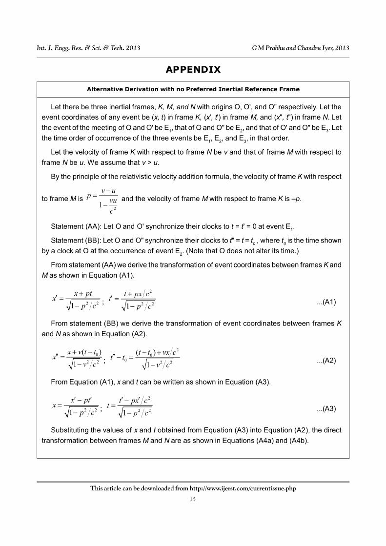
Let there be three inertial frames, K, M, and N with origins O, O', and O" respectively. Let the
event coordinates of any event be (x, t) in frame K, (x', t') in frame M, and (x", t") in frame N. Let
the event of the meeting of O and O' be E1, that of O and O" be E2, and that of O' and O" be E3. Let
the time order of occurrence of the three events be E1, E2, and E3, in that order.
Let the velocity of frame K with respect to frame N be v and that of frame M with respect to
frame N be u. We assume that v > u.
By the principle of the relativistic velocity addition formula, the velocity of frame K with respect
to frame M is 2
1
v up
vu
c
and the velocity of frame M with respect to frame K is –p.
Statement (AA): Let O and O' synchronize their clocks to t = t' = 0 at event E1.
Statement (BB): Let O and O" synchronize their clocks to t" = t = t0 , where t0 is the time shown
by a clock at O at the occurrence of event E2. (Note that O does not alter its time.)
From statement (AA) we derive the transformation of event coordinates between frames K and
M as shown in Equation (A1).
2 21
x ptx
p c
;
2
2 21
t px ct
p c
...(A1)
From statement (BB) we derive the transformation of event coordinates between frames K
and N as shown in Equation (A2).
0
2 2
( )
1
x v t tx
v c
;
20
0 2 2
( )
1
t t vx ct t
v c
...(A2)
From Equation (A1), x and t can be written as shown in Equation (A3).
2 21
x ptx
p c
;
2
2 21
t px ct
p c
...(A3)
Substituting the values of x and t obtained from Equation (A3) into Equation (A2), the direct
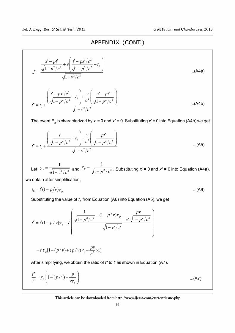
transformation between frames M and N are as shown in Equations (A4a) and (A4b).
APPENDIX
Alternative Derivation with no Preferred Inertial Reference Frame
16
This article can be downloaded from http://www.ijerst.com/currentissue.php
Int. J. Engg. Res. & Sci. & Tech. 2013 G M Prabhu and Chandru Iyer, 2013
APPENDIX (CONT.)
2
02 2 2 2
2 2
1 1
1
x pt t px cv t
p c p cx
v c
...(A4a)
2
0 22 2 2 2
0 2 2
1 1
1
t px c v x ptt
cp c p ct t
v c
...(A4b)
The event E3 is characterized by x' = 0 and x" = 0. Substituting x' = 0 into Equation (A4b) we get
0 22 2 2 2
0 2 2
1 1
1
t v ptt
cp c p ct t
v c
...(A5)
Let 2 2
1
1 /v
v c
and 2 2
1
1 /p
p c
. Substituting x' = 0 and x" = 0 into Equation (A4a),
we obtain after simplification,
0 (1 ) pt t p v ...(A6)
Substituting the value of t0 from Equation (A6) into Equation (A5), we get
2 2 2 2 2
2 2
1(1 / )
1 1(1 / )
1
p
p
pvp v
p c c p ct t p v t
v c
2[1 ( / ) ( / ) ]p v v
pvt p v p v
c
After simplifying, we obtain the ratio of t" to t' as shown in Equation (A7).
1 ( / )pv
t pp v
t v
...(A7)
17
This article can be downloaded from http://www.ijerst.com/currentissue.php
Int. J. Engg. Res. & Sci. & Tech. 2013 G M Prabhu and Chandru Iyer, 2013
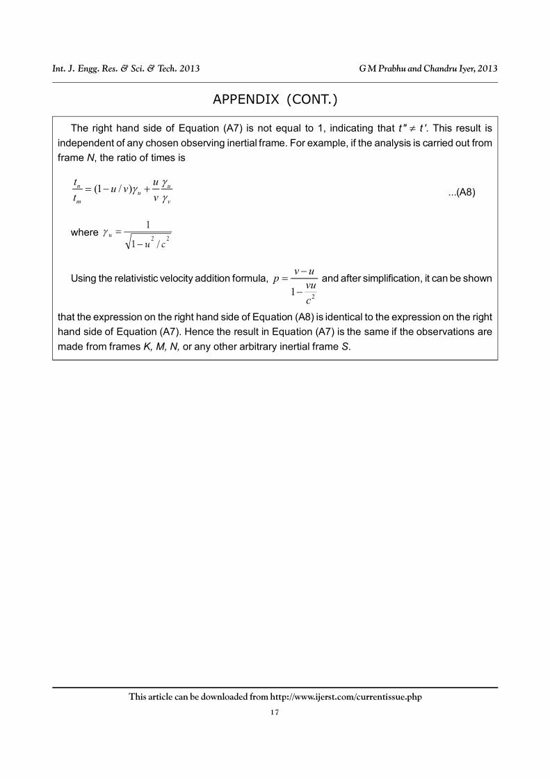
APPENDIX (CONT.)
The right hand side of Equation (A7) is not equal to 1, indicating that t" t '. This result is
independent of any chosen observing inertial frame. For example, if the analysis is carried out from
frame N, the ratio of times is
(1 / )n uu
m v
t uu v
t v
...(A8)
where 22
/1
1
cuu
Using the relativistic velocity addition formula,
21
v up
vu
c
and after simplification, it can be shown
that the expression on the right hand side of Equation (A8) is identical to the expression on the right
hand side of Equation (A7). Hence the result in Equation (A7) is the same if the observations are
made from frames K, M, N, or any other arbitrary inertial frame S.
Related Documents