a. b. c. d. d. c. b. a.

Welcome message from author
This document is posted to help you gain knowledge. Please leave a comment to let me know what you think about it! Share it to your friends and learn new things together.
Transcript

1Symmetry as a Continuous FeatureH. Zabrodsky, S. Peleg and D. AvnirIEEE Trans. Pattern Analysis and Machine Intelligence, 17(12), 1154-1166,1995
Abstract| Symmetry is treated as a continuous featureand a Continuous Measure of Distance from Symmetry inshapes is de�ned. The Symmetry Distance (SD) of a shape isde�ned to be the minimum mean squared distance requiredto move points of the original shape in order to obtain asymmetrical shape. This general de�nition of a symmetrymeasure enables a comparison of the \amount" of symmetryof di�erent shapes and the \amount" of di�erent symmetriesof a single shape. This measure is applicable to any type ofsymmetry in any dimension. The Symmetry Distance givesrise to a method of reconstructing symmetry of occludedshapes. We extend the method to deal with symmetries ofnoisy and fuzzy data. Finally, we consider grayscale imagesas 3D shapes, and use the Symmetry Distance to �nd theorientation of symmetric objects from their images, and to�nd locally symmetric regions in images.I. IntroductionOne of the basic features of shapes and objects is symme-try. Symmetry is considered a pre-attentive feature whichenhances recognition and reconstruction of shapes and ob-jects [4]. Symmetry is also an important parameter in phys-ical and chemical processes and is an important criterionin medical diagnosis.a. b. c.Fig. 1. Faces are not perfectly symmetrical.a) Original image.b) Left half of original image and its re ection.c) Right half of original image and its re ection.However, the exact mathematical de�nition of symmetry[23], [32] is inadequate to describe and quantify the sym-metries found in the natural world nor those found in thevisual world (a classic example is that of faces - see Fig-ure 1). Furthermore, even perfectly symmetric objects losetheir exact symmetry when projected onto the image planeor the retina due to occlusion, perspective transformations,digitization, etc. Thus, although symmetry is usually con-sidered a binary feature, (i.e. an object is either symmetricor it is not symmetric), we view symmetry as a continu-ous feature where intermediate values of symmetry denotesome intermediate \amount" of symmetry. This concept ofcontinuous symmetry is in accord with our perception ofsymmetry as can be seen, for example, in Figure 2.Considering symmmetry as a continuous feature, we in-troduce a \Symmetry Distance" that can measure andquantify all types of symmetries of objects. This measureH. Zabrodsky and S. Peleg are with the Institute of Computer Sci-ence, The Hebrew University of Jerusalem, Jerusalem, 91904 Israel.D. Avnir is with the Department of Organic Chemistry, The HebrewUniversity of Jerusalem, Jerusalem, 91904 Israel.
a. b. c. d.Fig. 2. Perceiving continuous symmetry.a) A shape perceived as perfectly symmetric (the oblique mir-ror axis passing through the vertex). b) Shortening an arm, theshape is perceived as \almost" symmetric. c) Further shorteningof the arm, the shape is perceived as having \less" symmetry.e) When the arm is eliminated the shape is again perfectly sym-metric (with a mirror axis perpendicular to the existing arm).will enable a comparison of the \amount" of symmetry ofdi�erent shapes and the \amount" of di�erent symmetriesof a single shape. Additionally, we present a simple andgeneral algorithm for evaluating this measure.In Section II we de�ne the Symmetry Distance and inSection III describe a method for evaluting this measure.Following, in Sections IV-VI we describe features of thesymmetry distance including its use in dealing with oc-cluded objects and with noisy data. Finally in Section VIIwe describe the application of the symmetry distance to�nding face orientation and to �nding locally symmetricregions in images.A. De�nitions of SymmetryIn this paper we refer to the symmetries de�ned be-low, although the de�nitions, methods and discussions pre-sented in this work apply to all other symmetries in anydimension. For further details and a review see [34].A 2D object is mirror-symmetric if it is invariant un-der a re ection about a line (the mirror-symmetry axis).A 3D object is mirror-symmetric if it is invariant un-der a re ection about a plane.A 2D object has rotational-symmetry of order n, de-noted Cn-Symmetry, if it is invariant under rotation of2�n radians about the center of mass of the object.A 3D object has rotational-symmetry of order n, de-noted Cn-Symmetry, if it is invariant under rotation of2�n radians about a line (the rotational symmetry axis)passing through the center of mass of the object.Radial symmetry is the symmetry of a 2D object havingboth mirror-symmetry and Cn-symmetry (note that suchobjects have n axes of mirror-symmetry). Radial symmetryof order n is denoted Dn-Symmetry. Circular symmetryis C1-symmetry (see Figure 3).d.c.b.a.Fig. 3. Examples of symmetries: a) C8-symmetry b) mirror-symmetry c) D8-symmetry d) circular symmetry.

2B. Studies of Symmetry In Computer VisionDetection of symmetry in images has been widely stud-ied; with respect to circular (radial) symmetries [6], [29]and with respect to mirror symmetries [22], [26]. Trans-formation of the symmetry detection problem to a patternmatching problem introduces e�cient algorithms for detec-tion of mirror and rotational symmetries and the locationof symmetry axes [3], [1]. These algorithms assume noisefree input and detect symmetry, if exists, on a global scale.As an intrinsic characteristic of objects and shapes, sym-metry has been used to describe and recognize shapes andobjects both on a global scale [17], [21] and as a local fea-ture [10], [8], [28]. Symmetrical features of images havebeen exploited for better image compression [20]. Symmet-rical descriptions of shapes and the detection of symmetri-cal features of objects are useful in guiding shape matching,model-based object matching and object recognition [27],[29]. Reconstruction of 3D objects has also been imple-mented using symmetry as a constraint [31], [24]. Morerecently, symmetry has been used to discriminate textures[9] and has been used in guiding robot grasping [7].Considerable work has been done on skewed symmetriesincluding detection and exploiting them in the reconstruc-tion of 3D structure [26], [27], [18], [14], [28].So far, symmetry has been treated as a binary feature:either it exists or it does not exist. The approach to sym-metry as a continuous feature is novel, although severalearly studies have approached the question of measuringsymmetry: In an early work, Gr�unbaum [15] reviews meth-ods of geometrically measuring symmetry of convex sets.Yodogawa [33] has presented an evaluation of symmetry(namely \Symmetropy") in single patterns which uses in-formation theory to evaluate the distribution of symme-tries in a pattern. Marola [22] presents a coe�cient ofmirror-symmetry with respect to a given axis where globalmirror-symmetry is found by roughly estimating the axislocation and then �ne tuning the location by minimizingthe symmetry coe�cient. Gilat [13], Hel-Or et.al.[16] andAvnir et.al. [5] present the idea of a Measure of Chirality(a measure of deviation from mirror-symmetry). Similarto Marola, Gilat's chirality measure is based on minimizingthe volume di�erence between the object and it's re ectionthrough a varying plane of re ection. Hel-Or et al. presenta measure of chirality for 2D objects based on rotationale�ects of chiral bodies on the surround.These symmetry detection and evaluation methods areeach limited to a certain type of symmetry (mirror or cir-cular symmetry). In this paper we introduce the notionof continuous symmetry and present a general continuousmeasure the symmetry distance for evaluating all types ofsymmetries in any dimension.II. A Continuous Symmetry Measure - DefinitionWe de�ne the Symmetry Distance (SD) as a quanti-�er of the minimum `e�ort' required to transform a givenshape into a symmetric shape. This `e�ort' is measured bythe mean of the square distances each point is moved from
its location in the original shape to its location in the sym-metric shape. Note that no a priori symmetric referenceshape is assumed.Denote by the space of all shapes of a given dimension,where each shape P is represented by a sequence of n pointsfPign�1i=0 . We de�ne a metric d on this space as follows:d : �! Rd(P;Q) = d(fPig; fQig) = 1n n�1Xi=0 kPi �Qik2This metric de�nes a distance function between every twoshapes in .We de�ne the Symmetry Transform of a shape P asthe symmetric shape P̂ , closest to P in terms of metric d.The Symmetry Distance (SD) of a shape P is de�nedas the distance between P and it's Symmetry Transform:SD = d(P; P̂ )The SD of a shape P = fPign�1i=0 is evaluated by �nding thesymmetry transform P̂ of P and computing:SD = 1n n�1Xi=0 kPi � P̂ik2This de�nition of the Symmetry Distance implicitly im-plies invariance to rotation and translation. Normalizationof the original shape prior to the transformation addition-ally allows invariance to scale (Figure 4). We normalize byscaling the shape so that the maximum distance betweenpoints on the contour and the centroid is a given constant(in this paper all examples are given following normaliza-tion to 10). The normalization presents an upper bound onthe mean squared distance moved by points of the shape.Thus the SD value is limited in range, where SD=0 forperfectly symmetric shapes. The general de�nition of theSymmetry Distance enables evaluation of a given shapefor di�erent types of symmetries (mirror-symmetries, ro-tational symmetries etc). Moreover, this generalization al-lows comparisons between the di�erent symmetry types,and allows expressions such as \a shape is more mirror-symmetric than C2-symmetric".1
P’
0P’
2P’
2P̂ 1P̂
0P̂
P’1
P’2
P’0
P̂0
P̂1P̂2
c.a. b.
1P2P
0P
symmetry transform
d.C - Symmetry = 12.80
normalize
3Fig. 4. Calculating the Symmetry Distance of a shape:a) Original shape fP0; P1; P2g.b) Normalized shape fP 00; P 01; P 02g, such that maximum distanceto the center of mass is a given constant (10).c) Applying the symmetry transform to obtain a symmetricshape fP̂0; P̂1; P̂2g.d) SD = 13 (kP 00 � P̂0k2 + kP 01 � P̂1k2 + kP 02 � P̂2k2)

3An additional feature of the Symmetry Distance is thatwe obtain the symmetric shape which is `closest' to thegiven one, enabling visual evaluation of the SD.3C 2C
6C Mirror
a.
b. c. d. e.Fig. 5. Symmetry Transforms of a 2D polygon.a) 2D polygon and its Symmetry Transform with respect tob) C2-symmetry (SD = 1.87).c) C3-symmetry (SD = 1.64).d) C6-symmetry (SD = 2.53).e) Mirror-symmetry (SD = 0.66).An example of a 2D polygon and it's symmetry trans-forms and SD values are shown in Fig. 5. Note that theshape in Fig. 5e is the most similar to the original shapeFig. 5a and, indeed, its SD value is the smallest. In thenext Section we describe a geometric algorithm for deriv-ing the Symmetry Transform of a shape. In Section IVwe deal with the initial step of representing a shape by acollection of points.III. Evaluating the Symmetry TransformIn this Section we describe a geometric algorithm forderiving the Symmetry Transform of a shape representedby a sequence of points fPign�1i=0 . In practice we �nd theSymmetry Transform of the shape with respect to a givensymmetry group. For simplicity and clarity of explanation,we describe the method by using some examples. Mathe-matical proofs and derivations can be found in Appendix A.We �rst present the algorithm for Cn-symmetry and latergeneralize it to any �nite symmetry group.Following is a geometrical algorithm for deriving thesymmetry transform of a shape P having n points withrespect to rotational symmetry of order n (Cn-symmetry).This method transforms P into a regular n-gon, keepingthe centroid in place.Algorithm for �nding the Cn-symmetry transform:1. Fold the points fPign�1i=0 by rotating each point Picounterclockwise about the centroid by 2�i=n radians(Figure 6b).2. Let P̂0 be the average of the points f ~Pign�1i=0 (Fig-ure 6c).3. Unfold the points, obtaining the Cn-symmetric pointsfP̂ign�1i=0 by duplicating P̂0 and rotating clockwiseabout the centroid by 2�i=n radians (Figure 6d).
P0^ P0
P1
P2
2π33
2π
32π
^
^
^
P2P1
P0 P0
P2
P1
d.a. b. c.
~
~
~
Fig. 6. The C3-symmetry Transform of 3 points.a) Original 3 points fPig2i=0.b) Fold fPig2i=0 into f ~Pig2i=0.c) Average f ~Pig2i=0 obtaining P̂0 = 13P2i=0 ~Pi.d) Unfold the average point obtaining fP̂ig2i=0.The centroid ! is marked by �.The set of points fP̂ign�1i=0 is the symmetry transform of thepoints fPign�1i=0 . i.e. they are the Cn-symmetric con�gu-ration of points closest to fPign�1i=0 in terms of the metricd de�ned in Section II (in terms of the average distancesquared). Proof is given in Appendix A.The common case, however, is that shapes have morepoints than the order of the symmetry. For symmetry oforder n, the folding method can be extended to shapeshaving a number of points which is a multiple of n. A 2Dshape P having qn points is represented as q sets fSrgq�1r=0of n interlaced points Sr = fPiq+rgn�1i=0 (see discussion inAppendix C). The Cn-symmetry transform of P (Figure 7)is obtained by applying the above algorithm to each set ofn points seperately, where the folding is performed aboutthe centroid of all the pointsP3 P
4
P5
P1
P0
P5
2P2P
P1
P4
P3
P0
a. b.
^
^
^
^
^
^Fig. 7. Geometric description of the C3-symmetry transformfor 6 points.The centroid ! of the points is marked by �.a) The original points shown as 2 sets of 3 points:S0=fP0; P2; P4g and S1=fP1; P3; P5g.b) The obtained C3-symmetric con�guration.The procedure for evaluating the symmetry transform formirror-symmetry is similar: Given a shape having m = 2qpoints we divide the points into q pairs of points (see Ap-pendix C) and given an initial guess of the symmetry axis,we apply the folding/unfolding method as follows (see Fig-ure 8):Algorithm for �nding the mirror-symmetry transform:1. for every pair of points fP0; P1g:(a) fold - by re ecting across the mirror symmetry axisobtaining f ~P0; ~P1g.(b) average - obtaining a single averaged point P̂0.(c) unfold - by re ecting back across the mirror sym-metry axis obtaining fP̂0; P̂1g.2. minimize over all possible axes of mirror-symmetry.

4The minimization performed in step 2 is, in practice, re-placed by an analytic solution (see Appendix B).P1
0PP1
0P~ 0P̂
P1~
P1^
0P̂
a. b.
mirror axis
c.
mirror axismirror axis~
~=P0
originoriginorigin
θθ θFig. 8. The mirror-symmetry transform of a single pair of pointsfor angle �, where the centroid of the shape is assumed tobe at the origin.a) The two points fP0; P1g are folded to obtain f ~P0; ~P1g.b) Points ~P0 and ~P1 are averaged to obtain P̂0.c) P̂1 is obtained by re ecting P̂0 about the symmetry axis.This method extends to any �nite point-symmetrygroup G in any dimension, where the folding and unfoldingare performed by applying the group elements about thecentroid (see derivations in Appendix A):Given a �nite symmetry group G (having n elements)and given a shape P represented by m = qn points,the symmetry transform of the shape with respect to G-symmetry is obtained as follows:Algorithm for �nding the G-symmetry transform:1. The points are divided into q sets of n points.2. For every set of n points:(a) The points are folded by applying the elements ofthe G-symmetry group.(b) The folded points are averaged, obtaining a singleaveraged point.(c) The averaged point is unfolded by applying the in-verse of the elements of the G-symmetry group. AG-symmetric set of n points is obtained.3. The above procedure is performed over all possibleorientations of the symmetry axis and planes of G.Select that orientation which minimizes the Symme-try Distance value. As previously noted, this mini-mization is analytic in 2D (derivation is given in Ap-pendix B) but requires an iterative minimization pro-cess in 3D (except for the 3D mirror-symmetry groupwhere a closed form solution has been derived [35]).Thus, the Symmetry Distance of a shape may be eval-uated with respect to any �nite symmetry group. Onemay consider as the `appropriate' symmetry of a shape,that symmetry group which minimizes the Symmetry Dis-tance. A minimization over all symmetry groups can beapplied, however, minimization over a �nite number of loworder groups usually su�ces (in 2D minimization over mir-ror and prime-ordered rotational symmetries is su�cient.Since evaluation of the Symmetry Distance in 2D is ana-lytical, this minimization is inexpensive).IV. Point Selection for Shape RepresentationAs symmetry has been de�ned on a sequence of points,representing a given shape by points must precede the ap-plication of the symmetry transform. Selection of points
4
3
2
P
P
P
P5P 1
2
3
4
P
P
P
PP
0
0P
1Fig. 9. When measuring symmetry of shapes inherently createdfrom points we represent the shape by these points.in uences the value of SD and depends on the type of ob-ject to be measured. If a shape is inherently created frompoints (such as a graph structure or cyclically connectedpoints creating a polygon) we can represent a shape bythese points (Figure 9). This is the case when analysingsymmetry of molecules ([37], [35]). There are several waysto select a sequence of points to represent continuous 2Dshapes. One such method is selection at equal distances -the points are selected along the shape's contour such thatthe curve length between every pair of adjacent points isequal (Figure 10).6l
l
6
6l
l
6
6l
l
6
4
5
3
2
1
0
P
P
P
P
P
P
Fig. 10. Point selection by equaldistance: points are selectedalong the contour at equal dis-tances in terms of curve length.In this example six points aredistributed along the contourspaced by 16 of the full contourlength.In many cases, however, contour length is not a mean-ingful measure, as in noisy or occluded shapes. In suchcases we propose to select points on a smoothed version ofthe contour and then project them back onto the originalcontour. The smoothing of the continuous contour is per-formed by moving each point on the continuous contour tothe centroid of its contour neighborhood. The greater thesize of the neighborhood, the greater is the smoothing (seeFigure 11). The level of smoothing can vary and for a highlevel of smoothing, the resulting shape becomes almost acircle about the centroid [25]. In this case, equal distanceson the circular contour is equivalent to equal angles aboutthe center. For maximum smoothing we, therefore, useselection at equal angles (Figure 12) where points are se-lected on the original contour at equal angular intervalsaround the centroid. For further details on the selection ofpoints by smoothing see [34].V. Symmetry of Occluded Shapes - Center ofSymmetryAs described in Section IV, a shape can be representedby points selected at regular angular intervals about thecentroid. Angular selection of points about a point otherthan the centroid will give a di�erent symmetry distancevalue. We de�ne the center of symmetry of a shapeas that point in the 2D plane about which selection atequal angles gives the minimum symmetry distance value

5(Fig. 13). Intuitively, the center of symmetry is that pointabout which rotation of the shape aligns it as close as pos-sible with itself (in terms of the mean squared distances).When a symmetric shape is complete the center of sym-metry coincides with the centroid of the shape. However,the center of symmetry of truncated or occluded objectsdoes not align with its centroid but is closer to the cen-troid of the complete shape. Thus the center of symmetryof a shape is robust under truncation and occlusion.To locate the center of symmetry, we use an iterativeprocedure of gradient descent that converges from the cen-troid of an occluded shape to the center of symmetry. De-note by center of selection, that point about which pointsare selected using selection at equal angles. We initializethe iterative process by setting the centroid as the cen-c. d. e. f.
a. b.
g. h. i. j.Fig. 11. Selection by smoothinga) Original continuous contour.b) Points are selected at equal distances along the contour.c-f) The smoothed shape is obtained by averaging neighbor-ing points of (b). The amount of smoothing depends on thesize of the neighborhood. The smoothed shapes (c-f) are ob-tained when neighborhood includes 5,10,15 and 20 percent ofthe points, respectively.g-j) The sampling of points on the original shape using thesmoothed shapes (c-f) respectively. Notice that fewer pointsare selected on the \noisy" part of the contour.82π
Fig. 12. Selection at equal angles:points are distributed alongthe contour at regular angularintervals around the centroid.Fig. 13. An occluded shape with sam-pled points selected at equal an-gles about the center of symme-try (marked by �). The symme-try distance obtained using thesepoints is smaller than the symme-try distance obtained using pointsselected at equal angles about thecentroid (marked by +).
a. b. c.Fig. 14. Reconstruction of an occluded shape.a) Original occluded shape, its centroid (+) and its center ofsymmetry(�).b,c) The closest C5-symmetric shape using angular selectionabout the centroid (b) and about the center of symmetry (c).Selection about the centroid gives a featureless shape, whileselection about the center of symmetry yields a more meaningfulshape.ter of selection. At each step we compare the symmetryvalue obtained from points selected at equal angles aboutthe center of selection with the symmetry value obtainedby selection about points in the center of selection's im-mediate neighborhood. That point about which selectionat equal angles gives minimum symmetry value, is set tobe the new center of selection. If the center of selectiondoes not change, the neighborhood size is decreased. Theprocess is terminated when neighborhood size reaches aprede�ned minimum size. The center of selection at theend of the process is taken as the center of symmetry.In the case of occlusions (Figure 14), the closest symmet-ric shape obtained by angular selection about the center ofsymmetry is visually more similar to the original than thatobtained by angular selection about the centroid. We canreconstruct the symmetric shape closest to the unoccludedshape by obtaining the symmetry transform of the occludedshape using angular selection about the center of symme-try (see Figure 14c). In Figure 15 the center of symmetryand the closest symmetric shapes were found for severaloccluded owers.The process of reconstructing the occluded shape can beimproved by altering the method of evaluating the sym-metry of a set of points. As described in Section III, thesymmetry of a set of points is evaluated by folding, aver-aging and unfolding about the centroid of the points. Wealter the method as follows:1. The folding and unfolding (steps 1 and 3) will beperformed about the center of symmetry rather thanabout the centroid of the points.2. Rather than averaging the folded points (step 2), weapply other robust clustering methods. In practice weaverage over the folded points, drop the points farthestfrom the average and then reaverage (see Figure 16).Intuitively, the robust clustering causes the reconstruc-tion to be strongly in uenced by contour points on theunoccluded portion of the shape while eliminating the in- uence of the points on the contour representing the trun-cated or occluded portion of the shape.The improvement in reconstruction of an occluded shapeis shown in Figure 17. This method improves both shapeand localization of the reconstruction. Assuming that theoriginal shape was symmetric, this method can reconstruct
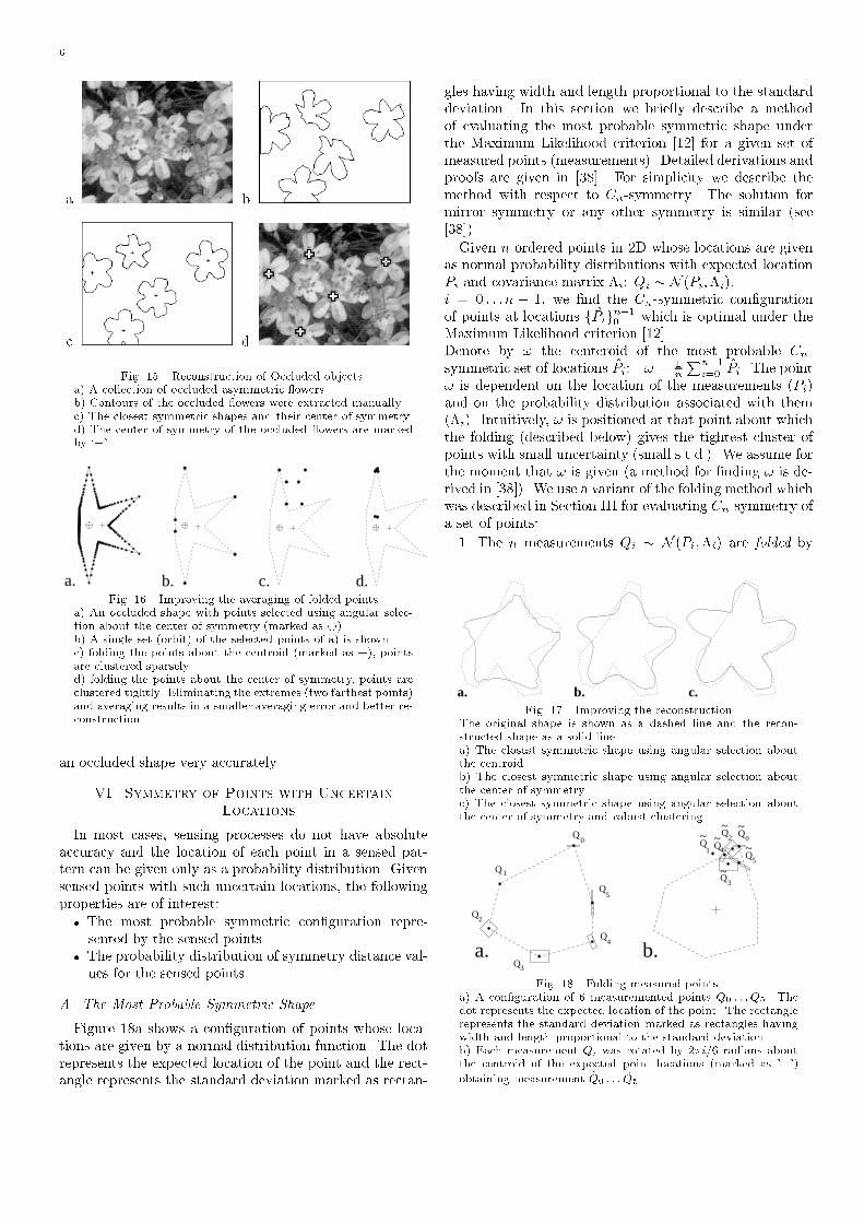
6a. b.c. d.Fig. 15. Reconstruction of Occluded objects.a) A collection of occluded asymmetric owers.b) Contours of the occluded owers were extracted manually.c) The closest symmetric shapes and their center of symmetry.d) The center of symmetry of the occluded owers are markedby `+'.
b.a. c. d.Fig. 16. Improving the averaging of folded pointsa) An occluded shape with points selected using angular selec-tion about the center of symmetry (marked as �).b) A single set (orbit) of the selected points of a) is shown.c) folding the points about the centroid (marked as +), pointsare clustered sparsely.d) folding the points about the center of symmetry, points areclustered tightly. Eliminating the extremes (two farthest points)and averaging results in a smaller averaging error and better re-construction.an occluded shape very accurately.VI. Symmetry of Points with UncertainLocationsIn most cases, sensing processes do not have absoluteaccuracy and the location of each point in a sensed pat-tern can be given only as a probability distribution. Givensensed points with such uncertain locations, the followingproperties are of interest:� The most probable symmetric con�guration repre-sented by the sensed points.� The probability distribution of symmetry distance val-ues for the sensed points.A. The Most Probable Symmetric ShapeFigure 18a shows a con�guration of points whose loca-tions are given by a normal distribution function. The dotrepresents the expected location of the point and the rect-angle represents the standard deviation marked as rectan-
gles having width and length proportional to the standarddeviation. In this section we brie y describe a methodof evaluating the most probable symmetric shape underthe Maximum Likelihood criterion [12] for a given set ofmeasured points (measurements). Detailed derivations andproofs are given in [38]. For simplicity we describe themethod with respect to Cn-symmetry. The solution formirror symmetry or any other symmetry is similar (see[38]).Given n ordered points in 2D whose locations are givenas normal probability distributions with expected locationPi and covariance matrix �i: Qi � N (Pi;�i);i = 0 : : : n � 1, we �nd the Cn-symmetric con�gurationof points at locations fP̂ign�10 which is optimal under theMaximum Likelihood criterion [12].Denote by ! the centeroid of the most probable Cn-symmetric set of locations P̂i: ! = 1nPn�1i=0 P̂i. The point! is dependent on the location of the measurements (Pi)and on the probability distribution associated with them(�i). Intuitively, ! is positioned at that point about whichthe folding (described below) gives the tightest cluster ofpoints with small uncertainty (small s.t.d.). We assume forthe moment that ! is given (a method for �nding ! is de-rived in [38]). We use a variant of the folding method whichwas described in Section III for evaluating Cn-symmetry ofa set of points:1. The n measurements Qi � N (Pi;�i) are folded bya. b. c.Fig. 17. Improving the reconstructionThe original shape is shown as a dashed line and the recon-structed shape as a solid line.a) The closest symmetric shape using angular selection aboutthe centroid.b) The closest symmetric shape using angular selection aboutthe center of symmetry.c) The closest symmetric shape using angular selection aboutthe center of symmetry and robust clustering.
~~
~Q
3
4Q Q
1
~~ ~Q
2 Q0
Q5
a. b.Q
Q
Q
Q
Q
Q4
5
0
1
2
3 Fig. 18. Folding measured points.a) A con�guration of 6 measuremented points Q0 : : :Q5. Thedot represents the expected location of the point. The rectanglerepresents the standard deviation marked as rectangles havingwidth and length proportional to the standard deviation.b) Each measurement Qi was rotated by 2�i=6 radians aboutthe centroid of the expected point locations (marked as '+')obtaining measurement ~Q0 : : : ~Q5.

7a. b. c. d. e.Fig. 19. The most probable symmetric shape.a) A con�guration of 6 measured points.b-e) The most probable symmetric shapes with respect to b)C2-symmetry.c) C3-symmetry.d) C6-symmetry.e) mirror-symmetry.rotating each measurement Qi by 2�i=n radians aboutthe point !. A new set of measurements~Qi � N ( ~Pi; ~�i) is obtained (see Figure 18b).2. The folded measurements are averaged using aweighted average, obtaining a single point P̂0. Averag-ing is done by considering the n folded measurements~Qi as n measurements of a single point and P̂0 repre-sents the most probable location of that point underthe Maximum Likelihood criterion.P̂0 � ! = (n�1Xj=0 ~��1j )�1 n�1Xi=0 ~��1i ~Pi � !3. The \average" point P̂0 is unfolded as described inSection III obtaining points fP̂ign�1i=0 which are per-fectly Cn-symmetric.When we are given m = qn measurements, we �nd themost probable Cn-symmetric con�guration of points, sim-ilar to the folding method of Section III. The m measure-ments fQigm�1i=0 , are divided into q interlaced sets of n mea-surements each, and the folding method as described aboveis applied seperately to each set of measurements. Deriva-tions and proof of this case is also found in [38].Several examples are shown in Figure 19, where for agiven set of measurements, the most probable symmetricshapes were found. Figure 20 shows an example of varyingthe probability distribution of the measurements on theresulting symmetric shape.a. b. c. d. e.Fig. 20. The most probable C3-symmetric shape for a setof measurements after varying the probability distributionand expected locations of the measurements.a-c) Changing the uncertainty (s.t.d.) of the measurements.d-e) Changing both the uncertainty and the expected locationof the measurements.B. The Probability Distribution of Symmetry ValuesFigure 21a displays a Laue photograph [2] which is an in-terefrence pattern created by projecting X-ray beams ontocrystals. Crystal quality is determined by evaluating thesymmetry of the pattern. In this case the interesting fea-ture is not the closest symmetric con�guration, but theprobability distribution of the symmetry distance values.
Consider the con�guration of 2D measurements given inFigure 18a. Each measurement Qi is a normal probabilitydistribution Qi � N (Pi;�i). We assume the centroid ofthe expectation of the measurements is at the origin. Theprobability distribution of the symmetry distance valuesof the original measurements is equivalent to the probabil-ity distribution of the location of the \average" point (P̂0)given the folded measurements as obtained in Step 1 andStep 2 of the algorithm in Section VI-A. It is shown in[38] that this probability distribution is a �2 distributionof order n� 1. However, we can approximate the distribu-tion by a gaussian distribution. Details of the derivationare given in [38].In Figure 21 we display distributions of the symmetrydistance value as obtained for the Laue photograph givenin Figure 21a. In this example we considered every darkpatch as a measured point with variance proportional tothe size of the patch. Thus in Figure 21b the rectangleswhich are proportional in size to the corresponding darkpatches of Figure 21a, represent the standard deviation ofthe locations of point measurements. Note that a di�erentanalysis could be used in which the variance of the mea-surement location is taken as inversely proportional to thesize of the dark patch.In Figure 22 we display distributions of the symmetrydistance value for various measurements. As expected, thedistribution of symmetry distance values becomes broaderas the uncertainties (the variance of the distribution) of themeasurements increase.a. b.c.
ProbabilityDensity
2000
6000
10000
14000
0.0036 0.00364 0.00368Symmetry ValueFig. 21. Probability distribution of symmetry valuesa) Interference pattern of crystals.b) Probability distribution of point locations corresponding to a.c) Probability distribution of symmetry distance values with re-spect to C10-symmetry was evaluated as described in the text.Expectation value = 0.003663.

8a. b. c. d.
b c d
a
0.02 0.025 0.03 0.035 0.04 0.045 0.05
50
100
150
200
250
300
350
Symmetry Value
ProbabilityDensity
0Fig. 22. Probability distribution of the symmetry distance valueas a function of the variance of the measured points.a-d) Some examples of con�gurations of measured points.e) Probability distribution of symmetry distance values withrespect to C6-symmetry for the con�gurations a-d.P1
P20P
P‘1
P‘2
P‘0
Reflection plane
Image plane
Fig. 23. Selecting points on the 3Dobject (a 2D analog is shown).For a possible re ection plane, theplane perpendicular to it is sam-pled. Elevations are recomputed onthe object relative to the samplingplane.VII. Application to ImagesA. Finding Orientation of Symmetric 3D ObjectsWhen dealing with images, we let pixel values denoteelevation, and consider an image as a 3D object on whichwe can measure 3D symmetries. We applied the SD to �ndorientation of symmetric 3D objects by �nding their 3Dmirror-symmetry. The 3D shape is represented by a set of3D points: for a possible re ection plane, the plane perpen-dicular to it is sampled. Each sampled points is projectedonto the 3D object and its elevation is recomputed relativeto the sampling plane (Figure 23). The symmetry value for3D mirror-symmetry is evaluated using the projected sam-pling points. The �nal re ection plane of the 3D objectis determined by minimizing the symmetry value over allpossible re ection planes. In practice only feasible symme-try planes were tested (i.e. planes which intersect the 3Dimage) and a gradient descent algorithm was used to in-crease e�ciency of convergence to the minimum symmetryvalue (the SD). Examples are shown in Figure 24, where asymmetric 3D object is rotated into a frontal vertical viewafter the re ection plane was found.
B. Using a Multiresolution SchemeIn many images the process of �nding the re ection planedid not converge to the correct solution, i.e. the processconverged to a local minima due to the sensitivity of thesymmetry value to noise and digitization errors. To over-come this problem we introduced a multiresolution scheme,where an initial estimation of the symmetry transform isobtained at low resolution (see Figure 25) and is �ne tunedusing high resolution images. The solution obtained forthe low resolution image is used as an initial guess of thesolution for the high resolution image. The low resolutionimages were obtained by creating gaussian pyramids [11].C. Finding Locally symmetric RegionsMost images cannot be assumed to have a single globalsymmetry, but contain a collection of symmetric and al-most symmetric patterns (be they objects or background).We aim to locate these local symmetries and segment thesymmetrical objects from the background. The followingthree staged process is used to extract locally symmetricregions in images.1. The �rst stage locates symmetry focals - those pointsabout which the image is locally symmetric. Severalmethods can be used to �nd the symmetry focals ([29],for example). We used a variant of the multiresolutionmethod presented in [36] for sampling and transmit-ting an image, which uses a simple model of the humanvisual attention mechanism.We used the Quad Tree [30] structure which is a hier-archical representation of an image, based on recursivesubdivisions of the image array into quadrants. Theprocess of locating symmetry focals builds a sequenceof quad trees and a sequence of corresponding divisionsof the image into quadrants. The process is initializedby setting the current quad tree to a single root node(corresponding to the whole image). At each step allquadrants of the image corresponding to the leaves ofthe quad tree are tested for a given \interest" func-a. b.c. d.Fig. 24. Applying the SD with respect to 3D mirror-symmetryin order to �nd orientation of a 3D object.a,c) original depth maps.b,d) The symmetry re ection plane has been found and theimage rotated to a frontal vertical view.

9tion. That node of the quad tree that corresponds tothe quadrant with highest \interest" value is selected.The current quad tree is expanded by creating the sonnodes of the selected node and accordingly, subdivid-ing the image quadrant associated with the selectednode. Several steps of this procedure are shown in Fig-ure 26. In our case the \interest" function was chosenas to be a function of the Symmetry Distance valueobtained for the image quadrant. Thus the proceduredescribed focuses onto regions of high symmetry con-tent and �nds symmetry focals. In practice, the \in-terest" function also took into account the busyness ofthe image quadrant, thus regions that had low busy-ness values (i.e. the grey-scale values were almost con-stant) gave low \interest" values although they werehighly symmetric (and gave low Symmetry Distancevalues). In Figure 27b, a mirror-symmetry focal andan associated re ection plane (passing through the fo-cal) were found.2. Given a symmetry focal and a re ection plane, a sym-metry map of the image is created as follows: the origi-nal image is sampled at points which are pairwise sym-metric with respect to the given re ection plane. Thesymmetry distance value obtained using the foldingmethod described in Section III for each pair of sam-a. b.c. d.
e)Fig. 25. Using multiresolution to �nd symmetry.The grey-level image is treated as a depth map and 3D mirror-symmetry is computed. The computed symmetry plane is usedto bring the image into a frontal vertical view.a) Original image.b) Applying the mirror-symmetry transform on (a) does not �ndcorrect re ection plane.c) A low resolution image obtainined by convolving (a) with agaussian.d) Applying the mirror-symmetry transform on the low resolu-tion image (c) gives a good estimation of the re ection planeand face orientation.e) Using the re ection plane found in (d) as an initial guess, theprocess now converges to the correct symmetry plane.
pled points is recorded and marked in the symmetrymap at the location corresponding to the coordinatesof the sampled points. Thus the symmetry map dis-plays the \amount" of mirror-symmetry at every point(with respect to the given re ection plane) where lowgrey values denote low SD values (i.e. high symmetrycontent) and high grey values denote high SD values(i.e. low symmetry content) (Figure 27c).3. Starting from the symmetry focals, regions are ex-panded using \active contours" [19] to include com-pact symmetric regions. The expansion is guided bythe symmetry map and continues as long as the pix-els included in the locally symmetric region do notdegrade the symmetry of the region more than a pre-de�ned threshold (Figure 27d).The process can be continued to extract several locallysymmetric regions, as shown in the example of Figure 28.VIII. ConclusionWe view symmetry as a continuous feature and de�nea Symmetry Distance (SD) of shapes. The general def-inition of the Symmetry Distance enables a comparisonof the \amount" of symmetry of di�erent shapes and the\amount" of di�erent symmetries of a single shape. Fur-thermore, the SD is associated with the symmetric shapewhich is `closest' to the given one, enabling visual evalua-tion of the SD. Several applications were described includ-ing reconstruction of occluded shapes, �nding face orienta-tion and �nding locally symmetric regions in images. Wealso described how we deal with uncertain data, i.e. with acon�guration of measurements representing the probabil-ity distribution of point location. The methods describedhere can be easily extended to higher dimensions and tomore complex symmetry groups. Further extensions willdeal with other symmetry classes such as planar symme-try (including translatory symmetry and fractals). Addi-tional work has been done on evaluating re ective symme-
Fig. 26. Several steps in the process of �nding symmetry focals.A sequence of quad trees (bottom row) and the correspondingrecursive division of the image (top row) is created. The pro-cess is initialized by creating a quad tree with a single root nodecorresponding to the whole image (left). At each step all quad-rants of the image corresponding to the leaves of the quad treeare tested for the \interest" function. The leaf of the quad treethat corresponds to the quadrant with highest value (markedin grey) is expanded to create the quad tree of the next step.Three additional steps are shown.
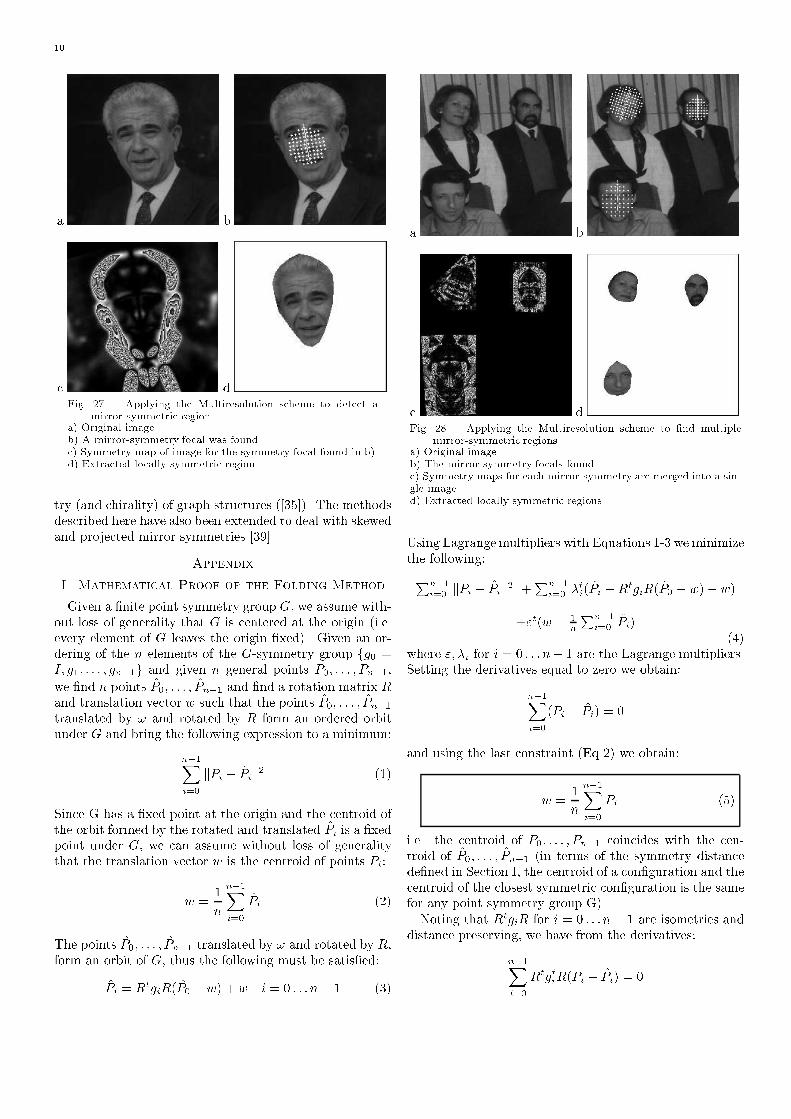
10a. b.c. d.Fig. 27. Applying the Multiresolution scheme to detect amirror-symmetric regiona) Original image.b) A mirror-symmetry focal was found.c) Symmetry map of image for the symmetry focal found in b).d) Extracted locally symmetric region.try (and chirality) of graph structures ([35]). The methodsdescribed here have also been extended to deal with skewedand projected mirror symmetries [39].AppendixI. Mathematical Proof of the Folding MethodGiven a �nite point symmetry group G, we assume with-out loss of generality that G is centered at the origin (i.e.every element of G leaves the origin �xed). Given an or-dering of the n elements of the G-symmetry group fg0 =I; g1; : : : ; gn�1g and given n general points P0; : : : ; Pn�1,we �nd n points P̂0; : : : ; P̂n�1 and �nd a rotation matrix Rand translation vector w such that the points P̂0; : : : ; P̂n�1translated by ! and rotated by R form an ordered orbitunder G and bring the following expression to a minimum:n�1Xi=0 kPi � P̂ik2 (1)Since G has a �xed point at the origin and the centroid ofthe orbit formed by the rotated and translated P̂i is a �xedpoint under G, we can assume without loss of generalitythat the translation vector w is the centroid of points P̂i:w = 1n n�1Xi=0 P̂i (2)The points P̂0; : : : ; P̂n�1 translated by ! and rotated by R,form an orbit of G, thus the following must be satis�ed:P̂i = RtgiR(P̂0 � w) + w i = 0 : : : n� 1 (3)
a. b.c. d.Fig. 28. Applying the Multiresolution scheme to �nd multiplemirror-symmetric regions.a) Original image.b) The mirror-symmetry focals found.c) Symmetry maps for each mirror-symmetry are merged into a sin-gle image.d) Extracted locally symmetric regions.Using Lagrangemultipliers with Equations 1-3 we minimizethe following:Pn�1i=0 kPi � P̂ik2 +Pn�1i=0 �ti(P̂i �RtgiR(P̂0 � w)� w)+"t(w � 1nPn�1i=0 P̂i) (4)where "; �i for i = 0 : : : n� 1 are the Lagrange multipliers.Setting the derivatives equal to zero we obtain:n�1Xi=0(Pi � P̂i) = 0and using the last constraint (Eq 2) we obtain:w = 1n n�1Xi=0 Pi (5)i.e. the centroid of P0; : : : ; Pn�1 coincides with the cen-troid of P̂0; : : : ; P̂n�1 (in terms of the symmetry distancede�ned in Section I, the centroid of a con�guration and thecentroid of the closest symmetric con�guration is the samefor any point symmetry group G).Noting that RtgiR for i = 0 : : : n� 1 are isometries anddistance preserving, we have from the derivatives:n�1Xi=0 RtgtiR(Pi � P̂i) = 0

11Expanding using the constraints we obtain:nP̂0 � n! = n�1Xi=0 RtgtiRPi � n�1Xi=0 RtgtiRwor P̂0 � w = 1n n�1Xi=0 RtgtiR(Pi � w) (6)The derivation of the rotation matrix R is given in thenext section, however, given R, the geometric interpreta-tion of Equation 6 is the folding method, as described inSection III, proving that the folding method results in theG-symmetric set of points closest to the given set.The common case, however, is that shapes have morepoints than the order of the symmetry. For symmetry of or-der n, the folding method can be extended to shapes havinga number of points which is a multiple of n. Given m = qnpoints (i.e. q sets of n points) fP j0 ; : : : ; P jn�1g j = 0 : : : q�1we follow the above derivation and obtain a result similarto that given in Equation 6. For each set of n points, i.e.for j = 0 : : : q � 1:P̂ j0 � w = 1n n�1Xi=0 RtgtiR(P ji � w) (7)where w = 1mPq�1j=0Pn�1i=0 P ji is the centroid of all mpoints. The geometric interpretation of Equation 7 is thefolding method, as described in Section III for the case ofa shape represented by m = qn points.The folding method for the cases where the number ofpoints is not a multiple of the number of elements in G isnot derived here. Details of this case can be found in [37].II. Finding the Optimal Orientation in 2DThe problem of �nding the minimizing orientation is ir-relevant for the Cn symmetry groups since every element gof these groups is a rotation and RtgR = g. In the case ofCn-symmetry groups, R is usually taken as I (the identitymatrix). We derive here a solution for the orientation inthe case where G is a Dn symmetry group.The 2n elements of the Dn-symmetry group can bedescribed as the n elements g0 = I; g1 = R1n; g2 =R2n; : : : ; gn�1 = Rn�1n (where Rin is the rotation of 2�i=nradians about the origin) and the n elements obtained byapplying a re ection Rf on each of these elements: gn =Rf ; gn+1 = RfR1n; gn+2 = RfR2n; : : : ; g2n�1 = RfRn�1n .We denote the orientation of the symmetry group as theangle � between the re ection axis and the y axis. ThusR = � cos � sin �� sin � cos � �
and the re ection operation Rf is given by:Rf = � cos � � sin �sin � cos � �� �1 00 1 �� cos � sin �� sin � cos � � =� � cos 2� � sin 2�� sin 2� cos 2� �Without loss of generality, we assume the centroid w is atthe origin (! = 0). Following Appendix I.B, we minimizeEquation 1 over �. Using Equation 3 and noting that RtgiRfor i = 0 : : : 2n�1 are distance preserving, we minimize thefollowing over �:2n�1Xi=0 kPi � P̂ik2 = 2n�1Xi=0 kRtgtiRPi � P̂0k2Substituting Equation 6 we minimize:2n�1Xi=0 kRtgtiRPi � 12n 2n�1Xj=0 RtgtjRPjk2Rearranging and noting that RtgtiR = gti for i = 0 : : : n�1,we minimize:2n�1Xi=0 k2nRtgtiRPi � n�1Xj=0 gtjPj � 2n�1Xj=n Rfgtj�nPjk2 (8)Denote by xi; yi the coordinates of the point gtiPi fori = 0 : : : n � 1 and gti�nPi for i = n : : : 2n � 1. Takingthe derivative of Equation 8 with respect to � we obtain:tan 2� = Pn�1i=0 P2n�1j=n (xiyj + xjyi)Pn�1i=0 P2n�1j=n (xixj � yiyj) (9)which is an analytic solution for the case of optimal ori-entation in 2D. In higher dimensions, however, no analyticsolution was found and a minimization procedure is used(except for the mirror symmetry group in 3D where a closedform solution is given - see [35]).III. Dividing Points of a Shape into setsAs described in Section III, when measuring Cn-symmetry of a shape represented by a multiple of n points,the points must be divided into sets of n points. In gen-eral, this problem is exponential, however when the pointsare ordered along a contour, as in our case, the possibledivisions into sets are more restricted since the ordering ispreserved under the symmetry transform of a shape. Forexample, points in 2D along the contour of a Cn-symmetricshape form orbits which are interlaced. An example isshown in Figure 29a for C3-symmetry, where 3 interlacedorbits are shown marked as �, � and 2. Thus, given aset of m = nq ordered points there is only one possibledivision of the points into q sets of n points such thatthe ordering is preserved in the symmetric shape - the qsets must be interlaced (as was shown in Figure 7). In

12the case of Dn-symmetry (rotational and re ective sym-metry of order n) the m = 2nq ordered points, form qorbits which are interlaced and partially inverted to ac-count for the re ection symmetry. An example is shown inFigure 29b for D4-symmetry where instead of 3 interlacedorbits � �2 � �2 : : : � �2 � �2, every other run is inverted:� � 22 � � : : : � �22 � �. Thus, given a set of m = 2nqordered points there are m=2n = q possible division of thepoints.a b.
Fig. 29. Dividing m se-lected points into in-terlaced sets: a) Cn-symmetry - 1 possibil-ity. b) Dn-symmetry -m=2n possibilitiesReferences[1] H. Alt, K. Mehlhorn, H. Wagener, and E. Welzl. Congruence,similarity and symmetries of geometric objects. ACM Journalof Computing, 4:308{315, 1987.[2] J.L. Amoros, M.J. Buerger, and M.Canut de Amoros. The LaueMethod. Academic Press, New York, 1975.[3] M. Atallah. On symmetry detection. IEEE Trans. on Comput-ers, c-34(7):663{666, 1985.[4] F. Attneave. Symmetry information and memory for patterns.American Journal of Psychology, 68:209{222, 1955.[5] D. Avnir and A.Y. Meyer. Quantifying the degree of molecularshape deformation. a chirality measure. Journal of MolecularStructure (Theochem), 94:211{222, 1991.[6] J. Big�un. Recognition of local symmetries in gray value imagesby harmonic functions. In International Conference on PatternRecognition, pages 345{347, 1988.[7] A. Blake, M. Taylor, and A. Cox. Grasping visual symmetry. InInternational Conference on Computer Vision, pages 724{733,Berlin, May 1993.[8] H. Blum and R.N. Nagel. Shape description using weighted sym-metric axis features. Pattern Recognition, 10:167{180, 1978.[9] Y. Bonneh, D. Reisfeld, and Y. Yeshurun. Texture discrimina-tion by local generalized symmetry. In International Conferenceon Pattern Recognition, pages 461{465, Berlin, May 1993.[10] M. Brady and H. Asada. Smoothed local symmetries and theirimplementation. International Journal of Robotics Research,3(3):36{61, 1984.[11] P. Burt and E.H. Adelson. The Laplacian pyramid as a compactimage code. IEEE Trans. on Communications, COM-31:532{540, 1983.[12] M. H. DeGroot. Probability and Statistics. Addison-Wesley,Reading, MA, 1975.[13] G. Gilat. Chiral coe�cient - a measure of the amount of struc-tural chirality. J. Phys. A: Math. Gen., 22:545{545, 1989.[14] A.D. Gross and T.E. Boult. Analyzing skewed symmetry. Inter-national Journal of Computer Vision, 13(1):91{111, 1994.[15] B. Gr�unbaum. Measures of symmetry for convex sets. Proc.Symp. Pure Math: American Mathematical Society, 7:233{270,1963.[16] Y. Hel-Or, S. Peleg, and D. Avnir. Characterization of righthanded and left handed shapes. Computer Vision, Graphics,and Image Processing, 53(2), 1991.[17] M-K. Hu. Visual pattern recognition by moment invariants. IRETransactions on Information Theory, IT-20:179{187, Feb 1962.[18] T. Kanade. Recovery of the three-dimensional shape of an objectfrom a single view. Arti�cial Intelligence, 17:409{460, 1981.[19] M. Kass, A. Witkin, and D. Terzopoulos. Snakes: active contourmodels. International Journal of Computer Vision, 1:322{332,1988.[20] M. Kirby and L. Sirovich. Application of the karhunen-loeveprocedure for the characterization of human faces. IEEE Trans.on Pattern Analysis and Machine Intelligence, 12(1):103{108,1990.[21] M. Leyton. Symmetry, Causality, Mind. MIT press, Cambridge,MA, 1992.[22] G. Marola. On the detection of the axes of symmetry of sym-metric and almost symmetric planar images. IEEE Trans. onPattern Analysis and Machine Intelligence, 11(1):104{108, 1989.[23] W. Miller. Symmetry Groups and their Applications. AcademicPress, London, 1972.[24] H. Mitsumoto, S. Tamura, K. Okazaki, N. Kajimi, and Y. Fukui.3-d reconstruction using mirror images based on a plane symme-
try recovering method. IEEE Trans. on Pattern Analysis andMachine Intelligence, 14(9):941{946, 1992.[25] F. Mokhatarian and A. Mackworth. A theory of multiscale,curvature-based shape representation for planar curves. IEEETrans. on Pattern Analysis and Machine Intelligence, 14:789{805, 1992.[26] V.S. Nalwa. Line-drawing interpretation: Bilateral symmetry.IEEE Trans. on Pattern Analysis and Machine Intelligence,11(10):1117{1120, 1989.[27] W.G. Oh, M. Asada, and S. Tsuji. Model based matching usingskewed symmetry information. In International Conference onPattern Recognition, pages 1043{1045, 1988.[28] J. Ponce. On characterizing ribbons and �nding skewed sym-metries. Computer Vision, Graphics, and Image Processing,52:328{340, 1990.[29] D. Reisfeld, H. Wolfson, and Y. Yeshurun. Robust detection offacial features by generalized symmetry. In International Con-ference on Pattern Recognition, pages A:117{120, June 1992.[30] H. Samet. The quadtree and related hierarchical data structures.ACM Computing Surveys, 16(2):187{260, June 1984.[31] D. Terzopoulos, A. Witkin, and M. Kass. Symmetry seekingmodels and object reconstruction. Int. J. Computer Vision,1:211{221, 1987.[32] H. Weyl. Symmetry. Princeton Univ. Press, 1952.[33] E. Yodogawa. Symmetropy, an entropy-like measure of visualsymmetry. Perception and Psychophysics, 32(3):230{240, 1982.[34] H. Zabrodsky. Computational Aspects of Pattern Characteriza-tion - Continuous Symmetry. PhD thesis, Hebrew University,Jerusalem, Israel, 1993.[35] H. Zabrodsky and D. Avnir. Continuous symmetry measures,iv: Chirality. J. Am. Chem. Soc., 117:462{473, 1995.[36] H. Zabrodsky and S. Peleg. Attentive transmission. Journalof Visual Communication and Image Representation, 1(2):189{198, November 1990.[37] H. Zabrodsky, S. Peleg, and D. Avnir. Continuous symmetrymeasures II: Symmetry groups and the tetrahedron. J. Am.Chem. Soc., 115:8278{8289, 1993.[38] H. Zabrodsky, S. Peleg, and D. Avnir. Symmetry of fuzzy data.In International Conference on Pattern Recognition, pages 499{504, Tel-Aviv, Israel, Oct 1994.[39] H. Zabrodsky and D. Weinshall. 3D symmetry from 2D data. InEuropean Conference on Computer Vision, Stockholm, Sweden,May 1994.
Related Documents