Start UP Guide Symmetra® LX Tower Rack-Mount UPS Models 200 V, 4–8 kVA 208/240 V, 4–8 kVA 220/230/240 V, 4–8 kVA 200 V, 4–16 kVA 208/240 V, 4–16 kVA 220/230/240 V, 4–16 kVA

Welcome message from author
This document is posted to help you gain knowledge. Please leave a comment to let me know what you think about it! Share it to your friends and learn new things together.
Transcript
Start UP GuideSymmetra® LX
TowerRack-Mount
UPS Models200 V, 4–8 kVA
208/240 V, 4–8 kVA220/230/240 V, 4–8 kVA
200 V, 4–16 kVA208/240 V, 4–16 kVA
220/230/240 V, 4–16 kVA

Important Safety MessagesSAVE THESE INSTRUCTIONS - This manual contains important instructions that should be followed duringinstallation and maintenance of the APCTM by Schneider Electric equipment and batteries.
Read the instructions carefully. Become familiar with the device before trying to install, operate, service or main-tain it. The following special messages may appear throughout this document or on the equipment to warn of potential hazards or to call attention to information that clarifies or simplifies a procedure.
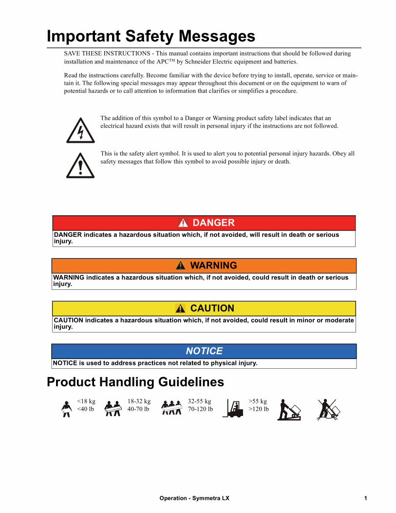
The addition of this symbol to a Danger or Warning product safety label indicates that an electrical hazard exists that will result in personal injury if the instructions are not followed.
This is the safety alert symbol. It is used to alert you to potential personal injury hazards. Obey all safety messages that follow this symbol to avoid possible injury or death.
Product Handling Guidelines
DANGERDANGER indicates a hazardous situation which, if not avoided, will result in death or serious injury.
WARNINGWARNING indicates a hazardous situation which, if not avoided, could result in death or serious injury.
CAUTIONCAUTION indicates a hazardous situation which, if not avoided, could result in minor or moderate injury.
NOTICENOTICE is used to address practices not related to physical injury.
<18 kg <40 lb
18-32 kg 40-70 lb
32-55 kg 70-120 lb
>55 kg >120 lb
1Operation - Symmetra LX
Safety and General InformationInspect the package contents upon receipt. Notify the carrier and dealer if there is any damage.
• This equipment is for use in a restricted access location.
• Adhere to all national and local electrical codes.
• All wiring must be performed by a qualified electrician.
• Do not work alone under hazardous conditions.
• Changes and modifications to this unit not expressly approved by Schneider Electric IT Corporation could void the warranty.
• This UPS is intended for indoor use only.
• Do not operate this unit in direct sunlight, in contact with fluids, or where there is excessive dust or humidity.
• Be sure the air vents on the UPS are not blocked. Allow adequate space for proper ventilation.
• For a UPS with a factory installed power cord, connect the UPS power cable directly to a wall outlet. Do not use surge protectors or extension cords.
• The equipment is heavy. Always practice safe lifting techniques adequate for the weight of the equipment.
• The batteries are heavy. Remove the batteries before installing the UPS and external battery packs (XLBPs), in a rack.
• Always install XLBPs at the bottom in rack-mount configurations. The UPS must be installed above the XLBPs.
• Always install peripheral equipment above the UPS in rack-mount configurations.
Electrical safety
• Do not handle any metallic connector before power has been disconnected.
• For models with a hardwired input, the connection to the branch circuit (mains) must be performed by a qualified electrician.
• 230 V models only: In order to maintain compliance with the EMC directive for products sold in Europe, output cords attached to the UPS must not exceed 10 meters in length.
• The protective earth conductor for the UPS carries the leakage current from the load devices (computer equipment). An insulated ground conductor is to be installed as part of the branch circuit that supplies the UPS. The conductormust have the same size and insulation material as the grounded and ungrounded branch circuit supply conductors. The conductor will typically be green, with or without a yellow stripe.
• Leakage current for a pluggable, Type A UPS may exceed 3.5 mA when a separate ground terminal is used.
• The UPS input ground conductor must be properly bonded to protective earth at the service panel.
• If the UPS input power is supplied by a separately derived system, the ground conductor must be properly bonded at the supply transformer or motor generator set.
Hardwire safety
• Check that all branch circuit (mains) and low voltage (control) circuits are deenergized, and locked out before installing cables or making connections, whether in the junction box or to the UPS.
• All wiring must be performed by a qualified electrician.
• Select wire size and connectors according to national and local codes.
• Wiring must be approved by a local wiring inspector.
• Strain relief is required for all hardwiring (supplied with select products). Snap in type strain reliefs are recommended.
• All openings that allow access to UPS hardwire terminals must be covered. Failure to do so may result in personal injury or equipment damage.
Operation - Symmetra LX2
De-energizing safety
• The UPS contains internal batteries and may present a shock hazard even when disconnected from AC and DC power.
• The AC and DC output connectors may be energized by remote or automatic control at any time.
• Before installing or servicing the equipment perform the following tasks:
• Set the System enable switch to the OFF position.
• Set the input circuit breaker to the OFF position.
• Disconnect the battery modules.
• Disconnect external battery cabinet if provided.
• Disconnect mains/branch circuit.
Battery safety
• When replacing batteries, replace with the same number and type.
• Batteries typically last for two to five years. Environmental factors impact battery life. Elevated ambient temperatures, poor quality utility power, and frequent short duration discharges will shorten battery life. Batteries should be replaced before end of life.
• Replace batteries immediately when the unit indicates battery replacement is necessary.
• APC TM by Schneider Electric uses Maintenance-Free sealed Lead Acid batteries. Under normal use and handling, there is no contact with the internal components of the battery. Over charging, over heating or other misuse of batteries can result in a discharge of battery electrolyte. Released electrolyte is toxic and may be harmful to the skin and eyes.
• CAUTION: Before installing or replacing the batteries, remove jewelry such as chains, wristwatches and rings. Use tools with insulated handles. High short circuit current through conductive materials could cause severe burns.
• CAUTION: Do not dispose of batteries in a fire. The batteries may explode.
• CAUTION: Do not open or mutilate batteries. Released material is harmful to the skin and eyes and may be toxic.
General information
• The model and serial numbers are located on a small, rear panel label. For some models, an additional label is located on the chassis under the front bezel.
• Always recycle used batteries.
• Recycle the package materials or save them for reuse.
3Operation - Symmetra LX
OverviewThis manual provides an overview of operations for the Symmetra™ LX and Extended Run Cabinet, including detailed explanations of monitoring, control, and configuration through the PowerView user interface.
Illustrations are representative. Your unit and configuration, including components and optional APC™ by Schneider Electric equipment, may vary from those depicted in this document. Manuals may be accessed through the APC by Schneider Electric web site, www.apc.com.
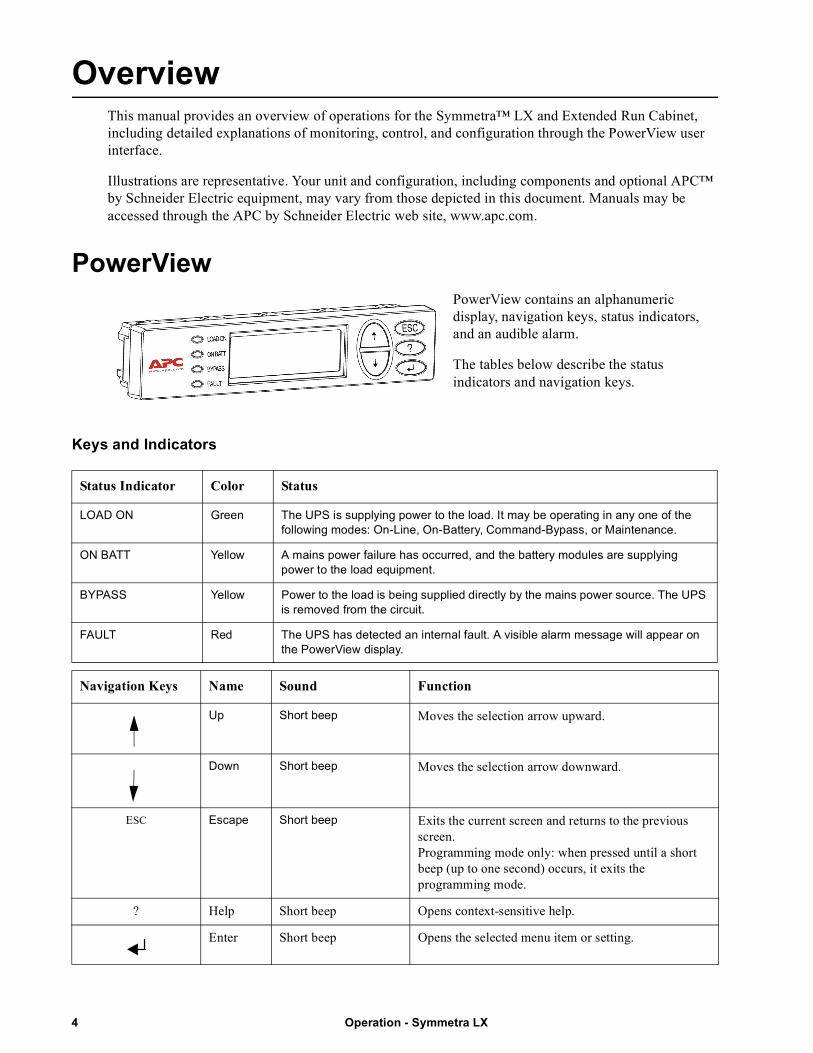
PowerViewPowerView contains an alphanumeric display, navigation keys, status indicators, and an audible alarm.
The tables below describe the status indicators and navigation keys.
Keys and Indicators
Status Indicator Color Status
LOAD ON Green The UPS is supplying power to the load. It may be operating in any one of the following modes: On-Line, On-Battery, Command-Bypass, or Maintenance.
ON BATT Yellow A mains power failure has occurred, and the battery modules are supplying power to the load equipment.
BYPASS Yellow Power to the load is being supplied directly by the mains power source. The UPS is removed from the circuit.
FAULT Red The UPS has detected an internal fault. A visible alarm message will appear on the PowerView display.
Navigation Keys Name Sound Function
Up Short beep Moves the selection arrow upward.
Down Short beep Moves the selection arrow downward.
ESC Escape Short beep Exits the current screen and returns to the previous screen.Programming mode only: when pressed until a short beep (up to one second) occurs, it exits the programming mode.
? Help Short beep Opens context-sensitive help.
Enter Short beep Opens the selected menu item or setting.
Operation - Symmetra LX4
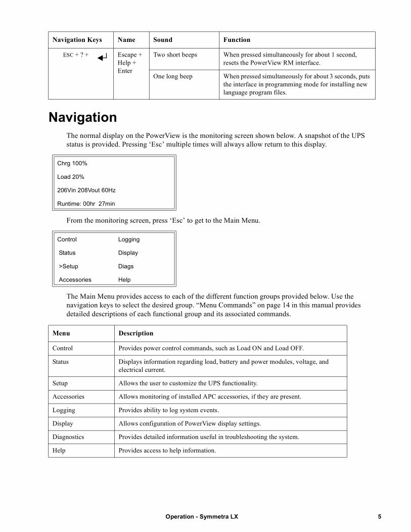
NavigationThe normal display on the PowerView is the monitoring screen shown below. A snapshot of the UPS status is provided. Pressing ‘Esc’ multiple times will always allow return to this display.
From the monitoring screen, press ‘Esc’ to get to the Main Menu.
The Main Menu provides access to each of the different function groups provided below. Use the navigation keys to select the desired group. “Menu Commands” on page 14 in this manual provides detailed descriptions of each functional group and its associated commands.
ESC + ? + Escape + Help + Enter
Two short beeps When pressed simultaneously for about 1 second, resets the PowerView RM interface.
One long beep When pressed simultaneously for about 3 seconds, puts the interface in programming mode for installing new language program files.
Chrg 100%
Load 20%
206Vin 208Vout 60Hz
Runtime: 00hr 27min
Control Logging
Status Display
>Setup Diags
Accessories Help
Menu Description
Control Provides power control commands, such as Load ON and Load OFF.
Status Displays information regarding load, battery and power modules, voltage, and electrical current.
Setup Allows the user to customize the UPS functionality.
Accessories Allows monitoring of installed APC accessories, if they are present.
Logging Provides ability to log system events.
Display Allows configuration of PowerView display settings.
Diagnostics Provides detailed information useful in troubleshooting the system.
Help Provides access to help information.
Navigation Keys Name Sound Function
5Operation - Symmetra LX
Basic Commands
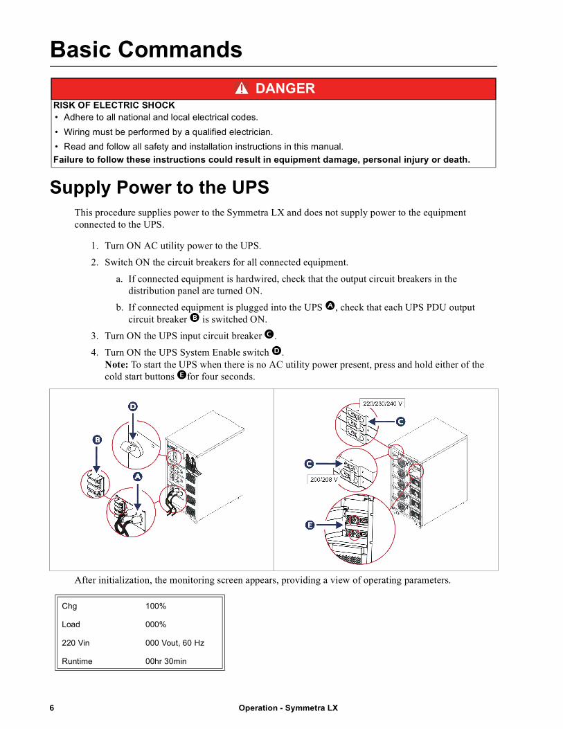
Supply Power to the UPSThis procedure supplies power to the Symmetra LX and does not supply power to the equipment connected to the UPS.
1. Turn ON AC utility power to the UPS.
2. Switch ON the circuit breakers for all connected equipment.
a. If connected equipment is hardwired, check that the output circuit breakers in the distribution panel are turned ON.
b. If connected equipment is plugged into the UPS , check that each UPS PDU output circuit breaker is switched ON.
3. Turn ON the UPS input circuit breaker.
4. Turn ON the UPS System Enable switch. Note: To start the UPS when there is no AC utility power present, press and hold either of the cold start buttons for four seconds.
After initialization, the monitoring screen appears, providing a view of operating parameters.
DANGERRISK OF ELECTRIC SHOCK• Adhere to all national and local electrical codes.
• Wiring must be performed by a qualified electrician.
• Read and follow all safety and installation instructions in this manual.
Failure to follow these instructions could result in equipment damage, personal injury or death.
Chg 100%
Load 000%
220 Vin 000 Vout, 60 Hz
Runtime 00hr 30min
Operation - Symmetra LX6
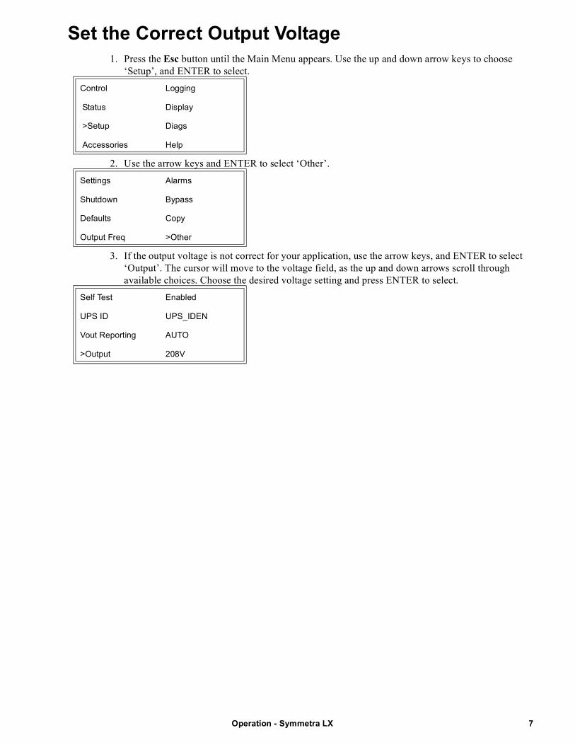
Set the Correct Output Voltage1. Press the Esc button until the Main Menu appears. Use the up and down arrow keys to choose
‘Setup’, and ENTER to select.
2. Use the arrow keys and ENTER to select ‘Other’.
3. If the output voltage is not correct for your application, use the arrow keys, and ENTER to select ‘Output’. The cursor will move to the voltage field, as the up and down arrows scroll through available choices. Choose the desired voltage setting and press ENTER to select.
Control Logging
Status Display
>Setup Diags
Accessories Help
Settings Alarms
Shutdown Bypass
Defaults Copy
Output Freq >Other
Self Test Enabled
UPS ID UPS_IDEN
Vout Reporting AUTO
>Output 208V
7Operation - Symmetra LX
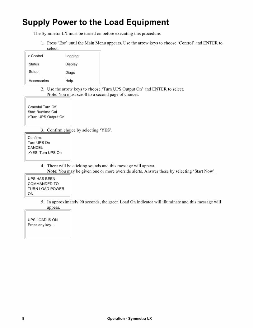
Supply Power to the Load EquipmentThe Symmetra LX must be turned on before executing this procedure.
1. Press ‘Esc’ until the Main Menu appears. Use the arrow keys to choose ‘Control’ and ENTER to select.
2. Use the arrow keys to choose ‘Turn UPS Output On’ and ENTER to select. Note: You must scroll to a second page of choices.
3. Confirm choice by selecting ‘YES’.
4. There will be clicking sounds and this message will appear. Note: You may be given one or more override alerts. Answer these by selecting ‘Start Now’.
5. In approximately 90 seconds, the green Load On indicator will illuminate and this message will appear.
> Control Logging
Status Display
Setup Diags
Accessories Help
Graceful Turn OffStart Runtime Cal>Turn UPS Output On
Confirm:Turn UPS OnCANCEL>YES, Turn UPS On
UPS HAS BEENCOMMANDED TO TURN LOAD POWER ON
UPS LOAD IS ONPress any key…
Operation - Symmetra LX8
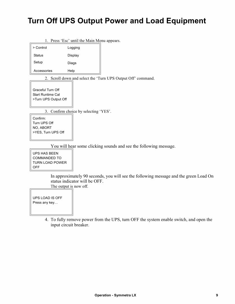
Turn Off UPS Output Power and Load Equipment
1. Press ‘Esc’ until the Main Menu appears.
2. Scroll down and select the ‘Turn UPS Output Off’ command.
3. Confirm choice by selecting ‘YES’.
You will hear some clicking sounds and see the following message.
In approximately 90 seconds, you will see the following message and the green Load On status indicator will be OFF.The output is now off.
4. To fully remove power from the UPS, turn OFF the system enable switch, and open the input circuit breaker.
> Control Logging
Status Display
Setup Diags
Accessories Help
Graceful Turn OffStart Runtime Cal>Turn UPS Output Off
Confirm:Turn UPS OffNO, ABORT>YES, Turn UPS Off
UPS HAS BEENCOMMANDED TO TURN LOAD POWER OFF
UPS LOAD IS OFFPress any key…
9Operation - Symmetra LX
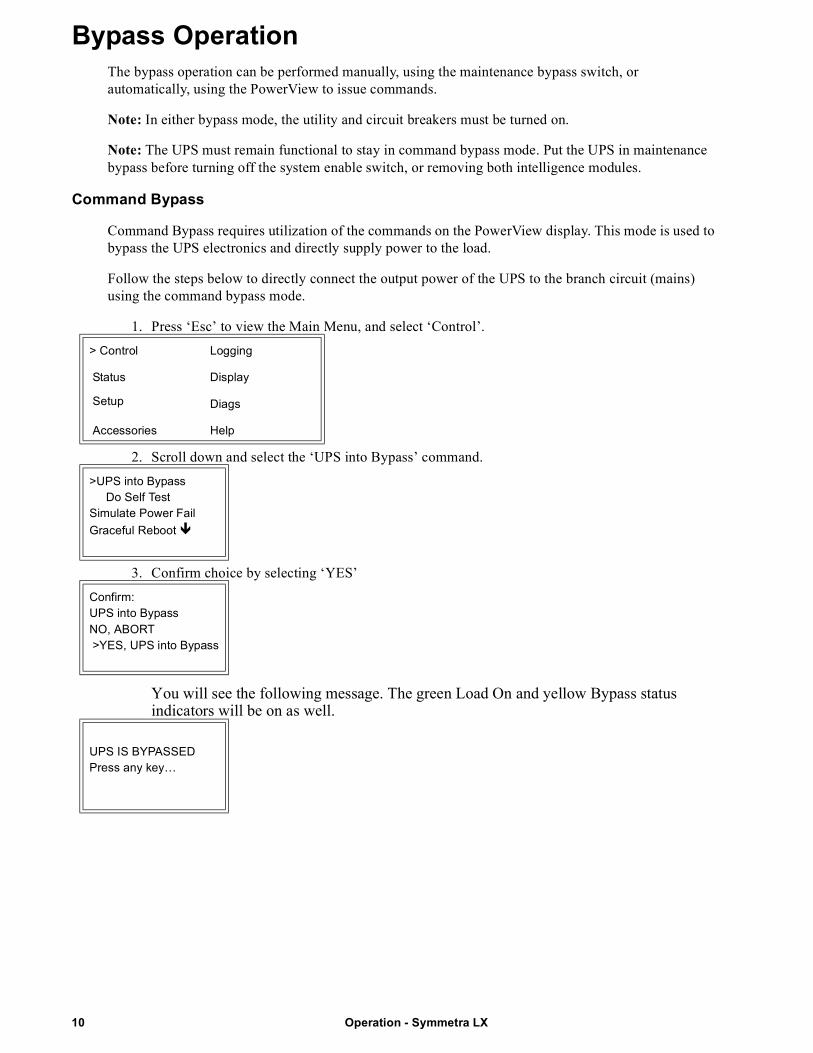
Bypass OperationThe bypass operation can be performed manually, using the maintenance bypass switch, or automatically, using the PowerView to issue commands.
Note: In either bypass mode, the utility and circuit breakers must be turned on.
Note: The UPS must remain functional to stay in command bypass mode. Put the UPS in maintenance bypass before turning off the system enable switch, or removing both intelligence modules.
Command Bypass
Command Bypass requires utilization of the commands on the PowerView display. This mode is used to bypass the UPS electronics and directly supply power to the load.
Follow the steps below to directly connect the output power of the UPS to the branch circuit (mains) using the command bypass mode.
1. Press ‘Esc’ to view the Main Menu, and select ‘Control’.
2. Scroll down and select the ‘UPS into Bypass’ command.
3. Confirm choice by selecting ‘YES’
You will see the following message. The green Load On and yellow Bypass status indicators will be on as well.
> Control Logging
Status Display
Setup Diags
Accessories Help
>UPS into Bypass Do Self TestSimulate Power Fail
Graceful Reboot
Confirm:UPS into BypassNO, ABORT >YES, UPS into Bypass
UPS IS BYPASSEDPress any key…
Operation - Symmetra LX10
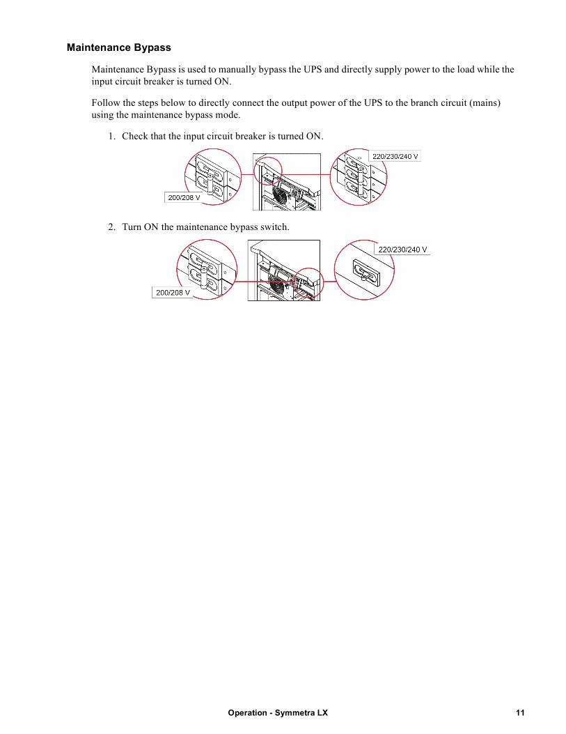
Maintenance Bypass
Maintenance Bypass is used to manually bypass the UPS and directly supply power to the load while the input circuit breaker is turned ON.
Follow the steps below to directly connect the output power of the UPS to the branch circuit (mains) using the maintenance bypass mode.
1. Check that the input circuit breaker is turned ON.
2. Turn ON the maintenance bypass switch.
11Operation - Symmetra LX
Language SettingThe factory default language of the user interface is English. You can change the language by downloading new firmware into the PowerView. French, German, Italian, and Spanish are available on the enclosed CD. Visit the APC by Schneider Electric web site at http://www.apc.com for multilingual product documentation and firmware language support.
Illustrations are representative. Your configuration may be different from the models shown in this procedure.
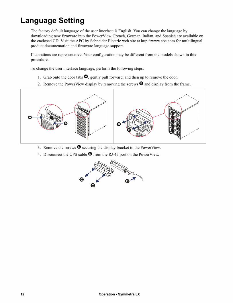
To change the user interface language, perform the following steps.
1. Grab onto the door tabs , gently pull forward, and then up to remove the door.
2. Remove the PowerView display by removing the screws and display from the frame.
3. Remove the screws securing the display bracket to the PowerView.
4. Disconnect the UPS cable from the RJ-45 port on the PowerView.
Operation - Symmetra LX12
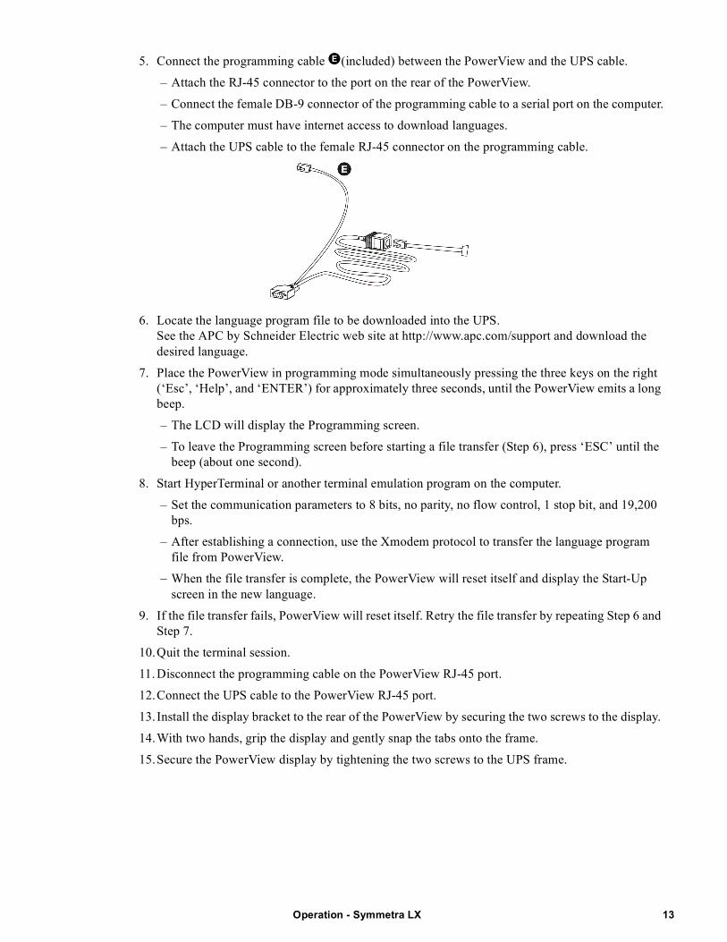
5. Connect the programming cable (included) between the PowerView and the UPS cable.
– Attach the RJ-45 connector to the port on the rear of the PowerView.
– Connect the female DB-9 connector of the programming cable to a serial port on the computer.
– The computer must have internet access to download languages.
– Attach the UPS cable to the female RJ-45 connector on the programming cable.
6. Locate the language program file to be downloaded into the UPS.See the APC by Schneider Electric web site at http://www.apc.com/support and download the desired language.
7. Place the PowerView in programming mode simultaneously pressing the three keys on the right (‘Esc’, ‘Help’, and ‘ENTER’) for approximately three seconds, until the PowerView emits a long beep.
– The LCD will display the Programming screen.
– To leave the Programming screen before starting a file transfer (Step 6), press ‘ESC’ until the beep (about one second).
8. Start HyperTerminal or another terminal emulation program on the computer.
– Set the communication parameters to 8 bits, no parity, no flow control, 1 stop bit, and 19,200 bps.
– After establishing a connection, use the Xmodem protocol to transfer the language program file from PowerView.
– When the file transfer is complete, the PowerView will reset itself and display the Start-Up screen in the new language.
9. If the file transfer fails, PowerView will reset itself. Retry the file transfer by repeating Step 6 and Step 7.
10.Quit the terminal session.
11. Disconnect the programming cable on the PowerView RJ-45 port.
12.Connect the UPS cable to the PowerView RJ-45 port.
13. Install the display bracket to the rear of the PowerView by securing the two screws to the display.
14.With two hands, grip the display and gently snap the tabs onto the frame.
15.Secure the PowerView display by tightening the two screws to the UPS frame.
13Operation - Symmetra LX
Menu CommandsThe following sections describe the details of each command. Commands are organized according to the menu hierarchy in the PowerView.
Accessories MenuThe Accessories Menu allows you to monitor APC by Schneider Electric accessories if they are installed. The PowerView must be connected to the computer interface port at the back of the UPS frame in order to monitor internal accessories.
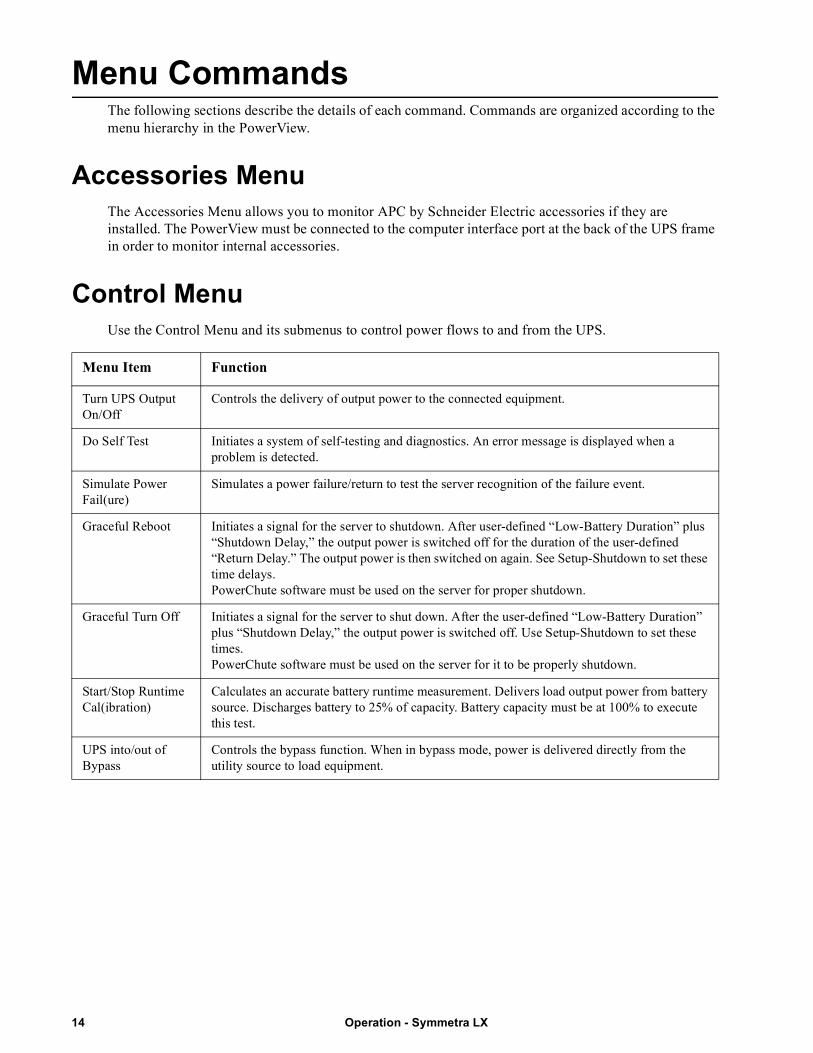
Control MenuUse the Control Menu and its submenus to control power flows to and from the UPS.
Menu Item Function
Turn UPS Output On/Off
Controls the delivery of output power to the connected equipment.
Do Self Test Initiates a system of self-testing and diagnostics. An error message is displayed when a problem is detected.
Simulate Power Fail(ure)
Simulates a power failure/return to test the server recognition of the failure event.
Graceful Reboot Initiates a signal for the server to shutdown. After user-defined “Low-Battery Duration” plus “Shutdown Delay,” the output power is switched off for the duration of the user-defined “Return Delay.” The output power is then switched on again. See Setup-Shutdown to set these time delays. PowerChute software must be used on the server for proper shutdown.
Graceful Turn Off Initiates a signal for the server to shut down. After the user-defined “Low-Battery Duration” plus “Shutdown Delay,” the output power is switched off. Use Setup-Shutdown to set these times.PowerChute software must be used on the server for it to be properly shutdown.
Start/Stop Runtime Cal(ibration)
Calculates an accurate battery runtime measurement. Delivers load output power from battery source. Discharges battery to 25% of capacity. Battery capacity must be at 100% to execute this test.
UPS into/out of Bypass
Controls the bypass function. When in bypass mode, power is delivered directly from the utility source to load equipment.
Operation - Symmetra LX14
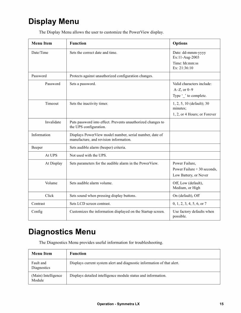
Display MenuThe Display Menu allows the user to customize the PowerView display.
Diagnostics MenuThe Diagnostics Menu provides useful information for troubleshooting.
Menu Item Function Options
Date/Time Sets the correct date and time. Date: dd-mmm-yyyyEx:11-Aug-2003
Time: hh:mm:ssEx: 21:36:10
Password Protects against unauthorized configuration changes.
Password Sets a password. Valid characters include:
A–Z, or 0–9
Type ‘_’ to complete.
Timeout Sets the inactivity timer. 1, 2, 5, 10 (default); 30 minutes;
1, 2, or 4 Hours; or Forever
Invalidate Puts password into effect. Prevents unauthorized changes to the UPS configuration.
Information Displays PowerView model number, serial number, date of manufacture, and revision information.
Beeper Sets audible alarm (beeper) criteria.
At UPS Not used with the UPS.
At Display Sets parameters for the audible alarm in the PowerView. Power Failure,
Power Failure + 30 seconds,
Low Battery, or Never
Volume Sets audible alarm volume. Off, Low (default), Medium, or High
Click Sets sound when pressing display buttons. On (default), Off
Contrast Sets LCD screen contrast. 0, 1, 2, 3, 4, 5, 6, or 7
Config Customizes the information displayed on the Startup screen. Use factory defaults when possible.
Menu Item Function
Fault and Diagnostics
Displays current system alert and diagnostic information of that alert.
(Main) Intelligence Module
Displays detailed intelligence module status and information.
15Operation - Symmetra LX
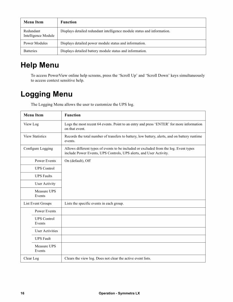
Help MenuTo access PowerView online help screens, press the ‘Scroll Up’ and ‘Scroll Down’ keys simultaneously to access context sensitive help.
Logging MenuThe Logging Menu allows the user to customize the UPS log.
Redundant Intelligence Module
Displays detailed redundant intelligence module status and information.
Power Modules Displays detailed power module status and information.
Batteries Displays detailed battery module status and information.
Menu Item Function
View Log Logs the most recent 64 events. Point to an entry and press ‘ENTER’ for more information on that event.
View Statistics Records the total number of transfers to battery, low battery, alerts, and on battery runtime events.
Configure Logging Allows different types of events to be included or excluded from the log. Event types include Power Events, UPS Controls, UPS alerts, and User Activity.
Power Events On (default), Off
UPS Control
UPS Faults
User Activity
Measure UPS Events
List Event Groups Lists the specific events in each group.
Power Events
UPS Control Events
User Activities
UPS Fault
Measure UPS Events
Clear Log Clears the view log. Does not clear the active event lists.
Menu Item Function
Operation - Symmetra LX16
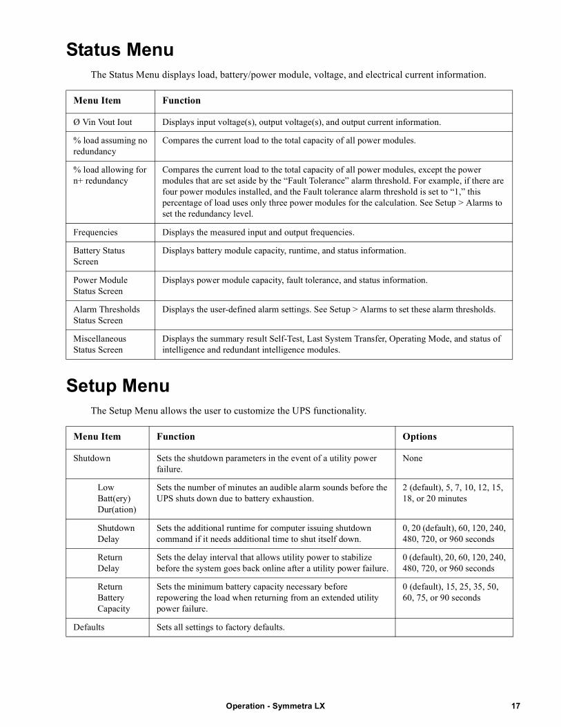
Status MenuThe Status Menu displays load, battery/power module, voltage, and electrical current information.
Setup MenuThe Setup Menu allows the user to customize the UPS functionality.
Menu Item Function
Ø Vin Vout Iout Displays input voltage(s), output voltage(s), and output current information.
% load assuming no redundancy
Compares the current load to the total capacity of all power modules.
% load allowing for n+ redundancy
Compares the current load to the total capacity of all power modules, except the power modules that are set aside by the “Fault Tolerance” alarm threshold. For example, if there are four power modules installed, and the Fault tolerance alarm threshold is set to “1,” this percentage of load uses only three power modules for the calculation. See Setup > Alarms to set the redundancy level.
Frequencies Displays the measured input and output frequencies.
Battery Status Screen
Displays battery module capacity, runtime, and status information.
Power Module Status Screen
Displays power module capacity, fault tolerance, and status information.
Alarm Thresholds Status Screen
Displays the user-defined alarm settings. See Setup > Alarms to set these alarm thresholds.
Miscellaneous Status Screen
Displays the summary result Self-Test, Last System Transfer, Operating Mode, and status of intelligence and redundant intelligence modules.
Menu Item Function Options
Shutdown Sets the shutdown parameters in the event of a utility power failure.
None
Low Batt(ery) Dur(ation)
Sets the number of minutes an audible alarm sounds before the UPS shuts down due to battery exhaustion.
2 (default), 5, 7, 10, 12, 15, 18, or 20 minutes
Shutdown Delay
Sets the additional runtime for computer issuing shutdown command if it needs additional time to shut itself down.
0, 20 (default), 60, 120, 240, 480, 720, or 960 seconds
Return Delay
Sets the delay interval that allows utility power to stabilize before the system goes back online after a utility power failure.
0 (default), 20, 60, 120, 240, 480, 720, or 960 seconds
Return Battery Capacity
Sets the minimum battery capacity necessary before repowering the load when returning from an extended utility power failure.
0 (default), 15, 25, 35, 50, 60, 75, or 90 seconds
Defaults Sets all settings to factory defaults.
17Operation - Symmetra LX
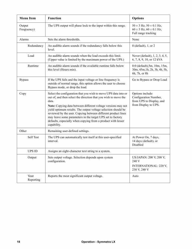
Output Freq(uency)
The UPS output will phase lock to the input within this range. 50 ± 3 Hz, 50 ± 0.1 Hz, 60 ± 3 Hz, 60 ± 0.1 Hz, Full range tracking
Alarms Sets the alarm thresholds. None
Redundancy An audible alarm sounds if the redundancy falls below this level.
0 (default), 1, or 2
Load An audible alarm sounds when the load exceeds this limit. (Upper value is limited by the maximum power of the UPS.)
Never (default), 1, 2, 3, 4, 5, 6, 7, 8, 9, 10, or 12 kVA
Runtime An audible alarm sounds if the available runtime falls below this level (Hours:min).
0:0 (default),5m, 10m, 15m, 30m, 45m,1h, 2h, 3h, 4h, 5h, 6h, 7h, or 8h
Bypass If the UPS fails and the input voltage or line frequency is outside of normal range, this option allows the user to choose Bypass mode, or drop the load.
Go to Bypass or Drop Load
Copy Select the configuration that you wish to move UPS data into or out of, and then select the direction that you wish to move the data.
Note: Copying data between different voltage versions may not yield optimum results. The output voltage selection should be reviewed by the user. Copying between different product lines may leave some parameters in the target UPS set to factory defaults, especially when copying from a product with lesser capability.
Options include: Configuration Number, from UPS to Display, and from Display to UPS.
Other Remaining user-defined settings.
Self Test The UPS can automatically test itself at this user-specified interval.
At Power On, 7 days, 14 days (default), or Disabled
UPS ID Assigns an eight-character text string to a system.
Output Sets output voltage. Selection depends upon system configuration.
US/JAPAN: 200 V, 208 V, 240 V
INTERNATIONAL: 220 V, 230 V, 240 V
Vout Reporting
Reports the most significant output voltage. Auto
Menu Item Function Options
Operation - Symmetra LX18
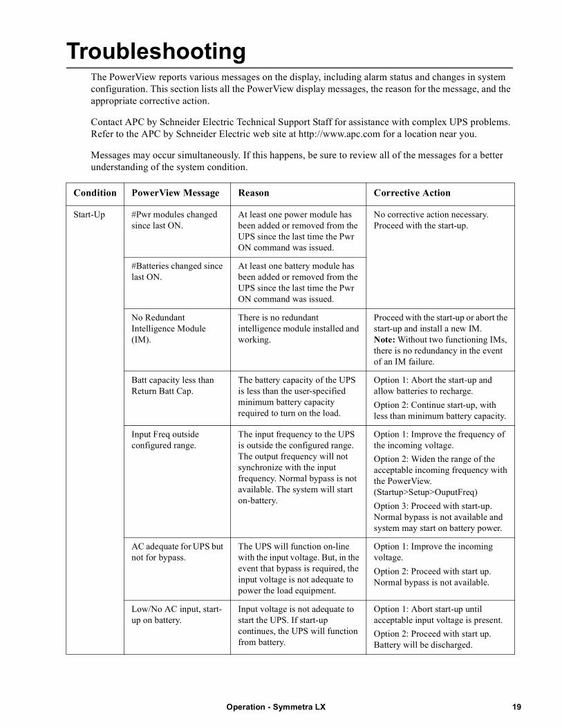
TroubleshootingThe PowerView reports various messages on the display, including alarm status and changes in system configuration. This section lists all the PowerView display messages, the reason for the message, and the appropriate corrective action.
Contact APC by Schneider Electric Technical Support Staff for assistance with complex UPS problems. Refer to the APC by Schneider Electric web site at http://www.apc.com for a location near you.
Messages may occur simultaneously. If this happens, be sure to review all of the messages for a better understanding of the system condition.
Condition PowerView Message Reason Corrective Action
Start-Up #Pwr modules changed since last ON.
At least one power module has been added or removed from the UPS since the last time the Pwr ON command was issued.
No corrective action necessary. Proceed with the start-up.
#Batteries changed since last ON.
At least one battery module has been added or removed from the UPS since the last time the Pwr ON command was issued.
No Redundant Intelligence Module (IM).
There is no redundant intelligence module installed and working.
Proceed with the start-up or abort the start-up and install a new IM.Note: Without two functioning IMs, there is no redundancy in the event of an IM failure.
Batt capacity less than Return Batt Cap.
The battery capacity of the UPS is less than the user-specified minimum battery capacity required to turn on the load.
Option 1: Abort the start-up and allow batteries to recharge.
Option 2: Continue start-up, with less than minimum battery capacity.
Input Freq outside configured range.
The input frequency to the UPS is outside the configured range. The output frequency will not synchronize with the input frequency. Normal bypass is not available. The system will start on-battery.
Option 1: Improve the frequency of the incoming voltage.
Option 2: Widen the range of the acceptable incoming frequency with the PowerView. (Startup>Setup>OuputFreq)
Option 3: Proceed with start-up. Normal bypass is not available and system may start on battery power.
AC adequate for UPS but not for bypass.
The UPS will function on-line with the input voltage. But, in the event that bypass is required, the input voltage is not adequate to power the load equipment.
Option 1: Improve the incoming voltage.
Option 2: Proceed with start up. Normal bypass is not available.
Low/No AC input, start-up on battery.
Input voltage is not adequate to start the UPS. If start-up continues, the UPS will function from battery.
Option 1: Abort start-up until acceptable input voltage is present.
Option 2: Proceed with start up. Battery will be discharged.
19Operation - Symmetra LX
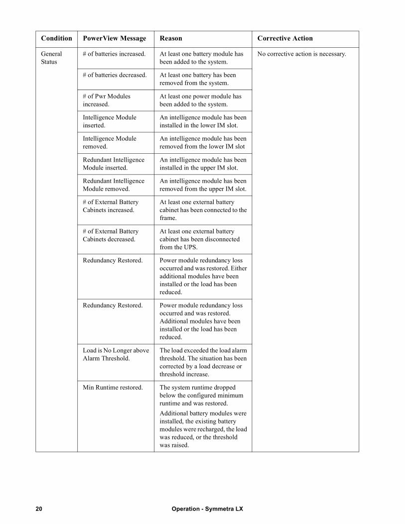
General Status
# of batteries increased. At least one battery module has been added to the system.
No corrective action is necessary.
# of batteries decreased. At least one battery has been removed from the system.
# of Pwr Modules increased.
At least one power module has been added to the system.
Intelligence Module inserted.
An intelligence module has been installed in the lower IM slot.
Intelligence Module removed.
An intelligence module has been removed from the lower IM slot
Redundant Intelligence Module inserted.
An intelligence module has been installed in the upper IM slot.
Redundant Intelligence Module removed.
An intelligence module has been removed from the upper IM slot.
# of External Battery Cabinets increased.
At least one external battery cabinet has been connected to the frame.
# of External Battery Cabinets decreased.
At least one external battery cabinet has been disconnected from the UPS.
Redundancy Restored. Power module redundancy loss occurred and was restored. Either additional modules have been installed or the load has been reduced.
Redundancy Restored. Power module redundancy loss occurred and was restored. Additional modules have been installed or the load has been reduced.
Load is No Longer above Alarm Threshold.
The load exceeded the load alarm threshold. The situation has been corrected by a load decrease or threshold increase.
Min Runtime restored. The system runtime dropped below the configured minimum runtime and was restored.
Additional battery modules were installed, the existing battery modules were recharged, the load was reduced, or the threshold was raised.
Condition PowerView Message Reason Corrective Action
Operation - Symmetra LX20
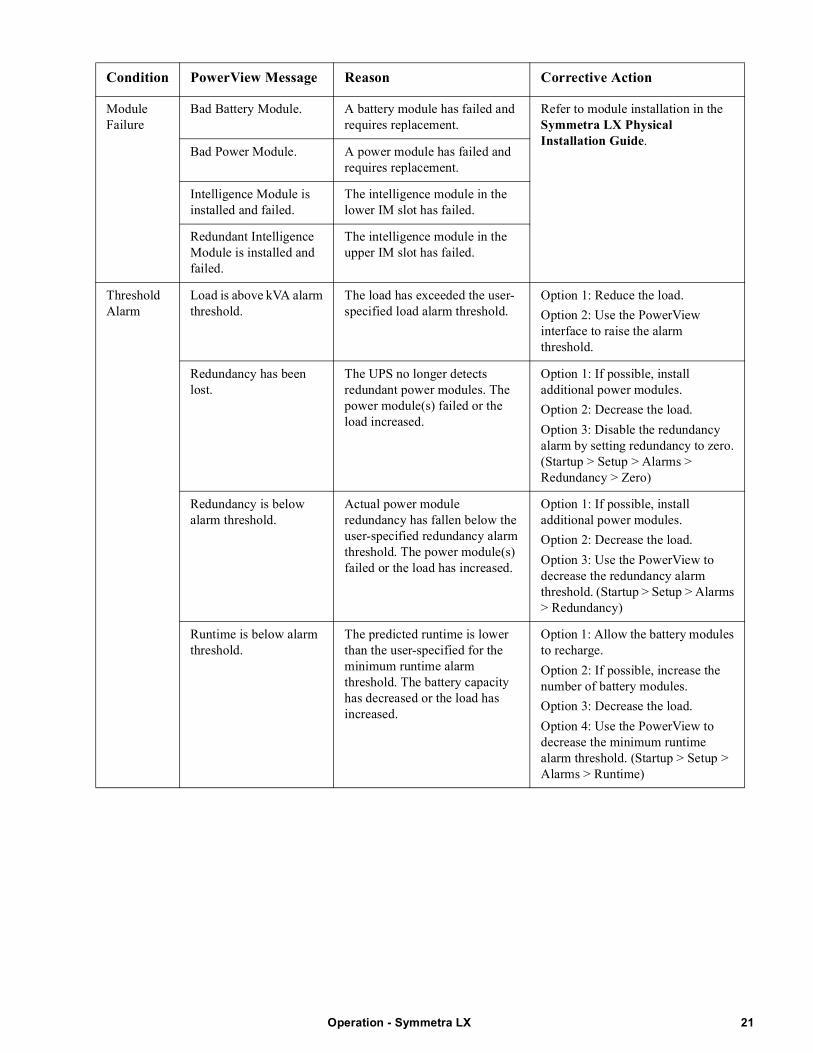
Module Failure
Bad Battery Module. A battery module has failed and requires replacement.
Refer to module installation in the Symmetra LX Physical Installation Guide.
Bad Power Module. A power module has failed and requires replacement.
Intelligence Module is installed and failed.
The intelligence module in the lower IM slot has failed.
Redundant Intelligence Module is installed and failed.
The intelligence module in the upper IM slot has failed.
Threshold Alarm
Load is above kVA alarm threshold.
The load has exceeded the user-specified load alarm threshold.
Option 1: Reduce the load.
Option 2: Use the PowerView interface to raise the alarm threshold.
Redundancy has been lost.
The UPS no longer detects redundant power modules. The power module(s) failed or the load increased.
Option 1: If possible, install additional power modules.
Option 2: Decrease the load.
Option 3: Disable the redundancy alarm by setting redundancy to zero. (Startup > Setup > Alarms > Redundancy > Zero)
Redundancy is below alarm threshold.
Actual power module redundancy has fallen below the user-specified redundancy alarm threshold. The power module(s) failed or the load has increased.
Option 1: If possible, install additional power modules.
Option 2: Decrease the load.
Option 3: Use the PowerView to decrease the redundancy alarm threshold. (Startup > Setup > Alarms > Redundancy)
Runtime is below alarm threshold.
The predicted runtime is lower than the user-specified for the minimum runtime alarm threshold. The battery capacity has decreased or the load has increased.
Option 1: Allow the battery modules to recharge.
Option 2: If possible, increase the number of battery modules.
Option 3: Decrease the load.
Option 4: Use the PowerView to decrease the minimum runtime alarm threshold. (Startup > Setup > Alarms > Runtime)
Condition PowerView Message Reason Corrective Action
21Operation - Symmetra LX
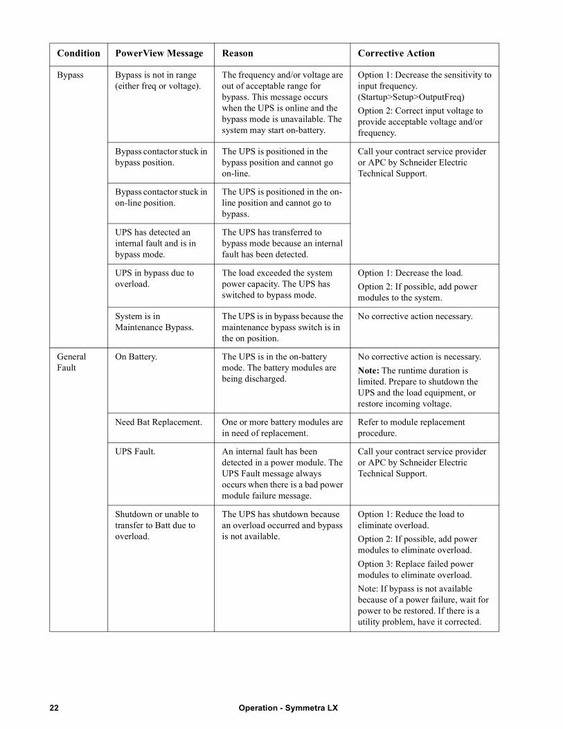
Bypass Bypass is not in range (either freq or voltage).
The frequency and/or voltage are out of acceptable range for bypass. This message occurs when the UPS is online and the bypass mode is unavailable. The system may start on-battery.
Option 1: Decrease the sensitivity to input frequency. (Startup>Setup>OutputFreq)
Option 2: Correct input voltage to provide acceptable voltage and/or frequency.
Bypass contactor stuck in bypass position.
The UPS is positioned in the bypass position and cannot go on-line.
Call your contract service provider or APC by Schneider Electric Technical Support.
Bypass contactor stuck in on-line position.
The UPS is positioned in the on-line position and cannot go to bypass.
UPS has detected an internal fault and is in bypass mode.
The UPS has transferred to bypass mode because an internal fault has been detected.
UPS in bypass due to overload.
The load exceeded the system power capacity. The UPS has switched to bypass mode.
Option 1: Decrease the load.
Option 2: If possible, add power modules to the system.
System is in Maintenance Bypass.
The UPS is in bypass because the maintenance bypass switch is in the on position.
No corrective action necessary.
General Fault
On Battery. The UPS is in the on-battery mode. The battery modules are being discharged.
No corrective action is necessary.
Note: The runtime duration is limited. Prepare to shutdown the UPS and the load equipment, or restore incoming voltage.
Need Bat Replacement. One or more battery modules are in need of replacement.
Refer to module replacement procedure.
UPS Fault. An internal fault has been detected in a power module. The UPS Fault message always occurs when there is a bad power module failure message.
Call your contract service provider or APC by Schneider Electric Technical Support.
Shutdown or unable to transfer to Batt due to overload.
The UPS has shutdown because an overload occurred and bypass is not available.
Option 1: Reduce the load to eliminate overload.
Option 2: If possible, add power modules to eliminate overload.
Option 3: Replace failed power modules to eliminate overload.
Note: If bypass is not available because of a power failure, wait for power to be restored. If there is a utility problem, have it corrected.
Condition PowerView Message Reason Corrective Action
Operation - Symmetra LX22
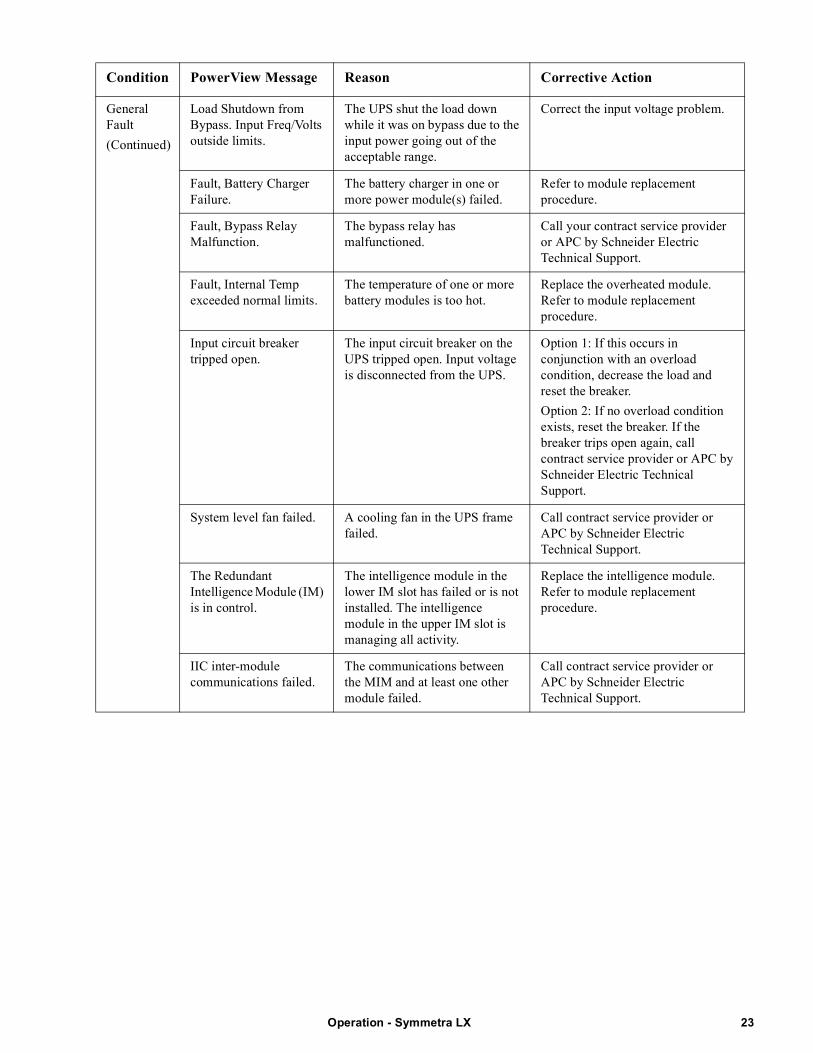
General Fault
(Continued)
Load Shutdown from Bypass. Input Freq/Volts outside limits.
The UPS shut the load down while it was on bypass due to the input power going out of the acceptable range.
Correct the input voltage problem.
Fault, Battery Charger Failure.
The battery charger in one or more power module(s) failed.
Refer to module replacement procedure.
Fault, Bypass Relay Malfunction.
The bypass relay has malfunctioned.
Call your contract service provider or APC by Schneider Electric Technical Support.
Fault, Internal Temp exceeded normal limits.
The temperature of one or more battery modules is too hot.
Replace the overheated module. Refer to module replacement procedure.
Input circuit breaker tripped open.
The input circuit breaker on the UPS tripped open. Input voltage is disconnected from the UPS.
Option 1: If this occurs in conjunction with an overload condition, decrease the load and reset the breaker.
Option 2: If no overload condition exists, reset the breaker. If the breaker trips open again, call contract service provider or APC by Schneider Electric Technical Support.
System level fan failed. A cooling fan in the UPS frame failed.
Call contract service provider or APC by Schneider Electric Technical Support.
The Redundant Intelligence Module (IM) is in control.
The intelligence module in the lower IM slot has failed or is not installed. The intelligence module in the upper IM slot is managing all activity.
Replace the intelligence module. Refer to module replacement procedure.
IIC inter-module communications failed.
The communications between the MIM and at least one other module failed.
Call contract service provider or APC by Schneider Electric Technical Support.
Condition PowerView Message Reason Corrective Action
23Operation - Symmetra LX
ServiceIf the UPS requires service, do not return it to the dealer. Follow these steps:
1. Review the problems discussed in the Troubleshooting chapter to eliminate common problems.
2. Verify that the circuit breakers have not tripped. A tripped circuit breaker is the most common UPS problem.
3. If the problem persists, call customer service or visit the APC by Schneider Electric web site at http://www.apc.com
a. Note the model number of the UPS, the serial number, and the date purchased. A technician will ask you to describe the problem and try to solve it over the phone, if possible. If this is not possible, the technician will issue a Returned Material Authorization Number (RMA#).
b. If the UPS is under warranty, repairs are free. If not, there is a repair charge.
4. Pack the UPS in its original packaging. If the original packing is not available, ask customer service about obtaining a new set. Visit the APC web site for customer support telephone numbers.
5. Pack the UPS properly to avoid damage in transit. Never use polystyrene beads for packaging. Damage sustained in transit is not covered under warranty.
6. Mark the RMA# on the outside of the package.
Battery Replacements Kits and Battery RecyclingSee your dealer or visit the APC by Schneider Electric web site at http://www.apc.com for information on battery replacement kits and battery recycling. If returning used batteries to APC for recycling, ship used batteries in the battery replacement packing material.
Operation - Symmetra LX24

05/2018EN 990-1546B-001
APC by Schneider Electric Worldwide Customer Support
Customer support for this or any other APC by Schneider Electric product is available at no charge in any of the following ways:
• Visit the APC by Schneider Electric web site to access documents in the APC by Schneider Electric Knowledge Base and to submit customer support requests.
– www.apc.com (Corporate Headquarters)Connect to localized APC by Schneider Electric Web sites for specific countries, each of which provides customer support information.
– www.apc.com/support/Global support searching APC by Schneider Electric Knowledge Base and using e-support.
• Contact the APC by Schneider Electric Customer Support Center by telephone or e-mail.
– Local, country-specific centers: go to www.apc.com/support/contact for contact information.
– For information on how to obtain local customer support, contact the APC by Schneider Electric representative or other distributors from whom you purchased your APC by Schneider Electric product.
© 2018 APC by Schneider Electric. APC, the APC logo, Smart-UPS, and Symmetra are owned by Schneider Electric Industries S.A.S., or their affiliated companies. All other trademarks are property of their respective
owners.
Related Documents