American Journal of Engineering Research (AJER) 2015 www.ajer.org Page 126 American Journal of Engineering Research (AJER) e-ISSN : 2320-0847 p-ISSN : 2320-0936 Volume-4, Issue-1, pp-126-137 www.ajer.org Research Paper Open Access Switching Of Security Lighting System Using Gsm Bakare, B. I 1, Odeyemi, F. M 2 1,2 (Department of Electrical/Computer Engineering Rivers State University of Science and Technology, Port Harcourt, Nigeria) ABSTRACT: .This paper shows how ATMEGA168 microcontroller can be used to remotely control security lighting via Short Message Service (SMS) from a Global System for Mobile Communication (GSM) phone anywhere outside the home. A Mobile phone is configured to transmit SMS signal to a home-based GSM modem. The GSM Modem then sends the received SMS to a ATMEGA168 microcontroller. The Microcontroller accesses the received SMS and Changes the State of the appliances if the received signal aggresses with a pre - set code. When this is done, the microcontroller then sends signal to the GSM modem which in turn send back a reply to the mobile phone via SMS. The system utilizes a LCD display with resolution of 96*64 using PCD8544 Driver/Controller to display the ON/OFF state of the lighting device. KEYWORDS : GSM, LCD, microcontroller, modem, SMS I. INTRODUCTION Mobile devices, such as mobile phones, are becoming multipurpose devices. Imagine being able to control all the electrical appliances in a house from virtually any place in the world, GSM home automation may seem like an idea of the future; however there are many possibilities of using it currently [1], The technology works by allowing communication between a receiver in the house and a mobile phone elsewhere. That receiver can then be signaled to “On” or “Off” appliances in the house based on command from the mobile phone . Through the use of micro-controller, any electrical or electronic device such as lighting a bulb can be controlled from a distance.[2] This paper presents a system that allows the user to control lighting systems remotely using mobile phones. It provides remote control via Short Messages Services (SMS) using Global System for Mobile Communication (GSM) technology. This system is related to past study which uses personal computer (PC) that contains the software components through which the lights and appliances are controlled and home security is monitored. This paper developed a system that uses a microcontroller instead of PC and hence the system size is reduced . The most common problem that home owners encountered in relation to lighting system is due to some negligence like leaving the lights ON in error resulting to greater power consumption. This wasted power directly affects the home owner electrical bills. Another problem is that of the busy home owners who will arrive home late at night; they may want to switch on their security lights from a distance in order to protect their house against robbery and crimes.[3].The mobile phone is configured to send SMS of the ON/OFF state of the appliance to a modem (a particular mobile phone line). The owner can control the system through his mobile phone by sending Attention (AT) commands to the Modem line and in turn, to the microcontroller. The system can also provide password security against operator misuse/abuse. II. MATERIALS AND METHODS The figure below shows the block diagram of the design

Switching Of Security Lighting System Using Gsm.
Jul 18, 2015
Welcome message from author
This document is posted to help you gain knowledge. Please leave a comment to let me know what you think about it! Share it to your friends and learn new things together.
Transcript

American Journal of Engineering Research (AJER) 2015
w w w . a j e r . o r g
Page 126
American Journal of Engineering Research (AJER)
e-ISSN : 2320-0847 p-ISSN : 2320-0936
Volume-4, Issue-1, pp-126-137
www.ajer.org
Research Paper Open Access
Switching Of Security Lighting System Using Gsm
Bakare, B. I 1,
Odeyemi, F. M2
1,2(Department of Electrical/Computer Engineering
Rivers State University of Science and Technology, Port Harcourt, Nigeria)
ABSTRACT: .This paper shows how ATMEGA168 microcontroller can be used to remotely control security
lighting via Short Message Service (SMS) from a Global System for Mobile Communication (GSM) phone
anywhere outside the home. A Mobile phone is configured to transmit SMS signal to a home-based GSM
modem. The GSM Modem then sends the received SMS to a ATMEGA168 microcontroller. The Microcontroller
accesses the received SMS and Changes the State of the appliances if the received signal aggresses with a pre -
set code. When this is done, the microcontroller then sends signal to the GSM modem which in turn send back a
reply to the mobile phone via SMS. The system utilizes a LCD display with resolution of 96*64 using PCD8544
Driver/Controller to display the ON/OFF state of the lighting device.
KEYWORDS : GSM, LCD, microcontroller, modem, SMS
I. INTRODUCTION Mobile devices, such as mobile phones, are becoming multipurpose devices. Imagine being able to
control all the electrical appliances in a house from virtually any place in the world, GSM home automation may
seem like an idea of the future; however there are many possibilities of using it currently [1], The technology
works by allowing communication between a receiver in the house and a mobile phone elsewhere. That receiver
can then be signaled to “On” or “Off” appliances in the house based on command from the mobile phone.
Through the use of micro-controller, any electrical or electronic device such as lighting a bulb can be controlled
from a distance.[2] This paper presents a system that allows the user to control lighting systems remotely using
mobile phones. It provides remote control via Short Messages Services (SMS) using Global System for Mobile
Communication (GSM) technology. This system is related to past study which uses personal computer (PC) that
contains the software components through which the lights and appliances are controlled and home security is
monitored. This paper developed a system that uses a microcontroller instead of PC and hence the system size is
reduced
. The most common problem that home owners encountered in relation to lighting system is due to
some negligence like leaving the lights ON in error resulting to greater power consumption. This wasted power
directly affects the home owner electrical bills. Another problem is that of the busy home owners who will
arrive home late at night; they may want to switch on their security lights from a distance in order to protect
their house against robbery and crimes.[3].The mobile phone is configured to send SMS of the ON/OFF state of
the appliance to a modem (a particular mobile phone line). The owner can control the system through his mobile
phone by sending Attention (AT) commands to the Modem line and in turn, to the microcontroller. The system
can also provide password security against operator misuse/abuse.
II. MATERIALS AND METHODS
The figure below shows the block diagram of the design

American Journal of Engineering Research (AJER) 2015
w w w . a j e r . o r g
Page 127
Figure 1: Block diagram of design
Principle of operation : The system is made up of two parts, namely; the transmitting part and receiving part.
The transmitting part consists of a normal GSM phone which transmits signal via SMS. The receiving part
consists of a microcontroller chip, a GSM modem, a buzzer, buttons and the appliance to be controlled .When
the GSM phone transmits signal via SMS, the GSM modem receives it and sends it to the microcontroller. The
microcontroller accesses the SMS and changes the state of the appliances if the signal is an appropriate code.
When this is done, the microcontroller sends signal to the GSM modem to send back reply to the GSM phone
via SMS. The switches are the alternative means of changing the state of the appliances. If the home owner is
close to the transmitting end, he/she can use the Switch buttons to change the state of the appliances.The buzzer
is for notification: to notify when there is a change of state. So whether one uses the switches or the GSM
phone, a sound will be produced to notify a change of state. The display is a Liquid Crystal Display (LCD)
which displays the signal processing results. For the security aspect, if one presses any of the switches, the GSM
modem will send a signal via SMS to the GSM phone, notifying that there is a change of state in a particular
appliance. Another security aspect is that if the cable of any of the appliances is cut, the GSM modem will also
send a signal via SMS to the GSM phone notifying that a particular cable has been removed.
III. HARDWARE DESIGN ANALYSIS The Buzzer Driver : The Buzzer requires a current of 30mAmps for proper operation as instructed by the
datasheet.[4] The configuration is shown below.
Figure 2: Buzzer driver.

American Journal of Engineering Research (AJER) 2015
w w w . a j e r . o r g
Page 128
The given transistor parameters are
Transistor (npn BC547)
Forward beta ( ) = 290,
CMAXI = 100mA,
Transistor’s renowned equations
BCEIII (1)
BCII (2)
From circuit analysis IC = 30mA
BImA *29030
290
10*303
B
I
000103448.0B
I
AIB
45.103
From the base emitter loop,
0BEBBB
VRIV (3)
BEBBBVVRI
B
BEB
B
I
VVR
610*45.103
7.05
BR
5761.45432B
R
KRB
45
KRB
43
Using a smaller value of resistor that will yield a wider range of base current without endangering the
transistor is ok but not exceeding the current limit of the base which is 500uAmps for 5mAmps of collector
current and higher for higher values of the collector as well.
KRB
10
3.2 The Relay Driver
The current requirement of the coil of the relay is 30mAmps. The figure below depicts a typical
connection of a relay driver.
Figure 3: Relay driver

American Journal of Engineering Research (AJER) 2015
w w w . a j e r . o r g
Page 129
Considering a visual indication of the relay state, an LED was then included giving rise to the figure below.
Figure 4: Relay driver with indicator
The component’s parameters are
LED current: 10mAmps.
Relay coil current: 30mAmps
Transistor (npn BC557)
Forward beta ( ) = 290,
CMAXI = 100mA,
From circuit analysis IC = 40mA
BImA *29040
290
10*403
B
I
000137931.0B
I
AIB
931.137
From the emitter base loop,
The equivalent resistor of 1k(LED bias resistor) and 400(coil resistance) ohm is 285ohm and the loop equation
is
0BBBEEQBcc
RIVRIV (4)
EQBBECCBBRIVVRI
B
EQBBECC
B
I
RIVVR
6
6
10*138
285*10*1387.012
B
R
058.81599B
R
KRB
82

American Journal of Engineering Research (AJER) 2015
w w w . a j e r . o r g
Page 130
The LCD Display :The display is used solely to display of project title and the indication of the status of the
peripherals (lighting points), typical indications are:-
North light: ON
South light: OFF
West light: ON
East light: ON
Fluorescent: ON
The title section is SMS CONTROLLED LIGHTING. The display supports 3.3volt for communication
but tolerate 5volts for its logic io(input output) pins. The vdd must be a 3.3volt so two diodes(1N4148) is used
to drop the voltage to a tolerable level of (5-2(0.7))= 3.6volts.
3.4 Power Supply
3.4.1 Transformer Design
The calculated load demand of the entire circuit is approximately 400mA; hence a transformer that is about
1000mA and above can be used for the circuit. Using a transformer with secondary voltage of 18V and current
of 1000mA.
i.e. Vac =18V
Iac = 1000mA
There are two quantities of interest with respect to the transformer design and their equations are
41.1
DC
AC
VV (5)
62.0
DC
AC
II (6)
But
VDC = Specified DC voltage + 2VD (7)
From equation (5)
ACdCVV *41.1
VVdC
18*41.1
V38.25
From equation (6)
ACdCII *62.0
mAIdC
1000*62.0
A62.0
From equation (3.3)
VDC = Specified DC voltage + 2VD
Specified voltage = VDC - 2VD
Where VD = 0.7volts
volts7.0238.25
volts98.23
3.4.2. Capacitor Design:
For the filter capacitor
100*R
DC
V
IC (8)
DCWVV *4.1 (9)
Where
C = Capacitance of the capacitor
American Journal of Engineering Research (AJER) 2015
w w w . a j e r . o r g
Page 131
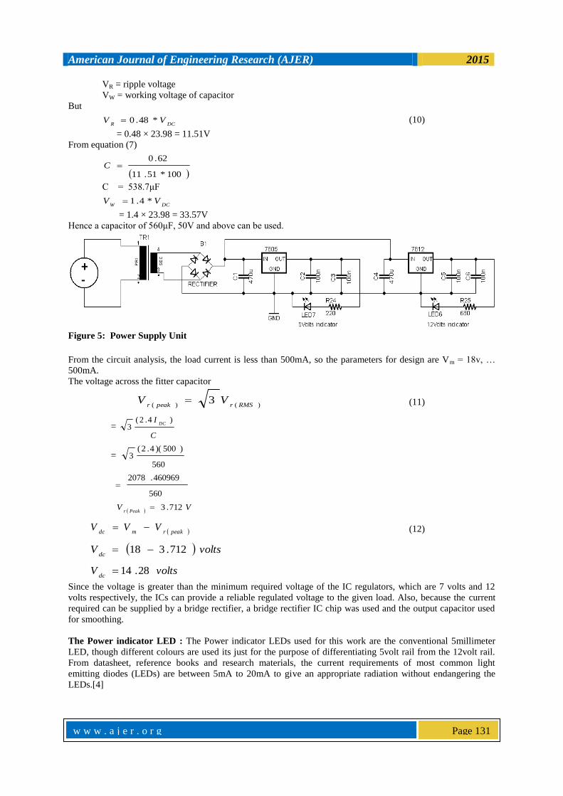
VR = ripple voltage
VW = working voltage of capacitor
But
DCRVV *48.0 (10)
= 0.48 × 23.98 = 11.51V
From equation (7)
100*51.11
62.0C
C = 538.7μF
DCWVV *4.1
= 1.4 × 23.98 = 33.57V
Hence a capacitor of 560μF, 50V and above can be used.
Figure 5: Power Supply Unit
From the circuit analysis, the load current is less than 500mA, so the parameters for design are Vm = 18v, …
500mA.
The voltage across the fitter capacitor
)()(3
RMSrpeakrVV (11)
= C
IDC
)4.2(3
=560
)500)(4.2(3
560
460969.2078
VVPeakr
712.3
peakrmdcVVV (12)
voltsVdc
712.318
voltsVdc
28.14
Since the voltage is greater than the minimum required voltage of the IC regulators, which are 7 volts and 12
volts respectively, the ICs can provide a reliable regulated voltage to the given load. Also, because the current
required can be supplied by a bridge rectifier, a bridge rectifier IC chip was used and the output capacitor used
for smoothing.
The Power indicator LED : The Power indicator LEDs used for this work are the conventional 5millimeter
LED, though different colours are used its just for the purpose of differentiating 5volt rail from the 12volt rail.
From datasheet, reference books and research materials, the current requirements of most common light
emitting diodes (LEDs) are between 5mA to 20mA to give an appropriate radiation without endangering the
LEDs.[4]

American Journal of Engineering Research (AJER) 2015
w w w . a j e r . o r g
Page 132
Figure 6: LED biasing
Given that,
Id = 10mA, (required current through LED)
Vd = 1.5volts, (voltage drop across LED)
Using KVL for a closed loop for LED1,
011
DDCC
VRIV (13)
DCCDVVRI
11
D
DCC
I
VVR
1
1
31
10*10
5.15R
3501
R
3301
R
Using KVL for a closed loop for LED2,
022
DDCC
VRIV (14)
DCCDVVRI
22
D
DCC
I
VVR
2
2
32
10*10
5.112R
10502
R
10002
R
3.6 The GSM Battery charging interface
In order for the GSM phone to maintain its normal operation its required of it to have a steady supply
of 5V luckily it has a battery in it but our paramount concern is charging it at regular interval,[5] this is achieved
with the figure below.

American Journal of Engineering Research (AJER) 2015
w w w . a j e r . o r g
Page 133
Figure 7: GSM Battery Charging Interface
From circuit analysis IC = 50mA
BImA *29050
290
10*503
B
I
000172414.0B
I
AIB
414.172
From the collector emitter loop,
0CCCC
RIV
CCCCVRI
C
CC
C
I
VR
310*50
5
CR
100C
R
From the base emitter loop,
0BEBBB
VRIV (15)
BEBBBVVRI
B
BEB
B
I
VVR
610*414.172
7.05
BR
97.24939B
R
KRB
22
The base resistor also maintains its available value which is 10K
3.7 The GSM interface
The GSM interface is solely for proper connection from the Mobile phone to the microcontroller
because the GSM interface requires a 3.3V for its transmit and receive pins whereas the microcontroller
provides 5v hence this interface circuit enables the 5v from the microcontroller to be converted to 3.3v before
sending to the GSM pins for proper communication. The circuits below illustrate the spelt out principle.

American Journal of Engineering Research (AJER) 2015
w w w . a j e r . o r g
Page 134
Figure.8: GSM Communication Interface
Switches : These five buttons are use to switch the five lighting point in question which are North light, South
light, East light, West light and the fluorescent to the desirable states which is either ON or OFF, though the
main function of these is purely toggling of state.
A typical switch or button connection used in a digital application is shown the figure below.
Figure 9 button press configuration
"Bouncing" is the term used to describe what happens when the switch is closed or opened. Instead of a
single, square edge as you may expect, a switch change consists of many short spikes, this as a result of the
button's contacts "bouncing" during the
transition. [6]This is shown in the diagram
below:
Figure10: illustration of button de-bouncing
Multiple Switch with ADC pin/Comparator : The ADC peripheral of the microcontroller can be used to
detect one or more switch closings by using a few resistors. As shown in figure below

American Journal of Engineering Research (AJER) 2015
w w w . a j e r . o r g
Page 135
Figure11: Multiple button with ADC configuration
From the figure above any button pressed registers a different level of voltage to the ADC pin.
The complete circuit diagram is shown below with its individual parts included.
Figure 12: complete schematic diagram of SMS controlled lighting
IV SOFTWARE DEVELOPMENT 4.1Microcontroller Operations : This paper uses software for the microcontroller and the computer system.
These programs were written using embedded C language, AT command and visual basic 6.0. Software
development involves a series of steps which are necessary for the development of reliable and maintainable
software. It is of great importance because hardware design cannot be of use in a microprocessor based system
without dependable software. A. The flow chart is shown fig. 11 below.

American Journal of Engineering Research (AJER) 2015
w w w . a j e r . o r g
Page 136
Figure11: Software programming flow chart

American Journal of Engineering Research (AJER) 2015
w w w . a j e r . o r g
Page 137
GSM phone and AT commands : The communication between the GSM module and the
microcontroller is achieve through AT(Attention) commands with a serial communication protocol of
UART(universal Asynchronous Receiver and Transmitter), with frame format parameters of 9600Baud rate,
8bit data, 1 start bit, 1 stop bit and no parity bit below are some command definitions to the GSM module are
shown below.
4.2.1Command Definition
AT+CSCA: Set the SMS center address. Mobile-originated messages are transmitted through this service
center.
AT+CMGS: Send short message to the SMS center
AT+CMGR: Read one message from the SIM card storage
AT+CMGD: Delete a message from the SIM card storage
AT+CMGF: Select format for incoming and outgoing messages: zero for PDU mode, one for Text mode
AT+CSMP: Set additional parameters for Text mode messages
All commands to the microcontroller is done with SMS, these messages have a format of
COMMAND.SUBCOMMAND.PERIPHERAL#PIN
The command in this case is switch.
The subcommand is either ON, OFF or TOGGLE.
The peripheral is either of the five lighting points.
The pin is a four digit numeral personal identification number (pin).
So the typical format will be,
Switch.on.north light#0123
V. CONCLUSION The Switching of Security Lighting System using GSM was discussed and the aim of the work which is the
design and implementation of a GSM based Security Lighting system Controller has been completed. This
system would make it easier for man to Control Security Lighting system from a distance. For places where
GSM coverage is not available, there is need for the installation of GSM base transceiver stations, since the
system operation is largely dependent on availability of efficient communication (network) coverage.
REFERENCES [1] Friedhelm Hillebrand, “GSM and UMTS: The Creation of Global Mobile Communication”, John Wiley, 2002
[2] C.O. Ohaneme, K.A. Akpado, E.N. Ifeagwu and C.O. Ezeagwu ,Implementation and Analysis of a GSM-Based Security System with Emergency Control, International Journal of Electronics Communication and Computer Engineering ,Vol. 5, Issue 1, 2014 pp
134 - 141
[3] The History of Text Messaging. Available:http://www.vxcl.org.htm/ [4] CD4017B Data Sheet (1999). [Online] Available: http://www.datasheetsdir.com/cd4017+download
[5] Delgado, A. R., Picking, R., & Grout, V. Remote-controlled home automation systems with different network
technologies.Proceedings of the 6th International Network Conference (INC 2006), University of Plymouth, 11-14 July 2006, pp. 357-366. Retrieved from http://www.newi.ac.uk/groutv/papers/p5.pdf
[6] Boylestad, R. L. and Nashelsky, L. Electronic Devices and Circuit Theory, 7th Edition, Prentice-Hall Publications, Inc., New Jersey, 1999
[7] Neamen, D. A. Electronic Circuit Analysis and Design, 2nd Edition, McGraw-Hill, Inc., New York., 2001
Related Documents