Isolation & Control Equipment 20A - 1000A • Switch Disconnectors. • Fuse Combination Units. • Changeover Switch Disconnectors. • High Temperature (Fire rated) Switch Disconnectors. • LUL (Section 12) isolation equipment. • Automatic Transfer Switches (ATS). ...make the switch switch Made in the U.K.

Welcome message from author
This document is posted to help you gain knowledge. Please leave a comment to let me know what you think about it! Share it to your friends and learn new things together.
Transcript
Isolation & Control Equipment 20A - 1000A
• Switch Disconnectors.• Fuse Combination Units.• Changeover Switch Disconnectors.• High Temperature (Fire rated) Switch Disconnectors.• LUL (Section 12) isolation equipment.• Automatic Transfer Switches (ATS).
...make the switch
switch
Made in the U.K.
I
switchrange
1page
1
Introduction& Index
Page No. Page No.
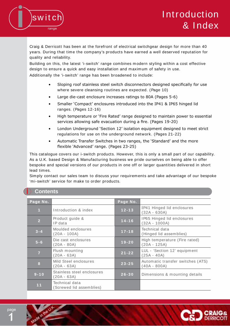
1 Introduction & index 12-13 IP41 Hinged lid enclosures(32A - 630A)
2 Product guide & IP data 14-16 IP65 Hinged lid enclosures
(32A - 1000A)
3-4 Moulded enclosures(20A - 100A) 17-18 Technical data
(Hinged lid assemblies)
5-6 Die cast enclosures(20A - 80A) 19-20 High temperature (Fire rated)
(20A - 125A)
7 Flush mounting(20A - 63A) 21-22 LUL - ‘Section 12’ equipment
(25A - 40A)
8 Mild Steel enclosures(20A - 63A) 23-25 Automatic transfer switches (ATS)
(40A - 800A)
9-10 Stainless steel enclosures(20A - 63A) 26-30 Dimensions & mounting details
11 Technical data(Screwed lid assemblies)
Contents
Craig & Derricott has been at the forefront of electrical switchgear design for more than 40 years. During that time the company’s products have earned a well deserved reputation for quality and reliability.
Building on this, the latest ‘i-switch’ range combines modern styling within a cost effective design to ensure a quick and easy installation and maximum of safety in use.
Additionally the ‘i-switch’ range has been broadened to include:
• Slopingroofstainlesssteelswitchdisconnectorsdesignedspecificallyforuse where severe cleansing routines are expected. (Page 10)
• Largedie-castenclosureincreasesratingsto80A(Pages5-6)
• Smaller‘Compact’enclosuresintroducedintotheIP41&IP65hingedlid ranges. (Pages 12-16)
• Hightemperatureor‘FireRated’rangedesignedtomaintainpowertoessential servicesallowingsafeevacuationduringafire.(Pages19-20)
• LondonUnderground‘Section12’isolationequipmentdesignedtomeetstrict regulations for use on the underground network. (Pages 21-22)
• AutomaticTransferSwitchesintworanges,the‘Standard’andthemore flexible‘Advanced’range.(Pages23-25)
This catalogue covers our i-switch products. However, this is only a small part of our capability. As a U.K. based Design & Manufacturing business we pride ourselves on being able to offer bespoke and special versions of our products in one off or larger quantities delivered in short lead times.Simply contact our sales team to discuss your requirements and take advantage of our bespoke ‘mi-switch’ service for make to order products.

switchrange
page
2
I
Product Guide & IP Data
Product GuideComparing todays ‘Trade’ descriptions to European standards:-
BSEN60947-3Definition
‘Trade’Description Technical Description
Switch-Disconnector
Sym. Isolator
A ‘Disconnector’ is a mechanical switch which in the ‘Open’ position, complies withrequirementsspecifiedfortheisolatingfunction.A‘Disconnector’ or ‘Isolator’ is an off-load device and marked ‘Isolate elsewhere before opening’ they have an AC20/DC20 utilisation category.
A ‘Switch’ is a mechanical switching device capable of making, carrying and breakingcurrentundernormalcircuitconditions,whichmayincludespecifiedoperatingoverloadconditions.Theyalsocarry,foraspecifiedtime,currentsunderspecifiedabnormalcircuitconditions,suchasthoseofshortcircuit(i.e. Utilisation category AC23A duty).
A ‘Switch-Disconnector’meetsbothofthesecriteriaandwithaRed/Yellowpadlockable handle may also be called a ‘Safety Isolator’.
Changeover Switch-Disconnector
Sym.
Changeover SwitchA ‘Changeover’ device is used to connect to one of two sources and in this isolation application will require a central ‘Off’ position. In all other respects it conforms to the ‘Switch Disconnector’ requirements.
Fuse Combination Unit
Sym.
Fuse Switch A ‘Fuse Combination Unit’ is a combination of a mechanical switching device with fuses in a composite assembly.
BS EN60947-3 descriptions have been used throughout this catalogue.
Ingress ProtectionWhen choosing an isolating device, apart from the electrical performance, consideration must be given to the environmental conditions in which the device will be placed. The item may be subjected to dust or dirt or it may come in contact with degreesofmoisture.Indoorconditionswillvaryconsiderablybutitemsmaywellbeplacedoutdoorswherethefullinfluenceof rain, ice & snow will be present.ProtectingitemstovaryingdegreesisdetailedinBSEN60529:1992.
Employingatwodigitcodethestandarddefinesprotectionagainstsolidobjectsandseparatelyprotectionagainstmoisturei.e.
IP66(protection against water)
(protection against solid objects)
ThefollowingextractdefinestheIPcategoriesusedwithinthisdocument.
1st Digit Protection against solid objects 2nd Digit Protection against water
0 Not Protected 0 Not Protected
2 Protected against solid objects greater than Ø12.5 1 Protected against
dripping water.
4 Protected against solid objects greater than Ø1.0 4
Protected against splashed water from
any direction.
5
Protected against dust - allowing a degree of
ingress that isn’t harmful to the assembly.
5Protected against
water jets from any direction.
6 No ingress of dust. 6
Protected against strong water jets
from any direction.
Ø12.5
Ø1.0
PleaserefertoBSEN60529:1992forfulldetails.
Product guide &IP Data

switchrange
page
3
Mo
uld
ed
Pla
stic Enclo
sures
Moulded Plastic-IP65/66 Enclosure (20A-100A)
Technical DataPage 11
DimensionsPages 26
Rating Format Interior Switch product range Cat. No. Enclosure
Size
20A6P GX20 SDP256 A
(IP66)6P+2EB Aux GX20 SDP256EB
25A
2P CS25 SDP252
A(IP66)
3P CS25 SDP2533P+NL CS25 SDP253NL3P+N CS25 SDP253N
3P+2EB Aux CS25 SDP253EB
32A
2P CS32 SDP322
A(IP66)
3P CS32 SDP3233P+NL CS32 SDP323NL3P+N CS32 SDP323N
3P+2EB Aux CS32 SDP323EB
40A
2P CS40R SDP402
B(IP66)
3P CS40R SDP4033P+NL CS40R SDP403NL3P+N CS40R SDP403N
3P+2EB Aux CS40R SDP403EB6P GX40 SDP406
6P+2EB Aux GX40 SDP406EB
63A
2P CS63 SDP632
B(IP66)
3P CS63 SDP6333P+NL CS63 SDP633NL3P+N CS63 SDP633N
3P+2EB Aux CS63 SDP633EB
80A
2P CS80 SDP802
C(IP65)
3P CS80 SDP8033P+NL CS80 SDP803NL3P+N CS80 SDP803N
3P+2EB Aux CS80 SDP803EB
100A
2P CS100 SDP1002
D(IP65)
3P CS100 SDP10033P+NL CS100 SDP1003NL3P+N CS100 SDP1003N
3P+2EB Aux CS100 SDP1003EB‘N’ = switched neutral (Early make, late break)‘NL’ = Unswitched neutral
Catalogue Numbers
Switch-Disconnectors (O-I)
Rating Format Interior Switch product range Cat. No. Enclosure
Size
20A2P GX20 SCODP252
A(IP66)3P GX20 SCODP253
4P GX20 SCODP254
40A2P GX40 SCODP402
B(IP66)3P GX40 SCODP403
4P GX40 SCODP404
Changeover Switch-Disconnectors (I-O-II)
General DescriptionSwitchgear housed in moulded plastic enclosures provide the basis for most industrial applications and the added benefitsofferedbythe‘i-switch’rangeprovidetheuserwithawealthofopportunitieswhenselectingthecorrectitemforaspecificapplication.SealinguptoIP66isastandardfeatureasistheabilitytoaddaselectionofauxiliaryblocks providing additional contacts and a choice of Neutral assemblies.
Safety Features
Padlocking
All items allow for the insertion of up to three padlocks in the ‘Off’ position thus preventing the isolator being to the ‘On’ position.
Standard shackle diameter Ø6.4
Watch a 3 minute video explaining the various safety features built-in to the design of the i-switch ‘screwed lid’product family.
(An option to allow padlocking in the ‘On’ position is available on request.)
Safety Interlock
Screwed lid enclosures have always been open to abuse by having the lid removable when the isolator is ‘Off’ and padlocked. This would allow the switch shaft to be turned manually to the ‘On’ position, thus defeating the safety padlocking feature.
The ‘i-switch’ range now incorporates a mechanical inter-lock which when a padlock is inserted prevents the enclo-sure lid from being removed.
With the ‘i-switch’ range comes an important safety fea-ture which prevents the enclosure cover being removed when the device has been padlocked in the ‘Off’ position. When combined with the excellent on-load breaking capacity of the ‘i-switch’ family this feature ensures that the term ‘Safety Switch’isfullysatisfied.

switchrange
page
4
Neutral Link 2 Early Break Neutral Link (Unswitched) Auxiliary (Switched)
Description Cat. No.
Auxiliary Contact - 2 Early Break SAUX2EB
Auxiliary Contact - 1 N/O + 1 N/C SAUXCO
25A Neutral (Unswitched) SNL25
32A & 40A Neutral (Unswitched) SNL40
63A Neutral (Unswitched) SNL63
80A Neutral (Unswitched) SNL80
100A Neutral (Unswitched) SNL100
25A Neutral (Switched) SSP25
32A & 40A Neutral (Switched) SSP40
63A Neutral (Switched) SSP63
80A Neutral (Switched) SSP80
100A Neutral (Switched) SSP100
Accessories (applicable to type ‘CS’ interiors only)
Design Features
Enclosure
Material 20A-63A PC/ABS 80A-100A PC
Colour Enclosure-GreyRAL7035
Entries Size A Enclosure - 2 x M20 knock-outs on top & bottom faces. Size B Enclosure - 2 x M20/25 knock- outs on top & bottom faces. Back face - 2 x M20 knock-outs. Size C & D Enclosures - Blank sides.
Cover Screws Stainless Steel (Captive)
Fixings Outside sealed cavity.
Switch-Disconnectors
2 & 3 Pole Type CS - base mounted. (Accepts add-on Aux. blocks & Neutrals)
6 Pole Type GX - base mounted. (also available with 2 E/B Aux.)
Changeover Switch-Disconnectors
2, 3 & 4 Pole Type GX - base mounted.
Earthing
Earth terminals are provided in the base of the enclosures.
Exploded view showing a type CS isolator interior with Auxiliary/Neutral options
Technical DataPage 11
DimensionsPages 26
Moulded Plastic-IP65/66 Enclosure (20A-100A)
Mo
uld
ed
Pla
stic Enclo
sures

switchrange
page
5Technical Data
Page 11DimensionsPages 27
General DescriptionThe ‘i-switch’ die cast range provides the user with a product that will withstand a good deal of rough treatment. With sealing up to IP66 these assemblies can be placed in environments where resistance to impacts, moisture and dust/dirt are a concern. The option to add a selection of auxiliary blocks providing additional contacts and a choice ofNeutralassembliesincreasestheflexibilityoftheproductrange.
Catalogue Numbers
Rating Format Interior Switch product range Cat. No. Enclosure
Size
20A2P GX20 SCODG252
A(IP66)3P GX20 SCODG253
4P GX20 SCODG254
40A2P GX40 SCODG402
B(IP66)3P GX40 SCODG403
4P GX40 SCODG404
C/O Switch-Disconnectors (I-O-II)
20A Changeover Switch-Disconnector in a size A enclosure
All safety features are identical to the plastic moulded range - see page 3 for details.
Die Cast Aluminium-IP66 Enclosure (20A-80A)
Die
Cast A
lum
iniu
m E
nclo
sures
Switch-Disconnectors (O-I)
‘N’ = switched neutral (Early make, late break)‘NL’ = Unswitched neutral
Rating Format
Interior Switch product range
Catalogue Nos.Enclosure
SizeGrey Red
20A6P GX20 SDDG256 SDDR256 A
(IP66)6P+2EB Aux GX20 SDDG256EB SDDR256EB
25A
2P CS25 SDDG252 SDDR252
A(IP66)
3P CS25 SDDG253 SDDR253
3P+NL CS25 SDDG253NL SDDR253NL
3P+N CS25 SDDG253N SDDR253N
3P+2EB Aux CS25 SDDG253EB SDDR253EB
32A
2P CS32 SDDG322 SDDR322
A(IP66)
3P CS32 SDDG323 SDDR323
3P+NL CS32 SDDG323NL SDDR323NL
3P+N CS32 SDDG323N SDDR323N
3P+2EB Aux CS32 SDDG323EB SDDR323EB
40A
2P CS40R SDDG402 SDDR402
B(IP66)
3P CS40R SDDG403 SDDR403
3P+NL CS40R SDDG403NL SDDR403NL
3P+N CS40R SDDG403N SDDR403N
3P+2EB Aux CS40R SDDG403EB SDDR403EB
6P GX40 SDDG406 SDDR406
6P+2EB Aux GX40 SDDG406EB SDDR406EB
63A
2P CS63 SDDG632 SDDR632
B(IP66)
3P CS63 SDDG633 SDDR633
3P+NL CS63 SDDG633NL SDDR633NL
3P+N CS63 SDDG633N SDDR633N
3P+2EB Aux CS63 SDDG633EB SDDR633EB
6P CS63 SDDG636 SDDR636
6P+2EB Aux CS63 SDDG636EB SDDR636EB
80A3P+NL CS80 SDDG803NL SDDR803NL B
(IP66)3P+N CS80 SDDG803N SDDR803N
Safety Features
Size A & Size B enclosures as Switch Disconnectors inbothRed&Grey
Screwed lid enclosures have always been open to abuse by having the lid removable when the isolator is ‘Off’ and padlocked. This would allow the switch shaft to be turned manually to the ‘On’ position, thus defeating the safety padlock-ing feature.
The ‘i-switch’ range now incorporates a mechan-ical interlock which when a padlock is inserted prevents the enclosure lid from being removed.
Description Cat. No.Auxiliary Contact - 2 Early Break SAUX2EBAuxiliary Contact - 1 N/O + 1 N/C SAUXCO25A Neutral (Unswitched) SNL2532A & 40A Neutral (Unswitched) SNL4063A Neutral (Unswitched) SNL6325A Neutral (Switched) SSP2532A & 40A Neutral (Switched) SSP4063A Neutral (Switched) SSP63
Accessories (applicable to type ‘CS’ interiors only)
switchrange
page
6Technical Data
Page 11DimensionsPages 27
Die Cast Aluminium-IP66 Enclosure (20A-80A)
Die
Cast A
lum
iniu
m E
nclo
sures
Design Features
Enclosure
Material DiecastaluminiumalloyLM24(BS1490)
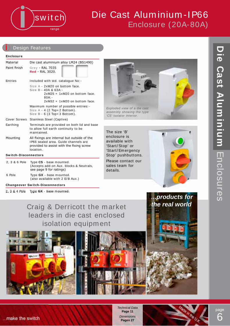
Paintfinish Grey-RAL7035 Red-RAL3020.
Entries Included with std. catalogue No:-
Size A - 2xM20 on bottom face. Size B - 40A & 63A:- 2xM25 + 1xM20 on bottom face. 80A:- 2xM32 + 1xM20 on bottom face.
Maximum number of possible entries:- Size A - 4 (2 Top+2 Bottom). Size B - 6 (3 Top+3 Bottom).
Cover Screws Stainless Steel (Captive)
Earthing Terminals are provided on both lid and base to allow full earth continuity to be maintained.
Mounting Allfixingsareinternalbutoutsideofthe IP66 sealed area. Guide channels are providedtoassistwiththefixingscrew location.
Switch-Disconnectors
2, 3 & 6 Pole Type CS - base mounted. (Accepts add-on Aux. blocks & Neutrals, seepage9forratings)
6 Pole Type GX - base mounted. (also available with 2 E/B Aux.)
Changeover Switch-Disconnectors
2, 3 & 4 Pole Type GX - base mounted.
Exploded view of a die cast assembly showing the type ‘CS’ isolator interior.
2, 3 & 4 Pole Type GX - base mounted.
Craig & Derricott the market leaders in die cast enclosed
isolation equipment
...products for the real world
The size ‘B’ enclosure is available with ‘Start/Stop’ or ‘Start/EmergencyStop’ pushbuttons. Please contact our sales team for details.
switchrange
page
7Technical Data
Page 11DimensionsPages 27
Flu
sh E
nclo
sures
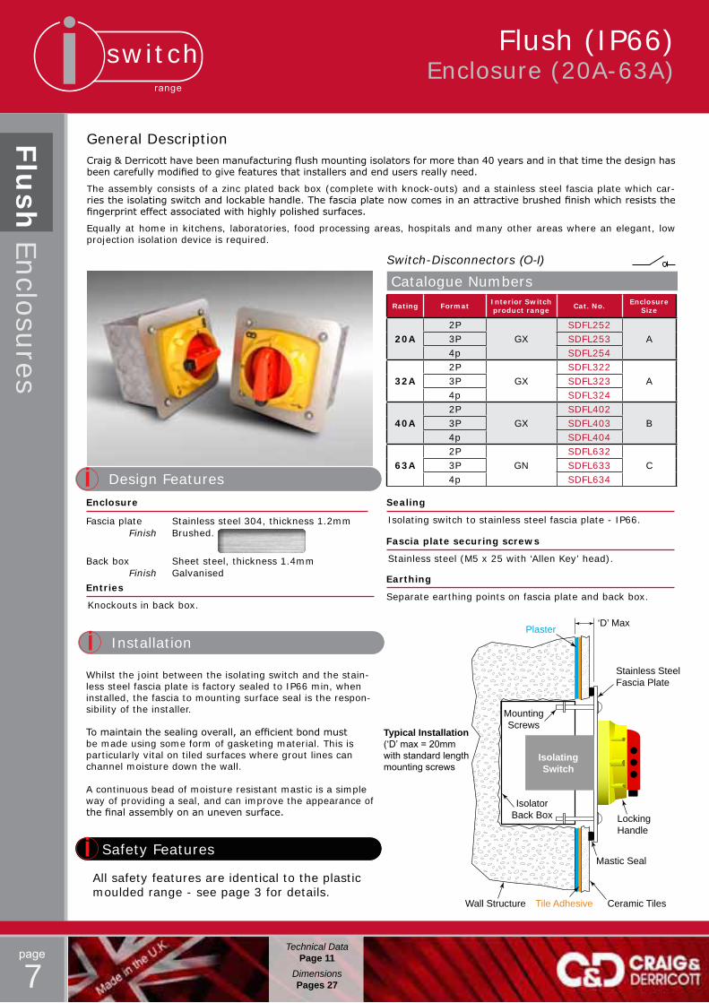
General DescriptionCraig&Derricotthavebeenmanufacturingflushmountingisolatorsformorethan40yearsandinthattimethedesignhasbeencarefullymodifiedtogivefeaturesthatinstallersandendusersreallyneed.
The assembly consists of a zinc plated back box (complete with knock-outs) and a stainless steel fascia plate which car-riestheisolatingswitchandlockablehandle.Thefasciaplatenowcomesinanattractivebrushedfinishwhichresiststhefingerprinteffectassociatedwithhighlypolishedsurfaces.
Equally at home in kitchens, laboratories, food processing areas, hospitals and many other areas where an elegant, low projection isolation device is required.
Rating Format Interior Switch product range Cat. No. Enclosure
Size
20A2P
GXSDFL252
A3P SDFL2534p SDFL254
32A2P
GXSDFL322
A3P SDFL3234p SDFL324
40A2P
GXSDFL402
B3P SDFL4034p SDFL404
63A2P
GNSDFL632
C3P SDFL6334p SDFL634
Catalogue Numbers
Switch-Disconnectors (O-I)
All safety features are identical to the plastic moulded range - see page 3 for details.
Safety Features
Design Features
Enclosure
Fascia plate Stainless steel 304, thickness 1.2mm Finish Brushed.
Back box Sheet steel, thickness 1.4mm Finish Galvanised
Entries
Knockouts in back box.
Earthing
Separate earthing points on fascia plate and back box.
Sealing
Isolating switch to stainless steel fascia plate - IP66.
Fascia plate securing screws
Stainless steel (M5 x 25 with ‘Allen Key’ head).
Isolator Back Box
Isolating Switch
MountingScrews
‘D’ Max
Stainless SteelFascia Plate
Locking Handle
Mastic Seal
Plaster
Tile Adhesive Ceramic TilesWall Structure
Installation
Whilst the joint between the isolating switch and the stain-less steel fascia plate is factory sealed to IP66 min, when installed, the fascia to mounting surface seal is the respon-sibility of the installer.
Tomaintainthesealingoverall,anefficientbondmustbe made using some form of gasketing material. This is particularly vital on tiled surfaces where grout lines can channel moisture down the wall.
A continuous bead of moisture resistant mastic is a simple way of providing a seal, and can improve the appearance of thefinalassemblyonanunevensurface.
Typical Installation(‘D’ max = 20mm with standard length mounting screws
Flush (IP66)Enclosure (20A-63A)
switchrange
page
8Technical Data
Page 11DimensionsPages 26
Enclosure (20A-63A)
Mild
Ste
el E
nclo
sures
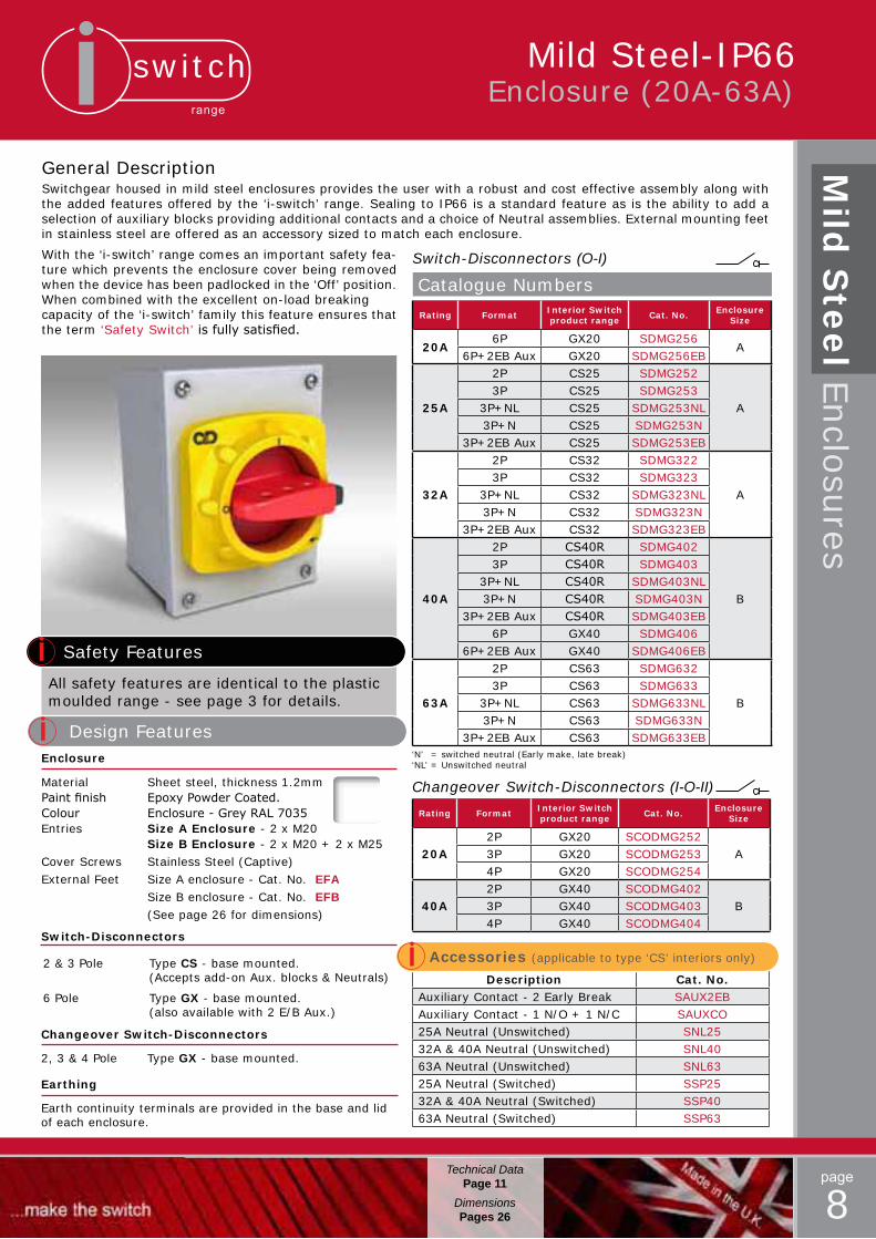
General DescriptionSwitchgear housed in mild steel enclosures provides the user with a robust and cost effective assembly along with the added features offered by the ‘i-switch’ range. Sealing to IP66 is a standard feature as is the ability to add a selection of auxiliary blocks providing additional contacts and a choice of Neutral assemblies. External mounting feet in stainless steel are offered as an accessory sized to match each enclosure.
Rating Format Interior Switch product range Cat. No. Enclosure
Size
20A6P GX20 SDMG256
A6P+2EB Aux GX20 SDMG256EB
25A
2P CS25 SDMG252
A3P CS25 SDMG253
3P+NL CS25 SDMG253NL3P+N CS25 SDMG253N
3P+2EB Aux CS25 SDMG253EB
32A
2P CS32 SDMG322
A3P CS32 SDMG323
3P+NL CS32 SDMG323NL3P+N CS32 SDMG323N
3P+2EB Aux CS32 SDMG323EB
40A
2P CS40R SDMG402
B
3P CS40R SDMG4033P+NL CS40R SDMG403NL3P+N CS40R SDMG403N
3P+2EB Aux CS40R SDMG403EB6P GX40 SDMG406
6P+2EB Aux GX40 SDMG406EB
63A
2P CS63 SDMG632
B3P CS63 SDMG633
3P+NL CS63 SDMG633NL3P+N CS63 SDMG633N
3P+2EB Aux CS63 SDMG633EB
Catalogue Numbers
Switch-Disconnectors (O-I)
Rating Format Interior Switch product range Cat. No. Enclosure
Size
20A2P GX20 SCODMG252
A3P GX20 SCODMG2534P GX20 SCODMG254
40A2P GX40 SCODMG402
B3P GX40 SCODMG4034P GX40 SCODMG404
Changeover Switch-Disconnectors (I-O-II)
Safety Features
Description Cat. No.Auxiliary Contact - 2 Early Break SAUX2EBAuxiliary Contact - 1 N/O + 1 N/C SAUXCO25A Neutral (Unswitched) SNL2532A & 40A Neutral (Unswitched) SNL4063A Neutral (Unswitched) SNL6325A Neutral (Switched) SSP2532A & 40A Neutral (Switched) SSP4063A Neutral (Switched) SSP63
Accessories (applicable to type ‘CS’ interiors only)
All safety features are identical to the plastic moulded range - see page 3 for details.
Design FeaturesEnclosure
Material Sheet steel, thickness 1.2mmPaintfinish EpoxyPowderCoated.Colour Enclosure-GreyRAL7035Entries Size A Enclosure - 2 x M20 Size B Enclosure - 2 x M20 + 2 x M25Cover Screws Stainless Steel (Captive)External Feet Size A enclosure - Cat. No. EFA Size B enclosure - Cat. No. EFB (See page 26 for dimensions)
Switch-Disconnectors
2 & 3 Pole Type CS - base mounted. (Accepts add-on Aux. blocks & Neutrals)
6 Pole Type GX - base mounted. (also available with 2 E/B Aux.)
Changeover Switch-Disconnectors
2, 3 & 4 Pole Type GX - base mounted.
Earthing
Earth continuity terminals are provided in the base and lid of each enclosure.
Mild Steel-IP66
With the ‘i-switch’ range comes an important safety fea-ture which prevents the enclosure cover being removed when the device has been padlocked in the ‘Off’ position. When combined with the excellent on-load breaking capacity of the ‘i-switch’ family this feature ensures that the term ‘Safety Switch’isfullysatisfied.
‘N’ = switched neutral (Early make, late break)‘NL’ = Unswitched neutral
switchrange
page
9Technical Data
Page 11DimensionsPages 26
Stainless Steel-IP66 Enclosure (20A-63A)
Sta
inle
ss Ste
el E
nclo
sures
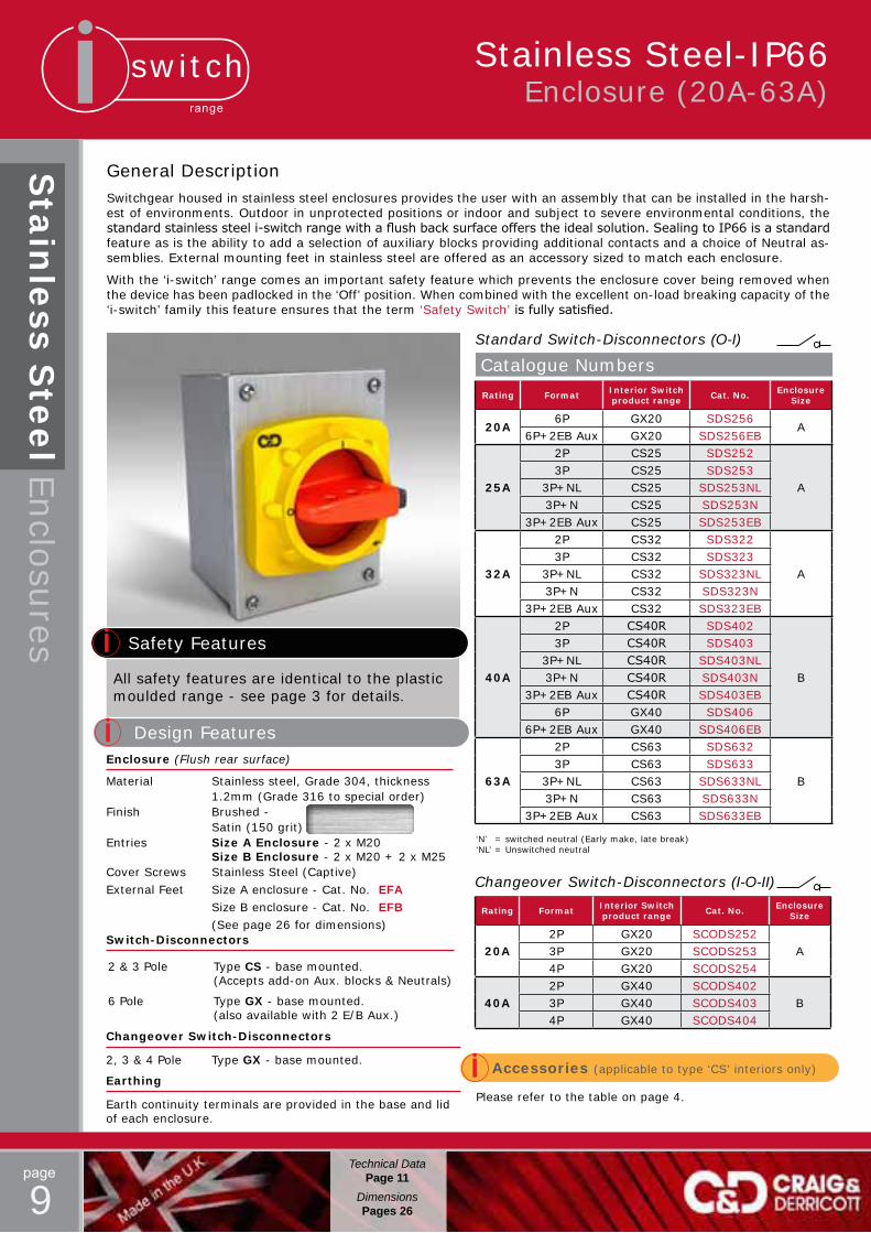
General DescriptionSwitchgear housed in stainless steel enclosures provides the user with an assembly that can be installed in the harsh-est of environments. Outdoor in unprotected positions or indoor and subject to severe environmental conditions, the standardstainlesssteeli-switchrangewithaflushbacksurfaceofferstheidealsolution.SealingtoIP66isastandardfeature as is the ability to add a selection of auxiliary blocks providing additional contacts and a choice of Neutral as-semblies. External mounting feet in stainless steel are offered as an accessory sized to match each enclosure.
With the ‘i-switch’ range comes an important safety feature which prevents the enclosure cover being removed when the device has been padlocked in the ‘Off’ position. When combined with the excellent on-load breaking capacity of the ‘i-switch’ family this feature ensures that the term ‘Safety Switch’isfullysatisfied.
Rating Format Interior Switch product range Cat. No. Enclosure
Size
20A6P GX20 SDS256
A6P+2EB Aux GX20 SDS256EB
25A
2P CS25 SDS252
A3P CS25 SDS253
3P+NL CS25 SDS253NL3P+N CS25 SDS253N
3P+2EB Aux CS25 SDS253EB
32A
2P CS32 SDS322
A3P CS32 SDS323
3P+NL CS32 SDS323NL3P+N CS32 SDS323N
3P+2EB Aux CS32 SDS323EB
40A
2P CS40R SDS402
B
3P CS40R SDS4033P+NL CS40R SDS403NL3P+N CS40R SDS403N
3P+2EB Aux CS40R SDS403EB6P GX40 SDS406
6P+2EB Aux GX40 SDS406EB
63A
2P CS63 SDS632
B3P CS63 SDS633
3P+NL CS63 SDS633NL3P+N CS63 SDS633N
3P+2EB Aux CS63 SDS633EB
Catalogue Numbers
Standard Switch-Disconnectors (O-I)
Rating Format Interior Switch product range Cat. No. Enclosure
Size
20A2P GX20 SCODS252
A3P GX20 SCODS2534P GX20 SCODS254
40A2P GX40 SCODS402
B3P GX40 SCODS4034P GX40 SCODS404
Changeover Switch-Disconnectors (I-O-II)
Safety Features
Please refer to the table on page 4.
Accessories (applicable to type ‘CS’ interiors only)
All safety features are identical to the plastic moulded range - see page 3 for details.
Design FeaturesEnclosure (Flush rear surface)
Material Stainless steel, Grade 304, thickness 1.2mm (Grade 316 to special order)Finish Brushed - Satin (150 grit)Entries Size A Enclosure - 2 x M20 Size B Enclosure - 2 x M20 + 2 x M25Cover Screws Stainless Steel (Captive)External Feet Size A enclosure - Cat. No. EFA Size B enclosure - Cat. No. EFB (See page 26 for dimensions)Switch-Disconnectors
2 & 3 Pole Type CS - base mounted. (Accepts add-on Aux. blocks & Neutrals)
6 Pole Type GX - base mounted. (also available with 2 E/B Aux.)
Changeover Switch-Disconnectors
2, 3 & 4 Pole Type GX - base mounted.
Earthing
Earth continuity terminals are provided in the base and lid of each enclosure.
‘N’ = switched neutral (Early make, late break)‘NL’ = Unswitched neutral

switchrange
page
10
Safety Features
Rating Format Interior Switch product range Cat. No. Enclosure
Size
20/25A
2P CS25 SDSSR252
A
3P CS25 SDSSR2533P+2EB AUX CS25 SDSSR253EB
3P+N CS25 SDSSR253N6P GX20 SDSSR256
6P+2EB AUX GX20 SDSSR256EB
32A
2P CS32 SDSSR322
A3P CS32 SDSSR323
3P+2EB AUX CS32 SDSSR323EB3P+N CS32 SDSSR323N
40A
2P CS40R SDSSR402
B
3P CS40R SDSSR4033P+2EB AUX CS40R SDSSR403EB
3P+N CS40R SDSSR403N6P GX40 SDSSR406
6P+2EB AUX GX40 SDSSR406EB
63A
2P CS63 SDSSR632
B3P CS63 SDSSR633
3P+2EB AUX CS63 SDSSR633EB3P+N CS63 SDSSR633N
Catalogue NumbersSloping Roof Switch-Disconnectors (O-I)
Stainless Steel-IP66 Enclosure (20A-63A)
Based upon Craig & Derricott’s ‘i-switch’ range of isolation equipment, the specially designed stainless steel ‘slop-ing roof’ enclosure is ideally suited for hygienic environments with their associated severe cleaning routines
Thedesignhasbeencreatedtominimiseareaswheredirtcanaccumulateandincorporatesaflushrearsurface anduniversalfixingthatincludeIP66sealings.
With the ‘i-switch’ range comes an important safety feature which prevents the enclosure cover being removed when the device has been padlocked in the ‘Off’ position. When combined with the excellent on-load breaking capacity of the ‘i-switch’ family this feature ensures that the term ‘Safety Switch’isfullysatisfied.
Safety Features
All safety features are identical to the plastic moulded range - see page 3 for details.
Design Features
Enclosure (Flush rear surface)
Material Stainless steel, Grade 316, thickness 1.2mm body, 1.5mm lid. (150 Slope)Finish Brushed - Satin 150 gritEntries The enclosures are supplied as standard without entries. Optional pre-drilled bottom entries can be supplied as follows:- Size A - 2xM20 (add M20 to cat No.) Size B - 2xM25 (add M25 to cat No.) e.g. SDSSR322/M20, SDSSR403N/M25Cover Screws Stainless Steel (Captive) (See page 25 for dimensions)
Switch-Disconnectors
2 & 3 Pole Type CS - base mounted. (Accepts add-on Aux. blocks & Neutrals)
6 Pole Type GX - base mounted. (also available with 2 E/B Aux.)Earthing
Earth continuity terminals are provided in the base and lid of each enclosure.
‘N’ - switched neutral (Early make, late break)
Section view showing the enclosures flush rear face with ‘sealed’ fixings that ensure the IP66 seal is maintained.
Fixings
Universalfixingsacrosstherange.
Please refer to the table on page 4.
Accessories (applicable to type ‘CS’ interiors only)
Sta
inle
ss Ste
el E
nclo
sures
Technical DataPage 11
DimensionsPages 26
switchrange
page
11Applicable to pages 3-10
Tech
nica
l Data
Fixed lid
assemblies
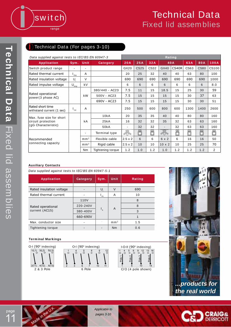
Application Category Sym. Unit Rating
Ratedinsulationvoltage - Ui V 690
Ratedthermalcurrent - Ith A 10
Ratedoperationalcurrent (AC15)
110V
Ie A
8
220-240V 8
380-400V 3
660-690V 1
Max. conductor size - - mm2 1.5
Tightening torque - - Nm 0.6
Technical Data (For pages 3-10)
Auxiliary Contacts
Data supplied against tests to IEC/BS EN 60947-5-1
2 & 3 Pole C/O (4 pole shown)6 Pole
Terminal Markings
O-I(900 indexing) O-I(900 indexing) I-O-II(900 indexing)1(L1) 3(L2) 5(L3)
2(T1) 4(T2) 6(T3)
1 4 5 8 9 12
2 3 6 7 10 11
Pol
e 1
Pol
e 2
Pol
e 3
Pol
e 4
1 4 5 8 9 12 13 16
1 6 10 14
Data supplied against tests to IEC/BS EN 60947-3 Rating
Application Sym. Unit Category 20A 25A 32A 40A 63A 80A 100A
Switch product range - - GX20 CS25 CS32 GX40 CS40R CS63 CS80 CS100
Ratedthermalcurrent Ithe A 20 25 32 40 40 63 80 100
Ratedinsulationvoltage Ui V 690 690 690 690 690 690 690 1000
Ratedimpulsevoltage Uimp kV 6 6 6 6 6 6 6 8.0
Ratedoperationalpower(3 phase AC) kW
380/440 - AC23 7.5 11 15 18.5 15 25 30 59
500V - AC23 7.5 15 15 15 15 30 37 63
690V-AC23 7.5 15 15 15 15 30 30 51
Ratedshorttimewithstand current (1 sec) Icw A 250 500 600 800 600 1300 1400 2600
Max. fuse size for short circuit protection (gG Characteristic)
kA
10kA 20 35 35 40 40 80 80 160
25kA 16 32 32 35 32 63 63 160
50kA - 32 32 - 32 63 63 160
Recommendedconnecting capacity
- Terminal type
mm2 Flexible cable 2.5 x 2 6 6 6 x 2 6 16 16 50
mm2 Rigidcable 2.5 x 2 10 10 10 x 2 10 25 25 70
Nm Tightening torque 1.2 1.0 1.2 1.0 1.2 1.2 1.2 2
...products for the real world
Technical DataFixed lid assemblies
switchrange
page
12
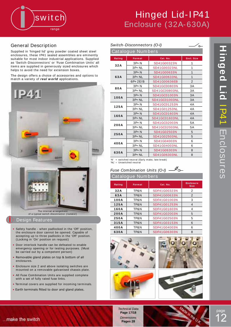
General DescriptionSupplied in ‘hinged lid’ grey powder coated sheet steel enclosures, these IP41 sealed assemblies are eminently suitable for most indoor industrial applications. Supplied as ‘Switch-Disconnectors’ or ‘Fuse Combination Units’ allitems are supplied in generously sized enclosures which helps to avoid the need for extension boxes.
The design offers a choice of accessories and options to match a variety of real world applications.
Design Features
•Safety handle - when padlocked in the ‘Off’ position, the enclosure door cannot be opened. Capable of accepting up to three padlocks in the ‘Off’ position. (Locking in ‘On’ position on request)
• Door interlock handle can be defeated to enable emergency opening or for testing purposes. (Must be carried out by a competent person)
•Removableglandplatesontop&bottomofall enclosures.
• Enclosure size 2 and above isolating switches are mounted on a removable galvanised chassis plate.
• All Fuse Combination Units are supplied complete with a set of fully rated fuse links.
• Terminal covers are supplied for incoming terminals.
•Earthterminalsfittedtodoorandglandplates.
The internal arrangement of a typical switch disconnector (Isolator)
IP41
Rating Format Cat. No. Encl. Size
32A3P+N SD41G00323N 13P+NL SD41G00323NL 1
63A3P+N SD41G00633N 13P+NL SD41G00633NL 1
6P+2E/B SD41G00636EB 2
80A3P+N SD41GC00803N 3A3P+NL SD41GC00803NL 3A
100A3P+N SD41GC01003N 3A3P+NL SD41GC01003NL 3A
125A3P+N SD41GC01253N 4A3P+NL SD41G01253NL 4A
160A3P+N SD41GC01603N 4A3P+NL SD41GC01603NL 4A
200A3P+N SD41GC02003N 5A3P+NL SD41GC02003NL 5A
250A3P+N SD41G02503N 53P+NL SD41G02503NL 5
400A3P+N SD41G04003N 63P+NL SD41G04003NL 6
630A3P+N SD41G06303N 83P+NL SD41G06303NL 8
Catalogue NumbersSwitch-Disconnectors (O-I)
Rating Format Cat. No. Enclosure Size
32A TP&N SDF41G00323N 263A TP&N SDF41G00633N 2
100A TP&N SDF41G01003N 3125A TP&N SDF41G01253N 4160A TP&N SDF41G01603N 4200A TP&N SDF41G02003N 5250A TP&N SDF41G02503N 5315A TP&N SDF41G03153N 6400A TP&N SDF41G04003N 6630A TP&N SDF41G06303N 8
Catalogue NumbersFuse Combination Units (O-I)
‘N’ = switched neutral (Early make, late break)‘NL’ = Unswitched neutral
Hin
ged
Lid
IP41 E
nclo
sures
Hinged Lid-IP41Enclosure (32A-630A)
Technical DataPage 17/18DimensionsPages 28
switchrange
page
13Technical Data
Page 17/18DimensionsPages 28
Hinged Lid-IP41Enclosure (32A-630A)
Hin
ged
Lid
IP41 E
nclo
sures
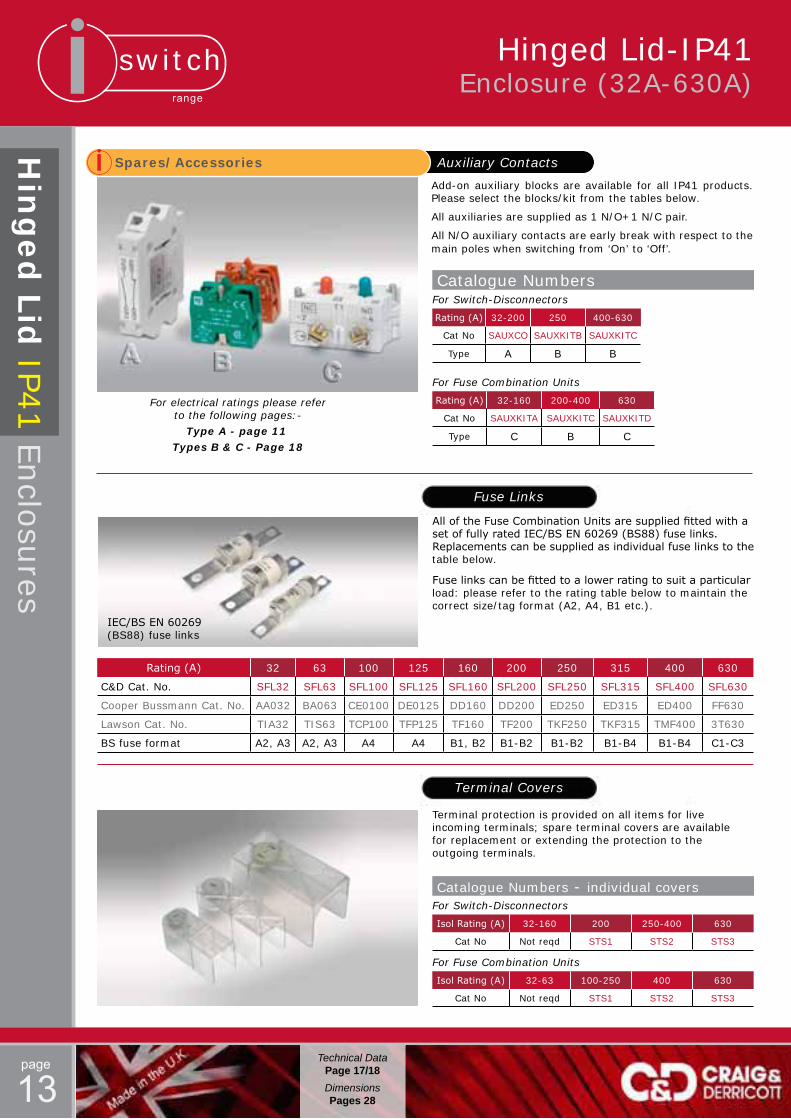
Spares/Accessories Auxiliary Contacts
Add-on auxiliary blocks are available for all IP41 products. Please select the blocks/kit from the tables below.
All auxiliaries are supplied as 1 N/O+1 N/C pair.
All N/O auxiliary contacts are early break with respect to the main poles when switching from ‘On’ to ‘Off’.
Catalogue Numbers
Rating(A) 32-200 250 400-630
Cat No SAUXCO SAUXKITB SAUXKITC
Type A B B
For Switch-Disconnectors
Rating(A) 32-160 200-400 630
Cat No SAUXKITA SAUXKITC SAUXKITD
Type C B C
For Fuse Combination Units
Fuse Links
AlloftheFuseCombinationUnitsaresuppliedfittedwithasetoffullyratedIEC/BSEN60269(BS88)fuselinks.Replacementscanbesuppliedasindividualfuselinkstothetable below.
Fuselinkscanbefittedtoalowerratingtosuitaparticularload: please refer to the rating table below to maintain the correct size/tag format (A2, A4, B1 etc.).
Terminal Covers
Terminal protection is provided on all items for live incoming terminals; spare terminal covers are available for replacement or extending the protection to the outgoing terminals.
Catalogue Numbers - individual covers
IsolRating(A) 32-160 200 250-400 630
Cat No Not reqd STS1 STS2 STS3
For Switch-Disconnectors
IsolRating(A) 32-63 100-250 400 630
Cat No Not reqd STS1 STS2 STS3
For Fuse Combination Units
For electrical ratings please refer to the following pages:-
Type A - page 11 Types B & C - Page 18
Rating(A) 32 63 100 125 160 200 250 315 400 630
C&D Cat. No. SFL32 SFL63 SFL100 SFL125 SFL160 SFL200 SFL250 SFL315 SFL400 SFL630
Cooper Bussmann Cat. No. AA032 BA063 CE0100 DE0125 DD160 DD200 ED250 ED315 ED400 FF630
Lawson Cat. No. TIA32 TIS63 TCP100 TFP125 TF160 TF200 TKF250 TKF315 TMF400 3T630
BS fuse format A2, A3 A2, A3 A4 A4 B1, B2 B1-B2 B1-B2 B1-B4 B1-B4 C1-C3
IEC/BSEN60269(BS88) fuse links

switchrange
page
14
Hinged Lid-IP65Enclosure (32A-1000A)
General DescriptionIn addition to the basic features of the IP41 enclosed range, the IP65 sealed family of products introduces:-
• IP65 Handle assemblies.
• Sealed gland plates
• Up to 1000A Switch Disconnectors
• Changeover Switch-Disconnectors
•GreyorStainlesssteelenclosures(Redalsoavailable)
Design Features
•Safety handle - when padlocked in the ‘Off’ position, the enclosure door cannot be opened. Capable of accepting up to three padlocks in the ‘Off’ position. (‘On’ position on request)
• Door interlock handle can be defeated to enable emergency opening or for testing purposes. (Must be carried out by a competent person)
•Removableglandplatesontop&bottomofall enclosures.
• Enclosure size 2 and above isolating switches are mounted on a removable galvanised chassis plate.
• All Fuse Combination Units are supplied complete with a set of fully rated fuse links.
• Stainless steel enclosures for severe environments.
• Changeover Switch Disconnectors in four pole format.
•EnclosuresfinishedRed(RAL3020)areavailableto order, please contact our Sales team for details.
IP65
The internal arrangement of a typical Fuse Combination Unit
Hin
ged
Lid
IP65 E
nclo
sures
Removable gland plates are fitted to the top & bottom faces and employ ‘blind’ fixings that will maintain the IP sealing even if a gland plate fixing screw should be missed.
...products for the real world
Need something special?
Why compromise?
Give our technical sales a call to discuss your requirements.
We can design, build & supply what you really need.
Technical DataPage 17/18DimensionsPages 28

switchrange
page
15
Hinged Lid-IP65Enclosure (32A-1000A)
Hin
ged
Lid
IP65 E
nclo
sures
Technical DataPage 17/18DimensionsPages 28
Rating Format Sheet steel (Grey) Stainless Steel Encl. Size
32A TP&N SDFG00323N SDFS00323N 263A TP&N SDFG00633N SDFS00633N 2
100A TP&N SDFG01003N SDFS01003N 3125A TP&N SDFG01253N SDFS01253N 4160A TP&N SDFG01603N SDFS01603N 4200A TP&N SDFG02003N SDFS02003N 5250A TP&N SDFG02503N SDFS02503N 5315A TP&N SDFG03153N SDFS03153N 6400A TP&N SDFG04003N SDFS04003N 6630A TP&N SDFG06303N SDFS06303N 8
Fuse Combination Units* (O-I)Catalogue Numbers
Rating Format Sheet steel Stainless Steel Encl. Size
63A 4P C/O SCODGC00634 SCODSC00634 3100A 4P C/O SCODGC01004 SCODSC01004 3125A 4P C/O SCODGC01254 SCODSC01254 5160A 4P C/O SCODGC01604 SCODSC01604 5200A 4P C/O SCODGC02004 SCODSC02004 5250A 4P C/O SCODG02504 SCODS02504 7400A 4P C/O SCODG04004 SCODS04004 9630A 4P C/O SCODG06304 SCODS06304 9
Changeover Isolating-Switches (I-O-II)Catalogue Numbers
Rating Format Sheet steel (Grey) Stainless Steel Encl. Size
63A3P+N SDG00633N SDS00633N 13P+NL SDG00633NL SDS00633NL 1
6P+2E/B SDG00636EB SDS00636EB 2
80A3P+N SDGC00803N SDSC00803N 3A3P+NL SDGC00803NL SDSC00803NL 3A
100A3P+N SDGC01003N SDSC01003N 3A3P+NL SDGC01003NL SDSC01003NL 3A
125A3P+N SDGC01253N SDSC01253N 4A3P+NL SDGC01253NL SDSC01253NL 4A
160A3P+N SDGC01603N SDSC01603N 4A3P+NL SDGC01603NL SDSC01603NL 4A
200A3P+N SDGC02003N SDSC02003N 5A3P+NL SDGC02003NL SDSC02003NL 5A
250A3P+N SDG02503N SDS02503N 53P+NL SDG02503NL SDS02503NL 5
400A3P+N SDG04003N SDS04003N 63P+NL SDG04003NL SDS04003NL 6
630A3P+N SDG06303N SDS06303N 83P+NL SDG06303NL SDS06303NL 8
800A3P+N SDG08003N SDS08003N 83P+NL SDG08003NL SDS08003NL 8
1000A3P+N SDG10003N SDS10003N 103P+NL SDG10003NL SDS10003NL 10
Switch-Disconnectors* (O-I)Catalogue Numbers
‘N’ = switched neutral (Early make, late break)‘NL’ = Unswitched neutral
Image shows a ‘flagged’ switch disconnector which are available to special order like any other feature not shown as a standard item in this catalogue.e
Most of the products in this catalogue are readily available through our stockist network.
Give us a call to find your nearest outlet or visit our website for a full up-to-date list of our U.K. and international distributors. w
ww
.cra
igan
dder
rico
tt.c
o.uk
/con
tent
/how
-to-
buy
...products for the real world
* I
tem
s fi
nis
hed
Red
(R
AL3
02
0)
are
read
ily a
vail
ab
le.
Ple
ase
co
nta
ct o
ur
Sale
s te
am
fo
r fu
rth
er
deta
ils
or
a b
roch
ure
.

switchrange
page
16
Spares/Accessories Auxiliary ContactsAdd-on auxiliary blocks are available for all IP65 products. Please select the blocks/kit from the tables below.All auxiliaries are supplied as 1 N/O+1 N/C pair.All N/O auxiliary contacts are early break with respect to the main poles when switching from ‘On’ to ‘Off’.For additional contacts or details regarding auxiliaries for Changeover Switch Disconnectors please contact our sales team.
Catalogue Numbers
Rating(A) 63-200 250 400-800 1000
Cat No SAUXCO SAUXKITB SAUXKITC SAUXKITD
Type A B B C
For Switch-Disconnectors
Rating(A) 32-160 200-400 630
Cat No SAUXKITA SAUXKITC SAUXKITD
Type C B C
For Fuse Combination Units
Fuse Links
AlloftheFuseCombinationUnitsaresuppliedfittedwithasetoffullyratedIEC/BSEN60269(BS88)fuselinks.Replacementcanbesuppliedasindividualfuselinkstothetable below.
Fuselinkscanbefittedtoalowerratingtosuitaparticularload: please refer to the rating table below to maintain the correct size/tag format (A2, A4, B1 etc.).
Rating(A) 32 63 100 125 160 200 250 315 400 630
C&D Cat. No. SFL32 SFL63 SFL100 SFL125 SFL160 SFL200 SFL250 SFL315 SFL400 SFL630
Cooper Bussmann Cat. No. AA032 BA063 CE0100 DE0125 DD160 DD200 ED250 ED315 ED400 FF630
Lawson Cat. No. TIA32 TIS63 TCP100 TFP125 TF160 TF200 TKF250 TKF315 TMF400 3T630
BS fuse format A2, A3 A2, A3 A4 A4 B1, B2 B1-B2 B1-B2 B1-B4 B1-B4 C1-C3
Terminal Covers
Terminal protection is provided on all items for live incoming terminals; spare terminal covers are available for replace-ment or extending the protection to the outgoing terminals. (Not available for 800A & 1000A switch disconnectors.)
Catalogue Numbers - individual covers
IsolRating(A) 63-160 200 250-400 630
Cat No Not reqd STS1 STS2 STS3
For Switch-Disconnectors
IsolRating(A) 32-63 100-250 400 630
Cat No Not reqd STS1 STS2 STS3
For Fuse Combination Units
For electrical ratings please refer to the following pages:-
Type A - page 11 Types B & C - Page 18
IEC/BSEN60269(BS88) fuse links
Hinged Lid (IP65)Enclosure (32A-1000A)
Hin
ged
Lid
IP65 E
nclo
sures
Technical DataPage 17/18DimensionsPages 28
switchrange
page
17
Technical Data Hinged lid assemblies
Tech
nica
l Data
Hin
ged
lid assem
blies
Applicable toPages 12-16
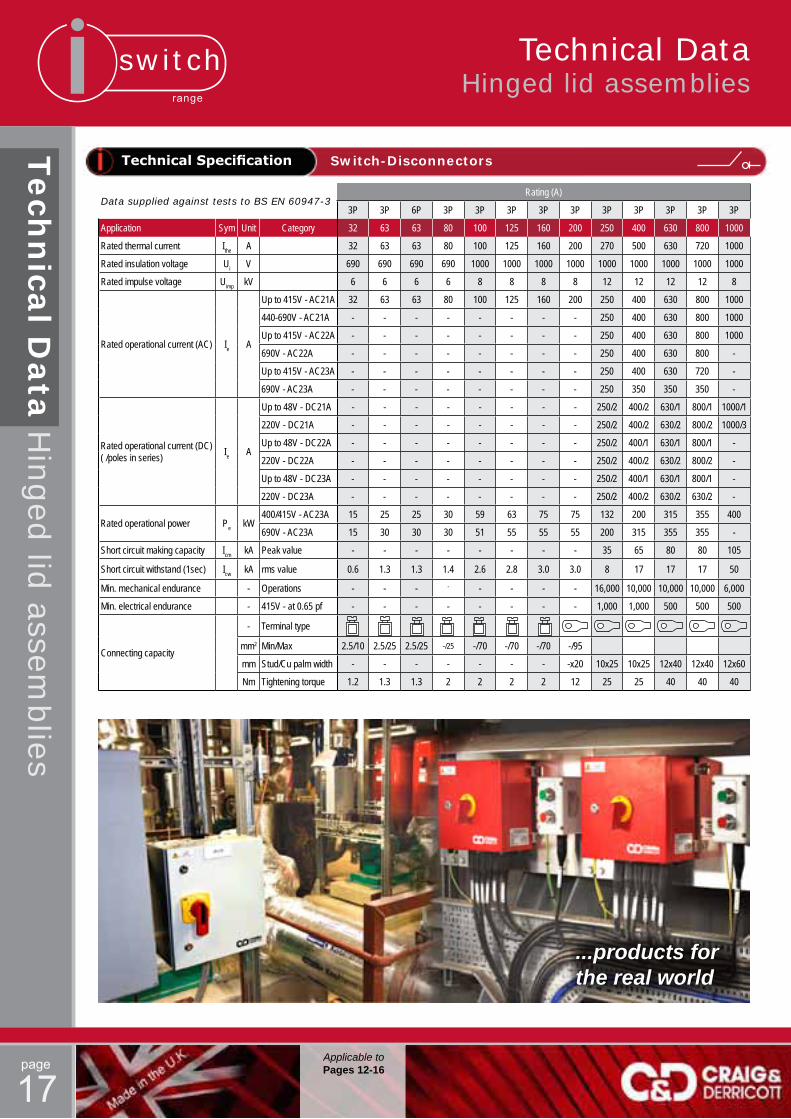
Technical Specification Switch-Disconnectors
Data supplied against tests to BS EN 60947-3Rating (A)
3P 3P 6P 3P 3P 3P 3P 3P 3P 3P 3P 3P 3P
Application Sym Unit Category 32 63 63 80 100 125 160 200 250 400 630 800 1000
Rated thermal current Ithe A 32 63 63 80 100 125 160 200 270 500 630 720 1000
Rated insulation voltage Ui V 690 690 690 690 1000 1000 1000 1000 1000 1000 1000 1000 1000
Rated impulse voltage Uimp kV 6 6 6 6 8 8 8 8 12 12 12 12 8
Rated operational current (AC) Ie A
Up to 415V - AC21A 32 63 63 80 100 125 160 200 250 400 630 800 1000
440-690V - AC21A - - - - - - - - 250 400 630 800 1000
Up to 415V - AC22A - - - - - - - - 250 400 630 800 1000
690V - AC22A - - - - - - - - 250 400 630 800 -
Up to 415V - AC23A - - - - - - - - 250 400 630 720 -
690V - AC23A - - - - - - - - 250 350 350 350 -
Rated operational current (DC) ( /poles in series) Ie A
Up to 48V - DC21A - - - - - - - - 250/2 400/2 630/1 800/1 1000/1
220V - DC21A - - - - - - - - 250/2 400/2 630/2 800/2 1000/3
Up to 48V - DC22A - - - - - - - - 250/2 400/1 630/1 800/1 -
220V - DC22A - - - - - - - - 250/2 400/2 630/2 800/2 -
Up to 48V - DC23A - - - - - - - - 250/2 400/1 630/1 800/1 -
220V - DC23A - - - - - - - - 250/2 400/2 630/2 630/2 -
Rated operational power Pe kW400/415V - AC23A 15 25 25 30 59 63 75 75 132 200 315 355 400
690V - AC23A 15 30 30 30 51 55 55 55 200 315 355 355 -
Short circuit making capacity Icm kA Peak value - - - - - - - - 35 65 80 80 105
Short circuit withstand (1sec) Icw kA rms value 0.6 1.3 1.3 1.4 2.6 2.8 3.0 3.0 8 17 17 17 50
Min. mechanical endurance - Operations - - - - - - - - 16,000 10,000 10,000 10,000 6,000
Min. electrical endurance - 415V - at 0.65 pf - - - - - - - - 1,000 1,000 500 500 500
Connecting capacity
- Terminal type
mm2 Min/Max 2.5/10 2.5/25 2.5/25 -/25 -/70 -/70 -/70 -/95
mm Stud/Cu palm width - - - - - - - -x20 10x25 10x25 12x40 12x40 12x60
Nm Tightening torque 1.2 1.3 1.3 2 2 2 2 12 25 25 40 40 40
...products for the real world

switchrange
page
18
Technical Specification Fuse Combination Units
* Two poles in series
Technical Specification Changeover Switch-Disconnectors
Data supplied against tests to BS EN 60947-3 Rating (A)
Application Sym Unit Category 32 63 100 125 160 200 250 315 400 630
Rated thermal current Ithe A 32 63 100 125 160 200 250 315 400 630
Rated insulation voltage Ui V 750 750 750 750 750 750 750 750 750 750
Rated impulse voltage Uimp kV 8 8 12 12 12 12 12 12 12 12
Rated operational current (AC)Ie A
415V - AC23A 32 63 100 125 160 200 250 315 400 630
Rated operational current (DC)* 220V - DC23A - - 100 125 160 200 250 315 400 630
Rated making capacity (AC23A) A 415V, 0.35 pf 320 630 1,000 1,250 1,600 2,000 2,500 3,150 4,000 6,300
Rated breaking capacity (AC23A) A 415V, 0.35 pf 256 504 800 1,000 1,280 1,600 2,000 2,520 3,200 5,040
Rated Conditional (Fused) short circuit
kA S/C current rms 80 80 80 80 80 80 80 80 80 80
A back-up fuse 32 63 100 125 160 200 250 315 400 630
Min. mechanical endurance - Operations 25,000 25,000 15,000 15,000 15,000 10,000 10,000 10,000 10,000 6,000
Min. electrical endurance - 415V - at 0.65 pf 1,500 1,500 1,000 1,000 1,000 1,000 1,000 1,000 1,000 1,000
BS fuse format F2 F2 A4 A4 B1, B2 B1, B2 B1, B2 B1, B4 B1, B4 C1, C3
Connecting capacity
- Terminal type
mm2 Min/Max 16 25 95 95 120 240 240 300 300 400
mm Stud/Cu palm width - - 8x20 8x20 8x20 10x25 10x25 10x25 10x25 12x50
Nm Tightening torque 3.5 5.5 9 12 16 25 30 35 45 50
Data supplied against tests to BS EN 60947-3 Rating (A)
Application Sym Unit Category 63 100 125 160 200 250 400 630
Rated thermal current Ithe A 63 100 125 160 200 250 400 630
Rated insulation voltage Ui V 750 750 1000 1000 1000 1000 1000 1000
Rated impulse voltage Uimp kV 6 6 6 6 6 12 12 12
Rated operational current Ie A415V - AC22A 63 100 125 160 200 250 400 630
415V - AC23A 63 100 125 160 160 250 400 630
Rated making capacity (AC23A) A 415V, 0.35 pf 630 630 1,250 1,600 2,000 2,500 4,000 6,300
Rated breaking capacity (AC23A) A 415V, 0.35 pf 504 504 1,000 1,280 1,600 2,000 3,200 5,040
Short circuit current kA rms (with fuses) 80 80 80 80 80 100 100 80
Rated S/C making capacity A Peak 15 15 20 20 20 30 40 50
Min. mechanical endurance - Operations 20,000 20,000 10,000 10,000 10,000 10,000 10,000 10,000
Min. electrical endurance - 415V - at 0.65 pf 2,500 1,500 1,000 1,000 1,000 1,000 1,000 500
Connecting capacity
- Terminal type
mm2 Max 16 25 50 70 95 240 300 400
mm Stud/Cu palm width 6x13.6 6x13.6 8x22 8x22 8x22 10x25 10x25 12x50
Nm Tightening torque 5 5 12 12 12 30 45 50
Sym. Category Auxiliary blocks type ‘B’ Auxiliary blocks type ‘C’Thermal current Ith 10A 10ARated insulation voltage Ui 660V a.c. or d.c. 500V
Utilisation Category - AC15 6.0A at 120V, 4.0A at 250V, 2.0A at 660V 240V - Make 30A, Break 3A480V - Make 15A, Break 1.5A
DC13 1.0A at 120V, 0.5A at 240V, 0.1A at 660V 240V - Make 30A, Break 3A480V - Make 15A, Break 1.5A
Pure Resistive 10A -
Auxiliary Blocks Data supplied against tests to BS EN 60947-1
Technical Data Hinged lid assemblies
Tech
nica
l Data
Hin
ged
lid assem
blies
Applicable toPages 12-16

switchrange
page
19
FireRated High temperature (20A-125A)
Fire
Rate
d (H
igh Tem
peratu
re)
DimensionsPages 29
General Description“Smoke kills more people than fire”
A well known fact, and it’s the job of the ventilation designer to ensure this doesn’t happen - to do this effectively he will need continuous power.
Craig & Derricott have been designing electrical switchgear for more than 65 years and it’s from this expertise that a development for the ventila-tion industry has led to the extensive ‘High Temperature Isolator’ range. Contact stability at extended temperatures, typically 4000C for 2 hours (F400), is the basis of the design.
The critical role these switches perform is to maintain the power to vital equipment such as smoke extraction fans, allowing the safe evacuation of business, car-parks or public areas. Often these devices are mounted local to the extraction fans and, as an assembly, it is essential that they comply with the stringent thermal requirements of BS EN 12101-3: 2003.
The complete range are housed in metal enclosures; the user can there-fore be assured that there will be no distortion affecting the connecting cables and their supports under high temperature conditions.
SpecificationWithin BS EN 12101-3: 2003 (Smoke and heat controls) there are severalclassesofdutywhichdefineaspecifictemperaturegradient,upper temperature limit and time period.
F200 2000C for 120 min. F300 3000C for 60 min. F400 4000C for 120 min.
Thespecificationcallsfordynamictestsdesignedtochecktheperformance of the complete ventilation system. The critical function of the associated isolator is required to maintain the essential supply for the duration of the test.
Rating Format Assembly Form
Catalogue No.(Finished Red)
Temp. Class.
Encl. size
20A
2PLid
mounted in sheet
steel enclosure
FSDMR0202
F400 A
3P FSDMR02033P+2EB Aux FSDMR0203EB
3P+N FSDMR0203N4P FSDMR02046P FSDMR0206
32A
2P
Lid mounted
in die-cast aluminium enclosure
FSDDR0322
F400 B
3P FSDDR03233P+2EB Aux FSDDR0323EB
3P+N FSDDR0323N4P FSDDR03246P FSDDR0326
6P+2EB Aux FSDDR0326EB
63A
2PBase
mounted in hinged lid sheet
steel enclosure
FSDMR0632
F400 C
3P FSDMR06333P+2EB Aux FSDMR0633EB
3P+N FSDMR0633N4P FSDMR06346P FSDMR0636
6P+2EB Aux FSDMR0636EB
125A
2PBase
mounted in hinged lid sheet
steel enclosure
RS1BD11/HPHT
F400 D
3P RS1BT21/HPHT
3P+2EB Aux RS1BT31/2EB/HPHT
3P+N RS1BT21/HPHT/NL
4P RS1BQ21HPHT
6P RS1BY31/HPHT
6P+2EB Aux RS1BY41/2EB/HPHT
Catalogue References.

switchrange
page
20
Data supplied against tests to IEC/BS EN 60947-3
Application Sym. Unit Category 20A 32A 63A 125A
Ratedthermalcurrent Ithe A 20 32 63 125
Ratedinsulationvoltage Ui V 690 690 690 690
Ratedimpulsevoltage Uimp kV 6.0 6.0 6.0 6.0
Ratedoperationalpower (3 phase AC) A/kW
415V - AC23A 20/9.5 32/15 40/18.5 100/55
690V-AC23B 20/9.5 20/9.5 20/9.5 -
660V - AC23B - - - 30/22
Conditional Short Circuit Current
FusegG
kA/Fuse(A)
415V 50/32 50/32 50/63 50/200
690V 40/32 40/32 40/63 50/63
Recommendedconnecting capacity
- Terminal type
mm2 Flexible cable 2.5 6 16 50
mm2 Rigidcable 2.5 10 25 50
Nm Tightening tor. 1.2 1.2 3.0 10.0
...products for the real worldIf you need something special, then
give our sales team a call.
They will be pleased to offer advice and suggest the next step to move your enquiry forward.
125A
63A
32A20A
High velocity extraction fans installed in an underground car park
Technical Specification
DimensionsPages 29
Fire
Rate
d (H
igh Tem
peratu
re)FireRated
High temperature (20A-125A)

switchrange
page
21DimensionsPages 29
BackgroundFollowingtheKingsCrossfireof1987,theresultingFennellenquirypromptedtheintroductionofadditionalfireprecautionsfor‘Sub-surfaceRailwayStations’.Theseadditionalrequirementswereintroducedundersection12oftheFirePrecautionsAct1971,andsince then have been known simply as ‘Section 12’ regs. There are at present around 120 London Underground stations that come under Section 12 requirements.
Theforensicreportonthefirecitedseveralinstancesofa‘flash over’ effectcausedbymaterialsandpaintfinishesbeingignitable.Exacerbating the conditions underground were toxic fumes given off by certain materials being excessively heated.
Althoughthenewregulationsdealtwithallaspectsoffireprevention such as the removal of wooden escalators, the installation of heat detectors, improved staff training etc, as far as actual equipment supplied for underground use, the overriding emphasis was on materialsandpaintfinishes.
With this isolation range, the overall consideration has been to meet, and where possible exceed, the Section 12 requirements. This has been achieved by the careful selection of individual component materialsandtheuseofonlyrecognisedandapprovedpaintfinishes.
Rating Format
Interior Switch product range
Catalogue Nos.Enclosure
SizeGrey Red
25A
2P GN25 DCG252LUL10 DCR252LUL10
A(IP65)
3P GN25 DCG253LUL10 DCR253LUL10
3P+2EB Aux GN25 DCG253EBLUL10 DCR253EBLUL10
4P GN25 DCG254LUL10 DCR254LUL10
6P GN25 DCG256LUL10 DCR256LUL10
6P+2EB Aux GN25 DCG256EBLUL10 DCR256EBLUL10
40A
2P R32 DCG402LUL10 DCR402LUL10
B(IP65)
3P R32 DCG403LUL10 DCR403LUL10
3P+2EB Aux R32 DCG403EBLUL10 DCR403EBLUL10
4P R32 DCG404LUL10 DCR404LUL10
6P R32 DCG406LUL10 DCR406LUL10
6P+2EB Aux R32 DCG406EBLUL10 DCR406EBLUL10
To order a neutral link please include in the catalogue ref. as follows:-Example - 3 Pole + Neutral Link - DCG403NLLUL10
Switch-Disconnectors (O-I)Die cast enclosures
Design Features
•PaintFinishes:- Copon EA9WBsystem Colour-LightGrey(RAL7035) Red(RAL3020)•Captivelidfixingscrewswitha security head.•Enclosurematerial-Aluminium(LM6)•SealingtoIP65.
•Suppliedwithpre-finished steel mounting brackets.•Padlockingcastleverhandle.•Positivebreakcontacts.•Earthingpointsonbothlidand base plus external earth stud.•Padlockinginboth‘Off’&‘On’.
•Secondproductlabelsuppliedloose forfittingbythecontractorwherethe original label may be obscured.•Labels-Engravedtraffolytelabelsin various colours can be supplied attached to the side of the enclosure orsuppliedlooseforfittingadjacent the the isolator.
Electrical ratings to BS EN 60947-3
Application Sym Unit Category Rating
Rated thermal current Ithe A - 25A 40A
Ratedoperationalpower(3 phase AC)
- kW 380/440VAC23A 11.0 15.0
Technical Specification
Products covered by London Underground Product Registration Certificates 638 & 639
LUL ‘Section 12’Isolation equipment (25A-40A)
LU
L ‘S
ectio
n 1
2’ Iso
lation eq
uip
men
t

switchrange
page
22
LUL ‘Section 12’Isolation equipment (25A-40A)
LU
L ‘S
ectio
n 1
2’ Iso
lation eq
uip
men
t
To order a neutral link please include in the catalogue ref. as follows:- Example - 3 Pole + Neutral Link - DS256EBNLLUL10
Stainless steel enclosures
Design Features
•Lidmountedswitchinteriors.•Captivelidfixingscrewswitha security head.•Enclosurematerial-18gauge stainless steel grade 304.•Finish-Natural-Brushed(Nonglare)•SealingtoIP65.
•Suppliedwithstainlesssteel mounting brackets.•Padlockingcastleverhandle.•Positivebreakcontacts.•Earthingpointsonbothlidand base plus external earth stud.•Padlockinginboth‘Off’&‘On’.
Electrical ratings to BS EN 60947-3
Application Sym Unit Category Rating
Ratedthermalcurrent Ithe A - 25A 40A
Ratedoperationalpower(3 phase AC) - kW 380/440V
AC23A 11.0 18.5
•Secondproductlabelsuppliedloose forfittingbythecontractorwherethe original label may be obscured.•Labels-Engravedtraffolytelabelsin various colours can be supplied attached to the side of the enclosure orsuppliedlooseforfittingadjacent to the isolator.
Technical Specification
Rating Format
Interior Switch product range
Catalogue Nos.Enclosure
SizeStainless steel
25A
2P GN25 DS252LUL10
C(IP65)
3P GN25 DS253LUL10
3P+2EB Aux GN25 DS253EBLUL10
4P GN25 DS254LUL10
6P GN25 DS256LUL10
6P+2EB Aux GN25 DS256EBLUL10
40A
2P GN40 DS402LUL10
D(IP65)
3P GN40 DS403LUL10
3P+2EB Aux GN40 DS403EBLUL10
4P GN40 DS404LUL10
6P GN40 DS406LUL10
6P+2EB Aux GN40 DS406EBLUL10
Switch-Disconnectors (O-I)
Craig & Derricott produce many other products to meet ‘Section 12’ requirements; for example:-
Hinged lid enclosed Switch Disconnectors. •Ratings40A-400A(3P+switchedN).•GreyorRed‘CoponEA9WB’finish.•Allmetalpadlockinghandle.•Canbesuppliedlockableinboth‘Off’&‘On’.•Removabletop&bottomglandplates.•SealingtoIP65.
Hinged lid enclosed Fuse Combination Units. •Ratings32A-630A(3P+switchedN).•GreyorRed‘CoponEA9WB’finish.•Allmetalpadlockinghandle.•Canbesuppliedlockableinboth‘Off’&‘On’.•Removabletop&bottomglandplates.•TakesBS88fuselinks.•SealingtoIP65.
Typical ‘Fuse Combination Unit’ and all metal handle assembly.
If you require further information on these products pleasecontact our technical sales team or download the relevant data sheets from our website:-www.craigandderricott.co.uk/casestudies/transport11/rail-infrastructure/section-12-equipment
DimensionsPages 29
switchrange
page
23
Automatic Transfer Switches ATS (45A-800A)
ATS
(45A-8
00AStandard
Range)
DimensionsPage 30
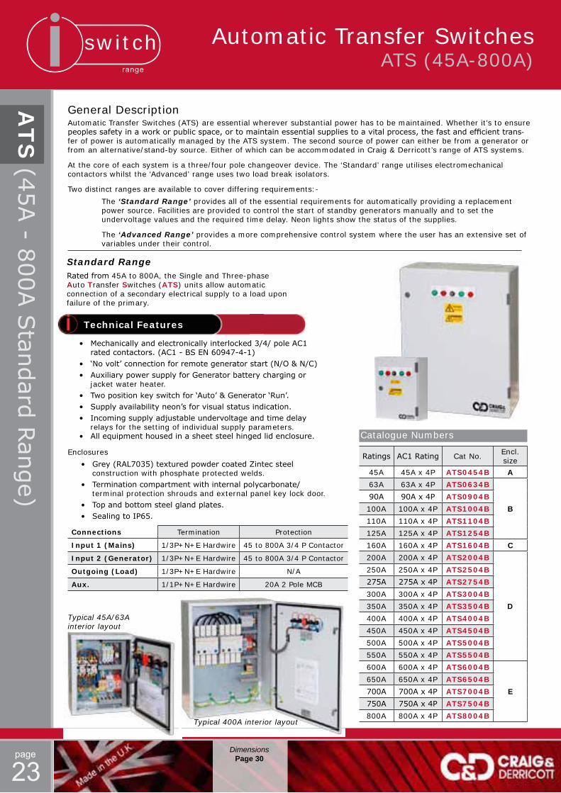
General DescriptionAutomatic Transfer Switches (ATS) are essential wherever substantial power has to be maintained. Whether it’s to ensure peoplessafetyinaworkorpublicspace,ortomaintainessentialsuppliestoavitalprocess,thefastandefficienttrans-fer of power is automatically managed by the ATS system. The second source of power can either be from a generator or from an alternative/stand-by source. Either of which can be accommodated in Craig & Derricott’s range of ATS systems.
At the core of each system is a three/four pole changeover device. The ‘Standard’ range utilises electromechanical contactors whilst the ‘Advanced’ range uses two load break isolators.
Two distinct ranges are available to cover differing requirements:-
The ‘Standard Range’ provides all of the essential requirements for automatically providing a replacement power source. Facilities are provided to control the start of standby generators manually and to set the undervoltage values and the required time delay. Neon lights show the status of the supplies.
The ‘Advanced Range’ provides a more comprehensive control system where the user has an extensive set of variables under their control.
Standard RangeRatedfrom 45A to 800A, the Single and Three-phase Auto Transfer Switches (ATS) units allow automatic connection of a secondary electrical supply to a load upon failure of the primary.
Enclosures
• Grey(RAL7035)texturedpowdercoatedZintecsteel construction with phosphate protected welds. • Terminationcompartmentwithinternalpolycarbonate/ terminal protection shrouds and external panel key lock door. • Topandbottomsteelglandplates. • SealingtoIP65.
Connections Termination Protection
Input 1 (Mains) 1/3P+N+E Hardwire 45 to 800A 3/4 P Contactor
Input 2 (Generator) 1/3P+N+E Hardwire 45 to 800A 3/4 P Contactor
Outgoing (Load) 1/3P+N+E Hardwire N/A
Aux. 1/1P+N+E Hardwire 20A 2 Pole MCB
Ratings AC1Rating Cat No. Encl. size
45A 45A x 4P ATS0454B A
63A 63A x 4P ATS0634B
B
90A 90Ax4P ATS0904B
100A 100A x 4P ATS1004B
110A 110A x 4P ATS1104B
125A 125A x 4P ATS1254B
160A 160A x 4P ATS1604B C
200A 200A x 4P ATS2004B
D
250A 250A x 4P ATS2504B
275A 275Ax4P ATS2754B
300A 300A x 4P ATS3004B
350A 350A x 4P ATS3504B
400A 400A x 4P ATS4004B
450A 450A x 4P ATS4504B
500A 500A x 4P ATS5004B
550A 550A x 4P ATS5504B
600A 600A x 4P ATS6004B
E
650A 650A x 4P ATS6504B
700A 700Ax4P ATS7004B
750A 750Ax4P ATS7504B
800A 800A x 4P ATS8004B
Catalogue Numbers
Typical 45A/63A interior layout
Typical 400A interior layout
• Mechanicallyandelectronicallyinterlocked3/4/poleAC1 ratedcontactors.(AC1-BSEN60947-4-1) • ‘Novolt’connectionforremotegeneratorstart(N/O&N/C) • AuxiliarypowersupplyforGeneratorbatterychargingor jacket water heater. • Twopositionkeyswitchfor‘Auto’&Generator‘Run’. • Supplyavailabilityneon’sforvisualstatusindication. • Incomingsupplyadjustableundervoltageandtimedelay relays for the setting of individual supply parameters. • Allequipmenthousedinasheetsteelhingedlidenclosure.
Technical Features

switchrange
page
24
Advanced RangeWithratingsfrom40Ato400ACraig&Derricott’s‘AdvancedRange’incorporates a modular style assembly with electronic control over a wide range of parameters.
Typical interior assembly
All Craig & Derricott ATS products are supplied fully assembled in enclosures and ready to install.
Featuring:-
•Twomechanicallyinterlocked four pole power switches.
• Aconfigurableautomaticcontrol associated with an emergency manual operation.
• Built-inconfigurationandcontrolinterface.
• Onloadswitchdisconnectorsproviding safety isolation combined with high making and breaking capacity.
• Fastelectromagneticoperation.
Single or three phase voltage and frequency control on networks I or II.•Independentover/undervoltageandover/underfrequency thresholds +/- 20% of nominal values.•Considerableassociatedhysteresisvalues.•Phaserotationandunbalancecontrol.
Metering•3phasesvoltagemeasurementsonnetworksI&II.•FrequencymeasurementonnetworksI&II.•Timersdisplay&countdown.
Display & Keypad•Parametersconfiguration(thresholds,timersetc).•3phasesvoltageandfrequencyforsourceI&II,timers, number of cycles and last event display.•Testsandpositionscontrolfacilities.
LED’s•PowerOn;Sourceavailability;Changeoverposition;‘MAN/ AUT’ mode; Test/Control operation; Fault.
3 Configurable Inputs•Automaticmodeinhibition;Testonloadandoffload; Manual re-transfer; Changeover position control; Network priority change.
Bi-stable output relay•ForGeneratorStart/Stopcommand-30VDC/2A
Two programmable output relays.•SourceIorIIavailability,Loadsheddingoutput;Faultrelay.• 250VAC/3A
Remote Display connection (Optional)• RJ45outputconnection.
Front of panel LCD display• Providesvisualisationandcontrol.• InhibitscontrolsonthefrontoftheSwitchingassembly.
Ingress Protection• IP65 (Without remote LCD display)
DimensionsPage 30
Typical assembly showing the optional front panel LCD display
ATS
(40A-4
00AAdvan
cedRange)
Automatic Transfer Switches ATS (40A-400A)
Ratings Format Cat No. Encl. size
40A 40A x 4P ATS0404
A
63A 63A x 4P ATS0634
100A 100A x 4P ATS1004
125A 125A x 4P ATS1254
160A 160A x 4P ATS1604
250A 250A x 4P ATS2504B
400A 400A x 4P ATS4004
Catalogue NumbersTechnical Features
switchrange
page
25
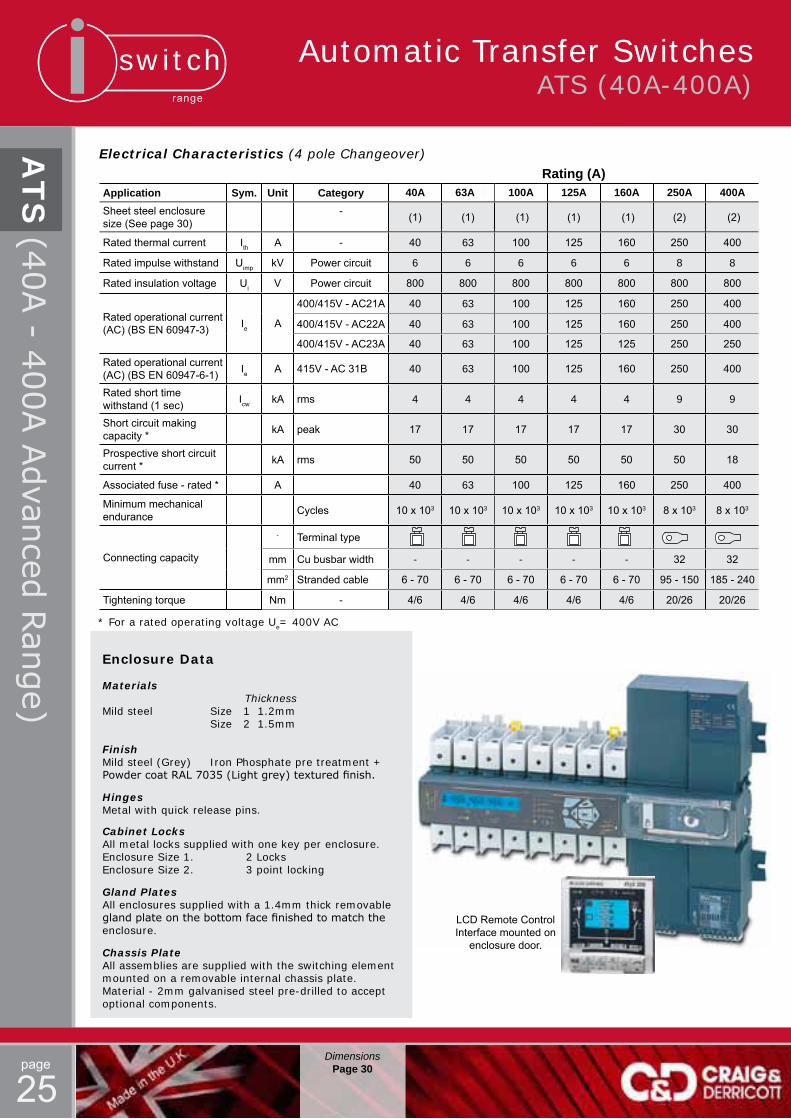
LCD Remote Control Interface mounted on
enclosure door.
Rating (A)Application Sym. Unit Category 40A 163A25 100A 125A 160A 250A 400ASheet steel enclosure size (See page 30)
- (1) (1) (1) (1) (1) (2) (2)
Rated thermal current Ith A - 40 63 100 125 160 250 400
Rated impulse withstand Uimp kV Power circuit 6 6 6 6 6 8 8
Rated insulation voltage Ui V Power circuit 800 800 800 800 800 800 800
Rated operational current (AC) (BS EN 60947-3) Ie A
400/415V - AC21A 40 63 100 125 160 250 400
400/415V - AC22A 40 63 100 125 160 250 400
400/415V - AC23A 40 63 100 125 125 250 250
Rated operational current (AC) (BS EN 60947-6-1) Ie A 415V - AC 31B 40 63 100 125 160 250 400
Rated short time withstand (1 sec) Icw kA rms 4 4 4 4 4 9 9
Short circuit making capacity * kA peak 17 17 17 17 17 30 30
Prospective short circuit current * kA rms 50 50 50 50 50 50 18
Associated fuse - rated * A 40 63 100 125 160 250 400
Minimum mechanical endurance Cycles 10 x 103 10 x 103 10 x 103 10 x 103 10 x 103 8 x 10³ 8 x 10³
Connecting capacity
- Terminal type
mm Cu busbar width - - - - - 32 32
mm2 Stranded cable 6 - 70 6 - 70 6 - 70 6 - 70 6 - 70 95 - 150 185 - 240
Tightening torque Nm - 4/6 4/6 4/6 4/6 4/6 20/26 20/26
Electrical Characteristics (4 pole Changeover)
* For a rated operating voltage Ue= 400V AC
Enclosure Data
Materials ThicknessMild steel Size 1 1.2mm Size 2 1.5mm
FinishMild steel (Grey) Iron Phosphate pre treatment + PowdercoatRAL7035(Lightgrey)texturedfinish.
HingesMetal with quick release pins.
Cabinet LocksAll metal locks supplied with one key per enclosure.Enclosure Size 1. 2 LocksEnclosure Size 2. 3 point locking
Gland PlatesAll enclosures supplied with a 1.4mm thick removable glandplateonthebottomfacefinishedtomatchtheenclosure.
Chassis PlateAll assemblies are supplied with the switching element mounted on a removable internal chassis plate. Material - 2mm galvanised steel pre-drilled to accept optional components.
DimensionsPage 30
Automatic Transfer Switches ATS (40A-400A)
ATS
(40A-4
00AAdvan
cedRange)
switchrange
page
26
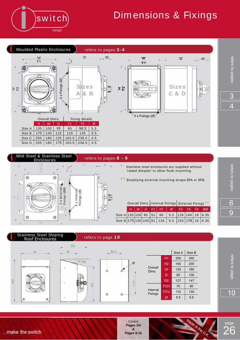
Moulded Plastic Enclosures refers to pages 3-4
Overall Dims. Fixing detailsH W D F1 F2 Ø
Size A 135 100 95 85 98.5 5.5Size B 175 130 115 115 135 5.5Size C 255 180 125 163.5 238.5 4.5Size D 255 180 175 163.5 238.5 4.5
Mild Steel & Stainless Steel Enclosures refers to pages 8 - 9
Overall Dims. Internal Fixings External Fixings † †
H W D F1 F2 Ø F3 F4 F5 ØØ
Size A 135 100 80 51 86 5.5 126 140 16 6.35
Size B 175 130 100 81 126 5.5 155 178 16 6.35
‘W’ ‘D’
‘H’
‘F1’
‘F2’
‘W’ ‘D’
‘H’
‘F1’
‘F2’
40
4 x Fixings (Ø)
Sizes C & D
refers to pages:refers to pages:
34
89
‘W’ ‘D’
‘H’
30F1
F2
4 x
Fixi
ngs
(Ø)
Sizes A & B
1
† Stainless steel enclosures are supplied without ‘raised dimples’ to allow flush mounting.
† † Employing external mounting straps EFA or EFB.
4 x
Inte
rnal
Fixi
ngs
(Ø)
†
4 x
Ext
ernal
Fixi
ngs
(ØØ
)
Dimensions & Fixings
Stainless Steel SlopingRoofEnclosures refers to page 10
Size A Size B
Overall Dims.
H1 200 240
H2 165 200
W 135 185
D 80 100
D2 127 147
Internal Fixings
FCH 70 90
FCV 110 130
Ø 5.5 5.5
Ø
refers to page:
10
CoversPages 3/4
&Pages 8-10
switchrange
page
27Covers
Pages 5-7
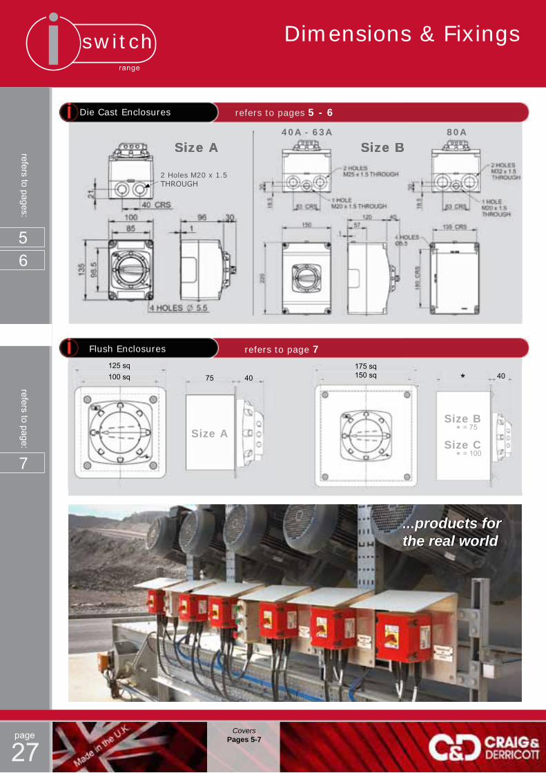
Die Cast Enclosures refers to pages 5 - 6
Size A Size B
Flush Enclosures
125 sq100 sq 75 40
175 sq150 sq 40*
Size B
Size C = 75*
= 100*
Size A
refers to page 7
refers to pages:
56
refers to page:
7
Dimensions & Fixings
...products for the real world
Size B40A - 63A 80A
Size A
2 Holes M20 x 1.5 THROUGH

switchrange
page
28
Hinged Lid Enclosures
Ø 4 off internal mounting holes
D BW
A H
Gland plate thickness (K)
Han
dle
proj
ectio
n
CJ
(CR
S)
J (C
RS
)
F G (CRS)
E
ØØ
External Mounting Feet (Four per set)Case Sizes 1 & 2 Cat No. SEFL1/KITCase Sizes 3 - 7 Cat No. SEFL2/KITCase Sizes 8 - 10 Cat No. SEFL3/KIT
MaterialsIP41 items Sheet steel IP65 items Sheet steel or stainless steelFinishIP41 & IP65 Sheet steel, iron phosphate pre treatment with a powder coat RAL 7035 (Light grey) textured finish.IP65 Stainless steel, grade 304 with a brushed finish.Hinges Metal with quick release pins.Door Locks All metal locks supplied with one key per enclosure. Enclosures 1 & 2 IP41 - 2 screw fixings IP65 - 1 lock Enclosures 3 - 9 IP41 & IP65 - 2 locks Enclosure size 10 IP41 & IP65 - 3 locksGland plates All enclosures are supplied with a removable gland plate on top & bottom faces finished to match the enclosure.Chassis plate Above case size 1, all assemblies have the switching element mounted on a removable chassis plate. Matl.- 2mm zinc plated steel.
refers to pages:
12
16
to
refers to pages 12 to 16
...products for the real world
Dim 1 2 3 3A 4 4A 5 5A 6 7 8 9 10H 250 250 400 350 500 400 550 550 750 750 900 900 1000
W 250 300 350 300 350 300 450 400 450 600 600 600 750
D 100 200 200 175 200 175 250 175 275 300 300 400 300
A 170 170 320 270 420 320 470 470 670 670 820 820 920
B 170 220 270 220 270 220 370 320 370 520 520 520 670
C 40 67 67 67 67 67 67 67 67 67 67 67 67
K 1.5 1.5 1.5 2.0 1.5 2.0 2.0 2.0 2.0 2.5 2.5 2.5 2.5
Ø 6.5 6.5 8.5 8.5 8.5 8.5 8.5 8.5 8.5 8.5 10.5 10.5 10.5
E 35 35 35 35 35 35 35 35 35 35 35 35 35
F 53 58 58 58 58 58 58 58 58 58 58 58 58
G 18 18 13 13 13 13 13 13 13 13 13 13 13
J 58 58 58 58 58 58 58 58 58 58 58 58 58
ØØ 6.5 6.5 8.5 8.5 8.5 8.5 8.5 8.5 8.5 8.5 10.5 10.5 10.5
Case Sizes
External Feet
Enclosure Data
CoversPages12-16
Dimensions & Fixings
switchrange
page
29Covers
Pages 19-22
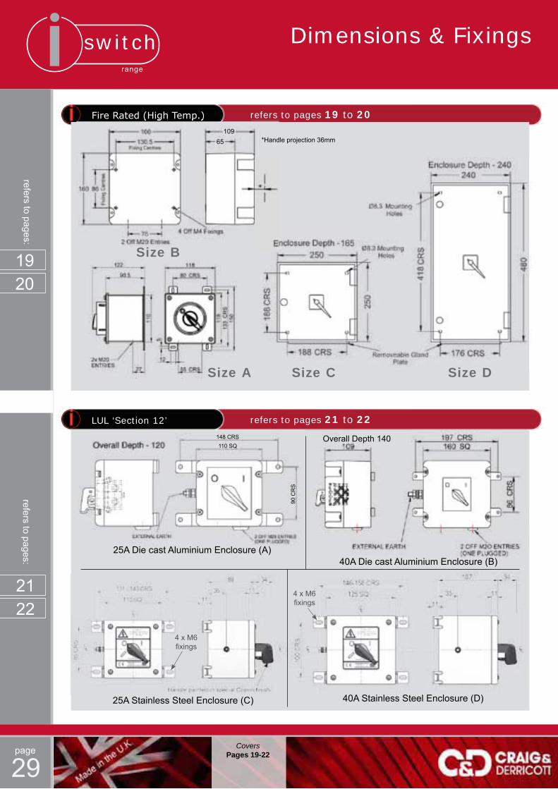
FireRated(HighTemp.) refers to pages 19 to 20
refers to pages:
1920
LUL ‘Section 12’ refers to pages 21 to 22
Overall Depth 140
25A Stainless Steel Enclosure (C) 40A Stainless Steel Enclosure (D)
25A Die cast Aluminium Enclosure (A)40A Die cast Aluminium Enclosure (B)
refers to pages:
2122
4 x M6 fixings
4 x M6 fixings
Dimensions & Fixings
(High Temp.) refers to pages
Size A
Size B
Size C Size D
*Handle projection 36mm109
65
148 CRS110 SQ
90 C
RS

switchrange
page
30
ATS assemblies refers to pages 23 to 25
Overall Dims.H W D
Size A 400 300 150Size B 600 400 250Size C 700 500 250Size D 800 600 300Size E 1000 800 300
No. of gland plates (Cut-out size as shown below):-Size 1 1 offSize 2 2 off
H W D A B C E FSize A 700 500 210 660 460 35 96 410Size B 1000 800 400 960 760 35 96 310
Standard Range Advanced Range
refers to pages:
23
to
No. of gland plates (Cut-out size as shown below):-Size 1 1 offSize 2 2 off
CoversPages 23-25
25
Dimensions & Fixings
Most of the products in this catalogue are
readily available through our stockist network.
Give us a call to find your nearest outlet or visit
our website for a full up-to-date list of our U.K.
and international distributors.
*
*
*
Contact us
Fit and forget
Rapiddelivery
Develop the design
Manufacture product
Craig & Derricott Ltd.Hall Lane, Walsall Wood,
Walsall, West Midlands, UKWS99DP
t:+44(0)1543375541
i-sw
itch
cata
logu
e is
sue
1 - 2
013
(CD
PD
1)
...also available
RotarySwitches
Pushbutton Control Stations
Transport Products
Grabwire Switches
Footswitches & Limit Switches
Bespoke Products
Related Documents