Last modified on 18/11/2002 Corresp. IMA Tech. Rep. No. 14/2001 SwingWrapper: Retiling Triangle Meshes for Better EdgeBreaker Compression Marco Attene * , Bianca Falcidieno * , Michela Spagnuolo * , Jarek Rossignac † C L E S C L E S R R Figure 1: The original model (on the left, courtesy of Cyberware) containing 134,074 triangles requires 4,100,000 bytes, when stored as a WRL file. A dense partitioning of its surface into deformed triangles, called “triangloids” (second), was produced by SwingWrapper. The corresponding retiled mesh (third) was generated by flattening the triangloids. Its L 2 distortion is about 0.007% of the bounding box diagonal and its 13642 triangles were encoded with a total of 3.5 bits per triangle, for the connectivity and geometry, using Edgebreaker’s connectivity compression combined with a novel geometry predictor. The resulting total of 6042 bytes represents a 678-to-1 compression ratio. A coarser partitioning (fourth) decomposes the original surface into 1505 triangloids. The distortion of the corresponding retiled mesh (last) is about 0.15%, and the encoded model requires 980 bytes: A 4000-to-1 compression. Colors are associated to the EdgeBreaker’s triangle labeling, demonstrating the regularity of the connectivity graph (96% of the triangles are of type C or R and 82% of the vertices have valence 6). Abstract We focus on the lossy compression of manifold triangle meshes. Our SwingWrapper approach partitions the surface of an original mesh M into simply connected regions, called triangloids. From these, we generate a new mesh M’. Each triangle of M’ is an approximation of a triangloid of M. By construction, the connectivity of M’ is fairly regular and can be compressed to less than a bit per triangle using EdgeBreaker or one of the other recently developed schemes. The locations of the vertices of M’ are compactly encoded with our new prediction technique, which uses a single correction parameter per vertex. SwingWrapper strives to reach a user-defined output file size rather than to guarantee a given error bound. For a variety of popular models, a rate of 0.4 bits/triangle yields an L 2 distortion of about 0.01% of the bounding box diagonal. The proposed solution may also be used to encode crude meshes for adaptive transmission or for controlling subdivision surfaces. Keywords: Triangle Meshes, Resampling, Geometry Compression, Simplification, Retiling. * {attene, falcidieno, spagnuolo}@ima.ge.cnr.it Istituto per la Matematica Applicata e Tecnologie Informatiche IMATI-CNR, Genova, ITALY. † [email protected] - College of Computing & GVU Center, Georgia Institute of Technology, Atlanta, USA.

Welcome message from author
This document is posted to help you gain knowledge. Please leave a comment to let me know what you think about it! Share it to your friends and learn new things together.
Transcript
Last modified on 18/11/2002 Corresp. IMA Tech. Rep. No. 14/2001
SwingWrapper: Retiling Triangle Meshes for Better EdgeBreaker Compression Marco Attene*, Bianca Falcidieno*, Michela Spagnuolo*, Jarek Rossignac†
C L E
S
C L E
S
R R
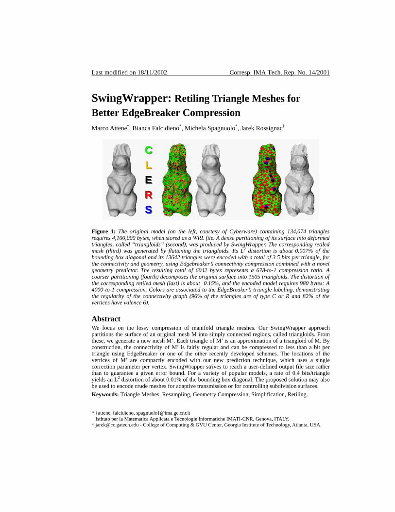
Figure 1: The original model (on the left, courtesy of Cyberware) containing 134,074 triangles requires 4,100,000 bytes, when stored as a WRL file. A dense partitioning of its surface into deformed triangles, called “triangloids” (second), was produced by SwingWrapper. The corresponding retiled mesh (third) was generated by flattening the triangloids. Its L2 distortion is about 0.007% of the bounding box diagonal and its 13642 triangles were encoded with a total of 3.5 bits per triangle, for the connectivity and geometry, using Edgebreaker’s connectivity compression combined with a novel geometry predictor. The resulting total of 6042 bytes represents a 678-to-1 compression ratio. A coarser partitioning (fourth) decomposes the original surface into 1505 triangloids. The distortion of the corresponding retiled mesh (last) is about 0.15%, and the encoded model requires 980 bytes: A 4000-to-1 compression. Colors are associated to the EdgeBreaker’s triangle labeling, demonstrating the regularity of the connectivity graph (96% of the triangles are of type C or R and 82% of the vertices have valence 6). Abstract We focus on the lossy compression of manifold triangle meshes. Our SwingWrapper approach partitions the surface of an original mesh M into simply connected regions, called triangloids. From these, we generate a new mesh M’. Each triangle of M’ is an approximation of a triangloid of M. By construction, the connectivity of M’ is fairly regular and can be compressed to less than a bit per triangle using EdgeBreaker or one of the other recently developed schemes. The locations of the vertices of M’ are compactly encoded with our new prediction technique, which uses a single correction parameter per vertex. SwingWrapper strives to reach a user-defined output file size rather than to guarantee a given error bound. For a variety of popular models, a rate of 0.4 bits/triangle yields an L2 distortion of about 0.01% of the bounding box diagonal. The proposed solution may also be used to encode crude meshes for adaptive transmission or for controlling subdivision surfaces. Keywords: Triangle Meshes, Resampling, Geometry Compression, Simplification, Retiling.
* {attene, falcidieno, spagnuolo}@ima.ge.cnr.it Istituto per la Matematica Applicata e Tecnologie Informatiche IMATI-CNR, Genova, ITALY. † [email protected] - College of Computing & GVU Center, Georgia Institute of Technology, Atlanta, USA.
Last modified on 18/11/2002 Corresp. IMA Tech. Rep. No. 14/2001
1. INTRODUCTION 3D graphics plays an increasingly important role in applications where 3D models are accessed through the Internet. Due to improved design and model acquisition tools, to the wider acceptance of this technology, and to the need for higher accuracy, the number and complexity of these models are growing more rapidly than phone, network, and air bandwidth. Consequently, it is imperative to continue improving the terseness of 3D data transmission formats and the performance and reliability of the associated compression and decompression algorithms. Although many representations have been proposed for 3D models, polygon and triangle meshes are the de facto standard for exchanging and viewing 3D models, because they are simple to generate, store, and process, and because they are well supported by graphics adapters, APIS and standards. Triangle meshes that form accurate representations of 3D shapes involve large numbers of triangles and thus require a significant amount of storage space or transmission time. Thus it is important to compress them. A triangle mesh may be represented by its vertex data and by its connectivity. Vertex data comprise coordinates of the vertices and optionally the vertex colors or normal and texture coordinates. In its simplest form, connectivity captures the incidence relation between the triangles of the mesh and their bounding vertices. It may be represented by a triangle-vertex incidence table, which associates with each triangle the references to its three bounding vertices. Many applications do not require that the exact original mesh (which is often an approximation of some real object or of an ideal curved shape) be preserved. Thus it is appropriate and often advantageous to use lossy compression. The SwingWrapper approach proposed here and illustrated in Figure 1 produces an approximating mesh particularly well suited for compression. Simplification and compression have been separated in the past. Simplification was focused on reducing the triangle count while minimizing or not exceeding some error estimate. Most compression techniques have been lossless (except for the quantization of the vertex coordinate). We combine them here, proposing a particular retiling approach that reduces the triangle-count while generating a mesh particularly suitable for compression, because it is fairly regular (so that its connectivity can be encoded concisely) and because the locations of its vertices are constrained (so that they are each defined by a single parameter) and quantized (so that the difference between their predicted and actual location can be encoded with a few bit integer). 2. PRIOR ART For manifold meshes with few handles, the number of triangles is roughly twice the number of vertices. Consequently, when pointers or integer indices are used as vertex-references and when floating point coordinates are used to encode vertex locations, uncompressed connectivity data consumes twice more storage than vertex coordinates. This prompted the invention of a number of algorithms for the compression of the connectivity. The connectivity of a triangle mesh that is homeomorphic to a sphere corresponds to a planar graph. Compact encodings of such graphs and their worst case bounds have been studied for over 40 years [1] and remain a vibrant research topic [17][3][4][18][19][20][21]. Recent
2
Last modified on 18/11/2002 Corresp. IMA Tech. Rep. No. 14/2001
results guarantee less than 2 bits per triangle encodings for the connectivity of such meshes [19][18]. The connectivity of regular meshes, where most vertices have exactly six neighbors, may often be encoded at a significantly lower cost [4][21][23]. To benefit from these advances, we strive to produce fairly regular retilings, however, the main benefit of the SwingWrapper approach described in this paper lies in the way in which we constrain vertex locations, so as to reduce their storage. A prior attempt in this sense has been made in [41] where the geometric information is completely omitted and, in the reconstruction phase, it is inferred using the hypothesis that all the edges have about the same length. 3D compression schemes developed over the last seven years have already impacted the design of hardware graphic adapters [2], of the MPEG-4 standard [3], and of 3D graphics software products [4]. These schemes encode triangle meshes and thus allocate a significant amount of storage to the precise location of vertices and to the connectivity of the original mesh. Yet, most applications do not require that the precise vertex positions on the surface and the original mesh connectivity be preserved. Techniques based on a retiling of the model promise to provide higher compression ratios. For example, a mesh can be retiled [33][34][36] by inserting few new vertices, distributed regularly with a density that may be uniform or that may depend on the local curvature. In a second step, the numerous original vertices can be removed. In a different approach, when the approximating surface is formulated as the result of a regular subdivision process applied to a coarse triangle mesh [5], the cost of storing connectivity is drastically reduced. When vertices are constrained to lie on specific rays emanating from a coarse mesh [6], their position may be encoded using a single coordinate. These approaches involve the delicate process of establishing a one-to-one mapping between the original surface and an approximating triangle mesh. In many situations, considerable savings may be achieved by initially transmitting a crude approximation and by holding off the transmission of its refinements until they become necessary, so several methods for a progressive encoding [7][8][9][10][11][43] have been developed. 3D compression has also been investigated for meshes with properties [12][13] and it has been improved for rendering and visualization purposes [14][15], where, when a slight loss of information is tolerable, high frequencies can be simplified [16]. We chose to implement SwingWrapper as a modification of the EdgeBreaker compression scheme [19][23], although it may be formulated as a modification of schemes that were designed to take advantage of the regularity of the connectivity of the mesh [4][21]. As several other compression schemes [3][4][17], Edgebreaker visits the triangles in a spiraling (depth-first) triangle-spanning-tree order and generates a string of descriptors, one per triangle, which indicate how the mesh can be rebuilt by attaching new triangles to previously reconstructed ones. The popularity of Edgebreaker lies in the fact that all descriptors are symbols from the set {C,L,E,R,S}. A particular edge separating a previously processed triangle from one that has not yet been processed is called the gate. (The tip of the triangle, its left and right edges and neighboring triangles are defined with respect to that gate.) At each step of the Edgebreaker compression and decompression, the unprocessed triangle attached at the gate is processed and a new gate is selected. When the tip of the new triangle corresponds to a vertex that has not been previously visited, the triangle is associated with the symbol C. Otherwise, only four cases are possible. If only the right neighbor of the new triangle has been previously visited, the new triangle is
3
Last modified on 18/11/2002 Corresp. IMA Tech. Rep. No. 14/2001
labeled R and its left edge becomes the gate. The symmetric situation corresponds to the L label. When both neighbors have not yet been visited (but the tip has), the algorithm starts a recursion with the right edge as gate and then resumes processing with the left edge as gate. This situation corresponds to the label S. When both neighbors have been visited, the triangle is marked with the label E and the recursion returns (or the algorithm terminates). Thus the process follows a corridor, breaking the edges that are successively identified as gates. At each S triangle, the corridor splits into two branches and we go right first. At each E triangle, we have reached the end of a branch. The string of labels produced by Edgebreaker is called the clers string. It is surprising that no other parameter is needed to encode the full connectivity. Specifically, it is not necessary to encode where the tip of an S triangle should be attached, because that information can be recomputed from the sequence of labels [19], except for pairs of S triangles that each correspond to the formation of a handle in the mesh. Because in a mesh with no handles half of the descriptors are Cs, a trivial code (C=0, L=110, E=111, R=101, S=100) guarantees 2 bits per triangle. A slightly more complex code guarantees 1.83 bits per triangle [18]. For large meshes, entropy codes further reduce the storage to less than a bit per triangle. Efficient methods [23][24] have been published that interpret the clers sequence to reconstruct the original connectivity. The Edgebreaker compression scheme has been extended to manifold meshes with handles and holes [19] and to triangulated boundaries of non-manifold solids [22]. It was also optimized for meshes with nearly regular connectivity [20]. Nevertheless, for sake of simplicity, in this paper, we restrict our focus to single component manifold and orientable closed T-meshes embedded in R3. Vertex coordinates may be compressed through various forms of quantization [2][3][25]. Most vertex compression approaches exploit the coherence in vertex locations by using local or global predictors to encode corrections instead of absolute vertex data. Both the encoder and the decoder use the same prediction formula. The encoder transmits the difference between the predicted and the correct vertex data. It uses variable length codes for the corrections. The better the prediction—the shorter the codes. The decoder receives the correction, decodes it and adds it to the predicted data to obtain the correct information for the next vertex. Thus the prediction can only exploit data that has been previously received and decoded. Most predictive schemes require only local connectivity between the next vertex and its previously decoded neighbors. Mesh simplification algorithms are used to reduce the number of polygons of the input model. Existing approaches are mainly based on vertex [26], edge [7][27][28] or face [29][30] simplification primitives; roughly speaking, at each step the algorithm chooses an element to be simplified, depending either on some error metrics or on characteristics such as the surface curvature, then the selected element is eliminated and the influenced region is re-triangulated. Most of these simplification techniques are particular versions of vertex clustering. The simplest and most efficient vertex clustering, [31][32] overlays a 3D grid on the model and collapses all vertices within each cell of the grid to the single most important vertex within the cell. Some simplification techniques provide a bound or an estimate on the error between the simplified and the original models [30][35]. Evaluating the difference between two 3D models is complex [10] and may be approached in different ways. For example, in [7]
4
Last modified on 18/11/2002 Corresp. IMA Tech. Rep. No. 14/2001
energy functions have been used to measure the total squared distance, while in [30] the distances of original vertices and the simplified surface are used. As in [10], we use the symmetric L2 distance D = max{d(M,M’), d(M’,M)} to evaluate the distortion of M’, where:
2/1
2)',()(
1)',(
= ∫
M
dxMxdMarea
MMd
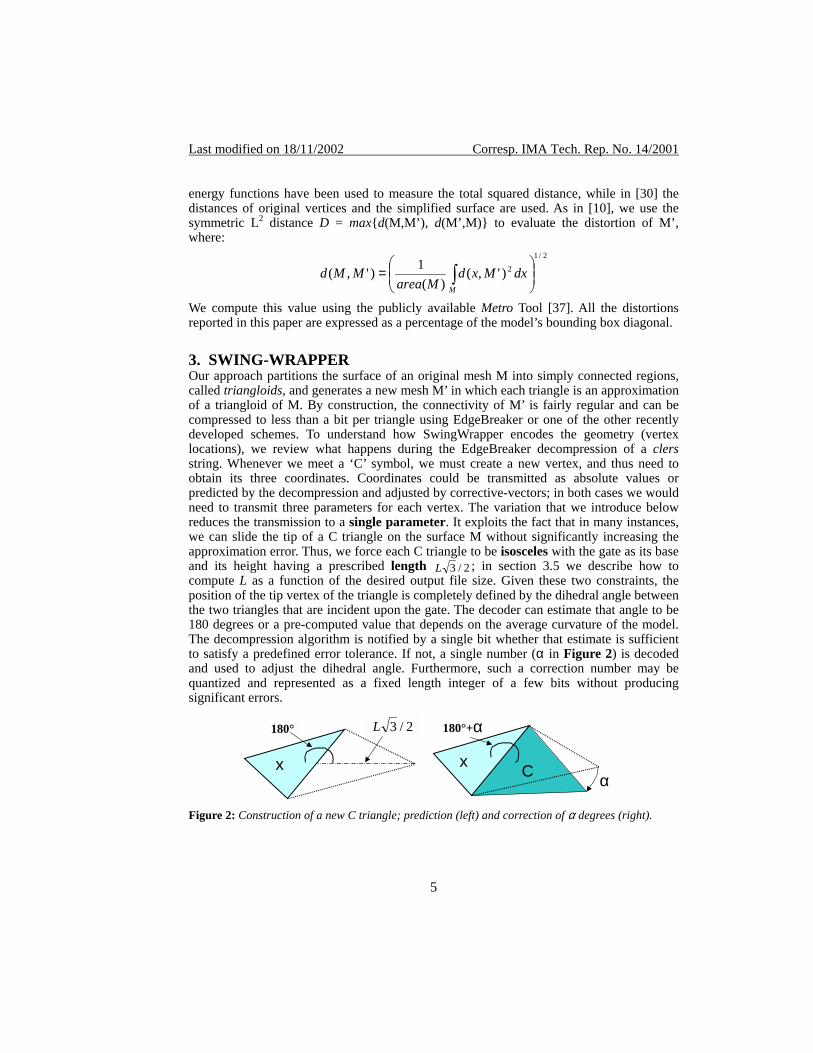
We compute this value using the publicly available Metro Tool [37]. All the distortions reported in this paper are expressed as a percentage of the model’s bounding box diagonal. 3. SWING-WRAPPER Our approach partitions the surface of an original mesh M into simply connected regions, called triangloids, and generates a new mesh M’ in which each triangle is an approximation of a triangloid of M. By construction, the connectivity of M’ is fairly regular and can be compressed to less than a bit per triangle using EdgeBreaker or one of the other recently developed schemes. To understand how SwingWrapper encodes the geometry (vertex locations), we review what happens during the EdgeBreaker decompression of a clers string. Whenever we meet a ‘C’ symbol, we must create a new vertex, and thus need to obtain its three coordinates. Coordinates could be transmitted as absolute values or predicted by the decompression and adjusted by corrective-vectors; in both cases we would need to transmit three parameters for each vertex. The variation that we introduce below reduces the transmission to a single parameter. It exploits the fact that in many instances, we can slide the tip of a C triangle on the surface M without significantly increasing the approximation error. Thus, we force each C triangle to be isosceles with the gate as its base and its height having a prescribed length 2/3L ; in section 3.5 we describe how to compute L as a function of the desired output file size. Given these two constraints, the position of the tip vertex of the triangle is completely defined by the dihedral angle between the two triangles that are incident upon the gate. The decoder can estimate that angle to be 180 degrees or a pre-computed value that depends on the average curvature of the model. The decompression algorithm is notified by a single bit whether that estimate is sufficient to satisfy a predefined error tolerance. If not, a single number (α in Figure 2) is decoded and used to adjust the dihedral angle. Furthermore, such a correction number may be quantized and represented as a fixed length integer of a few bits without producing significant errors.
Cx α
x
180° 2/3L 180°+α
Figure 2: Construction of a new C triangle; prediction (left) and correction of α degrees (right).
5
Last modified on 18/11/2002 Corresp. IMA Tech. Rep. No. 14/2001
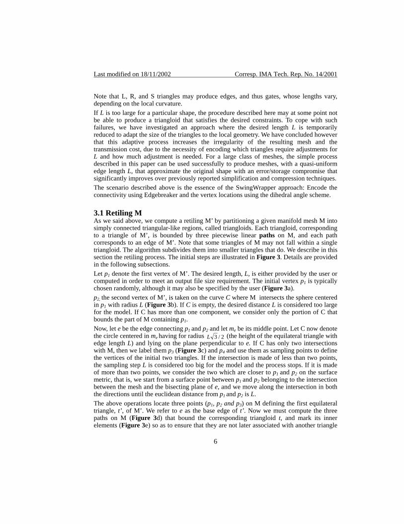
Note that L, R, and S triangles may produce edges, and thus gates, whose lengths vary, depending on the local curvature. If L is too large for a particular shape, the procedure described here may at some point not be able to produce a triangloid that satisfies the desired constraints. To cope with such failures, we have investigated an approach where the desired length L is temporarily reduced to adapt the size of the triangles to the local geometry. We have concluded however that this adaptive process increases the irregularity of the resulting mesh and the transmission cost, due to the necessity of encoding which triangles require adjustments for L and how much adjustment is needed. For a large class of meshes, the simple process described in this paper can be used successfully to produce meshes, with a quasi-uniform edge length L, that approximate the original shape with an error/storage compromise that significantly improves over previously reported simplification and compression techniques. The scenario described above is the essence of the SwingWrapper approach: Encode the connectivity using Edgebreaker and the vertex locations using the dihedral angle scheme. 3.1 Retiling M As we said above, we compute a retiling M’ by partitioning a given manifold mesh M into simply connected triangular-like regions, called triangloids. Each triangloid, corresponding to a triangle of M’, is bounded by three piecewise linear paths on M, and each path corresponds to an edge of M’. Note that some triangles of M may not fall within a single triangloid. The algorithm subdivides them into smaller triangles that do. We describe in this section the retiling process. The initial steps are illustrated in Figure 3. Details are provided in the following subsections. Let p1 denote the first vertex of M’. The desired length, L, is either provided by the user or computed in order to meet an output file size requirement. The initial vertex p1 is typically chosen randomly, although it may also be specified by the user (Figure 3a). p2, the second vertex of M’, is taken on the curve C where M intersects the sphere centered in p1 with radius L (Figure 3b). If C is empty, the desired distance L is considered too large for the model. If C has more than one component, we consider only the portion of C that bounds the part of M containing p1. Now, let e be the edge connecting p1 and p2 and let me be its middle point. Let C now denote the circle centered in me having for radius 2/3L (the height of the equilateral triangle with edge length L) and lying on the plane perpendicular to e. If C has only two intersections with M, then we label them p3 (Figure 3c) and p4 and use them as sampling points to define the vertices of the initial two triangles. If the intersection is made of less than two points, the sampling step L is considered too big for the model and the process stops. If it is made of more than two points, we consider the two which are closer to p1 and p2 on the surface metric, that is, we start from a surface point between p1 and p2 belonging to the intersection between the mesh and the bisecting plane of e, and we move along the intersection in both the directions until the euclidean distance from p1 and p2 is L. The above operations locate three points (p1, p2 and p3) on M defining the first equilateral triangle, t’, of M’. We refer to e as the base edge of t’. Now we must compute the three paths on M (Figure 3d) that bound the corresponding triangloid t, and mark its inner elements (Figure 3e) so as to ensure that they are not later associated with another triangle
6
Last modified on 18/11/2002 Corresp. IMA Tech. Rep. No. 14/2001
of M’. Tracking a path may require the insertion of new vertices where the path crosses edges of M. Thus edge and/or triangle splits are performed in order to build a coherent partitioning of M. The paths are approximations of the corresponding geodesic shortest paths (GSP). Although they could be computed exactly as described in [39], we use a more efficient procedure, described below, which exploits the fact that we are mainly interested in paths that remain close to a straight line. A second equilateral triangle (Figure 3f) has for vertices p1, p2 and p4. The two paths that bound the corresponding triangloid are computed using the same approach as above.
P1 P2
P1
Sphere-mesh intersection
(a) (b)
P1 P2 me
P3 Intersecting circle
(c)
P4
Intersecting circle
(e) (f)
P1 P2
P3 (d)
Figure 3: Construction of the initial triangles of M’.
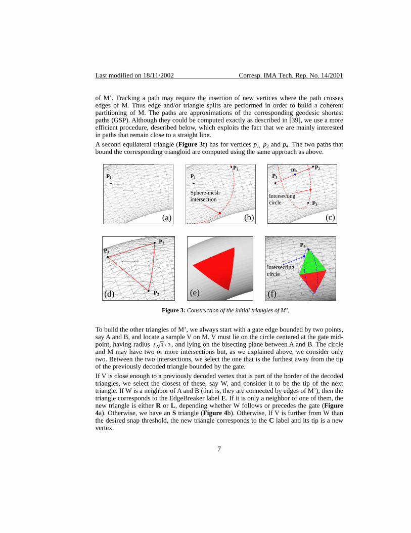
To build the other triangles of M’, we always start with a gate edge bounded by two points, say A and B, and locate a sample V on M. V must lie on the circle centered at the gate mid-point, having radius 2/3L , and lying on the bisecting plane between A and B. The circle and M may have two or more intersections but, as we explained above, we consider only two. Between the two intersections, we select the one that is the furthest away from the tip of the previously decoded triangle bounded by the gate. If V is close enough to a previously decoded vertex that is part of the border of the decoded triangles, we select the closest of these, say W, and consider it to be the tip of the next triangle. If W is a neighbor of A and B (that is, they are connected by edges of M’), then the triangle corresponds to the EdgeBreaker label E. If it is only a neighbor of one of them, the new triangle is either R or L, depending whether W follows or precedes the gate (Figure 4a). Otherwise, we have an S triangle (Figure 4b). Otherwise, If V is further from W than the desired snap threshold, the new triangle corresponds to the C label and its tip is a new vertex.
7
Last modified on 18/11/2002 Corresp. IMA Tech. Rep. No. 14/2001
If V is inside a previously processed triangloid, we do not use any limit and always perform a snap to the closest point, W (Figure 4a) on the border of the previously accounted triangloids. In our implementation we decided to perform the snap whenever the distance between V and W is less than L/2 because, after some experiments, we have found that this value leads to rather regular retilings. Since, in this context, the concept of closeness is relative to the surface metric, we move by adjacencies on M in a spiral-like manner, and we stop when we reach the threshold distance in all the directions.
a b
Figure 4: Simple (a) and Complex (b) Snaps.
Notice that the recently proposed use of local coordinate systems to encode the geometry seems a promising direction for 3D compression, especially when the local geometry is expressed in terms of angles [44]. 3.2 Computation of the path To compute an approximation of the geodesic path between a point A and a point B on M, we estimate the normals at A and B. Then we construct a plane that passes through A and B and is parallel to the sum of their normals. Then we walk from A towards B along the intersection of that plane with M. If we cannot reach B, we switch to the slower algorithm presented in [39] and compute the exact geodesic shortest path. If we reach B, we have a candidate path P that forms a polyline on M whose internal vertices are all on the edges or vertices of M. Then we attempt to shorten P by a series of local snaps. Each snap moves a vertex V of P along an edge of M. (If V lies in the relative interior of an edge of M, then the snap can only move it along that edge. If V coincides with a vertex of M, then the snap can move it along any of the edges of M that are incident upon that vertex). At each snap, we select the move that minimizes the length of P. Note that the move may bring the vertex to the end of the edge or to some internal point on the edge. If the surface is sufficiently smooth, the limit of this process produces the exact GSP, otherwise it converges to a locally shortest path. We tuned our implementation to a finite number (10) of refinement iterations. 3.3 Validity tests At each step of the sampling procedure described above, we compute and mark the corresponding triangloid by tracing the GSP paths that bound it and by identifying and marking the portions of M that they bound. We verify that the surface of the triangloid is simply connected and disjoint from previously encountered triangloids. For example, if a triangloid contains one end of a handle, its interior is not properly defined by its three
8
Last modified on 18/11/2002 Corresp. IMA Tech. Rep. No. 14/2001
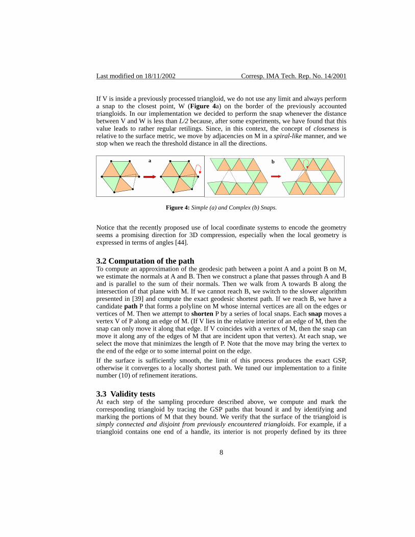
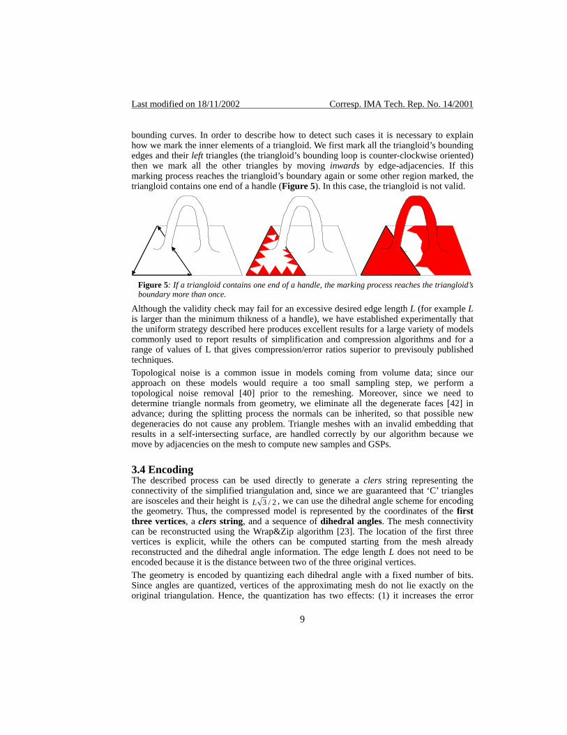
bounding curves. In order to describe how to detect such cases it is necessary to explain how we mark the inner elements of a triangloid. We first mark all the triangloid’s bounding edges and their left triangles (the triangloid’s bounding loop is counter-clockwise oriented) then we mark all the other triangles by moving inwards by edge-adjacencies. If this marking process reaches the triangloid’s boundary again or some other region marked, the triangloid contains one end of a handle (Figure 5). In this case, the triangloid is not valid.
Figure 5: If a triangloid contains one end of a handle, the marking process reaches the triangloid’s boundary more than once.
Although the validity check may fail for an excessive desired edge length L (for example L is larger than the minimum thikness of a handle), we have established experimentally that the uniform strategy described here produces excellent results for a large variety of models commonly used to report results of simplification and compression algorithms and for a range of values of L that gives compression/error ratios superior to previsouly published techniques. Topological noise is a common issue in models coming from volume data; since our approach on these models would require a too small sampling step, we perform a topological noise removal [40] prior to the remeshing. Moreover, since we need to determine triangle normals from geometry, we eliminate all the degenerate faces [42] in advance; during the splitting process the normals can be inherited, so that possible new degeneracies do not cause any problem. Triangle meshes with an invalid embedding that results in a self-intersecting surface, are handled correctly by our algorithm because we move by adjacencies on the mesh to compute new samples and GSPs. 3.4 Encoding The described process can be used directly to generate a clers string representing the connectivity of the simplified triangulation and, since we are guaranteed that ‘C’ triangles are isosceles and their height is 2/3L , we can use the dihedral angle scheme for encoding the geometry. Thus, the compressed model is represented by the coordinates of the first three vertices, a clers string, and a sequence of dihedral angles. The mesh connectivity can be reconstructed using the Wrap&Zip algorithm [23]. The location of the first three vertices is explicit, while the others can be computed starting from the mesh already reconstructed and the dihedral angle information. The edge length L does not need to be encoded because it is the distance between two of the three original vertices. The geometry is encoded by quantizing each dihedral angle with a fixed number of bits. Since angles are quantized, vertices of the approximating mesh do not lie exactly on the original triangulation. Hence, the quantization has two effects: (1) it increases the error
9
Last modified on 18/11/2002 Corresp. IMA Tech. Rep. No. 14/2001
estimate by adding to it the maximum displacement that a vertex could be subjected to during quantization and (2) it requires that the computation of the corrective values be adjusted to take quantization into account. The error increase due to quantization depends on L and on the number of bits used to store each value. It is easily computed for a single step. For example, using 8 bits guarantees a precision of 360/256 ≅ 1.41 degrees (corresponding to a Hausdorff distance of
( ) 2/41.1sin3L ). In hedral angle quantized with k bits leads to a Hausdorff distance of
general a di( ) 2/2/360sin3 kL .
To avoid error propagation during the decompression, the compression algorithm computes each new vertex starting from an approximating adjacent triangle, whose vertices do not necessarily lie on the original mesh. Thus the compression must simulate the work of the decompressor using only previously decoded information. To achieve this, we integrate quantization with the retiling process. At each step when a new vertex is introduced, a point V on M is used for computing the paths bounding the triangloid but a quantized version of that point is used when computing the following triangloids of M. 3.5 Results and discussion When each dihedral angle is quantized with 8 bits, and the first three vertices use 32 bits per coordinate, the method described here guarantees that the retiled mesh M’ with V vertices, T triangles and H handles can always be encoded with 32*3*3+8V+1.83T+2Hlog(T) bits. For simplicity, we assume that the number of handles, H, is negligeable with respect to V, and thus that T=2V. For large meshes, entropy encoding further reduces storage, bringing the connectivity cost down to about T bits and the geometry cost to about 6V bits (or equivalently 3T bits). Thus the total size is about 4T bits for large meshes, while it is guaranteed not to exceed 288+5.83T bits for meshes without handles. We have implemented a prototype to test the described method. The input is an original mesh M and the desired size S of the compressed model in bits. The first step of the SwingWrapper system is to use such a size to compute the sampling step L, by considering the following: • A = area of M. • a = 4/32L = area of an equilateral triangle with edge length L. • T = A/a = number of equilateral triangles that are necessary to wrap the whole M. We make two approximations: 1) we consider that all the triangles produced by SwingWrapper are equilateral and 2) that each triangle is encoded with exactly 4 bits. So we want that 4T = S and, by substitution, 16A/( 32L ) = S . Inverting, we obtain:
L = )3/(SA4 We found that the actual output size produced by our heuristics approaches the desired one (Figure 7, Figure 8 and Figure 9) within an accuracy that is sufficient for a wide variety of Web-based applications. When the user asks for a compression that would require a desired edge length L that is too large for the particular mesh, SwingWrapper reports a failure and the user must either suggest a less aggressive compression or rely on an automated binary search, which computes the largest L for which the mesh can be resampled with our
10
Last modified on 18/11/2002 Corresp. IMA Tech. Rep. No. 14/2001
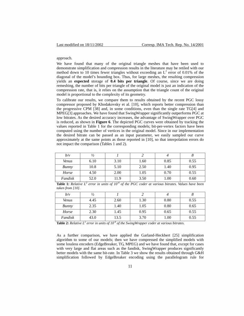
approach. We have found that many of the original triangle meshes that have been used to demonstrate simplification and compression results in the literature may be retiled with our method down to 10 times fewer triangles without exceeding an L2 error of 0.01% of the diagonal of the model’s bounding box. Thus, for large meshes, the resulting compression yields an expected storage of 0.4 bits per triangle. Of course, since we are doing remeshing, the number of bits per triangle of the original model is just an indication of the compression rate, that is, it relies on the assumption that the triangle count of the original model is proportional to the complexity of its geometry. To calibrate our results, we compare them to results obtained by the recent PGC lossy compressor proposed by Khodakovsky et al. [10], which reports better compression than the progressive CPM [38] and, in some conditions, even than the single rate TG[4] and MPEG[3] approaches. We have found that SwingWrapper significantly outperforms PGC at low bitrates. As the desired accuracy increases, the advantage of SwingWrapper over PGC is reduced, as shown in Figure 6. The depicted PGC curves were obtained by tracking the values reported in Table 1 for the corresponding models; bit-per-vertex factors have been computed using the number of vertices in the original model. Since in our implementation the desired bitrate can be passed as an input parameter, we easily sampled our curve approximately at the same points as those reported in [10], so that interpolation errors do not impact the comparison (Tables 1 and 2).
b/v ½ 1 2 4 8 Venus 6.10 3.10 1.60 0.85 0.55 Bunny 10.8 5.10 2.50 1.40 0.95 Horse 4.50 2.00 1.05 0.70 0.55
Fandisk 52.0 11.9 3.50 1.00 0.60 Table 1: Relative L2 error in units of 10-4 of the PGC coder at various bitrates. Values have been taken from [10].
b/v ½ 1 2 4 8 Venus 4.45 2.60 1.30 0.80 0.55 Bunny 2.35 1.40 1.05 0.80 0.65 Horse 2.30 1.45 0.95 0.65 0.55
Fandisk 43.0 13.5 3.70 1.00 0.55 Table 2: Relative L2 error in units of 10-4 of the SwingWrapper coder at various bitrates.
As a further comparison, we have applied the Garland-Heckbert [25] simplification algorithm to some of our models; then we have compressed the simplified models with some lossless encoders (EdgeBreaker, TG, MPEG) and we have found that, except for cases with very large and flat areas such as the fandisk, SwingWrapper produces significantly better models with the same bit-rate. In Table 3 we show the results obtained through G&H simplification followed by EdgeBreaker encoding using the parallelogram rule for
11
Last modified on 18/11/2002 Corresp. IMA Tech. Rep. No. 14/2001
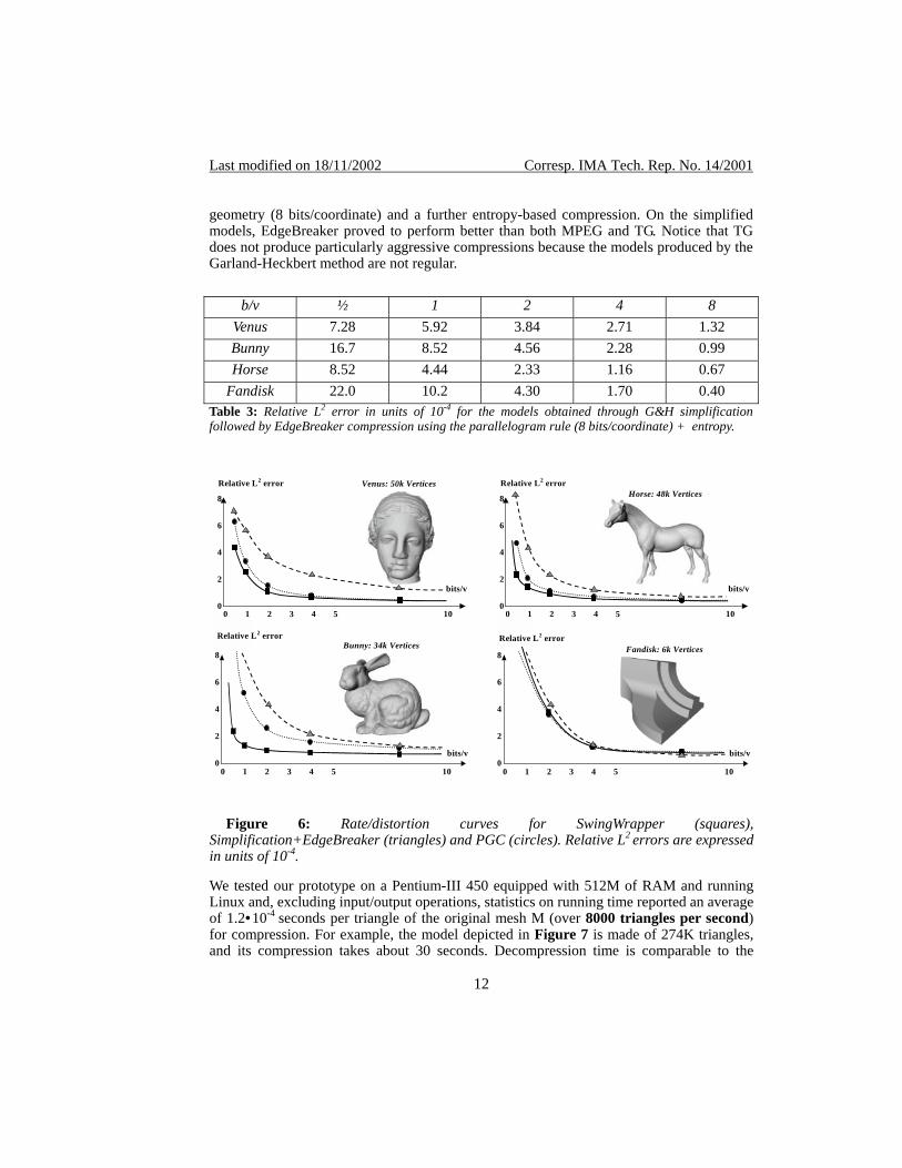
geometry (8 bits/coordinate) and a further entropy-based compression. On the simplified models, EdgeBreaker proved to perform better than both MPEG and TG. Notice that TG does not produce particularly aggressive compressions because the models produced by the Garland-Heckbert method are not regular.
b/v ½ 1 2 4 8 Venus 7.28 5.92 3.84 2.71 1.32 Bunny 16.7 8.52 4.56 2.28 0.99 Horse 8.52 4.44 2.33 1.16 0.67
Fandisk 22.0 10.2 4.30 1.70 0.40 Table 3: Relative L2 error in units of 10-4 for the models obtained through G&H simplification followed by EdgeBreaker compression using the parallelogram rule (8 bits/coordinate) + entropy.
0 1 2 3 4 10 5 0
2
4
6
8
bits/v
0 1 2 3 4 105 0
2
4
6
8
bits/v
Relative L2 error
0 1 2 3 4 10 5 0
2
4
6
8
bits/v
0 1 2 3 4 105 0
2
4
6
8
bits/v
Relative L2 error
Relative L2 error Relative L2 error
Venus: 50k Vertices
Bunny: 34k Vertices
Horse: 48k Vertices
Fandisk: 6k Vertices
Figure 6: Rate/distortion curves for SwingWrapper (squares),
Simplification+EdgeBreaker (triangles) and PGC (circles). Relative L2 errors are expressed in units of 10-4.
We tested our prototype on a Pentium-III 450 equipped with 512M of RAM and running Linux and, excluding input/output operations, statistics on running time reported an average of 1.2•10-4 seconds per triangle of the original mesh M (over 8000 triangles per second) for compression. For example, the model depicted in Figure 7 is made of 274K triangles, and its compression takes about 30 seconds. Decompression time is comparable to the
12
Last modified on 18/11/2002 Corresp. IMA Tech. Rep. No. 14/2001
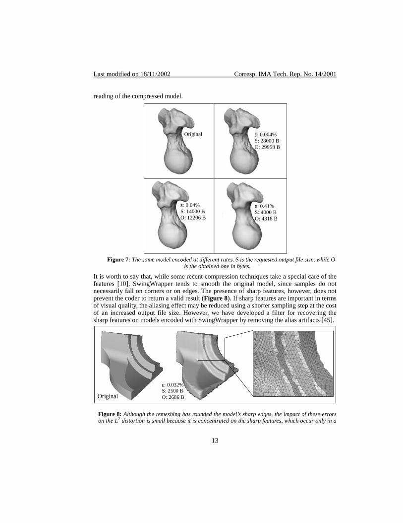
reading of the compressed model.
Original
ε: 0.004% S: 28000 B O: 29958 B
Figure 1
ε: 0.04% S: 14000 BO: 12206 B
Figure 1 ε: 0.41% S: 4000 B O: 4318 B
Figure 7: The same model encoded at different rates. S is the requested output file size, while O
is the obtained one in bytes.
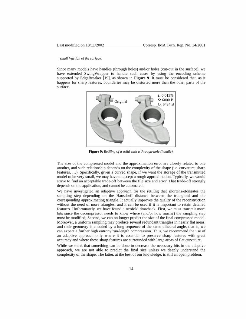
It is worth to say that, while some recent compression techniques take a special care of the features [10], SwingWrapper tends to smooth the original model, since samples do not necessarily fall on corners or on edges. The presence of sharp features, however, does not prevent the coder to return a valid result (Figure 8). If sharp features are important in terms of visual quality, the aliasing effect may be reduced using a shorter sampling step at the cost of an increased output file size. However, we have developed a filter for recovering the sharp features on models encoded with SwingWrapper by removing the alias artifacts [45].
Original
ε: 0.032% S: 2500 B O: 2686 B
Figure 8: Although the remeshing has rounded the model’s sharp edges, the impact of these errors on the L2 distortion is small because it is concentrated on the sharp features, which occur only in a
13
Last modified on 18/11/2002 Corresp. IMA Tech. Rep. No. 14/2001
small fraction of the surface.
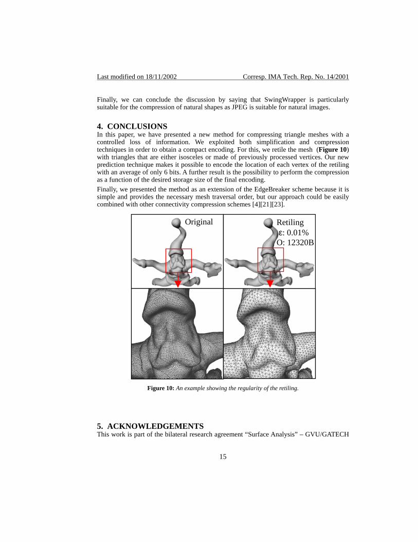
Since many models have handles (through holes) and/or holes (cut-out in the surface), we have extended SwingWrapper to handle such cases by using the encoding scheme supported by EdgeBreaker [19], as shown in Figure 9. It must be considered that, as it happens for sharp features, boundaries may be distorted more than the other parts of the surface.
Figure 1
ε: 0.013% S: 6000 B O: 6424 B
Original
Figure 9: Retiling of a solid with a through-hole (handle).
The size of the compressed model and the approximation error are closely related to one another, and such relationship depends on the complexity of the shape (i.e. curvature, sharp features, …). Specifically, given a curved shape, if we want the storage of the transmitted model to be very small, we may have to accept a rough approximation. Typically, we would strive to find an acceptable trade-off between the file size and error. That trade-off strongly depends on the application, and cannot be automated. We have investigated an adaptive approach for the retiling that shortens/elongates the sampling step depending on the Hausdorff distance between the triangloid and the corresponding approximating triangle. It actually improves the quality of the reconstruction without the need of more triangles, and it can be used if it is important to retain detailed features. Unfortunately, we have found a twofold drawback. First, we must transmit more bits since the decompressor needs to know where (and/or how much?) the sampling step must be modified; Second, we can no longer predict the size of the final compressed model. Moreover, a uniform sampling may produce several redundant triangles in nearly flat areas, and their geometry is encoded by a long sequence of the same dihedral angle, that is, we can expect a further high entropy/run-length compression. Thus, we recommend the use of an adaptive approach only where it is essential to preserve sharp features with great accuracy and where these sharp features are surrounded with large areas of flat curvature. While we think that something can be done to decrease the necessary bits in the adaptive approach, we are not able to predict the final size unless we deeply understand the complexity of the shape. The latter, at the best of our knowledge, is still an open problem.
14
Last modified on 18/11/2002 Corresp. IMA Tech. Rep. No. 14/2001
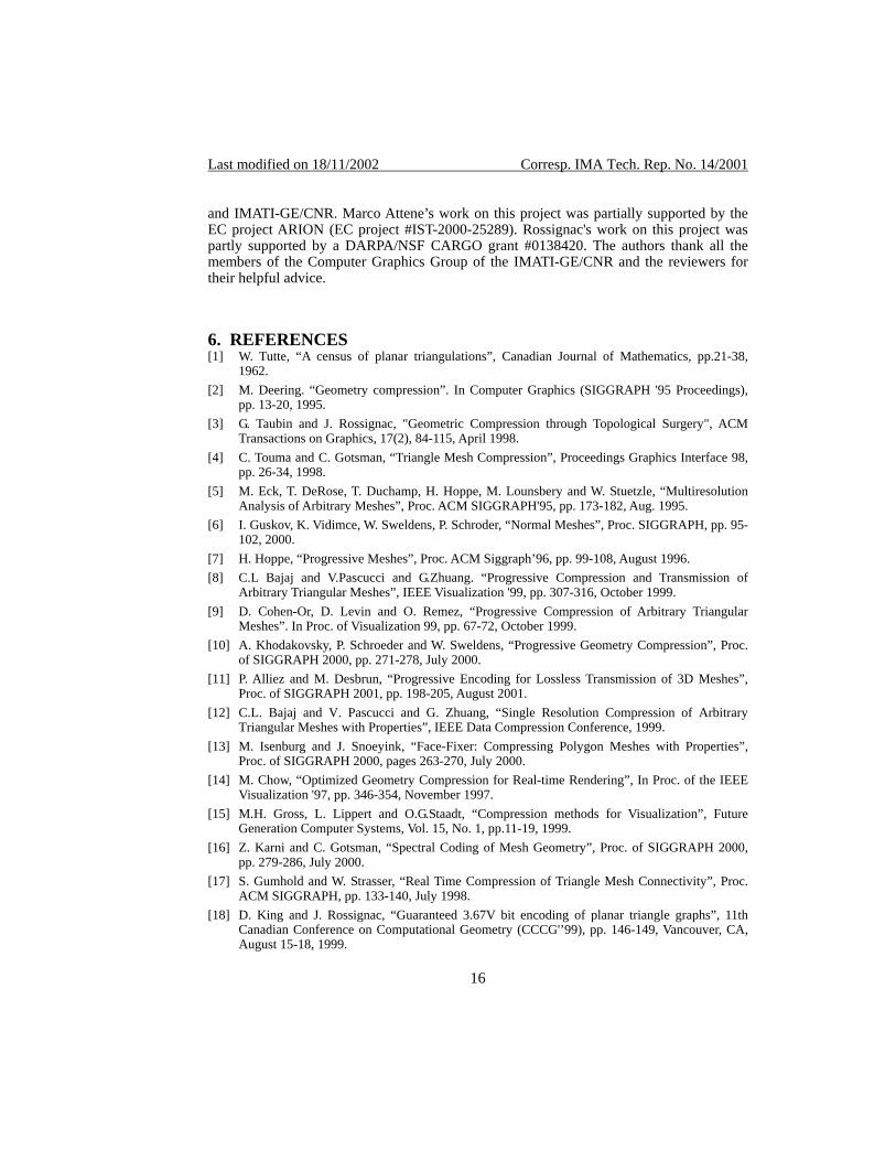
Finally, we can conclude the discussion by saying that SwingWrapper is particularly suitable for the compression of natural shapes as JPEG is suitable for natural images. 4. CONCLUSIONS In this paper, we have presented a new method for compressing triangle meshes with a controlled loss of information. We exploited both simplification and compression techniques in order to obtain a compact encoding. For this, we retile the mesh (Figure 10) with triangles that are either isosceles or made of previously processed vertices. Our new prediction technique makes it possible to encode the location of each vertex of the retiling with an average of only 6 bits. A further result is the possibility to perform the compression as a function of the desired storage size of the final encoding. Finally, we presented the method as an extension of the EdgeBreaker scheme because it is simple and provides the necessary mesh traversal order, but our approach could be easily combined with other connectivity compression schemes [4][21][23].
Original Retiling ε: 0.01% O: 12320B
Figure 10: An example showing the regularity of the retiling.
5. ACKNOWLEDGEMENTS This work is part of the bilateral research agreement “Surface Analysis” – GVU/GATECH
15
Last modified on 18/11/2002 Corresp. IMA Tech. Rep. No. 14/2001
and IMATI-GE/CNR. Marco Attene’s work on this project was partially supported by the EC project ARION (EC project #IST-2000-25289). Rossignac's work on this project was partly supported by a DARPA/NSF CARGO grant #0138420. The authors thank all the members of the Computer Graphics Group of the IMATI-GE/CNR and the reviewers for their helpful advice. 6. REFERENCES [1] W. Tutte, “A census of planar triangulations”, Canadian Journal of Mathematics, pp.21-38,
1962. [2] M. Deering. “Geometry compression”. In Computer Graphics (SIGGRAPH '95 Proceedings),
pp. 13-20, 1995. [3] G. Taubin and J. Rossignac, "Geometric Compression through Topological Surgery", ACM
Transactions on Graphics, 17(2), 84-115, April 1998. [4] C. Touma and C. Gotsman, “Triangle Mesh Compression”, Proceedings Graphics Interface 98,
pp. 26-34, 1998. [5] M. Eck, T. DeRose, T. Duchamp, H. Hoppe, M. Lounsbery and W. Stuetzle, “Multiresolution
Analysis of Arbitrary Meshes”, Proc. ACM SIGGRAPH'95, pp. 173-182, Aug. 1995. [6] I. Guskov, K. Vidimce, W. Sweldens, P. Schroder, “Normal Meshes”, Proc. SIGGRAPH, pp. 95-
102, 2000. [7] H. Hoppe, “Progressive Meshes”, Proc. ACM Siggraph’96, pp. 99-108, August 1996. [8] C.L Bajaj and V.Pascucci and G.Zhuang. “Progressive Compression and Transmission of
Arbitrary Triangular Meshes”, IEEE Visualization '99, pp. 307-316, October 1999. [9] D. Cohen-Or, D. Levin and O. Remez, “Progressive Compression of Arbitrary Triangular
Meshes”. In Proc. of Visualization 99, pp. 67-72, October 1999. [10] A. Khodakovsky, P. Schroeder and W. Sweldens, “Progressive Geometry Compression”, Proc.
of SIGGRAPH 2000, pp. 271-278, July 2000. [11] P. Alliez and M. Desbrun, “Progressive Encoding for Lossless Transmission of 3D Meshes”,
Proc. of SIGGRAPH 2001, pp. 198-205, August 2001. [12] C.L. Bajaj and V. Pascucci and G. Zhuang, “Single Resolution Compression of Arbitrary
Triangular Meshes with Properties”, IEEE Data Compression Conference, 1999. [13] M. Isenburg and J. Snoeyink, “Face-Fixer: Compressing Polygon Meshes with Properties”,
Proc. of SIGGRAPH 2000, pages 263-270, July 2000. [14] M. Chow, “Optimized Geometry Compression for Real-time Rendering”, In Proc. of the IEEE
Visualization '97, pp. 346-354, November 1997. [15] M.H. Gross, L. Lippert and O.G.Staadt, “Compression methods for Visualization”, Future
Generation Computer Systems, Vol. 15, No. 1, pp.11-19, 1999. [16] Z. Karni and C. Gotsman, “Spectral Coding of Mesh Geometry”, Proc. of SIGGRAPH 2000,
pp. 279-286, July 2000. [17] S. Gumhold and W. Strasser, “Real Time Compression of Triangle Mesh Connectivity”, Proc.
ACM SIGGRAPH, pp. 133-140, July 1998. [18] D. King and J. Rossignac, “Guaranteed 3.67V bit encoding of planar triangle graphs”, 11th
Canadian Conference on Computational Geometry (CCCG'’99), pp. 146-149, Vancouver, CA, August 15-18, 1999.
16
Last modified on 18/11/2002 Corresp. IMA Tech. Rep. No. 14/2001
[19] J. Rossignac, "Edgebreaker: Connectivity compression for triangle meshes", IEEE Transactions on Visualization and Computer Graphics, 5(1), 47-61, Jan-Mar 1999.
[20] A. Szymczak, D. King, J. Rossignac, “An Edgebreaker-based Efficient Compression Scheme for Connectivity of Regular Meshes”, Journal of Computational Geometry: Theory and Applications, 2000.
[21] P. Alliez and M. Desbrun, “Valence-Driven Connectivity Encoding for 3D Meshes”, Proc. of Eurographics '01, pp. 480-489, 2001.
[22] J. Rossignac and D. Cardoze, “Matchmaker: Manifold Breps for non-manifold r-sets”, Proceedings of the ACM Symposium on Solid Modeling, pp. 31-41, June 1999.
[23] J. Rossignac and A. Szymczak, "Wrap&Zip decompression of the connectivity of triangle meshes compressed with Edgebreaker", Computational Geometry, Theory and Applications, 14(1/3), 119-135, November 1999.
[24] M. Isenburg and J. Snoeyink, “Spirale Reversi: Reverse decoding of the Edgebreaker encoding”, Tech. Report TR-99-08, Computer Science, UBC, 1999.
[25] M. Garland and P. Heckbert. Simplifying Surfaces with Color and Texture using Quadratic Error Metric. Proceedings of IEEE Visualization, pp. 287-295, 1998.
[26] W. Schroeder, J. Zarge and W.E. Lorensen, “Decimation of triangle meshes”, Proc. ACM Siggraph 92, pp. 65-70, July 1992.
[27] M. E. Algorri and F. Schmitt, “Mesh simplification”, Proc. Eurographics 96, 15(3), pp. 78-86, 1996.
[28] R. Ronfard and J. Rossignac, “Full range approximation of triangulated polyhedra”, Proc. Eurographics 96, 15(3), pp. 67-76, 1996.
[29] P. Hinker and C. Hansen, “Geometric Optimization”, IEEE Visualization ’93 Proc., pp 189-195, October, 1993.
[30] A.D. Kalvin and R.H. Taylor, “Superfaces: Polygonal mesh simplification with bounded error”. IEEE Computer Graphics and Applications, 16(3), pp. 64-67,1996.
[31] J. Rossignac and P. Borrel, “Multi-resolution 3D approximations for rendering complex scenes”, Geometric Modeling in Computer Graphics, Springer Verlag, Berlin, pp. 445-465, 1993.
[32] K-L. Low and T.S.Tan, “Model Simplification using vertex clustering”, Proc. Symp. Interactive 3D Graphics, ACM Press, NY, pp. 75-82, 1997.
[33] G. Turk, “Re-tiling polygonal surfaces”, Proc. ACM Siggraph 92, pp. 55-64, July 1992. [34] M. Attene, S. Biasotti and M. Spagnuolo, “Re-meshing techniques for topological analysis”,
Proc. Shape Modeling International, pp. 142-151, 2001. [35] C. Bajaj, D. Schikore, “Topology Preserving Data Simplification with Error Bounds”, Journal
on Computers and Graphics, vol. 22.1, pp. 3-12, 1998. [36] A.Lee, W.Sweldens, P.Schröder, L.Cowsar, D.Dobkin, “MAPS: Multiresolution Adaptive
Parameterization of Surfaces”, Proc. SIGGRAPH’98, pp. 95-104, 1998. [37] P. Cignoni, C. Rocchini and R. Scopigno, “Metro: measuring error on simplified surfaces”,
Proc. Eurographics ’98, vol. 17(2), pp 167-174, June 1998. [38] R.Pajarola and J.Rossignac, “Compressed Progressive Meshes”, Tech. Rep. GIT-GVU-99-05,
Georgia Institute of Technology, 1999. [39] J. Chen and Y. Han, “Shortest paths on a polyhedron”, Procs. of 6th ACM Symposium on
Computational Geometry, pp. 360-369, 1990.
17
Last modified on 18/11/2002 Corresp. IMA Tech. Rep. No. 14/2001
[40] I. Guskov and Z. Wood, “Topological noise removal”, Procs. of Graphics Interface 2001, June 2001, pp. 19-26.
[41] M. Isenburg, S. Gumhold and C. Gotsman, “Connectivity Shapes”, Procs. Visualization 2001, pp. 135-142, 2001.
[42] M. Botsch and L. P. Kobbelt, “A Robust Procedure to Eliminate Degenerate Faces from Triangle Meshes”, Vision, Modeling and Visualization (VMV01), Stuttgart, Germany, November 21 - 23, 2001.
[43] Z. Karni, A. Bogomjacov and C. Gotsman, “Efficient Compression and Rendering of Multi-Resolution Meshes”, to appear in Procs. of Visualization 2002.
[44] H. Lee, P. Alliez and M. Desbrun, “Angle-Analyzer: A Triangle-Quad mesh Codec”, to appear in Procs. of Eurographics 2002.
[45] M. Attene, B.Falcidieno, M. Spagnuolo and J.Rossignac, “EdgeSharpener: A Geometric Filter for Recovering Sharp Features in Uniform Triangulations”, IMA Technical Report No. 6/2002.
18
Related Documents