March 24, 2006 - Trieste Italy Swift XRT Data Analysis Milvia Capalbi ASI Science Data Center (Frascati, Italy) Swift Team @ ASDC : P. Giommi, M.Capalbi,M.Perri (ASI - INAF) F.Tamburelli, B.Saija (Dataspazio) in collaboration with L.Angelini (HEASARC)

Welcome message from author
This document is posted to help you gain knowledge. Please leave a comment to let me know what you think about it! Share it to your friends and learn new things together.
Transcript

March 24, 2006 - Trieste Italy
Swift XRT Data Analysis
Milvia Capalbi
ASI Science Data Center (Frascati, Italy)
Swift Team @ ASDC :
P. Giommi, M.Capalbi,M.Perri (ASI - INAF)F.Tamburelli, B.Saija (Dataspazio)
in collaboration with L.Angelini (HEASARC)

March 24, 2006 - Trieste Italy
Overview
• The XRTDAS package
• XRT instrument and science modes
• Data reduction: main steps
• Extraction of products
• Archives and data retrieval
• Example of data processing and analysis (interactive demo)

March 24, 2006 - Trieste Italy
XRTDAS (1)
XRT Data Analysis Software (XRTDAS)
- Set of FTOOLS specifically developed for the XRT instrument
- Generates high-level scientific data products from the FITS-formatted telemetry data
- Uses the HEASARC calibration database (CALDB)
- Runs on most popular Unix platforms
- Written using C, Fortran and Perl languages
- Developed at the ISAC/ASDC (ASI Science Data Center, Italy) by a team of 3 scientists (ASI and INAF) and 2 software analysts
(Dataspazio) in collaboration with HEASARC at NASA/GSFC
- Included in the pipeline processing at NASA/GSFC to generate theXRT archive
March 24, 2006 - Trieste Italy
XRTDAS (2)
• XRTDAS is part of the HEAsoft Package distributed by NASA's HEASARC
• Current version of HEAsoft (6.0.4) contains XRTDAS v.1.7.1 (Nov. 2005)
• Latest XRT CALDB version is 20060104
• Download of the HEAsoft package (source code or pre-compiled) and SwiftCALDB at:
http://swift.gscf.nasa.gov/software/lheasoft/
http://heasarc.gscf.nasa.gov/docs/heasarc/caldb/swift/
• Software documentation (BAT, XRT, UVOT data reduction guides) availableas pdf files at:
http://swift.gscf.nasa.gov/docs/swift/analysis/

March 24, 2006 - Trieste Italy
XRT Instrument
Telescope Wolter I (grazing incidence)Focal Length 3.5 mEffective Area 110 cm² @ 1.5 keVPSF ~18 arcsec HPD @ 1.5 keVPosition accuracy ~5 arcsecDetector 600x600 pxls / 2.36 arcsec/pxlEnergy Range 0.2 – 10 keVSpectral resolution ~ 140 eV @ 6 keV

March 24, 2006 - Trieste Italy
XRT Readout Modes
XRT can automaticallyselect the CCD readoutmode according to theinstantaneous count rate(to avoid pile-up):
Photodiode (PD) Windowed Timing (WT) Photon Counting (PC)
For centroid determination:
Imaging mode (IM)
March 24, 2006 - Trieste Italy
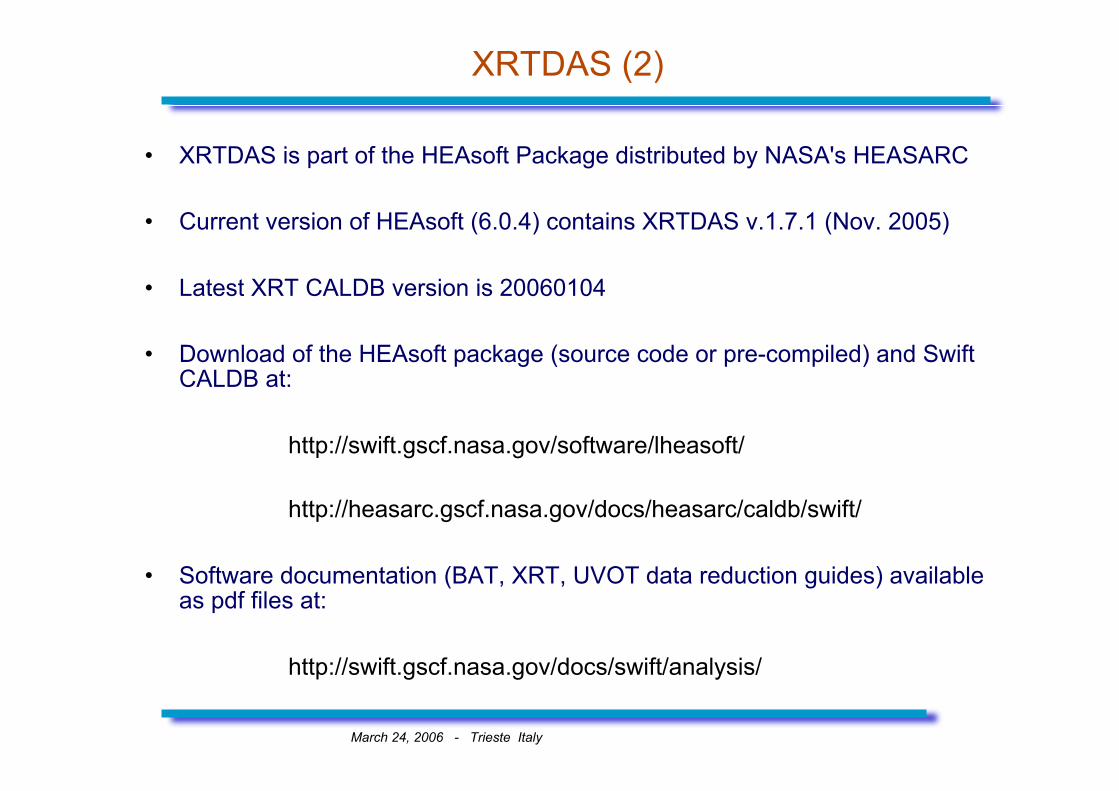
Photon Counting mode (PC)
• Default window: 500x500 pixels (20x20 arcmin) (1 pixel=2.36 arcsec)
• Each pixel contains the total charge collected on that pixel
• Bias map subtracted on-board
• On-board event recognition (3x3 pixels array telemetered)
• Time resolution: 2.5 s
• Flux Limit (to avoid pile-up): ~1 mCrab (~ 0.5 cts/s)

March 24, 2006 - Trieste Italy
Windowed Timing mode (WT)
• One readout every 10 parallel clock shifts: each row contains the sumof 10 CCD rows
• 1-D spatial information (default window of 200 pixels, ~8 arcmin)
• Bias row subtracted on-board
• No on-board event recognition
• Time resolution: ~1.8 ms
• Flux Limit: ~0.6 Crab (~200 cts/s)

March 24, 2006 - Trieste Italy
Photodiode mode (PD)
This mode is designed for very bright sources:
• 1 serial and 1 parallel clock shifts are alternate --> very rapidclocking of each pixel across the CCD
• no spatial information: every pixel contains the charge integratedover the entire field of view (image dominated by a bright source)
• Pixels with calibration sources contribute as well• No on-board event recognition
• Time resolution: ~0.14 ms• Flux Limit: ~60 Crab
• Two sub-modes (according to telemetry format):
- Piled-up (PU): all pixels are sent down- Low rate (LR): only pixels between LLD and ULD sent down

March 24, 2006 - Trieste Italy
Imaging mode (IM)
Used by the XRT to obtain a rapid position of a new GRB:
• 2-D spatial information• No X-ray event recognition• Each pixel contains the total charge collected in that pixel
Two possible integration times:
0.1 s (short image)2.5 s (long image)
Flux limits: ~45 Crab - 25 mCrab
March 24, 2006 - Trieste Italy
Data reduction: basic scheme
Input: telemetry data converted into FITS files (generated at the Swift Data Center at GSFC)
XRT data processing consists of three main stages:
• Stage 1: the data are calibrated using information from CALDBfiles, attitude and instrument housekeepings.
Output: Level 1 calibrated event files
• Stage 2: the calibrated data are screened by applying conditionson specified parameters (e.g. CCD Temperature, Sun Angle).
Output: Level 2 cleaned event files
– Stage 3: standard high-level scientific products (spectra, lightcurves, images) are extracted from the Level 2 event files.

March 24, 2006 - Trieste Italy
Stage 1: data calibration
The calibration stage is mode dependent and consists of severalsteps:
– sky coordinates calculation– bias subtraction– bad pixels (columns) flagging– hot pixels identification– reconstruction of photon arrival times ('time tagging') for
timing modes (Photodiode and Windowed Timing)– event reconstruction– photon energy calibration (conversion from PHA to PI)– GRADE assignment
March 24, 2006 - Trieste Italy
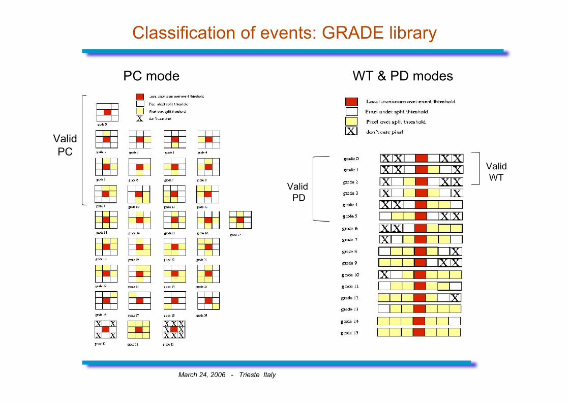
Classification of events: GRADE library
PC mode WT & PD modes
ValidPC
ValidWT
Valid PD
March 24, 2006 - Trieste Italy
Stage 2: data screening
Produces cleaned event files appropriate for scientific analysis.
Screening criteria can be grouped in three categories:
• attitude parameters• instrument HK parameters• event properties (STATUS and GRADE columns)
Two steps:
1. Good Time Intervals (GTIs) are calculated based on booleanexpressions
2. Data are filtered using the GTIs and event files columns
Attitude and instrument parameters included in the filter file (.mkf)
March 24, 2006 - Trieste Italy
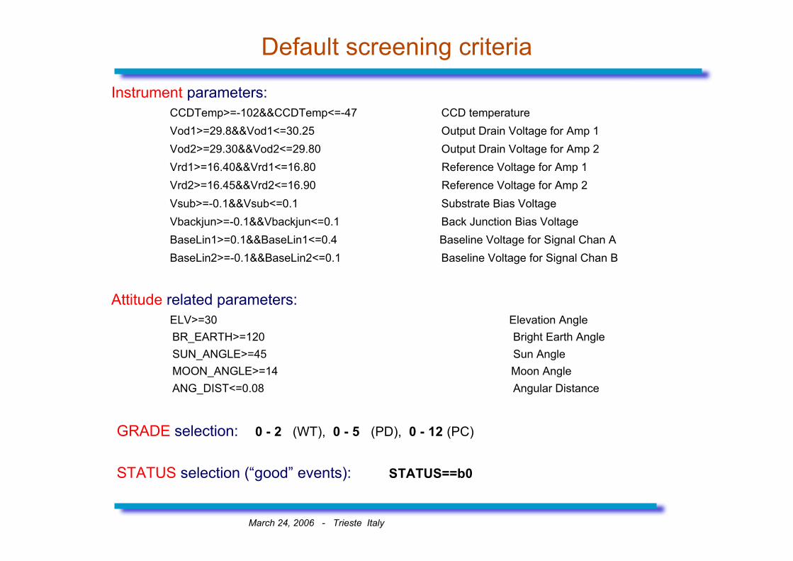
Default screening criteria
Instrument parameters: CCDTemp>=-102&&CCDTemp<=-47 CCD temperature
Vod1>=29.8&&Vod1<=30.25 Output Drain Voltage for Amp 1Vod2>=29.30&&Vod2<=29.80 Output Drain Voltage for Amp 2Vrd1>=16.40&&Vrd1<=16.80 Reference Voltage for Amp 1Vrd2>=16.45&&Vrd2<=16.90 Reference Voltage for Amp 2Vsub>=-0.1&&Vsub<=0.1 Substrate Bias VoltageVbackjun>=-0.1&&Vbackjun<=0.1 Back Junction Bias VoltageBaseLin1>=0.1&&BaseLin1<=0.4 Baseline Voltage for Signal Chan ABaseLin2>=-0.1&&BaseLin2<=0.1 Baseline Voltage for Signal Chan B
Attitude related parameters: ELV>=30 Elevation Angle
BR_EARTH>=120 Bright Earth AngleSUN_ANGLE>=45 Sun AngleMOON_ANGLE>=14 Moon AngleANG_DIST<=0.08 Angular Distance
GRADE selection: 0 - 2 (WT), 0 - 5 (PD), 0 - 12 (PC)
STATUS selection (“good” events): STATUS==b0
March 24, 2006 - Trieste Italy
Stage 3: Products extraction (all event modes)
Note: XSELECT can be used to extract products for different selections (e.g.intensity or grade)
Extraction of high-level scientific products from the Level 2 cleanedevent files.
xrtproducts:
● Generate high level products: images, spectra and light curves. If a spectrumis produced also generates the correspondig ARF file using xrtmkarf - the products extraction is performed through the XSELECT program - spatial (WT, PC) and temporal (all modes) filtering can be applied Output: Level 3 scientific products (images, spectra, light curves)
xrtmkarf (developed in collaboration with INAF/OAB):
● Calculate an Ancillary Response File (ARF) file for the PD, WT and PCmodes for a given input spectrum and response matrix. Vignetting and PSFcorrections are applied.
March 24, 2006 - Trieste Italy
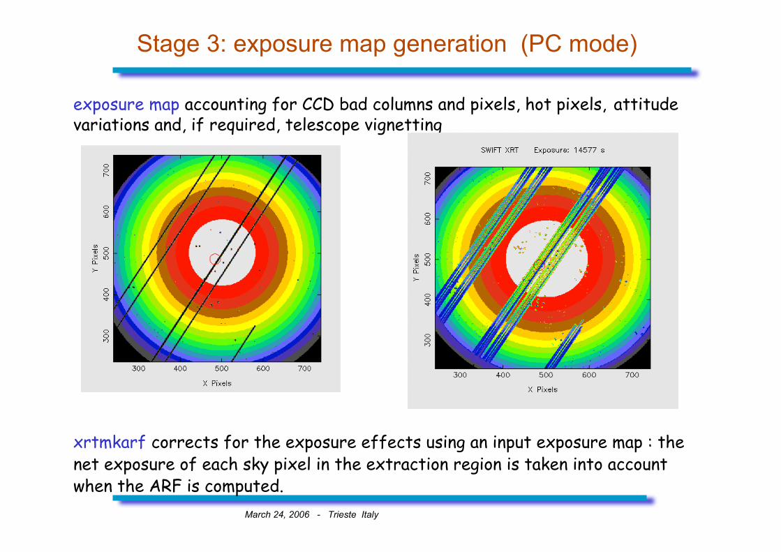
Stage 3: exposure map generation (PC mode)
exposure map accounting for CCD bad columns and pixels, hot pixels, attitudevariations and, if required, telescope vignetting
xrtmkarf corrects for the exposure effects using an input exposure map : thenet exposure of each sky pixel in the extraction region is taken into accountwhen the ARF is computed.

March 24, 2006 - Trieste Italy
How everything is tight together: xrtpipeline
Calibration, screening and products extraction are coded in the scriptxrtpipeline:
Timing Modes (PD & WT): Photon Counting Mode:xrthkproc xrtfilter
xrtfilter coordinator
xrtflagpix (WT only) xrtflagpix
xrtpdcorr (PD only) xrtpcgrade
xrttimetag xrtcalcpi
xrtevtrec xrthotpix
xrtcalcpi
xrtscreen Stage 2xrtscreen Stage 2 xrtproducts Stage 3
xrtproducts Stage 3
Imaging mode:
xrtimage
swiftxform
Stage 1
Stage 1
March 24, 2006 - Trieste Italy
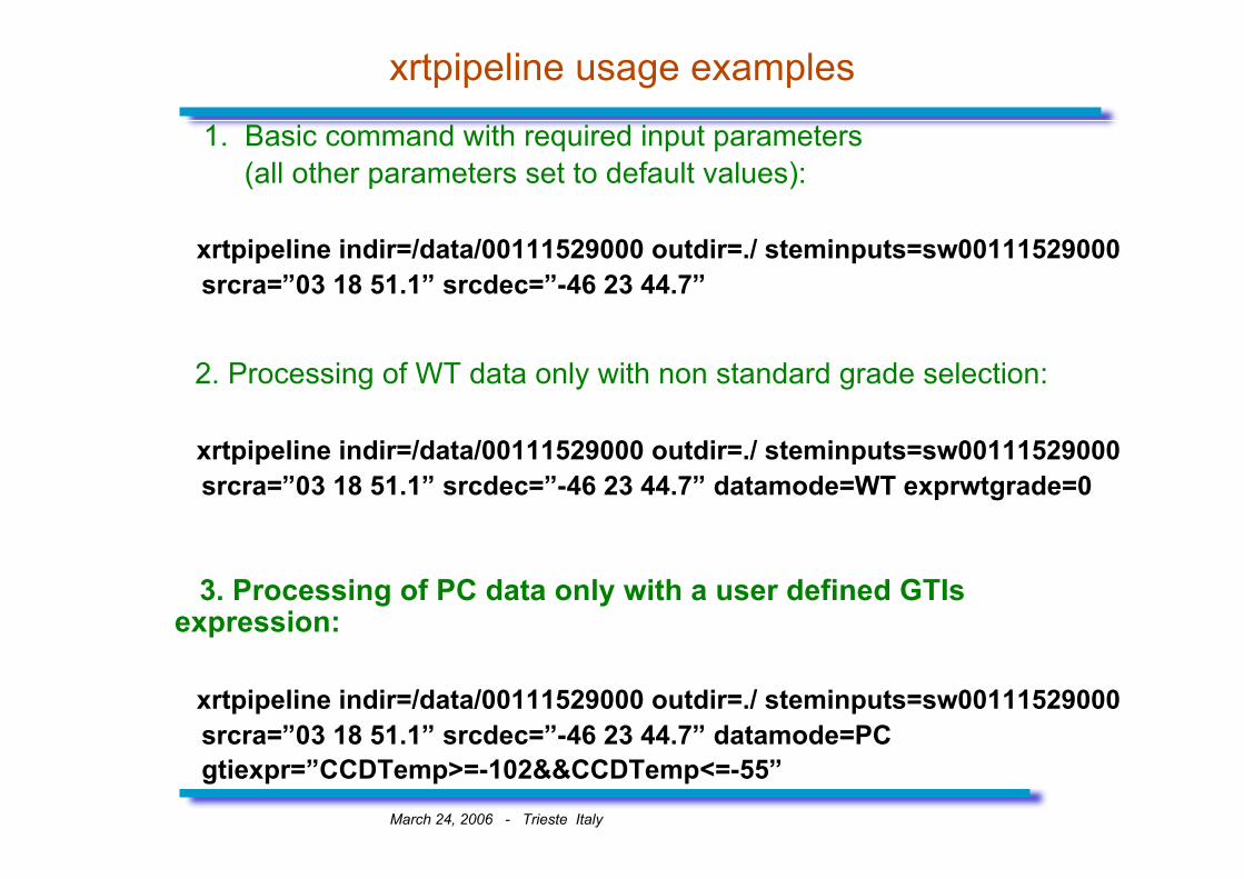
xrtpipeline usage examples
1. Basic command with required input parameters (all other parameters set to default values):
xrtpipeline indir=/data/00111529000 outdir=./ steminputs=sw00111529000 srcra=”03 18 51.1” srcdec=”-46 23 44.7”
2. Processing of WT data only with non standard grade selection:
xrtpipeline indir=/data/00111529000 outdir=./ steminputs=sw00111529000 srcra=”03 18 51.1” srcdec=”-46 23 44.7” datamode=WT exprwtgrade=0
3. Processing of PC data only with a user defined GTIsexpression:
xrtpipeline indir=/data/00111529000 outdir=./ steminputs=sw00111529000 srcra=”03 18 51.1” srcdec=”-46 23 44.7” datamode=PC gtiexpr=”CCDTemp>=-102&&CCDTemp<=-55”
March 24, 2006 Trieste - Italy
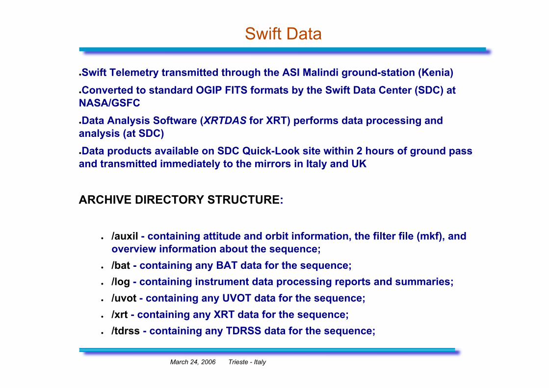
Swift Data
●Swift Telemetry transmitted through the ASI Malindi ground-station (Kenia)●Converted to standard OGIP FITS formats by the Swift Data Center (SDC) atNASA/GSFC●Data Analysis Software (XRTDAS for XRT) performs data processing andanalysis (at SDC)●Data products available on SDC Quick-Look site within 2 hours of ground passand transmitted immediately to the mirrors in Italy and UK
ARCHIVE DIRECTORY STRUCTURE:
● /auxil - containing attitude and orbit information, the filter file (mkf), andoverview information about the sequence;
● /bat - containing any BAT data for the sequence;● /log - containing instrument data processing reports and summaries;● /uvot - containing any UVOT data for the sequence;● /xrt - containing any XRT data for the sequence;● /tdrss - containing any TDRSS data for the sequence;

March 24, 2006 Trieste - Italy
Swift Quick Look Site
● The Quick Look site contains the more recentdata.
● After one week data are archived at HEASARC,ISAC-ASDC and UKDC.
March 24, 2006 Trieste - Italy
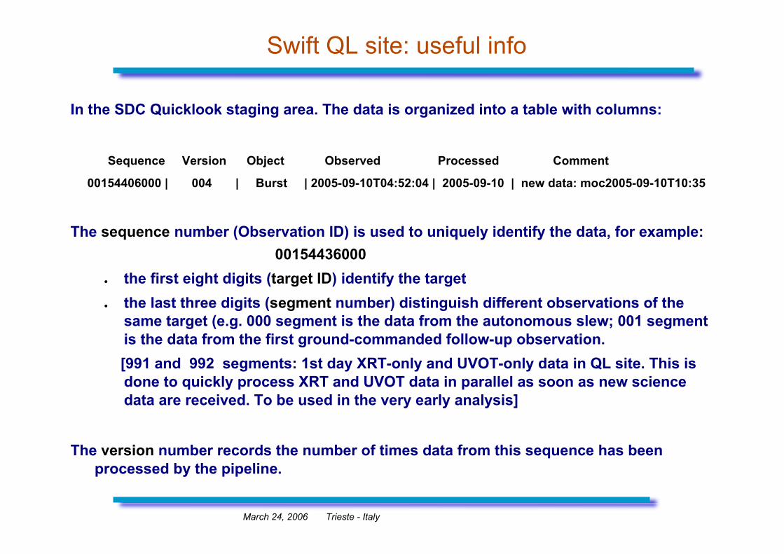
Swift QL site: useful info
In the SDC Quicklook staging area. The data is organized into a table with columns:
Sequence Version Object Observed Processed Comment
00154406000 | 004 | Burst | 2005-09-10T04:52:04 | 2005-09-10 | new data: moc2005-09-10T10:35
The sequence number (Observation ID) is used to uniquely identify the data, for example: 00154436000
● the first eight digits (target ID) identify the target● the last three digits (segment number) distinguish different observations of the
same target (e.g. 000 segment is the data from the autonomous slew; 001 segmentis the data from the first ground-commanded follow-up observation.
[991 and 992 segments: 1st day XRT-only and UVOT-only data in QL site. This isdone to quickly process XRT and UVOT data in parallel as soon as new sciencedata are received. To be used in the very early analysis]
The version number records the number of times data from this sequence has beenprocessed by the pipeline.

March 24, 2006 Trieste - Italy
Swift XRT File Naming convention
File name format for the Swift XRT science event files:
sw[obs_id]x[mm][ww][pp]_[lev].evt
[obs_id]: 11 digits number (target sequence)[mm]: XRT science mode (two character string, e.g. pc, wt)[ww]: window setting (e.g. w2 for 500x500 pixels PC
window)[pp]: satellite status (slew, settling or pointing phase)[lev]: file level (e.g. uf and cl for level 1 and 2)
Examples:sw00111529000xpcw2po_uf.evtsw00111529000xwtw2po_cl.evt
March 24, 2006 Trieste - Italy
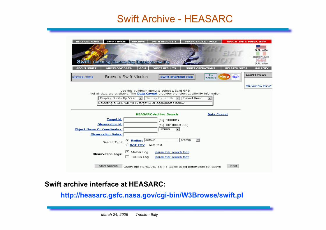
Swift Archive - HEASARC
Swift archive interface at HEASARC: http://heasarc.gsfc.nasa.gov/cgi-bin/W3Browse/swift.pl
March 24, 2006 Trieste - Italy
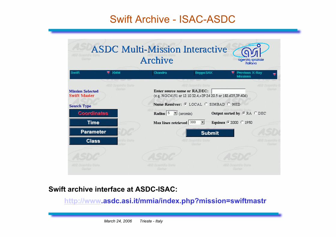
Swift Archive - ISAC-ASDC
Swift archive interface at ASDC-ISAC: http://www.asdc.asi.it/mmia/index.php?mission=swiftmastr
March 24, 2006 Trieste - Italy
Swift XRT data processing: demo
XRT data analysis session...
Related Documents