Swift Motorhome Owner's Handbook

Welcome message from author
This document is posted to help you gain knowledge. Please leave a comment to let me know what you think about it! Share it to your friends and learn new things together.
Transcript

Swift Motorhome Owner's Handbook

The pleasures of motorcaravanning
start with the motorhome you choose,
and you can’t make a better choice than
Swift.
The unique style of Swift makes them
leaders in the coachbuilt market, and
Chartered Trust are ideally placed to
help you. We have a wide choice of
motor finance programmes, each
designed to meet the varied needs of a
private or business motorist.
So, when it comes to motorcaravan-
ning, Chartered Trust can provide
the ideal combination.
Written quotations available on request.
THE IDEAL COMBINATION
24-26 Newport Road, Cardiff CF2 1SR
Telephone: (01222) 296863
THE IDEAL COMBINATION

Introduction
INTRODUCTIONDEAR OWNER
THANK YOU FOR DECIDING TO BUY ONEOF OUR NEW MOTORHOMES. WE ARESURE YOU WILL ENJOY MANY HAPPYHOURS IN IT AND WE HOPE THEINFORMATION AND HINTS IN THISHANDBOOK WILL HEIGHTEN YOURENJOYMENT.
THE HANDBOOK HAS BEEN DESIGNEDTO GIVE YOU A GENERAL GUIDE TO THECARE, USE AND MAINTENANCE OF YOURMOTORHOME. WHETHER YOU ARE ANEW OR AN EXPERIENCED MOTORHOMEUSER THE HINTS WILL HELP TO PROTECTYOUR INVESTMENT.
THE INFORMATION CONTAINED WILLANSWER MOST OF YOUR QUERIES, BUTIF THERE ARE ANY ASPECTS WHICH ARENOT COVERED PLEASE CONSULT YOURAPPOINTED DEALER.
HAPPY TOURING!
IMPORTANT - PLEASE QUOTE THEBODY SERIAL NUMBER & BASEVEHICLE CHASSIS NUMBER IN ALLCORRESPONDENCE WITH YOURDEALER OR SWIFT GROUP LIMITED.
All the illustrations and descriptive matter inthis handbook are intended to give a generalidea of the motorhome. Changing marketand supply situations may prevent us frommaintaining the exact specification details inthis handbook, we therefore reserve theright to alter specifications as materials andconditions demand.
Dealers are not agents of Swift GroupLimited and have absolutely no authority tobind Swift Group Limited by any express orimplied undertaking or representation.

CONTENTS
The Motorhome Code .................................................... 1
Preparing for the Road................................................... 5
‘En Route’ ........................................................................ 9
Safety & Security .......................................................... 11
Arrival at Site................................................................. 13
Connecting Services .................................................... 15
Electrical Systems ........................................................ 25
Equipment Details ........................................................ 31
Motorhome Care........................................................... 69
Useful Information ........................................................ 75
Index............................................................................... 79

THEMOTORHOME
CODE
Code of Conduct .............................................................................. 2
The Country Code ............................................................................ 4
The Coastal Code ............................................................................. 4
Motorhome Code
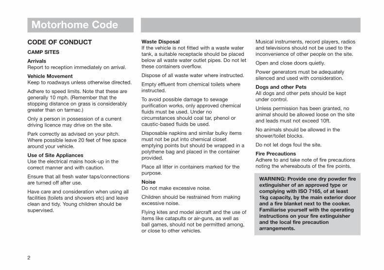
CODE OF CONDUCTCAMP SITES
ArrivalsReport to reception immediately on arrival.
Vehicle MovementKeep to roadways unless otherwise directed.
Adhere to speed limits. Note that these aregenerally 10 mph. (Remember that thestopping distance on grass is considerablygreater than on tarmac.)
Only a person in possession of a currentdriving licence may drive on the site.
Park correctly as advised on your pitch.Where possible leave 20 feet of free spacearound your vehicle.
Use of Site AppliancesUse the electrical mains hook-up in thecorrect manner and with caution.
Ensure that all fresh water taps/connectionsare turned off after use.
Have care and consideration when using allfacilities (toilets and showers etc) and leaveclean and tidy. Young children should besupervised.
Waste DisposalIf the vehicle is not fitted with a waste watertank, a suitable receptacle should be placedbelow all waste water outlet pipes. Do not letthese containers overflow.
Dispose of all waste water where instructed.
Empty effluent from chemical toilets whereinstructed.
To avoid possible damage to sewagepurification works, only approved chemicalfluids must be used. Under nocircumstances should coal tar, phenol orcaustic-based fluids be used.
Disposable napkins and similar bulky itemsmust not be put into chemical closetemptying points but should be wrapped in apolythene bag and placed in the containerprovided.
Place all litter in containers marked for thepurpose.
NoiseDo not make excessive noise.
Children should be restrained from makingexcessive noise.
Flying kites and model aircraft and the use ofitems like catapults or air-guns, as well asball games, should not be permitted among,or close to other vehicles.
Musical instruments, record players, radiosand televisions should not be used to theinconvenience of other people on the site.
Open and close doors quietly.
Power generators must be adequatelysilenced and used with consideration.
Dogs and other PetsAll dogs and other pets should be keptunder control.
Unless permission has been granted, noanimal should be allowed loose on the siteand leads must not exceed 10ft.
No animals should be allowed in theshower/toilet blocks.
Do not let dogs foul the site.
Fire PrecautionsAdhere to and take note of fire precautionsnoting the whereabouts of the fire points.
WARNING: Provide one dry powder fire extinguisher of an approved type or complying with ISO 7165, of at least 1kg capacity, by the main exterior door and a fire blanket next to the cooker. Familiarise yourself with the operating instructions on your fire extinguisher and the local fire precaution arrangements.
2

Motorhome CodeWhen using a dry powder extinguisher it issuggested that the motorhome be evacuateduntil the powder has settled, to avoidinhalation.
Unless permission has been granted,barbecues should not be used. If permissionis given, consideration should be given tothe annoyance that can be caused to otherusers of the site.
Open fires are not allowed.
Awnings and TentsAwnings and tents should only be usedwhen permission has been obtained.
When on grass and staying for more than afew days, the ground sheet and/or side flapsof awnings should be periodically raised inorder to avoid damage to the ground.
DepartureLeave the pitch clean and tidy.
On leaving, check out with reception payingthe required fees.
WILD CAMPING
Camping away from licensed sites, withoutthe permission from the land owner or hisagents, is not allowed in the UnitedKingdom.
When permission has been granted, allaspects of this Code should be adhered to.
On no account should:
(a) Litter be disposed of other than in the receptacles provided.
(b) Water be allowed to escape from the vehicle.
(c) Chemical toilets be emptied except into the disposal places agreed with the land owner.
(d) Washing or similar be hung outside the vehicle.
PARKING
Motorhomes should only be parked inapproved places.
When using the facilities of a motorhomecare and consideration should be given tothose around them.
DRIVING
When using a motorhome on either thepublic highway or private roads the HighwayCode should be complied with and fullconsideration given to other road users.
In the event of a motorhome travelling slowlythe driver of the motorhome should, wherepossible, pull over in order to let other trafficpass.
When the vehicle is in motion it iscompulsory for all front seat passengers towear seat belts and strongly recommendedfor rear seated passengers.
Before moving off, elevated roofs should belowered and correctly secured, and tophinged windows closed. Likewise all doorsand access lockers for gas containers andchemical toilets must be properly secured.
Exterior steps should be properly retractedand secured.
When the vehicle is being refuelled, or on aferry, all gas systems must be turned off.
HANDBOOK
Before using a motorhome all aspects of thehandbooks, produced by the chassismanufacturer and the converter, must beread and adhered to.
ENVIRONMENT
Care and consideration should be taken toprotect the environment.
Observe the Country and Coastal Codesshown overleaf.
3

Motorhome Code
THE COUNTRY CODEEnjoy the countryside but respect its life andwork.
More people than ever before are exploringthe countryside, interested in farming, plantlife, bird watching or just observing thegeneral wildlife. Whatever your interest, thereis a lot to learn, but please observe thefollowing code.
1. Guard against all risk of fires. Hay and heathland catch alight easily and once ablaze are very hard to put out.
REMEMBER: FIRE SPREADS QUICKLY.
2. Keep to the public paths across farmland.
3. Use gates and stiles to cross fences, hedges and walls.
4. Leave livestock, crops and machinery alone. View from a distance.
5. Take your litter home - it is unsightly and harmful to wildlife.
6. Help to keep all water clean.
7. Take special care on country roads.
8. Make no unnecessary noise. Most animals are very timid; noises can disturbthem unnecessarily. If you want to get thebest out of the country, go quietly.
THE COASTAL CODEAs our coastlines are increasingly used forrecreation and education, the followingsuggestions are made to enable us to enjoyour inheritance and preserve it for posterity.
Disturbance may mean DEATH.
DO NOT trample about, or move rocksunnecessarily.
DO NOT frighten seals or seabirds.
DO NOT spill detergents, solvents or fuelfrom boats as these can kill marine life.
When sailing, moderate your speed - thewash from a fast boat can destroy banksand nests.
Live molluscs and crustaceans need not becollected as souvenirs - dead shells canusually be found.
Shellfish can take years to grow and finescan be imposed for not observing nationalregulations.
DO NOT pull up seaweeds unnecessarily.
Make your visit instructive - not destructive.
Look at material - don’t remove it. Takenotes and photographs, not specimens.
Observe by-laws and be considerate toothers.
National Trust property and Country Parkshave regulations to protect the wildlife.Follow these and the Country and CoastalCodes.
4

PREPARINGFOR THE
ROAD
Before Moving Off .................................................................... 6
Loading of Vehicle .................................................................... 6
User Payload Allowance .......................................................... 6
Maximum Technically Permissible Laden Mass ................... 6
Roof Loading ............................................................................ 7
Tyres ............................................................................................7

Preparing for the Road
BEFORE MOVING OFFCheck:
- gas cylinders and all gas operated appliances have been isolated, including fridge, water heater, oven and space heater.
- loose articles are stowed securely. Do notstow tins, bottles or heavy items in overhead lockers.
- all lockers and cupboard doors are closed and secured.
- all bunks and ladders are secure. Place Luton ladder on its side in front of Luton bedboards.
- all rooflights are closed and secured.
- main table is stored in its transit position.
- fridge is on 12V operation and door lock is set.
- gas cylinders are correctly positioned, secured and turned off.
- battery selection switch is in the OFF position.
- tyre pressures and wheel nuts.
- rear corner steadies are raised.
- all drain taps are closed.
- 240V mains input socket flap is securely closed.
Special attention must be taken to ensure alltop hinged windows as well as the Lutonwindows are closed when in transit. All unitsshould be fully closed and latched to preventdamage. The motorhome exterior doorshould also be locked.
LOADING OF VEHICLECorrect weight distribution is an importantfactor in ensuring your vehicle is wellbalanced and easy to drive. It is thereforenecessary to load your motorhome carefullymaking sure all heavy articles are evenlydistributed and are preferably placed in thelower lockers or bed boxes.
Although it is essential to ensure that thetotal weight of your motorhome does notexceed the stipulated Maximum TechnicallyPermissible Laden Mass, (M.T.P.L.M.), it isimportant to remember that the front andrear axles also have individual maximumweights which must not be exceeded.
These weights, together with the M.T.P.L.M.,can be found on the Fiat/Peugeot/VW, theSwift Group or Al-Ko plates affixed to yourvehicle under the front edge of the bonnet.
WARNING: Isolate all gas appliances before moving off.
USER PAYLOAD ALLOWANCEThe User Payload (the weight of additionalitems such as personal effects, essentialhabitation equipment and optionalequipment, etc.) is calculated by deductingthe Mass in Running Order (manufacturer’sstandard vehicle specification weight) fromthe Maximum Technically Permissible LadenMass (manufacturer’s maximum authorisedweight).
NOTICE:Plese ensure you have allowed for themasses of all the items you intend to carry inyour motorhome.
MAXIMUM TECHNICALLYPERMISSIBLE LADEN MASSThis is the maximum legally allowable weightof the vehicle, fully laden, on the road.
See Specification pages for specific modelweights.
6
Preparing for the Road
ROOF LOADINGA maximum load of 200kgs can be evenlydistributed over the roof area. This figureMUST NOT be exceeded.
The roof areas, up to the over cab section,are capable of withstanding an averageperson’s weight (13 stone or 82.5kg).
Note: Do not walk on the over cab section.
Some motorhome roofs can be fitted with aroof rack (optional).
It is permitted to stand inside the roof rackfitted to the roof. The roof section beyondthe rack is not designed for walking on.
Note: When loading the roof rack, make surethe load is spread evenly and do not allowsharp objects to come into contact with theroof surface.
WARNING: When walking on the roof rack, deck type shoes should be worn - not leather soles.
TYRESThe law requires that the tyres and pressuresmust be suitable for the use to which theyare being put. The minimum tread depthmust be 1.6mm throughout a continuousband comprising the centre three-quarters ofthe breadth of the tread and around thecircumference of the tyre.
7
'EN ROUTE' Spare Wheel Removal ............................................................ 10

Fig.1
Fig.3
Fig.2
b
a b
Fig.4
'En Route'
REMOVAL OF SPARE WHEEL:Caution: Exercise care when lowering thewheel and frame due to its weight.
Removala) Spare wheel in the stowed position
(Fig. 1).
b) Remove the securing pins (a) from the supports (b) at each side of the spare wheel carrier frame (c) (Fig. 2).
c) Lift the wheel carrier frame (c) slightly and move the frame supports (b) forward and clear of the carrier frame (Fig. 3).
d) Lower the carrier frame and wheel to the ground (Fig. 4).
e) Remove the spare wheel.
ReplacementReplacement is a reversal of the removalprocedure.
Ensure the securing pins (a) are correctlylocated in the frame supports (b).
10
b
a
a
c
c

SAFETY & SECURITY
In Case of Fire ........................................................................ 12
Ventilation ............................................................................... 12
Security ................................................................................... 12

Safety & SecurityIMPORTANT: Your attention is drawn tothe notice affixed in your motorhomeadvising you on fire prevention, ventilationand what to do in case of a fire.
FIREIn case of fire1. Get everyone out of the motorhome as
quickly as possible using whichever exit is quickest including windows. Do not stop to collect any personal items.
2. Raise the alarm. Call the Fire Brigade.
3. Turn off gas supply valve, if safe to do so.
Fire Extinguishers (if fitted)It is recommended that a 1kg (2lb) minimumcapacity dry powder fire extinguishercomplying with the requirements of ISO 7165be carried inside your motorhome at alltimes and a fire blanket be kept next to thecooker.
A fat pan fire should not have anextinguisher aimed at it but be smotheredwith a fire blanket.
ChildrenDo not leave children alone in themotorhome in any event. Keep potentiallydangerous items out of reach as at home,e.g. matches, drugs, etc.
Escape PathsIt is important that you do not block escapepaths to emergency exits with obstructionsor hazzards.
VENTILATIONAll motorhomes are built to EN 721. Theventilation points on your motorhome arefixed points of ventilation which are statedby this standard. Under no circumstancesmust these vents be blocked or obstructed.
All ventilation levels are calculated to suiteach models requirements. There should beno modifications made which may result inreduced ventilation levels.
Ventilation is provided at low level by ventsfitted either to the furniture or in the entrancestep, and at high level by the roof lights.
It is advised that fixed ventilation points arechecked and cleaned (if necessary) on aregular basis with a small brush or a vacuumcleaner.
WARNING: NEVER use portable cooking or heating equipment other than electricheaters that are not of the direct radiant type, as it is a fire and asphyxiation hazard.
NEVER allow modification of electrical orLPG systems and appliances except byqualified tradesmen at a Swift Group Dealer
In the interests of safety, replacement partsfor an appliance should conform to theappliance manufacturers specification andshould be fitted by them or their authorisedagent.
Additional night time ventilation is obtained
on some windows by releasing the windowcatches and placing them in the secondgroove. Note the windows are not sealedfrom rain in this position.
WARNING: Do not obstruct ventilation
SECURITYMotorhome TheftThe theft of a motorhome can occur in themost unlikely circumstances; from a motor-way service area or even an owner’sdriveway.
Secure all windows and doors when yourmotorhome is unoccupied even if only for ashort length of time.
Chassis numberRecord your motorhome chassis number,which can be found under the bonnet, andthe body conversion serial number.
Make a note of these numbers in the spaceprovided at the rear of this handbook andmake a separate note of the numbers tokeep safe at home.
Additional securityWindow etching of the chassis number is acost effective deterrent.
Free crime prevention advice about securingyour motorhome, protecting your valuables,property marking either at home or whilst onsite, can be obtained from the CrimePrevention Officer through your local Policestation.
12
ARRIVAL AT SITE Positioning the Motorhome .................................................. 14
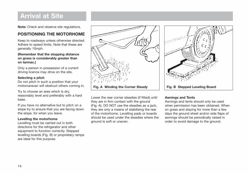
Fig. A Winding the Corner Steady Fig. B Stepped Leveling Board
Arrival at SiteNote: Check and observe site regulations.
POSITIONING THE MOTORHOMEKeep to roadways unless otherwise directed.Adhere to speed limits. Note that these aregenerally 10mph.
(Remember that the stopping distance on grass is considerably greater than on tarmac.)
Only a person in possession of a currentdriving licence may drive on the site.
Selecting a pitchDo not pitch in such a position that yourmotorcaravan will obstruct others coming in.
Try to choose an area which is dry,reasonably level and preferably with a hardbase.
If you have no alternative but to pitch on aslope try to ensure that you are facing downthe slope, for when you leave.
Levelling the motorhomeLevelling must be carried out in bothdirections for the refrigerator and otherequipment to function correctly. Steppedlevelling boards (Fig. B) or proprietary rampsare ideal for this purpose.
Lower the rear corner steadies (if fitted) untilthey are in firm contact with the ground (Fig. A). DO NOT use the steadies as a jack,they are only a means of stabilising the rearof the motorhome. Levelling pads or boardsshould be used under the steadies where theground is soft or uneven.
Awnings and TentsAwnings and tents should only be usedwhen permission has been obtained. Whenon grass and staying for more than a fewdays the ground sheet and/or side flaps ofawnings should be periodically raised inorder to avoid damage to the ground.
14

CONNECTINGSERVICES
Mains Socket/Water Connection .......................................... 16
Water System ......................................................................... 16
Gas ........................................................................................... 18
Types of Gas ........................................................................ 18
Safety Advice ....................................................................... 19
Electricity ................................................................................ 20
Overseas Connection ............................................................ 21
Wiring Diagram ....................................................................... 22
230V Mains Electrical Equipment Consumption ................. 23

Connecting ServicesConnection of services are dealt with underseparate headings. In all cases becomefamiliar with manufacturers’ instructions.
Before making connections of anydescription to the motorhome ensure ALL equipment is turned off.
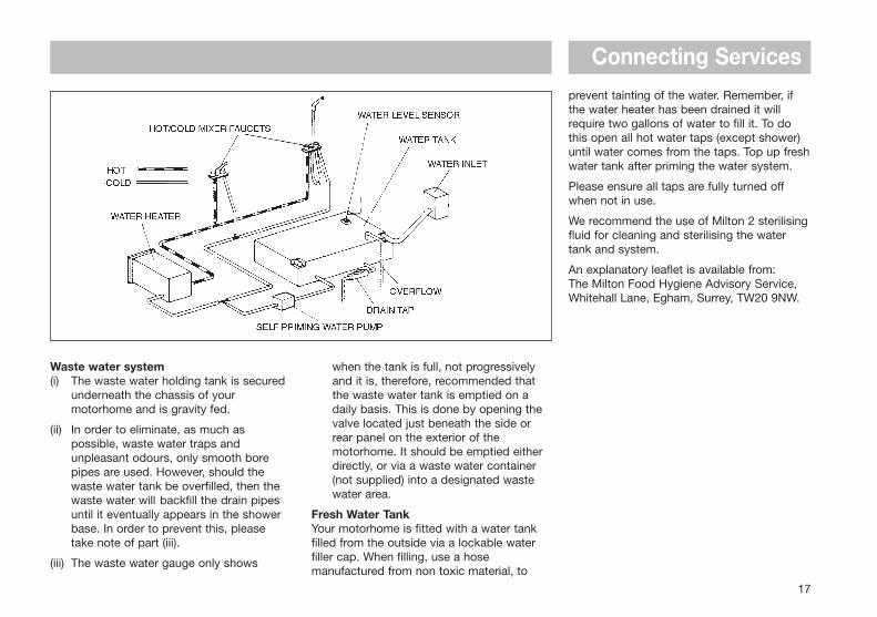
WATER SYSTEMFresh water system
(i) All fittings, including the holding tank, water pipes, taps and connections are of food quality material (to BS6920) and therefore, should not affect the quality of the water used. It is recommended however, that the system is flushed through twice before it is used for the first time, and always cleaned/flushed after it has stood unused for a period of time (eg over the winter period). Care hasbeen taken (using smooth bore pipes etc) to eliminate as many water traps as possible.
(ii) When filling the fresh water system remember to check that the water sourceis suitable for use as drinking water and, if you are using a hosepipe or water carrier, that it is also made from non-toxic materials (preferably food quality material).
(iii) The fresh water tank may be drained via a small tap located next to the water
16
Water Filler Inlet
SITE MAINSINPUT SOCKET
GAS BOTTLELOCKER
tank or via any one of the sink/shower taps through the normal waste water system.(iv) The fresh water system is pressurised by a pump which will continue to operate until it senses a pre-set pressure in the system.
WARNING:If the fresh water tank is completely empty the pump will be unable to pressurise the system and will operate continuously. In this situation it is essential that, in order to avoid damage to the pump, it is switched off using the pump isolator switch on the KT9M5 distribution panel until such time as the water tank has been filled.
Connecting Servicesprevent tainting of the water. Remember, ifthe water heater has been drained it willrequire two gallons of water to fill it. To dothis open all hot water taps (except shower)until water comes from the taps. Top up freshwater tank after priming the water system.
Please ensure all taps are fully turned offwhen not in use.
We recommend the use of Milton 2 sterilisingfluid for cleaning and sterilising the watertank and system.
An explanatory leaflet is available from: The Milton Food Hygiene Advisory Service,Whitehall Lane, Egham, Surrey, TW20 9NW.
17
Waste water system(i) The waste water holding tank is secured
underneath the chassis of your motorhome and is gravity fed.
(ii) In order to eliminate, as much as possible, waste water traps and unpleasant odours, only smooth bore pipes are used. However, should the waste water tank be overfilled, then the waste water will backfill the drain pipes until it eventually appears in the shower base. In order to prevent this, please take note of part (iii).
(iii) The waste water gauge only shows
when the tank is full, not progressively and it is, therefore, recommended that the waste water tank is emptied on a daily basis. This is done by opening the valve located just beneath the side or rear panel on the exterior of the motorhome. It should be emptied either directly, or via a waste water container (not supplied) into a designated waste water area.
Fresh Water TankYour motorhome is fitted with a water tankfilled from the outside via a lockable waterfiller cap. When filling, use a hosemanufactured from non toxic material, to

GASGENERAL INFORMATION
Gas BottlesBottled Liquidified Petroleum Gas (L.P.G.) isthe most convenient portable source of fuelfor your motorhome.
Make sure that heating, cooking appliancesand gas cylinders are switched off before youmove the motorhome.
Regularly check flexible gas hose, joints andconnections for tightness. Finally make surethat each gas appliance is working efficientlyto the recommendations of the appliancemanufacturers.
The gas bottle locker on your motorhome isdesigned to accommodate 4.5kg, 7kg or15kg Butane or 6kg or 13kg Propanecylinders.
The regulatorThe regulator (Fig. A) is a governing devicewhich adapts the bottle pressure to one thatsuits the equipment in the motorhome.
WARNING: Some industrial LPG appliances operate at high pressure and require a ‘high pressure’ regulator. This often has an adjusting handle on it. NEVER use such a regulator on a motorhome.
Note: Regulator valves should always beturned to the “OFF” position whilst themotorhome is being driven.
Propane and Butane gas regulators are notinterchangeable.
HosesHoses should be made from Neoprene andshould conform to BS 3212. Rubber hosingshould never be used. It is good practice toreplace hoses annually and in any case nolater than the expiration date marked on thehose. An approved hose clip is a worthwhileaddition to prevent accidental removal of thehose.
TYPES OF GAS
ButaneButane is supplied in the U.K. in green, blueor aluminium bottles.
All these have a male left hand threadEXCEPT for Camping Gaz which has aspecial female right hand thread and Calor,4.5kg, 7kg & 15kg, aluminium and 33lb/15kgbottles which have a special clip-onconnection.
Continental bottles usually have a male lefthand thread similar to but not identical withU.K. Butane.
Butane is suitable for use at temperaturesdown to 2˚C but will not work below that.
PropanePropane is supplied in red, or partly redbottles which have a female left handthreaded connector.
Scandinavian countries use the sameconnector.
Germany and Austria supply Propane with amale connection.
Propane will work at temperatures as low as -40˚C and is therefore suitable for all wintermotor caravanning.
Connecting Services
18
Fig. A Gas Regulators

Connecting Services
19
GAS SAFETY ADVICE
Facts about LPGLPG is not poisonous.
Bi-products are harmless.
There is danger if all air and oxygen areexcluded.
(Ventilation holes must be kept clear at alltimes).
LPG has been given a smell by themanufacturers in order to identify leaks.
Awning Spaces LPG Appliance ExhaustThere is no danger of pollution of anenclosed awning space by the LPG exhaustfrom a refrigerator venting into it.
Space heaters may produce sufficientexhaust to pollute the awning space, if it istotally enclosed, from a general comfort,smell and hygiene point of view. In extremecases there could be a build up of carbondioxide to a dangerous level.
Motorhome owners are advised to allowsome fresh air circulation in the awningspace when such appliances are in use.
PRECAUTIONS
a) Never look for a leak with a match. Always use a soap solution or its equivalent when testing connections. Do not operate any electrical apparatus whatsoever, especially light switches.
If the leak is not obvious, the motorhome should be evacuated and qualified personnel consulted.
b) Avoid naked lights when connecting or changing a cylinder.
c) Check the flexible hose frequently.
d) Gas is heavier than air and therefore sinks to the lowest point.
e) Keep bottle gas containers outside (and protected against frost). If they must be kept inside make sure they are well away from heat.
WARNING: If you smell gas or suspect a leak and if it is safe to do so, isolate the gas appliances and turn off the gas bottles at the regulator. Evacuate the motorhome and ventilate the vehicle. Seek professional advice as to the cause of the leak.
WARNING: Inspect flexible gas hose regularly for deterioration and renew as necessary, with the approved type, in any case not later than the expiry date marked on the hose. Flexible gas hose length should not exceed 400mm.
VentilationVents should not be obstructed in anymanner as this could lead to insufficientfresh air. In this case the confined
atmosphere becomes depleted of oxygenwhich leads to the formation of the highlypoisonous gas ‘carbon monoxide’. CarbonMonoxide is odourless, colourless andtasteless and will rapidly causeunconsciousness and death with little or nowarning prior to collapse.
THERE IS NO DANGER WHEN ADEQUATEVENTILATION IS PROVIDED.
Roof-mounted Flue InstallationsAll flue installations should be inspectedonce a year throughout their length forcorrosion. Flues should be replaced if anysign of perforation is found. Ensure that thereplacement is of an approved type.
ConnectionEnsure that the gas regulator is correctlyconnected to the gas cylinder in the gasbottle compartment and that the hose istight. Before turning on the gas supply,ensure that all gas operated equipment inthe motorhome is turned off.
Gas Tap ColoursAll gas equipment is supplied through a gasmanifold system which has individualisolation taps for each appliance as follows:
Red - Water HeaterWhite - Space HeaterGreen - Hob & Oven (combination)Green - Hob (separate)Yellow - Oven (separate)
ELECTRICITYAs with electricity in the home, care must beexercised when handling mains electricity.
Your attention is drawn to the followingnotice as laid down by the Institute ofElectrical Engineers.
INSTRUCTIONS FOR ELECTRICITYSUPPLY
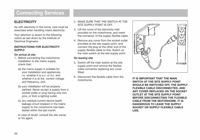
On arrival at site1. Before connecting the motorhome
installation to the mains supply, check that:
(a) the mains supply is suitable for your installation and appliances, i.e. whether it is a.c. or d.c. and whether it is at the correct voltage and frequency, and
(b) your installation will be properly earthed. Never accept a supply from asocket outlet or plug having only two pins, or from a lighting outlet.
(c) any residual current device (earth leakage circuit breaker) in the mains supply to the motorhome has been tested within the last month.
In case of doubt, consult the site owner or his agent.
2. MAKE SURE THAT THE SWITCH AT THE SITE SUPPLY POINT IS OFF.
3. Lift the cover of the electricity inlet provided on the motorhome, and insert the connector of the supply flexible cable.
4. Remove any cover from the socket outlet provided at the site supply point, and connect the plug at the other end of the supply flexible cable to this. Switch on the main switch at the site supply point.
On leaving site
5. Switch off the main switch at the site supply point and remove the flexible cable connector replacing any cover fitted.
6. Disconnect the flexible cable from the motorhome.
IT IS IMPORTANT THAT THE MAINSWITCH AT THE SITE SUPPLY POINTSHOULD BE SWITCHED OFF, THE SUPPLYFLEXIBLE CABLE DISCONNECTED, ANDANY COVER REPLACED ON THE SOCKETOUTLET AT THE SITE SUPPLY POINTBEFORE DISCONNECTING THE FLEXIBLECABLE FROM THE MOTORHOME. IT ISDANGEROUS TO LEAVE THE SUPPLYSOCKET OR SUPPLY FLEXIBLE CABLELIVE.
Connecting Services
20

Connecting Services
21
For motorhomes that are generally leftunused for long periods in the open it isstrongly advised that the mains installation isinspected periodically to ensure that it issafe to use. The IEE Wiring Regulationsrecommend that mains installations inmotorhomes are re-inspected every 3 years.An annual inspection by a qualified person isrecommended (see list below) who shouldsign and issue a periodic inspection report.
Suitably qualified persons acceptable to theSMMT/NCC to sign and issue Inspectionand Completion Certificates should be oneof the following:
• An approved contractor of the National Inspection Council for Electrical Installation Contracting* or
• A member of the Electrical Contractors’ Association of Scotland
• A qualified person acting on behalf of the above (in which event it should be stated for whom he is acting).
* The names and addresses of Approved Contractors in any locality (there are over 10,500 in the UK) can be obtained from Electricity Shops, or direct from:
NICEICVintage House37 Albert EmbankmentLondon SE1 7UJTelephone: 0171 582 7746
The names and addresses of members ofthe Electrical Contractors’ Associations canbe obtained direct from:
ECAEsca HousePalace CourtLondon W2 4HYTelephone: 0171 229 1266
ECA of Scotland23 Heriot RowEdinburgh EH3 6EWTelephone: 0131 225 7221
IN CASE OF DIFFICULTY CONSULT ANAPPROVED ELECTRICAL INSTALLATIONCONTRACTOR (WHO MAY BE THELOCAL ELECTRICITY COMPANY). IT ISDANGEROUS TO ATTEMPTMODIFICATIONS AND ADDITIONSYOURSELF. LAMPHOLDER-PLUGS(BAYONET CAP ADAPTORS) SHOULDNOT, IN ANY CIRCUMSTANCES, BEUSED.
OVERSEAS CONNECTIONNote: Connection to a mains voltage supplyOVERSEAS requires particular attention.
Care must be taken when connectingsupplies abroad since the supplies can be ofREVERSE POLARITY.
The significance of REVERSE POLARITY isthat when equipment is switched off it maynot be electrically isolated.
The only certain way of making equipmentsafe is to unplug it.
If electrical polarity indication is not includedin your motorhome electrical equipment, it isuseful to have a means of checking polarityof the mains supply, especially when touringoverseas.
There are available several proprietary makesof equipment for the purpose.
If it can be achieved, it is preferable toconnect live to live, and neutral to neutral tomaintain full electrical protection.
CHECK all motorhome equipment is set-upto accept the site supply before actuallyswitching on.

Connecting Services
WIRING OF CONNECTING CABLE AND MOTORHOME MAINS INLET
WARNINGIT IS ESSENTIAL THAT CONNECTIONS ARE MADE EXACTLY AS SHOWN. IF TERMINAL MARKINGS ARE NOT IN ACCORDANCE
WITH THE DIAGRAM THEY MUST BE IGNORED. IF IN DOUBT CONSULT A QUALIFIED ELECTRICIAN.THE LEGAL MAXIMUM LENGTH OF THE MAINS INLET CABLE IS 25 METRES. WHEN IN USE IT MUST BE FULLY UNCOILED.
22
MOTORHOME MAINS INLETCABLE COUPLER

Connecting Services
23
230V MAINS ELECTRICALEQUIPMENT POWERCONSUMPTIONPlease note:It is possible that the 230V mains electricalequipment may not all operatesimultaneously. A typical UK motorhome sitemains hook up point provides a maximumoutput of 10 amps and on some continentalsites the available output may be as low as 5amps. If your loading exceeds the sitesupply it may trip the site circuit breaker.Please check the available mains output withyour site operator.
The following items need to be addedtogether if used simultaneously.
230V Mains equipment typicalconsumption figures:
Carver Cascade 2 water heater 3.6A approx.
Travelling kettle 3.2A approx.
Battery charger 1.0A approx.
Portable colour TV 0.3A approx.
60w light bulb 0.3A approx.
Fanmaster on position 4 8.3A approx.
Fanmaster on position 2 or 3 4.2A approx.
THERMAL INSULATION ANDHEATINGYour motorhome has been designed toachieve a thermal insulation and heatinglevel for specific climatic conditions. Theclassifications are as follows:
Grade 1A motorhome with an average thermaltransmittance (u) that does not exceed1.7w/(m2K).
Grade 2A motorhome with an average thermaltransmittance (u) that does not exceed1.7w/(m2K) and which can achieve anaverage temperature difference of at least20K between inside and ousidetemperatures when the outside temperatureis 0°C.
Grade 3A motorhome with an average thermaltransmittance (u) that does not exceed1.2w/(m2K) and which can achieve anaverage temperature difference of at least35K between inside and ousidetemperatures when the outside temperatureis -15°C.

ELECTRICALSYSTEMS
Motorhome Battery ................................................................ 26
Fault Finding ........................................................................... 26
Mains Unit (CEC 225) ............................................................. 27
12V Power System ................................................................. 28
Transformer/Charger Unit KT12SM ...................................... 28
KT9M5 Distribution Panels .................................................... 29
Operation ............................................................................. 29
Fuses .................................................................................... 29
Generator Guidelines ............................................................. 30

Electrical Systems
26
MOTORHOME BATTERY
It is recommended that a good qualityleisure battery is always in circuit when thesystem is in use.
A deep cycling heavy duty 12V batteryshould be used to provide power for lightsand other electrical appliances. A proprietarybrand leisure battery with either a 60, 75 or90A capacity is recommended. (It must havetube venting capability for internal batteryboxes.)
It should be remembered that batteriessuitable for the electrical demands of amotorhome differ in design from those foruse with a car, and whilst the system mayoperate with a car battery, it is stronglyrecommended that only a leisure typebattery, maintained in good condition isused.
The battery should be vented to the outsideand should be properly secured. Whenconnecting the battery, ensure that thecorrect polarity is observed (black isnegative and red is positive), and that theterminals are securely fastened.
Under normal circumstances it should not benecessary to remove the battery other thanfor routine inspection of terminals.
WARNING: Explosive gases may be present at battery - prevent flames and sparks.
Do not store highly flammable materials or pressurised containers in this area.
WARNING: Smoking is prohibited around the battery compartment
Your motorhome has been fitted with an in-line fuse next to the + battery terminal. It isrecommended that the rating of the fusefitted in this location does not exceed 20A.
Where a second battery is factory suppliedplease note that this is NOT charged.
When fitting the battery, ensure that thecorrect polarity is observed and thatterminals are securely fastened.
Ensure the battery is secured with the strapprovided.
FAULT FINDING
1. Mains supplyIf mains supply is not available when mains switch and MCB’s are switched on, check supply at site distribution and/or mains lead and connections.
2. Earth faults or MCB trippedSee RCD/MCD Section.
3. Charger switch fails to illuminateCheck mains supply as for No.1 and 2.
4. Battery discharged or not charging with charger onCheck battery terminals.
5. 12V distribution circuit failureCheck and replace relevant DC output fuse as required.
6. Consult the manufacturers regarding any further difficulties, in particular those related to mains voltage section.
7. There are no user-serviceable or replacement parts in the PMS. All service of this nature should be referred to the manufacturers.
Note: Never use a mains supply lead whilstcoiled. Always uncoil the full length beforeconnecting to the supply and remember toprotect the cable from traffic.
PLUG-IN-SYSTEMS LIMITED PROVIDE AN ON-CALL SERVICE FOR WARRANTYOR NON-WARRANTY REPAIRS.
IF YOU WISH TO TAKE ADVANTAGE OFTHIS SERVICE FOR PLUG-IN-SYSTEMSEQUIPMENT ONLY:
Telephone: (01482) 652523 and ask forPRODUCT SUPPORT SERVICE.

Electrical Systems
If an earth fault develops or a person touchesa live piece of equipment the leakage ofcurrent to earth should immediately operatethe RCD (residual current device) and ‘trip’the main switch, to the OFF position.
This switch is only re-settable afterelimination of the fault.
To re-set, operate the switch as for MCB’s.
Periodically the RCD should be checked byoperating the test button marked ‘T’. The unitshould immediately switch to the OFFposition. If the unit does not switch off then aqualified electrician should be consulted.
MAINS UNIT (CEC 225)This acts as the main switch for themotorhome allowing isolation of all circuits. Itforms part of the Power System along withthe KT12SM Transformer/Charger Unit (iffitted).
The mains unit replaces the conventionalfusebox. Similar, but larger ones are oftenfitted in new houses.
The unit gives both overload (MCBs) andearth leakage protection (RCD) for theelectrical supply in your motorhome.
For normal operation all switches on the unitneed to be in the ON position. The switcheson the left of the unit are known as MCBs(miniature circuit breakers).
These take the place of the conventional fusebut are more convenient.
Note: Having too many appliances switchedon at the same time will trip the MCBs. Thisis a safety measure. (For appliance ratings,see mains consumption, below).
In the event of a fault the MCB ‘trips’ i.e.automatically moves to the OFF position.
After elimination of the fault the MCB can bere-set by switching to the ON position,(against the spring pressure in an upwardsdirection).
If the unit does switch off, the test iscomplete and the switch can be re-setrestoring the supply back to normal.
Add together the current ratings for eachelectrical appliance you wish to usesimultaneously and ensure the total does notexceed 10A. You will find the following tablea useful guide to typical values.
220/240V MAINS CONSUMPTION
FRIDGE 0.5A
CHARGER 0.5A
WATER HEATER 2.75A
Formula for calculating current consumptionof appliances:
Watts
Volts = Amps
27
M.C.B
TestButton
MainsSwitch
KT12SM
Electrical Systems
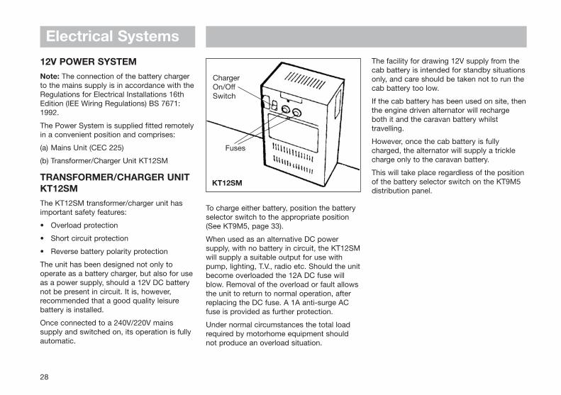
12V POWER SYSTEMNote: The connection of the battery chargerto the mains supply is in accordance with theRegulations for Electrical Installations 16thEdition (IEE Wiring Regulations) BS 7671:1992.
The Power System is supplied fitted remotelyin a convenient position and comprises:
(a) Mains Unit (CEC 225)
(b) Transformer/Charger Unit KT12SM
TRANSFORMER/CHARGER UNITKT12SMThe KT12SM transformer/charger unit hasimportant safety features:
• Overload protection
• Short circuit protection
• Reverse battery polarity protection
The unit has been designed not only tooperate as a battery charger, but also for useas a power supply, should a 12V DC batterynot be present in circuit. It is, however,recommended that a good quality leisurebattery is installed.
Once connected to a 240V/220V mainssupply and switched on, its operation is fullyautomatic.
The facility for drawing 12V supply from thecab battery is intended for standby situationsonly, and care should be taken not to run thecab battery too low.
If the cab battery has been used on site, thenthe engine driven alternator will rechargeboth it and the caravan battery whilsttravelling.
However, once the cab battery is fullycharged, the alternator will supply a tricklecharge only to the caravan battery.
This will take place regardless of the positionof the battery selector switch on the KT9M5distribution panel.
To charge either battery, position the batteryselector switch to the appropriate position(See KT9M5, page 33).
When used as an alternative DC powersupply, with no battery in circuit, the KT12SMwill supply a suitable output for use withpump, lighting, T.V., radio etc. Should the unitbecome overloaded the 12A DC fuse willblow. Removal of the overload or fault allowsthe unit to return to normal operation, afterreplacing the DC fuse. A 1A anti-surge ACfuse is provided as further protection.
Under normal circumstances the total loadrequired by motorhome equipment shouldnot produce an overload situation.
28
ChargerOn/OffSwitch
Fuses

Electrical Systems
29
KT9M5
KT9M5 DISTRIBUTION PANELThe 12V distribution panels have thefollowing facilities:
1. Battery Condition Indicator
2. Battery Selector Switch
3. Water Level Indicator
4. Water Level Selector Switch
5. Pump Isolation Switch
OPERATION
Battery Condition Indicator and SelectorSwitch
1. Select supply from either MOTORHOME AUXILIARY or CAB battery by use of the 3position switch.
2. Switch 240V charger off. Check that the meter-needle moves into the yellow or green sectors of the scale, indicating satisfactory state of battery charge. Red sector indicates charging is required.
12V DC power is now distributed to allcircuits.
If the central OFF position is selected, bothMOTORHOME AUXILIARY and CAB batterysupplies are switched off. If however, mainssupply is connected, a 12V supply will still beavailable direct from the transformer/chargerunit.
FUSES
Each 12V circuit is protected by a blade fuseof the appropriate rating. These fuses can befound in the PMS4 unit or in the fuse-block inthe wardrobe. The refrigerator fuse ismounted under the bonnet in all models.
If it is necessary to replace a fuse the currentrating, which is marked on the fuse end cap,must be STRICTLY observed.
Should a replacement fuse blow immediatelyafter fitting, under NO CIRCUMSTANCESshould it be replaced again without firstinvestigating the cause of the problem.
WARNING: Do not start your motor-home engine if the mains supply is connected. If the engine is started with KT12SM/PMS4 switched on and the KT9M5 switched to CAB then the output fuse will blow on the KT12SM/PMS4.
Water Level Indicator and Selector Switch
1. Select supply from either MOTORHOME AUXILIARY or CAB battery by use of the 3position switch.
2. Move the water level selector switch to the right or down to obtain a reading on the level indicator of the contents of the waste water tank (when fitted). The gauge only shows when the tank is full.
3. Move the selector switch to the left or up to obtain a reading of the contents of the fresh water tank.
4. The central OFF position isolates both water level sensors, and no reading will beshown on the indicator.

Electrical Systems
GENERATOR GUIDELINES• Lack of regular servicing can be the
cause of most generator problems, gensets under 2kW are mainly dependenton engine speed for output frequency and voltage. Poor or no servicing may cause the engine speed governor to run the genset engine too fast. Therefore, frequency and output voltage can rise above the specification of the machine data plate i.e. 240V at 50Hz. This may cause damage to electrical/electronic equipment (such as battery chargers).
• A generator should always run for a few minutes prior to connection with the motorhome electrics, to allow it to warm up and the output to settle to a steady level.
• The AC output of generators is often derived from an AC alternator, rectified to DC then inverted back to AC. In essence this means the output sinewave may not be very smooth and may not run sophisticated electronics efficiently. Someof the new wave of gensets are more sophisticated in their production of a sinewave output and are more suited to run electronic equipment.
• If in doubt consult your genset dealer or manufacturer for advice.
30

EQUIPMENTDETAILS
Water Pump (Shurflo) ............................................................. 32Water Pump (Whale) .............................................................. 32Cascade 2GE Water Heater .................................................. 32Carver P4 Blown Air Heating ................................................ 33Refrigerators ........................................................................... 34
Model RM4361 ..................................................................... 34Model RM4201 ..................................................................... 35Model RM4200 and RM4262 ............................................... 36Model RM4401...................................................................... 37Model RM4505 ..................................................................... 38Model RM4291.......................................................................41Travel Catches ..................................................................... 42
Stoves Combination Oven ..................................................... 43Stoves 8000/9000 Cooker ...................................................... 44Stoves Vanette Hob & Grill .................................................... 46Cramer Hob...............................................................................47Thetford Cassette C-200 ........................................................49Thetford Cassette Porta Potti ............................................... 52Heating .................................................................................... 56
Trumatic C3400 & C6000 ..................................................... 56Carver Space Heaters ......................................................... 59Carver 2000P, A & Fanmaster ............................................. 59Carver 4000P, A & Fanmaster ...............................................62
Butterfly Outlets ......................................................................64Side Locker ............................................................................. 64Front Swivel Seat ................................................................... 64Bedding ................................................................................... 65Tables ...................................................................................... 65Rooflights & Windows..............................................................66Ash Framed Doors ...................................................................67Shower.......................................................................................67

TO OPERATE THE HEATER ON GAS
1. CHECK that the gas and 12V D.C. electrical supplies have been connected and turned on.
2. SWITCH THE WATER HEATER ON at the wall switch. The green light will come on and remain on.
3. THE GREEN LIGHT indicates that the heater is operating satisfactorily and does not refer directly to the burner operation.
4. THE YELLOW AND GREEN LIGHTS on together indicate that the voltage of the power supply to the heater is too low. Theheater is automatically switched off until the voltage is high enough.
5. THE RED AND GREEN LIGHTS on together show that the burner has failed to light in the 10 second ignition period. This is usually due to failure of the gas supply or, in the case of a new installation,air in the gas pipes. Switch off and on again, which resets the controller and initiates a new ignition sequence. To clear air from the gas lines, several repetitions may be required.
Equipment DetailsIMPORTANT
To maximise the use and life of all fittedequipment in your motorhome it is essentialthat any accompanying manufacturers’literature is read fully. All recommendedmaintenance and preparation proceduresshould be followed. The information providedin this handbook is only intended as a guide.If in any doubt consult your Swift Groupappointed dealer, particularly beforeattempting to install EXTRA EQUIPMENT.
SHURFLO WATER PUMPThis pump is a completely sealed unitdesigned for intermittent use and is self-priming.
WHALE WATER PUMPThe Whale pump is a non self primingintermittently rated centrifugal pump whichdraws approximately two amperes from a 12V battery and therefore maximumcontinuous operation should not exceed 15minutes.
The pump should not run without water andshould not be used to pump water of atemperature above 60°C.
CASCADE 2 GE WATER HEATEROPERATING INSTRUCTIONS
The Cascade Water Heater must not beswitched on until water flows from the hotwater taps which indicates the water heateris full.
The Cascade Water Heater should not beused on BATTERY CHARGER ONLY (i.e.without a 12V battery in circuit) as this maycause the heater to operate incorrectly.
Under no circumstances connect TheCascade Water Heater directly to a mainswater supply.
32
GREEN
YELLOW
RED
'OFF' SWITCH 'ON' SWITCH
that any snow is cleaned off the side of the vehicle on which the terminals are mounted.
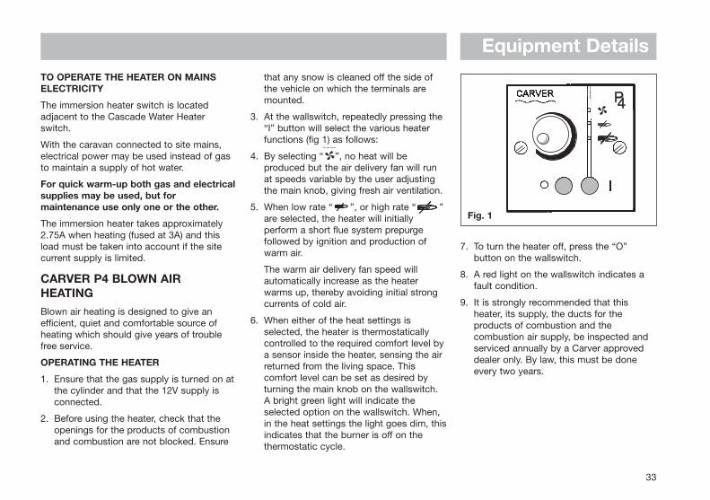
3. At the wallswitch, repeatedly pressing the “I” button will select the various heater functions (fig 1) as follows:
4. By selecting “ ”, no heat will be produced but the air delivery fan will run at speeds variable by the user adjusting the main knob, giving fresh air ventilation.
5. When low rate “ ”, or high rate “ ” are selected, the heater will initially perform a short flue system prepurge followed by ignition and production of warm air.
The warm air delivery fan speed will automatically increase as the heater warms up, thereby avoiding initial strong currents of cold air.
6. When either of the heat settings is selected, the heater is thermostatically controlled to the required comfort level bya sensor inside the heater, sensing the air returned from the living space. This comfort level can be set as desired by turning the main knob on the wallswitch. A bright green light will indicate the selected option on the wallswitch. When, in the heat settings the light goes dim, thisindicates that the burner is off on the thermostatic cycle.
Equipment Details
33
7. To turn the heater off, press the “O” button on the wallswitch.
8. A red light on the wallswitch indicates a fault condition.
9. It is strongly recommended that this heater, its supply, the ducts for the products of combustion and the combustion air supply, be inspected and serviced annually by a Carver approved dealer only. By law, this must be done every two years.
TO OPERATE THE HEATER ON MAINSELECTRICITY
The immersion heater switch is locatedadjacent to the Cascade Water Heaterswitch.
With the caravan connected to site mains,electrical power may be used instead of gasto maintain a supply of hot water.
For quick warm-up both gas and electricalsupplies may be used, but formaintenance use only one or the other.
The immersion heater takes approximately2.75A when heating (fused at 3A) and thisload must be taken into account if the sitecurrent supply is limited.
CARVER P4 BLOWN AIRHEATINGBlown air heating is designed to give anefficient, quiet and comfortable source ofheating which should give years of troublefree service.
OPERATING THE HEATER
1. Ensure that the gas supply is turned on atthe cylinder and that the 12V supply is connected.
2. Before using the heater, check that the openings for the products of combustion and combustion are not blocked. Ensure
Fig. 1
Equipment Details
REFRIGERATORSBefore using your refrigerator for the firsttime, it is advisable to wash the interior andits accessories.
When using the refrigerator on gas ensurethat the gas isolation tap is fully open byturning the knob to the vertical position. Thetap is located inside the sink unit at floorheight. When travelling the fridge can only beoperated in the 12V mode.
The current drain is approximately 9A andpower is only available when the ignitioncircuit is switched on. On site, only themains electric or gas modes should be used.
The refrigerator can run on either 240V, 12Vor LP gas. Changing between these modesof operation is carried out by means of thecontrols on the control panel.
Caution: Only use one source of energy at a time.
After initial installation, servicing or changinggas cylinders etc., the gas lines may containsome air which should be allowed to escapeby briefly turning on the refrigerator or otherappliances. This will ensure that the flamelights immediately.
The flame failure device will automaticallyshut off the gas to the burner if the flame isblown out. On electric ignition versions, the
flame failure device will also shut off the gasif the burner does not re-light within about aminute of the flame being blown out.
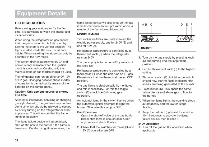
MODEL RM4361
Two rocker switches are used to select theelectric power supply, one for 240V (B) andone for 12V (A).
Refrigerator temperature is controlled by athermostat knob (C) when the refrigeratorruns on 240V.
The gas supply is turned on/off by means ofthe knob (D).
Refrigerator temperature is controlled by athermostat (E) when the unit runs on LP gas.Please note that the thermostat has no OFFposition.
The gas flame is electronically lit, monitoredand relit if necessary. For this the toggleswitch (F) should be ON during gasoperation.
An indicator lamp in the switch flashes whenthe automatic igniter attempts to light theburner. Otherwise this lamp is OFF.
Gas Operation1. Open the shut-off valve of the gas bottle
(check that there is enough gas). Open any on-board shut-off valve.
2. Check that the switches for mains (B) and12V (A) operation are OFF.
3. Turn on the gas supply by pressing knob (D) and turning it to the large flame position.
4. Set the thermostat knob (E) to the highest setting.
5. Throw on switch (F). A light in the switch should now start to flash, indicating that sparks are being generated at the burner.
6. Press button (D). This opens the flame failure device and allows gas to flow to the burner.
7. When the flame lights, the sparking stops automatically and the switch stops flashing.
8. Keep the button (D) pressed for a further 10–15 seconds to activate the flame failure device, then release it.
240V Operation1. Turn off the gas or 12V operation when
applicable.
34
RM4361
A B C D E F

Equipment Details
35
2. Turn knob (C) of the thermostat to its highest (coldest) position.
3. Set switch (B) to position I. The switch will light up green when the power supplyis connected.
12V OperationOnly operate your refrigerator on 12V whenthe engine of the vehicle is running -otherwise your battery will soon becomedischarged.
1. If applicable, turn off the gas operation.
2. Set the 12V rocker switch (A) to I. The switch will light up red when the power supply is connected.
WARNING:When in transit, your refrigerator should berun on 12V and NOT on gas.
Regulating the TemperatureIt will take a few hours for the refrigerator toreach normal operating temperature, so it issuggested to start the refrigerator well inadvance of a journey and, if possible, tostore it with pre-cooled foodstuffs.
On 240V operation the refrigerator iscontrolled by a thermostat knob (C) and thisshould be set at 3–5. If a lower (colder)temperature is desired, set the thermostat toa higher figure.
On 12V operation the refrigerator workscontinuously.
On LP gas operation the refrigeratortemperature is regulated by the gasthermostat (E) which should be set at 3–5. Ifa lower (colder) temperature is desired, setthe thermostat to a higher figure.
Caution: Only use one source of energy at a time.
MODEL RM4201
LP Gas Operation1. Open the shut-off valve of the gas bottle
(check that there is enough gas). Open any on-board shut-off valve.
2. Check that the switches for mains (B) and12V (A) operation are OFF.
3. Turn the gas control (D) to position ‘max’.
4. Turn on the electric igniter (E). A ticking sound will be heard and a lamp in the switch will start flashing.
5. Depress the knob (D) of the flame failure device.
6. When the lamp stops flashing the flame isalight.
7. Keep the flame failure knob (D) depressedfor a further 10–15 seconds.
8. Check that the flame remains alight by viewing through glass in the refrigerator.
9. To terminate gas operation, turn knob (D) to the OFF position. Set switch (E) to OFF.
240V Operation1. Turn off gas or 12V operation when
applicable.
2. Turn the knob (C) of the thermostat to its highest (coldest) position.
3. Set switch (B) to position I.
12V OperationOnly operate your refrigerator on 12V whenthe engine of the vehicle is running -otherwise your battery will soon bedischarged.
1. If applicable, turn off the gas operation.
2. Set the 12V rocker switch (A) to I.
Regulating the TemperatureIt will take a few hours for the refrigerator toreach normal operating temperature, so it issuggested that the refrigerator be startedwell in advance of a journey and, if possible,to store it with pre-cooled foodstuffs.
RM4201
A B C D E

Equipment DetailsOn 240V operation the refrigerator iscontrolled by a thermostat knob (C) and thisshould be set at 3–5. If a lower (colder)temperature is desired, set the thermostat toa higher figure.
On 12V operation the refrigerator workscontinuously.
LP gas operation should always be initiatedwith the knob (D) at the ‘max’ position. Oncethe refrigerator is running, the temperature is controlled by turning the control knobbetween ‘max’, ‘mid’ and ‘min’ settings -‘max’ being the coldest temperature.
5. Check the flame viewer (located bottom left of refrigerator) to see if the flame is alight.
6. Keep the safety device control knob depressed for a further 15–30 seconds.
7. Release the safety device control knob and again check to see that the flame is alight.
8. To terminate gas operation, turn knob (D) to ‘O’.
ELECTRIC OPERATION
240V Operation
1. Turn off gas or 12V operation when applicable.
2. Turn the knob (C) of the thermostat to its highest (coldest) position.
3. Set switch (B) to position I.
12V Operation
There is no thermostat control on 12Voperation.
Only operate your refrigerator on 12Vwhen the engine of your vehicle is running.
Note: Before operating the refrigerator on12V it should be pre-cooled, together withits contents, by running it on bottled gasor 240V for a few hours before changingover to 12V and starting on a journey.
MODEL RM4200 & RM4262
Bottled Gas Operation - Lighting theburner
1. Open the shut-off valve of the gas bottle (check that there is enough gas). Open any on-board shut-off valve.
2. Check that the switches for mains and 12V are off.
3. Depress and turn on the gas control safety device knob (D) to the large flame symbol.
4. Depress the gas control safety device knob (D) and hold it down while depressing the piezo-electric igniter button (E) rapidly 3 or 4 times in quick succession.
36
Flame Viewing Glass
Fig. A Control Panel - RM420 & RM4262
A B C D E

Equipment Details
37
1. If applicable, turn off the gas operation.
2. Set the 240V rocker switch (B) to ‘O’ and the 12V rocker switch (A) to 1.
Regulating the temperature
Once the refrigerator has been started it willtake a few hours to become cold.
On 240V operation the refrigerator iscontrolled by a thermostat and thethermostat knob (C) should be set at 3. If acolder temperature is required, set thethermostat to a higher number and viceversa.
On LP gas operation the refrigeratortemperature is regulated by the gas controlknob (D). If the ambient temperature is above25°C and/or the door of the refrigerator isfrequently opened, the knob should be set inthe ‘max’ position. Below 25°C, the knobshould be set at ‘mid’ and below 10°C at‘min’ to avoid temperatures below freezing inthe main compartment.
STARTING THE REFRIGERATOR
Caution!Only use one source of energy at a time.
LP Gas operation
After initial installation, servicing, or changinggas cylinders etc., the gas pipes may containsome air which should be allowed to escapeby briefly turning on the refrigerator or otherappliances. This will ensure that the flamelights immediately.
To start gas operation:
1. Open the shut-off valve of the gas bottle (check that there is enough gas). Open any on-board shut-off valve.
2. Check that the switches for mains and 12V operation are off.
3. Turn on the gas supply by pressing the (D)knob and turning it to the position.
4. Set the thermostat knob (E) to the highest setting.
5. Throw on switch (F). A light in the switch should now start to flash, indicating that sparks are being generated at the burner.
6. Press the (D) button. This opens the flamefailure device and allows gas to flow to the burner.
MODEL RM4401
The refrigerator can be run on either 240V,12V or LP gas. Changing between thesemodes of operation is carried out by meansof the controls on the control panel.
Two rocker switches are used to select theelectric power supply, one for 240V (B) andone for 12V (A).
Refrigerator temperature is controlled by athermostat (C) when the unit runs on 240V.The gas supply is turned on/off by means ofthe knob (D). When lighting the gas press inthe knob as explained further on.
Refrigerator temperature is controlled by athermostat (E) when the refrigerator runs onLP gas. Please note that the thermostat hasno OFF position.
RM4401
A B C D E F
Equipment Details7. When the flame lights, the sparking stops
automatically and the switch stops flashing.
8. Keep the (D) button pressed for a further 10-15 seconds to activate the flame failure device, then release it. To terminategas operation, turn knob (D) to "l" and (when applicable) set switch (F) to "0".
240V Operation
• Turn off gas or 12V operation when applicable.
• Turn the knob (C) of the thermostat to its highest (coldest) position.
• Set switch (B) to position 1. The switch will light up green when the power supplyis connected.
12V Operation
Only operate your refrigerator on 12V whenthe engine of the vehicle is running - other-wise your battery will soon be discharged.
• If applicable, turn off the gas operation.• Set the 12V rocker switch (A) to 1. The
switch will light up red when the power supply is connected.
Warning: You must run your refrigerator on 12V - and not on gas - when in transit.
WARNING: It is not allowed to have a naked flame at a fuel filling station.
REGULATING THE TEMPERATURE
The position number refers to fig. 3.
It will take a few hours for the refrigerator toreach normal operating temperature. Wesuggest you start it well in advance of a tripand, if possible, store it with precooledfoodstuffs.
On 240V operation the refrigerator iscontrolled by a thermostat and thethermostat knob (C) should be set at 3-5. If a lower (colder) temperature is desired, set the thermostat to a higher figure.
On 12V operation the refrigerator workscontinuously.
On LP gas operation the refrigeratortemperature is regulated by the gasthermostat (E), which should be set at 3-5. If a lower (colder) temperature is desired, set the thermostat to a higher figure.
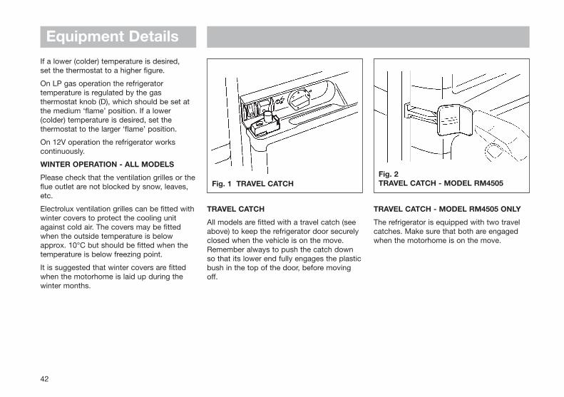
TRAVEL CATCH
Make sure that the travel catch is engagedwhen the motorhome is on the move, (fig. 1,Page 42).
The travel catch at the top of the door canbe set in two different positions. In oneposition the door is held tightly shut. In theother position the door is secured ajar sothat the refrigerator can be aired when not in use.
WINTER OPERATION
Please check that the ventilation grilles orthe flue outlet are not blocked by snow,leaves etc.
ELECTROLUX ventilation grilles can be fittedwith winter covers, to protect the coolingunit against cold air. The covers may befitted when the outside temperature is belowapprox. 10˚C but should be fitted when thetemperature is below the freezing point.
We suggest that you fit the winter coverswhen the vehicle is laid up during the wintermonths.
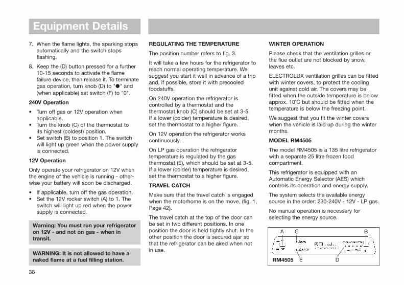
MODEL RM4505
The model RM4505 is a 135 litre refrigeratorwith a separate 25 litre frozen foodcompartment.
This refrigerator is equipped with anAutomatic Energy Selector (AES) whichcontrols its operation and energy supply.
The system selects the available energysource in the order: 230-240V - 12V - LP gas.
No manual operation is necessary forselecting the energy source.
38
RM4505
A BC
E D

Equipment Details
39
OPERATING INSTRUCTIONS
The refrigerator is set into operation bypushing button (A) (main switch). The AESLED (C) lights green showing that the AESsystem is working. Push-button (B) is usedfor setting the electronic thermostat. Thethermostat LEDs (D) show the chosentemperature position. When there is ademand for refrigeration, AES will connectthe most favourable of the available energysources.
Note: 12V must always be available tosupply the electronics.
STARTING THE REFRIGERATOR
LP Gas Operation
AES will select LP gas operation under the following conditions:
• No AC (230-240V) available
• Engine not running (no high current at 12V DC available)
• AC available but too low
• Engine running but DC supply too low
(condition three and four are briefly described in item Undervoltage Operation over the page)
When the system chooses LP Gasoperation, the flame failure device isautomatically opened, allowing the gas toflow to the burner. At the same time, theelectronic igniter is energised.
After initial installation, servicing, or changinggas cylinders etc., the gas pipes maycontain some air which should be allowed toescape by briefly turning on the refrigeratoror other appliances. This will ensure that theflame lights immediately.
If the flame goes out (by gust of wind etc.),the igniter is immediately activated andreignites the gas.
Note: The control electronics and the ignitermust have a DC (battery) supply to operate.
Gas trouble-shooting
If the AES LED (C) is flashing red, the systemwas not able to start or continue gasoperation. Set the switch (A) to OFF andcheck that there is enough gas in the gasbottle, that its valve is open and that anyvalves in the gas line to the refrigerator areopen.
Push button (A) to "ON" again. After 10 sec.AES will repeat the ignition sequence. If theAES LED (C) again starts flashing red after30 sec., the problem persists (air in the line,no gas?). Switch (A) briefly off and then onagain. It might be necessary to repeat thisoperation 2-3 times if the tubing contains air(after changing gas bottles, repairs etc.).
If this does not help, you should consult aservice technician.
230-240V Operation
When a mains connection is available, AESwill select this. Please note, that even beingin AC mode, 12V DC is necessary for theinternal supply of the electronics.
12V Operation
AES will select the 12V mode of operationonly when the vehicle engine is running(detected by the alternator connection of thefridge D+).
SWITCHING BETWEEN ENERGYSOURCES
When switching from one energy source toanother, there are some delays implementedin the AES system. The 15 min. delaybetween switching off the engine andstarting gas mode is intended to delay thestarting of gas mode e.g. when stopping at afilling station.
WARNING: It is not allowed to have a naked flame at a gas filling station. If you are not sure that your stop is shorter than 15 min., you are advised to switch off the main switch (A), when stopping at a filling station.

Equipment DetailsUNDERVOLTAGE OPERATION
The AES system is designed to guaranteethe maximum cooling efficiency under anycircumstance. The system continuouslymonitors the voltage level while in either 12VDC or 230-240V AC mode. If the voltage istoo low, the system switches to gas modeshown by the yellow LED (E). The systemstays in gas mode, until the electrical supplyvoltage has recovered to normal level.
REGULATING THE TEMPERATURE
It will take a few hours for the refrigerator toreach normal operating temperature. So wesuggest you start it well in advance of a tripand if possible store it with precooledfoodstuffs.
The temperature of the refrigerator maincompartment is set for all three sources ofenergy, by means of the thermostat knob (B).After turning on the refrigerator the systemautomatically chooses the mid-position. Withsome experience you will soon find asuitable setting. This does not normally needresetting as the same thermostat controlsthe main compartment temperature for allthree sources of energy.
TURNING OFF THE REFRIGERATOR
If the refrigerator is not to be used for sometime:
1. Set the switch (A), to "OFF".
2. Shut off any on-board valve in the gas line to the refrigerator.
3. Empty the refrigerator. Defrost and clean it as described earlier. Leave the doors of the refrigerator and frozen food compartment ajar.
4. When the vehicle is laid up for a long period of time (e.g. during the winter months), we suggest fitting the winter covers on to the grills.
IF THE REFRIGERATOR FAILS TO WORK
Check the following points before calling aservice technician:
1. That the green AES LED goes on when the switch (A) is set to "ON" (12V must be available).
2. When mains are connected but the refrigerator stays in gas operation check the refrigerator is correctly connected and the fuse (230-240 V) is intact.
3. Is the 12V fuse intact?
4. Disconnect the wall plug, and the 12V wires before servicing. Check the fuses on the circuit board, (under the black cover at the top of the refrigerator and
behind the control panel).
Remove the two screws holding the control panel, pull out the control panel with its electronics. Remove the cover and check the fuses.
5. In transit, if the refrigerator does not operate in DC mode check the alternator (D+) is correctly connected.
6. If the AES LED (C) flashes red, see chapter Gas trouble-shooting.
If the refrigerator is not cold enough itmay be because:
1. The ventilation is inadequate owing to reduced area of the ventilation passages (partial blockage of grilles from wire mesh etc.).
2. The evaporator is frosted up.
3. The temperature control setting is incorrect.
4. The gas pressure is incorrect - check the pressure regulator at the gas container.
5. The ambient temperature is too high.
6. Too much food is loaded at one time.
7. The door is not properly closed or the magnetic sealing strip is defective.
If the refrigerator still does not workproperly, call a service technician.
40
Equipment Details
41
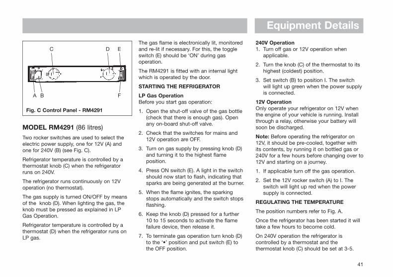
The gas flame is electronically lit, monitoredand re-lit if necessary. For this, the toggleswitch (E) should be ‘ON’ during gasoperation.
The RM4291 is fitted with an internal lightwhich is operated by the door.
STARTING THE REFRIGERATOR
LP Gas OperationBefore you start gas operation:
1. Open the shut-off valve of the gas bottle (check that there is enough gas). Open any on-board shut-off valve.
2. Check that the switches for mains and 12V operation are OFF.
3. Turn on gas supply by pressing knob (D) and turning it to the highest flame position.
4. Press ON switch (E). A light in the switch should now start to flash, indicating that sparks are being generated at the burner.
5. When the flame ignites, the sparking stops automatically and the switch stops flashing.
6. Keep the knob (D) pressed for a further 10 to 15 seconds to activate the flame failure device, then release it.
7. To terminate gas operation turn knob (D) to the ‘•’ position and put switch (E) to the OFF position.
240V Operation1. Turn off gas or 12V operation when
applicable.
2. Turn the knob (C) of the thermostat to its highest (coldest) position.
3. Set switch (B) to position I. The switch will light up green when the power supplyis connected.
12V OperationOnly operate your refrigerator on 12V whenthe engine of your vehicle is running. Installthrough a relay, otherwise your battery willsoon be discharged.
Note: Before operating the refrigerator on12V, it should be pre-cooled, together withits contents, by running it on bottled gas or240V for a few hours before changing over to12V and starting on a journey.
1. If applicable turn off the gas operation.
2. Set the 12V rocker switch (A) to I. The switch will light up red when the power supply is connected.
REGULATING THE TEMPERATURE
The position numbers refer to Fig. A.
Once the refrigerator has been started it willtake a few hours to become cold.
On 240V operation the refrigerator iscontrolled by a thermostat and thethermostat knob (C) should be set at 3-5.
Fig. C Control Panel - RM4291
MODEL RM4291 (86 litres)
Two rocker switches are used to select theelectric power supply, one for 12V (A) andone for 240V (B) (see Fig. C).
Refrigerator temperature is controlled by athermostat knob (C) when the refrigeratorruns on 240V.
The refrigerator runs continuously on 12Voperation (no thermostat).
The gas supply is turned ON/OFF by meansof the knob (D). When lighting the gas, theknob must be pressed as explained in LPGas Operation.
Refrigerator temperature is controlled by athermostat (D) when the refrigerator runs onLP gas.
C D E
A B F
Equipment Details
42
If a lower (colder) temperature is desired, set the thermostat to a higher figure.
On LP gas operation the refrigeratortemperature is regulated by the gasthermostat knob (D), which should be set atthe medium ‘flame’ position. If a lower(colder) temperature is desired, set thethermostat to the larger ‘flame’ position.
On 12V operation the refrigerator workscontinuously.
WINTER OPERATION - ALL MODELS
Please check that the ventilation grilles or theflue outlet are not blocked by snow, leaves,etc.
Electrolux ventilation grilles can be fitted withwinter covers to protect the cooling unitagainst cold air. The covers may be fittedwhen the outside temperature is belowapprox. 10°C but should be fitted when thetemperature is below freezing point.
It is suggested that winter covers are fittedwhen the motorhome is laid up during thewinter months.
TRAVEL CATCH
All models are fitted with a travel catch (seeabove) to keep the refrigerator door securelyclosed when the vehicle is on the move.Remember always to push the catch downso that its lower end fully engages the plasticbush in the top of the door, before movingoff.
TRAVEL CATCH - MODEL RM4505 ONLY
The refrigerator is equipped with two travelcatches. Make sure that both are engagedwhen the motorhome is on the move.
Fig. 1 TRAVEL CATCHFig. 2 TRAVEL CATCH - MODEL RM4505
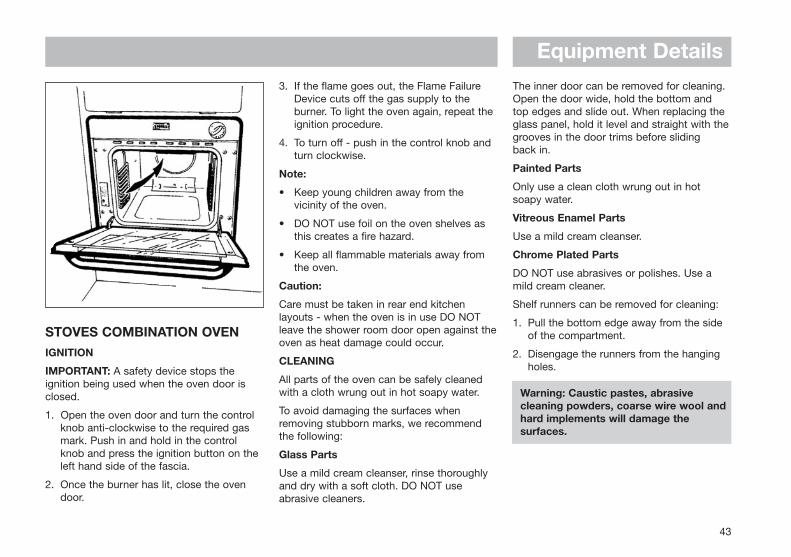
Equipment Details
43
STOVES COMBINATION OVENIGNITION
IMPORTANT: A safety device stops theignition being used when the oven door isclosed.
1. Open the oven door and turn the control knob anti-clockwise to the required gas mark. Push in and hold in the control knob and press the ignition button on the left hand side of the fascia.
2. Once the burner has lit, close the oven door.
3. If the flame goes out, the Flame Failure Device cuts off the gas supply to the burner. To light the oven again, repeat the ignition procedure.
4. To turn off - push in the control knob and turn clockwise.
Note:
• Keep young children away from the vicinity of the oven.
• DO NOT use foil on the oven shelves as this creates a fire hazard.
• Keep all flammable materials away from the oven.
Caution:
Care must be taken in rear end kitchenlayouts - when the oven is in use DO NOTleave the shower room door open against theoven as heat damage could occur.
CLEANING
All parts of the oven can be safely cleanedwith a cloth wrung out in hot soapy water.
To avoid damaging the surfaces whenremoving stubborn marks, we recommendthe following:
Glass Parts
Use a mild cream cleanser, rinse thoroughlyand dry with a soft cloth. DO NOT useabrasive cleaners.
The inner door can be removed for cleaning.Open the door wide, hold the bottom and top edges and slide out. When replacing theglass panel, hold it level and straight with thegrooves in the door trims before sliding back in.
Painted Parts
Only use a clean cloth wrung out in hotsoapy water.
Vitreous Enamel Parts
Use a mild cream cleanser.
Chrome Plated Parts
DO NOT use abrasives or polishes. Use amild cream cleaner.
Shelf runners can be removed for cleaning:
1. Pull the bottom edge away from the side of the compartment.
2. Disengage the runners from the hanging holes.
Warning: Caustic pastes, abrasive cleaning powders, coarse wire wool and hard implements will damage the surfaces.

Equipment Details
44
STOVES 8000/9000 COOKERTHE OVEN
Important: A safety device stops the ignitionbeing used when the oven door is closed.
To light the oven
1. Open the oven door and turn the control knob anticlockwise to the required gas mark. Push in and hold in the control knob, and either press the ignition button or hold a match to the burner.
2. Once the burner has lit, close the oven door and hold the knob in for 15–20 seconds.
3. If the flame goes out, the flame sensing device cuts off the gas supply to the burner. To light the oven again, wait for 3 minutes and repeat the ignition procedure.
To turn off the oven
Push in the control knob and turn clockwise.
Note:A 15 minute warm-up time is recommendedbefore using the oven.
Keep young children away from the vicinity ofthe oven.
DO NOT use foil on the oven shelves as thiscreates a fire hazard.
Keep all flammable materials away from theoven.
CLEANING
All parts of the oven can be safety cleanedwith a cloth wrung out in hot soapy water.
To avoid damaging the surfaces whenremoving stubborn marks, we recommendthe following:
Glass Parts
Use a mild cream cleaner, rinse thoroughlyand dry with a soft cloth. DO NOT useabrasive cleaners.
The inner door glass panel can be removedfor cleaning. Open the door wide, hold thebottom and top edges and slide out. Whenreplacing the glass panel, hold it level and
straight with the grooves in the door trimsbefore sliding back in.
Painted Parts
Only use a clean cloth wrung out in hotsoapy water.
Vitreous Enamel Parts
Use a mild cream cleaner.
Chrome Plated Parts
DO NOT use abrasives or polishes. Use amild cream cleaner.
Shelf runners can be removed for cleaning.
1. Pull the bottom edge away from the side of the compartment.
2. Disengage the runners from the hanging holes.
Warning: Caustic pastes, abrasive cleaning powders, coarse wire wool and hard implements will damage the surfaces.

Equipment Details
45
THE HOB
Ignition
1. Push in the control knob and turn anti-clockwise to the large flame symbol.
2. Keep the knob depressed and press the ignition button (if fitted), or hold a lighted match or taper to the burner.
Keep the control knob depressed for 15-20 seconds before releasing.
Note: The FFD (Flame Failure Device) will cut off the gas supply if the flame goes out for any reason.
3. Turn the control knob to the required setting.
• Do not use foil on the hob as it creates a fire hazard.
• Glass lids may shatter when heated. Turn off all burners before shutting the lid.
Always use the most appropriate size ofburner for the pan you wish to use. Usepans with a flat base of minimum 100mm/4indiameter and maximum 200mm/8indiameter, which are stable in use. Avoid oldor mishapen pans as these may causeinstability.
Warning: All pans should be mounted centrally over the burners, even when cooling, to protect adjacent walls.
Do not lower hob cover until hobs have cooled.
On no account should this appliance be used as a space heater.
THE GRILL
Note: The door must be open when the grillis in use.
Caution: When the grill is being used,accessible parts may be hot; young childrenshould be kept away.
• Never cover the grill pan or grid with cooking foil, or allow fat to build up in thegrill pan as this creates a fire hazard.
• Keep all flammable material away from the appliance.
To light the grill
Push in the control knob and turn anti-clockwise to the large flame symbol. Keepthe knob depressed, and press the ignitionbutton (if fitted), or hold a lighted taper to theburner. The knob must be held in for 15–20seconds before releasing.
Using the grill
Push in the grill pan until it locates centrallyunder the grill burner. There are 3 differentgrilling positions as the trivet can be invertedto give a high or low position or it may beremoved.
1. The high trivet position is suitable for toasting bread.
2. The low trivet position is suitable for grilling all types of meat.
3. With the trivet removed the food is placeddirectly on the base of the grill pan, e.g. when cooking dishes such as whole fish.
Always pre-heat the grill for 3 minutes forbest results.
When you have finished grilling, check thecontrol knob is in the OFF position.
Warning: When cooking it is essential to provide additional ventilation such as opening windows near the grill, cooker and oven.
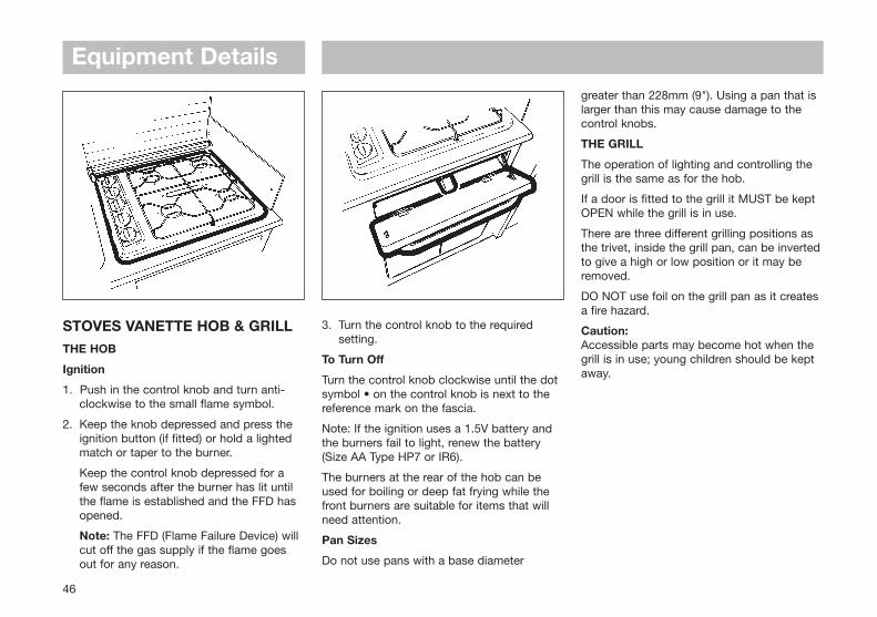
Equipment Details
46
STOVES VANETTE HOB & GRILLTHE HOB
Ignition
1. Push in the control knob and turn anti- clockwise to the small flame symbol.
2. Keep the knob depressed and press the ignition button (if fitted) or hold a lighted match or taper to the burner.
Keep the control knob depressed for a few seconds after the burner has lit until the flame is established and the FFD has opened.
Note: The FFD (Flame Failure Device) will cut off the gas supply if the flame goes out for any reason.
3. Turn the control knob to the required setting.
To Turn Off
Turn the control knob clockwise until the dotsymbol • on the control knob is next to thereference mark on the fascia.
Note: If the ignition uses a 1.5V battery andthe burners fail to light, renew the battery(Size AA Type HP7 or IR6).
The burners at the rear of the hob can beused for boiling or deep fat frying while thefront burners are suitable for items that willneed attention.
Pan Sizes
Do not use pans with a base diameter
greater than 228mm (9"). Using a pan that islarger than this may cause damage to thecontrol knobs.
THE GRILL
The operation of lighting and controlling thegrill is the same as for the hob.
If a door is fitted to the grill it MUST be keptOPEN while the grill is in use.
There are three different grilling positions asthe trivet, inside the grill pan, can be invertedto give a high or low position or it may beremoved.
DO NOT use foil on the grill pan as it createsa fire hazard.
Caution:Accessible parts may become hot when thegrill is in use; young children should be keptaway.

Equipment Details
47
CRAMER HOBPlease read these operating instructionscarefully before using the appliance
ValidityThese operating instructions apply to thefollowing Cramer Built-in-Cookers in the EK2000 model range:
EK-1101 to EK-1277, CE-1300 to CE-1414
Initial Operation of the Appliance
1. Open the gas-bottle valve.
2. Open the cooker shut-off valve.
3. Turn the control knob of the relevant burner from the off-position (0-mark), anticlockwise to maximum (high flame).
4. Push the knob in and hold it in this position.
5. Ignite the burner with a match or other suitable ignition device.
6. If the burner ignites, the knob can be released after approximately 10 seconds.
7. The knob may now be set to the required burner position:
High flame = maximum position (depending from model: 2.0kW, 1.6kW or 1.0kW)
Low flame = minimum position (ca. 0.5kW)
8. The entire ignition process should be clearly visible from above and not obstructed by cooking utensils.
Switching off the Appliance
1. Turn the control knob to the off-position (0-mark) to extinguish the burner.
2. Close the cooker shut-off valve.
3. Close the bottle valve during longer periods of non-operation.
Action in case of Faults
1. If a fault occurs the appliance must be switched off (see above) and a specialist consulted.
Correct Use of the Cooker
Saucepans
1. Care should be taken that saucepans are placed in the middle of the ring and that flames do not rise above the rims.
2. Pans with misshapen/distorted bottoms must not be used.
Air supply
1. Ventilation openings with a cross section of at least 150cm≤ are essential in the room where the cooker is operated during use of the burner(s). (See instructions displayed above the cooker).
2. The combustion air supply pipes should be checked from time to time and cleaned if necessary.
3. The burners must not be used as heaters.
WARNING: The burners must not be operated during refuelling or in garages.
Instructions for Long Periods of Non-Operation
1. Turn the knobs to the off-position(0-mark).
2. Close the cooker shut-off valve.
3. Close the bottle valve.
4. After a long period of non-operation the appliance should be examined by a specialist*.
Care and Cleaning of the Appliance
1. A standard cleansing agent can be used to clean the appliance.
2. Allow the appliance to cool down before cleaning.
3. To avoid damage, the outer surface of theappliance should be cleaned using only adamp cloth without the addition of chemical or granular cleansing agents.
4. The burner head(s) must not be dismantled when cleaning the appliance.
5. Care must be taken that cleanser does not spill into the burner(s).
6. After longer journeys the appliance should be examined for any obvious damage or loose parts.

Equipment Details
48
Maintenance
1. For safety reasons it is essential that the appliance be examined annually by a specialist* for fault-free operation and anyfaults eliminated.
2. The following functions, in particular, should be checked during the annual service:
a. Inspection of gas density.
b. Inspection of burner safety and flame stability.
c. Inspection of fresh air supply.
d. Inspection of the safety and control fittings (burner taps).
3. During each service the cooker box should be examined in correlation with the appliance and should be checked against the relevant regulations.
4. If the flame openings of the burner heads become dirty or blocked, they must be cleaned.
5. The thermo-couple must be kept cleanedand the correct distance between the burner head and the thermo-element maintained (ca 2-4mm).
6. The liquid gas supply system of appliances used in motorised vehicles should be tested by a specialist*, before initial operation and every two years
thereafter, for tightness and function. A test conformance certificate should be issued by the specialist*. It is the user's responsibility to arrange these tests.
7. Pressure loss should be checked during the test.
General Safety Advice
1. If the smell of gas is detected:
a. Close the bottle valve and leave it closed until the fault is repaired.
b. Open all windows and leave the room.
c. Do not turn on any electrical equipment and avoid the use of naked flame, which could ignite the gas.
d. Consult a specialist*.
e. Under no circumstances attempt to find the leak with the aid of a naked flame.
2. Any alteration to the appliance could be dangerous and is not permitted.
3. Some parts of the appliance become veryhot during use; keep children away.
*Specialists
Expert gas specialists are those specialistswhose training, knowledge and practicalexperience guarantee that they will carry outthe inspection correctly.

Equipment Details
49
THETFORD CASSETTE C-200FEATURES
1. Removable seat and cover.
2. Rotatable bowl.
3. Valve blade handle: opens and closes valve blade manually.
4. Flush button: activates flush.
5. Only Cassette C-200S E/C-200 CE:Valve blade button: opens and closes valve blade electronically.
6. Waste-level warning device: indicates when holding tank requires emptying.
7. Rotating pour-out spout: makes emptyingholding tank easy and convenient.
8. Upper carrying handles.
9. Automatic holding tank vent: vents the holding tank when there is over pressureif holding tank is inserted into the toilet.
10. Valve blade opener.
11. Sliding cover: closes automatically when holding tank is taken out. Guarantees optimum hygiene.
12. Valve blade.
13. Press button valve: allows air in to avoid splashing while emptying.
14. Hand grip.
15. Access door (outside caravan).
04 06
05
03
0102
08 07 09 14 12
1311
14
10
15
C200-S & CS
C200-E & CE

Equipment Details
50
Cassette C-200 S and C-200 CS
The toilet section of the C-200 S/C-200 SCincludes a rotatable bowl, a removable seat,a control unit with a flush button and a wastelevel warning device. Under the bowl, thevalve blade handle is located.
Preparing for Use
1. To remove holding tank, open the access door. Pull retaining clip upwards (fig. 1).
2. Remove holding tank by pulling straight out. When holding tank hits the stop, tilt downwards slightly and remove (fig. 2).
3. Position tank vertically and swivel pour-out spout upwards (fig. 3).
4. Remove the cap of pour-out spout. Add required amount of toilet fluid through pour-out spout. Add small amount of water through spout to cover holding tankbottom. Replace cap and return pour-out spout to its original stored position (fig. 4).
Note: Hotter weather or longer retention time may require additional toilet fluid. Use only Thetford toilet fluidto achieve the best results.
Caution: Never add toilet fluid directly into toilet bowl.
5. Slide the holding tank into the vehicle through access door (fig. 5).
6. Make sure the holding tank is secured by the retaining clip. Close and lock access door (fig. 6).
Operation
7. Turn the bowl in the most comfortable position, when necessary (fig. 7)
8. Before using the toilet we recommend adding some water to the bowl by pressing the flush button. Flush will stop when the button is released (fig. 8).
1 2
3 4
5 6
7 8

Equipment Details
51
9. To open the blade turn the blade handle anti-clockwise (fig. 9).
10. To flush, press the flush button (fig. 10). After flushing, close the blade by turning the blade handle clockwise. The toilet may also be used with the valve blade open, which allows waste to pass directly into the holding tank.
CASSETTE C-200 E and C-200 CE
11. To open the blade, push on the left side of the blade opener button (fig. 11). Blade can also be opened by turning theblade handle andi-clockwise (fig. 9a).
12. To flush, press the flush button (fig. 10). After flushing, close the blade by pushing the right side of the blade opener button (fig. 12).
The blade can also be closed by turning the blade handle clockwise.
The toilet can also be used with the valve blade open, which allows waste to pass directly into the holding tank.
Emptying the Cassette
The holding tank capacity is approximately17 litres and the tank should be emptiedwhen waste-level warning device comes on.The waste-level warning device will come onwhen tank contains more than 15 litres of
waste. From that moment there isapproximately 2 litres capacity left. This isequal to approximately 5 uses.
CAUTION: Do not allow cassette tobecome overfilled. See trouble shootingsection for emergency emptyingprocedure.
13. Open access door and remove holding tank. Holding tank can only be removed when valve blade is closed (fig. 13).
14. Carry the holding tank, pour out spout up, to a normal household type toilet or other authorised disposal point. Set the holding tank in vertical position and rotate pour-out spout upwards (fig. 14).
15. Remove spout cap. Grasp unit by upper carrying handle nearest to pour-out spout. Place other hand on upper rear hand grip so that air relief valve button can be depressed with the thumb while emptying. This ensures smooth outflow of tank contents (fig. 15).
Note: Depress air relief valve button onlywhen pour-out spout is pointed downwards.
Rinse the holding tank with clear water. For preparing for use again, see steps 1 to 6.
9 9A
10 11
12 13
14 15
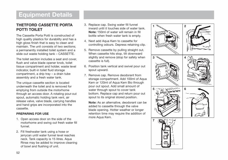
Equipment Details
52
THETFORD CASSETTE PORTAPOTTI TOILETThe Cassette Porta Potti is constructed ofhigh quality plastics for durability and has ahigh gloss finish that is easy to clean andmaintain. The unit consists of two sections; a permanently installed toilet system and aslide out waste holding tank – CASSETTE.
The toilet section includes a seat and cover,flush and valve blade opener knob, toilettissue compartment and holder, waste levelindicator, built-in toilet fluid storagecompartment, a drip tray – a drain tubeassembly and a fresh water tank.
The unique cassette section is locatedunderneath the toilet and is removed foremptying from outside the motorhomethrough an access door. A rotating pour-outspout, automatic holding tank vent, airrelease valve, valve blade, carrying handlesand hand grips are incorporated into thecassette.
PREPARING FOR USE
1. Open access door on the side of the motorhome and swing out fresh water fill funnel.
2. Fill freshwater tank using a hose or jerrycan until water funnel level reaches neck. Tank capacity is 15 litres. Aqua Rinse may be added to improve cleaning of bowl and flushing of unit.
3. Replace cap. Swing water fill funnel inward until it touches side of water tank. Note: 150ml of water will remain in fill bottle when fresh water tank is empty.
4. Next add Aqua Kem to cassette for controlling odours. Depress retaining clip.
5. Remove cassette by pulling straight out. When cassette hits stop, tilt downward slightly and remove (stop for safety when cassette is full).
6. Position tank vertical and swivel pour out spout upward.
7. Remove cap. Remove deodorant from storage compartment. Add 100ml of AquaKem or 120ml of Aqua Kem Bio through pour out spout. Add small amount of water through spout to cover tank bottom. Replace cap and return pour out spout to its original stored position.
Note: As an alternative, deodorant can beadded to cassette through the valve blade opening. Hotter weather or longer retention time may require the addition of more Aqua Kem.
1 2
3 4
5 6
7

Equipment Details
53
CAUTION: Do not add Aqua Kem Concentrate or Aqua Kem Bio directly into toilet bowl while cassette tank valve blade is closed. Pressure, due to heat and altitude change, can build up in the cassette tank causing bowl contents to splash upward upon opening the valve blade if opened too fast. Before each use, open and shut the cassette valve blade to vent the tank.
8. Slide the cassette, pour out spout facing outside, into the motorhome through access door. Never force insertion or removal of the cassette tank as damage to the system can occur.
9. Make sure the cassette is secured by the retaining clip. Close and lock access door.
OPERATION
Flushing (Electric Models)
10. Before using the toilet we advise adding some water to the bowl by pressing down the flush knob. This avoids marking the bowl. Water will stop flowingwhen knob is released.
11. To flush after use, press the flush knob down while turning in an anti-clockwise direction. The turning motion opens the valve blade, emptying the toilet bowl.
This procedure results in the best bowl rinse and most efficient use of water. After flushing, turn the knob in a clockwise direction to close valve blade. The toilet can also be used with the valve blade open, which allows waste to go directly into the holding tank.
Flushing (Manual Models)
10. Before using the toilet, we advise addingsome water to the bowl by turning the flush knob in a clockwise direction. When flush knob is released it will turn automatically back.
11. To flush after use, turn the valve knob in an anti-clockwise direction and turn the flush knob. This procedure results in the best bowl rinse and most efficient use of water.
TOILET TISSUE (Electric Models)
12. Toilet tissue is stored in the specially designed storage compartment that helps keep tissue clean and dry. Tissue can also be suspended on a tissue holder using the special wall bracket, if desired.
8 9
10 ELECTRIC 10 MANUAL
11 ELECTRIC 11 MANUAL
12 13

Equipment Details
54
13. To replace tissue, remove tissue holder from compartment by pulling up on tissue cover. Hold bottom of tissue holderin one hand and cover in the other and turn in opposite directions until you hear a click. Pull apart. Place tissue on holder, insert prongs of cover into holder. Hold cover and holder and twist in opposite directions until locked. Aqua Soft toilet tissue is recommended for best results.
EMPTYING THE CASSETTE
The cassette capacity is 20 litres and shouldbe emptied when the waste level gaugeindicator goes from green to full red. Thegauge does not begin to move from green tored until the tank is over half full.
Caution: Do not allow cassette to becomeoverfilled.
The holding tank features a unique slidingcover (1) which guarantees optimal hygiene.The sliding cover moves automatically whenthe holding tank is inserted. When holdingtank is removed, the cover automaticallyassumes its correct position. To clean theholding tank, you may remove the covermanually by sliding it towards the pour-outspout.
To empty cassette make sure that the valveblade is in the closed position.
14. Open the access door on side of motorhome. Depress the retainer clip, pull cassette until stop, tilt and remove cassette.
15. Carry the cassette using the lower carrying handle (pour out spout up) to a normal household type toilet or other authorised disposal point. Set cassette invertical position on the ground and rotatepour out spout upward.
16. Remove spout cap. Grasp unit by upper carrying handle nearest to pour out spout. Place other hand on upper rear grip so that the air relief valve button can be depressed with thumb while emptying, to ensure smooth outflow of tank contents. When empty, rinse tank and valve blade with water.
Note: Depress air release valve button only when pour out spout is pointed downwards.
17. After preparing for use, slide the cassetteinto the caravan. Check to make sure that the retaining clip secures the tank in a locked position. The pour out spout end of the tank should be visible through the access door opening. Add water to the fresh water tank as outlined in “Preparing for Use” section. Close and lock access door.
16 17
14 15
Equipment Details
55
CLEANING AND MAINTENANCE
No routine maintenance is required on theThetford Cassette Porta Potti. The use ofAqua Rinse helps to clean and protect thetoilet bowl, valve blade and seals duringflushing. Do not use strong householddetergents or cleaners with chlorine, solventsor acid contents, as they will damage valveseals.
Empty cassette and rinse tank with clearwater. Use a mild soap to clean toilet bowl,seat and cover, as well as exterior of toiletunit and cassette. Replace tank insidemotorhome.
Note: Pour-out spout and vent plug can beremoved. Seals should be greased ifnecessary with acid-free vaseline.
WINTERING/STORAGE
The Thetford Cassette Porta Potti is easilywinterised for storage or cold weather use.
18. Empty the fresh water tank using the drain tube. Pull drain tube down and outward through door opening to drain water from tank. In the case of the manual flush, turn the flush knob a few times to drain the pump assembly.
19. Empty the water fill funnel by pulling the bottle away from tank. Remove small water cap at fill bottom, allowing water todrain from water funnel.
Note: Do not tighten caps, this helps in keeping unit dry.
COLD WEATHER USE
To prevent freezing during cold weather use,add anti freeze to the fresh water tank. Use anon-toxic (propylen-glycol) type of antifreeze. Refer to chart on container to obtainlevel of protection.
HIGH ALTITUDE AND HOT WEATHER USE
With large temperature differences andchanging heights during driving, overpressurecan start to build up in the holding tank. Todepressurise your tank continuously, werecommend to keep the flush knob about 10degrees in the direction of the arrow.
THETFORD WARRANTY
1. The Thetford Cassette Porta Potti is warranted for one year from the date of purchase, provided the warranty card has been completed and returned to Swift within 30 days after the date of purchase.
2. The warranty covers replacement of parts arising from defects and workmanship and from the inability of the unit to perform its intended function.
3. In case of a defect apply to original dealerwith proof of purchase.
4. Defects, which in our judgement occurred from misuse, negligence or accident, are not covered by the warranty. In addition, the warranty does not apply if the productis; installed or handled improperly, other than the prescribed chemical agentshave been used, the product has been altered in any way or has been repaired byunqualified persons, or if the serial number and/or date has been altered or removed.
5. Should the original buyer wish to return tous parts believed to be defective, the parts should be sent prepaid. If we find the parts defective and covered by warranty, they will be repaired and returned. If warranty does not apply or has expired, a nominal charge will be made. Any transport costs are for the account of the owner.
18 19
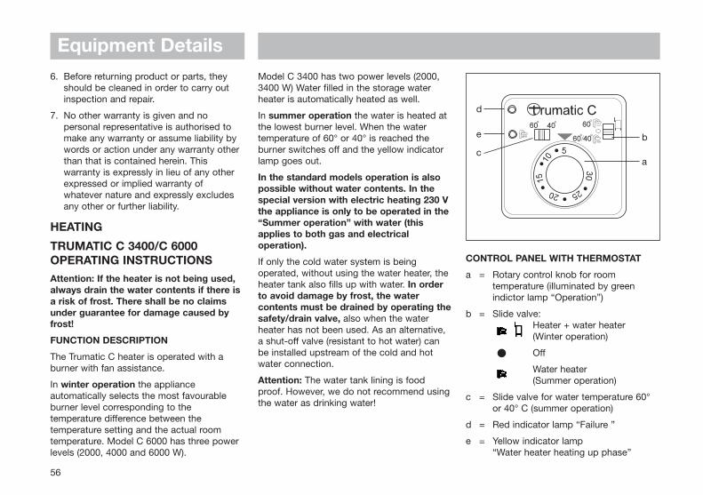
Equipment Details
56
6. Before returning product or parts, they should be cleaned in order to carry out inspection and repair.
7. No other warranty is given and no personal representative is authorised to make any warranty or assume liability by words or action under any warranty other than that is contained herein. This warranty is expressly in lieu of any other expressed or implied warranty of whatever nature and expressly excludes any other or further liability.
HEATING
TRUMATIC C 3400/C 6000OPERATING INSTRUCTIONSAttention: If the heater is not being used,always drain the water contents if there isa risk of frost. There shall be no claimsunder guarantee for damage caused byfrost!
FUNCTION DESCRIPTION
The Trumatic C heater is operated with aburner with fan assistance.
In winter operation the applianceautomatically selects the most favourableburner level corresponding to thetemperature difference between thetemperature setting and the actual roomtemperature. Model C 6000 has three powerlevels (2000, 4000 and 6000 W).
Model C 3400 has two power levels (2000,3400 W) Water filled in the storage waterheater is automatically heated as well.
In summer operation the water is heated atthe lowest burner level. When the watertemperature of 60° or 40° is reached theburner switches off and the yellow indicatorlamp goes out.
In the standard models operation is alsopossible without water contents. In thespecial version with electric heating 230 Vthe appliance is only to be operated in the“Summer operation” with water (thisapplies to both gas and electricaloperation).
If only the cold water system is beingoperated, without using the water heater, theheater tank also fills up with water. In orderto avoid damage by frost, the watercontents must be drained by operating thesafety/drain valve, also when the waterheater has not been used. As an alternative,a shut-off valve (resistant to hot water) canbe installed upstream of the cold and hotwater connection.
Attention: The water tank lining is foodproof. However, we do not recommend usingthe water as drinking water!
CONTROL PANEL WITH THERMOSTAT
a = Rotary control knob for room temperature (illuminated by green indictor lamp “Operation”)
b = Slide valve:Heater + water heater (Winter operation)
Off
Water heater (Summer operation)
c = Slide valve for water temperature 60°or 40° C (summer operation)
d = Red indicator lamp “Failure ”
e = Yellow indicator lamp “Water heater heating up phase”
d
e b
ac
Equipment Details
57
SWITCHING ON
1. Check that the cowl is not obstructed. Always remove any covers.
2. Turn on gas cylinder and open quick-acting valve in the gas supply line.
3. Set slide valve (b) to “winter operation” or“summer operation”.
4. In winter operation select required room temperature at rotary control knob (a).
5. In summer operation set slide valve (c) to required water temperature.
SWITCHING OFF
Set slide valve (b) to centre position. Whenthe appliance is switched off after a heatingphase, the fan may continue running in orderto utilize the residual heat .
Always drain water contents if there is arisk of frost!
If the appliance is not to be used for aprolonged period, close the quick-actingvalve in the gas supply line and turn off thegas cylinder.
GREEN INDICATOR LAMP “OPERATION”(UNDER ROTARY CONTROL KNOB)
When the appliance is switched on the greenindicator lamp is illuminated. If this indicatorlamp is not illuminated, consider theprovided (main) switch. For this purposeobserve the respective instructions of thevehicle manufacturer.
FUSES
The appliance fuses are on the electroniccontrol unit on the appliance.
Important note: Only replace the miniaturefuses F1 and F2 on the electronic controlp.c.b. with fuses of the same type.
F1 = 4 AT (slow action)
F2 = 0,5 AF (quick-action)
Attention: The fuse F3 is only to be replacedby an expert .
RED INDICATOR LAMP “FAILURE”
The red indicator lamp (d) lights uppermanently if there is a failure. Possiblecauses are: no gas, insufficient combustionair, fuse failure etc. Deactivate by switchingoff and then switching on again.
Flashing 1 x per second indicates insufficientoperating voltage, flashing 2 x per secondindicates that the operating voltage is toohigh for the appliance.
FILLING THE BOILER
1. Ensure that the yellow lever on top of the drain valve is in the horizontal (closed) position.
2. Switch on power for water pump (main switch or pump switch).
3. Open hot water taps in kitchen and bathroom, (set preselecting mixing taps or single-lever fittings to “hot”). Leave taps open until the water heater has forced out air and filled up with water andwater is flowing out of the taps.
DRAINING THE WATER HEATER
1. Interrupt power for water pump (main switch or pump switch).
2. Open hot water taps in kitchen and bathroom.
3. Set switch (9) to “0”.
Lift the yellow lever on the drain valve to thevertical (open) position.
There shall be no guarantee for damagecaused by frost!
MAINTENANCE
Use wine vinegar for de-scaling the waterheater. This is best introduced into theappliance via the water supply. Allow theproduct to react and then thoroughly flushout the appliance with plenty of fresh water.

Equipment Details
58
SPECIAL VERSION WITH ADDITIONALELECTRIC HEATING 230 V, 450 W
i = Rotary control knob On/Off
k = Yellow indicator lamp “Operation”
Set rotary control knob (i) for the electricheating to marking “1”. The yellow indicatorlamp (k) lights up.
The water temperature cannot bepreselected. Automatic temperature limitationis approx 70°C.
Note: To heat the water in the water heatermore quickly the appliance can besimultaneously operated with gas andelectric power.
Attention: In “summer operation” theappliance is only to be operated with water(this applies to both gas and electricaloperation)!
k
i
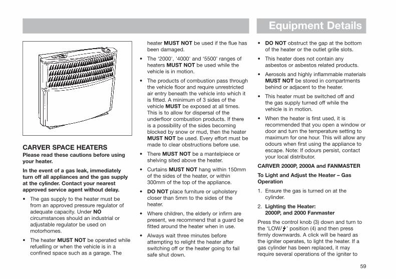
Equipment Details
59
CARVER SPACE HEATERSPlease read these cautions before usingyour heater.
In the event of a gas leak, immediatelyturn off all appliances and the gas supplyat the cylinder. Contact your nearestapproved service agent without delay.
• The gas supply to the heater must be from an approved pressure regulator of adequate capacity. Under NOcircumstances should an industrial or adjustable regulator be used on motorhomes.
• The heater MUST NOT be operated while refuelling or when the vehicle is in a confined space such as a garage. The
heater MUST NOT be used if the flue hasbeen damaged.
• The ‘2000', '4000' and ‘5500’ ranges of heaters MUST NOT be used while the vehicle is in motion.
• The products of combustion pass throughthe vehicle floor and require unrestricted air entry beneath the vehicle into which it is fitted. A minimum of 3 sides of the vehicle MUST be exposed at all times. This is to allow for dispersal of the underfloor combustion products. If there is a possibility of the sides becoming blocked by snow or mud, then the heater MUST NOT be used. Every effort must bemade to clear obstructions before use.
• There MUST NOT be a mantelpiece or shelving sited above the heater.
• Curtains MUST NOT hang within 150mm of the sides of the heater, or within 300mm of the top of the appliance.
• DO NOT place furniture or upholstery closer than 5mm to the sides of the heater.
• Where children, the elderly or infirm are present, we recommend that a guard be fitted around the heater when in use.
• Always wait three minutes before attempting to relight the heater after switching off or the heater going to fail safe shut down.
• DO NOT obstruct the gap at the bottom of the heater or the outlet grille slots.
• This heater does not contain any asbestos or asbestos related products.
• Aerosols and highly inflammable materialsMUST NOT be stored in compartments behind or adjacent to the heater.
• This heater must be switched off and the gas supply turned off while the vehicle is in motion.
• When the heater is first used, it is recommended that you open a window ordoor and turn the temperature setting to maximum for one hour. This will allow anyodours when first using the appliance to escape. Note: If odours persist, contact your local distributor.
CARVER 2000P, 2000A and FANMASTER
To Light and Adjust the Heater – GasOperation
1. Ensure the gas is turned on at the cylinder.
2. Lighting the Heater:2000P, and 2000 Fanmaster
Press the control knob (3) down and turn tothe ‘LOW/ ’ position (4) and then pressfirmly downwards. A click will be heard asthe igniter operates, to light the heater. If agas cylinder has been replaced, it mayrequire several operations of the igniter to

Equipment Details
60
light the flame. Observe through the viewingwindows on the lower half of the front case,that the burner lights.
2000A and 2000 Fanmaster(12V ‘Auto’ Ignition)
As above turn to the ‘ ’ position and pressfirmly down. A continuous ticking will beheard, as the spark generator is actuated. Anindicator light (2) built into the control knobwill light up when the flame is lit.
3. Continue to hold the knob down for 20 seconds and release. The flame supervision device will now have been actuated. The knob can now be released and adjusted to the desired setting as marked on the heater top panel.
4. If the burner is extinguished for any reason, or fails to remain alight, the heaterwill shut down to a safe condition. In the case of the 12V ‘Auto’ ignition models (2000A and Fanmasters with this ignition device), the continuous ticking of the
spark generator will be heard until turned off.
5. To turn off the heater at any time, turn the knob to the ‘O’ (1) position.
6. Wait for at least 3 minutes, after shut down, before attempting to relight these heaters.
Electric Heating – Fanmaster models only
Cautions:
• Read the operating instructions before using the Fanmaster.
• Read the operating instructions for the Carver gas heater before using it in conjunction with the Fanmaster.
• One or more duct outlets must be open whilst the Fanmaster is in use.
• The 230V external supply to the vehicle must be disconnected before driving off.
General Description
The Fanmaster is an automatically controlledfan designed to distribute warm air aroundthe motorhome via ducting.
All of the functions of the 2000 Fanmasterare controlled independently of the gascontrol – by front case slide switches whenright-hand build is installed (Fig. 1), or bywall-mounted control panel for a left-handinstallation (Fig. 2).
The air is heated either by the Fanmaster’sown electric element or by the Carver gasfired heater. Both the Carver gas heater andthe Fanmaster can be used at the same timeproviding the fan is in operation.
The built-in elements are automatically ormanually switchable between 0, 1kW and2kW and require a 230V AC mains supplydrawing a maximum of 8A at 2kW.
1 OFF2 INDICATOR LIGHT3 GAS CONTROL
KNOB4 LOW/IGNITION5 HIGH
Fig. 1
Fig. 2
3
4
2
1
5

Equipment Details
61
When using electric heating, the motorhometemperature is regulated by the thermostatmounted at the top of the installation box,but when using the gas heating thetemperature is controlled by the gas heaterthermostat. The night setting is a 1kWconvector heater setting. In the summer thefan may be operated without any heat inputto distribute cool air.
The Fanmaster has an air deflector allowingthe majority of air to be directed down onefan outlet. For example, down the longestducting run. This may have been preset oninstallation.
The duct outlets are generally of the butterflytype and may be opened or closed byadjusting the butterfly valves. Twisting thedisc in its housing directs the flow in thedirection required. One outlet on each leg ofthe duct layout must be kept open.
Servicing
In order to ensure that your heater continuesto operate effectively, you will need toarrange for it to be serviced at least once ayear by a competent and trained serviceengineer. By law no one is permitted to dealwith the installation and servicing of gasappliances unless they have provencompetence. Contact your nearestauthorised motorhome distributor if serviceor repair is required.
FANMASTER CONTROLLER OPERATIONS - SLIDE SWITCH ON HEATER TOP (R.H. INSTALLATION)
POSITION OPERATION (without gas) OPERATION (with gas)
0 Off Gas convector
Manual fan speed. Temperature Blown hot air distribution1 slider governs the fan speed.
For cool air distribution.
1kW electric convector heating, Electric and Gas convection, but a high gas 2 no fan. Temperature slider heater output will inhibit the electric heating
selects desired room temperature to maintain safe operating temperatures.
1kW electric fan heating, Electric and Gas blown distribution. Fan3 fan remains slow. speed adjusts automatically based on
outlet temperature.
2kW electric fan heating. Fan Electric and gas blown distribution. Fan4 automatically adjusts speed to suit. speed adjusts automatically.
FANMASTER CONTROLLER OPERATIONS - WALLSWITCH CONTROL(L.H. INSTALLATION)
POSITION OPERATION (without gas) OPERATION (with gas)
0 Off Gas convector
Manual fan speed. Wall switch Blown hot air distribution1 knob governs the fan speed.
For cool air distribution.
Automatic fan speed. Temperature Blown hot air distribution with automatic2 of heater governs fan speed. fan speed control.
1kW electric convector heating, no Electric and gas blown distribution. 3 fan. Wall switch knob selects Fan speed adjusts automatically based
desired room temperature. on outlet temperature.
1kW electric fan heating, Electric and gas blown distribution. 4 fan remains slow. Fan speed adjusts automatically.
2kW electric fan heating.5 Fan automatically adjusts speed to suit.
Equipment Details
62
CARVER 4000 and 5500 TURBOFANMASTER SPACE HEATER
Read the cautionary notes for the CarverSpace Heaters before using your heater.
Before Lighting the heater:
Ensure the gas is turned on at the cylinder.
Lighting the Heater (Fig. 3)
For the auto ignition press the control knob(4) down and rotate to the ‘ ’ position (2),maintaining downwards pressure. The igniterwill be heard to operate with a continuous‘ticking’ noise. On ignition the control knobindicator (3) will illuminate to show that aflame is present.
After the burner has lit, continue to holddown the control knob for a further 10seconds. Release the control knob and theindicator should remain illuminated to showthat the burner has remained alight.
For the Piezo ignition, press the control knob(4) down and rotate to the ‘ ’ position (2),maintaining downwards pressure. Press theignition button (7). Check through the viewingwindow on the front case that the pilotburner is alight, if so continue to hold thecontrol knob down for ten seconds.
Release the control knob and the pilot burnershould remain alight. It may require severaloperations of the igniter to light the burner.
To operate the main burner, turn the controlknob further anti-clockwise and set it at thedesired comfort level, between the high flameand low flame positions (5 & 6).
The main burner will ‘cycle’ automatically asrequired by the thermostat to maintain theset temperature, but the pilot light will alwaysremain alight.
Turning off the heater
Turn the control knob fully clockwise to the‘•’ position (1).
FANMASTER
General Description
The Fanmaster is an electric heating andblown air system controlled by the sliderswitches on the front case of the heater (Fig. 4).
The automatically controlled fan distributeswarm air around the motorhome via ducting.The air is heated either by the Fanmaster’sown electric element or by the Carver gasfired heater. The Carver gas fire and theFanmaster can be used at the same timeproviding the fan is in operation.
The built-in elements are automatically ormanually switchable between 0, 1kW and2kW and require a 230V AC mains supplydrawing a maximum of 8 amps at 2kW. Thefan requires a 12V DC supply and will take1.5A at maximum speed.
Fig. 3
1 OFF2 IGNITION POSITION3 INDICATOR LIGHT4 GAS CONTROL KNOB5 HIGH6 LOW7 ‘ ‘
6 5
7
2134
Fig. 4

Equipment Details
63
When using electric heating the motorhometemperature is regulated by the thermostatmounted at the bottom right of theinstallation box, but when using the gasheating the temperature is controlled by thegas heater thermostat. The night setting is a1kW convector heater setting. In the summerthe fan may be operated without any heatinput to distribute cool air.
The air ducting outlets are generally of thebutterfly type and may be opened or closedby adjusting the butterfly valves. Twisting thedisc in its housing directs the flow in thedirection required.
One outlet on each leg of the air ductinglayout must be kept open at all times.
Note:Mains hook-up is needed for positions 2, 3and 4. The current consumption will beapproximately 4A for positions 2 & 3 andapproximately 8A for position 4.
If you suspect that your mains hook-up isinadequate to supply the 8A required forposition 4 in addition to your existing mainsload, then for initial warm-up, use the Carvergas heater on a high setting and theFanmaster on the position 1 setting.
When comfortable, change to either positions2 or 3 and turn the gas heater off.
Typical mains current consumption is:
Carver Cascade 2 water heater 3.6A approx.Travelling kettle 3.2A approx.Battery charger 1.0A approx.Portable colour TV 0.3A approx.60w light bulb 0.3A approx.Fanmaster on position 4 8.3A approx.Fanmaster on position 2 or 3 4.2A approx.
The normal mains supply to UK sites arerated at 16A but some sites have only a 10Acapacity.
Servicing
In order to ensure that your heater continuesto operate effectively, you will need toarrange for it to be serviced at least once ayear by a competent and trained serviceengineer. By law no-one is permitted to deal
with the installation and servicing of gasappliances unless they have provencompetence. Contact your nearestmotorhome distributor if service or repair isrequired.
Safety
To prevent over-heating of the electricelements at least one warm air outlet mustbe open at all times. It is recommended thatone outlet should be of the non-closabletype and not a butterfly.
If all the outlets are closed the self-holdthermal trip will switch off the power to theelements. If this happens, open the outlets,switch the heater power off and wait until theunit has cooled down, the unit will then resetitself.
FANMASTER CONTROLLER OPERATIONS (Fig. 2)
POSITION OPERATION (without gas) OPERATION (with gas)
0 Off Gas convector
Manual fan speed. Temperature Blown hot air distribution1 slider governs the fan speed.
For cool air distribution.
1kW electric convector heating, Electric and Gas convection, but a high gas 2 no fan. Temperature slider heater output will inhibit the electric
selects desired room heating to maintain safe operatingtemperature. temperatures.
1kW electric fan heating, Electric and Gas blown distribution. 3 fan remains slow. Fan speed adjusts automatically based
on outlet temperature.
2kW electric fan heating. Fan Electric and gas blown distribution. 4 automatically adjusts speed to suit. Fan speed adjusts automatically.

Equipment Details
64
Make sure that clothing etc. is kept clear ofthe back of the heater.
Warranty Conditions
The space heaters are covered by a two yearguarantee from the date of purchase of theappliance or the registration date of thevehicle in which it is installed.
The guarantee is liable for all manufacturingfaults and defective components.
We strongly advise that all repairs on the unitare carried out by authorised ServiceCentres.
The guarantee does not cover installationerrors, tampering or damage caused by frost.
BUTTERFLY OUTLETS
The butterfly plate may be opened or closedto control the quantity of air and may also betwisted around to control direction.
For uniform distribution, outlets nearest theheater should be closed more than thosefurther away.
SEAT SWIVEL
The operation of some seat swivels mayrequire the handbrake to be released. If thisis necessary, please ensure that the engine isswitched off and the vehicle is in gear.
Re-engage the handbrake and take thevehicle out of gear as soon as the seat hasbeen rotated.
Butterfly Outlet Side (sliding) Locker
Front Swivel Seat
SIDE (SLIDING) LOCKER
Some models are provided with exterioraccess locker doors. These are suitable forstoring external equipment.
Equipment Details
65
BEDDINGSleeping bags and continental quilts can becompressed into small spaces and can beready to use in minutes.
WARNING: Always ensure safety boards are located before entering the bunk.
FREE STANDING TABLE
Note: The free standing table legs have apositive locking mechanism. Care must betaken to ensure that, when folded, the legwhich is closed first locks into the secondposition.
When engaging legs in down position themechanism must be positively locked down.
CAUTION!When erecting the free standing table, be careful to avoid trapping fingers.
Typical bed arrangement on the Luton style Motorhome
Table Securing ClipTo lock table, push clip to rail.
NOT TO SCALE

Equipment Details
66
ROOF LIGHTSWhen opening the roof lights, care must betaken to release the locking mechanism asthe unit is raised.
Roof lights must be fully closed when driving.
Roof lights provide 12,500mm2 of fixedventilation each.
WINDOWSSome opening windows have two catchpositions. The first position is for ventilationthe second seals the window from ventilationand rain.
HEKI-1 ROOF LIGHT (SEITZ)
To open the lift/tilt roof light, turn the handcrank until a resistance is felt - maximumangle of opening 70°.
To close the lift/tilt roof light, turn the handcrank until the glass pane is lying in position,then turn for another 2-3 turns to lock theroof completely. Check the roof is completelylocked (lift the glass by hand).
Only use the tilt mechanism when the roof isin the closed locked position.
Always use two hand to tilt the roof light
Heki-1 roof lights give no fixed ventilation.
HEKI-2 ROOF LIGHT (SEITZ)
The lift/tilt roof light can be set in 3 positionsby means of pneumatic springs.
Position 1 lifts the pane 12mm withoutallowing rain to enter the caravan.
Position 2 sets the pane to a 150mm openingand locks with a bar.
Position 3 opens the pane through 55°.
A fully adjustable flyscreen and black-outscreen are built into the inner frame. Theflyscreen can be drawn independently andthe black-out screen is variable for partial orfull black-out.
Forced ventilation functions via a brush linedduct instead of a ventilated pane.
A cover hood can be fitted for winterprotection.
Heki-2 roof lights provide 13,200mm2 of fixedventilation.
Close the roof light completely before driving.
Do not operate whilst the vehicle is moving.
Do not stand on the roof light.
Do not leave your vehicle whilst the roof lightis open.
Heki-2 Roof Light

Equipment Details
67
THE OMNIVENT (12V) ROOFLIGHT
The Omnivent is a double glazed rooflightconstructed from a synthetic ultra-violetscreened material. Its side operatingmechanism allows a completely free centralopening with built-in fixed ventilation whenclosed.
Red Switch = Mode of OperationInduction (IN)Expel (OUT)
Black Switch = Speed Control
1, 2 and 3
Omnivents give no fixed ventilation when seton induction.
ASH FRAMED DOORSIn order to provide customers with the latestdesigns of door furniture it is possible, due tothe use of natural wood, that warping mayoccur. This should not detract from thecorrect functioning of items fitted in themotorhome.
SHOWERWhen using the shower, always ensure thatthe shower curtain is fully drawn thusavoiding water spray on unprotected areas.
INOFFOUT

MOTORHOMECARE
Motorhome Exterior ............................................................... 70
Motorhome Interior ................................................................ 71
Chassis and Rear Axle ........................................................... 72
Exhaust Systems .................................................................... 72
Winterisation/Storage ............................................................ 72
Motorhome Care
MOTORHOME EXTERIORPAINTWORK
The exterior of your coachbuilt motorhome isfinished with glass reinforced plastic (GRP)which is very durable and easy to cleanowing to its smooth finish. GRP is now usedextensively in modern motorhomeconstruction and if cared for properly willenhance the appearance of your vehicle. Tomaintain a showroom finish wash themotorhome regularly with a mild detergent,rinse with cold water and leather off. A goodquality, silicon free car wax may be appliedwhich will make washing even easier.
Under no circumstances use any abrasivecleaning agents on the exterior of yourmotorhome. Stubborn stains may beremoved by using a soft cloth and a milddetergent.
WARNING: Overzealous use of detergents may loosen the decals and/or badges.
WARNING: Care should be taken as the silicon in some polishes can attack the rubber used on the exterior for seals and gaskets.
MOULDINGS
Some mouldings are anodised aluminiumand will retain their lustre for a long period ifno abrasive materials are used to cleanthem. If your motorhome is subjected toconstant changes of temperature, masticmay seep from joints between themouldings. Any excess that appears can beremoved by simply wiping with a soft cloth.
WARNING: Do not wash motorhome with a high pressure washer. These can cause permanent damage to the seals of your motorhome.
ACRYLIC WINDOWS
The windows in your motorhome are fullydouble glazed and with care will remainsparkling and scratch-free.
Keeping your acrylic windows sparkling:
Small Scratches: For small scratches use aliquid metal polish or a proprietary acrylicpolish of a suitable grade dependent uponthe severity of the scratches.
Cleaning: Wash down as you would yourcar. Do not use a sponge on dirty windows.When all dirt has been removed, dry with aleather or similar type cloth. The catches and stays do not require lubricating.
Removing Tar: Use a proprietary tarremover on your double glazed windows, it is obtainable from most leading caraccessory or Do-It-Yourself shops. Do not use petrol or other chemicals.
70
Motorhome Care
MOTORHOME INTERIORSIDE WALLS AND ROOF LINING
A simple wipe over with a damp cloth and avery mild detergent is all that is needed.
SOFT FURNISHINGS
These should be vacuumed occasionally toremove grit and sand and help to keep itssmart appearance and ensure long life. Theupholstery can be cleaned with a mild,reputable upholstery cleaner. It isrecommended that the curtains are drycleaned only.
WORK SURFACES
Work surfaces are made with heat resistanttops.
Note: You should not stand very hot itemson any of the work surfaces, especiallymodels with plastic moulded sink anddrainers.
CUPBOARD CATCHES
It is advisable to lightly oil all cupboardcatches, sliding bolts, telescopic bed slidesand hinges from time to time.
BATHROOM, SHOWER ROOM ANDKITCHEN EQUIPMENT
All the Thermoplastic parts in these areashave easy clean surfaces. To ensure long lifeand prevent damage you must not use anycleaning materials at all and ensure watertemperatures do not exceed 70°C, (puttingcold water in first is suggested). After everyuse it is essential that you rinse with cleanwater only and wipe with a soft damp cloth.Failure to follow these simple instructionsmay result in premature failure or crackingwhich will not be covered by any guarantees(including extended warranties).
CONDENSATION
Condensation will always occur whenhumidity inside your motorhome exceeds 60per cent. Correct heating and ventilating ofyour motorhome will help to controlcondensation. We therefore recommend thatyou make sure your motorhome is heatedand ventilated correctly at all times of theyear, particularly in inclement or very wetweather. It will assist in reducingcondensation if the windows are left in thenight latch position.
FURNITURE
A simple wipe over with a damp cloth shouldbe all that is required. Polishing with aproprietary brand of wax polish enhancesand maintains furniture in showroomcondition. Follow these guidelines to ensureyour investment is receiving the very bestattention.
It must be remembered that because theframes of the doors are made of ash, whichis a natural product, they can be affected bytemperature and humidity and may bowunder certain conditions. As conditionschange they may revert to their originalpositions.
71

Motorhome Care
CHASSIS AND REAR AXLESome models are built on Fiat Ducato orPeugeot Boxer base vehicles, the chassis ofwhich has been converted by Al-Ko. Thisconversion provides a hot dipped galvanisedsteel chassis coupled with a wide track rearaxle utilising steel torsion bar suspension,imparting vastly improved stability and roadholding. The rear axle is provided with agrease nipple at either side. Apply greaseevery 5,000 miles (8,000 kilometres) or atleast once a year.
Al-Ko EXHAUST SYSTEMA standard Fiat exhaust system is fittedutilising an Al-Ko modified tail pipe, availablethrough your approved dealer.
A standard Fiat exhaust system is fitted to allother models, with the addition of a SwiftGroup tail pipe.
WINTERISATION/STORAGEThis is probably an opportune moment toarrange for the motorhome to have itsannual service at your appointed dealer.
The following applies wherever yourmotorhome is stored particularly during thewinter months.
Do not park near trees or larch type fences,due to possible wind damage.
Keep any grass around the floor of themotorhome short, to maintain air flow andstop any possible damp getting into themotorhome.
It is advised that the motorhome is ventilatedregularly throughout the winterisation/storage period, opening windows, doors androoflight when possible.
General
All moving parts should be checked for freeoperation.
Clean all cooking appliances and refrigerator.
Lubrication should be carried out at thepoints illustrated in the general notes onchassis maintenance.
Charge the on-board battery every 2 months.
Leave the refrigerator door open.
Leave furniture doors and lockers open toallow air to circulate fully.
Soft Furnishings
Clean and dust the upholstery and ifpossible remove before placing themotorhome into winter storage. Alternatively,stand the cushions on their edges to allowcirculation of air. This will reduce thepossibility of dampness from condensation.
Keep curtains or blinds closed, to minimisefading of furniture.
Wheels and Tyres
Do not store in one position with partiallydeflated tyres. The tyre walls will suffer andpresent a real danger of blow outs,especially when travelling at faster speedsthan are allowed in the UK.
The wheels should be turned every couple ofweeks.
If you are removing the wheels, follow thejacking procedure for changing a wheel.
Water System
The Carver Cascade water heater MUST bedrained to prevent frost damage. The drainplug, which is on the outside of the fluecowl, should be unscrewed to permitdraining. When the plug reaches the end ofthe thread the plug can be pulled out a smalldistance, yet still be retained in the threadand permit draining to occur. To allow thesystem and the tank to drain effectively,open ALL hot and cold taps while the heateris still warm.
Remove shower head.
The Thetford Cassette porta potti is easilywinterised for storage. Empty the fresh watertank using the drain tube/fresh water tanklevel indicator (level indicator on electronicmodels only). Pull the lever indicator/draintube down from top plug position andoutward through door opening to drain waterfrom the tank.
72

Motorhome CareEmpty the water fill funnel by pulling thebottle away from tank. Remove the smallwater cap on the filler bottom, allowing waterto drain from the water funnel.
Do not tighten caps, this helps in keepingunit dry.
The pour out spout and vent plug can beremoved. Seals should be greased ifnecessary with acid-free vaseline.
Remove the drain stop plugs on the freshwater pipes. These are located through thefloor on the underside of the motorhome.
If a fresh water tank is fitted, drain the tankvia underfloor drain tap/plug.
Leave the drain plugs and taps open.
The motorhome may be left in this conditionover winter or until ready to use. It isrecommended to leave the taps in the openposition during storage.
Recommissioning the Water System
Fill the fresh water tank on the ThetfordCassette porta potti (certain models only)using a hose or jerrycan until the water in thefunnel reaches the neck. Tank capacity is 15litres. Aqua Rinse may be added to improvecleaning of bowl and flushing of unit.Replace cap. Swing back the water fill funneluntil it touches the water tank.
Add Aqua Kem (100 ml) into the Cassette (or120 ml if using Aqua Kem Bio) through the
pour out spout. Add small amount of waterthrough the pour out spout and replace thecap.
Close the cold taps and ensure all the drainplugs are fitted.
It is advisable after storage to flush the watersystem initially with a sterilising agent (suchas Milton), and then with water repeatinguntil the system is well flushed through.
Connect the pump.
Fill the system with water until water flowsfreely from the hot taps. About 2 gallons ofwater will be required. Close the hot taps.
Appliances
Before starting motor caravanning afterstorage, check all gas appliances andelectrical points.
Note: Preferably not less than once a year,the electrical installation should be inspectedand tested by a qualified electrician.
After storage it is advisable to air themotorhome and clean throughout, especiallycooking appliances and the refrigerator.
Replace the bedding and wheels if they wereremoved for storage.
ImportantAlways follow the manufacturer'srecommended procedures after use of fittedequipment in the motorhome and beforestoring for any length of time.
73

USEFULINFORMATION
Swift Group Spares and After Sales.......................................76
Repair Facilities ...................................................................... 76
Caravan Clubs ..........................................................................77
Motoring Organisations ...........................................................77
Trade Association.....................................................................77

Useful Information
MOTORHOME INFORMATION
Date of purchase ........................................
Supplying dealer ........................................
CAB Chassis No ........................................
Motorhome Serial No .................................
SWIFT GROUP SPARES AND AFTER SALESThere are numerous items available fromyour dealer in the specially packaged ‘SwiftGroup Spares’, ranging from door catchesthrough to spare wheels and touch-uppaints. Please note that all after salesenquiries must be directed through yoursupplying dealer. The after sales service atthe factory is geared to support our dealernetwork as is the service provided byappliance manufacturers.
NB Please remember to quote chassisnumber when ordering any items from yourdealer.
CUSTOMER CAREThe times for contacting Customer Care bytelephone are: 9am to 4pm Monday toThursday and 9am to 12.45pm Friday.Tel: 01482 875740 Fax: 01482 840861.
Swift Group Websitewww.swiftleisure.co.uk
Swift Group E-Mail [email protected]
REPAIR FACILITIESShould you be unfortunate enough to suffera major accident with your motorhome it iscomforting to know that Swift has acompletely separate repair shop facilitywhere their fully trained experts willundertake all types of major damage repairwork.
Repairs of a minor nature should be referredfirst to your local dealer.
76
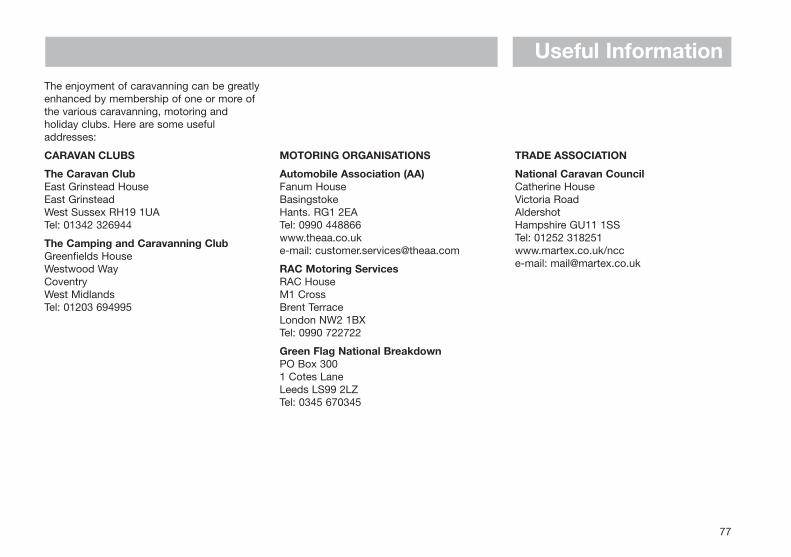
Useful Information
77
The enjoyment of caravanning can be greatlyenhanced by membership of one or more ofthe various caravanning, motoring andholiday clubs. Here are some usefuladdresses:
CARAVAN CLUBS
The Caravan ClubEast Grinstead HouseEast GrinsteadWest Sussex RH19 1UATel: 01342 326944
The Camping and Caravanning ClubGreenfields HouseWestwood WayCoventryWest MidlandsTel: 01203 694995
MOTORING ORGANISATIONS
Automobile Association (AA)Fanum HouseBasingstokeHants. RG1 2EATel: 0990 448866www.theaa.co.uke-mail: [email protected]
RAC Motoring ServicesRAC HouseM1 CrossBrent TerraceLondon NW2 1BXTel: 0990 722722
Green Flag National BreakdownPO Box 3001 Cotes LaneLeeds LS99 2LZTel: 0345 670345
TRADE ASSOCIATION
National Caravan CouncilCatherine HouseVictoria RoadAldershotHampshire GU11 1SSTel: 01252 318251www.martex.co.uk/ncce-mail: [email protected]

Index
A After Sales Support ......................................76Arrival at Site ................................................13Awnings/Tents ..............................................14
B Battery ..........................................................26Battery Charger ............................................28Beds..............................................................65Before moving off ...........................................6Blown Air Heating (Carver P4)......................33Butterfly Outlets............................................64
C Caravan Clubs ..............................................77Carver 2000P, A & Fanmaster ......................59Carver 4000P, A, 5500 & Fanmaster ...........62Carver P4 Blown Air Heater .........................33Carver Space Heaters ..................................59Cascade 2 GE Water Heater ........................32CEC 225 Unit................................................27Changing a Wheel ........................................10Codes of Conduct ..........................................2
Camp Sites.................................................2Coastal Code .............................................4Country Code.............................................4
Connecting Services ....................................15Corner Steadies............................................14Cramer Hob ..................................................47
D Distribution Panel KT9M5.............................29Doors ............................................................67
E Electrical Systems ........................................25Battery......................................................26Battery Charger ........................................28Distribution Panel KT9M5 ........................29Fuses (12V)...............................................29Generator Guidelines ...............................30Mains Unit ................................................27Power System (12V) .................................28
Transformer/Charger KT12SM .................28Electricity ......................................................20En Route .........................................................9Equipment Power Consumption ..................23
F Fanmaster Warm Air Heater....................59/62Fire ................................................................12Fuses ............................................................29
G Gas ...............................................................18Butane Gas ..............................................18Propane Gas ............................................18Regulators ................................................18
Gas Safety ....................................................19Generator Guidelines....................................30Grills.........................................................45/46
H Heating .........................................................56Hobs...................................................45/46/47
L Levelling the Vehicle .....................................14Loading the Vehicle ........................................6
M Mains Inlet Cable..........................................22Mains Unit (CEC 225) ...................................27Motorhome Care ..........................................69
Chassis/Rear Axle ....................................72Exhaust System .......................................72Exterior .....................................................70Interior ......................................................71Winterisation/Storage...............................72
Motoring Organisations ................................77
O Overseas Connections .................................21
P Payload Allowance .........................................6Positioning the Motorhome ..........................14Power System (12V) .....................................28Preparing for the Road ...................................5
R Refrigerators .................................................34Repair Facilities ............................................76Rooflights......................................................66Roof Loading ..................................................7
S Safety & Security ..........................................11Security.........................................................12Shower..........................................................67Side Locker...................................................64Space Heaters ..............................................59Spares...........................................................76Spare Wheel Removal ..................................10Stoves 8000/9000 Cooker............................44Stoves Combination Oven............................43Stoves Vanette Hob & Grill ...........................46Swivel Seats .................................................64
T Table .............................................................65Technically Permissible Laden Mass..............6Thermal Insulation .......................................23Thetford Cassette C-200..............................49Thetford Porta Potti ......................................52Toilets............................................................49Trade Association .........................................77Transformer/Charger KT12SM......................28Travel Catch..................................................42Trumatic C3400 & C6000 .............................56Tyres................................................................7
U Useful Information ........................................75
V Ventilation .....................................................12
W Water System ...............................................16Water Pump (Shurflo) ...................................32Water Pump (Whale).....................................32Weights ...........................................................6Windows .......................................................66Winterisation/Storage ...................................72
79
Swift Group LimitedDunswell Road, Cottingham,East Yorkshire HU16 4JXTel: (01482) 875740e-mail/web site: www.swiftleisure.co.uk
© 1999 SWIFT GROUP LTD
80

Quality with Style
SWIFT MOTORHOMES, DUNSWELL ROAD, COTTINGHAM, EAST YORKSHIRE HU16 4JX. TEL: 01482 847332 FAX: 01482 840082 e-mail/web site: www.swiftleisure.co.uk
Issued September 1999 9830014
Related Documents


