Transactions, SMiRT-25 Charlotte, NC, USA, August 4-9, 2019 Division II SWELLING OF THE WWER-1000 REACTOR CORE BAFFLE Yaroslav Dubyk 1 , Vladislav Filonov 2 , Yuliia Filonova 2 1 Head of the Department for Strength Calculations, “IPP-Centre” LLC, Kiev, Ukraine ([email protected]) 2 Engineer, “IPP-Centre” LLC, Kiev, Ukraine ABSTRACT This paper presents an in-depth assessment of WWER-1000 reactor core baffle integrity using ANSYS User-Programmable Features for irradiation, swelling and creep. The calculations used are based on the improved computational fluid dynamics (CFD) estimation of temperature field distribution. Further mechanical calculations presented account for material swelling due to radiation damage dose and radiation energy release, as well as radiation creep. The critical elements from a structural integrity point of view are established, from static and fracture analysis. Calculated gaps and contacts between the reactor internals do not limit the lifetime extension, except where possible contact with fuel assemblies can occur. INTRODUCTION Swelling of reactor vessel internals (PVI) is one of the limiting factors of operational longevity for WWER- 1000 (Water-Water Energetic Reactor of Soviet type) reactors, Pištora et al. (2017). The reactor core baffle experiences heavy loadings of neutron and gamma irradiation. Therefore, the degradation of reactor internal material along with geometric distortion, called swelling, is quite severe. This work is dedicated for an improved estimation of the core baffle stress-strain field distribution during reactor operation life cycle. For swelling calculations of the reactor internals, we have used the following expression from Margolin et al. (2011) and IAEA VERLIFE (2013): ( ) 2 0 [ ] – v n irr m S cF exp r T T = − , (1) Here с =1.03510 4 ; n v = 1.88; r = 1.82510 -4 ˚C -2 ; Т m = 470°C, Т irr and F are baffle temperature [˚C] and radiation damage dose [dpa]. Eq.(1) represents the simplest swelling law, also called free swelling. Stress level ( ) 1 eff f and plastic deformation ( ) 2 æ p f also affect the swelling process (Margolin et al., 2011; IAEA VERLIFE,2013): ( ) ( ) 0 1 2 æ eff p S S f f = , (2) ( ) ( ) 1 1 1 1 1 eff m eq f P = + − + , (3) ( ) ( ) 2 2 æ exp p p ep f d = − , (4) Here m − hydrostatic stress, eq − equivalent von-Mises stress, p ep − equivalent plastic strain, also in (3)-(4) we have used coefficients: 1 0.15 = , 2 8.75 = , 3 8 10 P MPa − = . Radiation creep is calculated using (Margolin et al., 2011; IAEA VERLIFE,2013): 6 3 (1 10 2.7 10 ) eq eq F S − − = + , (5) Note, that overdot denotes time derivative. The swelling calculations are extensive. The initial input data are radiation damage dose and radiation energy release. Then a detailed temperature field distribution using CFD can be obtained.

Welcome message from author
This document is posted to help you gain knowledge. Please leave a comment to let me know what you think about it! Share it to your friends and learn new things together.
Transcript

Transactions, SMiRT-25
Charlotte, NC, USA, August 4-9, 2019
Division II
SWELLING OF THE WWER-1000 REACTOR CORE BAFFLE
Yaroslav Dubyk1, Vladislav Filonov2, Yuliia Filonova2
1 Head of the Department for Strength Calculations, “IPP-Centre” LLC, Kiev, Ukraine
([email protected]) 2 Engineer, “IPP-Centre” LLC, Kiev, Ukraine
ABSTRACT
This paper presents an in-depth assessment of WWER-1000 reactor core baffle integrity using ANSYS
User-Programmable Features for irradiation, swelling and creep. The calculations used are based on the
improved computational fluid dynamics (CFD) estimation of temperature field distribution. Further
mechanical calculations presented account for material swelling due to radiation damage dose and radiation
energy release, as well as radiation creep. The critical elements from a structural integrity point of view are
established, from static and fracture analysis. Calculated gaps and contacts between the reactor internals do
not limit the lifetime extension, except where possible contact with fuel assemblies can occur.
INTRODUCTION
Swelling of reactor vessel internals (PVI) is one of the limiting factors of operational longevity for WWER-
1000 (Water-Water Energetic Reactor of Soviet type) reactors, Pištora et al. (2017). The reactor core baffle
experiences heavy loadings of neutron and gamma irradiation. Therefore, the degradation of reactor internal
material along with geometric distortion, called swelling, is quite severe.
This work is dedicated for an improved estimation of the core baffle stress-strain field distribution
during reactor operation life cycle. For swelling calculations of the reactor internals, we have used the
following expression from Margolin et al. (2011) and IAEA VERLIFE (2013):
( )2
0 [ ] – vn
irr mS c F exp r T T= − ,
(1)
Here с =1.035104; nv = 1.88; r = 1.82510-4 ˚C-2; Тm= 470°C, Тirr and F are baffle temperature [˚C]
and radiation damage dose [dpa]. Eq.(1) represents the simplest swelling law, also called free swelling.
Stress level ( )1 efff and plastic deformation ( )2 æpf also affect the swelling process (Margolin et al.,
2011; IAEA VERLIFE,2013):
( ) ( )0 1 2 æeff pS S f f= , (2)
( ) ( )1 1 11 1eff m eqf P = + − + , (3)
( ) ( )2 2æ exp p
p epf d = − , (4)
Here m − hydrostatic stress, eq − equivalent von-Mises stress, p
ep − equivalent plastic strain, also
in (3)-(4) we have used coefficients: 1 0.15 = , 2 8.75 = , 38 10P MPa−= .
Radiation creep is calculated using (Margolin et al., 2011; IAEA VERLIFE,2013): 6 3(1 10 2.7 10 )eq eqF S − −= + , (5)
Note, that overdot denotes time derivative. The swelling calculations are extensive. The initial input
data are radiation damage dose and radiation energy release. Then a detailed temperature field distribution
using CFD can be obtained.

25th Conference on Structural Mechanics in Reactor Technology
Charlotte, NC, USA, August 4-9, 2019
Division II
Analysis of (1) shows, that the swelling level greatly depends upon the temperature of the core baffle.
If temperature is changed only for 30°C volume, then the swelling decreases by 2.66 times. Thus, from the
viewpoint of increasing reactor internal resources, it is important to address to reducing the conservatism
of the temperature distribution calculations of the reactor baffle. A detailed analysis of the core baffle metal
thermohydraulic cooling characteristics are obtained earlier in Filonova et al. (2018) and the improved
results of it are described below. The main problems that baffle swelling causes are: the structural integrity
of baffle connection studs and baffle itself, because if they fail, then the baffle will split apart; the structural
integrity of the core barrel due to contact during baffle outside surface elongation; and baffle swelling
causing inside dimensions to become smaller, thus there is a danger of fuel rods sticking. Additionally,
when the baffle and barrel make contact, then the annulus between them becomes smaller, therefore a
reliable assessment of cooling of the baffle’s outer surface should be proven.
To address all these issues, a detailed swelling analysis (including radiation creep effects) is
performed. Swelling is of particular importance to the Ukraine, whose Nuclear Power Plants have WWER
-1000 reactors (generally applying to all WWER-1000 units), because reactor internal life-span extension
is being limited by this problem.
TEMPERATURE FIELD
In predicting the swelling process of core baffle material, particular attention is paid to the refinement of
its temperature field. As earlier noted in Filonova et al. (2018) we presented a procedure for an improved
assessment of the baffle metal temperature field. A developed approach for the use of three-dimensional
computational fluid dynamics (CFD) allowed reducing existing uncertainties and, accordingly, allowed
removing excessive conservatism. In order to reduce the computational model, we developed a preliminary
analytical procedure of evaluating the “replacement” boundary conditions, to account for the systematic
influence of the reactor facility elements. Although the calculated convection coefficient and the
temperature were in good agreement with the analytical model, that gave a more convenient result compared
to RELAP5/mod3.2, we have refined and improved our analytical model and three-dimensional CFD
concept.
Analytical model
In our first three-dimensional baffle cooling CFD model, the boundary conditions were of the “pressure-
pressure” type. We did this because the reactor nodalization of the system code RELAP5 neglected the
detailed characteristic geometry of the cooling channels groups. To obtain a convergent resultant, we
disregarded the flow characteristics, which account for the specifics of flow modeling in parallel channels
having a sudden narrowing / expansion in CFD codes and without special domain segregation. For this
reason, we developed a special procedure of mass boundary conditions estimation for cooling channels
using the pressure drop obtained in RELAP5.
The calculations are based on one-dimensional hydraulics, where each channel is replaced by an
equivalent geometry having the appropriate pressure loss characteristics.
For the general case for non-isothermal flow having large energy dissipation, it is necessary to solve
using a system of nonlinear differential equations. However, when the pressure drop relative to absolute
does not exceed 1.5%, and the coolant heating is less than 15°C, then the dependence of thermophysical
properties on the thermal state parameters can be neglected. Therefore, in order to determine the coolant
flow rate through equivalent channels, a transcendental equation of the following form is presented and
solved:
( )2
2 1 1
2BAFFLEin out
i
P P G G gHS
− = +
(6)
Here – density, BAFFLE
H – core baffle height, G – mass flow rate through an element; –-
hydraulic resistance coefficient; and S – channel cross section area.
Initially, the calculation procedure neglected the flow connection of the annular gap between baffle
and barrel with cooling channels in area near the studs Filonova et al. (2018). This could lead to

25th Conference on Structural Mechanics in Reactor Technology
Charlotte, NC, USA, August 4-9, 2019
Division II
underestimation / overestimation of these channels’ cooling capacity. In order to clarify the effect of this
mixing, we developed an additional element, consisting of 63 sections (Figure 1).
Figure 1. Equivalent calculation scheme with coolant mixing near the studs.
The comparative values of mass flow rates are given in the Table 1. The referenced density, adopted
in the assessment, is equal to 716 kg/m3.
Table 1: Comparison of results with and without mixing of the coolant.
Characteristic G, kg/s
(without mixing )
G, kg/s (Inlet/Outlet)
(with mixing ) ОКB “GP”
Annular channel 44,90 45,59/47,73 ~49,72
1 Group channel 0,59 0,60/0,19 ~0,56
2 Group channel 1,25 1,27/0,41 ~1
The results of our preliminary assessment indicate that the flow rate in channels, with mixing, is
lower (in the center, = 0.1-0.2 kg / s), which corresponds to a lower heat dissipation capacity. This
circumstance must be considered in nodal codes of the RELAP5 type, in order to obtain correct boundary
conditions with the subsequent baffle temperature field determination using only non-uniform thermal
conductivity. In the CFD model, a similar decrease in heat dissipation is predicted accurately.
CFD simulation
Our first CFD model (see Filonova et al. (2018)) was substantially simple, because we just wanted to
demonstrate a direct and improved approach in developing a way to estimate the baffle temperature field
for the swelling problem. Now, when the advantage of applying three-dimensional computational fluid
dynamics to this problem was made obvious, there is a goal of testing the influence of such previously
neglected baffle structural features as the presence of cooling ribs. In order to study the impacts of the

25th Conference on Structural Mechanics in Reactor Technology
Charlotte, NC, USA, August 4-9, 2019
Division II
cooling ribs’ presence, the previously developed CFD model has been improved. The main geometrical
difference of the new model is the consideration of cooling ribs and the improved detailing of the studs. A
general view of the previously used model, and the refined baffle geometry details are shown in Figure 2.
1 – core barrel fragment 5* – new core geometry
2 – cooling channels (2nd group) 6 – coolant in threaded rod (flowing part)
3 – coolant in the circular gap 7 – threaded rod
4 – cooling channels (1st group) 8 – stud (* - refined geometry)
5 – core (porous body) 9 – core baffle (* - refined geometry)
Figure 2. General view of the CFD model geometry.
The improved CFD model, like the simplified one, has a two-plane 60-degree symmetry and is
axially limited by the height of the baffle. In contrast to the original one, in new model the porous core
body is replaced by the coolant domain, from the cross section of which the hexagonal regions
corresponding in area to the fuel assemblies metal are subtracted. Such an approach simplifies the
formulation, because the model setting in this case is carried out with only one parameter – an additional
dissipative moment. In the rest, the description of the model and the applied boundary conditions
correspond to Filonova et al. (2018).
During the development of the computational mesh, special attention was paid to the discretization
of the boundary layer. With that, previously adopted dimensional characteristics of boundary layers’
elements for different groups of channels, that are relevant, were applied to the improved model. For the
new geometry of baffle metal, test calculations on grids with different discretization, both in the section
and in the axial direction, were carried out. The volume averaged temperature and maximum temperature
of baffle metal were chosen as the studied parameters. The results of variant calculations are presented in
Table 2. The Mesh#4 was chosen for further calculation.
Table 2: Results of calculations on different Meshes.
Characteristic Mesh#1 Mesh#2 Mesh#3
Mesh#4
(axial
detailed
Mesh#1)
Mesh#3
(model without
cooling ribs with
actual radiation
energy release)
Volume averaged Temperature, [⁰C] 314,7 314,98 314,98 314,96 315,73
Maximum Temperature, [⁰C] 367,9 368,2 368,2 368,2 369,05
Nodes (N) 60,8 10 61,5 10 62,4 10 61,4 10 69 10
Elements (E) 60,7 10 61,3 10 62,1 10 61,2 10 62,31 10
25th Conference on Structural Mechanics in Reactor Technology
Charlotte, NC, USA, August 4-9, 2019
Division II
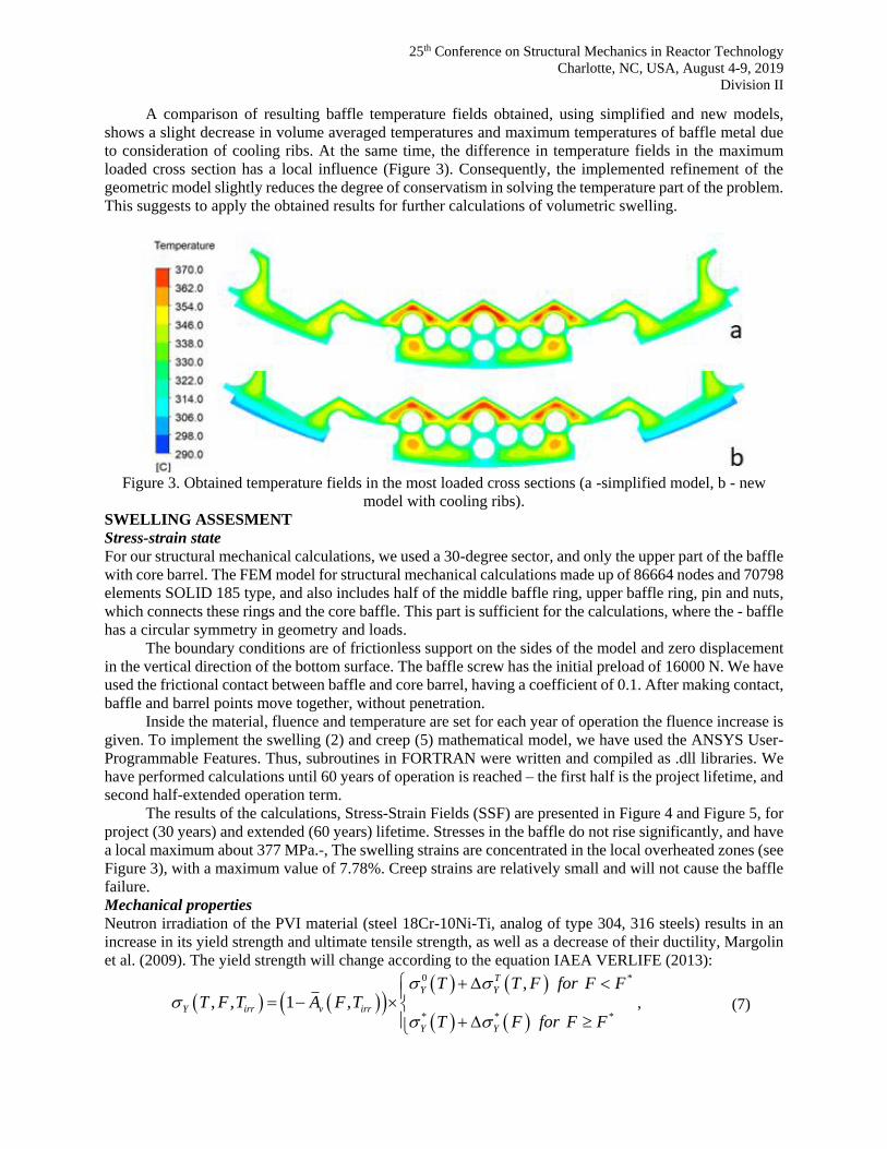
A comparison of resulting baffle temperature fields obtained, using simplified and new models,
shows a slight decrease in volume averaged temperatures and maximum temperatures of baffle metal due
to consideration of cooling ribs. At the same time, the difference in temperature fields in the maximum
loaded cross section has a local influence (Figure 3). Consequently, the implemented refinement of the
geometric model slightly reduces the degree of conservatism in solving the temperature part of the problem.
This suggests to apply the obtained results for further calculations of volumetric swelling.
Figure 3. Obtained temperature fields in the most loaded cross sections (a -simplified model, b - new
model with cooling ribs).
SWELLING ASSESMENT
Stress-strain state
For our structural mechanical calculations, we used a 30-degree sector, and only the upper part of the baffle
with core barrel. The FEM model for structural mechanical calculations made up of 86664 nodes and 70798
elements SOLID 185 type, and also includes half of the middle baffle ring, upper baffle ring, pin and nuts,
which connects these rings and the core baffle. This part is sufficient for the calculations, where the - baffle
has a circular symmetry in geometry and loads.
The boundary conditions are of frictionless support on the sides of the model and zero displacement
in the vertical direction of the bottom surface. The baffle screw has the initial preload of 16000 N. We have
used the frictional contact between baffle and core barrel, having a coefficient of 0.1. After making contact,
baffle and barrel points move together, without penetration.
Inside the material, fluence and temperature are set for each year of operation the fluence increase is
given. To implement the swelling (2) and creep (5) mathematical model, we have used the ANSYS User-
Programmable Features. Thus, subroutines in FORTRAN were written and compiled as .dll libraries. We
have performed calculations until 60 years of operation is reached – the first half is the project lifetime, and
second half-extended operation term.
The results of the calculations, Stress-Strain Fields (SSF) are presented in Figure 4 and Figure 5, for
project (30 years) and extended (60 years) lifetime. Stresses in the baffle do not rise significantly, and have
a local maximum about 377 MPa.-, The swelling strains are concentrated in the local overheated zones (see
Figure 3), with a maximum value of 7.78%. Creep strains are relatively small and will not cause the baffle
failure.
Mechanical properties
Neutron irradiation of the PVI material (steel 18Cr-10Ni-Ti, analog of type 304, 316 steels) results in an
increase in its yield strength and ultimate tensile strength, as well as a decrease of their ductility, Margolin
et al. (2009). The yield strength will change according to the equation IAEA VERLIFE (2013):
( ) ( )( )( ) ( )
( ) ( )
0 *
* * *
,, , 1 ,
T
Y Y
Y irr v irr
Y Y
T T F for F FT F T A F T
T F for F F
+
= − +
, (7)

25th Conference on Structural Mechanics in Reactor Technology
Charlotte, NC, USA, August 4-9, 2019
Division II
Here ( )0
Y T and ( )Y T − change in mechanical property due to the temperature, ( )0 ,Y T F and
( ),Y T F − influence of irradiation, vA − the relative area of the voids, due to the irradiation effects:
Figure 4. SSF for 30 years of operation: a) Equivalent von-Mises stress b) Creep strain c) Swelling strain.
Figure 5. SSF for 60 years of operation: a) Equivalent von-Mises stress b) Creep strain c) Swelling strain.
2/3
1v
SA
S
=
+ , (8)
The ultimate tensile strength will change according to formula IAEA VERLIFE (2013):
( ) ( ) ( ) ( )( )0, , 1 , ;ul irr ul ul V irr irrT F T T F A F T T T = + − , (9)
The reduction of a relative area, characteristics of plasticity:
( )( )1
1 1B
irr ini−
= − − , where
0,5
0
1 exp 0,4F
B AF
= − −
(10)
Analysis of formula (8) - (10) shows that due to the radiation, strength properties increase, and
plasticity decreases. In Figure 6 and Figure 7 we see the mechanical properties’ distribution for 30 and 60
years of operation. The yield strength and ultimate tensile strength rises significantly. In comparing with

25th Conference on Structural Mechanics in Reactor Technology
Charlotte, NC, USA, August 4-9, 2019
Division II
Figure 4 and Figure 5 we can state that plastic strain will not occur. Thus, the unloading cycles, caused by
reactor shut down for fuel change, may be omitted. In the zones of maximum swelling, some softening can
be seen, due to the voids, see Eq.(8). Increasing of yield and ultimate tensile strength and decreasing in irr from 40% to 16% significantly affects the baffle fatigue strength and should be addressed properly in
residual lifetime calculations.
Figure 6. Mechanical properties for 30 years of operation: a) Yield strength; b) Ultimate tensile strength
c) Reduction of area
Figure 7. Mechanical properties for 60 years of operation: a) Yield strength; b) Ultimate strength tensile
c) Reduction of area.
Displacements and gaps
As mentioned earlier, the analysis of gaps between baffle and fuel rods or barrel is of high importance. Due
to the baffle swelling, external points near the large channels are moving outwardly and are making contact
with the barrel inner surface. Points of the inner baffle surface, near the center teeth, move inside the center
and may make contact with the fuel rods. The narrowest place is the baffle ring flange, where the gap is
about 2.5 mm in the cold state of reactor. In the hot state, we note only half of this gap due only to baffle
non-uniform expansion. Depending upon fluence input data, contact on 20-40 year of operation is possible.
In Figure 8 the gap between the baffle rings and core barrel is presented. After 20 years of operation in the
25th Conference on Structural Mechanics in Reactor Technology
Charlotte, NC, USA, August 4-9, 2019
Division II
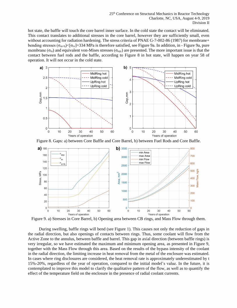
hot state, the baffle will touch the core barrel inner surface. In the cold state the contact will be eliminated.
This contact translates to additional stresses in the core barrel, however they are sufficiently small, even
without accounting for radiation hardening. The stress criteria of PNAE G-7-002-86 (1987) for membrane+
bending stresses (σm+b)<[σrv]=334 MPa is therefore satisfied, see Figure 9a. In addition, in - Figure 9a, pure
membrane (σm) and equivalent von-Mises stresses (σeqv) are presented. The more important issue is that the
contact between fuel rods and the baffle, according to Figure 8 in hot state, will happen on year 58 of
operation. It will not occur in the cold state.
Figure 8. Gaps: a) between Core Baffle and Core Barrel, b) between Fuel Rods and Core Baffle.
Figure 9. a) Stresses in Core Barrel, b) Opening area between CB rings, and Mass Flow through them.
During swelling, baffle rings will bend (see Figure 1). This causes not only the reduction of gaps in
the radial direction, but also openings of contacts between rings. Thus, some coolant will flow from the
Active Zone to the annulus, between baffle and barrel. This gap in axial direction (between baffle rings) is
very irregular, so we have estimated the maximum and minimum opening area, as presented in Figure 9,
together with the Mass Flow through this area. Based on the results of the bypass intensity of the coolant
in the radial direction, the limiting increase in heat removal from the metal of the enclosure was estimated.
In cases where ring disclosures are considered, the heat removal rate is approximately underestimated by t
15%-20%, regardless of the year of operation, compared to the initial model’s value. In the future, it is
contemplated to improve this model to clarify the qualitative pattern of the flow, as well as to quantify the
effect of the temperature field on the enclosure in the presence of radial coolant currents.

25th Conference on Structural Mechanics in Reactor Technology
Charlotte, NC, USA, August 4-9, 2019
Division II
Strength assessment
From Figure 9a we can conclude that for the core barrel, static strength is ensured, even after contact is
made with the core baffle. But for a core baffle, such a static criterion (in terms of membrane and bending
stresses) could be hardly adopted due to the complicated geometry and radiational effects. Thus, only
fatigue (Pištora et al., 2017) and fracture (Margolin et al., 2009) criteria should be addressed. For fracture
assessment we have chosen four zones of maximum stresses or severe brittle toughness degradations (see
Figure 10). We have postulated quarter-elliptical cracks, with depths a=0.25s, s – local wall thickness, and
dimensions of a/c=2/3 and a/c=1/3 and c is the crack half-length. The results of fracture calculations are
summarized in Table 3. Note that due to the radiation damage, fracture toughness in various zones differs.
For crack 1 we note the most severe degradation due to the swelling, but the Stress Intensity Factor (SIF)
is relatively small. Opposite crack 4 we note a large SIF and slight degradation. In all zones of postulated
crack fracture, the criterions are satisfied. Fatigue assessment will be addressed future research.
Figure 10. Hoop stresses (MPa) in Baffle cross-section for 60th fuel cycle, and zones of postulated cracks.
Table 3: SIF (MPa√m) for different zones of Core Baffle (see Figure 10).
Years
Crack 1 Crack 2 Crack 3 Crack 4
a/c=2/3 a/c=1/3 [K1c] a/c=2/3 a/c=1/3 [K1c] a/c=2/3 a/c=1/3 [K1c] a/c=2/3 a/c=1/3 [K1c]
30 9.0 8.9 46.3 24.5 31.5 76.8 24.1 28.6 88.3 19.9 22.9 96.6
60 11.0 10.4 44.2 23.4 28.6 58.9 29.4 35.9 69.6 36.7 42.8 81.5
Another critical element, from a structural integrity point of view, involve the connection studs (see
Figure 1). Static strength assessment for these are presented on Figure 11a. We note that equivalent von-
Mises(σeqv), and membrane+bending stresses(σm+b) do not exceed the criterial stresses [0.85Rp0.2]. In Figure
11a criterial stresses are given for a radiation hardened material. A more challenging task is determining
fracture toughness for this element. SIF for a crack in a stud can be calculated using the simple formula:
( )2
1 12.5 35 2K P d P = +
, (11)
Here P−screw pitch 1d − inner diameter of screw. A more realistic calculation accounts for stress
decomposition into membranne and bending API 579-1/ASME FFS-1 (2016):
1 m m b bK M M a = + , (12)
Here 2a P= − crack depth, 0d − outer diameter of screw, and coefficient for membrane and bending
stress have the form ( 0a d = ):
31.332 2 3 42.043 0.6507 0.5367 3.0469 19.504 45.647mM e −= + + + − + , (13)

25th Conference on Structural Mechanics in Reactor Technology
Charlotte, NC, USA, August 4-9, 2019
Division II
2 3 40.6301 0.03488 3.3365 13.406 6.0021bM = + − + − (14)
From Figure 11b we note that according to Eq. (11) fracture criteria is satisfied only up to 48 years
of operation. A more detailed Eq .(12) gives an additional resource for as extended lifetime.
Figure 11. Strength assessment of the baffle pins: a) Static strength; b) Brittle strength.
CONCLUSION
We have performed swelling calculations for the WWER-1000 reactor core baffle using compiled for
ANSYS User Subroutines. These calculations included detailed Stress-Strain Filed calculations with
radiation swelling and creep effects, mechanical properties hardening (ultimate and yield strength) analyses
as well as plastic properties degradation (fracture toughness and relative area reduction) assessment. The
calculations are based on an improved analysis of temperature field distributions from our previous work
Filonova et al. (2018) using CFD. From a mechanical point of view, the most loaded components of the
system are the studs, which connect core baffle rings. The fracture strength for these elements is critical.
Possible contact between baffle and barrel has also been addressed. The additional stresses in the core barrel
do not exceed the strength criteria of PNAE G-7-002-86. Due to the swelling process, the gaps in Reactor
Pressure Internal’s elements are reduced and the possible contact with fuel assemblies on the 58th year of
operation is critical and as such, limits the lifetime extension. The opening of contacts between rings, i.e.
the axial gaps will lead to redistribution of coolant flow and may result - in additional baffle cooling.
REFERENCES
API 579-1/ASME FFS-1. (2016). Fitness-For-Service. Washington DC, USA.
Filonova, Y., Filonov, V., Dubyk, Y. (2018). “Reactor baffle cooling CFD framework for swelling
assessment,” Proc. of the ASME 2018 26th International Conference on Nuclear Engineering
ICONE26-82365, London, England, V009T16A079. doi:10.1115/ICONE26-82365.
IAEA VERLIFE. (2013). Unified Procedure for Lifetime Assessment of Components and Piping in WWER
NPPs during Operation.
Margolin, B. Z., Murashova, A. I., Neustroev, V. S. (2011). “Effect of stress on radiation swelling of
austenitic steels,” Problems of materials science, 4(68) 124–139.
Margolin, B. Z., Kursevich, I. P., Sorokin, A. A., Neustroev, V. S. (2009). “The Relationship of Radiation
Embrittlement and Swelling for Austenitic Steels for WWER Internals,” ASME 2009 Pressure
Vessels and Piping Conference, Prague, Czech Republic, 939-948. doi:10.1115/PVP2009-77078
Pištora, V., Švrček, M, Mirzov, I. (2017). “Fatigue assessment of VVER-1000 core baffle,” 24th
Conference on Structural Mechanics in Reactor Technology BEXCO, Busan, Korea, 522-532.
PNAE G-7-002-86. (1987). Strength Analysis Code for Nuclear Power Plant Equipment and Piping.
Energoatomizdat.
Related Documents