Sustainable Drainage Design & Evaluation Guide

Welcome message from author
This document is posted to help you gain knowledge. Please leave a comment to let me know what you think about it! Share it to your friends and learn new things together.
Transcript

SustainableDrainage
Design & Evaluation Guide
3 2
Contents
1.0 Introduction
2.0 Understanding Rainfall
3.0 The Impact of Development
4.0 The Role of SuDS
5.0 The SuDS Design & Evaluation Process
6.0 Local SuDS requirements
7.0 Stage 1: Concept Design
8.0 Stage 2: Outline Design
9.0 Stage 3: Detailed Design
9.1 Objectives of Detailed Design
9.2 What Detailed Design Should Demonstrate
9.3 Typical Detailed Design Package
9.4 Critical Levels
9.5 Designing for Hydraulic Requirements
9.6 Controlling Flows
9.7 Water Quality
9.8 Amenity
9.9 Biodiversity
9.10 Planting Design for SuDS
9.11 SuDS Components
9.12 Management of the SuDS Landscape
Acronyms used in this document
4
9
13
17
21
25
57
67
68
68
69
76
77
93
102
107
111
113
123
139
inside back cover
Why this guide is needed
Our understanding of the negative impacts
of conventional drainage are now well
understood.
Pipe drainage collects and conveys water
away from where it rains, as quickly as
possible, contributing to increased risk of
flooding, likelihood of contaminated water
and the loss of our relationship with water
and the benefits it can bring to us all.
Sustainable Drainage, or SuDS, is a way of
managing rainfall that mimics the drainage
processes found in nature and addresses the
issues with conventional drainage.
Who this guide is intended for
In 2010 the Flood and Water Management
Act proposed that SuDS should be used on
most development and this was confirmed in
a ministerial statement on 23 March 2015
introducing the ‘non statutory technical
standards’ for SuDS.
The responsibility for ensuring that SuDS are
designed and implemented to a satisfactory
standard lies with the Local Planning
Authority (LPA).
SuDS Designers will need to meet these
required standards when submitting
proposals to the LPA.
Preface
What the guide provides
This guide links the design of SuDS with the
evaluation requirements of planning in a
sequence that mirrors the SuDS design
process.
This guide promotes the idea of integrating
SuDS into the fabric of development using
the available landscape spaces as well as the
construction profile of buildings. This
approach provides more interesting
surroundings, cost benefits, and simplified
future maintenance.
This guide begins by giving a background
context for SuDS design. Next, the three
accepted design stages are described:
Concept Design, Outline Design and Detail
Design. Subsequent chapters offer
supporting information.
It is intended that this guide will facilitate
consultation, in order to achieve the best
possible SuDS designs.
Lincolnshire County Council SuDS D & E Guide © 2018 McCloy Consulting & Robert Bray Associates Lincolnshire County Council SuDS D & E Guide © 2018 McCloy Consulting & Robert Bray Associates
5 4
This development guide has the support of 16
Local Authorities across England. The project
partners have contributed both financially and
informatively through facilitated workshops to
the development of the guide.
Project Partners
■ Lewisham Council
■ Lincolnshire County Council
■ London Borough of Bexley
■ London Borough of Enfield
■ London Borough of Hackney
■ London Borough of Hammersmith and
Fulham
■ London Borough of Haringey
■ London Borough of Hillingdon
■ London Borough of Merton
Copyright © 2018 Robert Bray Associates and McCloy Consulting
All rights reserved. No part of this publication may be reproduced, stored in a retrieval system, or
transmitted, in any form or by any means, including electronic, mechanical, photocopying, recording
or otherwise, except in accordance with the provisions of the Copyright, Designs and Patents Act
1998, without the prior written permission of the copyright holder, application for which should be
addressed to Robert Bray Associates and McCloy Consulting (c/o McCloy Consulting).
No responsibility for loss or damage caused to any person acting or refraining from action as a result
of the material included in this publication can be accepted by the authors.
If you would like to reproduce any of the images, figures, text or technical information from this
publication for use in other documents or publications, please contact Robert Bray Associates and
McCloy Consulting.
■ Luton Borough Council
■ Oxford City Council
■ Oxfordshire County Council
■ Peterborough City Council
■ Royal Borough of Kensington and Chelsea
■ Worcestershire County Council
■ North Worcestershire Water Management
Districts:
Wyre Forest District Council
Bromsgrove District Council
Redditch Borough Council
Bob Bray Director Robert Bray Associates
Robert Bray has been a pioneer of UK SuDS
since 1996. He has been at the forefront of
demonstrating how SuDS can be fully
integrated with the surrounding landscape.
Bob has been a key tutor for the (CIRIA)
National SuDS training workshops since
2003.
Kevin Barton Director Robert Bray Associates
Kevin Barton has been working as a
Landscape Architect for over 20 years and
designing SuDS landscapes exclusively since
2011. In addition to project work, Kevin has
also contributed to SuDS Guidance
documents for Planning Authorities and
presented on SuDS topics at Conferences,
CIRIA ‘Susdrain’ events and to Planning
Authorities.
Kevin Tidy - LLFA (retired)
Acknowledgements
Ruth Newton - Planner
Anthony McCloy Director McCloy Consulting
Anthony McCloy is a Chartered Engineer
working exclusively in the water sector since
1998. Since 2003 he has focused on SuDS
design, hydraulic modelling for SuDS and
flood risk. He has co-authored SuDS
Guidance documents for Planning Authorities
and is a key tutor for the (CIRIA) National
SuDS training workshops since 2006.
Lincolnshire County Council SuDS D & E Guide © 2018 McCloy Consulting & Robert Bray Associates Lincolnshire County Council SuDS D & E Guide © 2018 McCloy Consulting & Robert Bray Associates
Overv
iew
Overv
iew
2 1
Since 2000 there have been an increasing number of publications that identify
the problems with traditional drainage and describe a different approach to
managing rainfall called Sustainable Drainage Systems or SuDS.
1.0
1.1 The origins of SuDS
The industrialisation of the UK and the
extensive use of pipes to collect and convey
runoff to streams and rivers has created a
legacy of flooding and pollution.
Pipe systems are at capacity, or surcharge in
heavy rain, washing everyday contamination
from hard surfaces directly into our
watercourses.
During the 1990s an awareness of better
ways to manage rainfall began to influence
thinking in Britain.
Ideas from the US and Sweden were initially
introduced in Scotland, to deal with runoff
from a large new development in
Dunfermline. Most of the concepts and terms
commonly used in Sustainable Drainage
Systems (SuDS) were introduced to Britain at
this time.
1.2 SuDS today
There have been a number of definitions of
Sustainable Drainage over the years, but the
following is based on the SuDS Manual 2015,
which was published by the Construction
Industry Research and Information
Association (CIRIA):
Introduction
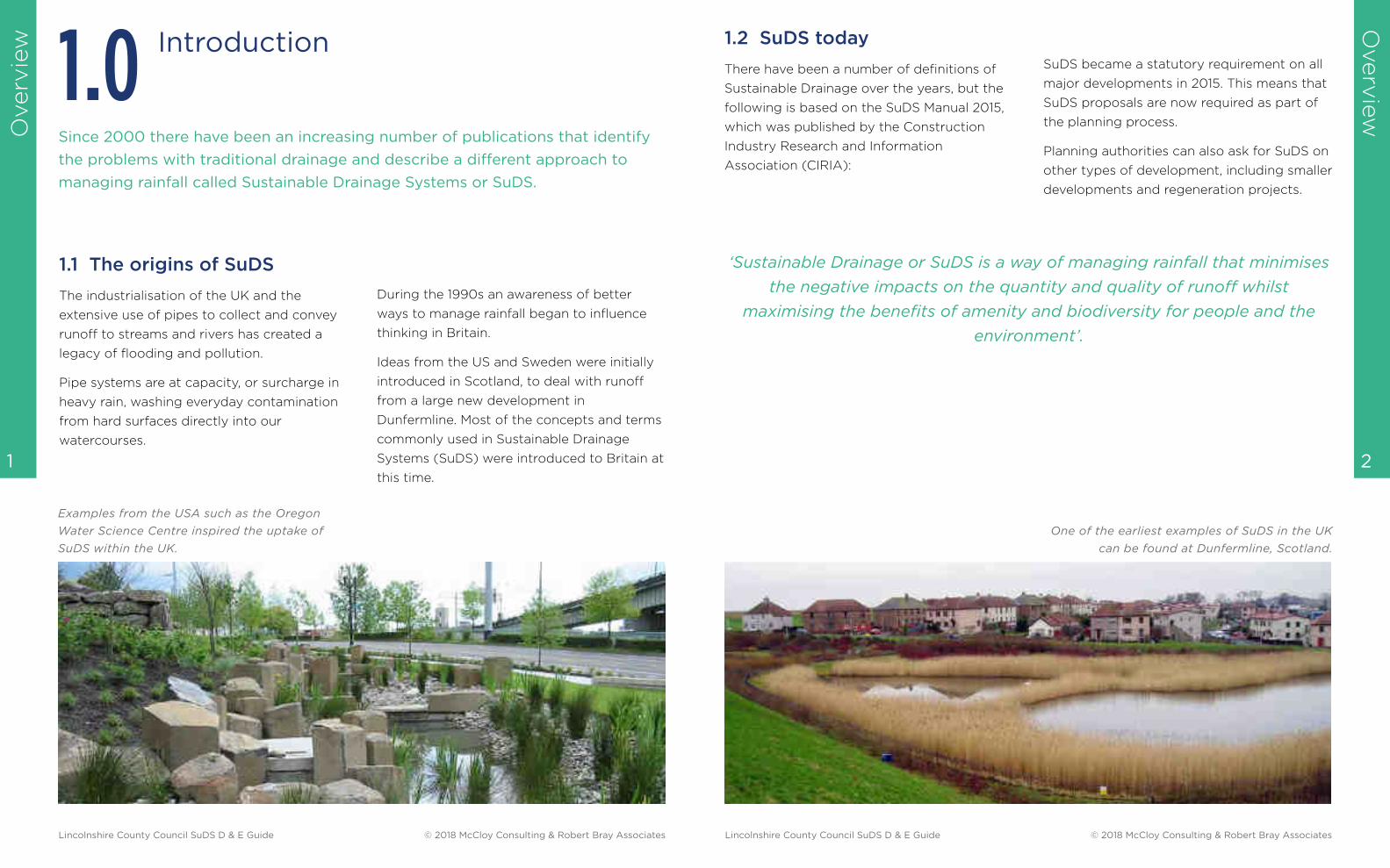
Examples from the USA such as the Oregon
Water Science Centre inspired the uptake of
SuDS within the UK.
One of the earliest examples of SuDS in the UK
can be found at Dunfermline, Scotland.
SuDS became a statutory requirement on all
major developments in 2015. This means that
SuDS proposals are now required as part of
the planning process.
Planning authorities can also ask for SuDS on
other types of development, including smaller
developments and regeneration projects.
‘Sustainable Drainage or SuDS is a way of managing rainfall that minimises
the negative impacts on the quantity and quality of runoff whilst
maximising the benefits of amenity and biodiversity for people and the
environment’.
Lincolnshire County Council SuDS D & E Guide © 2018 McCloy Consulting & Robert Bray Associates Lincolnshire County Council SuDS D & E Guide © 2018 McCloy Consulting & Robert Bray Associates
Overv
iew
Overv
iew
4 3
This guide is complementary to:
■ The National Planning Policy Framework (NPPF)
■ Relevant Local Planning Policy
■ Construction Industry Research and Information Association (CIRIA) 2015 SuDS Manual
(C753)
■ SuDS Non-Statutory Technical Standards (NSTS)
■ Local Authority SuDS Officer Organisation (LASOO) NSTS Practice Guidance
This guide draws upon the experience of the authoring team, which has been gained over 20
years of practical SuDS application.
A number of SuDS guides have been
produced in the UK since 2000, many of
which outline the benefits of SuDS, but fail to
provide sufficient insight into how design
should be approached with SuDS in mind,
and with little guidance on the evaluation
process for developments. This guide
considers design and evaluation of SuDS as
complementary. It explains both, from the
earliest iteration of Concept Design through
to the Detailing stage, in order to successfully
integrate SuDS into development.
The main objectives of this Design and
Evaluation guide are:
■ To create a shared vision around SuDS for
all involved in design and evaluation.
■ To enable the design and evaluation of
SuDS to meet agreed standards.
■ To ensure SuDS are maintainable now and
in the future.
1.3 Background to this document
2.0Understanding Rainfall
It is important that everyone involved in the design and evaluation of SuDS has
an understanding of the natural processes that occur in response to rain, so that
proposed schemes can mimic these.
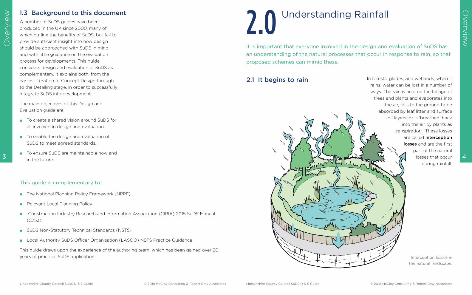
2.1 It begins to rain In forests, glades, and wetlands, when it
rains, water can be lost in a number of
ways. The rain is held on the foliage of
trees and plants and evaporates into
the air, falls to the ground to be
absorbed by leaf litter and surface
soil layers, or is ‘breathed’ back
into the air by plants as
transpiration. These losses
are called interception
losses and are the first
part of the natural
losses that occur
during rainfall.
Interception losses in
the natural landscape.
Lincolnshire County Council SuDS D & E Guide © 2018 McCloy Consulting & Robert Bray Associates Lincolnshire County Council SuDS D & E Guide © 2018 McCloy Consulting & Robert Bray Associates
Overv
iew
Overv
iew
6 5
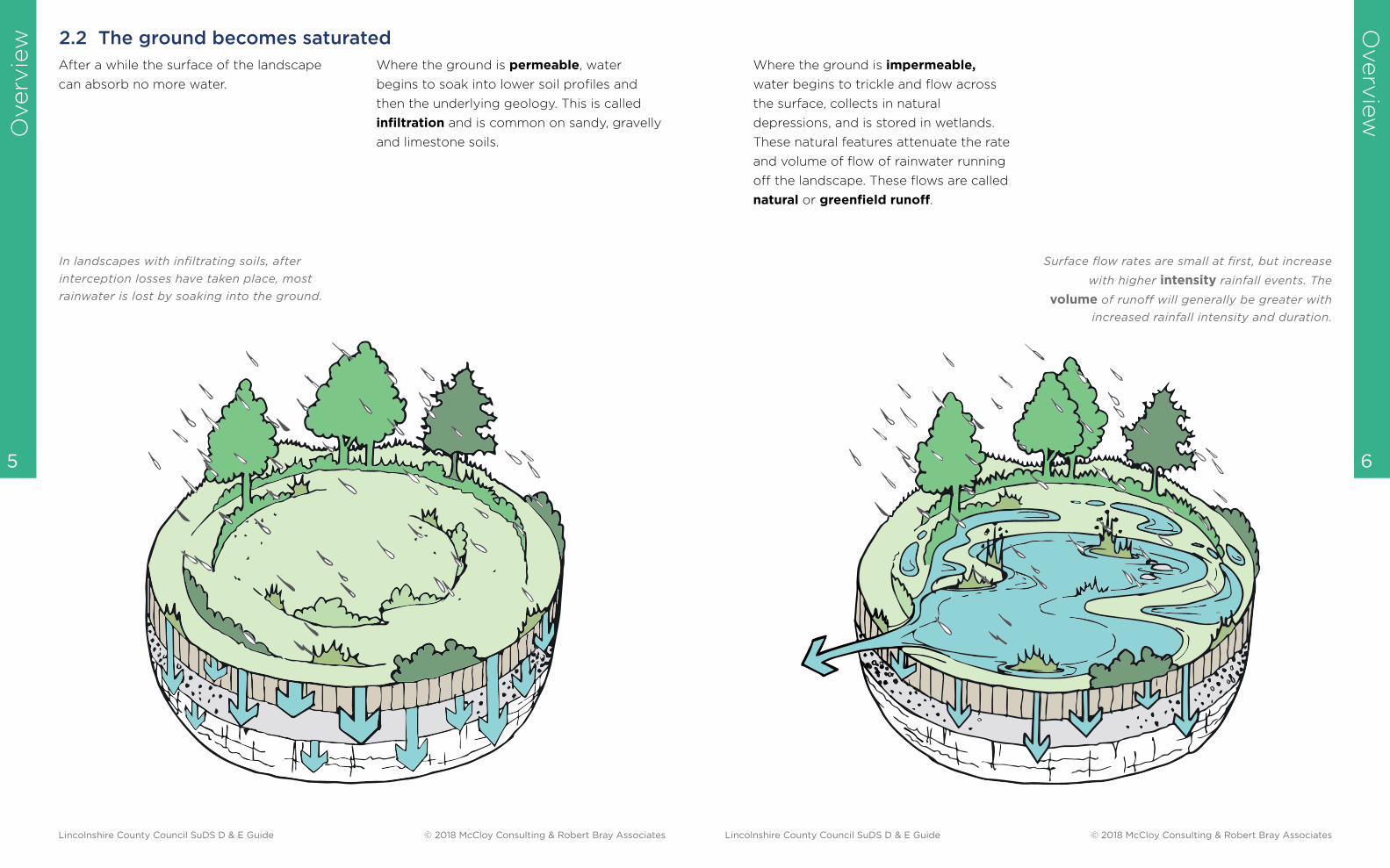
In landscapes with infiltrating soils, after
interception losses have taken place, most
rainwater is lost by soaking into the ground.
2.2 The ground becomes saturated
After a while the surface of the landscape
can absorb no more water.
Where the ground is permeable, water
begins to soak into lower soil profiles and
then the underlying geology. This is called
infiltration and is common on sandy, gravelly
and limestone soils.
Surface flow rates are small at first, but increase
with higher intensity rainfall events. The
volume of runoff will generally be greater with
increased rainfall intensity and duration.
Where the ground is impermeable,
water begins to trickle and flow across
the surface, collects in natural
depressions, and is stored in wetlands.
These natural features attenuate the rate
and volume of flow of rainwater running
off the landscape. These flows are called
natural or greenfield runoff.
Lincolnshire County Council SuDS D & E Guide © 2018 McCloy Consulting & Robert Bray Associates Lincolnshire County Council SuDS D & E Guide © 2018 McCloy Consulting & Robert Bray Associates
Overv
iew
7
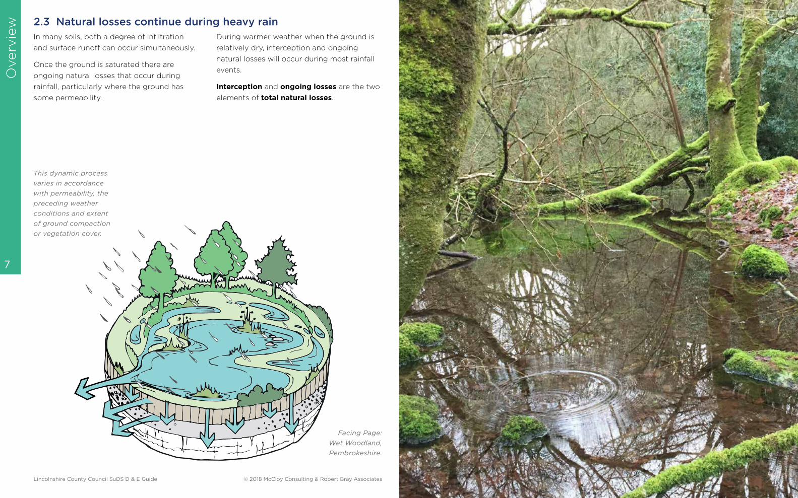
2.3 Natural losses continue during heavy rain
This dynamic process
varies in accordance
with permeability, the
preceding weather
conditions and extent
of ground compaction
or vegetation cover.
Facing Page:
Wet Woodland,
Pembrokeshire.
In many soils, both a degree of infiltration
and surface runoff can occur simultaneously.
Once the ground is saturated there are
ongoing natural losses that occur during
rainfall, particularly where the ground has
some permeability.
During warmer weather when the ground is
relatively dry, interception and ongoing
natural losses will occur during most rainfall
events.
Interception and ongoing losses are the two
elements of total natural losses.
Lincolnshire County Council SuDS D & E Guide © 2018 McCloy Consulting & Robert Bray Associates

Overv
iew
Overv
iew
10 9
For millennia, people have been making changes to our landscapes which
affect the fate of the rain that falls on the land. In recent history, the scale of
urbanisation and our attitudes toward rainwater have caused serious problems
both for ourselves and for the natural environment.
3.0The Impact of Development
3.1 A rural landscape becomes urban
runoff from buildings and streets, was
directed into a single underground pipe
called the combined sewer. In periods of
heavy rainfall, combined sewer overflows act
as a relief valve when flows exceed sewer
capacity, discharging untreated foul sewage
into local watercourses. Many British cities
and towns of Victorian age are served by
combined sewers.
The Combined Sewer.
Before the universal use of piped drainage it
was common to collect and convey runoff
across the land surface directly into ditches,
streams and local rivers.
With the growth of Victorian cities and the
development of piped drainage, human and
industrial waste, together with rainwater
Separate pipes for foul
sewage and surface water
were introduced in the
mid-twentieth century.
3.2 Separating rainwater from foul sewage
In the mid-twentieth century it was realised
that foul sewage and storm water should be
separated. A separate sewer arrangement
was introduced with the foul sewer for
human waste and the surface water sewer
for rainfall. However, in many urban areas
these connections are still unclear and are
complicated by highway drainage and other
ad hoc arrangements.
Unfortunately, rainwater still gets into the
foul sewer and misconnections
contaminate surface water sewers and
receiving watercourses. The SuDS
approach to managing rainfall can
minimise these misconnections by
keeping runoff at or near the surface.
Lincolnshire County Council SuDS D & E Guide © 2018 McCloy Consulting & Robert Bray Associates Lincolnshire County Council SuDS D & E Guide © 2018 McCloy Consulting & Robert Bray Associates
Overv
iew
Overv
iew
12 11
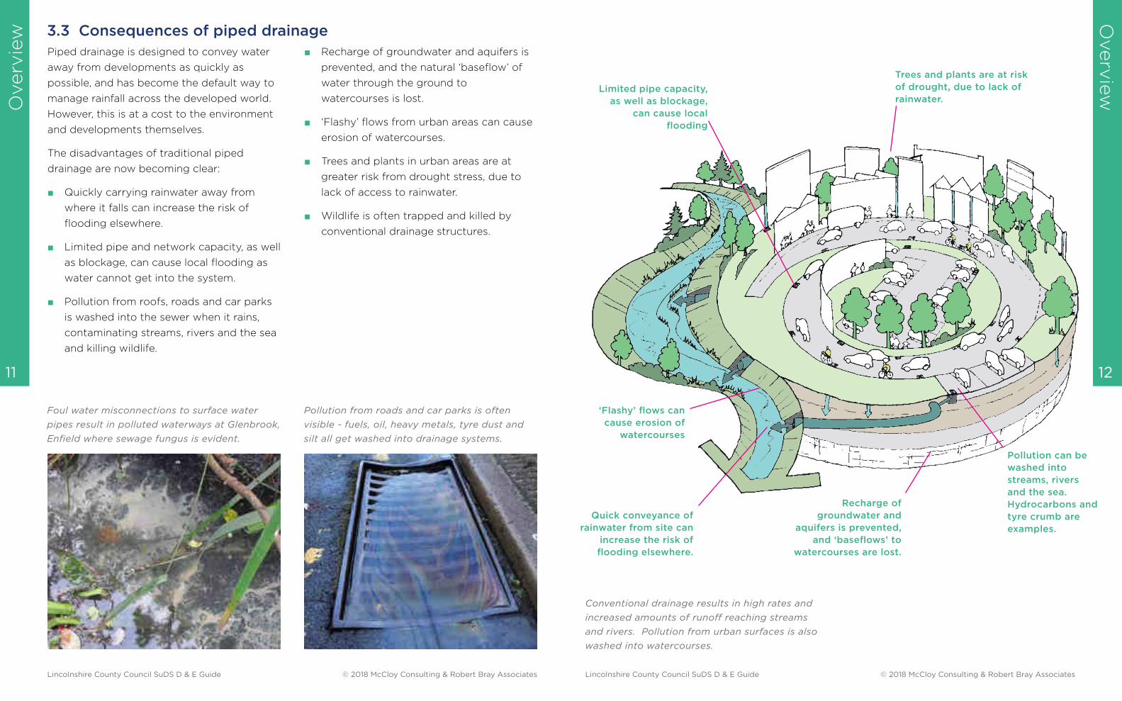
3.3 Consequences of piped drainage
■ Recharge of groundwater and aquifers is
prevented, and the natural ‘baseflow’ of
water through the ground to
watercourses is lost.
■ ‘Flashy’ flows from urban areas can cause
erosion of watercourses.
■ Trees and plants in urban areas are at
greater risk from drought stress, due to
lack of access to rainwater.
■ Wildlife is often trapped and killed by
conventional drainage structures.
Foul water misconnections to surface water
pipes result in polluted waterways at Glenbrook,
Enfield where sewage fungus is evident.
Pollution from roads and car parks is often
visible - fuels, oil, heavy metals, tyre dust and
silt all get washed into drainage systems.
Piped drainage is designed to convey water
away from developments as quickly as
possible, and has become the default way to
manage rainfall across the developed world.
However, this is at a cost to the environment
and developments themselves.
The disadvantages of traditional piped
drainage are now becoming clear:
■ Quickly carrying rainwater away from
where it falls can increase the risk of
flooding elsewhere.
■ Limited pipe and network capacity, as well
as blockage, can cause local flooding as
water cannot get into the system.
■ Pollution from roofs, roads and car parks
is washed into the sewer when it rains,
contaminating streams, rivers and the sea
and killing wildlife.
Conventional drainage results in high rates and
increased amounts of runoff reaching streams
and rivers. Pollution from urban surfaces is also
washed into watercourses.
Quick conveyance of
rainwater from site can
increase the risk of
flooding elsewhere.
Limited pipe capacity,
as well as blockage,
can cause local
flooding
Pollution can be
washed into
streams, rivers
and the sea.
Hydrocarbons and
tyre crumb are
examples.
‘Flashy’ flows can
cause erosion of
watercourses
Trees and plants are at risk
of drought, due to lack of
rainwater.
Recharge of
groundwater and
aquifers is prevented,
and ‘baseflows’ to
watercourses are lost.
Lincolnshire County Council SuDS D & E Guide © 2018 McCloy Consulting & Robert Bray Associates Lincolnshire County Council SuDS D & E Guide © 2018 McCloy Consulting & Robert Bray Associates
Overv
iew
Overv
iew
14 13
4.0The Role of SuDS
Sustainable Drainage is a way of managing rainfall that mimics natural drainage
processes and reduces the impact of development on communities and the
environment.
4.1 SuDS addresses community and environmental problems
Contaminants are broken down naturally as
runoff passes from one SuDS component to
the next.
Multi-functional SuDS components that
manage water at or near the surface, can
bring significant community benefits,
adapting their function to the weather.
The loss of aquatic habitat is reversed when
using the SuDS approach. It allows fauna and
flora to flourish, and to connect with existing
habitats.
A wildlife area at Robinswood Primary School,
Gloucestershire, manages rainfall as well as
providing amenity and biodiversity benefits to
the school.
Conventional drainage seeks to remove
runoff from development as quickly as
possible. In contrast, SuDS slow the flow and
store water in both hard and soft landscape
areas, thereby reducing the impact of large
volumes of polluted water flowing from
development.
SuDS uses components linked in series to
trap silt and heavy pollution ‘at source’.
SuDS Design
wate
r qua
ntity
water quality
amenity
biodiversity
control the rate and volume of runoff to reduce
flood risk, and preserve the natural water cycle
cre
ate
an
d s
usta
in b
ette
r p
laces for people
create and sustain better places for nature
manage the quality of ru
no
ff to p
revent p
ollu
tion
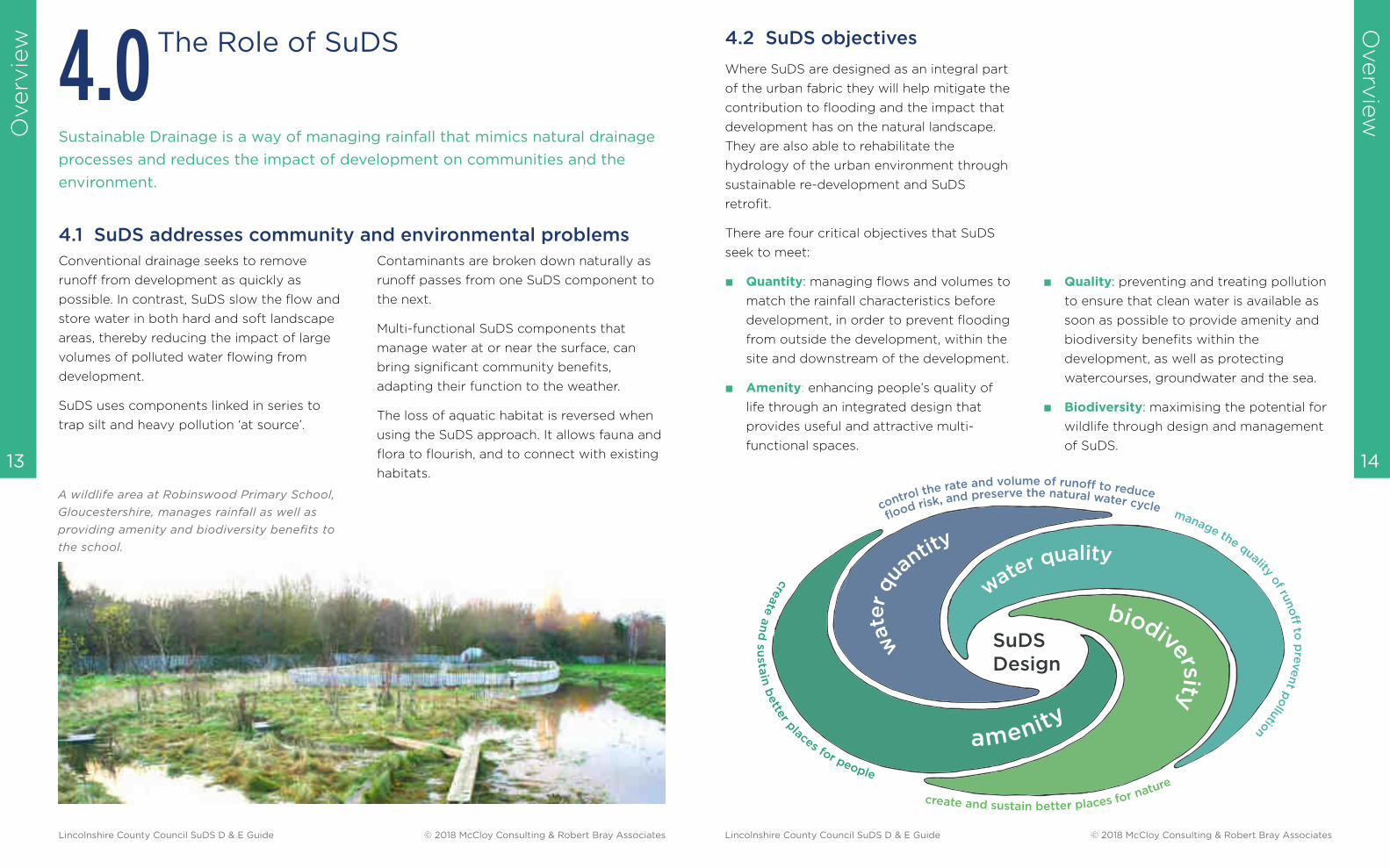
4.2 SuDS objectives
Where SuDS are designed as an integral part
of the urban fabric they will help mitigate the
contribution to flooding and the impact that
development has on the natural landscape.
They are also able to rehabilitate the
hydrology of the urban environment through
sustainable re-development and SuDS
retrofit.
There are four critical objectives that SuDS
seek to meet:
■ Quantity: managing flows and volumes to
match the rainfall characteristics before
development, in order to prevent flooding
from outside the development, within the
site and downstream of the development.
■ Amenity: enhancing people’s quality of
life through an integrated design that
provides useful and attractive multi-
functional spaces.
■ Quality: preventing and treating pollution
to ensure that clean water is available as
soon as possible to provide amenity and
biodiversity benefits within the
development, as well as protecting
watercourses, groundwater and the sea.
■ Biodiversity: maximising the potential for
wildlife through design and management
of SuDS.
Lincolnshire County Council SuDS D & E Guide © 2018 McCloy Consulting & Robert Bray Associates Lincolnshire County Council SuDS D & E Guide © 2018 McCloy Consulting & Robert Bray Associates

Overv
iew
Overv
iew
16 15
Reduced risk of
flooding over
conventional drainage,
as flows are held for
longer within SuDS
features
Surface flows minimise
any chance of
blockage
River erosion can
be reduced
Components linked in series
to trap silt and heavy
pollution ‘at source’ before
providing additional
treatment.
SuDS schemes offer diverse benefits over
conventional drainage.
Hydrocarbons are
remediated via
biological processes.
Robust planting is
required to manage this.
Trees and plants
can benefit
greatly from
additional water
inputs,
particularly in
stressful urban
situations.
Recharge of
groundwater and
aquifers via infiltration
Multi-functional SuDS
components can serve,
when dry, as significant
community spaces.
Habitat connections are
made
Lincolnshire County Council SuDS D & E Guide © 2018 McCloy Consulting & Robert Bray Associates Lincolnshire County Council SuDS D & E Guide © 2018 McCloy Consulting & Robert Bray Associates
Overv
iew
Overv
iew
18 17
5.1 The role of planning in
SuDS
The Ministerial Statement of December 2014
gave responsibility for evaluating SuDS within
planning applications to Local Planning
Authorities (LPAs).
SuDS designs should conform to DEFRA’s
Non-Statutory Technical Standards (NSTS)
for sustainable drainage systems and Local
Authority requirements.
The LPA considers that SuDS is appropriate
and reasonably practicable in most
developments.
The evaluation process is led by the LPA. The
LPA will consult with statutory consultees
including the Lead Local Flood Authority
(LLFA), and other professionals within
disciplines complementary to SuDS design.
Consultation with the LPA evaluation team
during the design process will help
developers and SuDS designers deliver
successful and cost-effective SuDS projects.
5.0 The SuDS Design & Evaluation
Process
Integrating SuDS into development is a planning-led activity. Planning
permission is required for all new development and re-development, and usually
for SuDS retrofit.
Non-statutory technical standards
www.gov.uk/
search?q=sustainable+drainage+systems
National Planning Policy Framework
www.gov.uk/government/uploads/system/
uploads/attachment_data/
file/6077/2116950.pdf
5.2 Design and evaluation in
parallel
This guide considers the design and
evaluation of SuDS as complementary. It
follows the process of design from the
earliest consideration of potential
development through to Detail Design. It
should involve both the developer and
designer together with the planner, LLFA and
all other parties with an interest in delivering
integrated SuDS design.
The separate design stages and requirements
for evaluation are set out in the guide for
both small and large developments, with
advice on how these design criteria can be
met by SuDS designers, and checked by the
evaluation team.
Refer to LASOO Practice Guidance for SuDS pg4 for an
Illustrative Planning process
www.susdrain.org/files/resources/other-guidance/lasoo_non_
statutory_suds_technical_standards_guidance_2016_.pdf
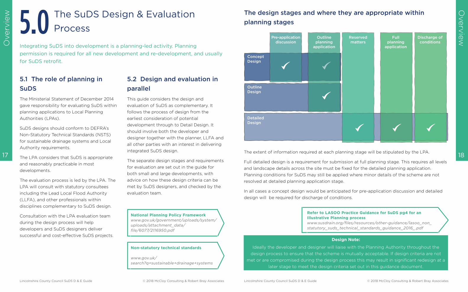
The design stages and where they are appropriate within
planning stages
Design Note:
Ideally the developer and designer will liaise with the Planning Authority throughout the
design process to ensure that the scheme is mutually acceptable. If design criteria are not
met or are compromised during the design process this may result in significant redesign at a
later stage to meet the design criteria set out in this guidance document.
Lincolnshire County Council SuDS D & E Guide © 2018 McCloy Consulting & Robert Bray Associates Lincolnshire County Council SuDS D & E Guide © 2018 McCloy Consulting & Robert Bray Associates
Concept
Design
Outline
Design
Detailed
Design
Outline
planning
application
Full
planning
application
Discharge of
conditions
Reserved
matters
Pre-application
discussion
The extent of information required at each planning stage will be stipulated by the LPA.
Full detailed design is a requirement for submission at full planning stage. This requires all levels
and landscape details across the site must be fixed for the detailed planning application.
Planning conditions for SuDS may still be applied where minor details of the scheme are not
resolved at detailed planning application stage.
In all cases a concept design would be anticipated for pre-application discussion and detailed
design will be required for discharge of conditions.
Overv
iew
Overv
iew
20 19
5.3 The objectives of the
evaluation process
Throughout the various design stages the
emerging designs should be evaluated
against core design criteria relating to the
four main objectives of SuDS design:
quantity, quality, amenity and biodiversity.
The objectives of the evaluation process are
to ensure that SuDS:
■ meet mandatory (NSTS) and LPA
requirements for water quantity and
quality, amenity and biodiversity
■ maximise opportunities for multi-
functionality and amenity uses
■ enhance biodiversity throughout the
development
■ integrate into the development’s layout
and design
■ are appropriate, cost-effective and robust
■ are practical to maintain in the long term.
5.4 SuDS design is considered
at the beginning
In the past, drainage was usually considered
at the end of the design process, with a
piped drainage solution superimposed onto a
site layout. In many respects the pipe
infrastructure was independent of the
topography, geology and other hydraulic and
environmental characteristics of the site.
Sustainable drainage, however, must be
integrated into the site design. It should
reflect the topography, geology and drainage
characteristics of the site together with the
character of the landscape.
SuDS Concept Design ensures that SuDS can
influence the layout of the development and
is a key part of pre-application discussions.
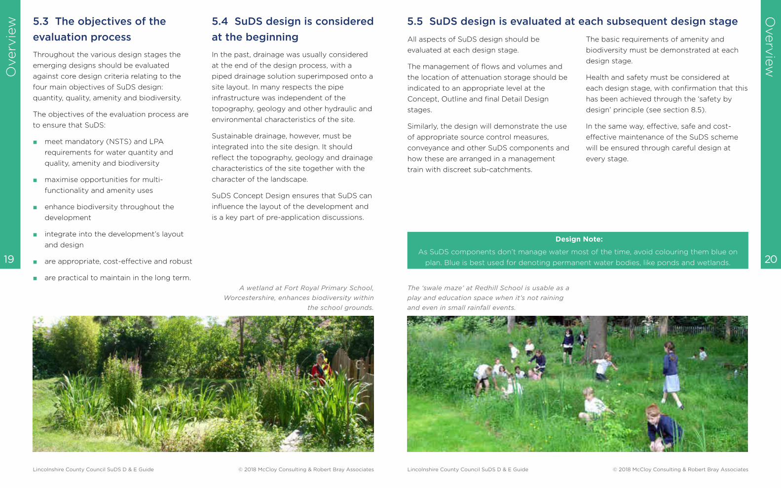
A wetland at Fort Royal Primary School,
Worcestershire, enhances biodiversity within
the school grounds.
Design Note:
As SuDS components don’t manage water most of the time, avoid colouring them blue on
plan. Blue is best used for denoting permanent water bodies, like ponds and wetlands.
All aspects of SuDS design should be
evaluated at each design stage.
The management of flows and volumes and
the location of attenuation storage should be
indicated to an appropriate level at the
Concept, Outline and final Detail Design
stages.
Similarly, the design will demonstrate the use
of appropriate source control measures,
conveyance and other SuDS components and
how these are arranged in a management
train with discreet sub-catchments.
The basic requirements of amenity and
biodiversity must be demonstrated at each
design stage.
Health and safety must be considered at
each design stage, with confirmation that this
has been achieved through the ‘safety by
design’ principle (see section 8.5).
In the same way, effective, safe and cost-
effective maintenance of the SuDS scheme
will be ensured through careful design at
every stage.
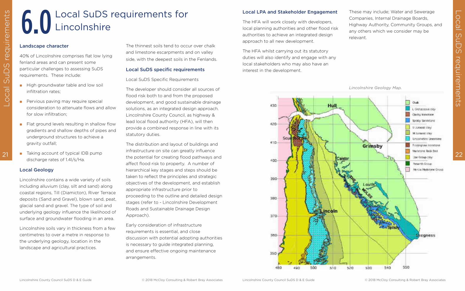
The ‘swale maze’ at Redhill School is usable as a
play and education space when it’s not raining
and even in small rainfall events.
5.5 SuDS design is evaluated at each subsequent design stage
Lincolnshire County Council SuDS D & E Guide © 2018 McCloy Consulting & Robert Bray Associates Lincolnshire County Council SuDS D & E Guide © 2018 McCloy Consulting & Robert Bray Associates
Lo
cal S
uD
S r
eq
uir
em
en
tsL
ocal S
uD
S re
qu
irem
en
ts
22 21
6.0
Lincolnshire County Council SuDS D & E Guide © 2018 McCloy Consulting & Robert Bray Associates Lincolnshire County Council SuDS D & E Guide © 2018 McCloy Consulting & Robert Bray Associates
Landscape character
40% of Lincolnshire comprises flat low lying
fenland areas and can present some
particular challenges to assessing SuDS
requirements. These include:
■ High groundwater table and low soil
infiltration rates;
■ Pervious paving may require special
consideration to attenuate flows and allow
for slow infiltration;
■ Flat ground levels resulting in shallow flow
gradients and shallow depths of pipes and
underground structures to achieve a
gravity outfall;
■ Taking account of typical IDB pump
discharge rates of 1.4l/s/Ha.
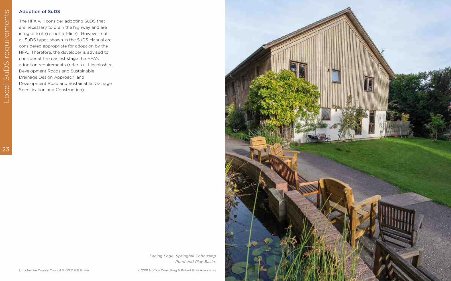
Local Geology
Lincolnshire contains a wide variety of soils
including alluvium (clay, silt and sand) along
coastal regions, Till (Diamicton), River Terrace
deposits (Sand and Gravel), blown sand, peat,
glacial sand and gravel. The type of soil and
underlying geology influence the likelihood of
surface and groundwater flooding in an area.
Lincolnshire soils vary in thickness from a few
centimetres to over a metre in response to
the underlying geology, location in the
landscape and agricultural practices.
The thinnest soils tend to occur over chalk
and limestone escarpments and on valley
side, with the deepest soils in the Fenlands.
Local SuDS specific requirements
Local SuDS Specific Requirements
The developer should consider all sources of
flood risk both to and from the proposed
development, and good sustainable drainage
solutions, as an integrated design approach.
Lincolnshire County Council, as highway &
lead local flood authority (HFA), will then
provide a combined response in line with its
statutory duties.
The distribution and layout of buildings and
infrastructure on site can greatly influence
the potential for creating flood pathways and
affect flood risk to property. A number of
hierarchical key stages and steps should be
taken to reflect the principles and strategic
objectives of the development, and establish
appropriate infrastructure prior to
proceeding to the outline and detailed design
stages (refer to - Lincolnshire Development
Roads and Sustainable Drainage Design
Approach).
Early consideration of infrastructure
requirements is essential, and close
discussion with potential adopting authorities
is necessary to guide integrated planning,
and ensure effective ongoing maintenance
arrangements.
Local SuDS requirements for
Lincolnshire
Local LPA and Stakeholder Engagement
The HFA will work closely with developers,
local planning authorities and other flood risk
authorities to achieve an integrated design
approach to all new development.
The HFA whilst carrying out its statutory
duties will also identify and engage with any
local stakeholders who may also have an
interest in the development.
Lincolnshire Geology Map.
These may include; Water and Sewerage
Companies, Internal Drainage Boards,
Highway Authority, Community Groups, and
any others which we consider may be
relevant.
Lo
cal S
uD
S r
eq
uir
em
en
ts
23
Lincolnshire County Council SuDS D & E Guide © 2018 McCloy Consulting & Robert Bray Associates
Adoption of SuDS
The HFA will consider adopting SuDS that
are necessary to drain the highway and are
integral to it (i.e. not off-line). However, not
all SuDS types shown in the SuDS Manual are
considered appropriate for adoption by the
HFA. Therefore, the developer is advised to
consider at the earliest stage the HFA’s
adoption requirements (refer to - Lincolnshire
Development Roads and Sustainable
Drainage Design Approach; and
Development Road and Sustainable Drainage
Specification and Construction).
Facing Page: Springhill Cohousing
Pond and Play Basin.
Co
ncep
t D
esi
gn
Co
ncep
t Desig
n
26 25
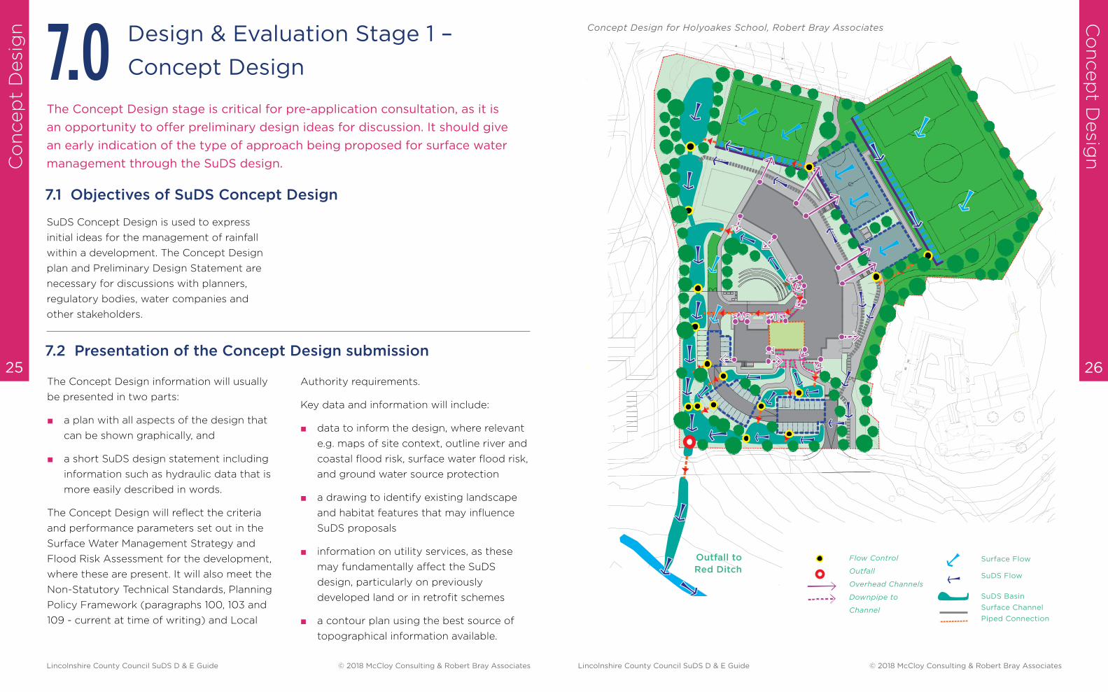
The Concept Design stage is critical for pre-application consultation, as it is
an opportunity to offer preliminary design ideas for discussion. It should give
an early indication of the type of approach being proposed for surface water
management through the SuDS design.
Design & Evaluation Stage 1 –
Concept Design7.0
SuDS Concept Design is used to express
initial ideas for the management of rainfall
within a development. The Concept Design
plan and Preliminary Design Statement are
necessary for discussions with planners,
regulatory bodies, water companies and
other stakeholders.
The Concept Design information will usually
be presented in two parts:
■ a plan with all aspects of the design that
can be shown graphically, and
■ a short SuDS design statement including
information such as hydraulic data that is
more easily described in words.
The Concept Design will reflect the criteria
and performance parameters set out in the
Surface Water Management Strategy and
Flood Risk Assessment for the development,
where these are present. It will also meet the
Non-Statutory Technical Standards, Planning
Policy Framework (paragraphs 100, 103 and
109 - current at time of writing) and Local
7.2 Presentation of the Concept Design submission
7.1 Objectives of SuDS Concept Design
Authority requirements.
Key data and information will include:
■ data to inform the design, where relevant
e.g. maps of site context, outline river and
coastal flood risk, surface water flood risk,
and ground water source protection
■ a drawing to identify existing landscape
and habitat features that may influence
SuDS proposals
■ information on utility services, as these
may fundamentally affect the SuDS
design, particularly on previously
developed land or in retrofit schemes
■ a contour plan using the best source of
topographical information available.
N
Concept Design for Holyoakes School, Robert Bray Associates
Flow Control
Outfall
Overhead Channels
Downpipe to
Channel
Surface Flow
SuDS Flow
SuDS Basin
Surface Channel
Piped ConnectionP
Sur
S
Outfall to
Red Ditch
Lincolnshire County Council SuDS D & E Guide © 2018 McCloy Consulting & Robert Bray Associates Lincolnshire County Council SuDS D & E Guide © 2018 McCloy Consulting & Robert Bray Associates
Co
ncep
t D
esi
gn
Co
ncep
t Desig
n
28 27
The SuDS Concept Design will demonstrate
an understanding of how proposed
development will impact on:
■ the site and its natural hydrology
■ historical drainage elements where these
are present
■ the ecology of the site and its
surroundings
■ the landscape character of the locality
■ natural flow routes.
Evaluation will begin with:
■ existing flow route analysis for the existing
site
■ a modified flow route analysis for the
proposed development.
Preliminary design will include:
■ Runoff collection – how rainfall is
collected and conveyed to source control
features.
■ Source control – runoff managed as close
as possible to where rain falls.
■ The management train – SuDS
components and storage features linked
in series, which convey flows along
modified flow routes through the
development.
■ Sub-catchments – small discrete areas
that manage their own runoff.
■ Maintenance – effective performance and
reasonable care costs.
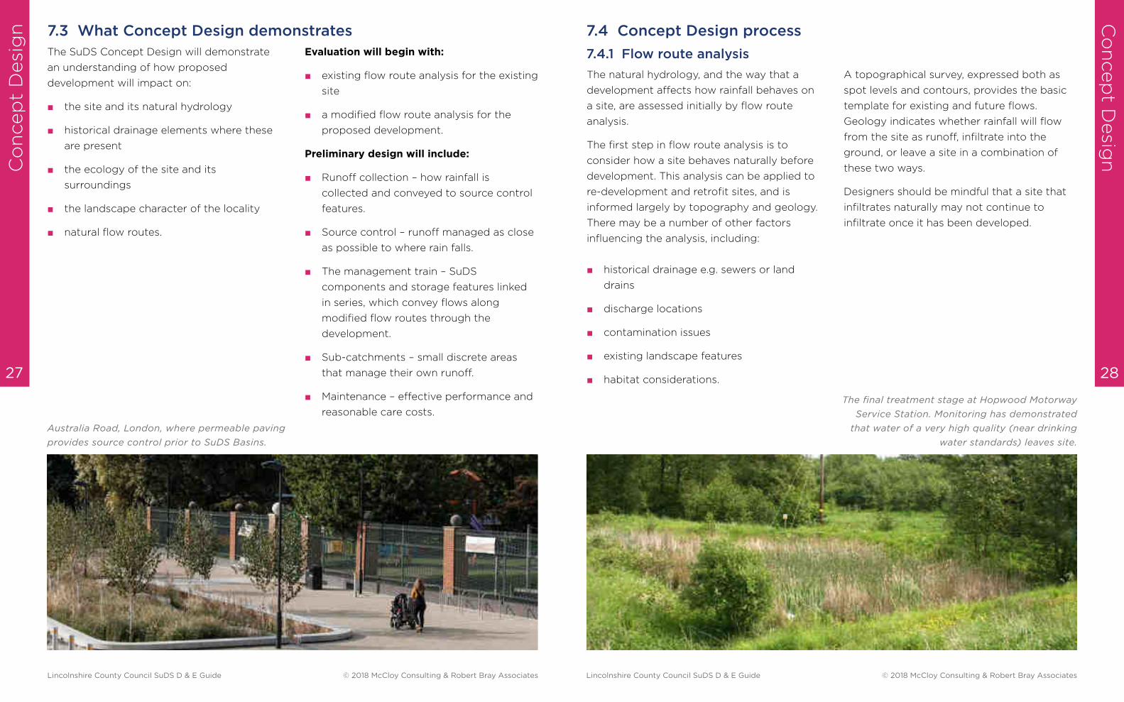
7.3 What Concept Design demonstrates
Australia Road, London, where permeable paving
provides source control prior to SuDS Basins.
7.4 Concept Design process
7.4.1 Flow route analysis
The natural hydrology, and the way that a
development affects how rainfall behaves on
a site, are assessed initially by flow route
analysis.
The first step in flow route analysis is to
consider how a site behaves naturally before
development. This analysis can be applied to
re-development and retrofit sites, and is
informed largely by topography and geology.
There may be a number of other factors
influencing the analysis, including:
■ historical drainage e.g. sewers or land
drains
■ discharge locations
■ contamination issues
■ existing landscape features
■ habitat considerations.
A topographical survey, expressed both as
spot levels and contours, provides the basic
template for existing and future flows.
Geology indicates whether rainfall will flow
from the site as runoff, infiltrate into the
ground, or leave a site in a combination of
these two ways.
Designers should be mindful that a site that
infiltrates naturally may not continue to
infiltrate once it has been developed.
The final treatment stage at Hopwood Motorway
Service Station. Monitoring has demonstrated
that water of a very high quality (near drinking
water standards) leaves site.
Lincolnshire County Council SuDS D & E Guide © 2018 McCloy Consulting & Robert Bray Associates Lincolnshire County Council SuDS D & E Guide © 2018 McCloy Consulting & Robert Bray Associates
Co
ncep
t D
esi
gn
Co
ncep
t Desig
n
30 29
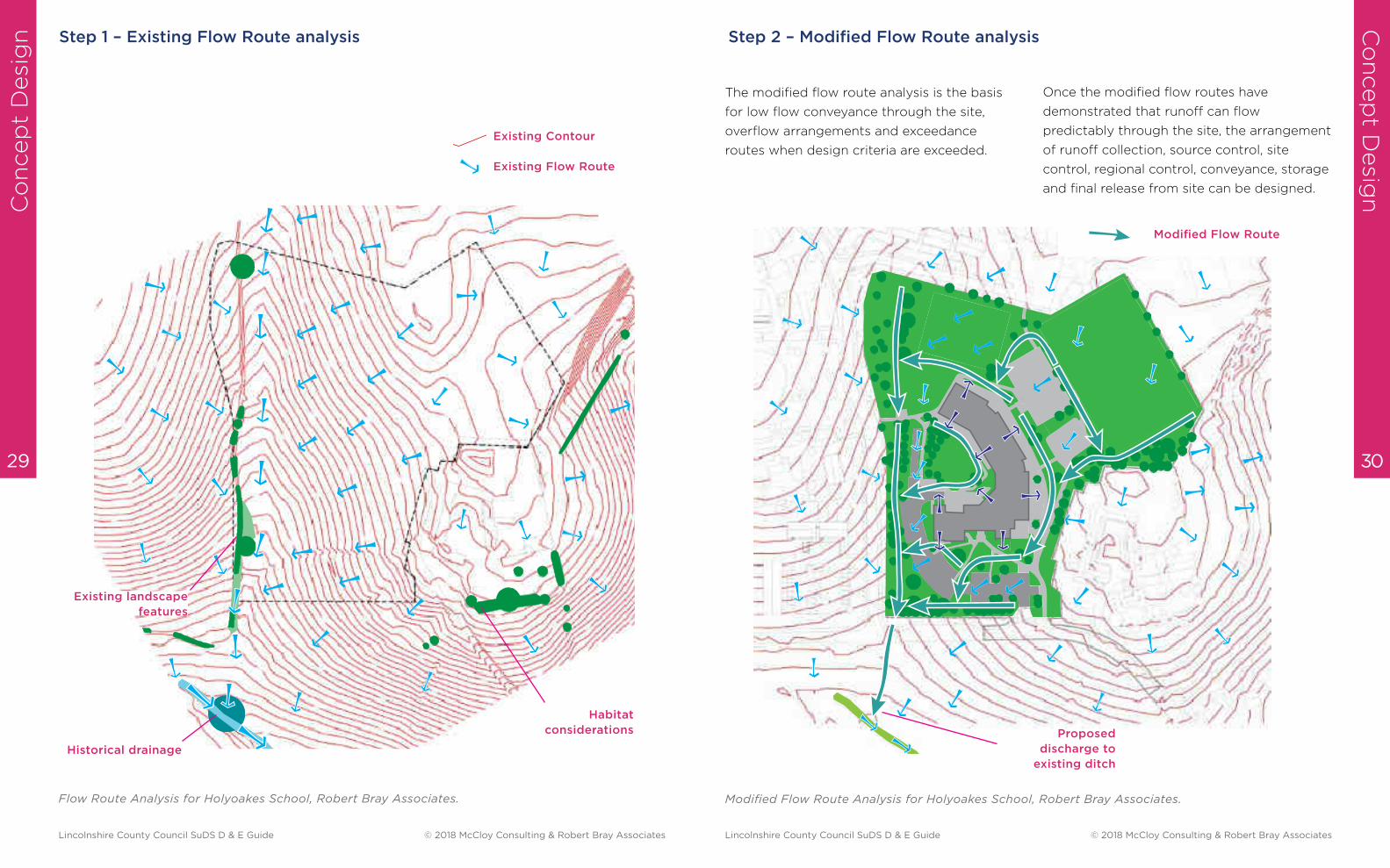
Step 1 – Existing Flow Route analysis
Existing c
Existing sur
Flow Route Analysis for Holyoakes School, Robert Bray Associates.
Existing Contour
Existing Flow Route
Historical drainage
Existing landscape
features
Habitat
considerations
Step 2 – Modified Flow Route analysis
The modified flow route analysis is the basis
for low flow conveyance through the site,
overflow arrangements and exceedance
routes when design criteria are exceeded.
Once the modified flow routes have
demonstrated that runoff can flow
predictably through the site, the arrangement
of runoff collection, source control, site
control, regional control, conveyance, storage
and final release from site can be designed.
Modified Flow Route Analysis for Holyoakes School, Robert Bray Associates.
Modified Flow Route
Proposed
discharge to
existing ditch
Lincolnshire County Council SuDS D & E Guide © 2018 McCloy Consulting & Robert Bray Associates Lincolnshire County Council SuDS D & E Guide © 2018 McCloy Consulting & Robert Bray Associates
Co
ncep
t D
esi
gn
Co
ncep
t Desig
n
32 31
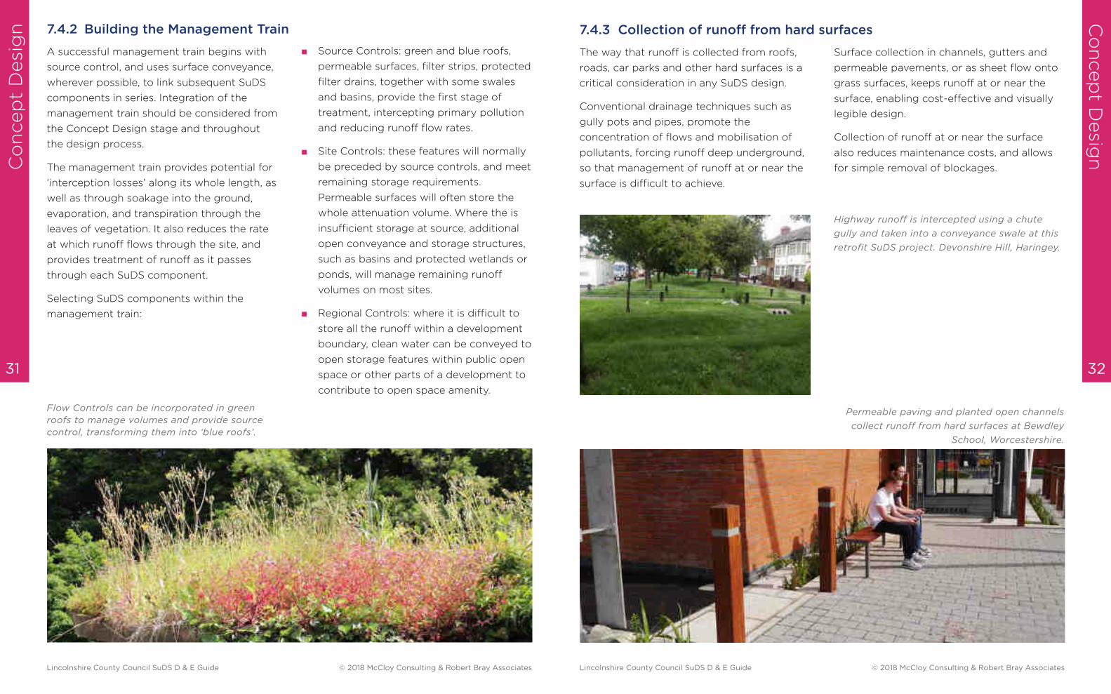
Flow Controls can be incorporated in green
roofs to manage volumes and provide source
control, transforming them into ‘blue roofs’.
A successful management train begins with
source control, and uses surface conveyance,
wherever possible, to link subsequent SuDS
components in series. Integration of the
management train should be considered from
the Concept Design stage and throughout
the design process.
The management train provides potential for
‘interception losses’ along its whole length, as
well as through soakage into the ground,
evaporation, and transpiration through the
leaves of vegetation. It also reduces the rate
at which runoff flows through the site, and
provides treatment of runoff as it passes
through each SuDS component.
Selecting SuDS components within the
management train:
■ Source Controls: green and blue roofs,
permeable surfaces, filter strips, protected
filter drains, together with some swales
and basins, provide the first stage of
treatment, intercepting primary pollution
and reducing runoff flow rates.
■ Site Controls: these features will normally
be preceded by source controls, and meet
remaining storage requirements.
Permeable surfaces will often store the
whole attenuation volume. Where the is
insufficient storage at source, additional
open conveyance and storage structures,
such as basins and protected wetlands or
ponds, will manage remaining runoff
volumes on most sites.
■ Regional Controls: where it is difficult to
store all the runoff within a development
boundary, clean water can be conveyed to
open storage features within public open
space or other parts of a development to
contribute to open space amenity.
7.4.2 Building the Management Train
The way that runoff is collected from roofs,
roads, car parks and other hard surfaces is a
critical consideration in any SuDS design.
Conventional drainage techniques such as
gully pots and pipes, promote the
concentration of flows and mobilisation of
pollutants, forcing runoff deep underground,
so that management of runoff at or near the
surface is difficult to achieve.
7.4.3 Collection of runoff from hard surfaces
Surface collection in channels, gutters and
permeable pavements, or as sheet flow onto
grass surfaces, keeps runoff at or near the
surface, enabling cost-effective and visually
legible design.
Collection of runoff at or near the surface
also reduces maintenance costs, and allows
for simple removal of blockages.
Permeable paving and planted open channels
collect runoff from hard surfaces at Bewdley
School, Worcestershire.
Highway runoff is intercepted using a chute
gully and taken into a conveyance swale at this
retrofit SuDS project. Devonshire Hill, Haringey.
Lincolnshire County Council SuDS D & E Guide © 2018 McCloy Consulting & Robert Bray Associates Lincolnshire County Council SuDS D & E Guide © 2018 McCloy Consulting & Robert Bray Associates

Co
ncep
t D
esi
gn
Co
ncep
t Desig
n
34 33
Source Control features include pervious
surfaces, filter strips, green / blue roofs, and
some basins and swales. Source control
features slow the flow of runoff, and remove
the worst pollution at the beginning of the
management train.
Source control features protect the remaining
parts of the management train, enhancing
amenity and biodiversity within the
development.
Design Note:
Source Control features, such as pervious pavements and blue-green roofs, can be designed
to attenuate all of the 1 in 100 + CCA storage, with the introduction of a simple flow control
device.
A basin without source control can result in silt,
oil and litter pollution that reduces both the
amenity and biodiversity value of the feature.
7.4.4 Source Control - managing runoff at source
Source control also ensures that SuDS
components are less susceptible to erosion
further down the management train, as
runoff is not conveyed at peak flow rates
along the system, thereby increasing the
potential for interception losses.
Runoff should travel along the management
train at or near the surface wherever
possible. The features commonly used for
this purpose are swales or other vegetated
channels and hard-surfaced channels such as
rills, gutters or dished channels in a more
urban context. Conveyance is also possible
through permeable pavement sub-base as
well as filter drains and under-drained swales.
Surface conveyance can provide the
following benefits:
■ a reduction in infrastructure costs
■ increased interception losses
■ treatment of pollution
■ ease of maintenance
■ easily understood SuDS – legibility
■ connectivity for wildlife
■ attractive landscape features.
7.4.5 Conveyance of runoff between SuDS components
Where runoff is conveyed below ground
through a pipe, for example connecting one
SuDS component to the next to facilitate
crossing under a road or pathway, the invert
level of the pipe should be kept as shallow as
possible to re-connect flow into surface SuDS
features. Pipes should ideally only be used as
short connectors, without inspection
chambers or bends, to reduce the risk of
blockage and allow simple rodding or jetting
when necessary.
The CIRIA SuDS manual (Page 876) notes
that:
“SuDS design usually avoids use of below-
ground structures such as gully pots, oil
interceptors, and other sumps which are a
wildlife hazard, often ineffective and
expensive to maintain.”
Identification of surface or shallow sub-
surface conveyance at the Concept Design
stage is important to ensure that these
pathways are retained through the remaining
design process.
Conveyance swale at
Waseley Hills High
School, Worcestershire.
Lincolnshire County Council SuDS D & E Guide © 2018 McCloy Consulting & Robert Bray Associates Lincolnshire County Council SuDS D & E Guide © 2018 McCloy Consulting & Robert Bray Associates
Co
ncep
t D
esi
gn
Co
ncep
t Desig
n
36 35
Many drainage designs adopt an approach
where all flows are taken to the lowest point
of the site and attenuated in a single location,
often referred to as a ‘pipe-to-pond’ or ‘pipe
to box’ approach.
The ‘pipe to pond’ approach can result in
unsightly, polluted and sometimes hazardous
pond or basin features that offer little
amenity or wildlife benefit. The ‘pipe to box’
approach results in below-ground structures
that provide no amenity or wildlife benefit at
all. All end of pipe solution may fill with silt
and generate management problems.
When integrating SuDS into a development,
the site should be divided into sub-
catchments to maximise treatment and
storage capacity.
The sub-catchment boundary is usually
defined as the surface area which drains to a
particular flow control, and can be
considered as a mini-watershed.
Flows are conveyed from one sub-catchment
to the next along one or more management
trains, following the modified flow routes
determined early in the design process.
Each sub-catchment contributes flows to the
following sub-catchment or to an outfall.
Controlled flows are released from one sub-
catchment feature to the next, as here at Birchen
Coppice Primary School, Kidderminster.
7.4.6 Introducing sub-catchments
Design Note:
Integrating storage within sub-catchments, as part of site layout, greatly reduces the land
take requirement for attenuation, by exploiting the inherent storage capacity of individual
SuDS features.
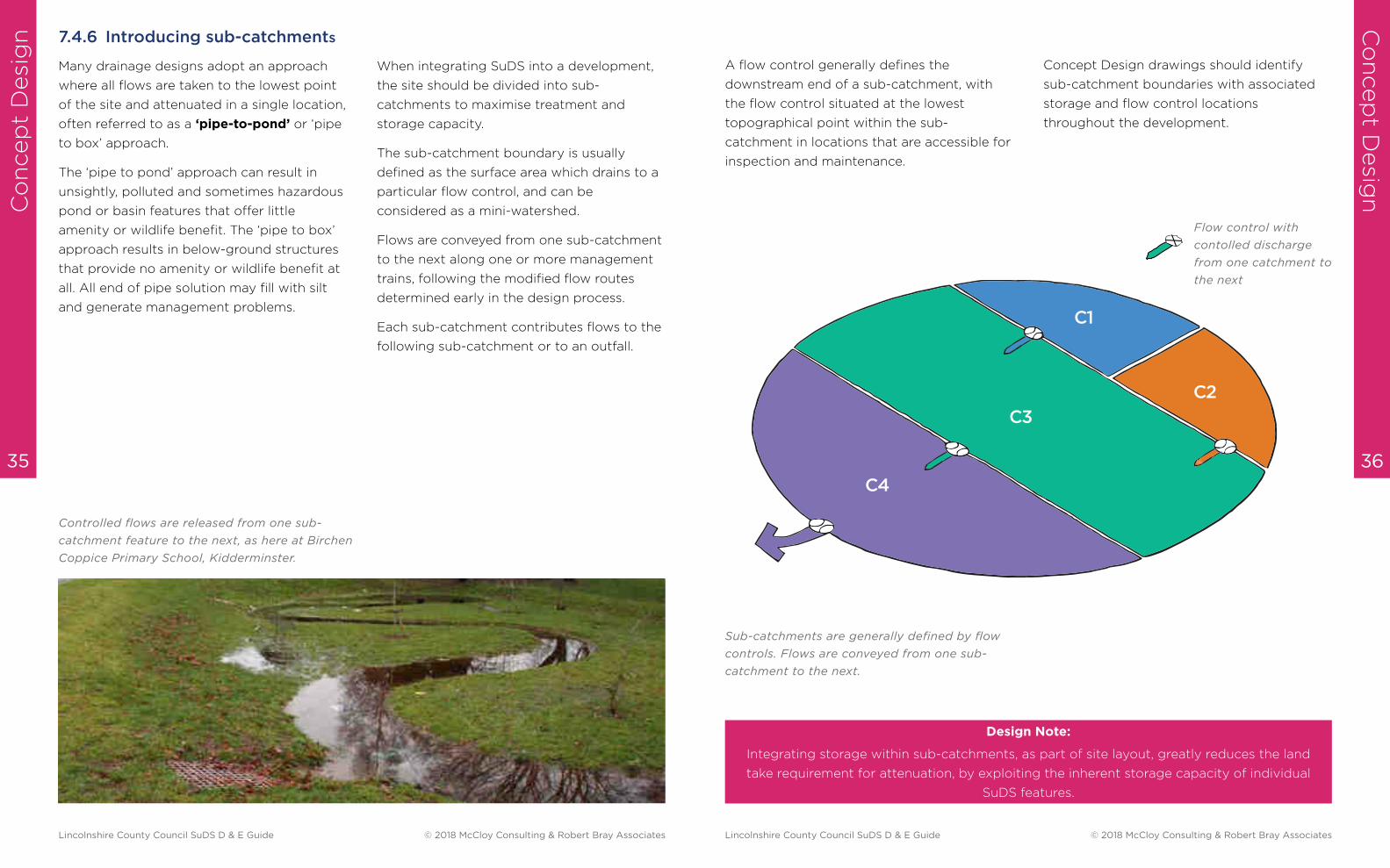
A flow control generally defines the
downstream end of a sub-catchment, with
the flow control situated at the lowest
topographical point within the sub-
catchment in locations that are accessible for
inspection and maintenance.
Concept Design drawings should identify
sub-catchment boundaries with associated
storage and flow control locations
throughout the development.
C3
C4
C1
C2
Sub-catchments are generally defined by flow
controls. Flows are conveyed from one sub-
catchment to the next.
Flow control with
contolled discharge
from one catchment to
the next
Lincolnshire County Council SuDS D & E Guide © 2018 McCloy Consulting & Robert Bray Associates Lincolnshire County Council SuDS D & E Guide © 2018 McCloy Consulting & Robert Bray Associates
Co
ncep
t D
esi
gn
Co
ncep
t Desig
n
38 37
The treatment required to mitigate pollution
depends upon the level of pollution hazard.
An adequate number (and type) of SuDS
components is required in order to intercept
or break down pollutants.
Source control components are introduced at
the beginning of any management train to
7.4.7 Managing pollution
Discharge to surface water (usually on impermeable soils)
Contributing Surface Type Pollution Hazard Level SuDS Components
Residential roofs Very Low Discharge to any SuDS
components
Normal commercial roofs Low Discharge to any SuDS
components
Leachable metal roofs Low but polluting Bioretention or source control
with one or two further SuDS
components. Refer to Detail
Design Section
Driveways, residential, car parks,
low traffic roads, low use car parks
(schools and offices)
Low Permeable pavement or
source control with one SuDS
component
Commercial yards, delivery areas,
busy car parks, other low traffic
roads (except trunk roads and
motorways)
Medium Permeable pavement or
source control with one or two
further SuDS components.
Refer to Detail Design Section
Haulage yard, lorry parks, waste
sites, sites handling chemicals and
fuels, industrial sites (for trunk
roads and motorways follow
Highways Agency risk assessment
process).
High Carry out detailed risk
assessment and consult with
the environmental regulator.
protect the development and meet amenity
and biodiversity criteria within the site.
The following table is based on the
requirements for discharge to surface waters
set out in the SuDS Manual, Chapter 26,
Water quality management: design methods,
(CIRIA, 2015).
■ Discharge to protected waters or protected groundwater (e.g. SSSI or SPZ’s) may require
additional treatment stages and liaison with the environmental regulator.
■ More general discharge to groundwater (usually infiltrating soils) can be referenced in table
26.4 of the SuDS Manual.
■ Medium pollution hazard level developments will require risk screening to determine
appropriate mitigation measures. Refer to table 26.5 and 26.6 of the SuDS Manual
■ For developments of a high pollution hazard level a detailed risk assessment will be required.
Additional considerations for infiltrating soils
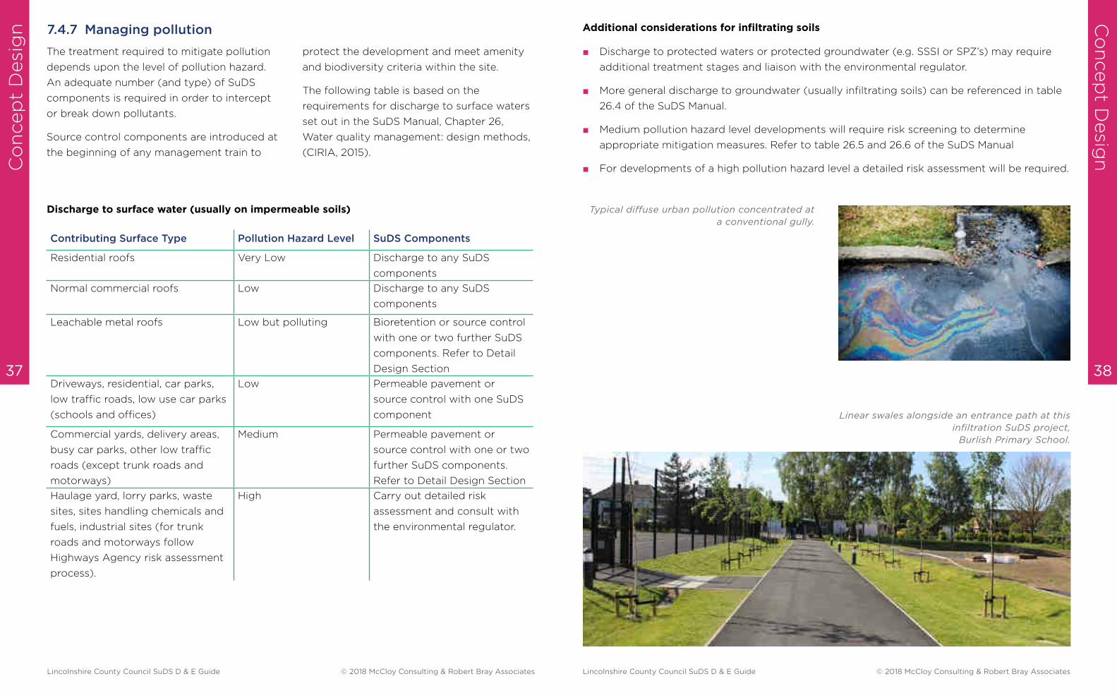
Linear swales alongside an entrance path at this
infiltration SuDS project,
Burlish Primary School.
Typical diffuse urban pollution concentrated at
a conventional gully.
Lincolnshire County Council SuDS D & E Guide © 2018 McCloy Consulting & Robert Bray Associates Lincolnshire County Council SuDS D & E Guide © 2018 McCloy Consulting & Robert Bray Associates

Co
ncep
t D
esi
gn
Co
ncep
t Desig
n
40 39
The final swale at Bewdley School is a colourful
outfall into the existing watercourse.
Rainfall should not discharge into the foul
sewer.
The way that rainfall leaves a development
should follow the preferred hierarchy:
7.4.8 Method of discharge – how rainfall leaves the site
1. re-use on site
2. infiltration into the ground
3. a natural watercourse
4. surface water sewer
5. combined sewer.
Each catchment may only control and attenuate
runoff up to lesser rainfall events (eg. 1 in 2
years, 1 in 10 year, 1 in 30 years) with residual
flows passing into the next subcatchment.
Flow control with
controlled discharge
from one catchment to
the next
Residual flows
C1
1 in 2
C2
1 in 10 C3
1 in 30
C4 1 in 100 yr (+CCA) + residual flows from
C1, C2 & C3 upto 1 in 100 yr (+CCA)
7.4.9 Preliminary flow and volume calculations
It is convenient to consider flow and volume
requirements at this stage in the design
process to ensure that natural losses are
replicated and sufficient volumes of runoff
can be temporarily accommodated to allow
for discharge from site via a flow control
and/or infiltration.
In some circumstances, for example where
development is speculative, it may be
acceptable for the Concept Stage to omit
flow and volume calculations, but a Modified
Flow Route analysis will be required to show
that runoff can be effectively conveyed to a
discharge location.
Storage volumes are usually presented as a
single volume.
This form of expression encourages the ‘pipe
to pond’ practice and prevents simple
comparison of storage values between similar
sites.
Expressing storage as ‘volume per m2’ allows
the designer to allocate storage throughout a
site in discrete sub-catchments, and provides
a straightforward way for the evaluation team
to check that calculated storage volumes are
acceptable.
Ideally each sub-catchment will manage its
own runoff up to the 1 in 100 year return
period rainfall event. Where this is not viable,
part of the storage volume will be provided
depending upon the opportunities for
storage within the subcatchment, with all
residual flows cascaded into an adjacent
sub-catchment or ‘site control’.
This approach maximises the opportunity for
storage throughout the development.
In this example the first three catchments
(C1, C2 & C3) only partially attenuate their
own runoff, with residual flows passing into
catchment C4 where these residual flows must
be attenuated, along with C4’s own runoff, to
the maixmum design storm (eg. 1 in 100 + CCA).
Lincolnshire County Council SuDS D & E Guide © 2018 McCloy Consulting & Robert Bray Associates Lincolnshire County Council SuDS D & E Guide © 2018 McCloy Consulting & Robert Bray Associates
Co
ncep
t D
esi
gn
Co
ncep
t Desig
n
42 41
After any allowances have been made for the
potential to harvest runoff, the next
consideration in managing flows and volumes
is to assess the ability of a site to infiltrate
rainfall completely, partially, or discharge
largely as runoff.
The ability of a site to infiltrate water should
be evaluated considering:
■ the nature of the soil geology and
capacity to infiltrate
■ the risk to stability of the ground where
infiltration is proposed
■ the risk of pollution to groundwater
■ the depth of seasonal groundwater
■ the risk of unpredictable pathways being
taken by infiltrating water.
Infiltration will generally be possible if the
infiltration rate is 1 x 10⁻⁵ ms (36mm/hr) or
greater, subject to the soil and subsoil
retaining infiltration capacity following
construction or site disturbance. Infiltration is
still viable on sites with lower infiltration
rates, however additional storage capacity
would be required to allow time for flows to
infiltrate.
Measures must be taken to protect infiltration
capacity during construction. Compaction of
soil layers may affect the ability of sites with
infiltration rates lower than 1 x 10⁻⁵ to allow
water to soak into the ground. These sites are
particularly susceptible to damage due to
construction activity.
The depth and location of infiltration tests
should reflect where infiltration is proposed
on site. Shallow features such as permeable
pavements will require shallow infiltration
tests.
Guidance exists which states that where
infiltration features are situated within 5m of
foundations, the risk to the foundations
should be considered. This is usually applied
as a general rule where infiltration within the
5m offset from the foundation is not
permitted. However, the guide was originally
intended for point infiltration soakaways in
susceptible soils. SuDS design encourages
‘blanket infiltration’ features that are less
likely to affect soil conditions, as they mimic
grass surfaces around buildings. The distance
offset for infiltration will be at the
professional judgment of a suitably qualified
engineer.
Additional site investigations will be
necessary to assess risks associated with
infiltration, and should follow guidance in the
CIRIA SuDS Manual 2015, Chapter 25 p543.
Risks Associated with Infiltration
CIRIA SuDS Manual 2015, Chapter 25
Using SuDS Close to Buildings
www.susdrain.org
BGS Infiltration SuDS map
www.bgs.ac.uk
7.4.10 Infiltration
If the site does not infiltrate effectively over
all return periods, then rainfall will leave the
site as runoff to a watercourse, the surface
water sewer or combined sewer. The
greenfield flow rates from the site must be
calculated, and then attenuation volumes
determined.
Rainfall calculations are necessary, even at
Concept Design stage, to gain an idea of
volumes of runoff to be stored on site.
These calculations can also be used at the
Outline Design stage, but may need to be
re-assessed at the Detail Design stage.
New hard surfaces that are introduced
through development increase both the rate
and volume of runoff. This is because runoff
flows more quickly from the site, and natural
volume losses do not happen as they did
before development.
The additional rate of runoff is managed
through attenuation storage.
Some of the pre-development volume losses
can be mimicked by using SuDS components
to demonstrate interception losses and
ongoing losses (Long Term Storage). Other
methods such as rainwater harvesting will
further reduce the additional volume
generated by the development.
The approach to managing flows and
volumes from developments - set out in the
NSTS - seeks to minimise the impact of the
additional volume generated by development
as well as control the rate of runoff to pre-
development patterns.
It allows a variable ‘greenfield rate’ of runoff
from development between the 1 in 1 and 1 in
100 year return periods with the additional
volume generated by the development
allowed to discharge at a maximum of 2 litres
per second per hectare. This approach
(Approach 1) is now the preferred method
set out in the 2015 SuDS Manual. Managing
flows and volumes to a single Qbar discharge
rate (Approach 2) may be acceptable if
Approach 1 can be shown to be unachievable.
See Section 7.4.13 for more info on
Flow rate calculations
Design Note:
The website www.uksuds.com provides estimation tools for the calculation of ‘greenfield
runoff rates’, ‘attenuation’ volumes and ‘long-term storage’ volume losses.
7.4.11 Managing runoff from site
Lincolnshire County Council SuDS D & E Guide © 2018 McCloy Consulting & Robert Bray Associates Lincolnshire County Council SuDS D & E Guide © 2018 McCloy Consulting & Robert Bray Associates
Co
ncep
t D
esi
gn
43
Attenuation is the temporary storage of
surface water at or near the surface in a
suitable feature. Attenuation is required
when the rate of runoff being generated by a
rainfall event (inflow) is greater than the
allowable discharge rate (outflow) from the
development. Discharge from the feature is
restricted by a flow control which allows the
stored water to drain down slowly.
The inflow of rainfall is calculated by
multiplying the design rainfall by the
developed area.
The developed area may be subject to an
Urban Creep factor to take into account the
creation of additional impermeable surfaces
following development (such as extensions,
additional parking and paving). This can
increase attenuation volumes by up to 10%.
The design rainfall is determined using
historic records to predict how much rainfall
is likely to occur at a particular location and
over a given return period. The data is then
used in attenuation calculations to calculate
runoff and inflow into SuDS components.
The design rainfall may be subject to a
Climate Change Allowance (CCA), applied to
rainfall intensity values. CCA is intended to
anticipate future increases in rainfall
intensities, and is currently estimated to
range between 5% and 40%. As it will impact
upon attenuation volumes, the appropriate
figure should be considered at Concept
Design stage.
The term ‘100-year rainfall event’ is used to
define rainfall (intensity and duration) that
statistically has a 1% chance of occurring in
any given year. This can also be expressed as
a 1 in 100 year event or 1% Annual Event
Probability (AEP).
In SuDS design it is useful to use a range of
return periods to identify everyday rainfall
(e.g. 1 in 1 or 1 in 2 year events), occasional
rainfall (e.g. 1 in 10 year events) and
exceptional rainfall (e.g. 1 in 30 or 1 in 100
year events). This enables the allocation of
different volumes in different places, and
encourages the use of sub-catchment design.
Design Note:
The Designer should consider the implications of Climate Change, Urban Creep and how
flows will be controlled (Approach 1 or Approach 2) as these can significantly impact the
amount of attenuation storage calculated.
Qbar and Qmed are terms used to describe the average Greenfield runoff rate. Qbar and
Qmed are derived using different equations but should result in similar values, as both relate
to a return period of approximately 1 in 2 year. Qbar / Qmed are used to define the maximum
outflow rate for Approach 2.
7.4.12 Attenuation storage - managing restricted flow rates
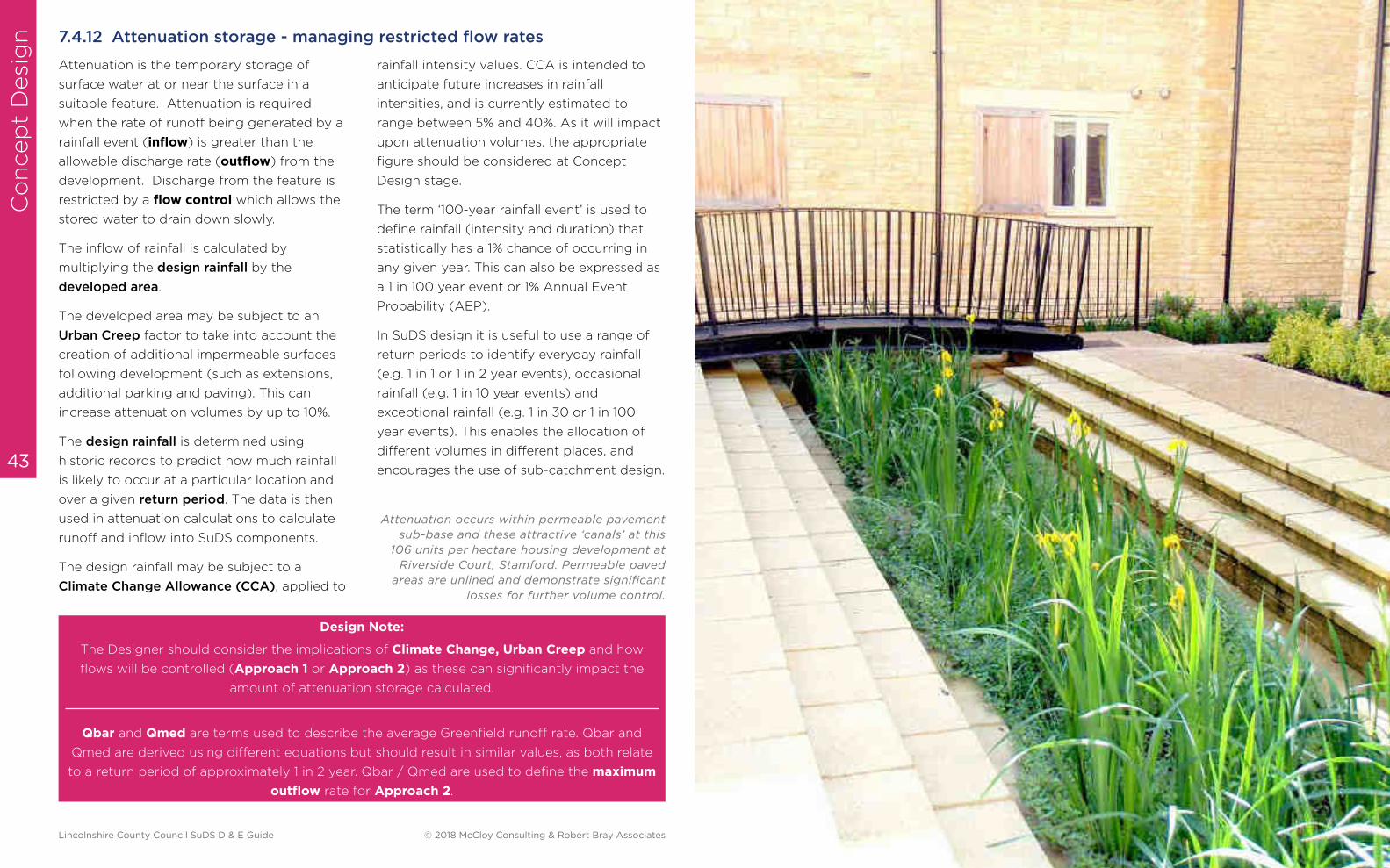
Attenuation occurs within permeable pavement
sub-base and these attractive ‘canals’ at this
106 units per hectare housing development at
Riverside Court, Stamford. Permeable paved
areas are unlined and demonstrate significant
losses for further volume control.
Lincolnshire County Council SuDS D & E Guide © 2018 McCloy Consulting & Robert Bray Associates
Co
ncep
t D
esi
gn
Co
ncep
t Desig
n
46 45
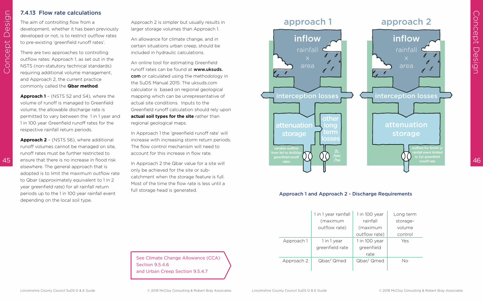
The aim of controlling flow from a
development, whether it has been previously
developed or not, is to restrict outflow rates
to pre-existing ‘greenfield runoff rates’.
There are two approaches to controlling
outflow rates: Approach 1, as set out in the
NSTS (non-statutory technical standards)
requiring additional volume management,
and Approach 2, the current practice
commonly called the Qbar method.
Approach 1 – (NSTS S2 and S4), where the
volume of runoff is managed to Greenfield
volume, the allowable discharge rate is
permitted to vary between the 1 in 1 year and
1 in 100 year Greenfield runoff rates for the
respective rainfall return periods.
Approach 2 – (NSTS S6), where additional
runoff volumes cannot be managed on site,
runoff rates must be further restricted to
ensure that there is no increase in flood risk
elsewhere. The general approach that is
adopted is to limit the maximum outflow rate
to Qbar (approximately equivalent to 1 in 2
year greenfield rate) for all rainfall return
periods up to the 1 in 100 year rainfall event
depending on the local soil type.
Approach 2 is simpler but usually results in
larger storage volumes than Approach 1.
An allowance for climate change, and in
certain situations urban creep, should be
included in hydraulic calculations.
An online tool for estimating Greenfield
runoff rates can be found at www.uksuds.
com or calculated using the methodology in
the SuDS Manual 2015. The uksuds.com
calculator is based on regional geological
mapping which can be unrepresentative of
actual site conditions. Inputs to the
Greenfield runoff calculation should rely upon
actual soil types for the site rather than
regional geological maps.
In Approach 1 the ‘greenfield runoff rate’ will
increase with increasing storm return periods.
The flow control mechanism will need to
account for this increase in flow rate.
In Approach 2 the Qbar value for a site will
only be achieved for the site or sub-
catchment when the storage feature is full.
Most of the time the flow rate is less until a
full storage head is generated.
See Climate Change Allowance (CCA)
Section 9.5.4.6
and Urban Creep Section 9.5.4.7
7.4.13 Flow rate calculations
inflowrainfall
xarea
interception losses
attenuation storage
inflowrainfall
xarea
approach 1 approach 2
interception losses
attenuation storage
other long term losses
outflow for 1in100 yr
rainfall event limited
to 2yr greenfield
runoff rate
variable outflow
from 1in1 to 1in100yr
greenfield runoff
rates
2L/sec/ha
1 in 1 year rainfall
(maximum
outflow rate)
1 in 100 year
rainfall
(maximum
outflow rate)
Long term
storage-
volume
control
Approach 1 1 in 1 year
greenfield rate
1 in 100 year
greenfield
rate
Yes
Approach 2 Qbar/ Qmed Qbar/ Qmed No
Approach 1 and Approach 2 - Discharge Requirements
Lincolnshire County Council SuDS D & E Guide © 2018 McCloy Consulting & Robert Bray Associates Lincolnshire County Council SuDS D & E Guide © 2018 McCloy Consulting & Robert Bray Associates
Co
ncep
t D
esi
gn
Co
ncep
t Desig
n
48 47
SuDS design seeks to mimic the natural
losses that occur across natural catchments.
The volume of post development runoff
should match that of the natural catchment.
Reduction in development runoff volume can
be achieved by:
■ rainwater re-use (harvesting)
■ interception losses
■ long-term storage.
Where rain harvesting is provided, 50% of the
harvest volume can be offset against volume
losses where demand exceeds yield. This is a
general rule of thumb which is stated within
BS8515.
Approach 1 and Approach 2 also apply to
management of rate and volume of runoff
from previously developed sites. LPAs will
request runoff from these sites to be reduced
to greenfield runoff rates.
A relaxation on outflow controls or the extent
of storage required will only be permitted
with the express agreement of the LPA and
LLFA at an early stage of the project. This
should be discussed at the Pre-Application
stage.
Previously developed land (Brownfield sites)
Long Term Storage
Design Note:
Storage volumes derived at the Concept Design stage may differ from those calculated at the
Detail Design stage. Storage volumes derived at Concept Design stage should be
approximate, in order to demonstrate that the scheme is sensibly proportioned.
SuDS components such as permeable
pavements provide interception losses.
Long- term storage can also be incorporated
into the pavement design and they can be used
for rainwater harvesting in certain situations,
paving
roads
paths
car parks
car p
arks
roofs
The area of development may change during
the design process, but it is important to
have an initial estimate of the amount of
storage, to inform the layout of the SuDS
design.
Design Note:
The percentage of rainfall that occurs as runoff from a surface is called the ‘coefficient of
volumetric runoff’ (Cv). Water & Sewerage Companies (WaSC) use Sewers for Adoption Ed7
(p.55) which recommends a Cv of 1.0 (100%) from all hard surfaces.
Cv’s of 0.95 from roofs and 0.9 from paved areas would be considered by the LLFA as part
of Technical Assessment, where SuDS are not being adopted by WaSC.
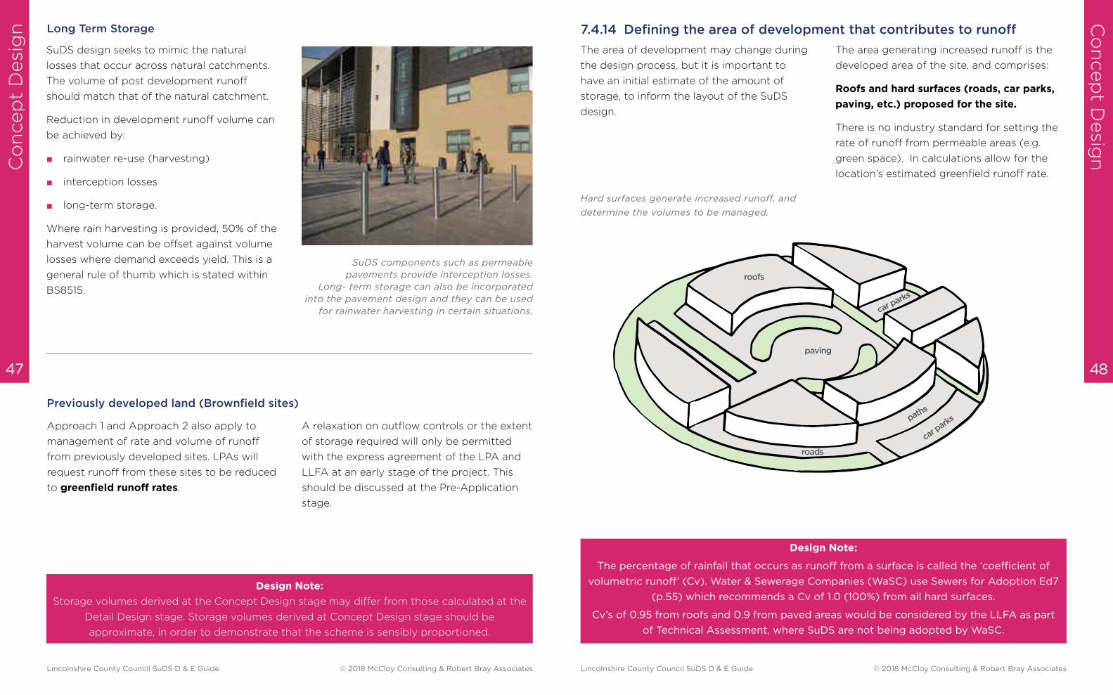
The area generating increased runoff is the
developed area of the site, and comprises:
Roofs and hard surfaces (roads, car parks,
paving, etc.) proposed for the site.
There is no industry standard for setting the
rate of runoff from permeable areas (e.g.
green space). In calculations allow for the
location’s estimated greenfield runoff rate.
Hard surfaces generate increased runoff, and
determine the volumes to be managed.
7.4.14 Defining the area of development that contributes to runoff
Lincolnshire County Council SuDS D & E Guide © 2018 McCloy Consulting & Robert Bray Associates Lincolnshire County Council SuDS D & E Guide © 2018 McCloy Consulting & Robert Bray Associates
Co
ncep
t D
esi
gn
Co
ncep
t Desig
n
50 49
The design team will provide a Concept
Design for a pre-application design meeting,
or as preliminary design information should a
pre-application meeting not be appropriate.
Pre-application discussions with the LPA and
LLFA provide an opportunity for the designer
to confirm the preliminary requirements for
the SuDS design, and for the evaluation team
to understand the objectives and character
of the SuDS proposed for the development.
7.5 Concept information required for SuDS evaluation
The information required at the Concept Design stage will depend on the type
and scope of the proposed development.
Constructive discussion between the LPA,
the LLFA and the SuDS designer will save the
developer time and the cost of potential
re-design, providing planners with
reassurance that the project that is delivered
will meet local planning expectations.
The discussions will be informed by the
LASOO (Local Authority SuDS Officer
Organisation) NSTS for Sustainable Drainage:
Practice Guidance.
7.5.1 Pre-application discussion
http://www.susdrain.org/files/
resources/other-guidance/lasoo_non_
statutory_suds_technical_standards_
guidance_2016_.pdf
A sunken SuDS courtyard with solar water feature
into a formal rill at Bromsgrove Civic Centre.
At the Concept Design stage it is necessary
to show how runoff is collected and how it is
stored within the development:
■ The designer will confirm whether
Approach 1 or Approach 2 is being used,
and confirm how volumes are being
managed.
■ A reduction in the volume of rainfall
discharged from the site will be
demonstrated by ‘interception losses’ and
long-term storage, where this is
appropriate (Approach 1).
7.5.2 Preliminary water quantity considerations
Design Note:
Ideally runoff should be stored in shallow landscape features. Where this is not possible,
deeper tank or pipe storage must be justified.
■ Approximate storage volumes should be
provided for each location where flows
are attenuated.
■ Storage will be demonstrated within
sub-catchments and along the
management train, with the location of
flow controls confirmed.
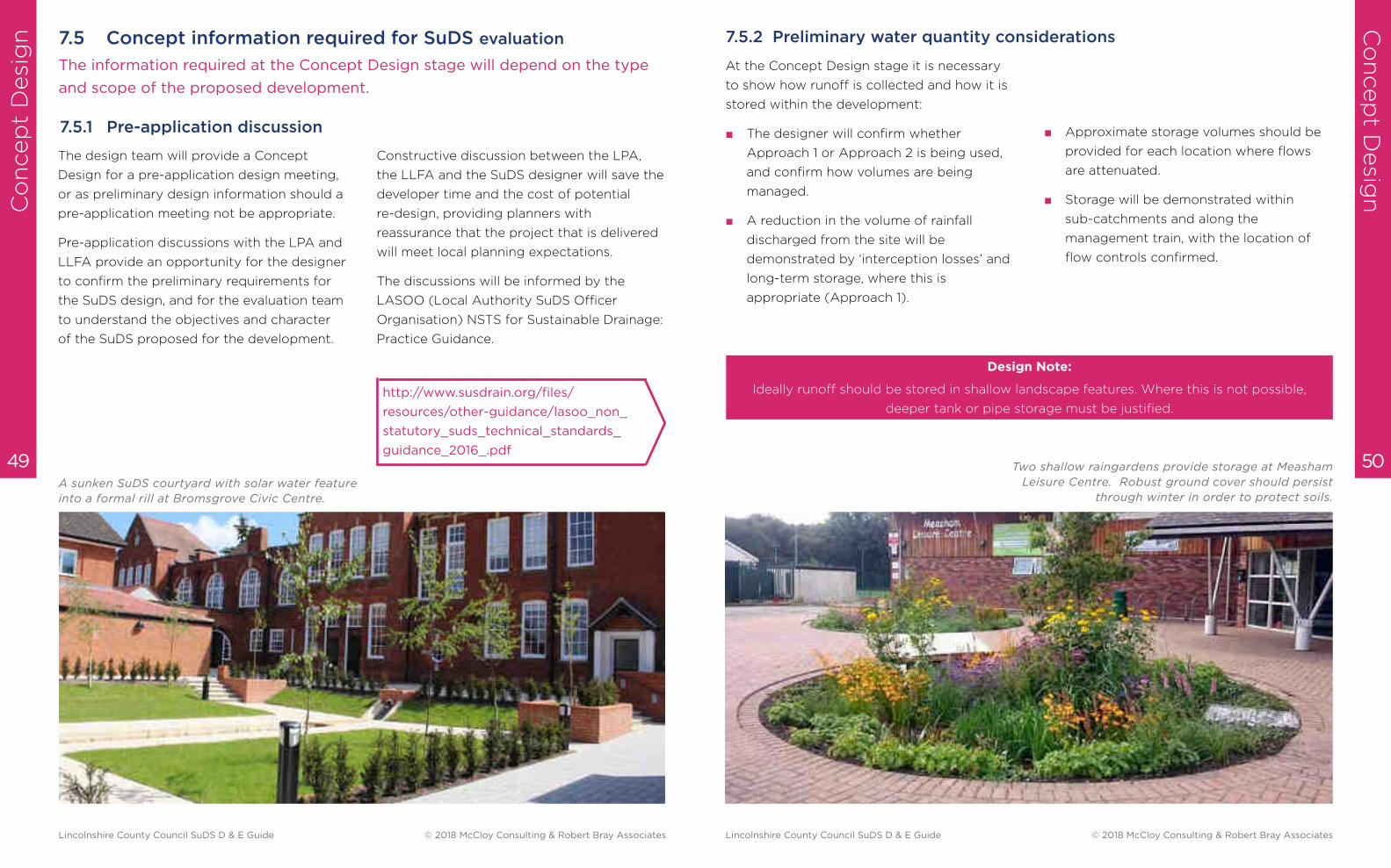
Two shallow raingardens provide storage at Measham
Leisure Centre. Robust ground cover should persist
through winter in order to protect soils.
Lincolnshire County Council SuDS D & E Guide © 2018 McCloy Consulting & Robert Bray Associates Lincolnshire County Council SuDS D & E Guide © 2018 McCloy Consulting & Robert Bray Associates

Co
ncep
t D
esi
gn
Co
ncep
t Desig
n
52 51
Design Note:
Where there is a high risk of pollution, a formal risk assessment is required.
High-risk development:
Trunk roads and highways – follow the guidance and risk assessment process set out in HA
(2009)
Haulage yards, lorry parks, highly frequented lorry approaches to industrial estates and waste
sites, sites where chemicals and fuels (other than domestic fuel oil) are to be delivered,
handled, stored, used or manufactured and industrial sites. Discharges may require an
environmental licence or permit obtain pre-permitting advice from the environmental
regulator. Risk assessment is likely to be required.
CIRIA The SuDS Manual 2015
■ A simple assessment of risk using the
‘treatment stage’ approach is acceptable
on low and medium risk development. If
the risk screening (SuDS Manual p571)
demonstrates that the ‘simple index
approach’ is appropriate, then the
‘treatment stage’ is acceptable.
■ All sites should demonstrate source
control to remove silt, heavy metals and
hydrocarbon pollution at the beginning of
the management train.
■ Unless permeable pavement is used to
collect runoff, where the pavement
provides high water quality treatment,
there will usually be a second feature to
manage additional volumes and provide
additional treatment.
7.5.3 Preliminary water quality considerations
The design will also consider:
■ Sensitivity of the receiving watercourse or
groundwater.
■ Environmental and technical constraints
such as contamination, protected
landscapes, SSSI, SAC, AONB, Ancient
Woodland and existing biodiversity
features.
■ The LPA and LLFA will not accept the
gully pot as a method of treatment. Table
26.15 of the CIRIA SuDS Manual denotes
that conventional gully and pipe drainage
provide zero treatment.
At the Concept Design stage it is necessary
to show how water quality is managed:
■ Clean water – ‘a controlled flow of clean
water’ is provided by the use of source
control at the beginning of the
management train. Subsequent surface
conveyance and open SuDS features will
ensure connectivity and habitat
opportunities.
■ Connectivity - habitat connections
outside and within the development
ensure that plants and animals can travel
between habitat areas.
7.5.5 Preliminary biodiversity considerations
■ Topographical diversity – variation in
vertical and horizontal structure allows for
complex habitat development. This is
implicit in SuDS design, e.g. swales, basins,
ponds and wetlands.
■ Ecological design - the creation of
habitats within the development.
■ Sympathetic management – through
considered management, a mosaic of
habitat types can be created, ensuring
maximum ecological value.
There are key biodiversity requirements that
should be demonstrated at the Concept
Design stage:
Amenity relates both to the usefulness and
the appearance of SuDS features. Ideally
SuDS features should be integrated into the
landscape, to minimise dedicated land take
and management obligations.
Key amenity elements to consider when
designing SuDS features include:
■ Legibility – can the design be understood
by users and managers?
■ Accessibility – can all parts of the SuDS
scheme be easily reached, both for
recreation and maintenance? All parts of
the scheme must be safe by design. It is
not usually appropriate to fence SuDS
features for safety reasons (except
toddler fences where young children may
not be fully supervised).
7.5.4 Preliminary amenity considerations
■ Multi-functionality – all parts of the SuDS
landscape should be available for use by
people when not performing a SuDS
function.
■ Visual character – all elements of the
SuDS design must be attractive (or at
least visually neutral, e.g. inlets, outlets
and control structures) and safe.
Lincolnshire County Council SuDS D & E Guide © 2018 McCloy Consulting & Robert Bray Associates Lincolnshire County Council SuDS D & E Guide © 2018 McCloy Consulting & Robert Bray Associates
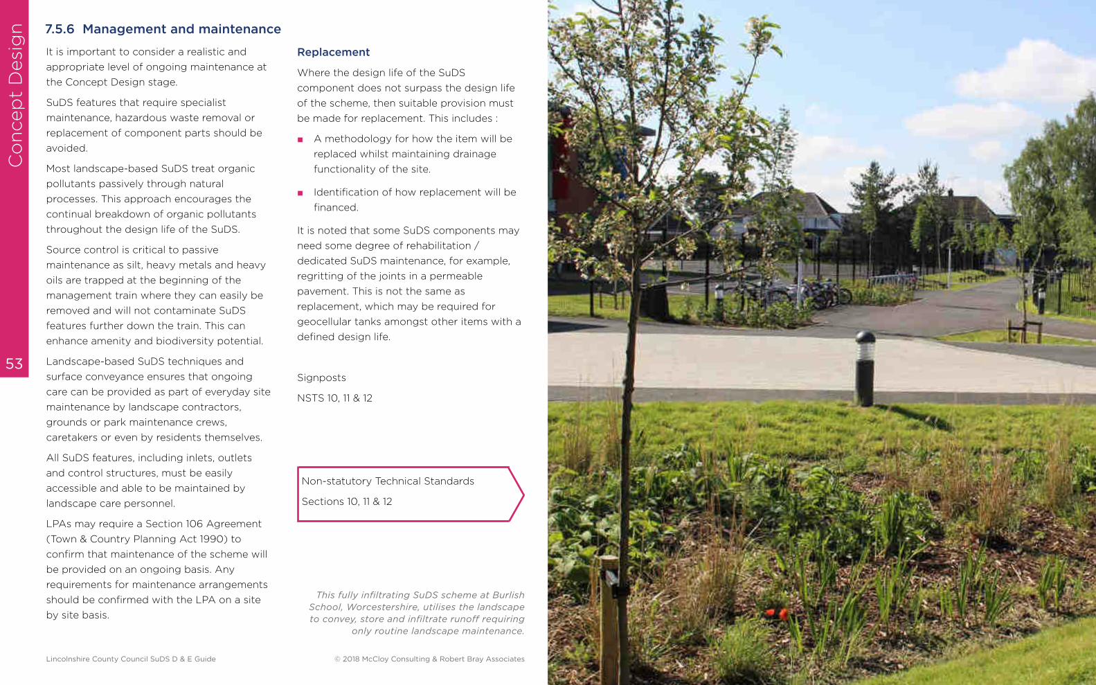
Co
ncep
t D
esi
gn
53
It is important to consider a realistic and
appropriate level of ongoing maintenance at
the Concept Design stage.
SuDS features that require specialist
maintenance, hazardous waste removal or
replacement of component parts should be
avoided.
Most landscape-based SuDS treat organic
pollutants passively through natural
processes. This approach encourages the
continual breakdown of organic pollutants
throughout the design life of the SuDS.
Source control is critical to passive
maintenance as silt, heavy metals and heavy
oils are trapped at the beginning of the
management train where they can easily be
removed and will not contaminate SuDS
features further down the train. This can
enhance amenity and biodiversity potential.
Landscape-based SuDS techniques and
surface conveyance ensures that ongoing
care can be provided as part of everyday site
maintenance by landscape contractors,
grounds or park maintenance crews,
caretakers or even by residents themselves.
All SuDS features, including inlets, outlets
and control structures, must be easily
accessible and able to be maintained by
landscape care personnel.
LPAs may require a Section 106 Agreement
(Town & Country Planning Act 1990) to
confirm that maintenance of the scheme will
be provided on an ongoing basis. Any
requirements for maintenance arrangements
should be confirmed with the LPA on a site
by site basis.
Where the design life of the SuDS
component does not surpass the design life
of the scheme, then suitable provision must
be made for replacement. This includes :
■ A methodology for how the item will be
replaced whilst maintaining drainage
functionality of the site.
■ Identification of how replacement will be
financed.
It is noted that some SuDS components may
need some degree of rehabilitation /
dedicated SuDS maintenance, for example,
regritting of the joints in a permeable
pavement. This is not the same as
replacement, which may be required for
geocellular tanks amongst other items with a
defined design life.
Signposts
NSTS 10, 11 & 12
7.5.6 Management and maintenance
This fully infiltrating SuDS scheme at Burlish
School, Worcestershire, utilises the landscape
to convey, store and infiltrate runoff requiring
only routine landscape maintenance.
Replacement
Non-statutory Technical Standards
Sections 10, 11 & 12
Lincolnshire County Council SuDS D & E Guide © 2018 McCloy Consulting & Robert Bray Associates
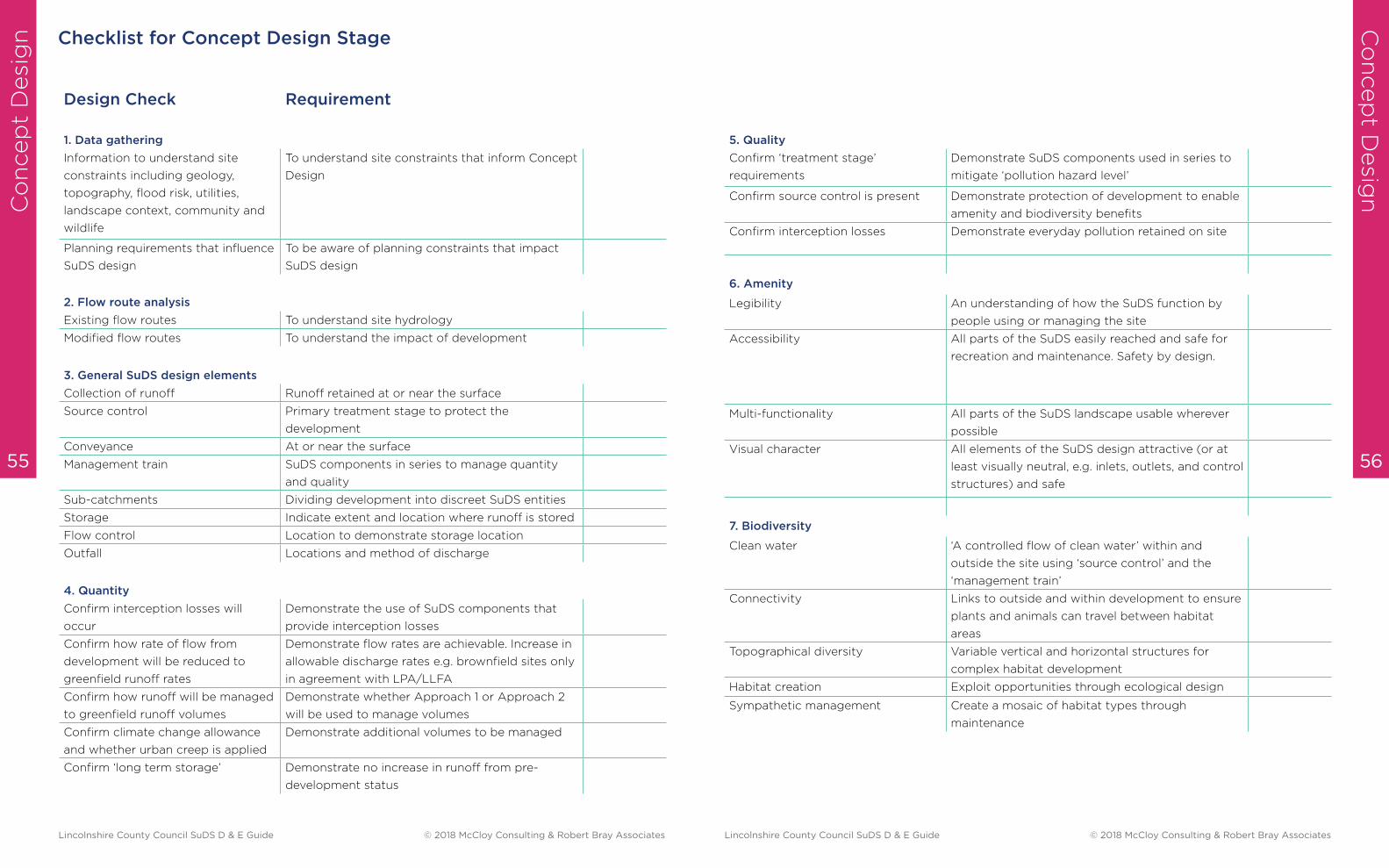
Co
ncep
t D
esi
gn
Co
ncep
t Desig
n
56 55
Checklist for Concept Design Stage
Design Check Requirement
1. Data gathering
Information to understand site
constraints including geology,
topography, flood risk, utilities,
landscape context, community and
wildlife
To understand site constraints that inform Concept
Design
Planning requirements that influence
SuDS design
To be aware of planning constraints that impact
SuDS design
2. Flow route analysis
Existing flow routes To understand site hydrology
Modified flow routes To understand the impact of development
3. General SuDS design elements
Collection of runoff Runoff retained at or near the surface
Source control Primary treatment stage to protect the
development
Conveyance At or near the surface
Management train SuDS components in series to manage quantity
and quality
Sub-catchments Dividing development into discreet SuDS entities
Storage Indicate extent and location where runoff is stored
Flow control Location to demonstrate storage location
Outfall Locations and method of discharge
4. Quantity
Confirm interception losses will
occur
Demonstrate the use of SuDS components that
provide interception losses
Confirm how rate of flow from
development will be reduced to
greenfield runoff rates
Demonstrate flow rates are achievable. Increase in
allowable discharge rates e.g. brownfield sites only
in agreement with LPA/LLFA
Confirm how runoff will be managed
to greenfield runoff volumes
Demonstrate whether Approach 1 or Approach 2
will be used to manage volumes
Confirm climate change allowance
and whether urban creep is applied
Demonstrate additional volumes to be managed
Confirm ‘long term storage’ Demonstrate no increase in runoff from pre-
development status
5. Quality
Confirm ‘treatment stage’
requirements
Demonstrate SuDS components used in series to
mitigate ‘pollution hazard level’
Confirm source control is present Demonstrate protection of development to enable
amenity and biodiversity benefits
Confirm interception losses Demonstrate everyday pollution retained on site
6. Amenity
Legibility An understanding of how the SuDS function by
people using or managing the site
Accessibility All parts of the SuDS easily reached and safe for
recreation and maintenance. Safety by design.
Multi-functionality All parts of the SuDS landscape usable wherever
possible
Visual character All elements of the SuDS design attractive (or at
least visually neutral, e.g. inlets, outlets, and control
structures) and safe
7. Biodiversity
Clean water ‘A controlled flow of clean water’ within and
outside the site using ‘source control’ and the
‘management train’
Connectivity Links to outside and within development to ensure
plants and animals can travel between habitat
areas
Topographical diversity Variable vertical and horizontal structures for
complex habitat development
Habitat creation Exploit opportunities through ecological design
Sympathetic management Create a mosaic of habitat types through
maintenance
Lincolnshire County Council SuDS D & E Guide © 2018 McCloy Consulting & Robert Bray Associates Lincolnshire County Council SuDS D & E Guide © 2018 McCloy Consulting & Robert Bray Associates
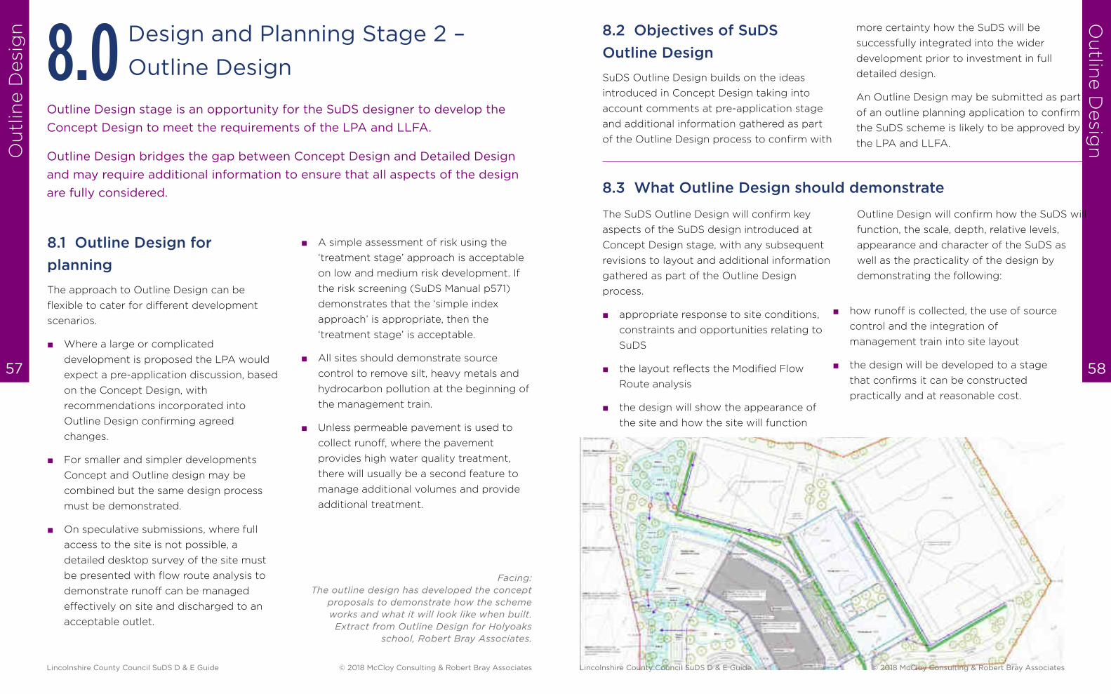
Ou
tlin
e D
esi
gn
Ou
tline D
esig
n
58 57
Design and Planning Stage 2 –
Outline Design8.0
8.1 Outline Design for
planning
The approach to Outline Design can be
flexible to cater for different development
scenarios.
■ Where a large or complicated
development is proposed the LPA would
expect a pre-application discussion, based
on the Concept Design, with
recommendations incorporated into
Outline Design confirming agreed
changes.
■ For smaller and simpler developments
Concept and Outline design may be
combined but the same design process
must be demonstrated.
■ On speculative submissions, where full
access to the site is not possible, a
detailed desktop survey of the site must
be presented with flow route analysis to
demonstrate runoff can be managed
effectively on site and discharged to an
acceptable outlet.
Outline Design stage is an opportunity for the SuDS designer to develop the
Concept Design to meet the requirements of the LPA and LLFA.
Outline Design bridges the gap between Concept Design and Detailed Design
and may require additional information to ensure that all aspects of the design
are fully considered.
Facing:
The outline design has developed the concept
proposals to demonstrate how the scheme
works and what it will look like when built.
Extract from Outline Design for Holyoaks
school, Robert Bray Associates.
■ A simple assessment of risk using the
‘treatment stage’ approach is acceptable
on low and medium risk development. If
the risk screening (SuDS Manual p571)
demonstrates that the ‘simple index
approach’ is appropriate, then the
‘treatment stage’ is acceptable.
■ All sites should demonstrate source
control to remove silt, heavy metals and
hydrocarbon pollution at the beginning of
the management train.
■ Unless permeable pavement is used to
collect runoff, where the pavement
provides high water quality treatment,
there will usually be a second feature to
manage additional volumes and provide
additional treatment.
The SuDS Outline Design will confirm key
aspects of the SuDS design introduced at
Concept Design stage, with any subsequent
revisions to layout and additional information
gathered as part of the Outline Design
process.
■ appropriate response to site conditions,
constraints and opportunities relating to
SuDS
■ the layout reflects the Modified Flow
Route analysis
■ the design will show the appearance of
the site and how the site will function
8.3 What Outline Design should demonstrate
8.2 Objectives of SuDS
Outline Design
SuDS Outline Design builds on the ideas
introduced in Concept Design taking into
account comments at pre-application stage
and additional information gathered as part
of the Outline Design process to confirm with
Outline Design will confirm how the SuDS will
function, the scale, depth, relative levels,
appearance and character of the SuDS as
well as the practicality of the design by
demonstrating the following:
■ how runoff is collected, the use of source
control and the integration of
management train into site layout
■ the design will be developed to a stage
that confirms it can be constructed
practically and at reasonable cost.
more certainty how the SuDS will be
successfully integrated into the wider
development prior to investment in full
detailed design.
An Outline Design may be submitted as part
of an outline planning application to confirm
the SuDS scheme is likely to be approved by
the LPA and LLFA.
Lincolnshire County Council SuDS D & E Guide © 2018 McCloy Consulting & Robert Bray Associates Lincolnshire County Council SuDS D & E Guide © 2018 McCloy Consulting & Robert Bray Associates
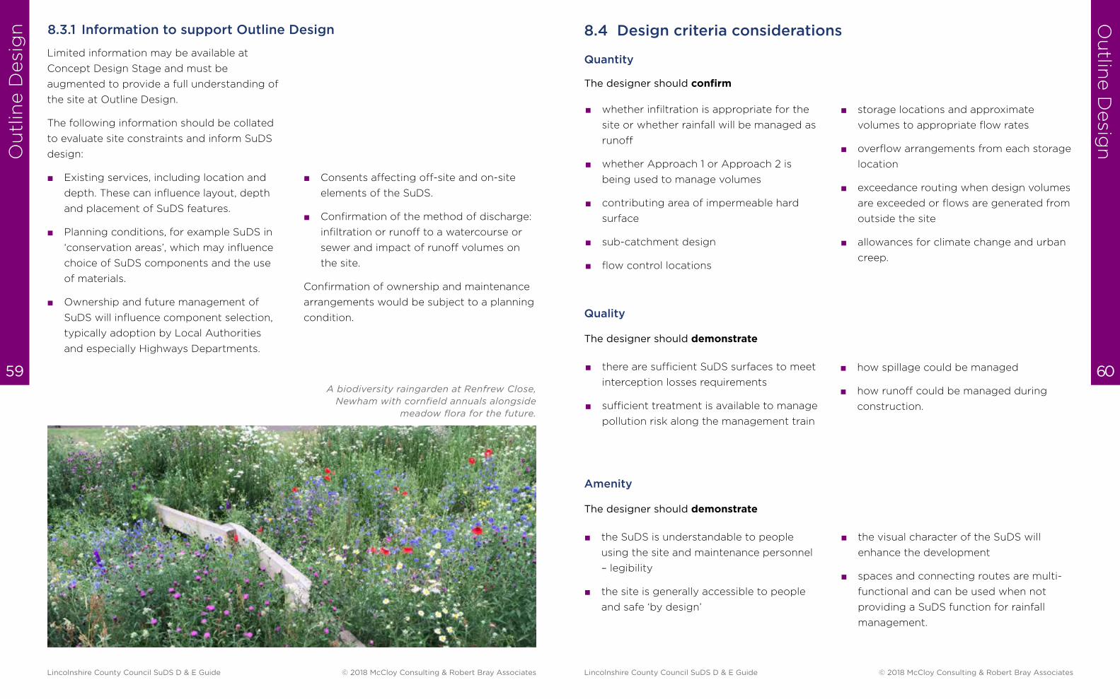
Ou
tlin
e D
esi
gn
Ou
tline D
esig
n
60 59
Limited information may be available at
Concept Design Stage and must be
augmented to provide a full understanding of
the site at Outline Design.
The following information should be collated
to evaluate site constraints and inform SuDS
design:
■ Existing services, including location and
depth. These can influence layout, depth
and placement of SuDS features.
■ Planning conditions, for example SuDS in
‘conservation areas’, which may influence
choice of SuDS components and the use
of materials.
■ Ownership and future management of
SuDS will influence component selection,
typically adoption by Local Authorities
and especially Highways Departments.
8.3.1 Information to support Outline Design
■ Consents affecting off-site and on-site
elements of the SuDS.
■ Confirmation of the method of discharge:
infiltration or runoff to a watercourse or
sewer and impact of runoff volumes on
the site.
Confirmation of ownership and maintenance
arrangements would be subject to a planning
condition.
A biodiversity raingarden at Renfrew Close,
Newham with cornfield annuals alongside
meadow flora for the future.
■ storage locations and approximate
volumes to appropriate flow rates
■ overflow arrangements from each storage
location
■ exceedance routing when design volumes
are exceeded or flows are generated from
outside the site
■ allowances for climate change and urban
creep.
■ how spillage could be managed
■ how runoff could be managed during
construction.
■ there are sufficient SuDS surfaces to meet
interception losses requirements
■ sufficient treatment is available to manage
pollution risk along the management train
8.4 Design criteria considerations
Quantity
The designer should confirm
■ whether infiltration is appropriate for the
site or whether rainfall will be managed as
runoff
■ whether Approach 1 or Approach 2 is
being used to manage volumes
■ contributing area of impermeable hard
surface
■ sub-catchment design
■ flow control locations
Quality
The designer should demonstrate
Amenity
The designer should demonstrate
■ the visual character of the SuDS will
enhance the development
■ spaces and connecting routes are multi-
functional and can be used when not
providing a SuDS function for rainfall
management.
■ the SuDS is understandable to people
using the site and maintenance personnel
– legibility
■ the site is generally accessible to people
and safe ‘by design’
Lincolnshire County Council SuDS D & E Guide © 2018 McCloy Consulting & Robert Bray Associates Lincolnshire County Council SuDS D & E Guide © 2018 McCloy Consulting & Robert Bray Associates
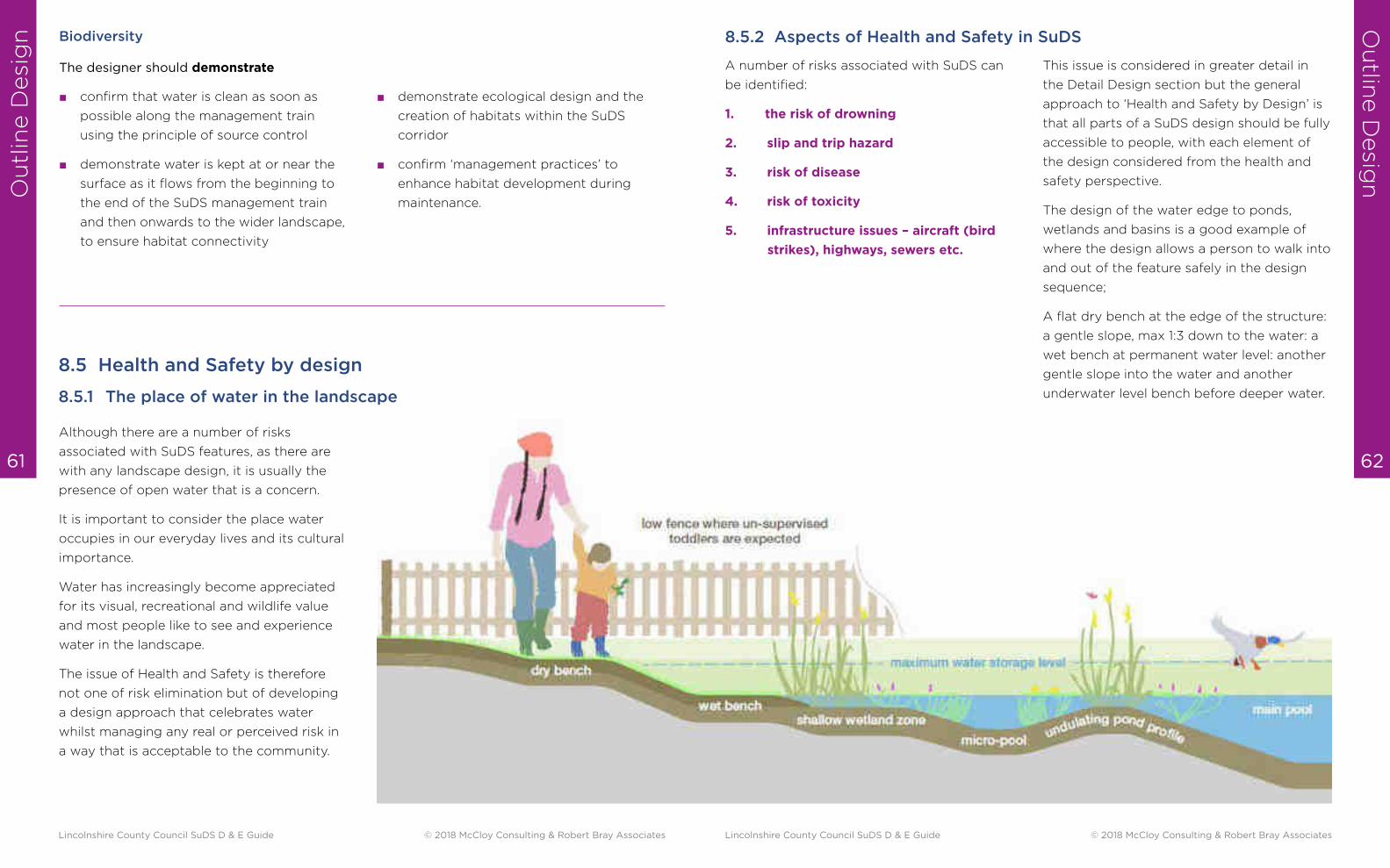
Ou
tlin
e D
esi
gn
Ou
tline D
esig
n
62 61
Biodiversity
The designer should demonstrate
■ confirm that water is clean as soon as
possible along the management train
using the principle of source control
■ demonstrate water is kept at or near the
surface as it flows from the beginning to
the end of the SuDS management train
and then onwards to the wider landscape,
to ensure habitat connectivity
■ demonstrate ecological design and the
creation of habitats within the SuDS
corridor
■ confirm ‘management practices’ to
enhance habitat development during
maintenance.
8.5 Health and Safety by design
Although there are a number of risks
associated with SuDS features, as there are
with any landscape design, it is usually the
presence of open water that is a concern.
It is important to consider the place water
occupies in our everyday lives and its cultural
importance.
Water has increasingly become appreciated
for its visual, recreational and wildlife value
and most people like to see and experience
water in the landscape.
The issue of Health and Safety is therefore
not one of risk elimination but of developing
a design approach that celebrates water
whilst managing any real or perceived risk in
a way that is acceptable to the community.
8.5.1 The place of water in the landscape
A number of risks associated with SuDS can
be identified:
1. the risk of drowning
2. slip and trip hazard
3. risk of disease
4. risk of toxicity
5. infrastructure issues – aircraft (bird
strikes), highways, sewers etc.
8.5.2 Aspects of Health and Safety in SuDS
This issue is considered in greater detail in
the Detail Design section but the general
approach to ‘Health and Safety by Design’ is
that all parts of a SuDS design should be fully
accessible to people, with each element of
the design considered from the health and
safety perspective.
The design of the water edge to ponds,
wetlands and basins is a good example of
where the design allows a person to walk into
and out of the feature safely in the design
sequence;
A flat dry bench at the edge of the structure:
a gentle slope, max 1:3 down to the water: a
wet bench at permanent water level: another
gentle slope into the water and another
underwater level bench before deeper water.
Lincolnshire County Council SuDS D & E Guide © 2018 McCloy Consulting & Robert Bray Associates Lincolnshire County Council SuDS D & E Guide © 2018 McCloy Consulting & Robert Bray Associates
Ou
tlin
e D
esi
gn
Ou
tline D
esig
n
64 63
The design of SuDS is influenced by the type
of development and how important each
component is to the appearance and
functionality of the scheme.
An urban renewal project in the city will
require a different approach to the visual
quality than a simple SuDS design for a
suburban layout.
SuDS components are cost effective when
compared to conventional drainage but cost
savings are only realised through good SuDS
design.
A good example of cost effective SuDS
design is the use of permeable pavement as
a replacement for impermeable surfaces. The
cost of the profile construction is marginally
The future maintenance of SuDS is influenced
by design. Wherever possible the idea of
‘passive maintenance’ should be considered
with SuDS components integrated into the
everyday management.
Although there will be situations where
dedicated SuDS components are appropriate
e.g. a pond or wetland, many SuDS features
can be incorporated into multifunctional
space e.g. courtyards, play basins and
recreational space.
more expensive but avoids extensive pipe
work, gullies, manhole, dedicated SuDS
storage and in some situations oil
interceptors. The open graded sub-base
provides 30% void storage which is
confirmed by a flow control and a low level
of maintenance into the future.
Completing a cost comparison for permeable
pavement demonstrates the wider
considerations of drainage, surfacing and
engineering profiles that have to be
considered.
In other locations a SuDS feature can
contribute to landscape infrastructure e.g.
the ‘rain garden’ or ‘bio retention’ element in
design.
Wherever possible maintenance should be
allocated to site care rather than SuDS
management.
This reduced dedicated maintenance
obligation can sometimes be reduced to just
checking inlets, outlets and control
structures.
Evidence for the cost effectiveness of
SuDS can be found here: http://www.
susdrain.org/resources/evidence.html
Design Note :
Well designed SuDS are not ‘land hungry’ in that they can be integrated into both hard and
soft landspace spaces which are available within development. Making SuDS cost effective
reinforces the requirement to consider SuDS layout at Concept Design stage.
8.6 Affordability
8.7 Management of the SuDS resource
8.8 Outline information required for SuDS evaluation
8.8.1
The information required at Outline Design
stage will depend on whether a Concept
Design has been provided and the level of
information included at that stage.
The design information should be provided in
plan form, confirming site layout and SuDS
infrastructure together with a SuDS Design
Statement presenting all information that
cannot be conveyed on plan.
Information recommended in the LASOO (Local
Authority SuDS Officer Organisation) Practical Guidance
Additional information to inform evaluation of the scheme:
The Outline SuDS Design will show what the
scheme will look like, how it will function and
confirm any additional information provided
since Concept Design Stage.
8.8.2 Outline Design – information checklist
■ Flood Risk Assessment (FRA) – a review
of critical elements
■ Outline Design Strategy Statement
■ Outline Design Plan – layout
■ the plan will incorporate preliminary
landscape proposals
■ topographical information and flow route
analysis
■ destination and discharge route of rainfall
via infiltration or runoff
■ infiltration investigation results where
appropriate
■ existing utilities plan confirming existing
watercourses or sewer locations
■ ground investigation review
■ evidence of third party agreement for
consent to discharge or agreement in
principle.
■ sensitive receptors for runoff where
appropriate e.g. SSSIs
■ offsite works that may be required
■ general maintenance principles
■ design life of any products used and
requirements for potential replacement.
Lincolnshire County Council SuDS D & E Guide © 2018 McCloy Consulting & Robert Bray Associates Lincolnshire County Council SuDS D & E Guide © 2018 McCloy Consulting & Robert Bray Associates
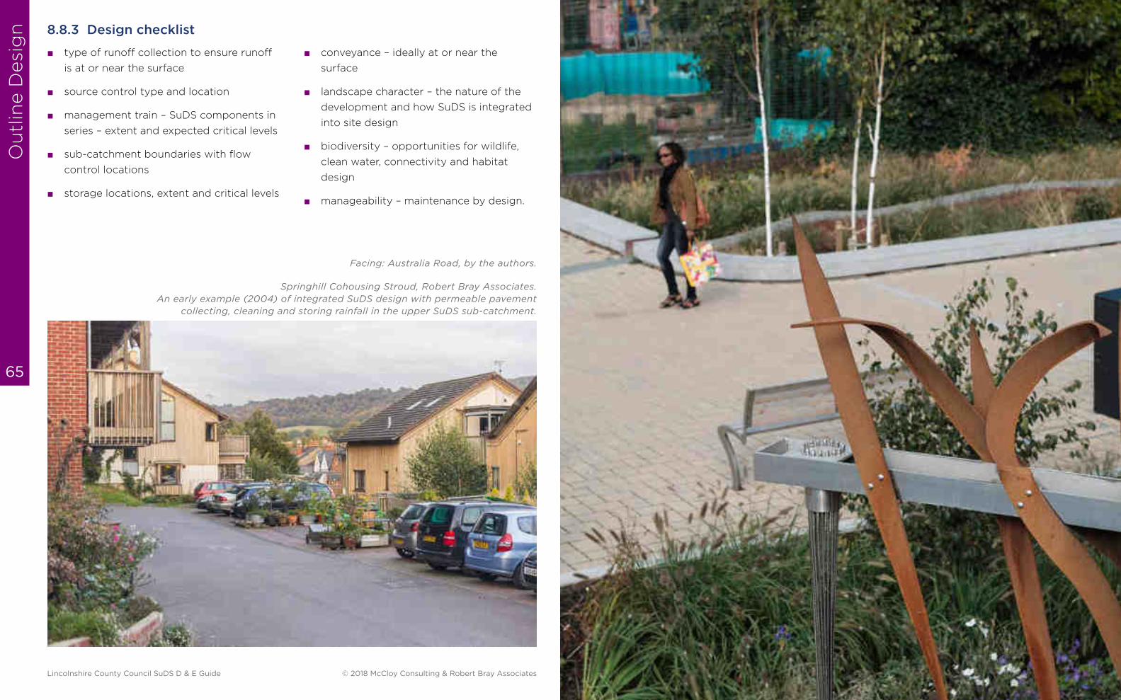
Ou
tlin
e D
esi
gn
65
8.8.3 Design checklist
■ type of runoff collection to ensure runoff
is at or near the surface
■ source control type and location
■ management train – SuDS components in
series – extent and expected critical levels
■ sub-catchment boundaries with flow
control locations
■ storage locations, extent and critical levels
■ conveyance – ideally at or near the
surface
■ landscape character – the nature of the
development and how SuDS is integrated
into site design
■ biodiversity – opportunities for wildlife,
clean water, connectivity and habitat
design
■ manageability – maintenance by design.
Springhill Cohousing Stroud, Robert Bray Associates.
An early example (2004) of integrated SuDS design with permeable pavement
collecting, cleaning and storing rainfall in the upper SuDS sub-catchment.
Facing: Australia Road, by the authors.
Lincolnshire County Council SuDS D & E Guide © 2018 McCloy Consulting & Robert Bray Associates
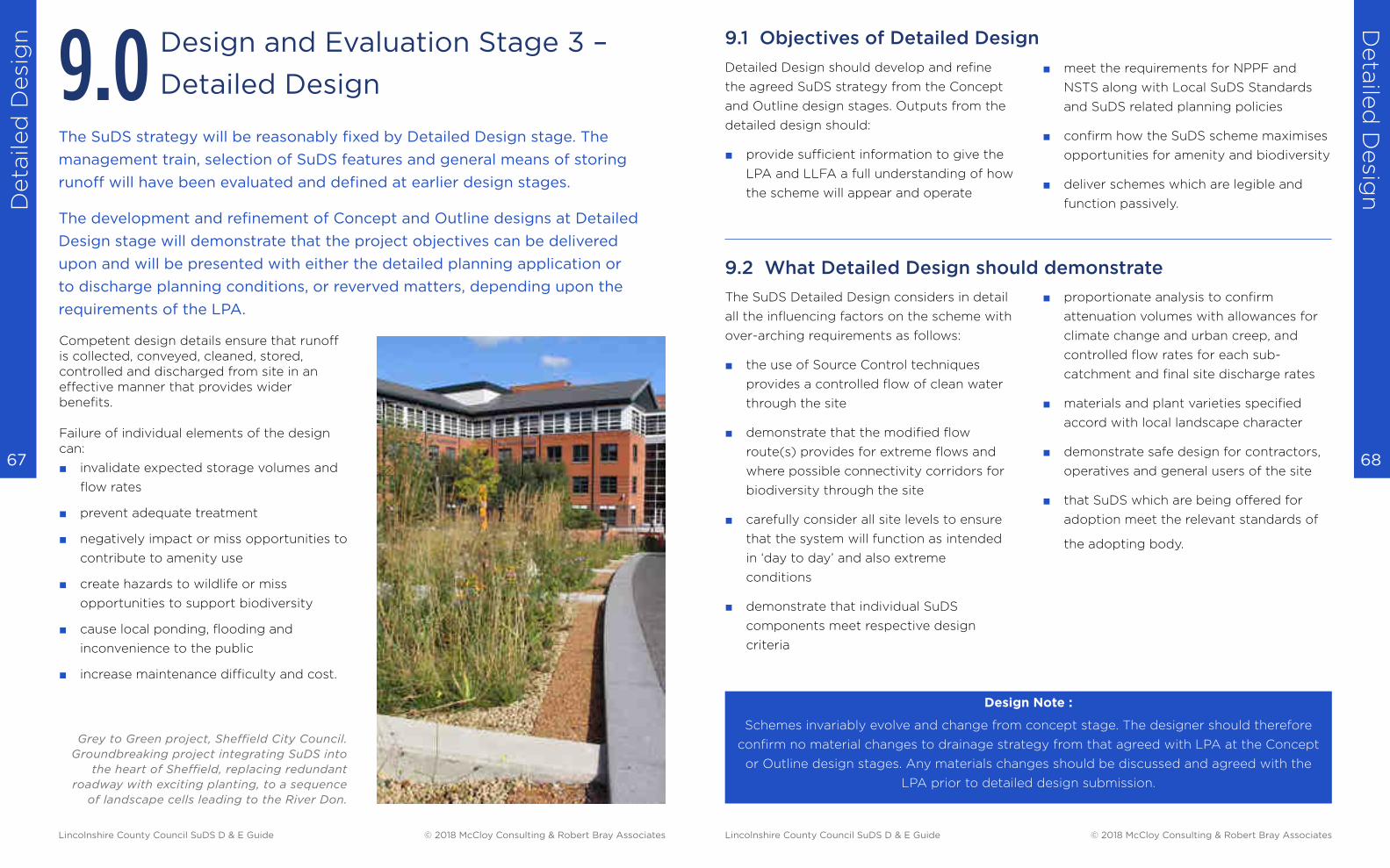
Deta
iled
Desi
gn
Deta
iled
Desig
n
68 67
Design and Evaluation Stage 3 –
Detailed Design9.0
Competent design details ensure that runoff is collected, conveyed, cleaned, stored, controlled and discharged from site in an effective manner that provides wider benefits.
Failure of individual elements of the design can:
■ invalidate expected storage volumes and
flow rates
■ prevent adequate treatment
■ negatively impact or miss opportunities to
contribute to amenity use
■ create hazards to wildlife or miss
opportunities to support biodiversity
■ cause local ponding, flooding and
inconvenience to the public
■ increase maintenance difficulty and cost.
The SuDS strategy will be reasonably fixed by Detailed Design stage. The
management train, selection of SuDS features and general means of storing
runoff will have been evaluated and defined at earlier design stages.
The development and refinement of Concept and Outline designs at Detailed
Design stage will demonstrate that the project objectives can be delivered
upon and will be presented with either the detailed planning application or
to discharge planning conditions, or reverved matters, depending upon the
requirements of the LPA.
Grey to Green project, Sheffield City Council.
Groundbreaking project integrating SuDS into
the heart of Sheffield, replacing redundant
roadway with exciting planting, to a sequence
of landscape cells leading to the River Don.
Design Note :
Schemes invariably evolve and change from concept stage. The designer should therefore
confirm no material changes to drainage strategy from that agreed with LPA at the Concept
or Outline design stages. Any materials changes should be discussed and agreed with the
LPA prior to detailed design submission.
The SuDS Detailed Design considers in detail
all the influencing factors on the scheme with
over-arching requirements as follows:
■ the use of Source Control techniques
provides a controlled flow of clean water
through the site
■ demonstrate that the modified flow
route(s) provides for extreme flows and
where possible connectivity corridors for
biodiversity through the site
■ carefully consider all site levels to ensure
that the system will function as intended
in ‘day to day’ and also extreme
conditions
■ demonstrate that individual SuDS
components meet respective design
criteria
Detailed Design should develop and refine
the agreed SuDS strategy from the Concept
and Outline design stages. Outputs from the
detailed design should:
■ provide sufficient information to give the
LPA and LLFA a full understanding of how
the scheme will appear and operate
■ meet the requirements for NPPF and
NSTS along with Local SuDS Standards
and SuDS related planning policies
■ confirm how the SuDS scheme maximises
opportunities for amenity and biodiversity
■ deliver schemes which are legible and
function passively.
■ proportionate analysis to confirm
attenuation volumes with allowances for
climate change and urban creep, and
controlled flow rates for each sub-
catchment and final site discharge rates
■ materials and plant varieties specified
accord with local landscape character
■ demonstrate safe design for contractors,
operatives and general users of the site
■ that SuDS which are being offered for
adoption meet the relevant standards of
the adopting body.
9.2 What Detailed Design should demonstrate
9.1 Objectives of Detailed Design
Lincolnshire County Council SuDS D & E Guide © 2018 McCloy Consulting & Robert Bray Associates Lincolnshire County Council SuDS D & E Guide © 2018 McCloy Consulting & Robert Bray Associates
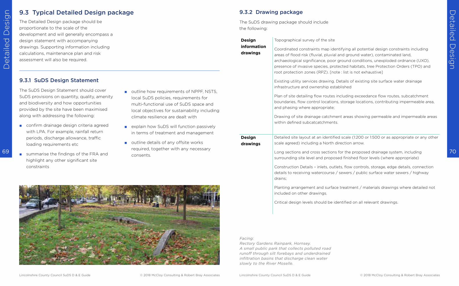
Deta
iled
Desi
gn
Deta
iled
Desig
n
70 69
The Detailed Design package should be
proportionate to the scale of the
development and will generally encompass a
design statement with accompanying
drawings. Supporting information including
calculations, maintenance plan and risk
assessment will also be required.
9.3.1 SuDS Design Statement
The SuDS Design Statement should cover
SuDS provisions on quantity, quality, amenity
and biodiversity and how opportunities
provided by the site have been maximised
along with addressing the following:
■ confirm drainage design criteria agreed
with LPA. For example, rainfall return
periods, discharge allowance, traffic
loading requirements etc
■ summarise the findings of the FRA and
highlight any other significant site
constraints
■ outline how requirements of NPPF, NSTS,
local SuDS policies, requirements for
multi-functional use of SuDS space and
local objectives for sustainability including
climate resilience are dealt with
■ explain how SuDS will function passively
in terms of treatment and management
■ outline details of any offsite works
required, together with any necessary
consents.
9.3 Typical Detailed Design package 9.3.2 Drawing package
The SuDS drawing package should include
the following:
Design
information
drawings
Topographical survey of the site
Coordinated constraints map identifying all potential design constraints including
areas of flood risk (fluvial, pluvial and ground water), contaminated land,
archaeological significance, poor ground conditions, unexploded ordnance (UXO),
presence of invasive species, protected habitats, tree Protection Orders (TPO) and
root protection zones (RPZ). [note : list is not exhaustive]
Existing utility services drawing. Details of existing site surface water drainage
infrastructure and ownership established
Plan of site detailing flow routes including exceedance flow routes, subcatchment
boundaries, flow control locations, storage locations, contributing impermeable area,
and phasing where appropriate;
Drawing of site drainage catchment areas showing permeable and impermeable areas
within defined subcatcatchments.
Design
drawings
Detailed site layout at an identified scale (1:200 or 1:500 or as appropriate or any other
scale agreed) including a North direction arrow.
Long sections and cross sections for the proposed drainage system, including
surrounding site level and proposed finished floor levels (where appropriate)
Construction Details – inlets, outlets, flow controls, storage, edge details, connection
details to receiving watercourse / sewers / public surface water sewers / highway
drains;
Planting arrangement and surface treatment / materials drawings where detailed not
included on other drawings.
Critical design levels should be identified on all relevant drawings.
Facing:
Rectory Gardens Rainpark, Hornsey.
A small public park that collects polluted road
runoff through silt forebays and underdrained
infiltration basins that discharge clean water
slowly to the River Moselle.
Lincolnshire County Council SuDS D & E Guide © 2018 McCloy Consulting & Robert Bray Associates Lincolnshire County Council SuDS D & E Guide © 2018 McCloy Consulting & Robert Bray Associates
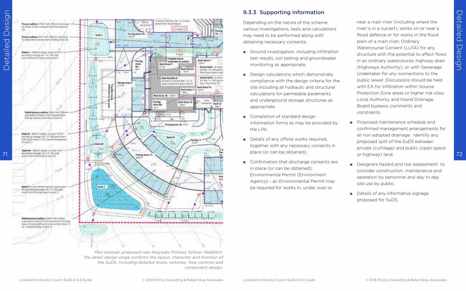
Deta
iled
Desi
gn
Deta
iled
Desig
n
72 71
Plan excerpt: proposed new Holyoaks Primary School, Redditch.
The detail design stage confirms the layout, character and function of
the SuDS, Including detailed levels, volumes, flow controls and
component design.
9.3.3 Supporting information
Depending on the nature of the scheme
various investigations, tests and calculations
may need to be performed along with
obtaining necessary consents:
■ Ground investigation, including infiltration
test results, soil testing and groundwater
monitoring as appropriate.
■ Design calculations which demonstrate
compliance with the design criteria for the
site including all hydraulic and structural
calculations for permeable pavements
and underground storage structures as
appropriate.
■ Completion of standard design
information forms as may be provided by
the LPA.
■ Details of any offsite works required,
together with any necessary consents in
place (or can be obtained).
■ Confirmation that discharge consents are
in place (or can be obtained):
Environmental Permit (Environment
Agency) - an Environmental Permit may
be required for works in, under, over or
near a main river (including where the
river is in a culvert), works on or near a
flood defence or for works in the flood
plain of a main river; Ordinary
Watercourse Consent (LLFA) for any
structure with the potential to affect flows
in an ordinary watercourse; highway drain
(Highways Authority); or with Sewerage
Undertaker for any connections to the
public sewer. Discussions should be held
with EA for Infiltration within Source
Protection Zone areas or higher risk sites;
Local Authority and Inland Drainage
Board byelaws, comments and
constraints.
■ Proposed maintenance schedule and
confirmed management arrangements for
all non adopted drainage. Identify any
proposed split of the SuDS between
private (curtilage) and public (open space
or highway) land.
■ Designers hazard and risk assessment- to
consider construction, maintenance and
operation by personnel and day to day
site use by public.
■ Details of any informative signage
proposed for SuDS.
Lincolnshire County Council SuDS D & E Guide © 2018 McCloy Consulting & Robert Bray Associates Lincolnshire County Council SuDS D & E Guide © 2018 McCloy Consulting & Robert Bray Associates
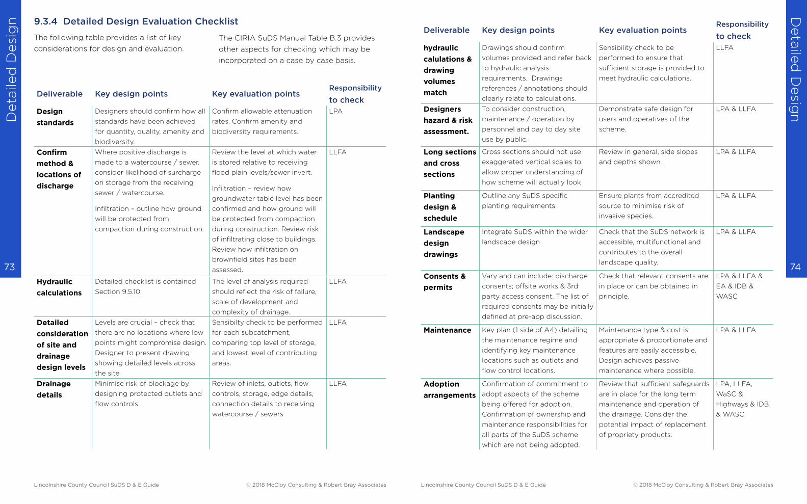
Deta
iled
Desi
gn
Deta
iled
Desig
n
74 73
The following table provides a list of key
considerations for design and evaluation.
Deliverable Key design points Key evaluation pointsResponsibility
to check
Design
standards
Designers should confirm how all
standards have been achieved
for quantity, quality, amenity and
biodiversity.
Confirm allowable attenuation
rates. Confirm amenity and
biodiversity requirements.
LPA
Confirm
method &
locations of
discharge
Where positive discharge is
made to a watercourse / sewer,
consider likelihood of surcharge
on storage from the receiving
sewer / watercourse.
Infiltration – outline how ground
will be protected from
compaction during construction.
Review the level at which water
is stored relative to receiving
flood plain levels/sewer invert.
Infiltration – review how
groundwater table level has been
confirmed and how ground will
be protected from compaction
during construction. Review risk
of infiltrating close to buildings.
Review how infiltration on
brownfield sites has been
assessed.
LLFA
Hydraulic
calculations
Detailed checklist is contained
Section 9.5.10.
The level of analysis required
should reflect the risk of failure,
scale of development and
complexity of drainage.
LLFA
Detailed
consideration
of site and
drainage
design levels
Levels are crucial – check that
there are no locations where low
points might compromise design.
Designer to present drawing
showing detailed levels across
the site
Sensibilty check to be performed
for each subcatchment,
comparing top level of storage,
and lowest level of contributing
areas.
LLFA
Drainage
details
Minimise risk of blockage by
designing protected outlets and
flow controls
Review of inlets, outlets, flow
controls, storage, edge details,
connection details to receiving
watercourse / sewers
LLFA
The CIRIA SuDS Manual Table B.3 provides
other aspects for checking which may be
incorporated on a case by case basis.
9.3.4 Detailed Design Evaluation Checklist Deliverable Key design points Key evaluation points
Responsibility
to check
hydraulic
calulations &
drawing
volumes
match
Drawings should confirm
volumes provided and refer back
to hydraulic analysis
requirements. Drawings
references / annotations should
clearly relate to calculations.
Sensibility check to be
performed to ensure that
sufficient storage is provided to
meet hydraulic calculations.
LLFA
Designers
hazard & risk
assessment.
To consider construction,
maintenance / operation by
personnel and day to day site
use by public.
Demonstrate safe design for
users and operatives of the
scheme.
LPA & LLFA
Long sections
and cross
sections
Cross sections should not use
exaggerated vertical scales to
allow proper understanding of
how scheme will actually look
Review in general, side slopes
and depths shown.
LPA & LLFA
Planting
design &
schedule
Outline any SuDS specific
planting requirements.
Ensure plants from accredited
source to minimise risk of
invasive species.
LPA & LLFA
Landscape
design
drawings
Integrate SuDS within the wider
landscape design
Check that the SuDS network is
accessible, multifunctional and
contributes to the overall
landscape quality.
LPA & LLFA
Consents &
permits
Vary and can include: discharge
consents; offsite works & 3rd
party access consent. The list of
required consents may be initially
defined at pre-app discussion.
Check that relevant consents are
in place or can be obtained in
principle.
LPA & LLFA &
EA & IDB &
WASC
Maintenance Key plan (1 side of A4) detailing
the maintenance regime and
identifying key maintenance
locations such as outlets and
flow control locations.
Maintenance type & cost is
appropriate & proportionate and
features are easily accessible.
Design achieves passive
maintenance where possible.
LPA & LLFA
Adoption
arrangements
Confirmation of commitment to
adopt aspects of the scheme
being offered for adoption.
Confirmation of ownership and
maintenance responsibilities for
all parts of the SuDS scheme
which are not being adopted.
Review that sufficient safeguards
are in place for the long term
maintenance and operation of
the drainage. Consider the
potential impact of replacement
of propriety products.
LPA, LLFA,
WaSC &
Highways & IDB
& WASC
Lincolnshire County Council SuDS D & E Guide © 2018 McCloy Consulting & Robert Bray Associates Lincolnshire County Council SuDS D & E Guide © 2018 McCloy Consulting & Robert Bray Associates
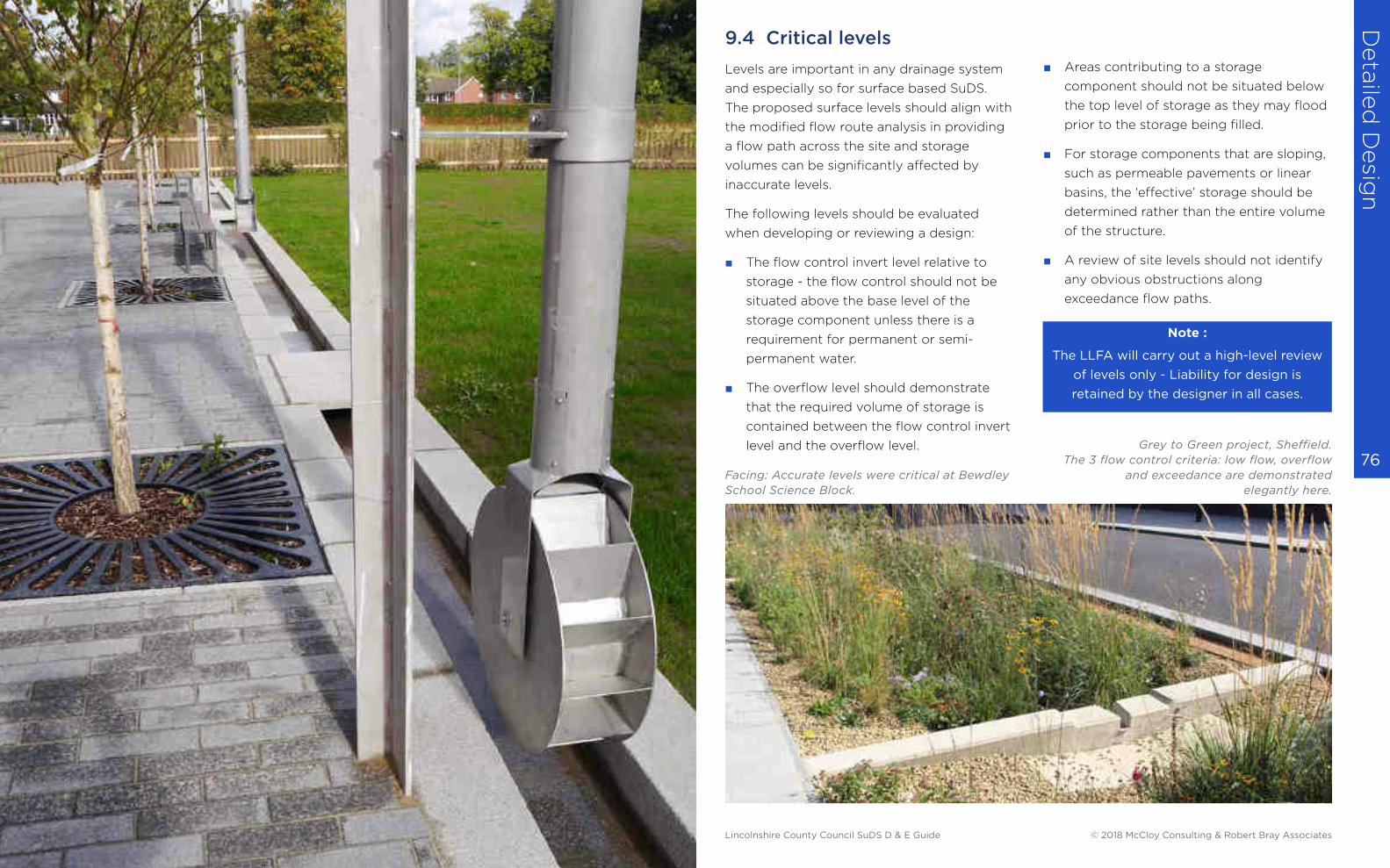
Deta
iled
Desig
n
76
9.4 Critical levels
Levels are important in any drainage system
and especially so for surface based SuDS.
The proposed surface levels should align with
the modified flow route analysis in providing
a flow path across the site and storage
volumes can be significantly affected by
inaccurate levels.
The following levels should be evaluated
when developing or reviewing a design:
■ The flow control invert level relative to
storage - the flow control should not be
situated above the base level of the
storage component unless there is a
requirement for permanent or semi-
permanent water.
■ The overflow level should demonstrate
that the required volume of storage is
contained between the flow control invert
level and the overflow level.
■ Areas contributing to a storage
component should not be situated below
the top level of storage as they may flood
prior to the storage being filled.
■ For storage components that are sloping,
such as permeable pavements or linear
basins, the ‘effective’ storage should be
determined rather than the entire volume
of the structure.
■ A review of site levels should not identify
any obvious obstructions along
exceedance flow paths.
Grey to Green project, Sheffield.
The 3 flow control criteria: low flow, overflow
and exceedance are demonstrated
elegantly here.
Facing: Accurate levels were critical at Bewdley
School Science Block.
Note :
The LLFA will carry out a high-level review
of levels only - Liability for design is
retained by the designer in all cases.
Lincolnshire County Council SuDS D & E Guide © 2018 McCloy Consulting & Robert Bray Associates

Deta
iled
Desi
gn
Deta
iled
Desig
n
78 77
Development causes an increase in runoff
which increases the risk of flooding on site
and elsewhere. Where runoff is temporarily
stored it allows for a controlled release either
into the ground or into a watercourse or
sewer.
The storage volume required can be
estimated using information such as the local
rainfall characteristics and the rate at which
flow is controlled to leaving the site.
Hydraulic calculations can:
■ inform and validate the SuDS design
■ provide confidence that there is sufficient
capacity to cater for the additional runoff
generated by the development to desired
design standards
Designers should demonstrate through the calculation process:
■ how the rates and volumes of runoff
generated from development will not
pose a flood risk within site boundary or
elsewhere
■ that future impacts to runoff such as
climate change and urban creep are
accounted for
■ that the correct calculation inputs and
processes have been used
■ where exceptional flows are experienced,
such as; design exceedance, instances of
blockage, or flows from offsite, they can
be managed within flow routes without
causing unreasonable risk to humans or
development.
Expressing calculation outputs in an
understandable format allows for easy
application within the design process as well
as transparency for evaluation.
■ make allowance for unknown factors such
as potential for runoff from off-site
■ provide confidence that SuDS will
function hydraulically and will not be
prone to erosion.
9.5 Designing for hydraulic requirements
9.5.2 What calculations should demonstrate
9.5.1 Objectives of hydraulic calculations
9.5.3 Calculation processes
Calculations used in SuDS design should
always be viewed as estimates of what is
experienced in reality. Calculation outputs
will vary depending upon how inputs are
selected and the calculation process used.
The calculations for SuDS design are used to
assess:
■ appropriate discharge rates via infiltration
or controlled discharge rates to a
watercourse or sewer
■ the volume of runoff that requires storage
to allow infiltration or attenuation to
controlled discharge rates (see 9.6)
■ the long-term storage volume that needs
to be managed (see 8.4.7)
■ flow velocities.
There are a number of methods that can be
used to carry out the calculations including
manual calculations, spreadsheets, online
tools and a variety of hydraulic modelling
software packages.
Calculation processes are summarised in the
following table:
Calculation process Purpose of calculation Main calculation inputs
Runoff rates from
greenfield and
brownfield sites
estimate
Used to define flow control rate Local rainfall data; site area; soil
characteristics.
Attenuation storage
or infiltration storage
estimate.
The runoff generated by the site is
balanced against the controlled rate
of outflow.
Local rainfall data; site area;
proposed site impermeable area;
climate and creep adjustments;
infiltration rates; soil characteristics;
discharge rate(s).
Long term storage
estimate
Determining the difference in the
volume of runoff between pre-
development and post development
scenarios
Local rainfall data; site area; existing
site impermeable area; proposed site
impermeable area; infiltration rates;
soil characteristics; rain harvest
volume, losses provide by SuDS,
proposed discharge rate(s).
Flow velocity check Flow velocity calculated to ensure:
Conveyance along vegetated
channels do not cause erosion;
Low flow velocities for 1 in 1 year
rainfall to allow settlement of silt.
Component sectional geometry;
component gradient; component
surface type (roughness); proposed
flow rates.
Lincolnshire County Council SuDS D & E Guide © 2018 McCloy Consulting & Robert Bray Associates Lincolnshire County Council SuDS D & E Guide © 2018 McCloy Consulting & Robert Bray Associates
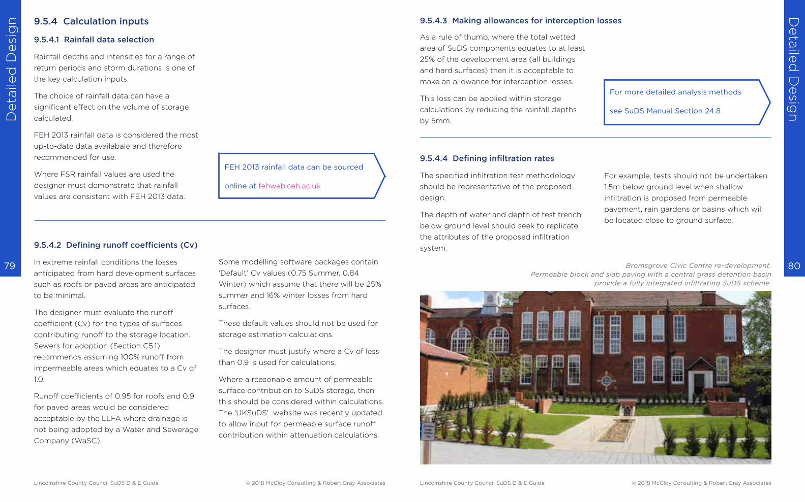
Deta
iled
Desi
gn
Deta
iled
Desig
n
80 79
9.5.4 Calculation inputs
9.5.4.1 Rainfall data selection
Rainfall depths and intensities for a range of
return periods and storm durations is one of
the key calculation inputs.
The choice of rainfall data can have a
significant effect on the volume of storage
calculated.
FEH 2013 rainfall data is considered the most
up-to-date data availabale and therefore
recommended for use.
Where FSR rainfall values are used the
designer must demonstrate that rainfall
values are consistent with FEH 2013 data.
9.5.4.2 Defining runoff coefficients (Cv)
In extreme rainfall conditions the losses
anticipated from hard development surfaces
such as roofs or paved areas are anticipated
to be minimal.
The designer must evaluate the runoff
coefficient (Cv) for the types of surfaces
contributing runoff to the storage location.
Sewers for adoption (Section C5.1)
recommends assuming 100% runoff from
impermeable areas which equates to a Cv of
1.0.
Runoff coefficients of 0.95 for roofs and 0.9
for paved areas would be considered
acceptable by the LLFA where drainage is
not being adopted by a Water and Sewerage
Company (WaSC).
Some modelling software packages contain
‘Default’ Cv values (0.75 Summer, 0.84
Winter) which assume that there will be 25%
summer and 16% winter losses from hard
surfaces.
These default values should not be used for
storage estimation calculations.
The designer must justify where a Cv of less
than 0.9 is used for calculations.
Where a reasonable amount of permeable
surface contribution to SuDS storage, then
this should be considered within calculations.
The ‘UKSuDS’ website was recently updated
to allow input for permeable surface runoff
contribution within attenuation calculations.
FEH 2013 rainfall data can be sourced
online at fehweb.ceh.ac.uk
As a rule of thumb, where the total wetted
area of SuDS components equates to at least
25% of the development area (all buildings
and hard surfaces) then it is acceptable to
make an allowance for interception losses.
This loss can be applied within storage
calculations by reducing the rainfall depths
by 5mm.
For more detailed analysis methods
see SuDS Manual Section 24.8
9.5.4.4 Defining infiltration rates
The specified infiltration test methodology
should be representative of the proposed
design.
The depth of water and depth of test trench
below ground level should seek to replicate
the attributes of the proposed infiltration
system.
For example, tests should not be undertaken
1.5m below ground level when shallow
infiltration is proposed from permeable
pavement, rain gardens or basins which will
be located close to ground surface.
Bromsgrove Civic Centre re-development.
Permeable block and slab paving with a central grass detention basin
provide a fully integrated infiltrating SuDS scheme.
9.5.4.3 Making allowances for interception losses
Lincolnshire County Council SuDS D & E Guide © 2018 McCloy Consulting & Robert Bray Associates Lincolnshire County Council SuDS D & E Guide © 2018 McCloy Consulting & Robert Bray Associates
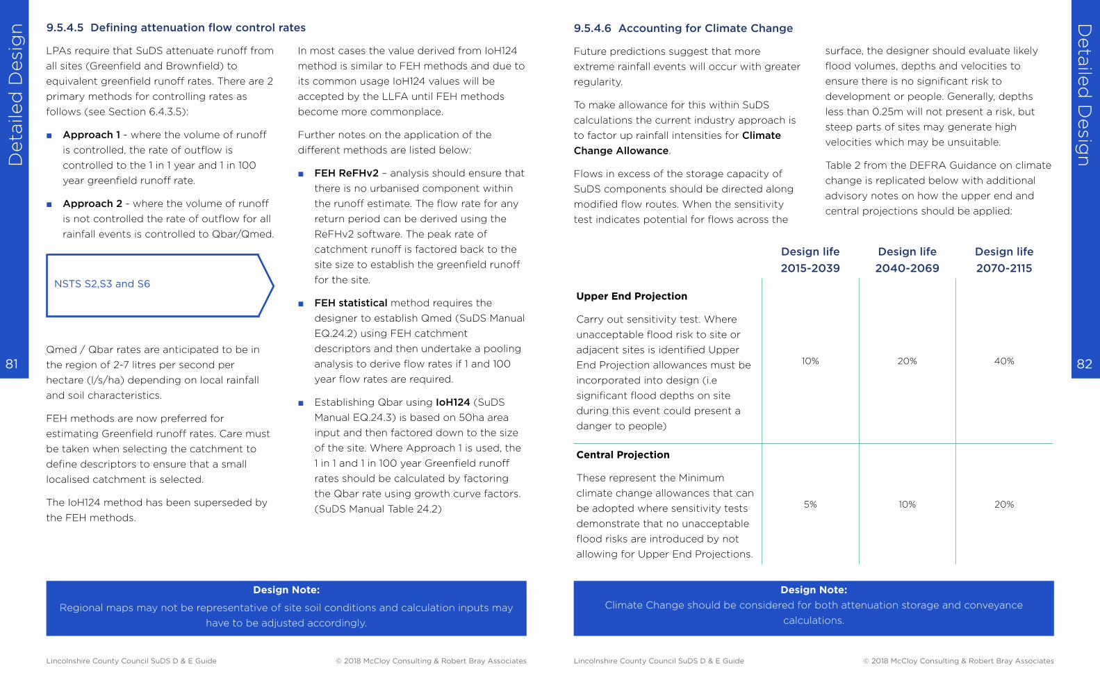
Deta
iled
Desi
gn
Deta
iled
Desig
n
82 81
LPAs require that SuDS attenuate runoff from
all sites (Greenfield and Brownfield) to
equivalent greenfield runoff rates. There are 2
primary methods for controlling rates as
follows (see Section 6.4.3.5):
■ Approach 1 - where the volume of runoff
is controlled, the rate of outflow is
controlled to the 1 in 1 year and 1 in 100
year greenfield runoff rate.
■ Approach 2 - where the volume of runoff
is not controlled the rate of outflow for all
rainfall events is controlled to Qbar/Qmed.
Qmed / Qbar rates are anticipated to be in
the region of 2-7 litres per second per
hectare (l/s/ha) depending on local rainfall
and soil characteristics.
FEH methods are now preferred for
estimating Greenfield runoff rates. Care must
be taken when selecting the catchment to
define descriptors to ensure that a small
localised catchment is selected.
The IoH124 method has been superseded by
the FEH methods.
NSTS S2,S3 and S6
Design Note:
Regional maps may not be representative of site soil conditions and calculation inputs may
have to be adjusted accordingly.
In most cases the value derived from IoH124
method is similar to FEH methods and due to
its common usage IoH124 values will be
accepted by the LLFA until FEH methods
become more commonplace.
Further notes on the application of the
different methods are listed below:
■ FEH ReFHv2 – analysis should ensure that
there is no urbanised component within
the runoff estimate. The flow rate for any
return period can be derived using the
ReFHv2 software. The peak rate of
catchment runoff is factored back to the
site size to establish the greenfield runoff
for the site.
■ FEH statistical method requires the
designer to establish Qmed (SuDS Manual
EQ.24.2) using FEH catchment
descriptors and then undertake a pooling
analysis to derive flow rates if 1 and 100
year flow rates are required.
■ Establishing Qbar using IoH124 (SuDS
Manual EQ.24.3) is based on 50ha area
input and then factored down to the size
of the site. Where Approach 1 is used, the
1 in 1 and 1 in 100 year Greenfield runoff
rates should be calculated by factoring
the Qbar rate using growth curve factors.
(SuDS Manual Table 24.2)
9.5.4.5 Defining attenuation flow control rates
Future predictions suggest that more
extreme rainfall events will occur with greater
regularity.
To make allowance for this within SuDS
calculations the current industry approach is
to factor up rainfall intensities for Climate
Change Allowance.
Flows in excess of the storage capacity of
SuDS components should be directed along
modified flow routes. When the sensitivity
test indicates potential for flows across the
Design life
2015-2039
Design life
2040-2069
Design life
2070-2115
Upper End Projection
Carry out sensitivity test. Where
unacceptable flood risk to site or
adjacent sites is identified Upper
End Projection allowances must be
incorporated into design (i.e
significant flood depths on site
during this event could present a
danger to people)
10% 20% 40%
Central Projection
These represent the Minimum
climate change allowances that can
be adopted where sensitivity tests
demonstrate that no unacceptable
flood risks are introduced by not
allowing for Upper End Projections.
5% 10% 20%
Design Note:
Climate Change should be considered for both attenuation storage and conveyance
calculations.
9.5.4.6 Accounting for Climate Change
surface, the designer should evaluate likely
flood volumes, depths and velocities to
ensure there is no significant risk to
development or people. Generally, depths
less than 0.25m will not present a risk, but
steep parts of sites may generate high
velocities which may be unsuitable.
Table 2 from the DEFRA Guidance on climate
change is replicated below with additional
advisory notes on how the upper end and
central projections should be applied:
Lincolnshire County Council SuDS D & E Guide © 2018 McCloy Consulting & Robert Bray Associates Lincolnshire County Council SuDS D & E Guide © 2018 McCloy Consulting & Robert Bray Associates
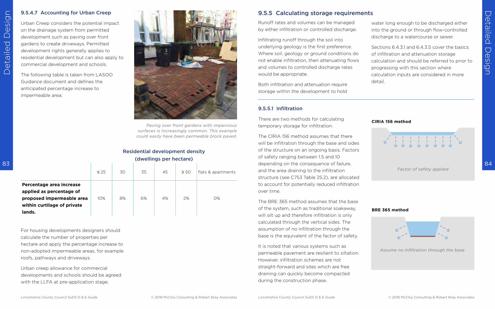
Deta
iled
Desi
gn
Deta
iled
Desig
n
84 83
9.5.4.7 Accounting for Urban Creep
Urban Creep considers the potential impact
on the drainage system from permitted
development such as paving over front
gardens to create driveways. Permitted
development rights generally applies to
residential development but can also apply to
commercial development and schools.
The following table is taken from LASOO
Guidance document and defines the
anticipated percentage increase to
impermeable area:
For housing developments designers should
calculate the number of properties per
hectare and apply the percentage increase to
non-adopted impermeable areas, for example
roofs, pathways and driveways.
Urban creep allowance for commercial
developments and schools should be agreed
with the LLFA at pre-application stage.
Residential development density
(dwellings per hectare)
≤ 25 30 35 45 ≥ 50 flats & apartments
Percentage area increase
applied as percentage of
proposed impermeable area
within curtilage of private
lands.
10% 8% 6% 4% 2% 0%
Paving over front gardens with impervious
surfaces is increasingly common. This example
could easily have been permeable block paved.
Runoff rates and volumes can be managed
by either infiltration or controlled discharge.
Infiltrating runoff through the soil into
underlying geology is the first preference.
Where soil, geology or ground conditions do
not enable infiltration, then attenuating flows
and volumes to controlled discharge rates
would be appropriate.
Both infiltration and attenuation require
storage within the development to hold
9.5.5.1 Infiltration
There are two methods for calculating
temporary storage for infiltration.
The CIRIA 156 method assumes that there
will be infiltration through the base and sides
of the structure on an ongoing basis. Factors
of safety ranging between 1.5 and 10
depending on the consequence of failure,
and the area draining to the infiltration
structure (see C753 Table 25.2), are allocated
to account for potentially reduced infiltration
over time.
The BRE 365 method assumes that the base
of the system, such as traditional soakaway,
will silt up and therefore infiltration is only
calculated through the vertical sides. The
assumption of no infiltration through the
base is the equivalent of the factor of safety.
It is noted that various systems such as
permeable pavement are resilient to siltation.
However, infiltration schemes are not
straight-forward and sites which are free
draining can quickly become compacted
during the construction phase.
water long enough to be discharged either
into the ground or through flow-controlled
discharge to a watercourse or sewer.
Sections 6.4.3.1 and 6.4.3.5 cover the basics
of infiltration and attenuation storage
calculation and should be referred to prior to
progressing with this section where
calculation inputs are considered in more
detail.
9.5.5 Calculating storage requirements
CIRIA 156 method
BRE 365 method
Factor of safety applied
Assume no infiltration through the base
Lincolnshire County Council SuDS D & E Guide © 2018 McCloy Consulting & Robert Bray Associates Lincolnshire County Council SuDS D & E Guide © 2018 McCloy Consulting & Robert Bray Associates

Deta
iled
Desi
gn
Deta
iled
Desig
n
86 85
Approach 1
For Approach 1, some runoff must be
retained on site for a longer period after
attenuation storage has emptied to mitigate
for the increased runoff volume generated by
the development. (NSTS S4)
There are a number of ways to reduce and
manage the volume of runoff generated by
development as follows:
Design Note:
Infiltration tests where low rates of infiltration are anticipated may have to be specified over a
period greater than 24 hours
■ Rain harvesting - Where it can be demonstrated that the harvesting system will be in use for
the majority of time and demand exceeds supply, 50% of the rain harvesting volume can be
offset against the long-term storage volume requirements. (BS 8515:2009)
■ Natural Losses – For SuDS components which provide natural losses a 5mm reduction can
be applied to rainfall depths to account for interception losses. To demonstrate potential for
sufficient interception losses, a ratio of ‘SuDS space’ to ‘developed area’ of 1:4 would be
considered acceptable by LPAs. Where SuDS components are unlined, some infiltration may
occur even if rates are very low. These additional losses can be offset against the long-term
storage volume requirements.
■ Separate area of storage - A separate area of storage can be provided. There are no set
procedures on how frequently long term storage is utilised.
It is prudent for areas which serve other
purposes such as carparks or playing fields
not to be inundated on a regular basis.
The 1 in 30 year event is suggested as the
point at which these areas would be first
utilised for storage.
In other locations such as raingardens and
long term storage basins within pond
complexes the frequency of fill may be much
more regular - i.e. they will be inundated for
rainfall events less than 1 in 30 year.
Outflow from Long Term storage area should
be via infiltration or a controlled discharge
rate of 2 l/s/ha.
9.5.5.2 Attenuation and long term storage
Approach 2
Where volumes cannot be managed to
predevelopment status, then outflow rate
should be controlled to a maximum of Qbar
rate (which is equivalent to a 1 in 2 year or
Qmed which is used by FEH methods) for all
rainfall return periods up to the 1 in 100 year
rainfall event plus climate change allowance.
This is the approach most commonly utilised
by industry at present due to simplicity of
analysis, but can result in a greater storage
requirement due to more restricted outflow
rates. (NSTS S6)
Riverside Court, Stamford.
Permeable pavement delivers a controlled flow of clean water to
landscape canal and rill features and to the River Welland.
Lincolnshire County Council SuDS D & E Guide © 2018 McCloy Consulting & Robert Bray Associates Lincolnshire County Council SuDS D & E Guide © 2018 McCloy Consulting & Robert Bray Associates
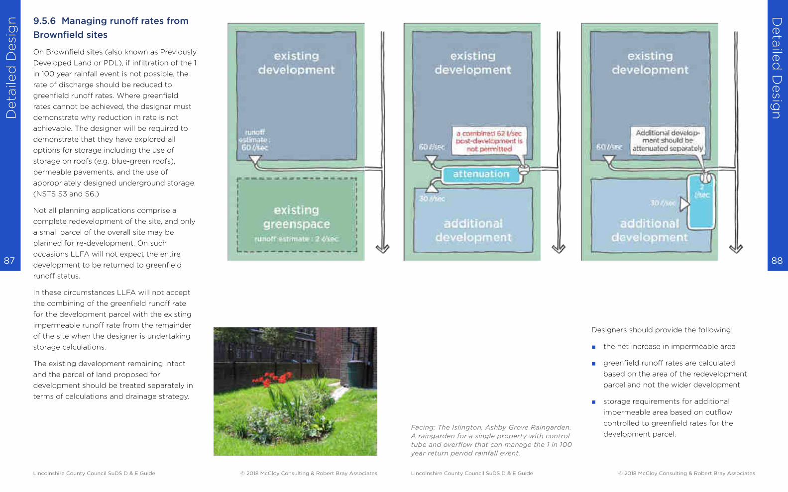
Deta
iled
Desi
gn
Deta
iled
Desig
n
88 87
9.5.6 Managing runoff rates from
Brownfield sites
On Brownfield sites (also known as Previously
Developed Land or PDL), if infiltration of the 1
in 100 year rainfall event is not possible, the
rate of discharge should be reduced to
greenfield runoff rates. Where greenfield
rates cannot be achieved, the designer must
demonstrate why reduction in rate is not
achievable. The designer will be required to
demonstrate that they have explored all
options for storage including the use of
storage on roofs (e.g. blue-green roofs),
permeable pavements, and the use of
appropriately designed underground storage.
(NSTS S3 and S6.)
Not all planning applications comprise a
complete redevelopment of the site, and only
a small parcel of the overall site may be
planned for re-development. On such
occasions LLFA will not expect the entire
development to be returned to greenfield
runoff status.
In these circumstances LLFA will not accept
the combining of the greenfield runoff rate
for the development parcel with the existing
impermeable runoff rate from the remainder
of the site when the designer is undertaking
storage calculations.
The existing development remaining intact
and the parcel of land proposed for
development should be treated separately in
terms of calculations and drainage strategy.
Designers should provide the following:
■ the net increase in impermeable area
■ greenfield runoff rates are calculated
based on the area of the redevelopment
parcel and not the wider development
■ storage requirements for additional
impermeable area based on outflow
controlled to greenfield rates for the
development parcel. Facing: The Islington, Ashby Grove Raingarden.
A raingarden for a single property with control
tube and overflow that can manage the 1 in 100
year return period rainfall event.
Lincolnshire County Council SuDS D & E Guide © 2018 McCloy Consulting & Robert Bray Associates Lincolnshire County Council SuDS D & E Guide © 2018 McCloy Consulting & Robert Bray Associates
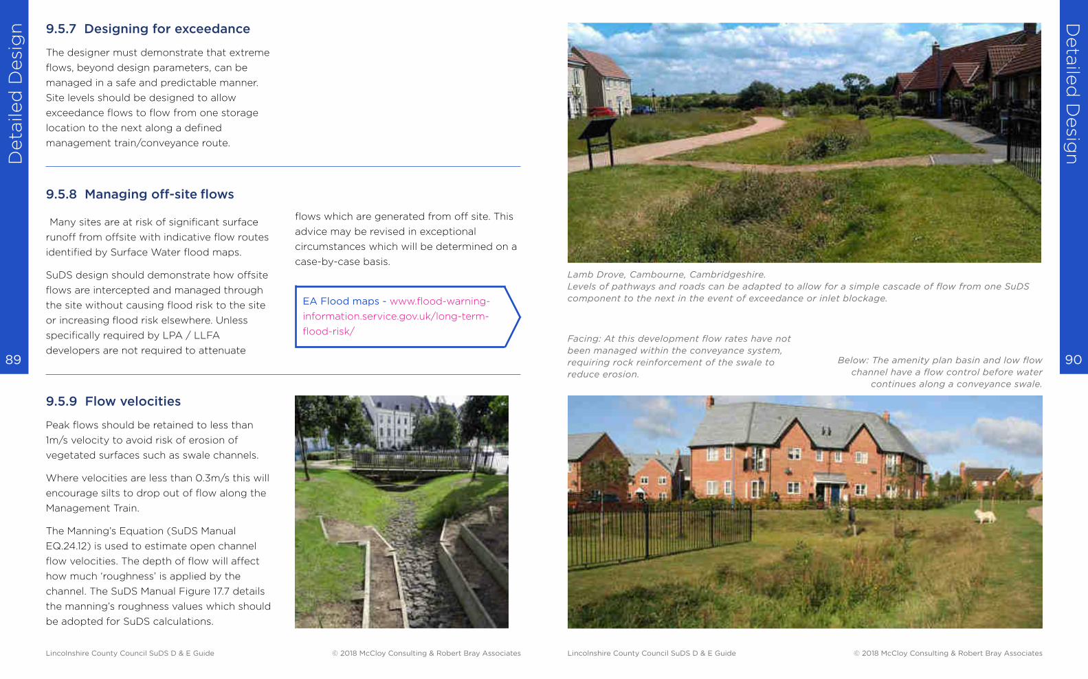
Deta
iled
Desi
gn
Deta
iled
Desig
n
90 89
9.5.7 Designing for exceedance
The designer must demonstrate that extreme
flows, beyond design parameters, can be
managed in a safe and predictable manner.
Site levels should be designed to allow
exceedance flows to flow from one storage
location to the next along a defined
management train/conveyance route.
9.5.8 Managing off-site flows
Many sites are at risk of significant surface
runoff from offsite with indicative flow routes
identified by Surface Water flood maps.
SuDS design should demonstrate how offsite
flows are intercepted and managed through
the site without causing flood risk to the site
or increasing flood risk elsewhere. Unless
specifically required by LPA / LLFA
developers are not required to attenuate
9.5.9 Flow velocities
Peak flows should be retained to less than
1m/s velocity to avoid risk of erosion of
vegetated surfaces such as swale channels.
Where velocities are less than 0.3m/s this will
encourage silts to drop out of flow along the
Management Train.
The Manning’s Equation (SuDS Manual
EQ.24.12) is used to estimate open channel
flow velocities. The depth of flow will affect
how much ‘roughness’ is applied by the
channel. The SuDS Manual Figure 17.7 details
the manning’s roughness values which should
be adopted for SuDS calculations.
EA Flood maps - www.flood-warning-
information.service.gov.uk/long-term-
flood-risk/
flows which are generated from off site. This
advice may be revised in exceptional
circumstances which will be determined on a
case-by-case basis.
Lamb Drove, Cambourne, Cambridgeshire.
Levels of pathways and roads can be adapted to allow for a simple cascade of flow from one SuDS
component to the next in the event of exceedance or inlet blockage.
Below: The amenity plan basin and low flow
channel have a flow control before water
continues along a conveyance swale.
Facing: At this development flow rates have not
been managed within the conveyance system,
requiring rock reinforcement of the swale to
reduce erosion.
Lincolnshire County Council SuDS D & E Guide © 2018 McCloy Consulting & Robert Bray Associates Lincolnshire County Council SuDS D & E Guide © 2018 McCloy Consulting & Robert Bray Associates
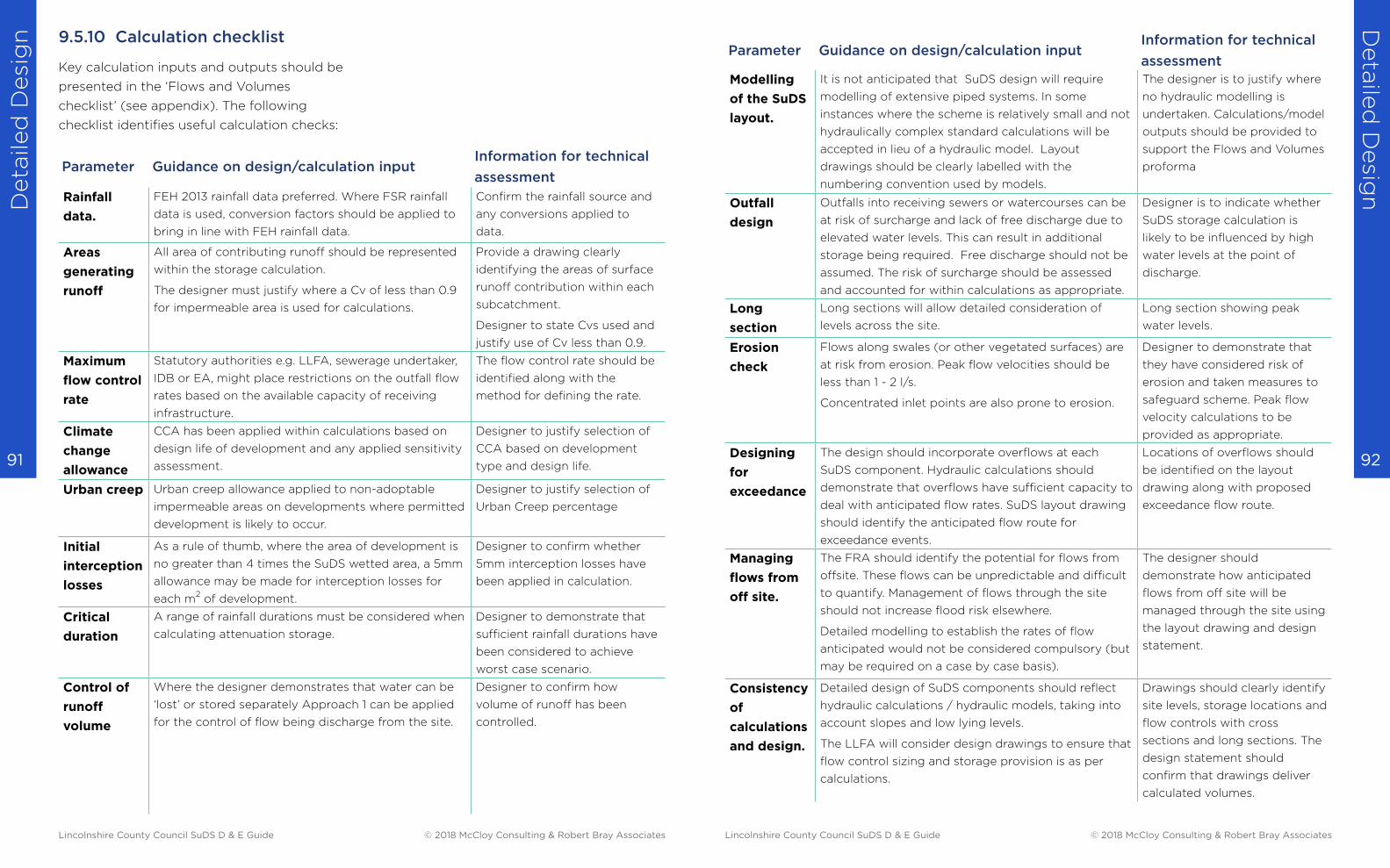
Deta
iled
Desi
gn
Deta
iled
Desig
n
92 91
9.5.10 Calculation checklist
Key calculation inputs and outputs should be
presented in the ‘Flows and Volumes
checklist’ (see appendix). The following
checklist identifies useful calculation checks:
Parameter Guidance on design/calculation inputInformation for technical
assessment
Rainfall
data.
FEH 2013 rainfall data preferred. Where FSR rainfall
data is used, conversion factors should be applied to
bring in line with FEH rainfall data.
Confirm the rainfall source and
any conversions applied to
data.
Areas
generating
runoff
All area of contributing runoff should be represented
within the storage calculation.
The designer must justify where a Cv of less than 0.9
for impermeable area is used for calculations.
Provide a drawing clearly
identifying the areas of surface
runoff contribution within each
subcatchment.
Designer to state Cvs used and
justify use of Cv less than 0.9.
Maximum
flow control
rate
Statutory authorities e.g. LLFA, sewerage undertaker,
IDB or EA, might place restrictions on the outfall flow
rates based on the available capacity of receiving
infrastructure.
The flow control rate should be
identified along with the
method for defining the rate.
Climate
change
allowance
CCA has been applied within calculations based on
design life of development and any applied sensitivity
assessment.
Designer to justify selection of
CCA based on development
type and design life.
Urban creep Urban creep allowance applied to non-adoptable
impermeable areas on developments where permitted
development is likely to occur.
Designer to justify selection of
Urban Creep percentage
Initial
interception
losses
As a rule of thumb, where the area of development is
no greater than 4 times the SuDS wetted area, a 5mm
allowance may be made for interception losses for
each m2 of development.
Designer to confirm whether
5mm interception losses have
been applied in calculation.
Critical
duration
A range of rainfall durations must be considered when
calculating attenuation storage.
Designer to demonstrate that
sufficient rainfall durations have
been considered to achieve
worst case scenario.
Control of
runoff
volume
Where the designer demonstrates that water can be
‘lost’ or stored separately Approach 1 can be applied
for the control of flow being discharge from the site.
Designer to confirm how
volume of runoff has been
controlled.
Parameter Guidance on design/calculation inputInformation for technical
assessment
Modelling
of the SuDS
layout.
It is not anticipated that SuDS design will require
modelling of extensive piped systems. In some
instances where the scheme is relatively small and not
hydraulically complex standard calculations will be
accepted in lieu of a hydraulic model. Layout
drawings should be clearly labelled with the
numbering convention used by models.
The designer is to justify where
no hydraulic modelling is
undertaken. Calculations/model
outputs should be provided to
support the Flows and Volumes
proforma
Outfall
design
Outfalls into receiving sewers or watercourses can be
at risk of surcharge and lack of free discharge due to
elevated water levels. This can result in additional
storage being required. Free discharge should not be
assumed. The risk of surcharge should be assessed
and accounted for within calculations as appropriate.
Designer is to indicate whether
SuDS storage calculation is
likely to be influenced by high
water levels at the point of
discharge.
Long
section
Long sections will allow detailed consideration of
levels across the site.
Long section showing peak
water levels.
Erosion
check
Flows along swales (or other vegetated surfaces) are
at risk from erosion. Peak flow velocities should be
less than 1 - 2 l/s.
Concentrated inlet points are also prone to erosion.
Designer to demonstrate that
they have considered risk of
erosion and taken measures to
safeguard scheme. Peak flow
velocity calculations to be
provided as appropriate.
Designing
for
exceedance
The design should incorporate overflows at each
SuDS component. Hydraulic calculations should
demonstrate that overflows have sufficient capacity to
deal with anticipated flow rates. SuDS layout drawing
should identify the anticipated flow route for
exceedance events.
Locations of overflows should
be identified on the layout
drawing along with proposed
exceedance flow route.
Managing
flows from
off site.
The FRA should identify the potential for flows from
offsite. These flows can be unpredictable and difficult
to quantify. Management of flows through the site
should not increase flood risk elsewhere.
Detailed modelling to establish the rates of flow
anticipated would not be considered compulsory (but
may be required on a case by case basis).
The designer should
demonstrate how anticipated
flows from off site will be
managed through the site using
the layout drawing and design
statement.
Consistency
of
calculations
and design.
Detailed design of SuDS components should reflect
hydraulic calculations / hydraulic models, taking into
account slopes and low lying levels.
The LLFA will consider design drawings to ensure that
flow control sizing and storage provision is as per
calculations.
Drawings should clearly identify
site levels, storage locations and
flow controls with cross
sections and long sections. The
design statement should
confirm that drawings deliver
calculated volumes.
Lincolnshire County Council SuDS D & E Guide © 2018 McCloy Consulting & Robert Bray Associates Lincolnshire County Council SuDS D & E Guide © 2018 McCloy Consulting & Robert Bray Associates

Deta
iled
Desi
gn
Deta
iled
Desig
n
94 93
9.6 Controlling flows
Where a single storage volume is presented,
it is the intuitive response of most designers
to try and accommodate all flow at a single
storage location. However, the opportunities
for storage across the site are diverse and
flexible.
Appearance, functionality and character of a
space can be influenced by how flows are
stored and controlled within each SuDS
component.
Raingarden and rill exploiting small pockets of
green space for creative water management at
Bewdley School Science Block.
These features visibly fill whenever it rains.
Plastic spacers are used to form open joints
between standard slabs at Abbey Park Campus
Leicester College, where all hard landscape
areas, including the pedestrian entrance plaza
to the building, are used for storage.
9.6.1 Design flexibility
A framework of three approaches which
deliver variable outflow rates (Approach 1)
are explored by this guide. These approaches
are intended to inspire the designer to think
about the possibilities that exist for
integrating storage as part of the
development rather than defaulting to an
underground storage structure prior to
discharge from the site. They can be
summarised as follows:
Distributed storage components
■ distributed storage volumes into discreet
storage components such as raingardens,
swales, basins and permeable pavement
with the potential for different rainfall
depths being stored at each location.
Single, uniform storage components
■ store up to the 1 in 100 year rainfall in a
single storage component, such as a
permeable pavement or blue-green roof,
with openings sized to achieve the
variable outflow rates.
Single, tiered storage components
■ store up to the 1 in 100 year rainfall in a
single, tiered storage component, such as
a smaller basin used on a regular basis
within a more extensive basin for more
extreme rainfall events and openings sized
to achieve the variable outflow rates.
Lincolnshire County Council SuDS D & E Guide © 2018 McCloy Consulting & Robert Bray Associates Lincolnshire County Council SuDS D & E Guide © 2018 McCloy Consulting & Robert Bray Associates
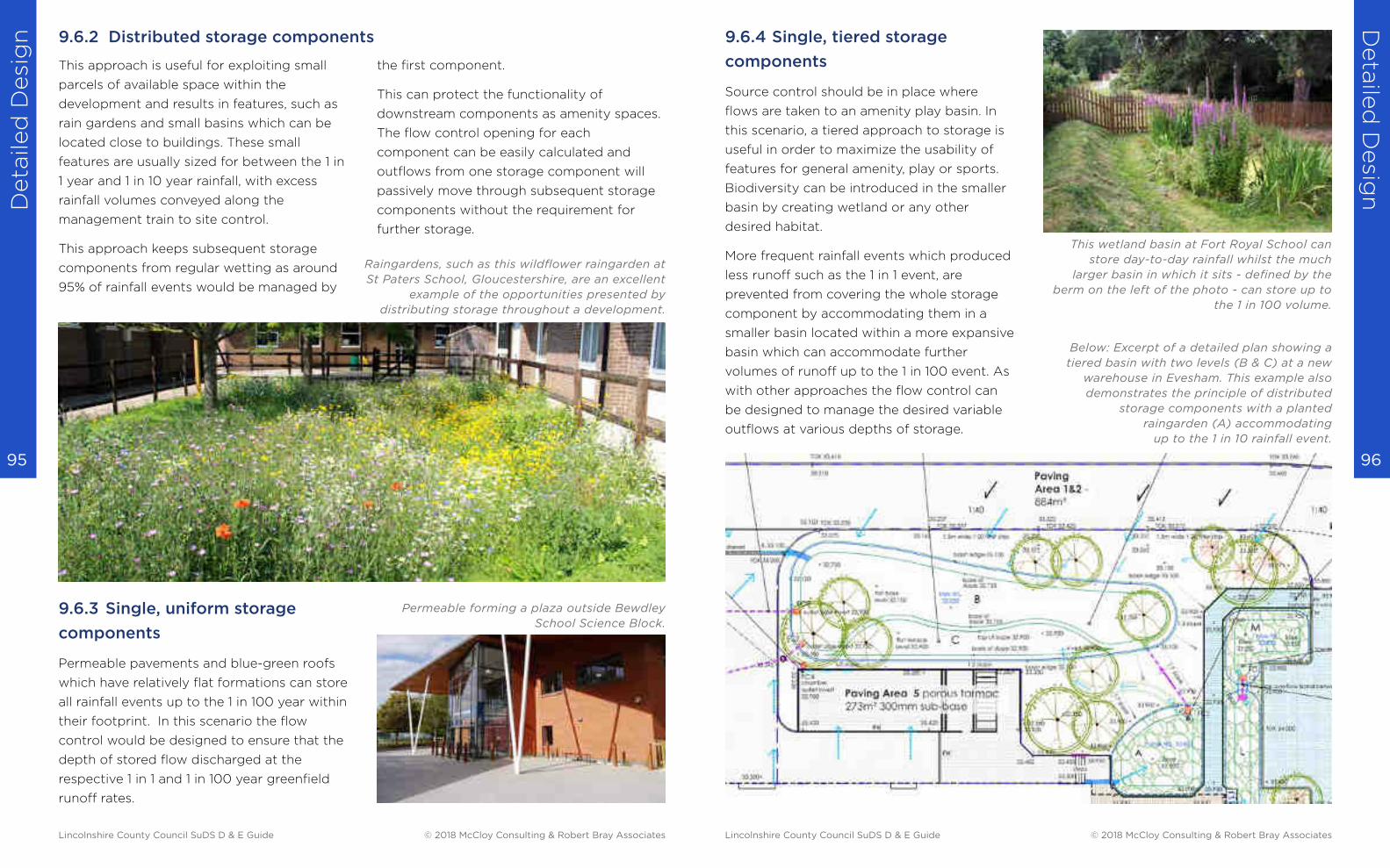
Deta
iled
Desi
gn
Deta
iled
Desig
n
96 95
This approach is useful for exploiting small
parcels of available space within the
development and results in features, such as
rain gardens and small basins which can be
located close to buildings. These small
features are usually sized for between the 1 in
1 year and 1 in 10 year rainfall, with excess
rainfall volumes conveyed along the
management train to site control.
This approach keeps subsequent storage
components from regular wetting as around
95% of rainfall events would be managed by
9.6.3 Single, uniform storage
components
Permeable pavements and blue-green roofs
which have relatively flat formations can store
all rainfall events up to the 1 in 100 year within
their footprint. In this scenario the flow
control would be designed to ensure that the
depth of stored flow discharged at the
respective 1 in 1 and 1 in 100 year greenfield
runoff rates.
the first component.
This can protect the functionality of
downstream components as amenity spaces.
The flow control opening for each
component can be easily calculated and
outflows from one storage component will
passively move through subsequent storage
components without the requirement for
further storage.
Raingardens, such as this wildflower raingarden at
St Paters School, Gloucestershire, are an excellent
example of the opportunities presented by
distributing storage throughout a development.
Permeable forming a plaza outside Bewdley
School Science Block.
9.6.2 Distributed storage components 9.6.4 Single, tiered storage
components
Source control should be in place where
flows are taken to an amenity play basin. In
this scenario, a tiered approach to storage is
useful in order to maximize the usability of
features for general amenity, play or sports.
Biodiversity can be introduced in the smaller
basin by creating wetland or any other
desired habitat.
More frequent rainfall events which produced
less runoff such as the 1 in 1 event, are
prevented from covering the whole storage
component by accommodating them in a
smaller basin located within a more expansive
basin which can accommodate further
volumes of runoff up to the 1 in 100 event. As
with other approaches the flow control can
be designed to manage the desired variable
outflows at various depths of storage.
Below: Excerpt of a detailed plan showing a
tiered basin with two levels (B & C) at a new
warehouse in Evesham. This example also
demonstrates the principle of distributed
storage components with a planted
raingarden (A) accommodating
up to the 1 in 10 rainfall event.
This wetland basin at Fort Royal School can
store day-to-day rainfall whilst the much
larger basin in which it sits - defined by the
berm on the left of the photo - can store up to
the 1 in 100 volume.
Lincolnshire County Council SuDS D & E Guide © 2018 McCloy Consulting & Robert Bray Associates Lincolnshire County Council SuDS D & E Guide © 2018 McCloy Consulting & Robert Bray Associates
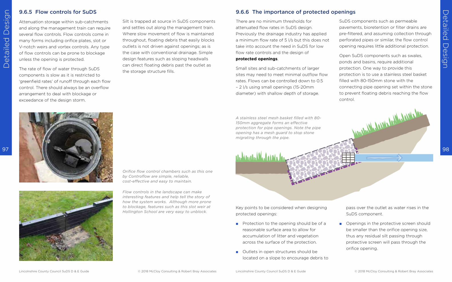
Deta
iled
Desi
gn
Deta
iled
Desig
n
98 97
9.6.5 Flow controls for SuDS
Attenuation storage within sub-catchments
and along the management train can require
several flow controls. Flow controls come in
many forms including orifice plates, slot or
V-notch weirs and vortex controls. Any type
of flow controls can be prone to blockage
unless the opening is protected.
The rate of flow of water through SuDS
components is slow as it is restricted to
‘greenfield rates’ of runoff through each flow
control. There should always be an overflow
arrangement to deal with blockage or
exceedance of the design storm.
Silt is trapped at source in SuDS components
and settles out along the management train.
Where slow movement of flow is maintained
throughout, floating debris that easily blocks
outlets is not driven against openings; as is
the case with conventional drainage. Simple
design features such as sloping headwalls
can direct floating debris past the outlet as
the storage structure fills.
Orifice flow control chambers such as this one
by Controflow are simple, reliable,
cost-effective and easy to maintain.
Flow controls in the landscape can make
interesting features and help tell the story of
how the system works. Although more prone
to blockage, features such as this slot weir at
Hollington School are very easy to unblock.
There are no minimum thresholds for
attenuated flow rates in SuDS design.
Previously the drainage industry has applied
a minimum flow rate of 5 l/s but this does not
take into account the need in SuDS for low
flow rate controls and the design of
protected openings.
Small sites and sub-catchments of larger
sites may need to meet minimal outflow flow
rates. Flows can be controlled down to 0.5
– 2 l/s using small openings (15-20mm
diameter) with shallow depth of storage.
SuDS components such as permeable
pavements, bioretention or filter drains are
pre-filtered, and assuming collection through
perforated pipes or similar, the flow control
opening requires little additional protection.
Open SuDS components such as swales,
ponds and basins, require additional
protection. One way to provide this
protection is to use a stainless steel basket
filled with 80-150mm stone with the
connecting pipe opening set within the stone
to prevent floating debris reaching the flow
control.
Key points to be considered when designing
protected openings:
■ Protection to the opening should be of a
reasonable surface area to allow for
accumulation of litter and vegetation
across the surface of the protection.
■ Outlets in open structures should be
located on a slope to encourage debris to
pass over the outlet as water rises in the
SuDS component.
■ Openings in the protective screen should
be smaller than the orifice opening size,
thus any residual silt passing through
protective screen will pass through the
orifice opening.
A stainless steel mesh basket filled with 80-
150mm aggregate forms an effective
protection for pipe openings. Note the pipe
opening has a mesh guard to stop stone
migrating through the pipe.
9.6.6 The importance of protected openings
Lincolnshire County Council SuDS D & E Guide © 2018 McCloy Consulting & Robert Bray Associates Lincolnshire County Council SuDS D & E Guide © 2018 McCloy Consulting & Robert Bray Associates

Deta
iled
Desi
gn
Deta
iled
Desig
n
100 99
9.6.8 Sizing flow control openings
The following methodologies for sizing flow
controls are intended for use by those with
knowledge of hydraulic calculations. Careful
consideration should always be given to the
selection of equations and coefficients.
Section 6.4.3.6 outlines two approaches for
the control of flow, summarised as follows:
Approach 1 – Variable control
Non Statutory Technical Standard S2 allows
for varying the outflow rate for the 1 in 1 year
and 1 in 100 year greenfield runoff rates for
the respective rainfall events.
Approach 2 - Qbar method
Where the design requirements for volume
control (S3) cannot be achieved then all
runoff from the site for the 1 in 100 year event
including CCA should be discharged at a
maximum Qbar rate (or equivalent) for the
development. A lower flow control threshold
of 2 l/sec/ha is acceptable to enable
reasonable drain down times.
It is noted that the maximum Qbar rate is
only reached when the SuDS component is
full and the design head reached.
9.6.8.1 Approach 1 methodology
An orifice opening will deliver variable
outflow rates as the severity of rainfall
increases, producing and storing more runoff.
As the depth of stored water increases the
gravitational pressure forces more flow
through the opening - sometimes referred to
as the ‘driving head’ of water stored.
The following steps outline the process of
calculating the opening size of an orifice flow
control to meet the requirements of NSTS S2:
1. Establish the controlled outflow (or
Greenfield runoff) rates for the 1 in 1 year
and 1 in 100 year rainfall event.
2. Define the first, lower orifice invert. A
reasonable starting point is to set the
invert at the base (or slightly below the
base) of storage.
3. Calculate the maximum storage depth for
your SuDS component, based on its
catchment, for the 1 in 100 year event and
He
ad
Graph comparing required flow rates
and the variable flow rate through a
simple orifice as head increases.
relationship between driving head and
flow through an orifice flow control
required 1 in 1 flow rate
the 1 in 100 flow rate - for example this
may be 350mm for a permeable
pavement or up to 600mm for basins.
4. Make a note of the calculated opening
size to achieve the 1 in 100 flow rate at
this storage depth.
5. Based on the same storage component
design and flow control opening, calculate
how a 1 in 1 year rainfall event will behave
– make a note of the maximum storage
depth and maximum flow rate. Note that
the volume and therefore driving head will
be significantly smaller for the 1 in 1 year
rainfall event and therefore the flow rate
through the orifice will be significantly
lower.
6. If the calculated maximum flow is less
that the 1 in 1 year control rate then the
opening does not need changing.
7. If the calculated maximum flow for the 1 in
1 event is larger than the 1 in 1 year control
rate then reduce the opening size and
recalculate based on the 1 in 1 event being
mindful that the 1 in 100 year scenario will
have to be reconsidered. Amend the
Flow
required 1 in 100 flow rate
flow rates derived by area drained
and respective growth curve
opening size until the 1 in 1 year event is
attenuated to the 1 in 1 discharge rate and
make a note of the resulting maximum
storage depth.
8. Re-run the calculations for the 1 in 100
year event based on the changed
opening. The maximum flow rate will now
be below the allowable discharge rate
resulting in more storage than is
necessary. To overcome this, a second
opening may be placed above the 1 in 1
storage depth noted in step 7. Add a
second opening so that it’s lower most
point (invert) is at or above the 1 in 1
storage depth and recalculate the storage
behavior in a 1 in 100 event. Adjust the
opening size and height above the 1 in 100
storage depth until the 1 in 100 flow rate is
achieved at the maximum storage depth
for the 1 in 100 event.
Design Notes:
Both the 1 in 1 and 1 in 100 discharge
rates can be achieved by any
combination of the following:
■ Adjusting the depth of each defined
storage tier by adjusting the area and
therefore volume of each tier
■ Incorporating one or more additional
openings
Other options can be explored where
there is difficulty in matching outflow
rates for both the 1 in 1 year and 1 in 100
year flows:
■ Try different types of openings such
as rectangular and v-notch weirs.
■ Store for a different return period – it
is not necessary to store for the 1 in
100 year return period in every sub-
catchment. The final discharge from
the site must meet requirements of
NSTS.
Lincolnshire County Council SuDS D & E Guide © 2018 McCloy Consulting & Robert Bray Associates Lincolnshire County Council SuDS D & E Guide © 2018 McCloy Consulting & Robert Bray Associates
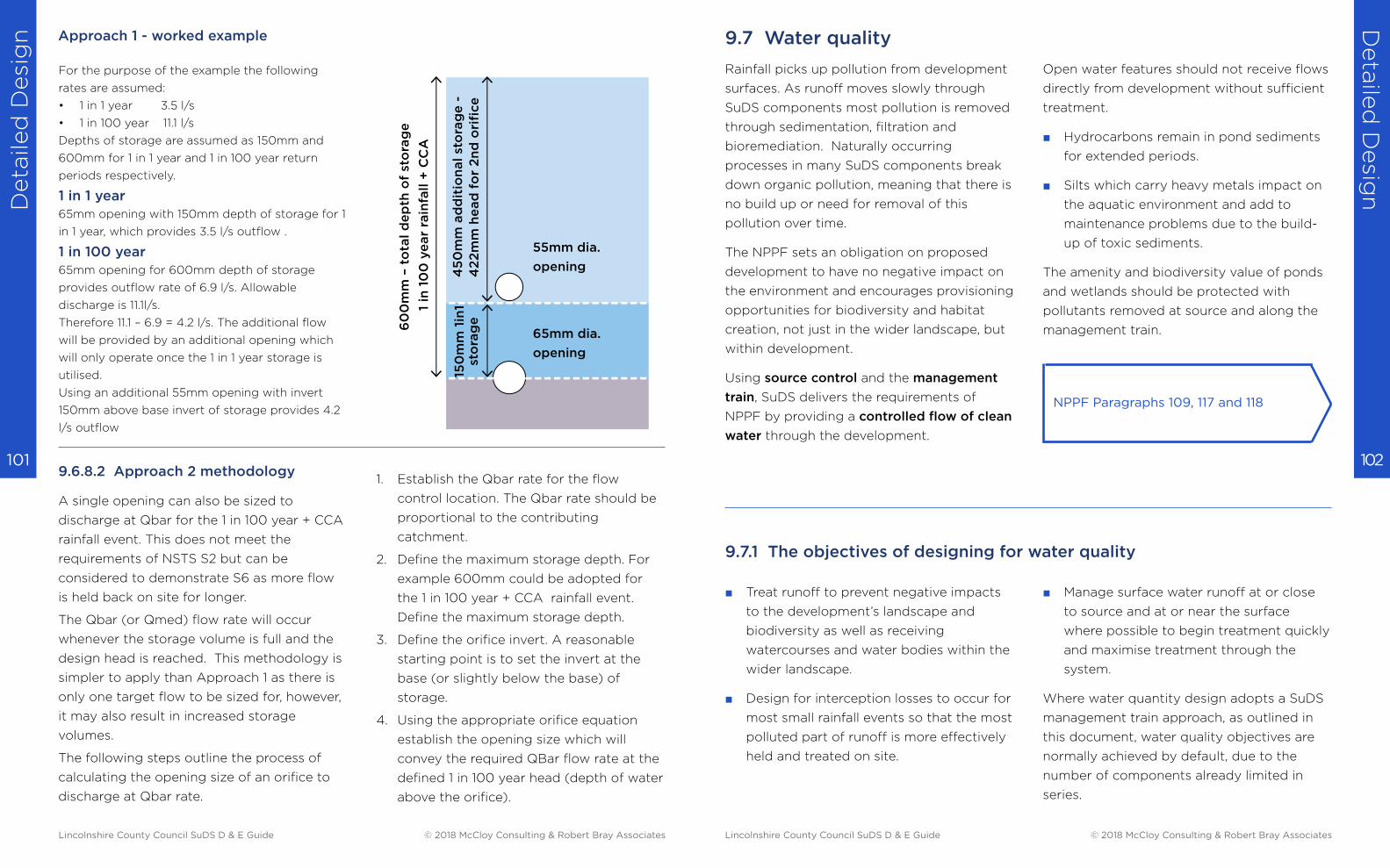
Deta
iled
Desi
gn
Deta
iled
Desig
n
102 101 9.6.8.2 Approach 2 methodology
A single opening can also be sized to
discharge at Qbar for the 1 in 100 year + CCA
rainfall event. This does not meet the
requirements of NSTS S2 but can be
considered to demonstrate S6 as more flow
is held back on site for longer.
The Qbar (or Qmed) flow rate will occur
whenever the storage volume is full and the
design head is reached. This methodology is
simpler to apply than Approach 1 as there is
only one target flow to be sized for, however,
it may also result in increased storage
volumes.
The following steps outline the process of
calculating the opening size of an orifice to
discharge at Qbar rate.
For the purpose of the example the following
rates are assumed:
• 1 in 1 year 3.5 l/s
• 1 in 100 year 11.1 l/s
Depths of storage are assumed as 150mm and
600mm for 1 in 1 year and 1 in 100 year return
periods respectively.
1 in 1 year65mm opening with 150mm depth of storage for 1
in 1 year, which provides 3.5 l/s outflow .
1 in 100 year 65mm opening for 600mm depth of storage
provides outflow rate of 6.9 l/s. Allowable
discharge is 11.1l/s.
Therefore 11.1 – 6.9 = 4.2 l/s. The additional flow
will be provided by an additional opening which
will only operate once the 1 in 1 year storage is
utilised.
Using an additional 55mm opening with invert
150mm above base invert of storage provides 4.2
l/s outflow
1. Establish the Qbar rate for the flow
control location. The Qbar rate should be
proportional to the contributing
catchment.
2. Define the maximum storage depth. For
example 600mm could be adopted for
the 1 in 100 year + CCA rainfall event.
Define the maximum storage depth.
3. Define the orifice invert. A reasonable
starting point is to set the invert at the
base (or slightly below the base) of
storage.
4. Using the appropriate orifice equation
establish the opening size which will
convey the required QBar flow rate at the
defined 1 in 100 year head (depth of water
above the orifice).
55mm dia.
opening45
0m
m a
dd
itio
nal st
ora
ge
-
42
2m
m h
ead
fo
r 2
nd
ori
fice
60
0m
m –
to
tal d
ep
th o
f st
ora
ge
1 in
10
0 y
ear
rain
fall +
CC
A
150
mm
1in
1 st
ora
ge
65mm dia.
opening
Approach 1 - worked example 9.7 Water quality
Rainfall picks up pollution from development
surfaces. As runoff moves slowly through
SuDS components most pollution is removed
through sedimentation, filtration and
bioremediation. Naturally occurring
processes in many SuDS components break
down organic pollution, meaning that there is
no build up or need for removal of this
pollution over time.
The NPPF sets an obligation on proposed
development to have no negative impact on
the environment and encourages provisioning
opportunities for biodiversity and habitat
creation, not just in the wider landscape, but
within development.
Using source control and the management
train, SuDS delivers the requirements of
NPPF by providing a controlled flow of clean
water through the development.
■ Treat runoff to prevent negative impacts
to the development’s landscape and
biodiversity as well as receiving
watercourses and water bodies within the
wider landscape.
■ Design for interception losses to occur for
most small rainfall events so that the most
polluted part of runoff is more effectively
held and treated on site.
NPPF Paragraphs 109, 117 and 118
Open water features should not receive flows
directly from development without sufficient
treatment.
■ Hydrocarbons remain in pond sediments
for extended periods.
■ Silts which carry heavy metals impact on
the aquatic environment and add to
maintenance problems due to the build-
up of toxic sediments.
The amenity and biodiversity value of ponds
and wetlands should be protected with
pollutants removed at source and along the
management train.
■ Manage surface water runoff at or close
to source and at or near the surface
where possible to begin treatment quickly
and maximise treatment through the
system.
Where water quantity design adopts a SuDS
management train approach, as outlined in
this document, water quality objectives are
normally achieved by default, due to the
number of components already limited in
series.
9.7.1 The objectives of designing for water quality
Lincolnshire County Council SuDS D & E Guide © 2018 McCloy Consulting & Robert Bray Associates Lincolnshire County Council SuDS D & E Guide © 2018 McCloy Consulting & Robert Bray Associates
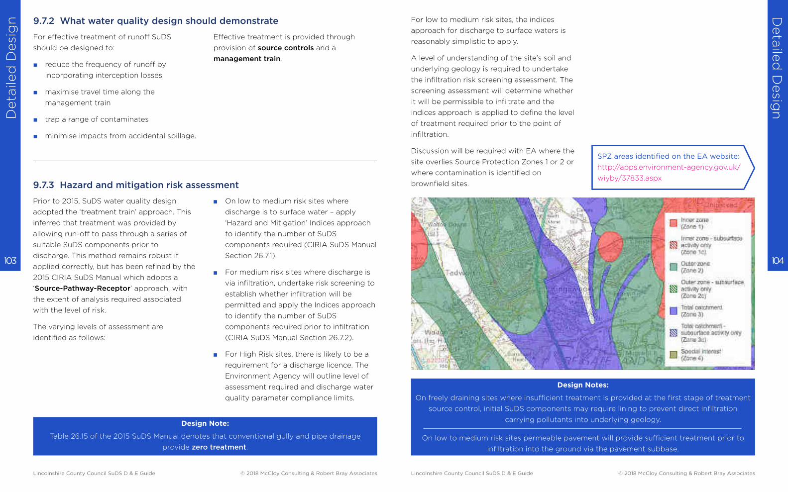
Deta
iled
Desi
gn
Deta
iled
Desig
n
104 103
For effective treatment of runoff SuDS
should be designed to:
■ reduce the frequency of runoff by
incorporating interception losses
■ maximise travel time along the
management train
■ trap a range of contaminates
■ minimise impacts from accidental spillage.
Prior to 2015, SuDS water quality design
adopted the ‘treatment train’ approach. This
inferred that treatment was provided by
allowing run-off to pass through a series of
suitable SuDS components prior to
discharge. This method remains robust if
applied correctly, but has been refined by the
2015 CIRIA SuDS Manual which adopts a
‘Source-Pathway-Receptor’ approach, with
the extent of analysis required associated
with the level of risk.
The varying levels of assessment are
identified as follows:
Design Note:
Table 26.15 of the 2015 SuDS Manual denotes that conventional gully and pipe drainage
provide zero treatment.
■ On low to medium risk sites where
discharge is to surface water – apply
‘Hazard and Mitigation’ Indices approach
to identify the number of SuDS
components required (CIRIA SuDS Manual
Section 26.7.1).
■ For medium risk sites where discharge is
via infiltration, undertake risk screening to
establish whether infiltration will be
permitted and apply the Indices approach
to identify the number of SuDS
components required prior to infiltration
(CIRIA SuDS Manual Section 26.7.2).
■ For High Risk sites, there is likely to be a
requirement for a discharge licence. The
Environment Agency will outline level of
assessment required and discharge water
quality parameter compliance limits.
Effective treatment is provided through
provision of source controls and a
management train.
9.7.2 What water quality design should demonstrate
9.7.3 Hazard and mitigation risk assessment
Design Notes:
On freely draining sites where insufficient treatment is provided at the first stage of treatment
source control, initial SuDS components may require lining to prevent direct infiltration
carrying pollutants into underlying geology.
On low to medium risk sites permeable pavement will provide sufficient treatment prior to
infiltration into the ground via the pavement subbase.
For low to medium risk sites, the indices
approach for discharge to surface waters is
reasonably simplistic to apply.
A level of understanding of the site’s soil and
underlying geology is required to undertake
the infiltration risk screening assessment. The
screening assessment will determine whether
it will be permissible to infiltrate and the
indices approach is applied to define the level
of treatment required prior to the point of
infiltration.
Discussion will be required with EA where the
site overlies Source Protection Zones 1 or 2 or
where contamination is identified on
brownfield sites.
SPZ areas identified on the EA website:
http://apps.environment-agency.gov.uk/
wiyby/37833.aspx
Lincolnshire County Council SuDS D & E Guide © 2018 McCloy Consulting & Robert Bray Associates Lincolnshire County Council SuDS D & E Guide © 2018 McCloy Consulting & Robert Bray Associates
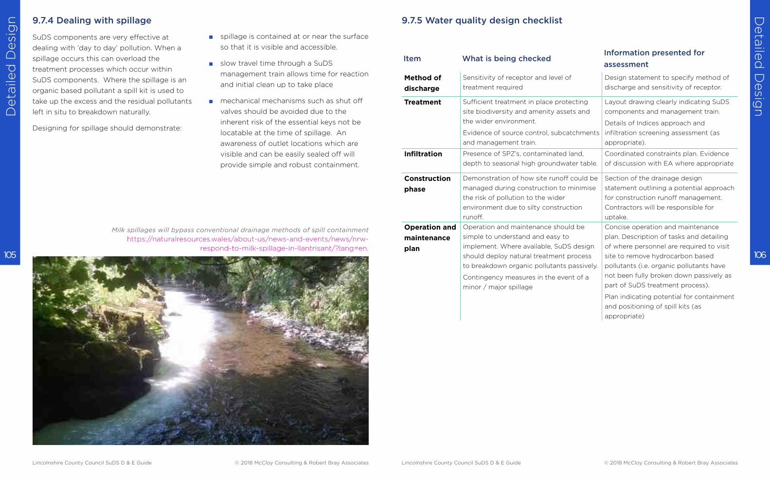
Deta
iled
Desi
gn
Deta
iled
Desig
n
106 105
9.7.4 Dealing with spillage
SuDS components are very effective at
dealing with ‘day to day’ pollution. When a
spillage occurs this can overload the
treatment processes which occur within
SuDS components. Where the spillage is an
organic based pollutant a spill kit is used to
take up the excess and the residual pollutants
left in situ to breakdown naturally.
Designing for spillage should demonstrate:
■ spillage is contained at or near the surface
so that it is visible and accessible.
■ slow travel time through a SuDS
management train allows time for reaction
and initial clean up to take place
■ mechanical mechanisms such as shut off
valves should be avoided due to the
inherent risk of the essential keys not be
locatable at the time of spillage. An
awareness of outlet locations which are
visible and can be easily sealed off will
provide simple and robust containment.
Milk spillages will bypass conventional drainage methods of spill containment
https://naturalresources.wales/about-us/news-and-events/news/nrw-
respond-to-milk-spillage-in-llantrisant/?lang=en.
9.7.5 Water quality design checklist
Item What is being checkedInformation presented for
assessment
Method of
discharge
Sensitivity of receptor and level of
treatment required
Design statement to specify method of
discharge and sensitivity of receptor.
Treatment Sufficient treatment in place protecting
site biodiversity and amenity assets and
the wider environment.
Evidence of source control, subcatchments
and management train.
Layout drawing clearly indicating SuDS
components and management train.
Details of Indices approach and
infiltration screening assessment (as
appropriate).
Infiltration Presence of SPZ’s, contaminated land,
depth to seasonal high groundwater table.
Coordinated constraints plan. Evidence
of discussion with EA where appropriate
Construction
phase
Demonstration of how site runoff could be
managed during construction to minimise
the risk of pollution to the wider
environment due to silty construction
runoff.
Section of the drainage design
statement outlining a potential approach
for construction runoff management.
Contractors will be responsible for
uptake.
Operation and
maintenance
plan
Operation and maintenance should be
simple to understand and easy to
implement. Where available, SuDS design
should deploy natural treatment process
to breakdown organic pollutants passively.
Contingency measures in the event of a
minor / major spillage
Concise operation and maintenance
plan. Description of tasks and detailing
of where personnel are required to visit
site to remove hydrocarbon based
pollutants (i.e. organic pollutants have
not been fully broken down passively as
part of SuDS treatment process).
Plan indicating potential for containment
and positioning of spill kits (as
appropriate)
Lincolnshire County Council SuDS D & E Guide © 2018 McCloy Consulting & Robert Bray Associates Lincolnshire County Council SuDS D & E Guide © 2018 McCloy Consulting & Robert Bray Associates
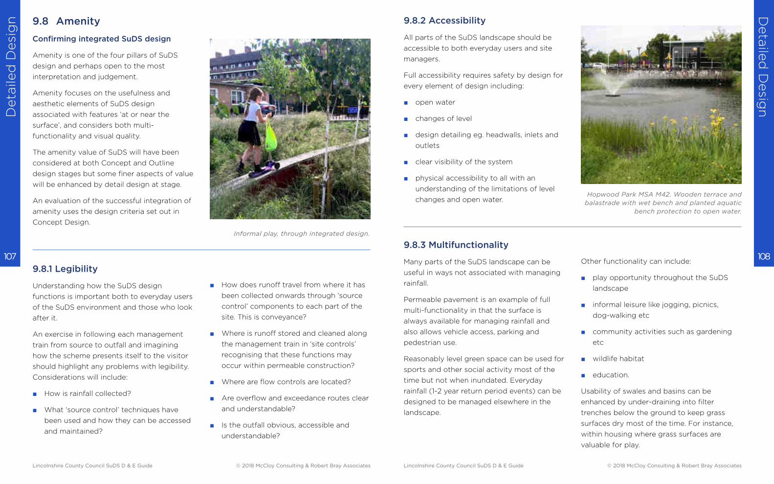
Deta
iled
Desi
gn
Deta
iled
Desig
n
108 107
Amenity is one of the four pillars of SuDS
design and perhaps open to the most
interpretation and judgement.
Amenity focuses on the usefulness and
aesthetic elements of SuDS design
associated with features ‘at or near the
surface’, and considers both multi-
functionality and visual quality.
The amenity value of SuDS will have been
considered at both Concept and Outline
design stages but some finer aspects of value
will be enhanced by detail design at stage.
An evaluation of the successful integration of
amenity uses the design criteria set out in
Concept Design.
9.8.1 Legibility
Understanding how the SuDS design
functions is important both to everyday users
of the SuDS environment and those who look
after it.
An exercise in following each management
train from source to outfall and imagining
how the scheme presents itself to the visitor
should highlight any problems with legibility.
Considerations will include:
■ How is rainfall collected?
■ What ‘source control’ techniques have
been used and how they can be accessed
and maintained?
■ How does runoff travel from where it has
been collected onwards through ‘source
control’ components to each part of the
site. This is conveyance?
■ Where is runoff stored and cleaned along
the management train in ‘site controls’
recognising that these functions may
occur within permeable construction?
■ Where are flow controls are located?
■ Are overflow and exceedance routes clear
and understandable?
■ Is the outfall obvious, accessible and
understandable?
Confirming integrated SuDS design
Informal play, through integrated design.
9.8 Amenity 9.8.2 Accessibility
All parts of the SuDS landscape should be
accessible to both everyday users and site
managers.
Full accessibility requires safety by design for
every element of design including:
■ open water
■ changes of level
■ design detailing eg. headwalls, inlets and
outlets
■ clear visibility of the system
■ physical accessibility to all with an
understanding of the limitations of level
changes and open water.
9.8.3 Multifunctionality
Many parts of the SuDS landscape can be
useful in ways not associated with managing
rainfall.
Permeable pavement is an example of full
multi-functionality in that the surface is
always available for managing rainfall and
also allows vehicle access, parking and
pedestrian use.
Reasonably level green space can be used for
sports and other social activity most of the
time but not when inundated. Everyday
rainfall (1-2 year return period events) can be
designed to be managed elsewhere in the
landscape.
Other functionality can include:
■ play opportunity throughout the SuDS
landscape
■ informal leisure like jogging, picnics,
dog-walking etc
■ community activities such as gardening
etc
■ wildlife habitat
■ education.
Usability of swales and basins can be
enhanced by under-draining into filter
trenches below the ground to keep grass
surfaces dry most of the time. For instance,
within housing where grass surfaces are
valuable for play.
Hopwood Park MSA M42. Wooden terrace and
balastrade with wet bench and planted aquatic
bench protection to open water.
Lincolnshire County Council SuDS D & E Guide © 2018 McCloy Consulting & Robert Bray Associates Lincolnshire County Council SuDS D & E Guide © 2018 McCloy Consulting & Robert Bray Associates
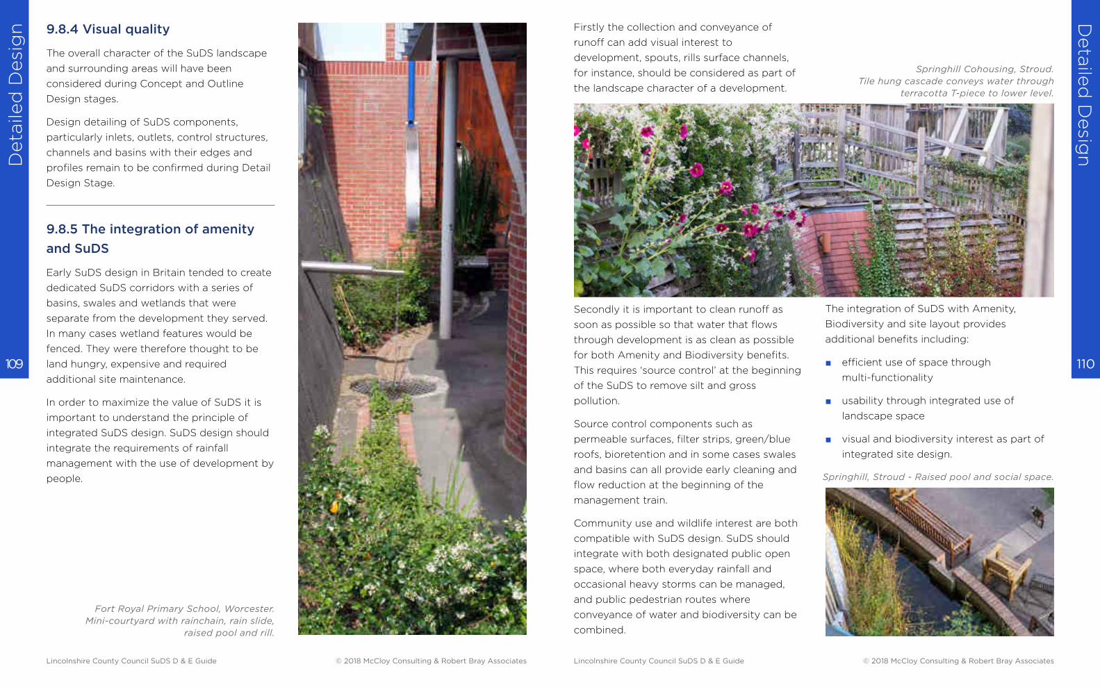
Deta
iled
Desi
gn
Deta
iled
Desig
n
110 109
9.8.4 Visual quality
The overall character of the SuDS landscape
and surrounding areas will have been
considered during Concept and Outline
Design stages.
Design detailing of SuDS components,
particularly inlets, outlets, control structures,
channels and basins with their edges and
profiles remain to be confirmed during Detail
Design Stage.
9.8.5 The integration of amenity
and SuDS
Early SuDS design in Britain tended to create
dedicated SuDS corridors with a series of
basins, swales and wetlands that were
separate from the development they served.
In many cases wetland features would be
fenced. They were therefore thought to be
land hungry, expensive and required
additional site maintenance.
In order to maximize the value of SuDS it is
important to understand the principle of
integrated SuDS design. SuDS design should
integrate the requirements of rainfall
management with the use of development by
people.
Fort Royal Primary School, Worcester.
Mini-courtyard with rainchain, rain slide,
raised pool and rill.
Firstly the collection and conveyance of
runoff can add visual interest to
development, spouts, rills surface channels,
for instance, should be considered as part of
the landscape character of a development.
Secondly it is important to clean runoff as
soon as possible so that water that flows
through development is as clean as possible
for both Amenity and Biodiversity benefits.
This requires ‘source control’ at the beginning
of the SuDS to remove silt and gross
pollution.
Source control components such as
permeable surfaces, filter strips, green/blue
roofs, bioretention and in some cases swales
and basins can all provide early cleaning and
flow reduction at the beginning of the
management train.
Community use and wildlife interest are both
compatible with SuDS design. SuDS should
integrate with both designated public open
space, where both everyday rainfall and
occasional heavy storms can be managed,
and public pedestrian routes where
conveyance of water and biodiversity can be
combined.
The integration of SuDS with Amenity,
Biodiversity and site layout provides
additional benefits including:
■ efficient use of space through
multi-functionality
■ usability through integrated use of
landscape space
■ visual and biodiversity interest as part of
integrated site design.
Springhill Cohousing, Stroud.
Tile hung cascade conveys water through
terracotta T-piece to lower level.
Springhill, Stroud - Raised pool and social space.
Lincolnshire County Council SuDS D & E Guide © 2018 McCloy Consulting & Robert Bray Associates Lincolnshire County Council SuDS D & E Guide © 2018 McCloy Consulting & Robert Bray Associates
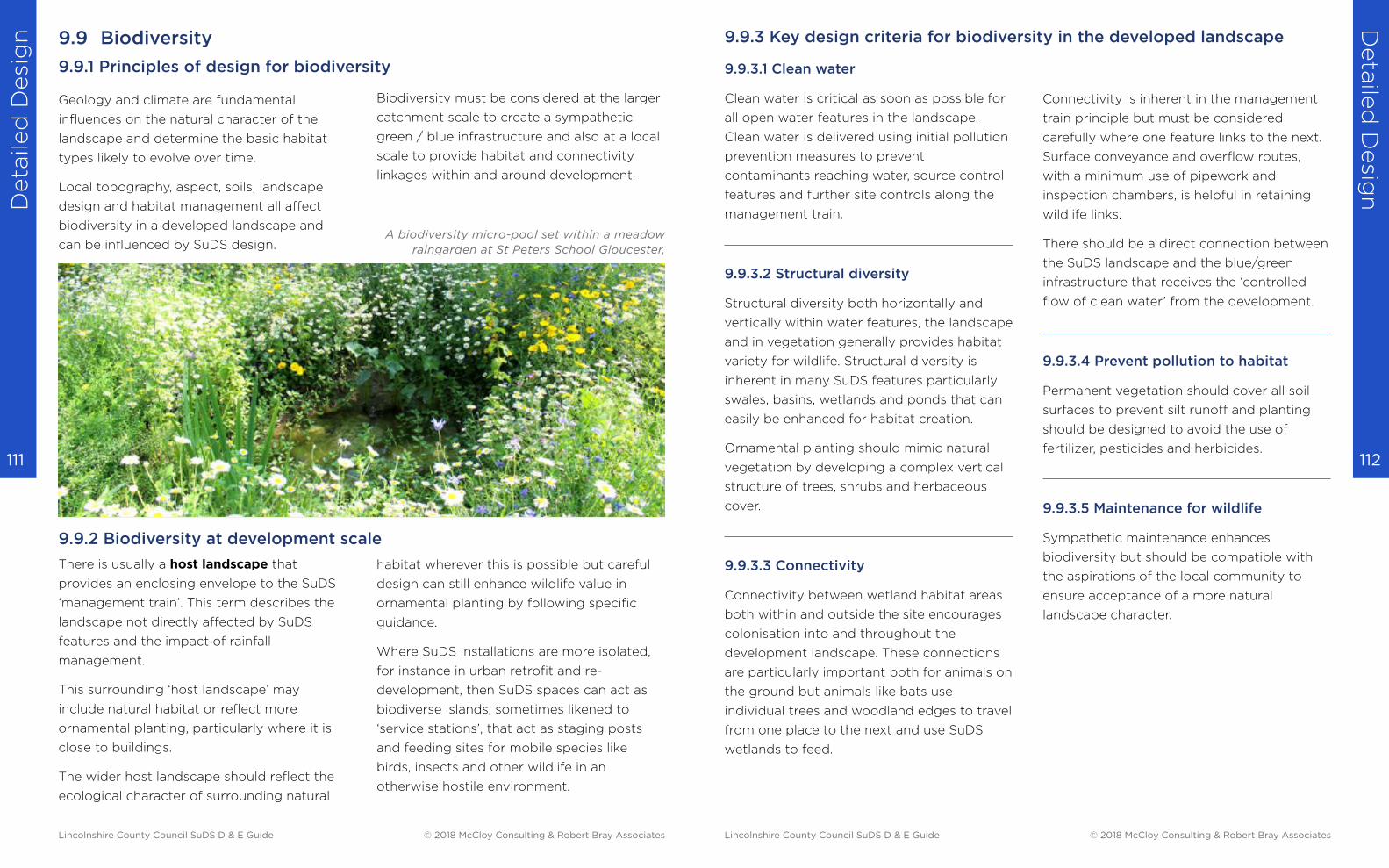
Deta
iled
Desi
gn
Deta
iled
Desig
n
112 111
9.9 Biodiversity
Geology and climate are fundamental
influences on the natural character of the
landscape and determine the basic habitat
types likely to evolve over time.
Local topography, aspect, soils, landscape
design and habitat management all affect
biodiversity in a developed landscape and
can be influenced by SuDS design.
There is usually a host landscape that
provides an enclosing envelope to the SuDS
‘management train’. This term describes the
landscape not directly affected by SuDS
features and the impact of rainfall
management.
This surrounding ‘host landscape’ may
include natural habitat or reflect more
ornamental planting, particularly where it is
close to buildings.
The wider host landscape should reflect the
ecological character of surrounding natural
habitat wherever this is possible but careful
design can still enhance wildlife value in
ornamental planting by following specific
guidance.
Where SuDS installations are more isolated,
for instance in urban retrofit and re-
development, then SuDS spaces can act as
biodiverse islands, sometimes likened to
‘service stations’, that act as staging posts
and feeding sites for mobile species like
birds, insects and other wildlife in an
otherwise hostile environment.
Biodiversity must be considered at the larger
catchment scale to create a sympathetic
green / blue infrastructure and also at a local
scale to provide habitat and connectivity
linkages within and around development.
A biodiversity micro-pool set within a meadow
raingarden at St Peters School Gloucester,
9.9.1 Principles of design for biodiversity
9.9.2 Biodiversity at development scale
9.9.3.1 Clean water
Clean water is critical as soon as possible for
all open water features in the landscape.
Clean water is delivered using initial pollution
prevention measures to prevent
contaminants reaching water, source control
features and further site controls along the
management train.
9.9.3.2 Structural diversity
Structural diversity both horizontally and
vertically within water features, the landscape
and in vegetation generally provides habitat
variety for wildlife. Structural diversity is
inherent in many SuDS features particularly
swales, basins, wetlands and ponds that can
easily be enhanced for habitat creation.
Ornamental planting should mimic natural
vegetation by developing a complex vertical
structure of trees, shrubs and herbaceous
cover.
9.9.3.3 Connectivity
Connectivity between wetland habitat areas
both within and outside the site encourages
colonisation into and throughout the
development landscape. These connections
are particularly important both for animals on
the ground but animals like bats use
individual trees and woodland edges to travel
from one place to the next and use SuDS
wetlands to feed.
Connectivity is inherent in the management
train principle but must be considered
carefully where one feature links to the next.
Surface conveyance and overflow routes,
with a minimum use of pipework and
inspection chambers, is helpful in retaining
wildlife links.
There should be a direct connection between
the SuDS landscape and the blue/green
infrastructure that receives the ‘controlled
flow of clean water’ from the development.
9.9.3.4 Prevent pollution to habitat
Permanent vegetation should cover all soil
surfaces to prevent silt runoff and planting
should be designed to avoid the use of
fertilizer, pesticides and herbicides.
9.9.3.5 Maintenance for wildlife
Sympathetic maintenance enhances
biodiversity but should be compatible with
the aspirations of the local community to
ensure acceptance of a more natural
landscape character.
9.9.3 Key design criteria for biodiversity in the developed landscape
Lincolnshire County Council SuDS D & E Guide © 2018 McCloy Consulting & Robert Bray Associates Lincolnshire County Council SuDS D & E Guide © 2018 McCloy Consulting & Robert Bray Associates
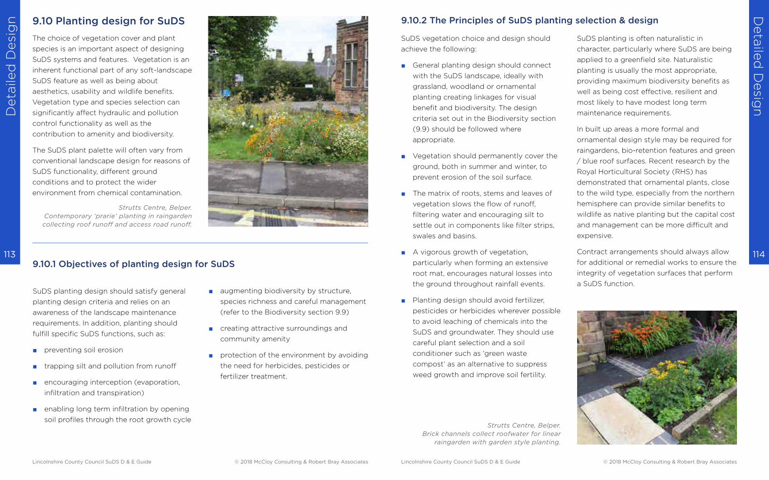
Deta
iled
Desi
gn
Deta
iled
Desig
n
114 113
9.10 Planting design for SuDS
The choice of vegetation cover and plant
species is an important aspect of designing
SuDS systems and features. Vegetation is an
inherent functional part of any soft-landscape
SuDS feature as well as being about
aesthetics, usability and wildlife benefits.
Vegetation type and species selection can
significantly affect hydraulic and pollution
control functionality as well as the
contribution to amenity and biodiversity.
The SuDS plant palette will often vary from
conventional landscape design for reasons of
SuDS functionality, different ground
conditions and to protect the wider
environment from chemical contamination.
■ augmenting biodiversity by structure,
species richness and careful management
(refer to the Biodiversity section 9.9)
■ creating attractive surroundings and
community amenity
■ protection of the environment by avoiding
the need for herbicides, pesticides or
fertilizer treatment.
SuDS planting design should satisfy general
planting design criteria and relies on an
awareness of the landscape maintenance
requirements. In addition, planting should
fulfill specific SuDS functions, such as:
■ preventing soil erosion
■ trapping silt and pollution from runoff
■ encouraging interception (evaporation,
infiltration and transpiration)
■ enabling long term infiltration by opening
soil profiles through the root growth cycle
Strutts Centre, Belper.
Contemporary ‘prarie’ planting in raingarden
collecting roof runoff and access road runoff.
9.10.1 Objectives of planting design for SuDS
SuDS vegetation choice and design should
achieve the following:
■ General planting design should connect
with the SuDS landscape, ideally with
grassland, woodland or ornamental
planting creating linkages for visual
benefit and biodiversity. The design
criteria set out in the Biodiversity section
(9.9) should be followed where
appropriate.
■ Vegetation should permanently cover the
ground, both in summer and winter, to
prevent erosion of the soil surface.
■ The matrix of roots, stems and leaves of
vegetation slows the flow of runoff,
filtering water and encouraging silt to
settle out in components like filter strips,
swales and basins.
■ A vigorous growth of vegetation,
particularly when forming an extensive
root mat, encourages natural losses into
the ground throughout rainfall events.
■ Planting design should avoid fertilizer,
pesticides or herbicides wherever possible
to avoid leaching of chemicals into the
SuDS and groundwater. They should use
careful plant selection and a soil
conditioner such as ‘green waste
compost’ as an alternative to suppress
weed growth and improve soil fertility.
SuDS planting is often naturalistic in
character, particularly where SuDS are being
applied to a greenfield site. Naturalistic
planting is usually the most appropriate,
providing maximum biodiversity benefits as
well as being cost effective, resilient and
most likely to have modest long term
maintenance requirements.
In built up areas a more formal and
ornamental design style may be required for
raingardens, bio-retention features and green
/ blue roof surfaces. Recent research by the
Royal Horticultural Society (RHS) has
demonstrated that ornamental plants, close
to the wild type, especially from the northern
hemisphere can provide similar benefits to
wildlife as native planting but the capital cost
and management can be more difficult and
expensive.
Contract arrangements should always allow
for additional or remedial works to ensure the
integrity of vegetation surfaces that perform
a SuDS function.
Strutts Centre, Belper.
Brick channels collect roofwater for linear
raingarden with garden style planting.
9.10.2 The Principles of SuDS planting selection & design
Lincolnshire County Council SuDS D & E Guide © 2018 McCloy Consulting & Robert Bray Associates Lincolnshire County Council SuDS D & E Guide © 2018 McCloy Consulting & Robert Bray Associates
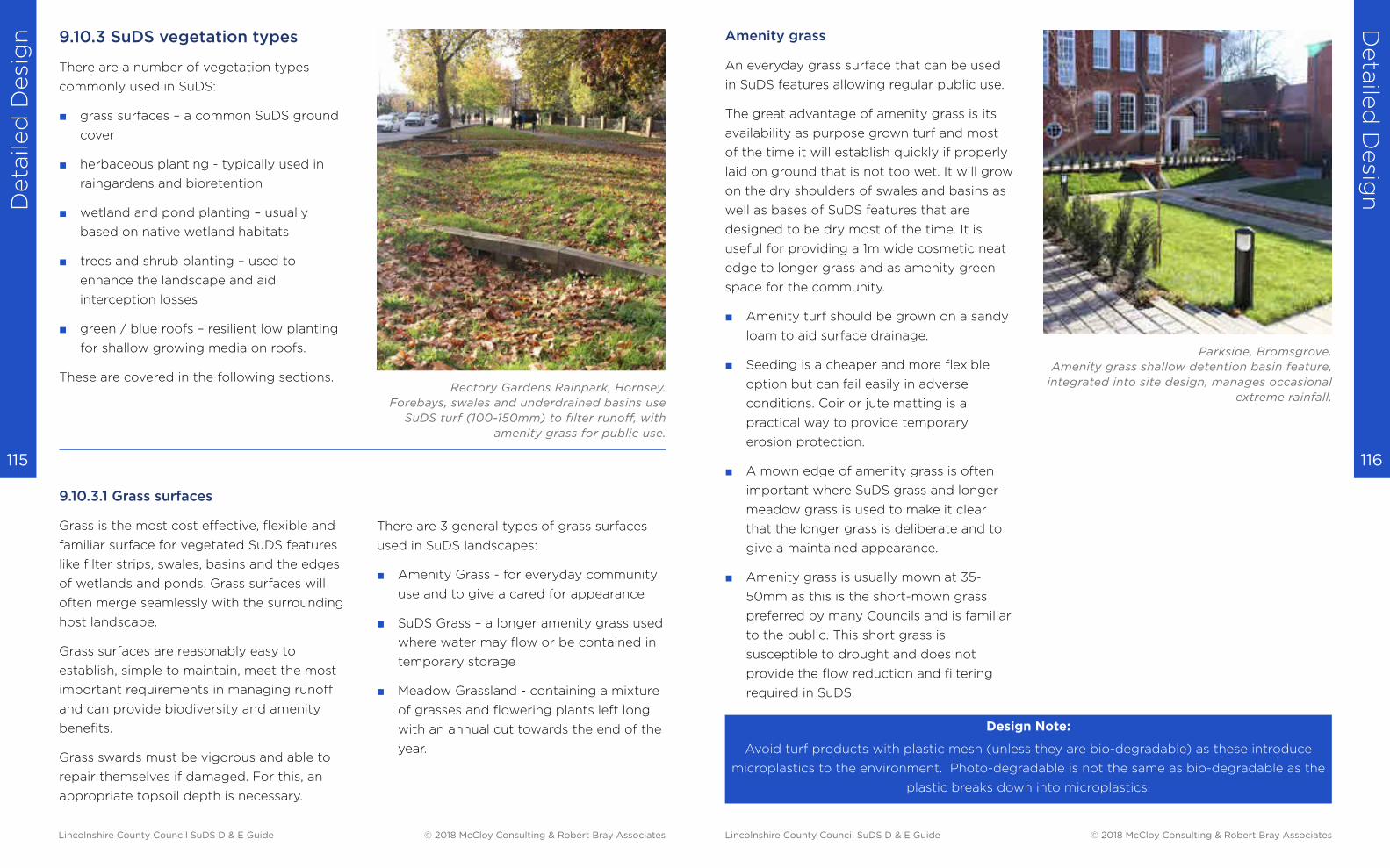
Deta
iled
Desi
gn
Deta
iled
Desig
n
116 115
9.10.3 SuDS vegetation types
There are a number of vegetation types
commonly used in SuDS:
■ grass surfaces – a common SuDS ground
cover
■ herbaceous planting - typically used in
raingardens and bioretention
■ wetland and pond planting – usually
based on native wetland habitats
■ trees and shrub planting – used to
enhance the landscape and aid
interception losses
■ green / blue roofs – resilient low planting
for shallow growing media on roofs.
These are covered in the following sections.
9.10.3.1 Grass surfaces
Grass is the most cost effective, flexible and
familiar surface for vegetated SuDS features
like filter strips, swales, basins and the edges
of wetlands and ponds. Grass surfaces will
often merge seamlessly with the surrounding
host landscape.
Grass surfaces are reasonably easy to
establish, simple to maintain, meet the most
important requirements in managing runoff
and can provide biodiversity and amenity
benefits.
Grass swards must be vigorous and able to
repair themselves if damaged. For this, an
appropriate topsoil depth is necessary.
There are 3 general types of grass surfaces
used in SuDS landscapes:
■ Amenity Grass - for everyday community
use and to give a cared for appearance
■ SuDS Grass – a longer amenity grass used
where water may flow or be contained in
temporary storage
■ Meadow Grassland - containing a mixture
of grasses and flowering plants left long
with an annual cut towards the end of the
year.
Rectory Gardens Rainpark, Hornsey.
Forebays, swales and underdrained basins use
SuDS turf (100-150mm) to filter runoff, with
amenity grass for public use.
Amenity grass
An everyday grass surface that can be used
in SuDS features allowing regular public use.
The great advantage of amenity grass is its
availability as purpose grown turf and most
of the time it will establish quickly if properly
laid on ground that is not too wet. It will grow
on the dry shoulders of swales and basins as
well as bases of SuDS features that are
designed to be dry most of the time. It is
useful for providing a 1m wide cosmetic neat
edge to longer grass and as amenity green
space for the community.
■ Amenity turf should be grown on a sandy
loam to aid surface drainage.
■ Seeding is a cheaper and more flexible
option but can fail easily in adverse
conditions. Coir or jute matting is a
practical way to provide temporary
erosion protection.
■ A mown edge of amenity grass is often
important where SuDS grass and longer
meadow grass is used to make it clear
that the longer grass is deliberate and to
give a maintained appearance.
■ Amenity grass is usually mown at 35-
50mm as this is the short-mown grass
preferred by many Councils and is familiar
to the public. This short grass is
susceptible to drought and does not
provide the flow reduction and filtering
required in SuDS.
Design Note:
Avoid turf products with plastic mesh (unless they are bio-degradable) as these introduce
microplastics to the environment. Photo-degradable is not the same as bio-degradable as the
plastic breaks down into microplastics.
Parkside, Bromsgrove.
Amenity grass shallow detention basin feature,
integrated into site design, manages occasional
extreme rainfall.
Lincolnshire County Council SuDS D & E Guide © 2018 McCloy Consulting & Robert Bray Associates Lincolnshire County Council SuDS D & E Guide © 2018 McCloy Consulting & Robert Bray Associates
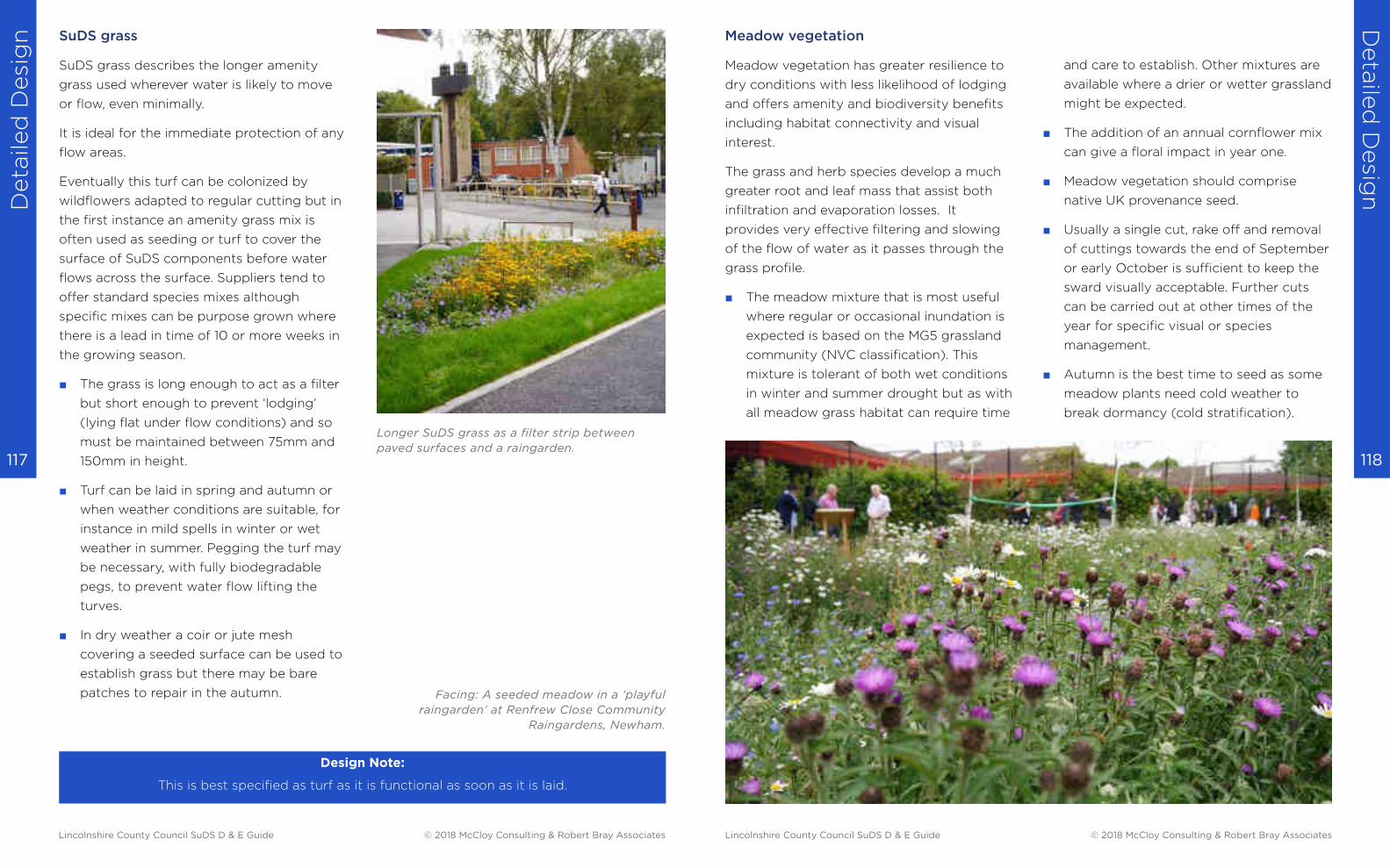
Deta
iled
Desi
gn
Deta
iled
Desig
n
118 117
SuDS grass
SuDS grass describes the longer amenity
grass used wherever water is likely to move
or flow, even minimally.
It is ideal for the immediate protection of any
flow areas.
Eventually this turf can be colonized by
wildflowers adapted to regular cutting but in
the first instance an amenity grass mix is
often used as seeding or turf to cover the
surface of SuDS components before water
flows across the surface. Suppliers tend to
offer standard species mixes although
specific mixes can be purpose grown where
there is a lead in time of 10 or more weeks in
the growing season.
■ The grass is long enough to act as a filter
but short enough to prevent ‘lodging’
(lying flat under flow conditions) and so
must be maintained between 75mm and
150mm in height.
■ Turf can be laid in spring and autumn or
when weather conditions are suitable, for
instance in mild spells in winter or wet
weather in summer. Pegging the turf may
be necessary, with fully biodegradable
pegs, to prevent water flow lifting the
turves.
■ In dry weather a coir or jute mesh
covering a seeded surface can be used to
establish grass but there may be bare
patches to repair in the autumn.
Design Note:
This is best specified as turf as it is functional as soon as it is laid.
Longer SuDS grass as a filter strip between
paved surfaces and a raingarden.
Facing: A seeded meadow in a ‘playful
raingarden’ at Renfrew Close Community
Raingardens, Newham.
Meadow vegetation
Meadow vegetation has greater resilience to
dry conditions with less likelihood of lodging
and offers amenity and biodiversity benefits
including habitat connectivity and visual
interest.
The grass and herb species develop a much
greater root and leaf mass that assist both
infiltration and evaporation losses. It
provides very effective filtering and slowing
of the flow of water as it passes through the
grass profile.
■ The meadow mixture that is most useful
where regular or occasional inundation is
expected is based on the MG5 grassland
community (NVC classification). This
mixture is tolerant of both wet conditions
in winter and summer drought but as with
all meadow grass habitat can require time
and care to establish. Other mixtures are
available where a drier or wetter grassland
might be expected.
■ The addition of an annual cornflower mix
can give a floral impact in year one.
■ Meadow vegetation should comprise
native UK provenance seed.
■ Usually a single cut, rake off and removal
of cuttings towards the end of September
or early October is sufficient to keep the
sward visually acceptable. Further cuts
can be carried out at other times of the
year for specific visual or species
management.
■ Autumn is the best time to seed as some
meadow plants need cold weather to
break dormancy (cold stratification).
Lincolnshire County Council SuDS D & E Guide © 2018 McCloy Consulting & Robert Bray Associates Lincolnshire County Council SuDS D & E Guide © 2018 McCloy Consulting & Robert Bray Associates
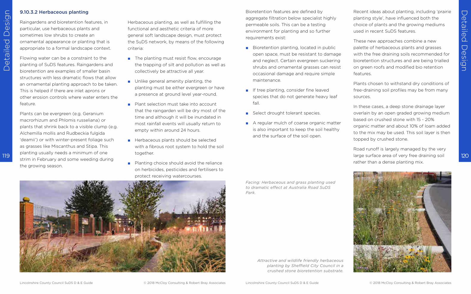
Deta
iled
Desi
gn
Deta
iled
Desig
n
120 119
9.10.3.2 Herbaceous planting
Raingardens and bioretention features, in
particular, use herbaceous plants and
sometimes low shrubs to create an
ornamental appearance or planting that is
appropriate to a formal landscape context.
Flowing water can be a constraint to the
planting of SuDS features. Raingardens and
bioretention are examples of smaller basin
structures with less dramatic flows that allow
an ornamental planting approach to be taken.
This is helped if there are inlet aprons or
other erosion controls where water enters the
feature.
Plants can be evergreen (e.g. Geranium
macrorhizum and Phlomis russeliana) or
plants that shrink back to a visible clump (e.g.
Alchemilla mollis and Rudbeckia fulgida
‘deamii’) or with winter-present foliage such
as grasses like Miscanthus and Stipa. This
planting usually needs a minimum of one
strim in February and some weeding during
the growing season.
Herbaceous planting, as well as fulfilling the
functional and aesthetic criteria of more
general soft landscape design, must protect
the SuDS network, by means of the following
criteria:
■ The planting must resist flow, encourage
the trapping of silt and pollution as well as
collectively be attractive all year.
■ Unlike general amenity planting, the
planting must be either evergreen or have
a presence at ground level year-round.
■ Plant selection must take into account
that the raingarden will be dry most of the
time and although it will be inundated in
most rainfall events will usually return to
empty within around 24 hours.
■ Herbaceous plants should be selected
with a fibrous root system to hold the soil
together.
■ Planting choice should avoid the reliance
on herbicides, pesticides and fertilisers to
protect receiving watercourses.
Bioretention features are defined by
aggregate filtration below specialist highly
permeable soils. This can be a testing
environment for planting and so further
requirements exist:
■ Bioretention planting, located in public
open space, must be resistant to damage
and neglect. Certain evergreen suckering
shrubs and ornamental grasses can resist
occasional damage and require simple
maintenance.
■ If tree planting, consider fine leaved
species that do not generate heavy leaf
fall.
■ Select drought tolerant species.
■ A regular mulch of coarse organic matter
is also important to keep the soil healthy
and the surface of the soil open.
Recent ideas about planting, including ‘prairie
planting style’, have influenced both the
choice of plants and the growing mediums
used in recent SuDS features.
These new approaches combine a new
palette of herbaceous plants and grasses
with the free draining soils recommended for
bioretention structures and are being trialled
on green roofs and modified bio retention
features.
Plants chosen to withstand dry conditions of
free-draining soil profiles may be from many
sources.
In these cases, a deep stone drainage layer
overlain by an open graded growing medium
based on crushed stone with 15 - 20%
organic matter and about 10% of loam added
to the mix may be used. This soil layer is then
topped by crushed stone.
Road runoff is largely managed by the very
large surface area of very free draining soil
rather than a dense planting mix.
Facing: Herbaceous and grass planting used
to dramatic effect at Australia Road SuDS
Park.
Attractive and wildlife friendly herbaceous
planting by Sheffield City Council in a
crushed stone bioretention substrate.
Lincolnshire County Council SuDS D & E Guide © 2018 McCloy Consulting & Robert Bray Associates Lincolnshire County Council SuDS D & E Guide © 2018 McCloy Consulting & Robert Bray Associates
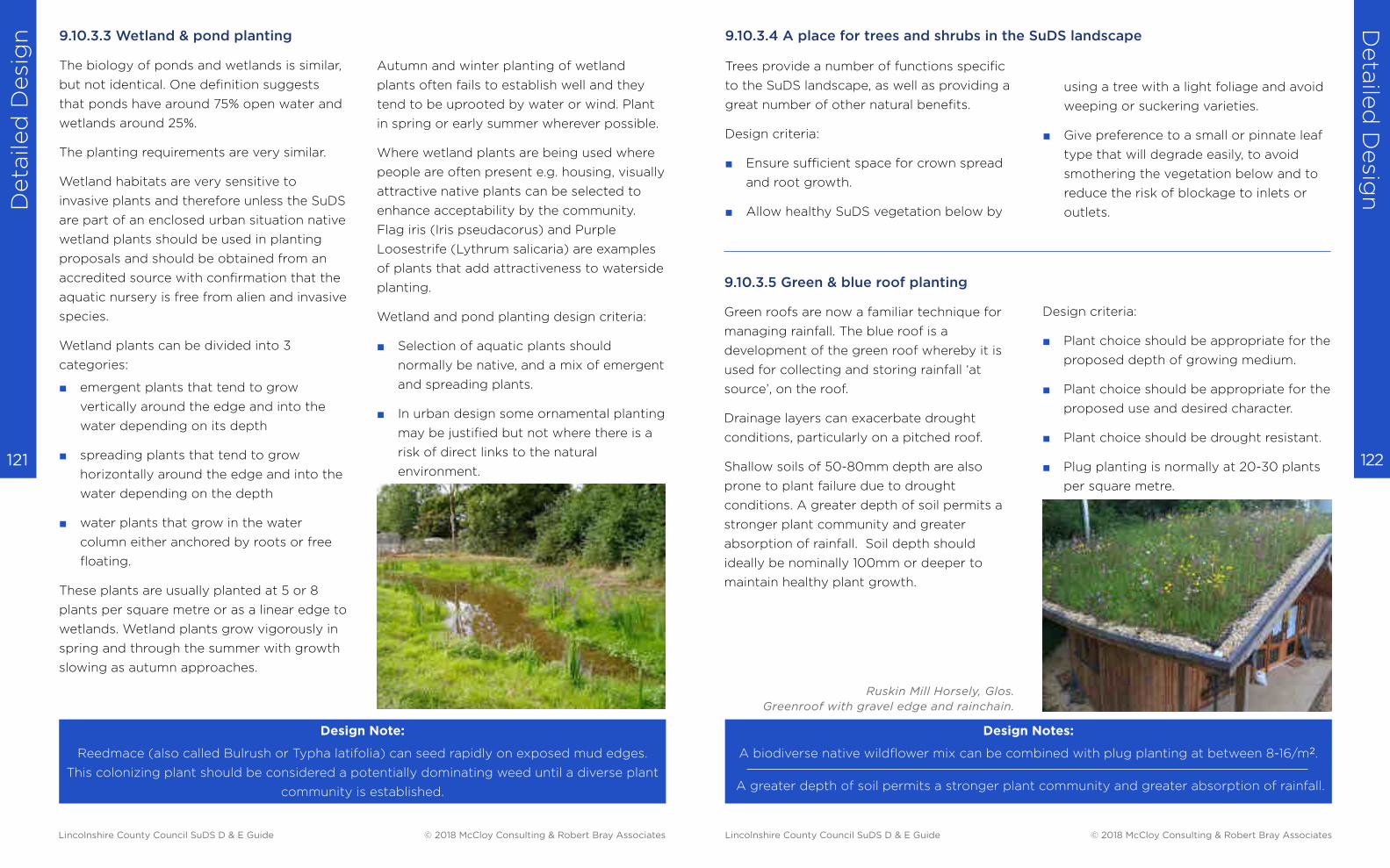
Deta
iled
Desi
gn
Deta
iled
Desig
n
122 121
9.10.3.3 Wetland & pond planting
The biology of ponds and wetlands is similar,
but not identical. One definition suggests
that ponds have around 75% open water and
wetlands around 25%.
The planting requirements are very similar.
Wetland habitats are very sensitive to
invasive plants and therefore unless the SuDS
are part of an enclosed urban situation native
wetland plants should be used in planting
proposals and should be obtained from an
accredited source with confirmation that the
aquatic nursery is free from alien and invasive
species.
Wetland plants can be divided into 3
categories:
■ emergent plants that tend to grow
vertically around the edge and into the
water depending on its depth
■ spreading plants that tend to grow
horizontally around the edge and into the
water depending on the depth
■ water plants that grow in the water
column either anchored by roots or free
floating.
These plants are usually planted at 5 or 8
plants per square metre or as a linear edge to
wetlands. Wetland plants grow vigorously in
spring and through the summer with growth
slowing as autumn approaches.
Autumn and winter planting of wetland
plants often fails to establish well and they
tend to be uprooted by water or wind. Plant
in spring or early summer wherever possible.
Where wetland plants are being used where
people are often present e.g. housing, visually
attractive native plants can be selected to
enhance acceptability by the community.
Flag iris (Iris pseudacorus) and Purple
Loosestrife (Lythrum salicaria) are examples
of plants that add attractiveness to waterside
planting.
Wetland and pond planting design criteria:
■ Selection of aquatic plants should
normally be native, and a mix of emergent
and spreading plants.
■ In urban design some ornamental planting
may be justified but not where there is a
risk of direct links to the natural
environment.
Design Note:
Reedmace (also called Bulrush or Typha latifolia) can seed rapidly on exposed mud edges.
This colonizing plant should be considered a potentially dominating weed until a diverse plant
community is established.
Trees provide a number of functions specific
to the SuDS landscape, as well as providing a
great number of other natural benefits.
Design criteria:
■ Ensure sufficient space for crown spread
and root growth.
■ Allow healthy SuDS vegetation below by
9.10.3.5 Green & blue roof planting
Green roofs are now a familiar technique for
managing rainfall. The blue roof is a
development of the green roof whereby it is
used for collecting and storing rainfall ‘at
source’, on the roof.
Drainage layers can exacerbate drought
conditions, particularly on a pitched roof.
Shallow soils of 50-80mm depth are also
prone to plant failure due to drought
conditions. A greater depth of soil permits a
stronger plant community and greater
absorption of rainfall. Soil depth should
ideally be nominally 100mm or deeper to
maintain healthy plant growth.
Design Notes:
A biodiverse native wildflower mix can be combined with plug planting at between 8-16/m2.
A greater depth of soil permits a stronger plant community and greater absorption of rainfall.
using a tree with a light foliage and avoid
weeping or suckering varieties.
■ Give preference to a small or pinnate leaf
type that will degrade easily, to avoid
smothering the vegetation below and to
reduce the risk of blockage to inlets or
outlets.
Design criteria:
■ Plant choice should be appropriate for the
proposed depth of growing medium.
■ Plant choice should be appropriate for the
proposed use and desired character.
■ Plant choice should be drought resistant.
■ Plug planting is normally at 20-30 plants
per square metre.
9.10.3.4 A place for trees and shrubs in the SuDS landscape
Ruskin Mill Horsely, Glos.
Greenroof with gravel edge and rainchain.
Lincolnshire County Council SuDS D & E Guide © 2018 McCloy Consulting & Robert Bray Associates Lincolnshire County Council SuDS D & E Guide © 2018 McCloy Consulting & Robert Bray Associates
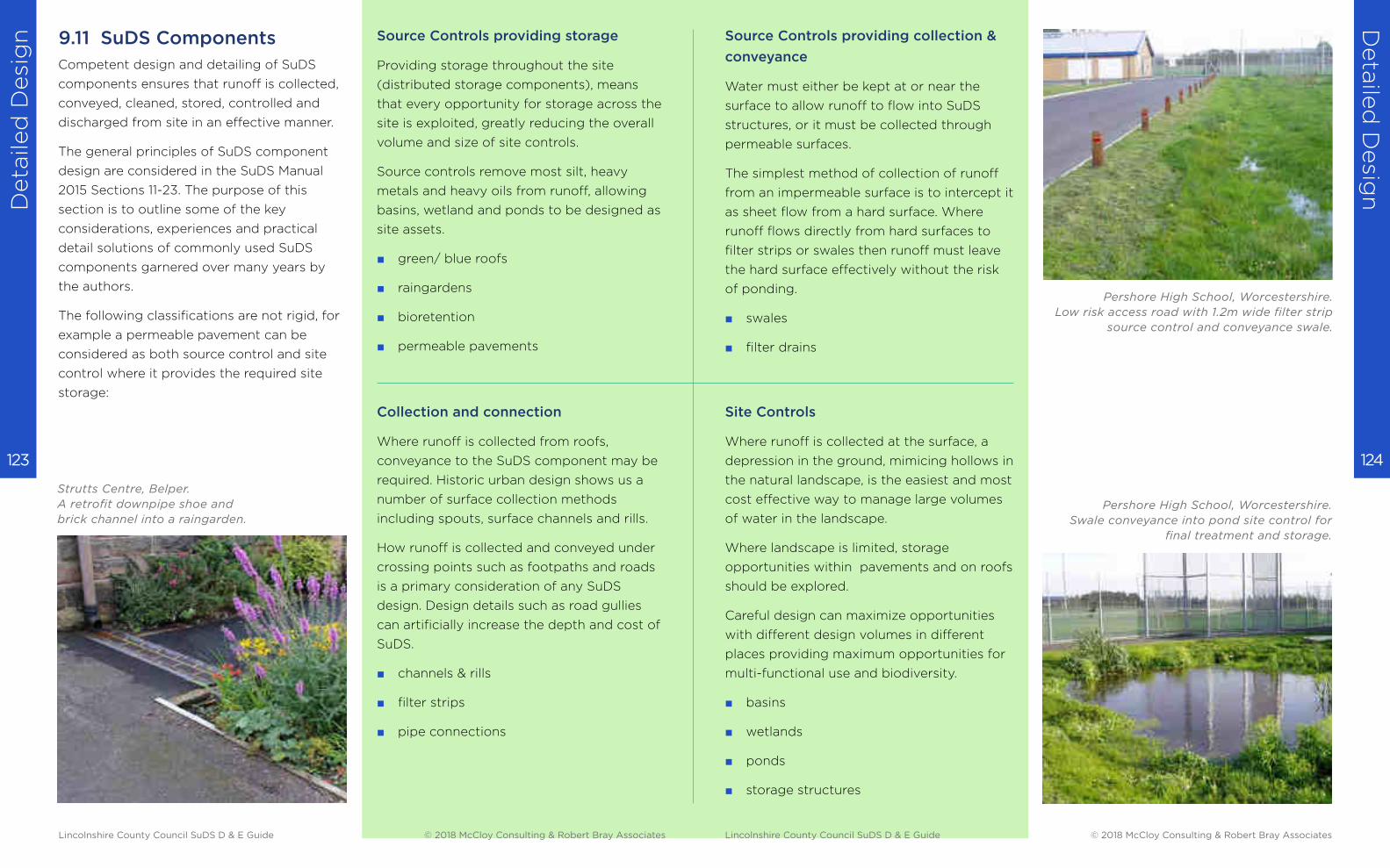
Deta
iled
Desi
gn
Deta
iled
Desig
n
124 123
9.11 SuDS Components
Competent design and detailing of SuDS
components ensures that runoff is collected,
conveyed, cleaned, stored, controlled and
discharged from site in an effective manner.
The general principles of SuDS component
design are considered in the SuDS Manual
2015 Sections 11-23. The purpose of this
section is to outline some of the key
considerations, experiences and practical
detail solutions of commonly used SuDS
components garnered over many years by
the authors.
The following classifications are not rigid, for
example a permeable pavement can be
considered as both source control and site
control where it provides the required site
storage:
Source Controls providing storage
Providing storage throughout the site
(distributed storage components), means
that every opportunity for storage across the
site is exploited, greatly reducing the overall
volume and size of site controls.
Source controls remove most silt, heavy
metals and heavy oils from runoff, allowing
basins, wetland and ponds to be designed as
site assets.
■ green/ blue roofs
■ raingardens
■ bioretention
■ permeable pavements
Collection and connection
Where runoff is collected from roofs,
conveyance to the SuDS component may be
required. Historic urban design shows us a
number of surface collection methods
including spouts, surface channels and rills.
How runoff is collected and conveyed under
crossing points such as footpaths and roads
is a primary consideration of any SuDS
design. Design details such as road gullies
can artificially increase the depth and cost of
SuDS.
■ channels & rills
■ filter strips
■ pipe connections
Strutts Centre, Belper.
A retrofit downpipe shoe and
brick channel into a raingarden.
Source Controls providing collection &
conveyance
Water must either be kept at or near the
surface to allow runoff to flow into SuDS
structures, or it must be collected through
permeable surfaces.
The simplest method of collection of runoff
from an impermeable surface is to intercept it
as sheet flow from a hard surface. Where
runoff flows directly from hard surfaces to
filter strips or swales then runoff must leave
the hard surface effectively without the risk
of ponding.
■ swales
■ filter drains
Site Controls
Where runoff is collected at the surface, a
depression in the ground, mimicing hollows in
the natural landscape, is the easiest and most
cost effective way to manage large volumes
of water in the landscape.
Where landscape is limited, storage
opportunities within pavements and on roofs
should be explored.
Careful design can maximize opportunities
with different design volumes in different
places providing maximum opportunities for
multi-functional use and biodiversity.
■ basins
■ wetlands
■ ponds
■ storage structures
Pershore High School, Worcestershire.
Low risk access road with 1.2m wide filter strip
source control and conveyance swale.
Pershore High School, Worcestershire.
Swale conveyance into pond site control for
final treatment and storage.
Lincolnshire County Council SuDS D & E Guide © 2018 McCloy Consulting & Robert Bray Associates Lincolnshire County Council SuDS D & E Guide © 2018 McCloy Consulting & Robert Bray Associates
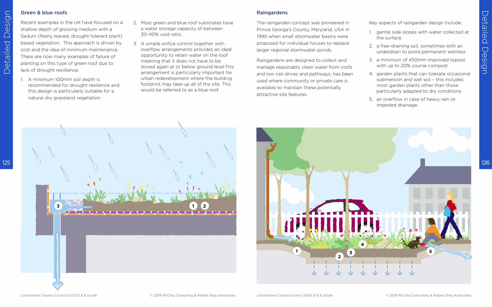
Deta
iled
Desi
gn
Deta
iled
Desig
n
126 125
Green & blue roofs
Recent examples in the UK have focused on a
shallow depth of growing medium with a
Sedum (fleshy leaved, drought tolerant plant)
based vegetation. This approach is driven by
cost and the idea of minimum maintenance.
There are now many examples of failure of
planting on this type of green roof due to
lack of drought resillience.
1. A minimum 100mm soil depth is
recommended for drought resilience and
this design is particularly suitable for a
natural dry grassland vegetation.
2. Most green and blue roof substrates have
a water storage capacity of between
30-40% void ratio.
3. A simple orifice control together with
overflow arrangements provides an ideal
opportunity to retain water on the roof
meaning that it does not have to be
stored again at or below ground level.This
arrangement is particularly important for
urban redevelopment where the building
footprint may take up all of the site. This
would be referred to as a blue roof.
1 23
Raingardens
The raingarden concept was pioneered in
Prince George’s County, Maryland, USA in
1990 when small stormwater basins were
proposed for individual houses to replace
larger regional stormwater ponds.
Raingardens are designed to collect and
manage reasonably clean water from roofs
and low risk drives and pathways, has been
used where community or private care is
available to maintain these potentially
attractive site features.
Key aspects of raingarden design include:
1. gentle side slopes with water collected at
the surface
2. a free-draining soil, sometimes with an
underdrain to avoid permanent wetness
3. a minimum of 450mm improved topsoil
with up to 20% course compost
4. garden plants that can tolerate occasional
submersion and wet soil – this includes
most garden plants other than those
particularly adapted to dry conditions
5. an overflow in case of heavy rain or
impeded drainage.
12
3
4
5
Lincolnshire County Council SuDS D & E Guide © 2018 McCloy Consulting & Robert Bray Associates Lincolnshire County Council SuDS D & E Guide © 2018 McCloy Consulting & Robert Bray Associates
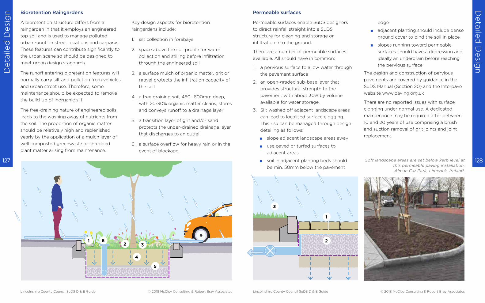
Deta
iled
Desi
gn
Deta
iled
Desig
n
128 127
Bioretention Raingardens
A bioretention structure differs from a
raingarden in that it employs an engineered
top soil and is used to manage polluted
urban runoff in street locations and carparks.
These features can contribute significantly to
the urban scene so should be designed to
meet urban design standards.
The runoff entering bioretention features will
normally carry silt and pollution from vehicles
and urban street use. Therefore, some
maintenance should be expected to remove
the build-up of inorganic silt.
The free-draining nature of engineered soils
leads to the washing away of nutrients from
the soil. The proportion of organic matter
should be relatively high and replenished
yearly by the application of a mulch layer of
well composted greenwaste or shredded
plant matter arising from maintenance.
Key design aspects for bioretention
raingardens include;
1. silt collection in forebays
2. space above the soil profile for water
collection and stilling before infiltration
through the engineered soil
3. a surface mulch of organic matter, grit or
gravel protects the infiltration capacity of
the soil
4. a free draining soil, 450 -600mm deep,
with 20-30% organic matter cleans, stores
and conveys runoff to a drainage layer
5. a transition layer of grit and/or sand
protects the under-drained drainage layer
that discharges to an outfall
6. a surface overflow for heavy rain or in the
event of blockage.
12 3
6
4
5
Permeable surfaces
Permeable surfaces enable SuDS designers
to direct rainfall straight into a SuDS
structure for cleaning and storage or
infiltration into the ground.
There are a number of permeable surfaces
available. All should have in common:
1. a pervious surface to allow water through
the pavement surface
2. an open-graded sub-base layer that
provides structural strength to the
pavement with about 30% by volume
available for water storage.
3. Silt washed off adjacent landscape areas
can lead to localised surface clogging.
This risk can be managed through design
detailing as follows:
■ slope adjacent landscape areas away
■ use paved or turfed surfaces to
adjacent areas
■ soil in adjacent planting beds should
be min. 50mm below the pavement
edge
■ adjacent planting should include dense
ground cover to bind the soil in place
■ slopes running toward permeable
surfaces should have a depression and
ideally an underdrain before reaching
the pervious surface.
The design and construction of pervious
pavements are covered by guidance in the
SuDS Manual (Section 20) and the Interpave
website www.paving.org.uk
There are no reported issues with surface
clogging under normal use. A dedicated
maintenance may be required after between
10 and 20 years of use comprising a brush
and suction removal of grit joints and joint
replacement.
1
2
3
Soft landscape areas are set below kerb level at
this permeable paving installation.
Almac Car Park, Limerick, Ireland.
Lincolnshire County Council SuDS D & E Guide © 2018 McCloy Consulting & Robert Bray Associates Lincolnshire County Council SuDS D & E Guide © 2018 McCloy Consulting & Robert Bray Associates

Deta
iled
Desi
gn
Deta
iled
Desig
n
130 129
Swale
Swales are shallow, flat bottomed vegetated
channels which can collect, treat, convey and
store runoff.
1. The basic profile is a 1 in 3 or 1 in 4 side
slope to a flat base falling at no more than
1 in 50 to prevent erosion.
2. Base width less than 1m wide will increase
the risk of erosion and ditch forming,
conversely, base width wider than 3m a
meandering channel can develop.
3. 150mm clean topsoil over subsoil. Ripping
or light harrowing will improve
establishment of the swale by providing a
key for the topsoil, encourage deep
rooting and assist infiltration.
4. Where swale vegetation is kept less than
100mm, the shoulders at the top of the
swale can be ‘scalped’ leaving bare soil.
The shoulders should therefore be
rounded to prevent this happening.
5. Where inlet flows are concentrated to
points through an upstand kerb an
erosion apron may be needed.
1
2
3
4
Filter drains
Filter drains, sometimes called a French drain
after Henry Flagg French (1813-1885), is an
open stone filled trench.
1. Runoff should ideally cross the long edge
of the trench as a sheet. This may require
a temporary level timber board along the
leading edge to prevent erosion of
unconsolidated soil.
2. A sacrificial top layer may be considered
at the top of the drain to trap any silt for
simple removal. Alternatively, a grass filter
strip placed in front of the filter drain will
reduce potential for clogging.
3. A lower perforated pipe will assist
discharge and an upper perforated pipe
can act as an overflow. However, neither
may be necessary depending on the
design and location.
Most filter drains are designed with geotextile
lining. Many geotextiles are susceptible to
blinding from fine materials in soils. An
alterative liner is the use of hessian which will
biodegrade over time by the time soils
around the filter drain will have stabilised.
1
2
3
Lincolnshire County Council SuDS D & E Guide © 2018 McCloy Consulting & Robert Bray Associates Lincolnshire County Council SuDS D & E Guide © 2018 McCloy Consulting & Robert Bray Associates
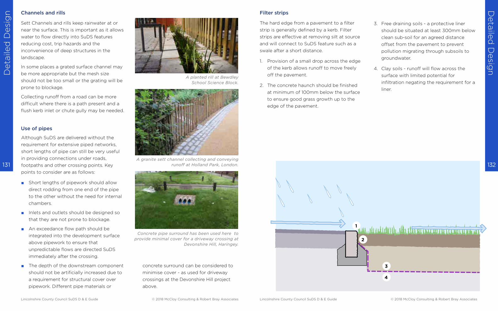
Deta
iled
Desi
gn
Deta
iled
Desig
n
132 131
Channels and rills
Sett Channels and rills keep rainwater at or
near the surface. This is important as it allows
water to flow directly into SuDS features
reducing cost, trip hazards and the
inconvenience of deep structures in the
landscape.
In some places a grated surface channel may
be more appropriate but the mesh size
should not be too small or the grating will be
prone to blockage.
Collecting runoff from a road can be more
difficult where there is a path present and a
flush kerb inlet or chute gully may be needed.
Although SuDS are delivered without the
requirement for extensive piped networks,
short lengths of pipe can still be very useful
in providing connections under roads,
footpaths and other crossing points. Key
points to consider are as follows:
■ Short lengths of pipework should allow
direct rodding from one end of the pipe
to the other without the need for internal
chambers.
■ Inlets and outlets should be designed so
that they are not prone to blockage.
■ An exceedance flow path should be
integrated into the development surface
above pipework to ensure that
unpredictable flows are directed SuDS
immediately after the crossing.
■ The depth of the downstream component
should not be artificially increased due to
a requirement for structural cover over
pipework. Different pipe materials or
Use of pipes
concrete surround can be considered to
minimise cover - as used for driveway
crossings at the Devonshire Hill project
above.
A granite sett channel collecting and conveying
runoff at Holland Park, London.
Concrete pipe surround has been used here to
provide minimal cover for a driveway crossing at
Devonshire Hill, Haringey.
A planted rill at Bewdley
School Science Block.
The hard edge from a pavement to a filter
strip is generally defined by a kerb. Filter
strips are effective at removing silt at source
and will connect to SuDS feature such as a
swale after a short distance.
1. Provision of a small drop across the edge
of the kerb allows runoff to move freely
off the pavement.
2. The concrete haunch should be finished
at minimum of 100mm below the surface
to ensure good grass growth up to the
edge of the pavement.
Filter strips
3. Free draining soils - a protective liner
should be situated at least 300mm below
clean sub-soil for an agreed distance
offset from the pavement to prevent
pollution migrating through subsoils to
groundwater.
4. Clay soils - runoff will flow across the
surface with limited potential for
infiltration negating the requirement for a
liner.
1
2
3
4
Lincolnshire County Council SuDS D & E Guide © 2018 McCloy Consulting & Robert Bray Associates Lincolnshire County Council SuDS D & E Guide © 2018 McCloy Consulting & Robert Bray Associates
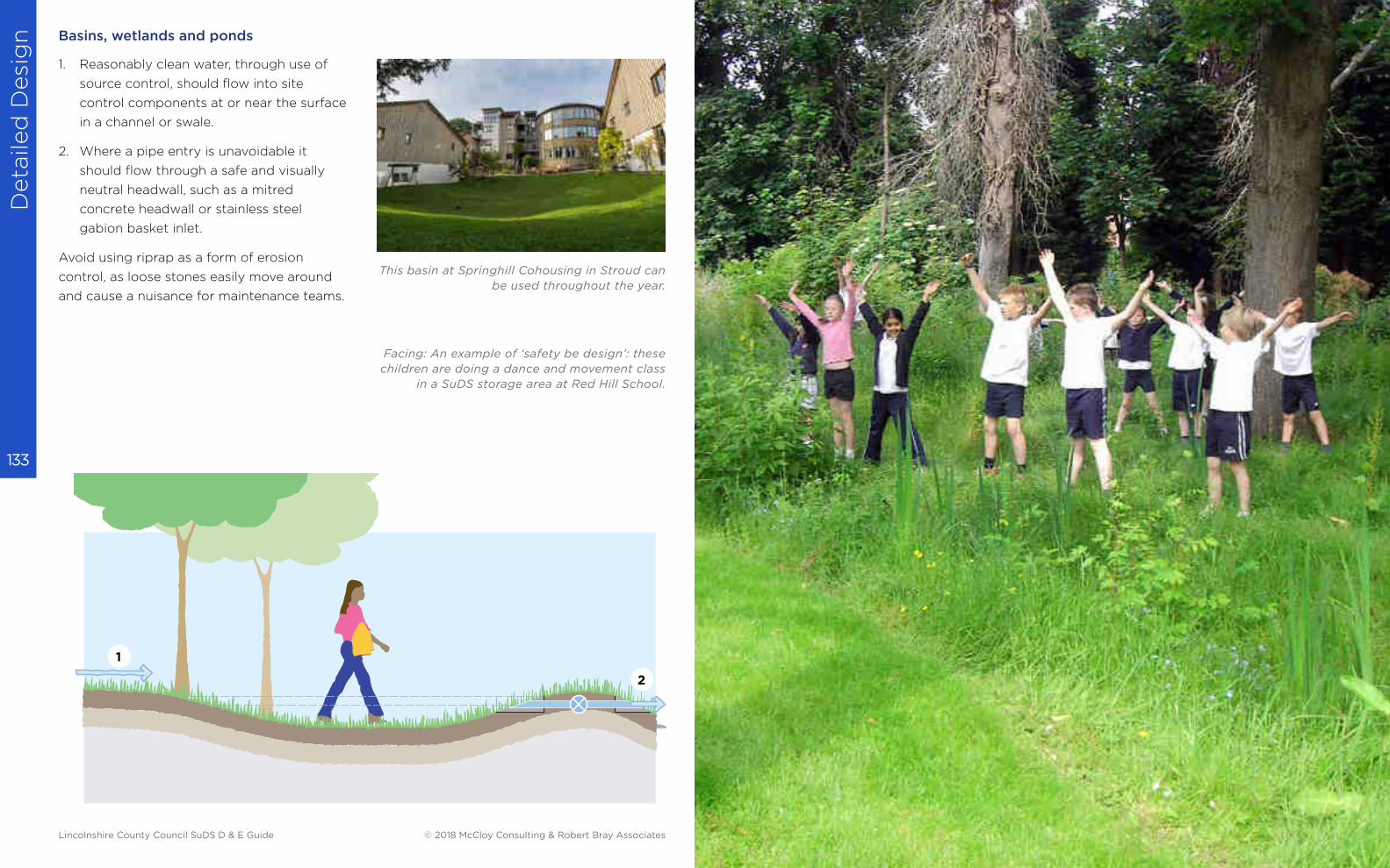
Deta
iled
Desi
gn
133
1. Reasonably clean water, through use of
source control, should flow into site
control components at or near the surface
in a channel or swale.
2. Where a pipe entry is unavoidable it
should flow through a safe and visually
neutral headwall, such as a mitred
concrete headwall or stainless steel
gabion basket inlet.
Avoid using riprap as a form of erosion
control, as loose stones easily move around
and cause a nuisance for maintenance teams.
Basins, wetlands and ponds
This basin at Springhill Cohousing in Stroud can
be used throughout the year.
1
2
Facing: An example of ‘safety be design’: these
children are doing a dance and movement class
in a SuDS storage area at Red Hill School.
Lincolnshire County Council SuDS D & E Guide © 2018 McCloy Consulting & Robert Bray Associates
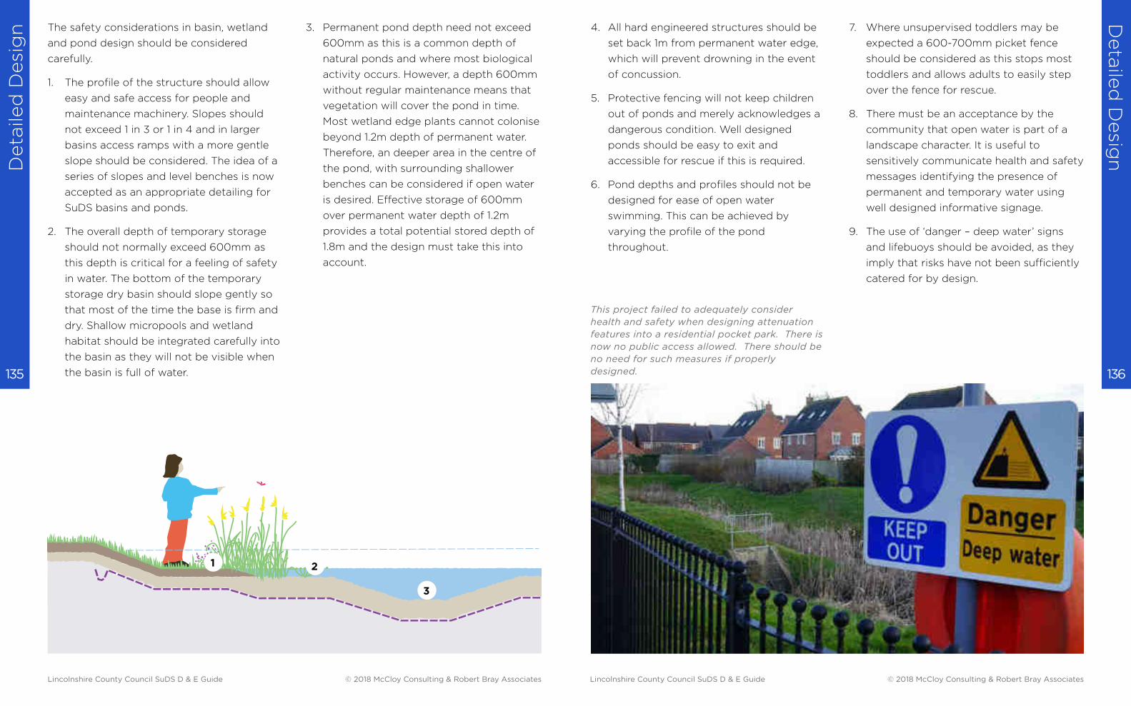
Deta
iled
Desi
gn
Deta
iled
Desig
n
136 135
The safety considerations in basin, wetland
and pond design should be considered
carefully.
1. The profile of the structure should allow
easy and safe access for people and
maintenance machinery. Slopes should
not exceed 1 in 3 or 1 in 4 and in larger
basins access ramps with a more gentle
slope should be considered. The idea of a
series of slopes and level benches is now
accepted as an appropriate detailing for
SuDS basins and ponds.
2. The overall depth of temporary storage
should not normally exceed 600mm as
this depth is critical for a feeling of safety
in water. The bottom of the temporary
storage dry basin should slope gently so
that most of the time the base is firm and
dry. Shallow micropools and wetland
habitat should be integrated carefully into
the basin as they will not be visible when
the basin is full of water.
3. Permanent pond depth need not exceed
600mm as this is a common depth of
natural ponds and where most biological
activity occurs. However, a depth 600mm
without regular maintenance means that
vegetation will cover the pond in time.
Most wetland edge plants cannot colonise
beyond 1.2m depth of permanent water.
Therefore, an deeper area in the centre of
the pond, with surrounding shallower
benches can be considered if open water
is desired. Effective storage of 600mm
over permanent water depth of 1.2m
provides a total potential stored depth of
1.8m and the design must take this into
account.
3
1 2
4. All hard engineered structures should be
set back 1m from permanent water edge,
which will prevent drowning in the event
of concussion.
5. Protective fencing will not keep children
out of ponds and merely acknowledges a
dangerous condition. Well designed
ponds should be easy to exit and
accessible for rescue if this is required.
6. Pond depths and profiles should not be
designed for ease of open water
swimming. This can be achieved by
varying the profile of the pond
throughout.
7. Where unsupervised toddlers may be
expected a 600-700mm picket fence
should be considered as this stops most
toddlers and allows adults to easily step
over the fence for rescue.
8. There must be an acceptance by the
community that open water is part of a
landscape character. It is useful to
sensitively communicate health and safety
messages identifying the presence of
permanent and temporary water using
well designed informative signage.
9. The use of ‘danger – deep water’ signs
and lifebuoys should be avoided, as they
imply that risks have not been sufficiently
catered for by design.
This project failed to adequately consider
health and safety when designing attenuation
features into a residential pocket park. There is
now no public access allowed. There should be
no need for such measures if properly
designed.
Lincolnshire County Council SuDS D & E Guide © 2018 McCloy Consulting & Robert Bray Associates Lincolnshire County Council SuDS D & E Guide © 2018 McCloy Consulting & Robert Bray Associates
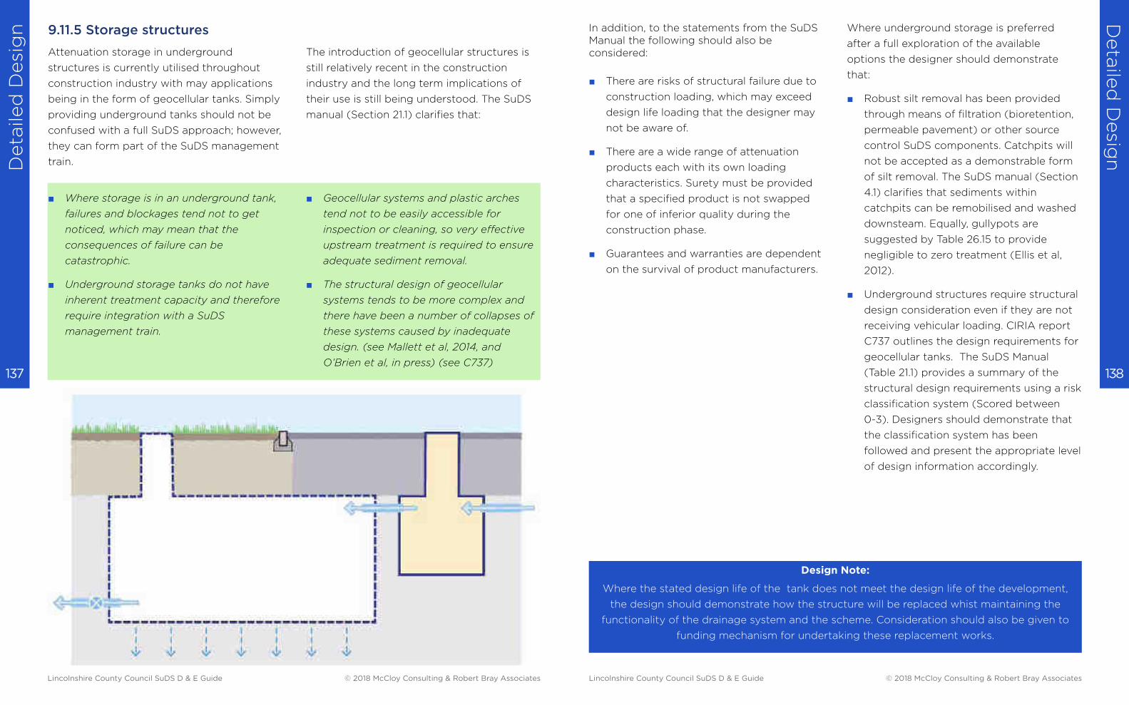
Deta
iled
Desi
gn
Deta
iled
Desig
n
138 137
9.11.5 Storage structures
Attenuation storage in underground
structures is currently utilised throughout
construction industry with may applications
being in the form of geocellular tanks. Simply
providing underground tanks should not be
confused with a full SuDS approach; however,
they can form part of the SuDS management
train.
■ Where storage is in an underground tank,
failures and blockages tend not to get
noticed, which may mean that the
consequences of failure can be
catastrophic.
■ Underground storage tanks do not have
inherent treatment capacity and therefore
require integration with a SuDS
management train.
The introduction of geocellular structures is
still relatively recent in the construction
industry and the long term implications of
their use is still being understood. The SuDS
manual (Section 21.1) clarifies that:
■ Geocellular systems and plastic arches
tend not to be easily accessible for
inspection or cleaning, so very effective
upstream treatment is required to ensure
adequate sediment removal.
■ The structural design of geocellular
systems tends to be more complex and
there have been a number of collapses of
these systems caused by inadequate
design. (see Mallett et al, 2014, and
O’Brien et al, in press) (see C737)
In addition, to the statements from the SuDS Manual the following should also be considered:
■ There are risks of structural failure due to
construction loading, which may exceed
design life loading that the designer may
not be aware of.
■ There are a wide range of attenuation
products each with its own loading
characteristics. Surety must be provided
that a specified product is not swapped
for one of inferior quality during the
construction phase.
■ Guarantees and warranties are dependent
on the survival of product manufacturers.
Where underground storage is preferred
after a full exploration of the available
options the designer should demonstrate
that:
■ Robust silt removal has been provided
through means of filtration (bioretention,
permeable pavement) or other source
control SuDS components. Catchpits will
not be accepted as a demonstrable form
of silt removal. The SuDS manual (Section
4.1) clarifies that sediments within
catchpits can be remobilised and washed
downsteam. Equally, gullypots are
suggested by Table 26.15 to provide
negligible to zero treatment (Ellis et al,
2012).
■ Underground structures require structural
design consideration even if they are not
receiving vehicular loading. CIRIA report
C737 outlines the design requirements for
geocellular tanks. The SuDS Manual
(Table 21.1) provides a summary of the
structural design requirements using a risk
classification system (Scored between
0-3). Designers should demonstrate that
the classification system has been
followed and present the appropriate level
of design information accordingly.
Design Note:
Where the stated design life of the tank does not meet the design life of the development,
the design should demonstrate how the structure will be replaced whist maintaining the
functionality of the drainage system and the scheme. Consideration should also be given to
funding mechanism for undertaking these replacement works.
Lincolnshire County Council SuDS D & E Guide © 2018 McCloy Consulting & Robert Bray Associates Lincolnshire County Council SuDS D & E Guide © 2018 McCloy Consulting & Robert Bray Associates
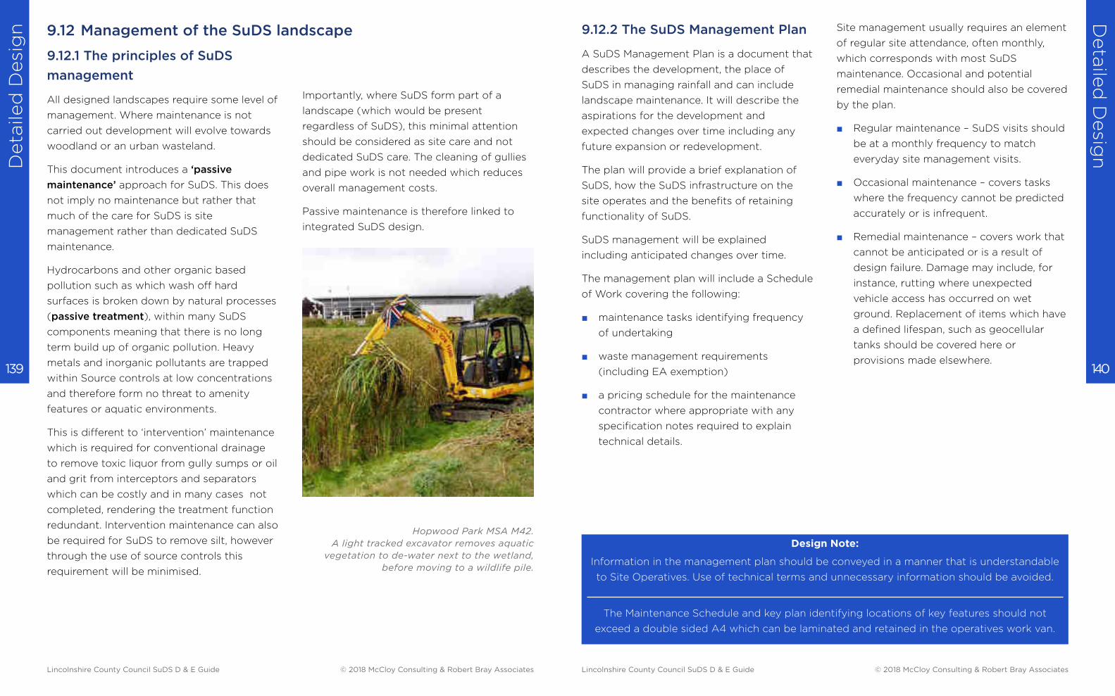
Deta
iled
Desi
gn
Deta
iled
Desig
n
140 139
9.12.1 The principles of SuDS
management
All designed landscapes require some level of
management. Where maintenance is not
carried out development will evolve towards
woodland or an urban wasteland.
This document introduces a ‘passive
maintenance’ approach for SuDS. This does
not imply no maintenance but rather that
much of the care for SuDS is site
management rather than dedicated SuDS
maintenance.
Hydrocarbons and other organic based
pollution such as which wash off hard
surfaces is broken down by natural processes
(passive treatment), within many SuDS
components meaning that there is no long
term build up of organic pollution. Heavy
metals and inorganic pollutants are trapped
within Source controls at low concentrations
and therefore form no threat to amenity
features or aquatic environments.
This is different to ‘intervention’ maintenance
which is required for conventional drainage
to remove toxic liquor from gully sumps or oil
and grit from interceptors and separators
which can be costly and in many cases not
completed, rendering the treatment function
redundant. Intervention maintenance can also
be required for SuDS to remove silt, however
through the use of source controls this
requirement will be minimised.
Importantly, where SuDS form part of a
landscape (which would be present
regardless of SuDS), this minimal attention
should be considered as site care and not
dedicated SuDS care. The cleaning of gullies
and pipe work is not needed which reduces
overall management costs.
Passive maintenance is therefore linked to
integrated SuDS design.
9.12 Management of the SuDS landscape
Hopwood Park MSA M42.
A light tracked excavator removes aquatic
vegetation to de-water next to the wetland,
before moving to a wildlife pile.
9.12.2 The SuDS Management Plan
A SuDS Management Plan is a document that
describes the development, the place of
SuDS in managing rainfall and can include
landscape maintenance. It will describe the
aspirations for the development and
expected changes over time including any
future expansion or redevelopment.
The plan will provide a brief explanation of
SuDS, how the SuDS infrastructure on the
site operates and the benefits of retaining
functionality of SuDS.
SuDS management will be explained
including anticipated changes over time.
The management plan will include a Schedule
of Work covering the following:
■ maintenance tasks identifying frequency
of undertaking
■ waste management requirements
(including EA exemption)
■ a pricing schedule for the maintenance
contractor where appropriate with any
specification notes required to explain
technical details.
Design Note:
Information in the management plan should be conveyed in a manner that is understandable
to Site Operatives. Use of technical terms and unnecessary information should be avoided.
The Maintenance Schedule and key plan identifying locations of key features should not
exceed a double sided A4 which can be laminated and retained in the operatives work van.
Site management usually requires an element
of regular site attendance, often monthly,
which corresponds with most SuDS
maintenance. Occasional and potential
remedial maintenance should also be covered
by the plan.
■ Regular maintenance – SuDS visits should
be at a monthly frequency to match
everyday site management visits.
■ Occasional maintenance – covers tasks
where the frequency cannot be predicted
accurately or is infrequent.
■ Remedial maintenance – covers work that
cannot be anticipated or is a result of
design failure. Damage may include, for
instance, rutting where unexpected
vehicle access has occurred on wet
ground. Replacement of items which have
a defined lifespan, such as geocellular
tanks should be covered here or
provisions made elsewhere.
Lincolnshire County Council SuDS D & E Guide © 2018 McCloy Consulting & Robert Bray Associates Lincolnshire County Council SuDS D & E Guide © 2018 McCloy Consulting & Robert Bray Associates
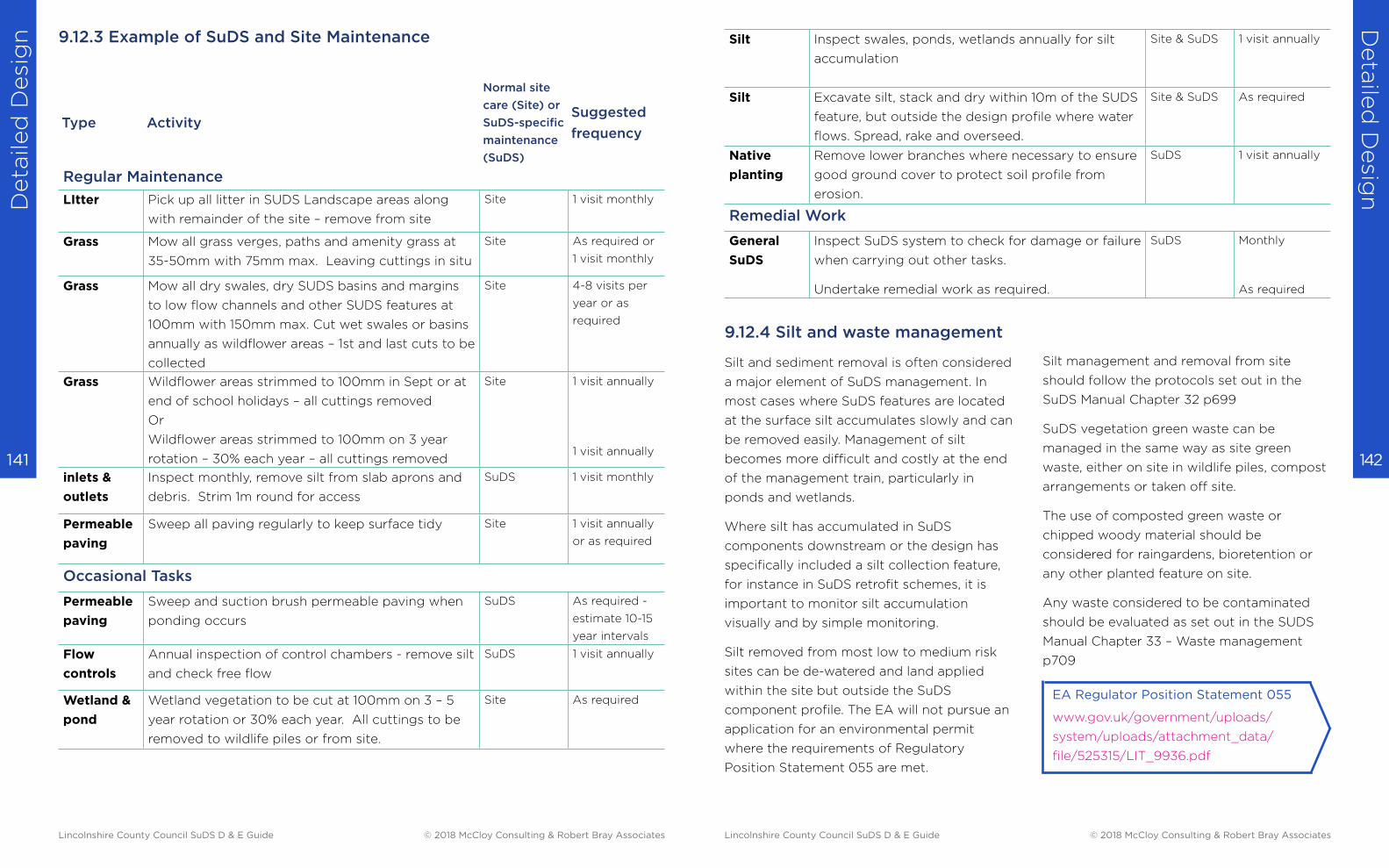
Deta
iled
Desi
gn
Deta
iled
Desig
n
142 141
9.12.3 Example of SuDS and Site Maintenance
Type Activity
Normal site
care (Site) or
SuDS-specific
maintenance
(SuDS)
Suggested
frequency
Regular Maintenance
LItter Pick up all litter in SUDS Landscape areas along
with remainder of the site – remove from site
Site 1 visit monthly
Grass Mow all grass verges, paths and amenity grass at
35-50mm with 75mm max. Leaving cuttings in situ
Site As required or
1 visit monthly
Grass Mow all dry swales, dry SUDS basins and margins
to low flow channels and other SUDS features at
100mm with 150mm max. Cut wet swales or basins
annually as wildflower areas – 1st and last cuts to be
collected
Site 4-8 visits per
year or as
required
Grass Wildflower areas strimmed to 100mm in Sept or at
end of school holidays – all cuttings removed
Or
Wildflower areas strimmed to 100mm on 3 year
rotation – 30% each year – all cuttings removed
Site 1 visit annually
1 visit annually
inlets &
outlets
Inspect monthly, remove silt from slab aprons and
debris. Strim 1m round for access
SuDS 1 visit monthly
Permeable
paving
Sweep all paving regularly to keep surface tidy Site 1 visit annually
or as required
Occasional Tasks
Permeable
paving
Sweep and suction brush permeable paving when
ponding occurs
SuDS As required -
estimate 10-15
year intervals
Flow
controls
Annual inspection of control chambers - remove silt
and check free flow
SuDS 1 visit annually
Wetland &
pond
Wetland vegetation to be cut at 100mm on 3 – 5
year rotation or 30% each year. All cuttings to be
removed to wildlife piles or from site.
Site As required
Silt Inspect swales, ponds, wetlands annually for silt
accumulation
Site & SuDS 1 visit annually
Silt Excavate silt, stack and dry within 10m of the SUDS
feature, but outside the design profile where water
flows. Spread, rake and overseed.
Site & SuDS As required
Native
planting
Remove lower branches where necessary to ensure
good ground cover to protect soil profile from
erosion.
SuDS 1 visit annually
Remedial Work
General
SuDS
Inspect SuDS system to check for damage or failure
when carrying out other tasks.
Undertake remedial work as required.
SuDS Monthly
As required
9.12.4 Silt and waste management
Silt and sediment removal is often considered
a major element of SuDS management. In
most cases where SuDS features are located
at the surface silt accumulates slowly and can
be removed easily. Management of silt
becomes more difficult and costly at the end
of the management train, particularly in
ponds and wetlands.
Where silt has accumulated in SuDS
components downstream or the design has
specifically included a silt collection feature,
for instance in SuDS retrofit schemes, it is
important to monitor silt accumulation
visually and by simple monitoring.
Silt removed from most low to medium risk
sites can be de-watered and land applied
within the site but outside the SuDS
component profile. The EA will not pursue an
application for an environmental permit
where the requirements of Regulatory
Position Statement 055 are met.
Silt management and removal from site
should follow the protocols set out in the
SuDS Manual Chapter 32 p699
SuDS vegetation green waste can be
managed in the same way as site green
waste, either on site in wildlife piles, compost
arrangements or taken off site.
The use of composted green waste or
chipped woody material should be
considered for raingardens, bioretention or
any other planted feature on site.
Any waste considered to be contaminated
should be evaluated as set out in the SUDS
Manual Chapter 33 – Waste management
p709
EA Regulator Position Statement 055
www.gov.uk/government/uploads/
system/uploads/attachment_data/
file/525315/LIT_9936.pdf
Lincolnshire County Council SuDS D & E Guide © 2018 McCloy Consulting & Robert Bray Associates Lincolnshire County Council SuDS D & E Guide © 2018 McCloy Consulting & Robert Bray Associates

Sheffield Grey to Green : an excellent council-
led SuDS project with SuDS advice from
McCloy Consulting and Robert Bray Associates. AEP
AONB
BGS
BRE
CCA
CDM
CIRIA
Cv
DEFRA
EA
FEH
GWSPZ
IoH
LASOO
LLFA
LPA
NPPF
NSTS
PPG
RefH2
SAC
SFRA
SSSI
SuDS
SWMP
WaSC
WFD
Annual Event Probability
Area of Outstanding Natural Beauty
British Geological Survey
Building Research Establishment
Climate Change Allowance
Construction (Design & Management)
Regulations
Construction Industry Research and
Information Association
Coefficient of volumetric runoff
Department for Environment Food &
Rural Affairs
Environment Agency
Flood Estimation Handbook
Groundwater Source Protection Zone
Institute of Hydrology
Local Authority SuDS Officer
Organisation
Lead Local Flood Authority
Local Planning Authority
National Planning Policy Framework
Non-Statutory Technical Standards
Planning Practice Guidance
The Revitalised Flood Hydrograph
Model
Special Area of Conservation
Strategic Flood Risk Assessment
Site of Special Scientific Interest
Sustainable Drainage Systems
Surface Water Management Plan
Water and Sewerage Company
Water Framework Directive
Acronyms used in this guide :

Related Documents