Suspension Supplement Inboard Anti Roll Bar Westfield Sportscars Ltd Unit One Gibbons Industrial Park Dudley Road Kingswinford West Midlands DY6 8XF www.westfield-sportscars.co.uk Tel: +44 (0) 1384 400077

Welcome message from author
This document is posted to help you gain knowledge. Please leave a comment to let me know what you think about it! Share it to your friends and learn new things together.
Transcript
Suspension Supplement Inboard Anti Roll Bar
Westfield Sportscars Ltd Unit One Gibbons Industrial Park
Dudley Road Kingswinford
West Midlands DY6 8XF
www.westfield-sportscars.co.uk
Tel: +44 (0) 1384 400077
Westfield Sportscars Elementary Build Manual
Inboard Anti Roll Bar
Fax: +44 (0) 1384 288781 Introduction This inboard anti roll bar assembly is designed to be used with semi-wide track front suspension. Note; It can only be fitted to vehicles with this suspension and not standard track suspension. For further information on wishbone specification please contact Westfield Sportscars.
All text, images and photographs Copyright Westfield Sportscars Ltd 2007
- 2 -
Westfield Sportscars Elementary Build Manual
Inboard Anti Roll Bar
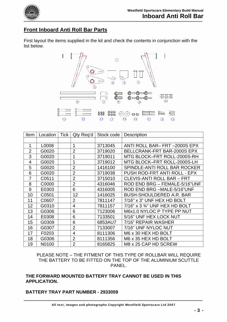
Front Inboard Anti Roll Bar Parts First layout the items supplied in the kit and check the contents in conjunction with the list below.
Item Location Tick Qty Req’d Stock code Description
1 L0008 1 3713045 ANTI ROLL BAR– FRT –2000S EPX 2 G0020 2 3719020 BELLCRANK-FRT BAR-2000S EPX 3 G0020 1 3719011 MTG BLOCK–FRT ROLL-2000S-RH 4 G0020 1 3719012 MTG BLOCK–FRT ROLL-2000S-LH 5 G0020 2 1416100 SPINDLE-ANTI ROLL BAR ROCKER 6 G0020 2 3719038 PUSH ROD-FRT ANTI ROLL - EPX 7 C0511 2 3715010 CLEVIS-ANTI ROLL BAR – FRT 8 C0000 2 4316046 ROD END BRG – FEMALE-5/16”UNF9 E0303 6 4316005 ROD END BRG –MALE-5/16”UNF
10 C0501 12 1416025 BUSH-SHOULDERED A.R. BAR 11 C0607 2 7811147 7/16” x 3” UNF HEX HD BOLT 12 G0310 4 7811157 7/16” x 3 ¾” UNF HEX HD BOLT 13 G0306 6 7123006 M6x1.0 NYLOC P TYPE PP NUT 14 E0308 6 7133501 5/16” UNF HEX LOCK NUT 15 G0309 6 6853AU7 7/16” REPAIR WASHER 16 G0307 2 7133007 7/16” UNF NYLOC NUT 17 F0203 4 8111306 M6 x 30 HEX HD BOLT 18 G0306 2 8111356 M6 x 35 HEX HD BOLT 19 N0100 2 8165825 M8 x 25 CAP HD SCREW
PLEASE NOTE – THE FITMENT OF THIS TYPE OF ROLLBAR WILL REQUIRE THE BATTERY TO BE FITTED ON THE TOP OF THE ALUMINIUM SCUTTLE
PANEL.
THE FORWARD MOUNTED BATTERY TRAY CANNOT BE USED IN THIS APPLICATION. BATTERY TRAY PART NUMBER - 2933059
All text, images and photographs Copyright Westfield Sportscars Ltd 2007
- 3 -
Westfield Sportscars Elementary Build Manual
Inboard Anti Roll Bar
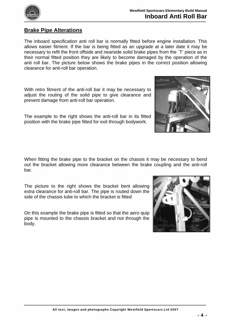
Brake Pipe Alterations The inboard specification anti roll bar is normally fitted before engine installation. This allows easier fitment. If the bar is being fitted as an upgrade at a later date it may be necessary to refit the front offside and nearside solid brake pipes from the `T’ piece as in their normal fitted position they are likely to become damaged by the operation of the anti roll bar. The picture below shows the brake pipes in the correct position allowing clearance for anti-roll bar operation. With retro fitment of the anti-roll bar it may be necessary to adjust the routing of the solid pipe to give clearance and prevent damage from anti-roll bar operation. The example to the right shows the anti-roll bar in its fitted position with the brake pipe fitted for exit through bodywork. When fitting the brake pipe to the bracket on the chassis it may be necessary to bend out the bracket allowing more clearance between the brake coupling and the anti-roll bar. The picture to the right shows the bracket bent allowing extra clearance for anti-roll bar. The pipe is routed down the side of the chassis tube to which the bracket is fitted On this example the brake pipe is fitted so that the aero quip pipe is mounted to the chassis bracket and not through the body.
All text, images and photographs Copyright Westfield Sportscars Ltd 2007
- 4 -
Westfield Sportscars Elementary Build Manual
Inboard Anti Roll Bar
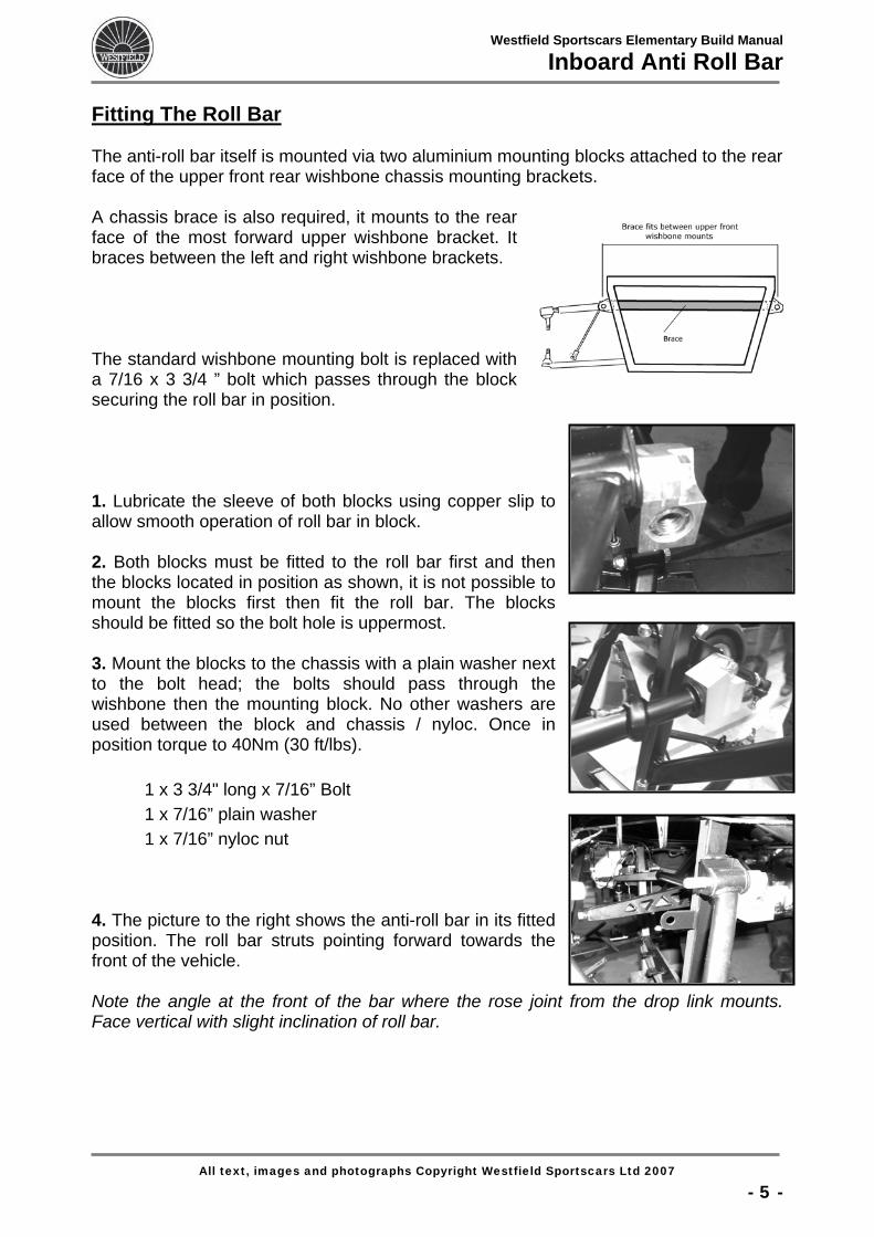
Fitting The Roll Bar The anti-roll bar itself is mounted via two aluminium mounting blocks attached to the rear face of the upper front rear wishbone chassis mounting brackets. A chassis brace is also required, it mounts to the rear face of the most forward upper wishbone bracket. It braces between the left and right wishbone brackets. The standard wishbone mounting bolt is replaced with a 7/16 x 3 3/4 ” bolt which passes through the block securing the roll bar in position. 1. Lubricate the sleeve of both blocks using copper slip to allow smooth operation of roll bar in block. 2. Both blocks must be fitted to the roll bar first and then the blocks located in position as shown, it is not possible to mount the blocks first then fit the roll bar. The blocks should be fitted so the bolt hole is uppermost. 3. Mount the blocks to the chassis with a plain washer next to the bolt head; the bolts should pass through the wishbone then the mounting block. No other washers are used between the block and chassis / nyloc. Once in position torque to 40Nm (30 ft/lbs).
1 x 3 3/4" long x 7/16” Bolt 1 x 7/16” plain washer 1 x 7/16” nyloc nut 4. The picture to the right shows the anti-roll bar in its fitted position. The roll bar struts pointing forward towards the front of the vehicle. Note the angle at the front of the bar where the rose joint from the drop link mounts. Face vertical with slight inclination of roll bar.
All text, images and photographs Copyright Westfield Sportscars Ltd 2007
- 5 -
Westfield Sportscars Elementary Build Manual
Inboard Anti Roll Bar
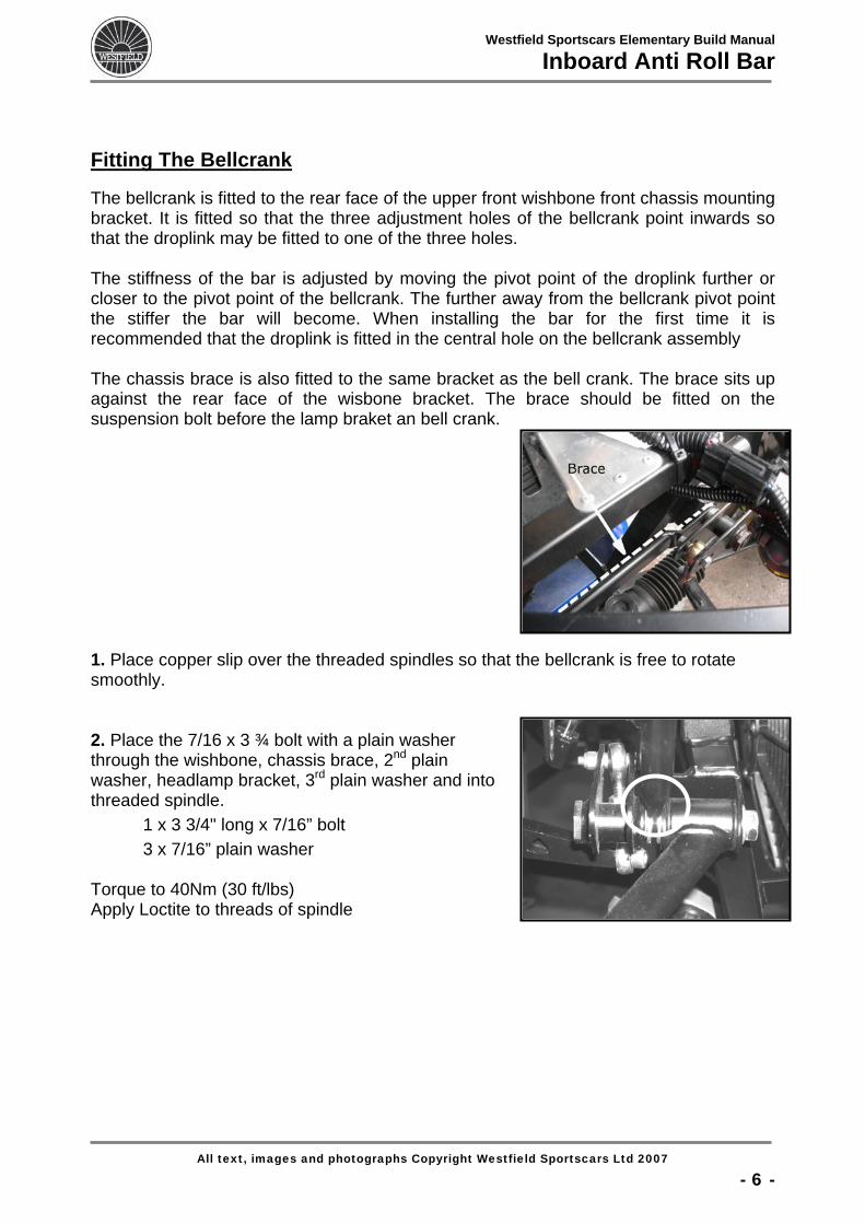
Fitting The Bellcrank The bellcrank is fitted to the rear face of the upper front wishbone front chassis mounting bracket. It is fitted so that the three adjustment holes of the bellcrank point inwards so that the droplink may be fitted to one of the three holes. The stiffness of the bar is adjusted by moving the pivot point of the droplink further or closer to the pivot point of the bellcrank. The further away from the bellcrank pivot point the stiffer the bar will become. When installing the bar for the first time it is recommended that the droplink is fitted in the central hole on the bellcrank assembly The chassis brace is also fitted to the same bracket as the bell crank. The brace sits up against the rear face of the wisbone bracket. The brace should be fitted on the suspension bolt before the lamp braket an bell crank.
1. Place copper slip over the threaded spindles so that the bellcrank is free to rotate smoothly. 2. Place the 7/16 x 3 ¾ bolt with a plain washer through the wishbone, chassis brace, 2nd plain washer, headlamp bracket, 3rd plain washer and into threaded spindle. 1 x 3 3/4" long x 7/16” bolt 3 x 7/16” plain washer Torque to 40Nm (30 ft/lbs) Apply Loctite to threads of spindle
All text, images and photographs Copyright Westfield Sportscars Ltd 2007
- 6 -
Westfield Sportscars Elementary Build Manual
Inboard Anti Roll Bar
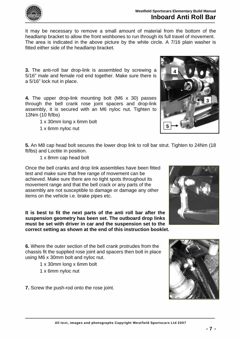
It may be necessary to remove a small amount of material from the bottom of the headlamp bracket to allow the front wishbones to run through its full travel of movement. The area is indicated in the above picture by the white circle. A 7/16 plain washer is fitted either side of the headlamp bracket. 3. The anti-roll bar drop-link is assembled by screwing a 5/16” male and female rod end together. Make sure there is a 5/16” lock nut in place. 4. The upper drop-link mounting bolt (M6 x 30) passes through the bell crank rose joint spacers and drop-link assembly, it is secured with an M6 nyloc nut. Tighten to 13Nm (10 ft/lbs)
4
5
3
1 x 30mm long x 6mm bolt 1 x 6mm nyloc nut 5. An M8 cap head bolt secures the lower drop link to roll bar strut. Tighten to 24Nm (18 ft/lbs) and Loctite in position. 1 x 8mm cap head bolt Once the bell cranks and drop link assemblies have been fitted test and make sure that free range of movement can be achieved. Make sure there are no tight spots throughout its movement range and that the bell crack or any parts of the assembly are not susceptible to damage or damage any other items on the vehicle i.e. brake pipes etc. It is best to fit the next parts of the anti roll bar after the suspension geometry has been set. The outboard drop links must be set with driver in car and the suspension set to the correct setting as shown at the end of this instruction booklet. 6. Where the outer section of the bell crank protrudes from the chassis fit the supplied rose joint and spacers then bolt in place using M6 x 30mm bolt and nyloc nut. 1 x 30mm long x 6mm bolt 1 x 6mm nyloc nut 7. Screw the push-rod onto the rose joint.
All text, images and photographs Copyright Westfield Sportscars Ltd 2007
- 7 -
Westfield Sportscars Elementary Build Manual
Inboard Anti Roll Bar
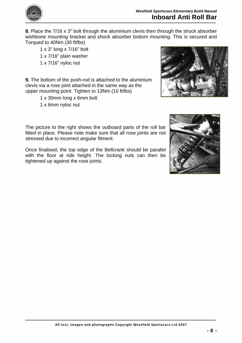
8. Place the 7/16 x 3” bolt through the aluminium clevis then through the shock absorber wishbone mounting bracket and shock absorber bottom mounting. This is secured and Torqued to 40Nm (30 ft/lbs) 1 x 3” long x 7/16” bolt 1 x 7/16” plain washer 1 x 7/16” nyloc nut 9. The bottom of the push-rod is attached to the aluminium clevis via a rose joint attached in the same way as the upper mounting point. Tighten to 13Nm (10 ft/lbs) 1 x 30mm long x 6mm bolt 1 x 6mm nyloc nut The picture to the right shows the outboard parts of the roll bar fitted in place. Please note make sure that all rose joints are not stressed due to incorrect angular fitment. Once finalised, the top edge of the Bellcrank should be parallel with the floor at ride height. The locking nuts can then be tightened up against the rose joints.
All text, images and photographs Copyright Westfield Sportscars Ltd 2007
- 8 -
Westfield Sportscars Elementary Build Manual
Inboard Anti Roll Bar
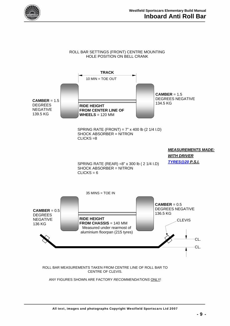
ROLL BAR SETTINGS (FRONT) CENTRE MOUNTING
HOLE POSITION ON BELL CRANK
10 MIN = TOE OUT
TRACK
MEASUREMENTS MADE:WITH DRIVER TYRES@20 P.S ..I
35 MINS = TOE IN
SPRING RATE (REAR) =8” x 300 lb ( 2 1/4 I.D) SHOCK ABSORBER = NITRON CLICKS = 6
RIDE HEIGHT FROM CENTER LINE OF WHEELS = 120 MM
CAMBER = 0.5 DEGREES NEGATIVE 136.5 KG
RIDE HEIGHT FROM CHASSIS = 140 MM
Measured under rearmost of aluminium floorpan (215 tyres)
CAMBER = 0.5 DEGREES NEGATIVE 136 KG
CLEVIS
CL.
CL.
CAMBER = 1.5 DEGREES NEGATIVE 139.5 KG
CAMBER = 1.5 DEGREES NEGATIVE 134.5 KG
SPRING RATE (FRONT) = 7” x 400 lb (2 1/4 I.D) SHOCK ABSORBER = NITRON CLICKS =8
R OLL BAR MEASUREMENTS TAKEN FROM CENTRE LINE OF ROLL BAR TOCENTRE OF CLEVIS.
ANY FIGURES SHOWN ARE FACTORY RECOMMENDATIONS ONLY!
All text, images and photographs Copyright Westfield Sportscars Ltd 2007
- 9 -
Related Documents