IEEE TRANSACTIONS ON INDUSTRY APPLICATIONS, VOL. 45, NO. 5, SEPTEMBER/OCTOBER 2009 1589 Design Aspects of an Active Electromagnetic Suspension System for Automotive Applications Bart L. J. Gysen, Student Member, IEEE, Jeroen L. G. Janssen, Student Member, IEEE, Johannes J. H. Paulides, Member, IEEE, and Elena A. Lomonova, Senior Member, IEEE Abstract—This paper is concerned with the design aspects of an active electromagnet suspension system for automotive appli- cations which combines a brushless tubular permanent-magnet actuator with a passive spring. This system provides for additional stability and safety by performing active roll and pitch control during cornering and braking. Furthermore, elimination of the road irregularities is possible, hence, passenger drive comfort is increased. Based upon measurements, static and dynamic specifi- cations of the actuator are derived. The electromagnetic suspen- sion is installed on a quarter-car test setup, and the improved performance using roll control is measured and compared with a commercial passive system. An alternative design using a slotless external-magnet tubular actuator is proposed which fulfills the thermal and volume specifications. Index Terms—Active suspension, optimization, permanent- magnet actuator. I. I NTRODUCTION I N THE FUTURE, active suspension systems will replace conventional passive suspension systems since vehicle sta- bility and passenger safety are high concerns for car designers. Cars tend to become smaller (SMART) and incorporate a higher center of gravity (SUV) and a reduced footprint, which increases the need for a suspension system with a rigid response when driving into turns while absorbing the road irregular- ities when driving under low-yaw circumstances (relatively straight). Currently, commercial systems consist of hydraulic or pneumatic actuators (for example, those installed on Citroen, Rolls-Royce, Mercedes Benz, etc.) which offer a high force density and ease in design due to the commercial availability of the various parts. However, these systems have a relatively low bandwidth (around 1 Hz) [1], [2] probably due to leakage in the valves and pressure hoses and limited bandwidth of the pump. Furthermore, these systems are inefficient due to the need for a continuous pressurized system. In general, electromagnetic suspension systems have a very small response time and are, Paper 2008-IDC-121.R1, presented at the 2008 Industry Applications Soci- ety Annual Meeting, Edmonton, AB, Canada, October 5–9, and approved for publication in the IEEE TRANSACTIONS ON I NDUSTRY APPLICATIONS by the Industrial Drives Committee of the IEEE Industry Applications Society. Manuscript submitted for review October 31, 2008 and released for publication March 3, 2009. First published July 14, 2009; current version published September 18, 2009. This work was supported by SKF. The authors are with the Department of Electrical Engineering, Eindhoven University of Technology, 5600 MB Eindhoven, The Netherlands (e-mail: [email protected]; [email protected]; [email protected]; e.lomonova@ tue.nl). Color versions of one or more of the figures in this paper are available online at http://ieeexplore.ieee.org. Digital Object Identifier 10.1109/TIA.2009.2027097 therefore, more suitable to absorb road vibrations and to react in lane-change maneuvers. An example of a commercial electro- magnetic semiactive suspension system is the magnetorheolog- ical damper [3], [4], developed by Delphi Corporation (installed on Audi, Cadillac, Ferrari), which has the ability to change its damper characteristic within 1 ms [5]. However, since it is a semiactive system, no active force can be applied and, therefore, total roll and pitch elimination is impossible. This paper proposes an electromagnetic active suspension system comprising of a brushless tubular permanent-magnet actuator (TPMA) [6], [7], in parallel with a mechanical spring [8], [9]. These actuators have a relatively high force density due to the tubular structure and excellent servo characteristics with a bandwidth in excess of 50 Hz. Furthermore, electromagnetic actuators allow for bidirectional power flow and hence, both motor and generator modes are possible. The former is used to apply active forces on the sprung mass to eliminate roll and pitch movements, and the latter is used to absorb road vibrations and act as a damper where the absorbed power can be fed to the battery in order to supply auxiliary loads. Actuator- force specifications will be derived in Section II based upon vertical-acceleration measurements during a test drive on the Nürburgring. In Section III, the proof of principle will be shown by means of measurements on an in-house designed and built quarter-car test setup which mimics the roll behavior. Since a redesign of the total suspension is an expensive solution, this paper proposes a “plug and play” suspension system in Section IV, which means that the volume specifications are based upon the currently installed passive suspension systems for both low-voltage (general cars) and high-voltage applica- tions (hybrid cars). A slotless TPMA is proposed in Section V where it is shown that, by means of optimization, the inverted Halbach magnetized topology offers the highest force density. II. SYSTEM SPECIFICATIONS In order to design a suspension system capable of eliminating roll and pitch behavior, it is necessary to identify the forces acting on the unsprung and sprung mass. As an example, during fast cornering, centrifugal forces tend to roll the car around the roll axis which causes an unbalance of the load or a load transfer from the inner to the outer wheels. In such an example, using Fig. 1, the vertical dynamic force on the tires can be calculated as [10] F dyn =(m s + m u )a y h CoG T (1) 0093-9994/$26.00 © 2009 IEEE

Welcome message from author
This document is posted to help you gain knowledge. Please leave a comment to let me know what you think about it! Share it to your friends and learn new things together.
Transcript

IEEE TRANSACTIONS ON INDUSTRY APPLICATIONS, VOL. 45, NO. 5, SEPTEMBER/OCTOBER 2009 1589
Design Aspects of an Active ElectromagneticSuspension System for Automotive Applications
Bart L. J. Gysen, Student Member, IEEE, Jeroen L. G. Janssen, Student Member, IEEE,Johannes J. H. Paulides, Member, IEEE, and Elena A. Lomonova, Senior Member, IEEE
Abstract—This paper is concerned with the design aspects ofan active electromagnet suspension system for automotive appli-cations which combines a brushless tubular permanent-magnetactuator with a passive spring. This system provides for additionalstability and safety by performing active roll and pitch controlduring cornering and braking. Furthermore, elimination of theroad irregularities is possible, hence, passenger drive comfort isincreased. Based upon measurements, static and dynamic specifi-cations of the actuator are derived. The electromagnetic suspen-sion is installed on a quarter-car test setup, and the improvedperformance using roll control is measured and compared witha commercial passive system. An alternative design using a slotlessexternal-magnet tubular actuator is proposed which fulfills thethermal and volume specifications.
Index Terms—Active suspension, optimization, permanent-magnet actuator.
I. INTRODUCTION
IN THE FUTURE, active suspension systems will replaceconventional passive suspension systems since vehicle sta-
bility and passenger safety are high concerns for car designers.Cars tend to become smaller (SMART) and incorporate ahigher center of gravity (SUV) and a reduced footprint, whichincreases the need for a suspension system with a rigid responsewhen driving into turns while absorbing the road irregular-ities when driving under low-yaw circumstances (relativelystraight). Currently, commercial systems consist of hydraulic orpneumatic actuators (for example, those installed on Citroen,Rolls-Royce, Mercedes Benz, etc.) which offer a high forcedensity and ease in design due to the commercial availability ofthe various parts. However, these systems have a relatively lowbandwidth (around 1 Hz) [1], [2] probably due to leakage in thevalves and pressure hoses and limited bandwidth of the pump.Furthermore, these systems are inefficient due to the need fora continuous pressurized system. In general, electromagneticsuspension systems have a very small response time and are,
Paper 2008-IDC-121.R1, presented at the 2008 Industry Applications Soci-ety Annual Meeting, Edmonton, AB, Canada, October 5–9, and approvedfor publication in the IEEE TRANSACTIONS ON INDUSTRY APPLICATIONS
by the Industrial Drives Committee of the IEEE Industry Applications Society.Manuscript submitted for review October 31, 2008 and released for publicationMarch 3, 2009. First published July 14, 2009; current version publishedSeptember 18, 2009. This work was supported by SKF.
The authors are with the Department of Electrical Engineering, EindhovenUniversity of Technology, 5600 MB Eindhoven, The Netherlands (e-mail:[email protected]; [email protected]; [email protected]; [email protected]).
Color versions of one or more of the figures in this paper are available onlineat http://ieeexplore.ieee.org.
Digital Object Identifier 10.1109/TIA.2009.2027097
therefore, more suitable to absorb road vibrations and to react inlane-change maneuvers. An example of a commercial electro-magnetic semiactive suspension system is the magnetorheolog-ical damper [3], [4], developed by Delphi Corporation (installedon Audi, Cadillac, Ferrari), which has the ability to changeits damper characteristic within 1 ms [5]. However, since itis a semiactive system, no active force can be applied and,therefore, total roll and pitch elimination is impossible. Thispaper proposes an electromagnetic active suspension systemcomprising of a brushless tubular permanent-magnet actuator(TPMA) [6], [7], in parallel with a mechanical spring [8], [9].These actuators have a relatively high force density due tothe tubular structure and excellent servo characteristics with abandwidth in excess of 50 Hz. Furthermore, electromagneticactuators allow for bidirectional power flow and hence, bothmotor and generator modes are possible. The former is usedto apply active forces on the sprung mass to eliminate rolland pitch movements, and the latter is used to absorb roadvibrations and act as a damper where the absorbed power can befed to the battery in order to supply auxiliary loads. Actuator-force specifications will be derived in Section II based uponvertical-acceleration measurements during a test drive on theNürburgring. In Section III, the proof of principle will be shownby means of measurements on an in-house designed and builtquarter-car test setup which mimics the roll behavior. Sincea redesign of the total suspension is an expensive solution,this paper proposes a “plug and play” suspension system inSection IV, which means that the volume specifications arebased upon the currently installed passive suspension systemsfor both low-voltage (general cars) and high-voltage applica-tions (hybrid cars). A slotless TPMA is proposed in Section Vwhere it is shown that, by means of optimization, the invertedHalbach magnetized topology offers the highest force density.
II. SYSTEM SPECIFICATIONS
In order to design a suspension system capable of eliminatingroll and pitch behavior, it is necessary to identify the forcesacting on the unsprung and sprung mass. As an example, duringfast cornering, centrifugal forces tend to roll the car around theroll axis which causes an unbalance of the load or a load transferfrom the inner to the outer wheels.
In such an example, using Fig. 1, the vertical dynamic forceon the tires can be calculated as [10]
Fdyn = (ms + mu)ayhCoG
T(1)
0093-9994/$26.00 © 2009 IEEE
1590 IEEE TRANSACTIONS ON INDUSTRY APPLICATIONS, VOL. 45, NO. 5, SEPTEMBER/OCTOBER 2009
Fig. 1. Half-car model for calculation of the roll forces.
TABLE IPARAMETERS OF THE TEST VEHICLE
where ay is the centrifugal acceleration during cornering. Thevertical forces exerted on the tires by the unsprung mass Fu andsprung mass Fs can be calculated as
Front : Fuf= muf
ayhu
T
Fsf= ψmmsay
hra
T
Factf=
1Cf
(γfFdyn − Fuf− Fsf
) (2)
Rear : Fur= mur
ayhu
T
Fsr= (1 − ψm)msay
hra
T
Factr=
1Cr
((1 − γf )Fdyn − Fur− Fsr
) (3)
where mufand mur
are the unsprung masses of the front andrear axle, respectively and ψm is the ratio of the total sprungmass acting on the front axle. Due to the independence of theactuators, it is possible to introduce a force ratio γf betweenthe front and rear axle which gives the possibility to controlfor understeer compared with the more dangerous oversteerbehavior. The force ratios Cf and Cr are introduced since thestruts are not exactly vertically mounted. In order to calculatethe actuator forces, the lateral acceleration ay is measuredduring a one-lap test drive with a BMW 530 on the Nürburgringin Germany, and the actuator forces are calculated using theparameters given in Table I. A short interval of the actuatorforces calculated from the measured lateral acceleration is
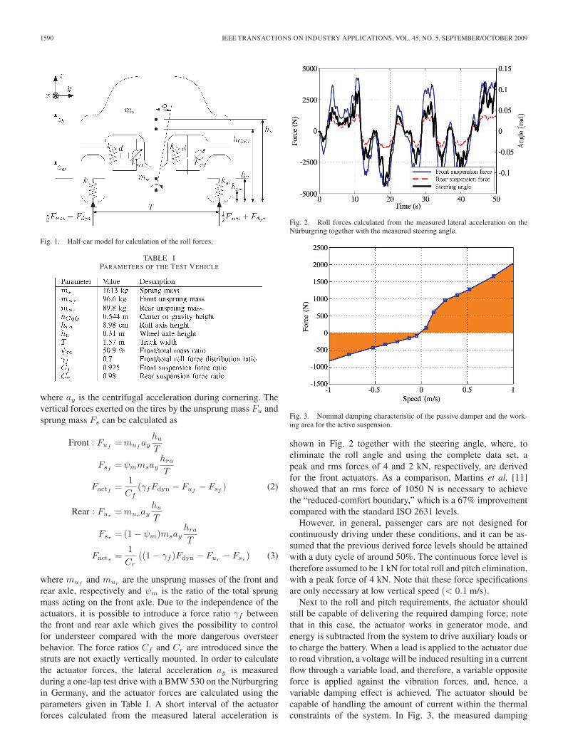
Fig. 2. Roll forces calculated from the measured lateral acceleration on theNürburgring together with the measured steering angle.
Fig. 3. Nominal damping characteristic of the passive damper and the work-ing area for the active suspension.
shown in Fig. 2 together with the steering angle, where, toeliminate the roll angle and using the complete data set, apeak and rms forces of 4 and 2 kN, respectively, are derivedfor the front actuators. As a comparison, Martins et al. [11]showed that an rms force of 1050 N is necessary to achievethe “reduced-comfort boundary,” which is a 67% improvementcompared with the standard ISO 2631 levels.
However, in general, passenger cars are not designed forcontinuously driving under these conditions, and it can be as-sumed that the previous derived force levels should be attainedwith a duty cycle of around 50%. The continuous force level istherefore assumed to be 1 kN for total roll and pitch elimination,with a peak force of 4 kN. Note that these force specificationsare only necessary at low vertical speed (< 0.1 m/s).
Next to the roll and pitch requirements, the actuator shouldstill be capable of delivering the required damping force; notethat in this case, the actuator works in generator mode, andenergy is subtracted from the system to drive auxiliary loads orto charge the battery. When a load is applied to the actuator dueto road vibration, a voltage will be induced resulting in a currentflow through a variable load, and therefore, a variable oppositeforce is applied against the vibration forces, and, hence, avariable damping effect is achieved. The actuator should becapable of handling the amount of current within the thermalconstraints of the system. In Fig. 3, the measured damping
GYSEN et al.: DESIGN ASPECTS OF ELECTROMAGNETIC SUSPENSION SYSTEM FOR AUTOMOTIVE APPLICATIONS 1591
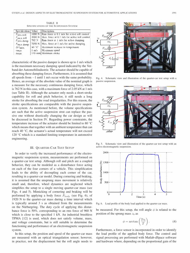
TABLE IISPECIFICATIONS OF THE SUSPENSION SYSTEM
characteristic of the passive damper is shown up to 1 m/s whichis the maximum necessary damping speed indicated by the Ver-band der Automobilindustrie. The actuator should be capable ofabsorbing these damping forces. Furthermore, it is assumed thatall speeds from −1 until 1 m/s occur with the same probability.Hence, an average of the absolute value of the nominal graph isa measure for the necessary continuous damping force, whichis 762 N in this case, with a maximum force of 2.05 kN at 1 m/s(see Table II). Although the actuator only needs a short-strokecapability for roll and pitch behavior, it still needs a longstroke for absorbing the road irregularities. For this reason, thestroke specifications are comparable with the passive suspen-sion system. As mentioned before, the volume specificationsare such that the active suspension strut can replace the pas-sive one without drastically changing the car design as willbe discussed in Section IV. Regarding power constraints, thetemperature increase of the actuator should be limited to 80 ◦Cwhich means that together with an ambient temperature that canreach 40 ◦C, the actuator’s actual temperature will not exceed120 ◦C which is a standard limiting temperature in automotiveengineering.
III. QUARTER-CAR TEST SETUP
In order to verify the increased performance of the electro-magnetic suspension system, measurements are performed ona quarter-car test setup. Although roll and pitch are a coupledbehavior, they can be modeled as a disturbance force actingon each of the four corners of a vehicle. This simplificationleads to the ability of decoupling each corner of the car,resulting in a quarter-car model. During cornering and braking,it is assumed that the unsprung mass movement is relativelysmall and, therefore, wheel dynamics are neglected whichsimplifies the setup to a single moving quarter-car mass (seeFigs. 4 and 5). Mimicking of cornering and braking will beperformed by applying a body force Fbody (see Fig. 6), of1920 N to the quarter-car mass during a time interval whichis typically around 3 s as obtained from the measurementson the Nürburgring. The duty cycle of applying this distur-bance force is 50%, corresponding to an rms force of 960 Nwhich is close to the specified 1 kN. An industrial brushlessTPMA [12] is used, which does not satisfy volume, mass,and voltage constraints, but is still suitable to determine thefunctioning and performance of an electromagnetic suspensionsystem.
In this setup, the position and speed of the quarter-car massare measured with an optical triangulation sensor; however,in practice, not the displacement but the roll angle needs to
Fig. 4. Schematic view and illustration of the quarter-car test setup with apassive suspension.
Fig. 5. Schematic view and illustration of the quarter-car test setup with anactive electromagnetic suspension.
Fig. 6. Load profile of the body load applied to the quarter-car mass.
be measured. For this setup, the roll angle φ is related to theposition of the sprung mass zb as
φ = arctan(
2zb
T
). (4)
Furthermore, a force sensor is incorporated in order to identifythe load profile of the applied body force. The control andsignal processing are performed with Matlab-dSpace softwareand hardware where, depending on the proportional gain of the

1592 IEEE TRANSACTIONS ON INDUSTRY APPLICATIONS, VOL. 45, NO. 5, SEPTEMBER/OCTOBER 2009
TABLE IIIPARAMETERS OF THE QUARTER-CAR TEST SETUP
Fig. 7. Passive and active roll control measurements.
controller, the body displacement can be minimized at theexpense of power consumption. The parameters of the setupare given in Table III. In Fig. 7, the simulated and measured re-sponses of the passive and active suspension system on the bodyforce are shown. It can be observed that the electromagneticsuspension system immediately reacts on the applied force, andthe roll angle is minimized up to 5.9% of the passive roll angle.This provides for a tradeoff between the allowable roll andpower consumption. For example, if zero body roll is obtained,no mechanical energy is produced, hence, speed-dependentlosses can be neglected. The steepness of the actuator S =F 2
act/Pcu, where Pcu are the copper losses, is 5790 N2/W, and,hence, the power as function of the body force and roll angle φcan approximately be written as
Pcu ≈
(Fbody − kaT tan(φ)
2
)2
S. (5)
To achieve zero body roll, 636 W is necessary per wheel for thebody disturbance of 1920 N. However, taking into account thespecified duty cycle of 50%, the continuous power is 318 Wper wheel. The used electromagnetic actuator has an activelength of 364 mm and an outer diameter of 157 mm, hence,it is not suitable regarding the available space envelope in aBMW 530. Furthermore, the induced peak electromotive force(EMF) at 1 m/s is 126.7 V. Hence, the next section will discussan alternative design of an actuator by means of an optimizationroutine with respect to the available space envelope and supplyvoltages.
IV. SUSPENSION DESIGN AND ACTUATOR CONSTRAINTS
A. Suspension Design
In Fig. 8(a), the passive suspension system is shown whichconsists of a mechanical spring in parallel with a passivehydraulic or pneumatic damper. The proposed electromagnetic
Fig. 8. Suspension struts. (a) Passive. (b) Active interior-magnet TPMA, (c)Active exterior-magnet TPMA.
active-suspension strut is shown in Fig. 8(b) and (c) whichboth consist of a slotless brushless three-phase TPMA in par-allel with a mechanical spring. Due to the ease in modeling,design, and fabrication, the low-force ripples and low cost, aslotless TPMA is preferred over a slotted one. Two differenttopologies are considered for the actuator: interior and exteriormagnet, as shown in Fig. 8(b) and (c), respectively, and thecross sections are shown in Fig. 9(a) and (b), respectively.The exterior-magnet topology offers the benefit of the absenceof a cable slap; however, in order to keep the power levelto a minimum, switching of coil sets should be implementedbased upon position monitoring. Since this is also necessaryfor commutation in order to have a long-stroke movement, alinear encoder is embedded in the hollow shaft. The permanentmagnets have a remanent flux density of 1.23 T and a relativerecoil permeability of 1.05.
B. Volume and Mass Constraints
The active-suspension strut is designed to replace the passiveone, and, as a result, the outer radius of the translator and theouter radius and length of the stator have an upper constraint.There is a minimum constraint on the radius of the hollow shaftsince a linear encoder is embedded. The moving mass shouldbe limited to 16 kg; however, considering the available volume,this is not a hard constraint and is therefore easily achieved. Thehousing of the strut is made of aluminum for its low weight,high thermal conductivity, and nonmagnetic properties.
C. Thermal Constraints
The design objective is to maximize the mean force withina constrained volume, hence, the actuator design always tendsto have the maximum outer radius and axial length, and, ifnot, aluminum could be added in order to increase the heatconvection and, hence, the performance. The air-gap length gis fixed to 1 mm to allow the use of sliding bearings, whichincreases the thermal conduction. The overall thermal behaviorof the tubular actuator only moderately changes by varying theother geometrical parameters or magnetization pattern, hence,

GYSEN et al.: DESIGN ASPECTS OF ELECTROMAGNETIC SUSPENSION SYSTEM FOR AUTOMOTIVE APPLICATIONS 1593
Fig. 9. Schematic view of slotless TPMA. (a) Interior magnet. (b) Exterior magnet.
Fig. 10. Temperature increment of the actuator as function of the copperlosses.
the maximum copper losses are obtained for a fixed maximumtemperature rise of 80 ◦C. However, significant differences doarise when the topology is varied, i.e., interior- or exterior-magnet topology. Using a 2-D thermal finite-element model,the temperature distribution is calculated for both topologies.To illustrate the thermal behavior, the maximum actuator tem-perature is given as a function of the copper losses, as shown inFig. 10. It can be observed that the maximum copper losses are193 and 143 W for the interior- and exterior-magnet topology,respectively, for the maximum temperature rise of 80 ◦C. Theexterior-magnet topology allows for less copper losses, sincethey have to travel through the air gap and magnet arraybefore convection can occur. The total temperature distributionfor the 80-◦C temperature rise is shown in Fig. 11 for bothtopologies. Finally, a list of all the constraints is presented inTable IV.
V. ACTUATOR MODELING, OPTIMIZATION, AND DESIGN
A. Magnetostatic Design
In this section, an actuator design will be derived accordingto the specifications and constraints mentioned in the previoussections. Both interior- and exterior-magnet topologies are con-sidered [see Fig. 9(a) and (b)], respectively, for three different
Fig. 11. Temperature distribution of (a) the interior-magnet topology and (b)the exterior magnet topology (Halbach magnetization).
TABLE IVACTUATOR CONSTRAINTS
magnetization patterns, radial, Halbach, and axial magnetiza-tions. It should be noted that for Halbach and axial magne-tizations, the back iron for the magnets vanishes, hti = 0 or

1594 IEEE TRANSACTIONS ON INDUSTRY APPLICATIONS, VOL. 45, NO. 5, SEPTEMBER/OCTOBER 2009
Fig. 12. Mean force level of the optimized interior-magnet topologies fordifferent pole-pair numbers.
hsi = 0 for interior and exterior magnet, respectively. Modelingof the magnetic field B inside the air gap is performed usingthe analytical framework proposed in [6] and [13], hence,end effects of the finite length of the stator and translator areneglected. Calculation of the force is obtained using the Lorentzequation at the center of the air gap and coil region Rag
Fact =∫V
J × BdV (6)
= 2πRag
Lact∫0
JsBrdz
∣∣∣∣r=Rag
(7)
where Js = hcJ is the surface current density and Br is theradial component of the magnetic field at the mean air-gapradius Rag, which is given by
Rag = Rt +g + hc
2for interior magnet (8)
Rag = Rt +g − hc
2for exterior magnet. (9)
Optimization is performed with sequential quadratic program-ming, where the objective is to maximize the force within thevolume and power constraints. The optimization is performedfor the three magnetization patterns, for interior- and exterior-magnet topologies, and for different number of pole pairs,1 ≤ Np ≤ 5.
In Figs. 12 and 13, the force level of the optimized interior-magnet and exterior-magnet topologies are shown, respectively,for different values of the pole-pair number, Np. It can beobserved that for a low pole-pair number, the force levels arerelatively low since the saturation level of the back iron (seeTable IV) is the limiting constraint. The Halbach magnetizationhas the highest force levels since no back iron for the magnetsis necessary compared with radial magnetization and, hence, ahigher magnet height is possible which increases the magnetic
Fig. 13. Mean force level of the optimized exterior-magnet topologies fordifferent pole-pair numbers.
loading B and, as a result, the force level (6). Compared withaxial magnetization, the Halbach magnetization has a higherforce level since the magnetic field is concentrated on the air-gap side, and due to the absence of iron pole pieces, it is notlimited by saturation levels. Another interesting observation isthat for Halbach magnetization, the exterior-magnet topologyoffers a higher force level compared with the interior-magnettopology since a higher magnet height is possible, increasing B,while the electrical loading is slightly decreased (due to thermallimitations), which is beneficial considering the total powerconsumption of the system. Hence, although the allowed copperlosses are 50 W less due to thermal limitations, the force levelis increased with 67 N. However, this does not hold for axialmagnetization since in this case, the flux is not completelyfocused on the air-gap side, and there is a lot of leakageto the exterior of the actuator (see Fig. 14). The final de-sign is therefore chosen to be an exterior Halbach-magnetizedtopology with a mean force level of 755 N; the flux densitydistribution of the full actuator is given in Fig. 15, and thefinal sizes are given in Table V. The force profile of the finaldesign is checked with a 2-D finite-element analysis (FEA)-simulation and shown in Fig. 16 together with the analyticalsolution, where the rms current density is 5.1 A/mm2. Theforce-current characteristic is linear up to 4.5 kN, and thenecessary rms current density to obtain the peak force of 4 kN isJrmsm
= 25.6 A/mm2.
B. Dynamic Design
In this section, the number of turns N will be determinedbased upon previously derived current-density levels, speedspecifications, and available supply voltages VDC . The lossesof the power electronics are neglected as well as the iron losses.The maximum value of the current Im can be related to themaximum rms current density by
Im =√
2JrmsmSc
NPf(10)
with Sc = hcτp/3 as the coil area and Pf = 0.5 as the packingfactor. The EMF ephN
per turn per phase is calculated with 2-D

GYSEN et al.: DESIGN ASPECTS OF ELECTROMAGNETIC SUSPENSION SYSTEM FOR AUTOMOTIVE APPLICATIONS 1595
Fig. 14. Flux distribution of (a) the exterior Halbach-magnetized topologyand (b) the exterior axial-magnetized topology (Np = 4).
FEA, including end effects at a rated speed of 1 m/s and shownin Fig. 17. From this, the peak EMF is related to the number ofturns N and the armature velocity v by
Em = KENvN (11)
where KEN= 1.88 V · s/m as observed from Fig. 17. Fur-
thermore, the synchronous inductance per turn is calculatedwhich is LsN
= 1.9 μH. Therefore, the reactance voltage canbe written as
VLm=ωLsN
N2Im =πv
τpLsN
N2Im
=√
2πJrmsmScvLsN
N
τp. (12)
The ohmic voltage drop can be written as
VRm= RphIm =
4πRcρNp
ScPfN2Im =
4√
2πJrmsmRcρNpN
Pf
(13)
where Rc is the mean radius of the coil, and ρ is the specificresistance. Due to commutation, the stator current is in phase
Fig. 15. Flux density in the exterior Halbach-magnetized tubular permanent-magnet actuator.
TABLE VFINAL DESIGN OF THE EXTERIOR HALBACH-MAGNETIZED
TUBULAR PERMANENT-MAGNET ACTUATOR
with the induced EMF, and, based upon the phasor diagram inthe d−q reference frame, the various voltages are related to thephase voltage Vm as
V 2m = (Em + VRm
)2 + V 2Lm
(14)
where Vm = VDC/√
3 for space-vector pulsewidth modula-tion. Considering a dc supply voltage of 14, 42, or 500 V(hybrid vehicle), the number of turns and values of the currentare given in Table VI. It can be observed that for the lowsupply voltages (14 and 42 V), the number of turns is verylow due to the limitations on the induced EMF. This results, ofcourse, in extreme high-current values, particularly for obtain-ing the peak force, which requires expensive power-electronicconverters and relatively thick wiring which is not preferredfor automotive applications. Therefore, the actuator should

1596 IEEE TRANSACTIONS ON INDUSTRY APPLICATIONS, VOL. 45, NO. 5, SEPTEMBER/OCTOBER 2009
Fig. 16. Force profile of the exterior Halbach-magnetized tubular permanent-magnet actuator.
Fig. 17. EMF of the final design of the exterior Halbach-magnetized tubularpermanent-magnet actuator at v = 1 m/s.
TABLE VICIRCUIT PARAMETERS FOR DIFFERENT SUPPLY VOLTAGES
have a higher force density and perhaps a slotted actuatorwould be more preferable. However, the low number of turnsresults in a low inductance and, therefore, a high-bandwidthperformance.
VI. CONCLUSION
This paper has described the design aspects for an elec-tromagnetic active suspension system capable of eliminatingroll and pitch behavior while maintaining damped behaviorof the road vibrations in automotive applications. First, basedupon measurements during a test drive on the Nürburgringwith a BMW 530 with a passive suspension system, staticand dynamic specifications are drawn. The proof of principle
is shown on a quarter-car test setup which mimics the rolland pitch behavior. Comparison of the passive and proposedactive electromagnetic suspension system showed the improvedperformance where a minimization of 94.4% of the passive rollangle is achieved. Since the used electromagnetic suspensionsystem does not meet the volume and mass requirements, analternative design is proposed. The magnetostatic design isbased upon optimization of the static force of a slotless actuatorstructure for different magnetization topologies as well as forinterior- and exterior-magnet solutions. Overall, the Halbachmagnetization offers the highest force density where for thegiven geometry specifications, the exterior Halbach-magnetizedtopology with four pole pairs is the optimal one. Although it isfound that the exterior Halbach magnet topology offers a higherforce density compared with the interior one, this does nothold for axial magnetization. Inverting the axial magnetizationstructure results in a large amount of leakage flux to the exteriorof the actuator. The final design is capable of providing acontinuous force of 755 N at a maximum speed of 1 m/s whichis very close to the obtained specification for active damping.Furthermore, considering the active roll specification, the peakforce of 4 kN at 0.1 m/s can be reached; however, the desiredrms force of 1 kN cannot be provided since the temperaturelimit would be exceeded. Due to the low number of turns, a lowinductance is obtained which results in a high-bandwidth per-formance. However, for the low-voltage applications, relativelylarge currents are necessary which results in expensive powerelectronic converter and, hence, a slotted actuator with a higherforce density is more preferred.
REFERENCES
[1] R. Rajamani and J. K. Hedrick, “Performance of active automotive sus-pensions with hydraulic actuators: Theory and experiment,” in Proc.Amer. Control Conf., Jun. 1994, vol. 2, pp. 1214–1218.
[2] Y. M. Sam and K. Hudha, “Modelling and force tracking control ofhydraulic actuator for an active suspension,” in Proc. 1st IEEE Conf. Ind.Electron. Appl., May 24–26, 2006, pp. 1–6.
[3] S. Guo, S. Li, and S. Yang, “Semi-active vehicle suspension systems withmagnetorheological dampers,” in Proc. IEEE Int. Conf. Veh. Electron.Safety, Dec. 13–15, 2006, pp. 403–406.
[4] S. Guo, S. Yang, and C. Pan, “Dynamic modeling of magnetorheologicaldamper behaviors,” J. Intell. Mater. Syst. Struct., vol. 17, no. 1, pp. 3–14,2006.
[5] Delphi Corporation. [Online]. Available: http://delphi.com/[6] J. Wang, G. W. Jewell, and D. Howe, “A general framework for the
analysis and design of tubular linear permanent magnet machines,” IEEETrans. Magn., vol. 35, no. 3, pp. 1986–2000, May 1999.
[7] J. Wang, G. W. Jewell, and D. Howe, “Design optimisation and compar-ison of tubular permanent magnet machine topologies,” Proc. Inst. Elect.Eng.—Elect. Power Appl., vol. 148, no. 5, pp. 456–464, Sep. 2001.
[8] J. J. H. Paulides, L. Encica, E. A. Lomonova, and A. J. A. Vandenput,“Design considerations for a semi-active electromagnetic suspension sys-tem,” IEEE Trans. Magn., vol. 42, no. 10, pp. 3446–3448, Oct. 2006.
[9] J. L. G. Janssen, J. J. H. Paulides, E. A. Lomonova, and A. J. A.Vandenput, “Cogging force reduction in tubular permanent magnet ac-tuators,” in Proc. IEEE IEMDC, May 2007, vol. 1, pp. 266–271.
[10] J. C. Dixon, Tires, Suspension and Handling. Cambridge, U.K.: Cam-bridge Univ. Press, 1996.
[11] I. Martins, J. Esteves, G. D. Marques, and F. P. da Silva, “Permanent-magnets linear actuators applicability in automobile active suspensions,”IEEE Trans. Veh. Technol., vol. 55, no. 1, pp. 86–94, Jan. 2006.
[12] California Linear Drives, Inc., User’s Manual Linear Motors, UM-102revision B ed., Carlsbad, CA, Nov. 2005.
[13] J. Wang and D. Howe, “Design optimization of radially magnetized, iron-cored, tubular permanent-magnet machines and drive systems,” IEEETrans. Magn., vol. 40, no. 5, pp. 3262–3277, Sep. 2004.

GYSEN et al.: DESIGN ASPECTS OF ELECTROMAGNETIC SUSPENSION SYSTEM FOR AUTOMOTIVE APPLICATIONS 1597
Bart L. J. Gysen (S’07) was born in Bilzen,Belgium, in 1984. He received the B.Sc. and M.Sc.degrees in electrical engineering from EindhovenUniversity of Technology, Eindhoven, TheNetherlands, where he is currently working towardthe Ph.D. degree in the Electromechanics and PowerElectronics Group.
His research interest is electromagnetic active-suspension systems for automotive applications.
Jeroen L. G. Janssen (S’07) was born in Boxmeer,The Netherlands, in 1982. He received the B.Sc.and M.Sc. degrees in electrical engineering fromEindhoven University of Technology, Eindhoven,The Netherlands, where he is currently working to-ward the Ph.D. degree in the Electromechanics andPower Electronics Group.
His research activities are focused on permanent-magnet-based electromagnetic-vibration isolationfor lithographic applications.
Johannes J. H. Paulides (M’06) was born inWaalwijk, The Netherlands, in 1976. He received theB.Eng. degree from the Technische Hogeschool ‘s-Hertogenbosch, The Netherlands, in 1998, and theM.Phil. and Ph.D. degrees in electrical and electron-ical engineering from the University of Sheffield,Sheffield, U.K., in 2000 and 2005, respectively.
Since 2005, he has been a Research Associateat Eindhoven University of Technology, Eindhoven,The Netherlands, and simultaneously a Director ofPaulides BV and Advanced Electromagnetics BV,
small and medium enterprises based in The Netherlands, producing electricalmachines and prototype electromagnetic devices. His research activities spanall facets of electrical machines, in particular, linear and rotating permanent-magnet-excited machines for automotive and high-precision applications.
Elena A. Lomonova (M’04–SM’07) was born inMoscow, Russia. She received the M.Sc. (cum laude)and Ph.D. (cum laude) degrees in electromechan-ical engineering from the Moscow State AviationInstitute (TU), Moscow, Russia, in 1982 and 1993,respectively.
She is currently an Assistant Professor atEindhoven University of Technology, Eindhoven,The Netherlands. She has worked onelectromechanical-actuators design, optimization,and development of advanced mechatronics systems.
Related Documents