Survivable Free Space Optical Mesh Network using High-Altitude Platforms Dieu Linh Truong *1 , Xuan Vuong Dang 1 and The Ngoc Dang † 2 1 School of Information and Communication Technology, Hanoi University of Science and Technology, Vietnam 2 Department of Wireless Communications, Posts and Telecommunication Institute of Technology, Vietnam Abstract Free space optical (FSO) communication refers to the infor- mation transmission technology based on the propagation of optical signals in space. FSO communication requires that the transmitter and receiver directly see each other. High- altitude platforms (HAPs) have been proposed for carrying FSO transceivers in the stratosphere. A multihop HAP net- work with FSO links can relay traffic between ground FSO nodes. In this study, we propose an end-to-end switching model for forwarding traffic between massive pairs of ground FSO nodes over a HAP network. A protection mechanism is employed for improving the communication survivability in the presence of clouds, which may break the line of sight (LoS) between HAPs and ground nodes. We propose an algorithm for designing the topology of the survivable HAP network, given a set of ground FSO nodes. The results demonstrate that, even though networks with survivable capacity use more resources, they are not necessary much more expensive than those without survivability in terms of equipment, i.e., HAPs and FSO devices, and in terms of wavelength resource uti- lization. Keywords— Free Space Optics, Survivable networks, Topology design, Routing 1 Introduction Free space optics (FSO) communication technology uses a laser beam to transmit information through air or vacuum between a pair of transceivers at high speed. Commercial FSO transceivers available in the market usually operate at 1.25 Gbps, 2.5 Gbps or even higher speeds. However, FSO communication requires line of sight (LoS) between transceivers, which is sometimes difficult to satisfy, mostly at long distances on the ground. In addition, terrestrial FSO links are sensitive to weather conditions such as rain, fog, or air turbulence leading to link failures. Some studies have addressed terrestrial FSO link failures by building terrestrial FSO networks with spare capacity, for example, the works in [1, 2, 3]. These works propose network dimensioning solutions, taking into account single link failures, multiple link failures, and partial link failures. * [email protected] † [email protected] Recent research has proposed the use of high-altitude platforms (HAP) for wireless communications, including FSO communica- tion at different scales [4, 5, 6, 7]. HAPs are high-flying aircraft or airships, which operate at altitudes of 17 to 24 km in the strato- sphere. HAPs are used to avoid physical obstacles and weather impact present on the ground. In stratosphere, HAPs suffers the least wind impact thus less power is required to stabilize the plat- form. HAPs carry FSO transceivers that play the role of interme- diate nodes forwarding traffic in the stratosphere or between the stratosphere and the ground. Figure 1 illustrates the communi- cation between the ground FSO transceivers (also called ground FSO nodes) using HAPs. The traffic between a pair of ground FSO transceivers follows a path comprising three parts: i) uplink : from the source-ground FSO node up to an FSO transceiver on a HAP, ii) inter-HAP links : between FSO transceivers on different HAPs, iii) downlink : from the last HAP down to the destination-ground FSO transceiver. A HAP can communicate with several ground FSO transceivers. Although inter-HAP links are not effected by weather conditions, uplink and downlink suffer interference from clouds floating at an altitude of approximately 10km. Several research projects on designing HAPs to deploy broad- band networks such as Halo, HeliNet, CAPANINA, SkyNet, Loon project etc., have been conducted worldwide. Some reviews can be found in [8, 9, 10, 11, 12]. A number of technical reports have been produced from these projects on general network architecture requirements [13] as well as physical interface specifications [14]. In general, HAP is not only costly but also limited in capacity in terms of payload weight and continuous flying time before land- ing to recharge. Therefore, the utilization of HAPs should be well planned. Other studies focus on the utilization of HAPs. In [6], each HAP carries a mobile based station that serves a cluster of mo- bile ground nodes. The work proposed a solution to divide ground nodes into clusters but the connectivity between HAPs has been omitted from the scope of this research. In [15], the authors proposed an optical transport network based on mesh HAP sys- tems with inter-HAP links using FSO technology, whereas radio frequency (RF) was used between HAPs and the ground. All- optical data transmission with wavelength routing was used be- tween HAPs. Nodes on HAPs are capable of MUX/DEMUX data received from the ground using a time devision multiplex- ing (TDM) technique. The authors agreed that the number of required wavelengths on the inter-HAP links and the wavelength routing scheme depend on the actual physical HAP topology. How- ever, they only evaluated the maximum number of required wave- lengths on two very particular network topologies: bus and full 1 arXiv:2202.07188v1 [cs.NI] 15 Feb 2022

Welcome message from author
This document is posted to help you gain knowledge. Please leave a comment to let me know what you think about it! Share it to your friends and learn new things together.
Transcript
Survivable Free Space Optical Mesh Network using High-Altitude Platforms
Dieu Linh Truong ∗1, Xuan Vuong Dang1 and The Ngoc Dang †2
1School of Information and Communication Technology, Hanoi University of Science and Technology,Vietnam
2Department of Wireless Communications, Posts and Telecommunication Institute of Technology,Vietnam
Abstract
Free space optical (FSO) communication refers to the infor-mation transmission technology based on the propagation ofoptical signals in space. FSO communication requires thatthe transmitter and receiver directly see each other. High-altitude platforms (HAPs) have been proposed for carryingFSO transceivers in the stratosphere. A multihop HAP net-work with FSO links can relay traffic between ground FSOnodes. In this study, we propose an end-to-end switchingmodel for forwarding traffic between massive pairs of groundFSO nodes over a HAP network. A protection mechanism isemployed for improving the communication survivability inthe presence of clouds, which may break the line of sight (LoS)between HAPs and ground nodes. We propose an algorithmfor designing the topology of the survivable HAP network,given a set of ground FSO nodes. The results demonstratethat, even though networks with survivable capacity use moreresources, they are not necessary much more expensive thanthose without survivability in terms of equipment, i.e., HAPsand FSO devices, and in terms of wavelength resource uti-lization.
Keywords— Free Space Optics, Survivable networks, Topologydesign, Routing
1 Introduction
Free space optics (FSO) communication technology uses a laserbeam to transmit information through air or vacuum between apair of transceivers at high speed. Commercial FSO transceiversavailable in the market usually operate at 1.25 Gbps, 2.5 Gbps oreven higher speeds. However, FSO communication requires lineof sight (LoS) between transceivers, which is sometimes difficultto satisfy, mostly at long distances on the ground. In addition,terrestrial FSO links are sensitive to weather conditions such asrain, fog, or air turbulence leading to link failures.
Some studies have addressed terrestrial FSO link failures bybuilding terrestrial FSO networks with spare capacity, for example,the works in [1, 2, 3]. These works propose network dimensioningsolutions, taking into account single link failures, multiple linkfailures, and partial link failures.
∗[email protected]†[email protected]
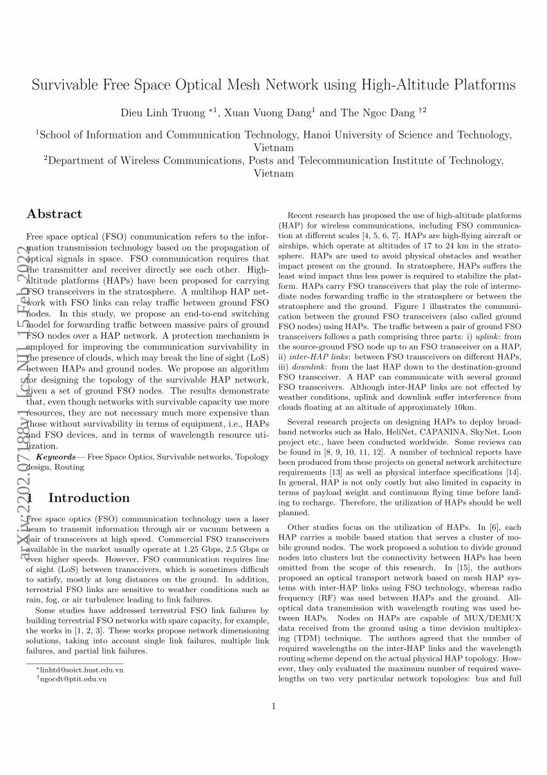
Recent research has proposed the use of high-altitude platforms(HAP) for wireless communications, including FSO communica-tion at different scales [4, 5, 6, 7]. HAPs are high-flying aircraft orairships, which operate at altitudes of 17 to 24 km in the strato-sphere. HAPs are used to avoid physical obstacles and weatherimpact present on the ground. In stratosphere, HAPs suffers theleast wind impact thus less power is required to stabilize the plat-form. HAPs carry FSO transceivers that play the role of interme-diate nodes forwarding traffic in the stratosphere or between thestratosphere and the ground. Figure 1 illustrates the communi-cation between the ground FSO transceivers (also called groundFSO nodes) using HAPs. The traffic between a pair of ground FSOtransceivers follows a path comprising three parts: i) uplink : fromthe source-ground FSO node up to an FSO transceiver on a HAP,ii) inter-HAP links: between FSO transceivers on different HAPs,iii) downlink : from the last HAP down to the destination-groundFSO transceiver. A HAP can communicate with several groundFSO transceivers. Although inter-HAP links are not effected byweather conditions, uplink and downlink suffer interference fromclouds floating at an altitude of approximately 10km.
Several research projects on designing HAPs to deploy broad-band networks such as Halo, HeliNet, CAPANINA, SkyNet, Loonproject etc., have been conducted worldwide. Some reviews canbe found in [8, 9, 10, 11, 12]. A number of technical reports havebeen produced from these projects on general network architecturerequirements [13] as well as physical interface specifications [14].In general, HAP is not only costly but also limited in capacity interms of payload weight and continuous flying time before land-ing to recharge. Therefore, the utilization of HAPs should be wellplanned.
Other studies focus on the utilization of HAPs. In [6], eachHAP carries a mobile based station that serves a cluster of mo-bile ground nodes. The work proposed a solution to divide groundnodes into clusters but the connectivity between HAPs has beenomitted from the scope of this research. In [15], the authorsproposed an optical transport network based on mesh HAP sys-tems with inter-HAP links using FSO technology, whereas radiofrequency (RF) was used between HAPs and the ground. All-optical data transmission with wavelength routing was used be-tween HAPs. Nodes on HAPs are capable of MUX/DEMUXdata received from the ground using a time devision multiplex-ing (TDM) technique. The authors agreed that the number ofrequired wavelengths on the inter-HAP links and the wavelengthrouting scheme depend on the actual physical HAP topology. How-ever, they only evaluated the maximum number of required wave-lengths on two very particular network topologies: bus and full
1
arX
iv:2
202.
0718
8v1
[cs
.NI]
15
Feb
2022
12
2
1
1
1
1
2
3
3
3
3
3
WDM switchIP router
IP router
WDM switch
12
2
p-HAP-2
1
3
3
p-HAP-1
toward HAP-2 of cluster-2toward HAP-1 of cluster-1
Serving HAP
Inter-HAP FSO transceiver
Ground FSO node
Serving FSO
31 2
inter-HAP linkinter-HAP link
Figure 1: Data communication in a FSO network using HAPs
mesh with five HAPs where each HAP only serves one ground sta-tion. The possibility that a HAP serves more than one groundstation has not been clearly discussed.
European studies on the availability of optical links betweenHAPs and ground in [16] show that single optical link availabil-ity varies from under 20% during winter in Northern Europe toover 70% during summer in Southern Europe. Research has fo-cused on improving the availability of single optical downlink toground stations by using a ground-station diversity scheme, i.e.,ground stations at geographically separate locations. Availabil-ity increases with the number of available stations. The schemerequires a HAP network to carry traffic toward available groundlinks. Four ground stations in Southern Europe can achieved 99%availability. Nevertheless, ground-station diversity is applicableonly if the location of the transmission destination is not impor-tant.
In [5], data from Earth observation satellites were relayed tosome HAPs at 20 km altitude through FSO links before sendingthem down to ground stations via microwave point-to-point links.Since there are no clouds at an altitude of 20 km, the availabilityof the FSO links is almost 100%. In cloud-free conditions, FSOlinks can also be used in place of microwave links for a higher datarate.
Research in [7] proposed multi-HAP networks for carrying databetween ground FSO nodes and optical slant links for transmittingdata up to and down from HAPs when primary connections failowing to air turbulence. This research focused only on analyzingthe bit error rate (BER) and the availability of a multihop FSOlink. The choice of HAP locations, slant links, connectivity be-tween HAPs and routing from ground nodes to ground nodes wereleft outside of the study.
Other studies either focused on analyzing the BER of multihopHAP-based FSO connections [17] or HAP network dimensioningwithout survivability against LoS loss [18].
In summary, to the best of our knowledge, there is no work onthe dimensioning of HAP-based FSO networks that are survivableagainst optical HAP-ground link failures. We address this prob-lem in this study. The network is composed of HAPs carryingFSO transceivers in the stratosphere for forwarding optical databetween ground FSO nodes, where all links including uplinks anddownlinks use FSO technology. Similar to [7] we use FSO slantlinks for survivability. We do not elect the RF technology for slantlinks because RF links offer much lower data rate than opticallinks leading to connection quality down-grading when failures oc-cur. Unlike previous studies, we focus on the dimensioning of the
HAP-ground network. There are two main contributions in thispaper: i) proposing an end-to-end data switching mechanism be-tween massive pairs of ground FSO nodes through a HAP networkwith a 1+1 protection mechanism against uplink and downlinkfailures, ii) a dimensioning solution for the survivable HAP-groundnetwork with the minimum cost of equipment including HAPs andFSO transceivers costs.
The remainder of this paper is organized as follows. Section 2presents the switching mechanism from end-to-end and the protec-tion mechanism against clouds. Section 3 describes the networkdimensioning problem. Section 4 presents the proposed dimen-sioning algorithm. Section 5 presents the simulation results anddiscussions. Finally, Section 6 concludes the paper.
2 Switching and Protection mecha-nisms
2.1 WDM communication between HAPand ground
Each HAP carries one down-facing FSO device to communicatewith a cluster of ground FSO transceivers. For the ground FSOtransceivers, the HAP is called the serving HAP and the FSOdevice on the HAP is called the serving FSO transceiver. Onthe same HAP, there may be other FSO transceivers for com-municating with other HAPs. These FSO transceivers are calledinter-HAP FSO transceivers. The serving FSO transceiver andinter-HAP FSO transceivers on the same HAP should be wiredtogether back-to-back using optical fibers (see Figure 1).
We divide the ground FSO transceivers into clusters, each hav-ing a serving HAP. Each ground FSO transceiver communicateswith its serving FSO bidirectionally by using two fixed wavelengthsfor the up and down directions. The wavelengths in the two di-rections are managed separately because each FSO transceiver hasa light source and a light receiver for sending and receiving dataindependently. The ground FSO devices of the same cluster shareaccess to the common serving FSO transceiver using wavelengthdevision multiplexing (WDM) technology. Figure 1 illustrates thismultiple-access method, where each color represents a wavelength.For simplification, we show only the wavelengths for the up ordown direction. Depending on wavelength density of the WDMtechnique to be used, 32, 64 or more ground FSO transceivers canbe served by a single FSO transceiver on HAP.
On inter-HAP links, WDM technique will also be used. BetweenHAPs data are forwarded on a wavelength-switching basis withoutwavelength conversion. Data sent from one HAP to the othermay travel through multiple HAPs using a continuous wavelength,the so-called lightpath. When the volume of traffic between apair of HAPs is larger than the capacity of a wavelength, multiplelightpaths may be necessary. These lightpaths do not need tofollow the same route.
2.2 Data switching on HAP
A ground FSO transceiver may have data to send to different re-mote ground FSO transceivers. This section explains how the dataare switched from end to end. We propose to employ one of twomodels: IP over WDM and SONET over WDM.
In IP over WDM model, the ground FSO nodes in the samecluster must be assigned IP addresses of the same network. An IProuter is installed on each HAP to groom traffic received from the
2
serving FSO transceiver based on destination clusters. Then, thegroomed traffic follows different lightpaths between HAPs to reachdestination clusters. The end-to-end data are switched as follows:
• At a source ground FSO node, data are encapsulated in IPpackets, of which the destination IP addresses are those ofthe destination ground FSO nodes.
• The packets follow an uplink and arrive at the serving FSO ofthe source. Here, the IP packets pass through an IP routerthat directs the packets to different ports dedicated to dif-ferent destination cluster networks. If the amount of dataaddressed to a cluster network is larger than the capacity ofa wavelength then multiple ports should be used for that clus-ter.The flow of IP packets going out from each router port isregenerated in optical domain using a wavelength and thenforwarded to a WDM switch to take a lightpath to get to theserving HAP of the destination cluster.
• At the serving HAP of the destination cluster, IP packetsinside each lightpath are DEMUX by the IP router of theHAP according to their destination IP addresses. IP pack-ets heading to the same destination ground FSO node areregenerated in optical domain, using the wavelength assignedto the destination ground FSO node, and transmitted to theground.
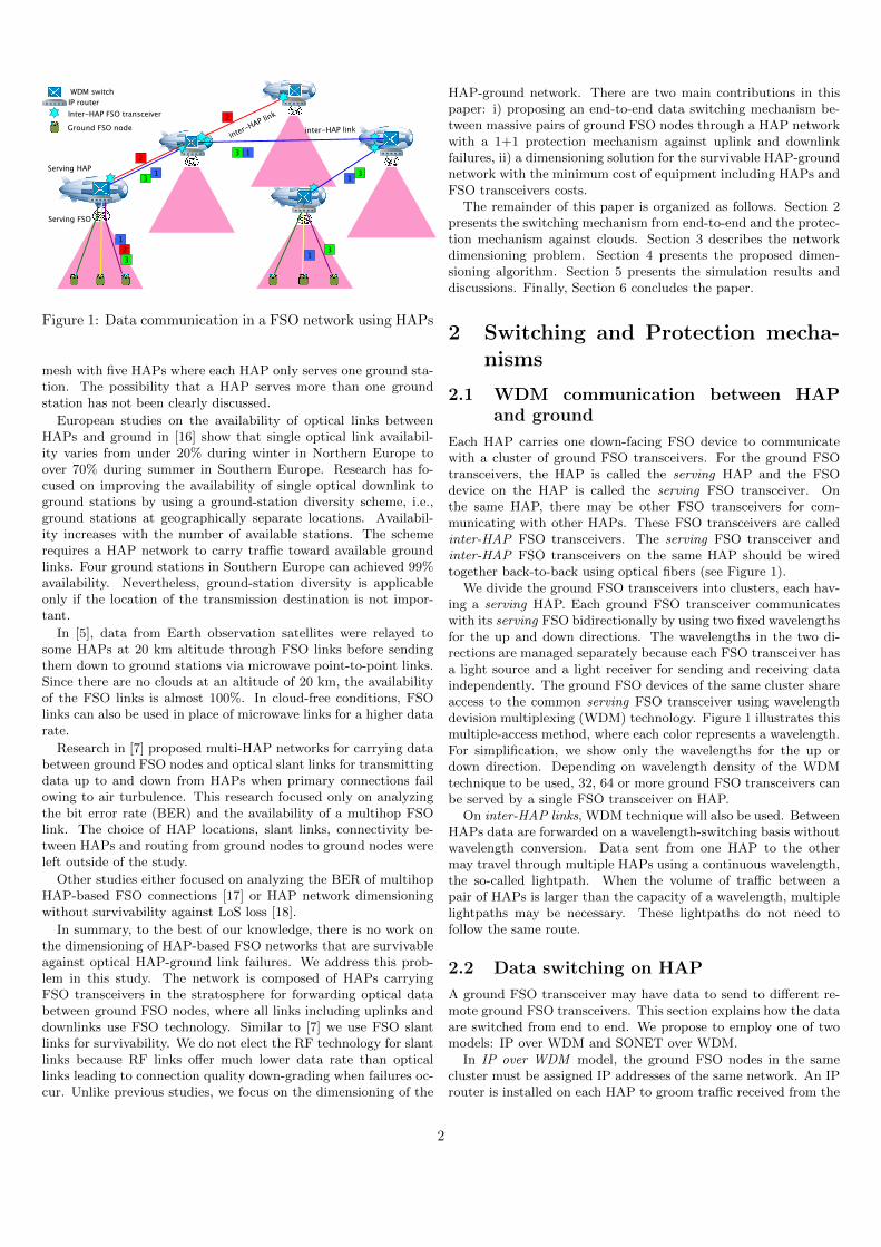
In this switching mechanism, the set of lightpaths betweenHAPs should be pre-configured beforehand. These lightpaths canbe considered as physical links between IP routers. Figure 2 il-lustrates data switching on a HAP. Port p-HAP-1 is dedicatedto receiving traffic for HAP-1 to get to network cluster-1. Portp-HAP-2 receives traffic for HAP-2 to get to network cluster-2.Table 1 shows the IP routing table of the router in Figure 2.
Network InterfaceNetwork address of cluster-1 p-HAP-1Network address of cluster-2 p-HAP-2. . . . . .
Table 1: Routing table of the IP router in Figure 2
In SONET over WDM model, SONET switches replace IProuters. While IP routers forward data by packet switching basis,SONET switches work on TDM circuit switching basis. Therefore,a circuit should be established for each pair of ground FSO nodesby taking a fixed time slot inside the lightpath between the asso-ciated source and destination serving HAPs. The data rate of thetime slot corresponds to the volume of requested traffic betweenthe two ground FSOs.
Once one of the above models is employed, the remaining ques-tion is setting up lightpaths between HAPs and configuring the IProuters/SONET switches for grooming traffic to lightpaths. In Sec-tion 4, we propose algorithms for building the HAP topology andthe lightpaths between HAPs, i.e., their paths and wavelengths.Subsequently, IP routers/SONET switches can be easily config-ured.
2.3 Protection model
On cloudy days, clouds may cut the LoS between a ground FSOnode and its serving FSO device. Clouds generally float at analtitude of 10 km. To maintain continuous communication in the
Figure 2: Data switching on HAP.
network, we propose the following protection mechanism againstclouds.
When the LoS between ground FSO nodes and their servingFSO are cut, these ground nodes should forward all their traf-fic to a nearby alternative HAP, for which the LoS is still clear.Let primary HAP be the serving HAP where data travel in caseof no failure whereas the alternative HAP is backup HAP. Thebackup HAP, after receiving data from a ground FSO node on awavelength, will simply forward that wavelength to the primaryHAP without any processing. At the primary HAP, traffic is han-dled exactly as it is received directly from the ground, i.e. passingthrough the IP router and continuing the original lightpaths to thedestinations. To receive the backup traffic from the ground, eachbackup HAP should have a dedicated FSO device that looks at itsbackup zone. This FSO device is called backup-serving FSO.
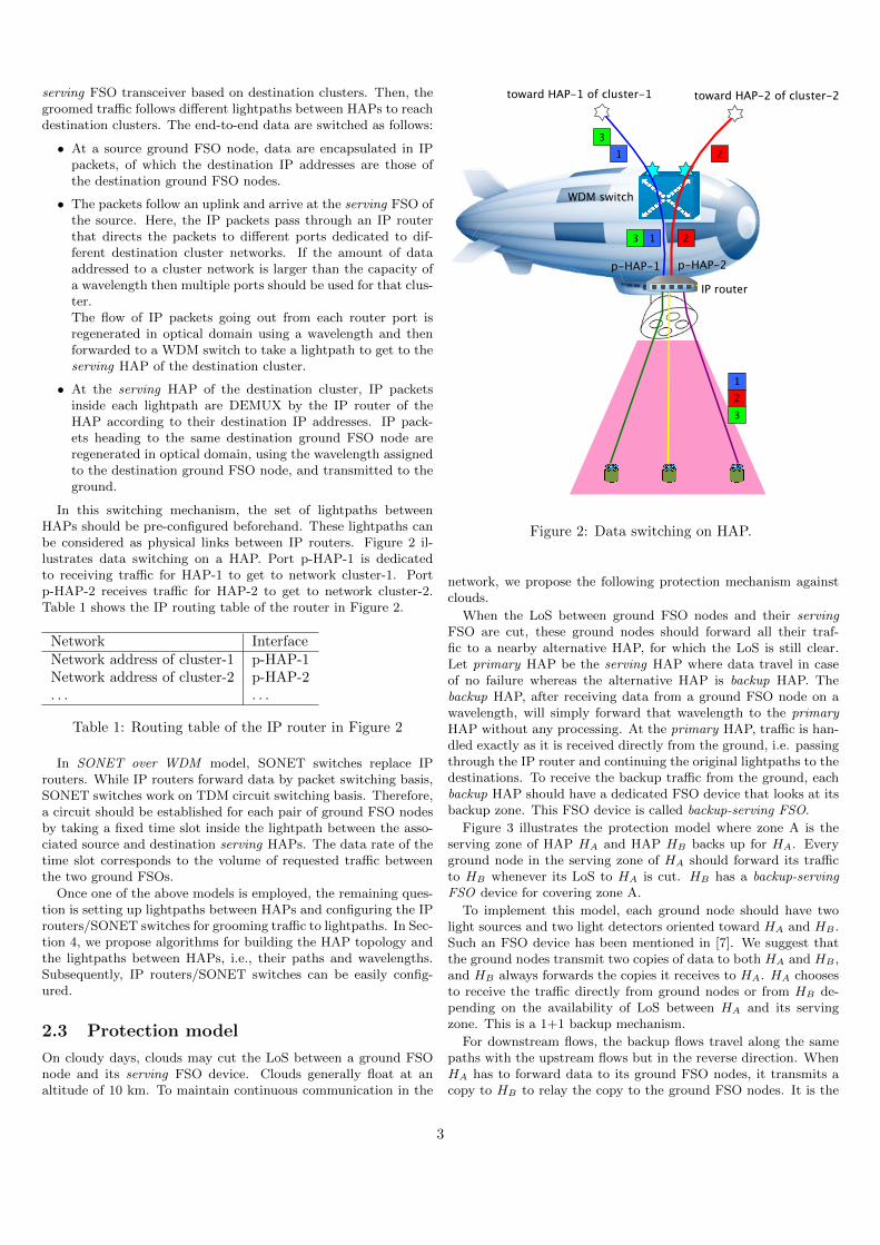
Figure 3 illustrates the protection model where zone A is theserving zone of HAP HA and HAP HB backs up for HA. Everyground node in the serving zone of HA should forward its trafficto HB whenever its LoS to HA is cut. HB has a backup-servingFSO device for covering zone A.
To implement this model, each ground node should have twolight sources and two light detectors oriented toward HA and HB .Such an FSO device has been mentioned in [7]. We suggest thatthe ground nodes transmit two copies of data to both HA and HB ,and HB always forwards the copies it receives to HA. HA choosesto receive the traffic directly from ground nodes or from HB de-pending on the availability of LoS between HA and its servingzone. This is a 1+1 backup mechanism.
For downstream flows, the backup flows travel along the samepaths with the upstream flows but in the reverse direction. WhenHA has to forward data to its ground FSO nodes, it transmits acopy to HB to relay the copy to the ground FSO nodes. It is the
3
ground node that decides whether to receive from HA or HB .A backup HAP HB must be sufficiently far from its primary
HAP HA to avoid that a cloud cuts both links to primary HAP andbackup HAP. Based on the altitude of HAPs and clouds, we deducethat the minimum distance between HA and HB should be twicethe maximum size of clouds. However, a backup HAP should notbe too far from its backup ground FSOs because greater distancecauses greater attenuation and air turbulence impact leading tohigh BER. Therefore, the distance d(HA, HB) between HA andHB is restricted by:
2× dc < d(HA, HB) < LHH (1)
where dc is the maximum cloud size, LHH is the maximum lengthof inter-HAP links with BER under the requirement threshold ofthe current Forward Error Correction techniques.
It is worth noting that if HB backs up HA, then topologically,HA could also backup HB .
Although the links from a ground node to its primary HAP andbackup HAP are not influenced simultaneously by the same cloud,they can still be interrupted by two independent clouds. Let theprobability that a link between a ground node and a HAP is cutby clouds be pcut, then the probability that both links from aground node to its primary HAP and backup HAP are cut by twoindependent clouds is p2cut. Consequently, the probability that oneof the two links is available for transmission is 1− p2cut.
The following two cases illustrate the availability offered by theproposed protection mechanism. In the Southern of Europe, theavailability of a single link varies between 50% – 85% over a year[16]. Therefore, the proposed protection mechanism allows to in-crease the joint availability of the links to primary HAP and backupHAP to 75% – 97,75%, which is relatively good. However, in theNorthern of Europe, the mean availability of a single link is lowerthan 40% then joint availability of the two links is still under 64%.More than one slant link may need be considered for improvingthe joint availability with trade off in cost of backup HAPs andbackup FSO transceivers. However, in this research, we focus onsingle backup slant link only.
3 Survivable ground-HAP networkdimensioning problem statement
In this section, we propose a network dimensioning solution thatidentifies the topology of the HAP network, as well as the rout-ing between ground FSO nodes over that network. The dimen-sioning solution aims to minimize the investment cost in termsof HAPs and FSO devices while satisfying the constraints for alltraffic demands to be backed up against clouds. In order to modelthe impacts of air turbulence, we use Gamma-Gamma distribu-tion model proposed in [17] for both ground-HAP and inter-HAPchannels. The impacts are represented as BERs of ground-HAPand inter-HAP links. Then, while dimensioning the ground-HAPnetwork, we requires that all lightpaths between HAPs must haveend-to-end BER under a threshold δ such that bit errors could becorrected by current FEC techniques.
This dimensioning problem is stated as follows.Given:
• A set of ground FSO devices.
• M: the matrix of traffic demands between ground FSO de-vices.
• Some other parameters as listed in Table 2.
Figure 3: Protection model: when LoS between HA and itsserving zone is cut, every ground node in serving zone of HA
should forward its traffic to HB . Backup HAP should be at adistance of at least 2 times the size of cloud from its primaryHAP.
Param. Description Sim. valueN Set of ground FSO transceivers 100-4000 nodesD Ground coverage diameter
of an FSO transceiver on HAP 15 kmW Number of wavelengths in WDM
technique 128rmax Data rate of a wavelength 1 Gbpsdc Maximum cloud size 10 kmC Payload capacity of a HAP
in terms of FSO devices 10 devicesLHH Maximal distance between HAPs 60 kmδ BER threshold 10−3
Table 2: Parameters of the dimensioning problem and theirsimulation values.
Output: A survivable topology using the proposed protectionmodel that satisfies:
• All traffic demands are routed, i.e, there exist a serving HAPfor each ground FSO node and an inter-HAP lightpath forcarrying each demand.
• All traffic demands are backed up.
• From HAPs to HAPs, data are routed over continuous light-paths with end-to-end BER under a threshold δ.
• The total investment cost is minimized
min(nHAP ∗ cHAP + nFSO ∗ cFSO) (2)
where nHAP and nFSO are the number of HAPs and the totalnumber of serving FSO installed on HAPs, respectively. cHAP
and cFSO are the investment costs for a HAP and an FSO onHAP, respectively.
In this research, we assume that the apertures of serving FSOsare identical, thus their coverages on the ground are fixed by D.
4
4 Proposed dimensioning solution
It is difficult to find an optimal HAP topology with the mini-mum total cost of HAPs and FSO transceivers in a single step.Therefore, we divide the design problem into three steps: i) mini-mum clustering : identifying the minimum set of HAPs for servingall ground FSO nodes, ii) backup matching : identifying a backupHAPfor each primary HAP, iii) topology design: linking HAPstogether with the minimum number of FSO links in such a waythat both the traffic demands of matrix M and their correspondingbackup traffic are accommodated.
4.1 Minimum clustering
To identify a minimum set of HAPs for serving all ground nodes,the ground nodes are organized into clusters, each of which is as-signed a serving HAP. There are several constraints to be consid-ered:
• Limited coverage of FSO transceivers on HAPs: groundnodes in a cluster should be inside the coverage diameter Dof its serving FSO. Larger D allows a serving FSO commu-nicating with more ground nodes leading to fewer HAPs, butrequires larger serving FSO apertures thus higher transmitpower to maintain the link quality. As a result, HAPs need torecharge more often. The optimal diameter D should be con-sidered in taking count the trade off between HAP rechargingcost and HAP cost. We reserve this optimization problem fora future work as fix D as a parameter in this research.
• Limited number of wavelengths: The number of ground FSOnodes per cluster is limited by W, the number of wavelengthsavailable according to the WDM technique.
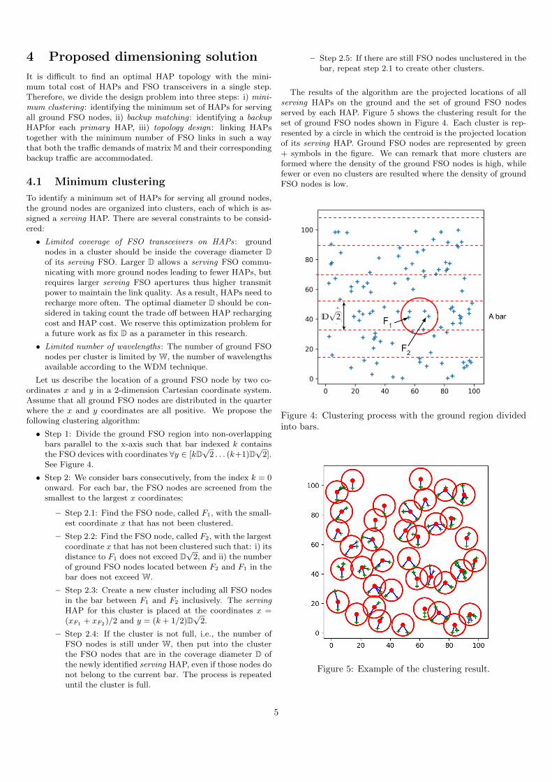
Let us describe the location of a ground FSO node by two co-ordinates x and y in a 2-dimension Cartesian coordinate system.Assume that all ground FSO nodes are distributed in the quarterwhere the x and y coordinates are all positive. We propose thefollowing clustering algorithm:
• Step 1: Divide the ground FSO region into non-overlappingbars parallel to the x-axis such that bar indexed k containsthe FSO devices with coordinates ∀y ∈ [kD
√2 . . . (k+1)D
√2].
See Figure 4.
• Step 2: We consider bars consecutively, from the index k = 0onward. For each bar, the FSO nodes are screened from thesmallest to the largest x coordinates:
– Step 2.1: Find the FSO node, called F1, with the small-est coordinate x that has not been clustered.
– Step 2.2: Find the FSO node, called F2, with the largestcoordinate x that has not been clustered such that: i) itsdistance to F1 does not exceed D
√2, and ii) the number
of ground FSO nodes located between F2 and F1 in thebar does not exceed W.
– Step 2.3: Create a new cluster including all FSO nodesin the bar between F1 and F2 inclusively. The servingHAP for this cluster is placed at the coordinates x =(xF1 + xF2)/2 and y = (k + 1/2)D
√2.
– Step 2.4: If the cluster is not full, i.e., the number ofFSO nodes is still under W, then put into the clusterthe FSO nodes that are in the coverage diameter D ofthe newly identified serving HAP, even if those nodes donot belong to the current bar. The process is repeateduntil the cluster is full.
– Step 2.5: If there are still FSO nodes unclustered in thebar, repeat step 2.1 to create other clusters.
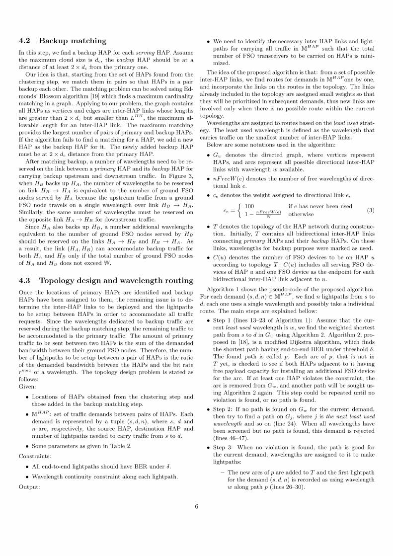
The results of the algorithm are the projected locations of allserving HAPs on the ground and the set of ground FSO nodesserved by each HAP. Figure 5 shows the clustering result for theset of ground FSO nodes shown in Figure 4. Each cluster is rep-resented by a circle in which the centroid is the projected locationof its serving HAP. Ground FSO nodes are represented by green+ symbols in the figure. We can remark that more clusters areformed where the density of the ground FSO nodes is high, whilefewer or even no clusters are resulted where the density of groundFSO nodes is low.
Figure 4: Clustering process with the ground region dividedinto bars.
Figure 5: Example of the clustering result.
5
4.2 Backup matching
In this step, we find a backup HAP for each serving HAP. Assumethe maximum cloud size is dc, the backup HAP should be at adistance of at least 2× dc from the primary one.
Our idea is that, starting from the set of HAPs found from theclustering step, we match them in pairs so that HAPs in a pairbackup each other. The matching problem can be solved using Ed-monds’ Blossom algorithm [19] which finds a maximum cardinalitymatching in a graph. Applying to our problem, the graph containsall HAPs as vertices and edges are inter-HAP links whose lengthsare greater than 2 × dc but smaller than LHH , the maximum al-lowable length for an inter-HAP link. The maximum matchingprovides the largest number of pairs of primary and backup HAPs.If the algorithm fails to find a matching for a HAP, we add a newHAP as the backup HAP for it. The newly added backup HAPmust be at 2× dc distance from the primary HAP.
After matching backup, a number of wavelengths need to be re-served on the link between a primary HAP and its backup HAP forcarrying backup upstream and downstream traffic. In Figure 3,when HB backs up HA, the number of wavelengths to be reservedon link HB → HA is equivalent to the number of ground FSOnodes served by HA because the upstream traffic from a groundFSO node travels on a single wavelength over link HB → HA.Similarly, the same number of wavelengths must be reserved onthe opposite link HA → HB for downstream traffic.
Since HA also backs up HB , a number additional wavelengthsequivalent to the number of ground FSO nodes served by HB
should be reserved on the links HA → HB and HB → HA. Asa result, the link (HA, HB) can accommodate backup traffic forboth HA and HB only if the total number of ground FSO nodesof HA and HB does not exceed W.
4.3 Topology design and wavelength routing
Once the locations of primary HAPs are identified and backupHAPs have been assigned to them, the remaining issue is to de-termine the inter-HAP links to be deployed and the lightpathsto be setup between HAPs in order to accommodate all trafficrequests. Since the wavelengths dedicated to backup traffic arereserved during the backup matching step, the remaining traffic tobe accommodated is the primary traffic. The amount of primarytraffic to be sent between two HAPs is the sum of the demandedbandwidth between their ground FSO nodes. Therefore, the num-ber of lightpaths to be setup between a pair of HAPs is the ratioof the demanded bandwidth between the HAPs and the bit ratermax of a wavelength. The topology design problem is stated asfollows:Given:
• Locations of HAPs obtained from the clustering step andthose added in the backup matching step.
• MHAP : set of traffic demands between pairs of HAPs. Eachdemand is represented by a tuple (s, d, n), where s, d andn are, respectively, the source HAP, destination HAP andnumber of lightpaths needed to carry traffic from s to d.
• Some parameters as given in Table 2.
Constraints:
• All end-to-end lightpaths should have BER under δ.
• Wavelength continuity constraint along each lightpath.
Output:
• We need to identify the necessary inter-HAP links and light-paths for carrying all traffic in MHAP such that the totalnumber of FSO transceivers to be carried on HAPs is mini-mized.
The idea of the proposed algorithm is that: from a set of possibleinter-HAP links, we find routes for demands in MHAP one by one,and incorporate the links on the routes in the topology. The linksalready included in the topology are assigned small weights so thatthey will be prioritized in subsequent demands, thus new links areinvolved only when there is no possible route within the currenttopology.
Wavelengths are assigned to routes based on the least used strat-egy. The least used wavelength is defined as the wavelength thatcarries traffic on the smallest number of inter-HAP links.
Below are some notations used in the algorithm:
• Gw denotes the directed graph, where vertices representHAPs, and arcs represent all possible directional inter-HAPlinks with wavelength w available.
• nFreeW (e) denotes the number of free wavelengths of direc-tional link e.
• ce denotes the weight assigned to directional link e,
ce =
{100 if e has never been used
1− nFreeW (e)W otherwise
(3)
• T denotes the topology of the HAP network during construc-tion. Initially, T contains all bidirectional inter-HAP linksconnecting primary HAPs and their backup HAPs. On theselinks, wavelengths for backup purpose were marked as used.
• C(u) denotes the number of FSO devices to be on HAP uaccording to topology T . C(u) includes all serving FSO de-vices of HAP u and one FSO device as the endpoint for eachbidirectional inter-HAP link adjacent to u.
Algorithm 1 shows the pseudo-code of the proposed algorithm.For each demand (s, d, n) ∈ MHAP , we find n lightpaths from s tod, each one uses a single wavelength and possibly take a individualroute. The main steps are explained bellow:
• Step 1 (lines 13–23 of Algorithm 1): Assume that the cur-rent least used wavelength is w, we find the weighted shortestpath from s to d in Gw using Algorithm 2. Algorithm 2, pro-posed in [18], is a modified Dijkstra algorithm, which findsthe shortest path having end-to-end BER under threshold δ.The found path is called p. Each arc of p, that is not inT yet, is checked to see if both HAPs adjacent to it havingfree payload capacity for installing an additional FSO devicefor the arc. If at least one HAP violates the constraint, thearc is removed from Gw, and another path will be sought us-ing Algorithm 2 again. This step could be repeated until noviolation is found, or no path is found.
• Step 2: If no path is found on Gw for the current demand,then try to find a path on Gj , where j is the next least usedwavelength and so on (line 24). When all wavelengths havebeen screened but no path is found, this demand is rejected(lines 46–47).
• Step 3: When no violation is found, the path is good forthe current demand, wavelengths are assigned to it to makelightpaths:
– The new arcs of p are added to T and the first lightpathfor the demand (s, d, n) is recorded as using wavelengthw along path p (lines 26–30).
6
Algorithm 1 Topology design and wavelength routing algo-rithm1: function Main2: for all r(s, d, n) ∈ MHAP do3: Routing-one-demand(s,d,n)4: end for5: end function6: function Routing-one-demand(s, d,n)7: T ← ∅8: LP-set ← NULL . set of lightpaths to be found9: nb-trial-w ← 0 . number of trial wavelengths
10: repeat11: w ← the least used wavelength12: nb-trial-w ++13: repeat14: p← SP-Constraint(Gw, s, d)15: valid-path ← true16: for all (u, v) ∈ p and (u, v) /∈ T do17: if C(u) ≥ C or C(v) ≥ C then18: valid-path ← false19: Gw ← Gw \ (u, v)20: break;21: end if22: end for23: until p not found or valid-path = true24: if p not found then next . try the next
wavelength25: end if26: if valid-path then . Assign wavelengths27: for all (u, v) ∈ p do28: T ← T ∪ (u, v) . add new arcs to T29: end for30: LP-set ∪ path p wavelength w.31: remain-LP ← n− 132: while remain-LP> 0 and nb-trial-w<W do33: wk ← the next least used wavelength34: if wk is available along p then35: LP-set ∪ path p wavelength wk
36: remain-LP ← remain-LP -137: end if38: end while39: if remain-LP > 0 then40: MHAP← MHAP∪ (s,d, remain-LP)41: else42: break43: end if44: end if45: until nb-trial-w= W46: if remain-LP> 0 then47: return false . Reject demand48: end if49: return LP-set50: end function
– If the number of requested lightpaths n > 1, the remain-ing number of lightpaths to be created is remain−LP =n−1. We try to make the remaining lightpaths by usingalways path p but other wavelengths starting from theleast used wavelength available first (lines 31–38).
– If there are still not enough available wavelengths toroute the entire demand over p, the un-routed light-paths should follow a different path. We consider theremaining part of the current demand as a new one withparameters (s, d, remain−LP ) and add it to MHAP forlater handling (lines 39–40).
At the end of the algorithm, we obtain the topology T forthe HAP network and all lightpaths for the accepted demandsin MHAP .
Algorithm 2 Shortest path with BER constraint
1: function SP-Constraint(G, s, d)2: Q ← vertex set of G3: for all vertex v ∈ Q do4: dist[v] ← INFINITY5: prev[v] ← UNDEFINED6: end for7: dist[s] ← 08: while Q 6= ∅ do9: u ← vertex in Q with min dist[u]
10: for all neighbor v of u do11: alt ← dist[u] + length(u, v)12: if alt < dist[v] and BER-e2e(s,u,v) then13: dist[v] ← alt14: prev[v] ← u15: end if16: end for17: end whilereturn dist[d], prev[d]18: end function19: function BER-e2e(s,u,v)20: prod← (1− BER(u,v))21: for ` ∈ current path from s to v do22: prod← prod× (1− BER`)23: end for24: if prod > 1− δ then25: return true26: else27: return false28: end if29: end function
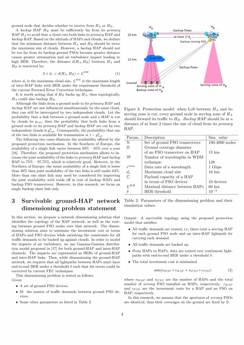
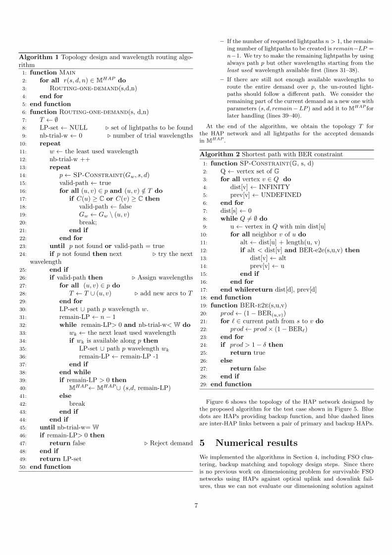
Figure 6 shows the topology of the HAP network designed bythe proposed algorithm for the test case shown in Figure 5. Bluedots are HAPs providing backup function, and blue dashed linesare inter-HAP links between a pair of primary and backup HAPs.
5 Numerical results
We implemented the algorithms in Section 4, including FSO clus-tering, backup matching and topology design steps. Since thereis no previous work on dimensioning problem for survivable FSOnetworks using HAPs against optical uplink and downlink fail-ures, thus we can not evaluate our dimensioning solution against
7
0
20
40
60
80
100
0 20 40 60 80 100
y-ax
is
x-axis
Figure 6: HAP network designed by the proposed algorithms.Blue dots are HAPs acting as backup HAPs, blue dashed linesare inter-HAP links between a pair of primary and backupHAPs.
any previous one. We will thus concentrate on analyzing the im-pact of protection on topologies by comparing the topologies withprotection against the topologies without protection. Topologieswithout protection were obtained by running only the clusteringand topology design steps.
The comparisons were made on different test cases. The groundFSO node locations were generated randomly on a square surfaceof 100km × 100km, which is the size of a metropolitan area. Thetotal number of ground FSO nodes was generated randomly inthe range of 100 to 4000 nodes. The following parameters were setbased on the technological and theoretical review in [10] on opticalcommunications for HAP. The transmission rate per wavelengthrmax was set to 1 Gbps. The aperture of serving FSO devices wasset approximately 40◦; thus, the ground coverage diameter of aserving FSO was D ∼ 15 km. Traffic requirement was generatedrandomly between ground FSO nodes, but the total incoming oroutgoing traffic of a ground FSO node does not exceed 1 Gbps,which is the capacity of a single wavelength.
The BER of an inter-HAP link was calculated according to airturbulence model using Gamma-Gamma distribution in [17] withmoderate turbulence condition. BER threshold for an end-to-endlightpath as well as for a single inter-HAP link was set as δ = 10−3,so that the errors could be recover by current FEC techniques.According to the BER computation model, inter-HAP link longerthan 60 km having BER greater than δ = 10−3, therefore, LHH
was set to 60 km. The wavelength density of the WDM techniquewas W = 128 wavelengths. The recapitulation of the parametervalues is shown in Table 2.
In all test cases, we observed no demand rejection either withor without protection. We will discuss the impact of protection
on the number of HAPs and the number of FSO devices on HAPsto be invested. We also analyze the resource occupation with andwithout protection.
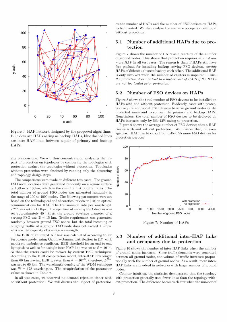
5.1 Number of additional HAPs due to pro-tection
Figure 7 shows the number of HAPs as a function of the numberof ground nodes. This shows that protection requires at most onemore HAP in all test cases. The reason is that: if HAPs still havefree payload for installing backup serving FSO devices, servingHAPs of different clusters backup each other. The additional HAPis only involved when the number of clusters is impaired. Thus,the protection does not lead to a higher cost of HAPs if the HAPsare not too loaded prior protection.
5.2 Number of FSO devices on HAPs
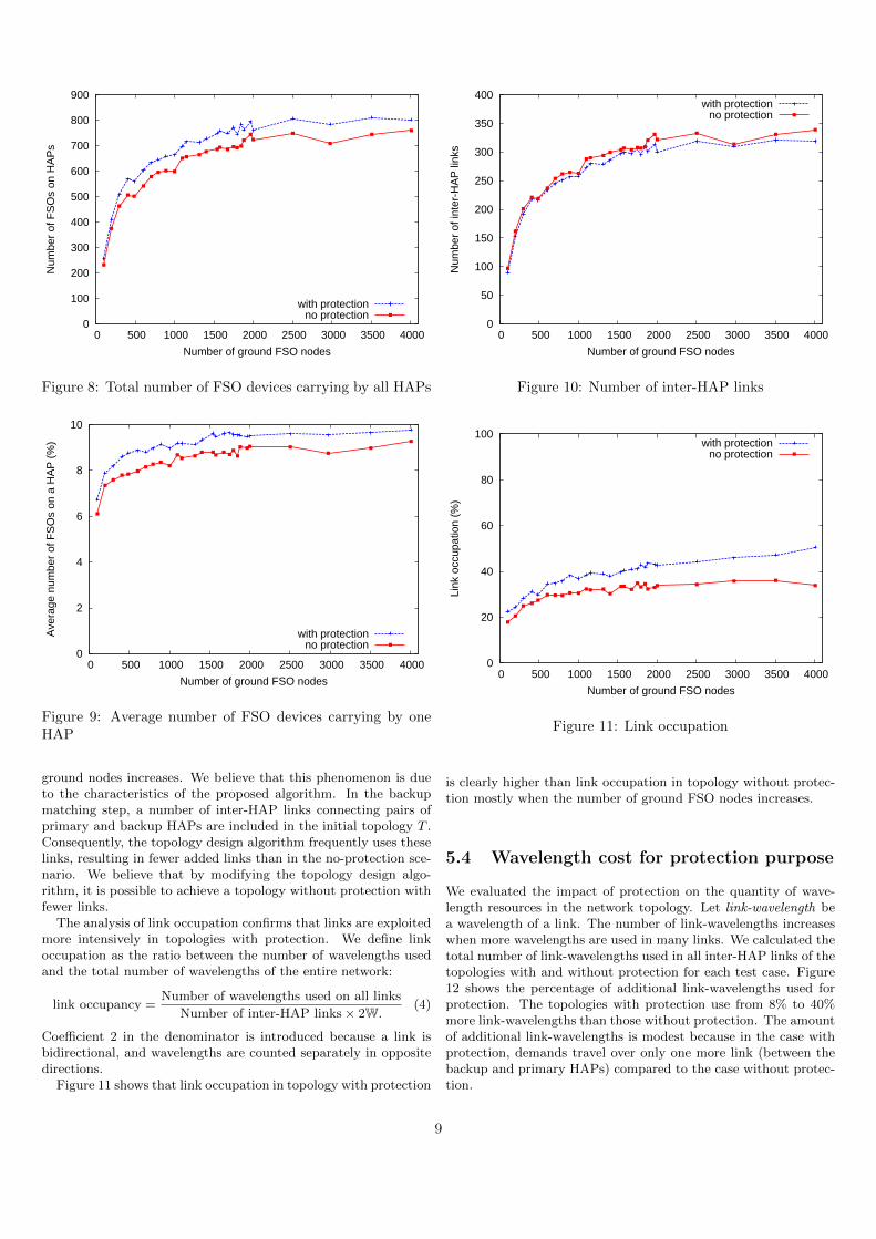
Figure 8 shows the total number of FSO devices to be installed onHAPs with and without protection. Evidently, cases with protec-tion require additional FSO devices to serve ground nodes in theprotected zones and to connect the primary and backup HAPs.Nonetheless, the total number of FSO devices to be deployed onHAPs increases only by 5%–12% owing to protection.
Figure 9 shows the average number of FSO devices that a HAPcarries with and without protection. We observe that, on aver-age, each HAP has to carry from 0.45–0.95 more FSO devices forprotection purpose.
0
20
40
60
80
100
0 500 1000 1500 2000 2500 3000 3500 4000
Num
ber
of H
AP
s
Number of ground FSO nodes
with protectionno protection
Figure 7: Number of HAPs
5.3 Number of additional inter-HAP linksand occupancy due to protection
Figure 10 shows the number of inter-HAP links when the numberof ground nodes increases. Since traffic demands were generatedbetween all ground nodes, the volume of traffic increases propor-tionally with the number of ground nodes. As a result, more inter-HAP links are involved in networks with larger number of groundnodes.
Counter intuition, the statistics demonstrate that the topologywith protection generally uses fewer links than the topology with-out protection. The difference becomes clearer when the number of
8
0
100
200
300
400
500
600
700
800
900
0 500 1000 1500 2000 2500 3000 3500 4000
Num
ber
of F
SO
s on
HA
Ps
Number of ground FSO nodes
with protectionno protection
Figure 8: Total number of FSO devices carrying by all HAPs
0
2
4
6
8
10
0 500 1000 1500 2000 2500 3000 3500 4000
Ave
rage
num
ber
of F
SO
s on
a H
AP
(%
)
Number of ground FSO nodes
with protectionno protection
Figure 9: Average number of FSO devices carrying by oneHAP
ground nodes increases. We believe that this phenomenon is dueto the characteristics of the proposed algorithm. In the backupmatching step, a number of inter-HAP links connecting pairs ofprimary and backup HAPs are included in the initial topology T .Consequently, the topology design algorithm frequently uses theselinks, resulting in fewer added links than in the no-protection sce-nario. We believe that by modifying the topology design algo-rithm, it is possible to achieve a topology without protection withfewer links.
The analysis of link occupation confirms that links are exploitedmore intensively in topologies with protection. We define linkoccupation as the ratio between the number of wavelengths usedand the total number of wavelengths of the entire network:
link occupancy =Number of wavelengths used on all links
Number of inter-HAP links× 2W.(4)
Coefficient 2 in the denominator is introduced because a link isbidirectional, and wavelengths are counted separately in oppositedirections.
Figure 11 shows that link occupation in topology with protection
0
50
100
150
200
250
300
350
400
0 500 1000 1500 2000 2500 3000 3500 4000
Num
ber
of in
ter-
HA
P li
nks
Number of ground FSO nodes
with protectionno protection
Figure 10: Number of inter-HAP links
0
20
40
60
80
100
0 500 1000 1500 2000 2500 3000 3500 4000
Link
occ
upat
ion
(%)
Number of ground FSO nodes
with protectionno protection
Figure 11: Link occupation
is clearly higher than link occupation in topology without protec-tion mostly when the number of ground FSO nodes increases.
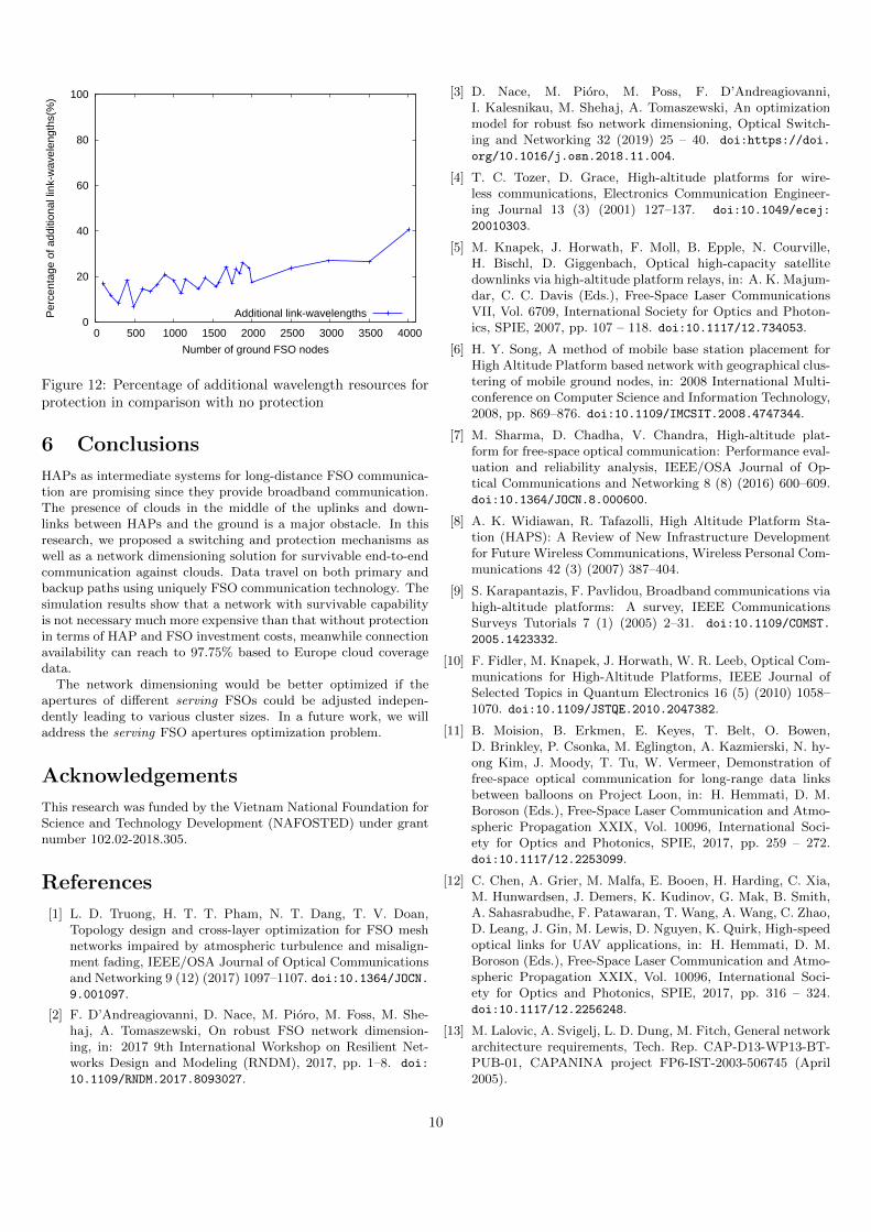
5.4 Wavelength cost for protection purpose
We evaluated the impact of protection on the quantity of wave-length resources in the network topology. Let link-wavelength bea wavelength of a link. The number of link-wavelengths increaseswhen more wavelengths are used in many links. We calculated thetotal number of link-wavelengths used in all inter-HAP links of thetopologies with and without protection for each test case. Figure12 shows the percentage of additional link-wavelengths used forprotection. The topologies with protection use from 8% to 40%more link-wavelengths than those without protection. The amountof additional link-wavelengths is modest because in the case withprotection, demands travel over only one more link (between thebackup and primary HAPs) compared to the case without protec-tion.
9
0
20
40
60
80
100
0 500 1000 1500 2000 2500 3000 3500 4000
Per
cent
age
of a
dditi
onal
link
-wav
elen
gths
(%)
Number of ground FSO nodes
Additional link-wavelengths
Figure 12: Percentage of additional wavelength resources forprotection in comparison with no protection
6 Conclusions
HAPs as intermediate systems for long-distance FSO communica-tion are promising since they provide broadband communication.The presence of clouds in the middle of the uplinks and down-links between HAPs and the ground is a major obstacle. In thisresearch, we proposed a switching and protection mechanisms aswell as a network dimensioning solution for survivable end-to-endcommunication against clouds. Data travel on both primary andbackup paths using uniquely FSO communication technology. Thesimulation results show that a network with survivable capabilityis not necessary much more expensive than that without protectionin terms of HAP and FSO investment costs, meanwhile connectionavailability can reach to 97.75% based to Europe cloud coveragedata.
The network dimensioning would be better optimized if theapertures of different serving FSOs could be adjusted indepen-dently leading to various cluster sizes. In a future work, we willaddress the serving FSO apertures optimization problem.
Acknowledgements
This research was funded by the Vietnam National Foundation forScience and Technology Development (NAFOSTED) under grantnumber 102.02-2018.305.
References
[1] L. D. Truong, H. T. T. Pham, N. T. Dang, T. V. Doan,Topology design and cross-layer optimization for FSO meshnetworks impaired by atmospheric turbulence and misalign-ment fading, IEEE/OSA Journal of Optical Communicationsand Networking 9 (12) (2017) 1097–1107. doi:10.1364/JOCN.9.001097.
[2] F. D’Andreagiovanni, D. Nace, M. Pioro, M. Foss, M. She-haj, A. Tomaszewski, On robust FSO network dimension-ing, in: 2017 9th International Workshop on Resilient Net-works Design and Modeling (RNDM), 2017, pp. 1–8. doi:
10.1109/RNDM.2017.8093027.
[3] D. Nace, M. Pioro, M. Poss, F. D’Andreagiovanni,I. Kalesnikau, M. Shehaj, A. Tomaszewski, An optimizationmodel for robust fso network dimensioning, Optical Switch-ing and Networking 32 (2019) 25 – 40. doi:https://doi.
org/10.1016/j.osn.2018.11.004.
[4] T. C. Tozer, D. Grace, High-altitude platforms for wire-less communications, Electronics Communication Engineer-ing Journal 13 (3) (2001) 127–137. doi:10.1049/ecej:
20010303.
[5] M. Knapek, J. Horwath, F. Moll, B. Epple, N. Courville,H. Bischl, D. Giggenbach, Optical high-capacity satellitedownlinks via high-altitude platform relays, in: A. K. Majum-dar, C. C. Davis (Eds.), Free-Space Laser CommunicationsVII, Vol. 6709, International Society for Optics and Photon-ics, SPIE, 2007, pp. 107 – 118. doi:10.1117/12.734053.
[6] H. Y. Song, A method of mobile base station placement forHigh Altitude Platform based network with geographical clus-tering of mobile ground nodes, in: 2008 International Multi-conference on Computer Science and Information Technology,2008, pp. 869–876. doi:10.1109/IMCSIT.2008.4747344.
[7] M. Sharma, D. Chadha, V. Chandra, High-altitude plat-form for free-space optical communication: Performance eval-uation and reliability analysis, IEEE/OSA Journal of Op-tical Communications and Networking 8 (8) (2016) 600–609.doi:10.1364/JOCN.8.000600.
[8] A. K. Widiawan, R. Tafazolli, High Altitude Platform Sta-tion (HAPS): A Review of New Infrastructure Developmentfor Future Wireless Communications, Wireless Personal Com-munications 42 (3) (2007) 387–404.
[9] S. Karapantazis, F. Pavlidou, Broadband communications viahigh-altitude platforms: A survey, IEEE CommunicationsSurveys Tutorials 7 (1) (2005) 2–31. doi:10.1109/COMST.
2005.1423332.
[10] F. Fidler, M. Knapek, J. Horwath, W. R. Leeb, Optical Com-munications for High-Altitude Platforms, IEEE Journal ofSelected Topics in Quantum Electronics 16 (5) (2010) 1058–1070. doi:10.1109/JSTQE.2010.2047382.
[11] B. Moision, B. Erkmen, E. Keyes, T. Belt, O. Bowen,D. Brinkley, P. Csonka, M. Eglington, A. Kazmierski, N. hy-ong Kim, J. Moody, T. Tu, W. Vermeer, Demonstration offree-space optical communication for long-range data linksbetween balloons on Project Loon, in: H. Hemmati, D. M.Boroson (Eds.), Free-Space Laser Communication and Atmo-spheric Propagation XXIX, Vol. 10096, International Soci-ety for Optics and Photonics, SPIE, 2017, pp. 259 – 272.doi:10.1117/12.2253099.
[12] C. Chen, A. Grier, M. Malfa, E. Booen, H. Harding, C. Xia,M. Hunwardsen, J. Demers, K. Kudinov, G. Mak, B. Smith,A. Sahasrabudhe, F. Patawaran, T. Wang, A. Wang, C. Zhao,D. Leang, J. Gin, M. Lewis, D. Nguyen, K. Quirk, High-speedoptical links for UAV applications, in: H. Hemmati, D. M.Boroson (Eds.), Free-Space Laser Communication and Atmo-spheric Propagation XXIX, Vol. 10096, International Soci-ety for Optics and Photonics, SPIE, 2017, pp. 316 – 324.doi:10.1117/12.2256248.
[13] M. Lalovic, A. Svigelj, L. D. Dung, M. Fitch, General networkarchitecture requirements, Tech. Rep. CAP-D13-WP13-BT-PUB-01, CAPANINA project FP6-IST-2003-506745 (April2005).
10
URL https://www.capanina.org/documents/
CAP-D13-WP13-BT-PUB-01.pdf
[14] T. Dreischer, General network architecture requirements,Tech. Rep. CAP-D08-WP34-CSAG-PUB-02, CAPANINAproject FP6-IST-2003-506745 (Oct 2004).URL https://www.capanina.org/documents/
CAP-D08-WP34-CSAG-PUB-02.pdf
[15] M. Mohorcic, A. Vilhar, M. Beriolli, A. Werner, A. Donner,Optical transport network based on a meshed HAP systemwith interplatform links, in: Proc. Advanced Satellite MobileSystems (ASMS) Conference, 2005, pp. 29–31.
[16] F. Moll, M. Knapek, Wavelength selection criteria and linkavailability due to cloud coverage statistics and attenuationaffecting satellite, aerial, and downlink scenarios, in: A. K.Majumdar, C. C. Davis (Eds.), Free-Space Laser Communica-tions VII, Vol. 6709, International Society for Optics and Pho-tonics, SPIE, 2007, pp. 347 – 358. doi:10.1117/12.734269.
[17] N. T. T. Nguyen, M. B. Vu, H. T. Le, V. V. Mai, N. T.Dang, Hap-based multi-hop fso systems using all-optical re-laying and coherent receiver, in: 2019 6th NAFOSTED Con-ference on Information and Computer Science (NICS), 2019,pp. 119–124. doi:10.1109/NICS48868.2019.9023866.
[18] D. L. Truong, N. T. Dang, P. M. Hien Vu, Dimensioning offree-space optical mesh network using high-altitude platforms,in: 2019 6th NAFOSTED Conference on Information andComputer Science (NICS), 2019, pp. 125–129.
[19] J. Edmonds, Paths, trees, and flowers, Canadian Jour-nal of Mathematics 17 (1965) 449–467. doi:10.4153/
CJM-1965-045-4.
11
Related Documents