SURVEYING GUIDELINES Prepared by: Engineers Without Borders – USA April, 2006 DRAFT

Welcome message from author
This document is posted to help you gain knowledge. Please leave a comment to let me know what you think about it! Share it to your friends and learn new things together.
Transcript
SURVEYING GUIDELINES
Prepared by:
Engineers Without Borders – USA
April, 2006
DRAFT

Foreword: The intention of the EWB-USA guideline series is to provide the basic elements for making informed decisions when investigating and designing sustainable systems in developing countries. This guide does not replace the need for supervision of the project by an experienced engineer or surveyor. Authors: Louise Dion P.E., TAC Member Mark Reiner P.E., EWB-USA Projects Director TAC Reviewers: Mike Paddock P.E. Dave Robinson P.E. Andy Rodriguez P.E.
CHAPTER 1 INTRODUCTION............................................................................................................ 5
1.1 TYPES OF SURVEYS................................................................................................................. 6 Control Surveys............................................................................................................................... 6 Boundary or Property Surveys......................................................................................................... 6 Topographic Surveys....................................................................................................................... 6 Hydrographic Surveys ..................................................................................................................... 6 Construction Surveys....................................................................................................................... 6
1.2 BASIC TRIGONOMETRY ........................................................................................................... 7 1.3 CONVERSION OF UNITS OF MEASURE....................................................................................... 8 1.4 MEASUREMENT OF DIMENSIONS.............................................................................................. 9 1.5 ROUNDING OFF AND SIGNIFICANT FIGURES............................................................................. 10
Significant Figures ........................................................................................................................ 10 Rounding off numbers.................................................................................................................... 10 Checking Computations................................................................................................................. 10
CHAPTER 2 SAFETY RESPONSIBILITIES..................................................................................... 11
2.1 PLANNING FOR SAFETY OPERATIONAL PRECAUTIONS............................................................. 11 2.2 PERSONAL HEALTH ............................................................................................................... 11 2.3 PERSONAL PROTECTIVE EQUIPMENT...................................................................................... 11 2.4 FIRST-AID REQUIREMENTS.................................................................................................... 12 2.5 SUN ...................................................................................................................................... 12 2.6 HEAT/COLD .......................................................................................................................... 12 2.7 RAIN .................................................................................................................................... 13 2.8 TOOLS AND EQUIPMENT........................................................................................................ 13 2.9 TRAFFIC HAZARDS................................................................................................................ 14 2.10 ENVIRONMENTAL HAZARDS.................................................................................................. 14 2.11 PRIVATE VS. PUBLIC LAND AND PERMISSION......................................................................... 14 2.12 LETTERS AND PERMITS.......................................................................................................... 14 2.13 CULTURAL UNDERSTANDING ................................................................................................ 15
CHAPTER 3 SURVEYING EQUIPMENT......................................................................................... 15
3.1 MEASURING DISTANCE (RANGE) ............................................................................................ 15 Tapes ............................................................................................................................................ 15 Steel Tapes.................................................................................................................................... 15 Fiberglass Tapes ........................................................................................................................... 16 Professional Measuring Wheels..................................................................................................... 17
3.2 MEASURING DIRECTION (BEARING, ANGLE, AZIMUTH)............................................................ 17 Compass ....................................................................................................................................... 17 Engineer's Transit ......................................................................................................................... 18 Hand Levels .................................................................................................................................. 19 Clinometers................................................................................................................................... 19 Engineer's Levels........................................................................................................................... 20
3.3 INSTRUMENTAL ERRORS....................................................................................................... 20 3.4 LEVEL RODS AND ACCESSORIES............................................................................................ 21 3.5 ELECTRONIC SURVEYING SYSTEMS ....................................................................................... 22
Laser Levels .................................................................................................................................. 22 Electronic Distance-Measuring Equipment .................................................................................... 23 Global Positioning System (GPS)................................................................................................... 23
3.6 SURVEYING ACCESSORIES..................................................................................................... 25 Tripod........................................................................................................................................... 25 Plumb Bob, Cord, and Target ........................................................................................................ 26
3.7 ACCURACY AND SAMPLING ................................................................................................... 26
CHAPTER 4 FIELDWORK ................................................................................................................ 29
4.1 PREPARATION AND PRE-SURVEY ........................................................................................... 29 Existing Maps................................................................................................................................ 29 Basemaps...................................................................................................................................... 29 Fieldnotes ..................................................................................................................................... 30 Photos and Sketches ...................................................................................................................... 30 Benchmarks................................................................................................................................... 30 Datum........................................................................................................................................... 30 Checking Level Accuracy Prior to Survey ...................................................................................... 30 Survey Boundaries......................................................................................................................... 31 Vegetation and Runnability............................................................................................................ 31
4.2 ERRORS................................................................................................................................ 31 Accuracy and Traverses................................................................................................................. 31
CHAPTER 5 SURVEYING TECHNIQUES ....................................................................................... 32
5.1 LEVELING AND HOI .............................................................................................................. 32 5.2 HORIZONTAL ANGLE MEASURING......................................................................................... 34
Bearing and Azimuth ..................................................................................................................... 34 5.2 DISTANCE MEASURING ......................................................................................................... 35
Pacing........................................................................................................................................... 35 Horizontal by Stadia...................................................................................................................... 35 Electronic Distance Measuring (EDM) .......................................................................................... 36 Vertical by Transit......................................................................................................................... 36
5.3 TOPOGRAPHIC SURVEY ......................................................................................................... 37 Contours ....................................................................................................................................... 37 Traverses ...................................................................................................................................... 37 Cross Sections............................................................................................................................... 38 Interpolating ................................................................................................................................. 38 Coordinate Square Method............................................................................................................ 39
CHAPTER 6 CONSTRUCTION SURVEYING.................................................................................. 39
6.1 SITE SURVEYING................................................................................................................... 39 Squaring Site................................................................................................................................. 39 Baseline and Offset Control ........................................................................................................... 39
6.2 EARTHWORK ........................................................................................................................ 40 Areas............................................................................................................................................. 40
CHAPTER 7 CARE OF INSTRUMENTS .......................................................................................... 40
7.1 SERVICE AND REPAIR............................................................................................................ 40 7.2 HANDLING , CARRYING AND STORING.................................................................................... 41 7.3 CLEANING AND LUBRICATION ............................................................................................... 41 7.4 INSTRUMENT ADJUSTMENT AND REPAIR................................................................................ 42
Instrument Adjustment................................................................................................................... 42 General Adjustment Procedures..................................................................................................... 43
7.5 ENGINEER’S LEVEL ADJUSTMENTS........................................................................................ 44 7.6 MAINTAINING TAPES............................................................................................................ 44 7.7 TRANSPORTING SURVEYING INSTRUMENTS AND ACCESSORIES............................................... 45 7.8 CUSTOMS............................................................................................................................. 45
CHAPTER 8 SOURCE OF SUPPLY .................................................................................................. 46
CHAPTER 9 REFERENCES............................................................................................................... 46
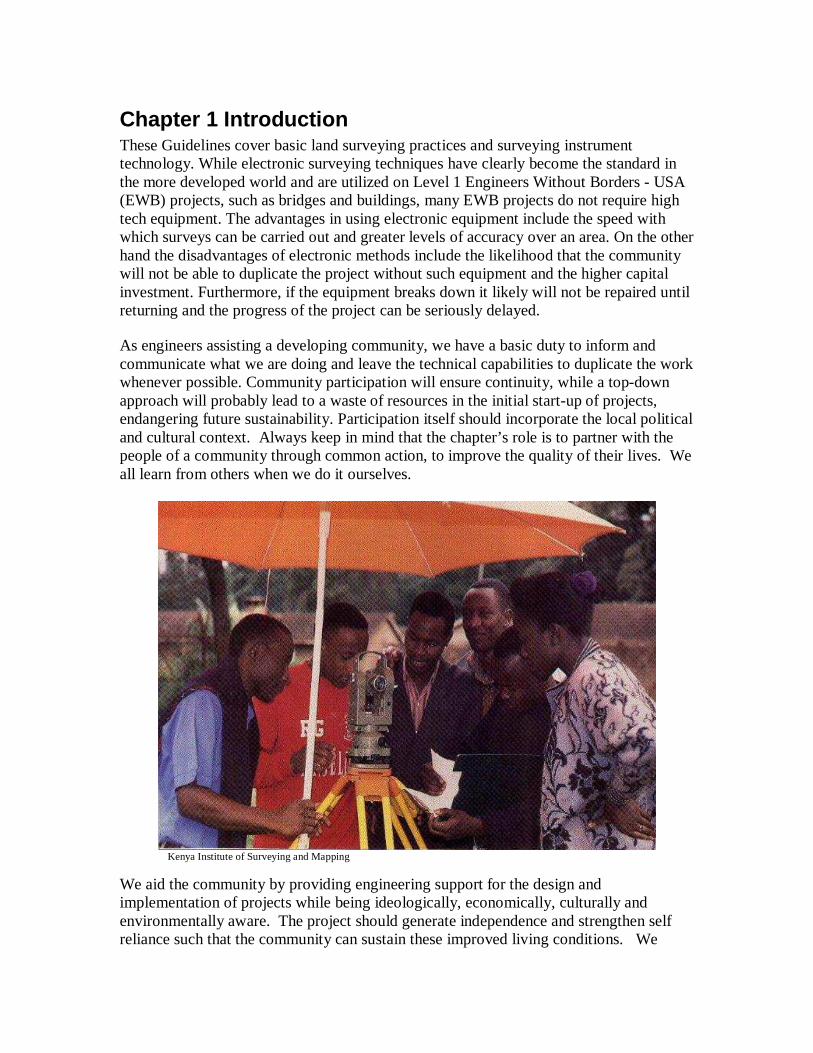
Chapter 1 Introduction These Guidelines cover basic land surveying practices and surveying instrument technology. While electronic surveying techniques have clearly become the standard in the more developed world and are utilized on Level 1 Engineers Without Borders - USA (EWB) projects, such as bridges and buildings, many EWB projects do not require high tech equipment. The advantages in using electronic equipment include the speed with which surveys can be carried out and greater levels of accuracy over an area. On the other hand the disadvantages of electronic methods include the likelihood that the community will not be able to duplicate the project without such equipment and the higher capital investment. Furthermore, if the equipment breaks down it likely will not be repaired until returning and the progress of the project can be seriously delayed. As engineers assisting a developing community, we have a basic duty to inform and communicate what we are doing and leave the technical capabilities to duplicate the work whenever possible. Community participation will ensure continuity, while a top-down approach will probably lead to a waste of resources in the initial start-up of projects, endangering future sustainability. Participation itself should incorporate the local political and cultural context. Always keep in mind that the chapter’s role is to partner with the people of a community through common action, to improve the quality of their lives. We all learn from others when we do it ourselves.
Kenya Institute of Surveying and Mapping
We aid the community by providing engineering support for the design and implementation of projects while being ideologically, economically, culturally and environmentally aware. The project should generate independence and strengthen self reliance such that the community can sustain these improved living conditions. We
strive to develop projects in a way that stimulates the community to participate, creates incentives and instills confidence. The ultimate outcome would be to develop the knowledge base such that the people of the community can rely on themselves to solve problems rather than on outsiders. We hope that the methods outlined in these guidelines provide an avenue for knowledge sharing with the community.
1.1 Types of Surveys The intent of these guidelines is to provide useful information for the type of surveys most commonly required for successful EWB projects. Although a variety of surveys exist for the purposes of gathering land and engineering information the following will apply most frequently to EWB projects: Control Surveys provide basic horizontal and vertical position data to establish datum for the site. For most surveying work the vertical position of points in terms of height above a curved reference surface is mean sea level. Relatively few points or stations are established by the control survey. They are so arranged that they can be easily observed and measured by triangulation, traverse, or grid. Elevations of such points are determined by leveling. These provide an accurate framework on which less accurate survey data, such as ground elevations, can be based without accumulating accidental errors or incurring high cost of making all measurements precise. Boundary or Property Surveys determine boundary lines, property corners, rights-of-way which provide the length and direction of land lines. However, these are legal boundaries and a datum may already be established. Generally, EWB projects will not verify such legal boundaries unless performed by a licensed surveyor and approved of by the EWB Technical Advisory Committee. Topographic Surveys determine the horizontal and vertical location of the physical features at the site to provide information on the existing conditions. Hydrographic Surveys map the shorelines of bodies of water; chart the bottom of streams, lakes, harbours and coastal waters; measure the flow of rivers; and assess other factors affecting navigation and water resources. The sounding of depths by radar is typically replaced by dropping weighted lines or dipping long poles into streams on EWB projects. Construction Surveys are the translation of construction plans into physical points on the ground that can be used as a basis for the actual construction. Construction surveying provides not only the horizontal location of new improvements, but also the vertical information required to ensure that foundations are level and surfaces drain as required
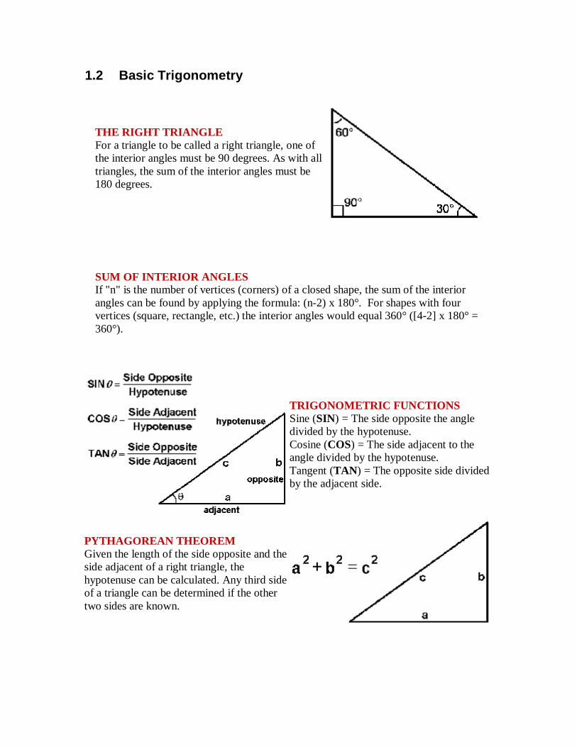
1.2 Basic Trigonometry THE RIGHT TRIANGLE For a triangle to be called a right triangle, one of the interior angles must be 90 degrees. As with all triangles, the sum of the interior angles must be 180 degrees.
SUM OF INTERIOR ANGLES If "n" is the number of vertices (corners) of a closed shape, the sum of the interior angles can be found by applying the formula: (n-2) x 180°. For shapes with four vertices (square, rectangle, etc.) the interior angles would equal 360° ([4-2] x 180° = 360°).
.
TRIGONOMETRIC FUNCTIONS Sine (SIN) = The side opposite the angle divided by the hypotenuse. Cosine (COS) = The side adjacent to the angle divided by the hypotenuse. Tangent (TAN) = The opposite side divided by the adjacent side.
PYTHAGOREAN THEOREM Given the length of the side opposite and the side adjacent of a right triangle, the hypotenuse can be calculated. Any third side of a triangle can be determined if the other two sides are known.
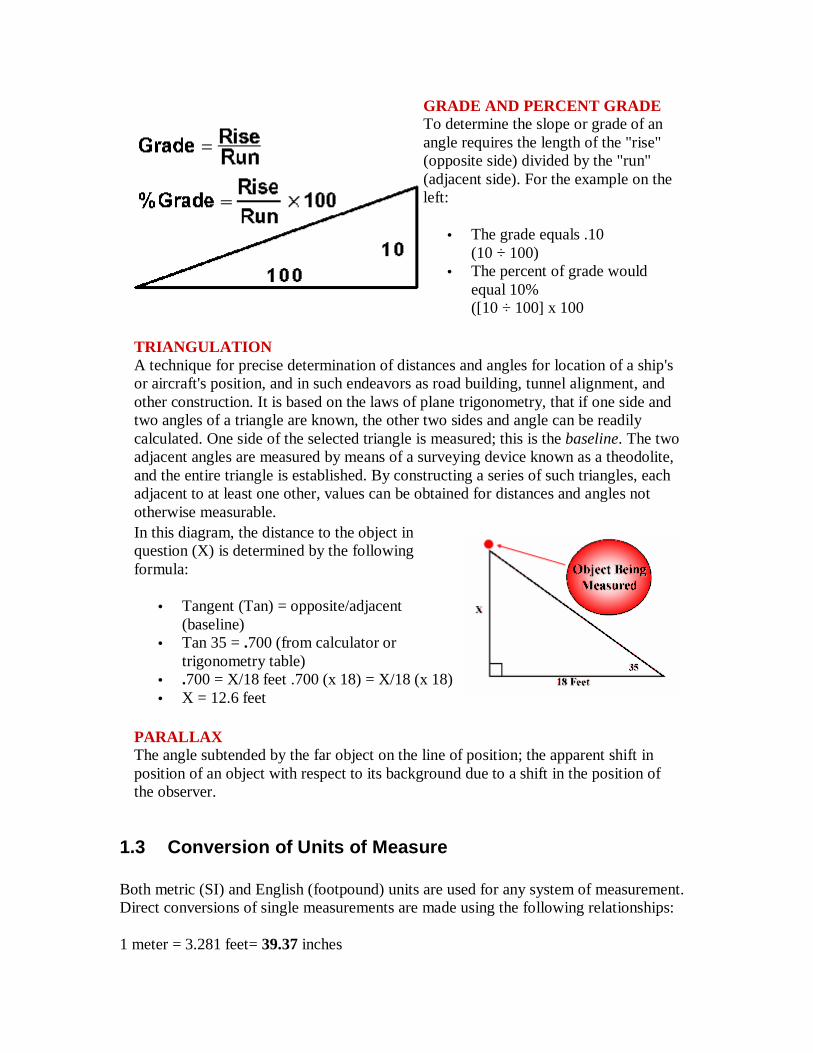
GRADE AND PERCENT GRADE To determine the slope or grade of an angle requires the length of the "rise" (opposite side) divided by the "run" (adjacent side). For the example on the left:
• The grade equals .10 (10 ÷ 100)
• The percent of grade would equal 10% ([10 ÷ 100] x 100
TRIANGULATION A technique for precise determination of distances and angles for location of a ship's or aircraft's position, and in such endeavors as road building, tunnel alignment, and other construction. It is based on the laws of plane trigonometry, that if one side and two angles of a triangle are known, the other two sides and angle can be readily calculated. One side of the selected triangle is measured; this is the baseline. The two adjacent angles are measured by means of a surveying device known as a theodolite, and the entire triangle is established. By constructing a series of such triangles, each adjacent to at least one other, values can be obtained for distances and angles not otherwise measurable. In this diagram, the distance to the object in question (X) is determined by the following formula:
• Tangent (Tan) = opposite/adjacent (baseline)
• Tan 35 = .700 (from calculator or trigonometry table)
• .700 = X/18 feet .700 (x 18) = X/18 (x 18) • X = 12.6 feet
PARALLAX The angle subtended by the far object on the line of position; the apparent shift in position of an object with respect to its background due to a shift in the position of the observer.
1.3 Conversion of Units of Measure
Both metric (SI) and English (footpound) units are used for any system of measurement. Direct conversions of single measurements are made using the following relationships: 1 meter = 3.281 feet= 39.37 inches
1 centimeter = 0.3937 inches 1 kilometer = 3,281 feet= 0.6214 miles 1 foot= 0.3048 meters 1 mile = 1.609 kilometers Some other units in common use for surveying are: 1 cubic meter = 35.31 cubic feet 1 hectare = 2.47 acres Note: When converting coordinates, one needs to be careful in choosing the US Survey Foot or the International Foot.
1.4 Measurement of Dimensions Four geometries are measured in a survey: horizontal lengths, vertical lengths, horizontal angles, and vertical angles. A horizontal length is the straight line distance measured in a horizontal plane. In most cases a distance measured on a slope is changed to its horizontal equivalent. Measurements are made by direct and indirect methods. Direct measurements are made by wheels, human pacing, or measuring tapes. Indirect measurements are made by use of stadia-equipped instruments and graduated rods or by electronic distance-measuring equipment. The type of measurement and equipment used depends on required accuracy, access to the line, and the time and cost involved. A vertical length is a measurement of a difference in height or elevation. Relative measurements can be made by an altimeter, which indicates barometric pressure; or more accurate measurements by a transit; or by plumb line and tape for short vertical distances. In most cases remoteness of points and accuracy require indirect measurements with instruments such as the level and graduated rod. A horizontal angle is the difference in direction between:
1. two intersecting lines in a horizontal plane; 2. two intersecting vertical planes; or 3. two intersecting lines of sight to points in different vertical planes.
It is measured in the horizontal plane in degrees of arc. Horizontal angles usually are measured clockwise but may be measured counterclockwise. Angles are usually measured by transit. An interior angle is on the inside of an enclosing figure, and an exterior angle is on the outside of an enclosing figure. A deflection angle is that angle which any line extended makes with the succeeding or forward line. The direction of the deflection is identified as "right" or "left." An angle-to-the-right is the clockwise angle at the vertex between the back line and forward line.
A vertical angle is the difference in direction between a horizontal plane and an intersecting line, plane, or a line of sight to a point. It is measured in the vertical plane in degrees of arc. Measurements are referenced "up" or "down" from the horizontal as "plus angles" or "minus angles."
1.5 Rounding off and significant figures
Significant Figures In a measured quantity, the number of significant figures is determined by the accuracy of the measurement. In surveying, the significant figures should reflect the allowable error or tolerance in the measurements. For example, suppose a measurement of 941.26 units is made with a probable error of ± 0.03 unit. The ± 0.03 casts some doubt on the fifth digit which can vary from 3 to 9, but the fourth digit will still remain 2. We can say that 941.26 is five significant figures; and from the allowable error, we know the fifth digit is doubtful. However, if the probable error were ±0.07, the fourth digit could be affected. The number could vary from 941.19 to 941.33, and the fourth digit could be read 1, 2, or 3. The fifth digit in this measurement is meaningless. The number has only four significant figures and should be written as such.
Rounding off numbers Rounding off is the process of dropping one or more digits and replacing them with zeros, if necessary, to indicate the number of significant figures. Numbers used in surveying are rounded off according to the following rules: 1. When the digit to be dropped is less than 5, the number is written without the digit or any others that follow it. (Example: 0.054 becomes 0.05.) 2. When the digit is equal to 5, the nearest EVEN number is substituted for the preceding digit. (Examples: 0.055 becomes 0.06; 0.045 becomes 0.04.) 3. When the digit to be dropped is greater than 5, the preceding digit is increased by one. (Example: 0.047 becomes 0.05.) 4. Dropped digits to the left of the decimal point are replaced by zeros. 5. Dropped digits to the right of the decimal points are never replaced.
Checking Computations Most mathematical problems can be solved by more than one method. To check a set of computations, you should use a method that differs from the original method, if possible. An inverse solution, starting with the computed value and solving for the field data, is one possibility. The planimeter and the protractor are also used for approximate checking. A graphical solution can be used, when feasible, especially if it takes less time than a mathematical or logarithmic solution. Each step that cannot be checked by any other method must be recomputed; and, if possible, another survey team member should

recompute the problem. When an error or mistake is found, the computation should be rechecked before the correction is accepted.
Chapter 2 Safety Responsibilities Surveyors and field engineers face unique hazards, namely site conditions and logistics, which must be considered to ensure health and safety of surveyors. Remember: The best safety rule is to keep alert and think about what y ou are doing. See and avoid all danger. The following summarizes health and safety pertinent to surveying and field engineering work:
2.1 Planning for Safety Operational Precautions Safety shall be given top priority in planning all surveys and field engineering assignments. Factors considered when planning an assignment shall include:
• Scheduling work for the safest time of day • Assigning the optimum number of survey crew to accomplish the assignment safely. • Assigning specially trained and qualified team members to more hazardous conditions. • Using methods that minimize exposure of survey team to hazardous conditions. • Ensuring access to, and sufficiency of, specialized tools and equipment necessary to conduct the assignment safely.
Each field survey team member shall observe operational precautions by:
• Not entering ditches, trenches or other spaces until you are certain it is safe to do so. • Suspending operations when unsafe conditions or uncontrollable hazards develop; and resuming work only when safe conditions have been restored. • Using particular caution when working at night, if for some reason night work is required.
2.2 Personal Health Each surveyor must have proper food, nutrition, lunch, etc. It is important that everyone be in fit physical condition before performing work, especially strenuous activity. If you are prone to getting sick when you are at home, you'll surely be sick in the field. The food you eat, the water you drink, and the air that you breathe will all be different, and foreign. Minor stomach and intestinal disorders are the most common, and often can be treated with over-the-counter medicines. Be careful, these maladies can become severe and require medical attention. If your work will take you away from home for an extended period be sure to inform your physician. They should be able to make some recommendations. Also find out what kind of medical care is available where you are going.
2.3 Personal Protective Equipment Each survey team member must wear clothing and footwear that will provide adequate protection for the assigned task, including as required or directed:
• Necessary clothing, hat, gloves and boots to adequately protect against the outdoor elements (e.g., heat, cold, rain, snow, rugged terrain, construction hazards). Light or neutral colors will attract less flies.
• Earplugs or muffs must be worn when working around noise levels that may cause injury or hearing loss.
2.4 First-Aid Requirements At least one member of each field survey team should have received first-aid training and possess a current certification. Each survey team vehicle should be equipped with a standard first-aid kit.
2.5 Sun There are no safe UV rays or safe suntans. Be especially careful in the sun if you burn easily, spend a lot of time outdoors, or have any of the following physical features: numerous, irregular, or large moles; freckles; fair skin; or blond, red, or light brown hair. • Cover up. Wear loose-fitting, long-sleeved shirts and long pants. • Use sunscreen with a sun protection factor (SPF) of at least 30. Be sure to follow application directions on the bottle or tube. • Wear a hat. A wide brim hat, not a baseball cap, works best because it protects the neck, ears, eyes, forehead, nose, and scalp. • Wear UV-absorbent sunglasses (eye protection). Sunglasses don’t have to be expensive, but they should block 99 to 100 percent of UVA and UVB radiation. Before you buy sunglasses, read the product tag or label. • Limit exposure. UV rays are most intense between 10 a.m. and 4 p.m.
2.6 Heat/Cold Extremes of air temperature occur in all parts of the country. The ideal comfort range for humans is between 16 to 32ºC (60 to 90ºF). Hypothermia and hyperthermia normally occur in temperatures outside this range.
Hypothermia is a condition of reduced body temperature caused by exposure to cold, and aggravated by wet clothes, wind, hunger, and exhaustion. Hypothermia in extremities can lead to frostbite. Hypothermia can occur with air temperature above 16ºC (60ºF) under wet and (or) windy conditions. The best way to avoid hypothermia is to dress warm and stay dry. The warning signals of hypothermia are uncontrollable fits of shivering, incoherence, listlessness, fumbling hands, frequent stumbling, drowsiness, and inability to get up after resting. Victims of hypothermia must be treated immediately by removing them from exposure to the elements, replacing wet clothes with dry ones, and giving them warm, non-alcoholic drinks. Seek emergency facilities as soon as possible.
To prevent hypothermia: 1. Put on rain gear before it starts to rain or snow. 2. Put on additional clothes before starting to shiver. 3. Seek shelter immediately if conditions become severe. Hyperthermia is a condition of increased body temperature caused by exposure to excessive heat. Contributing factors are physical exertion, clothing, humidity, lack of air movement, and temperature, but the most important factor is body hydration. The normal body requirement for fluids in temperate regions is 2 1/2 quarts per day; desert conditions require more fluid. Early warning symptoms of hyperthermia are chilling, a throbbing pressure in the head, unsteadiness, dizziness, nausea, dry skin (either hot and red or cool and pale), rapid pulse, and muscle pains and spasms. The combination of heat and humidity can be a serious health threat so take precautions. Persons suffering from hyperthermia should seek medical attention immediately. First aid involves cooling down and rehydrating. To avoid hyperthermia: 1. Drink water in moderate amounts on a scheduled basis---do not wait until you
are thirsty. 2. Avoid alcohol, caffeine, and soda---these liquids are not water substitutes.
Avoid taking large amounts of sugar as well. 3. Wear light-colored, loose-fitting, breathable clothing—cotton is good and a
wide-brimmed hat. 4. Schedule activities that require the most exertion in early morning or late
afternoon, if possible, and not when air temperature is at its highest. Work in the shade when possible.
5. Take frequent short breaks in cool shade. 6. Eat smaller meals before work activity. 7. If you are taking medications, find out from your health care provider if your
medications and heat don’t mix.
2.7 Rain Rain can fall at a rate of several inches per hour and rapidly create dangerous flash flood conditions, either in the area where you are working or several miles away. Weather forecasts will be helpful in planning your activities accordingly to ensure your safety. Always be aware of rapidly rising stages in rivers and creeks. Beware of dry creek beds that can become raging rivers in a short period of time.
2.8 Tools and Equipment Only the proper tool, in the proper condition, should be used for each job. Equipment should not be operated unless the survey crew is familiar with its use and convinced it is functioning properly.
2.9 Traffic Hazards Although unlikely for most of the EWB projects there may be an occasional project which will be near traffic areas. Work, no matter how short the duration, must not be performed on or adjacent to traveled roadways without instituting proper protective measures to protect other drivers and pedestrians. These measures include using appropriate signs, flaggers, lookouts and/or lane closures, as required to work safely. Additional personal protective clothing that may be necessary when working near traffic are:
• Orange or strong yellow-green vests, shirts or other highly visible garments when exposed to vehicular or equipment traffic.
• Hard hats.
2.10 Environmental Hazards Field work can be physically demanding and is often carried out in what appears to be the worst conditions. For example, if you are measuring stream response to storms, you will have to be out in the rain and getting wet. You will also have to face the threat of injury. Barbed wire fences, thorny brush, rugged terrain (streams, cliffs), the sun, insects, animals (snakes, wild dogs etc.) all pose a threat. Cuts, bruises, broken bones, heat exhaustion, and bites are all part of the job. Expect to be injured and be prepared for just such occasions. Carry a first aid kit (Section 6 of the EWB Sourcebook www.ewb-usa.org), or have one close at hand. Never work alone in the bush. Always let someone know where you are going, your route and when you will be back. Never work on a cliff edge. Be careful of falling rock and soil at cliff bottoms.
2.11 Private vs. Public Land and Permission Surveyors are almost always dealing with land either owned or controlled by people other than themselves. In a very general sense lands can be classified as either privately or publicly owned, but this distinction can sometimes be blurred. Surveyors must be conscious of the various systems, and nuances, of land tenure. Be courteous, polite, and professional. Think about how you would feel if someone wanted to conduct research on your land.
Once you identify someone of authority, usually the person living or working on the land, explain your intensions and desires and ask his or her permission. Be sure to inquire if there are other parties you should contact. Get permission from as many people as possible.
2.12 Letters and Permits When conducting field work, it is a very good idea to carry an official letter of introduction. At the very least you should carry some type of document from the agency for which you work. If you are working in a foreign country, a letter of introduction from a person in authority will help immeasurably. Many countries require official permits for various types of field work to be done within their borders.
In many cases, it is impossible to carry-out a successful project without official documents. Take, for example, someone conducting agricultural research in Ghana who plans to analyze in the United States, soil samples collected in the field. That person may not have difficulty collecting the samples, if she or he has been approved to do so by the proper authorities in Ghana, but that researcher must have a permit to import those samples into the United States.
Bottom line is get permission ahead of time, and get it in writing!
2.13 Cultural Understanding By and large, land owners and users are no different than you. Imagine how you would feel if someone from a government agency, another state (say New Hampshire), or a foreign country (e.g., Iraq) knocked on your door and asked if he could carry-out some studies of your land. You would have lots of questions, wouldn't you? Working in a foreign country can be doubly difficult, especially in less-developed economies. While citizens of such countries can be friendly, courteous, and helpful, survey teams must always remember that what they are doing is viewed with either suspicion or wonderment. What might seem important to one person can be seen as an extravagance by another.
Chapter 3 Surveying Equipment
3.1 Measuring distance (range)
Tapes Most surveyors' tapes are made of steel ribbon with a favored length being 100m. Metal tapes suffer from kinks and are easily broken. Non-metallic tapes are woven from synthetic yarns with or without metallic threads. These tapes are strong and wear well but can be subject to errors due to temperature and moisture changes. Many modern tapes are made of durable 'plastic' or fiberglass. All tapes need to be handled with care.
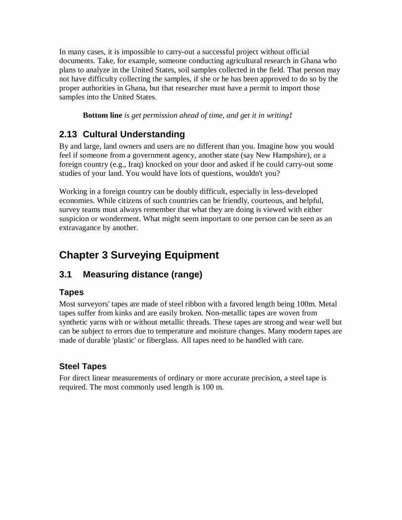
Steel Tapes For direct linear measurements of ordinary or more accurate precision, a steel tape is required. The most commonly used length is 100 m.
Steel professional tape
Steel tapes are made of flat steel bands or cables known as cam-lines. The markings on tapes may be etched, stamped on clamps or soldered sleeves, or stamped on bosses. Steel tapes may be obtained in lengths up to 150 m (~500 ft), although the most commonly used are 30 m (~100 ft) long. Steel tapes are usually marked at 1-m and 0.5-m or at 1-ft intervals, except the last meter or foot, which is graduated in centimeters or tenths and hundredths of a foot. A steel tape is sometimes equipped with a reel on which the tape can be wound.
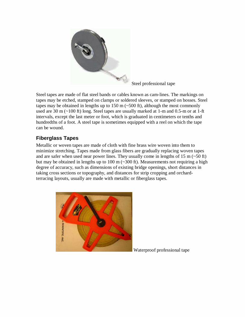
Fiberglass Tapes Metallic or woven tapes are made of cloth with fine brass wire woven into them to minimize stretching. Tapes made from glass fibers are gradually replacing woven tapes and are safer when used near power lines. They usually come in lengths of 15 m (~50 ft) but may be obtained in lengths up to 100 m (~300 ft). Measurements not requiring a high degree of accuracy, such as dimensions of existing bridge openings, short distances in taking cross sections or topography, and distances for strip cropping and orchard-terracing layouts, usually are made with metallic or fiberglass tapes.
Waterproof professional tape
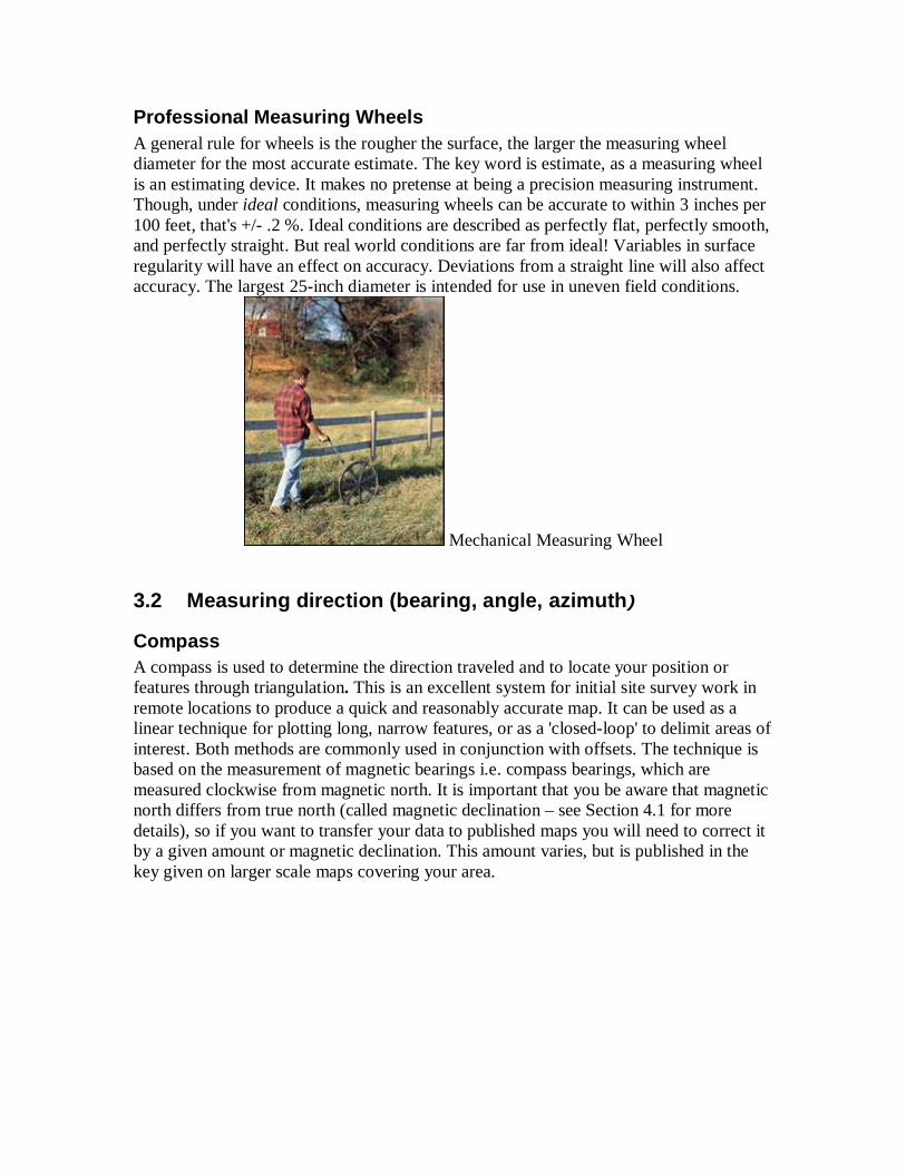
Professional Measuring Wheels A general rule for wheels is the rougher the surface, the larger the measuring wheel diameter for the most accurate estimate. The key word is estimate, as a measuring wheel is an estimating device. It makes no pretense at being a precision measuring instrument. Though, under ideal conditions, measuring wheels can be accurate to within 3 inches per 100 feet, that's +/- .2 %. Ideal conditions are described as perfectly flat, perfectly smooth, and perfectly straight. But real world conditions are far from ideal! Variables in surface regularity will have an effect on accuracy. Deviations from a straight line will also affect accuracy. The largest 25-inch diameter is intended for use in uneven field conditions.
Mechanical Measuring Wheel
3.2 Measuring direction (bearing, angle, azimuth )
Compass A compass is used to determine the direction traveled and to locate your position or features through triangulation. This is an excellent system for initial site survey work in remote locations to produce a quick and reasonably accurate map. It can be used as a linear technique for plotting long, narrow features, or as a 'closed-loop' to delimit areas of interest. Both methods are commonly used in conjunction with offsets. The technique is based on the measurement of magnetic bearings i.e. compass bearings, which are measured clockwise from magnetic north. It is important that you be aware that magnetic north differs from true north (called magnetic declination – see Section 4.1 for more details), so if you want to transfer your data to published maps you will need to correct it by a given amount or magnetic declination. This amount varies, but is published in the key given on larger scale maps covering your area.
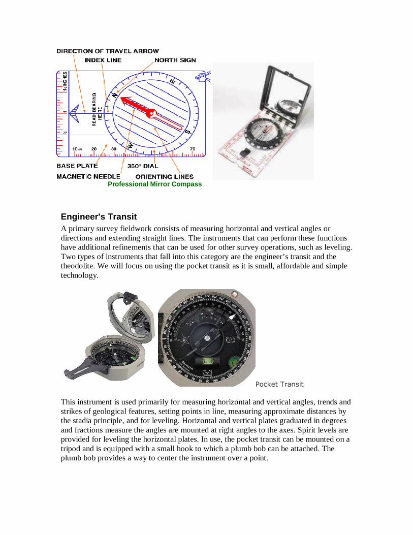
Professional Mirror Compass
Engineer's Transit A primary survey fieldwork consists of measuring horizontal and vertical angles or directions and extending straight lines. The instruments that can perform these functions have additional refinements that can be used for other survey operations, such as leveling. Two types of instruments that fall into this category are the engineer’s transit and the theodolite. We will focus on using the pocket transit as it is small, affordable and simple technology.
Pocket Transit This instrument is used primarily for measuring horizontal and vertical angles, trends and strikes of geological features, setting points in line, measuring approximate distances by the stadia principle, and for leveling. Horizontal and vertical plates graduated in degrees and fractions measure the angles are mounted at right angles to the axes. Spirit levels are provided for leveling the horizontal plates. In use, the pocket transit can be mounted on a tripod and is equipped with a small hook to which a plumb bob can be attached. The plumb bob provides a way to center the instrument over a point.
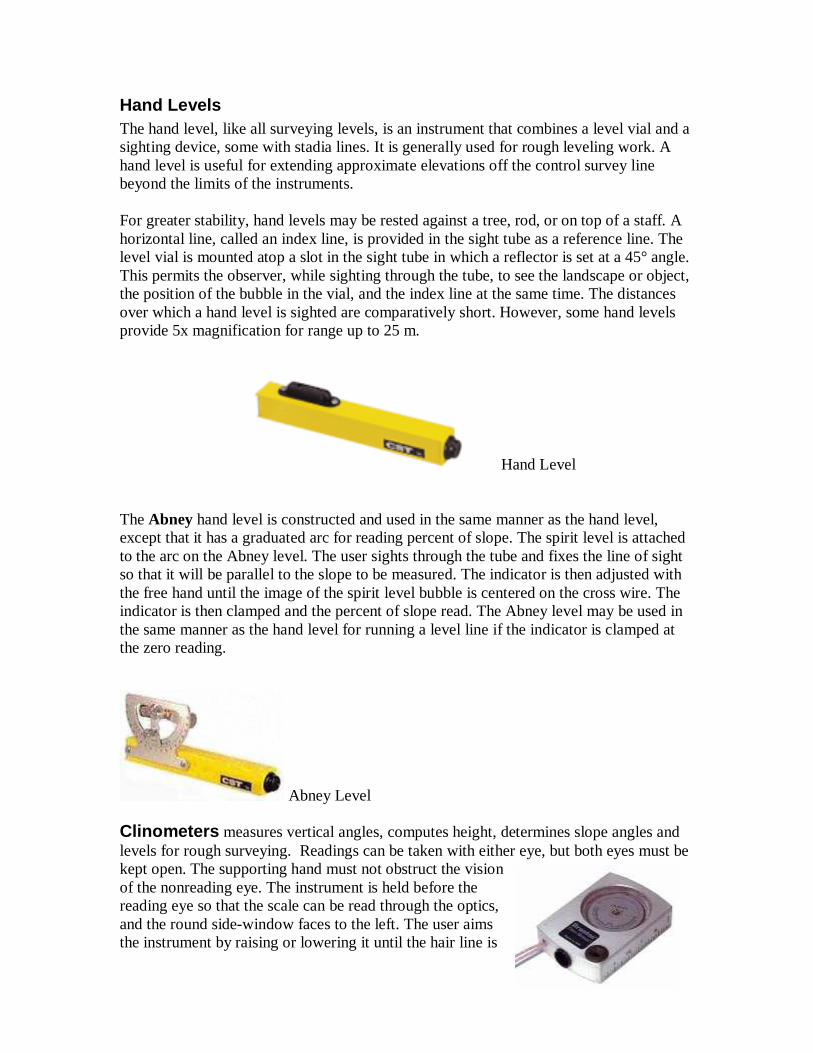
Hand Levels The hand level, like all surveying levels, is an instrument that combines a level vial and a sighting device, some with stadia lines. It is generally used for rough leveling work. A hand level is useful for extending approximate elevations off the control survey line beyond the limits of the instruments. For greater stability, hand levels may be rested against a tree, rod, or on top of a staff. A horizontal line, called an index line, is provided in the sight tube as a reference line. The level vial is mounted atop a slot in the sight tube in which a reflector is set at a 45° angle. This permits the observer, while sighting through the tube, to see the landscape or object, the position of the bubble in the vial, and the index line at the same time. The distances over which a hand level is sighted are comparatively short. However, some hand levels provide 5x magnification for range up to 25 m.
Hand Level The Abney hand level is constructed and used in the same manner as the hand level, except that it has a graduated arc for reading percent of slope. The spirit level is attached to the arc on the Abney level. The user sights through the tube and fixes the line of sight so that it will be parallel to the slope to be measured. The indicator is then adjusted with the free hand until the image of the spirit level bubble is centered on the cross wire. The indicator is then clamped and the percent of slope read. The Abney level may be used in the same manner as the hand level for running a level line if the indicator is clamped at the zero reading.
Abney Level Clinometers measures vertical angles, computes height, determines slope angles and levels for rough surveying. Readings can be taken with either eye, but both eyes must be kept open. The supporting hand must not obstruct the vision of the nonreading eye. The instrument is held before the reading eye so that the scale can be read through the optics, and the round side-window faces to the left. The user aims the instrument by raising or lowering it until the hair line is
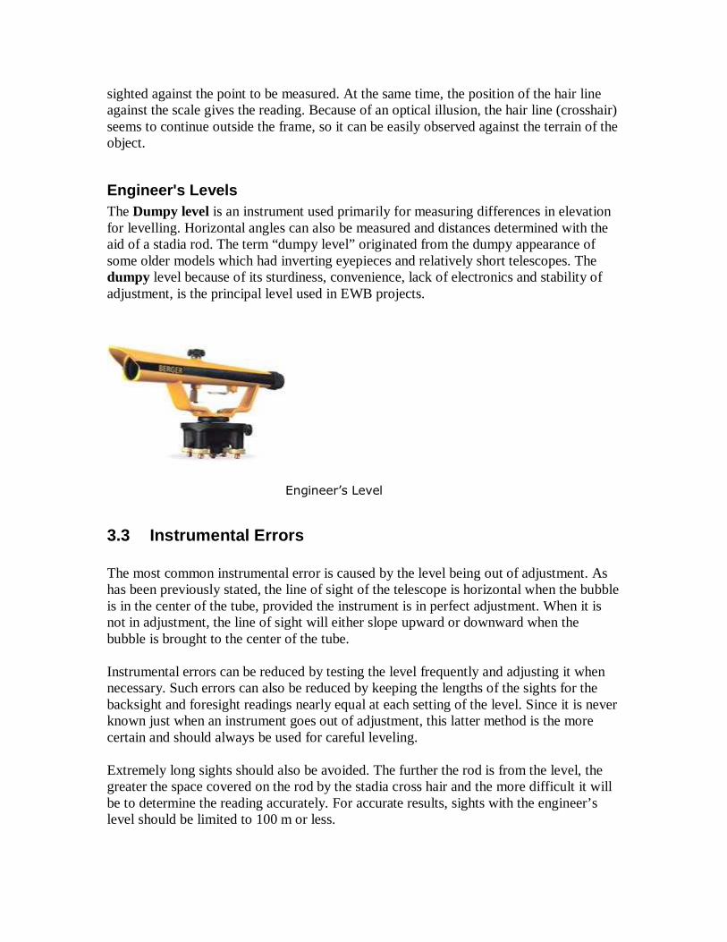
sighted against the point to be measured. At the same time, the position of the hair line against the scale gives the reading. Because of an optical illusion, the hair line (crosshair) seems to continue outside the frame, so it can be easily observed against the terrain of the object.
Engineer's Levels
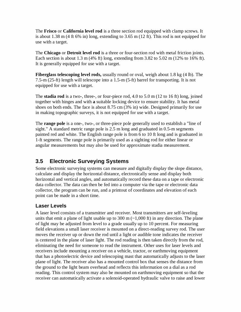
The Dumpy level is an instrument used primarily for measuring differences in elevation for levelling. Horizontal angles can also be measured and distances determined with the aid of a stadia rod. The term “dumpy level” originated from the dumpy appearance of some older models which had inverting eyepieces and relatively short telescopes. The dumpy level because of its sturdiness, convenience, lack of electronics and stability of adjustment, is the principal level used in EWB projects.
Engineer’s Level
3.3 Instrumental Errors The most common instrumental error is caused by the level being out of adjustment. As has been previously stated, the line of sight of the telescope is horizontal when the bubble is in the center of the tube, provided the instrument is in perfect adjustment. When it is not in adjustment, the line of sight will either slope upward or downward when the bubble is brought to the center of the tube. Instrumental errors can be reduced by testing the level frequently and adjusting it when necessary. Such errors can also be reduced by keeping the lengths of the sights for the backsight and foresight readings nearly equal at each setting of the level. Since it is never known just when an instrument goes out of adjustment, this latter method is the more certain and should always be used for careful leveling. Extremely long sights should also be avoided. The further the rod is from the level, the greater the space covered on the rod by the stadia cross hair and the more difficult it will be to determine the reading accurately. For accurate results, sights with the engineer’s level should be limited to 100 m or less.
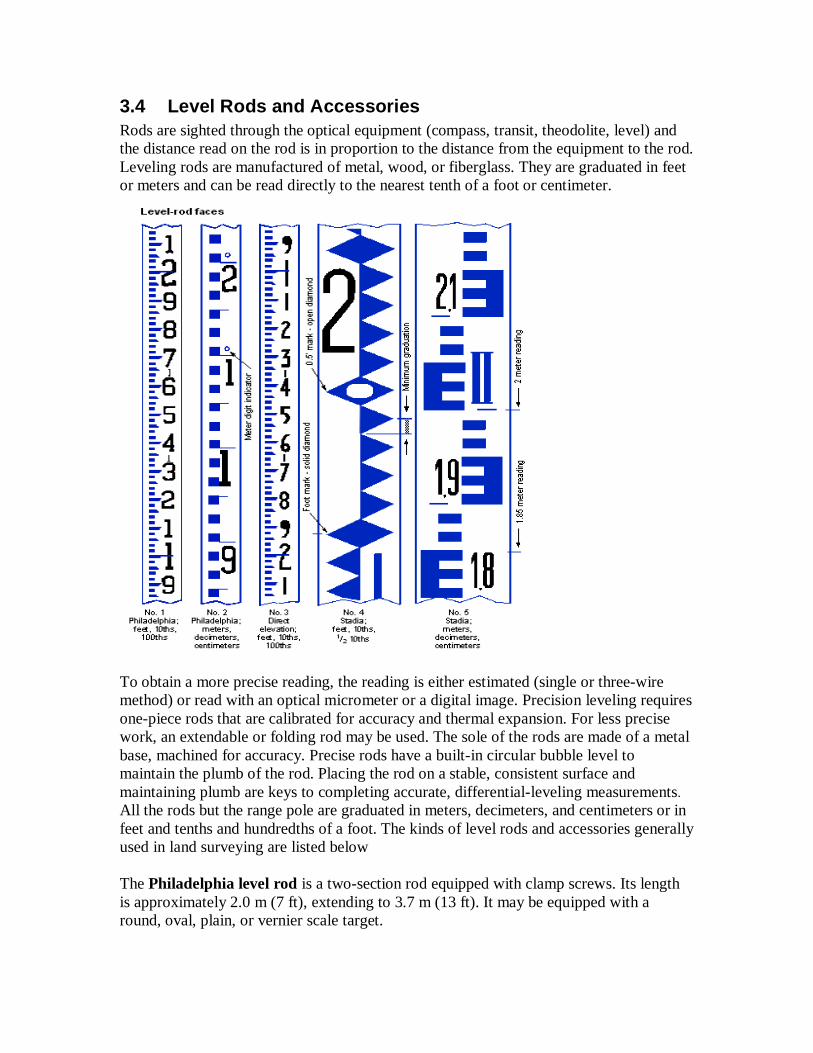
3.4 Level Rods and Accessories Rods are sighted through the optical equipment (compass, transit, theodolite, level) and the distance read on the rod is in proportion to the distance from the equipment to the rod. Leveling rods are manufactured of metal, wood, or fiberglass. They are graduated in feet or meters and can be read directly to the nearest tenth of a foot or centimeter.
To obtain a more precise reading, the reading is either estimated (single or three-wire method) or read with an optical micrometer or a digital image. Precision leveling requires one-piece rods that are calibrated for accuracy and thermal expansion. For less precise work, an extendable or folding rod may be used. The sole of the rods are made of a metal base, machined for accuracy. Precise rods have a built-in circular bubble level to maintain the plumb of the rod. Placing the rod on a stable, consistent surface and maintaining plumb are keys to completing accurate, differential-leveling measurements. All the rods but the range pole are graduated in meters, decimeters, and centimeters or in feet and tenths and hundredths of a foot. The kinds of level rods and accessories generally used in land surveying are listed below The Philadelphia level rod is a two-section rod equipped with clamp screws. Its length is approximately 2.0 m (7 ft), extending to 3.7 m (13 ft). It may be equipped with a round, oval, plain, or vernier scale target.
The Frisco or California level rod is a three section rod equipped with clamp screws. It is about 1.38 m (4 ft 6% in) long, extending to 3.65 m (12 ft). This rod is not equipped for use with a target. The Chicago or Detroit level rod is a three or four-section rod with metal friction joints. Each section is about 1.3 m (4% ft) long, extending from 3.82 to 5.02 m (12% to 16% ft). It is generally equipped for use with a target. Fiberglass telescoping level rods, usually round or oval, weigh about 1.8 kg (4 lb). The 7.5-m (25-ft) length will telescope into a 1.5-m (5-ft) barrel for transporting. It is not equipped for use with a target. The stadia rod is a two-, three-, or four-piece rod, 4.0 to 5.0 m (12 to 16 ft) long, joined together with hinges and with a suitable locking device to ensure stability. It has metal shoes on both ends. The face is about 8.75 cm (3% in) wide. Designed primarily for use in making topographic surveys, it is not equipped for use with a target. The range pole is a one-, two-, or three-piece pole generally used to establish a "line of sight." A standard metric range pole is 2.5 m long and graduated in 0.5-m segments painted red and white. The English range pole is from 6 to 10 ft long and is graduated in 1-ft segments. The range pole is primarily used as a sighting rod for either linear or angular measurements but may also be used for approximate stadia measurement.
3.5 Electronic Surveying Systems Some electronic surveying systems can measure and digitally display the slope distance, calculate and display the horizontal distance, electronically sense and display both horizontal and vertical angles, and automatically record these data on a tape or electronic data collector. The data can then be fed into a computer via the tape or electronic data collector, the program can be run, and a printout of coordinates and elevation of each point can be made in a short time.
Laser Levels A laser level consists of a transmitter and receiver. Most transmitters are self-leveling units that emit a plane of light usable up to 300 m (~1,000 ft) in any direction. The plane of light may be adjusted from level to a grade usually up to 10 percent. For measuring field elevations a small laser receiver is mounted on a direct-reading survey rod. The user moves the receiver up or down the rod until a light or audible tone indicates the receiver is centered in the plane of laser light. The rod reading is then taken directly from the rod, eliminating the need for someone to read the instrument. Other uses for laser levels and receivers include mounting a receiver on a vehicle, tractor, or earthmoving equipment that has a photoelectric device and telescoping mast that automatically adjusts to the laser plane of light. The receiver also has a mounted control box that senses the distance from the ground to the light beam overhead and reflects this information on a dial as a rod reading. This control system may also be mounted on earthmoving equipment so that the receiver can automatically activate a solenoid-operated hydraulic valve to raise and lower

a blade or other earthmoving device. Similar types of receivers and equipment are being used on land drainage equipment.
Electronic Distance-Measuring Equipment Electronic Distance Measurement (EDM) equipment is of various types relying on the reflection of electromagnetic radiation such as microwaves, infra-red, and laser radiation waves from a reflector at the distant station. The design of most units enables most members of a surveying team to use the equipment after a short period of training. An EDM instrument is calibrated on a baseline to determine instrument constants and errors. A series of measurements on a base can also be used to check the performance and reliability of the instrument and to assess its precision against the manufacturer’s claims and specified minimum standards. EDM are now the prime measuring device for land surveyors and others. EDM is also used routinely for measuring field event performances and checking the heights of the bar in the high jump and pole vault events at major track and field competitions.
Global Positioning System (GPS) GPS provides Point Position (Latitude/Longitude) and Relative Position (Vector). GPS can differentiate between every square meter on the earth’s surface thus allowing a new international standard for defining locations and directions. GPS positions are affected by various ranging errors: 1) Ephemeris data-- these are inaccuracies of the satellite's reported location. 2) Satellite clock-- a receiver's built-in clock is not as accurate as the atomic clocks onboard the GPS satellites. Therefore, it may have very slight timing errors. 3) Ionosphere and Troposphere delays -- the satellite signal slows as it passes through the atmosphere. 4) Signal Multipath -- this occurs when the GPS signal is reflected off objects such as tall buildings or large rock surfaces before it reaches the receiver. This increases the travel time of the signal, thereby causing errors. 5) Receiver--errors in the receiver's measurement of range caused by thermal noise, software accuracy, and inter-channel biases 6) Number of satellites visible -- the more satellites a GPS receiver can "see," the better the accuracy. Buildings, terrain, electronic interference, or sometimes even dense foliage can block signal reception, causing position errors or possibly no position reading at all. GPS units typically will not work indoors, underwater or underground. 7) Satellite geometry/shading -- this refers to the relative position of the satellites at any given time. Ideal satellite geometry exists when the satellites are located at wide angles relative to each other. Poor geometry results when the satellites are located in a line or in a tight grouping. The ultimate accuracy of GPS positions are determined by the sum of all these errors. It is difficult to quantify this specification as receiver manufacturers are constantly finding
new ways to improve accuracy. There are a variety of receivers on the market yielding various levels of accuracy. Receivers typically fall into 3 categories: survey, mapping, and navigation grades. Handheld GPS unit most likely to be used on EWB project will either be mapping or navigational grade depending on budget and accuracy needs. Be sure and align your expectations with what a GPS receiver can really deliver. It cannot reliably deposit you at your front door but can locate your yard. Nor will it replace a compass in all applications. The important thing to remember is that a GPS receiver needs to see at least 3 satellites (preferably more) in order to calculate the position, and that due to the nature of the signal, the receiver can see only satellites that are above the horizon. Under less than optimal conditions, not all GPS units are created equal in their ability to get strong enough signals to determine a location fix. Mountains, canyon walls, forested terrain, nearby buildings, a human body, heavy leaf cover and moisture on leaves can block or attenuate satellite signals. The main factor that makes some GPS units work better under these conditions than others is the design of their antenna. In most situations there are enough satellites visible to a receiver to calculate the position. If your receiver cannot lock on to three or more satellites, change your position. Simple turning around to face the opposite direction may do the trick. In the woods, under very heavy foliage, you might need to look for a clearing. If you are in a canyon or such, try moving closer to the middle of it or to one of the sides. You can expect typical GPS accuracies in the range of 6-12 meters (2-40 feet). Estimate the accuracy of your GPS receiver by following these four steps. A set of measurements is worth a thousand expert opinions - trust your own plot.
1. Find any convenient unobstructed place. 2. Record the coordinates for that place. Don't throw out ANY data points. 3. Make a graphic plot of Eastings and Northings (pencil and paper works really
well for this). 4. Repeat steps 2,3 (at different times of day and night... the more the better)
Always carry extra batteries. Leave fresh batteries in your unit at all times and check on a regular basis to be sure they are OK. Not to do so could prematurely run down the internal lithium battery which maintains your data.
A GPS is not to be depended on for accurate elevation readings, even units with altimeters, due to barometric pressure fluctuations. Generally, the elevation errors will be great enough to make the readings useless. However handheld GPS unit allow for quick and reasonably accurate identification of one's position anywhere in the world. You can put locational data (for example where in-country building materials can be found) into a GPS unit while you are conducting your research druing project assessment trips. There is a wide range of software that can be used to map GPS data. GPS Maps are map images, waypoint coordinates, route, and track data for handheld and GPS (Global Positioning System) receivers from Garmin, Magellan, Lowrance and others. A variety of formats are available, primarily the GPX (GPS eXchange) file format which can also
be used with Google Earth applications along with the increasingly popular KML format. Other data formats available include: MapCreate, Garmin MapSource (including IMG files); National Geographic Topo!; MapTech Chart Navigator and Terrain Navigator; TopoGrafix ExpertGPS and EasyGPS; DeLorme Topo USA, Topo Quads, Street Atlas. Note: Not all formats are available for every GPS Map.
3.6 Surveying Accessories
Surveying accessories include the equipment, tools, and other devices used in surveying that are not considered to be an integral part of the surveying instrument itself. When you run a traverse, for example, your primary instruments may be the transit and the steel tape. The accessories you need to do the actual measurement will be the following: a tripod to support the transit; a range pole to sight on in line; a plumb bob to center the instrument on the point; perhaps tape supports if the survey is of high precision; and so forth. It is important that you become familiar with the proper care of this equipment and use it properly.
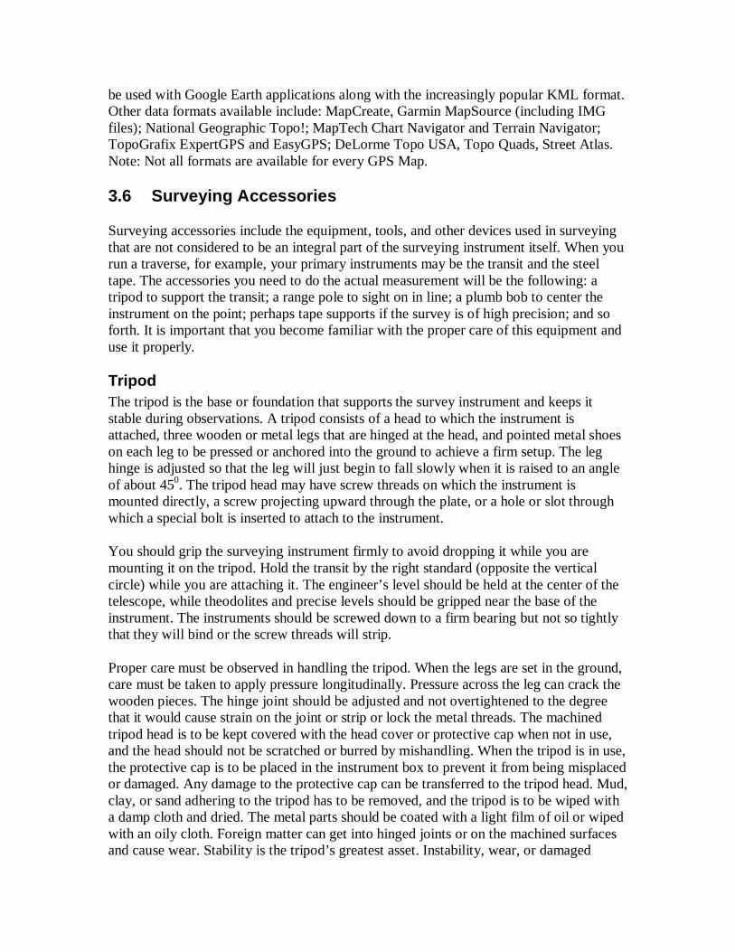
Tripod The tripod is the base or foundation that supports the survey instrument and keeps it stable during observations. A tripod consists of a head to which the instrument is attached, three wooden or metal legs that are hinged at the head, and pointed metal shoes on each leg to be pressed or anchored into the ground to achieve a firm setup. The leg hinge is adjusted so that the leg will just begin to fall slowly when it is raised to an angle of about 450. The tripod head may have screw threads on which the instrument is mounted directly, a screw projecting upward through the plate, or a hole or slot through which a special bolt is inserted to attach to the instrument.
You should grip the surveying instrument firmly to avoid dropping it while you are mounting it on the tripod. Hold the transit by the right standard (opposite the vertical circle) while you are attaching it. The engineer’s level should be held at the center of the telescope, while theodolites and precise levels should be gripped near the base of the instrument. The instruments should be screwed down to a firm bearing but not so tightly that they will bind or the screw threads will strip.
Proper care must be observed in handling the tripod. When the legs are set in the ground, care must be taken to apply pressure longitudinally. Pressure across the leg can crack the wooden pieces. The hinge joint should be adjusted and not overtightened to the degree that it would cause strain on the joint or strip or lock the metal threads. The machined tripod head is to be kept covered with the head cover or protective cap when not in use, and the head should not be scratched or burred by mishandling. When the tripod is in use, the protective cap is to be placed in the instrument box to prevent it from being misplaced or damaged. Any damage to the protective cap can be transferred to the tripod head. Mud, clay, or sand adhering to the tripod has to be removed, and the tripod is to be wiped with a damp cloth and dried. The metal parts should be coated with a light film of oil or wiped with an oily cloth. Foreign matter can get into hinged joints or on the machined surfaces and cause wear. Stability is the tripod’s greatest asset. Instability, wear, or damaged
bearing surfaces on the tripod can evolve into unexplainable errors in the final survey results.
Plumb Bob, Cord, and Target
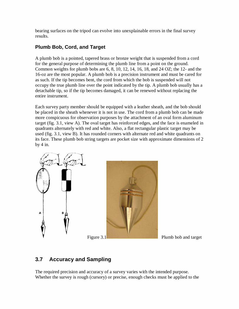
A plumb bob is a pointed, tapered brass or bronze weight that is suspended from a cord for the general purpose of determining the plumb line from a point on the ground. Common weights for plumb bobs are 6, 8, 10, 12, 14, 16, 18, and 24 OZ; the 12- and the 16-oz are the most popular. A plumb bob is a precision instrument and must be cared for as such. If the tip becomes bent, the cord from which the bob is suspended will not occupy the true plumb line over the point indicated by the tip. A plumb bob usually has a detachable tip, so if the tip becomes damaged, it can be renewed without replacing the entire instrument.
Each survey party member should be equipped with a leather sheath, and the bob should be placed in the sheath whenever it is not in use. The cord from a plumb bob can be made more conspicuous for observation purposes by the attachment of an oval form aluminum target (fig. 3.1, view A). The oval target has reinforced edges, and the face is enameled in quadrants alternately with red and white. Also, a flat rectangular plastic target may be used (fig. 3.1, view B). It has rounded corners with alternate red and white quadrants on its face. These plumb bob string targets are pocket size with approximate dimensions of 2 by 4 in.
Figure 3.1 Plumb bob and target
3.7 Accuracy and Sampling The required precision and accuracy of a survey varies with the intended purpose. Whether the survey is rough (cursory) or precise, enough checks must be applied to the
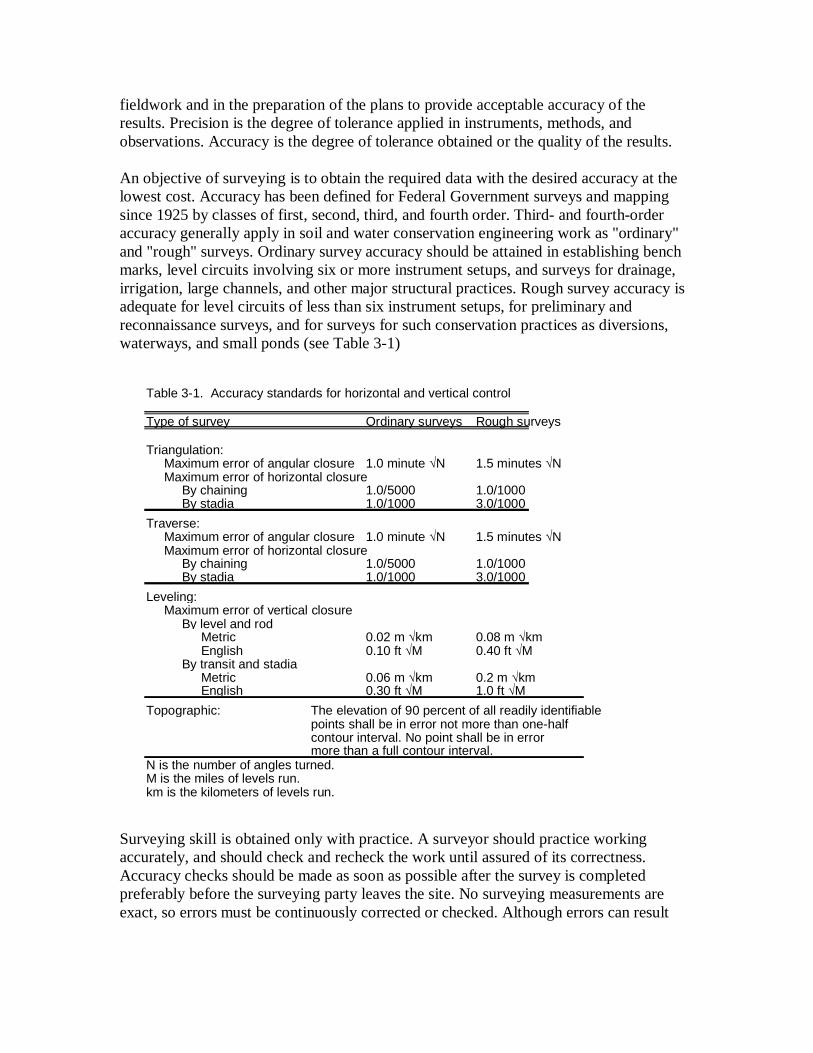
fieldwork and in the preparation of the plans to provide acceptable accuracy of the results. Precision is the degree of tolerance applied in instruments, methods, and observations. Accuracy is the degree of tolerance obtained or the quality of the results. An objective of surveying is to obtain the required data with the desired accuracy at the lowest cost. Accuracy has been defined for Federal Government surveys and mapping since 1925 by classes of first, second, third, and fourth order. Third- and fourth-order accuracy generally apply in soil and water conservation engineering work as "ordinary" and "rough" surveys. Ordinary survey accuracy should be attained in establishing bench marks, level circuits involving six or more instrument setups, and surveys for drainage, irrigation, large channels, and other major structural practices. Rough survey accuracy is adequate for level circuits of less than six instrument setups, for preliminary and reconnaissance surveys, and for surveys for such conservation practices as diversions, waterways, and small ponds (see Table 3-1) Surveying skill is obtained only with practice. A surveyor should practice working accurately, and should check and recheck the work until assured of its correctness. Accuracy checks should be made as soon as possible after the survey is completed preferably before the surveying party leaves the site. No surveying measurements are exact, so errors must be continuously corrected or checked. Although errors can result
Table 3-1. Accuracy standards for horizontal and vertical control
Type of survey Ordinary surveys Rough surveys
Triangulation: Maximum error of angular closure 1.0 minute √N 1.5 minutes √N Maximum error of horizontal closure By chaining 1.0/5000 1.0/1000 By stadia 1.0/1000 3.0/1000
Traverse: Maximum error of angular closure 1.0 minute √N 1.5 minutes √N Maximum error of horizontal closure By chaining 1.0/5000 1.0/1000 By stadia 1.0/1000 3.0/1000
Leveling: Maximum error of vertical closure By level and rod
Metric 0.02 m √km 0.08 m √km English 0.10 ft √M 0.40 ft √M
By transit and stadia Metric 0.06 m √km 0.2 m √km English 0.30 ft √M 1.0 ft √M
Topographic: The elevation of 90 percent of all readily identifiable points shall be in error not more than one-half contour interval. No point shall be in error more than a full contour interval.
N is the number of angles turned. M is the miles of levels run. km is the kilometers of levels run.
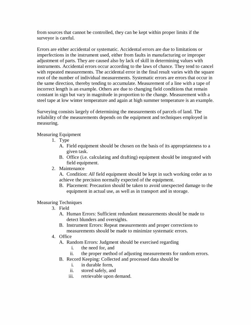
from sources that cannot be controlled, they can be kept within proper limits if the surveyor is careful. Errors are either accidental or systematic. Accidental errors are due to limitations or imperfections in the instrument used, either from faults in manufacturing or improper adjustment of parts. They are caused also by lack of skill in determining values with instruments. Accidental errors occur according to the laws of chance. They tend to cancel with repeated measurements. The accidental error in the final result varies with the square root of the number of individual measurements. Systematic errors are errors that occur in the same direction, thereby tending to accumulate. Measurement of a line with a tape of incorrect length is an example. Others are due to changing field conditions that remain constant in sign but vary in magnitude in proportion to the change. Measurement with a steel tape at low winter temperature and again at high summer temperature is an example.
Surveying consists largely of determining the measurements of parcels of land. The reliability of the measurements depends on the equipment and techniques employed in measuring.
Measuring Equipment 1. Type
A. Field equipment should be chosen on the basis of its appropriateness to a given task.
B. Office (i.e. calculating and drafting) equipment should be integrated with field equipment.
2. Maintenance A. Condition: All field equipment should be kept in such working order as to achieve the precision normally expected of the equipment. B. Placement: Precaution should be taken to avoid unexpected damage to the
equipment in actual use, as well as in transport and in storage.
Measuring Techniques 3. Field
A. Human Errors: Sufficient redundant measurements should be made to detect blunders and oversights.
B. Instrument Errors: Repeat measurements and proper corrections to measurements should be made to minimize systematic errors.
4. Office A. Random Errors: Judgment should be exercised regarding
i. the need for, and ii. the proper method of adjusting measurements for random errors.
B. Record Keeping: Collected and processed data should be i. in durable form,
ii. stored safely, and iii. retrievable upon demand.
When surveys are not carried out in accordance with a carefully prepared plan, many staff hours are lost, needed data are omitted, and many useless data are collected. The survey plan should contain the following:
(1) list of the data needed; (2) best method of obtaining the data; (3) degree of accuracy acceptable; (4) list of the people needed to perform the work; (5) list of needed equipment; and (6) complete time schedule for performing the survey work.
Chapter 4 Fieldwork EWB-USA projects cover all levels of required surveying accuracy, from general logistical assessment of a community and surrounding areas to precision measurements for structural projects. EWB projects are in every type of terrain and demographic region. Therefore, this section is intended to be a checklist of preparing for the survey and the basic concepts.
4.1 Preparation and Pre-Survey There are several sources of information that can be obtained for your project area and some surveying techniques that should be investigated prior to departing on the trip. This information will provide a better evaluation of the time and equipment that will be necessary to complete the survey. Caution should be used when using existing maps for design purposes as the source and reported accuracy may not be trustworthy.
Existing Maps Many nations have geologic and topographic information available. Whether it is available online or requires locating the Department/Ministry once in the country varies by nation. Free sources for locating the community are available online from sources such as http://www.fallingrain.com/world/ and http://earth.google.com/ . However, possibly the best free source information can often be obtained from the NGO or community that could draw a reasonable sketch of the survey area for you with relative distances and slopes. For a fee, archived satellite photography may be obtained from sources such as www.digitalglobe.com at relatively reasonable prices (less than $500 for a square kilometer). However, satellite photography will not provide topography. If the community location is not available on the archived data, or if you want topographic contours, then the fee increases by a couple orders of magnitude!
Basemaps The existing map information will serve as the basemap, or field map for the survey. The scale (if possible), north arrow (showing true and magnetic north), date and source of
existing map should be included on the basemap. For magnetic declination of the world, see http://geomag.usgs.gov/charts/ig00d.pdf.
Fieldnotes The fieldnotes include sketches, notes and the measurements of direction, distance and elevation. These notes are ultimately the survey and represent the time taken in the field and should be safeguarded by duplication by recording in a fieldbook as well as on the fieldmap. The fieldbook is the official record of the survey and should not be on loose leaf pages. Instead, a water-resistant fieldbook should be obtained for the project with the community and country clearly written on the cover. There are three general types of notes:
1. Tabulations: The numerical measurements are recorded in columns according to a prescribed plan depending on the instrument used, order of accuracy of the survey, and the type of measurement.
2. Sketches: Sketches clarify field notes and should be used liberally. They may be drawn to scale or approximate scale, or exaggerated for clarity. Measurements and direction should be added to the sketch.
3. Descriptions: Descriptions may be only one or two words to clarify the recorded measurements. More information.
Photos and Sketches One of the first things a geographer, or for that matter any field worker, should try to get his or her hands on well before going into the field is a good map or aerial photograph of the study area.
Benchmarks A relatively permanent point, natural or artificial, of known, absolute location is called a "bench mark." Often, these points are government documented.
Datum A temporary point of known, but non-governmentally-documented, relative location is called a "datum." In most cases, it is more convenient to tie features to a datum that is within the area of the basemap. It can be something as inconspicuous as the top of a cornerstone of a public building or a nail in the root of a baobab tree. Avoid using existing ground elevation as a datum as erosion may change the terrain.
Checking Level Accuracy Prior to Survey Over time, the line of sight may depart from level, causing error. The lines of error are shown greatly exaggerated (lines AY1, BY1 and EW1 below). The magnitude of error can be checked as follows:
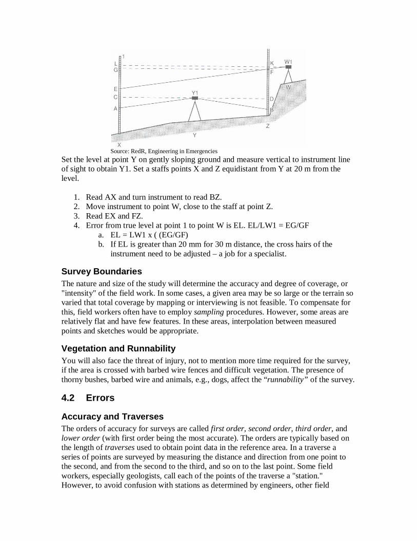
Source: RedR, Engineering in Emergencies
Set the level at point Y on gently sloping ground and measure vertical to instrument line of sight to obtain Y1. Set a staffs points X and Z equidistant from Y at 20 m from the level.
1. Read AX and turn instrument to read BZ. 2. Move instrument to point W, close to the staff at point Z. 3. Read EX and FZ. 4. Error from true level at point 1 to point W is EL. EL/LW1 = EG/GF
a. EL = LW1 x ( (EG/GF) b. If EL is greater than 20 mm for 30 m distance, the cross hairs of the
instrument need to be adjusted – a job for a specialist.
Survey Boundaries The nature and size of the study will determine the accuracy and degree of coverage, or "intensity" of the field work. In some cases, a given area may be so large or the terrain so varied that total coverage by mapping or interviewing is not feasible. To compensate for this, field workers often have to employ sampling procedures. However, some areas are relatively flat and have few features. In these areas, interpolation between measured points and sketches would be appropriate.
Vegetation and Runnability You will also face the threat of injury, not to mention more time required for the survey, if the area is crossed with barbed wire fences and difficult vegetation. The presence of thorny bushes, barbed wire and animals, e.g., dogs, affect the “runnability” of the survey.
4.2 Errors
Accuracy and Traverses The orders of accuracy for surveys are called first order, second order, third order, and lower order (with first order being the most accurate). The orders are typically based on the length of traverses used to obtain point data in the reference area. In a traverse a series of points are surveyed by measuring the distance and direction from one point to the second, and from the second to the third, and so on to the last point. Some field workers, especially geologists, call each of the points of the traverse a "station." However, to avoid confusion with stations as determined by engineers, other field
workers call the points of a traverse the "hubs," "corners" or just "points." The lines between the points are referred to by everyone as the "legs."
Often, closed traverses (i.e., begin and end at the same point) will not "close." That is, the ending point and the starting point might not coincide. This happens frequently and is in large part a function of the accuracy of equipment. The degree of accuracy tolerance is relative to the project. Generally speaking, it is a proportion of the traverse length.
♦ First Order Accuracy = 1:25,000 ♦ Second Order Accuracy = 1:10,000 ♦ Third Order Accuracy = 1:5,000 ♦ Lower Order Accuracy = User specified
Another way to assist in improving the accuracy of a traverse is to determine the azimuths and measure the distances of a few legs between two points that are not in sequence or next to each other. In effect, this is triangulation as triangles are being completed. The closure, or lack of it as the case may be, can be checked. If the gap or error is too great, all the legs should be re-measured and the bearings reread.
Chapter 5 Surveying Techniques Prior to departure, at least one member, preferably more, should have good knowledge of surveying techniques that may be needed in the given reference area. This section provides a brief overview of techniques required for the operation of an engineering transit.
5.1 Leveling and HOI Locating points in a vertical plane is called leveling. In direct leveling, a horizontal line of sight is established for the transit to establish a horizontal plane about the vertical axis of the level. The leveling operation consists of a reconnaissance of the terrain to find setup locations were the line of sight of the instrument is above the ground in all directions. Once a location has been selected, place the transit on a tripod and adjust the level to perpendicular to the axis of rotation using diametrically opposite leveling screws and a center bubble to the cross-hairs. Turn the telescope slowly about its vertical axis and make sure bubble is centered in cross-hairs in all directions. With one person holding a survey rod vertically on a point of known elevation, a level reading known as a backsight (BS) is taken as the vertical distance from the ground elevation at the point of known elevation (benchmark or datum) to the line of sight of the instrument. By adding this backsight reading to the known elevation, the line-of-sight elevation is determined. The height-of-instrument (HOI) is determined by either the benchmark elevation plus the backsight or measuring the vertical distance along a plumb line from the center of the instrument sight piece to the ground and adding to the ground elevation at that point. This vertical distance can be subtracted from the line of sight elevation to determine the ground elevation at the transit location.
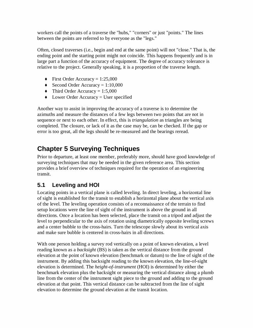
To establish elevations at new points, the staff is moved to a point of interest at an unknown elevation and a foresight (FS) shot to the point is taken. The vertical distance from the ground elevation at the point to the elevation of the line of sight is measured on the staff. By subtracting the foresight reading from the line-of-sight elevation, the elevation of the new point is established. This procedure is shown on the example below.
Source: Schaum’s Outline Introductory Surveying
Given: Distance Elevation
BM 10 to A = 50 ft. BS A to BM 10 = 4.250 ft. A to TP2 = 50 ft. FS A to TP 2 = 3.250 ft. TP 2 to B = 45 ft. BS B to TP 2 = 1.250 ft. B to TP3 = 45 ft. FS B to TP 3 = 2.750 ft. TP 3 to C = 51 ft. BS C to TP 3 = 1.750 ft. C to TP 4 = 53 ft. FS C to TP 4 = 0.525 ft. TP 4 to D = 73 ft. BS D to TP 4 = 4.100 ft. D to BM 11 = 75 ft. FS D to BM 11 = 1.750 ft. Notation: BM 1 elevation = 145.250 + BS + 4.250 HOI @ A = 149.500 - FS - 3.250 Elevation TP2 146.250 + BS + 1.250 HOI @ B = 147.500 -FS - 2.750 Elevation TP3 144.750 +BS + 1.750 HOI @ C = 146.500 - FS - 0.525 Elevation TP4 145.975 +BS + 4.100
HOI @ D = 150.075 - FS - 1.750 BM 2 elevation = 148.325 BM 1 elevation = 145.250 + sum of BS’s +11.350 - sum of FS’s - 8.275 Check of BM 2 148.325 (checks out with survey) Note: If only one known point, then the survey should continue and end with BM 1 as the last point to close the loop.
5.2 Horizontal Angle Measuring Some surveys follow the border of a figure or area and close (tie in) to the starting point. The angles inside the figure are interior angles and those outside are exterior angles. The accuracy of the angle readings can be determined by how close the end of the survey is to the first point or, if you can close the horizon, meaning the sum of interior angles equals the sum of angles in a closed polygon, i.e., (n-2)(180°), where n = the number of angles in the polygon. For converting degrees, minutes, seconds into decimal degrees, a useful website is http://www.fcc.gov/mb/audio/bickel/DDDMMSS-decimal.html.
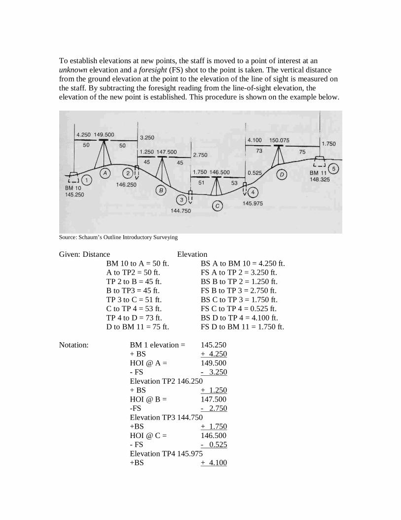
Bearing and Azimuth The azimuth of a line is the horizontal direction measured clockwise from a zero direction which points north from the station occupied. Azimuths are measured from north or south, and the angles vary from 0° to 360°. The bearing keeps measurements within quadrants with reference to a meridian (i.e., north or south) and, therefore angles are less than 90°. An example of the same direction in azimuth and bearing are would be 177° and South 03° East. This is shown below.
A traverse consists of a series of angles and distances, or distances and bearings (or azimuths). A closed traverse ends at the beginning point of the survey and should be conducted for most site maps in order to evaluate the accuracy of “closing” the loop. An open traverse continues on in more or less a continuous line, e.g., the survey of a road.
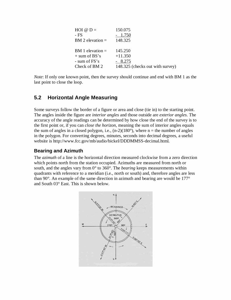
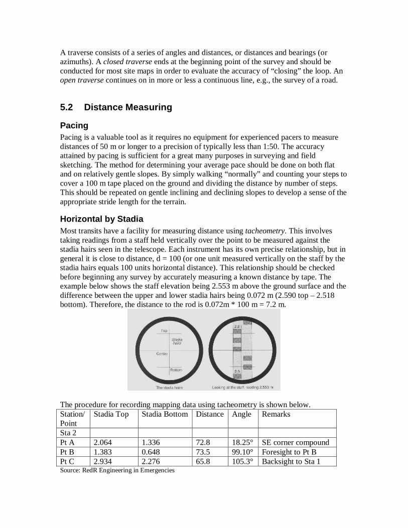
5.2 Distance Measuring
Pacing Pacing is a valuable tool as it requires no equipment for experienced pacers to measure distances of 50 m or longer to a precision of typically less than 1:50. The accuracy attained by pacing is sufficient for a great many purposes in surveying and field sketching. The method for determining your average pace should be done on both flat and on relatively gentle slopes. By simply walking “normally” and counting your steps to cover a 100 m tape placed on the ground and dividing the distance by number of steps. This should be repeated on gentle inclining and declining slopes to develop a sense of the appropriate stride length for the terrain.
Horizontal by Stadia Most transits have a facility for measuring distance using tacheometry. This involves taking readings from a staff held vertically over the point to be measured against the stadia hairs seen in the telescope. Each instrument has its own precise relationship, but in general it is close to distance, d = 100 (or one unit measured vertically on the staff by the stadia hairs equals 100 units horizontal distance). This relationship should be checked before beginning any survey by accurately measuring a known distance by tape. The example below shows the staff elevation being 2.553 m above the ground surface and the difference between the upper and lower stadia hairs being 0.072 m (2.590 top – 2.518 bottom). Therefore, the distance to the rod is 0.072m * 100 m = 7.2 m.
The procedure for recording mapping data using tacheometry is shown below. Station/Point
Stadia Top Stadia Bottom Distance Angle Remarks
Sta 2 Pt A 2.064 1.336 72.8 18.25° SE corner compound Pt B 1.383 0.648 73.5 99.10° Foresight to Pt B Pt C 2.934 2.276 65.8 105.3° Backsight to Sta 1 Source: RedR Engineering in Emergencies
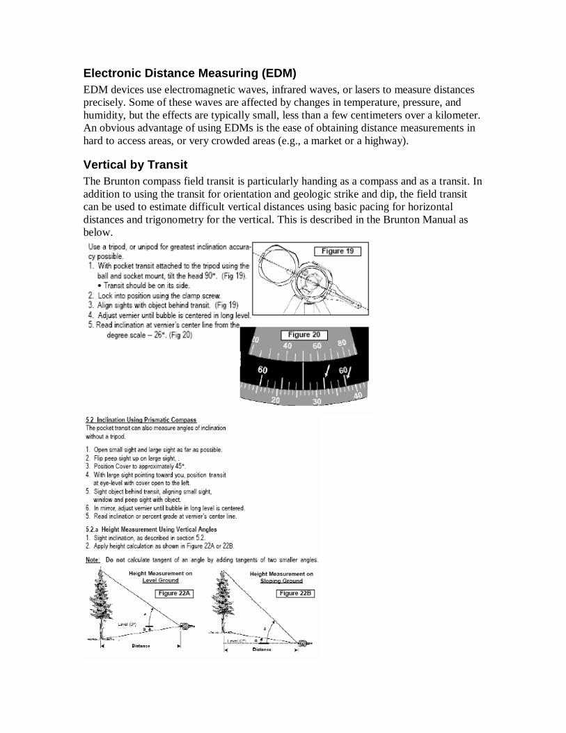
Electronic Distance Measuring (EDM) EDM devices use electromagnetic waves, infrared waves, or lasers to measure distances precisely. Some of these waves are affected by changes in temperature, pressure, and humidity, but the effects are typically small, less than a few centimeters over a kilometer. An obvious advantage of using EDMs is the ease of obtaining distance measurements in hard to access areas, or very crowded areas (e.g., a market or a highway).
Vertical by Transit The Brunton compass field transit is particularly handing as a compass and as a transit. In addition to using the transit for orientation and geologic strike and dip, the field transit can be used to estimate difficult vertical distances using basic pacing for horizontal distances and trigonometry for the vertical. This is described in the Brunton Manual as below.
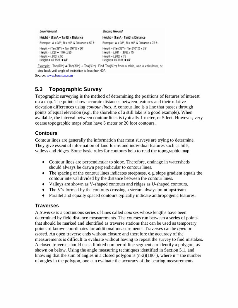
Source: www.brunton.com
5.3 Topographic Survey Topographic surveying is the method of determining the positions of features of interest on a map. The points show accurate distances between features and their relative elevation differences using contour lines. A contour line is a line that passes through points of equal elevation (e.g., the shoreline of a still lake is a good example). When available, the interval between contour lines is typically 1 meter, or 5 feet. However, very coarse topographic maps often have 5 meter or 20 foot contours.
Contours Contour lines are generally the information that most surveys are trying to determine. They give essential information of land forms and individual features such as hills, valleys and ridges. Some basic rules for contours help to read the topographic map.
♦ Contour lines are perpendicular to slope. Therefore, drainage in watersheds should always be drawn perpendicular to contour lines.
♦ The spacing of the contour lines indicates steepness, e.g. slope gradient equals the contour interval divided by the distance between the contour lines.
♦ Valleys are shown as V-shaped contours and ridges as U-shaped contours. ♦ The V’s formed by the contours crossing a stream always point upstream. ♦ Parallel and equally spaced contours typically indicate anthropogenic features.
Traverses A traverse is a continuous series of lines called courses whose lengths have been determined by field distance measurements. The courses run between a series of points that should be marked and identified as traverse stations that can be used as temporary points of known coordinates for additional measurements. Traverses can be open or closed. An open traverse ends without closure and therefore the accuracy of the measurements is difficult to evaluate without having to repeat the survey to find mistakes. A closed traverse should use a limited number of line segments to identify a polygon, as shown on below. Using the angle measuring techniques identified in Section 5.1, and knowing that the sum of angles in a closed polygon is (n-2)(180°), where n = the number of angles in the polygon, one can evaluate the accuracy of the bearing measurements.
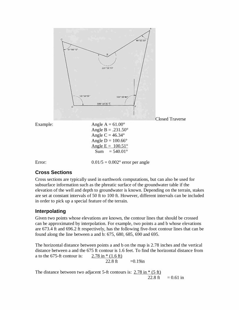
Closed Traverse Example: Angle A = 61.00° Angle B = .231.50° Angle C = 46.34° Angle D = 100.66° Angle E = 100.51° Sum = 540.01° Error: 0.01/5 = 0.002° error per angle
Cross Sections Cross sections are typically used in earthwork computations, but can also be used for subsurface information such as the phreatic surface of the groundwater table if the elevation of the well and depth to groundwater is known. Depending on the terrain, stakes are set at constant intervals of 50 ft to 100 ft. However, different intervals can be included in order to pick up a special feature of the terrain.
Interpolating Given two points whose elevations are known, the contour lines that should be crossed can be approximated by interpolation. For example, two points a and b whose elevations are 673.4 ft and 696.2 ft respectively, has the following five-foot contour lines that can be found along the line between a and b: 675, 680, 685, 690 and 695. The horizontal distance between points a and b on the map is 2.78 inches and the vertical distance between a and the 675 ft contour is 1.6 feet. To find the horizontal distance from a to the 675-ft contour is: 2.78 in * (1.6 ft) 22.8 ft =0.19in The distance between two adjacent 5-ft contours is: 2.78 in * (5 ft) 22.8 ft = 0.61 in
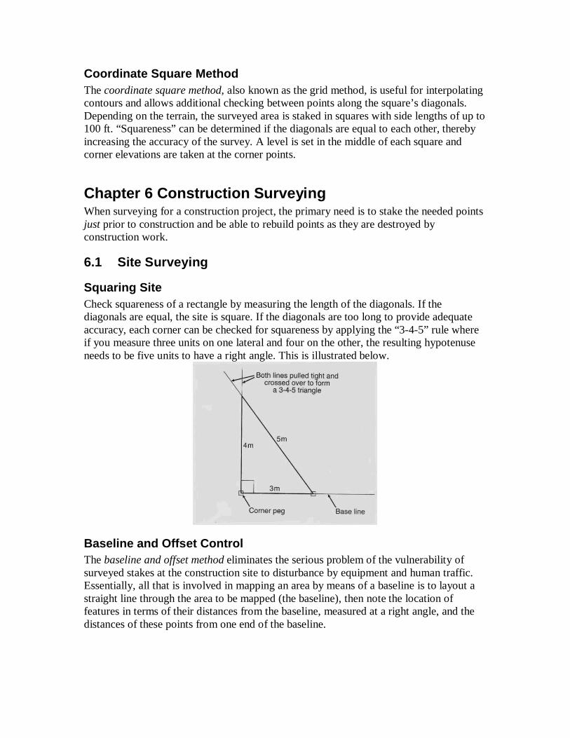
Coordinate Square Method The coordinate square method, also known as the grid method, is useful for interpolating contours and allows additional checking between points along the square’s diagonals. Depending on the terrain, the surveyed area is staked in squares with side lengths of up to 100 ft. “Squareness” can be determined if the diagonals are equal to each other, thereby increasing the accuracy of the survey. A level is set in the middle of each square and corner elevations are taken at the corner points.
Chapter 6 Construction Surveying When surveying for a construction project, the primary need is to stake the needed points just prior to construction and be able to rebuild points as they are destroyed by construction work.
6.1 Site Surveying
Squaring Site Check squareness of a rectangle by measuring the length of the diagonals. If the diagonals are equal, the site is square. If the diagonals are too long to provide adequate accuracy, each corner can be checked for squareness by applying the “3-4-5” rule where if you measure three units on one lateral and four on the other, the resulting hypotenuse needs to be five units to have a right angle. This is illustrated below.
Baseline and Offset Control The baseline and offset method eliminates the serious problem of the vulnerability of surveyed stakes at the construction site to disturbance by equipment and human traffic. Essentially, all that is involved in mapping an area by means of a baseline is to layout a straight line through the area to be mapped (the baseline), then note the location of features in terms of their distances from the baseline, measured at a right angle, and the distances of these points from one end of the baseline.
The baseline method is often used with offset to stake the proposed structure when either a well defined property line or the wall of an existing building is relatively close to the project. Distances (offset) are then pulled from these baselines to establish control.
6.2 Earthwork In road and other major construction projects, where the movement of large volumes or earth is necessary, accurate estimates are critical to schedule the number of workers, equipment and time necessary. Earthwork computations are as accurate as the survey that has determined the cross sections needed for estimating. These cross sections are also critical on long roads where understanding where cut and fill locations are helpful to stage the entire project. Typically, estimates are made from cross sections with two lines; one showing the existing ground surface (dashed) and the other line showing proposed grade (solid). Where the solid line is below the dashed – cut is required and when the solid is above the dashed - fill is required. The following techniques are used in estimating earthwork.
Areas Cross sectional areas between the existing and proposed can be determined by simple geometry if the grades are more or less straight lines. If the topography is irregular and the proposed grade is not a continuous grade through the cut, plotting the cross section to scale on engineering graph paper and counting squares to estimate the volume is acceptable. Of course, when you’re not in the field, AutoCAD or a planimeter are preferable.
Chapter 7 Care of Instruments
7.1 Service and Repair To a great extent, the accuracy and quality of your surveys will depend upon how well you take care of your surveying equipment; therefore, the proper instrument handling, stowing, and maintenance is very important. While to some readers this review may seem redundant, taking care of your equipment properly cannot be overemphasized. In this chapter we also discuss instrument adjustment and repair. As used in this chapter, the term adjustment means bringing the various fixed parts of an instrument into proper relationship with one another. It is different from the ordinary operations of leveling the instrument, aligning the telescope, and so forth. As you know, every instrument is accompanied by a user’s manual that tells you not only the proper operation and components of the instrument but also its proper care and maintenance. Study this user’s manual thoroughly before you even attempt to use the instrument. Some suggestions for the care and maintenance of surveying equipment are discussed in the following paragraphs.
7.2 Handling, Carrying and Storing Always exercise care in handling instruments. When removing an instrument from its carrying case, NEVER grasp the telescope. Wrenching the telescope in this manner could damage a number of delicate parts. When you set up an instrument, make sure that it is securely fastened to the tripod head. In tightening the various clamp screws, leveling screws, and adjustment screws, bring them only to a firm bearing. Overtightening these screws may strip the threads, twist off the screw, bend the connecting part, or place undue stresses in the instrument. NEVER leave an instrument unattended while it is set upon a street, near construction work or in any other place where it can be damaged. When you carry an instrument mounted on a tripod, place the instrument and tripod on one shoulder with the tripod legs pointing forward and held together by your hand and forearm. If you are walking alongside a hill, you should always carry the instrument on the downhill shoulder. This leaves the uphill arm and hand free to catch yourself should you trip or stumble. Before climbing over a fence, you should first place the instrument on the other side with the tripod legs well spread. Also, when carrying an instrument, you should ensure that all clamp screws are only lightly clamped so that the parts will move if the instrument is struck. Avoid carrying the instrument on your shoulder through doorways or beneath low-hanging branches; instead, you should carry it under your arm with the head of the instrument to the front. Every instrument comes equipped with a carrying box or case. The instrument and its accessories can be stowed in the case in a manner that ensures a minimum of motion during transportation. The instrument should ALWAYS be stowed in the carrying case when it is not in use. Bags are provided for carrying stakes and hubs. These are usually canvas bags equipped with a shoulder strap and closely resemble a newsboy’s bag. A newsboy’s bag, in fact, makes an excellent carrying bag for stakes and hubs. So does a Navy seabag, equipped with a shoulder strap. Various types of leather or canvas bags and sheaths, such as chaining-pin quivers, plumb-bob sheaths, and sheaths for Abney and Locke levels, are provided for various items of equipment. Most of these can be attached to the belt. Leather pouches, also usually attachable to the belt, are available for carrying small tools, marking equipment, turning-point pins, and the like. In time you will learn various conveniences, such as carrying your supply of surveyor’s tacks stuck in a rubber ball or in a piece of softwood attached to your belt
7.3 Cleaning and Lubrication All surveying instruments, equipment, or tools must be thoroughly cleaned immediately after you have used them; for example, after each use, you must dust off the instrument and wipe it dry before placing it back in its case. Remove all dust with a soft brush before wiping dirty components with a clean cloth. When the carrying case and dry it thoroughly at room temperature once you get home. NEVER leave a wet instrument stored in the carrying case. NEVER rub the lenses of a telescope with your fingers or with a rough cloth. Clean chamois leather or a lint-free soft cloth is suitable for this purpose. Occasionally, you may clean the lenses with a soft cloth that is dampened with a mixture
of equal parts of water and alcohol. You should always remove mud and dirt from tripods, range poles, leveling rods, and so forth, immediately after each use. This is very important, especially when the surveying gear is made of a material that is susceptible to rust action or decay. When lubricating instruments, you must use the right lubricant that is recommended for the climatic condition in your area; for instance, it is recommended that graphite be used to lubricate the moving parts of a transit when the transit is to be used in sub-zero temperatures; however, in warmer climates you should use alight film of oil (preferably watch oil). Consult the manufacturer’s manual whenever you are in doubt before doing anything to an instrument.
7.4 Instrument Adjustment and Repair Making minor adjustments and minor repairs to surveying instruments are among the responsibilities of the survey crew. Minor adjustments and minor repairs are those that can generally be done in the field using simple tools. Major adjustments and major repairs are those generally done in the factory. If the defect in the instrument cannot be corrected by minor adjustment or minor repair, do not attempt to disassemble it; instead, make necessary arrangements for sending the instrument to the manufacturer. Most surveying instruments are precision instruments for which major adjustments and recalibration require special skills and tools that can be provided only by the instrument company or its subsidiaries.
Instrument Adjustment As stated previously, adjustment, as used in this chapter, means the process of bringing the various parts of an instrument into proper relationship with one another. The ability to make these adjustments is an important qualification of any surveyor. To make proper adjustments, the surveyor should have the following knowledge: 1. They must be familiar with the principles upon which the adjustments are based. 2. They must know the methods or tests used to determine if an instrument is out of adjustment. 3. They must know the procedure for making adjustments and the correct sequence by which adjustments must be made. 4. They must be able to tell what effect the adjustment of one part will have on other parts of the instrument. 5. They must understand the effect of each adjustment upon the instrument when it is actually used for measurement. Generally, instrument adjustments involve the level tubes, the telescope, and the reticle; for example, if one or both of the plate-level bubbles of an engineer’s transit are centered when the plate is, in fact, not level, the instrument is out of adjustment. An optical instrument equipped with vertical and horizontal cross hairs is out of adjustment if the point of intersection between the cross hairs does not coincide with the optical axis. If the reflected bubble on a Locke or Abney level is centered when the optical axis is other than horizontal, the instrument is out of adjustment. The process of adjustment chiefly involves the steps that are necessary to bring a bubble to center when it should be at
center or to bring a cross-hair point of intersection into coincidence with the optical axis. Instrument manufacturers publish handbooks containing recommended adjustment procedures. These are usually small pamphlets, obtainable free of charge. The following discussion is intended to give you an idea of general instrument adjustment procedures. For adjusting your particular instruments, however, you should follow the appropriate manufacturer’s instructions.
General Adjustment Procedures Instruments should be carefully checked periodically to determine whether or not they need adjustment. There is an adage that an instrument should be checked frequently but adjusted rarely. The basis for this adage is the fact that modern quality instruments get out of adjustment much less frequently than is generally believed; consequently, a need for adjustment is frequently caused by a previous improper adjustment that was not really required but resulted from errors in checking. Before assuming that the adjustment is necessary, you must positively ascertain that an apparent maladjustment actually exists. The following procedures apply, in general, to all tripod-mounted optical instruments that you may use in surveying: 1. Check the instrument on a cloudy day, if possible. 2. Ascertain that the tripod shoes are tight and that the instrument is screwed all the way down on the tripod. 3. Set the tripod up on firm ground in the shade, but in a good light, where a sight of at least 200 feet can be taken in opposite directions. 4. Spread the tripod feet well apart and place them so that the plate is approximately level. Press the shoes in firmly, or set them in cracks or chipped depressions if on a hardened surface. (Avoid setting up on asphalt pavement in warm weather.) 5. After the tripod feet are set, release and then retighten the wing nuts. The purpose of this is to release any possible residual friction that, if not released, might cause an eventual shift in the legs. 6. Level the instrument with particular care. After leveling, loosen all level screws slightly (again to release residual friction) and relevel. Tighten all screws with equal firmness but avoid overtightening. Too much tightness will eventually deform the centers, causing both friction and play. 7. Carry out all checks in the order prescribed for the instrument. Do NOT make an adjustment unless the same check, repeated at least three times, indicates the same amount of error every time. 8. Remember that most tests show an error that is double the actual displacement error in the instrument. Be especially watchful for creep; that is, a change in position caused by settlement or by temperature change in the instrument. To detect any possible creep, you should allow every set bubble or setline of sight to stand for a few seconds and ensure that no movement occurs during the interval. Before an adjustment is made, consider whether or not the error discovered will have a material effect on field results. Make adjustments in a prescribed order. After making an adjustment, retighten the adjusting parts firmly but not too tightly. Then repeat the original check and readjust if necessary. After making all the
contemplated adjustments, repeat the entire round of checks in the prescribed order. This will indicate whether or not an adjustment has been disturbed by a subsequent adjustment. While the principles of performing the adjustments are nearly the same for one manufacturer’s level or transit as compared to those produced by another manufacturer, there are some differences in detail. For this reason, when preparing to perform an adjustment to an instrument, you should first consult the operator’s manual for that instrument. When a high degree of accuracy is required for surveying results, the level or transit used must be in perfect adjustment. In this event, you must perform the tests described in the following sections and make any necessary adjustments to the instrument. When results of lower accuracy can be tolerated, however, you can usually compensate for the maladjustment of a part until a proper adjustment can be made. Therefore, at the end of each of the following instrument-adjustment discussions, a method of compensating for the maladjustment is noted. You should keep in mind, however, that if you frequently check your instruments and keep them in good adjustment, these compensations should seldom be necessary.
7.5 Engineer’s Level Adjustments Regardless of how well an engineer’s level is manufactured, you should perform certain checks and field adjustment at regular intervals; for example, you should test the instrument every day before starting work. You also should check it for proper adjustment anytime the level is bumped or jolted. The parts of the level that you will check are the level tube and the cress hairs. For the latter, be sure that parallax is removed and that the cross hairs and objective are sharply focused. To do this, use a well-defined object at least 250 feet away. When parallax is present, the image is not exactly in the plane of the cross hairs, and the objective focusing must be refined. Since this condition can occur each time the objective lens is focused, you must make a parallax check each time you observe a new object. When adjusting the engineer’s level, it is important that you accomplish the tests and adjustments in a prescribed sequence. The reason for this is that one adjustment may depend upon, or alter, another adjustment. The following paragraphs describe, in proper sequence, the test and adjustment procedures that you should follow when checking and adjusting the engineer’s level.
7.6 Maintaining Tapes Steel tapes are broken easily if not handled properly. They should not be jerked needlessly, stepped on, bent around sharp corners, or run over by vehicles. The most common cause of a broken tape is pulling on it when there is a loop or kink in it. Slight deformations caused by kinking should be straightened carefully. Insofar as practicable, avoid dragging the tape with markings face down, because abrasive action will remove markings. In spite of reasonable care, tapes will be broken occasionally, so a tape repair kit is necessary if you use steel tapes and chains. After each day's use, wipe the tapes dry and clean them with a clean cloth. After being cleaned, steel tapes should be given a light
covering of oil by wiping with an oily cloth. Steel tapes and chains are often wound on a reel for storage and ease of handling.
7.7 Transporting Surveying Instruments and Accessor ies Surveying instruments should be carried in the instrument case in the cab of the vehicle, preferably on the floor or in a well-padded equipment box. Rods should be in cases and carried where they will be protected from weather and from materials being piled on top of or against them. Tripods and other surveying equipment should be similarly protected from damage and the weather.
7.8 Customs
You can't afford to ignore the other country's customs procedures. Delays at customs could potentially affect your project. Laws are subject to interpretation, and if you get a customs supervisor who doesn't understand the law, it can get dicey. You usually don't have problems — but if you do, they tend to be big problems. Make sure that you are familiar with customs authorities’ requirements and practices and that the goods can be released from customs on a timely basis.
Your customs arrangements will depend on the product and its foreign market. To ensure your compliance with local customs regulations you should understand your target country's requirements, either through your own research or by obtaining expert advice. Often we’re not aware of the documents they need to clear customs in the target market.
Registering all equipment with U.S. Customs on your way out of the country reduces questions about whether it was purchased during your trip. Problems typically occur at re-entry — and registering equipment with a foreign customs agency may not work if the value of a single piece of equipment exceeds $1,500.
One way to avoid these problems is to use either a customs broker — who will typically charge a couple hundred dollars for the service — or a carnet, a document that proves you're the owner of the equipment and that you'll be leaving the country with the same equipment you brought in. One caveat in certain Third World countries, carnets may or may not be of help, because customs law there may be so esoteric they don't recognize the document. Follow these basic guidelines for getting your exports smoothly through foreign customs:
1. Complete all customs requirements before you ship or bring the goods. Don't wait until they're at the border to discover that you need a pre-shipment inspection certificate or an import permit or license. 2. Make sure the documents are consistent and complete in terms of quantities, descriptions and so on. For example, when using part numbers, also provide a written description that will help classify the goods for customs purposes.
3. Make sure the documents match the shipment exactly. If you toss in a few promotional items at the last moment and they're not on the invoice, it may create problems for your importer. 4. If you use a customs broker, make sure you pick a reputable one. If possible, also choose a broker who deals with your type of product. 5. Finally obtain expert advice from sources familiar with that market's customs procedures and regulations.
Chapter 8 Source of Supply General Equipment http://www.forestry-suppliers.com http://www.benmeadows.com Land Surveying References http://www.lsrp.com http://www.johann-sandra.com/surveying/land-surveying-links.htm http://www.tpub.com/content/engineering/14069/index.htm http://www.info.usda.gov/CED/ftp/CED/EFH-Ch01.pdf http://www.info.usda.gov/CED/ftp/CED/tr62.pdf http://www.usace.army.mil/usace-docs/eng-manuals/em1110-1-1005/toc.htm Software http://www.sonic.net/~trollhei/survsoft.html free surveying software Maps http://www.usgs.gov/ http://earth.google.com/earth_pro.html http://geomag.usgs.gov/charts/ig00d.pdf Compasses, Transits, GPS http://www.brunton.com/ http://www.silva.se/ http://www.magellangps.com http://www.gpstm.com/ http://gpsinformation.net/
Chapter 9 References 1. Jan Davis and Robert Lambert, RedR. Engineering in Emergencies: A Practical
Guide for Relief Workers. ITDG Publishing. 1995.
2. James R. Wirshing and Roy H. Wirshing, Schaum’s Outlines, Introductory Surveying. McGraw-Hill Publishing. 1985
Related Documents


