INCOSE MBSE Focus Group Survey of Candidate Model-Based Engineering (MBSE) Methodologies Page 1 of 47 Rev. A May 25, 2007 INCOSE MBSE Focus Group Survey of Model-Based Systems Engineering (MBSE) Methodologies Jeff A. Estefan Jet Propulsion Laboratory California Institute of Technology Pasadena, California, U.S.A. [email protected] 1. Introduction 1.1 Purpose The purpose of this report is to provide a cursory description of some of the leading Model- Based Systems Engineering (MBSE) methodologies used in industry today. It is intended that the material described herein provides a direct response to the INCOSE MBSE Roadmap element for a “Catalog of MBSE lifecycle methodologies.” In this report, a methodology is defined as a collection of related processes, methods, and tools [1]. A MBSE methodology can be characterized as the collection of related processes, methods, and tools used to support the discipline of systems engineering in a “model- based” or “model-driven” context. The intent of this survey is to educate the reader— principally, members of the INCOSE MBSE Focus Group—about the various candidate MBSE methodologies that are commercially available as well as the control- and state-based MBSE methodology that has been developed at NASA’s Jet Propulsion Laboratory (JPL), which has been published in the open literature. 1.2 Scope This memo describes the result of a MBSE methodology survey only; it is not a methodology assessment. The material contained herein is expected to be reviewed and shared by the INCOSE MBSE Focus Group and its governing leaders. It should be noted that this is a cursory survey and only the top-level synopses of each candidate methodology is described. Detailed descriptions of each can be found in the cited references. As will be described, tools are an important element of any MBSE methodology; however, a survey of MBSE tools is beyond the scope of this report. It is expected that during an organization’s candidate MBSE methodology assessment process (including impact to native processes and procedures), a tool survey and assessment will occur concurrently or shortly thereafter, followed by selection and piloting of relevant tools. This latter effort requires participation from the organization’s systems engineering practitioner community because that is the community that will most heavily be using the tools. It is intended that this report be a living document and updated on a periodic basis based on feedback and input by members of the INCOSE community at large. 1.3 Overview This memo is organized as follows: Section 2 characterizes the difference between methodologies and processes, methods, and lifecycle models (development, acquisition, and

Welcome message from author
This document is posted to help you gain knowledge. Please leave a comment to let me know what you think about it! Share it to your friends and learn new things together.
Transcript
INCOSE MBSE Focus Group
Survey of Candidate Model-Based Engineering (MBSE) Methodologies Page 1 of 47
Rev. A May 25, 2007
INCOSE MBSE Focus Group
Survey of Model-Based Systems Engineering (MBSE) Methodologies
Jeff A. Estefan
Jet Propulsion Laboratory
California Institute of Technology
Pasadena, California, U.S.A.
1. Introduction
1.1 Purpose
The purpose of this report is to provide a cursory description of some of the leading Model-
Based Systems Engineering (MBSE) methodologies used in industry today. It is intended
that the material described herein provides a direct response to the INCOSE MBSE Roadmap
element for a “Catalog of MBSE lifecycle methodologies.”
In this report, a methodology is defined as a collection of related processes, methods, and
tools [1]. A MBSE methodology can be characterized as the collection of related processes,
methods, and tools used to support the discipline of systems engineering in a “model-
based” or “model-driven” context. The intent of this survey is to educate the reader—
principally, members of the INCOSE MBSE Focus Group—about the various candidate MBSE
methodologies that are commercially available as well as the control- and state-based MBSE
methodology that has been developed at NASA’s Jet Propulsion Laboratory (JPL), which has
been published in the open literature.
1.2 Scope
This memo describes the result of a MBSE methodology survey only; it is not a methodology
assessment. The material contained herein is expected to be reviewed and shared by the
INCOSE MBSE Focus Group and its governing leaders. It should be noted that this is a
cursory survey and only the top-level synopses of each candidate methodology is described.
Detailed descriptions of each can be found in the cited references.
As will be described, tools are an important element of any MBSE methodology; however, a
survey of MBSE tools is beyond the scope of this report. It is expected that during an
organization’s candidate MBSE methodology assessment process (including impact to native
processes and procedures), a tool survey and assessment will occur concurrently or shortly
thereafter, followed by selection and piloting of relevant tools. This latter effort requires
participation from the organization’s systems engineering practitioner community because
that is the community that will most heavily be using the tools.
It is intended that this report be a living document and updated on a periodic basis based
on feedback and input by members of the INCOSE community at large.
1.3 Overview
This memo is organized as follows: Section 2 characterizes the difference between
methodologies and processes, methods, and lifecycle models (development, acquisition, and

INCOSE MBSE Focus Group
Survey of Candidate Model-Based Engineering (MBSE) Methodologies Page 2 of 47
Rev. A May 25, 2007
INCOSE MBSE Focus Group
systems engineering). Also described is the role of models in the systems engineering
process. Section 3 documents the survey results of leading MBSE methodologies used in
industry. Section 4 describes the role of the Object Management Group™ (OMG™) Unified
Modeling Language™ (UML®) and Systems Modeling Language™ (OMG SysML™), which are
industry-standard, visual modeling languages used to support the disciplines of software
and systems engineering, and how these modeling standards relate to MBSE methodologies.
Section 5 provides a list of references used in preparation of this survey report and for the
benefit of the reader. Finally, Section 6 provides a list of acronyms and abbreviations used
in this report.
2. Differentiating Methodologies from Processes, Methods, and Lifecycle Models
In order to better understand key features of the various leading MBSE methodologies
surveyed in this study, it is critically important to establish the terminology associated with
processes, methods, and methodology, and to acknowledge the myriad lifecycle models
used in the acquisition and development of large-scale, complex systems. Without such
grounding, it will be extremely difficult to map any assessment and selection of candidate
MBSE methodologies into the fabric of the systems engineering environment within a
particular organization.
2.1 Process, Method, Tool, Methodology, and Environment Defined
The word methodology is often erroneously considered synonymous with the word process.
For purposes of this study, the following definitions from Martin [1] are used to distinguish
methodology from process, methods, and tools:
� A Process (P) is a logical sequence of tasks performed to achieve a particular
objective. A process defines “WHAT” is to be done, without specifying “HOW” each
task is performed. The structure of a process provides several levels of aggregation
to allow analysis and definition to be done at various levels of detail to support
different decision-making needs.
� A Method (M) consists of techniques for performing a task, in other words, it defines
the “HOW” of each task. (In this context, the words “method,” “technique,”
“practice,” and “procedure” are often used interchangeably.) At any level, process
tasks are performed using methods. However, each method is also a process itself,
with a sequence of tasks to be performed for that particular method. In other words,
the “HOW” at one level of abstraction becomes the “WHAT” at the next lower level.
� A Tool (T) is an instrument that, when applied to a particular method, can enhance
the efficiency of the task; provided it is applied properly and by somebody with
proper skills and training. The purpose of a tool should be to facilitate the
accomplishment of the “HOWs.” In a broader sense, a tool enhances the “WHAT”
and the “HOW.” Most tools used to support systems engineering are computer- or
software-based, which also known as Computer Aided Engineering (CAE) tools.
Based on these definitions, a methodology can be defined as a collection of related
processes, methods, and tools. A methodology is essentially a “recipe” and can be thought
of as the application of related processes, methods, and tools to a class of problems that all
have something in common [2].

INCOSE MBSE Focus Group
Survey of Candidate Model-Based Engineering (MBSE) Methodologies Page 3 of 47
Rev. A May 25, 2007
INCOSE MBSE Focus Group
Associated with the above definitions for process, methods (and methodology), and tools is
environment. An Environment (E) consists of the surroundings, the external objects,
conditions, or factors that influence the actions of an object, individual person or group [1].
These conditions can be social, cultural, personal, physical, organizational, or functional.
The purpose of a project environment should be to integrate and support the use of the
tools and methods used on that project. An environment thus enables (or disables) the
“WHAT” and the “HOW.”
A visual graphic that depicts the relationship between the so-called “PMTE” elements
(Process, Methods, Tools, and Environment) is illustrated in Figure 2-1 along with the
effects of technology and people on the PMTE elements.
Figure 2-1. The PMTE Elements and Effects of Technology and People.
As stated by Martin [1], the capabilities and limitations of technology must be considered
when developing a systems engineering development environment. This argument extends,
of course, to an MBSE environment. Technology should not be used “just for the sake of
technology.” Technology can either help or hinder systems engineering efforts. Similarly,
when choosing the right mix of PMTE elements, one must consider the knowledge, skills and
abilities (KSA) of the people involved [1]. When new PMTE elements are used, often the
KSAs of the people must be enhanced through special training and special assignments.
2.2 Lifecycle Development Models
A number of lifecycle development models have been created and applied to large-scale
system and software development projects used in government, industry, and academia,
but most are grounded in one of three seminal models. These are 1) Royce’s Waterfall
Model [3], Boehm’s Spiral Model [4], and Forsberg and Moog’s “Vee” Model [5,6]. A
graphical depiction of each of these lifecycle development models is shown in Figure 2-2.
There are large volumes of literature that describe each of these models; therefore,
elaboration of each will not be provided here. Suffice it to say that variations of the
waterfall and spiral models to support structured as well as iterative and incremental
development have been used extensively in software development projects, while the “Vee”
model and modified versions of the “Vee” have been applied extensively in the areas of
systems engineering and systems development.
In addition to recognizing that such major lifecycle development models exist, they can also
serve as meta-models for lifecycle development. In other words, they provide the lifecycle

INCOSE MBSE Focus Group
Survey of Candidate Model-Based Engineering (MBSE) Methodologies Page 4 of 47
Rev. A May 25, 2007
INCOSE MBSE Focus Group
development templates on which project- or domain-specific plans are built. This will be
more evident during the review of the various MBSE methodologies described in Section 3,
many of which leverage one of these three lifecycle development models.
(a) (b)
(c)
Figure 2-2. Seminal Lifecycle Development Models: (a) Waterfall,
(b) Spiral, (c) “Vee”.
2.3 Acquisition Lifecycle Models
U.S. Government departments and agencies such as the U.S. Department of Defense (DoD)
and the National Aeronautics and Space Administration (NASA) are responsible for
managing billions of tax payer dollars annually in the development and acquisition of large-
scale, complex systems. Consequently, these agencies must follow rigid acquisition
guidelines to insure that they are good stewards of U.S. tax payer dollars, and that there is
accountability for investment in such large-scale, potentially very costly programs.

INCOSE MBSE Focus Group
Survey of Candidate Model-Based Engineering (MBSE) Methodologies Page 5 of 47
Rev. A May 25, 2007
INCOSE MBSE Focus Group
DoD acquisition reform was instituted in May 2003 to help streamline the defense
acquisition process, which in the past, was so onerous it took literally decades to field new
weapons systems. DoD best practices for acquisition are rooted in DoD policy directives and
instructions, namely, DoD Directive (DoDD) 5000.1 The Defense Acquisition System and
DoD Instruction (DoDI) 5000.2 Operation of the Defense Acquisition System [7,8]. DoD’s
revised acquisition policy includes a lifecycle framework and is depicted in Figure 2-3.
Figure 2-3. DoD Lifecycle Framework.
Milestone A represents the start of the development phase, Milestone B represents program
start, and Milestone C represents production commitment. Milestones correspond to
decision “gates” on which major programmatic decisions (e.g., funding) are made during
gate review processes. IOC and FOC are abbreviations for Initial and Full Operational
Capability, respectively. Further elaboration of the DoD acquisition lifecycle model will not
be provided here. What is important to note for this report is that the acquisition model
contains key lifecycle phases as well as decision milestones and gate reviews.
Similar to the DoD acquisition lifecycle model, the NASA lifecycle model has a set of key
lifecycle phases as well as decision milestones and gate reviews (see Figure 2-4).
Figure 2-4. NASA Project Lifecycle.

INCOSE MBSE Focus Group
Survey of Candidate Model-Based Engineering (MBSE) Methodologies Page 6 of 47
Rev. A May 25, 2007
INCOSE MBSE Focus Group
NASA best practices for acquisition are rooted in NASA policy directives and requirements;
specifically, NASA Policy Directive (NPD) 7120.4 Program/Project Management and NASA
Policy Requirement (NPR) 7120.5 NASA Program and Project Management Processes and
Requirements [9,10]. Because NASA is a federal agency, programs the agency funds must
also pass decision milestones and gate reviews to ensure programs are meeting cost,
schedule, and technical baselines.
As with the development lifecycle models described in Section 2.2, the DoD and NASA
acquisition lifecycle models captured here can be considered meta-models on which project-
or domain-specific plans are built. Development lifecycles and acquisition lifecycles differ in
many ways, but the critical difference between them is that development lifecycles can be
applied one or more times during a single acquisition lifecycle.
One of the reasons for describing acquisition models as part of this MBSE survey is to
acknowledge the heritage of these traditional, document-driven, programmatic reviews and
the challenge organizations face when attempting to adopt more advanced, electronic- or
model-driven techniques such as MBSE. Traditionally, acquisition program reviews have
relied on paper documents, because that was the state-of-the-art at the time government
acquisition lifecycle models were first initiated [11]. Advances in information technology
over the last decade or so have afforded the opportunity to create “electronic” documents
using Microsoft® Word and PowerPoint and Adobe® Acrobat®; however, such electronic
resources are still often considered “hardcopy” document artifacts. This is evident as these
artifacts are almost always printed on paper for members of review boards during decision
milestone and gate reviews. Despite the fact that information technology has advanced to a
point where the technology can easily support fully electronic- or model-driven
programmatic reviews, the traditional document-driven approach is likely to continue for the
foreseeable future. Therefore, whatever MBSE methodology and approach that is assessed
and utilized by an organization will have to ultimately map back to the organization’s project
lifecycle and decision milestones and gates (and subsequently gate products) as part of the
programmatic review process.
2.4 Systems Engineering Process Standards and Capability Models
A systems engineering (SE) process is a process model that defines the primary activities
(“WHAT”) that must be performed to implement systems engineering. SE processes are
related to the phases in an acquisition lifecycle model in that the process usually begins at
an early stage of the system lifecycle, typically the very beginning of a project; however, on
some occasions, the SE process can also begin at the middle of an acquisition lifecycle.
A variety of SE process standards have been proposed by different international standards
bodies, but most SE process standards in use today have evolved from the early days of
DoD-MIL-STD 499. The heritage of these SE process standards together with industry
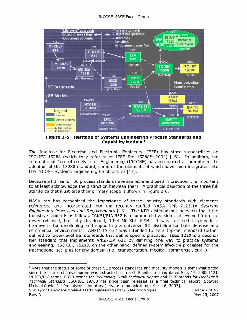
standard capability models and the relationship between them is illustrated in Figure 2-5
[12]. Also shown is the relationship to relevant ISO/IEC software process standards.
The ANSI/EIA 632 Processes for Engineering a System standard [13] and the IEEE 1220-
1998 Standard for Application and Management of the Systems Engineering Process [14]
were sources into the creation of ISO/IEC 15288:2002 Systems Engineering—System Life
Cycle Processes [15]. ISO/IEC 19760 Guide for ISO/IEC 15288 — System Life Cycle
Processes is, as the name implies, a guidance document for ISO/IEC 15288.
INCOSE MBSE Focus Group
Survey of Candidate Model-Based Engineering (MBSE) Methodologies Page 7 of 47
Rev. A May 25, 2007
INCOSE MBSE Focus Group
Figure 2-5. Heritage of Systems Engineering Process Standards and
Capability Models.1
The Institute for Electrical and Electronic Engineers (IEEE) has since standardized on
ISO/IEC 15288 (which they refer to as IEEE Std 15288™-2004) [16]. In addition, the
International Council on Systems Engineering (INCOSE) has announced a commitment to
adoption of the 15288 standard, some of the elements of which have been integrated into
the INCOSE Systems Engineering Handbook v3 [17].
Because all three full SE process standards are available and used in practice, it is important
to at least acknowledge the distinction between them. A graphical depiction of the three full
standards that illustrates their primary scope is shown in Figure 2-6.
NASA too has recognized the importance of these industry standards with elements
referenced and incorporated into the recently ratified NASA NPR 7123.1A Systems
Engineering Processes and Requirements [18]. The NPR distinguishes between the three
industry standards as follows: “ANSI/EIA 632 is a commercial version that evolved from the
never released, but fully developed, 1994 Mil-Std 499B. It was intended to provide a
framework for developing and supporting a universal SE discipline for both defense and
commercial environments. ANSI/EIA 632 was intended to be a top-tier standard further
defined to lower-level tier standards that define specific practices. IEEE 1220 is a second-
tier standard that implements ANSI/EIA 632 by defining one way to practice systems
engineering. ISO/IEC 15288, on the other hand, defines system lifecycle processes for the
international set, plus for any domain (i.e., transportation, medical, commercial, et al.).”
1 Note that the status of some of these SE process standards and maturity models is somewhat dated
since the source of this diagram was extracted from a G. Roedler briefing dated Sep. 17, 2002 [12].
In ISO/IEC terms, PDTR stands for Preliminary Draft Technical Report and FDIS stands for Final Draft
Technical Standard; ISO/IEC 19760 has since been released as a final technical report [Source:
Michael Gayle, Jet Propulsion Laboratory (private communication), Mar. 16, 2007].

INCOSE MBSE Focus Group
Survey of Candidate Model-Based Engineering (MBSE) Methodologies Page 8 of 47
Rev. A May 25, 2007
INCOSE MBSE Focus Group
Figure 2-6. Breadth and Depth of Leading SE Process Standards.
As seen in Figure 2-6, the ISO/IEC 15288 standard follows more closely the acquisition
lifecycle models that were described in Section 2.3. The 15288 Std. system lifecycle is
shown in Figure 2-7 while system lifecycle process elements of the 15288 Std. are captured
in Figure 2-8.
Figure 2-7. ISO/IEC 15288 System Lifecycle.
Figure 2-8. ISO/IEC 15288 Process Elements.

INCOSE MBSE Focus Group
Survey of Candidate Model-Based Engineering (MBSE) Methodologies Page 9 of 47
Rev. A May 25, 2007
INCOSE MBSE Focus Group
The purpose of each major SE process model standard can be summarized as follows [12]:
� ISO/IEC 15288 – Establish a common framework for describing the lifecycle of
systems.
� ANSI/EIA 632 – Provide an integrated set of fundamental processes to aid a
developer in the engineering or re-engineering of a system.
� IEEE 1220 – Provide a standard for managing a system.
Indeed, the IEEE 1220 provides useful guidance on developing a Systems Engineering
Management Plan (SEMP), and a template is provided in Annex B of the standard. The
NASA NPR 7123.1A also provides useful guidance on preparation of a SEMP. The NPR
defines a SEMP as providing “the specifics of the technical effort and describes what
technical processes will be used, how the processes will be applied using appropriate
activities, how the project will be organized to accomplish the activities, and the cost and
schedule associated with accomplishing the activities.” Relative to the NASA acquisition
lifecycle, the SEMP is used to “establish the technical content of the engineering work early
in the Formulation Phase for each project and updated throughout the project life cycle.”
2.5 Models in Support of SE Processes
In a nutshell, model-based engineering (MBE) is about elevating models in the engineering
process to a central and governing role in the specification, design, integration, validation,
and operation of a system. For many organizations, this is a paradigm shift from traditional
document-based and acquisition lifecycle model approaches, many of which follow a “pure”
waterfall model of system definition, system design, and design qualification. One of the
biggest communication barriers that exists between the traditional engineering design
disciplines (including the discipline of systems engineering) and MBE is that in a model-
based process, activities that support the engineering process are to be accomplished
through development of increasing detailed models. Skipper suggests that this
communication chasm has existed for years and many managers and practitioners still do
not identify with the fact that various MBE process models and supporting methodologies
are intended to show emphasis rather than be purely waterfall, and that the entire system
model grows over time (see Figure 2-9).2
Baker et al. [19] articulate some of the key foundational concepts of model driven system
design (MDSD) and contrast the model-driven approach with standard SE process models;
in this case, the SE process model specified by the IEEE 1220 standard.3 The authors
suggest that basic sub-processes apply to each of the major development phases of a
project (i.e., system definition, preliminary design, detailed design, and design qualification)
and that MDSD the basic sub-processes are repeated as many times as necessary. An
illustration of the basic sub-processes for MDSD is shown in Figure 2-10.
The authors proceed to describe various distinctive features of MDSD for each of the four
major development phases of the project. The interested reader is encouraged to review
these features in the cited reference as they will not be repeated here.
2 Joseph Skipper, Jet Propulsion Laboratory (private communication), Apr. 6, 2007. 3 Some authors use the term “MDSD” (Model-Driven System Design) and other use MBSE (Model-
Based Systems Engineering). While subtleties exist between the two terms, the latter is primarily
used in this report and any reference to MDSD is intended to be synonymous with MBSE.

INCOSE MBSE Focus Group
Survey of Candidate Model-Based Engineering (MBSE) Methodologies Page 10 of 47
Rev. A May 25, 2007
INCOSE MBSE Focus Group
Figure 2-9. Generic SE Process and Integrated Model (Entire Model grows over
Time, Not “Pure” Waterfall).
Figure 2-10. Sub-Processes for MDSD.
Another important concept that is introduced in the Baker et al. paper [19] is the notion of
an information model for MDSD, which is illustrated in Figure 2-11.

INCOSE MBSE Focus Group
Survey of Candidate Model-Based Engineering (MBSE) Methodologies Page 11 of 47
Rev. A May 25, 2007
INCOSE MBSE Focus Group
Figure 2-11. Information Model for MDSD.
Boxes show kinds of information, lines represent relationships, arrows show the direction of
the relationship (not the direction of information flow), and bullets show a “many”
relationship. The diagram elements can be interpreted as follows:
� Requirements specify Components
� Requirements may be decomposed into other Requirements
� Components may be decomposed into other Components
� Design Alternates satisfy Requirements
� Design Alternates represent Components
� Models execute Design Alternates
� Models represent Components
An information model is a very important part of MDSD as it facilitates the ability to view
MDSD from the kinds of “information” to be used in such an approach and their
relationships. Once again, a concurrent, incremental process is encouraged in which, as
Baker et al. state, “in early states, the models are low fidelity and geared towards decision
making; eventually, models become sufficiently faithful for compliance assessment” [19].
Also described in the cited paper is a useful and insightful contrast between document-
centered system design and MDSD.
3. Leading MBSE Methodologies
The following is a cursory review of some of the more notable MBSE methodologies that
have received attention in the various industry forums and publications and are intended to
serve as candidates for adoption and tailoring to an organization’s SE practices and
procedures. A brief synopsis of each methodology is described. Also included in this survey
of MBSE methodologies is a JPL-developed methodology known as State Analysis.
Reader Warning: Although references to candidate MBSE methodologies will be made,
some providers refer to or name their methodology a “process”—an unfortunate
consequence that often leads to confusion. For purposes of this survey, methodology is
implied, even if the formal offering uses the term “process” to describe or name the
methodology.
INCOSE MBSE Focus Group
Survey of Candidate Model-Based Engineering (MBSE) Methodologies Page 12 of 47
Rev. A May 25, 2007
INCOSE MBSE Focus Group
3.1 Telelogic Harmony-SE
3.1.1. Overview
Harmony-SE is a subset of a larger integrated systems and software development process
known as Harmony® [20]. Development of Harmony-SE and Harmony® originated at I-
Logix, Inc., formerly a leading provider of modeling tools for the embedded market. I-Logix
was acquired by Telelogic AB in March 2006. The Telelogic product portfolio has grown in
recent years not only due to the I-Logix acquisition but also due to the acquisition of Popkin
Software, which included the System Architect tool that is widely used within the DoD and
DoD acquisition communities. Telelogic is perhaps best known for its DOORS® product suite
for requirements management and tracking.
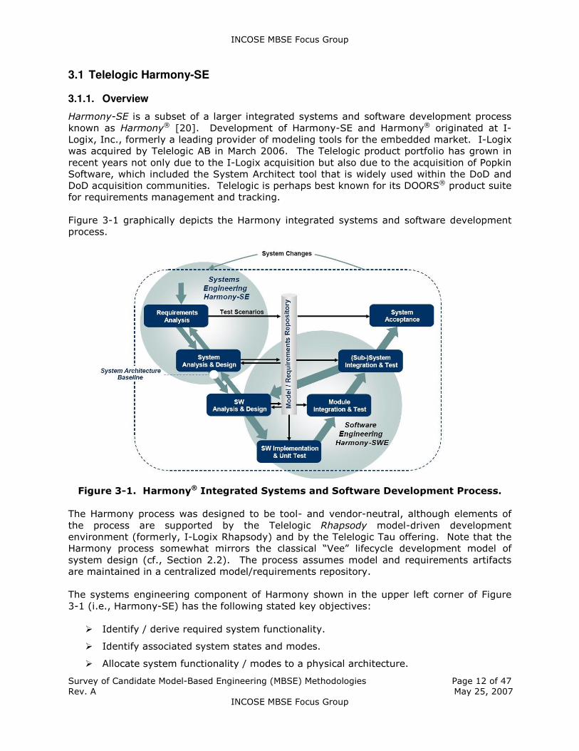
Figure 3-1 graphically depicts the Harmony integrated systems and software development
process.
Figure 3-1. Harmony® Integrated Systems and Software Development Process.
The Harmony process was designed to be tool- and vendor-neutral, although elements of
the process are supported by the Telelogic Rhapsody model-driven development
environment (formerly, I-Logix Rhapsody) and by the Telelogic Tau offering. Note that the
Harmony process somewhat mirrors the classical “Vee” lifecycle development model of
system design (cf., Section 2.2). The process assumes model and requirements artifacts
are maintained in a centralized model/requirements repository.
The systems engineering component of Harmony shown in the upper left corner of Figure
3-1 (i.e., Harmony-SE) has the following stated key objectives:
� Identify / derive required system functionality.
� Identify associated system states and modes.
� Allocate system functionality / modes to a physical architecture.

INCOSE MBSE Focus Group
Survey of Candidate Model-Based Engineering (MBSE) Methodologies Page 13 of 47
Rev. A May 25, 2007
INCOSE MBSE Focus Group
Harmony-SE uses a “service request-driven” modeling approach along with Object
Management Group™ Systems Modeling Language™ (OMG SysML™) artifacts [21]. In the
service request-driven modeling approach, system structure is described by means of
SysML structure diagrams using blocks as basic structure elements. Communication
between blocks is based on messages (services requests). Provided services are at the
receiving part of service requests and state/mode change or operations (activities) are
described as operational contracts. Functional decomposition is handled through
decomposition of activity operational contracts. A SysML visual representation of the
service request-driven approach is shown in Figure 3-2.
Figure 3-2. OMG SysML™ Representation of Service Request-Driven Approach.
Task flow and work products (artifacts) in the Harmony-SE process include the following
three top-level process elements:
� Requirements analysis
� System functional analysis
� Architectural design
The following graphic (Figure 3-3) better illustrates these process elements along with the
flow of some of the primary work products:

INCOSE MBSE Focus Group
Survey of Candidate Model-Based Engineering (MBSE) Methodologies Page 14 of 47
Rev. A May 25, 2007
INCOSE MBSE Focus Group
Figure 3-3. Harmony-SE Process Elements.
Note that in addition to the use of a model/requirements repository as shown in the
Harmony process (Figure 3-1), a test data repository is also recommended in order to
capture use case scenarios.
Detailed task flows and work products are provided for each of the three process elements
(shown as the dark filled boxes in the center of Figure 3-3) with detailed guidance provided
in the Harmony-SE/SysML Deskbook [22].
An example of such a task flow and associated work products for the System Functional
Analysis process element is illustrated in Figure 3-4. Similarly, an example of the task flow
and associated work products for the Subsystem Architectural Design sub-process of the
Architectural Design process is depicted in Figure 3-5.
3.1.2. Tool Support
No process framework tool exists from Telelogic AB or a third-party provider for Harmony-
SE or the integrated systems and software engineering process, Harmony.
Recall that the Harmony-SE and Harmony were created as tool- and vendor-neutral, model-
based methodologies. Tool support for MBSE that supports the methods specified by
Harmony-SE and Harmony is, of course, provided by Telelogic AB via the Telelogic Tau and
Telelogic Rhapsody product offerings.
3.1.3. Offering/Availability
As stated earlier, a Harmony-SE/SysML Deskbook has been published to help guide the
systems engineer and project manager through the entire MBSE methodology [22]. In
addition, Telelogic AB offers professional services to support methodology adoption.

INCOSE MBSE Focus Group
Survey of Candidate Model-Based Engineering (MBSE) Methodologies Page 15 of 47
Rev. A May 25, 2007
INCOSE MBSE Focus Group
Figure 3-4. System Functional Analysis Task Flow and Work Products.
Figure 3-5. Subsystem Architectural Design Task Flow and Work Products.

INCOSE MBSE Focus Group
Survey of Candidate Model-Based Engineering (MBSE) Methodologies Page 16 of 47
Rev. A May 25, 2007
INCOSE MBSE Focus Group
3.2 INCOSE Object-Oriented Systems Engineering Method (OOSEM)
3.2.1. Overview
The Object-Oriented Systems Engineering Method (OOSEM) integrates a top-down, model-
based approach that uses OMG SysML™ to support the specification, analysis, design, and
verification of systems. OOSEM leverages object-oriented concepts in concert with more
traditional top down systems engineering methods and other modeling techniques, to help
architect more flexible and extensible systems that can accommodate evolving technology
and changing requirements. OOSEM is also intended to ease integration with object-
oriented software development, hardware development, and test.
OOSEM evolved from work in the mid 1990’s at the Software Productivity Consortium (now
the Systems and Software Consortium) in collaboration with Lockheed Martin Corporation.4
The methodology was applied in part to a large distributed information system development
at Lockheed Martin that included hardware, software, database, and manual procedure
components. INCOSE Chesapeake Chapter established the OOSEM Working Group in
November 2000 to help further evolve the methodology.5 OOSEM is summarized in various
industry and INCOSE papers [23-25], and is available as a full day tutorial [26].
The OOSEM objectives are the following:
� Capture and analysis of requirements and design information to specify complex
systems.
� Integration with object-oriented (OO) software, hardware, and other engineering
methods.
� Support for system-level reuse and design evolution.
As stated above, OOSEM is a hybrid approach that leverages object-oriented techniques and
a systems engineering foundation. It also introduces some unique techniques as indicated
in see Figure 3-6.
Figure 3-6. Foundation of OOSEM.
4 Sanford Friedenthal, Lockheed Martin Corporation (private communication), Apr. 4, 2007. 5 David Griffith, Northrop Grumman Corporation (private communication), Mar. 15, 2007.

INCOSE MBSE Focus Group
Survey of Candidate Model-Based Engineering (MBSE) Methodologies Page 17 of 47
Rev. A May 25, 2007
INCOSE MBSE Focus Group
The OOSEM supports a SE process as illustrated in Figure 3-7.
Figure 3-7. OOSEM Activities in the Context of the System Development Process.
The core tenets of OOSEM include recognized practices essential to systems engineering
that include: 1) Integrated Product Development (IPD), essential to improve
communications, and 2) a recursive “Vee” lifecycle process model that is applied to each
multiple level of the system hierarchy.
As shown in Figure 3-8, OOSEM includes the following development activities:
� Analyze Stakeholder Needs
� Define System Requirements
� Define Logical Architecture
� Synthesize Candidate Allocated Architectures
� Optimize and Evaluate Alternatives
� Validate and Verify System
These activities are consistent with typical systems engineering “Vee” process that can be
recursively and iteratively applied at each level of the system hierarchy. Fundamental
tenets of systems engineering, such as disciplined management processes (i.e. risk
management, configuration management, planning, measurement, etc.) and the use of
multi-disciplinary teams, must be applied to support each of these activities to be effective.
OOSEM utilizes a model-based approach to represent the various artifacts generated by the
development activities using OMG SysML as the predominant modeling language. As such,
it enables the systems engineer to precisely capture, analyze, and specify the system and
its components and ensure consistency among various system views. The modeling artifacts
can also be refined and reused in other applications to support product line and evolutionary
development approaches. A summary description of the activities and artifacts is provided
on the following pages [25].

INCOSE MBSE Focus Group
Survey of Candidate Model-Based Engineering (MBSE) Methodologies Page 18 of 47
Rev. A May 25, 2007
INCOSE MBSE Focus Group
Figure 3-8. OOSEM Activities and Modeling Artifacts.
Analyze Stakeholder Needs
This activity captures the “as-is” systems and enterprise, their limitations and potential
improvement areas. The results of the “as-is” analysis is used to develop the to-be
enterprise and associated mission requirements. An enterprise model depicts the
enterprise, its constituent systems, including the systems to be developed or modified, and
enterprise actors (entities external to the enterprise). The as-is enterprise is analyzed using
causal analysis techniques to determine its limitations, and used as a basis for deriving the
mission requirements and to-be enterprise model. The mission requirements are specified
in terms of the mission / enterprise objectives, measures of effectiveness, and top-level use
cases. The use cases and scenarios capture the enterprise functionality.
Define System Requirements
This activity is intended to specify the system requirements that support the mission
requirements. The system is modeled as a black box that interacts with the external
systems and users represented in the enterprise model. The system-level use cases and
scenarios reflect the operational concept for how the system is used to support the
enterprise. The scenarios are modeled using activity diagrams with swim lanes that
represent the black box system, users, and external systems. The scenarios for each use
case are used to derive the black box system functional, interface, data, and performance
requirements. The requirements management database is updated during this activity to
trace each system requirement to the enterprise/mission level use case and mission
requirements.
Requirements variation is evaluated in terms of the probability that a requirement will
change, which is included in the risks, and later analyzed to determine how to design the
system to accommodate the potential change. A typical example may be a system interface
that is likely to change or a performance requirement that is expected to increase.

INCOSE MBSE Focus Group
Survey of Candidate Model-Based Engineering (MBSE) Methodologies Page 19 of 47
Rev. A May 25, 2007
INCOSE MBSE Focus Group
Define Logical Architecture
This activity includes decomposing and partitioning the system into logical components that
interact to satisfy the system requirements. The logical components capture the system
functionality. Examples may include a user interface that is realized by a web browser, or
an environmental monitor that is realized by a particular sensor. The logical
architecture/design mitigates the impact of requirements changes on the system design,
and helps to manage technology changes.
OOSEM provides guidelines for decomposing the system into its logical components. The
logical scenarios preserve system black box interactions with its environment. In addition,
the logical component functionality and data are repartitioned based on partitioning criteria
such as cohesion, coupling, design for change, reliability, performance, and other
considerations.
Synthesize Candidate Allocated Architectures
The allocated architecture describes relationship among the physical components of the
system including hardware, software, data and procedures. The system nodes define the
distribution of resources. Each logical component is first mapped to a system node to
address how the functionality is distributed. Partitioning criteria is applied to address
distribution concerns such as performance, reliability, and security. The logical components
are then allocated to hardware, software, data, and manual procedure components. The
software, hardware, and data architecture are derived based on the component
relationships. The requirements for each component are traced to the system requirements
and maintained in the requirements management database.
Optimize and Evaluate Alternatives
This activity is invoked throughout all other OOSEM activities to optimize the candidate
architectures and conduct trade studies to select the preferred architecture. Parametric
models for modeling performance, reliability, availability, life-cycle cost, and other specialty
engineering concerns, are used to analyze and optimize the candidate architectures to the
level needed to compare the alternatives. The criteria and weighting factors used to
perform the trade studies are traceable to the system requirements and measures of
effectiveness. This activity also includes the monitoring of technical performance measures
and identifies potential risks.
Validate and Verify System
This activity is intended to verify that the system design satisfies its requirements and to
validate that the requirements meet the stakeholder needs. It includes the development of
verification plans, procedures, and methods (e.g., inspection, demonstration, analysis,
test). System-level use cases, scenarios, and associated requirements are primary inputs
to the development of the test cases and associated verification procedures. The
verification system can be modeled using the same activities and artifacts described above
for modeling the operational system. The requirements management database is updated
during this activity to trace the system requirements and design information to the system
verification methods, test cases, and results.
The full description of each OOSEM activity and process flows are provided in the referenced
OOSEM tutorial [26].

INCOSE MBSE Focus Group
Survey of Candidate Model-Based Engineering (MBSE) Methodologies Page 20 of 47
Rev. A May 25, 2007
INCOSE MBSE Focus Group
3.2.2. Tool Support
A dedicated process framework tool for OOSEM does not exist; however, tool support for
OOSEM can be provided by COTS-based OMG SysML tools and associated requirements
management tools. Other tools required to support the full system lifecycle should be
integrated with the SysML and requirements management tools, such as configuration
management, performance modeling, and verification tools.
A more complete set of OOSEM tool requirements is provided in the referenced OOSEM
tutorial [26].
3.2.3. Offering/Availability
The OOSEM tutorial and training materials can be made available by contacting the INCOSE
OOSEM Working Group to gain access through the INCOSE Connect collaboration space.
Unlike other industry-provided MBSE methodologies, OOSEM is not a formal offering that
can be purchased from any specific vendor, including professional services. Support
services may be available by contacting representatives of the INCOSE OOSEM Working
Group.6
3.3 IBM Rational Unified Process for Systems Engineering (RUP SE) for Model-Driven Systems Development (MDSD)
3.3.1. Overview
The Rational Unified Process for Systems Engineering (RUP SE) is a derivative of the
Rational Unified Process® (RUP®). RUP is a methodology that is both a process framework
and process product from IBM Rational and has been used extensively in government and
industry to manage software development projects [27].
RUP SE was created to specifically address the needs of systems engineering projects
[28,29]. The objective for its creation was to apply the discipline and best practices of the
RUP for software development to the challenges of system specification, analysis, design,
and development. Its goal is to help organizations save time, cut costs, reduce risk, and
improve the quality of the systems they build. According to Cantor,7 in current parlance,
“RUP SE is the extension of the Rational Unified Process [RUP] to support Model-Driven
Systems Development [MDSD].” The spirit of MDSD as envisioned by key IBM systems
engineering leaders is documented in the cited reference by Balmelli et al. and will not be
replicated here [11].
Before describing the guiding principles, methods, and architectural framework of RUP SE to
support MDSD, it is helpful to familiarize the reader with the software development lifecycle
focused RUP. RUP is based on a set of building blocks, or content elements, describing what
is to be produced, the necessary skills required, and the step-by-step explanation describing
how specific development goals are achieved. A graphical depiction of the RUP process
framework is shown in Figure 3-9 [27], sometimes referred to in the industry as the “whale
chart.”
6 L. Mark Walker, Lockheed Martin Corporation (private communication), Apr. 19, 2007. 7 Murray Cantor, IBM Corporation (private communication), Feb. 27, 2007.

INCOSE MBSE Focus Group
Survey of Candidate Model-Based Engineering (MBSE) Methodologies Page 21 of 47
Rev. A May 25, 2007
INCOSE MBSE Focus Group
Figure 3-9. The Rational Unified Process® (RUP®) (“Whale Chart”).
The main content elements of the RUP are the following:
� Roles (“WHO”) – A role defines a set of related skills, competencies, and
responsibilities.
� Work Products (“WHAT”) – A work product represents something resulting from a
task, including all the documents and models produced while working through the
process.
� Tasks (“HOW”) – A task describes a unit of work assigned to a role that provides a
meaningful result.
Within each iteration, the tasks are categorized into a total of nine (9) disciplines:
Engineering Disciplines:
1. Business modeling
2. Requirements
3. Analysis and design
4. Implementation
5. Test
6. Deployment
Supporting Disciplines:
7. Configuration and change management
8. Project management
9. Environment

INCOSE MBSE Focus Group
Survey of Candidate Model-Based Engineering (MBSE) Methodologies Page 22 of 47
Rev. A May 25, 2007
INCOSE MBSE Focus Group
The RUP lifecycle is an implementation of the spiral model for iterative and incremental
development (cf., Section 2.2). It was created by assembling the content elements into
semi-ordered sequences. Consequently the RUP lifecycle is available as a work breakdown
structure (WBS), which can be customized to address the specific needs of a project. The
RUP lifecycle organizes the tasks into phases and iterations.
A project has four phases:
� Inception
� Elaboration
� Construction
� Transition
A typical project profile showing the relative sizes of the four phases is shown in Figure 3-10
[27].
Figure 3-10. Typical Profile Showing Relative Sizes of the Four RUP Phases.
Because RUP SE is derived from RUP, it retains RUP’s cornerstone principles, which have
been refined and extended to enhance their utility for systems engineering efforts. RUP SE
brings the RUP style of concurrent design and iterative development to systems engineering
(as illustrated in Figure 3-11) [30]. In addition, it provides the highly configurable discipline
(workflow) templates required to identify the hardware, software, and worker role
components that comprise a systems engineering project.
RUP and RUP SE both are designed to help teams systematically define, organize,
communicate, and manage requirements. Both methodologies support change control and
quality initiatives. Without these capabilities, no systems engineering project is likely to be
deemed a success relative to cost or business objectives.
Key elements in RUP SE that extend the RUP to systems engineering include the following:
� New roles. In RUP SE, the development team includes system engineers in addition
to worker roles such as architects, developers, testers, etc. The role of the system
engineer is primarily concerned with the specification of the overall system and
deployment thereof, and to help address overall system requirements.

INCOSE MBSE Focus Group
Survey of Candidate Model-Based Engineering (MBSE) Methodologies Page 23 of 47
Rev. A May 25, 2007
INCOSE MBSE Focus Group
Figure 3-11. Illustration of RUP SE lifecycle.
� New artifacts and workflows. RUP includes full support for software system
concerns, such as usability, maintainability, performance, and scalability. RUP SE
adds artifacts and workflows that address additional concerns in the systems
engineering domain, such as security, training, and logistics support.
� An emphasis on business modeling. Whatever kind of system being architected,
it is important to understand the business purpose it will serve. Otherwise, system
requirements will not accurately reflect business activities. RUP SE does not include
changes to the business modeling features of RUP. However, RUP SE users are
strongly encouraged to create business use cases with the associated identification of
business actors and the flow of business events, in order to adequately define
system requirements. Furthermore, the RUP SE use-case flowdown activity is applied
to derive system requirements from business requirements.
� Viewpoints for systems engineering. An architecture framework for RUP SE has
been developed that contains the elements of model levels, viewpoints, and views
(see Table 3-1). The concept of viewpoints and views used in the RUP SE
architecture framework is consistent with industry standard definitions as articulated
by the ISO/ITU 10746 standard Reference Model for Open Distributed Processing
(RM-ODP) [31] and the ANSI/IEEE 1471-2000 standard Recommended Practice for
Architectural Description of Software-Intensive Systems [32]. The cells in RUP SE
architecture framework represent views.
RUP SE supports domain-specific viewpoints common to system architectures, such
as safety, security, and mechanical. Modeling levels are similar for most systems
regardless of their complexity.

INCOSE MBSE Focus Group
Survey of Candidate Model-Based Engineering (MBSE) Methodologies Page 24 of 47
Rev. A May 25, 2007
INCOSE MBSE Focus Group
Table 3-1. The RUP SE architecture framework.
Model Viewpoints Model Levels Worker Logical Information Distribution Process Geometric
Context Role
definition, activity modeling
Use case
diagram specification
Enterprise data view
Domain-
dependent views
Domain-
dependent views
Analysis Partitioning of system
Product logical decomposition
Product data
conceptual schema
Product locality view
Product
process view
Layouts
Design Operator instructions
Software
component design
Product data schema
ECM
(electronic control media design)
Timing diagrams
MCAD
(mechanical computer-assisted design)
Implementation Hardware and software configuration
Note: The Distribution viewpoint describes how the functionality of the system is
distributed across physical resources. At the analysis level, it is necessary to describe
a generalized view of resources, capturing the attributes needed to support the
transformation from analysis and design. Cantor introduced the concept of locality to
represent a generalized resource [28]. A locality is defined as a member of a system
partition representing a generalized or abstract view of the physical resources.
Localities can perform operations and have attributes appropriate for specifying
physical designs. Localities are linked to each other with connections. Connections
are defined as generalized physical linkages in RUP SE. Connections are
characterized by what they carry or transmit and the necessary performance and
quality attributes in order to specify their physical realization at the design level. A
RUP SE distribution diagram showing two localities and a connection between them is
illustrated in Figure 3-12.
Figure 3-12. Two Localities and a Connection.
A model level is defined as a subset of the architecture model that represents a
certain level of specificity (abstract to concrete); lower levels capture more specific
technology choices. Model levels are not levels of abstraction; in fact, a model level
may contain multiple levels of abstraction. Model levels are elements designed to
group artifacts with a similar level of detail (see Table 3-2).

INCOSE MBSE Focus Group
Survey of Candidate Model-Based Engineering (MBSE) Methodologies Page 25 of 47
Rev. A May 25, 2007
INCOSE MBSE Focus Group
Table 3-2. Model levels in the RUP SE architecture framework.
Model Level Expresses
Context System black box—the system and its actors (through this is a black-box view for the system, it is a white-box view for the enterprise containing the system.
Analysis System white box—initial system partitioning in each viewpoint that establishes the conceptual approach.
Design Realization of the analysis level in hardware, software, and people
Implementation Realization of the design model into specific configurations
� Scalability enhancements. Once design decisions have been captured in
viewpoints and specified via model levels, the system architecture is captured in a
set of OMG™ UML®/SysML™ diagrams; these further describe it from the various
viewpoints and model levels. Although many of these artifacts are similar across
RUP and RUP SE, there are a couple of important differences. In a nutshell, these
new artifacts allow you to break the system down (1) by subsystems, and (2) by the
localities where processing takes place. Each subsystem coupled with its locality has
its own derived requirements in RUP SE, enabling the process to scale to meet the
needs of even the largest and most complex projects.
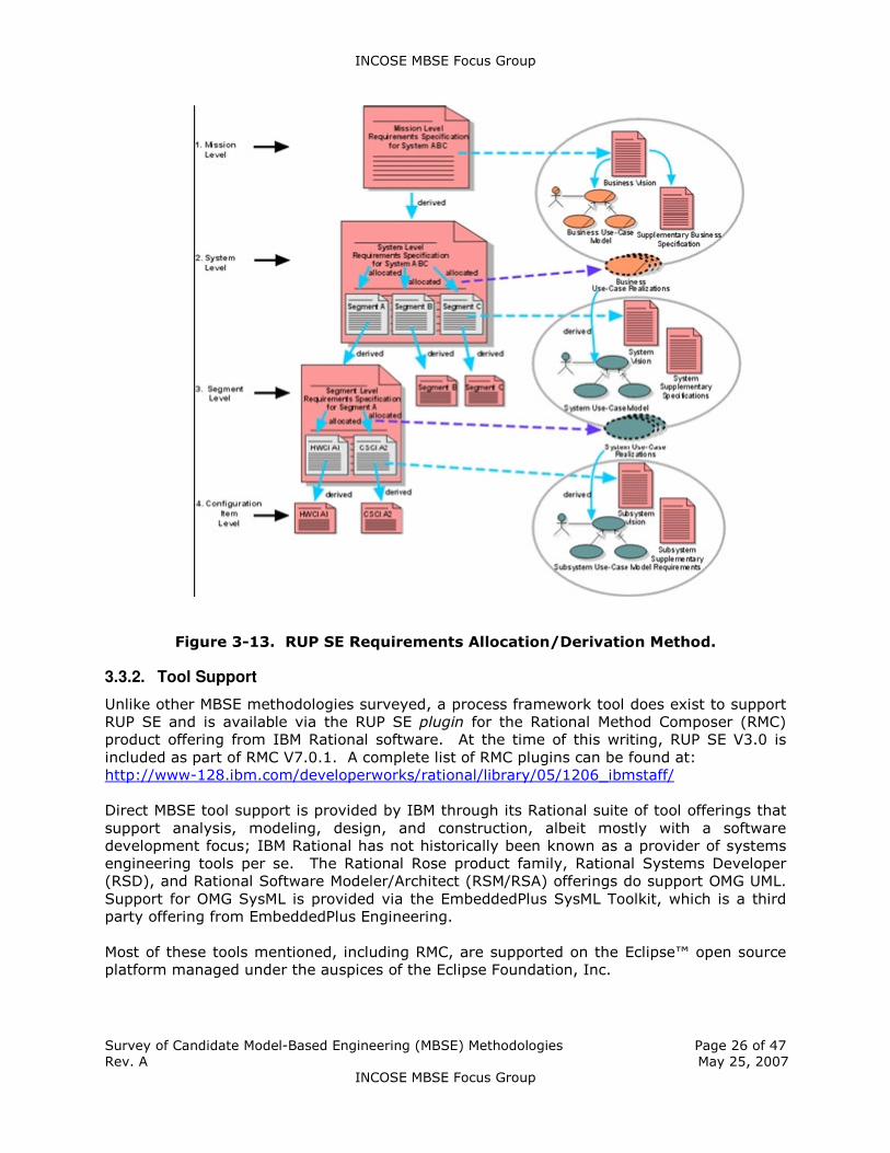
� Allocated versus derived requirements. RUP SE encompasses two types of
system requirements: use-cases, which capture functional requirements; and
supplementary requirements, which cover non-functional (quality) attributes like
reliability and maintainability (see Figure 3-13) [30]. With respect to the
requirements associated with subsystems and localities, RUP SE makes a further distinction between those requirements that are allocated and those that are derived.
A locality or subsystem requirement is allocated if a locality or subsystem is assigned
sole responsibility for fulfilling a system requirement. A locality or subsystem
requirement is derived if it is identified by studying how the subsystem or locality
collaborates with others to meet a system requirement.
� Subsystem-level flowdown activity. RUP SE derives system requirements from
business requirements via use-case flowdown activities. However, RUP SE departs
from the RUP in that it also specifies a flow of events in a subsystem-level, "white
box" view that references specific architectural elements.8 This extra step is
necessary in order to make decisions about where events are hosted, and to relate
processes to events.
� Support for designing additional components. The design-level specification of
system components with RUP SE is similar to its software-only counterpart in RUP.
The key difference, as previously mentioned, is that systems engineering typically
entails additional types of components than software engineering, such as hardware.
Delineation of these components is supported via analysis of the RUP SE subsystem
and locality use-case surveys that are generated prior to specifying component
designs.
8 The classical notion of a “white box” (the elements or parts that make up a system) and “black box”
(characteristics of the system as a whole: the services it provides, the requirements it meets)
characterization of a system is consistent with the IBM Model-Driven Systems Development (MDSD)
approach and is described as part of the RUP SE methodology [11].
INCOSE MBSE Focus Group
Survey of Candidate Model-Based Engineering (MBSE) Methodologies Page 26 of 47
Rev. A May 25, 2007
INCOSE MBSE Focus Group
Figure 3-13. RUP SE Requirements Allocation/Derivation Method.
3.3.2. Tool Support
Unlike other MBSE methodologies surveyed, a process framework tool does exist to support
RUP SE and is available via the RUP SE plugin for the Rational Method Composer (RMC)
product offering from IBM Rational software. At the time of this writing, RUP SE V3.0 is
included as part of RMC V7.0.1. A complete list of RMC plugins can be found at:
http://www-128.ibm.com/developerworks/rational/library/05/1206_ibmstaff/
Direct MBSE tool support is provided by IBM through its Rational suite of tool offerings that
support analysis, modeling, design, and construction, albeit mostly with a software
development focus; IBM Rational has not historically been known as a provider of systems
engineering tools per se. The Rational Rose product family, Rational Systems Developer
(RSD), and Rational Software Modeler/Architect (RSM/RSA) offerings do support OMG UML.
Support for OMG SysML is provided via the EmbeddedPlus SysML Toolkit, which is a third
party offering from EmbeddedPlus Engineering.
Most of these tools mentioned, including RMC, are supported on the Eclipse™ open source
platform managed under the auspices of the Eclipse Foundation, Inc.

INCOSE MBSE Focus Group
Survey of Candidate Model-Based Engineering (MBSE) Methodologies Page 27 of 47
Rev. A May 25, 2007
INCOSE MBSE Focus Group
3.3.3. Offering/Availability
As stated in Section 3.3.2, RUP SE tool support is provided by the RUP SE plugin for
Rational Method Composer (RMC); however, it is recommended that adoption and tailoring
of the RUP SE methodology be supported through IBM professional services; specifically,
IBM Software Services. A textbook by Kruchten exist for the baseline RUP methodology
that details core tenets and elements of the methodology and provides tailoring guidelines
[27]. Such a companion text does not yet exist for RUP SE, at least not at the time of this
survey report.
3.4 Vitech Model-Based System Engineering (MBSE) Methodology
3.4.1. Overview
Vitech Corporation, providers of the CORE® product suite, offer a MBSE methodology via a
set of tutorials developed and offered by Vitech CEO and Chief Methodologist James (“Jim”)
E. Long [33]. A variation of the tutorial has been delivered at a number of INCOSE
International Symposia as a half-day event [34]. Although the Vitech MBSE methodology is
considered “tool-independent,” there is a strong tie of the tutorial materials to the CORE
tool set.
The Vitech MBSE methodology is based on four primary concurrent SE activities that are
linked and maintained through a common System Design Repository (see Figure 3-14).
Figure 3-14. Vitech MBSE Primary SE Activities.
Each of these primary SE activities is linked within the context of associated “domains” as
illustrated in Figure 3-15, where the SE activities are considered elements of a particular
kind of domain known as the Process Domain.
In the Vitech MBSE methodology, it is stressed that a MBSE System Definition Language
(SDL) is needed to manage model artifacts, which means that an agreed-upon information
model in the form of a schema or ontology is necessary to manage the syntax (structure)
and semantics (meaning) of the model artifacts [35,36]. Such an “SDL” has a number of

INCOSE MBSE Focus Group
Survey of Candidate Model-Based Engineering (MBSE) Methodologies Page 28 of 47
Rev. A May 25, 2007
INCOSE MBSE Focus Group
uses such as providing a structured, common, explicit, context-free language for technical
communication serving as a guide for requirements analysts, system designers, and
developers, and providing a structure for the graphic view generators, report generator
scripts, and consistency checkers.9 An example of a Vitech-specified MBSE SDL is illustrated
in Table 3-3. Vitech MBSE System Definition Language (SDL). and based on and Entity-
Relationship-Attribute (ERA) model.
Figure 3-15. Vitech MBSE Primary SE Domains.
Five core tenets help drive the Vitech MBSE methodology:
1. Model via modeling “language” the problem and the solution space; include
semantically-meaningful graphics to stay explicit and consistent. This helps facilitate
model traceability, consistent graphics, automatic documentation and artifacts,
dynamic validation and simulation, and promotes more precise communication.
2. Utilize a MBSE system design repository.
3. Engineer the system horizontally before vertically, i.e., do it in complete, converging
layers.
4. Use tools to do the “perspiration stuff” and your brain to do the “inspiration stuff.”
To support tenet #3 above, the Vitech MBSE utilizes an incremental SE process known as
the “Onion Model,” which allows complete interim solutions at increasing levels of detail
9 Many of these features of an MBSE SDL are targeted at the MBSE tool that interacts with or hosts
the system design repository and is beyond the scope of other key elements of MBSE methodologies
such as processes and methods. Nevertheless, the importance of specifying, owning, and utilizing an
MBSE information model is acknowledged and a factor that is not explicitly called out in the literature
of other MBSE methodologies surveyed in this study.

INCOSE MBSE Focus Group
Survey of Candidate Model-Based Engineering (MBSE) Methodologies Page 29 of 47
Rev. A May 25, 2007
INCOSE MBSE Focus Group
during the system specification process [37]. A visual representation of the Onion Model is
illustrated in Figure 3-16.
Table 3-3. Vitech MBSE System Definition Language (SDL).
SDL
Language*
English
Equivalent
MBSE Example
Element Noun • Requirement: Place Orders
• Function: Cook Burgers
• Component: Cooks
Relationship Verb • Requirement basis of Functions
• Functions are allocated to Components
Attribute Adjective • Creator
• Creation Date
• Description
Attribute of Relationship
Adverb • Resource consumed by Function
• Amount (of Resource)
• Acquire Available (Priority)
Structure N/A • Viewed as Enhanced Function Flow Block Diagram (EFFBD) or
FFBD
*Mapped to model element property sheets in Vitech CORE®
Figure 3-16. Vitech MBSE "Onion Model."
The Onion Model iterates the primary concurrent SE activities at each layer. According to
Childers and Long [37], as the SE team successfully completes one level of system design,
they “peel off a layer of the onion” and start to explore the next layer. When the team
reaches the desired level of detail (the center), their design is complete. The primary
benefit of the Onion Model over say more traditional waterfall SE approaches is that it
provides a lower risk design approach since complete solutions at increasing levels of detail
are available for early review and validation [37].
INCOSE MBSE Focus Group
Survey of Candidate Model-Based Engineering (MBSE) Methodologies Page 30 of 47
Rev. A May 25, 2007
INCOSE MBSE Focus Group
Completeness and convergence are essential principles of the Onion Model in that the SE
team must complete a layer before moving to the next layer (completeness) and the team
cannot iterate back more than one layer (convergence). If no valid, consistent solution can
be found at any layer, the team must check if the system statement is overly constrained
and may need to negotiate modifications such as modifications to the design
implementation at the previous layer [37]. It is important to discover such constraints early
as system design breakage that occurs in several layers lower in the iterative process can
adversely impact cost and schedule. Guidance for determining completeness at each layer
is provided in Table 3-4.
Table 3-4. Completion Criteria for Each Layer of the "Onion Model."
Process Element Completion Criteria
1. Originating Requirements 1. Agreement on Acceptance Criteria.
2. Behavior/Functional Architecture 2. Each function is uniquely allocated to at most
one component.
3. Physical Architecture Definition 3. Segment/component specs are complete
requirements documents.
4. Qualification 4. V&V requirements have been traced to test system components.
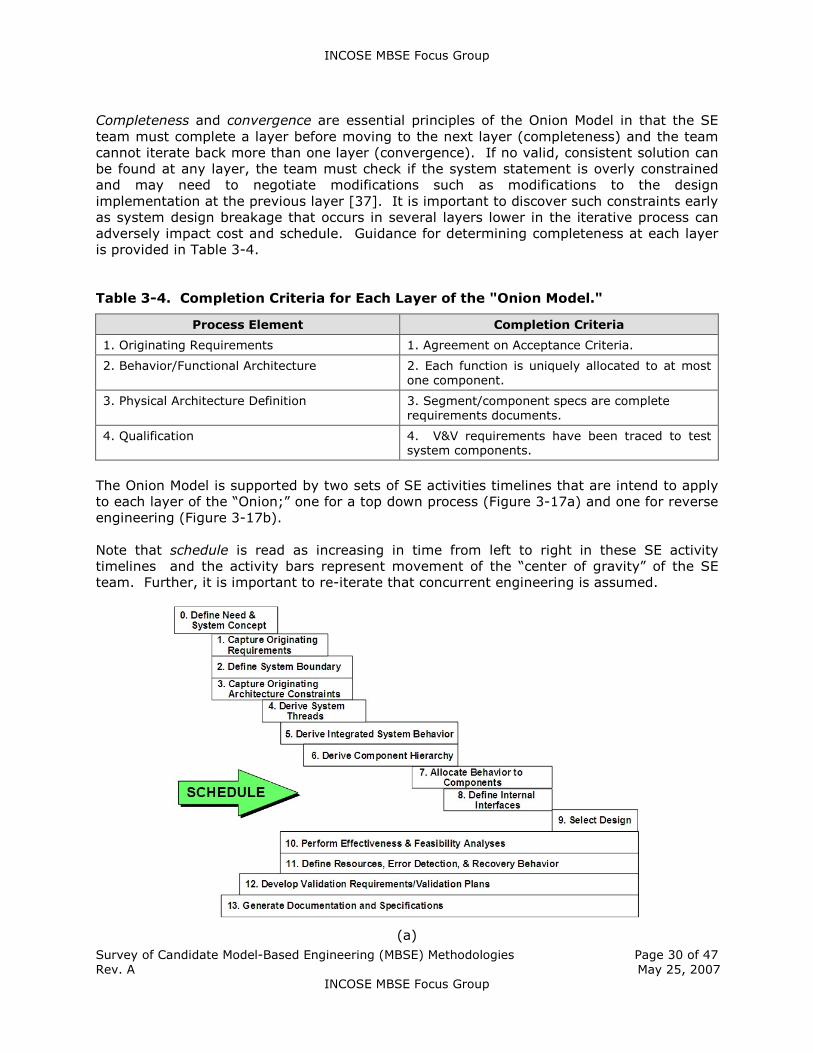
The Onion Model is supported by two sets of SE activities timelines that are intend to apply
to each layer of the “Onion;” one for a top down process (Figure 3-17a) and one for reverse
engineering (Figure 3-17b).
Note that schedule is read as increasing in time from left to right in these SE activity
timelines and the activity bars represent movement of the “center of gravity” of the SE
team. Further, it is important to re-iterate that concurrent engineering is assumed.
(a)

INCOSE MBSE Focus Group
Survey of Candidate Model-Based Engineering (MBSE) Methodologies Page 31 of 47
Rev. A May 25, 2007
INCOSE MBSE Focus Group
(b)
Figure 3-17. Vitech MBSE Activities Timeline - Top Down (a) and
(b) Reverse Engineering.
According to Long [35], three models are necessary and sufficient to completely specify a
system: (1) control (functional behavior) model, (2) interface (I/O) model, and (3) physical
architecture (component) model. Performance requirements/resources are captured with
parts or combinations of one of these three models. These three models provide a basis for
knowing when the SE of the system has been completed, i.e., when—within projected
technology—an achievable design specification for all system components has been reached,
and the system V&V plans are defined and fully traced.
The Vitech MBSE methodology that is taught as part of the tutorial includes methods in
support of a set of learning objectives for each of the four top-level SE activities areas
articulated in Figure 3-14. Details of each method and tooling support will not be described
here; however, as an example, the learning objectives associated with Source Requirements
and Analysis and Architecture/Synthesis are shown in Table 3-5. Additional details on
methods associated with the Vitech MBSE methodology are also described by Baker and
Long [36], although described in the context to what the authors refer to as the “System
Logic Modeling (SLM)” Process.
Table 3-5. Learning Objectives and Sub-Activities for Vitech MBSE Top-Level SE
Activities of Source Requirements Analysis and Architecture/Synthesis.
Source Requirements & Analysis Architecture/Synthesis
Objective Identify structure and analyze requirements from a source.
Expand our understanding of the system.
Activities 1. Identify and extract
requirements
2. Organize requirements
3. Analyze requirements
3.1 Discover and identify issues
1. Define:
1.1 System boundaries
1.2 Potential interfaces
1.3 Preliminary physical architecture components

INCOSE MBSE Focus Group
Survey of Candidate Model-Based Engineering (MBSE) Methodologies Page 32 of 47
Rev. A May 25, 2007
INCOSE MBSE Focus Group
3.2 Discover and identify risks
4. Establish requirements relationships
5. View the requirements graphically
6. Generate the requirements and related information in a table
1.4 Preliminary functionality
2. Maintain traceability to originating requirements
3. Identify performance factors
4. Identify constraints
5. Continue to mitigate issues and risks
Methods used in the Vitech MBSE methodology to support the Functional/Behavior Analysis
top-level activity is based on a set of visual behavior models and constructs in an
executable graphical language known as Enhanced Function Flow Block Diagrams (EFFBDs).
Other supporting visual modeling languages to support Functional/Behavior Analysis include
standard FFBDs, N2 charts, and Behavior diagrams; each of these modeling constructs is
described in greater detail by Long [38]. Note that the Vitech MBSE tool CORE does not
currently support the standard visual modeling language standards of the UML® or OMG
SysML™. This contrast, particularly with respect to EFFBDs, is described in greater detail in
Section 4. Although an assessment of use of the UML in support of the Vitech MBSE
methodology was described by Skipper in 2003 [39], it is not yet clear that UML and/or
SysML are on the Vitech CORE product roadmap for future support.
Methods associated with the Vitech MBSE methodology to support the Design Verification
and Validation (V&V) top-level activity include test plan development and test planning with
best practices emphasizing that test planning begins during the originating requirements
extraction and analysis phase. Test threads are also described with test paths specified as
derived from system behavior. Software testing methods are highlighted as well as system
testing methods. The primary system testing methods described by the MBSE methodology
are summarized in Table 3-6.
Table 3-6. System Testing Methods Defined in the Vitech MBSE Methodology.
Functional Testing Test conditions are set up to ensure that the correct outputs are
produced, based upon the inputs of the test conditions. Focus is on
whether the outputs are correct given the inputs (also called “black box” testing).
Structural Testing Examines the structure of the system and its proper functioning. Includes
such elements as performance, recovery, stress, security, safety, availability. Some of the less obvious elements are described below.
Performance Examination of the system performance under a range of nominal
conditions, ensures system is operational as well.
Recovery Various failure modes are created and the system’s ability to return to an
operational mode is determined.
Interface Examination of all interface conditions associated with the system’s reception of inputs and sending of outputs.
Stress Testing Above-normal loads are placed on the system to ensure that the system
can handle them; these above-normal loads are increased to determine
the system’s breaking point; these tests proceed for a long period of time in an environment as close to real as possible.
3.4.2. Tool Support
There is no process framework tool offered by Vitech Corporation or third party provider
that supports the Vitech MBSE methodology. Vitech does offer an MBSE tool set via its
CORE® product suite.

INCOSE MBSE Focus Group
Survey of Candidate Model-Based Engineering (MBSE) Methodologies Page 33 of 47
Rev. A May 25, 2007
INCOSE MBSE Focus Group
3.4.3. Offering/Availability
A half-day tutorial on the Vitech MBSE methodology will be offered at the forthcoming 2007
INSOSE International Symposium in San Diego, California on Sunday, June 24th (see
http://www.incose.org/symp2007/tutorials.html). This tutorial is entitled “H0D: Model
Based Systems Engineering for Project Success: The Complete Process (PM)” and will be
taught by James (“Jim”) E. Long. More detailed, multi-day courses are offered through the
Vitech training services (see http://vitechcorp.com/services/).
3.5 State Analysis (SA)
3.5.1. Overview
State Analysis (SA) is a JPL-developed MBSE methodology that leverages a model- and
state-based control architecture (see Figure 3-18), where state is defined to be “a
representation of the momentary condition of an evolving system,” and models describe
how state evolves [40].
Figure 3-18. Model- and State-Based Control Architecture ("Control Diamond").
SA provides a process for capturing system and software requirements in the form of
explicit models, thereby helping reduce the gap between the requirements on software
specified by systems engineers and the implementation of these requirements by software
engineers. Traditionally, software engineers must perform the translation of requirements
into system behavior, hoping to accurately capture the system engineer’s understanding of
the system behavior, which is not always explicitly specified. In SA, model-based
requirements map directly to software.
In SA, it is important to distinguish between the “state” of a system and the “knowledge” of
that state. The real state may be arbitrarily complex, but ones knowledge of it is generally
captured in simpler abstractions that one finds useful and sufficient to characterize the
system state. These abstractions are called state variables. The known state of the system
is the value of its state variables at the time of interest. Together, state and models supply
what is needed to operate a system, predict future state, control toward a desired state,
and assess performance.

INCOSE MBSE Focus Group
Survey of Candidate Model-Based Engineering (MBSE) Methodologies Page 34 of 47
Rev. A May 25, 2007
INCOSE MBSE Focus Group
Note: State defined in the context of SA extends the classical control theory definition of
state (e.g., spacecraft position and attitude and corresponding rates) to include all aspects
of the system that the system engineer is interested in for the purpose of control, and that
might need to be estimated. This could include, for example, device operating modes and
health, temperatures and pressures, resource levels (e.g., propellant; volatile and non-
volatile memory) and any other “care abouts” for purposes of control [40].
Given the above definitions of state and state variables, it is useful to articulate the key
features of the “Control Diamond” illustrated in Figure 3-18:
� State is explicit. The full knowledge of the state of the system under control is
represented in a collection of state variables.
� State estimation is separate from state control. Estimation and control are
coupled only through state variables. Keeping these two tasks separate promotes
objective assessment of system state, ensures consistent use of state across the
system, simplifies the design, promotes modularity, and facilitates implementation in
software.
� Hardware adapters provide the sole interface between the system under
control and the control system. They form the boundary of the state
architecture, provide all the measurement and command abstractions used for
control and estimation, and are responsible for translating and managing raw
hardware input and output.
� Models are ubiquitous throughout the architecture. Models are used both for
the execution (estimating and controlling state) and higher-level planning (e.g.,
resource management). SA requires that the models be documented explicitly, in
whatever form is most convenient for the given application.
� The architecture emphasizes goal-directed closed-loop operation. Instead of
specifying desired behavior in terms of low-level open-loop commands, SA uses
goals, which are constraints on state variables over a time interval.
� The architecture provides a straightforward mapping into software. The
control diamond elements can be mapped directly into components in a modular
software architecture, such as Mission Data System (MDS).10
In addition to these features of the model- and state-based control architecture on which SA
is based, there are a set of three core tenets that serve as guiding principles behind the SA
methodology:
� Control subsumes all aspects of the system operation. It can be understood and
exercised intelligently only through models of the system under control. Therefore, a
clear distinction must be made between the control system and the system under
control.11
10 MDS is an embedded software architecture intended to provide multi-mission information and
control architecture for robotic exploration spacecraft [41]. The regular structure of SA is replicated in
the MDS architecture, with every SA product having a direct counterpart in the software
implementation. 11 A control system has cognizance over the system under control. This means that the control
system is aware of the state of the system under control, and it has a model of how the system under
control behaves. The premise of SA is that this knowledge of state and its behavior is complete, i.e.,
no other information is required to control a system [40].

INCOSE MBSE Focus Group
Survey of Candidate Model-Based Engineering (MBSE) Methodologies Page 35 of 47
Rev. A May 25, 2007
INCOSE MBSE Focus Group
� Models of the system under control must be explicitly identified and used in a way
that assures consensus among systems engineers. Understanding state if
fundamental to successful modeling. Everything we need to know and everything we
want to do can be expressed in terms of the state of the system under control.
� The manner in which models inform software design and operation should be direct,
requiring minimal translation.
The SA methodology defines an iterative process for state discovery and modeling, which
allows the models to evolve as appropriate across the project lifecycle. (A tool known as
the State Database compiles information that is traditionally documented in a variety of
systems engineering artifacts [42].) In addition, mechanisms are specified by which the
models are used to design software and operations artifacts. In summary then, SA provides
a methodical and rigorous approach for the following three primary activities:
1. State-based behavioral modeling. Modeling behavior in terms of system state
variables and the relationships between them.
2. State-based software design. Describing the methods by which objectives will be
achieved.
3. Goal-directed operations engineering. Capturing mission objectives in detailed
scenarios motivated by operator intent.
It should be noted that state-based behavior modeling directly influences/contributes to
state-based software design and goal-directed operations engineering. This makes the SA
approach to systems engineering ideally suited for application to complex embedded
systems, autonomy, and closed-loop commanding. In fact, for JPL managed space missions
with such characteristics, this author recommends that the SA methodology be fully
exploited.
A detailed description of the methods (“HOWs”) for each of the three aspects of SA
identified above will not be described here as there are a myriad of published resources and
training materials available to the JPL community (see [43] and [44] for example).
At first blush, SA appears to be a significant paradigm shift from document- and model-
driven system design approaches that utilize the traditional functional analysis &
decomposition approach to systems engineering. In actuality, SA is highly complementary
to functional analysis; both approaches add value and reduce risk in the development of
complex systems.
Relation to Functional Analysis & Decomposition
In support of a JPL internal research and development (R&D) activity entitled Model-Based
Engineering Design (MBED) with the intent of demonstrating infusion of model-based
concepts to engineering design applied to the formulation phase of a space system project
lifecycle, Ingham [45] showed that SA could be synthesized with a functional analysis
model-driven process as a more comprehensive and rigorous approach to system behavior
modeling.
Figure 3-19 illustrates the result of the iterative decomposition process that is part of
traditional functional analysis & decomposition that ultimately results in a hierarchy of
functions, physical components (product breakdown structure) and requirements and the
linkages between the functional, physical, and requirements hierarchies [45].

INCOSE MBSE Focus Group
Survey of Candidate Model-Based Engineering (MBSE) Methodologies Page 36 of 47
Rev. A May 25, 2007
INCOSE MBSE Focus Group
What Ingham and his colleagues showed as part of the MBED FY06 effort was that it was
possible to augment the functional analysis schema used by the Vitech CORE® MBSE tool
(which is patterned after the linkages and elements shown in Figure 3-19, consistent with
traditional functional analysis) with the SA elements of state variables, commands, and
measurements (see Figure 3-20).
Figure 3-19. Conceptual Layout of Requirements, Functions, and Physical
Components. (Operational Scenarios are also Shown.)
(a) (b)
Figure 3-20. (a) Functional Analysis Elements and Relationships, (b) Elements
and Relationships of State Analysis Synthesized with Functional Analysis.12
This ability to synthesize functional and state analysis as demonstrated under the MBED
R&D task for the FY06 year highlighted the complementary nature of these two MBSE
methodologies and promises to yield significant benefits, including:
� Better understanding and documentation of designed behavior
� Earlier identification of unexpected design challenges
� Improved traceability to developed software
� More robust fault protection in the design system
12 Although the SA element of goals, is shown as part of the integrated schema in Figure 3-20b, the
goal-based operations engineering aspect of SA was not demonstrated.

INCOSE MBSE Focus Group
Survey of Candidate Model-Based Engineering (MBSE) Methodologies Page 37 of 47
Rev. A May 25, 2007
INCOSE MBSE Focus Group
Relation to Hazard Analysis
At the heart of the discipline of system safety is a practice known as Hazard Analysis, where
hazard is defined as “a state or set of conditions that, together, with other conditions in the
environment, may lead to an accident (loss event)” [46].13 Hazard Analysis is used for
developing safety-related requirements and design constraints, validating those
requirements and constraints, preparing operational procedures and instructions, test
planning, and management planning. Hazard analysis serves as a framework for design for
safety and as a checklist to ensure management and technical responsibilities for safety are
accomplished. All hazard analysis techniques rest on an underlying model of how accidents
are assumed to be caused. Most traditional hazard analysis techniques are based on
causal-chain accident models [47]. Fault Tree Analysis (FTA) and Failure Modes and Effects
Criticality Analysis (FMECA) are examples of traditional, event-based hazard analysis
techniques.
A new hazard analysis technique that is being pursued by Leveson and her colleagues is
known as the STAMP-Based Hazard Analysis, or STPA for short [48]. STAMP stands for
Systems Theoretic Accident Modeling and Process, and it is an accident model in which
accidents are conceived as resulting not from component failures, but from inadequate
control of safety-related constraints on the design, development, and operation of the
system. The most basic concept in STAMP is not an event, but a constraint. In STAMP,
safety is viewed as a control problem, i.e., accidents occur when component failures,
external disturbances, and/or dysfunctional interactions among system components are not
adequately handled. The control processes that enforce these constraints must limit system
behavior to the safe adaptations implied by the constraints. It is this “controls”-based
aspect of STAMP and the derived STPA methodology—together with the new technical
standards being levied by NASA on software safety [49]—that have initiated a new task at
JPL aimed at the possible harmonization of the controls-based STPA hazard analysis
methodology with the controls-based SA MBSE methodology.
It is important to note that STPA does not supplant a traditional or model-based systems
engineering process but rather augments it with a system safety process (see Figure 3-21)
[46]. It is also important to acknowledge that hazard analysis is only one part of a
comprehensive system safety process. Other important elements such as Intent
Specifications [50] and component-based systems engineering [51] used in concert with
hazard analysis techniques such as STPA provide an integrated approach to system,
software, and safety engineering for complex, safety-critical systems [46].
13 An accident, as defined by Leveson [47], is “an undesired and unplanned (but not necessarily
unexpected) [loss] event that results in (at least) a specified level of loss.” Safety, in this context, is
defined as “freedom from accidents or losses.” System safety can be measured on a continuum where
a system is considered to be either safe (no loss) or at some increasing level of loss.
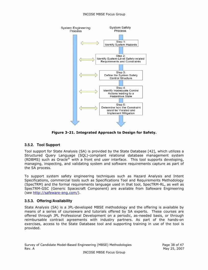
INCOSE MBSE Focus Group
Survey of Candidate Model-Based Engineering (MBSE) Methodologies Page 38 of 47
Rev. A May 25, 2007
INCOSE MBSE Focus Group
Figure 3-21. Integrated Approach to Design for Safety.
3.5.2. Tool Support
Tool support for State Analysis (SA) is provided by the State Database [42], which utilizes a
Structured Query Language (SQL)-compliant relational database management system
(RDBMS) such as Oracle® with a front end user interface. This tool supports developing,
managing, inspecting, and validating system and software requirements capture as part of
the SA process.
To support system safety engineering techniques such as Hazard Analysis and Intent
Specifications, commercial tools such as Specifications Tool and Requirements Methodology
(SpecTRM) and the formal requirements language used in that tool, SpecTRM-RL, as well as
SpecTRM-GSC (Generic Spacecraft Component) are available from Safeware Engineering
(see http://safeware-eng.com/).
3.5.3. Offering/Availability
State Analysis (SA) is a JPL-developed MBSE methodology and the offering is available by
means of a series of courseware and tutorials offered by SA experts. These courses are
offered through JPL Professional Development on a periodic, as-needed basis, or through
reimbursable contract agreements with industry partners. As part of the hands-on
exercises, access to the State Database tool and supporting training in use of the tool is
provided.

INCOSE MBSE Focus Group
Survey of Candidate Model-Based Engineering (MBSE) Methodologies Page 39 of 47
Rev. A May 25, 2007
INCOSE MBSE Focus Group
4. Role of OMG™ UML®/SysML™
The Unified Modeling Language™ (UML®) and Systems Modeling Language™ (OMG SysML™)
are visual modeling language standards managed under the auspices of the Object
Management Group™ (OMG™); an open membership, not-for-profit consortium that
produces and maintains computer industry specifications for interoperable enterprise
applications [52,53].
UML and OMG SysML are intended to be complementary. SysML was developed in
partnership between the OMG and INCOSE and is based on the UML, specifically, UML 2.0
(see Figure 4-1) [53]. SysML provides an additional set of modeling diagrams to model
complex systems that include hardware, software, data, procedures and other system
components. Together, UML and SysML go a long way to help unify what has historically
been a communication chasm between the systems and software engineering communities.
Figure 4-1. UML 2 and OMG SysML.
It is important to note that the UML and SysML are not software or systems methodologies
but rather visual modeling languages that are agnostic to any one specific methodology.
Several commercially-offered model-based systems and software engineering
methodologies, including most of the MBSE methodologies surveyed in this study,
incorporate the UML and/or SysML into specific methods and artifacts produced as part of
the methodology.
Use of industry-standard visual modeling languages allows members of a systems and
software lifecycle development activity to communicate in an unambiguous fashion.
Further, such industry standards facilitate the ability to leverage commercial visual modeling
tools as well as education and training provided by industry and academia. It is expected
that more-and-more junior engineers in the discipline of systems and software engineering
will be versed in one or both of these visual modeling standards in the coming years.
Additional information about UML and OMG SysML can be found at the following web sites:
� http://www.uml.org/
� http://www.omgsysml.org/

INCOSE MBSE Focus Group
Survey of Candidate Model-Based Engineering (MBSE) Methodologies Page 40 of 47
Rev. A May 25, 2007
INCOSE MBSE Focus Group
Relevance to State Analysis
With respect to State Analysis (SA), the UML component diagram is a modeling artifact that
is currently used to describe the static structure of software components, although in
somewhat a non-normative fashion. The term “non-normative” means that the visual
models are not fully compliant with the standard; this is not a problem provided the models
are clearly labeled as non-normative. It is recommended that SA component diagrams
utilize the UML 2 standard and clearly delineate non-normative models.
UML and OMG SysML are extensible by means of profiles and the use of stereotypes, which
allows these visual modeling standards to be tailored to specific domain areas or areas of
application. Because of this extension/tailoring mechanism, it is recommended that, in
addition to UML component diagrams, other UML/SysML structure and behavior diagrams be
explored for adoption in the SA MBSE methodology, for example, state effects diagrams and
state timelines.
Relevance to EFFBDs (or other “de-facto” MBSE visual modeling standards)
A recommendation for the MBSE tool vendors that currently do not support UML and/or
OMG SysML is to add this capability to the product roadmap as soon as possible;
particularly, SysML. The advantage of using industry standard visual modeling languages
over vendor-specific modeling languages is clear and does not warrant debate. Some MBSE
tools, for example, only support the Enhanced Function Flow Block Diagram (EFFBD) visual
modeling capability, which in some cases (e.g., Vitech CORE/COREsim) support executable
modeling constructs that allows the systems engineer to run discrete-event simulations
based on EFFBD models. This is a very powerful capability and there is no technical reason
that such an executable capability could not be added to OMG SysML diagrams such as
activity diagrams and state diagrams. Bock [54,55] has how both UML (UML 2 specifically)
and SysML can be used for activity modeling and how these standards can extended to fully
support EFFBDs.
5. References
Additional information regarding the content of this report, including resources that describe
the various candidate MBSE methodologies described herein, can be found in this section.
[1] Martin, James N., Systems Engineering Guidebook: A Process for Developing
Systems and Products, CRC Press, Inc.: Boca Raton, FL, 1996.
[2] Bloomberg, Jason and Ronald Schmelzer, Service Orient or Be Doomed!, John Wiley
& Sons: Hoboken, New Jersey, 2006.
[3] Royce, Winston W., “Managing the Development of Large Software Systems,”
Proceedings of IEEE WESCON 26, pp. 1-9, Aug. 1970.
[4] Boehm, Barry W., “A Spiral Model of Software Development and Enhancement,”
Computer, pp. 61-72, May 1988.
[5] Forsberg, Kevin and Harold Mooz, “The Relationship of Systems Engineering to the Project
Cycle,” Engineering Management Journal, 4, No. 3, pp. 36-43, 1992.

INCOSE MBSE Focus Group
Survey of Candidate Model-Based Engineering (MBSE) Methodologies Page 41 of 47
Rev. A May 25, 2007
INCOSE MBSE Focus Group
[6] Forsberg, Kevin and Harold Mooz, “Application of the “Vee” to Incremental and
Evolutionary Development,” Proceedings of the Fifth Annual International Symposium
of the National Council on Systems Engineering, St. Louis, MO, July 1995.
[7] Department of Defense Directive (DoDD) Number 5000.1, “The Defense Acquisition
System,” Undersecretary of Defense for Acquisition and Technology, U.S.
Department of Defense, May 12, 2003.
[8] Department of Defense Instruction (DoDI) Number 5000.2, “Operation of the
Defense Acquisition System,” U.S. Department of Defense, May 12, 2003.
[9] NASA Policy Directive (NPD) 7120.4C, “Program/Project Management,” National
Aeronautics and Space Administration, Washington, D.C., Dec. 6, 1999.
[10] NASA Procedural Requirement (NPR) 7120.5D, “NASA Space Flight Program and
Project Management Requirements,” National Aeronautics and Space Administration,
Washington, D.C., Mar. 6, 2007.
[11] Balmelli, L., Brown, D., Cantor, M. and M. Mott, “Model-Driven Systems
Development,” IBM Systems Journal, 45, No. 3, pp. 569-585, 2006.
[12] Roedler, Garry, “What is ISO/IEC 15288 and Why Should I Care?” (presentation
slides), ISO/IEC JTC1/SC7/WG7, Geneva: International Organization for
Standardization, Sept. 23, 2002.
[13] ANSI/EIA 632, Processes for Engineering a System, American National Standards
Institute/Electronic Industries Alliance, 1999.
[14] IEEE Std 1220-1998, IEEE Standard for Application and Management of the Systems
Engineering Process, Institute for Electrical and Electronic Engineers, Dec. 8, 1998.
[15] ISO/IEC 15288:2002, Systems Engineering – System Life Cycle Processes,
International Organization for Standardization/International Electrotechnical
Commission, Nov. 15, 2003.
[16] IEEE Std 15288™-2004, Systems Engineering – System Life Cycle Processes,
Institute for Electrical and Electronic Engineers, June 8, 2005.
[17] Haskins, Cecilia (ed.), INCOSE Systems Engineering Handbook: A Guide for System
Life Cycle Processes and Activities, v. 3, INCOSE-TP-2003-002-03, International
Council on Systems Engineering, June 2006.
[18] NASA Procedural Requirement (NPR) 7123.1A, “NASA Systems Engineering
Processes and Requirements,” National Aeronautics and Space Administration,
Washington, D.C., Mar. 26, 2007.
[19] Baker, Loyd, Clemente, Paul, Cohen, Bob, Permenter, Larry, Purves, Byron and Pete
Salmon, “Foundational Concepts for Model Driven System Design,” white paper,
INCOSE Model Driven System Design Interest Group, International Council on
Systems Engineering, Jul. 15, 2000.

INCOSE MBSE Focus Group
Survey of Candidate Model-Based Engineering (MBSE) Methodologies Page 42 of 47
Rev. A May 25, 2007
INCOSE MBSE Focus Group
[20] Douglass, Bruce P., “The Harmony Process,” I-Logix white paper, I-Logix, Inc., Mar.
25, 2005.
[21] Hoffmann, Hans-Peter, “SysML-Based Systems Engineering Using a Model-Driven
Development Approach,” Proceedings of INCOSE 2006 International Symposium,
Orlando, FL, Jul. 12, 2006.
[22] Hoffmann, Hans-Peter, “Harmony-SE/SysML Deskbook: Model-Based Systems
Engineering with Rhapsody,” Rev. 1.51, Telelogic/I-Logix white paper, Telelogic AB,
May 24, 2006.
[23] Lykins, Howard, Friedenthal, Sanford and Abraham Meilich, “Adapting UML for an
Object-Oriented Systems Engineering Method (OOSEM),” Proceedings of the INCOSE
2000 International Symposium, Minneapolis, MN, Jul. 2000.
[24] Friedenthal, Sanford, “Object Oriented Systems Engineering,” Process Integration for
2000 and Beyond: Systems Engineering and Software Symposium. New Orleans, LA,
Lockheed Martin Corporation, 1998.
[25] “Object Oriented System Engineering Method”, OOSEM Descriptive Outline for
INCOSE SE Handbook Version 3, Annotated Update, Sect. 6.4.2, pp. 6-1 to 6-6, Mar.
14, 2006.
[26] “Object-Oriented Systems Engineering Method (OOSEM) Tutorial,” Ver. 02.42.00,
Lockheed Martin Corporation and INCOSE OOSEM Working Group, Apr. 2006.
[27] Kruchten, Philippe, The Rational Unified Process: An Introduction, Third Edition,
Addison-Wesley Professional: Reading, MA, 2003.
[28] Cantor, Murray, “RUP SE: The Rational Unified Process for Systems Engineering,”
The Rational Edge, Rational Software, Nov. 2001.
[29] Cantor, Murray, “Rational Unified Process® for Systems Engineering, RUP SE®
Version 2.0,” IBM Rational Software white paper, IBM Corporation, May 8, 2003.
[30] Cantor, Murray, IBM Corporation (private communication), Feb. 27, 2007.
[30] Viljoen, Jaco, “RUP SE: The Rational Unified Process for Systems Engineering,”
INCOSE SA [South Africa] Newsletter, Issue 01: Q4, 2003.
[31] ISO/IEC 10746-1:1998(E), Information technology – Open Distributed Processing –
Reference model: Overview, International Organization for
Standardization/International Electrotechnical Commission, Nov. 15, 2003.
[32] ANSI/IEEE Std 1471-2000, IEEE Recommended Practice for Architectural Description
of Software-Intensive Systems, American National Standards Institute/Institute for
Electrical and Electronic Engineers, Sep. 21, 2000.
[33] Long, James E., “Systems Engineering (SE) 101,” CORE®: Product & Process
Engineering Solutions, Vitech training materials, Vitech Corporation, Vienna, VA,
2000.
INCOSE MBSE Focus Group
Survey of Candidate Model-Based Engineering (MBSE) Methodologies Page 43 of 47
Rev. A May 25, 2007
INCOSE MBSE Focus Group
[34] “Vitech Announces Participation in INCOSE’s 17th Annual International Symposium,
Delivering Five Key Systems Engineering Presentations, Papers and Panels,” Vitech
News Release, Vitech Corporation, Vienna, VA, Feb. 23, 2007.
[35] Long, James E., “MBSE in Practice: Developing Systems with CORE,” Vitech briefing
slides, Vitech Corporation, Vienna, VA, Mar. 2007.
[36] Baker, Loyd Jr. and James E. Long, “Role of System Engineering Across The System
Life Cycle,” Vitech white paper, Vitech Corporation, Vienna, VA, Jul. 15, 2000.
[37] Childers, Susan Rose and James E. Long, “A Concurrent Methodology for the System
Engineering Design Process,” Vitech white paper, Vitech Corporation, Vienna, VA,
May 20, 2004.
[38] Long, Jim, “Relationships between Common Graphical Representations in Systems
Engineering,” Vitech white paper, Vitech Corporation, Vienna, VA, Aug. 6, 2002.
[39] Skipper, J. F., “A Systems Engineer’s Position on the Unified Modeling Language,”
Vitech white paper, Vitech Corporation, Vienna, VA, Jul. 15, 2003.
[40] Ingham, Michel D., Rasmussen, Robert D., Bennett, Matthew B. and Alex C.
Moncada, “Generating Requirements for Complex Embedded Systems Using State
Analysis,” Acta Astronautica, 58, Iss. 12, pp. 648-661, Jun. 2006.
[41] Dvorak, Dan, Rasmussen, Robert, Reeves, Glenn and Allan Sacks, “Software
Architecture Themes in JPL’s Mission Data System,” Proceedings of the AIAA
Guidance, Navigation, and Control Conference, paper AIAA-99-4553, 1999.
[42] Bennett, Matthew B., Rasmussen, Robert D. And Michel D. Ingham, “A Model-Based
Requirements Database Tool for Complex Embedded Systems,” Proceedings of the
INCOSE 2005 International Symposium, Rochester, NY, Jul. 2005.
[43] Rasmussen, Bob, “Session 1: Overview of State Analysis,” (internal document),
State Analysis Lite Course, Jet Propulsion Laboratory, California Institute of
Technology, Pasadena, CA, 2005.
[44] Ingham, Mitch, “State Analysis Overview: What PSEs ought to know,” Briefing Slides
(internal document), Jet Propulsion Laboratory, California Institute of Technology,
Pasadena, CA, Nov. 2, 2006.
[45] Kordon, Mark, Wall, Steve, Stone, Henry, Blume, William, Skipper, Joseph, Ingham,
Mitch, Neelon, Joe, Chase, James, Baalke, Ron, Hanks, David, Salcedo, Jose, Solish,
Benjamin, Postma, Mona, and Richard Machuzak, “Model-Based Engineering Design
Pilots at JPL,” 2007 IEEE Aerospace Conference Proceedings, 1-4244-0524-4/07,
IEEEAC paper #1678, Institute of Electrical and Electronic Engineers, 2005.
[46] Weiss, Kathryn A., “Engineering Spacecraft Mission Software using a Model-Based
and Safety-Driven Design Methodology,” Journal of Aerospace Computing,
Information, and Communication, 3, pp. 562-586, Nov. 2006.
[47] Leveson, Nancy G., Safeware: System Safety and Computers, Addison-Wesley:
Reading, MA, pp. 171-184 and 313-358, 1995.

INCOSE MBSE Focus Group
Survey of Candidate Model-Based Engineering (MBSE) Methodologies Page 44 of 47
Rev. A May 25, 2007
INCOSE MBSE Focus Group
[48] Leveson, Nancy G., “A New Approach to Hazard Analysis for Complex Systems,”
International Conference of the System Safety Society, Ottawa, Canada, Aug. 2003.
[49] NASA Software Safety Standard, NASA Technical Standard, NASA-STD-8719.13B
w/Change 1, National Aeronautics and Space Administration, Washington, D.D., Jul.
8, 2004.
[50] Leveson, Nancy G., “Intent Specifications: An Approach to Building Human-Centered
Specifications,” IEEE Transactions on Software Engineering, 26, No. 1, Jan. 2000.
[51] Weiss, Kathryn A., Ong, Elwin C. and Nancy G. Leveson, “Reusable Specification
Components for Model-Driven Development,” Proceedings of the INCOSE 2003
International Symposium, Crystal City, VA, Jul. 2003.
[52] Object Management Group, Unified Modeling Language: Superstructure, Ver. 2.1.1,
OMG Adopted Specification, OMG document formal/2007-02-05, Feb. 2007.
[53] Object Management Group, OMG SysML Specification, OMG Adopted Specification,
OMG document ptc/06-05-04, May 2006.
[54] Bock, Conrad, “UML 2 for Systems Engineering,” Briefing Slides, National Institute of
Standards and Technology, Mar. 27, 2003.
[55] Bock, Conrad, “SysML and UML 2 Support for Activity Modeling,” Systems
Engineering, 9, No. 2, pp. 160-186, 2006.
6. Acronyms and Abbreviations
ANSI American National Standards Institute
CAE Computer Aided Engineering
CMMI Capability Maturity Model Integrated
COTS Commercial Off-The-Shelf
DoD Department of Defense
DoDD Department of Defense Directive
DoDI Department of Defense Instruction
EFFBD Extended Function Flow Block Diagram
EIA Electronic Industries Alliance
FDD Functional Design Description
FDIS Final Draft International Standard
FMECA Failure Modes and Effects Criticality Analysis
FOC Full Operational Capability
FTA Fault Tree Analysis
IEC International Electrotechnical Commission

INCOSE MBSE Focus Group
Survey of Candidate Model-Based Engineering (MBSE) Methodologies Page 45 of 47
Rev. A May 25, 2007
INCOSE MBSE Focus Group
IEEE Institute for Electrical and Electronic Engineers
INCOSE International Council on Systems Engineering
IOC Initial Operational Capability
IPD Integrated Product Development
IPPD Integrated Product and Process Development
ISO International Organization for Standardization
ITU International Telecommunication Union
JPL Jet Propulsion Laboratory
KSA Knowledge, Skills, and Abilities
MBED Model-Based Engineering Design
MBSE Model-Based Systems Engineering
MDS Mission Data System
MDSD Model-Driven Systems Development
NASA National Aeronautics and Space Administration
NPD NASA Policy Directive
NPR NASA Procedural Requirement
OMG Object Management Group
OOSEM Object-Oriented Systems Engineering Method
PMTE Process, Methods, Tools, and Environment
RMC Rational Method Composer
RUP Rational Unified Process
RUP SE Rational Unified Process for Systems Engineering
SA State Analysis
SE Systems Engineering
SEMP Systems Engineering Management Plan
STAMP Systems Theoretic Accident Modeling and Process
STPA STAMP-based Hazard Analysis
SysML Systems Modeling Language
UML Unified Modeling Language
V&V Verification and Validation
WBS Work Breakdown Structure
INCOSE MBSE Focus Group
Survey of Candidate Model-Based Engineering (MBSE) Methodologies Page 46 of 47
Rev. A May 25, 2007
INCOSE MBSE Focus Group
Acknowledgments
The author would like to thank Joseph Skipper, Mark Kordon, Ross Jones, Kenny Meyer,
Michel Ingham, and Kathryn Weiss all of JPL for their valuable feedback and review of this
survey report. In addition, the author would like thank Sanford (“Sandy”) Friedenthal of
Lockheed Martin Corporation, Murray Cantor of IBM Corporation, and James (“Jim”) Long of
Vitech Corporation for their valuable feedback of the OOSEM, RUP-SE, and Vitech MBSE
methodologies, respectively.
The work carried out in this report was carried out at the Jet Propulsion Laboratory,
California Institute of Technology under a contract with the National Aeronautics and Space
Administration.

INCOSE MBSE Focus Group
Survey of Candidate Model-Based Engineering (MBSE) Methodologies Page 47 of 47
Rev. A May 25, 2007
INCOSE MBSE Focus Group
Document Change Record
Date Revision Description Author(s)
May 23, 2007 A Initial revision. Jeff A. Estefan
Related Documents