U.S. Department of Transportation Federal Aviation Administration Surveillance and Broadcast Services (SBS) Group Surveillance and Broadcast Services Description Document SRT-047, Revision 05 November 20, 2020 Approved By: _______________ Ammyanna Williams, Group Manager (Acting) Date Surveillance and Broadcast Services Group, AJM-4200 Federal Aviation Administration 600 Independence Avenue, SW Washington, DC 20591

Welcome message from author
This document is posted to help you gain knowledge. Please leave a comment to let me know what you think about it! Share it to your friends and learn new things together.
Transcript
U.S. Department of Transportation
Federal Aviation Administration
Surveillance and Broadcast Services (SBS) Group
Surveillance and Broadcast Services
Description Document
SRT-047, Revision 05
November 20, 2020 Approved By: _______________ Ammyanna Williams, Group Manager (Acting) Date Surveillance and Broadcast Services Group, AJM-4200
Federal Aviation Administration 600 Independence Avenue, SW
Washington, DC 20591
FAA Surveillance and Broadcast Services Surveillance and Broadcast Services Description Document
SRT-047, Rev. 05 – November 20, 2020 Page i
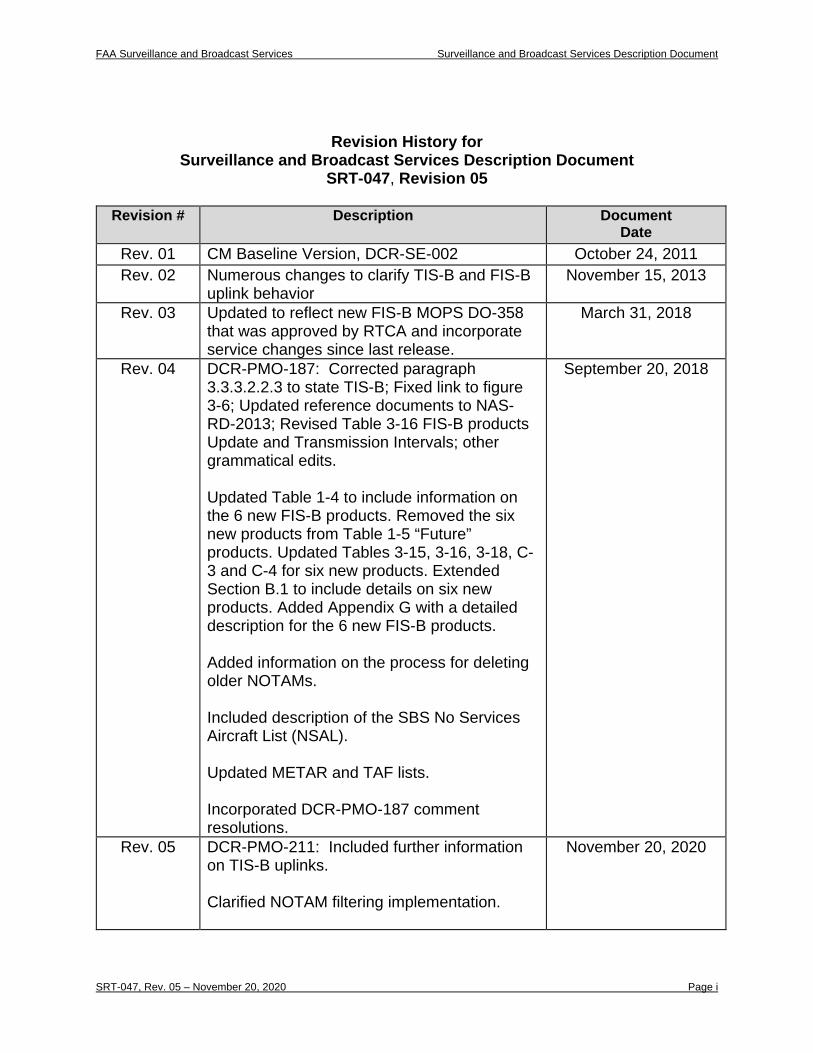
Revision History for Surveillance and Broadcast Services Description Document
SRT-047, Revision 05
Revision # Description Document Date
Rev. 01 CM Baseline Version, DCR-SE-002 October 24, 2011 Rev. 02 Numerous changes to clarify TIS-B and FIS-B
uplink behavior November 15, 2013
Rev. 03 Updated to reflect new FIS-B MOPS DO-358 that was approved by RTCA and incorporate service changes since last release.
March 31, 2018
Rev. 04 DCR-PMO-187: Corrected paragraph 3.3.3.2.2.3 to state TIS-B; Fixed link to figure 3-6; Updated reference documents to NAS-RD-2013; Revised Table 3-16 FIS-B products Update and Transmission Intervals; other grammatical edits. Updated Table 1-4 to include information on the 6 new FIS-B products. Removed the six new products from Table 1-5 “Future” products. Updated Tables 3-15, 3-16, 3-18, C-3 and C-4 for six new products. Extended Section B.1 to include details on six new products. Added Appendix G with a detailed description for the 6 new FIS-B products. Added information on the process for deleting older NOTAMs. Included description of the SBS No Services Aircraft List (NSAL). Updated METAR and TAF lists. Incorporated DCR-PMO-187 comment resolutions.
September 20, 2018
Rev. 05 DCR-PMO-211: Included further information on TIS-B uplinks. Clarified NOTAM filtering implementation.
November 20, 2020
FAA Surveillance and Broadcast Services Surveillance and Broadcast Services Description Document
SRT-047, Rev. 05 – November 20, 2020 Page ii
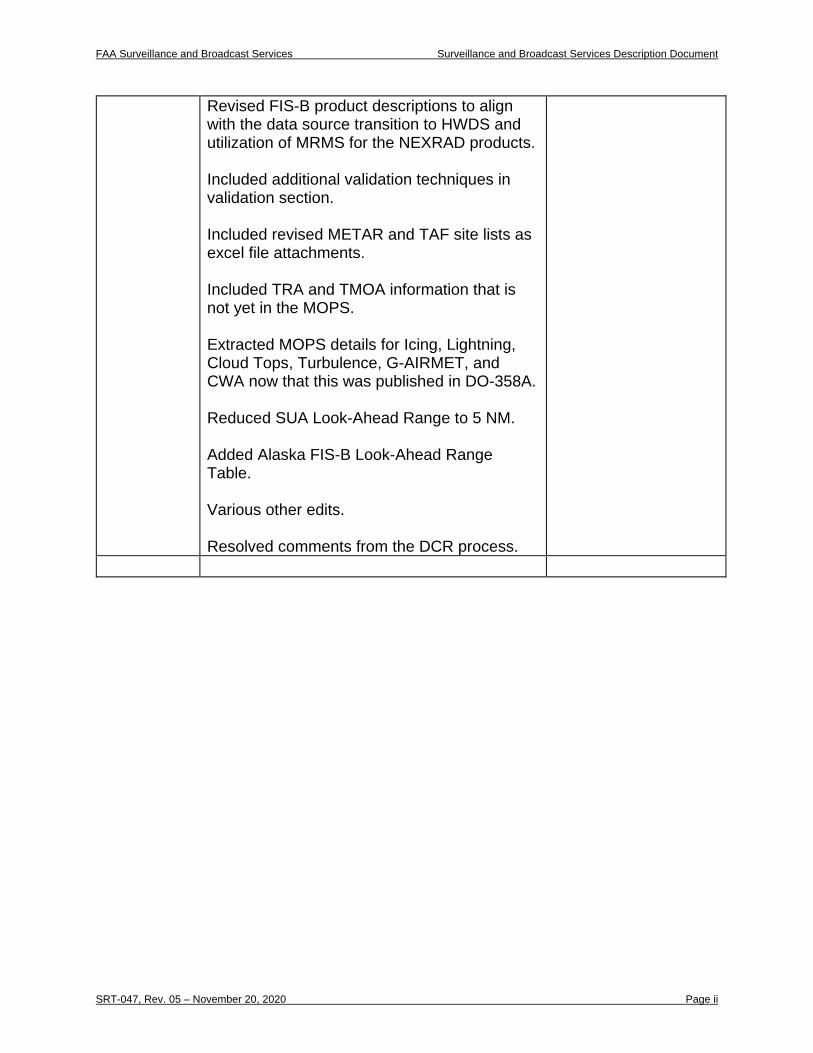
Revised FIS-B product descriptions to align with the data source transition to HWDS and utilization of MRMS for the NEXRAD products. Included additional validation techniques in validation section. Included revised METAR and TAF site lists as excel file attachments. Included TRA and TMOA information that is not yet in the MOPS. Extracted MOPS details for Icing, Lightning, Cloud Tops, Turbulence, G-AIRMET, and CWA now that this was published in DO-358A. Reduced SUA Look-Ahead Range to 5 NM. Added Alaska FIS-B Look-Ahead Range Table. Various other edits. Resolved comments from the DCR process.
FAA Surveillance and Broadcast Services Surveillance and Broadcast Services Description Document
SRT-047, Rev. 05 – November 20, 2020 Page iii
TABLE OF CONTENTS
1 Scope 1 1.1 Summary: Background and Purpose 1 1.2 Subsystem Responsibility List: SBSS and External Interfaces 4
1.2.1 ADS-B Equipped Aircraft in the NAS 5 1.2.1.1 1090ES and UAT Equipages 5 1.2.1.2 Requirements of the Final Rule for ADS-B Equipage 5 1.2.1.3 Dual Technology Link Equipage 5
1.2.2 FAA SDP for Radar Data, ADS-B Target Delivery and Service Monitoring 6
1.2.3 Meteorological and Aeronautical Data Source 6 1.3 SBSS Services Overview 6
1.3.1 ADS-B Surveillance Service 6 1.3.1.1 Air-to-Air ADS-B 7 1.3.1.2 Air-to-Ground ADS-B 7
1.3.2 ADS-R Service 7 1.3.3 TIS-B Service 9 1.3.4 FIS-B Service 10
1.3.4.1 Current FIS-B products 11 1.4 Message Interchange Summary 14
2 Referenced Documents 15 2.1 Government Documents 15 2.2 Non-Government Documents 16
3 Air Interface Characteristics: Service Descriptions 18 3.1 General Air Interface Characteristics 18 3.2 Service Identification and Description 18
3.2.1 ADS-B Surveillance Service 21 3.2.2 ADS-R Service 22
3.2.2.1 ADS-R Concept of Operations 22 3.2.2.2 ADS-R Client Identification 22 3.2.2.3 ADS-R Target Identification 22 3.2.2.4 ADS-R in En Route and Terminal Airspace Domains 23 3.2.2.5 ADS-R in Surface Domains 23 3.2.2.6 Transmission of ADS-R Targets Over the Air Interface 24 3.2.2.7 ADS-R Service Status Notification 24 3.2.2.8 ADS-R Same Link Rebroadcast 25
3.2.3 TIS-B Service 26 3.2.3.1 TIS-B Service Concept of Operations 26 3.2.3.2 TIS-B in En Route and Terminal Airspace Domains 27 3.2.3.3 TIS-B in Surface Domains 27 3.2.3.4 Transmission of TIS-B Target Messages 28 3.2.3.5 TIS-B Service Status Notification 28 3.2.3.6 False Tracks and Incorrect Associations 28 3.2.3.7 TIS-B Target Uplink Limitations 29
FAA Surveillance and Broadcast Services Surveillance and Broadcast Services Description Document
SRT-047, Rev. 05 – November 20, 2020 Page iv
3.2.4 FIS-B Service 29 3.3 Service Messages and Performance 31
3.3.1 ADS-B Service Messages and Performance 31 3.3.1.1 ADS-B Information Units—Message Content 31 3.3.1.2 ADS-B Quality of Service 34
3.3.2 ADS-R Service Messages and Performance 36 3.3.2.1 ADS-R Information Units—Message Content 36 3.3.2.2 Quality of Service 37
3.3.3 TIS-B Service Messages and Performance 39 3.3.3.1 TIS-B Information Units—Message Content 39 3.3.3.2 TIS-B Quality of Service 43
3.3.4 FIS-B Service Messages and Performance 48 3.3.4.1 FIS-B Information Units – Message Content 49 3.3.4.2 FIS-B Information Units – FIS-B Application Protocol Data Unit
(APDU) 49 3.3.4.3 FIS-B Information Units – TIS-B/ADS-R Service Status 49 3.3.4.4 FIS-B Quality of Service 50
3.3.5 ADS-B Service 53 3.3.6 ADS-R Service 55 3.3.7 TIS-B Service 56 3.3.8 FIS-B Service 57
3.3.8.1 DO-358 Errata for FIS-B Services 58 3.4 Uplink Interface Design Characteristics Summary 59 3.5 No Services Aircraft List 59
4 Abbreviations and Acronyms 61
Appendix A. Coverage Maps and Radio Stations 63 A.1 Current Coverage 63 A.2 Radio Station Locations 63
Appendix B. FIS-B Quantity of Available Products and Other Aspects 64 B.1 FIS-B Quantity of Available Products 64
B.1.1 SIGMET / Convective SIGMET 64 B.1.2 AIRMET 64 B.1.3 METAR 64 B.1.4 CONUS NEXRAD 64 B.1.5 Regional NEXRAD 64 B.1.6 NOTAM 64 B.1.7 PIREP 64 B.1.8 SUA Status 64 B.1.9 TAF 65 B.1.10 Winds and Temperatures Aloft 65 B.1.11 Icing 66 B.1.12 Cloud Tops 66 B.1.13 Turbulence 66 B.1.14 Lightning 66 B.1.15 G-AIRMET 67
FAA Surveillance and Broadcast Services Surveillance and Broadcast Services Description Document
SRT-047, Rev. 05 – November 20, 2020 Page v
B.1.16 Center Weather Advisory 67
Appendix C. FIS-B Tiering Configuration 68 C.1 TIS-B Site ID Field and Data Channel Assignment 68 C.2 Product Parameters for Low/Medium/High Altitude Tier Radios 69 C.3 Product Parameters for Surface Radios 70
Appendix D. Listing of Service Volumes (SV) 72 D.1 En Route SVs 72 D.2 Terminal SVs 73 D.3 Surface SVs 74
Appendix E. METAR Stations 75
Appendix F. TAF Stations 76
Appendix G. FIS-B Products 77 G.1 Background 77
G.1.1 Text with Graphical Overlay FIS-B Products 77 G.1.1.1 General Formatting 77 G.1.1.2 NOTAMs and Product Updates Unavailable (Products #8, #16,
#17) 97 G.2 Current Report List (CRL) 104
G.2.1 CRL Header Encoding 105 G.2.1.1 Product ID 105 G.2.1.2 TFR 105 G.2.1.3 Reserved 105 G.2.1.4 O Flag 105 G.2.1.5 L Flag 105 G.2.1.6 Product Range 106 G.2.1.7 LocID 106 G.2.1.8 Number of CRL Items Listed 106
G.2.2 CRL Payload Encoding 106 G.2.2.1 Reserved Bit 106 G.2.2.2 Report Year 106 G.2.2.3 Text 107 G.2.2.4 Graphic 107 G.2.2.5 Report Number 107
FAA Surveillance and Broadcast Services Surveillance and Broadcast Services Description Document
SRT-047, Rev. 05 – November 20, 2020 Page vi
LIST OF FIGURES
Figure 1-1. SBSS and External Interfaces ...................................................................................... 4 Figure 1-2. ADS-B Service Data Flows ......................................................................................... 7 Figure 1-3. ADS-R Service Data Flows ......................................................................................... 8 Figure 1-4. TIS-B Service Data Flows ........................................................................................... 9 Figure 1-5. FIS-B Service Data Flows .......................................................................................... 10 Figure 3-1. SBSS and ADS-B Aircraft Interconnectivity ............................................................. 18 Figure 3-2. SBS Service Volumes ................................................................................................ 20 Figure 3-3. ADS-R Client Proximity Determination .................................................................... 23 Figure 3-4. ADS-R SLR Example at PHL Airport ....................................................................... 25 Figure 3-5. TIS-B Client Proximity Determination ...................................................................... 27 Figure 3-6. Continuity Region around Airport with Surface SV .................................................. 47 Figure 3-7. ADS-B Air-to-Air Protocol Stack .............................................................................. 53 Figure 3-8. ADS-B Service Air-to-Ground Protocol Stack .......................................................... 54 Figure 3-9. ADS-R Service Protocol Stack .................................................................................. 55 Figure 3-10. TIS-B Service Protocol Stack .................................................................................. 56 Figure B-1. Locations of U.S Winds/Temperatures Aloft Forecast Locations ............................. 66 Figure D-1. En Route Service Volume Boundaries ...................................................................... 72 Figure G-1: Decomposition Showing TWGO FIS-B Payload ..................................................... 78 Figure G-2: TWGO Header Byte-Level Format ........................................................................... 78 Figure G-3: Text Record Byte-Level Format ............................................................................... 80 Figure G-4: Graphical Record Byte-Level Format ....................................................................... 82 Figure G-5: Record Applicability Byte-Level Format .................................................................. 87 Figure G-6: Extended Range Circular Prism ................................................................................ 90 Figure G-7: Example of 3D Polygon with mixed altitude reference datums ............................... 95 Figure G-8: Example of 3D Polygon with mixed altitude reference datums ............................... 96 Figure G-9: Decomposition Showing the CRL .......................................................................... 104 Figure G-10: CRL Encoding ....................................................................................................... 104
FAA Surveillance and Broadcast Services Surveillance and Broadcast Services Description Document
SRT-047, Rev. 05 – November 20, 2020 Page vii
LIST OF TABLES
Table 1-1. SBSS Supported and Complementary ADS-B Services ............................................... 2 Table 1-2. ADS-B Applications, Services, and Functions .............................................................. 3 Table 1-3. ADS-B Equipage Types in the NAS ............................................................................. 5 Table 1-4. FIS-B Products Provided by SBSS.............................................................................. 11 Table 1-5. Message Interchange Summary ................................................................................... 14 Table 3-1. Service Volume Boundaries and Airspace Domain .................................................... 19 Table 3-2. Target Provision to ADS-B-IN Aircraft: Dependence on Equipage ........................... 20 Table 3-3. Required ADS-B OUT Performance to be an ADS-R Client ..................................... 22 Table 3-4. Required ADS-B OUT Performance for ADS-R Traffic Uplink to Clients ............... 23 Table 3-5. Required ADS-B OUT Performance to be a TIS-B Client ......................................... 26 Table 3-6. 1090ES ADS-B Message ME bit-mapping to SDP ADS-B Report Data
Items .......................................................................................................................... 32 Table 3-7. UAT ADS-B Message mapping to SDP ADS-B Report Data Items .......................... 33 Table 3-8. FAA SDP ADS-B Report ............................................................................................ 33 Table 3-9. 1090ES ADS-R Message Types to Encode Upon Receipt of UAT Message
Types ......................................................................................................................... 36 Table 3-10. Transmitted 1090ES TIS-B Message Types ............................................................. 40 Table 3-11. Payload Composition of 1090ES TIS-B Messages ................................................... 40 Table 3-12. Payload Composition of UAT TIS-B Messages ....................................................... 42 Table 3-13. Requirements for Track Accuracy ............................................................................. 45 Table 3-14. UAT TIS-B / ADS-R Service Status Format ............................................................ 49 Table 3-15. FIS-B Products Supported by SBSS.......................................................................... 50 Table 3-16. FIS-B Product Update and Transmit Intervals .......................................................... 51 Table 3-17. FIS-B Service Protocol Stack .................................................................................... 57 Table 3-19. 1090 Uplink Interface Requirements Table .............................................................. 59 Table 3-20. UAT Uplink Interface Requirements Table .............................................................. 59 Table C-1. TIS-B Site ID field values .......................................................................................... 68 Table C-2. FIS-B Data Channel Assignment ................................................................................ 68 Table C-3. Product Look-Ahead Range for Low/Medium/High Altitude Tier Radios ................ 69 Table C-4. Alaska Product Look-Ahead Ranges for Low/Medium/High Altitude Tier
Radios ........................................................................................................................ 70 Table C-5. Product Parameters for Surface Radios ...................................................................... 70 Table D-1. List of Airports Supported by Terminal SVs .............................................................. 73 Table D-2. List of Airports Supported by Surface SVs ................................................................ 74 Table G-1: Record Format Options .............................................................................................. 79 Table G-2: Report Status .............................................................................................................. 81 Table G-3: Report Year & Record Applicability Year Example .................................................. 83 Table G-4: Object Types ............................................................................................................... 84 Table G-5: Airspace Object Elements .......................................................................................... 84 Table G-6: Object Status ............................................................................................................... 85 Table G-7: Record Applicability Options ..................................................................................... 86 Table G-8: Date/Time Format ...................................................................................................... 86 Table G-9: Overlay Geometry Options ......................................................................................... 88 Table G-10: Overlay Geometry Encoding .................................................................................... 91

FAA Surveillance and Broadcast Services Surveillance and Broadcast Services Description Document
SRT-047, Rev. 05 – November 20, 2020 Page viii
Table G-11: Angular Weighted Binary Encoding of Latitude and Longitude ............................. 91 Table G-12: Angular Weighted Binary 19-Bit Encoding of Latitude and Longitude .................. 92 Table G-13: Overlay Operators .................................................................................................... 93 Table G-14: Overlay Operators .................................................................................................... 98 Table G-15: NOTAM Text Record Elements ............................................................................... 99 Table G-16: NOTAM Text Record Elements ............................................................................. 102
FAA Surveillance and Broadcast Services Surveillance and Broadcast Services Description Document
SRT-047, Rev. 05 – November 20, 2020 Page 1 of 107
1 Scope This document discusses the design of the Air Interface between the Surveillance and Broadcast Services System (SBSS) and Automatic Dependent Surveillance-Broadcast (ADS-B) equipped aircraft.
1.1 Summary: Background and Purpose The overall purpose of this document is to describe the services provided by the Surveillance and Broadcast Services System (SBSS) over the Air Interface to ADS-B Equipped aircraft. It is oriented primarily to ADS-B avionics manufacturers. It documents the detailed design of the Air Interface to help ensure that vendor offerings of ADS-B avionics are fully compatible with the SBSS, and that they may be designed to take full advantage of the offered services. In the National Airspace System (NAS), there are two applicable ADS-B equipage types:
• 1090 Extended Squitter (1090ES): an extension of Mode-S technology in which 1090ES avionics periodically broadcast short messages at 1090 MHz that provide their identity (24-Bit Address), target state vector (position, velocity) and other aircraft status information.
• Universal Access Transceiver (UAT): a new technology in which UAT avionics periodically broadcast messages at 978 MHz that provide their identity, target state vector and other status information.
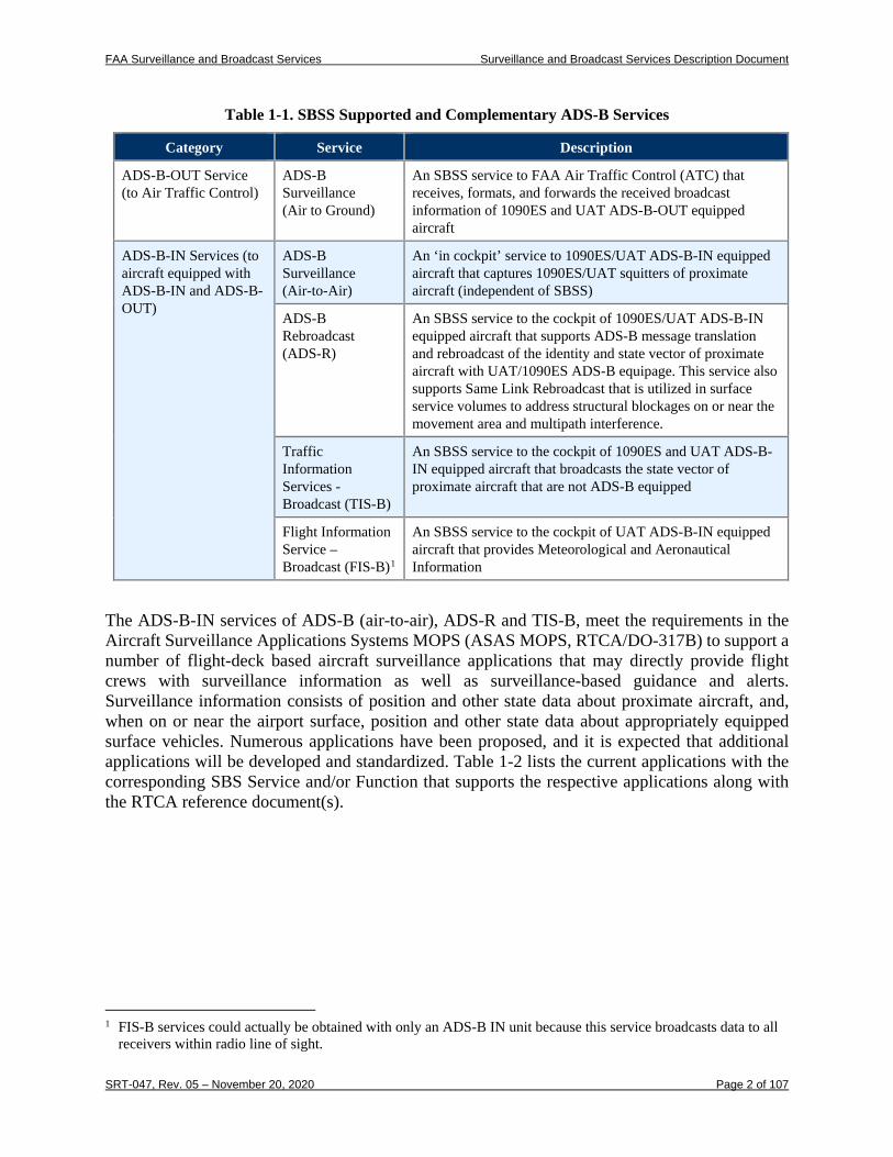
Each of the above equipage types may support only ADS-B-OUT services or may be more comprehensive so that they support ADS-B-IN services as well. Table 1-1 introduces the ADS-B-OUT and -IN services that are provided by SBSS to aircraft with the different equipage types. It also describes ADS-B air-to-air surveillance, which is complementary to, but independent of the broadcast services supported by SBSS. Each of these services will be described in further detail in sections 1 and 3 of this document.
FAA Surveillance and Broadcast Services Surveillance and Broadcast Services Description Document
SRT-047, Rev. 05 – November 20, 2020 Page 2 of 107
Table 1-1. SBSS Supported and Complementary ADS-B Services
Category Service Description
ADS-B-OUT Service (to Air Traffic Control)
ADS-B Surveillance (Air to Ground)
An SBSS service to FAA Air Traffic Control (ATC) that receives, formats, and forwards the received broadcast information of 1090ES and UAT ADS-B-OUT equipped aircraft
ADS-B-IN Services (to aircraft equipped with ADS-B-IN and ADS-B-OUT)
ADS-B Surveillance (Air-to-Air)
An ‘in cockpit’ service to 1090ES/UAT ADS-B-IN equipped aircraft that captures 1090ES/UAT squitters of proximate aircraft (independent of SBSS)
ADS-B Rebroadcast (ADS-R)
An SBSS service to the cockpit of 1090ES/UAT ADS-B-IN equipped aircraft that supports ADS-B message translation and rebroadcast of the identity and state vector of proximate aircraft with UAT/1090ES ADS-B equipage. This service also supports Same Link Rebroadcast that is utilized in surface service volumes to address structural blockages on or near the movement area and multipath interference.
Traffic Information Services - Broadcast (TIS-B)
An SBSS service to the cockpit of 1090ES and UAT ADS-B-IN equipped aircraft that broadcasts the state vector of proximate aircraft that are not ADS-B equipped
Flight Information Service – Broadcast (FIS-B)1
An SBSS service to the cockpit of UAT ADS-B-IN equipped aircraft that provides Meteorological and Aeronautical Information
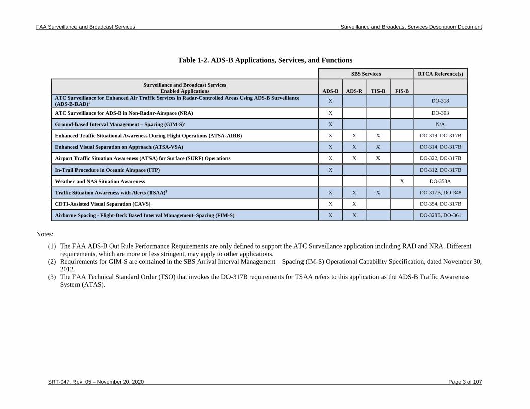
The ADS-B-IN services of ADS-B (air-to-air), ADS-R and TIS-B, meet the requirements in the Aircraft Surveillance Applications Systems MOPS (ASAS MOPS, RTCA/DO-317B) to support a number of flight-deck based aircraft surveillance applications that may directly provide flight crews with surveillance information as well as surveillance-based guidance and alerts. Surveillance information consists of position and other state data about proximate aircraft, and, when on or near the airport surface, position and other state data about appropriately equipped surface vehicles. Numerous applications have been proposed, and it is expected that additional applications will be developed and standardized. Table 1-2 lists the current applications with the corresponding SBS Service and/or Function that supports the respective applications along with the RTCA reference document(s).
1 FIS-B services could actually be obtained with only an ADS-B IN unit because this service broadcasts data to all
receivers within radio line of sight.
FAA Surveillance and Broadcast Services Surveillance and Broadcast Services Description Document
SRT-047, Rev. 05 – November 20, 2020 Page 3 of 107
Table 1-2. ADS-B Applications, Services, and Functions
SBS Services RTCA Reference(s)
ADS-B ADS-R TIS-B FIS-B Surveillance and Broadcast Services
Enabled Applications ATC Surveillance for Enhanced Air Traffic Services in Radar-Controlled Areas Using ADS-B Surveillance (ADS-B-RAD)1 X DO-318
ATC Surveillance for ADS-B in Non-Radar-Airspace (NRA) X DO-303
Ground-based Interval Management – Spacing (GIM-S)2 X N/A
Enhanced Traffic Situational Awareness During Flight Operations (ATSA-AIRB) X X X DO-319, DO-317B
Enhanced Visual Separation on Approach (ATSA-VSA) X X X DO-314, DO-317B
Airport Traffic Situation Awareness (ATSA) for Surface (SURF) Operations X X X DO-322, DO-317B
In-Trail Procedure in Oceanic Airspace (ITP) X DO-312, DO-317B
Weather and NAS Situation Awareness X DO-358A
Traffic Situation Awareness with Alerts (TSAA)3 X X X DO-317B, DO-348
CDTI-Assisted Visual Separation (CAVS) X X DO-354, DO-317B
Airborne Spacing - Flight-Deck Based Interval Management–Spacing (FIM-S) X X DO-328B, DO-361
Notes:
(1) The FAA ADS-B Out Rule Performance Requirements are only defined to support the ATC Surveillance application including RAD and NRA. Different requirements, which are more or less stringent, may apply to other applications.
(2) Requirements for GIM-S are contained in the SBS Arrival Interval Management – Spacing (IM-S) Operational Capability Specification, dated November 30, 2012.
(3) The FAA Technical Standard Order (TSO) that invokes the DO-317B requirements for TSAA refers to this application as the ADS-B Traffic Awareness System (ATAS).
FAA Surveillance and Broadcast Services Surveillance and Broadcast Services Description Document
SRT-047, Rev. 05 – November 20, 2020 Page 4 of 107
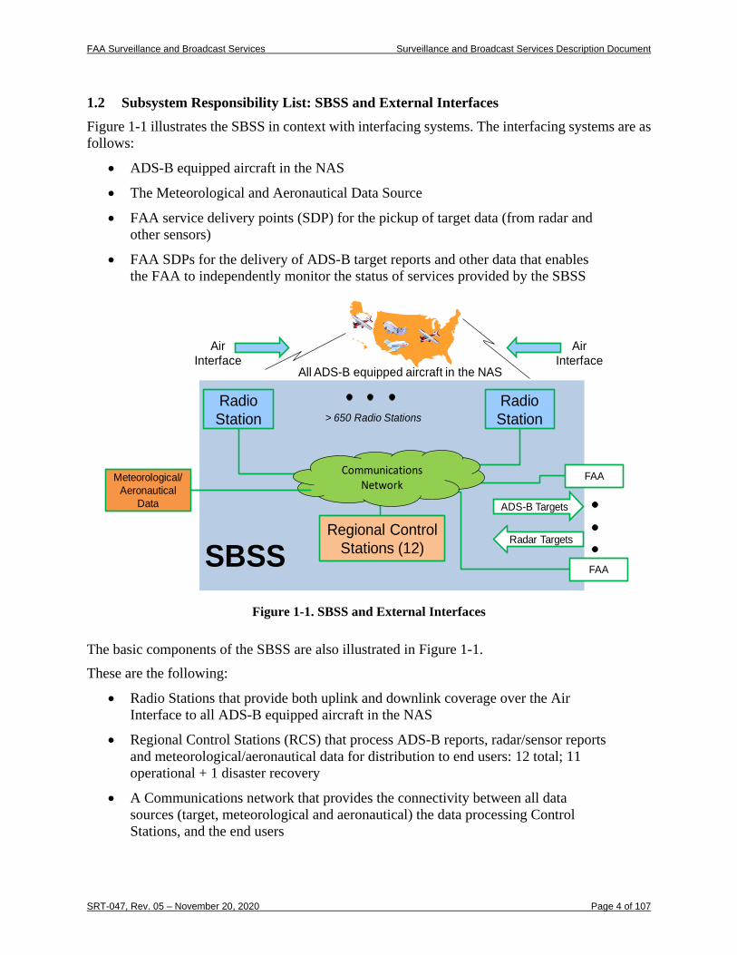
1.2 Subsystem Responsibility List: SBSS and External Interfaces Figure 1-1 illustrates the SBSS in context with interfacing systems. The interfacing systems are as follows:
• ADS-B equipped aircraft in the NAS
• The Meteorological and Aeronautical Data Source
• FAA service delivery points (SDP) for the pickup of target data (from radar and other sensors)
• FAA SDPs for the delivery of ADS-B target reports and other data that enables the FAA to independently monitor the status of services provided by the SBSS
Radio Station
SBSS
All ADS-B equipped aircraft in the NAS
> 650 Radio Stations
FAA
FAA
Radio Station
Regional Control Stations (12)
Meteorological/ Aeronautical
Data ADS-B Targets
Radar Targets
Communications Network
Air Interface
Air Interface
Figure 1-1. SBSS and External Interfaces
The basic components of the SBSS are also illustrated in Figure 1-1. These are the following:
• Radio Stations that provide both uplink and downlink coverage over the Air Interface to all ADS-B equipped aircraft in the NAS
• Regional Control Stations (RCS) that process ADS-B reports, radar/sensor reports and meteorological/aeronautical data for distribution to end users: 12 total; 11 operational + 1 disaster recovery
• A Communications network that provides the connectivity between all data sources (target, meteorological and aeronautical) the data processing Control Stations, and the end users
FAA Surveillance and Broadcast Services Surveillance and Broadcast Services Description Document
SRT-047, Rev. 05 – November 20, 2020 Page 5 of 107
1.2.1 ADS-B Equipped Aircraft in the NAS
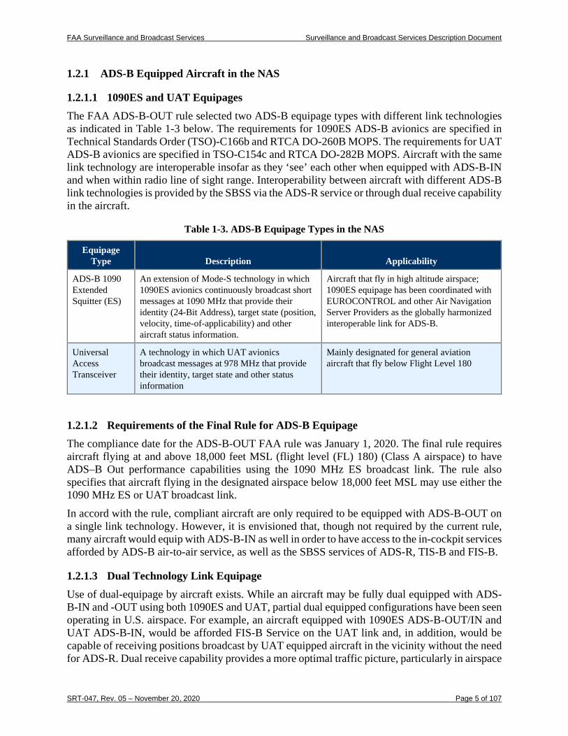
1.2.1.1 1090ES and UAT Equipages The FAA ADS-B-OUT rule selected two ADS-B equipage types with different link technologies as indicated in Table 1-3 below. The requirements for 1090ES ADS-B avionics are specified in Technical Standards Order (TSO)-C166b and RTCA DO-260B MOPS. The requirements for UAT ADS-B avionics are specified in TSO-C154c and RTCA DO-282B MOPS. Aircraft with the same link technology are interoperable insofar as they ‘see’ each other when equipped with ADS-B-IN and when within radio line of sight range. Interoperability between aircraft with different ADS-B link technologies is provided by the SBSS via the ADS-R service or through dual receive capability in the aircraft.
Table 1-3. ADS-B Equipage Types in the NAS
Equipage Type Description Applicability
ADS-B 1090 Extended Squitter (ES)
An extension of Mode-S technology in which 1090ES avionics continuously broadcast short messages at 1090 MHz that provide their identity (24-Bit Address), target state (position, velocity, time-of-applicability) and other aircraft status information.
Aircraft that fly in high altitude airspace; 1090ES equipage has been coordinated with EUROCONTROL and other Air Navigation Server Providers as the globally harmonized interoperable link for ADS-B.
Universal Access Transceiver
A technology in which UAT avionics broadcast messages at 978 MHz that provide their identity, target state and other status information
Mainly designated for general aviation aircraft that fly below Flight Level 180
1.2.1.2 Requirements of the Final Rule for ADS-B Equipage The compliance date for the ADS-B-OUT FAA rule was January 1, 2020. The final rule requires aircraft flying at and above 18,000 feet MSL (flight level (FL) 180) (Class A airspace) to have ADS–B Out performance capabilities using the 1090 MHz ES broadcast link. The rule also specifies that aircraft flying in the designated airspace below 18,000 feet MSL may use either the 1090 MHz ES or UAT broadcast link. In accord with the rule, compliant aircraft are only required to be equipped with ADS-B-OUT on a single link technology. However, it is envisioned that, though not required by the current rule, many aircraft would equip with ADS-B-IN as well in order to have access to the in-cockpit services afforded by ADS-B air-to-air service, as well as the SBSS services of ADS-R, TIS-B and FIS-B.
1.2.1.3 Dual Technology Link Equipage Use of dual-equipage by aircraft exists. While an aircraft may be fully dual equipped with ADS-B-IN and -OUT using both 1090ES and UAT, partial dual equipped configurations have been seen operating in U.S. airspace. For example, an aircraft equipped with 1090ES ADS-B-OUT/IN and UAT ADS-B-IN, would be afforded FIS-B Service on the UAT link and, in addition, would be capable of receiving positions broadcast by UAT equipped aircraft in the vicinity without the need for ADS-R. Dual receive capability provides a more optimal traffic picture, particularly in airspace
FAA Surveillance and Broadcast Services Surveillance and Broadcast Services Description Document
SRT-047, Rev. 05 – November 20, 2020 Page 6 of 107
not covered by ADS-B ground infrastructure wherein the aircraft can receive ADS-B direct air-to-air regardless of the transmit link used by other aircraft.
1.2.2 FAA SDP for Radar Data, ADS-B Target Delivery and Service Monitoring At selected SDPs, SBSS picks up non-ADS-B sensor target data that provides the basis for provision of the TIS-B Service. The sensor target data sources include En Route Radars, Terminal Radars, ASDE-X, MLAT, and WAM systems. The SBSS provides ADS-B targets to the SDPs for ATC to utilize this surveillance data in the provision of separation assurance services. Finally, the SBSS sends FAA Monitor SDPs a variety of data products that allow the FAA to independently monitor the performance of SBSS in its provision of ADS-B, ADS-R, TIS-B and FIS-B Services.
1.2.3 Meteorological and Aeronautical Data Source Harris Weather Data Services (HWDS) provides all FIS-B product data for the SBSS. The primary FIS-B Data Source, HWDS’ Melbourne FL facility, is a hardened facility with internal redundancy with a design uptime of well over 0.9999. This is complemented by the backup FIS-B Data Source at HWDS’ Smyrna GA facility.
1.3 SBSS Services Overview
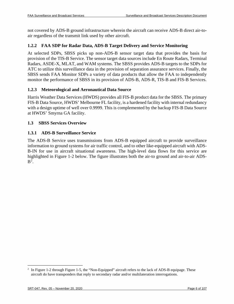
1.3.1 ADS-B Surveillance Service The ADS-B Service uses transmissions from ADS-B equipped aircraft to provide surveillance information to ground systems for air traffic control, and to other like-equipped aircraft with ADS-B-IN for use in aircraft situational awareness. The high-level data flows for this service are highlighted in Figure 1-2 below. The figure illustrates both the air-to ground and air-to-air ADS-B2.
2 In Figure 1-2 through Figure 1-5, the “Non-Equipped” aircraft refers to the lack of ADS-B equipage. These
aircraft do have transponders that reply to secondary radar and/or multilateration interrogations.
FAA Surveillance and Broadcast Services Surveillance and Broadcast Services Description Document
SRT-047, Rev. 05 – November 20, 2020 Page 7 of 107
Figure 1-2. ADS-B Service Data Flows
1.3.1.1 Air-to-Air ADS-B ADS-B-IN equipped aircraft are capable of receiving ADS-B transmissions from other aircraft equipped with the same link technology. This provides applications on board the aircraft with information about aircraft within range of the radio transmissions. The double arrows between aircraft in the above figure illustrate this transfer of position information between aircraft equipped with the same link technology. Note that air-to-air ADS-B is a complementary service to those provided by SBSS, but SBSS plays no part in air-to-air ADS-B other than to share access to the same radio frequency (RF) channel. For aircraft equipped with dual link receive capability, the traffic service for seeing ADS-B Out equipped aircraft is provided directly by air to air without reliance on the SBS ground infrastructure.
1.3.1.2 Air-to-Ground ADS-B The SBSS infrastructure of radio stations provides the capability of capturing surveillance information transmitted by ADS-B equipped aircraft anywhere in the NAS and providing the information to SBSS control stations. The control stations process received ADS-B reports, perform validity checks, and provide a low-latency feed of surveillance information to designated FAA SDPs for use in separation assurance and other ATC services.
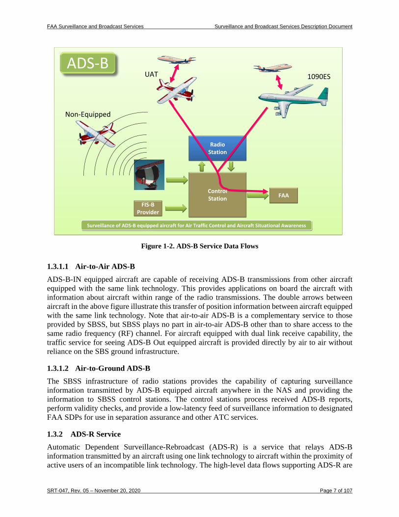
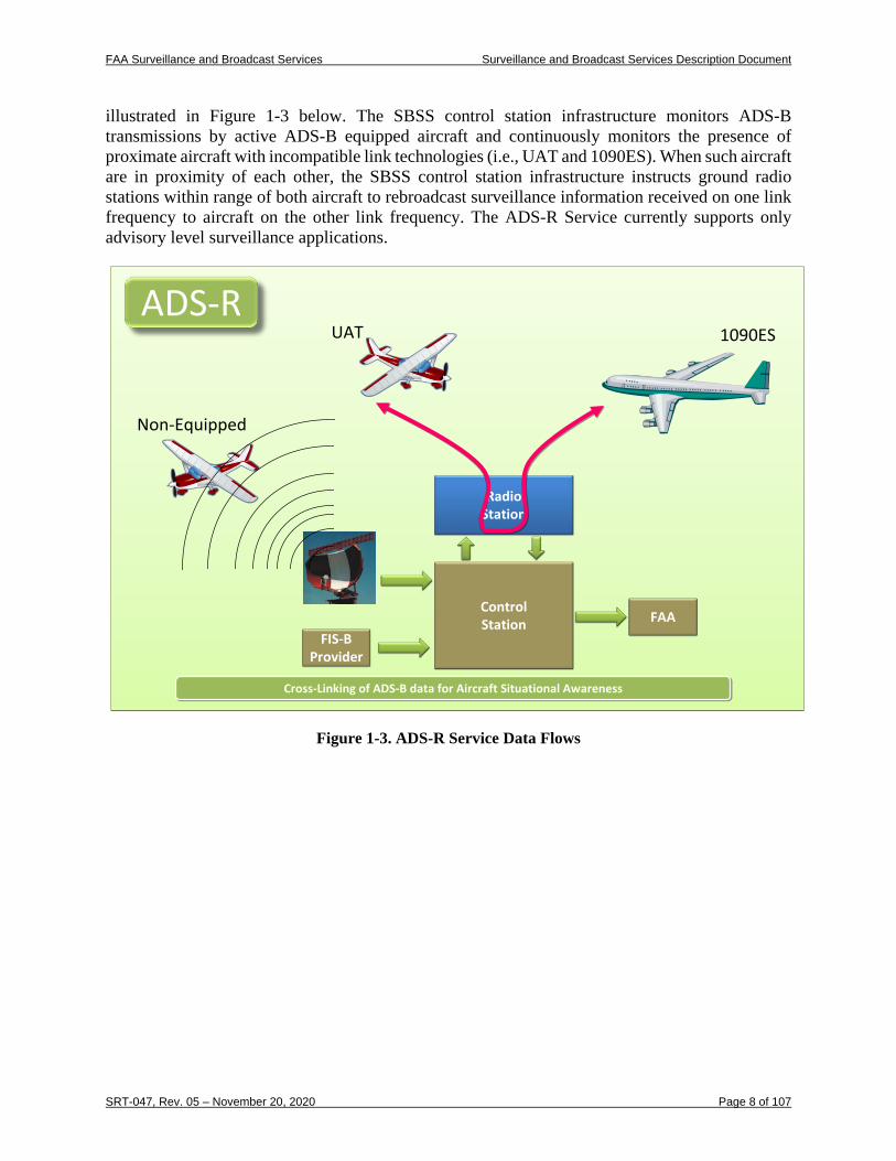
1.3.2 ADS-R Service Automatic Dependent Surveillance-Rebroadcast (ADS-R) is a service that relays ADS-B information transmitted by an aircraft using one link technology to aircraft within the proximity of active users of an incompatible link technology. The high-level data flows supporting ADS-R are
1090ESUAT
Non-Equipped
ADS-B
RadioStation
ControlStation
FIS-BProvider
FAA
Surveillance of ADS-B equipped aircraft for Air Traffic Control and Aircraft Situational AwarenessSurveillance of ADS-B equipped aircraft for Air Traffic Control and Aircraft Situational Awareness
1090ESUAT
Non-Equipped
ADS-BADS-B
RadioStationRadio
Station
ControlStationControlStation
FIS-BProvider
FIS-BProvider
FAAFAA
Surveillance of ADS-B equipped aircraft for Air Traffic Control and Aircraft Situational AwarenessSurveillance of ADS-B equipped aircraft for Air Traffic Control and Aircraft Situational Awareness
FAA Surveillance and Broadcast Services Surveillance and Broadcast Services Description Document
SRT-047, Rev. 05 – November 20, 2020 Page 8 of 107
illustrated in Figure 1-3 below. The SBSS control station infrastructure monitors ADS-B transmissions by active ADS-B equipped aircraft and continuously monitors the presence of proximate aircraft with incompatible link technologies (i.e., UAT and 1090ES). When such aircraft are in proximity of each other, the SBSS control station infrastructure instructs ground radio stations within range of both aircraft to rebroadcast surveillance information received on one link frequency to aircraft on the other link frequency. The ADS-R Service currently supports only advisory level surveillance applications.
Figure 1-3. ADS-R Service Data Flows
1090ES
Non-Equipped
ADS-R
RadioStation
ControlStation
FIS-BProvider
FAA
Cross-Linking of ADS-B data for Aircraft Situational AwarenessCross-Linking of ADS-B data for Aircraft Situational Awareness
UAT
1090ES
Non-Equipped
ADS-RADS-R
RadioStationRadio
Station
ControlStationControlStation
FIS-BProvider
FIS-BProvider
FAAFAA
Cross-Linking of ADS-B data for Aircraft Situational AwarenessCross-Linking of ADS-B data for Aircraft Situational Awareness
UAT
FAA Surveillance and Broadcast Services Surveillance and Broadcast Services Description Document
SRT-047, Rev. 05 – November 20, 2020 Page 9 of 107
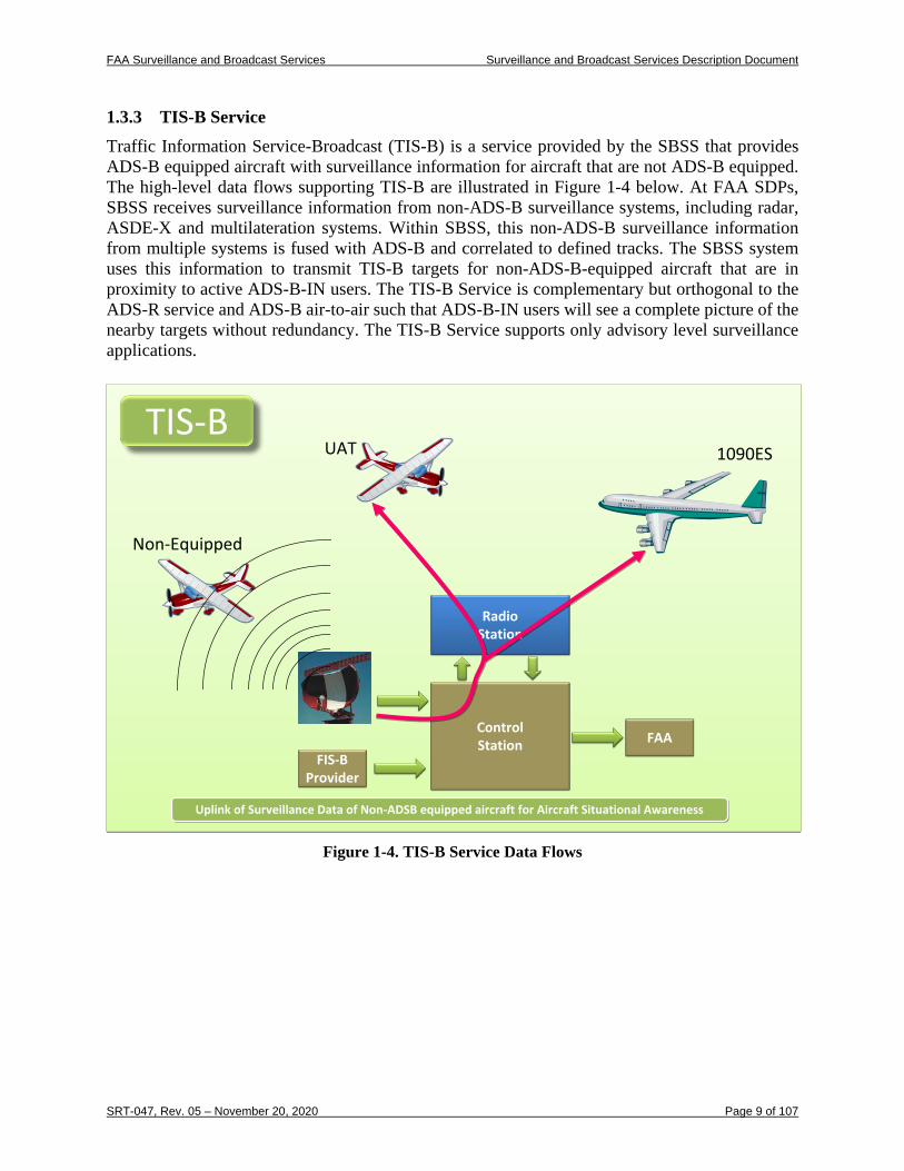
1.3.3 TIS-B Service Traffic Information Service-Broadcast (TIS-B) is a service provided by the SBSS that provides ADS-B equipped aircraft with surveillance information for aircraft that are not ADS-B equipped. The high-level data flows supporting TIS-B are illustrated in Figure 1-4 below. At FAA SDPs, SBSS receives surveillance information from non-ADS-B surveillance systems, including radar, ASDE-X and multilateration systems. Within SBSS, this non-ADS-B surveillance information from multiple systems is fused with ADS-B and correlated to defined tracks. The SBSS system uses this information to transmit TIS-B targets for non-ADS-B-equipped aircraft that are in proximity to active ADS-B-IN users. The TIS-B Service is complementary but orthogonal to the ADS-R service and ADS-B air-to-air such that ADS-B-IN users will see a complete picture of the nearby targets without redundancy. The TIS-B Service supports only advisory level surveillance applications.
Figure 1-4. TIS-B Service Data Flows
1090ESUAT
Non-Equipped
TIS-B
RadioStation
ControlStation
FIS-BProvider
FAA
Uplink of Surveillance Data of Non-ADSB equipped aircraft for Aircraft Situational AwarenessUplink of Surveillance Data of Non-ADSB equipped aircraft for Aircraft Situational Awareness
1090ESUAT
Non-Equipped
TIS-BTIS-B
RadioStationRadio
Station
ControlStationControlStation
FIS-BProvider
FIS-BProvider
FAAFAA
Uplink of Surveillance Data of Non-ADSB equipped aircraft for Aircraft Situational AwarenessUplink of Surveillance Data of Non-ADSB equipped aircraft for Aircraft Situational Awareness
FAA Surveillance and Broadcast Services Surveillance and Broadcast Services Description Document
SRT-047, Rev. 05 – November 20, 2020 Page 10 of 107
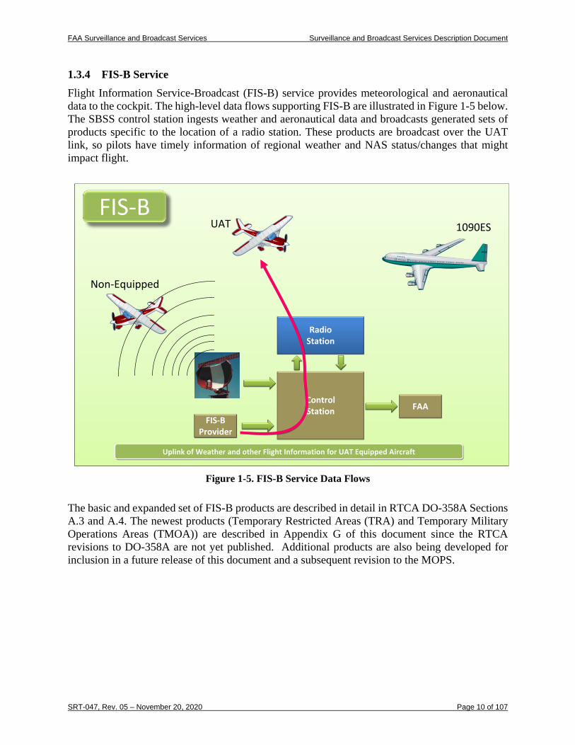
1.3.4 FIS-B Service Flight Information Service-Broadcast (FIS-B) service provides meteorological and aeronautical data to the cockpit. The high-level data flows supporting FIS-B are illustrated in Figure 1-5 below. The SBSS control station ingests weather and aeronautical data and broadcasts generated sets of products specific to the location of a radio station. These products are broadcast over the UAT link, so pilots have timely information of regional weather and NAS status/changes that might impact flight.
Figure 1-5. FIS-B Service Data Flows
The basic and expanded set of FIS-B products are described in detail in RTCA DO-358A Sections A.3 and A.4. The newest products (Temporary Restricted Areas (TRA) and Temporary Military Operations Areas (TMOA)) are described in Appendix G of this document since the RTCA revisions to DO-358A are not yet published. Additional products are also being developed for inclusion in a future release of this document and a subsequent revision to the MOPS.
1090ESUAT
Non-Equipped
FIS-B
RadioStation
ControlStation
FIS-BProvider
FAA
Uplink of Weather and other Flight Information for UAT Equipped AircraftUplink of Weather and other Flight Information for UAT Equipped Aircraft
1090ESUAT
Non-Equipped
FIS-BFIS-B
RadioStationRadio
Station
ControlStationControlStation
FIS-BProvider
FIS-BProvider
FAAFAA
Uplink of Weather and other Flight Information for UAT Equipped AircraftUplink of Weather and other Flight Information for UAT Equipped Aircraft
FAA Surveillance and Broadcast Services Surveillance and Broadcast Services Description Document
SRT-047, Rev. 05 – November 20, 2020 Page 11 of 107
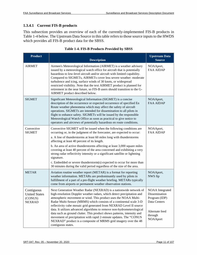
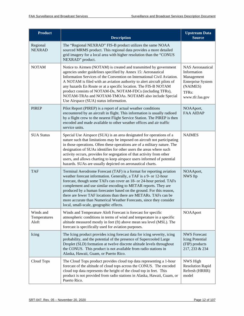
1.3.4.1 Current FIS-B products This subsection provides an overview of each of the currently-implemented FIS-B products in Table 1-4 below. The Upstream Data Source in this table refers to those source inputs to the HWDS which provides all FIS-B product data for the SBSS.
Table 1-4. FIS-B Products Provided by SBSS
Product Description
Upstream Data Source
AIRMET Airmen's Meteorological Information (AIRMET) is a weather advisory issued by a meteorological watch office for aircraft that is potentially hazardous to low-level aircraft and/or aircraft with limited capability. Compared to SIGMETs, AIRMETs cover less severe weather: moderate turbulence and icing, surface winds of 30 knots, or widespread restricted visibility. Note that the text AIRMET product is planned for retirement in the near future, so FIS-B users should transition to the G-AIRMET product described below.
NOAAport, FAA AIDAP
SIGMET Significant Meteorological Information (SIGMET) is a concise description of the occurrence or expected occurrence of specified En Route weather phenomena which may affect the safety of aircraft operations. SIGMETs are intended for dissemination to all pilots in flight to enhance safety. SIGMETs will be issued by the responsible Meteorological Watch Office as soon as practical to give notice to operators and aircrews of potentially hazardous en route conditions.
NOAAport, FAA AIDAP
Convective SIGMET
Convective SIGMET will be issued when the following conditions are occurring or, in the judgment of the forecaster, are expected to occur: a. A line of thunderstorms at least 60 miles long with thunderstorms affecting at least 40 percent of its length. b. An area of active thunderstorms affecting at least 3,000 square miles covering at least 40 percent of the area concerned and exhibiting a very strong radar reflectivity intensity or a significant satellite or lightning signature. c. Embedded or severe thunderstorm(s) expected to occur for more than 30 minutes during the valid period regardless of the size of the area.
NOAAport, FAA AIDAP
METAR Aviation routine weather report (METAR) is a format for reporting weather information. METARs are predominantly used by pilots in fulfillment of a part of a pre-flight weather briefing. METARs typically come from airports or permanent weather observation stations.
NOAAport, NWS ftp
Contiguous United States (CONUS) NEXRAD
Next Generation Weather Radar (NEXRAD) is a nationwide network of high-resolution Doppler weather radars, which detect precipitation and atmospheric movement or wind. This product uses the NOAA Multi-Radar Multi-Sensor (MRMS) which consists of a continental scale 3-D reflectivity cube mosaic grid generated from NEXRAD Level II source data. It utilizes advanced algorithms to remove non-hydrometerological data such as ground clutter. This product shows patterns, intensity and movement of precipitation with rapid 2-minute updates. The “CONUS NEXRAD” product is a composite of MRMS grid imagery over the 48 contiguous states.
NOAA Integrated Dissemination Program (IDP) Data Centers Alternate feed through NOAAport
FAA Surveillance and Broadcast Services Surveillance and Broadcast Services Description Document
SRT-047, Rev. 05 – November 20, 2020 Page 12 of 107
Product Description
Upstream Data Source
Regional NEXRAD
The “Regional NEXRAD” FIS-B product utilizes the same NOAA sourced MRMS product. This regional data provides a more detailed grid imagery for a local area with higher resolution than the “CONUS NEXRAD” product.
NOTAM Notice to Airmen (NOTAM) is created and transmitted by government agencies under guidelines specified by Annex 15: Aeronautical Information Services of the Convention on International Civil Aviation. A NOTAM is filed with an aviation authority to alert aircraft pilots of any hazards En Route or at a specific location. The FIS-B NOTAM product consists of NOTAM-Ds, NOTAM-FDCs (including TFRs), NOTAM-TRAs and NOTAM-TMOAs. NOTAMS also include Special Use Airspace (SUA) status information.
NAS Aeronautical Information Management Enterprise System (NAIMES) TFRs: www.tfr.faa.gov
PIREP Pilot Report (PIREP) is a report of actual weather conditions encountered by an aircraft in flight. This information is usually radioed by a flight crew to the nearest Flight Service Station. The PIREP is then encoded and made available to other weather offices and air traffic service units.
NOAAport, FAA AIDAP
SUA Status Special Use Airspace (SUA) is an area designated for operations of a nature such that limitations may be imposed on aircraft not participating in those operations. Often these operations are of a military nature. The designation of SUAs identifies for other users the areas where such activity occurs, provides for segregation of that activity from other users, and allows charting to keep airspace users informed of potential hazards. SUAs are usually depicted on aeronautical charts.
NAIMES
TAF Terminal Aerodrome Forecast (TAF) is a format for reporting aviation weather forecast information. Generally, a TAF is a 9- or 12-hour forecast, though some TAFs can cover an 18- or 24-hour period. TAFs complement and use similar encoding to METAR reports. They are produced by a human forecaster based on the ground. For this reason, there are fewer TAF locations than there are METARs. TAFs can be more accurate than Numerical Weather Forecasts, since they consider local, small-scale, geographic effects.
NOAAport, NWS ftp
Winds and Temperatures Aloft
Winds and Temperature Aloft Forecast is forecast for specific atmospheric conditions in terms of wind and temperature in a specific altitude measured mostly in feet (ft) above mean sea level (MSL). The forecast is specifically used for aviation purposes.
NOAAport
Icing The Icing product provides icing forecast data for icing severity, icing probability, and the potential of the presence of Supercooled Large Droplet (SLD) formation at twelve discrete altitude levels throughout the CONUS. This product is not available from radio stations in Alaska, Hawaii, Guam, or Puerto Rico.
NWS Forecast Icing Potential (FIP) products 217, 233 & 234
Cloud Tops The Cloud Tops product provides cloud top data representing a 1-hour forecast of the altitude of cloud tops across the CONUS. The encoded cloud top data represents the height of the cloud top in feet. This product is not provided from radio stations in Alaska, Hawaii, Guam, or Puerto Rico.
NWS High Resolution Rapid Refresh (HRRR) model
FAA Surveillance and Broadcast Services Surveillance and Broadcast Services Description Document
SRT-047, Rev. 05 – November 20, 2020 Page 13 of 107
Product Description
Upstream Data Source
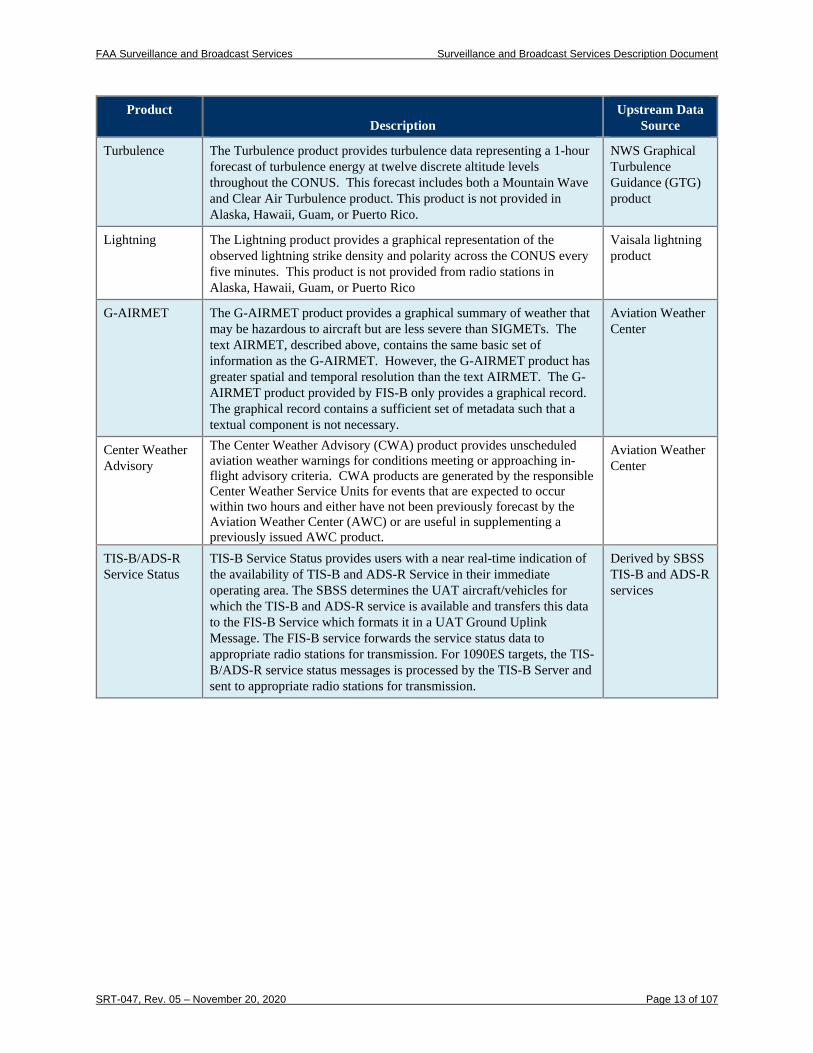
Turbulence The Turbulence product provides turbulence data representing a 1-hour forecast of turbulence energy at twelve discrete altitude levels throughout the CONUS. This forecast includes both a Mountain Wave and Clear Air Turbulence product. This product is not provided in Alaska, Hawaii, Guam, or Puerto Rico.
NWS Graphical Turbulence Guidance (GTG) product
Lightning The Lightning product provides a graphical representation of the observed lightning strike density and polarity across the CONUS every five minutes. This product is not provided from radio stations in Alaska, Hawaii, Guam, or Puerto Rico
Vaisala lightning product
G-AIRMET The G-AIRMET product provides a graphical summary of weather that may be hazardous to aircraft but are less severe than SIGMETs. The text AIRMET, described above, contains the same basic set of information as the G-AIRMET. However, the G-AIRMET product has greater spatial and temporal resolution than the text AIRMET. The G-AIRMET product provided by FIS-B only provides a graphical record. The graphical record contains a sufficient set of metadata such that a textual component is not necessary.
Aviation Weather Center
Center Weather Advisory
The Center Weather Advisory (CWA) product provides unscheduled aviation weather warnings for conditions meeting or approaching in-flight advisory criteria. CWA products are generated by the responsible Center Weather Service Units for events that are expected to occur within two hours and either have not been previously forecast by the Aviation Weather Center (AWC) or are useful in supplementing a previously issued AWC product.
Aviation Weather Center
TIS-B/ADS-R Service Status
TIS-B Service Status provides users with a near real-time indication of the availability of TIS-B and ADS-R Service in their immediate operating area. The SBSS determines the UAT aircraft/vehicles for which the TIS-B and ADS-R service is available and transfers this data to the FIS-B Service which formats it in a UAT Ground Uplink Message. The FIS-B service forwards the service status data to appropriate radio stations for transmission. For 1090ES targets, the TIS-B/ADS-R service status messages is processed by the TIS-B Server and sent to appropriate radio stations for transmission.
Derived by SBSS TIS-B and ADS-R services
FAA Surveillance and Broadcast Services Surveillance and Broadcast Services Description Document
SRT-047, Rev. 05 – November 20, 2020 Page 14 of 107
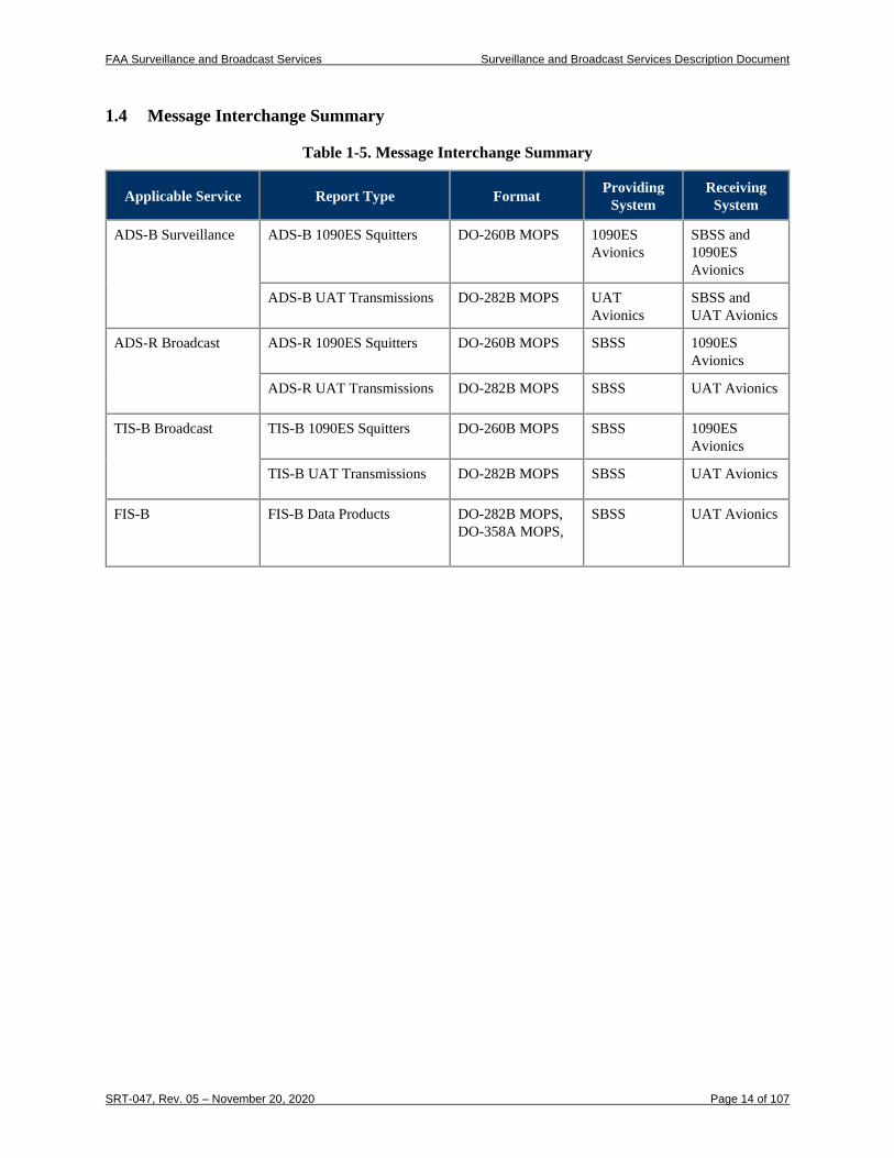
1.4 Message Interchange Summary
Table 1-5. Message Interchange Summary
Applicable Service Report Type Format Providing System
Receiving System
ADS-B Surveillance ADS-B 1090ES Squitters DO-260B MOPS 1090ES Avionics
SBSS and 1090ES Avionics
ADS-B UAT Transmissions DO-282B MOPS UAT Avionics
SBSS and UAT Avionics
ADS-R Broadcast ADS-R 1090ES Squitters DO-260B MOPS SBSS 1090ES Avionics
ADS-R UAT Transmissions DO-282B MOPS SBSS UAT Avionics
TIS-B Broadcast TIS-B 1090ES Squitters DO-260B MOPS SBSS 1090ES Avionics
TIS-B UAT Transmissions DO-282B MOPS SBSS UAT Avionics
FIS-B FIS-B Data Products DO-282B MOPS, DO-358A MOPS,
SBSS UAT Avionics
FAA Surveillance and Broadcast Services Surveillance and Broadcast Services Description Document
SRT-047, Rev. 05 – November 20, 2020 Page 15 of 107
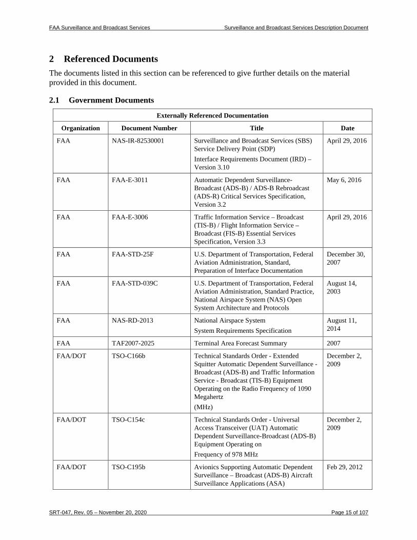
2 Referenced Documents The documents listed in this section can be referenced to give further details on the material provided in this document.
2.1 Government Documents
Externally Referenced Documentation
Organization Document Number Title Date
FAA NAS-IR-82530001 Surveillance and Broadcast Services (SBS) Service Delivery Point (SDP) Interface Requirements Document (IRD) – Version 3.10
April 29, 2016
FAA FAA-E-3011 Automatic Dependent Surveillance-Broadcast (ADS-B) / ADS-B Rebroadcast (ADS-R) Critical Services Specification, Version 3.2
May 6, 2016
FAA FAA-E-3006 Traffic Information Service – Broadcast (TIS-B) / Flight Information Service – Broadcast (FIS-B) Essential Services Specification, Version 3.3
April 29, 2016
FAA FAA-STD-25F U.S. Department of Transportation, Federal Aviation Administration, Standard, Preparation of Interface Documentation
December 30, 2007
FAA FAA-STD-039C U.S. Department of Transportation, Federal Aviation Administration, Standard Practice, National Airspace System (NAS) Open System Architecture and Protocols
August 14, 2003
FAA NAS-RD-2013 National Airspace System System Requirements Specification
August 11, 2014
FAA TAF2007-2025 Terminal Area Forecast Summary 2007
FAA/DOT TSO-C166b Technical Standards Order - Extended Squitter Automatic Dependent Surveillance - Broadcast (ADS-B) and Traffic Information Service - Broadcast (TIS-B) Equipment Operating on the Radio Frequency of 1090 Megahertz (MHz)
December 2, 2009
FAA/DOT TSO-C154c Technical Standards Order - Universal Access Transceiver (UAT) Automatic Dependent Surveillance-Broadcast (ADS-B) Equipment Operating on Frequency of 978 MHz
December 2, 2009
FAA/DOT TSO-C195b Avionics Supporting Automatic Dependent Surveillance – Broadcast (ADS-B) Aircraft Surveillance Applications (ASA)
Feb 29, 2012
FAA Surveillance and Broadcast Services Surveillance and Broadcast Services Description Document
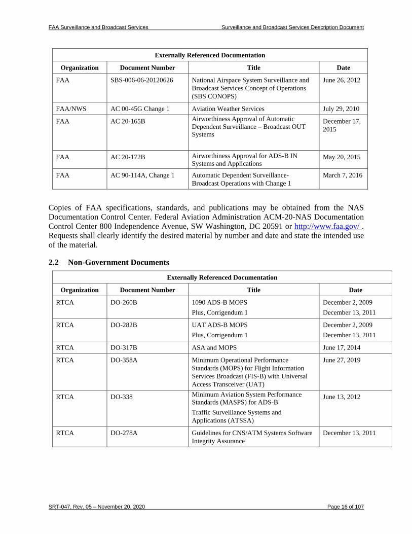
SRT-047, Rev. 05 – November 20, 2020 Page 16 of 107
Externally Referenced Documentation
Organization Document Number Title Date
FAA SBS-006-06-20120626 National Airspace System Surveillance and Broadcast Services Concept of Operations (SBS CONOPS)
June 26, 2012
FAA/NWS AC 00-45G Change 1 Aviation Weather Services July 29, 2010
FAA AC 20-165B Airworthiness Approval of Automatic Dependent Surveillance – Broadcast OUT Systems
December 17, 2015
FAA AC 20-172B Airworthiness Approval for ADS-B IN Systems and Applications
May 20, 2015
FAA AC 90-114A, Change 1 Automatic Dependent Surveillance-Broadcast Operations with Change 1
March 7, 2016
Copies of FAA specifications, standards, and publications may be obtained from the NAS Documentation Control Center. Federal Aviation Administration ACM-20-NAS Documentation Control Center 800 Independence Avenue, SW Washington, DC 20591 or http://www.faa.gov/ . Requests shall clearly identify the desired material by number and date and state the intended use of the material.
2.2 Non-Government Documents
Externally Referenced Documentation
Organization Document Number Title Date
RTCA DO-260B 1090 ADS-B MOPS Plus, Corrigendum 1
December 2, 2009 December 13, 2011
RTCA DO-282B UAT ADS-B MOPS Plus, Corrigendum 1
December 2, 2009 December 13, 2011
RTCA DO-317B ASA and MOPS June 17, 2014
RTCA DO-358A Minimum Operational Performance Standards (MOPS) for Flight Information Services Broadcast (FIS-B) with Universal Access Transceiver (UAT)
June 27, 2019
RTCA DO-338 Minimum Aviation System Performance Standards (MASPS) for ADS-B Traffic Surveillance Systems and Applications (ATSSA)
June 13, 2012
RTCA DO-278A Guidelines for CNS/ATM Systems Software Integrity Assurance
December 13, 2011
FAA Surveillance and Broadcast Services Surveillance and Broadcast Services Description Document
SRT-047, Rev. 05 – November 20, 2020 Page 17 of 107
Externally Referenced Documentation
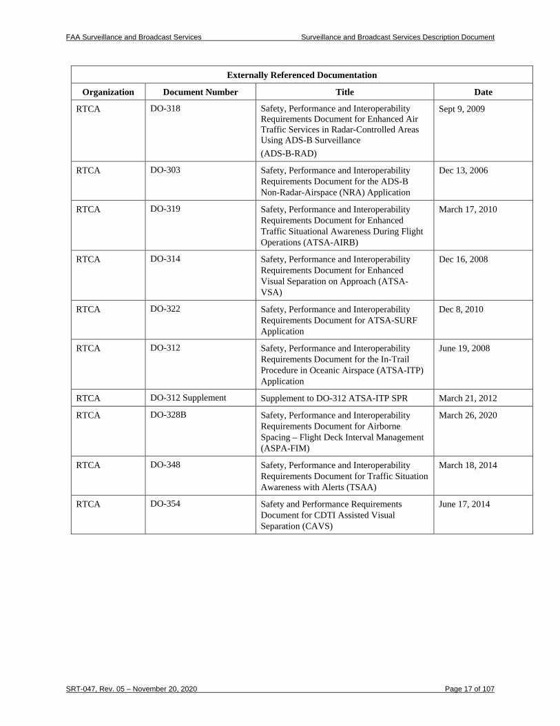
Organization Document Number Title Date
RTCA DO-318 Safety, Performance and Interoperability Requirements Document for Enhanced Air Traffic Services in Radar-Controlled Areas Using ADS-B Surveillance (ADS-B-RAD)
Sept 9, 2009
RTCA DO-303 Safety, Performance and Interoperability Requirements Document for the ADS-B Non-Radar-Airspace (NRA) Application
Dec 13, 2006
RTCA DO-319 Safety, Performance and Interoperability Requirements Document for Enhanced Traffic Situational Awareness During Flight Operations (ATSA-AIRB)
March 17, 2010
RTCA DO-314 Safety, Performance and Interoperability Requirements Document for Enhanced Visual Separation on Approach (ATSA-VSA)
Dec 16, 2008
RTCA DO-322 Safety, Performance and Interoperability Requirements Document for ATSA-SURF Application
Dec 8, 2010
RTCA DO-312
Safety, Performance and Interoperability Requirements Document for the In-Trail Procedure in Oceanic Airspace (ATSA-ITP) Application
June 19, 2008
RTCA DO-312 Supplement Supplement to DO-312 ATSA-ITP SPR March 21, 2012
RTCA DO-328B Safety, Performance and Interoperability Requirements Document for Airborne Spacing – Flight Deck Interval Management (ASPA-FIM)
March 26, 2020
RTCA DO-348 Safety, Performance and Interoperability Requirements Document for Traffic Situation Awareness with Alerts (TSAA)
March 18, 2014
RTCA DO-354 Safety and Performance Requirements Document for CDTI Assisted Visual Separation (CAVS)
June 17, 2014
FAA Surveillance and Broadcast Services Surveillance and Broadcast Services Description Document
SRT-047, Rev. 05 – November 20, 2020 Page 18 of 107
3 Air Interface Characteristics: Service Descriptions
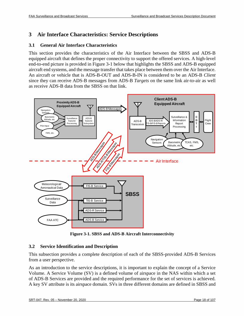
3.1 General Air Interface Characteristics This section provides the characteristics of the Air Interface between the SBSS and ADS-B equipped aircraft that defines the proper connectivity to support the offered services. A high-level end-to-end picture is provided in Figure 3-1 below that highlights the SBSS and ADS-B equipped aircraft end systems, and the message transfer that takes place between them over the Air Interface. An aircraft or vehicle that is ADS-B-OUT and ADS-B-IN is considered to be an ADS-B Client since they can receive ADS-B messages from ADS-B Targets on the same link air-to-air as well as receive ADS-B data from the SBSS on that link.
Figure 3-1. SBSS and ADS-B Aircraft Interconnectivity
3.2 Service Identification and Description This subsection provides a complete description of each of the SBSS-provided ADS-B Services from a user perspective. As an introduction to the service descriptions, it is important to explain the concept of a Service Volume. A Service Volume (SV) is a defined volume of airspace in the NAS within which a set of ADS-B Services are provided and the required performance for the set of services is achieved. A key SV attribute is its airspace domain. SVs in three different domains are defined in SBSS and
Surveillance Transmit
Processing
ADS-B Transmit
Subsystem
Navigation Sensors
Barometric Altitude, etc.
Pilot Input
FMS, etc.
Proximity ADS-B Equipped Aircraft
ADS-B Messages
Surveillance Data
SBSSTIS-B Service
ADS-R Service
Meteorological/ Aeronautical Data
FAA ATC
FIS-B Service
ADS-B Service
Air Interface
Surveillance & Information
Report Processing
Navigation Sensors Barometric
Altitude, etc.TCAS, FMS,
etc.
Client ADS-B Equipped Aircraft
ADS-B Transceiver
ADS-B/ADS-R/TIS-B/FIS-B Reports
CDTI
Flight Crew
FAA Surveillance and Broadcast Services Surveillance and Broadcast Services Description Document
SRT-047, Rev. 05 – November 20, 2020 Page 19 of 107
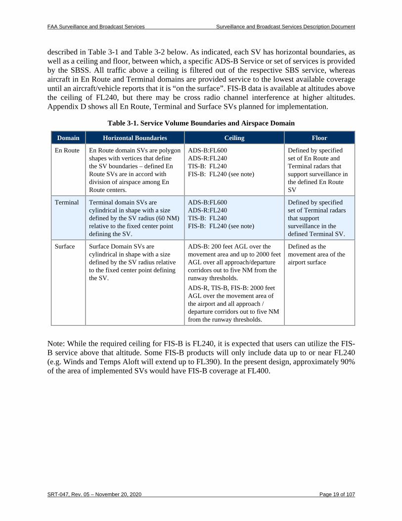
described in Table 3-1 and Table 3-2 below. As indicated, each SV has horizontal boundaries, as well as a ceiling and floor, between which, a specific ADS-B Service or set of services is provided by the SBSS. All traffic above a ceiling is filtered out of the respective SBS service, whereas aircraft in En Route and Terminal domains are provided service to the lowest available coverage until an aircraft/vehicle reports that it is “on the surface”. FIS-B data is available at altitudes above the ceiling of FL240, but there may be cross radio channel interference at higher altitudes. Appendix D shows all En Route, Terminal and Surface SVs planned for implementation.
Table 3-1. Service Volume Boundaries and Airspace Domain
Domain Horizontal Boundaries Ceiling Floor
En Route En Route domain SVs are polygon shapes with vertices that define the SV boundaries – defined En Route SVs are in accord with division of airspace among En Route centers.
ADS-B:FL600 ADS-R:FL240 TIS-B: FL240 FIS-B: FL240 (see note)
Defined by specified set of En Route and Terminal radars that support surveillance in the defined En Route SV
Terminal Terminal domain SVs are cylindrical in shape with a size defined by the SV radius (60 NM) relative to the fixed center point defining the SV.
ADS-B:FL600 ADS-R:FL240 TIS-B: FL240 FIS-B: FL240 (see note)
Defined by specified set of Terminal radars that support surveillance in the defined Terminal SV.
Surface Surface Domain SVs are cylindrical in shape with a size defined by the SV radius relative to the fixed center point defining the SV.
ADS-B: 200 feet AGL over the movement area and up to 2000 feet AGL over all approach/departure corridors out to five NM from the runway thresholds. ADS-R, TIS-B, FIS-B: 2000 feet AGL over the movement area of the airport and all approach / departure corridors out to five NM from the runway thresholds.
Defined as the movement area of the airport surface
Note: While the required ceiling for FIS-B is FL240, it is expected that users can utilize the FIS-B service above that altitude. Some FIS-B products will only include data up to or near FL240 (e.g. Winds and Temps Aloft will extend up to FL390). In the present design, approximately 90% of the area of implemented SVs would have FIS-B coverage at FL400.
FAA Surveillance and Broadcast Services Surveillance and Broadcast Services Description Document
SRT-047, Rev. 05 – November 20, 2020 Page 20 of 107
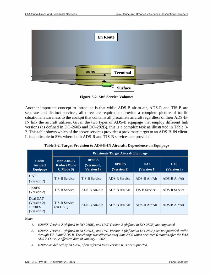
Figure 3-2. SBS Service Volumes
Another important concept to introduce is that while ADS-B air-to-air, ADS-R and TIS-B are separate and distinct services, all three are required to provide a complete picture of traffic situational awareness to the cockpit that contains all proximate aircraft regardless of their ADS-B-IN link the aircraft utilizes. Given the two types of ADS-B equipage that employ different link versions (as defined in DO-260B and DO-282B), this is a complex task as illustrated in Table 3-2. This table shows which of the above services provides a proximate target to an ADS-B-IN client. It is applicable in SVs where both ADS-R and TIS-B services are provided.
Table 3-2. Target Provision to ADS-B-IN Aircraft: Dependence on Equipage
Client Aircraft
Equipage
Proximate Target Aircraft Equipage
Non ADS-B Radar (Mode
C/Mode S)
1090ES (Version 0, Version 1)
1090ES (Version 2)
UAT (Version 1)
UAT (Version 2)
UAT (Version 2)
TIS-B Service TIS-B Service ADS-R Service ADS-B Air/Air ADS-B Air/Air
1090ES (Version 2) TIS-B Service ADS-B Air/Air ADS-B Air/Air TIS-B Service ADS-R Service
Dual UAT (Version 2) /1090ES (Version 2)
TIS-B Service (on UAT) ADS-B Air/Air ADS-B Air/Air ADS-B Air/Air ADS-B Air/Air
Note:
1. 1090ES Version 2 (defined in DO-260B), and UAT Version 2 (defined in DO-282B) are supported.
2. 1090ES Version 1 (defined in DO-260A), and UAT Version 1 (defined in DO-282A) are not provided traffic through TIS-B and ADS-R. This change was effective as of June 2020 which occurred 6 months after the FAA ADS-B Out rule effective date of January 1, 2020.
3. 1090ES as defined by DO-260, often referred to as Version 0, is not supported.
60 NM
Surface
Terminal
En Route
FAA Surveillance and Broadcast Services Surveillance and Broadcast Services Description Document
SRT-047, Rev. 05 – November 20, 2020 Page 21 of 107
3.2.1 ADS-B Surveillance Service The ADS-B Service provides a surveillance capability that can enhance existing radar by providing target data with higher update rates and accuracy and provide service in areas without radars. In this Service, ADS-B equipped aircraft (and vehicles) broadcast their state vector (horizontal and vertical position; and horizontal and vertical velocity) and other information over an approved ADS-B link technology. The approved ADS-B link technologies for use in the NAS are 1090ES and UAT data link. ADS-B message broadcasts may be received directly by other ADS-B equipped aircraft. Additionally, these ADS-B messages on both link technologies are received and processed by the SBSS. The SBSS formats and validates the received Messages for delivery to ATC for use in separation assurance and other services. It also filters data to remove redundant reports and non-compliant link versions (i.e. version 0) from the data stream delivered to ATC. Provision of the ADS-B Service by the SBSS includes two major SBSS subsystems, individual Radio Stations which receive ADS-B Messages and ADS-B processors in centralized SBSS processing (called “Control”) stations. The role of the Radio in ADS-B Service provision to ATC is to receive and decode ADS-B Messages; to perform a message “reasonableness” test; and to forward all ADS-B reports (triggered by reception of either a 1090ES or UAT Message) to the central processing facility in a common message format. Note that received 1090ES Messages include those in the Version 0, 1 and 2 formats while received UAT Messages include those in the Version 1 and 2 formats. All received ADS-B reports identify the source target through the use of a 24-bit address assigned to the aircraft/vehicle ADS-B avionics. The 24-bit address may be either an ICAO address or a self-assigned address (applicable to UAT only). The “reasonableness” test employed in the Radio Station identifies such conditions as incomplete ADS-B messages; messages associated with a specific 24-bit address whose reported position is not in line with previously reported positions (called “position outlier” condition); and the anomalous condition when two separate aircraft/vehicles are using a common 24-bit address (called “duplicate address” condition). When ADS-B reports are provided to the SBSS central processing facility, the ADS-B processing subsystem groups and filters the ADS-B reports; performs ADS-B report validation; and formats and sends ADS-B reports to ATC service delivery points. The grouping and filtering functionality requires clustering of ADS-B reports resulting from a single ADS-B transmission. This capability is required because the SBSS Radios provide overlapping coverage and a single aircraft ADS-B transmission is received at multiple radios. Additionally, filtering by geographically defined service regions or exclusion zones, or by a configured set of 24-bit addresses, is performed by the ADS-B processing subsystem. The filtering process also reapplies the algorithm for identifying position outliers and duplicate addresses (described in the paragraph above). In this case, the test for outliers and duplicates is applied to ADS-B report receptions from different Radio Stations. A configurable capability of the SBSS is to perform ADS-B report validation. When implemented, the ADS-B processing subsystem uses one or more of the following validation methods: time-difference of message arrival; radar validation (using primary radar, secondary radar or both if available); passive ranging (if target report is based on a UAT ADS-B Message); active ranging for 1090ES targets; kinematic; and geo-context. After grouping, filtering and validation processing, ADS-B reports are scheduled for delivery to the SDP. Reports are provided to the SDP in a common format and at update intervals that are dependent on Service Volume classification. Typically, the reports for ADS-B targets are provided to the SDP at update intervals that are faster than the minimum required for the SV.
FAA Surveillance and Broadcast Services Surveillance and Broadcast Services Description Document
SRT-047, Rev. 05 – November 20, 2020 Page 22 of 107
3.2.2 ADS-R Service
3.2.2.1 ADS-R Concept of Operations Since two incompatible ADS-B link technologies are allowed, aircraft equipped with a single link technology input will not be able to receive ADS-B transmissions from the other link technology, and therefore will be unable to receive all ADS-B transmissions. The ADS-R service closes this gap. In defined airspace regions, the ADS-R service will receive ADS-B transmissions on one link and retransmit them on the complementary link when there is an aircraft of the complementary link technology in the vicinity3. An aircraft or vehicle that is an active ADS-B user and is receiving ADS-R service is known as an ADS-R Client. An ADS-B equipped aircraft or vehicle on the opposite link of the ADS-R Client that has its messages translated and transmitted by the SBSS is known as an ADS-R Target.
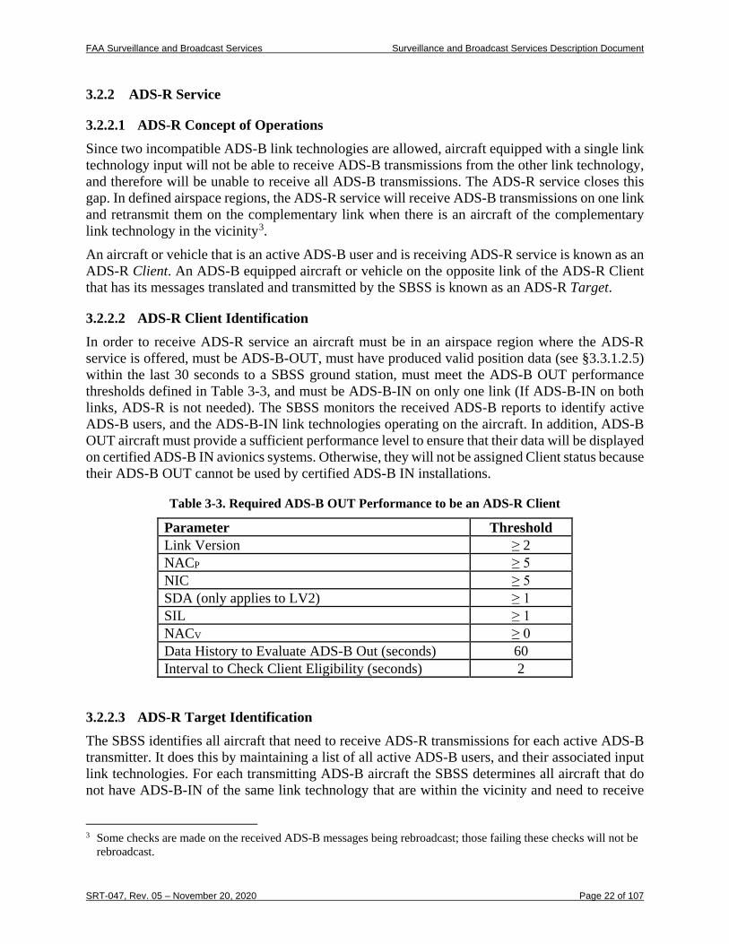
3.2.2.2 ADS-R Client Identification In order to receive ADS-R service an aircraft must be in an airspace region where the ADS-R service is offered, must be ADS-B-OUT, must have produced valid position data (see §3.3.1.2.5) within the last 30 seconds to a SBSS ground station, must meet the ADS-B OUT performance thresholds defined in Table 3-3, and must be ADS-B-IN on only one link (If ADS-B-IN on both links, ADS-R is not needed). The SBSS monitors the received ADS-B reports to identify active ADS-B users, and the ADS-B-IN link technologies operating on the aircraft. In addition, ADS-B OUT aircraft must provide a sufficient performance level to ensure that their data will be displayed on certified ADS-B IN avionics systems. Otherwise, they will not be assigned Client status because their ADS-B OUT cannot be used by certified ADS-B IN installations.
Table 3-3. Required ADS-B OUT Performance to be an ADS-R Client
Parameter Threshold Link Version ≥ 2 NACP ≥ 5 NIC ≥ 5 SDA (only applies to LV2) ≥ 1 SIL ≥ 1 NACV ≥ 0 Data History to Evaluate ADS-B Out (seconds) 60 Interval to Check Client Eligibility (seconds) 2
3.2.2.3 ADS-R Target Identification The SBSS identifies all aircraft that need to receive ADS-R transmissions for each active ADS-B transmitter. It does this by maintaining a list of all active ADS-B users, and their associated input link technologies. For each transmitting ADS-B aircraft the SBSS determines all aircraft that do not have ADS-B-IN of the same link technology that are within the vicinity and need to receive
3 Some checks are made on the received ADS-B messages being rebroadcast; those failing these checks will not be
rebroadcast.
FAA Surveillance and Broadcast Services Surveillance and Broadcast Services Description Document
SRT-047, Rev. 05 – November 20, 2020 Page 23 of 107
ADS-R transmissions. If these aircraft are determined to be ADS-R Clients based on the eligibility criteria defined above, the ADS-R traffic will be transmitted to them. ADS-B target data for ADS-R must also meet a defined performance level for it to be useable by Clients. The performance thresholds for ADS-B data to be transmitted as traffic to Clients over ADS-R are identified in the following table.
Table 3-4. Required ADS-B OUT Performance for ADS-R Traffic Uplink to Clients
Parameter Threshold NACP ≥ 5 NIC ≥ 0 SDA (only applies to LV2) ≥ 1 SIL ≥ 0 NACV ≥ 0 History (seconds) 10
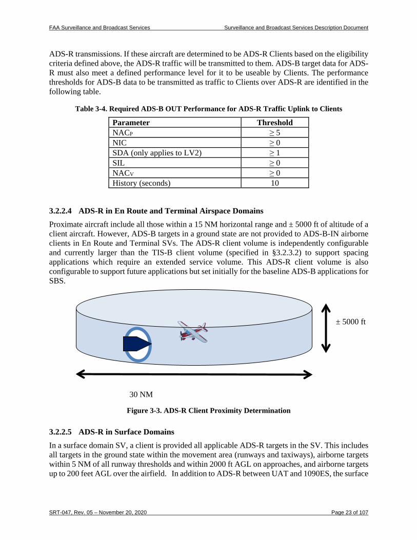
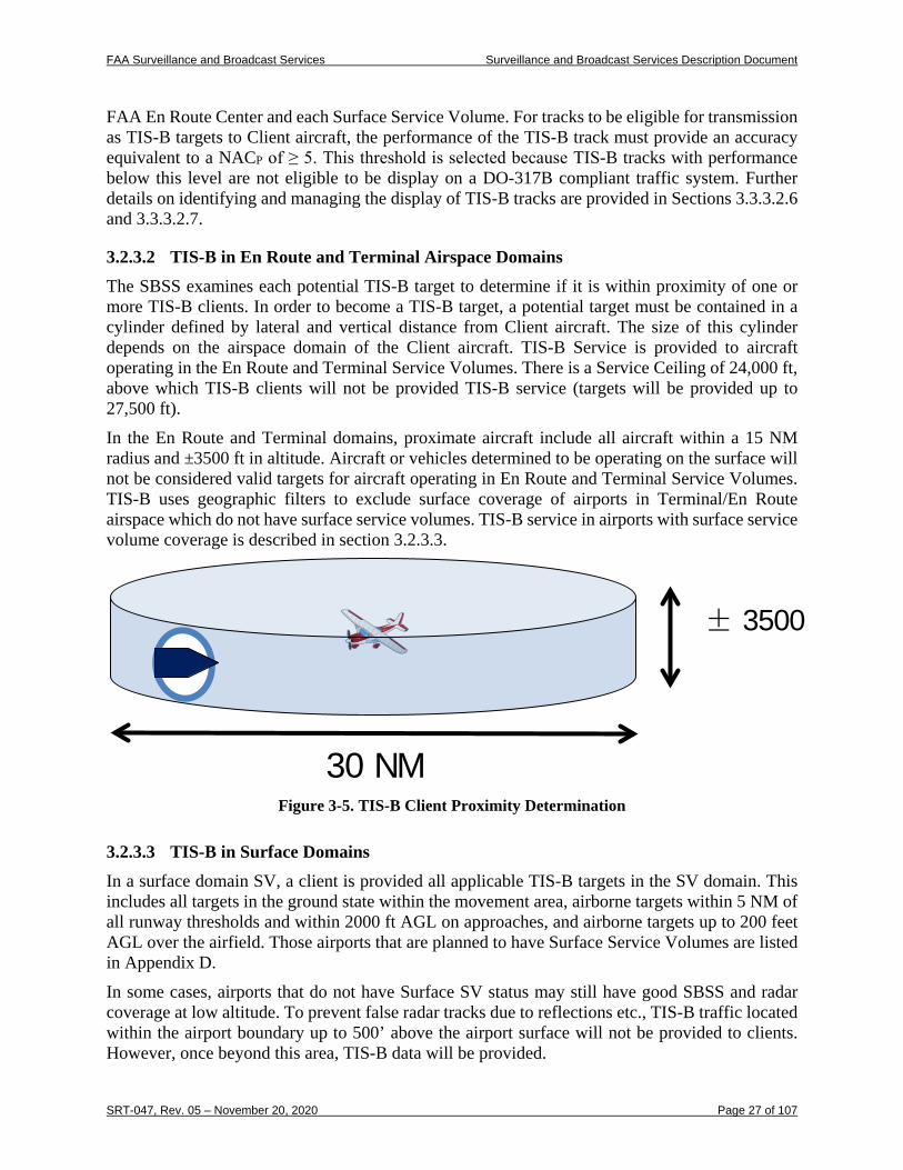
3.2.2.4 ADS-R in En Route and Terminal Airspace Domains Proximate aircraft include all those within a 15 NM horizontal range and ± 5000 ft of altitude of a client aircraft. However, ADS-B targets in a ground state are not provided to ADS-B-IN airborne clients in En Route and Terminal SVs. The ADS-R client volume is independently configurable and currently larger than the TIS-B client volume (specified in §3.2.3.2) to support spacing applications which require an extended service volume. This ADS-R client volume is also configurable to support future applications but set initially for the baseline ADS-B applications for SBS.
Figure 3-3. ADS-R Client Proximity Determination
3.2.2.5 ADS-R in Surface Domains In a surface domain SV, a client is provided all applicable ADS-R targets in the SV. This includes all targets in the ground state within the movement area (runways and taxiways), airborne targets within 5 NM of all runway thresholds and within 2000 ft AGL on approaches, and airborne targets up to 200 feet AGL over the airfield. In addition to ADS-R between UAT and 1090ES, the surface
30 NM
± 5000 ft
FAA Surveillance and Broadcast Services Surveillance and Broadcast Services Description Document
SRT-047, Rev. 05 – November 20, 2020 Page 24 of 107
domain includes a function known as ADS-R Same Link Rebroadcast (SLR). This is necessary at some airports to overcome problems with blockage by structures and multipath.
3.2.2.6 Transmission of ADS-R Targets Over the Air Interface Each ADS-R Target aircraft may have one or more client aircraft that need to receive ADS-R transmissions, possibly in different domains. The SBSS determines the ADS-R transmission rate required by the client in the most demanding domain. The SBSS control station also determines the radio or set of radios necessary to transmit ADS-R messages to all clients. If a radio selected for transmissions to a client is also receiving transmissions from the client, the SBSS prepares a transmission schedule and submits it to the radio. The transmission schedule identifies the 24-bit address of the target aircraft, and an update interval. When the radio receives transmissions from the target aircraft it will retransmit the report on the opposite link, according to the provided schedule. Most ADS-R transmissions are of this type. In the uncommon case where a client and target are not served by a common radio, the SBSS will receive the ADS-B report from the receiving radio and forward the report to the transmitting radio. A client aircraft that is receiving ADS-R service will receive reports for ADS-B aircraft on the opposite link within its vicinity. Since a single target may have multiple clients, sometimes in different domains, a client may receive ADS-R reports more frequently than required for the client’s domain. An aircraft may also be in range of a ground radio station that is transmitting reports required by other aircraft. When this is the case it will receive reports of aircraft that are outside the altitude and horizontal range of its vicinity. The cumulative number of messages transmitted by all SBSS radio stations within reception range of any aircraft in the NAS will not exceed 1,000 1090ES messages per second with received signal strength greater than -78 dBm. This limit applies to both the ADS-R and TIS-B Service combined (although ADS-R transmissions are prioritized over TIS-B when approaching capacity limits). The cumulative maximum number of UAT messages received by an aircraft will not exceed 400 messages per second with received signal strength greater than -82 dBm. These limits are achieved through a combination of the client proximity filter size, the density of radios, radio transmit power, the best radio selection algorithm, and the required update intervals.
3.2.2.7 ADS-R Service Status Notification The SBSS will notify UAT Link Version 2 clients that ADS-R service is being provided. This notification is provided through the TIS-B/ADS-R Service Status, provided as an information product through FIS-B. The SBSS will notify 1090ES link version 2 clients that ADS-R service is being provided. This notification is provided through the TIS-B/ADS-R Service Status message4. For message format descriptions and guidance on displaying this status message, see Appendix H of RTCA DO-317B.
4 No Service Status Notification will be provided for 1090ES v0 or v1 equipage because the service status message
was not defined in these earlier versions of the ADS-B MOPS. Service Status Notification is also no longer provided for UAT v1 equipage.
FAA Surveillance and Broadcast Services Surveillance and Broadcast Services Description Document
SRT-047, Rev. 05 – November 20, 2020 Page 25 of 107
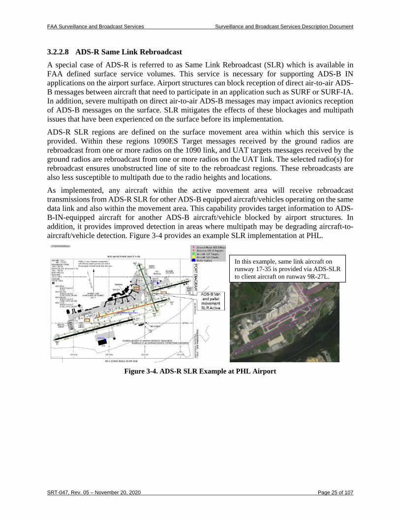
3.2.2.8 ADS-R Same Link Rebroadcast A special case of ADS-R is referred to as Same Link Rebroadcast (SLR) which is available in FAA defined surface service volumes. This service is necessary for supporting ADS-B IN applications on the airport surface. Airport structures can block reception of direct air-to-air ADS-B messages between aircraft that need to participate in an application such as SURF or SURF-IA. In addition, severe multipath on direct air-to-air ADS-B messages may impact avionics reception of ADS-B messages on the surface. SLR mitigates the effects of these blockages and multipath issues that have been experienced on the surface before its implementation. ADS-R SLR regions are defined on the surface movement area within which this service is provided. Within these regions 1090ES Target messages received by the ground radios are rebroadcast from one or more radios on the 1090 link, and UAT targets messages received by the ground radios are rebroadcast from one or more radios on the UAT link. The selected radio(s) for rebroadcast ensures unobstructed line of site to the rebroadcast regions. These rebroadcasts are also less susceptible to multipath due to the radio heights and locations. As implemented, any aircraft within the active movement area will receive rebroadcast transmissions from ADS-R SLR for other ADS-B equipped aircraft/vehicles operating on the same data link and also within the movement area. This capability provides target information to ADS-B-IN-equipped aircraft for another ADS-B aircraft/vehicle blocked by airport structures. In addition, it provides improved detection in areas where multipath may be degrading aircraft-to-aircraft/vehicle detection. Figure 3-4 provides an example SLR implementation at PHL.
Figure 3-4. ADS-R SLR Example at PHL Airport
In this example, same link aircraft on runway 17-35 is provided via ADS-SLR to client aircraft on runway 9R-27L.
FAA Surveillance and Broadcast Services Surveillance and Broadcast Services Description Document
SRT-047, Rev. 05 – November 20, 2020 Page 26 of 107
3.2.3 TIS-B Service
3.2.3.1 TIS-B Service Concept of Operations The TIS-B service provides active ADS-B users with a low-latency stream of position reports of non-ADS-B equipped aircraft or those that have older ADS-B LV0 or LV1 equipage. TIS-B service is available in supported Service Volumes when there is both adequate surveillance coverage from non-ADS-B ground sensors and adequate RF coverage from SBSS ground radio stations. An aircraft or vehicle that is an active ADS-B user and is receiving TIS-B service is known as a TIS-B Client. A non-ADS-B equipped aircraft or vehicle that has its position transmitted in TIS-B reports is known as a TIS-B Target.
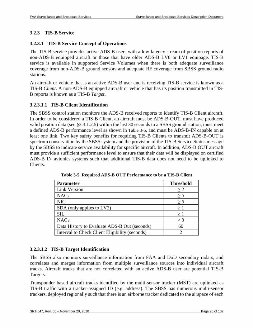
3.2.3.1.1 TIS-B Client Identification The SBSS control station monitors the ADS-B received reports to identify TIS-B Client aircraft. In order to be considered a TIS-B Client, an aircraft must be ADS-B-OUT, must have produced valid position data (see §3.3.1.2.5) within the last 30 seconds to a SBSS ground station, must meet a defined ADS-B performance level as shown in Table 3-5, and must be ADS-B-IN capable on at least one link. Two key safety benefits for requiring TIS-B Clients to transmit ADS-B-OUT is spectrum conservation by the SBSS system and the provision of the TIS-B Service Status message by the SBSS to indicate service availability for specific aircraft. In addition, ADS-B OUT aircraft must provide a sufficient performance level to ensure that their data will be displayed on certified ADS-B IN avionics systems such that additional TIS-B data does not need to be uplinked to Clients.
Table 3-5. Required ADS-B OUT Performance to be a TIS-B Client
Parameter Threshold Link Version ≥ 2 NACP ≥ 5 NIC ≥ 5 SDA (only applies to LV2) ≥ 1 SIL ≥ 1 NACV ≥ 0 Data History to Evaluate ADS-B Out (seconds) 60 Interval to Check Client Eligibility (seconds) 2
3.2.3.1.2 TIS-B Target Identification The SBSS also monitors surveillance information from FAA and DoD secondary radars, and correlates and merges information from multiple surveillance sources into individual aircraft tracks. Aircraft tracks that are not correlated with an active ADS-B user are potential TIS-B Targets. Transponder based aircraft tracks identified by the multi-sensor tracker (MST) are uplinked as TIS-B traffic with a tracker-assigned ID (e.g. address). The SBSS has numerous multi-sensor trackers, deployed regionally such that there is an airborne tracker dedicated to the airspace of each
FAA Surveillance and Broadcast Services Surveillance and Broadcast Services Description Document
SRT-047, Rev. 05 – November 20, 2020 Page 27 of 107
FAA En Route Center and each Surface Service Volume. For tracks to be eligible for transmission as TIS-B targets to Client aircraft, the performance of the TIS-B track must provide an accuracy equivalent to a NACP of ≥ 5. This threshold is selected because TIS-B tracks with performance below this level are not eligible to be display on a DO-317B compliant traffic system. Further details on identifying and managing the display of TIS-B tracks are provided in Sections 3.3.3.2.6 and 3.3.3.2.7.
3.2.3.2 TIS-B in En Route and Terminal Airspace Domains The SBSS examines each potential TIS-B target to determine if it is within proximity of one or more TIS-B clients. In order to become a TIS-B target, a potential target must be contained in a cylinder defined by lateral and vertical distance from Client aircraft. The size of this cylinder depends on the airspace domain of the Client aircraft. TIS-B Service is provided to aircraft operating in the En Route and Terminal Service Volumes. There is a Service Ceiling of 24,000 ft, above which TIS-B clients will not be provided TIS-B service (targets will be provided up to 27,500 ft). In the En Route and Terminal domains, proximate aircraft include all aircraft within a 15 NM radius and ±3500 ft in altitude. Aircraft or vehicles determined to be operating on the surface will not be considered valid targets for aircraft operating in En Route and Terminal Service Volumes. TIS-B uses geographic filters to exclude surface coverage of airports in Terminal/En Route airspace which do not have surface service volumes. TIS-B service in airports with surface service volume coverage is described in section 3.2.3.3.
Figure 3-5. TIS-B Client Proximity Determination
3.2.3.3 TIS-B in Surface Domains In a surface domain SV, a client is provided all applicable TIS-B targets in the SV domain. This includes all targets in the ground state within the movement area, airborne targets within 5 NM of all runway thresholds and within 2000 ft AGL on approaches, and airborne targets up to 200 feet AGL over the airfield. Those airports that are planned to have Surface Service Volumes are listed in Appendix D. In some cases, airports that do not have Surface SV status may still have good SBSS and radar coverage at low altitude. To prevent false radar tracks due to reflections etc., TIS-B traffic located within the airport boundary up to 500’ above the airport surface will not be provided to clients. However, once beyond this area, TIS-B data will be provided.
30 NM
± 3500
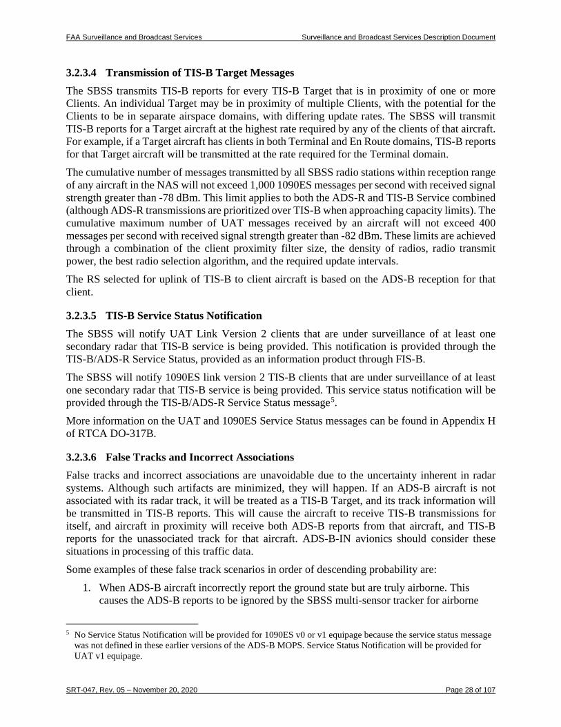
FAA Surveillance and Broadcast Services Surveillance and Broadcast Services Description Document
SRT-047, Rev. 05 – November 20, 2020 Page 28 of 107
3.2.3.4 Transmission of TIS-B Target Messages The SBSS transmits TIS-B reports for every TIS-B Target that is in proximity of one or more Clients. An individual Target may be in proximity of multiple Clients, with the potential for the Clients to be in separate airspace domains, with differing update rates. The SBSS will transmit TIS-B reports for a Target aircraft at the highest rate required by any of the clients of that aircraft. For example, if a Target aircraft has clients in both Terminal and En Route domains, TIS-B reports for that Target aircraft will be transmitted at the rate required for the Terminal domain. The cumulative number of messages transmitted by all SBSS radio stations within reception range of any aircraft in the NAS will not exceed 1,000 1090ES messages per second with received signal strength greater than -78 dBm. This limit applies to both the ADS-R and TIS-B Service combined (although ADS-R transmissions are prioritized over TIS-B when approaching capacity limits). The cumulative maximum number of UAT messages received by an aircraft will not exceed 400 messages per second with received signal strength greater than -82 dBm. These limits are achieved through a combination of the client proximity filter size, the density of radios, radio transmit power, the best radio selection algorithm, and the required update intervals. The RS selected for uplink of TIS-B to client aircraft is based on the ADS-B reception for that client.
3.2.3.5 TIS-B Service Status Notification The SBSS will notify UAT Link Version 2 clients that are under surveillance of at least one secondary radar that TIS-B service is being provided. This notification is provided through the TIS-B/ADS-R Service Status, provided as an information product through FIS-B. The SBSS will notify 1090ES link version 2 TIS-B clients that are under surveillance of at least one secondary radar that TIS-B service is being provided. This service status notification will be provided through the TIS-B/ADS-R Service Status message5. More information on the UAT and 1090ES Service Status messages can be found in Appendix H of RTCA DO-317B.
3.2.3.6 False Tracks and Incorrect Associations False tracks and incorrect associations are unavoidable due to the uncertainty inherent in radar systems. Although such artifacts are minimized, they will happen. If an ADS-B aircraft is not associated with its radar track, it will be treated as a TIS-B Target, and its track information will be transmitted in TIS-B reports. This will cause the aircraft to receive TIS-B transmissions for itself, and aircraft in proximity will receive both ADS-B reports from that aircraft, and TIS-B reports for the unassociated track for that aircraft. ADS-B-IN avionics should consider these situations in processing of this traffic data. Some examples of these false track scenarios in order of descending probability are:
1. When ADS-B aircraft incorrectly report the ground state but are truly airborne. This causes the ADS-B reports to be ignored by the SBSS multi-sensor tracker for airborne
5 No Service Status Notification will be provided for 1090ES v0 or v1 equipage because the service status message
was not defined in these earlier versions of the ADS-B MOPS. Service Status Notification will be provided for UAT v1 equipage.
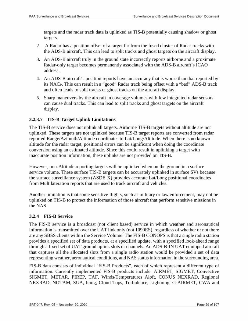
FAA Surveillance and Broadcast Services Surveillance and Broadcast Services Description Document
SRT-047, Rev. 05 – November 20, 2020 Page 29 of 107
targets and the radar track data is uplinked as TIS-B potentially causing shadow or ghost targets.
2. A Radar has a position offset of a target far from the fused cluster of Radar tracks with the ADS-B aircraft. This can lead to split tracks and ghost targets on the aircraft display.
3. An ADS-B aircraft truly in the ground state incorrectly reports airborne and a proximate Radar-only target becomes permanently associated with the ADS-B aircraft’s ICAO address.
4. An ADS-B aircraft’s position reports have an accuracy that is worse than that reported by its NACP. This can result in a “good” Radar track being offset with a “bad” ADS-B track and often leads to split tracks or ghost tracks on the aircraft display.
5. Sharp maneuvers by the aircraft in coverage volumes with few integrated radar sensors can cause dual tracks. This can lead to split tracks and ghost targets on the aircraft display.
3.2.3.7 TIS-B Target Uplink Limitations The TIS-B service does not uplink all targets. Airborne TIS-B targets without altitude are not uplinked. These targets are not uplinked because TIS-B target reports are converted from radar reported Range/Azimuth/Altitude coordinates to Lat/Long/Altitude. When there is no known altitude for the radar target, positional errors can be significant when doing the coordinate conversion using an estimated altitude. Since this could result in uplinking a target with inaccurate position information, these uplinks are not provided on TIS-B. However, non-Altitude reporting targets will be uplinked when on the ground in a surface service volume. These surface TIS-B targets can be accurately uplinked in surface SVs because the surface surveillance system (ASDE-X) provides accurate Lat/Long positional coordinates from Multilateration reports that are used to track aircraft and vehicles. Another limitation is that some sensitive flights, such as military or law enforcement, may not be uplinked on TIS-B to protect the information of those aircraft that perform sensitive missions in the NAS.
3.2.4 FIS-B Service The FIS-B service is a broadcast (not client based) service in which weather and aeronautical information is transmitted over the UAT link only (not 1090ES), regardless of whether or not there are any SBSS clients within the Service Volume. The FIS-B CONOPS is that a single radio station provides a specified set of data products, at a specified update, with a specified look-ahead range through a fixed set of UAT ground uplink slots or channels. An ADS-B-IN UAT equipped aircraft that captures all the allocated slots from a single radio station would be provided a set of data representing weather, aeronautical conditions, and NAS status information in the surrounding area. FIS-B data consists of individual "FIS-B Products”, each of which represent a different type of information. Currently implemented FIS-B products include: AIRMET, SIGMET, Convective SIGMET, METAR, PIREP, TAF, Winds/Temperatures Aloft, CONUS NEXRAD, Regional NEXRAD, NOTAM, SUA, Icing, Cloud Tops, Turbulence, Lightning, G-AIRMET, CWA and
FAA Surveillance and Broadcast Services Surveillance and Broadcast Services Description Document
SRT-047, Rev. 05 – November 20, 2020 Page 30 of 107
TIS-B/ADS-R Service Status. Each of these products is broadcast at maximum update intervals and transmission intervals, and with a minimum latency. The geographic scope of the uplinked products is specified with each FIS-B Product in the form of a minimum “look-ahead” distance. This ensures that all available products of each type will be broadcast at a specified geographic radius from each UAT ground radio station. An empty FIS-B message will be sent from a radio as a heartbeat, once per second, if no other FIS-B product messages are scheduled to be sent from that radio. This heartbeat takes the form of a valid UAT header, but with no product data. This heartbeat is sent to inform aircraft of the availability of the FIS-B service. A FIS-B heartbeat message can be distinguished from other FIS-B messages if the I-Frame length is encoded as 0 for the first I-Frame. When this is the case, the remaining bytes in the FIS-B message payload need not be processed (they will all be 0). The radio stations that provide FIS-B service are configured in a tiered design. The general structure of the tiered approach established for SBSS is described in RTCA DO-358A Appendix D. A brief summary is given here.
• Radio Stations will be grouped into four tiers as follows: – Surface: these radio stations will service aircraft in the immediate vicinity of
major airports. – Low-altitude: services aircraft at low altitude: up to 3000 ft AGL. – Medium-altitude: services aircraft from low altitude up to 14,000 ft AGL. – High-altitude: services aircraft from low altitude up to 24,000 ft AGL.
• The products provided from a Radio Stations will depend upon its Tier under the following rules – A higher tier radio station will contain all the data products provided by a
lower tier radio station. – Higher tier radio stations will provide additional data products not provided
by lower tier radio stations that are of interest to the high-altitude user. – Higher tier radio stations will provide greater ‘look-ahead’ ranges for data
products – the look ahead range is the distance between the radio station and the geo-tagged products provided by the radio station.
– Higher tier radio stations will have a greater number of UAT ground uplink slots assigned – the absolute maximum number of assigned slots allocated to a single radio station is 5 slots, but 4 is likely the practical maximum to mitigate co-channel interference.
The tier of a radio station which is being received can be identified through the use of the TIS-B Site ID Field, as described in Section C.1. While the required ceiling for FIS-B is FL240, it is expected that users can utilize the FIS-B service above that altitude. In the present design, approximately 90% of the area of implemented SVs would have FIS-B coverage at FL400. Although there are no practical RF propagation limitations for receiving FIS-B at high altitudes, co-channel interference could cause some areas of spotty coverage for A3 UAT avionics with high Desired/Undesired reception requirements (> 9dB).
FAA Surveillance and Broadcast Services Surveillance and Broadcast Services Description Document
SRT-047, Rev. 05 – November 20, 2020 Page 31 of 107
3.3 Service Messages and Performance
3.3.1 ADS-B Service Messages and Performance ADS-B is a Critical service as defined by the SBS Critical Services Specification. The objective of the ADS-B Service is to provide ADS-B Reports to SDPs. To achieve this objective, the ADS-B Service has to successfully receive and decode ADS-B Messages broadcast by aircraft and vehicles. Some of the information received in an ADS-B Message is decoded and inserted directly into the corresponding ADS-B Report fields. Other Message information requires some additional processing before entering into the Report. Additionally, some Report information has to be ascertained by the ADS-B Service. The performance that has to be achieved in delivering the ADS-B Service is detailed in following paragraphs.
3.3.1.1 ADS-B Information Units—Message Content The ADS-B Service SDP Report structure is shown in Table 3-6 with each data item associated with a Field Reference Number (FRN). The specific data item formats are described in the FAA SDP IRD (NAS-IR-82530001). For 1090ES, each SDP ADS-B Report is triggered by either a position message or a velocity message. The velocity message Report triggering is a configurable system option, which is typically not implemented. For UAT, each SDP ADS-B Report is triggered by either a “short” or a “long” UAT message. The SBSS maintains state variables, such as Flight ID, from the other ADS-B messages over specified validity times. Table 3-7 and Table 3-8 show how the specific ADS-B Messages and their content map to the SDP ADS-B Report data items.
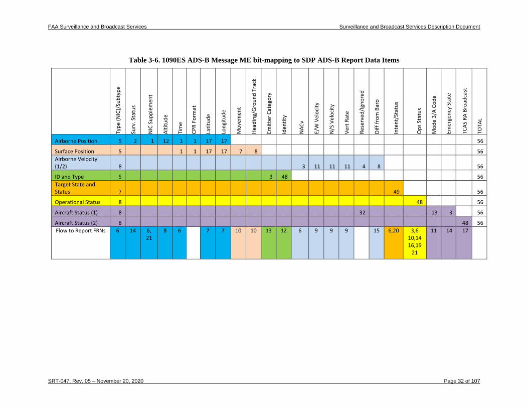
FAA Surveillance and Broadcast Services Surveillance and Broadcast Services Description Document
SRT-047, Rev. 05 – November 20, 2020 Page 32 of 107
Table 3-6. 1090ES ADS-B Message ME bit-mapping to SDP ADS-B Report Data Items
Type
(NIC
)/Su
btyp
e
Surv
. Sta
tus
NIC
Sup
plem
ent
Altit
ude
Tim
e
CPR
Form
at
Latit
ude
Long
itude
Mov
emen
t
Head
ing/
Gro
und
Trac
k
Emitt
er C
ateg
ory
Iden
tity
NAC
v
E/W
Vel
ocity
N/S
Vel
ocity
Vert
Rat
e
Rese
rved
/Ign
ored
Diff
from
Bar
o
Inte
nt/S
tatu
s
Ops
Sta
tus
Mod
e 3/
A Co
de
Emer
genc
y St
ate
TCAS
RA
Broa
dcas
t
TOTA
L
Airborne Position 5 2 1 12 1 1 17 17 56
Surface Position 5 1 1 17 17 7 8 56 Airborne Velocity (1/2) 8 3 11 11 11 4 8 56
ID and Type 5 3 48 56 Target State and Status 7 49 56
Operational Status 8 48 56
Aircraft Status (1) 8 32 13 3 56
Aircraft Status (2) 8 48 56 Flow to Report FRNs 6 14 6,
21 8 6 7 7 10 10 13 12 6 9 9 9 15 6,20 3,6
10,14 16,19
21
11 14 17
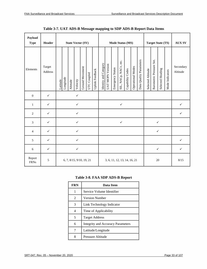
FAA Surveillance and Broadcast Services Surveillance and Broadcast Services Description Document
SRT-047, Rev. 05 – November 20, 2020 Page 33 of 107
Table 3-7. UAT ADS-B Message mapping to SDP ADS-B Report Data Items
Payload
Type Header State Vector (SV) Mode Status (MS) Target State (TS) AUX SV
Elements Target
Address
Latit
ude
Long
itude
Alti
tude
Vel
ocity
Gro
und
Mov
emen
t
UTC
Cou
pled
Upl
ink
Feed
back
Iden
tity
and
Cat
egor
y U
AT
MO
PS V
ersi
on
Emer
genc
y St
atus
SIL,
NA
Cp,
NA
Cv,
etc
.
Cap
abili
ty C
odes
Ope
ratio
nal M
odes
Dat
a Q
ualit
y Pa
ram
eter
s
Sele
cted
Alti
tude
Bar
omet
ric P
ress
ure
Set.
Sele
cted
Hea
ding
Mod
e In
dica
tors
Secondary
Altitude
0
1
2
3
4
5
6
Report FRNs
5 6, 7, 8/15, 9/10, 19, 21 3, 6, 11, 12, 13, 14, 16, 21 20 8/15
Table 3-8. FAA SDP ADS-B Report
FRN Data Item
1 Service Volume Identifier
2 Version Number
3 Link Technology Indicator
4 Time of Applicability
5 Target Address
6 Integrity and Accuracy Parameters
7 Latitude/Longitude
8 Pressure Altitude
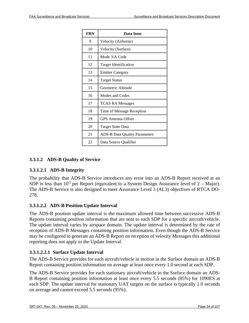
FAA Surveillance and Broadcast Services Surveillance and Broadcast Services Description Document
SRT-047, Rev. 05 – November 20, 2020 Page 34 of 107
FRN Data Item
9 Velocity (Airborne)
10 Velocity (Surface)
11 Mode 3/A Code
12 Target Identification
13 Emitter Category
14 Target Status
15 Geometric Altitude
16 Modes and Codes
17 TCAS RA Messages
18 Time of Message Reception
19 GPS Antenna Offset
20 Target State Data
21 ADS-B Data Quality Parameters
22 Data Source Qualifier
3.3.1.2 ADS-B Quality of Service
3.3.1.2.1 ADS-B Integrity The probability that ADS-B Service introduces any error into an ADS-B Report received at an SDP is less than 10-5 per Report (equivalent to a System Design Assurance level of 2 – Major). The ADS-B Service is also designed to meet Assurance Level 3 (AL3) objectives of RTCA DO-278.
3.3.1.2.2 ADS-B Position Update Interval The ADS-B position update interval is the maximum allowed time between successive ADS-B Reports containing position information that are sent to each SDP for a specific aircraft/vehicle. The update interval varies by airspace domain. The update interval is determined by the rate of reception of ADS-B Messages containing position information. Even though the ADS-B Service may be configured to generate an ADS-B Report on reception of velocity Messages this additional reporting does not apply to the Update Interval.
3.3.1.2.2.1 Surface Update Interval The ADS-B Service provides for each aircraft/vehicle in motion in the Surface domain an ADS-B Report containing position information on average at least once every 1.0 second at each SDP. The ADS-B Service provides for each stationary aircraft/vehicle in the Surface domain an ADS-B Report containing position information at least once every 5.5 seconds (85%) for 1090ES at each SDP. The update interval for stationary UAT targets on the surface is typically 1.0 seconds on average and cannot exceed 5.5 seconds (95%).
FAA Surveillance and Broadcast Services Surveillance and Broadcast Services Description Document
SRT-047, Rev. 05 – November 20, 2020 Page 35 of 107
3.3.1.2.2.2 Terminal Update Interval The ADS-B Service provides for each aircraft/vehicle in the Terminal domain an ADS-B Report containing position information with an update interval no greater than 3.0 seconds (95%) at each SDP.
3.3.1.2.2.3 En Route Update Interval The ADS-B Service provides for each aircraft/vehicle in the En Route domain an ADS-B Report containing position information with an update interval no greater than 6.0 seconds (95%) at each SDP. The ADS-B Service provides for each aircraft/vehicle in En Route domains identified as “En Route High Update (HU)” an ADS-B Report containing position information with an update interval no greater than 3.0 seconds (95%) at each SDP.
3.3.1.2.3 ADS-B Latency The ADS-B Latency for the SBSS includes the ADS-B Service processing delay and the delay in communicating the ADS-B Reports to the Service Delivery Points. Latency is measured from the reception of the last bit of an ADS-B Message to the reception of the first bit of the corresponding ADS-B Report at the SDP. The maximum delay between the reception of the last bit of an ADS-B Message, containing a State Vector or an emergency condition, and the reception of the first bit of the corresponding ADS-B Report at the Service Delivery Point is less than or equal to 700 ms within the various operating environments. UTC coupled aircraft allow the SBSS to compute the time of applicability of the horizontal position within ± 200 ms.
3.3.1.2.4 ADS-B Service Availability The ADS-B Service is a safety-critical service as classified by NAS-RD-2013 for surveillance services. This requirement is driven by the ATC Surveillance application. The ADS-B Service meets a minimum Availability of 0.99999 in each defined service volume at SDPs identified as critical.
3.3.1.2.5 Independent Validation In certain Service Volumes, the FAA will require that the ADS-B Service provide independent validation of the position information received in the ADS-B Messages. An independent ADS-B validation capability may assure to a specified probability that each ADS-B Message, and the position information contained within, is from a real aircraft/vehicle with a valid position source rather than from a source broadcasting erroneous information or a spoofer. The independent validation tolerances are defined to support approach and 3 NM separation in Terminal airspace as well as 5 NM separation in En Route airspace. The validation process uses a combination of the methods listed below:
1. Use of time difference of arrival techniques, 2. Comparison to radar, 3. Comparing a one way “passive range” with range to target indicated by ADS-B
(available for UAT equipped targets),
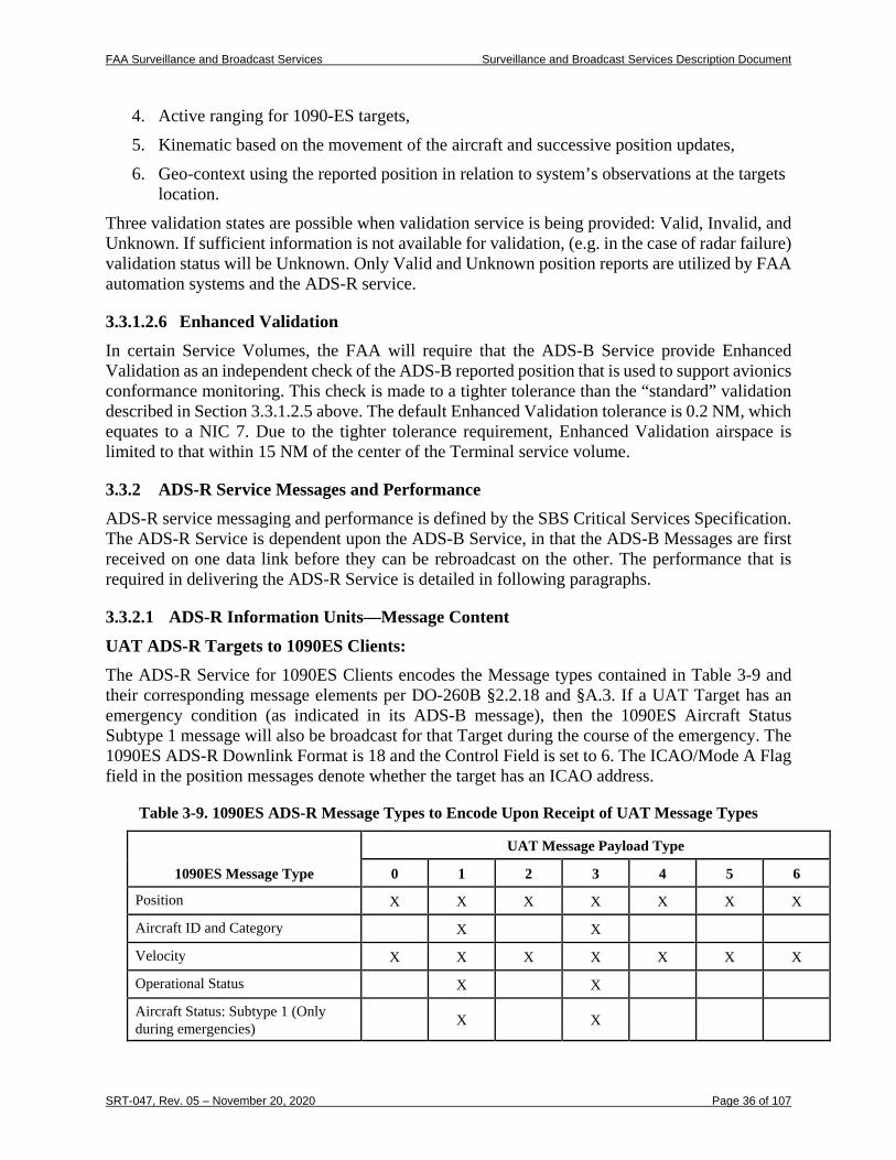
FAA Surveillance and Broadcast Services Surveillance and Broadcast Services Description Document
SRT-047, Rev. 05 – November 20, 2020 Page 36 of 107
4. Active ranging for 1090-ES targets, 5. Kinematic based on the movement of the aircraft and successive position updates, 6. Geo-context using the reported position in relation to system’s observations at the targets
location. Three validation states are possible when validation service is being provided: Valid, Invalid, and Unknown. If sufficient information is not available for validation, (e.g. in the case of radar failure) validation status will be Unknown. Only Valid and Unknown position reports are utilized by FAA automation systems and the ADS-R service.
3.3.1.2.6 Enhanced Validation In certain Service Volumes, the FAA will require that the ADS-B Service provide Enhanced Validation as an independent check of the ADS-B reported position that is used to support avionics conformance monitoring. This check is made to a tighter tolerance than the “standard” validation described in Section 3.3.1.2.5 above. The default Enhanced Validation tolerance is 0.2 NM, which equates to a NIC 7. Due to the tighter tolerance requirement, Enhanced Validation airspace is limited to that within 15 NM of the center of the Terminal service volume.
3.3.2 ADS-R Service Messages and Performance ADS-R service messaging and performance is defined by the SBS Critical Services Specification. The ADS-R Service is dependent upon the ADS-B Service, in that the ADS-B Messages are first received on one data link before they can be rebroadcast on the other. The performance that is required in delivering the ADS-R Service is detailed in following paragraphs.
3.3.2.1 ADS-R Information Units—Message Content UAT ADS-R Targets to 1090ES Clients: The ADS-R Service for 1090ES Clients encodes the Message types contained in Table 3-9 and their corresponding message elements per DO-260B §2.2.18 and §A.3. If a UAT Target has an emergency condition (as indicated in its ADS-B message), then the 1090ES Aircraft Status Subtype 1 message will also be broadcast for that Target during the course of the emergency. The 1090ES ADS-R Downlink Format is 18 and the Control Field is set to 6. The ICAO/Mode A Flag field in the position messages denote whether the target has an ICAO address.
Table 3-9. 1090ES ADS-R Message Types to Encode Upon Receipt of UAT Message Types
1090ES Message Type
UAT Message Payload Type
0 1 2 3 4 5 6
Position X X X X X X X
Aircraft ID and Category X X
Velocity X X X X X X X
Operational Status X X
Aircraft Status: Subtype 1 (Only during emergencies) X X
FAA Surveillance and Broadcast Services Surveillance and Broadcast Services Description Document
SRT-047, Rev. 05 – November 20, 2020 Page 37 of 107
1090 ADS-R Targets to UAT Clients: The ADS-R Service for UAT Clients could be “short” (Payload Type code 0) or “long” (Payload Type code 1 and 2) messages. ADS-R transmissions follow the A1H equipment class transmission cycle, which is a mixed population of short and long UAT messages (see §2.2.6.1.2 and §2.2.6.1.3 of RTCA DO-282B). The UAT ADS-R Address Qualifier is either set to 2 (target with ICAO address) or 6 (target with non-ICAO address). When the UAT Address Qualifier is 2, there are no other fields which convey whether the message is TIS-B or ADS-R.
3.3.2.2 Quality of Service
3.3.2.2.1 ADS-R Integrity and Accuracy The probability that ADS-R Service introduces any error into a rebroadcast ADS-B Message is less than or equal to 10-5 per Message (equivalent to a System Design Assurance level of 2 – Major). This probability of error includes the linear position extrapolation process using the instantaneous velocity reported for a target on the opposite ADS-B data link. The ADS-R Service limits the NIC value to 8 and NACP value to 9 in ADS-R Message transmissions. ADS-R uplink functions are not designed to support the precision mode of operation, i.e., NIC values greater than 8 and NACP values greater than 9.
3.3.2.2.2 ADS-R Position Update Interval The ADS-R Service broadcasts state vector updates for aircraft/vehicles transmitting on one data link to aircraft/vehicles on the other data link at an interval that will support the aircraft/vehicle based applications that are to be performed in the Service Volume. The state vector update intervals required to support each application are detailed in the SBS CONOPS and summarized as follows:
• ATSA-AIRB: 5 seconds
• ATSA-VSA: 5 seconds
• ATSA-SURF: 2 seconds
• Traffic Situation Awareness with Alerts (TSAA): 10 seconds
• Airborne Spacing - Flight-Deck Based Interval Management–Spacing (FIM-S): 10 seconds
The ADS-R update interval requirements are based upon the most stringent application that is to be supported within each domain. The update intervals apply to the reception by a client aircraft of all eligible ADS-R aircraft/vehicles within the range and altitude limits at any point within the Service Volume. Thus, the 1090 MHz interference environments had to be considered to meet the update intervals. The ADS-R update interval is limited by the ADS-B Message reception rate from each aircraft/vehicle (as rebroadcasts may be made only when Messages are received), the UAT uplink capacity, spectrum restrictions for 1090ES, the performance characteristics of the aircraft/vehicle ADS-B equipment, and the interference environment. The maximum message transmission rate for a 1090ES Target ADS-R to a UAT client is 2 times per second since a Ground Station will receive a 1090ES position message approximately every 0.5 seconds. The actual uplink rate may be configured to be less than this depending on the airspace
FAA Surveillance and Broadcast Services Surveillance and Broadcast Services Description Document
SRT-047, Rev. 05 – November 20, 2020 Page 38 of 107
and applications to be supported. The expected minimum power received by UAT avionics is -93 dBm. The ADS-R link margin for UAT clients is expected to be > 11 dB for the majority of the NAS airspace. The nominal message packet transmission rate for a UAT Target ADS-R to a 1090 client is 1 time per second since a Ground Station will receive a UAT message approximately every 1 second. A 1090 ADS-R message packet consists of 2 position messages, 1 Aircraft ID and Category message, 1 Velocity message (if airborne), and 1 Operational Status message. All of the 1090 ADS-R messages in the packet are transmitted within milliseconds of each other. The expected minimum power received by 1090 avionics is -79 dBm in low interference environments and -72 dBm in high interference environments. The ADS-R link margin for 1090ES clients is expected to be > 5 dB for the majority of the NAS airspace. As the system becomes loaded with more than 250 ADS-R targets on each link, these target message transmission rates will decrease in a process known as Graceful Degradation. The purpose of Graceful Degradation (GD) is to gradually throttle the ADS-R messages sent to Aircraft/Vehicles based on load. The GD algorithm uses several configurable parameters to control the flow of reports and messages until the maximum load is reached.
3.3.2.2.2.1 Surface Update Interval The ADS-R Service transmits the number of ADS-R Messages necessary to meet an update interval of no greater than 2 seconds (95%) for each client aircraft for all traffic within 5 NM and within ± 2000 feet of each client within the Surface Service Volume.
3.3.2.2.2.2 Terminal Update Interval The ADS-R Service transmits the number of ADS-R Messages necessary to meet an update interval of no greater than 5 seconds (95%) for each client aircraft for all traffic within 15 NM and within ± 5000 feet of each client within the Terminal Service Volume.
3.3.2.2.2.3 En Route Update Interval The ADS-R Service transmits the number of ADS-R Messages necessary to meet an update interval of no greater than 10 seconds (95%) for each client aircraft for all traffic within 15 NM and within ± 5000 feet of each client within the En Route Service Volume.
3.3.2.2.3 ADS-R Latency The additional latency introduced by the ground infrastructure is less than the latency required by the most stringent applications in the SBS CONOPS minus the inherent airborne latencies on both ends. The maximum delay between the time of message received of an ADS-B Message that results in the generation of ADS-R Uplink Messages and the transmission of the first bit of any corresponding broadcast Message on the opposite link technology is less than or equal to 1 second. The service provider ground infrastructure design is such that the time it takes for a received ADS-B message to be processed into ADS-R format and sent to the ADS-R transmission scheduler is 400 milliseconds or less. This ADS-B to ADS-R transmission latency is compensated in the ADS-R horizontal position by linearly extrapolating to the time of transmission.
FAA Surveillance and Broadcast Services Surveillance and Broadcast Services Description Document
SRT-047, Rev. 05 – November 20, 2020 Page 39 of 107
3.3.2.2.4 ADS-R Service Availability The ADS-R Service is currently a safety-essential service as classified by NAS-RD-2013 for surveillance services. The ADS-R Service meets a minimum Availability of 0.999 at SDPs (in this case, SDP refers to client aircraft that are receiving ADS-R).
3.3.2.2.5 ADS-R Media Access 1090ES ADS-R transmissions contend with air-to-air 1090ES ADS-B transmissions and potentially with nearby SBSS Ground Station 1090ES transmissions. However, 1090ES transmissions are randomized to minimize interference and each SBSS Ground Station has a maximum 1090ES transmission duty cycle of 6% (combines all 1090 TIS-B and ADS-R messages). UAT ADS-R transmissions contend with air-to-air UAT ADS-B transmissions since they are in the ADS-B segment of the UAT Frame (not the Ground Segment) and potentially with nearby SBSS Ground Station UAT transmissions. However, UAT transmissions are randomized to minimize interference and each SBSS Ground Station has a maximum UAT transmission duty cycle of 12.5% (combines all UAT TIS-B and ADS-R messages). Although ADS-R transmissions are event-driven by receptions of ADS-B messages, both 1090ES and UAT have configurable minimum ADS-R transmit intervals (currently set to 1.5 ms) with an added random time (up to 3 ms) appended to the minimum interval. Additionally, typically only one radio rebroadcasts a particular target at any given time.
3.3.3 TIS-B Service Messages and Performance TIS-B is an Essential service as defined by the SBS Essential Services Specification. The TIS-B Service provides users equipped with ADS-B avionics the ability to receive, process, and display state information on proximate traffic that are not ADS-B equipped and are only tracked by other ground-based surveillance systems (i.e. radar and multilateration systems). The performance that is required in delivering the TIS-B Service is detailed in following paragraphs.
3.3.3.1 TIS-B Information Units—Message Content The 1090ES TIS-B Service encodes the TIS-B Message types contained in Table 3-10 and their corresponding message elements per DO-260B §2.2.17 and §A.2. The format of the DO-260B TIS-B message is identical to the DO-260A TIS-B message with the exception of the Ground Speed/Movement field encoding (see §2.2.3.2.4.2 in DO-260B). TIS-B Velocity messages are also transmitted for Surface targets in order to convey the NACP to ADS-B-IN users for surface applications (although velocity data is zeroed out). The 1090ES TIS-B Downlink Format is 18 and the Control Field is either set to 2 (target with ICAO address) or 5 (target with track file identifier). Three squitters (even position, odd position, and velocity) are sent for every TIS-B report transmitted over the 1090ES link. These transmissions are sent as a group, close together in time (as specified in §3.3.3.2.5), and if necessary will be repeated to ensure probability of detection. The 1090 TIS-B/ADS-R Service Status message format is defined in DO-317B and will be broadcast for 1090ES ADS-B-IN Link Version 2 clients.

FAA Surveillance and Broadcast Services Surveillance and Broadcast Services Description Document
SRT-047, Rev. 05 – November 20, 2020 Page 40 of 107
Table 3-10. Transmitted 1090ES TIS-B Message Types
Message Types RTCA/DO-260B
Reference Paragraphs
TIS-B Fine Airborne Position §2.2.17.3.1 & §A.2.4.1
TIS-B Fine Surface Position §2.2.17.3.2 & §A.2.4.2
TIS-B Velocity §2.2.17.3.4 & §A.2.4.4
TIS-B/ADS-R Service Status Management
§2.2.17.2 & §A.2
Table 3-11. Payload Composition of 1090ES TIS-B Messages
TIS-B Message Encoding Used
TIS-B Message Field
MSG Bit #
DO-260B Reference
All
Set to decimal 18 (10010) for all TIS-B Messages DF TYPE 1-5 §2.2.17.2.1
“2” for Fine TIS-B Message with AA=24-bit ICAO address and “5” for Fine TIS-B Message with AA=TIS-B Service generated 24-bit track ID
Control Field (CF) 6-8 §2.2.17.2.2
A 24-bit address; ICAO address or service generated track ID
Address Announced (AA) 9-32 §2.2.17.2.3
Algorithm that operates on the first 88 bits of the message
Parity / Identity (PI)
89-112 §2.2.3.2.1.7
TIS-
B F
ine
Airb
orne
Pos
ition
Determined from altitude type and NIC TYPE 33-37 §2.2.3.2.3.1
Set to 00 for all TIS-B Messages Surveillance Status 38-39 §2.2.3.2.3.2
“0” to indicate a 24-bit address Note: This flag is always set to 0 since Mode 3/A code is not allowed to be embedded in the 24-bit address
ICAO Mode Flag (IMF) 40 §2.2.17.3.1.2
12 bits of barometric altitude data. Pressure Altitude 41-52 §2.2.3.2.3.4.1
Set to ZERO Reserved 53 -
Transmit Function to alternate between “0” = even; “1” = odd. CPR Format 54 §2.2.3.2.3.6
CPR encoded Latitude and Longitude of target position.
CPR Latitude 55-71 §2.2.3.2.3.7
CPR Longitude 72-88 §2.2.3.2.3.8
TIS-
B F
ine
Surf
ace
Posi
tion
Determined from altitude type and NIC TYPE 33-37 §2.2.3.2.4.1
Ground Speed of target on surface (Note: the movement field is different in DO-260B) Movement 38-44 §2.2.3.2.4.2
Validity of heading/ground track Heading Status 45 §2.2.3.2.4.3
Ground Track/Heading of target on surface Heading 46-52 §2.2.3.2.4.4
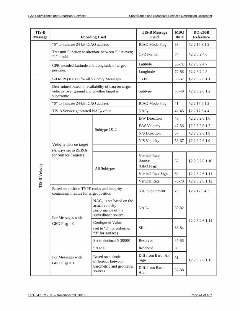
FAA Surveillance and Broadcast Services Surveillance and Broadcast Services Description Document
SRT-047, Rev. 05 – November 20, 2020 Page 41 of 107
TIS-B Message Encoding Used
TIS-B Message Field
MSG Bit #
DO-260B Reference
“0” to indicate 24-bit ICAO address ICAO Mode Flag 53 §2.2.17.3.1.2
Transmit Function to alternate between “0” = even; “1” = odd. CPR Format 54 §2.2.3.2.4.6
CPR encoded Latitude and Longitude of target position.
Latitude 55-71 §2.2.3.2.4.7
Longitude 72-88 §2.2.3.2.4.8
TIS-
B V
eloc
ity
Set to 19 (10011) for all Velocity Messages TYPE 33-37 §2.2.3.2.6.1.1
Determined based on availability of data on target velocity over ground and whether target is supersonic
Subtype 38-40 §2.2.3.2.6.1.2
“0” to indicate 24-bit ICAO address ICAO Mode Flag 41 §2.2.17.3.1.2
TIS-B Service generated NACP value NACP 42-45 §2.2.17.3.4.4
Velocity data on target (Always set to ZEROs for Surface Targets)
Subtype 1& 2
E/W Direction 46 §2.2.3.2.6.1.6
E/W Velocity 47-56 §2.2.3.2.6.1.7
N/S Direction 57 §2.2.3.2.6.1.8
N/S Velocity 58-67 §2.2.3.2.6.1.9
All Subtypes
Vertical Rate Source (GEO Flag)
68 §2.2.3.2.6.1.10
Vertical Rate Sign 69 §2.2.3.2.6.1.11
Vertical Rate 70-78 §2.2.3.2.6.1.12
Based on position TYPE codes and integrity containment radius for target position NIC Supplement 79 §2.2.17.3.4.3
For Messages with GEO Flag = 0
NACV is set based on the actual velocity performance of the surveillance source
NACV 80-82
§2.2.3.2.6.1.14 Configured Value (set to “2” for airborne; “3” for surface)
SIL 83-84
Set to decimal 0 (0000) Reserved 85-88
For Messages with GEO Flag = 1
Set to 0 Reserved 80
§2.2.3.2.6.1.15 Based on altitude difference between barometric and geometric sources
Diff from Baro. Alt Sign 81
Diff. from Baro. Alt. 82-88
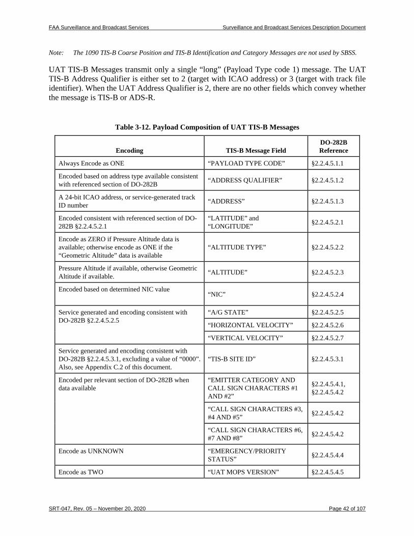
FAA Surveillance and Broadcast Services Surveillance and Broadcast Services Description Document
SRT-047, Rev. 05 – November 20, 2020 Page 42 of 107
Note: The 1090 TIS-B Coarse Position and TIS-B Identification and Category Messages are not used by SBSS.
UAT TIS-B Messages transmit only a single “long” (Payload Type code 1) message. The UAT TIS-B Address Qualifier is either set to 2 (target with ICAO address) or 3 (target with track file identifier). When the UAT Address Qualifier is 2, there are no other fields which convey whether the message is TIS-B or ADS-R.
Table 3-12. Payload Composition of UAT TIS-B Messages
Encoding TIS-B Message Field DO-282B Reference
Always Encode as ONE “PAYLOAD TYPE CODE” §2.2.4.5.1.1
Encoded based on address type available consistent with referenced section of DO-282B “ADDRESS QUALIFIER” §2.2.4.5.1.2
A 24-bit ICAO address, or service-generated track ID number “ADDRESS” §2.2.4.5.1.3
Encoded consistent with referenced section of DO-282B §2.2.4.5.2.1
“LATITUDE” and “LONGITUDE” §2.2.4.5.2.1
Encode as ZERO if Pressure Altitude data is available; otherwise encode as ONE if the “Geometric Altitude” data is available
“ALTITUDE TYPE” §2.2.4.5.2.2
Pressure Altitude if available, otherwise Geometric Altitude if available. “ALTITUDE” §2.2.4.5.2.3
Encoded based on determined NIC value
“NIC” §2.2.4.5.2.4
Service generated and encoding consistent with DO-282B §2.2.4.5.2.5
“A/G STATE” §2.2.4.5.2.5
“HORIZONTAL VELOCITY” §2.2.4.5.2.6
“VERTICAL VELOCITY” §2.2.4.5.2.7
Service generated and encoding consistent with DO-282B §2.2.4.5.3.1, excluding a value of “0000”. Also, see Appendix C.2 of this document.
“TIS-B SITE ID” §2.2.4.5.3.1
Encoded per relevant section of DO-282B when data available
“EMITTER CATEGORY AND CALL SIGN CHARACTERS #1 AND #2”
§2.2.4.5.4.1, §2.2.4.5.4.2
“CALL SIGN CHARACTERS #3, #4 AND #5” §2.2.4.5.4.2
“CALL SIGN CHARACTERS #6, #7 AND #8” §2.2.4.5.4.2
Encode as UNKNOWN “EMERGENCY/PRIORITY STATUS” §2.2.4.5.4.4
Encode as TWO “UAT MOPS VERSION” §2.2.4.5.4.5
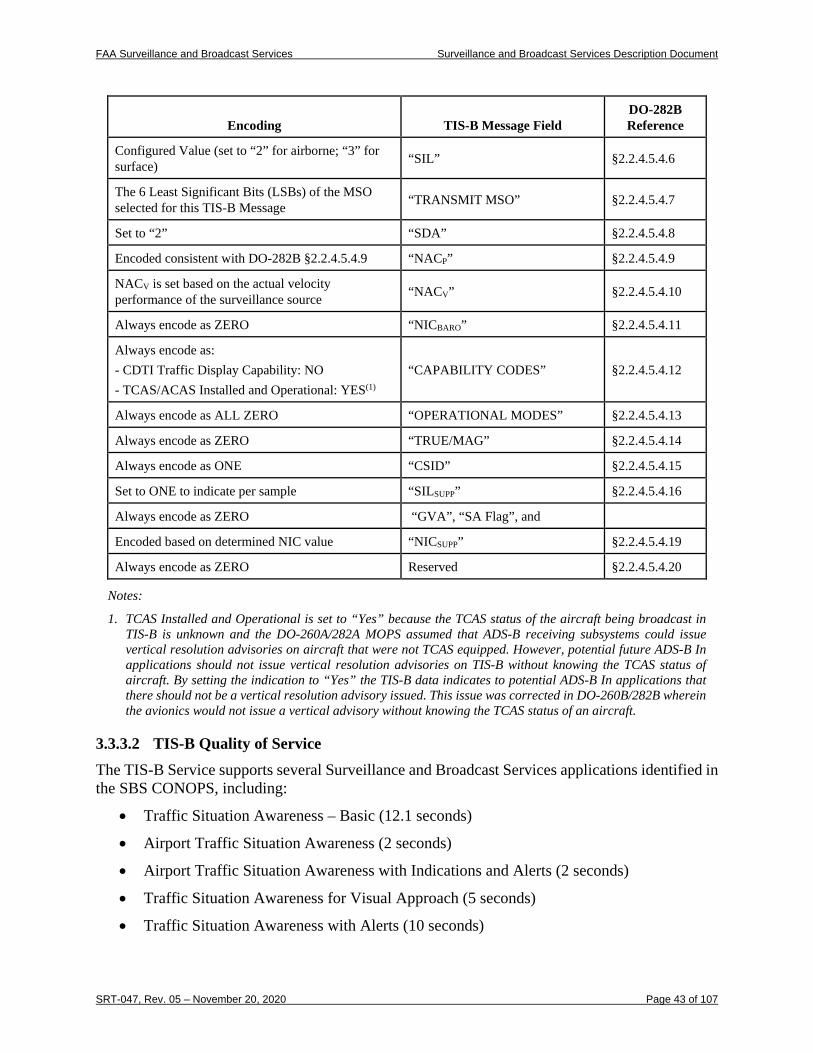
FAA Surveillance and Broadcast Services Surveillance and Broadcast Services Description Document
SRT-047, Rev. 05 – November 20, 2020 Page 43 of 107
Encoding TIS-B Message Field DO-282B Reference
Configured Value (set to “2” for airborne; “3” for surface) “SIL” §2.2.4.5.4.6
The 6 Least Significant Bits (LSBs) of the MSO selected for this TIS-B Message “TRANSMIT MSO” §2.2.4.5.4.7
Set to “2” “SDA” §2.2.4.5.4.8
Encoded consistent with DO-282B §2.2.4.5.4.9 “NACP” §2.2.4.5.4.9
NACV is set based on the actual velocity performance of the surveillance source “NACV” §2.2.4.5.4.10
Always encode as ZERO “NICBARO” §2.2.4.5.4.11
Always encode as: - CDTI Traffic Display Capability: NO - TCAS/ACAS Installed and Operational: YES(1)
“CAPABILITY CODES” §2.2.4.5.4.12
Always encode as ALL ZERO “OPERATIONAL MODES” §2.2.4.5.4.13
Always encode as ZERO “TRUE/MAG” §2.2.4.5.4.14
Always encode as ONE “CSID” §2.2.4.5.4.15
Set to ONE to indicate per sample “SILSUPP” §2.2.4.5.4.16
Always encode as ZERO “GVA”, “SA Flag”, and
Encoded based on determined NIC value “NICSUPP” §2.2.4.5.4.19
Always encode as ZERO Reserved §2.2.4.5.4.20
Notes:
1. TCAS Installed and Operational is set to “Yes” because the TCAS status of the aircraft being broadcast in TIS-B is unknown and the DO-260A/282A MOPS assumed that ADS-B receiving subsystems could issue vertical resolution advisories on aircraft that were not TCAS equipped. However, potential future ADS-B In applications should not issue vertical resolution advisories on TIS-B without knowing the TCAS status of aircraft. By setting the indication to “Yes” the TIS-B data indicates to potential ADS-B In applications that there should not be a vertical resolution advisory issued. This issue was corrected in DO-260B/282B wherein the avionics would not issue a vertical advisory without knowing the TCAS status of an aircraft.
3.3.3.2 TIS-B Quality of Service The TIS-B Service supports several Surveillance and Broadcast Services applications identified in the SBS CONOPS, including:
• Traffic Situation Awareness – Basic (12.1 seconds)
• Airport Traffic Situation Awareness (2 seconds)
• Airport Traffic Situation Awareness with Indications and Alerts (2 seconds)
• Traffic Situation Awareness for Visual Approach (5 seconds)
• Traffic Situation Awareness with Alerts (10 seconds)
FAA Surveillance and Broadcast Services Surveillance and Broadcast Services Description Document
SRT-047, Rev. 05 – November 20, 2020 Page 44 of 107
• Flight-Deck Based Interval Management–Spacing (10 seconds)
• The TIS-B/ADS-R Service Status message will be broadcast such that each client will receive this message with their 24-bit address with an update interval of 20 seconds (95%). The TIS-B/ADS-R Service Status message will only be provided to clients that are eligible for both TIS-B and ADS-R service which requires that the aircraft be within both radar and ADS-B coverage.
3.3.3.2.1 TIS-B Integrity and Accuracy The probability that TIS-B Service introduces any error into a TIS-B Message is less than or equal to 10-5 per Message (equivalent to a System Design Assurance level of 2 – Major). This probability of error includes the linear position extrapolation process using the instantaneous velocity reported for a target. The Source Integrity Level (SIL) is a SBSS-wide configured value and is set to 2 by default. The Navigation Integrity Category (NIC) is computed for TIS-B messages based on the configured SIL value, the target’s NACP (described below), and the containment error ‘tail’ based on radar plot error assumptions. Radar PARROTs and the ASDE-X system will be monitored for faults and excessive biases. The SIL supplement will always be encoded as 1 to indicate that the probability of a TIS-B target exceeding the NIC containment radius is calculated on a per sample basis. Although the SDA and SIL supplement are not transmitted over the 1090ES link, they should be assumed to be the values stated in this document by avionics processors in support of the relevant applications. The NACV in TIS-B messages will be set based on the performance of the surveillance source. TIS-B for surface Multilateration sources will support NACV of 2 on the surface and NACV of 1 on approach. TIS-B for targets detected by Terminal radars will likely support a NACV of 1. TIS-B for targets only detected by En Route radar sources are will likely have a NACV of 0. The altitude included in TIS-B reports is the uncorrected Mode C reported altitude transmitted by the Target. The TIS-B Service computes a NACP, as defined in DO-242A Table 2-3 (excluding the Vertical Estimated Position Uncertainty), for each target at each track state vector update. For the applications supported by TIS-B, Navigation Accuracy Category - Position (NACP) is limited to the horizontal position information. NACP for a TIS-B target is based on the surveillance sources used to derive the target position rather than navigation sources used to supply ADS-B position. Therefore, the derivation of NACP for TIS-B will likely be different from that for ADS-B. For example, the NACP value must include the uncertainty in converting slant range measurements to horizontal position estimates. Track angle and position accuracy in the Surface environment are based upon the accuracy provided by ASDE-X. The TIS-B Service sets the Track Angle to Invalid when the target ground speed drops below a defined threshold (currently set to 11.84 Knots). Ground TIS-B Targets provided by ASDE-X in the Surface domain will typically have a NACP of 9 or better. Airborne targets provided by ASDE-X in the Surface environment will typically have a NACP of 6 or better. In En Route and Terminal environments the track accuracy will meet or exceed the values shown below.
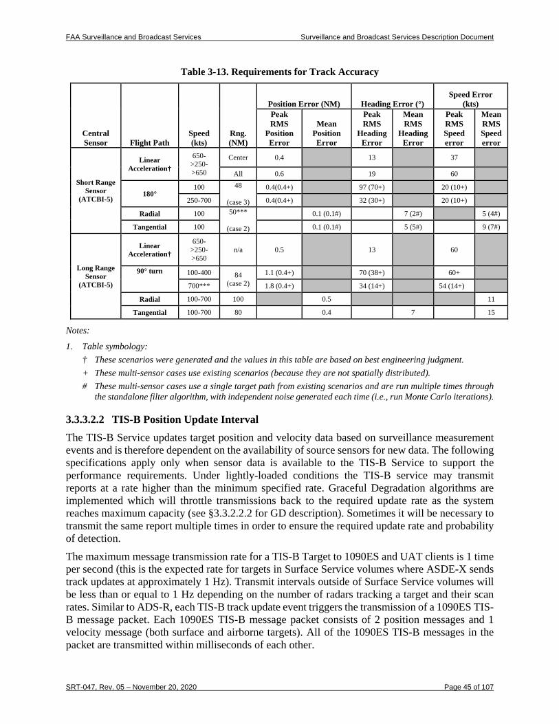
FAA Surveillance and Broadcast Services Surveillance and Broadcast Services Description Document
SRT-047, Rev. 05 – November 20, 2020 Page 45 of 107
Table 3-13. Requirements for Track Accuracy
Central Sensor Flight Path
Speed (kts)
Rng. (NM)
Position Error (NM) Heading Error (°) Speed Error
(kts) Peak RMS
Position Error
Mean Position Error
Peak RMS
Heading Error
Mean RMS
Heading Error
Peak RMS Speed error
Mean RMS Speed error
Short Range Sensor
(ATCBI-5)
Linear Acceleration†
650->250->650
Center 0.4 13 37
All 0.6 19 60
180° 100 48
(case 3)
0.4(0.4+) 97 (70+) 20 (10+)
250-700 0.4(0.4+) 32 (30+) 20 (10+)
Radial 100 50***
(case 2)
0.1 (0.1#) 7 (2#) 5 (4#)
Tangential 100 0.1 (0.1#) 5 (5#) 9 (7#)
Long Range Sensor
(ATCBI-5)
Linear Acceleration†
650- >250- >650
n/a 0.5 13 60
90° turn
100-400 84 (case 2)
1.1 (0.4+) 70 (38+) 60+
700*** 1.8 (0.4+) 34 (14+) 54 (14+)
Radial 100-700 100 0.5 11
Tangential 100-700 80 0.4 7 15
Notes:
1. Table symbology: † These scenarios were generated and the values in this table are based on best engineering judgment. + These multi-sensor cases use existing scenarios (because they are not spatially distributed). # These multi-sensor cases use a single target path from existing scenarios and are run multiple times through
the standalone filter algorithm, with independent noise generated each time (i.e., run Monte Carlo iterations).
3.3.3.2.2 TIS-B Position Update Interval The TIS-B Service updates target position and velocity data based on surveillance measurement events and is therefore dependent on the availability of source sensors for new data. The following specifications apply only when sensor data is available to the TIS-B Service to support the performance requirements. Under lightly-loaded conditions the TIS-B service may transmit reports at a rate higher than the minimum specified rate. Graceful Degradation algorithms are implemented which will throttle transmissions back to the required update rate as the system reaches maximum capacity (see §3.3.2.2.2 for GD description). Sometimes it will be necessary to transmit the same report multiple times in order to ensure the required update rate and probability of detection. The maximum message transmission rate for a TIS-B Target to 1090ES and UAT clients is 1 time per second (this is the expected rate for targets in Surface Service volumes where ASDE-X sends track updates at approximately 1 Hz). Transmit intervals outside of Surface Service volumes will be less than or equal to 1 Hz depending on the number of radars tracking a target and their scan rates. Similar to ADS-R, each TIS-B track update event triggers the transmission of a 1090ES TIS-B message packet. Each 1090ES TIS-B message packet consists of 2 position messages and 1 velocity message (both surface and airborne targets). All of the 1090ES TIS-B messages in the packet are transmitted within milliseconds of each other.
FAA Surveillance and Broadcast Services Surveillance and Broadcast Services Description Document
SRT-047, Rev. 05 – November 20, 2020 Page 46 of 107
The expected minimum power received by UAT avionics is -93 dBm. The TIS-B link margin for UAT clients is expected to be > 11 dB for the majority of the NAS airspace. The expected minimum power received by 1090 avionics is -79 dBm in low interference environments and -72 dBm in high interference environments. The TIS-B link margin for 1090ES clients is expected to be > 5 dB for the majority of the NAS airspace.
3.3.3.2.2.1 Surface Update Interval The TIS-B Service transmits the number of TIS-B Messages necessary to meet an update interval of no greater than 2 seconds (95%) for each client aircraft for all traffic within 5 NM and within ±2000 feet of each client within the Surface Service Volume.
3.3.3.2.2.2 Terminal Update Interval The TIS-B Service transmits the number of TIS-B Messages necessary to meet an update interval of no greater than 6 seconds (95%) for each client aircraft for all traffic within 15 NM and within ±3500 feet of each client within the Terminal Service Volume. Airborne TIS-B targets in a Surface SV will also be provided to those in a Terminal SV. However, ground state targets will not be provided to clients in Terminal SVs.
3.3.3.2.2.3 En Route Update Interval The TIS-B Service transmits the number of TIS-B Messages necessary to meet an update interval of no greater than 12.1 seconds (95%) for each client aircraft for all traffic within 15 NM and within ±3500 feet of each client within the En Route Service Volume.
3.3.3.2.3 TIS-B Latency The latency for TIS-B Service processing of TIS-B data is less than 1.5 seconds as measured from the FAA Surveillance SDP (for surveillance data to the Service Provider) to the start of the TIS-B Message transmission. This SDP to TIS-B transmission latency is compensated in the TIS-B horizontal position by linearly extrapolating to the time of transmission. Overall end-to-end latency from sensor measurement to start of the TIS-B transmission is less than 3.25 seconds. The Essential Services Specification states: “This requirement applies to services delivered to the airport surface, Terminal airspace and En Route airspace. The TIS-B MASPS allocates 3.25 s from sensor measurement to TIS-B Message transmission. The expected maximum delay associated with getting target measurements from a radar sensor is 1.725 seconds, leaving the balance of time to the TIS-B Service.” Analysis of En Route/Terminal tracker cross-track/along-track errors indicates that the uncompensated latency for these Service Volume types is typically less than 0.5 seconds. For Surface Service Volumes with ASDE-X, the uncompensated latency is less than 0.5 seconds and the maximum total latency for ASDE-X data between aircraft signal transmission and the arrival of the target reports at the SBSS control station is 1.6 seconds.
3.3.3.2.4 TIS-B Service Availability The TIS-B service is a safety-essential service as classified by NAS-RD-2013 for surveillance services. The availability of the TIS-B Service specified in this section is limited to the SBSS. It includes the ADS-B Receive Function but does not include FAA surveillance sensors providing sensor data. The TIS-B Service meets a minimum Availability of 0.999 at SDPs.
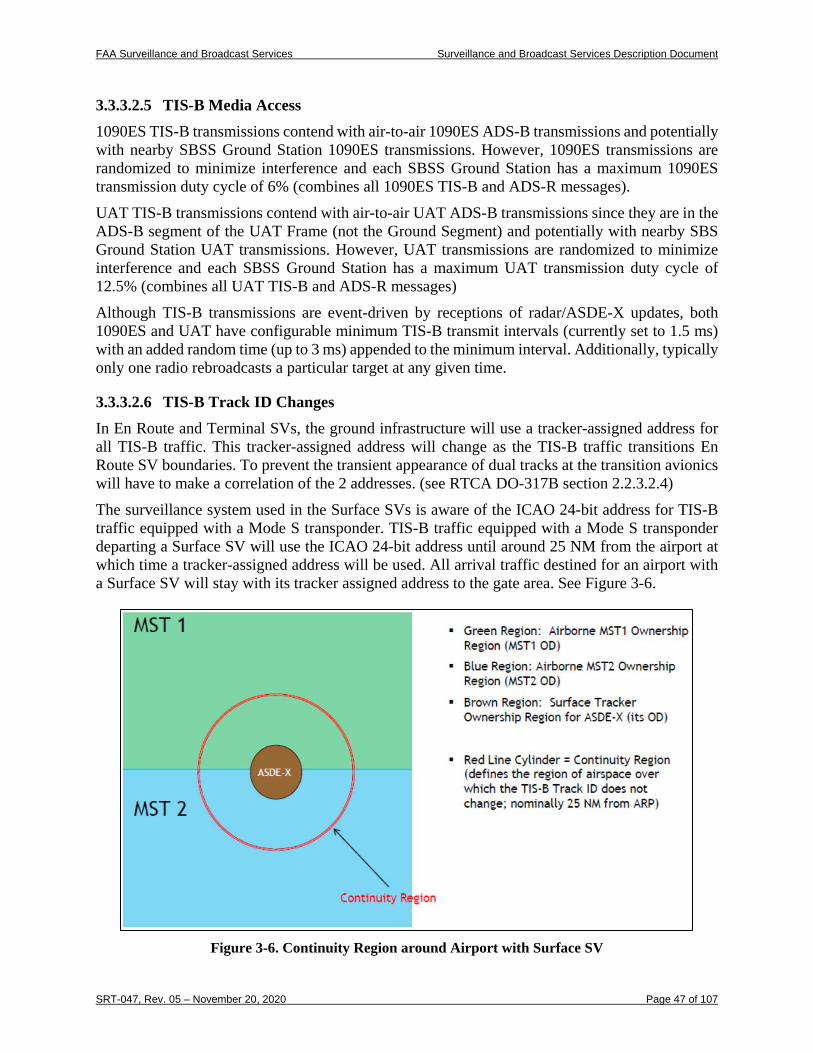
FAA Surveillance and Broadcast Services Surveillance and Broadcast Services Description Document
SRT-047, Rev. 05 – November 20, 2020 Page 47 of 107
3.3.3.2.5 TIS-B Media Access 1090ES TIS-B transmissions contend with air-to-air 1090ES ADS-B transmissions and potentially with nearby SBSS Ground Station 1090ES transmissions. However, 1090ES transmissions are randomized to minimize interference and each SBSS Ground Station has a maximum 1090ES transmission duty cycle of 6% (combines all 1090ES TIS-B and ADS-R messages). UAT TIS-B transmissions contend with air-to-air UAT ADS-B transmissions since they are in the ADS-B segment of the UAT Frame (not the Ground Segment) and potentially with nearby SBS Ground Station UAT transmissions. However, UAT transmissions are randomized to minimize interference and each SBSS Ground Station has a maximum UAT transmission duty cycle of 12.5% (combines all UAT TIS-B and ADS-R messages) Although TIS-B transmissions are event-driven by receptions of radar/ASDE-X updates, both 1090ES and UAT have configurable minimum TIS-B transmit intervals (currently set to 1.5 ms) with an added random time (up to 3 ms) appended to the minimum interval. Additionally, typically only one radio rebroadcasts a particular target at any given time.
3.3.3.2.6 TIS-B Track ID Changes In En Route and Terminal SVs, the ground infrastructure will use a tracker-assigned address for all TIS-B traffic. This tracker-assigned address will change as the TIS-B traffic transitions En Route SV boundaries. To prevent the transient appearance of dual tracks at the transition avionics will have to make a correlation of the 2 addresses. (see RTCA DO-317B section 2.2.3.2.4) The surveillance system used in the Surface SVs is aware of the ICAO 24-bit address for TIS-B traffic equipped with a Mode S transponder. TIS-B traffic equipped with a Mode S transponder departing a Surface SV will use the ICAO 24-bit address until around 25 NM from the airport at which time a tracker-assigned address will be used. All arrival traffic destined for an airport with a Surface SV will stay with its tracker assigned address to the gate area. See Figure 3-6.
Figure 3-6. Continuity Region around Airport with Surface SV
FAA Surveillance and Broadcast Services Surveillance and Broadcast Services Description Document
SRT-047, Rev. 05 – November 20, 2020 Page 48 of 107
3.3.3.2.7 Appearance of TIS-B Dual Traffic Tracks Due to the client-based nature of the TIS-B service, certain TIS-B traffic near an En Route SV border could be uplinked redundantly. This would occur when the same traffic is uplinked separately to clients on each side of the boundary. The most uplink redundancy would occur at a point where 3 separate En Route SV areas come together. In boundary areas it is possible one of the clients could hear multiple uplinks for the same traffic. Each uplink will use a different tracker assigned ID since a different tracker is used on each side of the boundary. To prevent the transient appearance of multiple tracks at the transition, avionics will have to make a correlation of the multiple uplinks (e.g. multiple tracker-assigned addresses). The surface surveillance system will not associate its tracks with ADS-B if the ADS-B installation does not meet the requirements for surface operations6. This will cause the reception of direct ADS-B as well as a TIS-B track for these aircraft. Since departing TIS-B tracks use the 24-bit address as described, the 24-bit address will be identical so avionics can make the correlation using the address. Arriving traffic will have a TIS-B address that is tracker assigned, resulting in different addresses for the ADS-B and TIS-B tracks of the same aircraft. In this case avionics will need to make the correlation spatially. It is possible that individual radar sensors could (for numerous reasons) report a single aircraft as two. The SBSS tracker used for TIS-B has requirements that the dual track rate output is less than 0.1% and that any dual tracks output will be eliminated within 30 seconds.
3.3.3.2.8 Determination of Air-Ground State for TIS-B in Surface Service Volumes A/G state is determined based on a combination of speed and altitude of the traffic. For most traffic, if the speed is >100 knots AND height above the surface is >100 feet the traffic is AIRBORNE; otherwise it is determined to be ON GROUND. If the traffic can be determined to be a rotorcraft, then it will always be reported as AIRBORNE.
Notes: 1. The ON GROUND/AIRBORNE status reported by the Mode S transponder can falsely report the ON GROUND state in some aircraft. For this reason, the above speed and altitude tests are used to determine the ON GROUND/AIRBORNE state for TIS-B in surface SV. 2. The speed and altitude thresholds for the Air-Ground state algorithm are configurable and may be adjusted in the future to better determine aircraft state.
3.3.4 FIS-B Service Messages and Performance FIS-B is an Essential service as defined by the SBS Essential Services Specification. The FIS-B service provides NAS users with accurate, reliable and timely data on weather phenomena occuring in the NAS and non-control aeronautical information regarding the status of NAS systems and resources. The performance that is required in delivering the FIS-B Service is detailed in following paragraphs. FIS-B is advisory in nature, and considered non-binding advice provided to assist in the safe and legal conduct of flight operations. FIS-B is not intended to replace existing voice networks, Flight Service Station services, or usurp any joint duties or responsibilities required by part 121 operators. 6 For ADS-B transmissions to be used by SBSS in Surface SVs, they must meet all the requirements of FAR 91.227
including providing a NACP of 8 or better.
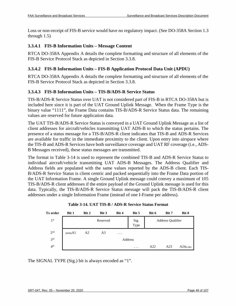
FAA Surveillance and Broadcast Services Surveillance and Broadcast Services Description Document
SRT-047, Rev. 05 – November 20, 2020 Page 49 of 107
Loss or non-receipt of FIS-B service would have no regulatory impact. (See DO-358A Section 1.3 through 1.5)
3.3.4.1 FIS-B Information Units – Message Content RTCA DO-358A Appendix A details the complete formatting and structure of all elements of the FIS-B Service Protocol Stack as depicted in Section 3.3.8.
3.3.4.2 FIS-B Information Units – FIS-B Application Protocol Data Unit (APDU) RTCA DO-358A Appendix A details the complete formatting and structure of all elements of the FIS-B Service Protocol Stack as depicted in Section 3.3.8.
3.3.4.3 FIS-B Information Units – TIS-B/ADS-R Service Status TIS-B/ADS-R Service Status over UAT is not considered part of FIS-B in RTCA DO-358A but is included here since it is part of the UAT Ground Uplink Message. When the Frame Type is the binary value “1111”, the Frame Data contains TIS-B/ADS-R Service Status data. The remaining values are reserved for future application data. The UAT TIS-B/ADS-R Service Status is conveyed in a UAT Ground Uplink Message as a list of client addresses for aircraft/vehicles transmitting UAT ADS-B to which the status pertains. The presence of a status message for a TIS-B/ADS-R client indicates that TIS-B and ADS-R Services are available for traffic in the immediate proximity to the client. Upon entry into airspace where the TIS-B and ADS-R Services have both surveillance coverage and UAT RF coverage (i.e., ADS-B Messages received), these status messages are transmitted. The format in Table 3-14 is used to represent the combined TIS-B and ADS-R Service Status to individual aircraft/vehicle transmitting UAT ADS-B Messages. The Address Qualifier and Address fields are populated with the same values reported by the ADS-B client. Each TIS-B/ADS-R Service Status is client centric and packed sequentially into the Frame Data portion of the UAT Information Frame. A single Ground Uplink message could convey a maximum of 105 TIS-B/ADS-R client addresses if the entire payload of the Ground Uplink message is used for this data. Typically, the TIS-B/ADS-R Service Status message will pack the TIS-B/ADS-R client addresses under a single Information Frame (instead of one I-Frame per address).
Table 3-14. UAT TIS-B / ADS-R Service Status Format
Tx order Bit 1 Bit 2 Bit 3 Bit 4 Bit 5 Bit 6 Bit 7 Bit 8
1st Reserved Sig. Type
Address Qualifier
2nd (MSB)A1 A2 A3 . . .
3rd Address
4th . . . A22 A23 A24(LSB)
The SIGNAL TYPE (Sig.) bit is always encoded as “1”.
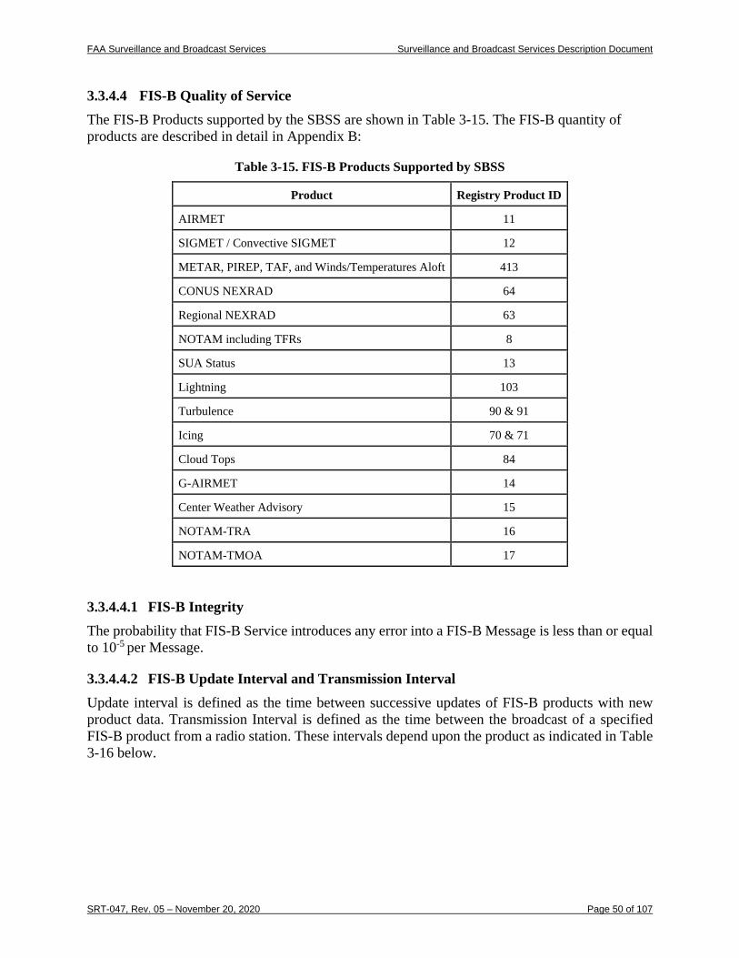
FAA Surveillance and Broadcast Services Surveillance and Broadcast Services Description Document
SRT-047, Rev. 05 – November 20, 2020 Page 50 of 107
3.3.4.4 FIS-B Quality of Service The FIS-B Products supported by the SBSS are shown in Table 3-15. The FIS-B quantity of products are described in detail in Appendix B:
Table 3-15. FIS-B Products Supported by SBSS
Product Registry Product ID
AIRMET 11
SIGMET / Convective SIGMET 12
METAR, PIREP, TAF, and Winds/Temperatures Aloft 413
CONUS NEXRAD 64
Regional NEXRAD 63
NOTAM including TFRs 8
SUA Status 13
Lightning 103
Turbulence 90 & 91
Icing 70 & 71
Cloud Tops 84
G-AIRMET 14
Center Weather Advisory 15
NOTAM-TRA 16
NOTAM-TMOA 17
3.3.4.4.1 FIS-B Integrity The probability that FIS-B Service introduces any error into a FIS-B Message is less than or equal to 10-5 per Message.
3.3.4.4.2 FIS-B Update Interval and Transmission Interval Update interval is defined as the time between successive updates of FIS-B products with new product data. Transmission Interval is defined as the time between the broadcast of a specified FIS-B product from a radio station. These intervals depend upon the product as indicated in Table 3-16 below.
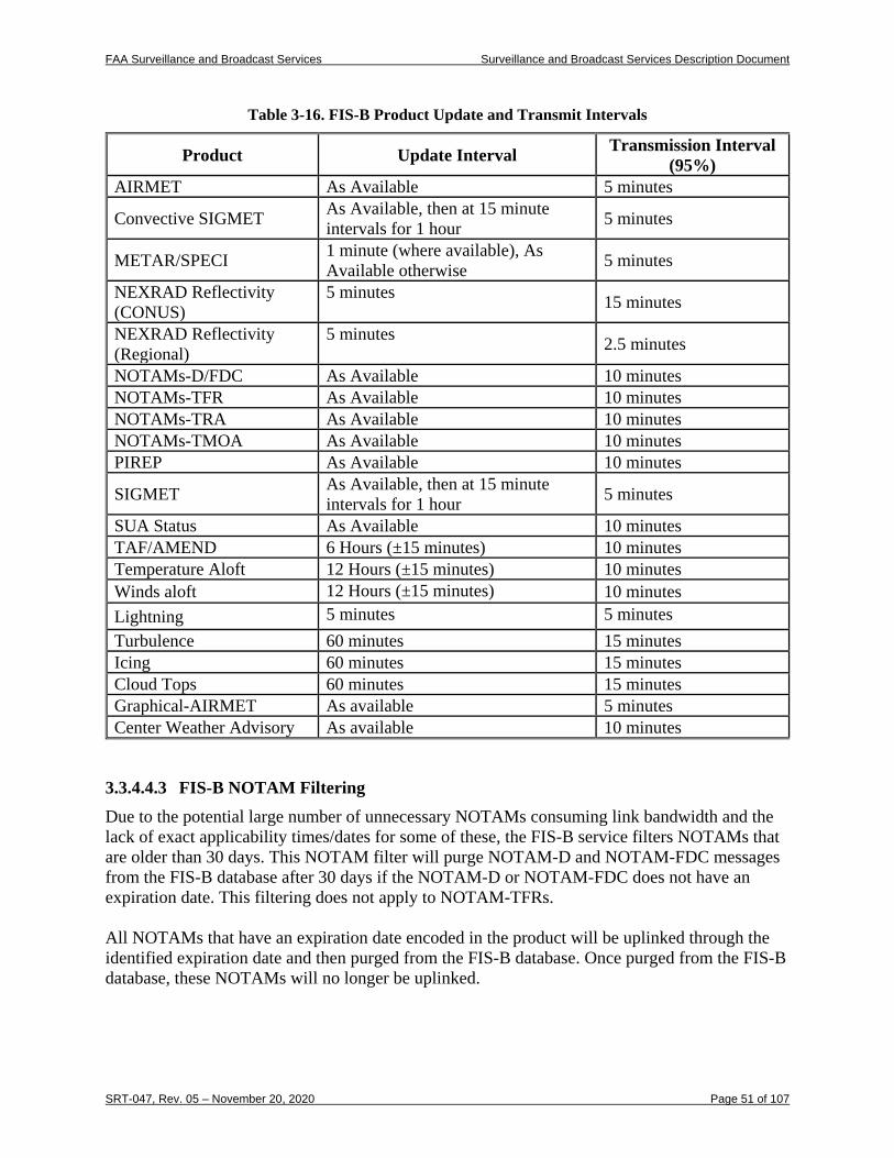
FAA Surveillance and Broadcast Services Surveillance and Broadcast Services Description Document
SRT-047, Rev. 05 – November 20, 2020 Page 51 of 107
Table 3-16. FIS-B Product Update and Transmit Intervals
Product Update Interval Transmission Interval (95%)
AIRMET As Available 5 minutes
Convective SIGMET As Available, then at 15 minute intervals for 1 hour 5 minutes
METAR/SPECI 1 minute (where available), As Available otherwise 5 minutes
NEXRAD Reflectivity (CONUS)
5 minutes 15 minutes
NEXRAD Reflectivity (Regional)
5 minutes 2.5 minutes
NOTAMs-D/FDC As Available 10 minutes NOTAMs-TFR As Available 10 minutes NOTAMs-TRA As Available 10 minutes NOTAMs-TMOA As Available 10 minutes PIREP As Available 10 minutes
SIGMET As Available, then at 15 minute intervals for 1 hour 5 minutes
SUA Status As Available 10 minutes TAF/AMEND 6 Hours (±15 minutes) 10 minutes Temperature Aloft 12 Hours (±15 minutes) 10 minutes Winds aloft 12 Hours (±15 minutes) 10 minutes Lightning 5 minutes 5 minutes Turbulence 60 minutes 15 minutes Icing 60 minutes 15 minutes Cloud Tops 60 minutes 15 minutes Graphical-AIRMET As available 5 minutes Center Weather Advisory As available 10 minutes
3.3.4.4.3 FIS-B NOTAM Filtering Due to the potential large number of unnecessary NOTAMs consuming link bandwidth and the lack of exact applicability times/dates for some of these, the FIS-B service filters NOTAMs that are older than 30 days. This NOTAM filter will purge NOTAM-D and NOTAM-FDC messages from the FIS-B database after 30 days if the NOTAM-D or NOTAM-FDC does not have an expiration date. This filtering does not apply to NOTAM-TFRs. All NOTAMs that have an expiration date encoded in the product will be uplinked through the identified expiration date and then purged from the FIS-B database. Once purged from the FIS-B database, these NOTAMs will no longer be uplinked.
FAA Surveillance and Broadcast Services Surveillance and Broadcast Services Description Document
SRT-047, Rev. 05 – November 20, 2020 Page 52 of 107
3.3.4.4.4 FIS-B Service Availability The FIS-B service is a safety-essential service as classified by NAS-RD-2013 for surveillance services. The service availability reflects the availability of each individual FIS-B product being processed and broadcast to users in each designated Service Volume. The availability does not include product source data or the systems providing these data. The FIS-B Service meets a minimum Availability of 0.999. The FIS-B Service will notify aircraft/vehicles of a FIS-B Service outage in a Service Volume within 30 seconds of the outage occurrence (via a NOTAM) and continue to provide the notification until service is returned (assuming the communications link is still intact). Requirements in the RTCA DO-358A accommodate lost link conditions. Service availability does not apply to outages that may occur on individual aircraft or to individual product sources.
3.3.4.4.5 FIS-B Media Access See RTCA DO-358A Appendix G for details on the media access approach used by UAT ground stations.
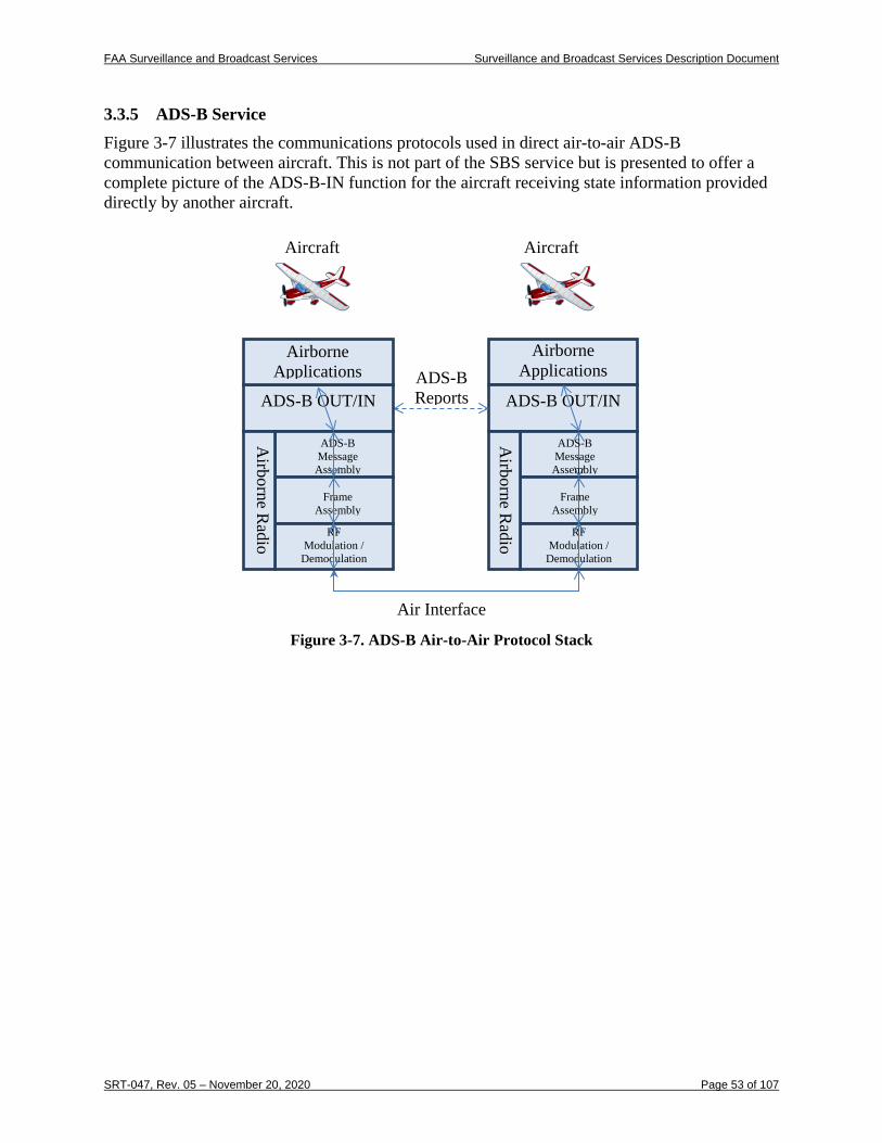
FAA Surveillance and Broadcast Services Surveillance and Broadcast Services Description Document
SRT-047, Rev. 05 – November 20, 2020 Page 53 of 107
3.3.5 ADS-B Service Figure 3-7 illustrates the communications protocols used in direct air-to-air ADS-B communication between aircraft. This is not part of the SBS service but is presented to offer a complete picture of the ADS-B-IN function for the aircraft receiving state information provided directly by another aircraft.
Figure 3-7. ADS-B Air-to-Air Protocol Stack
Airborne Applications ADS-B
Reports ADS-B OUT/IN
Airborne R
adio
RF Modulation /
Demodulation
Aircraft Aircraft
Air Interface
Frame Assembly
ADS-B Message
Assembly
ADS-B OUT/IN
Airborne R
adio
RF Modulation /
Demodulation
Frame Assembly
ADS-B Message Assembly
Airborne Applications
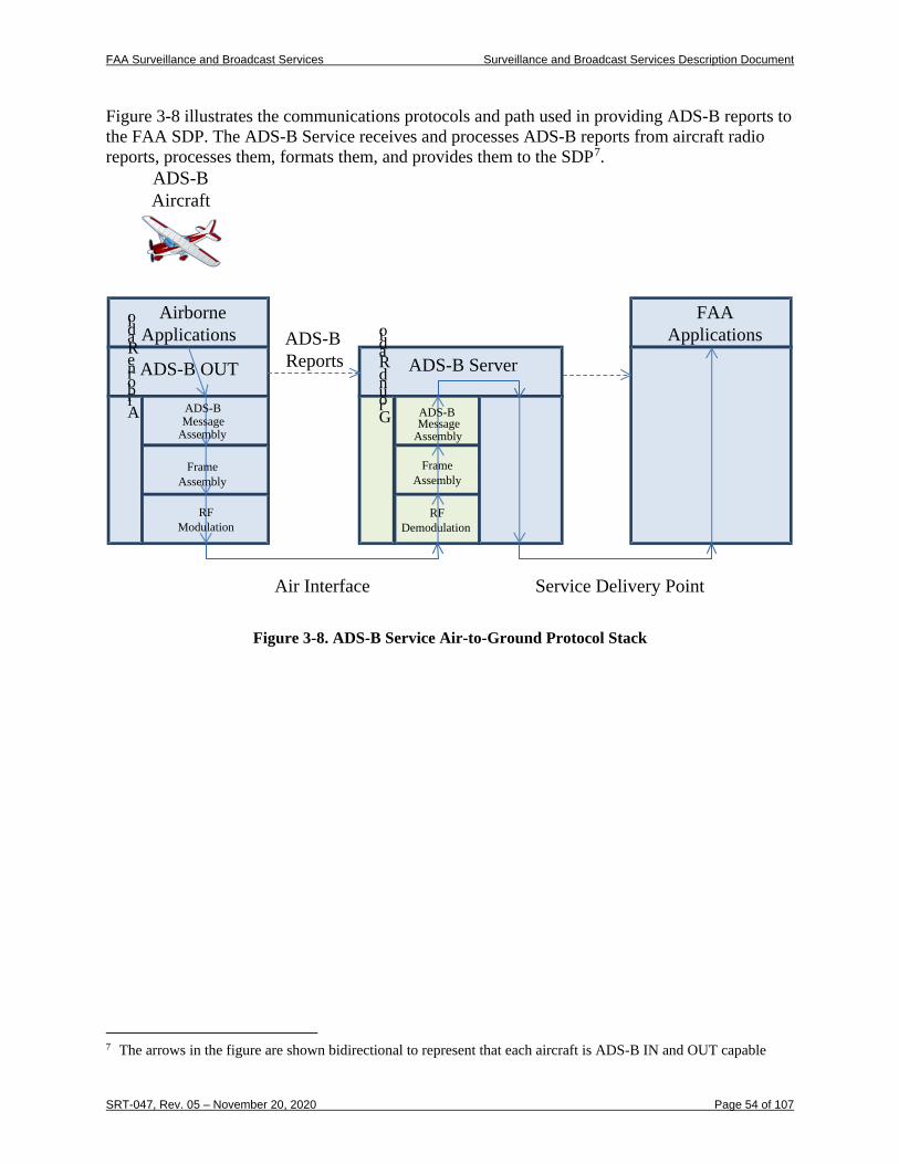
FAA Surveillance and Broadcast Services Surveillance and Broadcast Services Description Document
SRT-047, Rev. 05 – November 20, 2020 Page 54 of 107
Figure 3-8 illustrates the communications protocols and path used in providing ADS-B reports to the FAA SDP. The ADS-B Service receives and processes ADS-B reports from aircraft radio reports, processes them, formats them, and provides them to the SDP7.
Air Interface
RF Demodulation
ADS-B Server
Airborne Applications
ADS-B OUT
Ground Radio
Airborne Radio
ADS-BAircraft
ADS-BMessage
Assembly
Frame Assembly
ADS-BMessage
Assembly
Frame Assembly
RF Modulation
FAA Applications
Service Delivery Point
ADS-BReports
Figure 3-8. ADS-B Service Air-to-Ground Protocol Stack
7 The arrows in the figure are shown bidirectional to represent that each aircraft is ADS-B IN and OUT capable
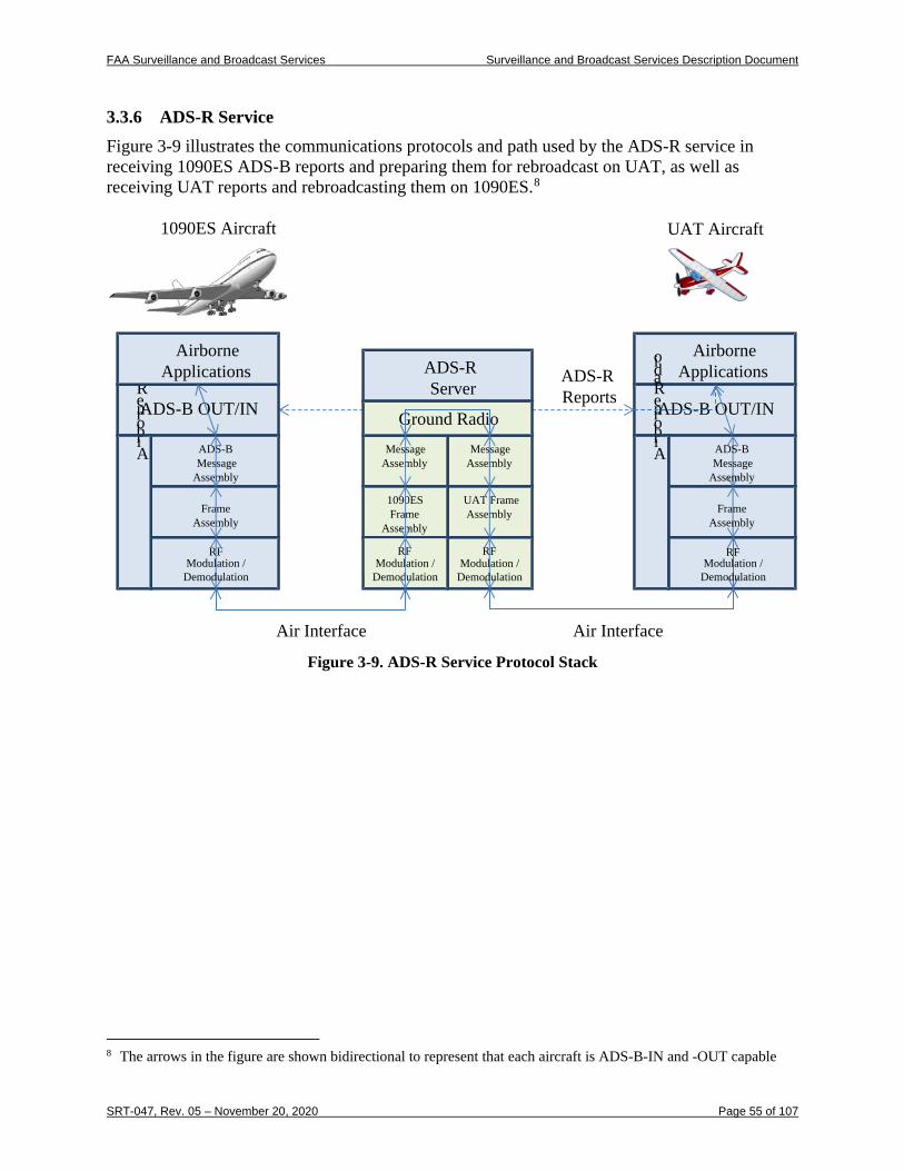
FAA Surveillance and Broadcast Services Surveillance and Broadcast Services Description Document
SRT-047, Rev. 05 – November 20, 2020 Page 55 of 107
3.3.6 ADS-R Service Figure 3-9 illustrates the communications protocols and path used by the ADS-R service in receiving 1090ES ADS-B reports and preparing them for rebroadcast on UAT, as well as receiving UAT reports and rebroadcasting them on 1090ES.8
RF
ADS-RServer
Airborne ApplicationsADS-R
ReportsADS-B OUT/IN
Airborne Radio
RF
1090ES Aircraft UAT Aircraft
Air Interface
Message Assembly
UAT Frame Assembly Frame
Assembly
ADS-BMessage
Assembly
ADS-B OUT/IN
Airborne Radio
RF
Frame Assembly
ADS-BMessage
Assembly
RF Modulation /
Demodulation
Message Assembly
1090ES Frame
Assembly
Ground Radio
Airborne Applications
Air Interface
Modulation / Demodulation
Modulation / Demodulation
Modulation / Demodulation
Figure 3-9. ADS-R Service Protocol Stack
8 The arrows in the figure are shown bidirectional to represent that each aircraft is ADS-B-IN and -OUT capable
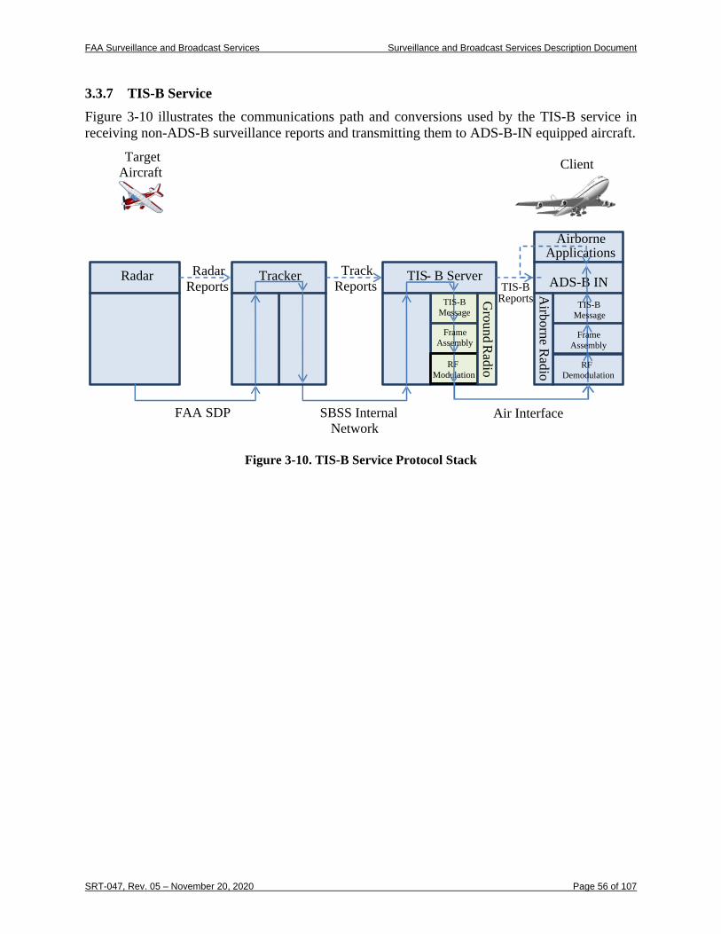
FAA Surveillance and Broadcast Services Surveillance and Broadcast Services Description Document
SRT-047, Rev. 05 – November 20, 2020 Page 56 of 107
3.3.7 TIS-B Service Figure 3-10 illustrates the communications path and conversions used by the TIS-B service in receiving non-ADS-B surveillance reports and transmitting them to ADS-B-IN equipped aircraft.
Figure 3-10. TIS-B Service Protocol Stack
RF Modulation
TIS- B Server
Airborne Applications
Tracker
Track Reports TIS-B
Reports
Radar Reports
Radar ADS-B IN
Ground R
adio
Airborne R
adio
Target Aircraft Client
Aircraft
FAA SDP SBSS Internal Network
Air Interface
TIS-BMessage
Frame Assembly Frame
Assembly
TIS-BMessage
RF Demodulation
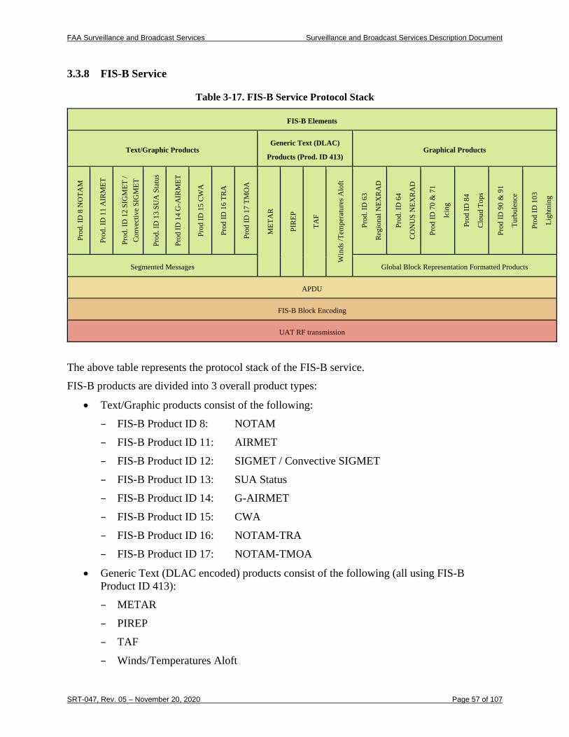
FAA Surveillance and Broadcast Services Surveillance and Broadcast Services Description Document
SRT-047, Rev. 05 – November 20, 2020 Page 57 of 107
3.3.8 FIS-B Service
Table 3-17. FIS-B Service Protocol Stack
FIS-B Elements
Text/Graphic Products Generic Text (DLAC)
Products (Prod. ID 413) Graphical Products
Prod
. ID
8 N
OTA
M
Prod
. ID
11
AIR
MET
Prod
. ID
12
SIG
MET
/ C
onve
ctiv
e SI
GM
ET
Prod
. ID
13
SUA
Sta
tus
Prod
ID 1
4 G
-AIR
MET
Prod
ID 1
5 C
WA
Prod
ID 1
6 TR
A
Prod
ID 1
7 TM
OA
MET
AR
PIR
EP
TAF
Win
ds /T
empe
ratu
res A
loft
Prod
. ID
63
Reg
iona
l NEX
RA
D
Prod
. ID
64
CO
NU
S N
EXR
AD
Prod
ID 7
0 &
71
Icin
g
Prod
ID 8
4
Clo
ud T
ops
Prod
ID 9
0 &
91
Turb
ulen
ce
Prod
ID 1
03
Ligh
tnin
g
Segmented Messages Global Block Representation Formatted Products
APDU
FIS-B Block Encoding
UAT RF transmission
The above table represents the protocol stack of the FIS-B service. FIS-B products are divided into 3 overall product types:
• Text/Graphic products consist of the following:
– FIS-B Product ID 8: NOTAM
– FIS-B Product ID 11: AIRMET
– FIS-B Product ID 12: SIGMET / Convective SIGMET
– FIS-B Product ID 13: SUA Status
– FIS-B Product ID 14: G-AIRMET
– FIS-B Product ID 15: CWA
– FIS-B Product ID 16: NOTAM-TRA
– FIS-B Product ID 17: NOTAM-TMOA
• Generic Text (DLAC encoded) products consist of the following (all using FIS-B Product ID 413):
– METAR
– PIREP
– TAF
– Winds/Temperatures Aloft
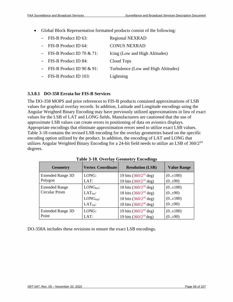
FAA Surveillance and Broadcast Services Surveillance and Broadcast Services Description Document
SRT-047, Rev. 05 – November 20, 2020 Page 58 of 107
• Global Block Representation formatted products consist of the following:
– FIS-B Product ID 63: Regional NEXRAD
– FIS-B Product ID 64: CONUS NEXRAD
– FIS-B Product ID 70 & 71: Icing (Low and High Altitudes)
– FIS-B Product ID 84: Cloud Tops
– FIS-B Product ID 90 & 91: Turbulence (Low and High Altitudes)
– FIS-B Product ID 103: Lightning
3.3.8.1 DO-358 Errata for FIS-B Services The DO-358 MOPS and prior references to FIS-B products contained approximations of LSB values for graphical overlay records. In addition, Latitude and Longitude encodings using the Angular Weighted Binary Encoding may have previously utilized approximations in lieu of exact values for the LSB of LAT and LONG fields. Manufacturers are cautioned that the use of approximate LSB values can create errors in positioning of data on avionics displays. Appropriate encodings that eliminate approximation errors need to utilize exact LSB values. Table 3-18 contains the revised LSB encoding for the overlay geometries based on the specific encoding option utilized by the product. In addition, the encoding of LAT and LONG that utilizes Angular Weighted Binary Encoding for a 24-bit field needs to utilize an LSB of 360/224 degrees.
Table 3-18. Overlay Geometry Encodings
Geometry Vertex Coordinate Resolution (LSB) Value Range
Extended Range 3D Polygon
LONG: LAT:
19 bits (360/219 deg) 19 bits (360/219 deg)
(0..±180) (0..±90)
Extended Range Circular Prism
LONGbot: LATbot: LONGtop: LATtop:
18 bits (360/218 deg) 18 bits (360/21 8 deg) 18 bits (360/21 8 deg) 18 bits (360/218 deg)
(0..±180) (0..±90) (0..±180) (0..±90)
Extended Range 3D Point
LONG: LAT:
19 bits (360/219 deg) 19 bits (360/219 deg)
(0..±180) (0..±90)
DO-358A includes these revisions to ensure the exact LSB encodings.
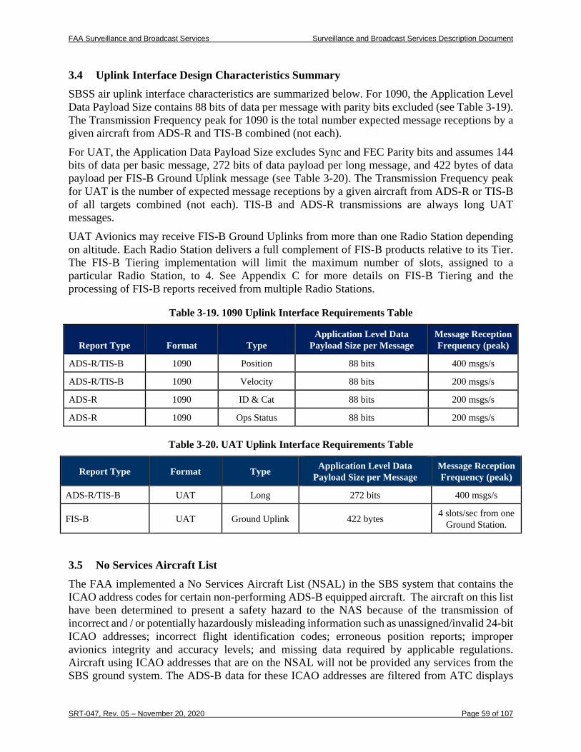
FAA Surveillance and Broadcast Services Surveillance and Broadcast Services Description Document
SRT-047, Rev. 05 – November 20, 2020 Page 59 of 107
3.4 Uplink Interface Design Characteristics Summary SBSS air uplink interface characteristics are summarized below. For 1090, the Application Level Data Payload Size contains 88 bits of data per message with parity bits excluded (see Table 3-19). The Transmission Frequency peak for 1090 is the total number expected message receptions by a given aircraft from ADS-R and TIS-B combined (not each). For UAT, the Application Data Payload Size excludes Sync and FEC Parity bits and assumes 144 bits of data per basic message, 272 bits of data payload per long message, and 422 bytes of data payload per FIS-B Ground Uplink message (see Table 3-20). The Transmission Frequency peak for UAT is the number of expected message receptions by a given aircraft from ADS-R or TIS-B of all targets combined (not each). TIS-B and ADS-R transmissions are always long UAT messages. UAT Avionics may receive FIS-B Ground Uplinks from more than one Radio Station depending on altitude. Each Radio Station delivers a full complement of FIS-B products relative to its Tier. The FIS-B Tiering implementation will limit the maximum number of slots, assigned to a particular Radio Station, to 4. See Appendix C for more details on FIS-B Tiering and the processing of FIS-B reports received from multiple Radio Stations.
Table 3-19. 1090 Uplink Interface Requirements Table
Report Type Format Type Application Level Data
Payload Size per Message Message Reception Frequency (peak)
ADS-R/TIS-B 1090 Position 88 bits 400 msgs/s
ADS-R/TIS-B 1090 Velocity 88 bits 200 msgs/s
ADS-R 1090 ID & Cat 88 bits 200 msgs/s
ADS-R 1090 Ops Status 88 bits 200 msgs/s
Table 3-20. UAT Uplink Interface Requirements Table
Report Type Format Type Application Level Data Payload Size per Message
Message Reception Frequency (peak)
ADS-R/TIS-B UAT Long 272 bits 400 msgs/s
FIS-B UAT Ground Uplink 422 bytes 4 slots/sec from one Ground Station.
3.5 No Services Aircraft List The FAA implemented a No Services Aircraft List (NSAL) in the SBS system that contains the ICAO address codes for certain non-performing ADS-B equipped aircraft. The aircraft on this list have been determined to present a safety hazard to the NAS because of the transmission of incorrect and / or potentially hazardously misleading information such as unassigned/invalid 24-bit ICAO addresses; incorrect flight identification codes; erroneous position reports; improper avionics integrity and accuracy levels; and missing data required by applicable regulations. Aircraft using ICAO addresses that are on the NSAL will not be provided any services from the SBS ground system. The ADS-B data for these ICAO addresses are filtered from ATC displays
FAA Surveillance and Broadcast Services Surveillance and Broadcast Services Description Document
SRT-047, Rev. 05 – November 20, 2020 Page 60 of 107
and are not utilized for providing any air traffic services. Aircraft using an ICAO address on the NSAL are also ineligible to receive uplink traffic services through ADS-R, TIS-B, and ADS-R SLR. For more information, refer to the federal register notice on the NSAL implementation at: https://www.federalregister.gov/documents/2017/12/20/2017-27202/change-to-automatic-dependent-surveillance-broadcast-services.
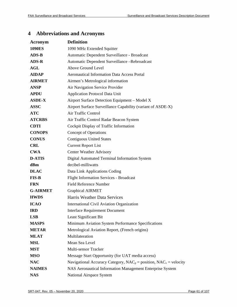
FAA Surveillance and Broadcast Services Surveillance and Broadcast Services Description Document
SRT-047, Rev. 05 – November 20, 2020 Page 61 of 107
4 Abbreviations and Acronyms Acronym Definition 1090ES 1090 MHz Extended Squitter ADS-B Automatic Dependent Surveillance - Broadcast ADS-R Automatic Dependent Surveillance –Rebroadcast AGL Above Ground Level AIDAP Aeronautical Information Data Access Portal AIRMET Airmen’s Metrological information ANSP Air Navigation Service Provider APDU Application Protocol Data Unit ASDE-X Airport Surface Detection Equipment – Model X ASSC Airport Surface Surveillance Capability (variant of ASDE-X) ATC Air Traffic Control ATCRBS Air Traffic Control Radar Beacon System CDTI Cockpit Display of Traffic Information CONOPS Concept of Operations CONUS Contiguous United States CRL Current Report List CWA Center Weather Advisory D-ATIS Digital Automated Terminal Information System dBm decibel-milliwatts DLAC Data Link Applications Coding FIS-B Flight Information Services - Broadcast FRN Field Reference Number G-AIRMET Graphical AIRMET HWDS Harris Weather Data Services ICAO International Civil Aviation Organization IRD Interface Requirement Document LSB Least Significant Bit MASPS Minimum Aviation System Performance Specifications METAR Metrological Aviation Report, (French origins) MLAT Multilateration MSL Mean Sea Level MST Multi-sensor Tracker MSO Message Start Opportunity (for UAT media access) NAC Navigational Accuracy Category, NACp = position, NACv = velocity NAIMES NAS Aeronautical Information Management Enterprise System NAS National Airspace System
FAA Surveillance and Broadcast Services Surveillance and Broadcast Services Description Document
SRT-047, Rev. 05 – November 20, 2020 Page 62 of 107
Acronym Definition NEXRAD Next Generation Weather Radar NIC Navigation Integrity Category NM Nautical Mile NOAA National Oceanic and Atmospheric Administration NOTAM Notices to Airmen NSAL No Services Aircraft List NWS National Weather Service OMO One Minute Observations PIREP Pilot Reports as defined in FAA Order 7110 RF Radio Frequency RS Radio Station SBS Surveillance and Broadcast Services (FAA program, program documents, services,
service volumes or applications) SBSS Surveillance and Broadcast Services System (the implementation) SDP Service Delivery Points SIGMET Significant Metrological Information SIL Source Integrity Level SLR Same Link Rebroadcast SSR Secondary Surveillance Radar SUA Special Use Airspace SV Service Volume TAF Terminal Aerodrome (Airport) Forecast TFR Temporary Flight Restriction TIS-B Traffic Information Services - Broadcast TMOA Temporary Military Operations Areas TRA Temporary Restricted Areas UAT Universal Access Transceiver UTC Coordinated Universal Time Z Zulu time, Coordinated Universal Time
FAA Surveillance and Broadcast Services Surveillance and Broadcast Services Description Document
SRT-047, Rev. 05 – November 20, 2020 Page 63 of 107
Appendix A. Coverage Maps and Radio Stations
A.1 Current Coverage A final end state coverage chart that includes the coverage provided by all radios currently deployed in the NAS is provided at the FAA’s NextGen website located at the following url: https://www.faa.gov/nextgen/programs/adsb/ICM/
A.2 Radio Station Locations The radio station locations and other information on the SBS deployed radio network is available at the following url: https://www.faa.gov/foia/electronic_reading_room/media/ADS-B_Ground_Stations_as_of_08-31-2018.pdf
FAA Surveillance and Broadcast Services Surveillance and Broadcast Services Description Document
SRT-047, Rev. 05 – November 20, 2020 Page 64 of 107
Appendix B. FIS-B Quantity of Available Products and Other Aspects
B.1 FIS-B Quantity of Available Products The following subsections will describe the typical quantity of products which are available within the NAS for each of the current FIS-B products. Note that among this quantity of available product data, the subset of product data which is transmitted from a ground station is a function of the look-ahead range (Table C-3 and Table C-4) for each particular FIS-B product. Each of the below products are described in more detail in RTCA DO-358A Appendix A
B.1.1 SIGMET / Convective SIGMET SIGMET / Convective SIGMETs are issued on as as-needed basis, and thus do not have a finite quantity of products. The SIGMET / Convective SIGMETs which are broadcast by FIS-B include all valid SIGMET / Convective SIGMETs (within the applicable look-ahead range).
B.1.2 AIRMET AIRMETs are issued on as as-needed basis, and thus do not have a finite quantity of products. The AIRMETs which are broadcast by FIS-B include all valid AIRMETs (within the applicable look-ahead range).
B.1.3 METAR Appendix E of this document lists the domestic U.S. METAR locations that are currently uplinked by SBSS. This is the current SBSS adapted set of METAR stations being uplinked. This list will be updated periodically as new METAR sites are commissioned or other changes are implemented for METAR stations.
B.1.4 CONUS NEXRAD See RTCA DO-358A Appendix E for background on the source and details of the CONUS NEXRAD. RTCA DO-358A Appendix I provides information on the uplink timing. B.1.5 Regional NEXRAD See RTCA DO-358A Appendix E for background on the source and details of the Regional NEXRAD. RTCA DO-358A Appendix I provides information on the uplink timing.
B.1.6 NOTAM NOTAMs are issued on as as-needed basis, and thus do not have a finite quantity of products.
B.1.7 PIREP PIREPs are issued on as as-needed basis, and thus do not have a finite quantity of products.
B.1.8 SUA Status SUA Status is issued on as as-needed basis, and thus does not have a finite quantity of products. The SUA Status products which are broadcast by FIS-B include the status of SUA within the applicable look-ahead range. FIS-B only broadcasts the SUA Status as a text product and does not
FAA Surveillance and Broadcast Services Surveillance and Broadcast Services Description Document
SRT-047, Rev. 05 – November 20, 2020 Page 65 of 107
broadcast the SUA Status graphic overlay. SUAs uplinked are the set of currently active SUAs or those SUAs expected to be active within the next 24 hours. This set is then geographically filtered for each RS.
Note: SUA Status reports are also uplinked as D-NOTAMS. The FIS-B MOPS recommends that avionics process SUA status information from D-NOTAMS in lieu of this product to avoid confusion or conflicting information concerning SUA Status. The SUA product range is limited to 5 NM and this product will likely be eliminated in the future since the same information is available through a D-NOTAM.
B.1.9 TAF Appendix E of this document lists the domestic U.S. TAF locations that are currently uplinked by SBSS. This is the current SBSS adapted set of TAF stations being uplinked. This list will be updated periodically if TAF sites change. B.1.10 Winds and Temperatures Aloft The locations for Winds and Temperatures Aloft forecast reporting are shown in Figure B-1. There are a total of 233 U.S. Winds and Temperatures Aloft forecast locations from the National Weather Service as of October 25, 2016 (including CONUS, Alaska, Hawaii, Pacific Ocean, Atlantic Ocean, and Gulf of Mexico). Note that there are no Winds and Temperature Aloft forecasts produced for Puerto Rico and the U.S Virgin Islands. The Winds and Temperatures Aloft forecast locations are available from Aviation Weather Services products provided by the National Weather Service (https://www.nws.noaa.gov/directives/010/010.php). The current list of forecast locations are available at: https://www.nws.noaa.gov/directives/sym/pd01008012curr.pdf.
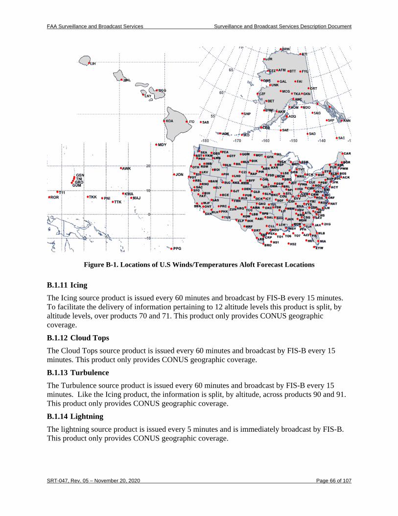
FAA Surveillance and Broadcast Services Surveillance and Broadcast Services Description Document
SRT-047, Rev. 05 – November 20, 2020 Page 66 of 107
Figure B-1. Locations of U.S Winds/Temperatures Aloft Forecast Locations
B.1.11 Icing The Icing source product is issued every 60 minutes and broadcast by FIS-B every 15 minutes. To facilitate the delivery of information pertaining to 12 altitude levels this product is split, by altitude levels, over products 70 and 71. This product only provides CONUS geographic coverage.
B.1.12 Cloud Tops The Cloud Tops source product is issued every 60 minutes and broadcast by FIS-B every 15 minutes. This product only provides CONUS geographic coverage.
B.1.13 Turbulence The Turbulence source product is issued every 60 minutes and broadcast by FIS-B every 15 minutes. Like the Icing product, the information is split, by altitude, across products 90 and 91. This product only provides CONUS geographic coverage.
B.1.14 Lightning The lightning source product is issued every 5 minutes and is immediately broadcast by FIS-B. This product only provides CONUS geographic coverage.
FAA Surveillance and Broadcast Services Surveillance and Broadcast Services Description Document
SRT-047, Rev. 05 – November 20, 2020 Page 67 of 107
B.1.15 G-AIRMET G-AIRMETs are issued on an as-needed basis and, thus, does not have a finite quantity of products. The G-AIRMETs which are broadcast by FIS-B include all valid G-AIRMETs (within the applicable look-ahead range). It is anticipated that the G-AIRMET product will replace the AIRMET product in the future.
B.1.16 Center Weather Advisory CWAs are issued on an as-needed basis and, thus, does not have a finite quantity of products. The CWAs which are broadcast by FIS-B include all valid CWAs (within the applicable look-ahead range).
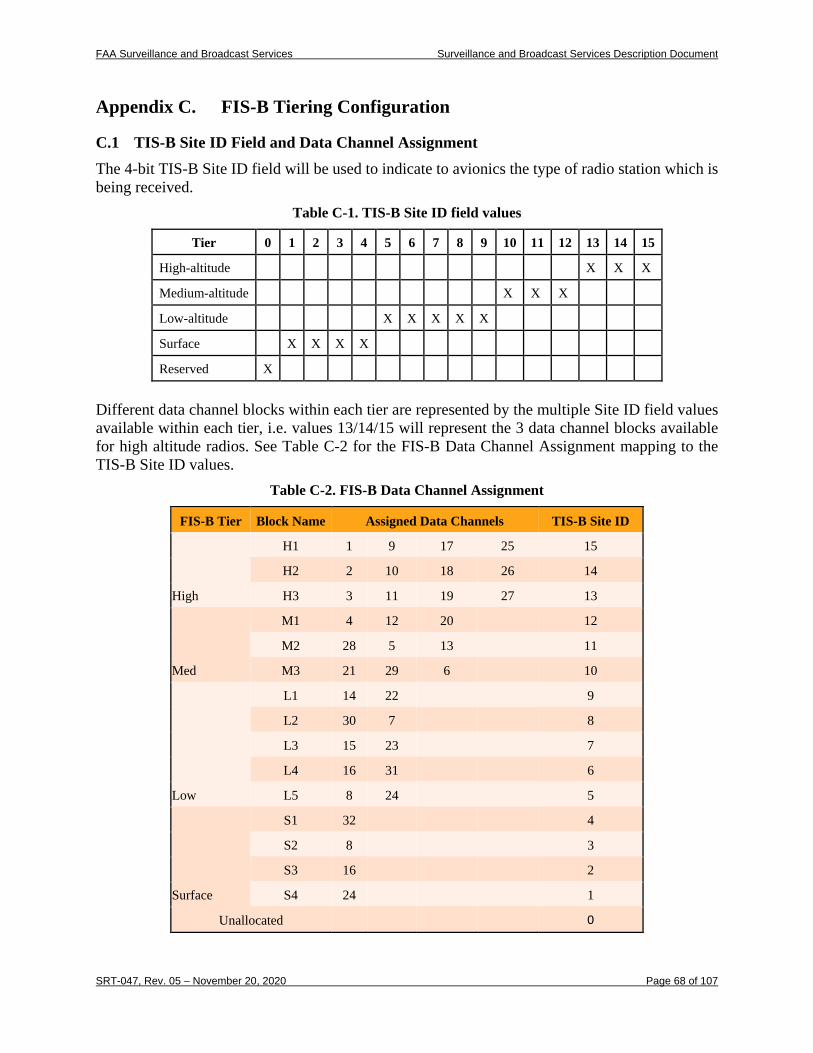
FAA Surveillance and Broadcast Services Surveillance and Broadcast Services Description Document
SRT-047, Rev. 05 – November 20, 2020 Page 68 of 107
Appendix C. FIS-B Tiering Configuration
C.1 TIS-B Site ID Field and Data Channel Assignment The 4-bit TIS-B Site ID field will be used to indicate to avionics the type of radio station which is being received.
Table C-1. TIS-B Site ID field values
Tier 0 1 2 3 4 5 6 7 8 9 10 11 12 13 14 15
High-altitude X X X
Medium-altitude X X X
Low-altitude X X X X X
Surface X X X X
Reserved X
Different data channel blocks within each tier are represented by the multiple Site ID field values available within each tier, i.e. values 13/14/15 will represent the 3 data channel blocks available for high altitude radios. See Table C-2 for the FIS-B Data Channel Assignment mapping to the TIS-B Site ID values.
Table C-2. FIS-B Data Channel Assignment
FIS-B Tier Block Name Assigned Data Channels TIS-B Site ID
High
H1 1 9 17 25 15
H2 2 10 18 26 14
H3 3 11 19 27 13
Med
M1 4 12 20 12
M2 28 5 13 11
M3 21 29 6 10
Low
L1 14 22 9
L2 30 7 8
L3 15 23 7
L4 16 31 6
L5 8 24 5
Surface
S1 32 4
S2 8 3
S3 16 2
S4 24 1
Unallocated 0
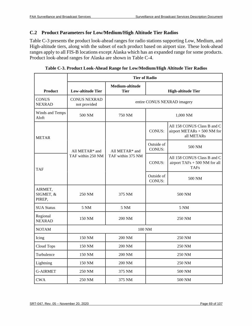
FAA Surveillance and Broadcast Services Surveillance and Broadcast Services Description Document
SRT-047, Rev. 05 – November 20, 2020 Page 69 of 107
C.2 Product Parameters for Low/Medium/High Altitude Tier Radios Table C-3 presents the product look-ahead ranges for radio stations supporting Low, Medium, and High-altitude tiers, along with the subset of each product based on airport size. These look-ahead ranges apply to all FIS-B locations except Alaska which has an expanded range for some products. Product look-ahead ranges for Alaska are shown in Table C-4.
Table C-3. Product Look-Ahead Range for Low/Medium/High Altitude Tier Radios
Product
Tier of Radio
Low-altitude Tier Medium-altitude
Tier High-altitude Tier
CONUS NEXRAD
CONUS NEXRAD not provided entire CONUS NEXRAD imagery
Winds and Temps Aloft 500 NM 750 NM 1,000 NM
METAR
All METAR* and TAF within 250 NM
All METAR* and TAF within 375 NM
CONUS: All 158 CONUS Class B and C airport METARs + 500 NM for
all METARs
Outside of CONUS: 500 NM
TAF CONUS:
All 158 CONUS Class B and C airport TAFs + 500 NM for all
TAFs
Outside of CONUS: 500 NM
AIRMET, SIGMET, & PIREP,
250 NM 375 NM 500 NM
SUA Status 5 NM 5 NM 5 NM
Regional NEXRAD 150 NM 200 NM 250 NM
NOTAM 100 NM
Icing 150 NM 200 NM 250 NM
Cloud Tops 150 NM 200 NM 250 NM
Turbulence 150 NM 200 NM 250 NM
Lightning 150 NM 200 NM 250 NM
G-AIRMET 250 NM 375 NM 500 NM
CWA 250 NM 375 NM 500 NM
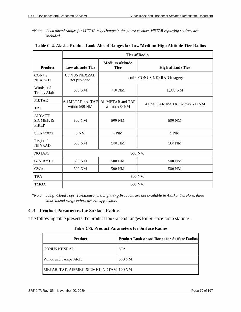
FAA Surveillance and Broadcast Services Surveillance and Broadcast Services Description Document
SRT-047, Rev. 05 – November 20, 2020 Page 70 of 107
*Note: Look ahead ranges for METAR may change in the future as more METAR reporting stations are included.
Table C-4. Alaska Product Look-Ahead Ranges for Low/Medium/High Altitude Tier Radios
Product
Tier of Radio
Low-altitude Tier Medium-altitude
Tier High-altitude Tier
CONUS NEXRAD
CONUS NEXRAD not provided entire CONUS NEXRAD imagery
Winds and Temps Aloft 500 NM 750 NM 1,000 NM
METAR All METAR and TAF within 500 NM
All METAR and TAF within 500 NM All METAR and TAF within 500 NM
TAF
AIRMET, SIGMET, & PIREP
500 NM 500 NM 500 NM
SUA Status 5 NM 5 NM 5 NM
Regional NEXRAD 500 NM 500 NM 500 NM
NOTAM 500 NM
G-AIRMET 500 NM 500 NM 500 NM
CWA 500 NM 500 NM 500 NM
TRA 500 NM
TMOA 500 NM
*Note: Icing, Cloud Tops, Turbulence, and Lightning Products are not available in Alaska, therefore, these look- ahead range values are not applicable.
C.3 Product Parameters for Surface Radios The following table presents the product look-ahead ranges for Surface radio stations.
Table C-5. Product Parameters for Surface Radios
Product Product Look-ahead Range for Surface Radios
CONUS NEXRAD N/A
Winds and Temps Aloft 500 NM
METAR, TAF, AIRMET, SIGMET, NOTAM 100 NM

FAA Surveillance and Broadcast Services Surveillance and Broadcast Services Description Document
SRT-047, Rev. 05 – November 20, 2020 Page 71 of 107
PIREP and SUA Status N/A
Regional NEXRAD 150 NM
Icing, Cloud Tops, Turbulence, Lightning N/A
G-AIRMET, CWA N/A
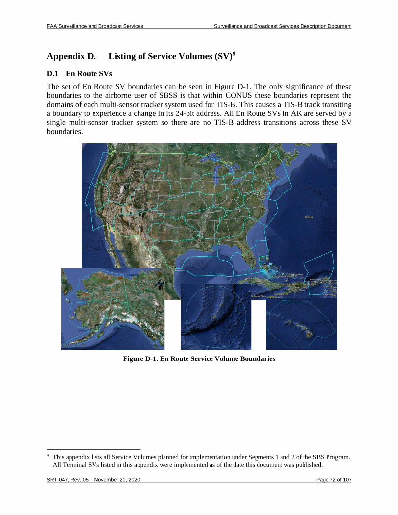
FAA Surveillance and Broadcast Services Surveillance and Broadcast Services Description Document
SRT-047, Rev. 05 – November 20, 2020 Page 72 of 107
Appendix D. Listing of Service Volumes (SV)9
D.1 En Route SVs The set of En Route SV boundaries can be seen in Figure D-1. The only significance of these boundaries to the airborne user of SBSS is that within CONUS these boundaries represent the domains of each multi-sensor tracker system used for TIS-B. This causes a TIS-B track transiting a boundary to experience a change in its 24-bit address. All En Route SVs in AK are served by a single multi-sensor tracker system so there are no TIS-B address transitions across these SV boundaries.
Figure D-1. En Route Service Volume Boundaries
9 This appendix lists all Service Volumes planned for implementation under Segments 1 and 2 of the SBS Program.
All Terminal SVs listed in this appendix were implemented as of the date this document was published.
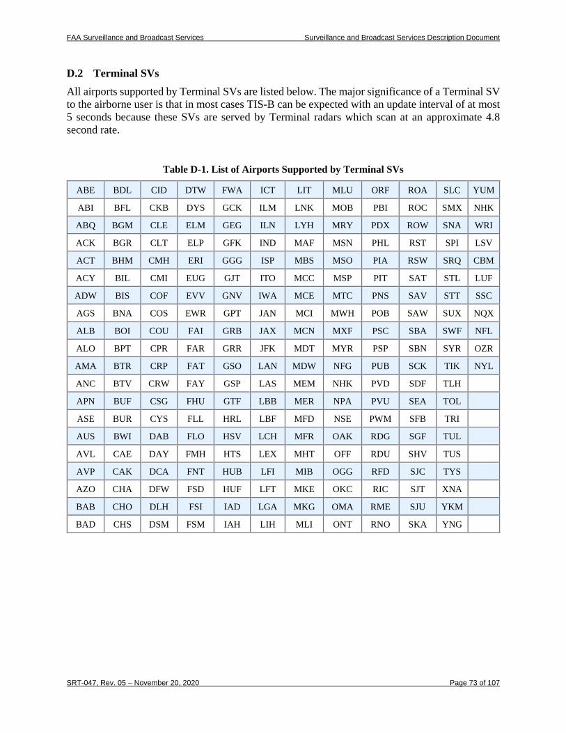
FAA Surveillance and Broadcast Services Surveillance and Broadcast Services Description Document
SRT-047, Rev. 05 – November 20, 2020 Page 73 of 107
D.2 Terminal SVs All airports supported by Terminal SVs are listed below. The major significance of a Terminal SV to the airborne user is that in most cases TIS-B can be expected with an update interval of at most 5 seconds because these SVs are served by Terminal radars which scan at an approximate 4.8 second rate.
Table D-1. List of Airports Supported by Terminal SVs
ABE BDL CID DTW FWA ICT LIT MLU ORF ROA SLC YUM
ABI BFL CKB DYS GCK ILM LNK MOB PBI ROC SMX NHK
ABQ BGM CLE ELM GEG ILN LYH MRY PDX ROW SNA WRI
ACK BGR CLT ELP GFK IND MAF MSN PHL RST SPI LSV
ACT BHM CMH ERI GGG ISP MBS MSO PIA RSW SRQ CBM
ACY BIL CMI EUG GJT ITO MCC MSP PIT SAT STL LUF
ADW BIS COF EVV GNV IWA MCE MTC PNS SAV STT SSC
AGS BNA COS EWR GPT JAN MCI MWH POB SAW SUX NQX
ALB BOI COU FAI GRB JAX MCN MXF PSC SBA SWF NFL
ALO BPT CPR FAR GRR JFK MDT MYR PSP SBN SYR OZR
AMA BTR CRP FAT GSO LAN MDW NFG PUB SCK TIK NYL
ANC BTV CRW FAY GSP LAS MEM NHK PVD SDF TLH
APN BUF CSG FHU GTF LBB MER NPA PVU SEA TOL
ASE BUR CYS FLL HRL LBF MFD NSE PWM SFB TRI
AUS BWI DAB FLO HSV LCH MFR OAK RDG SGF TUL
AVL CAE DAY FMH HTS LEX MHT OFF RDU SHV TUS
AVP CAK DCA FNT HUB LFI MIB OGG RFD SJC TYS
AZO CHA DFW FSD HUF LFT MKE OKC RIC SJT XNA
BAB CHO DLH FSI IAD LGA MKG OMA RME SJU YKM
BAD CHS DSM FSM IAH LIH MLI ONT RNO SKA YNG
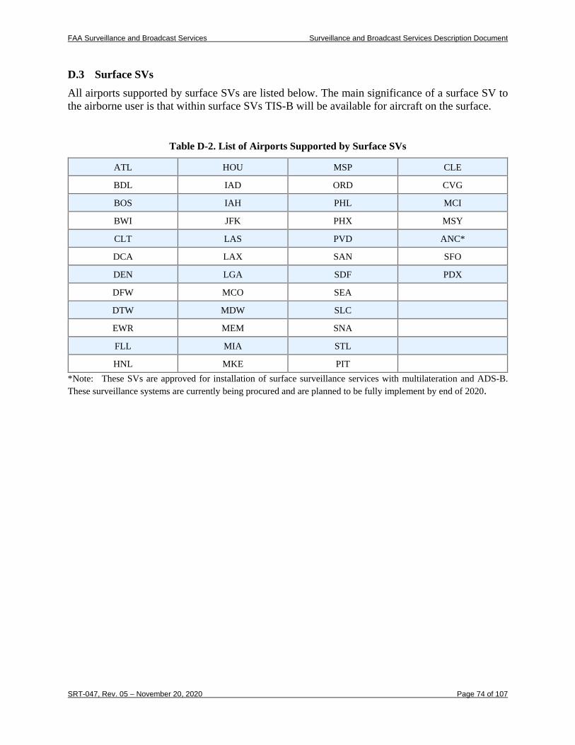
FAA Surveillance and Broadcast Services Surveillance and Broadcast Services Description Document
SRT-047, Rev. 05 – November 20, 2020 Page 74 of 107
D.3 Surface SVs All airports supported by surface SVs are listed below. The main significance of a surface SV to the airborne user is that within surface SVs TIS-B will be available for aircraft on the surface.
Table D-2. List of Airports Supported by Surface SVs
ATL HOU MSP CLE
BDL IAD ORD CVG
BOS IAH PHL MCI
BWI JFK PHX MSY
CLT LAS PVD ANC*
DCA LAX SAN SFO
DEN LGA SDF PDX
DFW MCO SEA
DTW MDW SLC
EWR MEM SNA
FLL MIA STL
HNL MKE PIT *Note: These SVs are approved for installation of surface surveillance services with multilateration and ADS-B. These surveillance systems are currently being procured and are planned to be fully implement by end of 2020.
FAA Surveillance and Broadcast Services Surveillance and Broadcast Services Description Document
SRT-047, Rev. 05 – November 20, 2020 Page 75 of 107
Appendix E. METAR Stations The following Microsoft Excel© (.xlxs) file attachment contains METAR Stations for which the FIS-B service will uplink METARS when the data is available for these airports. The FAA will periodically update this file to include any new METAR Stations or delete stations that may be decommissioned and no longer provide this service. An update file will be released as they become available.
METARS Only File July 2020.xlsx
FAA Surveillance and Broadcast Services Surveillance and Broadcast Services Description Document
SRT-047, Rev. 05 – November 20, 2020 Page 76 of 107
Appendix F. TAF Stations The TAF stations listed in the attached Microsoft Excel© (.xlsx) file are those that were actively providing forecasts through the National Weather Service (NWS) as of November 20, 2020. The NWS may also add or remove some TAFs in the future such as when special events require enhanced weather forecasts for an airport. Therefore, the FIS-B service may uplink additional TAF reports if the report is from an airport on the METARS list provided in Appendix E and is available from the NWS.
TAFS Only File July 2020.xlsx
FAA Surveillance and Broadcast Services Surveillance and Broadcast Services Description Document
SRT-047, Rev. 05 – November 20, 2020 Page 77 of 107
Appendix G. FIS-B Products The material in this appendix will be copyrighted by RTCA, Inc. (www.rtca.org) when it is published in DO-358B. It is used with permission from RTCA.
G.1 Background FIS-B products are separated into three classes: Generic Text products, Global Block Representation products, and Text with Graphical Overlay products. Generic Text products are always assigned a Product ID of 413 and use the Data Link Application Control (DLAC) 6-bit alphabet. These products are represented as strings of characters in a format that is independent of the type of text product itself. Generic Text products include METAR, PIREP, TAF and WINDS. Global Block Representation products provide various weather data using an image format. GBR products consist of Regional NEXRAD (Product ID #63), CONUS NEXRAD (Product ID #64), Lightning (Product ID #103), Cloud Tops (Product ID #84), Icing Low (Product ID #70), Icing High (Product ID #71), Turbulence Low (Product ID #90), and Turbulence High (Product ID #91). TWGO products include a textual portion and an optional graphical portion. TWGO products consist of NOTAM-Ds (Product ID #8), NOTAM-FDCs (Product ID #8), NOTAM-TFRs (Product ID #8), NOTAM-TRAs (Product ID #16), NOTAM-TMOAs (Product ID #17), FIS-B Product Updates Unavailable Reports (Product ID #8), AIRMETs (Product ID #11), SIGMETs (Product ID #12), Convective SIGMETs (WST) (Product ID #12), G-AIRMETs (Product ID #14), and CWAs (Product ID #15). Note: This appendix only addresses the two new products (NOTAM-TRA and NOTAM-TMOA). Details regarding the other products defined in this document can be found in the “MOPS for FIS-B with UAT” RTCA document number DO-358A.
G.1.1 Text with Graphical Overlay FIS-B Products This section describes the encoding format used for the TWGO product class.
Note: This class of FIS-B products employs an encoding framework that contains flexibility to represent graphic objects not currently present in FIS-B uplink products. Many fields documented here contain states that do not presently occur. Where this occurs, these states are marked Future Use within this appendix. The encoding framework also includes some optional fields that were not used at the time DO-358 was developed. These currently unused optional fields are omitted in this appendix.
G.1.1.1 General Formatting The APDU Payload for TWGO FIS-B Products supports textual and graphical overlay representations. The payload consists of a header and one or more records. The APDU Payload
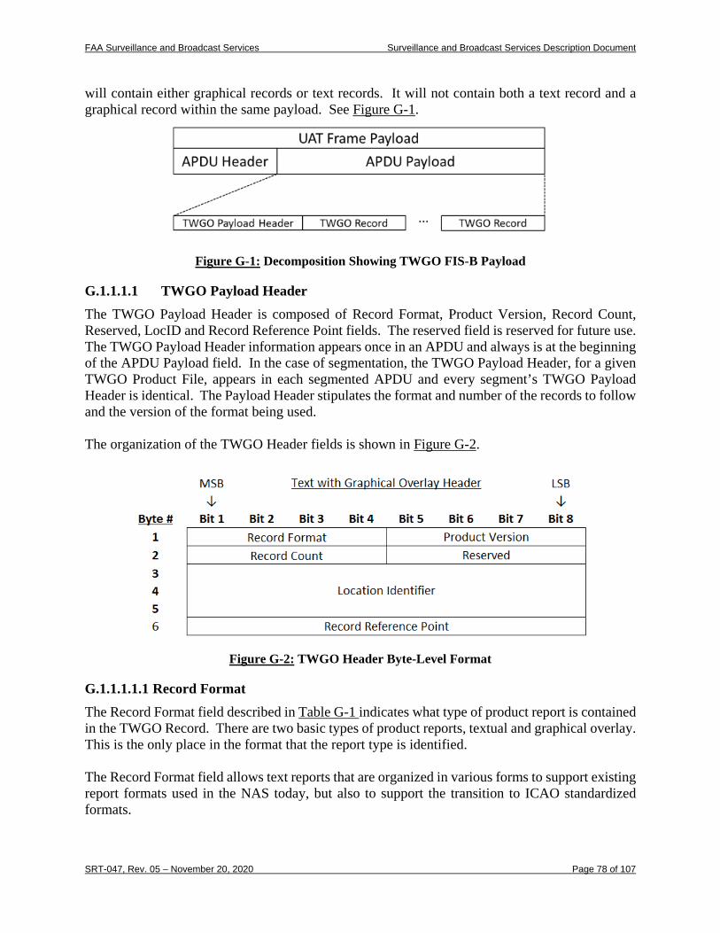
FAA Surveillance and Broadcast Services Surveillance and Broadcast Services Description Document
SRT-047, Rev. 05 – November 20, 2020 Page 78 of 107
will contain either graphical records or text records. It will not contain both a text record and a graphical record within the same payload. See Figure G-1.
Figure G-1: Decomposition Showing TWGO FIS-B Payload
G.1.1.1.1 TWGO Payload Header The TWGO Payload Header is composed of Record Format, Product Version, Record Count, Reserved, LocID and Record Reference Point fields. The reserved field is reserved for future use. The TWGO Payload Header information appears once in an APDU and always is at the beginning of the APDU Payload field. In the case of segmentation, the TWGO Payload Header, for a given TWGO Product File, appears in each segmented APDU and every segment’s TWGO Payload Header is identical. The Payload Header stipulates the format and number of the records to follow and the version of the format being used. The organization of the TWGO Header fields is shown in Figure G-2.
Figure G-2: TWGO Header Byte-Level Format
G.1.1.1.1.1 Record Format The Record Format field described in Table G-1 indicates what type of product report is contained in the TWGO Record. There are two basic types of product reports, textual and graphical overlay. This is the only place in the format that the report type is identified. The Record Format field allows text reports that are organized in various forms to support existing report formats used in the NAS today, but also to support the transition to ICAO standardized formats.
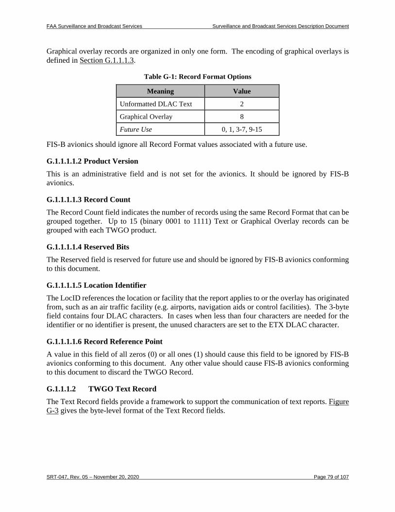
FAA Surveillance and Broadcast Services Surveillance and Broadcast Services Description Document
SRT-047, Rev. 05 – November 20, 2020 Page 79 of 107
Graphical overlay records are organized in only one form. The encoding of graphical overlays is defined in Section G.1.1.1.3.
Table G-1: Record Format Options
Meaning Value
Unformatted DLAC Text 2
Graphical Overlay 8
Future Use 0, 1, 3-7, 9-15
FIS-B avionics should ignore all Record Format values associated with a future use.
G.1.1.1.1.2 Product Version This is an administrative field and is not set for the avionics. It should be ignored by FIS-B avionics.
G.1.1.1.1.3 Record Count The Record Count field indicates the number of records using the same Record Format that can be grouped together. Up to 15 (binary 0001 to 1111) Text or Graphical Overlay records can be grouped with each TWGO product.
G.1.1.1.1.4 Reserved Bits The Reserved field is reserved for future use and should be ignored by FIS-B avionics conforming to this document.
G.1.1.1.1.5 Location Identifier The LocID references the location or facility that the report applies to or the overlay has originated from, such as an air traffic facility (e.g. airports, navigation aids or control facilities). The 3-byte field contains four DLAC characters. In cases when less than four characters are needed for the identifier or no identifier is present, the unused characters are set to the ETX DLAC character.
G.1.1.1.1.6 Record Reference Point A value in this field of all zeros (0) or all ones (1) should cause this field to be ignored by FIS-B avionics conforming to this document. Any other value should cause FIS-B avionics conforming to this document to discard the TWGO Record.
G.1.1.1.2 TWGO Text Record The Text Record fields provide a framework to support the communication of text reports. Figure G-3 gives the byte-level format of the Text Record fields.
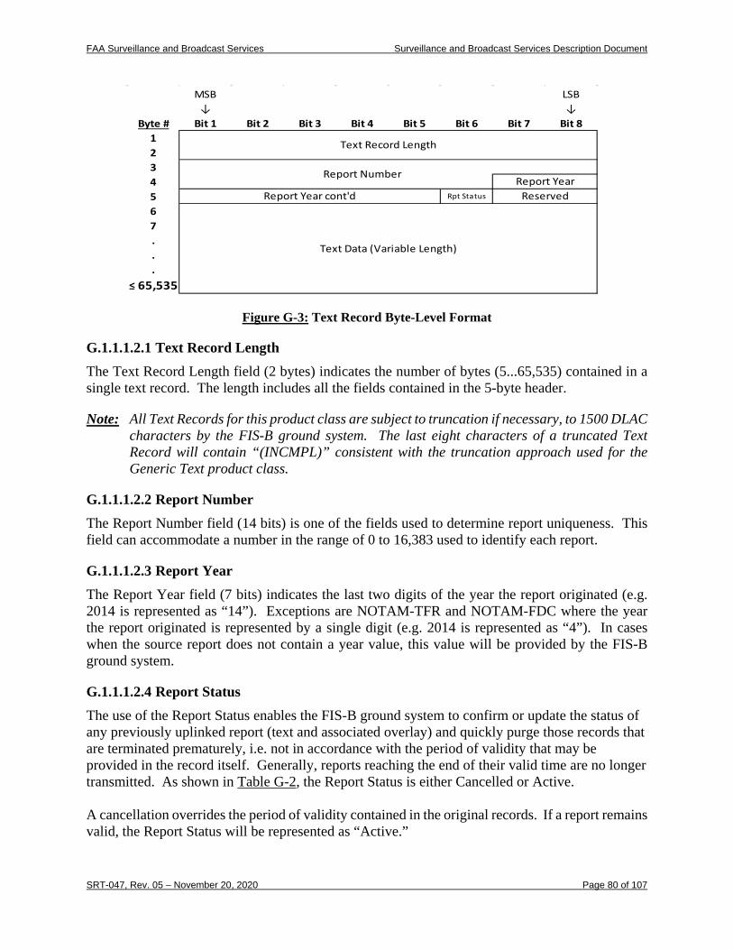
FAA Surveillance and Broadcast Services Surveillance and Broadcast Services Description Document
SRT-047, Rev. 05 – November 20, 2020 Page 80 of 107
Figure G-3: Text Record Byte-Level Format
G.1.1.1.2.1 Text Record Length The Text Record Length field (2 bytes) indicates the number of bytes (5...65,535) contained in a single text record. The length includes all the fields contained in the 5-byte header.
Note: All Text Records for this product class are subject to truncation if necessary, to 1500 DLAC characters by the FIS-B ground system. The last eight characters of a truncated Text Record will contain “(INCMPL)” consistent with the truncation approach used for the Generic Text product class.
G.1.1.1.2.2 Report Number The Report Number field (14 bits) is one of the fields used to determine report uniqueness. This field can accommodate a number in the range of 0 to 16,383 used to identify each report.
G.1.1.1.2.3 Report Year The Report Year field (7 bits) indicates the last two digits of the year the report originated (e.g. 2014 is represented as “14”). Exceptions are NOTAM-TFR and NOTAM-FDC where the year the report originated is represented by a single digit (e.g. 2014 is represented as “4”). In cases when the source report does not contain a year value, this value will be provided by the FIS-B ground system.
G.1.1.1.2.4 Report Status The use of the Report Status enables the FIS-B ground system to confirm or update the status of any previously uplinked report (text and associated overlay) and quickly purge those records that are terminated prematurely, i.e. not in accordance with the period of validity that may be provided in the record itself. Generally, reports reaching the end of their valid time are no longer transmitted. As shown in Table G-2, the Report Status is either Cancelled or Active. A cancellation overrides the period of validity contained in the original records. If a report remains valid, the Report Status will be represented as “Active.”
Byte # Bit 1 Bit 2 Bit 3 Bit 4 Bit 5 Bit 6 Bit 7 Bit 812345 Rpt Status
67...
≤ 65,535
Report Year cont'd Reserved
Text Data (Variable Length)
MSB↓
LSB↓
Text Record Length
Report NumberReport Year
FAA Surveillance and Broadcast Services Surveillance and Broadcast Services Description Document
SRT-047, Rev. 05 – November 20, 2020 Page 81 of 107
Table G-2: Report Status
Meaning Value
Cancelled Report 0
Active Report 1
A key feature of the Report Status is that it enables the status of all records associated with a previously uplinked report (including overlay records) to be updated without having to retransmit the entire record or set of records. This is accomplished by only transmitting the first five (5) bytes of the text record (see Section G.1.1.1.2), which includes only those fields necessary to reference the record(s) and status.
G.1.1.1.2.5 Reserved Bits Bits 7 through 8 of byte 5 are reserved for future use and should be ignored.
G.1.1.1.2.6 Text Data Field The Text Data Field contains the DLAC encoded text for a single report.
G.1.1.1.3 TWGO Graphical Overlay Record The Graphical Overlay Record contains the fields for the graphical depictions of NAS Status information (e.g. NOTAM-TFR and SIGMET reports). A byte-level format of the Graphical Overlay Record is shown in Figure G-4.
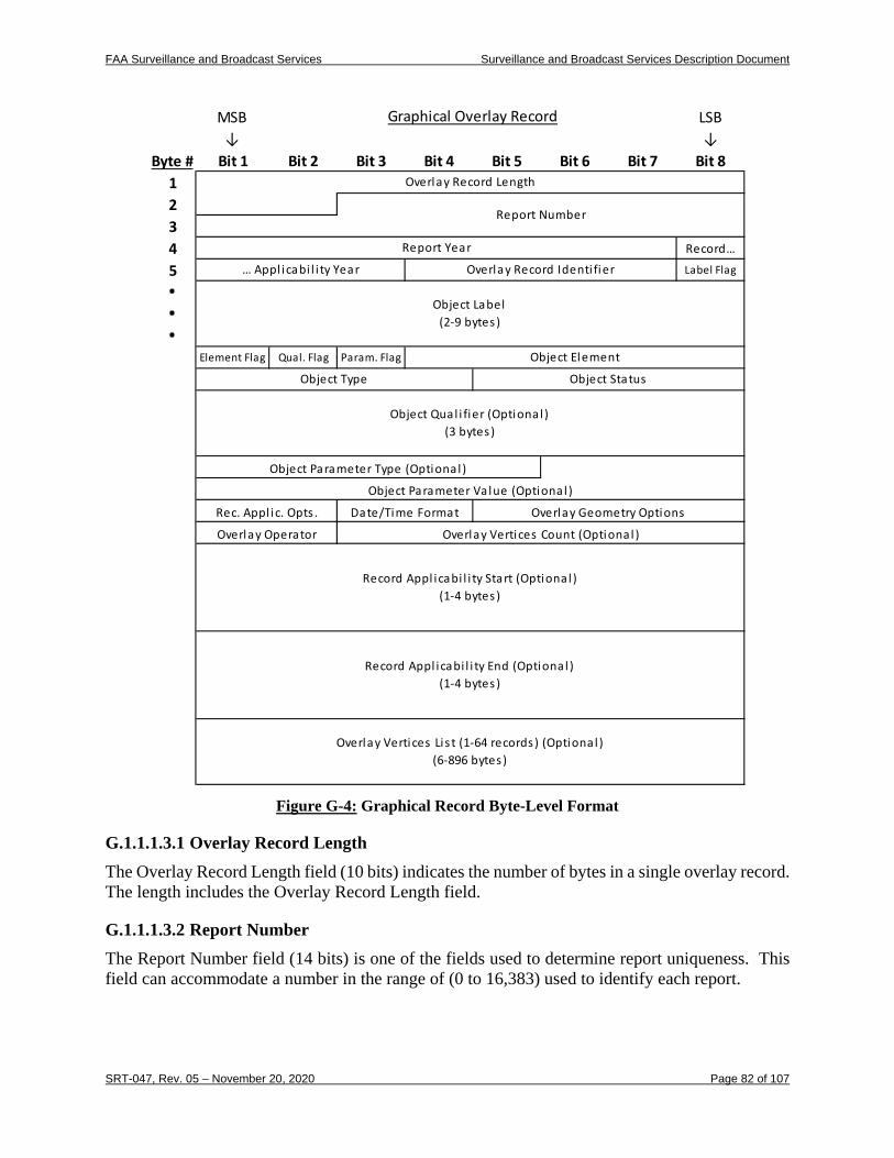
FAA Surveillance and Broadcast Services Surveillance and Broadcast Services Description Document
SRT-047, Rev. 05 – November 20, 2020 Page 82 of 107
Figure G-4: Graphical Record Byte-Level Format
G.1.1.1.3.1 Overlay Record Length The Overlay Record Length field (10 bits) indicates the number of bytes in a single overlay record. The length includes the Overlay Record Length field.
G.1.1.1.3.2 Report Number The Report Number field (14 bits) is one of the fields used to determine report uniqueness. This field can accommodate a number in the range of (0 to 16,383) used to identify each report.
Byte # Bit 1 Bit 2 Bit 3 Bit 4 Bit 5 Bit 6 Bit 7 Bit 81234 Record…
5 Label Flag...
Element Flag Qual. Flag Param. Flag
Object Type Object Status
MSB↓
Graphical Overlay Record LSB↓
Overlay Record Length
Report Number
Report Year
… Appl icabi l i ty Year Overlay Record Identi fier
Object Label(2-9 bytes )
Object Element
Object Qual i fier (Optional )(3 bytes )
Object Parameter Type (Optional )
Object Parameter Va lue (Optional )
Rec. Appl ic. Opts . Date/Time Format Overlay Geometry Options
Overlay Operator Overlay Vertices Count (Optional )
Record Appl icabi l i ty Start (Optional )(1-4 bytes )
Record Appl icabi l i ty End (Optional )(1-4 bytes )
Overlay Vertices Li s t (1-64 records) (Optional )(6-896 bytes )
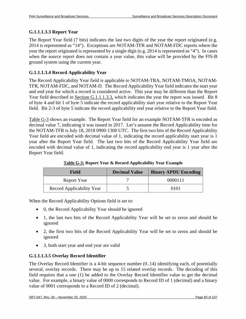
FAA Surveillance and Broadcast Services Surveillance and Broadcast Services Description Document
SRT-047, Rev. 05 – November 20, 2020 Page 83 of 107
G.1.1.1.3.3 Report Year The Report Year field (7 bits) indicates the last two digits of the year the report originated (e.g. 2014 is represented as “14”). Exceptions are NOTAM-TFR and NOTAM-FDC reports where the year the report originated is represented by a single digit (e.g. 2014 is represented as “4”). In cases when the source report does not contain a year value, this value will be provided by the FIS-B ground system using the current year.
G.1.1.1.3.4 Record Applicability Year The Record Applicability Year field is applicable to NOTAM-TRA, NOTAM-TMOA, NOTAM-TFR, NOTAM-FDC, and NOTAM-D. The Record Applicability Year field indicates the start year and end year for which a record is considered active. This year may be different than the Report Year field described in Section G.1.1.1.3.3, which indicates the year the report was issued. Bit 8 of byte 4 and bit 1 of byte 5 indicate the record applicability start year relative to the Report Year field. Bit 2-3 of byte 5 indicate the record applicability end year relative to the Report Year field. Table G-3 shows an example. The Report Year field for an example NOTAM-TFR is encoded as decimal value 7, indicating it was issued in 2017. Let’s assume the Record Applicability time for the NOTAM-TFR is July 18, 2018 0900-1300 UTC. The first two bits of the Record Applicability Year field are encoded with decimal value of 1, indicating the record applicability start year is 1 year after the Report Year field. The last two bits of the Record Applicability Year field are encoded with decimal value of 1, indicating the record applicability end year is 1 year after the Report Year field.
Table G-3: Report Year & Record Applicability Year Example
Field Decimal Value Binary APDU Encoding
Report Year 7 0000111
Record Applicability Year 5 0101 When the Record Applicability Options field is set to:
• 0, the Record Applicability Year should be ignored
• 1, the last two bits of the Record Applicability Year will be set to zeros and should be ignored
• 2, the first two bits of the Record Applicability Year will be set to zeros and should be ignored
• 3, both start year and end year are valid
G.1.1.1.3.5 Overlay Record Identifier The Overlay Record Identifier is a 4-bit sequence number (0..14) identifying each, of potentially several, overlay records. There may be up to 15 related overlay records. The decoding of this field requires that a one (1) be added to the Overlay Record Identifier value to get the decimal value. For example, a binary value of 0000 corresponds to Record ID of 1 (decimal) and a binary value of 0001 corresponds to a Record ID of 2 (decimal).
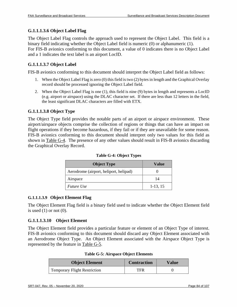
FAA Surveillance and Broadcast Services Surveillance and Broadcast Services Description Document
SRT-047, Rev. 05 – November 20, 2020 Page 84 of 107
G.1.1.1.3.6 Object Label Flag The Object Label Flag controls the approach used to represent the Object Label. This field is a binary field indicating whether the Object Label field is numeric (0) or alphanumeric (1). For FIS-B avionics conforming to this document, a value of 0 indicates there is no Object Label and a 1 indicates the text label is an airport LocID.
G.1.1.1.3.7 Object Label FIS-B avionics conforming to this document should interpret the Object Label field as follows:
1. When the Object Label Flag is zero (0) this field is two (2) bytes in length and the Graphical Overlay record should be processed ignoring the Object Label field.
2. When the Object Label Flag is one (1), this field is nine (9) bytes in length and represents a LocID (e.g. airport or airspace) using the DLAC character set. If there are less than 12 letters in the field, the least significant DLAC characters are filled with ETX.
G.1.1.1.3.8 Object Type The Object Type field provides the notable parts of an airport or airspace environment. These airport/airspace objects comprise the collection of regions or things that can have an impact on flight operations if they become hazardous, if they fail or if they are unavailable for some reason. FIS-B avionics conforming to this document should interpret only two values for this field as shown in Table G-4. The presence of any other values should result in FIS-B avionics discarding the Graphical Overlay Record.
Table G-4: Object Types
Object Type Value
Aerodrome (airport, heliport, helipad) 0
Airspace 14
Future Use 1-13, 15
G.1.1.1.3.9 Object Element Flag
The Object Element Flag field is a binary field used to indicate whether the Object Element field is used (1) or not (0).
G.1.1.1.3.10 Object Element The Object Element field provides a particular feature or element of an Object Type of interest. FIS-B avionics conforming to this document should discard any Object Element associated with an Aerodrome Object Type. An Object Element associated with the Airspace Object Type is represented by the feature in Table G-5.
Table G-5: Airspace Object Elements
Object Element Contraction Value Temporary Flight Restriction TFR 0
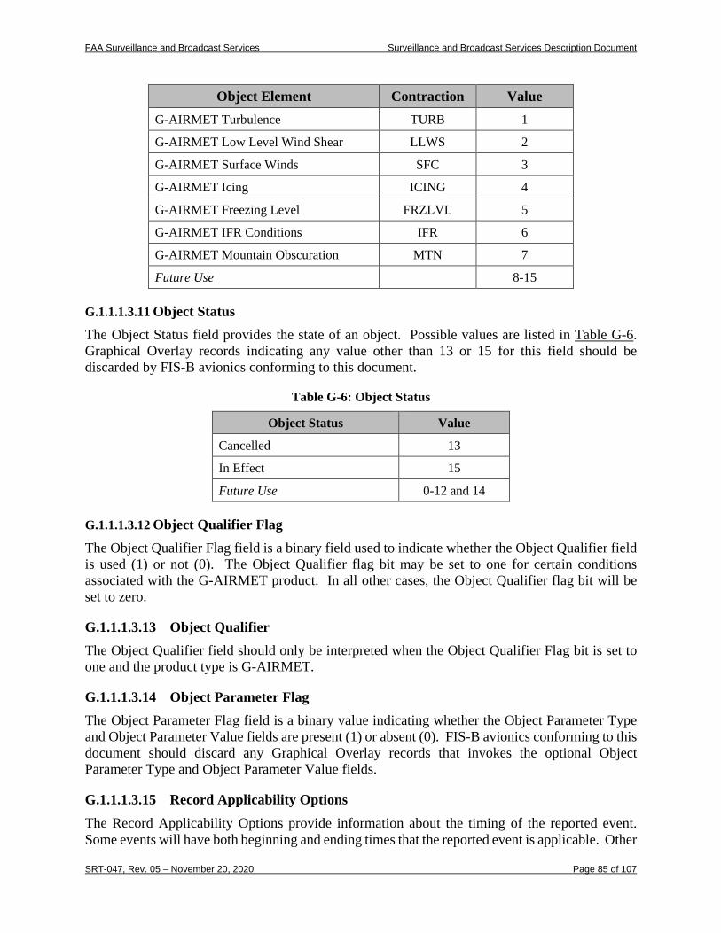
FAA Surveillance and Broadcast Services Surveillance and Broadcast Services Description Document
SRT-047, Rev. 05 – November 20, 2020 Page 85 of 107
Object Element Contraction Value G-AIRMET Turbulence TURB 1
G-AIRMET Low Level Wind Shear LLWS 2
G-AIRMET Surface Winds SFC 3
G-AIRMET Icing ICING 4
G-AIRMET Freezing Level FRZLVL 5
G-AIRMET IFR Conditions IFR 6
G-AIRMET Mountain Obscuration MTN 7
Future Use 8-15
G.1.1.1.3.11 Object Status
The Object Status field provides the state of an object. Possible values are listed in Table G-6. Graphical Overlay records indicating any value other than 13 or 15 for this field should be discarded by FIS-B avionics conforming to this document.
Table G-6: Object Status
Object Status Value
Cancelled 13
In Effect 15
Future Use 0-12 and 14
G.1.1.1.3.12 Object Qualifier Flag
The Object Qualifier Flag field is a binary field used to indicate whether the Object Qualifier field is used (1) or not (0). The Object Qualifier flag bit may be set to one for certain conditions associated with the G-AIRMET product. In all other cases, the Object Qualifier flag bit will be set to zero.
G.1.1.1.3.13 Object Qualifier The Object Qualifier field should only be interpreted when the Object Qualifier Flag bit is set to one and the product type is G-AIRMET.
G.1.1.1.3.14 Object Parameter Flag The Object Parameter Flag field is a binary value indicating whether the Object Parameter Type and Object Parameter Value fields are present (1) or absent (0). FIS-B avionics conforming to this document should discard any Graphical Overlay records that invokes the optional Object Parameter Type and Object Parameter Value fields.
G.1.1.1.3.15 Record Applicability Options
The Record Applicability Options provide information about the timing of the reported event. Some events will have both beginning and ending times that the reported event is applicable. Other
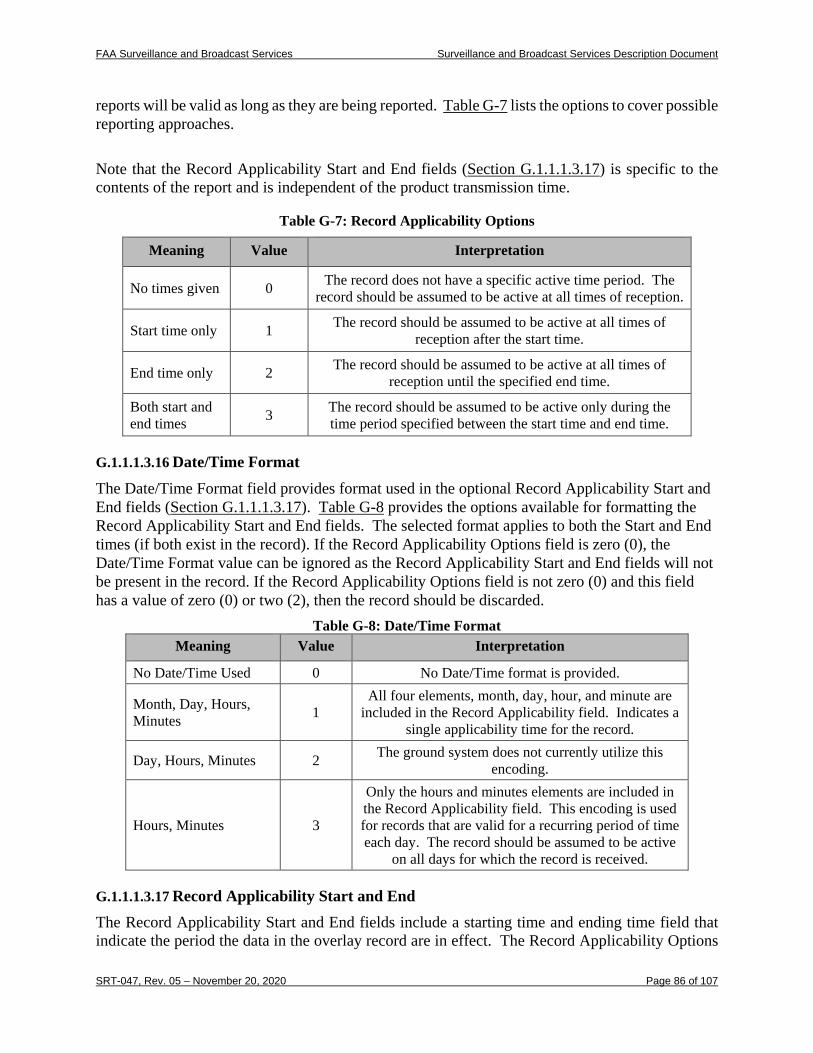
FAA Surveillance and Broadcast Services Surveillance and Broadcast Services Description Document
SRT-047, Rev. 05 – November 20, 2020 Page 86 of 107
reports will be valid as long as they are being reported. Table G-7 lists the options to cover possible reporting approaches.
Note that the Record Applicability Start and End fields (Section G.1.1.1.3.17) is specific to the contents of the report and is independent of the product transmission time.
Table G-7: Record Applicability Options
Meaning Value Interpretation
No times given 0 The record does not have a specific active time period. The record should be assumed to be active at all times of reception.
Start time only 1 The record should be assumed to be active at all times of reception after the start time.
End time only 2 The record should be assumed to be active at all times of reception until the specified end time.
Both start and end times 3 The record should be assumed to be active only during the
time period specified between the start time and end time.
G.1.1.1.3.16 Date/Time Format The Date/Time Format field provides format used in the optional Record Applicability Start and End fields (Section G.1.1.1.3.17). Table G-8 provides the options available for formatting the Record Applicability Start and End fields. The selected format applies to both the Start and End times (if both exist in the record). If the Record Applicability Options field is zero (0), the Date/Time Format value can be ignored as the Record Applicability Start and End fields will not be present in the record. If the Record Applicability Options field is not zero (0) and this field has a value of zero (0) or two (2), then the record should be discarded.
Table G-8: Date/Time Format Meaning Value Interpretation
No Date/Time Used 0 No Date/Time format is provided.
Month, Day, Hours, Minutes 1
All four elements, month, day, hour, and minute are included in the Record Applicability field. Indicates a
single applicability time for the record.
Day, Hours, Minutes 2 The ground system does not currently utilize this encoding.
Hours, Minutes 3
Only the hours and minutes elements are included in the Record Applicability field. This encoding is used for records that are valid for a recurring period of time each day. The record should be assumed to be active
on all days for which the record is received.
G.1.1.1.3.17 Record Applicability Start and End
The Record Applicability Start and End fields include a starting time and ending time field that indicate the period the data in the overlay record are in effect. The Record Applicability Options
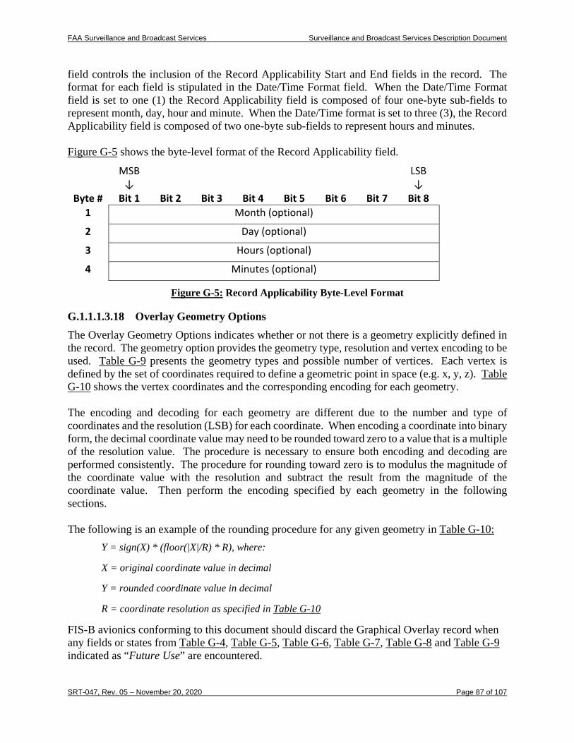
FAA Surveillance and Broadcast Services Surveillance and Broadcast Services Description Document
SRT-047, Rev. 05 – November 20, 2020 Page 87 of 107
field controls the inclusion of the Record Applicability Start and End fields in the record. The format for each field is stipulated in the Date/Time Format field. When the Date/Time Format field is set to one (1) the Record Applicability field is composed of four one-byte sub-fields to represent month, day, hour and minute. When the Date/Time format is set to three (3), the Record Applicability field is composed of two one-byte sub-fields to represent hours and minutes. Figure G-5 shows the byte-level format of the Record Applicability field.
MSB ↓
LSB ↓
Byte # Bit 1 Bit 2 Bit 3 Bit 4 Bit 5 Bit 6 Bit 7 Bit 8 1 Month (optional)
2 Day (optional)
3 Hours (optional)
4 Minutes (optional)
Figure G-5: Record Applicability Byte-Level Format
G.1.1.1.3.18 Overlay Geometry Options The Overlay Geometry Options indicates whether or not there is a geometry explicitly defined in the record. The geometry option provides the geometry type, resolution and vertex encoding to be used. Table G-9 presents the geometry types and possible number of vertices. Each vertex is defined by the set of coordinates required to define a geometric point in space (e.g. x, y, z). Table G-10 shows the vertex coordinates and the corresponding encoding for each geometry. The encoding and decoding for each geometry are different due to the number and type of coordinates and the resolution (LSB) for each coordinate. When encoding a coordinate into binary form, the decimal coordinate value may need to be rounded toward zero to a value that is a multiple of the resolution value. The procedure is necessary to ensure both encoding and decoding are performed consistently. The procedure for rounding toward zero is to modulus the magnitude of the coordinate value with the resolution and subtract the result from the magnitude of the coordinate value. Then perform the encoding specified by each geometry in the following sections. The following is an example of the rounding procedure for any given geometry in Table G-10:
Y = sign(X) * (floor(|X|/R) * R), where:
X = original coordinate value in decimal
Y = rounded coordinate value in decimal
R = coordinate resolution as specified in Table G-10
FIS-B avionics conforming to this document should discard the Graphical Overlay record when any fields or states from Table G-4, Table G-5, Table G-6, Table G-7, Table G-8 and Table G-9 indicated as “Future Use” are encountered.
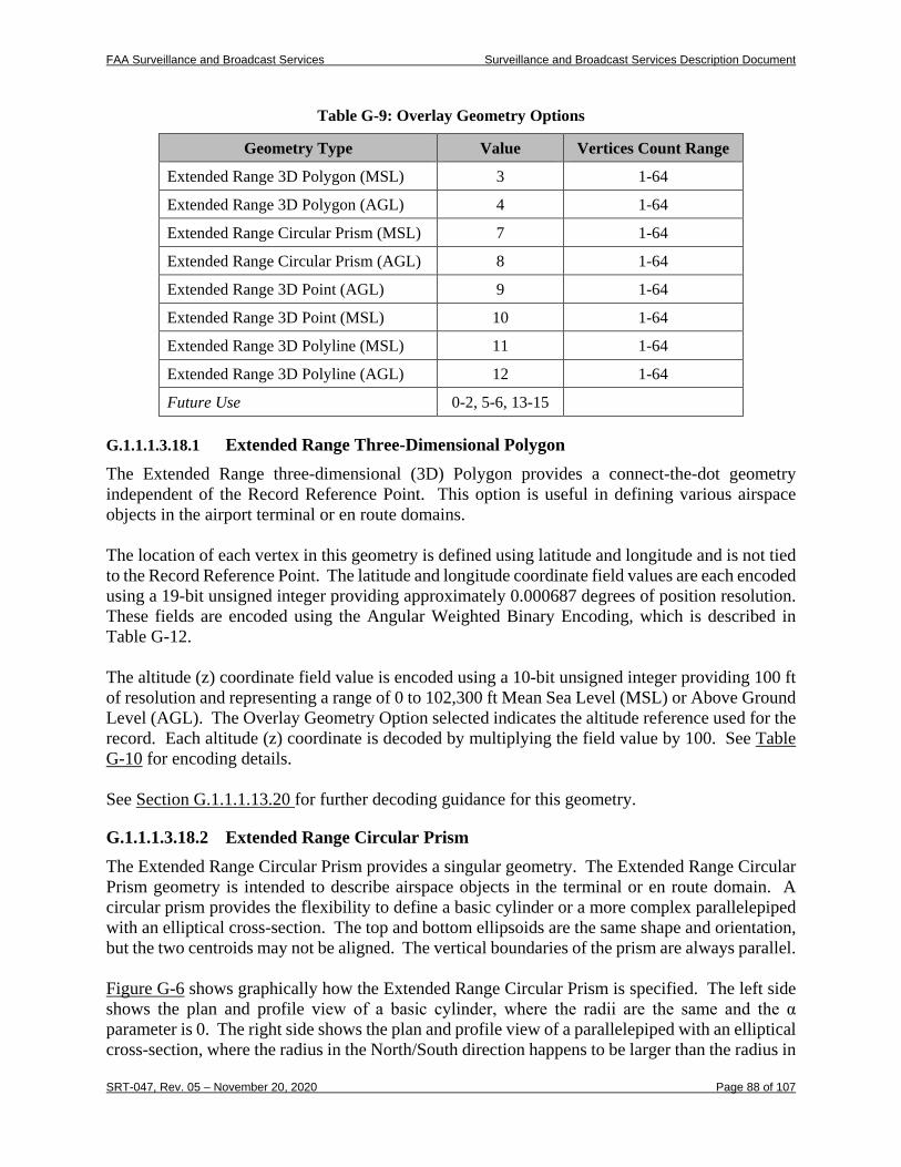
FAA Surveillance and Broadcast Services Surveillance and Broadcast Services Description Document
SRT-047, Rev. 05 – November 20, 2020 Page 88 of 107
Table G-9: Overlay Geometry Options
Geometry Type Value Vertices Count Range
Extended Range 3D Polygon (MSL) 3 1-64
Extended Range 3D Polygon (AGL) 4 1-64
Extended Range Circular Prism (MSL) 7 1-64
Extended Range Circular Prism (AGL) 8 1-64
Extended Range 3D Point (AGL) 9 1-64
Extended Range 3D Point (MSL) 10 1-64
Extended Range 3D Polyline (MSL) 11 1-64
Extended Range 3D Polyline (AGL) 12 1-64
Future Use 0-2, 5-6, 13-15
G.1.1.1.3.18.1 Extended Range Three-Dimensional Polygon
The Extended Range three-dimensional (3D) Polygon provides a connect-the-dot geometry independent of the Record Reference Point. This option is useful in defining various airspace objects in the airport terminal or en route domains. The location of each vertex in this geometry is defined using latitude and longitude and is not tied to the Record Reference Point. The latitude and longitude coordinate field values are each encoded using a 19-bit unsigned integer providing approximately 0.000687 degrees of position resolution. These fields are encoded using the Angular Weighted Binary Encoding, which is described in Table G-12. The altitude (z) coordinate field value is encoded using a 10-bit unsigned integer providing 100 ft of resolution and representing a range of 0 to 102,300 ft Mean Sea Level (MSL) or Above Ground Level (AGL). The Overlay Geometry Option selected indicates the altitude reference used for the record. Each altitude (z) coordinate is decoded by multiplying the field value by 100. See Table G-10 for encoding details. See Section G.1.1.1.13.20 for further decoding guidance for this geometry.
G.1.1.1.3.18.2 Extended Range Circular Prism The Extended Range Circular Prism provides a singular geometry. The Extended Range Circular Prism geometry is intended to describe airspace objects in the terminal or en route domain. A circular prism provides the flexibility to define a basic cylinder or a more complex parallelepiped with an elliptical cross-section. The top and bottom ellipsoids are the same shape and orientation, but the two centroids may not be aligned. The vertical boundaries of the prism are always parallel. Figure G-6 shows graphically how the Extended Range Circular Prism is specified. The left side shows the plan and profile view of a basic cylinder, where the radii are the same and the α parameter is 0. The right side shows the plan and profile view of a parallelepiped with an elliptical cross-section, where the radius in the North/South direction happens to be larger than the radius in
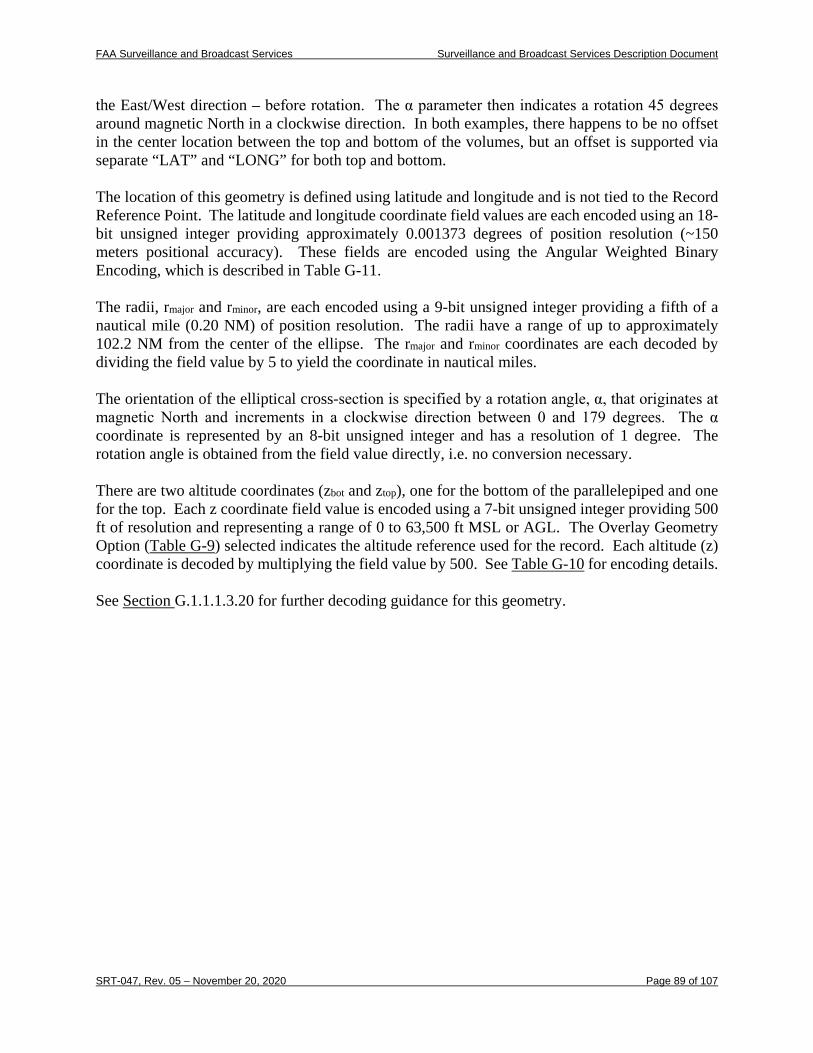
FAA Surveillance and Broadcast Services Surveillance and Broadcast Services Description Document
SRT-047, Rev. 05 – November 20, 2020 Page 89 of 107
the East/West direction – before rotation. The α parameter then indicates a rotation 45 degrees around magnetic North in a clockwise direction. In both examples, there happens to be no offset in the center location between the top and bottom of the volumes, but an offset is supported via separate “LAT” and “LONG” for both top and bottom. The location of this geometry is defined using latitude and longitude and is not tied to the Record Reference Point. The latitude and longitude coordinate field values are each encoded using an 18-bit unsigned integer providing approximately 0.001373 degrees of position resolution (~150 meters positional accuracy). These fields are encoded using the Angular Weighted Binary Encoding, which is described in Table G-11. The radii, rmajor and rminor, are each encoded using a 9-bit unsigned integer providing a fifth of a nautical mile (0.20 NM) of position resolution. The radii have a range of up to approximately 102.2 NM from the center of the ellipse. The rmajor and rminor coordinates are each decoded by dividing the field value by 5 to yield the coordinate in nautical miles. The orientation of the elliptical cross-section is specified by a rotation angle, α, that originates at magnetic North and increments in a clockwise direction between 0 and 179 degrees. The α coordinate is represented by an 8-bit unsigned integer and has a resolution of 1 degree. The rotation angle is obtained from the field value directly, i.e. no conversion necessary. There are two altitude coordinates (zbot and ztop), one for the bottom of the parallelepiped and one for the top. Each z coordinate field value is encoded using a 7-bit unsigned integer providing 500 ft of resolution and representing a range of 0 to 63,500 ft MSL or AGL. The Overlay Geometry Option (Table G-9) selected indicates the altitude reference used for the record. Each altitude (z) coordinate is decoded by multiplying the field value by 500. See Table G-10 for encoding details. See Section G.1.1.1.3.20 for further decoding guidance for this geometry.
FAA Surveillance and Broadcast Services Surveillance and Broadcast Services Description Document
SRT-047, Rev. 05 – November 20, 2020 Page 90 of 107
Figure G-6: Extended Range Circular Prism
G.1.1.1.3.18.3 Extended Range 3D Point The Extended Range 3D Point provides a singular geometry. This option is useful in defining locations within the airspace to identify or reference points of interest to pilots. The location the vertex in this geometry is defined using latitude and longitude and altitude. The latitude and longitude coordinate field values are each encoded using a 19-bit unsigned integer providing approximately 0.000687 degrees of position resolution. These fields are encoded using the Angular Weighted Binary Encoding, which is described in Table G-12. The altitude (z) coordinate field value is encoded using a 10-bit unsigned integer providing 100 ft of resolution and representing a range of 0 to 102,300 ft MSL or AGL. The Overlay Geometry Option selected indicates the altitude reference used. Each altitude (z) coordinate is decoded by multiplying the field value by 100. See Table G-10 for encoding details. When multiple Extended Range 3D Point geometries are packed in a single record, each is, by definition, independent of each other. When multiple Extended Range 3D Point geometries are packed across multiple records, each individual geometry is also independent. See Section G.1.1.1.3.20 for further encoding rules for this geometry.

FAA Surveillance and Broadcast Services Surveillance and Broadcast Services Description Document
SRT-047, Rev. 05 – November 20, 2020 Page 91 of 107
G.1.1.1.3.18.4 Extended Range 3D Polyline
The Extended Range 3D Polyline describes a line composed of line segments that do not close into a polygon. This is useful for conditions that span a lateral or longitudinal range across a given region, such as freezing levels across CONUS. The resolution of the latitude/longitude/altitude components are the same as was described for the Extended Range 3D Point geometry. See Section G.1.1.1.3.20 for further encoding rules for this geometry.
Table G-10: Overlay Geometry Encoding
Geometry Vertex Coordinate Resolution (LSB) Value Range
Extended Range 3D Polygon
LONG: LAT: z:
19 bits (360/219 deg) 19 bits (360/219 deg) 10 bits (100 ft)
(0..±180) (0..±90) (0..102,300)
Extended Range Circular Prism
LONGbot: LATbot: LONGtop: LATtop: zbot: ztop: rmajor: rminor: α:
18 bits (360/218 deg) 18 bits (360/218 deg) 18 bits (360/218 deg) 18 bits (360/218 deg) 7 bits (500 ft) 7 bits (500 ft) 9 bits (0.2 NM) 9 bits (0.2 NM) 8 bits (1 deg)
(0..±180) (0..±90) (0..±180) (0..±90) (0..63, 500) (0..63, 500) (0..102.2) (0..102.2) (0..179)
Extended Range 3D Point
LONG: LAT: z:
19 bits (360/219 deg) 19 bits (360/219 deg) 10 bits (100 ft)
(0..±180) (0..±90) (0..102,300)
Extended Range 3D Polyline
LONG: LAT: z:
19 bits (360/219 deg) 19 bits (360/219 deg) 10 bits (100 ft)
(0..±180) (0..±90) (0..102,300)
G.1.1.1.3.18.5 Angular Weighted Binary Encoding of Latitude and Longitude Table G-11 shows the angular weighted binary 18-bit encoding of latitude and longitude.
Table G-11: Angular Weighted Binary Encoding of Latitude and Longitude
Quadrant “Latitude” or “Longitude”
bits Meaning
(LSB = 360/218≅1.373291 x 10-3 degrees)
MSB LSB Latitude Longitude
1st quadrant
00 0000 0000 0000 0000 ZERO degrees (Equator) ZERO degrees (Prime Meridian)
00 0000 0000 0000 0001 LSB degrees North LSB degrees East
. . . . . . . . .
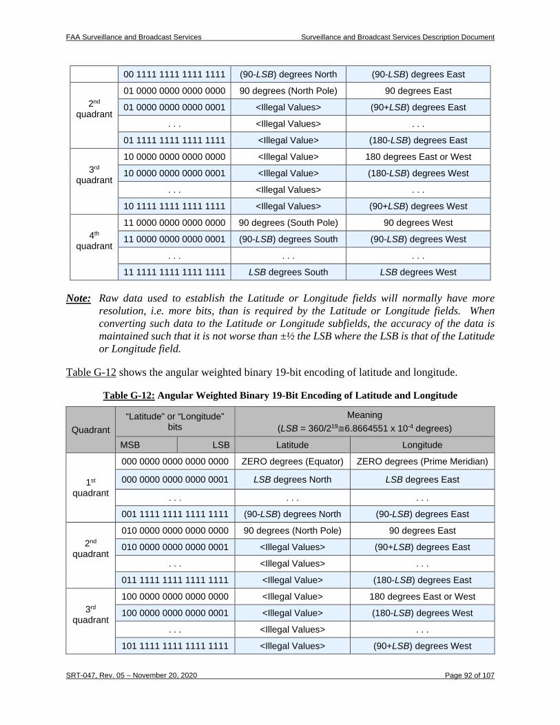
FAA Surveillance and Broadcast Services Surveillance and Broadcast Services Description Document
SRT-047, Rev. 05 – November 20, 2020 Page 92 of 107
Note: Raw data used to establish the Latitude or Longitude fields will normally have more resolution, i.e. more bits, than is required by the Latitude or Longitude fields. When converting such data to the Latitude or Longitude subfields, the accuracy of the data is maintained such that it is not worse than ±½ the LSB where the LSB is that of the Latitude or Longitude field.
Table G-12 shows the angular weighted binary 19-bit encoding of latitude and longitude.
Table G-12: Angular Weighted Binary 19-Bit Encoding of Latitude and Longitude
Quadrant “Latitude” or “Longitude”
bits Meaning
(LSB = 360/219≅6.8664551 x 10-4 degrees)
MSB LSB Latitude Longitude
1st quadrant
000 0000 0000 0000 0000 ZERO degrees (Equator) ZERO degrees (Prime Meridian)
000 0000 0000 0000 0001 LSB degrees North LSB degrees East
. . . . . . . . .
001 1111 1111 1111 1111 (90-LSB) degrees North (90-LSB) degrees East
2nd quadrant
010 0000 0000 0000 0000 90 degrees (North Pole) 90 degrees East
010 0000 0000 0000 0001 <Illegal Values> (90+LSB) degrees East
. . . <Illegal Values> . . .
011 1111 1111 1111 1111 <Illegal Value> (180-LSB) degrees East
3rd quadrant
100 0000 0000 0000 0000 <Illegal Value> 180 degrees East or West
100 0000 0000 0000 0001 <Illegal Value> (180-LSB) degrees West
. . . <Illegal Values> . . .
101 1111 1111 1111 1111 <Illegal Values> (90+LSB) degrees West
00 1111 1111 1111 1111 (90-LSB) degrees North (90-LSB) degrees East
2nd quadrant
01 0000 0000 0000 0000 90 degrees (North Pole) 90 degrees East
01 0000 0000 0000 0001 <Illegal Values> (90+LSB) degrees East
. . . <Illegal Values> . . .
01 1111 1111 1111 1111 <Illegal Value> (180-LSB) degrees East
3rd quadrant
10 0000 0000 0000 0000 <Illegal Value> 180 degrees East or West
10 0000 0000 0000 0001 <Illegal Value> (180-LSB) degrees West
. . . <Illegal Values> . . .
10 1111 1111 1111 1111 <Illegal Values> (90+LSB) degrees West
4th quadrant
11 0000 0000 0000 0000 90 degrees (South Pole) 90 degrees West
11 0000 0000 0000 0001 (90-LSB) degrees South (90-LSB) degrees West
. . . . . . . . .
11 1111 1111 1111 1111 LSB degrees South LSB degrees West
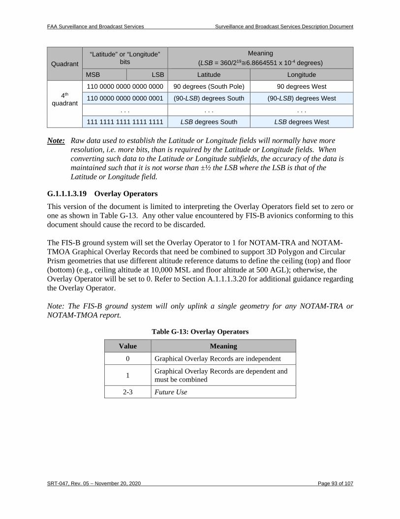
FAA Surveillance and Broadcast Services Surveillance and Broadcast Services Description Document
SRT-047, Rev. 05 – November 20, 2020 Page 93 of 107
Quadrant “Latitude” or “Longitude”
bits Meaning
(LSB = 360/219≅6.8664551 x 10-4 degrees)
MSB LSB Latitude Longitude
4th quadrant
110 0000 0000 0000 0000 90 degrees (South Pole) 90 degrees West
110 0000 0000 0000 0001 (90-LSB) degrees South (90-LSB) degrees West
. . . . . . . . .
111 1111 1111 1111 1111 LSB degrees South LSB degrees West
Note: Raw data used to establish the Latitude or Longitude fields will normally have more resolution, i.e. more bits, than is required by the Latitude or Longitude fields. When converting such data to the Latitude or Longitude subfields, the accuracy of the data is maintained such that it is not worse than ±½ the LSB where the LSB is that of the Latitude or Longitude field.
G.1.1.1.3.19 Overlay Operators This version of the document is limited to interpreting the Overlay Operators field set to zero or one as shown in Table G-13. Any other value encountered by FIS-B avionics conforming to this document should cause the record to be discarded. The FIS-B ground system will set the Overlay Operator to 1 for NOTAM-TRA and NOTAM-TMOA Graphical Overlay Records that need be combined to support 3D Polygon and Circular Prism geometries that use different altitude reference datums to define the ceiling (top) and floor (bottom) (e.g., ceiling altitude at 10,000 MSL and floor altitude at 500 AGL); otherwise, the Overlay Operator will be set to 0. Refer to Section A.1.1.1.3.20 for additional guidance regarding the Overlay Operator. Note: The FIS-B ground system will only uplink a single geometry for any NOTAM-TRA or NOTAM-TMOA report.
Table G-13: Overlay Operators
Value Meaning
0 Graphical Overlay Records are independent
1 Graphical Overlay Records are dependent and must be combined
2-3 Future Use
FAA Surveillance and Broadcast Services Surveillance and Broadcast Services Description Document
SRT-047, Rev. 05 – November 20, 2020 Page 94 of 107
G.1.1.1.3.20 Guidance for Decoding and Rendering Overlay Geometries
G.1.1.1.3.20.1 3D Polygons
G.1.1.1.3.20.1.1 Overlay Operator set to 0
When the Overlay Geometry Option is set to (3) Extended Range 3D Polygon (MSL) or (4) Extended Range 3D Polygon (AGL) and the Overlay Operator is set to 0 the following guidance for decode and rendering apply:
• All polygons will be closed by the FIS-B ground system (at least as it appears to the pilot) and each polygon is a “geometry.”
• Vertices for a geometry can span multiple records.
• Pen lifts between records. The FIS-B ground system will repeat last vertex of the previous record into the first vertex of the subsequent record to effectively keep the pen down unless the new record is starting a new geometry.
• Pen stays down to connect vertices within a record for vertices at the same altitude.
• Pen lifts between vertices at different altitudes within a record. Additional details regarding geometries with a range of altitudes are described below.
When encoding the ceiling altitude and a floor altitude (e.g., 17,999 ft to 3,000 ft), the Overlay Vertices List will first be populated with the vertices at the ceiling altitude followed by the vertices at the floor altitude. If the floor altitude of the geometry is zero (or rounds to zero) the FIS-B ground system will omit (i.e., not encode and uplink) the vertices at the floor altitude from the overlay record(s). FIS-B avionics should assume there are floor vertices at 0 ft MSL or AGL, depending on the Overlay Geometry Option encoding, that duplicate the ceiling vertices’ latitude and longitude values. Note: NOTAM-TFR geometries only support the uplink of a single altitude (z) value across all vertices within the overlay record(s), even if the associated NOTAM-TFR text record describes a range of altitudes (e.g. 17,999 ft to 3,000 ft). The above recommendation to create a duplicate set of vertices at 0 ft altitude does not apply to NOTAM-TFRs.
G.1.1.1.3.20.1.2 Overlay Operator set to 1
When the Overlay Geometry Option is set to (3) Extended Range 3D Polygon (MSL) or (4) Extended Range 3D Polygon (AGL) and the Overlay Operator is set to 1 the following rules for decode and rendering apply:
• All polygons will be closed by the FIS-B ground system (at least as it appears to the pilot) and each polygon is a “geometry.”
• Vertices for a geometry can span multiple records.
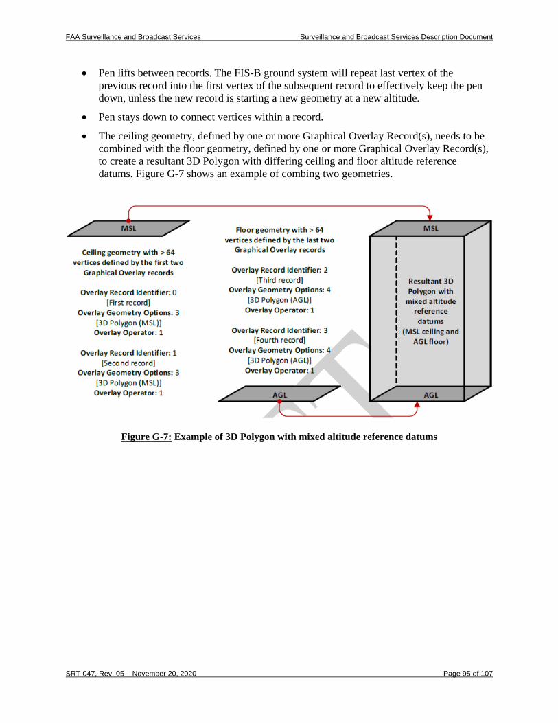
FAA Surveillance and Broadcast Services Surveillance and Broadcast Services Description Document
SRT-047, Rev. 05 – November 20, 2020 Page 95 of 107
• Pen lifts between records. The FIS-B ground system will repeat last vertex of the previous record into the first vertex of the subsequent record to effectively keep the pen down, unless the new record is starting a new geometry at a new altitude.
• Pen stays down to connect vertices within a record.
• The ceiling geometry, defined by one or more Graphical Overlay Record(s), needs to be combined with the floor geometry, defined by one or more Graphical Overlay Record(s), to create a resultant 3D Polygon with differing ceiling and floor altitude reference datums. Figure G-7 shows an example of combing two geometries.
Figure G-7: Example of 3D Polygon with mixed altitude reference datums
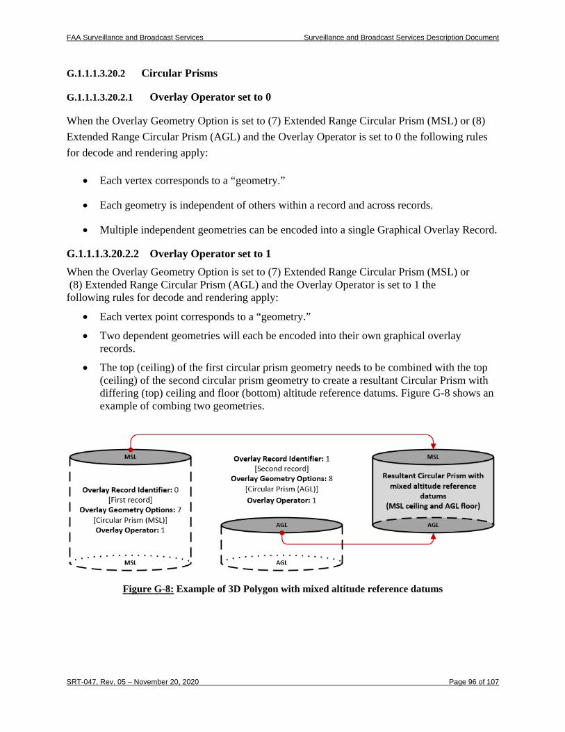
FAA Surveillance and Broadcast Services Surveillance and Broadcast Services Description Document
SRT-047, Rev. 05 – November 20, 2020 Page 96 of 107
G.1.1.1.3.20.2 Circular Prisms
G.1.1.1.3.20.2.1 Overlay Operator set to 0
When the Overlay Geometry Option is set to (7) Extended Range Circular Prism (MSL) or (8) Extended Range Circular Prism (AGL) and the Overlay Operator is set to 0 the following rules for decode and rendering apply:
• Each vertex corresponds to a “geometry.”
• Each geometry is independent of others within a record and across records.
• Multiple independent geometries can be encoded into a single Graphical Overlay Record.
G.1.1.1.3.20.2.2 Overlay Operator set to 1 When the Overlay Geometry Option is set to (7) Extended Range Circular Prism (MSL) or (8) Extended Range Circular Prism (AGL) and the Overlay Operator is set to 1 the following rules for decode and rendering apply:
• Each vertex point corresponds to a “geometry.”
• Two dependent geometries will each be encoded into their own graphical overlay records.
• The top (ceiling) of the first circular prism geometry needs to be combined with the top (ceiling) of the second circular prism geometry to create a resultant Circular Prism with differing (top) ceiling and floor (bottom) altitude reference datums. Figure G-8 shows an example of combing two geometries.
Figure G-8: Example of 3D Polygon with mixed altitude reference datums
FAA Surveillance and Broadcast Services Surveillance and Broadcast Services Description Document
SRT-047, Rev. 05 – November 20, 2020 Page 97 of 107
G.1.1.1.3.20.3 3D Points When the Overlay Geometry Option is set to (9) Extended Range 3D Point (MSL) or (10) Extended Range 3D Point (AGL) the following rules for decode and rending apply:
• Each vertex point corresponds to a “geometry.”
• Each geometry/vertex is independent of others within a record and across records.
• Multiple geometries/vertices can be encoded into a single record.
Note: The Overlay Operator for 3D Points geometries will always be set to 0.
G.1.1.1.3.20.4 3D Polylines When the Overlay Geometry Option is set to (11) Extended Range 3D Polyline (MSL) or (11) Extended Range 3D Polyline (AGL) the following rules for decode and rendering apply:
• Vertices can span multiple records.
• Pen stays down to connect vertices within a record.
• Pen lifts between records; however, the FIS-B ground system will repeat last vertex of the previous record into the first vertex of the subsequent record to effectively keep the pen down—unless starting a new geometry.
Note: The Overlay Operator for 3D Polyline geometries will always be set to 0.
G.1.1.1.3.21 Overlay Vertices Count The Overlay Vertices Count field indicates the number of vertices listed in the Overlay Vertices List field. The Overlay Count field is an optional field that is only present when the Overlay Geometry Option field is non-zero. The Overlay Vertices List can contain up to 64 polygon vertices. Since the circular prism geometries have a single vertex, up to 64 of these geometries can be included in the Overlay Vertices List. The decoding of this field requires that one be added to the Overlay Vertices Count value to get the decimal value.
G.1.1.1.3.22 Overlay Vertices List The Overlay Vertices List field is a variable length field containing a list of vertices for the geometry specified in the Overlay Geometry Options. Only one geometry type can be included in each overlay record (e.g. polygon and prism geometries cannot exist in the same record). The Overlay Vertices List field is optional and is only present when the Overlay Geometry Option field is non-zero. The number of vertices in the list is specified in the Overlay Vertices Count field.
G.1.1.2 NOTAMs and Product Updates Unavailable (Products #8, #16, #17) Within the scope of Product #8, #16, and #17, is a set of current, valid NOTAMs issued from the FAA’s NOTAM system plus special notification reports generated within the FIS-B ground
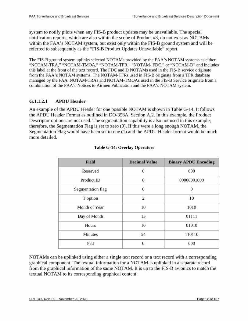
FAA Surveillance and Broadcast Services Surveillance and Broadcast Services Description Document
SRT-047, Rev. 05 – November 20, 2020 Page 98 of 107
system to notify pilots when any FIS-B product updates may be unavailable. The special notification reports, which are also within the scope of Product #8, do not exist as NOTAMs within the FAA’s NOTAM system, but exist only within the FIS-B ground system and will be referred to subsequently as the “FIS-B Product Updates Unavailable” report. The FIS-B ground system uplinks selected NOTAMs provided by the FAA’s NOTAM systems as either “NOTAM-TRA,” “NOTAM-TMOA,” “NOTAM-TFR,” “NOTAM- FDC,” or “NOTAM-D” and includes this label at the front of the text record. The FDC and D NOTAMs used in the FIS-B service originate from the FAA’s NOTAM systems. The NOTAM-TFRs used in FIS-B originate from a TFR database managed by the FAA. NOTAM-TRAs and NOTAM-TMOAs used in the FIS-B Service originate from a combination of the FAA’s Notices to Airmen Publication and the FAA’s NOTAM system.
G.1.1.2.1 APDU Header An example of the APDU Header for one possible NOTAM is shown in Table G-14. It follows the APDU Header Format as outlined in DO-358A, Section A.2. In this example, the Product Descriptor options are not used. The segmentation capability is also not used in this example; therefore, the Segmentation Flag is set to zero (0). If this were a long enough NOTAM, the Segmentation Flag would have been set to one (1) and the APDU Header format would be much more detailed.
Table G-14: Overlay Operators
Field Decimal Value Binary APDU Encoding
Reserved 0 000
Product ID 8 00000001000
Segmentation flag 0 0
T option 2 10
Month of Year 10 1010
Day of Month 15 01111
Hours 10 01010
Minutes 54 110110
Pad 0 000
NOTAMs can be uplinked using either a single text record or a text record with a corresponding graphical component. The textual information for a NOTAM is uplinked in a separate record from the graphical information of the same NOTAM. It is up to the FIS-B avionics to match the textual NOTAM to its corresponding graphical content.
FAA Surveillance and Broadcast Services Surveillance and Broadcast Services Description Document
SRT-047, Rev. 05 – November 20, 2020 Page 99 of 107
G.1.1.2.2 NOTAM Specific Notes
G.1.1.2.2.1 APDU Timestamp The APDU timestamp is encoded with one of three times depending on what information is available for a particular NOTAM. When the effective date is available, the effective start time is used in the APDU Header Time. If the effective date is not available, then the issuance date is used in the APDU Header Time. When the effective date and issuance date are not available, the time the NOTAM is first received by the FIS-B ground system is used in the APDU Header Time. The time option bits in the APDU Header Time are set to a value of 2 meaning the Month, Day, Hour and Minute are encoded.
G.1.1.2.2.2 Formatting of NOTAM Text Records The FIS-B ground system uplinks NOTAMs provided by the FAA’s NOTAM systems as either “NOTAM-TRA,” “NOTAM-TMOA,” “NOTAM-TFR,” “NOTAM-FDC”, or “NOTAM-D” and includes this label at the front of the text record. The FIS-B ground system formats the NOTAM text record in the following syntax.
<Product Type> space <Location ID> space <Timestamp> space <Text Report> Table G-15 provides descriptions of each component of the text record shown above. Note: The Text Report is slightly different from the text that is displayed at the TFR product source. The FIS-B service removes the Air Route Traffic Control Center (ARTCC) identifier. For example, “FDC 7/8493 ZMP MN..AIRSPACE ELY, MN..TEMPORARY FLIGHT RESTRICTIONS…” becomes “NOTAM-TFR 7/8493 161600Z MN..AIRSPACE ELY, MN..TEMPORARY FLIGHT RESTRICTIONS…”.
Table G-15: NOTAM Text Record Elements
Syntax Element Description
<> Denotes a required text string
space Denotes a single space character (bit encoding of 100000)
RS Denotes the Record Separator character (bit encoding of 011101)
Product Type NOTAM-D, NOTAM-FDC, NOTAM-TFR, NOTAM-TRA, or NOTAM-TMOA
XXXX.MM/### for NOTAM-D where XXXX is the four-letter location identifier, MM is the report month as indicated in the APDU header, and ### is the last three digits of the NOTAM-D report number.
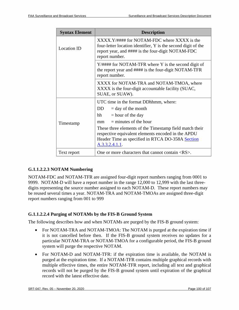
FAA Surveillance and Broadcast Services Surveillance and Broadcast Services Description Document
SRT-047, Rev. 05 – November 20, 2020 Page 100 of 107
Syntax Element Description
Location ID
XXXX.Y/#### for NOTAM-FDC where XXXX is the four-letter location identifier, Y is the second digit of the report year, and #### is the four-digit NOTAM-FDC report number.
Y/#### for NOTAM-TFR where Y is the second digit of the report year and #### is the four-digit NOTAM-TFR report number.
XXXX for NOTAM-TRA and NOTAM-TMOA, where XXXX is the four-digit accountable facility (SUAC, SUAE, or SUAW).
Timestamp
UTC time in the format DDhhmm, where: DD = day of the month hh = hour of the day mm = minutes of the hour These three elements of the Timestamp field match their respective equivalent elements encoded in the APDU Header Time as specified in RTCA DO-358A Section A.3.3.2.4.1.1.
Text report One or more characters that cannot contain <RS>.
G.1.1.2.2.3 NOTAM Numbering NOTAM-FDC and NOTAM-TFR are assigned four-digit report numbers ranging from 0001 to 9999. NOTAM-D will have a report number in the range 12,000 to 12,999 with the last three-digits representing the source number assigned to each NOTAM-D. These report numbers may be reused several times a year. NOTAM-TRA and NOTAM-TMOAs are assigned three-digit report numbers ranging from 001 to 999
G.1.1.2.2.4 Purging of NOTAMs by the FIS-B Ground System The following describes how and when NOTAMs are purged by the FIS-B ground system:
• For NOTAM-TRA and NOTAM-TMOA: The NOTAM is purged at the expiration time if it is not cancelled before then. If the FIS-B ground system receives no updates for a particular NOTAM-TRA or NOTAM-TMOA for a configurable period, the FIS-B ground system will purge the respective NOTAM.
• For NOTAM-D and NOTAM-TFR: if the expiration time is available, the NOTAM is purged at the expiration time. If a NOTAM-TFR contains multiple graphical records with multiple effective times, the entire NOTAM-TFR report, including all text and graphical records will not be purged by the FIS-B ground system until expiration of the graphical record with the latest effective date.
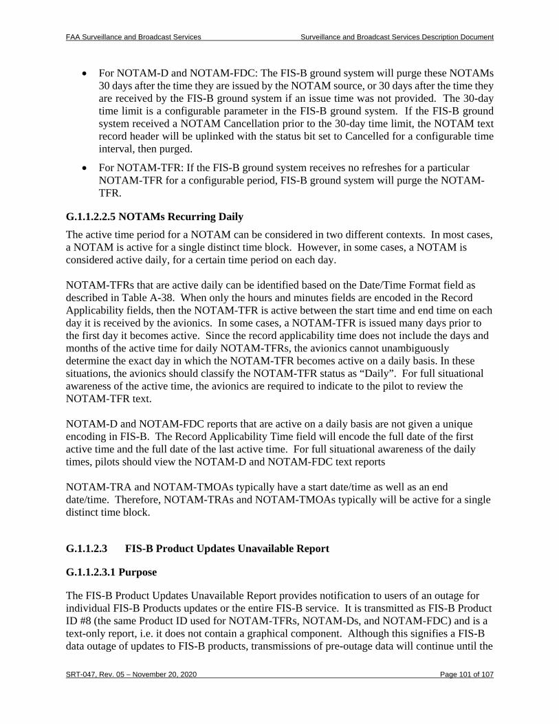
FAA Surveillance and Broadcast Services Surveillance and Broadcast Services Description Document
SRT-047, Rev. 05 – November 20, 2020 Page 101 of 107
• For NOTAM-D and NOTAM-FDC: The FIS-B ground system will purge these NOTAMs 30 days after the time they are issued by the NOTAM source, or 30 days after the time they are received by the FIS-B ground system if an issue time was not provided. The 30-day time limit is a configurable parameter in the FIS-B ground system. If the FIS-B ground system received a NOTAM Cancellation prior to the 30-day time limit, the NOTAM text record header will be uplinked with the status bit set to Cancelled for a configurable time interval, then purged.
• For NOTAM-TFR: If the FIS-B ground system receives no refreshes for a particular NOTAM-TFR for a configurable period, FIS-B ground system will purge the NOTAM-TFR.
G.1.1.2.2.5 NOTAMs Recurring Daily The active time period for a NOTAM can be considered in two different contexts. In most cases, a NOTAM is active for a single distinct time block. However, in some cases, a NOTAM is considered active daily, for a certain time period on each day. NOTAM-TFRs that are active daily can be identified based on the Date/Time Format field as described in Table A-38. When only the hours and minutes fields are encoded in the Record Applicability fields, then the NOTAM-TFR is active between the start time and end time on each day it is received by the avionics. In some cases, a NOTAM-TFR is issued many days prior to the first day it becomes active. Since the record applicability time does not include the days and months of the active time for daily NOTAM-TFRs, the avionics cannot unambiguously determine the exact day in which the NOTAM-TFR becomes active on a daily basis. In these situations, the avionics should classify the NOTAM-TFR status as “Daily”. For full situational awareness of the active time, the avionics are required to indicate to the pilot to review the NOTAM-TFR text. NOTAM-D and NOTAM-FDC reports that are active on a daily basis are not given a unique encoding in FIS-B. The Record Applicability Time field will encode the full date of the first active time and the full date of the last active time. For full situational awareness of the daily times, pilots should view the NOTAM-D and NOTAM-FDC text reports NOTAM-TRA and NOTAM-TMOAs typically have a start date/time as well as an end date/time. Therefore, NOTAM-TRAs and NOTAM-TMOAs typically will be active for a single distinct time block.
G.1.1.2.3 FIS-B Product Updates Unavailable Report
G.1.1.2.3.1 Purpose
The FIS-B Product Updates Unavailable Report provides notification to users of an outage for individual FIS-B Products updates or the entire FIS-B service. It is transmitted as FIS-B Product ID #8 (the same Product ID used for NOTAM-TFRs, NOTAM-Ds, and NOTAM-FDC) and is a text-only report, i.e. it does not contain a graphical component. Although this signifies a FIS-B data outage of updates to FIS-B products, transmissions of pre-outage data will continue until the
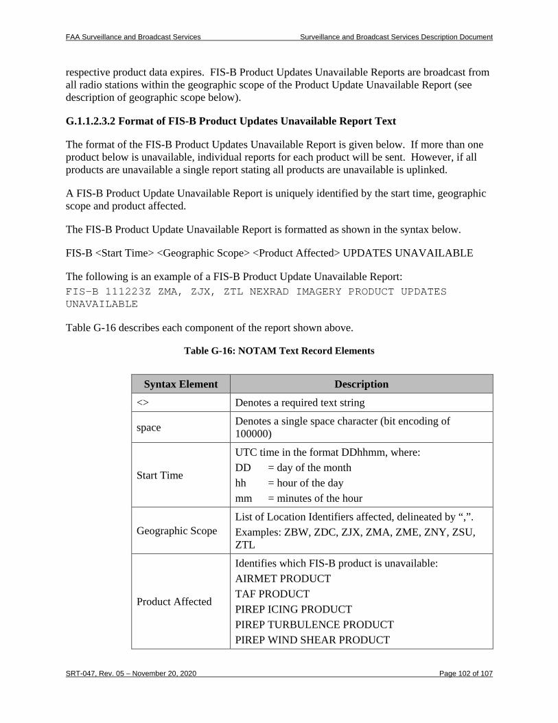
FAA Surveillance and Broadcast Services Surveillance and Broadcast Services Description Document
SRT-047, Rev. 05 – November 20, 2020 Page 102 of 107
respective product data expires. FIS-B Product Updates Unavailable Reports are broadcast from all radio stations within the geographic scope of the Product Update Unavailable Report (see description of geographic scope below).
G.1.1.2.3.2 Format of FIS-B Product Updates Unavailable Report Text
The format of the FIS-B Product Updates Unavailable Report is given below. If more than one product below is unavailable, individual reports for each product will be sent. However, if all products are unavailable a single report stating all products are unavailable is uplinked.
A FIS-B Product Update Unavailable Report is uniquely identified by the start time, geographic scope and product affected.
The FIS-B Product Update Unavailable Report is formatted as shown in the syntax below.
FIS-B <Start Time> <Geographic Scope> <Product Affected> UPDATES UNAVAILABLE
The following is an example of a FIS-B Product Update Unavailable Report: FIS-B 111223Z ZMA, ZJX, ZTL NEXRAD IMAGERY PRODUCT UPDATES UNAVAILABLE
Table G-16 describes each component of the report shown above.
Table G-16: NOTAM Text Record Elements
Syntax Element Description
<> Denotes a required text string
space Denotes a single space character (bit encoding of 100000)
Start Time
UTC time in the format DDhhmm, where: DD = day of the month hh = hour of the day mm = minutes of the hour
Geographic Scope List of Location Identifiers affected, delineated by “,”. Examples: ZBW, ZDC, ZJX, ZMA, ZME, ZNY, ZSU, ZTL
Product Affected
Identifies which FIS-B product is unavailable: AIRMET PRODUCT TAF PRODUCT PIREP ICING PRODUCT PIREP TURBULENCE PRODUCT PIREP WIND SHEAR PRODUCT
FAA Surveillance and Broadcast Services Surveillance and Broadcast Services Description Document
SRT-047, Rev. 05 – November 20, 2020 Page 103 of 107
Syntax Element Description PIREP URGENT PRODUCT ROUTINE PIREP PRODUCT TRA-NOTAM/TMOA-NOTAM PRODUCT D-NOTAM PRODUCT FDC-NOTAM PRODUCT METAR PRODUCT NEXRAD IMAGERY PRODUCT SIGMET / CONVECTIVE SIGMET PRODUCT TFR NOTAM PRODUCT SUA PRODUCT WINDS AND TEMPERATURE ALOFT PRODUCT NOTAM-FDC-CANCEL PRODUCT NOTAM-D-CANCEL PRODUCT SAN JUAN NEXRAD PRODUCT HAWAII NEXRAD PRODUCT ALASKA NEXRAD PRODUCT GUAM NEXRAD PRODUCT G-AIRMET PRODUCT CWA PRODUCT TURBULENCE PRODUCT CLOUD TOPS PRODUCT ICING PRODUCT LIGHTNING PRODUCT
Notes: 1. A separate Product Update Unavailable Report will be issued for each product.
However, when all products are unavailable a single report containing the term ALL PRODUCT is used.
2. Since the SUA product will be discarded per Requirement 07, the FIS-B Product Updates Unavailable Report referring to SUA PRODUCT will also be discarded.
3. When either the NOTAM-TRA or NOTAM-TMOA product is unavailable, it is included in the TRA-NOTAM/TMOA-NOTAM PRODUCT UNAVAILABLE message.
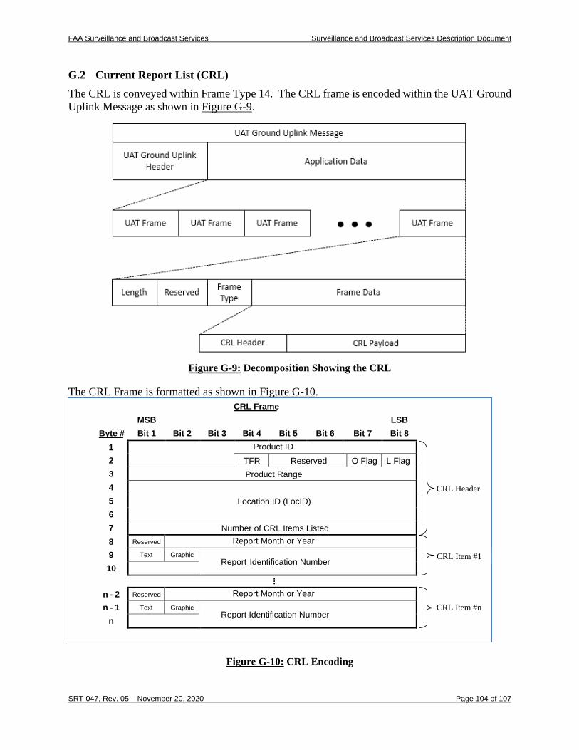
FAA Surveillance and Broadcast Services Surveillance and Broadcast Services Description Document
SRT-047, Rev. 05 – November 20, 2020 Page 104 of 107
G.2 Current Report List (CRL) The CRL is conveyed within Frame Type 14. The CRL frame is encoded within the UAT Ground Uplink Message as shown in Figure G-9.
Figure G-9: Decomposition Showing the CRL
The CRL Frame is formatted as shown in Figure G-10.
Figure G-10: CRL Encoding
CRL Frame MSB LSB
Byte # Bit 1 Bit 2 Bit 3 Bit 4 Bit 5 Bit 6 Bit 7 Bit 8 1 Product ID 2 TFR Reserved O Flag L Flag 3 Product Range 4
Location ID (LocID) 5 6 7 Number of CRL Items Listed 8 Reserved Report Month or Year 9 Text Graphic Report Identification Number 10 ...
n - 2 Reserved Report Month or Year n - 1 Text Graphic Report Identification Number n
CRL Header
CRL Item #1
CRL Item #n
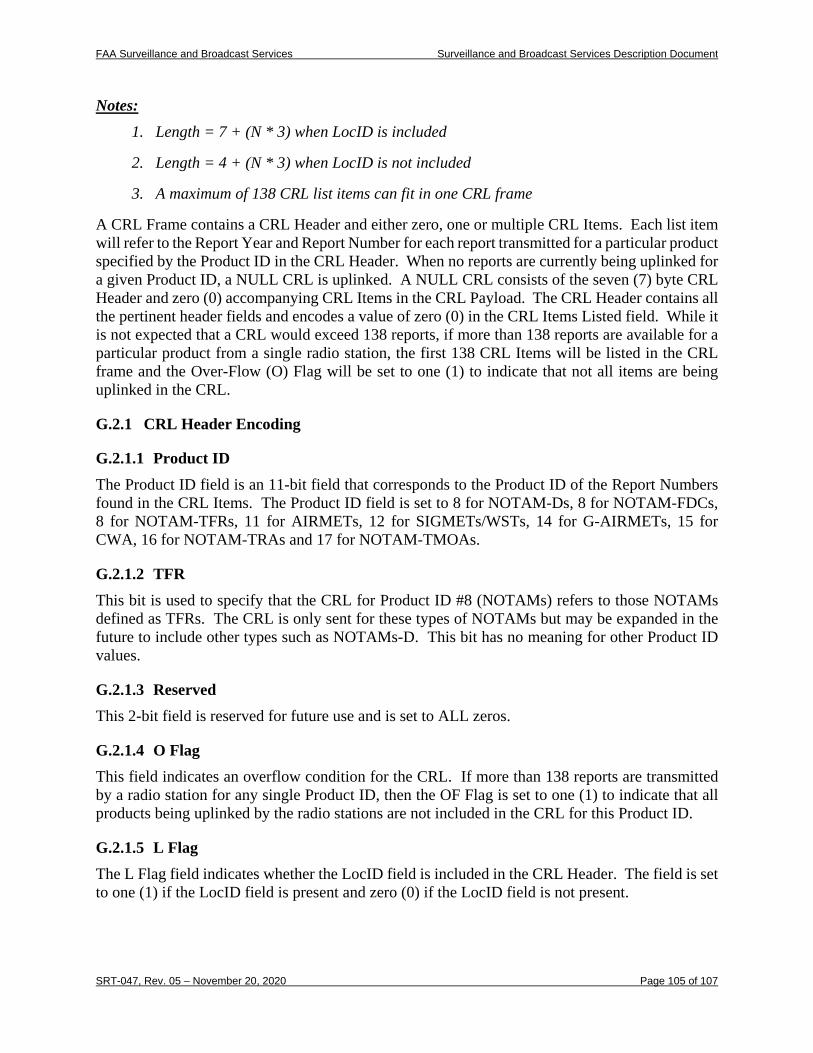
FAA Surveillance and Broadcast Services Surveillance and Broadcast Services Description Document
SRT-047, Rev. 05 – November 20, 2020 Page 105 of 107
Notes: 1. Length = 7 + (N * 3) when LocID is included
2. Length = 4 + (N * 3) when LocID is not included
3. A maximum of 138 CRL list items can fit in one CRL frame
A CRL Frame contains a CRL Header and either zero, one or multiple CRL Items. Each list item will refer to the Report Year and Report Number for each report transmitted for a particular product specified by the Product ID in the CRL Header. When no reports are currently being uplinked for a given Product ID, a NULL CRL is uplinked. A NULL CRL consists of the seven (7) byte CRL Header and zero (0) accompanying CRL Items in the CRL Payload. The CRL Header contains all the pertinent header fields and encodes a value of zero (0) in the CRL Items Listed field. While it is not expected that a CRL would exceed 138 reports, if more than 138 reports are available for a particular product from a single radio station, the first 138 CRL Items will be listed in the CRL frame and the Over-Flow (O) Flag will be set to one (1) to indicate that not all items are being uplinked in the CRL.
G.2.1 CRL Header Encoding
G.2.1.1 Product ID The Product ID field is an 11-bit field that corresponds to the Product ID of the Report Numbers found in the CRL Items. The Product ID field is set to 8 for NOTAM-Ds, 8 for NOTAM-FDCs, 8 for NOTAM-TFRs, 11 for AIRMETs, 12 for SIGMETs/WSTs, 14 for G-AIRMETs, 15 for CWA, 16 for NOTAM-TRAs and 17 for NOTAM-TMOAs.
G.2.1.2 TFR This bit is used to specify that the CRL for Product ID #8 (NOTAMs) refers to those NOTAMs defined as TFRs. The CRL is only sent for these types of NOTAMs but may be expanded in the future to include other types such as NOTAMs-D. This bit has no meaning for other Product ID values.
G.2.1.3 Reserved This 2-bit field is reserved for future use and is set to ALL zeros.
G.2.1.4 O Flag This field indicates an overflow condition for the CRL. If more than 138 reports are transmitted by a radio station for any single Product ID, then the OF Flag is set to one (1) to indicate that all products being uplinked by the radio stations are not included in the CRL for this Product ID.
G.2.1.5 L Flag The L Flag field indicates whether the LocID field is included in the CRL Header. The field is set to one (1) if the LocID field is present and zero (0) if the LocID field is not present.
FAA Surveillance and Broadcast Services Surveillance and Broadcast Services Description Document
SRT-047, Rev. 05 – November 20, 2020 Page 106 of 107
G.2.1.6 Product Range This field defines the look ahead range for the Product ID represented in this CRL. The CRL encompasses all the reports with this product ID that are within this look ahead range relative to the position of the broadcasting radio station. The Product Range is represented by an 8-bit value with an LSB of 5 NM. Therefore, the Product Range has values from 0 to 1,275 NM on 5 NM increments.
G.2.1.7 LocID The LocID field indicates the local identifier associated with the reports found in the CRL List Items. It is optional and for future use by the FIS-B service for NOTAM-Ds.
G.2.1.8 Number of CRL Items Listed This field indicates the number of items in the CRL Frame. When there are no reports currently being uplinked, the FIS-B service will set this field to zero (0), to provide the avionics a positive indication that there are no current reports being transmitted for this Product ID. The maximum value possible for this field is 138 reports.
G.2.2 CRL Payload Encoding The CRL Payload is made up of 1 to 138 CRL List Items. Each individual CRL List Item contains the following fields.
G.2.2.1 Reserved Bit This field is reserved and set to zero (0) to maintain byte boundary consistency.
G.2.2.2 Report Month or Year Note that currently the FIS-B service uplinks the CRL for all Product IDs with the Report Year. However, this resulted in ambiguous CRL information for TRA and TMOA products. Therefore, this field is being modified to contain the Report Month only when the Product ID field is 16 (NOTAM-TRA) or 17 (NOTAM-TMOA). For all other Product IDs, this field will continue to contain the Report Year. The Report Month will provide the month of the TRA or TMOA Product ID reports associated with their respective CRL List Items. It is used to aid in uniquely identifying the report. The Report Month is an exact match to the Month encoded in the corresponding report’s APDU Header Time as described in Section G.1.1.2.1. The current FIS-B uplink does not encode the Report Month for the TRA and TMOA CRL. This will be implemented in the next release of the FIS-B software that is planned to be deployed by March 2021. Early developers that are implementing the TRA and TMOA products prior to the release of RTCA DO-358B should consider this upcoming change in their designs for these items. The Report Year field indicates the year of the report within each CRL List Item. The Report Year is an exact match to the Report Year encoded in the corresponding report and described in Section G.1.1.1.2.3.
FAA Surveillance and Broadcast Services Surveillance and Broadcast Services Description Document
SRT-047, Rev. 05 – November 20, 2020 Page 107 of 107
G.2.2.3 Text The Text bit is set to indicate this report is associated with a Textual record.
G.2.2.4 Graphic The Graphic bit is set to indicate this report is associated with a Graphical record.
G.2.2.5 Report Number The Report Number provides the unique report identifier for the Product ID report associated with this CRL List Item. The Report Number is an exact match to the Report Number encoded in the corresponding report and described in Section G.1.1.1.2.2. Three LocIDs are applicable to TRA and TMOA products (SUAE, SUAC, SUAW). To ensure the avionics systems ability to unambiguously decode the CRL information for Product ID 16 (NOTAM-TRA) and Product ID 17 (NOTAM-TMOA) reports, this Location ID information will be encoded into the Report Number by the FIS-B Ground System. NOTAM-TRA and NOTAM-TMOA report numbers in the range of 13,000 to 13,999 will be issued for LocID SUAE, report numbers in the range of 14,000 to 14,999 will be issued for LocID SUAC, and report numbers in the range of 15,000 to 15,999 will be issued from LocID SUAW. The Location ID is an exact match to the Location Identifier encoded in the corresponding report’s TWGO Header as described in Section G.1.1.1.1. The current FIS-B uplink does not encode the LocID in the report number for the TRA and TMOA CRL. This will be implemented in the next release of the FIS-B software that is planned to be deployed by March 2021. Early developers that are implementing the TRA and TMOA products prior to the release of RTCA DO-358B should consider this upcoming change in their designs for these items.
Notes: 1. A text-only report will be uplinked as a single CRL List Item with the Text bit set to one
(1) and the Graphic bit set to zero (0). 2. Each CRL List Item associated with a G-AIRMET report will have the Text bit set to zero
(0) and the Graphic bit set to one (1) since the G-AIRMET product only includes a graphical record.
3. A CRL List Item representing a TWGO report with both a text and graphical record will be uplinked as a single CRL List Item with both the Text and Graphic bit set to one (1).
Related Documents