Surgical Technique Guide inViZia ® Anterior Cervical Plate System

Welcome message from author
This document is posted to help you gain knowledge. Please leave a comment to let me know what you think about it! Share it to your friends and learn new things together.
Transcript
Surgical Technique Guide
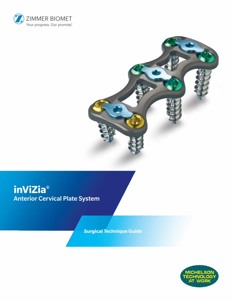
inViZia®
Anterior Cervical Plate System
2 inViZia® Anterior Cervical Plate System—Surgical Technique Guide
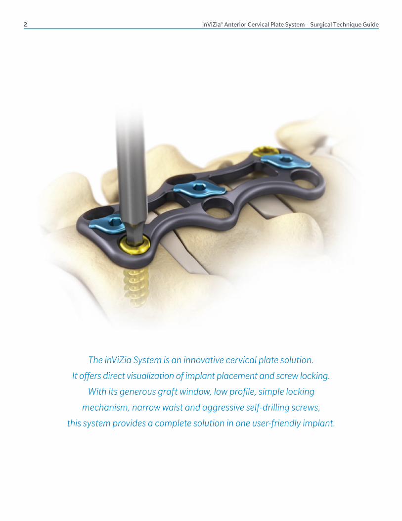
The inViZia System is an innovative cervical plate solution.
It off ers direct visualization of implant placement and screw locking.
With its generous graft window, low profi le, simple locking
mechanism, narrow waist and aggressive self-drilling screws,
this system provides a complete solution in one user-friendly implant.
inViZia® Anterior Cervical Plate System—Surgical Technique Guide 3
Zimmer Biomet Spine does not practice medicine. This technique was developed in conjunction
with health care professionals. This document is intended for surgeons and is not intended for
laypersons. Each surgeon should exercise his or her own independent judgment in the diagnosis
and treatment of an individual patient, and this information does not purport to replace the
comprehensive training surgeons have received. As with all surgical procedures, the technique
used in each case will depend on the surgeon’s medical judgment as the best treatment for each
patient. Results will vary based on health, weight, activity and other variables. Not all patients are
candidates for this product and/or procedure.
TABLE OF CONTENTS
Surgical Technique 4
Plate Bending Option 5
Temporary Fixation 6
Screw Hole Preparation 7
Revision/Removal Option 17
Implants 18
Instruments 20
Kit Contents 22
Important Information on the inViZia Cervical Plate System 26
TABLE OF CONTENTS
4 inViZia® Anterior Cervical Plate System—Surgical Technique Guide
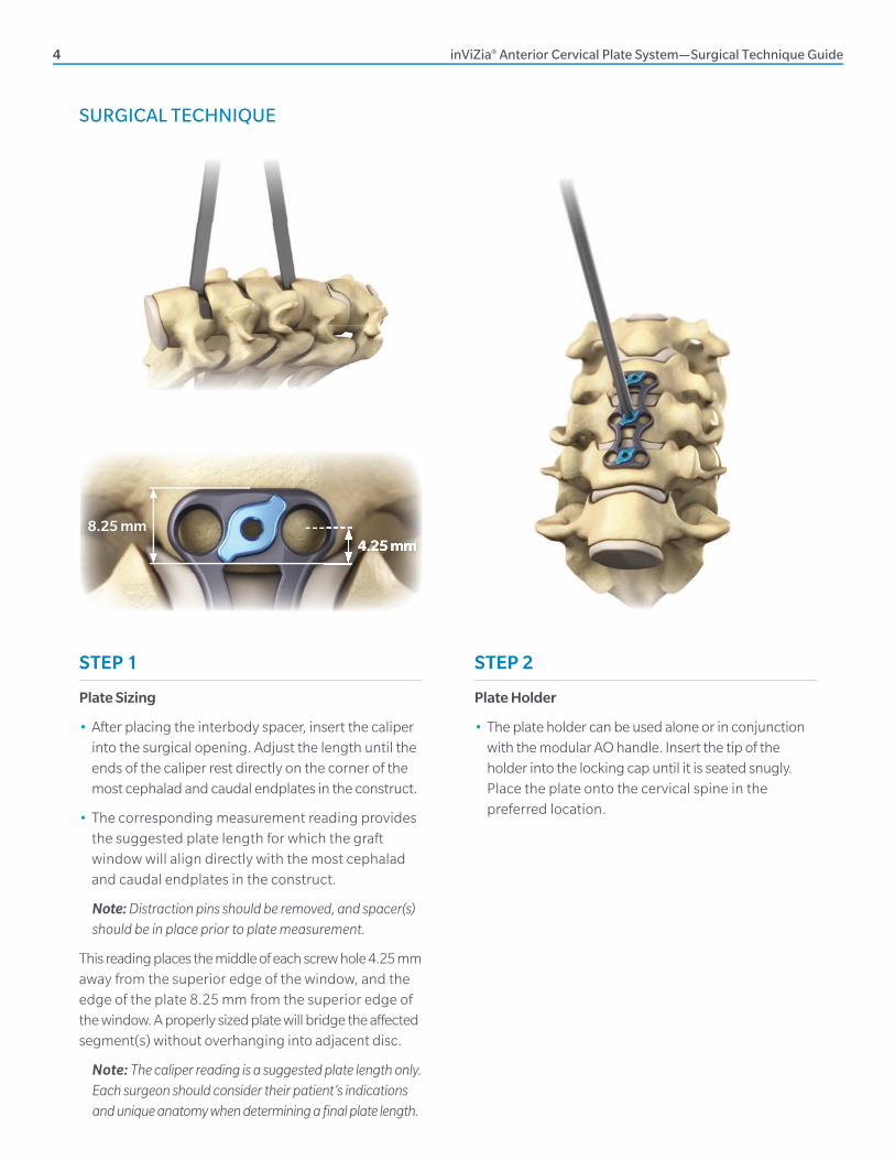
SURGICAL TECHNIQUE
STEP 1
Plate Sizing
• After placing the interbody spacer, insert the caliper into the surgical opening. Adjust the length until the ends of the caliper rest directly on the corner of the most cephalad and caudal endplates in the construct.
• The corresponding measurement reading provides the suggested plate length for which the graft window will align directly with the most cephalad and caudal endplates in the construct.
Note: Distraction pins should be removed, and spacer(s) should be in place prior to plate measurement.
This reading places the middle of each screw hole 4.25 mm away from the superior edge of the window, and the edge of the plate 8.25 mm from the superior edge of the window. A properly sized plate will bridge the aff ected segment(s) without overhanging into adjacent disc.
Note: The caliper reading is a suggested plate length only. Each surgeon should consider their patient’s indications and unique anatomy when determining a final plate length.
8.25 mm4.25 mm
STEP 2
Plate Holder
• The plate holder can be used alone or in conjunction with the modular AO handle. Insert the tip of the holder into the locking cap until it is seated snugly. Place the plate onto the cervical spine in the preferred location.
4.25 mm
inViZia® Anterior Cervical Plate System—Surgical Technique Guide 5
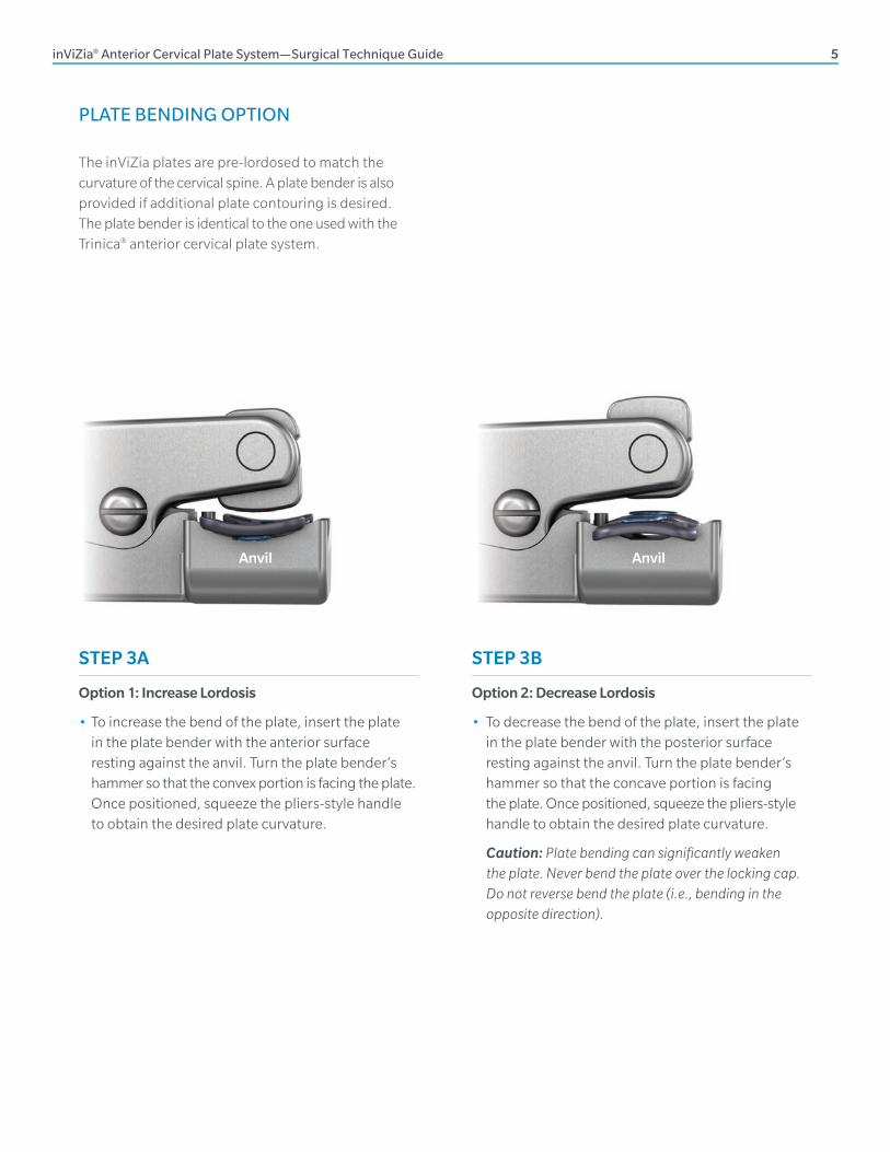
PLATE BENDING OPTION
STEP 3B
Option 2: Decrease Lordosis
• To decrease the bend of the plate, insert the plate in the plate bender with the posterior surface resting against the anvil. Turn the plate bender’s hammer so that the concave portion is facing the plate. Once positioned, squeeze the pliers-style handle to obtain the desired plate curvature.
Caution: Plate bending can signifi cantly weaken the plate. Never bend the plate over the locking cap. Do not reverse bend the plate (i.e., bending in the opposite direction).
Anvil
The inViZia plates are pre-lordosed to match the curvature of the cervical spine. A plate bender is also provided if additional plate contouring is desired. The plate bender is identical to the one used with the Trinica® anterior cervical plate system.
STEP 3A
Option 1: Increase Lordosis
• To increase the bend of the plate, insert the plate in the plate bender with the anterior surface resting against the anvil. Turn the plate bender’s hammer so that the convex portion is facing the plate. Once positioned, squeeze the pliers-style handle to obtain the desired plate curvature.
Anvil
6 inViZia® Anterior Cervical Plate System—Surgical Technique Guide
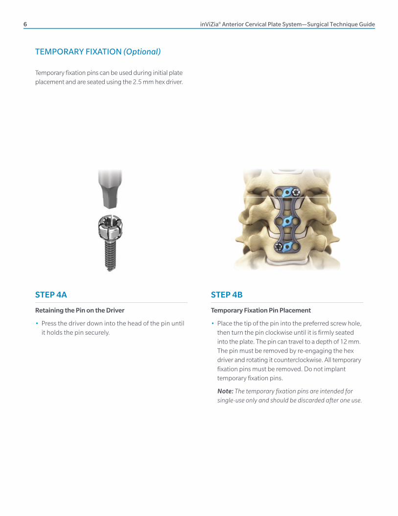
STEP 4A
Retaining the Pin on the Driver
• Press the driver down into the head of the pin until it holds the pin securely.
Temporary fi xation pins can be used during initial plate placement and are seated using the 2.5 mm hex driver.
STEP 4B
Temporary Fixation Pin Placement
• Place the tip of the pin into the preferred screw hole, then turn the pin clockwise until it is fi rmly seated into the plate. The pin can travel to a depth of 12 mm. The pin must be removed by re-engaging the hex driver and rotating it counterclockwise. All temporary fi xation pins must be removed. Do not implant temporary fi xation pins.
Note: The temporary fi xation pins are intended for single-use only and should be discarded after one use.
TEMPORARY FIXATION (Optional)
inViZia® Anterior Cervical Plate System—Surgical Technique Guide 7
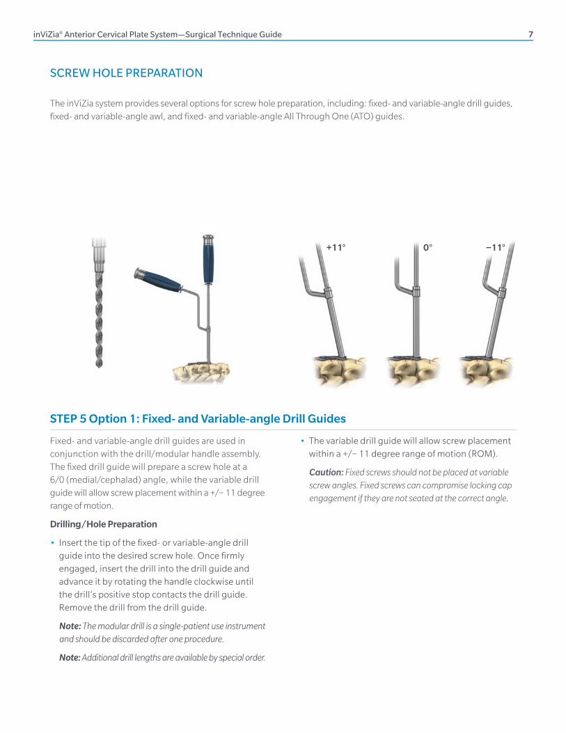
SCREW HOLE PREPARATION
The inViZia system provides several options for screw hole preparation, including: fi xed- and variable-angle drill guides, fi xed- and variable-angle awl, and fi xed- and variable-angle All Through One (ATO) guides.
+11° 0° −11°
Fixed- and variable-angle drill guides are used in conjunction with the drill/modular handle assembly. The fi xed drill guide will prepare a screw hole at a 6/0 (medial/cephalad) angle, while the variable drill guide will allow screw placement within a +/− 11 degree range of motion.
Drilling/Hole Preparation
• Insert the tip of the fi xed- or variable-angle drill guide into the desired screw hole. Once fi rmly engaged, insert the drill into the drill guide and advance it by rotating the handle clockwise until the drill’s positive stop contacts the drill guide. Remove the drill from the drill guide.
Note: The modular drill is a single-patient use instrument and should be discarded after one procedure.
Note: Additional drill lengths are available by special order.
• The variable drill guide will allow screw placement within a +/− 11 degree range of motion (ROM).
Caution: Fixed screws should not be placed at variable screw angles. Fixed screws can compromise locking cap engagement if they are not seated at the correct angle.
STEP 5 Option 1: Fixed- and Variable-angle Drill Guides
8 inViZia® Anterior Cervical Plate System—Surgical Technique Guide
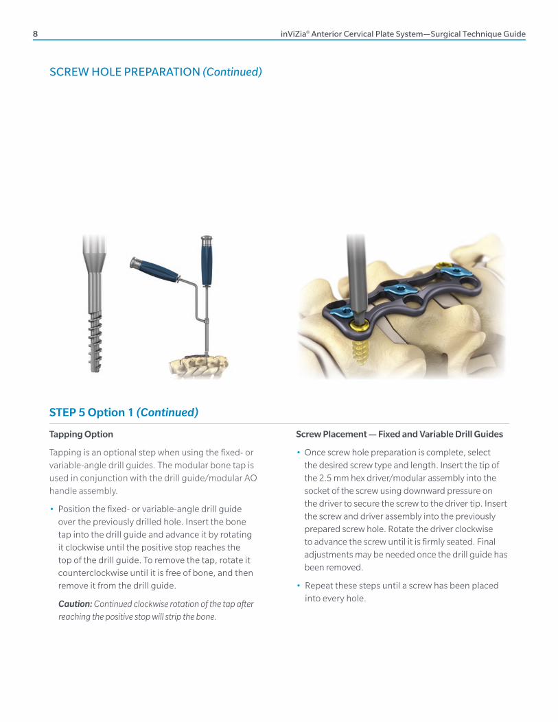
Tapping Option
Tapping is an optional step when using the fi xed- or variable-angle drill guides. The modular bone tap is used in conjunction with the drill guide/modular AO handle assembly.
• Position the fi xed- or variable-angle drill guide over the previously drilled hole. Insert the bone tap into the drill guide and advance it by rotating it clockwise until the positive stop reaches the top of the drill guide. To remove the tap, rotate it counterclockwise until it is free of bone, and then remove it from the drill guide.
Caution: Continued clockwise rotation of the tap after reaching the positive stop will strip the bone.
Screw Placement — Fixed and Variable Drill Guides
• Once screw hole preparation is complete, select the desired screw type and length. Insert the tip of the 2.5 mm hex driver/modular assembly into the socket of the screw using downward pressure on the driver to secure the screw to the driver tip. Insert the screw and driver assembly into the previously prepared screw hole. Rotate the driver clockwise to advance the screw until it is fi rmly seated. Final adjustments may be needed once the drill guide has been removed.
• Repeat these steps until a screw has been placed into every hole.
SCREW HOLE PREPARATION (Continued)
STEP 5 Option 1 (Continued)
inViZia® Anterior Cervical Plate System—Surgical Technique Guide 9
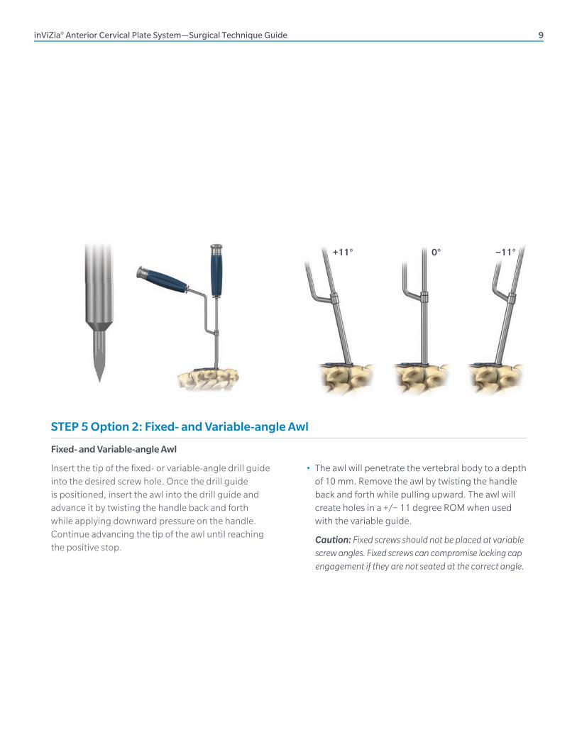
Fixed- and Variable-angle Awl
Insert the tip of the fi xed- or variable-angle drill guide into the desired screw hole. Once the drill guide is positioned, insert the awl into the drill guide and advance it by twisting the handle back and forth while applying downward pressure on the handle. Continue advancing the tip of the awl until reaching the positive stop.
• The awl will penetrate the vertebral body to a depth of 10 mm. Remove the awl by twisting the handle back and forth while pulling upward. The awl will create holes in a +/− 11 degree ROM when used with the variable guide.
Caution: Fixed screws should not be placed at variable screw angles. Fixed screws can compromise locking cap engagement if they are not seated at the correct angle.
+11° 0° −11°
STEP 5 Option 2: Fixed- and Variable-angle Awl
10 inViZia® Anterior Cervical Plate System—Surgical Technique Guide
STEP 5 Option 2 (Continued)
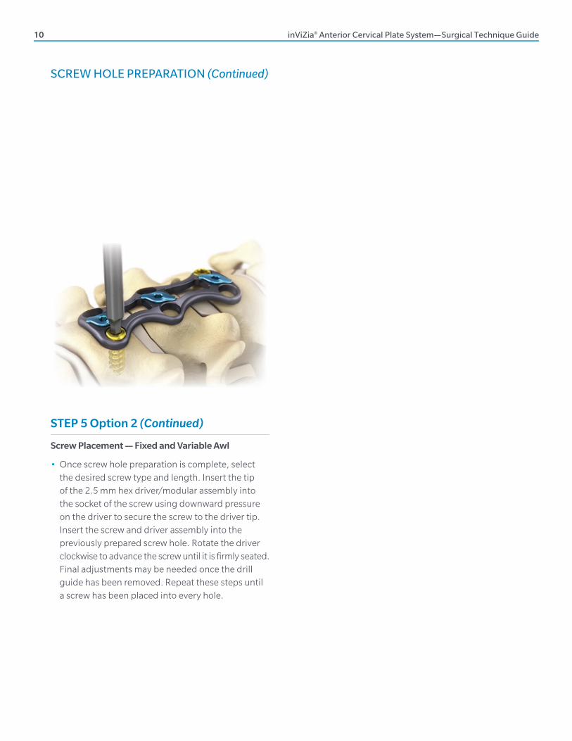
Screw Placement — Fixed and Variable Awl
• Once screw hole preparation is complete, select the desired screw type and length. Insert the tip of the 2.5 mm hex driver/modular assembly into the socket of the screw using downward pressure on the driver to secure the screw to the driver tip. Insert the screw and driver assembly into the previously prepared screw hole. Rotate the driver clockwise to advance the screw until it is fi rmly seated. Final adjustments may be needed once the drill guide has been removed. Repeat these steps until a screw has been placed into every hole.
SCREW HOLE PREPARATION (Continued)
inViZia® Anterior Cervical Plate System—Surgical Technique Guide 11
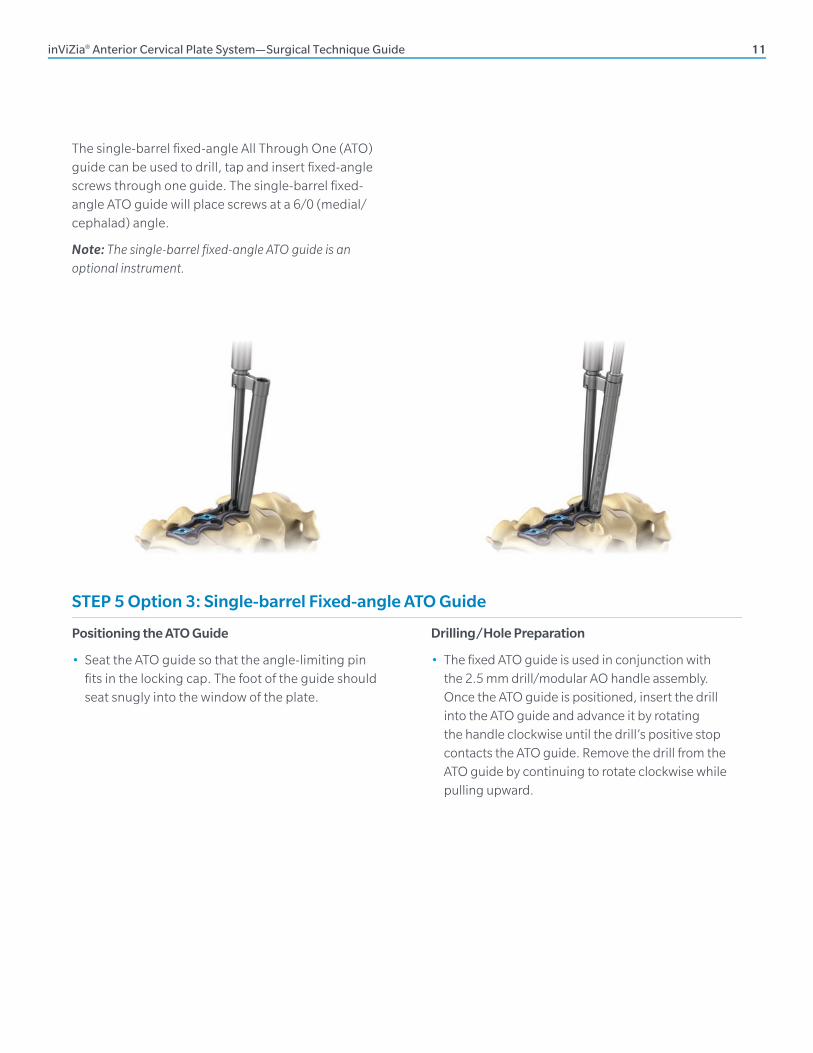
The single-barrel fi xed-angle All Through One (ATO) guide can be used to drill, tap and insert fi xed-angle screws through one guide. The single-barrel fi xed-angle ATO guide will place screws at a 6/0 (medial/cephalad) angle.
Note: The single-barrel fi xed-angle ATO guide is an optional instrument.
Positioning the ATO Guide
• Seat the ATO guide so that the angle-limiting pin fi ts in the locking cap. The foot of the guide should seat snugly into the window of the plate.
Drilling/Hole Preparation
• The fi xed ATO guide is used in conjunction with the 2.5 mm drill/modular AO handle assembly. Once the ATO guide is positioned, insert the drill into the ATO guide and advance it by rotating the handle clockwise until the drill’s positive stop contacts the ATO guide. Remove the drill from the ATO guide by continuing to rotate clockwise while pulling upward.
STEP 5 Option 3: Single-barrel Fixed-angle ATO Guide
12 inViZia® Anterior Cervical Plate System—Surgical Technique Guide
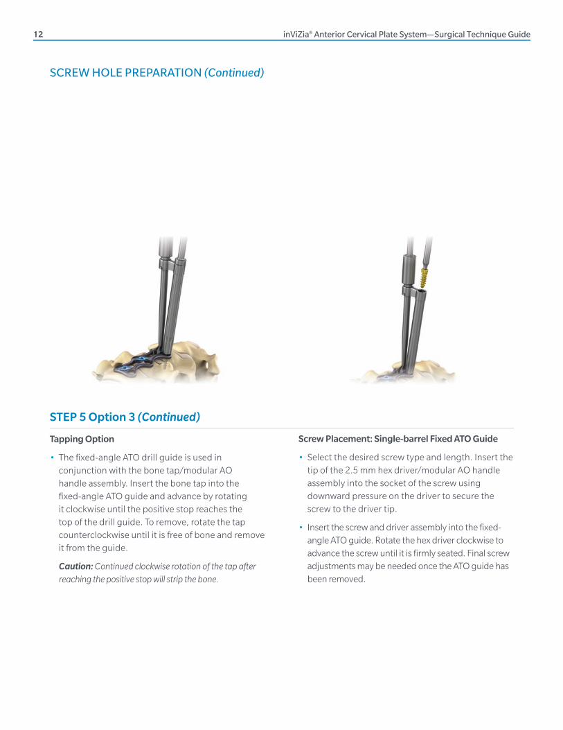
STEP 5 Option 3 (Continued)
Tapping Option
• The fi xed-angle ATO drill guide is used in conjunction with the bone tap/modular AO handle assembly. Insert the bone tap into the fi xed-angle ATO guide and advance by rotating it clockwise until the positive stop reaches the top of the drill guide. To remove, rotate the tap counterclockwise until it is free of bone and remove it from the guide.
Caution: Continued clockwise rotation of the tap after reaching the positive stop will strip the bone.
Screw Placement: Single-barrel Fixed ATO Guide
• Select the desired screw type and length. Insert the tip of the 2.5 mm hex driver/modular AO handle assembly into the socket of the screw using downward pressure on the driver to secure the screw to the driver tip.
• Insert the screw and driver assembly into the fi xed-angle ATO guide. Rotate the hex driver clockwise to advance the screw until it is fi rmly seated. Final screw adjustments may be needed once the ATO guide has been removed.
SCREW HOLE PREPARATION (Continued)
inViZia® Anterior Cervical Plate System—Surgical Technique Guide 13
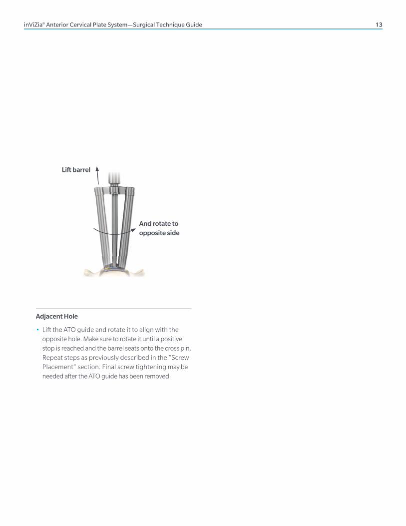
And rotate to opposite side
Lift barrel
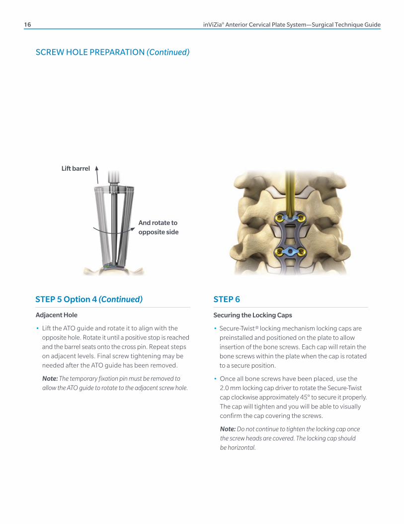
Adjacent Hole
• Lift the ATO guide and rotate it to align with the opposite hole. Make sure to rotate it until a positive stop is reached and the barrel seats onto the cross pin. Repeat steps as previously described in the “Screw Placement” section. Final screw tightening may be needed after the ATO guide has been removed.
14 inViZia® Anterior Cervical Plate System—Surgical Technique Guide
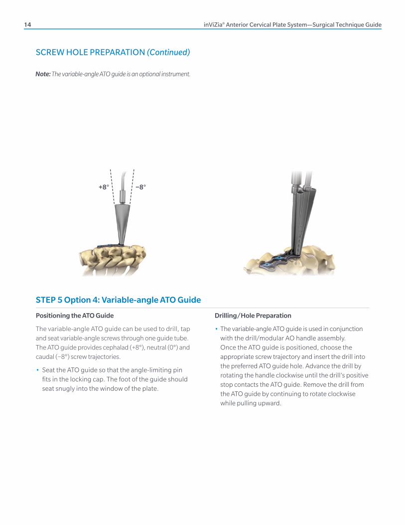
Drilling/Hole Preparation
• The variable-angle ATO guide is used in conjunction with the drill/modular AO handle assembly. Once the ATO guide is positioned, choose the appropriate screw trajectory and insert the drill into the preferred ATO guide hole. Advance the drill by rotating the handle clockwise until the drill’s positive stop contacts the ATO guide. Remove the drill from the ATO guide by continuing to rotate clockwise while pulling upward.
Note: The variable-angle ATO guide is an optional instrument.
+8° −8°
Positioning the ATO Guide
The variable-angle ATO guide can be used to drill, tap and seat variable-angle screws through one guide tube. The ATO guide provides cephalad (+8°), neutral (0°) and caudal (−8°) screw trajectories.
• Seat the ATO guide so that the angle-limiting pin fi ts in the locking cap. The foot of the guide should seat snugly into the window of the plate.
SCREW HOLE PREPARATION (Continued)
STEP 5 Option 4: Variable-angle ATO Guide
inViZia® Anterior Cervical Plate System—Surgical Technique Guide 15
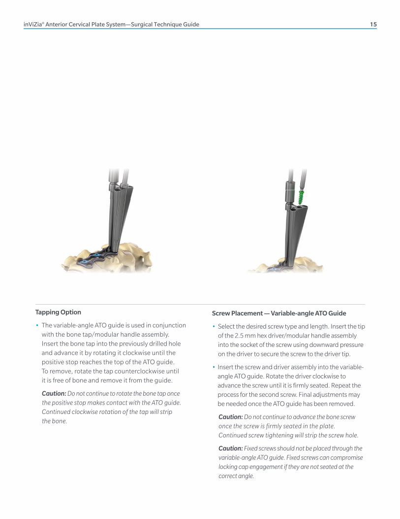
Tapping Option
• The variable-angle ATO guide is used in conjunction with the bone tap/modular handle assembly. Insert the bone tap into the previously drilled hole and advance it by rotating it clockwise until the positive stop reaches the top of the ATO guide. To remove, rotate the tap counterclockwise until it is free of bone and remove it from the guide.
Caution: Do not continue to rotate the bone tap once the positive stop makes contact with the ATO guide. Continued clockwise rotation of the tap will strip the bone.
Screw Placement — Variable-angle ATO Guide
• Select the desired screw type and length. Insert the tip of the 2.5 mm hex driver/modular handle assembly into the socket of the screw using downward pressure on the driver to secure the screw to the driver tip.
• Insert the screw and driver assembly into the variable-angle ATO guide. Rotate the driver clockwise to advance the screw until it is fi rmly seated. Repeat the process for the second screw. Final adjustments may be needed once the ATO guide has been removed.
Caution: Do not continue to advance the bone screw once the screw is firmly seated in the plate. Continued screw tightening will strip the screw hole.
Caution: Fixed screws should not be placed through the variable-angle ATO guide. Fixed screws can compromise locking cap engagement if they are not seated at the correct angle.
16 inViZia® Anterior Cervical Plate System—Surgical Technique Guide
STEP 6
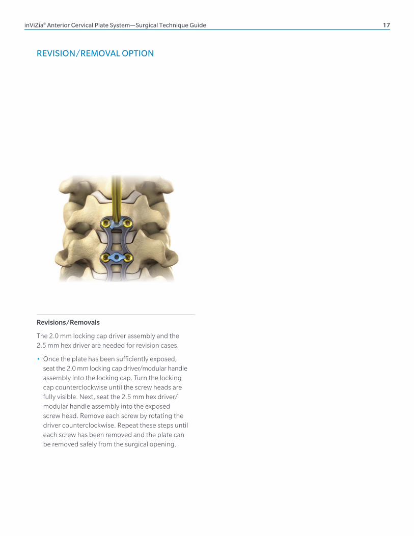
Securing the Locking Caps
• Secure-Twist ® locking mechanism locking caps are preinstalled and positioned on the plate to allow insertion of the bone screws. Each cap will retain the bone screws within the plate when the cap is rotated to a secure position.
• Once all bone screws have been placed, use the 2.0 mm locking cap driver to rotate the Secure-Twist cap clockwise approximately 45° to secure it properly. The cap will tighten and you will be able to visually confi rm the cap covering the screws.
Note: Do not continue to tighten the locking cap once the screw heads are covered. The locking cap should be horizontal.
Adjacent Hole
• Lift the ATO guide and rotate it to align with the opposite hole. Rotate it until a positive stop is reached and the barrel seats onto the cross pin. Repeat steps on adjacent levels. Final screw tightening may be needed after the ATO guide has been removed.
Note: The temporary fi xation pin must be removed to allow the ATO guide to rotate to the adjacent screw hole.
Lift barrel
And rotate to opposite side
SCREW HOLE PREPARATION (Continued)
STEP 5 Option 4 (Continued)
inViZia® Anterior Cervical Plate System—Surgical Technique Guide 17
REVISION/REMOVAL OPTION
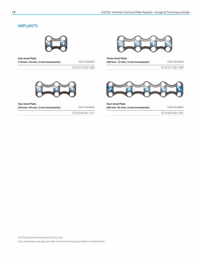
Revisions/Removals
The 2.0 mm locking cap driver assembly and the 2.5 mm hex driver are needed for revision cases.
• Once the plate has been suffi ciently exposed, seat the 2.0 mm locking cap driver/modular handle assembly into the locking cap. Turn the locking cap counterclockwise until the screw heads are fully visible. Next, seat the 2.5 mm hex driver/modular handle assembly into the exposed screw head. Remove each screw by rotating the driver counterclockwise. Repeat these steps until each screw has been removed and the plate can be removed safely from the surgical opening.
18 inViZia® Anterior Cervical Plate System—Surgical Technique Guide
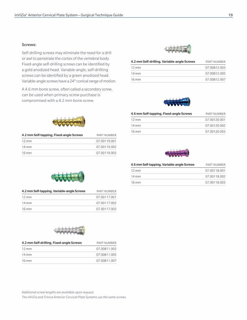
IMPLANTS
inViZia plates are measured end-to-end.
Four-level plates are special order items and are not provided in standard sets.
One-level Plate (18 mm–34 mm, 2 mm increments)
PART NUMBER
07.01615.001–009
Three-level Plate (48 mm–72 mm, 3 mm increments)
PART NUMBER
07.01617.001–009
Two-level Plate (34 mm–54 mm, 2 mm increments)
PART NUMBER
07.01616.001–011
Four-level Plate (68 mm–92 mm, 4 mm increments)
PART NUMBER
07.01618.001–007
inViZia® Anterior Cervical Plate System—Surgical Technique Guide 19
4.2 mm Self-drilling, Variable-angle Screws PART NUMBER
12 mm 07.00812.003
14 mm 07.00812.005
16 mm 07.00812.007
Additional screw lengths are available upon request.
The inViZia and Trinica Anterior Cervical Plate Systems use the same screws.
4.6 mm Self-tapping, Fixed-angle Screws PART NUMBER
12 mm 07.00120.001
14 mm 07.00120.002
16 mm 07.00120.003
4.6 mm Self-tapping, Variable-angle Screws PART NUMBER
12 mm 07.00118.001
14 mm 07.00118.002
16 mm 07.00118.003
Screws:
Self-drilling screws may eliminate the need for a drill or awl to penetrate the cortex of the vertebral body. Fixed-angle self-drilling screws can be identified by a gold anodized head. Variable-angle, self-drillling screws can be identified by a green anodized head. Variable-angle screws have a 24° conical range of motion.
A 4.6 mm bone screw, often called a secondary screw, can be used when primary screw purchase is compromised with a 4.2 mm bone screw.
4.2 mm Self-tapping, Fixed-angle Screws PART NUMBER
12 mm 07.00119.001
14 mm 07.00119.002
16 mm 07.00119.003
4.2 mm Self-tapping, Variable-angle Screws PART NUMBER
12 mm 07.00117.001
14 mm 07.00117.002
16 mm 07.00117.003
4.2 mm Self-drilling, Fixed-angle Screws PART NUMBER
12 mm 07.00811.003
14 mm 07.00811.005
16 mm 07.00811.007
20 inViZia® Anterior Cervical Plate System—Surgical Technique Guide
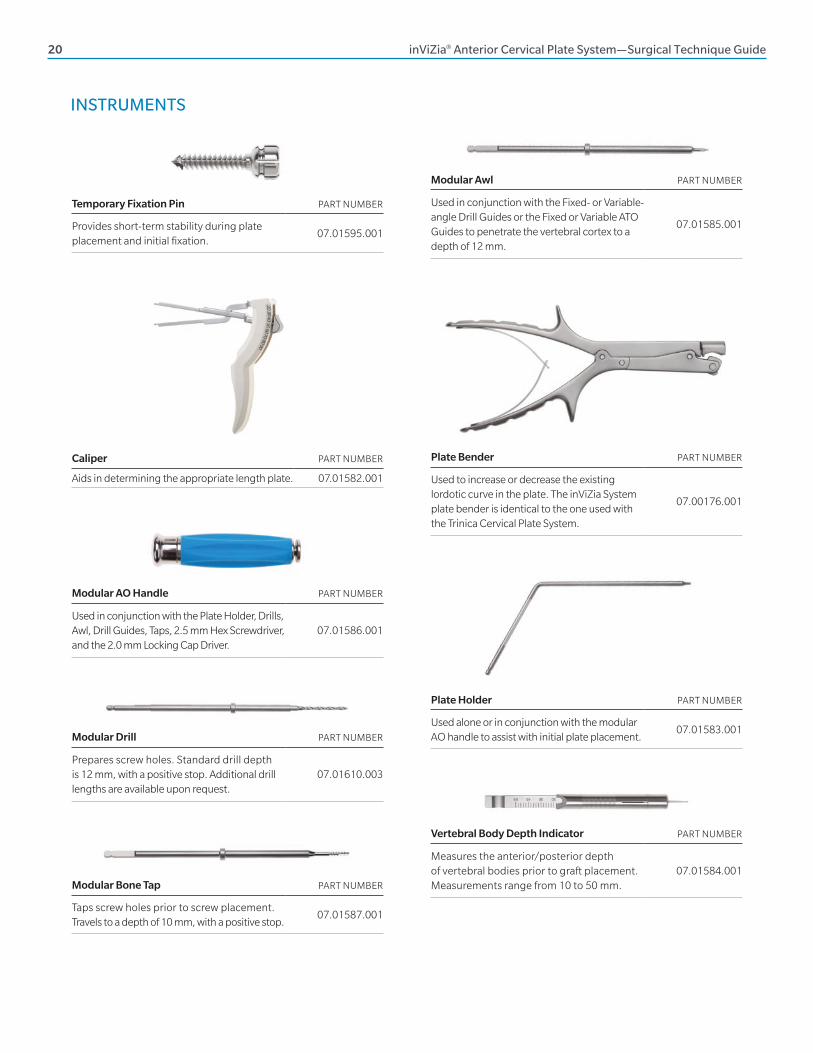
INSTRUMENTS
Temporary Fixation Pin PART NUMBER
Provides short-term stability during plate placement and initial fixation.
07.01595.001
Caliper PART NUMBER
Aids in determining the appropriate length plate. 07.01582.001
Modular AO Handle PART NUMBER
Used in conjunction with the Plate Holder, Drills, Awl, Drill Guides, Taps, 2.5 mm Hex Screwdriver, and the 2.0 mm Locking Cap Driver.
07.01586.001
Modular Drill PART NUMBER
Prepares screw holes. Standard drill depth is 12 mm, with a positive stop. Additional drill lengths are available upon request.
07.01610.003
Modular Bone Tap PART NUMBER
Taps screw holes prior to screw placement. Travels to a depth of 10 mm, with a positive stop.
07.01587.001
Modular Awl PART NUMBER
Used in conjunction with the Fixed- or Variable-angle Drill Guides or the Fixed or Variable ATO Guides to penetrate the vertebral cortex to a depth of 12 mm.
07.01585.001
Plate Bender PART NUMBER
Used to increase or decrease the existing lordotic curve in the plate. The inViZia System plate bender is identical to the one used with the Trinica Cervical Plate System.
07.00176.001
Plate Holder PART NUMBER
Used alone or in conjunction with the modular AO handle to assist with initial plate placement.
07.01583.001
Vertebral Body Depth Indicator PART NUMBER
Measures the anterior/posterior depth of vertebral bodies prior to graft placement. Measurements range from 10 to 50 mm.
07.01584.001
inViZia® Anterior Cervical Plate System—Surgical Technique Guide 21
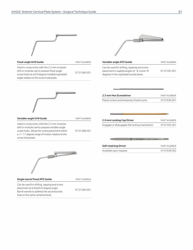
Fixed-angle Drill Guide PART NUMBER
Used in conjunction with the 2.5 mm modular drill or modular awl to prepare fixed-angle screw holes at a 6/0 degree (medial/cephalad) angle relative to the screw hole/plate.
07.01589.001
Variable-angle Drill Guide PART NUMBER
Used in conjunction with the 2.5 mm modular drill or modular awl to prepare variable-angle screw holes. Allows for screw placement within a +/− 11 degree range of motion relative to the screw hole/plate.
07.01588.001
Single-barrel Fixed ATO Guide PART NUMBER
Can be used for drilling, tapping and screw placement at a fixed 6/0 degree angle. Barrel swivels to address the second screw hole on the same vertebral level.
07.01590.001
Variable-angle ATO Guide PART NUMBER
Can be used for drilling, tapping and screw placement in sagittal angles of −8, 0 and +8 degrees in the cephalad/caudal plane.
07.01592.001
2.5 mm Hex Screwdriver PART NUMBER
Places screws and temporary fixation pins. 07.01638.001
2.0 mm Locking Cap Driver PART NUMBER
Engages or disengages the locking mechanism. 07.01593.001
Self-retaining Driver PART NUMBER
Available upon request. 07.01638.002
22 inViZia® Anterior Cervical Plate System—Surgical Technique Guide
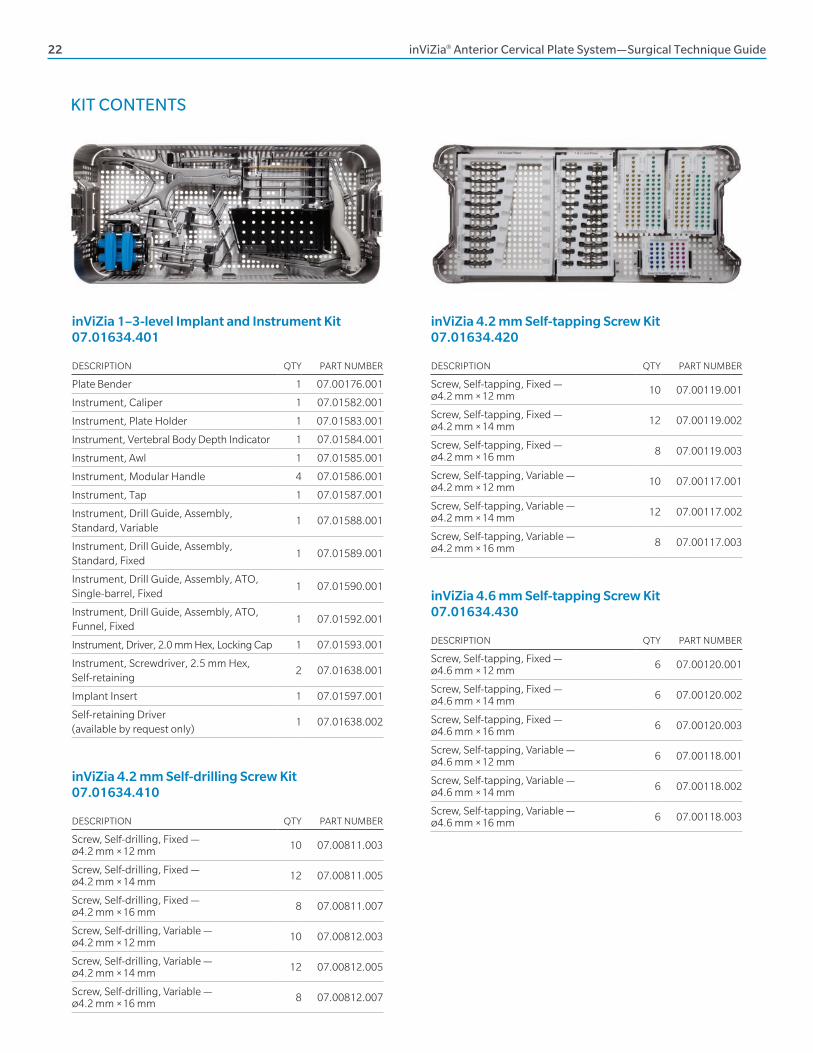
KIT CONTENTS
DESCRIPTION QTY PART NUMBER
Plate Bender 1 07.00176.001
Instrument, Caliper 1 07.01582.001
Instrument, Plate Holder 1 07.01583.001
Instrument, Vertebral Body Depth Indicator 1 07.01584.001
Instrument, Awl 1 07.01585.001
Instrument, Modular Handle 4 07.01586.001
Instrument, Tap 1 07.01587.001
Instrument, Drill Guide, Assembly, Standard, Variable
1 07.01588.001
Instrument, Drill Guide, Assembly, Standard, Fixed
1 07.01589.001
Instrument, Drill Guide, Assembly, ATO, Single-barrel, Fixed
1 07.01590.001
Instrument, Drill Guide, Assembly, ATO, Funnel, Fixed
1 07.01592.001
Instrument, Driver, 2.0 mm Hex, Locking Cap 1 07.01593.001
Instrument, Screwdriver, 2.5 mm Hex, Self-retaining
2 07.01638.001
Implant Insert 1 07.01597.001
Self-retaining Driver (available by request only)
1 07.01638.002
inViZia 1–3-level Implant and Instrument Kit 07.01634.401
DESCRIPTION QTY PART NUMBER
Screw, Self-tapping, Fixed — Ø4.2 mm × 12 mm 10 07.00119.001
Screw, Self-tapping, Fixed — Ø4.2 mm × 14 mm 12 07.00119.002
Screw, Self-tapping, Fixed — Ø4.2 mm × 16 mm 8 07.00119.003
Screw, Self-tapping, Variable — Ø4.2 mm × 12 mm 10 07.00117.001
Screw, Self-tapping, Variable — Ø4.2 mm × 14 mm 12 07.00117.002
Screw, Self-tapping, Variable — Ø4.2 mm × 16 mm 8 07.00117.003
DESCRIPTION QTY PART NUMBER
Screw, Self-drilling, Fixed — Ø4.2 mm × 12 mm 10 07.00811.003
Screw, Self-drilling, Fixed — Ø4.2 mm × 14 mm 12 07.00811.005
Screw, Self-drilling, Fixed — Ø4.2 mm × 16 mm 8 07.00811.007
Screw, Self-drilling, Variable — Ø4.2 mm × 12 mm 10 07.00812.003
Screw, Self-drilling, Variable — Ø4.2 mm × 14 mm 12 07.00812.005
Screw, Self-drilling, Variable — Ø4.2 mm × 16 mm 8 07.00812.007
inViZia 4.2 mm Self-drilling Screw Kit 07.01634.410
inViZia 4.2 mm Self-tapping Screw Kit 07.01634.420
DESCRIPTION QTY PART NUMBER
Screw, Self-tapping, Fixed — Ø4.6 mm × 12 mm 6 07.00120.001
Screw, Self-tapping, Fixed — Ø4.6 mm × 14 mm 6 07.00120.002
Screw, Self-tapping, Fixed — Ø4.6 mm × 16 mm 6 07.00120.003
Screw, Self-tapping, Variable — Ø4.6 mm × 12 mm 6 07.00118.001
Screw, Self-tapping, Variable — Ø4.6 mm × 14 mm 6 07.00118.002
Screw, Self-tapping, Variable — Ø4.6 mm × 16 mm 6 07.00118.003
inViZia 4.6 mm Self-tapping Screw Kit 07.01634.430
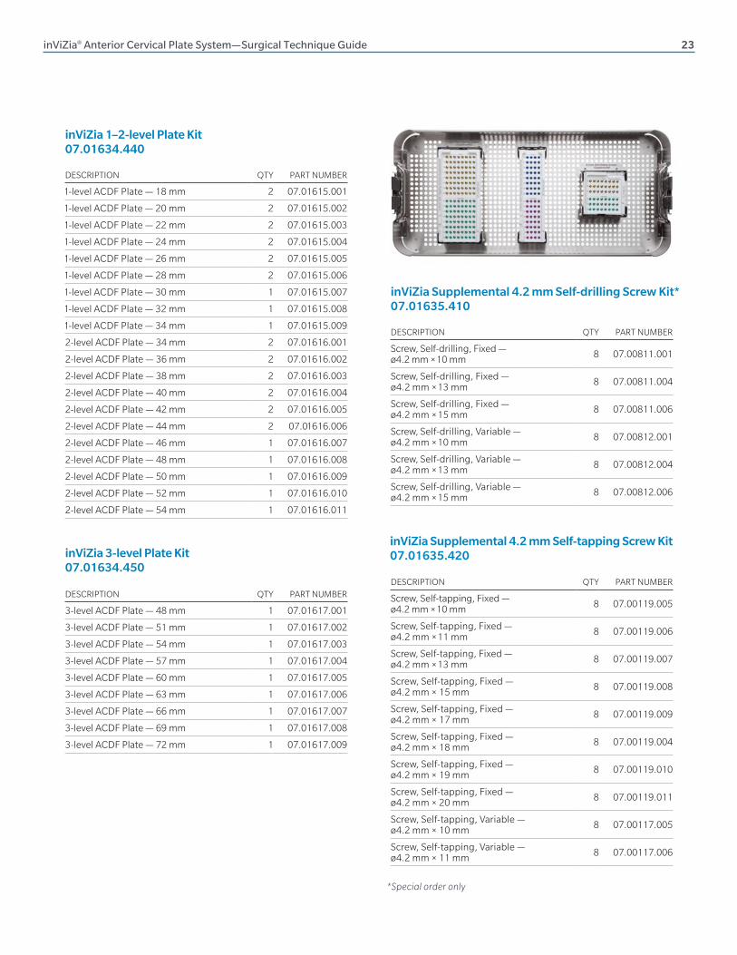
inViZia® Anterior Cervical Plate System—Surgical Technique Guide 23
DESCRIPTION QTY PART NUMBER
1-level ACDF Plate — 18 mm 2 07.01615.001
1-level ACDF Plate — 20 mm 2 07.01615.002
1-level ACDF Plate — 22 mm 2 07.01615.003
1-level ACDF Plate — 24 mm 2 07.01615.004
1-level ACDF Plate — 26 mm 2 07.01615.005
1-level ACDF Plate — 28 mm 2 07.01615.006
1-level ACDF Plate — 30 mm 1 07.01615.007
1-level ACDF Plate — 32 mm 1 07.01615.008
1-level ACDF Plate — 34 mm 1 07.01615.009
2-level ACDF Plate — 34 mm 2 07.01616.001
2-level ACDF Plate — 36 mm 2 07.01616.002
2-level ACDF Plate — 38 mm 2 07.01616.003
2-level ACDF Plate — 40 mm 2 07.01616.004
2-level ACDF Plate — 42 mm 2 07.01616.005
2-level ACDF Plate — 44 mm 2 07.0 1616.006
2-level ACDF Plate — 46 mm 1 07.01616.007
2-level ACDF Plate — 48 mm 1 07.01616.008
2-level ACDF Plate — 50 mm 1 07.01616.009
2-level ACDF Plate — 52 mm 1 07.01616.010
2-level ACDF Plate — 54 mm 1 07.01616.011
inViZia 1–2-level Plate Kit 07.01634.440
DESCRIPTION QTY PART NUMBER
Screw, Self-drilling, Fixed — ø4.2 mm × 10 mm 8 07.00811.001
Screw, Self-drilling, Fixed — ø4.2 mm × 13 mm 8 07.00811.004
Screw, Self-drilling, Fixed — ø4.2 mm × 15 mm 8 07.00811.006
Screw, Self-drilling, Variable — ø4.2 mm × 10 mm 8 07.00812.001
Screw, Self-drilling, Variable — ø4.2 mm × 13 mm 8 07.00812.004
Screw, Self-drilling, Variable — ø4.2 mm × 15 mm 8 07.00812.006
inViZia Supplemental 4.2 mm Self-drilling Screw Kit* 07.01635.410
*Special order only
DESCRIPTION QTY PART NUMBER
3-level ACDF Plate — 48 mm 1 07.01617.001
3-level ACDF Plate — 51 mm 1 07.01617.002
3-level ACDF Plate — 54 mm 1 07.01617.003
3-level ACDF Plate — 57 mm 1 07.01617.004
3-level ACDF Plate — 60 mm 1 07.01617.005
3-level ACDF Plate — 63 mm 1 07.01617.006
3-level ACDF Plate — 66 mm 1 07.01617.007
3-level ACDF Plate — 69 mm 1 07.01617.008
3-level ACDF Plate — 72 mm 1 07.01617.009
inViZia 3-level Plate Kit 07.01634.450
DESCRIPTION QTY PART NUMBER
Screw, Self-tapping, Fixed — ø4.2 mm × 10 mm 8 07.00119.005
Screw, Self-tapping, Fixed — ø4.2 mm × 11 mm 8 07.00119.006
Screw, Self-tapping, Fixed — ø4.2 mm × 13 mm 8 07.00119.007
Screw, Self-tapping, Fixed — ø4.2 mm × 15 mm 8 07.00119.008
Screw, Self-tapping, Fixed — ø4.2 mm × 17 mm 8 07.00119.009
Screw, Self-tapping, Fixed — ø4.2 mm × 18 mm 8 07.00119.004
Screw, Self-tapping, Fixed — ø4.2 mm × 19 mm 8 07.00119.010
Screw, Self-tapping, Fixed — ø4.2 mm × 20 mm 8 07.00119.011
Screw, Self-tapping, Variable — ø4.2 mm × 10 mm 8 07.00117.005
Screw, Self-tapping, Variable — ø4.2 mm × 11 mm 8 07.00117.006
inViZia Supplemental 4.2 mm Self-tapping Screw Kit 07.01635.420
24 inViZia® Anterior Cervical Plate System—Surgical Technique Guide
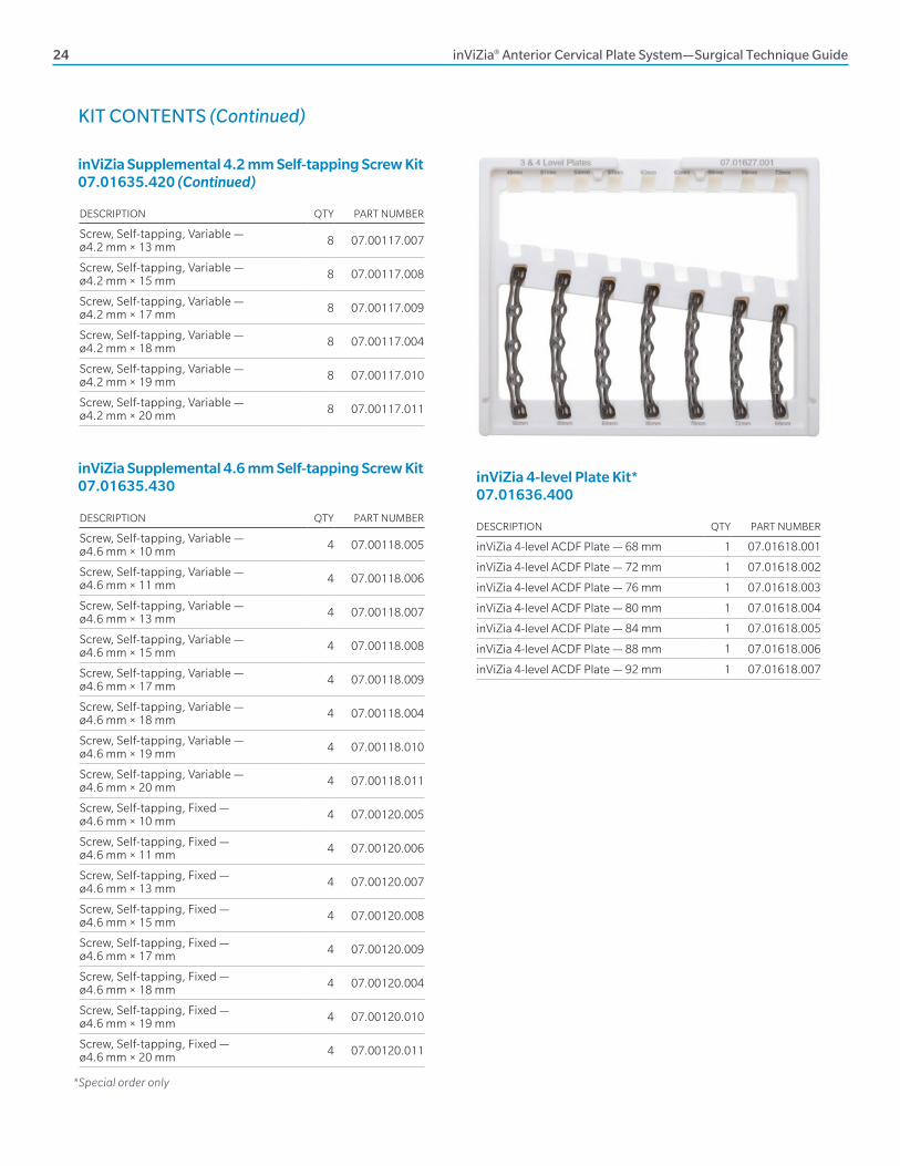
DESCRIPTION QTY PART NUMBER
Screw, Self-tapping, Variable — ø4.2 mm × 13 mm 8 07.00117.007
Screw, Self-tapping, Variable — ø4.2 mm × 15 mm 8 07.00117.008
Screw, Self-tapping, Variable — ø4.2 mm × 17 mm 8 07.00117.009
Screw, Self-tapping, Variable — ø4.2 mm × 18 mm 8 07.00117.004
Screw, Self-tapping, Variable — ø4.2 mm × 19 mm 8 07.00117.010
Screw, Self-tapping, Variable — ø4.2 mm × 20 mm 8 07.00117.011
KIT CONTENTS (Continued)
*Special order only
DESCRIPTION QTY PART NUMBER
inViZia 4-level ACDF Plate — 68 mm 1 07.01618.001
inViZia 4-level ACDF Plate — 72 mm 1 07.01618.002
inViZia 4-level ACDF Plate — 76 mm 1 07.01618.003
inViZia 4-level ACDF Plate — 80 mm 1 07.01618.004
inViZia 4-level ACDF Plate — 84 mm 1 07.01618.005
inViZia 4-level ACDF Plate — 88 mm 1 07.01618.006
inViZia 4-level ACDF Plate — 92 mm 1 07.01618.007
inViZia 4-level Plate Kit* 07.01636.400
inViZia Supplemental 4.2 mm Self-tapping Screw Kit 07.01635.420 (Continued)
DESCRIPTION QTY PART NUMBER
Screw, Self-tapping, Variable — ø4.6 mm × 10 mm 4 07.00118.005
Screw, Self-tapping, Variable — ø4.6 mm × 11 mm 4 07.00118.006
Screw, Self-tapping, Variable — ø4.6 mm × 13 mm 4 07.00118.007
Screw, Self-tapping, Variable — ø4.6 mm × 15 mm 4 07.00118.008
Screw, Self-tapping, Variable — ø4.6 mm × 17 mm 4 07.00118.009
Screw, Self-tapping, Variable — ø4.6 mm × 18 mm 4 07.00118.004
Screw, Self-tapping, Variable — ø4.6 mm × 19 mm 4 07.00118.010
Screw, Self-tapping, Variable — ø4.6 mm × 20 mm 4 07.00118.011
Screw, Self-tapping, Fixed — ø4.6 mm × 10 mm 4 07.00120.005
Screw, Self-tapping, Fixed — ø4.6 mm × 11 mm 4 07.00120.006
Screw, Self-tapping, Fixed — ø4.6 mm × 13 mm 4 07.00120.007
Screw, Self-tapping, Fixed — ø4.6 mm × 15 mm 4 07.00120.008
Screw, Self-tapping, Fixed — ø4.6 mm × 17 mm 4 07.00120.009
Screw, Self-tapping, Fixed — ø4.6 mm × 18 mm 4 07.00120.004
Screw, Self-tapping, Fixed — ø4.6 mm × 19 mm 4 07.00120.010
Screw, Self-tapping, Fixed — ø4.6 mm × 20 mm 4 07.00120.011
inViZia Supplemental 4.6 mm Self-tapping Screw Kit 07.01635.430
inViZia® Anterior Cervical Plate System—Surgical Technique Guide 25
DESCRIPTION QTY PART NUMBER
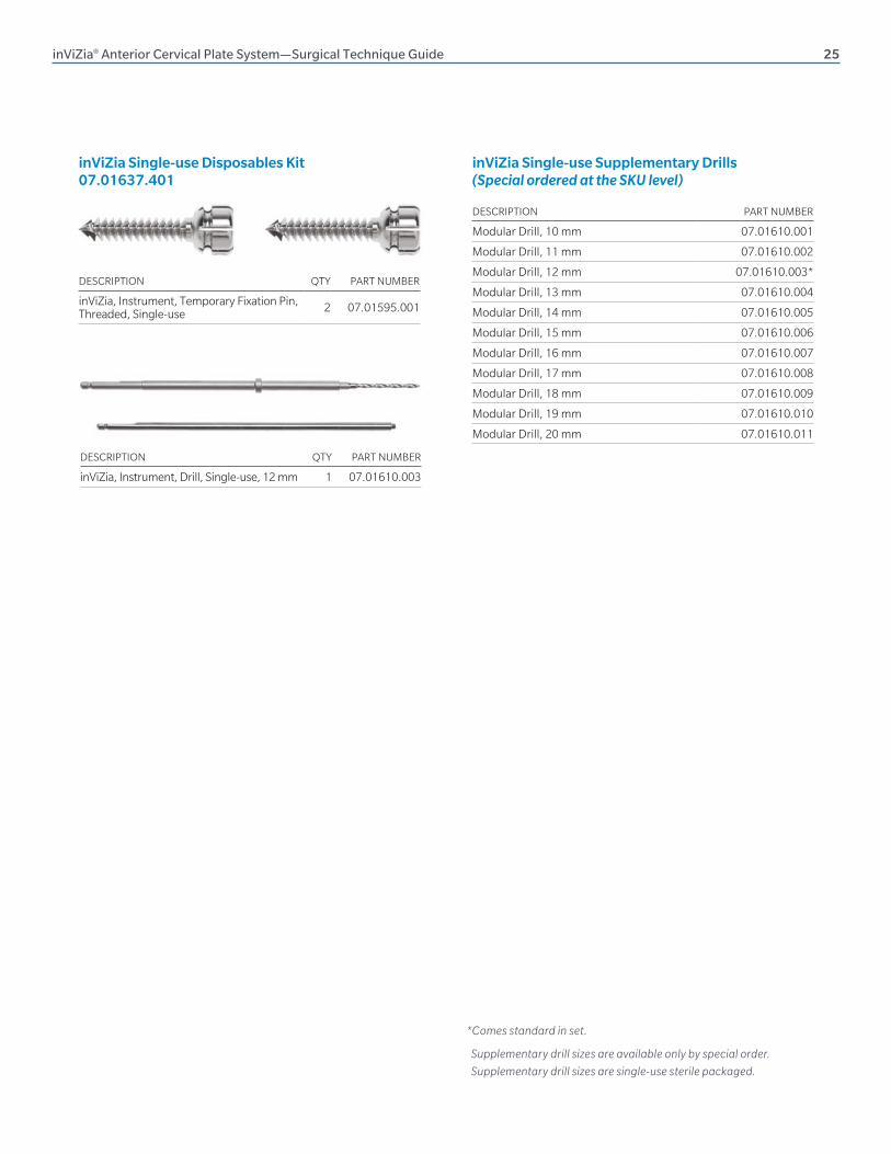
inViZia, Instrument, Drill, Single-use, 12 mm 1 07.01610.003
inViZia Single-use Disposables Kit 07.01637.401
DESCRIPTION PART NUMBER
Modular Drill, 10 mm 07.01610.001
Modular Drill, 11 mm 07.01610.002
Modular Drill, 12 mm 07.01610.003*
Modular Drill, 13 mm 07.01610.004
Modular Drill, 14 mm 07.01610.005
Modular Drill, 15 mm 07.01610.006
Modular Drill, 16 mm 07.01610.007
Modular Drill, 17 mm 07.01610.008
Modular Drill, 18 mm 07.01610.009
Modular Drill, 19 mm 07.01610.010
Modular Drill, 20 mm 07.01610.011
inViZia Single-use Supplementary Drills (Special ordered at the SKU level)
Supplementary drill sizes are available only by special order.
Supplementary drill sizes are single-use sterile packaged.
DESCRIPTION QTY PART NUMBER
inViZia, Instrument, Temporary Fixation Pin, Threaded, Single-use 2 07.01595.001
*Comes standard in set.
26 inViZia® Anterior Cervical Plate System—Surgical Technique Guide
IMPORTANT INFORMATION ON THE INVIZIA ANTERIOR CERVICAL PLATE SYSTEM
Device Description
The inViZia Anterior Cervical Plate System consists of:
• Cervical plates
• Locking caps
Fixed- and variable-angle bone screws (these are the same bone screws used in the Trinica Anterior Cervical Plate System) Instrumentation necessary for implantation of the system.
All implant components are made from titanium alloy (Ti-6Al-4V). The inViZia Anterior Cervical Plate System is intended to provide stabilization of the cervical vertebrae for the indications below. The fixation construct consists of a cervical plate that is attached to the vertebral body of the cervical spine with self-tapping and self-drilling bone screws using an anterior approach. Bone screws are available for fixed-angle or variable-angle implantation. These are the same screws used in the Trinica Anterior Cervical Plate System. The inViZia Anterior Cervical Plate System is intended to be removed after solid fusion has occurred.
Indications
The inViZia Anterior Cervical Plate System is designed for anterior interbody screw fixation of the cervical spine at levels C2–T1.
The inViZia Anterior Cervical Plate System is indicated for use in the temporary stabilization of the anterior spine during the development of cervical spinal fusions in patients with degenerative disc disease (as defined by neck pain of discogenic origin with degeneration of the disc confirmed by patient history and radiographic studies), trauma (including fractures), tumors, deformity (defined as kyphosis, lordosis or scoliosis), pseudoarthrosis and/or failed previous fusions.
Warning: This device is not approved for screw attachment to the posterior elements (pedicles) of the cervical, thoracic or lumbar spine.
Contraindications
Contraindications for use of the inViZia Anterior Cervical Plate System include:
• Overt infection or distant foci of infections
• Local inflammation, with or without fever or leukocytosis
• Pregnancy
• Diseases or conditions other than those specifically described in the Indications section
• Use in the posterior elements (pedicles) of the cervical, thoracic or lumbar vertebrae
• Where attempted correction exceeds the limits of physiologic conditions
• Uncooperative patient or patient with neurologic disorders rendering the patient incapable of following instructions
• Metabolic disorders that may impair bone formation
• Inadequate bone stock to support the device
• Inability to restrict high activity level
• Obesity
• Poor prognosis for good wound healing (e.g., decubitis ulcer, end-stage diabetes, severe protein deficiency and/or malnutrition)
Warnings
Some metals, polymers, chemicals and other materials used with orthopedic implants have been known to cause cancer and other adverse body reactions, or reports in the literature have suggested such causation. Any factor that causes chronic damage to tissues may be oncogenic. Cancer can metastasize from soft tissue sites (lung, breast, digestive system and others) to bone, including areas adjacent to implants, or it can be seeded to these locations during operative and diagnostic procedures (such as biopsies). Paget disease has been reported to progress to cancer; surgical candidates suffering from this disease should be warned accordingly.
Implantation of foreign material in tissues can elicit an inflammatory reaction. Current literature suggests that wear debris (including metal, polyethylene, ceramic, and cement particles) can initiate the process of histiocytic granuloma formation and consequent osteolysis and loosening.
Metal sensitivity has been reported following exposure to orthopedic implants. The most common metallic sensitivities (nickel, cobalt and chromium) are present in medical grade stainless steel and cobalt-chrome alloys.
inViZia Anterior Cervical Plate System is a temporary internal fixation device. Internal fixation devices are designed to stabilize the operative site during the normal healing process. After healing occurs, these devices serve no functional purpose and must be removed. Implant removal should be followed by adequate postoperative management to avoid fracture or refracture.
inViZia® Anterior Cervical Plate System—Surgical Technique Guide 27
Precautions
The inViZia Anterior Cervical Plate System instrumentation should only be used after the surgeon has had adequate training in this method of fixation and has become thoroughly knowledgeable about the spinal anatomy and biomechanics. A surgical technique for the inViZia Anterior Cervical Plate System is available upon request. This technique is not a substitute for training and is for general informational purposes only.
The inViZia System uses the Trinica System bone screws and plate bender. Components from other anterior cervical plating systems, however, should not be used with the inViZia System because compatibility has not been established.
Do not use implants made from dissimilar metals (such as cobalt chromium-molybdenum alloy or stainless steel) in contact with components of the inViZia Anterior Cervical Plate System; otherwise, galvanic corrosion may occur.
If contouring of the implant is necessary for optimal fit, the contouring should be gradual and avoid any notching or scratching of the implant(s) surface. The plates must not be repeatedly or excessively bent. Do not reverse bend the plate.
All implants and some instruments are intended for single- use only; refer to the product label to determine whether the instrument is intended for single-use only. Single-use devices should not be re-used. Possible risks associated with re-use of single-use devices include:
• Mechanical malfunction
• Transmission of infectious agents
©2017 Zimmer Biomet Spine, Inc. All rights reserved.
All content herein is protected by copyright, trademarks and other intellectual property rights, as applicable, owned by or
licensed to Zimmer Biomet Spine, Inc. or its affiliates unless otherwise indicated, and must not be redistributed, duplicated
or disclosed, in whole or in part, without the express written consent of Zimmer Biomet Spine. This material is intended for
health care professionals, the Zimmer Biomet Spine sales force and authorized representatives. Distribution to any other
recipient is prohibited.
0266.1-GLBL-en-REV0917
800.447.3625 ⁄ zimmerbiomet.com
Disclaimer: This document is intended exclusively for physicians and is not intended for laypersons. Information on the products and procedures contained in this document is of a general nature and does not represent and does not constitute medical advice or recommendations. Because this information does not purport to constitute any diagnostic or therapeutic statement with regard to any individual medical case, each patient must be examined and advised individually, and this document does not replace the need for such examination and/or advice in whole or in part.
Caution: Federal (USA) law restricts this device to sale by or on the order of a physician. Rx only. Please refer to the package inserts for important product information, including, but not limited to, indications, contraindications, warnings, precautions, adverse effects, and patient counseling information.
Manufactured by: Zimmer Biomet Spine, Inc. 10225 Westmoor Dr. Westminster, CO 80021 USA +1 800.447.3625
Zimmer GmbHSulzerallee 8CH-8404 WinterthurSwitzerland+41 058.854.80.00
Related Documents