Surgical Lead Implantation Guide NEUROSTIMULATION THERAPY FOR CHRONIC PAIN Innovating for life.

Welcome message from author
This document is posted to help you gain knowledge. Please leave a comment to let me know what you think about it! Share it to your friends and learn new things together.
Transcript

Surgical Lead Implantation GuideNeurostimulatioN therapy for ChroNiC paiN
Innovating for life.

Medtronic®, PrimeAdvanced®, Restore®, RestoreAdvanced®, RestoreUltra®, and
Specify® are registered trademarks of Medtronic, Inc.
S U R G I C A L L E A D I M P L A N T A T I O N G U I D E
Contents
3
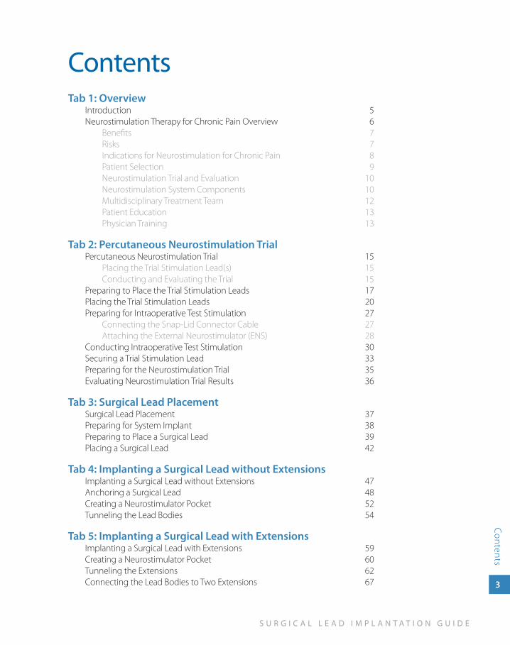
ContentsTab 1: Overview
Introduction 5Neurostimulation Therapy for Chronic Pain Overview 6
Benefits 7Risks 7Indications for Neurostimulation for Chronic Pain 8Patient Selection 9Neurostimulation Trial and Evaluation 10Neurostimulation System Components 10Multidisciplinary Treatment Team 12Patient Education 13Physician Training 13
Tab 2: Percutaneous Neurostimulation TrialPercutaneous Neurostimulation Trial 15
Placing the Trial Stimulation Lead(s) 15Conducting and Evaluating the Trial 15
Preparing to Place the Trial Stimulation Leads 17Placing the Trial Stimulation Leads 20Preparing for Intraoperative Test Stimulation 27
Connecting the Snap-Lid Connector Cable 27Attaching the External Neurostimulator (ENS) 28
Conducting Intraoperative Test Stimulation 30Securing a Trial Stimulation Lead 33Preparing for the Neurostimulation Trial 35Evaluating Neurostimulation Trial Results 36
Tab 3: Surgical Lead PlacementSurgical Lead Placement 37Preparing for System Implant 38Preparing to Place a Surgical Lead 39Placing a Surgical Lead 42
Tab 4: Implanting a Surgical Lead without ExtensionsImplanting a Surgical Lead without Extensions 47Anchoring a Surgical Lead 48Creating a Neurostimulator Pocket 52Tunneling the Lead Bodies 54
Tab 5: Implanting a Surgical Lead with ExtensionsImplanting a Surgical Lead with Extensions 59Creating a Neurostimulator Pocket 60Tunneling the Extensions 62Connecting the Lead Bodies to Two Extensions 67
4
N E U R O S T I M U L A T I O N T H E R A P Y
Con
tent
s
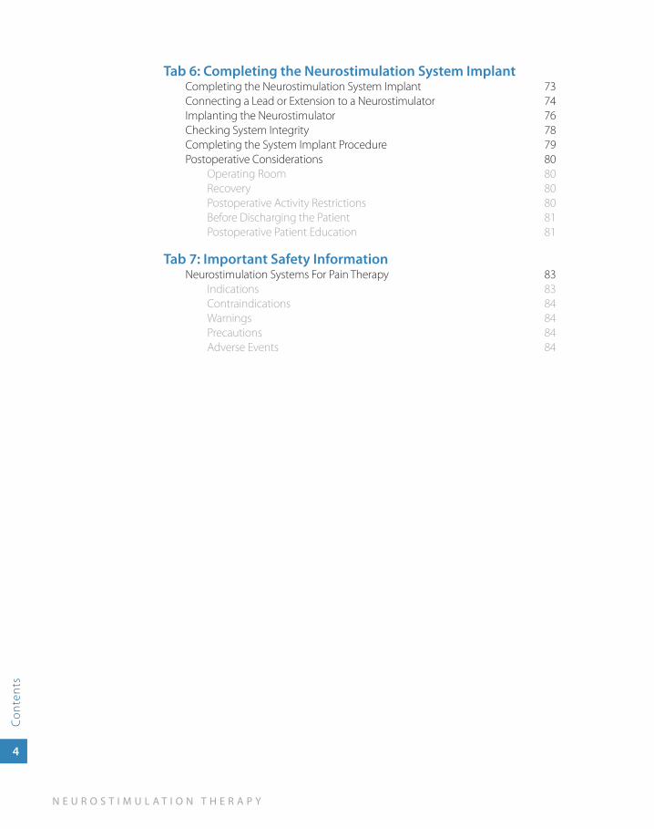
Tab 6: Completing the Neurostimulation System ImplantCompleting the Neurostimulation System Implant 73Connecting a Lead or Extension to a Neurostimulator 74Implanting the Neurostimulator 76Checking System Integrity 78Completing the System Implant Procedure 79Postoperative Considerations 80
Operating Room 80Recovery 80Postoperative Activity Restrictions 80Before Discharging the Patient 81Postoperative Patient Education 81
Tab 7: Important Safety InformationNeurostimulation Systems For Pain Therapy 83
Indications 83Contraindications 84Warnings 84Precautions 84Adverse Events 84

1o
ver
vie
w
Overview
S U R G I C A L L E A D I M P L A N T A T I O N G U I D E
Overview
5
IntroductionThe Neurostimulation Therapy for Chronic Pain Surgical Lead Implantation Guide for 16-Electrode Leads is an educational guide to be used for physician education purposes only. See the product labeling for complete indications, contraindications, warnings, cautions, adverse events, and surgical procedures for specific components.
This guide presents one representative surgical procedure. The procedure starts with a neurostimulation trial using percutaneous leads and continues through a system implant using surgical leads. Although some physicians choose to use surgical leads for neurostimulation trials, a surgical lead trial procedure is not covered in this guide. Neurostimulation programming is also not covered.
The example procedure applies to the following components:
Neurostimulation trial ■
1x8 percutaneous lead or 1x8 percutaneous trial stimulation lead »External Neurostimulator (ENS) with snap-lid connector cable »
Neurostimulation system implant ■
65-cm Specify 5-6-5 or Specify 2x8 lead »30-cm Specify 5-6-5 or Specify 2x8 lead with two 1x8 extensions »R » estore, RestoreAdvanced, PrimeAdvanced, or RestoreUltra neurostimulator
Alternate leads, anchors, extensions, and neurostimulators are available through Medtronic.
6
N E U R O S T I M U L A T I O N T H E R A P Y
Ove
rvie
w
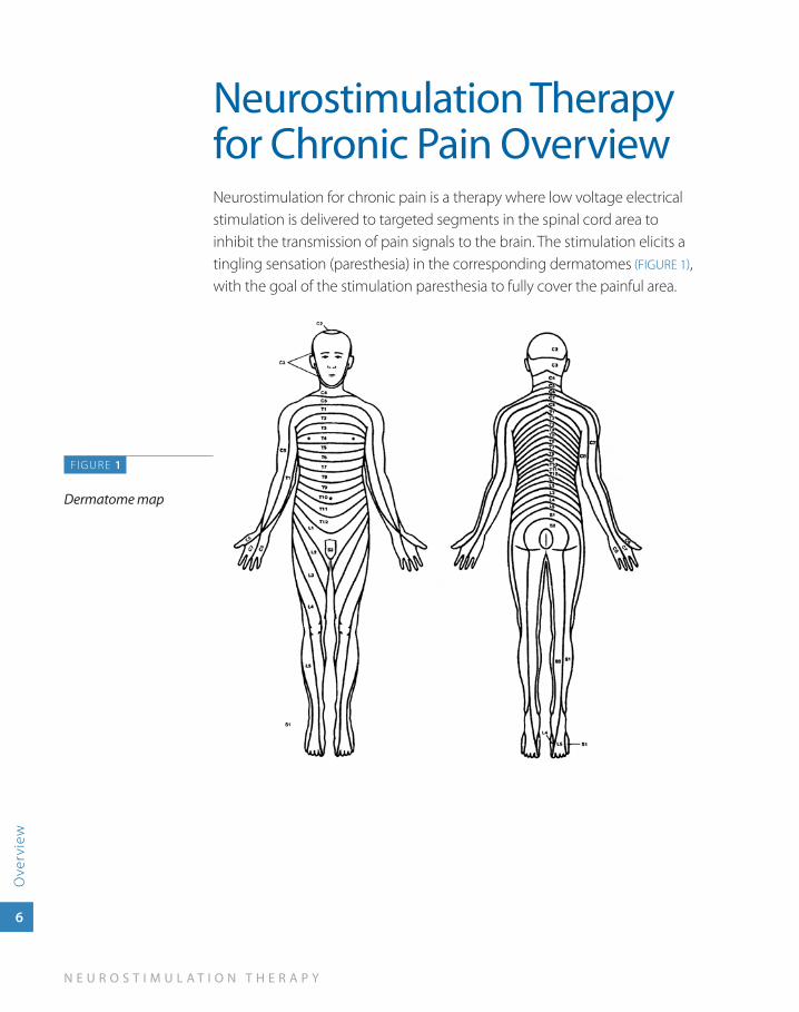
Neurostimulation Therapy for Chronic Pain OverviewNeurostimulation for chronic pain is a therapy where low voltage electrical stimulation is delivered to targeted segments in the spinal cord area to inhibit the transmission of pain signals to the brain. The stimulation elicits a tingling sensation (paresthesia) in the corresponding dermatomes (FIGURE 1), with the goal of the stimulation paresthesia to fully cover the painful area.
FIGURE 1
Dermatome map
S U R G I C A L L E A D I M P L A N T A T I O N G U I D E
Overview
7
BenefitsBenefits may include:
Significant and sustained reduction in leg and back pain ■1,2,3
Improved ability to function ■1,2
Improved participation in activities of daily living ■2,3
Less oral pain medication ■4
Safe and effective when used as directed ■
Reversible—therapy can be turned off or, if desired, the neurostimulator ■
can be surgically removed
RisksCommon adverse effects include:
Lead movement resulting in a change in stimulation or loss of stimulation ■
Intermittent stimulation ■
Uncomfortable stimulation ■
Pain at the neurostimulator site ■
Programmer or data transmission problems ■
Serious adverse effects are possible, but occur less frequently and include:
Postsurgical infection ■
Hematoma or seroma developing in the area where the neurostimulator ■
is implanted
Spinal cord injury from incorrect surgical placement of the lead ■
Device complications requiring surgery to relocate, revise, or replace ■
system components
See Important Safety Information on page 83 and page 84 for more details.
1. Kumar K, Taylor RS, Jacques L, et al. Spinal cord stimulation versus conventional medical management for neuropathic pain: a multicentre randomised controlled trial in patients with failed back surgery syndrome. Pain. 2007;132:179-188.
2. Kumar K, Taylor RS, Jacques L, et al. The effects of spinal cord stimulation in neuropathic pain are sustained: a 24-month follow-up of the prospective randomized controlled multicenter trial of the effectiveness of spinal cord stimulation. Neurosurgery. 2008;63: 762-770.
3. Turner JA, Loseser JD, Deyo RA, Sanders SB. Spinal cord stimulation for patients with failed back surgery syndrome or complex regional pain syndrome: a systematic review of effectiveness and complications. Pain. 2004;108:137-147.
4. Ohnmeiss DD, Rashbaum RF, Bogdanffy GM. Prospective outcome evaluation of spinal cord stimulation in patients with intractable leg pain. Spine. 1996;21:1344-1350.
8
N E U R O S T I M U L A T I O N T H E R A P Y
Ove
rvie
w
Indications for Neurostimulation for Chronic PainA Medtronic implantable neurostimulation system is indicated for spinal cord stimulation (SCS) system as an aid in the management of chronic, intractable pain of the trunk and/or limbs—including unilateral or bilateral pain associated with the following conditions:
Failed back syndrome (FBS) or low back syndrome or failed back ■
Radicular pain syndrome or radiculopathies resulting in pain secondary ■
to FBS or herniated disk
Postlaminectomy pain ■
Multiple back operations ■
Unsuccessful disk surgery ■
Degenerative disk disease (DDD)/herniated disk pain refractory to ■
conservative and surgical interventions
Peripheral causalgia ■
Epidural fibrosis ■
Arachnoiditis or lumbar adhesive arachnoiditis ■
Complex regional pain syndrome (CRPS), reflex sympathetic ■
dystrophy (RSD), or causalgia
S U R G I C A L L E A D I M P L A N T A T I O N G U I D E
Overview
9
Patient SelectionIdentifying appropriate candidates is critical for increased patient satisfaction and for therapy success. Following standard pain evaluation practices, relevant information regarding the patient’s pain history is collected. The patient’s pain history is then evaluated in combination with criteria that includes:
Chronic, intractable pain for more than 3 months ■
Lack of adequate relief from more conventional treatments ■
Objective evidence of pathology ■
Initial or further surgical intervention not indicated ■
No contraindications to therapy or surgery exist ■
Patient can properly operate system ■
Patient understands therapy risks ■
Therapy goals have been established ■
Satisfactory results from neurostimulation trial ■
No untreated substance abuse ■
Psychological clearance obtained ■
18 years of age or older ■
Patient is not pregnant ■
10
N E U R O S T I M U L A T I O N T H E R A P Y
Ove
rvie
w
Neurostimulation Trial and EvaluationA typical neurostimulation system implant with surgical leads is completed in two stages. The first stage is a 3- to 10-day neurostimulation trial. The neurostimulation trial system described in this guide uses percutaneous leads and an External Neurostimulator (ENS). Some physicians use surgical leads for the trial.
To prepare for a neurostimulation trial using percutaneous lead(s), one or more percutaneous lead(s) are placed into the epidural space. The clinician programs the portable ENS to generate the electrical pulses that produce the desired stimulation.
During the trial, the patient uses the neurostimulation trial system while completing daily activities. In some cases, the patient can use a patient control device to change some stimulation settings within physician-programmed limits.
Throughout the trial, the ENS collects patient use data. The patient also records activities, stimulation settings, and degree of pain relief in a trial log. After the trial, the results are evaluated to determine if the patient is a candidate for the second stage, a neurostimulation system implant.
Neurostimulation System ComponentsIn a neurostimulation system, the following components are implanted:
Neurostimulator—Rechargeable or nonrechargeable implanted power ■
source that generates electrical pulses according to programmable stimulation parameters and features.
Lead—A set of thin wires with a protective coating and electrodes ■
near the tip (percutaneous lead) or on a paddle (surgical lead). The electrodes transmit the electrical pulses to the stimulation site.
Extension—A set of thin wires with a protective coating that connects ■
the neurostimulator to the lead (not required for all neurostimulation systems).
S U R G I C A L L E A D I M P L A N T A T I O N G U I D E
Overview
11
Additional components are used during a neurostimulation trial or to program, control, and maintain an implanted or trial neurostimulation system:
External Neurostimulator (ENS)—External, programmable ■
neurostimulator used during intraoperative lead placement and during the neurostimulation trial. The ENS produces comparable paresthesia to the Restore, RestoreAdvanced, PrimeAdvanced, and RestoreUltra neurostimulators when set to the same parameter settings.
Clinician programmer—Handheld programmer used by the clinician to ■
program all stimulation parameters and features.
Patient programmer—Handheld programmer used by the patient to: ■
Turn the neurostimulator on and off. »Make adjustments to stimulation parameters within »physician-prescribed limits.
Battery Charger—Portable recharger used by the patient to charge ■
the neurostimulator battery (applicable in rechargeable neurostimulation systems).
12
N E U R O S T I M U L A T I O N T H E R A P Y
Ove
rvie
w
Multidisciplinary Treatment TeamWhether neurostimulation therapy is being prescribed and implanted in a comprehensive pain center or through a network of referrals, a multidisciplinary team should be established.
The team members include:
Referring physician team ■
Implanting physician team ■
Psychologist—Before the trial evaluation, the psychologist can: ■
Help patient specify clear goals »Reinforce realistic pain relief expectations »Administer and interpret a psychological assessment »
Patient Management Coordinator (PMC)—Preferably trained as a ■
clinical nurse or nurse practitioner, the PMC coordinates:Patient evaluation and education »Pain clinic support »Ongoing patient management and outcome tracking »
Other team members may include: ■
Physician assistants »Physical therapists »Physiatrists »Occupational therapists » Vocational counselors »

S U R G I C A L L E A D I M P L A N T A T I O N G U I D E
Overview
13
Patient EducationThorough preoperative and postoperative patient education is crucial to the long-term success of neurostimulation therapy. In addition to standard preoperative and postoperative patient education topics, the patient, family, and caregiver should be educated on topics including the neurostimulation trial and neurostimulation system implant procedure, risks and benefits, device operation, device maintenance, and patient activity restrictions. Medtronic produces a number of materials such as brochures, DVDs, and patient manuals to use in patient education.
Physician TrainingPrescribing physicians should be experienced in the diagnosis and treatment of chronic intractable pain, and should be familiar with using the neurostimulation system. Implanting physicians should be experienced in epidural access procedures, trained in the use of neurostimulation devices, and thoroughly familiar with all product labeling.

2 per
cu
tan
eou
s n
eur
ostim
ula
tion
tria
l
PercutaneousNeurostimulation
Trial
S U R G I C A L L E A D I M P L A N T A T I O N G U I D E
Percutaneous Neurostim
ulation Trial
15
Percutaneous Neurostimulation TrialThe example procedure in this guide covers placing percutaneous lead(s) without an extension (percutaneous trial) and conducting intraoperative stimulation. A trial may also be completed using one or more percutaneous lead(s) with extension(s) or a surgical lead with extensions (buried lead trial).
Placing the Trial Stimulation Lead(s)Lead placement is done under local anesthesia. Since the patient must interact during anesthesia, monitored anesthesia care (MAC) should be implemented according to physician judgment.
To place the lead(s), one or more percutaneous leads are introduced into the epidural space with the objective of positioning the electrodes near the spinal segment that innervates the targeted anatomical site. The proximal end of the lead(s) are externalized and temporarily anchored (e.g., with medical tape) at the skin exit site(s). The externalized end of the lead(s) are connected to a cable that is attached to an External Neurostimulator (ENS).
Intraoperative test stimulation is used to position the lead(s), select the electrodes, and select the initial parameter settings for stimulation. During intraoperative test stimulation, the patient responds to questions as to whether paresthesia covers the painful regions.
Conducting and Evaluating the TrialDuring the 3- to 10-day neurostimulation trial, the patient uses the trial system while completing daily activities. In some cases, the patient can use a patient control device to change some stimulation settings within programmed limits.
The ENS collects patient use data. The patient also records activities, stimulation settings, and degree of pain relief in a trial log. The pain
16
N E U R O S T I M U L A T I O N T H E R A P Y
Perc
utan
eous
Neu
rost
imul
atio
n Tr
ial
management team uses the data collected by the ENS and the entries in the trial log to evaluate if the neurostimulation trial is successful and if the patient is a candidate for a neurostimulation system implant.
After the trial, the lead(s) from a percutaneous trial are removed.
The example procedure in this section uses the following components:
One or more 1x8 percutaneous leads or 1x8 percutaneous trial leads ■
Alternate leads are available through Medtronic.
S U R G I C A L L E A D I M P L A N T A T I O N G U I D E
Percutaneous Neurostim
ulation Trial
17
Preparing to Place the Trial Stimulation Leads
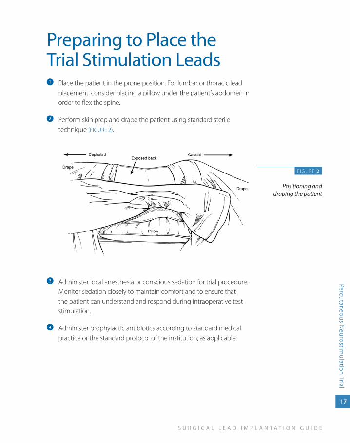
Place the patient in the prone position. For lumbar or thoracic lead a
placement, consider placing a pillow under the patient’s abdomen in order to flex the spine.
Perform skin prep and drape the patient using standard sterile b
technique (FIGURE 2).
Administer local anesthesia or conscious sedation for trial procedure. c
Monitor sedation closely to maintain comfort and to ensure that the patient can understand and respond during intraoperative test stimulation.
Administer prophylactic antibiotics according to standard medical d
practice or the standard protocol of the institution, as applicable.
F IGURE 2
Positioning and draping the patient
18
N E U R O S T I M U L A T I O N T H E R A P Y
Perc
utan
eous
Neu
rost
imul
atio
n Tr
ial
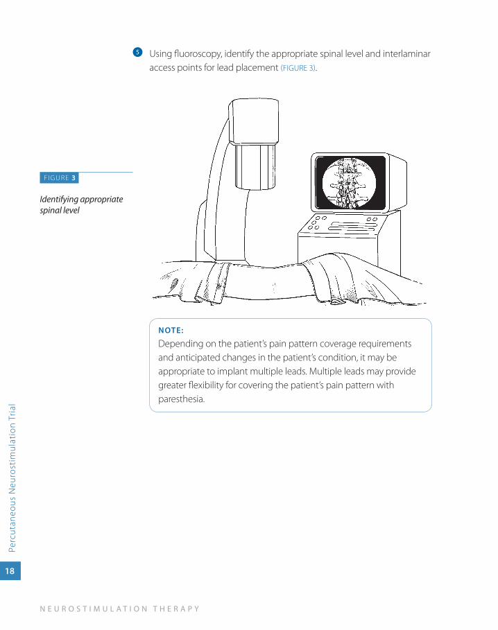
Using fluoroscopy, identify the appropriate spinal level and interlaminar e
access points for lead placement (FIGURE 3).
NOTE:
Depending on the patient’s pain pattern coverage requirements and anticipated changes in the patient’s condition, it may be appropriate to implant multiple leads. Multiple leads may provide greater flexibility for covering the patient’s pain pattern with paresthesia.
FIGURE 3
Identifying appropriate spinal level
S U R G I C A L L E A D I M P L A N T A T I O N G U I D E
Percutaneous Neurostim
ulation Trial
19
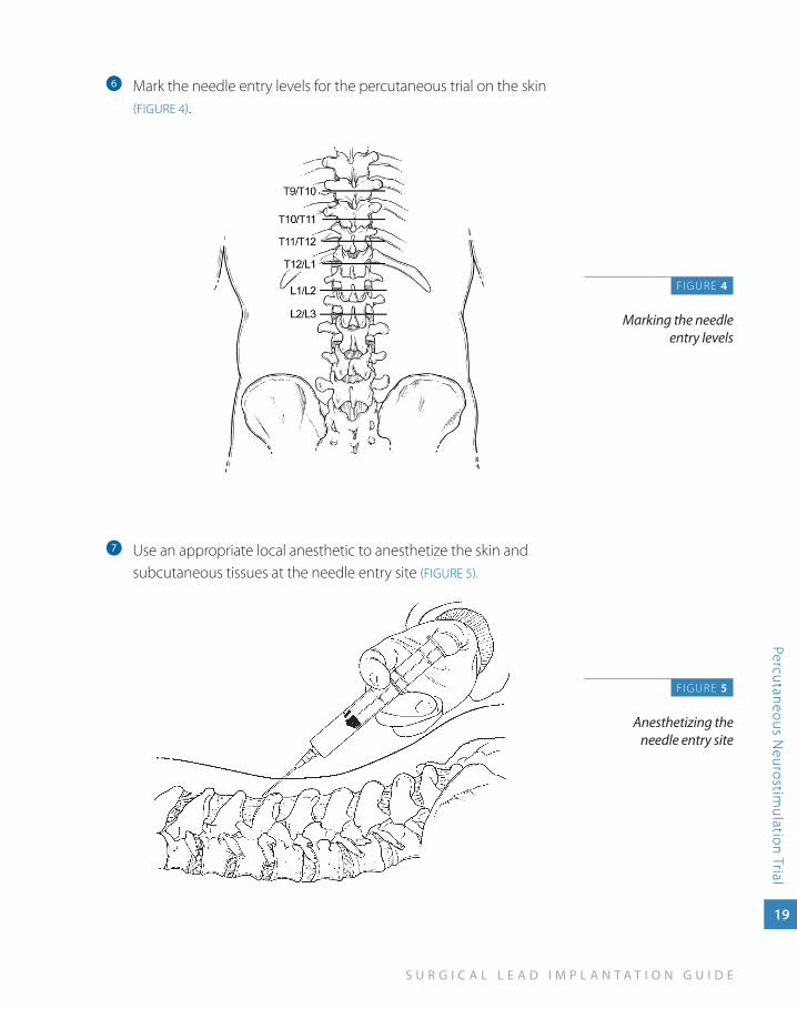
Mark the needle entry levels for the percutaneous trial on the skin f
(FIGURE 4).
Use an appropriate local anesthetic to anesthetize the skin and g
subcutaneous tissues at the needle entry site (FIGURE 5).
F IGURE 4
Marking the needle entry levels
FIGURE 5
Anesthetizing the needle entry site
20
N E U R O S T I M U L A T I O N T H E R A P Y
Perc
utan
eous
Neu
rost
imul
atio
n Tr
ial
Placing the Trial Stimulation Leads
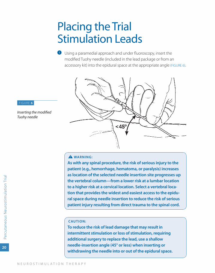
Using a paramedial approach and under fluoroscopy, insert the a
modified Tuohy needle (included in the lead package or from an accessory kit) into the epidural space at the appropriate angle (FIGURE 6).
waRNINg:
as with any spinal procedure, the risk of serious injury to the patient (e.g., hemorrhage, hematoma, or paralysis) increases as location of the selected needle insertion site progresses up the vertebral column—from a lower risk at a lumbar location to a higher risk at a cervical location. Select a vertebral loca-tion that provides the widest and easiest access to the epidu-ral space during needle insertion to reduce the risk of serious patient injury resulting from direct trauma to the spinal cord.
CauTION:
To reduce the risk of lead damage that may result in intermittent stimulation or loss of stimulation, requiring additional surgery to replace the lead, use a shallow needle-insertion angle (45° or less) when inserting or withdrawing the needle into or out of the epidural space.
FIGURE 6
Inserting the modified Tuohy needle
S U R G I C A L L E A D I M P L A N T A T I O N G U I D E
Percutaneous Neurostim
ulation Trial
21
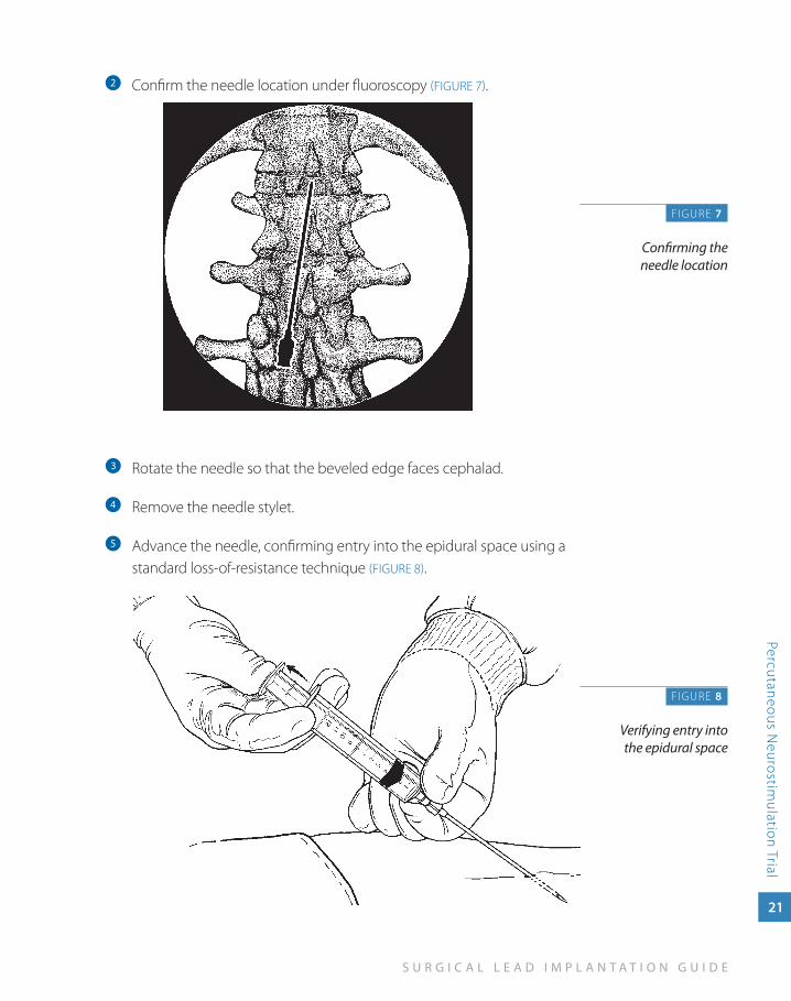
Confirm the needle location under fluoroscopy b (FIGURE 7).
Rotate the needle so that the beveled edge faces cephalad.c
Remove the needle stylet. d
Advance the needle, confirming entry into the epidural space using a e
standard loss-of-resistance technique (FIGURE 8).
F IGURE 7
Confirming the needle location
FIGURE 8
Verifying entry into the epidural space
22
N E U R O S T I M U L A T I O N T H E R A P Y
Perc
utan
eous
Neu
rost
imul
atio
n Tr
ial
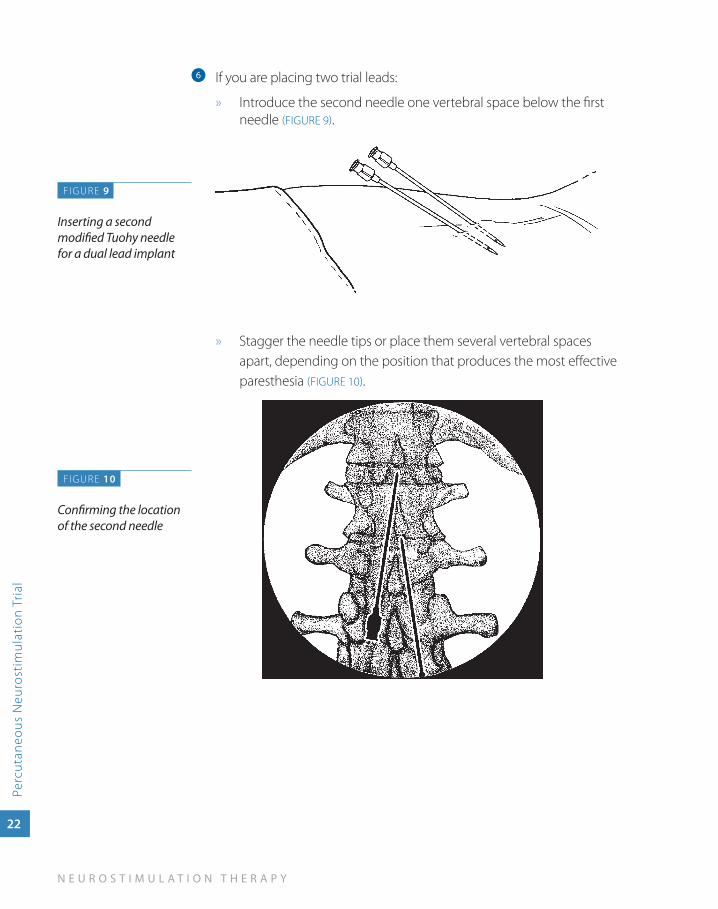
If you are placing two trial leads:f
Introduce the second needle one vertebral space below the first »needle (FIGURE 9).
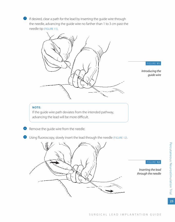
» Stagger the needle tips or place them several vertebral spaces apart, depending on the position that produces the most effective paresthesia (FIGURE 10).
F IGURE 9
Inserting a second modified Tuohy needle for a dual lead implant
FIGURE 10
Confirming the location of the second needle
S U R G I C A L L E A D I M P L A N T A T I O N G U I D E
Percutaneous Neurostim
ulation Trial
23
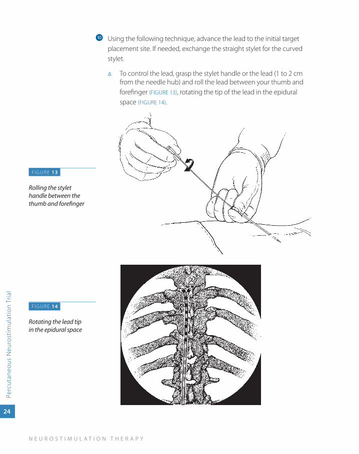
If desired, clear a path for the lead by inserting the guide wire through g
the needle, advancing the guide wire no farther than 1 to 3 cm past the needle tip (FIGURE 11).
NOTE:
If the guide wire path deviates from the intended pathway, advancing the lead will be more difficult.
Remove the guide wire from the needle.h
Using fluoroscopy, slowly insert the lead through the needle i (FIGURE 12).
F IGURE 11
Introducing the guide wire
FIGURE 12
Inserting the lead through the needle
24
N E U R O S T I M U L A T I O N T H E R A P Y
Perc
utan
eous
Neu
rost
imul
atio
n Tr
ial
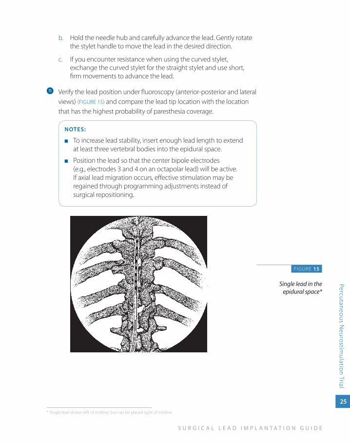
Using the following technique, advance the lead to the initial target j
placement site. If needed, exchange the straight stylet for the curved stylet.
To control the lead, grasp the stylet handle or the lead (1 to 2 cm a. from the needle hub) and roll the lead between your thumb and forefinger (FIGURE 13), rotating the tip of the lead in the epidural space (FIGURE 14).
F IGURE 13
Rolling the stylet handle between the thumb and forefinger
FIGURE 14
Rotating the lead tip in the epidural space
S U R G I C A L L E A D I M P L A N T A T I O N G U I D E
Percutaneous Neurostim
ulation Trial
25
Hold the needle hub and carefully advance the lead. Gently rotate b. the stylet handle to move the lead in the desired direction.
If you encounter resistance when using the curved stylet, c. exchange the curved stylet for the straight stylet and use short, firm movements to advance the lead.
Verify the lead position under fluoroscopy (anterior-posterior and lateral k
views) (FIGURE 15) and compare the lead tip location with the location that has the highest probability of paresthesia coverage.
NOTES:
To increase lead stability, insert enough lead length to extend ■
at least three vertebral bodies into the epidural space.
Position the lead so that the center bipole electrodes ■
(e.g., electrodes 3 and 4 on an octapolar lead) will be active. If axial lead migration occurs, effective stimulation may be regained through programming adjustments instead of surgical repositioning.
FIGURE 15
Single lead in the epidural space*
* Single lead shown left of midline, but can be placed right of midline.
26
N E U R O S T I M U L A T I O N T H E R A P Y
Perc
utan
eous
Neu
rost
imul
atio
n Tr
ial
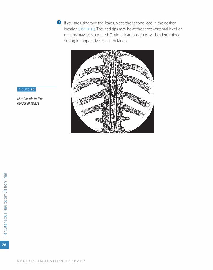
If you are using two trial leads, place the second lead in the desired l
location (FIGURE 16). The lead tips may be at the same vertebral level, or the tips may be staggered. Optimal lead positions will be determined during intraoperative test stimulation.
FIGURE 16
Dual leads in the epidural space
S U R G I C A L L E A D I M P L A N T A T I O N G U I D E
Percutaneous Neurostim
ulation Trial
27
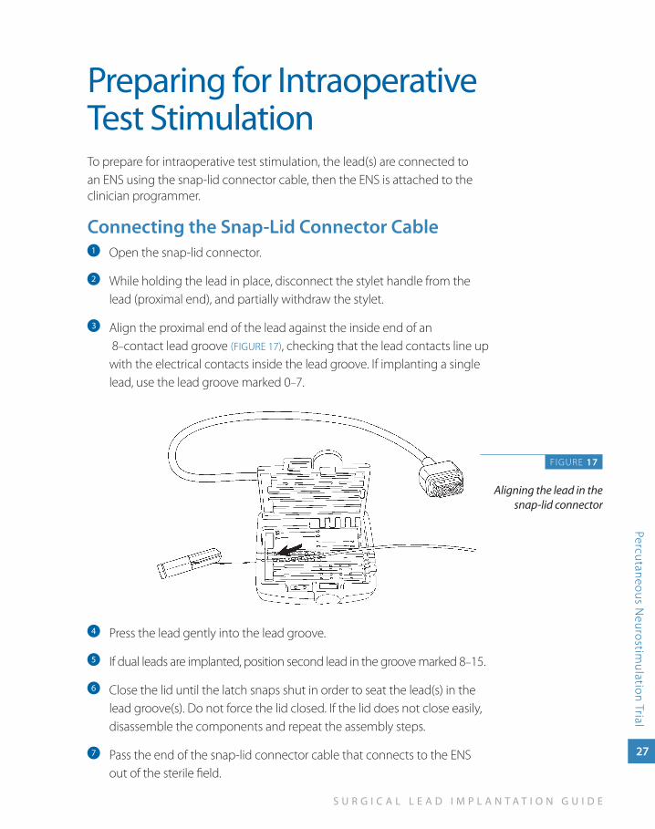
Preparing for Intraoperative Test StimulationTo prepare for intraoperative test stimulation, the lead(s) are connected to an ENS using the snap-lid connector cable, then the ENS is attached to the clinician programmer.
Connecting the Snap-Lid Connector CableOpen the snap-lid connector.a
While holding the lead in place, disconnect the stylet handle from the b
lead (proximal end), and partially withdraw the stylet.
Align the proximal end of the lead against the inside end of an c
8–contact lead groove (FIGURE 17), checking that the lead contacts line up with the electrical contacts inside the lead groove. If implanting a single lead, use the lead groove marked 0–7.
Press the lead gently into the lead groove. d
If dual leads are implanted, position second lead in the groove marked 8e –15.
Close the lid until the latch snaps shut in order to seat the lead(s) in the f
lead groove(s). Do not force the lid closed. If the lid does not close easily, disassemble the components and repeat the assembly steps.
Pass the end of the snap-lid connector cable that connects to the ENS g
out of the sterile field.
FIGURE 17
Aligning the lead in the snap-lid connector
28
N E U R O S T I M U L A T I O N T H E R A P Y
Perc
utan
eous
Neu
rost
imul
atio
n Tr
ial
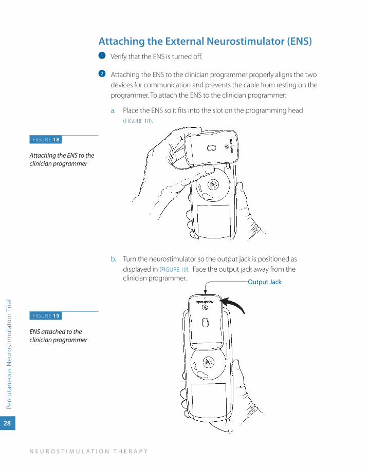
attaching the External Neurostimulator (ENS)Verify that the ENS is turned off.a
Attaching the ENS to the clinician programmer properly aligns the two b
devices for communication and prevents the cable from resting on the programmer. To attach the ENS to the clinician programmer:
Place the ENS so it fits into the slot on the programming head a. (FIGURE 18).
Turn the neurostimulator so the output jack is positioned as b. displayed in (FIGURE 19). Face the output jack away from the clinician programmer.
FIGURE 18
Attaching the ENS to the clinician programmer
FIGURE 19
ENS attached to the clinician programmer
Output Jack
S U R G I C A L L E A D I M P L A N T A T I O N G U I D E
Percutaneous Neurostim
ulation Trial
29
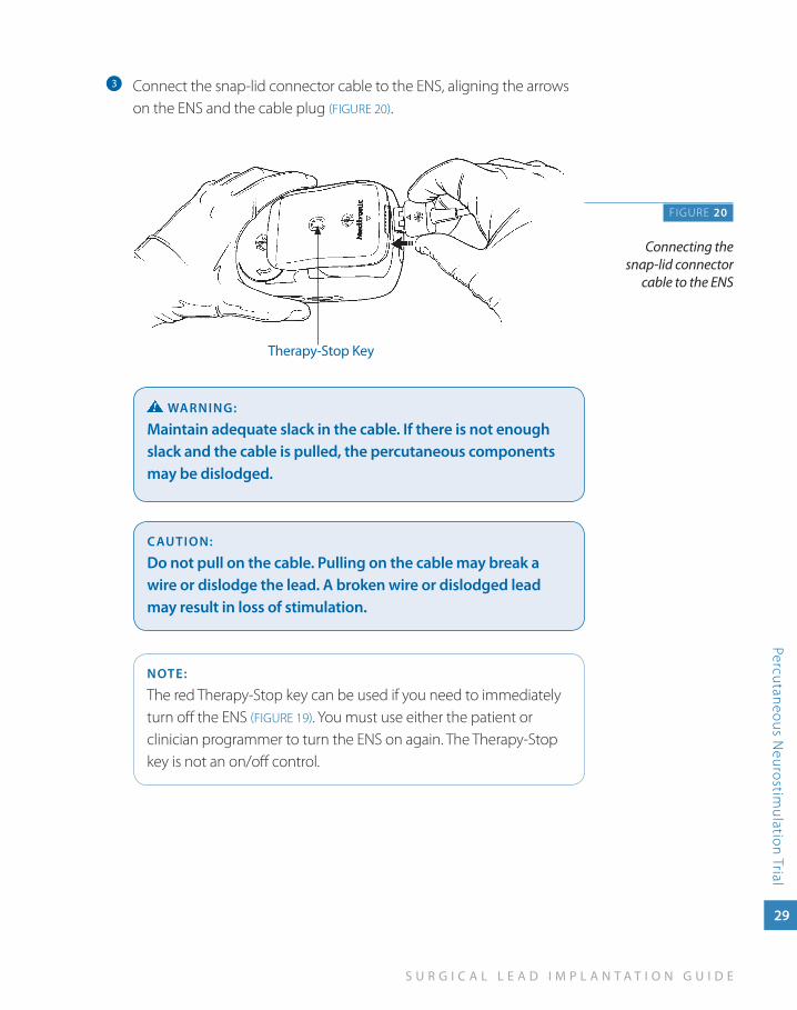
Connect the snap-lid connector cable to the ENS, aligning the arrows c
on the ENS and the cable plug (FIGURE 20).
waRNINg:
Maintain adequate slack in the cable. If there is not enough slack and the cable is pulled, the percutaneous components may be dislodged.
CauTION:
Do not pull on the cable. Pulling on the cable may break a wire or dislodge the lead. a broken wire or dislodged lead may result in loss of stimulation.
NOTE:
The red Therapy-Stop key can be used if you need to immediately turn off the ENS (FIGURE 19). You must use either the patient or clinician programmer to turn the ENS on again. The Therapy-Stop key is not an on/off control.
F IGURE 20
Connecting the snap-lid connector
cable to the ENS
Therapy-Stop Key
30
N E U R O S T I M U L A T I O N T H E R A P Y
Perc
utan
eous
Neu
rost
imul
atio
n Tr
ial
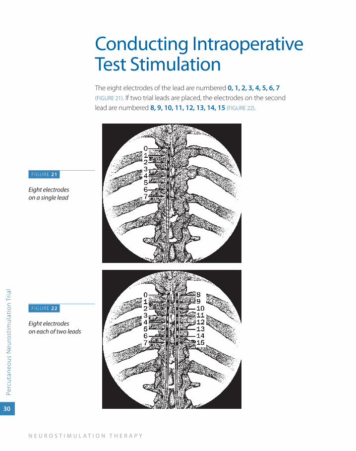
Conducting Intraoperative Test StimulationThe eight electrodes of the lead are numbered 0, 1, 2, 3, 4, 5, 6, 7 (FIGURE 21). If two trial leads are placed, the electrodes on the second lead are numbered 8, 9, 10, 11, 12, 13, 14, 15 (FIGURE 22).
F IGURE 21
Eight electrodes on a single lead
FIGURE 22
Eight electrodes on each of two leads
S U R G I C A L L E A D I M P L A N T A T I O N G U I D E
Percutaneous Neurostim
ulation Trial
31
Ensure that the patient can provide immediate feedback.a
Testing the stimulation for each lead separately, identify optimal b
electrode polarities and stimulation parameters, beginning with the following settings:
Pulse width: ■ 210–240 µs or higher
Rate: ■ 30 Hz
amplitude: ■ 0.0 V
Electrodes: ■ Use center bipoles for programming flexibility
While increasing the amplitude ask the patient closed ended c
questions to identify:
Perception threshold (the amplitude at which the patient first ■
perceives paresthesia).
Discomfort threshold (the amplitude at which paresthesia is ■
beyond the patient’s tolerance or described as uncomfortable).
CauTION:
To prevent possible uncomfortable or unexpected stimulation (jolting or shocking sensation):
Program parameter changes in small increments ■
above the perception threshold.
Decrease the amplitude(s) to 0.0 V before: ■
Connecting or disconnecting the cable to the »External NeurostimulatorTurning on the External Neurostimulator »
Adjust amplitude, pulse width, and rate until the pain area is covered d
and the patient has satisfactory paresthesia coverage.
If satisfactory paresthesia coverage is not attained, change electrode e
settings and retest thresholds before moving the leads.
32
N E U R O S T I M U L A T I O N T H E R A P Y
Perc
utan
eous
Neu
rost
imul
atio
n Tr
ial
If a lead has moved, retest for perception and discomfort thresholds f
before adjusting parameters for satisfactory paresthesia coverage.
If two leads were placed, repeat the process for the second lead, then g
optimize paresthesia coverage using both leads simultaneously.
When testing is complete, use the clinician programmer to turn h
the ENS off.
NOTE:
Decreasing the amplitude to 0.0 V before turning the ENS off may prevent possible uncomfortable or unexpected stimulation when the ENS is turned back on.
Record all settings and patient responses to stimulation in the i
patient’s chart.
Obtain baseline fluoroscopy images to record the lead position(s) and j
place in patient’s file.
Disconnect the snap-lid connector cable from the lead(s). Leave the k
cable in the sterile field for additional testing.
CauTION:
Do not pull on the cable. Pulling on the cable may break a wire or dislodge the lead. a broken wire or dislodged lead may result.
S U R G I C A L L E A D I M P L A N T A T I O N G U I D E
Percutaneous Neurostim
ulation Trial
33
Securing a Trial Stimulation Lead
Carefully, and without moving the lead, disconnect the stylet from the a
lead by gently bending the stylet handle from the lead.
Partially expose, but do not completely withdraw the stylet.b
Secure the lead position by grasping the lead proximal to the needle hub. c
While holding the lead secure, gently retract the needle from the d
epidural space and the ligamentum flavum while simultaneously indexing the lead to maintain lead position.
Carefully retract the needle through the tissue until the lead is visible e
at the distal end of the needle.
Hold the lead to maintain position and slowly withdraw the stylet.f
Carefully grasp the exposed lead and slip the needle off the proximal g
end of the lead.
CauTION:
use minimal traction to remove the needle because quick or sudden removal may dislodge the lead.
If two leads were placed, repeat steps 1 through 7 for the second lead.h
Verify that the lead location and pattern of stimulation have not i
changed:
Connect the snap-lid connector cable to the lead(s). a.
Connect the plug end of the snap-lid connector cable to the ENS.b.
Use the clinician programmer to verify that the pattern of c. stimulation has not changed.
Use fluoroscopy to verify that the lead location has not changed.d.
Disconnect the snap-lid connector cable from the lead(s).e.
CauTION:
Do not pull on the cable. Pulling on the cable may break a wire or dislodge the lead. a broken wire or dislodged lead may result.
34
N E U R O S T I M U L A T I O N T H E R A P Y
Perc
utan
eous
Neu
rost
imul
atio
n Tr
ial
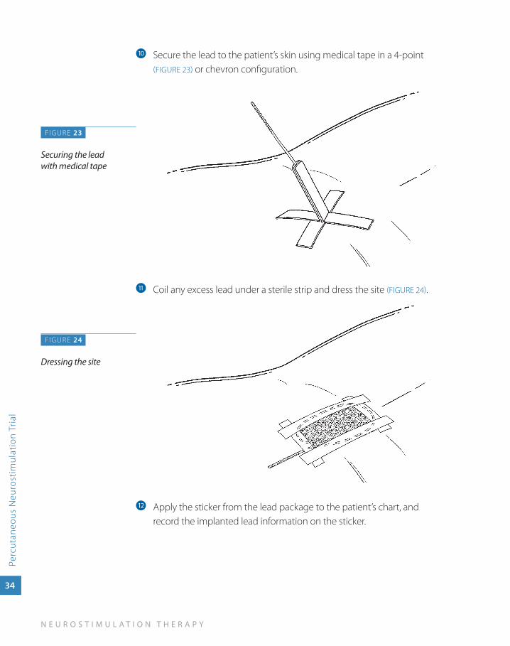
Secure the lead to the patient’s skin using medical tape in a 4-point j
(FIGURE 23) or chevron configuration.
Coil any excess lead under a sterile strip and dress the site k (FIGURE 24).
Apply the sticker from the lead package to the patient’s chart, and l
record the implanted lead information on the sticker.
F IGURE 23
Securing the lead with medical tape
FIGURE 24
Dressing the site
S U R G I C A L L E A D I M P L A N T A T I O N G U I D E
Percutaneous Neurostim
ulation Trial
35
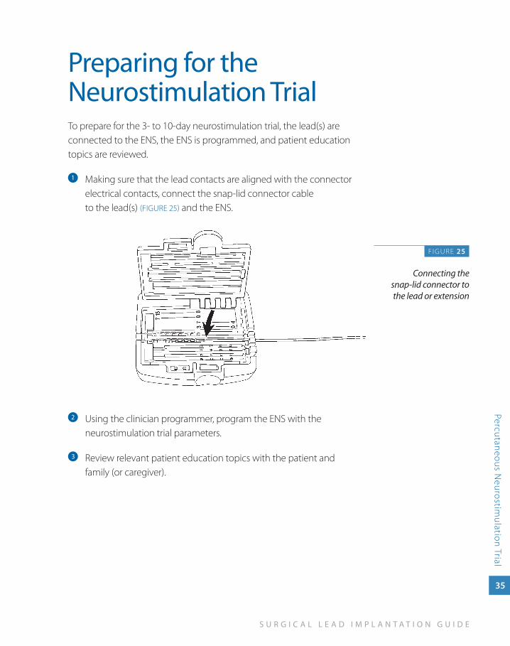
Preparing for the Neurostimulation TrialTo prepare for the 3- to 10-day neurostimulation trial, the lead(s) are connected to the ENS, the ENS is programmed, and patient education topics are reviewed.
Making sure that the lead contacts are aligned with the connector a
electrical contacts, connect the snap-lid connector cable to the lead(s) (FIGURE 25) and the ENS.
Using the clinician programmer, program the ENS with the b
neurostimulation trial parameters.
Review relevant patient education topics with the patient and c
family (or caregiver).
F IGURE 25
Connecting the snap-lid connector to the lead or extension
36
N E U R O S T I M U L A T I O N T H E R A P Y
Perc
utan
eous
Neu
rost
imul
atio
n Tr
ial
Evaluating Neurostimulation Trial ResultsAfter the neurostimulation trial, review input from the pain management team, the patient, and the patient’s family or caregivers. Evaluate if the goals of a neurostimulation trial have been met and determine if a full neurostimulation system will be implanted.
The goals of a neurostimulation trial are:
Stimulation covers the patient’s pain areas. ■
Patient is comfortable with the sensation of stimulation. ■
Patient experiences adequate pain relief. ■
Patient experiences improved function. ■
After the trial, percutaneous trial lead(s) are removed.

3su
rg
ica
l lead
pla
cem
ent
Surgical Lead Placement
S U R G I C A L L E A D I M P L A N T A T I O N G U I D E
Surgical Lead Placem
ent
37
Surgical Lead Placement
Lead placement is the first step in a system implant. To place a surgical lead, a laminotomy is performed, then the lead paddle is positioned in the epidural space.
Lead placement is done under local anesthesia. Since the patient must interact during anesthesia, monitored anesthesia care (MAC) should be implemented according to physician judgment.
The example procedure applies to both of the following:
65-cm Specify 5-6-5 or Specify 2x8 lead ■
30-cm Specify 5-6-5 or Specify 2x8 lead with two 1x8 extensions ■
Alternate leads are available through Medtronic.
38
N E U R O S T I M U L A T I O N T H E R A P Y
Surg
ical
Lea
d P
lace
men
t
Preparing for System Implant
With patient participation, plan and mark the neurostimulator implant a
site based on patient preference, comfort, and ability to recharge the neurostimulator battery (if applicable).
CauTION:
Select a location that is:
a minimum of 20 cm (8 in) away from another ■
neurostimulator to minimize telemetry interference and possible inappropriate therapy.
On the opposite side of the body from another active ■
implanted device (e.g., pacemaker, defibrillator) to minimize possible interaction between the devices.
away from bony structures (e.g., 3–4 cm [1.2–1.6 in]) to ■
minimize discomfort at the neurostimulator site.
away from areas of restriction or pressure to minimize the ■
potential for skin erosion and patient discomfort.
In an area accessible to the patient for proper operation of ■
a patient control device (i.e., patient programmer).
Verify neurostimulator operation:b Before opening the sterile neurostimulator package, verify that the neurostimulator is operable by using the clinician programmer to interrogate the neurostimulator and read the neurostimulator battery charge level (if applicable).
Charge the neurostimulator battery:c If implanting a rechargeable neurostimulator, charge the neurostimulator battery before opening the package.
S U R G I C A L L E A D I M P L A N T A T I O N G U I D E
Surgical Lead Placem
ent
39
Preparing to Place a Surgical Lead
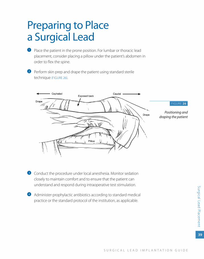
Place the patient in the prone position. For lumbar or thoracic lead a
placement, consider placing a pillow under the patient’s abdomen in order to flex the spine.
Perform skin prep and drape the patient using standard sterile b
technique (FIGURE 26).
Conduct the procedure under local anesthesia. Monitor sedation c
closely to maintain comfort and to ensure that the patient can understand and respond during intraoperative test stimulation.
Administer prophylactic antibiotics according to standard medical d
practice or the standard protocol of the institution, as applicable.
F IGURE 26
Positioning and draping the patient
40
N E U R O S T I M U L A T I O N T H E R A P Y
Surg
ical
Lea
d P
lace
men
t
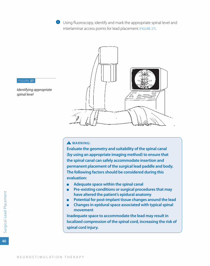
Using fluoroscopy, identify and mark the appropriate spinal level and e
interlaminar access points for lead placement (FIGURE 27).
waRNINg:
Evaluate the geometry and suitability of the spinal canal (by using an appropriate imaging method) to ensure that the spinal canal can safely accommodate insertion and permanent placement of the surgical lead paddle and body. The following factors should be considered during this evaluation:
adequate space within the spinal canal ■
Pre-existing conditions or surgical procedures that may ■
have altered the patient’s epidural anatomyPotential for post-implant tissue changes around the lead ■
Changes in epidural space associated with typical spinal ■
movementInadequate space to accommodate the lead may result in localized compression of the spinal cord, increasing the risk of spinal cord injury.
FIGURE 27
Identifying appropriate spinal level
S U R G I C A L L E A D I M P L A N T A T I O N G U I D E
Surgical Lead Placem
ent
41
CauTION:
Implanting the surgical lead paddle in anatomical locations that have a high degree of mobility (such as the cervical spine) is not recommended. The stresses associated with these locations may reduce the functional survival time of the lead, requiring reprogramming and/or early replacement of the lead to restore effective therapy.
NOTE:
The laminotomy should be performed 1-2 vertebral spaces inferior to the desired final location of the surgical lead paddle.
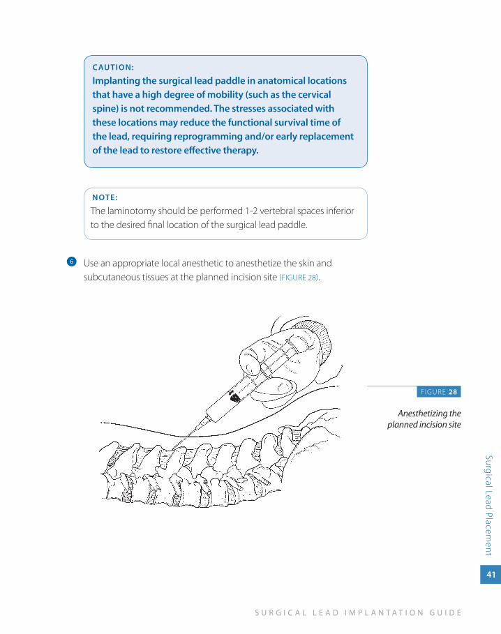
Use an appropriate local anesthetic to anesthetize the skin and f
subcutaneous tissues at the planned incision site (FIGURE 28).
F IGURE 28
Anesthetizing the planned incision site
42
N E U R O S T I M U L A T I O N T H E R A P Y
Surg
ical
Lea
d P
lace
men
t
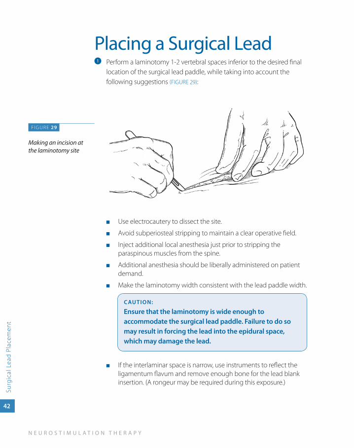
Placing a Surgical LeadPerform a laminotomy 1-2 vertebral spaces inferior to the desired final a
location of the surgical lead paddle, while taking into account the following suggestions (FIGURE 29):
Use electrocautery to dissect the site. ■
Avoid subperiosteal stripping to maintain a clear operative field. ■
Inject additional local anesthesia just prior to stripping the ■
paraspinous muscles from the spine.
Additional anesthesia should be liberally administered on patient ■
demand.
Make the laminotomy width consistent with the lead paddle width. ■
CauTION:
Ensure that the laminotomy is wide enough to accommodate the surgical lead paddle. Failure to do so may result in forcing the lead into the epidural space, which may damage the lead.
If the interlaminar space is narrow, use instruments to reflect the ■
ligamentum flavum and remove enough bone for the lead blank insertion. (A rongeur may be required during this exposure.)
FIGURE 29
Making an incision at the laminotomy site
S U R G I C A L L E A D I M P L A N T A T I O N G U I D E
Surgical Lead Placem
ent
43
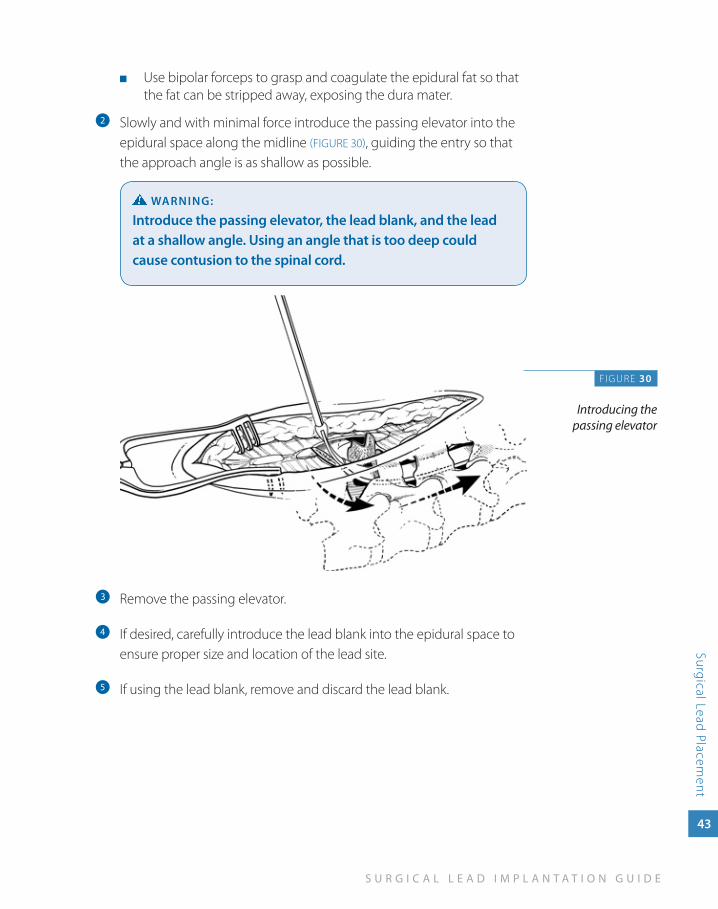
Use bipolar forceps to grasp and coagulate the epidural fat so that ■
the fat can be stripped away, exposing the dura mater.
Slowly and with minimal force introduce the passing elevator into the b
epidural space along the midline (FIGURE 30), guiding the entry so that the approach angle is as shallow as possible.
waRNINg:
Introduce the passing elevator, the lead blank, and the lead at a shallow angle. using an angle that is too deep could cause contusion to the spinal cord.
Remove the passing elevator.c
If desired, carefully introduce the lead blank into the epidural space to d
ensure proper size and location of the lead site.
If using the lead blank, remove and discard the lead blank.e
FIGURE 30
Introducing the passing elevator
44
N E U R O S T I M U L A T I O N T H E R A P Y
Surg
ical
Lea
d P
lace
men
t
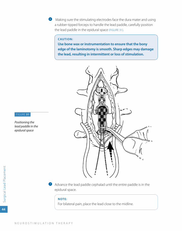
Making sure the stimulating electrodes face the dura mater and using f
a rubber-tipped forceps to handle the lead paddle, carefully position the lead paddle in the epidural space (FIGURE 31).
CauTION:
use bone wax or instrumentation to ensure that the bony edge of the laminotomy is smooth. Sharp edges may damage the lead, resulting in intermittent or loss of stimulation.
Advance the lead paddle cephalad until the entire paddle is in the g
epidural space.
NOTE:
For bilateral pain, place the lead close to the midline.
FIGURE 31
Positioning the lead paddle in the epidural space
S U R G I C A L L E A D I M P L A N T A T I O N G U I D E
Surgical Lead Placem
ent
45
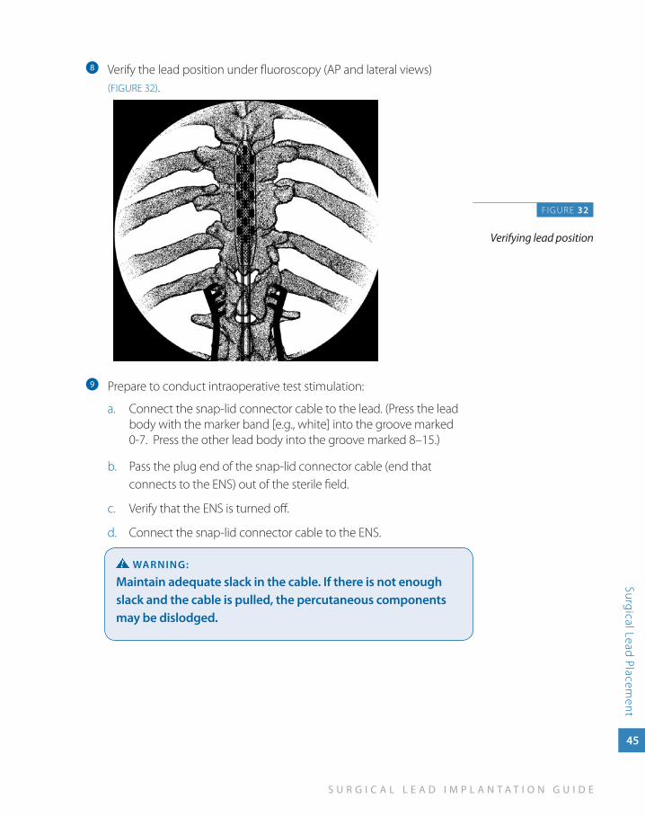
Verify the lead position under fluoroscopy (AP and lateral views) h
(FIGURE 32).
Prepare to conduct intraoperative test stimulation:i
Connect the snap-lid connector cable to the lead. (Press the lead a. body with the marker band [e.g., white] into the groove marked 0-7. Press the other lead body into the groove marked 8–15.)
Pass the plug end b. of the snap-lid connector cable (end that connects to the ENS) out of the sterile field.
Verify that the ENS is turned off.c.
Connect the snap-lid connector cable to the ENS.d.
waRNINg:
Maintain adequate slack in the cable. If there is not enough slack and the cable is pulled, the percutaneous components may be dislodged.
FIGURE 32
Verifying lead position
46
N E U R O S T I M U L A T I O N T H E R A P Y
Surg
ical
Lea
d P
lace
men
t
Conduct intraoperative test stimulation:j
Identify optimal stimulation parameters, beginning with a. the following settings:
Pulse width: » 210–240 µs or higher
Rate: » 30 Hz
Amplitude: » 0.0 V
NOTE:
Ensure that the patient can provide immediate feedback.
While increasing the amplitude ask the patient closed-ended b. questions to identify:
Perception threshold (the amplitude at which the patient first »perceives paresthesia)
» Discomfort threshold (the amplitude at which paresthesia is beyond the patient’s tolerance or described as uncomfortable
Paresthesia coverage »
NOTE:
If good paresthesia coverage is not attained, change electrode settings before repositioning the lead to confirm the direction of lead movement.
In the patient’s chart, document the lead position that provided k
appropriate stimulation coverage:Record settings and patient responses »Include a fluoroscopic image of the final lead position »
Disconnect the l snap-lid connector cable from the lead. Leave the cable in the sterile field for additional parameter testing before closing.
CauTION:
Do not pull on the cable. Pulling on the cable may break a wire or dislodge the lead. a broken wire or dislodged lead may result.
If implanting a 65-cm Specify 5-6-5 or Specify 2x8 lead, go to:m » Implanting a Surgical Lead without Extensions on page 47.
If implanting a 30-cm Specify 5-6-5 or Specify 2x8 lead, go to: n Implanting a Surgical Lead with Extensions » on page 59.

4im
pla
nt
ing
a su
rg
ica
l lead
w
ith
ou
t ext
ensio
ns
Implanting a Surgical Lead
without Extensions
S U R G I C A L L E A D I M P L A N T A T I O N G U I D E
47
Imp
lanting a Surgical Lead
without Extensions
Implanting a Surgical Lead without ExtensionsIf you are implanting a 65-cm Specify 5-6-5 or Specify 2x8 lead, the lead is optionally secured to the fascia with anchors supplied in the lead kit. The lead kit contains several kinds of anchors. The example procedure in this section uses the two-wing anchor.
After the lead is anchored, a neurostimulator pocket is created and the lead bodies are tunneled to the neurostimulator site.
Alternate leads are available through Medtronic.
48
N E U R O S T I M U L A T I O N T H E R A P Y
Imp
lant
ing
a S
urgi
cal L
ead
wit
hout
Ext
ensi
ons
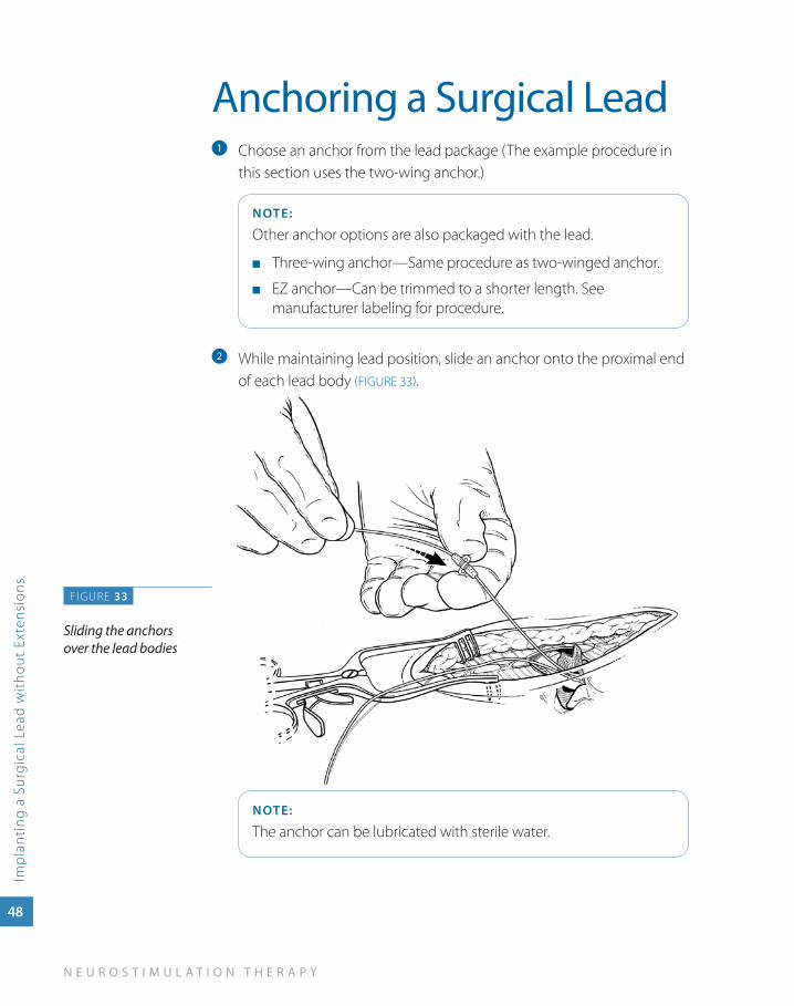
Anchoring a Surgical LeadChoose an anchor from the lead package (The example procedure in a
this section uses the two-wing anchor.)
NOTE:
Other anchor options are also packaged with the lead.
Three-wing anchor—Same procedure as two-winged anchor. ■
EZ anchor—Can be trimmed to a shorter length. See ■
manufacturer labeling for procedure.
While maintaining lead position, slide an anchor onto the proximal end b
of each lead body (FIGURE 33).
NOTE:
The anchor can be lubricated with sterile water.
F IGURE 33
Sliding the anchors over the lead bodies
S U R G I C A L L E A D I M P L A N T A T I O N G U I D E
Imp
lanting a Surgical Lead
without Extensions
49
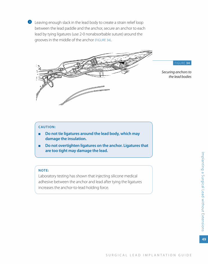
Leaving enough slack in the lead body to create a strain relief loop c
between the lead paddle and the anchor, secure an anchor to each lead by tying ligatures (use 2-0 nonabsorbable suture) around the grooves in the middle of the anchor (FIGURE 34).
CauTION:
Do not tie ligatures around the lead body, which may ■
damage the insulation.
Do not overtighten ligatures on the anchor. Ligatures that ■
are too tight may damage the lead.
NOTE:
Laboratory testing has shown that injecting silicone medical adhesive between the anchor and lead after tying the ligatures increases the anchor-to-lead holding force.
FIGURE 34
Securing anchors to the lead bodies
50
N E U R O S T I M U L A T I O N T H E R A P Y
Imp
lant
ing
a S
urgi
cal L
ead
wit
hout
Ext
ensi
ons
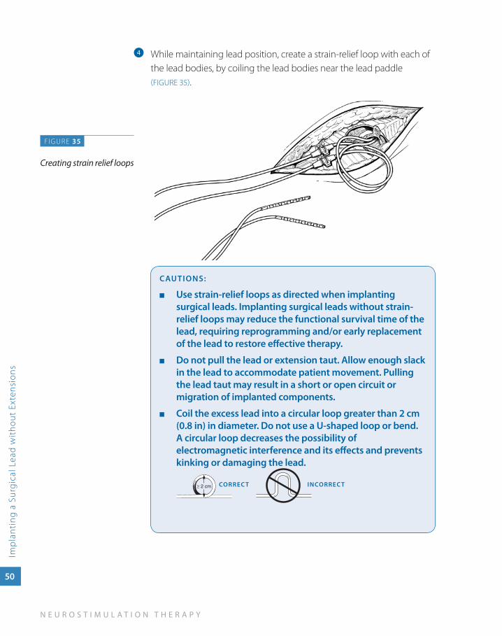
While maintaining lead position, create a strain-relief loop with each of d
the lead bodies, by coiling the lead bodies near the lead paddle (FIGURE 35).
CauTIONS:
use strain-relief loops as directed when implanting ■
surgical leads. Implanting surgical leads without strain-relief loops may reduce the functional survival time of the lead, requiring reprogramming and/or early replacement of the lead to restore effective therapy.
Do not pull the lead or extension taut. allow enough slack ■
in the lead to accommodate patient movement. Pulling the lead taut may result in a short or open circuit or migration of implanted components.
Coil the excess lead into a circular loop greater than 2 cm ■
(0.8 in) in diameter. Do not use a u-shaped loop or bend. a circular loop decreases the possibility of electromagnetic interference and its effects and prevents kinking or damaging the lead.
CORREC T INCORREC T
FIGURE 35
Creating strain relief loops
S U R G I C A L L E A D I M P L A N T A T I O N G U I D E
Imp
lanting a Surgical Lead
without Extensions
51
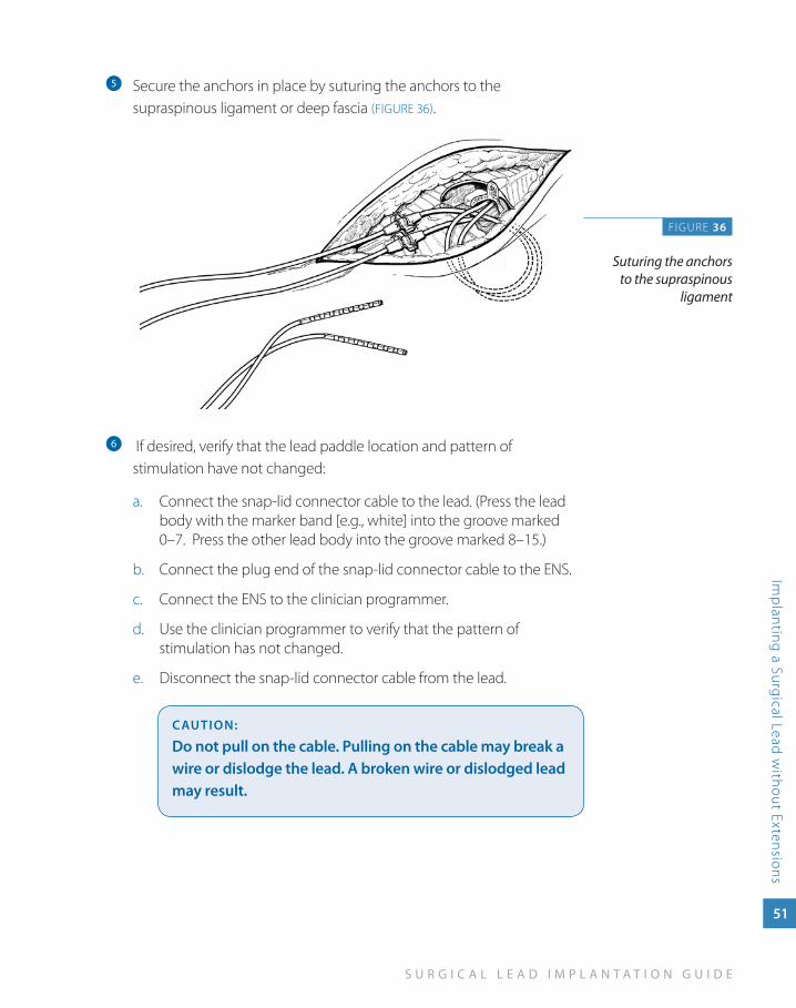
Secure the anchors in place by suturing the anchors to the e
supraspinous ligament or deep fascia (FIGURE 36).
f If desired, verify that the lead paddle location and pattern of stimulation have not changed:
Connect the snap-lid connector cable to the lead. (Press the lead a. body with the marker band [e.g., white] into the groove marked 0–7. Press the other lead body into the groove marked 8–15.)
Connect the plug end of the snap-lid connector cable to the ENS.b.
Connect the ENS to the clinician programmer.c.
Use the clinician programmer to verify that the pattern of d. stimulation has not changed.
Disconnect the snap-lid connector cable from the lead.e.
CauTION:
Do not pull on the cable. Pulling on the cable may break a wire or dislodge the lead. a broken wire or dislodged lead may result.
FIGURE 36
Suturing the anchors to the supraspinous
ligament
52
N E U R O S T I M U L A T I O N T H E R A P Y
Imp
lant
ing
a S
urgi
cal L
ead
wit
hout
Ext
ensi
ons
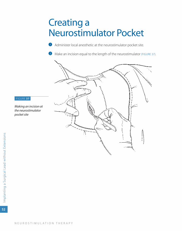
Creating a Neurostimulator Pocket
Administer local anesthetic at the neurostimulator pocket site. a
Make an incision equal to the length of the neurostimulator b (FIGURE 37).
F IGURE 37
Making an incision at the neurostimulator pocket site
S U R G I C A L L E A D I M P L A N T A T I O N G U I D E
Imp
lanting a Surgical Lead
without Extensions
53
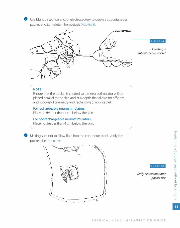
Use blunt dissection and/or electrocautery to create a subcutaneous c
pocket and to maintain hemostasis (FIGURE 38).
NOTE:Ensure that the pocket is created so the neurostimulator will be placed parallel to the skin and at a depth that allows for efficient and successful telemetry and recharging (if applicable):
For rechargeable neurostimulators: Place no deeper than 1 cm below the skin.
For nonrechargeable neurostimulators: Place no deeper than 4 cm below the skin.
Making sure not to allow fluid into the connector block, verify the d
pocket size (FIGURE 39).
F IGURE 38
Creating a subcutaneous pocket
FIGURE 39
Verify neurostimulator pocket size
54
N E U R O S T I M U L A T I O N T H E R A P Y
Imp
lant
ing
a S
urgi
cal L
ead
wit
hout
Ext
ensi
ons
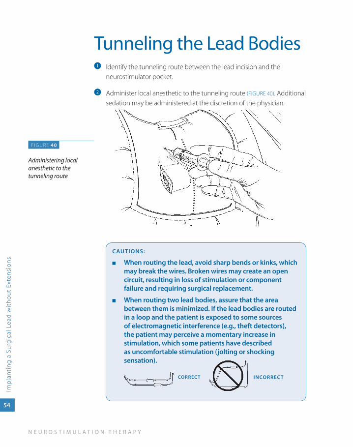
Tunneling the Lead BodiesIdentify the tunneling route between the lead incision and the a
neurostimulator pocket.
Administer local anesthetic to the tunneling route b (FIGURE 40). Additional sedation may be administered at the discretion of the physician.
CauTIONS:
when routing the lead, avoid sharp bends or kinks, which ■
may break the wires. Broken wires may create an open circuit, resulting in loss of stimulation or component failure and requiring surgical replacement.
when routing two lead bodies, assure that the area ■
between them is minimized. If the lead bodies are routed in a loop and the patient is exposed to some sources of electromagnetic interference (e.g., theft detectors), the patient may perceive a momentary increase in stimulation, which some patients have described as uncomfortable stimulation (jolting or shocking sensation).
INCORREC TCORREC T
FIGURE 40
Administering local anesthetic to the tunneling route
S U R G I C A L L E A D I M P L A N T A T I O N G U I D E
Imp
lanting a Surgical Lead
without Extensions
55
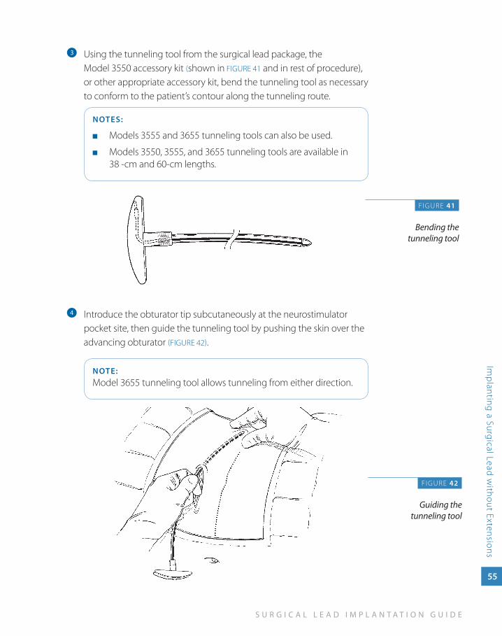
Using the tunneling tool from the surgical lead package, the c
Model 3550 accessory kit (shown in FIGURE 41 and in rest of procedure), or other appropriate accessory kit, bend the tunneling tool as necessary to conform to the patient’s contour along the tunneling route.
NOTES:
Models 3555 and 3655 tunneling tools can also be used. ■
Models 3550, 3555, and 3655 tunneling tools are available in ■
38 -cm and 60-cm lengths.
Introduce the obturator tip subcutaneously at the neurostimulator d
pocket site, then guide the tunneling tool by pushing the skin over the advancing obturator (FIGURE 42).
NOTE:Model 3655 tunneling tool allows tunneling from either direction.
F IGURE 41
Bending the tunneling tool
FIGURE 42
Guiding the tunneling tool
56
N E U R O S T I M U L A T I O N T H E R A P Y
Imp
lant
ing
a S
urgi
cal L
ead
wit
hout
Ext
ensi
ons
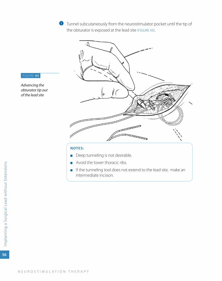
Tunnel subcutaneously from the neurostimulator pocket until the tip of e
the obturator is exposed at the lead site (FIGURE 43).
NOTES:
Deep tunneling is not desirable. ■
Avoid the lower thoracic ribs. ■
If the tunneling tool does not extend to the lead site, make an ■
intermediate incision.
FIGURE 43
Advancing the obturator tip out of the lead site
S U R G I C A L L E A D I M P L A N T A T I O N G U I D E
Imp
lanting a Surgical Lead
without Extensions
57
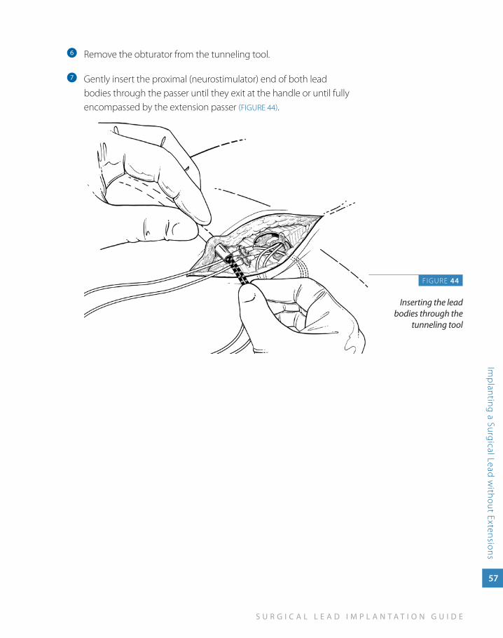
Remove the obturator from the tunneling tool.f
Gently insert the proximal (neurostimulator) end of both lead g
bodies through the passer until they exit at the handle or until fully encompassed by the extension passer (FIGURE 44).
F IGURE 44
Inserting the lead bodies through the
tunneling tool
58
N E U R O S T I M U L A T I O N T H E R A P Y
Imp
lant
ing
a S
urgi
cal L
ead
wit
hout
Ext
ensi
ons
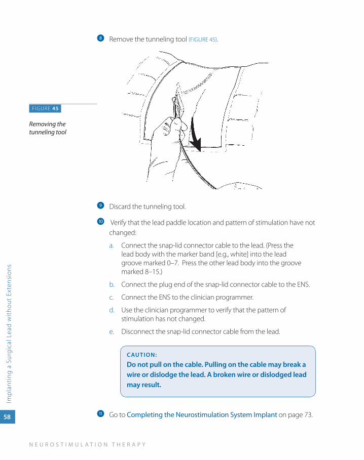
Remove the tunneling tool h (FIGURE 45).
Discard the tunneling tool.i
Verify that the lead paddle location and pattern of stimulation have not j
changed:
Connect the snap-lid connector cable to the lead. (Press the a. lead body with the marker band [e.g., white] into the lead groove marked 0–7. Press the other lead body into the groove marked 8–15.)
Connect the plug end of the snap-lid connector cable to the ENS.b.
Connect the ENS to the clinician programmer.c.
Use the clinician programmer to verify that the pattern of d. stimulation has not changed.
Disconnect the snap-lid connector cable from the lead.e.
CauTION:
Do not pull on the cable. Pulling on the cable may break a wire or dislodge the lead. a broken wire or dislodged lead may result.
Go to k Completing the Neurostimulation System Implant on page 73.
FIGURE 45
Removing the tunneling tool

5im
pla
nt
ing
a su
rg
ica
l lea
d w
ith
ext
ensio
ns
Implanting a Surgical Lead with
Extensions
S U R G I C A L L E A D I M P L A N T A T I O N G U I D E
Imp
lanting a Surgical Lead
with Extensions
59
Implanting a Surgical Lead with Extensions
If you are implanting a 30-cm Specify 5-6-5 or Specify 2x8 lead, the neurostimulator pocket is created and two 1x8 extensions are tunneled to the neurostimulator site. The extensions are connected to the two lead bodies, and the lead-extension connector is sutured to the fascia.
Alternate leads and extensions are available through Medtronic.
60
N E U R O S T I M U L A T I O N T H E R A P Y
Imp
lant
ing
a S
urgi
cal L
ead
wit
h Ex
tens
ions
Creating a Neurostimulator Pocket
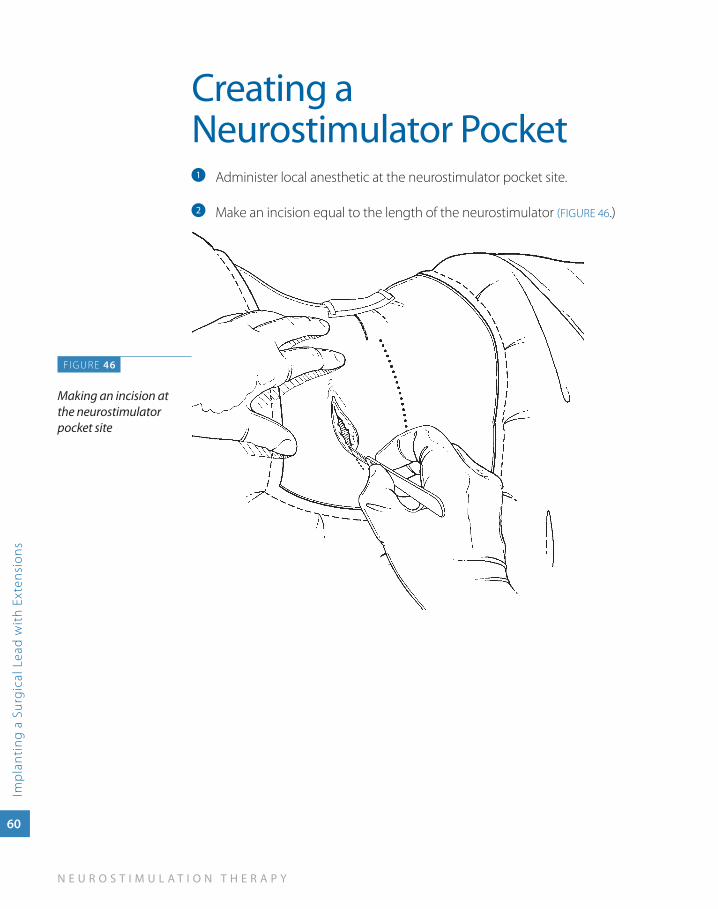
Administer local anesthetic at the neurostimulator pocket site. a
Make an incision equal to the length of the neurostimulator b (FIGURE 46.)
F IGURE 46
Making an incision at the neurostimulator pocket site
S U R G I C A L L E A D I M P L A N T A T I O N G U I D E
Imp
lanting a Surgical Lead
with Extensions
61
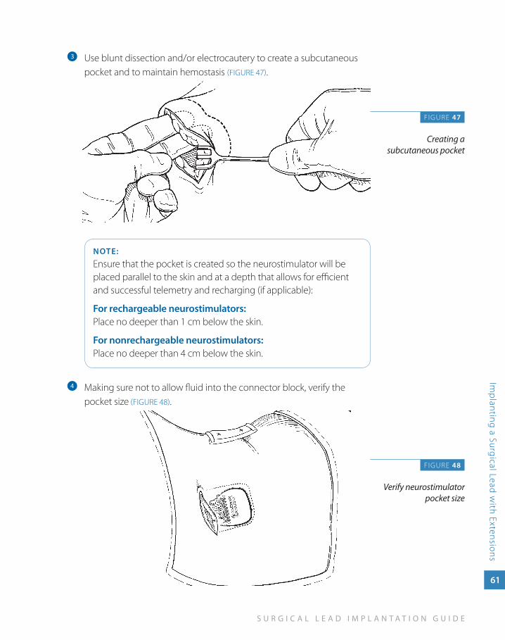
Use blunt dissection and/or electrocautery to create a subcutaneous c
pocket and to maintain hemostasis (FIGURE 47).
NOTE:
Ensure that the pocket is created so the neurostimulator will be placed parallel to the skin and at a depth that allows for efficient and successful telemetry and recharging (if applicable):
For rechargeable neurostimulators: Place no deeper than 1 cm below the skin.
For nonrechargeable neurostimulators: Place no deeper than 4 cm below the skin.
Making sure not to allow fluid into the connector block, verify the d
pocket size (FIGURE 48).
F IGURE 47
Creating a subcutaneous pocket
FIGURE 48
Verify neurostimulator pocket size
62
N E U R O S T I M U L A T I O N T H E R A P Y
Imp
lant
ing
a S
urgi
cal L
ead
wit
h Ex
tens
ions
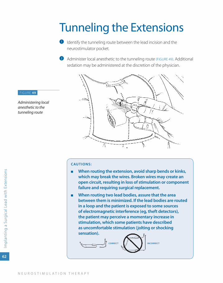
Tunneling the ExtensionsIdentify the tunneling route between the lead incision and the a
neurostimulator pocket.
Administer local anesthetic to the tunneling route b (FIGURE 49). Additional sedation may be administered at the discretion of the physician.
CauTIONS:
when routing the extension, avoid sharp bends or kinks, ■
which may break the wires. Broken wires may create an open circuit, resulting in loss of stimulation or component failure and requiring surgical replacement.
when routing two lead bodies, assure that the area ■
between them is minimized. If the lead bodies are routed in a loop and the patient is exposed to some sources of electromagnetic interference (eg, theft detectors), the patient may perceive a momentary increase in stimulation, which some patients have described as uncomfortable stimulation (jolting or shocking sensation).
CORREC T INCORREC T
FIGURE 49
Administering local anesthetic to the tunneling route
S U R G I C A L L E A D I M P L A N T A T I O N G U I D E
Imp
lanting a Surgical Lead
with Extensions
63
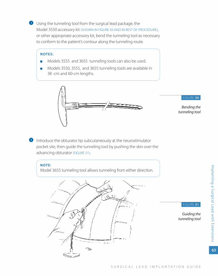
Using the tunneling tool from the surgical lead package, the c
Model 3550 accessory kit (SHOWN IN FIGURE 50 AND IN REST OF PROCEDURE), or other appropriate accessory kit, bend the tunneling tool as necessary to conform to the patient’s contour along the tunneling route.
NOTES:
Models 3555 and 3655 tunneling tools can also be used. ■
Models 3550, 3555, and 3655 tunneling tools are available in ■
38 -cm and 60-cm lengths.
Introduce the obturator tip subcutaneously at the neurostimulator d
pocket site, then guide the tunneling tool by pushing the skin over the advancing obturator (FIGURE 51).
NOTE:Model 3655 tunneling tool allows tunneling from either direction.
F IGURE 50
Bending the tunneling tool
FIGURE 51
Guiding the tunneling tool
64
N E U R O S T I M U L A T I O N T H E R A P Y
Imp
lant
ing
a S
urgi
cal L
ead
wit
h Ex
tens
ions
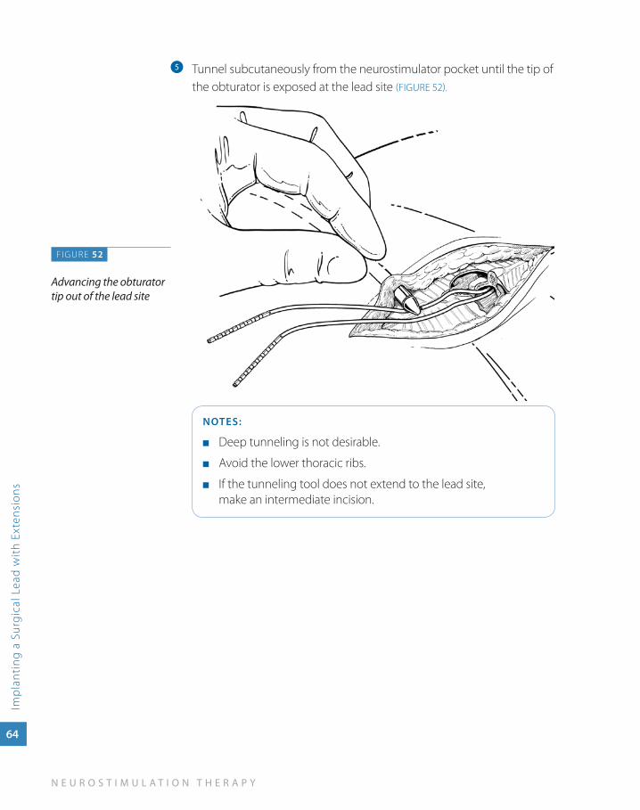
Tunnel subcutaneously from the neurostimulator pocket until the tip of e
the obturator is exposed at the lead site (FIGURE 52).
NOTES:
Deep tunneling is not desirable. ■
Avoid the lower thoracic ribs. ■
If the tunneling tool does not extend to the lead site, ■
make an intermediate incision.
FIGURE 52
Advancing the obturator tip out of the lead site
S U R G I C A L L E A D I M P L A N T A T I O N G U I D E
Imp
lanting a Surgical Lead
with Extensions
65
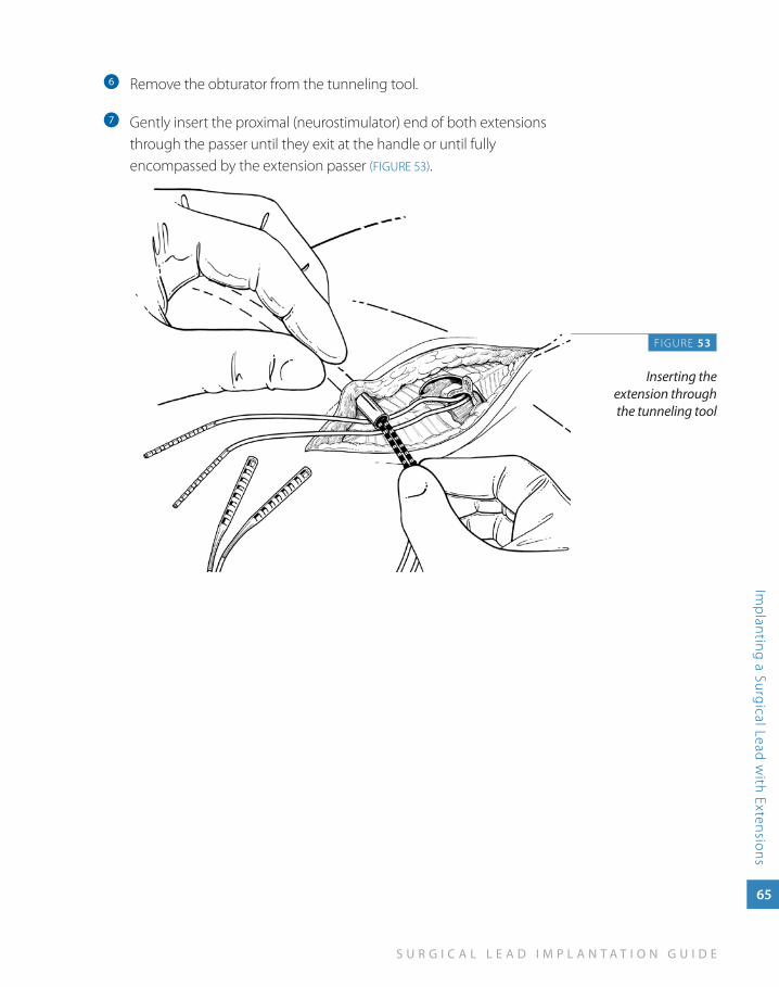
Remove the obturator from the tunneling tool.f
Gently insert the proximal (neurostimulator) end of both extensions g
through the passer until they exit at the handle or until fully encompassed by the extension passer (FIGURE 53).
F IGURE 53
Inserting the extension through the tunneling tool
66
N E U R O S T I M U L A T I O N T H E R A P Y
Imp
lant
ing
a S
urgi
cal L
ead
wit
h Ex
tens
ions
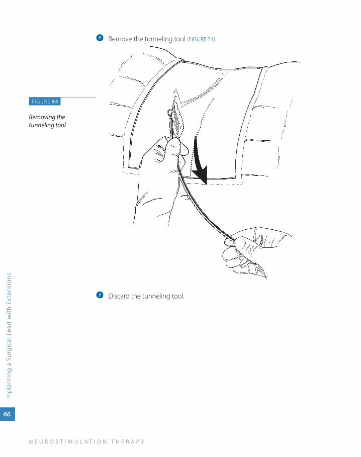
Remove the tunneling tool h (FIGURE 54).
Discard the tunneling tool.i
FIGURE 54
Removing the tunneling tool
S U R G I C A L L E A D I M P L A N T A T I O N G U I D E
Imp
lanting a Surgical Lead
with Extensions
67
Connecting the Lead Bodies to Two Extensions
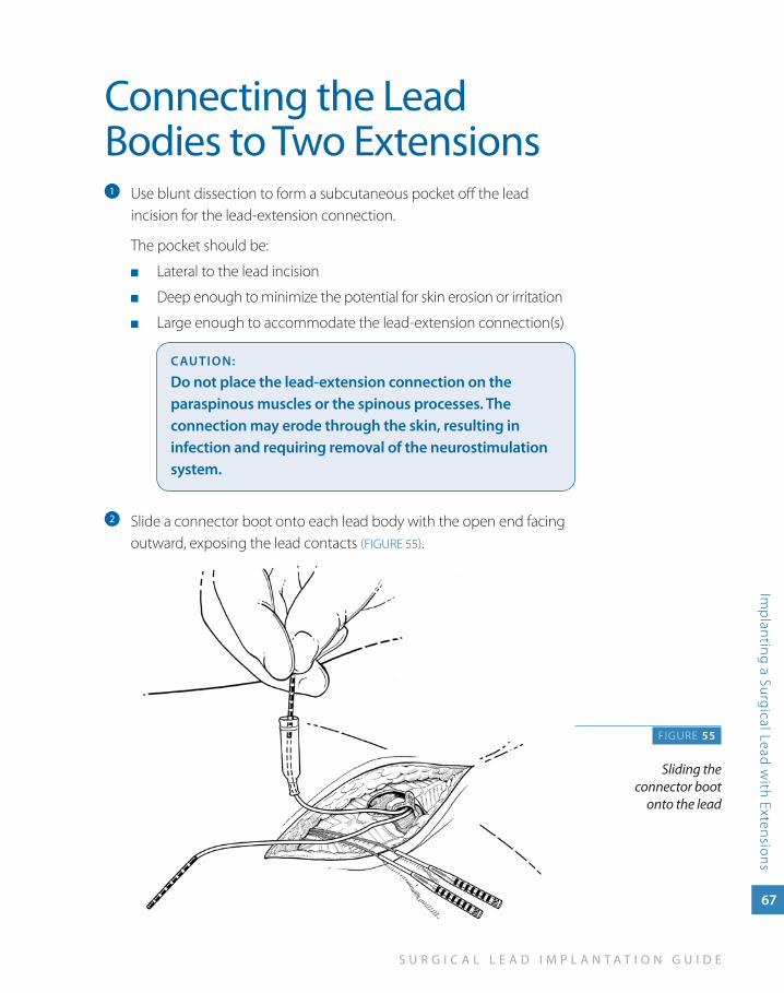
Use blunt dissection to form a subcutaneous pocket off the lead a
incision for the lead-extension connection.
The pocket should be:
Lateral to the lead incision ■
Deep enough to minimize the potential for skin erosion or irritation ■
Large enough to accommodate the lead-extension connection(s) ■
CauTION:
Do not place the lead-extension connection on the paraspinous muscles or the spinous processes. The connection may erode through the skin, resulting in infection and requiring removal of the neurostimulation system.
Slide a connector boot onto each lead body with the open end facing b
outward, exposing the lead contacts (FIGURE 55).
F IGURE 55
Sliding the connector boot
onto the lead
68
N E U R O S T I M U L A T I O N T H E R A P Y
Imp
lant
ing
a S
urgi
cal L
ead
wit
h Ex
tens
ions
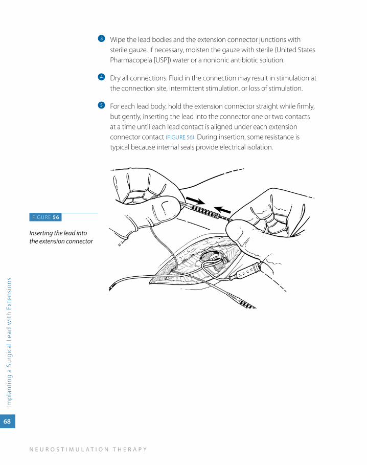
Wipe the lead bodies and the extension connector junctions with c
sterile gauze. If necessary, moisten the gauze with sterile (United States Pharmacopeia [USP]) water or a nonionic antibiotic solution.
Dry all connections. Fluid in the connection may result in stimulation at d
the connection site, intermittent stimulation, or loss of stimulation.
For each lead body, hold the extension connector straight while firmly, e
but gently, inserting the lead into the connector one or two contacts at a time until each lead contact is aligned under each extension connector contact (FIGURE 56). During insertion, some resistance is typical because internal seals provide electrical isolation.
FIGURE 56
Inserting the lead into the extension connector
S U R G I C A L L E A D I M P L A N T A T I O N G U I D E
Imp
lanting a Surgical Lead
with Extensions
69
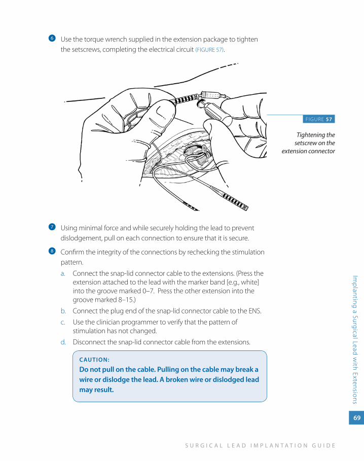
Use the torque wrench supplied in the extension package to tighten f
the setscrews, completing the electrical circuit (FIGURE 57).
Using minimal force and while securely holding the lead to prevent g
dislodgement, pull on each connection to ensure that it is secure.
Confirm the integrity of the connections by rechecking the stimulation h
pattern.
Connect the snap-lid connector cable to the extensions. (Press the a. extension attached to the lead with the marker band [e.g., white] into the groove marked 0–7. Press the other extension into the groove marked 8–15.)
Connect the plug end of the snap-lid connector cable to the ENS.b.
Use the clinician programmer to verify that the pattern of c. stimulation has not changed.
Disconnect the snap-lid connector cable from the extensions.d.
CauTION:
Do not pull on the cable. Pulling on the cable may break a wire or dislodge the lead. a broken wire or dislodged lead may result.
FIGURE 57
Tightening the setscrew on the
extension connector
70
N E U R O S T I M U L A T I O N T H E R A P Y
Imp
lant
ing
a S
urgi
cal L
ead
wit
h Ex
tens
ions
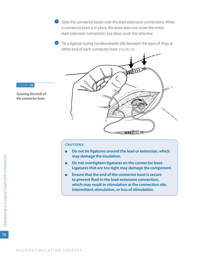
Slide the connector boots over the lead-extension connections. When i
a connector boot is in place, the boot does not cover the entire lead-extension connection, but does cover the setscrew.
Tie a ligature (using nonabsorbable silk) between the pairs of rings at j
either end of each connector boot (FIGURE 58).
CauTIONS:
Do not tie ligatures around the lead or extension, which ■
may damage the insulation.
Do not overtighten ligatures on the connector boot. ■
Ligatures that are too tight may damage the component.
Ensure that the end of the connector boot is secure ■
to prevent fluid in the lead-extension connection, which may result in stimulation at the connection site, intermittent stimulation, or loss of stimulation.
FIGURE 58
Suturing the ends of the connector boot
S U R G I C A L L E A D I M P L A N T A T I O N G U I D E
Imp
lanting a Surgical Lead
with Extensions
71
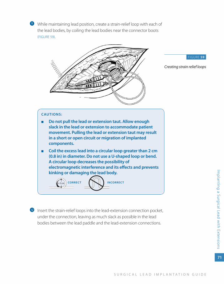
While maintaining lead position, create a strain-relief loop with each of k
the lead bodies, by coiling the lead bodies near the connector boots (FIGURE 59).
CauTIONS:
Do not pull the lead or extension taut. allow enough ■
slack in the lead or extension to accommodate patient movement. Pulling the lead or extension taut may result in a short or open circuit or migration of implanted components.
Coil the excess lead into a circular loop greater than 2 cm ■
(0.8 in) in diameter. Do not use a u-shaped loop or bend. a circular loop decreases the possibility of electromagnetic interference and its effects and prevents kinking or damaging the lead body.
CORREC T INCORREC T
Insert the strain-relief loops into the lead-extension connection pocket, l
under the connection, leaving as much slack as possible in the lead bodies between the lead paddle and the lead-extension connections.
FIGURE 59
Creating strain relief loops
72
N E U R O S T I M U L A T I O N T H E R A P Y
Imp
lant
ing
a S
urgi
cal L
ead
wit
h Ex
tens
ions
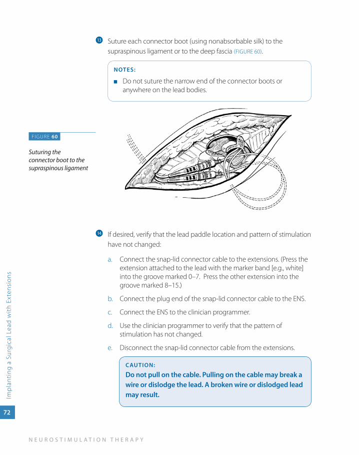
Suture each connector boot (using nonabsorbable silk) to the m
supraspinous ligament or to the deep fascia (FIGURE 60).
NOTES:
Do not suture the narrow end of the connector boots or ■
anywhere on the lead bodies.
If desired, verify that the lead paddle location and pattern of stimulation n
have not changed:
Connect the snap-lid connector cable to the extensions. (Press the a. extension attached to the lead with the marker band [e.g., white] into the groove marked 0–7. Press the other extension into the groove marked 8–15.)
Connect the plug end of the snap-lid connector cable to the ENS.b.
Connect the ENS to the clinician programmer.c.
Use the clinician programmer to verify that the pattern of d. stimulation has not changed.
Disconnect the snap-lid connector cable from the extensions.e.
CauTION:
Do not pull on the cable. Pulling on the cable may break a wire or dislodge the lead. a broken wire or dislodged lead may result.
FIGURE 60
Suturing the connector boot to the supraspinous ligament
6c
om
ple
tin
g t
he
neu
ro
stim
ula
tio
n sy
stem
im
pla
nt
Completing the Neurostimulation
System Implant
S U R G I C A L L E A D I M P L A N T A T I O N G U I D E
Com
pleting
the Neurostim
ulation System Im
plant
73
Completing the Neurostimulation System Implant
To complete the neurostimulation system implant, the lead bodies or extensions are connected to the neurostimulator. The neurostimulator is then sutured into the pocket, and a system integrity check is performed to verify that the components are properly connected.
In addition to standard postoperative considerations, activity restrictions and patient education specific to neurostimulation therapy are addressed. Neurostimulation therapy may be initiated during postoperative recovery or at a follow-up appointment.
The example procedure in this section uses a RestoreUltra neurostimulator.
Alternate neurostimulators are available through Medtronic.
74
N E U R O S T I M U L A T I O N T H E R A P Y
Com
ple
ting
the
Neu
rost
imul
atio
n Sy
stem
Imp
lant
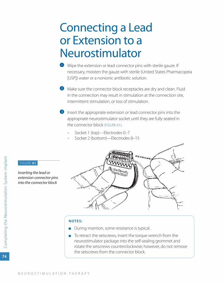
Connecting a Lead or Extension to a Neurostimulator
Wipe the extension or lead connector pins with sterile gauze. If a
necessary, moisten the gauze with sterile (United States Pharmacopeia [USP]) water or a nonionic antibiotic solution.
Make sure the connector block receptacles are dry and clean. Fluid b
in the connection may result in stimulation at the connection site, intermittent stimulation, or loss of stimulation.
Insert the appropriate extension or lead connector pins into the c
appropriate neurostimulator socket until they are fully seated in the connector block (FIGURE 61).
Socket 1 (top)—Electrodes 0–7 »Socket 2 » (bottom)—Electrodes 8–15
NOTES:
During insertion, some resistance is typical. ■
To retract the setscrews, insert the torque wrench from the ■
neurostimulator package into the self-sealing grommet and rotate the setscrews counterclockwise; however, do not remove the setscrews from the connector block.
FIGURE 61
Inserting the lead or extension connector pins into the connector block
S U R G I C A L L E A D I M P L A N T A T I O N G U I D E
Com
pleting
the Neurostim
ulation System Im
plant
75
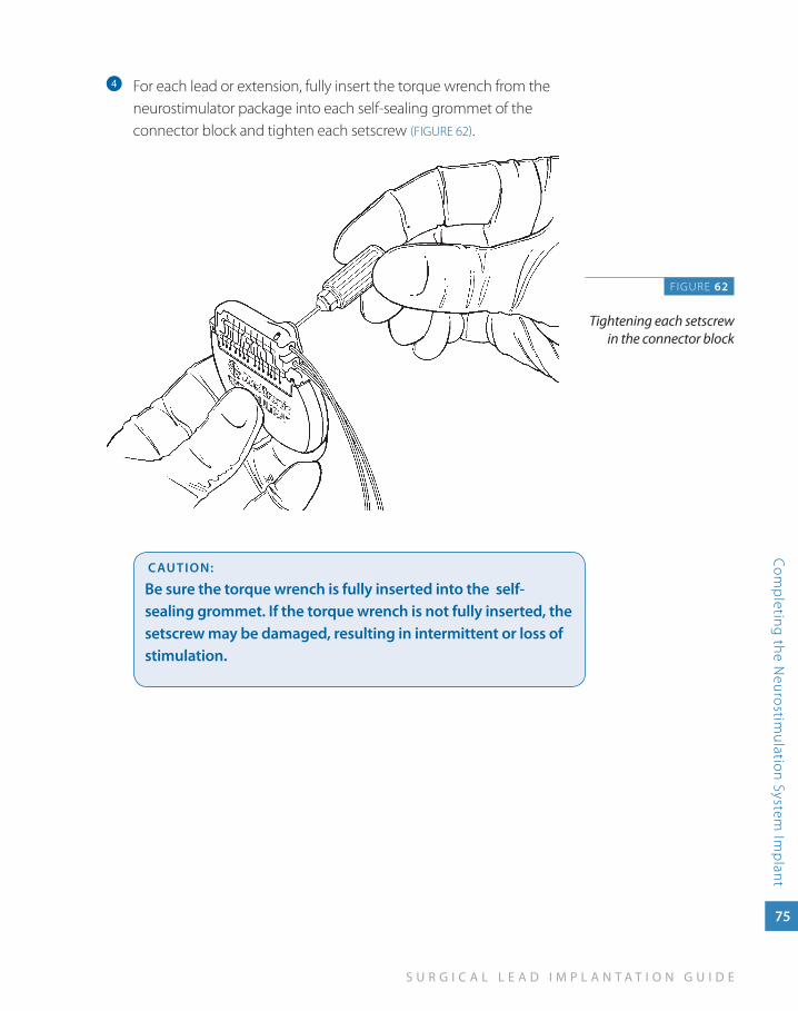
For each lead or extension, fully insert the torque wrench from the d
neurostimulator package into each self-sealing grommet of the connector block and tighten each setscrew (FIGURE 62).
CauTION:
Be sure the torque wrench is fully inserted into the self-sealing grommet. If the torque wrench is not fully inserted, the setscrew may be damaged, resulting in intermittent or loss of stimulation.
FIGURE 62
Tightening each setscrew in the connector block
76
N E U R O S T I M U L A T I O N T H E R A P Y
Com
ple
ting
the
Neu
rost
imul
atio
n Sy
stem
Imp
lant
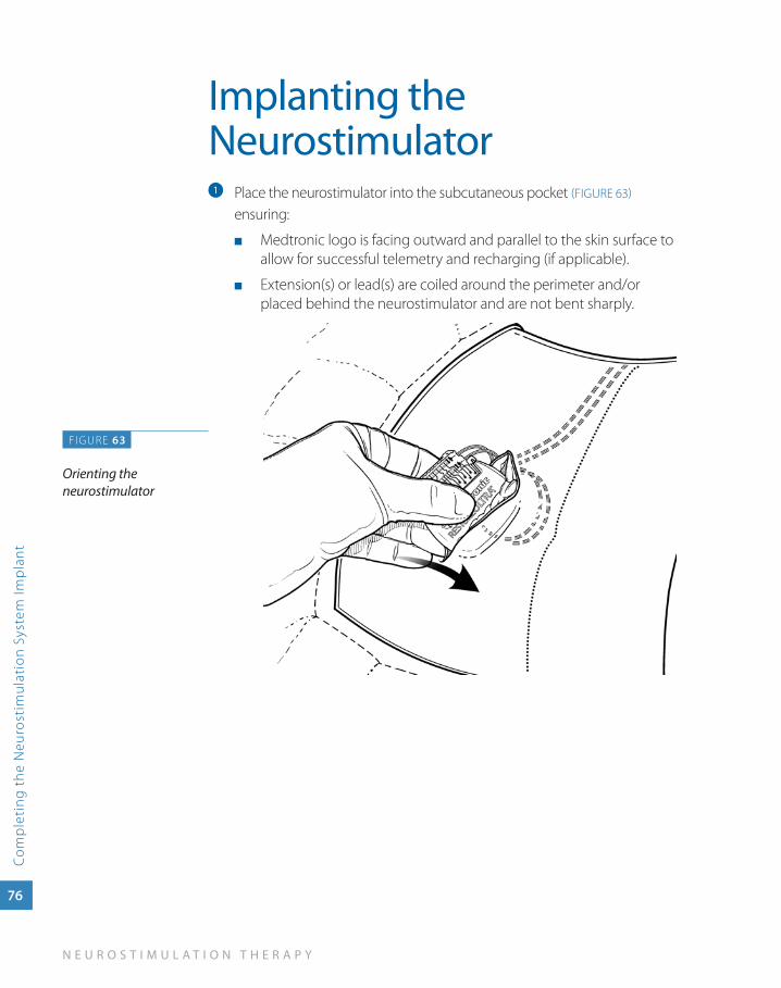
Implanting the Neurostimulator
Place the neurostimulator into the subcutaneous pocket a (FIGURE 63)
ensuring:
Medtronic logo is facing outward and parallel to the skin surface to ■
allow for successful telemetry and recharging (if applicable).
Extension(s) or lead(s) are coiled around the perimeter and/or ■
placed behind the neurostimulator and are not bent sharply.
F IGURE 63
Orienting the neurostimulator
S U R G I C A L L E A D I M P L A N T A T I O N G U I D E
Com
pleting
the Neurostim
ulation System Im
plant
77
CauTION:
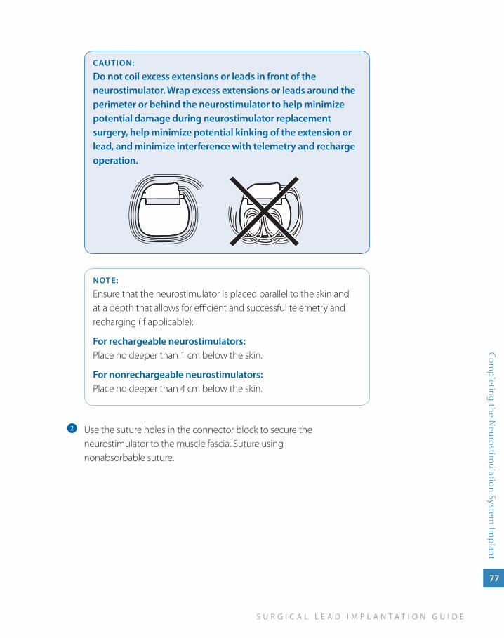
Do not coil excess extensions or leads in front of the neurostimulator. wrap excess extensions or leads around the perimeter or behind the neurostimulator to help minimize potential damage during neurostimulator replacement surgery, help minimize potential kinking of the extension or lead, and minimize interference with telemetry and recharge operation.
NOTE:
Ensure that the neurostimulator is placed parallel to the skin and at a depth that allows for efficient and successful telemetry and recharging (if applicable):
For rechargeable neurostimulators: Place no deeper than 1 cm below the skin.
For nonrechargeable neurostimulators: Place no deeper than 4 cm below the skin.
Use the suture holes in the connector block to secure the b
neurostimulator to the muscle fascia. Suture using nonabsorbable suture.
78
N E U R O S T I M U L A T I O N T H E R A P Y
Com
ple
ting
the
Neu
rost
imul
atio
n Sy
stem
Imp
lant
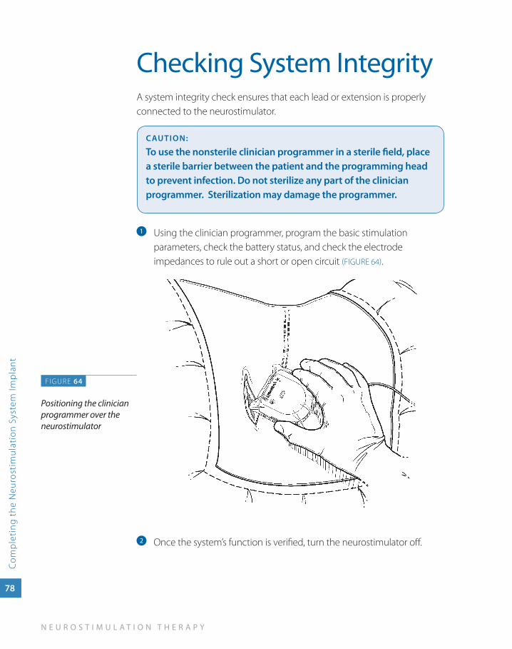
Checking System IntegrityA system integrity check ensures that each lead or extension is properly connected to the neurostimulator.
CauTION:
To use the nonsterile clinician programmer in a sterile field, place a sterile barrier between the patient and the programming head to prevent infection. Do not sterilize any part of the clinician programmer. Sterilization may damage the programmer.
Using the clinician programmer, program the basic stimulation a
parameters, check the battery status, and check the electrode impedances to rule out a short or open circuit (FIGURE 64).
Once the system’s function is verified, turn the neurostimulator off.b
FIGURE 64
Positioning the clinician programmer over the neurostimulator
S U R G I C A L L E A D I M P L A N T A T I O N G U I D E
Com
pleting
the Neurostim
ulation System Im
plant
79
Completing the System Implant Procedure
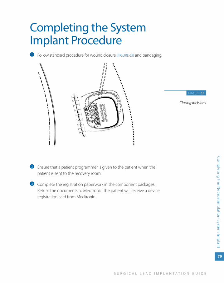
Follow standard procedure for wound closure a (FIGURE 65) and bandaging.
Ensure that a patient programmer is given to the patient when the b
patient is sent to the recovery room.
Complete the registration paperwork in the component packages. c
Return the documents to Medtronic. The patient will receive a device registration card from Medtronic.
FIGURE 65
Closing incisions
80
N E U R O S T I M U L A T I O N T H E R A P Y
Com
ple
ting
the
Neu
rost
imul
atio
n Sy
stem
Imp
lant
Postoperative ConsiderationsOperating RoomIf desired, immediately postoperatively take anteroposterior (AP) and lateral images to establish baseline lead placement.
RecoveryUse routine procedures and standard practice for patient management in the recovery area.
If desired, you can initiate neurostimulation therapy in recovery. At this time, you can program the initial settings, but programming for maximum coverage may not be appropriate until a follow-up appointment.
Postoperative activity RestrictionsPostoperative activity restrictions emphasize that maintaining lead position is critical. The patient should understand that abrupt movements may shift the implanted lead position, and small movements may produce significant changes in stimulation.
To maintain lead position, the patient should avoid:
Lifting their arms overhead ■
Lifting more than 5 lbs (2.3 kg), stretching, reaching, pulling, or twisting ■
Electromagnetic interference (MRI, lithotripsy), postural changes or ■
other activities (e.g., driving, operating power tools) that could cause an unexpected jolt or shock*
*For complete information on EMI warnings and cautions, see product labeling.
S U R G I C A L L E A D I M P L A N T A T I O N G U I D E
Com
pleting
the Neurostim
ulation System Im
plant
81
Before Discharging the PatientBefore the patient is discharged:
Schedule the initial follow-up appointment. ■
Ensure the patient is ambulatory and capable of appropriate ■
range-of-motion exercises.
Provide the patient with a temporary ID card and educational materials ■
(brochures, manuals, DVDs).
To expedite appropriate treatment during an emergency, recommend ■
that patients wear a medical alert bracelet or necklace indicating that they have an implanted device.
Postoperative Patient EducationThorough postoperative patient education is crucial to the long-term success of neurostimulation therapy. In addition to standard postoperative patient education topics, the patient, family, and caregiver should be educated on topics related to their neurostimulation system including:
Neurostimulator and patient programmer operation ■
Neurostimulation system maintenance ■
Patient activity restrictions ■
Applicable cautions and warnings including how MRI affects the ■
neurostimulation system
Instructions to carry patient identification card at all times in order to ■
inform emergency or medical personnel of device information.
Medtronic produces a number of materials such as brochures, DVDs, and patient manuals to use in patient education related to the neurostimulation system.


imp
or
tan
t safe
ty
info
rm
at
ion
7Important Safety
Information
S U R G I C A L L E A D I M P L A N T A T I O N G U I D E
Imp
ortant Safety Information
83
Neurostimulation Systems For Pain TherapyBrief Summary: Product manuals must be reviewed prior to use for detailed disclosure.
Indications Implantable neurostimulation systems—A Medtronic implantable neurostimulation system is indicated for spinal cord stimulation (SCS) system as an aid in the management of chronic, intractable pain of the trunk and/or limbs-including unilateral or bilateral pain associated with the following conditions:
Failed back syndrome (FBS) or low back syndrome or failed back ■
Radicular pain syndrome or radiculopathies resulting in pain secondary to FBS or ■
herniated disk
Postlaminectomy pain ■
Multiple back operations ■
Unsuccessful disk surgery ■
Degenerative disk disease (DDD)/herniated disk pain refractory to conservative ■
and surgical interventions
Peripheral causalgia ■
Epidural fibrosis ■
Arachnoiditis or lumbar adhesive arachnoiditis ■
Complex regional pain syndrome (CRPS), reflex sympathetic dystrophy (RSD), or ■
causalgia
84
N E U R O S T I M U L A T I O N T H E R A P Y
Imp
orta
nt S
afet
y In
form
atio
n
Contraindications Diathermy—Do not use shortwave diathermy, microwave or therapeutic ultrasound diathermy (all now referred to as diathermy) on patients implanted with a neurostimulation system. Energy from diathermy can be transferred through the implanted system and cause tissue damage at the locations of the implanted electrodes, resulting in severe injury or death.
warningsSources of strong electromagnetic interference (eg, defibrillation, diathermy, electrocautery, MRI, RF ablation, and therapeutic ultrasound) can interact with the neurostimulation system, resulting in serious patient injury or death. These and other sources of EMI can also result in system damage, operational changes to the neurostimulator or unexpected changes in stimulation. Rupture or piercing of the neurostimulator can result in severe burns. An implanted cardiac device (eg, pacemaker, defibrillator) may damage a neurostimulator, and the electrical pulses from the neurostimulator may result in an inappropriate response of the cardiac device.
PrecautionsThe safety and effectiveness of this therapy has not been established for pediatric use (patients under the age of 18), pregnancy, unborn fetus, or delivery. Patients should be detoxified from narcotics prior to lead placement. Clinicians and patients should follow programming guidelines and precautions provided in product manuals. Patients should avoid activities that may put undue stress on the implanted neurostimulation system components. Patients should not scuba dive below 10 meters of water or enter hyperbaric chambers above 2.0 atmosphere absolute (ATA). Electromagnetic interference, postural changes, and other activities may cause shocking or jolting.
adverse EventsAdverse events may include: undesirable change in stimulation described by some patients as uncomfortable, jolting or shocking; hematoma, epidural hemorrhage, paralysis, seroma, CSF leakage, infection, erosion, allergic response, hardware malfunction or migration, pain at implant site, loss of pain relief, chest wall stimulation, and surgical risks.
For further information, please call Medtronic at 1-800-328-0810 and/or consult Medtronic’s website at www.medtronic.com.
USA Rx Only Rev 0209

United States of Americamedtronic Neuromodulation 710 medtronic parkway minneapolis, mN 55432-5604 usa tel. 763-505-5000 toll-free 1-800-328-0810
Europemedtronic international trading sàrl route du molliau 31 Case postale Ch-1131 tolochenaz switzerland tel. +41-21-802-7000
Asia-Pacificmedtronic international, ltd. suite 1602 16/f manulife plaza the lee Gardens, 33 hysan avenue Causeway Bay hong Kong tel. 852-2891-4456
Australiamedtronic australasia pty. ltd. 97 Waterloo road North ryde NsW 2113 australia tel. +61-2-9857-9000 www.medtronicneuro.com.au
Canadamedtronic of Canada ltd. 6733 Kitimat road mississauga, ontario l5N 1W3 Canada tel. 1-905-826-6020
professional.medtronic.com
uC2
0070
4947
eN
NI7
909
© 2
010
med
tron
ic, i
nc. p
rinte
d in
usa
.
Related Documents